Embed Size (px)
DESCRIPTION
doc for passat b6
Citation preview
96 - 1
Interior - Lights and Switches
Footwell Lights
Footwell lights:
Left Footwell Light W9
Right Footwell Light W10
Note:
The front foot well lights are located in trim beneath the instrument panel.
Footwell lights, removing and installing
Special tools, testers and auxiliary items required
Trim removal wedge 3409
Note:
The front foot well lights are located in trim beneath the instrument panel.
Removal and installation for all foot well lights is performed in the same way and is only described for one light.
Removing:
Caution!
Стр. 1 из 3Interior - Lights and Switches
Switch off all electrical consumers.
Switch ignition off and remove ignition key.
When removing switches, trim, covers or displays, prevent damage to visible areas by always applying appropriate tape to area surrounding the component, and the tools being used (screwdrivers, wedges etc.).
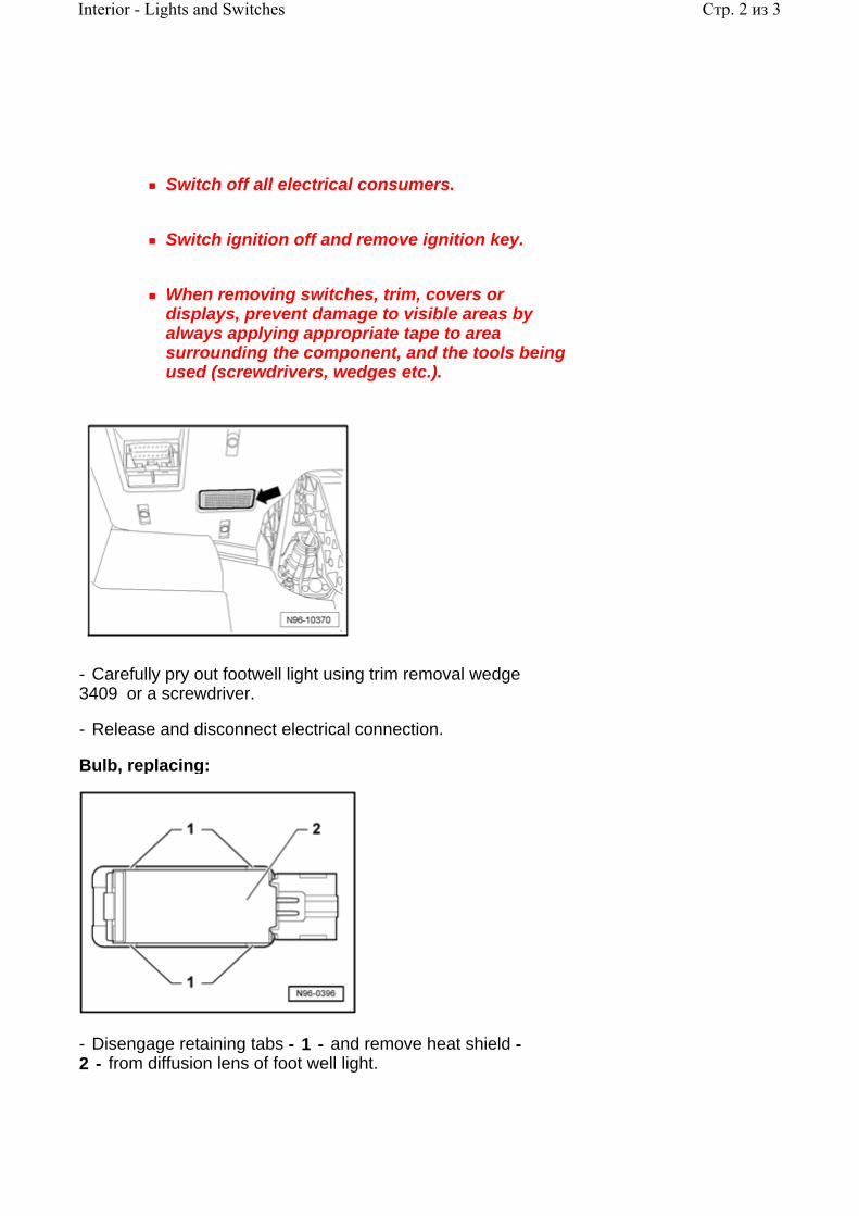
- Carefully pry out footwell light using trim removal wedge 3409 or a screwdriver.
- Release and disconnect electrical connection.
Bulb, replacing:
- Disengage retaining tabs - 1 - and remove heat shield - 2 - from diffusion lens of foot well light.
Стр. 2 из 3Interior - Lights and Switches

- Carefully pry bulb from socket.
- Replace bulb (12 V, 5 W).
Installing:
Install in reverse order of removal.
Footwell lights, checking
Left Footwell Light W9 and Right Footwell Light W10 function can be checked using Vehicle Electrical System Control Module J519 On Board Diagnostic (OBD) program function "Output Diagnostic Test Mode (DTM)" 97-6, Vehicle Electrical System Control Module J519 , Output Diagnostic Test Mode (DTM) .
Стр. 3 из 3Interior - Lights and Switches
96 - 2
Engine Compartment - Lights and Switches
Front Hood Switch F266 , removing and installing
Removing:
Caution!
Switch off all electrical consumers.
Switch ignition off and remove ignition key.
- Remove front hood lock
.
Repair Manual, Body Exterior, Repair Group 55, Hood; removing and installing hood lock; removing
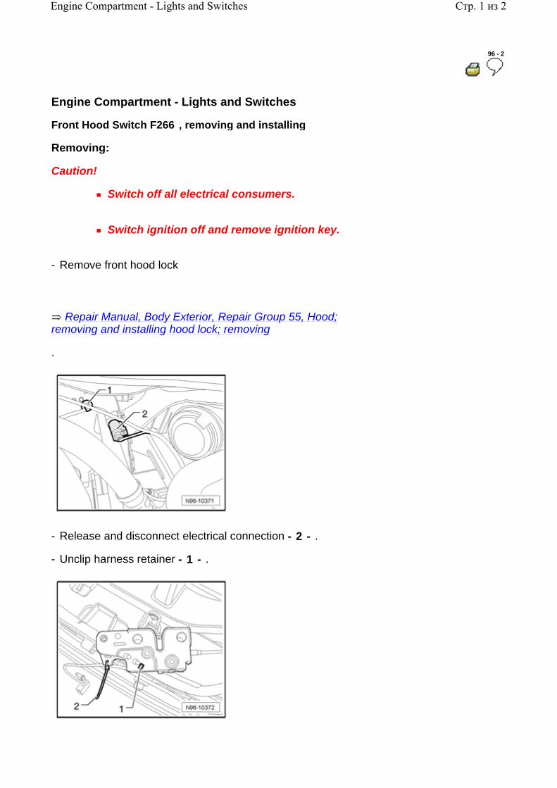
- Release and disconnect electrical connection - 2 - .
- Unclip harness retainer - 1 - .
Стр. 1 из 2Engine Compartment - Lights and Switches

- Cut cable tie - 2 - .
- Release tab - 1 - and move Front Hood Switch F266 in the elongated holes so that switch can be removed.
Installing:
Install in reverse order of removal.
Стр. 2 из 2Engine Compartment - Lights and Switches

96 - 3
Instrument Panel - Lights and Switches
Light Switch E1 , removing and installing
The following components are integrated with Light Switch E1 :
Fog Lamp Switch E7
Rear Fog Lamp Switch E18
headlamp Switch Light L9
Removing:
Caution!
Switch off all electrical consumers.
Switch ignition off and remove ignition key.
- Turn light switch rotary knob to "0" position.
- Press light switch rotary knob inward - arrow 1 - and turn slightly to the right - arrow 2 - .
- Hold rotary knob in this position and pull Light Switch E1 using rotary knob from instrument panel - arrow3 - .
Стр. 1 из 13Instrument Panel - Lights and Switches

- Release electrical connection - arrow - and disconnect from Light Switch E1 .
Installing:
- Reconnect electrical connection to Light Switch E1 .
Note:
For clarity, electrical connection not shown in illustration.
- Hold Light Switch E1 and push rotary knob in - 1 - and turn to the right slightly - 2 - .
- Hold rotary knob in this position and insert Light Switch E1 into instrument panel - 3 - .
- Turn rotary handle to position "0" , release and engage switch.
Headlamp Adjuster E102 and Instrument Panel Illumination Dimmer Switch E20 , removing and installing
Note:
Manual headlamp range adjuster Headlamp Adjuster
Стр. 2 из 13Instrument Panel - Lights and Switches

E102 is not applicable to USA/CDN.
Removing:
Caution!
Switch off all electrical consumers.
Switch ignition off and remove ignition key.
- Remove cover - 2 - .
- Remove adjuster - 1 - towards rear from instrument panel opening.
- Release and disconnect electrical connection - arrow - .
Installing:
Install in reverse order of removal.
Electro-Mechanical Parking Brake Button E538 , removing and installing
The following components are integrated with Electro-
Стр. 3 из 13Instrument Panel - Lights and Switches

Mechanical Parking Brake Button E538 :
Electro-mechanical Parking Brake Indicator Lamp K213
-AUTO HOLD- Indicator Lamp 2 K238
Special tools, testers and auxiliary items required
Trim removal wedge VAS 3409
Removing:
Caution!
Switch off all electrical consumers.
Switch ignition off and remove ignition key.
When removing switches, trim, covers or displays, prevent damage to visible areas by always applying appropriate tape to area surrounding the component, and the tools being used (screwdrivers, wedges etc.).
Стр. 4 из 13Instrument Panel - Lights and Switches
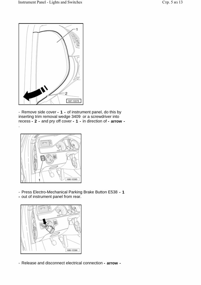
- Remove side cover - 1 - of instrument panel, do this by inserting trim removal wedge 3409 or a screwdriver into recess - 2 - and pry off cover - 1 - in direction of - arrow - .
- Press Electro-Mechanical Parking Brake Button E538 - 1 - out of instrument panel from rear.
- Release and disconnect electrical connection - arrow -
Стр. 5 из 13Instrument Panel - Lights and Switches

.
Installing:
Install in reverse order of removal.
Front Passengers Airbag Disabled Indicator Lamp K145 , removing and installing
Warning!
Special safety precautions apply to vehicles equipped with airbags
Repair Manual, Body Interior, Repair Group 69, Airbag, CAUTIONS and WARNINGS
Special tools, testers and auxiliary items required
Trim removal wedge 3409
Removing:
Caution!
Switch off all electrical consumers.
Switch ignition off and remove ignition key.
When removing switches, trim, covers or displays, prevent damage to visible areas by always applying appropriate tape to area surrounding the component, and the tools being used (screwdrivers, wedges etc.).
Стр. 6 из 13Instrument Panel - Lights and Switches
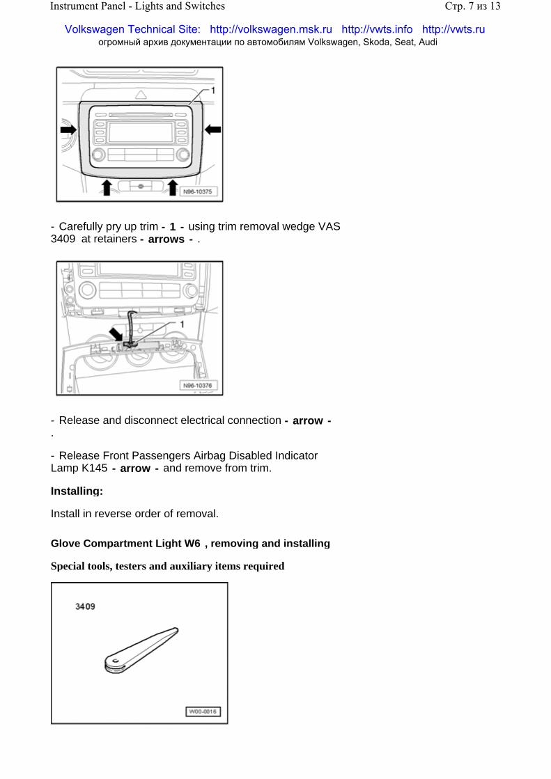
- Carefully pry up trim - 1 - using trim removal wedge VAS 3409 at retainers - arrows - .
- Release and disconnect electrical connection - arrow - .
- Release Front Passengers Airbag Disabled Indicator Lamp K145 - arrow - and remove from trim.
Installing:
Install in reverse order of removal.
Glove Compartment Light W6 , removing and installing
Special tools, testers and auxiliary items required
Стр. 7 из 13Instrument Panel - Lights and Switches
Volkswagen Technical Site: http://volkswagen.msk.ru http://vwts.info http://vwts.ru огромный архив документации по автомобилям Volkswagen, Skoda, Seat, Audi
Trim removal wedge 3409
Removing:
Caution!
Switch off all electrical consumers.
Switch ignition off and remove ignition key.
When removing switches, trim, covers or displays, prevent damage to visible areas by always applying appropriate tape to area surrounding the component, and the tools being used (screwdrivers, wedges etc.).
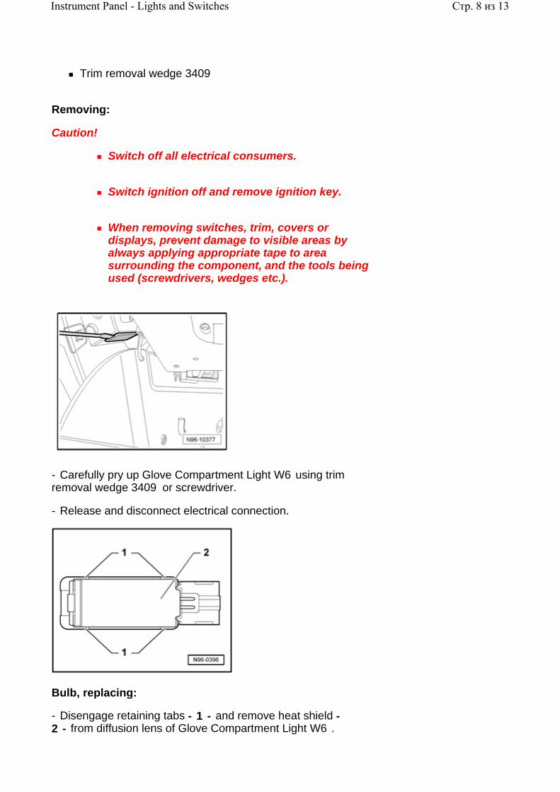
- Carefully pry up Glove Compartment Light W6 using trim removal wedge 3409 or screwdriver.
- Release and disconnect electrical connection.
Bulb, replacing:
- Disengage retaining tabs - 1 - and remove heat shield - 2 - from diffusion lens of Glove Compartment Light W6 .
Стр. 8 из 13Instrument Panel - Lights and Switches

- Carefully pry bulb from socket.
- Replace bulb (12 V, 5 W).
Installing:
Install in reverse order of removal.
Glove Compartment Lamp Switch E26 , removing and installing
Note:
The illustration shows Glove Compartment Lamp Switch E26 - 1 - with instrument panel removed. The instrument panel does not need to be removed in order to remove and install the switch.
Glove Compartment Lamp Switch E26 - 1 - can be reached from open glove compartment and can be unclipped.
Removing:
Caution!
Switch off all electrical consumers.
Стр. 9 из 13Instrument Panel - Lights and Switches
Switch ignition off and remove ignition key.
- Unclip Glove Compartment Lamp Switch E26 - 1 - with wiring connected - arrows A - .
- Pull Glove Compartment Lamp Switch E26 out from opening, as far as wiring allows, and disconnect electrical connection.
Installing:
Install in reverse order of removal.
Emergency Flasher Switch E3 , removing and installing
The following components are integrated with Emergency Flasher Switch E3 :
Emergency Flasher Indicator Lamp K6
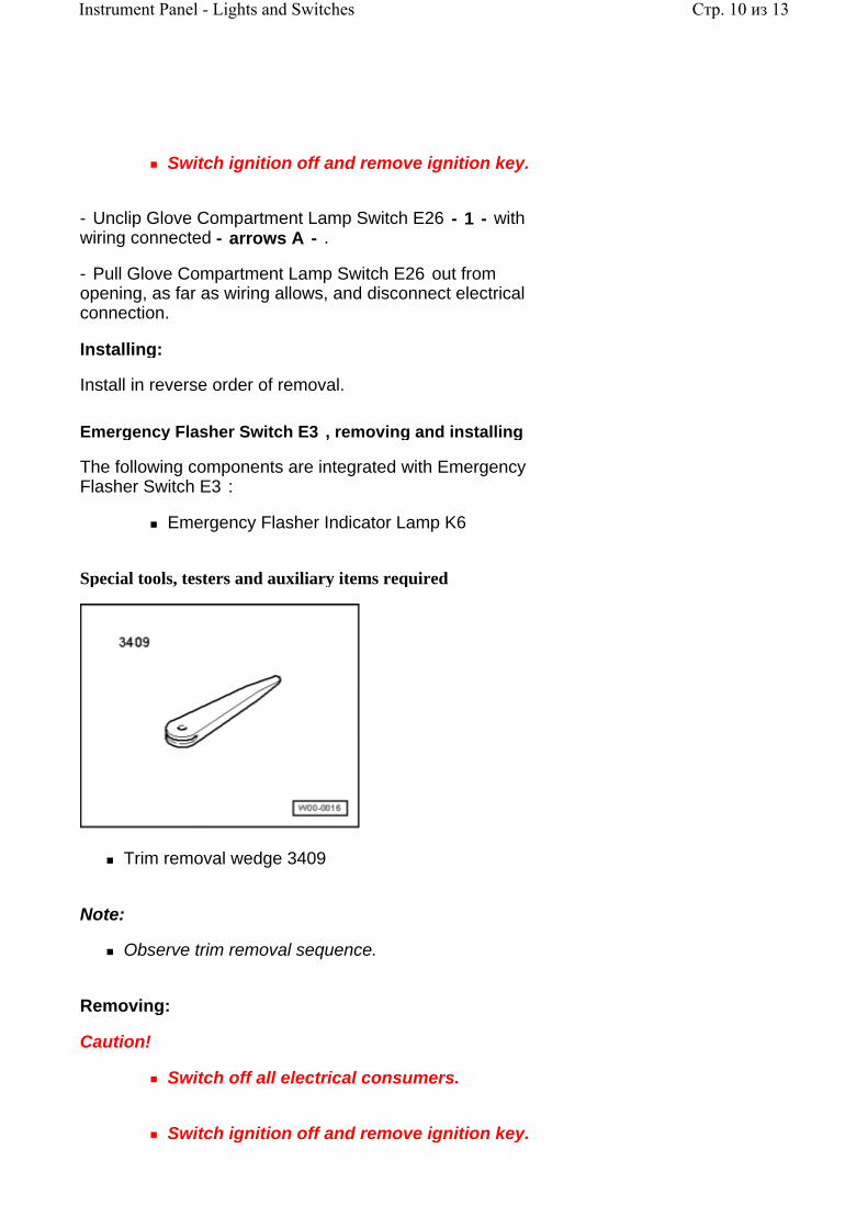
Special tools, testers and auxiliary items required
Trim removal wedge 3409
Note:
Observe trim removal sequence.
Removing:
Caution!
Switch off all electrical consumers.
Switch ignition off and remove ignition key.
Стр. 10 из 13Instrument Panel - Lights and Switches

When removing switches, trim, covers or displays, prevent damage to visible areas by always applying appropriate tape to area surrounding the component, and the tools being used (screwdrivers, wedges etc.).
- Remove trim - 2 - using trim removal wedge 3409
.
Repair Manual, Body Interior, Repair Group 68, Storage compartments, covers and trim
- Remove trim - 1 - using trim removal wedge 3409
.
Repair Manual, Body Interior, Repair Group 68, Storage compartments, covers and trim
- Remove trim - 5 - using trim removal wedge 3409
.
Repair Manual, Body Interior, Repair Group 68, Storage compartments, covers and trim
- Remove trim - 4 - using trim removal wedge 3409
Стр. 11 из 13Instrument Panel - Lights and Switches

.
Repair Manual, Body Interior, Repair Group 68, Storage compartments, covers and trim
- Remove trim - 3 - using trim removal wedge 3409
.
Repair Manual, Body Interior, Repair Group 68, Storage compartments, covers and trim
- Remove screws - arrows - and remove bracket - 1 - with Emergency Flasher Switch E3 .
- Release and disconnect electrical connection - arrow - .
Стр. 12 из 13Instrument Panel - Lights and Switches

- Release tabs - arrows - and remove Emergency Flasher Switch E3 - 1 - .
Installing:
Install in reverse order of removal.
Стр. 13 из 13Instrument Panel - Lights and Switches

96 - 4
Front Doors - Lights and Switches
Drivers door switch module, removing and installing
Depending on equipment level, the following components are integrated with the drivers door switch module:
Left Front Window Regulator Switch E40
Drivers Left Rear Window Regulator Switch E53
Drivers Right Rear Window Regulator Switch E55
Drivers Right Front Window Regulator Switch E81
Child Safety Button E318
Push Button Illumination L76
Special tools, testers and auxiliary items required
Trim removal wedge 3409
Removing:
Caution!
Switch off all electrical consumers.
Switch ignition off and remove ignition key.
When removing switches, trim, covers or
Стр. 1 из 14Front Doors - Lights and Switches

displays, prevent damage to visible areas by always applying appropriate tape to area surrounding the component, and the tools being used (screwdrivers, wedges etc.).
- Carefully pry up grip trim from retainers - arrows - using trim removal wedge 3409 .
- Release and disconnect electrical connection - arrow - .
- Release retainers - arrows - and remove switch module - 1 - from grip trim.
Стр. 2 из 14Front Doors - Lights and Switches

Installing:
Install in reverse order of removal.
Drivers Interior Locking Button E308 , removing and installing
The following components are integrated with Drivers Interior Locking Button E308 :
Push Button Illumination L76
Drivers Interior Locking Indicator Lamp K174
Removing:
Caution!
Switch off all electrical consumers.
Switch ignition off and remove ignition key.
- Remove door trim
.
Repair Manual, Body Interior, Repair Group 70, Door trim; front door trim, driver side, removing and installing; removing
- Release and disconnect electrical connection - 1 - and remove screw - arrow - .
Стр. 3 из 14Front Doors - Lights and Switches

- Release retainers - arrows - and remove door pull with Drivers Interior Locking Button E308 .
- Release retainers - arrows - and remove Drivers Interior Locking Button E308 - 1 - .
Installing:
Install in reverse order of removal.
Mirror Adjustment Switch E43 , removing and installing
Depending on equipment level, the following components are integrated with Mirror Adjustment Switch E43 :
Mirror Selector Switch E48
Outside Mirror Heating Switch E231
Mirror Folding Switch E263
Mirror Adjustment Switch Illumination L78
Special tools, testers and auxiliary items required
Стр. 4 из 14Front Doors - Lights and Switches

Trim removal wedge 3409
Removing:
Caution!
Switch off all electrical consumers.
Switch ignition off and remove ignition key.
When removing switches, trim, covers or displays, prevent damage to visible areas by always applying appropriate tape to area surrounding the component, and the tools being used (screwdrivers, wedges etc.).
- Carefully pry up grip trim from retainers - arrows - using trim removal wedge 3409 .
Стр. 5 из 14Front Doors - Lights and Switches
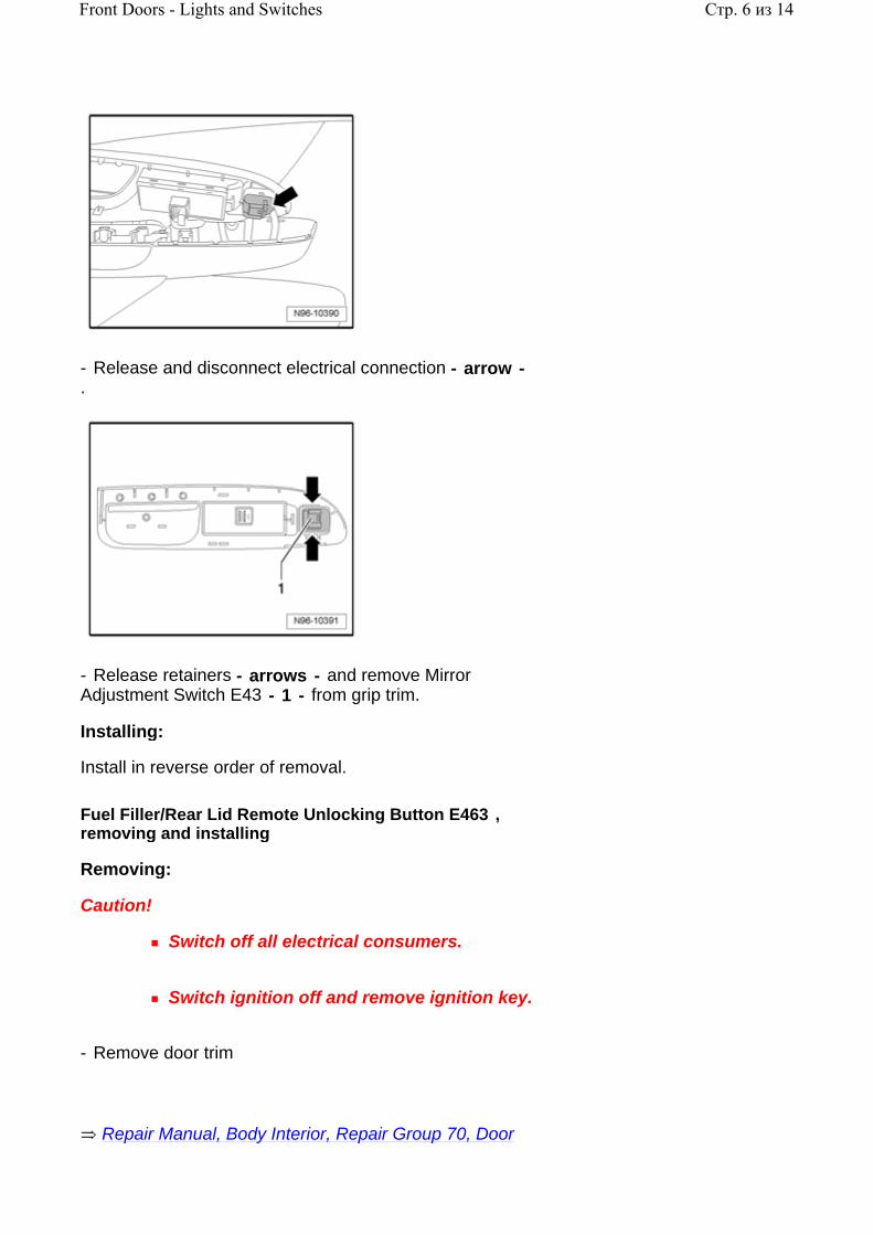
- Release and disconnect electrical connection - arrow - .
- Release retainers - arrows - and remove Mirror Adjustment Switch E43 - 1 - from grip trim.
Installing:
Install in reverse order of removal.
Fuel Filler/Rear Lid Remote Unlocking Button E463 , removing and installing
Removing:
Caution!
Switch off all electrical consumers.
Switch ignition off and remove ignition key.
- Remove door trim
Repair Manual, Body Interior, Repair Group 70, Door
Стр. 6 из 14Front Doors - Lights and Switches

.
trim; front door trim, driver side, removing and installing; removing
- Release and disconnect electrical connection - 1 - .
- Release retainers - arrows - and remove Fuel Filler/Rear Lid Remote Unlocking Button E463 - 2 - from door trim.
Installing:
Install in reverse order of removal.
Rear Lid Remote Lock Key Switch E232 , removing and installing
Removing:
Caution!
Switch off all electrical consumers.
Switch ignition off and remove ignition key.
- Remove door trim
.
Repair Manual, Body Interior, Repair Group 70, Door trim; front door trim, driver side, removing and installing; removing
Стр. 7 из 14Front Doors - Lights and Switches

- Release connector lock - 1 - and disconnect electrical connection.
- Depress retainers - arrows - and remove switch - 1 - from door trim.
Installing:
Install in reverse order of removal.
Central Locking -SAFE- Indicator Lamp K133
Central Locking -SAFE- Indicator Lamp K133 , removing and installing
Removing:
Caution!
Switch off all electrical consumers.
Switch ignition off and remove ignition key.
- Remove door trim
Стр. 8 из 14Front Doors - Lights and Switches

.
Repair Manual, Body Interior, Repair Group 70, Door trim; front door trim, driver side, removing and installing; removing
- Depress retainers - arrows - and unclip Central Locking -SAFE- Indicator Lamp K133 - 1 - from door trim.
- Disconnect electrical connection - 1 - from Central Locking -SAFE- Indicator Lamp K133 - 2 - .
Installing:
Install in reverse order of removal.
Central Locking -SAFE- Indicator Lamp K133 , checking
Central Locking -SAFE- Indicator Lamp K133 function can be checked using Drivers Door Control Module J386 On Board Diagnostic (OBD) program function "Output Diagnostic Test Mode (DTM) 97-6, Drivers Door Control Module J386 , performing Output Diagnostic Test Mode (DTM) .
Window Regulator Switch (in RF door) E107 , removing and installing
Note:
Стр. 9 из 14Front Doors - Lights and Switches

The Window Regulator Switch (in RF door) E107 also includes Power Window Switch Illumination L53 which cannot be replaced or serviced separately.
Removing:
Caution!
Switch off all electrical consumers.
Switch ignition off and remove ignition key.
- Remove door trim
.
Repair Manual, Body Interior, Repair Group 70, Door trim; front door trim, driver side, removing and installing; removing
- Release and disconnect electrical connection - 1 - .
- Remove screws - arrows - and remove grip with Window Regulator Switch (in RF door) E107 .
Стр. 10 из 14Front Doors - Lights and Switches
- Release retainers - arrows - and remove switch - 1 - .
Installing:
Install in reverse order of removal.
Left Front Entry Light W31 and Right Front Entry Light W32
Note:
Removal and installation for all entry lights is performed in the same way and is only described for one light.
Entry lights:
Left Front Entry Light W31
Right Front Entry Light W32
Left Rear Entry Light W33
Right Rear Entry Light W34
Left Front Entry Light W31 and Right Front Entry Light W32 , removing and installing
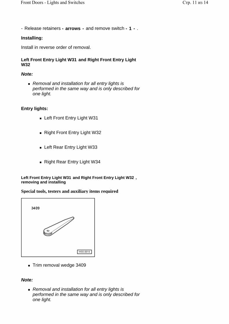
Special tools, testers and auxiliary items required
Trim removal wedge 3409
Note:
Removal and installation for all entry lights is performed in the same way and is only described for one light.
Стр. 11 из 14Front Doors - Lights and Switches
Removing:
Caution!
Switch off all electrical consumers.
Switch ignition off and remove ignition key.
When removing switches, trim, covers or displays, prevent damage to visible areas by always applying appropriate tape to area surrounding the component, and the tools being used (screwdrivers, wedges etc.).
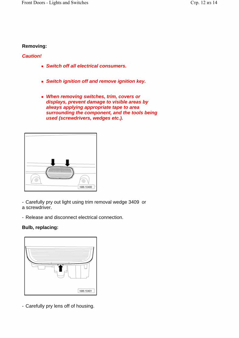
- Carefully pry out light using trim removal wedge 3409 or a screwdriver.
- Release and disconnect electrical connection.
Bulb, replacing:
- Carefully pry lens off of housing.
Стр. 12 из 14Front Doors - Lights and Switches
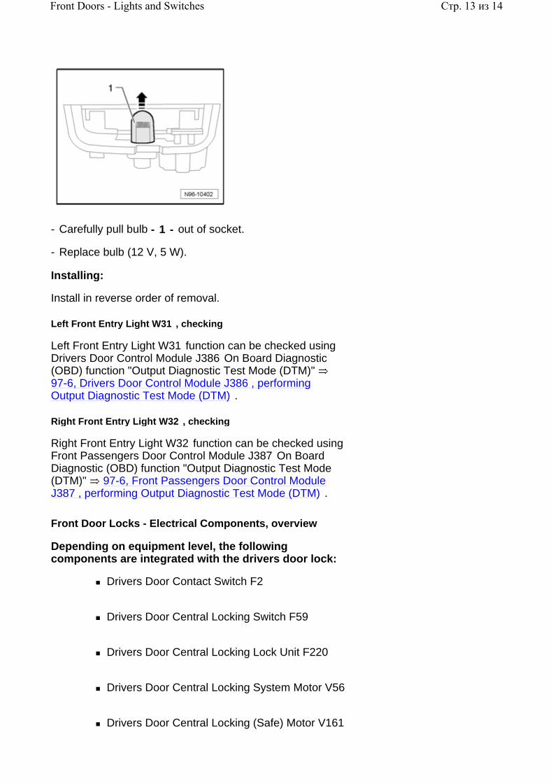
- Carefully pull bulb - 1 - out of socket.
- Replace bulb (12 V, 5 W).
Installing:
Install in reverse order of removal.
Left Front Entry Light W31 , checking
Left Front Entry Light W31 function can be checked using Drivers Door Control Module J386 On Board Diagnostic (OBD) function "Output Diagnostic Test Mode (DTM)" 97-6, Drivers Door Control Module J386 , performing Output Diagnostic Test Mode (DTM) .
Right Front Entry Light W32 , checking
Right Front Entry Light W32 function can be checked using Front Passengers Door Control Module J387 On Board Diagnostic (OBD) function "Output Diagnostic Test Mode (DTM)" 97-6, Front Passengers Door Control Module J387 , performing Output Diagnostic Test Mode (DTM) .
Front Door Locks - Electrical Components, overview
Depending on equipment level, the following components are integrated with the drivers door lock:
Drivers Door Contact Switch F2
Drivers Door Central Locking Switch F59
Drivers Door Central Locking Lock Unit F220
Drivers Door Central Locking System Motor V56
Drivers Door Central Locking (Safe) Motor V161
Стр. 13 из 14Front Doors - Lights and Switches
Depending on equipment level, the following components are integrated with the front passengers door lock:
Front Passengers Door Contact Switch F3
Front Passengers Door Central Locking Lock Unit F221
Front Passengers Door Central Locking System Motor V57
Front Passengers Central Locking (Safe) Motor V162
Note:
The components listed above cannot be replaced separately.
All components in drivers door lock can be checked using Drivers Door Control Module J386 On Board Diagnostic (OBD) program function "Output Diagnostic Test Mode (DTM)" 97-6, Drivers Door Control Module J386 , performing Output Diagnostic Test Mode (DTM) .
All components in front passengers door lock can be checked using Front Passengers Door Control Module J387 On Board Diagnostic (OBD) program function "Output Diagnostic Test Mode (DTM)" 97-6, Front Passengers Door Control Module J387 , performing Output Diagnostic Test Mode (DTM) .
In the event of front door lock component malfunctions:
- Replace affected door lock
.
Repair Manual, Body Exterior, Repair Group 57, Front door, door lock, removing and installing
Стр. 14 из 14Front Doors - Lights and Switches

96 - 5
Rear Doors - Lights and Switches
Left Rear Window Switch, (in LR door) E52 and Right Rear Window Switch, (in RR door) E54 , removing and installing
Note:
Removal and installation of Left Rear Window Switch (In LR Door) E52 and Right Rear Window Switch (In RR Door) E54 is the same and is described for only one switch.
The Left Rear Window Switch (In LR Door) E52 includes Power Window Switch Illumination L53 which cannot be serviced or replaced separately.
The Right Rear Window Switch (In LR Door) E54 includes Power Window Switch Illumination L53 which cannot be serviced or replaced separately.
Removing:
Caution!
Switch off all electrical consumers.
Switch ignition off and remove ignition key.
- Remove door trim
.
Repair Manual, Body Interior, Repair Group 70, Door trim; rear door trim, removing and installing
Стр. 1 из 4Rear Doors - Lights and Switches

- Remove screws - arrows - and remove grip with window switch.
- Release retainers - arrows - and remove switch - 1 - .
Installing:
Install in reverse order of removal.
Left Rear Entry Light W33 and Right Rear Entry Light W34
Left Rear Entry Light W33 and Right Rear Entry Light W34 , removing and installing
Note:
Removal and installation for all entry lights is performed in the same way and is only described for one light 96-4, Left Front Entry Light W31 and Right Front Entry Light W32 , removing and installing .
Left Rear Entry Light W33 and Right Rear Entry Light W34 , checking
Left Rear Entry Light W33 and Right Rear Entry Light W34 function can be checked using Comfort System Central
Стр. 2 из 4Rear Doors - Lights and Switches

Control Module J393 On Board Diagnostic (OBD) program function "Output Diagnostic Test Mode (DTM)" 97-6, Comfort System Central Control Module J393 , performing Output Diagnostic Test Mode (DTM) .
Rear Door Locks - Electrical Components, overview
Depending on equipment level, the following components are integrated with the left rear door lock:
Left Rear Door Contact Switch F10
Left Rear Central Locking Lock Unit F222
Left Rear Central Locking (Safe) Motor V163
Left Rear Central Locking (Lock) Motor V214
Depending on equipment level, the following components are integrated with the right rear door lock:
Right Rear Door Contact Switch F11
Right Rear Central Locking Lock Unit F223
Right Rear Central Locking (Safe) Motor V164
Right Rear Central Locking (Lock) Motor V215
Note:
The components listed above cannot be replaced separately.
Left Rear Central Locking Lock Unit F222 and Right Rear Central Locking Lock Unit F223 function can be checked using Comfort System Central Control Module J393 On Board Diagnostic (OBD) program function "Output Diagnostic Test Mode (DTM)" 97-6, Comfort System Central Control Module J393 , performing Output Diagnostic Test Mode (DTM) .
In the event of rear door lock component malfunctions:
Стр. 3 из 4Rear Doors - Lights and Switches

- Replace affected door lock
.
Repair Manual, Body Exterior, Repair Group 58, Rear door; removing and installing door lock
Стр. 4 из 4Rear Doors - Lights and Switches

96 - 6
Luggage Compartment - Lights and Switches
Luggage Compartment Light W3
Luggage Compartment Light W3 , removing and installing
Special tools, testers and auxiliary items required
Trim removal wedge 3409
Removing:
Caution!
Switch off all electrical consumers.
Switch ignition off and remove ignition key.
- Carefully pry up Luggage Compartment Light W3 using trim removal wedge 3409 or screwdriver.
Стр. 1 из 3Luggage Compartment - Lights and Switches

- Release and disconnect electrical connection - arrow - .
Bulb, replacing:
- Push contact plate - 1 - of Luggage Compartment Light W3 in direction of - arrow - and remove bulb - 2 - from socket.
- Replace bulb (12 V, 10 W).
Installing:
Install in reverse order of removal.
Rear Lid Lock Unit F256
The following components are integrated with Rear Lid Lock Unit F256 :
Luggage Compartment Light Switch F5
Rear Lid Opening Motor V254
Note:
The components listed above cannot be replaced
Стр. 2 из 3Luggage Compartment - Lights and Switches

separately.
Rear Lid Lock Unit F256 function can be checked using Comfort System Central Control Module J393 On Board Diagnostic (OBD) function "Output Diagnostic Test Mode (DTM)" 97-6, Comfort System Central Control Module J393 , performing Output Diagnostic Test Mode (DTM) .
Rear Lid Lock Unit F256 , removing and installing
Rear Lid Lock Unit F256 is integrated in rear lid lock and cannot be replaced separately.
In the event the Rear Lid Lock Unit F256 malfunctions, the complete rear lid lock must be replaced.
- Rear lid lock, replacing
.
Repair Manual, Body Exterior, Repair Group 55, Rear lid; Locking and unlocking components - assembly overview
Стр. 3 из 3Luggage Compartment - Lights and Switches
96 - 7
Headliner - Lights and Switches
Front interior lights
Depending on equipment level, the following components are integrated with the front interior light module:
Front Interior Lamp Button E326
Drivers Reading Light Button E457
Front Passengers Reading Light Button E458
Front Interior Light W1
Left Center Reading Light W39
Right Center Reading Light W40
Sunroof Switch E8
Sunroof Switch Illumination L65
Telephone Microphone R38
Front interior light module, removing and installing
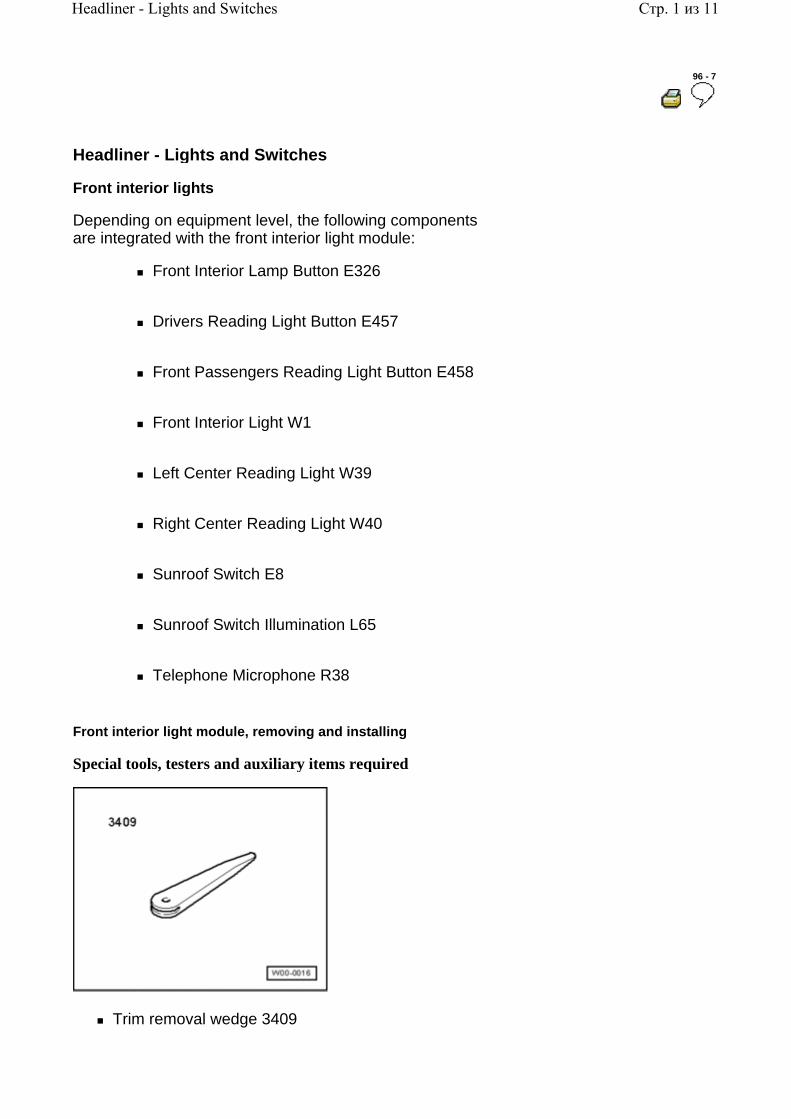
Special tools, testers and auxiliary items required
Trim removal wedge 3409
Стр. 1 из 11Headliner - Lights and Switches

Removing:
Caution!
Switch off all electrical consumers.
Switch ignition off and remove ignition key.
When removing switches, trim, covers or displays, prevent damage to visible areas by always applying appropriate tape to area surrounding the component, and the tools being used (screwdrivers, wedges etc.).
- Carefully remove trim - 1 - .
- Remove screws - 1 - , release retainers - arrows B - and remove interior light module from headliner opening - arrow A - , as far as wiring allows.
Стр. 2 из 11Headliner - Lights and Switches
Volkswagen Technical Site: http://volkswagen.msk.ru http://vwts.info http://vwts.ru огромный архив документации по автомобилям Volkswagen, Skoda, Seat, Audi

- Release and disconnect electrical connections - 1 - and - 2 - .
- On vehicles with voice control, unclip Telephone Microphone R38 - arrow - .
- Remove front interior light module.
Installing:
Install in reverse order of removal.
Front Interior Light W1 - bulb, replacing
Removing:
Caution!
Switch off all electrical consumers.
Switch ignition off and remove ignition key.
- Remove front interior light module 96-7, Front interior light module, removing and installing .
- Push contact plate - 1 - of Front Interior Light W1 in - direction of arrow - and remove soffit - 2 - together with
Стр. 3 из 11Headliner - Lights and Switches
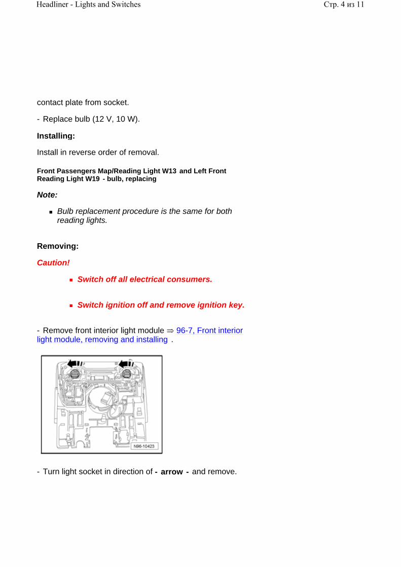
contact plate from socket.
- Replace bulb (12 V, 10 W).
Installing:
Install in reverse order of removal.
Front Passengers Map/Reading Light W13 and Left Front Reading Light W19 - bulb, replacing
Note:
Bulb replacement procedure is the same for both reading lights.
Removing:
Caution!
Switch off all electrical consumers.
Switch ignition off and remove ignition key.
- Remove front interior light module 96-7, Front interior light module, removing and installing .
- Turn light socket in direction of - arrow - and remove.
Стр. 4 из 11Headliner - Lights and Switches

- Carefully remove bulb from socket.
- Replace bulb (12 V, 5 W).
Installing:
Install in reverse order of removal.
Front Interior Lamp Button E326 , Drivers Reading Light Button E457 and Front Passengers Reading Light Button E458 , removing and installing
Note:
The Front Interior Lamp Button E326 , Drivers Reading Light Button E457 and Front Passengers Reading Light Button E458 cannot be serviced or replaced separately.
In the event of malfunction, the entire assembly must be replaced.
Sunroof Switch E8 , removing and installing
Note:
The Sunroof Switch Illumination L65 is located in Sunroof Switch E8 .
Removing:
Caution!
Switch off all electrical consumers.
Switch ignition off and remove ignition key.
- Remove front interior light module 96-7, Front interior
Стр. 5 из 11Headliner - Lights and Switches

light module, removing and installing .
- Disconnect electrical connection - arrow - .
- Release retainers - arrows - and remove Sunroof switch E8 from trim.
Installing:
Install in reverse order of removal.
Rear Interior and Reading Lights
The following components are integrated in the rear interior and reading lights:
Left Rear Reading Light W11
Right Rear Reading Light W12
Rear Courtesy Light W43
Note:
Removal and installation of all lights is the same 96-7, Rear interior and reading lights - bulbs,
Стр. 6 из 11Headliner - Lights and Switches

replacing
Interior and reading lights as well as switches for interior and reading lights are integrated and cannot be serviced or replaced separately. In the event of malfunction, the entire assembly must be replaced.
Rear interior and reading lights, removing and installing
Special tools, testers and auxiliary items required
Trim removal wedge 3409
Removing:
Caution!
Switch off all electrical consumers.
Switch ignition off and remove ignition key.
When removing switches, trim, covers or displays, prevent damage to visible areas by always applying appropriate tape to area surrounding the component, and the tools being used (screwdrivers, wedges etc.).
Стр. 7 из 11Headliner - Lights and Switches
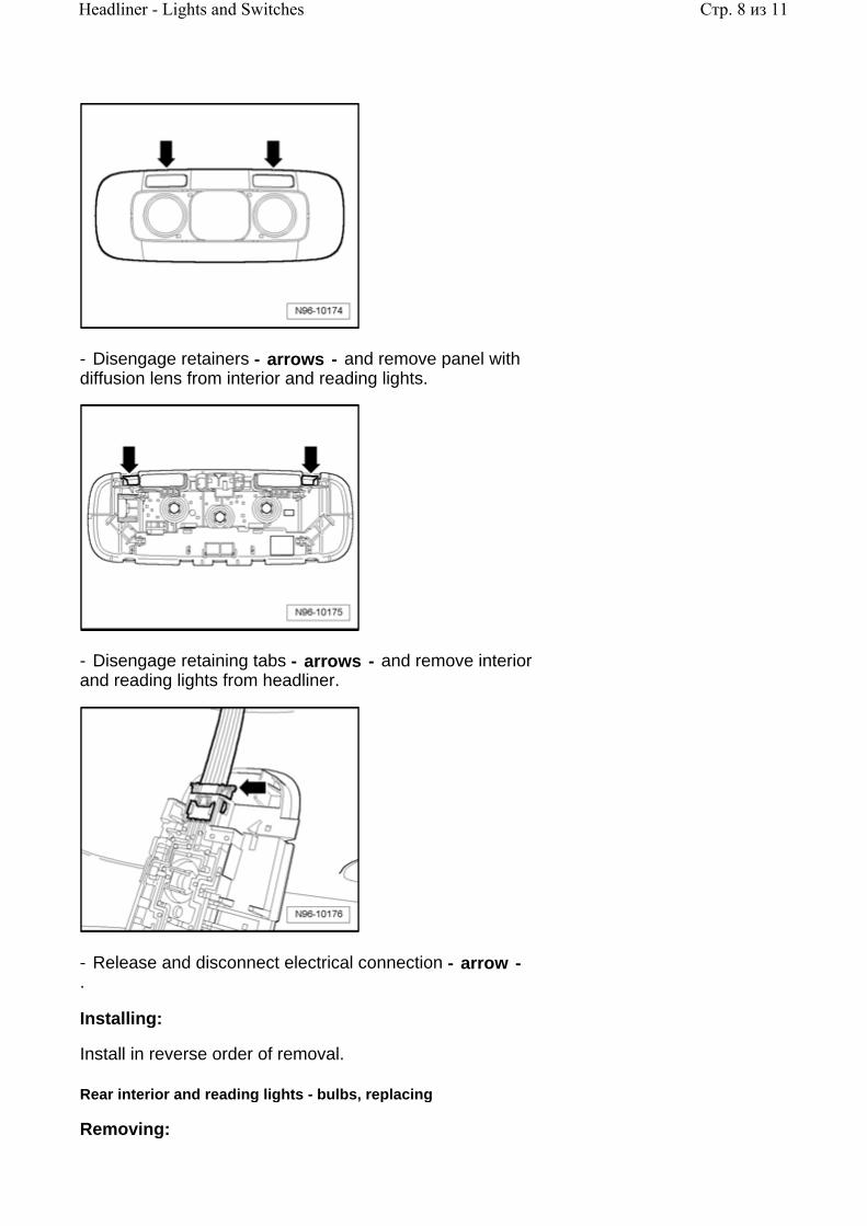
- Disengage retainers - arrows - and remove panel with diffusion lens from interior and reading lights.
- Disengage retaining tabs - arrows - and remove interior and reading lights from headliner.
- Release and disconnect electrical connection - arrow - .
Installing:
Install in reverse order of removal.
Rear interior and reading lights - bulbs, replacing
Removing:
Стр. 8 из 11Headliner - Lights and Switches
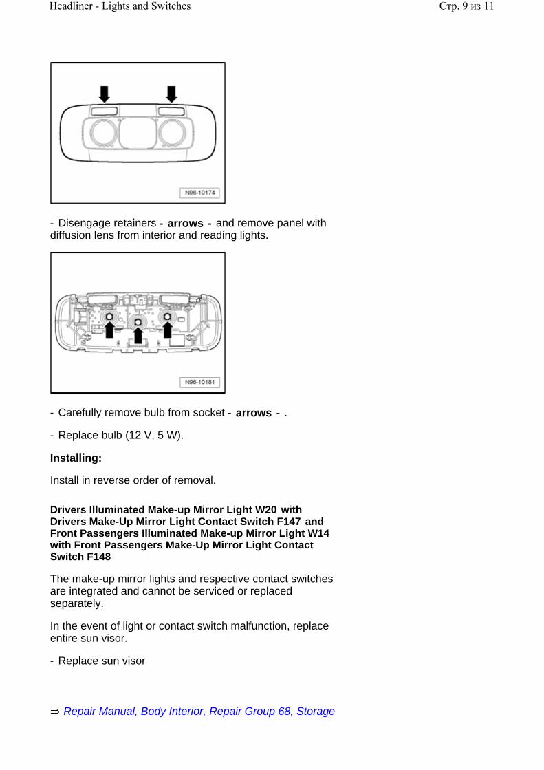
- Disengage retainers - arrows - and remove panel with diffusion lens from interior and reading lights.
- Carefully remove bulb from socket - arrows - .
- Replace bulb (12 V, 5 W).
Installing:
Install in reverse order of removal.
Drivers Illuminated Make-up Mirror Light W20 with Drivers Make-Up Mirror Light Contact Switch F147 and Front Passengers Illuminated Make-up Mirror Light W14 with Front Passengers Make-Up Mirror Light Contact Switch F148
The make-up mirror lights and respective contact switches are integrated and cannot be serviced or replaced separately.
In the event of light or contact switch malfunction, replace entire sun visor.
- Replace sun visor
Repair Manual, Body Interior, Repair Group 68, Storage
Стр. 9 из 11Headliner - Lights and Switches
.
compartments, covers and trim; Sun Visor (Simple), removing and installing
- Replace sun visor
.
Repair Manual, Body Interior, Repair Group 68, Storage compartments, covers and trim; Sun Visor (Double), removing and installing
Garage Door Opener
General information
The garage door opener is integrated with the drivers sun visor. The sun visor contains the Garage Door Opener Control Module J530 , in which is integrated the Garage Door Opener Button 1 E392 , Garage Door Opener Button 2 E393 , Garage Door Opener Button 3 E394 and Garage Door Opener Indicator Lamp K179 .
Garage Door Opener, removing and installing
Note:
The garage door opener cannot be serviced or replaced separately. In the event of malfunction, replace entire sun visor.
Additional information:
Owners Manual
Removing:
- Replace drivers sun visor
or
Repair Manual, Body Interior, Repair Group 68, Storage compartments, covers and trim; Sun Visor (Simple), removing and installing
Стр. 10 из 11Headliner - Lights and Switches

.
Repair Manual, Body Interior, Repair Group 68, Storage compartments, covers and trim; Sun Visor (Double), removing and installing
Стр. 11 из 11Headliner - Lights and Switches

96 - 8
Center Console - Lights and Switches
Center console switches, removing and installing
Removal and installation of the following components is performed in the same way and is only described for one component.
Rear Window Shade Switch E149
ASR/ESP Button E256
Parking Aid Button E266
Tire Pressure Monitoring Display Button E492
-AUTO HOLD- Button E540
Special tools, testers and auxiliary items required
Trim removal wedge 3409
Removing:
Caution!
Switch off all electrical consumers.
Switch ignition off and remove ignition key.
When removing switches, trim, covers or displays, prevent damage to visible areas by
Стр. 1 из 6Center Console - Lights and Switches

always applying appropriate tape to area surrounding the component, and the tools being used (screwdrivers, wedges etc.).
- Carefully remove trim - 1 - .
- Disconnect electrical connection.
- Disengage retainers and remove switch.
Installing:
Install in reverse order of removal.
Front Ashtray Light, removing and installing
Ashtray illumination function takes place via Cigarette Lighter Illumination L28 . This is a component of Cigarette Lighter U1 and can only be removed and installed in conjunction with the Cigarette Lighter U1 .
- Cigarette Lighter U1 removing and installing 96-8, Cigarette Lighter U1 , removing and installing .
Cigarette Lighter U1 , removing and installing
The Cigarette Lighter U1 is located in the front center console, near the ashtray.
Information not available at time of publication.
Left Rear Heated Seat Regulating Switch E128 and Right Rear Heated Seat Regulating Switch E129 , removing and installing
The procedure to remove and install the Left Rear Heated Seat Regulating Switch E128 and Right Rear Heated Seat Regulating Switch E129 is the same.
Стр. 2 из 6Center Console - Lights and Switches

Special tools, testers and auxiliary items required
Trim removal wedge 3409
Removing:
Caution!
Switch off all electrical consumers.
Switch ignition off and remove ignition key.
When removing switches, trim, covers or displays, prevent damage to visible areas by always applying appropriate tape to area surrounding the component, and the tools being used (screwdrivers, wedges etc.).
- Carefully remove trim - 1 - .
Стр. 3 из 6Center Console - Lights and Switches

- Remove screws - arrows - .
- First pull trim in direction of - arrow 1 - towards rear, then in direction of - arrow 2 - upwards, and remove trim.
- Release and disconnect electrical connection - 1 - .
- Remove Left Rear Heated Seat Regulating Switch E128 - 2 - from trim.
Installing:
Install in reverse order of removal.
Storage Compartment Illumination L120 , removing and
Стр. 4 из 6Center Console - Lights and Switches

installing
Special tools, testers and auxiliary items required
Trim removal wedge 3409
Removing:
Caution!
Switch off all electrical consumers.
Switch ignition off and remove ignition key.
When removing switches, trim, covers or displays, prevent damage to visible areas by always applying appropriate tape to area surrounding the component, and the tools being used (screwdrivers, wedges etc.).
- Carefully remove trim - 1 - .
Стр. 5 из 6Center Console - Lights and Switches

- Remove screws - arrows - .
- First pull trim in direction of - arrow 1 - towards rear, then in direction of - arrow 2 - upwards, and remove trim.
- Unclip, release and disconnect electrical connection - 2 - .
- Unclip Storage Compartment Illumination L120 - 1 - and remove with cable.
Installing:
Install in reverse order of removal.
Стр. 6 из 6Center Console - Lights and Switches

96 - 9
Horn
High Tone Horn H2 and Low Tone Horn H7 , removing and installing
Note:
High Tone Horn H2 and Low Tone Horn H7 are activated in parallel by Vehicle Electrical System Control Module J519 .
Removal and installation procedure for both horns is the same.
High Tone Horn H2 is installed at left and Low Tone Horn H7 is installed at right, next to radiator.
Removing:
Caution!
Switch off all electrical consumers.
Switch ignition off and remove ignition key.
- Remove noise insulation
Repair Manual, Body Exterior, Repair Group 50, front body; noise insulation
- Disconnect electrical connection - 2 - .
- Remove screw - 1 - and remove horn - 3 - with
Стр. 1 из 3Horn

bracket.
Installing:
- Install in reverse order of removal, noting the following:
- Torque all fasteners according to value in table 96-12, Lights, Switches - Interior, Anti-theft, tightening torques .
High Tone Horn H2 and Low Tone Horn H7 , checking
High Tone Horn H2 and Low Tone Horn H7 function can be checked using Vehicle Electrical System Control Module J519 On Board Diagnostic (OBD) program function "Output Diagnostic Test Mode (DTM)" 97-6, Vehicle Electrical System Control Module J519 , Output Diagnostic Test Mode (DTM) .
Signal Horn Activation H
Signal Horn Activation occurs via the spring-bearing cover in center of steering wheel. Depending on equipment, signal horn activation is either a structural component of steering wheel or integrated in the drivers side airbag unit and cannot be replaced separately. If signal horn activation is malfunctioning, replace drivers side airbag unit or steering wheel.
Removing drivers side airbag unit
.
Repair Manual, Body Interior, Repair Group 69, Airbag; removing and installing drivers side airbag unit
Removing steering wheel
.
Repair Manual, Suspension, Wheels, Steering, Repair Group 48, Assembly overview of steering column; removing and installing steering wheel
Checking signal horn activation
- Connect Vehicle Diagnosis, Testing and Information System VAS 5051A 97-1, VAS 5051 / 5052 .
- In Vehicle Diagnosis, Testing and Information System VAS 5051A , select operating mode "Guided Fault
Стр. 2 из 3Horn
Finding" .
- Via the "Go to" button, select "Function-/Component selection" and the following menu points in sequence:
Body
Electrical system
01 - On Board Diagnostic (OBD) capable systems
Steering wheel electronics
Electrical components
H - Signal Horn Activation
Стр. 3 из 3Horn

96 - 10
Anti-theft Immobilizer
General information
The Passat is equipped with Anti-theft Immobilizer 4 with online connection. The essential component of Anti-theft Immobilizer 4 is a central database in which all anti-theft relevant data of the participating control modules are stored. It is not possible to adapt participating control modules to the anti-theft immobilizer without an online connection to this database.
Online system test 96-10, Online system test
Modifications from Immobilizer 3:
It is not possible to request the PIN of anti-theft immobilizer components via fax or earlier clearing of the components.
All components participating in the anti-theft immobilizer must be adapted online.
All vehicle keys--including subsequently ordered keys--have already been precoded by the factory for a specific vehicle and can only be adapted to this vehicle.
The subsequent ordering of vehicle keys must be performed via entry of the respective Vehicle Identification Number (VIN).
It is no longer possible to perform adaptation on components originating from other VWAG brands in Volkswagen vehicles.
Note:
Should an attempt be made to start vehicle using a wrong key (i.e.: from another vehicle), the key will remain locked in the. On automatic transmission models, remove locked key by first depressing shifter lever button. Information on removal of locked (wrong) key on manual transmission models not available at time of publication.
Before troubleshooting or servicing, technicians must be
Стр. 1 из 14Anti-theft Immobilizer
familiar with the functions and operation specifics of the anti-theft immobilizer system. Always read the owners manual and review applicable system functions.
Components of anti-theft immobilizer:
Anti-Theft Immobilizer Control Module J362 96-10, Anti-Theft Immobilizer Control Module J362
Electronic Steering Column Lock Control Module J764 96-10, Electronic Steering Column Lock Control Module J764
Electronic Ignition Switch D9 96-10, Electronic Ignition Switch D9
Engine Control Module (ECM) J623
Repair Manual, Engine Mechanical, Fuel Injection Ignition, Repair Group 24, Engine Control Module (ECM)
Ignition Key 96-10, Ignition Key
Replacing all immobilizer components 96-10, New identity when replacing all components
Functions of Anti-Theft Immobilizer Control Module J362 :
Stores all anti-theft-relevant data in central database via online connection.
Communication amongst all components participating in the anti-theft immobilizer.
Data encryption between participating control modules.
Note:
Additional information:
Owners Manual
Стр. 2 из 14Anti-theft Immobilizer

Self Study Program - Course Number 891503 "The 2006 Passat Introduction"
Self Study Program - Course Number 871503 "The 2006 Passat Electrical Systems Design and Function"
Electrical Wiring Diagrams, Troubleshooting and Component Locations binder
CAN-Bus wire repairs 97-8, Repairing CAN-Bus wires
On Board Diagnostic (OBD), function
The immobilizer is equipped with On Board Diagnostic (OBD) capabilities which aids in troubleshooting.
For troubleshooting, use Vehicle Diagnostic, Testing and Information System VAS 5051/5052 in operating mode "Guided Fault Finding" .
Anti-Theft Immobilizer Control Module J362
The Anti-theft Immobilizer Control Module J362 is integrated with the Comfort System Central Control Module J393 .
In the event of immobilizer control module malfunctions, the Comfort System Central Control Module J393 must be replaced.
- Comfort System Central Control Module J393 , removing and installing 97-6, Comfort System Central Control Module J393 , removing and installing
Note:
Should the Comfort System Central Control Module J393 require replacement, always read the coding stored in the control module by performing On Board Diagnostic (OBD) program function "Comfort System Central Control Module, replacing/coding" 97-6, Comfort System Central Control Module J393 , replacing/coding .
After replacing Comfort System Central Control Module J393 , other functions of Comfort System Central Control Module such as "Anti-theft Immobilizer" , "Anti-theft Alarm System" , "tire pressure monitoring" and central locking system key must also be adapted, depending on vehicle equipment.
Стр. 3 из 14Anti-theft Immobilizer

In this case, start by adapting the Anti-theft Immobilizer 96-10, Adapting Anti-Theft Immobilizer Control Module J362 and then the other equipment-dependent functions of Comfort System Central Control Module J393 in any order.
Adapting Anti-Theft Immobilizer Control Module J362
Anti-theft immobilizer must be adapted after replacing Comfort System Central Control Module J393 .
- Connect Vehicle Diagnostic, Testing and Information System VAS 5051/5052 97-1, VAS 5051 / 5052 .
- In Vehicle Diagnostic, Testing and Information System VAS 5051/5052 , select operating mode "Guided Fault Finding" .
- Using the "Go To" button, select "Functions/Component selection" and the following menu options in sequence:
Body
Electrical system
01 - On Board Diagnostic (OBD) capable systems
Anti-theft Immobilizer
Anti-theft Immobilizer functions
Adaptation when replacing Anti-theft Immobilizer
Anti-Theft Immobilizer Reading Module D1
The Anti-Theft Immobilizer Reading Module D1 is integrated with Electronic Ignition Switch D9 and cannot be serviced or replaced separately.
Electronic Ignition Switch D9 : 96-10, Electronic Ignition Switch D9
Electronic Ignition Switch D9
Depending on equipment level, the following components are integrated with Electronic Ignition Switch D9 :
Anti-Theft Immobilizer Reading Module D1
Стр. 4 из 14Anti-theft Immobilizer
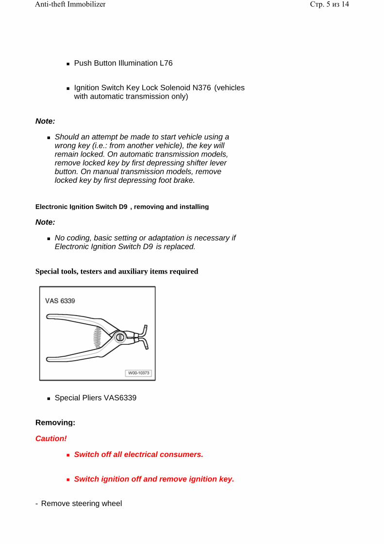
Push Button Illumination L76
Ignition Switch Key Lock Solenoid N376 (vehicles with automatic transmission only)
Note:
Should an attempt be made to start vehicle using a wrong key (i.e.: from another vehicle), the key will remain locked. On automatic transmission models, remove locked key by first depressing shifter lever button. On manual transmission models, remove locked key by first depressing foot brake.
Electronic Ignition Switch D9 , removing and installing
Note:
No coding, basic setting or adaptation is necessary if Electronic Ignition Switch D9 is replaced.
Special tools, testers and auxiliary items required
Special Pliers VAS6339
Removing:
Caution!
Switch off all electrical consumers.
Switch ignition off and remove ignition key.
- Remove steering wheel
Стр. 5 из 14Anti-theft Immobilizer
.
Repair Manual, Body Interior, Repair Group 69, Airbag
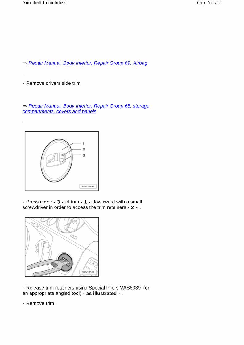
- Remove drivers side trim
.
Repair Manual, Body Interior, Repair Group 68, storage compartments, covers and panels
- Press cover - 3 - of trim - 1 - downward with a small screwdriver in order to access the trim retainers - 2 - .
- Release trim retainers using Special Pliers VAS6339 (or an appropriate angled tool) - as illustrated - .
- Remove trim .
Стр. 6 из 14Anti-theft Immobilizer

- Remove screw - 1 - .
- Release retainers - arrow - on both sides and remove electronic ignition switch - 2 - in direction of - arrow - from trim - 1 - .
Installing:
Install in reverse order of removal.
Note:
When installing, ensure that switch is properly secured in drivers trim.
Checking Electronic Ignition Switch D9
- Connect Vehicle Diagnostic, Testing and Information System VAS 5051/5052 97-1, VAS 5051 / 5052 .
- In Vehicle Diagnostic, Testing and Information System VAS 5051/5052 , select operating mode "Guided Fault Finding" .
- Using the "Go To" button, select "Functions/Component selection" and the following menu options in sequence:
Body
Стр. 7 из 14Anti-theft Immobilizer

Electrical system
01 - On Board Diagnostic (OBD) capable systems
Anti-theft Immobilizer
Electrical components of anti-theft immobilizer
Electronic Ignition Switch D9
Electronic Steering Column Lock Control Module J764
The Steering Column Lock Actuator N360 is integrated in the Electronic Steering Column Lock Control Module J764 . Steering Column Lock Actuator N360 cannot be replaced separately.
Authorization to lock and unlock the steering column occurs via the Anti-Theft Immobilizer Control Module J362 in the Comfort System Central Control Module J393 .
The Electronic Steering Column Lock Control Module J764 is attached to the steering column with shear bolts, and in the event of malfunction can only be replaced as part of the complete steering column. The Comfort System Central Control Module J393 must also be replaced.
Electronic Steering Column Lock Control Module J764 , removing and installing
Note:
Electronic Steering Column Lock Control Module J764 is secured to steering column with shear bolts and may only be replaced as part of the complete steering column.
All information regarding further procedures are obtained via the Vehicle Diagnostic, Testing and Information System VAS 5051/5052 .
If Electronic Steering Column Lock Control Module J764 is to be replaced, in any case the work procedure "Adapt Electronic Steering Column Lock Control Module" must be performed beforehand 96-10, Adapting Electronic Steering Column Lock
Стр. 8 из 14Anti-theft Immobilizer

Control Module J764 .
- Remove steering column with Electronic Steering Column Lock Control Module J764
.
Repair Manual, Suspension, Wheels, Steering, Repair Group 48,
Adapting Electronic Steering Column Lock Control Module J764
- Connect Vehicle Diagnostic, Testing and Information System VAS 5051/5052 97-1, VAS 5051 / 5052 .
- In Vehicle Diagnostic, Testing and Information System VAS 5051/5052 , select operating mode "Guided Fault Finding" .
- Using the "Go To" button, select "Functions/Component selection" and the following menu options in sequence:
Body
Electrical system
01 - On Board Diagnostic (OBD) capable systems
Anti-theft Immobilizer
Anti-theft Immobilizer functions
Adaptation of electronic steering column lock and anti-theft immobilizer
Checking Electronic Steering Column Lock Control Module J764
- Connect Vehicle Diagnostic, Testing and Information System VAS 5051/5052 97-1, VAS 5051 / 5052 .
- In Vehicle Diagnostic, Testing and Information System VAS 5051/5052 , select operating mode "Guided Fault Finding" .
- Using the "Go To" button, select "Functions/Component
Стр. 9 из 14Anti-theft Immobilizer

selection" and the following menu options in sequence:
Body
Electrical system
01 - On Board Diagnostic (OBD) capable systems
Anti-theft Immobilizer
Electrical components of anti-theft immobilizer
J764 Electronic Steering Column Lock Control Module
Ignition Key
The ignition key is designed without a key bit as the vehicle is started for the first time using a sliding motion and not a rotational motion. The reading coil for key identification and an emergency key is integrated in the ignition key. The emergency key is used to unlock the drivers door mechanically in the event it is not possible to open via remote control. Emergency key is inserted in the ignition key and can be disengaged by pressing the side button in two stages.
Stop position 1 = emergency key is completely inserted
Stop position 2 = key-ring attachment ring can be used - emergency key remains locked
Switching on the various terminal voltages (terminal S, terminal 15) and the start procedure is performed via a sliding motion of the ignition key in Electronic Ignition Switch D9 . The following switch positions are possible via sliding motions of the ignition key:
P0 - Off (ignition off)
P1 - S-contact on
P2 - terminal 15 on
P3 - terminal 15 drive (ignition key springs back into this position automatically after starting procedure)
Стр. 10 из 14Anti-theft Immobilizer

P4 - terminal 50 on
Ignition key lost
All vehicle keys--including subsequently ordered keys--have already been precoded by the factory for a specific vehicle and can only be adapted to this vehicle. The subsequent ordering of vehicle keys must be performed via entry of the respective Vehicle Identification Number (VIN) and then the new keys must be adapted to the Comfort System Central Control Module J393 .
Note:
If the complete lock-set (all keys and lock cylinder) is replaced, Electronic Steering Column Lock Control Module J764 must also be replaced together with the Comfort System Central Control Module J393 .
The function "New identity when replacing all components" must be called up 96-10, New identity when replacing all components before removing the lock-set or the control modules.
Adapting ignition key to Comfort System Central Control Module J393 96-10, Adapting ignition key
Check ignition key 96-10, Checking ignition key .
Adapting ignition key
Adapting ignition key to Comfort System Central Control Module J393 :
- Connect Vehicle Diagnostic, Testing and Information System VAS 5051/5052 97-1, VAS 5051 / 5052 .
- In Vehicle Diagnostic, Testing and Information System VAS 5051/5052 , select operating mode "Guided Fault Finding" .
- Using the "Go To" button, select "Functions/Component selection" and the following menu options in sequence:
Body
Electrical system
Стр. 11 из 14Anti-theft Immobilizer
01 - On Board Diagnostic (OBD) capable systems
Anti-theft Immobilizer
Anti-theft Immobilizer functions
Ignition key adaptation
Checking ignition key
- Connect Vehicle Diagnostic, Testing and Information System VAS 5051/5052 97-1, VAS 5051 / 5052 .
- In Vehicle Diagnostic, Testing and Information System VAS 5051/5052 , select operating mode "Guided Fault Finding" .
- Using the "Go To" button, select "Functions/Component selection" and the following menu options in sequence:
Body
Electrical system
01 - On Board Diagnostic (OBD) capable systems
Anti-theft Immobilizer
Electrical components of anti-theft immobilizer
Ignition Key
New identity when replacing all components
This program performs all required steps necessary for new installation of all immobilizer components.
- Connect Vehicle Diagnostic, Testing and Information System VAS 5051/5052 97-1, VAS 5051 / 5052 .
- In Vehicle Diagnostic, Testing and Information System VAS 5051/5052 , select operating mode "Guided Fault Finding" .
- Using the "Go To" button, select "Functions/Component selection" and the following menu options in sequence:
Стр. 12 из 14Anti-theft Immobilizer
Body
Electrical system
01 - On Board Diagnostic (OBD) capable systems
Anti-theft Immobilizer
Anti-theft Immobilizer functions
New identity when replacing all components
Online system test
The following steps will be performed by this test program:
System test for online connection
Test of user authorization
Test of correct wire connection to Volkswagen database
The requirements for this is the online connection (network connection) of the tester
- Connect Vehicle Diagnosis, Testing and Information System VAS 5051A 97-1, VAS 5051 / 5052 .
- In Vehicle Diagnosis, Testing and Information System VAS 5051A , select operating mode "Guided Fault Finding" .
- Via the "Go to" button, select "Function-/Component selection" and the following menu points in sequence:
Body
Electrical system
01 - On Board Diagnostic (OBD) capable systems
Immobilizer
Стр. 13 из 14Anti-theft Immobilizer

Immobilizer functions
Online system test
Стр. 14 из 14Anti-theft Immobilizer
96 - 11
Anti-Theft Alarm System
General information
Anti-theft alarm system functions are integrated in Comfort System Central Control Module J393 .
Anti-theft alarm system must be adapted after replacing Comfort System Central Control Module J393 97-6, Comfort System Central Control Module J393 , servicing .
Note:
Should the Comfort System Central Control Module J393 require replacement, always read the coding stored in the control module by performing On Board Diagnostic (OBD) program function "Comfort System Central Control Module, replacing/coding" 97-6, Comfort System Central Control Module J393 , replacing/coding .
After replacing Comfort System Central Control Module J393 , other functions of Comfort System Central Control Module such as "Anti-theft Immobilizer" , "Anti-theft Alarm System" , "tire pressure monitoring" and central locking system key must also be adapted, depending on vehicle equipment.
In this case, start by adapting the Anti-theft Immobilizer 96-10, Adapting Anti-Theft Immobilizer Control Module J362 and then the other equipment-dependent functions of Comfort System Central Control Module J393 in any order.
On Board Diagnostic (OBD), function
Anti-theft alarm system is equipped with On Board Diagnostic (OBD) capabilities which assists troubleshooting.
For troubleshooting, use Vehicle Diagnostic, Testing and Information System VAS 5051/5052 in operating mode "Guided Fault Finding" .
Note:
After anti-theft alarm system has triggered, the alarm source, which is stored in Comfort System Central
Стр. 1 из 11Anti-Theft Alarm System

Control Module J393 , can be checked 97-6, Anti-theft alarm system - alarm sources, checking .
After the Alarm Horn H12 has been activated, the alarm source, which is stored in Comfort System Central Control Module J393 , can be checked 97-6, Alarm Horn - alarm sources, checking .
Anti-theft Alarm System, component overview
Note:
Anti-theft Alarm System components are dependent on vehicle equipment and market version. Radar interior monitoring, associated switches and inclination sensor are not applicable to USA/CDN models.
Front Hood Switch F266
Стр. 2 из 11Anti-Theft Alarm System
Volkswagen Technical Site: http://volkswagen.msk.ru http://vwts.info http://vwts.ru огромный архив документации по автомобилям Volkswagen, Skoda, Seat, Audi

in front hood latch
Removing and installing 96-2, Front Hood Switch F266 , removing and installing
Alarm Horn H12
in right front wheel well
Removing and installing 96-11, Alarm Horn H12 , removing and installing
Comfort System Central Control Module J393
Behind glove compartment
Removing and installing 97-6, Comfort System Central Control Module J393 , removing and installing
Front Passengers Door Control Module J387
in front passengers door
Removing and installing
Front Passengers Door Contact Switch F3
in Front Passengers Door Central Locking Lock Unit F221
Removing and installing
Repair Manual, Body Exterior, Repair Group 64, Glass, Window regulators; Window regulator motor, removing and installing
Стр. 3 из 11Anti-Theft Alarm System

Radar Interior Monitoring Control Module 1 G303 with interior monitoring sensors and Vehicle Inclination Sensor G384
Not applicable to USA/CDN models
Right Rear Door Contact Switch F11
in Right Rear Central Locking Lock Unit F223
Removing and installing
Rear Lid Lock Unit F256
Removing and installing
.
Left Rear Door Contact Switch F10
in Left Rear Central Locking Lock Unit F222
Removing and installing
Repair Manual, Body Exterior, Repair Group 57, Front doors, Window regulators, Central locking system; Door lock, removing and installing
Repair Manual, Body Exterior, Repair Group 58, Rear doors, Window regulators, Central locking system; Door lock, removing and installing
Repair Manual, Body Exterior, Repair Group 55, Rear lid; Locking and unlocking components - assembly overview
Стр. 4 из 11Anti-Theft Alarm System

Interior Monitoring Deactivation Switch E267 and Deactivate Vehicle Inclination Sensor Button E360
Not applicable to USA/CDN models
Drivers Door Contact Switch F2
in Drivers Door Central Locking Lock Unit F220
Removing and installing
Central Locking -SAFE- Indicator Lamp K133
in front door trim
Removing and installing 96-4, Central Locking -SAFE- Indicator Lamp K133
Drivers Door Control Module J386
in drivers door
Removing and installing
Repair Manual, Body Exterior, Repair Group 58, Rear doors, Window regulators, Central locking system; Door lock, removing and installing
Repair Manual, Body Exterior, Repair Group 57, Front doors, Window regulators, Central locking system; Door lock, removing and installing
Repair Manual, Body Exterior, Repair Group 64, Glass, Window regulators; Window regulator motor, removing and installing
Стр. 5 из 11Anti-Theft Alarm System
Central Locking and Anti-theft Alarm System Antenna R47
behind A-pillar trim 96-11, Central Locking and Anti-theft Alarm System Antenna R47
Anti-theft Alarm System, activating and deactivating
Anti-theft alarm system, activating:
Anti-theft alarm system is automatically switched on by locking the vehicle. Anti-theft alarm system is then activated immediately.
Note:
So that anti-theft alarm system does not trigger unnecessary alarms, close all windows and doors before locking the vehicle.
Anti-theft alarm system does not activate whenever:
The ignition is switched on (terminal 15).
the immobilizer registers an authorized key.
the drivers door is open.
the door control module is malfunctioning.
Anti-theft alarm system, deactivating:
Anti-theft warning system is deactivated when the vehicle is unlocked via the unlock button on radio-frequency remote control, or
when the ignition is switched on (terminal 15), or
the immobilizer registers an authorized key.
Unlocking vehicle mechanically (emergency opening)
Стр. 6 из 11Anti-Theft Alarm System

- Unlock vehicle at drivers door using emergency key.
Anti-theft alarm system remains activated, however no alarm is triggered.
- Switch on ignition within 15 seconds.
Note:
If the ignition is not switched on after 15 seconds the alarm is triggered.
By switching on the ignition, the electronic immobilizer recognizes a valid vehicle key and deactivates the anti-theft alarm system.
Central Locking and Anti-theft Alarm System Antenna R47
The Central Locking and Anti-Theft Alarm System Antenna R47 receives radio-frequency signals from the ignition key with radio-frequency remote control and relays them to the Comfort System Central Control Module J393 .
The Central Locking and Anti-Theft Alarm System Antenna R47 consists of an RG174 HF-cable which has approximately 17 cm of the shielding removed (the unshielded area of the cable serves as the antenna). The Central Locking and Anti-Theft Alarm System Antenna R47 is integrated with the wiring harness in the left A-pillar and cannot be serviced or replaced separately.
Alarm delay when drivers door opened, adapting
Via this function, the alarm delay when opening the drivers door can be switched on and off.
- Connect Vehicle Diagnostic, Testing and Information System VAS 5051/5052 97-1, VAS 5051 / 5052 .
- In Vehicle Diagnostic, Testing and Information System VAS 5051/5052 , select operating mode "Guided Fault Finding" .
- Using the "Go To" button, select "Functions/Component selection" and the following menu options in sequence:
Body
Body repair procedures
01 - On Board Diagnostic (OBD) capable systems
Стр. 7 из 11Anti-Theft Alarm System
Comfort system
Functions - central control module for comfort system
Alarm delay when drivers door opened, adapting
Alarm Horn H12
The Alarm Horn H12 is located in the right front wheel housing.
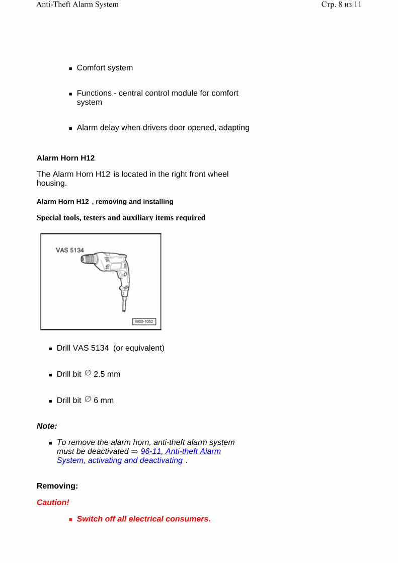
Alarm Horn H12 , removing and installing
Special tools, testers and auxiliary items required
Drill VAS 5134 (or equivalent)
Drill bit 2.5 mm
Drill bit 6 mm
Note:
To remove the alarm horn, anti-theft alarm system must be deactivated 96-11, Anti-theft Alarm System, activating and deactivating .
Removing:
Caution!
Switch off all electrical consumers.
Стр. 8 из 11Anti-Theft Alarm System
Switch ignition off and remove ignition key.
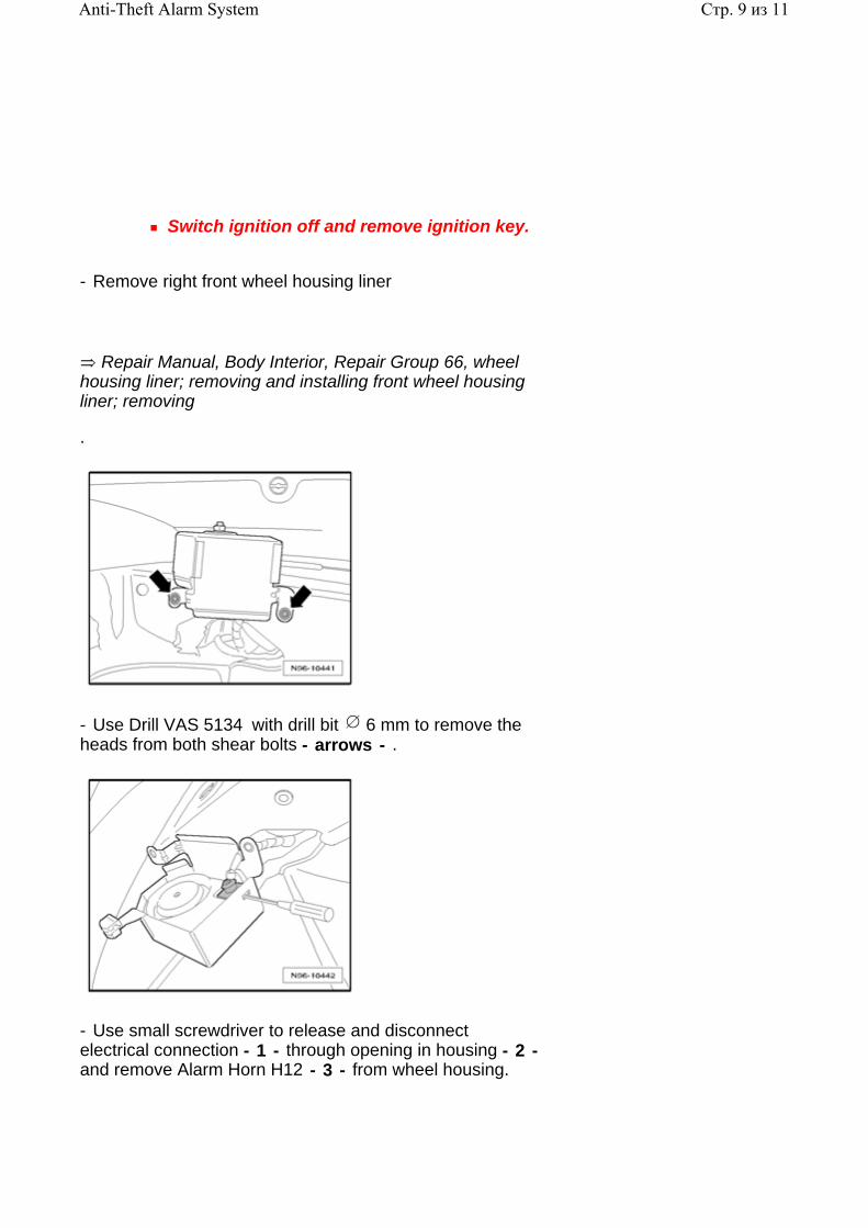
- Remove right front wheel housing liner
.
Repair Manual, Body Interior, Repair Group 66, wheel housing liner; removing and installing front wheel housing liner; removing
- Use Drill VAS 5134 with drill bit 6 mm to remove the heads from both shear bolts - arrows - .
- Use small screwdriver to release and disconnect electrical connection - 1 - through opening in housing - 2 - and remove Alarm Horn H12 - 3 - from wheel housing.
Стр. 9 из 11Anti-Theft Alarm System

- Use Drill VAS 5134 with drill bit 2.5 mm to remove remaining threads - arrows - . Restore threads with appropriate thread tap.
Installing:
Note:
Remove all metal shavings.
- Perform required corrosion protection measures.
- Reconnect electrical connection to Alarm Horn H12 .
Note:
For clarity, the Alarm Horn H12 (with connection) is not included in the following illustration.
- Guide clip - 2 - for Alarm Horn H12 into body cutout - 1 - .
- Secure Alarm Horn H12 using new shear bolts.
- Tighten shear bolts until bolt heads shear off.
- Install right front wheel housing liner
Стр. 10 из 11Anti-Theft Alarm System

.
Repair Manual, Body Interior, Repair Group 66, wheel housing liner; removing and installing front wheel housing liner; removing
Alarm Horn H12 , checking
Alarm Horn H12 function can be checked using Comfort System Central Control Module J393 On Board Diagnostic (OBD) program function "Output Diagnostic Test Mode (DTM)" 97-6, Comfort System Central Control Module J393 , performing Output Diagnostic Test Mode (DTM) .
Стр. 11 из 11Anti-Theft Alarm System

96 - 12
Lights, Switches - Interior, Anti-theft, tightening torques
Alarm Horn H12 , tightening torque
Fasteners Tightening torques
Self-locking mounting nut 5 Nm
Shear bolts 7 Nm
High Tone Horn H2 , tightening torques
Fasteners Tightening torques
Screw to long member 20 Nm
Low Tone Horn H7 , tightening torque
Fasteners Tightening torques
Screw to long member 20 Nm
Стр. 1 из 1Lights, Switches - Interior, Anti-theft, tightening torques


