Embed Size (px)
Citation preview
., .) .~,>, ,,.,/ .f ,, “:
+ J -
UCRL-11.L126261
BaBar Technical Design ReportChapter 9- Magnet Coil and Flux Return
T. O’CorumrLawrence Livermore National Laboratory
March 1995

DISCLAIMER
Thii document W= pqan!d as an &xx)uot Of WWk SpOliSOd byan88cncyoftbcUnitedS$MCS+GOVmUnCnt.NeithertheUnitedStatesGovernmentnortheUniversityoft2&fcmdanoranyoftheirempbyccs,* any
=rA-4:-zTtiTz”mTib:%:;theaccuracy,CQmpletcness,oruscfblnes6ofanyin6nuultion#appar+wprivatelyownedrights.Rc.fcleacchcmintoanysped% coothawisc,doesnot
mmcrcmlproduc+pmm& a service by tmde nanE tmdcmark, rmmutkpq, orIMxesaily constiaJtcor imply its 4ometrEot!
CaliforniaThcviewsandopkdonsof*expmsacd hmin donotoa,orfivoringbtheUoitedStatesOovcrmncn
~~fy stat..&t thoseoftheunitedSd ‘&&u&Y%”&UniversityofCaliforniaandshallnotbeusedforadwtisiiorproducldomemcntpmposcs.
Tldsrcport haslmatqmduccd&@y !lom * bestawulabkcopy.
Avaihbk to DOE and DOEconmom from*Officeof scientific and Tcchnkalhbnnation
P.O.BOX 62 Oak Ridge, TN 37831Prim avaiMle fmm (615) 576-WI, ITS 626-8401
Available to the public tiwn theNationalTdmicaiInformationservice
‘“s” !z%%-&xw-SP@field, VA 221;1

BABARTechnicalDesign Report
Chapter
./... ”-. . .
----
.-----. . .
Magnet Coil and Flux Return--
...... .. .
.
BABAR CohbumtiowCanah_-~anuXimmany-Itiy-Noway-Rtia-Ttiwm-Utiti Kingdom-Utiti S@@S
:.<++,L,-- ,,., . .
; ... :,. -. . ... .
F
.,

. . .-.——. —.——,..——.. .——... ...——.
Technical Design Report
The BA13wCollaboration
March, 1995
I

i
The BA13AR Collaboration
LAPP Annecy, Annecy-l+Vieux, lbnceD. Boutigny, Y. Karyotakis, S. Lees-Rosier, P. Petitpas
INFN, Sezione di Bari and Universitildi Bari, Elari,Italy
C. Evangelista,A. Palano
Beijing Glass Research Institute, Beijing, ChinaG. Chen, Y.T. Wang, O. Wen
Institute of High Energy Physics, Beijing, ChinaY.N. Guo, H.B. Lan, KS. Mao, N.D. Qi, W.G. Yan, C.C. Zhang, W.R. Zhao, Y.S. Zhu
University of Bristol, Bristol, UKN. Dyce, B. Foster, R.S. Gilrnore, C.J.S. Morgado
University of Bergen, Bergen, ~OIWSY
G. Eigen
University of British Columbia, Vancouwx, British Cokmbia, CanadaC. Goodenough, C. Hearty, J. Heise, J.A. McKenna
Brunei University, London, UKT. Champion, A. Hasan, A.K. McKemey
Budker Institute of Nuclear Physics, Novosibirsk, RussiaA.R. Buzykaev, V.N. Golubev, V.N. Ivanchenko, S.G. Klimenko, E.A. Kravchenko, G.M. Kolachev,A.P. Onuchin, V.S. Panin, S.1. Serednyakov, A.G. Shamov, Ya.I. Skovpen, V.I. Telnov
California Institute of Technology, Pasadena, Caitiornia, USAD.G. Hitlin, J. Oyang, F.C. Porter, M. Weaver, A.J. Weinstein, R. Zhu
University of Cahfornia, Davis, Davis, California, USAF. Rouse
University of California, IIRPA, La Jolla, California, USAA.M. Eisner, M. Sullivan, W. Vernon, Y.-x. Wang
TECHNICAL DESIGN REPORT FOR THE 13ABAR DETECTOR
ii
University of California, Irvine, Irvine, CaMorm”ajUSAK. Gollwitzer, A. Lankford, M. Mandelkern, G. McGrath, J. Schultz,D. Stoker, G. Zioulas
University of CaHfornia, Los Angeles, Los Angeles, CalMom”a, USAK. Arisaka, C. Buchanan, J. Kubic, W. Slater
University of California, San Diego La Jolla, Cal.ifom”a, USAV. Sharma
University of C~lfornia, Santa Barbara, San~a Barbara, Caliform”a, USAD. Bauer, D. Caldwell, A. Lu, H. Nelson, J. Richman, D. Roberts, M. Witherell, S. Yellin
University of California, Santa Cruz, Santa Cruz, C@om”a, USAJ. DeWitt, D. Dorfan, A.A. Grillo, C. Heusch, R.P. Johnson, E. Kashigin, S. Kashigin, W. Kroeg(W. Lockman, K. O’Shaughnessy, H. Sadrozinski, A. Seiden, E. Spencer
Carleton University and CRPPt, Ottawa, Ontario, CanadaK. Edwards, D. Karlen, M. O’Neillt
University of Cincinnati, Cincinnati, Ohio, USAS. Devmal, B.T. Meadows, A.K.S. Santha, M.D. Sokoloff
University of Colorado, Bozdder, Colorado, USAA. Barker, B. Broomer, E. Erdosj W. Ford, U. Nauenberg, H. Park, P. Rankin, J. Roy, J.G. Smj
Colo~aLo State University, Fort Collins, Colorado, USAJ. Harton, R. Malchow, M. Smy, H. Staengle, W. Toki, D. Warner, R. Wilson
Technische Universitat Dresden, Institut fiiir Kern- und ‘I%ilchenphysik,Dresden, GermanyJ. Brose, G. Dahlinger, P. Eckstein, K.R. Schubert, R. Schwierz, R. Seitz, R. Waldi
Joint Institute for Nuclear Research, Dubna, RwiaA. Bannikov, S. Baranov, I. Boyko, G. Chelkov, V. Dodonov, Yu. Gornushkin, M. IgnatenkcN. Khovansky, Z. Krumstein, V. Malyshev, M. Nikolenko, A. Nozdrin, Yu. Sedykh, A. Sissaki~Z. Silagadze, V. Tokmenin, Yu. Yatsunenko
TECHIWCAL DESIGN REPORT FOR THE BABARDETECTOR

. . .m
University of Edinburgh, Edinburgh, UKK. Peach, A. Walker
INFN, Sezione di Ferrara, Ferrara, MyL. Piemontese .
Laboratory Nazionr& di Frascati dell’ INFN, Fkascati, ItalyR. Baldti, A. Calcaterra, R. De Sangro, I. Peruzzi (also Univ. Peru@a), M. Piccolo, A. Zallo
INFN, Sezione di Geneva and Universitii di Geneva, Geneva, ItalyA. Buzzo, R. Contri,G. Crosetti,P. F’abbricatore,S. Farinon,R. Monge, M. Olcese,R. Parodl,
S. Passaggio,C. patrignani,M.G. Pia,C. Salvo,A. Santroni
University of Iowa, Iowa CitX Iowa, USAU. MaIlik, E. McCliment, M.-Z. Wang
Iowa State University, Ames, Iowa, USAH.B. Crawley, A. Firestone, J.W. Lamsa, R. McKay, W.T. Meyer, E.I. Rosenberg
Northern Kentucky University, Highland Heights, Kentucky, USAM. Falbo-Kenkel
University of Lancaster, Lancaster, UKC.K. Bowdery, A.J. Finch, F. Foster
Lawrence Berkeley Laboratory, BerkeJey Caltiornia, USAG.S. Abrams, D. Brown, T. Collins, C.T. Day, S.F. DOW,F. Goozen, R. Jacobsen, R.C. Jared,J. Kadyk, L.T. Kerth, I. Kipnis, J.F. Kral, R. Lafever, R. Lee, M. Levi, L. Luo, G.R. Lynch,M. Momayezi, M. Nyman, P.J. Oddone, W.L. Pope, M. Pripstein, D.R. Quarrie, J. ~on,N.A. Roe, M.T. Ronan, W.A. Wenzel, S. Wunduke
Lawrence Livermore National Laboratory, Livermore, CalMornia, USAO. Alford, J. Berg, R.M. Bionta,A. Brooks, F.S. Dietrich,O.D. Fackler,M.N. Kreisler,
M.A. Libkind, M.J. Mugge, T. O’Comor, L. Pedrotti,X. Shi,W. Stoeffl,K. van Bibber,
T.J.Wenaus, D.M. Wright,C.R. Wuest, R.M. Yamamoto
University of Liverpool, Liverpool, UKJ.R. Fry, E. Gabathuler,R. Garnet,A. Muir,P. Sanders
TECHNICAL DESIGN REPORT FOR THE 13@AR DETECTOR
iv—
of London, Imperial College of Science, Technology and Medicine,u,,, , ,i(ti$~
~(,,,,j,.,i :-~
L Duane, L. Moneta, J.Nash, D. Price~ ,,,,\\i*. -
~,,, , ,m@- of London, Queen Mary & Westfield College, London, UK,~,{~:.P.F.Harrison, I. Scott, B. Zou
1).1’
U,,, , *:@iQ-of London, Royal Holloway & Bedford New Coilege, Egham, Surrey, UKN.G. Green; D.L. Johnson, E. Tetteh-Larteyy !‘J””
~,,1 , ●@.iQ- of Louisville, Louisville, Kentucky, ~SA
C.1\ l.ii s
~,, . tl! ~~versi% J40ntrdal, Quebec, CanadaR-Fernholz, D. MacFarlane, P. Patel, C. Smith, B. Spaan, J. Trischuk~ ,,,,,s.’3.
~,,,, ..isity of Manchester, Manchester,UKw IL Barlow, G. Lafferty, K. Stephens
.J. ‘~:b”-’
~, ,,(, .Xsity of Maryland, College Park, Maryland, USAN*i.-cx)la,Y. Foucher, H. Jawahery, A. Skuja~, \t+.. .
~\, ,,, <’shy of Massachusetts, Amherst, Massachusetts, USA.*@mfer.J.-J. Gomez-Cadenas, S.S. Hertzbach, R.& Kofler, M.G. Strauss,,, ~\\\**s--
~,1,,,.xhu-tts I~titute of Tec~ology~ C-bridge, Mwacfmsetts, USA!.wxu. XJ. Fero, R.K. Yamamoto]~~.}.
,:*N ~ $. Sezione di Milano and Universitii di Milano, M&UIO, hlY
MJ C. Cattadori, R. Diaferia, F. Lanni, C. Matteuzzi, F. Palombo, A. Sala, T. Tabarelli, i.~..
.,+- of Mississippi, Oxford, Mississippi, USAl],,\i*-’.,~.:.k’.5. Bracker,L, CremaldilK. Gounder, R. Kroeger,J.Reidy,D. Summers
LI
~l,?’,S+t e de Montr6al, Montr&d, Quebec, Canada.,.MI.~in. M Beaulieu, B. Lorazo, J.P. Martin, P. ‘RUSS,V. Zacek
(:
~~, .QS Holyoke College, SoutlI Hadley, Massachusetts, USA, ~ \ . :y’k~n. C.S. Sutton
,;,. \. SeziOne di Napoli and University di Napoli, Napoli, Italy, i\:{.~. L.Lista,S. Mele,P. Parascandolo,C. Sciacca
b
, \::.~-LDESIGN REPORT FOR THE 13AELIRDETECTOR
v
University of Notre Dame, Notre Dame, Indiana, USAJ.M. Bishop, N.N. Biswas, N.M. Cason, J.M. LoSecco, A.H. Sanjari, W.D. Shephard
Oak Ridge National Laboratory/Y-12, Oak Ridge, Tennessee, USAF.S. Alsmiller,R.G. Alsmiller,Jr.,T.A. Gabriel,J.L.Heck
LAL Orsay, OrSay fianceD. Breton, R. Cizeron, S. Du, A.-M. Lutz, J.M. Noppe, S. Plaszczynski, M.-H. Schune,E. Torassa, K. Truong, G. Wormser
INFN, Sezione di Padova and University di PadOva, Padowt, ItalyF. Dal Corso, M. Morandm, M. Posocco, R. Stroili, C. Voci
Ecoie Polytechnique Palaiseau, LPNHE, Palaiseau, fianceL. Behr, G. Bonneaud, P. Matricon,G. Vasileiadis,M. Verderi
LPNHE des Universit4s Paris 6 et Paris 7, Pan”s, hnceM. Benayoun, H. Briand, J. Chauveau, P. David, C. De La Vaissiere, L. Del Buono, J.F. Genat,O. Hamon, P. Leruste, J. Lory, J.-L. Narjoux, B. Zhang
INFN, Sezione di Milano and Universit& di Pavia, Pavia, ItzdyP.F. Manfredi, V. Re, V. Speziali, F. Svelto
University of Pennsylvania, Philadelphia, Pennsyhni”a, USAL. Gladney
INFN, Sezione di Piss, Universit& di Pisat and Scuola Normale Superiore$,Piss, ItidyG. Batignanit, S. Bettarini, F. Bosi, U. Bottiglit, M. Carpinelli, F. Costantinit,F. Forti, D. Gambino, M. Giorgit, A. Lusiani$, P.S. Marrocchesi, M. Morgantit,G. Rizzo, G. !lliggianit, J. Walsh
Prairie View A&M University, Prairie View, Texas, USAM. Gui, D.J. Judd, K. Paick, D.E. Wagoner
Princeton University, Princeton, New Jerseyj USAC. Bula, C. Lu, K.T. McDonald
TECHNICAL DESIGN REPORT FOR THE l&13AR DETECTOR
vi
INFN, Instituto Superiore di Sanit& Roma, ItalyC. Bosio
lNFN, Sezione di Roma and University “La Sapienza/’ Roma, ItalyF. Ferroni, E. Lamanna, M.A. Mazzoni, S. Morganti, G. Piredda, R. %ntacesaria
Rutgers University, Rutgers, New Jersey, USAP. Jacques, M. Kalelkar, R. Piano, P. Stainer
Rutherford Appleton Laboratory, Chdton, Didcot, UKP.D. Dauncey, J. Dowdell, B. I?ranek, N.I. Geddes, G.P. Gopal, R. Halsall,J.A. Lidbury, V.J. Perera 4
CEA, DAPNIA, CE-Saclay,l Giflsur-Yvette, I?kaaceR. Aleksan, P. Besson, T. Bolognese, P. Bourgeois, A. de Lesquen, A. Gaidot, L. Gosset,G. Hamel de Monchenault, P. Jarry, G. London, M. Turluer, G. Vasseur, C. Yeche, M. Zito
Shanghai Institute of Ceramics (SICCAS), Shanghai, ChinaJ.R. Jing, P.J. Li, D.S. Yan, Z.W. Yin
University of South Carolina, Cohunbia, South Carolina, USAM.V. Purohit, J. Wilson
St5nford Linear Accelerator Center, Stdord, Califom”a, USAD. Aston,R. Becker-Szendy, R. Bell, E. Bloom, C. Boeheim, A. Boyarski, R.F. Boyce,D. Briggs, F. Bulos, W. Burgess, R.L.A. Cottrell, D.H. Coward, D.P. Coupal, W. Craddock,H. DeStaebler, J.M. Dorfan, W. Dunwoodie, T. Fieguth, D. Freytag, R. Gearhart, T. GlanznG. ‘30dfrey, G. Hailer, J. Hewett, T. Himel, J. Hoefiich, W, Innes, C.P. Jessop, W.B. Johnso:H. ~~wahara, L. Keller,2 M.E. King, J. Krebs, P. Kunz, W. Langeveld, E. Lee, D.W.G.S. LeiV.G. ‘Liith, H. Lynch, H. Marsiske, T. Mattison, R. Melen, K. Moffeit, L. Moss, D. Muller,M. Perl, G. Oxoby, M. Pertsova, H. Quinn, B.N. RatcliE, S.F. SchaiTner, R.H. Schindler,S. Shapiro, C. Simopolous, A.E. Snyder, E.J. Soderstrom, J. Vav’ra, S. Wagner, D. Walz,R. Wang, J.L. White, W. Wisniewski, N. Yu
Stanford University, Stanford, California, USAP. Burchat, R. Zaliznyak
1Subjecttoapprovaloffundingagency.%etired
TECHNICAL DESIGN REPORT FOR THE 13ABARDETECTOR

vii
Academia Sinica, Zhipei, ThhvanH.-Y. Chau, M-L. Chu, S.-C. Lee
University of Texas at Dallas, Richardson, Texas, USAJ.M. Izen, X. Lou
INFN, Sezione di Torino and University di Torino, Torino, ItaiyF. Bianchi, D. Gamba, G. Giraudo, A. Romero
INFN, Sezione di Trieste and University di Trieste, lkieste, ItalyL. Bosisio, R. Della Marina, G. Della Ricca, B. Gobbo, L. Lanceri, P. Poropat
TRIUMF, Vancouver, British Columbia, CanadaR. Henderson, A. fiudel
Tsinghua University, Be@g, ChinaY.P. Kuang, R.C. Shang, B.B. Shao, J.J. Wang
Vanderbilt University, Nashvifle, Tennessee, USAR.S. Panvini, T.W. Reeves, P.D. Sheldon, M.S. Webster
university of Victoria, Victoria, British co~~bia, CmadaM. McDouga,ld, D. Pitman
University of Wisconsin, Madison, Wisconsin, USAH.R. Band, J.R. Johnson, R. Prepost, G.H. Zapalac
York University, Toronto, Ontario, CanadaW. Fkisken
Babar and thedistinctiveliienessaretrademarksofLaurentde Brunhoffand areusedwithhispermission.
Copyright@ Laurentde Brunhoff
AllRightsReserved
TECHNICAL DESIGN REPORT FOR THE 13AB.MzDETECTOR
● ✎ ✎
Vlll
i
●
r’”’
TECHNICAL DESIGN REPORT FOR THE J3ABARDETECTOR
1 Introduction
2 Detector Overview
2.1
2.2
2.3
2.4
2.5
Introduction . . . . . . . . . . . . . . . .
General Design Considerations . . . . . .
2.2.1 Acceptance . . . . . . . . . . .
. .
.
.
.
.
.
.
Contents
. . . . . . . . . . . . .
. . . . . . . . . . . . .
. . . . . . . . . . . . .
2.2.2 Charged Track Resolution and Multiple Scattering . . . . . . .
2.2.3 Photon Efficiency and Resolution . . . . . . . .
2.2.4 Identification of Hadrons . . . . . . . . . . . . .
2.2.5 Interaction with the Accelerator . . . . . . . . .
2.2.6 Considerations of Cost and Schedule . . . . . .
The Experimental Design . . . . . . . . . . . . . . . . . .
Detector Optimization . . . . . . . . . . . . . . . . . .
2.4.1 Impact of Particle Identification . . . . . . .
2.4.2 Optimization of Performance versus Cost . .
Detector
2.5.1
2.5.2
2.5.3
2.5.4
2.5.5
2.5.6
Performance . .
Vertex Detector
Drift Chamber .
. . . . . . . . . . . . . . . .
. . . . . . . . . . . . . . . .
. . . . . . . . . . . . . . . .
Particle Identification . . . . . . . . . . . . .
Electromagnetic Calorimeter . . . . . . . . .
Muon and Neutral Hadron Detector . . . . .
Electronics, Trigger, and Data Acquisition .
.
.
.
,.
,.
. . . . . . .
. . . . . . .
. . . . . . .
. . . . . . .
. . . . . . .
. . .
. . .
. . . . .
. . . . .
. . . . .
. . . . .
. . . . .
. . . . .
. . . . .
. ...<
.
.
.
. .
. .
. .
. .
. .
. .
. .
. .
. .
. .
.
.
.
.
.
.
.
.
,.
,.
,.
. .
. .
. .
1
7
7
8
8
9
11
12
13
14
14
20
20
21
25
25
28
30
32
37
39

x
2.6 Physics Performance . . . . . . . . . . . . . . . . . . . . . . . . . . . . . .
2.6.1 Acceptance and Mass Resolution for Decays to Charged Particles
2.6.2 Separation between B Decay Vertices
2.6.3 Z“ Efficiency and Resolution . . ,
2.6.4 Lepton Identification . . . . . . .
2.6.5 Charged Hadron Identification . .
2.7 Performance for Non-CP Physics . . . . .●
2.7.1 Other BPhysics . . . . . . . . .
2.7.2 Detector Issues for Charm Physics .
2.7.3 Detector Issues for Tau Physics . .
.
.
.
.
.
.
.
.
.
.
.
.
.
.
.
.
.
.
.
.
.
.
2.7.4 Detector Issues for Tw~Photon Physics .
3 Physics with BABAR
.
.
.
.
.
.
.
.
.
.
.
.
.
.
.
.
.
.
.
.
.
. . .
. . .
. .
. .
. . .
. . .
,..
. . .
,..
.
.
.
3.1
32
3:; “
3A
3.5
Physics Context . . . . . . . . . . . . .
Simulation Tools . . . . . . . . . . . .
3.2.1 ASLUND . . . . . . . . . . .
3.2.2 GEANT Simulation-BBSIM
Studies of 13° ~ J/@ Modes . . . . . .
3.3.1 BO+J/$K: . . . . . . . . .
3.3.2 BO-+J/$K: . . . . . . . . .
3.3.3 BLJ/+KO* . . . . . . . . .
Studies of BO toDouble Charm Modes
3.4.1 BO~D+D- . . . . . . . . .
3.4.2 @-+ D*+ D*- . . . . . . . . .
3.4.3 B* DD* . . . . . . . . . . .
Studies of B + m Modes . . . . . . .
3.5.1 B“+r+r . . . . . . . . . .
. .
,.
. .
. .
. .
. .
. .
.,
. .
. .
. .
. .
. .
.,
.
.
.
.
.
.
.
.
,,
.
.
.
.
.
.
.
.
,.
.
.
.
.
.
.
.
.
,.
.
.
.
.
.
.
.
.
.
.
.
,,
.
.
.
.
.
.
.
!.
.
.
.
.
.
..
.
.
.
.
.
. .
.
.
.
.
.
.
.
.
.
.
. .
. .
. .
,.
,.
.
.
.
.
.
.
.
.
.
.
.
.
.
.
.
.
.
.
.
.
.
.
.
.
.
.
.
.
.
.
.
.
.
.
.
.
.
.
.
.
.
.
TECHNICAL DESIGN REPORT FOR THE BAB.. DETECTOR
xi
3.5.2 BO+ZOTO . . . . . . . . . .
3.5.3 @ + m+m” Decays . . . . .
67
68
68
72
73
74
76
76
77
77
78
79
81
82
84
85
.
.
.
.
.
.
.
.
.
.
.
. .
. .
. .
. .
. .
. .
. .
,.
. .
. .
. .
. .
. .
. .
. .
. .
. .
.,
. . . .
. . . .
. . . .
. . . .
. . . .
. . . .
. . . .
. . . .
. . . .
. . . .
. . . .
,.. .
. . . .
. . . .
. . . .
. . . .
. . .
. . .
. . .
.
.
.
.
.
.
.
.
.
.
.
.
.
.
.
BO+p%~ . . . . .
Tagging Modes . . .
3.7.1 Kaon Tags .
3.7.2 Lepton Tags
3.7.3 Other Tags
3.6
3.7
3.8
3.9
3.10
3.11
3.12
3.13
3.14
. . . . . . . .
. . . . . . . . .
. . . . . . . . .
. . . . . . . . .
. . . . . . . . .
. .
.
.
.
.
.
.
3.7.4 Combined Tagging . . . . .
Estimate of CP-Angle Measurement .
.
.
.
.
.
.
3.8.1 Method of Calculation ,..
,..
,..
. . .
. . .
. .
. . .
3.8.2 Tagging Modes . .
3.8.3 C’P Modes . . . . .
CKM Matrix Determination
3.9.1 v* . . . . . . . . .
3.9.2 Cub . . . . . . . . .
3.9.3 Vtd . . . . . . . . .
. .
. .
. .
. .
. .
. .
.
Rare B Decays . . . . . . . . .
3.10.1 B+ To . . . . . . . .
85
86
87
87
87
88
88
89
90
91
.
.
. . . .
. . .
. .
. .
. .
. .
,..
l..
,..
. . .
. . .
. . .
. . . . .
. . . . . . , .
.3.10.2 B+ XJ?+4- . . . . . . . . . .
3,10.3 B+ X, AD . . . . . . . . . . .
CP Asymmetries in Charged B Decays
Charm Physics . . . . . . . . . . . . .
3.12.1 D“@ Mixing . . . . . . . . .
. . . . . . . . .
. . . . . . . . . . . . .
. . . . . . . . . . . . .
,.. . . . . . . . . . . .
. . . . . . . . . . . . . .
.
.
.
.
.
.
.
Violation in Charm Decays . . . . . . . . . . . . .3.12.2 CP
Tau Physics
Two-Photon
.
. . . . . . . . . . . . . . . . . . . . . . . . . . . . .
Physics . . . . . . . . . . . . . . . . . . . . . . . .
TECHNICAL DESIGN REPORT FOR THE 13ABARDETECTOR
xii
3.15 summary . . . . . . . . . . .
4 Vertex Detector
4.1
4.2
4.3
. .1’”’
4:4
4.5
Vertex Detector Requirements
4.1.1 Resolution . . . . . .
4.1.2 Acceptance . . . . .
4.1.3 Efficiency . . . . . .
4.1.4 Radiation Tolerance .
4.1.5 Reliability . . . . . .
Vertex Detector Overview . .
4.2.1 Choice of Technology
4.2.2 Detector Layout . . .
4.2.3 Electronic Readout .
4.2.4 Mechanical Support .
Detector Performance Studies
4.3.1 Resolution . . . . . .
4.3.2 Pattern Recognition .
4.3.3 Solid Angle Coverage
Silicon Detectors . . . . . . .
4.4.1 Requirements . . . .
4.4.2 Silicon Detector Design .
4.4.3 Fanout Circuit Design .
. .
. .
. .
. .
. .
, ●✎
✎ ✎
✎ ✎
✎ ✎
✎ ✎
✎ ✎
✎ ✎
✎ ✎
✎ ✎
✎ ✎
✎ ✎
.
.
.
.
.
.
.
.
.
.
.
.
.
.
.
. . .
. . .
. . . . . . .
. . . . . . .
. . . . . . .
. . . . . . .
. . . . . . .
. . . . . . .
. . . . . . .
. . . . . . .
. . . . . . .
. . . . . . .
. . . . . . .
. . . . . . .
. . . . . . .
. . . . . . .
. . . . . . .
. . . . . . .
. . . . . . .
. . . . . .. .
. . . . . . . . . .
. . . . . . . . . .
4,4.4 R&D on Detectors and Fanouts . . . . . .
.
.
.
.
.
.
.
.
.
.
.
.
.
.
.
.
.
.
.
.
.
.
.
.
.
.
.
.
.
.
. .
. .
. .
. .
. .
. .
. .
,.
,.
,.
. .
. .
. .
. .
. .
. .
. .
. .
. .
. .
. .
.
.
.
.
.
.
.
.
.
.
.
.
.
.
.
.
.
.
. .
. .
. .
. .
. .
. .
. .
. .
. .
. .
. .
. .
. .
,.
!.
,.
. .
. .
. .
. .
. .
. .
. .
. .
. .
. .
. .
.
.
.
.
Electronic Readout . .
4.5.1 Introduction .
4.5.2 Readout Chip
4.5.3 Hybrid Design
. . . . . . . . . . . . . . . . . . . . . . . . . . . . .
. . . . . . . . . . . . . . . . . . . . . . . . . . . . .
. . . . . . . . . . . . . . . . . . . . . . . . . . . . .
. . . . . . . . . . . . . . . . . . . . . . . . . . . . .
(
1
1
1
1
1
1
1
1:
1
1
1
1
1
1
1
1
1
1
TECHNICAL DESIGN REPORT FOR THE 13A&R DETECTOR
...
● ✎ ✎
Xlll
4.6
4.7
5 Drift
5.1
5.2
5.3
5.4
4.5.4 Data Transmission
4.5.5 Baseline Design .
4.5.6 Power Supplies .
4.5.7 Electronics R&D
. . . .
. . . .
. . . .
. . . .
Mechanical Support and Assembly .
4.6.1 IR Constraints . . . . . . .
4.6.2 Module Assembly . . . . .
. . . . .
. . . . .
. . . . .
. . . . .
. . . . .
. . . . .
. . . . .
4.6.3 Detector Assembly and Installation
4.6.4
4.6.5
4.6.6
Services,
4.7.1
4.7.2
Detector
Detector
Placement and Survey . .
Monitoring . . .
R& D Program . . . . . . .
Utilities, and ES&H Issues
Services and Utilities . . .
ES&H Issues . . . . . . . .
. . . . .
. . . . .
. . . .
. . . . .
. . . . .
Physics Requirements and Performance Goals
Tracking Chamber Overview . . . . . . . .
Projected Performance . . . . . . . . . . .
Drift System Desi~ . . . . . . . . . . . . .
5.4.1
5.4.2
5.4.3
5.4.4
5.4.5
5.4.6
5.4.7
Cell Design . . . . . . . . . . . .
Layer Arrangement . . . . . . . .
Total Channel Count . . . . . . .
Cell Studies . . . . . . . . . . . .
Gain Variation . . . . . . . . . .
Electrostatic Forces ant Stability
Pattern Recognition Studies . . .
.
.
.
.
.
.
.
. . . .
. . . .
,.. . .
. . . . .
. . .
. . . .
. . . .
. . . .
. . .
. . . .
. . . .
,.
,.
. .
. .
. .
. .
. .
. .
. .
. .
,.
,.
. .
. .
. .
. .
.0
. .
. . . . . . . . .
. . . . . . . .
. . . . . . . . .
. . . . . . . . .
. . . . . . . .
. . . . . . . . .
. . . . . . . . .
. . . . . . . . .
. . . . . . . . .
. . . . . . . . .
. . . . . . . . .
. . . . . . . . .
. . . . . . . . .
. . . . . . . . . . .
. . . . . . . . . . .
. . . . . . . . . . .
. . . . . . . . . . . . .
. . . . . . . . . . . . .
. . . . . . . . . . . . .
. . . . . . . . . . . . .
. . . . . . . . . . . . .
. . . . . . . . . . . . .
. . . . . . . . . . . . .
. . . . . . . . . . . . .
. . . . . . . . . . . . .
132
133
135
135
136
137
137
139
142
144
146
147
147
147
151
151
153
155
158
158
159
162
166
170
171
171
TECHNICAL DESIGN REPORT FOR THE BABAR DETECTOR
xiv
5.5
5.6
5.7
5.8
5.9
5.10
5.11
.
Gas Choice and Properties . . ..- . . . . . . . . . . . . . . . . . . . . . 172
Mechanical Design . . . . . . . . . . . . ..”” ..” . . . . . . . . ...175
5.6.1
5.6.2
5.6.3
5.6.4
5.6.5
5.6.6
5.6.7
5.6.8
5.6.9
Endplates . . . . . . . . . ...” .“” . . . . . . . . . . ...175
I.nnerwall . . . . . . . ...”.”. . . . . . . . . . . . . ...176
Outer Wall . . . . . . . . . . . . . . . . . . . . . . . . . . ...177
Joints . . . . . . . . . . .
R&DProgramon Structura
Wires . . . . . . . . . . . .
. . . . . . . . . . . . . . . . . . . . . 178
(components . . . . . . . . . . . . . 179
. . . . . . . . . . . . . . . . . . . . 180
Feedthroughs . . . . . . . . . ...”” ..” . . . . . . . . . ...181
Stringing . . . . . . . . . . ...”.. s . . . . . . . . . . . ...183
Endplate Connections . . . . . . . . . . . . . . . . . . . . . ...185
Front-End Electronics . . . . . . . . . .....o...””..”....... 187
High Voltage System . . . . . . . . ....”...”...”””.”.... .188
Calibration and Monitoring . . . . . . ..”. ..”” .” . . . . . . . ...189
5.9.1 Calibration . . . . . . . ...”.” “’”- ” . . ..” . . . ...189
5.9.2 Slow Controls........”.”.” . . . ..” . . . . . . ...189
5.?73 Monitoring.............”. ““. ”.-” . . . . . . ...190
Integration . . . . . . . . . . . . . . . .....”............... 191
5.10.1 Overall Geometry and Mech~~ll@Support . . . . . . . . . . . . . 191
5.10.2 Cable Plant and Utilities Routi[lg . . . . . . . . . . . . . . . . . . 191
5.10.3 Access . . . . . . . . . . . . . . . . . . . . . ..” . . . . . . ...192
5.1o.4 Integration Aspects of the GM system . . . . . . . . . . . . . . . 193
5.1o.5 Installation and A@ment . . . . . . . . . . . . . . . . . . . . . 193
R& DUsing Prototype Drift Chamber . . . . . . . . . . . . . . . . . . . 194
5.11.1 Prototype I Chamber . . . . . . . . . . ..”. ” . . . . . ...194
5.11.2 Prototype II . . . . . . . . . . . . . .s. ” . . . . . . . . ...195
TECHNICAL DESIGN REPORT FOR THE BABAR l’:’rEcToR

xv
5.11.3 Other R.& DEffort s . . . . . . . . . . . . . . . . . .
6 particle Identification
6.1
6.2
6.3
6.4
6.5
Physics Requirement and Performance Goals . . . . . . . . . .
6.1.1
6.1.2
6.1.3
6.1.4
Particle
6.2.1
6.2.2
Introduction . . . . . . . . . . . . . . . . . . . . . . .
11 Flavor Tagging . . . . . . . . . . . . . . . . . . .
Exclusive 13 decays . . . . . . . . . . . . . . . . . . .
Summary of Requirements . . . . . . . . . . . . . . .
[identification Overview . . . . . . . . . . . . . . . . .
The DIRC . .
The ATC’ . .
Projected Performance
. . . . . . . . . . . . . . . . . . . . . .
. . . . . . . . . . . . . . . . . . . . . .
. . . . . . . . . . . . . . . . . . . . . .
6.3.1 Simulation Based on Prototype Results . . . . . . . .
6.3.2 Pattern Recognition in the DIRC . . . . . . . . . . .
6.3.3 Particle Identification in the DIRC . . . . . . . . . .
6.3.4 Particle Identification in the ATC . . . . . . . . . . .
6.3.5 Performance Requirements for Ttack Reconstruction.
6.3.6 Effects of Backgrounds on PID Detector Performance
The DIRC Detector . . . . . . . . . . . . . . . . . . . . . . . .
6.4.1 DIRCMechanical Desi$p . . . . . . . . . . . . . . . .
6.4.2 Photodetectors and Readouts . . . . . . . . . . . . .
6.4.3 Laser Flasher Monitoring and Calibration System . .
6.4.4 Integration Issues . . . . .
6.4.5 Research and Development
The ATC Detector . . . . . . . . .
6.5.1 ATC Mechanical Design .
. . . . . . . . . . . . . . .
Program . . . . . . . . .
. . . . . . . . . . . . . . .
. . . . . . . . . . . . . . .
6.5.2 Photodetectors and Readouts . . . . . . . . . . . . .
. . . . . . . 195
197
. . . . . . . 197
. . . . . . . 197
. . . . . . . 197
. . . . . . . 199
. . . . . . . 200
. . . . . . . 200
. . . . . . . 201
. . . . . . . 203
. . . . . . . 204
. . . . . . . 204
. . . . . . . 207
. . . . . . . 210
. . . . . . . 212
. . . . . . . 212
. . . . . . . 214
. . . . . . . 216
. . . . . . . 216
. . . . . . . 223
. . . . . . . 225
. . . . . . . 226
. . . . . . . 228
. . . . . . . 232
. . . . . . . 232
. . . . . . . 234
TECHNICAL DESIGN REPORT FOR THE BABAR DETECTOR

xvi
I
I
I
!
!
I
I
1!
6.5.3 Monitoring and Calibration System . . . . . . . . . . . . . . . . . 237
6.5.4 Integration Issues . . . . . . . . . . . . . . . . . . . . . . . . ...237
6.5.5 Research and Development Program . . . . . . . . . . . . . . . . 238
7 Electromagnetic Calorimeter 245
7.1
7.2
7.3
7.4
7.5
Physics Requirements and Performance Goals . . . . . . . . . . . . . . . . 245
7.1.1 Physics Processes Influencing Performance Goals . . . . . . . . . . 245
7.1.2 Summary of Performance Targets . . . . . . . . . . . . . . . . . . 248
CalorimeterOverview . . . . . . . . . . . . . . . . . . . . . . . . . . . . . . 249
7.2.1 Technolo~ Choice . . . . . . . . . . . . . . . . . . . . . . . ...249
7.2.2 Description of the Calorimeter . . . . . . . . . . . . . . . . . . . . 250
7.2.3 Readout Chain and Tagger . . . . . . . . . . . . . . . . . . ...253
7.2.4 Review of Options . . . . . . . . . . . . . . . . . . . . . . . ...254
Projected Calorimeter Performance . . . . . . . . . . . . . . . . . . . . . . 256
7.3.1 Contributions to Photon Resolution and Efficiency . . . . . . . . . 256
7.3.2 Modeling . . . . . . . . . . . . . . . . . . . . . . . . . . . . . ...259
7.3” ~ Expected Performance for Photons . . . . . . . . . . . . . . . . . 260
7.3.4 Expected Performance fot~Os . . . . . . . . . . . . . . . . . . . . 261
7.3.5 e/n Separation . . . . . . . . . . . . . . . . . . . . . . . . . ...264
7.3.6 Performance and Cost Optimization . . . . . . . . . . . . . . . . . 266
Crystal Subassemblies and Readout. . . . . . . . . . . . . . . . . . . . . . 269
7.4.1 Photodiode l%eadou t . . . . . . . . . . . . . . . . . . . . . ...270
7.4.2 Light Collection . . . . . . . . . . . . . . . . . . . . . . . . . ...274
7.4.3 Light Yield Measurements . . . . . . . . . . . . . . . . . . . ...276
7.4.4 Reliability of Inaccessible Readout Components . . . . . . . . . . 278
Calibration . . . . . . . . . . . . . . . . . . . . . . . . . . . . . . . . . . . .280
7.5.1 Requirements and Ingredients . . . . . . . . . . . . . . . . . . . . 280
TECHNICAL DESIGN REPORT FOR THE 13A.Z3wzDETECTOR

xvii
7.5.2 Energy Calibration with Beam Events . . . . . 281
282
283
283
288
296
299
301
301
303
. .
. .
. .
. .
. .
,.
,.
.
.
.
.
.
.
.
.
.
.
.
.
.
.
.
.
.
.
.
.
.
.
.
.
.
7.5.3 Source Calibration . . . .
Mechanical Support Structure . . .
7.6.1 Design Considerations : .
.
. . . . . . . . . . .
. . . . . . . . . . .
. . . . . . . . . . .
.
.
.
.
.
7.6
7.7
7.8
7.6.2 Barrel Fabrication, Assembly, and Installation .
7.6.3 Endcap Fabrication, Assembly, and Installation
Optimization and Prototype Studies . . . . . . .
. . . . . .
.
.
.
. .
. .
. .
. .
Crystal Procurement Issues . . . . . .
.
7.8.1 Radiation Hardness
7.8.2 Quality Control and
. . . . . .
. . . . . .
. . . . .
Testing
.
8 Muon and Neutral Hadron Detector
Physics Requirements and Performmce Goals
307
307
312
312
315
316
316
322
324
328
328
330
335
335
336
336
8.1
8.2
8.3
8.4
8.5
.
.
.
.
.
.
.
.
.
.
.
.
. . .. .
,.
. .
. .
. .
.,
Detector Overview . . . . . . . . . . . . . . .
8.2.1 The Iron Structure . . . . . . . . . .
8.2.2 The Active Detector Choice . . . . .
.. .
.
.
.
.
. .
.
.
.
.
.
.
.
.
.Projected Performance . . . . . .
8.3.1 Muon Identification . . .
8.3.2 Muon Tagging . . . . . .
8.3.3 @ Detection . . . . . .
Detector Design and R.&D . . . .
. . . . . .
.
.
.
.
. . . . . .
. . . . . .
. . . . . .
. . . . . .
.
.
. . .
. .
. .
. .
. . .
. . .
. . .
. ..
8.4.1 Chamber Construction and
8.4.2 System Layout . . . . . .
Gas System . . . . . . . . . . . . .
8.5.1 Gas Composition and Flow
8.5.2 Mixer . . . . . . . . . . .
8.5.3 Distribution . . . . . . . .
Assembly . . . . . .
. . . . . .
. . . . . .
. . . . . .
. .
. . . . . .
. . . . . .
.
.
.
.
.Rates . .
. . . . . . . . . .. . . . . .
. . . . . . . . . . . . . . . .
TECHNICAL DESIGN REPORT FOR THE 13ABARDETECTOR
,
I..0
Xvlll
8.6 Front-End Electronics and High Voltage . . . . . . . . . . . . . . . . . . . 336
8.7 Final Assembly, Installation, and Monitoring . . . . . . . . . . . . . . . . . 337
9 Magnet Coil and Flux Return 341
9.1
9.2
9.3
9.4
9.5
9.6
Physics Requirements and Performance Goals . . . . . . . . . . . . . . . . 341
overview. . . . . . . . . . . . . . . . . . . . . . . . . . . . . . . . . . . . . 342
9.2.1 Description of Key Interfaces . . . . . . . . . . . . . . . . . . . . . 3Q
Summary of Projected Magnet Performance . . . . . . . . . . . . . . . . . 346
9.3.1 Central Field Magnitude and Coil Performance. . . . . . . . . . . 346
9.3.2 Shielding of Forward Q2 . . . . . . . . . . . . . . . . . . . . ...347
9.3.3 Flux Return . . . . . . . . . . . . . . . . . . . . . . . . . . . ...347
Superconducting Solenoid . . . . . . . . . . . . . . . . . . . . . . . . . ..35o
9.4.1 Magnetic Design . . . . . . . . . . ., . . . . . . . . . . . . . ..35o
9.4.2 Cold Mass Design . . . . . . . . . . . . . . . . . . . . . . . . ...352
9.4.3 Quench Protection and Stability . . . . . . . . . . . . . . . . . . . 354
9.4.4 Cold Mass Cooling . . . . . . . . . . . . . . . . . . . . . . . ...358
9.4:5 Cryostat Design . . . . . . . . . . . . . . . . . . . . . . . . . ...359
9.4.t! Coil Assembly and Transportation . . . . . . . . . . . . . . . . . . 361
Cryogenic Supply System and Instrumentation . . . . . . . . . . . . . . . . 362
Flux Return . . . . . . . . . . . . . . . . . . . . . . . . . . . . . . . . . . .364
9.6.1 Overview . . . . . . . . . . . . . . . . . . . . . . . . . . . . . ...364
9.6.2 Barrel Flux Return Description . . . . . . . . . . . . . . . . . . . 364
9.6.3 End Door Description . . . . . . . . . . . . . . . . . . . . . . ...368
9.6.4 Options and Detailed Design Issues . . . . . . . . . . . . . . . . . 371
9.6.5 Procurement, Fabrication, Assembly, and Schedule . . . . . . . . . 371
10 Electronics 375
TECHNICAL DESIGN REPORT FOR THE BA.BARDETECTOR
I xix
10.10 verview . . . . . . . . . . . . . . . . . . . . . . . . . . . . . . . . . . ...375
10.l.l Introduction, . . . . . . . . . . . . . . . . . . . . . . . . . . . .. 375
10.1.2 Front-End . . . . . . . . . . . . . . . . . . . . . . . . . . . . ...377
10.1.3 Trigger . . . . . . . . . . . . . . . . . . . . . . . . . . . . . . . . . 378
10.1.4 Data Acquisition.. . . . . . . . . . . . . . . . . . . . . . . ...380
10.2 SiliconVertex Detector . . . . . . . . . . . . . . . . . . . . . . . . . . ...382
10.2.1 Requirements . . . . . . . . . . . . . . . . . . . . . . . . . . . . .382
10.2.20verview . . . . . . . . . . . . . . . . . . . . . . . . . . . . . ...382
10.2.3 Data Format . . . . . . . . . . . . . . . . . . . . . . . . . . . . . .384
10.2.4 Description of the Readout Module . . . . . . . . . . . . . . . . . 384
10.3 Drift Chamber. . . . . . . . . . . . . . . . . . . . . . . . . . . . . . ...385
10.3.1 Requirements . . . . . . . . . . . . . . . . . . . . . . . . . . . . . 385
10.3.2 Preamplifiers . . . . . . . . . . . . . . . . . . . . . . . . . . . . .386
~10.3.3 Digitizer Options . . . . . . . . . . . . . . . . . . . . . . . . . . .387
10.3.4 Implementing the A1l-FADC Scheme . . . . . . . . . . . . . . . . 388
10.3.5 Calibration . . . . . . . . . . . . . . . . . . . . . . . . . . . ...391
10.3.6 Research and Development . . . . . . . . . . . . . . . . . . . . . . 391
10.4 DIRC! . . . . . . . . . . . . . . . . . . . . . . . . . . . . . . . . . . . . . . . 394
10.4.1
10.4.2
10.4.3
10.4.4
10.4.5
10.5 Aerogel
10.5.1
10.5.2
Requirements . . . . . . . . . . . . . . . . . . . . . . . . . . ...394
B*eline DesiW . . . . . . . . . . . . . . . . . . . . . . . . . ...395
Research and Development . . . . . . . . . . . . . . . . . . . ...398
HighVoltageS ystem. . . . . . . . . . .,.............400
LOW Voltage Power Suppliesand Control Systems . . . . . . . . . 400
rhreshold Cherenkov Counter (ATC) . . . . . . . . . . . . . . . . 401
Requirements and Overview . . . . . . . . . . . . . . . . . . . . . 401
Fkont-End Electronics . . . . . . . . . . . . . . . . . . . . . . ...401
TECHNICAL DESIGN REPORT FOR THE 13ABARDETECTOR
—
10.5.3 Readout . .
~‘).(; Calorimeter . . . . .
10.6.1
10.6.2
10.6.3
10.6.4
10.6.5
10.6.6
10.6.7
10.6.8
Requirements
Overview . .
... ,. . . . .
. . . . . . . .
. . . . . . . .
. . . . . . . .
. . . .
. . . .
. . . .
,., . .
The Preamplifier Card . . . .
Digitizing Board . . . . . . . .
Readout Module . . . . . . .
Electronic Calibration . . . .
Monitoring and Control . . .
Research and Development . .
1I17 Muon System Electronics . . . . . . . .
10.7.1
10.7.2
10.7.3
10.7.4
10.7.5
10j6
10.7.7
Electronics Requirements . . .
General Architecture . . . . .
Implementation . . . . . . . .
Time Measurements . . . . . ,
.
.
.
.
. . . . . . .
. . . . . . .
. . . . . . .
. . . . . . .
. . . . . . .
. . . . . . .
. . . . . . .
. . . . . . .
. . . . . . .
. . . . . . .
. . . . . . . .
. . . . . . . .
. . . . . . . .
. . . . . . ..
. . . . . . . .
Time Calibration . . . . . . . . . . . . . . . . ...!
Monitoring . . . . . . . . . . . . . .
Diagnostics . . . . . . . . . . . . .
I~IN TriggerRequirements iind Background Rates
10.8.1 Introduction . . . . . . . . . . . . .
10.8.2 Requirements . . . . . . . . . . . .
10.8.3 Backgrounds and Trigger Rates . .
. . . . . . . . . .
. . . . . . . . . . ,
.
.
.
,.
,.
. .
. .
. .
!.
. .
. .
. .
,.
. .
. .
. .
.4
/
. . . . . .
. . . . . .
. . . . . . . . . . . . . . . -
. . . . . . . . . . . . . . . .
. . . . . . . . . . . . . . . .
10.8.4 Definitions of Trigger Filter Concepts
10.8.5 Performance of Some Simple Triggers
l~i!~Level l Trigger . . . . . . . . . . . . . . . . .
10,9.10verview . . . . . . . . . . . . . . . .
. . . . . . . . . . . . . . . . .
. . . . . . . . . . . . . . . “
. . . . . . . . . . . . . ..”
. . . . . . . . ...” . . . .
.-l s. . . . . . . . . . . . . . . e-
‘I’I’L!\YI(I:~LDESIGN REPORT FOR THE ~,d3.w~ETECTOR
10.10
10.11
10.12
10.9.2 Drift Chamber Trigger . . .
10.9.3 Calorimeter Trigger . . . . .
10.9.4 Global ‘lligger , . . . . . . .
10.9.5 Simulation . , . . . . . . . .
10.9.6 Trigger System . . . . . . .
Data Acquisition . . . . . . . . . . .
10.10.1
10.10.2
10.10.3
10.10.4
10.10.5
10.10.6
10.10.7
10.10.8
10.10.9
Introduction . , . . . . . . .
Requirements . . . . . . . .
Architectural Overview . . .
Readout Crates . . . . . . .
Event-Data Flow Control . .
Event Assembly . . . . . . .
Event Distribution . . . . .
Data Integrity . . . . . . . .
Research and Development .
Level 2 Trigger . . . . .
10.11.1 Filter . . . . . .
10.11.2 Implementation
10.11.3 Conclusion . . .
.
Global Support Electronics
.
.
. .
. . .
. . .
. . .
. . .
.
.
.
.
.
.
.
.
.
.
.
.
.
.
.
.
.
.
.
.
.
.
.
.
.
10.12.1 Detector Monitoring and Control
10.12.2 Data Monitoring Support . . .
10.12.3 Diagnostic Support
10.12.4 Calibration Support
11 Computing
11.1 Requirements . . . . . . . .
. . . . . .
. . . . . .
. . . . . ,
.
.
.
.
.
.
.
.
.
.
.
.
.
.
.
.
.
.
.
. .
. .
. .
. .
. .
,.
. .
. .
. .
. .
. .
. .
. .
. .
. .
. .
. .
. .
,.
. .
,,
.,
. .
. .
. .
.
.
.
.
.
.
.
.
.
.
.
.
.
.
.
. . . .
,.. .
,.. .
,.. .
,.. .
,.. .
. . . .
,.. .
,.. .
. . . .
,.. .
,.. .
. . . .
. . . .
. . . .
. . . .
. . . .
. . . .
. . . .
. . . .
. . . .
. . . .
. . . .
. . . .
. . .
432
435
436
-w’
43s
441
441
~~~
445
449
45?
456
460
462
46?
463
463
464
465
466
466
468
468
469
475
475
TECHNICAL DESIGN REPORT FOR THE ~fiAP
*
.0.
Xxlll
519
519
520
520
520
521
521
521
522
523
524
529
530
530
531
532
534
535
535
535
536
536
538
538
538
541
11.6.4 Framework . . . . . . .
11.6.5 Application Builder . .
11.6.6 Standard Applications
.
.
.
.
.
.
.
.
.
.
.
.
.
.
.
.
. ,.
. .
. .
. .
. .
. .
.,
. .
. .
. . . .
,.. .
,.. .
,.. .
.
.
.
.
.
.
.
.
.
.
.
.
.
.
.
.
.
.
.
.
.
.
.
.
.
.
.
.
,
.
.
.
.
.
.
.
11.6.7 Job Submission . . .
11.6.8 Bulk Production . .
Computing Support . . . . . .
11.7.1 Introduction . . . . .
.
.
.
.
.
.
.
.
.
.
.
.
,.
11.7
11.8
11.9
.
. .
.
.
.
.
.
.
11.7.2 Collaboration Support
11.7.3 Inhstructure Support
Integration Issues . . . . . . . .
.
.
.System Responsibilities and Management
Interaction Region and Backgrounds
12.1 PEP-lI Design . . . . . . . . . . . . . . .
12
.
.
.
.
.
.
Parameters . . . . . . . . . . .
Interaction Region Components
Background Implications . . . .
12.1.1
12.1.2
12.1.3
12.1.4
12.2 Tools .
12.2.1
12.2.2
12.2.3
12.2.4
12.2.5
. . .
. . .
. . . .
. . . .
. . . .
. . .
. . .
. . .
. . .
. . .
,.
~perating Modes
. . . . . . . . . . .
QSRAD . . . . .
Decay TURTLE .
OBJEGS . . . . .
GEANT . . . . .
GELHAD . . . .
,..
. . .
. . .
. . .
. . .
. . .
. . .
. . .
. . . . .
. ...4 . . .,
.
.
. . . . . . .
. . . . . . .
. . . . . . .
. . . . . . .
. . . . .
. . . . . .
. . . . .
. . . . . .
. . .
. . .
. . .
. . .
. . . .
. . . .
. . . . . . . . . . . . .
. . . . . . . . . . . . .
. . . . . . . .
. . . . . . . .12.3 Background Sources . . . .
12.3.1 Synchrotrons Radiation
Particles . . . . .
. . . . . . . . . . . . . . . . . . . . .
. . . . . . . . . . . . . . . . . . . . .
TECHNICAL DESIGN REPORT FOR THE BABAR DETECTOR
xxiv
13
12.3.3 Hadrons . . . . . . . . . . . . . .
12.3,4 Luminosity Backgrounds . . . . .
12.3.5 Other Sources . . . . . . . . . . .
12.4 Background Rates and Detector Responses
12.4.1 Vertex Detector
12.4.2 Drift Chamber .
12.4.3 Particle ID . . .
12.4,4 Calorimeter . .
12.4.5 Muons
12.5 Physics Impact
12.6 Summary . . .
Safety
13.1
13.2
13.3
13.4
13.5
13.6
13.7
13.8
13.9
13.10
Introduction . .
. . . . .
. . . . .
. . . . .
. . . . .
. .
. .
. .
. .
. .
. .
. .
. .
Detector Safety Overview . .
Beam Pipe and Support Barrel
Vertex Detector . . . . . . . . .
Drift Chamber . . . . . . . . . .
Particle Identification . . . . . .
13.6.1 DIRE . . . . . . . . . . .
13.6.2 Aerogel . . . . . . . . . . .
Electromagnetic Calorimeter . . . .
Muon and Neutral Hadron Detector
Magnet Coil and Flux Return
Generic Hazards . . . . . . . .
,.
. .
. .
. .
. .
. .
. .
. .
. .
. .
. .
. .
. .
. .
. .
.,
. .
).
. .
. .
. .
. .
. .
. .
. .
. .
. .
. .
. .
. . .
. . .
. . . .
. . . .
14 Facilities, Assembly, Access and Integration
. .
. .
.
.
.
.
.
.
.
.
.
.
.
.
.
.
.
.
.
.
.
.
.
.
.
.
.
.
.
.
.
.
.
.
.
.
.
.
.
.
.
.
.
.
.
.
.
.
.
.
. . .
. . .
. . .
544
547
550
552
553 ‘
558
560
561
562
562
563
567
567
567
568
569
569
570
570
571
571
572
573
574
577
TECHNICAL DESIGN REPORT FOR THE BABAR DETECTOR

—.
,14.1 Facilities . . . . . . . . . . . . . . . . . . . . . . . . . . . . . . . . . . ...577
14.2 Detector Coordinate System... . . . . . . . . . . . . . . . . . . . . . ..579
14.3 Structmal Support of Systems . . . . . . . . . . . . . . . . . . . . . . . . .579
14.41nsta.llation Ovetiew . . . . . . . . . . . . . . . . . . . . . . . . . . . . . . 580
14.5 Detector Component Installations . . . . . . . . . . . . . . . . . . . . . . . 580
14.5.1
14.5.2
14.5.3
14.5.4
14.5.5
14.5.6
14.5.7
14.5.8
14.5.9
14.5.10
14.5.11
14.5.12
IR-2Detector Hall Preparation . . . . . . . . . . . . . . . . . . . 580
Coiland IFRInstallation . . . . . . . . . . . . . . . . . . . . ...582
Barrel Calorimeter Installation.. . . . . . . . . . . . . . . . . . . 585
DIRC Tube Assembly Installation . . . . . . . . . . . . . . . . . . 586
Drift Chamber Installation . . . . . . , . . . . . . . . . . . . ...587
Aerogel/Forward Calorimeter Installation . . . . . . . . . . . . . . 587
Vertex Assembly Installation . . . . . . . . . . . . . . . . . . . . . 588
Backward End Plug Installation . . . . . . . . . . . . . . . . . . . 589
Electronics House . . . . . . . . . . . . . . . . . . . . . . . . ...589
Detector’IhnsportS ystem. . . . . . . . . . . . .’ . . . . . . . . . 589
Final Position of Detector in Beam Line . . . . . . . . . . . . . . 589
Service Space . . . . . . . . . . . . . . . . . . . . . . . . . . ...590
14.6 Detector Maintenance Access . . . . . . . . . . . . . . . . . . . . . . . . . 590
14.7 Detector Integration . . . . . . . . . . . . . . . . . . . . . . . . . . . ...591
14.7.1 Assembly Clearances . . . . . . . . . . . . . . . . . . . . . . . .. 592
14.7.2 Good Neighbor Policy . . . . . . . . . . . . . . . . . . . . . ...593
14.7.3 Common Services . . . . . . . . . . . . . . .. . . . . . . . . . . ..593
15 Collaboration Issues and Project Management 597
15.1 Membership . . . . . . . . . . . . . . . . . . . . . . . . . . . . . . . . ...597
15.2 Collaboration Council . . . . . . . . . . . . . . . . . . . . . . . . . . . . . .599
15.3 Spokesperson . . . . . . . . . . . . . . . . . . . . . . . . . . . . . . . ...599
TECHNICAL DESIGN REPORT FOR THE 13.@iRDETECTOR

9
Magnet Coil and Flux Return
9.1 Physics Requirements and Performance Goals
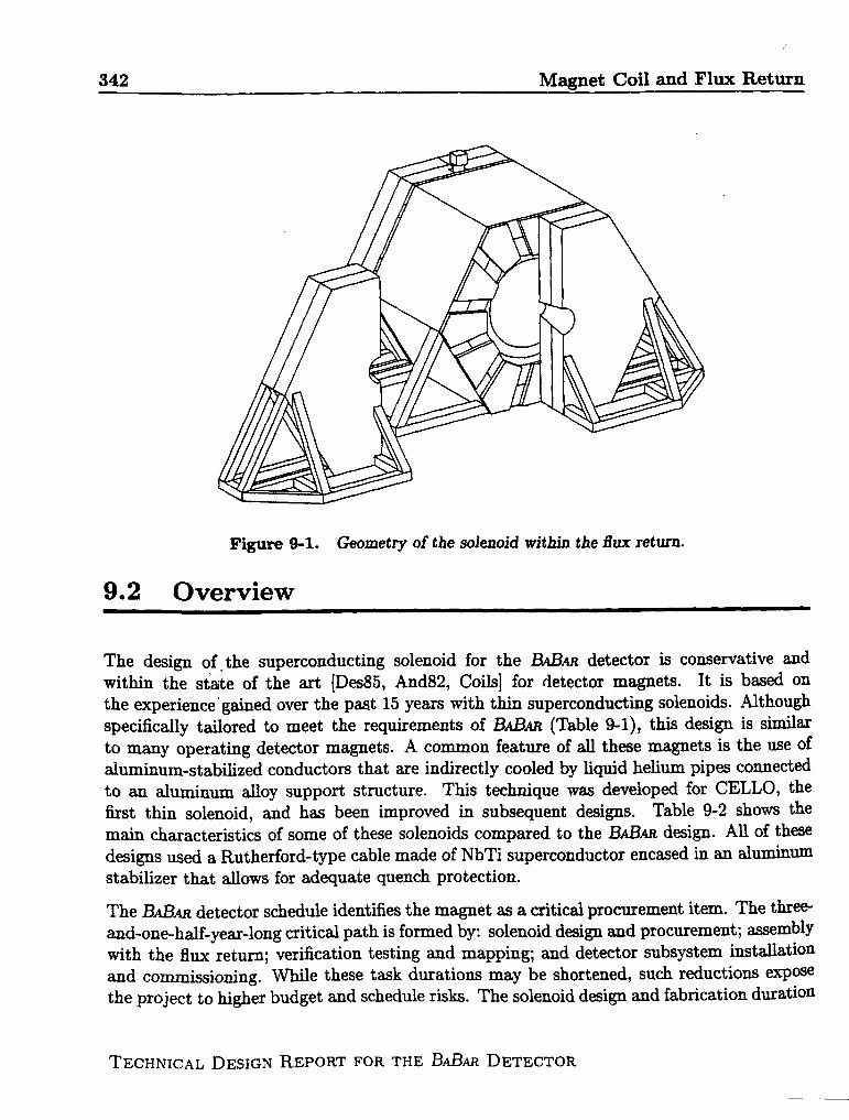
T he 13ABARmagnet is a thin, 1.5 T superconducting solenoid within a hexagonal fluxreturn, as shown in Figure 9-1. Detector performance criteria and geometry consider-
ations drive the design of the solenoid and the flux return. The magnitude and uniformityspecifications for the magnetic field are derived from drift chamber track finding and momen-tum resolution requirements. StudieS of l?” -+ r+~- suggest that a ma~etic field of 1.5 T is
necessary to achieve a mass resolution of 21 MeV/c2. The combined thickness of the vertexdetector, drift chamber, particle identification system, electromagnetic calorimeter, andappropriate clearances set the solenoid inner diameter. Solenoid length is also determined bythe length of the nested subsystems. The solenoid thickness limits the momentum thresholdfor detecting muons and the efficiency of@ detection within the instrumented flux return.
The segmented geometry of the flux return allows tracking of muons and provides fordetection of@ with adequate angular resolution. The total thickness of the steel layers inthe barrel and end door is determined both by the minimum steel required to avoid magneticsaturation and by tkz need for sufficient thickness to ensure that most of the pions interactin the steel. The mi~mal steel thickness to prevent pion punch-through is 55 cm (x3.6 Ai.t).Plate segmentation and thicknesses are specified both for efficient identification of K:s and
for distinguishing muons from pions based on range measurements. For more informationon the meson detection system refer to Chapter 8.
The overall thickness of the flux return is the sum of both the steel thickness and the numberand thickness of the RPC layers. Cost is also a factor in determining the number of RPClayers. Separation and movement of the end doors are constrained by beam line componentsand by the need to provide ready access to detector subsystems.
The physics performance and operational requirements for the solenoid and flux return(Table 9-1) are similar to those of many operating detector magnets (Table 9-2).
342 Magnet Coil and Flux Return
‘1
The design Of, the superconducting solenoid for the 13d3m detector is conservative andwithin the state of the art [Des85, And82, Coils] for detector magnets. It is based on
the experience’ gained over the paat 15 years with thin superconducting solenoids. Althoughspecifically tailored to meet the requirements of 13ABm (Table 9-1), this design is similarto many operating detector magnets. A common feature of all these magnets is the use ofaluminum-stabilized conductors that are indirectly cooled by liquid helium pipes connectedto an aluminum alloy support structure. This technique was developed for CELLO, thefirst thin solenoid, and has been improved in subsequent designs. Table 9-2 shows the
main characteristics of some of these solenoids compared to the BABfi design. All of thesedesigns used a Rutherford-type cable made of NbTi superconductor encased in an aluminumstabilizer that allows for adequate quench protection.
The BABm detector schedule identifies the magnet as a critical procurement item. The three-and-one-half-year-long critical path is formed by: solenoid design and procurement; sssemblywith the flux retu~; verification testing and mapping; ad detector subsystem i~ta,llation
and commissioning. While these task durations may be shortened, such reductions exposethe project to Mgher budget and schedule risks. The solenoid desi~ ~d fabrication duration
TECHNICAL DESIGN REPORT FOR THE BABW DETECTOR
Figure 9-1. Geometry of the solenoid m“thin the f?ux return.
9.2 Overview
!i
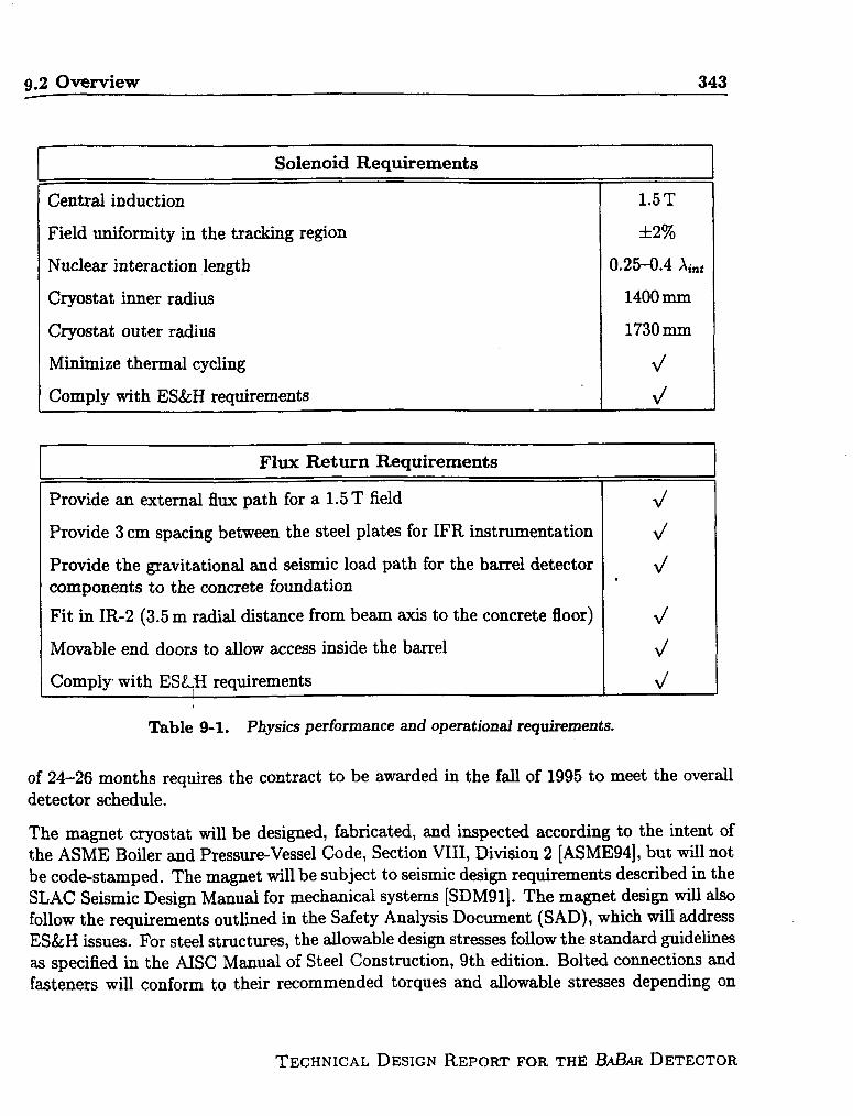
9.2 Overview 343
Solenoid Requirements
Central induction 1.5T
Field uniformity in the tracking region &2%
Nuclear interaction length 0.25-0.4 Ai.t
Cryostat inner radius 1400 mm
Cryostat outer radius 1730mm
Minimize thermal cycling 4
Comply with ES&H requirements d
Flux Return Requirements,
Provide an external flux path for a 1.5 T field
Provide 3 cm spacing between the steel plates for IFR instrumentation
Provide the gravitational and seismic load path for the barrel detectorcomponents to the concrete foundation
Fit in IR-2 (3.5 m radial distance from beam axis to the concrete floor)
Movable end doors to allow access inside the barrel
Comply with ES&$I requirements
Table 9-1. Physics performance and operational requirements.
of 24–26 months requires the contract to be awarded in the fall of 1995 to meet the overalldetector schedule.
The magnet cryostat will be designed, fabricated, and inspected according to the intent ofthe ASME Boiler and Pressure-Vessel Code, Section VIII, Division 2 [ASME94], but will notbe code-stamped. The magnet will be subject to seismic design requirements described in theSLAC Seismic Design Manual for mechanical systems [SDM91]. The magnet design will alsofollow the requirements outlined in the Safety Analysis Document (SAD), whkh will addressES&H issues. For steel structures, the allowable design stresses follow the standard guidelinesas specified in the AISC Manual of Steel Construction, 9th edition. Bolted connections andfasteners will conform to their recommended torques and allowable stresses depending on
TECHNICAL DESIGN REPORT FOR THE BABAR DETECTOR

244 Magnet Coil and Flux Return
Location: .MimufacturerYear completed
hm(,r Bore (m) ‘brjgth (m)St.(,red Energy (MJ)
current (A)
T~,T.aiWeight (t)R~diation Length
; ~[,nrluct,orDimensions (mm)
CDF ZEUS CLEO-11 ALEPH BABm ‘
FNAL DESY Cornell CERN SLACHitachi Ansaldo Oxford
1984 1988 19871.5 1.8 1.5
2.86 1.85 2.885 2.5 3.48
30 12.5 255000 5000 3300
11 2.5 7.00.85 0.9 n/a
3.89x20 4.3X15, 5x165.56x15
Saclay ?1986 19971.5 1.5
4.96 2.807 3.46
137 ~ j
5000 ::1060 ‘-~..~
1.6 :.4 ZXiX3.6x35 :.:.30
64 78 42 40 i -+ I
Table 9-2. Comparison of solenoids sinu”kr to 13A.Bw.
the conn~!ction The flm return is fabricated from ASTMalateri;d with similar mechanical and magnetic properties.
9.2.1 Description of Key Interfaces
Sllperconducting Solenoid and Flux Return. The radial distance betw-= --ie outerdiamet~;r of the solenoid ad the inner surface of the b~el flu return is 50 mm. ~:– solenoid
WI ght and magnetic forces are transmitted to the inner and outer hexagon= ~Es of theflUK retllrn ~ show in Figure 9-2. This att~~ent, located at the verticti ‘_-pl~e ofthf! det(:(:tor, ~so provides the load path of the inner detector components to ::= :-=el fluxrfil,llrn.
Ttl~: b}i~:kward end doors provide a chase for the cryostat chirrme~. The CL-S = 400 ~
WI~lcaml extends 400 mm into the backward end doors.
Barrel and End Door. Both ends of the barrel flux return have a 60% SOL= .=~i contactaN!:~at the interface with the end doors. This area is composed of the 150 =—–tick innerring slll)l)ort plates, 150 mm-tfi~ joint braces, and 15(Imm-thick steelsap fi~n –~tes. Therclrlairllrlg40% open ~ea on the barrelends isreservedforcabling~d ut~v—= 2rom thein mr fi(:t,ector components. The end doors are attached to the barrtl with z ~ =.ates thatarl’ }m]tt~(~to the end door structure and to the barrel.
7’ [:(:rl;:l{ ,f~ DE~lG~ R~pORT FOR THE B.@M DETECTOR

9.2 Overview 345
/SUPERCONDUCTINGSOLENOID \
M36
INNER RING JSUPPORT PLATE
7
Figure 9-2. Superconducting solenoid support bracket attached tothemid-plane of theffux return.
Particle Identification System. A vertical slot between the backward end doors permitsthe support structure for the DIRC to penetrate into the detector. This structure alsosupports the backward beam magnets Q2, Q4, Q5, and the backward flux return field shaping
plug located physicd~ inside the DIRC. The iinal design details of the DIRC and themounting of the backward beam magnets are not yet fu~y resolved.
Forward Q2 Beam Magnetlocated within the forward endshield plug is mounted to the
Shielding. The forward beam magnet Q2 is physicallydoors. A specizdly designed, three-piece, conical magneticend doors to isolate Q2 from the detector magnet. The
0shielding plugs are split along their vertical centerline, and each half is attached to a half-round mounting flange that is bolted to the face of each forward end door.
Inner R.PC Detector and Solenoid. There is an RPC detector located between thecalorimeter and the solenoid. This RPC detector attaches directly to the inner diameterof the solenoid cryostat with a 20 mm clearance gap between the RPC detector and thecalorimeter.
TECHNICAL DESIGN REPORT FOR THE B.d3mzDETECTOR

346 Magnet Coil and Flux Return
Movable End Door Skids and the Beam Line. The end doors are mounted on skidsequipped with rollers so that they can be moved away from the barrel for maintenance access.The end door skids move on tracks installed in the floor of IR-2. The end doors clear thebeam line magnets, vacuum pumps, magnet stands, and other beam line equipment duringdoor opening.
External Platforms, Stairways, and Walkways. The external platforms necessary toinstall and service electronic racks and cryogenic equipment are supported horn the fluxreturn. The requirements of these components have not yet been determined.
9.3 Summary of Projected Magnet Performance
9.3.I Central Field Magnitude and coil Performance
The magnetic field of 1.5 T is obtained by energizing the solenoid with a constant currentof 7110A. The conductor is operated at 45~o of the critical current, with a peak field in theconductor of 2.5 T. This gives a large safety margin.
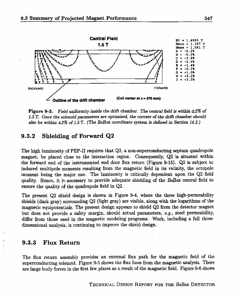
Magnetic uniformity is achieved by doubling the current density in regions at both endsof the solenoid. This is done by adding more aluminum stabilizer to the central regionconductor, which reduces the current density there. Figure 9-3 shows the field uniformity inthe central region. The areas in which the field nonuniformity is greater than 2% are smalland are located in regions in which they do not affect the performance of the drift chamber.In addition, once the solenoid parameters are optimized, the corners of the drift chambershould also be within A2’?ZOof 1.5 T.
The radial pressure on the conductor during operation is 1.5 MPa in the high current-densityregions and 0.78 MPa in the central region of the conductor. An aluminum support cylindersurrounds the coiled conductor to react against these radial pressures and keep the conductorfrom yielding.
The integrated axial force on the winding is 3.5 MN. The conductor winding and suppo~cylinder are mechanically coupled by an epoxy bond. This epoxy bond allows some ofthe axial load to be transmitted in shear to the outer aluminum cylinder, which keeps theconductor from yielding. There is an axial 18 kN de-centering force applied to the conductorwinding due to an asymmetry in the iron, mainly due to the differences in the forwsrd ~dbackward Q2 shielding.
TECHNICAL DESIGN REPORT FOR THE ~~AR DETECTOR
—-. ,.
9.3 Summary of Projected Magnet performance 347
Central Field1.5T
BAC RD
BO = 1.4995 TBmin = 1.397 TBmax= 1.561 TA = -6.2%B= -5.0%c= -3.8%D= -2.6%E = -1.4%F= -0.2%G= +1.0%H = +2.2%I = +3.5%
L Outlineofthedriftchamber (Coil centar atz =370 mm)
Figure 9-3. Field um”formityinside the drifl chamber. The central field is m-thin ●2% of1.5 T. Once the solenoid parameters are optimized, the corners of the drift chamber shouldalso be within &2% of 1.5 T. (The BABARcoordinate system is defined in Section 14.2.]
9.3.2 Shielding of Forward Q2
The high luminosity of PEP-II requires that Q2, a non-superconducting septum quadruplemagnet, be placed close to the interaction region. Consequently, Q2 is situated withinthe forward end of the instrumented end door flux return (Figure 9-15). Q2 is subject toinduced multipole moments resulting from the magnetic field in its vicinity, the octopolemoment being the major one. The luminosity is critically dependent upon the Q2 field
quality. Hence, it ic. necessary to provide adequate shielding of the BABARcentral field toensure the quality o! the quadruple field in Q2.
The present Q2 shield design is shown in Figure 9-4, where the three high-permeabilityshields (dark gray) surrounding Q2 (light gray) are visible, along with the logarithms of themagnetic equipotentials. The present design appears to shield Q2 from the detector magnetbut does not provide a safety margin, should actual parameters, e.g., steel permeability,differ from those used in the magnetic modeling programs. Work, including a full three-dimensional analysis, is continuing to improve the shield design.
9.3.3 Flux Return
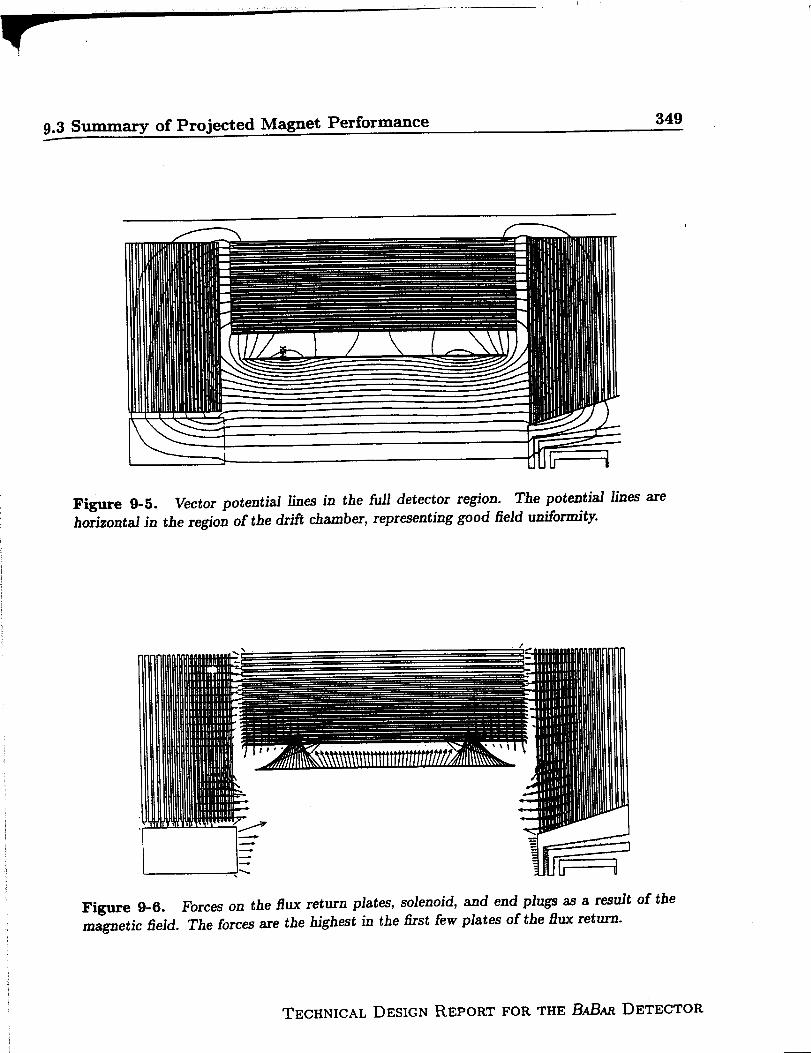
The flux return assembly provides an external flux path for the magnetic field of thesuperconducting solenoid. Fig-me 9-5 shows the flux lines from the magnetic analysis. Thereare large body forces in the first few plates as a result of the magnetic field. Figure 9-6 shows
TECHNICAL DESIGN REPORT FOR THE ILLBARDETECTOR

348 Magnet Coiland FluxReturn
Z (meter)
Figure9-4.Logarithms of magnetic squipotentiala in the region of the Q2 septumquadruple.
the force vectors in the barrel and end doors of the flux return. Preliminary results showthat stiffeners are needed in the end door plates to resist these axial forces. The presentdesign has two stiffeners in each end door. As the end door design is refined, the locationsand number of the plate stiffeners may change to keep the deflections and stresses in theplates within acceptable levels.
TECHNIC.ILDESIGNREPORT FOR THE B.dAsDETECTOR
9.3 Summary of Projected Magnet Performance349
Figure 9-5.horizontal in
Vector potential lines in the full detector region. The potentialthe re~”onof the drifi chamber, representing good fieid unifom”ty.
linesare
Figure 9-6. Forces on the flux return plates, solenoid,magnetic field. The forces are the highest in the first few
and end plugs as a resultplates of the flux return.
of the
TECHNICAL DESIGN REPORT FOR THE 13ABARDETECTOR
,
350 Magnet Coil and FIUX Return
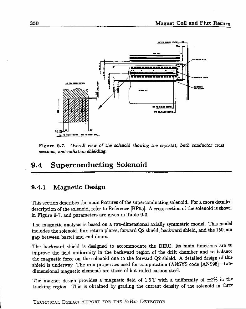
Figure 9-7. Overall view of the solenoid showing the cryostat, both conductor crosssections, and radiation shielding.
9.4 Superconducting Solenoid
9.4.1 Magnetic Design
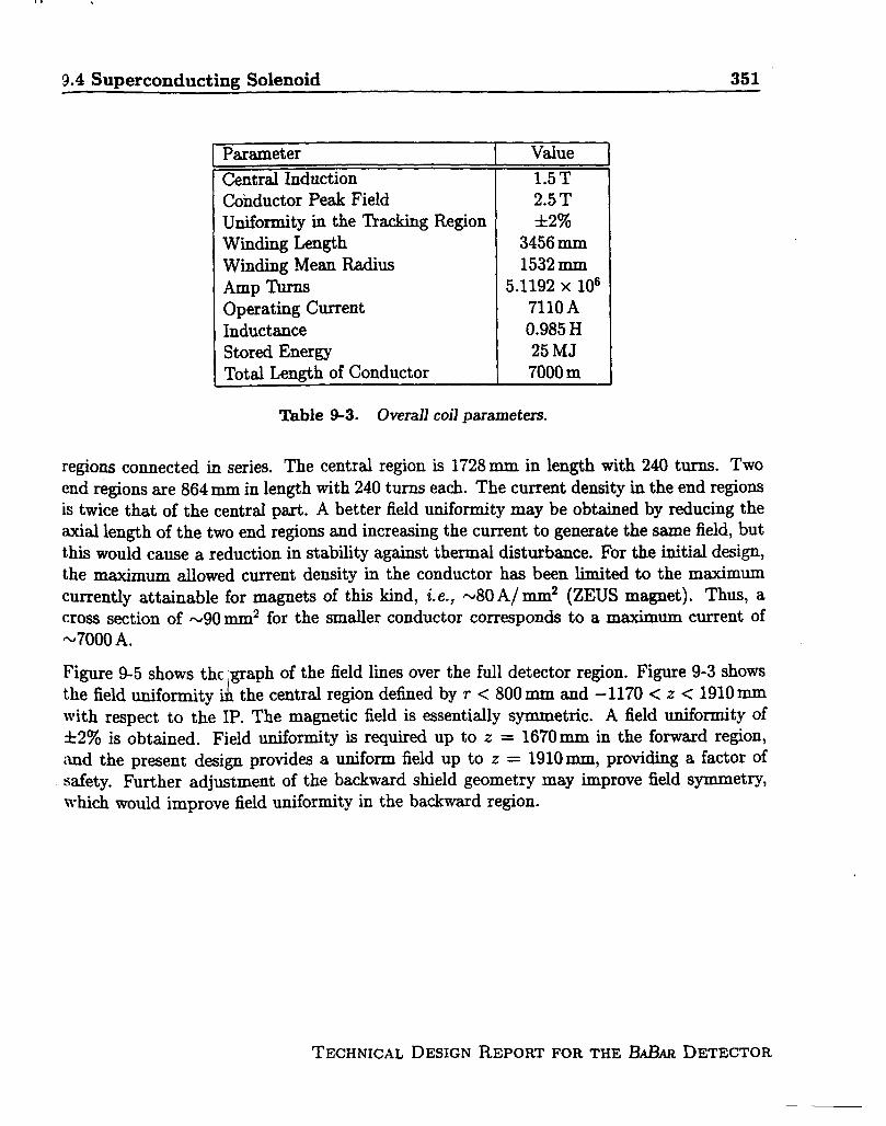
This section describes the main features of the superconducting solenoid. For a more detaileddescription of the solenoid, refer to Reference [BF95]. A cross section of the solenoid is shownin Figure 9-7, and parameters are given in Table 9-3.
The magnetic analysis is based on a two-dimensional axially symmetric model. This modelincludes the solenoid, flux return plates, forward Q2 shield, backward shield, and the 150 mIXI
gap between barrel and end doors.
The backward shield is designed to accommodate the DIRC. Its main functions are toimprove the field uniformity in the backward region of the drift chamber and to balmce
the magnetic force on the solenoid due to the forward Q2 shield. A detailed design of thisshield is underway. The iron properties used for computation (ANSYS code [ANS95]—twO-dimensional magnetic element) are those of hot-rolled carbon steel.
The magnet design provides a magnetic fieldof 1.5T with a uniformity of &2’?10in the
tracking region. This is obtained by grading the current density of the solenoidin thee
TECHNICAL DESIGN REPORT FOR THE BAILw DETECTOR
—
9.4 Superconducting Solenoid 351
,
Parameter I Value.—— - . .I
Central Induction 1.5T
Conductor Peak FieldUniformity in the ‘hacking RegionWinding Length
Winding Mean Radius
Amp ‘l%rnsOperating CurrentInductanceStored EnergyTotal Lemrth of Conductor
2.5 T&2%
3456 mm1532mm
5.1192 x 106711OA0.985 H25 MJ7000 m
Table 9-3. Overall coil parametem
regions connected in series. The central region is 1728 mm in length with 240 turns. TWO
end regions are 864 mm in length with 240 turns each. The current density in the end regionsis twice that of the central part. A better field uniformity may be obtained by reducing theaxial length of the two end regions and increasing the current to generate the same field, butthis would came a reduction in stability against thermal disturbance. For the initial design,the maxim~ ~owed current density in the conductor has been limitedto the maximum
currentlyatttina~lefor magnets of thiskind, i.e.,-80A/ m.m2 (ZEUS magnet). Thus, a
I
cross section of ~90 ~2 for the smaller conductor corresponds to a maximum current of
*7000 A.
Figure 9-5 shows the .~aph of the field lines over the full detector region. Figure 9-3 showsthe field ~ifofity i~ the central region defined by r <800 mm and – 1170< z <1910 mmwith r~pect to the IP. The magnetic field is essentially symmetric. A field uniformity of
*2% is obtained. Field uniformity is required up to z = 1670 mm in the forward region,
imd the present design provides a uniform field up to z = 1910 mm, providing a factor ofsafety. ~~her adjustment of the backward shield geometry may improve field symmetry,which would improve field uniformity in the backward region.
I
TECHNICAL DESIGN REPORT FOR THE BABAR DETECTOR
I

9.4 Superconducting Solenoid 353
Parameter
Conductor Type
Aluminum RRRConductor Unit LengthNumber of LengthsDimensions: Bare
Insulated
Superconducting CableDimensionsStrands DiameterNumber of Strandscu/scFilament DiameterIC (B = 2.5 T, T =Insulation Type
4.5 K)
Insulation Thickness
Value
NbTi, Pure Al-stabilized,Co-extruded
>5001.2km
63.2 and 6.8 X 30.0 mm23.6 and 7.2 X 30.4 mm2
Rutherford
I 9 X 1.23mm20.84mm
201.8
20pm> 16kA
I Fiberglass Tape0.4 mm
Thble 9-4. Conductor parameters.
An integrated compressive axial force of 3.5 MN is induced in the winding. The distribution
of the =al force within the coil is complex. The end regions, with higher current density,compress the central part with 5.4 MN. The central part is axially stressed outward by a
force of 1.9 MN. For preliminary calculations of the axial stress, the maximum force (6 MN)was considered. This would lead to an axial stress of 18 MPa on the pure aluminum, withonly the winding supporting the axial forces. However, if the axial force is transmitted to theouter cylinder, the stress is lowered by a factor of two, with the pure aluminum working wellbelow its elastic limit. In this case, the shear stress between the winding and outer supportingcylinder is less than 2 MPa. This low value of shear stress will allow the winding and supportcylinder to be mechanically coupled through an epoxy impregnation without applying anyaxial prestress to the winding (as was done for the ZEUS magnet). Epoxy impregnation cansupport a shear stress higher than 20 MPa, providing a high safety margin. This leads to asimplification and cost saving in the winding fabrication.
The current design causes axial de-centering forces on the coil due to the iron asymmetry anda residual force of 18 kN is applied to the winding. A more careful design of the backwardshield can help reduce the amount of this residual axial force by a factor of two or three.
Offset forces have been calculated as follows. An axial displacement of the solenoid of 10 mmcauses an axial force of 98 kN in the direction of the displacement. A radial misalignment
TECHNICAL DESIGN REPORT FOR THE BA.BARDETECTOR
354 Magnet Coil and Flux Return
of 10 mm gives rise to a force of 89 kN. These values will be taken into consideration in
designing the SUPPfJrtsystem and ‘hould not present ~Y sk@fic~t problems.
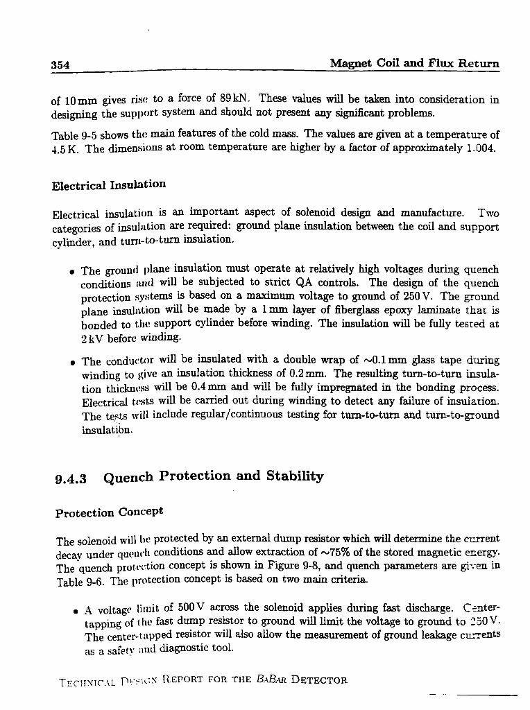
Table 9-5 shows t~l[!m~n feat~es of the COldmw. The v~ues me given at a temperature of4.5 K. The dimensions at room ‘emperat~e We higher by a factor of approximately 1.004.
Electrical Insulation
Electrical insulation is ~ ‘mport~t ~Pect Of solenoid dd~ ~d ma.mfacture. Twocategories of i~~ll:~tion ~e requir:d: 8TOURdP~~e i~~ation between the coil ~d supportcylinder, and turn- to-t~ insulation.
●
●
The grouml Plane insulation must oPerate at relatively high voltages during quenchconditions :l[ld will be subjected tO strict QA controk. The design of the quenchprotection systems is b~ed on a mmimum voltage to ground of 250 V. The groundplane insulation wi~ be made by a 1 mm layer of fiberglass epoxy laminate that is
bonded to tile suPPofi cylinder before winding. The imtiation *U be fully tested at2 kV before winding”
The condu~@r will be ins~ated with a double wrap of -0.1 mm glass tape duringwinding to give an indation thickness of 0.2 mm. The resulting turn-to-turn insula-
tion thickn~~ss will be 0.4 mm ~d wi~ be f~ly impregnated in the bonding process.Electrical t,(~stswill be carried OUt during winding to detect any failure of insulation.The tests ~~ill include re@m/continuous testing for turn-to-turn and turn-to-groundinsulatlbn.
g.4.3 Quench Protection and Stability
Protection Concept
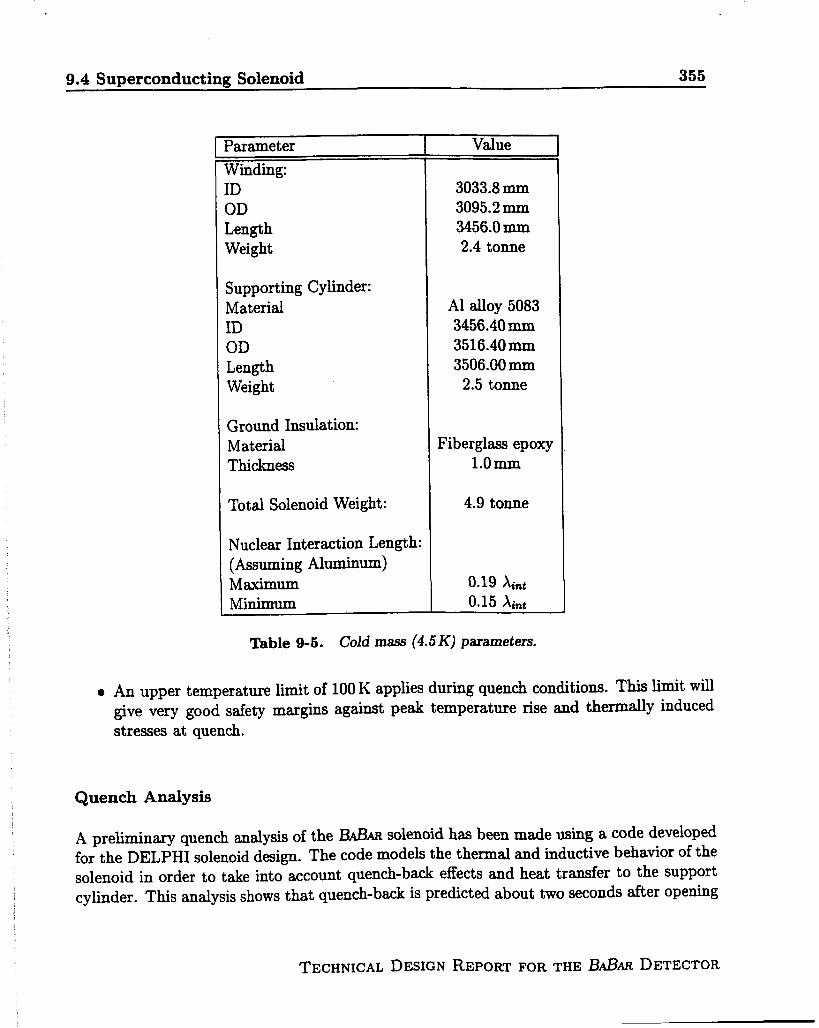
The solenoid will IN?prot:c~ed by ~ external dup resistor which will determine the C=ent
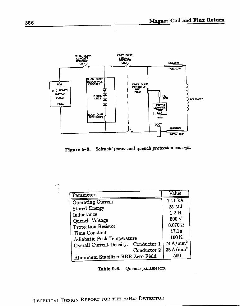
decay under qu~’11~11con~tlons ~d ~low extraction of IU75% of the stored magnetic energy.The quench prot (’ction concePt Is sho~ in Figure 9-8, and quench parameters me @;en inTable 9-6. The pr{)tection concePt is baed on two main criteria.
. A voltage limitof 500 V across the solenoid appliesduring fastdischarge. Canter-
tapping Of the fast dump resistor to ground will limit the voltage to ground to 2-50V.The ~enter.t i~pped resistor will aiso allow the measurement of ground leakage currents
as a safety ;~mi dia~ostic tool.
TECHSIC’.iL PI:SI(:N REPORT FOR THE M?.% DETECTOR
7
9.4 Superconducting Solenoid 355
‘arameter I Value. —— ----
Mdirlg:[D 3033.8 mm
3D 3095.2 mm
Length 3456.0 mm
Weight 2.4 tonne
suppofiing Cylinder:Material Al ~Oy 5083
ID 3456.40 mm
OD 3516.40mm
Length 3506.00 mm
Weight 2.5 tonne
Ground InsulationMaterial Fiberglass epoxy
Thickness l.omrn
Total Solenoid Weight: 4.9 tonne
Nuclear Interaction Length:(Assuming Aluminm)Maximum 0.19 A~n~
Minimum 0.15 ~~n~
Table 9-5. Cold mass (4.5 K] parameters.
An upper temperature limit of 100 K applies during quench conditions. This limit will
give very good safety margins agaimt pe~ temperature rise and thermally inducedstresses at quench.
Quench Analysis
A preliminary quench analysis of the BABm solenoid has been made using a code developed
for the DELPHI solenoid design. The code modek the thermal and inductive behavior of thesolenoid in order to take into account quench-b~ effects and heat transfer to the supportcylinder. This analysis shows that quench-baa is predicted about two seconds after opening
TECHNICAL DESIGN REPORT FOR THE BABti DETECTOR
356 Magnet Coil and Flux Return
?
P&3.
D.c -
7.9M
BEG .
7 PC8.WP
Figure 9-8. Solenoid power and quench protection concept.
,.i
parameter Value
tlm..ntin u (%rwnt, 7.11 kAwl’J-A-’”--t3 v—. ._.Stored Energy
II
25 MJ
Ihductance 1.2 H
Quench Voltage 500 vProtection Resistor 0.070 !2
---Time (hMtiid l“i.1s
Adiabatic Peak Temperature 100 K
C)verall Current Density: Conductor 1 74 A/mm2
Conductor 2 35 A/mm2
Aluminum Stabilizer RRR Zero Field 500
Table 9-6. Quench parameters.
TECHNICAL DESIGN REPORT FOR THE BABA.RDETECTOR

I
I
9.4 superconducting Solenoid 357 ‘
40.0
_____ ’-. --------------
(/’ — Coil(l-hc(l)lq
[--- Suppon Cylinder(ThS(l) K)
/
1’
0.00.0 10.0 20.0 30.0 40.0 50.0
Time(s)
Figure 9-9. Temperature w“ation during quench. The temperature rise in the coil andsupport cylindm during a quench should not exceed 40K.
the protection circuit breakers. Figure 9-9 shows that the temperature rise in the coil andsupport cylinder during a quench should not exceed 40 K.
Stability
The 13d3ARsolenoid coil will be indirectly cooled using the technology established for existingdetector magnets such as DELPHI and ALEPH. The reiiable operation of those magnets hasdemonstrated that safe stability margins can be achieved using high-purity, aluminum-cladsuperconductors in a fully bonded, indirectly cooled coil structure.
Conductor stability has been estimated using an analysis code in order to establish theminimum quench energy (MQE) for transient heat pulses. The computed MQE = 1.4J. Thecomputed minimum quench length (MQZ) is 0.6 m.
These margins are considered to be safe for the BABARsolenoid due to its low-stress design.The stability margin will be optimized during the full design study.
TECHNICAL DESIGN REPORT FOR THE BABAR DETECTOR
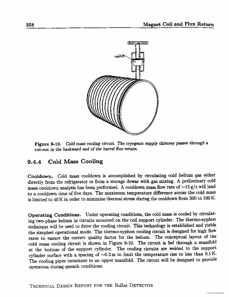
. .. . . .. .. ,:.~,..,.$, ,! ,,, < ,,. . . . . . . . . .*., -.. ,.$
1
I
,
/
i
I
I
(
,
358 Magnet Coil md Flw Return
Figure 9-10. Cokl mass cooling circuit. The cryogenic supply chimney passes through acut-out in the backward end of the barrel flux return.
9.4.4 Cold hkss
Cooldown. Cold mass
Cooling
cooldown is accomplished by circulating cold helium gas either
directly from the refrigerator or from a storage dewar with gas mixing. A preliminary coldmass cooldown analysis has been performed. A cooldown mass flow rate of N15 g/s will leadto a cooldown time of five days. The maximum temperature difference across the cold massis limited to 40 K in order to minimize thermal stress during the cooldown from 300 to 100 K.
Operating Conditions. Under operating conditions, the cold mass is cooled by circulat-ing two-phase helium in circuits mounted on the coil support cylinder. The thermo-syphontechnique will be used to drive the cooling circuit. This technology is established and yieldsthe simplest operational mode. The thermo-syphon cooling circuit is designed for high flOW
rates to ensure the correct quality factor for the helium. The conceptual layout of thecold mass cooling circuit is shorn in Figure 9-10. The circuit is fed through a manifoldat the bottom of the support cylinder. The cooling circuits are welded to the supportcylinder surface with a spacing of -0.3 m to limit the temperature rise to less than 0.1 K.The cooling pipes terminate in an upper manifold. The circuit will be designed to provideoperation during quench conditions.
TECHNICAL DESIGN REPORT FOR THE BA.BM DETECTOR
— — . . ---g.4 Superconducting Solenoid 359
Heat Loads. The estimated static heat loads for the solenoid are given in Table 9-7. EddyCurrentheating in the support.Cylinderwiu Came additionalheat loads during charging ofthe solenoid. However, for a solenoid ~mging time of 30 minutes, the estimated transientpower is N2 W, which is small compared to static heat loads.
9.4.5 Cryostat Design
Vacuum Vessel. The cryostat consists of anation shields and superinsulation (Figure 9-7).number of basic criteria
1.
2.
3.
4.
5.
Support vacuum loads in accordance with
annular vacuum vessel equipped with radi-The vacuum vessel is designed to satisfy a
recognized pressure vessel codes;
Carry the cold mass and radiation shield weight through the insulating supports;
Operate with deflections of less than 2 mm under all loads when mounted in the fluxreturn barrel;
Carry the loading of the inner detectors; and
operate under defined seismic loadings.
The vacuum vessel is designed as two concentric cylinders with thick annular end plates, allof aluminum alloy 5083; its basic parameters are given in Table 9-8. A preliminary finiteelement (FE) structural analysis of the vessel has coniirmed that design criteria (l)–(4)can be met with reasonable safety factors. Maximum vessel deflections are less than 2 mm,and stress levels are generally lower than 40 MPa with all loads applied. Deflections areminimized when the vessel is supported on the horizontal centerline and detector loads arealso applied at that point. Performance of the vessel under seismic loadings (5) is still underconsideration.
Thermal Shielding. The cryostat is equipped with radiation shields, which operate at40-80 K, and superinsulation. The shields are cooled by helium gas supplied directly fromthe refrigerator. About 30 layers of superinsulation separate the vacuum vessel walls fromthe radiation shields. Another five layers will be installed between the shields.
Services. Cryogenic supplies and current supplies are connected from a services turret tothe cryostat through the service chimney in the backward end door. Current leads and localcontrol valves are ‘mounted in the services turret. Cryogenic relief valves are also mountedin the service turret for quench and refrigeration failure conditions.
TECHNICAL DESIGN REPORT FOR THE BABARDETECTOR
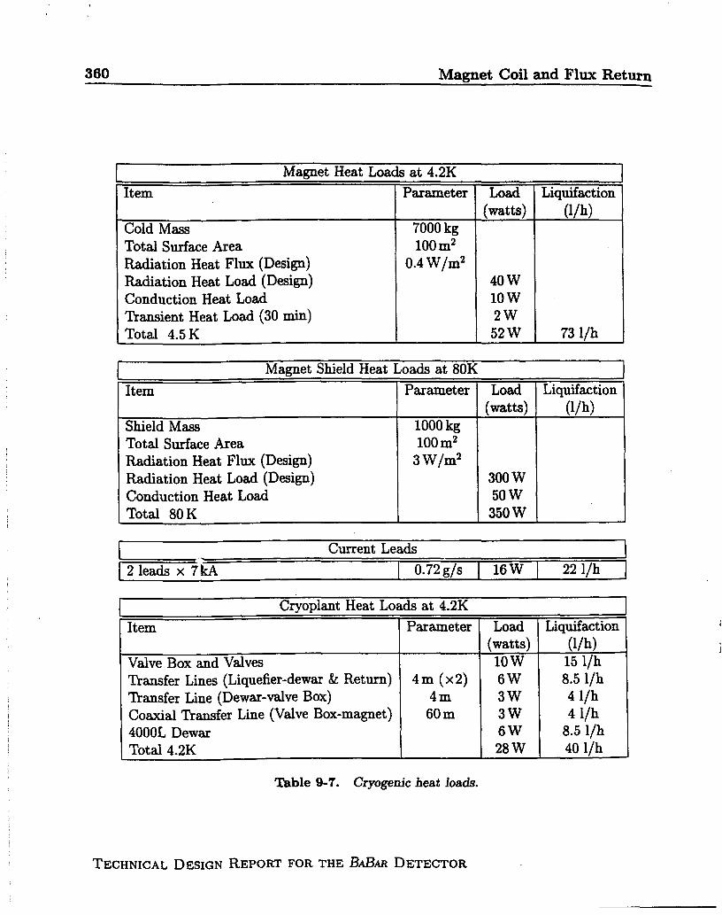
, . ., . .,,a,,,,,..,
360 Magnet Coil and Flux Return
Maguet Heat Loads at 4.2K
Item Parameter Load Liquefaction(watts) (l/h)
Cold Mass 7000 kgTotal Surface AreaRadiation Heat Flux (Design)Radiation Heat Load (Design)Conduction Heat Load
Ttansient Heat Load (30 rein)Total 4.5 K
100 mi0.4 W/m2
40 w10 w2W
52 W 73 lih
Magnet Shield Heat Loads at 80K
Item Parameter Load Liquefaction(watts) (l/h)
Shield Mass 1000 kgTotal Surface Area 100 m2Radiation Heat Flux (Design) 3 W/m2
Radiation Heat Load (Design) 300 wConduction Heat Load 50 wTotal 80 K 350 w
I Current Leads IL I
[ 2 leads x 71cA 0.72 g/s I 16 W I 22 l/h
Crvodant Heat Loads at 4.2K I. .
Item
Valve Box and ValvesTransfer Lines (Liquefier-dewm & Return)llansfer Line (Dewar-valve Box)Coaxial Transfer Line (Valve Box-magnet)4000L DewarTotal 4.2K
Parameter Load Liquefaction(watts) (l/h)
10 w 15 l/h4m (x2) 6W 8.5 l/h
4m 3W 4 I/h60 m 3W 4 l/h
6W 8.5 l/h28 W 40 llh
Table 9-7. Cryogeru”cheat loads.
TECHNICAL DESIGN REPORT FOR THE 13fiAR DETECTOR

9.4 Superconducting Solenoid 361
Envelope Dimensions
Inner Radius 1400 mmOuter Radius 1730 mmLength 3850 mmMaterials AL5083
I Desirrn Loads II J
I Vessel Weight I 6 tonne
ICold Mass 6 tonne
Calorimeter 50 tonne
Seismic Load Factors (Max)
Horizontal 1.2 gVertical 2.og
Table 9-8. Vacuum vessel parameters.
9.4.6 Coil Assembly and Transportation
I
The coil will be assembled inside the cryostat at the manufacturer’s plant. Electrical ~dcryogen connections will be made at the chimney so that the coil cm be tested beforeshipping.
A complete cooldown will be carried out from room temperature to the operating tempera-
ture of 4.5 K. The cooldown will allow checking of cooldown time, temperature control, heatloads, and full operation of sensors. A magnetic test will also be performed at low field (30%
of the operating current) to check superconductor operation, the joint resistance, and theadditional losses due to the energization.
Before delivering the magnet, but after the tests at the factory, the end flanges will bedismounted to allow a hard connection of the cold mass to the cryostat walls. Dep(:n&ngon the transport facilities, the chimney may also be dismounted. In this case, the electricaland cryogen connections also must be dismounted and protected against breakage.
TECHNICAL DESIGN REPORT FOR THE 13ABAR DETECTOR

362 Magnet Coil and Flux Ret-
1
I
II
II
I
9.5 Cryogenic Supply System and Instrumentation
Operation of the superconducting solenoid requires both liquid helium and cold helium gas
(20 K to 100 K) for cooldown and refrigeration of the thermal shields. Similar systems havebeen used successfidly throughout the HEP community. A summary of the cryogenic loadsis given in Table 9-7.
The helium plant, consisting of a helium liquefier/refrigerator, a 40004 supply dewar, anda distribution valve box (DVB), is located adjacent to the experimental hall, apprmcimately60 m from the magnet, w shown in Figure 9-11. It is possible that the DVB will be incor-porated within the helium liquefier cold box, depending upon the helium liquefier selected.This liquid helium plant meets all of SLAC’S requirements and is sized conservatively at150-200 //hr. It will supply LHe to the BABAR superconducting solenoid, the two futuresuperconducting beam line focusing magnets (Ql), and an auxiliary dewar/trailer for allother SLAC experiments. The detector solenoid is expected to consume less than 1004/hrof LHe.
Liquid nitrogen is required for the helium liquefier, for the initial stages of coil cooldown,and miscellaneous uses in IR-2. It will be supplied from a 20,0004 tank located on the apronabove the experimental hall. This tank, which is an existing SLAC unit, will be refurbishedto serve all cryogenic system requirements. A second, similar vessel is also available if a
reserve LN2 supply is required. Vacuum-insulated transfer lines connect the LN2 tank tothe helium plant.
The 4000 / liquid helium dewar is a refurbished SLAC unit fed directly from the liquefier.This volume ~~ovides approximately 30 hours of autonomous operation of the solenoid andquadruple magnet systems in the event of a minor liquefier/compressor malfunction. LHefrom the dewar is supplied at N1.25 bar, via proportional control valves in the DVB, to theappropriate magnet/auxiliary dewar system as required. Three el~tro-pneurnatic operatedvalves are actuated by process controllers and superconducting LHe level gauges.
Liquid helium and cold helium gas are supplied to the detector solenoid and Q1 supercon-
ducting magnets in flexible, vacuum-insulated, low-loss transfer k=. These transfer linesprovide the cold gas return path to the liquefier/refrigerator. This type of transfer line h=
been used successfully by SLD. The transfer lines are designed to be compatible with theSLD lines so that the latter can serve as spares and/or Q1 trmfer ~~. LHe and cold shieldgas for the solenoid are routed to the magnet service chimney at the detector backward enddoor penetration (north end). Magnet cooldown to N20 K is achieved with cold helium g~via the DVB. Warm helium gas from magnet current leads is routed in uninsulated pipingto compressor suction.
TECHNICAL DESIGN REPORT FOR THE ~ABAR DETECTOR
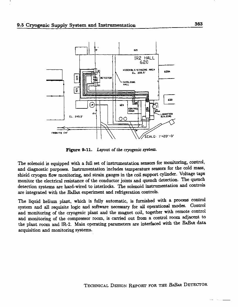
9.5 Cryogenic Supply System and Instrumentation 363
EL.
F-he
24s.5’II II
621
4SSD4BLY/STAGING ARC~
EL. ?0S.S’
\ SHISLDINGVALL
620A
1
LnlJlwKRBuILDING
IL II’
H \\ \vjjcALE:,.,,-,.
Figure 9-11. La~ut of the cryogenic system.
The solenoid is equipped with a full set of instrumentation sensors for monitotig, control,~d diagnostic purposes. Instrumentation includes temperature sensors for the cold m-,shield cryogen flOW mmitming, and strain gaug~ in the coil SUpPOrtcylinder. Voltage taps
monitor the electrical resistance of the conductor joints and quench detection. The quen~detection systems are hard-wired to interlocks. me solenoid ~tnxrnentation and controlsare integrated with the IkILm experiment and refrigeration controls.
The liquid helium plant, which is fully automatic, is shed with a process controlsystem and all requisite logic and software necessary for all operational modes. Controland monitoring of the cryogenic plant and the ma~et coil, together with remote control~d monitoring of the compressor room, is cfi~ out from a control room adjacent to
the plant room and IR-2. Main operating parameters me interfaced with the 13ABARdataacquisition and monitoring systems.
I
TECHNICAL DESIGN REPORT FOR THE &.&iR DETECTORI

9.6 Flux Return 365 ,
Outer Ring Description
L_/
RING ~SWSJ .
&%RTSTRhP
JOINT ‘BRACE
Figure 9-12. Barrel flux return assembly showing the support of the solenoid, gap Iilkrplates, and the external support legs.
the positive z direction. The bsrrel flux return extends radially horn the detector sxis from1780 mm to 2920 mm and consists of inner and outer hexagonally-shaped concentric steelrings. The radial gap between the inner and outer rings is 50 mm. The rings consist ofblocks with multipIq’steel plates oriented parallel to the axis of the solenoid. Two side platesand the inner and duter parallel plates of each block are welded into a rigid box using full
penetration welds along their entire length in the z direction (parallel to the beam line).The remaining parallel plates are held in place using skip welds at their connections withthe side plates. The use of double block construction for each of the hexagonal segmentsof the barrel flux return provides a significant safety margin with respect to the 45-tonnerated capacity of the overhead crane in IR-2. The blocks are designed to provide continuousmuon detection in azimuth. The weight of the barrel flux return is 312 tonne excluding theexternal support legs.
1
The outer ring is the primary structural support for the BABAR detector. This ring iscomposed of six blocks. Each block consists of six 30 mm-thick and three 50 mm-thick parallel
TECHNICAL DESIGN REPORT FOR THE B@AR DETECTOR

366 Magnet Coil and Flux Return
SUPERCONDUCTINGSCILENCIID
T l_WELIIFULL PENETRATION
Figure9-13. Bloc&-to-block interface in the flux return.
structural plates oriented so that the thicker plates are positioned towards the outermostportion of the barrel hexagon. The plates are positioned in each block to provide 30 mm ofclear space between each plate and the next for the installation of Resistive Plate Chambers(RPCS). The inner surface of the outer block is located 2350 mm radially from the interactionpoint. The 30 mm spacing between plates is to be maintained during block fabrication.Therefore, the tolerance build-up due to variations in the plate thickness and plate flatnessextends outward in the radial direction. The spacing of the parallel plates is held fixed by60 mm-thick side plates located at the block-to-block interface, as shown in Figure 9-13.Two of the blocks are provided with threaded holes in their outer plates for mounting of theexternal support legs. Each block is 3750 mm in length, 570 mm in nominal height, 2714 mmwide at the inner trapezoid base, and 3372 mm wide at the nominal outer trapezoid surface.Each outer block weighs approximately 31.2 tonne.
Inner Ring Description
The inner ring is also composed of six blocks. Each block consists of eleven 20 mm-thickparallel structural plates positioned to provide 30 mm of clear space between plates for theinstallation of RPCS. The inner surface of the inner block is located 1780 mm radiflY
from the interaction point. Like the outer plates, the 30 mm spacing is held fixed, and theplate manufacturing tolerances are allowed to accumulate in the outward direction. A gaP
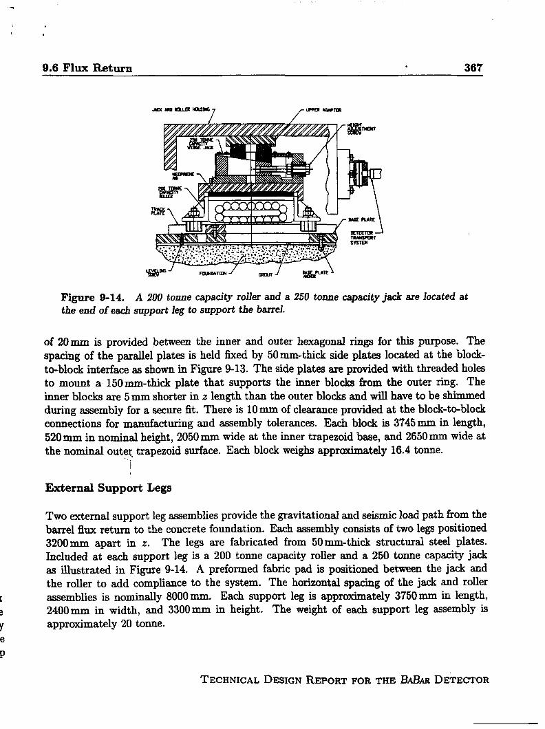
9.6 Flux Return . 367
.
.
s
,1
).
ene.
w’ raB4MTIm1 GmRj BAAPLAIE~
Figure 9-14. A 200tonne capacity roller and a 250 tonne capaci~ jack are located atthe end of ea~ support leg to support the barrel.
of 20 mm is provided between the inner and outer hexagonal rings for this purpose. Thespacing of the parallel plates is held fixed by 50 mm-thick side plates located at the block-to-block interface as shown in Figure 9-13. The side plates are provided with threaded holesto mount a 150 mm-thick plate that supports the inner blocks horn the outer ring. Theinner blocks are 5 mm shorter in z length than the outer blocks and will have to be shimmedduring assembly for a secure fit. There is 10 mm of clearance provided at the block-to-blockconnections for manufacturing and assembly tolerances. Each block is 3745 mm in length,520 mm in nominal height, 2050 mm wide at the inner trapezoid base, and 2650 mm wide atthe nominal oute~ trap~zoid
I
External Support Legs
surface. Each block weighs approximately 16.4 tonne.
Two external support leg assemblies provide the gravitational and seismic load path from thebarrel flux return to the concrete foundation. Each assembly consists of two legs positioned3200 mm apart in z. The legs are fabricated from 50 mm-thick structural steel plates.Included at each support leg is a 200 tonne capacity roller and a 250 tonne capaci~ jackas illustrated in Figure 9-14. A preformed fabric pad is positioned between the jack andthe roller to add compliance to the system. The horizontal spacing of the jack and roller
assemblies is nominally 8000 mm. Each support leg is approximately 3750 mm in length,2400 mm in width, and 3300 mm in height. The weight of each support leg assembly isapproximately 20 tonne.
TECHNICAL DESIGN REPORT FOR THE 13A,Z3ARDETECTOR
368 Magnet Coil -d FIUX Return
9.6.3 End Door Description
The forward and backward end doors are an array of steel plates that forma regular hexagon
approximately 5840 mm across the fiats and 1120 mm thick. The array cowists of eleven20 mm-thick plates, six 30 mm-thick plates, and three 50 mm-thick plates. There iS a nominalgap width of 30 mm between plates in the array for locating the RPCS. The plates for boththe forward and backward end doors weigh approximately 255 tonne. This weight doesnot include plates and bars that tie the plates together for structural reasons, the supportmembers that attach the end doors to a movable skid, or the skid itself (Figures 8-23 and9-15). Both the forward and backward end doors are split along the vertical centerline ofthe detector forming right and left end doors.
Each end door is mounted on a skid that permits it to be raised onto high load capacityrollers by hydraulic jacks and to be moved on tracks located in the IR-2 hall. This providesa means to move the end doors into proper a&nrnent with the barrel prior to being boltedin place, and to be moved away horn the barrel for maintenance access to the detector. Thecenter of gravity of the end door plates is high compared to the depth of the base. The skidprovides additional stability during the horizontal accelerations experienced during movingor seismic events.
During operation, the magnet exerts an inward axial force that causes a significant bendingmoment on the end door plates. The forward end doors also support the weight of the Q2shielding plug and carry the axial magnetic load induced in the plug. To resist gravitationaland seismic loads, and to limit the plate stresses and deflections, all the end door plates are
joined together to form a single structural member.
The design of the end doors permits each door to be assembled and disassembled inside theIR-2 hall with the existing facility crane. Since the capacity of the IR-2 crane is 45 tonne,each separable part, together with all rigging and lifting fixtures needed, cannot exceed thislimit. Each end door is therefore composed of two weldments that are fastened together atinstallation. The inner wekiment consists of eleven 20 mm plates and two 30 mm plates, witheach plate welded to a chrm.nel-shaped frame that extends along the top and bottom of thehexagon shape and along the boundary between the right and left doors. Two horizontalstiffeners are positioned between the 20 mm plates. Additional stiffeners are also requiredto stiffen the weldrnent and help maintain the necessary gaps for the RPCS. The outerweldment consists of four 30 mm plates and three 50 mm plates welded together with similarstiffening members. The detailed analysis of the response of the plates to the magnetic force
distribution is not yet available, nor has a detailed seismic analysis been done for the enddoor plates. Several design options are being studied that can provide the necessary strengthand stifi!ness.

,
9.6 FIUX Return369
I!
m-skid
\ OumrmdDowwoMlnnl
ICountor Wolghl
l-t-l
i- Stl
I
Figure 9-15. Side view of the fo-d end door showing the Q2 shielding, counter weights,and SUppOti rOfleXS.
TECHNICAL DESIGN REPORT FOR THE - DETECTOR
370 Magnet Coil and Flux Return
The inner and outer weldments are joined together at installation by bolting each weldmentto the top of the skid along the bottom of the hex, and by bolting tie plates around theremaining perimeter of the wekiments, except where the shielding plugs are located. Theoutside tie plates are bolted in place after the RPCS are installed, and provisions for cablingare provided in these outside plates. These tie plates are also used to attach the end doorsto the barrel of the flux return.
End Door Skids
Each end door is mounted on a skid that is equipped with four 70 tonne capacity rollers, andfour 45 tonne hydraulic jacks, one in each comer, which allow each of the doors to be movedrelative to the barrel for maintenance access. The rollers ride on hardened steel tracks thatare permanently located in the floor of IR-2. Because the bases of the end doors are narrowcompared to their high centers of gravity, 30 tonne of existing scrap steel is bolted to eachskid to lower the center of gravity and move it toward the middle of the skid.
The end doors are bolted either to the barrel of the flux return when in the operating positionor to seismic restraint brackets when in the parked position. While the doors are being moved,the 30 tonne counter weight provides lateral stability for a horizontal acceleration of 0.3 g.
Forward Q2 Shielding Plug Support
The preferred option for mounting the Q2 shielding plug is to fabricate and assemble theshield in two sections split along the vertical axis. These assemblies are mounted to large half-round flanges that are bolted to the back 50 mm plates of the forward end doors (Figure 9-15).This simplifies access to the front portion of the detector when the end doors are moved. Itis likely that the halves of the end door will be tied together by two additional hti-roundflanges oriented at 90° to the shielding plug supports to sttien the assembly. This optionrequires that each half of the shield be installed in the end doors at final assembly since
each half of the shield assembly weighs approximately 20 tonne. Special lifting and assemblyfixtures are required to accomplish this task.
The alignment of the shield and the Q2 magnet is done by adjusting the position of each haJf-round flange on the end door and installing dowel pins to maintain the alignment. SufEcientclearance between the shield and the forward Q2 magnet is provided to permit the shield tomove vertically with the stroke of the jack as the end door is raised to be rolled out of theway for detector access.
TECHNICAL DESIGN REPORT FOR THE &ELt.R DETECTOR
.
9.6 Flux Return 371
9.6.4 Options and Detailed Design Issues
A detailed stress and deflection analysis is proceeding for the finalized overall envelopedimensions. A detailed magnetic field and force analysis of the end doors ensures that theywill have adequate strength and stiffness to meet all the requirements imposed on them.
The tolerance on plate flatness must be defined together with the envelope dimensions ofthe RPCS. Standard mill tolerances for plate flatness do not meet our requirements forthe end door plates to permit reliable RPC installation; these tolerances exceed 15 mm,half the nominal gap width. This issue, together with weld distortion in the plates duringfabrication, must be resolved with both the plate supplier and the barrel and end doorfabricator. Other manufacturhg tolerances must be established as the system interfacedimensions are ihl.ized, and the effects of these tolerances on the physics performance ofthe detector are reviewed.
9.6.5 Procurement, Fabrication, Assembly, and Schedule
The barrel and the end doors will be built by the same fabricator as part of the same procure-ment contract. This will eliminate some duplication in the review of vendor quaMcations,
quality control plans and actions, and many contract administration issues. In addition,control of other characteristics of the plate material, such aa the chemistry of the plates asit affects weldabilit y and machinability, the mechanical properties of the plate, etc., may bemore easily tracked by having one set of acceptance inspection criteria horn one supplier forall plates.
The barrel and end”tioors will be fully assembled and inspected at the fabricator’s shop. Inthis way, any problem that arise can be solved before final assembly in the IR-2 hall. Thiswill also permit a thorough review of the assembly procedure by an experienced fabricatorand ensure that the necessary lifiing and assembly iixtures are functional and are providedwith the barrel and end doors. The details of the fabrication and assembly plan will bedeveloped by the fabricator subject to the review of the responsible design engineer in theMAR collaboration.
TECHNICAL DESIGN REPORT FOR THE &.EIAR DETECTOR
3’72 REFERENCES ‘
References
[And82]
[ANS95]
[ASME94]
[BF95]
{Coils]
D. fbirews et al., “A Superconducting Solenoid for CoWiing Beam Experi-ments,” Ad. Cryogenic Eng. 27 (1982).
ANSYS, INC, ‘GenersJ Finite Element Code: Rev. 5.1 (1995).
ASME, “1992 ASME Boiler and Pressure Vessel Code” (1992).
E. Baynham and P. Fabbricatore, ‘Superconducting Solenoid for the BABmDetector,” B.ABAUNote in preparation.
A, Bonito Oliva et al., “ZEUS Magnets Construction Status Report,” llth Int.Conference on Magnet Technology, MT-11, 229 (1989).P. Clee et aL, “Towards the Realization of Two 1.2 T Superconducting Solenoidsfor Particle Physics Experiments,” llth Int. Conference on Magnet TechnologyMT-11, 206 (1989).H. Desportes et al., “Construction and Test of the CELLO Thin-Wall Solenoid,”Ad. Cryogenics Eng. 25, 175 (1980).H. Desportes et al., “General Design and Conductor Study for the ALEPHSuperconducting Solenoid,” J. Phys. (Paris) Cl-341, S1-T45 (1984).Y. Doi et aZ., ‘A 3T Superconducting Magnet for the AMY Detector,” Ohrcl.Jhstr. AIethods A274, 95 (1989).M.A. Green et d., “Construction and Testing of the Two-Meter-Diameter TPCThin Superconducting Solenoid: Ad. Cryogenics Eng. 25, 194 (1980).M.A. Green et aL, ‘A Large Superconducting Thin Solenoid for the STARExperiment at RHIC~ IEEE Trans. App. Superconductivity, 104 (1993).H. Hirabayashi, “Detector Magnet Technology for High Energy Accelerators:lCEC-11, 115 (1986).H. Minemura et al., ‘Fabrication of a 3 m-dia. x5 m Superconducting Solenoidfor the Fermilab Collider Detector Facility,” J. Phys. (Paris) Cl-333, S1-T45,(1984).C.M. Monroe et al., “The CLEO-H Magnet-Design, Mwmfacture, and Tests7K!EC-12, 773 (1988).M. Wake et al., “Excitation of a Superconducting Large Thin Solenoid Magnet,”MAG-23, 1236 (1987).F. Wittgenstein et al., ‘Construction of the L3 Magnet,” llth ‘Internation~Conference on MaWet Technology, MT-11, 131, (1989).A. Yarnarnoto et al., “Thin Superconducting Solenoid Wound with the Internal
Winding Method for Colli&ng Beam Experiments,” J. Phys. (Ptis) C1-337,S1-T45 (1984).
TECHNICAL DESIGN REPORT FOR THE BABAR DETECTOR
REFE~N~S 373
[DeB85]
[SDM91]
“i’
TECHNICAL DESIGN REPORT FOR THE - DETECTOR
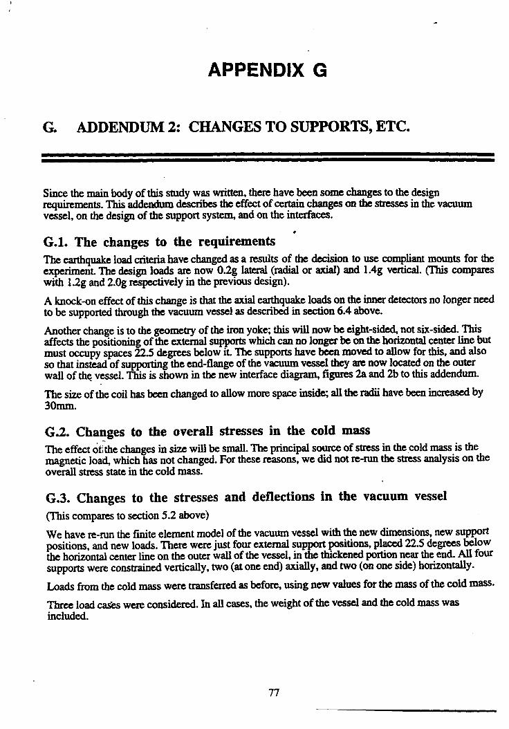
APPENDIX G
G. ADDENDUM2: CHANGESTO SUPPORTS,ETC.
Since the mainbody of this study was written,therehave been some changes to the designrequirements.W addendumdescribes the effect of certainchanges on the stresses in the vacuumvessel, on the design of the supportsysten and on the interfaces.
G.1. The changes to the requirements 4The earthquakeload criteriahave changedas a results of the decision to use compliantmounts for theexperiment. The design loads are now 0.2g lateral(radialor axiaI) and 1.4g vertical. (This compamwith 1.2g and 2.Ogrespectively in the previous design).
A knock-oneffect of this change is thatthe axial earthquakeloads on the innerdetectorsno longer needto be supportedthroughthe vacuum vessel as describedin section 6.4 above.
Another change is to the geometry of the iron yok, this will now be eight-sided not six-sided. Thisaffects the positioning of the external supportswhich can no longer be on the horizontalcenterline butmust occupy spaces 22.5 degrees below it. The supports have been moved to allow for this, and alsoso that instead of suppating the end-flange of the vacuum vessel they am now located on the outerwall of the vessel. This is shown in the new interfacedia~ figures 2a and 2b to this addendum.
The size of the coil has been changed to allow more space insi~, all the radii have been increased by3omm.
G.2. Changes to the overall stresses in the cold massThe effect oihe changesin size will be small. The principalsource of stress in the cold mass is themagnetic load, which has not changed. For these reasons, we did not re-runthe stress analysis on theoverall stress state in the cold mass.
G.3. Changes to the stresses and deflections in the vacuum vessel(This comparesto section 5.2 above)
We have re-runthe ftite element model of the vacuum vessel with the new dimensions,new supportpositions, andnew loads. There were just fourexternal supportpositions, placed 22.5 degrees belowthe horizontalcenterlie on the outerwall of the vessel, in the thickenedportionnearthe end. All foursupportswere constrainedvertically, two (at one end) axially, and two (on one side) horizontally.
Loads from the cold mass were transferredas before, using new values for the mass of the cold mass.
Three load cai”~ were considered.In all cases, theweight of the vessel andthe cold mass wasincluded.
77

1
1
-●
4
G. Addendum - supports -q*mw* ~eOkOkJ-?hYIM
Table G.1Description Additional Loads MS)( Max general Mexbcai
deflection stress(MPa) stress(mm) (MPa)
1 Axial w + 0.2g on cold 0.71 17 38.1mass, 02g axial onvessel.
2 Radii 2ot+02g on oold 2.34 16 70.8mass,0.2gfadd onvessel
3 Veclicai 2ot+ 1.4g on mid 0.68 17 37.7mass, 1.4g onvessel.
The work is fully written up in reportm.udxr RAUASDKMWMW015.
G.4. Changes to the loads on the supportsThiscompares with section 6.2.2
The masses are now vessel mass = 5.4t, cold mass= 7.34 radiation shields etc = 1.5t. Thus cryostit =6.9t.
The earthquakeloads are now 0.2g sideways and 1.4g vertical.
The new table of loads is
Table G.2(compare with table 6.1 of the design study)
Combined load on(7.3 tonnes] supports
Max. radial )oads:9foroes (0.2g) I 1.5 1.4
magnetic alignment 20errorsTotal 21.5 1.4 22.9t
Max. axial loads:~ forces (0.2g) 1.5 1.4
magnetic loads due 10to known geometrymagnetic alignment 20errorsTotal 31.5 1.4 32.9t
Max. vertical loads:weight ● 7.3 I 6.9
~ forces(1.4q) 10.2 9.7
magnetic atignment 20errors-. r .- . 4e e CA 44
’78
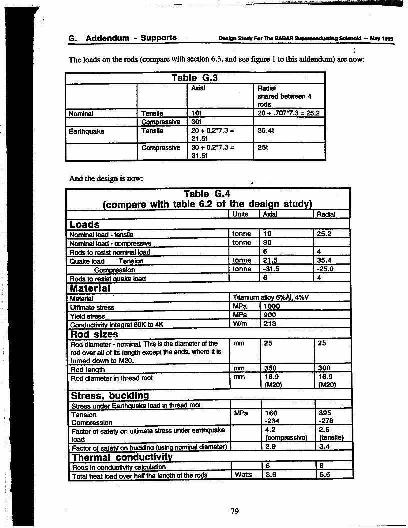
I
G. Addendum - supports oeslglletudyForl’h@aA6AR~Sc)hO&i - Nhylsss
The loads on the rods (comp~ witi -on 6.3, and see figure 1 to this addendum)are now:
Table G.3Axial Radial
shared between 4rods
Nominal Tensile 1Ot 20+ .7077.3 = 25.2Compressive 3ot
Earthquake Tensile 20+ 0.27.3 = 35.4t21.5t
Compressive 30+ 0.27.3 = 25t
And the design is now:●
Table G.4(compare with table 6.2 of the design study)
I Units [ Axial I Radial
LoadsNominal foad - tensite tonne 10 25.2Nominal load - oompressive tonne 30Rods to resistnominaf load 6 4
Quake toad Tension tonne 21.5 35.4Compression tonne -31.5 -25.0
Rods to resistquake toad 6 4
MaterialMaterial Titanium altov6%AI, 4%VUftimatestress MPa 1000Yield strass MPa 900
Conduotivii integral 80K to 4K W/m 213
Rod sizesRod diameter ~nominaf.TM isthe diameterof the ~ 25 25rod over all of its length except the ends, where it isturned down to M20;Rod length nYn 350 300
Rod diameter in thread root m 16.9 16.9(M20) (M20)
Stress, bucklingStress under E@hquake load in thread rootTension MPa 160 395Compression -234 -278
Faotor of safety on ultimatestressunderearthquake 4.2 2.5load (Oompressive) (tensile)
Faotor of safety on buoMng (usingnominaldiameter) 2.9 3.4
Thermal conductivityRods in conduotiwty“ oalcutation 16 8
Total heat load over half the fermthof the rods Watts ! 3.6 5.6
79

!
I
The changes to the loads arenot very great and seine to increasethe safety margins in all cases. Itmight be possible to reduce the size or numberof the rods,but it was not considered worthwhiletopursuethat option here.
G.5. Changes to the design of the external supportsme major change nxuks from the fact that the coil no longer has to transferthe loads from the innerdetectors. We have done away with the subsidiary axial supportplates, and simplifkd the design of themain support brackets. Conceptually, the design is now as shown in the interface diagram.
G.6. Changes to the interfaces
The interface diagram (figure 11.1 of the design study)hasbeenmodifiedto reflect the newdimensions and supportdesign, see figure 2 of this addendum.The design of the inner detectornolonger needs to allow for the supportbrackets as was shown in figure 11.2. The suppmts no longeroccupy partof the axial spacebetween the end flange of the vacuumvessel and the end-capof theyoke.
.
80
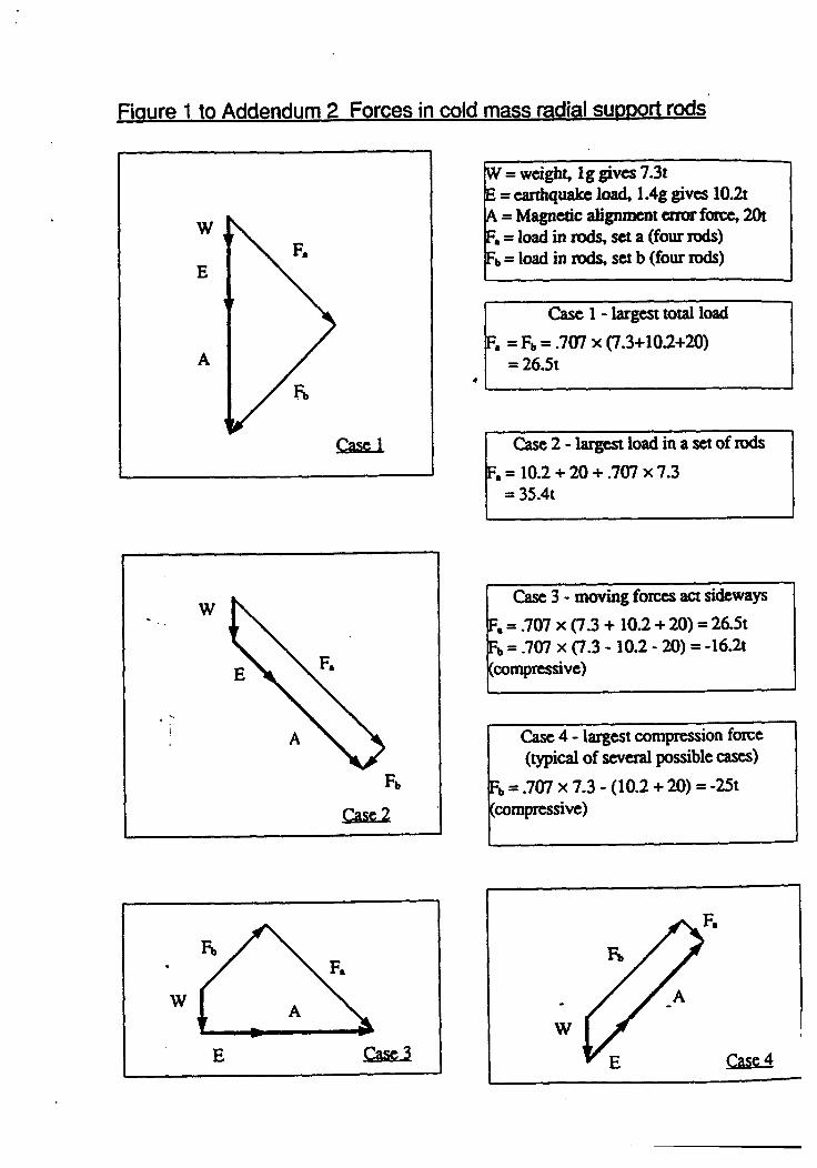
Casd
w
, -,
E
●
W = wcigh~ Ig gives 7.3tE= earthquakeIoti 1.4g givCS10.2tA = Magnetic alignmentenurf~ 20tF,= load in rids, set a (four rods)F~= load in reds, SCt b (four rods)
T
I I
Case3-moving fomes act sideways
Case 4- largest compression force(typical of several possible cases)
%=.707 x 7.3- (10.2 +20)= -25t(compressive)
.
w

\ T’(’(
I
\ q I
!II
II
Ii
\ \ \\
r—— -—-— —II
.—
‘A*
itil-l- 1*I—I—I,
—
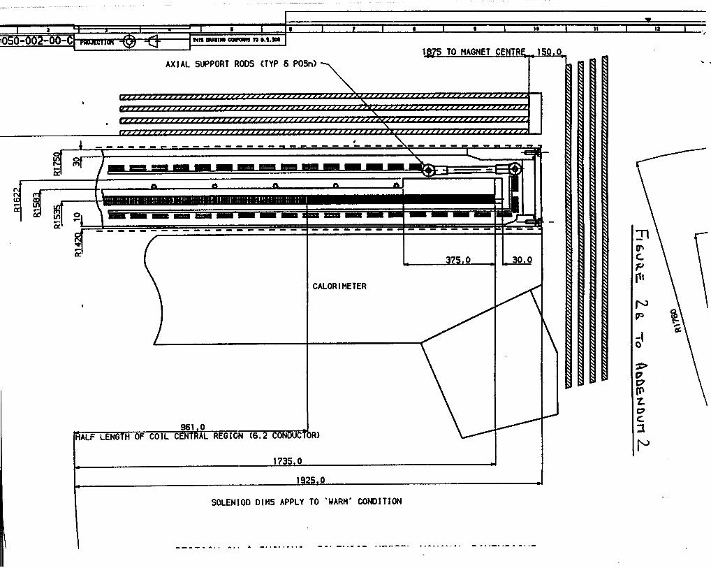
AXIAL SUPPORT ROOS (TYP 6 POSn)
,
I
----- ----- ----- ----
w
I
961 ●oHALF LENGTH OF COIL CENTRALREGIGN (6.2 CONOUC
CALORIMETER
1735.0e ●
192S,0* 1
SOLEN1OO OIHS APPLY TO ‘UARII’ CONDITION
*
\
\
---- . -. . -. . A -. . . . . . . .- - -, -. ,- . - . ,- - - -. . ,-. .- , . . . - -. . . . .- . -. .-
Technical Inform
ation Departm
ent • Lawrence Liverm
ore National Laboratory
University of C
alifornia • Livermore, C
alifornia 94551