Embed Size (px)
Citation preview
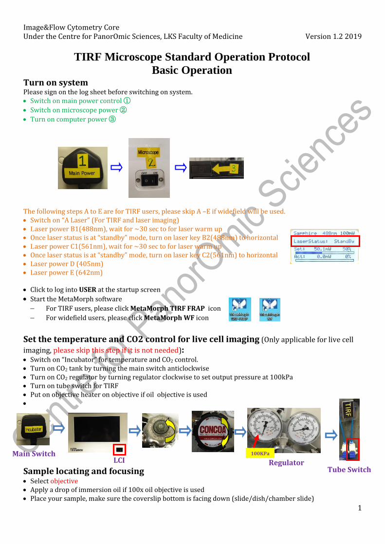
Image&Flow Cytometry Core Under the Centre for PanorOmic Sciences, LKS Faculty of Medicine Version 1.2 2019
1
Turn on system Please sign on the log sheet before switching on system. • Switch on main power control ①
• Switch on microscope power ②
• Turn on computer power ③
The following steps A to E are for TIRF users, please skip A –E if widefield will be used. • Switch on “A Laser” (For TIRF and laser imaging) • Laser power B1(488nm), wait for ~30 sec to for laser warm up • Once laser status is at “standby” mode, turn on laser key B2(488nm) to horizontal • Laser power C1(561nm), wait for ~30 sec to for laser warm up • Once laser status is at “standby” mode, turn on laser key C2(561nm) to horizontal • Laser power D (405nm) • Laser power E (642nm)
• Click to log into USER at the startup screen
• Start the MetaMorph software − For TIRF users, please click MetaMorph TIRF FRAP icon − For widefield users, please click MetaMorph WF icon
Set the temperature and CO2 control for live cell imaging (Only applicable for live cell
imaging, please skip this step if it is not needed): • Switch on “Incubator” for temperature and CO2 control. • Turn on CO2 tank by turning the main switch anticlockwise • Turn on CO2 regulator by turning regulator clockwise to set output pressure at 100kPa • Turn on tube switch for TIRF • Put on objective heater on objective if oil objective is used •
Sample locating and focusing • Select objective • Apply a drop of immersion oil if 100x oil objective is used • Place your sample, make sure the coverslip bottom is facing down (slide/dish/chamber slide)
TIRF Microscope Standard Operation Protocol
Basic Operation
LCI Main Switch
Regulator Tube Switch
100KPa
Image&Flow Cytometry Core Under the Centre for PanorOmic Sciences, LKS Faculty of Medicine Version 1.2 2019
2
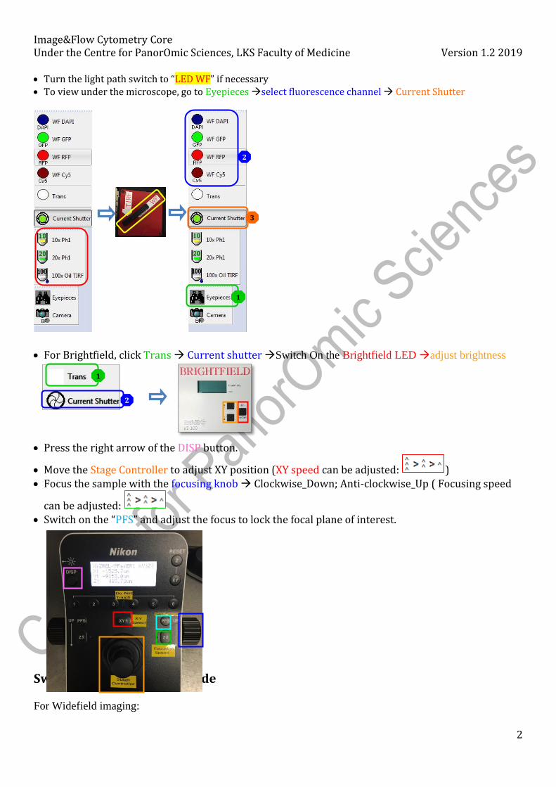
• Turn the light path switch to “LED WF” if necessary • To view under the microscope, go to Eyepieces →select fluorescence channel → Current Shutter
• For Brightfield, click Trans → Current shutter →Switch On the Brightfield LED →adjust brightness
• Press the right arrow of the DISP button.
• Move the Stage Controller to adjust XY position (XY speed can be adjusted: ) • Focus the sample with the focusing knob → Clockwise_Down; Anti-clockwise_Up ( Focusing speed
can be adjusted: • Switch on the “PFS” and adjust the focus to lock the focal plane of interest.
Switching to Acquisition mode For Widefield imaging:
1
3
2
1
2
Image&Flow Cytometry Core Under the Centre for PanorOmic Sciences, LKS Faculty of Medicine Version 1.2 2019
3
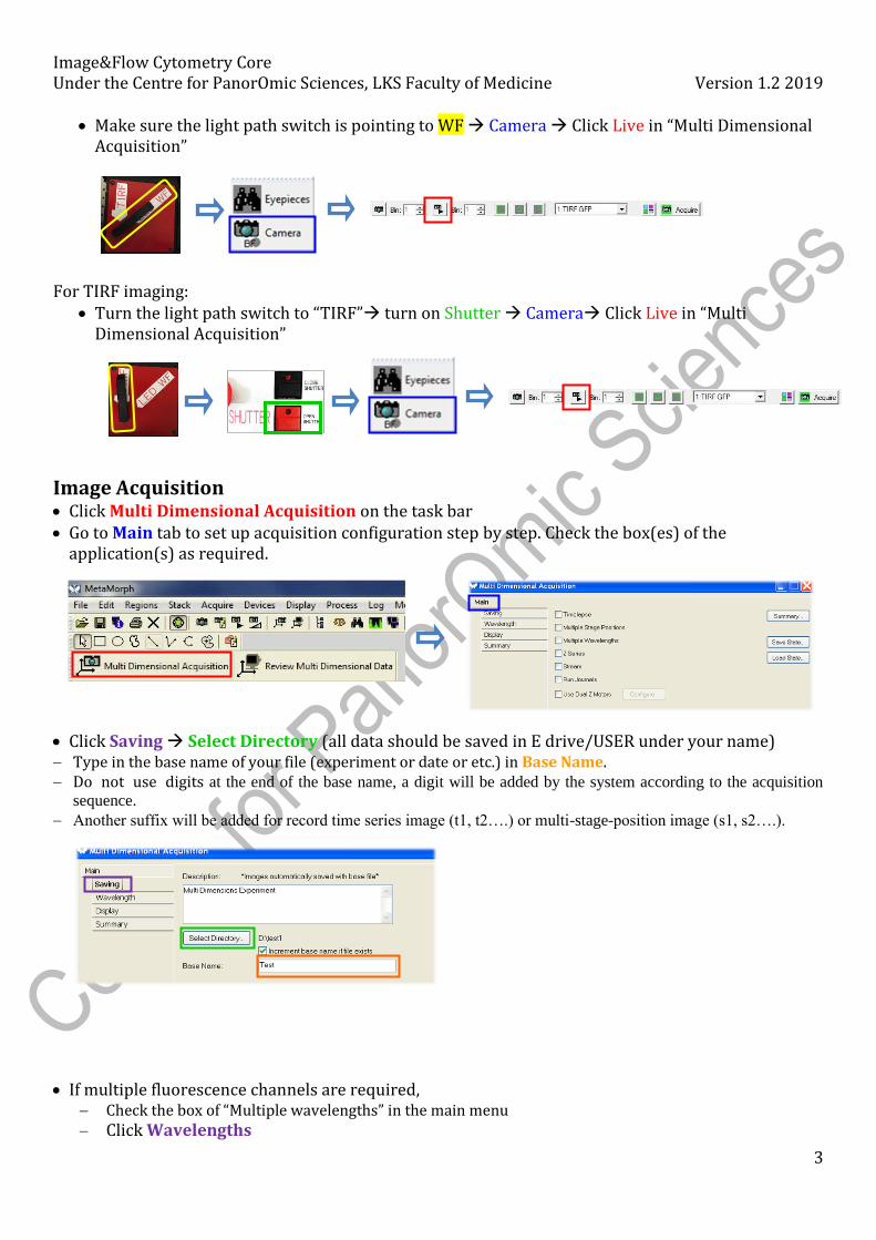
• Make sure the light path switch is pointing to WF → Camera → Click Live in “Multi Dimensional Acquisition”
For TIRF imaging:
• Turn the light path switch to “TIRF”→ turn on Shutter → Camera→ Click Live in “Multi Dimensional Acquisition”
Image Acquisition • Click Multi Dimensional Acquisition on the task bar • Go to Main tab to set up acquisition configuration step by step. Check the box(es) of the
application(s) as required.
• Click Saving → Select Directory (all data should be saved in E drive/USER under your name) − Type in the base name of your file (experiment or date or etc.) in Base Name. − Do not use digits at the end of the base name, a digit will be added by the system according to the acquisition
sequence.
− Another suffix will be added for record time series image (t1, t2….) or multi-stage-position image (s1, s2….).
• If multiple fluorescence channels are required, − Check the box of “Multiple wavelengths” in the main menu − Click Wavelengths
Image&Flow Cytometry Core Under the Centre for PanorOmic Sciences, LKS Faculty of Medicine Version 1.2 2019
4
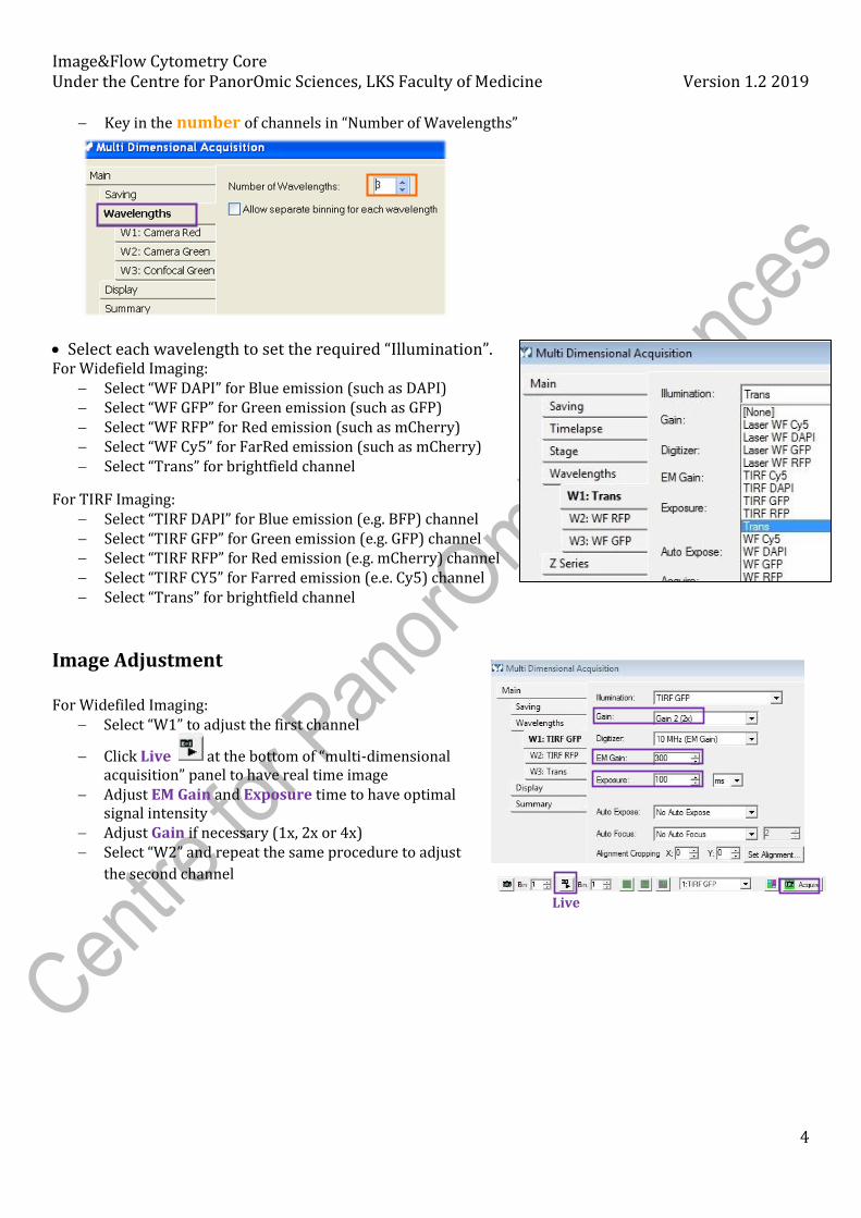
− Key in the number of channels in “Number of Wavelengths”
• Select each wavelength to set the required “Illumination”. For Widefield Imaging:
− Select “WF DAPI” for Blue emission (such as DAPI) − Select “WF GFP” for Green emission (such as GFP) − Select “WF RFP” for Red emission (such as mCherry) − Select “WF Cy5” for FarRed emission (such as mCherry) − Select “Trans” for brightfield channel
For TIRF Imaging: − Select “TIRF DAPI” for Blue emission (e.g. BFP) channel − Select “TIRF GFP” for Green emission (e.g. GFP) channel − Select “TIRF RFP” for Red emission (e.g. mCherry) channel − Select “TIRF CY5” for Farred emission (e.e. Cy5) channel − Select “Trans” for brightfield channel
Image Adjustment For Widefiled Imaging:
− Select “W1” to adjust the first channel
− Click Live at the bottom of “multi-dimensional acquisition” panel to have real time image
− Adjust EM Gain and Exposure time to have optimal signal intensity
− Adjust Gain if necessary (1x, 2x or 4x) − Select “W2” and repeat the same procedure to adjust
the second channel
Live
Image&Flow Cytometry Core Under the Centre for PanorOmic Sciences, LKS Faculty of Medicine Version 1.2 2019
5
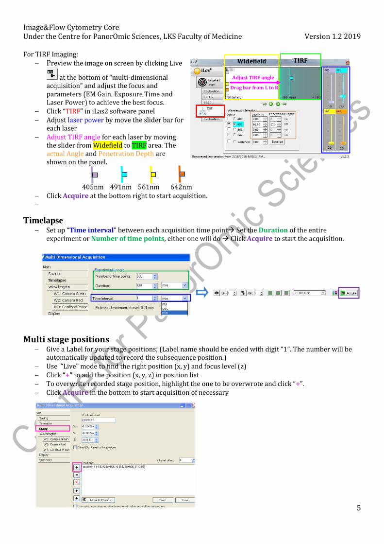
For TIRF Imaging: − Preview the image on screen by clicking Live
at the bottom of “multi-dimensional acquisition” and adjust the focus and parameters (EM Gain, Exposure Time and Laser Power) to achieve the best focus.
− Click “TIRF” in iLas2 software panel − Adjust laser power by move the slider bar for
each laser − Adjust TIRF angle for each laser by moving
the slider from Widefield to TIRF area. The actual Angle and Penetration Depth are shown on the panel.
405nm 491nm 561nm 642nm − Click Acquire at the bottom right to start acquisition. −
Timelapse − Set up “Time interval” between each acquisition time point→ Set the Duration of the entire
experiment or Number of time points, either one will do → Click Acquire to start the acquisition.
Multi stage positions
− Give a Label for your stage positions; (Label name should be ended with digit “1”. The number will be automatically updated to record the subsequence position.)
− Use “Live” mode to find the right position (x, y) and focus level (z) − Click “+” to add the position (x, y, z) in position list − To overwrite recorded stage position, highlight the one to be overwrote and click “+”. − Click Acquire in the bottom to start acquisition of necessary
Widefield TIRF
Adjust TIRF angle
Drag bar from L to R
Image&Flow Cytometry Core Under the Centre for PanorOmic Sciences, LKS Faculty of Medicine Version 1.2 2019
6
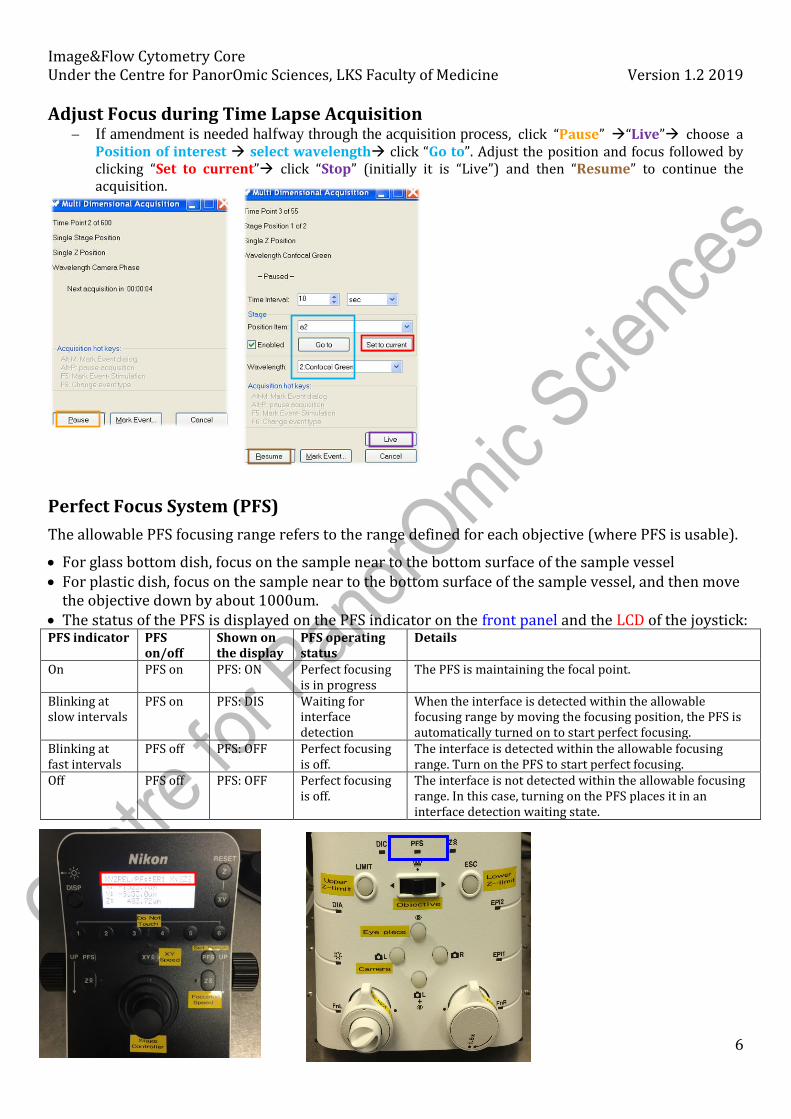
Adjust Focus during Time Lapse Acquisition − If amendment is needed halfway through the acquisition process, click “Pause” →“Live”→ choose a
Position of interest → select wavelength→ click “Go to”. Adjust the position and focus followed by clicking “Set to current”→ click “Stop” (initially it is “Live”) and then “Resume” to continue the acquisition.
Perfect Focus System (PFS)
The allowable PFS focusing range refers to the range defined for each objective (where PFS is usable).
• For glass bottom dish, focus on the sample near to the bottom surface of the sample vessel • For plastic dish, focus on the sample near to the bottom surface of the sample vessel, and then move
the objective down by about 1000um. • The status of the PFS is displayed on the PFS indicator on the front panel and the LCD of the joystick: PFS indicator PFS
on/off Shown on the display
PFS operating status
Details
On PFS on PFS: ON Perfect focusing is in progress
The PFS is maintaining the focal point.
Blinking at slow intervals
PFS on PFS: DIS Waiting for interface detection
When the interface is detected within the allowable focusing range by moving the focusing position, the PFS is automatically turned on to start perfect focusing.
Blinking at fast intervals
PFS off PFS: OFF Perfect focusing is off.
The interface is detected within the allowable focusing range. Turn on the PFS to start perfect focusing.
Off PFS off PFS: OFF Perfect focusing is off.
The interface is not detected within the allowable focusing range. In this case, turning on the PFS places it in an interface detection waiting state.
Image&Flow Cytometry Core Under the Centre for PanorOmic Sciences, LKS Faculty of Medicine Version 1.2 2019
7
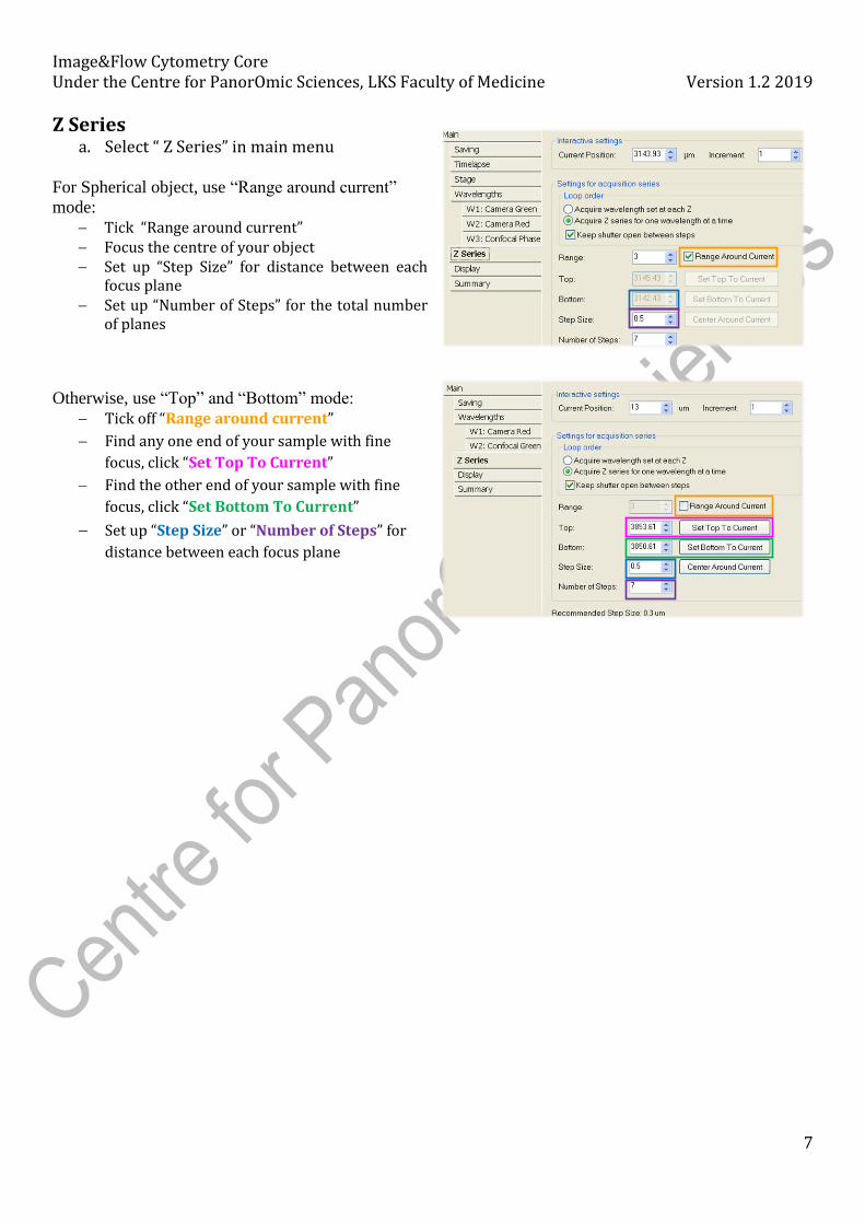
Z Series a. Select “ Z Series” in main menu
For Spherical object, use “Range around current”
mode:
− Tick “Range around current” − Focus the centre of your object − Set up “Step Size” for distance between each
focus plane − Set up “Number of Steps” for the total number
of planes
Otherwise, use “Top” and “Bottom” mode:
− Tick off “Range around current”
− Find any one end of your sample with fine
focus, click “Set Top To Current”
− Find the other end of your sample with fine
focus, click “Set Bottom To Current”
− Set up “Step Size” or “Number of Steps” for
distance between each focus plane
Image&Flow Cytometry Core Under the Centre for PanorOmic Sciences, LKS Faculty of Medicine Version 1.2 2019
8
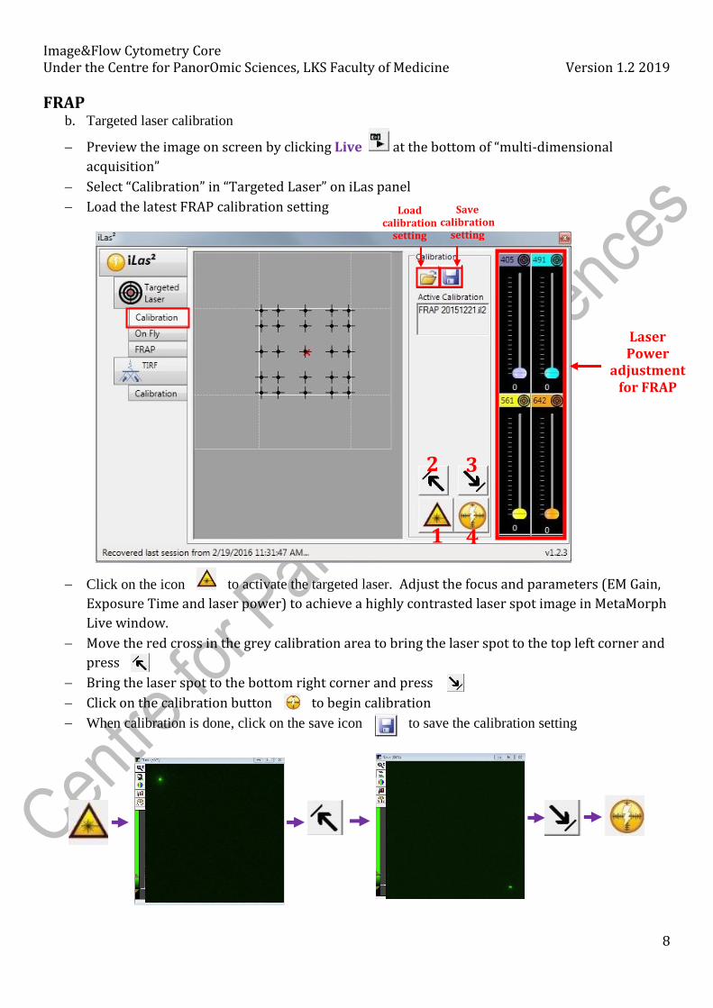
FRAP b. Targeted laser calibration
− Preview the image on screen by clicking Live at the bottom of “multi-dimensional
acquisition”
− Select “Calibration” in “Targeted Laser” on iLas panel
− Load the latest FRAP calibration setting
− Click on the icon to activate the targeted laser. Adjust the focus and parameters (EM Gain,
Exposure Time and laser power) to achieve a highly contrasted laser spot image in MetaMorph
Live window.
− Move the red cross in the grey calibration area to bring the laser spot to the top left corner and
press
− Bring the laser spot to the bottom right corner and press
− Click on the calibration button to begin calibration
− When calibration is done, click on the save icon to save the calibration setting
Load calibration
setting
Laser Power
adjustment for FRAP
1 4
3 2
Save calibration
setting
Image&Flow Cytometry Core Under the Centre for PanorOmic Sciences, LKS Faculty of Medicine Version 1.2 2019
9
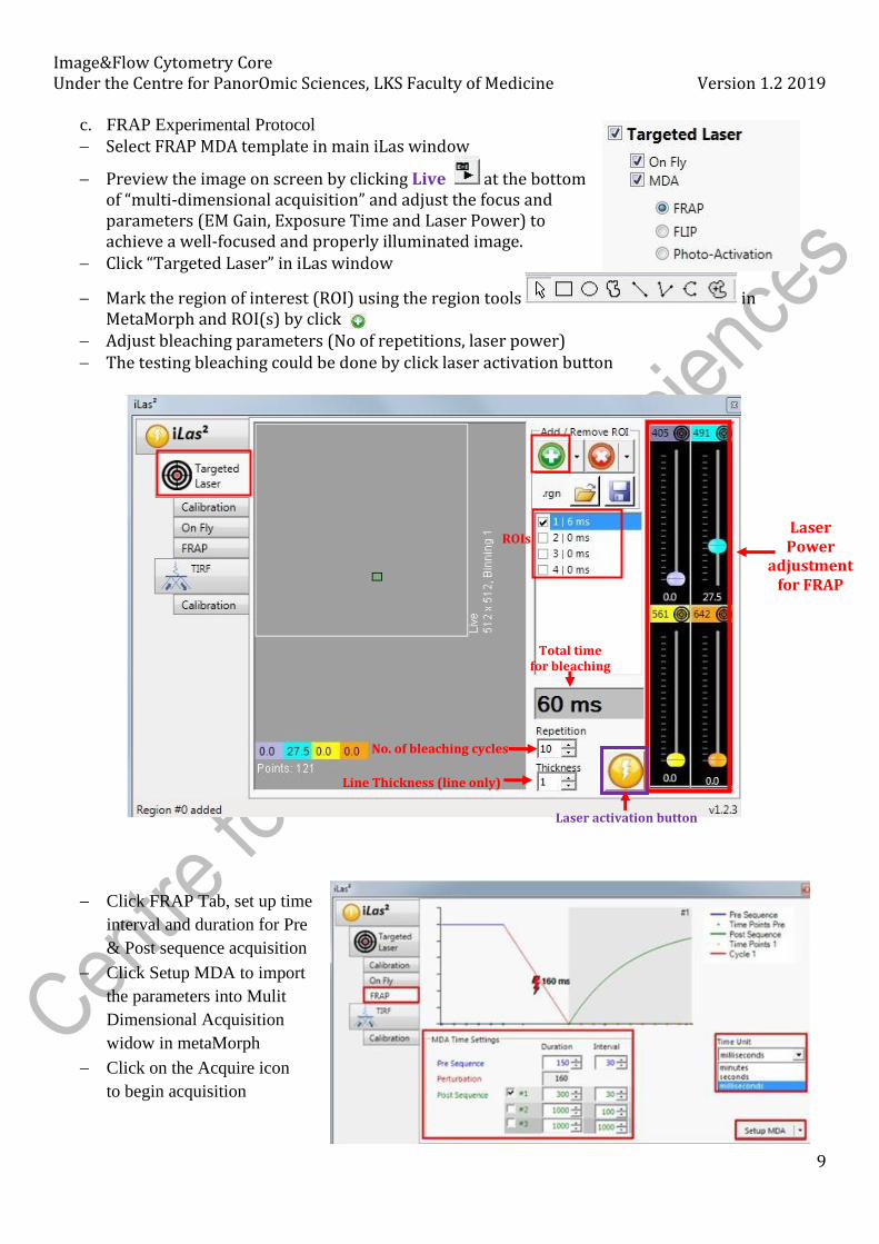
c. FRAP Experimental Protocol
− Select FRAP MDA template in main iLas window
− Preview the image on screen by clicking Live at the bottom of “multi-dimensional acquisition” and adjust the focus and parameters (EM Gain, Exposure Time and Laser Power) to achieve a well-focused and properly illuminated image.
− Click “Targeted Laser” in iLas window
− Mark the region of interest (ROI) using the region tools in MetaMorph and ROI(s) by click
− Adjust bleaching parameters (No of repetitions, laser power) − The testing bleaching could be done by click laser activation button
− Click FRAP Tab, set up time
interval and duration for Pre
& Post sequence acquisition
− Click Setup MDA to import
the parameters into Mulit
Dimensional Acquisition
widow in metaMorph
− Click on the Acquire icon
to begin acquisition
Total time for bleaching
Laser Power
adjustment for FRAP
No. of bleaching cycles
Line Thickness (line only)
Laser activation button
ROIs
Image&Flow Cytometry Core Under the Centre for PanorOmic Sciences, LKS Faculty of Medicine Version 1.2 2019
10
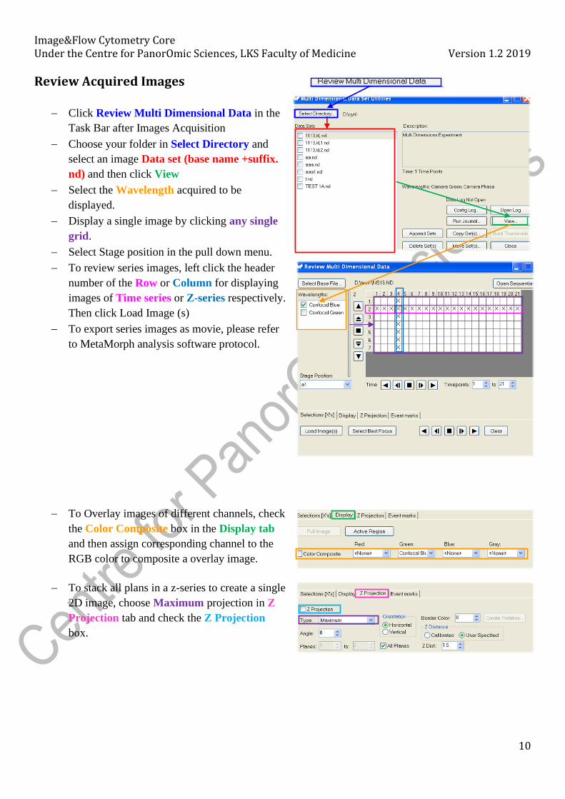
Review Acquired Images
− Click Review Multi Dimensional Data in the
Task Bar after Images Acquisition
− Choose your folder in Select Directory and
select an image Data set (base name +suffix.
nd) and then click View
− Select the Wavelength acquired to be
displayed.
− Display a single image by clicking any single
grid.
− Select Stage position in the pull down menu.
− To review series images, left click the header
number of the Row or Column for displaying
images of Time series or Z-series respectively.
Then click Load Image (s)
− To export series images as movie, please refer
to MetaMorph analysis software protocol.
− To Overlay images of different channels, check
the Color Composite box in the Display tab
and then assign corresponding channel to the
RGB color to composite a overlay image.
− To stack all plans in a z-series to create a single
2D image, choose Maximum projection in Z
Projection tab and check the Z Projection
box.
Image&Flow Cytometry Core Under the Centre for PanorOmic Sciences, LKS Faculty of Medicine Version 1.2 2019
11
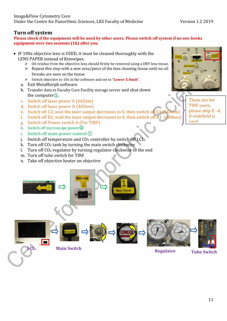
Turn off system Please check if the equipment will be used by other users. Please switch off system if no one books equipment over two sessions (1h) after you.
• IF 100x objective lens is USED, it must be cleaned thoroughly with the LENS PAPER instead of Kimwipes.
➢ Oil residue from the objective lens should firstly be removed using a DRY lens tissue.
➢ Repeat this step with a new area/piece of the lens cleaning tissue until no oil
Streaks are seen on the tissue. ➢ Switch objective to 10x in the software and set to “Lower Z-limit”.
a. Exit MetaMorph software b. Transfer data to Faculty Core Facility storage server and shut down
the computer③.
c. Switch off laser power E (642nm) d. Switch off laser power D (405nm) e. Switch off C2, wait the laser output decreases to 0, then switch off C1 (561nm) f. Switch off B2, wait the laser output decreases to 0, then switch off B1 (488nm) g. Switch off Power switch A (For TIRF) h. Switch off microscope power②
i. Switch off main power control ① j. Switch off temperature and CO2 controller by switch off LCI. k. Turn off CO2 tank by turning the main switch clockwise l. Turn off CO2 regulator by turning regulator clockwise to the end m. Turn off tube switch for TIRF n. Take off objective heater on objective
LCI
Regulator Tube Switch Main Switch
Those are for TIRF users, please skip E –A if widefield is used.