Embed Size (px)
Citation preview

CER
N-A
CC
-201
4-03
3001
/12/
2014
CERN-ACC-2014-0330
BE Department Annual Report 2013
G. Arduini, R. Billen, O. Brüning, P. Collier, R. Garoby, E. Hatziangeli, E. Jensen, R. Jones, M. Lamont, A. Mackney
Abstract The Beams Department hosts the Groups responsible for the beam generation, acceleration, diagnostics, controls and performance optimization for the whole CERN accelerator complex. This Report describes the 2013 highlights for the BE Department.

LHC: BE-ABP Group
Proton-lead collisions in the LHC
Following the first extremely successful single proton-lead pilot physics fill in 2012, the heavy-ion team in ABP led the implementation and commissioning of the first full one-month physics run at NN 5.02 TeV s = in early 2013. The luminosity was increased by an impressive factor 1000 during the one month run, and reached 29 -2 -11.1 10 cm s× at 4Z TeV. Part of the gain came from a new squeeze of the collision optics at all four experiments and from record Pb beam intensity provided by the injectors. The first physics fills finally provided the full test of the prediction that it would be possible to inject and ramp many bunches with unequal revolution frequencies and moving long-range beam-beam encounters, which included having to deal with complex bunch patterns like alternating 200 and 225ns spacings to provide all four main experiments with collisions. This was the first run in the extreme luminosity burn-off regime anticipated for Pb-Pb and p-p operation at the future HL-LHC. By the end of the run, all the experimental requests had been met. The collision conditions had been varied (some low-luminosity running for minimum-bias data-taking, reversed solenoids and beam directions) and most importantly, an integrated nucleon-nucleon luminosity equivalent to that obtained in the previous Pb-Pb runs had been achieved. This almost unprecedented mode of collider operation has been established as an integral part of the LHC programme in the long term. The last few days before the start of the long shutdown were devoted to obtaining the equivalent luminosity yet again, but with proton-proton reference collisions at NN 2.76 TeV =s
Figure 1: Summary of the first 10 days of the p-Pb run, when protons were in Beam 1, Pb in Beam 2. The proton intensity (yellow) barely changes during collisions while the Pb beam intensity (light blue) decays rapidly, determining the luminosity (pink, darker blue, green, violet for the four experiments). The rapid ramp-up of the number of bunches and the intensity in the first few days is clearly visible. Later the ALICE solenoid polarity was reversed. In the first few days, ALICE was operated at low luminosity for minimum-bias data-taking, but this was compensated later by a special fill with IP1 and IP5 separated (giving much longer luminosity lifetime). In the second half of the run (not shown) the beams were reversed.
LHC-related LS1 activities The planned replacements of main dipoles and quadrupoles required the choice of appropriate magnets from the stock of spare devices and the following formal activities steered by the
[2]

Magnet Evaluation Board. Furthermore, a follow up of the non-conformities that emerged during the LS1 period has been performed, with reporting to the official committees. LS1 was also an opportunity to collate results and review them in workshops. The 2013 LHC Optics Measurement and Correction review had as main goal to assess the readiness of the optics commissioning procedures in view of 2015 operation at higher energy and coming out of the first long shutdown. Interesting outcomes are the application of DOROS BPMs for a coupling feedback and the request of a tool to extract the LHC machine configuration at any given time, which has been adopted by the on-line model. The ICFA Mini Workshop on Beam-Beam effects in Hadron Colliders was held at CERN in March. The LHC has provided a vast amount of beam-beam observations, including head-on as well as long-range beam-beam interactions, and coherent beam-beam effects. Many new developments were discussed, including beam-beam compensation schemes, and a consensus emerged that beam-beam effects cannot be treated separately from other beam dynamics effects.
BE-BI Group
BI LS1 Work in 2013
2013 saw the completion of a detailed scheduling of BE-BI activities for LS1 in the LHC and its injectors, along with the first phase of its implementation. A total of 90 different activities involving interventions to BE-BI detectors under machine vacuum were planned as well as numerous interventions to the accompanying acquisition systems both in the tunnel and in surface buildings.
One of the first and most labour intensive tasks was the removal of the some 2500 beam-loss monitors and associated local electronics in the LHC arcs to allow access to the superconducting magnet interconnects. This activity was excellently coordinated through collaboration with IHEP, Protvino, Russia, who provided the teams working in the tunnel during the entire duration of LS1. The next priority for BE-BI was to remove LHC instruments planned for major consolidation or upgrade: several BTV monitors in the injection and dump regions for repair of RF contacts, the synchrotron radiation monitor (BSRTM) for replacement of the extraction mirror, wire scanners for a bellow re-design, Schottky monitors for complete refurbishment. Instruments such as BPMs and BTVs were also removed to allow NEG coating of beam-facing surfaces to minimise electron cloud effects.
Surface activities included the replacement of all BPM and BLM acquisition racks with temperature regulated racks to minimise the drifts in the electronics due to thermal effects observed on both systems during Run 1.
Synchrotron Light Telescope (BSRT) upgrade In 2012 excessive RF induced heating of the synchrotron light extraction mirrors of the BSRT system was observed. The problem turned out to be so severe as to require a stop of the beam to extract the in-vacuum mirror. During the design phase of the BSRT such RF heating had been taken into consideration, concluding that the addition of RF absorbing ferrites would maintain any heating to acceptable levels. In reality it turned out that the power absorbed by the ferrites was much higher than could be evacuated by radiation alone. This heated them up beyond their Curie point, making them ineffective at damping RF wakefields in the structure, in turn leading to the overheating of the mirror and its support. A crash program was immediately started in
[3]

order to solve this issue involving experts from many groups: EN-MME, BE-RF, TE-VSC and BE-ABP. Two alternative designs were developed in parallel, one an adaptation of the old support and the other a completely new design. Electromagnetic simulations and laboratory measurements on prototypes were then performed before the decision was taken to retain the new design for installation; a design which does not require ferrites and is expected to be much less susceptible to overheating. A new optical system for the synchrotron light telescope has also been designed in order to cope with the increase in the beam energy for Run II, where the resolution will be dominated by diffraction. The new optics includes two sets of lenses, one optimized for the visible range for the low energy part of the cycle, and one optimized for smaller wavelengths (250 nm) for high energy. Remote controlled actuators will allow switching between them. All the mirrors, including the extraction mirror, will also be adapted to this extended wavelength. The whole optical design is now complete with the procurement of parts, assembly and installation foreseen for 2014.
Figure 2: BSRT extraction mirror modification (left) and new optical system (right).
Ionization profile monitor studies While data taking with the LHC Beam Gas Ionization profile monitor (BGI) during protons fills it was found that the profiles obtained at high beam energy were greatly distorted. All the effects that could lead to such distortion have been investigated in detail:
1. wrong correction for camera tilt with respect to the beam direction 2. optical point-spread-function (PSF) 3. PSF due to multi-channel plate granularity 4. underestimation of electron gyro-radius
The conclusion of these studies showed that the problem was related to the beam space-charge which repels the electrons produced during ionization before they leave the beam envelope, significantly increasing their gyro-radius.
[4]
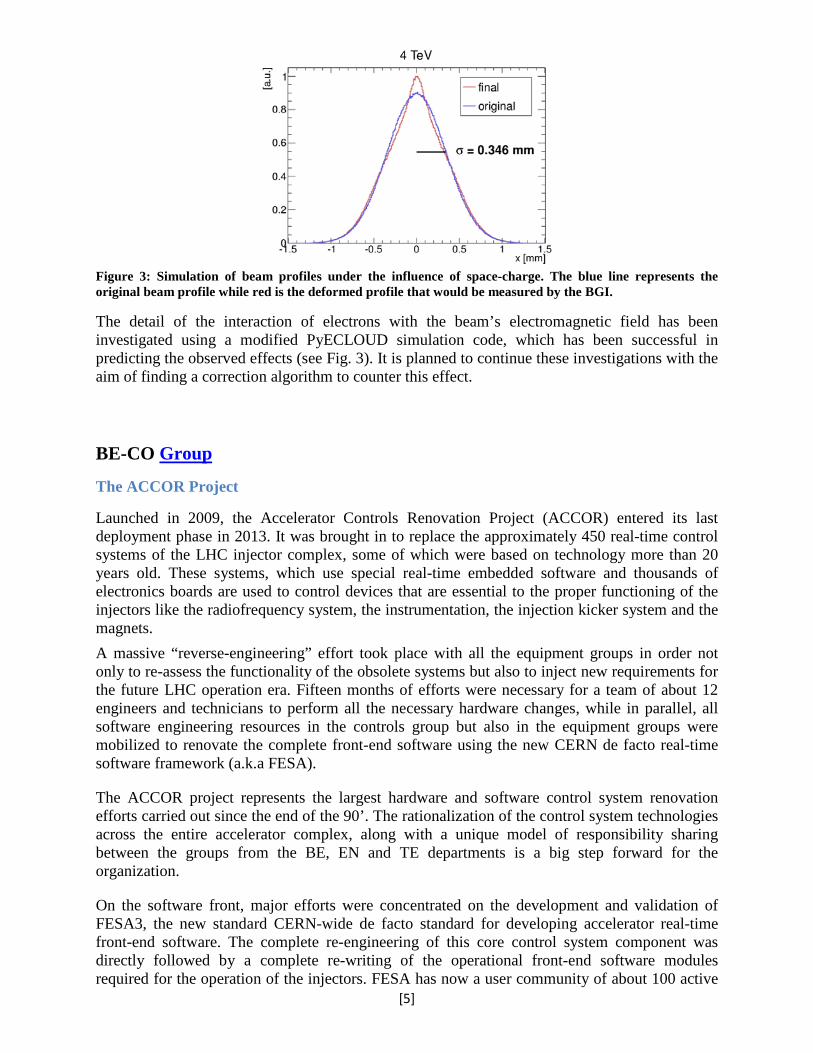
Figure 3: Simulation of beam profiles under the influence of space-charge. The blue line represents the original beam profile while red is the deformed profile that would be measured by the BGI.
The detail of the interaction of electrons with the beam’s electromagnetic field has been investigated using a modified PyECLOUD simulation code, which has been successful in predicting the observed effects (see Fig. 3). It is planned to continue these investigations with the aim of finding a correction algorithm to counter this effect.
BE-CO Group
The ACCOR Project
Launched in 2009, the Accelerator Controls Renovation Project (ACCOR) entered its last deployment phase in 2013. It was brought in to replace the approximately 450 real-time control systems of the LHC injector complex, some of which were based on technology more than 20 years old. These systems, which use special real-time embedded software and thousands of electronics boards are used to control devices that are essential to the proper functioning of the injectors like the radiofrequency system, the instrumentation, the injection kicker system and the magnets. A massive “reverse-engineering” effort took place with all the equipment groups in order not only to re-assess the functionality of the obsolete systems but also to inject new requirements for the future LHC operation era. Fifteen months of efforts were necessary for a team of about 12 engineers and technicians to perform all the necessary hardware changes, while in parallel, all software engineering resources in the controls group but also in the equipment groups were mobilized to renovate the complete front-end software using the new CERN de facto real-time software framework (a.k.a FESA).
The ACCOR project represents the largest hardware and software control system renovation efforts carried out since the end of the 90’. The rationalization of the control system technologies across the entire accelerator complex, along with a unique model of responsibility sharing between the groups from the BE, EN and TE departments is a big step forward for the organization.
On the software front, major efforts were concentrated on the development and validation of FESA3, the new standard CERN-wide de facto standard for developing accelerator real-time front-end software. The complete re-engineering of this core control system component was directly followed by a complete re-writing of the operational front-end software modules required for the operation of the injectors. FESA has now a user community of about 100 active
[5]

programmers CERN wide.
Last but not least, according to the scale and criticality of these changes, an extensive program of operational “dry runs” was established by the controls group in order to ensure a safe re-start of the injector complex
The ACCOR project, as joined effort between the BE, TE and EN departments represents the largest hardware and software control system renovation efforts carried out since the end of the 90’. The rationalization of the control system technologies across the entire accelerator complex, hardware and software wise, along with a unique model of responsibility sharing across the whole of CERN is a big step forward for the organization.
Figure 4: Controls renovation in numbers
Hardware Development On the hardware development side, the design of the 100 MS/s ADC mezzanines was completed and documented, and a first series of modules built, tested and deployed. These mezzanines complemented the TDC FMC and the SVEC and SPEC FMC carriers as part of an emerging standard CO hardware kit.
Figure 5: ADC mezzanine
[6]

After an intensive functional testing campaign, the nanoFIP chip, a radiation-tolerant, FPGA-based replacement of the microFIP used in all worldFIP agents, was tested for radiation tolerance. Results were satisfactory both for Total Ionizing Dose and Single Event Upsets. A total of 5000 chips were made available for future developments in equipment groups. Drivers The second version of the Encore tool for automated generation of Linux device driver code was successfully deployed, along with 90 drivers generated in this way by the equipment groups, for 32 and 64-bit architectures. Timing The General Machine Timing system saw a migration of the central timing facilities in CTF3 and Linac 4. The new systems run on Linux-based VME computers and use new FESA classes. A prototype of the new central timing of the AD was successfully demonstrated, following the publication and approval of its technical specifications. A new central timing system was also deployed for LHC. On the distributed timing side, 1600 timings were migrated from old TG8 modules to the newer CTR modules, controlled by the LTIM FESA class.
CMW - Controls Middleware: RDA, RBAC, JAPC, Tracing and JMS In 2013, the controls middleware infrastructure was maintained on an excellent level of performance and availability without any service disruptions for the accelerator community. During LS1, the development activities affected all core middleware services, including: RDA, Directory Service, RBAC, JAPC, Tracing and JMS, however only most critical changes are depicted below.
Figure 6: New LHC Timing Fixed Display
[7]

Following a thorough study and review of the underlying communication protocol, which was completed in mid-2012, a major development effort was undertaken in 2013 in order to develop a completely new version of the middleware core library, namely RDA3 (Remote Device Access), based on the modern, open-source ZeroMQ transport layer. RDA3 library was designed according to updated requirements of the CERN community, bringing new, improved API and advanced logic responsible for handling reliably client-server connections and their interactions. RDA3 aims to solve the outstanding issues experienced with RDA2, including: handling of ‘slow-clients’ saturating servers resources, much better scalability for handling many concurrent clients, major improvements for handling of subscriptions. By end of 2013, the fully working beta versions of RDA3 C++ & Java libraries were delivered to several projects for validation. RDA3 was also fully integrated with JAPC and RBAC frameworks, which enabled smooth integration for all major controls sub-systems (e.g.: InCA/LSA, CALS, SIS, etc.). Early performance and scalability tests, conducted together with the BE-CO Timing team, showed satisfactory results and helped to validate the internal architecture. Next challenge for RDA3 will be operational deployment in 2014, starting with the Injector complex. The BE/CO Log & Tracing service played an important role in 2013. It helped to a large extend developers to locate and identify problems in newly developed and migrated C/C++ services as it delivers important runtime events (logs, errors, exceptions). This service is being used by many projects in and outside CO and currently handles about 1000events/sec from over 3000 sources. The InCA/LSA project In 2013, the main focus for the InCA/LSA team was to perform an important consolidation of the project after more than ten years of development, adaptations and deployments of the system on almost all accelerators and experimental zones at CERN. Most of the efforts were put into three areas: review and generalizations of the LSA public APIs, refactoring of the InCA Acquisition Core in order to monitor and calculate statuses for all operational parameters, and simplifications in configuration of Working Sets and Knobs – the main generic graphical user interfaces used in the LHC and SPS injectors. Together with OP, the InCA team implemented also a new version of the Function Editor application offering a wide variety of edition capabilities, meant for the OP team but also for the equipment specialists. LHC Beam Sequencer During 2013, the possibility to pass arguments into operational sequences was introduced. The new feature allows operations to reuse existing sequences, thus significantly decreasing the number of operational sequences and their maintenance by OP.
[8]

Figure 7
The Software Interlock System (SIS) After 7 years in operation the Software Interlock System (SIS) has become an indispensable and mission-critical controls tool covering many operational areas from general machine protection to diagnostics. Currently the SIS ecosystem consists of 12 actively used processes helping the operations from the Linacs up to the LHC. Originally the typical SIS configuration was a mixture of Velocity statements, XML tags, Groovy scripts and references to Java classes, making it overly complex and difficult to understand and maintain. In response to those issues, a new way of configuring the system has been implemented aiming at simplifying the configuration process by making it faster, more user friendly and understandable for wider audiences and domain experts alike. The final solution makes use of the Groovy scripting language, as it is particularly well suited for writing a custom Domain-Specific Language (DSL). In 2013 the SIS was used to replace Compars in the PSB (Stray Field Compensation) and to replace completely the CTF Compar installation. PSB-SIS (SFC) Previously done with a set of 3 interconnected Compar, instances the new SIS-based Stray Field Compensation mechanism corrects the impact of the field coming from the PS ring magnets in the Booster DHZ magnets located in the LTB line. This line is physically located close to the PS ring. Currently the correction is done on two DHZ30 & DHZ20 magnets. The mechanism reads the historical field from the PS samplers and based on its values calculates the appropriate adjustments of the field in the Booster. If the sampler data is not available the theoretical LSA-based magnetic field is used instead. The mechanism is triggered on each Booster cycle with a forewarning -350 timing event and the results of the calculation are sent to the devices precisely before the PSB injection takes place. The outcome of the correction and the parameters used to
[9]

fine-tune it are visible via a dedicated working set. The whole can also be diagnosed using the standard SIS Gui and the Laser console. CTF-SIS In order to completely eradicate the Compar-based condition verification mechanism, the SIS instance was put in place. The full description of the system and its conditions exceed the scope of this report. It can be found at: https://edms.cern.ch/file/1252427/1/CTF3_Soft_Interlock_System.pdf. The SIS conditions are checking various elements needed to have the beam permit like vacuum, radiation, bending magnets or the gun itself. It is all summarized in the BEAM_OK permit tree. Another SIS tree is checking the GUN authorization based on the klystron conditions together with the GUN reset algorithm. The whole calculation is also based on the dynamic destination calculation with the DESTINATION tree. The klystrons can be included or excluded from the gun inhibit chain automatically based on the destination logic. The system is controllable from the SIS GUI or from a dedicated, “InCA:ified” working set (as InCA is not deployed in general in the CTF). DIAMON and LASER After the introduction in 2012 of DIAMON-2, based on C2MON (the BE-GS common monitoring platform), 2013 was mainly devoted to consolidation. Administration procedures and performance were improved. In addition, a number of new features were introduced:
- plugins for JMX (monitoring of Java applications) and CMX (monitoring of C/C++ applications, developed by BE-CO-IN) were introduced in the DIAMON graphical user interface
- a first version of the configuration editor was made available, which allows to more easily add new elements to be monitored, or change configuration parameters like thresholds
- the notification service was extended with status reports and reminders The LASER alarms system now offers many reports available to all users through the "LASER DB portal". It is possible to update alarm instructions through a new web interface. Especially for LHC operation, alarms can be hidden/displayed depending on the LHC machine mode. Post Mortem Analysis (PMA) The Logging Service Despite a reduction in logging acitivity during 2013, the logging service was still available throughout the year, and heavily relied upon to support the various hardware tests that took place.
[10]
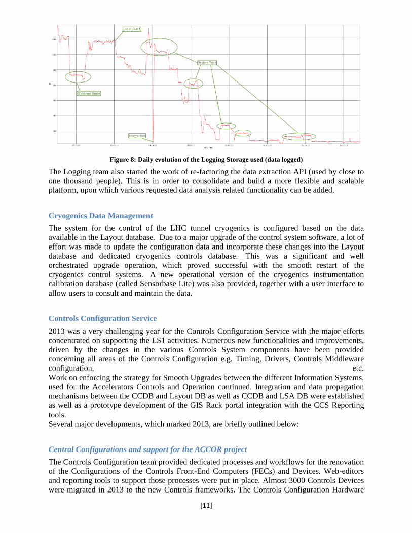
Figure 8: Daily evolution of the Logging Storage used (data logged)
The Logging team also started the work of re-factoring the data extraction API (used by close to one thousand people). This is in order to consolidate and build a more flexible and scalable platform, upon which various requested data analysis related functionality can be added. Cryogenics Data Management The system for the control of the LHC tunnel cryogenics is configured based on the data available in the Layout database. Due to a major upgrade of the control system software, a lot of effort was made to update the configuration data and incorporate these changes into the Layout database and dedicated cryogenics controls database. This was a significant and well orchestrated upgrade operation, which proved successful with the smooth restart of the cryogenics control systems. A new operational version of the cryogenics instrumentation calibration database (called Sensorbase Lite) was also provided, together with a user interface to allow users to consult and maintain the data. Controls Configuration Service 2013 was a very challenging year for the Controls Configuration Service with the major efforts concentrated on supporting the LS1 activities. Numerous new functionalities and improvements, driven by the changes in the various Controls System components have been provided concerning all areas of the Controls Configuration e.g. Timing, Drivers, Controls Middleware configuration, etc. Work on enforcing the strategy for Smooth Upgrades between the different Information Systems, used for the Accelerators Controls and Operation continued. Integration and data propagation mechanisms between the CCDB and Layout DB as well as CCDB and LSA DB were established as well as a prototype development of the GIS Rack portal integration with the CCS Reporting tools. Several major developments, which marked 2013, are briefly outlined below: Central Configurations and support for the ACCOR project The Controls Configuration team provided dedicated processes and workflows for the renovation of the Configurations of the Controls Front-End Computers (FECs) and Devices. Web-editors and reporting tools to support those processes were put in place. Almost 3000 Controls Devices were migrated in 2013 to the new Controls frameworks. The Controls Configuration Hardware
[11]

Editor was renovated with new functionalities and improvements to support the FECs and cables configurations, and incorporating images of the modules being configured. Central Configurations for FESA3 One of the major achievements for 2013 was the successful delivery of the functionality supporting the Front-End Software Architecture (FESA) v.3.1.0 framework in July 2013 and its integration with the rest of the central configuration model of the Controls System. A second major release supporting FESA v.3.2.0 was delivered in December 2013. The new functionalities included the development of the database model, business logic, APIs for class, deployment and instantiation configuration insertion and instantiation configuration extraction. A new Configuration Web based editor was provided for editing the configuration data for the devices and instantiation units. Central Configurations for the DIAMON system Development of processes and coherent data flows for propagating configurations to the Diamon Server as well as database models and web-editor marked 2013. A major release of Configuration functionality was done in April 2013 in order to support the switch to DIAMON2 as the operational version of the system. Smooth upgrades LS1 was the moment to do radical upgrades and consolidation of the Linux-based computer platforms. The DO system administrator team first created an “island” of computers only for the accelerators and services that needed to remain operational during LS1, e.g. CTF3 and Cryogenics. These computers were placed on the Meyrin site, to pave the way for the renovation of the CCR with the expected electricity outages. Then the sysadmins upgraded all backend servers and consoles to the newest version of Linux. On the front-end computers, they had to prepare and carefully validate new real-time kernels, a new 32bit kernel for SLC5 and a 64bit kernel for SLC6. The kernels are the heart of the operating system, and if they fail, the entire machine crashes miserably. LS1 also was the time to get rid of old OS versions, such as SLC4. This cannot be done from one day to another, but has to be carefully planned and coordinated with the users. Official support statements and end-of-life dates were announced and enforced for the operating system versions. SLC6/64bit is the official platform for all our systems. SLC5/32bit is obsolete for consoles and backend server after LS1, and was eradicated to over 95% in 2013. Only users who really can justify the need for this version still receive support for this version. On the front-end computers (FECs), SLC5/32bit is still supported until LS2, but users are encouraged to migrate before. The reason why more time is given to migrate away from SLC5/32bit on the FECs is that equipment groups typically have to port their low-level and device software from 32bit to 64bit, from Drivergen2 to Encore and from GM or FESA2 to FESA3. The sysadmin team made operational machines more reliable and resilient to failure. A recurrent risk of failure are shared disk partitions mounted from NFS and AFS servers. If an NFS or AFS server goes down, the connected computers freeze. Especially home directories are sensitive in this context, because all programs access them all the time. Therefore the sysadmin team migrated the home directories of all operational users (lhcop, spsop, cpsop, psbop, etc.) from NFS servers to the local hard disk of each computer. A similar decision was taken for AFS on operational backend servers: all dependency on AFS was removed because risky and not necessary. It shall be underlined in this context that both NFS and AFS continue to be heavily
[12]

used for personal home directories of human users and for development, where some risk of downtime is acceptable. Last but not least, in 2013 the sysadmin team took time to address some of its technical debt. Amongst others, they reviewed the configurations of hundreds of machines, to make them more homogeneous and coherent. They also invested time to clean up our configuration in the controls database (CCDB) and in the network database (LANDB), and to make them coherent. Software development tools The DO section provides development tools for roughly 180 Java and FESA3 developers of the whole accelerator sector, and gives second-level user support to them. Developers install these tools on their Linux or Windows Virtual Machines, and on desktop computers or laptops. The apparently simplest approach would have been to ask each user to download Eclipse from the Internet and install it themselves. However, the initial installation is only a small part of the overall work. Each user would have had to spend time and effort to customize their Eclipse with appropriate plugins and to add configurations, e.g. to use the CO release tools and to connect to the SVN repository. Users would also have had to regularly install new versions of Eclipse, which needs to be updated, as any other software. Finally, user support would have been very difficult to give with individual, incoherent installations of Eclipse on end user computers. Therefore, the DO tools team selected a commercial solution called Secure Delivery Center. They used it to create a carefully tailored Eclipse distribution both for Java and FESA3 developers, complete with in-house plugins (e.g. for FESA3 development) and 3rd party plugins for quality assurance (PMD, Findbugs, EclEmma Coverage, Sonar). All plugins are carefully configured and customized for the accelerator sector, and follow quality assurance guidelines specified by SIP, the Software Improvement Process. Thanks to this customization, developers can be productive immediately. The Eclipse distribution is updated once a week, which makes installations on all user computers coherent. This coherence and the remote assistance functionality of SDC make it much easier for the DO team to give support. JWS JWS is a tool developed by DO and it replaces the Java Webstart tool (javaws), which was used for many years to deploy and run all operational Java applications in the CCC and on any other console. JWS perfectly suits our needs, and – unlike javaws – is extensible. Amongst others, jws makes it possible to gather information about which GUI application is deployed and executed on which console, and to detect when a new version of the GUI is deployed. This information is highly useful for diagnostic purposes and Smooth Upgrades. Virtualisation 2013 The BE/CO VirtualPC infrastructure has been consolidated and expanded. An integrated tool was developed and has dramatically reduced the human time for VPC management, allowing the team to focus the attention on bug fixes and faster users support. 540 new development machines have been installed. VPC infrastructure have been integrated in DIAMON, 12 new hypervisor servers added, 150 32bit machine migrated to x64. Benchmark results and user feedback survey have defined the steps for performance improvement in 2014. Also the BE-CO Terminal Servers for experts in cryogenics, cooling, ventilation, radio-frequency, vacuum, instrumentation have been migrated to a virtual solution and a portion of these have been already migrated to the OpenStack technology. A cluster model virtual terminal servers has been tested and will become the default after LS1.
[13]

TN Security 2013 For the first time we disconnected the GPN from the TN and discovered that unfortunately, many resources and services in the GPN have a critical unexpected impact on operation control software and infrastructure. BE-CO is very active in the CNIC meetings where, with IT experts and security teams, we have discussed and put in place the solutions to fix some of the critical issued identified during the first TN disconnection tests. Weekly meeting between BE-CO and Security team took place in order to propose a vision and a strategy for the future. From the technical point of view, all Windows XP machines have been eradicated, new antivirus have been installed, new Oracle Java 7 and the JWS solution have been distributed on windows via CMF, all the control system software have been integrated and updated, all TN windows machines and servers have been patched on regular base. Finally a training security lecture for Accelerators developer newcomers have been organised. Control Room Infrastructure A BE/OP/TI backup control room has been deployed in the Firebrigade control room on the Meyrin site. The CCC/CCR network Starpoint underwent a major modification in UTP distribution resulting in a 15% capacity increase. In addition, a complete network architecture renewal with the installation of 3 new routers directly linked to our Blades enclosures allowed a very powerful 10Gb uplink broadband. As a result we now have:
• New and fully redundant electricity distribution and cooling and ventilation infrastructure with the installation of water-cooled rack doors
• Renewal of the IT starpoint and deployment of a 10Gb network
BE-OP Group
2013 Operation – introduction
2013 was a remarkable year for the operations team. The year started early with a proton-lead run in the LHC and a lead ion program in the North Area. These runs required the full complex in operation and the results were very satisfactory from a physics viewpoint. After proton-lead the LHC continued with an intermediate energy proton-proton run, and finished beam-based operations with some valuable quench tests. Operations stopped with beam on the 16th February when the large part of the complex went into powering test mode for some weeks before the start of long shutdown 1 (LS1) proper. TI operations continued, as always, in 24/7 mode for the rest of the year aided on shift by colleagues from the accelerator sections. The rest of the group dispersed across the organization and made valuable contributions in a wide number of areas. These ranged from developing quench protection system testers for industrial production to LHC interconnect weld quality control. Perhaps the most labour intensive engagement was the splice quality control campaign in the LHC. Here the group took a leading role, and, in a remarkable team effort, performed over 400,000 resistance measurements in situ in the tunnel.
[14]

LHC The first LHC run ended with a successful period were proton and lead beams were collided together for the first time at LHC. A special squeeze sequence had to be developed in a very short time, and the first collisions could be delivered on January 20th. In the running period that followed 31 nb-1 were delivered to ATLAS, ALICE and CMS. The data was delivered more or less equally in the two configurations with protons in ring 1 and lead in ring 2 as well as with lead in ring 1 and protons in ring 2. The TOTEM, ALFA and LHCf experiments also took data during this period. With the start of the Long Shutdown 1 (LS1) all members of the LHC operation sections were involved in the different activities related to the magnet consolidation. Three members of the section led the Coordination Support and Infrastructure (CSI) office for the high level coordination of all splice and magnet consolidation activities. This team monitored and coordinated the progress of the work, managed upcoming non-conformities and provided the interface between the various activities. A large team of operation group members from the different sections contributed to the quality control of the LHC main interconnection splices, an activity that was led by the LHC operation section. The busbar stabilizer splices were consolidated during this first long LHC shutdown by soldering additional Copper shunts. In view of the large number of quality controls that were integrated in the splice consolidation process, efficient and unambiguous quality control procedures were developed and implemented in the field. Direct current electrical resistance measurements were performed for the control of the busbar splices and the individual shunts. About 400 000 resistance measurements performed at room temperature before and after each consolidation step were made by the quality control teams. Roughly one third of the pre-LS1 busbar splices had to be unsoldered due to electrical or geometrical non-conformities. All those spices had re-soldered with improved quality.
BE-RF Group Physics Run II of LHC was completed in Spring 2013 with p-Pb Physics. In order to accelerate these beams, the two beam control systems for ring 1 and ring 2 are decoupled during injection and ramp with the trains of proton and lead bunches sliding against each other. Both rings follow a different frequency program. At flat top, when both beams are both sufficiently relativistic, the two beam control systems are locked together following a synchronization procedure similar to that used before the transfer of beams between two accelerators. The transition between the p-p run and the p-Pb run has been very smooth with a minimal set-up time required to put into operation the synchronization scheme. In addition transverse damper system (ADT) was also set-up for low intensity and single bunch mode damping instabilities that were feared to be provoked by the sliding p-bunch train on the Pb bunch train. At the very end of the accelerator run, a series of quench tests were conducted with five different methods – four of these used ADT as exciter. Quenches occurred during both the fast losses quench tests and the steady state quench tests, by directly provoking oscillations on the beam by the transverse damper and driving the beam into the cold aperture of a target magnet. These tests were essential to probe the true limit of losses and will be used to refine the Beam Loss Monitor Settings for Run 2. At the start of LS1, preparations started for the upgrade of the ADT system, consisting essentially in doubling the number of pick-ups and redesigning part of the LLRF electronics to gain performance and flexibility as well as increasing the possibilities for beam observation.
[15]

New electronics were commissioned for a peak detected Schottky Measurement in LHC. In SR4, civil works started to close the RF zone and install a dedicated air conditioning system, which will render the LLRF systems less sensitive to changes of the building environment (temperature, humidity). For the high power part of the ADT system, after tube failures had been observed in the similar SPS system, which were identified as lack of filament socket cooling. Triggered by this, a complete revision of the LHC system was conducted and revealed difficulties, for example a failing connection amplifier to kicker – early enough to intervene in the LHC tunnel. A study for a new clamp was launched and a 3D-printed clamp was produced based on a temperature and X-ray insensitive ceramic powder.
Figure 9: New, 3D-printed connection box and clamp between amplifier and kicker of the LHC ADT system.
The LHC RF beam observation infrastructure consisting of the pick-ups, fibre-optics and low level electronics was equally improved. The development of the peak detectors for LHC continued. Detailed information about the bunch profile and bunch position measurements in LHC provided for the ATLAS LAr Calorimeter experts helped in a better understanding of the bunch position data and detector time resolution.
High Luminosity LHC (HL-LHC) – LHC Upgrade
BE-ABP Group During 2013 the optics and layout of the high luminosity insertions of HL-LHC has been updated (HL-LHCv1.0) to take into account the latest version of the triplet design based on a 140 T/m gradient and a coil aperture of 150 mm and a complete pre-squeeze sequence developed. The work towards the specification of the magnet and field quality specifications has progressed with particular emphasis for the matching section, providing constraints for the maximum acceptable field errors in particular for the D2 recombination dipole. An updated impedance model of the LHC has been produced and the contribution of new HL-LHC components evaluated, with the confirmation that low impedance collimators are needed. The heat load on the triplet beam screen due to electron cloud has been estimated for different properties of the beam screen surface (in particular Secondary Electron Yield) taking into account the detailed geometry of the beam screen and the beam displacement of the two counter-rotating beams due to the crossing angle and separation. This study has confirmed the need of
[16]

low SEY coatings and/or clearing electrodes in the new insertion regions to keep the heat loads within the expected cooling capacity as initially planned. Similar actions will be required for the beam screen of the triplets/D1 in IR2 and IR8. Beam-beam effects are being evaluated and the results of the simulations are confirming the validity of the nominal scenario based on the * levelling m quality of the various magnets on the dynamic aperture in the presence of beam-beam effects is being addressed in order to provide additional information for the steering of the field quality of the magnets. An updated set of beam parameters consistent all through the Injector Chain and the LHC has been defined and agreed as a result of a review of the LHC and Injector Upgrade Plans. Alternative scenarios to mitigate technological risk on the most challenging components in the machine and in the detectors are being investigated and have reached a sufficient level of detail.
Figure 10: A few snapshots of the e- distribution for the present LHC and the future HL-LHC triplets.
BE-BI Group
BGV design
The Beam Gas Vertex (BGV) detector is foreseen as a possible non-invasive beam size measurement instrument for the LHC and its luminosity upgrade. This technique is based on the reconstruction of beam-gas interaction vertices, where the charged particles produced in inelastic beam-gas interactions are measured with high-precision tracking detectors. The chosen strategy is to first demonstrate the potential of the beam-gas imaging technique for the LHC by installing and commissioning a prototype BGV system on one beam in the LHC by the end of 2015. A collaboration between CERN, EPFL Lausanne, and RWTH Aachen has been formed to design and constuct this detector. The results and experience will be used to develop a more advanced BGV system which could be installed on both beams of the LHC during Long Shutdown 2. The vacuum chamber concept and design was carried out in 2013 and used technology and methods developed for the LHC experiments. A thin window, to minimise the impact on secondary particles created in the gas volume, was developed and optimised using the ANSYS
[17]

finite element code (see Fig. 11 below). The thickness varies as a function of the radius down to a minimum of 0.8 mm closest to the beam axis where the particle flux is highest. The material selected for the window was the AA2219 aluminium alloy, extensively qualified at CERN as a weldable, bakeable alloy for experimental vacuum chambers.
Figure 11: Non-linear buckling model of the BGV exit window
The ‘downstream’ chamber element, also depicted in Fig. 11, around which the scintillating fibre detectors will be placed, was likewise optimised to allow it to be machined from the same block as the exit window. Flanges on the window chamber are of an explosion-bonded bi-metallic design. All other components were selected to be procurable within the tight project schedule and to present the lowest chance of technical problems during the production phase.
BE-RF Group
HL-LHC Crab Cavities
Fabrication of three prototype crab cavities to validate the compact cavity designs were completed with the first successful tests performed for the 4-Rod and the RF dipole cavities. Although the first tests of the 4-Rod cavity revealed poor results both in 𝑄𝑄0 and kick voltage, a subsequent surface treatment was sufficient to establish the nominal kick field of 3.4 MV with a factor 4 or more higher than surface resistance that was specified. The RF dipole tests revealed excellent results with a kick voltage reach of approximately 7 MV (twice the specified) and also with a slightly higher surface resistance which was attributed to the stainless steel flanges. The double quarter-wave cavity was prepared for re-testing after the first tests revealed a contamination of the inner surface during the surface treatment. An important decision to terminate the development of the elliptical designs in favour of successful results of the one of the crab cavities was taken. A significant effort is being directed toward the engineering design of the dressed cavities and cryomodule for the SPS tests.
[18]
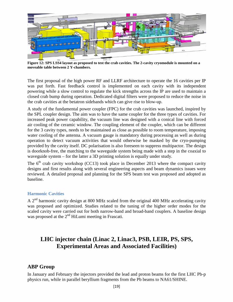
Figure 12: SPS LSS4 layout as proposed to test the crab cavities. The 2-cavity cryomodule is mounted on a moveable table between 2 Y-chambers.
The first proposal of the high power RF and LLRF architecture to operate the 16 cavities per IP was put forth. Fast feedback control is implemented on each cavity with its independent powering while a slow control to regulate the kick strengths across the IP are used to maintain a closed crab bump during operation. Dedicated digital filters were proposed to reduce the noise in the crab cavities at the betatron sidebands which can give rise to blow-up. A study of the fundamental power coupler (FPC) for the crab cavities was launched, inspired by the SPL coupler design. The aim was to have the same coupler for the three types of cavities. For increased peak power capability, the vacuum line was designed with a conical line with forced air cooling of the ceramic window. The coupling element of the coupler, which can be different for the 3 cavity types, needs to be maintained as close as possible to room temperature, imposing water cooling of the antenna. A vacuum gauge is mandatory during processing as well as during operation to detect vacuum activities that would otherwise be masked by the cryo-pumping provided by the cavity itself. DC polarisation is also foreseen to suppress multipactor. The design is doorknob-free, the matching to the waveguide system being made with a step in the coaxial to waveguide system – for the latter a 3D printing solution is equally under study. The 6th crab cavity workshop (CC13) took place in December 2013 where the compact cavity designs and first results along with several engineering aspects and beam dynamics issues were reviewed. A detailed proposal and planning for the SPS beam test was proposed and adopted as baseline. Harmonic Cavities A 2nd harmonic cavity design at 800 MHz scaled from the original 400 MHz accelerating cavity was proposed and optimized. Studies related to the tuning of the higher order modes for the scaled cavity were carried out for both narrow-band and broad-band couplers. A baseline design was proposed at the 2nd HiLumi meeting in Frascati.
LHC injector chain (Linac 2, Linac3, PSB, LEIR, PS, SPS, Experimental Areas and Associated Facilities)
ABP Group In January and February the injectors provided the lead and proton beams for the first LHC Pb-p physics run, while in parallel beryllium fragments from the Pb beams to NA61/SHINE.
[19]

All the accelerators profited from the last running to complete beam dynamics MDs, and in particular to collect all data needed before LS1. LEIR produced a higher Pb beam intensity (5.5x10⁸ vs. the goal of 4.5x10⁸ ions per bunch) at the design transverse emittance (ε*RMS=0.7μm) and at a lower long. emittance (8.1eVs matched area) than the design value (10.4eVs matched area). Once the physics was finished, the injectors entered their own long shutdown including many long overdue maintenance and renovation tasks. At Linac2 the main modifications were the refurbishment of the chilled water system, a new access system, upgrades on beam diagnostic elements, improvements to the vacuum pumping and the general control hardware and software renovations. ABP contributed to the definition for a strategy for the PSB magnet realignment campaign where thanks to the availability of new orbit correctors, the decision was to realign radially to zero and vertically to a smooth line all quadrupoles and pickups in the ring, and bending magnets in the vertical plane whenever they could represent an aperture restriction, while in the past the quadrupoles were deliberately misaligned by up to +/-4mm in horizontal and vertical planes as the only means to correct the COD. Furthermore, analysis and simulations work lead to the build-up of the linear optics model of the machine via kick-response measurements and the benchmarking of space-charge codes with measurements. The PS underwent a series of interventions. A new wide-band RF cavity, based on Finemet technology, was installed and will be used as longitudinal kicker to reduce coupled-bunch instabilities for the current and future LHC-type beams. A new one-turn delay feedback was installed on all 10 MHz cavities. Two new electron-cloud monitors were installed in the beam pipe of a main magnet. These detectors should observe for the first time the electron cloud, forming during the LHC beam extraction process, in a combined-function magnet. On the theoretical side, progresses on some collective effects limiting the machine performance have been achieved: space-charge studies brought new understating of the interplay between beam- and lattice-induced resonances; the long-standing issue of the intra-bunch beam oscillations observed during the first turns was explained by the combined effect of indirect space charge and large injection errors; the longitudinal and transverse impedance models have been further developed. The shielding on top of the Route Goward and the extraction region 16 was significantly increased according to the new RP requirements, as well as a dummy septum being installed which will lead to better control of losses once commissioned. At Linac3, from March to May the argon ion beam was set-up in the source and linac for the first time. Roughly ten times the particle current compared to lead could be reached at the end of the linac, but the test demonstrated that argon beam and plasma causes considerable damage in particular to the source which will need regular maintenance during operation.
BE-BI Group
Fast Beam Current Transformer Renovation in the PSB and PS
A total of 11 Fast Beam Current Transformers (BCTs) are used to measure the transfer efficiency along the PS complex transfer lines. These are all old, of different designs, with many suffering from radiation damage. This makes their maintenance very difficult and leads to a reduced accuracy in transfer efficiency measurements. A new Fast BCT design has therefore been produced, based on a commercial magnetic toroid and optimized for minimum beam position
[20]

and bunch length dependency. Several studies were made prior to LS1 confirming a maximum error of ~1% for a ±30mm beam displacement, well within specifications. All 11 of the old fast BCTs will therefore be replaced by this new version. Fig. 13 below pictures a new Fast BCT installed in the TT2 line and the typical signals acquired. The scope-like acquisition plot shown allows the remote setting-up of measurement gates.
Figure 13: Left: New BCT in the TT2 line; Right:Beam acquisition followed by a calibration pulse
Linac2, Linac3 and PSB/PS transfer line BCT acquisition upgrade During LS1, old analogue electronics consisting of integrators, gate generators and calibrators were replaced with a single VME “TRIC” module which reproduces the above mentioned functions in the digital domain. The advantages of the new system are an integrated design with remote control and advanced acquisition capabilities. The same TRIC hardware, but with a different front-end software (FESA class), will be used on all PSB fast extraction transfer lines (BT, BTM, BTP and BTY) as well as the TT2 line from the PS. A total of 24 BCTs are in the process of being upgraded with the new TRIC-based electronics and software. PSB extraction BPM renovation The BT line recombines the four vertical PSB extraction lines into a single line at the BT.U40 location. Downstream of this monitor a bending magnet sends the beam either to the PS via the BTP line, to the Isolde experiment via the BTY line, or to the measurement line BTM. Since 2009, the beam trajectory system of the Booster extraction lines has undergone an extensive consolidation programme. This work was completed in LS1. The old capacitive monitors have been replaced by larger aperture inductive monitors and two new monitors have been added near the Isolde target station (see Fig. 14). All in all twenty monitors and two spares have been produced. As the old acquisition chain would not be able to cope with the increase of beam intensity after the PSB energy upgrade, the electronics and low-level software was also renovated.
[21]

Figure 14: New Inductive BPM in the GPS Isolde line.
PS complex SEM grid electronics renovation Secondary emission wire harps, also known as SEM-grids or SEM-fils, are routinely used to measure the transverse profiles of low energy particle beams in the injector complex. The acquisition system of all these SEM-GRIDs was close to the end of its life, showing clear signs of increased unreliability. The system required continuous corrective maintenance and some component had already become obsolete. The development of a completely new system had been in the pipeline for years and was finally merged with the development of the LINAC4 SEM-GRID system. At the beginning of LS1 the design was phase was over, with prototypes tested with beam in both LEIR and TT2. During 2013 hundreds of these electronic cards were therefore produced, tested and installed (Fig. 15). The new system is expected to have a better performance than the old one and in particular to be much more reliable and maintainable. Care has been taken to introduce a lot of self-diagnostics for the status of the electronics chain and also the possibility of checking the status of the wires. However, while this latter functionality is implemented for the new LINAC4 devices, the rest of the injector complex cannot profit from this until hardware modifications are made to the SEM-GRID heads (in vacuum) which was not in the scope of this current upgrade.
Figure 15: New SEM-GRID acquisition system. Left to right: Control and acquisition crates, front-end amplifier near the detector heads, close-up of a front end amplifier box.
FE amplifiers
Booster tunnel
Linac 3
PLC
PLC PLC
VME
Control
Control
[22]
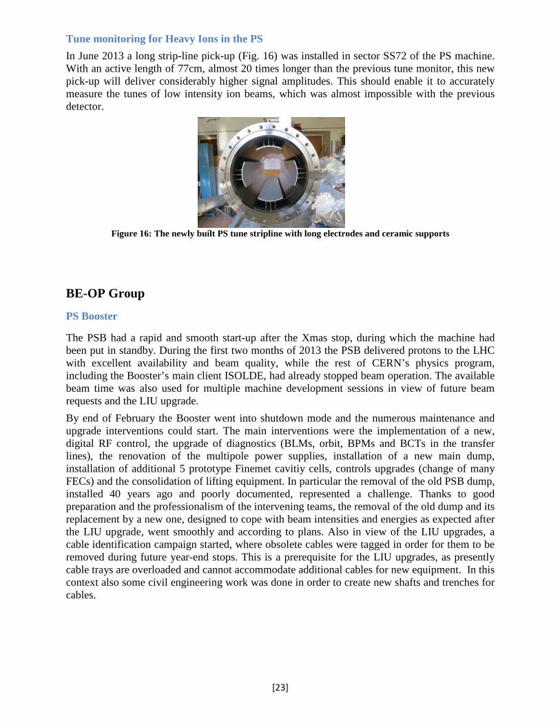
Tune monitoring for Heavy Ions in the PS In June 2013 a long strip-line pick-up (Fig. 16) was installed in sector SS72 of the PS machine. With an active length of 77cm, almost 20 times longer than the previous tune monitor, this new pick-up will deliver considerably higher signal amplitudes. This should enable it to accurately measure the tunes of low intensity ion beams, which was almost impossible with the previous detector.
Figure 16: The newly built PS tune stripline with long electrodes and ceramic supports
BE-OP Group
PS Booster
The PSB had a rapid and smooth start-up after the Xmas stop, during which the machine had been put in standby. During the first two months of 2013 the PSB delivered protons to the LHC with excellent availability and beam quality, while the rest of CERN’s physics program, including the Booster’s main client ISOLDE, had already stopped beam operation. The available beam time was also used for multiple machine development sessions in view of future beam requests and the LIU upgrade. By end of February the Booster went into shutdown mode and the numerous maintenance and upgrade interventions could start. The main interventions were the implementation of a new, digital RF control, the upgrade of diagnostics (BLMs, orbit, BPMs and BCTs in the transfer lines), the renovation of the multipole power supplies, installation of a new main dump, installation of additional 5 prototype Finemet cavitiy cells, controls upgrades (change of many FECs) and the consolidation of lifting equipment. In particular the removal of the old PSB dump, installed 40 years ago and poorly documented, represented a challenge. Thanks to good preparation and the professionalism of the intervening teams, the removal of the old dump and its replacement by a new one, designed to cope with beam intensities and energies as expected after the LIU upgrade, went smoothly and according to plans. Also in view of the LIU upgrades, a cable identification campaign started, where obsolete cables were tagged in order for them to be removed during future year-end stops. This is a prerequisite for the LIU upgrades, as presently cable trays are overloaded and cannot accommodate additional cables for new equipment. In this context also some civil engineering work was done in order to create new shafts and trenches for cables.
[23]
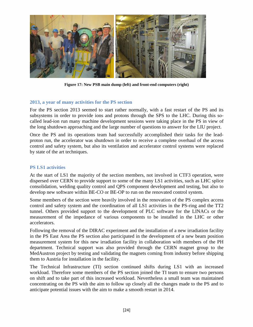
Figure 17: New PSB main dump (left) and front-end computers (right)
2013, a year of many activities for the PS section For the PS section 2013 seemed to start rather normally, with a fast restart of the PS and its subsystems in order to provide ions and protons through the SPS to the LHC. During this so-called lead-ion run many machine development sessions were taking place in the PS in view of the long shutdown approaching and the large number of questions to answer for the LIU project. Once the PS and its operations team had successfully accomplished their tasks for the lead-proton run, the accelerator was shutdown in order to receive a complete overhaul of the access control and safety system, but also its ventilation and accelerator control systems were replaced by state of the art techniques. PS LS1 activities At the start of LS1 the majority of the section members, not involved in CTF3 operation, were dispersed over CERN to provide support to some of the many LS1 activities, such as LHC splice consolidation, welding quality control and QPS component development and testing, but also to develop new software within BE-CO or BE-OP to run on the renovated control system. Some members of the section were heavily involved in the renovation of the PS complex access control and safety system and the coordination of all LS1 activities in the PS-ring and the TT2 tunnel. Others provided support to the development of PLC software for the LINACs or the measurement of the impedance of various components to be installed in the LHC or other accelerators. Following the removal of the DIRAC experiment and the installation of a new irradiation facility in the PS East Area the PS section also participated in the development of a new beam position measurement system for this new irradiation facility in collaboration with members of the PH department. Technical support was also provided through the CERN magnet group to the MedAustron project by testing and validating the magnets coming from industry before shipping them to Austria for installation in the facility. The Technical Infrastructure (TI) section continued shifts during LS1 with an increased workload. Therefore some members of the PS section joined the TI team to ensure two persons on shift and to take part of this increased workload. Nevertheless a small team was maintained concentrating on the PS with the aim to follow up closely all the changes made to the PS and to anticipate potential issues with the aim to make a smooth restart in 2014.
[24]
The CLIC team is looking forward now to start beam operation to continue the experiments, and the PS operations team is eager to restart the PS and to provide the operational beams to the different users. SPS The first two months of the year, SPS delivered 200 nsec proton and Pb beams for the LHC proton-ion run. The intensity of the Pb-bunches in the LHC reached 1.4 108 ions, resulting in twice the design brightness. In the meantime, Pb-ions were delivered to the north area at three different energies. SPS stopped on Saturday morning, February 16th, marking the start of LS1. During the long shutdown, the SPS operations crew was involved in many activities. Several people contributed to the SPS shutdown work. They were strongly involved in the removal and re-installation of a big part of TT10, in order to allow civil engineering the repair of cracks in floor and ceiling. SPS-OP took also the responsibility to remove, as much as possible, bad earth loops on the vacuum chamber, due to wrong connections and damaged insulation on flenses. In sextant 5 and sextant 6 the vertical level of the SPS magnets was raised in order to bring them back in an adjustable region for the geometers. SPS crew was also investigating suspected aperture limits and rectified them where needed. A lot of effort was spent on software development. New function generators (FGC’s) required fundamental changes in LSA, power convertor control, cycle generation and interlocks. A lot of effort went also in the new control software for RF power, low level RF as well as the damper. A vast majority of the applications used for running the SPS had to be adapted to the new FESA3. SPS-OP also produced software for LHC (e.g. machine protection, collimator control,…) and for the north area. Some people were detached to other departments where some of their special competences could be put to profit. One person worked in the mechanical measurement lab. He contributed to the study of the vibrations on cry-compressors provoking shafts to break. The problem could be identified and a cure was implemented. Another SPS-OP crew member was temporarily detached to a chemical lab, doing surface analyses on coated material bombarded with electrons, as part of the electron cloud studies. Most of the SPS crew participated, at one time or another, in the splice quality control campaign in the LHC tunnel. Some members were more involved than others, taking up training and coordination responsibilities. One person was coordinating the R2E activity in point 7. SPS crew also took a fair share in TI operations, a very busy job during LS1.
BE-RF Group
PS
In addition to the extensive general maintenance program performed, two major interventions took place during the 2013 shut-down on the high power RF systems of the PS, one to fix a problem with the PS 40 MHz RF system, the other to reconfigure the cavity groups of the 10 MHz system. The problem with the PSC40-78 system, where the final amplifier had caught fire in August 2012, concerned the RF power coupler. The large heat that developed during the incident in the transmission line between the amplifier and the cavity caused detachment of the RF coupler, which fell inside the cavity. Accurate cleaning of the cavity surface and the reconstruction of the RF coupler allowed re-establishing the full power operation. The PS 10 MHz system, whose 10 cavities are arranged in groups, requires that cavities in the same group
[25]

follow the same voltage and frequency program, was reconfigured to gain flexibility for their use by the LLRF during sophisitaced beam gymnastics.
Figure 18: Repaired power coupler of the PS 40 MHz cavity (left), rearranging the ferrite bias of the PS 10 MHz systems (centre), repair work on half a PS 10 MHz cavity SPS During the SPS operation period, the LHC beam quality was the main preoccupation. This concerned especially the 200 ns beam. Several improvements of the SPS low level were made during the 2013 run and the shut-down. The new VME module for cavity loop gain and phase measurement was commissioned and the noise performance of the 10 MHz reference distribution from the LHC to the SPS was improved. The response of all SPS BPW pick-ups was measured and the electrical isolation of several pick-ups in the SPS was restored in collaboration with the Operations Group and the Vacuum Group. SPS control systems are being renovated in LS1 which required finding inventive solutions for the different type of hardware used. A key VME board developed was a specific function generator with 250 µs granularity and 32 bit precision beyond what will be available from the EPC group after LS2. All obsolete G64 chassis were removed in the SPS Faraday cage and replaced by new VME crates. Work on the renovation of the beam control systems for the 800 MHz system continued with feedback functionalities that will be tested during the SPS run in 2014. Studies on noise were carried out at the end of the 2013 run to identify sources of the degraded lifetime of the ion beam. The studies led to improvement in the ion beam control system that is implemented during LS1. The SPS frequency program was renovated using LHC and Linac4-style VME hardware with new firmware, DSP code and FESA front-end software. It will provide full multi-cycling operation. Frequency generation during the ramp and rephasing towards LHC has been demonstrated under simulated conditions in the lab. A new SPS RF MMI graphical user interface is being developed on top of LSA, which allows control of all the Low-Level RF equipment. The first series amplifiers of the new IOT based system for the TWC800 system arrived in 2013. All old eight klystron transmitters were completely dismantled and six new IOT transmitters were successfully commissioned.
[26]

Figure 19: The new, IOT based amplifiers of the SPS TWC800 system during commissioning
In March 2013, at the end of run 1, high power tests were made with both Siemens and Philips power stations of the SPS 200 MHz system. The systems were able to deliver 1.05 MW peak power per cavity as well as the maximum 750 kW CW power. Weak items of the systems were identified and improvements will be implemented to reliably operate these systems up to these power levels for run 2. RF Firmware/software development tools The “Cheburashka” memory map management tool has been further developed and is now in operational use. This is a tool for consistent definition of a board’s memory map between the FPGA firmware, the Linux device driver and the FESA class. The memory map is entered using the graphical editor, and stored as an XML file. The tool can then be used to generate:
• VHDL for inclusion in the FPGA firmware • a configuration file for the BE-CO Linux device driver generation tool • C language header files for the DSP code • Web documentation of the memory map • A complete FESA 2.10 or FESA 3 class giving register-level access for testing of
hardware. Cheburashka also standardizes commonly used features such as acquisition memory buffers, allowing efficient implementation of firmware and software with rapid development cycles.
LHC Injector Upgrade
BE-ABP Group The main goal of the LHC Injectors Upgrade (LIU) project is to boost the performance of the LHC injectors in order to match the (High Luminosity LHC) HL-LHC requirements. For this purpose, brightness and intensity of the physics production beams must be increased by the primary upgrades of injecting 160MeV H- ions into the PSB; raising the PSB to PS transfer energy to 2GeV; and doubling the RF power and mitigating electron cloud in the SPS.
[27]

Further upgrades are also necessary across PSB, PS and SPS to make them capable of accelerating and manipulating these higher intensity beams (e.g., impedance reduction, feedback systems, resonance compensation, improved instrumentation), and the LIU project works together with the consolidation project to take the actions necessary to provide reliable operation and lifetime into the HL-LHC era (i.e. until ~2035), such as upgrade or replace all ageing equipment (e.g., power supplies, magnets, RF) and improve radioprotection measures (e.g., shielding, ventilation). The injectors of the ion chain (Linac3, LEIR, PS, SPS) also have a planned improvement to produce beam parameters at the LHC injection that can meet the post-LS2 Pb-Pb and p-Pb luminosity goals. Machine development studies, backed up with simulation effort is essential in order to investigate and test new techniques, operational developments and production schemes; test hardware; provide detailed beam parameter estimations after LIU and define the best final path for LIU works in LS2 During the last two months of operational beam, machine development in the injectors concentrated on: • Optics modeling, space charge and transverse stability at the PSB. Furthermore, the final tests were performed to be ready to fully deploy YASP and digital LLRF control at the restart after LS1. • Space charge, resonance compensation, transverse and longitudinal stability, impedance localization and electron cloud at the PS. Important steps were taken towards making the transverse damper operational against head-tail instabilities at low energy and electron cloud instabilities at 26 GeV/c. • Impedance measurements (transverse and longitudinal), TMCI thresholds in Q20 and Q26, production of two batches of doublet beam, stabilization of single bunch with high bandwidth feedback system. The efficiency of the doublet beam to enhance electron cloud was proven, opening to its potential use in future scrubbing runs not only at the SPS but also at the LHC. Also the impedance measurements, together with detailed electromagnetic and beam dynamics simulations, proved to be instrumental to the identification of the vacuum flanges as a major longitudinal impedance source, which needs to be mitigated in order to extend the intensity reach of the LHC beams out of the SPS. A table listing all the beam parameters across the whole LHC injection chain for the existing LHC beam production schemes (standard and BCMS), was produced in order to establish the achievable parameter range for a baseline set of LIU upgrades. This exercise allowed us to highlight both the impact of the LIU planned improvements and the future bottlenecks. During the long shutdown, installations required for LIU already began with all the circular proton injectors receiving new equipment for RF, instrumentation, magnets and the coating of 2 full cells in the SPS with amorphous carbon coating to reduce electron cloud. On the ion chain, analysis of beam data at LEIR revealed a positive chromaticity in the vertical plan, coherent transverse motion at RF-capture; a separation of the low energy beam loss from the magnetic ramp and that the machine working point is very close to a 4th order resonance. These findings are vital in the quest to resolve the performance limiting low-energy-beam-loss in LEIR, in order to reach the LIU Ions goals of 8x10⁸ ions/bunch at extraction by the end of LS2. The Space Charge 2013 workshop took place at CERN and the program is available at the indico page: https://indico.cern.ch/conferenceDisplay.py?confId=221441. The workshop has shown a rich activity on space charge related topics at many labs including experimental studies and simulation benchmarking, where in particular noise in PIC codes provoked much discussion, and
[28]

the decision has been taken to use the GSI test suite for benchmarking of frozen space charge models also for the benchmarking of PIC codes, both 2.5D and 3D.
BE-BI Group
Beam Loss Measurement for the LHC Injectors
The existing beam loss monitoring (BLM) systems in the PS Booster and PS use outdated electronics and are based on old Aluminium Cathode Emission Monitors (ACEM). The LIU baseline is to upgrade the PSB and PS with systems similar to what is currently being developed for Linac4, with their transfer lines equipped with the same system as part of BE-BI consolidation requests. The SPS will be consolidated at a later stage with a different type of electronics more suited to its large ring architecture.
Figure 20: Overview of the BLM system under development for the CERN Injector Complex
The main design goals for the new injector BLM system are to cover a high dynamic loss range and to provide high reliability and availability, all based on a generic, modular and highly configurable architecture. With this in mind the acquisition electronics will be compatible with several detector types. In the majority of the cases the detectors will be ionisation chambers similar to those used in the LHC. Double-shielded coaxial cables have installed to transport the signal between the detector and the front-end electronics, to minimise the amount of EMC noise introduced. The digitisation is based on a new design concept that allows the measurement of currents from 10 pA to 200 mA, equivalent to a dynamic range in the order of 1010. The processing part of the system will keep track of several integrated loss windows, ranging from 2 μs to 1.2 s, for each detector. A block diagram of the architecture of the system can be seen in Fig 20. The first prototypes of this electronics have now been qualified with beam and production has started on a pre-series to be installed in parallel to the old system of the PSB during LS1. PSB H- injection BTVs The LINAC4 H- beams will be injected into the PSB using a carbon stripping foil via a charge exchange mechanism. In order to tune the injection trajectories and to monitor the status of the stripping foils beam observation using a radiation hard camera (BTV) is foreseen. This BTV should be able to image both the beam (just downstream of the foil) and the foil itself (for integrity inspection). Moreover the system has to be integrated into an already crowded area. The image of the beam is produced on a doped alumina scintillating screen (CHROMOX) that can be moved in and out of the beam by an electric actuator. The imaging optical system is composed of two mirrors and a camera lens with one of the mirrors placed inside the vacuum tank. A
[29]
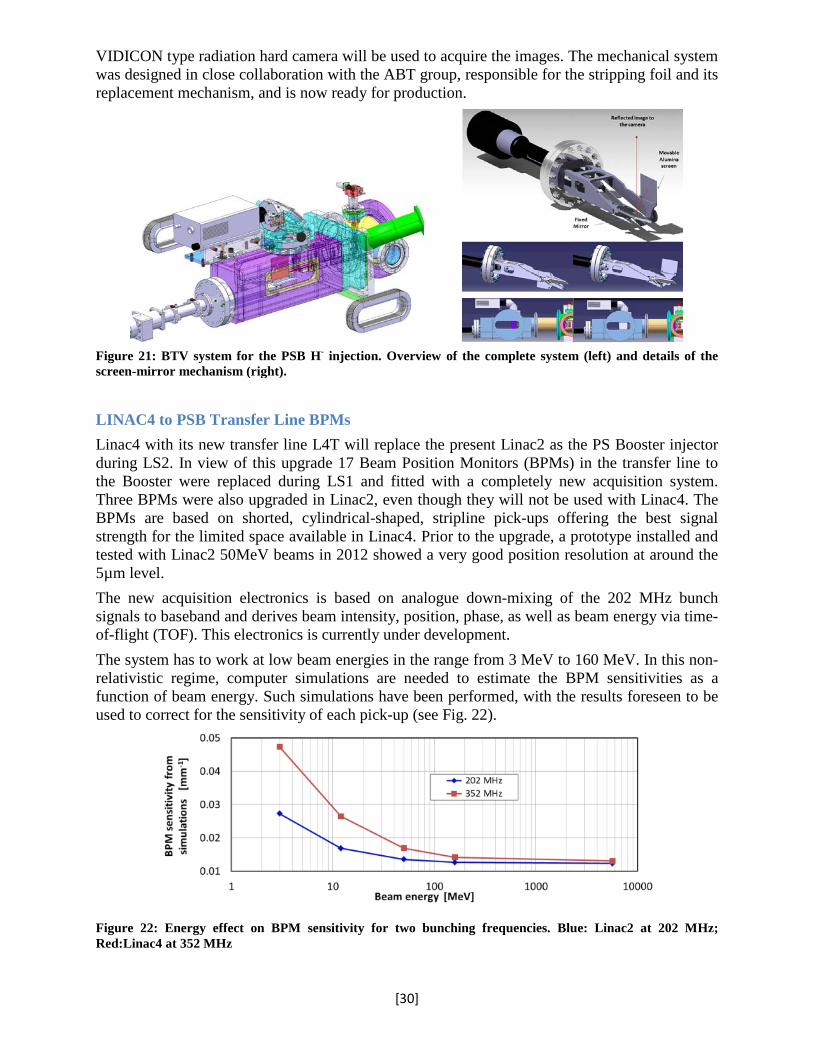
VIDICON type radiation hard camera will be used to acquire the images. The mechanical system was designed in close collaboration with the ABT group, responsible for the stripping foil and its replacement mechanism, and is now ready for production.
Figure 21: BTV system for the PSB H- injection. Overview of the complete system (left) and details of the screen-mirror mechanism (right).
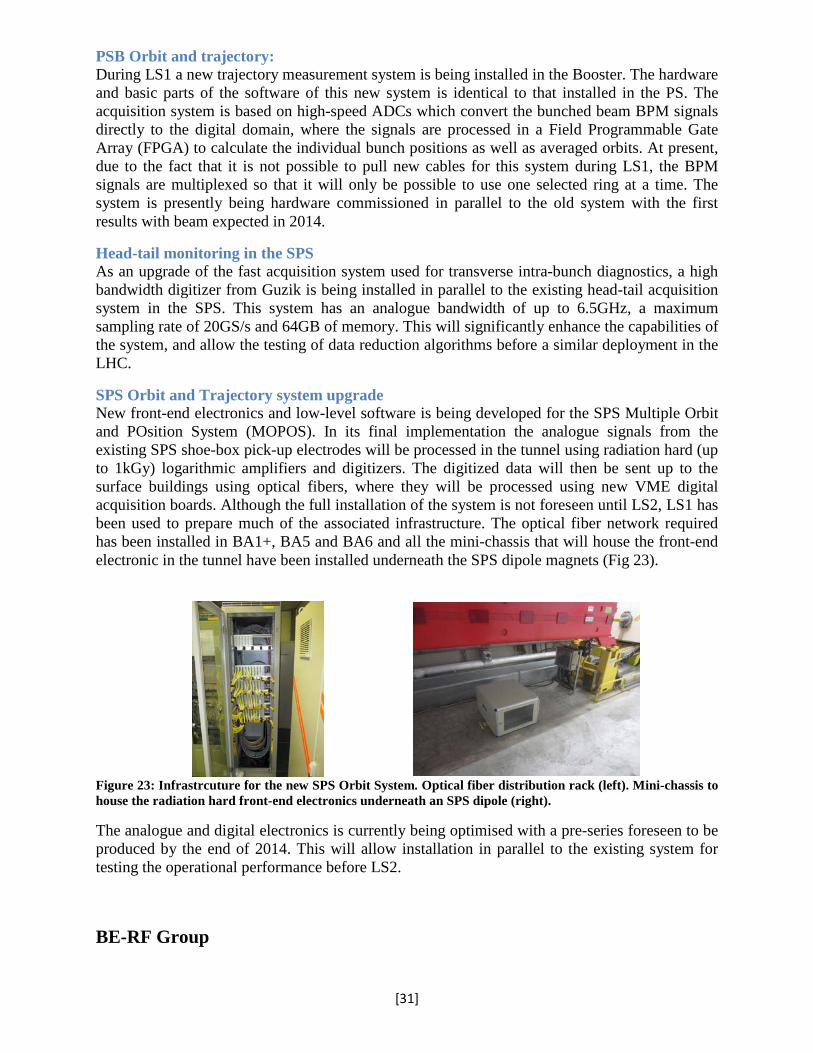
LINAC4 to PSB Transfer Line BPMs Linac4 with its new transfer line L4T will replace the present Linac2 as the PS Booster injector during LS2. In view of this upgrade 17 Beam Position Monitors (BPMs) in the transfer line to the Booster were replaced during LS1 and fitted with a completely new acquisition system. Three BPMs were also upgraded in Linac2, even though they will not be used with Linac4. The BPMs are based on shorted, cylindrical-shaped, stripline pick-ups offering the best signal strength for the limited space available in Linac4. Prior to the upgrade, a prototype installed and tested with Linac2 50MeV beams in 2012 showed a very good position resolution at around the 5µm level. The new acquisition electronics is based on analogue down-mixing of the 202 MHz bunch signals to baseband and derives beam intensity, position, phase, as well as beam energy via time-of-flight (TOF). This electronics is currently under development. The system has to work at low beam energies in the range from 3 MeV to 160 MeV. In this non-relativistic regime, computer simulations are needed to estimate the BPM sensitivities as a function of beam energy. Such simulations have been performed, with the results foreseen to be used to correct for the sensitivity of each pick-up (see Fig. 22).
Figure 22: Energy effect on BPM sensitivity for two bunching frequencies. Blue: Linac2 at 202 MHz; Red:Linac4 at 352 MHz
[30]
PSB Orbit and trajectory: During LS1 a new trajectory measurement system is being installed in the Booster. The hardware and basic parts of the software of this new system is identical to that installed in the PS. The acquisition system is based on high-speed ADCs which convert the bunched beam BPM signals directly to the digital domain, where the signals are processed in a Field Programmable Gate Array (FPGA) to calculate the individual bunch positions as well as averaged orbits. At present, due to the fact that it is not possible to pull new cables for this system during LS1, the BPM signals are multiplexed so that it will only be possible to use one selected ring at a time. The system is presently being hardware commissioned in parallel to the old system with the first results with beam expected in 2014.
Head-tail monitoring in the SPS As an upgrade of the fast acquisition system used for transverse intra-bunch diagnostics, a high bandwidth digitizer from Guzik is being installed in parallel to the existing head-tail acquisition system in the SPS. This system has an analogue bandwidth of up to 6.5GHz, a maximum sampling rate of 20GS/s and 64GB of memory. This will significantly enhance the capabilities of the system, and allow the testing of data reduction algorithms before a similar deployment in the LHC.
SPS Orbit and Trajectory system upgrade New front-end electronics and low-level software is being developed for the SPS Multiple Orbit and POsition System (MOPOS). In its final implementation the analogue signals from the existing SPS shoe-box pick-up electrodes will be processed in the tunnel using radiation hard (up to 1kGy) logarithmic amplifiers and digitizers. The digitized data will then be sent up to the surface buildings using optical fibers, where they will be processed using new VME digital acquisition boards. Although the full installation of the system is not foreseen until LS2, LS1 has been used to prepare much of the associated infrastructure. The optical fiber network required has been installed in BA1+, BA5 and BA6 and all the mini-chassis that will house the front-end electronic in the tunnel have been installed underneath the SPS dipole magnets (Fig 23).
Figure 23: Infrastrcuture for the new SPS Orbit System. Optical fiber distribution rack (left). Mini-chassis to house the radiation hard front-end electronics underneath an SPS dipole (right).
The analogue and digital electronics is currently being optimised with a pre-series foreseen to be produced by the end of 2014. This will allow installation in parallel to the existing system for testing the operational performance before LS2.
BE-RF Group
[31]

PS Booster Upgrade Full production of the hardware for the LLRF upgrade to fully digital was launched and completed. A first ring was equipped with new hardware and various beams were set up to verify the system functionality. During LS1, this new hardware was deployed on all rings, ready for full commissioning with the start-up 2014. The hardware is also produced in view of the ELENA project, the upgrade of LEIR and AD as well as the new MedAustron Accelerator in Wiener Neustadt. Hardware has been delivered to MedAustron and the LLRF team is scheduled to participate in its commissioning. PS Upgrade Coupled bunch instability and damping studies confirmed the feasibility of the planned longitudinal damper with wideband cavities operating in baseband and instabilities being detector by the electronics in the image frequency band at 10 MHz. New digital AVC loops integrated with the 1 TFB back were deployed on all 10 MHz cavities in LS1 following successful tests at the end of the 2013 run. SPS Upgrade Preparations started to upgrade the SPS transverse dampers, made necessary by a number of new requirements, amongst them the SPS scrubbing beam with doublets. Within the LIU project studies also continued for a wideband transverse feedback system. Decisions for the upgrade of the 200 MHz LLRF system were taken with implementation foreseen to start in 2015 and completion during LS2. The 200 MHz amplifier upgrade project has equally made good progress: Invitation to tender has been launched for the drivers. The outcome of this tendering process will impact choices for the final amplifiers, which will chose the best technology: contenders are SSPA, IOTs, Tetrodes and Diacrodes. The new RF building, BAF3, civil engineering work has stared, the new building is expected to be delivered by the beginning of 2015.
Figure 24: Civil engineering work has started on the bew RF building BAF3
SPS Wideband Transverse Feedback Studies for a wideband transverse feedback system with the LARP program continued with potential application also in LHC to damp head tail modes. In particular a study comparing different type of kicker structures, strip-lines, multiple cavities and a slotted structure were completed at the end of 2013 and results published.
[32]

LINAC4 BE-ABP Group Three important milestones were achieved at Linac4’s 3MeV test stand in building 152: in February a 45keV H- beam was obtained from the newly designed ion source; in March the beam was accelerated to 3 MeV through the RFQ and finally in May the beam was successfully chopped in the MEBT Line. These measurements validated the design choices of the different components and confirmed the sound mechanical, RF and beam dynamics design. The operation of the 3 MeV test stand was concluded on May 30th. The system was then prepared for the move to its final location in the tunnel of building 400 where operation at 3 MeV was resumed in November 2013. A second survey of the underground geodetic reference network was completed in the main Linac tunnel and transfer line, and a full 3D scan made to produce a complete "as built" reference. A global metrology of the seven CCDTL assemblies has been performed in order to determine the “beam” axis with the 6 drift-tubes centres before the alignment their PMQs. BE-BI Group
The 3 MeV test stand diagnostics
To test the low energy part of Linac-4, particularly sensitive to emittance blow up, and to get acquainted with the specific requirements of H- beams, a test stand was set up in building 152, containing the source and the low energy beam transport line (LEBT) at an energy of 45 keV. At the beginning of the year this test stand was extended to 3 MeV by the addition of an RFQ and the medium energy beam transport line (MEBT) with its bunchers and the chopper. In order to fully characterize the beam a dedicated measurement line was designed, installed and commissioned including a number of rather diverse measurement instruments:
• Beam Current transformers (BCT) (one in the straight line and one in the spectrometer line) were used to measure the beam current along the beam pulse. This instrument was the first one to “see” the beam accelerated through the RFQ to 3 MeV.
• Beam Position Monitors (BPM) designed to measure beam position, (relative) intensity and phase were used in intensity measurement mode and the beam shape was compared to the BCT showing very good agreement.
• A spectrometer with a wire grid was used to measure the energy spread. • A longitudinal bunch shape monitor (BSM) measured the longitudinal distribution of the
beam. Its results could be compared to the spectrometer measurements and showed excellent agreement. The spectrometer and the BSM were used to phase tune the MEBT bunchers.
• A slit/grid device with a specifically designed slit capable of withstanding the thermal load of the 3 MeV beam was used to measure the transverse emittance with a time resolution of 4 µs.
• Two wire scanners in the chopper line were used to measure beam profiles and the beam displacement caused by the chopper.
All these instruments were set up and commissioned in a very short time and a number of hardware and software problems were identified and solved along the way. After only a few
[33]

hours of dedicated beam time to assess their performance, the instruments were handed over to the Linac-4 commissioning team for regular operation. The experimental results achieved with the beam diagnostics were then compared to the beam dynamics models and were of paramount importance for understating/tuning the beam optics, characterizing space charge effects and optimizing the beamline acceleration, transmission, chopping efficiency and transverse emittance preservation.
BE-RF Group
RFQ
In the Linac4 chain the first acceleration step is represented by a Radio Frequency Quadrupole (RFQ) operating at the frequency of 352.21 MHz and accelerating the H- beam from 45 keV to 3 MeV. In January 2013 the RFQ fabrication was completed and the final tuning performed at the 3 MeV Test Stand, showing an excellent level of agreement, better than 1%, between the designed and the measured accelerating field. The RF commissioning was gently started on the 22nd February and the nominal accelerating field was achieved with stable operation after about 80 hours. After completing the RF conditioning, few days were required for connecting the RFQ to the LEBT and to the measurement line and, finally, on the 13th March, 15 minutes after that the sector valve between the ion source and the RFQ was opened, the first H- beam was successfully accelerated under nominal transmission conditions.
Figure 25: Left: The RFQ installed in the Linac4 tunnel, right: Comparison of beam transmission measurements performed at the 3 MeV Test Stand and in the Linac4 tunnel
The RF power required to compensate losses in copper at the nominal inter-vane voltage of 78 kV resulted to be 390 kW, as expected from calculations. The RFQ is fed by a restored LEP klystron capable of 1.2 MW maximum output power, which is enough to accelerate beam currents of up to 70 mA. Linac4 tunnel installation The RFQ operation continued at the Test Stand until June 2013, when the whole Linac4 Front End was moved into the Linac4 tunnel in just three months. On November 4th, the beam was again successfully accelerated by the RFQ to the energy of 3 MeV and injected into the Medium Energy Beam Transport (MEBT) line. The comparison of measurements of the beam transmission previously performed at the Test Stand with those made in the Linac4 tunnel confirmed that the transfer has been successful.
[34]

For the buncher cavities in the MEBT, three 30 kW solid state amplifiers were successfully qualified, delivered and installed in the Linac4 RF gallery. The first DTL tank of Linac4 was successfully assembled at CERN and the RF tuning of the structure started. The assembly of the 7 CCDTL modules was completed in 2013. The work was carried out by a mixed team of technicians from BINP, Novosibirsk and CERN. At the end of the year, all modules were leak-tight and aligned on their respective supports (all beam openings within ±0.3 mm around the beam axis). The ISTC contract with the 2 Russian partner labs (BINP and VNIITF) was thus successfully completed within the foreseen budget. In the construction effort of the PI-Mode Structure (PIMS), all critical fabrication steps were qualified at the collaboration partner NCBJ (Poland). A short module consisting of 6 instead of 15 elements was assembled at CERN and its RF properties were validated. By the end of the year the parts of a first complete cavity were delivered to CERN, marking the beginning of the series production at NCBJ. Furthermore all supporting jacks for Linac4 were delivered, assembled and qualified and also the first pre-series of movable tuners was received from industry. Prototypes of the Linac4 RF couplers were received from RRCAT (India) and a contract for the series construction was launched in industry. 3 MeV Test Stand In 2013 the 3 MeV Test Stand was developed to the maximum of its possibilities, in order to host the beam tests of the complete Linac4 low energy Front End, from the ion source to the MEBT and including a dedicated spectrometer and measurement line. A VME based system has been installed for RF signal generation and acquisition in the Linac4 H- source, allowing fine-tuning of the frequency and amplitude along the RF pulse. This has enabled the source team to provide beam pulses for the 3MeV tests with an optimally flat time profile. A 18 mA H- beam was accelerated from 45 keV to 3 MeV in the RFQ commissioning period from March 2013 to the end of May. In the frame of the MEBT tests it was possible to demonstrate the successful operation of the beam chopper, which has been able to completely suppress a slice of 100 s within 250 s of the accelerated beam pulse. At the 3 MeV Test Stand, an analogue LLRF system was adopted to drive the RFQ RF system, for sake of simplicity, while in Linac4 a new, fully digital LLRF system was deployed and successfully commissioned.
[35]

Figure 26: Left: 3 MeV test stand, top right: 1st beam accelerated in 3 MeV test stand (13 March 2013), bottom right: 1st beam accelerated in Linac4 (14 November 2013))
To assure the safe operation of the 3 MeV Test Stand during the beam tests a LHC-type interlock system called BIS (Beam Interlock System) was adopted for hardware beam interlocks with fast reaction time and the Java-based SIS (Software Interlock System) for slower changing parameters. The system integrated also the interlock capability required to guarantee that no access was possible during beam operation. The Linac4 pre-series RF windows for the Fundamental Power Coupler were validated up to 750 kW in standing-wave mode at all phases in SM18. The series production was launched for 26 windows. The 3 MeV test stand was modified in order to allow the processing of the series windows.
Figure 27: Linac 4 FPC: Concept (left), ceramic window (centre) and FPC test stand in the 3 MeV test stand (right)
Linac 4 LLRF and RF Controls A family of VME boards derived from the LHC developments was customized for the LINAC4 frequencies and prototypes produced. This includes a tuner loop module with DSP and FPGA, a clock distribution module, Switch and limit module for protection and the important cavity loops module which contains the regulation loop for ramping the field and producing a flat top segment for the beam pulse. Commissioning started with this system being installed first on the RFQ. All klystron control racks have been installed in the Linac4 hall, along with the PLCs handling the access and interlock systems. FESA supervision software is running for the RFQ power system. Java application software panels have been built using the Inspector tool from BE-OP.
[36]

SURVEY FOR ALIGNMENT PS complex The PS Ring was measured in the vertical plane showing almost the same shape as in 2005 but in the horizontal direction, surprisingly, it shows that its radius is smaller by 4mm w.r.t its nominal shape and w.r.t the previous measurement. Following the initial measurement and a careful analysis by the Beam Physics team, the PS Booster has had 40 magnets realigned during two iterations.
SPS complex The SPS was completely measured and realigned in the vertical and horizontal plane, including the “hole” of the sextant 6. Consequently, the first 500 m of the TI2 transfer line were completely realigned. For the rest of the line, only the quadrupoles were realigned, 27% in the vertical plane and 30% in the horizontal one. All the components of the TI8 were measured, 38% of the quads were realigned in the vertical and 35% in the horizontal. LHC The beginning of the LS1 has been dedicated to a quick redetermination of the vertical position of the magnets after three and a half years of run. This operation would also allow the redetermination of the deep references located closed to the IPs. The closure of the levelling was quite good (below 5 mm over the 27 km). All the LSSs were completely re-measured and realigned in the vertical and horizontal direction. Important misalignments were discovered on the D1 magnets around IP1 and IP5 in both directions. Also in IP6, at the junction with the TD62 beam dump, some important misalignment (> 3mm) has been detected and this has been corrected. This phenomena was also detected in 2009. The 18 cryo-magnets which were exchanged have been successfully aligned as well as many new components such as collimators, roman pots, BPM, etc. The link between the accelerators components and the cavern network was realised for the four LHC experiments. New co-ordinates of the reference points were re-determined using fast levelling data, standard measurements and permanent monitoring systems data. For these reference points, new transformation parameters between the CERN Coordinates System and the local coordinate system of each experiment were recalculated. The monitoring systems of the inner triplet regions were checked before being disassembled and prepared for the installation of additional instrumentation. The system and sensor checks provided a validation of the measurement data obtained during last year’s run. Two automated validation systems have been designed, delivered and partially tested. The systems will allow the remote variation of the hydrostatic levelling water surface and the remote displacement of the reference wire. Hence the operation state of systems and sensors can be checked remotely and avoid human intervention. In addition, a system to detect broken reference wires has been developed.
[37]
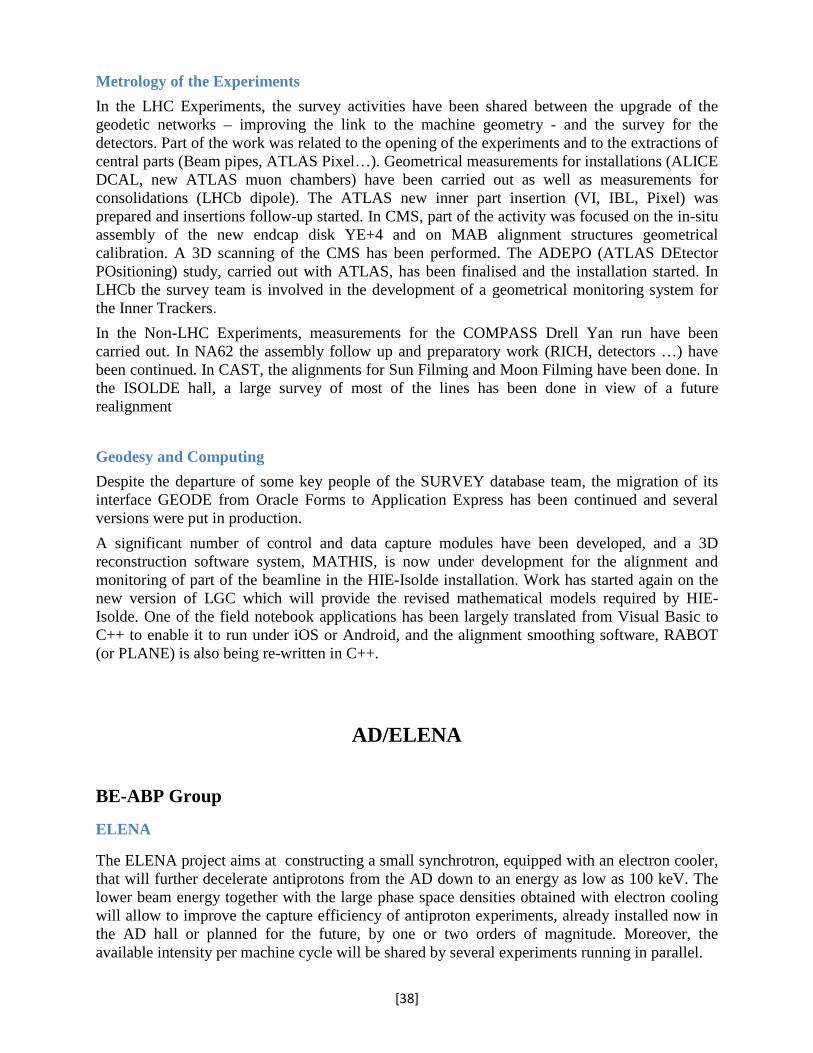
Metrology of the Experiments In the LHC Experiments, the survey activities have been shared between the upgrade of the geodetic networks – improving the link to the machine geometry - and the survey for the detectors. Part of the work was related to the opening of the experiments and to the extractions of central parts (Beam pipes, ATLAS Pixel…). Geometrical measurements for installations (ALICE DCAL, new ATLAS muon chambers) have been carried out as well as measurements for consolidations (LHCb dipole). The ATLAS new inner part insertion (VI, IBL, Pixel) was prepared and insertions follow-up started. In CMS, part of the activity was focused on the in-situ assembly of the new endcap disk YE+4 and on MAB alignment structures geometrical calibration. A 3D scanning of the CMS has been performed. The ADEPO (ATLAS DEtector POsitioning) study, carried out with ATLAS, has been finalised and the installation started. In LHCb the survey team is involved in the development of a geometrical monitoring system for the Inner Trackers. In the Non-LHC Experiments, measurements for the COMPASS Drell Yan run have been carried out. In NA62 the assembly follow up and preparatory work (RICH, detectors …) have been continued. In CAST, the alignments for Sun Filming and Moon Filming have been done. In the ISOLDE hall, a large survey of most of the lines has been done in view of a future realignment Geodesy and Computing Despite the departure of some key people of the SURVEY database team, the migration of its interface GEODE from Oracle Forms to Application Express has been continued and several versions were put in production. A significant number of control and data capture modules have been developed, and a 3D reconstruction software system, MATHIS, is now under development for the alignment and monitoring of part of the beamline in the HIE-Isolde installation. Work has started again on the new version of LGC which will provide the revised mathematical models required by HIE-Isolde. One of the field notebook applications has been largely translated from Visual Basic to C++ to enable it to run under iOS or Android, and the alignment smoothing software, RABOT (or PLANE) is also being re-written in C++.
AD/ELENA
BE-ABP Group
ELENA
The ELENA project aims at constructing a small synchrotron, equipped with an electron cooler, that will further decelerate antiprotons from the AD down to an energy as low as 100 keV. The lower beam energy together with the large phase space densities obtained with electron cooling will allow to improve the capture efficiency of antiproton experiments, already installed now in the AD hall or planned for the future, by one or two orders of magnitude. Moreover, the available intensity per machine cycle will be shared by several experiments running in parallel.
401 in ATLAS
[38]

In autumn, the project, which has significantly evolved since the approval of the project, has been presented to a technical review committee. The review board has endorsed both the principle of adding a small ring to further decelerate antiprotons from the AD and the basic design and recommended some further studies. Preparations for the technical design report have advanced as well, such that the machine to be built is well known by the end of the year. The construction of an annex necessary to free space in the AD hall now occupied by kicker generators and infrastructure by the experiments has will advanced and has been completed at the beginning of 2014. The design of the ELENA ring and of the electrostatic transfer lines has further advanced. First measurements with a bending magnet prototype have taken place and shown that the required field quality can be reached even at the very low field levels at extraction. Studies and design of many more components as very sensitive instrumentation for low intensity beams, vacuum system, the RF system have advanced as well. The purchase of equipment with long construction times as large magnets have been prepared such that first orders will be placed in 2014.
BE-OP Group
AD
No beam operation took place in AD during 2013 due to LS1 and the non-availability of protons from the PS complex. Instead, the opportunity was taken to do some of the longer and more complicated interventions related to the AD consolidation program and the preparations for installation of the ELENA ring. To mention a few:
• Removal of 1 of the 24 main bending magnets for inspection and renovation in the workshop. This included removal of the ATRAP positron source situated just above.
• Dismantling of the AD ejection line to prepare for the installation of a modified line permitting beam transfer to both the existing experimental beam lines as well as to ELENA.
• Removal of remaining un-used magnetic elements of the old transfer line for reverse proton injection.
• Preparations for a new access point for the AD ring with PAD and mini-MAD.
• Start of a comprehensive target area consolidation program including renewal of target and horn control systems, refurbishing the access gallery and one of the surface buildings and also upgrade of the access point and systems.
• Upgrade of the AD control system within the ACCOR project.
• Definitions and conceptual work for a new AD timing and cycle generation system. This is to be commissioned in 2014 and will serve as a base for the ELENA system.
Furthermore, conceptual studies, planning and start of fabrication of components for an additional beamline to the recently approved BASE experiment was made. A small area in the AD hall could be cleared and equipped for this experiment.
[39]

BE-RF Group
ELENA
Conceptual work on a magnetic pick-up and a scheme to use the electrostatic pick-ups in the ring were completed with results published at IBIC’13. AD Consolidation work on the AD stochastic cooling was carried out: The LLRF electronics on the “Platform Fritz” was re-cabled and received a modern PLC controls interface, the DC motors powering the pickup and kicker movement were renewed, the amplifier power supplies were renovated: the large power supplies have been replaced by new smaller power supplies, one per amplifier, with a new PLC control system.
REX/ISOLDE/HIE-ISOLDE:
BE-ABP Group The ABP group is responsible for the low-energy part of the REX-ISOLDE post accelerator, which with the installation of the superconducting linac extension is soon to become HIE-ISOLDE. As the injector complex went through LS1, no radioactive beams were available, but nevertheless in the beginning of the year stable beams were delivered for tests of HIE-ISOLDE related equipment. Maintenance work included opening the cryostat of the REXEBIS superconducting solenoid and mechanically modifying it in collaboration with PH-UAT in order to successfully recover the liquid helium holding time, as well as a new buffer-gas injection system for REXTRAP. During the year we also expanded our simulation toolbox for electron beams, incorporating and comparing the performances of TRAK 2D Charged Particle Toolkit and CST Particle Studio 3D. The codes have been used to simulate and explain the beam losses limiting the electron current at REXEBIS, as well as to optimize the gun and collector geometries of the High Energy Current Compression (HEC2) gun that could potentially be used at an upgraded EBIS charge breeder. The EBIS upgrade study continued with the production and test of a first version of the HEC2 electron gun in collaboration with the BNL, with the electron beam exceeding 1.5 A at 30 keV and was transmitted in pulsed mode during the autumn, representing a record for high-current, high-compression EBIS/T guns. Using the spare superconducting solenoid offered from the Manne Siegbahn Laboratory, the TwinEBIS test bench took a large leap forward, almost finishing the hardware installation to be followed by commissioning. Thereby there is now a full set of spare parts for the operational REXEBIS, and a facility for systematic studies of the magnetic field alignment were performed and new guidelines were established that should speed up the procedure in the future if a cryostat intervention is needed. ABP lead a full integration study of the Test Storage Ring (TSR) from Heidelberg at ISOLDE. The technical and radiological aspects of the integration of the machine, spare part situation, infrastructure and building, beam-optics for the injection line, and operational constraints were
[40]
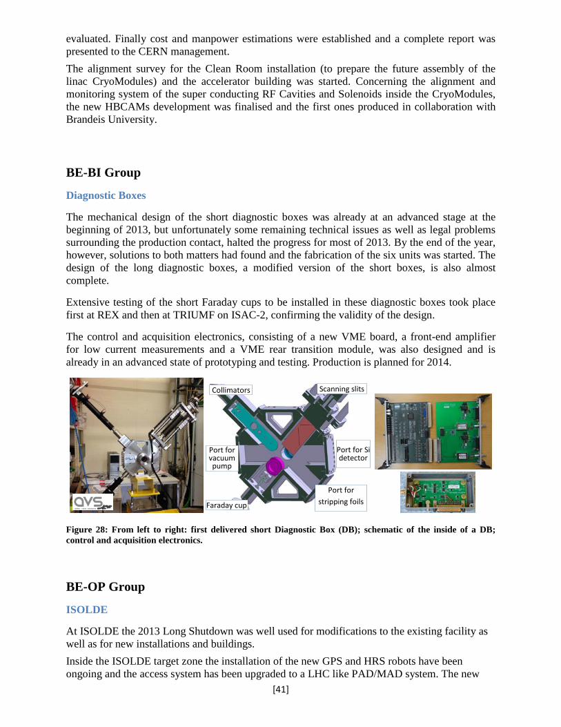
evaluated. Finally cost and manpower estimations were established and a complete report was presented to the CERN management. The alignment survey for the Clean Room installation (to prepare the future assembly of the linac CryoModules) and the accelerator building was started. Concerning the alignment and monitoring system of the super conducting RF Cavities and Solenoids inside the CryoModules, the new HBCAMs development was finalised and the first ones produced in collaboration with Brandeis University.
BE-BI Group
Diagnostic Boxes
The mechanical design of the short diagnostic boxes was already at an advanced stage at the beginning of 2013, but unfortunately some remaining technical issues as well as legal problems surrounding the production contact, halted the progress for most of 2013. By the end of the year, however, solutions to both matters had found and the fabrication of the six units was started. The design of the long diagnostic boxes, a modified version of the short boxes, is also almost complete.
Extensive testing of the short Faraday cups to be installed in these diagnostic boxes took place first at REX and then at TRIUMF on ISAC-2, confirming the validity of the design.
The control and acquisition electronics, consisting of a new VME board, a front-end amplifier for low current measurements and a VME rear transition module, was also designed and is already in an advanced state of prototyping and testing. Production is planned for 2014.
Figure 28: From left to right: first delivered short Diagnostic Box (DB); schematic of the inside of a DB; control and acquisition electronics.
BE-OP Group
ISOLDE
At ISOLDE the 2013 Long Shutdown was well used for modifications to the existing facility as well as for new installations and buildings. Inside the ISOLDE target zone the installation of the new GPS and HRS robots have been ongoing and the access system has been upgraded to a LHC like PAD/MAD system. The new
Scanning slits
Port for stripping foils Faraday cup
Port for Si detector
Collimators
Port for vacuum pump
[41]

Groundbreaking for MEDICIS
HIE ISOLDE service buildings
HIE Cryo Module
TSR TDR
New robot handling at ISOLDE
industrial linear axis mounted robots will replace the existing 20 year old ones. This new system will be operational for the upcoming 2014 physics run.
Outside the ISOLDE target area civil engineering has started with the extension of the Class A lab for the MEDICIS project (Medical Isotopes Collected from ISOLDE). In the future left-over protons from ISOLDE can be used to produce radioactive isotopes for medical research in the field of imaging and cancer treatment. Behind the ISOLDE experimental hall the old user building and workshop have been demolished and a new building is arising for laser labs, solid-state physics, ISOLDE/RILIS control rooms, workshop and visitor room. For HIE ISOLDE the installation is according to plan. The construction of the service buildings has finished and buildings are being filled with the HIE ISOLDE infrastructure equipment such as the cooling installations, cryogenics plant and electrical services. In the ISOLDE experimental
hall the construction of the HIE linac shielding tunnel is ongoing and in SM18 the assembly of the cleanroom for the upcoming cryo-module assembly has started. As far as the technical
achievements are concerned
the design of the High-Energy Beam Transferlines has been finalised and is now in the tendering and procurement phase. The cryo-module design has been completed and cavities have reached their specifications with an accelerating gradient of 6MW/m at 10W RF power. Serie production is underway. For possible future development and extension of the ISOLDE
facility an integration study was carried out in 2013 on the installation of the TSR, a storage ring presently installed at the Max Planck Institute for Nuclear Physics in Heidelberg. TSR elements were evaluated by CERN specialists and a final report was submitted to the Director of accelerators and the department leaders in August. The Long Shutdown was also well used by the ISOLDE physics community to analyse data and publish results. Examples are the MINIBALL studies on octupole deformation in 220Rn and 224Ra. These studies of pear-shaped nuclei using accelerated radioactive
beams from REX-ISOLDE were published in Nature. Others publications are the mass of 54Ca and 3-body forces by the ISOLTRAP experiment and the ionisation potential of Astatine by the RILIS setup.
[42]

BE-RF Group
Superconducting Linac
While 2012 results of the high-beta cavity was still short of nominal performance, 2013 brought the long-awaited break-through – continued improvements and refinement of procedures, paired with persistence and thoroughness in testing, led finally to cavities which first reached finally well surpassed the performance goal of 6 MV/m with 10 W loss by 43%!
Figure 28: Progress of HIE-ISOLDE cavity performance in 2012 and 2013. The cavity is shown on the inset.
HIE-ISOLDE LLRF LLRF conceptual design started for the control of the 32 superconducting cavities planned for the final phase of HIE-Isolde. Digital down-conversion is used undersampling the narrowband 100 MHz RF signal. Using prototype hardware the self-excited Mode (SEL) was tested, whereby the cavity, not on tune is part of an oscillator circuit which can after start-up be pulled by detuning the cavity to the right frequency. This mode of start-up is essential for testing and operating these cavities due to their very high 𝑄𝑄 value.
[43]
Neutrino Facilities Studies
BE-ABP Group
The European Spallation Source (ESS) currently under construction in Lund, Sweden, is a 2GeV proton source of unprecedented 5MW average beam power and gives the opportunity to produce, in parallel with the neutron production, a cost effective and high performance neutrino beam. The proposal for neutrino production is to upgrade the linac to 10 MW average power using higher pulse rates, and adding an accumulator ring to compress the beam pulses. This ring would ultimately accumulate 2.5 1014 protons per pulse by laser stripping of H- pulses from the proton driver. Ongoing work on the layout of the ring on the ESS site will set the boundaries on the final geometry of the ring and the transfer lines, and permit continuation of the work on the design report. ABP participates with the accumulator ring in a proposal to the H2020 call. A proposal to implement a small muon racetrack ring nuSTORM (Neutrinos from Stored Muons) at CERN, for neutrino cross section measurements, sterile neutrino search, muon cooling and accelerator R&D (proposal to SPSC 2013), is now subject to some steps towards a design report. Collaboration with the initiators of this facility (FNAL) on accelerator issues, including instrumentation and magnets, has lead to the specification of work packages for the CERN design work, specific to the CERN infrastructure and environment.
Medical Related Experiments
BE-ABP Group BioLEIR The idea of BioLEIR is to provide light ion beams in the range from protons to neon to the radiobiological user community. In this context a front end providing light ion beams to the Low Energy Ion Ring (LEIR) needs to be designed. One possibility would be to re-use Linac3 with a new light ion source and a dedicated light ion RFQ. A study was done to define the general design of the light ion beam line and the basic structure of a light ion RFQ. A critical element in this design is the switchyard to combine the original Linac3 line with the light ion line in front of the main accelerator structure, because any modification of Linac3 should not jeopardize the heavy ion performance.
CTF3/CLIC:
BE-ABP Group
The re-baselining of the CLIC parameters for cost and power optimization, also taking into account stages as needed for initial Higgs-measurements, is well underway and is expected to
[44]

conclude in 2014. A very significant interest in using CLIC technology for compact XFELs has led to the initiation of specification studies of several such facilities in conjunction with collaborating light source laboratories, also increasing the overall industrial basis. Dedicated studies and interactions with key industrial partners have shown the potential of the X-band technology also in medical and industrial accelerator systems. In 2013 the CLIC team contributed to the operation, commissioning and tests at ATF2, where the collaboration achieved a world record low beam size of 65 nm. The ultra-low beta proposal has progressed significantly and it’s planned that the CLIC study will provide two octupoles which should allow to cancel the existing aberrations and reach design beam sizes of 37 nm. Further work has been done in the damping ring area on vertical emittance tuning, notably at SLS and at ALS, which reported a record emittance of 1nm, at the quantum limit, by indirect measurements. The SC wiggler tests in ANKA are prepared, analysis of turn-by- turn data from the ATF damping ring was done and used for beta-beating and coupling correction. Dispersion-Free Steering - including emittance reduction measurements - successfully tested in 2012 at the FACET facility at SLAC was documented in a peer reviews paper. A new method (Wakefield-Free Steering) has been developed, and initial tests have shown a unprecedented low emittance in the linac sector under test. In CTF3 further improvements in beam stability, repeatability and availability were obtained thanks to new beam-based feed-backs, a better knowledge of the beam optics and improved operational procedures and tools. The beam tests of main and drive beam BPMs in CLEX were successful, and will continue in the 2014 run. The Electro-Optical bunch length monitor was installed and the first tests were performed. Several hardware modifications needed to achieve the experimental goal were identified and have been implemented in view of beam tests to be carried out in early 2014. The first phase of the Beam Loading experiment has been successfully carried out. The installation is now complete, and the first run is scheduled for summer 2014. The two new structures in the Two-beam test stand were conditioned to the nominal level. The wake-field monitors were commissioned, the measurements show a performance (resolution) consistent with expectations taking into account the low beam charge, and electronic noise of the acquisition system. The impact of high-power in the fundamental mode has been identified, as well as the electro-magnetic noise from the drive beam. While clearly visible, this impact should not degrade the monitor performance below an acceptable level. A full confirmation will need more measurements, planned in 2014 with higher beam charges and improved electronics. The preparation for the installation of the Two-Beam module is well under way, and its installation is scheduled for mid 2014. In TBL we had reached 35% deceleration. Good agreement for deceleration and for optics predictions were measured and documented. Drive Beam phase feed-forward the monitors were fully characterised and are well within specs, the modifications of the beam line and the kickers installation was done within schedule. In 2013 the first X-band test facility at CERN has become operational and has successfully been used for accelerating structure conditioning and measurements, and two more facilities are being prepared providing a factor three increase of the overall test capacity. On the Two Beam Modules setup, thermal tests simulating the duty cycles of the CLIC machine have started: the control of the alignment of the components and their associated supports under different conditions of temperature and ventilation is under way, using data from sensors and measurements from AT401. RasDif and RasNik proximity sensors developed by NIKHEF have been installed on the TBTM to perform an inter-comparison with capacitive wire positioning sensors and a database to store all the data has been put in place. A first prototype of support based on flexural joints has been designed and manufactured to adjust the DB quadrupole according to 5 DOF, within a micrometric resolution and in a very limited space. A laser based alignment system, based on a laser beam reference and sensors consisting of a shutter closed to observe the beam speckles indirectly via a CCD camera, is under development.
[45]
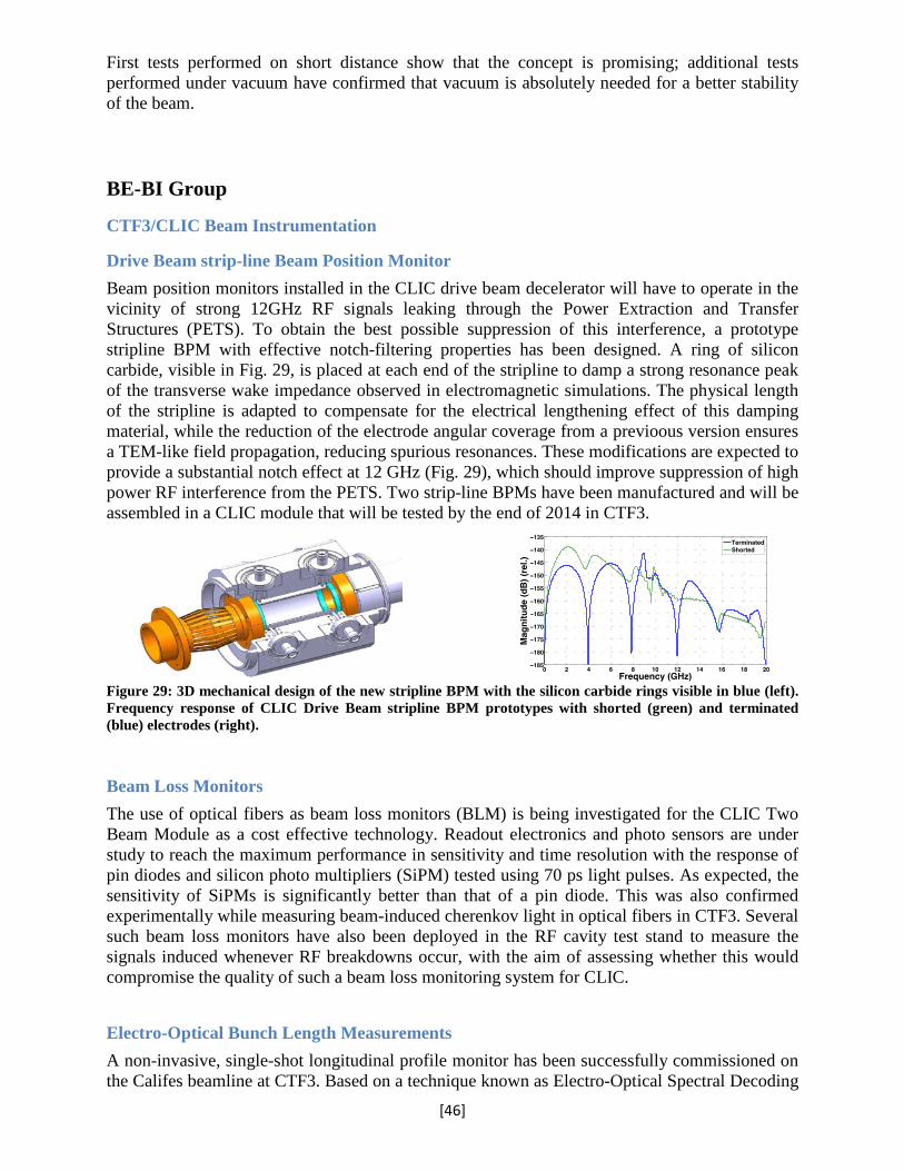
First tests performed on short distance show that the concept is promising; additional tests performed under vacuum have confirmed that vacuum is absolutely needed for a better stability of the beam.
BE-BI Group
CTF3/CLIC Beam Instrumentation
Drive Beam strip-line Beam Position Monitor Beam position monitors installed in the CLIC drive beam decelerator will have to operate in the vicinity of strong 12GHz RF signals leaking through the Power Extraction and Transfer Structures (PETS). To obtain the best possible suppression of this interference, a prototype stripline BPM with effective notch-filtering properties has been designed. A ring of silicon carbide, visible in Fig. 29, is placed at each end of the stripline to damp a strong resonance peak of the transverse wake impedance observed in electromagnetic simulations. The physical length of the stripline is adapted to compensate for the electrical lengthening effect of this damping material, while the reduction of the electrode angular coverage from a previoous version ensures a TEM-like field propagation, reducing spurious resonances. These modifications are expected to provide a substantial notch effect at 12 GHz (Fig. 29), which should improve suppression of high power RF interference from the PETS. Two strip-line BPMs have been manufactured and will be assembled in a CLIC module that will be tested by the end of 2014 in CTF3.
Figure 29: 3D mechanical design of the new stripline BPM with the silicon carbide rings visible in blue (left). Frequency response of CLIC Drive Beam stripline BPM prototypes with shorted (green) and terminated (blue) electrodes (right).
Beam Loss Monitors The use of optical fibers as beam loss monitors (BLM) is being investigated for the CLIC Two Beam Module as a cost effective technology. Readout electronics and photo sensors are under study to reach the maximum performance in sensitivity and time resolution with the response of pin diodes and silicon photo multipliers (SiPM) tested using 70 ps light pulses. As expected, the sensitivity of SiPMs is significantly better than that of a pin diode. This was also confirmed experimentally while measuring beam-induced cherenkov light in optical fibers in CTF3. Several such beam loss monitors have also been deployed in the RF cavity test stand to measure the signals induced whenever RF breakdowns occur, with the aim of assessing whether this would compromise the quality of such a beam loss monitoring system for CLIC. Electro-Optical Bunch Length Measurements A non-invasive, single-shot longitudinal profile monitor has been successfully commissioned on the Califes beamline at CTF3. Based on a technique known as Electro-Optical Spectral Decoding
[46]

(EOSD), the Coulomb field of the particle bunch is spectrally encoded onto a chirped laser pulse as it passes through a 4mm long birefringent ZnTe crystal. The laser probe is then coupled into an optical fibre for transport to a bespoke spectrometer. An example of a spectral decoding measurement on the Califes beam line is shown in Fig. 30 for a 6.6ps long bunch. In its current state, the system has the capability to resolve bunch lengths as short as 1ps.
Figure 30: Single shot bunch profile measurement performed on Califes beam line
BE-RF Group
X-band RF structures
The X-band test stand XBox1 was operational all year – the highlight of the results was the successful high power processing of two CERN made X-band structures a TD25R05 and a TD26CC, which demonstrated for the first time breakdown rates close to the CLIC requirements. The Xbox2 engineering design, production and assembly have been completed. Several RF components have been studied and ordered: 3 dB splitters, PETS On-Off mechanism, vacuum gate valves, compact pumping ports, 60 dB directional coupler, High Power Loads.
Figure 31: Examples of CLIC/CTF3 hardware produced: PETS ON-OFF mechanism (left), RF compatible vacuum gate valve (centre), compact pumping port (right)
Several micron-precision 12 GHz structures were produced for CERN and collaborators: TD26 CC, TD26 CLEX, TD24R05, FACET, DDS and CLIC crab cavity.
[47]

Figure 32: Micron-precision X-band structures produced in 2013: FACET test structure (left), DDS (centre) and TD26 CLEX (right)
For the LLRF system of Xbox2, a master oscillator at 3 GHz is used and down-converted signals are digitized by commercial hardware for observation of the different RF signals during structure testing. CLIC Modules Regarding the Two-Beam Module Lab, the first prototype module T0 was completed and tests have started, the second T0 was under completion. For the fabrication of these modules a rigorous QA system was implemented to manage the procurement and the traceability of thousands of components. Regarding the Two-Beam Module for the CTF3 EXperimental area CLEX, integration of T0 has been made, the first two Super Accelerating Structures have been built and the supporting system was prepared.
Figure 33: CLIC Modules: Finished T0 module in the Two-Beam Module Lab (left), module concept (centre) and installation of T0 support system in CLEX (right)
Regarding industrialisation, a qualification of companies for series production program has started. Dedicated programs on bonding, brazing, and alignment have also been launched. A two-beam module industrialisation has also been launched in order to start transfer of production to industries. CTF3 Experiments and status The test beam line in CTF3 produced a record deceleration of 36% and power production of 720 MW of 12 GHz rf power in 2013.
[48]

The studies for the CLIC drive beam injector made a lot of progress during the year. A fully revised beam dynamics design with respect to the CDR has been produced promising a reduction of the satellite population to 2%. The rf-design of the sub-harmonic buncher has been completed and the mechanical design has been started. In addition the purchasing procedure for the development of two L-band high-efficiency multi-beam klystrons has been completed and the first one has been ordered in industry. The second contract is expected to be awarded soon.
SPL
BE-RF Group A faulty mono-cell cavity was repaired by replacing its cut-off tube. The cavity was then electropolished and cold tested in SM18 up to a maximum gradient of 20 MV/m with a low-gradient 𝑄𝑄 value of 2 ∙ 1010. The onset of field emissions was observed at 12 MV/m, which is a respectable result considering that the repair history of the cavity. Four 5-cell Nb cavities from Research Instruments (RI) were received just before the end of the year to be qualified and tested in 2014. The half-cell and full cavity tuning was made at RI in close collaboration with CERN experts. Also the construction process and in particular the process of necking out the ports on the cut-off tubes was done in collaboration with EN-MME. Cavity tuning was successfully tested on a copper cavity prototype using a CERN manufactured tuning machine. In order to test the concept of supporting the cavities with the power couplers a cryo mock-up was assembled by TE-MSC and put into operation. Two types of power couplers were developed for use on the SPL cavities: i) a cylindrical window type, and ii) a disk window type. Both types have been successfully high-power tested in travelling wave mode up to full power. Limitations have been reached in full reflection mode for some phases of the reflection due to arcing on the air side of the waveguide system. Maximum achieved powers were 550 kW with the cylindrical window and 650 kW with the disk window. Improved forced air cooling was implemented to reduce arcing.
Figure 34: SPL power couplers: Cylindrical window type (left) and flat window type (right)
In the frame of collaboration with ESS, an agreement was signed to collaborate on the subject of high-power, multi-beam IOTs. ESS will sponsor the development of such a device in industry and CERN will set up a test stand for the qualification of the devices.
[49]

COLLIMATION PROJECT:
BE-ABP Group The collimation project team continued the strong support to the LHC beam operation in 2013, including quench free p-Pb physics run. Additionally, proton quench tests at 4 TeV were conducted to address the performance of the dispersion suppressor magnets around IR7 and extrapolate the system performance at higher energies, and proved that the collimation system can withstand safely peak beam losses up to 1MJ without quenches. An external review was organized in May 2013 to gather feedback on the proposed collimation upgrade strategies for LS2 and LS3. The outcome of this review was the definition of the basic upgrade strategy for LS2, which includes the implementation of local dispersion suppressor cleaning based on 11T dipoles around the ALICE experiment (or around IR7 in case of unexpected problems during proton operation). LS1 involved the installation of 30 new, moved or replaced collimators, of which 18 new collimators were produced in-house, with beam pickup monitors integrated in the jaws for a faster alignment. Other LS1 upgrades foresee improved layouts for physics debris collimation in the high-luminosity insertions, improved dose reduction for warm magnets in IR3, and preparation of IR7 layouts for crystal collimation tests in Run II. BE-BI Group
Collimator BPM production
During LS1, 16 tungsten tertiary collimators and 2 carbon secondary collimators are being replaced by new collimators with integrated beam position monitors (BPMs). All components required for the BPM assembly have been procured and delivered to the external company manufacturing the entire collimator. Test procedures and a test set-up have also been delivered to qualify the BPM performance before welding shut the collimator assembly. Some pictures of the different components of the collimator BPM assembly are shown in Fig 35.
Figure 35: From left to right: Backside of the jaw with a BPM button electrode connected; Routing of the BPM cables; the BPM button after bake-out; a fully assembled TCTP collimator.
[50]

Future machines and EuCARD
BE-ABP
EuCARD ended in the summer of 2013. Its Work Package 4, “Accelerator Networks” (AccNet) contained three tasks: EuroLumi, RFTech, and EuroNNAc . Major scientific results of AccNet, harvested in 2013 and documented in more than 100 reports, include the following: EuroLumi turned the previously disputed crab cavities into a realistic LHC upgrade scheme, now adopted by CERN and at the heart of the LHC upgrade plan. EuroLumi launched brainstorming on a higher-energy pp colliders (VHE-LHC, now FCC-hh) based on 16-T to 20-T dipoles in a ~100 km tunnel. EuroLumi also initiated brainstorming on circular e+e- collider Higgs factories (LEP3 and FCC-ee/TLEP) as a novel alternative to linear colliders, with the advantage of very high luminosity, robust technologies and sharing of existing or new tunnel with pp colliders, thereby offering a 50 year strategy for particle physics in Europe. EuroLumi also launched brainstorming on ERL based gamma-gamma colliders, such as SAPPHIRE. RFTech delivered a monograph on SC technology giving the R&D directions of R&D to improve the RF gradients (especially the thin-film technology), as well as a summary of RF test stations with their capabilities. EuroNNAc started combining the achievements and competence of the laser and plasma experts with the technical expertise of the accelerator scientists and engineers, to define a roadmap towards a demonstrator experiment for the production, with plasma acceleration, of quality beams in a reliable and reproducible fashion From mid to end 2013, the new EuCARD-2 Work Package 5 “Extreme Beams” (XBEAM) has organized or co-organized 4 topical workshops. Most active was the task on “Extreme Colliders” (XCOLL), with three workshops, on TLEP (now FCC-ee), SuperKEKB, and HL-LHC (crab cavities), respectively, all of which already had a strong impact on the formulation of future strategies. The “Extreme Performance Rings” (XRING) task held a workshop on “Beam Dynamics meets Magnets,” bringing together several communities, and so successful as to initiate a new event series.
Other Group Activitities and Cross Departmental Activities
BE-ABP
Code Development
MAD-X is the workhorse software application for the design and study of the beam dynamics in CERN accelerators and transfer lines. During 2013 the code was both consolidated, and extended to support the RF-multipoles element for modelling the future HL-LHC crab-cavities. The thick symplectic maps for quadrupole magnets were also added to the code and the studies for dipole magnets started as part of a long-term improvement aiming to simplify the transition between optics design and beam dynamics studies. Finally, the tracking module was extended to support frozen-model space-charge physics developed in collaboration with Fermilab. SixTrack is the other large code that is routinely used to evaluate long-term particle motion stability and collimation performance, especially for the present and future LHC. It is highly
[51]
integrated in CERN cluster computing and the LHC@Home project through which some hundred thousand volunteers contribute to CERN with their spare computing power. In 2013 a new website http:/cern.ch/sixtrack has been put in place to revamp the development activities by distributing a new physics manual and start a developers’ manual to clarify the used physics models and to reduce the time needed by new developers to contribute to the code. Thanks to the legal support of KT, we started to distribute SixTrack with the LGPL open source license to attract external developers.
BE-ASR Group
The Administration, Safety and Resources (ASR) group is mandated to provide overall assistance to the department, to each individual group and to each and every member of the personnel in the department in the smoothest and most unobtrusive way while being careful at the same time to minimize the inevitable overhead associated with administrative work, resources planning and control, and Safety. Specific responsibilities, mainly concerning human resources, have been mandated to the BE-ASR group leader, by delegation of the department head. Such departmental representation is hence ensured in staff selection committees, the CERN contract review board, and the Standing Concertation sub-group dealing with modifications of the Staff Rules & Regulations, Administrative Circulars and Operational Circulars. In order to overview, plan and control all resources – human and financial – within the medium term period, the ASR group leader has also taken up the full responsibility of Departmental Planning Officer (DPO). The BE Newsletter Another three issues of the BE Newsletter, introduced in 2011, were published in 2013. The content varies widely from scientific and technical to practical, social and safety information, provided by each group via its correspondent. The management, compilation of all contributions and final editorial work is in the hands of BE-ASR. The feedback – even from retired staff – continues to be positive, so the journalistic efforts are pursued. Administration & Secretariats – BE-ASR-AS The Administration and Secretariats team is tasked with ensuring an effective and high quality administrative assistance for Group Leaders and Section Leaders, as well as providing an administrative support for all categories of personnel for a wide range of activities. The team of seven group secretaries and departmental support in the Central Secretariat (DAO, DDAO) is geographically split between the Meyrin and Prévessin parts of the CERN site and located in different buildings. The recurring activities of the assistants start from the welcoming of new arrivals (132 in 2013), ensuring that appropriate space and furniture is made available, as well as the management and follow-up of contract extensions, transfers, secondments, contract terminations and departure formalities. Of particular importance also is the coordination of selection committees for Fellows as well as Doctoral, Technical and Summer students. At department level the central secretariat is also involved in the follow-up of induction interviews, mid- and end-probation reports, the coordination of the MARS exercise as well as all actions related to advancement, promotion and awards of staff members within the Department, treatment and monthly control of overtime, shift and stand-by duty. In the groups the secretaries
[52]

assist the CERN personnel with arranging official travel and calculation of reimbursements, treatment of reimbursements of education fees, management of subsistence fees, control of absences and third party claims. The secretaries also provide assistance with the administrative organization of events and conferences (e.g. IPAC’13, ICALEPCS2013, COOL’13), the creation and update of group websites and documentation systems and the coordination of visits onsite, especially in the CCC. The Departmental Administrative Officer (DAO) collaborates proactively and continuously with the HR department and the Legal Service to streamline and improve the administrative procedures, making sure to implement correctly and efficiently the revisions of administrative circulars and contributing to the pragmatic documentation of the CERNAdmin e-guide. The entry into force of the administrative circular No.11, Rev. 2 (1.1.2013), introducing new statutes such as Cooperation Associates (COAS) and Visiting Scientists (VISC), has created substantial extra work. The establishment of a specific procedure, the search for existing agreements, creation and verification of new agreements with the Legal Service, the Procurement Service and supervisors are resource intensive activities. For the year 2013, 140 COAS and 17 VISC were registered. Resources & Logistics – BE-ASR-RL The main tasks of the Resources and Logistics team are to provide assistance to the Departmental Planning Officer (DPO) and his deputy (DDPO) on budgetary and financial matters, and to the Departmental Space Manager (DSM) for space and storage management, follow-up of small works and related logistics. The financial and budget related activities concern primarily monitoring and reporting on material budgets for all BE Groups and projects, monitoring and follow-up of the invoices and yearly accruals, maintenance of budget codes and signature rights. This includes externally funded budgets such as EU projects and the collaboration for the HIE-ISOLDE project. The activities of space management continued to be challenging. After an internal mobility, a new Departmental Space Manager (DSM) – from BE-ABP – was appointed. A major effort was put on visiting most of the offices, labs and storage areas in order to rationalize the space and to record the information correctly in the central information system GESLOC. The DSM, as member of the Groupe de Travail sur le Partage de l’Espace (GTPE) actively contributes to the CERN-wide space management. The rental of the two modular buildings on the CERN Meyrin and Prévessin sites was very beneficial to overcome the lack of office space. Since the cornerstone laying ceremony on February, 28th, the construction of the Prévessin main building 774 is progressing. The departmental logistics includes the management of keys and cylinders (435 requests), management of the departmental car fleet, the departmental inventory of equipment, the monitoring of the use of telephones, management of photocopiers and office and workshop furniture. Car-sharing solutions are strongly promoted and some specific solutions have been implemented in order to optimise the resources for transport. The new application prototype for the inventory was scrutinized and debugged to reach an operational deployment. The Departmental Training Officer (DTO) has put in place a rigorous departmental strategy, in line with new Learning & Development Policy, on communication (news and reporting), training request authorisations and budget follow-up. The fourth annual BE Workshop – a 3-day residential forum to create dialog between staff members and the Departmental Management – was considered as very useful with many
[53]

constructive ideas. The idea of internal secondments for 1 or 2 years was implemented immediately by means of adapted vacancy notices. Safety Unit – BE-ASR-SU Although the BE-Safety still comprises eight members in 2013 (six staff, one fellow and one BE-BI staff), their respective functions have shifted over the year:
• The assistant DSO became RSO (Radiation Safety Officer). • The Nuclear Safety Officer became DDSO (Deputy Department Safety Officer), • A Safety engineer became PSO (Project Safety Officer) for the LIU project. • The RSO became PSO for CENF and was detached to HSE (70%) in October.
This leads to a total of 5.9 FTE for the section. Two colleagues started an e-learning session to achieve recognition for their health and safety skills and knowledge by preparing the NEBOSH International General Certificate on Occupational Health and Safety. The Safety unit is committed in the establishment of the CERN Crisis Team through our Nuclear Safety Officer. The goal is to set up a crisis organization to react and manage a crisis, should it happen at CERN. Safety of Personnel The effort to improve Safety communication in the department was pursued this year. The departmental Safety web site is often updated with Safety Tips. Short Safety messages (sensibilisation) about the use of safety helmets. The Safety Unit also organised, in collaboration with the HSE Unit, the third edition of the World Day for Safety and Health at work. This year’s emphasis was on the prevention of occupational diseases, work stress and musculoskeletal disorders. Approximately 350 persons including the DG stopped at the stands that were set up at the three restaurants with posters, videos and practical exercises. HSE, the Medical Service and the Fire Brigade participated actively in the organisation of the event. Two articles and three Safety columns were published in the BE Newsletter. The Safety Unit continues to contribute in this task which consists of informing on subjects which are of interest to all BE staff. The main topics concerned safety during LS1. The Safety officers continue to maintain frequent and positive communication with the TSOs: regular meetings are organised in order to share experiences and provide them with information that could make their tasks easier. Part of the departmental Safety web site is dedicated to useful information concerning the function of TSOs. The HSE objectives are communicated to the TSOs and actions to achieve them are discussed altogether. A new safety-training scheme was proposed with the aim to rationalize the numerous safety courses that people must attend prior to get access to the beam facilities. The new scheme proposes shorter courses, which build on top of one another, and avoid repetition of too many information. The new scheme was discussed and agreed with the HSE Unit, as well as with the CSAPs. Preparation of the new training courses has started accordingly. Over the last three years, the numbers of BE members trained as first aiders has increased from 54 to 102. The signalisation for evacuation of the LHC was completed during LS1, with the exception of Point-7 where new ventilation door are being installed to limit the release of radioactive air to the
[54]

environment and the local population. « Mise à niveau de la signalisation d'évacuation dans le tunnel LHC » EDMS 1182620. Evacuation exercises have started in tertiary buildings in 2013, e.g. for building 864 in November. A guideline to organize them has been written in collaboration with the Fire Brigade “Evacuation exercise procedure” EDMS 1334683. The mandatory training of emergency guides has started in parallel. The qualification of people requesting access to the SPS and LHC tunnel still has to be checked manually, and some 2300 access requests have been treated in the framework of LS1 in 2013. The Safety Unit put a great effort on the follow up of PPEs (Personal Protective Equipment) in 2013. Indeed following two safety alerts sent by HSE, one on lanyards and the second on harnesses, an inventory of all the personnel using those PPEs was made. The users were personally contacted and brought back there PPEs to the Safety Unit. The aim of this inventory was to reference equipment for working at heights for periodic annual inspections. Out-of-date safety helmet are also collected by the Safety Unit and properly disposed of. Following the planning established by HSE concerning building inspections, 25 out of 66 buildings were inspected. The inspections have not identified any major lack of compliance with rules and standards. The Safety Unit supports the TSOs during these inspections and their follow-up. The DDSO conducted a series of trainings on the procedure “Predefined reactions to AL3 and incidents/ accidents for the LHC machine”. Coordination of GS-FB and BE-OP interventions. Safety and security responsibilities”. EDMS 1154191. Around 40 people were trained over 4 half-days sessions. Performing Safety Patrols was one of the safety objectives set by the DG for 2013, with the aim to improve safety of personnel and limit the number of accidents in the accelerators. Safety Patrols ensure a regular presence in the machines in order to enhance people’s safety. This means: identify a breach of general safety procedures and check people’s behaviour in the machines. Safety officers from the Accelerator & Technology sector and the Medical Service are today the main actors of Safety Patrols. Around 60 Safety Patrols have been conducted so far in eight machines / installations. Among the most frequently issued recommendations, we can note: wear appropriate PPE, primarily helmets, install evacuation signs wisely, mark out a temporary hazard zone on working site, dispose of not adequately stored material and evacuate any combustible wastes. Concerning the core Safety objective for a better hazard control set by the DG for 2013, the BE Safety Officers pursued the campaign to identify chemical products stored on the BE premises. Inventories were sent to HSE Unit who started to help with the risk analysis. Inventories of pressure lines in the buildings are also progressing, and these are removed of renewed whenever they are found obsolete or too hazardous. With respect to the core Safety objective for the protection of the environment, the TSOs have identified open cooling circuit using drinking water. Some small ones have been replaced by closed circuits or decommissioned if obsolete. A major one, in the AD hall will be modified by GS as soon as resources will be allocated. Old fridges were also identified during safety inspections, and three of them have been properly eliminated. As requested in the first HSE objective for BE “Limit the number of accidents/incidents at work” the Safety Unit continued to emphasise on the reporting of incidents and accidents. Four types of accidents were reported: slips, trips and falls, commuting accidents and manipulation. There were overall 361 accidents at CERN in 2013. BE figures are generally very good: 29 accidents in 2013, (22 in 2012 and 23 in 2011). Our Safety officer has conducted 8 analyses in this domain.
[55]

However, increase in commuting accidents is still worrying: 67% bike, 16.5% car, 16.5% motorbike. (2012: 21% bike, 79% car; 2011: 50% bike, 50% car). Electrical Safety in beam facilities due to the recent “Décret n° 2010-1118 du 22 septembre 2010”, the Safety Unit proposes a way for implementing the revised Electrical Habilitation requirements in the accelerators. The proposal consists in defining a safe passage in all machines (emergency exit path). Access to machines would then be controlled automatically on a SIR access module course. Any work on equipment of the machines would be controlled by IMPACT procedure. This proposal is validated by the HSE Unit. Specific actions of equipment groups are being detailed in order to assure the required resources before presentation at the management and possible implementation. Laser Safety In 2013 the LS1 works allowed many of the A&T sectors’ laser laboratories to suspend their activities as they are part of the machine operation, e.g. LARIS, RILIS in the ISOLDE experimental facility. Some have seized the opportunity to engage in infrastructure and equipment upgrades and two new facilities are in the planning and construction phases with ongoing laser safety input from the Laser Safety Officer of the Department who also maintains the CERN inventory of all hazardous lasers. The laboratories are being re-assessed for safety as they come back online. The LSO has also reviewed and updated the content of the Laser Users training course with the aim of making it available more frequently by using the CERN LSOs as instructors. Safety of Installations The implementation of the quality assurance plan concerning the EIS (Equipment Important for Safety), has continued this year. Thanks to the help of the BE-CO and TE-EPC groups, the register in the Layout database is being populated, and equipment groups are progressing with their maintenance and intervention procedures. Identification labels are stuck on the EIS on site to warn people about special procedures for intervention. The Safety Unit is still a driver in encouraging the establishment of Safety Files for Beam Facilities. Our role is either to edit safety files (LHC, PS, PSB, LIU and Linac4) or give advice and assistance to others. The “Safety Folders’ Editors Club” set by the DDSO still provides helpful share of experience and proofs its necessity. In the frame of the CERN 2013 Open Days, five visiting points were under BE responsibility: CTF3 (RF), Linacs (ABP), LEIR (OP), LHC-Pt-4 (RF) and 866 (BI). The safety files were prepared by the people in charge of the respective visited points with the help of the Safety Unit before being validated by HSE. The process went smoothly, the visitors were happy and neither accidents nor incidents were to be deplored. BE RSO and his deputy collaborated with RP and spent time studying possible changes to radiation shielding around accelerators in particular, to guarantee the visitor’s safety. A procedure is under approval by EN-MEF. Radiation Safety: 15 DIMR (Dossier d’Intervention en Milieu Radioactif) were managed in BE. The BE personal doses kept is well below 3mSv, the maximum was 1.5 mSv. The RSO was asked to study the procedures concerning shielding installations management: the goal was to find the best way to identify and control their status. All shielding blocks will be traced in the future (EDMS: 1296757 and 1307609). The project in place is now under the responsibility of EN-MEF.
[56]

The DSO of the Beams Department has been nominated project owner for TREC (Traceability of Radioactive Equipment at CERN). The installation of the system continues, along with the commissioning of the new access system and the Buffer Zones around the PS complex; this is driven mainly by GS-ASE. Ten out of fifteen TREC stations are operational. Additional features discussed in the TREC team (BE-DSO, GS-ASE and DGS-RP) have been added by GS-ASE and are also operational. A proposal to unify the access rights to the Buffer Zones was made and accepted by the DSOC. It will now be presented to the Joint-CSAP and implemented. Most members of our unit are committed in the three Complex Safety Advisory Panels, “CSAP” (LHC, SPS and PS), for which we also provide two scientific secretaries. These panels are composed of members from all technical departments, report to the EIFC & LMC and recommended action in matters of safe operation of CERN Accelerators Complexes. They also advise the Complex Manager in matters of safe operation of a given Complex. The system allowing the reporting of deviations in matters of Safety (EDMS 1161842) developed in 2012 was extended to all the departments. The system is now using SNOW (service now tool) and the Safety Unit is in first line to deal with the deviations reported. 29 deviations were reported in 2013: 10 « DEF » (Défaillance d'équipements de sûreté ou de sécurité), 8 « NR » (Non-respect de règles et/ou de procédures liées à la sûreté/sécurité), 5 « RP » (Non-respect de règles et/ou de procédures liées à la radioprotection) and 6 « Other ». Concerning Safety documentation, various procedures were updated or implemented this year, among which should be noted:
• Entrée ou sortie du LHC en cas de maintenance ou de panne d'ascenseur. EDMS 1236746.
• Etapes à suivre pour organiser des visites professionnelles dans les installations faisceaux. EDMS 1281098.
BE-BI Group
BE-BI Beamline Operational Spares Strategy (BOSS)
The BE-BI group, similar to many other technical groups at CERN, was merged from a number of smaller groups and sections that have been serving different machines over a long period of time. This has left BE-BI with much missing documentation of installed layouts, outdated instrument designs and little knowledge of the status of spares, particularly for the PS complex. To correct for this, 2013 saw the start of the Beamline Operational Spares Strategy (BOSS) project. The aims of this project are to produce a complete picture of all the instruments installed in the beamlines of all machines; to quantify the criticality of these instruments to the operation of the CERN accelerator complex and then to use this data to ensure that spares critical to CERN operation are available when needed. The first step of this project has been completed, taking advantage of LS1 to produce a complete picture of the instruments installed and to label them with radiation and heat resistant bar codes. BE-CO Group
The Layout Service in the A&T Sector
As a central point of reference for numerous aspects of the accelerator complex, the Layout Service was heavily solicited throughout 2013, for the capture, update, and propagation of data
[57]

to reflect changes due to the various installation and renovation activities. In addition, the Layout database infrastructure and graphical tools were extended to support the identification and layout of EIS structures. Database extensions and a dedicated tool was also developed to support the “Rack Inventory” project.
Figure 36
Quality Assurance Activities in the A&T Sector Naming Service Various improvements of the Naming Service interfaces to benefit the huge user base across the BE, EN, TE, GS, IT and PH departments were implemented in 2013. Common codes search across various information systems (e.g. Naming, CSS, EDMS, Infor - MTF) was put in place on the Naming portal as well as establishing and documenting (BPMN diagrams) the processes and templates for codes requests. A lot of effort was put in promoting, guiding and assisting users throughout the Accelerators sector to correctly adopt the established naming conventions. LS1 was a good moment to refactor existing equipment codes in areas such as Cryogenics and Power Converters and at the same time to assist new facilities such as LINAC4 and activities such as the Maintenance Management Project for their needs in establishing equipment codes.
[58]
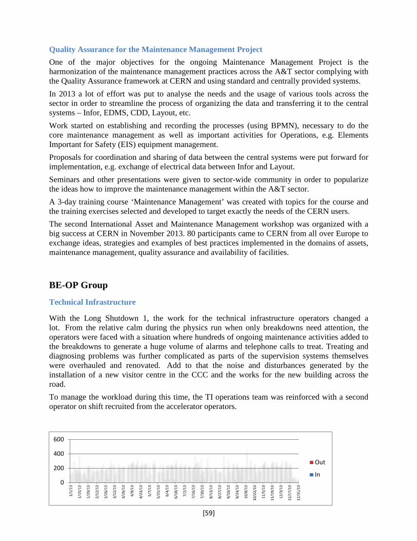
Quality Assurance for the Maintenance Management Project One of the major objectives for the ongoing Maintenance Management Project is the harmonization of the maintenance management practices across the A&T sector complying with the Quality Assurance framework at CERN and using standard and centrally provided systems. In 2013 a lot of effort was put to analyse the needs and the usage of various tools across the sector in order to streamline the process of organizing the data and transferring it to the central systems – Infor, EDMS, CDD, Layout, etc. Work started on establishing and recording the processes (using BPMN), necessary to do the core maintenance management as well as important activities for Operations, e.g. Elements Important for Safety (EIS) equipment management. Proposals for coordination and sharing of data between the central systems were put forward for implementation, e.g. exchange of electrical data between Infor and Layout. Seminars and other presentations were given to sector-wide community in order to popularize the ideas how to improve the maintenance management within the A&T sector. A 3-day training course ‘Maintenance Management’ was created with topics for the course and the training exercises selected and developed to target exactly the needs of the CERN users. The second International Asset and Maintenance Management workshop was organized with a big success at CERN in November 2013. 80 participants came to CERN from all over Europe to exchange ideas, strategies and examples of best practices implemented in the domains of assets, maintenance management, quality assurance and availability of facilities.
BE-OP Group
Technical Infrastructure
With the Long Shutdown 1, the work for the technical infrastructure operators changed a lot. From the relative calm during the physics run when only breakdowns need attention, the operators were faced with a situation where hundreds of ongoing maintenance activities added to the breakdowns to generate a huge volume of alarms and telephone calls to treat. Treating and diagnosing problems was further complicated as parts of the supervision systems themselves were overhauled and renovated. Add to that the noise and disturbances generated by the installation of a new visitor centre in the CCC and the works for the new building across the road. To manage the workload during this time, the TI operations team was reinforced with a second operator on shift recruited from the accelerator operators.
0
200
400
600
1/1/
13
1/15
/13
1/29
/13
2/12
/13
2/26
/13
3/12
/13
3/26
/13
4/9/
13
4/23
/13
5/7/
13
5/21
/13
6/4/
13
6/18
/13
7/2/
13
7/16
/13
7/30
/13
8/13
/13
8/27
/13
9/10
/13
9/24
/13
10/8
/13
10/2
2/13
11/5
/13
11/1
9/13
12/3
/13
12/1
7/13
12/3
1/13
Out
In
[59]

The number of major events recorded fell by 100 from 156 in 2012 to only 56 in 2013. The reason is of course that the run was stopped, but there were also a number of events after the machines were stopped such as power losses or tunnel evacuations related to the shutdown work.
BE-RF Group
SM18 SRF Infrastructure upgrade
In 2013 the Electropolishing facility was completed and the clean room upgrade in SM18 was started. Furthermore a high-pressure water rinsing system was ordered and the magnetic shielding in a vertical cryostat was replaced to be compatible with the needs of testing SPL cavities at 2 K. The replacement of the cryogenic supply line for the RF test area in SM18 was completed and is now capable of providing sufficient cooing for 2 K cavity tests in the vertical cryostats as well as in the RF bunkers. A good part of the SM18 upgrade were co-financed by the European Commission under the CRISP (Cluster of Research Infrastructure for Synergies in Physics) programme, notably to cover the needs of HIE-ISOLDE, HL-LHC and SPL; these upgrades consisted in a cryogenics infrastructure upgrade, new or upgraded ultra-clean preparation and assembly areas and a new cavity reception lab. The new facilities have been commissioned and released for operation in November 2013.
******************************
020406080
100120140160180
2009 2010 2011 2012 2013
Major events by year
[60]