Embed Size (px)
Citation preview
7/25/2019 Best Practice for Temp Calibration
http://slidepdf.com/reader/full/best-practice-for-temp-calibration 1/9
Temperature plays a key role in many industrial and commercial processes. Examplesinclude monitoring cooking temperature in food processing, measuring the temperatureof molten steel in a mill, verifying the temperature in a cold storage warehouse or refrig-eration system, or regulating temperatures in the drying rooms of a paper manufacturer.
A temperature transmitter will use a measuring device to sense the temperature, andthen regulate a 4-20 mA feedback loop to a control element that affects the temperature(Fig. 1). The control element might consist of a valve that opens or closes to allow moresteam into a heating process or more fuelto a burner. The two most common types
of temperature sensing devices are thethermocouple (TC) and resistive tempera-ture detector (RTD).
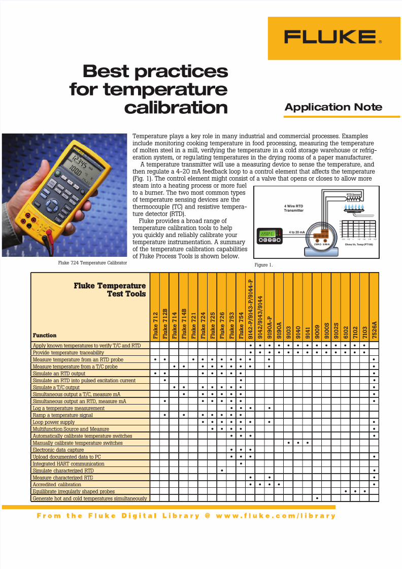
Fluke provides a broad range oftemperature calibration tools to helpyou quickly and reliably calibrate yourtemperature instrumentation. A summaryof the temperature calibration capabilitiesof Fluke Process Tools is shown below.
Application Note
ZERO SPAN
4 to 20 mA
4 Wire RTD
Transmitter
RTD Sensor
2200 ºC
0
50
100
150
200
250
300
- 20 0 -1 00 0 1 00 2 00 3 00 4 00
Ohms Vs. Temp (PT100)
ENTERMENU
2200° C
Best practicesfor temperature
calibration
Fluke 724 Temperature Calibrator Figure 1.
Fluke TemperatureTest Tools
F l u k e
7 1 2
F l u k e
7 1 2 B
F l u k e
7 1 4
F l u k e
7 1 4 B
F l u k e
7 2 1
F l u k e
7 2 4
F l u k e
7 2 5
F l u k e
7 2 6
F l u k e
7 5 3
F l u k e
7 5 4
9 1 4 2 - P / 9 1 4 3 - P /
9 1 4 4 - P
9 1 4 2 / 9 1 4 3 / 9 1 4 4
9 1 9 0 A - P
9 1 9 0 A
9 1 0 3
9 1 4 0
9 1 4 1
9 0 0 9
9 1 0 0 S
9 1 0 2 S
6 1 0 2
7 1 0 2
7 1 0 3
7 5 2 6 A
Function
Apply known temperatures to verify T/C and RTD • • • • • • • • • • • • •
Provide temperature traceability • • • • • • • • • • • • •
Measure temperature from an RTD probe • • • • • • • • • • •
Measure temperature from a T/C probe • • • • • • • • • •
Simulate an RTD output • • • • • • • •
Simulate an RTD into pulsed excitation current • • •
Simulate a T/C output • • • • • • • •
Simultaneous output a T/C, measure mA • • • • • • •
Simultaneous output an RTD, measure mA • • • • • • •
Log a temperature measurement • • • •
Ramp a temperature signal • • • • • • •
Loop power supply • • • • • • • •
Multifunction Source and Measure • • • • •
Automatically calibrate temperature switches • • • •
Manually calibrate temperature switches • • •
Electronic data capture • • •
Upload documented data to PC • • • •
Integrated HART communication •
Simulate characterized RTD • •
Measure characterized RTD • • •
Accredited calibration • • • • •
Equilibrate irregularly shaped probes • • •
Generate hot and cold temperatures simultaneously •

7/25/2019 Best Practice for Temp Calibration
http://slidepdf.com/reader/full/best-practice-for-temp-calibration 2/9
2 Fluke Corporation Best practices for temperature calibration
Typical Temperature Calibration Applications
How to calibrate a Thermocouple input transmitter
The Fluke 724 TemperatureCalibrator can provide the threethings necessary to calibrate atemperature transmitter. You cansource a temperature, provideloop power, and measure theresulting output current. Thefollowing example shows how tocalibrate a Type K TC transmitterthat is ranged from 0-150 de-grees centigrade, generating anoutput current range from4-20 mA.
Basic Calibrator Setup1. Connect the 724 test leads tothe TC transmitter as shown.The output from the ther-mocouple jacks on the 724will simulate a temperatureinput to the transmitter. Thered and black test leads willprovide loop power to thetransmitter and will measurethe current resulting fromtemperature changes into thetransmitter.
2. Power on the 724 calibrator.
Select the mA button and theLOOP button to select mea-sure milliamps with 24 V looppower applied.
3. Press the Meas/Source buttonuntil the lower portion of the724 display indicates thesource mode.
4. Depress the TC button until aTC type of K is displayed.
5. Select the °C button forcentigrade.
6. Set the Zero Point for thisapplication into the Calibra-tor. To do this set the displayinitially to 0.0 °C. You can usethe up and down arrow keysto change the output value.
Use the left and right arrowsto control which decadevalue of the display is beingchanged. When the displayreads 0.0, hold down the 0 %key on the 724 and observethat 0 % is displayed in thelower right corner of thescreen. This establishes theZero point for calibration.
7. Set the Span Point in theCalibrator. Set the display tothe desired Span value forcalibration. In this examplethe display should read150 °C. Depress the 100 %key and observe that 100 %is displayed in the lowerright corner of the screen.This establishes the Spanpoint for calibration.
Performing an “As Found” Test8. Depress the 0 % key; record
the applied temperature andthe corresponding mA mea-surement.
9. Depress the 25 %↑ key (2)times; record the applied tem-perature and the correspond-ing mA measurement.
10. Depress the 100 % key; re-cord the applied temperatureand the corresponding mAmeasurement.
11. Calculate the errors for eachof the (3) points using thefollowing formula: ERROR =
([(I-4)/16]-[(T/TSPAN])*100 where Error is in % of span,I is your recorded mA mea-surement, T is the recordedtemperature and TSPAN is thetemperature input span(100 % - 0 % points). Theerror calculation table belowshows how to apply theformula to actual recordedmeasurements.
12. If your calculated errorsare less than the specifiedinstrument tolerance, thetransmitter has passed theAs-Found test. If the test hasnot passed, perform adjust-ments as necessary.
Adjusting the Transmitter13. Depress the 0 % key to source
the proper temperature for a4 mA output. Adjust the zeropotentiometer until the cur-rent reading is 4.00 mA.
14. Depress the 100 % key tosource the proper temperaturefor a 20 mA output. Adjust theSpan potentiometer until the
current reading is 20.00 mA.15. Depress the 0 % key again
and adjust the zero potenti-ometer again if necessary, toget a 4.00 mA output.
Perform an “As Left” TestRepeat steps 8 through 12 tocomplete the full calibrationprocedure on your temperaturetransmitter.mA Measurement TC Source T Span Formula Error %
4.02 0 °C 150 °C ([4.02-4)/16]-[0/150])*100 0.1250
11.95 75 °C 150 °C ([11.95-4)/16]-[75/150])*100 -0.3125
20.25 150 °C 150 °C ([20.25-4)/16]-[150/150])*100 1.5625
Temperature transmitter error calculation example
TEST DCPWR
++ – –
VmA
MEASURESOURCE / MEASURE
30V MAX ALL TERMINALS
4W
3W V
RTD
TC
COM COM
LOOP
TEMPERATURE CALIBRATOR 724
Rosemount 444
100%
25%
25%
RECALL
MEAS
SOURCE
STORESETUP
TC RTD
0%
V
F
˚C
V LOOPmA
7/25/2019 Best Practice for Temp Calibration
http://slidepdf.com/reader/full/best-practice-for-temp-calibration 3/9
3 Fluke Corporation Best practices for temperature calibration
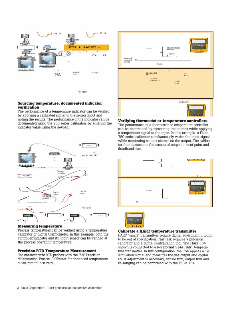
Measuring temperatureProcess temperatures can be verified using a temperaturecalibrator or digital thermometer. In this example, both thecontroller/indicator and its’ input sensor can be verified atthe process operating temperature.
Sourcing temperature, documented indicatorverification
The performance of a temperature indicator can be verifiedby applying a calibrated signal to the sensor input andnoting the results. The performance of the indicator can bedocumented using the 750 series calibrators by entering theindicator value using the keypad.
Verifying thermostat or temperature controllersThe performance of a thermostat or temperature controllercan be determined by measuring the outputs while applyinga temperature signal to the input. In this example, a Fluke750 series calibrator simultaneously varies the input signalwhile monitoring contact closure on the output. The calibra-tor then documents the measured setpoint, reset point anddeadband size.
Calibrate a HART temperature transmitterHART “smart” transmitters require digital adjustment if foundto be out of specification. This task requires a precisioncalibrator and a digital configuration tool. The Fluke 754shown is connected to a Rosemount 3144 HART tempera-ture transmitter. In this configuration, the 754 applies a T/Csimulation signal and measures the mA output and digitalPV. If adjustment is necessary, sensor trim, output trim andre-ranging can be performed with the Fluke 754.
Precision RTD Temperature MeasurementUse characteristic RTD probes with the 726 PrecisionMultifunction Process Calibrator for enhanced temperaturemeasurement accuracy.
754 DOCUMENTING PROCESS CALIBRATOR
ENTERMENU
98.9° C
B
A
Measuredcontrolledprocess
Indicator setpointcontroller
DisconnectedT/C
TCinput
Control
Outputor alarm
Controlvalve
Fuel supply
754 DOCUMENTING PROCESSCALIBRATOR
1
2 3
4
5
T
+
–
3144
Transmitter
TC
+ TC
–
754 DOCUMENTING PROCESS CALIBRATOR
ENTERMENU
98.9° C
B
A
Measuredcontrolledprocess
Indicator setpointcontroller
DisconnectedT/C
TC input
Control
Outputor alarm
Controlvalve
Fuel supply
754 DOCUMENTING PROCESS CALIBRATOR
ENTERMENU
100.0° C
Measuredcontrolledprocess
Setpointcontroller
T/C input
TC probe
Controloutput
Controlvalve
Fuel supply
7/25/2019 Best Practice for Temp Calibration
http://slidepdf.com/reader/full/best-practice-for-temp-calibration 4/9
4 Fluke Corporation Best practices for temperature calibration
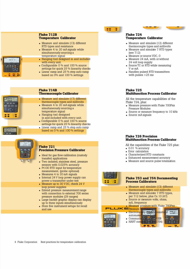
Fluke 725
Multifunction Process CalibratorAll the temperature capabilities of theFluke 724, plus:• Measure pressure with Fluke 700Pxx
Pressure Modules• Source or measure frequency to 10 kHz• Source mA signals
Fluke 753 and 754 DocumentingProcess Calibrators
• Measure and simulate (13) differentthermocouple types and millivolts
• Measure and simulate 7 RTD types,per 712 below, plus Cu 10 (47)
• Source or measure volts, ohms,mA, frequency
• Measure pressure with Fluke 750PxxPressure Modules
• Electronically capture results ofautomated procedures
• Communication to PC-USB• HART communication (754)
Fluke 721Precision Pressure Calibrator
• Ideal for gas flow calibration (custodytransfer) applications
• Two isolated, stainless steel, pressuresensors with 0.025% accuracy
• Pt100 RTD input for temperaturemeasurement, (probe optional)
• Measures 4 to 20 mA signals• Internal 24 V loop power supply can
power a transmitter under test• Measure up to 30 V DC, check 24 V
loop power supplies• Extend pressure measurement rangewith connection to external 700 seriespressure modules (29 ranges)
• Large backlit graphic display can displayup to three inputs simultaneously
• Store five instrument setups for recalland use
Fluke 724Temperature Calibrator
• Measure and simulate (12) different
thermocouple types and millivolts• Measure and simulate 7 RTD types
(see 712)• Measure or source VDC, Ω• Measure 24 mA, with or without
24 volt loop supply• Source TC or RTD while measuring
V or mA• Handles pulsed RTD transmitters
with pulses >25 ms
Fluke 712BTemperature Calibrator
• Measure and simulate (13) different
RTD types and resistance• Measure 4 to 20 mA signals while
simultaneously sourcing atemperature signal
• Hanging tool designed in and includedwith every unit.
• Configurable 0 % and 100 % sourcesettings for quick 25 % linearity checks
• Linear ramp and 25 % step auto rampbased on 0% and 100 % settings
Fluke 714B
Thermocouple Calibrator• Measure and simulate (17) different
thermocouple types and millivolts• Measure 4 to 20 mA signals while
simultaneously sourcing atemperature signal
• Hanging tool designedin and included with every unit.
• Configurable 0 % and 100 % sourcesettings for quick 25 % linearity checks
• Linear ramp and 25 % step auto rampbased on 0 % and 100 % settings
Fluke 726 Precision
Multifunction Process CalibratorAll the capabilities of the Fluke 725 plus:• 0.01 % accuracy• Error calculation• Characterized RTD constants• Enhanced measurement accuracy
• Measure and source pulse totalization
7/25/2019 Best Practice for Temp Calibration
http://slidepdf.com/reader/full/best-practice-for-temp-calibration 5/9
5 Fluke Corporation Best practices for temperature calibration
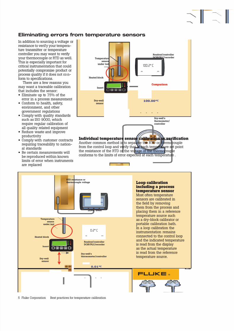
Eliminating errors from temperature sensors
In addition to sourcing a voltage orresistance to verify your tempera-ture transmitter or temperaturecontroller you may want to verify
your thermocouple or RTD as well.This is especially important forcritical instrumentation that couldpotentially compromise product orprocess quality if it does not con-form to specifications.
There are a few reasons youmay want a traceable calibrationthat includes the sensor: • Eliminate up to 75% of the
error in a process measurement• Conform to health, safety,
environment, and othergovernment regulations
• Comply with quality standardssuch as ISO 9000, whichrequire regular calibration ofall quality related equipment
• Reduce waste and improveproductivity
• Comply with customer contractsrequiring traceability to nation-al standards
• Be certain measurements willbe reproduced within knownlimits of error when instrumentsare replaced
Temperaturesensor
under test
Heated block
Insert
Dry-wellsensor
Dry-well’sthermometer/controller
Readout/controller
DCSP/PLC/recorder
Comparison
F4F3F2F1
100.00°C
ENTERMENU
100.2° C
ZERO SPAN
2200 ºC
RTD resistance orthermocouple voltage
Temperaturesensor
under test
Heated block
Insert
Dry-wellsensor
Dry-well’sthermometer/controller
Readout/controllerDCSP/PLC/recorder
F4F3F2F1
0.01°C
ENTERMENU
0.2° C
Loop calibrationincluding a processtemperature sensorMost often temperaturesensors are calibrated inthe field by removingthem from the process andplacing them in a referencetemperature source suchas a dry-block calibrator orportable calibration bath.In a loop calibration the
instrumentation remainsconnected to the control loopand the indicated temperatureis read from the displayas the actual temperatureis read from the referencetemperature source.
Individual temperature sensor calibration or verificationAnother common method is to separate the RTD or thermocouplefrom the control loop and verify that at each temperature set pointthe resistance of the RTD or the voltage of the thermocoupleconforms to the limits of error expected at each temperature.
7/25/2019 Best Practice for Temp Calibration
http://slidepdf.com/reader/full/best-practice-for-temp-calibration 6/9
6 Fluke Corporation Best practices for temperature calibration
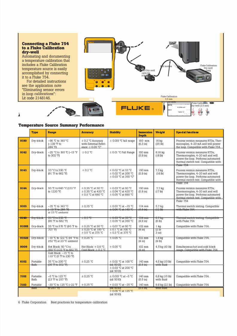
Connecting a Fluke 754to a Fluke Calibrationdry-wellAutomating and documentinga temperature calibration thatincludes a Fluke Calibrationtemperature source is easilyaccomplished by connectingit to a Fluke 754.
For detailed instructionssee the application note“Eliminating sensor errorsin loop calibrations”:Lit code 2148146.
Temperature Source Summary Performance
754 DOCUMENTING PROCESS CALIBRATOR
Null modem
Dry-well (3.5 mm)
Dry-well(DB9)Hart Dry-well
cable kit,P/N 2111088
3.5 mminterface cable
Fluke Calibration
Fluke Calibration
Fluke Calibration
Type Range Accuracy Stability ImmersionDepth
Weight Special functions
9190 Dry-block –95 °C to 140 °C(–139 °F to284 °F)
± 0.2 °C Accuracywith External Refer-ence: ± 0.05 °C”
± 0.015 °C full range 160 mm(6.3 in)
16 kg(35 lb)
Process version measures RTDs, Ther-mocouples, 4-20 mA and will powerthe loop. Compatible with Fluke 754.
9142 Dry-block –25 °C to 150 °C (–13 °Fto 302 °F)
± 0.2 °C ± 0.01 °C Full Range 150 mm(5.9 in)
8.16 kg(18 lb)
Process version measures RTDs,Thermocouples, 4-20 mA and willpower the loop. Performs automatedthermal switch test. Compatible withFluke 754
9143 Dry-block 33 °C to 350 °C(91 °F to 662 °F)
± 0.2 °C ± 0.02 °C at 33 °C± 0.02 °C at 200 °C
± 0.03 °C at 350 °C”
150 mm(5.9 in)
7.3 kg(16 lb)
Process version measures RTDs,Thermocouples, 4-20 mA and will
power the loop. Performs automatedthermal switch test. Compatible withFluke 754
9144 Dry-block 50 °C to 660 °C (122 °Fto 1220 °F)
± 0.35 °C at 50 °C± 0.35 °C at 420 °C± 0.5 °C at 660 °C
± 0.03 °C at 50 °C± 0.04 °C at 420 °C± 0.05 °C at 660 °C
150 mm(5.9 in)
7.7 kg(17 lb)
Process version measures RTDs,Thermocouples, 4-20 mA and willpower the loop. Performs automatedthermal switch test. Compatible withFluke 754
9103 Dry-block –25 °C to 140 °C(–13 °F to 284 °F)at 23 °C ambient
± 0.25 °C ± 0.02 °C at –25 °C± 0.04 °C at 140 °C
124 mm(4.9 in)
5.7 kg(12 lb)
Thermal switch testing. Compatiblewith Fluke 754.
9140 Dry-block 35 °C to 350 °C(95 °F to 662 °F)
± 0.5 °C ± 0.03 °C at 50 °C± 0.05 °C at 350 °C
124 mm(4.9 in)
2.7 kg(6 lb)
Thermal switch testing. Compatiblewith Fluke 754.
9100S Dry-block 35 °C to 375 °C (95 °F to707 °F)
± 0.25 °C at 50 °C± 0.25 °C at 100 °C± 0.5 °C at 375 °C
± 0.07 °C at 50 °C± 0.1 °C at 100 °C± 0.3 °C at 375 °C
102 mm(4 in)
1 kg(2 lb3 oz)
Compatible with Fluke 754.
9102S Dry-block –10 °C to 122 °C (14 °F to252 °F) at 23 °C ambient
± 0.25 °C ± 0.05 °C 102 mm(4 in)
1.8 kg(4 lb)
Compatible with Fluke 754.
9009 Dry-block Hot Block: 50 °C to350 °C (122 °F to 662 °F)Cold Block: –15 °C to110 °C (5 °F to 230 °F)
Hot Block: ± 0.6 °CCold Block: ± 0.2 °C
± 0.05 °C 102 mm(4 in)
4.5 kg (10 lb) Simultaneous hot and cold blockusage. Compatible with Fluke 754
6102 PortableBath
35 °C to 200 °C(95 °F to 392 °F)
± 0.25 °C ± 0.02 °C at 100 °C(oil 5013)± 0.03 °C at 200 °C(oil 5013)
140 mm(5.5 in)
4.5 kg (10 lb)with fluid
Compatible with Fluke 754.
7102 PortableBath
–5 °C to 125 °C(23 °F to 257 °F)
± 0.25 °C ± 0.015 °C at –5 °C(oil 5010)
140 mm(5.5 in)
6.8 kg (15 lb)with fluid
Compatible with Fluke 754.
7103 PortableBath
–30 °C to 125 °C (–22 °Fto 257 °F)
± 0.25 °C ± 0.03 °C at –25 °C(oil 5010)± 0.05 °C at 125 °C
(oil 5010)
140 mm(5.5 in)
9.8 kg (22 lb)with fluid
Compatible with Fluke 754.
7/25/2019 Best Practice for Temp Calibration
http://slidepdf.com/reader/full/best-practice-for-temp-calibration 7/9
7 Fluke Corporation Best practices for temperature calibration
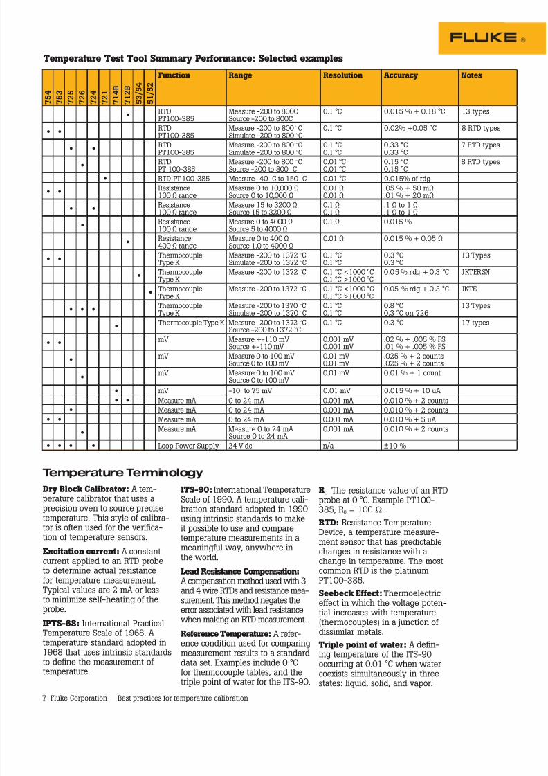
Temperature Test Tool Summary Performance: Selected examples
Dry Block Calibrator: A tem-perature calibrator that uses aprecision oven to source precisetemperature. This style of calibra-tor is often used for the verifica-tion of temperature sensors.
Excitation current: A constantcurrent applied to an RTD probeto determine actual resistancefor temperature measurement.Typical values are 2 mA or lessto minimize self-heating of theprobe.
IPTS-68: International PracticalTemperature Scale of 1968. Atemperature standard adopted in1968 that uses intrinsic standardsto define the measurement oftemperature.
ITS-90: International TemperatureScale of 1990. A temperature cali-bration standard adopted in 1990using intrinsic standards to makeit possible to use and comparetemperature measurements in ameaningful way, anywhere inthe world.
Lead Resistance Compensation: A compensation method used with 3and 4 wire RTDs and resistance mea-surement. This method negates theerror associated with lead resistancewhen making an RTD measurement.
Reference Temperature: A refer-ence condition used for comparingmeasurement results to a standarddata set. Examples include 0 °Cfor thermocouple tables, and the
triple point of water for the ITS-90.
R0 The resistance value of an RTDprobe at 0 °C. Example PT100-385, R0 = 100 Ω.
RTD: Resistance TemperatureDevice, a temperature measure-
ment sensor that has predictablechanges in resistance with achange in temperature. The mostcommon RTD is the platinumPT100-385.
Seebeck Effect: Thermoelectriceffect in which the voltage poten-tial increases with temperature(thermocouples) in a junction ofdissimilar metals.
Triple point of water: A defin-ing temperature of the ITS-90occurring at 0.01 °C when watercoexists simultaneously in threestates: liquid, solid, and vapor.
Temperature Terminology
7 5 4
7 5 3
7 2 5
7 2 6
7 2 4
7 2 1
7 1 4 B
7 1 2 B
5 3 / 5 4
5 1 / 5 2
Function Range Resolution Accuracy Notes
•RTDPT100-385
Measure -200 to 800CSource -200 to 800C
0.1 °C 0.015 % + 0.18 °C 13 types
• •RTD
PT100-385
Measure -200 to 800 °C
Simulate -200 to 800 °C
0.1 °C 0.02% +0.05 °C 8 RTD types
• •RTDPT100-385
Measure -200 to 800 °CSimulate -200 to 800 °C
0.1 °C0.1 °C
0.33 °C0.33 °C
7 RTD types
•RTDPT 100-385
Measure -200 to 800 °CSource -200 to 800 °C
0.01 °C0.01 °C
0.15 °C0.15 °C
8 RTD types
• RTD PT 100-385 Measure -40 °C to 150 °C 0.01 °C 0.015% of rdg
• •Resistance100 Ω range
Measure 0 to 10,000 ΩSource 0 to 10,000 Ω
0.01 Ω0.01 Ω
.05 % + 50 mΩ
.01 % + 20 mΩ
• •Resistance100 Ω range
Measure 15 to 3200 ΩSource 15 to 3200 Ω
0.1 Ω0.1 Ω
.1 Ω to 1 Ω
.1 Ω to 1 Ω
•Resistance100 Ω range
Measure 0 to 4000 ΩSource 5 to 4000 Ω
0.1 Ω 0.015 %
•Resistance400 Ω range
Measure 0 to 400 ΩSource 1.0 to 4000 Ω
0.01 Ω 0.015 % + 0.05 Ω
• •ThermocoupleType K
Measure -200 to 1372 °CSimulate -200 to 1372 °C
0.1 °C0.1 °C
0.3 °C0.3 °C
13 Types
• ThermocoupleType K
Measure -200 to 1372 °C 0.1 °C <1000 °C0.1 °C >1000 °C
0.05 % rdg + 0.3 °C JKTERSN
•ThermocoupleType K
Measure -200 to 1372 °C 0.1 °C <1000 °C0.1 °C >1000 °C
0.05 % rdg + 0.3 °C JKTE
• • •ThermocoupleType K
Measure -200 to 1370 °CSimulate -200 to 1370 °C
0.1 °C0.1 °C
0.8 °C0.3 °C on 726
13 Types
•Thermocouple Type K Measure -200 to 1372 °C
Source -200 to 1372 °C0.1 °C 0.3 °C 17 types
• •mV Measure +-110 mV
Source +-110 mV0.001 mV0.001 mV
.02 % + .005 % FS
.01 % + .005 % FS
•mV Measure 0 to 100 mV
Source 0 to 100 mV0.01 mV0.01 mV
.025 % + 2 counts
.025 % + 2 counts
•mV Measure 0 to 100 mV
Source 0 to 100 mV0.01 mV 0.01 % + 1 count
• mV -10 to 75 mV 0.01 mV 0.015 % + 10 uA
• • Measure mA 0 to 24 mA 0.001 mA 0.010 % + 2 counts
• Measure mA 0 to 24 mA 0.001 mA 0.010 % + 2 counts• • Measure mA 0 to 24 mA 0.001 mA 0.010 % + 5 uA
•Measure mA Measure 0 to 24 mA
Source 0 to 24 mA0.001 mA 0.010 % + 2 counts
• • • • Loop Power Supply 24 V dc n/a ±10 %
7/25/2019 Best Practice for Temp Calibration
http://slidepdf.com/reader/full/best-practice-for-temp-calibration 8/9
8 Fluke Corporation Best practices for temperature calibration
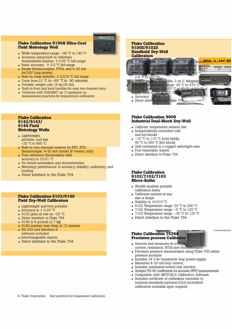
Fluke Calibration9100S/9102SHandheld Dry-Well
Calibrators• A temperature source that you can take anywhere• Fast and easy calibrations of temperature sensors• 9102S weighs only 4 lbs (1.8 kilograms)• 9102S temperature range: –10 °C to 122 °C
(14 °F to 252 °F)• 9100S weighs only 2 lbs, 3 oz (1 kilogram)• 9100S temperature range: 35 °C to 375 °C• 9100S accuracy: ± 0.07 °C at 50 °C; ± 0.1 °C at
100 °C; ± 0.3 °C at 375 °C• Accuracy: ± 0.25 °C• Direct interface to the Fluke 754
Fluke Calibration 9009Industrial Dual-Block Dry-Well
• Calibrate temperature sensors fast• Independently controlled cold
and hot blocks• –15 °C to 110 °C (cold block),
50 °C to 350 °C (hot block)• Self-contained in a rugged watertight case• Four removable inserts
• Direct interface to Fluke 754
Fluke Calibration6102/7102/7103Micro-Baths
• World’s smallest portablecalibration baths
• Calibrates sensors of anysize or shape
• Stability to ±0.015 °C• 6102 Temperature range: 35 °C to 200 °C• 7102 Temperature range: –5 °C to 125 °C• 7103 Temperature range: –30 °C to 125 °C
• Direct interface to the Fluke 754
Fluke Calibration 7526APrecision process Calibrator
• Sources and measures dc voltage,current, resistance, RTDs and thermocouples
• Precision pressure measurement using Fluke 700 seriespressure modules
• Includes 24 V dc transmitter loop power supply• Measures 4-20 mA loop current• Includes automated switch-test function• Accepts ITS-90 coefficients for accurate SPRT measurements• Compatible with MET/CAL® Calibration Software• Includes certificate of calibration traceable to
national standards (optional A2LA accredited
calibration available upon request)
Fluke Calibration 9190A Ultra-CoolField Metrology Well
• Wide temperature range: –95 °C to 140 °C
• Accuracy using built-in referencethermometer readout: ± 0.05 °C full range• Basic accuracy: ± 0.2 °C full range• Reads thermocouples, RTDs, and 4-20 mA
(w/24V Loop power)• Best-in-class stability: ± 0.015 °C full range
• Cools from 23 °C to –95 °C in 90 minutes• Portable: weighs only 16 kg (35 lbs)
• Built-in front and back handles for easy two-handed carry
• Conforms with EURAMET cg-13 guidance onmeasurement practices for temperature calibrators
Fluke Calibration9142/9143/9144 FieldMetrology Wells
• Lightweight,portable, and fast-25 °C to 660 °C
• Built-in two-channel readout for PRT, RTD,thermocouple, 4-20 mA current (P version only)
• True reference thermometry withaccuracy to ±0.01 °C
• On-board automation and documentation• Metrology performance in accuracy, stability, uniformity, and
loading
• Direct interface to the Fluke 754
Fluke Calibration 9103/9140Field Dry-Well Calibrators
• Lightweight and very portable• Accuracy to ± 0.25 °C• 9103 goes as low as –25 °C.• Direct interface to Fluke 754• 9140 is 6 pounds (2.7 kg)• 9140 reaches max temp in 12 minutes
• RS-232 and Interface-itsoftware included• Interchangeable inserts
• Direct interface to the Fluke 754
7/25/2019 Best Practice for Temp Calibration
http://slidepdf.com/reader/full/best-practice-for-temp-calibration 9/9
9 Fluke Corporation Best practices for temperature calibration
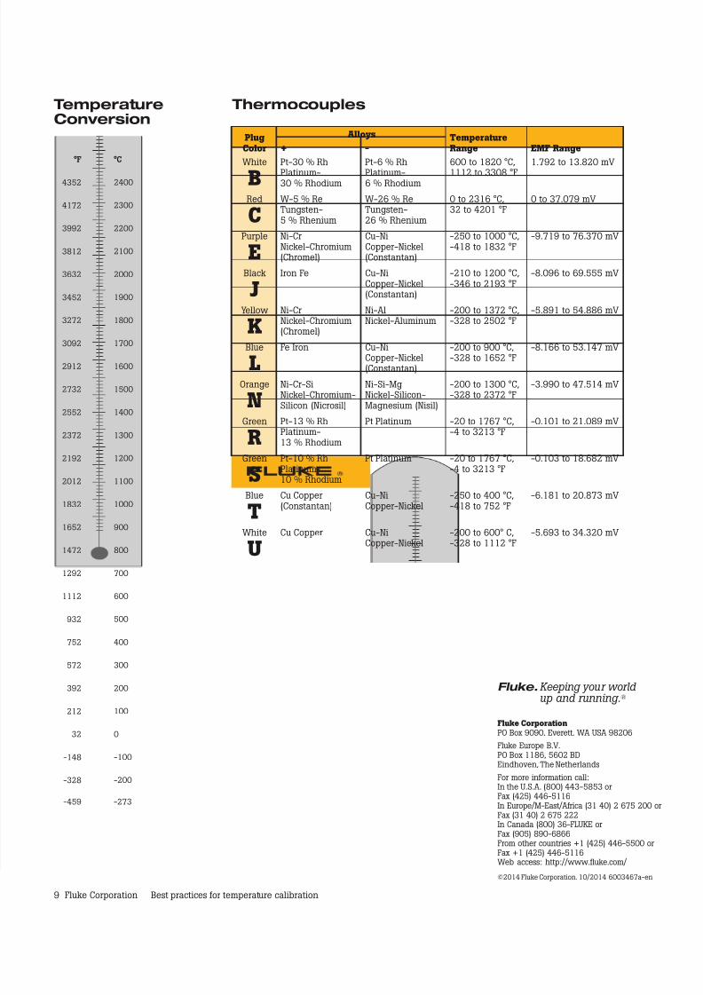
Thermocouples TemperatureConversion
°F
4352
4172
3992
3812
3632
3452
3272
3092
2912
2732
2552
2372
2192
2012
1832
1652
1472
1292
1112
932
752
572
392
212
32
-148
-328
°C
2400
2300
2200
2100
2000
1900
1800
1700
1600
1500
1400
1300
1200
1100
1000
900
800
700
600
500
400
300
200
100
0
-100
-200
-459 -273
Fluke CorporationPO Box 9090, Everett, WA USA 98206
Fluke Europe B.V.PO Box 1186, 5602 BDEindhoven, The Netherlands
For more information call:In the U.S.A. (800) 443-5853 orFax (425) 446-5116In Europe/M-East/Africa (31 40) 2 675 200 orFax (31 40) 2 675 222In Canada (800) 36-FLUKE orFax (905) 890-6866From other countries +1 (425) 446-5500 orFax +1 (425) 446-5116Web access: http://www.fluke.com/
©2014 Fluke Corporation. 10/2014 6003467a-en
Fluke. Keeping your world
up and running.®
PlugColor
Alloys TemperatureRange EMF Range+ -
White
BPt-30 % Rh
Platinum-30 % Rhodium
Pt-6 % Rh
Platinum-6 % Rhodium
600 to 1820 °C,
1112 to 3308 °F
1.792 to 13.820 mV
Red
CW-5 % ReTungsten-5 % Rhenium
W-26 % ReTungsten-26 % Rhenium
0 to 2316 °C,32 to 4201 °F
0 to 37.079 mV
Purple
ENi-CrNickel-Chromium(Chromel)
Cu-NiCopper-Nickel(Constantan)
-250 to 1000 °C,-418 to 1832 °F
-9.719 to 76.370 mV
Black
JIron Fe Cu-Ni
Copper-Nickel(Constantan)
-210 to 1200 °C,-346 to 2193 °F
-8.096 to 69.555 mV
Yellow
KNi-CrNickel-Chromium(Chromel)
Ni-AlNickel-Aluminum
-200 to 1372 °C,-328 to 2502 °F
-5.891 to 54.886 mV
Blue
LFe Iron Cu-NiCopper-Nickel
(Constantan)
-200 to 900 °C,-328 to 1652 °F -8.166 to 53.147 mV
Orange
NNi-Cr-SiNickel-Chromium-Silicon (Nicrosil)
Ni-Si-MgNickel-Silicon-Magnesium (Nisil)
-200 to 1300 °C,-328 to 2372 °F
-3.990 to 47.514 mV
Green
RPt-13 % RhPlatinum-13 % Rhodium
Pt Platinum -20 to 1767 °C,-4 to 3213 °F
-0.101 to 21.089 mV
Green
SPt-10 % RhPlatinum-10 % Rhodium
Pt Platinum -20 to 1767 °C,-4 to 3213 °F
-0.103 to 18.682 mV
Blue
T
Cu Copper(Constantan)
Cu-NiCopper-Nickel
-250 to 400 °C,-418 to 752 °F
-6.181 to 20.873 mV
White
UCu Copper Cu-Ni
Copper-Nickel-200 to 600° C,-328 to 1112 °F
-5.693 to 34.320 mV