Embed Size (px)
Citation preview
BeLT COnveyOR
Section content
Bolt-Together StraightBolt-Together Incline/DeclineWelded StraightBelt CurveOptional Equipment and Devices
15
P.O. Box 352 n Alpena, Michigan 49707Phone 989.358.7000Fax [email protected]

17
8" Dia. DRive Pulley
4" Dia. Pulley
2 1/2" Dia. snuB RolleR
BeLt conVeYoR
A 4" - 36"B 3' - 102'C 16" - 84"D A + 5"e A + 9 1/8"F A + 2"
A = Belt Width (BW) (1" Increments) B = Overall Length (OAL) (Any Increment)C = Top of Belt (TOB)D = Bed Width E = Overall Drive Width F = Between Frame (BF)
Bc
SLiDeR BeD
B
inteRMeDiate sections
5 1/2"
8" enD DRive
3"
12" 12"
3" - 9"**4" Dia. take-uP Pulley
FlowFinGeR GuaRD
RolleR ReMoveD wHen take-uP close to enD
2 1/2" Dia. snuB RolleR
1.9" Dia. RetuRn RolleR
4" Dia. DRive Pulley
FlowFinGeR GuaRD
10 1/16"
12"
inteRMeDiate sections
5 1/2"
3"
12" 12"
3"4" Dia. PulleyFlow
4" enD DRive
**Dependent upon overall conveyor length
c
8" CenTeR DRive
c
B
c8" Dia. DRive Pulley
D
a
e
F
D
a
e
F
Why BC?
n Provides the most versatile means of handling a wide variety of products n Achieves higher speeds than other conveyor types n Many belt options for specific applications n Common applications include assembly, sorting, inspecting and transportation
6"
4" Dia. take-uP Pulley
Belt wiDtH (Bw)
3 1/2"
1.9" Dia. RetuRn RolleR
FoRMeD steel BeD
BeD wiDtH = Bw + 5"
18
2 1/2" Dia. snuB RolleR
4" Dia. Pulley
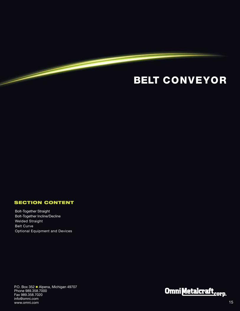
A 4" - 36"B 3' - 102'C 16" - 84"D A + 5"e A + 9 1/8"F A + 2"
A = Belt Width (BW) (1" Increments) B = Overall Length (OAL) (Any Increment)C = Top of Belt (TOB)D = Bed WidthE = Overall Drive Width F = Between Frame (BF)
RoLLeR BeD
inteRMeDiate sections
5 1/2"
8" enD DRive
3"
12" 12"
3" - 9"**4" Dia. take-uP Pulley
FlowFinGeR GuaRD
RolleR ReMoveD wHen take-uP close to enD
2 1/2" Dia. snuB RolleR
1.9" Dia. RetuRn RolleR
4" Dia. DRive Pulley
8" Dia. DRive Pulley Flow
FinGeR GuaRD
10 1/16"
12"
inteRMeDiate sections
5 1/2"
3"
12" 12"
3"4" Dia. PulleyFlow
1.9" Dia. RetuRn RolleR
4" enD DRive
1.9" Dia. BeD RolleR
6"
8" CenTeR DRive
**Dependent upon overall conveyor length
B
c
c
B
c
DRiVe LocationS
LeFT enD CenTeR RiGhT enD
Re
ve
Rs
iBle
Flo
w
Flo
w
D
a
e
F
D
a
e
F4" Dia. take-uP Pulley
Note: A short belt segment laced on both ends, commonly called a “dutchman”, is provided with conveyors over 47' OAL. This allows future belt stretch with standard end take-up. If short segment is not desired, a center drive/take-up is required.
Belt wiDtH (Bw)
5 1/2"
1.9" Dia. RetuRn RolleR
oveRall wiDtH = Bw + 5"
1.9" Dia. BeD RolleR
7/16"Between FRaMe = Bw + 2"1 1/2"

19
BeLt conVeYoR incLineBci
A = Angle B = Bed Length C = Bed Width (1" Increments)*D = Infeed/Discharge Bed LengthE = Overall Drive Width*
*Reference horizontal belt for end views
STyLe 3 DeCLine BeLT COnveyOR
STyLe 2 inCLineD BeLT COnveyOR
STyLe 1 inCLineD BeLT COnveyOR
Flow
Flow
nose oveR
B
FlooR sPace
liFt
a
B
FlooR sPace
liFt
Flow
B
FlooR sPace
nose oveR
3" - 9"**
**Dependent upon overall conveyor length
12"
6"
12"
3"
nose oveR
a
D 12"
D 12" liFt
12"
3"
a
A 7.5° - 27.5°B 5' - 50'C 6" - 36"D 1' - 9'e A + 9 1/8"
20
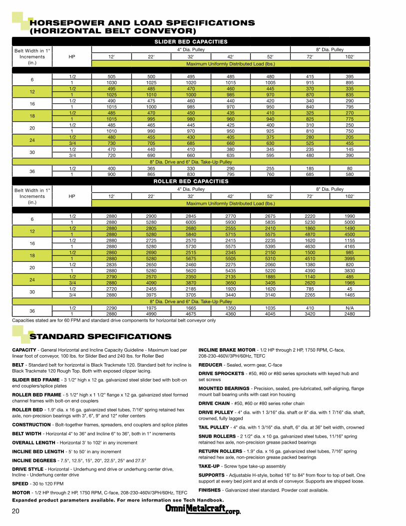
SLiDeR BeD CAPACiTieS
Belt Width in 1" Increments
(in.)HP
4" Dia. Pulley 8" Dia. Pulley
12' 22' 32' 42' 52' 72' 102'
Maximum Uniformly Distributed Load (lbs.)
6 1/2 505 500 495 485 480 415 395
1 1030 1025 1020 1015 1005 915 895
12 1/2 495 485 470 460 445 370 335
1 1025 1010 1000 985 970 870 835
16 1/2 490 475 460 440 420 340 290
1 1015 1000 985 970 950 840 795
18 1/2 485 470 450 435 410 325 270
1 1015 995 980 960 940 825 775
20 1/2 485 465 445 425 400 310 250
1 1010 990 970 950 925 810 750
24 1/2 480 455 430 405 375 280 205 3/4 730 705 685 660 630 525 455
30 1/2 470 440 410 380 345 235 145 3/4 720 690 660 635 595 480 390
8" Dia. Drive and 6" Dia. Take-Up Pulley
36 1/2 400 365 330 290 255 185 80
1 900 865 830 795 760 685 580
CAPACiTy - General Horizontal and Incline Capacity Guideline - Maximum load per linear foot of conveyor, 100 lbs. for Slider Bed and 240 lbs. for Roller Bed
BeLT - Standard belt for horizontal is Black Trackmate 120. Standard belt for incline is Black Trackmate 120 Rough Top. Both with exposed clipper lacing.
SLiDeR BeD FRAMe - 3 1/2" high x 12 ga. galvanized steel slider bed with bolt-on end couplers/splice plates
ROLLeR BeD FRAMe - 5 1/2" high x 1 1/2" flange x 12 ga. galvanized steel formed channel frames with bolt-on end couplers
ROLLeR BeD - 1.9" dia. x 16 ga. galvanized steel tubes, 7/16" spring retained hex axle, non-precision bearings with 3", 6", 9" and 12" roller centers
COnSTRUCTiOn - Bolt-together frames, spreaders, end couplers and splice plates
BeLT WiDTh - Horizontal 4" to 36" and Incline 6" to 36", both in 1" increments
OveRALL LenGTh - Horizontal 3' to 102' in any increment
inCLine BeD LenGTh - 5' to 50' in any increment
inCLine DeGReeS - 7.5°, 12.5°, 15°, 20°, 22.5°, 25° and 27.5°
DRive STyLe - Horizontal - Underhung end drive or underhung center drive, Incline - Underhung center drive
SPeeD - 30 to 120 FPM
MOTOR - 1/2 HP through 2 HP, 1750 RPM, C-face, 208-230-460V/3PH/60Hz, TEFC
StanDaRD SPeciFicationS
inCLine BRAKe MOTOR - 1/2 HP through 2 HP, 1750 RPM, C-face, 208-230-460V/3PH/60Hz, TEFC
ReDUCeR - Sealed, worm gear, C-face
DRive SPROCKeTS - #50, #60 or #80 series sprockets with keyed hub and set screws
MOUnTeD BeARinGS - Precision, sealed, pre-lubricated, self-aligning, flange mount ball bearing units with cast iron housing
DRive ChAin - #50, #60 or #80 series roller chain
DRive PULLey - 4" dia. with 1 3/16" dia. shaft or 8" dia. with 1 7/16" dia. shaft, crowned, fully lagged
TAiL PULLey - 4" dia. with 1 3/16" dia. shaft, 6" dia. at 36" belt width, crowned
SnUB ROLLeRS - 2 1/2" dia. x 10 ga. galvanized steel tubes, 11/16" spring retained hex axle, non-precision grease packed bearings
ReTURn ROLLeRS - 1.9" dia. x 16 ga. galvanized steel tubes, 7/16" spring retained hex axle, non-precision grease packed bearings
TAKe-UP - Screw type take-up assembly
SUPPORTS - Adjustable H-style, bolted 16" to 84" from floor to top of belt. One support at every bed joint and at ends of conveyor. Supports are shipped loose.
FiniSheS - Galvanized steel standard. Powder coat available.
hoRSePoWeR anD LoaD SPeciFicationS (hoRizontaL BeLt conVeYoR)
ROLLeR BeD CAPACiTieS
Belt Width in 1" Increments
(in.)HP
4" Dia. Pulley 8" Dia. Pulley
12' 22' 32' 42' 52' 72' 102'
Maximum Uniformly Distributed Load (lbs.)
6 1/2 2880 2900 2845 2770 2675 2220 1990
1 2880 5280 6005 5930 5835 5230 5000
12 1/2 2880 2805 2680 2555 2410 1860 1490
1 2880 5280 5840 5715 5575 4870 4500
16 1/2 2880 2725 2570 2415 2235 1620 1155
1 2880 5280 5730 5575 5395 4630 4165
18 1/2 2860 2690 2515 2345 2150 1500 985
1 2880 5280 5675 5505 5310 4510 3995
20 1/2 2835 2650 2460 2275 2060 1380 820
1 2880 5280 5620 5435 5220 4390 3830
24 1/2 2790 2570 2350 2135 1885 1140 485 3/4 2880 4090 3870 3650 3405 2620 1965
30 1/2 2720 2455 2185 1920 1620 785 45 3/4 2880 3975 3705 3440 3140 2265 1465
8" Dia. Drive and 6" Dia. Take-Up Pulley
36 1/2 2290 1975 1665 1350 1035 410 N/A
1 2880 4990 4675 4360 4045 3420 2480Capacities stated are for 60 FPM and standard drive components for horizontal belt conveyor only
expanded product parameters available. For more information see Tech handbook.

BeLt SPeciFicationS
BeLTBLACK TRACKMATe 120
(hORiZOnTAL STAnDARD)
BLACK TRACKMATe 120 ROUGh TOP
(inCLine STAnDARD)BLACK OMniThAne 150 WhiTe PvC 120
Characteristics Excellent Tracking Friction Surface Cut and Abrasion Resistant Non-Marking
Cover Embossed PVC Rough Top PVC Smooth Polyurethane Smooth PVC
Strength 120 PIW 120 PIW 150 PIW 120 PIW
Thickness .1" .23" .16" .14"
Lacing Clipper
Other types of belt available upon request
PORTABLE H-STANDS
KNEE BRACE SUPPORTS
SiDe GUiDeS - Available in fixed or adjustable with multiple contact surfaces. Allows product to be guided and kept in place within the conveying surface. Side guides are bolted to the conveyor frame.
Fixed Angle Side Guides - Standard 1 1/2" x 2" high or 1 1/2" x 6" high formed, 12 ga. angle
Fixed Channel Side Guides - Standard 2 1/2" high or 3 1/2" high, 12 ga. formed channel
UHMW Fixed Angle Side Guides - Replaceable UHMW face provides wear protection for angle guides
Adjustable Rail UHMW Side Guides - Replaceable UHMW face provides wear protection on rails, width and height adjustable
Tall Fixed Channel Side Guides - Higher formed angle for tall product
Tall Fixed Channel Side Guides with Gussets - Higher formed and gusseted angle for tall product
Tall Fixed Channel Side Guides with Threaded Rod - Higher formed angle with threaded rod adjustment for tall product
Fixed Angle Side Guides with Spacer Bar - Spacer bar allows side guide to overlap belt to remove gap
Skatewheel Side Guides - Vertically mounted skatewheels
Side Guides with Belt Skirts - Belt skirts attached to formed angle to keep product off the belt edges
Flared Side Guides - Funnel type side guides for guiding product during loading (v-guided belt only)
oPtionaL equiPMent anD DeViceS
SuppOrTS - Available with caster options for portability. Supports are designed to be bolted to the conveyor frame. Supports are shipped loose.
Knee Brace Supports - Formed angle brace adds stability to conveyor and leg supports
Portable H-Stands - 3" x 1 1/2" x 12 ga. formed channel leg uprights (800 lbs. capacity)
TALL FIXED CHANNEL SIDE GUIDES
TALL FIXED CHANNEL SIDE GUIDES WITH GUSSETS
TALL FIXED CHANNEL SIDE GUIDES WITH
THREADED ROD
SKATEWHEEL SIDE GUIDES
SIDE GUIDES WITH BELT SKIRTS FLARED SIDE GUIDES
UHMW FIXED ANGLE SIDE GUIDES
FIXED CHANNEL SIDE GUIDES
FIXED ANGLE SIDE GUIDES
ADjUSTABLE RAIL UHMW SIDE GUIDES
FIXED ANGLE SIDE GUIDES WITH SPACER BAR
21
SuppOrTS
SidE GuidES

oPtionaL equiPMent anD DeViceS
RECESSED HIDDEN
FLAPOVER STANDARD (EXPOSED)
cleaR
SHAFT MOUNT END DRIVE
MOTORIZED PULLEy OVERTOP END DRIVE
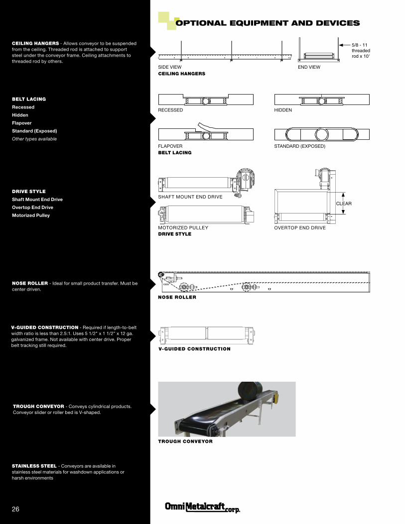
CEiLiNG HANGErS - Allows conveyor to be suspended from the ceiling. Threaded rod is attached to support steel under the conveyor frame. Ceiling attachments to threaded rod by others.
5/8 - 11 threaded rod x 10'
SIDE VIEW END VIEW
NOSE rOLLEr
NOSE rOLLEr - Ideal for small product transfer. Must be center driven.
TrOuGH CONvEyOr
TrOuGH CONvEyOr - Conveys cylindrical products. Conveyor slider or roller bed is V-shaped.
v-GuidEd CONSTruCTiON - Required if length-to-belt width ratio is less than 2.5:1. Uses 5 1/2" x 1 1/2" x 12 ga. galvanized frame. Not available with center drive. Proper belt tracking still required.
STAiNLESS STEEL - Conveyors are available in stainless steel materials for washdown applications or harsh environments
22
v-GuidEd CONSTruCTiON
CEiLiNG HANGErS
BELT LACiNG
drivE STyLE
BELT LACiNG
Recessed
Hidden
Flapover
Standard (Exposed)
Other types available
drivE STyLE
Shaft Mount End Drive
Overtop End Drive
Motorized Pulley

23
8" Dia. DRive Pulley
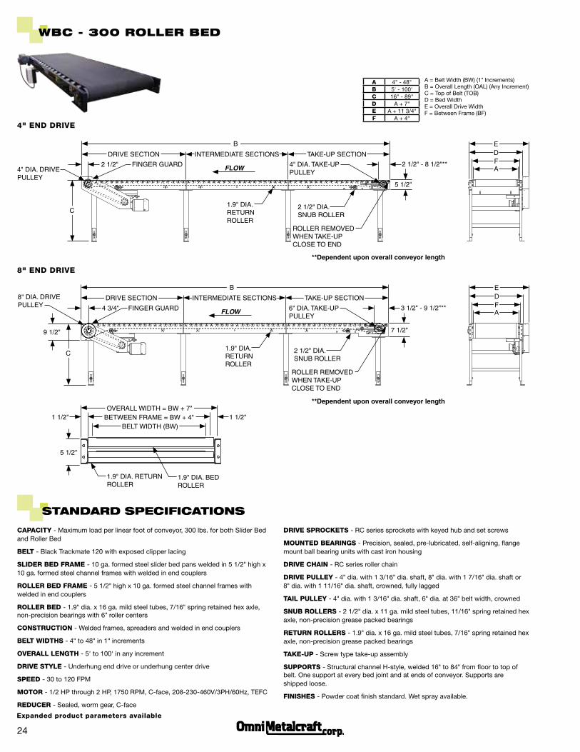
WeLDeD BeLt conVeYoR
A 4" - 48"B 5' - 100'C 16" - 89"D A + 7"e A + 11 3/4"F A + 4"
A = Belt Width (BW) (1" Increments) B = Overall Length (OAL) (Any Increment)C = Top of Belt (TOB) D = Bed Width E = Overall Drive Width F = Between Frame (BF)
WBc
WBc - 300 SLiDeR BeD
4" enD DRive
Why WBC?
n Stronger welded frame construction than bolt-together frame n Provides the most versatile means of handling a wide variety of products n Achieves higher speeds than other conveyor types n Many belt options for specific applications n Common applications include assembly, sorting, inspecting and transportation
D
a
e
F
8" enD DRive
B
inteRMeDiate sections
5 1/2"
2 1/2" 2 1/2" - 8 1/2"**4" Dia. take-uP Pulley
FlowBeD acts as FinGeR GuaRD
RolleR ReMoveD wHen take-uP close to enD
2 1/2" Dia. snuB RolleR
1.9" Dia. RetuRn RolleR
c
4" Dia. DRive Pulley
D
a
e
F
B
inteRMeDiate sections
7 1/2"
4 3/4" 3 1/2" - 9 1/2"**6" Dia. take-uP Pulley
FlowBeD acts as FinGeR GuaRD
RolleR ReMoveD wHen take-uP close to enD
2 1/2" Dia. snuB RolleR
1.9" Dia. RetuRn RolleR
c
**Dependent upon overall conveyor length
**Dependent upon overall conveyor length
DRiVe LocationS
LeFT enD CenTeR RiGhT enD
Re
ve
Rs
iBle
Flo
w
Flo
w
DRive section take-uP section
Belt wiDtH (Bw)
5 1/2"
1.9" Dia. RetuRn RolleR
oveRall wiDtH = Bw + 7"
10 Ga. FoRMeD steel sliDeR Pan
Between FRaMe = Bw + 4"1 1/2"
9 1/2"
DRive section take-uP section
24
CAPACiTy - Maximum load per linear foot of conveyor, 300 lbs. for both Slider Bed and Roller Bed
BeLT - Black Trackmate 120 with exposed clipper lacing
SLiDeR BeD FRAMe - 10 ga. formed steel slider bed pans welded in 5 1/2" high x 10 ga. formed steel channel frames with welded in end couplers
ROLLeR BeD FRAMe - 5 1/2" high x 10 ga. formed steel channel frames with welded in end couplers
ROLLeR BeD - 1.9" dia. x 16 ga. mild steel tubes, 7/16" spring retained hex axle, non-precision bearings with 6" roller centers
COnSTRUCTiOn - Welded frames, spreaders and welded in end couplers
BeLT WiDThS - 4" to 48" in 1" increments
OveRALL LenGTh - 5' to 100' in any increment
DRive STyLe - Underhung end drive or underhung center drive
SPeeD - 30 to 120 FPM
MOTOR - 1/2 HP through 2 HP, 1750 RPM, C-face, 208-230-460V/3PH/60Hz, TEFC
ReDUCeR - Sealed, worm gear, C-face
StanDaRD SPeciFicationS
DRive SPROCKeTS - RC series sprockets with keyed hub and set screws
MOUnTeD BeARinGS - Precision, sealed, pre-lubricated, self-aligning, flange mount ball bearing units with cast iron housing
DRive ChAin - RC series roller chain
DRive PULLey - 4" dia. with 1 3/16" dia. shaft, 8" dia. with 1 7/16" dia. shaft or 8" dia. with 1 11/16" dia. shaft, crowned, fully lagged
TAiL PULLey - 4" dia. with 1 3/16" dia. shaft, 6" dia. at 36" belt width, crowned
SnUB ROLLeRS - 2 1/2" dia. x 11 ga. mild steel tubes, 11/16" spring retained hex axle, non-precision grease packed bearings
ReTURn ROLLeRS - 1.9" dia. x 16 ga. mild steel tubes, 7/16" spring retained hex axle, non-precision grease packed bearings
TAKe-UP - Screw type take-up assembly
SUPPORTS - Structural channel H-style, welded 16" to 84" from floor to top of belt. One support at every bed joint and at ends of conveyor. Supports are shipped loose.
FiniSheS - Powder coat finish standard. Wet spray available.
A 4" - 48"B 5' - 100'C 16" - 89"D A + 7"e A + 11 3/4"F A + 4"
A = Belt Width (BW) (1" Increments) B = Overall Length (OAL) (Any Increment)C = Top of Belt (TOB) D = Bed Width E = Overall Drive Width F = Between Frame (BF)
WBc - 300 RoLLeR BeD
4" enD DRive
D
a
e
F
8" enD DRive
B
inteRMeDiate sections
5 1/2"
2 1/2" 2 1/2" - 8 1/2"**4" Dia. take-uP Pulley
FlowFinGeR GuaRD
RolleR ReMoveD wHen take-uP close to enD
2 1/2" Dia. snuB RolleR
1.9" Dia. RetuRn RolleR
c
4" Dia. DRive Pulley
D
a
e
F
B
7 1/2"
4 3/4" 3 1/2" - 9 1/2"**6" Dia. take-uP Pulley
FlowFinGeR GuaRD
RolleR ReMoveD wHen take-uP close to enD
2 1/2" Dia. snuB RolleR
1.9" Dia. RetuRn RolleR
c
8" Dia. DRive Pulley
**Dependent upon overall conveyor length
**Dependent upon overall conveyor length
DRive section take-uP section
DRive section take-uP sectioninteRMeDiate sections
9 1/2"
Belt wiDtH (Bw)
5 1/2"
1.9" Dia. RetuRn RolleR
oveRall wiDtH = Bw + 7"
1.9" Dia. BeD RolleR
Between FRaMe = Bw + 4"1 1/2" 1 1/2"
expanded product parameters available

BeLt SPeciFicationS
BeLT BLACK TRACKMATe 120BLACK TRACKMATe 120
ROUGh TOPBLACK OMniThAne 150 WhiTe PvC 120
Characteristics Excellent Tracking Friction Surface Cut and Abrasion Resistant Non-Marking
Cover Embossed PVC Rough Top PVC Smooth Polyurethane Smooth PVC
Strength 120 PIW 120 PIW 150 PIW 120 PIW
Thickness .1" .23" .16" .14"
Lacing Clipper
Other types available upon request
SiDe GUiDeS - Available in fixed or adjustable with multiple contact surfaces. Allows product to be guided and kept in place within the conveying surface. Side guides are bolted to the conveyor frame.
Fixed Angle Side Guides - Standard 1 1/2" x 2" high or 1 1/2" x 6"high formed, 10 ga. angle
Fixed Channel Side Guides - Standard 2 1/2" high or 3 1/2" high, 10 ga. formed channel
UHMW Fixed Angle Side Guides - Replaceable UHMW face provides wear protection for angle guides
Adjustable Rail UHMW Side Guides - Replaceable UHMW face provides wear protection on rails, width and height adjustable
Tall Fixed Channel Side Guides - Higher formed angle for tall product
Tall Fixed Channel Side Guides with Gussets - Higher formed and gusseted angle for tall product
Tall Fixed Channel Side Guides with Threaded Rod - Higher formed angle with threaded rod adjustment for tall product
Fixed Angle Side Guides with Spacer Bar - Spacer bar allows side guide to overlap belt to remove gap
Skatewheel Side Guides - Vertically mounted skatewheels
Side Guides with Belt Skirts - Belt skirts attached to formed angle to keep product off the belt edges
Flared Side Guides - Funnel type side guides for guiding product during loading (v-guided belt only)
oPtionaL equiPMent anD DeViceS
25
TALL FIXED CHANNEL SIDE GUIDES
TALL FIXED CHANNEL SIDE GUIDES WITH GUSSETS
TALL FIXED CHANNEL SIDE GUIDES WITH
THREADED ROD
SKATEWHEEL SIDE GUIDES
SIDE GUIDES WITH BELT SKIRTS FLARED SIDE GUIDES
UHMW FIXED ANGLE SIDE GUIDES
FIXED CHANNEL SIDE GUIDES
FIXED ANGLE SIDE GUIDES
ADjUSTABLE RAIL UHMW SIDE GUIDES
FIXED ANGLE SIDE GUIDES WITH SPACER BAR
SidE GuidES
PORTABLE H-STANDS
KNEE BRACE SUPPORTS
SuppOrTS
SuppOrTS - Available with caster options for portability. Supports are designed to be bolted to the conveyor frame. Supports are shipped loose.
Knee Brace Supports
Portable H-Stands
26
oPtionaL equiPMent anD DeViceS
NOSE rOLLEr
RECESSED HIDDEN
FLAPOVER STANDARD (EXPOSED)
cleaR
SHAFT MOUNT END DRIVE
MOTORIZED PULLEy OVERTOP END DRIVE
CEiLiNG HANGErS - Allows conveyor to be suspended from the ceiling. Threaded rod is attached to support steel under the conveyor frame. Ceiling attachments to threaded rod by others.
5/8 - 11 threaded rod x 10'
SIDE VIEW END VIEW
TrOuGH CONvEyOr
TrOuGH CONvEyOr - Conveys cylindrical products. Conveyor slider or roller bed is V-shaped.
v-GuidEd CONSTruCTiON - Required if length-to-belt width ratio is less than 2.5:1. Uses 5 1/2" x 1 1/2" x 12 ga. galvanized frame. Not available with center drive. Proper belt tracking still required.
STAiNLESS STEEL - Conveyors are available in stainless steel materials for washdown applications or harsh environments
v-GuidEd CONSTruCTiON
CEiLiNG HANGErS
BELT LACiNG
drivE STyLE
NOSE rOLLEr - Ideal for small product transfer. Must be center driven.
BELT LACiNG
Recessed
Hidden
Flapover
Standard (Exposed)
Other types available
drivE STyLE
Shaft Mount End Drive
Overtop End Drive
Motorized Pulley
27
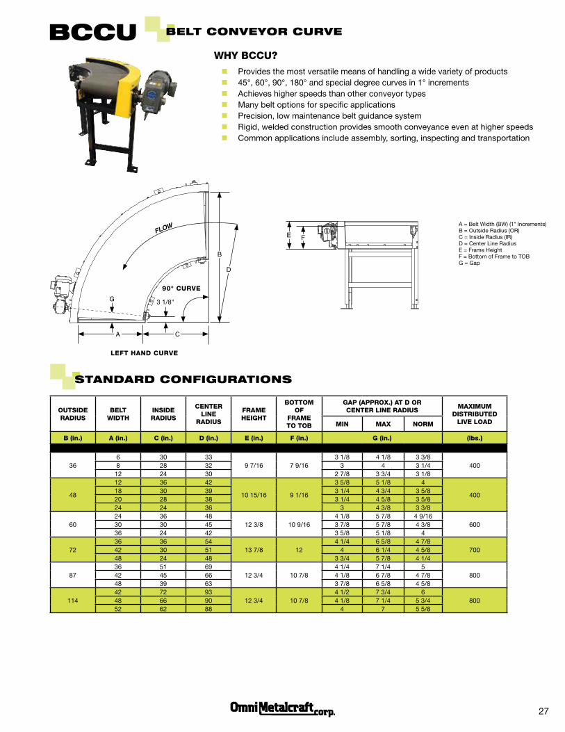
OUTSiDe RADiUS
BeLT WiDTh
inSiDe RADiUS
CenTeR Line
RADiUS
FRAMe heiGhT
BOTTOM OF
FRAMe TO TOB
GAP (APPROX.) AT D OR CenTeR Line RADiUS
MAXiMUM DiSTRiBUTeD
Live LOADMin MAX nORM
B (in.) A (in.) C (in.) D (in.) e (in.) F (in.) G (in.) (lbs.)
366 30 33
9 7/16 7 9/163 1/8 4 1/8 3 3/8
4008 28 32 3 4 3 1/412 24 30 2 7/8 3 3/4 3 1/8
48
12 36 42
10 15/16 9 1/16
3 5/8 5 1/8 4
40018 30 39 3 1/4 4 3/4 3 5/820 28 38 3 1/4 4 5/8 3 5/824 24 36 3 4 3/8 3 3/8
6024 36 48
12 3/8 10 9/164 1/8 5 7/8 4 9/16
60030 30 45 3 7/8 5 7/8 4 3/836 24 42 3 5/8 5 1/8 4
7236 36 54
13 7/8 124 1/4 6 5/8 4 7/8
70042 30 51 4 6 1/4 4 5/848 24 48 3 3/4 5 7/8 4 1/4
8736 51 69
12 3/4 10 7/84 1/4 7 1/4 5
80042 45 66 4 1/8 6 7/8 4 7/848 39 63 3 7/8 6 5/8 4 5/8
11442 72 93
12 3/4 10 7/84 1/2 7 3/4 6
80048 66 90 4 1/8 7 1/4 5 3/452 62 88 4 7 5 5/8
StanDaRD conFiguRationS
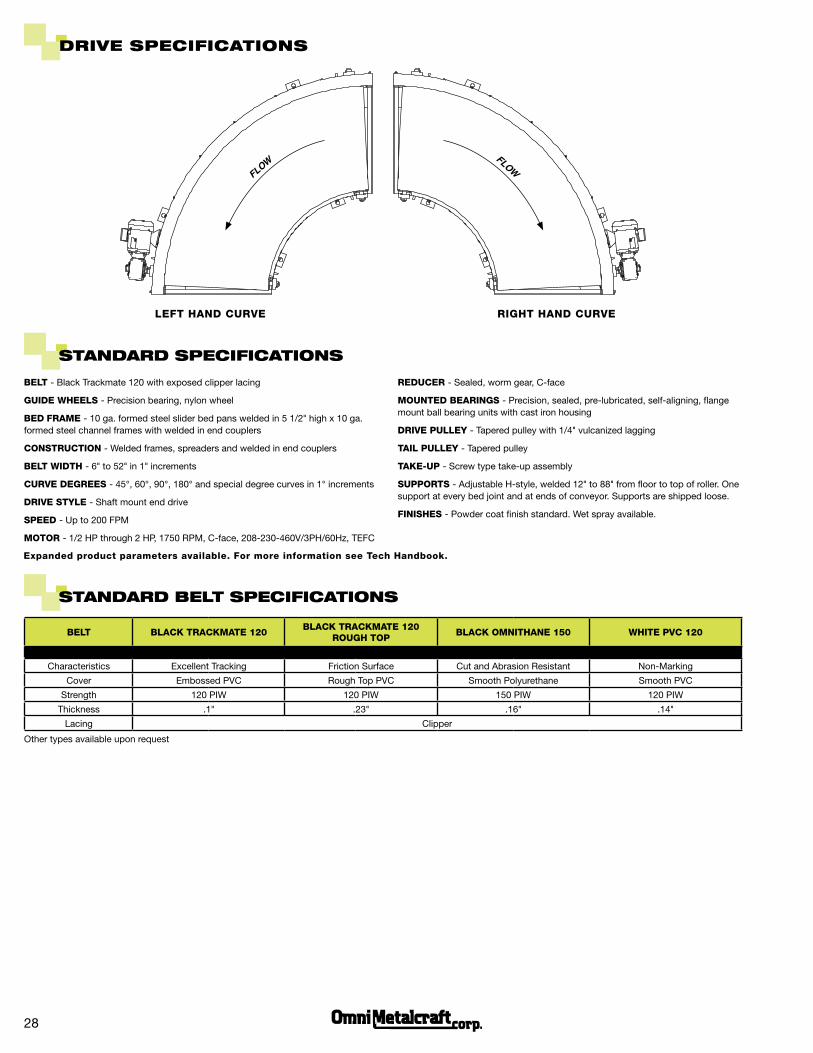
BeLt conVeYoR cuRVe
A = Belt Width (BW) (1" Increments) B = Outside Radius (OR)C = Inside Radius (IR)D = Center Line Radius E = Frame Height F = Bottom of Frame to TOB G = Gap
Bccu
3 1/8"
a c
B
90° CURve
e
Why BCCU?
n Provides the most versatile means of handling a wide variety of products n 45°, 60°, 90°, 180° and special degree curves in 1° increments n Achieves higher speeds than other conveyor types n Many belt options for specific applications n Precision, low maintenance belt guidance system n Rigid, welded construction provides smooth conveyance even at higher speeds n Common applications include assembly, sorting, inspecting and transportation
G
D
Flow
F
LeFT hAnD CURve
28
DRiVe SPeciFicationS
BeLT - Black Trackmate 120 with exposed clipper lacing
GUiDe WheeLS - Precision bearing, nylon wheel
BeD FRAMe - 10 ga. formed steel slider bed pans welded in 5 1/2" high x 10 ga. formed steel channel frames with welded in end couplers
COnSTRUCTiOn - Welded frames, spreaders and welded in end couplers
BeLT WiDTh - 6" to 52" in 1" increments
CURve DeGReeS - 45°, 60°, 90°, 180° and special degree curves in 1° increments
DRive STyLe - Shaft mount end drive
SPeeD - Up to 200 FPM
MOTOR - 1/2 HP through 2 HP, 1750 RPM, C-face, 208-230-460V/3PH/60Hz, TEFC
StanDaRD SPeciFicationS
ReDUCeR - Sealed, worm gear, C-face
MOUnTeD BeARinGS - Precision, sealed, pre-lubricated, self-aligning, flange mount ball bearing units with cast iron housing
DRive PULLey - Tapered pulley with 1/4" vulcanized lagging
TAiL PULLey - Tapered pulley
TAKe-UP - Screw type take-up assembly
SUPPORTS - Adjustable H-style, welded 12" to 88" from floor to top of roller. One support at every bed joint and at ends of conveyor. Supports are shipped loose.
FiniSheS - Powder coat finish standard. Wet spray available.
StanDaRD BeLt SPeciFicationS
LeFT hAnD CURve RiGhT hAnD CURve
expanded product parameters available. For more information see Tech handbook.
FlowFlow
BeLT BLACK TRACKMATe 120BLACK TRACKMATe 120
ROUGh TOPBLACK OMniThAne 150 WhiTe PvC 120
Characteristics Excellent Tracking Friction Surface Cut and Abrasion Resistant Non-Marking
Cover Embossed PVC Rough Top PVC Smooth Polyurethane Smooth PVC
Strength 120 PIW 120 PIW 150 PIW 120 PIW
Thickness .1" .23" .16" .14"
Lacing Clipper
Other types available upon request
FIXED ANGLE SIDE GUIDES
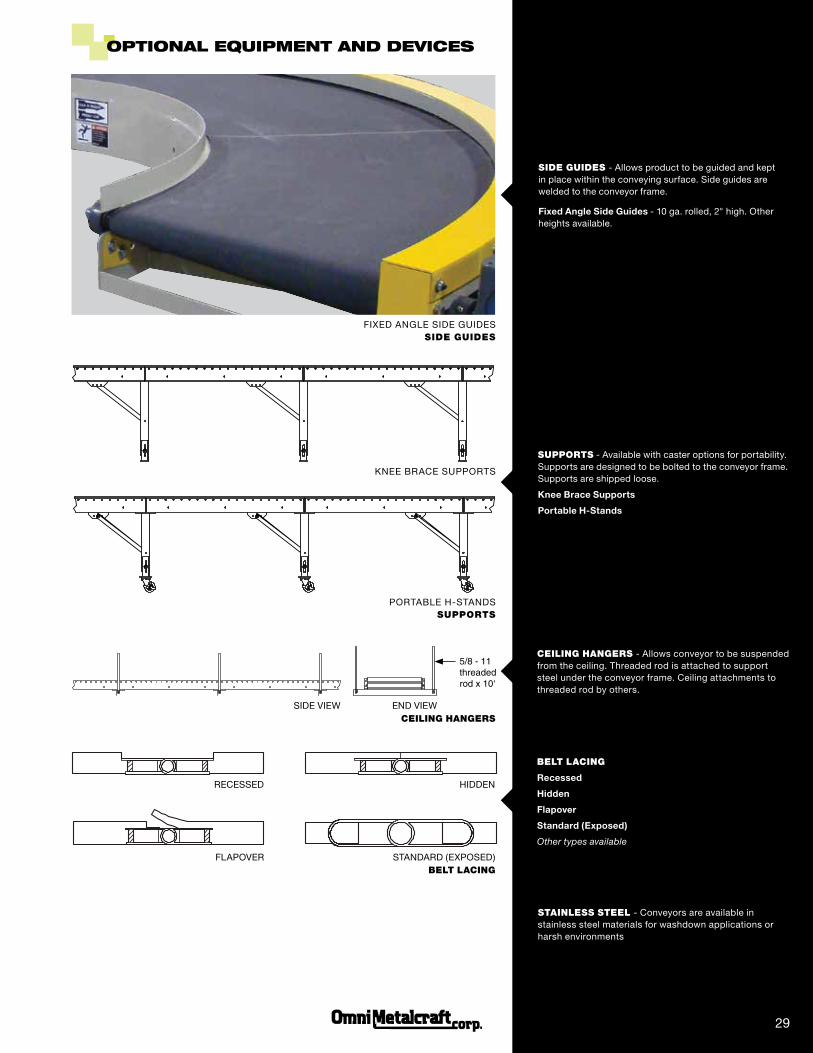
SuppOrTS - Available with caster options for portability. Supports are designed to be bolted to the conveyor frame. Supports are shipped loose.
Knee Brace Supports
Portable H-Stands
KNEE BRACE SUPPORTS
PORTABLE H-STANDS
SidE GuidES - Allows product to be guided and kept in place within the conveying surface. Side guides are welded to the conveyor frame.
Fixed Angle Side Guides - 10 ga. rolled, 2" high. Other heights available.
CEiLiNG HANGErS - Allows conveyor to be suspended from the ceiling. Threaded rod is attached to support steel under the conveyor frame. Ceiling attachments to threaded rod by others.
BELT LACiNG
Recessed
Hidden
Flapover
Standard (Exposed)
Other types available
oPtionaL equiPMent anD DeViceS
STAiNLESS STEEL - Conveyors are available in stainless steel materials for washdown applications or harsh environments
29
RECESSED HIDDEN
FLAPOVER STANDARD (EXPOSED)
5/8 - 11 threaded rod x 10'
SIDE VIEW END VIEW
SidE GuidES
SuppOrTS
CEiLiNG HANGErS
BELT LACiNG