Embed Size (px)
Citation preview

EDKVF93−05.6v_
Ä.6v_ä
Information for the operator of the machine
9300 vector 250 ... 400 kW
�
EVF9381 ... EVF9383
Frequency inverter
efesotomasyon.com - Lenze

This documentation is valid for ...
... 9300 vector frequency inverters as of nameplate data:
� � � Nameplate
Type EVF 93xx ˘ x V Vxx 1x 7x
EVF 93xx ˘ x V Vxx Vx 6x
Product series
EVF = Frequency inverter
EVM = Master of frequency inverter
EVL = Slave of frequency inverter
Type no. / rated power
400 V 500 V
9381 = 250 kW 315 kW
9382 = 315 kW 400 kW
9383 = 400 kW 500 kW
Type
E = Panel−mounted unit
Design
V = Vector−controlled frequency inverter
Variant
Integrated RFI filter A
Integrated brake transistor
– 400 V – –
V030 = 400 V � –
V060 = 400 V – �
V110 = 400 V � �
V210 = 400 V / 500 V – –
V240 = 400 V / 500 V � –
V270 = 400 V / 500 V – �
V300 = 400 V / 500 V � �
Hardware version
Software version
xx = Slave (no software version)
efesotomasyon.com - Lenze
� Note!This documentation contains all the information required by the machine operator torun the drive controllers of the 9300 vector series installed in your machine/system.
You may make further use of the information contained in this documentation withoutasking Lenze for permission if you do not change the contents.
0Fig. 0Tab. 0
� Tip!Current documentation and software updates concerning Lenze products can be foundon the Internet in the "Services & Downloads" area under
http://www.Lenze.com
© 2007 Lenze Drive Systems GmbH, Hans−Lenze−Straße 1, D−31855 AerzenWe have compiled all information in this documentation with great care und have checked it with regard to compliance withthe hardware and software described. Nevertheless, we cannot entirely exclude deviations. We do not accept legalresponsibility or liability for damage possibly resulting therefrom. We will include necessary amendments in the subsequenteditions.
efesotomasyon.com - Lenze

5
1
5
1
1
5
E2
E4
E5
39
13
428
E1
E3
23
37
K32
62
K31
GN
DA
1A
2A
3A
4S
T1
ST2
59
34
76
3LO
HIX4
X3
X1
X11
X8
X9
X10
X5
X6
� �
+UGL1 L2 L3 BR1 BR2 U V W-UG +UGL1 L2 L3 PEPE BR1 BR2 U V W-UG
L1, L2, L3, PEL1, L2, L3, PE
U, V, WU, V, W
+UG, -UG+UG, -UG
BR1, BR2BR1, BR2
�
9300vec0181
efesotomasyon.com - Lenze

Key for overview
Position Description
� 9300 vector frequency inverter − master
� 9300 vector frequency inverter − slave
Connections and interfaces
Position Description
L1, L2, L3, PE Mains connection
+UG, −UG DC supply (only for the variants V210, V240, V270, V300)
BR1, BR2 Connection of brake resistor (only for the variants V210, V240, V270, V300)
U, V, W, PE Motor connection
X1 AIF interface (automation interface)slot for communication module (e.g. keypad XT EMZ9371BC)
X3 Jumper for setting the analog input signal at X6/1, X6/2
X4 Terminal strip for connection of system bus (CAN)
X5 Terminal strips for connection of digital inputs and outputs
X6 Terminal strips for connection of analog inputs and outputs
X8 Sub−D connector (male) for connection of incremental encoder with TTL level or sin/cos encoder and KTYthermal sensor of the motor
X9 Sub−D connector (male) for connection of digital frequency input signal
X10 Sub−D connector (female) for connection of digital frequency output signal
X11 Terminal strip for connection of relay output KSR for "safe standstill"
Status displays
Position LED red LED green Operating status
� Off On Controller is enabled
On On Mains is switched on and automatic start is inhibited
Off Blinking slowly Controller is inhibited
Off On Motor data identification is active
Blinking quickly Off Undervoltage or overvoltage
Blinking slowly Off Active fault
efesotomasyon.com - Lenze

Contentsi
� 6 EDKVF93−05 EN 1.0
1 Safety instructions 7 . . . . . . . . . . . . . . . . . . . . . . . . . . . . . . . . . . . . . . . . . . . . . . . . . . . . . . . . .
1.1 General safety and application instructions for Lenze controllers 7 . . . . . . . . . . . . .
1.2 Residual hazards 10 . . . . . . . . . . . . . . . . . . . . . . . . . . . . . . . . . . . . . . . . . . . . . . . . . . . . .
1.3 Definition of notes used 11 . . . . . . . . . . . . . . . . . . . . . . . . . . . . . . . . . . . . . . . . . . . . . . .
2 Parameter setting 12 . . . . . . . . . . . . . . . . . . . . . . . . . . . . . . . . . . . . . . . . . . . . . . . . . . . . . . . . .
2.1 Parameter setting with the XT EMZ9371BC keypad 12 . . . . . . . . . . . . . . . . . . . . . . . .
2.1.1 General data and operating conditions 12 . . . . . . . . . . . . . . . . . . . . . . . . . .
2.1.2 Installation and commissioning 13 . . . . . . . . . . . . . . . . . . . . . . . . . . . . . . . .
2.1.3 Display elements and function keys 13 . . . . . . . . . . . . . . . . . . . . . . . . . . . . .
2.1.4 Changing and saving parameters 15 . . . . . . . . . . . . . . . . . . . . . . . . . . . . . . .
2.1.5 Loading a parameter set 17 . . . . . . . . . . . . . . . . . . . . . . . . . . . . . . . . . . . . . . .
2.1.6 Transfering parameters to other standard devices 18 . . . . . . . . . . . . . . . . .
2.1.7 Activating password protection 20 . . . . . . . . . . . . . . . . . . . . . . . . . . . . . . . . .
2.1.8 Diagnostics 21 . . . . . . . . . . . . . . . . . . . . . . . . . . . . . . . . . . . . . . . . . . . . . . . . . .
2.1.9 Menu structure 22 . . . . . . . . . . . . . . . . . . . . . . . . . . . . . . . . . . . . . . . . . . . . . .
3 Troubleshooting and fault elimination 24 . . . . . . . . . . . . . . . . . . . . . . . . . . . . . . . . . . . . . . .
3.1 Display of operating data, diagnostics 24 . . . . . . . . . . . . . . . . . . . . . . . . . . . . . . . . . . .
3.1.1 Display of operating data 24 . . . . . . . . . . . . . . . . . . . . . . . . . . . . . . . . . . . . . .
3.1.2 Diagnostics 25 . . . . . . . . . . . . . . . . . . . . . . . . . . . . . . . . . . . . . . . . . . . . . . . . . .
3.2 Troubleshooting 26 . . . . . . . . . . . . . . . . . . . . . . . . . . . . . . . . . . . . . . . . . . . . . . . . . . . . .
3.2.1 Status display (LEDs on the controller) 26 . . . . . . . . . . . . . . . . . . . . . . . . . . .
3.2.2 Fault analysis with the history buffer 27 . . . . . . . . . . . . . . . . . . . . . . . . . . . .
3.3 Drive behaviour in the event of faults 28 . . . . . . . . . . . . . . . . . . . . . . . . . . . . . . . . . . . .
3.4 Error elimination 29 . . . . . . . . . . . . . . . . . . . . . . . . . . . . . . . . . . . . . . . . . . . . . . . . . . . . .
3.4.1 Drive errors 29 . . . . . . . . . . . . . . . . . . . . . . . . . . . . . . . . . . . . . . . . . . . . . . . . . .
3.4.2 Controller in clamp operation 30 . . . . . . . . . . . . . . . . . . . . . . . . . . . . . . . . . . .
3.4.3 Fault messages on the keypad or in the parameter setting program Global Drive Control 33 . . . . . . . . . . . . . . . . . . . . . . . . . . . . . . . . . . . . . . . . . . .
3.5 Resetting error messages 38 . . . . . . . . . . . . . . . . . . . . . . . . . . . . . . . . . . . . . . . . . . . . . .
efesotomasyon.com - Lenze

Safety instructionsGeneral safety and application instructions for Lenze controllers
1
� 7EDKVF93−05 EN 1.0
1 Safety instructions
1.1 General safety and application instructions for Lenze controllers
(According to: Low−Voltage Directive 73/23/EEC)
For you personal safety
Lenze controllers (frequency inverters, servo inverters, DC speed controllers) and theaccessory components can include live and rotating parts − depending on their type ofprotection − during operation. Surfaces can be hot.
Unauthorised removal of the required cover, inappropriate use, incorrect installation oroperation, create the risk of severe injury to persons or damage to material assets.
High amounts of energy are released in the controller. Thus, it is required to always weara personal protective equipment (body protection, headgear, eye protection, earprotection, hand guard).
All operations concerning transport, installation, and commissioning as well asmaintenance must be carried out by qualified, skilled personnel (IEC 364 and CENELEC HD384 or DIN VDE 0100 and IEC report 664 or DIN VDE 0110 and national regulations for theprevention of accidents must be observed).
According to this basic safety information, qualified, skilled personnel are persons who arefamiliar with the assembly, installation, commissioning, and operation of the product andwho have the qualifications necessary for their occupation.
Application as directed
Drive controllers are components which are designed for installation in electrical systemsor machinery. They are not to be used as household appliances. They are intendedexclusively for professional and commercial purposes according to EN 61000−3−2.
When installing the controllers into machines, commissioning (i.e. starting of operation asdirected) is prohibited until it is proven that the machine complies with the regulations ofthe EC Directive 98/37/EC (Machinery Directive); EN 60204 must be observed.
Commissioning (i.e. starting of operation as directed) is only allowed when there iscompliance with the EMC Directive (89/336/EEC).
The controllers meet the requirements of the Low−Voltage Directive 73/23/EEC. Theharmonised standard EN 61800−5−1 applies to the controllers.
The technical data and information on connection conditions must be obtained from thenameplate and the documentation. They must be observed in any case.
Warning: The controllers can be used according to EN 61800−3 in drive systems of thecategory C2. These products can cause radio interferences in residential areas. In this case,special measures are required.
efesotomasyon.com - Lenze

Safety instructionsGeneral safety and application instructions for Lenze controllers
1
� 8 EDKVF93−05 EN 1.0
Transport, storage
Please observe the notes on transport, storage and appropriate handling.
Observe the climatic conditions according the technical data.
Installation
The controllers must be installed and cooled according to the instructions given in thecorresponding documentation.
Ensure proper handling and avoid mechanical stress. Do not bend any components and donot change any insulation distances during transport or handling. Do not touch anyelectronic components and contacts.
Controllers contain electrostatically sensitive components, which can easily be damagedby inappropriate handling. Do not damage or destroy any electrical components since thismight endanger your health!
Electrical connection
When working on live controllers, the valid national regulations for the prevention ofaccidents (e.g. VBG 4) must be observed.
The electrical installation must be carried out according to the appropriate regulations(e.g. cable cross−sections, fuses, PE connection). Additional information can be obtainedfrom the documentation.
The documentation contains information about installation in compliance with EMC(shielding, earthing, filter arrangement, and cable installation). These notes must also beobserved for CE−marked controllers. The manufacturer of the system or machine isresponsible for ensuring compliance with the limit values demanded by the EMClegislation. The controllers must be installed in housings (e.g. control cabinets) to complywith the limit values for radio interferences valid at the site of installation. The housingsmust enable an EMC−compliant installation. Make sure in particular that e.g. the controlcabinet doors have a circumferential metal connection to the housing. Reduce housingopenings and cutouts to a minimum.
Lenze controllers can cause a DC current in the protective conductor. If a residual currentdevice (RCD) is used as a protective means in the case of direct or indirect contact, only aresidual current device (RCD) of type B may be used on the current supply side of thecontroller. Otherwise, another protective measure, such as separation from theenvironment through double or reinforced insulation or disconnection from the mains bymeans of a transformer must be used.
efesotomasyon.com - Lenze

Safety instructionsGeneral safety and application instructions for Lenze controllers
1
� 9EDKVF93−05 EN 1.0
Operation
If necessary, systems including controllers must be equipped with additional monitoringand protection devices according to the valid safety regulations (e.g. law on technicalequipment, regulations for the prevention of accidents). The controller can be adapted toyour application. Please observe the corresponding information given in thedocumentation.
After a controller has been disconnected from the voltage supply, all live components andpower connections must not be touched immediately because capacitors can still becharged. Please observe the corresponding stickers on the controller.
All protection covers and doors must be shut during operation.
Note for UL approved systems with integrated controllers: UL warnings are notes that onlyapply to UL systems. The documentation contains special information about UL.
Safety functions
Certain variants of the drive controller support safety functions (e.g. "safe torque off",formerly "safe standstill") according to the requirements of Appendix I No. 1.2.7 of the ECMachinery Directive 98/37/EC, EN 954−1 Category 3 and EN 1037. You must observe thenotes pertaining to the safety functions in the documentation for the variants.
Maintenance and servicing
The controllers do not require any maintenance if the prescribed conditions of operationare observed.
If the ambient air is polluted, the cooling surfaces of the controller may become dirty or theair vents of the controller may be obstructed. Therefore, clean the cooling surfaces and airvents periodically under these operating conditions. Do not use sharp or pointed tools forthis purpose!
Waste disposal
Recycle metal and plastic materials. Ensure professional disposal of assembled PCBs.
The product−specific safety and application notes given in these instructions must beobserved!
efesotomasyon.com - Lenze

Safety instructionsResidual hazards
1
� 10 EDKVF93−05 EN 1.0
1.2 Residual hazards
Protection of persons
ƒ Before working on the controller, check that no voltage is applied to the powerterminals:
– The power terminals U, V, W, +UG, −UG, BR1, BR2 and 101 ... 104 remain live for atleast five minutes after disconnecting the mains.
– The power terminals L1, L2, L3, U, V, W, +UG, −UG, BR1, BR2 and 101 ... 104 remainlive with the motor stopped.
ƒ The leakage current to earth (PE) is > 3.5 mA. According to EN 50178 a fixedinstallation is required.
ƒ The heatsink of the controller has an operating temperature of > 80 °C:
– Contact with the heatsink results in burns.
ƒ If you use the "flying−restart circuit" function (C0142 = 2, 3) for machines with a lowmoment of inertia and minimum friction:
– After the controller is enabled at standstill, the motor can start briefly or changebriefly the direction of rotation since the flying restart process is executed at zerospeed as well.
ƒ During parameter set transfer, the control terminals of the controller can haveundefined states!
– Therefore the plugs X5 and X6 must be pulled off before the transfer is executed.This ensures that the controller is inhibited and all control terminals have thespecified "LOW" state.
Device protection
ƒ Frequent mains switching (e.g. inching mode via mains contactor) can overload anddestroy the input current limitation of the controller.
– Thus, at least five minutes have to pass between two switch−on processes.
– In case of frequent, safety−related disconnections use the "safe torque off" safetyfunction (STO).
Motor protection
ƒ Certain drive controller settings can overheat the connected motor:
– E. g. long−time operation of the DC injection brake.
– Long−time operation of self−ventilated motors at low speeds.
Protection of the machine/system
ƒ Drives can reach dangerous overspeeds (e. g. setting of high output frequencies inconnection with motors and machines not suitable for this purpose):
– The drive controllers do not provide protection against such operating conditions.For this purpose, use additional components.
efesotomasyon.com - Lenze

Safety instructionsDefinition of notes used
1
� 11EDKVF93−05 EN 1.0
1.3 Definition of notes used
The following pictographs and signal words are used in this documentation to indicatedangers and important information:
Safety instructions
Structure of safety instructions:
� Danger!(characterises the type and severity of danger)
Note
(describes the danger and gives information about how to prevent dangeroussituations)
Pictograph and signal word Meaning
� Danger!Danger of personal injury through dangerous electrical voltage.Reference to an imminent danger that may result in death or seriouspersonal injury if the corresponding measures are not taken.
� Danger!Danger of personal injury through a general source of danger.Reference to an imminent danger that may result in death or seriouspersonal injury if the corresponding measures are not taken.
Stop!Danger of property damage.Reference to a possible danger that may result in property damage if thecorresponding measures are not taken.
Application notes
Pictograph and signal word Meaning
� Note! Important note to ensure troublefree operation
� Tip! Useful tip for simple handling
Reference to another documentation
efesotomasyon.com - Lenze

Parameter settingParameter setting with the XT EMZ9371BC keypadGeneral data and operating conditions
2
� 12 EDKVF93−05 EN 1.0
2 Parameter setting
2.1 Parameter setting with the XT EMZ9371BC keypad
Description
The keypad is available as an accessory. A full description of the keypad can be obtainedfrom the Instructions included in the keypad delivery.
Plugging in the keypad
It is possible to plug the keypad into the AIF interface or remove it during operation.
As soon as the keypad is supplied with voltage, it carries out a self−test. The keypad is readyfor operation if it is in display mode.
2.1.1 General data and operating conditions
� ��
� �
�
� ����SHPRG
Para
Code
Menu
0050 00
50.00_Hz
M C T R L - N O U T
0 b
ca
9371BC011
Feature Values
Dimensions
Width a 60 mm
Height b 73.5 mm
Depth c 15 mm
Environmental conditions
Climate
Storage IEC/EN 60721−3−1 1K3 (−25 ... +60 °C)
Transport IEC/EN 60721−3−2 2K3 (−25 ... +70 °C)
Operation IEC/EN 60721−3−3 3K3 (−10 ... +60 °C)
Enclosure IP 20
efesotomasyon.com - Lenze
Parameter settingParameter setting with the XT EMZ9371BC keypad
Installation and commissioning
2
� 13EDKVF93−05 EN 1.0
2.1.2 Installation and commissioning
�
��
�
�
�
�
�
�
���
SHPRG Pa
raCode
Menu 00
5000
50.00_Hz
MCTRL-NOUT
E82ZWLxxx
� ��
� �
�
� ����SHPRG
Para
Code
Menu
0050 00
50.00_Hz
M C T R L - N O U T
E82ZBBXC
EMZ9371BC
� ��
� �
�
� ����SHPRG
Para
Code
Menu
0050 00
G L O B A L D R I V E
I n i t
� ��
� �
�
�
0050 00
50.00 Hz
2 0 %
� ��
� �
�
�
0050 00
50.00 Hz
2 0 %
�
�
�� ��� �
�
� �
9371BC018
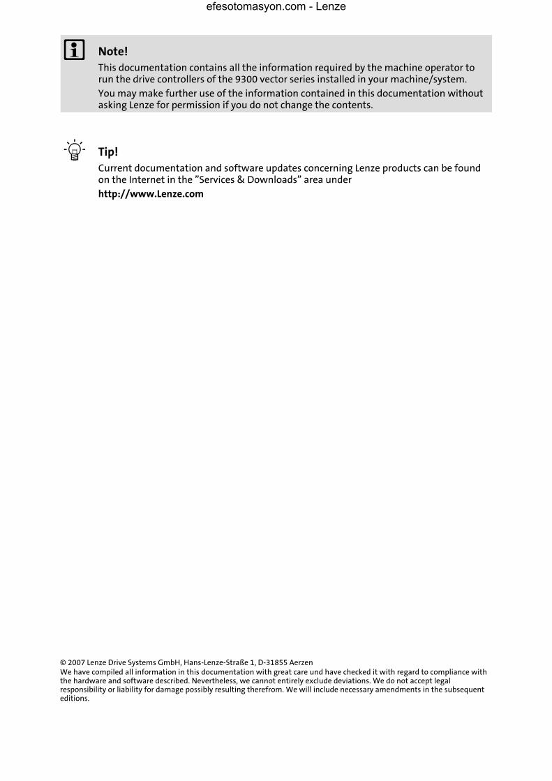
Fig.2−1 Installation and commissioning of XT EMZ9371BC keypad or E82ZBBXC diagnosis terminal
� Connect keypad to the AIF interface on the front of the standard device.
The keypad can be connected/disconnected during operation.
� As soon as the keypad is supplied with voltage, it carries out a short self−test.
� The operation level indicates, when the keypad is ready for operation:
� Current state of the standard device
� Memory location 1 of the user menu (C0517):
Code number, subcode number, and current value
� Active fault message or additional status message
� Actual value in % of the status display defined in C0004
� must be pressed to leave the operation level
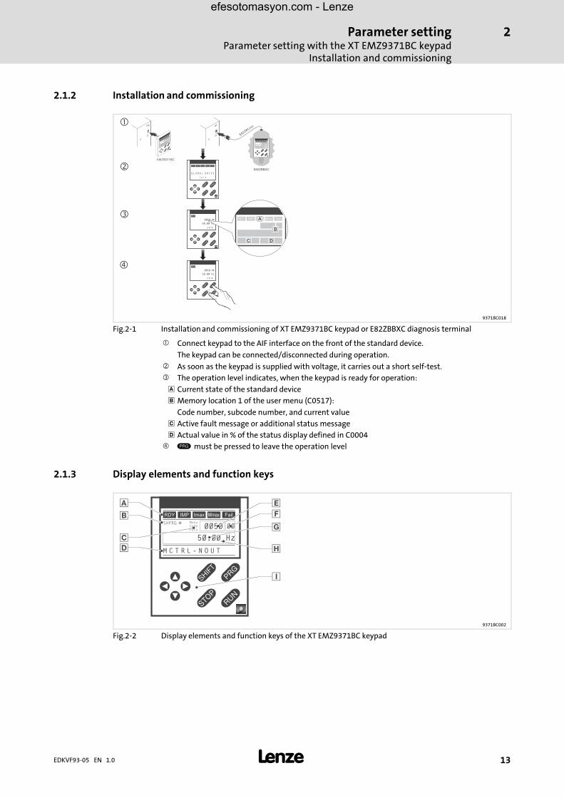
2.1.3 Display elements and function keys
� ��
� �
�
� ����SHPRG
Para
Code
Menu
0050 00
50.00_Hz
M C T R L - N O U T
�
�
�
�
�
�
�
�
�
9371BC002
Fig.2−2 Display elements and function keys of the XT EMZ9371BC keypad
efesotomasyon.com - Lenze
Parameter settingParameter setting with the XT EMZ9371BC keypadDisplay elements and function keys
2
� 14 EDKVF93−05 EN 1.0
Displays
Display Meaning Explanation
� Status displays of standard device
� Ready for operation
� Pulse inhibit is active Power outputs are inhibited
� Set current limit is exceeded in motor orgenerator mode
� Speed controller 1 in its limitation Drive is torque−controlled(Only active for operation with standard devicesof 9300 series)
� Active fault
� Parameter acceptance
� Parameter is accepted �immediately � Standard device operates immediately with thenew parameter value
SHPRG � Parameter must be confirmed with �
Standard device operates with the new parametervalue after being confirmed
SHPRG When the controller is inhibited theparameter must be confirmed with �
Standard device operates with the new parametervalue after the controller is re−enabled
None Display parameter Change is not possible
� Active level
Menu Menu level is active Select main menu and submenus
Code Code level is active Select codes and subcodes
Para Parameter level is active Change parameters in the codes or subcodes
None Operating level is active Display operating parameters
� Short text
Alphanumeric Contents of the menus, meaning of thecodes and parameters
In the operating level C0004 (in %) andthe active fault are displayed
� Number
Menu level With active level:Menu number
Only active for operation with standard devices of8200 vector or 8200 motec series
Code level With active level:Four−digit code number
� Number
Menu level With active level:Submenu number
Only active for operation with standard devices of8200 vector or 8200 motec series
Code level With active level:Two−digit subcode number
� Parameter value
Parameter value with unit
� Cursor
In the parameter level, the figure above the cursorcan be changed directly
� Function keys
For description see the following table
efesotomasyon.com - Lenze
Parameter settingParameter setting with the XT EMZ9371BC keypad
Changing and saving parameters
2
� 15EDKVF93−05 EN 1.0
Function keys
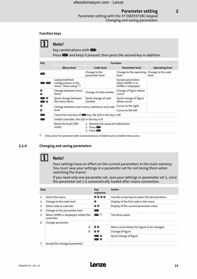
� Note!Key combinations with �:
Press � and keep it pressed, then press the second key in addition.
Key Function
Menu level Code level Parameter level Operating level
Change to theparameter level
Change to the operatinglevel
Change to the codelevel
� Load predefinedconfigurations in themenu "Short setup" 1)
Accept parameterswhen SHPRG � orSHPRG is displayed
�
�
Change between menuitems
Change of code numberChange of figure abovecursor
� �
� �
Quick change betweenthe menu items
Quick change of codenumber
Quick change of figureabove cursor
� Change between main menu, submenus and codelevel
Cursor to the right
� Cursor to the left
� Cancel the function of � key, the LED in the key is off
� Inhibit controller, the LED in the key is lit
Reset the fault (TRIPreset):
1. Remedy the cause of malfunction2. Press �3. Press �
1) Only active for operation with standard devices of 8200 vector or 8200 motec series
2.1.4 Changing and saving parameters
� Note!Your settings have an effect on the current parameters in the main memory.You must save your settings in a parameter set for not losing them whenswitching the mains!
If you need only one parameter set, save your settings in parameter set 1, sincethe parameter set 1 is automatically loaded after mains connection.
Step Keysequence
Action
1. Select the menu � � � � Use the arrow keys to select the desired menu
2. Change to the code level � Display of the first code in the menu
3. Select code or subcode � � Display of the current parameter value
4. Change to the parameter level
5. When SHPRG is displayed, inhibit thecontroller
� 1) The drive coasts
6. Change parameter
A � � Move cursor below the figure to be changed
B � � Change of figure
� �
� �
Quick change of figure
7. Accept the changed parameter
efesotomasyon.com - Lenze

Parameter settingParameter setting with the XT EMZ9371BC keypadChanging and saving parameters
2
� 16 EDKVF93−05 EN 1.0
ActionKeysequence
Step
Display of SHPRG or SHPRG � � Confirm change to accept the parameterDisplay "OK"
Display � − The parameter has been accepted immediately
8. Enable the controller, if required � 1) The drive runs again
9. Change to the code level
A Display of the operating level
B Display of the code with changed parameter
10. Change further parameters Restart the "loop" with step 1. or 3.
11. Save changed parameters
A � � � � Select the code C0003 "PAR SAVE" in the menu"Load/Store"
B Change to the parameter levelDisplay "0" and "READY"
Select the parameter set in whichthe parameters are to be savedpermanently
C � Save as parameter set 1:� Set "1" "Save PS1"
Save as parameter set 2:� Set "2" "Save PS2"
Save as parameter set 3:� Set "3" "Save PS3"
Save as parameter set 4:� Set "4" "Save PS4"
D � When "OK" is displayed, the settings are permanentlysaved in the selected parameter set.
12. Change to the code level
A Display of the operating level
B Display of C0003 "PAR SAVE"
13. Set parameters for another parameterset
Restart the "loop" with step 1. or 3.
1) The function of the � key can be programmed:C0469 = 1: Controller inhibitC0469 = 2: Quick stop (Lenze setting)
efesotomasyon.com - Lenze

Parameter settingParameter setting with the XT EMZ9371BC keypad
Loading a parameter set
2
� 17EDKVF93−05 EN 1.0
2.1.5 Loading a parameter set
The keypad serves to load a saved parameter set into the main memory when the controlleris inhibited. After the controller is enabled, it operates with the new parameters.
� Danger!ƒ When a new parameter set is loaded, the controller is reinitialised and acts
as if it had been connected to the mains:– ��System configurations and terminal assignments can be changed. Make
sure that your wiring and drive configuration comply with the settings ofthe parameter set.
ƒ Only use terminal X5/28 as source for the controller inhibit! Otherwise thedrive may start in an uncontrolled way when switching over to anotherparameter set.
� Note!ƒ After switching on the supply voltage, the controller always loads parameter
set 1 into the main memory.
ƒ It is also possible to load other parameter sets into the main memory via thedigital inputs or bus commands.
Step Keysequence
Action
1. Inhibit controller Terminal X5/28 = LOW
2. Load the saved parameter set into themain memory
A � � � � Select the code C0002 "PAR LOAD" in the menu"Load/Store"
B Change to the parameter levelThe active parameter set is displayed, e. g. display "0"and "Load Default"If you want to restore the delivery status, proceed withD
Select the parameter set to beloaded
C � Load parameter set 1:� Set "1" "Load PS1"
Load parameter set 2:� Set "2" "Load PS2"
Load parameter set 3:� Set "3" "Load PS3"
Load parameter set 4:� Set "4" "Load PS4"
D � "RDY" goes off. The parameter set is loaded completelyinto the main memory if "RDY" is displayed again.
3. Change to the code level
A Display of the operating level
B Display of C0002 "PAR LOAD"
4. Enable controller Terminal X5/28 = HIGHThe drive is running with the settings of the loadedparameter set
efesotomasyon.com - Lenze

Parameter settingParameter setting with the XT EMZ9371BC keypadTransfering parameters to other standard devices
2
� 18 EDKVF93−05 EN 1.0
2.1.6 Transfering parameters to other standard devices
The keypad enables you to copy parameter settings from one standard device to another.
For this purpose use the "Load/Store" menu:
� Danger!During the transfer of the parameters from the keypad to the controller, thecontrol terminals may adopt undefined states!
For this reason it is imperative you disconnect connectors X5 and X6 from thecontroller prior to the transfer. In this way you will ensure that the drivecontroller is inhibited and all control terminals are in the defined "LOW" state.
Copying parameter sets from the standard device to the keypad
� Note!After the parameter sets are copied to the keypad XT (C0003 = 11), theparameter set last loaded using C0002 is always activated.
So the actual parameters remain active also after copying:
ƒ Prior to copying, save the actual parameters in the parameter set and loadthis parameter set into the drive controller using C0002.
Step Keysequence
Action
1. Connect keypad to controller 1
2. Inhibit controller Terminal X5/28 = LOWThe drive coasts.
3. On the "Load/Store" menu selectC0003
� � � � On the "Load/Store" menu select code C0003 "PARSAVE" using the arrow keys.
4. Change to the parameter level Display "0" and "READY"
5. Copy all parameter sets to the keypad The settings stored in the keypad are overwritten.
� Set "11" "Save extern"
6. Start copying � The "RDY" status display goes off. "BUSY" is indicatedas parameter value.When "BUSY" goes off after approx. one minute, allparameter sets have been copied to the keypad. The"RDY" status display illuminates.
7. Change to the code level
A Display of the operating level
B Display of C0003 and "PAR SAVE"
8. Enable controller Terminal X5/28 = HIGH
9. Remove keypad from controller 1
efesotomasyon.com - Lenze

Parameter settingParameter setting with the XT EMZ9371BC keypad
Transfering parameters to other standard devices
2
� 19EDKVF93−05 EN 1.0
Copying parameter sets from the keypad to the standard device
Step Keysequence
Action
1. Connect keypad to controller 2
2. Inhibit controller Terminal X5/28 = LOWThe "IMP" status display illuminates.The drive coasts
3. Disconnect connectors X5 and X6 All control terminals have the defined "LOW" state.
4. On the "Load/Store" menu selectC0002
� � � � On the "Load/Store" menu select code C0002 "PARLOAD" using the arrow keys.
5. Change to the parameter level The active parameter set is displayed, e. g. display "0"and "Load Default"
6. Select the correct copy function The settings stored in the controller are overwritten.
� Copy all available parameter sets to thecontroller and save in non−volatile memory.
The parameters are not yet active after copying. Selectparameter set and load into main memory. ! 17
� Set "20" "ext −> EEPROM"
� Copy individual parameter sets to main memory.
� Copy parameter set 1:� Set "11" "Load ext PS1"
Copy parameter set 2:� Set "12" "Load ext PS2"
Copy parameter set 3:� Set "13" "Load ext PS3"
Copy parameter set 4:� Set "14" "Load ext PS4"
7. Start copying � The "RDY" status display goes off. "BUSY" is indicatedas parameter value.When "BUSY" goes off, all selected parameter setshave been copied to the controller. The "RDY" statusdisplay illuminates.
8. Change to the code level
A Display of the operating level
B Display of C0002 and "PAR LOAD"
9. Save individually copied parametersets in non−volatile memory
� � � � On the "Load/Store" menu select code C0003 "PARSAVE" using arrow keys and save contents of the mainmemory in non−volatile memory.
10. Connect connectors X5 and X6
11. Enable controller Terminal X5/28 = HIGHThe drive runs with the new settings.
efesotomasyon.com - Lenze
Parameter settingParameter setting with the XT EMZ9371BC keypadActivating password protection
2
� 20 EDKVF93−05 EN 1.0
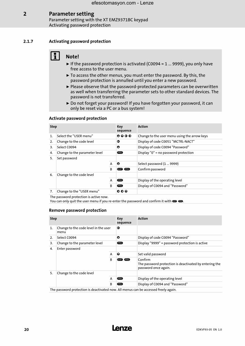
2.1.7 Activating password protection
� Note!ƒ If the password protection is activated (C0094 = 1 ... 9999), you only have
free access to the user menu.
ƒ To access the other menus, you must enter the password. By this, thepassword protection is annulled until you enter a new password.
ƒ Please observe that the password−protected parameters can be overwrittenas well when transferring the parameter sets to other standard devices. Thepassword is not transferred.
ƒ Do not forget your password! If you have forgotten your password, it canonly be reset via a PC or a bus system!
Activate password protection
Step Keysequence
Action
1. Select the "USER menu" � � � � Change to the user menu using the arrow keys
2. Change to the code level � Display of code C0051 "MCTRL−NACT"
3. Select C0094 � Display of code C0094 "Password"
4. Change to the parameter level Display "0" = no password protection
5. Set password
A � Select password (1 ... 9999)
B � Confirm password
6. Change to the code level
A Display of the operating level
B Display of C0094 and "Password"
7. Change to the "USER menu" � � �
The password protection is active now.You can only quit the user menu if you re−enter the password and confirm it with �" .
Remove password protection
Step Keysequence
Action
1. Change to the code level in the usermenu
�
2. Select C0094 � Display of code C0094 "Password"
3. Change to the parameter level Display "9999" = password protection is active
4. Enter password
A � Set valid password
B � ConfirmThe password protection is deactivated by entering thepassword once again.
5. Change to the code level
A Display of the operating level
B Display of C0094 and "Password"
The password protection is deactivated now. All menus can be accessed freely again.
efesotomasyon.com - Lenze
Parameter settingParameter setting with the XT EMZ9371BC keypad
Diagnostics
2
� 21EDKVF93−05 EN 1.0
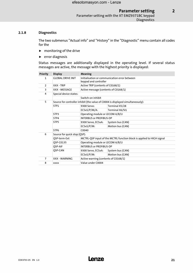
2.1.8 Diagnostics
The two submenus "Actual info" and "History" in the "Diagnostic" menu contain all codesfor the
ƒ monitoring of the drive
ƒ error diagnosis
Status messages are additionally displayed in the operating level. If several statusmessages are active, the message with the highest priority is displayed:
Priority Display Meaning
1 GLOBAL DRIVE INIT Initialisation or communication error betweenkeypad and controller
2 XXX − TRIP Active TRIP (contents of C0168/1)
3 XXX − MESSAGE Active message (contents of C0168/1)
4 Special device states:
Switch−on inhibit
5 Source for controller inhibit (the value of C0004 is displayed simultaneously):
STP1 9300 Servo: Terminal X5/28
ECSxS/P/M/A: Terminal X6/SI1
STP3 Operating module or LECOM A/B/LI
STP4 INTERBUS or PROFIBUS−DP
STP5 9300 Servo, ECSxA: System bus (CAN)
ECSxS/P/M: Motion bus (CAN)
STP6 C0040
6 Source for quick stop (QSP):
QSP−term−Ext MCTRL−QSP input of the MCTRL function block is applied to HIGH signal
QSP−C0135 Operating module or LECOM A/B/LI
QSP−AIF INTERBUS or PROFIBUS−DP
QSP−CAN 9300 Servo, ECSxA: System bus (CAN)
ECSxS/P/M: Motion bus (CAN)
7 XXX − WARNING Active warning (contents of C0168/1)
8 xxxx Value under C0004
efesotomasyon.com - Lenze

Parameter settingParameter setting with the XT EMZ9371BC keypadMenu structure
2
� 22 EDKVF93−05 EN 1.0
2.1.9 Menu structure
For simple, user−friendly operation, the codes are clearly arranged in function−relatedmenus:
Main menu Submenus Description
Display Display
User−Menu Codes defined in C0517
Code list All available codes
ALL All available codes listed in ascending order (C0001 ... C7999)
PS 1 Codes in parameter set 1 (C0001 ... C1999)
PS 2 Codes in parameter set 2 (C2001 ... C3999)
PS 3 Codes in parameter set 3 (C4001 ... C5999)
PS 4 Codes in parameter set 4 (C6001 ... C7999)
Load/Store Parameter set managementParameter set transfer, restore delivery status
Diagnostic Diagnostic
Actual info Display codes to monitor the drive
History Fault analysis with history buffer
Short setup Quick configuration of predefined applicationsConfiguration of the user menuThe predefined applications depend on the type of the standard device (frequencyinverter, servo inverter, position controller, ...)
Main FB Configuration of the main function blocks
NSET Setpoint processing
NSET−JOG Fixed setpoints
NSET−RAMP1 Ramp function generator
MCTRL Motor control
DFSET Digital frequency processing
DCTRL Internal control
Terminal I/O Connection of inputs and outputs with internal signals
AIN1 X6.1/2 Analog input 1
AIN2 X6.3/4 Analog input 2
AOUT1 X6.62 Analog output 1
AOUT2 X6.63 Analog output 2
DIGIN Digital inputs
DIGOUT Digital outputs
DFIN Digital frequency input
DFOUT Digital frequency output
State bus State bus (not with 9300 frequency inverter)
Controller Configuration of internal control parameters
Speed Speed controller
Current Current controller or torque controller
Phase Phase controller (not with 9300 frequency inverter)
Motor/Feedb. Input of motor data, configuration of speed feedback
Motor adj Motor data
Feedback Configuration of feedback systems
Monitoring Configuration of monitoring functions
efesotomasyon.com - Lenze

Parameter settingParameter setting with the XT EMZ9371BC keypad
Menu structure
2
� 23EDKVF93−05 EN 1.0
DescriptionSubmenusMain menu Description
DisplayDisplay
LECOM/AIF Configuration of operation with communication modules
LECOM A/B Serial interface
AIF interface Process data
Status word Display of status words
System bus Configuration of system bus (CAN)
Management CAN communication parameters
CAN−IN1CAN object 1
CAN−OUT1
CAN−IN2CAN object 2
CAN−OUT2
CAN−IN3CAN object 3
CAN−OUT3
Status word Display of status words
FDO Free digital outputs
Diagnostic CAN diagnostic
FB config Configuration of function blocks
Func blocks Parameterisation of function blocksThe submenus contain all available function blocks
FCODE Configuration of free codes
Identify Identification
Drive Software version of standard device
Op Keypad Software version of keypad
efesotomasyon.com - Lenze
Troubleshooting and fault eliminationDisplay of operating data, diagnosticsDisplay of operating data
3
� 24 EDKVF93−05 EN 1.0
3 Troubleshooting and fault elimination
3.1 Display of operating data, diagnostics
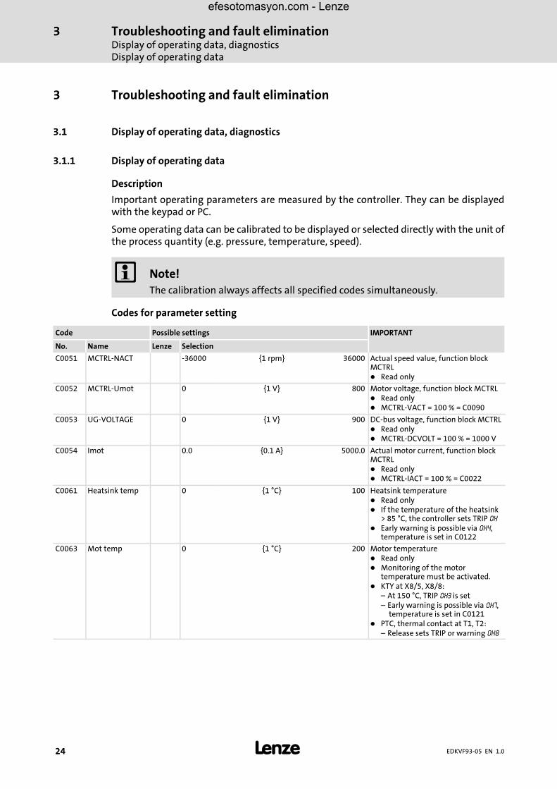
3.1.1 Display of operating data
Description
Important operating parameters are measured by the controller. They can be displayedwith the keypad or PC.
Some operating data can be calibrated to be displayed or selected directly with the unit ofthe process quantity (e.g. pressure, temperature, speed).
� Note!The calibration always affects all specified codes simultaneously.
Codes for parameter setting
Code Possible settings IMPORTANT
No. Name Lenze Selection
C0051 MCTRL−NACT −36000 {1 rpm} 36000 Actual speed value, function blockMCTRL� Read only
C0052 MCTRL−Umot 0 {1 V} 800 Motor voltage, function block MCTRL� Read only� MCTRL−VACT = 100 % = C0090
C0053 UG−VOLTAGE 0 {1 V} 900 DC−bus voltage, function block MCTRL� Read only� MCTRL−DCVOLT = 100 % = 1000 V
C0054 Imot 0.0 {0.1 A} 5000.0 Actual motor current, function blockMCTRL� Read only� MCTRL−IACT = 100 % = C0022
C0061 Heatsink temp 0 {1 °C} 100 Heatsink temperature� Read only� If the temperature of the heatsink
> 85 °C, the controller sets TRIP OH� Early warning is possible via OH4,
temperature is set in C0122
C0063 Mot temp 0 {1 °C} 200 Motor temperature� Read only� Monitoring of the motor
temperature must be activated.� KTY at X8/5, X8/8:
– At 150 °C, TRIP OH3 is set– Early warning is possible via OH7,
temperature is set in C0121� PTC, thermal contact at T1, T2:
– Release sets TRIP or warning OH8
efesotomasyon.com - Lenze

Troubleshooting and fault eliminationDisplay of operating data, diagnostics
Diagnostics
3
� 25EDKVF93−05 EN 1.0
IMPORTANTPossible settingsCode
SelectionLenzeNameNo.
C0064 Utilization 0 {1 %} 150 Device utilisation I×t� Read only� Device utilisation during the last
180 s of operating time� C0064 > 100 % releases warning
OC5
� C0064 >140 % limits the outputcurrent to the rated controllercurrent
C0150 Status word Bit00 — Bit08 Status code Read onlyDecimal status word for networkingvia automation interface (AIF)� Binary interpretation indicates the
bit states
Bit01 IMP Bit09 Status code
Bit02 — Bit10 Status code
Bit03 — Bit11 Status code
Bit04 — Bit12 Warning
Bit05 — Bit13 Message
Bit06 n = 0 Bit14 —
Bit07 CINH Bit15 —
3.1.2 Diagnostics
Description
Display codes for diagnostics
Codes for parameter setting
Code Possible settings IMPORTANT
No. Name Lenze Selection
C0093 Drive ident Controller identification� Read only
0 Invalid Defective power section
1 None No power section
14...20
9335VC 400V...9383VC 400V
Display of the controller used
21...28
9334VC 500V...9383VC 500V
9321...9333
9321 VC...9333VC
C0099 S/W version x.y Software version� Read onlyx
yMain versionSubversion
efesotomasyon.com - Lenze

Troubleshooting and fault eliminationTroubleshootingStatus display (LEDs on the controller)
3
� 26 EDKVF93−05 EN 1.0
3.2 Troubleshooting
Detecting failures
The controller LEDs and the status information displayed on the keypad immediatelyindicate errors or operation problems.
Analysing errors
You can analyse an error using the history buffer. The �Error messages" list helps you toeliminate the error. (# 33)
3.2.1 Status display (LEDs on the controller)
During operation, the operating status of the controller is indicated by means of two LEDs.
LED Operating status
Red � Green �
Off On Controller is enabled
On On Mains is switched on and automatic start isinhibited
Off Blinking slowly Controller is inhibited
Off On Motor data identification is being performed
Blinking quickly Off Undervoltage
Blinking slowly Off Active fault
efesotomasyon.com - Lenze
Troubleshooting and fault eliminationTroubleshooting
Fault analysis with the history buffer
3
� 27EDKVF93−05 EN 1.0
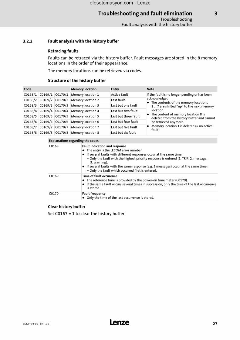
3.2.2 Fault analysis with the history buffer
Retracing faults
Faults can be retraced via the history buffer. Fault messages are stored in the 8 memorylocations in the order of their appearance.
The memory locations can be retrieved via codes.
Structure of the history buffer
Code Memory location Entry Note
C0168/1 C0169/1 C0170/1 Memory location 1 Active fault If the fault is no longer pending or has beenacknowledged:� The contents of the memory locations
1 ... 7 are shifted "up" to the next memorylocation.
� The content of memory location 8 isdeleted from the history buffer and cannotbe retrieved anymore.
� Memory location 1 is deleted (= no activefault).
C0168/2 C0169/2 C0170/2 Memory location 2 Last fault
C0168/3 C0169/3 C0170/3 Memory location 3 Last but one fault
C0168/4 C0169/4 C0170/4 Memory location 4 Last but two fault
C0168/5 C0169/5 C0170/5 Memory location 5 Last but three fault
C0168/6 C0169/6 C0170/6 Memory location 6 Last but four fault
C0168/7 C0169/7 C0170/7 Memory location 7 Last but five fault
C0168/8 C0169/8 C0170/8 Memory location 8 Last but six fault
Explanations regarding the codes
C0168 Fault indication and response� The entry is the LECOM error number� If several faults with different responses occur at the same time:
– Only the fault with the highest priority response is entered (1. TRIP, 2. message,3. warning).
� If several faults with the same response (e.g. 2 messages) occur at the same time:– Only the fault which occurred first is entered.
C0169 Time of fault occurence� The reference time is provided by the power−on time meter (C0179).� If the same fault occurs several times in succession, only the time of the last occurrence
is stored.
C0170 Fault frequency� Only the time of the last occurrence is stored.
Clear history buffer
Set C0167�=�1 to clear the history buffer.
efesotomasyon.com - Lenze

Troubleshooting and fault eliminationDrive behaviour in the event of faultsFault analysis with the history buffer
3
� 28 EDKVF93−05 EN 1.0
3.3 Drive behaviour in the event of faults
The controller reacts in different ways to the three possible types of fault (TRIP, messageor warning):
TRIP
TRIP (display of keypad XT: � �)
ƒ Switches the power outputs U, V, W to a high resistance until TRIP is reset
ƒ Entry of the fault indication into the history buffer as "current fault" in C0168/1.
ƒ The drive is coasting without control!
ƒ After TRIP reset (# 38):
– The drive accelerates to its setpoint along the set ramps.
– The fault indication is moved into C0168/2 as "last fault".
Messages
Message (display of keypad XT: � �)
ƒ Switches the power outputs U, V, W to a high resistance.
ƒ Entry of the fault indication into the history buffer as "current fault" in C0168/1.
ƒ In case of a fault �5 s:
– The drive is coasting without control as long as the message is active!
– If the message is not active anymore, the drive accelerates to its setpoint withmaximum torque.
ƒ In case of a fault >5 s:
– The drive is coasting without control as long as the message is active!
– If the message is not active anymore, the drive accelerates to its setpoint along theset ramps.
ƒ If the message is not active anymore, the fault indication is moved to C0168/2 as"last fault".
Warning
"Heatsink overtemperature" (keypad XT:OH � �)
ƒ The drive operates under control!
ƒ The warning signal goes off if the fault is not active anymore.
"Error in motor phase" (keypad XT:LP1)
"PTC monitoring" (keypad XT:OH51)
ƒ The drive operates under control!
ƒ Entry of the fault indication into the history buffer as "current fault" in C0168/1.
ƒ After TRIP reset, the fault indication is moved into C0168/2 as "last fault".
efesotomasyon.com - Lenze

Troubleshooting and fault eliminationError elimination
Drive errors
3
� 29EDKVF93−05 EN 1.0
3.4 Error elimination
3.4.1 Drive errors
Malfunction Cause Remedy
An asynchronous motorwith feedback rotates in anuncontrolled manner andwith low speed
The motor phases are reversed so that the rotating fieldof the motor is not identical with the rotating field ofthe feedback system. The drive shows the followingbehaviour:� U/f characteristic control (C0006 = 5)
– The motor rotates faster than the speed setpoint bythe value set in C0074 (influence of the speedcontroller, Lenze setting 10 % of nmax). After thecontroller is enabled, it does not stop at zero speedsetpoint or quick stop (QSP).
– The final motor current depends, among otherthings, on the set value of the Umin boost (C0016)and can rise to Imax (C0022). This may activate thefault message OC5.
� Vector control (C0006 = 1)– The motor rotates slowly with maximum slip speed
(depending on motor data and maximum current)and does not react to a speed setpoint. Thedirection of rotation, however, is determined bythe sign of the speed setpoint.
– The motor current rises up to Imax (C0022). Thismay activate the fault message OC5 with a timedelay.
� Check motor cable for correct phaserelation.
� If possible, operate the motor withdeactivated feedback (C0025 = 1) andcheck the direction of rotation of themotor.
Motor does not rotatealthough the controller isenabled (� is off) and aspeed setpoint has beenspecified.
The two terminal strips X5 are reversed. Since X5/A1 andX5/28 face each other, the controller can be enabled ifthe control terminals are internally supplied. All otherconnections, however, are assigned incorrectly so thatthe motor cannot start.
Check the position of the terminal strips:� If you look at the connection unit in
reading direction, the left terminalstrip X5 must be connected with theinput signals and the right terminalstrip X5 must be connected with theoutput signals.
The monitoring of themotor phases (LP1) doesnot respond if a motorphase is interrupted,although C0597 = 0 or 2
The function block MLP1 is not entered into theprocessing table.
Enter the function block MLP1 into theprocessing table. The function block MLP1requires 30 �s of calculating time.
If during high speedsDC−injection braking (GSB)is activated, the fault OC1(TRIP) or OU (TRIP) occurs
During DC−injection braking the controller sets pulseinhibit for a short time (DCTRL−IMP) to reduce themagnetisation in the motor before a DC voltage isinjected into the motor. At high speeds (e. g. in case ofmid−frequency motors) the residual voltage whichdevelops from the residual magnetism and high speedcan generate such a high motor current that OC1 or OUare activated.
Prolong the duration of the pulse inhibit:� Connect the output signal DCTRL−IMP
to the function block TRANSx andadjust the desired switch−off timethere (usually 500 ms). IfDCTRL−CINH1 is set to HIGH, theduration of the pulse inhibit isprolonged by the time adjusted.
efesotomasyon.com - Lenze
Troubleshooting and fault eliminationError eliminationController in clamp operation
3
� 30 EDKVF93−05 EN 1.0
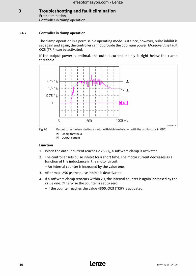
3.4.2 Controller in clamp operation
The clamp operation is a permissible operating mode. But since, however, pulse inhibit isset again and again, the controller cannot provide the optimum power. Moreover, the faultOC3 (TRIP) can be activated.
If the output power is optimal, the output current mainly is right below the clampthreshold.
9300vec110
Fig.3−1 Output current when starting a motor with high load (shown with the oscilloscope in GDC)
� Clamp threshold
� Output current
Function
1. When the output current reaches 2.25 × Ir, a software clamp is activated.
2. The controller sets pulse inhibit for a short time. The motor current decreases as afunction of the inductance in the motor circuit.
– An internal counter is increased by the value one.
3. After max. 250 �s the pulse inhibit is deactivated.
4. If a software clamp reoccurs within 2 s, the internal counter is again increased by thevalue one. Otherwise the counter is set to zero.
– If the counter reaches the value 4300, OC3 (TRIP) is activated.
efesotomasyon.com - Lenze

Troubleshooting and fault eliminationError elimination
Controller in clamp operation
3
� 31EDKVF93−05 EN 1.0
If the DC−bus voltage (UDC) exceeds the switch−off threshold OU, pulse inhibit will be set.At the same time, an internal timer for a delay time (C0912) will be started.
Pulse inhibit will be reset, if the voltage falls below the switch−on threshold OU and thedelay time has elapsed.
Thresholds for DC−bus overvoltage (OU)
Types EVF93xx−EVV210, EVF93xx−EVV240, EVF93xx−EVV270 and EVF93xx−EVV300
Mains voltage range C0173 Switch−off threshold OU Switch−on threshold OU
< 400 V Operation with or withoutbrake transistor
0 770 V 755 V
400 V Operation with or withoutbrake transistor
1 * 770 V 755 V
460 V Operation with or withoutbrake transistor
2 770 V 755 V
480 V Brake transistor 3 770 V 755 V
480 V Brake transistor 4 800 V 785 V
500 V Operation with or withoutbrake transistor
5 900 V 885 V
* Lenze setting
Types EVF93xx−EV, EVF93xx−EVV060 and EVF93xx−EVV110
Mains voltage range C0173 Switch−off threshold OU Switch−on threshold OU
400 V Operation with or withoutbrake transistor
Read only 700 V 685 V
Codes for parameter setting
Code Possible settings IMPORTANT
No. Name Lenze Selection
C0912 OV delay time � − {1 ms} − Delay time of the pulse enable afteran OU message� Depending on C0082, C0086,
C0087, C0088, C0089, C0090,C0091, C0092A change of one of the codesresets C0912 to the time of theselected motor
� The time is derived from thedouble rotor time constant
efesotomasyon.com - Lenze
Troubleshooting and fault eliminationError eliminationController in clamp operation
3
� 32 EDKVF93−05 EN 1.0
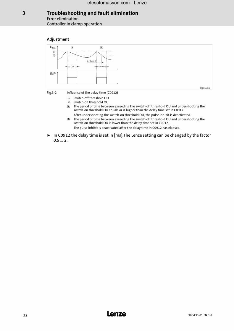
Adjustment
UDC
t C0912�
t < C0912
t = C0912
�
�
� �
IMP
9300vec142
Fig.3−2 Influence of the delay time (C0912)
� Switch−off threshold OU� Switch−on threshold OU� The period of time between exceeding the switch−off threshold OU and undershooting the
switch−on threshold OU equals or is higher than the delay time set in C0912.
After undershooting the switch−on threshold OU, the pulse inhibit is deactivated.
� The period of time between exceeding the switch−off threshold OU and undershooting theswitch−on threshold OU is lower than the delay time set in C0912.
The pulse inhibit is deactivated after the delay time in C0912 has elapsed.
ƒ In C0912 the delay time is set in [ms].The Lenze setting can be changed by the factor0.5 ... 2.
efesotomasyon.com - Lenze

Troubleshooting and fault eliminationError elimination
Fault messages on the keypad or in the parameter setting program Global Drive Control
3
� 33EDKVF93−05 EN 1.0
3.4.3 Fault messages on the keypad or in the parameter setting program Global Drive Control
� Note!If you use GDC or a fieldbus module to retrieve the fault (C0168/x), the errormessage will be represented by an error number.
Display Error numberx = 0: TRIPx = 1: Messagex = 2: Warning
Error Cause Remedy
−−− −−− No fault — —
CCr x071 System fault Processor is overloaded or there is afault in the program processing
Reduce processor load. Remove functionblocks that are not needed from theprocessing table
Strong interference on control cables Shield control cables
Ground or earth loops in the wiring Check wiring
CE0 x061 Communicationerror
Fault during transmission of controlcommands via automation interface X1
Plug in automation module firmly, boltdown, if necessary
CE1 x062 Communicationerror at the processdata input objectCAN−IN1
CAN−IN1 object receives faulty data, orcommunication is interrupted
� Check cable at X4� Check sender� Increase monitoring time under
C0357/1 if necessary
CE2 x063 Communicationerror at the processdata input objectCAN−IN2
CAN−IN2 object receives faulty data, orcommunication is interrupted
� Check cable at X4� Check sender� Increase monitoring time under
C0357/2 if necessary
CE3 x064 Communicationerror at the processdata input objectCAN−IN3
CAN−IN3 object receives faulty data, orcommunication is interrupted
� Check cable at X4� Check sender� Increase monitoring time under
C0357/3 if necessary
CE4 x065 BUS−OFF state Controller has received too manyincorrect telegrams via system bus X4,and has disconnected from the bus
� Check wiring� Check bus termination (if any)� Check shield contact of the cables� Check PE connection� Check bus load� Reduce baud rate (observe cable
length)
EEr x091 External fault(TRIP−Set)
A digital input assigned with TRIP−setfunction has been activated (in the mostbasic configurations the input X5/E4 isLOW−active and linked with the TRIP−setfunction)
� Check external encoder� Check signal at the digital input
X5/E4:– Either connect HIGH level or– Change polarity in C0114 to
HIGH−active. CAUTION! Whenchanging to HIGH level, thewire−break protection gets lost.
The two terminal strips at X5 arereversed
Check the position of the terminalstrips:� If you look at the connection unit in
reading direction, the left terminalstrip X5 must be connected with theinput signals and the right terminalstrip X5 must be connected with theoutput signals.
H05 x105 Internal fault Contact Lenze
H07 x107 Wrong powerstage
During initialisation of the controller, awrong power stage was detected
Contact Lenze
efesotomasyon.com - Lenze

Troubleshooting and fault eliminationError eliminationFault messages on the keypad or in the parameter setting program Global Drive Control
3
� 34 EDKVF93−05 EN 1.0
RemedyCauseErrorError numberx = 0: TRIPx = 1: Messagex = 2: Warning
Display
H10 x110 Sensor fault −heatsinktemperature
Sensor of the heatsink temperaturedetection indicates undefined values
Contact Lenze� Fault message can only be reset by
mains switching
H11 x111 Sensor fault −temperature insidethe device
Sensor of the internal temperaturedetection indicates undefined values
Contact Lenze� Fault message can only be reset by
mains switching
ID1 x140 Error during motordata identification
� No motor connected� Stator resistance too high� Controller inhibited externally
� Check motor connection� Check motor data entry� Enable controller and repeat motor
data identification. The controllerenable must be pendingcontinuously until the end of theidentification process.
ID2 x141 Error during motordata identification
Motor too small � Check entered motor data– When setting parameters with
Global Drive Control, use the inputassistant for motor data
� The measurements for the invertererror characteristic and the statorresistance are correct (save measuredvalues in C0003). In the operatingmode U/f characteristic control, themotor data identification can becompleted.
Controller inhibited externally Enable controller and repeat motor dataidentification. The controller enablemust be pending continuously until theend of the identification process.
LP1 x032 Motor phasefailure
A current−carrying motor phase hasfailed
� Check motor� Check supply cables
The current limit is set too high Set a lower current limit value underC0599
This monitoring is not suitable for fieldfrequencies >480 Hz and synchronousservo motors
Deactivate monitoring with C0597= 3
LU x030 Undervoltage DC bus voltage is smaller than the valueset under C0173
� Check mains voltage� Check supply module
NMAX x200 Maximum systemspeed exceeded(C0596)
Active load too high Check drive dimensioning
Drive is not speed−controlled, torqueexcessively limited
If required, increase torque limit
Current speed is detected incorrectly Check parameter setting of theincremental encoder (C0025)
OC1 x011 Overcurrent(motor current >2.25−fold ratedcontroller current,hardwaremonitoring)
Short circuit/earth fault � Remove cause of short circuit/earthfault
� Check motor and cable� If required, measure the insulation
resistance
Capacitive charging current of themotor cable too high (especially withlower powers)
Use shorter or low−capacitance motorcable
Acceleration/deceleration times tooshort in proportion to the load (C0012,C0013, C0105)
� Increase the gain (P component) ofthe current controller (C0075)
� Reduce integral−action time (integralaction component) of the Imaxcontroller (C0076)
efesotomasyon.com - Lenze
Troubleshooting and fault eliminationError elimination
Fault messages on the keypad or in the parameter setting program Global Drive Control
3
� 35EDKVF93−05 EN 1.0
RemedyCauseErrorError numberx = 0: TRIPx = 1: Messagex = 2: Warning
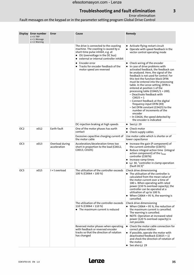
Display
The drive is connected to the coastingmachine. The coasting is caused by ashort−time pulse inhibit, e.g. at� OU (overvoltage in the DC bus)� external or internal controller inhibit
� Activate flying restart circuit� Operate with speed feedback in the
vector control operating mode
� Encoder error� Tracks for encoder feedback of the
motor speed are reversed
� Check wiring of the encoder� In case of drive problems with
activated feedback, the feedback canbe analysed. Here, the signal of thefeedback is not used for control. Forthis test the function block DFINmust be entered into the processingtable. In the Lenze setting, DFIN isentered at position 1 of theprocessing table (C0465/1 = 200).– Deactivate feedback with
C0025 = 1– Connect feedback at the digital
frequency input DFIN (X9)– Set DFIN constant (C0425) to the
number of increments of theencoder
– In C0426, the speed detected bythe encoder is indicated
DC−injection braking at high speeds � See ! 29
OC2 x012 Earth fault One of the motor phases has earthcontact
� Check motor� Check supply cables
Excessive capacitive charging current ofthe motor cable
Use motor cable which is shorter or oflower capacitance
OC3 x013 Overload duringacceleration
Acceleration/deceleration times tooshort in proportion to the load (C0012,C0013, C0105)
� Increase the gain (P component) ofthe current controller (C0075)
� Reduce integral−action time (integralaction component) of the Imaxcontroller (C0076)
� Increase ramp times� ! 30, "controller in clamp operation
(fault OC3)"
OC5 x015 I × t overload The utilisation of the controller exceeds100 % (C0064 > 100 %)
Check drive dimensioning� The utilisation of the controller is
calculated from the mean value ofthe motor current over a time of180 s. When operating with ratedpower (150 % overload capacity), thecontroller can be operated at autilisation of up to 100 %.
� When C0064 = 95 %, the warning iscancelled.
The utilisation of the controller exceeds110 % (C0064 > 110 %)� The maximum current is reduced
Check drive dimensioning� When C0064 = 95 %, the reduction of
the maximum current is cancelled.The warning is cancelled.
� NOTE: Operation at increased ratedpower (120 % overload capacity) isnot possible.
Reversed motor phases when operatingwith feedback or reversed encodertracks so that the direction of rotationhas changed
� Check the motor cable connection forcorrect phase relation
� If possible, operate the motor withdeactivated feedback (C0025 = 1)and check the direction of rotation ofthe motor.
� See also ! 29
efesotomasyon.com - Lenze

Troubleshooting and fault eliminationError eliminationFault messages on the keypad or in the parameter setting program Global Drive Control
3
� 36 EDKVF93−05 EN 1.0
RemedyCauseErrorError numberx = 0: TRIPx = 1: Messagex = 2: Warning
Display
OH x050 Heatsinktemperature ishigher than thevalue set in thecontroller
Ambient temperature Tu > 40 °C or 50 °C � Allow controller to cool and ensurebetter ventilation
� Check ambient temperature in thecontrol cabinet
Heatsink very dirty Clean heatsink
Wrong mounting position Change mounting position
OH3 x053 Motor temperatureis higher than thevalue set in thecontroller
Motor too hot because of excessivecurrent or frequent and too longacceleration
Check drive dimensioning
No KTY is connected to X8 Connect KTY or switch off monitoring(C0583 = 3)
OH4 x054 Heatsinktemperature ishigher than thevalue set in C0122
Ambient temperature Tu > 40 °C or50 °C.
� Allow controller to cool and ensurebetter ventilation
� Check ambient temperature in thecontrol cabinet
Heatsink very dirty Clean heatsink
Wrong mounting position Change mounting position
The value entered in C0122 is too low Enter higher value
OH7 x057 Motor temperatureis higher than thevalue set in C0121
Motor too hot because of excessivecurrent or frequent and too longacceleration
Check drive dimensioning
No KTY is connected to X8 Connect KTY or switch off monitoring(C0584 = 3)
The value entered in C0121 is too low Enter higher value
OH8 x058 PTC at terminalsT1, T2 indicatesmotor overheating
Motor too hot because of excessivecurrent or frequent and too longacceleration
Check drive dimensioning
Terminals T1, T2 are not assigned Connect PTC or thermal contact orswitch off monitoring (C0585=3)
OU x020 Overvoltage in theDC bus
Only for variants V210, V240, V270,V300:� Wrong values in C0173� Wrong values in C0174
� Set correct values in C0173� Set correct values in C0174
PEr x074 Program fault An error has been detected in theprogram flow. The parameter set 1 isloaded automatically. Parameter datawhich has been changed and not hasbeen saved, will get lost.
Contact Lenze
PI x079 Initialisation error � A fault was detected during transferof parameter sets between thecontrollers
� Parameter set does not match thecontroller
Correct parameter set
PR0 x075 Parameter set error Error while loading a parameter set. Theparameters saved do not match thesoftware version of the controller.CAUTION! The Lenze setting is loadedautomatically.
� Correct parameter set� Save all parameter sets with C0003
and reset the fault message by mainsswitching
PR1PR2PR3PR4
x072x073x077x078
Parameter set error � Fault while loading a parameter set� The transmission of parameter sets
with keypad XT has been interrupted(e.g. by an early disconnection of thekeypad XT)
CAUTION! The Lenze setting is loadedautomatically.
Set the required parameters and savethem with C0003
Sd3 x083 Encoder error at X9 Cable interrupted Check cable for wire breakage
efesotomasyon.com - Lenze

Troubleshooting and fault eliminationError elimination
Fault messages on the keypad or in the parameter setting program Global Drive Control
3
� 37EDKVF93−05 EN 1.0
RemedyCauseErrorError numberx = 0: TRIPx = 1: Messagex = 2: Warning
Display
Pin X9/8 is not assigned Assign pin X9/8 with 5 V or switch offmonitoring (C0587 = 3)
Sd5 x085 Encoder at X6/1,X6/2 is defective
Current at X6/1, X6/2 < 2 mA � Check cable for wire breakage� Check encoder
Sd6 x086 Sensor error at X8 KTY at X8 indicates undefined values � Check supply cable for firmconnection
� Switch off monitoring withC0594 = 3 if necessary
efesotomasyon.com - Lenze
Troubleshooting and fault eliminationResetting error messagesFault messages on the keypad or in the parameter setting program Global Drive Control
3
� 38 EDKVF93−05 EN 1.0
3.5 Resetting error messages
Eliminate the cause of TRIP fault message
After you have eliminated the cause of a TRIP fault message, you must reset the faultmessage with the command "TRIP reset". Only then the drive restarts.
� Note!A TRIP fault message can have several causes. Only if all causes of the TRIPhave been eliminated, the TRIP reset can be executed.
TRIP reset
ƒ Keypad XT: Press $. Then press % to enable the controller.
ƒ Fieldbus module: Set C0043 = 0
ƒ Control word: C0135
ƒ Terminal: X5/E5 = HIGH
ƒ Control word via AIF
ƒ Control word via system bus (CAN)
Mains switching always executes TRIP reset.
Codes for parameter setting
Code Possible settings IMPORTANT
No. Name Lenze Selection
C0043 Trip reset 0 0 no/trip reset Reset actual error
1 trip active There is a TRIP error
efesotomasyon.com - Lenze

Troubleshooting and fault eliminationResetting error messages
Fault messages on the keypad or in the parameter setting program Global Drive Control
3
� 39EDKVF93−05 EN 1.0
efesotomasyon.com - Lenze

&Lenze Drive Systems GmbHHans−Lenze−Straße 1D−31855 AerzenGermany
EDKVF93−05EN 1.0
© 08/2007TD19
+49�(0)�51�54�82−0
Service 00�80�00�24�4�68�77 (24 h helpline)
� Service +49�(0)�51�54�82−1112
E−Mail [email protected]
Internet www.Lenze.com10 9 8 7 6 5 4 3 2 1
efesotomasyon.com - Lenze