Embed Size (px)
Citation preview
Biochimica et Biophysica Acta 1830 (2013) 2150–2159
Contents lists available at SciVerse ScienceDirect
Biochimica et Biophysica Acta
j ourna l homepage: www.e lsev ie r .com/ locate /bbagen
Review
Optimized negative-staining electron microscopy for lipoprotein studies
Lei Zhang, Huimin Tong, Mark Garewal, Gang Ren ⁎The Molecular Foundry, Lawrence Berkeley National Laboratory, Berkeley CA 94720, USA
Abbreviations: EM, electron microscopy; NS, negatnegative staining; cryo-EM, cryo-electron microscopy;tron tomography; HDL, high-density lipoprotein; LDL, lvery low-density lipoprotein; IDL, intermediate-density lPTA, phosphotungstic acid; SNR, signal-to-noise ratio; CV⁎ Corresponding author. Tel.: +1 510 495 2375.
E-mail address: [email protected] (G. Ren).
0304-4165/$ – see front matter. Published by Elsevier Bhttp://dx.doi.org/10.1016/j.bbagen.2012.09.016
a b s t r a c t
a r t i c l e i n f oArticle history:
Received 10 June 2012Received in revised form 20 September 2012Accepted 23 September 2012Available online 29 September 2012Keywords:Protein structureLipoprotein structureElectron microscopyNegative-stainingOptimized negative-staining protocolIndividual-particle electron tomography
Background: Negative-staining (NS), a rapid, simple and conventional technique of electron microscopy(EM), has been commonly used to initially study the morphology and structure of proteins for half a century.Certain NS protocols however can cause artifacts, especially for structurally flexible or lipid-related proteins,such as lipoproteins. Lipoproteins were often observed in the form of rouleau as lipoprotein particlesappeared to be stacked together by conventional NS protocols. The flexible components of lipoproteins, i.e.lipids and amphipathic apolipoproteins, resulted in the lipoprotein structure being sensitive to the NS samplepreparation parameters, such as operational procedures, salt concentrations, and the staining reagents.Scope of review: The most popular NS protocols that have been used to examine lipoprotein morphology andstructure were reviewed.Major conclusions: The comparisons show that an optimized NS (OpNS) protocol can eliminate the rouleauartifacts of lipoproteins, and that the lipoproteins are similar in size and shape as statistically measuredfrom two EM methods, OpNS and cryo-electron microscopy (cryo-EM). OpNS is a high-throughput,
high-contrast and high-resolution (near 1 nm, but rarely better than 1 nm) method which has been usedto discover the mechanics of a small protein, 53 kDa cholesterol ester transfer protein (CETP), and the struc-ture of an individual particle of a single protein by individual-particle electron tomography (IPET), i.e. a14 Å-resolution IgG antibody three-dimensional map.General significance: It is suggested that OpNS can be used as a general protocol to study the structure of pro-teins, especially highly dynamic proteins with equilibrium-fluctuating structures.Published by Elsevier B.V.
1. Introduction
Most transmission electron microscopy (TEM) has the capabilityto display the atomic structure of hard materials [1]. However,when examining the structure of soft (especially biological) materialssuch as proteins it is challenging to obtain structure at even near onenanometer resolution [2], due to radiation damage, low contrast ofimages, structural collapse or flattening, and dehydration [3,4].
Cryo-electron microscopy (cryo-EM) is an advanced approach todetermining protein structure at an atomic resolution under nearphysiological conditions [5–7]. The cryo-EM technique involves pre-paring the sample in vitreous ice by flash freezing the specimen,and then examining the specimen under cryogenic conditions, suchas liquid nitrogen or helium temperatures [6–10]. Advantages ofcryo-EM include absence of artifacts, and the ability to examine theprotein with near-native state images [4]. Despite its advantagescryo-EM has many complications. The primary disadvantages involve
ive staining; OpNS, optimizedIPET, individual-particle elec-ow-density lipoprotein; VLDL,ipoprotein; UF, uranyl formate;D, cardiovascular disease
.V.
low contrast and necessary expensive equipment that is not readilyaccessible to many laboratories, including specimen cryo-holdersand a cryo-plunger that is needed for sample preparation apparatuseswith liquid nitrogen. In addition, preparing a cyro-EM sample withperfect ice thickness and imaging under low-dose conditions requireshighly intensive specialized training [4,11,12]. Namely knowledgewith image processing software to enhance the poor signal-to-noiseratio (SNR) of cryo-EM [3] images which has a steep learning curveand is time consuming. In addition, the one-time usage of thecryo-specimens limits the chance for catching unexpected discover-ies, especially when the sample is difficult to purify or is unstableafter isolation [13].
Historically, the study of protein structure via negative-staining(NS) was initially developed with viruses by Brenner and Horne ahalf century ago [14]. The concept of NS began with light microscopyby submerging bacteria into a dense stain to provide darkness aroundthe specimen, thus illuminating the sample utilizing a negative con-trast [15]. NS-EM involves coating the specimen with a thin stainlayer of cationic or anionic heavy-metal salts. NS-EM can producehigh-contrast images with these coated heavy-metal stains [4], sincethe heavy-metal stains more strongly scatter electrons than do thelighter atoms within the proteins themselves [16–19].
Preparation of the sample for NS-EM can be easily adapted in anylaboratory. Heavy metal stains allow for higher electron dose tolerance,

2151L. Zhang et al. / Biochimica et Biophysica Acta 1830 (2013) 2150–2159
improved contrast, and also function as a fixative for the specimen.NS-EM also delivers images that contain high SNR, and an intermedi-ate (near a nanometer) resolution [3] for reconstruction of three-dimensional (3D) models [20]. However, certain effects of theheavy-metal stain produce undesirable outcomes due to interactionswith the specimen, such as aggregation, molecular dissociation, andartifacts of stacking [4,21,22].
Since the early 1970s, the NS method has been used to examine thestructure and morphology of lipoproteins [15,23–30]. Lipoproteins arecomposed of lipids and apolipoproteins (apo), and are known to bestructurally dynamic and flexible in nature [8,29–34]. The structuresof lipoproteins are also sensitive to the buffer pH, salt concentrationand chemical reagents. An obvious artifact of lipoprotein structure ob-served for decades is how the lipoprotein particles regularly presentstacking rouleau in NS images [35–40]. This is significant in that rouleauformation is absent from serum analysis, native-gel, small-angle scat-tering, and cryo-EM studies [12,22,29,30,36,39,41–44]. Consideringthat rouleau formation displayed in NS images could lead to inaccurateinterpretations of lipoprotein structure and function, a thorough inves-tigation or comparison of the NS protocols used to examine the lipopro-tein structure is necessary.
Here, we have reviewed the literature by focusing on the structureandmorphology of lipoprotein-related NS sample preparation parame-ters. The comparisons were performed from three parameters: opera-tional procedures, salt concentrations, and the staining reagentsthemselves. These comparisons show that the optimized NS (OpNS)protocol eliminates the artifact of rouleau in lipoproteins and deliversstructural features that are most similar in size and shape to that fromcryo-EM images. OpNS features make it a suitable protocol to study li-poprotein structure and morphology. Moreover, OpNS displays itselfas a reliable and powerful protocol revealing the mechanics and struc-tures of small and asymmetric proteins, such as 53 kDa cholesterylester transfer protein (CETP) [45], and an individual 160 kDa IgG anti-body (with ~1 nm high-resolution 3D reconstruction) [11].
B)A)
Fig. 1. Electron micrographs presented with rouleau of different lipoproteins by NS with parrHDL. (C) LDL. Micrographs (up panel) and selected particles (down panel) are shown. Barspublished in the Journal of Lipid Research as reference [29,30] @ the American Society for B
2. Rouleau artifact in lipoproteins under negative-staining
With certain popular and conventional NS protocols [15,46], lipo-protein particles regularly present stacking into rouleau formation[35–40]. For example, apoE4-contained high-density lipoprotein(HDL) (Fig. 1A), apoA-I-contained discoidal nascent HDL (Fig. 1B),and even apoB-contained human plasma LDL (Fig. 1C) form rouleauby the conventional NS method [29,30]. The rouleau formation seemsunrelated to comprising apolipoprotein types or particle concentra-tions, although it may relate to lipid component type (cationic orionic). However, rouleau formation is absent in the results fromnondenaturing polyacrylamide gradient gel electrophoresis, mass spec-trometry [47,48], X-ray crystallography [49,50], small-angle X-ray dif-fraction data [43], or cryo-EM studies [29,47,51–53]. Thus, rouleauformation is generally believed to be an artifact of the conventionalNS-EM protocol [29,30]. Unfortunately, the observation of rouleau for-mation by conventional NS protocol (because of the challenges in imag-ing the lipoproteins in their near native-state by cryo-EM) has fordecades been an indicator of successful synthesis of HDL particles.
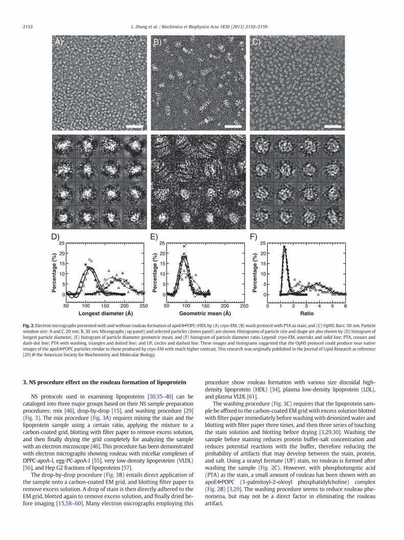
Recently, Ren et al. have faced these same challenges in imaginglipoproteins under near physiological buffer conditions by cryo-EM[8,11,12,29,44,54]. We investigated the NS protocols by using the im-ages obtained from cryo-electron microscopy (cryo-EM) of apoE4HDL as a standard control for comparison, and reported an optimizednegative-staining (OpNS) protocol (Fig. 2) [29]. OpNS eliminates therouleau artifact of apoE4 HDL, and provides images that are highlysimilar (difference b5%) in size and shape to that from cryo-EM(Fig. 2A), but with higher contrast [29]. A validation of OpNS protocolhas been conducted by examining the elimination of rouleau artifactin various lipoprotein samples [30].
To further illuminate the different NS protocol effects in the struc-ture and conformation of lipoproteins, we cataloged the effects of NSprotocols from the three NS parameters, i.e. NS sample preparationprocedures, salt concentrations, and staining reagents.
C)
ameters of PTA, and the mix procedure. (A) apoE4-contained rHDL. (B) 9.6-nm nascent: 50 nm. Particle window size: A and B, 30 nm; C, 60 nm. This research was originallyiochemistry and Molecular Biology.
B)P
erce
nta
ge
(%)
Longest diameter (Å)
D)
Per
cen
tag
e (%
)
Geometric mean (Å)
E)
Per
cen
tag
e (%
)
Ratio
F)
A) C)
Fig. 2. Electronmicrographs presentedwith andwithout rouleau formation of apoE4•POPC rHDL by (A) cryo-EM, (B) wash protocol with PTA as stain, and (C) OpNS. Bars: 50 nm. Particlewindow size: A and C, 20 nm; B, 30 nm.Micrographs (up panel) and selected particles (down panel) are shown. Histograms of particle size and shape are also shown by (D) histogram oflongest particle diameter, (E) histogram of particle diameter geometric mean, and (F) histogram of particle diameter ratio. Legend: cryo-EM, asterisks and solid line; PTA, crosses anddash-dot line; PTA with washing, triangles and dotted line; and UF, circles and dashed line. These images and histograms suggested that the OpNS protocol could produce near nativeimages of the apoE4•POPC particles similar to those produced by cryo-EMwithmuch higher contrast. This research was originally published in the Journal of Lipid Research as reference[29] @ the American Society for Biochemistry and Molecular Biology.
2152 L. Zhang et al. / Biochimica et Biophysica Acta 1830 (2013) 2150–2159
3. NS procedure effect on the rouleau formation of lipoprotein
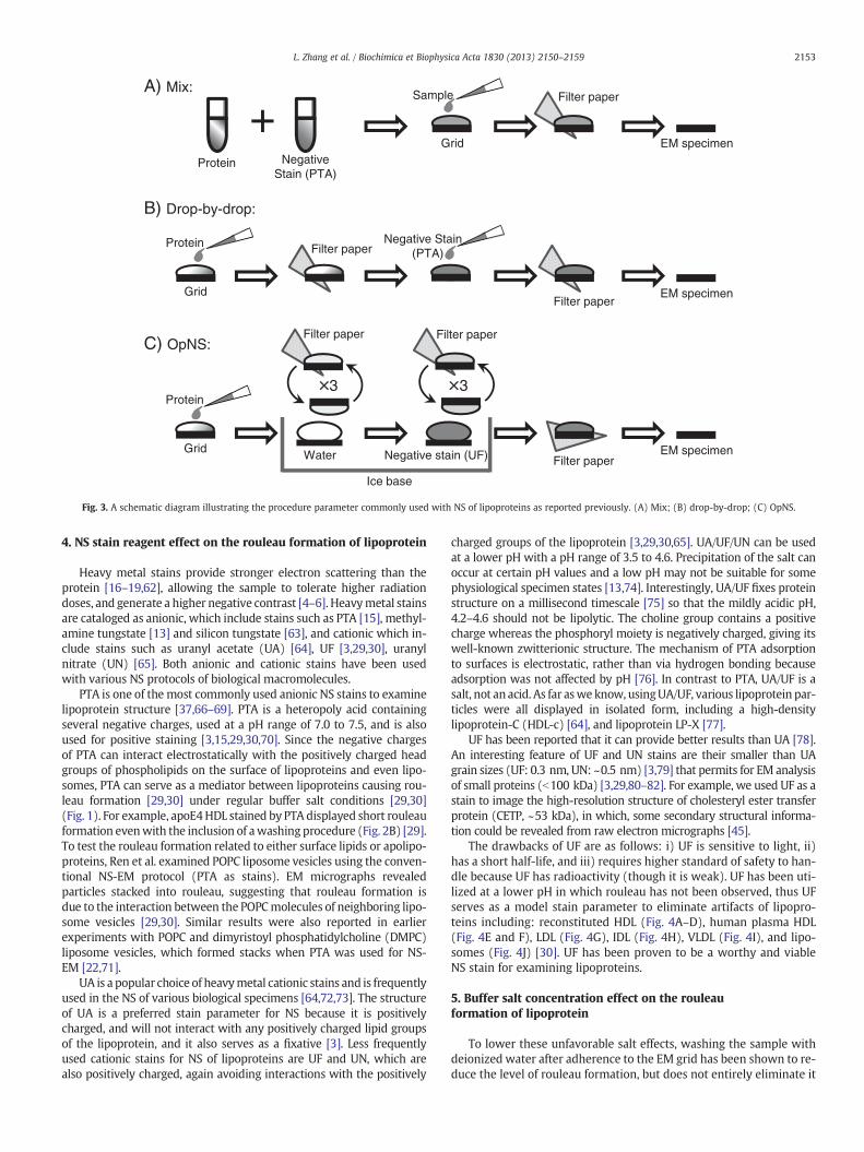
NS protocols used in examining lipoproteins [30,35–40] can becataloged into three major groups based on their NS sample preparationprocedures: mix [46], drop-by-drop [15], and washing procedure [29](Fig. 3). The mix procedure (Fig. 3A) requires mixing the stain and thelipoprotein sample using a certain ratio, applying the mixture to acarbon-coated grid, blotting with filter paper to remove excess solution,and then finally drying the grid completely for analyzing the samplewith an electronmicroscope [46]. This procedure has been demonstratedwith electron micrographs showing rouleau with micellar complexes ofDPPC-apoA-I, egg-PC-apoA-I [55], very low-density lipoproteins (VLDL)[56], and Hep G2 fractions of lipoproteins [57].
The drop-by-drop procedure (Fig. 3B) entails direct application ofthe sample onto a carbon-coated EM grid, and blotting filter paper toremove excess solution. A drop of stain is then directly adhered to theEM grid, blotted again to remove excess solution, and finally dried be-fore imaging [15,58–60]. Many electron micrographs employing this
procedure show rouleau formation with various size discoidal high-density lipoprotein (HDL) [34], plasma low-density lipoprotein (LDL),and plasma VLDL [61].
The washing procedure (Fig. 3C) requires that the lipoprotein sam-ple be affixed to the carbon-coated EMgridwith excess solution blottedwith filter paper immediately beforewashingwith deionizedwater andblotting with filter paper three times, and then three series of touchingthe stain solution and blotting before drying [3,29,30]. Washing thesample before staining reduces protein buffer-salt concentration andreduces potential reactions with the buffer, therefore reducing theprobability of artifacts that may develop between the stain, protein,and salt. Using a uranyl formate (UF) stain, no rouleau is formed afterwashing the sample (Fig. 2C). However, with phosphotungstic acid(PTA) as the stain, a small amount of rouleau has been shown with anapoE4•POPC (1-palmitoyl-2-oleoyl phosphatidylcholine) complex(Fig. 2B) [3,29]. The washing procedure seems to reduce rouleau phe-nomena, but may not be a direct factor in eliminating the rouleauartifact.
Ice base
+A) Mix:
Protein NegativeStain (PTA)
Grid
Sample Filter paper
EM specimen
Filter paper
B) Drop-by-drop:
EM specimenGrid
Protein Negative Stain(PTA)
Filter paper
C) OpNS:
EM specimenGrid
Protein
Water
Filter paper
Negative stain (UF) Filter paper
Filter paper
3 3
Fig. 3. A schematic diagram illustrating the procedure parameter commonly used with NS of lipoproteins as reported previously. (A) Mix; (B) drop-by-drop; (C) OpNS.
2153L. Zhang et al. / Biochimica et Biophysica Acta 1830 (2013) 2150–2159
4. NS stain reagent effect on the rouleau formation of lipoprotein
Heavy metal stains provide stronger electron scattering than theprotein [16–19,62], allowing the sample to tolerate higher radiationdoses, and generate a higher negative contrast [4–6]. Heavymetal stainsare cataloged as anionic, which include stains such as PTA [15], methyl-amine tungstate [13] and silicon tungstate [63], and cationic which in-clude stains such as uranyl acetate (UA) [64], UF [3,29,30], uranylnitrate (UN) [65]. Both anionic and cationic stains have been usedwith various NS protocols of biological macromolecules.
PTA is one of the most commonly used anionic NS stains to examinelipoprotein structure [37,66–69]. PTA is a heteropoly acid containingseveral negative charges, used at a pH range of 7.0 to 7.5, and is alsoused for positive staining [3,15,29,30,70]. Since the negative chargesof PTA can interact electrostatically with the positively charged headgroups of phospholipids on the surface of lipoproteins and even lipo-somes, PTA can serve as a mediator between lipoproteins causing rou-leau formation [29,30] under regular buffer salt conditions [29,30](Fig. 1). For example, apoE4HDL stained by PTA displayed short rouleauformation evenwith the inclusion of awashing procedure (Fig. 2B) [29].To test the rouleau formation related to either surface lipids or apolipo-proteins, Ren et al. examined POPC liposome vesicles using the conven-tional NS-EM protocol (PTA as stains). EM micrographs revealedparticles stacked into rouleau, suggesting that rouleau formation isdue to the interaction between the POPCmolecules of neighboring lipo-some vesicles [29,30]. Similar results were also reported in earlierexperiments with POPC and dimyristoyl phosphatidylcholine (DMPC)liposome vesicles, which formed stacks when PTA was used for NS-EM [22,71].
UA is a popular choice of heavymetal cationic stains and is frequentlyused in the NS of various biological specimens [64,72,73]. The structureof UA is a preferred stain parameter for NS because it is positivelycharged, and will not interact with any positively charged lipid groupsof the lipoprotein, and it also serves as a fixative [3]. Less frequentlyused cationic stains for NS of lipoproteins are UF and UN, which arealso positively charged, again avoiding interactions with the positively
charged groups of the lipoprotein [3,29,30,65]. UA/UF/UN can be usedat a lower pH with a pH range of 3.5 to 4.6. Precipitation of the salt canoccur at certain pH values and a low pH may not be suitable for somephysiological specimen states [13,74]. Interestingly, UA/UF fixes proteinstructure on a millisecond timescale [75] so that the mildly acidic pH,4.2–4.6 should not be lipolytic. The choline group contains a positivecharge whereas the phosphoryl moiety is negatively charged, giving itswell-known zwitterionic structure. The mechanism of PTA adsorptionto surfaces is electrostatic, rather than via hydrogen bonding becauseadsorption was not affected by pH [76]. In contrast to PTA, UA/UF is asalt, not an acid. As far aswe know, usingUA/UF, various lipoprotein par-ticles were all displayed in isolated form, including a high-densitylipoprotein-C (HDL-c) [64], and lipoprotein LP-X [77].
UF has been reported that it can provide better results than UA [78].An interesting feature of UF and UN stains are their smaller than UAgrain sizes (UF: 0.3 nm, UN: ~0.5 nm) [3,79] that permits for EM analysisof small proteins (b100 kDa) [3,29,80–82]. For example, we used UF as astain to image the high-resolution structure of cholesteryl ester transferprotein (CETP, ~53 kDa), in which, some secondary structural informa-tion could be revealed from raw electron micrographs [45].
The drawbacks of UF are as follows: i) UF is sensitive to light, ii)has a short half-life, and iii) requires higher standard of safety to han-dle because UF has radioactivity (though it is weak). UF has been uti-lized at a lower pH in which rouleau has not been observed, thus UFserves as a model stain parameter to eliminate artifacts of lipopro-teins including: reconstituted HDL (Fig. 4A–D), human plasma HDL(Fig. 4E and F), LDL (Fig. 4G), IDL (Fig. 4H), VLDL (Fig. 4I), and lipo-somes (Fig. 4J) [30]. UF has been proven to be a worthy and viableNS stain for examining lipoproteins.
5. Buffer salt concentration effect on the rouleauformation of lipoprotein
To lower these unfavorable salt effects, washing the sample withdeionized water after adherence to the EM grid has been shown to re-duce the level of rouleau formation, but does not entirely eliminate it

A) 7.8-nm rHDL B) 8.4-nm rHDL C) 9.6-nm rHDL D) 9.3-nm rHDL E) Plasma HDL-αα
F) Plasma HDL G) Plasma LDL H) Plasma IDL I) Plasma VLDL J) Liposome
Fig. 4. Electron micrographs presented without rouleau of different lipoproteins and liposome by OpNS. (A) 7.8-nm rHDL. (B) 8.4-nm rHDL. (C) 9.6-nm rHDL. (D) 9.3-nm sphericalrHDL. (E) Human plasma α HDL. (F) Human plasma HDL. (G) Human plasma LDL. (H) Human plasma IDL. (I) Human plasma VLDL. (J) Liposome. Micrographs (up panel) and se-lected particles (down panel) are shown. Bars: 50 nm. Particle window size: A-D, 20 nm; E and F, 25 nm; G, 50 nm; H and I, 100 nm; I, 80 nm. This research was originally pub-lished in the Journal of Lipid Research as reference [30] @ the American Society for Biochemistry and Molecular Biology.
2154 L. Zhang et al. / Biochimica et Biophysica Acta 1830 (2013) 2150–2159
with the PTA stain parameter. A few drops of water can be enough towash the sample to reduce salt effects. However, in one particular ex-treme case, ten drops of water were used to wash the sample prior tostaining with PTA, and some rouleaux were still observed in electronmicrographs [83]. A noteworthy study was conducted by Ren et al. toreveal rouleau formation in liposome vesicles via PTA after interac-tions with variable salt concentrations, and with the mix procedure.Liposome vesicles with high salt (0.5 M NaCl), regular salt (0.25 MNaCl), low salt (0.1 M NaCl), and absence of salt all showed rouleauformation in electron micrographs [30] (Fig. 5). Notably, the highersalt concentrations in liposomes showed tighter rouleau (Fig. 5Aand B). In comparison, with decreased levels of salt concentration,shorter rouleau was observed (Fig. 5C and D). Interestingly, usingthe parameters of UF and the optimized procedure presented no rou-leau formation and isolated particles were observed of the same lipo-some vesicle [30] (Fig. 4J). Thus, salt concentrations provide for alevel of vesicle-vesicle interaction that can cause rouleau. Similar re-sults were also observed with apoE4 HDL [29]. These results suggestthat a procedure to reduce the buffer salt concentration is a necessarystep, but not an independently sufficient step for elimination of rou-leau in POPC-containing biological samples.
6. High-resolution images of individual particles ofprotein by OpNS
Ren et al. reported that OpNS as a general NS protocol can be usedto examine a series of lipoprotein species and complexes without in-troducing the rouleau artifact [29,30]. The lipoproteins that have beenvalidated [30] include nascent HDL (Fig. 4A–C), spherical HDL(Fig. 4D), plasma HDL (Fig. 4E and F), LDL, IDL and VLDL (Fig. 4G–I).Moreover, the complexes formed by the interactions between lipo-proteins and proteins can also be imaged by the OpNS, such as LDL/CETP, LDL/CETP/HDL, LDL/antibody, and HDL/antibody [45]. More-over, Ren et al. have used the OpNS for high resolution (~1 nm) imag-ing of one of smallest proteins in the EM field, 53 kDa CETP (Fig. 6)[45].
CETP mediates the transfer of neutral lipids, including cholesteryl es-ters (CEs) and triglycerides (TGs), between HDL, LDL and verylow-density lipoproteins (VLDL) [84]. An elevated level of LDL-cholesterol (LDL-C) and/or a low level of HDL-cholesterol (HDL-C)in human plasma are major risk factors for cardiovascular disease(CVD) [85,86]. Since increased CETP can reduce HDL-C concentration[87] and CETP deficiency is associated with elevated HDL-C levels

A) C) D)PTA, high salt (~0.5 M) PTA, regular salt (~0.25 M) PTA, low salt (~0.1 M) PTA, no salt
B)
Fig. 5. Electron micrographs presented rouleau formation of liposomes by mix NS protocol (PTA as stain) with different salt concentrations. (A) High salt concentration (~0.5 M NaCl).(B) Regular salt concentration (~0.25 M NaCl). (C) Low salt concentration (~0.1 M NaCl). (D) No salt. Micrographs (up panel) and selected particles (down panel) are shown. Bars:100 nm. Particle window size: 80 nm. This research was originally published in the Journal of Lipid Research as reference [30] @ the American Society for Biochemistry and MolecularBiology.
2155L. Zhang et al. / Biochimica et Biophysica Acta 1830 (2013) 2150–2159
[88,89], CETP inhibitors, including torcetrapib, anacetrapib anddalcetrapib, have been investigated in clinical trials for treating CVD[90–92]. Despite the intense clinical interest in CETP inhibition, little isknown concerning the molecular mechanisms of CETP-mediated lipidtransfer among lipoproteins, or even how CETP interacts withlipoproteins.
Ren et al. used OpNS protocol as a high-throughput and high-resolutionmethod and preparedmore than 300 EMspecimens to revealhow CETP interacts with various lipoproteins [45]. They also used
A) B) C
Fig. 6. Electron micrographs of CETP by the OpNS. (A) Survey view of the micrograph showrandomly oriented particles selected, reference-free, and class-averaged images usually shoaverage image demonstrating a larger, dense and more globular end and a smaller, less de2OBD) onto this class average image shows a near-perfect match in structural shape and spublished in the Nature Chemical Biology as reference [45].
single-particle image processing for the 3D reconstruction of CETP andCETP bound to HDL, and they used molecular dynamics simulation tostudy and better understand the CETP mechanism in CE transferamong lipoproteins. They discovered that CETP bridges a ternary com-plex with its N-terminal β-barrel domain penetrating into HDL and itsC-terminal domain interacting with LDL or VLDL, and discovered atunnel mechanism. In this mechanistic model, the CETP lipoprotein-interacting regions, which are highly mobile, form pores that connectto a hydrophobic central cavity, thereby forming a tunnel for transfer
) D)
s the banana-shaped CETP (dashed circles). (B) Selected particles of CETP. (C) In thesew one distal end of CETP larger and denser than the other. (D) A reference-free, classnse and more tapered end (top panel). Overlaying the CETP crystal structure (PDB ID:ize (bottom panel). Bars: A, 50 nm; B–C, 10 nm; D, 5 nm. This research was originally

2156 L. Zhang et al. / Biochimica et Biophysica Acta 1830 (2013) 2150–2159
of neutral lipids from donor to acceptor lipoproteins [45]. These new in-sights into CETP transfer provide a molecular basis for analyzing mech-anisms for CETP inhibition.
Another exciting application of OpNS is the 3D reconstruction ofthe first individual protein structure, an individual IgG antibody(Fig. 7) [11,93,94]. The OpNS EM images of individual antibody parti-cles from a series of tilt-angle images provide high-resolution andhigh-contrast structural information that allow the successful recon-struction of an individual particle of protein by individual particleelectron tomography (IPET) (Fig. 7D–F) [11]. In IPET 3D reconstruc-tion [11], the specimen movements between different exposures fordifferent tilted-view images were precisely computed, and then theserials of those targeted IgG antibody images were precisely alignedto their global center for 3D reconstruction calculated via a focus-electron tomography reconstruction (FETR) algorithm [11]. Notably,the successfully reconstructed individual IgG antibody particle hasopened the gate to study the dynamics and fluctuations of small pro-teins [11,44,54,94–96].
7. Optimized NS (OpNS) protocol
Considering that the OpNS is a reliable protocol to be used to ex-amine the structure of various lipoproteins, that OpNS is a high-throughput approach for studying protein mechanism, and that itprovides a high-contrast and high-resolution imaging method forstudying the individual particle 3D structure of protein, it is necessaryto give a complete description of OpNS protocol below [29,30].
i. Prepare 100 ml of a 1% (w/v) UF solution. Put UF powder in de-ionized water and stir it overnight in a dark room at room tem-perature. Cover the bottle of solution with aluminum foil. Filter5 ml of the 1% solution with the NORM-JECT syringe and theAnotop filter of 0.02 μm, and aliquot it into 2 ml vials, wrappedin aluminum foil to keep the solution in the dark. Immediatelyafter aliquoting the 1% UF solution, place the vials into liquidnitrogen by using long handle forceps.
ii. Store the 2 ml vials of the 1% solution in an −80 °C freezeruntil use.
PDB:
EM X-ra
A) B) C)
Fig. 7. Human IgG antibody particles imaged and reconstructed by OpNS. (A) Survey viewmains within each particle. (B) Selected three particles display low-density regions (holethe crystal structure (PDB ID: 1IGT) displayed in their corresponding holes within the corresfeatures instead of the artifact from neither negative-staining nor defocus-related contrast tby IPET is shown. (D) The process of IPET. (E) The final 3D reconstruction of a targeted indivdomains that corresponding to three domain of IgG antibody. (F) Docking the crystal structuIgG showed a good fit. Bars: A, 50 nm; F, 5 nm. This research was originally published in th
iii. Before use, thaw a vial in a 4 °C water bath, and make sure itremains wrapped (cover it) in aluminum foil to keep the vialin the dark.
iv. Once the UF is thawed and in liquid form, filter the UF again,using a 1 ml NORM-JECT syringe, and using the Anotop filterof 0.02 μm pore size (Anotop 10). Cover it with aluminumfoil and store it on ice or at 4 °C.
v. Place ice in a uniformly level manner into the flat ice chamber,and cover it.
vi. Designate 3 rows of 6 small circular regions in Parafilm. Placethe Parafilm in the flat ice chamber and then place ~35 μldrops of deionized water in the first three circle regions ineach row. Subsequently place ~35 μl drops of the filtered UFin the next three small circle regions in each row.
vii. Fill the icebox with ice, cover it, and let it stand for ~5 minutes.viii. Obtain thin carbon film-coated copper EM grids (Cu-300CN,
Pacific Grid-tech, San Francisco, CA) with Dumont #5 medicaltweezers with clamping ring, put the carbon film side up on aclean glass microscope slide, perform glow-discharge for15 seconds with an EMS 100, and place the slide on a clean fil-ter paper in a petri dish and cover it.
ix. Open the icebox and hold the grid with tweezers at a 45°angle; place ~3 μl of the lipoprotein sample (~0.005 mg/ml,protein, diluted by Dulbecco's Phosphate Buffered Saline) onthe EM grid carbon film side and incubate for ~1 minute.
x. After ~1 minute, remove excess solution by gently touchingthe edge of the grid with filter paper (#1, Whatman). Washthe grid by briefly placing the surface of the grid with a drop(~35 μl) of deionized water on Parafilm and then blot with fil-ter paper to remove the excess solution. The touching and blot-ting steps are to be performed quickly three times, each with aclean drop of deionized water. Perform the same touching andblotting steps with three successive drops (~35 μl) of 1% UF so-lution applied on Parafilm, and remove the excess solution byblotting similarly with water. Contact the grid with the lastUF drop with the sample side down for 1–3 minutes in thedark (close the lid of the flat ice chamber) before removing ex-cess stain by blotting again in the entire backside parallel to the
E)
F)
D)
-60
-45
-30
-15
0
+15
+30
+45
+60
1igT
y
of human IgG antibody imaged. The white-circled particles clearly displayed three do-s indicated by dash arrows) within domains. (C) Their corresponding orientations ofponding domains can also be visualized, suggesting the holes are the intrinsic structureransfer function (CTF). (D–E) 3D reconstruction of one single-instance of IgG antibodyidual antibody particle was displayed. The reconstruction displayed three ring-shapedre (PDB ID: 1IGT) of each domain of the IgG antibody into each ring-shaped density ofe PloS ONE as reference [11].
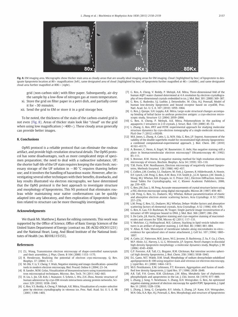
Fig. 8. EM imaging area. Micrographs show thicker stain area as cloudy areas that are usually ideal imaging areas for EM imaging. Cloud (highlighted by box) of lipoprotein to des-ignate lipoprotein location at 80× magnification (left), same designated area of cloud (highlighted by box) of lipoprotein further magnified at 4K× (middle), and same designatedcloud area further magnified at 80K× (right).
2157L. Zhang et al. / Biochimica et Biophysica Acta 1830 (2013) 2150–2159
grid (non-carbon side) with filter paper. Subsequently, air-drythe sample by a low-flow of nitrogen gas at room temperature.
xi. Store the grid on filter paper in a petri dish, and partially coverit for ~30 minutes.
xii. Send the grid to EM or store it in a grid storage box.
To be noted, the thickness of the stain of the carbon-coated grid isnot even (Fig. 8). Areas of thicker stain look like “cloud” on the gridwhen using lowmagnification (b400×). These cloudy areas generallycan provide better images.
8. Conclusions
OpNS protocol is a reliable protocol that can eliminate the rouleauartifact, and provide high-resolution structural details. The OpNS proto-col has some disadvantages, such as more complicated steps of speci-men preparation; the need to deal with a radioactive substance, UF;the shorter half-life of theUF stain requires keeping the stain fresh; nec-essary storage of the UF solution in −80 °C requires thawing beforeuse; and it involves the handling of hazardouswaste. However, after in-vestigating several other techniqueswith their benefits, drawbacks, andkey results illustrated via electron micrographs, we have determinedthat the OpNS protocol is the best approach to investigate structureand morphology of lipoproteins. This NS protocol that eliminates rou-leau while maintaining near native conformations can be quicklyadapted into any laboratory, and then exploration of lipoprotein func-tion related to structure can be more thoroughly investigated.
Acknowledgments
We thankMr.Matthew J. Rames for editing comments. Thisworkwassupported by the Office of Science, Office of Basic Energy Sciences of theUnited States Department of Energy (contract no. DE-AC02-05CH11231)and the National Heart, Lung, And Blood Institute of the National Insti-tutes of Health (no. R01HL115153).
References
[1] Z.L. Wang, Transmission electron microscopy of shape-controlled nanocrystalsand their assemblies, J. Phys. Chem. B 104 (2000) 1153–1175.
[2] R. Henderson, Realizing the potential of electron cryo-microscopy, Q. Rev.Biophys. 37 (2004) 3–13.
[3] M. Ohi, Y. Li, Y. Cheng, T.Walz, Negative staining and image classification—powerfultools in modern electron microscopy, Biol. Proced. Online 6 (2004) 23–34.
[4] B. Sander, M.M. Golas, Visualization of bionanostructures using transmission elec-tron microscopical techniques, Microsc. Res. Tech. 74 (2011) 642–663.
[5] H. Liu, L. Jin, S.B. Koh, I. Atanasov, S. Schein, L. Wu, Z.H. Zhou, Atomic structure ofhuman adenovirus by cryo-EM reveals interactions among protein networks, Sci-ence 329 (2010) 1038–1043.
[6] G. Ren, V.S. Reddy, A. Cheng, P. Melnyk, A.K. Mitra, Visualization of a water-selectivepore by electron crystallography in vitreous ice, Proc. Natl. Acad. Sci. U. S. A. 98(2001) 1398–1403.
[7] G. Ren, A. Cheng, V. Reddy, P. Melnyk, A.K. Mitra, Three-dimensional fold of thehuman AQP1 water channel determined at 4 A resolution by electron crystallogra-phy of two-dimensional crystals embedded in ice, J. Mol. Biol. 301 (2000) 369–387.
[8] G. Ren, G. Rudenko, S.J. Ludtke, J. Deisenhofer, W. Chiu, H.J. Pownall, Model ofhuman low-density lipoprotein and bound receptor based on cryoEM, Proc.Natl. Acad. Sci. U. S. A. 107 (2010) 1059–1064.
[9] G. Ren, J. Quispe, S.H. Leppla, A.K. Mitra, Large-scale structural changes accompa-ny binding of lethal factor to anthrax protective antigen: a cryo-electron micro-scopic study, Structure 12 (2004) 2059–2066.
[10] G. Ren, A. Cheng, P. Melnyk, A.K. Mitra, Polymorphism in the packing ofaquaporin-1 tetramers in 2-D crystals, J. Struct. Biol. 130 (2000) 45–53.
[11] L. Zhang, G. Ren, IPET and FETR: experimental approach for studying molecularstructure dynamics by cryo-electron tomography of a single-molecule structure,PLoS One 7 (2012) e30249.
[12] M.K. Jones, L. Zhang, A. Catte, L. Li, M.N. Oda, G. Ren, J.P. Segrest, Assessment of thevalidity of the double superhelix model for reconstituted high density lipoproteins:a combined computational-experimental approach, J. Biol. Chem. 285 (2010)41161–41171.
[13] A. Bremer, C. Henn, A. Engel, W. Baumeister, U. Aebi, Has negative staining still aplace in biomacromolecular electron microscopy? Ultramicroscopy 46 (1992)85–111.
[14] S. Brenner, R.W. Horne, A negative staining method for high resolution electronmicroscopy of viruses, Biochim. Biophys. Acta 34 (1959) 103–110.
[15] T.M. Forte, R.W. Nordhausen, Electron microscopy of negatively stained lipopro-teins, Methods Enzymol. 128 (1986) 442–457.
[16] C. Colliex, J.M. Cowley, S.L. Dudarev, M. Fink, J. Gjonnes, R. Hilderbrandt, A. Howie,D.F. Lynch, L.M. Peng, G. Ren, A.W. Ross, V.H. Smith Jr., J.C.H. Spence, J.W. Steeds, J.Wang, M.J. Whelan, B.B. Zvyagin, in: E. Prince (Ed.), Electron Diffraction, Interna-tional Tables For Crystallography, vol. C, Kluwer Academic Publishers, 2006,pp. 259–429.
[17] G. Ren, J.M. Zuo, L.-M. Peng, Accuratemeasurements of crystal structure factors usinga FEG electron microscope using digital micrographs, Micron 28 (1997) 459–467.
[18] L.M. Peng, G. Ren, S.L. Dudarev, M.J. Whelan, Robust parameterization of elasticand absorptive electron atomic scattering factors, Acta Crystallogr. A 52 (1996)257–276.
[19] L.M. Peng, G. Ren, S.L. Dudarev, M.J. Whelan, Debye–Waller factors and absorptivescattering factors of elemental crystals, Acta Crystallogr. A 52 (1996) 456–470.
[20] G. Ren, K. Gao, F.D. Bushman, M. Yeager, Single-particle image reconstruction of atetramer of HIV integrase bound to DNA, J. Mol. Biol. 366 (2007) 286–294.
[21] S. De Carlo, J.R. Harris, Negative staining and cryo-negative staining of macromol-ecules and viruses for TEM, Micron 42 (2011) 117–131.
[22] V. Melchior, C.J. Hollingshead, M.E. Cahoon, Stacking in lipid vesicle tubulin mix-tures is an artifact of negative staining, J. Cell Biol. 86 (1980) 881–884.
[23] V. Allan, R. Vale, Movement of membrane tubules along microtubules in-vitro—evidence for specialized sites of motor attachment, J. Cell Sci. 107 (1994) 1885–1897.
[24] A. Catte, J.C. Patterson, M.K. Jones, W.G. Jerome, D. Bashtovyy, Z. Su, F. Gu, J. Chen,M.P. Aliste, S.C. Harvey, L. Li, G. Weinstein, J.P. Segrest, Novel changes in discoidalhigh density lipoprotein morphology: a molecular dynamics study, Biophys. J. 90(2006) 4345–4360.
[25] G.P. Forester, A.R. Tall, C.L. Bisgaier, R.M. Glickman, Rat intestine secretes spheri-cal high density lipoproteins, J. Biol. Chem. 258 (1983) 5938–5943.
[26] D.L. Gantz, M.T. Walsh, D.M. Small, Morphology of sodium deoxycholate-solubilizedapolipoprotein B-100 using negative stain and vitreous ice electron microscopy,J. Lipid Res. 41 (2000) 1464–1472.
[27] M.O. Pentikainen, E.M. Lehtonen, P.T. Kovanen, Aggregation and fusion of modi-fied low density lipoprotein, J. Lipid Res. 37 (1996) 2638–2649.
[28] A.R. Tall, P.H. Green, R.M. Glickman, J.W. Riley, Metabolic fate of chylomicronphospholipids and apoproteins in the rat, J. Clin. Invest. 64 (1979) 977–989.
[29] L. Zhang, J. Song, Y. Newhouse, S. Zhang, K.H. Weisgraber, G. Ren, An optimizednegative-staining protocol of electron microscopy for apoE4 POPC lipoprotein, J. LipidRes. 51 (2010) 1228–1236.
[30] L. Zhang, J. Song, G. Cavigiolio, B.Y. Ishida, S. Zhang, J.P. Kane, K.H. Weisgraber,M.N. Oda, K.A. Rye, H.J. Pownall, G. Ren, Morphology and structure of lipoproteins
2158 L. Zhang et al. / Biochimica et Biophysica Acta 1830 (2013) 2150–2159
revealed by an optimized negative-staining protocol of electron microscopy, J. LipidRes. 52 (2011) 175–184.
[31] R. Carnemolla, X. Ren, T.K. Biswas, S.C. Meredith, C.A. Reardon, J. Wang, G.S. Getz,The specific amino acid sequence between helices 7 and 8 influences the bindingspecificity of human apolipoprotein A-I for high density lipoprotein (HDL) sub-classes: a potential for HDL preferential generation, J. Biol. Chem. 283 (2008)15779–15788.
[32] A. Sivashanmugam, Y. Yang, V. Murray, C. McCullough, B. Chen, X. Ren, Q. Li, J.Wang, Structural basis of human high-density lipoprotein formation and assem-bly at sub nanometer resolution, Methods Cell Biol. 90 (2008) 327–364.
[33] G. Cavigiolio, B. Shao, E.G. Geier, G. Ren, J.W. Heinecke, M.N. Oda, The interplaybetween size, morphology, stability, and functionality of high-density lipoproteinsubclasses, Biochemistry 47 (2008) 4770–4779.
[34] B. Chen, X. Ren, T. Neville, W.G. Jerome, D.W. Hoyt, D. Sparks, G. Ren, J. Wang, Apo-lipoprotein AI tertiary structures determine stability and phospholipid-binding ac-tivity of discoidal high-density lipoprotein particles of different sizes, Protein Sci.18 (2009) 921–935.
[35] E.L. Gong, A.V. Nichols, K.H.Weisgraber, T.M. Forte, V.G. Shore, P.J. Blanche, Discoidalcomplexes containing apolipoprotein E and their transformation by lecithin-cholesterol acyltransferase, Biochim. Biophys. Acta 1006 (1989) 317–328.
[36] L.A. Schneeweis, V. Koppaka, S. Lund-Katz, M.C. Phillips, P.H. Axelsen, Structuralanalysis of lipoprotein E particles, Biochemistry 44 (2005) 12525–12534.
[37] V. Raussens, J. Drury, T.M. Forte, N. Choy, E. Goormaghtigh, J.M. Ruysschaert, V.Narayanaswami, Orientation and mode of lipid-binding interaction of humanapolipoprotein E C-terminal domain, Biochem. J. 387 (2005) 747–754.
[38] X. Li, H.Y. Kan, S. Lavrentiadou, M. Krieger, V. Zannis, Reconstituted discoidalApoE-phospholipid particles are ligands for the scavenger receptor BI. The amino-terminal 1-165 domain of ApoE suffices for receptor binding, J. Biol. Chem. 277(2002) 21149–21157.
[39] T.L. Innerarity, R.E. Pitas, R.W. Mahley, Binding of arginine-rich (E) apoproteinafter recombination with phospholipid vesicles to the low density lipoprotein re-ceptors of fibroblasts, J. Biol. Chem. 254 (1979) 4186–4190.
[40] B. Lu, J.A. Morrow, K.H. Weisgraber, Conformational reorganization of thefour-helix bundle of human apolipoprotein E in binding to phospholipid, J. Biol.Chem. 275 (2000) 20775–20781.
[41] D.C. Peng, C. Song, C.A. Reardon, S.S. Liao, G.S. Getz, Lipoproteins produced byApoE−/− astrocytes infectedwith adenovirus expressing humanApoE, J. Neurochem.86 (2003) 1391–1402.
[42] C.A. Peters-Libeu, Y. Newhouse, S.C. Hall, H.E. Witkowska, K.H. Weisgraber, Apo-lipoprotein E*dipalmitoylphosphatidylcholine particles are ellipsoidal in solution,J. Lipid Res. 48 (2007) 1035–1044.
[43] C.A. Peters-Libeu, Y. Newhouse, D.M. Hatters, K.H. Weisgraber, Model of biologi-cally active apolipoprotein E bound to dipalmitoylphosphatidylcholine, J. Biol.Chem. 281 (2006) 1073–1079.
[44] L. Zhang, G. Cavigiolio, M. Oda, K.-A. Rye, G. Ren, A method to study thetime-dependent remodeling of high density lipoproteins by individual-particleelectron cryo-tomography, Biophys. J. 98 (2010) 440a.
[45] L. Zhang, F. Yan, S. Zhang, D. Lei, M.A. Charles, G. Cavigiolio, M. Oda, R.M. Krauss, K.H.Weisgraber, K.A. Rye, H.J. Pownall, X. Qiu, G. Ren, Structural basis of transfer betweenlipoproteins by cholesteryl ester transfer protein, Nat. Chem. Biol. 8 (2012) 342–349.
[46] T. Forte, K.R. Norum, J.A. Glomset, A.V. Nichols, Plasma lipoproteins in familiallecithin: cholesterol acyltransferase deficiency: structure of low and high density li-poproteins as revealed by elctron microscopy, J. Clin. Invest. 50 (1971) 1141–1148.
[47] R.A. Silva, R. Huang, J. Morris, J. Fang, E.O. Gracheva, G. Ren, A. Kontush, W.G.Jerome, K.A. Rye, W.S. Davidson, Structure of apolipoprotein A-I in sphericalhigh density lipoproteins of different sizes, Proc. Natl. Acad. Sci. U. S. A. 105(2008) 12176–12181.
[48] W.S. Davidson, R.A. Silva, Apolipoprotein structural organization in high density lipo-proteins: belts, bundles, hinges and hairpins, Curr. Opin. Lipidol. 16 (2005) 295–300.
[49] Y. Newhouse, C. Peters-Libeu, K.H. Weisgraber, Crystallization and preliminaryX-ray diffraction analysis of apolipoprotein E-containing lipoprotein particles,Acta Crystallogr. F Struct. Biol. Cryst. Commun. 61 (2005) 981–984.
[50] A.A. Ajees, G.M. Anantharamaiah, V.K. Mishra, M.M. Hussain, H.M. Murthy, Crystalstructure of human apolipoprotein A-I: insights into its protective effect againstcardiovascular diseases, Proc. Natl. Acad. Sci. U. S. A. 103 (2006) 2126–2131.
[51] R. van Antwerpen, M. La Belle, E. Navratilova, R.M. Krauss, Structural heterogene-ity of apoB-containing serum lipoproteins visualized using cryo-electron micros-copy, J. Lipid Res. 40 (1999) 1827–1836.
[52] R. van Antwerpen, G.C. Chen, C.R. Pullinger, J.P. Kane, M. LaBelle, R.M. Krauss, C.Luna-Chavez, T.M. Forte, J.C. Gilkey, Cryo-electron microscopy of low density li-poprotein and reconstituted discoidal high density lipoprotein: imaging of theapolipoprotein moiety, J. Lipid Res. 38 (1997) 659–669.
[53] R. van Antwerpen, Preferred orientations of LDL in vitreous ice indicate a discoidshape of the lipoprotein particle, Arch. Biochem. Biophys. 432 (2004) 122–127.
[54] L. Zhang, G. Cavigiolio, J. Wang, K.A. Rye, M. Oda, G. Ren, Structure of 9.6nm dis-coidal high-density lipoprotein revealed by individual-particle electron tomogra-phy, Biophys. J. 98 (2010) 440a.
[55] C.E. Matz, A. Jonas, Micellar complexes of human apolipoprotein A-I with phos-phatidylcholines and cholesterol prepared from cholate-lipid dispersions, J. Biol.Chem. 257 (1982) 4535–4540.
[56] J.A. Glomset, K. Applegate, T. Forte, W.C. King, C.D. Mitchell, K.R. Norum, E. Gjone,Abnormalities in lipoproteins of d b1.006 g/ml in familial lecithin:cholesterolacyltransferase deficiency, J. Lipid Res. 21 (1980) 1116–1127.
[57] R.N. Thrift, T.M. Forte, B.E. Cahoon, V.G. Shore, Characterization of lipoproteins pro-duced by the human liver cell line, Hep G2, under defined conditions, J. Lipid Res.27 (1986) 236–250.
[58] Y. Fang, O. Gursky, D. Atkinson, Lipid-binding studies of human apolipoproteinA-I and its terminally truncated mutants, Biochemistry 42 (2003) 13260–13268.
[59] O. Gursky, Ranjana, D.L. Gantz, Complex of human apolipoprotein C-1 withphospholipid: thermodynamic or kinetic stability? Biochemistry 41 (2002)7373–7384.
[60] S. Jayaraman, D.L. Gantz, O. Gursky, Effects of protein oxidation on the structureand stability of model discoidal high-density lipoproteins, Biochemistry 47(2008) 3875–3882.
[61] C.M. Li, B.H. Chung, J.B. Presley, G. Malek, X. Zhang, N. Dashti, L. Li, J. Chen, K.Bradley, H.S. Kruth, C.A. Curcio, Lipoprotein-like particles and cholesteryl estersin human Bruch's membrane: initial characterization, Invest. Ophthalmol. Vis.Sci. 46 (2005) 2576–2586.
[62] G. Ren, L.M. Peng, The analytic Doyle–Turner representation of high energy elec-tron absorptive structure factors, Acta Phys. Sin. 45 (1996) 1344–1349.
[63] G. Camejo, Z.M. Suarez, V. Munoz, The apo-lipoproteins of human plasma highdensity lipoprotein: a study of their lipid binding capacity and interaction withlipid monolayers, Biochim. Biophys. Acta 218 (1970) 155–166.
[64] A. Kondo, Y. Muranaka, I. Ohta, T. Kanno, Dynamic reaction in a homogeneousHDL-cholesterol assay visualized by electron microscopy, Clin. Chem. 45 (1999)1974–1980.
[65] M. Tufteland, G. Ren, R.O. Ryan, Nanodisks derived from amphotericin B lipidcomplex, J. Pharm. Sci. 97 (2008) 4425–4432.
[66] M.A. Clay, D.H. Pyle, K.A. Rye, P.J. Barter, Formation of spherical, reconstitutedhigh density lipoproteins containing both apolipoproteins A-I and A-II is medi-ated by lecithin:cholesterol acyltransferase, J. Biol. Chem. 275 (2000) 9019–9025.
[67] H.V. Desilva, J. Masoliva, J.M. Taylor, R.W. Mahley, Identification of apolipoproteinB-100 low-density lipoproteins, apolipoprotein B-48 remnants, and apolipopro-tein E-rich high-density-lipoproteins in the mouse, J. Lipid Res. 35 (1994)1297–1310.
[68] A.M. Fagan, D.M. Holtzman, G. Munson, T. Mathur, D. Schneider, L.K. Chang, G.S.Getz, C.A. Reardon, J. Lukens, J.A. Shah, M.J. LaDu, Unique lipoproteins secretedby primary astrocytes from wild type, apoE (−/−), and human apoE transgenicmice, J. Biol. Chem. 274 (1999) 30001–30007.
[69] T.A. Musliner, M.D. Long, T.M. Forte, A.V. Nichols, E.L. Gong, P.J. Blanche, R.M.Krauss, Dissociation of high density lipoprotein precursors from apolipoproteinB-containing lipoproteins in the presence of unesterified fatty acids and a sourceof apolipoprotein A-I, J. Lipid Res. 32 (1991) 917–933.
[70] L. Silverman, D. Glick, The reactivity and staining of tissue proteins withphosphotungstic acid, J. Cell Biol. 40 (1969) 761–767.
[71] L.S. Guo, R.L. Hamilton, J. Goerke, J.N.Weinstein, R.J. Havel, Interaction of unilamellarliposomes with serum lipoproteins and apolipoproteins, J. Lipid Res. 21 (1980)993–1003.
[72] R.L. Hamilton, M.C. Williams, C.J. Fielding, R.J. Havel, Discoidal bilayer structure ofnascent high density lipoproteins from perfused rat liver, J. Clin. Invest. 58 (1976)667–680.
[73] H. Pollard, A.M. Scanu, E.W. Taylor, On the geometrical arrangement of the pro-tein subunits of human serum low-density lipoprotein: evidence for a dodecahe-dral model, Proc. Natl. Acad. Sci. U. S. A. 64 (1969) 304–310.
[74] J.M. Frasca, V.R. Parks, A routine technique for double-staining ultrathin sectionsusing uranyl and lead salts, J. Cell Biol. 25 (1965) 157–161.
[75] F.Q. Zhao, R. Craig, Capturing time-resolved changes in molecular structure bynegative staining, J. Struct. Biol. 141 (2003) 43–52.
[76] G. Quintarelli, R. Zito, J.A. Cifonelli, On phosphotungstic acid staining. I, J.Histochem. Cytochem. 19 (1971) 641–647.
[77] D. Seidel, B. Agostini, P. Muller, Structure of an Abnormal Plasma Lipopro-tein (Lp-X) Characterizing Obstructive-Jaundice, Biochim. Biophys. Acta260 (1972) 146-&.
[78] D.P. Knight, Negative staining of rat tail tendon collagen fibrils with uranyl for-mate, Tissue Cell 7 (1975) 651–654.
[79] S. Dash, M. Kamruddin, S. Bera, P.K. Ajikumar, A.K. Tyagi, S.V. Narasimhan, B. Raj,Temperature programmed decomposition of uranyl nitrate hexahydrate, J. Nucl.Mater. 264 (1999) 271–282.
[80] J.R. Harris, W. Gebauer, F.U. Guderian, J. Markl, Keyhole limpet hemocyanin(KLH), I: Reassociation from Immucothel followed by separation of KLH1 andKLH2, Micron 28 (1997) 31–41.
[81] J.R. Harris, W. Gebauer, S.M. Sohngen, M.V. Nermut, J. Markl, Keyhole limpet he-mocyanin (KLH), II: Characteristic reassociation properties of purified KLH1 andKLH2, Micron 28 (1997) 43–56.
[82] H. M.A., Principles and Techniques of Electron Microscopy: Biological Applica-tions, Cambridge University Press, Cambridge, 2000.
[83] Z.G. Jiang, M.N. Simon, J.S. Wall, C.J. McKnight, Structural analysis of reconstitutedlipoproteins containing the N-terminal domain of apolipoprotein B, Biophys. J. 92(2007) 4097–4108.
[84] P.J. Barter, H.B. Brewer Jr., M.J. Chapman, C.H. Hennekens, D.J. Rader, A.R. Tall,Cholesteryl ester transfer protein: a novel target for raising HDL andinhibiting atherosclerosis, Arterioscler. Thromb. Vasc. Biol. 23 (2003) 160–167.
[85] G. Camejo, S. Waich, G. Quintero, M.L. Berrizbeitia, F. Lalaguna, The affinity of lowdensity lipoproteins for an arterial macromolecular complex. A study in ischemicheart disease and controls, Atherosclerosis 24 (1976) 341–354.
[86] T. Gordon, W.P. Castelli, M.C. Hjortland, W.B. Kannel, T.R. Dawber, High density li-poprotein as a protective factor against coronary heart disease. The FraminghamStudy, Am. J. Med. 62 (1977) 707–714.
[87] T. Hayek, N. Azrolan, R.B. Verdery, A. Walsh, T. Chajek-Shaul, L.B. Agellon, A.R. Tall,J.L. Breslow, Hypertriglyceridemia and cholesteryl ester transfer protein interact
2159L. Zhang et al. / Biochimica et Biophysica Acta 1830 (2013) 2150–2159
to dramatically alter high density lipoprotein levels, particle sizes, and metabo-lism. Studies in transgenic mice, J. Clin. Invest. 92 (1993) 1143–1152.
[88] M.L. Brown, A. Inazu, C.B. Hesler, L.B. Agellon, C. Mann, M.E. Whitlock, Y.L. Marcel,R.W. Milne, J. Koizumi, H. Mabuchi, et al., Molecular basis of lipid transfer proteindeficiency in a family with increased high-density lipoproteins, Nature 342 (1989)448–451.
[89] A. Inazu, M.L. Brown, C.B. Hesler, L.B. Agellon, J. Koizumi, K. Takata, Y. Maruhama,H. Mabuchi, A.R. Tall, Increased high-density lipoprotein levels caused by a com-mon cholesteryl-ester transfer protein gene mutation, N. Engl. J. Med. 323 (1990)1234–1238.
[90] E.J. Niesor, Different effects of compounds decreasing cholesteryl ester transferprotein activity on lipoprotein metabolism, Curr. Opin. Lipidol. 22 (2011) 288–295.
[91] M.A. Miyares, Anacetrapib and dalcetrapib: two novel cholesteryl ester transferprotein inhibitors, Ann. Pharmacother. 45 (2011) 84–94.
[92] P.J. Kappelle, A. van Tol, B.H. Wolffenbuttel, R.P. Dullaart, Cholesteryl ester trans-fer protein inhibition in cardiovascular risk management: ongoing trials will endthe confusion, Cardiovasc. Ther. 29 (2011) e89–e99.
[93] L. Zhang, A. Kaspar, G.Woodnutt, G. Ren, Monitoring the Structural Changes of Con-jugated Antibodies by High-Resolution Electron Microscopy and Individual-ParticleElectron Tomography, Biophys. J. 98 (2010) 440a–441a.
[94] L. Zhang, G. Ren, Determining the Dynamic Protein Structure by Individual-ParticleElectron Tomography: An Individual Antibody Structure at a Nanometer Resolution,Biophys. J. 98 (2010) 441a.
[95] G. Ren, L. Zhang, Asymmetric Small Protein Structure Determination by IndividualParticle Electron Tomography, Biophys. J. 102 (2012) 394a.
[96] L. Zhang, G. Ren, Structural Determination of Heterogeneous Protein by Individual-Particle Electron Tomography - Combination of Electron Tomography and Local Refine-ment ReconstructionMethod for High-Resolution Structural Determination of Each In-dividual Protein Particle, Biophys. J. 98 (2010) 441a.