Embed Size (px)
Citation preview
BLUE-FLAME VENT-FREEPROPANE/LP GAS HEATER
OWNER'S OPERATION AND INSTALLATION MANUAL
RP30E
! S / - ,41' [k ,* IJi
CGP20BCGP20LB
WARNING: If the information in this manual is not fol-
lowed exactly, a fire or explosion may result causingproperty damage, personal injury, or loss of life.
Do not store or use gasoline or other flammablevapors and liquids in the vicinity of this or any otherappliance.
-- WHAT TO DO IF YOU SMELL GAS• Do not try to light any appliance.• Do not touch any electrical switch; do not use any
phone in your building.• Immediately call your gas supplier from a
neighbor's phone. Follow the gas supplier's in-structions.
• If you cannot reach your gas supplier, call the firedepartment.
-- Installation and service must be performed by a quali-fied installer, service agency, or the gas supplier.
WARNING: Improper installation,adjustment, alteration, service, or
maintenance can cause injury orproperty damage. Refer to thismanual for correct installation and
operational procedures. For as-sistance or additional information
consult a qualified installer, ser-
vice agency, or the gas supplier.
WARNING: This is an unventedgas-fired heater. It uses air (oxy-gen) from the room in which it isinstalled. Provisions for adequatecombustion and ventilation airmust be provided. Refer to Air forCombustion and Ventilation sec-tion on page 4 of this manual.
This appliance may be Installed In an aftermarket* manufactured (mobile) home, where not prohibitedby state or local codes.*Aftermsrket: Completion of sale, not for purpose of resale, from the manufacturer. (I.E. Installat;on of this product is3ermltted after the manufactured (mobile) home Is sited)
This appliance is only for use with the type of gas indicated on the rating plata.This appliance is not €onvertible for use with other gases.
Save this manual for future reference.
BLUE-FLAME CGP20B, CGP20LB AND RP30E
VENT-FREE PROPANE/LP GAS HEATER
SAFETYINFORMATION
_, WARNINGS
IMPORTANT: Read this Owner'sManual carefully and completelybefore trying to assemble, oper-ate, or service this heater. Im-proper use of this heater cancause serious injury or deathfrom burns, fire, explosion, elec-trical shock, and carbon monox-ide poisoning.
_, DANGER: Carbon monoxide
poisoning may lead to deathl
Carbon Monoxide Poisoning: Earlysigns of carbon monoxide poisoning re-semble the flu, with headaches, dizziness,or nausea. If you have these signs, the heatermay not be working properly. Get fresh airat once! Have heater serviced. Some peopleare more affected by carbon monoxide thanothers. These includepregnant women, per-sons with heart or lung disease or anemia,those under the influence of alcohol, andthose at high altitudes.
Propane/LP Gas: Propane/LP gas isodor-less. An odor-making agent is added topropane/LP gas. The odor helps you detecta propane/LP gas leak. However, the odoradded to propane/LP gas can fade. Propane/LP gas may be present even though no odorexists.
Make certain you read and understand allWarnings. Keep this manual for reference.It is your guide to safe and proper operationof this heater.
I _WARNING: Any changeto thisheater or its controls can bedangerous.
1. This appliance is only for use with thetype of gas indicated on therating plate.This appliance is not convertible for usewith other gases.
2. Do not place pmpane/LP supply tank(s)inside any structure. Locate propane/LP supply tank(s) outdoors.
3. This heater shall not be installed in abedroom or bathroom.
4. If you smell gas• shut off gas supply• do not try to light any appliance• do not touch any electrical switch;
do not use any phone in your building• immediately call your gas supplier
from a neighbor's phone. Follow thegas supplier's instructions
• if you cannot reach your gas supplier,call the fire department
5. Never install the heater• in a recreational vehicle• where curtains, furniture, clothing, or
other flammable objects are less than36 inches from the front, top, or sidesof the heater
• as a fireplace insert• in high traffic areas• in windy or drafty areas
6. This heater needs fresh, outside air van-tilation to run properly. This heater hasan oxygen depletion sensor (ODS) pi-lot light safety system. The ODS shutsdown the heater if not enough fresh airis available. See Air for Combustionand Ventilation, pages 4 through 6.
7. Keep all air openings in the front andbottom of heater clear and free of de-
bris. This will insure enough air forproper combustion.
8. If heater shuts off, do not relight untilyou provide fresh, outside air. If heaterkeeps shutting off, have it serviced.
9. Do not run heater
• where flammable liquids or vaporsare used or stored
• under dusty conditions
10. Never place any objects on the heater.
11. Surface of heater becomes very hotwhen running heater. Keep children andadults away from hot surface to avoidburns and clothing ignition. Heater willremain hot for a time after shutdown.
Allow surface to cool before touching.
12. Make sure grill guard is in place be-fore running heater.
13. Carefully supervise young childrenwhen they are in same room withheater.
14. Do not use heater if any part has beenunder water. Immediately call a quali-fied service technician to inspect theroom heater and to replace any part ofthe control system and any gas controlwhich has been under water.
15. Turn off heater and let cool before ser-vicing. Only a qualified service personshould service and repair heater.
16. Operating heater above elevations of4,500 feet could cause pilot outage.
17. To prevent performance problems, donot use propane fuel tank of less thanthan 100 lbs. capacity.
2 fo_2
OWNER'S MANUAL
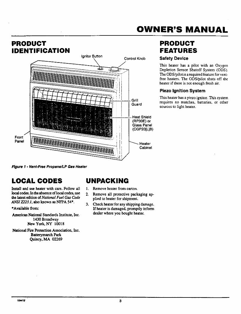
PRODUCTIDENTIFICATION
IgnitorButtonControl Knob
3rillGuard
PRODUCTFEATURESSafety Device
This heater has a pilot with an OxygenDepletion Sensor Shutoff System (ODS).The ODS/pilot is a required feature for vent-free heaters. The ODS/pilot shuts off theheater if there is not enough fresh air.
Piezo Ignition System
This heater has a piezo ignitor. This systemrequires no matches, batteries, or othersources to light heater.
FrontPanel
Heat Shield(RP30E) orGlass Panel(CGP20[L]B)
Cabinet
Figure 1 - Vent-Free Propane.ALPGas Heater
LOCAL CODES UNPACKINGInstall and use heater with care. Follow all 1.
local codes. Inthe absence of local codes, use 2.the latest edition of National Fuel Gas Code
ANSI 7223.1, also known as NFPA 54*. 3.*Available from:
American National Standards Institute, Inc.1430 Broadway
New York, NY 10018
NationalFireProtectionAssociation,Inc.
BatterymarchPark
Quincy,MA 02269
Remove heater from canon.
Remove all protective packaging ap-plied to heater for shipment.
Check heater for any shipping damage.If heater is damaged, promptly informdealer where you bought heater.
_o_ " 3

BLUE-FLAME CGP20B, CGP20LB AND RP30E
VENT-FREE PROPANE/LP GAS HEATER
AIR FORCOMBUSTION ANDVENTILATION
WARNING: This heater shallnot be installed In a confinedspace unless provisions are pro-vided for adequate combustionand ventilation air. Read the fol-lowing instructions to insureproper fresh air for this and otherfuel-burning appliances in yourhome.
Today's homes are built more energy effi-cient than ever. New materials, increasedinsulation, and new construction methodshelp reduceheat loss in homes. Home ownersweather sl_p and caulk aroundwindows anddoorstokeepthe cdd ah"outandthe warm airin. During heating months, home ownerswant their homes as airtight as possible.
While it is good to make your home energyefficient, your home needs to breathe. Freshair must enter your home. All fuel-burningappliances need fresh air for proper com-bustion and ventilation.
Exhaustfans,fireplaces, clothes dryers,andfuel burningappfiances draw air from thehouse to operate. You must provide ad-equate flesh air for these appliances. Thiswill insure proper venting of vented fuel-burningappliances.
PROVIDING ADEQUATEVENTILATION
The following is excerpts from NationalFuel Gas Code. NFPA 54/ANSI Z223.1,Section 5.3, Air for Combustion andVentilation.
All spaces in homes fall into one of the threefollowing ventilation classifications:
1. Unusually Tight Construction
2. Unconfined Space
3. Confined Space
The information on pages 4 through 6 willhelp you classify your space and provideadequate ventilation.
Unusually Tight Construction
The air that leaks around doors and win-
dows may provide enough flesh air forcombustion and ventilation. However, inbuildings of unusually tight construction,you must provide additional fresh air.
Unusually tight construction is de-fined as construction where:
a. walls and celllngs exposed to theoutside atmosphere have a con-tinuous water vapor retarder witha rating of one penn (6 x 10-11kgper pa-sec-nd) or less with open-Ings gasketad or sealed and
b. weather stripping has beenadded on openable windows anddoors and
€. caulldng or sealants are appliedto areas such as Joints aroundwindow and door frames, be-tween sole plates and floors, be-tween wall-ceiling Joints, be-tween wall panels, at penetra-tions for plumbing, electrical, andgas lines, and st other openings.
ff your home meets all of the three¢riterle above, you must provide ad-ditional fresh air. See Ventilation AirFrom Outdoors, page 6.
If your home does not meet all of thethree ¢dteda above, proceed to Dater.mining Fresh-Air Flow for Heater Lo-cation, page S.
Confined and Unconfined Space
The National Fuel Gas Code (ANSI Z223.1,1992 Section 5.3) defines a confined spaceas a space whose volume is less than 50cubic feet per 1,000 Btu per hour (4.8 m3perkw) of the aggregate input rating of allappLiances installed in that space and anunconfialng space as a space whose volumeis not less than 50 cubic feet per 1,000 Btuper hour (4.8 m3per kw) of the aggregateinput rating of all appliances installed in thatspace. Rooms communicating directly withthe space in which the appliances are in-stalled*, through openings not furnishedwith doors, are considered a part of theunconfined space.
This heater shall not be installed in a con-fined space or unusually tight constructionunless provisions are provided for adequatecombustion and ventilation air.
*Adjoiningroomsare communicatingonlyif there are doorless passageways or ventila-tion grills between them.
4 lo_12

OWNER'S MANUAL
AIR FORCOMBUSTION ANDVENTILATIONContinued
DETERMINING FRESH-AIR FLOW FOR HEATER LOCATION
Determining if You Have a Confined or Unconfined Space
Use this worksheet to determine if you have a confined or unconfined space.
Space: Includes the room in which you will install heater plus any adjoining rooms with doorless passageway s or ventilation gillls betweenthe rooms.
1. Determine the volume of the space (length x width x height).
Length x Width x Height = cu. ft. (volume of space)
Example: Space size 20 ft, (length) x 16 ft. (width) x 8 ft, (ceiling height) = 2560 cu. ft. (volume of space)
If additional ventilation to adjoining room is supplied with grills or openings, add the volume of these rooms to the total volume of
the space.
2. Divide the space volume by 50 cubic feet to determine the maximum Btu/Hr the space can support.
(volume of space) + 50 cu. ft. = (Maximum Btu/Hr the space can support)
Example: 2560 cu. ft. (volume of space) + 50 cu. ft. = 51.2 or 51,200 (maximum Btu/Hr the space can support)
3. Add the Btu/Hr of all fuel burning appliances in the space.
Btu/Hr
Btu/Hr
Btu/I_
Btu/Hr
Vent-free heater
Gas water heater*
Gas furnace
Vented gas heater
Gas fireplace logs
Other gas appliances*
Total
Btu/Hr
+ Btu/Hr
Example:
Gas water heater 40,000
Vent-free heater + 20,000
Total = 60,000
Btu/Hr
Btu/Hr
Btu/Hr
= Btu/Hr
* Do not include direct-vent gas appliances. Direct-vent draws combustion air from the outdoors and vents to the outdoors.
4. Compare the maximum Btu/Hr the space can support with the actual amount of Btu/Hr used.
Bm/Hr (maximum the space can support)
Btu/Hr (actual amount of Btu/Hr used)
Example: 51,200 Btu/Hr (maximum the spacecansupport)
60,000 Btu/Hr (actual amount of Btu/Hr used)
The space in tbe above example is a confined space because the actual Btu/Hr used is more than the maximum Btu/Hr the space can support.You must provide additional fresh air. Your options are as follows:
A. Rework worksheet, adding the space of an adjoining room. If the extra space provides an unconfined space, remove door to adjoin-hagroom or add ventilation grills between rooms. See Ventilation Air From Inside Building, page 6.
B. VeatroomcYu'ecflytotheoutdoors. SeeVentilationAirFromOutdoors, page6.
C. Install a lower Btu/Hr heater, ff lower Btu/Hr size makes room unconfined.
Iftbe actual Btu/Hr used is less than the maximum Btu/Hr the space can support, the space is an unconfined space. You will need noadflitional fresh airventilation.
provide adequate combustion and ventilation air by one of the methods described in the NationalFuel Gas Code,
Continued
_k_ARN_NG_fthe_rce_nwh_hth_hcetermaybe_perated_manerthanthatde_ned_sanunc_n_nedspace_ I• ANSIZ223.1, 1992, Section 5.3 or applicable local codes.
1044U_ 5
BLUE-FLAME CGP20B, CGP20LB AND RP30E
VENT-FREE PROPANE/LP GAS HEATER
AIR FORCOMBUSTION ANDVENTILATIONContinued
VENTILATION AIR
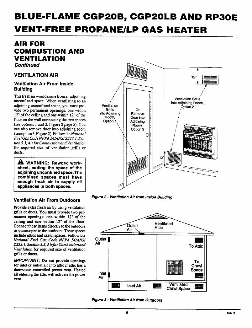
Ventilation Air From Inside
Building
Thisfreshairwouldcomefromanadjoiningunconfinedspace.When ventilatingtoanadjoiningunconfinedspace,you mustpro-videtwo permanent openings: one within12" of the ceiling and one within 12" of thefloor on the wall connecting the two spaces(see options I and 2, Figure 2 page 5). Youcan also remove door into adjoining room(see option 3, Figure 2). Follow the NationalFuel Gas Code NFPA 54/ANSI Z223.1, Sec-tion 5.3, Air for Combustion and Ventilationfor required size of ventilation grills orducts.
• k WARNING: Rework work-
sheet, adding the space of theadjoining unconfined space. Thecombined spaces must haveenough fresh air to supply allappliances in both spaces.
Ventilation Air From Outdoors
Provide extra fresh air by using ventilationgrills or ducts. You must provide two per-manent openings: one within 12" of theceiling and one within 12" of the floor.Connect these items directly to the outdoorsorspaces open to the outdoors. These spacesinclude attics and crawl spaces. Follow theNational Fuel Gas Code NFPA 54/ANSI
7923.1, Section 5.3, Air for CombustionandVentilation for required size of ventilationgrills or ducts.
IMPORTANT: Do not provide openingsfor inlet or oudet air into attic if attic has athermostat-controlled power vent. Heatedairentering the attic will activate the powervent.
VentilationGdils Or
into Adjoining RemoveRoom, Door into
Option 1 AdjoiningRoom,
Option 3
12"
VentilationGrillsInto AdjoiningRoom,
Dption2
Figure 2 - Ventilation Air from Inside Building
OutletAir
Inlet Air
InletAir
To Attic
To
CrawlSpace
VentilatedCrawl Space
Figure 3. Ventilation Air from Outdoors
6 104412
OWNER'S MANUAL
INSTALLATION
NOTICE: This heater is intendedfor use as supplemental heat. Usethis heater along with your pri-mary heating system. Do not in-stall this heater as your primaryheat source. If you have a centralheating system, you may runsystem's circulating blower whileusing heater. This will help circu-late the heat throughout thehouse. In the event of a poweroutage, you can use this heateras your primary heat source.
NOTICE: A qualified service per-son must install heater. Followall local codes.
CHECK GAS TYPE
Use only propane/LP gas. If your gas supplyis not propane/LP, do not install heater. Calldealer where you bought heater for propertype heater.
INSTALLATION ITEMS
Before installing heater, make sure you havethe items listed below.
• external regulator (supplied by installer)
• piping (check local codes)• sealant (resistant to propaneJLP gas)• manual shutoff valve *
• ground joint union• test gauge connection * (see Figure 13,
page 10)
• sediment trap• tee joint
• pipe wrench
• An A.G.A. design certified manual shutoffvalve with 1/8" NPT tap is an acceptablealternative to test gauge connection. Pur-chase the optional A.G.A. design certi-fied manual shutoff valve from yourdelder.See Accessories, page 22,
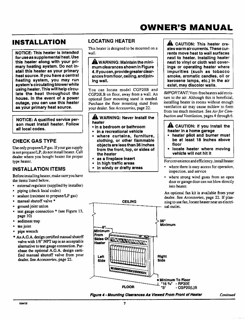
LOCATING HEATER
This heater is designed to be mounted on awall.
_WARNING: Maintain the mini-mum clearances shown In Figure4. ffyou can, provide greater clear-ances from floor, ceiling, and join-ing wall,
You can locate model CGP20B and
CGP20LB on floor, away from a wall. Anoptional floor mounting stand is needed.Purchase the floor mounting stand fromour dealer. See Accessories, page 22.
WARNING: Never install theheater• in a bedroom or bathroom• in a recreational vehicle• where curtains, furniture,
clothing, or other flammableobjects are less than 36 inchesfrom the front, top, or sides ofthe heater
• as a fireplace insert• in high traffic areas
i " in windy or drafty areas
CEILING
From51des €Pleater
LeftSide
CAUTION: This heater cre-ates warm air currents. These cu r-rents move heat to wall surfacesnext to heater. Installing heaternext to vinyl or cloth wall cover-ings or operating heater whereimpurities (such as tobaccosmoke, aromatic candles, oil orkerosene lamps, etc.) in the airexist, may discolor walls.
IMPORTANT: Vent-free heaters add mois-
ture to the air. Although this is beneficial,installing heater in rooms without enoughventilation air may cause mildew to formfrom too much moisture. See Air for Com-bustion and Ventilation, pages 4 through 6.
AAm CAUTION: If you install theheater in a home garage• heater pilot and burner must
be at least 18 inches abovefloor
• locate heater where movingvehicle will not hit it
For convenience and efficiency, install heater
• where there is easy access for operation,inspection, and service
• where strong wind gusts from an opendoor or garage door can not blow directlyinto heater.
An optional fan kit is available from yourdealer. See Accessories, page 22. If plan-ning to use fan, locate heater near an electri-cal outlet.
> 36"Minimum
RightSide
* Minimum To Floor"16 s/4" - RP30EFLOOR "3" - CGP20(L)B
Figure 4. Mounting Clearances As Viewed From Front of Heater Continued
104412 7
BLUE-FLAME CGP2OB, CGP2OLB AND RP30E
VENT-FREE PROPANE/LP GAS HEATER
INSTALLATIONContinued
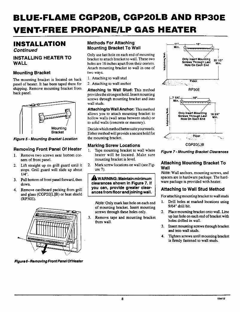
INSTALLING HEATER TOWALL
Mounting Bracket
The mounting bracket is located on backpanel of beater. It has been taped there forshipping. Remove mounting bracket fromback panel.
Figure 5 - Mounting Bracket Location
Removing Front Panel Of Heater1. Remove two screws near bottom cor-
ners of front panel.
2. Lift straight up on grill guard until itstops. Grill guard will slide up about1/4".
3, Pull bottom of front panel forward, thendown.
4. Remove cardboard packing from grilland glass (CGP20[L]B) or heat shield(RP30E).
Figure 6- Removing Front Panel Of Heeter
Methods For AttachingMounting Bracket To Wall
Only use last hole on each end of mountingbracket to attach bracket to wall. These two _'holes are 16inches apartfrom their centers.Attach mounting bracket to wall in one oftwo ways.
1. Attaching to wall stud
2. Attaching to wall anchor
Attaching to Wall Stud: This methodprovides the strongest hold. Insert mountingscrews through mounting bracket and intowail studs.
Attaching to Wall Anchor: This methodallows you to attach mounting bracket tohollow walls (wall areas between studs) orto solid walls (concrete or masonry).
Decide which method better suitsyour needs.Either method will provide a secure hold forthe mounting bracket.
Marking Screw Locations1. Tape mounting bracket to walt where
heater will be located. Make sure
mounting bracket is level.
2. Mark screw locations on wall (see Fig-ure 7).
_WARNING: Maintaln minlmum
clearances shown in Figure 7. Ifyou can, provlde greater clear-ances from floor and joining wall.
3.
Note: Only mark last hole on each endof mounting bracket. Insert mountingscrews through these holes only.
Remove tape and mounting bracketfrom wall.
,\ / LOn y Insert Mounting 32 1/2"Screws Through Last Min,
Hole On Each End
'_': :Floor
RP30E
-7 1/_16"
Ol Mny nsert ountng 183/4"Screws Through Last Min.
I Hole Orl Each End I
.(" Floor ._,
CGP20(L)B
Figure ? - Mounting Bracket Clearances
Attaching Mounting Bracket ToWallNote: Wail anchors, mountingscrews,andspacers are in hardware package. The hard-ware package is provided with heater.
Attaching to Wall Stud Method
Forattaching mounting bracketto wall studs
1. Drill holes at marked locations using9/64" drill bit.
,
3.
4.
Place mounting bracket onto wall. Lineup last hole on each end of bracket withholes drilled in wall.
Insert mounting screws through bracketand into wall studs.
Tighten screws until mounting bracketis firmly fastened to wall studs.
8 104412
OWNER'S MANUAL
INSTALLATIONContinued
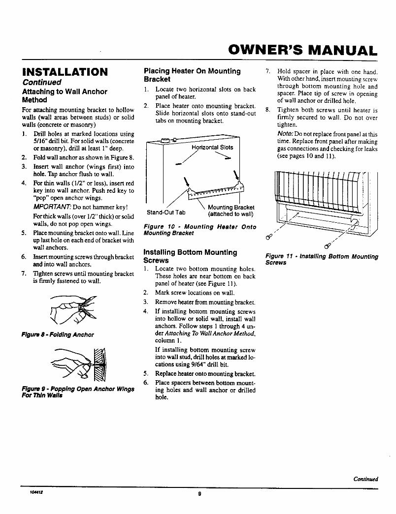
Attaching to Wall AnchorMethod
For attaching mounting bracket to hollowwalls (wall areas between studs) or solidwalls (concrete or masonry)
1. Drill holes at marked locations using5/16" dril! bit. For solid walls (concrete
or masonry), drill at least 1" deep.
2. Fold wall anchor as shown in Figure 8.
3. Insert wall anchor (wings first) intohole. Tap anchor flush to wall.
4. For thin walls (1/2" or less), insert redkey into wall anchor. Push red key to"pop" open anchor wings.
MPORTANT" Do not hammer key!
For thick walls (over 1/2" thick) or solidwalls, do not pop open wings.
5. Place mounting bracket onto wall. Lineup last hole on each end of bracket withwall anchors.
6. Insert mounting screws through bracketand into wall anchors.
7. Tighten screws until mounting bracketis firmly fastened to wall.
Figure 8 - Folding Anchor
Rgure 9 - Popping Open Anchor WingsFor Thin Walls
Placing Heater On Mounting 7.Bracket
1. Locate two horizontal slots on back
panel of heater.
2. Place heater onto mounting bracket. 8.Slide horizontal slots onto stand-out
tabs on mounting bracket.
HorizontalSlots
\\
/ :r.oketStand-OutTab (attached to wall)
Figure 10 - Mounting Heater OntoMounting Bracket
Installing Bottom MountingScrews
1. Locate two bottom mounting holes.These holes are near bottom on backpanel of heater (see Figure 1] ).
2. Mark screw locations on wall.
3. Remove heater from mounting bracket.
4. If installing bottom mounting screwsinto hollow or solid wall, install wallanchors. Follow steps 1 through 4 un-der Attaching To Wall Anchor Method,column 1.
If installing bottom mounting screwinto wall stud, drill holes at marked lo-cations using 9/64" drill bit.
5. Replace heater onto mounting bracket.
6. Place spacers between bottom mount-ing holes and wall anchor or drilledhole.
Hold spacer in place with one hand.With other hand, insert mounting screwthrough bottom mounting hole andspacer. Place tip of screw in openingof wall anchor or drilled hole.
Tighten both screws until heater isfirmly secured to wall. Do not overtighten.
Note: Do not replace front panel at thistime. Replace front panel after makinggas connections and checking for leaks(see pages 10 and 11).
i
[_ /
Figure 11 - Installing Bottom MountingScrews
Continued
1044_2 9
BLUE-FLAME CGP20B, CGP20LB AND RP30E
VENT-FREE PROPANE/LP GAS HEATER
INSTALLATIONContinued
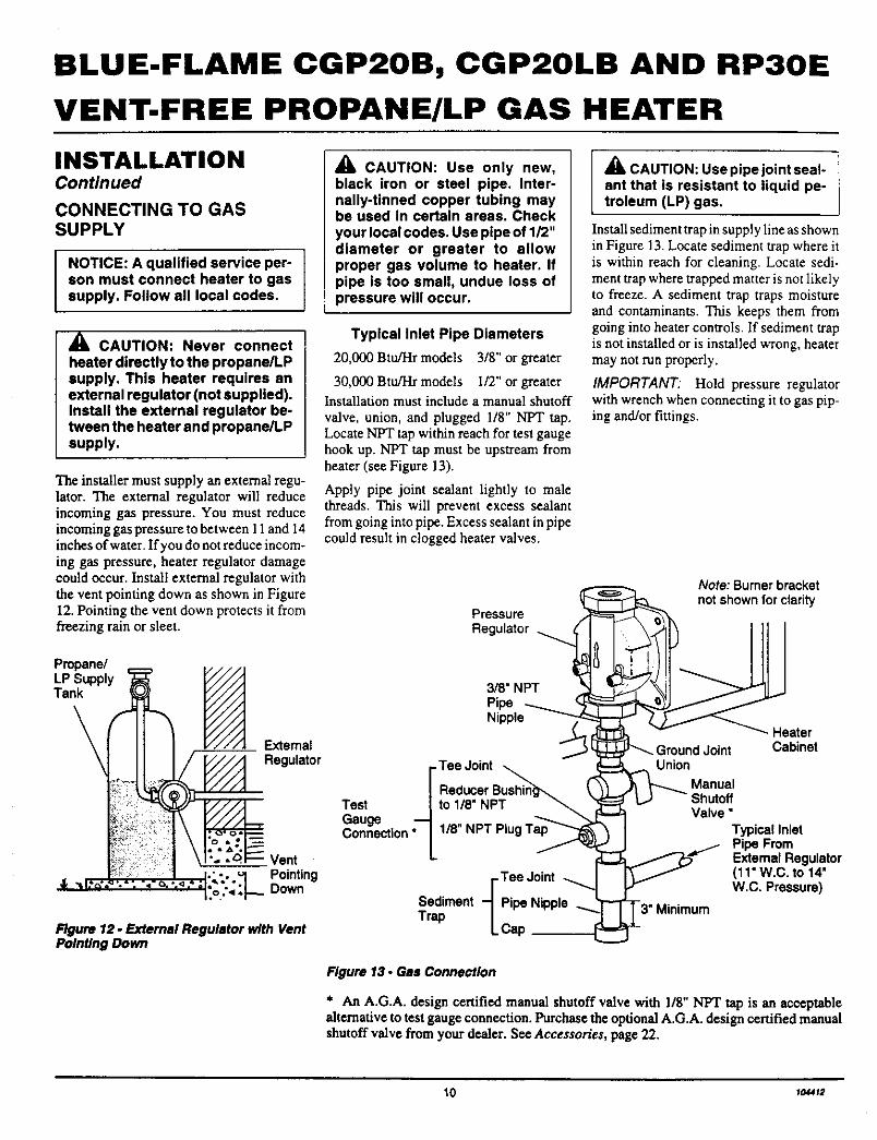
CONNECTING TO GASSUPPLY
NOTICE: A qualified service per-son must connect heater to gassupply. Follow all local codes.
CAUTION: Never connectheater directly to the propane/LPsupply. This heater requires anexternal regulator (not supplied).Install the external regulator be-tween the heater and propane/LPsupply.
The installer must supply an external regu-lator. The external regulator will reduceincoming gas pressure. You must reduceincoming gas pressure to between 11 and 14inches of water. If you do not reduce incom-ing gas pressure, heater regulator damagecould occur. Install external regulator withthe vent pointing down as shown in Figure12. Pointing the vent down protects it fromfreezing rain or sleet.
_IL CAUTION: Use only new,black iron or steel pipe. Inter-nally-tinned copper tubing maybe used in certain areas. Checkyour local codes. Use pipe of 1/2"diameter or greater to allowproper gas volume to heater. Ifpipe is too small, undue loss ofpressure will occur.
Typical Inlet Pipe Diameters
20,000 Btu/Hr models 3/8" or greater
30,000 Btu/Hr models 1/2" or greaterInstallation must include a manual shutoffvalve, union, and plugged 1/8" NPT tap.Locate NPT tap within reach for test gaugehook up. NPT tap must be upstream fromheater (see Figure 13).
Apply pipe joint sealant lightly to malethreads. This will prevent excess sealantfrom going into pipe. Excess sealant in pipecould result in clogged heater valves.
Pressure
Regulator
CAUTION: Use pipe joint seal-ant that is resistant to liquid pe-troleum (LP) gas.
Install sediment trap in supply line as shownin Figure 13. Locate sediment trap where itis within reach for cleaning. Locate sedi-ment trap where trapped matter is not likelyto freeze. A sediment trap traps moistureand contaminants. This keeps them fromgoing into heater controls. If sediment trapis not installed or is installed wrong, heatermay not run properly.
IMPORTANT: Hold pressure regulatorwith wrench when connecting it to gas pip-ing and/or fittings.
Note: Bumer bracketnot shown for clarity
Propane/LP SupplyTank
\
'%''. "9"_
Extemal
/ _/////_ Regulator
_Vent
. I._-..H Pointing"<" :'1:o:,,:_ Down
Figure 12 - External Regulator with VentPointing Down
3/8" NPT
PipeNipple_
I"Tee Joint
| ReducerTest [to 1/8" NPTGauge "1
Connection" [
I" Tee Joint
Sediment q Pipe NippleTrap L Cap
Figure 13. Gas Connection
Union
Manual
Valve"
HeaterCabinet
Typical InletPipe FromExternalRegulator(11"W.C. to 14'W.C. Pressure)
* An A.G.A. design certified manual shutoff valve with 1/8" NPT tap is an acceptablealternative to test gauge connection. Purchase the optional A.G.A. design certified manualshutoff valve from your dealer. S¢€ Accessories, page 22.
10 to_t2
OWNER'S MANUAL
INSTALLATIONContinued
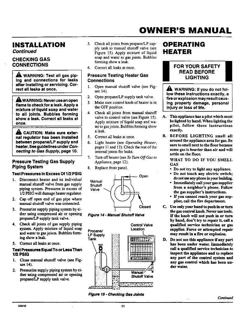
CHECKING GASCONNECTIONS
_k WARNING: Test all gas pip-Ing and connections for leaksafter Installing or servicing. Cor-rect all leaks at once.
• L WARNING: Never use an openflame to check for a leak. Apply amlxture of liquid soap and waterto all joints. Bubbles formingshow a leak. Correct all leaks stonce.
A CAUTION: Make sure exter-nal regulator has been installedbetween propane/LP supply andbeater. See guidelines under Con-necting to Gas Supply, page 10.
Pressure Testing Gas SupplyPlplng System
Test Pressures In Excess Of 1/2 PSIG
1. Disconnect heater and its individualmanual shutoff valve from gas supplypiping system. Pressures in excess of1/2 PSIG will damage heater regulator.
2. Cap off open end of gas pipe wheremanual shutoff valve was connected.
3. Pressurize supply piping system by ei-ther using compressed air or openingpropane/LP supply tank valve.
4. Check all joints of gas supply pipingsystem. Apply mixture of liquid soapand water to gas joints. Bubbles form-iag show a leak.
5. Con'ect all leaks at once.
Teat Pressures Equal To or Less Than1/2 PSIG
I. Close manual shutoff valve (see Fig-ure 14).
2. Pressurize supply piping system by ei-ther using compressed air or openingpropane/LP supply tank valve.
3. Check all joints from propane/LP sup-ply tank to manual shutoff valve (seeFigure 15). Apply mixture of liquidsoap and water to gas joints. Bubblesforming show a leak.
4. Correct all leaks at once.
Pressure Testing Heater GasConnections
1. Open manual shutoff valve (see Fig-ure 14).
2. Open propane/LP supply tank valve.
3. Make sure control knob of heater is in
the OFF position.
4. Check all joints from manual shutoffvalve to control valve (see Figure 15).Apply mixture of liquid soap and wa-ter to gas joints. Bubbles forming showa leak.
5.
6.
7.
8.
Correct all leaks at once.
Light heater (see Operating Heater,pages 11 and 12). Check the rest of theinternal joints for leaks.
Turn off heater (see To Turn Off Gas toAppliance, page 12).
Replace front panel.
Manual
Shutoff /
Valve "_
J_-_ Open
Closed
Figure 14. Manual Shutoff Valve
PropanelLP SupplyTank
ControlValveLocation
,///
ShutoffValveo.-
Figure 15 - OhecldngGas ,kdnte
OPERATINGHEATER
i FORYOUR SAFETY !READ BEFORE
LIGHTING
_lb WARNING: If you do not fol-low these instructions exactly, afire or explosion may result caus-ing property damage, personalinjury or loss of life.
A. This appliance has a pilot which mustbe lighted by hand. When lighting thepilot, follow these instructionsexactly.
B. BEFORE LIGHTING smell nil
around the appliance area for gas. Besure to smell next to the floor becausesome gas is heavier than air and willsettle on the floor.
C°
D.
WHAT TO DO IF YOU SMELLGAS
• Do not try to light any appliance.• Do not touch any electric switch;
do not use any phone in your buildiag.• Immediately call your gas supplier
from a neighbor's phone. Followthe gas suppller's instructions.
• If you cannot reach your gas sup-plier, call the fire department.
Use only your hand to push in or turnthe gas control knob. Never use tools.If the knob will not push in or turnby hand, don't try to repair it, call aqualified service technician or gassupplier. Force or attempted repairmay result in a fire or explosion.
Do not use this appliance if any parthas been under water. Immediatelycall a qualified service technician toinspect she appliance and to replaceany part of she control system andany gas control which has been un-der water.
Continued
_0_12 11
BLUE-FLAME CGP20B, CGP20LB AND RP30E
VENT-FREE PROPANE/LP GAS HEATER
OPERATING 8' Turn c°ntr°' kn°b c°untercl°ckwise l 1to the LOW position. The TO TURN OFF GASHEATER main burner should light. Set control TO APPLIANCEContinued knob toany heat levelbetweenHIGH
andLOW.Toturncontrolknobfrom Shutting Off Heater
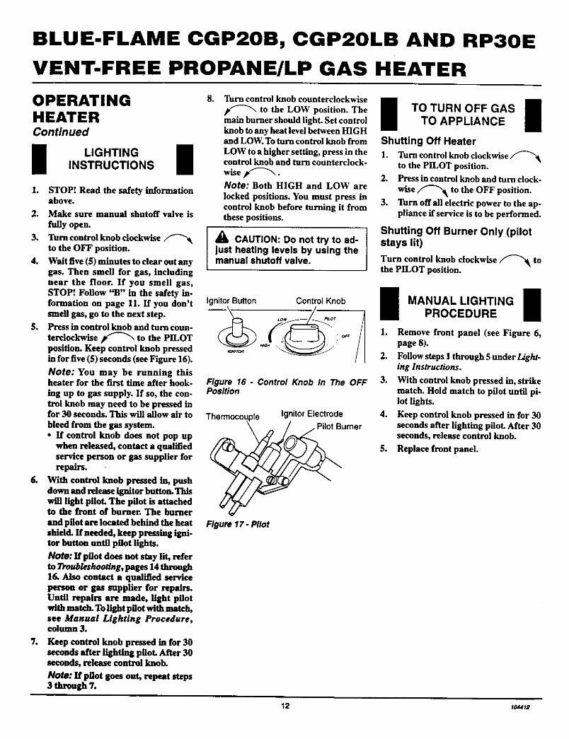
LIGHTINGINSTRUCTIONS 11. STOP.* Read the safety information
above.
2. Make sure manual shutoff valve isfully open.
3. Turn control knob clockwiseto the OFF position.
4. Wait five (5) minutes to clear out anygas. Then smell for gas, includingnear the floor. If you smell gas,STOP! Follow "B" in the safety in-formation on page 11. If you don'tsmell gas, go to the next step.
5. Press in control knob and turn coun-
terclockwise _ to the PILOTposition. Keep control knob pressedin for five ($) seconds (see Figure 16).
Note: You may be running thisheater for the first time after hook-ing up to gas supply. If so, the con-trol knob may need to be pressed infor 30 seconds. This will allow air tobleed from the gas system.• If control knob does not pop up
when released, contact a qualifiedservice person or gas supplier forrepairs.
6. With control knob pressed in, pushdown and release ignitor button. Thiswill light pilot. The pilot is attachedto the front of burner. The burnerand pilot are located behind the heatshield. If needed, keep pressing igni-tor button until pilot lights.
Note: If pilot does not stay lit, referto Troubleshooting, pages 14 through16. Also contact a qualified serviceperson or gas supplier for repairs.Until repairs are made, light pilotwith match. To light pilot with match,see Manual Lighting Procedure,column 3.
LOW to a higher setting, press in the 1.control knob and turn counterclock-
wise f"-'_. 2.Note: Both HIGH and LOW are
locked positions. You must press in 3.control knob before turning it fromthese positions.
7e Keep control knob pressed in for 30seconds after lighting pilot. After 30seconds, release control knob.
Note: If pilot goes out, repeat steps3 through 7.
_k CAUTION: Do not try to ad-just heating levels by using themanual shutoff valve.
IgnitorButton ControlKnob
-1Figure 16 - Control Knob In The OFFPosition
pie Ignitor ElectrodeBurner
Figure 17- Pilot
Turn control knob clockwiseto the PILOT position.Press in control knob and turn clock.
wise _ to the OFF position.Turn offall electric power to the ap-pliance if service is to he performed.
Shutting Off Burner Only (pilotstays lit)
Turn control knob clockwise _ tothe PILOT position.
MANUAL LIGHTING 1PROCEDURE
1. Remove front panel (see Figure 6,page 8).
2. Follow steps 1 through 5 under Light.ing Instructions.
3. With control knob pressed in, strikematch. Hold match to pilot until pi-lot lights.
4. Keep control knob pressed in for 30seconds after lighting piloL After 30seconds, release control knob.
5. Replace front panel.
12 y0,u12
OWNER'S MANUAL
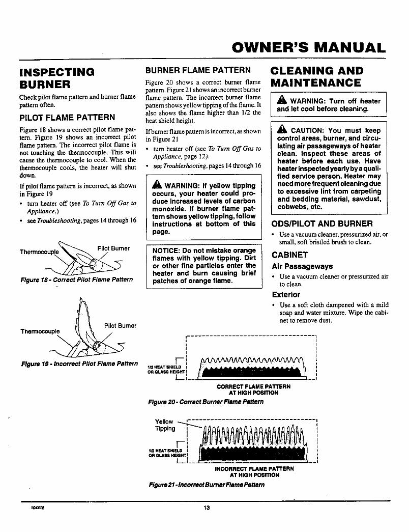
INSPECTINGBURNERCheck pilot flame pattern and burner flamepattern often.
PILOT FLAME PATTERN
Figure 18 shows a correct pilot flame pat-tern. Figure 19 shows an incorrect pilotflame pattern. The incorrect pilot flame isnot touching the thermocouple. This willcause the thermocouple to cool. When thethermocouple cools, the heater will shutdown.
If pilot flame pattern is incorrect, as shownin Figure 19
• turn heater off (see To Turn Off Gas toAppliance,)
• see Troubleshooting, pages 14 through 16
Thermoc_ er
Figure 18 - Correct Pilot Flame Pattern
Pilot BumerThermoco
Figure 19- Incorrect Pilot Rsme Pattern
BURNER FLAME PATTERN
Figure 20 shows a correct burner flamepattern. Figure 21 shows an incorrect burnerflame pattern. The incorrect burner flamepattern shows yellow tipping of the flame. Italso shows the flame higher than 1/2 theheat shield height.
If burner flame pattern is incorrect, as shownin Figure 21
• turn heater off(see To Turn OffGas toAppliance, page 12).
• see Troubleshooting, pages 14through 16
_i, WARNING: If yellow tippingoccurs, your heater could pro-duce increased levels of carbonmonoxide. If burner flame pat-tern shows yellow tipping, followinstructions at bottom of thispage.
NOTICE: Do not mistake orangeflames with yellow tipping. Dirtor other fine particles enter theheater end burn causing briefpatches of orange flame.
CLEANING ANDMAINTENANCE
_lL WARNING: Turn off heaterand let cool before cleaning.
CAUTION: You must keepcontrol areas, burner, and circu-lating air passageways of heaterclean. Inspect these areas ofheater before each use. Haveheater inspected yearly by a quali-fied service person. Heater mayneed more frequent cleaning dueto excessive lint from carpetingand bedding material, sawdust,cobwebs, etc.
ODS/PILOT AND BURNER
• Use a vacuum cleaner, pressurized air, orsmall, soft bristled brush to clean.
CABINET
Air Passageways
• Use a vacuum cleaner or pressurized airto clean.
Exterior
• Use a soft cloth dampened with a mildsoap and water mixture. Wipe the cabi-net to remove dust.
IIIIII
l--',1/2 HF.AT SHIELD IOR GLASS HEIGHT !
t__,'CORRECT FLAME PATTERN
AT HIGH PosmoN
Figure 20 - Correct Burner Flame Pattern
Yellow -... i"Tipping
II
F!1/2 HEATSHIELD IOR GLASS HEIGHT!
L.- I__ I=
INCORRECT FLAME pATTERNAT HIGH PosmoN
---I
Flgure21-1ncorrectBurnerFIsmePsttem
to,_7_ 13
BLUE-FLAME CGP20B, CGP20LB AND RP30E
VENT-FREE PROPANE/LP GAS HEATER
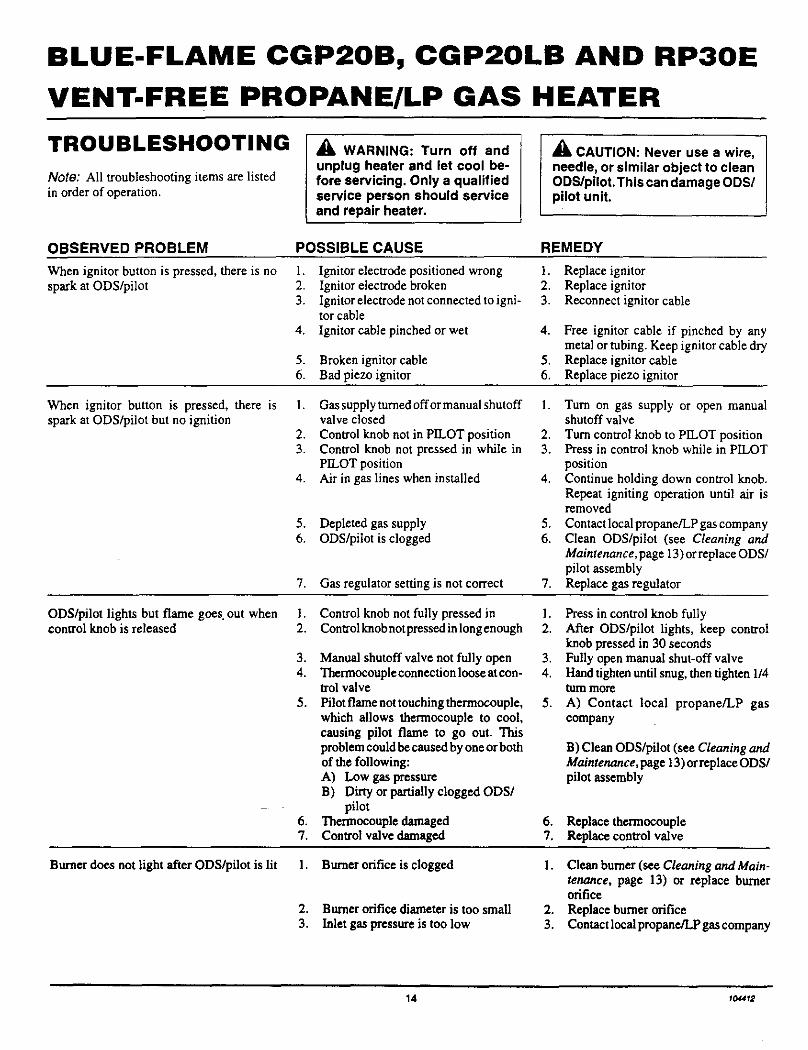
TROUBLESHOOTING
Note: All troubleshooting items are listedin order of operation.
WARNING: Turn off and
unplug heater and let cool be-fore servicing, Only a qualifiedservice person should serviceand repair heater.
CAUTION: Never use a wire,needle, or similar object to cleanODS/pilot. This can damage ODS/pilot unit.
OBSERVED PROBLEM POSSIBLE CAUSE REMEDY
When ignitor button is pressed, there is nospark at ODS/pilot
1. Ignitor electrode positioned wrong2. Ignitor electrode broken3. Ignitor electrode not connected to igni-
tor cable
4. Ignitor cable pinched or wet
5. Broken ignitor cable6. Bad piezo ignitor
1. Replace ignitor2. Replace ignitor3. Reconnect ignitor cable
4. Free ignitor cable if pinched by anymetal or tubing. Keep ignitor cable dry
5. Replace ignitor cable6. Replace piezo ignitor
When ignitor button is pressed, there isspark at ODS/pilot but no ignition
1. Gas supply turned offer manual shutoffvalve closed
2. Control knob not in PILOT position3. Control knob not pressed in while in
PILOT position4. Air in gas lines when installed
5. Depleted gas supply6. ODS/pilot is clogged
7. Gas regulator setting is not correct
1. Turn on gas supply or open manualshutoff valve
2. Turn control knob to PILOT position3. Press in control knob while in PILOT
position4. Continue holding down control knob.
Repeat igniting operation until air isremoved
5. Contactlocalpropane/LP gas company6. Clean ODS/pilot (see Cleaning and
Maintenance, page 13) or replace ODS/pilot assembly
7. Replace gas regulator
ODS/pilot lights but flame goes out whencontrol knob is released
l. Control knob not fully pressed in2. Controlknob not pressedin long enough
3. Manual shutoff valve not fully open4. Thermocouple connection loose at con-
trol valve
5. Pilot fiame not touching thermocouple,which allows thermocouple to cool,causing pilot flame to go out. Thisproblem could be caused by one or bothof the following:A) Low gas pressureB) Dirty or partially clogged ODS/
pilot6. Tbermocouple damaged7. Control valve damaged
l. Press in control knob fully2. After ODS/pilot lights, keep control
knob pressed in 30 seconds3. Fully open manual shut-off valve4. Hand tighten until snug, then tighten 1/4
turn more
5. A) Contact local propane/LP gascompany
B) Clean ODS/pilot (see Cleaning andMaintenance, page 13) orreplace ODS/pilot assembly
6. Replace thermocouple7. Replace control valve
Burner does not light after ODS/pilot is lit 1. Burner orifice is clogged
2, Burner orifice diameter is too small
3. Inlet gas pressure is too low
1. Clean burner (see Cleaning and Main-tenance, page 13) or replace burnerorifice
2. Replace burner orifice3. Contact local propane/LP gas company
14 1o_412
OWNER'S MANUAL
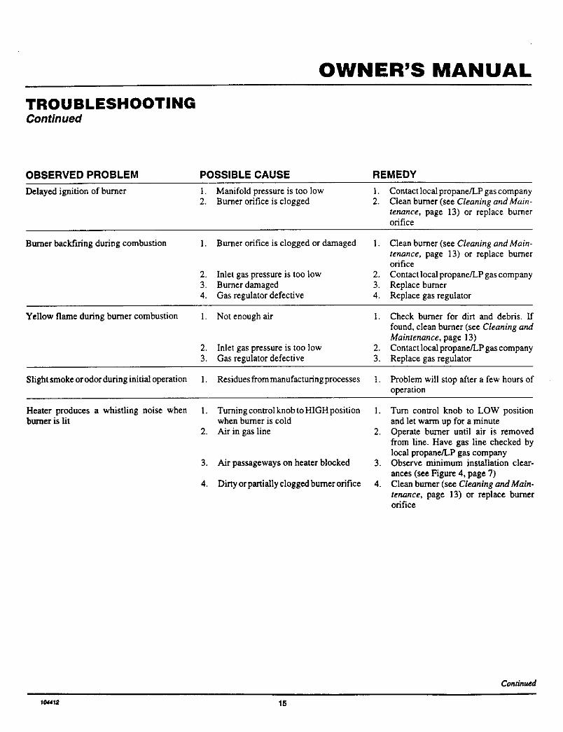
TROUBLESHOOTINGContinued
OBSERVED PROBLEM
Delayed ignition of burner
POSSIBLE CAUSE
1. Manifold pressure is too low2. Burner orifice is clogged
REMEDY
I.
2.Contact local propane/LP gas companyClean burner (see Cleaning and Main-tenance, page 13) or replace burnerorifice
Burner backfiring during combustion 1. Burner orifice is clogged or damaged
2. Inlet gas pressure is too low3. Burner damaged4. Gas regulator defective
1. Clean burner (see Cleaning and Main-tenance, page 13) or replace burnerorifice
2. Contactlocal propane/LP gas company3. Replace burner4. Replace gas regulator
Yellow flame during burner combustion 1. Not enough air I. Check burner for dirt and debris. Iffound, clean burner (see Cleaning andMaintenance, page 13)
2. Inlet gas pressure is too low 2. Contactlocalpropane/LPgaseompany3. Gas regulator defective 3. Replace gas regulator
Slightsmokeorodorduringinitialoperation 1. Residuesfrommanufacturingprocesses t. Problem will stop after a few hours ofoperation
Heater produces a whistling noise when 1. TurningcontrolknobtoHIGHposition 1. Turn control knob to LOW positionburner is lit when burner is cold and let warm up for a minute
2. Air in gas line 2. Operate burner until air is removed
3. Air passageways on heater blocked
4. Dirty or partially clogged burner orifice
from line. Have gas line checked bylocal propane/LP gas company
3. Observe minimum installation clear-
ances (see Figure 4, page 7)4. Clean burner (see Cleaning and Main.
tenance, page 13) or replace burnerorifice
_minued
ICMT;_ 15
BLUE-FLAME CGP2OB, CGP2OLB AND RP3OE
VENT-FREE PROPANE/LP GAS HEATER
TROUBLESHOOTINGContinued
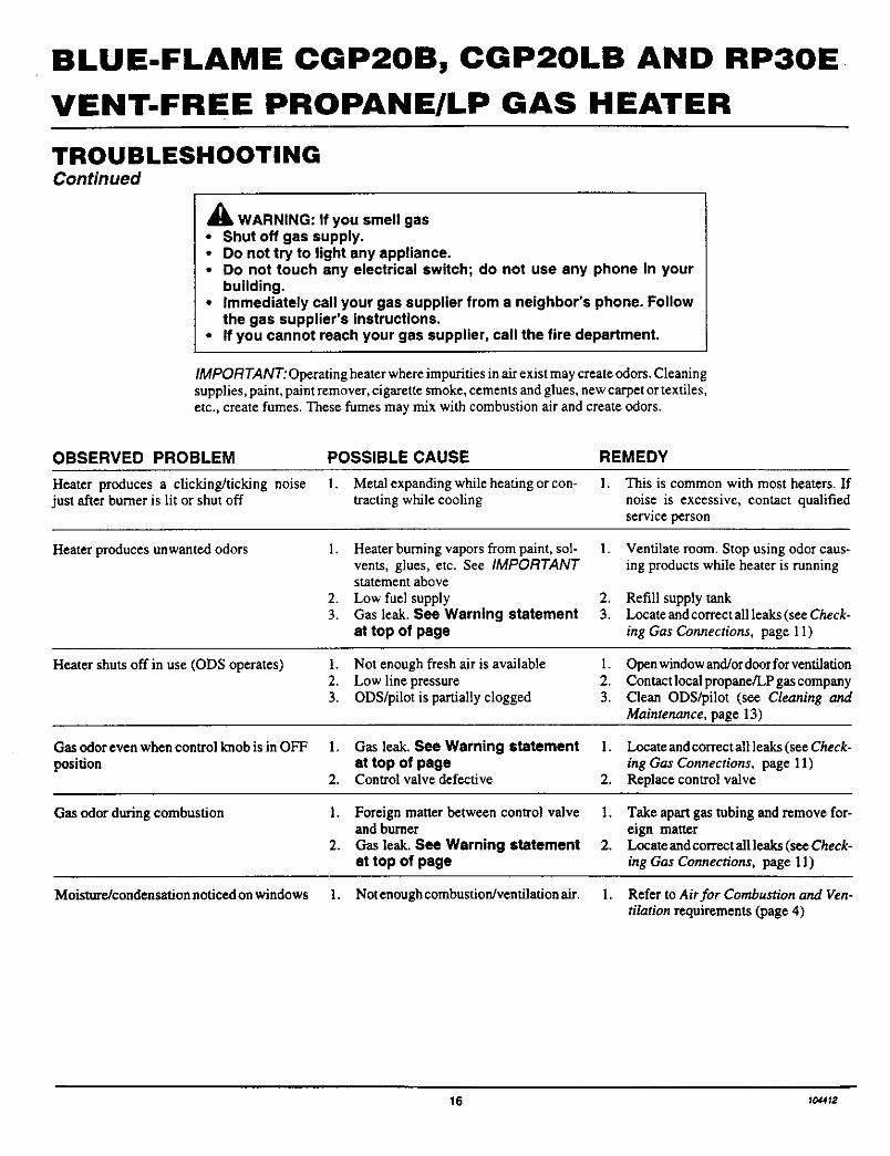
A WARNING: If you smell gas• Shut off gas supply.• Do not try to light any appliance.• Do not touch any electrical switch; do not use any phone in your
building.• Immediately call your gas supplier from a neighbor's phone. Follow
the gas supplier's instructions.• If you cannot reach your gas supplier, call the fire department.
IMPORTANT: Operating heater where impurities in air exist may create odors. Cleaningsupplies, paint, paint remover, cigarette smoke, cements and glues, new carpet or textiles,etc., create fumes. These fumes may mix with combustion air and create odors.
OBSERVED PROBLEM POSSIBLE CAUSE REMEDY
Heater produces a clicking/ticking noise 1. Metal expanding while heating or con- I. This is common with most heaters. Ifjust after burner is lit or shut off tracting while cooling noise is excessive, contact qualified
service person
Heater produces unwanted odors 1. Heater burning vapors from paint, sol-vents, glues, etc. See IMPORTANTstatement above
2. Low fuel supply3. Gas leak. See Warning statement
at top of page
1. Ventilate room. Stop using odor caus-ing products while heater is running
2. Refill supply tank3. Locate and correct all leaks (see Check-
ing Gas Connections, page 11)
Heater shuts off in use (ODS operates) 1. Not enough fresh air is available 1. Openwindow and/ordoorforventilation2. Low line pressure 2. Contactlocalpropane/LPgascompany3. ODS/pilot is partially clogged 3. Clean ODS/pilot (see Cleaning and
Maintenance, page 13)
Gas odor even when control knob is in OFF 1. Gas leak. See Warning statement 1. Locate and correct allleaks (see Check-position at top of page ing Gas Connections, page 11)
2. Control valve defective 2. Replace control valve
Gas odor during combustion 1. Foreign matter between control valve 1. Take apart gas tubing and remove for-and burner ¢ign matter
2. Gas leak. See Warning statement 2. Loca_andcorrectallleaks(seeCheck-at top of page ing Gas Connections, page 11)
Moisture/condensation noticed on windows 1. Not enough combustion/ventilation air. 1. Refer to Air for Combustion and Ven-tilation requirements (page 4)
16 1o._2
OWNER'S MANUAL
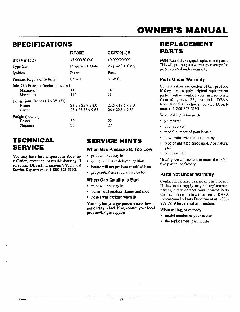
SPECIFICATIONS
RP30E CGP20(L)B
Btu(Variable) 15,000130,000 10,000120,000
Type Gas Propane/LP Only Propane/LP Only
Ignition Piezo Piezo
Pressure Regulator Setting 8" W.C. 8" W.C.
Inlet Gas Pressure (inches of water)Maximum 14"Minimum 11"
Dimensions, Inches (H x W x D)Heater 23.5 x 25.9 x 8.0Carton 26 x 27.75 x 9.63
Weight (pounds)Heater 30
Shipping 35
14"
11"
23.5 x 18.5 x 8.026 x 20:5 x 9.63
2227
TECHNICALSERVICE
You may have further questions about in-stallation, operation, or troubleshooting. Ifso, contact DESA International's Technical
Service Depamnent at 1-800-323-5190.
SERVICE HINTS
When Gas Pressure Is Too Low
• pilot will not stay lit
• burner will have delayed ignition
• heater will not produce specified heat
• propane/LP gas supply may be low
When Gas Quality Is Bad
• pilot will not stay lit
• burner will produce flames and soot• heater will backfire when lit
You may feel your gas pressure is too low orgas quality is bad. If so, contact your localpropane/LP gas supplier.
REPLACEMENTPARTS
Note: Use only original replacement parts.This will protect your warranty coverage forparts replaced under warranty.
Parts Under Warranty
Contact authorized dealers of this product.If they can't supply original replacementpart(s), either contact your nearest PartsCentral (page 23) or call DESAInternational's Technical Service Depart-ment at 1-800-323-5190.
When calling, have ready
• your name
• your address
• model number of your heater
• how heater was malfunctioning
• type of gas used (propane/LP or naturalgas)
• purchase date
Usually, we will ask you to return the defec-tive part to the factory.
Parts Not Under Warranty
Contact authorized dealers of this product.If they can't supply original replacementpa_(s), either contact your nearest PartsCentral (see below) or call DESAInternational's Parts Department at 1-800-972-7879 for referral information.
When calling, have ready
• model number of your heater
• the replacement part number
I_I_ 17
BLUE-FLAME CGP20B, CGP20LB AND RP30E
VENT-FREE PROPANE/LP GAS HEATER
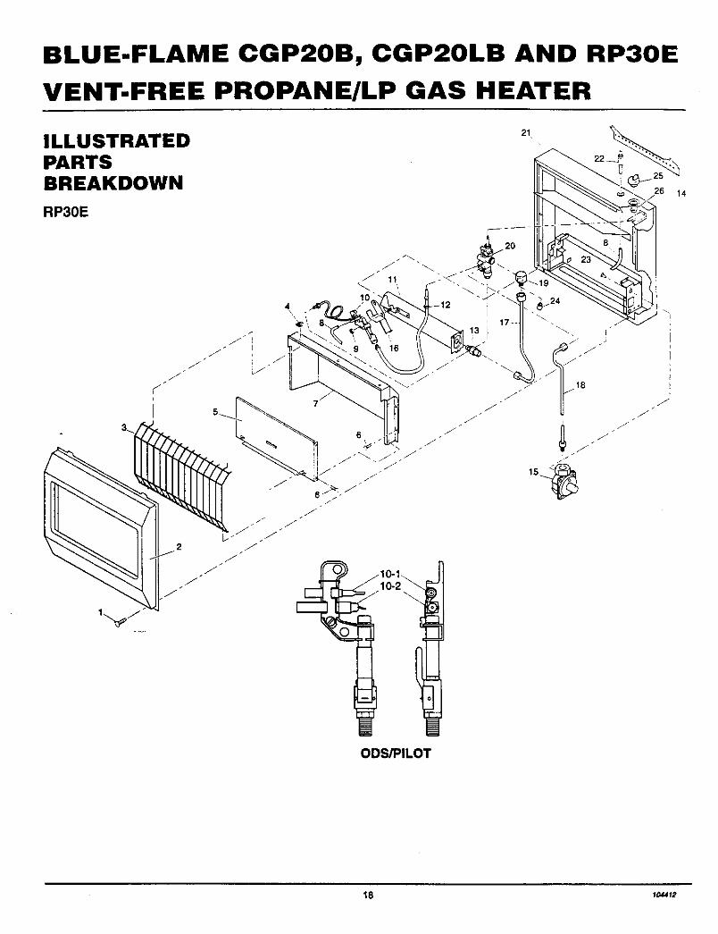
ILLUSTRATEDPARTSBREAKDOWN
RP30E
21
26 14
4\
.J J
JI
5_
J
JJ
J
ODS/PILOT
18 t_f2
OWNER'S MANUAL
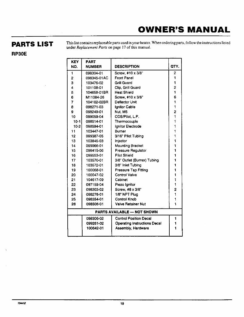
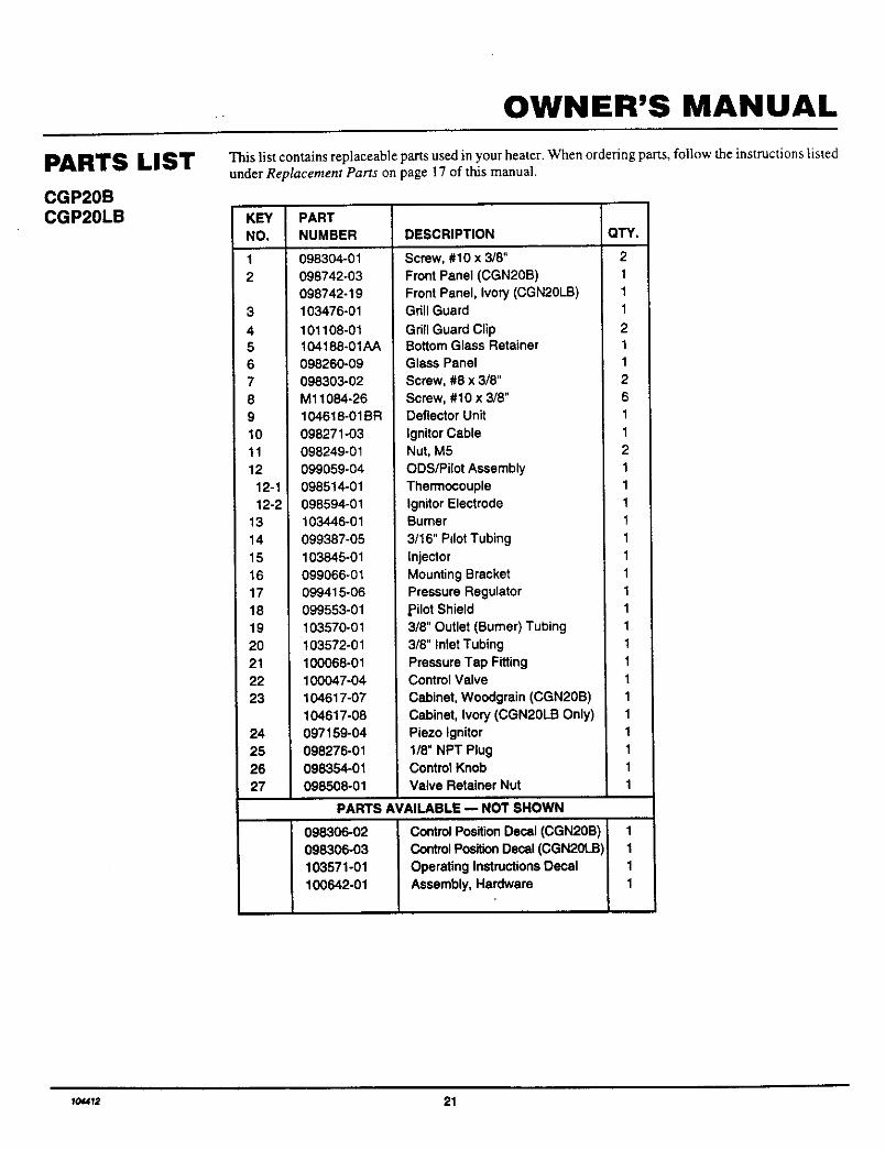
PARTS LIST
RP30E
This list contains replaceable parts used in your heater. When ordering parts, follow the instructions listedunder Replacement Parts on page 17 of this manual.
KEY
NO.
1 098304-01
2 098345-01AC
3 103476-024 101106-01
5 104658-01BR
6 M11084-26
7 104102-02 BR
8 098271-03
9 098249-0110 099059-04
10-1 098514-01
10-2 098594-01
11 103447-01
12 099387-05
13 103845-0314 099066-01
15 099415-06
16 099553-01
17 10357_01
18 103572-01
19 100068-01
20 100047-02
21 104617-09
22 097159-04
23 098303-02
24 098276-01
25 098354-0!
26 098508-01
PART
NUMBER DESCRIPTION OTY.
Screw, #10 x 3/8" 2Front Panel 1
Grill Guard 1
Clip, Grill Guard 2Heat Shield 1
Screw, #10 x 3/8" 6Deflector Unit 1
Ignitor Cable 1
Nut, M5 2
ODS/Pilot, L.P. 1
Thermocouple 1
Ignitor Electrode 1Burner 1
3/16" Pilot Tubing 1
Injector 1
Mounting Bracket 1Pressure Regulator 1Pilot Shield 1
3/8" Outlet (Burner) Tubing 1
3/8" Inlet Tubing 1
Pressure Tap Fitting 1Control Valve 1
Cabinet 1
Piezo Ignitor 1
Screw, #8 x 3/8" 2
1/8" NPT Plug 1Control Knob 1
Valve Retainer Nut 1
PARTS AVAILABLE -- NOT SHOWN
098306-02 ControlPositionDecal 1099261-02 OperatingInstructionsDecal 1100642-01 Assembly,Hardware 1
1o,_1_ 19

BLUE-FLAME CGP20B, CGP20LB AND RP30E
VENT-FREE PROPANE/LP GAS HEATER
ILLUSTRATEDPARTSBREAKDOWN
CGP20BCGP20LB
23
4
_ Lf_ -_
6
ODS/PILOT
20 I0_12
OWNER'S MANUAL
PARTS LIST
CGP20BCGP20LB
This list contains replaceable parts used in your heater. When ordering parts, follow the instructions listedunder Replacement Parts on page 17 of this manual.
KEY PARTNO, NUMBER DESCRIPTION
12
3
45
6
7
8
9
10
11
12
12-1
12-2
13
14
15
1617
18
1920
21
2223
24
25
26
27
098304-01
098742-03
098742-19
103476-01
101108-01104188-01AA
098260-09
098303-02
Ml1084-2610461 6-01BR
098271-03
098249-01
099059-04
098514-01
098594-01
103446-01
099387-05
103845-01
099066-01
09941 6-06
099553-01
103570-01
103572-01
100068-01
100047-04
104617-07
104617-08
097159-04
098276-01
098354-01
098508-01
QTY.
Screw, #10 x 3/8" 2
Front Panel (CGN20B) 1
Front Panel, Ivory (CGN20LB) 1Grill Guard 1
Grill Guard Clip 2Bottom Glass Retainer 1
Glass Panel 1
Screw, #8 x 3/8" 2
Screw, #10 x 3/8" 6Deflector Unit 1
Ignitor Cable 1
Nut, M5 2
ODSiPilot Assembly 1
Thermocouple 1
Ignitor Electrode 1Burner 1
3/16" Pilot Tubing 1
Injector 1
Mounting Bracket 1
Pressure Regulator 1
pilot Shield 1
3/8" Outlet (Burner) Tubing 1
3/8" Inlet Tubing 1
Pressure Tap Fitting 1Control Valve 1
Cabinet, Woodgrain (CGN20B) 1
Cabinet, Ivory (CGN20LB Only) 1
Piezo Ignitor 1
1/8" NPT Plug 1Control Knob 1
Valve Retainer Nut 1
PARTS AVAILABLE _ NOT SHOWN
098306-02 Control Position Decal (CGN20B) 1098306-03 Control Position Deca (CGN20LB) 1
103571-01 Operating Instructions Decal 1
100642-01 Assembly, Hardware 1
1_12 21
BLUE-FLAME CGP20B, CGP20LB AND RP30E
VENT-FREE PROPANE/LP GAS HEATER
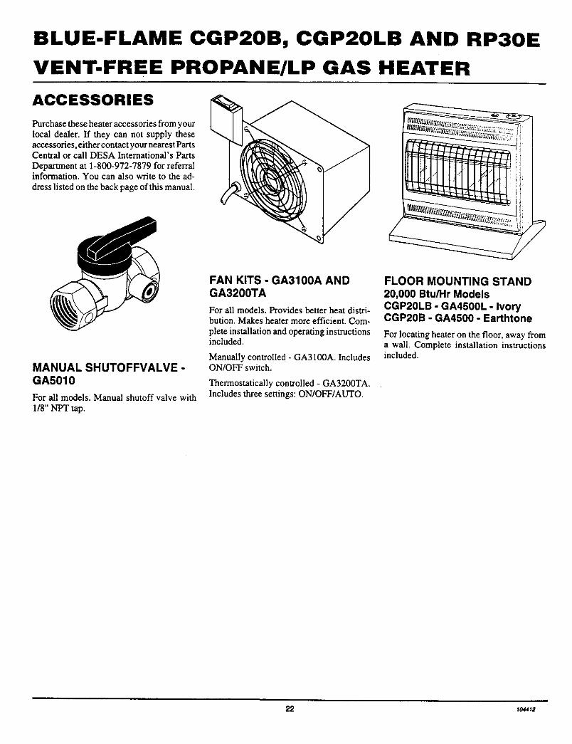
ACCESSORIES
Purchase these heater accessories from yourlocal dealer. If they can not supply theseaccessories, either contact your nearest PartsCentral or call DESA International's PartsDepartment at 1-800-972-7879 for referralinformation. You can also write to the ad-
dress listed on the back page of this manual.
MANUAL SHUTOFFVALVE -GA5010
For all models. Manual shutoff valve with
118" NPT tap.
FAN KITS - GA3100A ANDGA3200TA
For all models. Provides better heat distri-bution. Makes heater more efficient. Com-
plete installation and operating instructionsincluded.
ManualIy controlled - GA3100A. IncludesON/OFF switch.
Thermostatically controlled - GA3200TA.Includes three settings: ON/OFF/AUTO.
FLOOR MOUNTING STAND
20,000 Btu/Hr ModelsCGP20LB - GA4500L - IvoryCGP20B - GA4500 - Earthtone
For locating heater on the floor, away froma wall. Complete installation instructionsincluded.
ff144_

OWNER'S MANUAL
PARTS CENTRALS
Baltimore Electric1348 Dixwell AvenueHamden, CT 065141-800-397-7553203-248-7553
Parts Department
Portable Heater Parts
342 N. County Rd. 400 EastValparaiso, IN 46383All States219-462-74411-800-362-6951
Parts Department
FBD1349 Adams Street
Bowling Green, KY 42103502-846-11991-800-654-8534Fax: 1-800-846-0090
Four Flags Power Products1115 Stateline RoadNiles, MI 49120616-684-26971-800-268-4983
PartsOnly
These Parts Centrals are privately owned businesses. They have agreed to suppon ourcustomer's needs by providing original replacement parts and accessories. When calling aParts Central, ask for the Parts Department.
Master Parts Distributor1184Wilson N'W
Grand Rapids, MI 49504US 1-800-446-1446616-791-0505Fax: 1-616-791-8270
Parts Department
Washer Equipment Co.1715 Main Street
Kansas City, MO 64108KS, MO, AR816-842-3911
Parts Department
East Coast Energy Products707 BroadwayW. Long Branch, NJ 07764908-870-88091-800-755-8809
Parts Department
Tarantin Tank Co.P.O. Box 6129Freehold, NJ 07728908-780-93401-800-922-0724
Parts Department
Dayton HardwareP.O. Box 275
North Dayton StationDayton, OH 45404All States513-258-3721OH 1-800-762-3426
Parts Department
Halco Enterprises208 Carter Drive, Unit 21West Chester, PA 19382610-430-7717US 1-800-368-0803
Parts Department
Laporte's Parts & Service2444 North 5th StreetHartsville, SC 29550803-332-0191
Pans Department
Cans Unlimited, Inc.P.O. Box 645
Taylor, SC 29687All States803-879-30091-800-845-5301
I¢M412 23
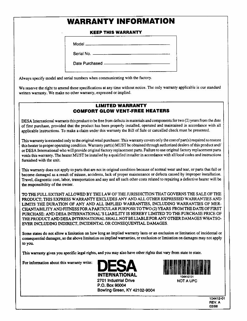
WARRANTY INFORMATION
KEEP THIS WARRANTY
Model
Serial No.
Date Purchased
Always specify model and serial numbers when communicating with the factory.
We reserve the right to amend these specifications at any time without notice. The only warranty applicable is our standardwritten warranty. We make no other warranty, expressed or implied.
LIMITED WARRANTY
COMFORT GLOW VENT-FREE HEATERS
3ESA International warrants this product to be free from defects in materials and components for two (2) years from the date
of first purchase, provided that the product has been properly installed, operated and maintained in accordance with allapplicable instructions. To make a claim under this warranty the Bill of Sale or cancelled check must be presented.
This warranty is extended only to the original retail purchaser. This warranty covers only the cost of part(s)required to restore:hisheater to proper operating condition. Warranty part(s) MUST be obtained through authorized dealers of this product and!or DESA International who will provide original factory replacement parts. Failure to use original factory replacement parts
voids this warranty. The heater MUST be installed by a qualified installer in accordance with all local codes and instructionsfurnished with the unit.
This warranty does not apply to parts that am not in original condition because of normal wear and tear, or parts that fail orbecome damaged as a result of misuse, accidents, lack of proper maintenance or defects caused by improper installation.Travel, diagnostic cost, labor, transportation and any and all such other costs related to repairing a defective heater will be
the responsibility of the owner.
TO THE FULL EXTENT ALLOWED BY THE LAW OF THE JURISDICTION THAT GOVERNS THE SALE OF THE
PRODUCT; Tills EXPRESS WARRANTY EXCLUDES ANY AND ALL OTHER EXPRESSED WARRANTIES ANDLIMITS TIlE DURATION OF ANY AND ALL IMPLIED WARRANTIES, INCLUDING WARRANTIES OF MER-
, CHANTABILITY AND FITNESS FOR A PARTICULAR PLrRI_SE TO TWO (2) YEARS FROM THE DATE OF FIRSTPURCHASE: AND DESA INTERNATIONAL'S LIABILITY IS HEREBY LIMITED TO THE PURCHASE PRICE OFTHE PRODUCT AND DESA INTERNATIONAL SHALL NOT BE LIABLE FOR ANY OTHER DAMAGES WHATS O-EVER INCLUDING INDIRECT, INCIDENTAL OR CONSEQUENTIAL DAMAGES.
Some states do not allow a limitation on how long an implied warranty lasts or an exclusion or limitation of incidental or
consequential damages, so the above limitation on implied warranties, or exclusion or limitation on damages may not apply
to you.
This warranty gives you specific legal rights, and you may also have other rights that vary from state to state.
For information about this warranty write: DESAINTERNATIONAL2701 Industdal DriveP.O. Box 90004Bowling Green, KY 42102-9004
I|l[lllmll|illl104412 01
NOT A UPC
104412-01REV. A02/98