Embed Size (px)
Citation preview

Bos3 Propeller ASTM F2506-10 Compliance Summary
AC00038-2 21st Nov 2014
Issue 1 Issued By: DS Page: 1 of 13
L:\Aerocraft\Reports\AC00038-2_Bolly_BOS3_CompSumm.docx
Engineering Report: AC00038-2 Issue: 2 Date: 21st Nov 2014 Subject: Bos3 Propeller ASTM F2506-10 Compliance Summary Prepared By: Douglas Smith Reviewed By: Peter Tapp
Prepared Approved:
D. Smith B.E. (Aerospace)
Peter Tapp
Issue Details of Change
1 Original Issue
1 GENERAL ............................................................................................................................................................. 2
1.1 DEFINITIONS ..................................................................................................................................................... 2 1.2 DESCRIPTION ................................................................................................................................................... 2 1.3 APPLICABILITY .................................................................................................................................................. 2 1.4 REFERENCED DOCUMENTS ............................................................................................................................... 3
2 ASTM F2506-10 COMPLIANCE SUMMARY ....................................................................................................... 4

Bos3 Propeller ASTM F2506-10 Compliance Summary
AC00038-2 21st Nov 2014
Issue 1 Issued By: DS Page: 2 of 13
L:\Aerocraft\Reports\AC00038-2_Bolly_BOS3_CompSumm.docx
1 General
1.1 Definitions
Table 1 - Definitions
Item Definition
AC Advisory Circular
CASA Civil Aviation Safety Authority (Australia)
Bolly Props Australia “Bolly”
LSA Light Sport Aircraft
MDL Master Document List. Contains all documents needed to control the design as identified by the standard.
1.2 Description The BOS3 propeller is a ground adjustable, 2, 3 or 4 bladed design.
The propeller has a diameter of 1829mm (72”) measured from tip to tip.
The blades are moulded from Epoxy resin & Carbon Fibre with a small amount of Kevlar.
The blades use a solid, non-porous core made up from resin and filler material.
The leading edge is formed out of high-density urethane for abrasion and impact protection.
The moulding, core design, layup and leading edge design of the propeller blade have been developed by Bolly Props Australia (“Bolly”).
The hub is machined out of 6061 Aluminium, tempered to T6.
The propeller is a ground adjustable type.
1.3 Applicability This summary has been prepared to show that Bolly BOS3 propellers which meet the serial number limitations given in below meet the requirements of ASTM F2506-10 “Standard Specification For Design and Testing of Fixed-Pitch or Ground Adjustable Light Sport Aircraft Propellers”.
Blade Serial Numbers Blades marked D or E Specification
Rear Hub Serial Numbers ID numbers starting with “AA” are compliant
Front Hub Serial Numbers ID numbers starting with “AA” are compliant
Bos3 Propeller ASTM F2506-10 Compliance Summary
AC00038-2 21st Nov 2014
Issue 1 Issued By: DS Page: 3 of 13
L:\Aerocraft\Reports\AC00038-2_Bolly_BOS3_CompSumm.docx
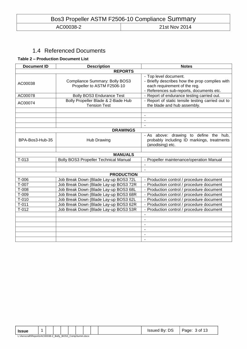
1.4 Referenced Documents
Table 2 – Production Document List
Document ID Description Notes
REPORTS
AC00038 Compliance Summary: Bolly BOS3
Propeller to ASTM F2506-10
- Top level document. - Briefly describes how the prop complies with
each requirement of the reg. - References sub-reports, documents etc.
AC00078 Bolly BOS3 Endurance Test - Report of endurance testing carried out.
AC00074 Bolly Propeller Blade & 2-Bade Hub
Tension Test - Report of static tensile testing carried out to
the blade and hub assembly.
-
-
-
DRAWINGS
BPA-Bos3-Hub-35 Hub Drawing - As above: drawing to define the hub,
probably including ID markings, treatments (anodising) etc.
MANUALS
T-013 Bolly BOS3 Propeller Technical Manual - Propeller maintenance/operation Manual
-
-
PRODUCTION
T-006 Job Break Down (Blade Lay-up BOS3 72L - Production control / procedure document
T-007 Job Break Down (Blade Lay-up BOS3 72R - Production control / procedure document
T-008 Job Break Down (Blade Lay-up BOS3 68L - Production control / procedure document
T-009 Job Break Down (Blade Lay-up BOS3 68R - Production control / procedure document
T-010 Job Break Down (Blade Lay-up BOS3 62L - Production control / procedure document
T-011 Job Break Down (Blade Lay-up BOS3 62R - Production control / procedure document
T-012 Job Break Down (Blade Lay-up BOS3 53R - Production control / procedure document
-
-
-
-
-
-
Bos3 Propeller ASTM F2506-10 Compliance Summary
AC00038-2 21st Nov 2014
Issue 1 Issued By: DS Page: 4 of 13
L:\Aerocraft\Reports\AC00038-2_Bolly_BOS3_CompSumm.docx
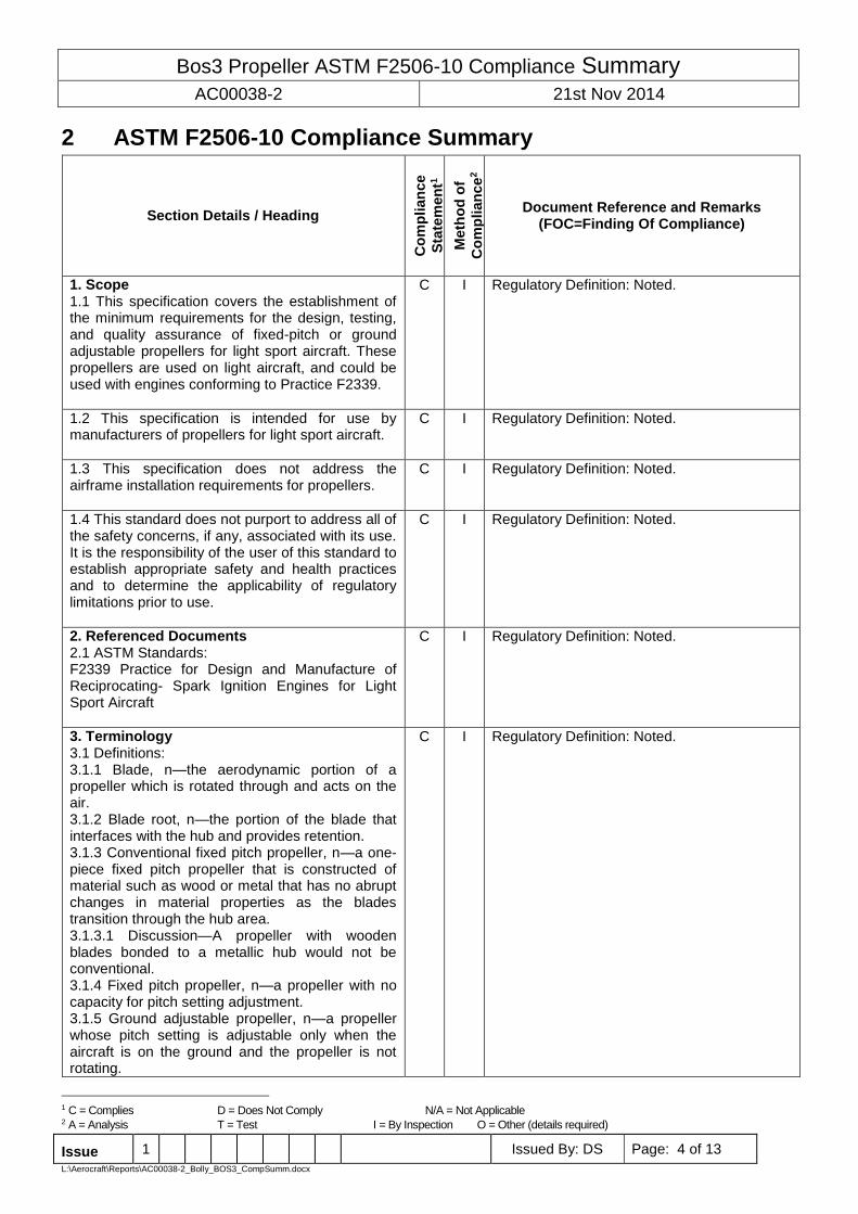
2 ASTM F2506-10 Compliance Summary
Section Details / Heading
Co
mp
lian
ce
Sta
tem
en
t1
Meth
od
of
Co
mp
lian
ce
2
Document Reference and Remarks (FOC=Finding Of Compliance)
1. Scope 1.1 This specification covers the establishment of the minimum requirements for the design, testing, and quality assurance of fixed-pitch or ground adjustable propellers for light sport aircraft. These propellers are used on light aircraft, and could be used with engines conforming to Practice F2339.
C I Regulatory Definition: Noted.
1.2 This specification is intended for use by manufacturers of propellers for light sport aircraft.
C I Regulatory Definition: Noted.
1.3 This specification does not address the airframe installation requirements for propellers.
C I Regulatory Definition: Noted.
1.4 This standard does not purport to address all of the safety concerns, if any, associated with its use. It is the responsibility of the user of this standard to establish appropriate safety and health practices and to determine the applicability of regulatory limitations prior to use.
C I Regulatory Definition: Noted.
2. Referenced Documents 2.1 ASTM Standards: F2339 Practice for Design and Manufacture of Reciprocating- Spark Ignition Engines for Light Sport Aircraft
C I Regulatory Definition: Noted.
3. Terminology 3.1 Definitions: 3.1.1 Blade, n—the aerodynamic portion of a propeller which is rotated through and acts on the air. 3.1.2 Blade root, n—the portion of the blade that interfaces with the hub and provides retention. 3.1.3 Conventional fixed pitch propeller, n—a one-piece fixed pitch propeller that is constructed of material such as wood or metal that has no abrupt changes in material properties as the blades transition through the hub area. 3.1.3.1 Discussion—A propeller with wooden blades bonded to a metallic hub would not be conventional. 3.1.4 Fixed pitch propeller, n—a propeller with no capacity for pitch setting adjustment. 3.1.5 Ground adjustable propeller, n—a propeller whose pitch setting is adjustable only when the aircraft is on the ground and the propeller is not rotating.
C I Regulatory Definition: Noted.
1 C = Complies D = Does Not Comply N/A = Not Applicable 2 A = Analysis T = Test I = By Inspection O = Other (details required)
Bos3 Propeller ASTM F2506-10 Compliance Summary
AC00038-2 21st Nov 2014
Issue 1 Issued By: DS Page: 5 of 13
L:\Aerocraft\Reports\AC00038-2_Bolly_BOS3_CompSumm.docx
Section Details / Heading
Co
mp
lian
ce
Sta
tem
en
t1
Meth
od
of
Co
mp
lian
ce
2
Document Reference and Remarks (FOC=Finding Of Compliance)
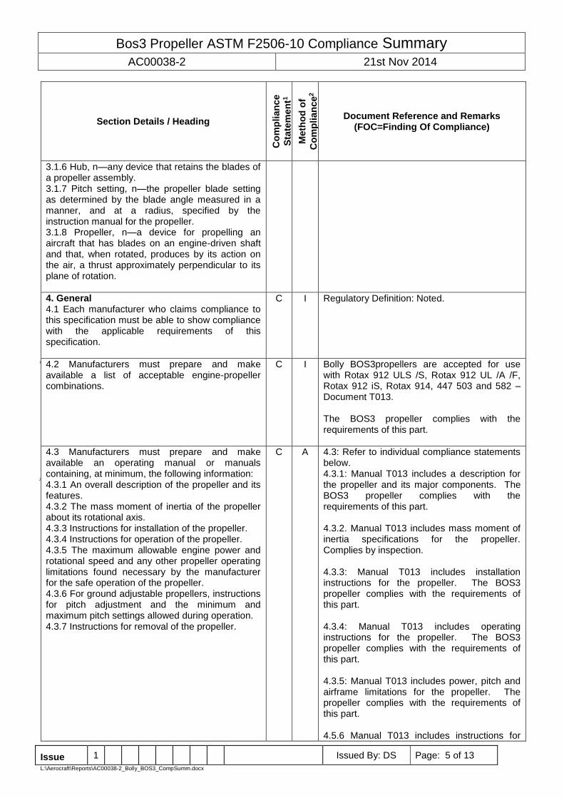
3.1.6 Hub, n—any device that retains the blades of a propeller assembly. 3.1.7 Pitch setting, n—the propeller blade setting as determined by the blade angle measured in a manner, and at a radius, specified by the instruction manual for the propeller. 3.1.8 Propeller, n—a device for propelling an aircraft that has blades on an engine-driven shaft and that, when rotated, produces by its action on the air, a thrust approximately perpendicular to its plane of rotation.
4. General 4.1 Each manufacturer who claims compliance to this specification must be able to show compliance with the applicable requirements of this specification.
C I Regulatory Definition: Noted.
4.2 Manufacturers must prepare and make available a list of acceptable engine-propeller combinations.
C I Bolly BOS3propellers are accepted for use with Rotax 912 ULS /S, Rotax 912 UL /A /F, Rotax 912 iS, Rotax 914, 447 503 and 582 – Document T013. The BOS3 propeller complies with the requirements of this part.
4.3 Manufacturers must prepare and make available an operating manual or manuals containing, at minimum, the following information: 4.3.1 An overall description of the propeller and its features. 4.3.2 The mass moment of inertia of the propeller about its rotational axis. 4.3.3 Instructions for installation of the propeller. 4.3.4 Instructions for operation of the propeller. 4.3.5 The maximum allowable engine power and rotational speed and any other propeller operating limitations found necessary by the manufacturer for the safe operation of the propeller. 4.3.6 For ground adjustable propellers, instructions for pitch adjustment and the minimum and maximum pitch settings allowed during operation. 4.3.7 Instructions for removal of the propeller.
C A 4.3: Refer to individual compliance statements below. 4.3.1: Manual T013 includes a description for the propeller and its major components. The BOS3 propeller complies with the requirements of this part. 4.3.2. Manual T013 includes mass moment of inertia specifications for the propeller. Complies by inspection. 4.3.3: Manual T013 includes installation instructions for the propeller. The BOS3 propeller complies with the requirements of this part. 4.3.4: Manual T013 includes operating instructions for the propeller. The BOS3 propeller complies with the requirements of this part. 4.3.5: Manual T013 includes power, pitch and airframe limitations for the propeller. The propeller complies with the requirements of this part. 4.5.6 Manual T013 includes instructions for
1
2
Bos3 Propeller ASTM F2506-10 Compliance Summary
AC00038-2 21st Nov 2014
Issue 1 Issued By: DS Page: 6 of 13
L:\Aerocraft\Reports\AC00038-2_Bolly_BOS3_CompSumm.docx
Section Details / Heading
Co
mp
lian
ce
Sta
tem
en
t1
Meth
od
of
Co
mp
lian
ce
2
Document Reference and Remarks (FOC=Finding Of Compliance)
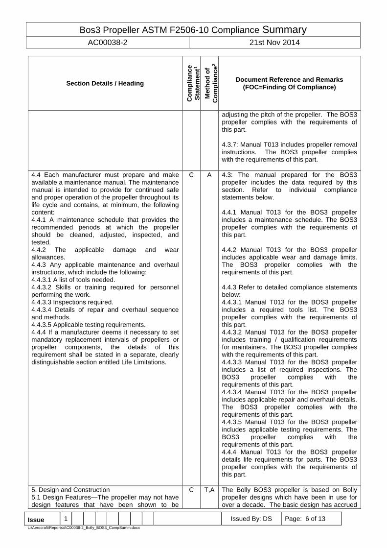
adjusting the pitch of the propeller. The BOS3 propeller complies with the requirements of this part. 4.3.7: Manual T013 includes propeller removal instructions. The BOS3 propeller complies with the requirements of this part.
4.4 Each manufacturer must prepare and make available a maintenance manual. The maintenance manual is intended to provide for continued safe and proper operation of the propeller throughout its life cycle and contains, at minimum, the following content: 4.4.1 A maintenance schedule that provides the recommended periods at which the propeller should be cleaned, adjusted, inspected, and tested. 4.4.2 The applicable damage and wear allowances. 4.4.3 Any applicable maintenance and overhaul instructions, which include the following: 4.4.3.1 A list of tools needed. 4.4.3.2 Skills or training required for personnel performing the work. 4.4.3.3 Inspections required. 4.4.3.4 Details of repair and overhaul sequence and methods. 4.4.3.5 Applicable testing requirements. 4.4.4 If a manufacturer deems it necessary to set mandatory replacement intervals of propellers or propeller components, the details of this requirement shall be stated in a separate, clearly distinguishable section entitled Life Limitations.
C A 4.3: The manual prepared for the BOS3 propeller includes the data required by this section. Refer to individual compliance statements below. 4.4.1 Manual T013 for the BOS3 propeller includes a maintenance schedule. The BOS3 propeller complies with the requirements of this part. 4.4.2 Manual T013 for the BOS3 propeller includes applicable wear and damage limits. The BOS3 propeller complies with the requirements of this part. 4.4.3 Refer to detailed compliance statements below: 4.4.3.1 Manual T013 for the BOS3 propeller includes a required tools list. The BOS3 propeller complies with the requirements of this part. 4.4.3.2 Manual T013 for the BOS3 propeller includes training / qualification requirements for maintainers. The BOS3 propeller complies with the requirements of this part. 4.4.3.3 Manual T013 for the BOS3 propeller includes a list of required inspections. The BOS3 propeller complies with the requirements of this part. 4.4.3.4 Manual T013 for the BOS3 propeller includes applicable repair and overhaul details. The BOS3 propeller complies with the requirements of this part. 4.4.3.5 Manual T013 for the BOS3 propeller includes applicable testing requirements. The BOS3 propeller complies with the requirements of this part. 4.4.4 Manual T013 for the BOS3 propeller details life requirements for parts. The BOS3 propeller complies with the requirements of this part.
5. Design and Construction 5.1 Design Features—The propeller may not have design features that have been shown to be
C T,A The Bolly BOS3 propeller is based on Bolly propeller designs which have been in use for over a decade. The basic design has accrued
Bos3 Propeller ASTM F2506-10 Compliance Summary
AC00038-2 21st Nov 2014
Issue 1 Issued By: DS Page: 7 of 13
L:\Aerocraft\Reports\AC00038-2_Bolly_BOS3_CompSumm.docx
Section Details / Heading
Co
mp
lian
ce
Sta
tem
en
t1
Meth
od
of
Co
mp
lian
ce
2
Document Reference and Remarks (FOC=Finding Of Compliance)
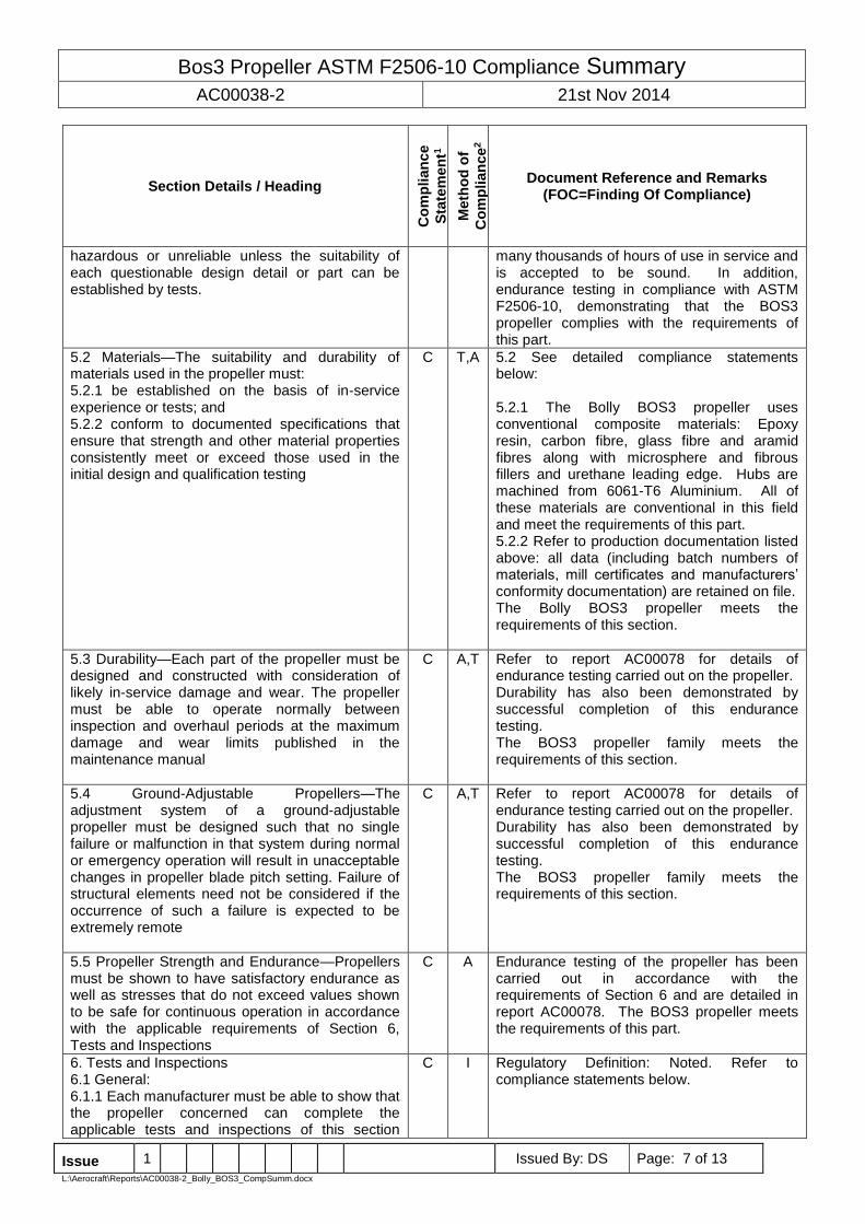
hazardous or unreliable unless the suitability of each questionable design detail or part can be established by tests.
many thousands of hours of use in service and is accepted to be sound. In addition, endurance testing in compliance with ASTM F2506-10, demonstrating that the BOS3 propeller complies with the requirements of this part.
5.2 Materials—The suitability and durability of materials used in the propeller must: 5.2.1 be established on the basis of in-service experience or tests; and 5.2.2 conform to documented specifications that ensure that strength and other material properties consistently meet or exceed those used in the initial design and qualification testing
C T,A 5.2 See detailed compliance statements below: 5.2.1 The Bolly BOS3 propeller uses conventional composite materials: Epoxy resin, carbon fibre, glass fibre and aramid fibres along with microsphere and fibrous fillers and urethane leading edge. Hubs are machined from 6061-T6 Aluminium. All of these materials are conventional in this field and meet the requirements of this part. 5.2.2 Refer to production documentation listed above: all data (including batch numbers of materials, mill certificates and manufacturers’ conformity documentation) are retained on file. The Bolly BOS3 propeller meets the requirements of this section.
5.3 Durability—Each part of the propeller must be designed and constructed with consideration of likely in-service damage and wear. The propeller must be able to operate normally between inspection and overhaul periods at the maximum damage and wear limits published in the maintenance manual
C A,T Refer to report AC00078 for details of endurance testing carried out on the propeller. Durability has also been demonstrated by successful completion of this endurance testing. The BOS3 propeller family meets the requirements of this section.
5.4 Ground-Adjustable Propellers—The adjustment system of a ground-adjustable propeller must be designed such that no single failure or malfunction in that system during normal or emergency operation will result in unacceptable changes in propeller blade pitch setting. Failure of structural elements need not be considered if the occurrence of such a failure is expected to be extremely remote
C A,T Refer to report AC00078 for details of endurance testing carried out on the propeller. Durability has also been demonstrated by successful completion of this endurance testing. The BOS3 propeller family meets the requirements of this section.
5.5 Propeller Strength and Endurance—Propellers must be shown to have satisfactory endurance as well as stresses that do not exceed values shown to be safe for continuous operation in accordance with the applicable requirements of Section 6, Tests and Inspections
C A Endurance testing of the propeller has been carried out in accordance with the requirements of Section 6 and are detailed in report AC00078. The BOS3 propeller meets the requirements of this part.
6. Tests and Inspections 6.1 General: 6.1.1 Each manufacturer must be able to show that the propeller concerned can complete the applicable tests and inspections of this section
C I Regulatory Definition: Noted. Refer to compliance statements below.

Bos3 Propeller ASTM F2506-10 Compliance Summary
AC00038-2 21st Nov 2014
Issue 1 Issued By: DS Page: 8 of 13
L:\Aerocraft\Reports\AC00038-2_Bolly_BOS3_CompSumm.docx
Section Details / Heading
Co
mp
lian
ce
Sta
tem
en
t1
Meth
od
of
Co
mp
lian
ce
2
Document Reference and Remarks (FOC=Finding Of Compliance)
without evidence of failure or malfunction
6.1.2 The minimum applicable testing and inspection requirements are outlined in Table 1 according to propeller material type.
C A The BOS3 propeller is a ground adjustable type with composite blades. Accordingly, the requirements of Section 6.2 must be met. Section 6.3 is optional. Testing for the requirements specified in this part has not been carried out. The requirements of Section 6.4 have been met: see notes below. The requirements of Section 6.5 have been met: see notes below. The requirements of Section 6.6 have been met: see notes below. The BOS3 propeller complies with the requirements of this part.
6.2 Strength Testing: 6.2.1 Proof of strength must be shown for all propellers except conventional fixed pitch propellers 6.2.2 On all other propellers, the blade root and blade retention system must be tested for 1 h at a load level equal to two times the centrifugal load that would be generated by the blade weight at maximum rated rotational speed. This may be done by either a whirl test or a static pull test. The required pull load for each blade must be carried by at least the inner 20 % of its span
C A,T 6.2.1 Noted. Refer below. 6.2.2 The BOS3 propeller has passed a test which meets the requirements of this section. Report AC00074 refers.
6.3 Stress Measurement, Fatigue Strength, and Fatigue Analysis—Vibration testing may be performed to allow reduced endurance test hours. This section does not apply to conventional fixed pitch wooden propellers. 6.3.1 The magnitude of the propeller vibration stresses, including any stress peaks and resonant conditions, throughout the operational envelope of the propeller shall be determined: 6.3.1.1 By direct measurement of stresses on a vibrationally representative engine, or 6.3.1.2 Comparison of the propeller to similar propellers installed on similar airplane installations for which these measurements have been made. 6.3.2 Through testing or analysis, the fatigue allowable for root, mid-blade and tip regions of the propeller blade shall be determined. This testing shall also account for normal in-service damage and wear 6.3.3 Using the measured stresses and root, mid-blade, and tip fatigue allowables, a fatigue assessment shall be conducted to show that failure of the propeller will not occur between the declared propeller inspection intervals when using the
N/A N/A Section 6.3 is optional. Testing for the requirements specified in this part has not been carried out.
Bos3 Propeller ASTM F2506-10 Compliance Summary
AC00038-2 21st Nov 2014
Issue 1 Issued By: DS Page: 9 of 13
L:\Aerocraft\Reports\AC00038-2_Bolly_BOS3_CompSumm.docx
Section Details / Heading
Co
mp
lian
ce
Sta
tem
en
t1
Meth
od
of
Co
mp
lian
ce
2
Document Reference and Remarks (FOC=Finding Of Compliance)
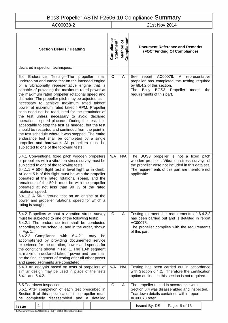
declared inspection techniques.
6.4 Endurance Testing—The propeller shall undergo an endurance test on the intended engine or a vibrationally representative engine that is capable of providing the maximum rated power at the maximum rated propeller rotational speed and diameter. The propeller pitch may be adjusted as necessary to achieve maximum rated takeoff power at maximum rated takeoff RPM. Propeller pitch need not be readjusted for the remainder of the test unless necessary to avoid declared operational speed placards. During the test, it is acceptable to stop the test as needed, but the test should be restarted and continued from the point in the test schedule where it was stopped. The entire endurance test shall be completed by a single propeller and hardware. All propellers must be subjected to one of the following tests:
C A See report AC00078. A representative propeller has completed the testing required by §6.4.2 of this section. The Bolly BOS3 Propeller meets the requirements of this part.
6.4.1 Conventional fixed pitch wooden propellers or propellers with a vibration stress survey must be subjected to one of the following tests: 6.4.1.1 A 50-h flight test in level flight or in climb. At least 5 h of this flight must be with the propeller operated at the rated rotational speed, and the remainder of the 50 h must be with the propeller operated at not less than 90 % of the rated rotational speed. 6.4.1.2 A 50-h ground test on an engine at the power and propeller rotational speed for which a rating is sought.
N/A N/A The BOS3 propeller is not a fixed pitch wooden propeller. Vibration stress surveys of the propeller were not included in this data set. The requirements of this part are therefore not applicable.
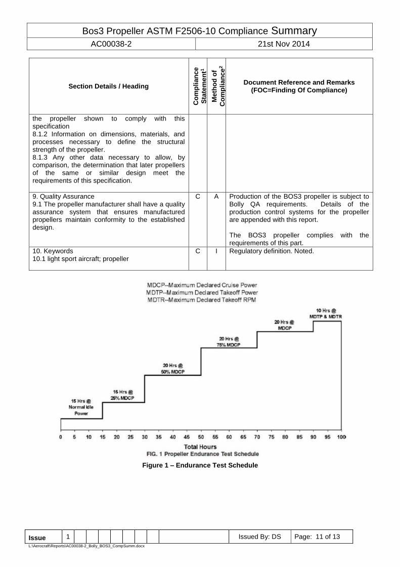
6.4.2 Propellers without a vibration stress survey must be subjected to one of the following tests: 6.4.2.1 The endurance test shall be conducted according to the schedule, and in the order, shown in Fig. 1. 6.4.2.2 Compliance with 6.4.2.1 may be accomplished by providing documented service experience for the duration, power and speeds for the conditions shown in Fig. 1. The 10-h segment at maximum declared takeoff power and rpm shall be the final segment of testing after all other power and speed segments are completed
C A Testing to meet the requirements of 6.4.2.2 has been carried out and is detailed in report AC00078. The propeller complies with the requirements of this part.
6.4.3 An analysis based on tests of propellers of similar design may be used in place of the tests 6.4.1 and 6.4.2.
N/A N/A Testing has been carried out in accordance with Section 6.4.2. Therefore the certification option outlined in this section is not required.
6.5 Teardown Inspection: 6.5.1 After completion of each test prescribed in Section 5 of this specification, the propeller must be completely disassembled and a detailed
C A The propeller tested in accordance with Section 6.4 was disassembled and inspected. Teardown details contained within report AC00078 refer.

Bos3 Propeller ASTM F2506-10 Compliance Summary
AC00038-2 21st Nov 2014
Issue 1 Issued By: DS Page: 10 of 13
L:\Aerocraft\Reports\AC00038-2_Bolly_BOS3_CompSumm.docx
Section Details / Heading
Co
mp
lian
ce
Sta
tem
en
t1
Meth
od
of
Co
mp
lian
ce
2
Document Reference and Remarks (FOC=Finding Of Compliance)
inspection must be made of the propeller parts for cracks, wear, distortion, and any other unusual conditions.
The propeller complies with the requirements of this part.
6.5.2 Any unsatisfactory findings during the teardown inspection must be resolved through design changes and additional testing as necessary to establish the compliance of the propeller to this specification.
C A Report AC00078 refers. While some minor wear items were noted in the inspection none were considered unsatisfactory. The BOS3 propeller complies with the requirements of this part.
6.6 Propeller Adjustments and Parts Replacements—The manufacturer may service and make repairs to the propeller during the tests. Any service or repairs completed must be allowed by the maintenance manual. If repairs or replacement of parts that are beyond the scope of the maintenance manual are found necessary during the tests or in the teardown inspection, the parts in question must be subjected to additional testing or design changes, or both, as necessary to establish the compliance of the propeller to this specification
C A Report AC00078 refers. The propeller completed around 104.75 hours of operation on the test rig. During that time the pitch remained stable. No unscheduled repairs or maintenance were required. The propeller complies with the requirements of this part.
7. Identification Marking 7.1 Each manufacturer of a propeller, propeller blade, or propeller hub shall identify each by means of a plate, stamping, engraving, etching, or other method of permanent identification.
C I The parts used in the BOS3 Propeller are identified as shown in Figure 2 to Figure 6. The propeller meets the requirements of this part.
7.2 The identification shall be placed on a non-critical surface that will not likely be defaced or removed during normal service or lost or destroyed in an accident.
C I Part identification markings are as shown in Figure 2 to Figure 6, complying with the requirements of this part.
7.3 The identification marking(s) shall contain the following information. Propeller diameter, pitch (for fixed-pitch propellers), and manufacturer’s identification must be obvious from the marking(s). The other required information can be encoded or abbreviated as necessary to limit the space required for the marking(s): 7.3.1 Manufacturer’s identification. 7.3.2 Propeller model designation. 7.3.3 Propeller serial number 7.3.4 Part number (or equivalent). 7.3.5 Propeller diameter. 7.3.6 Propeller pitch (for fixed-pitch propellers).
C I Refer to Figure 2 to Figure 6. All major parts are labelled for P/No. and S/No. as is the overall assembly. As an adjustable propeller pitch is not detailed on the labels.
8. Design Control 8.1 The design of a propeller consists of at least the following: 8.1.1 The drawings and specifications, and a listing of those drawings and specifications necessary to define the configuration and the design features of
C I 8.1 Refer to separate statements below: 8.1.1 Regulatory definition: noted. 8.1.2 Regulatory definition: noted. 8.1.3 Regulatory definition: noted.
Bos3 Propeller ASTM F2506-10 Compliance Summary
AC00038-2 21st Nov 2014
Issue 1 Issued By: DS Page: 11 of 13
L:\Aerocraft\Reports\AC00038-2_Bolly_BOS3_CompSumm.docx
Section Details / Heading
Co
mp
lian
ce
Sta
tem
en
t1
Meth
od
of
Co
mp
lian
ce
2
Document Reference and Remarks (FOC=Finding Of Compliance)
the propeller shown to comply with this specification 8.1.2 Information on dimensions, materials, and processes necessary to define the structural strength of the propeller. 8.1.3 Any other data necessary to allow, by comparison, the determination that later propellers of the same or similar design meet the requirements of this specification.
9. Quality Assurance 9.1 The propeller manufacturer shall have a quality assurance system that ensures manufactured propellers maintain conformity to the established design.
C A Production of the BOS3 propeller is subject to Bolly QA requirements. Details of the production control systems for the propeller are appended with this report. The BOS3 propeller complies with the requirements of this part.
10. Keywords 10.1 light sport aircraft; propeller
C I Regulatory definition. Noted.
Figure 1 – Endurance Test Schedule
Bos3 Propeller ASTM F2506-10 Compliance Summary
AC00038-2 21st Nov 2014
Issue 1 Issued By: DS Page: 12 of 13
L:\Aerocraft\Reports\AC00038-2_Bolly_BOS3_CompSumm.docx
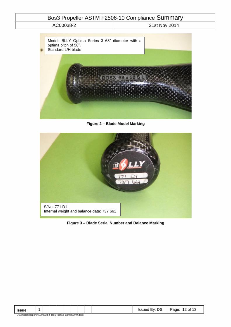
Figure 2 – Blade Model Marking
Figure 3 – Blade Serial Number and Balance Marking
Model: BLLY Optima Series 3 68” diameter with a optima pitch of 58”. Standard L/H blade
S/No. 771 D1 Internal weight and balance data: 737 661

Bos3 Propeller ASTM F2506-10 Compliance Summary
AC00038-2 21st Nov 2014
Issue 1 Issued By: DS Page: 13 of 13
L:\Aerocraft\Reports\AC00038-2_Bolly_BOS3_CompSumm.docx
Figure 4 – Hub Marking (Manufacturer’s ID)
Figure 5 – Hub S/No. Marking
Figure 6 – Propeller Assembly S/No. Marking