Embed Size (px)
Citation preview

20
Limited Warranty
All EZ-Bridge®
LT+ products are supplied with a limited 24 month war-ranty which covers material and workmanship defects. This warranty
does not cover the following: ▫ Parts requiring replacement due to improper installation,
misuse, poor site conditions, faulty power, etc. ▫ Lightning damage. ▫ Physical damage to the external & internal parts. ▫ Products that have been opened, altered, or defaced. ▫ Water damage for units that were not sealed or mounted
according to user manual. ▫ Units that were not properly grounded. ▫ Usage other than in accordance with instructions and the normal intended use.
Do not return any products until you receive a Return Material Authori-zation (RMA) number. Products received without a valid RMA number will be rejected and returned to sender.
Warranty Repairs All returns must have a valid RMA number written clearly on the outside of the box. Without an RMA number the shipment will be refused. For customers located in United States and Canada, customer pays all shipping charges incurred to ship the product to Tycon Systems
®. Ty-
con Systems® pays shipping charges to return the product to the origi-
nal purchaser. For all other countries, the original purchaser shall pay all shipping, broker fees, duties and taxes incurred in shipping products to and from Tycon Systems
®. Provided the goods have not been modi-
fied or repair attempted by someone other than Tycon Systems®, at the
option of Tycon Systems®, products may be returned either as repaired
or replaced. If it is determined that there is no fault found (NFF) on a unit within warranty, the customer will be charged $75 USD for testing time. For products out of warranty, the standard NFF charge is $200. This charge will be at the discretion of Tycon Systems
®. The RMA num-
ber is valid for 14 days from date of issue. The product must be re-ceived by the repair depot within these 14-days or the shipment may be refused.
Shipping and Damage Claims All shipping damage claims are the purchaser's responsibility. Inspect each shipment upon delivery and IMMEDIATELY report all damage, to the carrier. There may be time limits and inspections may be required.
Phone: 801-432-0003 [email protected]
8000005 Rev15 EZ-Bridge® LT+ Qwik Install Guide
EZ-Bridge® LT+
High Performance Point to Point Wireless Bridge System
▫ Achieve up to 100 Mbit/sec speed ▫ Link up to 3 miles with good line of sight ▫ Plug and Play Simple Installation ▫ Best security available (WPA) ▫ Field Proven Wireless Technology
Now with TyconOS™ Firmware

2
EZ-Bridge® Wireless Antenna System
Router
Internet Source PC
Note 1. Warning! These antennas utilize 12 to 24 VDC passive PoE (maximum). Do not connect to standard PoE power sources as they typically have higher voltages exceeding 48 VDC. Doing so will damage units and void the warranty.
Antenna “A”
Router
LAN Port
POE Port
See Notes 1 and 2
19
Appendix:
Federal Communication Commission Interference Statement This equipment has been tested and found to comply with the limits for a Class B digital device, pursuant to Part 15 of the FCC Rules. These limits are designed to provide reasonable protection against harmful interference in a residential installation. This equipment generates, uses and can radiate radio frequency energy and, if not installed and used in accordance with the instructions, may cause harmful interference to radio communications. However, there is no guarantee that interference will not occur in a particular installation. If this equipment does cause harmful interference to radio or television reception, which can be deter-mined by turning the equipment off and on, the user is encouraged to try to correct the interference by one of the following measures:
• Reorient or relocate the receiving antenna.
• Increase the separation between the equipment and receiver.
• Connect the equipment into an outlet on a circuit different from that to which the receiver is connected.
• Consult the dealer or an experienced radio/TV technician for help.
• FCC Caution: Any changes or modifications not expressly ap-proved by the party responsible for compliance could void the user's authority to operate this equipment.
This device complies with Part 15 of the FCC Rules. Operation is sub-ject to the following two conditions: (1) This device may not cause harmful interference, and (2) this device must accept any interference received, including interference that may cause undesired operation. IMPORTANT NOTE: FCC Radiation Exposure Statement: This equipment complies with FCC radiation exposure limits set forth for an uncontrolled environment. This equipment should be installed and operated with minimum distance 20cm between the radiator & your body. The antenna(s) used for this transmitter must not be co-located or operating in conjunction with any other antenna or transmitter.

18
2.4GHz 5GHz
Standards 802.11g/n 802.11a/n
Certifications FCC / CE
Radio Specifications
Operating Frequency 2400 to 2497MHz 4900 to 6000MHz Available Transmit Power 10 to 316mW 10 to 316mW
Receive Sensitivity 802.11g -75dBm 802.11n -90dBm
802.11a -75dBm 802.11n -90dBm
Security 64/128bit WEP, WPA, WPA2
Remote Configuration By IP Address; thru Wireless or Ethernet
Antenna Specifications
Antenna Gain 14 dBi 16 dBi
Antenna Beamwidth (H /V) 35 deg 27 deg
Antenna Front to Back >20dB >22dB
Polarization MIMO MIMO
POE Specification
Power Over Ethernet INPUT: 100 – 240VAC @ 50 – 60Hz
OUTPUT: 24VDC @ 0.5A Average Power Consumption 4W
Mechanical Specifications
Color White
Dimensions (L x W x H) 12.4” x 7.3” x 2.5” (314 x 187x 65mm)
System Weight 7 lb (3 kg)
Ethernet Connector RJ45
Mount Pole (up to 2” dia) or Wall
Environmental Specifications
Operating Temperature -22 to 158 Deg F (-30 to +70 Deg C)
Humidity 0 to 100% RH
Wind Loading (125MPH survivability) 100MPH / 23lbs; 125MPH / 35lbs
Technical Specifications Note: Subject to Change Without Notice
2.4GHz 5GHz
3
Antenna “B”
Router or Switch
PC
Typical IP Device(s) Cameras, Access Points,
Radios, Other.
Note 2. Do not plug or unplug antennas while PoE Power is applied. (No hot swapping). Doing so may damage units and void the warranty
Simplified Hook-Up Diagram
All connections beyond this point must happen after EZ-Bridge Set-Up
and Verification Tests.
WAN/Internet Port
See Notes 1 and 2
POE port
LAN Port

4
Getting Started We strongly recommend that you setup the EZ-Bridge
® system
in a single room to get acquainted with the operation of the units before installing outdoors.
CAUTION: Applying a voltage higher than 24V will damage the unit and void the warranty. Do not plug the antenna directly into standard PoE sources because most of PoE voltages far exceed the 24VDC maximum.
CAUTION: Do not plug/unplug the CAT5/6 cable to the antenna with power applied (hot swapping) as this could damage the unit. Always plug cable first and then apply power to the PoE inserter. Always disconnect power from the PoE inserter before disconnecting cables.
DANGER! Avoid Powerlines! You Can Be Killed!
When following the instructions in this guide to install the antenna take extreme care to avoid contact with overhead power lines, lights and power circuits. Contact with power lines, lights or power circuits may be fatal. We recommend to install antenna no closer than 20 feet to any power lines.
Safety: For your own protection, follow these safety rules.
▫ Perform as many functions as possible on the ground ▫ Do not attempt to install the antenna on a rainy, windy or
snowy day or if there is ice or snow accumulation at the install site or if the site is wet.
▫ Make sure there are no people, pets, etc. below when you are working on a roof or ladder.
▫ Watch out for any power lines which may be overhead, under-ground or behind walls, keeping safely clear of them with the antenna, ladders or any tools.
▫ See appendix for FCC RF exposure guidelines Recommended Tools: Pliers, Screws and screwdriver if mounting to a wall. NOTE: You should be familiar with using tools such as these before attempting installation of the antenna. You should be comfortable with working on a ladder.
Note: We highly recommend connecting the EZ-Bridge®
power sup-ply to a surge protected outlet or an Uninterruptable Power Supply system. We also recommend using shielded and grounded CAT5/6 cable between the antenna and the POE Inserter. This will help pre-vent damage from lightning and electrical surges caused by lightning.
17
Make sure your EZ Bridge set up is similar to the diagram shown on pages 2-3.
Make sure you are using the appropriate discovery tool for your EZ Bridge.
TyconOS Discovery Tool V2.4 for EZ Bridge LT+ WISPOS Discovery Tool v1-3-5 for EZ Bridge LT Ultra Discovery Tool for EZ Bridge Ultra
Check the LEDs below the antenna. Make sure the signal strength indi-cators are lit. If it is not, power cycle both antennas. Do a factory reset if changes were made prior to the failure.
Connect the computer directly to the LAN port of antenna B. Turn the computer’s Wi-fi off. (Do a quick search online if you are not sure how to). Run the discovery tool and check if you can find the antennas.
Try using different CAT5/6 cables. There are times where the 8 pins are swapped or not installed properly.
Make sure both antennas have clear line of sight. If the antennas are already installed, make sure they are not behind a glass window or any sort of obstruction.
If your set up involves a second router on the remote/receiving end, make sure that the LAN port of side B’s PoE inserter is connected to the WAN/Internet port of the router. The WAN/Internet port is usually separated from the other ports or at least colored differently.
For a more detailed troubleshooting step by step procedure and check-list, please visit this page
https://tyconsystems.com/support?view=kb&kbartid=24
Start up procedure flow chart can be found here
https://tyconsystems.com/support?view=faq&faqid=104

16
TROUBLESHOOTING
1. Link Down If a link goes down the first thing to do is run the discov-ery tool from both sides of the network. The discovery tool should be able to discover both units from each side of the link. If it can see the local unit but not the remote unit then the wireless link is down or the remote unit is down. Run the discovery tool on the remote side. If it can see the remote unit then the wireless link is down. Reset both units to factory defaults and power cycle them. If it cannot see the remote unit from the remote side, bring the power supply and POE Inserter cable from the working side and see if that fixes the problem. Also check your cables.
2. Poor Performance If you are seeing poor performance, power cycle both units then after about 10 minutes check the signal strength on the status page of the web based control panel. If signal strength is be-tween –76 and –90dBm the signal level is abnormally low and could be because the antennas have lost their physical alignment. Check the alignment. Antennas are more sensitive to vertical tilt than horizontal. Next, make sure there haven’t been any changes to line of site like new trees or buildings or vehicles. Line of site issues can usually be helped by moving the antenna to a new location with better line of site. If signal level is good (between –35 and –75dBm) try changing the wireless channel on the AP unit. You should also do a site survey on both units to see what channels are already being used. Select a channel that is not already used or one that has a very low signal strength. If the signal level is too hot, -30dBm, because the units are very close, you should turn down the transmit power on both units.
3. Discovery Tool is not working. Make sure you are running the Ty-conOS Discovery tool and you have Java installed on your computer.
Common issues with Windows is it doesn’t associate .jar files to run using Java, you can use a small program like jarfix. Download it here: https://johann.loefflmann.net/downloads/jarfix.exe. Certain versions of Windows 7 and 8 could not run the discovery tool so you would need to use a different network scanning tool like Advanced IP Scanner http://www.advanced-ip-scanner.com/. The EZ Bridge antennas will show up as “Compex Systems”.
With MacOS, you would need to right click on the discovery tool and select “Open” as MacOS usually blocks .jar files from opening.
4. EZ Bridge is not working or can’t be discovered over the net-work. We test each pair of EZ Bridges before shipping them out so they should connect automatically as long as it is installed as instructed.
5
Qwik Install
Things You Need: 1. Computer with an RJ45 port 2. Qty. (4) CAT5/6 cables. STEP 1: Remove the antenna bottom cover by using a coin or house key or screwdriver to push in one of the side snaps and then re-move the cover.
STEP 2: Identify Antenna A by the label on the back side of the unit “Side A” (Also called “AP” Antenna) Plug a CAT5/6 cable from the PoE port on the power inserter to the an-tenna (RJ45 jack farthest from the LEDs). Plug another cable from the inserter LAN port to a (non-powered) spare port on your router. Plug in the PoE power inserter to the AC outlet to power up the bridge. You will hear 2 beeps from the antenna when it is fully booted up. (2-3 Minutes) STEP 3: Identify Antenna B by the label on the back side of the unit “Side B” (Also called “Client” Antenna) Plug a CAT5/6 cable from the PoE port on the power inserter to the an-tenna (RJ45 jack farthest from the LEDs). Plug a PC directly to the LAN port of the B side power inserter. Plug in the PoE power inserter to the AC outlet to power up the bridge. You will hear 2 beeps from the anten-na when it is fully booted up. (2-3 minutes) Place the antennas a few feet away from each other facing opposite directions. STEP 4: Turn the computer’s Wi-Fi off and try to pull up a web page. If you can pull up a web page, then the EZ Bridge works. If you can’t pull up a web page, please go to the troubleshooting section (page 16) of this user manual. STEP 5: Choose a mounting location with good line of sight to the re-mote location. The supplied bracket can be mounted to a wall or to an existing pole up to 2” diameter.
TECH TIP: Microwaves travel in straight lines and they lose strength quickly when going thru buildings and trees. These units
are designed for clear line of sight. Be aware of trees that may grow up to block sight line and beware of objects that may move in and out such as swaying trees that may block the sight line.

6
STEP 6: Mount the Bracket:
To mount to a pole: Use the supplied U-Bolt and wing nuts. Make sure to use a lock washer at each wing nut. Tighten wing nuts evenly by hand. Use pliers if additional tightness is needed.
To mount to a wall: The supplied U-bolt is not used and the bracket is screwed directly to a wall using customer supplied screws.
STEP 7: Mount the antenna housing to the bracket. Put the hex head bolt thru the housing back fin. Put the star lock washer so it is between plastic housing and metal bracket. Install wing nut with lock washer. Adjust desired tilt angle and tighten wing nut. Use pliers if additional tightness is needed.
TECH TIP: Because of the specially designed wide beam width antenna, pointing is not critical and simply pointing in the general direction of the receiving antenna will yield great results.
STEP 8: Route a CAT5/6 cable through the bottom cover and plug into the RJ45 jack farthest from the LEDs. Keep the black gasket material in the bottom of the cover to help keep out dust and insects. STEP 9: Route CAT5/6 cable from the antenna into the building. Al-ways create a strain relief near the antenna so the cable is not pulling directly on the antenna. Use the CAT5/6 strain relief hook feature built into the housing back fin. The Ethernet spec allows for a maximum ca-ble length of 100 meters or about 328 feet.
STEP 10: Connect the device needing network connectivity to the LAN port of Side B’s PoE inserter.
15
Hit Save & Apply. It will take 2 minutes for the antennas to find each other and establish a connection. You should then be able to see them in the Discovery Tool.
Repeat the same steps for the other pairs. In my case, I would have the host names EZBridgePair2AP and EZBridgePair2Station. Then EZBRIDGEPair2 as the ESSID and MyEZBridgePassword as the key for both and antennas.
Can I power a second device off my EZ-Bridge® ? The RJ45 connectors on the LT+ don’t have PoE output capability but you can use a 5.5 x 2.1mm DC Plug Jumper to power up the second EZ-Bridge
®.
Maximum 10W output @ 15-24V DC. PoE Voltage in = VDC Out. (Note: The EZ-Bridge requires much less than 10W)

14
IMPORTANT: Make sure the ESSID and the Wireless Security Key is the same for both Antennas! Hit Save & Apply. The remote antenna will then be disconnected from your network and will not reconnect until settings for the local antenna matches up. Now make the changes on the local antenna (Usually Antenna A) Change the host names of each antennas for easier management. Go to System --> System --> System Properties --> Hostname Then click Save & Apply
Change the ESSID by going to Network --> Wi-Fi --> Edit --> Interface Configuration --> ESSID Required if password was set on the other antenna: Change the Wire-less Security Key
IMPORTANT: Make sure the ESSID and the Wireless Security Key is the same for both Antennas!
7
Advanced Features Since documentation for the advanced features is too extensive to cov-er here please visit our online wiki at https://tyconsystems.com/index.php/support?view=kb&kbartid=2 FAQs: https://tyconsystems.com/index.php/support?view=faq Knowledge Base: https://tyconsystems.com/index.php/support?view=kb
Software Settings We strongly recommend that you create a working plug and play link before making ANY changes to the soft-ware settings
1. There is an HTML management system (control panel) built into eve-ry EZ-Bridge
® unit which is accessed thru a standard web browser. The
unit can communicate thru the CAT5/6 Ethernet cable connection or with an established link, through the wireless bridge connection, so you can manage remote units from a single location. NOTE: The device will usually go into a 2-3 minute reboot cycle when clicking on SAVE & APPLY CHANGES. During this time it will be unre-sponsive. The unit will beep once when it reboots and beep twice when it is ready.
2. IP ADDRESS: Default fallback IP addresses for the EZ-Bridge® are
192.168.1.139 and 192.168.1.239. To access the EZ-Bridge® control
panel, your computer IP address must be on the same subnet ie; 192.168.1.xxx. The EZ-Bridge
® ships with DHCP client enabled so if the
unit has access to your network it will get its IP address automatically from your network. To find the units IP address use the Discovery Tool which is available at tyconsystems.com/support/firmware. We recom-mend after everything is working to your satisfaction that you assign a unique static IP to each unit so you always know how to access the units on your network. The IP address setting can be changed at NET-WORK | INTERFACES | EDIT LAN | PROTOCOL
TECH TIP: We recommend always making changes to the remote unit first and the local unit second. The EZ Bridges are shipped with
the two antennas paired up. No additional changes on the settings is required. Avoid making any changes to the settings if you are not sure what that setting does. Please refer to our FAQs and knowledge base articles if you have questions.
3. SECURITY: Security is pre-configured with system passwords and

8
WPA2 encryption pre-set. This is so that you can setup a plug and play link and have confidence that the link is secure and that your data and network are safe. Once you feel comfortable with the system and its operation, we would recommend the following security changes :
a. PASSWORD: Change the password on each side of the link by going to SYSTEM | ADMINISTRATION and re-setting the radio password. The default password = link4me. The user name, EZTEAM, cannot be changed.
b. ENCRYPTION: Change the WPA2 encryption key by going to NETWORK | WIFI | EDIT | INTERFACE CONFIGURATION WIRELESS SECURITY | KEY .
c. MAC ADDRESS VERIFICATION: On the AP side of the link go to NETWORK | WIFI | EDIT | INTERFACE CONFIGURA-TION MAC-FILTER | ALLOW LISTED ONLY and enter the MAC address of the client unit. The client MAC address can be found on the AP ‘s STATUS | OVERVIEW page.
d.. HIDE ESSID: Hiding the ESSID will insure that the SSID of the EZ-Bridge
® won’t show up in a normal wireless network
scan. This adds a level of security because it makes the unit nearly invisible. Go to NETWORK | WIFI | EDIT | INTERFACE CONFIGURATION | HIDE ESSID. Check the box.
TECH TIP: When setting encryption you must setup both sides of the link to have identical encryption keys. You can setup the remote
unit first and then the local unit last in order to be able to configure both units from one location across the wireless link. Keys can use any ASCII characters. The more random the key, the more secure the code.
4. CHANNELS: The default channel is set to AUTO on both units. The only reason you might want to set a fixed channel is if you experience interference from local wireless systems and you find a channel that works better. To change the channel go to NETWORK | WIFI | EDIT | CHANNEL.. NOTE: You only need to change the channel on the AP side. The client will automatically follow after a few minutes.
5. TRANSMIT POWER (Tx Power): Normally there wouldn’t be any reason to change the power setting. The factory default setting is MAX. which should be good for most applications. If you have a very short link you will actually get better performance if you turn down the Tx Power. This is because at close range there is too much power and it has a tendency to overload the input stage of the units and perfor-mance degrades. The best performance will be seen with signal strength of –40 to –60dBm. This signal strength can be viewed on the STATUS | OVERVIEW page. To change the Tx power go to NET-
13
Can I use multiple EZ-Bridge®s in the same network? The EZ Bridge antennas connect via their ESSID, so having 2 or more pairs of EZ Bridge with the same ESSID in the same network would cause issues. We suggest making these adjustments one pair at a time. Please avoid using spaces and special characters on the ESSID and password fields. Let's start by changing the settings on the remote antenna (Usually An-tenna B) for Pair 1: Change the host names of each antennas for easier management. Go to System --> System --> System Properties --> Hostname
Then click Save & Apply Change the ESSID by going to Network --> Wi-Fi --> Edit --> Interface Configuration --> ESSID
Optional: Change the Wireless Security Key
12
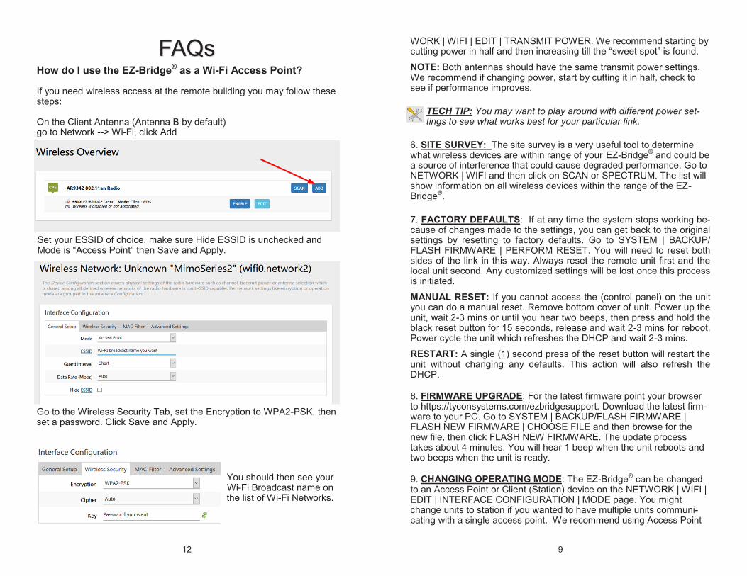
FAQs How do I use the EZ-Bridge® as a Wi-Fi Access Point? If you need wireless access at the remote building you may follow these steps: On the Client Antenna (Antenna B by default) go to Network --> Wi-Fi, click Add
Set your ESSID of choice, make sure Hide ESSID is unchecked and Mode is “Access Point” then Save and Apply.
Go to the Wireless Security Tab, set the Encryption to WPA2-PSK, then set a password. Click Save and Apply.
You should then see your Wi-Fi Broadcast name on the list of Wi-Fi Networks.
9
WORK | WIFI | EDIT | TRANSMIT POWER. We recommend starting by cutting power in half and then increasing till the “sweet spot” is found.
NOTE: Both antennas should have the same transmit power settings. We recommend if changing power, start by cutting it in half, check to see if performance improves.
TECH TIP: You may want to play around with different power set-tings to see what works best for your particular link.
6. SITE SURVEY: The site survey is a very useful tool to determine what wireless devices are within range of your EZ-Bridge
® and could be
a source of interference that could cause degraded performance. Go to NETWORK | WIFI and then click on SCAN or SPECTRUM. The list will show information on all wireless devices within the range of the EZ-Bridge
®.
7. FACTORY DEFAULTS: If at any time the system stops working be-cause of changes made to the settings, you can get back to the original settings by resetting to factory defaults. Go to SYSTEM | BACKUP/FLASH FIRMWARE | PERFORM RESET. You will need to reset both sides of the link in this way. Always reset the remote unit first and the local unit second. Any customized settings will be lost once this process is initiated.
MANUAL RESET: If you cannot access the (control panel) on the unit you can do a manual reset. Remove bottom cover of unit. Power up the unit, wait 2-3 mins or until you hear two beeps, then press and hold the black reset button for 15 seconds, release and wait 2-3 mins for reboot. Power cycle the unit which refreshes the DHCP and wait 2-3 mins.
RESTART: A single (1) second press of the reset button will restart the unit without changing any defaults. This action will also refresh the DHCP.
8. FIRMWARE UPGRADE: For the latest firmware point your browser to https://tyconsystems.com/ezbridgesupport. Download the latest firm-ware to your PC. Go to SYSTEM | BACKUP/FLASH FIRMWARE | FLASH NEW FIRMWARE | CHOOSE FILE and then browse for the new file, then click FLASH NEW FIRMWARE. The update process takes about 4 minutes. You will hear 1 beep when the unit reboots and two beeps when the unit is ready.
9. CHANGING OPERATING MODE: The EZ-Bridge® can be changed
to an Access Point or Client (Station) device on the NETWORK | WIFI | EDIT | INTERFACE CONFIGURATION | MODE page. You might change units to station if you wanted to have multiple units communi-cating with a single access point. We recommend using Access Point

10
(WDS) and Station (WDS) to maintain the highest level of network transparency.
10. AUTOMATIC REBOOT: We highly recommend setting up an auto-mated reboot to reboot both units every night during the wee hours when the link is not being used. This will ensure that the units run smoothly without need for intervention because it clears memory and corrects issues like corrupted flash. Go to SYSTEM | SERVICES | AU-TO REBOOT. Set the AP to reboot first and the station to reboot about 5 minutes later.
TECH CORNER Additional Information you may find useful
1. ADDING A SECOND ROUTER — Don’t attempt to add a second router to your network until you first have a working EZ-Bridge
® link and
you are familiar with the operation. We have a white paper which may help you to install the second router here: http://tyconsystems.com/documentation/WhitePapers
2. RAIN, SNOW, ICE – The frequencies being used by the EZ-Bridge®
LT+ will not be affected by heavy rain or falling snow. You should not see any performance degradation due to inclement weather. If snow or ice collects on the front of the antenna, you may see some reduced per-formance assuming you are shooting a long distance ( >1miles) and the ice or snow buildup is greater than 1” thick on the surface of the anten-na. For this reason, we suggest mounting under an eave of a house if feasible for your particular situation.
3. SUN AND HEAT– The EZ-Bridge® is constructed of all UV protected
materials so it will survive for many years in the most extreme of solar environments (ie; an Arizona rooftop during the summer). The unit has been tested and qualified for constant operation at over 158 deg F am-bient temperature. Even though the EZ-Bridge
® is designed for long
term survivability in extreme environments, we would still recommend that the unit be mounted in a more protected location, like under a roof eave, if possible. Of course if line of sight is better with the antenna mounted in a non-protected environment then we would recommend the better line of sight mounting location.
4. LIGHTNING – Lightning is the single worst enemy of outdoor elec-tronics equipment. No electronics will survive a direct strike but there are close proximity strikes that can cause huge electrical fields to be generated which can damage electronic equipment. We have taken special care in the design of the EZ-Bridge
® unit to ensure proper
grounding of the electronics inside the enclosure to prevent damage
11
from electrical storms. Make sure that the POE Power Supply is plugged into a surge protected outlet such as a surge protected power strip or UPS inside the house. Shielded CAT5/6 cable is also recom-mended between the POE Inserter and antenna.
5. PAINTING – The EZ-Bridge® unit can be painted to match a particu-
lar house color. Only non metallic enamel or latex paints should be used. If a paint with metal content is used, it will block the microwaves and cause reduced performance.
6. COMMON MICROWAVE BARRIERS – Tinted windows are made by applying a metallized film to the window. If a window has tinting, it will usually block the microwaves and cause reduced performance of the EZ-Bridge® . Concrete walls are also a significant barrier to microwave signals. Aluminum siding on houses is also a barrier to microwave sig-nals. Wood frame houses covered with brick or stucco are pretty trans-parent to microwave signals and they will reduce the signal strength but the signal will still pass thru the structure. We are bringing this up to you so you can better understand possible causes of performance issues.
7. DEVICE CONNECTIONS and FEATURES: