Embed Size (px)
Citation preview
8132019 Brushed DC Sensorless Feedback
httpslidepdfcomreaderfullbrushed-dc-sensorless-feedback 13
Sensorless SpeedPosition Control of Brushed DC
MotorE AfjeiA Nadian Ghomsheh and A Karami
Shahid Beheshti university Saadat Research Institute
Tehran Iranafjeiyahoocom
Abstract - This paper presents a new and novel technique for
speed control of a brushed DC motor without employing any
direct shaft transducer in its feedback mechanism This method
uses the currentvoltage variation produced on the motor main
input power lines as the brushes move from collector blade to
the next The frequency of variation is proportional to the motor
speed and the rotor position can also be detected by monitoring
the changes for each collector blade The performance of the
motor torque speed characteristic using this system as its
feedback has been evaluated through laboratory testing This
configuration is very suitable for harsh environment and places
with not enough space for the motor with discrete sensors
Keywords- DC motor Speed Control sensorless control
I INTRODUCTION
Brushed DC motors used in many applications such as stillrolling mills electric trains electric vehicles electric cranes
and robotic manipulators require speed controllers to performtheir tasks These motors are easy to dive fully controllableand readily available in all sizes and configurations [1-2] DCdrive systems are often used in many industrial applicationssuch as robotics actuation and manipulators In the first two
a wide range of speed or position control is required Inmanipulators dc motors are used to follow a predetermined
speed or position track under variable load Different controlstrategies have been proposed to control and achieve good performance of DC motors [3-4] In general the open loopcurrent control acts directly on torque and thus protects the
electronics the motor and the load In open loop variablevoltage control with current limiting circuit constitutes the
simplest way of varying speed However a closed-loop speedcontrol is utilized if precision for the speed control is required[5]
The speed of DC motors can be adjusted within wide
boundaries so that this provides easy controllability and high
performance Speed controller of DC motors is carried out bymeans of voltage control in 1981 by Ward Leonard [6] Thespeed of a brushed DC motor is proportional to the appliedvoltage Nowadays using digital control a pulse width
modulated (PWM) signal is used to generate an averagevoltage The motor winding acts as a low pass filter so aPWM waveform of sufficient frequency will generate a stablecurrent in the motor winding The frequency of the PWMsignal is an important consideration Low frequency willresult in a noisy motor at low speeds and sluggish response to
the changes in duty cycle Very high frequency tends to
decrease overall efficiency of the system due to switchinglosses in the drive circuit power transistors In order to control precise motor speed it is necessary to include some sort offeedback mechanism in the system Speed feedback isimplemented in one of two ways [7] The first involves the
use of a direct speed or position sensor which is mounted onthe motor shaft The second uses some kind of sensorlessschemes There are a variety of sensors used forspeedposition feedback The most common are opticalencoders synchros resolvers hall effects andtachogenerators
There are two basic generic styles of optical encodersincremental and absolute The incremental encoder provides a pulse each time the shaft has rotated a defined distance whilean absolute encoder provides a whole world output with a
unique code pattern representing each position A synchro isan angular position transducer It consists of a primary wound
on the rotor and three secondaries placed 120deg apart on thestator The magnitude and phase of the voltage induced intoeach stator winding depends on the position of and voltageapplied to the rotor So for a known primary voltage thesecondary voltages uniquely define the rotors position The
resolver is similar to the synchro except there are twosecondaries on the stator placed 90deg apart [8]In the sensorless scheme the back EMF which is
proportional to the motor speed is measured while the PWM
signal to the motor is turned off [9] There are of course manydifferent methods in control of dc motor speedposition using
fuzzy logic [10-11] and genetic algorithm [12]
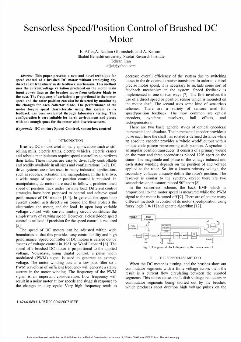
Fig 1 The general block diagram of the motor control
II THE SENSORLESS METHOD
When the DC motor is turning and the brushes short outcommutator segments with a finite voltage across them theresult is a current flow circulating between the shortedsegments This action causes the L didt voltage that occurs in
commutator segments being shorted out by the brusheswhich produces short duration high voltage pulses on the
Authorized licensed use limited to Univ Politecnica de Madrid Downloaded on January 14 2010 at 0900 from IEEE Xplore Restrictions apply
1-4244-0891-107 2000 9832092007 IEEE
8132019 Brushed DC Sensorless Feedback
httpslidepdfcomreaderfullbrushed-dc-sensorless-feedback 23
motor terminal Due to change of current direction in some ofthe coils in the DC motors a small periodic current variationcan be detected as the brushes go from a collector segment tothe next The period of current variation and also the numberof fast pulses are proportionally related to the motor speed
As the motor speed changes so does these quantities Thecurrent variation or the short duration pulses can be used as a
feed back to detect the rotor position or control the motor
speed The general block diagram of the motor control isshown in Fig 1
For the motor control the H-bridge driver is used The R sense
takes the sample of the motor line current variations Thereare two kinds of variations namely high voltage pulses when
commutator segments being shorted out by the brushes andalmost a sine wave or saw tooth type
variation as the brushes go from a collector segment to thenext can be detected Fig 2 shows the actual voltage pulses
and the voltagecurrent waveform on the input main supply tothe motor
Fig 2 The actual high voltage pulses and the current waveform
The current variation and the voltage pulses are clearly
shown in Fig 2 The short duration pulses occur exactly onthe highest and the lowest part of the wave where thecollector blades are shorted Due to triggering of oscilloscope
one of these pulses did not appear in the Fig 2There are two ways to go about either detecting the rotor position or controlling the motor speed In the first method
the current waveform variation is used while in the secondmethod the fast voltage pulses are employed for the job Inthis paper the current waveform has utilized for the task Inorder to have a nice and clean waveform without fast
voltagecurrent pulses the entire signal has gone through afilter to get rid of the high voltage pulses The resulting output
is shown in Fig 3
Fig 3 Resulting filter output
The frequency of the wave shown in Fig 3 is proportionalto the motor speed and each variation period corresponds to
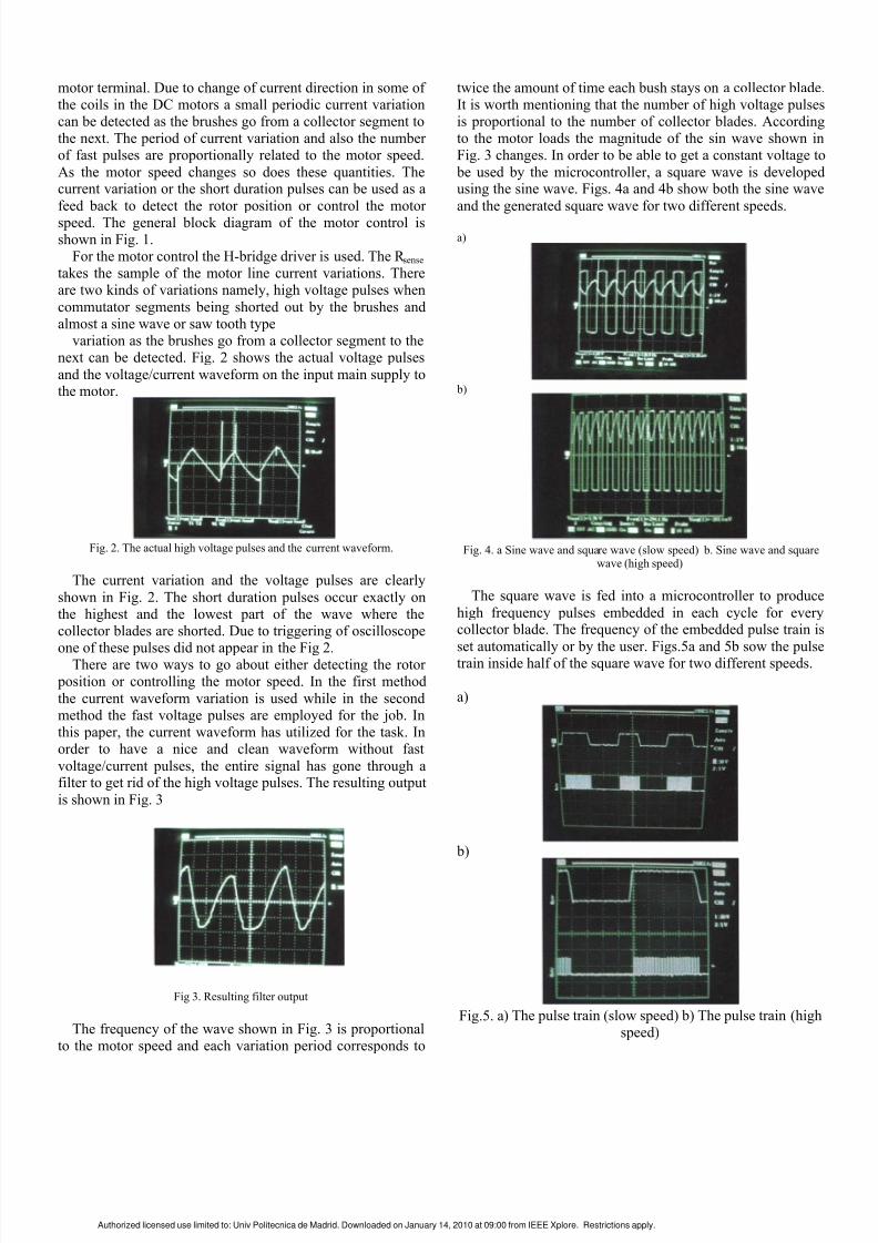
twice the amount of time each bush stays on a collector bladeIt is worth mentioning that the number of high voltage pulsesis proportional to the number of collector blades Accordingto the motor loads the magnitude of the sin wave shown inFig 3 changes In order to be able to get a constant voltage to
be used by the microcontroller a square wave is developedusing the sine wave Figs 4a and 4b show both the sine wave
and the generated square wave for two different speeds
a)
b)
Fig 4 a Sine wave and square wave (slow speed) b Sine wave and squarewave (high speed)
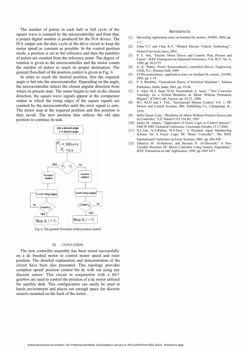
The square wave is fed into a microcontroller to produce
high frequency pulses embedded in each cycle for everycollector blade The frequency of the embedded pulse train is
set automatically or by the user Figs5a and 5b sow the pulsetrain inside half of the square wave for two different speeds
a)
b)
Fig5 a) The pulse train (slow speed) b) The pulse train (highspeed)
Authorized licensed use limited to Univ Politecnica de Madrid Downloaded on January 14 2010 at 0900 from IEEE Xplore Restrictions apply
8132019 Brushed DC Sensorless Feedback
httpslidepdfcomreaderfullbrushed-dc-sensorless-feedback 33
The number of pulses in each half or full cycle of the
square wave is counted by the microcontroller and from thata proper digital number is produced for the DA device TheDA output sets the duty cycle of the drive circuit to keep the
motor speed as constant as possible In the control positionmode a position is set as the reference and then the numbers
of pulses are counted from the reference point The degree of
rotation is given to the microcontroller and the motor countsthe number of pulses to reach its proper destination Thegeneral flowchart of the position control is given in Fig 6
In order to reach the desired position first the requiredangle is fed into the microcontroller Depending on the anglethe microcontroller selects the closest angular direction fromwhere its present state The motor begins to turn in the chosendirection the square wave signals appear at the comparatoroutput in which the rising edges of the square signals are
counted by the microcontroller until the error signal is zeroThe motor stop at the required position and this position isthen saved The new position data utilizes the old data position to continue its task
Fig 6 The general flowchart of the position control
III CONCLUSION
The new controller assembly has been tested successfullyon a dc brushed motor to control motor speed and rotor
position The detailed explanation and demonstration of thecircuit have been also presented This topology providescomplete speed position control the dc with out using anydiscrete sensor This circuit in conjunction with a 601gearbox are used to control the position of a dc motor utilized
for satellite dish This configuration can easily be used inharsh environment and places not enough space for discretesensors mounted on the back of the motor
R EFERENCES
[1] Microchip application notes on brushed Dc motors AN905 2004 pp
1-7[2] Chan CC and Chau KT ldquoModem Electric Vehicle Technologyrdquo
Oxford University press 2001[3] P C Sen ldquoElectric Motor Drives and Control Past Present and
Futurerdquo IEEE Transaction on Industrial Electronics Vol IE37 No 6
1990 pp 562-575 [4] G K Dubey Power Semiconductor controlled Drives Englewood
Cliffs NJ Prentice Hall 1989 [5] STMicroelectronics application notes on brushed Dc motors AN380
2003 pp 1-14 [6] P S Bimbhra ldquoGeneralized Theory of Electrical Machinesrdquo Khanna
Publishers Delhi India 2001 pp 93-98[7] E Afjei MA Saati MM Nezamabadi S Ataei ldquo New Converter
Topology for a Hybrid Brushless dc Motor Without Permanent
Magnetrdquo ICEM Conf Greece pp 20-25 2006 [8] BC KUO and J TAL ldquoIncremental Motion Control Vol 1 DC
Motors and Control Systems SRL Publishing Co Champaign IL
1979[9] Seiko Epson Corp ldquoBrushless dc Motor Without Position Sensor and
its Controllerrdquo EP Patent 0 553 354 B1 1993 [10] James M Adams ldquoApplication of Fuzzy Logic to Control Sensorsrdquo
EMCW 2002 Technical Conference Cincinnati October 15-172002 [11] HLTan NARahim WPHewrdquo A Dynamic Input Membership
Scheme for A Fuzzy Logic DC Motor Controllerrdquo The IEEE
International Conference on Fuzzy Systems 2003 pp 426-429[12] Zakariya M Al-Hamouz and Hussain N AI-Duwaish A New
Variable Structure DC Motor Controller Using Genetic AlgorithmsIEEE Transaction on Ind Application 1998 pp1669-1673
Authorized licensed use limited to Univ Politecnica de Madrid Downloaded on January 14 2010 at 0900 from IEEE Xplore Restrictions apply
8132019 Brushed DC Sensorless Feedback
httpslidepdfcomreaderfullbrushed-dc-sensorless-feedback 23
motor terminal Due to change of current direction in some ofthe coils in the DC motors a small periodic current variationcan be detected as the brushes go from a collector segment tothe next The period of current variation and also the numberof fast pulses are proportionally related to the motor speed
As the motor speed changes so does these quantities Thecurrent variation or the short duration pulses can be used as a
feed back to detect the rotor position or control the motor
speed The general block diagram of the motor control isshown in Fig 1
For the motor control the H-bridge driver is used The R sense
takes the sample of the motor line current variations Thereare two kinds of variations namely high voltage pulses when
commutator segments being shorted out by the brushes andalmost a sine wave or saw tooth type
variation as the brushes go from a collector segment to thenext can be detected Fig 2 shows the actual voltage pulses
and the voltagecurrent waveform on the input main supply tothe motor
Fig 2 The actual high voltage pulses and the current waveform
The current variation and the voltage pulses are clearly
shown in Fig 2 The short duration pulses occur exactly onthe highest and the lowest part of the wave where thecollector blades are shorted Due to triggering of oscilloscope
one of these pulses did not appear in the Fig 2There are two ways to go about either detecting the rotor position or controlling the motor speed In the first method
the current waveform variation is used while in the secondmethod the fast voltage pulses are employed for the job Inthis paper the current waveform has utilized for the task Inorder to have a nice and clean waveform without fast
voltagecurrent pulses the entire signal has gone through afilter to get rid of the high voltage pulses The resulting output
is shown in Fig 3
Fig 3 Resulting filter output
The frequency of the wave shown in Fig 3 is proportionalto the motor speed and each variation period corresponds to
twice the amount of time each bush stays on a collector bladeIt is worth mentioning that the number of high voltage pulsesis proportional to the number of collector blades Accordingto the motor loads the magnitude of the sin wave shown inFig 3 changes In order to be able to get a constant voltage to
be used by the microcontroller a square wave is developedusing the sine wave Figs 4a and 4b show both the sine wave
and the generated square wave for two different speeds
a)
b)
Fig 4 a Sine wave and square wave (slow speed) b Sine wave and squarewave (high speed)
The square wave is fed into a microcontroller to produce
high frequency pulses embedded in each cycle for everycollector blade The frequency of the embedded pulse train is
set automatically or by the user Figs5a and 5b sow the pulsetrain inside half of the square wave for two different speeds
a)
b)
Fig5 a) The pulse train (slow speed) b) The pulse train (highspeed)
Authorized licensed use limited to Univ Politecnica de Madrid Downloaded on January 14 2010 at 0900 from IEEE Xplore Restrictions apply
8132019 Brushed DC Sensorless Feedback
httpslidepdfcomreaderfullbrushed-dc-sensorless-feedback 33
The number of pulses in each half or full cycle of the
square wave is counted by the microcontroller and from thata proper digital number is produced for the DA device TheDA output sets the duty cycle of the drive circuit to keep the
motor speed as constant as possible In the control positionmode a position is set as the reference and then the numbers
of pulses are counted from the reference point The degree of
rotation is given to the microcontroller and the motor countsthe number of pulses to reach its proper destination Thegeneral flowchart of the position control is given in Fig 6
In order to reach the desired position first the requiredangle is fed into the microcontroller Depending on the anglethe microcontroller selects the closest angular direction fromwhere its present state The motor begins to turn in the chosendirection the square wave signals appear at the comparatoroutput in which the rising edges of the square signals are
counted by the microcontroller until the error signal is zeroThe motor stop at the required position and this position isthen saved The new position data utilizes the old data position to continue its task
Fig 6 The general flowchart of the position control
III CONCLUSION
The new controller assembly has been tested successfullyon a dc brushed motor to control motor speed and rotor
position The detailed explanation and demonstration of thecircuit have been also presented This topology providescomplete speed position control the dc with out using anydiscrete sensor This circuit in conjunction with a 601gearbox are used to control the position of a dc motor utilized
for satellite dish This configuration can easily be used inharsh environment and places not enough space for discretesensors mounted on the back of the motor
R EFERENCES
[1] Microchip application notes on brushed Dc motors AN905 2004 pp
1-7[2] Chan CC and Chau KT ldquoModem Electric Vehicle Technologyrdquo
Oxford University press 2001[3] P C Sen ldquoElectric Motor Drives and Control Past Present and
Futurerdquo IEEE Transaction on Industrial Electronics Vol IE37 No 6
1990 pp 562-575 [4] G K Dubey Power Semiconductor controlled Drives Englewood
Cliffs NJ Prentice Hall 1989 [5] STMicroelectronics application notes on brushed Dc motors AN380
2003 pp 1-14 [6] P S Bimbhra ldquoGeneralized Theory of Electrical Machinesrdquo Khanna
Publishers Delhi India 2001 pp 93-98[7] E Afjei MA Saati MM Nezamabadi S Ataei ldquo New Converter
Topology for a Hybrid Brushless dc Motor Without Permanent
Magnetrdquo ICEM Conf Greece pp 20-25 2006 [8] BC KUO and J TAL ldquoIncremental Motion Control Vol 1 DC
Motors and Control Systems SRL Publishing Co Champaign IL
1979[9] Seiko Epson Corp ldquoBrushless dc Motor Without Position Sensor and
its Controllerrdquo EP Patent 0 553 354 B1 1993 [10] James M Adams ldquoApplication of Fuzzy Logic to Control Sensorsrdquo
EMCW 2002 Technical Conference Cincinnati October 15-172002 [11] HLTan NARahim WPHewrdquo A Dynamic Input Membership
Scheme for A Fuzzy Logic DC Motor Controllerrdquo The IEEE
International Conference on Fuzzy Systems 2003 pp 426-429[12] Zakariya M Al-Hamouz and Hussain N AI-Duwaish A New
Variable Structure DC Motor Controller Using Genetic AlgorithmsIEEE Transaction on Ind Application 1998 pp1669-1673
Authorized licensed use limited to Univ Politecnica de Madrid Downloaded on January 14 2010 at 0900 from IEEE Xplore Restrictions apply
8132019 Brushed DC Sensorless Feedback
httpslidepdfcomreaderfullbrushed-dc-sensorless-feedback 33
The number of pulses in each half or full cycle of the
square wave is counted by the microcontroller and from thata proper digital number is produced for the DA device TheDA output sets the duty cycle of the drive circuit to keep the
motor speed as constant as possible In the control positionmode a position is set as the reference and then the numbers
of pulses are counted from the reference point The degree of
rotation is given to the microcontroller and the motor countsthe number of pulses to reach its proper destination Thegeneral flowchart of the position control is given in Fig 6
In order to reach the desired position first the requiredangle is fed into the microcontroller Depending on the anglethe microcontroller selects the closest angular direction fromwhere its present state The motor begins to turn in the chosendirection the square wave signals appear at the comparatoroutput in which the rising edges of the square signals are
counted by the microcontroller until the error signal is zeroThe motor stop at the required position and this position isthen saved The new position data utilizes the old data position to continue its task
Fig 6 The general flowchart of the position control
III CONCLUSION
The new controller assembly has been tested successfullyon a dc brushed motor to control motor speed and rotor
position The detailed explanation and demonstration of thecircuit have been also presented This topology providescomplete speed position control the dc with out using anydiscrete sensor This circuit in conjunction with a 601gearbox are used to control the position of a dc motor utilized
for satellite dish This configuration can easily be used inharsh environment and places not enough space for discretesensors mounted on the back of the motor
R EFERENCES
[1] Microchip application notes on brushed Dc motors AN905 2004 pp
1-7[2] Chan CC and Chau KT ldquoModem Electric Vehicle Technologyrdquo
Oxford University press 2001[3] P C Sen ldquoElectric Motor Drives and Control Past Present and
Futurerdquo IEEE Transaction on Industrial Electronics Vol IE37 No 6
1990 pp 562-575 [4] G K Dubey Power Semiconductor controlled Drives Englewood
Cliffs NJ Prentice Hall 1989 [5] STMicroelectronics application notes on brushed Dc motors AN380
2003 pp 1-14 [6] P S Bimbhra ldquoGeneralized Theory of Electrical Machinesrdquo Khanna
Publishers Delhi India 2001 pp 93-98[7] E Afjei MA Saati MM Nezamabadi S Ataei ldquo New Converter
Topology for a Hybrid Brushless dc Motor Without Permanent
Magnetrdquo ICEM Conf Greece pp 20-25 2006 [8] BC KUO and J TAL ldquoIncremental Motion Control Vol 1 DC
Motors and Control Systems SRL Publishing Co Champaign IL
1979[9] Seiko Epson Corp ldquoBrushless dc Motor Without Position Sensor and
its Controllerrdquo EP Patent 0 553 354 B1 1993 [10] James M Adams ldquoApplication of Fuzzy Logic to Control Sensorsrdquo
EMCW 2002 Technical Conference Cincinnati October 15-172002 [11] HLTan NARahim WPHewrdquo A Dynamic Input Membership
Scheme for A Fuzzy Logic DC Motor Controllerrdquo The IEEE
International Conference on Fuzzy Systems 2003 pp 426-429[12] Zakariya M Al-Hamouz and Hussain N AI-Duwaish A New
Variable Structure DC Motor Controller Using Genetic AlgorithmsIEEE Transaction on Ind Application 1998 pp1669-1673
Authorized licensed use limited to Univ Politecnica de Madrid Downloaded on January 14 2010 at 0900 from IEEE Xplore Restrictions apply