Embed Size (px)
Citation preview
1
Sub: BUDGETARY OFFER – Budgetary offer requested to complete the partially erected 1 No.15 T ELLW Crane of M/s. Jessop & Co., located at SQ-I including load testing, commissioning and handing over as per the
Technical Specification – DUE DATE FOR THE SUBMISSION
OF BUDGETARY OFFER IS 06.09.2011- Reg., *****
M/s. Jessop & Co., Kolkata , have erected 1 No.15 T Electric Level Luffing Wharf
Crane at SQ-I in partial condition as per the Technical specification enclosed. In order
to meet the traffic requirements, it is proposed to commission the above crane through
out side agencies.
Therefore, budgetary offer is invited for the above work. The Probable tenderers
are requested to inspect the crane and study completely and follow the Technical
specification as a guidance and accordingly to quote the rates in the cost schedule
enclosed. The following systems shall be repaired / modified / changed to meet the
technical requirement of the Specification of Mechanical, Electrical and Electronics
systems.
a) Long Travel mechanism - 8 Units
b) Slew mechanism - 1 Unit
c) Luffing mechanism - 1 Unit
d) Hoist mechanism - 1 Unit
e) Grabb mechanism - 1 Unit
f) Cable Reel Driving
mechanism - I Unit
g) Structural - Corroded structural members / plates / handrails to be placed.
h) Painting - Sand blasting and Epoxy painting of complete structures.
2
i) Ballasting - High density concrete (Counter weight) – a total of 58.5 T have been cast in the following places:
Super Ballast Tan : 30.756 T Jib Trail Pocket : 4.000 T Super Base : 23.744 T Total : 58.500 T
All the structural including i) Jib structures ii) ‘A’ frame, iii) Machinery House, and
iv) Portal columns are to be checked properly and strengthened / replaced if required
and Safe Load Indicator testing shall be carried out by the Contractor in their scope
of work and at their cost. Suitable Insurance shall be taken during the Guarantee
period by the contractor.
The offerer can inspect the crane on any working day between 11 a.m. to
5.p.m. one day advance notice to be given about the inspection. And the offerer is to
get necessary harbour entry permit for the vehicle / person at his own cost and for
any further clarification you may contact Dy.CME(R&D) / SE(M) (R&D). The Technical
specifications for Mechanical, Electrical and Electronic systems are enclosed for your
reference and guidance.
Note:
1. Tools & other equipments, Transport to be arranged by contractor at his
own cost.
2. Space requirement: As per Trust scale of rates space will be given if
available
3. Power / Water Supply: As per Trust scale of rates.
4. Necessary Test Load shall be arranged by the Tenderer at his own cost.
5. Floating Crane and other Port Equipments if available will be given at the
Port scale of rate
It is requested to furnish the budgetary offer within 30 days from the date of
issue of this letter.
3
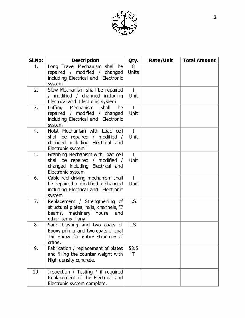
Sl.No: Description Qty. Rate/Unit Total Amount
1. Long Travel Mechanism shall be repaired / modified / changed including Electrical and Electronic system
8 Units
2. Slew Mechanism shall be repaired / modified / changed including Electrical and Electronic system
1 Unit
3. Luffing Mechanism shall be repaired / modified / changed including Electrical and Electronic system
1 Unit
4. Hoist Mechanism with Load cell shall be repaired / modified / changed including Electrical and Electronic system
1 Unit
5. Grabbing Mechanism with Load cell shall be repaired / modified / changed including Electrical and Electronic system
1 Unit
6. Cable reel driving mechanism shall be repaired / modified / changed including Electrical and Electronic system
1 Unit
7. Replacement / Strengthening of structural plates, rails, channels, ‘I’ beams, machinery house. and other items if any.
L.S.
8. Sand blasting and two coats of Epoxy primer and two coats of coal Tar epoxy for entire structure of crane.
L.S.
9. Fabrication / replacement of plates and filling the counter weight with High density concrete.
58.5 T
10. Inspection / Testing / if required Replacement of the Electrical and Electronic system complete.
4
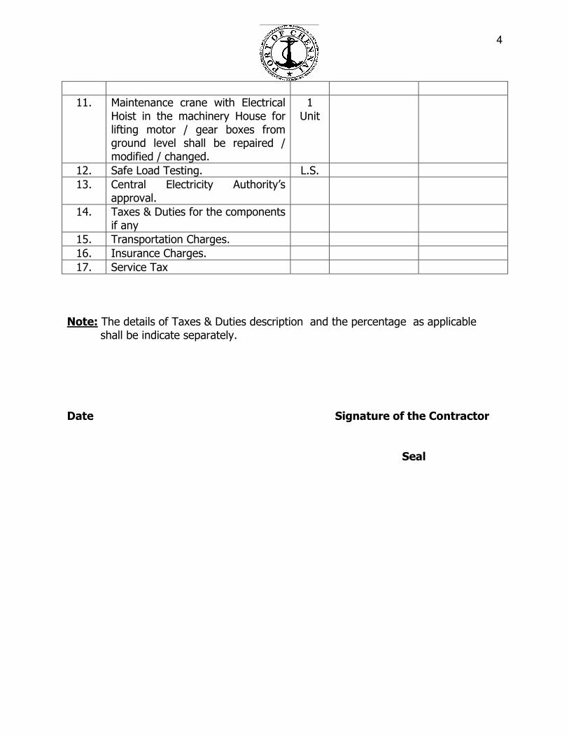
11. Maintenance crane with Electrical Hoist in the machinery House for lifting motor / gear boxes from ground level shall be repaired / modified / changed.
1 Unit
12. Safe Load Testing. L.S.
13. Central Electricity Authority’s approval.
14. Taxes & Duties for the components if any
15. Transportation Charges.
16. Insurance Charges.
17. Service Tax
Note: The details of Taxes & Duties description and the percentage as applicable
shall be indicate separately. Date Signature of the Contractor Seal

5
TECHNICAL SPECIFICATION FOR 15 TON ELECTRIC LEVEL LUFFING CRANE PARTIALLY ERECTED 1 No. OF M/s JESSOP & Co., LOCATED AT SQ1 INCLUDING LOAD TESSTING, COMMISIONNG AND HANDING OVER. 1.0 SCOPE OF WORK: The specification indicated is intended for Revamping, Erection, Commissioning and Teting of 15Ton Electrical level luffing wharf crane, with ballasted jip system with provisions for hook, four rope grab and tub operational function at SQ I.
1.1 The primary function of the crane shall be to on and off load general cargo, bulk materials on a continuous basis as follows:
i. General cargo with hook ii. Dry bulk cargo with four rope grab (coal, urea, rock phosphate, sulphur, iron
ore, steam coke and wheat) iii. Lump materials like barytes, quartz and cut stones to be loaded into ships
using tubs. 1.2 The crane shall be capable of carrying the rated loads while traveling and the
jib at the appropriate corresponding outreach as given under “ Leading Parameters in clauses 2.0” .
1.3 The crane shall be stable under maximum operating conditions, with the
permissible loads at the corresponding maximum and minimum outreaches as given under “ Leading Parameters in clause 2.0”.
1.4 The crane shall be stable under maximum operating conditions of simultaneous
hoisting, level luffing, slewing and traveling motions as given under “Leading Parameters in clause 2.0”.
1.5 When not in operation the crane shall stowed with the jib in minimum radius,
the slewing superstructures locked to the portal and the crane secured to the track by means of rail clamps/stowage pins.
1.6 Wind speed under operating conditions (including gusts and supposed to act
over crane structure) 20 m/s. 1.7 Maximum wind speed (crane in stowed and/or tied down condition ) 55 m/s
6
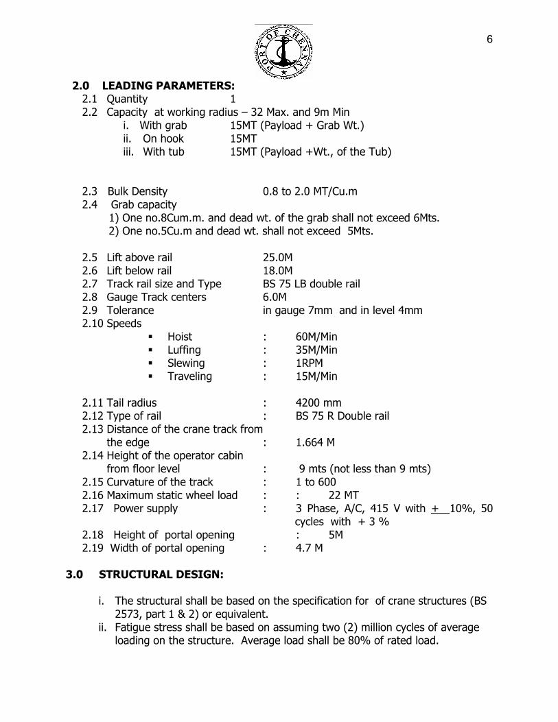
2.0 LEADING PARAMETERS:
2.1 Quantity 1 2.2 Capacity at working radius – 32 Max. and 9m Min
i. With grab 15MT (Payload + Grab Wt.) ii. On hook 15MT iii. With tub 15MT (Payload +Wt., of the Tub)
2.3 Bulk Density 0.8 to 2.0 MT/Cu.m 2.4 Grab capacity
1) One no.8Cum.m. and dead wt. of the grab shall not exceed 6Mts. 2) One no.5Cu.m and dead wt. shall not exceed 5Mts.
2.5 Lift above rail 25.0M 2.6 Lift below rail 18.0M 2.7 Track rail size and Type BS 75 LB double rail 2.8 Gauge Track centers 6.0M 2.9 Tolerance in gauge 7mm and in level 4mm 2.10 Speeds
� Hoist : 60M/Min � Luffing : 35M/Min � Slewing : 1RPM � Traveling : 15M/Min
2.11 Tail radius : 4200 mm 2.12 Type of rail : BS 75 R Double rail 2.13 Distance of the crane track from
the edge : 1.664 M 2.14 Height of the operator cabin
from floor level : 9 mts (not less than 9 mts) 2.15 Curvature of the track : 1 to 600 2.16 Maximum static wheel load : : 22 MT 2.17 Power supply : 3 Phase, A/C, 415 V with + 10%, 50
cycles with + 3 % 2.18 Height of portal opening : 5M 2.19 Width of portal opening : 4.7 M
3.0 STRUCTURAL DESIGN:
i. The structural shall be based on the specification for of crane structures (BS 2573, part 1 & 2) or equivalent.
ii. Fatigue stress shall be based on assuming two (2) million cycles of average loading on the structure. Average load shall be 80% of rated load.
7
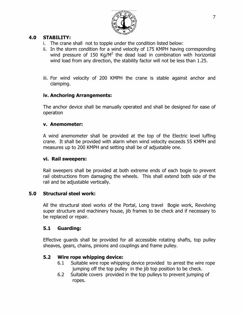
4.0 STABILITY:
i. The crane shall not to topple under the condition listed below: ii. In the storm condition for a wind velocity of 175 KMPH having corresponding
wind pressure of 150 Kg/M2 the dead load in combination with horizontal wind load from any direction, the stability factor will not be less than 1.25.
iii. For wind velocity of 200 KMPH the crane is stable against anchor and clamping.
iv. Anchoring Arrangements:
The anchor device shall be manually operated and shall be designed for ease of operation
v. Anemometer:
A wind anemometer shall be provided at the top of the Electric level luffing crane. It shall be provided with alarm when wind velocity exceeds 55 KMPH and measures up to 200 KMPH and setting shall be of adjustable one.
vi. Rail sweepers:
Rail sweepers shall be provided at both extreme ends of each bogie to prevent rail obstructions from damaging the wheels. This shall extend both side of the rail and be adjustable vertically.
5.0 Structural steel work:
All the structural steel works of the Portal, Long travel Bogie work, Revolving super structure and machinery house, jib frames to be check and if necessary to be replaced or repair.
5.1 Guarding:
Effective guards shall be provided for all accessible rotating shafts, top pulley sheaves, gears, chains, pinions and couplings and frame pulley.
5.2 Wire rope whipping device:
6.1 Suitable wire rope whipping device provided to arrest the wire rope jumping off the top pulley in the jib top position to be check. 6.2 Suitable covers provided in the top pulleys to prevent jumping of ropes.
8
5.3 Machinery house: The Machinery house steel construction if rusted to be replaced and all other items in the machinery house to be check and if need to be service. Operator’s cabin:
i. The operator’s cabin accessories and seat to be service. ii. All the operation panels and indication in the operator room should be in
operation condition.
5.4 Ladders & Walkways:
All points requiring maintenance are conveniently accessible through ladders and platform ,structures to be check and if necessary to be replaced.
6.0 MECHANICAL EQUIPMENT:-
6.1 HOIST MECHANISM:
The Gear boxes shall be open and check. The gears, brake and motor shall be check for the rated output and performance.
6.2 GRAB CLOSING AND OPENING MECHANISM:
The assembly, located in the machinery house, shall consist of motor with two brakes, gear box and wire rope drum, which shall be used for grab opening and closing. The rotating equipment shall be mounted on a steel pedestal in rigid, anti friction, bearing pillow blocks to assure rigid shaft alignment and to minimize vibration. Suitable device to eliminate over lapping of wire ropes on the drum shall be check and if necessary service.
Slow down and stop limit switches shall be checked. In general stop limit switches shall be operated automatically at the point of grab opening and closing extreme limits. Over speed centrifugal switch for motor shall be checked / provided. Load indicator with over load protection device shall be included in the system which gives an audio - visual alarm when SWL is reached and also cuts off power to the motor in case the load lifted exceeds the SWL by 10% shall be checked
6.3 Luffing Mechanism: The complete luff drive mechanism including the screw system and gear box shall be check and if necessary to be service. The raising and lowering of jib shall be effected by a suitably designed screw spindle/nut arrangement. The luff motor shall be connected to the required gear box by a gear coupling. A double shoe electric hydraulic/thruster brake shall be checked / provided and if necessary to be service.
9
6.4 Slew Mechanism:
The entire revolving structure mounted on an anti friction slew bearing with integral gear (Rothe Erde type). and. The vertical shaft shall rotate on antifriction bearings,the circular platform provided around the slew bearing for maintenance purpose. The slewing gear is arranged on the revolving machinery frame. The motor is connected to the gear box through an over load safety clutch. The worm gear box is of enclosed oil tight construction with the shafts running anti friction bearings. The output shaft project downwards and is coupled to a drive shaft with a pinion on it engaging with the slew bearing gear. The brake is of combined hydraulic - cum - thruster operated type. In service it is pedal operated from the operator’s cabin by hydraulic action to achieve very smooth and sensitive braking. When out of service, the thruster is de-energized for keeping the brake applied. A mechanical locking pin provided to arrest the movement and electrically interlocked with slew motors. In addition a storm lock provided. Emergency brake for slew mechanism provided.
6.5 Long Travel Mechanism:
The long travel mechanism motors and gear box shall be service and check for performance. NOTE :All the above mechanism to be thoroughly checked and if necessary to be serviced
6.6 Cable Reeling Drum (CRD):
Cable reeling drum of mono spiral type shall be service and check for performance.
6.7 Welding:
All welding materials procedures shall conform to IS 816/IS823/FEM/AISE Rules/or its equivalent. Field welding will not be permitted unless the welder’s qualification are fully approved by the Chief Mechanical Engineer or his representative and may be permitted under special circumstances on written permission.
10
6.8 Platform and walkways:
a. Width : Standard 600mm b. Floor : Open grantings / expanded metal c. Toe plate : Flat steel bar
6.9 Hand rails:
a. Height : 1000mm b. Hand rail : 25mm steel pipe c. Stanchion : L 50 X 50 X 6 steel d. Distance : Maximum 2000mm
7.0 ELECTRICAL EQUIPMENT:
7.1 Electrical design requirement:
1. The electrical equipment to be provided for the wharf crane includes the
following main items. However, tenderer shall understand that this list is of a general nature only.
2. All cables, wire, junction boxes, mounting details, grounding details etc.,
and all ancillary equipment required for a complete and operating system shall be provided.
3. Flexible power cable complete with collecting cable reel mounted on
crane for 415 V 3 Ph/50 Hz power feed to wharf crane stall torque motor operated. Scope includes supply and installation of cable reeling drum, current collector rings, 75m length of required capacity 4 core EPR rubber insulated flexible trailing cable and metal enclosed junction box at power feed point complete with terminals for connection of flexible feed cable to crane and Trust will provide supply at the plug pit.
7.2 Incoming power circuit breaker
i. Drives: All motors namely Hoisting, Grabbing, Slewing, Luffing and Long
Travel motors shall be of “AC” Slip Ring Induction motors confirming to IS 325.
ii. Speed control: Speed control shall be through “ AC Thyristor with
Variable Voltage Digital Control”
11
iii. Thyristor Control Drive System:
7.3 Thyristor Drives:
The Digital Type thristor controller shall be designed suitably with rated components to meet the power requirements required for controlling the operations of AC slip ring induction motor for hoist / grab, slew, travel and luff drives. The thyristor panel shall be suitable for operation on AC main supply 415 volts + or -10%, 3phase 50 cycles + 10% 0r -5%. The drive shall be complete with anti parallel system with thyristor bridge on head sink for effective head dissipation permitting both direction operation.
A. The thyrister drive shall incorporate the following protection
devices:
a. Current limiting protection b. Over current protection c. Surge protection. d. Over voltage (for each thyristor against high voltage) e. Semi conductor fuses with fuse failure indication for individual thyristors. f. Negative phase sequence trip and phase loss. g. Individual thyristor failure indication. h. Gate suppression. i. Thyristor cooling device with failure indication. j. Earth fault. k. Unbalanced phase currents. l. Stall protection. m. Component failure protection such as processor fault memory fault, internal power supply failure.
The rating of the converters and over load capability shall conform to
Class IV duty of IEEE Standard 444.
B. Design of Drives The thyristor bank shall be of modular in construction for easy
maintainability. Then individual drive control system shall have a front programmable and display unit to display the fault condition as mentioned above and to programme the set parameters.

12
The individual drive controller shall have the status indicator for the following:
1. Motor running 2. Supply voltage 3. Gate triggering 4. Hardware fault
The panel shall have all metering at the top for indicating current, voltage,
speed of the individual drives and hour meter. The thyristor drive control shall have the following main and monitoring software.
C. Main Software:
a. Sequential controllers for controlling and monitoring the converter logic, b. Current controllers for controlling the thyristor firing and monitors the
meter current and power supply. c. Current reference handler for handling current reference with adjustable
current limits. d. Speed controller for feed back e. Constant power controller for controlling and obtaining speed at low load f. Hoist and grab controller shall have suitable controllers to run both the
drives at same speed while lifting / lowering hoisting operation and share the lead equally.
g. Grab controller shall work individually when grabbing operation is carried out and hoist operation shall be non functional.
D. Monitoring Software:
b. Motor over load based on current and motor time constant. c. Over voltage. d. Torque compares speed reference and feed back. e. Over speed protection, zero speed indication and presence of speed and
current feed back f. Hare ware - defects hare ware fault . g. On line monitoring the circuits and parameters.

13
7.4 PLC System:
A) Programmable logical controller system shall have the following
specifications.:-
i. The hardware must be using modular type CPU, power supply, input / out put (Digital and analog) memory units.
ii. Shall be provided with protection to prevent accidental or
unauthorized changes to part of the memory.
iii. The hardware shall be easy to handle and shall be of rack mounted type.
iv. Shall have all protective measures including short circuit, over
voltage protection.
v. PLC shall have meters for checking analog / digital inputs like master controller inputs, encoders etc.,
vi. Digital / Analog inputs and out puts shall be designed as per the
requirement with at least 20% as spare. vii. Programming language shall be compatible to international MS DOS
and suitable for sequence control purposes.
viii. Shall withstand the shock load 11 gms. Min and vibration load 2 gms. (Minimum)
B) Monitoring Software Specification:
Software of PLC shall be menu driven with the following main menus:
a. System: General current status of all inputs and outputs of the PLC (on or off status)
b. Drives: Drive parameters (Set and actual) such as voltage,
current and control parameters can be displayed and provision is also made to modify these parameter.
c. Fault alarm: Indicate the current fault with description and
fault No.
14
d. Drawing: Complete online and offline ladder logic circuit of
the PLC logic control system shall be displayed.
e. Online Monitoring: Shall be possible to monitor the ladder diagram and parameters online.
All the above menus shall be accessible to the maintenance personnel at the PLC panel.
Circuit protective power distribution switchgear in ventilated, metal weather protective enclosure.
Controllers for the following main drives, all reversing:
a. Hoist / lowering } Double master controller -for hoist and grab motors. b. Grab close/opening }
c. Slewing drive } One master controller- To
operate by single hand. d. Luffing drive } e. Long travel - One master controller f. Control equipment in Operator’s cabin. g. Operator’s controls console. h. Lighting system. i. Ground system. j. Safety and control interlocking devices. k. Alarms.
8.0 Standards: The design, manufacture and installation of all electrical equipment shall conform to as minimum standards.
All applicable Electricity Rules and the current issue of Indian Standards.
i. - IS 900 : Installation & Maintenance of Induction Motors
ii. - IS 3043 : Code of practice for earthling
iii. - IS 2309 : Protection of building and allied structures against Lighting
15
iv. - IS 732 : Electrical wiring installation ( System voltage not exceeding 650V) v. - IS 694 : Specification for PVC Insulated cables for Voltage up to
and including 1100 volts.
vi. - IS 1554 : Specification for PVC Insulated (heavy duty electrical cables)
vii. - IS 7098 : Specification for Cross linked polyethylene Insulated PVC
sheathed cables.
viii. - IS 10118 : Code of practice for selection, installation, maintenance of switch gear and control gear.
9.0 Materials: 9.1 General:
a. All the items not specifically mentioned herein, but which are obviously necessary to make a complete working installation within the scope of the work shall be provided, including any necessary field engineering and / or detailed drawings required. Drawings shall be submitted for review as provided for under conditions of contract.
b. It shall be the contractor’s responsibility to schedule and coordinate his work in order to avoid undue interference, congestion and delays in construction.
c. All electrical equipment shall be new offered specifically for this equipments and delivered to the site in the original manufacturer’s unopened cartons.
d. Materials shall be suitably packed to protect it form all hazards in transit such as excessive heat, moisture or crushing. The Chief Mechanical Engineer reserves the right to judge any material unsatisfactory in respect of any of the above factors. The contractor shall not use any such rejected material and shall immediately replace it with new material.
16
e. All material supplied by the contractor shall be inherently rust resistant or shall be suitably protected from rust by plating process. Any material found lacking in the above requirements shall be replaced with suitable material approved by the Chief Mechanical Engineer at no additional cost.
9.2 Cable and Wire:
General:
a. All wires and cables shall be of 1100 volt grade, having strand. Wire and cable shall be new, shall have size, grade of insulation, voltage and manufacturer’s name permanently marked on outer covering at regular intervals and shall be delivered in complete coils or reels with identifying size and insulation tags.
b. Wire and cable shall be suitably protected from weather and damage during storage and handling and shall be in first class condition when installed.
c. All conductors shall be stranded and of copper.
d. Wiring and cable shall be factory colour coded with separate colour for each phase and neutral used consistently throughout the system. Conductors intended solely for grounding purposes shall be coloured green.
9.3 Volt Power Feeder Cables:
a. Main feeder power cable to motor controllers and motor feeder cables shall be rated for operation on a nominal 440/415 Volts system with + 10%, 50 Hz + 3%, 3 phase, 4 wire. All control cables inside the panels shall be carried out by means of a single core flexible strandard copper conductor of size not less 2.5 sq.mm.
b. For power wiring the min. size of cable shall be not less than 4 sq.mm and shall be of copper.
c. Power supply, Electrical components shall be designed to operate with supply voltage of 415 V + 10%, 50 Hz + 3%, 3 phase, 4 wire.
17
d. Cabling on the machine: Fixed cable. i. Power: 1.1 KV grade PVC Insulated, armoured copper Conductor.
ii. Control: 1.1 KV grade PVC Insulated, armoured copper Conductor. 9.4 Trays and Racks:
a. All cable trays and racks shall be galvanized steel construction not less
than 2 mm thick. Cable trays and racks and their accessories shall be one manufacturer.
b. Trays and racks shall be supported at intervals and in a manner
recommended by the tray and rack manufacturer for the tray and rack loading condition. The loading condition shall be calculated as that load being carried by the trays and racks when they are filled to their maximum capacity.
c. All tray and racks turns or bends shall have an adequate radius to
accommodate the cable installed therein. This radius shall not be less than that recommended by the cable manufacturer.
d. All cable installed in cable trays or on racks shall be confined to a single
layer and shall be separated by a maximum air space of at least the outside diameter of the larger cable over the armour, All power and control terminals shall be designed and ferruled at both ends for proper identification.
9.5 Flexible connections:
All flexible connections, including those in control runs shall include a ground wire.
9.6 Power Supply:
a. Voltage and frequency variation.
The electrical equipment shall operate satisfactorily and shall be capable of delivering rated output at rated power factor with:
i. Terminal voltage differing from rated value by not more than + 10% or
ii. The frequency differing from rated value by not more than + 3 % or

18
iii) With combination of a & b to + 10% but the frequency restricted to + 3 %
b. Adequate power at 415 volts, 3 phase 50 Hz, AC will be arranged by Port
Authorities for operation of machine at plug pit. The underground plug box consisting of HE plug and SHE plug will be supplied and installed by the firm with the on load isolator and necessary protection against overload short circuit and earth fault. The above 415 supply system shall have a solidly earthed neutral system. The plug box shall be suitable for service in an exposed outdoor location. It shall be suitable for terminating the incoming 415 V / 3 phase supply armoured cable and the flexible power cable to the crane.
c Cable entry for incoming and outgoing cables from bottom with ample space
for cable terminators and stress cones.
d Necessary centre column shall be provided in the crane for receiving the power supply from the incoming switch box and providing supply to the outgoing feeders at the machine room centre column collector rings shall be rated for 600A, 415 V switchgear. Air tight transparent window shall be provided for inspection of slip ring and bushes.
e. As main incoming switch box with isolator shall be fixed below the sill beam of
the crane to isolate the power supply, isolator shall be operated by a handle without opening the box.
f. Low voltage switch gear metal enclosure shall be provided in the electrical room
of 415 V, 3 phase, 50 cycles, 4 wire.
1. Rating 415 Volt, 3 phase, 4 wire, 50 cycles,
2. Enclosures, free standing, general purpose.
3. Upper compartment with: Ammeter and selector switch Voltmeter and selector switch.
4. Centre compartment with: Main Air Circuit Breaker, 440V/600 Amps. (minimum) continuous, 3 pole, fixed type manually operated with standard trip units with 25 MVA short circuit capacity.
5. Lower compartment with space for future circuit breaker. 6. A ground bus shall be installed to run the entire length of the cubicle.
The cubicle shall be complete with necessary buses, terminal wiring,
19
etc., and shall be completely factory wired and tested and ready for installation. 7. Rear of the cubicle with bolted – on cover.
8. Aviation Light :a) Following aircraft warning light shall be provided.
At top of Frame :b) 2 Nos, neon bulb with red glass globe.
9.7 Portable inspection light: 2 Nos. of 20 watt incandescent lamp with 3 core flexible cable of length 10
mtrs. with 3 pin plug shall be provided one on the machinery house and one at electrical room.
The lamp shall be suitable for 24V. 9.8 Welding Socket:
2 Nos. 3 phase 415 Volts welding sockets controlled through a 100 A MCCB shall be provided one at portal leg and one at machinery house shall be provided.
9.9 A.C. Motors:
All motors shall be foot mounted TEFC, S4 duty slip ring induction motor suitable for thyristor control, confirming to IS 325. Hoist and Grab motor shall be provided with thermistor. Motors shall have minimum pull out torque of 27% of rated torque. All the motors shall be designed for 300 starts/ stops per hour. If electrical braking is in used the duty class of motor shall be designed accordingly.
All motors shall have Class “F” insulation with IP 55 protection.
9.10 Panels:
All panels shall be spray painted, painted with anti-corrosive primer and sufficient coat of epoxy base paint suitable for corrosive and humid environment. Heavy duty vibration damping pads shall be provided for all panels. Non- aging gaskets shall be provided for all panels. Non – ageing gaskets shall be provided for the door sealing of the panels and shall be adequately supported so that these may not come out.
20
Special care shall be taken to ensure approach facility and maintenance facility for all components and PCB’s from front itself. All electrical panels shall have built in air conditioning unit.
9.11 Equipment Grounding:
a. A complete system of equipment grounding shall be provided. All non
current carrying metal parts of the wiring system or of apparatus connected to it, such as metal conduits, metal raceway, metal armour or cables, outlet boxes, panels, cabinets, switch boxes, motors frames and metal enclosures of motor controllers shall be connected together through a metallic circuit of low resistance.
b. All ground wire shall be stranded bare copper wire. Exposed ground
connections shall be made with approved compression type connectors. Natural conductors shall not be used as equipment grounds even though interconnected at some point.
c. All switchgear, control centre and all other major equipment shall be
grounded with two (2) 50 sq.mm. copper wires with suitable ground connectors so as to provide two ground paths to the grounding conductor of the Crane power supply cable.
9.12 Energy Meter:
A watt hour meter shall be provided to measure electrical energy.
10.0 Details of Hoist Drive:
There shall be minimum lift of 25 mtrs from the wharf level to the top most portion of the hook or grab at which the hoist motor should stop by limit switch minimum lift below the wharf level be 18 mtrs.
Hoist drive shall be capable of the following:
a. Hoisting and lowering of 15 Ton load from wharf level / from the hatches shall be done at a normal speed of 60m / min. hoist and lowering speed shall be adjustable from zero to full speed by the operator through the master controller.
21
b. Hoist and lowering of the rated load on hook with rated speed ranging from 0 to
full speed with stepless drive. It shall be ensured that all the ropes are equally loaded and that the speed of all the ropes are fully equalized. It is necessary that no time of the cycle, there is any slackness in the rope during the operation and slackness if any should be effectively sensed and the operations stopped by electrical actuation.
11.0 Grab Operation:
a. Opening and closing of the grabs shall be arranged through 2 ropes driven by one single motor drum combinations. The other set of motor drum shall be braked during grab operation.
b. After the grabs are fully closed or opened, hoisting or lowering will be done by means of 4 ropes driven by 2 motors and 2 drums. All the four wire ropes shall be kept in full tension during the entire operation, viz grab closing, grab opening, hoisting and lowering.
12.0 Tub Operation: During tub operation the hoist and grab drive control shall be programmed for continuous discharging of cargoes like Barites, Quartz, etc., to the ship which are unevenly loaded in to the tub by pay loaders. It should be possible to tilt the tub on both sides by the driver. The tilting of the tubs in both directions in the same plane should be possible.
A sketch showing the tub operation is enclosed.
13.0 Method of Drive:
a. Operation shall be by means of 2 nos. of 3 phase slip ring induction motors of suitable rating and identical specifications in all respects.
b. Supply available is 415V, 3 phase, 50 cycles AC system. Hoist and grab motors shall be 3 phase slip ring motors is suitable rating. The control shall be suitable for change over from grab to tub or hook. Selection shall be provided at operators cabin. Each motor shall share the load while hoisting or lowering with closed grab or with hook, load or tub load.
22
Details of Motors (Hoist and Grab Motors):
Quantity : 2 Nos.
Duty : Crane duty class 4 – S4.
Type : 3 phase slip ring AC Induction Motors.
Voltage : 415volts 3 phase 50 cycles ACI 10%.
Enclosure : Totally enclosed Fan Cooled (IP - 54). The motor shall be designed for crane duty with
shift operation.
No. of starts and stops : 300 times per hour.
Insulation : Class “F”
Starting and Speed : By Thyristor control with position control
encoder for grabbing control.
Redundency in Capacity : Minimum 15% 14.0 Slewing and Luffing Drives:
a. The crane shall be capable of slewing all the 3600 and the same shall be powered by two nos. 3 phase slip ring induction motor with reversible drive.
b. The starting and speed control shall be by means of Thyristor control.
c. The motor shall be horizontal foot mounted with IP55 enclosure class of Insulation – F.
d. No. of starts and stops – 300 times per hour slewing motors shall be covered with Aluminium if located outside.
e. Luffing drive shall be fully balanced by means of suitable counted weights.
f. Minimum radius shall be 9 mtrs. from the centre of the crane track.
g. Maximum radius shall be 32 mtrs. with full load. Motor shall be horizontal foot
mounted with IP 55 enclosure. Class of Insulation “F”, No. starts and stops – 300 time per hour (S3 duty).
h. Minimum redundancy shall be about 10% Luffing motor and brake unit shall be
covered by Aluminium sheet.
23
15.0 Travelling Drive:
a. The crane shall be capable of travelling at 15 mtrs. per minute. Travelling mechanism shall be within the portals and not outside the portals.
b. The Travel motors speed control shall be by thyristor control. Stating torque shall be such that it shall be possible to travel the crane with 7 motors in case of failure of one motor / gear box. The motor shall have IP55 protection with class F
insulation and shall be suitable for 300 times starts / stops per hour. The traveling motors and brakes shall be covered with Aluminium sheets.
c. Brake thrustor shall be provided for all the travelling motors.
d. Storm fixtures shall be provided for all the portal legs.
16.0 Electrical Interlocks:
The following electrical interlocks shall be provided.
I For Hoist and Lowering:
a. Hoisting drive shall be stopped beyond the 25 mtr. Height from the wharf level.
b. The Lowering shall be stopped below 18 mtr. From the wharf level.
II For Luff Drive:
a. Luffing drive shall be stopped beyond 32 mtr. From the centre of the crane.
b. Luffing drive (Luffing IN) shall be restricted to 9mtr. of jib radius.
III Grab: Differential limit switch shall be provided for the hoisting and lowering operations so that the grabs will be automatically lifted once the grabbing operation is completed. IV For wharf crane travel:
a. Necessary interlocks shall be provided for cable reeling drum and long traveling so that minimum of 2 turns of trailing cable is always on the drum.
b. The driving motors shall be controlled by common controller provided with overload tripping facility and shall be electrically synchronized.
24
c. Interlock to prevent operation of travel drive while the crane anchoring device is
engaged and failure of cable reeling system.
d. Trip in the event of drive overload.
e. Travel shall not be permitted while the hoist drive is operating.
f. Operation of main hoist drive shall not be permitted while gantry travel is energized.
g. Emergency stop button shall be provided as follows:
1. 1 No. in the operator cabin. 2. 1 No. in the crane leg at top level. 3. 1 No. in the “A” frame. 4. 1 No. in the Machinery House.
17.0 Travel Warning Devices:
a. Visual and audible warning devices shall be provided and warn persons in the vicinity of the crane that the crane is moving. One rotating beam light and one hooter shall be located at each of the leg (Total of 4 each).
b. The light and hooter on the two legs facing the direction of travel shall be energised while the crane is travelling in the direction at all speeds.
c. In addition, a motor driven siren shall be provided complete with on – off control switch in the operator’s cabin.
d. A long traveling shall be provided with limit switches for slow / stop at each end corners for preventing collusion.
18.0 Installation of wire and cable:
a. No wire or cable shall be drawn into conduit until work of such nature which may cause injury to it, has been completed. When pulling the wire and cable care must be taken to keep conductors free from twisting and these shall lie parallel in the conduit. If a conductor is found to be grounded all wires in the conduit shall be replaced.
b. No conductors for lighting or motor wiring shall be less than 4 sq.mm unless otherwise stated.
25
c. Lighting circuit wiring shall be 4 sq.mm. for short runs. Where runs are longer and in order or reduce voltage drop, the entire circuit run shall be larger as required by voltage drop.
d. All cable terminals and splices shall be made secure with solderies pressure type connectors.
e. Every multi conductor cable shall be identified at both ends and every conductor
or pull box, by means of a cable number and listed in the cable list. The means of identification shall be an embossed metal tape, firmly attached to the cable by positive mechanical means.
f. Compression type fittings shall be installed with approved type tool as recommended by the manufacturer.
g. Control leads between various control i.e. selector switches, push buttons,
thermostats, and the like shall be run their full length without slices.
h. All feeders and motor feeder shall be continuous from origin to termination without slices.
i. All wire and cable shall be brought to the job in unbroken packages or on cable reels. All wire and cables shall be stored in a clean dry location. In order to prevent damaging of cable, cable shall not be removed from any reel until the complete reels has reached a normalizing temperature recommended by cable vendor.
j. Filling compounds may be used, but shall be of standard recognized manufacturer and manufactured solely for this purpose.
k. On completion of installation, the 415 Volt power system wiring and the lighting system wiring shall be given an insulation check with a 1000 volt megger.
l. Any portion of the system reading less than 1 mega ohm shall be checked out and the cause founds and corrected before being energized.
m. All conductors of copper shall be so sized that the voltage drop to the farthest outlet does not exceed 3 % with the circuit carrying normal load.
n. Resistances if used, for motors shall be of punched stainless steel as per relevant IS.

26
19.0 Protection Panel:
a. Protection panel shall consist main circuit breaker contractors, relays and over load relays for all the motors such as hoist and grab motors, slew and luff motors and all the travel motors.
b. Protection shall be provided against short circuit, overload and earth fault for all the individual motors. In addition to this, thermistor protection shall be provided in all the motors.
c. The electrical system shall be complete with all the electrical cables, wire
junction boxes, mounting or clamping details, earthing and all ancillary equipment required for the design.
d. Lighting for the crane shall be adequate for working the crane during night. Intensity of illumination shall be around 100 Lux at the wharf level just below the fitting. Minimum intensity shall be around 20 lux.
i. No. 1000 watts metal halide light fitting shall be provided in the Jib.
ii. 4 Nos. 250 watts metal halide light fitting shall be provided on quay slides.
iii. 1 Nos. 250 watts metal halide light fitting shall be provided below the slewing platform.
Machine room and the cabin room shall be provided with adequate ventilation and lighting.
e. Lighting shall be arranged at 220 Volts 50 cycles AC by providing lighting transformers. Two nos. distribution panel with MCB’s shall be provided for lightning systems out of which one shall be on the portal and the other in the machinery house.
20.0 Wiring and Cabling:
a. All wires and cables shall conform to the relevant Indian Standard –Wires and Cables shall be of 660 volts grade having standard copper conductors.
b. Wires and cables shall be suitably protected from whether and damage during handling and laying shall be in the first class condition when installed.
c. Wiring and cable shall be colour coded with a separate colour for each phase and neutral using consistently throughout the system. Earthing conductors shall be
27
d. coloured green. Suitable lighting at landing platforms, machinery house, centre
column, A frame and walkways as per standards shall be provided. 21.0 Earthing:
a. The cranes shall be earthed throughout using copper or equivalent GI wires of suitable cross section. The fourth core in the main trailing cable shall be used for earthing purposes. The earthing rings shall be provided on the collect or coloumn. Double earthing and running of earth wires shall be as per Indian Electricity Rules and the relevant Indian Standards.
b. The complete wiring and electrical connection shall be as per the relevant Indian
Standards and as per Indian Electricity Rules, Electrical installation shall be approved by Central Electrical Authority.
22.0 Important Notes:
Double master controller for two drives viz.,
a. Hoist and lowering with 2 motors and b. Grab closing and opening with 1 motor c. Master controller for Slewing Operation d. Master controller for Luffing Operation e. Master controller for Long Travel of the crane.
23.0 Safety Devices:
a. Suitable capacity MCCB with manually adjustable type and protection against over load / short circuit and under voltage for all motions viz., hoist, grab, luff and slew operations shall be provided. Suitable MCB’s shall be provided for all control circuits.
b. Rotary / Gear type or snap type limit switches shall be provided for the luff operation at three locations viz, at gear box side, luff shaft and Operator’s cabin.
c. All the limit switches or proximity switches provided for hoist / grab etc., shall be of rotary / gear type only and chain operation system shall not be used.
d. Two nos. balanced counterweight operated brake assy.system with thrustor brakes shall be provided for the luff motion.
28
24.0 Over load Safety Indicator:
Load at the hook, grab and at the tub shall be sensed by means of proven load cells of dynamometer type and the same shall be indicated in the drivers cabin. When the load exceeds,, the rated load and the power system shall be immediately stopped and the same shall be done without any scope for manipulation from the crane driver. The system shall respond within 50 micro seconds to trip the crane if any overload or shock load is encountered.
25.0 Programme Logic Control (PLC) and On-Line monitoring System:
The crane shall be provided with programme logic control and on-line monitoring system for monitoring the various “ faults like motor over load, safety limit operation, brake release, positioning of drive etc., and indicate the fault text message at operator cabin. All safety devices shall have individual inputs at “PLC”.
26.0 General:
a. Necessary arrangement shall be made in the machine room / panel room of the
crane to provide openings with easily removable type covers for removal / replacement of motors, gears etc.,
b. Necessary drain pits shall be provided in the machine room, cabin room etc., to drain the spilled oil from gear boxes and also rain water, so as to avoid
stagnation inside the machine and subsequent damage to cables and also to avoid accident to persons, due to slippage.
c. The gear assembly for travel motion shall be of fully concealed type to avoid accumulation of dust and other handling materials, like coal, fertilizer, sulphur etc., inside the gear box assembly. A motor/gear box assembly for travel motion shall be provided in between the legs and shall not keep projecting outside the legs or equalizer beams. Direct coupling system shall be provided for the motor / gear box interconnection for the travel motion instead of the dog clutch system of coupling.
INSPECTION AND TESTING: 27.0 Shop Tests and Inspection:
a. Tenderer shall provide samples of materials for examination or testing as requested by the Chief Mechanical Engineer. Mill test certificates shall be furnished by the tenderer.

29
b. The Chief Mechanical Engineer or his representative the right to determine
whether any of the material including finished items offered or delivered for use in the work are suitable for the purpose. Test/Tests will be as per procedure specified in the relevant standards/codes decided by the Chief Mechanical Engineer or his representative. The cost of such tests will be on the account of the tenderer. In the event of the Test reveals that the equipment / material is faulty the Engineer/tenderer may have the option to repeat test. The cost incurred for such repeat test will be to the account of the contractor. In case the equipment/materials is found to pass the test and if the Chief Mechanical Engineer or his representative orders a repeat test on the same equipment / material, the cost of such repeat test will be reimbursed to the tenderer.
c. Wheels shall be tested ultrasonically. Critical castings shall be checked for internal flaws by X-ray or ultrasonic method.
d. Sampling and testing of materials for approval and testing as called for under appropriate Indian Standard or other relevant standard specifications shall be done free of charge well before fabrication and use. Samples provided to the Chief Mechanical Engineer or his representative shall be in labelled boxes suitable for storage. Late submission of samples and test values shall not be accepted as valid reasons for delay in completion of the contract.
e. At the discretion of the Chief Mechanical Engineer, all materials and workmanship may be subjected to inspection by the Chief Mechanical Engineer or his representative at the place of manufacture or fabrication of the tenderer and / or the sub tenderer or at the site work. The tenderer shall advice Chief
Mechanical Engineer sufficiently in advance so that in case of rejection, the rectification work involved does not delay the progress of the contract.
f. The Chief Mechanical Engineer reserves the right to inspect any material, equipment and manufacturing with prior notice of 15 days.
g. In case of sub-letting to other tenderer or manufacturers or suppliers by the tenderer, the Chief Mechanical Engineer will reserve the right as follows:-
i. that, inspection and/or testing will be carried out at the manufacturer’s
work.
ii. or that, inspection will be waived subject at site by his representative.

30
iii. or that, inspection will be waived subject to the tenderer furnishing a certificate of compliance with specification by competent authority recognized by national/international institute.
h. The tenderer shall notify the Chief Mechanical Engineer of the dates on which manufacturer or fabrication of items is to be carried out at the supplier’s factory, of the dates on which item of standard manufacture will be available for inspection and / or ready for despatch. In the case of items in the manufacture of which intermediate stage are to be inspected as the work proceeds the tenderer shall notify the Chief Mechanical Engineer from time to time the date at which such inspection can be made. The tenderer shall allow reasonable time for the Chief Mechanical Engineer to make arrangements for inspection or give permission for despatch or as the case may be.
i. Not withstanding the fact that a material or a piece of equipment has passed
the inspection carried out during the stage of manufacture, the tenderer is not relieved from his obligations to conform to the quality, workmanship, guarantee or performance etc., as per the relevant terms of this contract.
j. Any defective material, equipment or workmanship which may come to the
notice of the Chief Mechanical Engineer or his representative after erection and installation shall be liable for rejection and the tenderer shall have to replace such materials, equipments etc., or rectify the defects at his own cost.
k. Welding work castings and forgings shall be subject to radiographic or ultrasonic
testing as instructed by the Chief Mechanical Engineer and the test certificates shall be furnished. The Chief Mechanical Engineer or his representative reserves the right to examine the radiographic films or welding joints independently. In case of difference of opinion on a radiographic film about the soundness of any welding joint between the renderer and the Chief Mechanical Engineer, the opinion of any testing laboratory/institute in India approved by Indian Standard Institute shall govern.
i. Suitable means shall be adopted in identifying each radiographically tested
joints with reference to the radiographic films even after commissioning and the same information shall be furnished to the Chief Mechanical Engineer at the time of delivery of the equipment for documentations.
ii. Minimum 30 millimetre for for each 1000 millimetre length of welding joints
shall be radiographically tested in the following cases.
31
A) Wherever design/manufacturing drawing call for testing.
B) in case the major load carrying members are made more that one piece to make up the dimensionally welding.
iii The Chief Mechanical Engineer reserves the right to test radiographically about 3% length of any other welding joints which are not covered by. iv If any of the test shows defective welding, further test shall be carried out. All
such tests shall be at tenderer’s cost.
l. All radiographic quality welding joints shall be principally grade “black”. However, grades ‘blue’ and ‘green’ will also be acceptable, subject to the approval of the Chief Mechanical Engineer, on tension and shear load carrying members respectively provided they are of short lengths.
28.0 Shop Assembly:
a. Equipment shall be shop assembled prior to shipment to extent required to ensure satisfactory field erection. All critical dimensions shall be verified. All motions checked and equipment tested in the shop prior to shipment. All sub-assemblies and parts shall be match-marked and metal tagged with part number to facilitate field assembly.
b. All major joints of crane structure shall be shop assembled to establish and check proper fit between mating parts. Position of structure that are not shop assembled are to be designed with provisions of filed adjustments to ensure proper assembly.
c. Three copies of all test reports shall be submitted to the Chief Mechanical Engineer.
29.0 PAINTING SYSTEM:
Zinc Epoxy painting shall be used to ensure corrosion free and long paint life of cranes exterior services which are exposed to corrosive coastal atmosphere. The Contractor shall guarantee a minimum paint life of 5 years against corrosion, peeling and discolouration. The painting specifications shall be as follows:
32
29.1 SURFACE PREPARATION AND SHOP PRIMER:
a. All material shall be blast cleaned to SA 2 ½ , Swedish standard. On the cleaned
painting, one coat of Epoxy Zinc rich shop primer of Dry Film Thickness not less than 25 Microns shall be applied.
b. All the structures exposed to atmospheric condition shall be applied with one coat of epoxy rich primer of dry film thickness of not les than 70 microns on the shop primer. One coat Epoxy Micaceous Iron Oxide shall be applied over the Primer which shall have a dry film thickness of not less than 100 microns. The structures shall be applied with 2 coats of Poly urethane re-coatable finished painting of dry film thickness of not less than 50 microns each. The minimum total dry film thickness for external structure shall be not less than 295 microns.
c. All the interior parts of structure shall be applied with one coat of Zinc Rich Primer of not less than 70 microns on the shop primer and they should be applied with one coat of high build epoxy poly amide finishing coat of dry film thickness of not less than 100 DFT. The minimum total dry film thickness for interior of crane length shall be not less than 195 microns.
d. The interior of machine room, electrical rooms, machines, etc., shall be applied with one coat of Zinc rich primer of dry film thickness of not less than 70 microns. They should also be applied with one coat o Epoxy Micaceous Iron Oxide of DFT of not less than 100 microns. The final finished coat shall be poly urethane re-coatable finishing painting of DFT not less than 50 microns. The minimum total DFT of interior of machinery used, etc., shall be not less than 245 microns.
e. The required properties of the different systems of the painting shall be as follows:
i. Epoxy Zinc Rich Primer: The paint shall be of two component – Expoxy poly amide type having high flash point and fast, dry property. The Zince content shall be not less than 85% in the dry film.
ii. Epoxy Micaceous Iron Oxide:
This shall be of two component Epoxy Poly amide type. It should be high build product with indefinite period for over coating. It shall be suitable to be used as Sealer Coat over Zine Epoxy Primer. The paint shall be micaceous iron oxide pigmentation.

33
iii. Polyurethane finish:
The system shall be of two components polyurethane, isocyanate type which will have high gloss finish and high abrasion in the systems. It shall have excellent chemical and solvent resistance. The paint shall be weather resistance pigmentation.
iv. High Build Epoxy Poly amide finishing:
The system shall be of two component, poly urethane, isocyanate type with high blast finishing and high abrasion resistance. It shall have excellent chemical and solvent systems and resistance together and shall have weather resistance pigmentation.
f. The exact colour of the finished coats of polyurethane paints shall be indicated by CME at the time of approval of the painting scheme. 7.MPT logo and lettering requirements for the machinery used and at the gantry structure will be furnished to the contractor at later date. The crane shall be fitted with plates clearly showing the safe working load at both sides of the gantry structure which shall be clearly legible from the ground level.
30.0 Field Tests:
a. Tenderer shall be responsible for all necessary alignment and adjustment of
machinery and equipment to obtain efficient operation.
b. All critical and specialized adjustment shall be carried out in the presence of the Chief Mechanical Engineer. Procedures and necessary precautions in regard to such adjustments shall be conveyed to Chief Mechanical Engineer in writing.
c. After completion of the erection of each crane, all equipment and machinery shall be tested. The crane shall be run without load and all necessary adjustments shall then be completed.
31.0 Tests:
a. The tests shall comprise the following:
i. Equipment /unit assembly test
ii. Adjustments and settings.
iii. Final operational tests at rated capacities.
34
b. Before any electrical system is put to use, the contractor shall carry out the following tests at site in the presence of and to the satisfaction of the Chief Mechanical Engineer or his representative.
i. Insulation resistance tests on cables, motors and transformers.
ii. Tests for verification of time current characteristics of all the thermal overload relays, over current relays (both) induction disc and attracted armature (types) and over current and short circuit release on molded case circuit release, air circuit breakers, etc., as applicable.
iii. Tests for earth (ground) continuity and earthing grounding resistance of
electrodes.
iv. Polarity tests wherever applicable. c. For the period of adjustments and setting, the contractor shall provide services
of an adequate number of personnel which shall include, but not be limited to, engineers, foremen, fitters, welders, electricians, etc., who apart from their technical experience are well acquainted with all the machinery and equipment.
d. All tests shall be carried out in the presence of the Chief Mechanical Engineer
and any corrections found necessary shall be approved by the Chief Mechanical Engineer and the contractor shall be responsible for producing all necessary work sketches and drawings for the approval of the Chief Mechanical Engineer. The contractor shall be responsible for obtaining the service of sub-contractors (as and when necessary).
e. The tests shall include operational and capacity test. The capacity test for hoist
motion shall be with an overload of 25% in excess of the rated working load. The date for operational and capacity test shall be set by the Chief Mechanical Engineer and contractor shall be informed of the date in advance. The contractor shall be responsible for any adjustments or corrections found necessary during these tests.
Notes:
i. During the capacity test the specified speeds need not be attained. But the crane shall be capable of lifting such overloads without difficulty.
ii. All motions shall be checked in both directions.
35
iii. The correct speeds to be achieved are contingent on the voltage and frequency of the electric supply to the crane being correctly maintained within the permissible limit.
iv. Measurements of the voltage and amperage of the motors shall be taken and reports of the same shall be furnished.
f. Tenderer shall demonstrate that each crane shall be able to meet the duty cycle requirement specified herein without any undue strain and vibration. It shall be able to achieve the speeds of various motions as assumed for duty specified. The tests for duty cycle shall be carried out on minimum ten load in succession and time taken for each cycle shall noted. Such test as described above, shall be repeated three times and mean time of all the cycle times will be used to arrive at the achievable duty cycle per hour.
g. All brakes shall be tested with 25% overload of the crane. In addition, each brake for the hoisting and luff motions shall be tested under full load from the associated maximum rated working speed to rest, not less than three times in quick succession.
h. All limit switches and safety apparatus for hoisting, slew and long travel drives shall be tested and adjusted as required.
i. All the ‘OFF’ position interlock and switches on the controllers shall be tested.
j. Tests for verification of time-current characteristics of all thermal overload relay, over current relays and over current and short circuit release on moulded case circuit brakers, air circuit brakers, etc., as applicable. All circuits and equipment shall be tested by the tenderer for grounds, short circuits and proper operation.
k. A certified record of the test fiqures along with the appropriate certificates of tests and inspection under the dock safety requirements shall be supplied by the tenderer.
l. After the erection of the crane at the site the tenderer shall have duly inspected by the Electrical Inspector’s approval certificate as soon as possible after the inspection.
m. When the crane is completed in all respects and adjustments and setting are over, final operational tests at rated capacities shall be carried out by the Chennai Port Trust operators in the presence of the Chief Mechanical Engineer, or his representative and if accepted the crane shall be handed over to the Chief Mechanical Engineer or his representative when the final operational tests at rated capacities will be successfully completed or all at a time according to the programme given to the tenderer by the Chief Mechanical Engineer in advance.
n. All materials and equipments, which fail during the tests shall be replaced.
CHIEF MECHANICAL ENGINEER CHENNAI PORT TRUST