Embed Size (px)
Citation preview
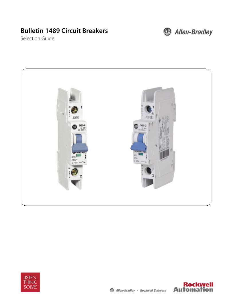
Bulletin 1489 Circuit BreakersSelection Guide

Thermal Magnetic Circuit Breakers
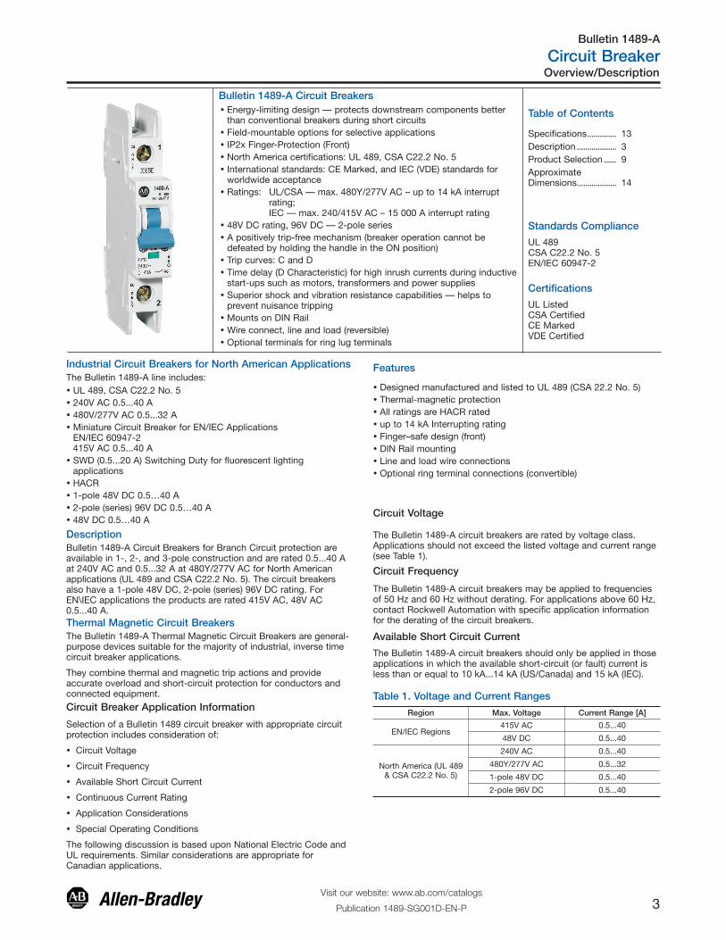
� Energy-limiting design — protects downstream components betterthan conventional breakers during short circuits
� Field-mountable options for selective applications� IP2x Finger-Protection (Front)� North America certifications: UL 489, CSA C22.2 No. 5� International standards: CE Marked, and IEC (VDE) standards for
worldwide acceptance� Ratings: UL/CSA — max. 480Y/277V AC – up to 14 kA interrupt
rating;IEC — max. 240/415V AC – 15 000 A interrupt rating
� 48V DC rating, 96V DC — 2-pole series� A positively trip-free mechanism (breaker operation cannot be
defeated by holding the handle in the ON position)� Trip curves: C and D� Time delay (D Characteristic) for high inrush currents during inductive
start-ups such as motors, transformers and power supplies� Superior shock and vibration resistance capabilities — helps to
prevent nuisance tripping� Mounts on DIN Rail� Wire connect, line and load (reversible)� Optional terminals for ring lug terminals
Bulletin 1489-A Circuit Breakers
Industrial Circuit Breakers for North American Applications
� UL 489, CSA C22.2 No. 5� 240V AC 0.5...40 A� 480V/277V AC 0.5...32 A� Miniature Circuit Breaker for EN/IEC Applications
EN/IEC 60947-2415V AC 0.5...40 A
� SWD (0.5...20 A) Switching Duty for fluorescent lightingapplications
� HACR� 1-pole 48V DC 0.5…40 A� 2-pole (series) 96V DC 0.5…40 A� 48V DC 0.5…40 A
The Bulletin 1489-A line includes:
Standards Compliance
Certifications
Features
� Designed manufactured and listed to UL 489 (CSA 22.2 No. 5)� Thermal-magnetic protection� All ratings are HACR rated� up to 14 kA Interrupting rating� Finger–safe design (front)� DIN Rail mounting� Line and load wire connections� Optional ring terminal connections (convertible)
DescriptionBulletin 1489-A Circuit Breakers for Branch Circuit protection areavailable in 1-, 2-, and 3-pole construction and are rated 0.5...40 Aat 240V AC and 0.5...32 A at 480Y/277V AC for North Americanapplications (UL 489 and CSA C22.2 No. 5). The circuit breakersalso have a 1-pole 48V DC, 2-pole (series) 96V DC rating. ForEN\IEC applications the products are rated 415V AC, 48V AC0.5...40 A.
UL 489CSA C22.2 No. 5EN/IEC 60947-2
UL ListedCSA CertifiedCE MarkedVDE Certified
The Bulletin 1489-A Thermal Magnetic Circuit Breakers are general-purpose devices suitable for the majority of industrial, inverse timecircuit breaker applications.
They combine thermal and magnetic trip actions and provideaccurate overload and short-circuit protection for conductors andconnected equipment.
Circuit Breaker Application Information
Selection of a Bulletin 1489 circuit breaker with appropriate circuitprotection includes consideration of:
� Circuit Voltage
� Circuit Frequency
� Available Short Circuit Current
� Continuous Current Rating
� Application Considerations
� Special Operating Conditions
The following discussion is based upon National Electric Code andUL requirements. Similar considerations are appropriate forCanadian applications.
Circuit Voltage
The Bulletin 1489-A circuit breakers are rated by voltage class.Applications should not exceed the listed voltage and current range(see Table 1).
Circuit Frequency
The Bulletin 1489-A circuit breakers may be applied to frequenciesof 50 Hz and 60 Hz without derating. For applications above 60 Hz,contact Rockwell Automation with specific application informationfor the derating of the circuit breakers.
Available Short Circuit Current
The Bulletin 1489-A circuit breakers should only be applied in thoseapplications in which the available short-circuit (or fault) current isless than or equal to 10 kA...14 kA (US/Canada) and 15 kA (IEC).
Table 1. Voltage and Current Ranges
Region Max. Voltage Current Range [A]
EN/IEC Regions415V AC 0.5...40
48V DC 0.5...40
North America (UL 489& CSA C22.2 No. 5)
240V AC 0.5...40
480Y/277V AC 0.5...32
1-pole 48V DC 0.5...40
2-pole 96V DC 0.5...40
Overview/Description
Visit our website: www.ab.com/catalogs
Publication 1489-SG001D-EN-P 3
Bulletin 1489-A
Circuit Breaker
Table of Contents
Specifications.............. 13Description ................... 3Product Selection ...... 9ApproximateDimensions................... 14
Continuous Current RatingStandard current ratings are: 0.5, 1, 1.5, 2, 3, 4, 5, 6, 7, 8, 10, 15,16, 20, 25, 30, 32, 35, and 40 A.
The Bulletin 1489-A circuit breakers are rated in RMS amperes at a40 °C (104 °F) ambient temperature per the UL 489 (CSA 22.2 No.5) standard. This temperature is generally used as the averagetemperature within an industrial enclosure. If a circuit breaker isapplied in a temperature that exceeds the 40 °C (104 °F) ambient,then the circuit breaker should be derated. For IEC 60 947-2standard, the products carry an ambient rating of 30 °C. Followstandard IEC application considerations for temperature rating indifferent ambient temperatures.
The characteristic trip curves are shown on page 7. The trip bandsshown for each breaker represent current tripping limits for a circuitbreaker and are within the limits established by UL. For a specificcurrent at 40 °C (104 °F), a circuit breaker will open ("clear thecircuit") automatically at some total time that will be within the"Minimum" and "Maximum" time shown on the curves. Forexample, page 7 shows that a one-pole, 15 A, Bulletin 1489-Acircuit breaker trips in not less than 10 s and not more than 120 son a 30 A current. Because the UL standard defines this timespread, users should not specify exact tripping time. The lowercurrent portion of the curves (upper left) depict the time to trip dueto thermal action and reflect overload protection of the wire andconnect load. The higher current portion of the curves (lower right)depicts the trip due to magnetic action of the circuit breaker andreflects protection due to short circuit level currents.
Application ConsiderationsThe following is a discussion of application considerations related toNorth American applications. When applying product to IECregional requirements, follow IEC practices and guidelines.
The selection of a specific ampere rating for a specific application isdependent on the type of load and duty cycle and is governed bythe National Electric Code (Canadian Electric Code) and UL/CSA. Ingeneral, the codes require that overcurrent protection is at thecurrent supply and at points where wire sizes are reduced. Inaddition, the codes state that conductors be protected according totheir current carrying capacity. There are specific situations thatrequire application consideration, such as motor circuit, andguidelines for the selection for transformer protection.
The Bulletin 1489-A circuit breakers are “non 100 percent rated” asdefined by UL 489, para 7.1.4.2. As such, the circuit breaker'srating should be loaded to no more than 80% if used withcontinuous loads.
Line and load may be reversed. The Bulletin 1489 circuit breakermay be bottom fed.
Branch Circuits:
Bulletin 1489-A circuit breakers may be used to protect branchcircuits. A branch circuit is the wiring portion of a system extendingbeyond the final overcurrent device protecting the circuit.
Guidelines established in NEC, CEC, UL, and CSA should be usedto determine the specific device. For example:
1) Motor Branch Circuit
Bulletin 1489-A circuit breakers are not horsepower rated becausethey are able to safely interrupt currents far in excess of the lockedrotor value for a selected motor. This ability is recognized in thecodes and standards and is also established by the UL and CSAtests described in UL 489 and CSA C22.2 No. 5 standards.
The size of a Bulletin 1489 circuit breaker should be determined
following the guidelines for an Inverse Time Circuit Breaker.
References: NEC 430.51 and UL 489. Also see CEC and appropriateCanadian Standards.
2) Transformer Protection
Bulletin 1489-A circuit breakers may be used for transformerprotection following the guidelines established.
References: NEC 450 and UL 489. Also see CEC and appropriateCanadian Standards.
3) Heater Load, Lighting, and Other Load Protection
Bulletin 1489-A circuit breakers may be used for protection ofheater loads, lighting loads, and other loads following the guidelinesestablished.
References: NEC Article 31 and UL 508A. Also see CEC andappropriate Canadian Standards.
Coordinated Overcurrent Protection
Where an orderly shutdown is required to minimize the hazards topersonnel and equipment, a system of coordination based upon thefaulted or overloaded circuit is isolated by selective operation ofonly the overcurrent protective device closest to the overcurrentcondition. The user should select devices that meet thisrequirement.
References: NEC 240.12. Also see CEC.
HACR Rating
Bulletin 1489-A Circuit Breakers are rated as Heating, AirConditioning and Refrigeration circuit breakers as defined by UL489, paragraph 6.7 and may used in this type of application.
SWD Rating
The Bulletin 1489 breakers (0.5 … 20 A) are rated as SWD and assuch may be applied to switch fluorescent lighting loads up to theircurrent and voltage maximum.
Current Limiting
Bulletin 1489-A Circuit Breakers are rated as current limiting circuitbreakers as defined by UL 489, paragraph 8.6.
The Bulletin 1489-A line features the ability to achieve short circuitinterruptions far more effectively than conventional breakers. Inconventional circuit breakers, the short circuit interruption timerequired is approximately one or two half cycles of an AC sine wave.When the contacts open, the resulting arc continues to burn untilthe current level passes through zero. The arc may re-ignitebecause of the insufficient width of the contact gap. The currentthat flows until the arc is extinguished produces a heating effectproportional to the I2t value (let-through-energy) of the fault current.
The Bulletin 1489-A device is designed to substantially reduce theamount of let-through-current and the resulting let-through-energythat can damage protected components. The Bulletin 1489 has theability to interrupt short circuit current within the first half cycle ofthe fault. Limiting let-through current and energy will protect againstthe harmful effects of overcurrent and is focused primarily onavoiding the following:
� Excessive Heat
� Mechanical Damage
Both of these factors are proportional to the square of the current.Thermal energy is proportional to the square of the RMS value andmagnetic forces are proportional to the square of the peak value.The most effective way to provide protection is to substantially limitlet-through-energy. This provides the following advantages
Description, Continued
Visit our website: www.ab.com/catalogs
Publication 1489-SG001D-EN-P4
Bulletin 1489-A
Circuit Breaker
� Far less damage at the location of the short circuit.
� Fast electric separation of a faulty unit from the system, especiallypower supplies connected in parallel that are switched off whenthe voltage of the power bus drops below a certain level.
� Far less wear on the miniature circuit breaker itself. This meansmore safe interruptions.
� Better protection of all components in the short circuit path.
� Far wider range of selective action when used with an upstreamprotective device. (No nuisance shut downs from feeder lineinterruptions, causing a blackout in all connected branches.)
The following values are applicable to the whole product range withfrequency of 50/60 Hz.
The values were derived from worst case V AC testing of:
D trip 40 A, 240V AC @ 10 kA
D trip 32 A, 480Y/277V AC @ 10 kA
D trip 20 A, 480Y/277V AC @ 14 kA
Current-Limiting at 240V / 10 kA1p, 2p, 3p I²t = 43 kA²s and Ipeak= 6.2 kA
Current-Limiting at 480Y/277V / 10 kA 1p, 2p, 3p I²t = 60 kA²s andIpeak = 6.2 kA
Current-Limiting at 480Y/277V / 14 kA 1p, 2p, 3p I²t = 65 kA²s andIpeak = 7.5 kA
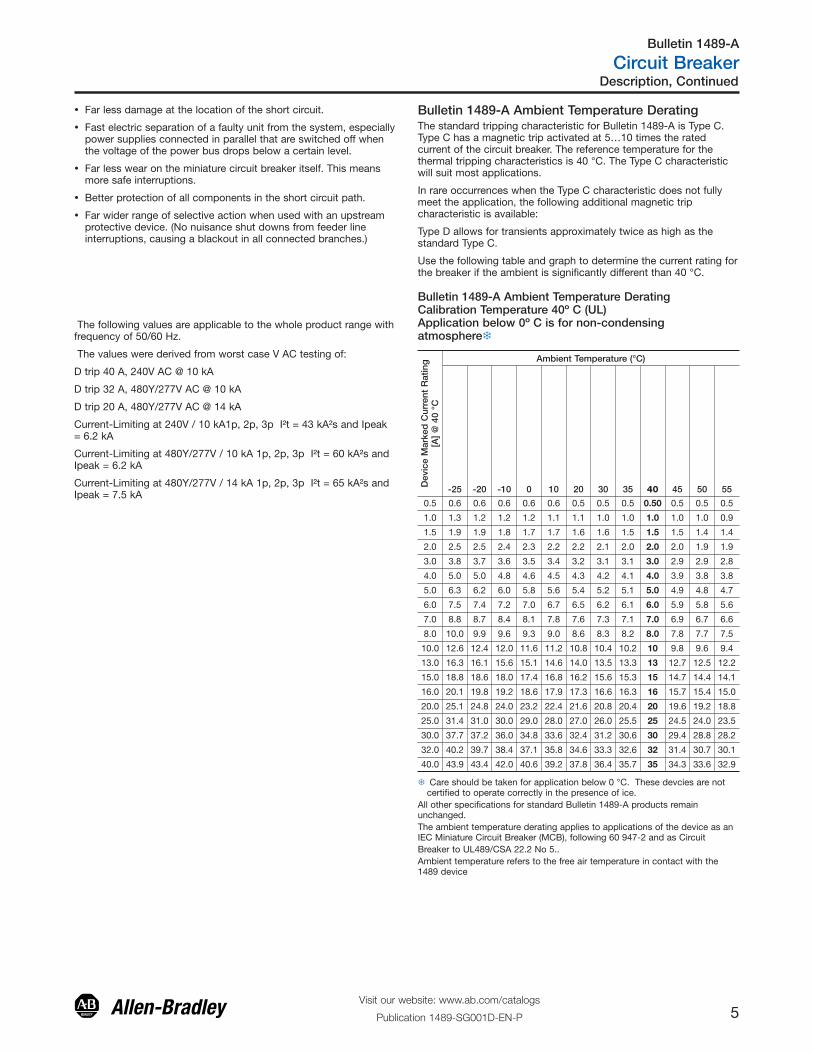
Bulletin 1489-A Ambient Temperature DeratingThe standard tripping characteristic for Bulletin 1489-A is Type C.Type C has a magnetic trip activated at 5…10 times the ratedcurrent of the circuit breaker. The reference temperature for thethermal tripping characteristics is 40 °C. The Type C characteristicwill suit most applications.
In rare occurrences when the Type C characteristic does not fullymeet the application, the following additional magnetic tripcharacteristic is available:
Type D allows for transients approximately twice as high as thestandard Type C.
Use the following table and graph to determine the current rating forthe breaker if the ambient is significantly different than 40 °C.
Bulletin 1489-A Ambient Temperature DeratingCalibration Temperature 40º C (UL)Application below 0º C is for non-condensingatmosphere�
Dev
ice
Mar
ked
Cur
rent
Rat
ing
[A]
@ 4
0 °C
Ambient Temperature (°C)
-25 -20 -10 0 10 20 30 35 40 45 50 55
0.5 0.6 0.6 0.6 0.6 0.6 0.5 0.5 0.5 0.50 0.5 0.5 0.5
1.0 1.3 1.2 1.2 1.2 1.1 1.1 1.0 1.0 1.0 1.0 1.0 0.9
1.5 1.9 1.9 1.8 1.7 1.7 1.6 1.6 1.5 1.5 1.5 1.4 1.4
2.0 2.5 2.5 2.4 2.3 2.2 2.2 2.1 2.0 2.0 2.0 1.9 1.9
3.0 3.8 3.7 3.6 3.5 3.4 3.2 3.1 3.1 3.0 2.9 2.9 2.8
4.0 5.0 5.0 4.8 4.6 4.5 4.3 4.2 4.1 4.0 3.9 3.8 3.8
5.0 6.3 6.2 6.0 5.8 5.6 5.4 5.2 5.1 5.0 4.9 4.8 4.7
6.0 7.5 7.4 7.2 7.0 6.7 6.5 6.2 6.1 6.0 5.9 5.8 5.6
7.0 8.8 8.7 8.4 8.1 7.8 7.6 7.3 7.1 7.0 6.9 6.7 6.6
8.0 10.0 9.9 9.6 9.3 9.0 8.6 8.3 8.2 8.0 7.8 7.7 7.5
10.0 12.6 12.4 12.0 11.6 11.2 10.8 10.4 10.2 10 9.8 9.6 9.4
13.0 16.3 16.1 15.6 15.1 14.6 14.0 13.5 13.3 13 12.7 12.5 12.2
15.0 18.8 18.6 18.0 17.4 16.8 16.2 15.6 15.3 15 14.7 14.4 14.1
16.0 20.1 19.8 19.2 18.6 17.9 17.3 16.6 16.3 16 15.7 15.4 15.0
20.0 25.1 24.8 24.0 23.2 22.4 21.6 20.8 20.4 20 19.6 19.2 18.8
25.0 31.4 31.0 30.0 29.0 28.0 27.0 26.0 25.5 25 24.5 24.0 23.5
30.0 37.7 37.2 36.0 34.8 33.6 32.4 31.2 30.6 30 29.4 28.8 28.2
32.0 40.2 39.7 38.4 37.1 35.8 34.6 33.3 32.6 32 31.4 30.7 30.1
40.0 43.9 43.4 42.0 40.6 39.2 37.8 36.4 35.7 35 34.3 33.6 32.9
� Care should be taken for application below 0 °C. These devcies are notcertified to operate correctly in the presence of ice.
All other specifications for standard Bulletin 1489-A products remainunchanged.The ambient temperature derating applies to applications of the device as anIEC Miniature Circuit Breaker (MCB), following 60 947-2 and as Circuit Breaker to UL489/CSA 22.2 No 5.. Ambient temperature refers to the free air temperature in contact with the1489 device
Description, Continued
Visit our website: www.ab.com/catalogs
Publication 1489-SG001D-EN-P 5
Bulletin 1489-A
Circuit Breaker
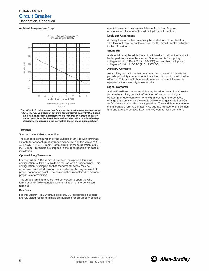
Ambient Temperature Graph
1.40
1.30
1.20
1.10
1.00
0.90
-20 -10 0 10 20 30 40 50
Ambient Temperature T [°C]
Maximum load I at Ambient Temperature T: L
L I (T) = I K (T) T n
Load
Fac
tor K
[I/
I ]
T n
Influence of Ambient Temperature (T)on Load-Carrying Capacity
The 1489-A circuit breaker can function over a wide temperature range(-30°...+60 °C). Operation in ambient temperatures below 0 °C is based
on a non condensing atmosphere (no ice). Use the graph above orcontact your local Rockwell Automation sales office or Allen-Bradley
distributor to determine the correction factor based upon ambient
Terminals
Standard wire (cable) connection
The standard configuration of the Bulletin 1489-A is with terminalssuitable for connection of stranded copper wire of the wire size #18… 8 AWG (1.0 … 10 mm2). Strip length for the termination is 0.5in. (12 mm). Terminals are shipped in the open position for ease ofinstallation.
Optional Ring Termination
For the Bulletin 1489-A circuit breakers, an optional terminalconfiguration (suffix R) is available for use with a ring terminal. Thisconfiguration is shipped so that the terminal screw may beunscrewed and withdrawn for the insertion of the ring terminal atproper connection point. The screw is then retightened to provideproper wire termination.
This unique terminal may be field converted to open the wiretermination to allow standard wire termination of the convertedterminal.
Bus Bars
For the Bulletin 1489-A circuit breakers, UL Recognized bus barsand UL Listed feeder terminals are available for group connection of
circuit breakers. They are available in 1-, 2-, and 3- poleconfigurations for connection of multiple circuit breakers.
Lock-out Attachment
A sturdy lock-out attachment may be added to a circuit breaker.This lock-out may be padlocked so that the circuit breaker is lockedin the off position.
Shunt Trip
A shunt trip may be added to a circuit breaker to allow the device tobe tripped from a remote source. One version is for trippingvoltages of 12…110V AC (12…60V DC) and another for trippingvoltages of 110…415V AC (110…230V DC).
Auxiliary Contacts
An auxiliary contact module may be added to a circuit breaker toprovide pilot duty contacts to indicate the position of circuit breaker,off or on. This contact changes state when the circuit breaker isoperated either manually or electrically.
Signal Contacts
A signal/auxiliary contact module may be added to a circuit breakerto provide auxiliary contact information off and on and signalcontact pilot duty contacts. With signal contacts, the contactschange state only when the circuit breaker changes state from Onto Off because of an electrical operation. The module contains onesignal contact, form C contact (N.O. and N.C contact with common)and one auxiliary contact (N.O. and N.C contact with common).
Description, Continued
Visit our website: www.ab.com/catalogs
Publication 1489-SG001D-EN-P6
Bulletin 1489-A
Circuit Breaker
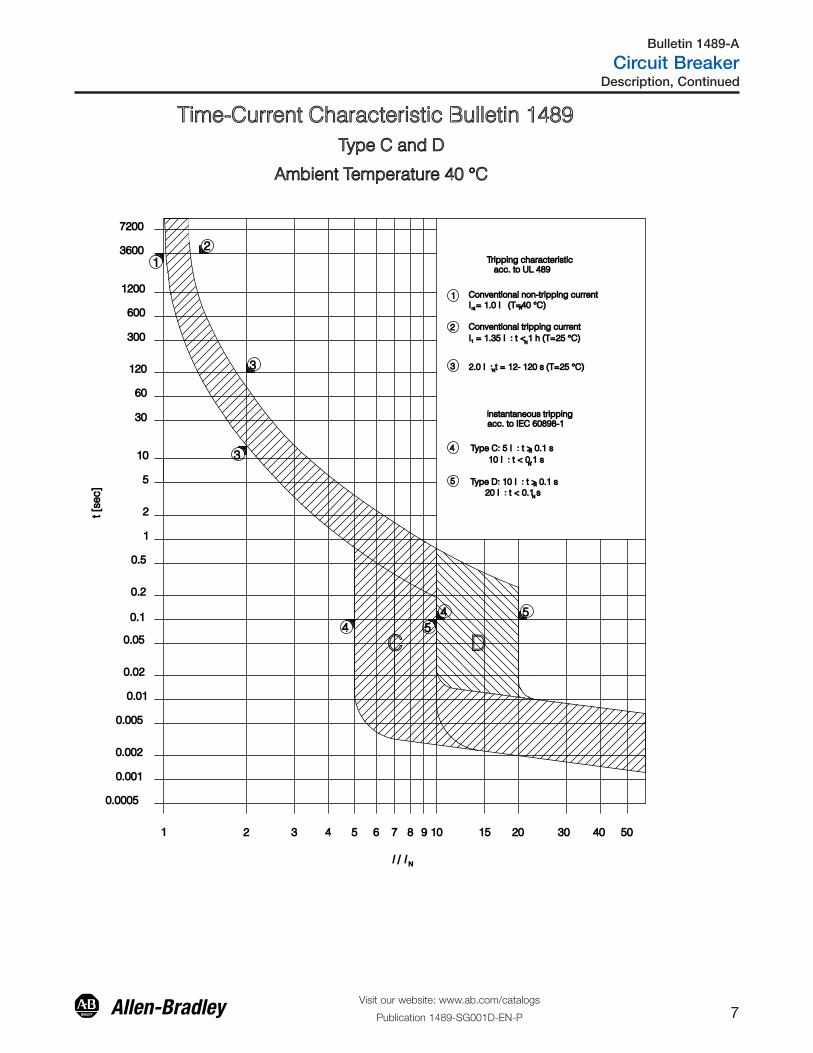
Time-Current Characteristic Bulletin 1489 Type C and D
Ambient Temperature 40 °C
C D
3
acc. to UL 489 Tripping characteristic
Type D: 10 I : t > 0.1 s
Type C: 5 I : t > 0.1 s
Conventional tripping current
Conventional non-tripping current
20 I : t < 0.1 s
10 I : t < 0.1 s
2.0 I : t = 12- 120 s (T=25 °C)
I = 1.35 I : t < 1 h (T=25 °C)
I = 1.0 I (T=40 °C)
3 N
5
4
N
N
N
N
nt
t
2
1
N
N
2 1
3
4 5 4 5
instantaneous trippingacc. to IEC 60898-1
1 2 3 4 5 6 7 8 9 10 15 20 30 40 50
0.001
0.002
0.01
0.005
0.02
0.05
0.1
0.2
0.5
1
2
5
10
30
60
120
300
600
1200
3600
7200
I / I N
t [se
c]
0.0005
Description, Continued
Visit our website: www.ab.com/catalogs
Publication 1489-SG001D-EN-P 7
Bulletin 1489-A
Circuit Breaker
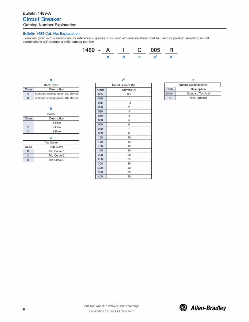
Bulletin 1489 Cat. No. ExplanationExamples given in this section are for reference purposes. This basic explanation should not be used for product selection; not allcombinations will produce a valid catalog number.
1489 - A 1 C 005 Ra b c d e
bPoles
Code Description
1 1-Pole
2 2-Pole
3 3-Pole
cTrip Curve
Code Trip Curve
B Trip Curve B
C Trip Curve C
D Trip Curve D
dRated Current (In)
Code Current [A]
005 0.5
010 1
015 1.5
020 2
030 3
040 4
050 5
060 6
070 7
080 8
100 10
130 13
150 15
160 16
200 20
250 25
300 30
320 32
350 35
400 40
eFactory Modifications
Code Description
blank Standard Terminal
R Ring Terminal
Catalog Number Explanation
Visit our website: www.ab.com/catalogs
Publication 1489-SG001D-EN-P8
Bulletin 1489-A
Circuit Breaker
aBody Style
Code Description
A Standard configuration, AC Device
D Standard configuration, DC Device
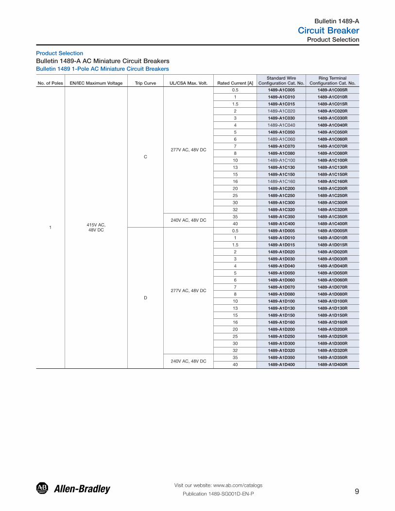
No. of Poles EN/IEC Maximum Voltage Trip Curve UL/CSA Max. Volt. Rated Current [A]Standard Wire
Configuration Cat. No.Ring Terminal
Configuration Cat. No.
1 415V AC, 48V DC
C
277V AC, 48V DC
0.5 1489-A1C005 1489-A1C005R
1 1489-A1C010 1489-A1C010R
1.5 1489-A1C015 1489-A1C015R
2 1489-A1C020 1489-A1C020R
3 1489-A1C030 1489-A1C030R
4 1489-A1C040 1489-A1C040R
5 1489-A1C050 1489-A1C050R
6 1489-A1C060 1489-A1C060R
7 1489-A1C070 1489-A1C070R
8 1489-A1C080 1489-A1C080R
10 1489-A1C100 1489-A1C100R
13 1489-A1C130 1489-A1C130R
15 1489-A1C150 1489-A1C150R
16 1489-A1C160 1489-A1C160R
20 1489-A1C200 1489-A1C200R
25 1489-A1C250 1489-A1C250R
30 1489-A1C300 1489-A1C300R
32 1489-A1C320 1489-A1C320R
240V AC, 48V DC35 1489-A1C350 1489-A1C350R
40 1489-A1C400 1489-A1C400R
D
277V AC, 48V DC
0.5 1489-A1D005 1489-A1D005R
1 1489-A1D010 1489-A1D010R
1.5 1489-A1D015 1489-A1D015R
2 1489-A1D020 1489-A1D020R
3 1489-A1D030 1489-A1D030R
4 1489-A1D040 1489-A1D040R
5 1489-A1D050 1489-A1D050R
6 1489-A1D060 1489-A1D060R
7 1489-A1D070 1489-A1D070R
8 1489-A1D080 1489-A1D080R
10 1489-A1D100 1489-A1D100R
13 1489-A1D130 1489-A1D130R
15 1489-A1D150 1489-A1D150R
16 1489-A1D160 1489-A1D160R
20 1489-A1D200 1489-A1D200R
25 1489-A1D250 1489-A1D250R
30 1489-A1D300 1489-A1D300R
32 1489-A1D320 1489-A1D320R
240V AC, 48V DC35 1489-A1D350 1489-A1D350R
40 1489-A1D400 1489-A1D400R
Product SelectionBulletin 1489-A AC Miniature Circuit BreakersBulletin 1489 1-Pole AC Miniature Circuit Breakers
Product Selection
Visit our website: www.ab.com/catalogs
Publication 1489-SG001D-EN-P 9
Bulletin 1489-A
Circuit Breaker
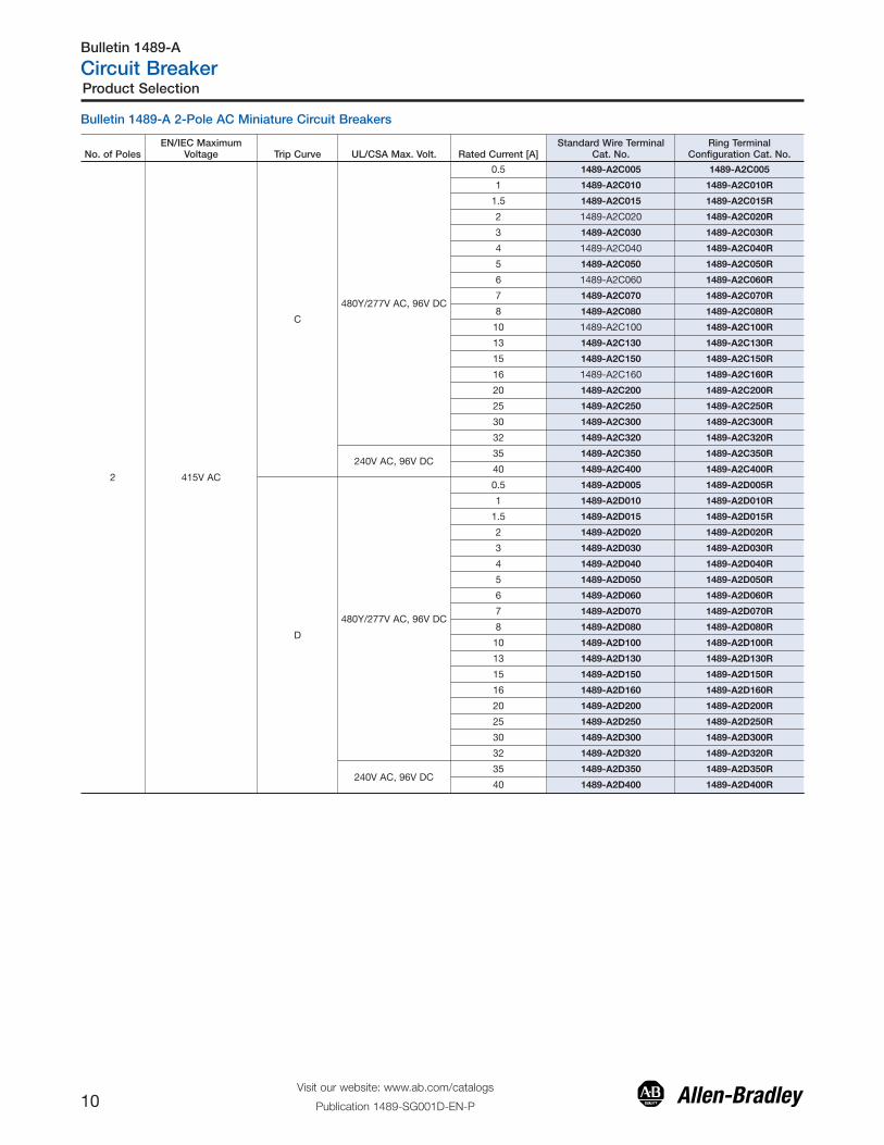
Bulletin 1489-A 2-Pole AC Miniature Circuit Breakers
No. of PolesEN/IEC Maximum
Voltage Trip Curve UL/CSA Max. Volt. Rated Current [A]Standard Wire Terminal
Cat. No.Ring Terminal
Configuration Cat. No.
2 415V AC
C
480Y/277V AC, 96V DC
0.5 1489-A2C005 1489-A2C005
1 1489-A2C010 1489-A2C010R
1.5 1489-A2C015 1489-A2C015R
2 1489-A2C020 1489-A2C020R
3 1489-A2C030 1489-A2C030R
4 1489-A2C040 1489-A2C040R
5 1489-A2C050 1489-A2C050R
6 1489-A2C060 1489-A2C060R
7 1489-A2C070 1489-A2C070R
8 1489-A2C080 1489-A2C080R
10 1489-A2C100 1489-A2C100R
13 1489-A2C130 1489-A2C130R
15 1489-A2C150 1489-A2C150R
16 1489-A2C160 1489-A2C160R
20 1489-A2C200 1489-A2C200R
25 1489-A2C250 1489-A2C250R
30 1489-A2C300 1489-A2C300R
32 1489-A2C320 1489-A2C320R
240V AC, 96V DC35 1489-A2C350 1489-A2C350R
40 1489-A2C400 1489-A2C400R
D
480Y/277V AC, 96V DC
0.5 1489-A2D005 1489-A2D005R
1 1489-A2D010 1489-A2D010R
1.5 1489-A2D015 1489-A2D015R
2 1489-A2D020 1489-A2D020R
3 1489-A2D030 1489-A2D030R
4 1489-A2D040 1489-A2D040R
5 1489-A2D050 1489-A2D050R
6 1489-A2D060 1489-A2D060R
7 1489-A2D070 1489-A2D070R
8 1489-A2D080 1489-A2D080R
10 1489-A2D100 1489-A2D100R
13 1489-A2D130 1489-A2D130R
15 1489-A2D150 1489-A2D150R
16 1489-A2D160 1489-A2D160R
20 1489-A2D200 1489-A2D200R
25 1489-A2D250 1489-A2D250R
30 1489-A2D300 1489-A2D300R
32 1489-A2D320 1489-A2D320R
240V AC, 96V DC35 1489-A2D350 1489-A2D350R
40 1489-A2D400 1489-A2D400R
Product Selection
Visit our website: www.ab.com/catalogs
Publication 1489-SG001D-EN-P10
Bulletin 1489-A
Circuit Breaker
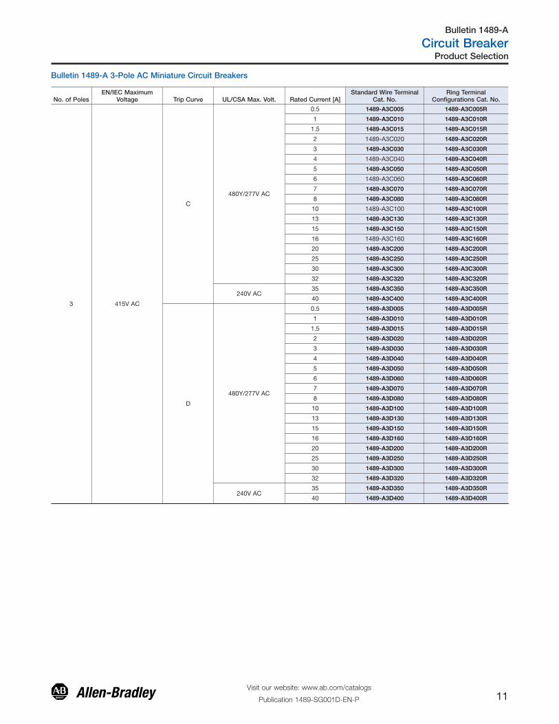
No. of PolesEN/IEC Maximum
Voltage Trip Curve UL/CSA Max. Volt. Rated Current [A]Standard Wire Terminal
Cat. No.Ring Terminal
Configurations Cat. No.
3 415V AC
C
480Y/277V AC
0.5 1489-A3C005 1489-A3C005R
1 1489-A3C010 1489-A3C010R
1.5 1489-A3C015 1489-A3C015R
2 1489-A3C020 1489-A3C020R
3 1489-A3C030 1489-A3C030R
4 1489-A3C040 1489-A3C040R
5 1489-A3C050 1489-A3C050R
6 1489-A3C060 1489-A3C060R
7 1489-A3C070 1489-A3C070R
8 1489-A3C080 1489-A3C080R
10 1489-A3C100 1489-A3C100R
13 1489-A3C130 1489-A3C130R
15 1489-A3C150 1489-A3C150R
16 1489-A3C160 1489-A3C160R
20 1489-A3C200 1489-A3C200R
25 1489-A3C250 1489-A3C250R
30 1489-A3C300 1489-A3C300R
32 1489-A3C320 1489-A3C320R
240V AC35 1489-A3C350 1489-A3C350R
40 1489-A3C400 1489-A3C400R
D
480Y/277V AC
0.5 1489-A3D005 1489-A3D005R
1 1489-A3D010 1489-A3D010R
1.5 1489-A3D015 1489-A3D015R
2 1489-A3D020 1489-A3D020R
3 1489-A3D030 1489-A3D030R
4 1489-A3D040 1489-A3D040R
5 1489-A3D050 1489-A3D050R
6 1489-A3D060 1489-A3D060R
7 1489-A3D070 1489-A3D070R
8 1489-A3D080 1489-A3D080R
10 1489-A3D100 1489-A3D100R
13 1489-A3D130 1489-A3D130R
15 1489-A3D150 1489-A3D150R
16 1489-A3D160 1489-A3D160R
20 1489-A3D200 1489-A3D200R
25 1489-A3D250 1489-A3D250R
30 1489-A3D300 1489-A3D300R
32 1489-A3D320 1489-A3D320R
240V AC35 1489-A3D350 1489-A3D350R
40 1489-A3D400 1489-A3D400R
Bulletin 1489-A 3-Pole AC Miniature Circuit Breakers
Product Selection
Visit our website: www.ab.com/catalogs
Publication 1489-SG001D-EN-P 11
Bulletin 1489-A
Circuit Breaker
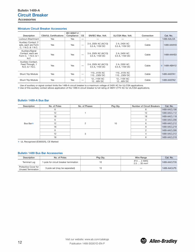
Miniature Circuit Breaker Accessories
Description CSA/UL CertificationsIEC 60947-2Compliance CE EN/IEC Max. Volt. UL/CSA Max. Volt. Connection Cat. No.
Lockout Attachment Yes Yes — — — — 1489-AALOA
Auxiliary Contact, 2sets, each are FormC, 1 N.O. & 1 N.C.
Yes Yes — 3 A, 250V AC (AC13)0.5 A, 110V DC
2 A, 240V AC0.5 A, 110V DC Cable 1489-AAHH3
Auxiliary/SignalContact, each are
Form C, 1 N.O. & 1N.C
Yes Yes — 3 A, 250V AC (AC13)0.5 A, 110V DC
2 A, 240V AC0.5 A, 110V DC Cable 1489-AAHS3
Auxiliary Contact,Feed Through, 1
N.O. & 1 N.C. Yes Yes — 3 A, 250V AC (AC13)0.5 A, 110V DC
2 A, 230V AC0.5 A, 110V DC Cable � 1489-ABH12
Shunt Trip Module Yes Yes — 110...415V AC110…230V DC
110...415V AC110…230V DC Cable 1489-AASTA1
Shunt Trip Module Yes Yes — 12...110V AC12…60V DC
12...110V AC12…60V DC Cable 1489-AASTA2
Use of auxiliary or signal contact limits the 1489-A circuit breaker to a maximum voltage of 240V AC for UL/CSA applications.�Use of this auxiliary contact allows application of the 1489-A circuit breaker to full rating of 480Y/ 277V AC for UL/CSA applications.
Bulletin 1489-A Bus Bar
Description No. of Poles No. of Phases Pkg Qty. Number of Circuit Breakers Cat. No.
Bus Bar�
6
1
10
6 1489-AACL106
12 12 1489-AACL112
18 18 1489-AACL118
6
2
3 1489-AACL206
12 6 1489-AACL212
18 9 1489-AACL218
6
3
2 1489-AACL306
12 4 1489-AACL312
18 6 1489-AACL318
� UL Recognized (E300325), CE Marked
Bulletin 1489 Bus Bar Accessories
Description No. of Poles Pkg Qty. Wire Range Cat. No.
Terminal Lug 1-pole for circuit breaker termination 10 #14 … 2 AWG2.5 … 35 mm2 1489-AACLT35
Protective Cover forUnused Termination 3-pole set (may be separated) 10 — 1489-AACLPS
Accessories
Visit our website: www.ab.com/catalogs
Publication 1489-SG001D-EN-P12
Bulletin 1489-A
Circuit Breaker
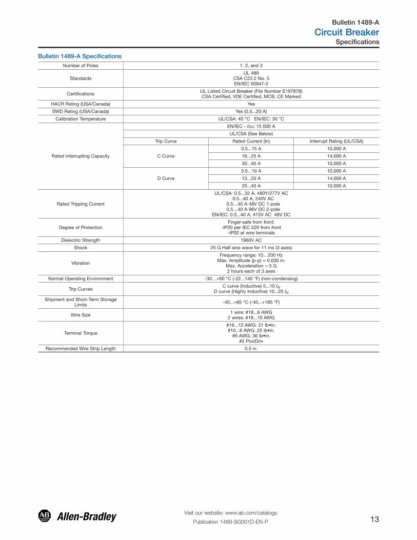
Bulletin 1489-A Specifications
Number of Poles 1, 2, and 3
StandardsUL 489
CSA C22.2 No. 5EN/IEC 60947-2
Certifications UL Listed Circuit Breaker (File Number E197878)CSA Certified, VDE Certified, MCB, CE Marked
HACR Rating (USA/Canada) Yes
SWD Rating (USA/Canada) Yes (0.5...20 A)
Calibration Temperature UL/CSA: 40 °C EN/IEC: 30 °C
Rated Interrupting Capacity
EN/IEC - Icu: 15 000 A
UL/CSA (See Below)
Trip Curve Rated Current (In) Interrupt Rating (UL/CSA)
C Curve
0.5...15 A 10,000 A
16...25 A 14,000 A
30...40 A 10,000 A
D Curve
0.5...10 A 10,000 A
13...20 A 14,000 A
25...40 A 10,000 A
Rated Tripping Current
UL/CSA: 0.5...32 A, 480Y/277V AC0.5...40 A, 240V AC
0.5…40 A 48V DC 1-pole0.5…40 A 96V DC 2-pole
EN/IEC: 0.5...40 A, 415V AC 48V DC
Degree of ProtectionFinger-safe from front:
-IP20 per IEC 529 from front-IP00 at wire terminals
Dielectric Strength 1960V AC
Shock 25 G Half sine wave for 11 ms (3 axes)
Vibration
Frequency range: 10…200 HzMax. Amplitude (p-p) = 0.030 in.
Max. Acceleration = 5 G2 hours each of 3 axes
Normal Operating Environment -30…+60 °C (-22...140 °F) (non-condensing)
Trip CurvesC curve (Inductive) 5...10 IN
D curve (Highly Inductive) 10...20 IN
Shipment and Short-Term StorageLimits -40...+85 °C (-40...+185 °F)
Wire Size 1 wire: #18...6 AWG2 wires: #18...10 AWG
Terminal Torque
#18...12 AWG: 21 lb•in.#10...8 AWG: 25 lb•in.
#6 AWG: 36 lb•in.#2 PoziDriv
Recommended Wire Strip Length 0.5 in.
Specifications
Visit our website: www.ab.com/catalogs
Publication 1489-SG001D-EN-P 13
Bulletin 1489-A
Circuit Breaker
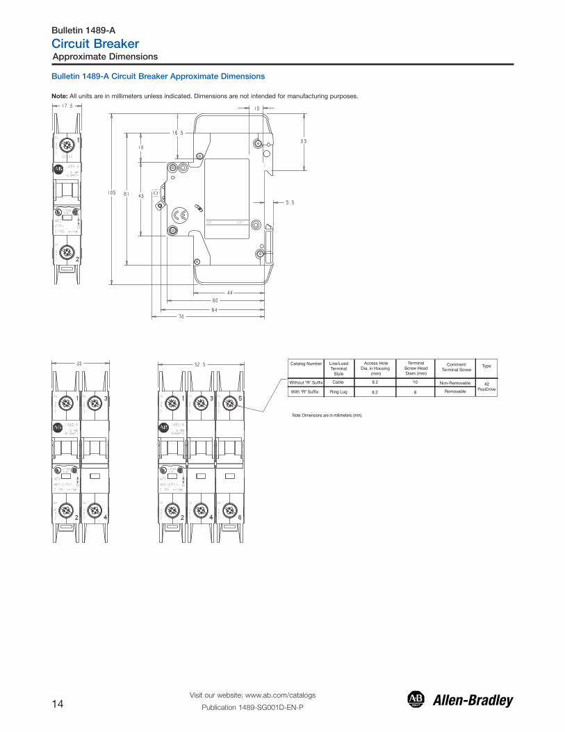
Note: All units are in millimeters unless indicated. Dimensions are not intended for manufacturing purposes.
Note: Dimensions are in millimeters (mm).
Catalog Number Line/LoadTerminal
Style
Access Hole Dia. in Housing
(mm)
Terminal Screw Head Diam (mm)
Comment: Terminal Screw
Type
Without “R” Suffix
With “R” Suffix
Cable
Ring Lug
8.2
8.2
10
8 Removable
Non-Removable #2 PoziDrive
Bulletin 1489-A Circuit Breaker Approximate Dimensions
Approximate Dimensions
Visit our website: www.ab.com/catalogs
Publication 1489-SG001D-EN-P14
Bulletin 1489-A
Circuit Breaker
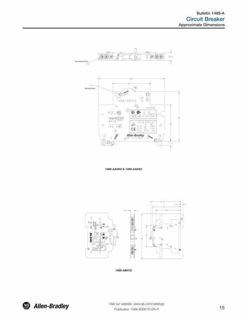
Mounting Screws
Terminal Screw/Clamp
1489-AAHH3 & 1489-AAHS3
1489-ABH12
Approximate Dimensions
Visit our website: www.ab.com/catalogs
Publication 1489-SG001D-EN-P 15
Bulletin 1489-A
Circuit Breaker
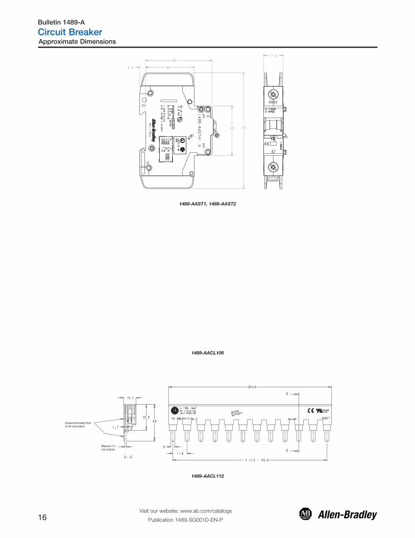
1489-AAST1, 1489-AAST2
1489-AACL106
Surfaces Nominally Flush(in the same plane)
Maximum 1.5(out of plane)
1489-AACL112
Approximate Dimensions
Visit our website: www.ab.com/catalogs
Publication 1489-SG001D-EN-P16
Bulletin 1489-A
Circuit Breaker
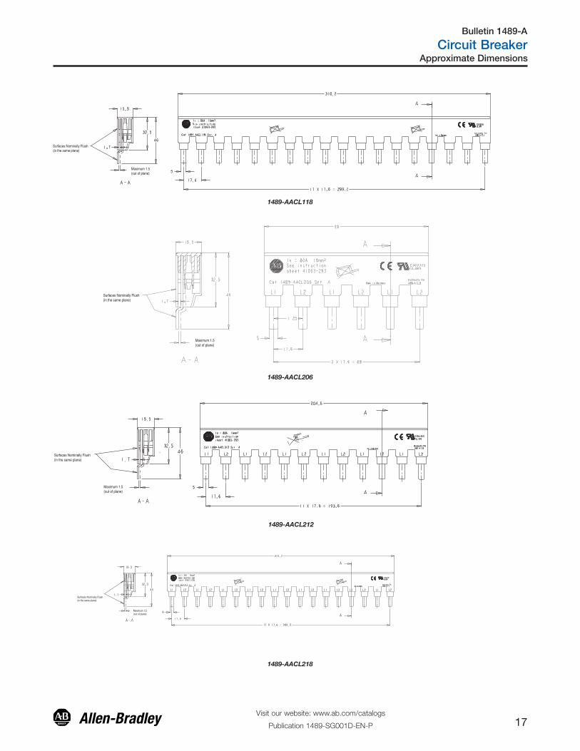
Surfaces Nominally Flush(in the same plane)
Maximum 1.5(out of plane)
1489-AACL118
Surfaces Nominally Flush(in the same plane)
Maximum 1.5(out of plane)
1489-AACL206
Surfaces Nominally Flush(in the same plane)
Maximum 1.5(out of plane)
1489-AACL212
Surfaces Nominally Flush(in the same plane)
Maximum 1.5(out of plane)
1489-AACL218
Approximate Dimensions
Visit our website: www.ab.com/catalogs
Publication 1489-SG001D-EN-P 17
Bulletin 1489-A
Circuit Breaker
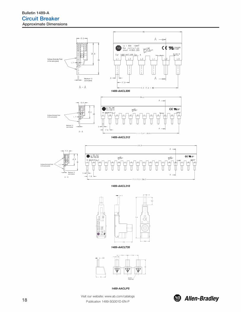
Surfaces Nominally Flush(in the same plane)
Maximum 1.5(out of plane)
1489-AACL306
Surfaces Nominally Flush(in the same plane)
Maximum 1.5(out of plane)
1489-AACL312
Surfaces Nominally Flush(in the same plane)
Maximum 1.5(out of plane)
1489-AACL318
Cat
148
9-AA
CLT
35 S
er. A
Se
e in
stru
ctio
n sh
eet 4
1063
-293
E300
325
UL4
89
IEC
: 2,5
- 35
mm
² U
L: #
14 -
2 AW
G
6 3
6 , 1 7
2 , 6 1 3 , 1 3
.56
In
14m
m
5, 3 1
1489-AACLT35
6 , 7 1 6 , 7 1 7
5 5 , 3
42
K C A L B G N I T NI R P
6 1
1489-AACLPS
Approximate Dimensions
Visit our website: www.ab.com/catalogs
Publication 1489-SG001D-EN-P18
Bulletin 1489-A
Circuit Breaker
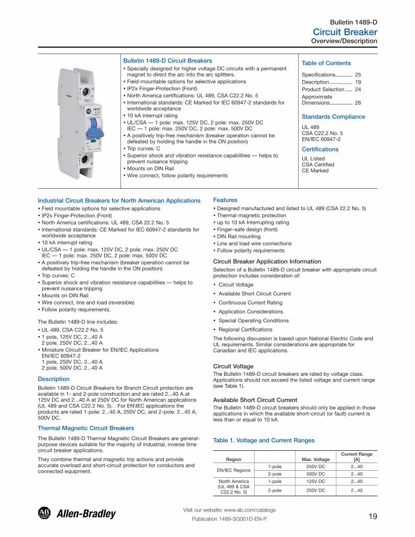
Bulletin 1489-D Circuit Breakers
Standards Compliance
UL 489CSA C22.2 No. 5EN/IEC 60947-2
Certifications
UL ListedCSA CertifiedCE Marked
Features� Designed manufactured and listed to UL 489 (CSA 22.2 No. 5)� Thermal-magnetic protection� up to 10 kA Interrupting rating� Finger–safe design (front)� DIN Rail mounting� Line and load wire connections� Follow polarity requirements
� Specially designed for higher voltage DC circuits with a permanentmagnet to direct the arc into the arc splitters.
� Field-mountable options for selective applications� IP2x Finger-Protection (Front)� North America certifications: UL 489, CSA C22.2 No. 5� International standards: CE Marked for IEC 60947-2 standards for
worldwide acceptance� 10 kA interrupt rating� UL/CSA — 1 pole: max. 125V DC, 2 pole: max. 250V DC
IEC — 1 pole: max. 250V DC, 2 pole: max. 500V DC� A positively trip-free mechanism (breaker operation cannot be
defeated by holding the handle in the ON position)� Trip curves: C� Superior shock and vibration resistance capabilities — helps to
prevent nuisance tripping� Mounts on DIN Rail� Wire connect, follow polarity requirements
Industrial Circuit Breakers for North American Applications� Field mountable options for selective applications� IP2x Finger-Protection (Front)� North America certifications: UL 489, CSA 22.2 No. 5� International standards: CE Marked for IEC 60947-2 standards for
worldwide acceptance� 10 kA interrupt rating� UL/CSA — 1 pole: max. 125V DC, 2 pole: max. 250V DC
IEC — 1 pole: max. 250V DC, 2 pole: max. 500V DC� A positively trip-free mechanism (breaker operation cannot be
defeated by holding the handle in the ON position)� Trip curves: C� Superior shock and vibration resistance capabilities — helps to
prevent nuisance tripping� Mounts on DIN Rail� Wire connect, line and load (reversible)� Follow polarity requirements.
� UL 489, CSA C22.2 No. 5� 1 pole, 125V DC, 2...40 A
2 pole, 250V DC, 2...40 A� Miniature Circuit Breaker for EN/IEC Applications
EN/IEC 60947-21 pole, 250V DC, 2...40 A2 pole, 500V DC, 2...40 A
The Bulletin 1489-D line includes:
DescriptionBulletin 1489-D Circuit Breakers for Branch Circuit protection areavailable in 1- and 2-pole construction and are rated 2...40 A at125V DC and 2...40 A at 250V DC for North American applications(UL 489 and CSA C22.2 No. 5). . For EN\IEC applications theproducts are rated 1-pole: 2...40 A, 250V DC, and 2-pole: 2...40 A,500V DC.
Thermal Magnetic Circuit Breakers
The Bulletin 1489-D Thermal Magnetic Circuit Breakers are general-purpose devices suitable for the majority of industrial, inverse timecircuit breaker applications.
They combine thermal and magnetic trip actions and provideaccurate overload and short-circuit protection for conductors andconnected equipment.
Circuit Breaker Application InformationSelection of a Bulletin 1489-D circuit breaker with appropriate circuitprotection includes consideration of:
� Circuit Voltage
� Available Short Circuit Current
� Continuous Current Rating
� Application Considerations
� Special Operating Conditions
� Regional Certifications
The following discussion is based upon National Electric Code andUL requirements. Similar considerations are appropriate forCanadian and IEC applications.
Circuit VoltageThe Bulletin 1489-D circuit breakers are rated by voltage class.Applications should not exceed the listed voltage and current range(see Table 1).
Available Short Circuit CurrentThe Bulletin 1489-D circuit breakers should only be applied in thoseapplications in which the available short-circuit (or fault) current isless than or equal to 10 kA.
Table 1. Voltage and Current Ranges
Region Max. VoltageCurrent Range
[A]
EN/IEC Regions1-pole 250V DC 2...40
2-pole 500V DC 2...40
North America(UL 489 & CSAC22.2 No. 5)
1-pole 125V DC 2...40
2-pole 250V DC 2...40
Visit our website: www.ab.com/catalogs
Publication 1489-SG001D-EN-P 19
Bulletin 1489-D
Circuit BreakerOverview/Description
Table of Contents
Specifications.............. 25Description ................... 19Product Selection ...... 24ApproximateDimensions................... 26
Continuous Current RatingStandard current ratings are: 2, 3, 4, 5, 6, 7, 8, 10, 15, 16, 20, 25,30, 32, 35, and 40 A.
The Bulletin 1489-D circuit breakers are rated in amperes at a 40 °C(104 °F) ambient temperature per the UL 489 (CSA 22.2 No. 5)standard. This temperature is generally used as the averagetemperature within an industrial enclosure. If a circuit breaker isapplied in a temperature that exceeds the 40 °C (104 °F) ambient,then the circuit breaker should be derated. For IEC 60 947-2standard, the products carry an ambient rating of 30 °C. Followstandard IEC application considerations for temperature rating indifferent ambient temperatures.
The characteristic trip curve is shown on page 22. The trip bandsshown for each breaker represent current tripping limits for a circuitbreaker and are within the limits established by UL. For a specificcurrent at 40 °C (104 °F), a circuit breaker will open ("clear thecircuit") automatically at some total time that will be within the"Minimum" and "Maximum" time shown on the curves. Forexample, page 21 shows that a one-pole, 15 A, Bulletin 1489 circuitbreaker trips in not less than 10 s and not more than 120 s on a 30A current. Because the UL standard defines this time spread, usersshould not specify exact tripping time. The lower current portion ofthe curves (upper left) depict the time to trip due to thermal actionand reflect overload protection of the wire and connect load. Thehigher current portion of the curves (lower right) depicts the trip dueto magnetic action of the circuit breaker and reflects protection dueto short circuit level currents.
Application Considerations
The following is a discussion of application considerations related toNorth American applications. When applying product to IECregional requirements, follow IEC practices and guidelines.
The selection of a specific ampere rating for a specific application isdependent on the type of load and duty cycle and is governed bythe National Electric Code (Canadian Electric Code) and UL/CSA. Ingeneral, the codes require that overcurrent protection is at thecurrent supply and at points where wire sizes are reduced. Inaddition, the codes state that conductors be protected according totheir current carrying capacity. There are specific situations thatrequire application consideration, such as motor circuit, andguidelines for the selection for transformer protection.
The Bulletin 1489-D circuit breakers are “non 100 percent rated” asdefined by UL 489, para 7.1.4.2. As such, the circuit breaker'srating should be loaded to no more than 80% if used withcontinuous loads.
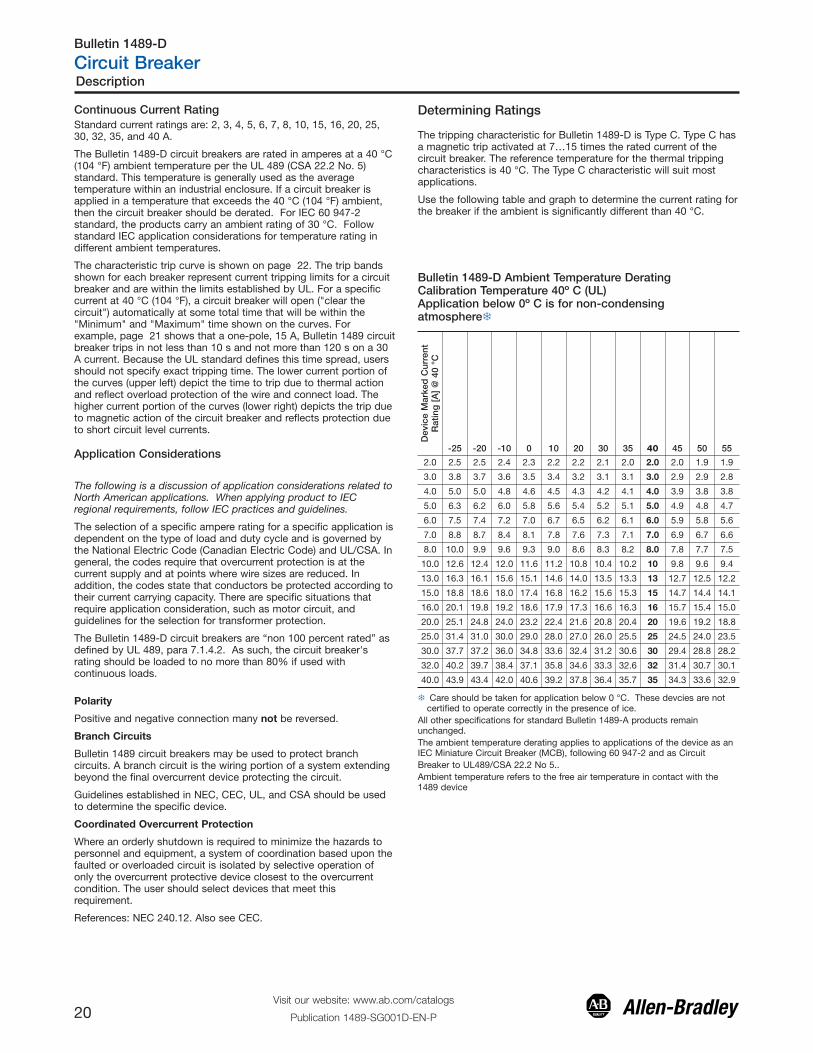
Determining Ratings
Bulletin 1489-D Ambient Temperature DeratingCalibration Temperature 40º C (UL)Application below 0º C is for non-condensingatmosphere�
Dev
ice
Mar
ked
Cur
rent
Rat
ing
[A
] @
40
°C
-25 -20 -10 0 10 20 30 35 40 45 50 55
2.0 2.5 2.5 2.4 2.3 2.2 2.2 2.1 2.0 2.0 2.0 1.9 1.9
3.0 3.8 3.7 3.6 3.5 3.4 3.2 3.1 3.1 3.0 2.9 2.9 2.8
4.0 5.0 5.0 4.8 4.6 4.5 4.3 4.2 4.1 4.0 3.9 3.8 3.8
5.0 6.3 6.2 6.0 5.8 5.6 5.4 5.2 5.1 5.0 4.9 4.8 4.7
6.0 7.5 7.4 7.2 7.0 6.7 6.5 6.2 6.1 6.0 5.9 5.8 5.6
7.0 8.8 8.7 8.4 8.1 7.8 7.6 7.3 7.1 7.0 6.9 6.7 6.6
8.0 10.0 9.9 9.6 9.3 9.0 8.6 8.3 8.2 8.0 7.8 7.7 7.5
10.0 12.6 12.4 12.0 11.6 11.2 10.8 10.4 10.2 10 9.8 9.6 9.4
13.0 16.3 16.1 15.6 15.1 14.6 14.0 13.5 13.3 13 12.7 12.5 12.2
15.0 18.8 18.6 18.0 17.4 16.8 16.2 15.6 15.3 15 14.7 14.4 14.1
16.0 20.1 19.8 19.2 18.6 17.9 17.3 16.6 16.3 16 15.7 15.4 15.0
20.0 25.1 24.8 24.0 23.2 22.4 21.6 20.8 20.4 20 19.6 19.2 18.8
25.0 31.4 31.0 30.0 29.0 28.0 27.0 26.0 25.5 25 24.5 24.0 23.5
30.0 37.7 37.2 36.0 34.8 33.6 32.4 31.2 30.6 30 29.4 28.8 28.2
32.0 40.2 39.7 38.4 37.1 35.8 34.6 33.3 32.6 32 31.4 30.7 30.1
40.0 43.9 43.4 42.0 40.6 39.2 37.8 36.4 35.7 35 34.3 33.6 32.9
� Care should be taken for application below 0 °C. These devcies are notcertified to operate correctly in the presence of ice.
All other specifications for standard Bulletin 1489-A products remainunchanged.The ambient temperature derating applies to applications of the device as anIEC Miniature Circuit Breaker (MCB), following 60 947-2 and as Circuit Breaker to UL489/CSA 22.2 No 5.. Ambient temperature refers to the free air temperature in contact with the1489 device
Description
Visit our website: www.ab.com/catalogs
Publication 1489-SG001D-EN-P20
Bulletin 1489-D
Circuit Breaker
The tripping characteristic for Bulletin 1489-D is Type C. Type C hasa magnetic trip activated at 7…15 times the rated current of thecircuit breaker. The reference temperature for the thermal trippingcharacteristics is 40 °C. The Type C characteristic will suit mostapplications.
Use the following table and graph to determine the current rating forthe breaker if the ambient is significantly different than 40 °C.
Polarity
Positive and negative connection many not be reversed.
Branch Circuits
Bulletin 1489 circuit breakers may be used to protect branchcircuits. A branch circuit is the wiring portion of a system extendingbeyond the final overcurrent device protecting the circuit.
Guidelines established in NEC, CEC, UL, and CSA should be usedto determine the specific device.
Coordinated Overcurrent Protection
Where an orderly shutdown is required to minimize the hazards topersonnel and equipment, a system of coordination based upon thefaulted or overloaded circuit is isolated by selective operation ofonly the overcurrent protective device closest to the overcurrentcondition. The user should select devices that meet thisrequirement.
References: NEC 240.12. Also see CEC.
1.40
1.30
1.20
1.10
1.00
0.90
-20 -10 0 10 20 30 40 50
Ambient Temperature T [°C]
Maximum load I at Ambient Temperature T: L
L I (T) = I K (T) T n
Load
Fac
tor K
[I/
I ]
T n
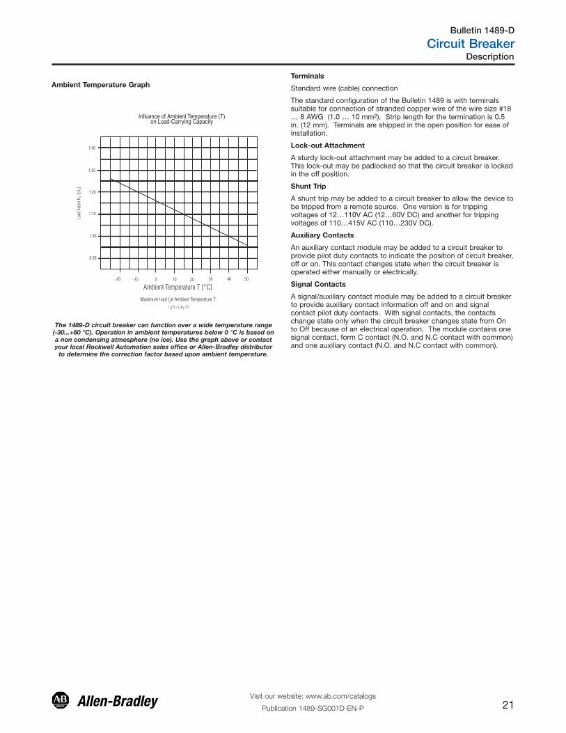
Influence of Ambient Temperature (T)on Load-Carrying Capacity
The 1489-D circuit breaker can function over a wide temperature range(-30...+60 °C). Operation in ambient temperatures below 0 °C is based ona non condensing atmosphere (no ice). Use the graph above or contactyour local Rockwell Automation sales office or Allen-Bradley distributor
to determine the correction factor based upon ambient temperature.
Terminals
Standard wire (cable) connection
The standard configuration of the Bulletin 1489 is with terminalssuitable for connection of stranded copper wire of the wire size #18… 8 AWG (1.0 … 10 mm2). Strip length for the termination is 0.5in. (12 mm). Terminals are shipped in the open position for ease ofinstallation.
Lock-out Attachment
A sturdy lock-out attachment may be added to a circuit breaker.This lock-out may be padlocked so that the circuit breaker is lockedin the off position.
Shunt Trip
A shunt trip may be added to a circuit breaker to allow the device tobe tripped from a remote source. One version is for trippingvoltages of 12…110V AC (12…60V DC) and another for trippingvoltages of 110…415V AC (110…230V DC).
Auxiliary Contacts
An auxiliary contact module may be added to a circuit breaker toprovide pilot duty contacts to indicate the position of circuit breaker,off or on. This contact changes state when the circuit breaker isoperated either manually or electrically.
Signal Contacts
A signal/auxiliary contact module may be added to a circuit breakerto provide auxiliary contact information off and on and signalcontact pilot duty contacts. With signal contacts, the contactschange state only when the circuit breaker changes state from Onto Off because of an electrical operation. The module contains onesignal contact, form C contact (N.O. and N.C contact with common)and one auxiliary contact (N.O. and N.C contact with common).
Ambient Temperature Graph
Description
Visit our website: www.ab.com/catalogs
Publication 1489-SG001D-EN-P 21
Bulletin 1489-D
Circuit Breaker
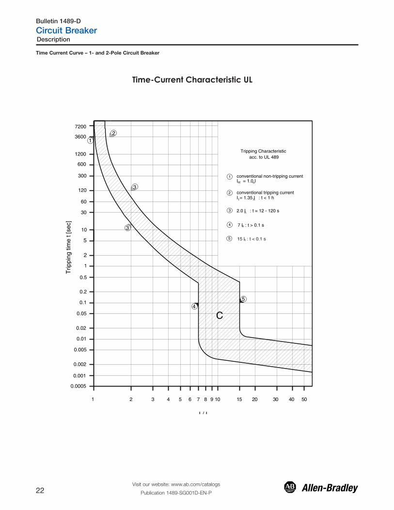
Time Current Curve – 1- and 2-Pole Circuit Breaker
Time-Current Characteristic UL
0.0005
Trip
ping
tim
e t [
sec]
I / I
7200
3600
1200
600
300
120
60
30
10
5
2
1
0.5
0.2
0.1
0.05
0.02
0.005
0.01
0.002
0.001
03 04 0551 022 3 4 5 6 7 8 9 011
C
1
2
t
nt
4
3
I = 1.0 In
I = 1.35 In : t < 1 h
2.0 In : t = 12 - 120 s
conventional non-tripping current
conventional tripping current
7 In : t > 0.1 s
Tripping Characteristic acc. to UL 489
15 In : t < 0.1 s
54
3
2
3
1
5
Description
Visit our website: www.ab.com/catalogs
Publication 1489-SG001D-EN-P22
Bulletin 1489-D
Circuit Breaker
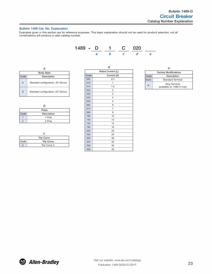
aBody Style
Code Description
A Standard configuration, AC Device
D Standard configuration, DC Device
bPoles
Code Description
1 1-Pole
2 2-Pole
cTrip Curve
Code Trip Curve
C Trip Curve C
dRated Current (In)
Code Current [A]
005 0.5
010 1
015 1.5
020 2
030 3
040 4
050 5
060 6
070 7
080 8
100 10
130 13
150 15
160 16
200 20
250 25
300 30
320 32
350 35
400 40
eFactory Modifications
Code Description
blank Standard Terminal
R Ring Terminal (available on 1489-A only)
Bulletin 1489 Cat. No. ExplanationExamples given in this section are for reference purposes. This basic explanation should not be used for product selection; not allcombinations will produce a valid catalog number.
1489 - D 1 C 020a b c d e
Catalog Number Explanation
Visit our website: www.ab.com/catalogs
Publication 1489-SG001D-EN-P 23
Bulletin 1489-D
Circuit Breaker
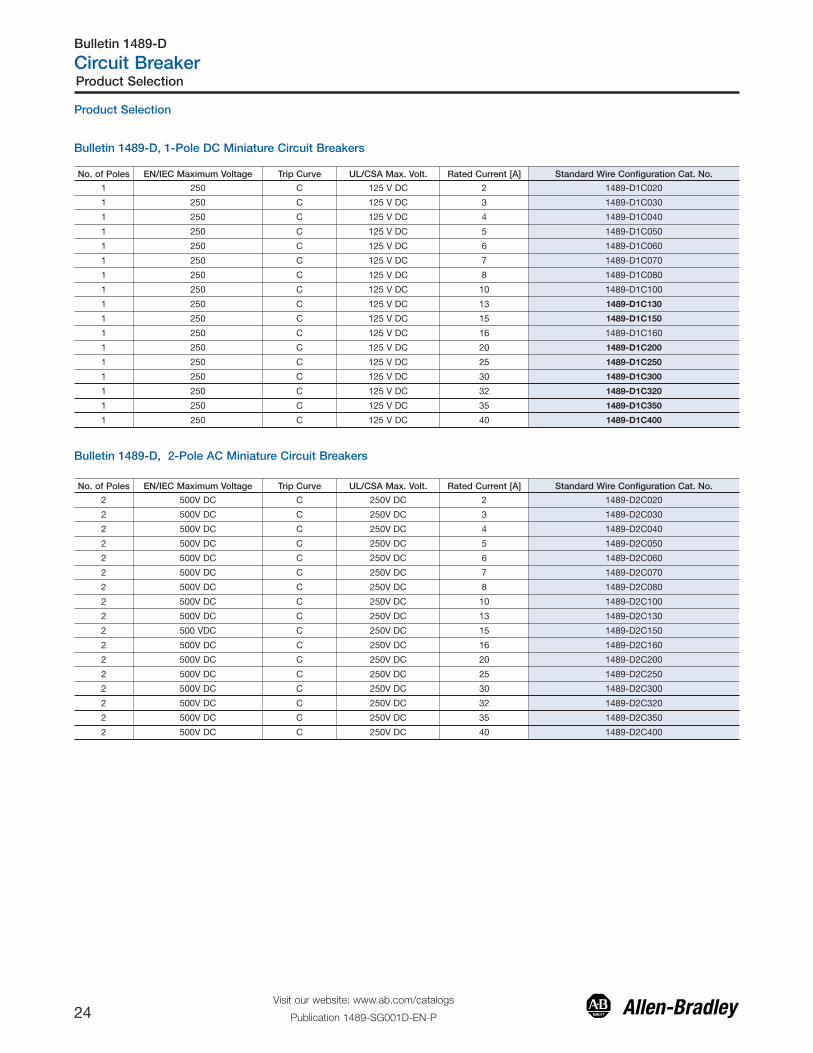
Product Selection
Bulletin 1489-D, 1-Pole DC Miniature Circuit Breakers
No. of Poles EN/IEC Maximum Voltage Trip Curve UL/CSA Max. Volt. Rated Current [A] Standard Wire Configuration Cat. No.
1 250 C 125 V DC 2 1489-D1C020
1 250 C 125 V DC 3 1489-D1C030
1 250 C 125 V DC 4 1489-D1C040
1 250 C 125 V DC 5 1489-D1C050
1 250 C 125 V DC 6 1489-D1C060
1 250 C 125 V DC 7 1489-D1C070
1 250 C 125 V DC 8 1489-D1C080
1 250 C 125 V DC 10 1489-D1C100
1 250 C 125 V DC 13 1489-D1C130
1 250 C 125 V DC 15 1489-D1C150
1 250 C 125 V DC 16 1489-D1C160
1 250 C 125 V DC 20 1489-D1C200
1 250 C 125 V DC 25 1489-D1C250
1 250 C 125 V DC 30 1489-D1C300
1 250 C 125 V DC 32 1489-D1C320
1 250 C 125 V DC 35 1489-D1C350
1 250 C 125 V DC 40 1489-D1C400
Bulletin 1489-D, 2-Pole AC Miniature Circuit Breakers
No. of Poles EN/IEC Maximum Voltage Trip Curve UL/CSA Max. Volt. Rated Current [A] Standard Wire Configuration Cat. No.
2 500V DC C 250V DC 2 1489-D2C020
2 500V DC C 250V DC 3 1489-D2C030
2 500V DC C 250V DC 4 1489-D2C040
2 500V DC C 250V DC 5 1489-D2C050
2 500V DC C 250V DC 6 1489-D2C060
2 500V DC C 250V DC 7 1489-D2C070
2 500V DC C 250V DC 8 1489-D2C080
2 500V DC C 250V DC 10 1489-D2C100
2 500V DC C 250V DC 13 1489-D2C130
2 500 VDC C 250V DC 15 1489-D2C150
2 500V DC C 250V DC 16 1489-D2C160
2 500V DC C 250V DC 20 1489-D2C200
2 500V DC C 250V DC 25 1489-D2C250
2 500V DC C 250V DC 30 1489-D2C300
2 500V DC C 250V DC 32 1489-D2C320
2 500V DC C 250V DC 35 1489-D2C350
2 500V DC C 250V DC 40 1489-D2C400
Product Selection
Visit our website: www.ab.com/catalogs
Publication 1489-SG001D-EN-P24
Bulletin 1489-D
Circuit Breaker
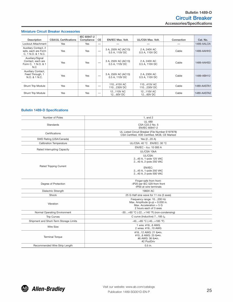
Miniature Circuit Breaker Accessories
Description CSA/UL CertificationsIEC 60947-2Compliance CE EN/IEC Max. Volt. UL/CSA Max. Volt. Connection Cat. No.
Lockout Attachment Yes Yes — — — — 1489-AALOA
Auxiliary Contact, 2sets, each are FormC, 1 N.O. & 1 N.C.
Yes Yes — 3 A, 250V AC (AC13)0.5 A, 110V DC
2 A, 240V AC0.5 A, 110V DC Cable 1489-AAHH3
Auxiliary/SignalContact, each are
Form C, 1 N.O. & 1N.C
Yes Yes — 3 A, 250V AC (AC13)0.5 A, 110V DC
2 A, 240V AC0.5 A, 110V DC Cable 1489-AAHS3
Auxiliary Contact,Feed Through, 1
N.O. & 1 N.C. Yes Yes — 3 A, 250V AC (AC13)0.5 A, 110V DC
2 A, 230V AC0.5 A, 110V DC Cable 1489-ABH12
Shunt Trip Module Yes Yes — 110...415V AC110…230V DC
110...415V AC110…230V DC Cable 1489-AASTA1
Shunt Trip Module Yes Yes — 12...110V AC12…60V DC
12...110V AC12…60V DC Cable 1489-AASTA2
Bulletin 1489-D Specifications
Number of Poles 1, and 2
StandardsUL 489
CSA C22.2 No. 5EN/IEC 60947-2
Certifications UL Listed Circuit Breaker (File Number E197878)CSA Certified, VDE Certified, MCB, CE Marked
SWD Rating (USA/Canada) Yes (2...20 A)
Calibration Temperature UL/CSA: 40 °C EN/IEC: 30 °C
Rated Interrupting CapacityEN/IEC - Icu: 10 000 A
UL/CSA 10kA
Rated Tripping Current
UL/CSA: 2...40 A, 1-pole 125 VAC2...40 A, 2-pole 250 VAC
EN/IEC:2...40 A, 1-pole 250 VAC2...40 A, 2-pole 500 VAC
Degree of ProtectionFinger-safe from front:
-IP20 per IEC 529 from front-IP00 at wire terminals
Dielectric Strength 1960V AC
Shock 25 G Half sine wave for 11 ms (3 axes)
Vibration
Frequency range: 10…200 HzMax. Amplitude (p-p) = 0.030 in.
Max. Acceleration = 5 G2 hours each of 3 axes
Normal Operating Environment -30…+60 °C (-22...+140 °F) (non-condensing)
Trip Curves C curve (Inductive) 7...185 IN
Shipment and Short-Term Storage Limits -40...+85 °C (-40...+185 °F)
Wire Size 1 wire: #18...6 AWG2 wires: #18...10 AWG
Terminal Torque
#18...12 AWG: 21 lb•in.#10...8 AWG: 25 lb•in.
#6 AWG: 36 lb•in.#2 PoziDriv
Recommended Wire Strip Length 0.5 in.
Accessories/Specifications
Visit our website: www.ab.com/catalogs
Publication 1489-SG001D-EN-P 25
Bulletin 1489-D
Circuit Breaker
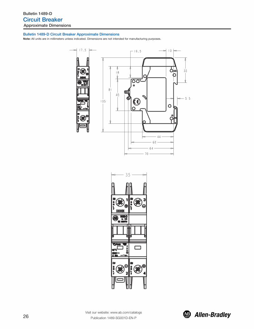
Bulletin 1489-D Circuit Breaker Approximate DimensionsNote: All units are in millimeters unless indicated. Dimensions are not intended for manufacturing purposes.
Approximate Dimensions
Visit our website: www.ab.com/catalogs
Publication 1489-SG001D-EN-P26
Bulletin 1489-D
Circuit Breaker
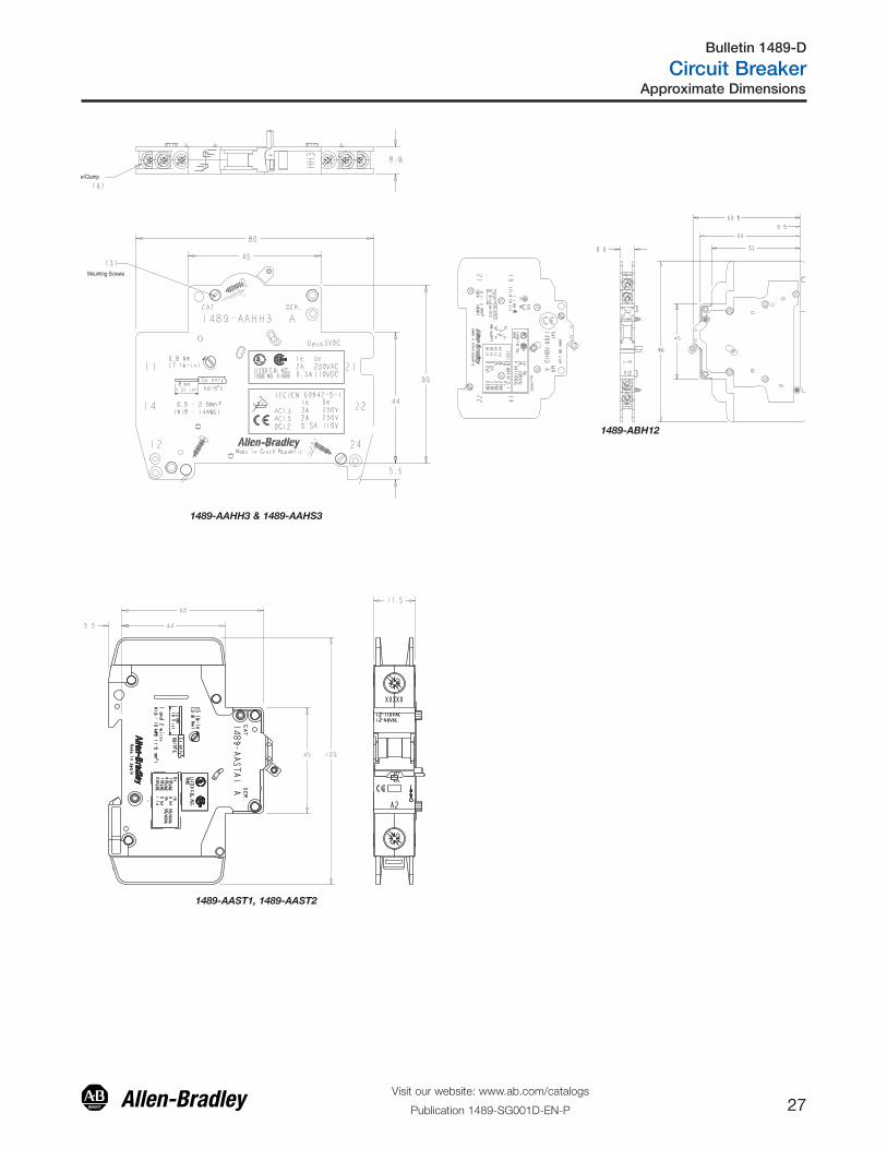
1489-AAST1, 1489-AAST2
Mounting Screws
w/Clamp
1489-AAHH3 & 1489-AAHS3
1489-ABH12
Approximate Dimensions
Visit our website: www.ab.com/catalogs
Publication 1489-SG001D-EN-P 27
Bulletin 1489-D
Circuit Breaker

Publication 1489-SG001D-EN-P – December 2010 Copyright ©2010 Rockwell Automation, Inc. All Rights Reserved. Printed in USA.Supersedes Publication 1489-SG001C-EN-P– June 2010
Allen-Bradley and Rockwell Automation are trademarks of Rockwell Automation, Inc.