Embed Size (px)
DESCRIPTION
Cable Laying & Blowing
Citation preview
Cable Laying & Blowing
Brief Flow of the Presentation:
• Preparation of Cable Laying
• Cable Laying
• Blowing
• Back Filling process
• Duct Integrity Tests
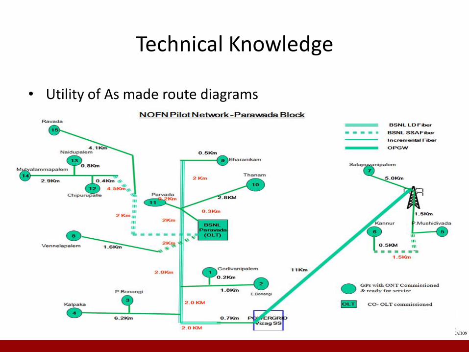
Technical Knowledge
• Utility of As made route diagrams
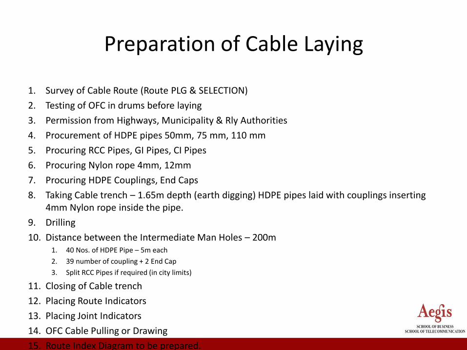
Preparation of Cable Laying
1. Survey of Cable Route (Route PLG & SELECTION)
2. Testing of OFC in drums before laying
3. Permission from Highways, Municipality & Rly Authorities
4. Procurement of HDPE pipes 50mm, 75 mm, 110 mm
5. Procuring RCC Pipes, GI Pipes, CI Pipes
6. Procuring Nylon rope 4mm, 12mm
7. Procuring HDPE Couplings, End Caps
8. Taking Cable trench – 1.65m depth (earth digging) HDPE pipes laid with couplings inserting 4mm Nylon rope inside the pipe.
9. Drilling
10. Distance between the Intermediate Man Holes – 200m1. 40 Nos. of HDPE Pipe – 5m each
2. 39 number of coupling + 2 End Cap
3. Split RCC Pipes if required (in city limits)
11. Closing of Cable trench
12. Placing Route Indicators
13. Placing Joint Indicators
14. OFC Cable Pulling or Drawing
15. Route Index Diagram to be prepared.

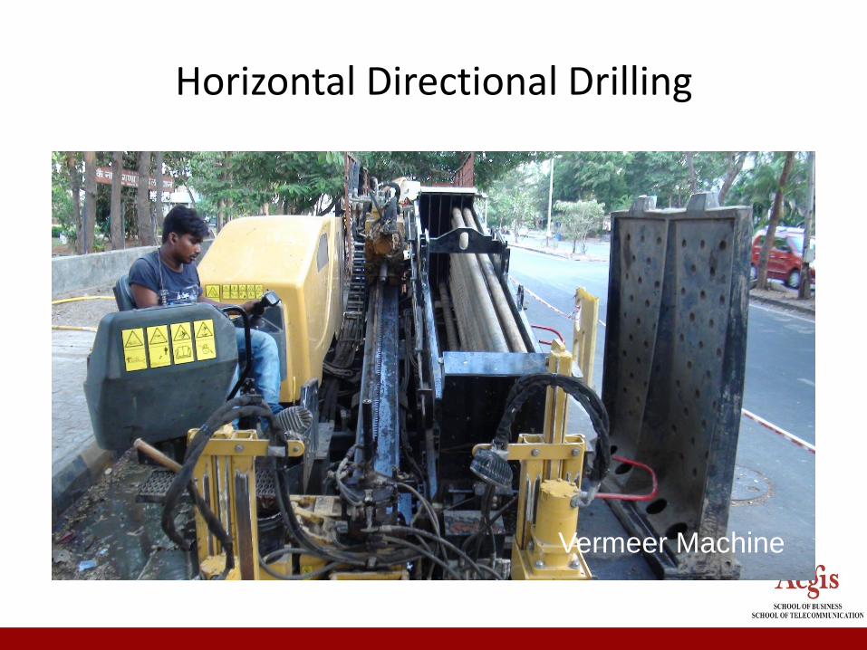
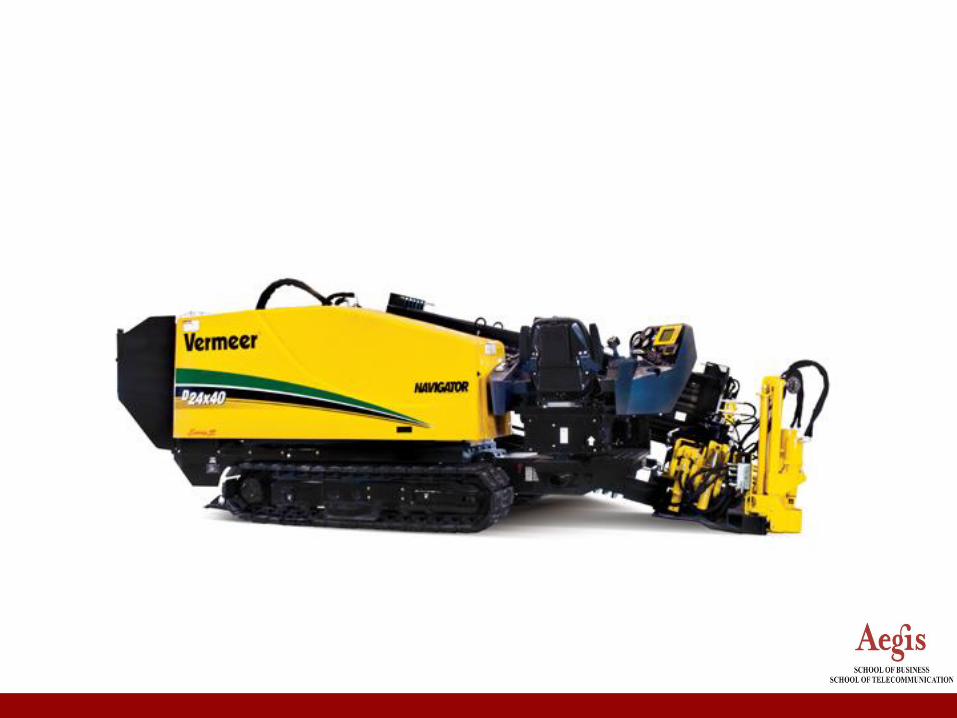
Horizontal Directional Drilling
Vermeer Machine
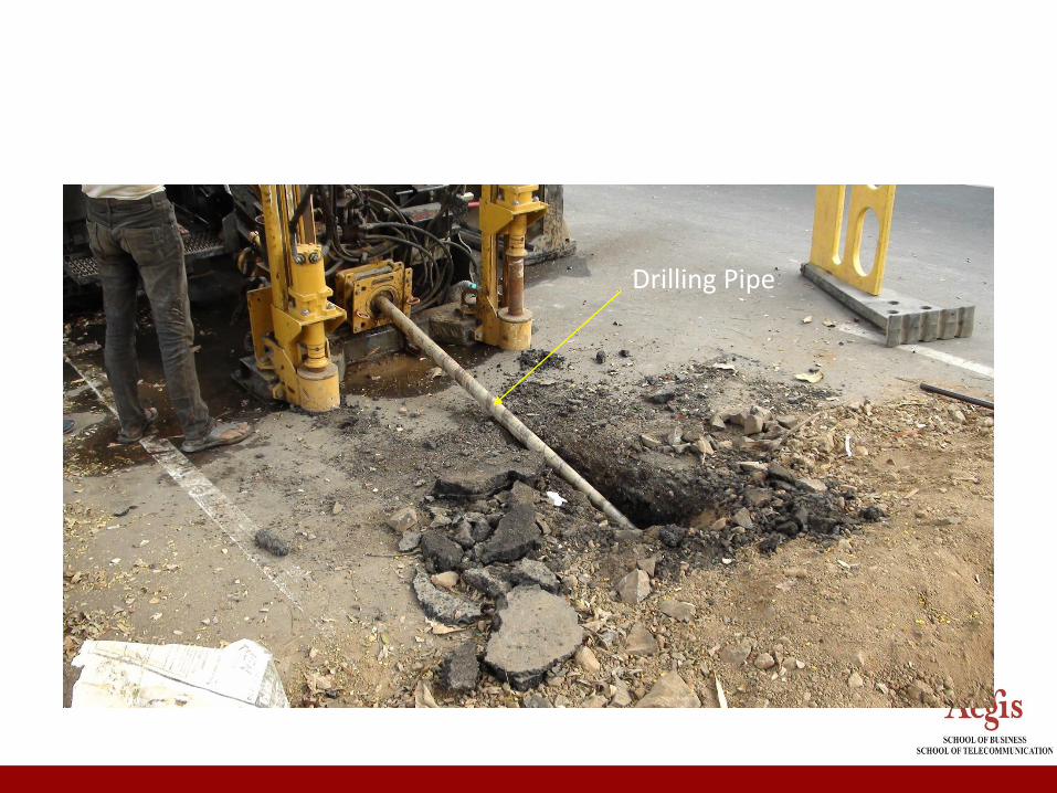
Drilling Pipe
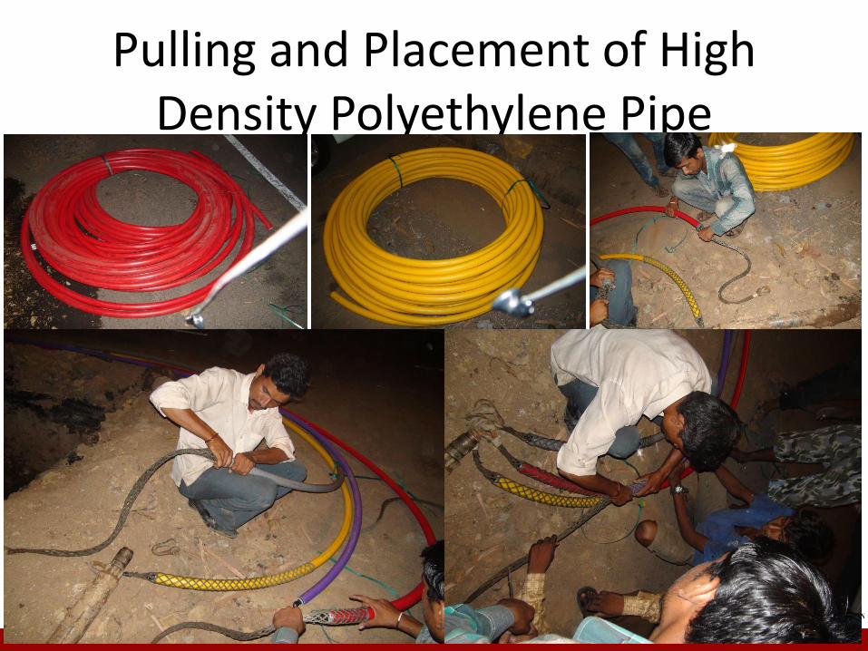
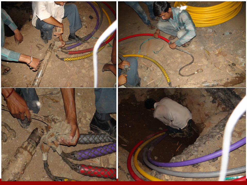
Pulling and Placement of High Density Polyethylene Pipe

Cable Laying
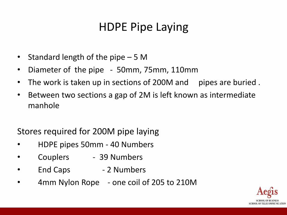
HDPE Pipe Laying
• Standard length of the pipe – 5 M
• Diameter of the pipe - 50mm, 75mm, 110mm
• The work is taken up in sections of 200M and pipes are buried .
• Between two sections a gap of 2M is left known as intermediate manhole
Stores required for 200M pipe laying
• HDPE pipes 50mm - 40 Numbers
• Couplers - 39 Numbers
• End Caps - 2 Numbers
• 4mm Nylon Rope - one coil of 205 to 210M

OFC pulling method
• 10 Sections of 200M each HDPE pipes are buried
• Open all the 9 intermediate Manholes
• Before laying the cable, ensure no blockage
• Bring the cable drum to the center at 1000M
• Center laying method is adopted
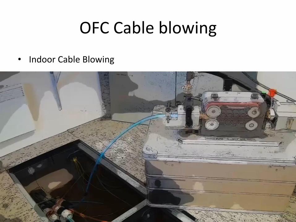
OFC Cable blowing
• Indoor Cable Blowing

OFC Cable blowing
• Outdoor Cable Blowing

Blowing
Blowing
• Some interesting installation methods are being used to put fiber optic cable in duct. Cable blowing is a method which use a high-volume air flow (7 bar back pressure) to "push" the cable. Most blowing machines also have mechanical "pushing", where the cable is pushed by traction rollers as it enters the duct.
Two basic types of blowing installation.
1. Piston Type - In this type of blowing unit, an air-tight piston is attached to the front of the cable. The air pushes this piston, and the piston "pulls" the cable. The pulling force is essentially the air pressure times the piston area. At 8 bar, the force can be 700N for 32mm high density polyethylene inner duct. Field users should be aware that a pulling force exists in piston blowing, and cable tension maximums should be respected
2. Laminar Flow Type - The second type of blowing unit does not use a piston -and allows full air flow through the duct. Calculations indicate that air speeds of 100 m/h are possible. This rushing air pushes on the cable jacket, providing a general force "all over" the jacket.
Mechanical "Pushing"
• Pushing has always been an effective way to make short runs of cable in conduct. However, you can only push a cable to the point that it buckles, which can be less than 50N for a flexible, indoor cable, and up to 300N for an armored, outdoor type cable.
• Even in straight ducts, pushing of typical outdoor cables is limited to maximum 100m.
• This means the air forces, piston or laminar, are key to making blowing units function for the 1000 - 2000m runs typical for outdoor cable application.
Air Tight Duct
• Cable blowing machines don't work unless the duct is air-tight. Reinforced duct splices are usually required. Most cable blowing to date has been done in continuous polyethylene innerduct, which minimizes opportunities for air loss. It's a mistake to try to blow cable into a duct that has not been prepared for the pressures and forces involved.
Key Application Parameters
• Fiber Optic cable-blowing research indicates three major factors control how far a cable can be blown. These are: – Duct fill (cable to duct size ratio)
– Cable flexibility or stiffness
– Coefficient of friction (lubrication)
• Belden completed a series of experiments in 1996 on high speed air blowing with both piston- and laminar flow unit. Coefficient of friction was studied. The results are useful to those blowing or planning on blowing cable.
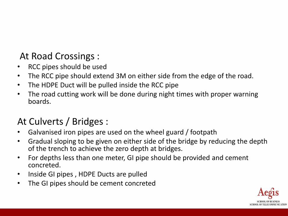
At Road Crossings :• RCC pipes should be used • The RCC pipe should extend 3M on either side from the edge of the road.• The HDPE Duct will be pulled inside the RCC pipe• The road cutting work will be done during night times with proper warning
boards.
At Culverts / Bridges :• Galvanised iron pipes are used on the wheel guard / footpath• Gradual sloping to be given on either side of the bridge by reducing the depth
of the trench to achieve the zero depth at bridges.• For depths less than one meter, GI pipe should be provided and cement
concreted.• Inside GI pipes , HDPE Ducts are pulled• The GI pipes should be cement concreted

At Railway Crossing :• Permission should be applied well in advance
• Cast Iron pipes are used below the tracks
• With in this CI pipe, HDPE should be drawn
• Angle of crossing should be 90 degrees
• The work is carried out by railway authorities
• Thrust boring method is used
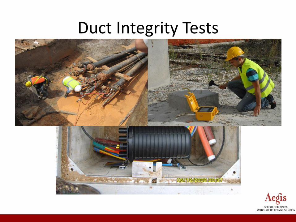
Duct Integrity Tests
Duct Integrity Tests
• After backfilling ducts shall be tested for integrity (air tightness and kink-free shape). Air tightness test is done by pressurizing 2 km duct stretches at a time.
• One end of duct will be closed and compressed air at 5-6kg/cm2 is sent from the other end.
• At about 5kg/cm2 pressure the inlet of compressed air will be closed. Fall in pressure should not be more than 50% in 1(one) hour.
• To check that duct has not collapsed or kinked a wooden cylindrical piece (shuttle) is blown into the duct with far end fitted with Flexible wire grip/stocking.
• The wooden shuttle should pass through duct at far end with out any obstruction and within approx. 10 minutes or less.
• Fiber Termination All fibers of OF cables will be terminated on Fiber Management
• System (FMS) at each regenerator (REG) or ADM (add drop multiplexer) location. Installation of FMS is done according to the manufacturer's specification.
• End to End testing can be carried out from the FMS to FMS using the connectors who are mounted on the FMS.
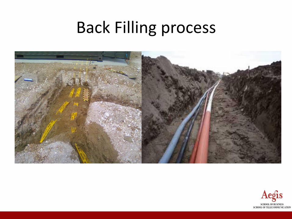
Back Filling process
Back Filling process
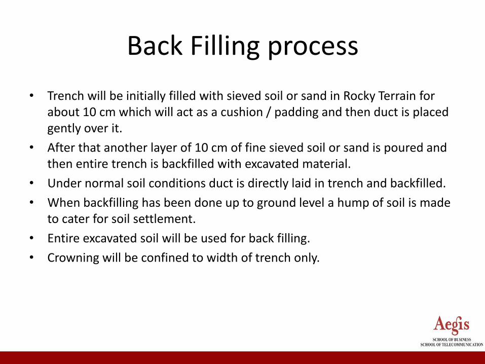
• Trench will be initially filled with sieved soil or sand in Rocky Terrain for about 10 cm which will act as a cushion / padding and then duct is placed gently over it.
• After that another layer of 10 cm of fine sieved soil or sand is poured and then entire trench is backfilled with excavated material.
• Under normal soil conditions duct is directly laid in trench and backfilled.
• When backfilling has been done up to ground level a hump of soil is made to cater for soil settlement.
• Entire excavated soil will be used for back filling.
• Crowning will be confined to width of trench only.
Thank You


![Ropes for Subsea Cable Laying - brunton-shaw.com · [ BUOY & GRAPNEL ] Cable Laid combined (wire and natural fibre) ropes specially designed for Subsea Cable Laying duties Ropes for](https://img.pdfslide.net/doc/110x75/5e126c3ed43a5b3e643fb493/ropes-for-subsea-cable-laying-brunton-shawcom-buoy-grapnel-cable-laid.jpg)