Embed Size (px)
Citation preview

Equipped with a sophisticated transmitter (including extensive diagnostics, a large display, and field configurability via keypad), the Cameron CT Series are high- performance Coriolis flow meters capable of mass flow measurement with a high degree of accuracy. Particularly worth noting are its uses in non-routine flow rate measurement, including measurement of extra low-volume flows, short-duration filling processes, etc.
FEATURES + Outstanding zero stability performance + High-accuracy density: ±0.0005 g/mL (Models CC003 to CC250)
+ Fast response and calculation frequency + Dual independent pulse outputs, dual independent analog outputs, one status input and one status output
+ Configurable via keypad or digital communications + Extensive self-diagnostic capabilities (connection faults, pipeline vibration, media pulsation, etc.)
+ Enhanced maintenance functions (event/user change logging and downloads, recoverable factory configuration and calibration, etc.)
+ User-configurable alarms + Compatible with HART and Modbus communication protocols
UNITSThe specifications for the CT Series meters are presented in both U.S. customary units and metric units. For U.S. customary units, see page 2 through page 22. For metric units, see Appendix A: Metric Units, page A-1.
ADDITIONAL INFORMATION To view available product configurations and to request additional information, see Appendix B, beginning on page B-1.
CamCorTM CT Series MetersHigh-Performance Coriolis Flow Meters
PRODUCT OVERVIEW MEASUREMENT SOLUTIONS

CamCorTM CT Series Coriolis Flow Meter
GENERAL PERFORMANCE
Flow Rate
Meter type Model Size (in.)
Guaranteed minimum rate (lb/min)
Minimum setting rate (lb/min)
Maximum service rate (lb/min)
Maximum allowable rate (lb/min)
Uncertainty (5) Repeatability (5) Zero stability (lb/min)
Analog output uncertainty
Liquids Gases Liquids Gases
Low-flow CC00A 1/4 0.00088 0.0044 0.088 0.132 ±0.2% “of reading (±ZS) (5)”
±0.5%of reading (±ZS)
±0.05% of reading(±1/2 ZS)
±0.25%of reading (±1/2 ZS)
0.000013 ±0.1%of full scaleCC001 0.0033 0.0165 0.33 0.496 0.00005
CC003 1/2 0.026 (0.033) (1) 0.13 2.65 5.29 (6.61) (1) ±0.1%of reading (2)
±0.5%of reading (3)
0.000066CC006 1/2 0.132 0.66 13.23 26.46 0.00066CC010 1/2 0.44 2.2 44.09 88.18 0.0022CC015 1/2 1.32 6.61 132 265 0.0066
Standard and Low-temperature
CC025 1 3.97 19.8 397 794 0.0198CC040 1-1/2 14.33 71.7 1433 2866 0.071CC050 2CC080 3 44.09 220 4409 8818 0.22CC100 4 126 628 12566 25133 “±0.1%
of reading(±ZS) (4)
– ±0.05%of reading (±1/2 ZS)
– 0.628
CC150 6CC15H 6 257 1286 25721 51441 1.286CC200 8CC20H 8 514 2572 51441 102883 2.572CC250 10
High-pressure CC010 3/8 0.88 4.41 30.86 61.73 ±0.2% of reading(±ZS) (5)
±0.5% of reading (±ZS)
±0.1%of reading (±1/2 ZS)
±0.25%of reading (±1/2 ZS)
0.0077
CC015 3/4 2.87 14.33 93.7 187 0.0234
High-temperature
CC025 1 3.97 19.8 397 794 ±0.1% of reading(±ZS)
– ±0.5% of reading(±1/2 ZS)
– 0.0396
CC040 1-1/2 14.33 71.7 1433 2866 0.143CC050 2CC080 3 44.09 220 4409 8818 0.441CC100 4 126 628 12566 25133 1.257CC150 6
1. When a maximum allowable range 6.61 lb/min is adopted, the minimum flow rate is 0.033 lb/min.2. ±ZS is applied for flow rates below 5% ( 2.5% for Model CC003) of the maximum service rate (within the guaranteed flow range).3. ±1/2 ZS is applied for flow rates below 5% (2.5% for Model CC003) of the maximum service rate (within the guaranteed flow range).4. If an uncertainty of ±0.1% of reading is required, consult Cameron.5. Above maximum service flow rate, the uncertainty is ±0.3% of reading (±ZS).
* If you request volume flow measurement for the purpose of fiscal transactions or weights and measurements transactions, contact Cameron.
* In gas measurement, the maximum permissible flow velocity varies with the type of gas and some may be beyond the bounds of measurement. If so, contact Cameron.
* ZS = Zero stability error (During testing, zero stability and current flow rate should be read in the same measurement unit.). Zero stability error = Zero stability
Current flow rate x 100
CamCorTM CT Series Coriolis Flow Meter
GENERAL PERFORMANCE
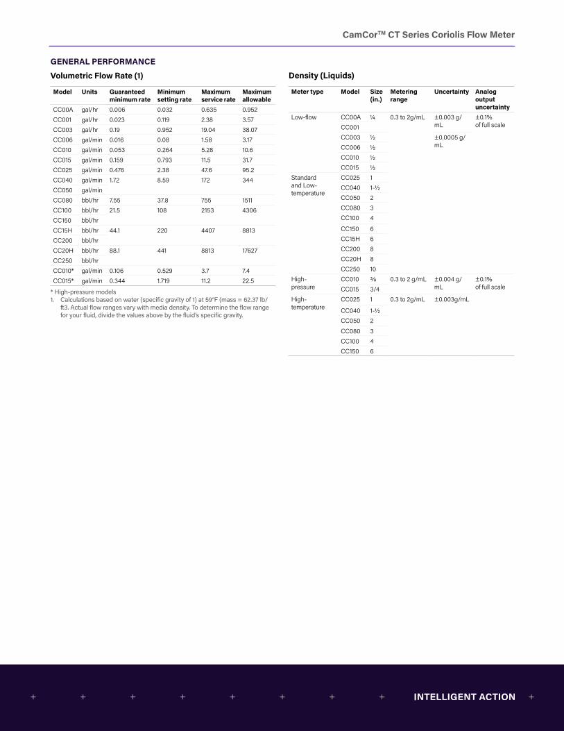
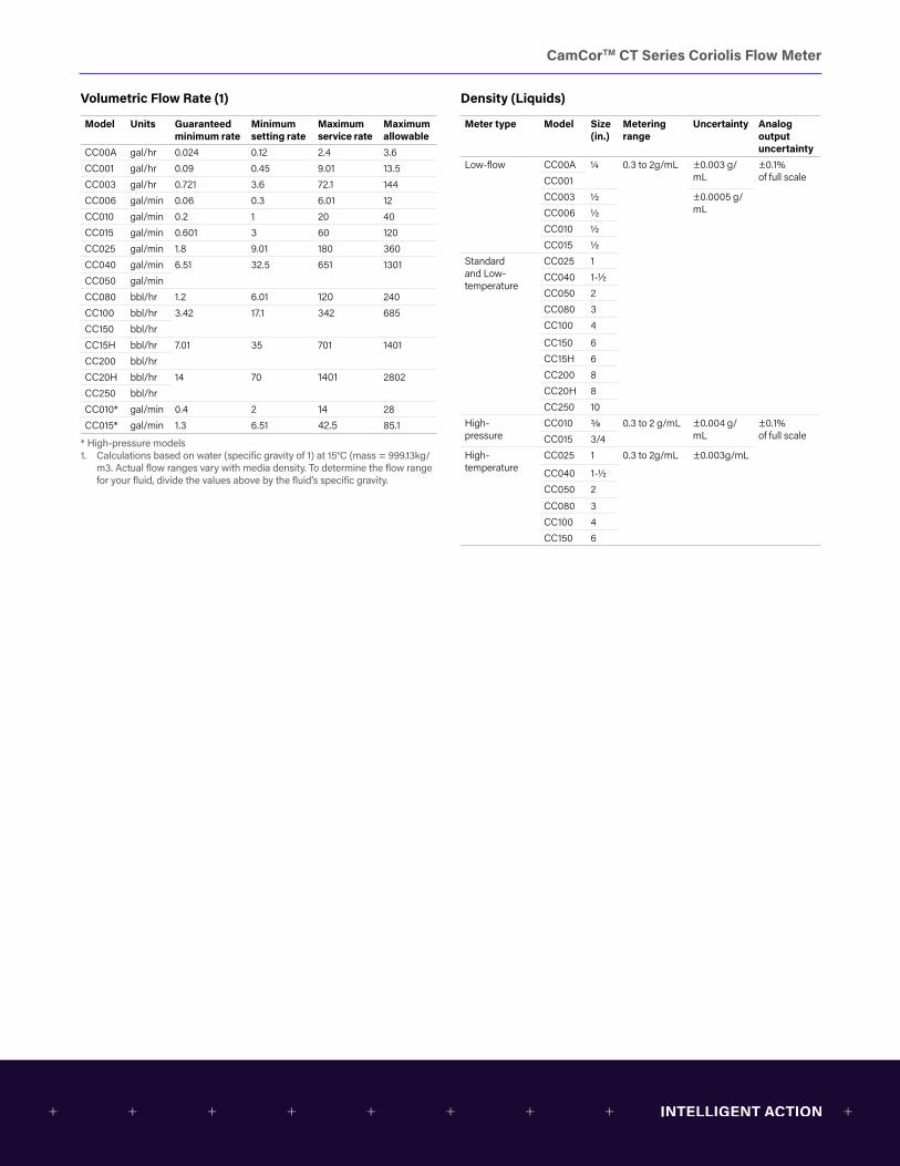
Volumetric Flow Rate (1)
Model Units Guaranteed minimum rate
Minimum setting rate
Maximum service rate
Maximum allowable
CC00A gal/hr 0.006 0.032 0.635 0.952CC001 gal/hr 0.023 0.119 2.38 3.57CC003 gal/hr 0.19 0.952 19.04 38.07CC006 gal/min 0.016 0.08 1.58 3.17CC010 gal/min 0.053 0.264 5.28 10.6CC015 gal/min 0.159 0.793 11.5 31.7CC025 gal/min 0.476 2.38 47.6 95.2CC040 gal/min 1.72 8.59 172 344CC050 gal/minCC080 bbl/hr 7.55 37.8 755 1511CC100 bbl/hr 21.5 108 2153 4306CC150 bbl/hrCC15H bbl/hr 44.1 220 4407 8813CC200 bbl/hrCC20H bbl/hr 88.1 441 8813 17627CC250 bbl/hrCC010* gal/min 0.106 0.529 3.7 7.4CC015* gal/min 0.344 1.719 11.2 22.5
* High-pressure models1. Calculations based on water (specific gravity of 1) at 59°F (mass = 62.37 lb/
ft3. Actual flow ranges vary with media density. To determine the flow range for your fluid, divide the values above by the fluid’s specific gravity.
Density (Liquids)
Meter type Model Size (in.)
Metering range
Uncertainty Analog output uncertainty
Low-flow CC00A 1/4 0.3 to 2g/mL ±0.003 g/mL
±0.1%of full scaleCC001
CC003 1/2 ±0.0005 g/mLCC006 1/2
CC010 1/2CC015 1/2
Standard and Low-temperature
CC025 1CC040 1-1/2CC050 2CC080 3CC100 4
CC150 6CC15H 6CC200 8CC20H 8CC250 10
High- pressure
CC010 3/8 0.3 to 2 g/mL ±0.004 g/mL
±0.1%of full scaleCC015 3/4
High- temperature
CC025 1 0.3 to 2g/mL ±0.003g/mL
CC040 1-1/2CC050 2CC080 3CC100 4CC150 6
CamCorTM CT Series Coriolis Flow Meter
GENERAL PERFORMANCE
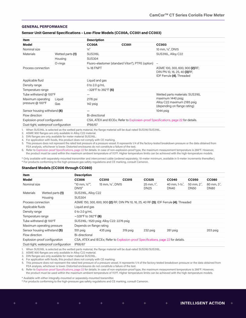
Sensor Unit General Specifications – Low-Flow Models (CC00A, CC001 and CC003)
Item DescriptionModel CC00A CC001 CC003Nominal size 1/4” 10 mm, 1/2″, DN15Materials Wetted parts (1) SUS316L SUS316L, Alloy C22
Housing SUS304O-rings Fluoro-elastomer (standard Viton®), PTFE (option) –
Process connection 1/4-18 FNPT ASME 100, 300, 600, 900 (2)RF;DIN PN 10, 16, 25, 40 (3)RF,IDF Ferrule (4), Threaded
Applicable fluid Liquid and gasDensity range 0 to 2.0 g/mLTemperature range −328°F to 392°F (5)Tube withstand @ 100°F — Wetted parts materials: SUS316L
maximum 1440 psig;Alloy C22 maximum 2185 psig (depending on flange rating)
Maximum operating pressure @ 100°F
Liquid 2176 psiGas 142 psig
Sensor housing withstand (6) — 1044 psigFlow direction Bi-directionalExplosion-proof configuration CSA, ATEX and IECEx; Refer to Explosion-proof Specifications, page 22 for details.Dust-tight, waterproof configuration IP66/67
1. When SUS316L is selected as the wetted parts material, the flange material will be dual-rated SUS316/SUS316L.2. ASME 900 flanges are only available in Alloy C22 material.3. DIN flanges are only available for meter material SUS316L.4. For application with foods, this product does not comply with CE marking.5. This pressure does not represent the rated test pressure of a pressure vessel. It represents 1/4 of the factory-tested breakdown pressure or the data obtained from
FEA analysis, whichever is lower. Distorted enclosures do not constitute a failure of the test.6. Refer to Explosion-proof Specifications, page 22 for details. In case of non-explosion-proof type, the maximum measurement temperature is 266°F. However,
the product must be used within the maximum ambient temperature of 113°F. Higher temperature limits can be achieved with the high-temperature models.
* Only available with separately-mounted transmitter and interconnect cable (ordered separately; 10-meter minimum, available in 5-meter increments thereafter).* For products conforming to the high-pressure gas safety regulations and CE marking, consult Cameron.
Standard Models (CC006 through CC080)
Item DescriptionModel CC006 CC010 CC015 CC025 CC040 CC050 CC080Nominal size “10 mm, 1/2””,
DN15”15 mm, 1/2 ,̋ DN15 25 mm, 1 ,̋
DN2540 mm, 1-1/2 ,̋ DN40
50 mm, 2 ,̋ DN50
80 mm, 3 ,̋ DN80
Materials Wetted parts (1) SUS316L, Alloy C22Housing SUS304
Process connection ASME 150, 300, 600, 900 (2) RF; DIN PN 10, 16, 25, 40 RF (3); IDF Ferrule (4); ThreadedApplicable fluids Liquid and gasDensity range 0 to 2.0 g/mLTemperature range −328°F to 392°F (6)Tube withstand @ 100°F SUS316L: 1520 psig; Alloy C22: 2276 psigMaximum operating pressure Depends on flange ratingSensor housing withstand (5) 551 psig 435 psig 319 psig 232 psig 261 psig 203 psigFlow direction Bi-directionalExplosion-proof configuration CSA, ATEX and IECEx; Refer to Explosion-proof Specifications, page 22 for details.Dust-tight, waterproof configuration IP66/67
1. When SUS316L is selected as the wetted parts material, the flange material will be dual-rated SUS316/SUS316L.2. ASME 900 flanges are only available in Alloy C22 material.3. DIN flanges are only available for meter material SUS316L.4. For application with foods, this product does not comply with CE marking.5. This pressure does not represent the rated test pressure of a pressure vessel. It represents 1/4 of the factory-tested breakdown pressure or the data obtained from
FEA analysis, whichever is lower. Distorted enclosures do not constitute a failure of the test.6. Refer to Explosion-proof Specifications, page 22 for details. In case of non-explosion-proof type, the maximum measurement temperature is 266°F. However,
the product must be used within the maximum ambient temperature of 113°F. Higher temperature limits can be achieved with the high-temperature models.
* Available with either integrally-mounted or separately-mounted transmitter.* For products conforming to the high-pressure gas safety regulations and CE marking, consult Cameron.
CamCorTM CT Series Coriolis Flow Meter
GENERAL PERFORMANCE
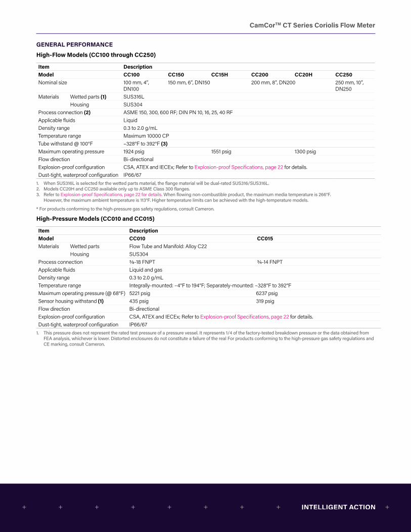
High-Flow Models (CC100 through CC250)
Item DescriptionModel CC100 CC150 CC15H CC200 CC20H CC250Nominal size 100 mm, 4″,
DN100150 mm, 6″, DN150 200 mm, 8″, DN200 250 mm, 10″,
DN250Materials Wetted parts (1) SUS316L
Housing SUS304Process connection (2) ASME 150, 300, 600 RF; DIN PN 10, 16, 25, 40 RFApplicable fluids LiquidDensity range 0.3 to 2.0 g/mLTemperature range Maximum 10000 CPTube withstand @ 100°F –328°F to 392°F (3)Maximum operating pressure 1924 psig 1551 psig 1300 psigFlow direction Bi-directionalExplosion-proof configuration CSA, ATEX and IECEx; Refer to Explosion-proof Specifications, page 22 for details.Dust-tight, waterproof configuration IP66/67
1. When SUS316L is selected for the wetted parts material, the flange material will be dual-rated SUS316/SUS316L.2. Models CC20H and CC250 available only up to ASME Class 300 flanges.3. Refer to Explosion-proof Specifications, page 22 for details. When flowing non-combustible product, the maximum media temperature is 266°F.
However, the maximum ambient temperature is 113°F. Higher temperature limits can be achieved with the high-temperature models.
* For products conforming to the high-pressure gas safety regulations, consult Cameron.
High-Pressure Models (CC010 and CC015)
Item DescriptionModel CC010 CC015Materials Wetted parts Flow Tube and Manifold: Alloy C22
Housing SUS304Process connection 3/8-18 FNPT 3/4-14 FNPTApplicable fluids Liquid and gasDensity range 0.3 to 2.0 g/mLTemperature range Integrally-mounted: –4°F to 194°F; Separately-mounted: –328°F to 392°FMaximum operating pressure (@ 68°F) 5221 psig 6237 psigSensor housing withstand (1) 435 psig 319 psigFlow direction Bi-directionalExplosion-proof configuration CSA, ATEX and IECEx; Refer to Explosion-proof Specifications, page 22 for details.Dust-tight, waterproof configuration IP66/67
1. This pressure does not represent the rated test pressure of a pressure vessel. It represents 1/4 of the factory-tested breakdown pressure or the data obtained from FEA analysis, whichever is lower. Distorted enclosures do not constitute a failure of the real For products conforming to the high-pressure gas safety regulations and CE marking, consult Cameron.
CamCorTM CT Series Coriolis Flow Meter
GENERAL PERFORMANCE
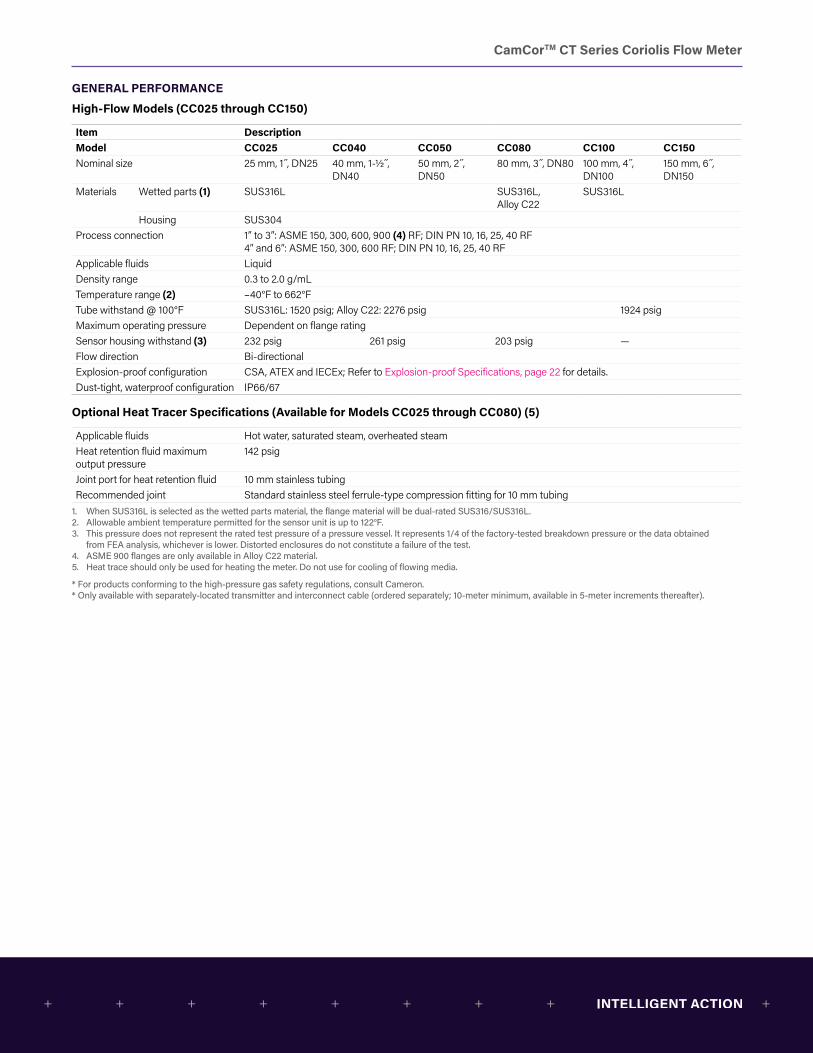
High-Flow Models (CC025 through CC150)
Item DescriptionModel CC025 CC040 CC050 CC080 CC100 CC150Nominal size 25 mm, 1 ,̋ DN25 40 mm, 1-1/2 ,̋
DN4050 mm, 2 ,̋ DN50
80 mm, 3 ,̋ DN80 100 mm, 4 ,̋ DN100
150 mm, 6 ,̋ DN150
Materials Wetted parts (1) SUS316L SUS316L,Alloy C22
SUS316L
Housing SUS304Process connection 1” to 3”: ASME 150, 300, 600, 900 (4) RF; DIN PN 10, 16, 25, 40 RF
4” and 6”: ASME 150, 300, 600 RF; DIN PN 10, 16, 25, 40 RFApplicable fluids LiquidDensity range 0.3 to 2.0 g/mLTemperature range (2) –40°F to 662°FTube withstand @ 100°F SUS316L: 1520 psig; Alloy C22: 2276 psig 1924 psigMaximum operating pressure Dependent on flange ratingSensor housing withstand (3) 232 psig 261 psig 203 psig —Flow direction Bi-directionalExplosion-proof configuration CSA, ATEX and IECEx; Refer to Explosion-proof Specifications, page 22 for details.Dust-tight, waterproof configuration IP66/67
Optional Heat Tracer Specifications (Available for Models CC025 through CC080) (5)
Applicable fluids Hot water, saturated steam, overheated steamHeat retention fluid maximum output pressure
142 psig
Joint port for heat retention fluid 10 mm stainless tubingRecommended joint Standard stainless steel ferrule-type compression fitting for 10 mm tubing
1. When SUS316L is selected as the wetted parts material, the flange material will be dual-rated SUS316/SUS316L.2. Allowable ambient temperature permitted for the sensor unit is up to 122°F.3. This pressure does not represent the rated test pressure of a pressure vessel. It represents 1/4 of the factory-tested breakdown pressure or the data obtained
from FEA analysis, whichever is lower. Distorted enclosures do not constitute a failure of the test.4. ASME 900 flanges are only available in Alloy C22 material.5. Heat trace should only be used for heating the meter. Do not use for cooling of flowing media.
* For products conforming to the high-pressure gas safety regulations, consult Cameron. * Only available with separately-located transmitter and interconnect cable (ordered separately; 10-meter minimum, available in 5-meter increments thereafter).
CamCorTM CT Series Coriolis Flow Meter
GENERAL PERFORMANCE
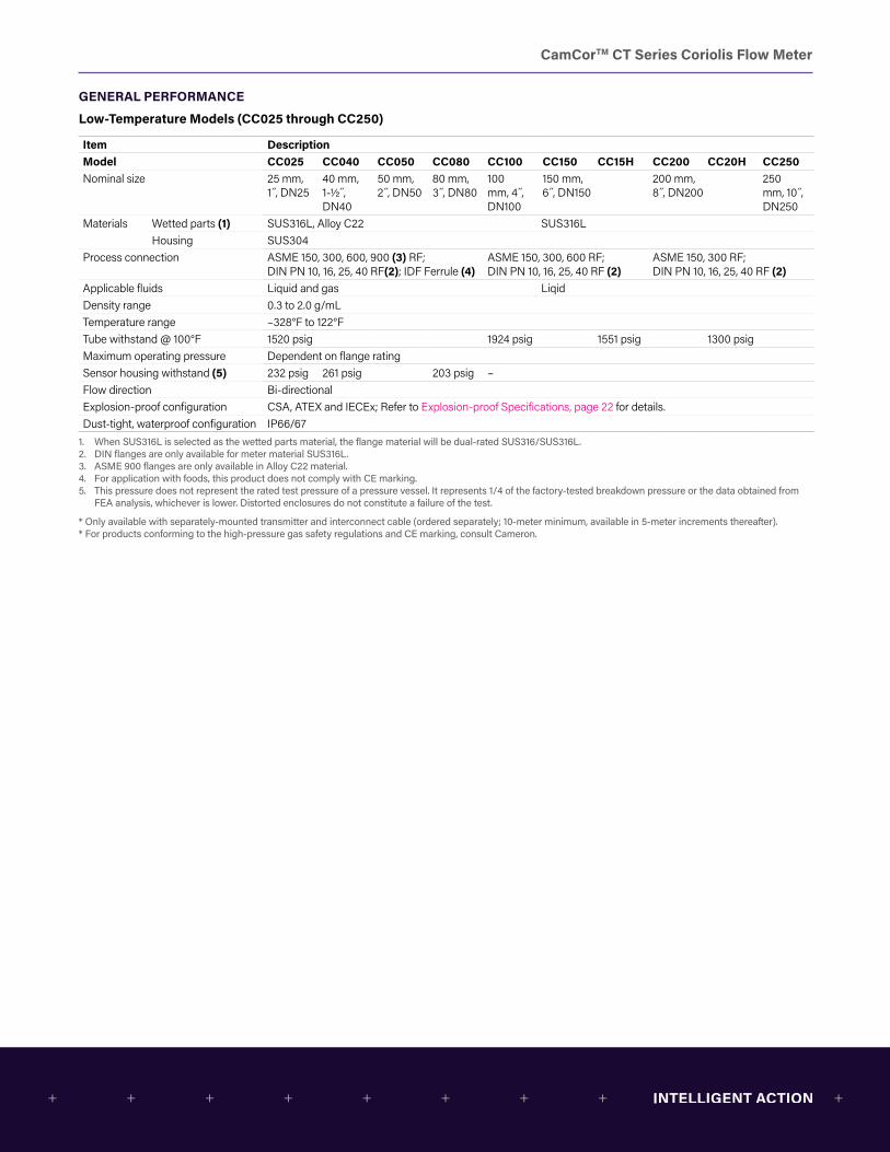
Low-Temperature Models (CC025 through CC250)
Item DescriptionModel CC025 CC040 CC050 CC080 CC100 CC150 CC15H CC200 CC20H CC250Nominal size 25 mm,
1 ,̋ DN25 40 mm, 1-1/2 ,̋ DN40
50 mm, 2 ,̋ DN50
80 mm, 3 ,̋ DN80
100 mm, 4 ,̋ DN100
150 mm,6 ,̋ DN150
200 mm,8 ,̋ DN200
250 mm, 10 ,̋ DN250
Materials Wetted parts (1) SUS316L, Alloy C22 SUS316LHousing SUS304
Process connection ASME 150, 300, 600, 900 (3) RF;DIN PN 10, 16, 25, 40 RF(2); IDF Ferrule (4)
ASME 150, 300, 600 RF;DIN PN 10, 16, 25, 40 RF (2)
ASME 150, 300 RF;DIN PN 10, 16, 25, 40 RF (2)
Applicable fluids Liquid and gas LiqidDensity range 0.3 to 2.0 g/mLTemperature range –328°F to 122°FTube withstand @ 100°F 1520 psig 1924 psig 1551 psig 1300 psig Maximum operating pressure Dependent on flange ratingSensor housing withstand (5) 232 psig 261 psig 203 psig –Flow direction Bi-directionalExplosion-proof configuration CSA, ATEX and IECEx; Refer to Explosion-proof Specifications, page 22 for details.Dust-tight, waterproof configuration IP66/67
1. When SUS316L is selected as the wetted parts material, the flange material will be dual-rated SUS316/SUS316L.2. DIN flanges are only available for meter material SUS316L.3. ASME 900 flanges are only available in Alloy C22 material.4. For application with foods, this product does not comply with CE marking.5. This pressure does not represent the rated test pressure of a pressure vessel. It represents 1/4 of the factory-tested breakdown pressure or the data obtained from
FEA analysis, whichever is lower. Distorted enclosures do not constitute a failure of the test.
* Only available with separately-mounted transmitter and interconnect cable (ordered separately; 10-meter minimum, available in 5-meter increments thereafter).* For products conforming to the high-pressure gas safety regulations and CE marking, consult Cameron.
CamCorTM CT Series Coriolis Flow Meter
GENERAL PERFORMANCE
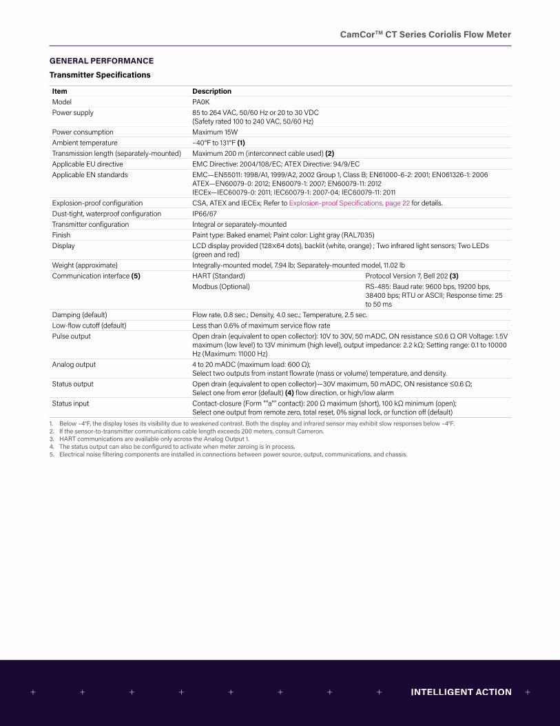
Transmitter Specifications
Item DescriptionModel PA0KPower supply 85 to 264 VAC, 50/60 Hz or 20 to 30 VDC
(Safety rated 100 to 240 VAC, 50/60 Hz)Power consumption Maximum 15WAmbient temperature –40°F to 131°F (1)Transmission length (separately-mounted) Maximum 200 m (interconnect cable used) (2)Applicable EU directive EMC Directive: 2004/108/EC; ATEX Directive: 94/9/ECApplicable EN standards EMC—EN55011: 1998/A1, 1999/A2, 2002 Group 1, Class B; EN61000-6-2: 2001; EN061326-1: 2006
ATEX—EN60079-0: 2012; EN60079-1: 2007; EN60079-11: 2012 IECEx—IEC60079-0: 2011; IEC60079-1: 2007-04; IEC60079-11: 2011
Explosion-proof configuration CSA, ATEX and IECEx; Refer to Explosion-proof Specifications, page 22 for details.Dust-tight, waterproof configuration IP66/67Transmitter configuration Integral or separately-mountedFinish Paint type: Baked enamel; Paint color: Light gray (RAL7035)Display LCD display provided (128×64 dots), backlit (white, orange) ; Two infrared light sensors; Two LEDs
(green and red)Weight (approximate) Integrally-mounted model, 7.94 lb; Separately-mounted model, 11.02 lbCommunication interface (5) HART (Standard) Protocol Version 7, Bell 202 (3)
Modbus (Optional) RS-485: Baud rate: 9600 bps, 19200 bps, 38400 bps; RTU or ASCII; Response time: 25 to 50 ms
Damping (default) Flow rate, 0.8 sec.; Density, 4.0 sec.; Temperature, 2.5 sec.Low-flow cutoff (default) Less than 0.6% of maximum service flow ratePulse output Open drain (equivalent to open collector): 10V to 30V, 50 mADC, ON resistance ≤0.6 Ω OR Voltage: 1.5V
maximum (low level) to 13V minimum (high level), output impedance: 2.2 kΩ; Setting range: 0.1 to 10000 Hz (Maximum: 11000 Hz)
Analog output 4 to 20 mADC (maximum load: 600 Ω); Select two outputs from instant flowrate (mass or volume) temperature, and density.
Status output Open drain (equivalent to open collector)—30V maximum, 50 mADC, ON resistance ≤0.6 Ω; Select one from error (default) (4) flow direction, or high/low alarm
Status input Contact-closure (Form ""a"" contact): 200 Ω maximum (short), 100 kΩ minimum (open); Select one output from remote zero, total reset, 0% signal lock, or function off (default)
1. Below –4°F, the display loses its visibility due to weakened contrast. Both the display and infrared sensor may exhibit slow responses below –4°F.2. If the sensor-to-transmitter communications cable length exceeds 200 meters, consult Cameron.3. HART communications are available only across the Analog Output 1.4. The status output can also be configured to activate when meter zeroing is in process.5. Electrical noise filtering components are installed in connections between power source, output, communications, and chassis.
CamCorTM CT Series Coriolis Flow Meter
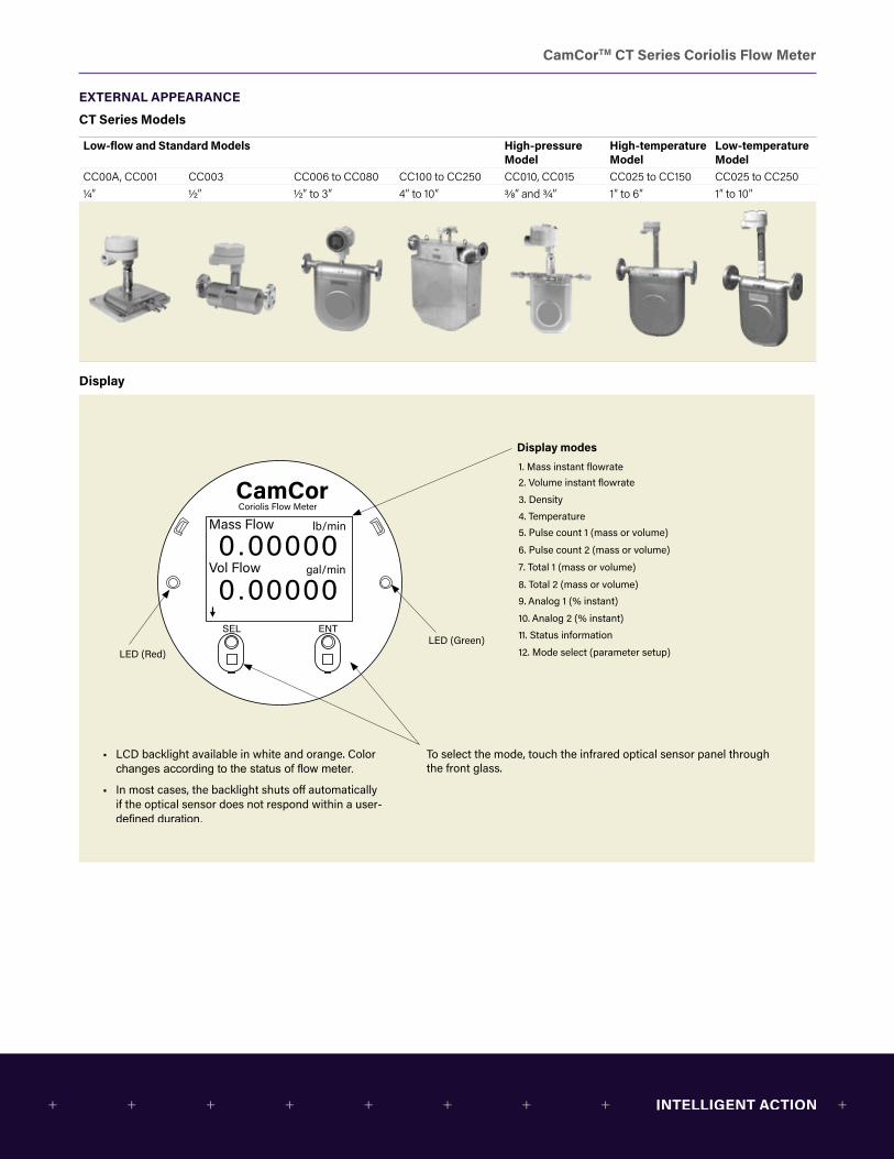
EXTERNAL APPEARANCE
CT Series Models
Low-flow and Standard Models High-pressure Model
High-temperature Model
Low-temperature Model
CC00A, CC001 CC003 CC006 to CC080 CC100 to CC250 CC010, CC015 CC025 to CC150 CC025 to CC2501/4″ 1/2″ 1/2″ to 3″ 4″ to 10″ 3/8” and 3/4” 1″ to 6″ 1″ to 10″
Display
lb/min
gal/min
Mass Flow
Vol Flow
CamCorCoriolis Flow Meter
1. Mass instant flowrate2. Volume instant flowrate
3. Density
4. Temperature5. Pulse count 1 (mass or volume)
6. Pulse count 2 (mass or volume)
7. Total 1 (mass or volume)
8. Total 2 (mass or volume)9. Analog 1 (% instant)
10. Analog 2 (% instant)
11. Status information
12. Mode select (parameter setup)LED (Green)
LED (Red)
To select the mode, touch the infrared optical sensor panel through the front glass.
Display modes
• LCD backlight available in white and orange. Color
• In most cases, the backlight shuts o� automatically if the optical sensor does not respond within a user-

CamCorTM CT Series Coriolis Flow Meter
PERFORMANCE
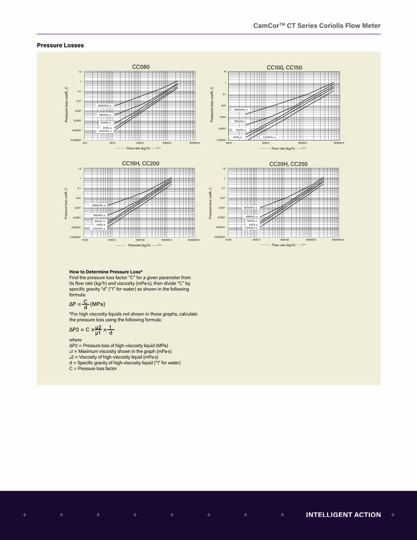
Pressure Losses
100
10
1
0.1
0.01
0.001
0.0001
0.00001
0.0000010.1 1.0 10 100
10mPa∙s
100mPa∙s
1000mPa∙s
1 10 100 1000
100
10
1
0.1
0.01
0.001
0.0001
0.00001
0.000001
0.1 1 10 100 1000
100
10
1
0.1
0.01
0.001
0.0001
0.00001
0.0000011 10 100 1000
100
10
1
0.1
0.01
0.001
0.0001
0.00001
0.000001
1 10 100 1000 10000
10
1
0.1
0.01
0.001
0.0001
0.00001
0.0000011 100 1000 10000
10
1
0.1
0.01
0.001
0.0001
0.00001
0.000001
10 100 1000 10000010000
10
1
0.1
0.01
0.001
0.0001
0.00001
0.000001
Flow rate (g/min)Flow rate (g/min)
Flow rate (kg/h) Flow rate (kg/h)
Flow rate (kg/h)Flow rate (kg/h)
Flow rate (kg/h)100 10000 1000001000
10
1
0.1
0.01
0.001
0.0001
0.00001
0.000001
Flow rate (kg/h)
Pre
ssur
e lo
ss c
oeff.
, CP
ress
ure
loss
coe
ff., C
Pre
ssur
e lo
ss c
oeff.
, C
Pre
ssur
e lo
ss c
oeff.
, C
Pre
ssur
e lo
ss c
oeff.
, C
Pre
ssur
e lo
ss c
oeff.
, C
Pre
ssur
e lo
ss c
oeff.
, CP
ress
ure
loss
coe
ff., C
1mPa∙s
0.01mPa∙s
10mPa∙s
100mPa∙s
1000mPa∙s
1mPa∙s
0.01mPa∙s
1000mPa∙s
100mPa∙s
10mPa∙s
1mPa∙s
0.01mPa∙s
10mPa∙s
100mPa∙s
1000mPa∙s
1mPa∙s
0.01mPa∙s
10mPa∙s
100mPa∙s
1000mPa∙s
1mPa∙s
0.01mPa∙s
10mPa∙s
100mPa∙s
1000mPa∙s
1mPa∙s
0.01mPa∙s
10mPa∙s
100mPa∙s
1000mPa∙s
1mPa∙s
0.01mPa∙s
10mPa∙s
100mPa∙s
1000mPa∙s
1mPa∙s
0.01mPa∙s
CC00A CC001
CC003 CC006
CC010 CC015
CC025 CC040, CC050
CamCorTM CT Series Coriolis Flow Meter
Pressure Losses
9
10 0 100 0 1000 0 10000 0 100000 0
1 0
1
0.1
0.01
0.001
0.0001
0.00001
0.000001
Flow rate (kg/h) Flow rate (kg/h)
Pres
sure
loss
coe
�., C
Pres
sure
loss
coe
�., C
100 0 1000 0 10000 0 100000 0
1
10
0.1
0.01
0.001
0.0001
0.00001
10 00 1000 0 1000 00 100000 0 1000000 0
1 0
1
0.1
0.01
0.001
0.0001
0.00001
0.000001
Flow rate (kg/h)
Pres
sure
loss
coe
�., C
10 00 1000 0 1000 00 100000 0 1000000 0
1 0
1
0.1
0.01
0.001
0.0001
0.00001
0.000001
Flowrate (kg/h)
Pres
sure
loss
coe
�., C
10mPa ∙s
1mPa ∙s0.01mPa ∙s
10mPa ∙s
100mPa ∙s
1000mPa ∙s
1mPa ∙s0.01mPa ∙s
10mPa ∙s
100mPa ∙s
1000mPa ∙s
1mPa ∙s 0.01mPa ∙s
10mPa ∙s100mPa ∙s
1000mPa ∙s
1mPa ∙s0.01mPa ∙s
1000mPa ∙s
100mPa ∙s
CC080 CC100, CC150
CC15H, CC200 CC20H, CC250
How to Determine Pressure Loss*Find the pressure loss factor “C” for a given parameter from its flow rate (kg/h) and viscosity (mPa∙s), then divide “C” by specific gravity “d” (“1” for water) as shown in the following formula:
*For high viscosity liquids not shown in these graphs, calculate the pressure loss using the following formula:
where ΔP2 = Pressure loss of high-viscosity liquid (MPa) μ1 = Maximum viscosity shown in the graph (mPa∙s) μ2 = Viscosity of high-viscosity liquid (mPa∙s) d = Specific gravity of high-viscosity liquid (“1” for water) C = Pressure loss factor
CamCorTM CT Series Coriolis Flow Meter
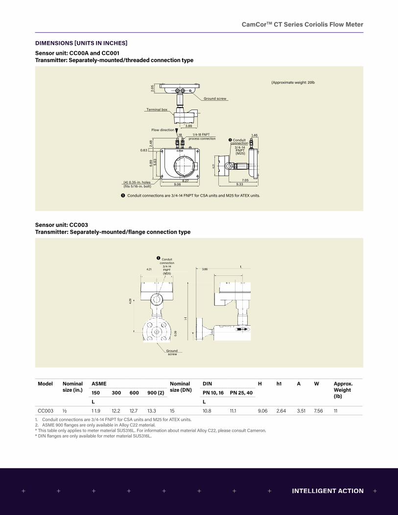
DIMENSIONS [UNITS IN INCHES]
Sensor unit: CC00A and CC001 Transmitter: Separately-mounted/threaded connection type
Conduit connections are 3/4-14 FNPT for CSA units and M25 for ATEX units.
(Approximate weight: 20lb
9.06
3.86
8.279.33
7.05
1.18
5.63
4.2
1
0.636.
892.
48
1.461/4-18 FNPT process connection
Ground screw
Terminal box
(4) 0.35-in. holes(fits 5/16-in. bolt)
Conduitconnection
2.05
Flow direction
3/4-14 FNPT(M25)
3.86
0.39
4.29
4.21
Conduit connection
3/4-14FNPT(M25)
L
A W
Hh1
Ground screw
L
D
Conduit connection
3/4-14 FNPT(M25)
0.39
Threaded connection
3.86
4.29
4.21
Ground screw
Sensor unit: CC003 Transmitter: Separately-mounted/flange connection type Conduit connections are 3/4-14 FNPT for CSA units and M25 for ATEX units.
(Approximate weight: 20lb
9.06
3.86
8.279.33
7.05
1.18
5.63
4.2
10.63
6.89
2.48
1.461/4-18 FNPT process connection
Ground screw
Terminal box
(4) 0.35-in. holes(fits 5/16-in. bolt)
Conduitconnection
2.05
Flow direction
3/4-14 FNPT(M25)
3.86
0.39
4.29
4.21
Conduit connection
3/4-14FNPT(M25)
L
A W
Hh1
Ground screw
L
D
Conduit connection
3/4-14 FNPT(M25)
0.39
Threaded connection
3.86
4.29
4.21
Ground screw
Model Nominal size (in.)
ASME Nominal size (DN)
DIN H h1 A W Approx. Weight (Ib)
150 300 600 900 (2) PN 10, 16 PN 25, 40
L L
CC003 1/2 1 1.9 12.2 12.7 13.3 15 10.8 11.1 9.06 2.64 3.51 7.56 11
1. Conduit connections are 3/4-14 FNPT for CSA units and M25 for ATEX units.2. ASME 900 flanges are only available in Alloy C22 material.* This table only applies to meter material SUS316L. For information about material Alloy C22, please consult Cameron.* DIN flanges are only available for meter material SUS316L.
CamCorTM CT Series Coriolis Flow Meter
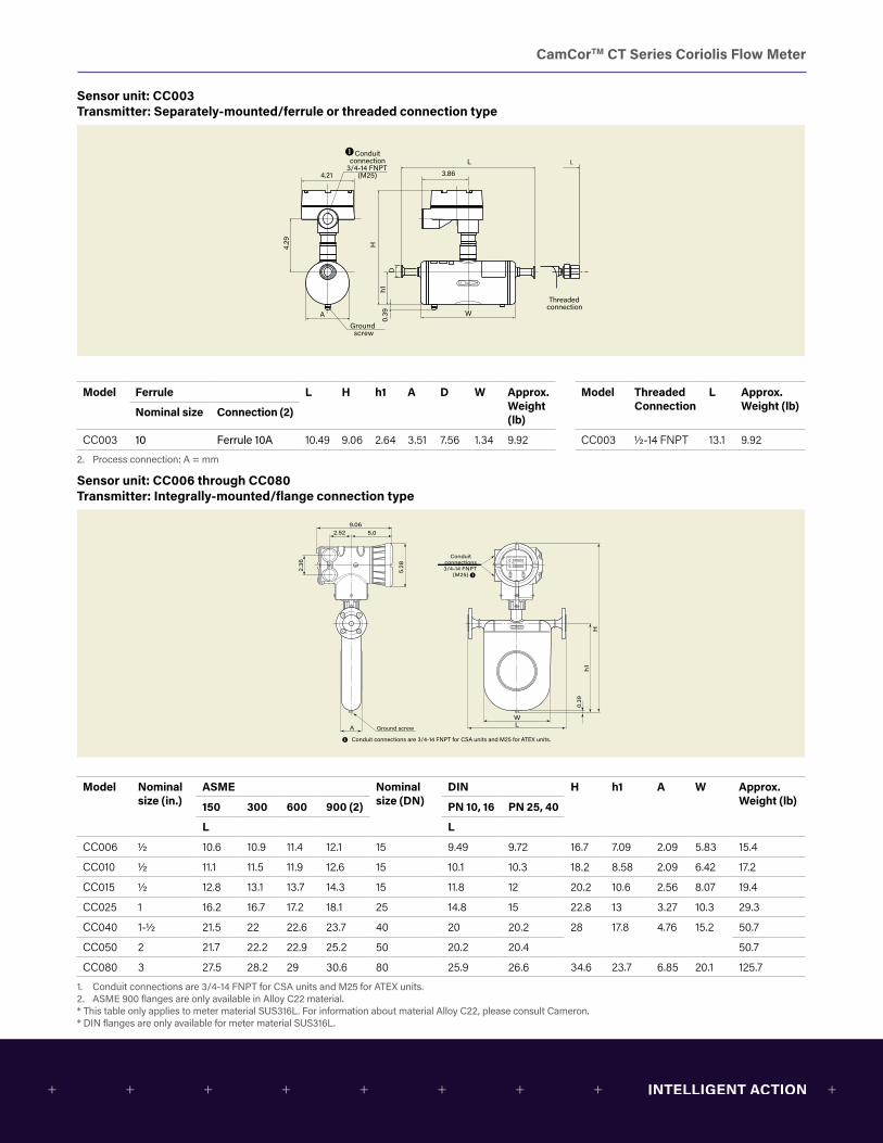
Sensor unit: CC003 Transmitter: Separately-mounted/ferrule or threaded connection type
Conduit connections are 3/4-14 FNPT for CSA units and M25 for ATEX units.
(Approximate weight: 20lb
9.06
3.86
8.279.33
7.05
1.18
5.63
4.2
1
0.63
6.89
2.48
1.461/4-18 FNPT process connection
Ground screw
Terminal box
(4) 0.35-in. holes(fits 5/16-in. bolt)
Conduitconnection
2.05
Flow direction
3/4-14 FNPT(M25)
3.86
0.39
4.29
4.21
Conduit connection
3/4-14FNPT(M25)
L
A W
Hh1
Ground screw
L
D
Conduit connection
3/4-14 FNPT(M25)
0.39
Threaded connection
3.86
4.29
4.21
Ground screw
Model Ferrule L H h1 A D W Approx.Weight (lb)
Model ThreadedConnection
L Approx.Weight (lb)Nominal size Connection (2)
CC003 10 Ferrule 10A 10.49 9.06 2.64 3.51 7.56 1.34 9.92 CC003 1/2-14 FNPT 13.1 9.92
2. Process connection: A = mm
Sensor unit: CC006 through CC080 Transmitter: Integrally-mounted/flange connection type
A
WL
5.28
h10.
39
H
Ground screw
Conduitconnections3/4-14 FNPT
(M25)
9.062.52 5.0
2.36
Conduit connections are 3/4-14 FNPT for CSA units and M25 for ATEX units.
A
WL
5.28
h1
0.39
H
Ground screw
9.062.52 5.0
2.36
Threaded connection
L
D
Conduit connections 3/4-14 FNPT
(M25)
Conduit connections are 3/4-14 FNPT for CSA units and M25 for ATEX units.
Model Nominal size (in.)
ASME Nominal size (DN)
DIN H h1 A W Approx.Weight (lb)150 300 600 900 (2) PN 10, 16 PN 25, 40
L L
CC006 1/2 10.6 10.9 11.4 12.1 15 9.49 9.72 16.7 7.09 2.09 5.83 15.4
CC010 1/2 11.1 11.5 11.9 12.6 15 10.1 10.3 18.2 8.58 2.09 6.42 17.2
CC015 1/2 12.8 13.1 13.7 14.3 15 11.8 12 20.2 10.6 2.56 8.07 19.4
CC025 1 16.2 16.7 17.2 18.1 25 14.8 15 22.8 13 3.27 10.3 29.3
CC040 1-1/2 21.5 22 22.6 23.7 40 20 20.2 28 17.8 4.76 15.2 50.7
CC050 2 21.7 22.2 22.9 25.2 50 20.2 20.4 50.7
CC080 3 27.5 28.2 29 30.6 80 25.9 26.6 34.6 23.7 6.85 20.1 125.7
1. Conduit connections are 3/4-14 FNPT for CSA units and M25 for ATEX units.2. ASME 900 flanges are only available in Alloy C22 material.* This table only applies to meter material SUS316L. For information about material Alloy C22, please consult Cameron.* DIN flanges are only available for meter material SUS316L.
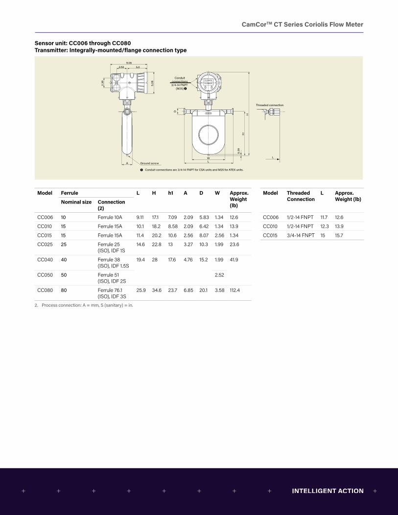
CamCorTM CT Series Coriolis Flow Meter
Sensor unit: CC006 through CC080 Transmitter: Integrally-mounted/flange connection type
A
WL
5.28
h10.
39
H
Ground screw
Conduitconnections3/4-14 FNPT
(M25)
9.062.52 5.0
2.36
Conduit connections are 3/4-14 FNPT for CSA units and M25 for ATEX units.
A
WL
5.28
h1
0.39
H
Ground screw
9.062.52 5.0
2.36
Threaded connection
L
D
Conduit connections 3/4-14 FNPT
(M25)
Conduit connections are 3/4-14 FNPT for CSA units and M25 for ATEX units.
Model Ferrule L H h1 A D W Approx. Weight (lb)
Model ThreadedConnection
L Approx.Weight (lb)Nominal size Connection
(2)
CC006 10 Ferrule 10A 9.11 17.1 7.09 2.09 5.83 1.34 12.6 CC006 1/2-14 FNPT 11.7 12.6
CC010 15 Ferrule 15A 10.1 18.2 8.58 2.09 6.42 1.34 13.9 CC010 1/2-14 FNPT 12.3 13.9
CC015 15 Ferrule 15A 11.4 20.2 10.6 2.56 8.07 2.56 1.34 CC015 3/4-14 FNPT 15 15.7
CC025 25 Ferrule 25 (ISO), IDF 1S
14.6 22.8 13 3.27 10.3 1.99 23.6
CC040 40 Ferrule 38 (ISO), IDF 1.5S
19.4 28 17.6 4.76 15.2 1.99 41.9
CC050 50 Ferrule 51 (ISO), IDF 2S
2.52
CC080 80 Ferrule 76.1 (ISO), IDF 3S
25.9 34.6 23.7 6.85 20.1 3.58 112.4
2. Process connection: A = mm, S (sanitary) = in.
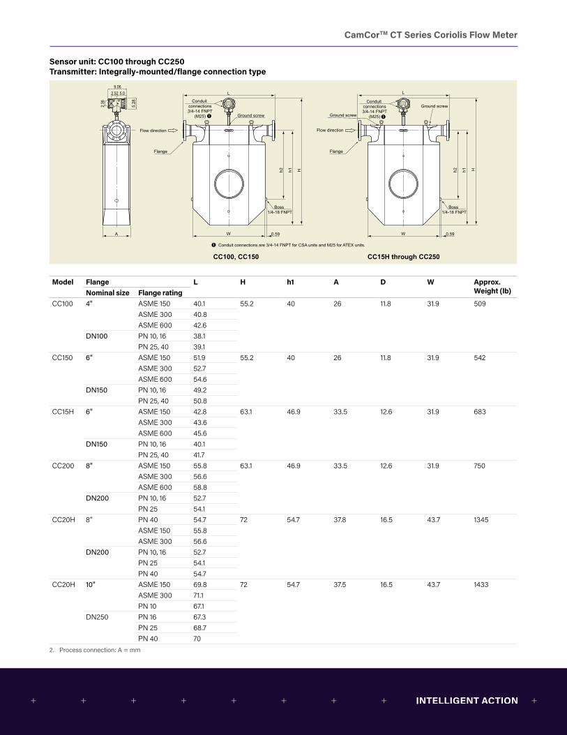
CamCorTM CT Series Coriolis Flow Meter
Sensor unit: CC100 through CC250 Transmitter: Integrally-mounted/flange connection type
5.28
9.062.52 5.0
2.36 Conduit
connections3/4-14 FNPT
(M25)
A
Hh1h2
W 0.59
L
Flow direction
Ground screw
Flange
Boss 1/4-18 FNPT
Conduit connections3/4-14 FNPT
(M25)
Hh1h2
W 0.59
L
Flow direction
Ground screw
Ground screw
Flange
Conduit connections are 3/4-14 FNPT for CSA units and M25 for ATEX units.
Boss 1/4-18 FNPT
CC100, CC150 CC15H through CC250
Model Flange L H h1 A D W Approx. Weight (lb)Nominal size Flange rating
CC100 4" ASME 150 40.1 55.2 40 26 11.8 31.9 509ASME 300 40.8ASME 600 42.6
DN100 PN 10, 16 38.1PN 25, 40 39.1
CC150 6" ASME 150 51.9 55.2 40 26 11.8 31.9 542ASME 300 52.7ASME 600 54.6
DN150 PN 10, 16 49.2PN 25, 40 50.8
CC15H 6" ASME 150 42.8 63.1 46.9 33.5 12.6 31.9 683ASME 300 43.6ASME 600 45.6
DN150 PN 10, 16 40.1PN 25, 40 41.7
CC200 8" ASME 150 55.8 63.1 46.9 33.5 12.6 31.9 750ASME 300 56.6ASME 600 58.8
DN200 PN 10, 16 52.7PN 25 54.1
CC20H 8” PN 40 54.7 72 54.7 37.8 16.5 43.7 1345ASME 150 55.8ASME 300 56.6
DN200 PN 10, 16 52.7PN 25 54.1PN 40 54.7
CC20H 10" ASME 150 69.8 72 54.7 37.5 16.5 43.7 1433ASME 300 71.1PN 10 67.1
DN250 PN 16 67.3PN 25 68.7PN 40 70
2. Process connection: A = mm
CamCorTM CT Series Coriolis Flow Meter
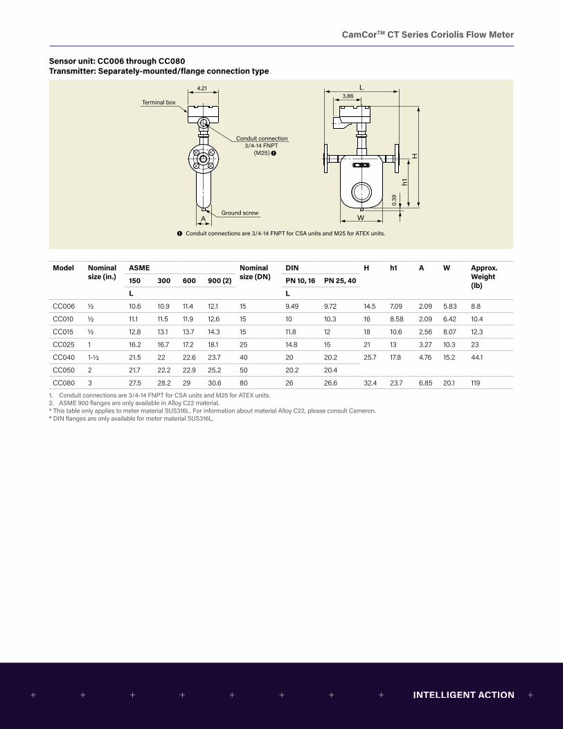
Sensor unit: CC006 through CC080 Transmitter: Separately-mounted/flange connection type
A
Hh1
W
L
0.39
Conduit connection3/4-14 FNPT
(M25)
Terminal box
Ground screw
4.21
Conduit connections are 3/4-14 FNPT for CSA units and M25 for ATEX units.
4.21
Hh1
W
L3.86
A
0.39
Ground screw
Conduit connection 3/4-14 FNPT
(M25)
L
Threaded connection
Terminal box
D
Conduit connections are 3/4-14 FNPT for CSA units and M25 for ATEX units.
3.86
Model Nominal size (in.)
ASME Nominal size (DN)
DIN H h1 A W Approx. Weight (lb)
150 300 600 900 (2) PN 10, 16 PN 25, 40
L L
CC006 1/2 10.6 10.9 11.4 12.1 15 9.49 9.72 14.5 7.09 2.09 5.83 8.8
CC010 1/2 11.1 11.5 11.9 12.6 15 10 10.3 16 8.58 2.09 6.42 10.4
CC015 1/2 12.8 13.1 13.7 14.3 15 11.8 12 18 10.6 2.56 8.07 12.3
CC025 1 16.2 16.7 17.2 18.1 25 14.8 15 21 13 3.27 10.3 23
CC040 1-1/2 21.5 22 22.6 23.7 40 20 20.2 25.7 17.8 4.76 15.2 44.1
CC050 2 21.7 22.2 22.9 25.2 50 20.2 20.4
CC080 3 27.5 28.2 29 30.6 80 26 26.6 32.4 23.7 6.85 20.1 119
1. Conduit connections are 3/4-14 FNPT for CSA units and M25 for ATEX units.2. ASME 900 flanges are only available in Alloy C22 material.* This table only applies to meter material SUS316L. For information about material Alloy C22, please consult Cameron.* DIN flanges are only available for meter material SUS316L.

CamCorTM CT Series Coriolis Flow Meter
Sensor unit: CC006 through CC080 Transmitter separately-mounted/ferrule or threaded connection type
A
Hh1
W
L
0.39
Conduit connection3/4-14 FNPT
(M25)
Terminal box
Ground screw
4.21
Conduit connections are 3/4-14 FNPT for CSA units and M25 for ATEX units.
4.21
Hh1
W
L3.86
A
0.39
Ground screw
Conduit connection 3/4-14 FNPT
(M25)
L
Threaded connection
Terminal box
D
Conduit connections are 3/4-14 FNPT for CSA units and M25 for ATEX units.
3.86
Model Ferrule L H h1 A W D Approx. Weight (lb)Nominal size Connection (2)
CC006 10 Ferrule 10A 9.11 14.5 7.09 2.09 5.83 1.34 6.2
CC010 15 Ferrule 15A 10.1 16 8.58 2.09 6.42 1.34 7.5
CC015 15 Ferrule 15A 11.4 18 10.6 2.56 8.07 1.34 9.3
CC025 25 Ferrule 25 (ISO), IDF 1S 14.6 20.6 13 3.27 10.3 1.99 17.2
CC040 40 Ferrule 38 (ISO), IDF 1.5S 19.4 25.7 17.8 4.76 15.2 1.99 35.3
CC050 50 Ferrule 51 (ISO), IDF 2S 2.52
CC080 80 Ferrule 76.1 (ISO), IDF 3S 25.9 32.4 23.7 6.85 20.1 3.58 105.8
1. Process connection: A = mm, S (sanitary) = in.
Model Threaded Connection L Approx. Weight (lb)
CC006 1/2-14 FNPT 11.7 6.2
CC010 1/2-14 FNPT 12.3 7.5
CC015 3/4-14 FNPT 15 9.3
CamCorTM CT Series Coriolis Flow Meter
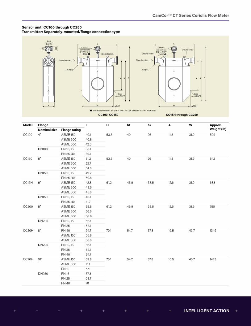
Sensor unit: CC100 through CC250 Transmitter: Separately-mounted/flange connection type
5.28
9.062.52 5.0
2.36 Conduit
connections3/4-14 FNPT
(M25)
A
Hh1h2
W 0.59
L
Flow direction
Ground screw
Flange
Boss 1/4-18 FNPT
Conduit connections3/4-14 FNPT
(M25)
Hh1h2
W 0.59
L
Flow direction
Ground screw
Ground screw
Flange
Conduit connections are 3/4-14 FNPT for CSA units and M25 for ATEX units.
Boss 1/4-18 FNPT
CC100, CC150 CC15H through CC250
Model Flange L H h1 h2 A W Approx. Weight (lb)Nominal size Flange rating
CC100 4" ASME 150 40.1 53.3 40 26 11.8 31.9 509ASME 300 40.8ASME 600 42.6
DN100 PN 10, 16 38.1PN 25, 40 39.1
CC150 6" ASME 150 51.2 53.3 40 26 11.8 31.9 542ASME 300 52.7ASME 600 54.6
DN150 PN 10, 16 49.2PN 25, 40 50.8
CC15H 6" ASME 150 42.8 61.2 46.9 33.5 12.6 31.9 683ASME 300 43.6ASME 600 45.6
DN150 PN 10, 16 40.1PN 25, 40 41.7
CC200 8" ASME 150 55.8 61.2 46.9 33.5 12.6 31.9 750ASME 300 56.6ASME 600 58.8
DN200 PN 10, 16 52.7PN 25 54.1
CC20H 8” PN 40 54.7 70.1 54.7 37.8 16.5 43.7 1345ASME 150 55.8ASME 300 56.6
DN200 PN 10, 16 52.7PN 25 54.1PN 40 54.7
CC20H 10" ASME 150 69.8 70.1 54.7 37.8 16.5 43.7 1433ASME 300 71.1PN 10 67.1
DN250 PN 16 67.3PN 25 68.7PN 40 70
CamCorTM CT Series Coriolis Flow Meter
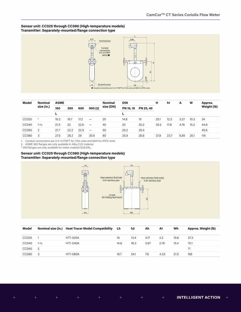
Sensor unit: CC025 through CC080 (High-temperature models) Transmitter: Separately-mounted/flange connection type
A W
h1
0.39
H
4.21 3.86L
Terminal box
Ground screw
Conduitconnection
3/4-14 FNPT(M25)
Conduit connections are 3/4-14 FNPT for CSA units and M25 for ATEX units.
0.39 stainless pipe 0.39 stainless pipe
Ah Wh
h2
A1 Lh
Heat retention fluid inlet Heat retention fluid outlet
1/4 bolt(for holding heat tracer)
11.81
54.6
1
39.9
6
25.9
8
31.89
3.86
L
4.21
Conduit connection 3/4-14 FNPT
(M25)
Terminal box
Flow direction
Flange
Groundscrew
0.59
Conduit connections are 3/4-14 FNPT for CSA units and M25 for ATEX units.
Boss 1/4-18 FNPT
Model Nominal size (in.)
ASME Nominal size (DN)
DIN H h1 A W Approx. Weight (Ib)150 300 600 900 (2) PN 10, 16 PN 25, 40
L L
CC025 1 16.2 16.7 17.2 — 25 14.8 15 25.1 12.3 3.27 10.3 24
CC040 1-1/2 21.5 22 22.6 — 40 20 20.2 30.2 17.8 4.76 15.2 44.8
CC050 2 21.7 22.2 22.9 — 50 20.2 20.4 45.6
CC080 3 27.5 28.2 29 30.6 80 25.9 26.6 37.8 23.7 6.85 20.1 119
1. Conduit connections are 3/4-14 FNPT for CSA units and M25 for ATEX units.2. ASME 900 flanges are only available in Alloy C22 material.* DIN flanges are only available for meter material SUS316L.
Sensor unit: CC025 through CC080 (High-temperature models) Transmitter: Separately-mounted/flange connection type
A W
h1
0.39
H
4.21 3.86L
Terminal box
Ground screw
Conduitconnection
3/4-14 FNPT(M25)
Conduit connections are 3/4-14 FNPT for CSA units and M25 for ATEX units.
0.39 stainless pipe 0.39 stainless pipe
Ah Wh
h2
A1 Lh
Heat retention fluid inlet Heat retention fluid outlet
1/4 bolt(for holding heat tracer)
11.81
54.6
1
39.9
6
25.9
8
31.89
3.86
L
4.21
Conduit connection 3/4-14 FNPT
(M25)
Terminal box
Flow direction
Flange
Groundscrew
0.59
Conduit connections are 3/4-14 FNPT for CSA units and M25 for ATEX units.
Boss 1/4-18 FNPT
Model Nominal size (in.) Heat Tracer Model Compatibility Lh h2 Ah A1 Wh Approx. Weight (lb)
CC025 1 HT1-025A 10 13.4 4.17 2.2 10.6 37.3
CC040 1-1/2 HT1-040A 14.8 18.3 5.67 2.76 15.4 70.1
CC050 2 71
CC080 3 HT1-080A 19.7 24.1 7.8 4.33 21.5 166
CamCorTM CT Series Coriolis Flow Meter
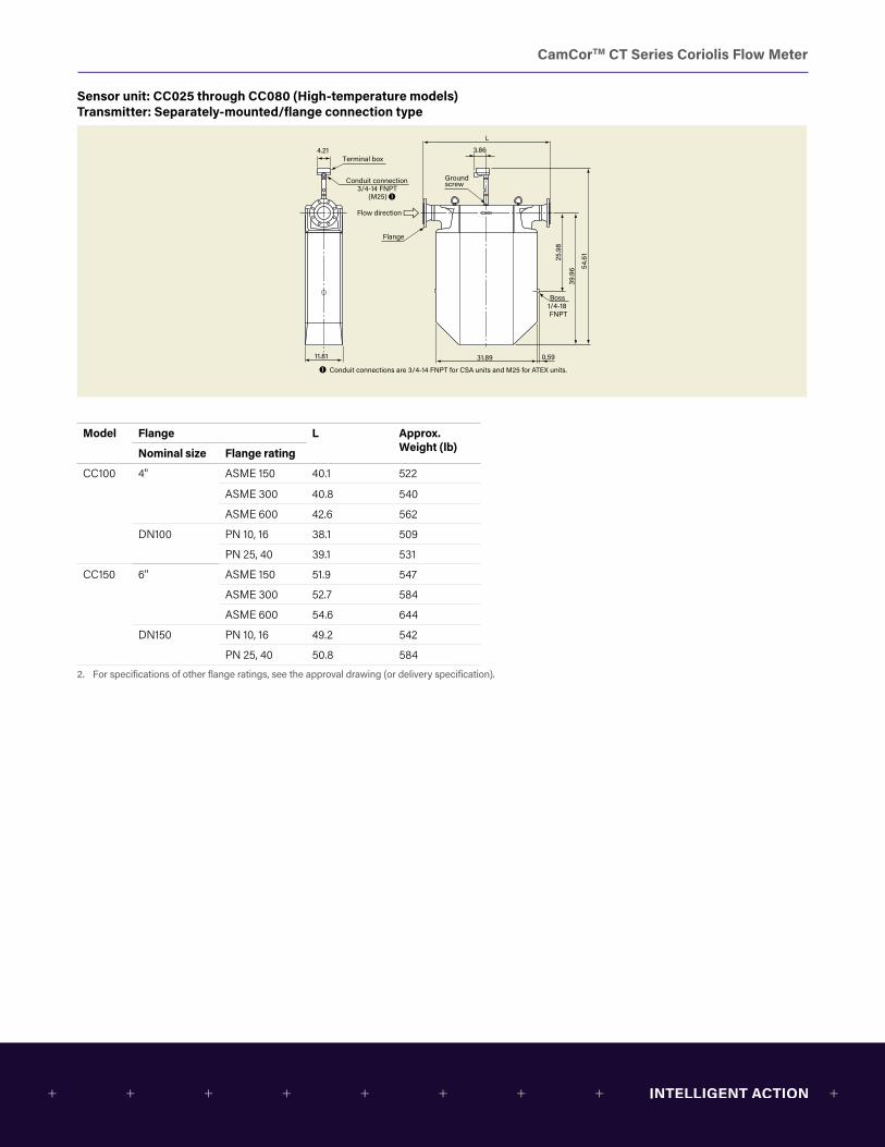
Sensor unit: CC025 through CC080 (High-temperature models) Transmitter: Separately-mounted/flange connection type
A W
h1
0.39
H
4.21 3.86L
Terminal box
Ground screw
Conduitconnection
3/4-14 FNPT(M25)
Conduit connections are 3/4-14 FNPT for CSA units and M25 for ATEX units.
0.39 stainless pipe 0.39 stainless pipe
Ah Wh
h2
A1 Lh
Heat retention fluid inlet Heat retention fluid outlet
1/4 bolt(for holding heat tracer)
11.81
54.6
1
39.9
6
25.9
8
31.89
3.86
L
4.21
Conduit connection 3/4-14 FNPT
(M25)
Terminal box
Flow direction
Flange
Groundscrew
0.59
Conduit connections are 3/4-14 FNPT for CSA units and M25 for ATEX units.
Boss 1/4-18 FNPT
Model Flange L Approx. Weight (lb)Nominal size Flange rating
CC100 4" ASME 150 40.1 522
ASME 300 40.8 540
ASME 600 42.6 562
DN100 PN 10, 16 38.1 509
PN 25, 40 39.1 531
CC150 6" ASME 150 51.9 547
ASME 300 52.7 584
ASME 600 54.6 644
DN150 PN 10, 16 49.2 542
PN 25, 40 50.8 584
2. For specifications of other flange ratings, see the approval drawing (or delivery specification).
CamCorTM CT Series Coriolis Flow Meter
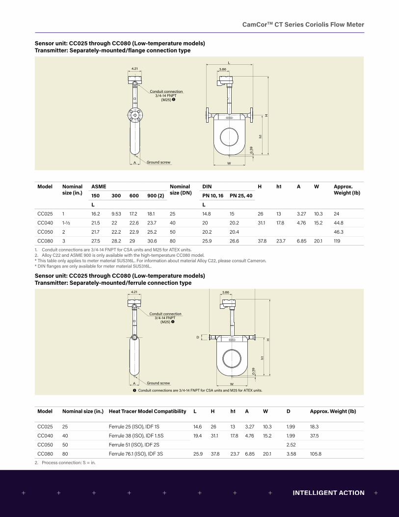
Sensor unit: CC025 through CC080 (Low-temperature models) Transmitter: Separately-mounted/flange connection type
Conduit connection3/4-14 FNPT
(M25)
A W
h1
0.39
H
Ground screw
4.21 3.86
L
Conduit connections are 3/4-14 FNPT for CSA units and M25 for ATEX units.
Conduit connection3/4-14 FNPT
(M25)
A W
h1
0.39
H
Ground screw
4.21
D
3.86
L
Conduit connections are 3/4-14 FNPT for CSA units and M25 for ATEX units.
Model Nominal size (in.)
ASME Nominal size (DN)
DIN H h1 A W Approx. Weight (Ib)150 300 600 900 (2) PN 10, 16 PN 25, 40
L L
CC025 1 16.2 9.53 17.2 18.1 25 14.8 15 26 13 3.27 10.3 24
CC040 1-1/2 21.5 22 22.6 23.7 40 20 20.2 31.1 17.8 4.76 15.2 44.8
CC050 2 21.7 22.2 22.9 25.2 50 20.2 20.4 46.3
CC080 3 27.5 28.2 29 30.6 80 25.9 26.6 37.8 23.7 6.85 20.1 119
1. Conduit connections are 3/4-14 FNPT for CSA units and M25 for ATEX units.2. Alloy C22 and ASME 900 is only available with the high-temperature CC080 model.* This table only applies to meter material SUS316L. For information about material Alloy C22, please consult Cameron.* DIN flanges are only available for meter material SUS316L.
Sensor unit: CC025 through CC080 (Low-temperature models) Transmitter: Separately-mounted/ferrule connection type
Conduit connection3/4-14 FNPT
(M25)
A W
h1
0.39
H
Ground screw
4.21 3.86
L
Conduit connections are 3/4-14 FNPT for CSA units and M25 for ATEX units.
Conduit connection3/4-14 FNPT
(M25)
A W
h1
0.39
H
Ground screw
4.21
D
3.86
L
Conduit connections are 3/4-14 FNPT for CSA units and M25 for ATEX units.
Model Nominal size (in.) Heat Tracer Model Compatibility L H h1 A W D Approx. Weight (lb)
CC025 25 Ferrule 25 (ISO), IDF 1S 14.6 26 13 3.27 10.3 1.99 18.3
CC040 40 Ferrule 38 (ISO), IDF 1.5S 19.4 31.1 17.8 4.76 15.2 1.99 37.5
CC050 50 Ferrule 51 (ISO), IDF 2S 2.52
CC080 80 Ferrule 76.1 (ISO), IDF 3S 25.9 37.8 23.7 6.85 20.1 3.58 105.8
2. Process connection: S = in.
CamCorTM CT Series Coriolis Flow Meter
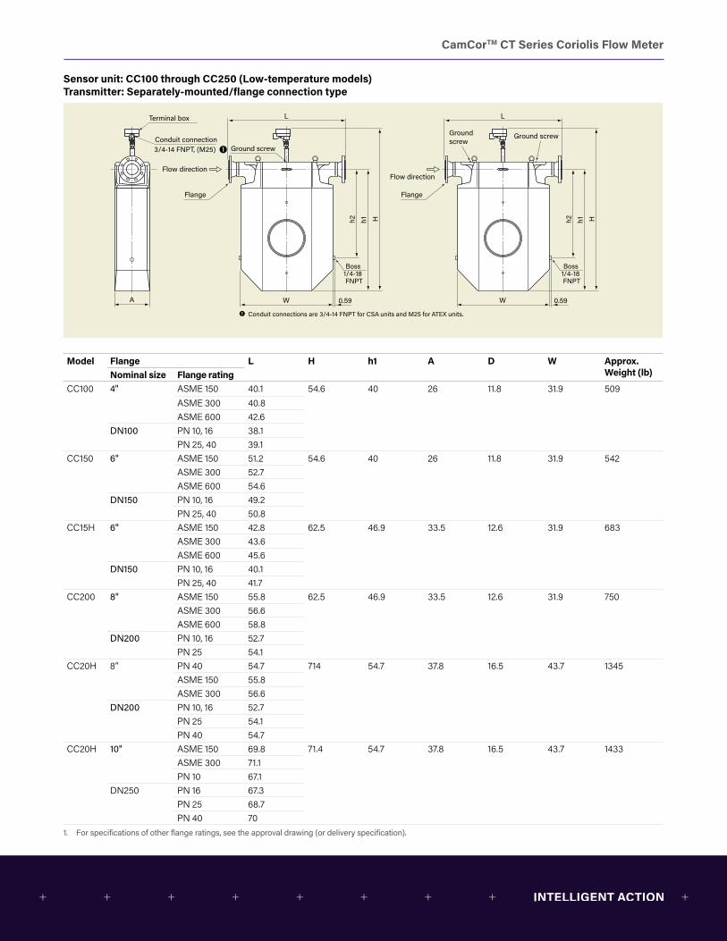
Sensor unit: CC100 through CC250 (Low-temperature models) Transmitter: Separately-mounted/flange connection type
A
Hh1h2
W 0.59
L
Flow direction
Ground screw
Flange
Conduit connection3/4-14 FNPT, (M25)
Terminal box
Hh1h2
W 0.59
L
Flow direction
Ground screwGround screw
Flange
Boss 1/4-18 FNPT
Boss 1/4-18 FNPT
Conduit connections are 3/4-14 FNPT for CSA units and M25 for ATEX units.
Model Flange L H h1 A D W Approx. Weight (lb)Nominal size Flange rating
CC100 4" ASME 150 40.1 54.6 40 26 11.8 31.9 509ASME 300 40.8ASME 600 42.6
DN100 PN 10, 16 38.1PN 25, 40 39.1
CC150 6" ASME 150 51.2 54.6 40 26 11.8 31.9 542ASME 300 52.7ASME 600 54.6
DN150 PN 10, 16 49.2PN 25, 40 50.8
CC15H 6" ASME 150 42.8 62.5 46.9 33.5 12.6 31.9 683ASME 300 43.6ASME 600 45.6
DN150 PN 10, 16 40.1PN 25, 40 41.7
CC200 8" ASME 150 55.8 62.5 46.9 33.5 12.6 31.9 750ASME 300 56.6ASME 600 58.8
DN200 PN 10, 16 52.7PN 25 54.1
CC20H 8” PN 40 54.7 714 54.7 37.8 16.5 43.7 1345ASME 150 55.8ASME 300 56.6
DN200 PN 10, 16 52.7PN 25 54.1PN 40 54.7
CC20H 10" ASME 150 69.8 71.4 54.7 37.8 16.5 43.7 1433ASME 300 71.1PN 10 67.1
DN250 PN 16 67.3PN 25 68.7PN 40 70
1. For specifications of other flange ratings, see the approval drawing (or delivery specification).
CamCorTM CT Series Coriolis Flow Meter
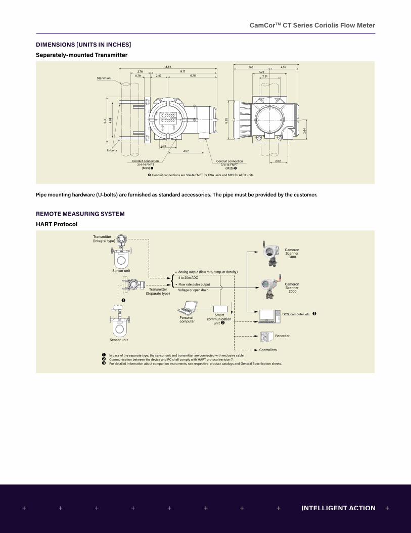
DIMENSIONS [UNITS IN INCHES]
Separately-mounted Transmitter
5.28
2.64
Conduit connection3/4-14 FNPT
(M25)
Conduit connection 3/4-14 FNPT
(M25)
9.065.0 4.06
4.722.91
2.52
4.92
2.36
6.3
4.88
13.542.76
Stanchion
U-bolts
9.170.79 2.43 6.75
lb/min
gal/min
Conduit connections are 3/4-14 FNPT for CSA units and M25 for ATEX units.
Analog output (flow rate, temp. or density)
Flow rate pulse output
Voltage or open drain
Sensor unit
Recorder
Controllers
4 to 20m ADC
Personal computer
Smartcommunication
unit
Sensor unit
In case of the separate type, the sensor unit and transmitter are connected with exclusive cable. Communication between the device and PC shall comply with HART protocol revision 7. For detailed information about companion instruments, see respective product catalogs and General Specification sheets.
Transmitter(Integral type)
Transmitter(Separate type)
{
Cameron Scanner
2000
Cameron Scanner
3100
DCS, computer, etc.
Sensor unit and separate transmitter are connected via the exclusive interconnect cable. The transmitter requires a separate power source (AC or DC) for its main power supply.
Modbus compatible host device(DCS, PC, etc.)
Modbus compatible(Separate type)
Modbus compatible(Integral type)
RS-485 (Separate terminating resistor is required.)USB or RS-232C ↔RS-485 converter
USB or RS-232C
Other field deviceOther field device
Sensor unit
Sensor unit
Pipe mounting hardware (U-bolts) are furnished as standard accessories. The pipe must be provided by the customer.
REMOTE MEASURING SYSTEM
HART Protocol5.
28
2.64
Conduit connection3/4-14 FNPT
(M25)
Conduit connection 3/4-14 FNPT
(M25)
9.065.0 4.06
4.722.91
2.52
4.92
2.36
6.3
4.88
13.542.76
Stanchion
U-bolts
9.170.79 2.43 6.75
lb/min
gal/min
Conduit connections are 3/4-14 FNPT for CSA units and M25 for ATEX units.
Analog output (flow rate, temp. or density)
Flow rate pulse output
Voltage or open drain
Sensor unit
Recorder
Controllers
4 to 20m ADC
Personal computer
Smartcommunication
unit
Sensor unit
In case of the separate type, the sensor unit and transmitter are connected with exclusive cable. Communication between the device and PC shall comply with HART protocol revision 7. For detailed information about companion instruments, see respective product catalogs and General Specification sheets.
Transmitter(Integral type)
Transmitter(Separate type)
{
Cameron Scanner
2000
Cameron Scanner
3100
DCS, computer, etc.
Sensor unit and separate transmitter are connected via the exclusive interconnect cable. The transmitter requires a separate power source (AC or DC) for its main power supply.
Modbus compatible host device(DCS, PC, etc.)
Modbus compatible(Separate type)
Modbus compatible(Integral type)
RS-485 (Separate terminating resistor is required.)USB or RS-232C ↔RS-485 converter
USB or RS-232C
Other field deviceOther field device
Sensor unit
Sensor unit
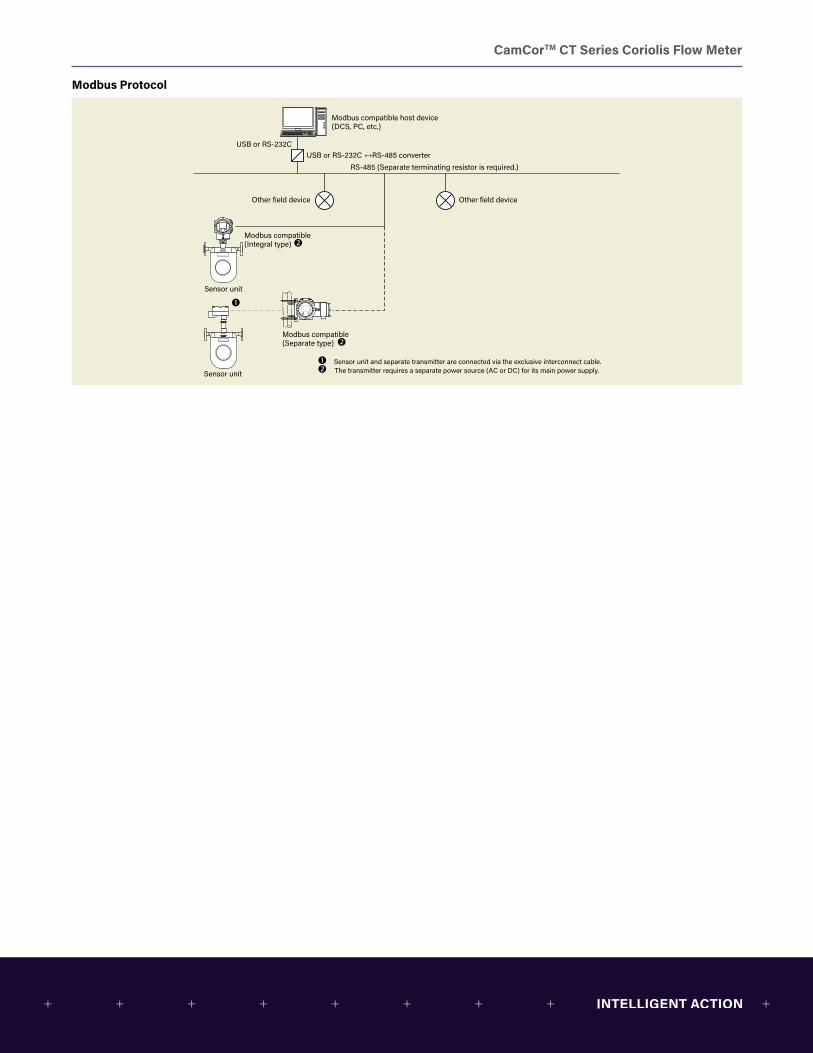
CamCorTM CT Series Coriolis Flow Meter
Modbus Protocol
5.28
2.64
Conduit connection3/4-14 FNPT
(M25)
Conduit connection 3/4-14 FNPT
(M25)
9.065.0 4.06
4.722.91
2.52
4.92
2.36
6.3
4.88
13.542.76
Stanchion
U-bolts
9.170.79 2.43 6.75
lb/min
gal/min
Conduit connections are 3/4-14 FNPT for CSA units and M25 for ATEX units.
Analog output (flow rate, temp. or density)
Flow rate pulse output
Voltage or open drain
Sensor unit
Recorder
Controllers
4 to 20m ADC
Personal computer
Smartcommunication
unit
Sensor unit
In case of the separate type, the sensor unit and transmitter are connected with exclusive cable. Communication between the device and PC shall comply with HART protocol revision 7. For detailed information about companion instruments, see respective product catalogs and General Specification sheets.
Transmitter(Integral type)
Transmitter(Separate type)
{
Cameron Scanner
2000
Cameron Scanner
3100
DCS, computer, etc.
Sensor unit and separate transmitter are connected via the exclusive interconnect cable. The transmitter requires a separate power source (AC or DC) for its main power supply.
Modbus compatible host device(DCS, PC, etc.)
Modbus compatible(Separate type)
Modbus compatible(Integral type)
RS-485 (Separate terminating resistor is required.)USB or RS-232C ↔RS-485 converter
USB or RS-232C
Other field deviceOther field device
Sensor unit
Sensor unit

CamCorTM CT Series Coriolis Flow Meter
Transmitter Power and Input/Output Signal Wiring
Status in/out terminals
Analog and pulse output terminals
Power terminals
Replaceable fuse 250V, 2A
Modbus RS-485 terminals
Ext. GND terminals
Item Label Description Remarks
Signal A1 (+) Analog Output 1 (4 to 20 mA) Maximum load resistance is 600Ω for Analog Outputs 1 and 2
A1 (–)
A2 (+) Analog Output 2 (4 to 20 mA)
A2 (–)
P1 (+) Pulse Output 1 (voltage/open drain)
Maximum pulse output (voltage/open drain) transmission length: + 10 m @ 10 kHz + 100 m @ 1 kHz + 1 m @ 100 Hz
Minimum conductor size: 18 AWG
P1 (–)
P2 (+) Pulse Output 2 (voltage/open drain)P2 (–)
SI (+) Status Input (contact) —
SI (–)
SO (+) Status Output (open drain)
SO (–)
I/O (+) Expanded Input/Output (Modbus communication, etc.)
For Modbus communications: + Maximum transmission length: 1200m + Minimum conductor size: 18 AWG"
I/O (–)
Power L (+) Power (with DC power: +) —
GND Earth Ground
N (–) Power (with DC power: –)

CamCorTM CT Series Coriolis Flow Meter
WIRING DIAGRAMS
Wiring Between Sensor Unit and Separately-mounted Transmitter
Interconnect cable(200 m maximum)
Sensor terminal box
Transmitter
SEL CUR
Cut off shielded wires here except forshielded wire over BRN and RED lines. Interconnect cable
(200 m maximum)
Transmitter terminal box Sensor terminal box Shielded(Protected by black tube)
Shielded(Protected by black tube)
cut
cut
cut
Barrier cover to be applied in a hazardous area
BrownRed
GreenWhite
BlueGrey
PurpleYellowOrange
BrownRed
GreenWhite
BlueGrey
PurpleYellow
Orange
Brown
Red
Green
White
Blue
Grey
Purple
Yellow
Orange
Shielded wires
Green
WhiteGrey
YellowBlue
Orange
Black
Purple
RedBrown
Use dedicated interconnect cable and prepare shielded wire as follows.
Transmitter end + Bundle shielded wires colored in brown/red, green/white, blue/grey and purple/yellow/orange and cover the wires with a black tube.
+ Connect only one wire to the terminal box (black), taking care to avoid potential contact with the housing or conductive parts.
Sensor end + Cover the brown/red shielded wire with a black tube and connect it to the terminal box, taking care to avoid potential contact with the housing or conductive parts.
+ Clip all shielded wires except brown/red as shown in the above figure.
Recommended cable end treatment
9
CamCor PRO Series Coriolis Flow Meter
WIRING DIAGRAMSWiring Between Sensor Unit and Separately-mounted Transmitter
Mass Flow
Vol Flow
Kg/min
L/min0.000000.00000SEL CUR
Cut off shielded wires here except for the shielded wire over BRN and RED lines. Interconnect cable
(5 m maximum)
Transmitter terminal box Sensor terminal box Shield(Protected by black tube)
Shield(Protected by black tube)
cut
cut
cut
Barrier cover to be appliedin a hazardous area
BrownRed
GreenWhite
BlueGray
PurpleYellowOrange
BrownRed
GreenWhite
BlueGray
PurpleYellow
Orange
Shield wires
Interconnect cable(5 m maximum)
Sensor terminal box
Transmitter
1. Use interconnect cable.
Use dedicated interconnect cable and prepare shielded wire as follows.
Transmitter end1. Bundle shielded wires colored in brown/red, green/white, blue/grey and purple/yellow/orange and cover the wires with a
black tube.
2. Connect only one wire to the terminal box (black), taking care to avoid potential contact with the housing or conductive parts.
Sensor end1. Cover the brown/red shielded wire with a black tube and connect it to the terminal box, taking care to avoid potential
contact with the housing or conductive parts.
2. Clip all shielded wires except brown/red as shown in the above figure.Recommended cable end treatment
Use of a crimp pin terminal is not necessary. 0.35 in.
Use of a crimp pin terminal is not necessary.
CamCorTM CT Series Coriolis Flow Meter
INSTALLATION
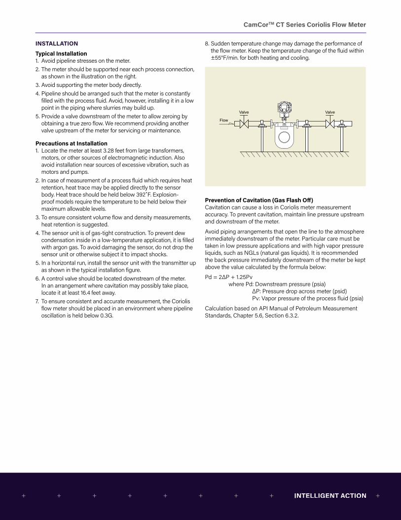
Typical Installation1. Avoid pipeline stresses on the meter.2. The meter should be supported near each process connection,
as shown in the illustration on the right.3. Avoid supporting the meter body directly.4. Pipeline should be arranged such that the meter is constantly
filled with the process fluid. Avoid, however, installing it in a low point in the piping where slurries may build up.
5. Provide a valve downstream of the meter to allow zeroing by obtaining a true zero flow. We recommend providing another valve upstream of the meter for servicing or maintenance.
Precautions at Installation1. Locate the meter at least 3.28 feet from large transformers,
motors, or other sources of electromagnetic induction. Also avoid installation near sources of excessive vibration, such as motors and pumps.
2. In case of measurement of a process fluid which requires heat retention, heat trace may be applied directly to the sensor body. Heat trace should be held below 392˚F. Explosion-proof models require the temperature to be held below their maximum allowable levels.
3. To ensure consistent volume flow and density measurements, heat retention is suggested.
4. The sensor unit is of gas-tight construction. To prevent dew condensation inside in a low-temperature application, it is filled with argon gas. To avoid damaging the sensor, do not drop the sensor unit or otherwise subject it to impact shocks.
5. In a horizontal run, install the sensor unit with the transmitter up as shown in the typical installation figure.
6. A control valve should be located downstream of the meter. In an arrangement where cavitation may possibly take place, locate it at least 16.4 feet away.
7. To ensure consistent and accurate measurement, the Coriolis flow meter should be placed in an environment where pipeline oscillation is held below 0.3G.
8. Sudden temperature change may damage the performance of the flow meter. Keep the temperature change of the fluid within ±55°F/min. for both heating and cooling.
Valve
Flow
Valve
Orie
ntat
ion Flow
directionFlowdirection
Flow
direction
(4) 0.35-in. mounting holes
Bench mount Wall mount
Prevention of Cavitation (Gas Flash Off)Cavitation can cause a loss in Coriolis meter measurement accuracy. To prevent cavitation, maintain line pressure upstream and downstream of the meter.
Avoid piping arrangements that open the line to the atmosphere immediately downstream of the meter. Particular care must be taken in low pressure applications and with high vapor pressure liquids, such as NGLs (natural gas liquids). It is recommended the back pressure immediately downstream of the meter be kept above the value calculated by the formula below:
Pd = 2ΔP + 1.25Pv where Pd: Downstream pressure (psia) ΔP: Pressure drop across meter (psid) Pv: Vapor pressure of the process fluid (psia)
Calculation based on API Manual of Petroleum Measurement Standards, Chapter 5.6, Section 6.3.2.
CamCorTM CT Series Coriolis Flow Meter
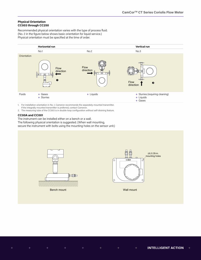
Physical Orientation CC003 through CC250
Recommended physical orientation varies with the type of process fluid. (No. 2 in the figure below shows basic orientation for liquid service.) Physical orientation must be specified at the time of order.
Horizontal run Vertical run
No.1 No.2 No.3
Orientation
Fluids + Gases + Slurries
+ Liquids + Slurries (requiring cleaning) + Liquids + Gases
1. For installation orientation in No. 1, Cameron recommends the separately-mounted transmitter. If the integrally-mounted transmitter is preferred, contact Cameron.
2. The measuring tube of the CC003 is in double-loop configuration without self-draining feature.
CC00A and CC001The instrument can be installed either on a bench or a wall. The following physical orientation is suggested. (When wall mounting, secure the instrument with bolts using the mounting holes on the sensor unit.)
Valve
Flow
Valve
Orie
ntat
ion Flow
directionFlowdirection
Flow
direction
(4) 0.35-in. mounting holes
Bench mount Wall mount
Valve
Flow
Valve
Orie
ntat
ion Flow
directionFlowdirection
Flow
direction
(4) 0.35-in. mounting holes
Bench mount Wall mount

CamCorTM CT Series Coriolis Flow Meter
EXPLOSION-PROOF SPECIFICATIONS
CSA
Integral Type + Transmitter ratings: Class I, Zone 1, Ex d ib IIB T4 Gb Class I, Zone 1, AEx d ib IIB T4 Gb
+ Sensor ratings: Class I, Zone 1, Ex ib IIB T4 Gb Class I, Zone 1, AEx ib IIB T4 Gb
+ Transmitter and sensor ambient temperature: –40°F to 131°F + Sensor to be connected: CC006 through CC250 + Fluid temperature: –40°F to 176°F + Communication: HART, Modbus
Separate Type + Transmitter ratings: Class I, Zone 1, Ex d [ib] IIB T6 Gb Class I, Zone 1, AEx d [ib] IIB T6 Gb
+ Sensor ratings: Class I, Zone 1, Ex ib IIC T1, T2, T3, T4, T5 Gb Class I, Zone 1, AEx ib IIC T1, T2, T3, T4, T5 Gb
+ Transmitter ambient temperature: –40°F to 131°F + Communication: HART, Modbus
Meter Combinations
Meter Temperature Category Transmitter Hazardous Location Temperature ClassModel Model
Code 7Description Nominal Media
Temp (˚F)Model Code 12
Mounting Type
Model Code 18
Description Media Temp (˚F)
Ambient Temp (˚F)
CC00A and CC001 2 Standard B 266° to 392° 2 Separate 3 Class T3 -40° to 302° -40° to 140°CC003 2 Standard B 266° to 392° 2 Separate 2 Class T2 -40° to 392° -40° to 140°CC006 through CC015 1 Standard A -40° to 266° 1 Integral 4 Class T4 -40° to 176° -40° to 140°
2 Standard B 266° to 392° 2 Separate 2 Class T2 -40° to 392° -40° to 140°CC025 through CC080
1 Standard A -40° to 266° 1 Integral 4 Class T4 -40° to 176° -40° to 140°1 Standard A -40° to 266° 2 Separate 3 Class T3 -40° to 302° -40° to 140°2 Standard B 266° to 392° 2 Separate 2 Class T2 -40° to 392° -40° to 140°3 High Temp 392° to 662° 2 Separate 1 Class T1 -4° to 662° -4° to 122°4 Low Temp -328° to 122° 2 Separate 5 Class T5 -328° to 122° -4° to 122°
CC100 through CC150 2 Standard B 266° to 392° 2 Separate 2 Class T2 -40° to 392° -40° to 140°3 High Temp 392° to 662° 2 Separate 1 Class T1 -4° to 662° -4° to 122°4 Low Temp -328° to 122° 2 Separate 5 Class T5 -328° to 122° -4° to 122°
CC15H through CC250
2 Standard B 266° to 392° 2 Separate 2 Class T2 -40° to 392° -40° to 140°4 Low Temp -328° to 122° 2 Separate 5 Class T5 -328° to 122° -4° to 122°
Temperature Category describes the nominal temperature rating of the meter, with no consideration for hazardous area certification. See Appendix B: Product Codes and Inquiry Form, page B-1 for product code selections.
Temperature Class describes “T” codes. which define temperature limitations that apply if the meter is installed in a hazardous area, per the CSA certification. See Appendix B: Product Codes and Inquiry Form, page B-1 for product code selections. If a meter will be used in a process with temperature lower than -22°F, Charpy impact testing is required.

CamCorTM CT Series Coriolis Flow Meter
EXPLOSION-PROOF SPECIFICATIONS
ATEX/IECEx
Integral Type + Transmitter ratings: Zones 1 and 2 II 2G Ex d ib IIC T4 Gb
+ Sensor ratings: Zones 1 and 2 II 2G Ex ib IIC T4 Gb
+ Transmitter and sensor ambient temperature: –40°F to 131°F + Sensor to be connected: CC006 through CC250 + Fluid temperature: –40°F to 176°F + Communication: HART, Modbuss
Separate Type + Transmitter rating: II 2G Ex d [ib] II C T6 Gb + Sensor ratings: II 2G Ex ib II C T1, T2, T3, T4, T5 + Transmitter ambient temperature: –40°F to 131°F + Communication: HART, Modbus
Meter Combinations
Meter Temperature Category Transmitter Hazardous Location Temperature ClassModel Model
Code 7Description Nominal Media
Temp (˚F)Model Code 12
Mounting Type
Model Code 18
Description Media Temp (˚F)
Ambient Temp (˚F)
CC00A and CC001 2 Standard B 266° to 392° 2 Separate 3 Class T3 -40° to 302° -40° to 140°CC003 2 Standard B 266° to 392° 2 Separate 2 Class T2 -40° to 392° -40° to 140°CC006 through CC015 1 Standard A -40° to 266° 1 Integral 4 Class T4 -40° to 176° -40° to 140°
2 Standard B 266° to 392° 2 Separate 2 Class T2 -40° to 392° -40° to 140°CC025 through CC080
1 Standard A -40° to 266° 1 Integral 4 Class T4 -40° to 176° -40° to 140°1 Standard A -40° to 266° 2 Separate 3 Class T3 -40° to 302° -40° to 140°2 Standard B 266° to 392° 2 Separate 2 Class T2 -40° to 392° -40° to 140°3 High Temp 392° to 662° 2 Separate 1 Class T1 -4° to 662° -4° to 122°4 Low Temp -328° to 122° 2 Separate 5 Class T5 -328° to 122° -4° to 122°
CC100 through CC150 2 Standard B 266° to 392° 2 Separate 2 Class T2 -40° to 392° -40° to 140°3 High Temp 392° to 662° 2 Separate 1 Class T1 -4° to 662° -4° to 122°4 Low Temp -328° to 122° 2 Separate 5 Class T5 -328° to 122° -4° to 122°
CC15H through CC250
2 Standard B 266° to 392° 2 Separate 2 Class T2 -40° to 392° -40° to 140°4 Low Temp -328° to 122° 2 Separate 5 Class T5 -328° to 122° -4° to 122°
Temperature Category describes the nominal temperature rating of the meter, with no consideration for hazardous area certification. See Appendix B: Product Codes and Inquiry Form, page B-1 for product code selections.
Temperature Class describes “T” codes. which define temperature limitations that apply if the meter is installed in a hazardous area, per the CSA certification. See Appendix B: Product Codes and Inquiry Form, page B-1 for product code selections. If a meter will be used in a process with temperature lower than -22°F, Charpy impact testing is required.

CamCorTM CT Series Coriolis Flow Meter
APPENDIX A: METRIC UNITS
GENERAL PERFORMANCE
Meter type Model Size (in.)
Guaranteed minimum rate (lb/min)
Minimum setting rate (lb/min)
Maximum service rate (lb/min)
Maximum allowable rate (lb/min)
Uncertainty (5) Repeatability (5) Zero stability (lb/min)
Analog output uncertainty
Liquids Gases Liquids Gases
Low-flow CC00A 1/4 0.024 0.12 2.4 3.6 ±0.2% “of reading (±ZS) (5)”
±0.5%of reading (±ZS)
±0.05% of reading(±1/2 ZS)
±0.25%of reading (±1/2 ZS)
0.00036 ±0.1%of full scale
CC001 0.09 0.45 9 13.5 0.00135
CC003 1/2 0.72 (0.9) (1) 3.6 72 144 (180) (1) ±0.1%of reading (2)
±0.5%of reading (3)
0.0018
CC006 1/2 3.6 18 360 720 0.018
CC010 1/2 12 60 1200 2400 0.06
CC015 1/2 36 180 3600 7200 0.18
Standard and Low-temperature
CC025 1 108 540 10800 21600 0.54
CC040 1-1/2 390 1950 39000 78000 1.95CC050 2CC080 3 1200 6000 120000 240000 6
CC100 4 3420 17100 342000 684000 “±0.1% of reading(±ZS) (4)
– ±0.05%of reading (±1/2 ZS)
– 17.1
CC150 6CC15H 6 7000 35000 700000 140000 35CC200 8CC20H 8 14000 70000 140000 28000 70CC250 10
High-pressure CC010 3/8 24 120 840 1680 ±0.2% of reading(±ZS) (5)
±0.5% of reading (±ZS)
±0.1%of reading (±1/2 ZS)
±0.25%of reading (±1/2 ZS)
0.21
CC015 3/4 78 390 2550 5100 0.636
High-temperature
CC025 1 108 540 10800 21600 ±0.1% of reading(±ZS)
– ±0.5% of reading(±1/2 ZS)
– 1.08
CC040 1-1/2 390 1950 39000 78000 3.9CC050 2CC080 3 1200 6000 120000 240000 12
CC100 4 3420 17100 342000 684000 34.2CC150 6
1. When a maximum allowable range 6.61 lb/min is adopted, the minimum flow rate is 0.033 lb/min.2. ±ZS is applied for flow rates below 5% ( 2.5% for Model CC003) of the maximum service rate (within the guaranteed flow range).3. ±1/2 ZS is applied for flow rates below 5% (2.5% for Model CC003) of the maximum service rate (within the guaranteed flow range).4. If an uncertainty of ±0.1% of reading is required, consult Cameron.5. Above maximum service flow rate, the uncertainty is ±0.3% of reading (±ZS).
* If you request volume flow measurement for the purpose of fiscal transactions or weights and measurements transactions, contact Cameron.
* In gas measurement, the maximum permissible flow velocity varies with the type of gas and some may be beyond the bounds of measurement. If so, contact Cameron.
* ZS = Zero stability error (During testing, zero stability and current flow rate should be read in the same measurement unit.). Zero stability error = Zero stability
Current flow rate x 100
CamCorTM CT Series Coriolis Flow Meter
Volumetric Flow Rate (1)
Model Units Guaranteed minimum rate
Minimum setting rate
Maximum service rate
Maximum allowable
CC00A gal/hr 0.024 0.12 2.4 3.6CC001 gal/hr 0.09 0.45 9.01 13.5CC003 gal/hr 0.721 3.6 72.1 144CC006 gal/min 0.06 0.3 6.01 12CC010 gal/min 0.2 1 20 40CC015 gal/min 0.601 3 60 120CC025 gal/min 1.8 9.01 180 360CC040 gal/min 6.51 32.5 651 1301CC050 gal/minCC080 bbl/hr 1.2 6.01 120 240CC100 bbl/hr 3.42 17.1 342 685CC150 bbl/hrCC15H bbl/hr 7.01 35 701 1401CC200 bbl/hrCC20H bbl/hr 14 70 1401 2802CC250 bbl/hrCC010* gal/min 0.4 2 14 28CC015* gal/min 1.3 6.51 42.5 85.1
* High-pressure models1. Calculations based on water (specific gravity of 1) at 15°C (mass = 999.13kg/
m3. Actual flow ranges vary with media density. To determine the flow range for your fluid, divide the values above by the fluid’s specific gravity.
Density (Liquids)
Meter type Model Size (in.)
Metering range
Uncertainty Analog output uncertainty
Low-flow CC00A 1/4 0.3 to 2g/mL ±0.003 g/mL
±0.1%of full scaleCC001
CC003 1/2 ±0.0005 g/mLCC006 1/2
CC010 1/2CC015 1/2
Standard and Low-temperature
CC025 1CC040 1-1/2CC050 2CC080 3CC100 4
CC150 6CC15H 6CC200 8CC20H 8CC250 10
High- pressure
CC010 3/8 0.3 to 2 g/mL ±0.004 g/mL
±0.1%of full scaleCC015 3/4
High- temperature
CC025 1 0.3 to 2g/mL ±0.003g/mL
CC040 1-1/2CC050 2CC080 3CC100 4CC150 6

CamCorTM CT Series Coriolis Flow Meter
GENERAL PERFORMANCE
Sensor Unit General Specifications – Low-Flow Models (CC00A, CC001 and CC003)
Item DescriptionModel CC00A CC001 CC003Nominal size 1/4” 10 mm, 1/2″, DN15Materials Wetted parts (1) SUS316L SUS316L, Alloy C22
Housing SUS304O-rings Fluoro-elastomer (standard Viton®), PTFE (option) –
Process connection 1/4-18 FNPT ASME 100, 300, 600, 900 (2)RF;DIN PN 10, 16, 25, 40 (3)RF,IDF Ferrule (4), Threaded
Applicable fluid Liquid and gasDensity range 0 to 2.0 g/mLTemperature range −200°C to 200°C (5)Tube withstand @ 37.8°C — Wetted parts materials: SUS316L
maximum 10 MPa;Alloy C22 maximum 15 MPa (depending on flange rating)
Maximum operating pressure @ 37.8°C
Liquid 15 MPaGas 15 MPa
Sensor housing withstand (6) — 7.2 MPaFlow direction Bi-directionalExplosion-proof configuration CSA, ATEX and IECEx; Refer to Explosion-proof Specifications, page A-22 for details.Dust-tight, waterproof configuration IP66/67
1. When SUS316L is selected as the wetted parts material, the flange material will be dual-rated SUS316/SUS316L.2. ASME 900 flanges are only available in Alloy C22 material.3. DIN flanges are only available for meter material SUS316L.4. For application with foods, this product does not comply with CE marking.5. This pressure does not represent the rated test pressure of a pressure vessel. It represents 1/4 of the factory-tested breakdown pressure or the data obtained from
FEA analysis, whichever is lower. Distorted enclosures do not constitute a failure of the test.6. Refer to Explosion-proof Specifications, page A-22 for details. In case of non-explosion-proof type, the maximum measurement temperature is 130°C. However,
the product must be used within the maximum ambient temperature of 45°C. Higher temperature limits can be achieved with the high-temperature models.
* Only available with separately-mounted transmitter and interconnect cable (ordered separately; 10-meter minimum, available in 5-meter increments thereafter).* For products conforming to the high-pressure gas safety regulations and CE marking, consult Cameron.
Standard Models (CC006 through CC080)
Item DescriptionModel CC006 CC010 CC015 CC025 CC040 CC050 CC080Nominal size “10 mm, 1/2””,
DN15”15 mm, 1/2 ,̋ DN15 25 mm, 1 ,̋
DN2540 mm, 1-1/2 ,̋ DN40
50 mm, 2 ,̋ DN50
80 mm, 3 ,̋ DN80
Materials Wetted parts (1) SUS316L, Alloy C22Housing SUS304
Process connection ASME 150, 300, 600, 900 (2) RF; DIN PN 10, 16, 25, 40 RF (3); IDF Ferrule (4); ThreadedApplicable fluids Liquid and gasDensity range 0 to 2.0 g/mLTemperature range −200°C to 200°C (5)Tube withstand @ 100°F 10.5 MPaMaximum operating pressure Depends on flange ratingSensor housing withstand (6) 3.8 MPa 3.0 MPa 2.2 MPa 1.6 MPa 1.8 MPa 1.4 MPaFlow direction Bi-directionalExplosion-proof configuration CSA, ATEX and IECEx; Refer to Explosion-proof Specifications, page A-22 for details.Dust-tight, waterproof configuration IP66/67
1. When SUS316L is selected as the wetted parts material, the flange material will be dual-rated SUS316/SUS316L.2. ASME 900 flanges are only available in Alloy C22 material.3. DIN flanges are only available for meter material SUS316L.4. For application with foods, this product does not comply with CE marking.5. This pressure does not represent the rated test pressure of a pressure vessel. It represents 1/4 of the factory-tested breakdown pressure or the data obtained from
FEA analysis, whichever is lower. Distorted enclosures do not constitute a failure of the test.6. Refer to Explosion-proof Specifications, page A-22 for details. In case of non-explosion-proof type, the maximum measurement temperature is 130°C. However,
the product must be used within the maximum ambient temperature of 45°C. Higher temperature limits can be achieved with the high-temperature models.
* Available with either integrally-mounted or separately-mounted transmitter.* For products conforming to the high-pressure gas safety regulations and CE marking, consult Cameron.
CamCorTM CT Series Coriolis Flow Meter
GENERAL PERFORMANCE
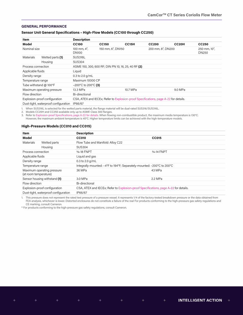
Sensor Unit General Specifications – High-Flow Models (CC100 through CC250)
Item DescriptionModel CC100 CC150 CC15H CC200 CC20H CC250Nominal size 100 mm, 4″,
DN100150 mm, 6″, DN150 200 mm, 8″, DN200 250 mm, 10″,
DN250Materials Wetted parts (1) SUS316L
Housing SUS304Process connection ASME 150, 300, 600 RF; DIN PN 10, 16, 25, 40 RF (2)Applicable fluids LiquidDensity range 0.3 to 2.0 g/mLTemperature range Maximum 10000 CPTube withstand @ 100°F –200°C to 200°C (3)Maximum operating pressure 13.3 MPa 10.7 MPa 9.0 MPaFlow direction Bi-directionalExplosion-proof configuration CSA, ATEX and IECEx; Refer to Explosion-proof Specifications, page A-22 for details.Dust-tight, waterproof configuration IP66/67
1. When SUS316L is selected for the wetted parts material, the flange material will be dual-rated SUS316/SUS316L.2. Models CC20H and CC250 available only up to ASME Class 300 flanges.3. Refer to Explosion-proof Specifications, page A-22 for details. When flowing non-combustible product, the maximum media temperature is 130°C.
However, the maximum ambient temperature is 45°C. Higher temperature limits can be achieved with the high-temperature models.
High-Pressure Models (CC010 and CC015)
Item DescriptionModel CC010 CC015Materials Wetted parts Flow Tube and Manifold: Alloy C22
Housing SUS304Process connection 3/8-18 FNPT 3/4-14 FNPTApplicable fluids Liquid and gasDensity range 0.3 to 2.0 g/mLTemperature range Integrally-mounted: –4°F to 194°F; Separately-mounted: –200°C to 200°CMaximum operating pressure (at room temperature)
36 MPa 43 MPa
Sensor housing withstand (1) 3.0 MPa 2.2 MPaFlow direction Bi-directionalExplosion-proof configuration CSA, ATEX and IECEx; Refer to Explosion-proof Specifications, page A-22 for details.Dust-tight, waterproof configuration IP66/67
1. This pressure does not represent the rated test pressure of a pressure vessel. It represents 1/4 of the factory-tested breakdown pressure or the data obtained from FEA analysis, whichever is lower. Distorted enclosures do not constitute a failure of the real For products conforming to the high-pressure gas safety regulations and CE marking, consult Cameron.
* For products conforming to the high-pressure gas safety regulations, consult Cameron.
CamCorTM CT Series Coriolis Flow Meter
GENERAL PERFORMANCE
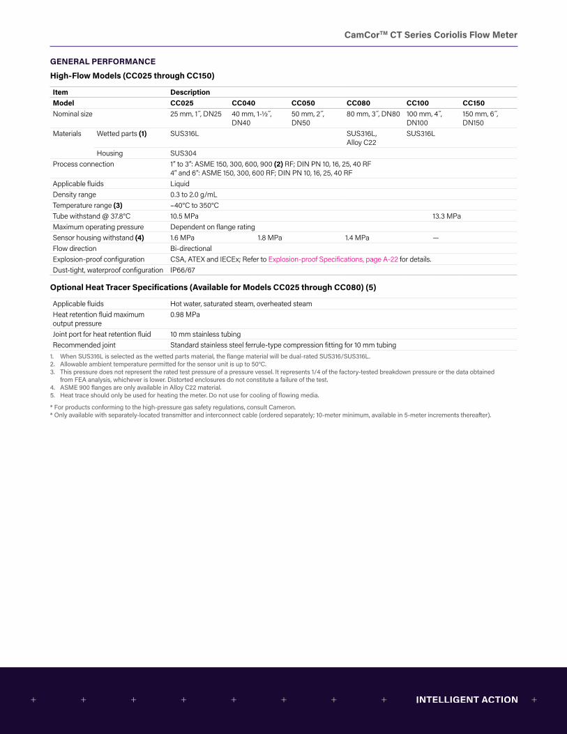
High-Flow Models (CC025 through CC150)
Item DescriptionModel CC025 CC040 CC050 CC080 CC100 CC150Nominal size 25 mm, 1 ,̋ DN25 40 mm, 1-1/2 ,̋
DN4050 mm, 2 ,̋ DN50
80 mm, 3 ,̋ DN80 100 mm, 4 ,̋ DN100
150 mm, 6 ,̋ DN150
Materials Wetted parts (1) SUS316L SUS316L,Alloy C22
SUS316L
Housing SUS304Process connection 1” to 3”: ASME 150, 300, 600, 900 (2) RF; DIN PN 10, 16, 25, 40 RF
4” and 6”: ASME 150, 300, 600 RF; DIN PN 10, 16, 25, 40 RFApplicable fluids LiquidDensity range 0.3 to 2.0 g/mLTemperature range (3) –40°C to 350°CTube withstand @ 37.8°C 10.5 MPa 13.3 MPaMaximum operating pressure Dependent on flange ratingSensor housing withstand (4) 1.6 MPa 1.8 MPa 1.4 MPa —Flow direction Bi-directionalExplosion-proof configuration CSA, ATEX and IECEx; Refer to Explosion-proof Specifications, page A-22 for details.Dust-tight, waterproof configuration IP66/67
Optional Heat Tracer Specifications (Available for Models CC025 through CC080) (5)
Applicable fluids Hot water, saturated steam, overheated steamHeat retention fluid maximum output pressure
0.98 MPa
Joint port for heat retention fluid 10 mm stainless tubingRecommended joint Standard stainless steel ferrule-type compression fitting for 10 mm tubing
1. When SUS316L is selected as the wetted parts material, the flange material will be dual-rated SUS316/SUS316L.2. Allowable ambient temperature permitted for the sensor unit is up to 50°C.3. This pressure does not represent the rated test pressure of a pressure vessel. It represents 1/4 of the factory-tested breakdown pressure or the data obtained
from FEA analysis, whichever is lower. Distorted enclosures do not constitute a failure of the test.4. ASME 900 flanges are only available in Alloy C22 material.5. Heat trace should only be used for heating the meter. Do not use for cooling of flowing media.
* For products conforming to the high-pressure gas safety regulations, consult Cameron. * Only available with separately-located transmitter and interconnect cable (ordered separately; 10-meter minimum, available in 5-meter increments thereafter).

CamCorTM CT Series Coriolis Flow Meter
GENERAL PERFORMANCE
Low-Temperature Models (CC025 through CC250)
Item DescriptionModel CC025 CC040 CC050 CC080 CC100 CC150 CC15H CC200 CC20H CC250Nominal size 25 mm,
1 ,̋ DN25 40 mm, 1-1/2 ,̋ DN40
50 mm, 2 ,̋ DN50
80 mm, 3 ,̋ DN80
100 mm, 4 ,̋ DN100
150 mm,6 ,̋ DN150
200 mm,8 ,̋ DN200
250 mm, 10 ,̋ DN250
Materials Wetted parts (1) SUS316L, Alloy C22 SUS316LHousing SUS304
Process connection ASME 150, 300, 600, 900 (2) RF;DIN PN 10, 16, 25, 40 RF(3); IDF Ferrule (4)
ASME 150, 300, 600 RF;DIN PN 10, 16, 25, 40 RF (3)
ASME 150, 300 RF;DIN PN 10, 16, 25, 40 RF (3)
Applicable fluids Liquid and gas LiqidDensity range 0.3 to 2.0 g/mLTemperature range –200°C to 122°CTube withstand @ 37.8°C 10.5 MPa 13.3 MPa 10.7 MPa 9.0 MPaMaximum operating pressure Dependent on flange ratingSensor housing withstand (5) 1.6 MPa 1.8 MPa 1.4 MPa –Flow direction Bi-directionalExplosion-proof configuration CSA, ATEX and IECEx; Refer to Explosion-proof Specifications, page A-22 for details.Dust-tight, waterproof configuration IP66/67
1. When SUS316L is selected as the wetted parts material, the flange material will be dual-rated SUS316/SUS316L.2. DIN flanges are only available for meter material SUS316L.3. ASME 900 flanges are only available in Alloy C22 material.4. For application with foods, this product does not comply with CE marking.5. This pressure does not represent the rated test pressure of a pressure vessel. It represents 1/4 of the factory-tested breakdown pressure or the data obtained from
FEA analysis, whichever is lower. Distorted enclosures do not constitute a failure of the test.
* Only available with separately-mounted transmitter and interconnect cable (ordered separately; 10-meter minimum, available in 5-meter increments thereafter).* For products conforming to the high-pressure gas safety regulations and CE marking, consult Cameron.

CamCorTM CT Series Coriolis Flow Meter
GENERAL PERFORMANCE
Transmitter Specifications
Item DescriptionModel PA0KPower supply 85 to 264 VAC, 50/60 Hz or 20 to 30 VDC
(Safety rated 100 to 240 VAC, 50/60 Hz)Power consumption Maximum 15WAmbient temperature –40°C to 55°C (1)Transmission length (separately-mounted) Maximum 200 m (interconnect cable used) (2)Applicable EU directive EMC Directive: 2004/108/EC; ATEX Directive: 94/9/ECApplicable EN standards EMC—EN55011: 1998/A1, 1999/A2, 2002 Group 1, Class B; EN61000-6-2: 2001; EN061326-1: 2006
ATEX—EN60079-0: 2012; EN60079-1: 2007; EN60079-11: 2012 IECEx—IEC60079-0: 2011; IEC60079-1: 2007-04; IEC60079-11: 2011
Explosion-proof configuration CSA, ATEX and IECEx; Refer to Explosion-proof Specifications, page A-22 for details.Dust-tight, waterproof configuration IP66/67Transmitter configuration Integral or separately-mountedFinish Paint type: Baked enamel; Paint color: Light gray (RAL7035)Display LCD display provided (128×64 dots), backlit (white, orange) ; Two infrared light sensors; Two LEDs
(green and red)Weight (approximate) Integrally-mounted model, 3.6kg; Separately-mounted model, 5.0kgCommunication interface (5) HART (Standard) Protocol Version 7, Bell 202 (3)
Modbus (Optional) RS-485: Baud rate: 9600 bps, 19200 bps, 38400 bps; RTU or ASCII; Response time: 25 to 50 ms
Damping (default) Flow rate, 0.8 sec.; Density, 4.0 sec.; Temperature, 2.5 sec.Low-flow cutoff (default) Less than 0.6% of maximum service flow ratePulse output Open drain (equivalent to open collector): 10V to 30V, 50 mADC, ON resistance ≤0.6 Ω OR Voltage: 1.5V
maximum (low level) to 13V minimum (high level), output impedance: 2.2 kΩ; Setting range: 0.1 to 10000 Hz (Maximum: 11000 Hz)
Analog output 4 to 20 mADC (maximum load: 600 Ω); Select two outputs from instant flowrate (mass or volume) temperature, and density.
Status output Open drain (equivalent to open collector)—30V maximum, 50 mADC, ON resistance ≤0.6 Ω; Select one from error (default) (4) flow direction, or high/low alarm
Status input Contact-closure (Form ""a"" contact): 200 Ω maximum (short), 100 kΩ minimum (open); Select one output from remote zero, total reset, 0% signal lock, or function off (default)
1. Below –20°C, the display loses its visibility due to weakened contrast. Both the display and infrared sensor may exhibit slow responses below –20°C.2. If the sensor-to-transmitter communications cable length exceeds 200 meters, consult Cameron.3. HART communications are available only across the Analog Output 1.4. The status output can also be configured to activate when meter zeroing is in process.5. Electrical noise filtering components are installed in connections between power source, output, communications, and chassis.

CamCorTM CT Series Coriolis Flow Meter
GENERAL PERFORMANCE
CT Series Models
Low-flow and Standard Models High-pressure Model
High-temperature Model
Low-temperature Model
CC00A, CC001 CC003 CC006 to CC080 CC100 to CC250 CC010, CC015 CC025 to CC150 CC025 to CC2501/4″ 1/2″ 1/2″ to 3″ 4″ to 10″ 3/8” and 3/4” 1″ to 6″ 1″ to 10″
Display
lb/min
gal/min
Mass Flow
Vol Flow
CamCorCoriolis Flow Meter
1. Mass instant flowrate2. Volume instant flowrate
3. Density
4. Temperature5. Pulse count 1 (mass or volume)
6. Pulse count 2 (mass or volume)
7. Total 1 (mass or volume)
8. Total 2 (mass or volume)9. Analog 1 (% instant)
10. Analog 2 (% instant)
11. Status information
12. Mode select (parameter setup)LED (Green)
LED (Red)
To select the mode, touch the infrared optical sensor panel through the front glass.
Display modes
• LCD backlight available in white and orange. Color
• In most cases, the backlight shuts o� automatically if the optical sensor does not respond within a user-

CamCorTM CT Series Coriolis Flow Meter
Pressure Losses
100
1 0
1
0.1
0.01
0.001
0.0001
0.00001
0.0000010.1 1. 0 1 0 10 0
10mPa ∙s
100mPa ∙s
1000mPa ∙s
1 1 0 10 0 100 0
10 0
1 0
1
0.1
0.01
0.001
0.0001
0.00001
0.000001
0.1 1 1 0 10 0 100 0
10 0
1 0
1
0.1
0.01
0.001
0.0001
0.00001
0.0000011 1 0 10 0 100 0
10 0
1 0
1
0.1
0.01
0.001
0.0001
0.00001
0.000001
1 1 0 10 0 100 0 1000 0
1 0
1
0.1
0.01
0.001
0.0001
0.00001
0.0000011 10 0 100 0 1000 0
1 0
1
0.1
0.01
0.001
0.0001
0.00001
0.000001
10 10 0 100 0 10000 01000 0
1 0
1
0.1
0.01
0.001
0.0001
0.00001
0.000001
Flow rate (g/min)Flow rate (g/min)
Flow rate (kg/h) Flow rate (kg/h)
Flow rate (kg/h)Flow rate (kg/h)
Flow rate (kg/h)100 10000 10000 0100 0
1 0
1
0.1
0.01
0.001
0.0001
0.00001
0.000001
Flow rate (kg/h)
Pres
sure
loss
coe
�., C
Pres
sure
loss
coe
�., C
Pres
sure
loss
coe
�., C
Pres
sure
loss
coe
�., C
Pres
sure
loss
coe
�., C
Pres
sure
loss
coe
�., C
Pres
sure
loss
coe
�., C
Pres
sure
loss
coe
�., C
CC025
1mPa ∙s
0.01mPa ∙s
10mPa ∙s
100mPa ∙s
1000mPa ∙s
1mPa ∙s
0.01mPa ∙s
1000mPa ∙s
100mPa ∙s
10mPa ∙s
1mPa ∙s
0.01mPa ∙s
10mPa ∙s
100mPa ∙s
1000mPa ∙s
1mPa ∙s
0.01mPa ∙s
10mPa ∙s
100mPa ∙s
1000mPa ∙s
1mPa ∙s
0.01mPa ∙s
10mPa ∙s
100mPa ∙s
1000mPa ∙s
1mPa ∙s
0.01mPa ∙s
10mPa ∙s
100mPa ∙s
1000mPa ∙s
1mPa ∙s
0.01mPa ∙s
10mPa ∙s
100mPa ∙s
1000mPa ∙s
1mPa ∙s
0.01mPa ∙s
CC040, CC050
CC010 CC015
CC00A CC001
CC003 CC006
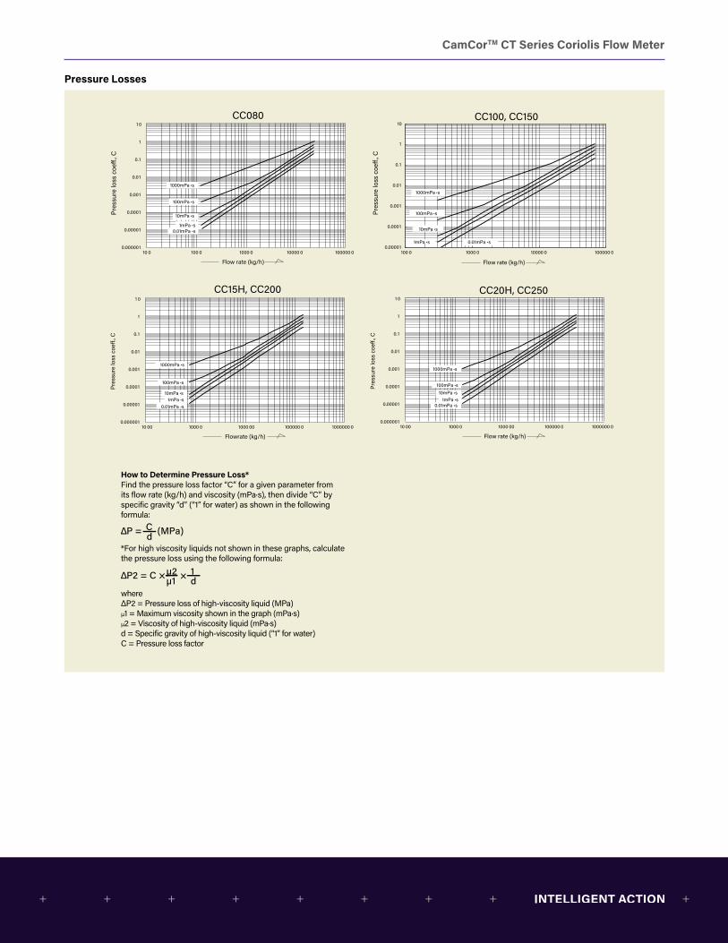
CamCorTM CT Series Coriolis Flow Meter
Pressure Losses
10 0 100 0 1000 0 10000 0 100000 0
1 0
1
0.1
0.01
0.001
0.0001
0.00001
0.000001
Flow rate (kg/h) Flow rate (kg/h)
Pres
sure
loss
coe
., C
Pres
sure
loss
coe
., C
100 0 1000 0 10000 0 100000 0
1
10
0.1
0.01
0.001
0.0001
0.00001
10 00 1000 0 1000 00 100000 0 1000000 0
1 0
1
0.1
0.01
0.001
0.0001
0.00001
0.000001
Flow rate (kg/h)
Pres
sure
loss
coe
., C
10 00 1000 0 1000 00 100000 0 1000000 0
1 0
1
0.1
0.01
0.001
0.0001
0.00001
0.000001
Flowrate (kg/h)
Pres
sure
loss
coe
., C
10mPa ∙s
1mPa ∙s0.01mPa ∙s
10mPa ∙s
100mPa ∙s
1000mPa ∙s
1mPa ∙s0.01mPa ∙s
10mPa ∙s
100mPa ∙s
1000mPa ∙s
1mPa ∙s 0.01mPa ∙s
10mPa ∙s100mPa ∙s
1000mPa ∙s
1mPa ∙s0.01mPa ∙s
1000mPa ∙s
100mPa ∙s
CC080 CC100, CC150
CC15H, CC200 CC20H, CC250
How to Determine Pressure Loss*Find the pressure loss factor “C” for a given parameter from its flow rate (kg/h) and viscosity (mPa∙s), then divide “C” by specific gravity “d” (“1” for water) as shown in the following formula:
*For high viscosity liquids not shown in these graphs, calculate the pressure loss using the following formula:
where ΔP2 = Pressure loss of high-viscosity liquid (MPa) μ1 = Maximum viscosity shown in the graph (mPa∙s) μ2 = Viscosity of high-viscosity liquid (mPa∙s) d = Specific gravity of high-viscosity liquid (“1” for water) C = Pressure loss factor
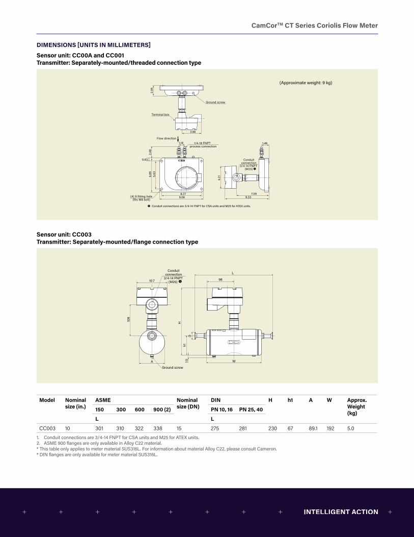
CamCorTM CT Series Coriolis Flow Meter
DIMENSIONS [UNITS IN MILLIMETERS]
Sensor unit: CC00A and CC001 Transmitter: Separately-mounted/threaded connection type
9.06
3.86
8.279.33
7.05
1.18
5.63
4.2
1
0.63
6.89
2.48
1.461/4-18 FNPT process connection
Ground screw
Terminal box
(4) 9 fitting hole(fits M8 bolt)
Conduitconnection
3/4-14 FNPT(M25)
2.05
Flow direction
Conduit connections are 3/4-14 FNPT for CSA units and M25 for ATEX units.
(Approximate weight: 9 kg)
L
A W
98
H109
h110
10 7
Ground screw
D
Conduitconnection
3/4-14 FNPT(M25)
L
A W
98
H109
h110
10 7
Ground screw
Threadedconnection
L
φD
Conduitconnection
3/4-14 FNPT(M25)
Conduit connections are 3/4-14 FNPT for CSA units and M25 for ATEX units.
Sensor unit: CC003 Transmitter: Separately-mounted/flange connection type
9.06
3.86
8.279.33
7.05
1.18
5.63
4.2
10.63
6.89
2.48
1.461/4-18 FNPT process connection
Ground screw
Terminal box
(4) 9 fitting hole(fits M8 bolt)
Conduitconnection
3/4-14 FNPT(M25)
2.05
Flow direction
Conduit connections are 3/4-14 FNPT for CSA units and M25 for ATEX units.
(Approximate weight: 9 kg)
L
A W
98
H109
h110
10 7
Ground screw
D
Conduitconnection
3/4-14 FNPT(M25)
L
A W
98
H109
h110
10 7
Ground screw
Threadedconnection
L
φD
Conduitconnection
3/4-14 FNPT(M25)
Conduit connections are 3/4-14 FNPT for CSA units and M25 for ATEX units.
Model Nominal size (in.)
ASME Nominal size (DN)
DIN H h1 A W Approx. Weight (kg)
150 300 600 900 (2) PN 10, 16 PN 25, 40
L L
CC003 10 301 310 322 338 15 275 281 230 67 89.1 192 5.0
1. Conduit connections are 3/4-14 FNPT for CSA units and M25 for ATEX units.2. ASME 900 flanges are only available in Alloy C22 material.* This table only applies to meter material SUS316L. For information about material Alloy C22, please consult Cameron.* DIN flanges are only available for meter material SUS316L.
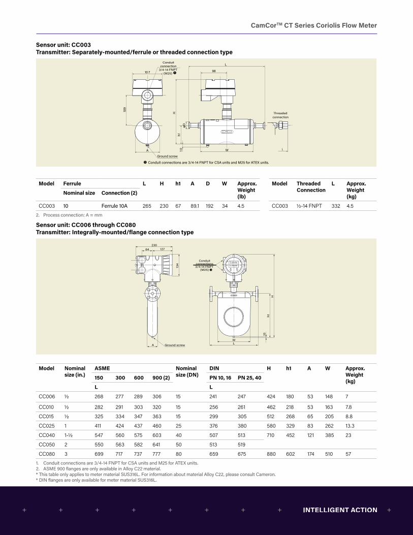
CamCorTM CT Series Coriolis Flow Meter
Sensor unit: CC003 Transmitter: Separately-mounted/ferrule or threaded connection type
9.06
3.86
8.279.33
7.05
1.18
5.63
4.2
1
0.63
6.89
2.48
1.461/4-18 FNPT process connection
Ground screw
Terminal box
(4) 9 fitting hole(fits M8 bolt)
Conduitconnection
3/4-14 FNPT(M25)
2.05
Flow direction
Conduit connections are 3/4-14 FNPT for CSA units and M25 for ATEX units.
(Approximate weight: 9 kg)
L
A W
98
H109
h110
10 7
Ground screw
D
Conduitconnection
3/4-14 FNPT(M25)
L
A W
98
H109
h110
10 7
Ground screw
Threadedconnection
L
φD
Conduitconnection
3/4-14 FNPT(M25)
Conduit connections are 3/4-14 FNPT for CSA units and M25 for ATEX units.
Model Ferrule L H h1 A D W Approx.Weight (lb)
Model ThreadedConnection
L Approx.Weight (kg)
Nominal size Connection (2)
CC003 10 Ferrule 10A 265 230 67 89.1 192 34 4.5 CC003 1/2-14 FNPT 332 4.5
2. Process connection: A = mm
Sensor unit: CC006 through CC080 Transmitter: Integrally-mounted/flange connection type
A
WL
134
h110
H
Ground screw
Conduitconnections3/4-14 FNPT
(M25)
23064 127
60
A
WL
134
h110
H
Ground screw
Conduitconnections3/4-14 FNPT
(M25)
23064 127
60
Threaded connection
L
φD
Conduit connections are 3/4-14 FNPT for CSA units and M25 for ATEX units.
Model Nominal size (in.)
ASME Nominal size (DN)
DIN H h1 A W Approx.Weight (kg)
150 300 600 900 (2) PN 10, 16 PN 25, 40
L L
CC006 1/2 268 277 289 306 15 241 247 424 180 53 148 7
CC010 1/2 282 291 303 320 15 256 261 462 218 53 163 7.8
CC015 1/2 325 334 347 363 15 299 305 512 268 65 205 8.8
CC025 1 411 424 437 460 25 376 380 580 329 83 262 13.3
CC040 1-1/2 547 560 575 603 40 507 513 710 452 121 385 23
CC050 2 550 563 582 641 50 513 519
CC080 3 699 717 737 777 80 659 675 880 602 174 510 57
1. Conduit connections are 3/4-14 FNPT for CSA units and M25 for ATEX units.2. ASME 900 flanges are only available in Alloy C22 material.* This table only applies to meter material SUS316L. For information about material Alloy C22, please consult Cameron.* DIN flanges are only available for meter material SUS316L.
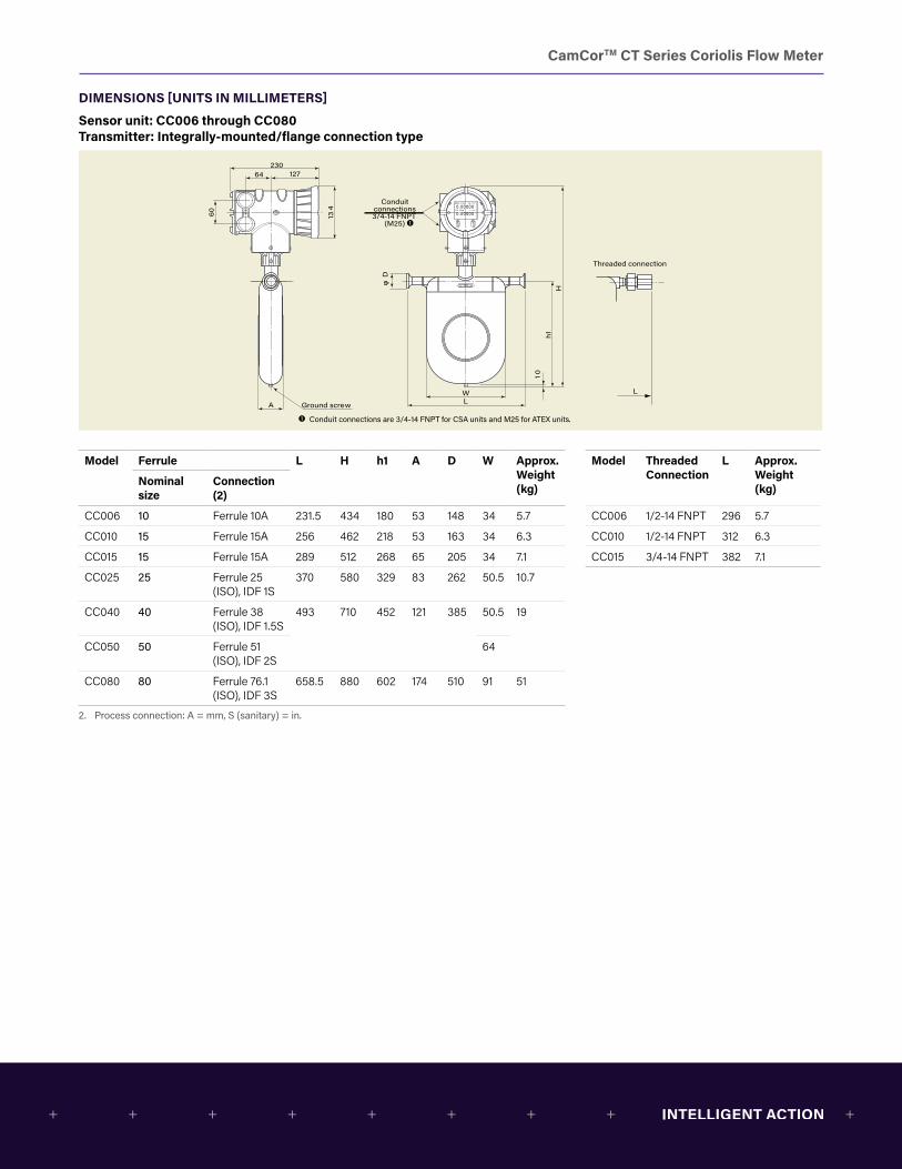
CamCorTM CT Series Coriolis Flow Meter
DIMENSIONS [UNITS IN MILLIMETERS]
Sensor unit: CC006 through CC080 Transmitter: Integrally-mounted/flange connection type
A
WL
134
h110
H
Ground screw
Conduitconnections3/4-14 FNPT
(M25)
23064 127
60
A
WL
134
h110
H
Ground screw
Conduitconnections3/4-14 FNPT
(M25)
23064 127
60
Threaded connection
Lφ
D
Conduit connections are 3/4-14 FNPT for CSA units and M25 for ATEX units.
Model Ferrule L H h1 A D W Approx. Weight (kg)
Model ThreadedConnection
L Approx.Weight (kg)
Nominal size
Connection (2)
CC006 10 Ferrule 10A 231.5 434 180 53 148 34 5.7 CC006 1/2-14 FNPT 296 5.7
CC010 15 Ferrule 15A 256 462 218 53 163 34 6.3 CC010 1/2-14 FNPT 312 6.3
CC015 15 Ferrule 15A 289 512 268 65 205 34 7.1 CC015 3/4-14 FNPT 382 7.1
CC025 25 Ferrule 25 (ISO), IDF 1S
370 580 329 83 262 50.5 10.7
CC040 40 Ferrule 38 (ISO), IDF 1.5S
493 710 452 121 385 50.5 19
CC050 50 Ferrule 51 (ISO), IDF 2S
64
CC080 80 Ferrule 76.1 (ISO), IDF 3S
658.5 880 602 174 510 91 51
2. Process connection: A = mm, S (sanitary) = in.

CamCorTM CT Series Coriolis Flow Meter
Sensor unit: CC100 through CC250 Transmitter: Internally-mounted/flange connection type
134
23064 127
60
A
Hh1h2
W 15
L
Flow direction
Ground screw
Flange
Conduit connection3/4-14 FNPT
(M25)
Hh1h2
W 15
L
Flow direction
Ground screw
Ground screw
Flange
Conduit connection3/4-14 FNPT
(M25)
Conduit connections are 3/4-14 FNPT for CSA units and M25 for ATEX units.
Boss 1/4-18 FNPT
Boss 1/4-18 FNPT
CC100, CC150 CC15H through CC250
Model Flange L H h1 h2 A W Approx. Weight (kg)Nominal size Flange rating
CC100 4" ASME 150 1018 1403 1015 660 300 810 231ASME 300 1036ASME 600 1082
DN100 PN 10, 16 968PN 25, 40 994
CC150 6" ASME 150 1318 1403 1015 660 300 810 246ASME 300 1338ASME 600 1388
DN150 PN 10, 16 1250PN 25, 40 1290
CC15H 6" ASME 150 1087 1604 1190 851 320 810 310ASME 300 1107ASME 600 1157
DN150 PN 10, 16 1019PN 25, 40 1059
CC200 8" ASME 150 1418 1604 1190 851 320 810 340ASME 300 1438ASME 600 1494
DN200 PN 10, 16 1338PN 25 1374
CC20H 8” PN 40 1390 1830 1390 960 420 1110 610ASME 150 1418ASME 300 1438
DN200 PN 10, 16 1338PN 25 1374PN 40 1390
CC20H 10" ASME 150 1773 1830 1390 960 420 1110 650ASME 300 1805PN 10 1705
DN250 PN 16 1709PN 25 1745PN 40 1779
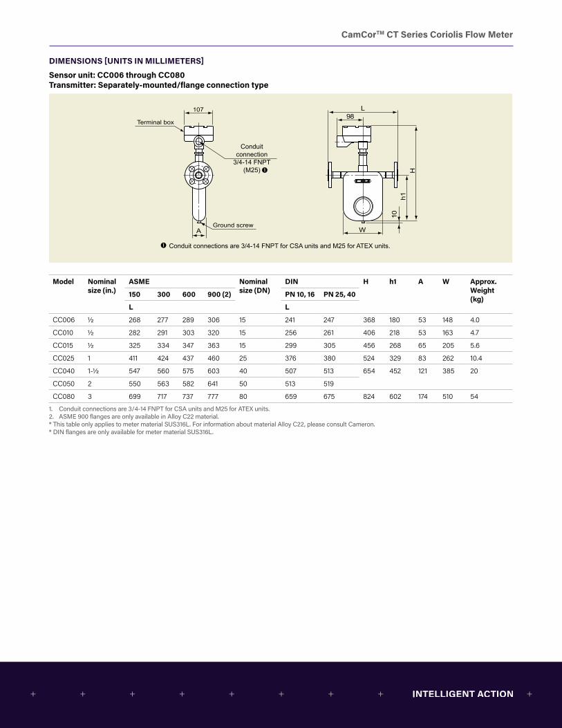
CamCorTM CT Series Coriolis Flow Meter
DIMENSIONS [UNITS IN MILLIMETERS]
Sensor unit: CC006 through CC080 Transmitter: Separately-mounted/flange connection type
A
107
Hh1
W
L98
10
Ground screw
Terminal box
Conduit connection
3/4-14 FNPT(M25)
107
Hh1
W
L98
A
10
Ground screw
Conduit connection 3/4-14 FNPT
(M25)
Conduit connections are 3/4-14 FNPT for CSA units and M25 for ATEX units.
L
Threaded connection
Terminal box
φD
Conduit connections are 3/4-14 FNPT for CSA units and M25 for ATEX units.
Model Nominal size (in.)
ASME Nominal size (DN)
DIN H h1 A W Approx. Weight (kg)
150 300 600 900 (2) PN 10, 16 PN 25, 40
L L
CC006 1/2 268 277 289 306 15 241 247 368 180 53 148 4.0
CC010 1/2 282 291 303 320 15 256 261 406 218 53 163 4.7
CC015 1/2 325 334 347 363 15 299 305 456 268 65 205 5.6
CC025 1 411 424 437 460 25 376 380 524 329 83 262 10.4
CC040 1-1/2 547 560 575 603 40 507 513 654 452 121 385 20
CC050 2 550 563 582 641 50 513 519
CC080 3 699 717 737 777 80 659 675 824 602 174 510 54
1. Conduit connections are 3/4-14 FNPT for CSA units and M25 for ATEX units.2. ASME 900 flanges are only available in Alloy C22 material.* This table only applies to meter material SUS316L. For information about material Alloy C22, please consult Cameron.* DIN flanges are only available for meter material SUS316L.
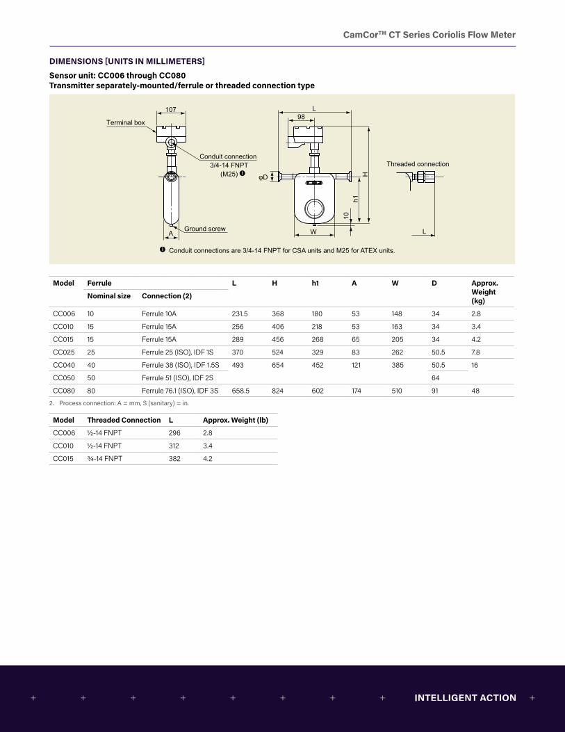
CamCorTM CT Series Coriolis Flow Meter
DIMENSIONS [UNITS IN MILLIMETERS]
Sensor unit: CC006 through CC080 Transmitter separately-mounted/ferrule or threaded connection type
A
107
Hh1
W
L98
10
Ground screw
Terminal box
Conduit connection
3/4-14 FNPT(M25)
107
Hh1
W
L98
A
10
Ground screw
Conduit connection 3/4-14 FNPT
(M25)
Conduit connections are 3/4-14 FNPT for CSA units and M25 for ATEX units.
L
Threaded connection
Terminal box
φD
Conduit connections are 3/4-14 FNPT for CSA units and M25 for ATEX units.
Model Ferrule L H h1 A W D Approx. Weight (kg)
Nominal size Connection (2)
CC006 10 Ferrule 10A 231.5 368 180 53 148 34 2.8
CC010 15 Ferrule 15A 256 406 218 53 163 34 3.4
CC015 15 Ferrule 15A 289 456 268 65 205 34 4.2
CC025 25 Ferrule 25 (ISO), IDF 1S 370 524 329 83 262 50.5 7.8
CC040 40 Ferrule 38 (ISO), IDF 1.5S 493 654 452 121 385 50.5 16
CC050 50 Ferrule 51 (ISO), IDF 2S 64
CC080 80 Ferrule 76.1 (ISO), IDF 3S 658.5 824 602 174 510 91 48
2. Process connection: A = mm, S (sanitary) = in.
Model Threaded Connection L Approx. Weight (lb)
CC006 1/2-14 FNPT 296 2.8
CC010 1/2-14 FNPT 312 3.4
CC015 3/4-14 FNPT 382 4.2
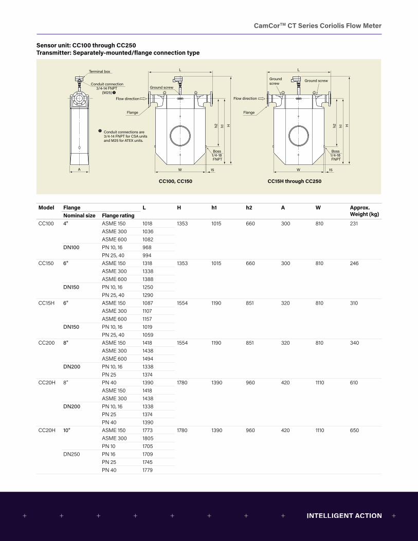
CamCorTM CT Series Coriolis Flow Meter
Sensor unit: CC100 through CC250 Transmitter: Separately-mounted/flange connection type
A
Hh1h2
W 15
L
Flow direction
Ground screw
Flange
Conduit connection3/4-14 FNPT
(M25)
Terminal box
Hh1h2
W 15
L
Flow direction
Ground screwGround screw
Flange
Conduit connections are 3/4-14 FNPT for CSA units and M25 for ATEX units.
Boss 1/4-18 FNPT
Boss 1/4-18 FNPT
CC100, CC150 CC15H through CC250
Model Flange L H h1 h2 A W Approx. Weight (kg)Nominal size Flange rating
CC100 4" ASME 150 1018 1353 1015 660 300 810 231ASME 300 1036ASME 600 1082
DN100 PN 10, 16 968PN 25, 40 994
CC150 6" ASME 150 1318 1353 1015 660 300 810 246ASME 300 1338ASME 600 1388
DN150 PN 10, 16 1250PN 25, 40 1290
CC15H 6" ASME 150 1087 1554 1190 851 320 810 310ASME 300 1107ASME 600 1157
DN150 PN 10, 16 1019PN 25, 40 1059
CC200 8" ASME 150 1418 1554 1190 851 320 810 340ASME 300 1438ASME 600 1494
DN200 PN 10, 16 1338PN 25 1374
CC20H 8” PN 40 1390 1780 1390 960 420 1110 610ASME 150 1418ASME 300 1438
DN200 PN 10, 16 1338PN 25 1374PN 40 1390
CC20H 10" ASME 150 1773 1780 1390 960 420 1110 650ASME 300 1805PN 10 1705
DN250 PN 16 1709PN 25 1745PN 40 1779
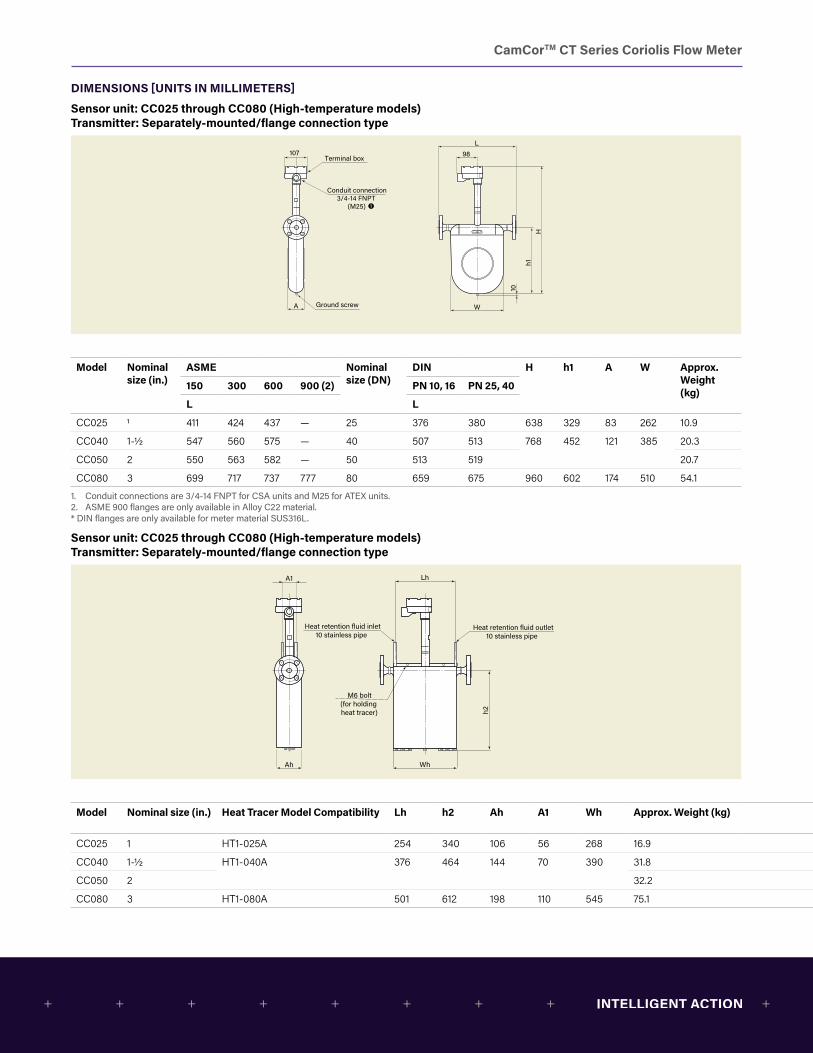
CamCorTM CT Series Coriolis Flow Meter
DIMENSIONS [UNITS IN MILLIMETERS]
Sensor unit: CC025 through CC080 (High-temperature models) Transmitter: Separately-mounted/flange connection type
A W
h1
10
H
107 98L
Terminal box
Ground screw
Conduit connection3/4-14 FNPT
(M25)
Conduit connections are 3/4-14 FNPT for CSA units and M25 for ATEX units.
Ah Wh
h2
A1 Lh
Heat retention fluid inlet10 stainless pipe
Heat retention fluid outlet10 stainless pipe
M6 bolt(for holding heat tracer)
300
1387
1015
660
810
98
L
107
Conduit connection3/4-14 FNPT
(M25)
Terminal box
1 5
Flow direction
Flange
Groundscrew
Conduit connections are 3/4-14 FNPT for CSA units and M25 for ATEX units.
Boss 1/4-18 FNPT
Model Nominal size (in.)
ASME Nominal size (DN)
DIN H h1 A W Approx. Weight (kg)
150 300 600 900 (2) PN 10, 16 PN 25, 40
L L
CC025 1 411 424 437 — 25 376 380 638 329 83 262 10.9
CC040 1-1/2 547 560 575 — 40 507 513 768 452 121 385 20.3
CC050 2 550 563 582 — 50 513 519 20.7
CC080 3 699 717 737 777 80 659 675 960 602 174 510 54.1
1. Conduit connections are 3/4-14 FNPT for CSA units and M25 for ATEX units.2. ASME 900 flanges are only available in Alloy C22 material.* DIN flanges are only available for meter material SUS316L.
Sensor unit: CC025 through CC080 (High-temperature models) Transmitter: Separately-mounted/flange connection type
A W
h1
10
H
107 98L
Terminal box
Ground screw
Conduit connection3/4-14 FNPT
(M25)
Conduit connections are 3/4-14 FNPT for CSA units and M25 for ATEX units.
Ah Wh
h2
A1 Lh
Heat retention fluid inlet10 stainless pipe
Heat retention fluid outlet10 stainless pipe
M6 bolt(for holding heat tracer)
300
1387
1015
660
810
98
L
107
Conduit connection3/4-14 FNPT
(M25)
Terminal box
1 5
Flow direction
Flange
Groundscrew
Conduit connections are 3/4-14 FNPT for CSA units and M25 for ATEX units.
Boss 1/4-18 FNPT
Model Nominal size (in.) Heat Tracer Model Compatibility Lh h2 Ah A1 Wh Approx. Weight (kg)
CC025 1 HT1-025A 254 340 106 56 268 16.9
CC040 1-1/2 HT1-040A 376 464 144 70 390 31.8
CC050 2 32.2
CC080 3 HT1-080A 501 612 198 110 545 75.1
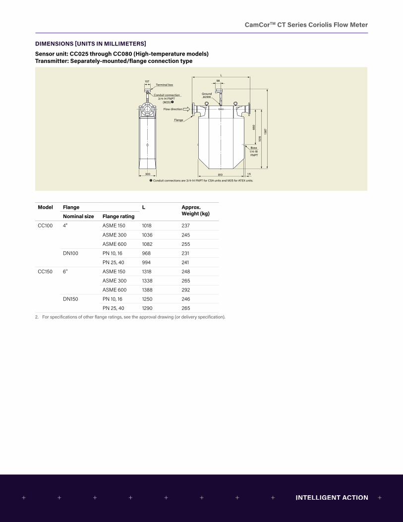
CamCorTM CT Series Coriolis Flow Meter
DIMENSIONS [UNITS IN MILLIMETERS]
Sensor unit: CC025 through CC080 (High-temperature models) Transmitter: Separately-mounted/flange connection type
A W
h1
10
H
107 98L
Terminal box
Ground screw
Conduit connection3/4-14 FNPT
(M25)
Conduit connections are 3/4-14 FNPT for CSA units and M25 for ATEX units.
Ah Wh
h2
A1 Lh
Heat retention fluid inlet10 stainless pipe
Heat retention fluid outlet10 stainless pipe
M6 bolt(for holding heat tracer)
300
1387
1015
660
810
98
L
107
Conduit connection3/4-14 FNPT
(M25)
Terminal box
1 5
Flow direction
Flange
Groundscrew
Conduit connections are 3/4-14 FNPT for CSA units and M25 for ATEX units.
Boss 1/4-18 FNPT
Model Flange L Approx. Weight (kg)Nominal size Flange rating
CC100 4" ASME 150 1018 237
ASME 300 1036 245
ASME 600 1082 255
DN100 PN 10, 16 968 231
PN 25, 40 994 241
CC150 6" ASME 150 1318 248
ASME 300 1338 265
ASME 600 1388 292
DN150 PN 10, 16 1250 246
PN 25, 40 1290 265
2. For specifications of other flange ratings, see the approval drawing (or delivery specification).
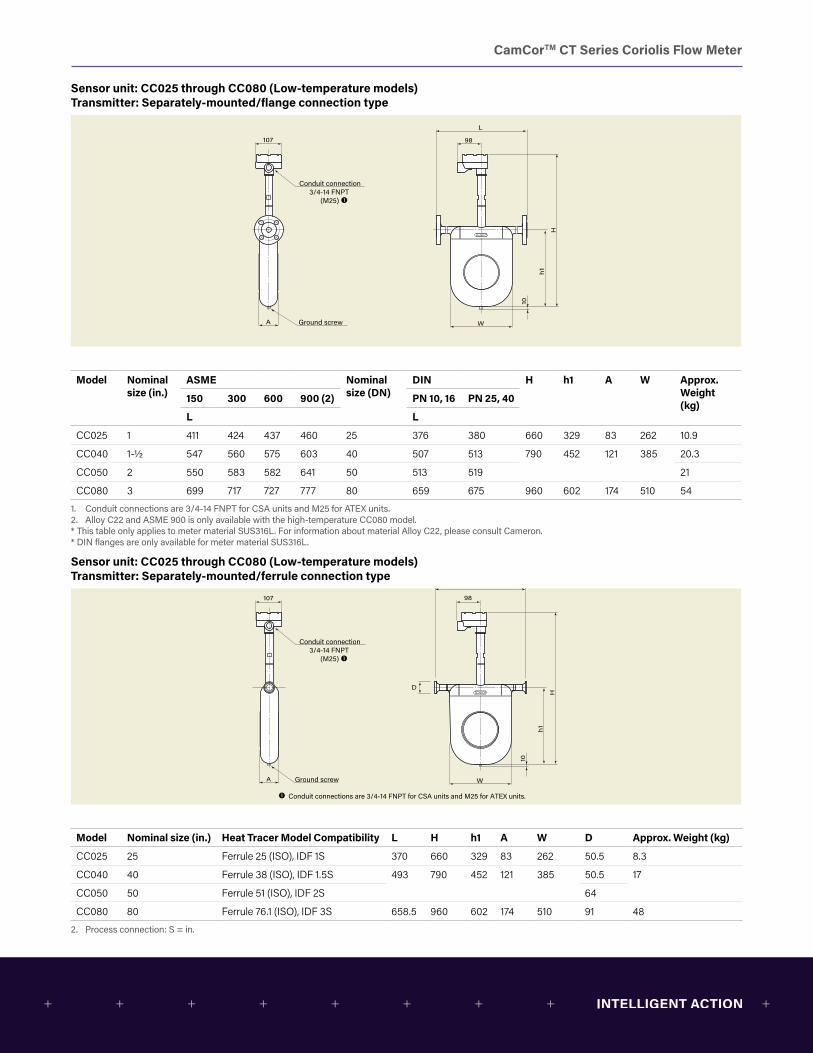
CamCorTM CT Series Coriolis Flow Meter
Sensor unit: CC025 through CC080 (Low-temperature models) Transmitter: Separately-mounted/flange connection type
Conduit connection3/4-14 FNPT
(M25)
A W
h1
10
H
Ground screw
107 98
L
Conduit connections are 3/4-14 FNPT for CSA units and M25 for ATEX units.
Conduit connection3/4-14 FNPT
(M25)
A W
h1
10
H
Ground screw
107
D
98
L
Conduit connections are 3/4-14 FNPT for CSA units and M25 for ATEX units.
Model Nominal size (in.)
ASME Nominal size (DN)
DIN H h1 A W Approx. Weight (kg)
150 300 600 900 (2) PN 10, 16 PN 25, 40
L L
CC025 1 411 424 437 460 25 376 380 660 329 83 262 10.9
CC040 1-1/2 547 560 575 603 40 507 513 790 452 121 385 20.3
CC050 2 550 583 582 641 50 513 519 21
CC080 3 699 717 727 777 80 659 675 960 602 174 510 54
1. Conduit connections are 3/4-14 FNPT for CSA units and M25 for ATEX units.2. Alloy C22 and ASME 900 is only available with the high-temperature CC080 model.* This table only applies to meter material SUS316L. For information about material Alloy C22, please consult Cameron.* DIN flanges are only available for meter material SUS316L.
Sensor unit: CC025 through CC080 (Low-temperature models) Transmitter: Separately-mounted/ferrule connection type
Conduit connection3/4-14 FNPT
(M25)
A W
h1
10
H
Ground screw
107 98
L
Conduit connections are 3/4-14 FNPT for CSA units and M25 for ATEX units.
Conduit connection3/4-14 FNPT
(M25)
A W
h1
10
H
Ground screw
107
D
98
L
Conduit connections are 3/4-14 FNPT for CSA units and M25 for ATEX units.
Model Nominal size (in.) Heat Tracer Model Compatibility L H h1 A W D Approx. Weight (kg)
CC025 25 Ferrule 25 (ISO), IDF 1S 370 660 329 83 262 50.5 8.3
CC040 40 Ferrule 38 (ISO), IDF 1.5S 493 790 452 121 385 50.5 17
CC050 50 Ferrule 51 (ISO), IDF 2S 64
CC080 80 Ferrule 76.1 (ISO), IDF 3S 658.5 960 602 174 510 91 48
2. Process connection: S = in.
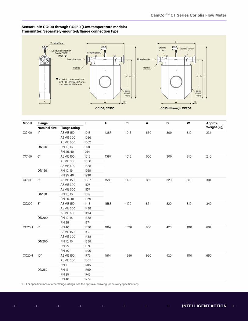
CamCorTM CT Series Coriolis Flow Meter
Sensor unit: CC100 through CC250 (Low-temperature models) Transmitter: Separately-mounted/flange connection type
A
Hh1h2
W 15
L
Flow direction
Ground screw
Flange
Conduit connection3/4-14 FNPT
(M25)
Terminal box
Hh1h2
W 15
L
Flow direction
Ground screwGround screw
Flange
Conduit connections are 3/4-14 FNPT for CSA units and M25 for ATEX units.
Boss 1/4-18 FNPT
Boss 1/4-18 FNPT
CC100, CC150 CC15H through CC250
Model Flange L H h1 A D W Approx. Weight (kg)Nominal size Flange rating
CC100 4" ASME 150 1018 1387 1015 660 300 810 231ASME 300 1036ASME 600 1082
DN100 PN 10, 16 968PN 25, 40 994
CC150 6" ASME 150 1318 1387 1015 660 300 810 246ASME 300 1338ASME 600 1388
DN150 PN 10, 16 1250PN 25, 40 1290
CC15H 6" ASME 150 1087 1588 1190 851 320 810 310ASME 300 1107ASME 600 1157
DN150 PN 10, 16 1019PN 25, 40 1059
CC200 8" ASME 150 1418 1588 1190 851 320 810 340ASME 300 1438ASME 600 1494
DN200 PN 10, 16 1338PN 25 1374
CC20H 8” PN 40 1390 1814 1390 960 420 1110 610ASME 150 1418ASME 300 1438
DN200 PN 10, 16 1338PN 25 1374PN 40 1390
CC20H 10" ASME 150 1773 1814 1390 960 420 1110 650ASME 300 1805PN 10 1705
DN250 PN 16 1709PN 25 1745PN 40 1779
1. For specifications of other flange ratings, see the approval drawing (or delivery specification).
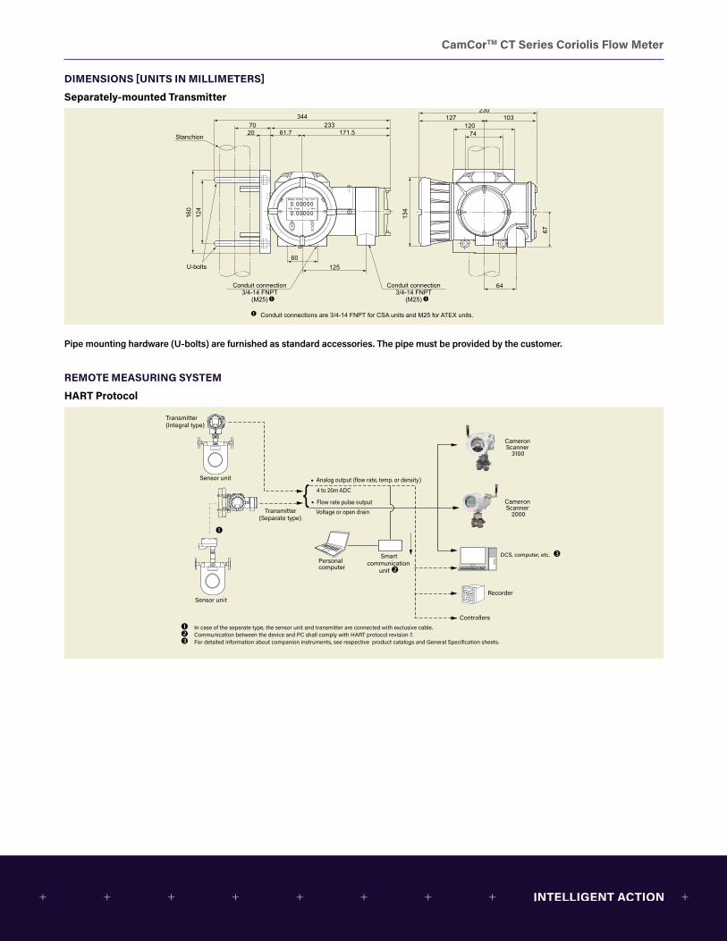
CamCorTM CT Series Coriolis Flow Meter
DIMENSIONS [UNITS IN MILLIMETERS]
Separately-mounted Transmitter
134
67
Conduit connection3/4-14 FNPT
(M25)
230127 103
12074
64
12560
160
124
34470
Stanchion
U-bolts
23320 61.7 171.5
Conduit connection3/4-14 FNPT
(M25)
Conduit connections are 3/4-14 FNPT for CSA units and M25 for ATEX units.
Pipe mounting hardware (U-bolts) are furnished as standard accessories. The pipe must be provided by the customer.
REMOTE MEASURING SYSTEM
HART Protocol5.
28
2.64
Conduit connection3/4-14 FNPT
(M25)
Conduit connection 3/4-14 FNPT
(M25)
9.065.0 4.06
4.722.91
2.52
4.92
2.36
6.3
4.88
13.542.76
Stanchion
U-bolts
9.170.79 2.43 6.75
lb/min
gal/min
Conduit connections are 3/4-14 FNPT for CSA units and M25 for ATEX units.
Analog output (flow rate, temp. or density)
Flow rate pulse output
Voltage or open drain
Sensor unit
Recorder
Controllers
4 to 20m ADC
Personal computer
Smartcommunication
unit
Sensor unit
In case of the separate type, the sensor unit and transmitter are connected with exclusive cable. Communication between the device and PC shall comply with HART protocol revision 7. For detailed information about companion instruments, see respective product catalogs and General Specification sheets.
Transmitter(Integral type)
Transmitter(Separate type)
{
Cameron Scanner
2000
Cameron Scanner
3100
DCS, computer, etc.
Sensor unit and separate transmitter are connected via the exclusive interconnect cable. The transmitter requires a separate power source (AC or DC) for its main power supply.
Modbus compatible host device(DCS, PC, etc.)
Modbus compatible(Separate type)
Modbus compatible(Integral type)
RS-485 (Separate terminating resistor is required.)USB or RS-232C ↔RS-485 converter
USB or RS-232C
Other field deviceOther field device
Sensor unit
Sensor unit

CamCorTM CT Series Coriolis Flow Meter
Modbus
5.28
2.64
Conduit connection3/4-14 FNPT
(M25)
Conduit connection 3/4-14 FNPT
(M25)
9.065.0 4.06
4.722.91
2.52
4.92
2.36
6.3
4.88
13.542.76
Stanchion
U-bolts
9.170.79 2.43 6.75
lb/min
gal/min
Conduit connections are 3/4-14 FNPT for CSA units and M25 for ATEX units.
Analog output (flow rate, temp. or density)
Flow rate pulse output
Voltage or open drain
Sensor unit
Recorder
Controllers
4 to 20m ADC
Personal computer
Smartcommunication
unit
Sensor unit
In case of the separate type, the sensor unit and transmitter are connected with exclusive cable. Communication between the device and PC shall comply with HART protocol revision 7. For detailed information about companion instruments, see respective product catalogs and General Specification sheets.
Transmitter(Integral type)
Transmitter(Separate type)
{
Cameron Scanner
2000
Cameron Scanner
3100
DCS, computer, etc.
Sensor unit and separate transmitter are connected via the exclusive interconnect cable. The transmitter requires a separate power source (AC or DC) for its main power supply.
Modbus compatible host device(DCS, PC, etc.)
Modbus compatible(Separate type)
Modbus compatible(Integral type)
RS-485 (Separate terminating resistor is required.)USB or RS-232C ↔RS-485 converter
USB or RS-232C
Other field deviceOther field device
Sensor unit
Sensor unit
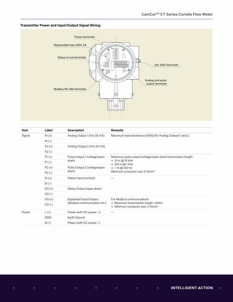
CamCorTM CT Series Coriolis Flow Meter
Transmitter Power and Input/Output Signal Wiring
Status in/out terminals
Analog and pulse output terminals
Power terminals
Replaceable fuse 250V, 2A
Modbus RS-485 terminals
Ext. GND terminals
Item Label Description Remarks
Signal A1 (+) Analog Output 1 (4 to 20 mA) Maximum load resistance is 600Ω for Analog Outputs 1 and 2
A1 (–)
A2 (+) Analog Output 2 (4 to 20 mA)
A2 (–)
P1 (+) Pulse Output 1 (voltage/open drain)
Maximum pulse output (voltage/open drain) transmission length: + 10 m @ 10 kHz + 100 m @ 1 kHz + 1 m @ 100 Hz
Minimum conductor size: 0.75mm2
P1 (–)
P2 (+) Pulse Output 2 (voltage/open drain)P2 (–)
SI (+) Status Input (contact) —
SI (–)
SO (+) Status Output (open drain)
SO (–)
I/O (+) Expanded Input/Output (Modbus communication, etc.)
For Modbus communications: + Maximum transmission length: 1200m + Minimum conductor size: 0.75mm2I/O (–)
Power L (+) Power (with DC power: +) —
GND Earth Ground
N (–) Power (with DC power: –)
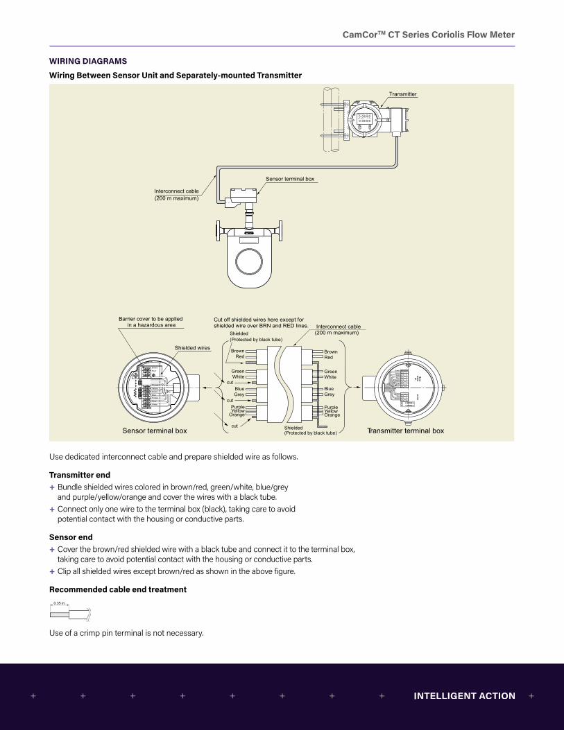
CamCorTM CT Series Coriolis Flow Meter
WIRING DIAGRAMS
Wiring Between Sensor Unit and Separately-mounted Transmitter
Interconnect cable(200 m maximum)
Sensor terminal box
Transmitter
SEL CUR
Cut off shielded wires here except forshielded wire over BRN and RED lines. Interconnect cable
(200 m maximum)
Transmitter terminal box Sensor terminal box Shielded(Protected by black tube)
Shielded(Protected by black tube)
cut
cut
cut
Barrier cover to be applied in a hazardous area
BrownRed
GreenWhite
BlueGrey
PurpleYellowOrange
BrownRed
GreenWhite
BlueGrey
PurpleYellow
Orange
Brown
Red
Green
White
Blue
Grey
Purple
Yellow
Orange
Shielded wires
Green
WhiteGrey
YellowBlue
Orange
Black
Purple
RedBrown
Use dedicated interconnect cable and prepare shielded wire as follows.
Transmitter end + Bundle shielded wires colored in brown/red, green/white, blue/grey and purple/yellow/orange and cover the wires with a black tube.
+ Connect only one wire to the terminal box (black), taking care to avoid potential contact with the housing or conductive parts.
Sensor end + Cover the brown/red shielded wire with a black tube and connect it to the terminal box, taking care to avoid potential contact with the housing or conductive parts.
+ Clip all shielded wires except brown/red as shown in the above figure.
Recommended cable end treatment
9
CamCor PRO Series Coriolis Flow Meter
WIRING DIAGRAMSWiring Between Sensor Unit and Separately-mounted Transmitter
Mass Flow
Vol Flow
Kg/min
L/min0.000000.00000SEL CUR
Cut off shielded wires here except for the shielded wire over BRN and RED lines. Interconnect cable
(5 m maximum)
Transmitter terminal box Sensor terminal box Shield(Protected by black tube)
Shield(Protected by black tube)
cut
cut
cut
Barrier cover to be appliedin a hazardous area
BrownRed
GreenWhite
BlueGray
PurpleYellowOrange
BrownRed
GreenWhite
BlueGray
PurpleYellow
Orange
Shield wires
Interconnect cable(5 m maximum)
Sensor terminal box
Transmitter
1. Use interconnect cable.
Use dedicated interconnect cable and prepare shielded wire as follows.
Transmitter end1. Bundle shielded wires colored in brown/red, green/white, blue/grey and purple/yellow/orange and cover the wires with a
black tube.
2. Connect only one wire to the terminal box (black), taking care to avoid potential contact with the housing or conductive parts.
Sensor end1. Cover the brown/red shielded wire with a black tube and connect it to the terminal box, taking care to avoid potential
contact with the housing or conductive parts.
2. Clip all shielded wires except brown/red as shown in the above figure.Recommended cable end treatment
Use of a crimp pin terminal is not necessary. 0.35 in.
Use of a crimp pin terminal is not necessary.

CamCorTM CT Series Coriolis Flow Meter
INSTALLATION
Typical Installation1. Avoid pipeline stresses on the meter.2. The meter should be supported near each process connection,
as shown in the illustration on the right.3. Avoid supporting the meter body directly.4. Pipeline should be arranged such that the meter is constantly
filled with the process fluid. Avoid, however, installing it in a low point in the piping where slurries may build up.
5. Provide a valve downstream of the meter to allow zeroing by obtaining a true zero flow. We recommend providing another valve upstream of the meter for servicing or maintenance.
Precautions at Installation1. Locate the meter at least 3.28 feet from large transformers,
motors, or other sources of electromagnetic induction. Also avoid installation near sources of excessive vibration, such as motors and pumps.
2. In case of measurement of a process fluid which requires heat retention, heat trace may be applied directly to the sensor body. Heat trace should be held below 392˚F. Explosion-proof models require the temperature to be held below their maximum allowable levels.
3. To ensure consistent volume flow and density measurements, heat retention is suggested.
4. The sensor unit is of gas-tight construction. To prevent dew condensation inside in a low-temperature application, it is filled with argon gas. To avoid damaging the sensor, do not drop the sensor unit or otherwise subject it to impact shocks.
5. In a horizontal run, install the sensor unit with the transmitter up as shown in the typical installation figure.
6. A control valve should be located downstream of the meter. In an arrangement where cavitation may possibly take place, locate it at least 16.4 feet away.
7. To ensure consistent and accurate measurement, the Coriolis flow meter should be placed in an environment where pipeline oscillation is held below 0.3G.
8. Sudden temperature change may damage the performance of the flow meter. Keep the temperature change of the fluid within ±55°F/min. for both heating and cooling.
Valve
Flow
Valve
Orie
ntat
ion Flow
directionFlowdirection
Flow
direction
(4) 0.35-in. mounting holes
Bench mount Wall mount
Prevention of Cavitation (Gas Flash Off)Cavitation can cause a loss in Coriolis meter measurement accuracy. To prevent cavitation, maintain line pressure upstream and downstream of the meter.
Avoid piping arrangements that open the line to the atmosphere immediately downstream of the meter. Particular care must be taken in low pressure applications and with high vapor pressure liquids, such as NGLs (natural gas liquids). It is recommended the back pressure immediately downstream of the meter be kept above the value calculated by the formula below:
Pd = 2ΔP + 1.25Pv where Pd: Downstream pressure (psia) ΔP: Pressure drop across meter (psid) Pv: Vapor pressure of the process fluid (psia)
Calculation based on API Manual of Petroleum Measurement Standards, Chapter 5.6, Section 6.3.2.

CamCorTM CT Series Coriolis Flow Meter
Physical Orientation CC003 through CC250
Recommended physical orientation varies with the type of process fluid. (No. 2 in the figure below shows basic orientation for liquid service.) Physical orientation must be specified at the time of order.
Horizontal run Vertical run
No.1 No.2 No.3
Orientation
Fluids + Gases + Slurries
+ Liquids + Slurries (requiring cleaning) + Liquids + Gases
1. For installation orientation in No. 1, Cameron recommends the separately-mounted transmitter. If the integrally-mounted transmitter is preferred, contact Cameron.
2. The measuring tube of the CC003 is in double-loop configuration without self-draining feature.
CC00A and CC001The instrument can be installed either on a bench or a wall. The following physical orientation is suggested. (When wall mounting, secure the instrument with bolts using the mounting holes on the sensor unit.)
Valve
Flow
Valve
Orie
ntat
ion Flow
directionFlowdirection
Flow
direction
(4) 0.35-in. mounting holes
Bench mount Wall mount
Valve
Flow
Valve
Orie
ntat
ion Flow
directionFlowdirection
Flow
direction
(4) 0.35-in. mounting holes
Bench mount Wall mount
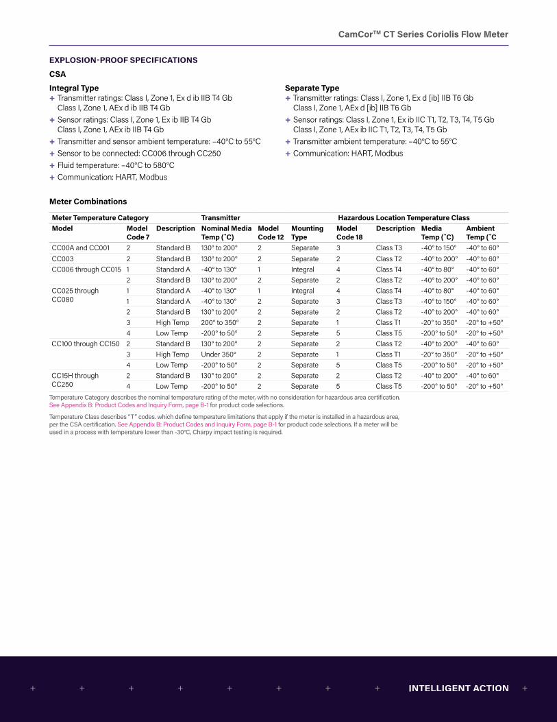
CamCorTM CT Series Coriolis Flow Meter
EXPLOSION-PROOF SPECIFICATIONS
CSA
Integral Type + Transmitter ratings: Class I, Zone 1, Ex d ib IIB T4 Gb Class I, Zone 1, AEx d ib IIB T4 Gb
+ Sensor ratings: Class I, Zone 1, Ex ib IIB T4 Gb Class I, Zone 1, AEx ib IIB T4 Gb
+ Transmitter and sensor ambient temperature: –40°C to 55°C + Sensor to be connected: CC006 through CC250 + Fluid temperature: –40°C to 580°C + Communication: HART, Modbus
Separate Type + Transmitter ratings: Class I, Zone 1, Ex d [ib] IIB T6 Gb Class I, Zone 1, AEx d [ib] IIB T6 Gb
+ Sensor ratings: Class I, Zone 1, Ex ib IIC T1, T2, T3, T4, T5 Gb Class I, Zone 1, AEx ib IIC T1, T2, T3, T4, T5 Gb
+ Transmitter ambient temperature: –40°C to 55°C + Communication: HART, Modbus
Meter Combinations
Meter Temperature Category Transmitter Hazardous Location Temperature ClassModel Model
Code 7Description Nominal Media
Temp (˚C)Model Code 12
Mounting Type
Model Code 18
Description Media Temp (˚C)
Ambient Temp (˚C
CC00A and CC001 2 Standard B 130° to 200° 2 Separate 3 Class T3 -40° to 150° -40° to 60°CC003 2 Standard B 130° to 200° 2 Separate 2 Class T2 -40° to 200° -40° to 60°CC006 through CC015 1 Standard A -40° to 130° 1 Integral 4 Class T4 -40° to 80° -40° to 60°
2 Standard B 130° to 200° 2 Separate 2 Class T2 -40° to 200° -40° to 60°CC025 through CC080
1 Standard A -40° to 130° 1 Integral 4 Class T4 -40° to 80° -40° to 60°1 Standard A -40° to 130° 2 Separate 3 Class T3 -40° to 150° -40° to 60°2 Standard B 130° to 200° 2 Separate 2 Class T2 -40° to 200° -40° to 60°3 High Temp 200° to 350° 2 Separate 1 Class T1 -20° to 350° -20° to +50°4 Low Temp -200° to 50° 2 Separate 5 Class T5 -200° to 50° -20° to +50°
CC100 through CC150 2 Standard B 130° to 200° 2 Separate 2 Class T2 -40° to 200° -40° to 60°3 High Temp Under 350° 2 Separate 1 Class T1 -20° to 350° -20° to +50°4 Low Temp -200° to 50° 2 Separate 5 Class T5 -200° to 50° -20° to +50°
CC15H through CC250
2 Standard B 130° to 200° 2 Separate 2 Class T2 -40° to 200° -40° to 60°4 Low Temp -200° to 50° 2 Separate 5 Class T5 -200° to 50° -20° to +50°
Temperature Category describes the nominal temperature rating of the meter, with no consideration for hazardous area certification. See Appendix B: Product Codes and Inquiry Form, page B-1 for product code selections.
Temperature Class describes “T” codes. which define temperature limitations that apply if the meter is installed in a hazardous area, per the CSA certification. See Appendix B: Product Codes and Inquiry Form, page B-1 for product code selections. If a meter will be used in a process with temperature lower than -30°C, Charpy impact testing is required.
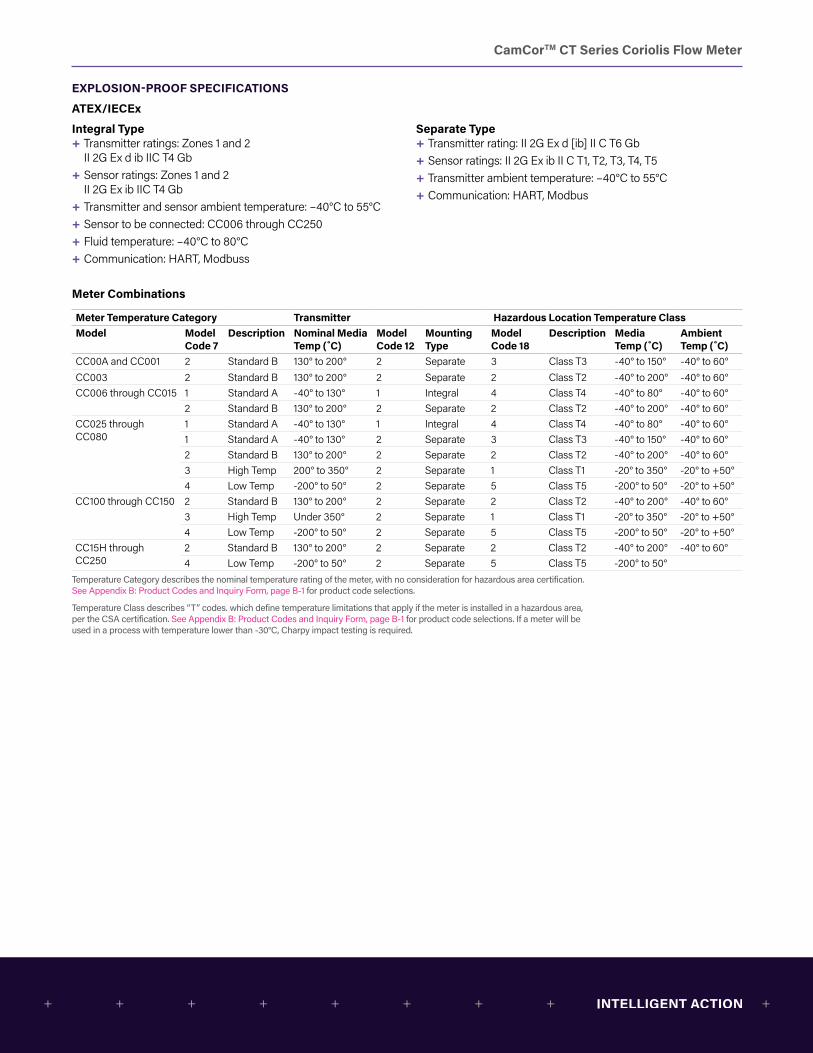
CamCorTM CT Series Coriolis Flow Meter
EXPLOSION-PROOF SPECIFICATIONS
ATEX/IECEx
Integral Type + Transmitter ratings: Zones 1 and 2 II 2G Ex d ib IIC T4 Gb
+ Sensor ratings: Zones 1 and 2 II 2G Ex ib IIC T4 Gb
+ Transmitter and sensor ambient temperature: –40°C to 55°C + Sensor to be connected: CC006 through CC250 + Fluid temperature: –40°C to 80°C + Communication: HART, Modbuss
Separate Type + Transmitter rating: II 2G Ex d [ib] II C T6 Gb + Sensor ratings: II 2G Ex ib II C T1, T2, T3, T4, T5 + Transmitter ambient temperature: –40°C to 55°C + Communication: HART, Modbus
Meter Combinations
Meter Temperature Category Transmitter Hazardous Location Temperature ClassModel Model
Code 7Description Nominal Media
Temp (˚C)Model Code 12
Mounting Type
Model Code 18
Description Media Temp (˚C)
Ambient Temp (˚C)
CC00A and CC001 2 Standard B 130° to 200° 2 Separate 3 Class T3 -40° to 150° -40° to 60°CC003 2 Standard B 130° to 200° 2 Separate 2 Class T2 -40° to 200° -40° to 60°CC006 through CC015 1 Standard A -40° to 130° 1 Integral 4 Class T4 -40° to 80° -40° to 60°
2 Standard B 130° to 200° 2 Separate 2 Class T2 -40° to 200° -40° to 60°CC025 through CC080
1 Standard A -40° to 130° 1 Integral 4 Class T4 -40° to 80° -40° to 60°1 Standard A -40° to 130° 2 Separate 3 Class T3 -40° to 150° -40° to 60°2 Standard B 130° to 200° 2 Separate 2 Class T2 -40° to 200° -40° to 60°3 High Temp 200° to 350° 2 Separate 1 Class T1 -20° to 350° -20° to +50°4 Low Temp -200° to 50° 2 Separate 5 Class T5 -200° to 50° -20° to +50°
CC100 through CC150 2 Standard B 130° to 200° 2 Separate 2 Class T2 -40° to 200° -40° to 60°3 High Temp Under 350° 2 Separate 1 Class T1 -20° to 350° -20° to +50°4 Low Temp -200° to 50° 2 Separate 5 Class T5 -200° to 50° -20° to +50°
CC15H through CC250
2 Standard B 130° to 200° 2 Separate 2 Class T2 -40° to 200° -40° to 60°4 Low Temp -200° to 50° 2 Separate 5 Class T5 -200° to 50°
Temperature Category describes the nominal temperature rating of the meter, with no consideration for hazardous area certification. See Appendix B: Product Codes and Inquiry Form, page B-1 for product code selections.
Temperature Class describes “T” codes. which define temperature limitations that apply if the meter is installed in a hazardous area, per the CSA certification. See Appendix B: Product Codes and Inquiry Form, page B-1 for product code selections. If a meter will be used in a process with temperature lower than -30°C, Charpy impact testing is required.
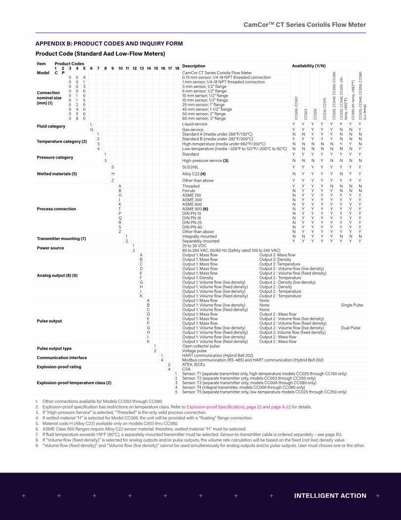
CamCorTM CT Series Coriolis Flow Meter
APPENDIX B: PRODUCT CODES AND INQUIRY FORM
Product Code (Standard Aad Low-Flow Meters)Item Product Codes Description1 2 3 4 5 6 7 8 9 10 11 12 13 14 15 16 17 18Model C P CamCor CT Series Coriolis Flow Meter
CC
00A
, CC
001
CC
003
CC
006
CC
010,
CC
015
CC
025,
CC
040,
CC
050,
CC
080
CC
025,
CC
040,
CC
050
(Hi-
tem
p, <
662°
F)
CC
080
(Hi-t
emp,
<66
2°F)
CC
025,
CC
040,
CC
050,
CC
080
(Lo-
tem
p)
Connectionnominal size (mm) (1)
0 0 A 0.75 mm sensor; 1/4-18 NPT threaded connection0 0 1 1 mm sensor; 1/4-18 NPT threaded connection0 0 3 3 mm sensor; 1/2" flange0 0 6 6 mm sensor; 1/2" flange0 1 0 10 mm sensor; 1/2" flange0 1 5 15 mm sensor; 1/2" flange0 2 5 25 mm sensor; 1" flange0 4 0 40 mm sensor; 1-1/2" flange0 5 0 50 mm sensor; 2" flange0 8 0 80 mm sensor; 3" flange
Fluid category L Liquid service Y Y Y Y Y Y Y YG Gas service Y Y Y Y Y N N Y
Temperature category (2)
1 Standard A (media under 266°F/130°C) N N Y Y Y N N N2 Standard B (media under 392°F/200°C) Y Y Y Y Y N N N3 High-temperature (media under 662°F/350°C) N N N N N Y Y N4 Low-temperature (media –328°F to 122°F/–200°C to 50°C) N N N N N N N Y
Pressure category1 Standard Y Y Y Y Y Y Y Y3 High-pressure service (3) N N N Y N N N N
Wetted materials (5)S SUS316L Y Y Y Y Y Y Y YH Alloy C22 (4) N Y Y Y Y N Y YZ Other than above Y Y Y Y Y Y Y Y
Process connection
A Threaded Y Y Y Y N N N NB Ferrule N Y Y Y Y N N NH ASME 150 N Y Y Y Y Y Y YJ ASME 300 N Y Y Y Y Y Y YK ASME 600 N Y Y Y Y Y Y YT ASME 900 (6) N Y Y Y Y Y Y YP DIN PN 10 N Y Y Y Y Y Y YQ DIN PN 16 N Y Y Y Y Y Y YR DIN PN 25 N Y Y Y Y Y Y YS DIN PN 40 N Y Y Y Y Y Y YZ Other than above N Y Y Y Y Y Y Y
Transmitter mounting (7) 1 Integrally-mounted N N Y Y Y N N N2 Separately-mounted Y Y Y Y Y Y Y Y
Power source 1 20 to 30 VDC2 85 to 264 VAC, 50/60 Hz (Safety rated 100 to 240 VAC)
Analog output (8) (9)
A Output 1: Mass flow Output 2: Mass flowB Output 1: Mass flow Output 2: DensityC Output 1: Mass flow Output 2: TemperatureD Output 1: Mass flow Output 2 : Volume flow (live density)E Output 1: Mass flow Output 2 : Volume flow (fixed density)F Output 1: Density Output 2 : TemperatureG Output 1: Volume flow (live density) Output 2 : Density (live density)H Output 1: Volume flow (fixed density) Output 2 : DensityJ Output 1: Volume flow (live density) Output 2 : TemperatureK Output 1: Volume flow (fixed density) Output 2 : Temperature
Pulse output
A Output 1: Mass flow NoneSingle PulseB Output 1: Volume flow (live density) None
C Output 1: Volume flow (fixed density) NoneD Output 1: Mass flow Output 2 : Mass flow
Dual Pulse
E Output 1: Mass flow Output 2 : Volume flow (live density)F Output 1: Mass flow Output 2 : Volume flow (fixed density)G Output 1: Volume flow (live density) Output 2 : Volume flow (live density)H Output 1: Volume flow (fixed density) Output 2: Volume flow (fixed density)J Output 1: Volume flow (live density) Output 2 : Mass flowK Output 1: Volume flow (fixed density) Output 2 : Mass flow
Pulse output type 1 Open collector pulse2 Voltage pulse
Communication interface 1 HART communication (Hybrid Bell 202)4 Modbus communication (RS-485) and HART communication (Hybrid Bell 202)
Explosion-proof rating 2 ATEX, IECEx4 CSA
Explosion-proof temperature class (2)
1 Sensor: T1 (separate transmitter only, high-temperature models CC025 through CC150 only)2 Sensor: T2 (separate transmitter only, models CC003 through CC250 only)3 Sensor: T3 (separate transmitter only, models CC00A through CC080 only)4 Sensor: T4 (integral transmitter, models CC006 through CC080 only)5 Sensor: T5 (separate transmitter only, low-temperature models CC025 through CC250 only)
1. Other connections available for Models CC003 through CC0802. Explosion-proof specification has restrictions on temperature class. Refer to Explosion-proof Specifications, page 22 and page A-22 for details.3. If “High-pressure Service” is selected, “Threaded” is the only valid process connection.4. If wetted material “H” is selected for Model CC006, the unit will be provided with a “floating” flange connection.5. Material code H (Alloy C22) available only on models C003 thru CC080.6. ASME Class 900 flanges require Alloy C22 sensor material; therefore, wetted material “H” must be selected.7. If fluid temperature exceeds 176°F (80°C), a separately-mounted transmitter must be selected. Sensor-to-transmitter cable is ordered separately – see page B3.8. If “Volume flow (fixed density)” is selected for analog outputs and/or pulse outputs, the volume rate calculation will be based on the fixed (not live) density value.9. “Volume flow (fixed density)” and “Volume flow (live density)” cannot be used simultaneously for analog outputs and/or pulse outputs. User must choose one or the other.
Availability (Y/N)
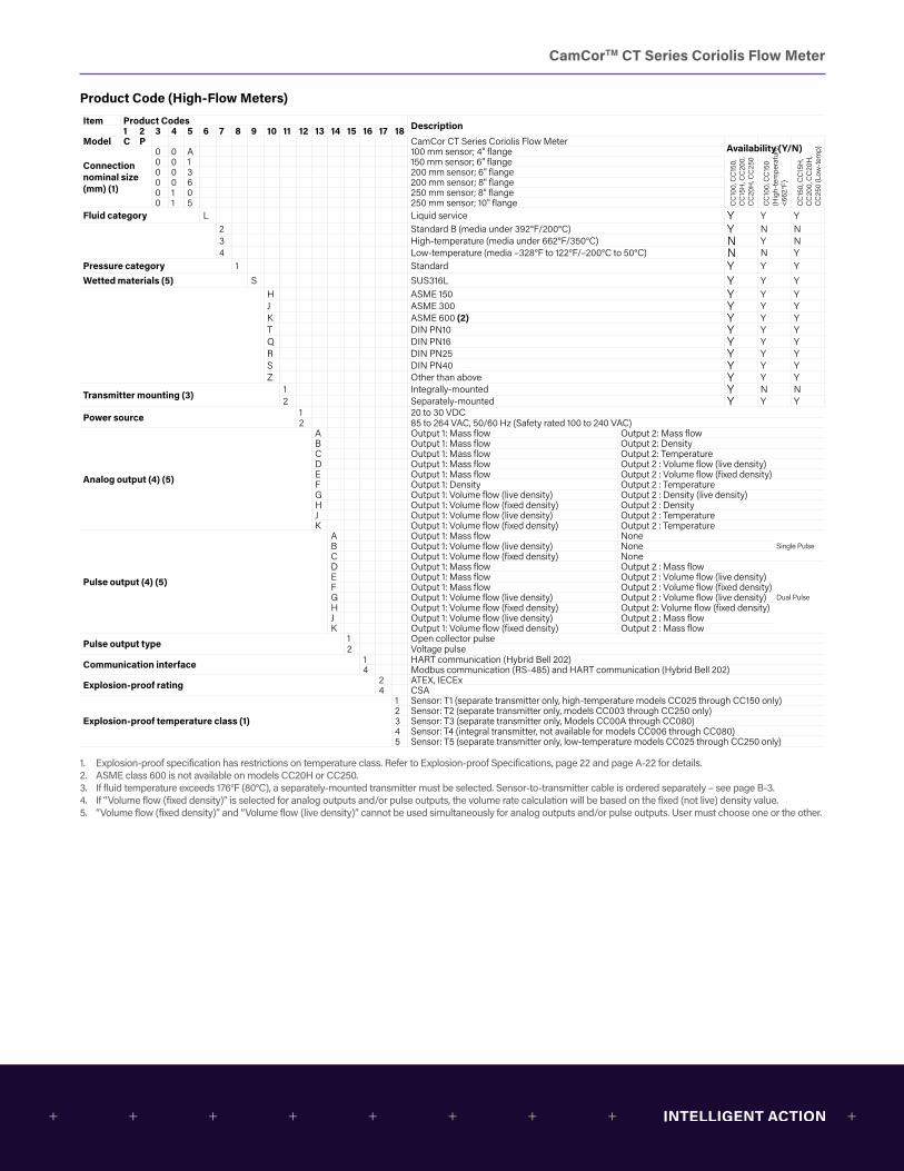
CamCorTM CT Series Coriolis Flow Meter
Product Code (High-Flow Meters)Item Product Codes Description1 2 3 4 5 6 7 8 9 10 11 12 13 14 15 16 17 18Model C P CamCor CT Series Coriolis Flow Meter
CC
100,
CC
150,
C
C15
H, C
C20
0,
CC
20H
, CC
250
CC
100,
CC
150
(Hig
h-te
mpe
ratu
re,
<662
°F)
CC
150,
CC
15H
, C
C20
0, C
C20
H,
CC
250
(Low
-tem
p)
Connectionnominal size (mm) (1)
0 0 A 100 mm sensor; 4" flange0 0 1 150 mm sensor; 6" flange0 0 3 200 mm sensor; 6" flange0 0 6 200 mm sensor; 8" flange0 1 0 250 mm sensor; 8" flange0 1 5 250 mm sensor; 10" flange
Fluid category L Liquid service Y Y Y2 Standard B (media under 392°F/200°C) Y N N3 High-temperature (media under 662°F/350°C) N Y N4 Low-temperature (media –328°F to 122°F/–200°C to 50°C) N N Y
Pressure category 1 Standard Y Y YWetted materials (5) S SUS316L Y Y Y
H ASME 150 Y Y YJ ASME 300 Y Y YK ASME 600 (2) Y Y YT DIN PN10 Y Y YQ DIN PN16 Y Y YR DIN PN25 Y Y YS DIN PN40 Y Y YZ Other than above Y Y Y
Transmitter mounting (3) 1 Integrally-mounted Y N N2 Separately-mounted Y Y Y
Power source 1 20 to 30 VDC2 85 to 264 VAC, 50/60 Hz (Safety rated 100 to 240 VAC)
Analog output (4) (5)
A Output 1: Mass flow Output 2: Mass flowB Output 1: Mass flow Output 2: DensityC Output 1: Mass flow Output 2: TemperatureD Output 1: Mass flow Output 2 : Volume flow (live density)E Output 1: Mass flow Output 2 : Volume flow (fixed density)F Output 1: Density Output 2 : TemperatureG Output 1: Volume flow (live density) Output 2 : Density (live density)H Output 1: Volume flow (fixed density) Output 2 : DensityJ Output 1: Volume flow (live density) Output 2 : TemperatureK Output 1: Volume flow (fixed density) Output 2 : Temperature
Pulse output (4) (5)
A Output 1: Mass flow NoneSingle PulseB Output 1: Volume flow (live density) None
C Output 1: Volume flow (fixed density) NoneD Output 1: Mass flow Output 2 : Mass flow
Dual Pulse
E Output 1: Mass flow Output 2 : Volume flow (live density)F Output 1: Mass flow Output 2 : Volume flow (fixed density)G Output 1: Volume flow (live density) Output 2 : Volume flow (live density)H Output 1: Volume flow (fixed density) Output 2: Volume flow (fixed density)J Output 1: Volume flow (live density) Output 2 : Mass flowK Output 1: Volume flow (fixed density) Output 2 : Mass flow
Pulse output type 1 Open collector pulse2 Voltage pulse
Communication interface 1 HART communication (Hybrid Bell 202)4 Modbus communication (RS-485) and HART communication (Hybrid Bell 202)
Explosion-proof rating 2 ATEX, IECEx4 CSA
Explosion-proof temperature class (1)
1 Sensor: T1 (separate transmitter only, high-temperature models CC025 through CC150 only)2 Sensor: T2 (separate transmitter only, models CC003 through CC250 only)3 Sensor: T3 (separate transmitter only, Models CC00A through CC080)4 Sensor: T4 (integral transmitter, not available for models CC006 through CC080)5 Sensor: T5 (separate transmitter only, low-temperature models CC025 through CC250 only)
1. Explosion-proof specification has restrictions on temperature class. Refer to Explosion-proof Specifications, page 22 and page A-22 for details.2. ASME class 600 is not available on models CC20H or CC250.3. If fluid temperature exceeds 176°F (80°C), a separately-mounted transmitter must be selected. Sensor-to-transmitter cable is ordered separately – see page B-3.4. If “Volume flow (fixed density)” is selected for analog outputs and/or pulse outputs, the volume rate calculation will be based on the fixed (not live) density value.5. “Volume flow (fixed density)” and “Volume flow (live density)” cannot be used simultaneously for analog outputs and/or pulse outputs. User must choose one or the other.
Availability (Y/N)
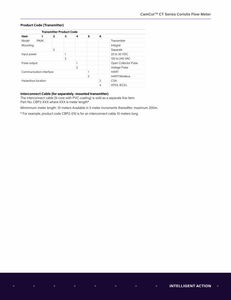
CamCorTM CT Series Coriolis Flow Meter
Product Code (Transmitter)
Transmitter Product CodeItem 1 2 3 4 5 6Model PA0K TransmitterMounting Integral
2 SeparateInput power 1 20 to 30 VDC
2 100 to 240 VACPulse output 1 Open Collector Pulse
2 Voltage PulseCommunication interface 1 HART
2 HART/ModbusHazardous location 2 CSA
4 ATEX, IECEx
Interconnect Cable (for separately -mounted transmitter)The interconnect cable (9-core with PVC coating) is sold as a separate line item: Part No. CBP2-XXX where XXX is meter length*
Minimmum meter length: 10 meters Available in 5 meter increments thereafter; maximum 200m.
* For example, product code CBP2-010 is for an interconnect cable 10 meters long.
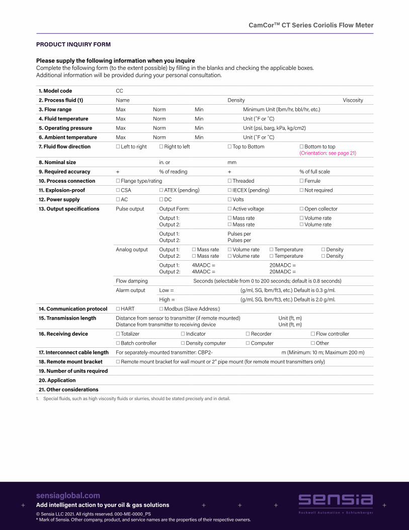
CamCorTM CT Series Coriolis Flow Meter
PRODUCT INQUIRY FORM
Please supply the following information when you inquireComplete the following form (to the extent possible) by filling in the blanks and checking the applicable boxes. Additional information will be provided during your personal consultation.
1. Model code CC
2. Process fluid (1) Name Density Viscosity
3. Flow range Max Norm Min Minimum Unit (lbm/hr, bbl/hr, etc.)
4. Fluid temperature Max Norm Min Unit (˚F or ˚C)
5. Operating pressure Max Norm Min Unit (psi, barg, kPa, kg/cm2)
6. Ambient temperature Max Norm Min Unit (˚F or ˚C)
7. Fluid flow direction Left to right Right to left Top to Bottom Bottom to top (Orientation: see page 21)
8. Nominal size in. or mm
9. Required accuracy + % of reading + % of full scale
10. Process connection Flange type/rating Threaded Ferrule
11. Explosion-proof CSA ATEX (pending) IECEX (pending) Not required
12. Power supply AC DC Volts
13. Output specifications Pulse output Output Form: Active voltage Open collector
Output 1:Output 2:
Mass rate Mass rate
Volume rate Volume rate
Output 1:Output 2:
Pulses per Pulses per
Analog output Output 1:Output 2:
Mass rate Mass rate
Volume rate Volume rate
Temperature Temperature
Density Density
Output 1:Output 2:
4MADC = 4MADC =
20MADC = 20MADC =
Flow damping Seconds (selectable from 0 to 200 seconds; default is 0.8 seconds)
Alarm output Low = (g/ml, SG, lbm/ft3, etc.) Default is 0.3 g/ml.
High = (g/ml, SG, lbm/ft3, etc.) Default is 2.0 g/ml.
14. Communication protocol HART Modbus (Slave Address:)
15. Transmission length Distance from sensor to transmitter (if remote mounted) Distance from transmitter to receiving device
Unit (ft, m) Unit (ft, m)
16. Receiving device Totalizer Indicator Recorder Flow controller
Batch controller Density computer Computer Other
17. Interconnect cable length For separately-mounted transmitter: CBP2- m (Minimum: 10 m; Maximum 200 m)
18. Remote mount bracket Remote mount bracket for wall mount or 2” pipe mount (for remote mount transmitters only)
19. Number of units required
20. Application
21. Other considerations1. Special fluids, such as high viscosity fluids or slurries, should be stated precisely and in detail.
sensiaglobal.comAdd intelligent action to your oil & gas solutions© Sensia LLC 2021. All rights reserved. 000-ME-0000_PS * Mark of Sensia. Other company, product, and service names are the properties of their respective owners.