Embed Size (px)
Citation preview
ENG.20061220.0029
BSC Design Calculation or Analysis Cover Sheet
Complete only applicable items.
1. QA: QA
2. Page 1
3. System , 4. Document Identifier .
Canister Receipt and Closure Facility 060-SYC-CR00-00400-000-00A
5. Title .
Canister Receipt and Closure Facility (CRCF) Seismic Analysis
6. Group
Civil / Structural / Architectural 7. Document Status Designation
0 Preliminary I Committed • Confirmed • Cancelled / Superseded •
8. Notes/Comments .
Attachments Total Number of
Pages
See Calculation Section 5. 51
RECORD OF REVISIONS
11. 12. 13. 14. 15. 9. 10.
Total # Last Originator Checker Approved/Accepted No. Reason For Revision
of Pgs. Pg. # (Print/Sign/Date) (Print/Sign/Date) (Print/Sign/Date)
00A Initial Issue 109 B-29 Gopal Rao . A. Joshi R. Magopal
01 4I Ar—. Ory-ory> V
1 — 18 —o 6
Michael Denlinger • 2. 12, 11 I"
(Attachments K & L)
' ' —
r---. ,/,,/,,,
EG-PRO-3DP-GO4B-00037.2-rl
Canister Receipt and Closure Facility (CRCF) Seismic Analysis 060-SYC-CR00-00400-000-00A
DISCLAIMER
The calculations contained• in this document were developed by Bechtel SAIC Company,
LLC(BSC) and are intended solely for the use of BSC in its work for Yucca Mountain Project.
2 December 2006
Canister Receipt and Closure Facility (CRCF) Seismic Analysis 060-SYC-CR00-00400-000-00A
CONTENTS
Page
FIGURES 5
TABLES 6
ACRONYMS AND ABBREVIATIONS 7
1. PURPOSE 8
2. REFERENCES 8 2.1 DESIGN INPUTS 8 2.2 DESIGN CONSTRAINTS 9 2.3 DESIGN OUTPUTS 9
3. ASSUMPTIONS 10 3.1 ASSUMPTIONS REQUIRING VERIFICATION 10 3.2 ASSUMPTIONS NOT REQUIRING VERIFICATION 10
4. METHODOLOGY 11 4.1 QUALITY ASSURANCE 11
4.2 USE OF SOFTWARE 11 4.3 ANALYSIS METHOD 11
5. LIST OF ATTACHMENTS 12
6. BODY OF CALCULATION 13 6.1 MEMBER PROPERTIES 13 6.2 CENTERS OF RIGIDITY 20 6.3 TORSION INCREASE FACTORS .29 6.4 SEISMIC MODELING AND ANALYSIS 33
7. RESULTS AND CONCLUSIONS 55
ATTACHMENT A A-1 ATTACHMENT B B-1 ATTACHMENT C CD ATTACHMENT D CD ATTACHMENT E CD ATTACHMENT F CD ATTACHMENT G CD ATTACHMENT H CD ATTACHMENT I CD ATTACHMENT J CD
3 December 2006
Canister Receipt and Closure Facility (CRCF) Seismic Analysis 060-SYC-CR00-00400-000-00A
ATTACHMENT K CD
ATTACHMENT L CD
ATTACHMENT M CD
ATTACHMENT N CD
4 December 2006
Canister Receipt and Closure Facility (CRCF) Seismic Analysis 060-SYC-CR00-00400-000-00A
FIGURES
Page
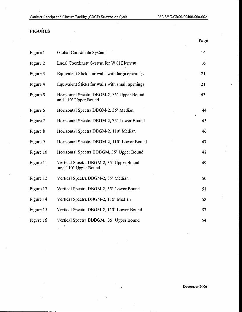
Figure 1 Global Coordinate System 14
Figure 2 Local Coordinate System for Wall Element 16
Figure 3 Equivalent Sticks for walls with large openings 21
Figure 4 Equivalent Sticks for walls with small openings 21
Figure 5 Horizontal Spectra DBGM-2, 35' Upper Bound 43 and 110' Upper Bound
Figure 6 Horizontal Spectra DBGM-2, 35' Median 44
Figure 7 Horizontal Spectra DBGM-2, 35' Lower Bound 45
Figure 8 Horizontal Spectra DBGM-2, 110' Median 46
Figure 9 Horizontal Spectra DBGM-2, 110' Lower Bound 47
Figure 10 Horizontal Spectra BDBGM, 35' Upper Bound 48
Figure 11 Vertical Spectra DBGM-2, 35' Upper Bound 49 and 110' Upper Bound
Figure 12 Vertical Spectra DBGM-2, 35' Median 50
Figure 13 Vertical Spectra DBGM-2, 35' Lower Bound 51
Figure 14 Vertical Spectra DBGM-2, 110' Median 52
Figure 15 Vertical Spectra DBGM-2, 110' Lower Bound 53
Figure 16 Vertical Spectra BDBGM, 35' Upper Bound 54
5 December 2006
Canister Receipt and Closure Facility (CRCF) Seismic Analysis 060-SYC-CR00-00400-000-00A
TABLES
Page
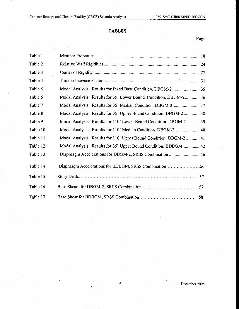
Table 1
Table 2
Table 3
Table 4
Table 5
Table 6
Table 7
Table 8
Table 9
Table 10
Table 11
Table 12
Table 13
Table 14
Table 15
Table 16
Table 17
Member Properties
Relative Wall Rigidities
Center of Rigidity
Torsion Increase Factors
Results for Fixed Base Condition. DBGM-2
Results for 35' Lower Bound Condition. DBGM-2.
Results for 35' Median Condition. DBGM-2
Results for 35' Upper Bound Condition. DBGM-2
Results for 110' Lower Bound Condition. DBGM-2
Results for 110' Median Condition. DBGM-2
Results for 110' Upper Bound Condition. DBGM-2
Results for 35' Upper Bound Condition. BDBGM
Diaphragm Accelerations for DBGM-2, SRSS Combination
Diaphragm Accelerations for BDBGM, SRSS Combination 56
Story Drifts 57
Base Shears for DBGM-2, SRSS Combination .57
Base Shear for BDBGM, SRSS Combination 58
Modal Analysis
Modal Analysis
Modal Analysis
Modal Analysis
Modal Analysis
Modal Analysis
Modal Analysis
Modal Analysis
18
24
27
31
35
36
37
38
39
40
41
42
56
6 December 2006
Canister Receipt and Closure Facility (CRCF) Seismic Analysis 060-SYC-CR00-00400-000-00A
ACRONYMS AND ABBREVIATIONS
3D three-dimensional
FEs finite elements
FEM finite element model
CRCF Canister Receipt and Closure Facility
c.g. Center of Gravity
DBGM Design Basis Ground Motion
BDBGM Beyond Design Basis Ground Motion
IBC International Building Code
SRSS Square Root of Sum of Squares
SSI Soil Structure Interaction
YMP Yucca Mountain Project
7 December 2006
Canister Receipt and Closure Facility (CRCF) Seismic Analysis 060-SYC-CR00-00400-000-00A
1. PURPOSE
The purpose of this calculation is to develop a lumped mass "beam-stick" finite element model of the Canister Receipt and Closure Facility (CRCF) and perform a response spectra analysis. The basis of design for the CRCF is defined in 000-3DR-MGRO-00300-000-000, Basis of Design
for the TAD Canister—Based Repository Design Concept (Ref.2.1.6).
Results of the response spectra analysis will yield the shear wall seismic forces and the diaphragm accelerations, which will be used in the subsequent structural design of the CRCF.
This calculation also investigates the effects of accidental torsion on the seismic design forces. A torsional increase factor is computed which will be used in subsequent design calculations to increase the forces obtained from this response spectra analysis to account for accidental torsion.
2. REFERENCES
2.1 DESIGN INPUTS
2.1.1 ASCE 4-98. 2000. Seismic Analysis of Safety-Related Nuclear Structures and
Commentary. Reston, Virginia: American Society of Civil Engineers. TIC: 253158. [DIRS 159618]
2.1.2 BSC (Bechtel SAIC Company) 2006. Project Design Criteria Document. 000-3DR- MGR0-00100-000 REV 006. Las Vegas, Nevada: Bechtel SAIC Company. ACC: ENG.20061201.0005.
2.1.3 Amrhein, J.E. 1998. Reinforced Masonry Engineering Handbook, Clay and Concrete
Masonry. 5th Edition Updated. Boca Raton, Florida: CRC Press. TIC: 255497. [DIRS 167017]
2.1.4 Not Used
2.1.5 Young, W.C. 1989. Roark's Formulas for Stress and Strain. 6th Edition. New York, New York: McGraw-Hill. TIC:10191. [DIRS 106720]
2.1.6 BSC (Bechtel SAIC Company) 2006. Basis of Design for the TAD Canister—Based
Repository Design Concept. 000-3DR-MGRO-00300-000-000. • Las Vegas, Nevada: Bechtel SAIC Company. ACC: ENG 20061023.0002.
2.1.7 BSC (Bechtel SAIC Company) 2006.Canister Receipt and Closure Facility (CRCF) Mass Properties. 060-SYC-CR00-00200-000-00A. Las Vegas, Nevada: Bechtel SAIC
. Company. ACC: ENG. 20061120.0019
8 December 2006
Canister Receipt and Closure Facility (CRCF) Seismic Analysis 060-SYC-CR00-00400-000-00A
2.1.8 BSC (Bechtel SAIC Company) 2006.Canister Receipt and Closure Facility (CRCF) Soil Springs. 060-SYC-CR00-00300-000-00A. Las Vegas, Nevada: Bechtel SAIC Company. ACC: ENG. 20061129.0019
2.1.9 M00411SDSTMHIS.006. Seismic Design Spectra and Time Histories for the Surface Facilities Area (Point DIE) at 5E-4 Annual Exceedance Frequency. Submittal date: 11/16/2004. [DIRS 172426]
2.1.10 M00411WHBDE104.003. Seismic Design Spectra and Time Histories for the Surface Facilities Area (Point DIE) at 1E-4 Annual Exceedance Frequency. Submittal date:
• 11/16/2004. [DIRS 172427]
2.1.11 DOE (U.S. Department of Energy) 2005. Software Validation Report for: SAP2000 version 9.1.4. Document ID: 11198-SVR-9.1.4-00-win 2000. Las Vegas, Nevada: U.S. Department of Energy, Office of Repository Development. ACC: MOL.20051012.0425. [DIRS 176790]
2.1.12 BSC (Bechtel SAIC Company) 2004, TED Surface Facility, 100-IED-WHS0-00101-000- 00B, Las Vegas, Nevada: Bechtel SAIC Company. ACC: ENG. 20041209.0002.
2.1.13 2.1.13 ICC (International Code Council) 2003. International Building Code 2000, with
Errata to the 2000 International Building Code. Falls Church, Virginia: International Code Council. TIC: 251054; 257198. [DIRS 173525]
2.2 DESIGN CONSTRAINTS
2.2.1 EG-PRO -3DP-GO4B -00037, Rev.006, ICNO. Calculations and Analyses. Las Vegas, Nevada: Bechtel SAIC Company. ACC:ENG.20061204.0001.
2.2.2 IT-PRO-0011 Rev.002, ICNO. Software Management. Las Vegas, Nevada, Bechtel SAIC Company. ACC: DOC.20061109.0011
2.2.3 BSC (Bechtel SAIC Company) 2006. Quality Management Directive. QA-DIR-10, Rev. 0. Las Vegas, Nevada: Bechtel SAIC Company. ACC: DOC.20060906.0001
[DIRS #177655]
2.2.4 ORD (Office of Repository Development) 2006. Repository Project Management
Automation Plan. 000-PLN-MGRO-00200-000, Rev. 00D. Las Vegas, Nevada: U.S. Department of Energy, Office of Repository Development. ACC: ENG.20060703.0001
2.3 DESIGN OUTPUTS
Results of this calculation will be used as input for the calculations for the design of shear walls, elevated slabs and basemat.
9 December 2006
Canister Receipt and Closure Facility (CRCF) Seismic Analysis 060-SYC-CR00-00400-000-00A
3. ASSUMPTIONS
3.1 ASSUMPTIONS REQUIRING VERIFICATION
3.1.1 Building plan, elevations and dimensions
The plan, elevations and dimensions in Attachment A are used as the basis for the structural
configuration of the shear walls to be used in the lumped mass stick model. Attachment A
was developed by cutting sections from the plant design three-dimensional (3D) model.
Dimensions were also obtained from the 3D model. The wall length dimensions (including
openings) are assumed as shown in Attachment A.
Rationale— The rationale for this assumption is that further refinement of the general
arrangements in plant design 3D model (e.g., adding doors and corridors) will not greatly affect the dynamic response of the structure. The development of the general arrangements
continues to be refined, however the major rooms and wall locations are defined. Properties computed in this calculation are adequate for Tier-1 seismic analysis.
Where used: Assumption is used in entire calculation.
3.1.2 Wall Thicknesses
Wall thicknesses utilized in design calculation, Canister Receipt and Closure Facility (CRCF)
Mass Properties, 060-SYC-CR00-00200-000-00A (Ref. 2.1.7) are assumed to be the same
for an initial stiffness properties calculation.
Rationale— The rationale for this assumption is that these are preliminary wall thickness that
will be used as a starting point for performing a dynamic analysis. The determination of wall
thicknesses is an iterative process and the thicknesses will be verified and refined through a
subsequent shear wall design calculation, using the seismic forces from the dynamic analysis.
Where used: Assumption is used in entire calculation.
3.2 ASSUMPTIONS NOT REQUIRING VERIFICATION
3.2.1 Wall Openings
In the center of rigidity calculation (Section 6.2), wall rigidity is calculated assuming the
• entire wall as solid, neglecting the small wall openings.
Rationale—This is a reasonable assumption considering that overall lengths of openings are
small compared to the length and height of the walls. See Figure 4.
Where used: Section 6.2.
10 December 2006
Canister Receipt and Closure Facility (CRCF) Seismic Analysis 060-SYC-CR00-00400-000-00A
4. METHODOLOGY
4.1 QUALITY ASSURANCE
This calculation was prepared in accordance with EG-PRO-3DP-GO4B-00037, Calculations
and Analyses (Ref. 2.2.1). Section 4.1.2 of the Basis of Design for the TAD Canister—Based
Repository Design Concept (Ref. 2.1.6) classifies the CRCF structure as ITS. Therefore, this
document is subject to the requirements of the BSC Quality Management Directive (Ref.
2.2.3, Section 2.1.C.1.1.a.i. and 17.E.) and the approved version is designated as QA:QA.
4.2 USE OF SOFTWARE
Excel 2000 and Word 2000, which are part of the Microsoft Office 2000 suite of programs, were used in this calculation. Microsoft Office 2000 as used in this calculation is classified as
Level 2 software usage as defined in IT-PRO-0011 (Ref. 2.2.2). Microsoft Office 2000 is
listed on the current Software Report (SW Tracking Number 607273), as well as the Repository Project Management Automation Plan (Ref. 2.2.4).
The software was executed on a PC system running Microsoft Windows 2000 operating
system. Results were confirmed by visual inspection and by performing hand calculations.
Excel 2000 was used to generate SAP2000 model input in this calculation. Word 2000 was used in the text preparation of this document, no calculations functions contained in word
were used in this document.
SAP2000, Version 9.1.4 as used in this calculation is classified as Level 1 software usage as defined in IT-PRO-0011 (Ref. 2.2.2). This software is a commercially available computer
program qualified to perform static and dynamic analysis of structural systems. This software
is listed in Nuclear Safety Software Report as qualified with Software Tracking Number
11198-9.1.4-00. The software is operated on a PC system running the Windows 2000
operating system. The SAP2000 Validation Report is contained in Ref. 2.1.11.
4.3 ANALYSIS METHOD
The process of developing the finite element model consists of the following steps.
• Prepare elevation views for each of the shear walls and locate the "beam-stick"
elements for each of the wall / wall piers. Wall elevations along with the beam stick elements are given in Attachment A.
• Compute the stiffness properties for each of the "beam-stick" elements. A spreadsheet
was developed where the starting point and ending point of a wall / wall pier and the
wall thickness is input. The spreadsheet in turn computes the centroid of the wall /
wall pier and 6 beam element properties, Ax, Ay, Az, Ix, Iy and Iz. For definition of
element properties, see section 6.1. The wall stiffness spreadsheet is shown in
Table 1.
11 December 2006
Number of Pages
22
29
CD
CD
CD
Canister Receipt and Closure Facility (CRCF) Seismic Analysis 060-SYC-CR00-00400-000-00A
• Using the "beam-stick" elements defined in step 1 along with the element properties
computed in step 2 a SAP2000 model can be developed. The boundary conditions
applied to the basemat are frequency independent soil springs computed in
calculation 060-SYC-CR00-00300-000-00A (Ref. 2.1.8). Lumped masses used in the
SAP2000 are computed in calculation 060-SYC-CR00-00200-000-00A (Ref. 2.1.7).
• Perform a response spectrum analysis for the following cases:
- DBGM-2 Lower Bound Soil Condition 35', and 110', alluvium
- DBGM-2 Median Soil Condition 35', and 110', alluvium
-DBGM-2 Upper Bound Soil Condition 35', and 110', alluvium
- BDBGM Upper Bound Soil Condition 35' alluvium
• Perform a fixed base modal and response spectrum analysis
• Compute the individual wall rigidities and the center of rigidity at each diaphragm
elevation. A spreadsheet was developed using the wall stiffness properties discussed
above that computes the rigidity of each wall and then computes the center of rigidity for all the walls located at a given diaphragm elevation. The center of rigidity and
sum of rigidities spreadsheets are shown in Table 2 and Table 3.
• Compute the torsional increase factors. The torsional increase factor is a factor that is used to account for the code mandated 5% accidental eccentricity required when
performing seismic analysis of structures (Section 3.1.1e, Ref. 2.1.1). The torsional increase factor is a factor that relates the forces in a structural element with accidental
torsion effects to the same wall without accidental torsion effects. Forces obtained
from the response spectrum analysis are increased by this torsion increase factor to
obtain the required design forces used in designing the structural elements. The
torsional increase factors are computed in Table 4.
Attachment A
Attachment B
Attachment C
Attachment D
Attachment E
5. LIST OF ATTACHMENTS
Floor Plan and Wall Elevations
SAP2000 Stick Model Input
DBGM-2 Fixed Base Modal and Response Spectrum
Analysis
DBGM-2 Upper Bound 35' Alluvium Modal Analysis and
Response Spectrum Analysis
DBGM-2 Median 35' Alluvium Modal Analysis and
Response Spectrum Analysis
12 December 2006
Canister Receipt and Closure Facility (CRCF) Seismic Analysis 060-SYC-CR00-00400-000-00A
Attachment
Attachment
Attachment
Attachment
Attachment
Attachment
Attachment
Attachment
Attachment
DBGM-2 Lower Bound 35' Alluvium Modal Analysis
and Response Spectrum Analysis
DBGM-2 Upper Bound 110' Alluvium Modal Analysis
and Response Spectrum Analysis
DBGM-2 Median 110' Alluvium Modal Analysis and
Response Spectrum Analysis
DBGM-2 Lower Bound 110' Alluvium Modal Analysis
and Response Spectrum Analysis
BDBGM Upper Bound 35' Alluvium Modal Analysis and
Response Spectrum Analysis
Base Shear Calculation for DBGM-2 and BDBGM Input
Ground Motions
L IBC Base Shear Calculation
M Excel and Word Files used in calculation preparation
N SAP2000 Database Files
CD
CD
CD
CD
CD
CD
CD
CD
CD
6. BODY OF CALCULATION
6.1 MEMBER PROPERTIES
In this section of the calculation, member properties are computed that will be assigned to
each of the beam elements used to develop the finite element model. Elevations of each of the structural shear walls are included and major wall penetrations are identified on the
sketches (Attachment A). After the major wall penetrations were identified, beam elements
were assigned to each of the wall—wall pier segments such that an accurate representation of the wall stiffness could be obtained. Starting and ending joint numbers were likewise
assigned to define each of the beam elements. Beam elements were assigned a unique
alphanumeric name. The naming convention used is in the form of "8A.1", or "A1.2" where
the first digit represents the wall name the second digit represents a vertical segment of that
wall and the third digit represents a unique identifier for the wall element. Nodes were
assigned a unique joint identifier using the following convention:
• Nodes 1-100: z = 0 ft —nodes located at bottom of walls/top of basemat.
• Nodes 101-199: 0< z < 32 ft - mid height wall nodes adjacent to penetrations
• Nodes 200-299: z =32 ft- nodes located on 32 ft- diaphragm
• Nodes 300-399: 32 <z <64 mid height wall nodes adjacent to penetrations
13 December 2006
Canister Receipt and Closure Facility (CRCF) Seismic Analysis 060-SYC-CR00-00400-000-00A
• Nodes 400-499: z = 64 ft —nodes located on 64 ft diaphragm.
• Nodes 500-599: z = 72ft —nodes located on 72 ft diaphragm.
• Nodes 600-699: z = 100 ft —nodes located on 100 ft diaphragm.
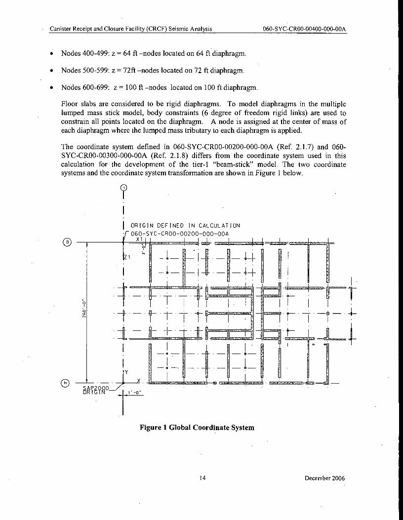
Floor slabs are considered to be rigid diaphragms. To model diaphragms in the multiple
lumped mass stick model, body constraints (6 degree of freedom rigid links) are used to
constrain all points located on the diaphragm. A node is assigned at the center of mass of
each diaphragm where the lumped mass tributary to each diaphragm is applied.
The coordinate system defined in 060-SYC-CR00-00200-000-00A (Ref. 2.1.7) and 060-
SYC-CR00-00300-000-00A (Ref. 2.1.8) differs from the coordinate system used in this
calculation for the development of the tier-1 "beam-stick" model. The two coordinate systems and the coordinate system transformation are shown in Figure 1 below.
1 ORIGIN DEFINED IN CALCULATION
060—SYC—CR00-00200-000-00A X1
Figure 1 Global Coordinate System
14 December 2006
Canister Receipt and Closure Facility (CRCF) Seismic Analysis 060-SYC-CR00-00400-000-00A
Coordinate Transformation between SAP2000 and 060-SYC-CR00-00200-000-00A (Ref. 2.1.7)
X(SAP2000) = X1 —1.00
Y(SAP2000) = 260.00 — Z1
Z(SAP2000) = Y1
Where Xl, Y1 AND Z1 represent the coordinate system defined in 060-SYC-CR00-00200-
000-00A. (Ref 2.1.7)
SAP2000 member stiffness properties are computed using the method discussed below.
An Excel spreadsheet (Table 1) was created to calculate member properties for the SAP2000
finite element model (FEM). The basic member properties calculated in Excel are Ax , Ay,
Az, Ix, and 1,, where:
= Cross-sectional area (ft 2)
Ay = Shear area with respect to the local y-axis (ft 2)
= Shear area with respect to the local z-axis (ft 2)
h = Torsional moment of inertia (ft 4)
Iy = Bending moment of inertia about the local y-axis (fe l)
= Bending moment of inertia about the local z-axis (ft 4)
The shear walls of the building are represented as finite elements (FEs) that extend between
the primary floor and roof elevations. The floor / roof elevations considered are 0 ft, 32 ft,
64 ft, 72 ft and 100 ft.
For an ideal wall with no openings a single stick element is used to model that wall.
However, the majority of walls in the CRCF structure have wall penetrations that require the
use of multiple beam elements to model that wall. Penetrations in a wall fall into two typical
categories - small penetrations, which create a discontinuity in the wall, and larger wall penetrations, which basically break the wall in to two distinct walls. For the first case beam
elements are assigned to each pier in the wall from the diaphragm level to the top of the
opening elevation, a single element is then used to model the remainder of the wall from the
top of the penetration elevation up to the next diaphragm elevation. The nodes located along
the elevation at the top of the opening are then constrained using the SAP2000 body
constraint. An example of this type of situation is shown along column line D, see
Attachment A, page A-16. The second situation occurs when the penetration is nearly the full
height of the wall, an example of this situation is shown along column line 2, see Attachment
A, page A-5.
15 December 2006
AG A v =F Ph (Eq. 6.1.1)
Canister Receipt and Closure Facility (CRCF) Seismic Analysis 060-SYC-CR00-00400-000-00A
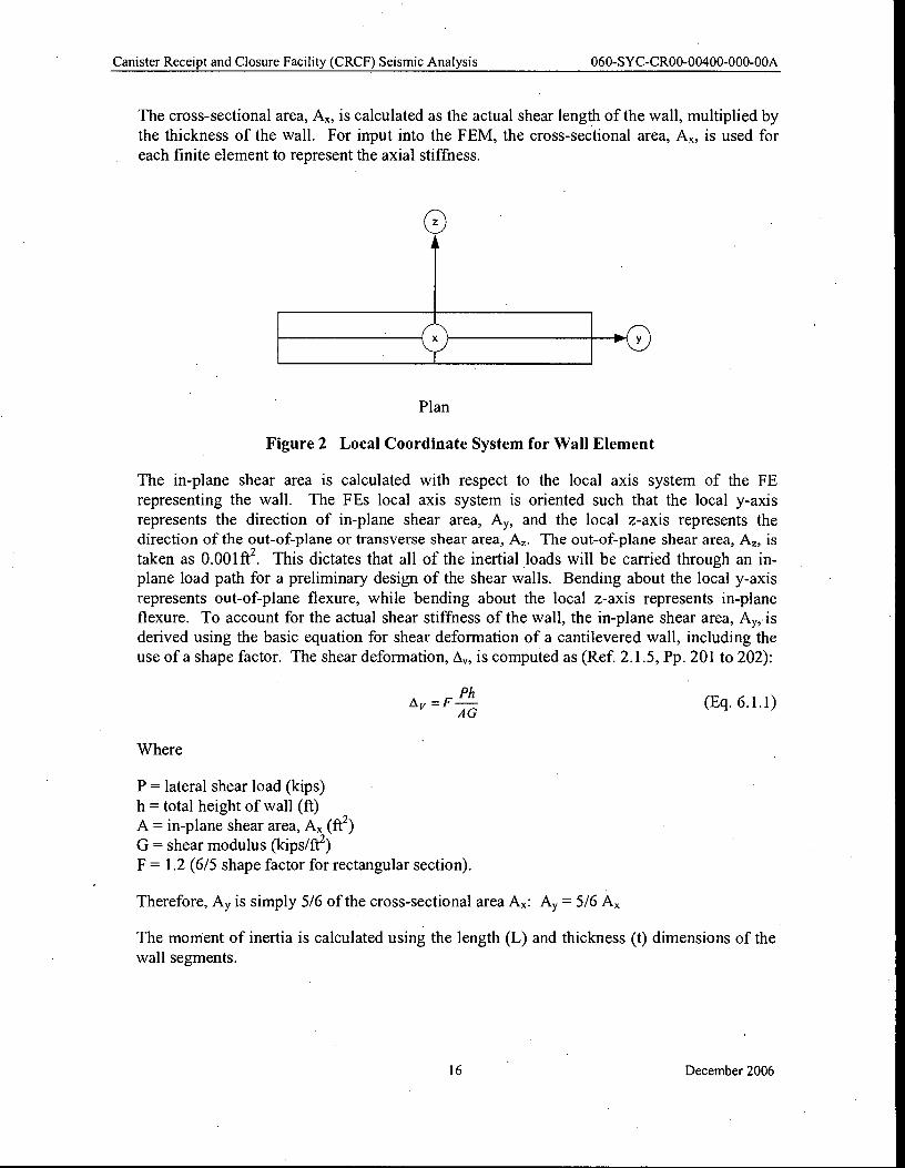
The cross-sectional area, A„, is calculated as the actual shear length of the wall, multiplied by
the thickness of the wall. For input into the FEM, the cross-sectional area, A„, is used for
each finite element to represent the axial stiffness.
Plan
Figure 2 Local Coordinate System for Wall Element
The in-plane shear area is calculated with respect to the local axis system of the FE
representing the wall. The FEs local axis system is oriented such that the local y-axis
represents the direction of in-plane shear area, A y, and the local z-axis represents the direction of the out-of-plane or transverse shear area, A. The out-of-plane shear area, A„ is
taken as 0.001 ft 2 . This dictates that all of the inertial loads will be carried through an in-plane load path for a preliminary design of the shear walls. Bending about the local y-axis
represents out-of-plane flexure, while bending about the local z-axis represents in-plane
flexure. To account for the actual shear stiffness of the wall, the in-plane shear area, Ay, is
derived using the basic equation for shear deformation of a cantilevered wall, including the
use of a shape factor. The shear deformation, i , is computed as (Ref 2.1.5, Pp. 201 to 202):
Where
P = lateral shear load (kips)
h = total height of wall (ft)
A = in-plane shear area, A„ (ft 2)
G = shear modulus (kips/ft 2)
F = 1.2 (6/5 shape factor for rectangular section).
Therefore, Ay is simply 5/6 of the cross-sectional area A x: Ay = 5/6 Ax
The moment of inertia is calculated using the length (L) and thickness (t) dimensions of the
wall segments.
16 December 2006
Ay = –5
(43) = 36 ft 2 6
(Eq. 6.1.4)
Canister Receipt and Closure Facility (CRCF) Seismic Analysis 060-SYC-CR00-00400-000-00A
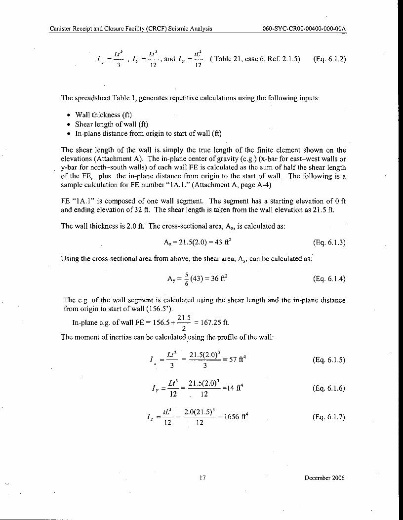
I = -Lt3
, I, – = — - ,and and / tL3
( Table 21, case 6, Ref. 2.1.5) (Eq. 6.1.2) z 3 12 12
The spreadsheet Table 1, generates repetitive calculations using the following inputs:
• • Wall thickness (ft)
• Shear length of wall (ft)
• In-plane distance from origin to start of wall (ft)
The shear length of the wall is simply the true length of the finite element shown on the
elevations (Attachment A). The in-plane center of gravity (c.g.) (x-bar for east–west walls or y-bar for north–south walls) of each wall FE is calculated as the sum of half the shear length
of the FE, plus the in-plane distance from origin to the start of wall. The following is a
sample calculation for FE number "1A.1." (Attachment A, page A-4)
FE "1A.1" is composed of one wall segment. The segment has a starting elevation of 0 ft
and ending elevation of 32 ft. The shear length is taken from the wall elevation as 21.5 ft.
The wall thickness is 2.0 ft. The cross-sectional area, A x, is calculated as:
A„= 21.5(2.0) = 43 ft 2 (Eq. 6.1.3)
Using the cross-sectional area from above, the shear area, A y, can be calculated as:
The c.g. of the wall segment is calculated using the shear length and the in -plane distance
from origin to start of wall (156.5').
In-plane c.g. of wall FE = 156.5 + --- 167.25 ft. 2
The moment of inertias can be calculated using the profile of the wall:
LP 21.5(2.0) 3 / = – 57 ft4 (Eq. 6.1.5) x 3 3
LP 21.5(2.0) 3 Iy = =14 ft4 (Eq. 6.1.6)
12 12
tL3 2.0(21.5) 3 – 1656 ft4 (Eq. 6.1.7)
- 12 12
17 December 2006
Canister Receipt and Closure Facility (CRCF) Seismic Analysis 060-SYC-CR00-00400-000-00A
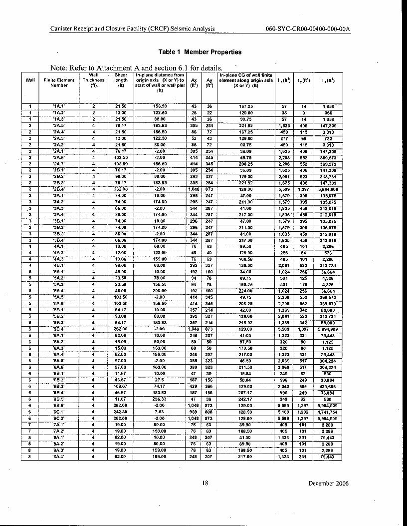
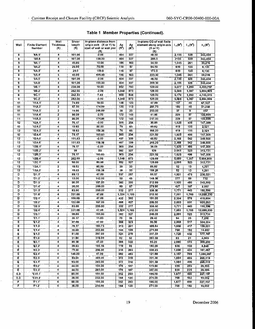
Table 1 Member Properties
Note: Refer to Attachment A and section 6.1 for details. Wall Shear In-plane distance from In-plane CG of wall finite
Wall Finite Element Thickness length origin axis (X or Y) to Ax Ay element along origin axis I „ (ft) I y (ft4 ) I .(fti ) Number (ft) (ft) start of wall or wall pier (ft2) (ft 4 ) (X or Y) (ft)
(ft)
1 '1A.1' 2 21.50 156.50 43 36 167.25 57 14 1,656
1 '1A.2' 2 13.00 _ 122.50 26 22 129.00 35 9 366
1 '1A.3' 2 21.50 80.00 43 36 90.75 57 14 1,656
2 2A.5 4 76.17 183.83 _ 305 254 221.92 _ 1,625 406 147,309
2 2A.4' 4 21.50 156.50 86 72 167.25 459 115 3,313
2 2A.3' 4 13.00 122.50 52 43 129.00 277 69 732
2 2A.2' 4 21.50 80.00 86 72 90.75 459 115 3,313
2 2A.1' 4 76.17 -2.00 305 254 36.09 1,625 406 147,309
2 '2A.6' 4 103.50 -2.00 414 345 49.75 2,208 552 369,573
2 '2A.7' 4 103.50 156.50 414 345 208.25 2,208 552 369,573
2 2B.1' 4 76.17 -2.00 305 254 36.09 1,625 406 147,309
2 '2B.2' 4 98.00 80.00 392 327 129.00 2,091 523 313,731
2 2B.3' 4 76.17 183.83 305 254 221.92 1,625 406 147,309
2 '2B.4' 4 262.00 -2.00 1,048 873 129.00 5,589 1,397 5,994,909
3 '3A.1' 4 74.00 10.00 296 247 47.00 1,579 395 135,075
3 '3A.2' 4 74.00 174.00 296 247 211.00 1,579 395 135,075
'3A.3' 4 86.00 -2.00 344 287 41.00 1,835 459 212,019
3 '3A.4' 4 86.00 174.00 344 287 217.00 1,835 ' 459 212,019
3 3B.1' 4 74.00 10.00 296 247 47.00 1,579 395 135,075
3 3B.2' 4 74.00 174.00 296 247 211.00 1,579 395 135,075
3 3B.3' 4 86.00 -2.00 344 287 41.00 1,835 459 212,019
3 3B.4' 4 86.00 174.00 344 287 217.00 1,835 459 212,019
4 '4A.1' 4 19.00 80.00 76 63 89.50 405 101 2,286
4 '4A.2' 4 12.00 123.00 48 40 129.00 256 64 576
4 '4A.3' 4 19.00 159.00 76 63 168.50 405 101 2,286
4 '4B.1' 4 98.00 80.00 392 327 129.00 2,091 523 313,731
5 '5A.1' 4 48.00 10.00 192 160 34.00 1,024 256 36,864
5 '5A.2' 4 23.50 78.00 94 78 89.75 501 125 4,326
5 '5A.3' 4 23.50 156.50 94 78 168.25 501 125 4,326
5 '5A.4' 4 48.00 200.00 192 160 224.00 1,024 256 36,864
5 '5A.5' 4 103.50 -2.00 414 345 49.75 2,208 552 369,573
5 '5A.6' 4 103.50 156.50 414 345 208.25 2,208 552 369,573
5 '5B.1' 4 64.17 10.00 257 214 42.09 1,369 342 88,080 .
5 '5B.2' 4 98.00 80.00 392 327 129.00 2,091 523 313,731
5 '5B.3' 4 64.17 183.83 257 214 215.92 1,369 342 88,080
5 '5B.4' 4 262.00 -2.00 1,048 873 129.00 5,589 1,397 5,994,909
6 '6A.1' 4 62.00 10.00 248 207 41.00 1,323 331 79,443
6 6A.2' 4 15.00 , 80.00 60 50 87.50 320 80 1,125
6 '6A.3' 4 15.00 163.00 60 50 170.50 320 80 1,125
6 '6A.4' 4 62.00 186.00 248 207 217.00 1,323 331 79,443
6 '6A.5' 4 97.00 -2.00 388 323 46.50 2,069 517 304,224
6 '6A.6' 4 97.00 163.00 388 323 211.50 2,069 517 304,224
6 '6E1.1' 4 11.67 10.00 47 39 15.84 249 62 530
6 '6B.2' 4 46.67 27.5 187 156 50.84 996 249 33,884
6 '6B.3' 4 109.67 74.17 439 366 129.00 2,340 585 439,686
6 '6B.4' 4 46.67 183.83 187 156 207.17 996 249 33,884
6 6BS 4 11.67 236.33 47 39 242.17 249 62 530
6 '6B.6' 4 262.00 -2.00 1,048 873 129.00 5,589 1,397 5,994,909
6 '6C.1' 4 242.30 7.83 969 808 128.98 5,169 1,292 4,741,754
6 '6C.2' 4 262.00 -2.00 1,048 873 129.00 5,589 1,397 5,994,909
7 '7A.1' 4 19.00 80.00 76 63 89.50 405 101 2,286 -
7 7A.2' 4 19.00 159.00 76 63 168.50 405 101 2,286
8 '8A.1' 4 62.00 10.00 248 207 41.00 1,323 331 79,443
8 '8A.2' 4 19.00 80.00 76 63 89.50 405 101 2,286
8 '8A.3' 4 19.00 159.00 76 63 168.50 405 101 2,286
8 8A.4' 4 62.00 186.00 248 207 217.00 1,323 331 79,443
18 December 2006
• Canister Receipt and Closure Facility (CRCF) Seismic Analysis 060-SYC-CR00-00400-000-00A
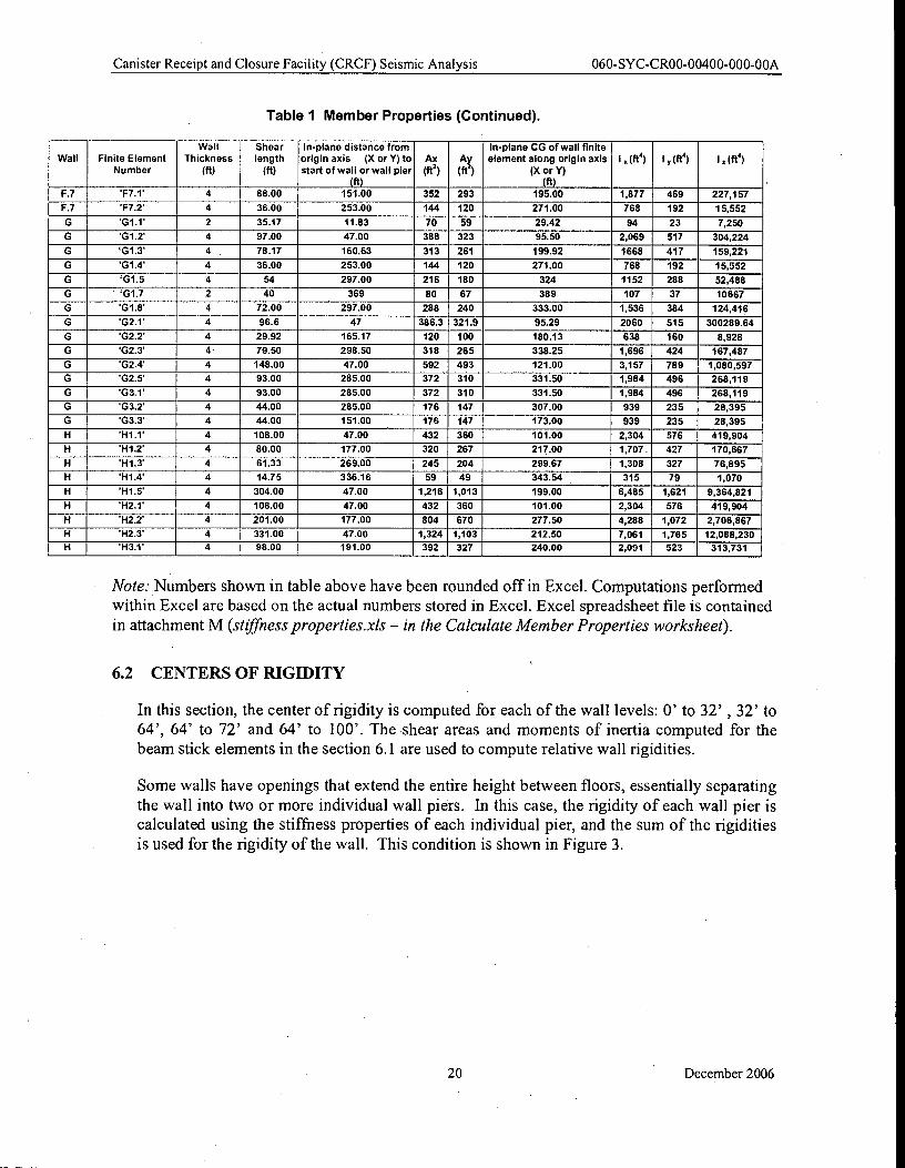
Table 1 Member Properties (Continued).
Wall Shear In-plane distance from in-plane CG of wall finite
Wall Finite Element Thickness length origin axis (X or Y) to Ax Ay element along origin axis I y (ft 4) I y (ft4) I .(ft4) Number (ft) . (ft) start of wall or wall pier (ft) (ft`) (X or Y)
(ft) (ft) 8 '8A.5' 4 101.00 -2.00 404 337 48.50 2,155 539 343,434
8 '8A.6 4 101.00 159.00 404 337 209.5 2155 539 343,434
9 '9A.1' 4 49.00 10.00 196 163 34.50 1,045 261 39,216
9 '9A.2' 4 29.00 70.00 116 97 84.50 619 155 8,130
9 '9A.3' 4 29.0 159.0 116 97 173.5 619 155 8,130
9 '9A.4' 4 49.00 199.00 196 163 223.50 1,045 261 39,216
9 '9A.5' 4 101.00 -2.00 404 337 48.50 2,155 539 343,434
9 '9A.6' 4 101.00 159.00 404 337 209.50 2,155 539 343,434
9 '9B.1' 4 238.00 10.00 952 793 129.00 5,077 1,269 4,493,757
9 '9B.2' 4 262.00 -2.00 - 1,048 873 129.00 5,589 1,397 5,994,909
9 '9C.1' 4 242.33 7.83 969 808 129.00 5,170 1,292 4,743,515
9 '9C.2' 4 262.00 -2.00 1,048 873 129.00 5,589 1,397 5,994,909
11 '11A.1' 2 74.00 10.00 148 123 47.00 197 49 67,537 -
11 '11A.2' 2 67.50 174.00 135 113 207.75 180 45 51,258
11 '11A.3' 2 14.00 246.00 28 23 253.00 37 9 457
11 '11A.4' 2 86.00 -2.00 172 143 41.00 229 57 106,009
11 '11A.5' 2 86.00 174.00 172 143 217.00 229 57 106,009
12 '12A.1' 4 76.17 -2.00 305 254 36.09 1,625 406 147,309
12 '12A.2' 4 19.63 80.00 79 65 89.82 419 105 2,521
12 '12A.3' 4 19.63 158.38 79 65 168.20 419 105 2,521
12 '12A.4' 4 76.17 183.83 305 254 221.92 1,625 406 147,309
12 '12A.5' 4 101.63 -2.00 407 339 48.82 2,168 542 349,900
12 '12A.6' 4 101.63 158.38 407 339 209.20 2,168 542 349,900
12 '128.1' 4 76.17 -2.00 305 254 36.09 1,625 406 147,309
12 '128.2' 4 98 80 392 327 129 2.091 523 313,731
12 '128.3' 4 76.17 183.83 305 254 221.92 1,625 406 147,309
12 '12B.4' 4 262.00 -2.00 1,048 873 129.00 5,589 1,397 5,994,909
12 '12C.1' 4 98.00 80.00 392 327 129.00 2,091 523 313,731
13 '13A.1' 2 19.63 80.00 39 33 89.82 52 13 1,261
13 '13A.2' 2 19.63 158.38 39 33 168.20 52 13 1,261
D '01.1' 4 89.13 47.00 357 297 91.57 1,901 475 236,021
D 131.2* 4 13.00 142.00 52 43 148.50 277 69 732
D '01.3' 4 90.00 167.00 360 300 212.00 1,920 480 243,000
D '01.4' 4 20.00 269.00 80 67 279.00 427 107 2,667
D '131.5' 4 83.00 295.00 332 277 336.50 1,771 443 190,596
D '01.6' 4 331.00 47.00 1,324 1,103 212.50 7,061 1,765 12,088,230
D '02.1' 4 108.00 47.00 432 360 101.00 2,304 576 419,904
D 'D2.2' 4 122.00 167.00 488 407 228.00 2,603 651 605,283
0 'D2.3' 4 83.00 295.00 332 277 336.50 1,771 443 190,596
D 'D2.4' 4 331.00 47.00 1,324 1,103 212.50 7,061 1,765 12,088,230
D '03.1' 4 98.00 191.00 392 327 240.00 2,091 523 313,731
E *E1.1' 2 35.17 11.83 70 59 29.42 94 23 7,250
E 'E1.2' 4 97.00 47.00 388 323 95.50 2,069 517 304,224
E 'E1.3' 4 78.17 160.75 313 261 199.84 1,668 417 159,221
E 'E1.4' 4 36.00 253.00 144 120 271.00 768 192 15,552
E 'E1.5' 4 81.00 297.00 324 270 337.50 1,728 432 177,147
E 'E1.6' 2 31.00 378.00 62 52 393.50 83 21 4,965
E 'E2.1' 4 96.58 47.00 386 322 95.29 2,060 515 300,290
E 'E2.2' 4 29.83 165.16 119 99 180.08 636 159 8,848
E 'E2.3' 4 79.50 298.50 318 265 338.25 1,696 424 167,487
E 'E2.4' 4 148.00 47.00 592 493 121.00 3,157 789 1,080,597
E 'E2.5' 4 93.00 285.00 372 310 331.50 1,984 496 268,119
E 'E3.1' 4 93.00 285.00 372 310 331.50 1,984 496 268,119
E 'E3.2' 4 44.00 151.00 176 147 173.00 939 235 28,395
E 'E3.3' 4 44.00 285.00 176 147 307.00 939 235 28,395 _.
E.3 'E31.1' 4 88.00 151.00 352 293 195.00 1,877 469 227,157
E.3 'E31.2' 4 36.00 253.00 144 120 271.00 768 192 15,552
F 'F1.1' 4 88.00 151.00 352 293 195.00 1,877 469 227,157
F 'F1.2' 4 36.00 253.00 144 120 271.00 768 192 15,552
19 December 2006
Canister Receipt and Closure Facility (CRCF) Seismic Analysis 060-SYC-CR00-00400-000-00A
Table 1 Member Properties (Continued).
Wall Shear In-plane distance from In-plane CG of wall finite
Wall Finite Element Thickness length origin axis (X or Y) to Ax Ay element along origin axis I „ (ft 4) I,, (ft) I 2(ft4 )
Number (ft) (ft) start of wall or wall pier (ft) (ft4) (X or Y)
(ft) (ft) F.7 'F7.1' 4 88.00 151.00 352 293 195.00 1,877 469 227,157
F.7 'F7.2' 4 36.00 253.00 144 120 271.00 768 192 15,552
G 'G1.1' 2 35.17 11.83 70 59 29.42 94 23 7,250
G 'G1.2' 4 97.00 47.00 388 323 95.50 2,069 517 304,224
G `G1.3' 4 78.17 160.63 313 261 199.92 1668 417 159,221
G 'G1.4' 4 36.00 253.00 144 120 271.00 768 192 15,552
G `G1.5 4 54 297.00 216 180 324 1152 288 52,488
G '61.7 2 40 369 80 67 389 107 37 10667
G 'G1.8 4 72.00 297.00 288 240 333.00 1,536 384 124,416
G *G2.1' 4 96.6 47 386.3 321.9 95.29 2060 515 300289.64
G 'G2.2' 4 29.92 165.17 120 100 180.13 638 160 8,928
G 'G2.3' 4 79.50 298.50 318 265 338.25 1,696 424 167,487
G '62.4' 4 148.00 47.00 592 493 121.00 3,157 789 1,080,597
G '62.5' 4 93.00 285.00 372 310 331.50 1,984 496 268,119
G .G3.1' 4 93.00 285.00 372 310 331.50 1,984 496 268,119
G '63.2' 4 44.00 285.00 176 147 307.00 939 235 28,395
G 'G3.3' 4 44.00 151.00 176 147 173.00 939 235 28,395
H 'H1.1' 4 108.00 47.00 432 360 101.00 2,304 576 419,904
H 'H1.2' 4 80.00 177.00 320 267 217.00 1,707. 427 170,667
H 'H1.3' 4 61.33 269.00 245 204 299.67 1,308 327 76,895
H 'H1.4' 4 14.75 336.16 59 49 343.54 315 79 1,070
H 'H1.5' 4 304.00 47.00 1,216 1,013 199.00 6,485 1,621 9,364,821
H 'H2.1' 4 108.00 47.00 432 360 101.00 2,304 576 419,904
H 'H2.2' 4 201.00 177.00 804 670 277.50 4,288 1,072 2,706,867
H 'H2.3' 4 331.00 47.00 1,324 1,103 212.50 7,061 1,765 12,088,230
H 'H3.1* 4 98.00 191.00 392 327 240.00 2,091 523 313,731
• Note: Numbers shown in table above have been rounded off in Excel. Computations performed within Excel are based on the actual numbers stored in Excel. Excel spreadsheet file is contained in attachment M (stiffness properties.xls - in the Calculate Member Properties worksheet).
6.2 CENTERS OF RIGIDITY
In this section, the center of rigidity is computed for each of the wall levels: 0' to 32' , 32' to
64', 64' to 72' and 64' to 100'. The shear areas and moments of inertia computed for the
beam stick elements in the section 6.1 are used to compute relative wall rigidities.
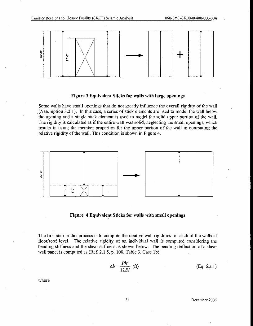
Some walls have openings that extend the entire height between floors, essentially separating
the wall into two or more individual wall piers. In this case, the rigidity of each wall pier is
calculated using the stiffness properties of each individual pier, and the sum of the rigidities is used for the rigidity of the wall. This condition is shown in Figure 3.
20 December 2006
Iv IN
;7?
i.- csi
s , s
CN CO
■1111111110.
CO
060-SYC-CR00-00400-000-00A Canister Receipt and Closure Facility (CRCF) Seismic Analysis
Figure 3 Equivalent Sticks for walls with large openings
Some walls have small openings that do not greatly influence the overall rigidity of the wall
.(Assumption 3.2.1). In this case, a series of stick elements are used to model the wall below
the opening and a single stick element is used to model the solid upper portion of the wall.
The rigidity is calculated as if the entire wall was solid, neglecting the small openings, which
results in using the member properties for the upper portion of the wall in computing the
relative rigidity of the wall. This condition is shown in Figure 4.
Figure 4 Equivalent Sticks for walls with small openings
The first step in this process is to compute the relative wall rigidities for each of the walls at
floor/roof level. The relative rigidity of an individual wall is computed considering the
bending stiffness and the shear stiffness as shown below. The bending deflection of a shear
wall panel is computed as (Ref. 2.1.5, p. 100, Table 3, Case lb):
Ab = Ph'
(ft) 12E1
where
(Eq. 6.2.1)
21 December 2006
1 Ab =
0h3
12/ (Eq. 6.2.2)
Ph As =
AsG (Eq. 6.2.3)
G =
25h As= —
As (Eq. 6.2.7)
Canister Receipt and Closure Facility (CRCF) Seismic Analysis 060-SYC-CR00-00400-000-00A
P = lateral shear load (kips)
h = wall height (ft)
E = modulus of Elasticity of the concrete (k/ft 2)
1 = in-plane (strong axis) moment of inertia of the wall (ft 4).
Since the relative rigidity of each wall relative to other walls and not the actual wall rigidity
is of interest, a value of P and E can be assumed. In this case a value of PIE = 10 has been
used, and Equation 6.2.1 is rewritten as:
The shear deflection of a shear wall is computed as (Ref. 2.1.5, pp. 201 to 202):
where
h = height of the wall (ft)
As = shear area of wall (ft 2) (for rectangular walls, As = 5/6 of the cross sectional area of the wall)
G = shear modulus of the concrete wall (k/ft 2).
The shear modulus may be expressed in terms of the modulus of elasticity, E, as (Ref. 2.1.5,
, p. 86):
2(1+ v)
For concrete, Poisson's ratio, v, is 0.17 (Ref. 2.1.2, Section 4.2.11.6.6).
Substituting this value into Equation 6.2.4 yields:
G = 0.4E
Substituting Equation 6.2.5 into Equation 6.2.3 yields:
As = 2.5Ph
AsE
Again letting P/E = 10, the shear deflection may be computed as:
(Eq. 6.2.4)
(Eq. 6.2.5)
(Eq. 6.2.6)
22 December 2006
X = " ER;
= ER i y i
ERi
where
Canister Receipt and Closure Facility (CRCF) Seismic Analysis 060-SYC-CR00-00400-000-00A
In the following spreadsheet, (Table 2), Equations 6.2.2 and 6.2.7 are used to determine the
relative bending and shear deflections of a wall and to compute the relative wall rigidity
using the computed deflections. The shear areas and moment of inertia are based on values
computed in Section 6.1 for each wall segment.
After the individual wall rigidities are calculated, the center of rigidity at each floor elevation
is computed by:
X and Y = are measured in feet from origin located on Ground Floor Plan in Attachment
A, page A-3.
R i = rigidity of an individual wall i.
Xi =center of rigidity of an individual wall i in x direction
Yi =center of rigidity of an individual wall i in y direction
The following spreadsheet, (Tables 2 and 3), is used to perform this calculation and
determine the center of rigidity at each floor elevation.
23 December 2006
1
3
4
5
7
8
9
1 1
Canister Receipt and Closure Facility (CRCF) Seismic Analysis 060-SYC-CR00-00400-000-00A
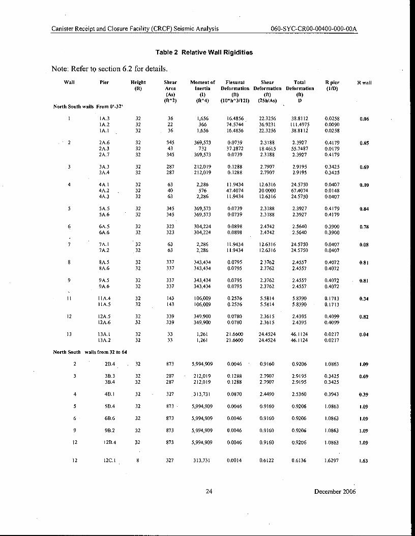
Table 2 Relative Wall Rigidities
Note: Refer to section 6.2 for details.
Wall Pier Height Shear Moment of Flexural Shear Total R pier R wall
(ft) Area Inertia Deformation Deformation Deformation (HD)
(As) (I) (ft) (ft) (ft)
(ft^2) (ft^4) (I0*h^3/121) (25h/As) D
' North South walls From 0'-32'
I A.3 32 36 1,656 16.4856 22.3256 38.8112 0.0258 0.06
1A.2 32 22 366 74.5744 36.9231 111.4975 0.0090 IA.1 32 36 1,656 16.4856 22.3256 38.8112 0.0258
2A.6 32 345 369,573 0.0739 2.3188 2.3927 0.4179 0.85
2A.3 32 43 732 37.2872 18.4615 55.7487 0.0179
2A.7 32 345 369,573 0.0739 2.3188 2.3927 0.4179
3A.3 32 287 212,019 0.1288 2.7907 2.9195 0.3425 0.69
3A.4 32 287 212,019 0.1288 2.7907 2.9195 0.3425
4A.1 32 63 2,286 11.9434 12.6316 24.5750 0.0407 0.10
4A.2 , 32 40 576 47.4074 20.0000 67.4074 0.0148
4A.3 32 63 2,286 11.9434 12.6316 24.5750 0.0407
5A.5 32 345 369,573 0.0739 2.3188 2.3927 0.4179 0.84
5A.6 32 345 369,573 0.0739 2.3188 2.3927 0.4179
6A.5 32 323 304,224 0.0898 2.4742 2.5640 0.3900 0.78
6A.6 32 323 304,224 0.0898 2.4742 2.5640 0.3900
7A.1 32 63 2,286 11.9434 12.6316 24.5750 0.0407 0.08
7A.2 32 63 2,286 11.9434 12.6316 24.5750 0.0407
8A.5 32 337 343,434 0.0795 2.3762 2.4557 0.4072 0.81
8A.6 32 337 343,434 0.0795 2.3762 2.4557 0.4072
9A.5 32 337 343,434 0.0795 2.3762 2.4557 0.4072 • 0.81
9A.6 32 337 343,434 0.0795 2.3762 2.4557 0.4072
1 I A.4 32 143 106,009 0.2576 5.5814 5.8390 0.1713 0.34
11A.5 32 143 106,009 0.2576 5.5814 5.8390 0.1713
12 1 2A .5 32 339 349,900 0.0780 2.3615 2.4395 0.4099 0.82
12A.6 32 339 349,900 0.0780 2.3615 2.4395 0.4099
13 13A.1 32 33 1,261 21.6600 24.4524 46.1124 0.0217 0.04
13A.2 32 33 1,261 21.6600 24.4524 46.1124 0.0217
North South walls from 32 to 64
2 ' 2B.4 32 873 5,994,909 0.0046 0.9160 0.9206 1.0863 1.09
3 3B.3 32 287 212,019 0.1288 2.7907 2.9195 0.3425 0.69
3B.4 32 287 212,019 0.1288 2.7907 2.9195 0.3425
4 4B.1 32 • 327 313,731 0.0870 2.4490 2.5360 0.3943 0.39
5 5B.4 32 873 5,994,909 0.0046 0.9160 0.9206 1.0863 1.09
6 6B.6 32 873 5,994,909 0.0046 0.9160 0.9206 1.0863 1.09
9 98.2 32 873 5,994,909 0.0046 0.9160 0.9206 1.0863 1.09
12 12114 32 873 5,994,909 0.0046 0.9160 0.9206 1.0863 1.09
12 12C.1 8 327 313,731 0.0014 0.6122 0.6136 1.6297 1.63
24 December 2006
Wall
9
6
9
Canister Receipt and Closure Facility (CRCF) Seismic Analysis 060-SYC-CR00-00400-000-00A
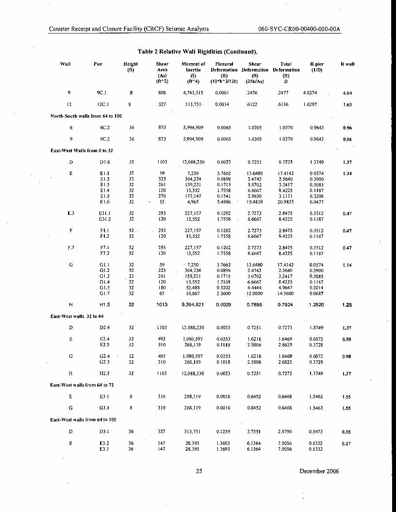
Table 2 Relative Wall Rigidities (Continued).
Pier Height Shear Moment of Flexural Shear Total R pier R wall
(ft) Area Inertia Deformation Deformation Deformation (I/D)
(As) (1) (ft) (ft) (ft)
(ft^2) (ft^4) (10*h^3/121) (25h/As) D
9C.1 8 808 4,743,5 I 5 0.0001 .2476 .2477 4.0374 4.04
12 12C.1 8 327 313,731 0.0014 .6122 .6136 1.6297 1.63
North-South walls from 64 to 100
6C.2 36 873 5,994,909 0.0065 1.0305 1.0370 0.9643 0.96
9C.2 36 873 5,994,909 0.0065 1.0305 1.0370 0.9643 0.96
East-West Walls from 0 to 32
D1.6 32 1103 12,088,230 0.0023 0.7251 0.7273 1.3749 1.37
E1.1 32 59 7,250 3.7662 13.6480 17.4142 0.0574 1.24
E1.2 32 323 304,224 0.0898 2.4742 2.5640 0.3900
E1.3 32 261 159,221 0.1715 3.0702 3.2417 0.3085
E1.4 32 120 15,552 1.7558 6.6667 8.4225 0.1187
E1.5 32 270 177,147 0.1541 2.9630 3.1171 0.3208
E1.6 32 - 52 4,965 5.4996 15.4839 20.9835 0.0477
E.3 E31.I 32 293 227,157 0.1202 2.7273 2.8475 0.3512 0.47
E31.2 32 120 15,552 1.7558 , 6.6667 8.4225 0.1187
FI.1 32 293 227,157 0.1202 2.7273 2.8475 0.3512 0.47
F1.2 32 120 15,552 1.7558 6.6667 8.4225 0.1187
F.7 F7.1 32 293 227,157 0.1202 2.7273 2.8475 0.3512 0.47
F7.2 32 120 15,552 1.7558 6.6667 8.4225 0.1187
G G1.1 32 59 • 7,250 3.7662 13.6480 17.4142 0.0574 1.14
GI.2 32 323 304,224 0.0898 2.4742 2.5640 0.3900
G1.3 32 261 159,221 0.1715 3.0702 3.2417 0.3085
01.4 32 120 15,552 1.7558 6.6667 8.4225 0.1187
01.5 32 180 . 52,488 0.5202 4.4444 4.9647 0.2014
G1.7 32 67 10,667 2.5600 12.0000 14.5600 0.0687
H H1.5 32 1013 9,364,821 0.0029 0.7895 0.7924 1.2620 1.26
East-West walls 32 to 64
D D2.4 32 1103 12,088,230 0.0023 0.7251 0.7273 1.3749 1.37
E E2.4 32 493 1,080,597 0.0253 1.6216 1.6469 0.6072 0.98
E2.5 32 310 268,119 0.1018 2.5806 2.6825 0.3728
G G2.4 • 32 493 1,080,597 0.0253 1.6216 1.6469 0.6072 0.98
02.5 32 310 268,119 0.1018 2.5806 2.6825 0.3728
H H2.3 32 1103 12,088,230 0.0023 0.7251 0.7273 1.3749 1.37
East-West walls from 64 to 72
E3.1 8 310 268,119 0.0016 0.6452 0.6468 1.5462 1.55
03.1 8 310 268,119 0.0016 0.6452 0.6468 1.5462 1.55
East-West walls from 64 to 100
D D3.1 36 327 313,731 0.1239 2.7551 2.8790 0.3473 0.35
E E3.2 36 147 28,395 1.3693 6.1364 7.5056 0.1332 0.27 E3.3 36 147 28,395 1.3693 6.1364 7.5056 0.1332
25 December 2006
Canister Receipt and Closure Facility (CRCF) Seismic Analysis 060-SYC-CR00-00400-000-00A
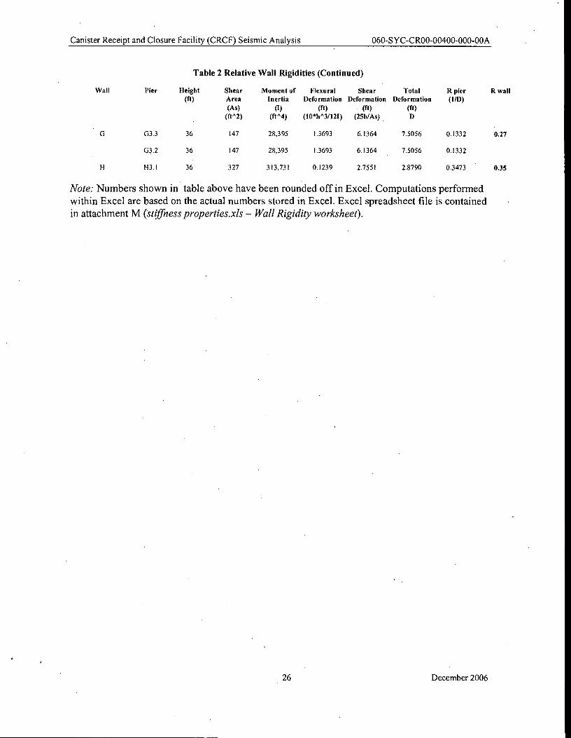
Table 2 Relative Wall Rigidities (Continued)
Pier Height Shear Moment of Flexural Shear Total R pier R wall (ft) Area Inertia Deformation Deformation Deformation (l/D)
(As) (I) (ft) (ft) (ft)
(ft^2) (ft^4) (I0*h^3/121) (25h/As) D
G G3.3 36 147 28,395 1.3693 6.1364 7.5056 0.1332 0.27
M.2 36 147 28,395 1.3693 6.1364 7.5056 0.1332
H H3.1 36 327 313,731 0.1239 2.7551 2.8790 0.3473 0.35
Note: Numbers shown in table above have been rounded off in Excel. Computations performed within Excel are based on the actual numbers stored in Excel. Excel spreadsheet file is contained in attachment M (stiffness properties.xls — Wall Rigidity worksheet).
Wall
26 December 2006
Canister Receipt and Closure Facility (CRCF) Seismic Analysis 060-SYC-CR00-00400-000-00A
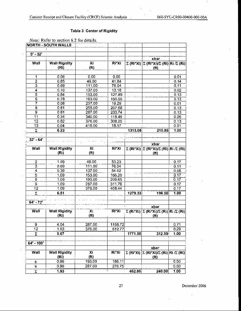
Table 3 Center of Rigidity
Note: Refer to section 6.2 for details. NORTH - SOUTH WALLS
0' - 32'
xbar Wall Wall Rigidity Xi Ri*Xi E (Ri*Xi) E (Ri*Xi)IE (Ri) Ri /E (Ri)
(Ri) (ft) (ft)
1 0.06 0.00 0.00 0.01
2 0.85 49.00 41.84 0.14
3 0.69 111.00 76.04 0.11
4 0.10 137.00 13.18 0.02
5 0.84 153.00 127.89 0.13
6 0.78 193.00 150.55 0.13
7 0.08 237.00 19.29 0.01
8 0.81 255.00 207.68 0.13
9 0.81 287.00 233.74 0.13
11 0.34 340.00 116.46 0.06
12 0.82 376.00 308.25 0.13
13 0.04 419.00 18.17 0.01
E 6.23 1313.08 210.85 1.00
32' -64 xbar
Wall Wall Rigidity Xi Ri*Xi E (Ri*Xi) E (Ri*Xi)/E (Ri) Ri /E (Ri) (Ri) (ft) (ft)
2 1.09 49.00 53.23 0.17
3 0.69 111.00 76.04 0.11
4 0.39 137.00 54.02 0.06
5 1.09 153.00 166.20 0.17 6 1.09 193.00 209.65 0.17
9 1.09 287.00 311.76 0.17
12 1.09 376.00 408.44 0.17
E 6.51 1279.33 196.50 1.00
64' - 72'
xbar Wall Wall Rigidity Xi Ri*Xi E (Ri*Xi) E (Ri*Xi)/E (Ri) Ri /E (Ri)
(Ri) (ft) (ft)
9 4.04 287.00 1158.72 0.71
12 1.63 376.00 612.77 0.29
E 5.67 1771.50 312.59 1.00
64' - 100'
xbar Wall Wall Rigidity Xi Ri*Xi E (Ri*Xi) E (Ri*XI)/E (Ri) Ri /E (Ri)
(Ri) (ft) (ft) 6 0.96 193.00 186.11 0.50
9 0.96 287.00 276.75 0.50
E 1.93 462.86 240.00 1.00
27 December 2006
Canister Receipt and Closure Facility (CRCF) Seismic Analysis 060-SYC-CR00-00400-000-00A
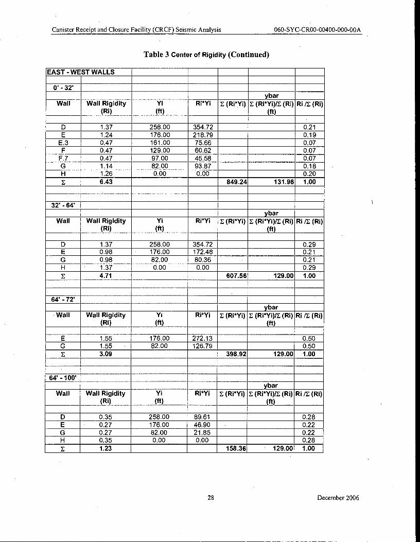
Table 3 Center of Rigidity (Continued)
EAST - WEST WALLS
0' - 32'
ybar Wall Wall Rigidity Yi Ri*Yi E (Ri*Yi) E (Ri*Yi)/E (RI) Ri /E (Ri)
(Ri) (ft) (ft)
D 1.37 258.00 354.72 0.21 1.24 176.00 218.79 0.19
E.3 0.47 161.00 75.66 0.07 F 0.47 129.00 60.62 0.07
F.7 0.47 97.00 45.58 0.07 G 1.14 82.00 93.87 0.18 H 1.26 0.00 0.00 0.20
E 6.43 849.24 131.98 1.00
32' - 64' ybar
Wall Wall Rigidity Vi Ri*Yi E (Ri*Yi) E (Ri*Yi)/E (Ri) Ri /E (Ri) (Ri) (ft) (ft)
D 1.37 258.00 354.72 0.29 E 0.98 176.00 172.48 0.21
G 0.98 82.00 80.36 0.21 H 1.37 0.00 0.00 0.29
E 4.71 607.56 129.00 1.00
_ 64' - 72'
ybar Wall Wall Rigidity Yi Ri*Yi E (Ri*Yi) E (Ri*YO/E (Ri) Ri /E (Ri)
(Ri) (ft) (ft)
E 1.55 176.00 272.13 0.50 G 1.55 82.00 126.79 0.50 E 3.09 398.92 129.00 1.00
64' -100' ybar
Wall Wall Rigidity Vi Ri*Yi E (Ri*Yi) E (Ri*Yi)IE (Ri) Ri /E (Ri) (Ri) (ft) (ft)
D 0.35 258.00 89.61 0.28 E 0.27 176.00 46.90 - 0.22
G 0.27 82.00 21.85 0.22 H 0.35 0.00 0.00 0.28
E 1.23 158.36 129.00 1.00
28 December 2006
Canister Receipt and Closure Facility (CRCF) Seismic Analysis 060-SYC-CR00-00400-000-00A
Note: Numbers shown in table above have been rounded off in Excel. Computations performed
within Excel are based on the actual number stored in Excel. The Excel spreadsheet file is
contained in attachment M (Stiffness properties.xls in the Shear Center Worksheet).
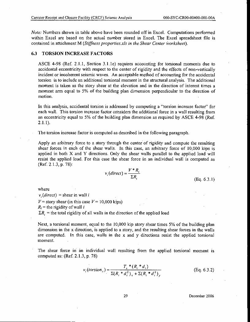
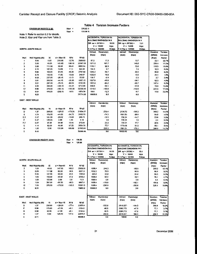
6.3 TORSION INCREASE FACTORS
ASCE 4-98 (Ref. 2.1.1, Section 3.1.1e) requires accounting for torsional moments due to
accidental eccentricity with respect to the center of rigidity and the effects of non-vertically
incident or incoherent seismic waves. An acceptable method of accounting for the accidental
torsion is to include an additional torsional moment in the structural analysis. The additional
moment is taken as the story shear at the elevation and in the direction of interest times a
moment arm equal to 5% of the building plan dimension perpendicular to the direction of motion. •
In this analysis, accidental torsion is addressed by computing a "torsion increase factor" for
each wall. This torsion increase factor considers the additional force in a wall resulting from
an eccentricity equal to 5% of the building plan dimension as required by ASCE 4-98 (Ref. 2.1.1).
The torsion increase factor is computed as described in the following paragraph.
Apply an arbitrary force to a story through the center of rigidity and compute the resulting shear forces in each of the shear walls. In this case, an arbitrary force of 10,000 kips is
applied in both X and Y directions. Only the shear walls parallel to the applied load will
resist the applied load. For this case the shear force in an individual wall is computed as (Ref. 2.1.3, p. 78):
R. vi(direct) =
V *
ER,
where
v; (direct) = shear in wall i
V= story shear (in this case V= 10,000 kips) Ri = the rigidity of wall i
ER, = the total rigidity of all walls in the direction of the applied load
(Eq. 6.3.1)
Next, a torsional moment, equal to the 10,000 kip story shear times 5% of the building plan
dimension in the x direction, is applied to a story, and the resulting shear forces in the walls
are computed. In this case, walls in the x and y directions resist the applied torsional
moment.
The shear force in an individual wall resulting from the applied torsional moment is
computed as: (Ref. 2.1.3, p. 78)
*(R * d i ) v i (torsion,)=
E(R i * +E(Ri * (Eq. 6.3.2)
29 December 2006
Vi (torsion)= Vvi (torsion,) 2 (torsion y) 2 (Eq. 6.3.4)
V, (torsion)torsion increase factor =
v, (direct) (Eq. 6.3.5)
Canister Receipt and Closure Facility (CRCF) Seismic Analysis 060-SYC-CR00-00400-000-00A
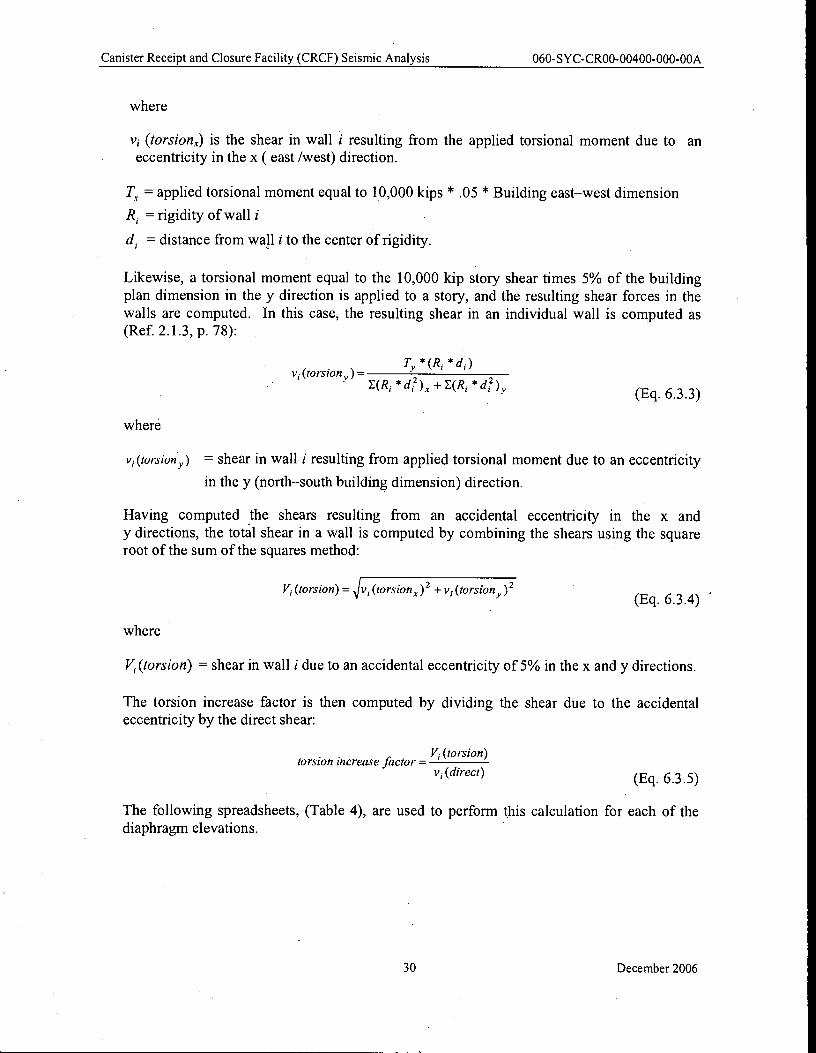
where
I); (torsion)) is the shear in wall i resulting from the applied torsional moment due to an eccentricity in the x ( east /west) direction.
= applied torsional moment equal to 10,000 kips * .05 * Building east—west dimension
R. rigidity of wall i
d. distance from wall i to the center of rigidity.
Likewise, a torsional moment equal to the 10,000 kip story shear times 5% of the building
plan dimension in the y direction is applied to a story, and the resulting shear forces in the
walls are computed. In this case, the resulting shear in an individual wall is computed as (Ref. 2.1.3, p. 78):
Ty * (R * d i ) v i (torsion y) =
E(R i * +E(Ri * 4)y
where
(Eq. 6.3.3)
v. (torsion) = shear in wall i resulting from applied torsional moment due to an eccentricity
in the y (north—south building dimension) direction.
Having computed the shears resulting from an accidental eccentricity in the x and
y directions, the total shear in a wall is computed by combining the shears using the square root of the sum of the squares method:
where
V1 (torsion) = shear in wall i due to an accidental eccentricity of 5% in the x and y directions.
The torsion increase factor is then computed by dividing the shear due to the accidental eccentricity by the direct shear:
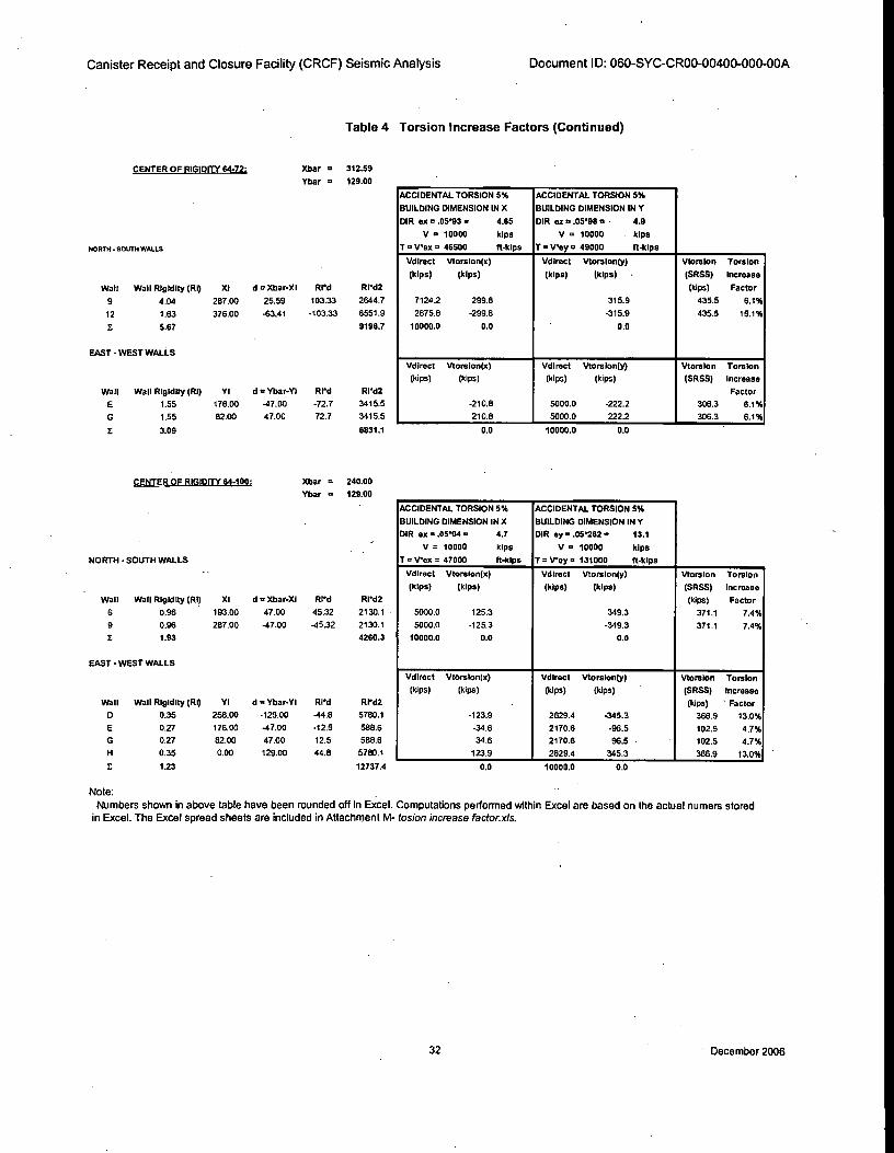
The following spreadsheets, (Table 4), are used to perform this calculation for each of the diaphragm elevations.
30 December 2006
Xbar =
Thar =
Table 4 Torsion Increase Factors 210.85 ft
131.98 ft
CENTER OF RIGIDITY 0-32:
Note 1: Refer to section 6.3 for details.
Note 2: Xbar and Ybar are from Table 3.
NORTH - SOUTH WALLS
Wall Wail Rigidity (RI) XI d = Xbar-XI Rrd Rrd2
1 0.06 0.00 210.85 12.76 2689.83
2 0.85 49.00 161.85 138.19 22367.09
3 0.69 111.00 99.85 68.41 6830.64
4 0.10 137.00 73.85 7.11 524.83
5 . 0.84 153.00 57.85 48.36 2797.80
6 • 0.78 193.00 17.85 13.93 248.67
7 0.08 , 237.00 -26.15 -2.13 55.63 .
8 0.81 255.00 -44.15 -35.95 1587.13
9 0.81 287.00 -76.15 -62.01 4722.05
11 0.34 340.00 -129.15 -44.24 5712.80
12 0.82 376.00 -165.15 -135.39 22358.99
13 0.04 419.00 -208.15 -9.03 1879.08
z 6.23 71774.53
EAST - WEST WALLS
Wall Wall Rigidity (RI) YI d =Ybar-YI Ri'd RI'd2
D 1.37 258.00 -126.02 -17326 21834.07
E 1.24 176.00 -44.02 -54.72 2408.70
E.3 0.47 161.00 -29.02 -13.64 395.71
F 0.47 129.00 2.98 1.40 4.18
F.7 0.47 97.00 34.98 16.44 575.04
G 1.14 82.00 49.98 57.22 2659.76
H 1.26 0.00 131.98 166.56 21983.01
1 6.43 50060.46 0.0 0.0 10000.00
NORTH - SOUTH WALLS
Wall Wall Rigidity (RI) Xi d i= Xbar-XI Ri'd R1'd2
2 1.09 49.00 147.50 160.2 23632.0
3 0.69 111.00 85.50 58.6 5007.5
4 0.39 137.00 59.50 23.5 1395.8
5 1.09 153.00 43.50 47.2 2055.2
6 1.09 193.00 3.50 3.8 13.3
9 1.09 287.00 -90.50 -98.3 8897.4
12 . 1.09 376.00 -179.50 -195.0 35001.0
E 6.51 76002.2
EAST - WEST WALLS
Wall Wail Rigidity (RI) Yi d = Ybar-YI RI'd R1ci2
D 1.37 258.00 -129.00 -177.4 22879.4
E 0.98 176.00 -47.00 -46.1 2164.8
G 0.98 82.00 47.00 46.1 2164.8
H 1.37 0.00 129.00 177.4 22879.4
i 4.71 50088.5 0.0 10000 0.0
Canister Receipt and Closure Facility (CRCF) Seismic Analysis Document ID: 060-SYC-CR00-00400-000-00A
ACCIDENTAL TORSION 5% ACCIDENTAL TORSION 5%
BUILDING DIMENSION IN X BUILDING DIMENSION IN Y
DIR ex = .05'331 = 16.55 DIR ey = .05262 = 13.1
V = 10000 kips V = 10000 klps
T = Wax = 165500 ft-klps T = Way = 131000 ft-kips
Vdirect Vtorslon(x) Vdirect Vtorsion(y) Vtorsion Torsion
(kips) (kips) (klps) (kips) (SRSS) incroase
(kips) Factor
97.2 17.3 13.7 22.1 22.7%
1371.0 187.7 148.6 239.4 17.5%
1100.1 92.9 73.6 118.5 10.8%
154.5 9.7 7.6 12.3 8.0%
1342.2 65.7 52.0 83.8 6.2%
1252.6 18.9 15.0 24.1 1.9%
130.7 -2.9 -2.3 3.7 2.8%
1307.8 -48.8 -38.7 62.3 4.8%
1307.8 -84.2 -66.7 107.4 8.2%
550.0 -60.1 -47.6 76.6 13.9%
1316.5 -183.9 - 145.6 234.6 17.8%
69.6 -12.3 -9.7 15.6 22.5%
10000.0 0.0 0.0
VdIrect Vtorsion(x) Vdlrect Vtorslon(y) Vtorsion Torsion
(kips) (MX) (kips) (kips) (SRSS) Increaso
(kips) Factor
-235.4 2136.73 -186.3 300.2 14.0%
-74.3 1931.95 -58.8 94.8 4.9%
-18.5 730.31 -14.7 23.6 3.2%
1.9 730.31 1.5 2.4 0.3%
22.3 730.31 17.7 28.5 3.9%
77.7 1779.08 61.5 99.1 5.6%
226.3 _ 1961.31 179.1 288.6 14.7%
CENTER OF RIGIDITY 32-64: Mar = 196.50
'(bar = 129.00
ACCIDENTAL TORSION 5% ACCIDENTAL TORSION 5%
BUILDING DIMENSION IN X BUILDING DIMENSION IN V
DIR ex = .osnsi = 16.55 DIR ay = .05262 = 13.1
V = 10000 klps V = 10000 kips
T = %rex a 165500 • ft-kips T = %re), = 131000 ft-kips
Vdirect Vtorsion(x) VdIrect Vtorslon(z) Vtorslon Torsion
(kips) (kips) (kips) (kips) (SRSS) Increase
(kips) Factor
1668.4 210.3 166.5 268.2 18.1%
1052.2 76.9 60.9 98.0 9.3%
605.6 30.8 24.4 39.3 6.5%
1668.4 62.0 49.1 79.1 4.7%
1668.4 5.0 3.9 6.4 0.4%
1668.4 -129.0 -102.1 164.6 9.9%
1668.4 -255.9 -202.6 326.4 19.6%
10000.0 0.0 . 0.0 .
Vdirect Vtorsion(x) Vdirect Vtorslon(y) Vtorsion Torsion
(bps) (kips) (kips) (kips) (SRSS) Increase
(kips) Factor
-232.8 2919.227 • -184.3 296.9 10.2%
-60.5 2080.773 -47.9 77.1 3.7%
60.5 2080.773 47.9 77.1 3.7%
232.8 2919.227 184.3 296.9 10.2%
31 December 2006
NORTH - SOUTH WALLS
Wan Wall Rigidity (RI) XI d = Xbar-XI RPd RI•c12
9 4.04 287.00 25.59 103.33 2644.7
12 1.63 376.00 -63.41 -103.33 6551.9
E 537 9196.7
EAST - WEST WALLS
Wall Wall Rigidity (RI) VI d = Ybar-Y1 Rid Ried2
E 1.55 176.00 -47.00 -72.7 3415.5
G 1.55 82.00 47.00 72.7 3415.5
I 3.09 6831.1 0.0 10000.0 0.0
NORTH • SOUTH WALLS
Wall Wall Rigidity (RI) XI d = Xbar-XI IRP'd RIPd2
s 0.96 193.00 47.00 45.32 2130.1
9 0.96 287.00 -47.00 -45.32 2130.1
E 1.93 4260.3
EAST -WEST WALLS
Wall Wall Rigidity (RI) Y1 d = Ybar-YI Rd RPd2
D 0.35 258.00 429.00 -44.8 5780.1
E 0.27 176.00 -47.00 -12.5 588.6
G 0.27 82.00 47.00 12.5 588.6
H 0.35 0.00 129.00 44.8 5780.1
E 1.23 12737.4 0.0 10000.0 0.0
Canister Receipt and Closure Facility (CRCF) Seismic Analysis Document ID: 060-SYC-CR00-00400-000-00A
Table 4 Torsion Increase Factors (Continued)
CENTER OF RIGIDITY 84-72: )(bar 312.59
Ybar a 129.00
ACCIDENTAL TORSION 5% ACCIDENTAL TORSION 5%
BUILDING DIMENSION IN X BUILDING DIMENSION IN Y
DIR ex = .0593 = 4.85 DIR oz * .0598 = • 4.9
V a 10000 kips V a 10000 klps
T = Weir = 46500 ft-klps T a Vey ix 49000 ft-klps
Vdirect Vtorslon(x) Vdlrect Vtorsion(y) Vtorslon Torsion
(kips) (hips) (hips) (kips) • (SRSS) Increase
(kips) Factor
7124.2 299.8 315.9 435.5 6.1%
2875.8 -299.8 -315.9 435.5 15.1%
. 10000.0 0.0 0.0
Vdlrect VtorsIon(x) VdIrect VtorsIon(y) Vtors Ion Torsion
(kips) (kips) (kips) (kips) (SRSS) Increase
Factor
-210.8 5000.0 -222.2 306.3 6.1%
210.8 5000.0 222.2 306.3 8.1%
CENTER OF RIGIDITY 64-100: Xbar = 240.00
Ybar a 129.00
ACCIDENTAL TORSION 5% ACCIDENTAL TORSION 5%
BUILDING DIMENSION IN X BUILDING DIMENSION IN Y
DIR ex =..05.94 = 4.7 DIR ey = .05262 a 13.1
V = 10000 klps V a 10000 kips
T =1.Pex = 47000 ft-klps T a %Pay • 131000 ft-kips
Vdinnt Vtorslon(x) Vdlrect Vtorslon(y) Vtoralon Torsion
(kips) (kips) (klps) (kips) (SRSS) Increase
(kips) Factor
5000.0 125.3 349.3 371.1 7.4%
5000.0 -125.3 -349.3 371.1 7.4%
10000.0 0.0 0.0
VdIrect VtorsIon(x) VdIrect Vtorslon(y) Vtorslon Torsion
(kiln) (kips) (kips) (kips) (SRSS) Increase
(kips) ' Factor
-123.9 2829.4 -345.3 366.9 13.0%
-34.6 2170.6 -96.5 102.5 4.7%
34.6 2170.6 963 • 102.5 4.7%
123.9 2829.4 345.3 _ 388.9 13.0%
Note:
Numbers shown in above table have been rounded off In Excel. Computations performed within Excel are based on the actual numers stored
in Excel. The Excel spread sheets are included in Attachment M- tosion increase factor.xls.
32 ' December 2006
Canister Receipt and Closure Facility (CRCF) Seismic Analysis 060-SYC-CR00-00400-000-00A
6.4 SEISMIC MODELING AND ANALYSIS
The values computed in Table 1 and the mass and center of mass properties calculated in Design
Calculation 060-SYC-CR00-00200-00A (Ref. 2.1.7) were utilized to generate the "beam stick'
finite element model in SAP2000. The mass for each floor was lumped at a dedicated node
located at the coordinates of the center of mass. Rigid body constraints are used to constrain all
nodes located on a diaphragm/slab. Attachment A, shows the wall elevations with the SAP2000
beam elements and joints labeled for the CRCF.
Soil structure interaction is considered using frequency independent soil springs with six degrees
of freedom. The springs were placed at the center of mass (SAP2000 node-98) of the basemat.
The spring properties calculated for 2,000 and 10,000-year return period seismic events were
used to analyze DBGM-2 and BDBGM basis ground motions. Six sets of springs were calculated to define lower bound, median and upper bound stiffness values for 35 ft depth of alluvium and
110ft depth of alluvium for each seismic event. These bounding calculations were computed in Design Calculation 060-SYC-CR00-00300-000-00A (Ref 2.1.8).
In this section the "beam-stick" model will be utilized to perform the following analyses:
• Fixed base modal and response spectrum analysis
• Modal analysis utilizing the upper bound, median and lower bound soil cases for 35' and 110' alluvium depths for the Design Basis Ground Motion (DBGM-2) case.
• Modal analysis utilizing the upper bound cases for 35' alluvium for the Beyond Design Basis
Ground Motion (BDBGM) case.
• Response Spectrum Analysis for the DBGM-2 cases utilizing results from the DBGM modal
analysis. Analysis will utilize the NRC 10 percent method for combining modal responses
and the square root of sum of the squares (SRSS) method for combining the North/South
(referred to as HY), East/West (referred to as HX) and Vertical (referred to as VZ) spectral
cases.
• Response Spectrum Analysis for the BDBGM case utilizing results from the BDBGM modal
analysis. Analysis will utilize the NRC 10 percent method for combining modal responses
and the square root sum of the squares (SRSS) method for combining the North/South
(referred to as HY), East/West (referred to as HX) and Vertical (referred to as VZ) spectral
cases.
• 1 g vertical case to determine the DL + 25%LL case.
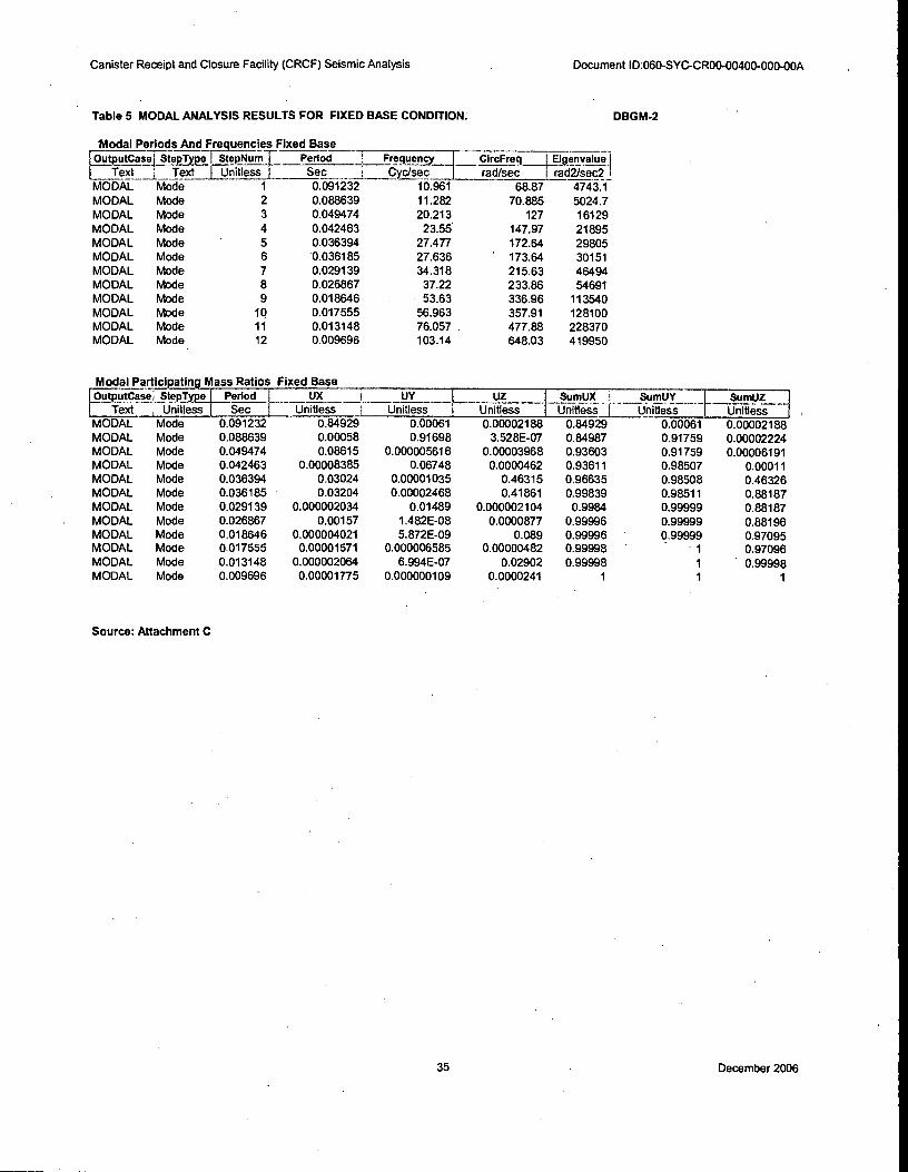
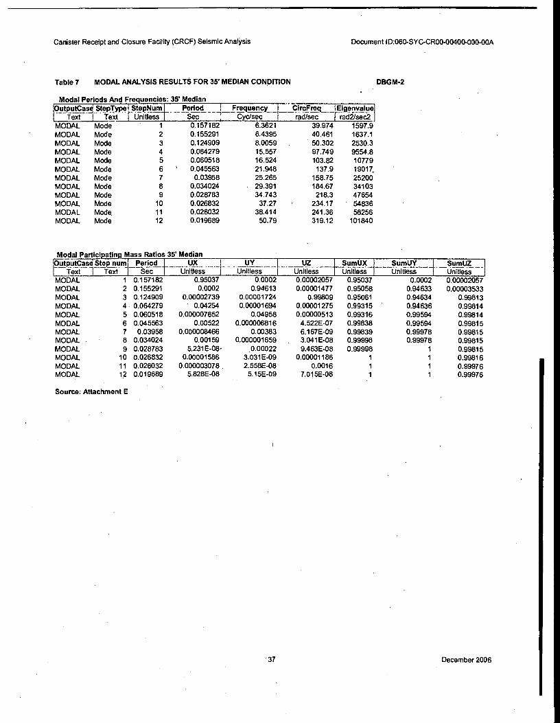
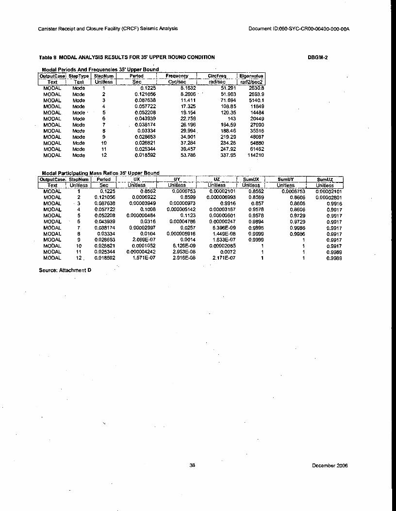
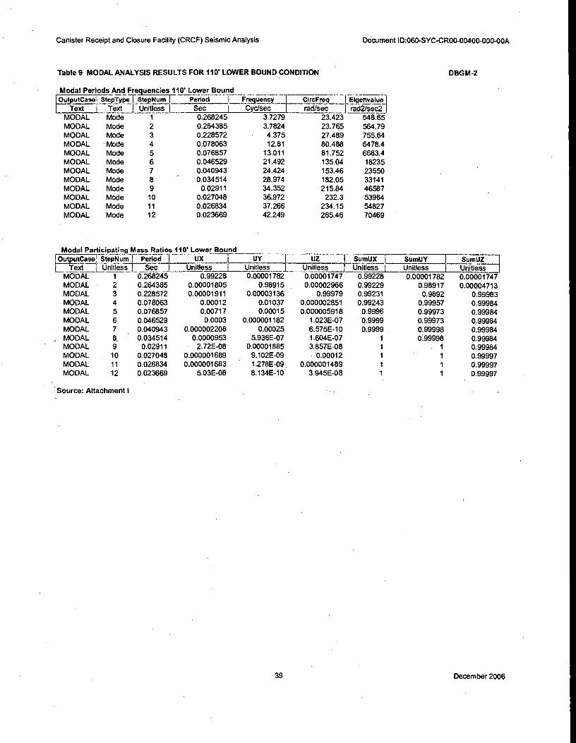
From the modal analysis results for the various soil spring cases described above it is observed
that the first three modes are SSI dominated modes with greater than 95% of the mass
participating in each of these modes. Refer to the modal analysis results summarized in Tables
5-12. Based on these results, damping values of 20% will be utilized for the first three modes and
7% damping will be used for the remaining modes in the response spectrum analysis for DBGM-
33 December 2006
Canister Receipt and Closure Facility (CRCF) Seismic Analysis 060-SYC-CR00-00400-000-00A
2. For the BDBGM response spectrum analysis, damping values of 20% will be utilized for first
three modes and 10% damping will be used for the remaining modes.
SAP2000 only allows the input of a single response spectra curve for a given response spectrum
analysis case. To consider the effect of different damping values for each mode the modal
damping over ride feature is utilized. Since only a single damped spectra is input, the SAP2000
program uses Newmark's method to scale the input spectra to other damping values. Since the
YMP spectra is defined at various damping values a 'hybrid' spectra is required for input into
SAP2000. This 'hybrid' spectra is developed by combining the 20% and 7% damped spectra
defined in Reference 2.1.9 for DBGM-2 analysis. Likewise the 20% and 10% damped spectra
defined in reference 2.1.10 is used in developing the 'hybrid' spectra for the BDBGM analysis.
Since the first three modes are soil deformation dominant, 20% damping value is applied to these
modes. The 'hybrid' spectra consists of the 20% spectral acceleration up to the frequency of the
third mode and the 7%/10% spectral acceleration at frequencies above the third mode. Since the
third mode frequency varies for each of the soil conditions, a series of 'hybrid' spectra are
developed to be used for the various soil conditions.
Drawing 100-IED-WHS0-00101-000-00B "TED Surface Facility", (Ref. 2.1.12) defines the
technical data files containing the DBGM-2 and BDBGM Response Spectra curves. The
following DTN's are cited on the Surface Facility TED:
DBGM-2 DTN: M00411SDSTMHIS.006, Seismic Design Spectra and Time Histories for
the Surface Facilities Area (Point DIE) at 5E -4 Annual Exceedance Frequency. Submittal
date: 11/16/2004. (Ref. 2.1.9)
BDBGM DTN: M00411WHBDE104.003, Seismic Design Spectra and Time Histories for
the Surface Facilities Area (Point DIE) at 1E-4 Annual Exceedance Frequency. Submittal date: 11/16/2004. (Ref. 2.1.10)
The 20%, 10% and 7% Response Spectra data used in the development of 'Hybrid' spectra were taken from Ref. 2.1.9 and Ref. 2.1.10 cited above.
The resulting 'Hybrid' spectra are shown in Figures 5-16.
34 December 2006
Canister Receipt and Closure Facility (CRCF) Seismic Analysis Document ID:060-SYC-CR00-00400-000-00A
Table 5 MODAL ANALYSIS RESULTS FOR FIXED BASE CONDITION. DBGM-2
Fixed Base
epNum 1-- Perii;c1 .L_Frequency I CIrcFreq Elienvalue I
Sec I -Cyc/sec 1 rad/sec rad2/sec2 0.091232 10.961 68.87 4743.1-
nitless
Modal Periods And Frequencies I
tputCase I StepTypel StepNum Perk-4
Text _Text 1 Unitless Sec
MODAL Mode 1
11.282
20.213
23.55
27.477
27.636
34.318
37.22
53.63
56.963
76.057
103.14
MODAL
MODAL
MODAL
MODAL
MODAL
MODAL
MODAL
MODAL
MODAL
MODAL
MODAL
Mode 2
Mode
Mode
Mode
Mode
Mode
Mode
Mode
Mode
Mode
Mode
0.088639
0.049474
0.042463
0.036394
0.036185
0.029139
0.026867
0.018646
0.017555
0.013148
0.009696
70.885 5024.7
127 16129
147.97 21895
172.64 29805
173.64 30151
215.63 46494
233.86 54691
336.96 113540
357.91 128100
477.88 228370
648.03 419950
3
4
5
6
7
8
9
10 11
12
Modal Participating Mass Ratios
Outputcase;. StepType
Text , Unitless
MODAL Mode
MODAL Mode
MODAL
MODAL
MODAL
MODAL
MODAL
MODAL
MODAL
MODAL
MODAL
MODAL
UX i UY 1 Uz SumUX _ !. SumUY Sumtg ...., Unitless I Unitless I Unitless Unitless 1 Unitless Unitless
0.84929 0.00061 0.00002188 0.84929 0.00061 0.00002188
0.00058 0.91698 3.528E-07 0.84987 0.91759 0.00002224
0.08615 0.000005616 0.00003968 0.93603 0.91759 0.00006191
0.00008385 0.06748 0.0000462 0.93611 0.98507 0.00011
0.03024 0.00001035 0.46315 0.96635 0.98508 0.46326
0.03204 0.00002468 0.41861 0.99839 0.98511 0.88187
0.000002034 0.01489 0.000002104 0.9984 0.99999 0.88187
0.00157 1.482E-08 0.0000877 0.99996 0.99999 0.88196
0.000004021 5.872E-09 0.089 0.99996 0.99999 0.97095
0.00001571 0.000006585 0.00000482 0.99998 - • 1 0.97096
0.000002064 6.994E-07 0.02902 0.99998 1 . 0.99998
0.00001775 0.000000109 0.0000241 1 1 1
Mode
Mode
Mode
Mode
Mode
Mode
Mode Mode
Mode
Mode
Period
Sec 0.091232
0.088639
0.049474
0.042463
0.036394
0.036185
0.029139
0.026867
0.018646 0.017555
0.013148
0.009696
Fixed Base
Source: Attachment C
35 December 2006

Canister Receipt and Closure Facility (CRCF) Seismic Analysis Document ID:060-SYC-CR00-00400-000-00A
Table 6 MODAL ANALYSIS RESULTS FOR 35' LOWER BOUND CONDITION DBGM-2
Modal Periods And Frequencies 35' Lower Bound
OutputCase; StepType I__Steptlum F Period Frequency I CircFreq Iffigenvaluei
Text ' Text ; -Giftless Sec I Cyc/sec
I
I rad/sec t radVseci
MODAL Mode 1 0.218979 4.5667 28.693 823.29 MODAL Mode 2 0.216027 4.6291 29.085 845.95 MODAL Mode 3 0.183456 5.4509 34.249 1173 MODAL Mode 4 0.071585 13.969 87.772 7703.9 MODAL Mode 5 0.070571 14.17 89.034 7927 MODAL Mode 6 0.046272 21.611 135.79 18438 MODAL Mode 7 0.040387 24.76 155.57 24203 MODAL Mode 8 0.034357 29.106 182.88 33445 MODAL Mode 9 0.028931 34.565 217.18 47166 MODAL Mode 10 0.026842 37.255 234.08 54795 MODAL Mode 11 0.026624 37.56 235.99 55694 MODAL Mode 12 0.021859 45.747 287.44 82620
Modal Participating Mass Ratios 35' Lower Bound •
OutputCase : Step_Typel Period I UX I UY T. uz I sumux _T - iumuy _ -1--ii_ tu-TUi_71]
Text 1 Unitless I Sec I Unitless _i_ Unitless -r Unitless 1 Unitless I Unitiess -E-U-niiiiii -I MODAL Mode 0.218979 0.98545 0.00004038 0.00001832 0.98545 0.00004038 0.00001832 MODAL Mode 0.216027 0.00004114 0.98158 0.00002429 0.98549 0.98162 0.00004261 MODAL Mode 0.183456 0.00002092 0.00002626 0.99956 0.98551 0.98165 0.99961 MODAL Mode 0.071585 0.01325 0.00021 0.000005393 0.99877 0.98185 0.99961 MODAL Mode 0.070571 0.00014 ' 0.01746 0.000005344 0.99891 0.99931 0.99962 MODAL Mode 0.046272 0.00082 0.000001767 1.622E-07 0.99973 0.99931 0.99962 MODAL Mode 0.040387. 0.0000031 0.00064 1.449E-09 0.99973 0.99996 0.99962 MODAL Mode 0.034357 0.00026 7.277E-07 1.321E-07 0.99999 0.99996 0.99962 MODAL Mode 0.028931 2.49E-08 0.00004273 5.341E-08 0.99999 1 0.99962 MODAL Mode 0.026842 0.000002041 4.007E-09 0.00001509 1 1 0.99963 MODAL Mode 0.026624 0.000003112 1.233E-08 0.00031 1 1 0.99994 MODAL Mode 0.021859 4.278E-08 8.181E-10 3.989E-08 1 1 0.99994
Source: Attachment F
36 December 2006
CircFreq__ lEigenv_alue
rad/sec 1 rad2/sec2
39.974 1597.9
40.461 1637.1
50.302 2530.3
97.749 9554.8
103.82 10779
137.9 19017,
158.75 25200
184.67 34103
218.3 47654
234.17 54836
241.36 58256
319.12 101840
Canister Receipt and Closure Facility (CRCF) Seismic Analysis Document ID:060-SYC-CR00-00400-000-00A
Table 7 MODAL ANALYSIS RESULTS FOR 35' MEDIAN CONDITION DBGM-2
Modal Periods And Frequencies: 35' Median
,r0 u t p u t C a s 4, Ste_p_Type' StepNum Period I Frequency
I Text I Text Unitless Sec 1 Cyc/sec
MODAL Mode 1 0.157182 6.3621
MODAL Mode 2 0.155291 6.4395
MODAL Mode 3 0.124909 8.0059
MODAL Mode 4 0.064279 15.557
MODAL Mode 5 0.060518 16.524
MODAL Mode 6 ' 0.045563 21.948
MODAL Mode 7 0.03958 25.265
MODAL Mode 8 0.034024 29.391
MODAL Mode 9 0.028783 34.743
MODAL Mode 10 0.026832 37.27
MODAL Mode 11 0.026032 38.414
MODAL Mode 12 0.019689 50.79
Modal Participating Mass Ratios 35' Median
Z5trii tputCasi Step num Period UX I_ UY _I UZ
1 Text 1 Text Sec Unitless 1 Unitless 1 Unitless Unitless Unitless
MODAL 1 0.157182 0.95037 0.0002 0.00002057 0.95037
MODAL 2 0.155291 0.0002 0.94613 0.00001477 0.95058 MODAL 3 0.124909 0.00002739 0.00001724 0.99809 0.95061
MODAL 4 0.064279 0.04254 0.00001694 0.00001275 0.99315
MODAL 5 0.060518 0.000007652 0.04958 0.00000513 0.99316
MODAL 6 0.045563 0.00522 0.000006816 4.522E-07 0.99838
MODAL 7 0.03958 0.000008466 0.00383 6.167E-09 0.99839 MODAL 8 0.034024 0.00159 0.000001659 . 3.041E-08 0.99998
MODAL 9 0.028783 5.231E-08- 0.00022 9.463E-08 0.99998 MODAL 10 0.026832 0.00001586 3.031E-09 0.00001186 1
MODAL 11 0.026032 0.000003078 2.558E-08 0.0016 1 MODAL 12 0.019689 5.828E-08 5.15E-09 7.015E-08 1
Source: Attachment E
SumUZ Unitless
0.0002 0.00002057
0.94633 0.00003533
0.94634 0.99813
0.94636 0.99814
0.99594 0.99814
0.99594 0.99815
0.99978 0.99815
0.99978 0.99815
1 0.99815
1 0.99816
1 0.99976
1 0.99976
37 December 2006
apNum_i____ _Period_ _Frequency_
Sec Cyc/sec
19.154
35' Upper Bound Modal Periods And Frequencies 35' Upper Bound
OutputCasej S pTypoj StepNum_
Text I -Text -Linitless
MODAL Mode
MODAL Mode MODAL Mode
MODAL Mode MODAL Mode • 5
MODAL Mode MODAL Mode MODAL Mode MODAL Mode
MODAL Mode MODAL Mode MODAL Mode
circFreq Elgenvalue 1 rid/sec -rad2 -/s-e-c2-
51.291 2630.8
51.903 2693.9
71.694 5140.1
108.85 11849
120.35 14484
143 20449
164.59 27090
188.46 35516
219.29 48087
234.26 54880
247.92 61462
337.95 114210
1 0.1225 8.1632
2 0.121056 8.2606
3 0.087638 11.411 4 0.057722 17.325
6 0.043939 22.759 7 0.038174 26.196
8 0.03334 29.994
9 0.028653 34.901 10 0.026821 37.284 11 0.025344 39.457 12 0.018592 53.786
0.1225
0.121056 0.087638 0.057722
0.052208
0.043939 0.038174
0.03334 0.028653 0.026821
0.025344 0.018592
OutputCase; StepNurni Period I
Text L Unitless I Sec Unitless
Modal Participating Mass Ratios 35'
MODAL MODAL MODAL MODAL MODAL
MODAL
MODAL MODAL MODAL MODAL MODAL MODAL
1 0.1225 2 0.121056
3 0.087638 4 0.057722
5 0.052208 6 0.043939
7 0.038174 8 0.03334 9 0.028653
10 0.026821 11 0.025344 12 . 0.018592
;atios 35' Upper Bound
SumUX -1--- SumUY ____I StinTtir--1
xi I UX 1_ UY 1 UZ
-I Unitless L Unitless t- Unitless Unitless I Unitless I Urirtress 1
0.8562 0.0006753 0.00002101 0.8562 0.0006753 0.650021-01
0.0006922 0.8599 0.000006993 0.8569 0.8606 0.00002801
0.00003949 0.00000973 0.9916 0.857 0.8606 0.9916
0.1008 0.000005142 0.00003167 0.9578 0.8606 0.9917
0.000000484 0.1123 0.00000601 0.9578 0.9729 0.9917
0.0316 0.00004786 0.00000247 0.9894 0.9729 0.9917
0.00002997 0.0257 6.396E-09 0.9895 0.9986 0.9917
0.0104 0.000005916 1.449E-08 0.9999 0.9986 0.9917
2.069E-07 0.0014 1.633E-07 0.9999 1 0.9917
0.0001052 6.126E-09 0.00002085 1 1 0.9917
0.000004242 2.953E-08 0.0072 1 1 0.9989
1.571E-07 2.916E-08 2.171E-07 1 1 0.9989
Canister Receipt and Closure Facility (CRCF) Seismic Analysis Document ID:060-SYC-CR00-00400-000-00A
Table 8 MODAL ANALYSIS RESULTS FOR 35 UPPER BOUND CONDITION DBGM-2
Source: Attachment D
38 December 2006
Canister Receipt and Closure Facility (CRCF) Seismic Analysis Document ID:060-SYC-CR00-00400-000-00A
Table 9 MODAL ANALYSIS RESULTS FOR 110 LOWER BOUND CONDITION DBGM-2
Modal Periods And Frequencies 110' Lower Bound_
[
Out t_p_it_case: StepTxpeTStepNum i Period I "F-resuency_ 1 CircFreq _illgenvaluel
Text i Text I_ Unitlessi_ Sec I Cyc/sec rad/sec f rad2/sec2
MODAL Mode 1 0.268245 3.7279 23.423 548.65
MODAL Mode 2 0.264385 3.7824 23.765 564.79
MODAL Mode 3 0.228572 - 4.375 27.489 755.64
MODAL - Mode 4 0.078063 12.81 80.488 6478.4
MODAL Mode 5 0.076857 13.011 81.752 6683.4
MODAL Mode 6 0.046529 21.492 135.04 18235
MODAL Mode 7 0.040943 24.424 153.46 23550
MODAL Mode 8 ' 0.034514 28.974 182.05 33141
MODAL Mode 9 0.02911 34.352 215.84 46587
MODAL Mode 10 0.027048 36.972 232.3 53964
MODAL Mode 11 0.026834 37.266 234.15 54827
MODAL Mode 12 0.023669 42.249 265.46 70469 •
Modal Participating Mass Ratios 110' Lower Bound
OutputCase; StepNum I Per-h7c-11 UX ----'--L______ UY ______T- UZ SumUX r SumUY
Text L Unitless I Sec_ I Unitless I Unitless I Unitless I Unitless I Unitless
MODAL 1 0.268245 0.99228 0.00001782 0.00001747 0.99228 0.00001782
MODAL 2 0.264385 0.00001805 0.98915 0.00002966 0.99229 0.98917 MODAL 3 0.228572 0.00001911 0.00003136 0.99979 0.99231 0.9892 MODAL 4 0.078063 0.00012 0.01037 0.000002851 0.99243 0.99957 MODAL 5 0.076857 0.00717 0.00015 0.000005918 0.9996 0.99973
MODAL 6 0.046529 0.0003 0.000001182 1.023E-07 0.9999 0.99973 MODAL 7 0.040943 0.000002208 0.00025 6.575E-10 0.9999 0.99998 MODAL 8, 0.034514 0.0000953 5.936E-07 1.604E-07 1 0.99998 MODAL 9 0.02911 2.72E-08 0.00001885 3.857E-08 1 1
MODAL 10 0.027048 0.000001689 9.102E-09 '0.00012 1 1
MODAL 11 0.026834 0.000001683 1.278E-09, 0.000001489 1 1
MODAL 12 0.023669 5.03E-08 8.134E-10 3.945E-08 1 1
Source: Attachment I
SUTI-15.1-171
Unitless-
0.00501747
0.00004713
0.99983
0.99984
0.99984
0.99984
0.99984
0.99984 0.99984
0.99997
0.99997
0.99997
39 December 2006
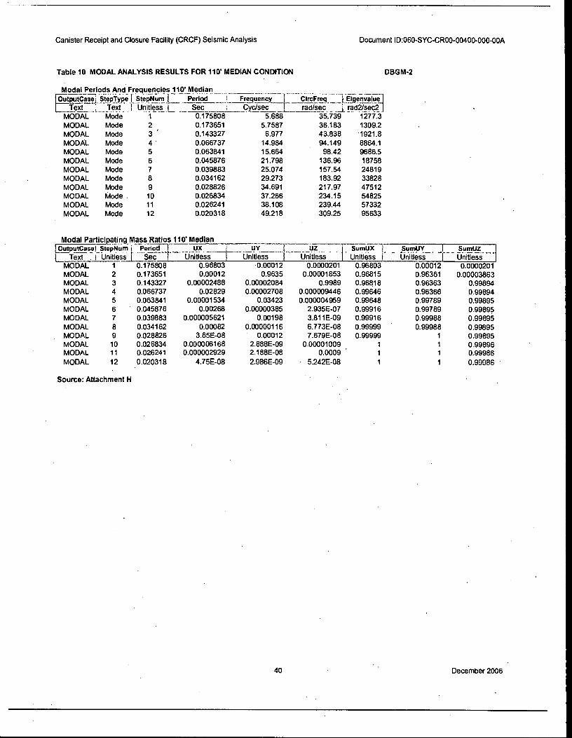
Canister Receipt and Closure Facility (CRCF) Seismic Analysis Document ID:060-SYC-CR00-00400-000-00A
Table 10 MODAL ANALYSIS RESULTS FOR 110' MEDIAN CONDITION DBGM-2
Modal Periods And Frequencies 110 Median
I OutputCase; Step_Typi-31-StepNurr; 1 Period I Frequency [ CircFreq igenvaluel
Text . Text I Unitless L_ Sec : Cyc/sec rad/sec a rad2/seC-2
MODAL Mode 1 0.175808 5.688 35.739 1277.3
MODAL Mode 2 0.173651 5.7587 36.183 1309.2
MODAL Mode 3 ' 0.143327 6.977 43.838 1921.8
MODAL Mode 4 0.066737 14.984 94.149 8864.1
MODAL Mode 5 0.063841 15.664 98.42 9686.5
MODAL Mode 6 0.045876 21.798 136.96 18758
MODAL Mode 7 0.039883 25.074 157.54 24819
MODAL Mode 8 0.034162 29.273 183.92 33828
MODAL Mode 9 0.028826 34.691 217.97 47512
MODAL Mode . 10 0.026834 37.266 234.15 54825
MODAL Mode 11 0.026241 38.108 239.44 57332
MODAL Mode 12 0.020318 49.218 309.25 95633
Modal Participating Mass Ratios 110' Median
OutputCasei StepNum i Period UX t UY UZ i Sumux I . _ sumusif. _ . _I _ _ SumUZ .... i
Text I Unitless r Sec Unitless I Unitless Unitless I Unitless I 'tininess I- rinitiesi -
MODAL 1 0.175808 0.96803 0.00012 0.0000201 0.96803 0.00012 0.0000201 MODAL 2 0.173651 0.00012 0.9635 0.00001853 0.96815 0.96361 0.00003863 MODAL 3 0.143327 0.00002488 0.00002084 0.9989 0.96018 0.96363 0.99894 MODAL 4 0.066737 0.02829 0.00002708 0.000009446 0.99646 0.96366 0.99894 MODAL 5 0.063841 0.00001534 0.03423 0.000004959 0.99648 0.99789 0.99895 MODAL 6 0.045876 0.00268 0.00000385 2.935E07 0.99916 0.99789 0.99895 MODAL 7 0.039883 0.000005621 0.00198 3.811E-09 0.99916 0.99988 0.99896
MODAL 8 0.034162 0.00082 0.00000116 6.773E-08 0.99999 . 0.99988 0.99895 MODAL 9 0.028826 3.65E-08 0.00012 7.679E-08 0.99999 1 0.99895
MODAL 10 0.026834 0.000008168 2.888E-09 0.00001009 1 1 0.99896 MODAL 11 0.026241 0.000002929 2.188E-08 0.0009 ' 1 1 0.99986
MODAL 12 0.020318 4.75E-08 2.986E-09 • 5.242E-08 1 1 0.99986 '
Source: Attachment H
40 December 2006

Canister Receipt and Closure Facility (CRCF) Seismic Analysis Document ID:060-SYC-CR00-00400-000-00A
Table 11 MODAL ANALYSIS RESULTS FOR 110 UPPER BOUND CONDITION DBGM-2
Modal Periods And Frequencies 110' Upper Bound
i
OutputCase! StepTraelf StepNuml Period l Frequency I CircFre_q__Thgenvalue
Text -1-Text Unitless I Sec I Cyc/sec i rad/sec I rad2/sec2 j MODAL Mode 1 0.127812 7.824 49.16 2416.7
MODAL Mode 2 0.126323 7.9162 49.739 2474
MODAL Mode 3 0.09392 10.647 66.9 4475.6
MODAL Mode 4 0.059007 16.947 106.48 11339
MODAL Mode 5 0.0538 18.587 116.79 13640
MODAL Mode 6 0.044399 22.523 141.52 20027
MODAL Mode 7 0.038578 25.922 162.87 26527
MODAL Mode 8 0.033538 29.817 187.35 35099
MODAL Mode 9 0.028685 34.861 219.04 47978
MODAL Mode 10 0.026824 37.28 234.24 54868
MODAL Mode 11 0.025508 39.203 246.32 60674
MODAL Mode 12 0.018754 53.321 335.02 112240
Modal PartIcipatin9 Mass Ratios 110' Upper Bound
OutputCasej StepNum I Period_ I uX I UY UZ _I SumUX [ SumUY
Text 1 Unitless_i_ Sec I Unitless I Unitless , Unitless 1 Unitless I • Unitless MODAL 1 0.127812 0.88088 0.00056 0.0000212 0.88088 0.00056
MODAL 2 0.126323 0.00058 0.88177 0.000008313 0.88146 0.88233
MODAL 3 0.09392 0.00003632 0.00001101 0.99377 0.88149 0.88234
MODAL 4 0.059007 0.089 0.000007206 0.00002593 0.97049 0.88235
MODAL 5 0.0538 1.043E-07 0.09929 0.000005744 0.97049 0.98164 MODAL 6 0.044399 0.02236 0.0000316 0.000001648 0.99285 0.98167
MODAL 7 0.038578 0.00002331 0.01738 8.579E-09 0.99287 0.99905
MODAL 8 0.033538 0.00705 .0.000004453 4.28E-09 0.99992 0.99906
MODAL 9 0.028685 1.503E-07 0.00094 1.469E-07 0,99992 1 MODAL , 10 0.026824 0.00007037 4.917E-09 0.00001867 1 1
MODAL 11 0.025508 0.000003885 2.959E-08 0.00538 1 1 MODAL 12 0.018754 1.234E-07 2.027E-08 1.686E-07 1 1
Source: Attachment G
§.0 TY? Unitless
0.0000212
0.00002951
0.9938
0.99382
0.99383
0.99383
0.99383
0.99383
0.99383 0.99385
0.99922
0.99922
41 December 2006

Canister Receipt and Closure Facility (CRCF) Seismic Analysis
Table 12 MODAL ANALYSIS RESULTS FOR 35' UPPER BOUND CONDITION
Document ID:060-SYC-CR00-00400-000:00A
BDBGM
Modal Periods And Frequencies BDBGM 35' Upper Bound
I
_OutputCaserStepTypelStepNurrir Period : Frequency CircFreq7ligenvid41
Text- 1 Text , Unitless L Sec 1 Cyc/sec rad/sec radtheci
-M71)15A-L Mode 1 0.124607 8.0252 50.424 2542.6 MODAL Mode 2 0.12314 8.1209 51.025 2603.5
MODAL Mode 3 0.090159 11.091 69.69 4856.7
MODAL Mode 4 0.058248 17.168 107.87 11636
MODAL Mode 5 0.052856 18.919 118.87 14131
MODAL Mode 6 0.044139 22.655 142.35 20263
MODAL Mode 7 0.038352 26.075 163.83 26841
MODAL Mode 8 0.033427 29.916 187.97 35331
MODAL Mode 9 0.028667 34.883 219.18 48040
MODAL Mode 10 0.026822 37.283 234.25 54875
MODAL Mode 11 0.025414 39.348 247.23 61125
MODAL Mode 12 0.018656 53.601 336.79 113420
Modal Participating Mass Ratios BDBGM 35' Upper Bound UX UY i F__)utpu.tCasel StepNuml . Period 1__
i -4-
UZ L $umUXM SumUY L SumUZ j Text I rinitiess I -Sec I Unitless I Unitless i Unitless I Unitless I Unitless I Unitiess-
MODAL 1 0.124607 0.86672 0.00062 0.00002112 0.86672 0.00062 0.00002112 MODAL 2 0.12314 0.00064 0.86914 0.000007511 0.86736 0.86976 0.00002863 MODAL 3 0.090159 0.00003813 0.00001023 0.99258 ' 0.8674 0.86977 0.99261 MODAL 4 0.058248 0.09616 0.00000598 0.00002916 0.96356 0.86978 0.99264 MODAL 5 0.052856 5.958E-08 0.10712 0.00000589 0.96356 0.97691 0.99264 MODAL 6 0.044139 0.02746 0.00004038 0.000002087 0.99101 0.97695 0.99264 MODAL 7 0.038352 0.00002706 0.02186 7.513E-09 0.99104 0.9988 0.99264 MODAL 8 0.033427 0.00886 0.000005257 9.622E-09 0.99991 0.99881 0.99264 MODAL 9 0.028667 1.808E-07 0.00119 1.564E-07 0.99991 1 0.99264 MODAL 10 0.026822 0.0000889 5.564E-09 0.00001994 0.99999 1 0.99266 MODAL 11 0.025414 0.00000409 2.958E-08 0.00641 1 1 0.99907 MODAL 12 0.018656 1.419E-07 2.508E-08 1.957E-07 1 1 0.99907
Source: Attachment J
42 December 2006
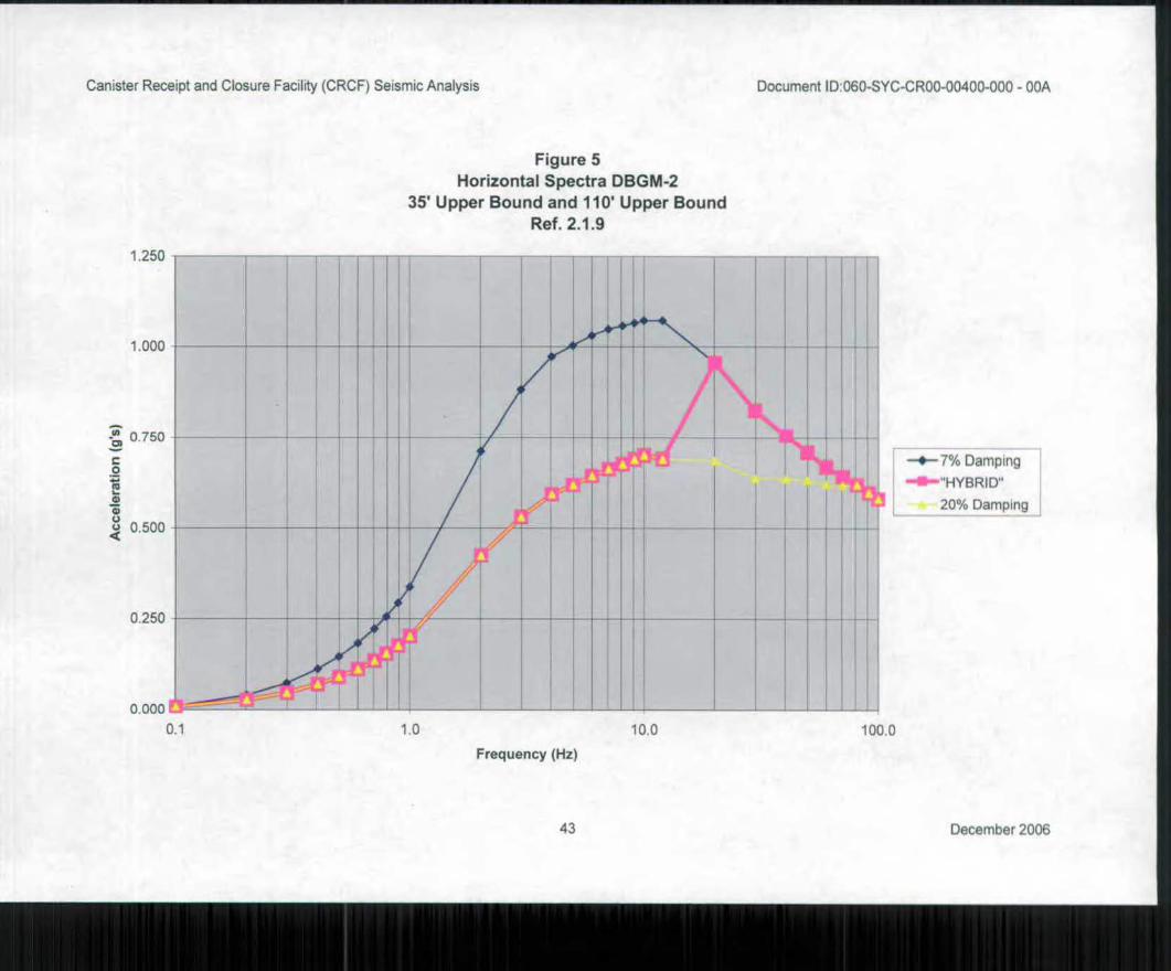
—40— 7% Damping
—0—"HYBRID"
20% Damping
Frequency (Hz)
43 December 2006
Canister Receipt and Closure Facility (CRCF) Seismic Analysis Document ID 060-SYC-CR00-00400-000 - 00A
Figure 5
Horizontal Spectra DBGM-2
35 Upper Bound and 110' Upper Bound
Ref. 2.1.9
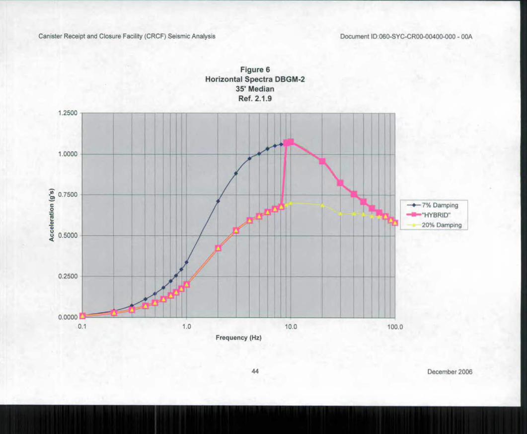
1 0000
-0) 0 7500
a>
c.) 0.5000
0.2500
0.0000
0.1 1.0
7% Damping
•■•••'HYBRID"
20% Damping i
10.0 100.0
Canister Receipt and Closure Facility (CRCF) Seismic Analysis Document ID.060-SYC-CR00-00400-000 - 00A
Figure 6
Horizontal Spectra DBGM-2
35' Median
Ref. 2.1.9
1 2500
Frequency (Hz)
44 December 2006
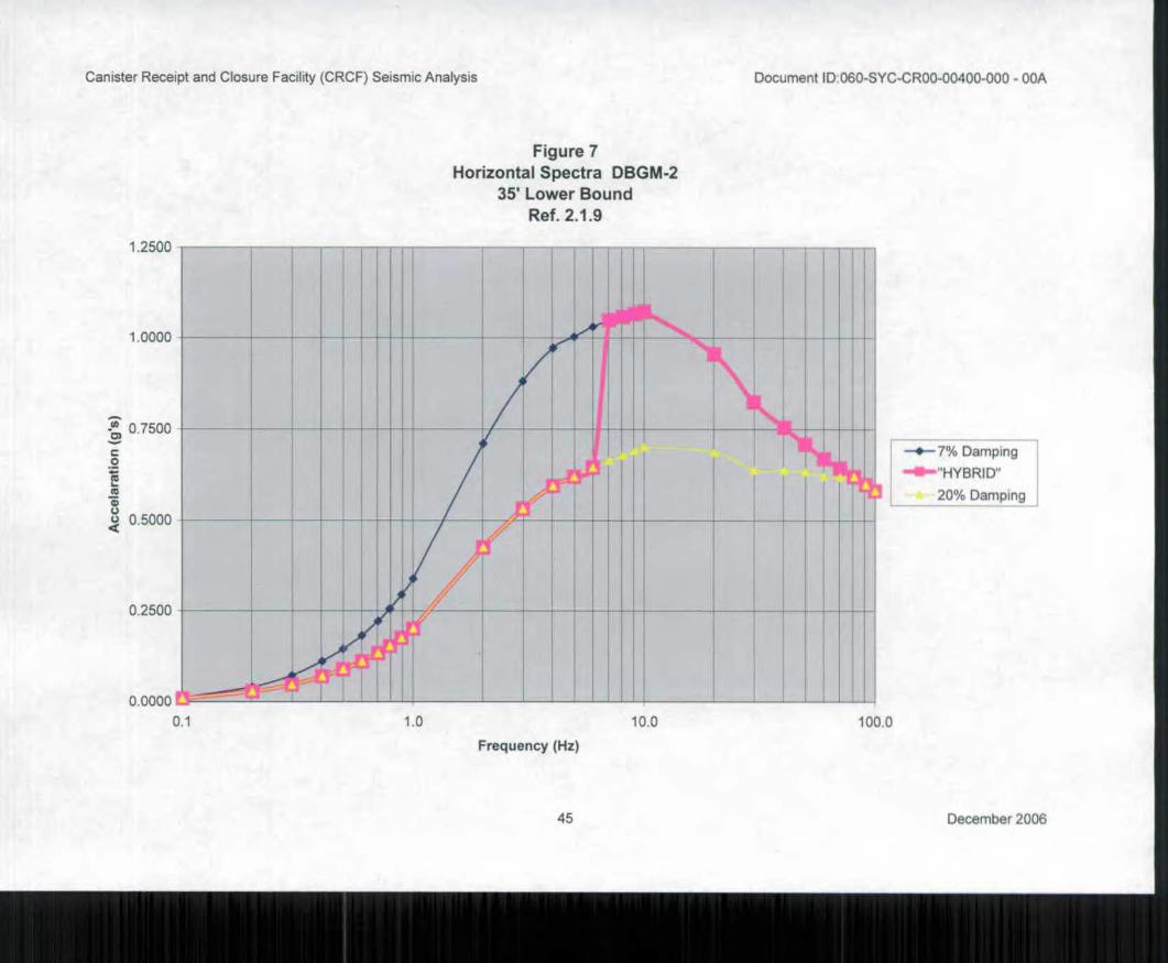
1,2500
1.0000
0.7500 "o)
T.
co
u 0.5000 <
0.2500
•
1
• • •
r •
/ A •
.41
0.0000
0.1
7% Damping
"HYBRID
20% Damping
10 10.0 100.0
Canister Receipt and Closure Facility (CRCF) Seismic Analysis Document ID 060-SYC-CR00-00400-000 - 00A
Figure 7
Horizontal Spectra DBGM-2
35' Lower Bound
Ref. 2.1.9
Frequency (Hz)
45 December 2006
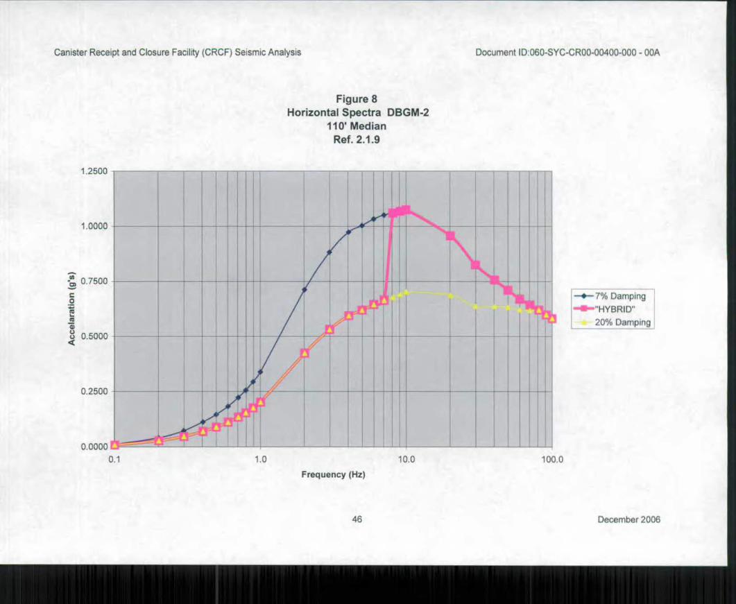
1 2500
1. 0000
3
0.2500
0. 0000
0. 1
Ac
ce
lara
tio
n (
g's
)
0 7500
0.5000
1.0 100.0 10.0
Canister Receipt and Closure Facility (CRCF) Seismic Analysis Document ID:060-SYC-CR00-00400-000 - 00A
Figure 8
Horizontal Spectra DBGM-2
110 Median
Ref. 2.1.9
Frequency (Hz)
7% Damping
—0—"HYBRID"
20% Damping
46 December 2006
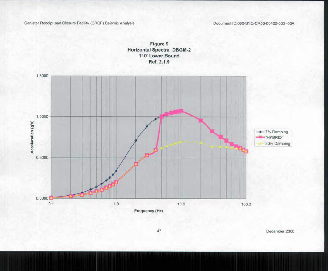
7% Damping
—0— "HYBRID"
20% Damping
1.0 10.0 100.0
1.0000
0.5000
0.0000
0.1
Canister Receipt and Closure Facility (CRCF) Seismic Analysis Document ID:060-SYC-CR00-00400-000 -00A
Figure 9
Horizontal Spectra DBGM-2
110' Lower Bound
Ref. 2.1.9
1 5000
Frequency (Hz)
47 December 2006
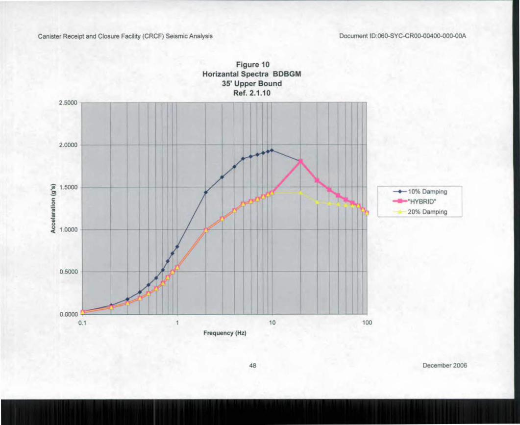
2, 0000
Ts') 1 5000
1.
( 1 0000
100
Canister Receipt and Closure Facility (CRCF) Seismic Analysis Document IDi060-SYC-CR00-00400-000-00A
Figure 10
Horizantal Spectra BDBGM
35' Upper Bound
Ref. 2.1.10
2,5000
Frequency (Hz)
—4-- 10% Damping
—41—"HYBRID"
20% Damping
48 December 2006
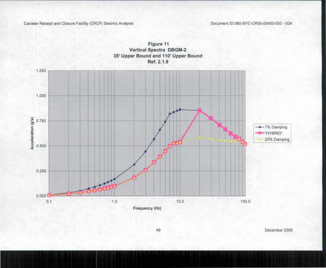
3
1 0 10.0 100.0
Canister Receipt and Closure Facility (CRCF) Seismic Analysis Document ID - 060-SYC-CR00-00400-000 - 00A
1.250
Figure 11
Vertical Spectra DBGM-2
35' Upper Bound and 110' Upper Bound
Ref. 2.1.9
1.000
J.7
0.750 co
re) 0.500
0.250
0.000
0.1
Frequency (Hz)
49 December 2006
—4-- 7% Damping
—41—"HYBRID"
20% Damping
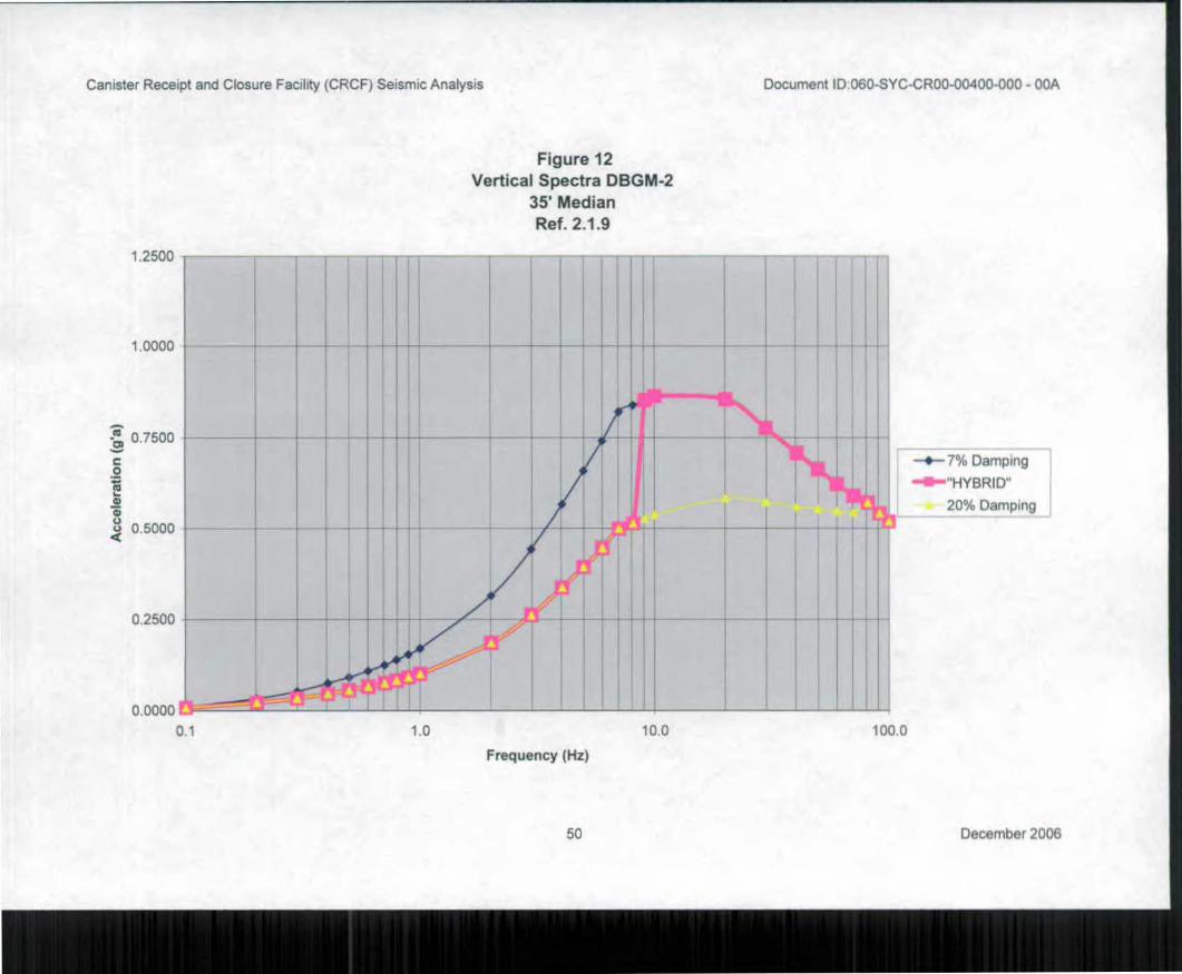
10 10.0 100.0
Canister Receipt and Closure Facility (CRCF) Seismic Analysis Document ID.060-SYC-CR00-00400-000 - 00A
Figure 12
Vertical Spectra DBGM-2
35' Median
Ref. 2.1.9
1.2500
1.0000
! 0.7500
2 0 0 0 o 0.5000
0.2500
0.0000
0.1
7% Damping
--o—"HYBRID"
20% Damping
Frequency (Hz)
50 December 2006

—4- 7% Damping
20% Damping
0.7500
C
.0)
0 5000
0,2500
0.0000
01
1.2500
1 0000
1.0 10.0 100.0
Canister Receipt and Closure Facility (CRCF) Seismic Analysis Document ID 060-SYC-CR00-00400-000 - 00A
Figure 13
Vertical Spectra DBGM-2
35 Lower Bound
Ref. 2.1.9
Frequency (Hz)
51 December 2006
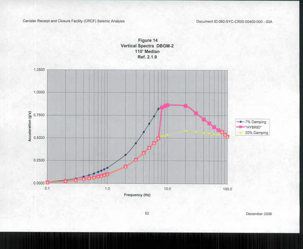
1.0 10.0 100.0
Canister Receipt and Closure Facility (CRC F) Seismic Analysis Document ID - 060-SYC-CR00-00400-000 - 00A
Figure 14
Vertical Spectra DBGM-2
110 Median
Ref. 2.1.9
1 2500
—*- 7% Damping , •■IIIF—"HYBRID"
L 20% Damping
1.0000
-0, 0.7500
0 0.5000
0.2500
0. 0000
0.1
Frequency (Hz)
52 December 2006
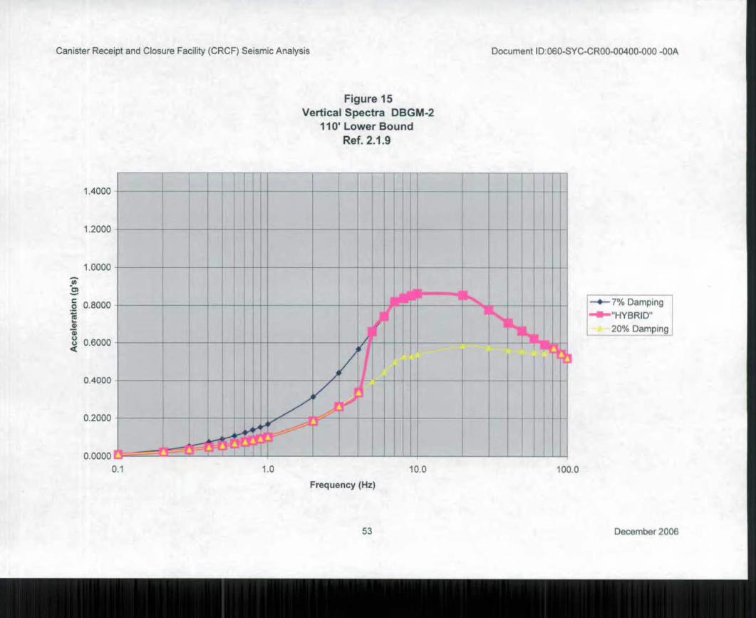
1.0 10.0 100.0
Canister Receipt and Closure Facility (CRCF) Seismic Analysis Document ID060-SYC-CR00-00400-000 -00A
Figure 15
Vertical Spectra DBGM-2
110 Lower Bound
Ref. 2.1.9
1.4000
1.2000
1.0000
•o
•
0.8000
17)
u
•
0.6000
0.4000
0.2000
0.0000 1
0.1
--*-7% Damping 1
441/■•"HYBRID"
20% Damping
Frequency (Hz)
53 December 2006
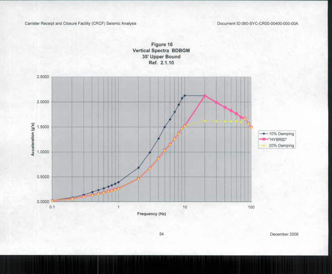
—4-10% Damping
"HYBRID"
20% Damping
2.0000
-74 1 5000 a)
c.) 1.0000
0.5000
10 100
Canister Receipt and Closure Facility (CRCF) Seismic Analysis Document ID060-SYC-CR00-00400-000-00A
Figure 16
Vertical Spectra BDBGM
35 Upper Bound
Ref. 2.1.10
2.5000
0.0000
0 . 1
Frequency (Hz)
54 December 2006
Canister Receipt and Closure Facility (CRCF) Seismic Analysis 060-SYC-CR00-00400-000-00A
7. RESULTS AND CONCLUSIONS
7.1 RESULTS
The results from this calculation are:
• Finite element member properties (Table 1) including A x, Ay, A„, I„, and Iz
• Centers of rigidity and sum of rigidities (Table 2 and 3) of each floor and roof level
• Torsion increase factors (Table 4) that will be used to account for torsional effects on the seismic inertial forces in a subsequent design calculation
• Member forces and diaphragm accelerations for DBGM-2 and BDBGM seismic events (Included in Attachments C thru J.)
• Building accelerations at Diaphragm Levels (Included in Attachments C thru J.)
• Base Shear Calculations (Included in Attachment K)
Output from the following runs and input files used in this calculation are contained in the
referenced attachments:
Attachment C DBGM-2 Fixed Base Modal and Response Spectrum Analysis
Attachment D DBGM-2 Upper Bound 35' Alluvium Modal Analysis and Response
Spectrum Analysis Attachment E
DBGM-2 Median 35' Alluvium Modal Analysis and Response Spectrum Analysis
Attachment F DBGM-2 Lower Bound 35' Alluvium Modal Analysis and Response Spectrum Analysis
Attachment G
DBGM-2 Upper Bound 110' Alluvium Modal Analysis and Response Spectrum Analysis
Attachment H
DBGM-2 Median 110' Alluvium Modal Analysis and Response Spectrum Analysis
Attachment I DBGM-2 Lower Bound 110' Alluvium Modal Analysis and Response Spectrum Analysis
Attachment J BDBGM Upper Bound 35' Alluvium Modal Analysis and Response Spectrum Analysis
Attachment K Base Shear Calculation for DBGM-2 and BDBGM Input Ground Motions
Attachment L IBC Base Shear Calculation
Attachment M Excel and Word Files used in calculation preparation
Attachment N SAP2000 Database Files
55 December 2006
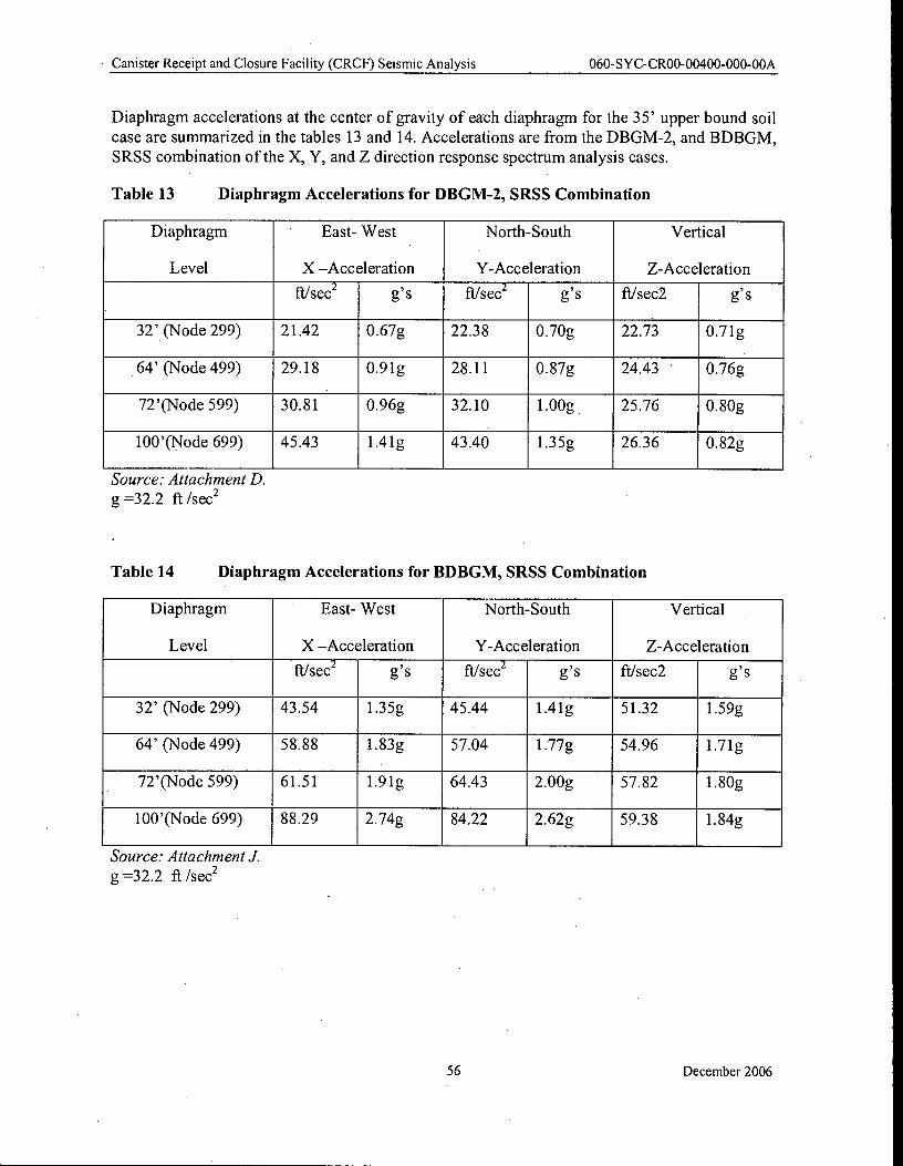
Canister Receipt and Closure Facility (CRCF) Seismic Analysis 060-SYC-CR00-00400-000-00A
Diaphragm accelerations at the center of gravity of each diaphragm for the 35' upper bound soil
case are summarized in the tables 13 and 14. Accelerations are from the DBGM-2, and BDBGM,
SRSS combination of the X, Y, and Z direction response spectrum analysis cases.
Table 13 Diaphragm Accelerations for DBGM-2, SRSS Combination
Diaphragm East- West North-South Vertical
Level X —Acceleration Y-Acceleration Z-Acceleration
ft/sec2 g's ft/sec 2 g's ft/sec2 g's
32' (Node 299) 21.42 0.67g 22.38 0.70g 22.73 0.71g
64' (Node 499) 29.18 0.91g 28.11 0.87g 24.43 0.76g
72'(Node 599) 30.81 0.96g 32.10 1.00g 25.76 0.80g
100'(Node 699) 45.43 1.41g 43.40 1.35g 26.36 0.82g
Source: Attachment D.
g32.2 ft /sec2
Table 14 Diaphragm Accelerations for BDBGM, SRSS Combination
Diaphragm East- West North-South Vertical
Level X —Acceleration Y-Acceleration Z-Acceleration
ft/sec 2 g's ft/sec2
g's ft/sec2 g's
32' (Node 299) 43.54 1.35g 45.44 1.41g 51.32 1.59g
64' (Node 499) 58.88 1.83g 57.04 1.77g 54.96 1.71g
72'(Node 599) 61.51 1.91g 64.43 2.00g 57.82 1.80g
100'(Node 699) 88.29 2.74g 84.22 2.62g 59.38 1.84g
Source: Attachment J.
g =32.2 ft /sec2
56 December 2006
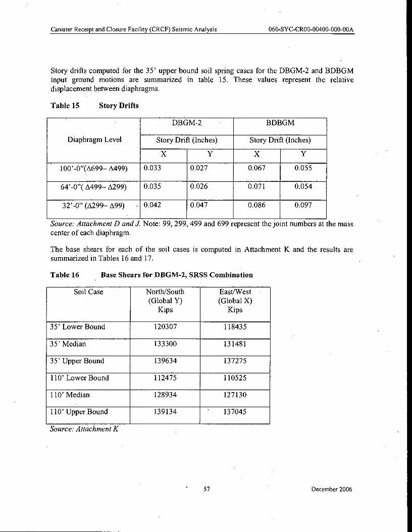
Canister Receipt and Closure Facility (CRCF) Seismic Analysis 060-SYC-CR00-00400-000-00A
Story drifts computed for the 35' upper bound soil spring cases for the DBGM-2 and BDBGM input ground motions are summarized in table 15. These values represent the relative displacement between diaphragms.
Table 15 Story Drifts
DBGM-2 BDBGM
Diaphragm Level Story Drift (Inches) Story Drift (Inches)
X Y X Y
100'-0"(A699— A499) 0.033 0.027 0.067 0.055
64'-0"( A499— A299) 0.035 0.026 0.071 0.054
32'-0" (A299— A99) . 0.042 0.047 0.086 0.097
Source: Attachment D and J. Note: 99, 299, 499 and 699 represent the joint numbers at the mass center of each diaphragm.
The base shears for each of the soil cases is computed in Attachment K and the results are summarized in Tables 16 and 17.
Table 16 Base Shears for DBGM-2, SRSS Combination
Soil Case North/South East/West (Global Y) (Global X)
Kips Kips
35' Lower Bound 120307 118435
35' Median 133300 131481
35' Upper Bound 139634 137275
110' Lower Bound 112475 110525
110' Median 128934 127130
110' Upper Bound 139134 ' 137045
Source: Attachment K
57 December 2006
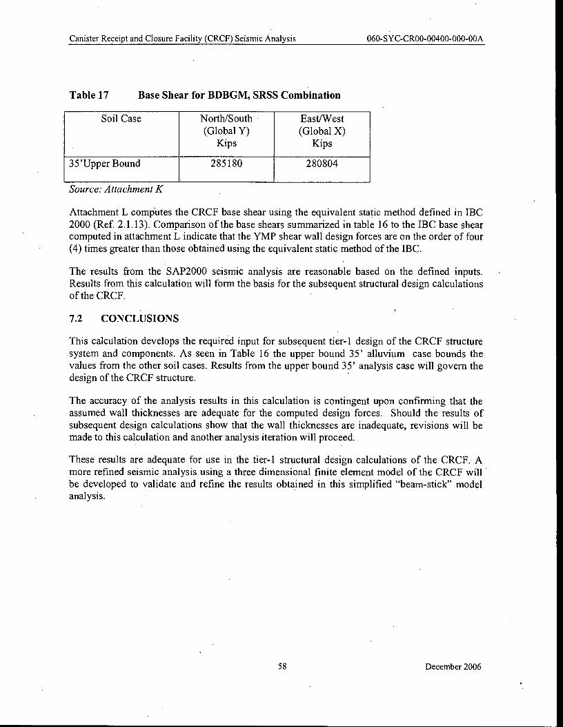
Canister Receipt and Closure Facility (CRCF) Seismic Analysis 060-SYC-CR00-00400-000-00A
Table 17 Base Shear for BDBGM, SRSS Combination
Soil Case North/South East/West
(Global Y) (Global X) Kips Kips
35'Upper Bound 285180 280804
Source: Attachment K
Attachment L computes the CRCF base shear using the equivalent static method defined in IBC
2000 (Ref. 2.1.13). Comparison of the base shears summarized in table 16 to the IBC base shear computed in attachment L indicate that the YMP shear wall design forces are on the order of four
(4) times greater than those obtained using the equivalent static method of the IBC.
The results from the SAP2000 seismic analysis are reasonable based on the defined inputs.
Results from this calculation will form the basis for the subsequent structural design calculations of the CRCF.
7.2 CONCLUSIONS
This calculation develops the required input for subsequent tier-1 design of the CRCF structure
system and components. As seen in Table 16 the upper bound 35' alluvium case bounds the
values from the other soil cases. Results from the upper bound 35' analysis case will govern the design of the CRCF structure.
The accuracy of the analysis results in this calculation is contingent upon confirming that the
assumed wall thicknesses are adequate for the computed design forces. Should the results of
subsequent design calculations show that the wall thicknesses are inadequate, revisions will be
made to this calculation and another analysis iteration will proceed.
These results are adequate for use in the tier-1 structural design calculations of the CRCF. A more refined seismic analysis using a three dimensional finite element model of the CRCF will
be developed to validate and refine the results obtained in this simplified "beam-stick" model analysis.
58 December 2006
Canister Receipt and Closure Facility (CRCF) Seismic Analysis 060-SYC-CR00-00400-000-00A
ATTACHMENT A
Floor Plan and Wall Elevations
A-I December 2006
Canister Receipt and Closure Facility (CRCF) Seismic Analysis 060-SYC-CR00-00400-000-00A
Attachment A : Floor Plan and Wall Elevations
Ground Floor Plan At EL 0'-0" A-3
Elevation Along Column Line 1 A-4
Elevation Along Column Line 2 A-5
Elevation Along Column Line 3 A-6
Elevation Along Column Line 4 A-7
Elevation Along Column Line 5 A-8
Elevation Along Column Line 6 A-9
Elevation Along Column Line 7 A-10
• Elevation Along Column Line 8 A-11
Elevation Along Column Line 9 A-12
Elevation Along Column Line 11 A-13 .
Elevation Along Column Line 12 A-14
Elevation Along Column Line 13 A-15
Elevation Along Column Line D A-16
Elevation Along Column Line E A-17
Elevation Along Column Line E.3 A-18
Elevation Along Column Line F A-19
Elevation Along Column Line F.7 A-20
Elevation Along Column Line G A-21
Elevation Along Column Line H .A-22
A-2 December 2006
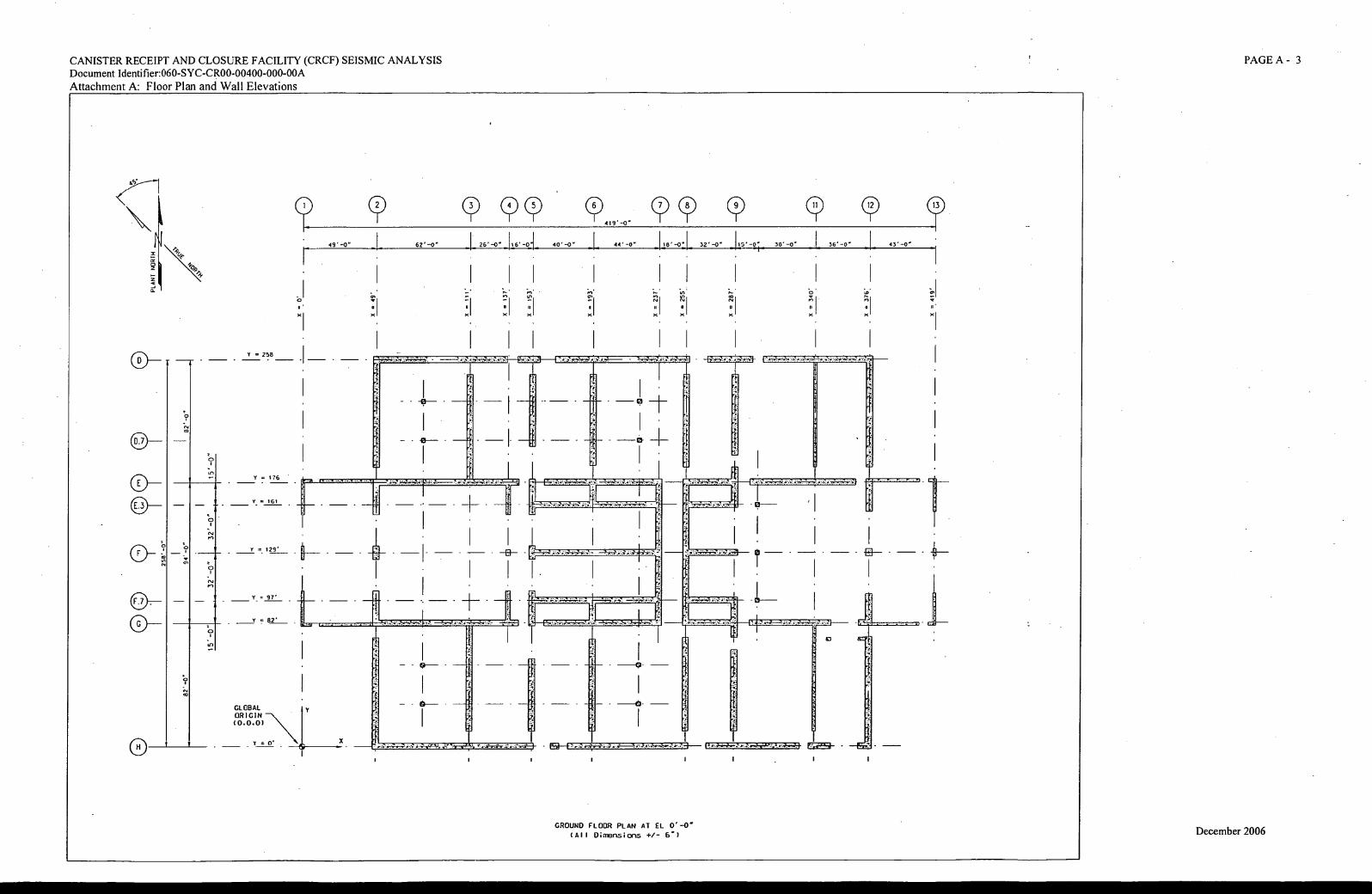
49'-o"
0 '
x
c'T 9' 91 40'-0" 44' -0" 118' -071 32'-O 115' -0; 38'-O .1 36'-O I 43'-O
1 1
419'
r- 1.1
'
A -
n 111
= 258
Y = 176
Y. = 161
2 9 _
7 . = 97'
r = 62'
GLOBAL ORIGIN (0.0.0)
`i) In
CANISTER RECEIPT AND CLOSURE FACILITY (CRCF) SEISMIC ANALYSIS
Document Identifier:060-SYC-CR00-00400-000-00A
Attachment A: Floor Plan and Wall Elevations
PAGE A - 3
\ L 62-0. 1 26-0-
1 I
GROUND FLOOR PLAN AT EL O'-O'
(All Dimensions +/- B . ) December 2006
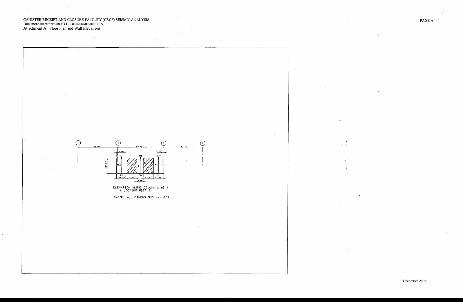
82'-0" 0
94' -0" 82 -0" 0
2' -0"
22? 228 229
fA.3
29
1 A.1
31
CANISTER RECEIPT AND CLOSURE FACILITY (CRCF) SEISMIC ANALYSIS Document Identifier:060-SYC-CR00-00400-000-00A
Attachment A: Floor Plan and Wall Elevations
PAGE A - 4
(4
• 30
1 A
r- 21 . -6" 21' 21 . -0" 21'-6
3' -0
ELEVATION ALONG COLUMN LINE 1 ( LOOKING WEST )
(NOTE: ALL DIMENSIONS +/- 6")
December 2006
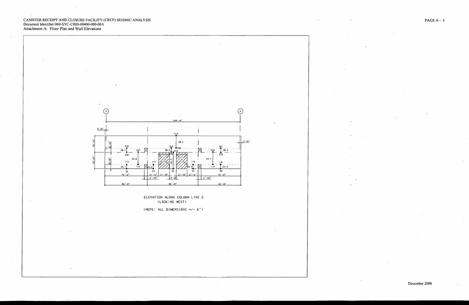
2
0
2' -0"
258'-0"
413
28.4
318 . . 319
2E1.11 231 VI 28.2
230
26.6
. ' - KIMP205.1
. . 1
113 • 115
11r
2A.11 - ' - 114 -
3
32
76' -2"
3
3' -0
116 .
26.7
117
5'-10"
82'-0" 98' -0" 82' -0"
CANISTER RECEIPT AND CLOSURE FACILITY (CRCF) SEISMIC ANALYSIS Document Identifier:060-SYC-CR00-00400-000-00A
Attachment A: Floor Plan and Wall Elevations
PAGE A - 5
33 I
21'-6"1_21'-0"
5'-10"
- 6-320
233 WA
011%; r
A'
35
21'-O 21'-6
321
234 128.3
235 T--- -
118
36
ELEVATION ALONG COLUMN LINE 2
(LOOKING WEST)
(NOTE: ALL DIMENSIONS +/- 6")
December 2006
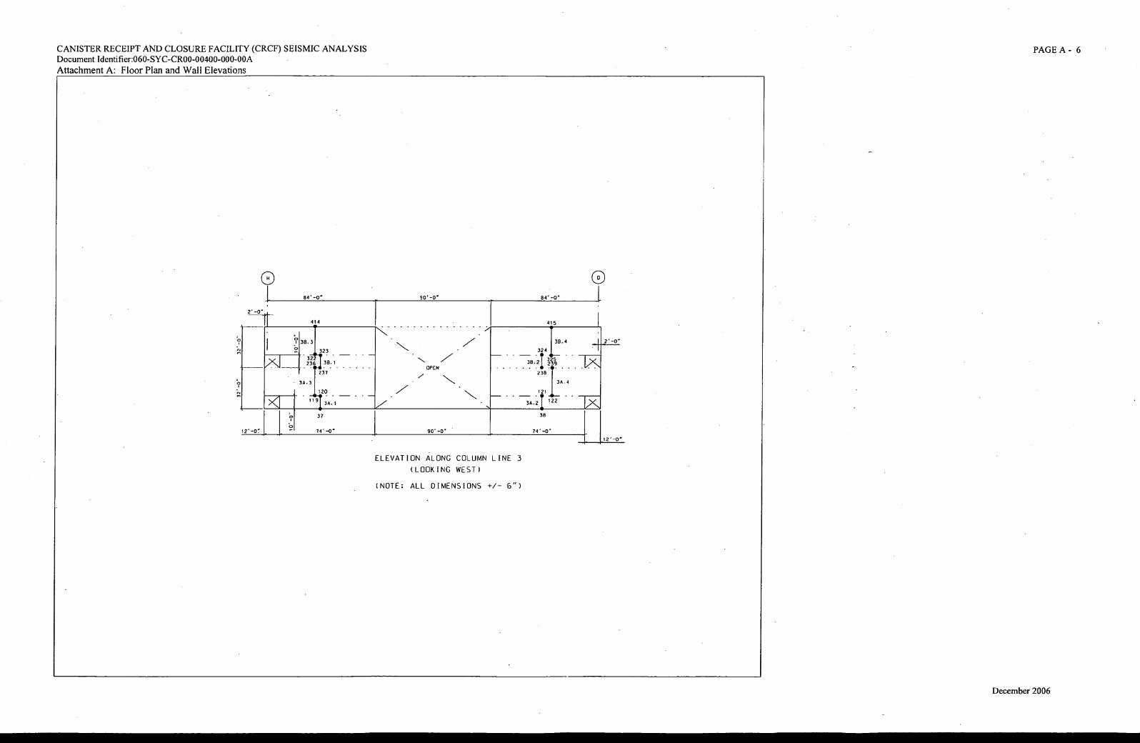
0 84 . -0" 90' -0' 84 -0"
414
. I 2 -0" 38.3
323
322 38.1 236
415
17.4
324 _
325 38.21 2 9 \ V
OPEN 237
34.3 38.4
120 121
37
12'
38
74 -
12'
CANISTER RECEIPT AND CLOSURE FACILITY (CRCF) SEISMIC ANALYSIS
Document Identifier:060-SYC-CR00-00400-000-00A
Attachment A: Floor Plan and Wall Elevations
PAGE A- 6
119 34. 1 3A.2 122
90 . -0'
ELEVATION ALONG COLUMN LINE 3
(LOOKING WEST)
(NOTE: ALL DIMENSIONS +/- 6")
December 2006
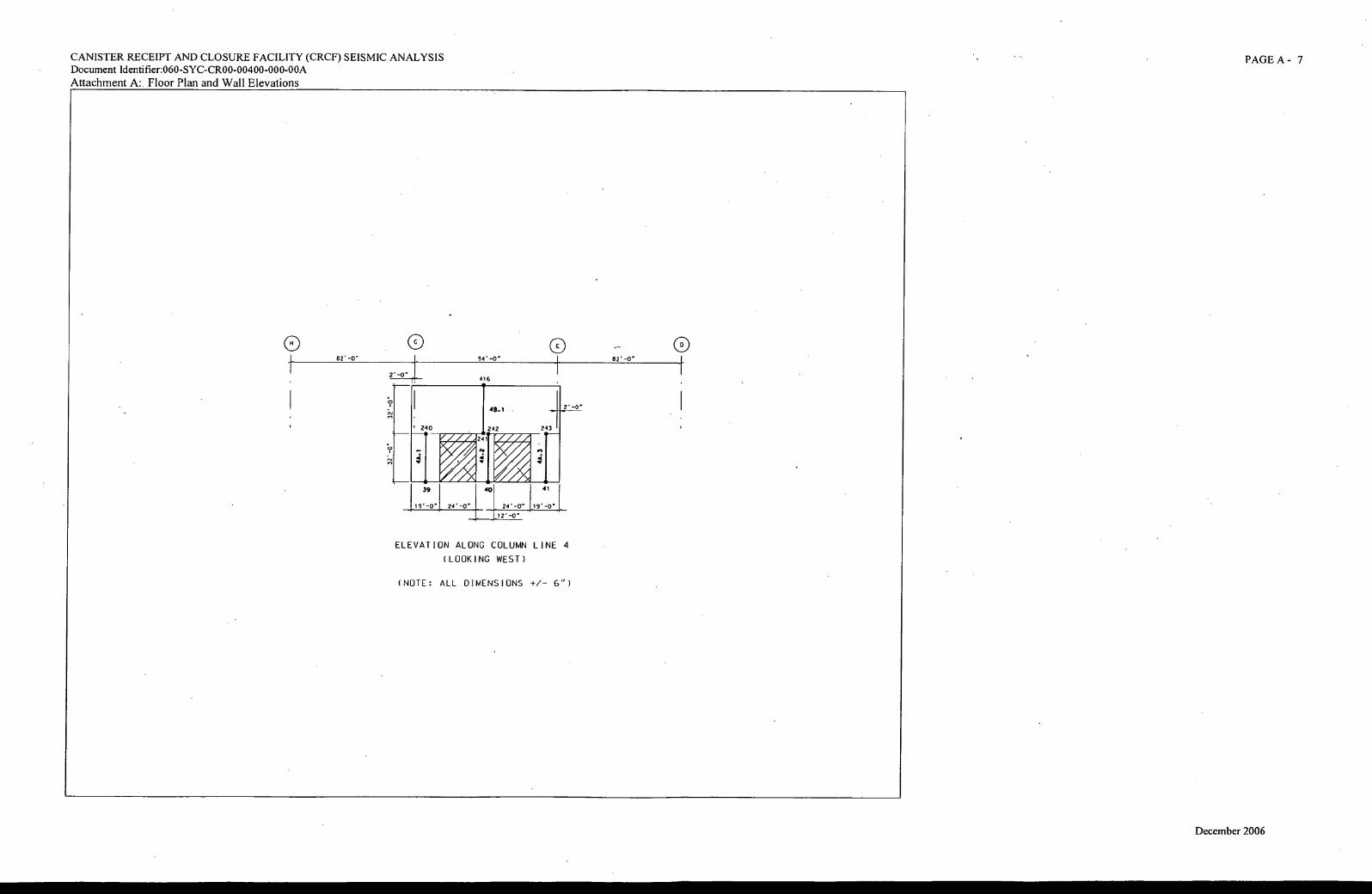
CANISTER RECEIPT AND CLOSURE FACILITY (CRCF) SEISMIC ANALYSIS Document Identifier:060-SYC-CR00-00400-000-00A
Attachment A: Floor Plan and Wall Elevations
PAGE A - 7
ELEVATION ALONG COLUMN LINE 4
(LOOKING WEST)
(NOTE: ALL DIMENSIONS +/- 6")
December 2006
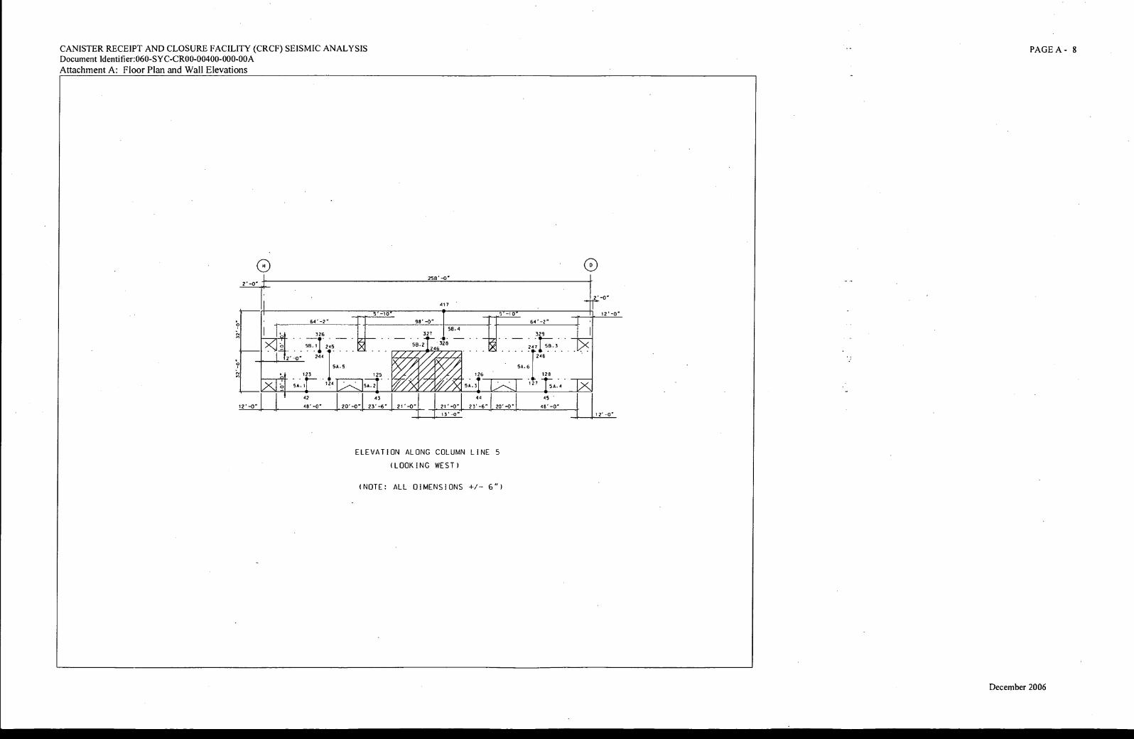
5' -10 5'-10 12 . -0"
98 . -0"
58.4 327
513.21246
328
r p "1". 64'-2"
329
2471-;- 3
— . 11248
54.6
128
45 •
. 126
5A.3
44
12' -O a 48'-0" 20'-0" 23 . -6" 21' -0" 21 . -0" 23 . -6" 48 . -0"
127 54.4
326
;7112 -45
-0. 244
123
64 . -2"
5A.5
5A. 1 124
A.2
13 . -0" 12' -0"
125
42 43
CANISTER RECEIPT AND CLOSURE FACILITY (CRCF) SEISMIC ANALYSIS
Document Identifier:060-SYC-CR00-00400-000-00A
Attachment A: Floor Plan and Wall Elevations
PAGE A - 8
2
258 -0"
417
ELEVATION ALONG COLUMN LINE 5
(LOOKING WEST)
(NOTE: ALL DIMENSIONS +/- 6")
December 2006
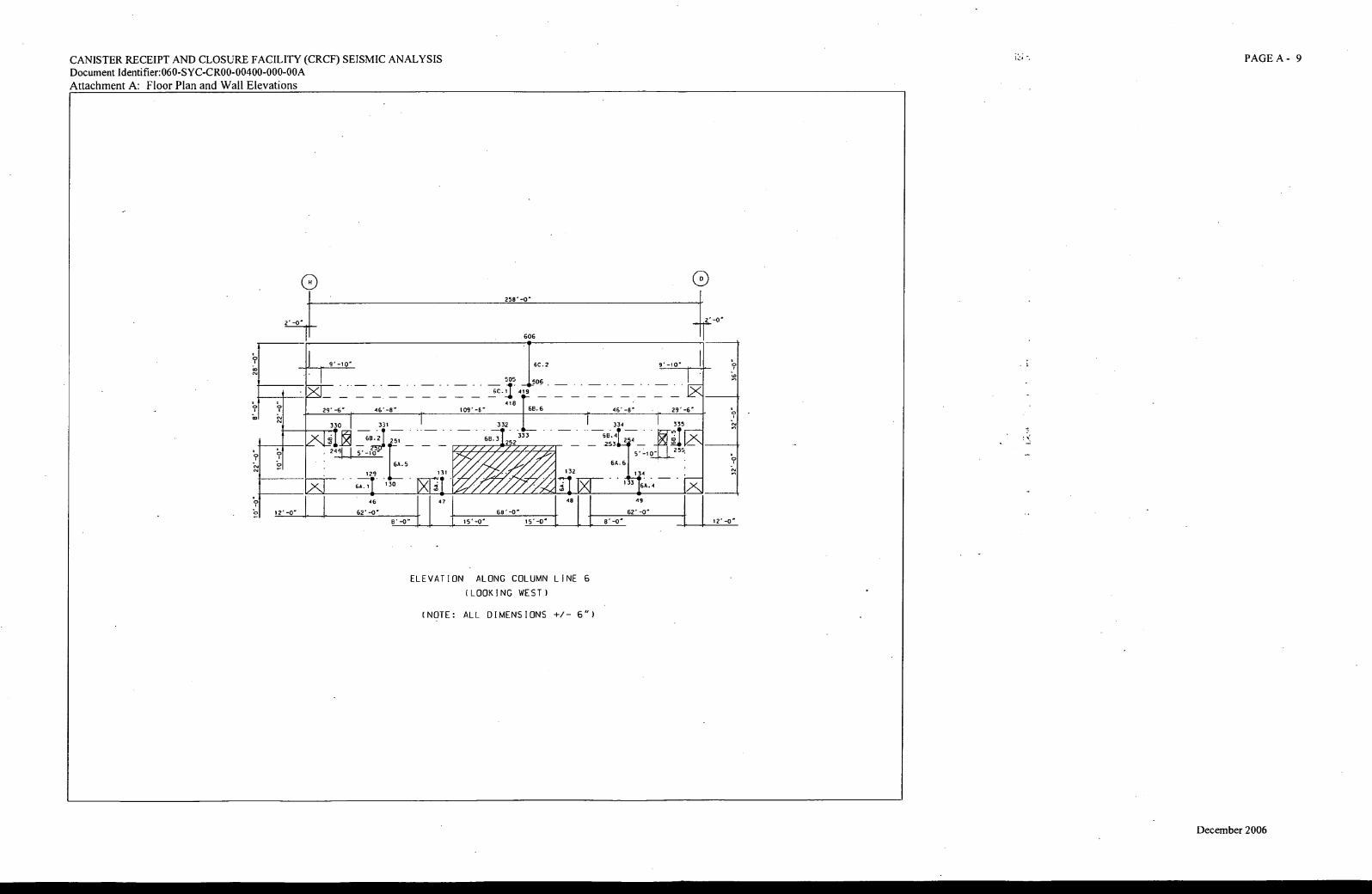
2 . -0" 2" -0"
0 9 . - 10"
29"-6'
335
2T . 253-
s'_io'jj 255.
64.6
134
64.4
613.4 4
133
64-5
129.
130 64.1
L---1 • . 1 1 5.-10
,Ai, kj
613
.2 f2 ,
-- IAIMIEWAIIAIAI 4irir
6B.3 252
24
a
'-6 ° 46'-8'
330 I 331
6B. 6
333
. 132
, ririr
31
Z. Ol d
1 ./ /
/ .7"/
k ." A 132
109-8"
332
46' -8'
334
46 47 48 49
12 . -0" 62' -0' 68' 62' -0'
8"-0" 15'-0' 15 . -0' 8 ' 12'
CANISTER RECEIPT AND CLOSURE FACILITY (CRCF) SEISMIC ANALYSIS PAGE A - 9
Document Identifier:060-SYC-CR00-00400-000-00A
Attachment A: Floor Plan and Wall Elevations
258'-O
9'-10'
606
6C.2
505 506
6C.1 419
418 1- -
ELEVATION ALONG COLUMN LINE 6
(LOOKING WEST )
(NOTE: ALL DIMENSIONS +/- 6")
December 2006
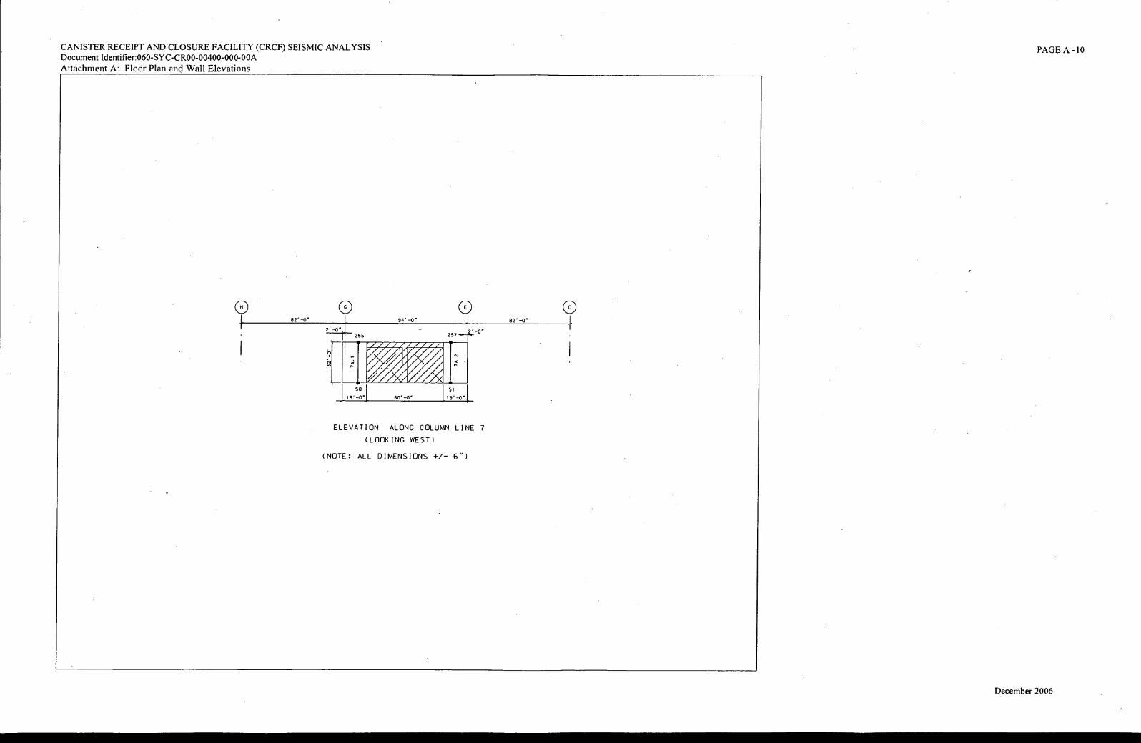
Ammo 97
1 11r/
/ A AO■
50
9 •
CANISTER RECEIPT AND CLOSURE FACILITY (CRCF) SEISMIC ANALYSIS Document Identifier:060-SYC-CR00-00400-000-00A
Attachment A: Floor Plan and Wall Elevations
PAGE A -10
51 60'-O 19 . -0"
ELEVATION ALONG COLUMN LINE 7
(LOOKING WEST)
(NOTE: ALL DIMENSIONS +/- 6")
December 2006
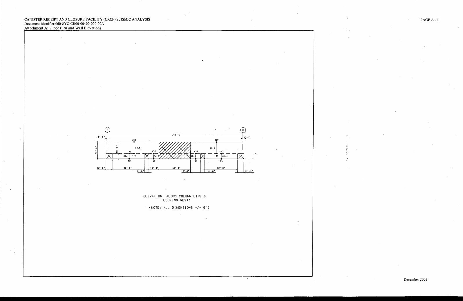
258 259
52 53 54 55
12' -0 " 62'-O 19' -0" 60' -0" 62 . -0"
19' -0" 12 . -0"
CANISTER RECEIPT AND CLOSURE FACILITY (CRCF) SEISMIC ANALYSIS Document Identifier:060-SYC-CR00-00400-000-00A
Attachment A: Floor Plan and Wall Elevations
PAGE A - 1 I
258' -0"
CV
1i:. 8A.5 Am Ag■
edA
8A.61 ID 135 137 0, Air Ile 138 140
___ ____ ___ ___
8A.1 1 36 :A.. 139 TET A.4 I■ A. zAo :A. A. .2.
ELEVATION ALONG COLUMN LINE 8 (LOOKING WEST)
(NOTE: ALL DIMENSIONS +/- 6")
December 2006
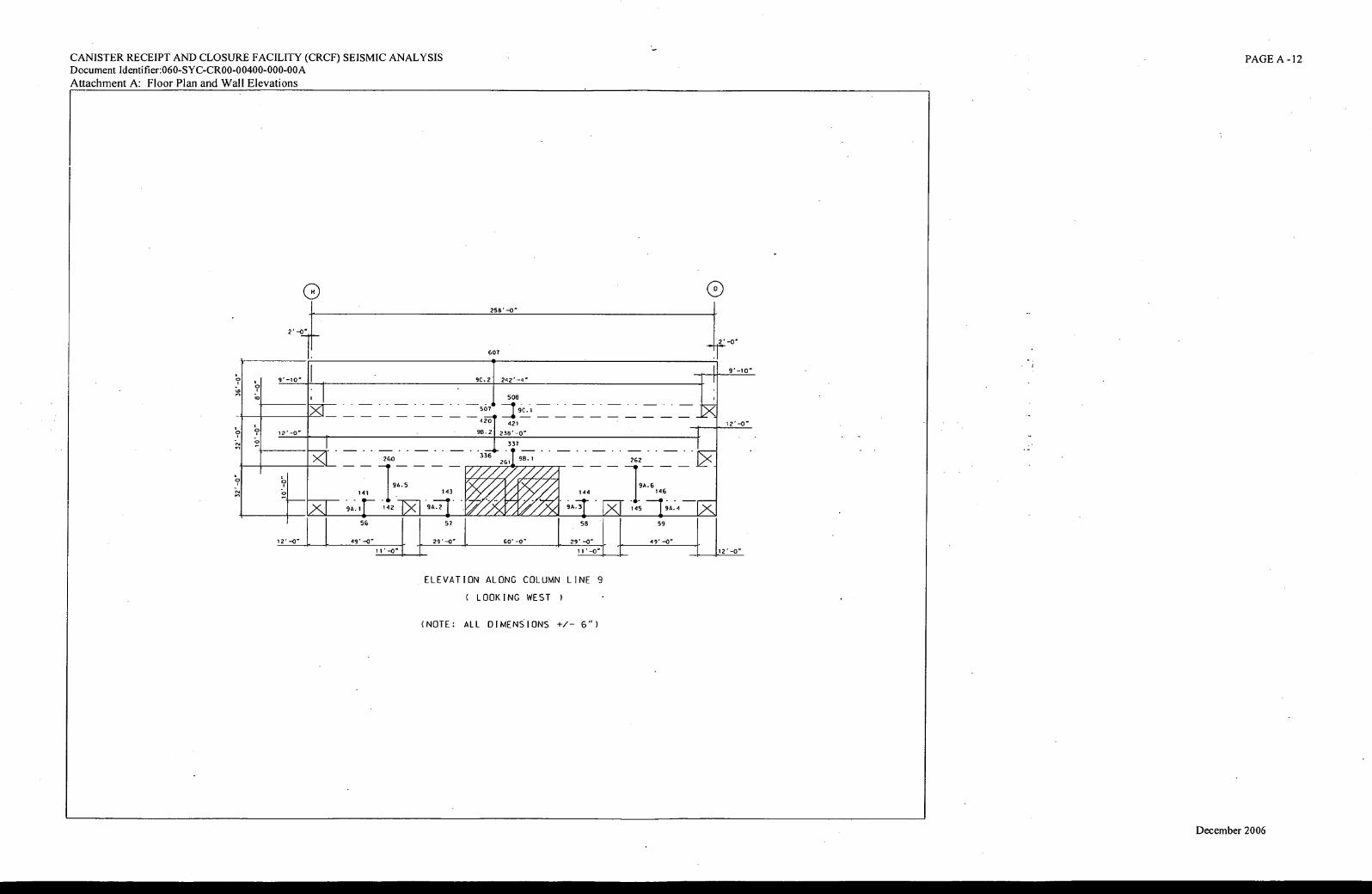
--T
X 11- i421
56
49'-0'
11.-0
12' -0 "
9' -10"
2' -0"
12' -0"
258.-0'
607
0
9C.2 242'
9 , -10'
re A
riA04 29' -0 " 60' -0'
57
9A.2
144
9A.3
58
143
261 98.1
336
337
12' -0
- 5671 8 -2;9 .C. -1
41 421
9B-2 238'-O
262
95.6 146
145 9A.4
59
49' -0'
11 '-0 12' -0"
CANISTER RECEIPT AND CLOSURE FACILITY (CRCF) SEISMIC ANALYSIS Document Identifier:060-SYC-CR00-00400-000-00A
Attachment A: Floor Plan and Wall Elevations
PAGE A -12
ELEVATION ALONG COLUMN LINE 9
( LOOKING WEST I
(NOTE: ALL DIMENSIONS +/- 6")
December 2006
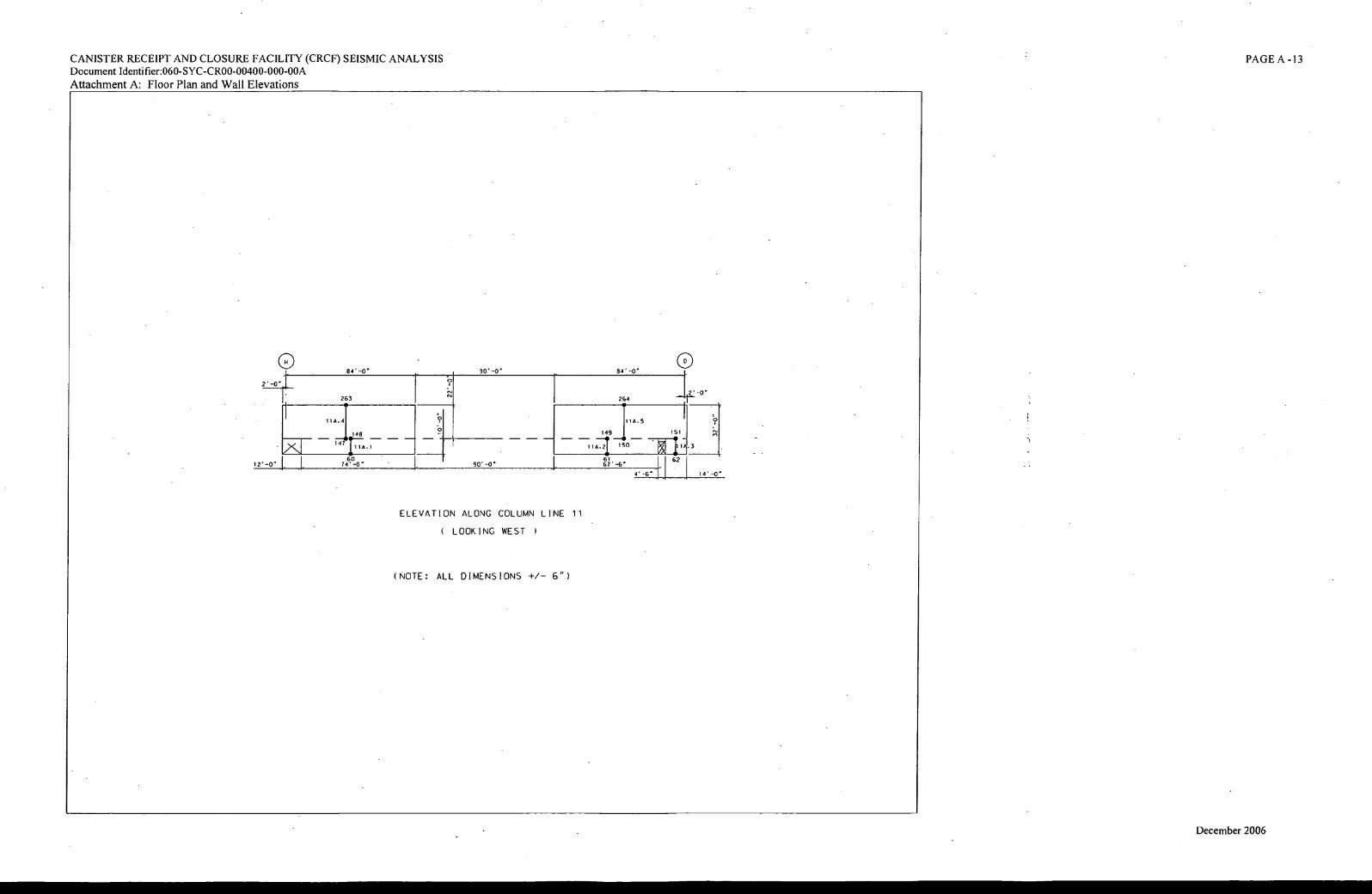
(S1
CANISTER RECEIPT AND CLOSURE FACILITY (CRCF) SEISMIC ANALYSIS
Document Identifier:060-SYC-CR00-00400-000-00A
Attachment A: Floor Plan and Wall Elevations
PAGE A -13
ELEVATION ALONG COLUMN LINE 11
( LOOKING WEST
(NOTE: ALL DIMENSIONS +/- 6")
December 2006
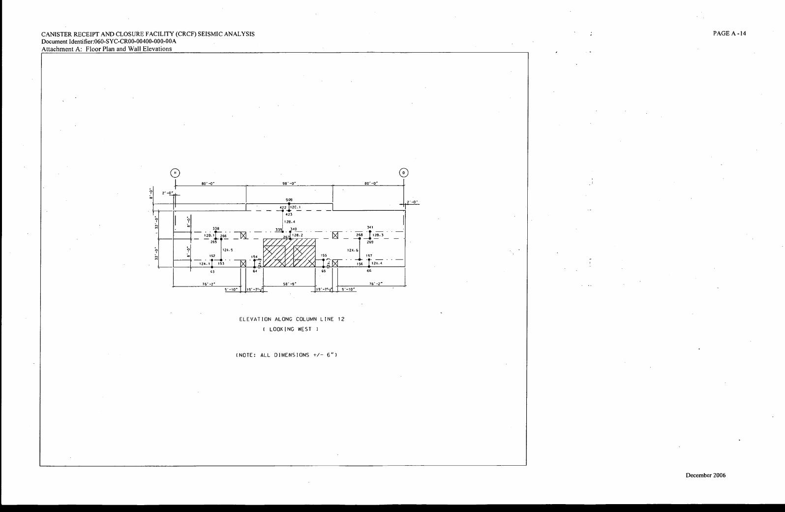
80 -0" 98' 80' -0"
CO
26
12A. 6
155 154
174 64 -
01
65
509
422120.1 --• -
423
128.4
339
128.2
i- z4 rr,r4 p 44
341
-268 1' 12-8.3 - ■■■
269
_IL 157
156 1 .12-A.4 -
66
338
1-213 • 1r266 •
265
12A. 5
152_41,
12A.1 153
63
76' -2" 58' -9 " 76' -2"
CANISTER RECEIPT AND CLOSURE FACILITY (CRCF) SEISMIC ANALYSIS Document Identifier:060-SYC-CR00-00400-000-00A
Attachment A: Floor Plan and Wall Elevations
PAGE A -14
0 0
5' -10" 119'-71/21 5' -10"
ELEVATION ALONG COLUMN LINE 12
( LOOKING WEST I
(NOTE: ALL DIMENSIONS +/- 6")
December 2006
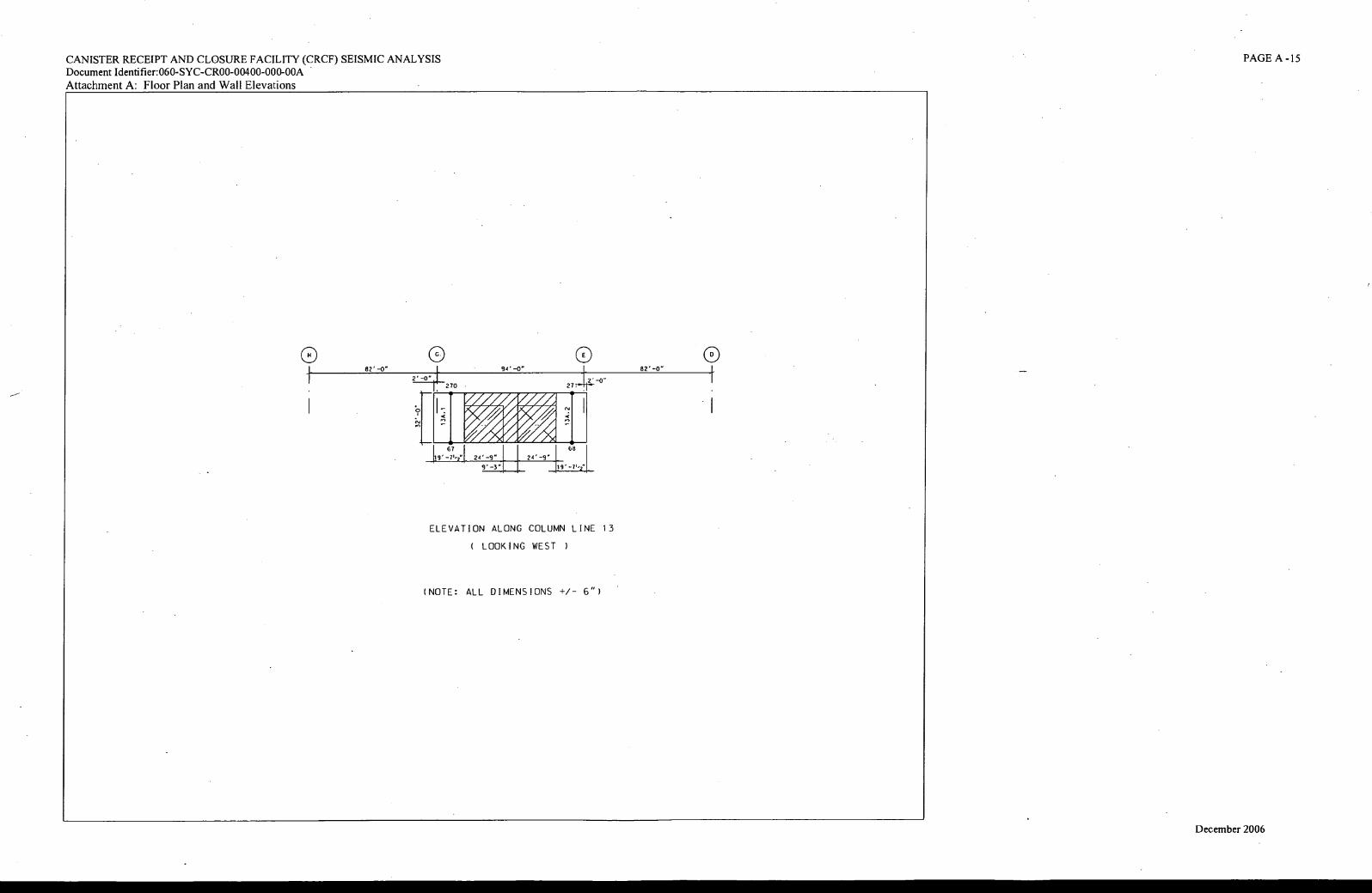
82 . -0"
2 . -0"
67 6
9" -3" 9'
CANISTER RECEIPT AND CLOSURE FACILITY (CRCF) SEISMIC ANALYSIS
Document Identifier:060-SYC-CR00-00400-000-00A
Attachment A: Floor Plan and Wall Elevations
PAGE A -15
0 0 0 82 . -0" 94 . -0"
270 . 27
WWA VFM/FWAII
artel Lf.T.L4 24' -9" 24 . -9"
ELEVATION ALONG COLUMN LINE 13
( LOOKING WEST )
(NOTE: ALL DIMENSIONS +/- 6")
December 2006
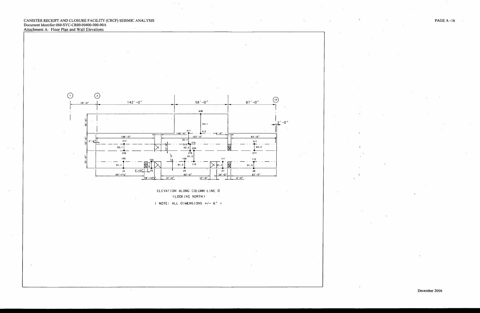
142' -0" 98'-0" 87' -0"
608
03.1 ..2' -0"
83' -0" 108' -0"
411 1J22
122'-0"
D2.4
(NI 316 316
02.2 226
314
275
111 108 158
a 22 1.14$ 1.4 01.4 01.1
317
r±02.3
277
112
01.51
109
61 276
01.6!
110 01.3
• 24 5'-10 26 27 28
CANISTER RECEIPT AND CLOSURE FACILITY (CRCF) SEISMIC ANALYSIS Document Identifier:060-SYC-CR00-00400-000-00A
Attachment A: Floor Plan and Wall Elevations
PAGE A -16
1v-10W
90'-O
12' -0
20' -0 .
12' -0"
83' -0"
6' -0"
ELEVATION ALONG COLUMN LINE D
(LOOKING NORTH)
( NOTE: ALL DIMENSIONS +/- 6"
December 2006
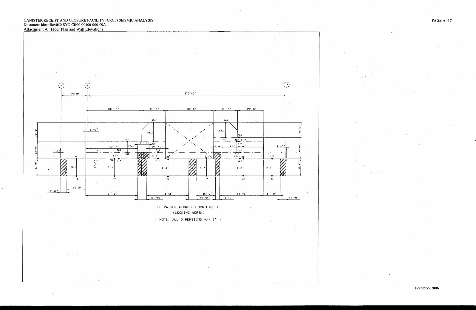
370'-0"
I. 90'-0" 44' -0" - 49"-0" 104'-0" 44'-0"
604 605
E3.2 63.3
407
96' -7"
309
ETI 310
23 1r- 219-
E1.2
rovr, A. A WIF
• A
NZ
N
r
it I
504
503 409 E3.1
410 •
13'-6" EZ. 5 79 ' -6°
. _VI? _
3121
62.3 224
I - - 223 -
61.5 E1.3
E2.4
P'
Pr'
1',0 °
217
E1.1
061
225
61.6
62.2
220
222
E1.4
21'-7" 108
29'-10"
311 311
21 23 18
35' -2"
12' -10'
97"-0" 31' -0" 36'-0"
14' -0" 11'-0"
22
81" -0"
8'-0"
20
78'-2"
16'-10"
CANISTER RECEIPT AND CLOSURE FACILITY (CRCF) SEISMIC ANALYSIS Document Identifier:060-SYC-CR00-00400-000-00A Attachment A: Floor Plan and Wall Elevations
PAGE A -17
0 0 49'-0 °
ELEVATION ALONG COLUMN LINE E
(LOOKING NORTH )
( NOTE: ALL DIMENSIONS +/- 6" )
December 2006
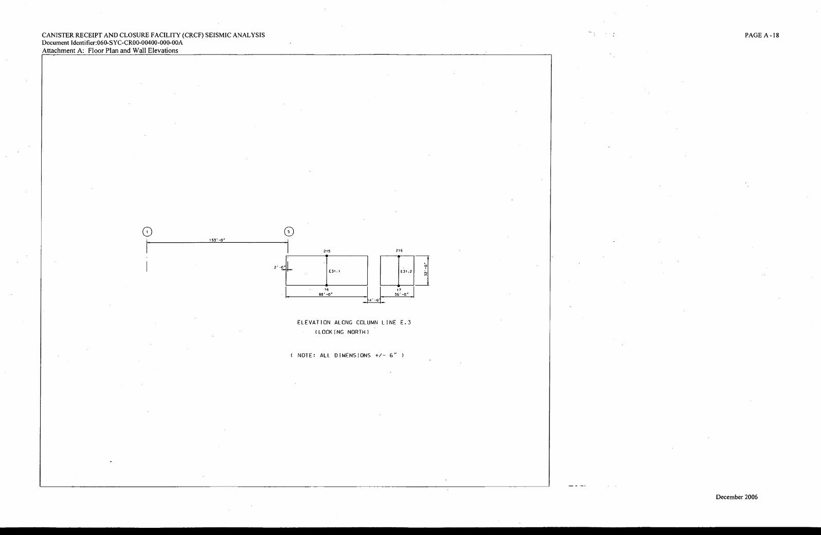
216
j I
E31.2
36"
4,-.1
2 -0"
CANISTER RECEIPT AND CLOSURE FACILITY (CRCF) SEISMIC ANALYSIS
Document Identifier:060-SYC-CR00-00400-000-00A
Attachment A: Floor Plan and Wall Elevations
PAGE A-18
153'-Cr 0
215 •
E31 . 1
• 16
86' -D .
ELEVATION ALONG COLUMN LINE E.3
(LOOKING NORTH)
( NOTE: ALL DIMENSIONS +/- 6" )
eq
December 2006
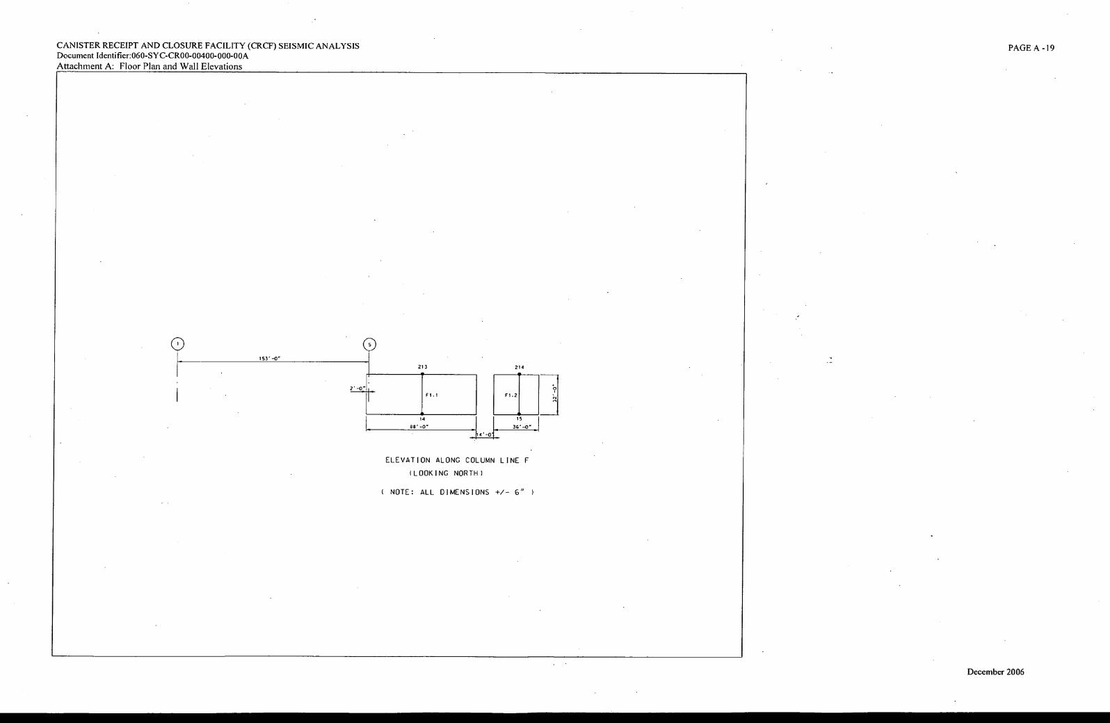
F1.1
14
CANISTER RECEIPT AND CLOSURE FACILITY (CRCF) SEISMIC ANALYSIS
Document Identifier:060-SYC-CR00-00400-000-00A Attachment A: Floor Plan and Wall Elevations
PAGE A -19
V-0 °
213 214
-21 15
36'-O
ELEVATION ALONG COLUMN LINE F
(LOOKING NORTH )
( NOTE: ALL DIMENSIONS +/- 6" )
153'-O"
December 2006
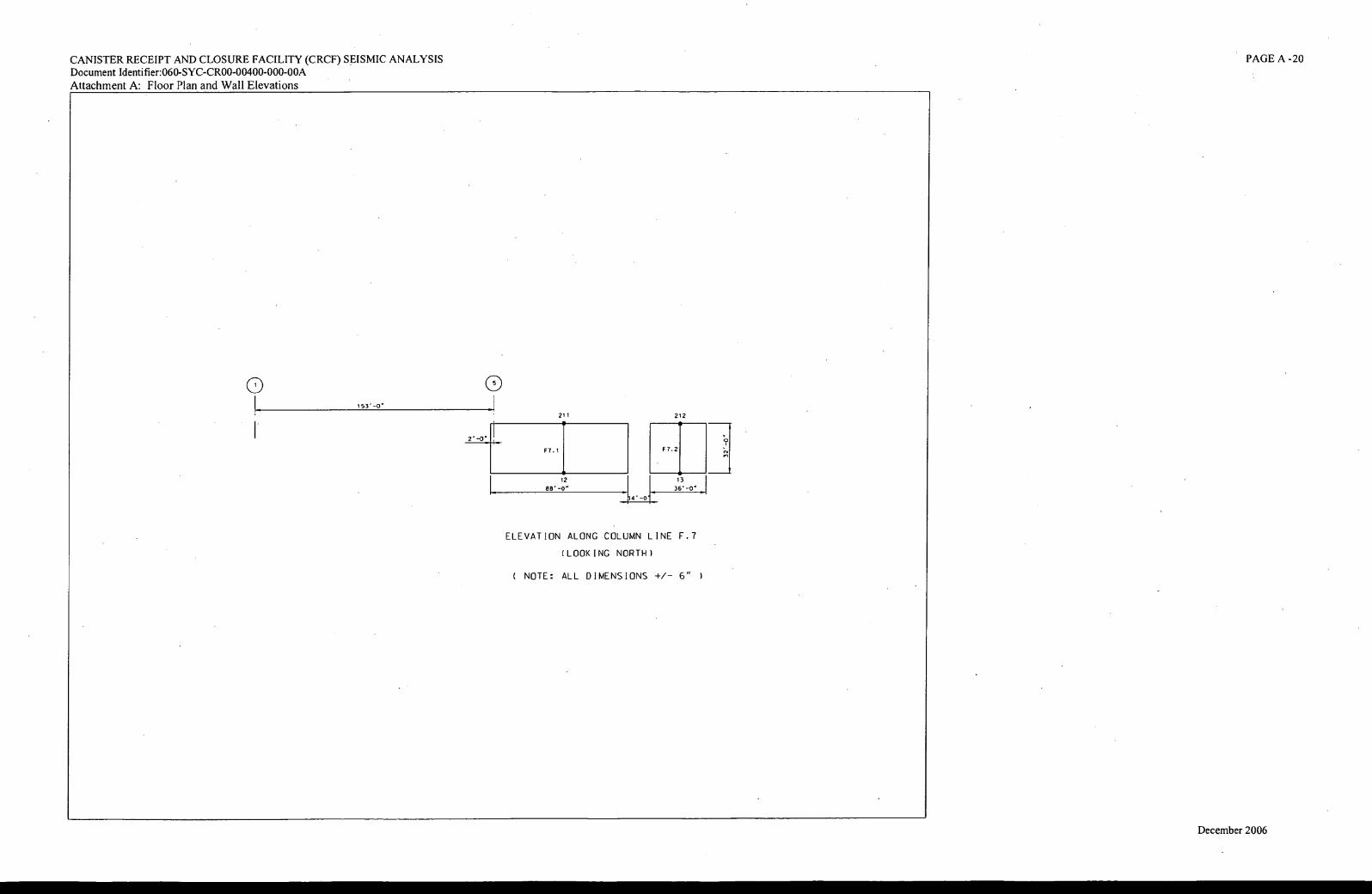
0 0
(tl F7.2 F7.1
•
4. -01 12
86 . -0"
CANISTER RECEIPT AND CLOSURE FACILITY (CRCF) SEISMIC ANALYSIS
Document Identifier:060-SYC-CR00-00400-000-00A
Attachment A: Floor Plan and Wall Elevations
PAGE A-20
153 . -0'
211 212
•
• 13
36 . -0'
ELEVATION ALONG COLUMN LINE F.7
(LOOKING NORTH)
( NOTE: ALL DIMENSIONS +/- 6" )
December 2006
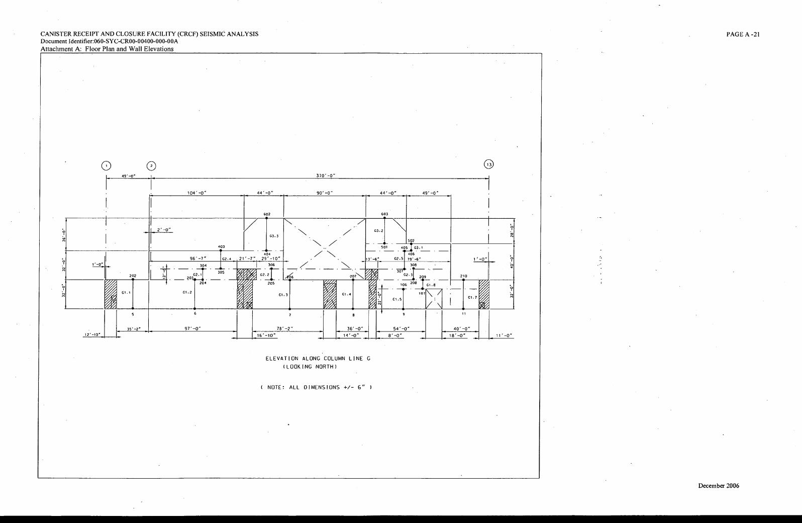
49* —0"
44'-0" 104'-0" 49'-0" 44'-0"
1:zo
N z N
N
N 10
63.2
63.3
502
_ 501 405 I 03.1
. . 406
13' —67 62.51 79-6 -
403
404
21' -7". 29' - 10" 96' -7" 02.4
306 308
307 62.31— G2.2 202 210 • •
33;.• V
oilr4
205
VA f
209
, 06 208 61.8
07N
304 . .
305
1:7;04]— 204
N. A vf Og
ft/r4
01.2 01.1 A G1.4 'eso on
61.3 61.7
61.5
V \I 3
5 6 7 a 9
35' —2" 97' -0" 78'-2" 3C-0" 54'-0" 40'-0"
12' —10" 16'-10" 14'-0" 8' —0" 18' —0" 1C-0"
CANISTER RECEIPT AND CLOSURE FACILITY (CRCF) SEISMIC ANALYSIS Document Identifier:060-SYC-CR00-00400-000-00A
Attachment A: Floor Plan and Wall Elevations
PAGE A -21
0 0 a 370'-0"
90'-0"
602 603 •
ELEVATION ALONG COLUMN LINE G
(LOOKING NORTH)
( NOTE: ALL DIMENSIONS +/- 6" )
December 2006
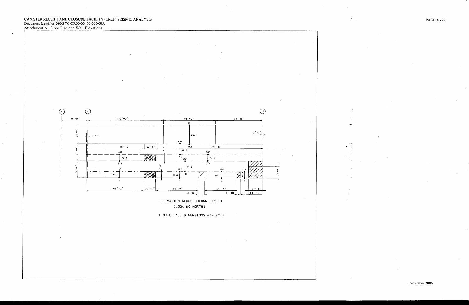
0 0 49" -0" 87'-0"
2' -0" H3.1
22' -0"
142'-0"
[ 2
1013"-0"
98'-0"
601 •
401
402 201" -0 -
I 142.3 303
302
. . .
201 H2.2
301
H2.1 % A4%1
H1.5 . .102
.
I
H12 1--103
2
274
104 . .
H1.3 77. -. 3
ref__ vvr
273
101
H1.1
105
22'-0" 80' -0" 61'-4" --41•••1
12'-0" 5'-10"
108' -0" 27"-0"
14'-10"
CANISTER RECEIPT AND CLOSURE FACILITY (CRCF) SEISMIC ANALYSIS Document Identifier:060-SYC-CR00-00400-000-00A
Attachment A: Floor Plan and Wall Elevations
PAGE A -22
• ELEVATION ALONG COLUMN LINE H
(LOOKING NORTH )
( NOTE: ALL DIMENSIONS +/— 6" )
December 2006
Canister Receipt and Closure Facility (CRCF) Seismic Analysis 060-SYC-CR00-00400-000-00A
ATTACHMENT B
SAP2000 Stick Model Input
B. -1 December 2006
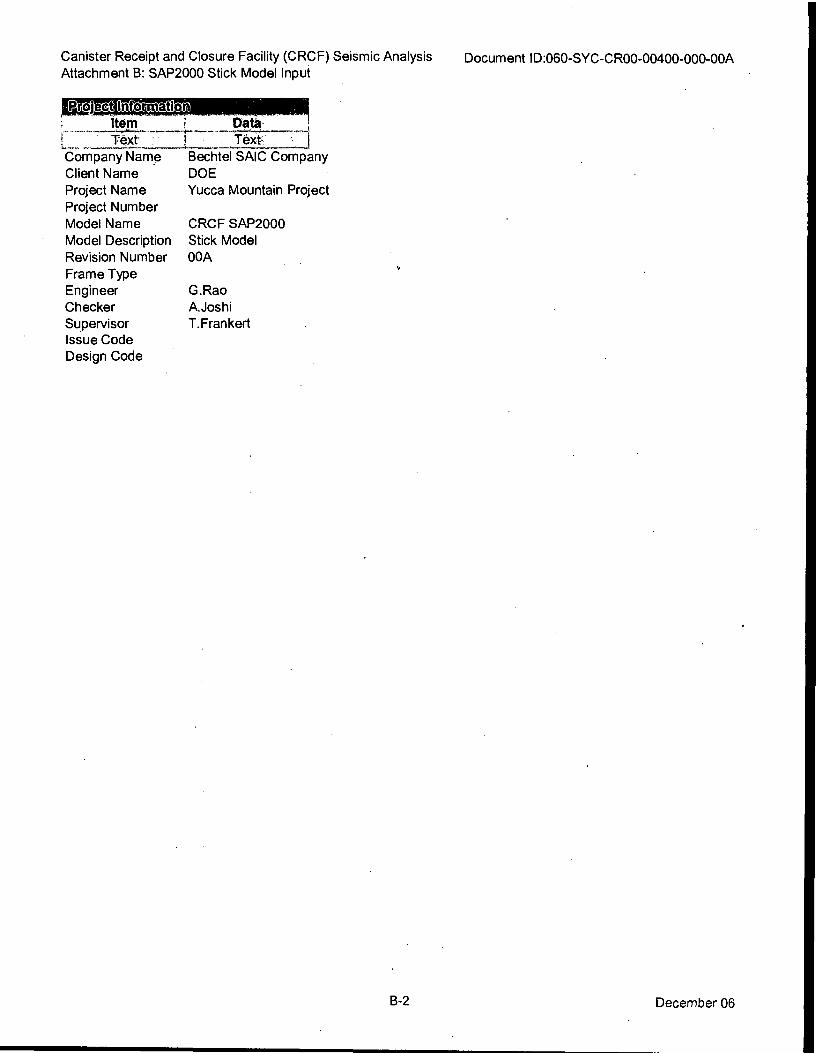
CRCF SAP2000
Stick Model
00A
G.Rao
A.Joshi
T.Frankert
Canister Receipt and Closure Facility (CRCF) Seismic Analysis
Attachment B: SAP2000 Stick Model Input Document ID:060-SYC-CR00-00400-000-00A
Data I
Text. I
Bechtel SAIC Company
DOE
Yucca Mountain Project
Item
L 1- '6xt Company Name
Client Name
Project Name
Project Number
Model Name
Model Description
Revision Number
Frame Type
Engineer
Checker
Supervisor
Issue Code
Design Code
B-2 December 06
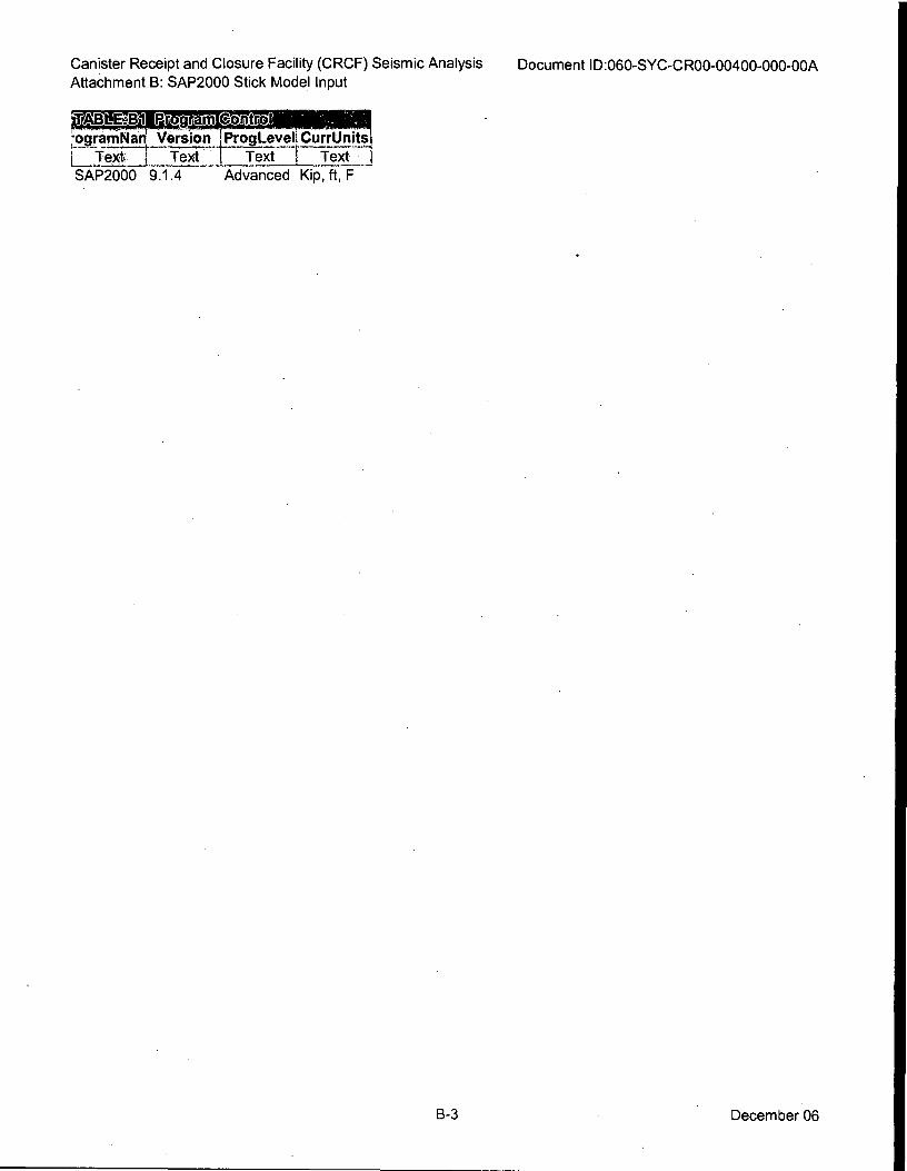
Canister Receipt and Closure Facility (CRCF) Seismic Analysis
Attachment B: SAP2000 Stick Model Input Document ID:060-SYC-CR00-00400-000-00A
.TAEILIE:Lio..Ø.,0311APeag
ogramNan Version ProgLeveli CurrUnits
L Text-7r Text Text Text SAP2000 9.1.4 Advanced Kip, ft, F
B-3 December 06
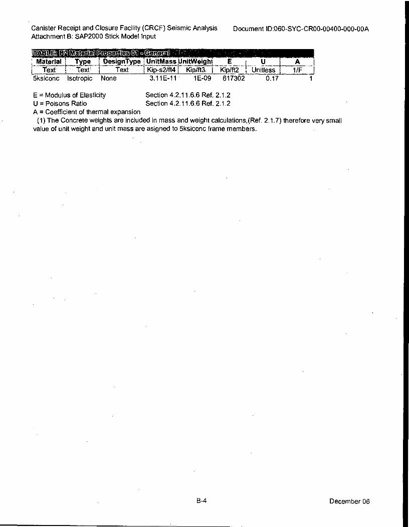
Canister Receipt and Closure Facility (CRCF) Seismic Analysis
Attachment B: SAP2000 Stick Model Input Document ID:060-SYC-CR00-00400-000-00A
EN WO:AU P operties Qalag Material Type I DesignType UnitMassgnitWeicitti_ . E
Text Text' I Text Kip-s2/ft41 IZIP7f-t37 RiP/ft2- Unitless 1/F J
5ksiconc Isotropic None 3.11E-11 1E-09 617302 0.17
E = Modulus of Elasticity
U = Poisons Ratio Section 4.2.11.6.6 Ref. 2.1.2
A = Coefficient of thermal expansion
(1) The Concrete weights are included in mass and weight calculations,(Ref. 2.1.7) therefore very small
value of unit weight and unit mass are asigned to 5ksiconc frame members.
Section 4.2.11.6.6 Ref. 2.1.2
B-4 December 06
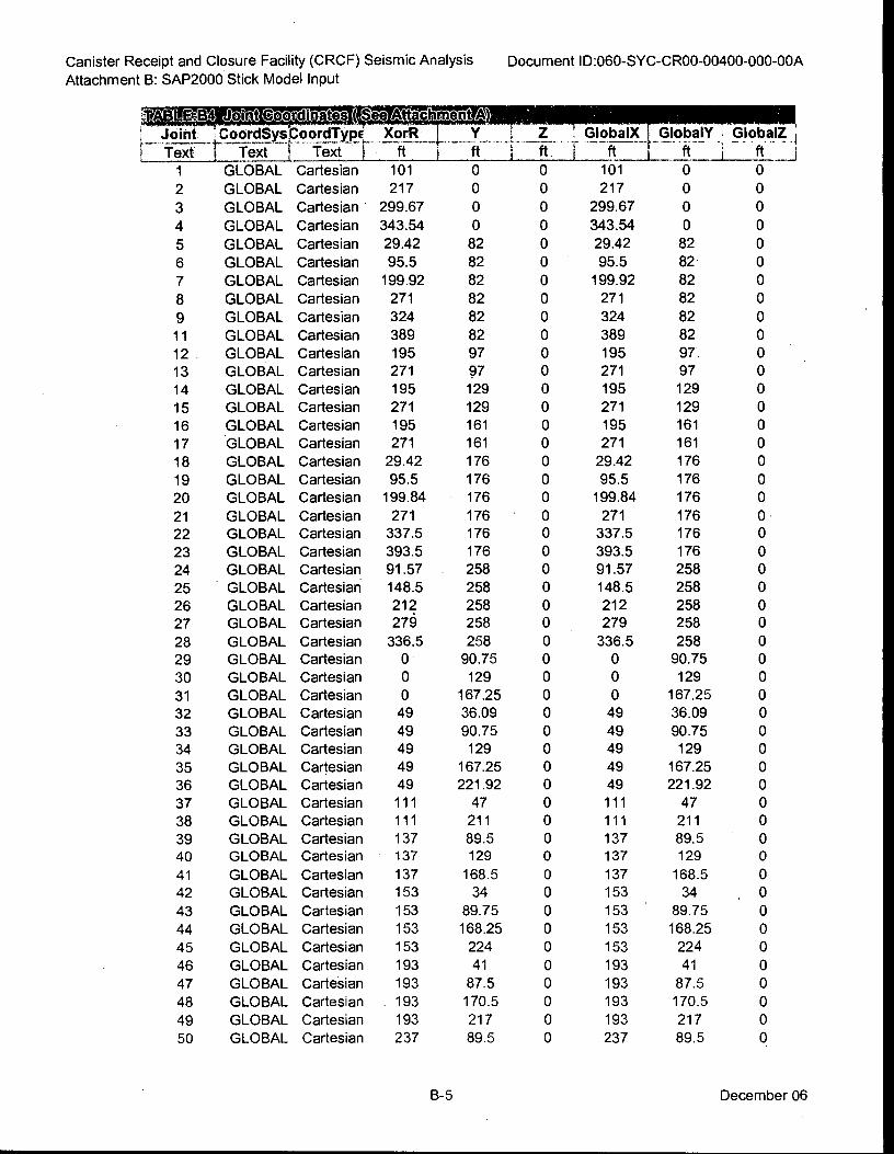
Canister Receipt and Closure Facility (CRCF) Seismic Analysis
Attachment B: SAP2000 Stick Model Input
Document ID:060-SYC-CR00-00400-000-00A
VABIMEA =arat itgalWio=4,1t Al , Joint CoordSys_CoordType XorR - _ . Y_ _ Ti . Z _ 1-, Global)c_f_GlobalY 1 GlobalZ j
r te-if t -Text I text r -ft- 7 -ft i -ii-: f ft- 1. ft i ft--___I
1 GLOBAL Cartesian 101 o o tot o T 2 GLOBAL Cartesian 217 o o 217 0 o 3 GLOBAL Cartesian • 299.67 o o 299.67 0 0
4 GLOBAL Cartesian 343.54 o o 343.54 o o 5 GLOBAL Cartesian 29.42 82 0 29.42 82 o 6 GLOBAL Cartesian 95.5 82 0 95.5 82 0
7 GLOBAL Cartesian 199.92 82 0 199.92 82 o 8 GLOBAL Cartesian 271 82 0 271 82 o 9 GLOBAL Cartesian 324 82 0 324 82 o
11 GLOBAL Cartesian 389 82 0 389 82 0
12 . GLOBAL Cartesian 195 97 o 195 97. o ' 13 GLOBAL Cartesian 271 97 0 271 97 0
14 GLOBAL Cartesian 195 129 o 195 129 0
15 GLOBAL Cartesian 271 129 0 271 129 0
16 GLOBAL Cartesian 195 161 0 195 161 0
17 GLOBAL Cartesian 271 161 0 271 161 0
18 GLOBAL Cartesian 29.42 176 0 29.42 176 0
19 GLOBAL Cartesian 95.5 176 0 95.5 176 0
20 GLOBAL Cartesian 199.84 176 0 199.84 176 0
21 GLOBAL Cartesian 271 176 0 271 176 0
22 GLOBAL Cartesian 337.5 176 0 337.5 176 0
23 GLOBAL Cartesian 393.5 176 0 393.5 176 0
24 GLOBAL Cartesian 91.57 . 258 0 91.57 258 0
25 GLOBAL Cartesian 148.5 258 0 148.5 258 o 26 GLOBAL Cartesian 212 258 o 212 258 0
27 GLOBAL Cartesian 276 258 0 279 258 o 28 GLOBAL Cartesian 336.5 258 0 336.5 258 o 29 GLOBAL Cartesian 0 90.75 0 o 90.75 o 30 GLOBAL Cartesian 0 129 o o 129 0
31 GLOBAL Cartesian 0 167.25 o o 167.25 o 32 GLOBAL Cartesian 49 36.09 0 49 36.09 0
33 GLOBAL Cartesian 49 90.75 o 49 90.75 o 34 GLOBAL Cartesian 49 129 o 49 129 0
35 GLOBAL Cartesian 49 167.25 0 49 167.25 0
36 GLOBAL Cartesian 49 221.92 0 49 221.92 o 37 GLOBAL Cartesian 111 47 o 111 47 o 38 GLOBAL Cartesian 111 211 o 111 211 o 39 GLOBAL Cartesian 137 89.5 0 137 89.5 . 0
40 GLOBAL Cartesian 137 129 0 137 129 0
41 GLOBAL Cartesian 137 168.5 0 137 168.5 0
42 GLOBAL Cartesian 153 34 0 153 34 . 0
43 GLOBAL Cartesian 153 89.75 0 153 . 89.75 o 44 GLOBAL Cartesian 153 168.25 o 153 168.25 o 45 GLOBAL Cartesian 153 224 o 153 224 o 46 GLOBAL Cartesian 193 41 o 193 41 o 47 GLOBAL Cartesian 193 87.5 0 193 87.5 o 48 GLOBAL Cartesian . 193 170.5 o 193 170.5 0
49 GLOBAL Cartesian 193 217 0 193 217 0
50 GLOBAL Cartesian 237 89.5 0 237 89.5 0
B-5 December 06
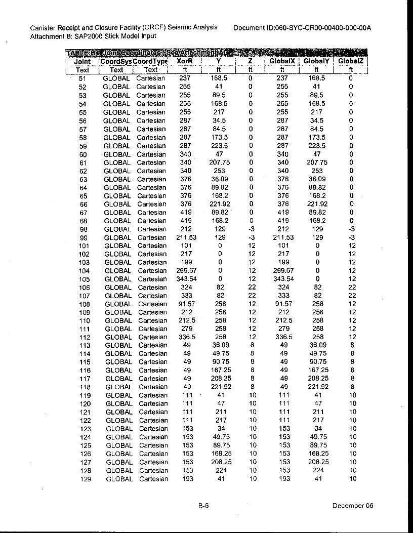
0
0
Canister Receipt and Closure Facility (CRCF) Seismic Analysis
Attachment B: SAP2000 Stick Model Input
Document ID:060-SYC-CR00-00400-000-00A
Joint_ CoordSys:poord.Ty0 XorRIY_ Z _GlobalX . GlobalY GlobalZ
I Text I Text Text I ft I ft I ft I ft I ft I ft . 237
255
255
255
255
287
287
287
287
340 340
340
376
376
376
376
419
419
212
211.53 101
217
199
299.67
343.54
324
333
91.57
212
212.5
279
336.5
49
49
49
49
49
49
111
111
111
111
153
153
153
153
153
153
193
• 51 GLOBAL Cartesian
52 GLOBAL Cartesian
53 GLOBAL Cartesian
54 GLOBAL Cartesian
55 GLOBAL Cartesian
56 GLOBAL Cartesian
57 GLOBAL Cartesian
58 GLOBAL Cartesian
59 GLOBAL Cartesian
60 GLOBAL Cartesian
61 GLOBAL Cartesian
62 GLOBAL Cartesian
63 GLOBAL Cartesian
64 GLOBAL Cartesian
65 GLOBAL Cartesian
66 GLOBAL Cartesian
67 GLOBAL Cartesian
68 GLOBAL Cartesian
98 GLOBAL Cartesian
99 GLOBAL Cartesian
101 GLOBAL Cartesian
102 GLOBAL Cartesian
103 GLOBAL Cartesian
104 GLOBAL Cartesian
105 GLOBAL Cartesian
106 GLOBAL Cartesian
107 GLOBAL Cartesian
108 GLOBAL Cartesian
109 GLOBAL Cartesian
110 GLOBAL Cartesian
111 GLOBAL Cartesian
112 GLOBAL Cartesian
113 GLOBAL Cartesian 114 GLOBAL Cartesian
115 GLOBAL Cartesian
116 GLOBAL Cartesian
117 GLOBAL Cartesian
118 GLOBAL Cartesian
119 GLOBAL Cartesian
120 GLOBAL Cartesian
121 GLOBAL Cartesian
122 GLOBAL Cartesian
123 GLOBAL Cartesian
124 GLOBAL Cartesian
125 GLOBAL Cartesian
126 GLOBAL Cartesian
127 GLOBAL Cartesian
128 GLOBAL Cartesian
129 GLOBAL Cartesian
168.5 0 237 168.5 0
41 0 255 41
89.5 0 255 89.5
168.5 0 255 168.5 0
217 0 255 217 0
34.5 0 287 34.5 0
84.5 0 287 84.5 0
173.5 0 287 173.5 0
223.5 0 287 223.5 0
47 0 340 47 0
207.75 0 340 207.75 0
253 0 340 253 0
36.09 0 376 36.09 0
89.82 0 376 89.82 0
168.2 0 376 168.2 0
221.92 0 376 221.92 0
89.82 0 419 89.82 0
168.2 0 419 168.2 0
129 -3 212 129 -3
129 -3 211.53 129 -3 0 12 101 0 12
0 12 217 0 12
0 12 199 0 12
0 12 299.67 0 12
0 12 343.54 0 12
82 22 324 82 22
82 22 333 82 22
258 12 91.57 258 12
258 12 212 258 12
258 12 212.5 258 12
258 12 279 258 12
258 12 336.5 258 12
36.09 8 49 36.09 8
49.75 8 49 49.75 8
90.75 8 49 90.75 8
167.25 8 49 167.25 8
208.25 8 49 208.25 8
221.92 8 49 221.92 8
41 10 111 41 10
47 10 111 47 10
211 10 111 211 10
217 10 111 217 10
34 10 153 34 10
49.75 10 153 49.75 10
89.75 10 153 89.75 10
168.25 10 153 168.25 10
208.25 10 153 208.25 10
224 10 153 224 10
41 10 193 41 10
B-6 December 06
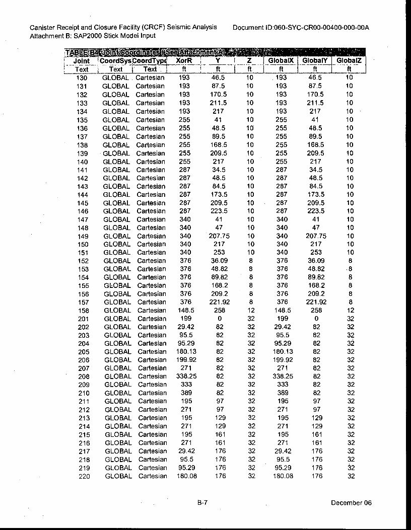
AILS.:6111 01,7-7314,..tnieritig
46.5
87.5
170.5
211.5
217
41
48.5
89.5
168.5
209.5
217
34.5
48.5
84.5
173.5
209.5
223.5
41
47
207.75
217
253
36.09
48.82
89.82
168.2
209.2
221.92
258
0
82
82
82
82
82
82
82
82
82
97
97
129
129
161
161
176
176
176
176
10
10
10
10
10
10
10
10
10
10
10
10
10
10
10
10 10
10
10
10
10
10
8
8
8
8
8
8
12
32
32
32
32
32
32
32
32
32
32
32
32
32
32
32
32
32
32
32
32
Canister Receipt and Closure Facility (CRCF) Seismic Analysis
Attachment B: SAP2000 Stick Model Input
Document ID:060-SYC-CR00-00400-000-00A
TABLE13
' Joint
L
Text
130
131
132
133
134
135
136
137
138
139
140
141
142
143
144
145
146
147
148
149
150
151
152
153
154
155
156
157
158
201
202
203
204
205
206
207
208
209
210
211
212
213
214
215
216
217
218
219
220
CoordSystoordTypi XorR
Text i• Text 1 ft
Cartesian 193
Cartesian 193
Cartesian 193
Cartesian 193
Cartesian 193
Cartesian 255
Cartesian 255
Cartesian 255
Cartesian 255
Cartesian 255
Cartesian 255
Cartesian 287
Cartesian 287
Cartesian 287
Cartesian 287
Cartesian 287
Cartesian 287
Cartesian 340
Cartesian 340
Cartesian 340
Cartesian 340
Cartesian 340
Cartesian 376
Cartesian 376
Cartesian 376
Cartesian 376
Cartesian 376
Cartesian 376
Cartesian 148.5
Cartesian 199
Cartesian 29.42
Cartesian 95.5
Cartesian 95.29
Cartesian 180.13
Cartesian 199.92
Cartesian 271
Cartesian 338.25
Cartesian 333
Cartesian 389
Cartesian 195
Cartesian 271
Cartesian 195
Cartesian 271
Cartesian 195
Cartesian 271
Cartesian 29.42
Cartesian 95.5
Cartesian 95.29
Cartesian 180.08
GlobalX
ft
193
193
193
193
193
255
255
255
255
255
255
287
287
287
287
287 287
340
340
340 340
340
376
376
376
376
376
376
148.5
199
29.42
95.5
95.29
180.13
199.92
271
338.25
333
389
195
271
195
271
195
271
29.42
95.5
95.29
180.08
GlobalY
ft
• 46.5
87.5
170.5
211.5
217
41
48.5
89.5
168.5
209.5
217
34.5
48.5
84.5
173.5
209.5
223.5
41
47
207.75
217
253
36.09
48.82
89.82
168.2
209.2
221.92
258
0
82
82
82
82
82
82
82
82
82
97
97
129
129
161
161
176
176
176
176
GlobalZ
ft
10
10
10
10
10
10
10
10
10
10
10
10
10
10
10
10
10
10
10
10
10
10
8
8
8
8
8
8
12
32
32
32
32
32
32
32
32
32
32
32
32
32
32
32
32
32
32
32
32
XorR
GLOBAL
GLOBAL
GLOBAL
GLOBAL
GLOBAL
GLOBAL
GLOBAL
GLOBAL
GLOBAL
GLOBAL
GLOBAL
GLOBAL
GLOBAL
GLOBAL
GLOBAL
GLOBAL
GLOBAL
GLOBAL
GLOBAL
GLOBAL
GLOBAL
GLOBAL
GLOBAL
GLOBAL
GLOBAL
GLOBAL
GLOBAL
GLOBAL
GLOBAL
GLOBAL
GLOBAL
GLOBAL
GLOBAL
GLOBAL
GLOBAL
GLOBAL
GLOBAL
GLOBAL
GLOBAL
GLOBAL
GLOBAL
GLOBAL
GLOBAL
GLOBAL
GLOBAL
GLOBAL
GLOBAL
GLOBAL
GLOBAL
B-7 December 06
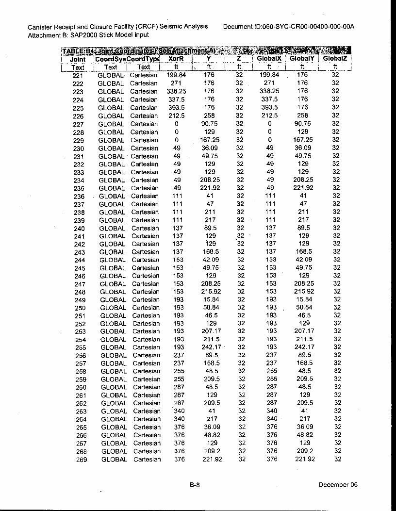
Canister Receipt and Closure Facility (CRCF) Seismic Analysis
Attachment B: SAP2000 Stick Model Input
1 . _ Joint iCoordSys,CoordType Xorll i Y Z 1 Elobali'l Globairr -GlobalZ i
L text : Text 1 text . 1 ft 1, ft ft
. -
ft ... i f • ...._ J . j
221 GLOBAL Cartesian 199.84 176 32 i-t99.84 . -17 6 3-2-
222 GLOBAL Cartesian 271 176 32 . 271 176 32
223 GLOBAL Cartesian 338.25 176 32 338.25 176 32
224 GLOBAL Cartesian 337.5 176 32 337.5 176 32
225 GLOBAL Cartesian 393.5 176 32 393.5 176 32
226 GLOBAL Cartesian 212.5 258 32 212.5 258 32
227 GLOBAL Cartesian 0 90.75 32 0 90.75 32
228 GLOBAL Cartesian 0 129 32 0 129 32
229 GLOBAL Cartesian 0 167.25 32 0 167.25 32
230 GLOBAL Cartesian 49 36.09 32 49 36.09 32
231 GLOBAL Cartesian 49 49.75 32 49 49.75 32
232 GLOBAL Cartesian 49 129 32 49 129 32
233 GLOBAL Cartesian 49 129 32 49 129 32
234 GLOBAL Cartesian 49 208.25 32 49 208.25 32
235 GLOBAL Cartesian 49 221.92 32 49 221.92 32
236 • GLOBAL Cartesian 111 41 32 111 41 32
237 GLOBAL Cartesian 111 47 32 111 47 32
238 GLOBAL Cartesian 111 211 32 111 211 32
239 GLOBAL Cartesian 111 217 32 111 217 32
240 GLOBAL Cartesian 137 89.5 32 137 89.5 32
241 GLOBAL Cartesian 137 129 .32 137 129 32
242 GLOBAL Cartesian 137 129 32 137 129 32
243 GLOBAL Cartesian 137 168.5 32 137 168.5 32
244 GLOBAL Cartesian 153 42.09 32 153 42.09 32
245 GLOBAL Cartesian 153 49.75 . 32 153 49.75 32
246 GLOBAL Cartesian 153 129 32 153 . 129 32
247 GLOBAL Cartesian 153 208.25 32 153 208.25 32
248 GLOBAL Cartesian 153 215.92 32 153 215.92 32
249 GLOBAL Cartesian 193 15.84 32 193 15.84 32
250 GLOBAL Cartesian 193 50.84 32 193 , 50.84 32
251 GLOBAL Cartesian 193 46.5 32 193 46.5 32
252 GLOBAL Cartesian 193 129 32 193 129 32
. 253 GLOBAL Cartesian 193 207.17 32 193 207.17 32
254 GLOBAL Cartesian 193 211.5 32 193 211.5 32
255 GLOBAL Cartesian 193 242.17 32 193 242.17 32
256 GLOBAL Cartesian 237 89.5 32 237 89.5 32
257 GLOBAL Cartesian 237 168.5 32 237 168.5 32
258 GLOBAL Cartesian 255 48.5 32 255 48.5 32
259 GLOBAL Cartesian 255 209.5 32 255 209.5 32
260 GLOBAL Cartesian 287 48.5 32 287 48.5 32
261 GLOBAL Cartesian 287 129 32 287 129 32
262 GLOBAL Cartesian 287 209.5 32 287 209.5 32
263 GLOBAL Cartesian 340 41 32 340 41 32
264 GLOBAL Cartesian 340 217 32 340 • 217 32
265 GLOBAL Cartesian 376 36.09 32 376 36.09 32
266 GLOBAL Cartesian 376 48.82 32 376 48.82 32
267 GLOBAL Cartesian 376 129 32 376 129 32
268 GLOBAL Cartesian 376 209.2 32 376 209.2 32
269 GLOBAL Cartesian 376 221.92 32 376 221.92 32
Document ID:060-SYC-CR00-00400-000-00A
B-8 December 06
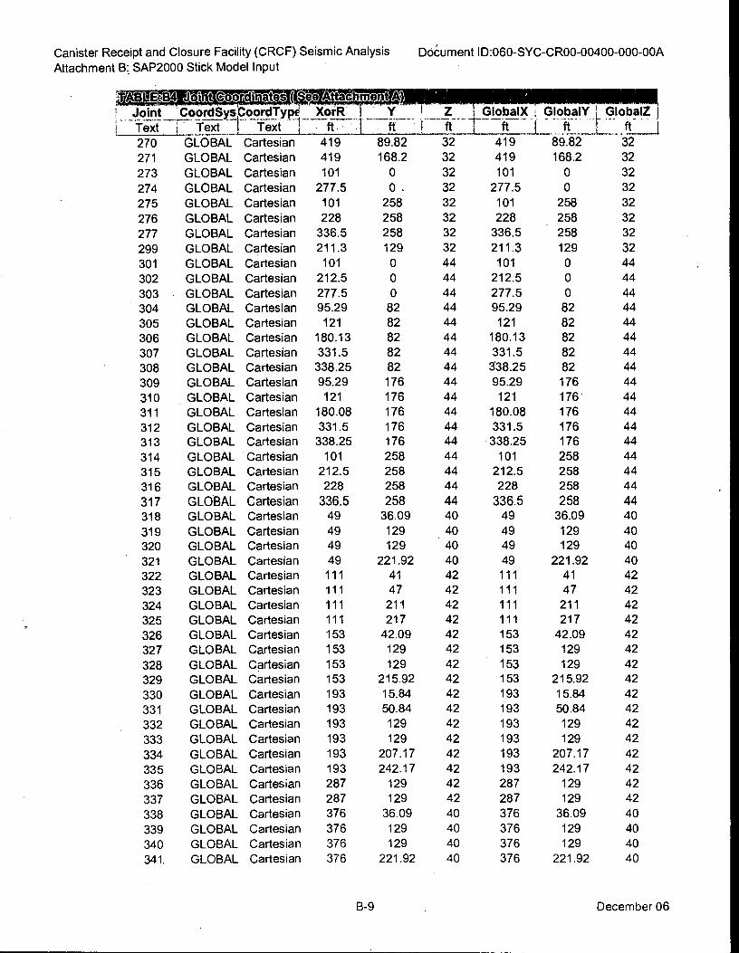
DoCument ID:060-SYC-CR00-00400-000-00A Canister Receipt and Closure Facility (CRCF) Seismic Analysis
Attachment B; SAP2000 Stick Model Input
I .. _Joint :CoordSys,toorciType XorR
teif -ter Text 1-i177
270 GLOBAL Cartesian 419
271 GLOBAL Cartesian 419
273 GLOBAL Cartesian 101
274 GLOBAL Cartesian 277.5
275 GLOBAL Cartesian 101
276 GLOBAL Cartesian 228
277 GLOBAL Cartesian 336.5
299 GLOBAL Cartesian 211.3
301 GLOBAL Cartesian 101
302 GLOBAL Cartesian 212.5
303 GLOBAL Cartesian 277.5
304 GLOBAL Cartesian 95.29
305 GLOBAL Cartesian 121
306 GLOBAL Cartesian 180.13
307 GLOBAL Cartesian 331.5
308 GLOBAL Cartesian 338.25
309 GLOBAL Cartesian 95.29
310 GLOBAL Cartesian 121
311 GLOBAL Cartesian 180.08
312 GLOBAL Cartesian 331.5
313 GLOBAL Cartesian 338.25
314 GLOBAL Cartesian 101
315 GLOBAL Cartesian 212.5
316 GLOBAL Cartesian 228
317 GLOBAL Cartesian 336.5
318 GLOBAL Cartesian 49
319 GLOBAL Cartesian 49
320 GLOBAL Cartesian 49
321 GLOBAL Cartesian 49
322 GLOBAL Cartesian 111
323 GLOBAL Cartesian 111
324 GLOBAL Cartesian 111
325 GLOBAL Cartesian 111
326 GLOBAL Cartesian 153
327 GLOBAL Cartesian 153
328 GLOBAL Cartesian 153
329 GLOBAL Cartesian 153
330 GLOBAL Cartesian 193
331 GLOBAL Cartesian 193
332 GLOBAL Cartesian 193
333 GLOBAL Cartesian 193
334 GLOBAL Cartesian 193
335 GLOBAL Cartesian 193
336 GLOBAL Cartesian 287
337 GLOBAL Cartesian 287
338 GLOBAL Cartesian 376
339 GLOBAL Cartesian 376
340 GLOBAL Cartesian 376
341. GLOBAL Cartesian 376
GlobalX ; GlobalY L GlobalZ ft I It I _ft
89.82 32 419 89.82 32
168.2 32 419 168.2 32
0 32 101 0 32
0. 32 277.5 0 32
258 32 101 258 32
258 32 228 . 258 32
258 32 336.5 258 32
129 32 211.3 129 32
0 44 101 0 44
0 44 212.5 0 44
0 44 277.5 0 44
82 44 95.29 82 44
82 44 121 82 44
82 44 180.13 82 44
82 44 331.5 82 44
82 44 538.25 82 44
176 44 95.29 176 44
176 44 121 176 44
176 44 180.08 176 44
176 44 331.5 176 44
176 44 338.25 176 44
258 44 101 258 44
258 44 212.5 258 44
258 44 228 258 44
258 44 336.5 258 44
36.09 40 49 36.09 40
129 40 49 129 40
129 40 49 129 40
221.92 40 49 221.92 40
41 42 111 41 42
47 42 111 47 42
211 42 111 211 42
217 42 111 217 42
42.09 42 153 42.09 42
129 42 153 129 42
129 42 153 129 42
215.92 42 153 215.92 42
15.84 42 193 15.84 42
50.84 42 193 50.84 42
129 42 193 129 42
129 42 193 129 42
207.17 42 193 207.17 42
242.17 42 193 242.17 42
129 42 287 129 42
129 42 287 129 42
36.09 40 376 36.09 40
129 40 376 129 40
129 40 376 129 40
221.92 40 376 221.92 40
B-9 December 06
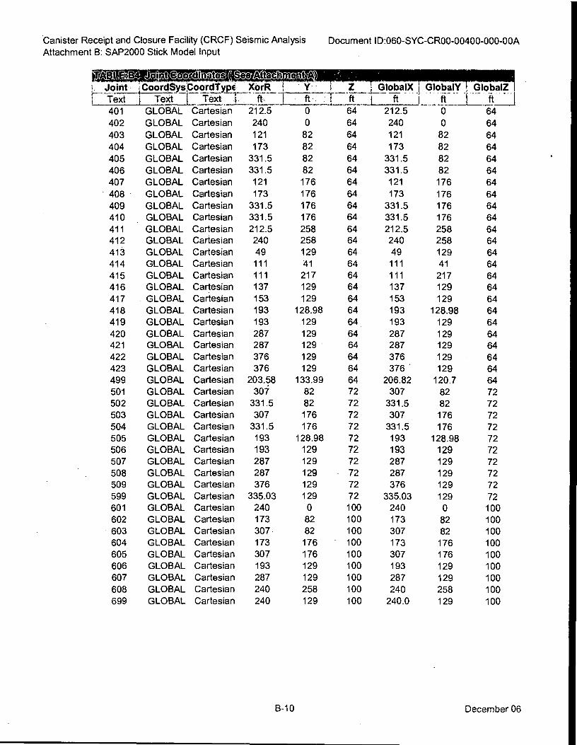
Canister Receipt and Closure Facility (CRCF) Seismic Analysis
Attachment B: SAP2000 Stick Model Input Document ID:060-SYC-CR00-00400-000-00A
L_ Joint 4_, CoordSysPoordTypi XorR ! ' Y - 1 Z LGlobalX ; GlobalY 1 GlobalZ ,
I "text 1 Te)--c-t 1— Text 1. ft. 1 ft . T ft I ft
401 GLOBAL Cartesian 212.5 0 64 212.5 -6– — –6-4—
402 GLOBAL Cartesian 240 0 64 240 0 64
403 GLOBAL Cartesian 121 82 64 121 82 64
404 GLOBAL Cartesian 173 82 64 173 82 64
405 GLOBAL Cartesian 331.5 82 64 331.5 82 64
406 GLOBAL Cartesian 331.5 82 64 331.5 82 64
407 GLOBAL Cartesian 121 176 64 121 176 64
• 408 • GLOBAL Cartesian 173 176 64 173 176 64
409 GLOBAL Cartesian 331.5 176 64 331.5 176 64
410 GLOBAL Cartesian 331.5 176 64 331.5 176 64
411 GLOBAL Cartesian 212.5 258 64 212.5 258 64
412 GLOBAL Cartesian 240 258 64 240 258 64
413 GLOBAL Cartesian 49 129 64 49 129 64
414 GLOBAL Cartesian 111 41 64 111 41 64
415 GLOBAL Cartesian 111 217 64 111 217 64
416 GLOBAL Cartesian 137 129 64 137 129 64
417 GLOBAL Cartesian 153 129 64 153 129 64
418 GLOBAL Cartesian 193 128.98 64 193 128.98 64
419 GLOBAL Cartesian 193 129 64 193 129 64
420 GLOBAL Cartesian 287 129 64 287 129 64'
421 GLOBAL Cartesian 287 129 64 287 129 64
422 GLOBAL Cartesian 376 129 64 376 129 64
423 GLOBAL Cartesian 376 129 64 376 ' 129 64
499 GLOBAL Cartesian 203.58 133.99 64 206.82 120.7 64
501 GLOBAL Cartesian 307 82 72 307 82 72
502 GLOBAL Cartesian 331.5 82 72 331.5 82 72
503 GLOBAL Cartesian 307 176 72 307 176 72
504 GLOBAL Cartesian 331.5 176 72 331.5 176 72
505 GLOBAL Cartesian 193 128.98 72 193 128.98 72
506 GLOBAL Cartesian 193 129 72 193 129 72
507 GLOBAL Cartesian 287 129 72 287 129 72
508 GLOBAL Cartesian 287 129 • 72 287 129 72
509 GLOBAL Cartesian 376 129 72 376 129 72
599 GLOBAL Cartesian 335.03 129 72 335.03 129 72
601 GLOBAL Cartesian 240 0 100 240 0 100
602 GLOBAL Cartesian 173 82 100 173 82 100
603 GLOBAL Cartesian 307 82 100 307 82 100
604 GLOBAL Cartesian 173 176 • 100 173 176 100
605 GLOBAL Cartesian 307 176 100 307 176 100
606 GLOBAL Cartesian 193 129 100 193 129 100
607 GLOBAL Cartesian 287 129 100 287 129 100
608 GLOBAL Cartesian 240 258 100 240 258 100
699 GLOBAL Cartesian 240 129 100 240.0 129 100
B-10 December 06
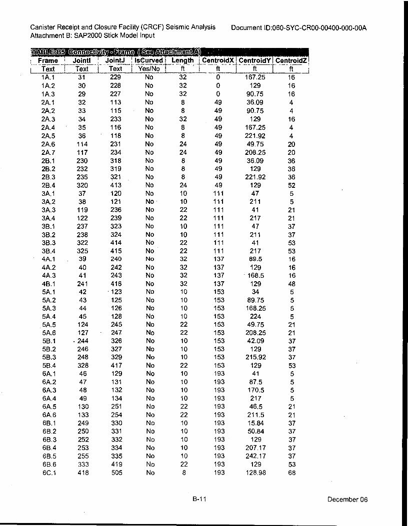
Canister Receipt and Closure Facility (CRCF) Seismic Analysis
Attachment B: SAP2000 Stick Model Input Document ID:060-SYC-CR00-00400-000-00A
totetivit'r-SIF atis=ie (pee issn tachE-It /4 .....4406....6.4.. Frame 1 Jointl_ ! JointJ !_lsCuryed _Length . ; CentroidX1CentroidY _1 CentroidZ!
1 Text ! Text i Text I Yes/No , ft . i ft 1 ft 1 ft ____I '
1A.1 31 229 No 32 0 167.25 16
1A.2 30 228 No 32 0 129 16
1A.3 29 227 No 32 0 90.75 16
2A.1 32 113 No 8 49 36.09 4
2A.2 33 115 No 8 49 90.75 4
2A.3 34 233 No 32 49 129 16
2A.4 35 116 No 8 49 167.25 4
2A.5 36 118 No 8 49 221.92 4
2A.6 114 231 No 24 49 49.75 20
2A.7 117 234 No 24 49 208.25 20
2B.1 230 318 No 8 49 36.09 36
2B.2 232 319 No 8 49 129 36
2B.3 235 321 No 8 49 221.92 36
2B.4 320 413 No 24 49 129 52
3A.1 37 120 No 10 111 47 5
3A.2 38 121 No 10 111 211 5
3A.3 119 236 No 22 111 41 21
3A.4 122 239 No 22 111 217 21
3B.1 237 323 No 10 111 47 37
3B.2 238 324 No 10 111 211 37
3B.3 322 414 No 22 111 41 53
3B.4 325 415 No 22 111 217 53
• 4A.1 39 240 No 32 137 89.5 16
4A.2 40 242 No 32 137 129 16
4A.3 41 243 No 32 137 • 168.5 16
4B.1 241 416 No 32 137 129 48
5A.1 42 • 123 No 10 153 34 5
5A.2 43 125 No 10 153 89.75 5
5A.3 44 126 No 10 153 168.25 5
5A.4 45 128 No 10 153 224 5
5A.5 124 245 No 22 153 49.75 21
5A.6 127 - 247 No 22 153 208.25 21
5B.1 • 244 326 No 10 153 42.09 37
5B.2 246 327 No 10 153 129 37
5B.3 248 329 No 10 153 215.92 37
5B.4 328 417 No 22 153 129 53
6A.1 46 129 No 10 193 41 5
6A.2 47 131 No 10 193 87.5 5
6A.3 48 132 No 10 193 170.5 5
6A.4 49 134 No 10 193 217 5
6A.5 130 251 No 22 193 46.5 21
6A.6 133 254 No 22 193 211.5 21
6B.1 249 330 No 10 193 15.84 37
6B.2 250 331 No 10 193 50.84 37
6B.3 252 332 No 10 193 129 37
6B.4 253 334 No 10 193 207.17 37
6B.5 255 335 No 10 193 242.17 37
6B.6 333 419 No 22 193 129 53
6C.1 418 505 No 8 193 128.98 68
B-11 December 06
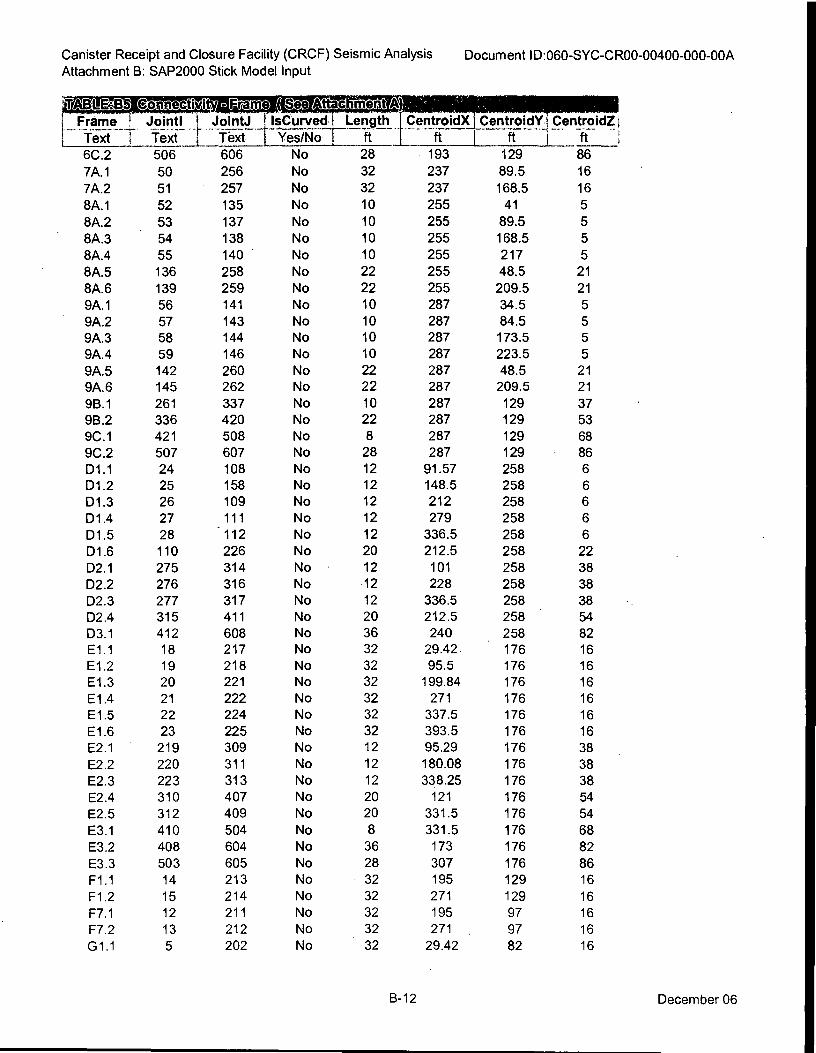
Canister Receipt and Closure Facility (CRCF) Seismic Analysis
Attachment B: SAP2000 Stick Model Input
Document ID:060-SYC-CR00-00400-000-00A
SIBEIV.plaustiviti linFrm Se MEM.. actiMI. M111111111111111111111111 Frame , Joint! 1JointJ I IsCurvedl Length I. CentroidX 1 CentroidY I CentroidZ 1 Text T Text r Text I Yes/No , ft ft I ft -1 - ---ft- ;
6C.2 506 606 No 28 193 129 86
7A.1 50 256 No 32 237 89.5 16
7A.2 51 257 No 32 237 168.5 16
8A.1 52 135 No 10 255 41 5
8A.2 53 137 No 10 255 89.5 5
8A.3 54 138 No 10 255 168.5 5
8A.4 55 140 No 10 255 217 5
8A.5 136 258 No 22 255 48.5 21
8A.6 139 259 No 22 255 209.5 21
9A.1 56 141 No 10 287 34.5 5
9A.2 57 143 No 10 287 84.5 5
9A.3 58 144 No 10 287 173.5 5
9A.4 59 146 No 10 287 223.5 5
9A.5 142 260 No 22 287 48.5 21
9A.6 145 262 No 22 287 209.5 21
9B.1 261 337 No 10 287 129 37
9B.2 336 420 No 22 287 129 53
9C.1 421 508 No 8 287 129 68
9C.2 507 607 No 28 287 129 . 86
D1.1 24 108 No 12 91.57 258 6
D1.2 25 158 No 12 148.5 258 6
D1.3 26 109 No 12 212 258 6
D1.4 27 111 No 12 279 258 6
D1.5 28 " 112 No 12 336.5 258 6
D1.6 110 226 No 20 212.5 258 22
D2.1 275 314 No 12 101 258 38
D2.2 276 316 No 12 228 258 38
D2.3 277 317 No 12 336.5 258 38
D2.4 315 411 No 20 212.5 258 54
D3.1 412 608 No 36 240 258 82
E1.1 18 217 No 32 29.42 176 16
E1.2 19 218 No 32 95.5 176 16
E1.3 20 221 No 32 199.84 176 16
E1.4 21 222 No 32 271 176 16
E1.5 22 224 No 32 337.5 176 16
E1.6 23 225 No 32 393.5 176 16
E2.1 219 309 No 12 95.29 176 38
E2.2 220 311 No 12 180.08 176 38
E2.3 223 313 No 12 338.25 176 38
E2.4 310 407 No 20 121 176 54
E2.5 312 409 No 20 331.5 176 54
E3.1 410 504 No 8 331.5 176 68
E3.2 408 604 No 36 173 176 82
E3.3 503 605 No 28 307 176 86
F1.1 14 213 No 32 195 129 16
F1.2 15 214 No 32 271 129 16
F7.1 12 211 No 32 195 97 16
F7.2 13 212 No 32 271 97 16
G1.1 5 202 No 32 29.42 82 16
B-12 December 06
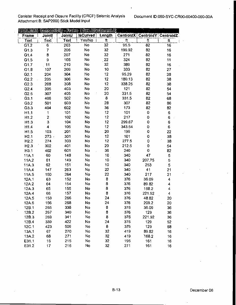
G1.2 6
G1.3 7
G1.4 8
G1.5 9
G1.7 11
G1.8 107
G2.1 204
G2.2 205
G2.3 208
G2.4 305
G2.5 307
G3.1 406
G3.2 501
G3.3 404
H1.1 1
H1.2 2
H1.3 3
H1.4 4
H1.5 103
H2.1 273 H2.2 274
H2.3 302
H3.1 402
11A.1 60
11A.2 61
11A.3 62
11A.4 147
11A.5 150
12A.1 63
12A.2 64
12A.3 65
12A.4 66
12A.5 153
12A.6 156
12B.1 265
12B.2 267
12B.3 269
12B.4 339
12C.1 423
13A.1 67
13A.2 68
E31.1 16
E31.2 17
203
206
207
106
210
209
304
306
308
403
405
502
603
602
101
102
104
105
201
301 303
401
601
148
149
151
263
264
152
154
155
157 266
268
338
340
341
422
509
270
271
215
216
No
No
No
No
No
No
No
No
No
No
No
No
No
No
No
No
No
No
No
No No
No
No
No
No
No
No
No
No
No
No
No
No
No
No
No
No
No
No
No
No
No
No
Canister Receipt and Closure Facility (CRCF) Seismic Analysis
Attachment B: SAP2000 Stick Model Input Document ID:060-SYC-CR00-00400-000-00A
"AMEN co7ffléctllty", rAtTatiT-Teit ! Frame 1 Jointl I Joint! IsCurved
[ Text
1 j Text I Text Yes/No
Length LCentroidX
ft I ft
32 95.5
32 199.92
32 271
22 324
32 389
10 333
12 95.29
12 180.13
12 338.25
20 121
20 331.5 8 331.5
28 307
36 173
12 101
12 217
12 299.67
12 343.54
20 199
12 101 12 277.5
20 212.5
36 240
10 340
10 340
10 340
22 340
22 340
8 376
8 376
8 376
8 376
24 376
24 376
8 376
8 376
8 376
24 376
8 376
32 419
32 419
32 195
32 271
CentroidY ' CentroidZ I
ft ft
82 16
82 16
82 16
82 11
82 16
82 27
82 38
82 38
82 38
82 54
82 54 82 68
82 86
82 82 0 6
0 6 0 6
0 6
0 22
0 38 0 38
0 54 0 82
47 5
207.75 5
253 5
41 21 217 21
36.09 4
89.82 4
168.2 4
221.92 4
48.82 20
209.2 20 36.09 36 129 36
221.92 36
129 52
129 68
89.82 16
168.2 16
161 16
161 16
B-13 December 06
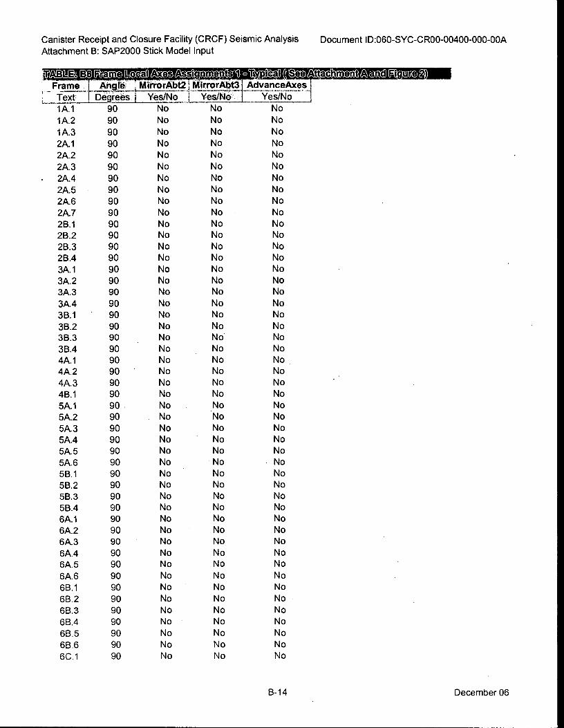
Canister Receipt and Closure Facility (CRCF) Seismic Analysis
Attachment B: SAP2000 Stick Model Input
Document ID:060-SYC-CR00-00400-000-00A
MT:al sigr=ienallaliranD Frame 1 Angie i MirrorAbt21 MirrorAbt3
; -
Text --r Degrees i Yes/No -1 . Yes/No.
1A.1 90 No
1A.2 90 No
1A.3 90 No
2A.1 90 No
2A.2 90 No
2A.3 90 No
• 2A.4 90 No
2A.5 90 No
2A.6 90 No
2A.7 90 No
2B.1 90 No
2B.2 90 No
2B.3 90 No
2B.4 90 No
3A.1 90 No
3A.2 90 No
3A.3 90 No
3A.4 90 No
3B.1 90 No
3B.2 90 No
3B.3 90 . No
3B.4 90 No
4A.1 90 No
4A.2 90 • No
4A.3 90 No
46.1 90 No
5A.1 90 No
5A.2 90 No
5A.3 90 No
5A.4 90 No
5A.5 90 No
5A.6 90 No
5B.1 90 No
5B.2 90 No
5B.3 90 No
5B.4 90 No
6A.1 90 No
6A.2 90 No
6A.3 90 No
6A.4 90 No
6A.5 90 No
6A.6 90 No
6B.1 90 No
6B.2 90 No
6B.3 90 No
6B.4 90 No
6B.5 90 No
6B.6 90 No
6C.1 90 No
AdvanceAxes
Yes/No
No
No
No
No
No
No
No
No
No
No
No
No
No
No
No
No
No
No
No
No
No
No
No
No
No
No
No
No
No
No
No
No
No
No
No
No
No
No
No
No
No
No
No
No
No
No
No
No
No
No
No
No
No
No
No
No
No
No
No
No
No
No
No
No
No
No
No
No
No
No
No
No
No
No
No
No
No
No
No
No
No
No
No
No
No
No
No
No
No
No
No
No
No
No
No
No
No
No
B-14 December 06
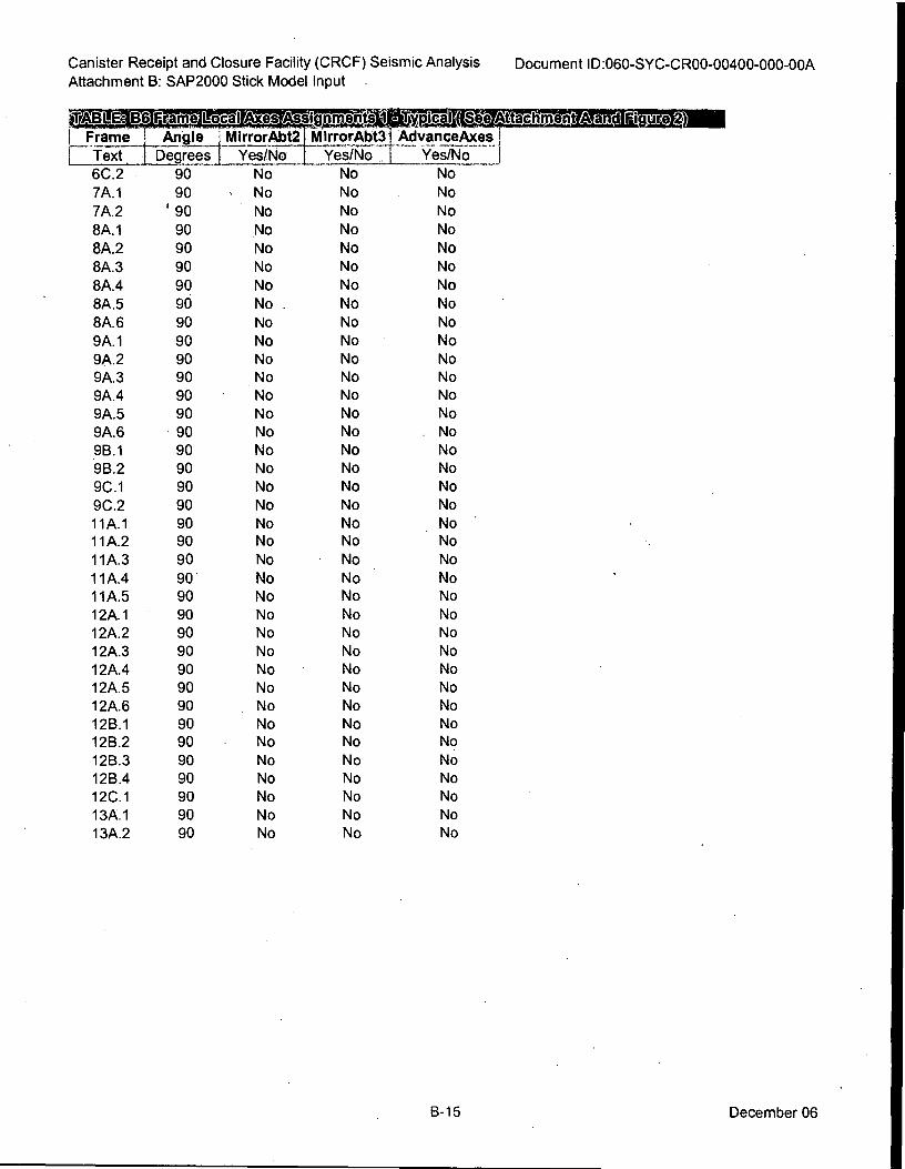
Canister Receipt and Closure Facility (CRCF) Seismic Analysis
Attachment B: SAP2000 Stick Model Input . Document ID:060-SYC-CR00-00400-000-00A
raliTiWrit;s1daTairell Frame I Angle 1 MirrorAbt2 MirrorAbt31 AdvanceAxes I _4
I Text I Degrees I Yes/No Yes/No I Yes/No - I
6C.2 90 No No No
7A.1 90 s No No No
7A.2 ' 90 No No No
8A.1 90 No No No
8A.2 90 No No No
8A.3 90 No No No
8A.4 90 No No No
8A.5 90 No . No No
8A.6 90 No No No
9A.1 90 No No No
9A.2 90 No No No
9A.3 90 No No No
9A.4 90 No No No
9A.5 90 No No No
9A.6 90 No No . No
9B.1 90 No No No
9B.2 90 No No No
9C.1 90 No No No
9C.2 90 No No No
11A.1 90 No No No -
11A.2 90 No No No
11A.3 90 No No No
11A.4 90 . No No No
11A.5 90 No No No
12A.1 90 No No No
12A.2 90 No No No
12A.3 90 No No No
12A.4 90 No No No
12A.5 90 No No No
12A.6 90 No No No
12B.1 90 No No No
12B.2 90 No No No
12B.3 90 No No No
12B.4 90 No No No
12C.1 90 No No No
13A.1 90 No No No
13A.2 90 No No No
B-15 December 06
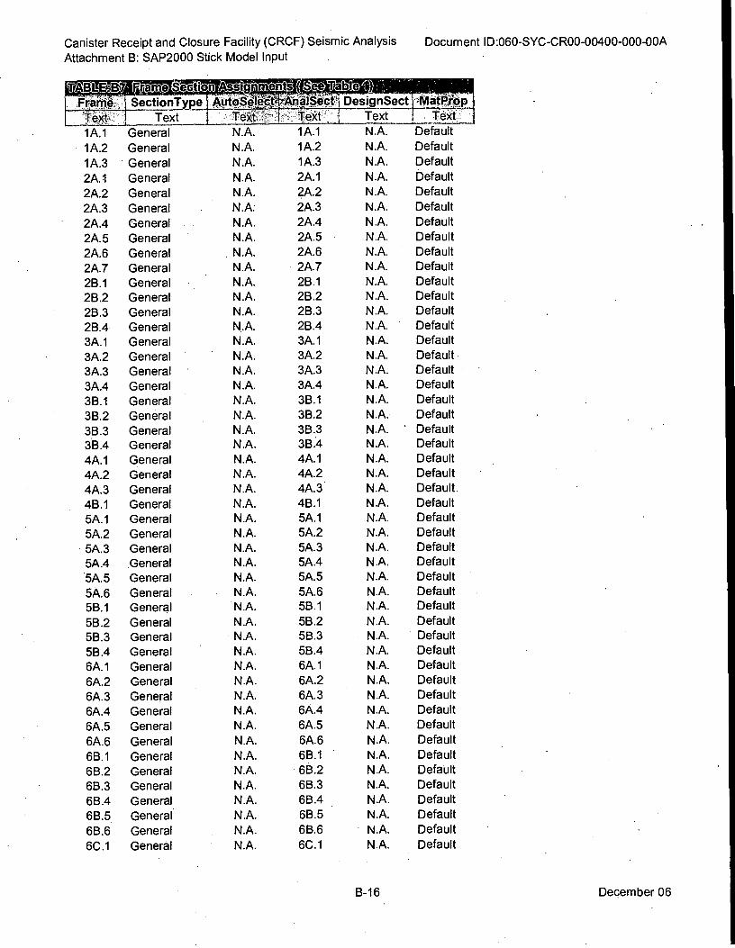
General
General
General
General
General
General
General
General
General
General
General
General
General
General
General
General
General
General
General
General
General
General
General
General
General
General
General
General
General
General
General
General General
General
General
General
General
General
General
General
General
General
General
General
General
General
General
General
General
N.A.
N.A.
N .A.
N.A.
N.A.
N.A.
N.A.
N.A.
N.A.
N.A.
N.A.
N .A.
N.A.
N.A.
N.A.
N.A.
N.A.
N.A.
N.A.
N.A.
N.A.
N .A.
N.A.
N.A.
N.A.
N.A.
N.A.
N.A.
N.A.
N .A.
N.A.
N.A.
N.A.
N .A.
N.A.
N.A.
N.A.
N.A.
N.A.
N.A.
N.A.
N.A.
N.A.
N.A.
N.A.
N .A.
N.A.
N.A.
N.A.
1A.1
1A.2
1A.3
2A.1
2A.2
2A.3
2A.4
2A.5
2A.6
2A.7
2B.1
2B.2
2B.3
2B.4
3A.1
3A.2
3A.3
3A.4
3B.1
3B.2
3B.3
3B.4
4A.1
4A.2
4A.3
4B.1
5A.1
5A.2
5A.3
5A.4
5A.5
5A.6 5B.1
5B.2
5B.3
5B.4
6A.1
6A.2
6A.3
6A.4
6A.5
6A.6
6B.1
6B.2
6B.3
6B .4
6B.5
6B.6
6C.1
Canister Receipt and Closure Facility (CRCF) Seismic Analysis Document ID:060-SYC-CR00-00400-000-00A
Attachment B: SAP2000 Stick Model Input
SectionType I AutoSelatAnalSecti DesignSect AslatPeop Text TeXt. ; Twit I Text Mid
N.A. Default
N.A. Default
N.A. Default
N.A. Default
N.A. Default
N.A. Default
N .A. Default
N.A. Default
N.A. Default
N.A. Default
N.A. Default
N.A. Default
N.A. Default
N.A. Default
N.A. Default
N.A. Default
N .A. Default
N.A. Default
N.A. Default
N.A. Default
N.A. ' Default
N.A. Default
N.A. Default
N.A. Default
N.A. Default
N.A. Default
N.A. Default
N.A. Default
N.A. Default
N.A. Default
N.A. Default
N.A. Default
N.A. Default
N.A. Default
N.A. Default
N.A. Default
N.A. Default
N.A. Default
N.A. Default
N.A. Default
N.A. Default
N.A. Default
N.A. Default
N.A. Default
N.A. Default
N .A. Default
N.A. Default
N.A. Default
N.A. Default
TeXt-
1A.1
1A.2
1A.3
2A.1
2A.2
2A.3
2A.4
2A.5
2A.6
2A.7
2B.1
2B.2
2B.3
2B.4
3A.1
3A.2
3A.3
3A.4
3B.1
3B.2
3B.3 3B.4
4A.1
4A.2
4A.3
4B.1
5A.1
5A.2
5A.3
5A.4
5A.5
5A.6 5B.1
5B .2
5B.3
5B.4
6A.1
6A.2
6A.3
6A.4
6A.5
6A.6
6B.1
6B.2
6B.3
6B.4
6B.5
6B.6
6C.1
B-16 December 06
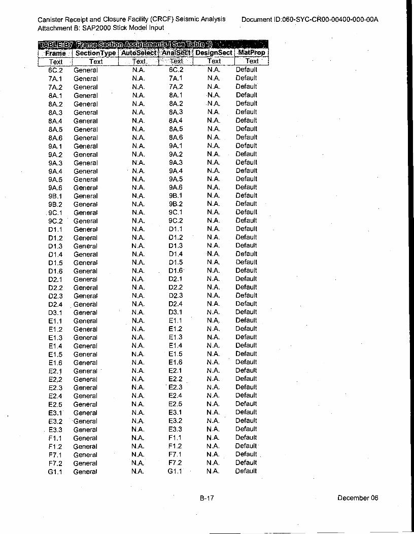
Canister Receipt and Closure Facility (CRCF) Seismic Analysis
Attachment B: SAP2000 Stick Model Input
Document ID:060-SYC-CR00-00400-000-00A
Text
6C.2
7A.1
7A.2
8A.1
8A.2
8A.3
8A.4
8A.5
8A.6
9A.1
9A.2
9A.3
9A.4
9A.5
9A.6
9B.1
9B.2
9C.1
9C.2
D1 .1
D1.2
D1 .3
D1.4
D1.5
D1.6'
D2.1
D2.2
D2.3
D2.4
D3.1
E1.1
E1.2
E1.3
E1.4
E1.5
E1.6
E2.1
E2.2
E2.3
E2.4
E2.5
E3.1
E3.2
E3.3
F1.1
F1.2
F7.1
F7.2
G1.1
LE413 mitifteV
Frame
Text
6C.2
7A.1
7A.2
8A.1
8A.2
8A.3
8A.4
8A.5
8A.6
9A.1
9A.2
9A.3
9A.4
9A.5
9A.6
9B.1
9B.2
9C.1
9C.2
D1.1
D1.2
D1.3
D1.4
D1.5
D1.6
D2.1
D2.2
D2.3
D2.4
D3.1
E1.1
E1.2
E1.3
E1.4
E1.5
E1.6
E2.1
E2.2
E2.3
E2.4
E2.5
E3.1
E3.2
E3.3
F1.1
F1.2
F7.1
F7.2
G1 .1
_lame Section 14ssi r1.2.67 91,71
SectionType AutOSelect
Text _ Text
General
General
General
General
General
General
General
General
General
General
General
General
General
General
General
General
General
General
General
General
General
General
General
General
General
General
General
General
General
General
General
General
General
General
General
General
General
General
General
General
General
General
General
General
General
General
General
General
General
DesignSect
Text_
N.A.
N.A.
N.A.
N.A.
N.A.
N.A.
N.A.
N.A.
N.A.
N.A.
N.A.
N.A.
N.A.
N.A.
N.A.
N.A.
N.A.
N.A.
N.A.
N.A.
N.A.
N.A.
N.A.
N.A.
N.A.
N.A.
N.A.
N.A.
N.A.
N.A.
N.A,
N.A.
N.A.
N.A.
N.A.
N.A.
N.A.
N.A.
N.A.
N.A.
N.A.
N.A.
N.A.
N.A.
N.A.
N.A.
N.A.
N.A.
N.A.
MatProp
Text
Default
Default
Default
Default
Default
Default
Default
Default
Default
Default
Default
Default
Default
Default
Default
Default
Default
Default
Default
Default
Default
Default
Default
Default
Default
Default
Default
Default
Default
Default
Default
Default
Default
Default
Default
Default
Default
Default
Default
Default
Default
Default
Default
Default
Default
Default
Default
Default
Default
N.A.
N.A.
N.A.
N.A.
N.A.
N.A.
NA.
N.A.
N.A.
N.A.
N.A.
NA.
N.A.
N.A.
N.A.
N.A.
N.A.
N.A.
NA.
N.A.
N.A.
N.A.
N.A.
N.A.
N.A.
N.A.
NA.
N.A.
N.A.
N.A.
N.A.
N.A.
N.A.
N.A.
N.A.
N.A.
N.A.
N.A.
N.A.
N.A.
N.A.
N.A.
N.A.
N.A.
N.A.
N.A.
N.A.
N.A.
N.A.
B-17 December 06
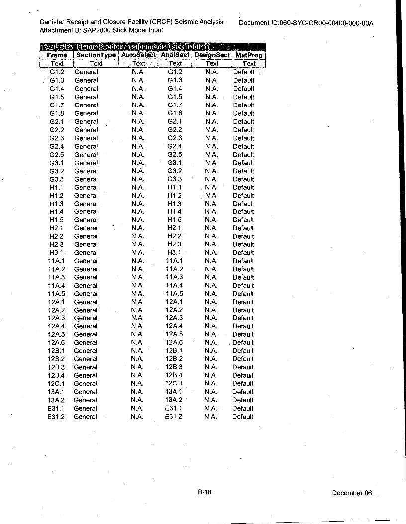
Canister Receipt and Closure Facility (CRCF) Seismic Analysis 'Document ID:060-SYC-CR00-00400-000-00A Attachment B: SAP2000 Stick Model Input
raVcitioTri Florj,„„illtSere:
Text- I Text I Text Text
AutoSeltetiAnalSect DesignSecil MatProp
N.A.
N.A.
N.A.
N.A.
N.A.
N.A.
N A.
N.A.
N.A.
N.A.
N.A.
N.A.
N.A.
N.A.
N.A.
N.A.
N.A.
N.A.
N.A.
N.A.
N.A.
N.A.
N.A.
N.A.
N.A. N.A.
N.A.
N.A.
N.A.
N.A.
N.A.
N.A.
N.A.
N.A.
N.A.
N.A.
N.A.
N.A.
N.A.
N.A.
N.A.
N.A.
N.A.
N.A.
N.A.
N.A.
N.A.
N.A.
N.A.
N.A.
N.A.
N.A.
N.A.
N.A.
N.A.
N.A.
N.A.
N.A.
N.A.
N.A.
N.A.
N.A.
N.A.
N.A.
N.A.
N.A.
N.A.
N.A.
N.A.
N.A.
N.A.
N.A.
N.A.
N.A.
N.A.
N.A.
N.A.
N.A.
N.A.
N.A.
N.A.
N.A.
N.A.
N.A.
N.A.
Frame
Text
G1.2
G1.3
G1.4
G1.5
G1.7
G1.8
G2.1
G2.2
G2.3
G2.4
G2.5
G3.1
G3.2
G3.3
H1.1
H1.2
H1.3 H1.4
H1.5
H2.1
H2.2
H2.3
H3.1
11A.1
11A.2
11A.3
11A.4
11A.5
12A.1
12A.2
12A.3
12A.4
12A.5
12A.6
12B.1
12B.2
12B.3
12B.4
12C.1
13A.1
13A.2
E31.1
E31.2
SectionType
Text
General
General
General
General
General
General
General
General
General
General
General
General
General
General
General
General
General
General
General
General
General
General
General
General
General
General
General
General
General
General
General
General
General
General
General
General
General
General
General
General
General
General
General
AnalSect
G1.2
G1.3
G1.4
G1.5
G1.7
G1.8
G2.1
G2.2
G2.3
G2.4
G2.5
G3.1
G3.2
G3.3
H1.1
H1.2
H1.3
H1.4
H1.5
H2.1
H2.2
H2.3
H3.1
11A.1
11A.2
11A.3
11A.4
11A.5
12A.1
12A.2
12A.3
12A.4
12A.5
12A.6
12B.1
12B.2
12B.3
128.4
12C.1
13A.1
13A.2
E31.1
E31.2
Default
Default
Default
Default
Default
Default
Default
Default
Default
Default
Default
Default
Default
Default
Default
Default
Default
Default
Default
Default
Default
Default
Default
Default
Default
Default
Default
Default
Default
Default
Default
Default
Default
Default
Default
Default
Default
Default
Default
Default
Default
Default
Default
B-18 December 06
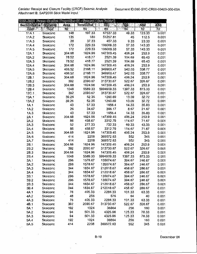
Canister Receipt and Closure Facility (CRCF) Seismic Analysis
Attachment B: SAP2000 Stick Model Input Document ID:060-SYC-CR00-00400-000-00A
.CeJavud ( I.Fa b e
1101#.0#,I. 1 Area To rsCiifis
Texti -To -I ft2 ft4
11A.1 5ksiconc 148 197.33
11A.2 5ksiconc 135 180
11A.3 5ksiconc 28 37.33
11A.4 5ksiconc 172 229.33
11A.5 5ksiconc 172 229.33
12A.1 5ksiconc 304.68 1624.96
12A.2 5ksiconc 78.52 418.77
12A.3 5ksiconc 78.52 418.77
12A.4 5ksiconc 304.68 1624.96
12A.5 5ksiconc 406.52 2168.11
12A.6 5ksiconc 406.52 2168.11
12B.1 5ksiconc 304.68 1624.96
12B.2 5ksiconc 392 2090.67
12B.3 5ksiconc 304.68 1624.96
12B.4 5ksiconc 1048 5589.33
12C.1 5ksiconc • 392 2090.67
13A.1 5ksiconc 39.26 52.35
13A.2 5ksiconc 39.26 52.35
1A.1 5ksiconc 43 57.33
1A.2 5ksiconc 26 34.67
1A.3 5ksiconc 43 57.33
2A.1 5ksiconc 304.68 1624.96
2A.2 5ksiconc 86 458.67
2A.3 5ksiconc 52 277.33
2A.4 5ksiconc 86 458.67
2A.5 5ksiconc 304.68 1624.96
2A.6 5ksiconc 414 2208
2A.7 5ksiconc 414 2208
2B.1 5ksiconc 304.68 1624.96
2B.2 5ksiconc 392 2090.67
2B.3 5ksiconc 304.68 1624.96
2B.4 5ksiconc 1048 5589.33
3A.1 5ksiconc 296 1578.67
3A.2 5ksiconc 296 1578.67
3A.3 5ksiconc 344 1834.67
3A.4 5ksiconc . 344 1834.67
3B.1 5ksiconc 296 1578.67
3B.2 5ksiconc 296 1578.67
3B.3 5ksiconc 344 1834.67
3B.4 5ksiconc 344 1834.67
4A.1 5ksiconc 76 405.33
4A.2 5ksiconc 48 256
4A.3 5ksiconc 76 405.33
4B.1 5ksiconc 392 2090.67
5A.1 5ksiconc 192 1024
5A.2 5ksiconc 94 501.33
5A.3 5ksiconc 94 501.33
5A.4 5ksiconc 192 1024
5A.5 5ksiconc 414 2208
•ft4
67537.33
51257.81
457.33
106009.33
106009.33
147309.45
2521.39
2521.39
147309.45
349900.47
349900.47
147309.45
313730.67
147309.45
5994909.33
313730.67
1260.69
1260.69
1656.4
366.17
1656.4 147309.45
3312.79
732.33
3312.79 147309.45
369572.63
369572.63
147309.45
313730.67
147309.45
5994909.33
135074.67
135074.67
212018.67
212018.67
135074.67
135074.67
212018.67
212018.67
2286.33
576
2286.33
313730.67
36864
4325.96
4325.96
36864
369572.63
49.33
45
9.33
57.33
57.33
406.24
104.69
104.69
406.24
542.03
542.03
406.24
522.67
406.24
1397.33
522.67
13.09
13.09
14.33
8.67
14.33
406.24
114.67
69.33
114.67
406.24
552
552
406.24
522.67
406.24
1397.33
394.67
394.67
458.67
458.67
394.67
394.67
458.67
458.67
101.33
64
101.33
522.67
256
125.33
125.33
256
552
AS2
123.33
112.5
23.33
143.33
143.33
253.9
65.43
65.43
253.9
338.77
338.77
253.9
326.67
253.9
873.33
326.67
32.72
32.72
35.83
21.67
35.83 253.9
71.67
43.33
71.67
253.9 345
345
253.9
326.67
253.9
873.33
246.67
246.67
286.67
286.67
246.67
246.67
286.67
286.67
63.33
40
63.33
326.67
160
78.33
78.33
160
345
AS3
ft2
0.001
0.001
0.001
0.001
0.001
0.001
0.001
0.001
0.001
0.001
0.001
0.001
0.001
0.001
0.001
0.001
0.001
0.001
0.001
0.001
0.001 0.001
0.001
0.001
0.001
0.001
0.001
0.001
0.001
0.001
0.001
0.001
0.001
0.001
0.001
0.001
0.001
0.001
0.001
0.001
0.001
0.001
0.001
0.001
0.001
0.001
0.001
0.001
0.001
B-19 December 06
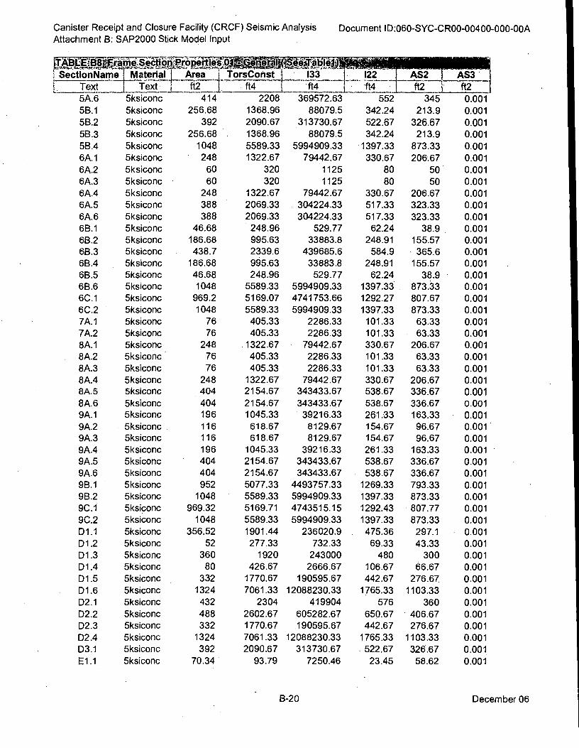
Canister Receipt and Closure Facility (CRCF) Seismic Analysis
Attachment B: SAP2000 Stick Model Input Document ID:060-SYC-CR00-00400-000-00A
ITAtittst8otkos,0 kopotigf a ppoo:si 9 ,-A.: tatogi
L 1 _ 1 L , 'ft4 1 ft4 ft2 ' ft2-
1 Secti
Text
onName 1 Material 1 Area Text ft2
j ft4TorsConst 1 133_ j 122 ' AS2 AS3 1 _____ .......-
5A.6 5ksiconc 414 2208 369572.63
..... -
5B.1 5ksiconc 256.68 1368.96 88079.5
5B.2 5ksiconc 392 2090.67 313730.67
5B.3 5ksiconc 256.68 1368.96 88079.5
5B.4 5ksiconc 1048 5589.33 5994909.33
6A.1 5ksiconc 248 1322.67 79442.67
6A.2 5ksiconc 60 320 1125
6A.3 5ksiconc • 60 320 1125
6A.4 5ksiconc 248 1322.67 79442.67
6A.5 5ksiconc 388 2069.33 304224.33
6A.6 5ksiconc 388 2069.33 304224.33
6B.1 5ksiconc 46.68 248.96 529.77
6B.2 5ksiconc 186.68 995.63 33883.8
6B.3 5ksiconc 438.7 2339.6 439685.6
6B.4 5ksiconc 186.68 995.63 33883.8
6B.5 5ksiconc 46.68 248.96 529.77
6B.6 5ksiconc 1048 5589.33 5994909.33
6C.1 5ksiconc 969.2 5169.07 4741753.66
6C.2 5ksiconc 1048 5589.33 5994909.33
7A.1 5ksiconc 76 405.33 2286.33
7A.2 5ksiconc 76 405.33 2286.33
8A.1 5ksiconc 248 1322.67 79442.67
8A.2 5ksiconc 76 405.33 2286.33
8A.3 5ksiconc 76 405.33 2286.33
8A.4 5ksiconc 248 1322.67 79442.67
8A.5 5ksiconc 404 2154.67 343433.67
8A.6 5ksiconc 404 2154.67 343433.67
9A.1 5ksiconc 196 1045.33 39216.33
9A.2 5ksiconc 116 618.67 8129.67
9A.3 5ksiconc 116 618.67 8129.67
9A.4 5ksiconc 196 1045.33 39216.33
9A.5 5ksiconc 404 2154.67 343433.67
9A.6 5ksiconc 404 2154.67 343433.67
9B.1 5ksiconc 952 5077.33 4493757.33
9B.2 5ksiconc 1048 5589.33 5994909.33
9C.1 5ksiconc 969.32 5169.71 4743515.15
9C.2 5ksiconc 1048 5589.33 5994909.33
D1.1 5ksiconc 356.52 1901.44 236020.9
D1.2 5ksiconc 52 277.33 732.33
D1.3 5ksiconc 360 1920 243000
D1.4 5ksiconc 80 426.67 2666.67
D1.5 5ksiconc 332 1770.67 190595.67
D1.6 5ksiconc 1324 7061.33 12088230.33
D2.1 5ksiconc 432 2304 419904
D2.2 5ksiconc 488 2602.67 605282.67
D2.3 5ksiconc 332 1770.67 190595.67
D2.4 5ksiconc 1324 7061.33 12088230.33
D3.1 5ksiconc 392 2090.67 313730.67
E1.1 5ksiconc 70.34 93.79 7250.46
552 345 0.001
342.24 213.9 0.001
522.67 326.67 0.001
342.24 213.9 0.001
1397.33 873.33 0.001
330.67 206.67 0.001
80 50 0.001
80 50 0.001
330.67 206.67 0.001
517.33 323.33 0.001
517.33 323.33 0.001
62.24 38.9 0.001
248.91 155.57 0.001
584.9 365.6 0.001
248.91 155.57 0.001
62.24 38.9 0.001
1397.33 873.33 0.001
1292.27 807.67 0.001
1397.33 873.33 0.001
101.33 63.33 0.001
101.33 63.33 0.001
330.67 206.67 0.001
101.33 63.33 0.001
101.33 63.33 0.001
330.67 206.67 0.001
538.67 336.67 0.001
538.67 336.67 0.001
261.33 163.33 0.001
154.67 96.67 0.001
154.67 96.67 0.001
261.33 163.33 0.001
538.67 336.67 0.001
538.67 336.67 0.001
1269.33 793.33 0.001
1397.33 873.33 0.001
1292.43 807.77 0.001
1397.33 873.33 0.001
475.36 297.1 0.001
69.33 43.33 0.001
480 300 0.001
106.67 66.67 0.001
442.67 276.67 0.001
1765.33 1103.33 0.001
576 360 0.001
650.67 406.67 0.001
442.67 276.67 0.001
1765.33 1103.33 0.001
522.67 326.67 0.001
23.45 58.62 0.001
B-20 December 06
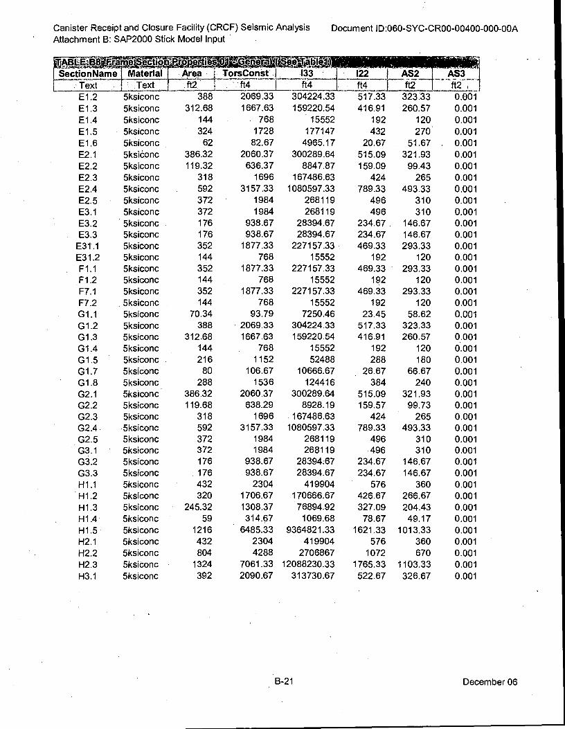
2069.33
1667.63
768
1728
82.67
2060.37
636.37
1696
3157.33
1984
1984
938.67
938.67
1877.33
768
1877.33
768
1877.33
768
93.79
2069.33
1667.63
768
1152
106.67
1536
2060.37
638.29
1696
3157.33
1984 1984
938.67
938.67
2304
1706.67
1308.37
314.67
6485.33
2304
304224.33
159220.54
15552
177147
4965.17
300289.64
8847.87
167486.63
1080597.33
268119
268119
28394.67
28394.67
227157.33
15552
227157.33
15552
227157.33
15552
7250.46
304224.33
159220.54
15552
52488
10666.67
124416
300289.64
8928.19
167486.63
1080597.33
268119 268119
28394:67
28394.67
419904
170666.67
76894.92
1069.68
9364821.33
419904
Canister Receipt and Closure Facility (CRCF) Seismic Analysis
Attachment B: SAP2000 Stick Model Input Document ID:060-SYC-CR00-00400-000-00A
TABLE438 / rains Sectici
SectionName I Material 11.111111.1111MO
122 j AS2 _AS3 ft4 nft2 ft2 Text
E1.2
E1.3
E1.4
E1.5
E1.6
E2.1
E2.2
E2.3
E2.4
E2.5
E3.1
E3.2
E3.3
E31.1
E31.2
F1.1
F1.2
F7.1
F7.2
G1.1
G1.2
G1.3
G1.4
G1.5
G1.7
G1.8
G2.1
G2.2
G2.3
G2.4
G2.5
G3.1
G3.2
G3.3
H1.1
H1.2
H1.3
H1.4
H1.5
H2.1
H2.2
H2.3
H3.1
Text
5ksiconc
5ksiconc
5ksiconc
5ksiconc
5ksiconc
5ksioonc
5ksiconc
5ksiconc
5ksiconc
5ksiconc
5ksiconc
5ksiconc
5ksiconc
5ksiconc
5ksiconc
5ksiconc
5ksiconc
5ksiconc
5ksiconc
5ksiconc
5ksiconc
5ksiconc
5ksiconc
5ksiconc
5ksiconc
5ksiconc
5ksiconc
5ksiconc
5ksiconc
5ksiconc
5ksiconc
5ksiconc
5ksiconc
5ksiconc
5ksiconc
5ksiconc
5ksiconc
5ksiconc
5ksiconc
5ksiconc
5ksiconc
5ksiconc
5ksiconc
*JO
Area TorsConst 1 133
ft2: ...ft4 "f14-
388
312.68
144
324
62
386.32
119.32
318
592
372
372
176
176
352
144
352
144
352
144
70.34
388
312.68
144
216
80
288
386.32
119.68
318
592
372 372
176
176
432
320
245.32
59
1216
432
804 4288 2706867
1324 7061.33 12088230.33
392 2090.67 313730.67
517.33
416.91
192
432
20.67
515.09
159.09
424
789.33
496
496
234.67
234.67
469.33
192
469.33
192
469.33
192
23.45
517.33
416.91
192
288
26.67
384
515.09
159.57
424
789.33
496
496
234.67
234.67
576
426.67
327.09
78.67
1621.33
576
1072
1765.33
522.67
323:33
260.57
120
270
51.67
321.93
99.43
265
493.33
310
310
146.67
146.67
293.33
120
293.33
120
293.33
120
58.62
323.33
260.57
120
180
66.67
240
321.93
99.73
265
493.33
310
310
146.67
146.67
360
266.67
204.43
49.17
1013.33
360
670
1103.33
326.67
0.001
0.001
0.001
0.001
0.001
0.001
0.001
0.001
0.001
0.001
0.001
0.001
0.001
0.001
0.001
0.001
0.001
0.001
0.001
0.001
0.001
0.001
0.001
0.001
0.001
0.001
0.001
0.001
0.001
0.001
0.001
0.001
0.001
0.001
0.001
0.001
0.001
0.001
0.001
0.001
0.001
0.001
0.001
B-21 December 06
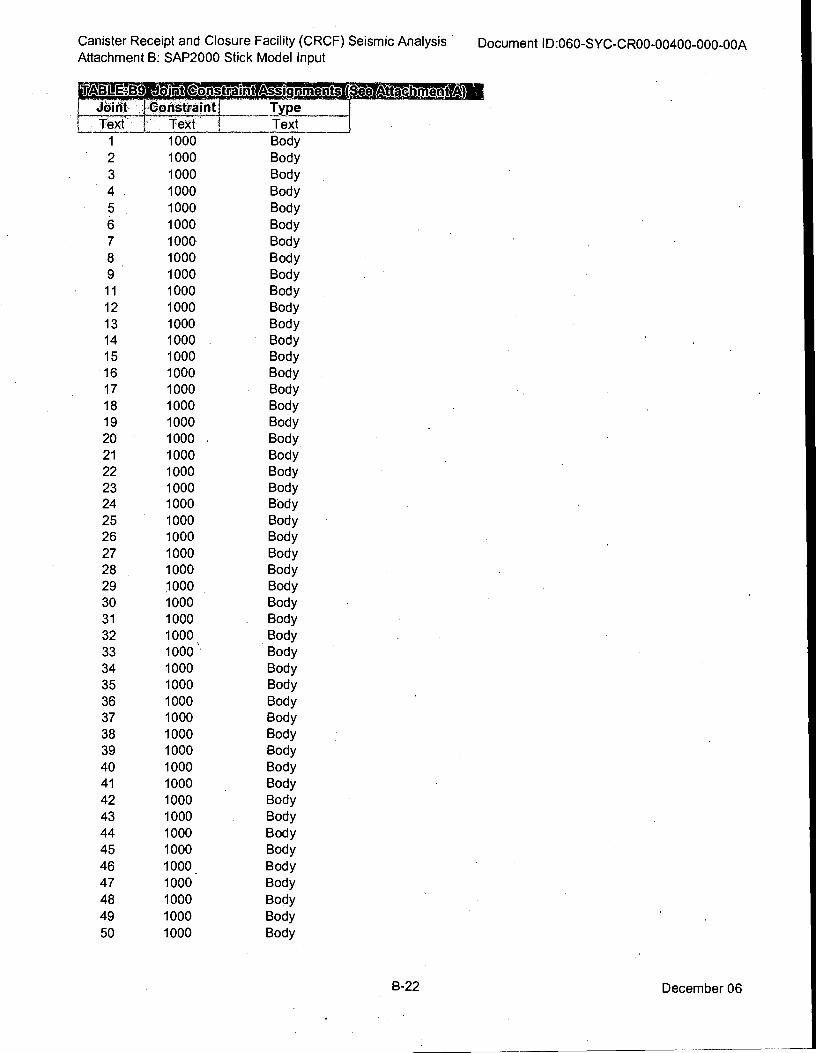
Canister Receipt and Closure Facility (CRCF) Seismic Analysis Document ID:060-SYC-CR00-00400-000-00A Attachment B: SAP2000 Stick Model Input
Joint J_Constraint I Type
Text I Text ! Text
1 1000 Body
2 1000 Body
3 1000 Body
4 1000 Body
5 1000 Body
6 1000 Body
7 1000 Body
8 1000 Body
9 1000 Body
11 1000 Body
12 1000 Body
13 1000 Body
14 1000 Body
15 1000 Body
16 1000 Body
17 1000 Body
18 1000 Body
19 1000 Body
20 1000 Body
21 1000 Body
22 1000 Body
23 1000 Body
24 1000 Body
25 1000 Body
26 1000 Body
27 1000 Body
28 1000 Body
29 1000 Body
30 1000 Body
31 1000 Body
32 1000 , Body
33 1000 Body
34 1000 Body
35 1000 Body
36 1000 Body
37 1000 Body
38 1000 Body
39 1000 Body
40 1000 Body
41 1000 Body
42 1000 Body
43 1000 Body
44 1000 Body
45 1000 Body
46 1000 . Body
47 1000 Body
48 1000 Body
49 1000 Body
50 1000 Body
6-22 December 06
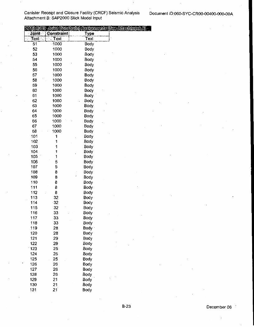
Canister Receipt and Closure Facility (CRCF) Seismic Analysis Document ID:060-SYC-CR00-00400-000-00A Attachment B: SAP2000 Stick Model Input
onstraint Type
Text 1 Text
51 1000 Body
52 1000 Body
53 1000 Body
54 1000 Body
55 1000 Body
56 1000 Body
57 1000 Body
58 1000 Body
59 1000 Body
60 1000 Body
61 1000 Body
62 '1000 . Body
63 1000 Body
64 1000 Body
65 1000 Body
66 1000 Body
67 1000 Body
68 1000 Body
101 1 Body
102 1 Body
103 1 Body
104 1 . Body
105 1 Body
106 5 Body
107 5 Body
108 8 Body
109 8 ' Body
110 8 Body
111 8 Body
112 8 Body
113 32 Body
114 32 Body
115 32 Body
116 33 Body
117 33 Body
118 33 Body
119 28 Body
120 28 Body
121 29 Body
122 29 Body
123 25 Body
124 25 Body
125 25 Body
126 26 Body
127 26 Body
128 26 Body
129 21 Body
130 21 Body
131 21 Body
B-23 December 06
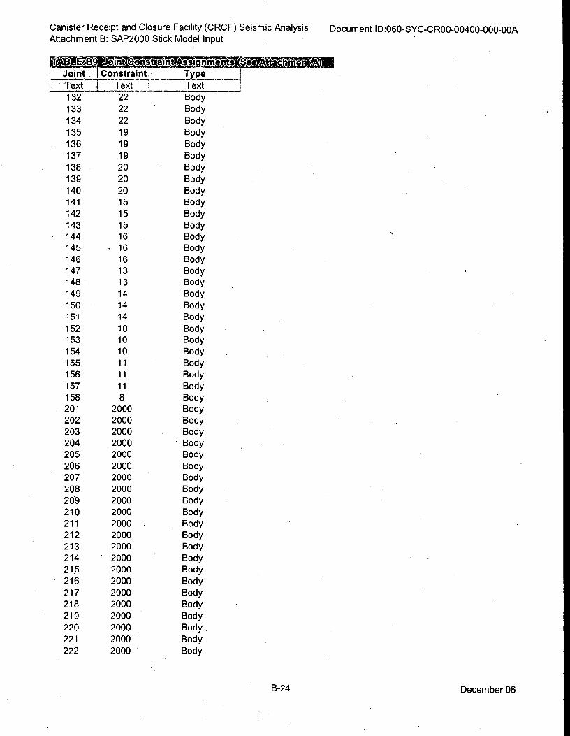
BLE1119 Ward. Bro Joint LConstrainti_ Type
Text i Text 1 Text
Canister Receipt and Closure Facility (CRCF) Seismic Analysis
Attachment B: SAP2000 Stick Model Input Document ID:060-SYC-CR00-00400-000-00A
132 22
133 22
134 22
135 19
136 19
137 19
138 20
139 20
140 20
141 15
142 15
143 15
144 16
145 - 16
146 16
147 13
148 13
149 14
150 14
151 14
152 10
153 10
154 10
155 11
156 11
157 11
158 8
201 2000
202 2000
203 2000
204 2000
205 2000
206 2000
207 2000
208 2000
209 2000
210 2000
211 2000
212 2000
213 2000
214 2000
215 2000
216 2000
217 2000
218 2000
219 2000
220 2000
221 2000
222 2000
Body
Body
Body
Body
Body
Body
Body
Body
Body
Body
Body
Body
Body
Body
Body
Body
Body
Body
Body
Body
Body
Body
Body
Body
Body
Body
Body
Body
Body
Body
' Body
Body
Body
Body
Body
Body
Body
Body
Body
Body
Body
Body
Body
Body
Body
Body
Body
Body
Body
B-24 December 06
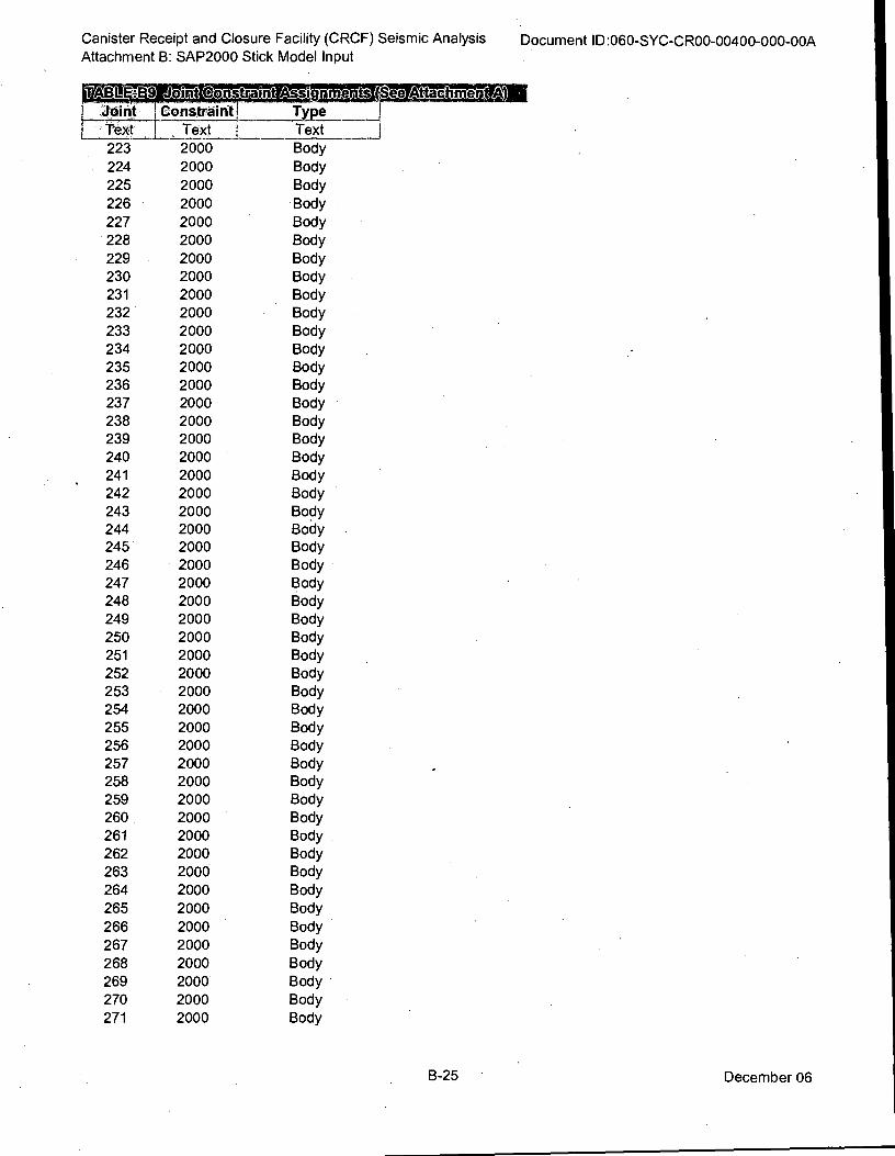
Canister Receipt and Closure Facility (CRCF) Seismic Analysis
Attachment B: SAP2000 Stick Model Input Document ID:060-SYC-CR00-00400-000-00A
I:j_I.oint I Constraint! Type
Text I , Text I Text
223 2000 Body
224 2000 Body
225 2000 Body
226 2000 •Body
227 2000 Body
228 2000 Body
229 2000 Body
230 2000 Body
231 2000 Body
232 2000 Body
233 2000 Body
234 2000 Body
235 2000 Body
236 2000 Body
237 2000 Body
238 2000 Body
239 2000 Body
240 2000 Body
241 2000 Body
242 2000 Body .
243 2000 Body
244 2000 Body
245 2000 Body
246 2000 Body •
247 2000 Body
248 2000 Body
249 2000 Body
250 2000 Body
251 2000 Body
252 2000 Body
253 2000 Body
254 2000 Body
255 2000 Body
256 2000 Body
257 2000 Body
258 2000 Body
259 2000 Body
260 2000 Body
261 2000 Body .
262 2000 Body
263 2000 Body
264 2000 Body
265 2000 Body
266 2000 Body
267 2000 Body
268 2000 Body
269 2000 Body
270 2000 Body
271 2000 Body
B-25 December 06
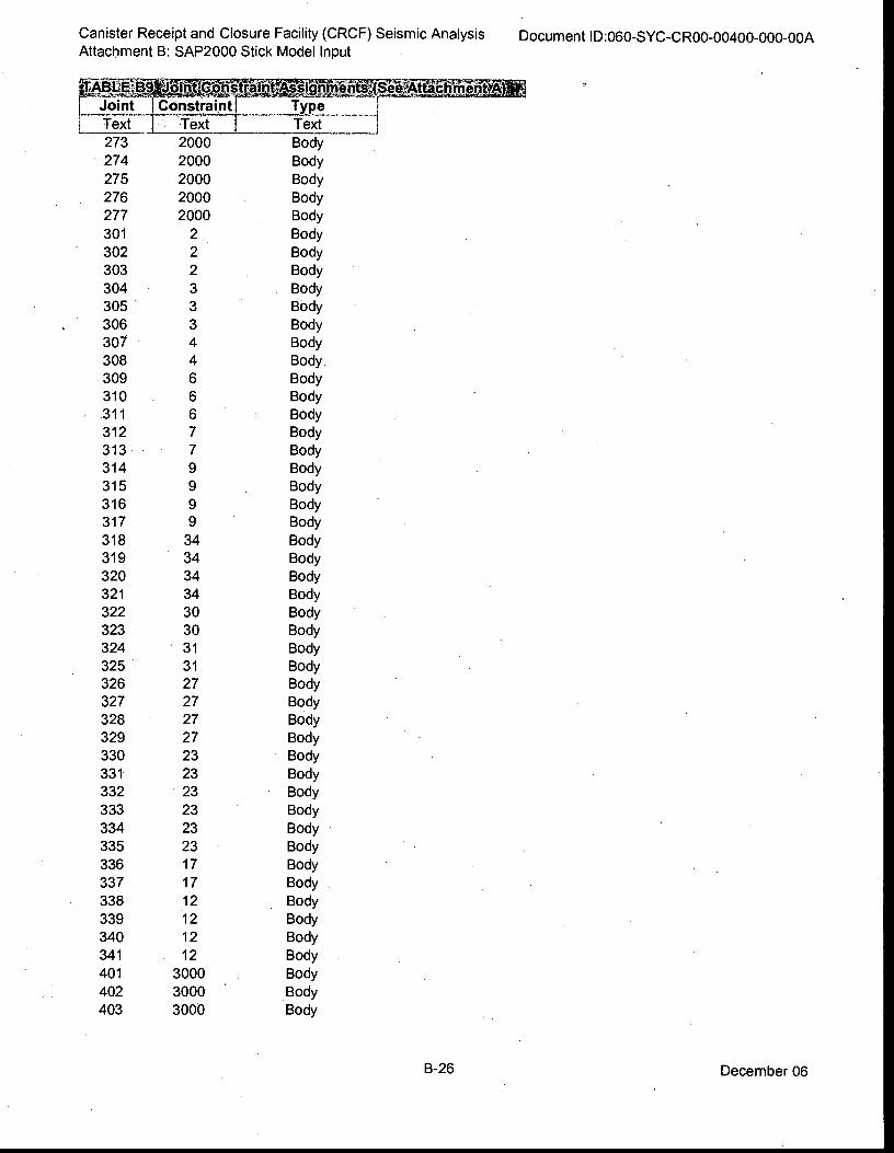
Canister Receipt and Closure Facility (CRCF) Seismic Analysis
Attachment B: SAP2000 Stick Model Input Document ID:060-SYC-CR00-00400-000-00A
K-Mkgig L Joint L Text
273
274
275
276
277
301
302
303
304
305
306
307
308
309
310
311
312
313
314
315
316
317
318
319
320
321
322
323
324
325
326
327
328
329
330
331
332
333
334
335
336
337
338
339
340
341
401
402
403
Constraint!
Text
2000
2000
2000
2000
2000
2
2
2
3
3
3
4
4
6
6
6
7
7
9 9
9
9
34
34
34
34
30
30
31
31 27
27
27
27
23
23
23
23
23
23
17
17
12
12
12
12
3000
3000
3000
Type Text
Body
Body
Body
Body
Body
Body
Body
Body
Body
Body
Body
Body
Body
Body
Body
Body
Body
Body
Body
Body
Body
Body
Body
Body
Body
Body
Body
Body
Body
Body
Body
Body
Body
Body
Body
Body
Body
Body
Body
Body
Body
Body
Body
Body
Body
Body
Body
Body
Body
B-26 December 06
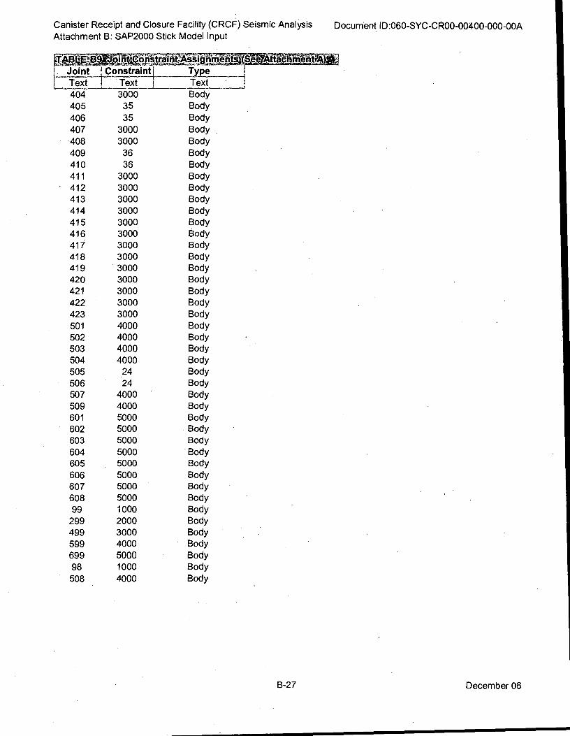
Canister Receipt and Closure Facility (CRCF) Seismic Analysis
Attachment B: SAP2000 Stick Model Input
4.41:),LEIB,9:*), in.,ter*Saint:ASigiu_oeati
:... Joint :.! Constrainti type
Text 1 Text i Text
404 3000 Body
405 35 Body
406 35 Body
407 3000 Body
408 3000 Body
409 36 Body
410 36 Body
411 3000 Body
412 3000 Body
413 3000 Body
414 3000 Body
415 3000 Body
416 3000 Body.
417 3000 Body
418 3000 Body
419 3000 Body
420 3000 Body
421 3000 Body
422 3000 Body
423 3000 Body
501 4000 Body
502 4000 Body
503 4000 Body
504 4000 Body
505 24 Body
506 24 Body
507 4000 Body
509 4000 Body
601 5000 Body
602 5000 Body
603 5000 Body
604 5000 Body
605 5000 Body
606 5000 Body
607 5000 Body
608 5000 Body
99 1000 Body
299 2000 Body
499 3000 Body
599 4000 Body
699 5000 Body
98 1000 Body
508 4000 Body
Document ID:060-SYC-CR00-00400-000-00A
,CSMALtigerhaeLitrtA
B-27 December 06
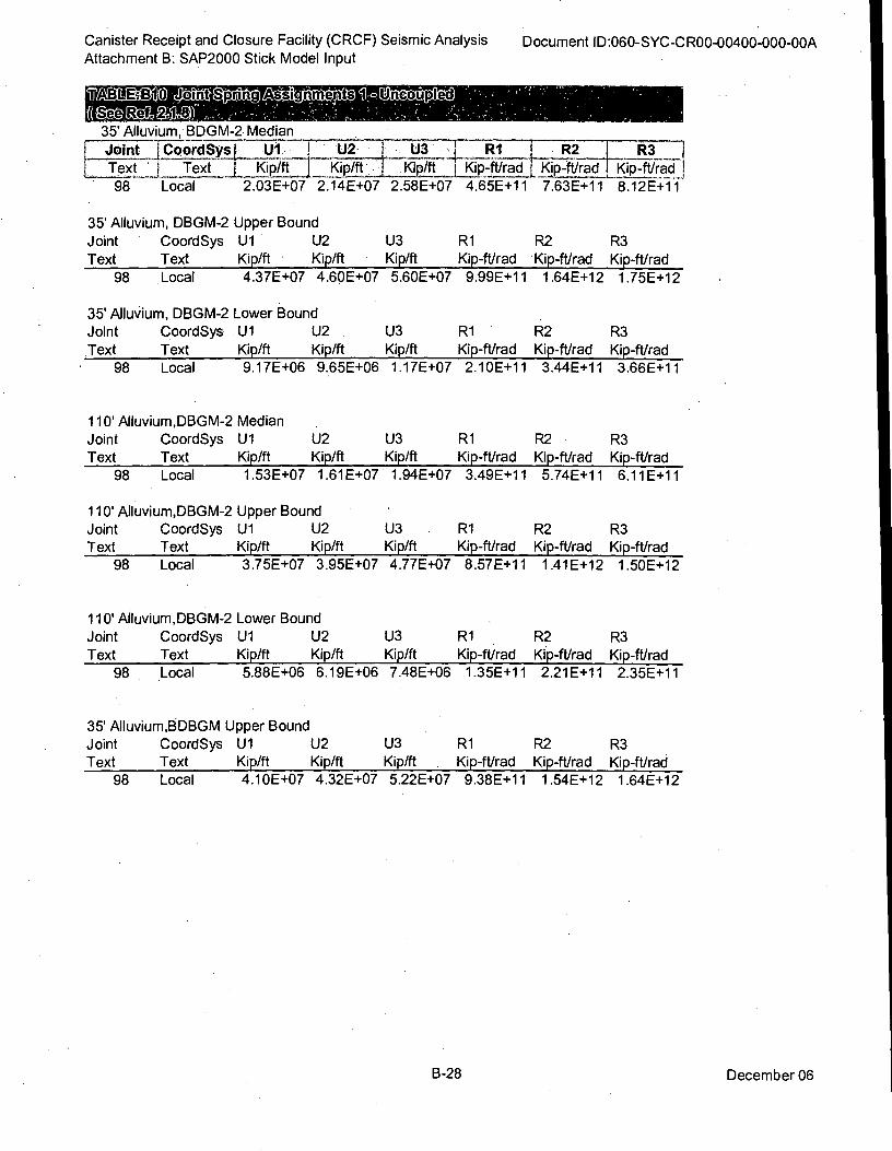
98 Local
Canister Receipt and Closure Facility (CRCF) Seismic Analysis Document ID:060-SYC-CR00-00400-000-00A Attachment B: SAP2000 Stick Model Input
9fABLEiI310 Joint SiringAs7gi
((@20 ,12:1149c0)" 35' Alluvium, BDGM-2 Median
Joint CoordSys U1•U2 113 R1 R2 R3 1
L___ Text i Text _ Kip/ft Kip/ft . Kip/ft Kip-ft/rad Kip-ft/rad Kip-ft/rad 2.03E+07 2.14E+07 2.58E+07 4.65E+11 7.63E+11 8.12E+1
35' Alluvium, DBGM-2
Joint CoordSys
Text Text
98 Local
35' Alluvium, DBGM-2
Joint CoordSys
Text Text
• 98 Local
110' Alluvium,DBGM-2
Joint CoordSys
Text Text
98 Local
110' Alluvium,DBGM-2
Joint CoordSys
Text Text
98 Local
Upper Bound
U1 U2
Kip/ft Kip/ft
4.37E+07 4.60E+07
Lower Bound
U1 U2
Kip/ft Kip/ft
9.17E+06 9.65E+06
Median
U1 U2
Kip/ft Kip/ft
1.53E+07 1.61E+07
Upper Bound
U1 U2
Kip/ft Kip/ft
3.75E+07 3.95E+07
U3 R1 R2 R3 Kip/ft Kip-ft/rad Kip-ft/rad Kip-ft/rad
5.60E+07 9.99E+11 1.64E+12 1.75E+12
U3 R1 R2 R3 Kip/ft Kip-ft/rad Kip-ft/rad Kip-ft/rad
1.17E+07 2.10E+11 3.44E+11 3.66E+11
U3 R1 R2 R3 Kip/ft Kip-ft/rad Kip-ft/rad Kip-ft/rad
1.94E+07 3.49E+11 5.74E+11 6.11E+11
U3 R1 R2 R3 Kip/ft Kip-ft/rad Kip-ft/rad Kip-ft/rad
4.77E+07 8.57E+11 1.41E+12 1.50E+12
110' Alluvium,DBGM-2 Lower Bound
Joint CoordSys U1 U2 U3 R1 R2 R3
Text Text Kip/ft Kip/ft Kip/ft Kip-ft/rad Kip-ft/rad Kip-ft/rad
98 Local 5.88E+06 6.19E+06 7.48E+06 1.35E+11 2.21E+11 2.35E+11
35' Alluvium,BDBGM Upper Bound
Joint CoordSys U1 U2 U3 R1 R2 R3
Text Text Kip/ft Kip/ft Kip/ft Kip-ft/rad Kip-ft/rad Kip-ft/rad
98 Local 4.10E+07 4.32E+07 5.22E+07 9.38E+11 1.54E+12 1.64E+12
B-28 December 06
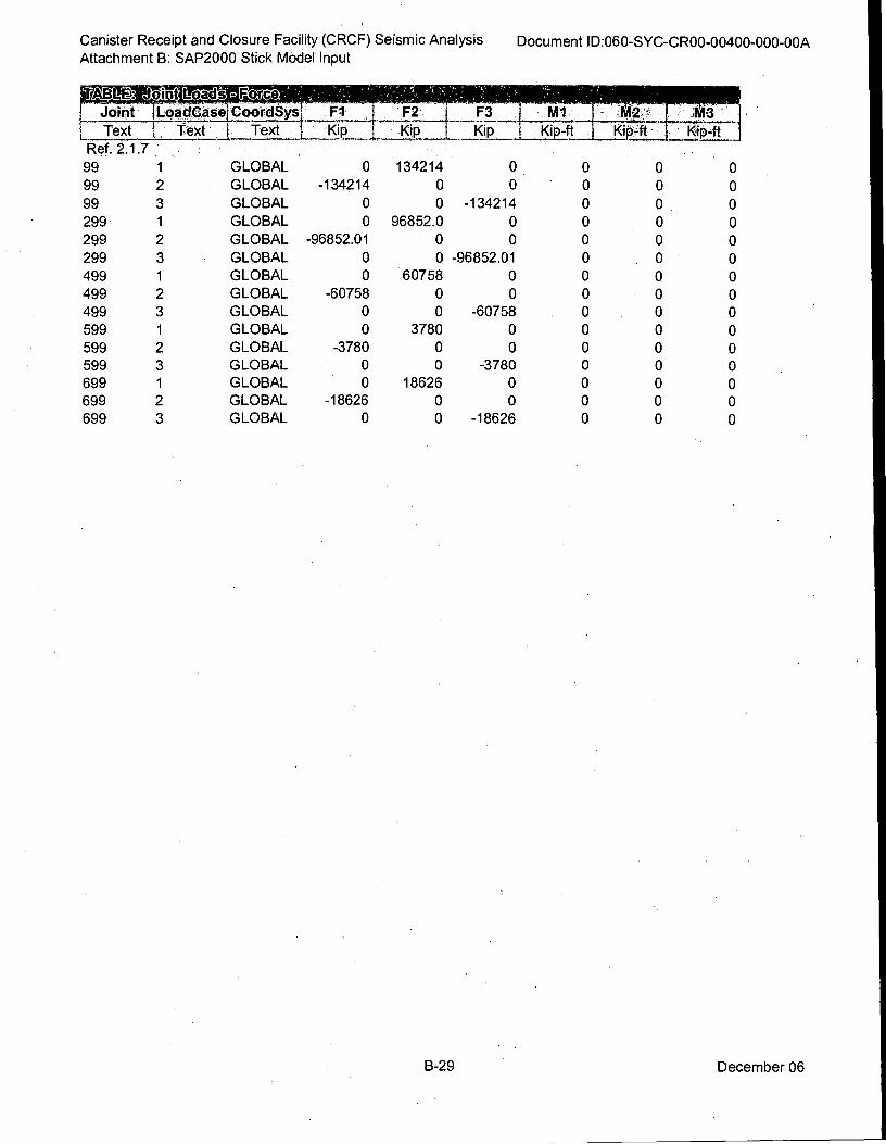
nig Joint ILoadCasej CoordSys
Text 1 , Text I Text
Canister Receipt and Closure Facility (CRCF) Seismic Analysis
Attachment B: SAP2000 Stick Model Input
Document ID:060-SYC-CR00-00400-000-00A
GLOBAL
GLOBAL
GLOBAL
GLOBAL
GLOBAL
GLOBAL
GLOBAL
GLOBAL
GLOBAL
GLOBAL
GLOBAL
GLOBAL
GLOBAL
GLOBAL
GLOBAL
Ref. 2.1.7
99 1
99 2
99 3
299 1
299 2
299 3
499 1
499 2
499 3
599 1
599 2
599 3
699 1
699 2
699 3
Fl F2.1 ,F3
KipI Kip I _Kip
0 134214 0
-134214 0 0
0 0 -134214
0 96852.0 0
-96852.01 0 0
0 0 -96852.01
0 60758 0
-60758 0 0
0 0 -60758
0 3780 0
-3780 0 0
0 0 -3780
0 18626 0
-18626 0 0
0 0 -18626
Kip-ft I
Kip-ft . j KipTt i _
M1 .7L_LFit:- LI: -1---
0 0 0
0 0 0
0 0 0
0 0 0
0 0 0
0 0 0
0 0 0
0 0 0
0 0 0
0 0 0
0 0 0
0 0 0
0 0 0
0 0 0
0 0 0
B-29 December 06
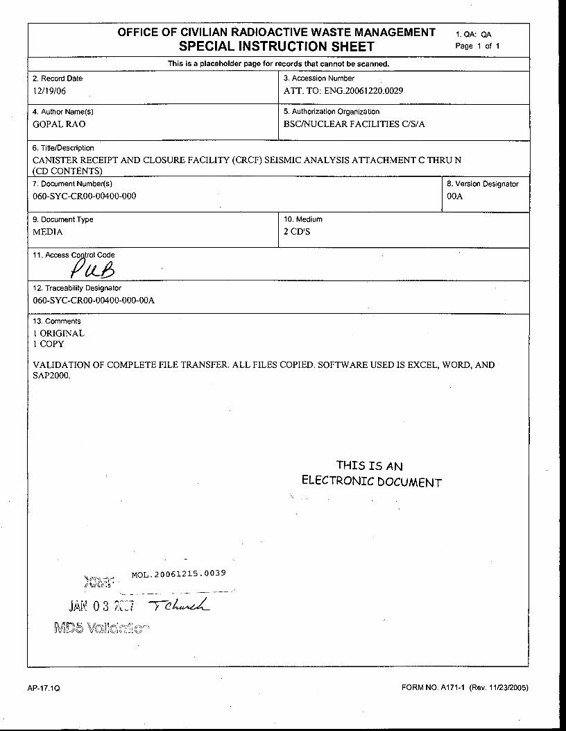
OFFICE OF CIVILIAN RADIOACTIVE WASTE MANAGEMENT 1. QA: QA
SPECIAL INSTRUCTION SHEET Page 1 of 1
This is a placeholder page for records that cannot be scanned.
2. Record Date 3. Accession Number
12/19/06 ATT. TO: ENG.20061220.0029
4. Author Name(s) 5. Authorization Organization
GOPAL RAO BSC/NUCLEAR FACILITIES C/S/A
6. Title/Description
CANISTER RECEIPT AND CLOSURE FACILITY (CRCF) SEISMIC ANALYSIS ATTACHMENT C THRU N
(CD CONTENTS)
7. Document Number(s) 8. Version Designator
060-SYC -CR00 -00400-000 00A
9. Document Type 10. Medium
MEDIA 2 CD'S
11. Access , Co trol Code
eL6 .
12. Traceability Designator
060-SYC-CR00-00400-000-00A
13. Comments
1 ORIGINAL
1 COPY
VALIDATION OF COMPLETE FILE TRANSFER. ALL FILES COPIED. SOFTWARE USED IS EXCEL, WORD, AND
SAP2000.
THIS IS AN
- ELECTRONIC DOCUMENT
. .
-
MOL.20061215. 0039
-- -- --- - — ----
JM 03 KJ
MD 5 Vo,HOia.» ---,
FORM NO. A171-1 (Rev. 11/23/2005) AP-17.1Q
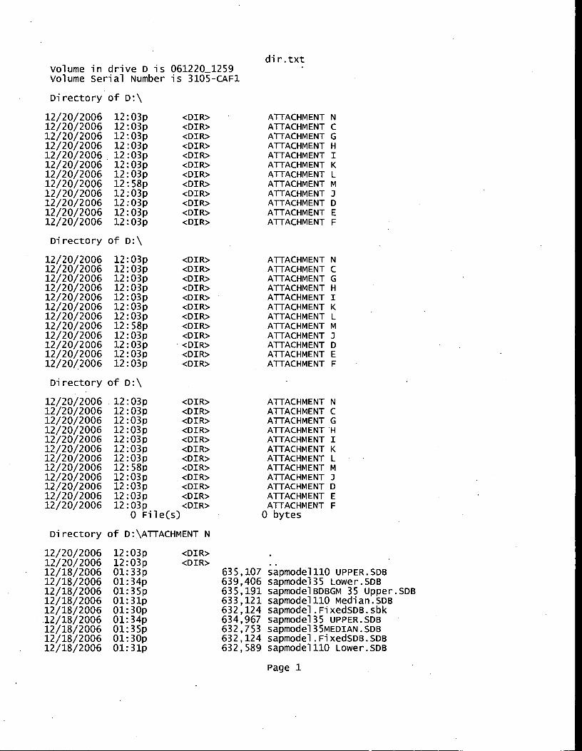
dir.txt volume in drive D is 061220_1259 Volume Serial Number is 3105-CAF1
Directory of D:\
12/20/2006 12:03p <DIR> 12/20/2006 12:03p
12/20/2006 12:03p <DIR>
12/20/2006 12:03p <DIR>
12/20/2006 12:03p <DIR>
12/20/2006 12:03p <DIR>
12/20/2006 12:03p <DIR>
12/20/2006 12:58p <DIR>
12/20/2006 12:03p <DIR>
12/20/2006 12:03p <DIR>
12/20/2006 12:03p <DIR>
12/20/2006 12:03p <DIR>
Directory of D:\
12/20/2006 12:03p 12/20/2006 12:03p 12/20/2006 12:03p 12/20/2006 12:03p 12/20/2006 12:03p 12/20/2006 12:03p 12/20/2006 12:03p 12/20/2006 12:58p 12/20/2006 12:03p 12/20/2006 12:03p 12/20/2006 12:03p 12/20/2006 12:03p
Directory of D:\
12/20/2006 12:03p <DIR>
12/20/2006 12:03p <DIR>
12/20/2006 12:03p <DIR>
12/20/2006 12:03p <DIR>
12/20/2006 12:03p <DIR>
12/20/2006 12:03p <DIR>
12/20/2006 12:03p <DIR>
12/20/2006 12:58p <DIR>
12/20/2006 12:03p <DIR>
12/20/2006 12:03p <DIR>
12/20/2006 12:03p <DIR>
12/20/2006 12:03p <DIR> 0 File(s)
Directory of D:\ATTACHMENT N
<DIR> <DIR> <DIR> <DIR> <DIR> <DIR> <DIR> <DIR> <DIR> <DIR> <DIR> <DIR>
ATTACHMENT N ATTACHMENT C ATTACHMENT G ATTACHMENT H ATTACHMENT I
ATTACHMENT K
ATTACHMENT L
ATTACHMENT M ATTACHMENT ATTACHMENT D ATTACHMENT E ATTACHMENT F
ATTACHMENT N ATTACHMENT C ATTACHMENT G ATTACHMENT H ATTACHMENT I
ATTACHMENT K
ATTACHMENT L
ATTACHMENT M ATTACHMENT J ATTACHMENT D
ATTACHMENT E ATTACHMENT F
ATTACHMENT N ATTACHMENT C ATTACHMENT G ATTACHMENT H ATTACHMENT I
ATTACHMENT K
ATTACHMENT L ATTACHMENT M ATTACHMENT ATTACHMENT D ATTACHMENT E ATTACHMENT F 0 bytes
12/20/2006 12:03p 12/20/2006 12:03p 12/18/2006 01:33p 12/18/2006 01:34p 12/18/2006 01:35p 12/18/2006 01:31p 12/18/2006 01:30p 12/18/2006 01:34p 12/18/2006 01:35p 12/18/2006 01:30p 12/18/2006 01:31p
<DIR> <DIR>
635,107 sapmode1110 UPPER.SDB 639,406 sapmode135 Lower.SDB 635,191 sapmodelBDBGM 35 Upper.SDB 633,121 sapmode1110 median.sm 632,124 sapmodel.FixedsDB.sbk 634,967 sapmode135 UPPER.SDB 632,753 sapmode135MEDIAN.SDB 632,124 sapmodel.FixedsDB.SDB 632,589 sapmode1110 Lower.SDB
Page 1
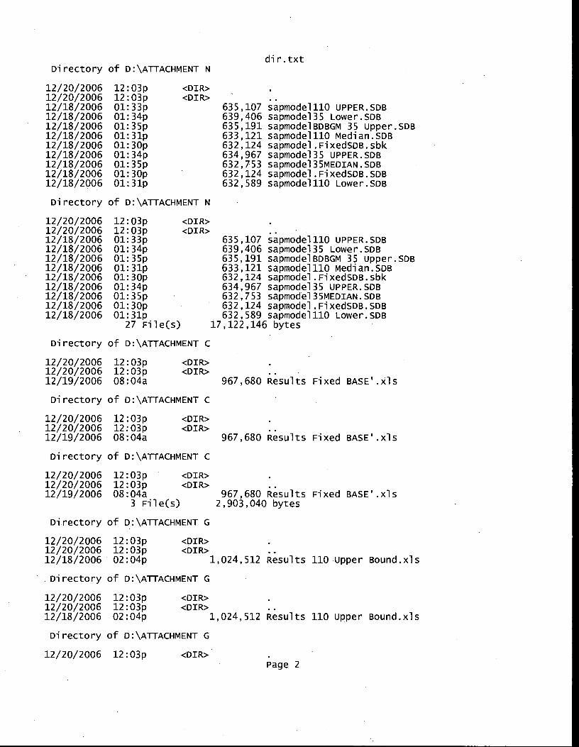
dir.txt Directory of D:\ATTACHmENT N
<DIR> 12/20/2006 12:03p 12/20/2006 12:03p 12/18/2006 01:33p 12/18/2006 01:34p 12/18/2006 01:35p 12/18/2006 01:31p 12/18/2006 01:30p 12/18/2006 01:34p 12/18/2006 01:35p 12/18/2006 01:30p 12/18/2006 01:31p
635,107 sapmode1110 UPPER.SDB 639,406 sapmode135 Lower.SDB 635,191 sapmodelBDBGM 35 Upper.SDB 633,121 sapmode1110 Median.SDB 632,124 sapmodel.FixedSDB.sbk 634,967 sapmode135 UPPER.SDB 632,753 sapmode135MEDIAN.SDB 632,124 sapmodel.FixedSDB.SDB 632,589 sapmode1110 Lower.SDB
Directory of D:\ATTACHMENT N
12/20/2006 12:03p 12/20/2006 12:03p 12/18/2006 01:33p 12/18/2006 01:34p 12/18/2006 01:35p 12/18/2006 01:31p 12/18/2006 01:30p 12/18/2006 01:34p 12/18/2006 01:35p 12/18/2006 01:30p 12/18/2006 01:31p
27 File(s)
<DIR> <DIR> •
635,107 sapmode1110 uPPER.sDB 639,406 sapmode135 Lower.SDB 635,191 sapmodelBDBGm 35 upper.sDB 633,121 sapmode1110 median.SDB 632,124 sapmodel.FixedSDB.sbk 634,967 sapmode135 UPPER.SDB 632,753 sapmode135MEDIAN.SDB 632,124 sapmodel.FixedSDB.SDB 632,589 sapmode1110 Lower.SDB
17,122,146 bytes
Directory of D:\ATTAcHmENT c
12/20/2006 12:03p <DIR> .
12/20/2006 12:03p <DIR> ..
12/19/2006 08:04a 967,680 Results Fixed BASE'.xls
Directory of D:\ATTACHMENT C
12/20/2006 12:03p <DIR>
12/20/2006 12:03p <DIR>
12/19/2006 08:04a 967,680 Results Fixed BASE'.xls
Directory of D:\ATTACHMENT C
12/20/2006 12:03p <DIR>
12/20/2006 12:03p <DIR>
12/19/2006 08:04a 967,680 Results Fixed BASE'.xls 3 File(s) 2,903,040 bytes
Directory of D:\ATTACHMENT G
12/20/2006 12:03p <DIR>
12/20/2006 12:03p <DIR>
12/18/2006 02:04p 1,024,512 Results 110 upper Bound.xls
• Directory of D:\ATTACHMENT G
12/20/2006 12:03p <DIR>
12/20/2006 12:03p <DIR>
12/18/2006 02:04p 1,024,512 Results 110 Upper Bound.xls
Directory of D:\ATTACHMENT G
12/20/2006 12:03p <DIR>
Page 2
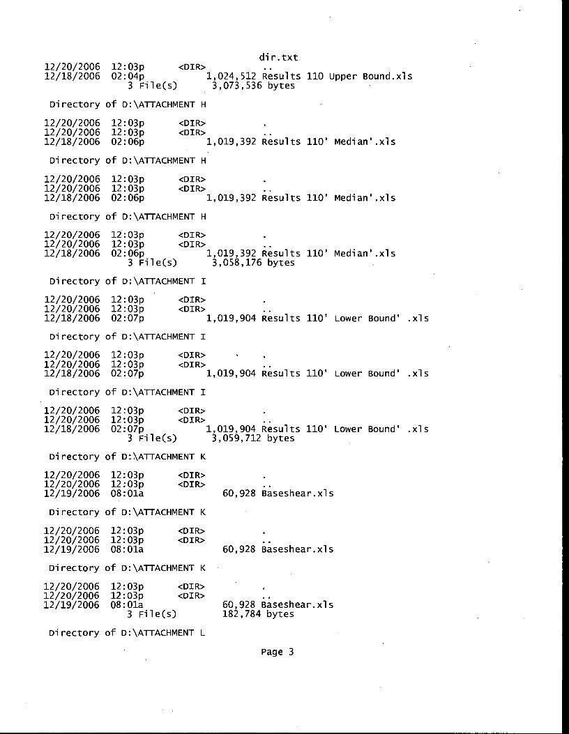
dir.txt
12/20/2006 12:03p <DIR> ..
12/18/2006 02:04p 1,024,512 Results 110 upper Bound.xls 3 File(s) 3,073,536 bytes
Directory of D:\ATTACHMENT H
12/20/2006 12:03p <DIR>
12/20/2006 12:03p <DIR> ..
12/18/2006 02:06p 1,019,392 Results 110' median'.xls
Directory of D:\ATTACHMENT H
12/20/2006 12:03p <DIR>
12/20/2006 12:03p <DIR> ..
12/18/2006 02:06p 1,019,392 Results 110' median'.xls
Directory of D:\ATTACHMENT H
12/20/2006 12:03p <DIR>
12/20/2006 12:03p <DIR> ..
12/18/2006 02:06p 1,019,392 Results 110' median'.xls 3 File(s) 3,058,176 bytes
Directory of DAATTACHMENT I
12/20/2006 12:03p <DIR> .
12/20/2006 12:03p <DIR> ..
12/18/2006 02:07p 1,019,904 Results 110' Lower Bound' .xls
Directory of DAATTACHMENT I
12/20/2006 12:03p <DIR> . .
12/20/2006 12:03p <DIR>
12/18/2006 02:07p 1,019,904 Results 110' Lower Bound' .xls
Directory of D:\ATTACHMENT I
12/20/2006 12:03p <DIR>
12/20/2006 12:03p <DIR> ..
12/18/2006 02:07p 1,019,904 Results 110' Lower Bound' .xls 3 File(s) 3,059,712 bytes
Directory of D:\ATTACHMENT K
12/20/2006 12:03p <DIR>
12/20/2006 12:03p <DIR> ..
12/19/2006 08:01a 60,928 Baseshear.xls
Directory of D:\ATTACHMENT K
12/20/2006 12:03p <DIR> .
12/20/2006 12:03p <DIR>
12/19/2006 08:01a 60,928 B'aseshear.xls
Directory of D:\ATTACHMENT K
12/20/2006 12:03p <DIR>
12/20/2006 12:03p <DIR> ..
12/19/2006 08:01a 60,928 Baseshear.xls 3 File(s) 182,784 bytes
Directory of D:\ATTACHMENT L
Page 3
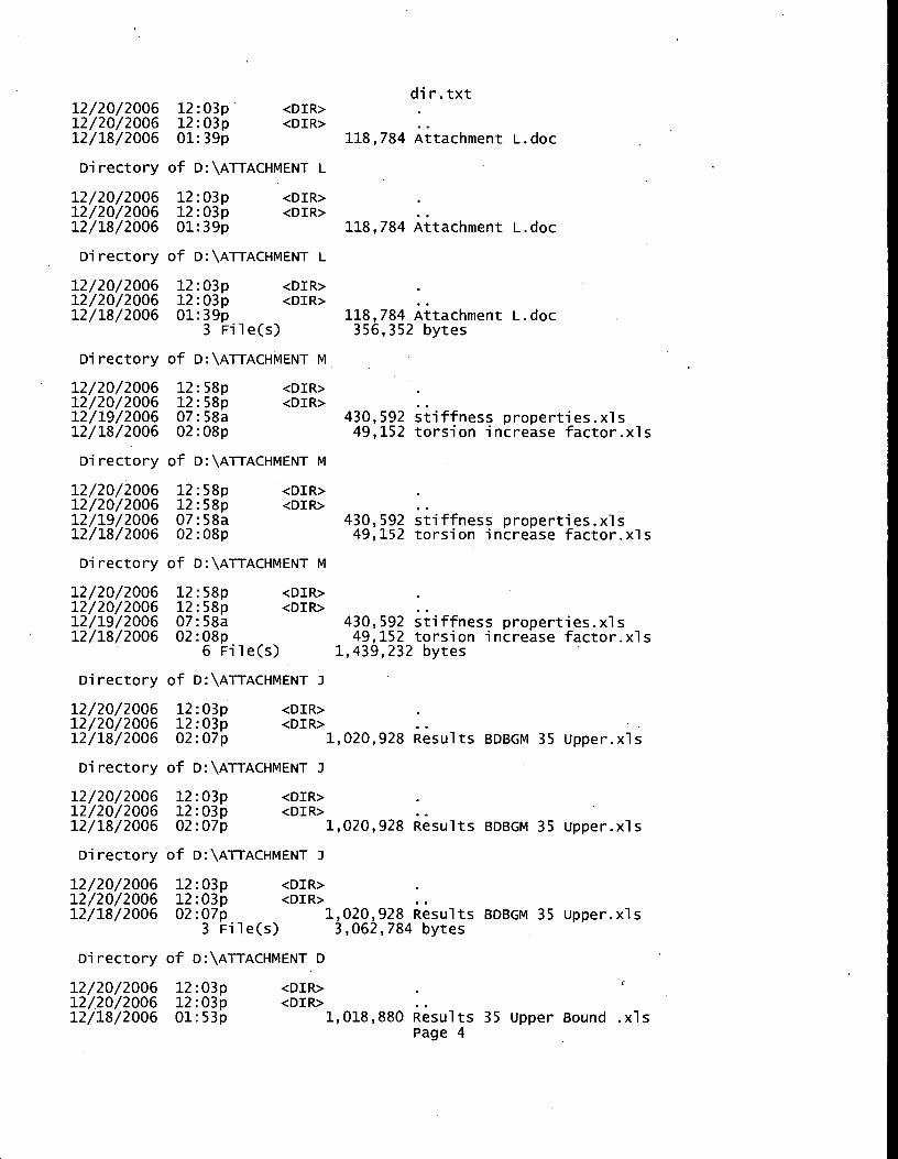
12/20/2006 12:03p 12/20/2006 12:03p 12/18/2006 02:07p
<DIR> <DIR>
1,020,928 Results BDBGM 35 upper.x
12/20/2006 12:03p 12/20/2006 12:03p 12/18/2006 01:39p
dir.txt <DIR> <DIR>
118,784 Attachment L.doc
Directory of D:\ATTACHMENT L
12/20/2006 12:03p <DIR> .
12/20/2006 12:03p <DIR> ..
12/18/2006 01:39p 118,784 Attachment L.doc
Directory of D:\ATTACHMENT L
12/20/2006 12:03p <DIR> .
12/20/2006 12:03p <DIR> .
12/18/2006 01:39p 118,784 Attachment L.doc 3 File(s) 356,352 bytes
Directory of D:\ATTACHMENT M
12/20/2006 12:58p 12/20/2006 12:58p 12/19/2006 07:58a 12/18/2006 02:08p
<DIR> <DIR>
430,592 stiffness properties.xls 49,152 torsion increase factor.xls
Directory of D:\ATTACHMENT M
12/20/2006 12:58p 12/20/2006 12:58p 12/19/2006 07:58a 12/18/2006 02:08p
<DIR> <DIR>
430,592 stiffness properties.xls 49,152 torsion increase factor.xls
Directory of D:\ATTACHMENT M
12/20/2006 12:58p <DIR> .
12/20/2006 12:58p <Dill> ..
12/19/2006 07:58a 430,592 stiffness properties.xls
12/18/2006 02:08p 49,152 torsion increase factor.xls 6 File(s) 1,439,232 bytes
Directory of D:\ATTACHMENT J
Directory of D:\ATTACHMENT J
12/20/2006 12:03p <DIR> .
12/20/2006 12:03p <DIR> ..
12/18/2006 02:07p 1,020,928 Results BDBGM 35 upper.xls
Directory of D:\ATTACHMENT J
12/20/2006 12:03p <DIR> .
12/20/2006 12:03p <DIR> ..
12/18/2006 02:07p 1,020,928 Results BDBGM 35 upper.xls 3 File(s) 3,062,784 bytes
Directory of D:\ATTACHMENTD
12/20/2006 12:03p <DIR>
12/20/2006 12:03p <DIR>
12/18/2006 01:53p 1,018,880 Results 35 upper Bound .xls Page 4
dir.txt
Directory of D:\ATTACHMENT D
12/20/2006 12:03p <DIR> .
12/20/2006 12:03p <DIR> ..
12/18/2006 01:53p 1,018,880 Results 35 Upper Bound .xls
Directory of D:\ATTACHMENT D
12/20/2006 12:03p <DIR> .
12/20/2006 12:03p <DIR> 12/18/2006 01:53p 1,018,880 Results 35 Upper Bound .xls
3 File(s) 3,056,640 bytes
Directory of D:\ATTACHMENT E
12/20/2006 12:03p <DIR>
12/20/2006 12:03p <DIR>
12/18/2006 01:53p 1,020,416 Results 35 Median.xls
Directory of D:\ATTACHMENT E
12/20/2006 12:03p <DIR>
12/20/2006 12:03p <DIR>
12/18/2006 01:53p 1,020,416 Results 35 Median.xls
.Directory of D:\ATTACHMENT E
12/20/2006 12:03p <DIR>
12/20/2006 12:03p <DIR>
12/18/2006 01:53p 1,020,416 Results 35 Median.xls 3 File(s) 3,061,248 bytes
Directory of D:\ATTACHMENT F
12/20/2006 12:03p <DIR>
12/20/2006 12:03p <DIR>
12/18/2006 01:53p 1,027,072 Results 35' Lower Bound.xls
Directory of D:\ATTACHMENT F
12/20/2006 12:03p <DIR>
12/20/2006 12:03p <DIR>
12/18/2006 01:53p 1,027,072 Results 35' Lower Bound.xls
Directory of DAATTACHMENT F
12/20/2006 12:03p <DIR>
12/20/2006 12:03p <DIR>
12/18/2006 01:53p 1,027,072 Results 35' Lower Bound.xls 3 File(s) 3,081,216 bytes
Total Files Listed: 63 File(s)
108 Dir(s) 43,456,866 bytes
0 bytes free
Page 5