Embed Size (px)
Citation preview
Team Logo
Here
(If You Want)
1
CanSat 2018
Preliminary Design Review (PDR)
Outline
Version 1.2
# 4128
TEAM CERVOS
CanSat 2018 PDR: #4128 Team CERVOS
Team Logo
Here
(If You Want)
2
Presentation Outline
Presenter: Burhan Kaplan
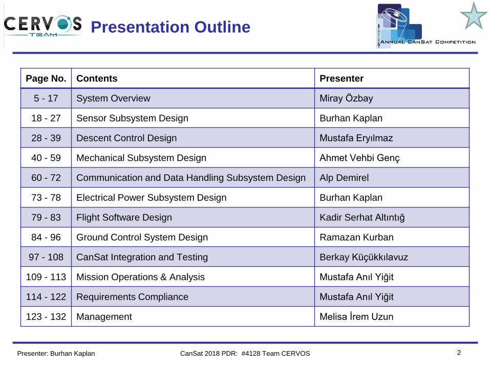
Page No. Contents Presenter
5 - 17 System Overview Miray Özbay
18 - 27 Sensor Subsystem Design Burhan Kaplan
28 - 39 Descent Control Design Mustafa Eryılmaz
40 - 59 Mechanical Subsystem Design Ahmet Vehbi Genç
60 - 72 Communication and Data Handling Subsystem Design Alp Demirel
73 - 78 Electrical Power Subsystem Design Burhan Kaplan
79 - 83 Flight Software Design Kadir Serhat Altıntığ
84 - 96 Ground Control System Design Ramazan Kurban
97 - 108 CanSat Integration and Testing Berkay Küçükkılavuz
109 - 113 Mission Operations & Analysis Mustafa Anıl Yiğit
114 - 122 Requirements Compliance Mustafa Anıl Yiğit
123 - 132 Management Melisa İrem Uzun
CanSat 2018 PDR: #4128 Team CERVOS
Team Logo
Here
(If You Want)
3
Team Organization
Presenter: Burhan Kaplan CanSat 2018 PDR: #4128 Team CERVOS
Team Logo
Here
(If You Want)
4
Acronyms
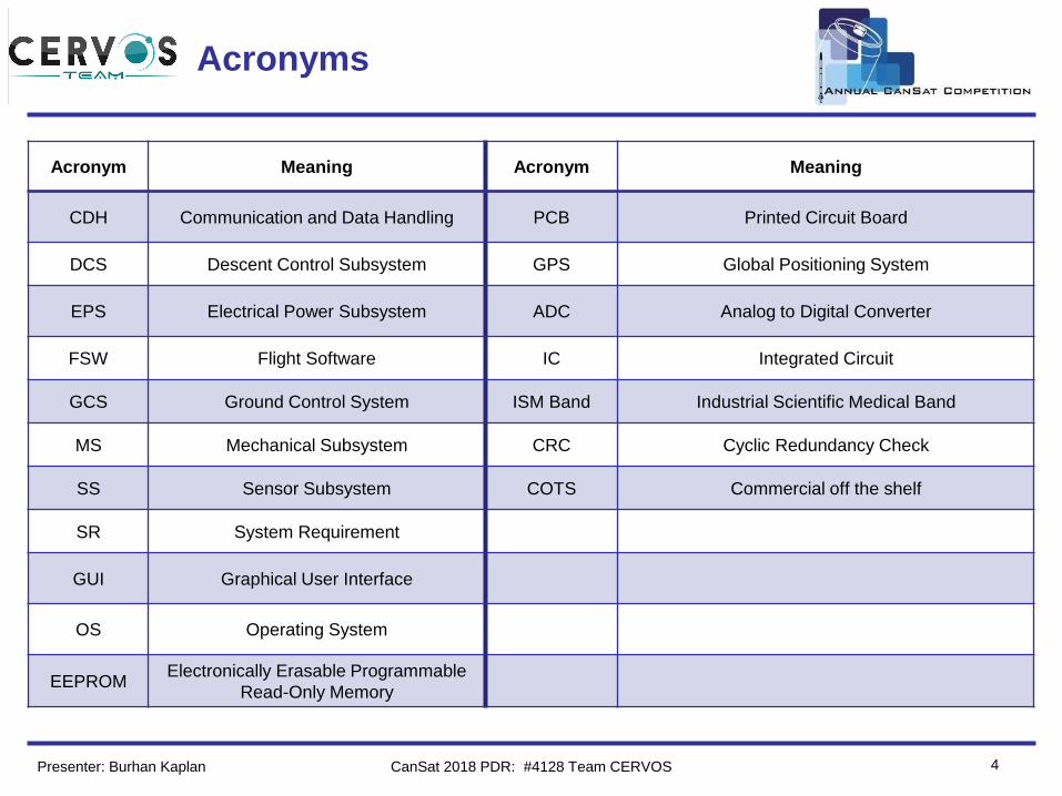
Acronym Meaning Acronym Meaning
CDH Communication and Data Handling PCB Printed Circuit Board
DCS Descent Control Subsystem GPS Global Positioning System
EPS Electrical Power Subsystem ADC Analog to Digital Converter
FSW Flight Software IC Integrated Circuit
GCS Ground Control System ISM Band Industrial Scientific Medical Band
MS Mechanical Subsystem CRC Cyclic Redundancy Check
SS Sensor Subsystem COTS Commercial off the shelf
SR System Requirement
GUI Graphical User Interface
OS Operating System
EEPROMElectronically Erasable Programmable
Read-Only Memory
Presenter: Burhan Kaplan CanSat 2018 PDR: #4128 Team CERVOS
Team Logo
Here
(If You Want)
5
Systems Overview
Miray Özbay
CanSat 2018 PDR: #4128 Team CERVOS
Team Logo
Here
(If You Want)
6
Mission Summary
Presenter: Miray Özbay
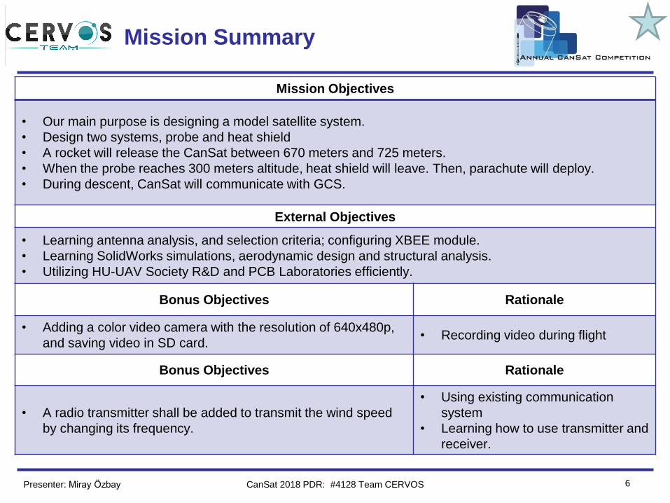
Mission Objectives
• Our main purpose is designing a model satellite system.
• Design two systems, probe and heat shield
• A rocket will release the CanSat between 670 meters and 725 meters.
• When the probe reaches 300 meters altitude, heat shield will leave. Then, parachute will deploy.
• During descent, CanSat will communicate with GCS.
External Objectives
• Learning antenna analysis, and selection criteria; configuring XBEE module.
• Learning SolidWorks simulations, aerodynamic design and structural analysis.
• Utilizing HU-UAV Society R&D and PCB Laboratories efficiently.
Bonus Objectives Rationale
• Adding a color video camera with the resolution of 640x480p,
and saving video in SD card.• Recording video during flight
Bonus Objectives Rationale
• A radio transmitter shall be added to transmit the wind speed
by changing its frequency.
• Using existing communication
system
• Learning how to use transmitter and
receiver.
CanSat 2018 PDR: #4128 Team CERVOS
Team Logo
Here
(If You Want) System Requirement Summary
7
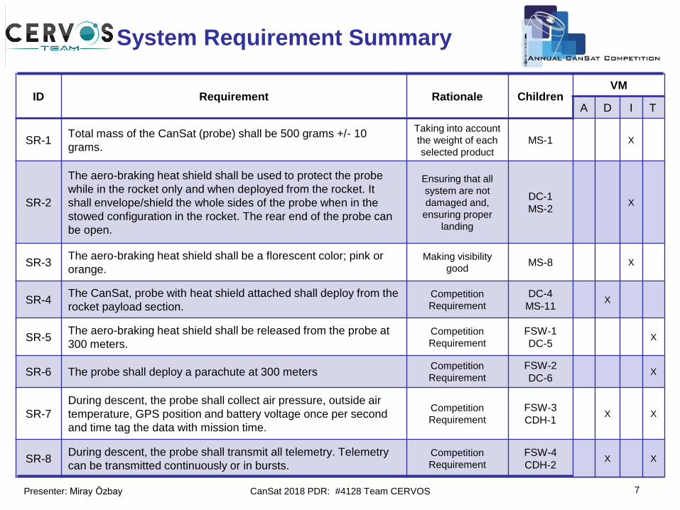
ID Requirement Rationale ChildrenVM
A D I T
SR-1Total mass of the CanSat (probe) shall be 500 grams +/- 10
grams.
Taking into account
the weight of each
selected product
MS-1 X
SR-2
The aero-braking heat shield shall be used to protect the probe
while in the rocket only and when deployed from the rocket. It
shall envelope/shield the whole sides of the probe when in the
stowed configuration in the rocket. The rear end of the probe can
be open.
Ensuring that all
system are not
damaged and,
ensuring proper
landing
DC-1
MS-2X
SR-3The aero-braking heat shield shall be a florescent color; pink or
orange.Making visibility
goodMS-8 X
SR-4The CanSat, probe with heat shield attached shall deploy from the
rocket payload section.Competition
Requirement
DC-4
MS-11X
SR-5The aero-braking heat shield shall be released from the probe at
300 meters.Competition
Requirement
FSW-1
DC-5X
SR-6 The probe shall deploy a parachute at 300 metersCompetition
Requirement
FSW-2
DC-6X
SR-7
During descent, the probe shall collect air pressure, outside air
temperature, GPS position and battery voltage once per second
and time tag the data with mission time.
Competition
Requirement
FSW-3
CDH-1X X
SR-8During descent, the probe shall transmit all telemetry. Telemetry
can be transmitted continuously or in bursts.Competition
Requirement
FSW-4
CDH-2X X
Presenter: Miray Özbay CanSat 2018 PDR: #4128 Team CERVOS
Team Logo
Here
(If You Want) System Requirement Summary(cont.)
8
ID Requirement Rationale ChildrenVM
A D I T
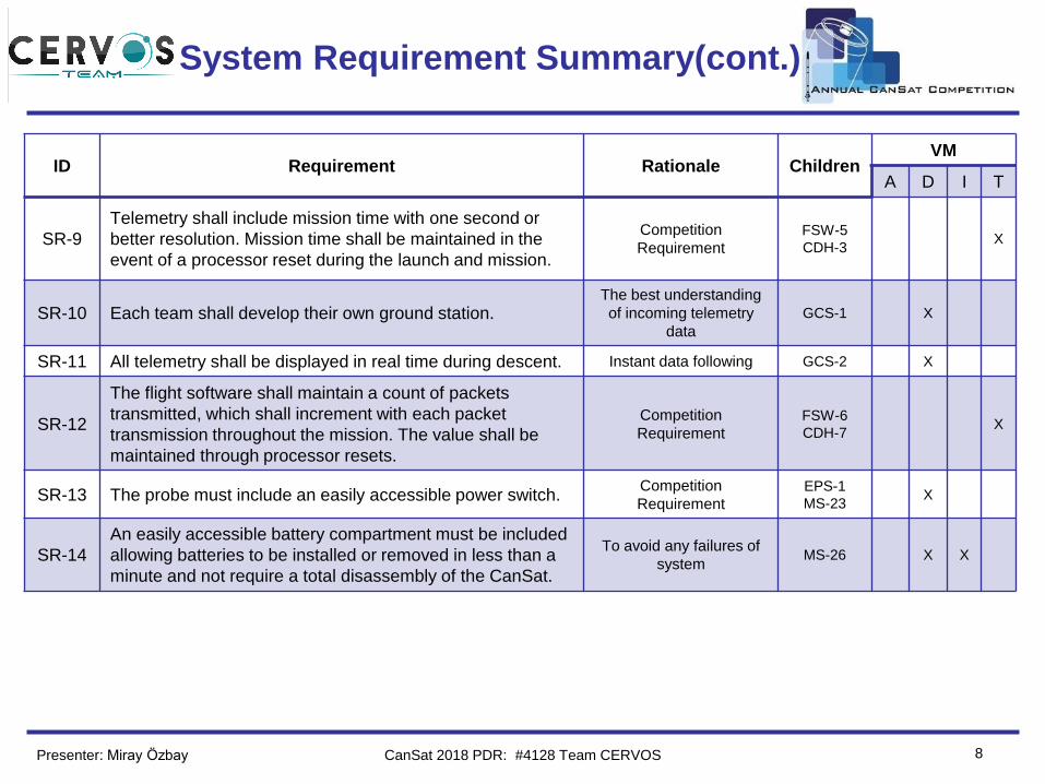
SR-9
Telemetry shall include mission time with one second or
better resolution. Mission time shall be maintained in the
event of a processor reset during the launch and mission.
Competition
Requirement
FSW-5
CDH-3X
SR-10 Each team shall develop their own ground station.The best understanding
of incoming telemetry
data
GCS-1 X
SR-11 All telemetry shall be displayed in real time during descent. Instant data following GCS-2 X
SR-12
The flight software shall maintain a count of packets
transmitted, which shall increment with each packet
transmission throughout the mission. The value shall be
maintained through processor resets.
Competition
Requirement
FSW-6
CDH-7X
SR-13 The probe must include an easily accessible power switch.Competition
Requirement
EPS-1
MS-23X
SR-14
An easily accessible battery compartment must be included
allowing batteries to be installed or removed in less than a
minute and not require a total disassembly of the CanSat.
To avoid any failures of
systemMS-26 X X
Presenter: Miray Özbay CanSat 2018 PDR: #4128 Team CERVOS
Team Logo
Here
(If You Want)
9
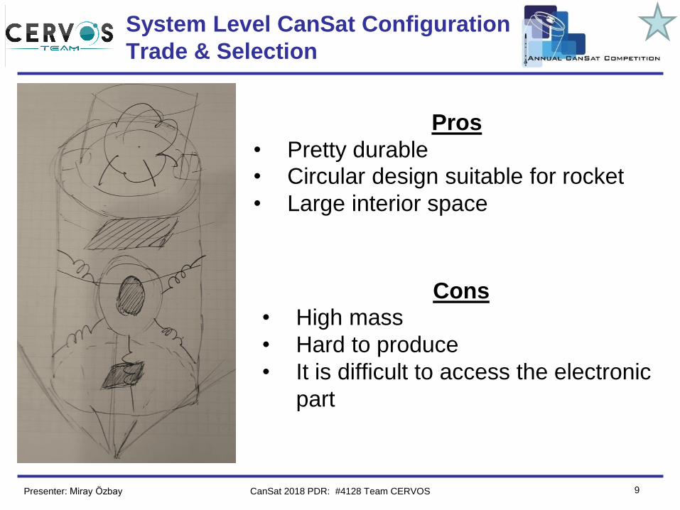
System Level CanSat Configuration
Trade & Selection
Pros
• Pretty durable• Circular design suitable for rocket
• Large interior space
Cons• High mass
• Hard to produce
• It is difficult to access the electronic
part
Presenter: Miray Özbay CanSat 2018 PDR: #4128 Team CERVOS
Team Logo
Here
(If You Want)
10
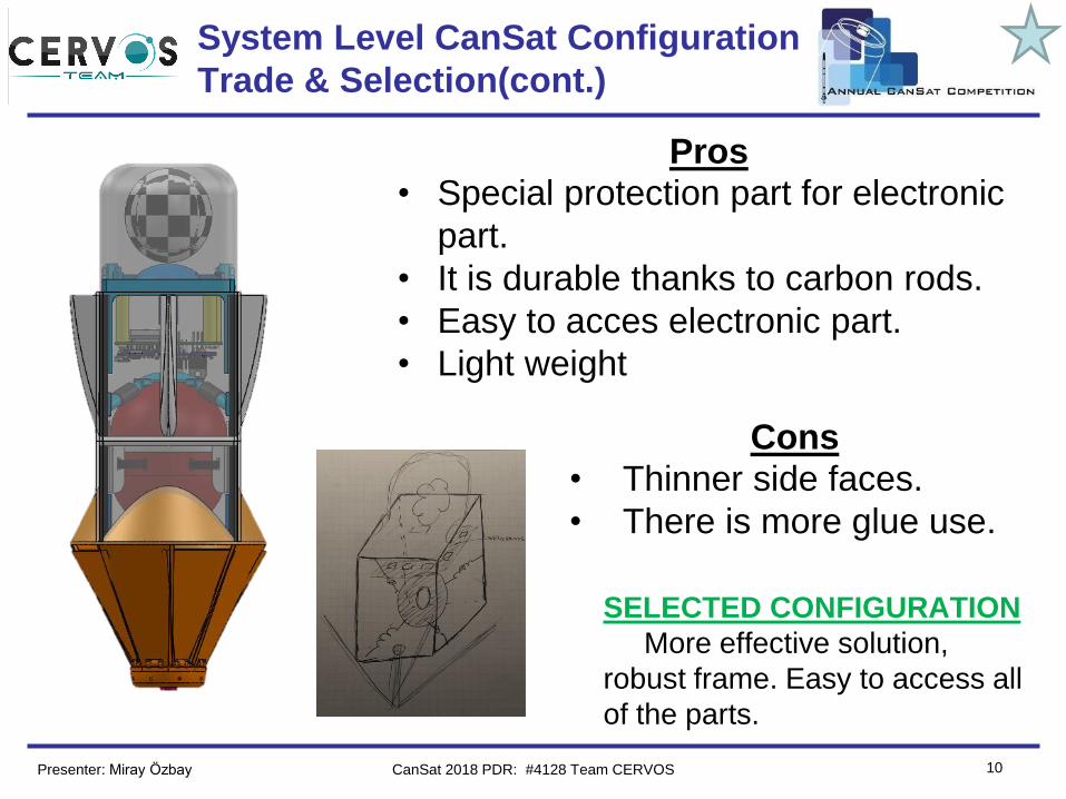
System Level CanSat Configuration
Trade & Selection(cont.)
Pros• Special protection part for electronic
part.
• It is durable thanks to carbon rods.
• Easy to acces electronic part.
• Light weight
Cons• Thinner side faces.
• There is more glue use.
SELECTED CONFIGURATION
More effective solution,
robust frame. Easy to access all
of the parts.
Presenter: Miray Özbay CanSat 2018 PDR: #4128 Team CERVOS
Team Logo
Here
(If You Want)
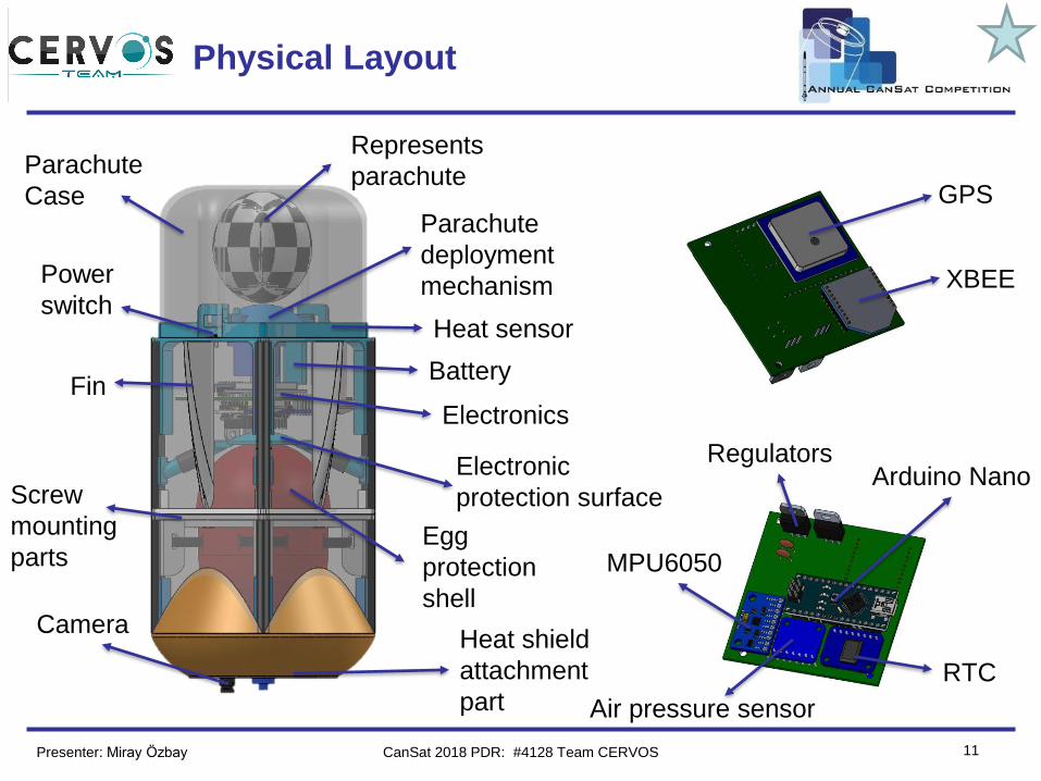
11
Physical Layout
Parachute
deployment
mechanism
Heat sensor
Electronics
Egg
protection
shell
Electronic
protection surface
Heat shield
attachment
part
Fin
Screw
mounting
parts
Camera
Power
switch
Parachute
Case
Represents
parachute
Battery
RTC
RegulatorsArduino Nano
Air pressure sensor
MPU6050
XBEE
GPS
Presenter: Miray Özbay CanSat 2018 PDR: #4128 Team CERVOS
Team Logo
Here
(If You Want)
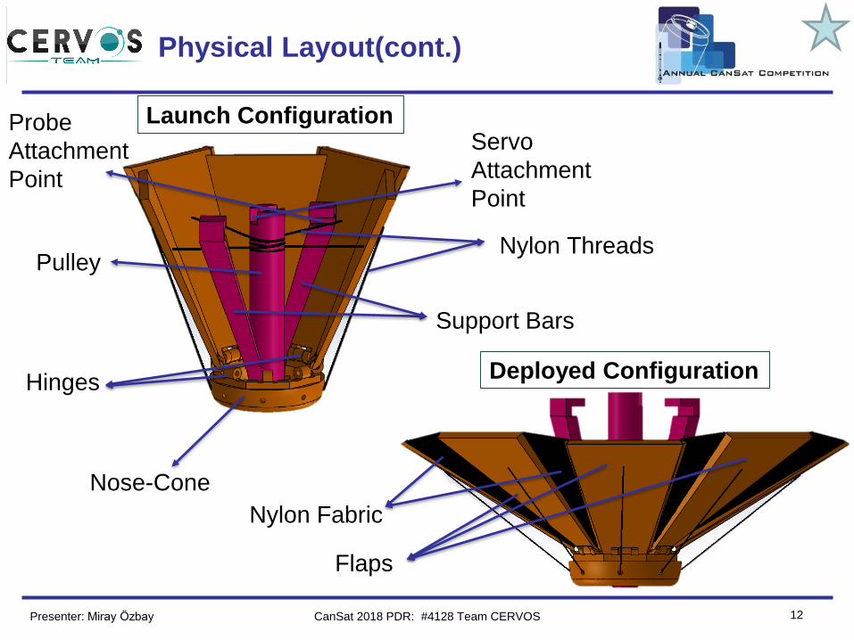
12
Physical Layout(cont.)
Nylon Threads
Support Bars
Pulley
Servo
Attachment
Point
Probe
Attachment
Point
Hinges
Nose-Cone
Flaps
Nylon Fabric
Launch Configuration
Deployed Configuration
Presenter: Miray Özbay CanSat 2018 PDR: #4128 Team CERVOS
Team Logo
Here
(If You Want)
13
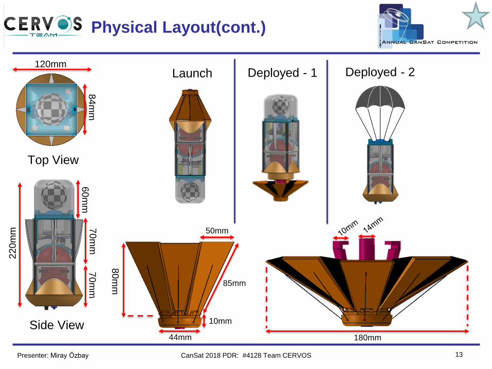
Physical Layout(cont.)
Top View
Side View
22
0m
m
120mm
84
mm
60m
m7
0m
m7
0m
m
Launch Deployed - 2Deployed - 1
44mm
10mm
80
mm
50mm
180mm
85mm
Presenter: Miray Özbay CanSat 2018 PDR: #4128 Team CERVOS
Team Logo
Here
(If You Want)
14
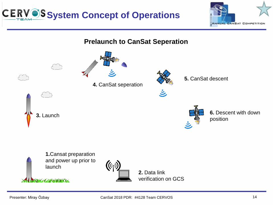
System Concept of Operations
2. Data link
verification on GCS
1.Cansat preparation
and power up prior to
launch
3. Launch
4. CanSat seperation5. CanSat descent
6. Descent with down
position
Prelaunch to CanSat Seperation
Presenter: Miray Özbay CanSat 2018 PDR: #4128 Team CERVOS
Team Logo
Here
(If You Want)
15
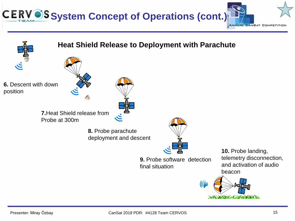
System Concept of Operations (cont.)
6. Descent with down
position
10. Probe landing,
telemetry disconnection,
and activation of audio
beacon
7.Heat Shield release from
Probe at 300m
8. Probe parachute
deployment and descent
9. Probe software detection
final situation
Heat Shield Release to Deployment with Parachute
Presenter: Miray Özbay CanSat 2018 PDR: #4128 Team CERVOS
Team Logo
Here
(If You Want)
16
System Concept of Operations (cont.)
Recovery and Data Reduction
• Recovery of probe with help of the observation in advance,
data from the GCS and audio beacon.
• Recovery of heat shield; Landing zone will be determined
by observing descent, by examining video that, probe
records and, by last GPS location data.
• Returning to launch site.
• Acquiring saved flight data from probe.
• Analyzing and filtering data if needed.
Presenter: Miray Özbay CanSat 2018 PDR: #4128 Team CERVOS
Team Logo
Here
(If You Want)
17
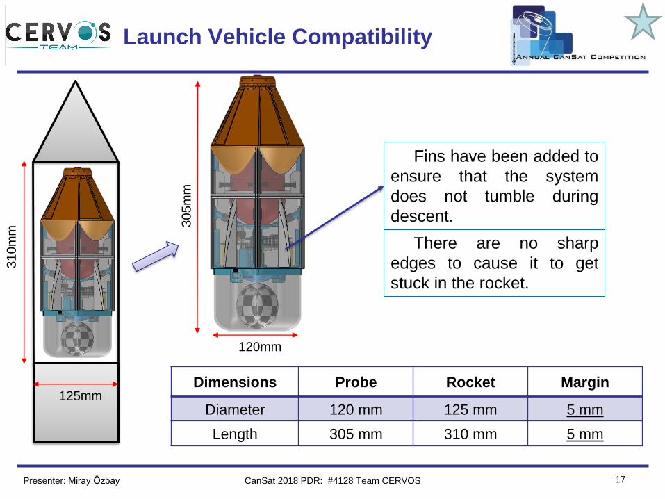
Launch Vehicle Compatibility
There are no sharp
edges to cause it to get
stuck in the rocket.
31
0m
m
Dimensions Probe Rocket Margin
Diameter 120 mm 125 mm 5 mm
Length 305 mm 310 mm 5 mm
Fins have been added to
ensure that the system
does not tumble during
descent.
125mm
30
5m
m
120mm
Presenter: Miray Özbay CanSat 2018 PDR: #4128 Team CERVOS
Team Logo
Here
(If You Want)
18
Sensor Subsystem Design
Burhan Kaplan
CanSat 2018 PDR: #4128 Team CERVOS
Team Logo
Here
(If You Want)
19
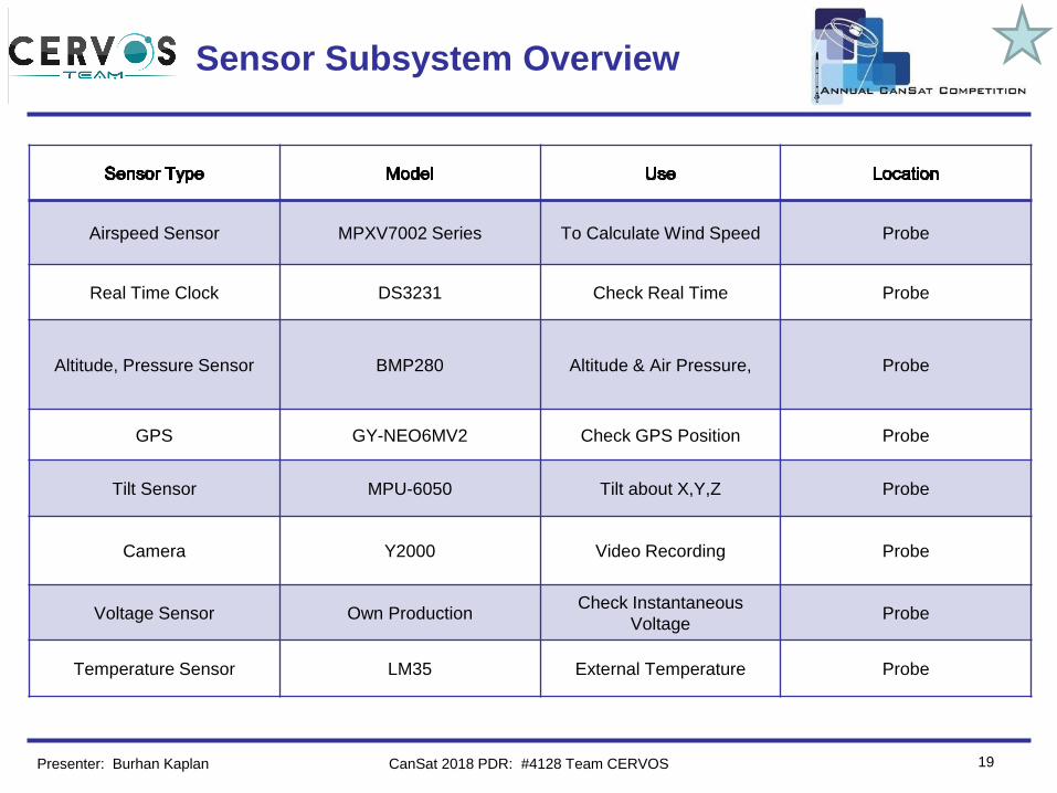
Sensor Subsystem Overview
Presenter: Burhan Kaplan
Airspeed Sensor MPXV7002 Series To Calculate Wind Speed Probe
Real Time Clock DS3231 Check Real Time Probe
Altitude, Pressure Sensor BMP280 Altitude & Air Pressure, Probe
GPS GY-NEO6MV2 Check GPS Position Probe
Tilt Sensor MPU-6050 Tilt about X,Y,Z Probe
Camera Y2000 Video Recording Probe
Voltage Sensor Own ProductionCheck Instantaneous
Voltage Probe
Temperature Sensor LM35 External Temperature Probe
CanSat 2018 PDR: #4128 Team CERVOS
Team Logo
Here
(If You Want)
20
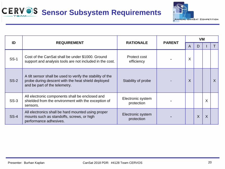
Sensor Subsystem Requirements
ID REQUIREMENT RATIONALE PARENTVM
A D I T
SS-1Cost of the CanSat shall be under $1000. Ground
support and analysis tools are not included in the cost.
Protect cost
efficiency- X
SS-2
A tilt sensor shall be used to verify the stability of the
probe during descent with the heat shield deployed
and be part of the telemetry.
Stability of probe - X X
SS-3
All electronic components shall be enclosed and
shielded from the environment with the exception of
sensors.
Electronic system
protection- X
SS-4
All electronics shall be hard mounted using proper
mounts such as standoffs, screws, or high
performance adhesives.
Electronic system
protection- X X
Presenter: Burhan Kaplan CanSat 2018 PDR: #4128 Team CERVOS
Team Logo
Here
(If You Want)
21
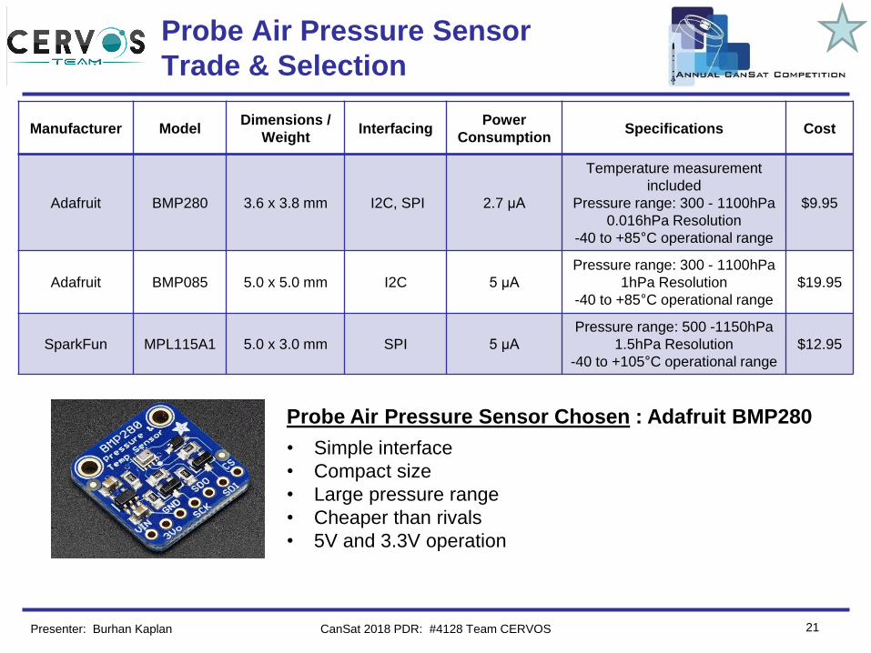
Probe Air Pressure Sensor
Trade & Selection
Manufacturer ModelDimensions /
Weight Interfacing
Power
ConsumptionSpecifications Cost
Adafruit BMP280 3.6 x 3.8 mm I2C, SPI 2.7 µA
Temperature measurement
included
Pressure range: 300 - 1100hPa
0.016hPa Resolution
-40 to +85°C operational range
$9.95
Adafruit BMP085 5.0 x 5.0 mm I2C 5 µA
Pressure range: 300 - 1100hPa
1hPa Resolution
-40 to +85°C operational range
$19.95
SparkFun MPL115A1 5.0 x 3.0 mm SPI 5 µA
Pressure range: 500 -1150hPa
1.5hPa Resolution
-40 to +105°C operational range
$12.95
Probe Air Pressure Sensor Chosen : Adafruit BMP280
• Simple interface
• Compact size
• Large pressure range
• Cheaper than rivals
• 5V and 3.3V operation
Presenter: Burhan Kaplan CanSat 2018 PDR: #4128 Team CERVOS
Team Logo
Here
(If You Want)
22
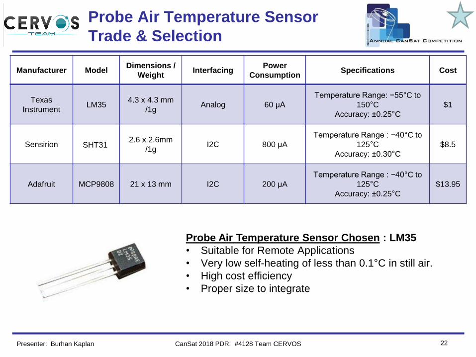
Probe Air Temperature Sensor
Trade & Selection
Manufacturer ModelDimensions /
Weight Interfacing
Power
ConsumptionSpecifications Cost
Texas
InstrumentLM35
4.3 x 4.3 mm
/1gAnalog 60 μA
Temperature Range: −55°C to
150°C
Accuracy: ±0.25°C
$1
Sensirion SHT312.6 x 2.6mm
/1gI2C 800 μA
Temperature Range : −40°C to
125°C
Accuracy: ±0.30°C
$8.5
Adafruit MCP9808 21 x 13 mm I2C 200 μA
Temperature Range : −40°C to
125°C
Accuracy: ±0.25°C
$13.95
Probe Air Temperature Sensor Chosen : LM35
• Suitable for Remote Applications
• Very low self-heating of less than 0.1°C in still air.
• High cost efficiency
• Proper size to integrate
Presenter: Burhan Kaplan CanSat 2018 PDR: #4128 Team CERVOS
Team Logo
Here
(If You Want)
23
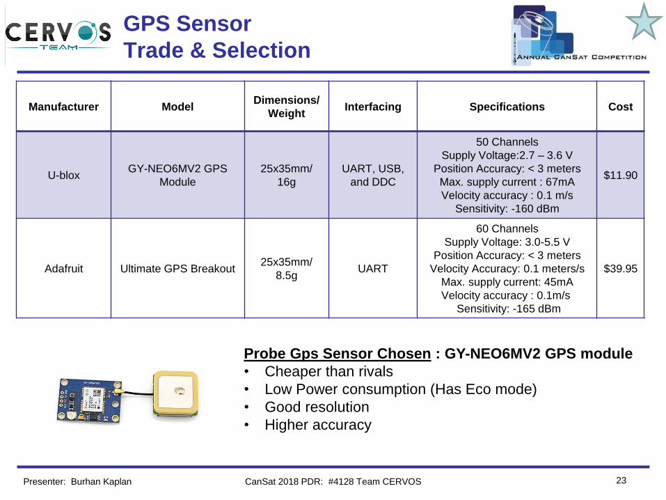
GPS Sensor
Trade & Selection
Manufacturer ModelDimensions/
WeightInterfacing Specifications Cost
U-bloxGY-NEO6MV2 GPS
Module
25x35mm/
16g
UART, USB,
and DDC
50 Channels
Supply Voltage:2.7 – 3.6 V
Position Accuracy: < 3 meters
Max. supply current : 67mA
Velocity accuracy : 0.1 m/s
Sensitivity: -160 dBm
$11.90
Adafruit Ultimate GPS Breakout25x35mm/
8.5gUART
60 Channels
Supply Voltage: 3.0-5.5 V
Position Accuracy: < 3 meters
Velocity Accuracy: 0.1 meters/s
Max. supply current: 45mA
Velocity accuracy : 0.1m/s
Sensitivity: -165 dBm
$39.95
Probe Gps Sensor Chosen : GY-NEO6MV2 GPS module
• Cheaper than rivals
• Low Power consumption (Has Eco mode)
• Good resolution
• Higher accuracy
Presenter: Burhan Kaplan CanSat 2018 PDR: #4128 Team CERVOS
Team Logo
Here
(If You Want)
24
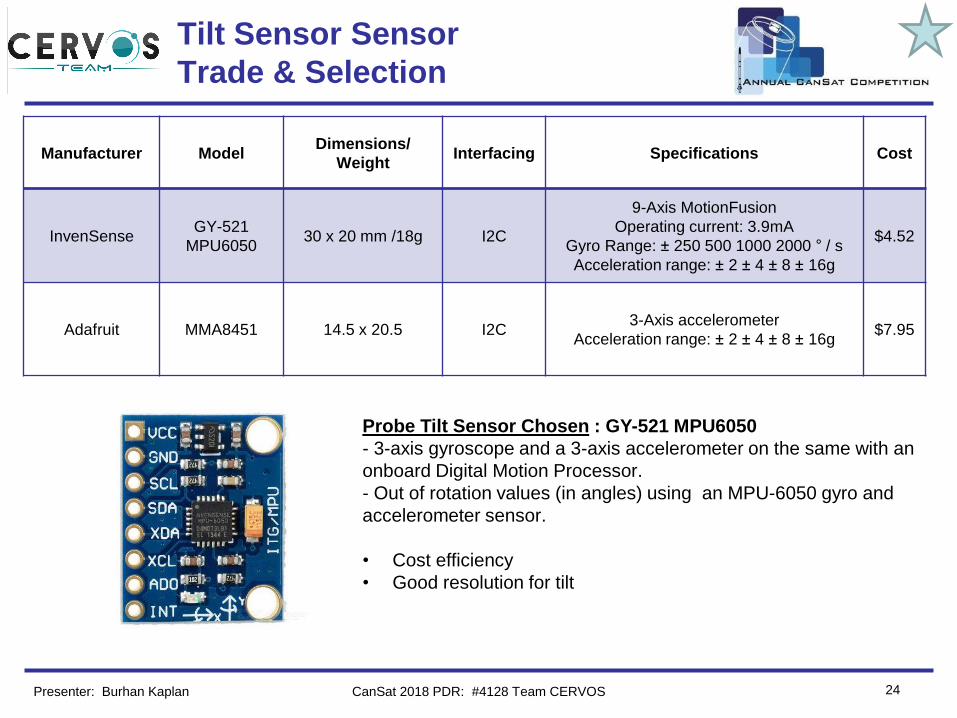
Tilt Sensor Sensor
Trade & Selection
Manufacturer ModelDimensions/
WeightInterfacing Specifications Cost
InvenSenseGY-521
MPU605030 x 20 mm /18g I2C
9-Axis MotionFusion
Operating current: 3.9mA
Gyro Range: ± 250 500 1000 2000 ° / s
Acceleration range: ± 2 ± 4 ± 8 ± 16g
$4.52
Adafruit MMA8451 14.5 x 20.5 I2C3-Axis accelerometer
Acceleration range: ± 2 ± 4 ± 8 ± 16g$7.95
Probe Tilt Sensor Chosen : GY-521 MPU6050
- 3-axis gyroscope and a 3-axis accelerometer on the same with an
onboard Digital Motion Processor.
- Out of rotation values (in angles) using an MPU-6050 gyro and
accelerometer sensor.
• Cost efficiency
• Good resolution for tilt
Presenter: Burhan Kaplan CanSat 2018 PDR: #4128 Team CERVOS
Team Logo
Here
(If You Want)
25
Bonus Camera Trade & Selection
Manufacturer ModelDimensions/
WeightInterfacing Specifications Cost
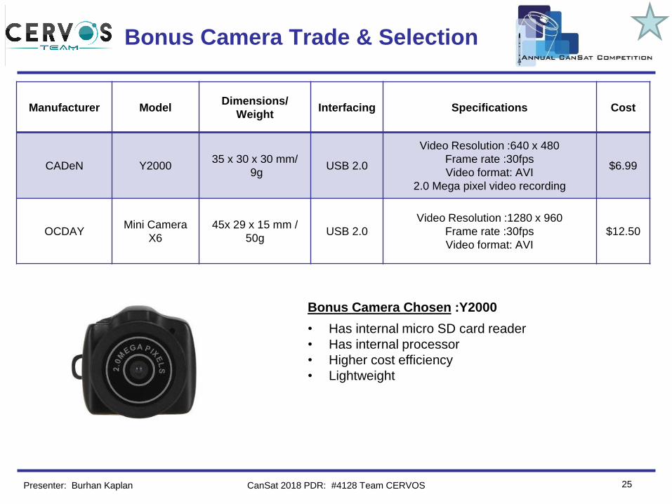
CADeN Y200035 x 30 x 30 mm/
9gUSB 2.0
Video Resolution :640 x 480
Frame rate :30fps
Video format: AVI
2.0 Mega pixel video recording
$6.99
OCDAYMini Camera
X6
45x 29 x 15 mm /
50gUSB 2.0
Video Resolution :1280 x 960
Frame rate :30fps
Video format: AVI
$12.50
Bonus Camera Chosen :Y2000
• Has internal micro SD card reader
• Has internal processor
• Higher cost efficiency
• Lightweight
Presenter: Burhan Kaplan CanSat 2018 PDR: #4128 Team CERVOS
Team Logo
Here
(If You Want) Bonus Wind Sensor
26
Manufacturer Model Interfacing Specifications Cost
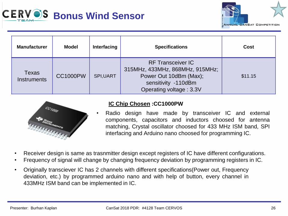
Texas
InstrumentsCC1000PW SPI,UART
RF Transceiver IC
315MHz, 433MHz, 868MHz, 915MHz;
Power Out 10dBm (Max);
sensitivity -110dBm
Operating voltage : 3.3V
$11.15
• Radio design have made by transceiver IC and external
components, capacitors and inductors choosed for antenna
matching, Crystal oscillator choosed for 433 MHz ISM band, SPI
interfacing and Arduino nano choosed for programming IC.
• Receiver design is same as trasnmitter design except registers of IC have different configurations.
• Frequency of signal will change by changing frequency deviation by programming registers in IC.
• Originally transciever IC has 2 channels with different specifications(Power out, Frequency
deviation, etc.) by programmed arduino nano and with help of button, every channel in
433MHz ISM band can be implemented in IC.
IC Chip Chosen :CC1000PW
Presenter: Burhan Kaplan CanSat 2018 PDR: #4128 Team CERVOS
Team Logo
Here
(If You Want) Bonus Wind Sensor(conts.)
27
Manufacturer Model
Dimensions
/ Weight Interfacing Specifications Cost
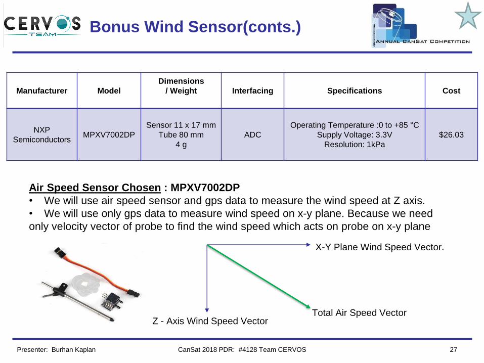
NXP
SemiconductorsMPXV7002DP
Sensor 11 x 17 mm
Tube 80 mm
4 g
ADC
Operating Temperature :0 to +85 °C
Supply Voltage: 3.3V
Resolution: 1kPa
$26.03
Air Speed Sensor Chosen : MPXV7002DP
• We will use air speed sensor and gps data to measure the wind speed at Z axis.
• We will use only gps data to measure wind speed on x-y plane. Because we need
only velocity vector of probe to find the wind speed which acts on probe on x-y plane
X-Y Plane Wind Speed Vector.
Z - Axis Wind Speed VectorTotal Air Speed Vector
Presenter: Burhan Kaplan CanSat 2018 PDR: #4128 Team CERVOS
Team Logo
Here
(If You Want)
28
Descent Control Design
Mustafa Eryılmaz
CanSat 2018 PDR: #4128 Team CERVOS
Team Logo
Here
(If You Want)
29
Descent Control Overview
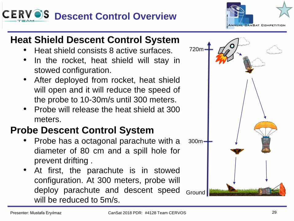
Heat Shield Descent Control System• Heat shield consists 8 active surfaces.
• In the rocket, heat shield will stay in
stowed configuration.
• After deployed from rocket, heat shield
will open and it will reduce the speed of
the probe to 10-30m/s until 300 meters.
• Probe will release the heat shield at 300
meters.
Probe Descent Control System• Probe has a octagonal parachute with a
diameter of 80 cm and a spill hole for
prevent drifting .
• At first, the parachute is in stowed
configuration. At 300 meters, probe will
deploy parachute and descent speed
will be reduced to 5m/s.
300m
720m
Ground
Presenter: Mustafa Eryılmaz CanSat 2018 PDR: #4128 Team CERVOS
Team Logo
Here
(If You Want)
CanSat 2018 PDR: #4128 Team CERVOS 30
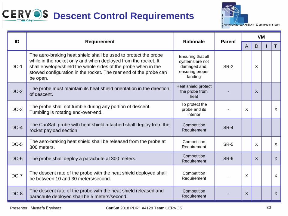
Descent Control Requirements
Presenter: Mustafa Eryılmaz
ID Requirement Rationale ParentVM
A D I T
DC-1
The aero-braking heat shield shall be used to protect the probe
while in the rocket only and when deployed from the rocket. It
shall envelope/shield the whole sides of the probe when in the
stowed configuration in the rocket. The rear end of the probe can
be open.
Ensuring that all
systems are not
damaged and,
ensuring proper
landing
SR-2 X
DC-2The probe must maintain its heat shield orientation in the direction
of descent.
Heat shield protect
the probe from
heat
- X
DC-3The probe shall not tumble during any portion of descent.
Tumbling is rotating end-over-end.
To protect the
probe and its
interior
- X X
DC-4The CanSat, probe with heat shield attached shall deploy from the
rocket payload section.Competition
RequirementSR-4
DC-5The aero-braking heat shield shall be released from the probe at
300 meters.Competition
RequirementSR-5 X X
DC-6 The probe shall deploy a parachute at 300 meters.Competition
RequirementSR-6 X X
DC-7The descent rate of the probe with the heat shield deployed shall
be between 10 and 30 meters/second.Competition
Requirement- X X
DC-8The descent rate of the probe with the heat shield released and
parachute deployed shall be 5 meters/second.Competition
Requirement- X X
Team Logo
Here
(If You Want)
31
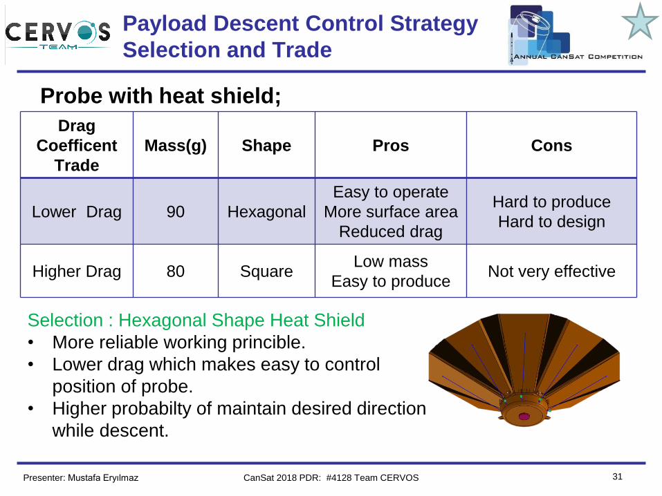
Payload Descent Control Strategy
Selection and Trade
Drag
Coefficent
Trade
Mass(g) Shape Pros Cons
Lower Drag 90 Hexagonal
Easy to operate
More surface area
Reduced drag
Hard to produce
Hard to design
Higher Drag 80 SquareLow mass
Easy to produceNot very effective
Probe with heat shield;
Selection : Hexagonal Shape Heat Shield
• More reliable working princible.
• Lower drag which makes easy to control
position of probe.
• Higher probabilty of maintain desired direction
while descent.
Presenter: Mustafa Eryılmaz CanSat 2018 PDR: #4128 Team CERVOS
Team Logo
Here
(If You Want)
32
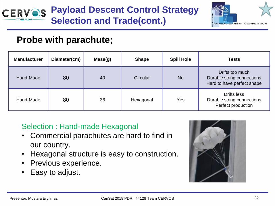
Payload Descent Control Strategy
Selection and Trade(cont.)
Manufacturer Diameter(cm) Mass(g) Shape Spill Hole Tests
Hand-Made 80 40 Circular No
Drifts too much
Durable string connections
Hard to have perfect shape
Hand-Made 80 36 Hexagonal Yes
Drifts less
Durable string connections
Perfect production
Probe with parachute;
Selection : Hand-made Hexagonal
• Commercial parachutes are hard to find in
our country.
• Hexagonal structure is easy to construction.
• Previous experience.
• Easy to adjust.
Presenter: Mustafa Eryılmaz CanSat 2018 PDR: #4128 Team CERVOS
Team Logo
Here
(If You Want)
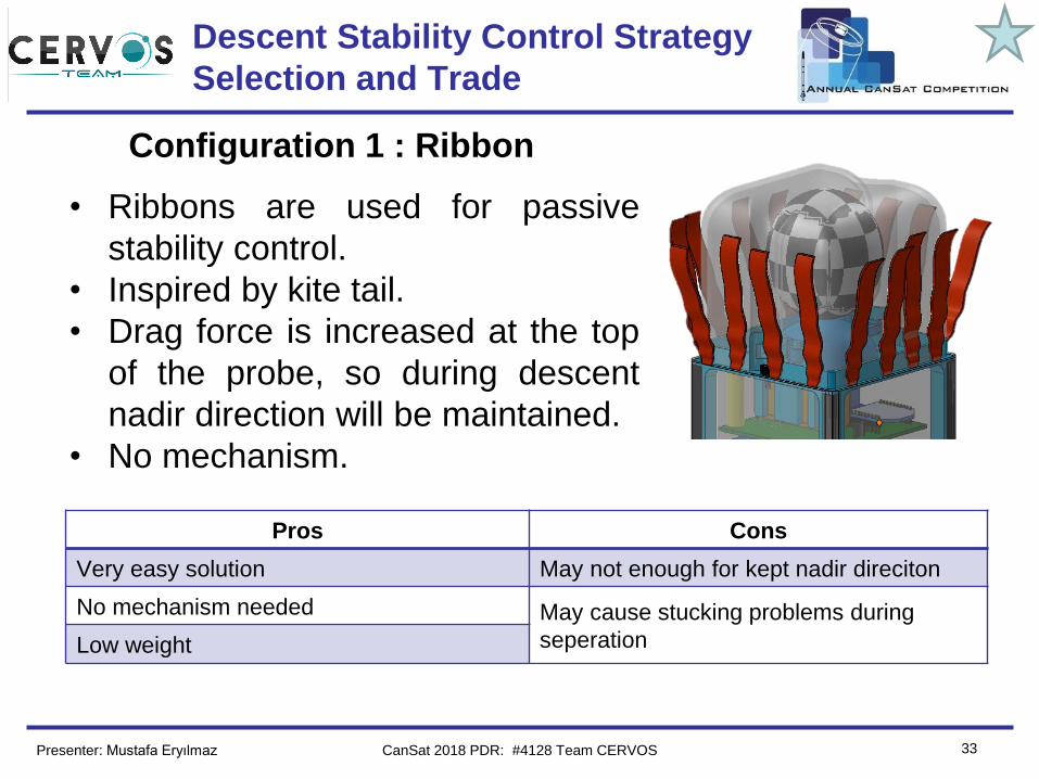
33
Configuration 1 : Ribbon
Pros Cons
Very easy solution May not enough for kept nadir direciton
No mechanism needed May cause stucking problems during
seperationLow weight
Descent Stability Control Strategy
Selection and Trade
• Ribbons are used for passive
stability control.
• Inspired by kite tail.
• Drag force is increased at the top
of the probe, so during descent
nadir direction will be maintained.
• No mechanism.
Presenter: Mustafa Eryılmaz CanSat 2018 PDR: #4128 Team CERVOS
Team Logo
Here
(If You Want)
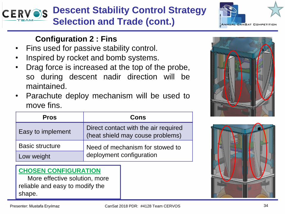
34
Configuration 2 : Fins
Pros Cons
Easy to implementDirect contact with the air required
(heat shield may couse problems)
Basic structure Need of mechanism for stowed to
deployment configurationLow weight
Descent Stability Control Strategy
Selection and Trade (cont.)
• Fins used for passive stability control.
• Inspired by rocket and bomb systems.
• Drag force is increased at the top of the probe,
so during descent nadir direction will be
maintained.
• Parachute deploy mechanism will be used to
move fins.
CHOSEN CONFIGURATION
More effective solution, more
reliable and easy to modify the
shape.
Presenter: Mustafa Eryılmaz CanSat 2018 PDR: #4128 Team CERVOS
Team Logo
Here
(If You Want)
35
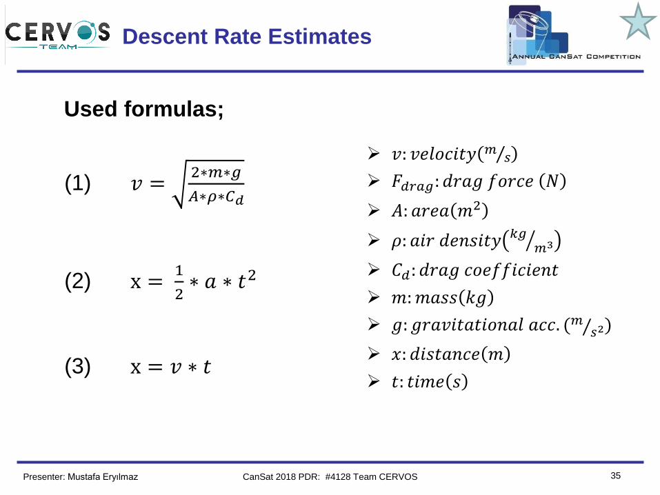
Descent Rate Estimates
Used formulas;
(1) 𝑣 =2∗𝑚∗𝑔
𝐴∗𝜌∗𝐶𝑑
(2) x =1
2∗ 𝑎 ∗ 𝑡2
(3) x = 𝑣 ∗ 𝑡
➢ 𝑣: 𝑣𝑒𝑙𝑜𝑐𝑖𝑡𝑦 Τ𝑚 𝑠
➢ 𝐹𝑑𝑟𝑎𝑔: 𝑑𝑟𝑎𝑔 𝑓𝑜𝑟𝑐𝑒 𝑁
➢ 𝐴: 𝑎𝑟𝑒𝑎 𝑚2
➢ 𝜌: 𝑎𝑖𝑟 𝑑𝑒𝑛𝑠𝑖𝑡𝑦 ൗ𝑘𝑔𝑚3
➢ 𝐶𝑑: 𝑑𝑟𝑎𝑔 𝑐𝑜𝑒𝑓𝑓𝑖𝑐𝑖𝑒𝑛𝑡
➢ 𝑚:𝑚𝑎𝑠𝑠 𝑘𝑔
➢ 𝑔: 𝑔𝑟𝑎𝑣𝑖𝑡𝑎𝑡𝑖𝑜𝑛𝑎𝑙 𝑎𝑐𝑐. ( Τ𝑚 𝑠2)
➢ 𝑥: 𝑑𝑖𝑠𝑡𝑎𝑛𝑐𝑒 𝑚
➢ 𝑡: 𝑡𝑖𝑚𝑒 𝑠
Presenter: Mustafa Eryılmaz CanSat 2018 PDR: #4128 Team CERVOS
Team Logo
Here
(If You Want)
36
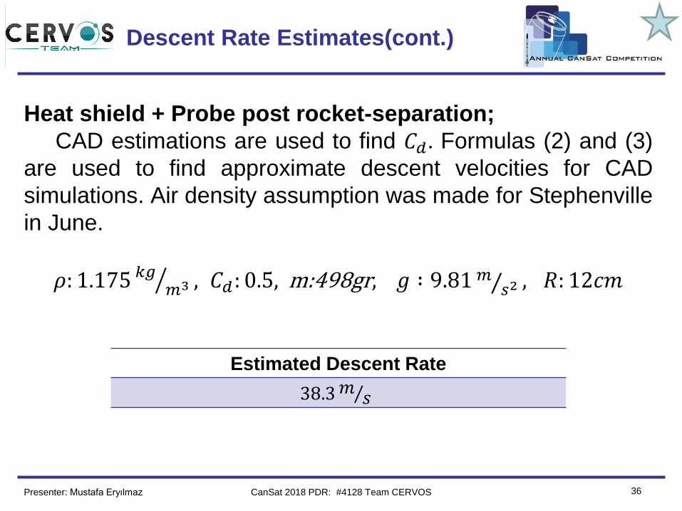
Descent Rate Estimates(cont.)
Heat shield + Probe post rocket-separation;
CAD estimations are used to find 𝐶𝑑 . Formulas (2) and (3)
are used to find approximate descent velocities for CAD
simulations. Air density assumption was made for Stephenville
in June.
𝜌: 1.175 ൗ𝑘𝑔𝑚3 , 𝐶𝑑: 0.5, m:498gr, 𝑔 ∶ 9.81 Τ𝑚 𝑠2 , 𝑅: 12𝑐𝑚
Estimated Descent Rate
38.3 Τ𝑚 𝑠
Presenter: Mustafa Eryılmaz CanSat 2018 PDR: #4128 Team CERVOS
Team Logo
Here
(If You Want)
37
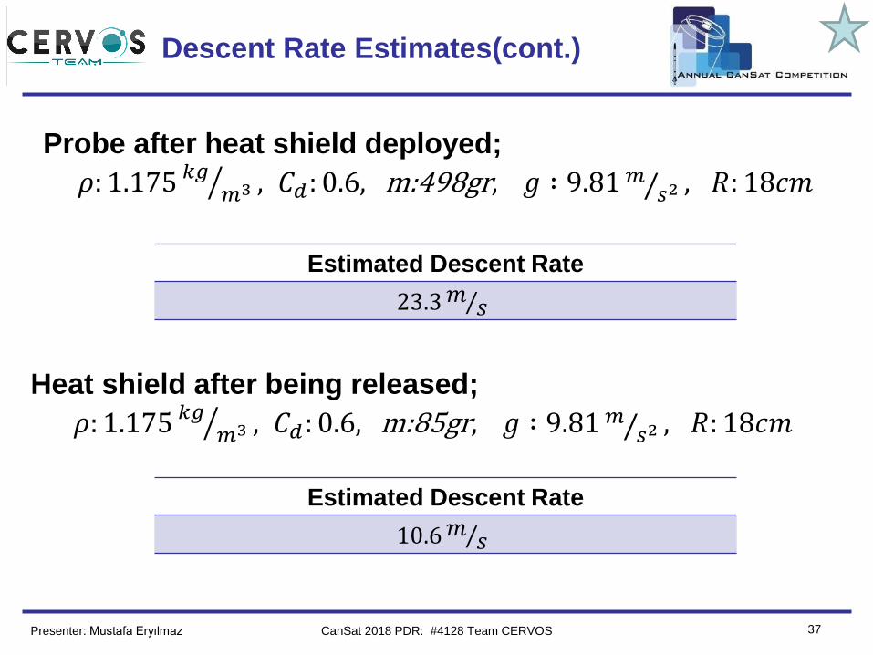
Descent Rate Estimates(cont.)
Heat shield after being released;
𝜌: 1.175 ൗ𝑘𝑔𝑚3 , 𝐶𝑑: 0.6, m:85gr, 𝑔 ∶ 9.81 Τ𝑚 𝑠2 , 𝑅: 18𝑐𝑚
Estimated Descent Rate
23.3 Τ𝑚 𝑠
Probe after heat shield deployed;
𝜌: 1.175 ൗ𝑘𝑔𝑚3 , 𝐶𝑑: 0.6, m:498gr, 𝑔 ∶ 9.81 Τ𝑚 𝑠2 , 𝑅: 18𝑐𝑚
Estimated Descent Rate
10.6 Τ𝑚 𝑠
Presenter: Mustafa Eryılmaz CanSat 2018 PDR: #4128 Team CERVOS
Team Logo
Here
(If You Want)
38
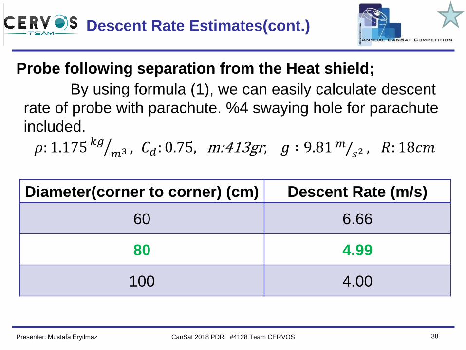
Probe following separation from the Heat shield;
Descent Rate Estimates(cont.)
By using formula (1), we can easily calculate descent
rate of probe with parachute. %4 swaying hole for parachute
included.
𝜌: 1.175 ൗ𝑘𝑔𝑚3 , 𝐶𝑑: 0.75, m:413gr, 𝑔 ∶ 9.81 Τ𝑚 𝑠2 , 𝑅: 18𝑐𝑚
Diameter(corner to corner) (cm) Descent Rate (m/s)
60 6.66
80 4.99
100 4.00
Presenter: Mustafa Eryılmaz CanSat 2018 PDR: #4128 Team CERVOS
Team Logo
Here
(If You Want)
39
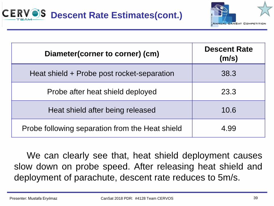
Descent Rate Estimates(cont.)
Diameter(corner to corner) (cm)Descent Rate
(m/s)
Heat shield + Probe post rocket-separation 38.3
Probe after heat shield deployed 23.3
Heat shield after being released 10.6
Probe following separation from the Heat shield 4.99
We can clearly see that, heat shield deployment causes
slow down on probe speed. After releasing heat shield and
deployment of parachute, descent rate reduces to 5m/s.
Presenter: Mustafa Eryılmaz CanSat 2018 PDR: #4128 Team CERVOS
Team Logo
Here
(If You Want)
40
Mechanical Subsystem Design
Ahmet Vehbi Genç
CanSat 2018 PDR: #4128 Team CERVOS
Team Logo
Here
(If You Want)
41
Mechanical Subsystem Overview
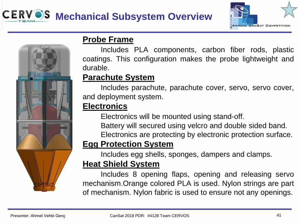
Probe Frame
Includes PLA components, carbon fiber rods, plastic
coatings. This configuration makes the probe lightweight and
durable.
Parachute System
Includes parachute, parachute cover, servo, servo cover,
and deployment system.
Electronics
Electronics will be mounted using stand-off.
Battery will secured using velcro and double sided band.
Electronics are protecting by electronic protection surface.
Egg Protection System
Includes egg shells, sponges, dampers and clamps.
Heat Shield System
Includes 8 opening flaps, opening and releasing servo
mechanism.Orange colored PLA is used. Nylon strings are part
of mechanism. Nylon fabric is used to ensure not any openings.
Presenter: Ahmet Vehbi Genç CanSat 2018 PDR: #4128 Team CERVOS
Team Logo
Here
(If You Want)
42
Mechanical Sub-System
Requirements
ID Requirement Rationale ParentVM
A D I T
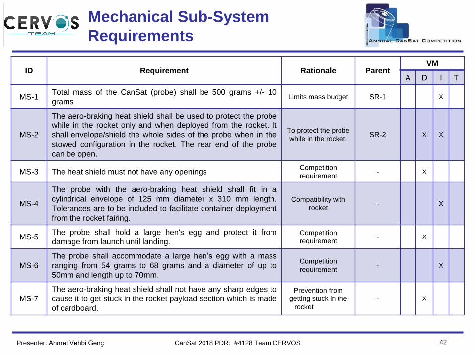
MS-1Total mass of the CanSat (probe) shall be 500 grams +/- 10
gramsLimits mass budget SR-1 X
MS-2
The aero-braking heat shield shall be used to protect the probe
while in the rocket only and when deployed from the rocket. It
shall envelope/shield the whole sides of the probe when in the
stowed configuration in the rocket. The rear end of the probe
can be open.
To protect the probe
while in the rocket.SR-2 X X
MS-3 The heat shield must not have any openingsCompetition
requirement- X
MS-4
The probe with the aero-braking heat shield shall fit in a
cylindrical envelope of 125 mm diameter x 310 mm length.
Tolerances are to be included to facilitate container deployment
from the rocket fairing.
Compatibility with
rocket- X
MS-5The probe shall hold a large hen's egg and protect it from
damage from launch until landing.Competition
requirement- X
MS-6
The probe shall accommodate a large hen’s egg with a mass
ranging from 54 grams to 68 grams and a diameter of up to
50mm and length up to 70mm.
Competition
requirement- X
MS-7
The aero-braking heat shield shall not have any sharp edges to
cause it to get stuck in the rocket payload section which is made
of cardboard.
Prevention from
getting stuck in the
rocket
- X
Presenter: Ahmet Vehbi Genç CanSat 2018 PDR: #4128 Team CERVOS
Team Logo
Here
(If You Want)
43
Mechanical Sub-System
Requirements(cont.)
ID Requirement Rationale ParentVM
A D I T
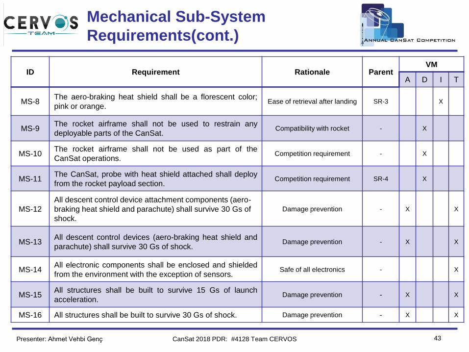
MS-8The aero-braking heat shield shall be a florescent color;
pink or orange.Ease of retrieval after landing SR-3 X
MS-9The rocket airframe shall not be used to restrain any
deployable parts of the CanSat.Compatibility with rocket - X
MS-10The rocket airframe shall not be used as part of the
CanSat operations.Competition requirement - X
MS-11The CanSat, probe with heat shield attached shall deploy
from the rocket payload section.Competition requirement SR-4 X
MS-12
All descent control device attachment components (aero-
braking heat shield and parachute) shall survive 30 Gs of
shock.
Damage prevention - X X
MS-13All descent control devices (aero-braking heat shield and
parachute) shall survive 30 Gs of shock.Damage prevention - X X
MS-14All electronic components shall be enclosed and shielded
from the environment with the exception of sensors.Safe of all electronics - X
MS-15All structures shall be built to survive 15 Gs of launch
acceleration.Damage prevention - X X
MS-16 All structures shall be built to survive 30 Gs of shock. Damage prevention - X X
Presenter: Ahmet Vehbi Genç CanSat 2018 PDR: #4128 Team CERVOS
Team Logo
Here
(If You Want)
44
Mechanical Sub-System
Requirements (cont.)
ID Requirement Rationale ParentVM
A D I T
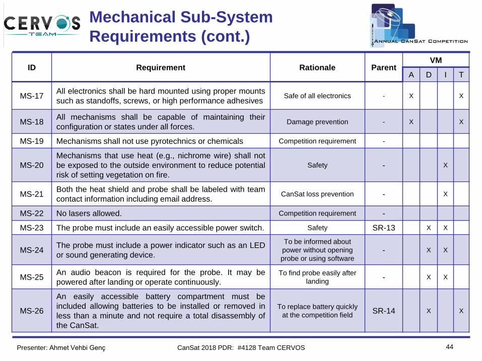
MS-17All electronics shall be hard mounted using proper mounts
such as standoffs, screws, or high performance adhesivesSafe of all electronics - X X
MS-18All mechanisms shall be capable of maintaining their
configuration or states under all forces.Damage prevention - X X
MS-19 Mechanisms shall not use pyrotechnics or chemicals Competition requirement -
MS-20
Mechanisms that use heat (e.g., nichrome wire) shall not
be exposed to the outside environment to reduce potential
risk of setting vegetation on fire.
Safety - X
MS-21Both the heat shield and probe shall be labeled with team
contact information including email address.CanSat loss prevention - X
MS-22 No lasers allowed. Competition requirement -
MS-23 The probe must include an easily accessible power switch. Safety SR-13 X X
MS-24The probe must include a power indicator such as an LED
or sound generating device.
To be informed about
power without opening
probe or using software- X X
MS-25An audio beacon is required for the probe. It may be
powered after landing or operate continuously.
To find probe easily after
landing- X X
MS-26
An easily accessible battery compartment must be
included allowing batteries to be installed or removed in
less than a minute and not require a total disassembly of
the CanSat.
To replace battery quickly
at the competition fieldSR-14 X X
Presenter: Ahmet Vehbi Genç CanSat 2018 PDR: #4128 Team CERVOS
Team Logo
Here
(If You Want)
45
Probe Mechanical Layout of
Components Trade & Selection
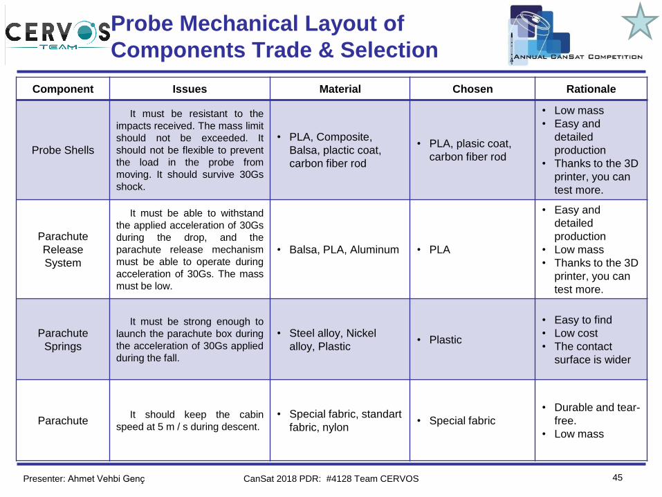
Component Issues Material Chosen Rationale
Probe Shells
It must be resistant to the
impacts received. The mass limit
should not be exceeded. It
should not be flexible to prevent
the load in the probe from
moving. It should survive 30Gs
shock.
• PLA, Composite,
Balsa, plactic coat,
carbon fiber rod
• PLA, plasic coat,
carbon fiber rod
• Low mass
• Easy and
detailed
production
• Thanks to the 3D
printer, you can
test more.
Parachute
Release
System
It must be able to withstand
the applied acceleration of 30Gs
during the drop, and the
parachute release mechanism
must be able to operate during
acceleration of 30Gs. The mass
must be low.
• Balsa, PLA, Aluminum • PLA
• Easy and
detailed
production
• Low mass
• Thanks to the 3D
printer, you can
test more.
Parachute
Springs
It must be strong enough to
launch the parachute box during
the acceleration of 30Gs applied
during the fall.
• Steel alloy, Nickel
alloy, Plastic • Plastic
• Easy to find
• Low cost
• The contact
surface is wider
ParachuteIt should keep the cabin
speed at 5 m / s during descent.
• Special fabric, standart
fabric, nylon• Special fabric
• Durable and tear-
free.
• Low mass
Presenter: Ahmet Vehbi Genç CanSat 2018 PDR: #4128 Team CERVOS
Team Logo
Here
(If You Want)
46
Probe Mechanical Layout of
Components Trade & Selection(cont.)
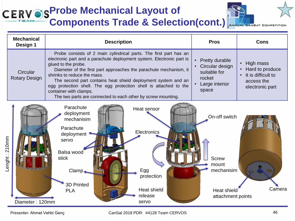
Mechanical
Design 1Description Pros Cons
Circular
Rotary Design
Probe consists of 2 main cylindrical parts. The first part has an
electronic part and a parachute deployment system. Electronic part is
glued to the probe.
Diameter of the first part approaches the parachute mechanism, it
shrinks to reduce the mass.
The second part contains heat shield deployment system and an
egg protection shell. The egg protection shell is attached to the
container with clamps.
The two parts are connected to each other by screw mounting.
• Pretty durable
• Circular design
suitable for
rocket
• Large interior
space
• High mass
• Hard to produce
• It is difficult to
access the
electronic part
Egg
protection
Parachute
deployment
mechanisim
Electronics
Heat shield
attachment points
Camera3D Printed
PLA
Balsa wood
stick
On-off switch
Heat sensor
Heat shield
release
servo
Parachute
deployment
servo
Clamp
Screw
mount
mechanisim
Diameter : 120mm
Le
ngh
t :
21
0m
m
Presenter: Ahmet Vehbi Genç CanSat 2018 PDR: #4128 Team CERVOS
Team Logo
Here
(If You Want)
47
Probe Mechanical Layout of
Components Trade & Selection(cont.)
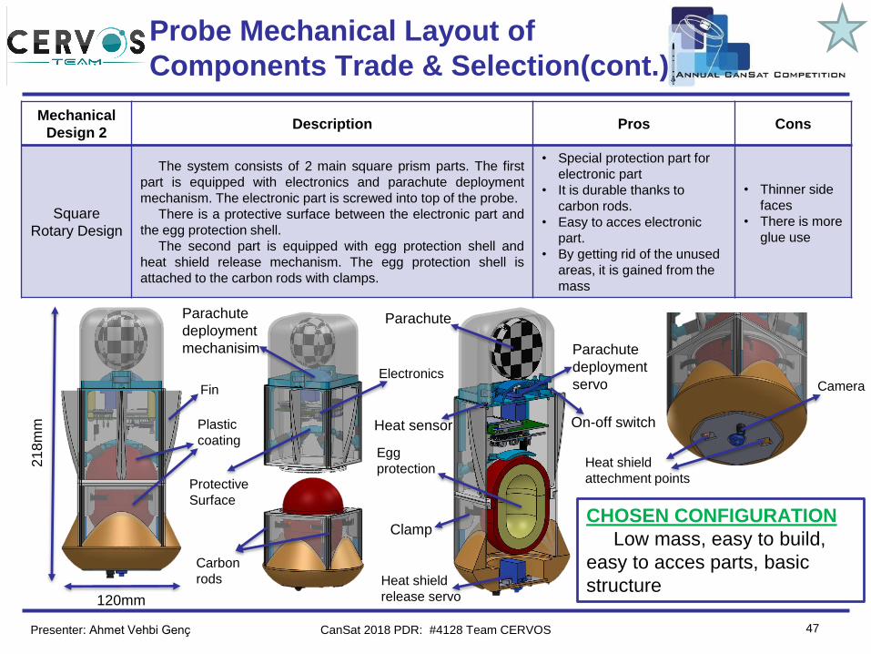
Mechanical
Design 2Description Pros Cons
Square
Rotary Design
The system consists of 2 main square prism parts. The first
part is equipped with electronics and parachute deployment
mechanism. The electronic part is screwed into top of the probe.
There is a protective surface between the electronic part and
the egg protection shell.
The second part is equipped with egg protection shell and
heat shield release mechanism. The egg protection shell is
attached to the carbon rods with clamps.
• Special protection part for
electronic part
• It is durable thanks to
carbon rods.
• Easy to acces electronic
part.
• By getting rid of the unused
areas, it is gained from the
mass
• Thinner side
faces
• There is more
glue use
CHOSEN CONFIGURATION
Low mass, easy to build,
easy to acces parts, basic
structure
ElectronicsCamera
Heat shield
attechment points
Heat shield
release servo
Egg
protection
Parachute
deployment
mechanisim Parachute
deployment
servoFin
Protective
Surface
Carbon
rods
Clamp
Parachute
Heat sensor
120mm
21
8m
m On-off switchPlastic
coating
Presenter: Ahmet Vehbi Genç CanSat 2018 PDR: #4128 Team CERVOS
Team Logo
Here
(If You Want)
48
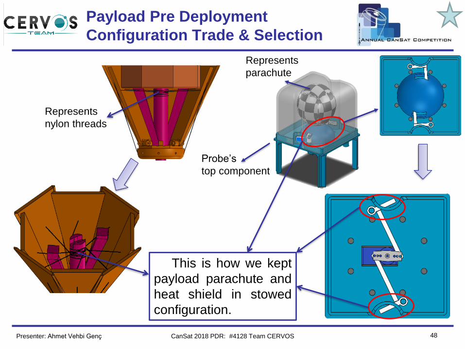
Payload Pre Deployment
Configuration Trade & Selection
Probe’s
top component
Represents
parachute
This is how we kept
payload parachute and
heat shield in stowed
configuration.
Represents
nylon threads
Presenter: Ahmet Vehbi Genç CanSat 2018 PDR: #4128 Team CERVOS
Team Logo
Here
(If You Want)
49
Heat Shield Deployment
Configuration Trade & Selection
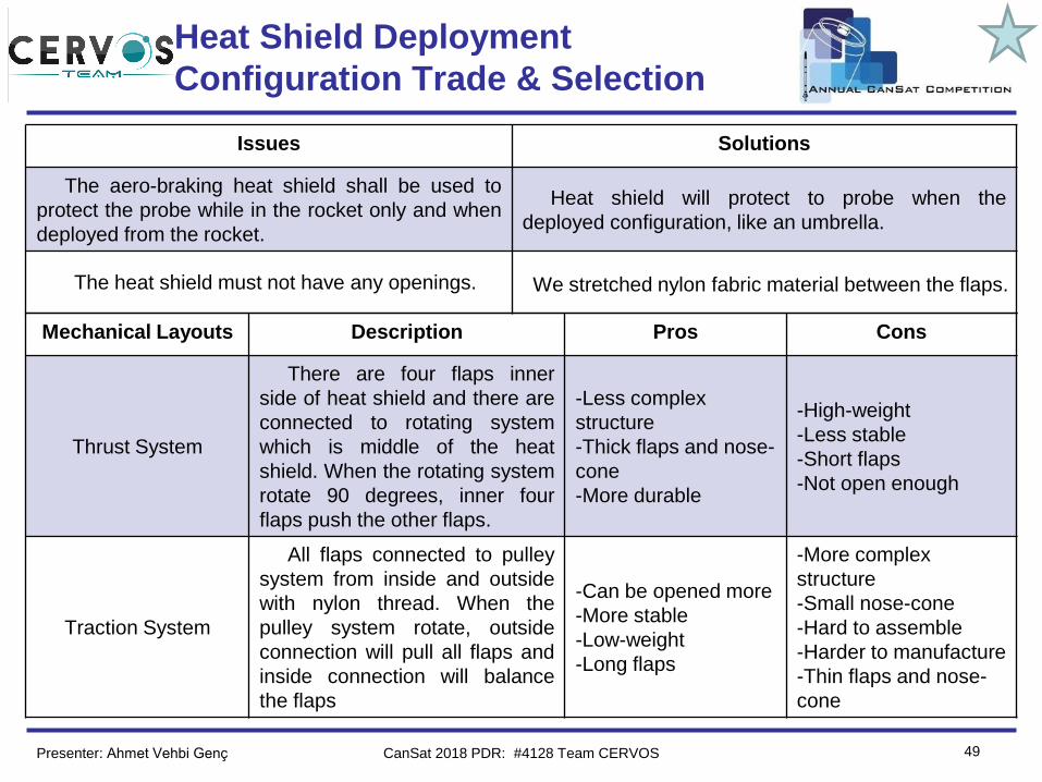
Issues Solutions
The aero-braking heat shield shall be used to
protect the probe while in the rocket only and when
deployed from the rocket.
Heat shield will protect to probe when the
deployed configuration, like an umbrella.
The heat shield must not have any openings. We stretched nylon fabric material between the flaps.
Mechanical Layouts Description Pros Cons
Thrust System
There are four flaps inner
side of heat shield and there are
connected to rotating system
which is middle of the heat
shield. When the rotating system
rotate 90 degrees, inner four
flaps push the other flaps.
-Less complex
structure
-Thick flaps and nose-
cone
-More durable
-High-weight
-Less stable
-Short flaps
-Not open enough
Traction System
All flaps connected to pulley
system from inside and outside
with nylon thread. When the
pulley system rotate, outside
connection will pull all flaps and
inside connection will balance
the flaps
-Can be opened more
-More stable
-Low-weight
-Long flaps
-More complex
structure
-Small nose-cone
-Hard to assemble
-Harder to manufacture
-Thin flaps and nose-
cone
Presenter: Ahmet Vehbi Genç CanSat 2018 PDR: #4128 Team CERVOS
Team Logo
Here
(If You Want)
50
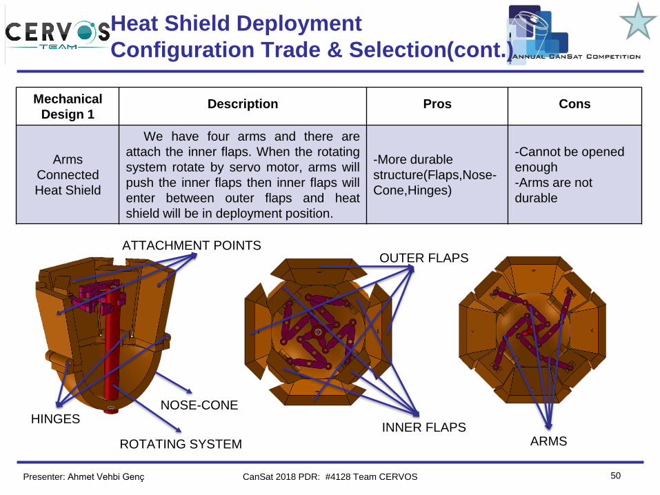
Mechanical
Design 1Description Pros Cons
Arms
Connected
Heat Shield
We have four arms and there are
attach the inner flaps. When the rotating
system rotate by servo motor, arms will
push the inner flaps then inner flaps will
enter between outer flaps and heat
shield will be in deployment position.
-More durable
structure(Flaps,Nose-
Cone,Hinges)
-Cannot be opened
enough
-Arms are not
durable
HINGESINNER FLAPS
OUTER FLAPS
ROTATING SYSTEM ARMS
NOSE-CONE
ATTACHMENT POINTS
Heat Shield Deployment
Configuration Trade & Selection(cont.)
Presenter: Ahmet Vehbi Genç CanSat 2018 PDR: #4128 Team CERVOS
Team Logo
Here
(If You Want)
51
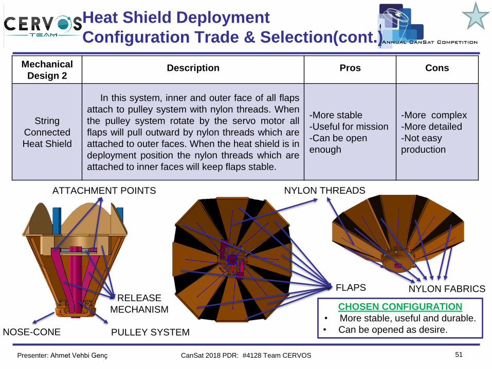
Mechanical
Design 2Description Pros Cons
String
Connected
Heat Shield
In this system, inner and outer face of all flaps
attach to pulley system with nylon threads. When
the pulley system rotate by the servo motor all
flaps will pull outward by nylon threads which are
attached to outer faces. When the heat shield is in
deployment position the nylon threads which are
attached to inner faces will keep flaps stable.
-More stable
-Useful for mission
-Can be open
enough
-More complex
-More detailed
-Not easy
production
PULLEY SYSTEM
FLAPS
NYLON THREADS
NOSE-CONE
NYLON FABRICS
CHOSEN CONFIGURATION
• More stable, useful and durable.
• Can be opened as desire.
RELEASE
MECHANISM
ATTACHMENT POINTS
Heat Shield Deployment
Configuration Trade & Selection(cont.)
Presenter: Ahmet Vehbi Genç CanSat 2018 PDR: #4128 Team CERVOS
Team Logo
Here
(If You Want)
52
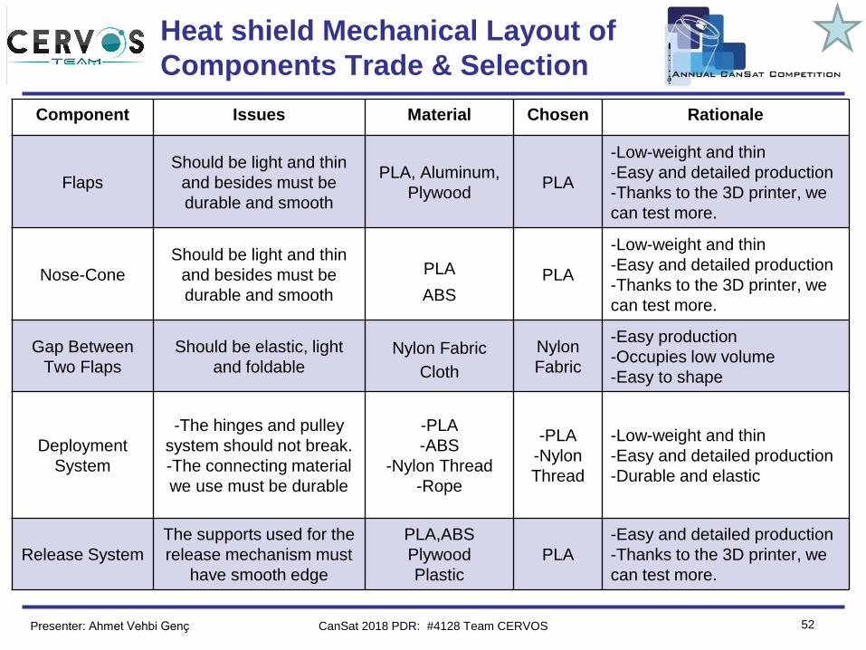
Heat shield Mechanical Layout of
Components Trade & Selection
Component Issues Material Chosen Rationale
Flaps
Should be light and thin
and besides must be
durable and smooth
PLA, Aluminum,
PlywoodPLA
-Low-weight and thin
-Easy and detailed production
-Thanks to the 3D printer, we
can test more.
Nose-Cone
Should be light and thin
and besides must be
durable and smooth
PLA
ABS
PLA
-Low-weight and thin
-Easy and detailed production
-Thanks to the 3D printer, we
can test more.
Gap Between
Two Flaps
Should be elastic, light
and foldableNylon Fabric
Cloth
Nylon
Fabric
-Easy production
-Occupies low volume
-Easy to shape
Deployment
System
-The hinges and pulley
system should not break.
-The connecting material
we use must be durable
-PLA
-ABS
-Nylon Thread
-Rope
-PLA
-Nylon
Thread
-Low-weight and thin
-Easy and detailed production
-Durable and elastic
Release System
The supports used for the
release mechanism must
have smooth edge
PLA,ABS
Plywood
Plastic
PLA
-Easy and detailed production
-Thanks to the 3D printer, we
can test more.
Presenter: Ahmet Vehbi Genç CanSat 2018 PDR: #4128 Team CERVOS
Team Logo
Here
(If You Want)
53
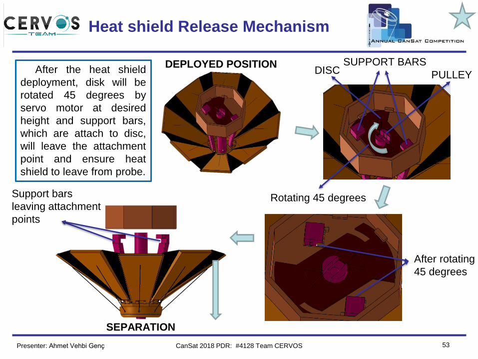
Heat shield Release Mechanism
DEPLOYED POSITION SUPPORT BARSDISC PULLEY
Rotating 45 degrees
After rotating
45 degrees
Support bars
leaving attachment
points
SEPARATION
After the heat shield
deployment, disk will be
rotated 45 degrees by
servo motor at desired
height and support bars,
which are attach to disc,
will leave the attachment
point and ensure heat
shield to leave from probe.
Presenter: Ahmet Vehbi Genç CanSat 2018 PDR: #4128 Team CERVOS
Team Logo
Here
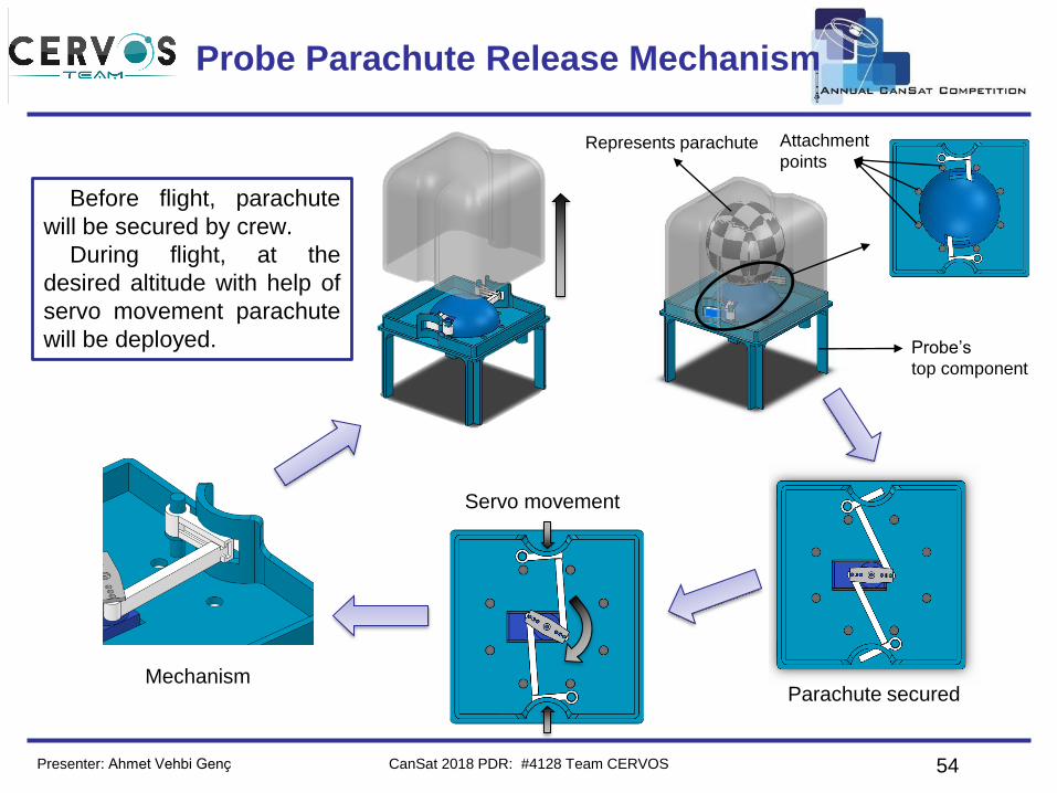
(If You Want) Probe Parachute Release Mechanism
54
Probe’s
top component
Attachment
points
Before flight, parachute
will be secured by crew.
During flight, at the
desired altitude with help of
servo movement parachute
will be deployed.
Represents parachute
Parachute secured
Servo movement
Mechanism
Presenter: Ahmet Vehbi Genç CanSat 2018 PDR: #4128 Team CERVOS
Team Logo
Here
(If You Want)
55
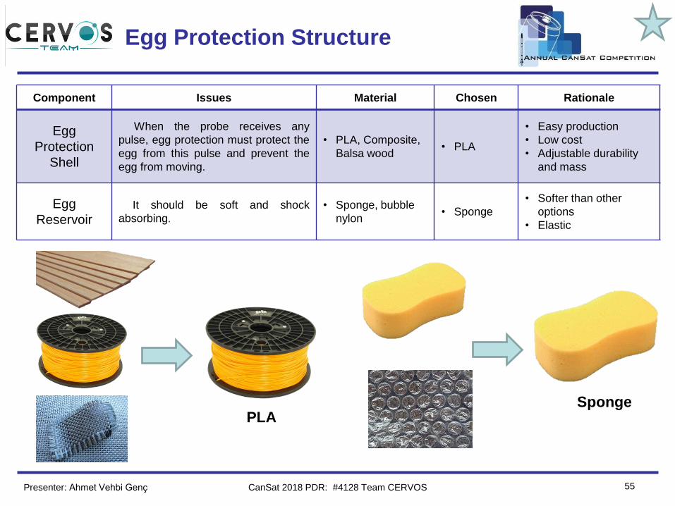
Egg Protection Structure
Component Issues Material Chosen Rationale
Egg
Protection
Shell
When the probe receives any
pulse, egg protection must protect the
egg from this pulse and prevent the
egg from moving.
• PLA, Composite,
Balsa wood• PLA
• Easy production
• Low cost
• Adjustable durability
and mass
Egg
ReservoirIt should be soft and shock
absorbing.
• Sponge, bubble
nylon• Sponge
• Softer than other
options
• Elastic
PLASponge
Presenter: Ahmet Vehbi Genç CanSat 2018 PDR: #4128 Team CERVOS
Team Logo
Here
(If You Want)
56
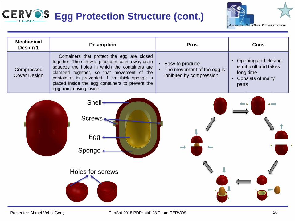
Egg Protection Structure (cont.)
Mechanical
Design 1Description Pros Cons
Compressed
Cover Design
Containers that protect the egg are closed
together. The screw is placed in such a way as to
squeeze the holes in which the containers are
clamped together, so that movement of the
containers is prevented. 1 cm thick sponge is
placed inside the egg containers to prevent the
egg from moving inside.
• Easy to produce
• The movement of the egg is
inhibited by compression
• Opening and closing
is difficult and takes
long time
• Consists of many
parts
Shell
Screws
Egg
Sponge
Holes for screws
Presenter: Ahmet Vehbi Genç CanSat 2018 PDR: #4128 Team CERVOS
Team Logo
Here
(If You Want)
57
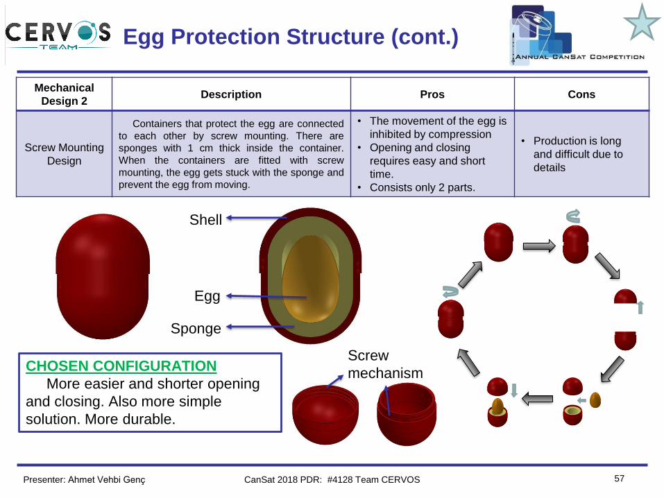
Egg Protection Structure (cont.)
Mechanical
Design 2Description Pros Cons
Screw Mounting
Design
Containers that protect the egg are connected
to each other by screw mounting. There are
sponges with 1 cm thick inside the container.
When the containers are fitted with screw
mounting, the egg gets stuck with the sponge and
prevent the egg from moving.
• The movement of the egg is
inhibited by compression
• Opening and closing
requires easy and short
time.
• Consists only 2 parts.
• Production is long
and difficult due to
details
Shell
Egg
Sponge
Screw
mechanismCHOSEN CONFIGURATION
More easier and shorter opening
and closing. Also more simple
solution. More durable.
Presenter: Ahmet Vehbi Genç CanSat 2018 PDR: #4128 Team CERVOS
Team Logo
Here
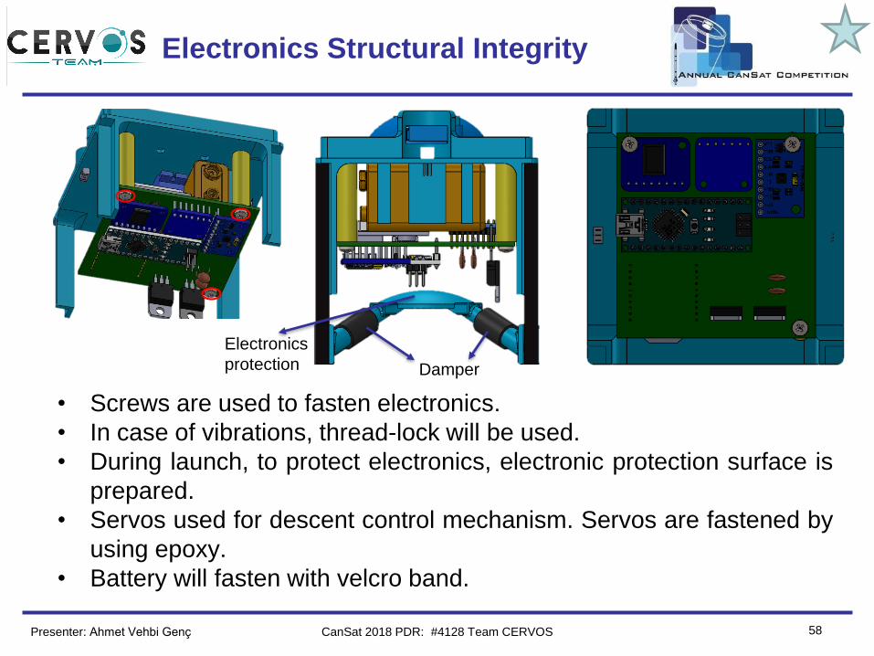
(If You Want) Electronics Structural Integrity
58
• Screws are used to fasten electronics.
• In case of vibrations, thread-lock will be used.
• During launch, to protect electronics, electronic protection surface is
prepared.
• Servos used for descent control mechanism. Servos are fastened by
using epoxy.
• Battery will fasten with velcro band.
Electronics
protection Damper
Presenter: Ahmet Vehbi Genç CanSat 2018 PDR: #4128 Team CERVOS
Team Logo
Here
(If You Want)
59
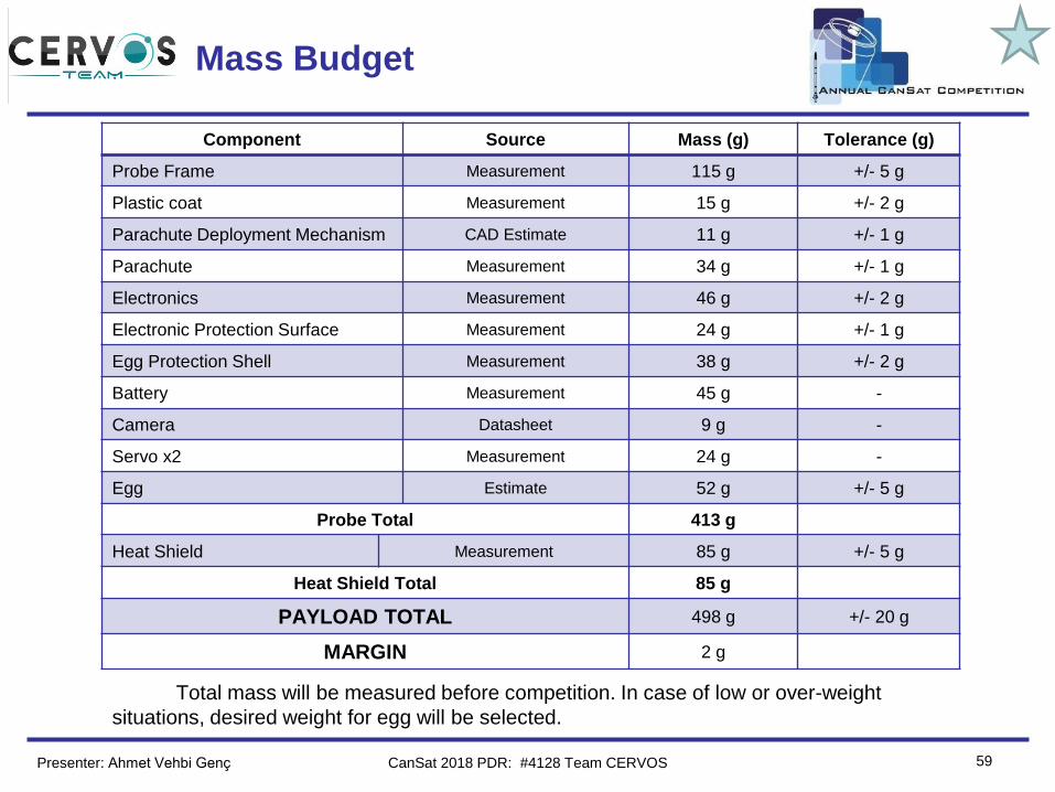
Mass Budget
Component Source Mass (g) Tolerance (g)
Probe Frame Measurement 115 g +/- 5 g
Plastic coat Measurement 15 g +/- 2 g
Parachute Deployment Mechanism CAD Estimate 11 g +/- 1 g
Parachute Measurement 34 g +/- 1 g
Electronics Measurement 46 g +/- 2 g
Electronic Protection Surface Measurement 24 g +/- 1 g
Egg Protection Shell Measurement 38 g +/- 2 g
Battery Measurement 45 g -
Camera Datasheet 9 g -
Servo x2 Measurement 24 g -
Egg Estimate 52 g +/- 5 g
Probe Total 413 g
Heat Shield Measurement 85 g +/- 5 g
Heat Shield Total 85 g
PAYLOAD TOTAL 498 g +/- 20 g
MARGIN 2 g
Total mass will be measured before competition. In case of low or over-weight
situations, desired weight for egg will be selected.
Presenter: Ahmet Vehbi Genç CanSat 2018 PDR: #4128 Team CERVOS
Team Logo
Here
(If You Want)
60
Communication and Data Handling
(CDH) Subsystem Design
Alp Demirel
CanSat 2018 PDR: #4128 Team CERVOS
Team Logo
Here
(If You Want)
61
CDH Overview
Presenter: Alp Demirel
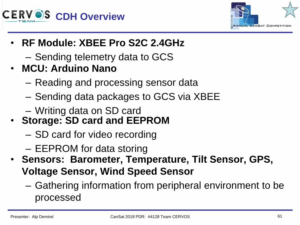
• RF Module: XBEE Pro S2C 2.4GHz
– Sending telemetry data to GCS• MCU: Arduino Nano
– Reading and processing sensor data
– Sending data packages to GCS via XBEE
– Writing data on SD card• Storage: SD card and EEPROM
– SD card for video recording
– EEPROM for data storing• Sensors: Barometer, Temperature, Tilt Sensor, GPS,
Voltage Sensor, Wind Speed Sensor
– Gathering information from peripheral environment to be
processed
CanSat 2018 PDR: #4128 Team CERVOS
Team Logo
Here
(If You Want)
62
CDH Requirements
ID Requirement Rationalite Parent VM
A D I T
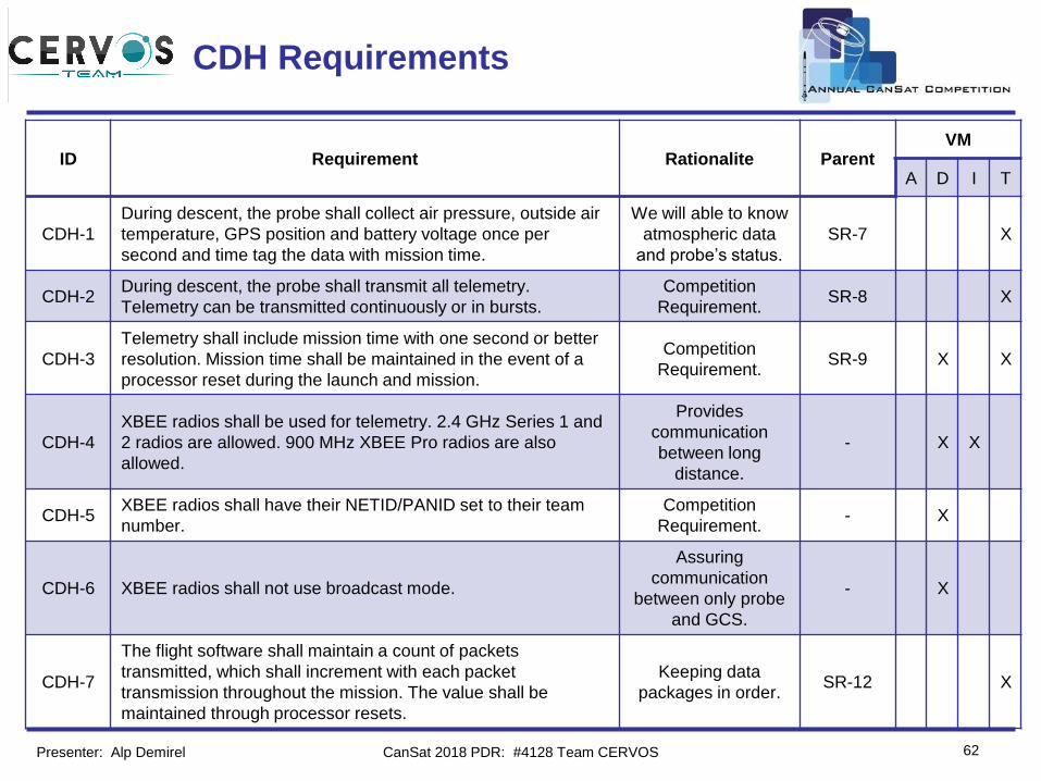
CDH-1
During descent, the probe shall collect air pressure, outside air
temperature, GPS position and battery voltage once per
second and time tag the data with mission time.
We will able to know
atmospheric data
and probe’s status.
SR-7 X
CDH-2During descent, the probe shall transmit all telemetry.
Telemetry can be transmitted continuously or in bursts.
Competition
Requirement.SR-8 X
CDH-3
Telemetry shall include mission time with one second or better
resolution. Mission time shall be maintained in the event of a
processor reset during the launch and mission.
Competition
Requirement.SR-9 X X
CDH-4
XBEE radios shall be used for telemetry. 2.4 GHz Series 1 and
2 radios are allowed. 900 MHz XBEE Pro radios are also
allowed.
Provides
communication
between long
distance.
- X X
CDH-5XBEE radios shall have their NETID/PANID set to their team
number.
Competition
Requirement.- X
CDH-6 XBEE radios shall not use broadcast mode.
Assuring
communication
between only probe
and GCS.
- X
CDH-7
The flight software shall maintain a count of packets
transmitted, which shall increment with each packet
transmission throughout the mission. The value shall be
maintained through processor resets.
Keeping data
packages in order.SR-12 X
Presenter: Alp Demirel CanSat 2018 PDR: #4128 Team CERVOS
Team Logo
Here
(If You Want)
63
Probe Processor & Memory
Trade & Selection
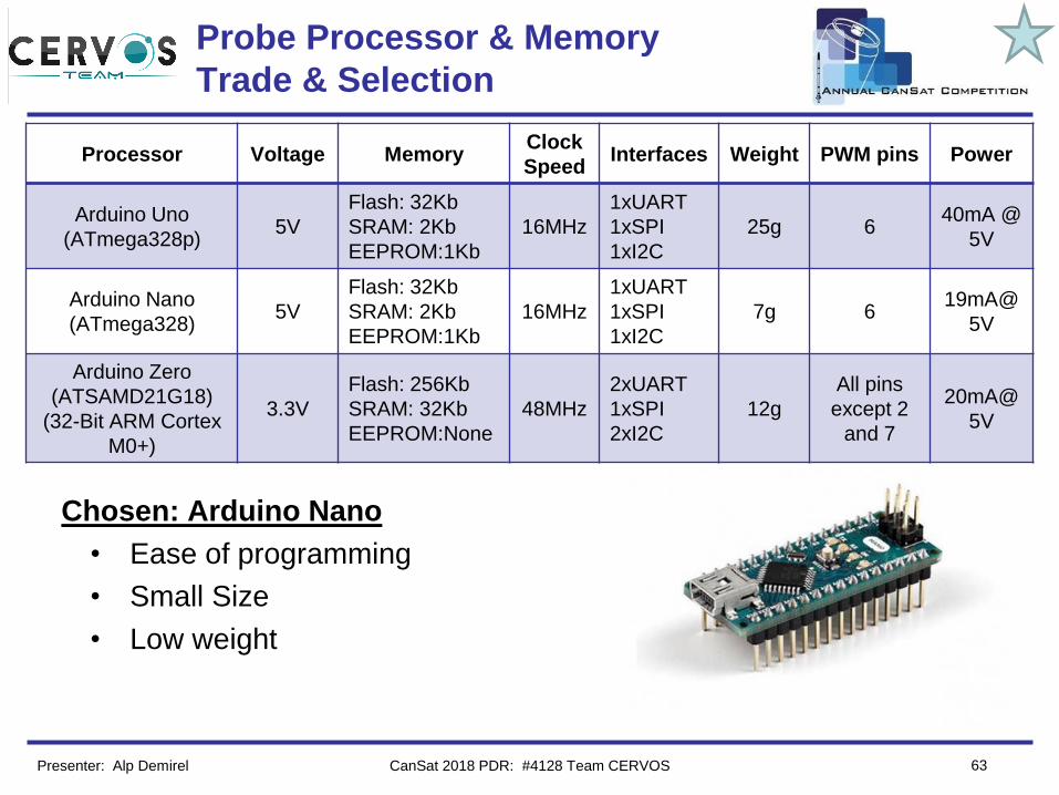
Chosen: Arduino Nano
• Ease of programming
• Small Size
• Low weight
Processor Voltage MemoryClock
SpeedInterfaces Weight PWM pins Power
Arduino Uno
(ATmega328p)5V
Flash: 32Kb
SRAM: 2Kb
EEPROM:1Kb
16MHz
1xUART
1xSPI
1xI2C
25g 640mA @
5V
Arduino Nano
(ATmega328)5V
Flash: 32Kb
SRAM: 2Kb
EEPROM:1Kb
16MHz
1xUART
1xSPI
1xI2C
7g 619mA@
5V
Arduino Zero
(ATSAMD21G18)
(32-Bit ARM Cortex
M0+)
3.3V
Flash: 256Kb
SRAM: 32Kb
EEPROM:None
48MHz
2xUART
1xSPI
2xI2C
12g
All pins
except 2
and 7
20mA@
5V
Presenter: Alp Demirel CanSat 2018 PDR: #4128 Team CERVOS
Team Logo
Here
(If You Want)
64
Probe Processor & Memory
Trade & Selection(Cont.)
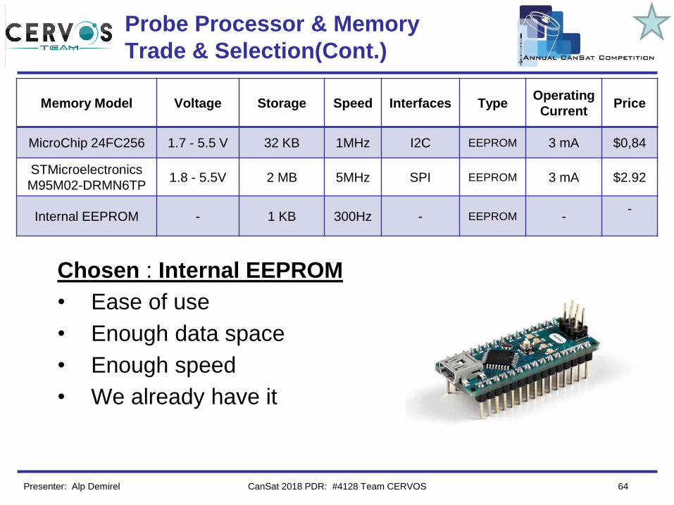
Chosen : Internal EEPROM
• Ease of use
• Enough data space
• Enough speed
• We already have it
Memory Model Voltage Storage Speed Interfaces TypeOperating
CurrentPrice
MicroChip 24FC256 1.7 - 5.5 V 32 KB 1MHz I2C EEPROM 3 mA $0,84
STMicroelectronics
M95M02-DRMN6TP1.8 - 5.5V 2 MB 5MHz SPI EEPROM 3 mA $2.92
Internal EEPROM - 1 KB 300Hz - EEPROM --
Presenter: Alp Demirel CanSat 2018 PDR: #4128 Team CERVOS
Team Logo
Here
(If You Want)
65
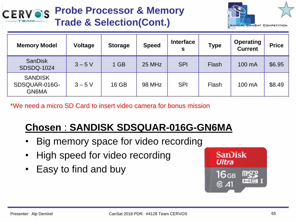
Probe Processor & Memory
Trade & Selection(Cont.)
Chosen : SANDISK SDSQUAR-016G-GN6MA
• Big memory space for video recording
• High speed for video recording
• Easy to find and buy
Memory Model Voltage Storage SpeedInterface
sType
Operating
CurrentPrice
SanDisk
SDSDQ-10243 – 5 V 1 GB 25 MHz SPI Flash 100 mA $6.95
SANDISK
SDSQUAR-016G-
GN6MA
3 – 5 V 16 GB 98 MHz SPI Flash 100 mA $8.49
*We need a micro SD Card to insert video camera for bonus mission
Presenter: Alp Demirel CanSat 2018 PDR: #4128 Team CERVOS
Team Logo
Here
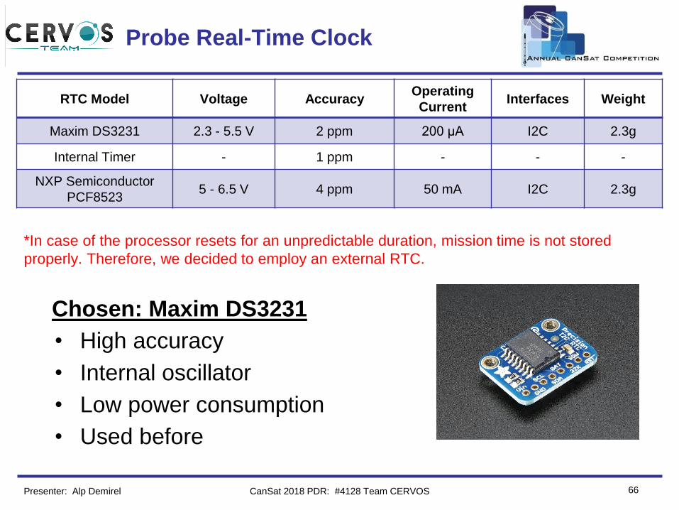
(If You Want) Probe Real-Time Clock
66
RTC Model Voltage AccuracyOperating
CurrentInterfaces Weight
Maxim DS3231 2.3 - 5.5 V 2 ppm 200 µA I2C 2.3g
Internal Timer - 1 ppm - - -
NXP Semiconductor
PCF85235 - 6.5 V 4 ppm 50 mA I2C 2.3g
Chosen: Maxim DS3231
• High accuracy
• Internal oscillator
• Low power consumption
• Used before
*In case of the processor resets for an unpredictable duration, mission time is not stored
properly. Therefore, we decided to employ an external RTC.
Presenter: Alp Demirel CanSat 2018 PDR: #4128 Team CERVOS
Team Logo
Here
(If You Want)
67
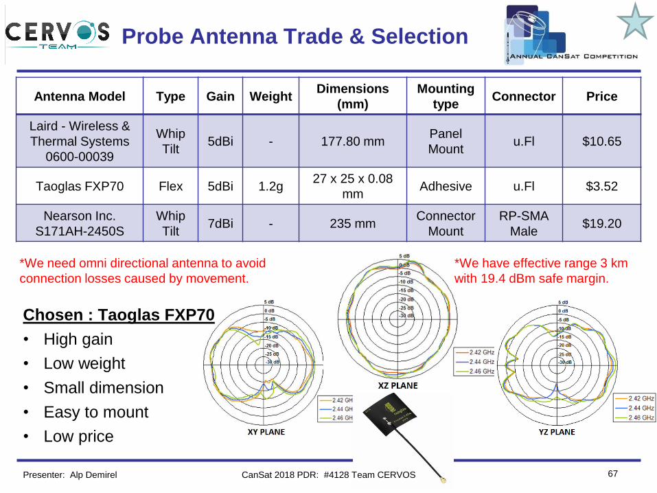
Probe Antenna Trade & Selection
Chosen : Taoglas FXP70
• High gain
• Low weight
• Small dimension
• Easy to mount
• Low price
Antenna Model Type Gain WeightDimensions
(mm)
Mounting
typeConnector Price
Laird - Wireless &
Thermal Systems
0600-00039
Whip
Tilt5dBi - 177.80 mm
Panel
Mountu.Fl $10.65
Taoglas FXP70 Flex 5dBi 1.2g27 x 25 x 0.08
mmAdhesive u.Fl $3.52
Nearson Inc.
S171AH-2450S
Whip
Tilt7dBi - 235 mm
Connector
Mount
RP-SMA
Male$19.20
*We need omni directional antenna to avoid
connection losses caused by movement.
Presenter: Alp Demirel CanSat 2018 PDR: #4128 Team CERVOS
*We have effective range 3 km
with 19.4 dBm safe margin.
Team Logo
Here
(If You Want)
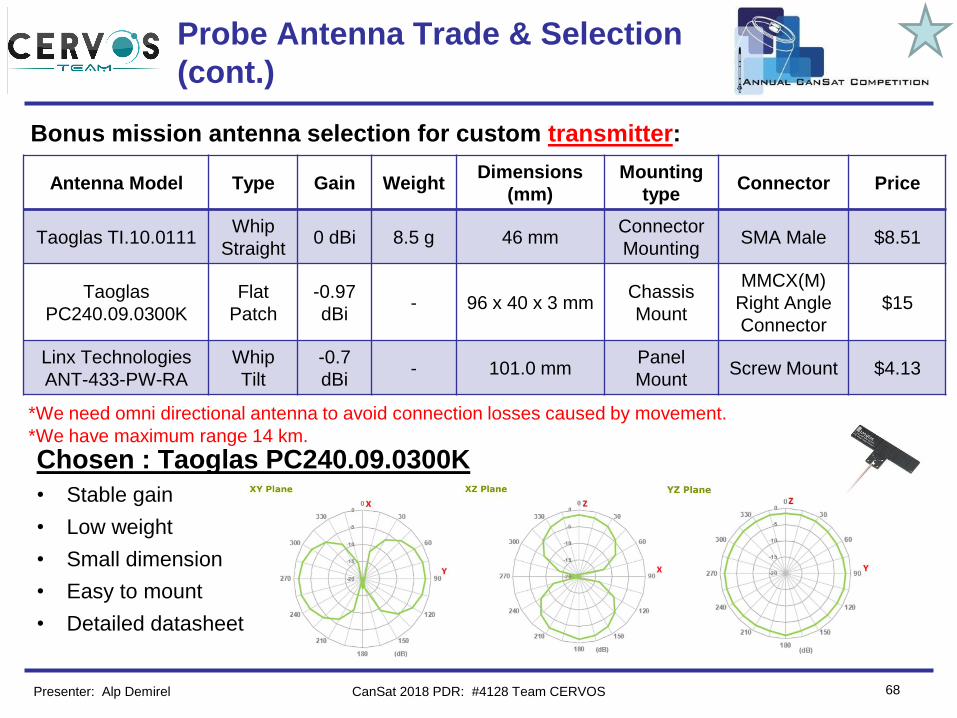
Chosen : Taoglas PC240.09.0300K
• Stable gain
• Low weight
• Small dimension
• Easy to mount
• Detailed datasheet
68
Probe Antenna Trade & Selection
(cont.)
Antenna Model Type Gain WeightDimensions
(mm)
Mounting
typeConnector Price
Taoglas TI.10.0111Whip
Straight0 dBi 8.5 g 46 mm
Connector
MountingSMA Male $8.51
Taoglas
PC240.09.0300K
Flat
Patch
-0.97
dBi- 96 x 40 x 3 mm
Chassis
Mount
MMCX(M)
Right Angle
Connector
$15
Linx Technologies
ANT-433-PW-RA
Whip
Tilt
-0.7
dBi- 101.0 mm
Panel
MountScrew Mount $4.13
*We need omni directional antenna to avoid connection losses caused by movement.
Bonus mission antenna selection for custom transmitter:
Presenter: Alp Demirel CanSat 2018 PDR: #4128 Team CERVOS
*We have maximum range 14 km.
Team Logo
Here
(If You Want)
69
Probe Antenna Trade & Selection
(cont.)
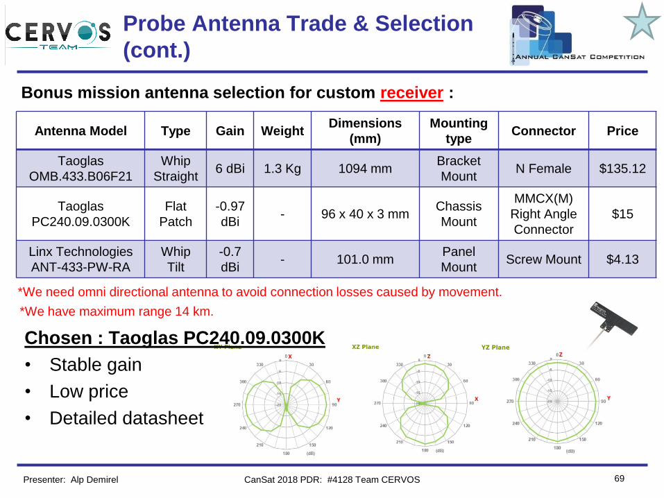
Chosen : Taoglas PC240.09.0300K
• Stable gain
• Low price
• Detailed datasheet
Antenna Model Type Gain WeightDimensions
(mm)
Mounting
typeConnector Price
Taoglas
OMB.433.B06F21
Whip
Straight6 dBi 1.3 Kg 1094 mm
Bracket
MountN Female $135.12
Taoglas
PC240.09.0300K
Flat
Patch
-0.97
dBi- 96 x 40 x 3 mm
Chassis
Mount
MMCX(M)
Right Angle
Connector
$15
Linx Technologies
ANT-433-PW-RA
Whip
Tilt
-0.7
dBi- 101.0 mm
Panel
MountScrew Mount $4.13
*We need omni directional antenna to avoid connection losses caused by movement.
Bonus mission antenna selection for custom receiver :
Presenter: Alp Demirel CanSat 2018 PDR: #4128 Team CERVOS
*We have maximum range 14 km.
Team Logo
Here
(If You Want)
70
Probe Radio Configuration
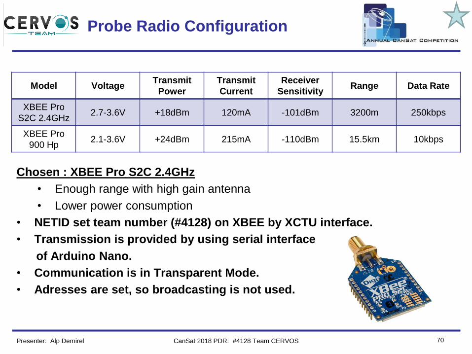
Chosen : XBEE Pro S2C 2.4GHz
• Enough range with high gain antenna
• Lower power consumption
• NETID set team number (#4128) on XBEE by XCTU interface.
• Transmission is provided by using serial interface
of Arduino Nano.
• Communication is in Transparent Mode.
• Adresses are set, so broadcasting is not used.
Model VoltageTransmit
Power
Transmit
Current
Receiver
SensitivityRange Data Rate
XBEE Pro
S2C 2.4GHz2.7-3.6V +18dBm 120mA -101dBm 3200m 250kbps
XBEE Pro
900 Hp 2.1-3.6V +24dBm 215mA -110dBm 15.5km 10kbps
Presenter: Alp Demirel CanSat 2018 PDR: #4128 Team CERVOS
Team Logo
Here
(If You Want)
71
Probe Radio Configuration(Cont.)
Presenter: Alp Demirel CanSat 2018 PDR: #4128 Team CERVOS
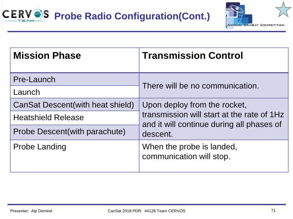
Mission Phase Transmission Control
Pre-LaunchThere will be no communication.
Launch
CanSat Descent(with heat shield) Upon deploy from the rocket,
transmission will start at the rate of 1Hz
and it will continue during all phases of
descent.
Heatshield Release
Probe Descent(with parachute)
Probe Landing When the probe is landed,
communication will stop.
Team Logo
Here
(If You Want)
72
Probe Telemetry Format
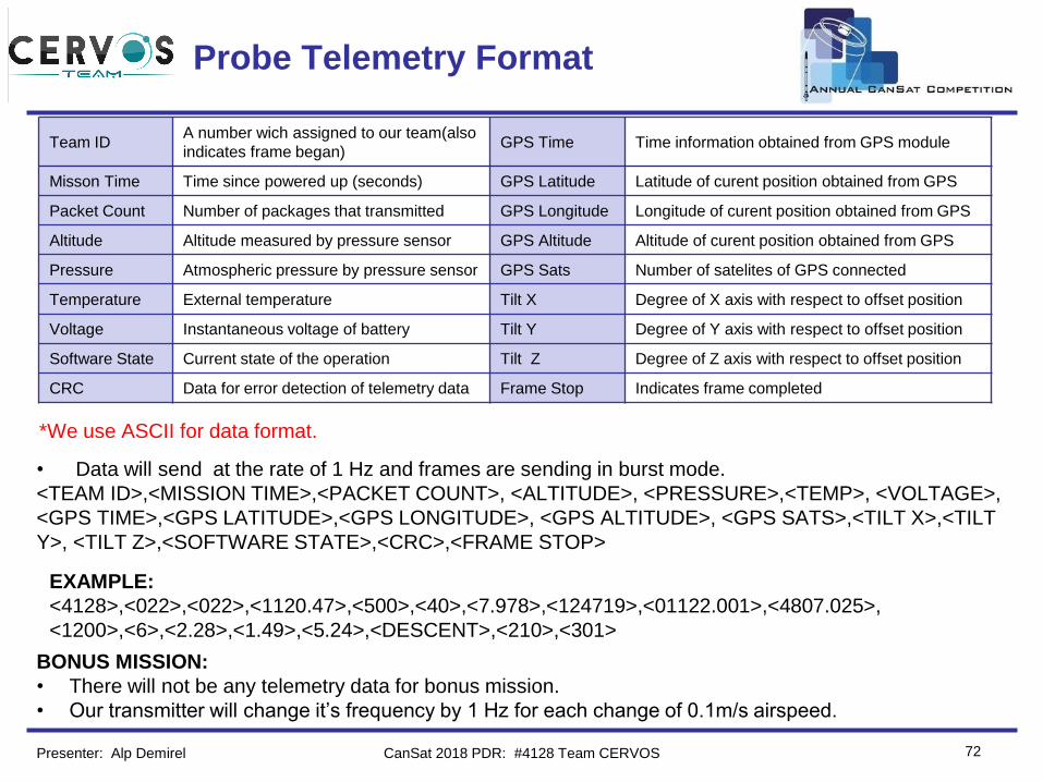
• Data will send at the rate of 1 Hz and frames are sending in burst mode.
<TEAM ID>,<MISSION TIME>,<PACKET COUNT>, <ALTITUDE>, <PRESSURE>,<TEMP>, <VOLTAGE>,
<GPS TIME>,<GPS LATITUDE>,<GPS LONGITUDE>, <GPS ALTITUDE>, <GPS SATS>,<TILT X>,<TILT
Y>, <TILT Z>,<SOFTWARE STATE>,<CRC>,<FRAME STOP>
Team IDA number wich assigned to our team(also
indicates frame began)GPS Time Time information obtained from GPS module
Misson Time Time since powered up (seconds) GPS Latitude Latitude of curent position obtained from GPS
Packet Count Number of packages that transmitted GPS Longitude Longitude of curent position obtained from GPS
Altitude Altitude measured by pressure sensor GPS Altitude Altitude of curent position obtained from GPS
Pressure Atmospheric pressure by pressure sensor GPS Sats Number of satelites of GPS connected
Temperature External temperature Tilt X Degree of X axis with respect to offset position
Voltage Instantaneous voltage of battery Tilt Y Degree of Y axis with respect to offset position
Software State Current state of the operation Tilt Z Degree of Z axis with respect to offset position
CRC Data for error detection of telemetry data Frame Stop Indicates frame completed
EXAMPLE:
<4128>,<022>,<022>,<1120.47>,<500>,<40>,<7.978>,<124719>,<01122.001>,<4807.025>,
<1200>,<6>,<2.28>,<1.49>,<5.24>,<DESCENT>,<210>,<301>
BONUS MISSION:
• There will not be any telemetry data for bonus mission.
• Our transmitter will change it’s frequency by 1 Hz for each change of 0.1m/s airspeed.
Presenter: Alp Demirel CanSat 2018 PDR: #4128 Team CERVOS
*We use ASCII for data format.
Team Logo
Here
(If You Want)
73
Electrical Power Subsystem (EPS)
Design
Burhan Kaplan
CanSat 2018 PDR: #4128 Team CERVOS
Team Logo
Here
(If You Want)
74
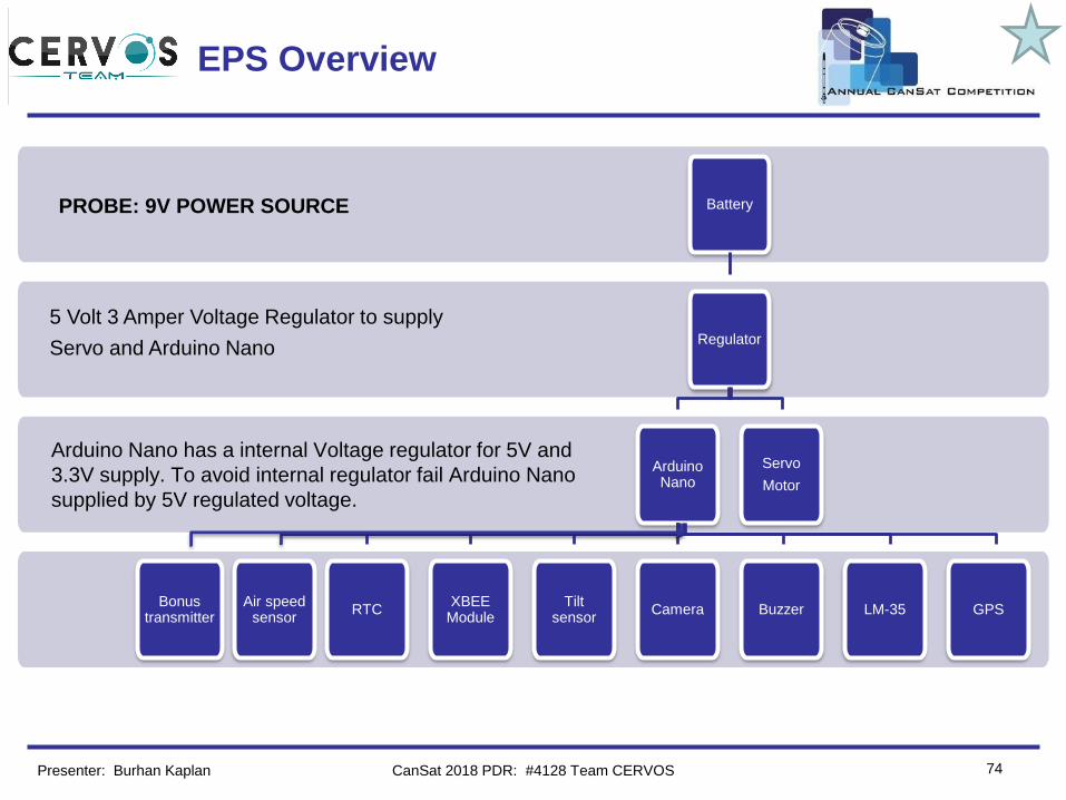
EPS Overview
Presenter: Burhan Kaplan
Battery
Regulator
ArduinoNano
RTCXBEE
ModuleTilt
sensorCamera Buzzer LM-35 GPS
Servo
Motor
Arduino Nano has a internal Voltage regulator for 5V and
3.3V supply. To avoid internal regulator fail Arduino Nano
supplied by 5V regulated voltage.
5 Volt 3 Amper Voltage Regulator to supply
Servo and Arduino Nano
Air speedsensor
Bonus transmitter
PROBE: 9V POWER SOURCE
CanSat 2018 PDR: #4128 Team CERVOS
Team Logo
Here
(If You Want)
75
EPS Requirements
ID REQUIREMENT RATIONALE PARENTVM
A D I T
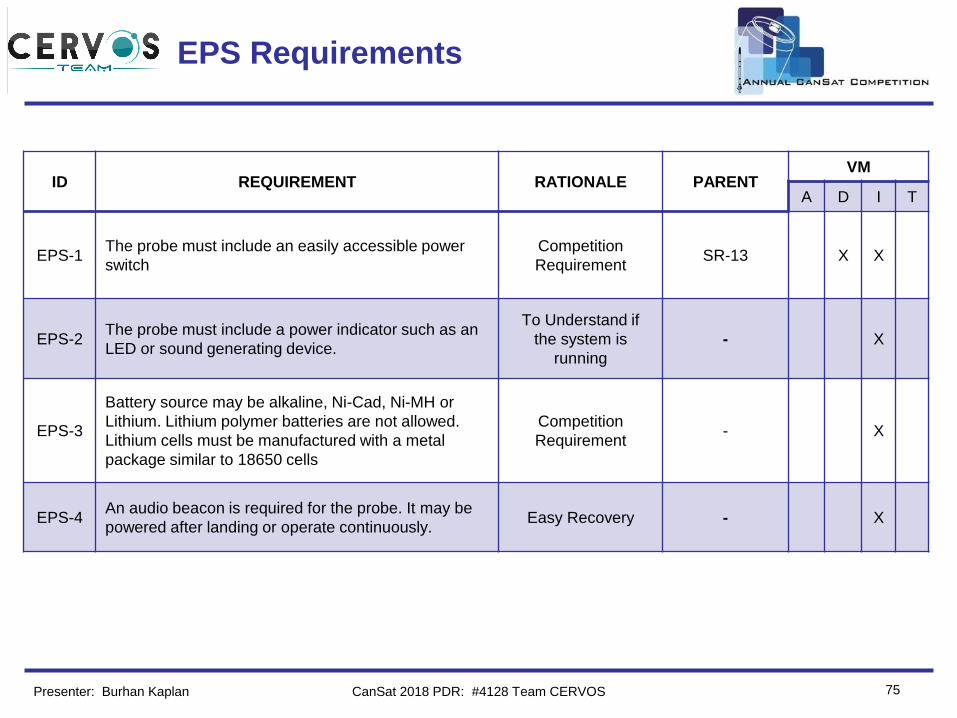
EPS-1The probe must include an easily accessible power
switch
Competition
Requirement SR-13 X X
EPS-2The probe must include a power indicator such as an
LED or sound generating device.
To Understand if
the system is
running
- X
EPS-3
Battery source may be alkaline, Ni-Cad, Ni-MH or
Lithium. Lithium polymer batteries are not allowed.
Lithium cells must be manufactured with a metal
package similar to 18650 cells
Competition
Requirement - X
EPS-4An audio beacon is required for the probe. It may be
powered after landing or operate continuously. Easy Recovery - X
Presenter: Burhan Kaplan CanSat 2018 PDR: #4128 Team CERVOS
Team Logo
Here
(If You Want)
76
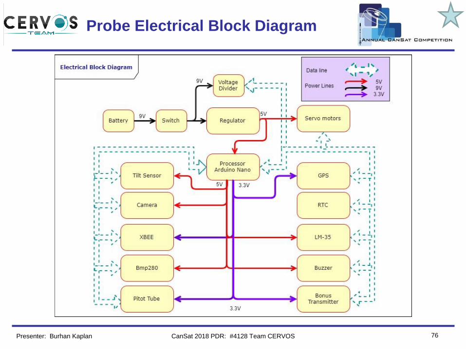
Probe Electrical Block Diagram
Presenter: Burhan Kaplan CanSat 2018 PDR: #4128 Team CERVOS

Team Logo
Here
(If You Want) Probe Power Trade & Selection
77
Manufacturer ModelDimensions /
Weight Power Storage Capacity Cost
ENERGIZER 522 45.6 g 4500 mWh 500 mAh $2.10
Duracell MN 1604 45 g 5040 mWh 560 mAh $1.25
Battery Chosen : Duracell MN1604
• Used before.
• More energy capacity than the
another.
Presenter: Burhan Kaplan CanSat 2018 PDR: #4128 Team CERVOS
*Single battery is connected seriesly to system.
Team Logo
Here
(If You Want)
78
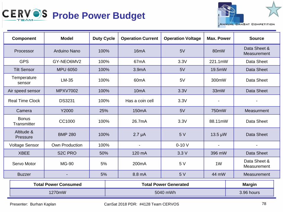
Probe Power Budget
Component Model Duty Cycle Operation Current Operation Voltage Max. Power Source
Processor Arduino Nano 100% 16mA 5V 80mWData Sheet &
Measurement
GPS GY-NEO6MV2 100% 67mA 3.3V 221.1mW Data Sheet
Tilt Sensor MPU 6050 100% 3.9mA 5V 19.5mW Data Sheet
Temperature
sensorLM-35 100% 60mA 5V 300mW Data Sheet
Air speed sensor MPXV7002 100% 10mA 3.3V 33mW Data Sheet
Real Time Clock DS3231 100% Has a coin cell 3.3V - -
Camera Y2000 25% 150mA 5V 750mW Measurment
Bonus
TransmitterCC1000 100% 26.7mA 3.3V 88.11mW Data Sheet
Altitude &
PressureBMP 280 100% 2.7 µA 5 V 13.5 µW Data Sheet
Voltage Sensor Own Production 100% - 0-10 V - -
XBEE S2C PRO 50% 120 mA 3.3 V 396 mW Data Sheet
Servo Motor MG-90 5% 200mA 5 V 1WData Sheet &
Measurement
Buzzer - 5% 8.8 mA 5 V 44 mW Measurement
Total Power Consumed Total Power Generated Margin
1270mW 5040 mWh 3.96 hours
Presenter: Burhan Kaplan CanSat 2018 PDR: #4128 Team CERVOS

Team Logo
Here
(If You Want)
79
Flight Software (FSW) Design
Kadir Serhat Altıntığ
CanSat 2018 PDR: #4128 Team CERVOS
Team Logo
Here
(If You Want)
80
FSW Overview
Presenter: Kadir Serhat Altıntığ
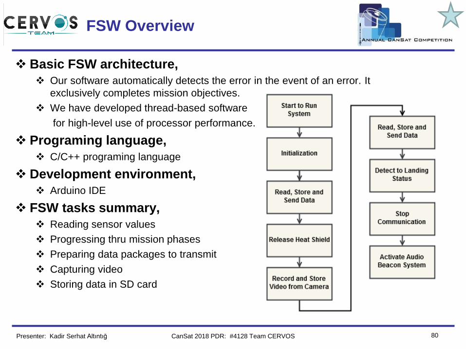
❖ Basic FSW architecture,
❖ Our software automatically detects the error in the event of an error. It
exclusively completes mission objectives.
❖ We have developed thread-based software
for high-level use of processor performance.
❖ Programing language,
❖ C/C++ programing language
❖ Development environment,
❖ Arduino IDE
❖ FSW tasks summary,
❖ Reading sensor values
❖ Progressing thru mission phases
❖ Preparing data packages to transmit
❖ Capturing video
❖ Storing data in SD card
CanSat 2018 PDR: #4128 Team CERVOS
Team Logo
Here
(If You Want)
81
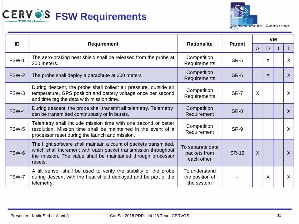
FSW Requirements
ID Requirement Rationalite ParentVM
A D I T
FSW-1The aero-braking heat shield shall be released from the probe at
300 meters.
Competition
RequirementsSR-5 X X
FSW-2 The probe shall deploy a parachute at 300 metersCompetition
RequirementsSR-6 X X
FSW-3
During descent, the probe shall collect air pressure, outside air
temperature, GPS position and battery voltage once per second
and time tag the data with mission time.
Competition
RequirementsSR-7 X X
FSW-4During descent, the probe shall transmit all telemetry. Telemetry
can be transmitted continuously or in bursts.
Competition
RequirementSR-8 X
FSW-5
Telemetry shall include mission time with one second or better
resolution. Mission time shall be maintained in the event of a
processor reset during the launch and mission.
Competition
RequirementSR-9 X
FSW-6
The flight software shall maintain a count of packets transmitted,
which shall increment with each packet transmission throughout
the mission. The value shall be maintained through processor
resets.
To separate data
packets from
each other
SR-12 X X
FSW-7
A tilt sensor shall be used to verify the stability of the probe
during descent with the heat shield deployed and be part of the
telemetry.
To understand
the position of
the system
- X X
Presenter: Kadir Serhat Altıntığ CanSat 2018 PDR: #4128 Team CERVOS
Team Logo
Here
(If You Want)
82
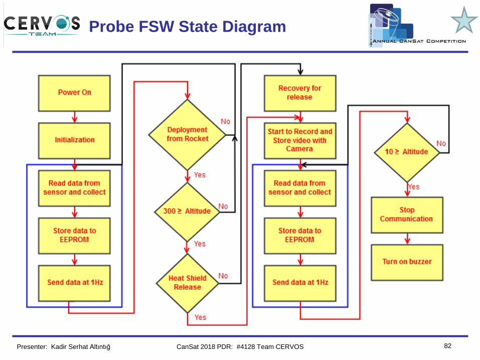
Probe FSW State Diagram
Presenter: Kadir Serhat Altıntığ CanSat 2018 PDR: #4128 Team CERVOS
Team Logo
Here
(If You Want)
83
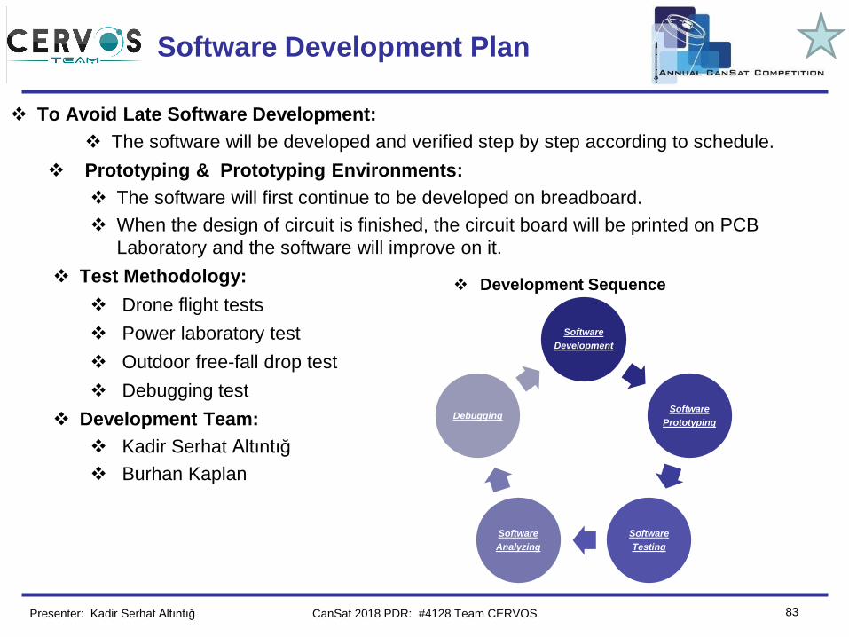
Software Development Plan
❖ To Avoid Late Software Development:
❖ The software will be developed and verified step by step according to schedule.
❖ Prototyping & Prototyping Environments:
❖ The software will first continue to be developed on breadboard.
❖ When the design of circuit is finished, the circuit board will be printed on PCB
Laboratory and the software will improve on it.
❖ Test Methodology:
❖ Drone flight tests
❖ Power laboratory test
❖ Outdoor free-fall drop test
❖ Debugging test
❖ Development Team:
❖ Kadir Serhat Altıntığ
❖ Burhan Kaplan
Presenter: Kadir Serhat Altıntığ
❖ Development Sequence
Software
Development
Software
Prototyping
Software
Testing
Software
Analyzing
Debugging
CanSat 2018 PDR: #4128 Team CERVOS
Team Logo
Here
(If You Want)
84
Ground Control System (GCS) Design
Ramazan Kurban
CanSat 2018 PDR: #4128 Team CERVOS
Team Logo
Here
(If You Want)
85
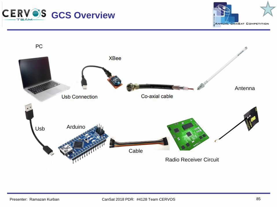
GCS Overview
Presenter: Ramazan Kurban
Radio Receiver Circuit
Antenna
Arduino
Cable
Usb
CanSat 2018 PDR: #4128 Team CERVOS
Team Logo
Here
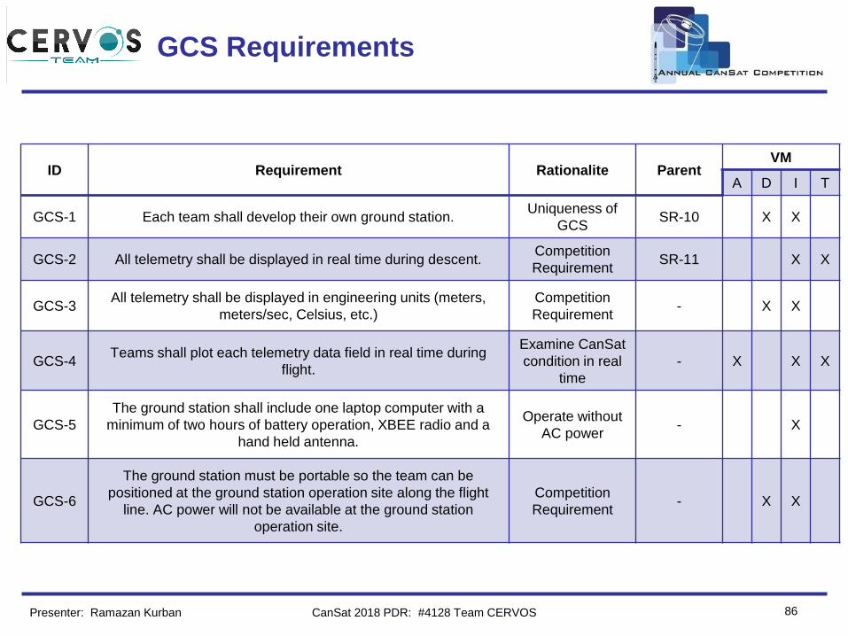
(If You Want) GCS Requirements
86
ID Requirement Rationalite ParentVM
A D I T
GCS-1 Each team shall develop their own ground station. Uniqueness of
GCSSR-10 X X
GCS-2 All telemetry shall be displayed in real time during descent. Competition
RequirementSR-11 X X
GCS-3All telemetry shall be displayed in engineering units (meters,
meters/sec, Celsius, etc.)
Competition
Requirement- X X
GCS-4Teams shall plot each telemetry data field in real time during
flight.
Examine CanSat
condition in real
time
- X X X
GCS-5
The ground station shall include one laptop computer with a
minimum of two hours of battery operation, XBEE radio and a
hand held antenna.
Operate without
AC power- X
GCS-6
The ground station must be portable so the team can be
positioned at the ground station operation site along the flight
line. AC power will not be available at the ground station
operation site.
Competition
Requirement- X X
Presenter: Ramazan Kurban CanSat 2018 PDR: #4128 Team CERVOS
Team Logo
Here
(If You Want) GCS Design
87
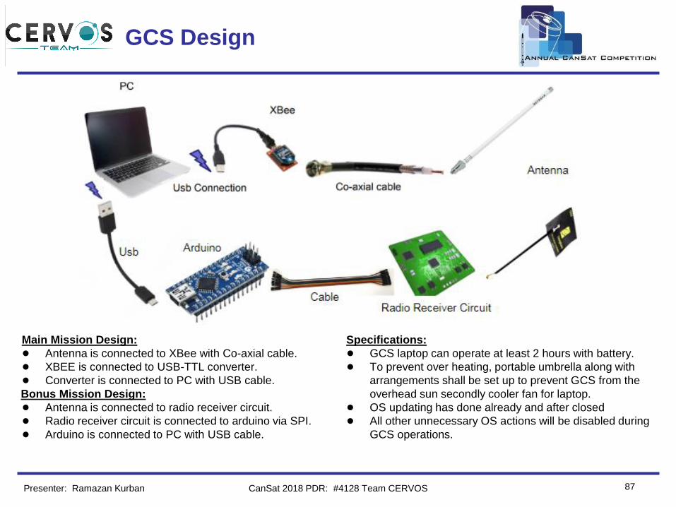
Main Mission Design:
● Antenna is connected to XBee with Co-axial cable.
● XBEE is connected to USB-TTL converter.
● Converter is connected to PC with USB cable.
Bonus Mission Design:
● Antenna is connected to radio receiver circuit.
● Radio receiver circuit is connected to arduino via SPI.
● Arduino is connected to PC with USB cable.
Specifications:
● GCS laptop can operate at least 2 hours with battery.
● To prevent over heating, portable umbrella along with
arrangements shall be set up to prevent GCS from the
overhead sun secondly cooler fan for laptop.
● OS updating has done already and after closed
● All other unnecessary OS actions will be disabled during
GCS operations.
Presenter: Ramazan Kurban CanSat 2018 PDR: #4128 Team CERVOS
Team Logo
Here
(If You Want)
88
GCS Antenna Trade & Selection
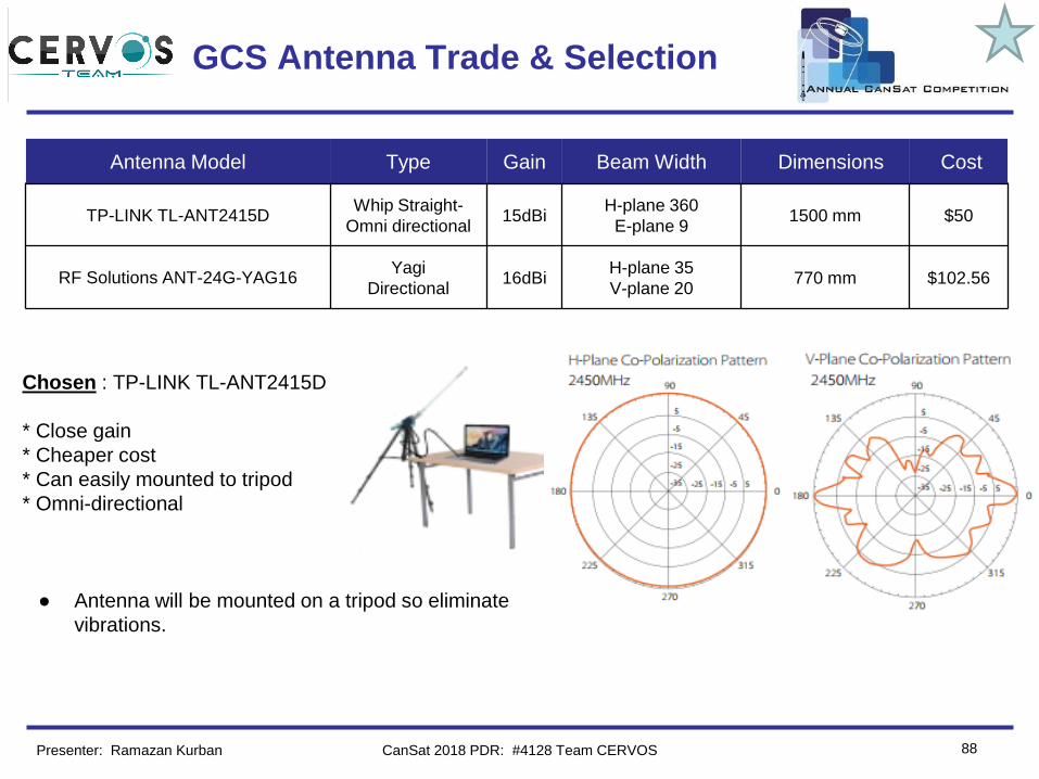
Antenna Model Type Gain Beam Width Dimensions Cost
TP-LINK TL-ANT2415DWhip Straight-
Omni directional15dBi
H-plane 360
E-plane 91500 mm $50
RF Solutions ANT-24G-YAG16Yagi
Directional16dBi
H-plane 35
V-plane 20770 mm $102.56
Chosen : TP-LINK TL-ANT2415D
* Close gain
* Cheaper cost
* Can easily mounted to tripod
* Omni-directional
● Antenna will be mounted on a tripod so eliminate
vibrations.
Presenter: Ramazan Kurban CanSat 2018 PDR: #4128 Team CERVOS
Team Logo
Here
(If You Want)
89
GCS Antenna Trade & Selection
(cont.)
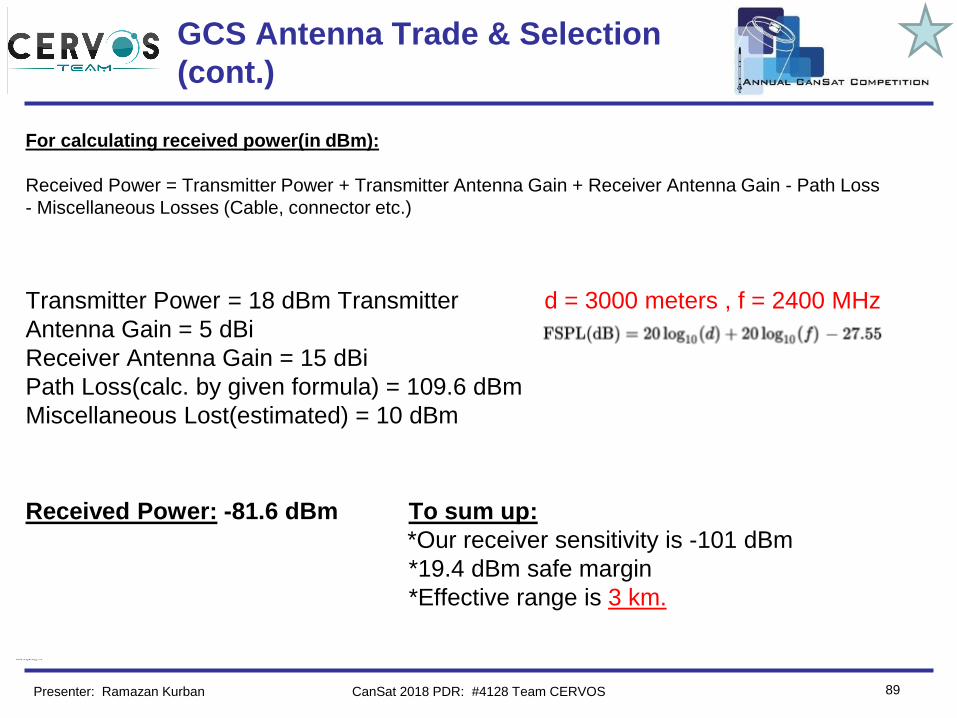
For calculating received power(in dBm):
Received Power = Transmitter Power + Transmitter Antenna Gain + Receiver Antenna Gain - Path Loss
- Miscellaneous Losses (Cable, connector etc.)
Transmitter Power = 18 dBm Transmitter d = 3000 meters , f = 2400 MHz
Antenna Gain = 5 dBi
Receiver Antenna Gain = 15 dBi
Path Loss(calc. by given formula) = 109.6 dBm
Miscellaneous Lost(estimated) = 10 dBm
Received Power: -81.6 dBm To sum up:
*Our receiver sensitivity is -101 dBm
*19.4 dBm safe margin
*Effective range is 3 km.
Presenter: Ramazan Kurban CanSat 2018 PDR: #4128 Team CERVOS
Team Logo
Here
(If You Want) GCS Software
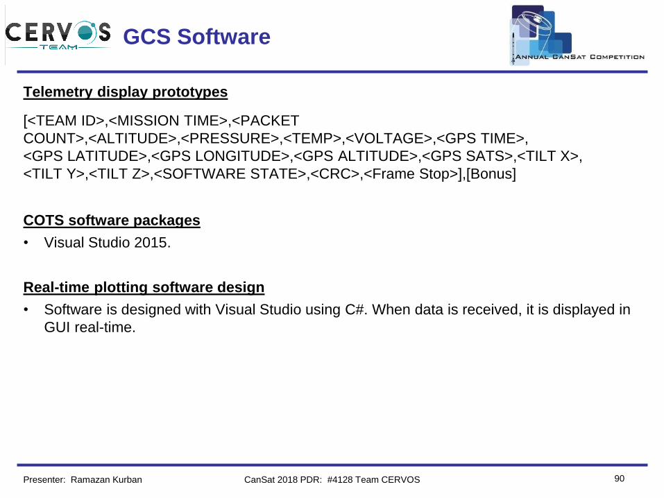
Telemetry display prototypes
[<TEAM ID>,<MISSION TIME>,<PACKET
COUNT>,<ALTITUDE>,<PRESSURE>,<TEMP>,<VOLTAGE>,<GPS TIME>,
<GPS LATITUDE>,<GPS LONGITUDE>,<GPS ALTITUDE>,<GPS SATS>,<TILT X>,
<TILT Y>,<TILT Z>,<SOFTWARE STATE>,<CRC>,<Frame Stop>],[Bonus]
COTS software packages
• Visual Studio 2015.
Real-time plotting software design
• Software is designed with Visual Studio using C#. When data is received, it is displayed in
GUI real-time.
90Presenter: Ramazan Kurban CanSat 2018 PDR: #4128 Team CERVOS
Team Logo
Here
(If You Want) GCS Software (cont.)
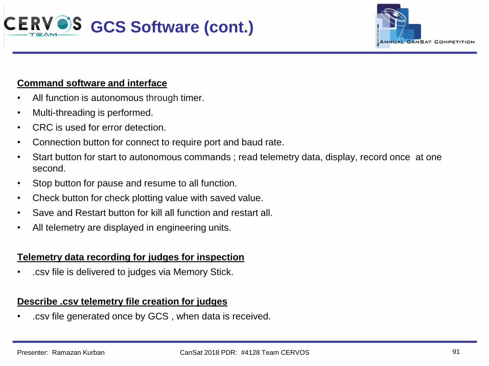
Command software and interface
• All function is autonomous through timer.
• Multi-threading is performed.
• CRC is used for error detection.
• Connection button for connect to require port and baud rate.
• Start button for start to autonomous commands ; read telemetry data, display, record once at one
second.
• Stop button for pause and resume to all function.
• Check button for check plotting value with saved value.
• Save and Restart button for kill all function and restart all.
• All telemetry are displayed in engineering units.
Telemetry data recording for judges for inspection
• .csv file is delivered to judges via Memory Stick.
Describe .csv telemetry file creation for judges
• .csv file generated once by GCS , when data is received.
91Presenter: Ramazan Kurban CanSat 2018 PDR: #4128 Team CERVOS
Team Logo
Here
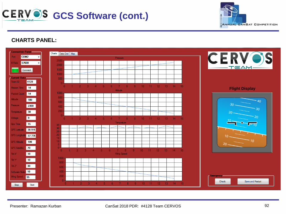
(If You Want) GCS Software (cont.)
92
CHARTS PANEL:
CanSat 2018 PDR: #4128 Team CERVOSPresenter: Ramazan Kurban
Flight Display
Team Logo
Here
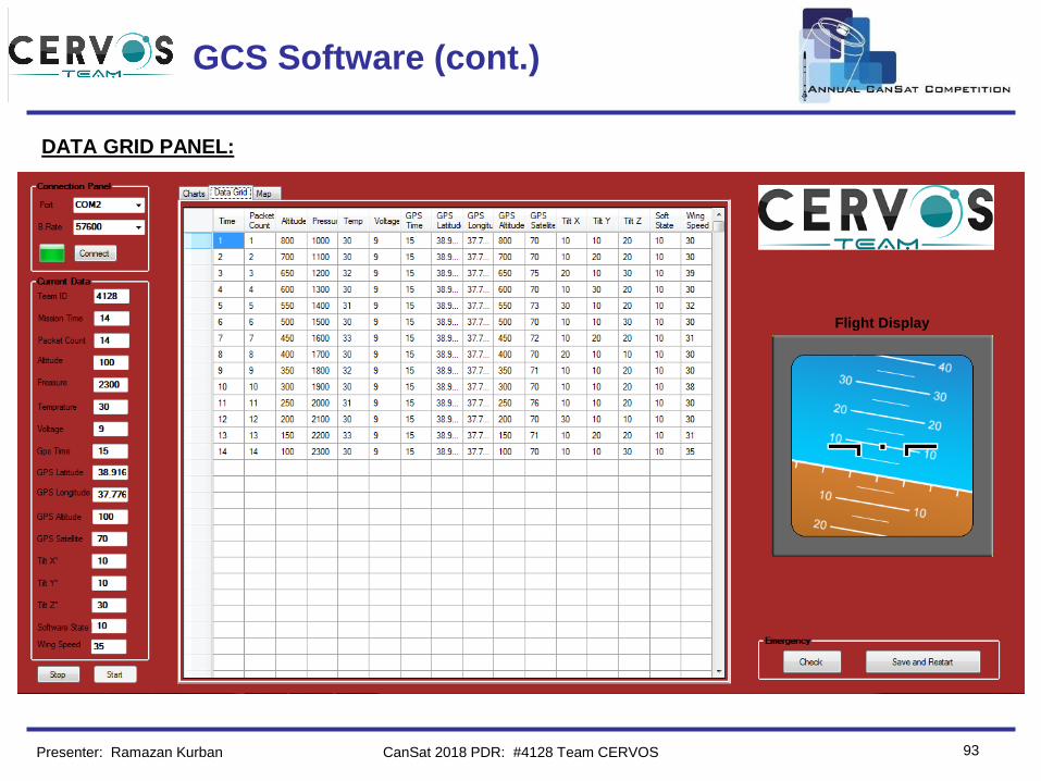
(If You Want) GCS Software (cont.)
93
DATA GRID PANEL:
Presenter: Ramazan Kurban CanSat 2018 PDR: #4128 Team CERVOS
Flight Display
Team Logo
Here
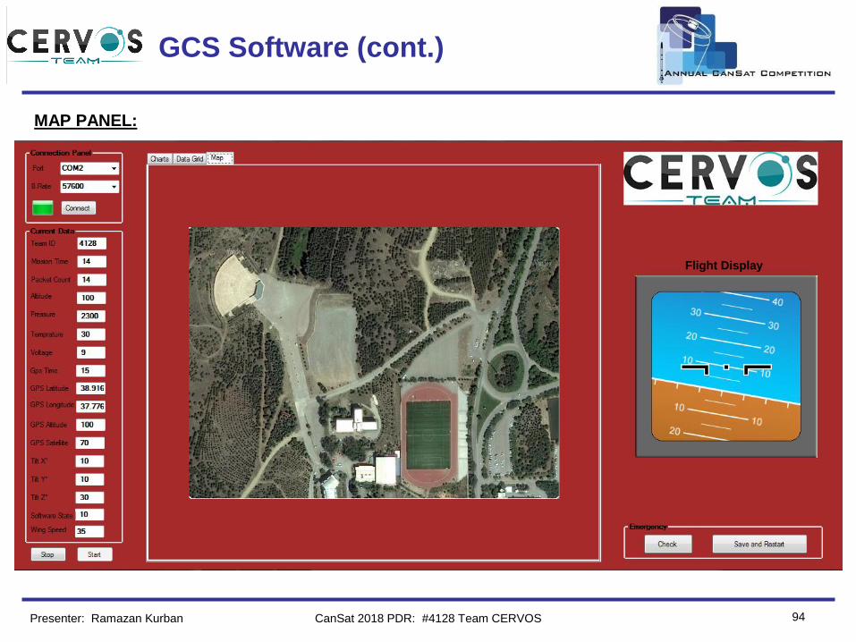
(If You Want) GCS Software (cont.)
94
MAP PANEL:
Presenter: Ramazan Kurban CanSat 2018 PDR: #4128 Team CERVOS
Flight Display
Team Logo
Here
(If You Want) GCS Software (cont.)
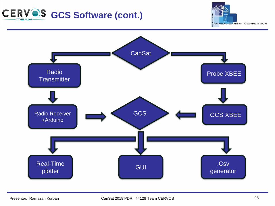
95Presenter: Ramazan Kurban CanSat 2018 PDR: #4128 Team CERVOS
Probe XBEE
GUIReal-Time
plotter
.Csv
generator
Radio
Transmitter
CanSat
GCS Radio Receiver
+ArduinoGCS XBEE
Team Logo
Here
(If You Want) GCS Bonus Wind Sensor
• Radio receiver circuit is connected to arduino via SPI.
• Arduino is connected to PC port via USB.
• GCS read wind sensor data with Serial Port via COM
port.
• Plotting chart for wind speed and display its value.
96Presenter: Ramazan Kurban CanSat 2018 PDR: #4128 Team CERVOS
Team Logo
Here
(If You Want)
97
CanSat Integration and Test
Berkay Küçükkılavuz
CanSat 2018 PDR: #4128 Team CERVOS
Team Logo
Here
(If You Want)
98
CanSat Integration and Test
Overview
Presenter: Berkay Küçükkılavuz
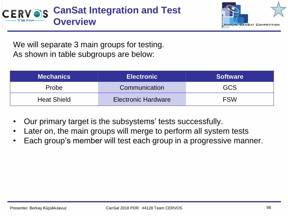
We will separate 3 main groups for testing.
As shown in table subgroups are below:
• Our primary target is the subsystems’ tests successfully.
• Later on, the main groups will merge to perform all system tests
• Each group’s member will test each group in a progressive manner.
Mechanics Electronic Software
Probe Communication GCS
Heat Shield Electronic Hardware FSW
CanSat 2018 PDR: #4128 Team CERVOS
Team Logo
Here
(If You Want) Subsystem Level Testing Plan
99Presenter: Berkay Küçükkılavuz
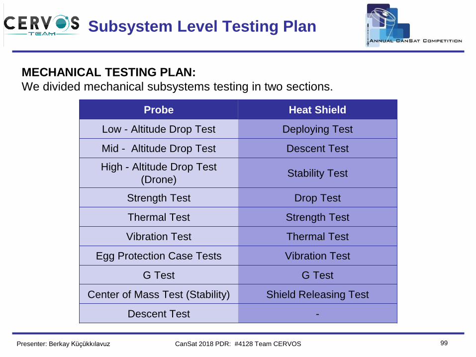
MECHANICAL TESTING PLAN:
We divided mechanical subsystems testing in two sections.
Probe Heat Shield
Low - Altitude Drop Test Deploying Test
Mid - Altitude Drop Test Descent Test
High - Altitude Drop Test
(Drone)Stability Test
Strength Test Drop Test
Thermal Test Strength Test
Vibration Test Thermal Test
Egg Protection Case Tests Vibration Test
G Test G Test
Center of Mass Test (Stability) Shield Releasing Test
Descent Test -
CanSat 2018 PDR: #4128 Team CERVOS
Team Logo
Here
(If You Want) Subsystem Level Testing Plan (cont.)
100Presenter: Berkay Küçükkılavuz
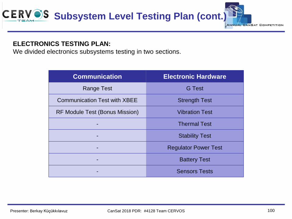
ELECTRONICS TESTING PLAN:
We divided electronics subsystems testing in two sections.
Communication Electronic Hardware
Range Test G Test
Communication Test with XBEE Strength Test
RF Module Test (Bonus Mission) Vibration Test
- Thermal Test
- Stability Test
- Regulator Power Test
- Battery Test
- Sensors Tests
CanSat 2018 PDR: #4128 Team CERVOS
Team Logo
Here
(If You Want) Subsystem Level Testing Plan (cont.)
101Presenter: Berkay Küçükkılavuz
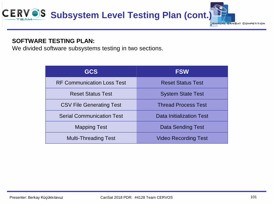
GCS FSW
RF Communication Loss Test Reset Status Test
Reset Status Test System State Test
CSV File Generating Test Thread Process Test
Serial Communication Test Data Initialization Test
Mapping Test Data Sending Test
Multi-Threading Test Video Recording Test
SOFTWARE TESTING PLAN:
We divided software subsystems testing in two sections.
CanSat 2018 PDR: #4128 Team CERVOS
Team Logo
Here
(If You Want) Integrated Level Functional Test Plan
102Presenter: Berkay Küçükkılavuz
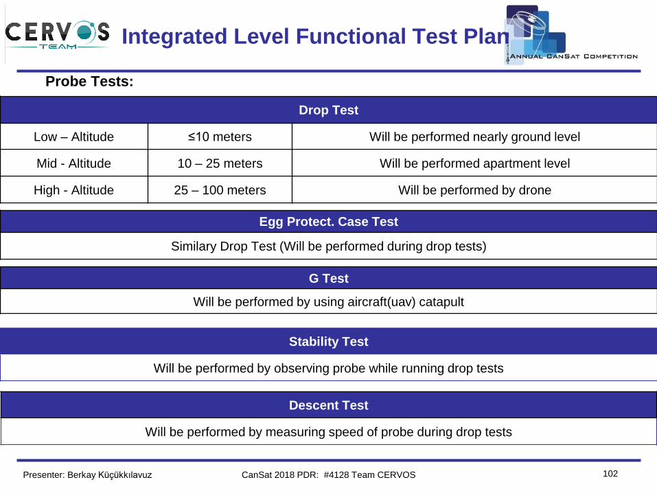
Probe Tests:
Drop Test
Low – Altitude ≤10 meters Will be performed nearly ground level
Mid - Altitude 10 – 25 meters Will be performed apartment level
High - Altitude 25 – 100 meters Will be performed by drone
Egg Protect. Case Test
Similary Drop Test (Will be performed during drop tests)
G Test
Will be performed by using aircraft(uav) catapult
Stability Test
Will be performed by observing probe while running drop tests
Descent Test
Will be performed by measuring speed of probe during drop tests
CanSat 2018 PDR: #4128 Team CERVOS
Team Logo
Here
(If You Want)
Integrated Level Functional Test Plan
(cont.)
103Presenter: Berkay Küçükkılavuz
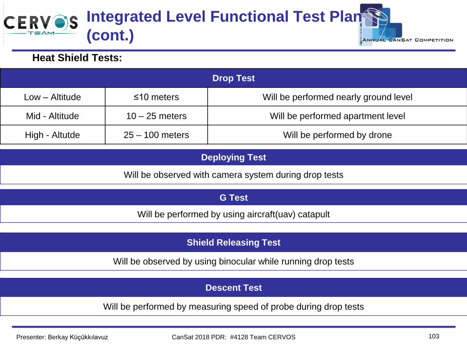
Heat Shield Tests:
Drop Test
Low – Altitude ≤10 meters Will be performed nearly ground level
Mid - Altitude 10 – 25 meters Will be performed apartment level
High - Altutde 25 – 100 meters Will be performed by drone
Deploying Test
Will be observed with camera system during drop tests
G Test
Will be performed by using aircraft(uav) catapult
Shield Releasing Test
Will be observed by using binocular while running drop tests
Descent Test
Will be performed by measuring speed of probe during drop tests
CanSat 2018 PDR: #4128 Team CERVOS
Team Logo
Here
(If You Want)
Integrated Level Functional Test Plan
(cont.)
104Presenter: Berkay Küçükkılavuz
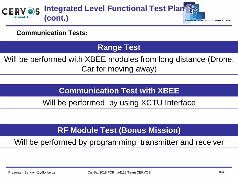
Communication Tests:
RF Module Test (Bonus Mission)
Will be performed by programming transmitter and receiver
Range Test
Will be performed with XBEE modules from long distance (Drone,
Car for moving away)
Communication Test with XBEE
Will be performed by using XCTU Interface
CanSat 2018 PDR: #4128 Team CERVOS
Team Logo
Here
(If You Want)
Integrated Level Functional Test Plan
(cont.)
105Presenter: Berkay Küçükkılavuz
Electronic Hardware Tests:
Regulator Power Test
Regulation will be observed while each component is drawing its maximum currents
Sensors Tests
Each sensors stability will be observed while they are working properly
G Test
Will be performed together with mechanical G test
Stability Test
Wires, sensors and soldered parts will be observed after every different situation that probe can be face with
Battery Test
Work duration will be observed when our circuit is worked unitl end of the battery capacity.
CanSat 2018 PDR: #4128 Team CERVOS
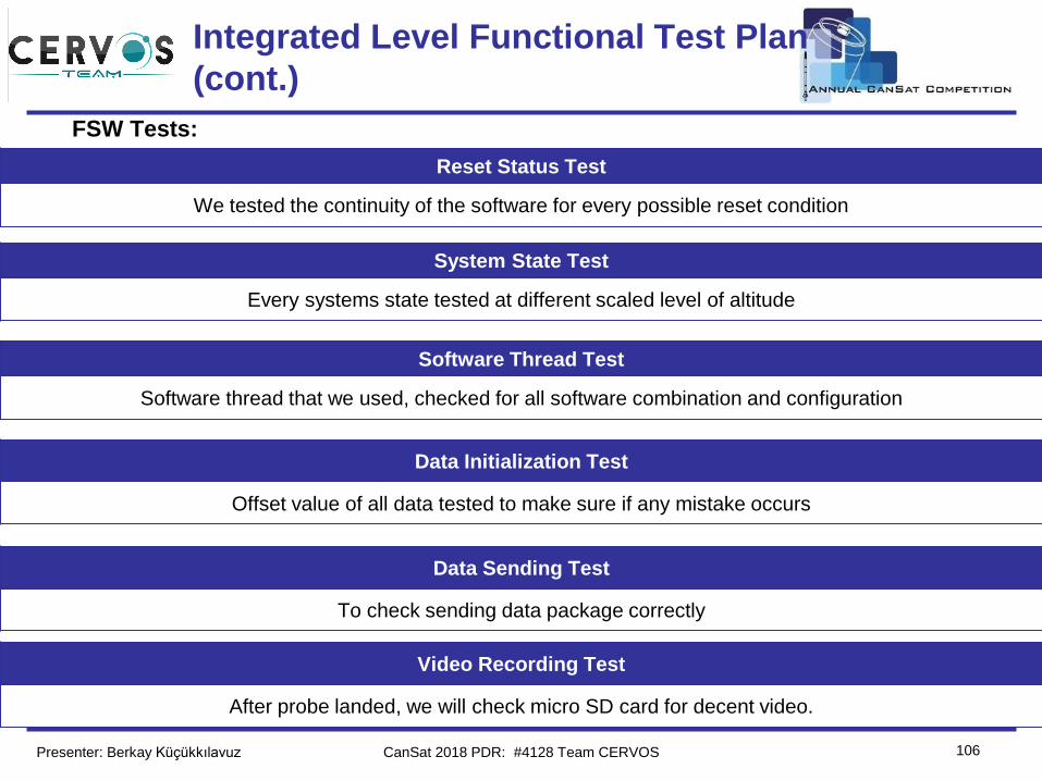
Team Logo
Here
(If You Want)
Integrated Level Functional Test Plan
(cont.)
106Presenter: Berkay Küçükkılavuz
FSW Tests:
Software Thread Test
Software thread that we used, checked for all software combination and configuration
Data Sending Test
To check sending data package correctly
Reset Status Test
We tested the continuity of the software for every possible reset condition
System State Test
Every systems state tested at different scaled level of altitude
Data Initialization Test
Offset value of all data tested to make sure if any mistake occurs
Video Recording Test
After probe landed, we will check micro SD card for decent video.
CanSat 2018 PDR: #4128 Team CERVOS
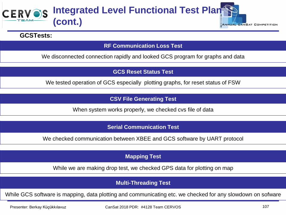
Team Logo
Here
(If You Want)
Integrated Level Functional Test Plan
(cont.)
107Presenter: Berkay Küçükkılavuz
GCSTests:
CSV File Generating Test
When system works properly, we checked cvs file of data
Mapping Test
While we are making drop test, we checked GPS data for plotting on map
RF Communication Loss Test
We disconnected connection rapidly and looked GCS program for graphs and data
GCS Reset Status Test
We tested operation of GCS especially plotting graphs, for reset status of FSW
Serial Communication Test
We checked communication between XBEE and GCS software by UART protocol
Multi-Threading Test
While GCS software is mapping, data plotting and communicating etc. we checked for any slowdown on sofware
CanSat 2018 PDR: #4128 Team CERVOS
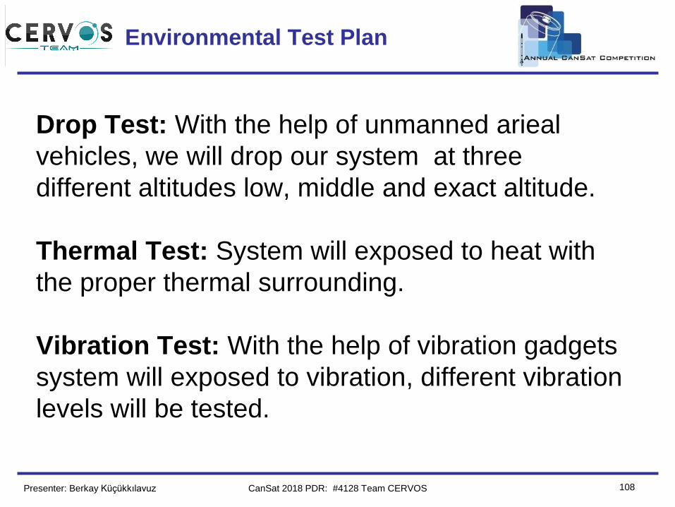
Team Logo
Here
(If You Want) Environmental Test Plan
108Presenter: Berkay Küçükkılavuz
Drop Test: With the help of unmanned arieal
vehicles, we will drop our system at three
different altitudes low, middle and exact altitude.
Thermal Test: System will exposed to heat with
the proper thermal surrounding.
Vibration Test: With the help of vibration gadgets
system will exposed to vibration, different vibration
levels will be tested.
CanSat 2018 PDR: #4128 Team CERVOS
Team Logo
Here
(If You Want)
109
Mission Operations & Analysis
Mustafa Anıl Yiğit
CanSat 2018 PDR: #4128 Team CERVOS
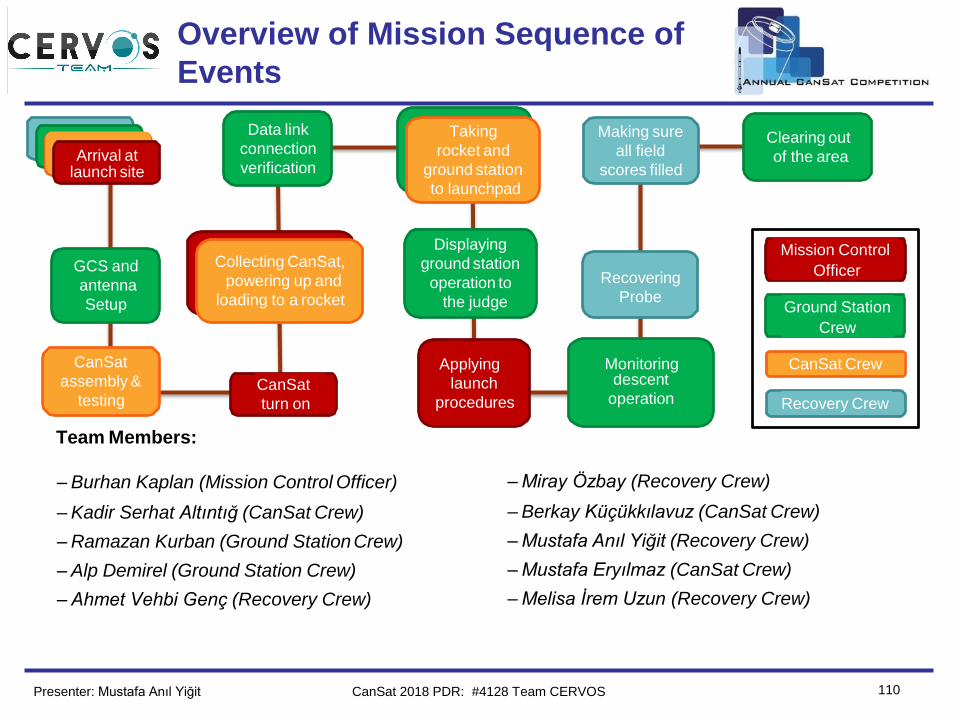
Team Logo
Here
(If You Want)
110
Overview of Mission Sequence of
Events
Presenter: Mustafa Anıl Yiğit
Team Members:
– Burhan Kaplan (Mission Control Officer)
– Kadir Serhat Altıntığ (CanSat Crew)
– Ramazan Kurban (Ground StationCrew)
– Alp Demirel (Ground Station Crew)
– Ahmet Vehbi Genç (Recovery Crew)
– Miray Özbay (Recovery Crew)
– Berkay Küçükkılavuz (CanSat Crew)
– Mustafa Anıl Yiğit (Recovery Crew)
– Mustafa Eryılmaz (CanSat Crew)
– Melisa İrem Uzun (Recovery Crew)
Recovery Crew
Ground Station
Crew
CanSat Crew
Mission Control
Officer
CanSat
assembly &
testing
GCS and
antenna
Setup
CanSat
turn on
Collecting CanSat,
powering up and
loading to a rocket
launch siteArrival at
Data link
connection
verification
Applying
launch
procedures
Taking
rocket and
ground station
to launchpad
Displaying
ground station
operation to
the judge
Recovering
Probe
Making sure
all field
scores filled
Clearing out
of the area
descent
operation
Monitoring
CanSat 2018 PDR: #4128 Team CERVOS
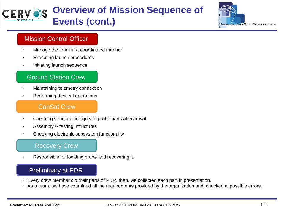
Team Logo
Here
(If You Want)
Overview of Mission Sequence of
Events (cont.)
111Presenter: Mustafa Anıl Yiğit
• Manage the team in a coordinated manner
• Executing launch procedures
• Initiating launch sequence
• Maintaining telemetry connection
• Performing descent operations
• Checking structural integrity of probe parts afterarrival
• Assembly & testing, structures
• Checking electronic subsystem functionality
• Responsible for locating probe and recovering it.
Mission Control Officer
Ground Station Crew
CanSat Crew
Recovery Crew
CanSat 2018 PDR: #4128 Team CERVOS
• Every crew member did their parts of PDR, then, we collected each part in presentation.
• As a team, we have examined all the requirements provided by the organization and, checked al possible errors.
Preliminary at PDR
Team Logo
Here
(If You Want)
112
Mission Operations Manual
Development Plan
• Mission operations manual will made according to
mission sequence of events.
• It will consist of reminders and checklists according to
member roles.
• Following subjects will be determined:– Assembly instructions
– Testing instructions
– GCS configuration guideline
– Descent operations
– Recovery operations
– Data analysis
• Mission operations plan will be finished after completing all
CanSat operational tests.
Presenter: Mustafa Anıl Yiğit CanSat 2018 PDR: #4128 Team CERVOS
Team Logo
Here
(If You Want)
113
CanSat Location and Recovery
Presenter: Mustafa Anıl Yiğit
Locating and Recovering Heat Shield
• Heat Shield will be painted with flourescent color.
• Landing zone will be determined by observing descension, by
examining video that, probe records and, by last GPS location
data.
Locating and Recovering Probe
• Probe will be painted with flourescent color.
• Landing zone will be determined by observing descension
and by GPS location data.
• Buzzer will be activated after landing and can be heard at a
distance.
Address Labeling
• Probe will have an address label to be returned. On that
address label there will be a mail address for
communication.
CanSat 2018 PDR: #4128 Team CERVOS
Team Logo
Here
(If You Want)
114
Requirements Compliance
Mustafa Anıl Yiğit
CanSat 2018 PDR: #4128 Team CERVOS
Team Logo
Here
(If You Want) Requirements Compliance Overview
115
• Full Comply:–By good cooperation with team members most of the requirements are met.
–Minor improvements and optimizations will be made.
–Mechanical prototypes have been made.
–Most of sensors are tested.
–GCS software have been done, appearance improvements will be made.
• Partial:–The probe stability will be tested and necessary improvements wil be made.
Presenter: Mustafa Anıl Yiğit CanSat 2018 PDR: #4128 Team CERVOS
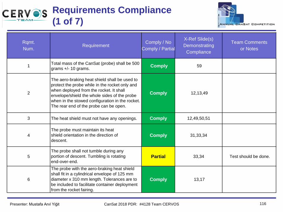
Team Logo
Here
(If You Want)
Requirements Compliance
(1 of 7)
116
Rqmt.
Num.Requirement
Comply / No
Comply / Partial
X-Ref Slide(s)
Demonstrating
Compliance
Team Comments
or Notes
1Total mass of the CanSat (probe) shall be 500
grams +/- 10 grams.Comply 59
2
The aero-braking heat shield shall be used to
protect the probe while in the rocket only and
when deployed from the rocket. It shall
envelope/shield the whole sides of the probe
when in the stowed configuration in the rocket.
The rear end of the probe can be open.
Comply 12,13,49
3 The heat shield must not have any openings. Comply 12,49,50,51
4
The probe must maintain its heat
shield orientation in the direction of
descent.Comply 31,33,34
5
The probe shall not tumble during any
portion of descent. Tumbling is rotating
end-over-end.Partial 33,34 Test should be done.
6
The probe with the aero-braking heat shield
shall fit in a cylindrical envelope of 125 mm
diameter x 310 mm length. Tolerances are to
be included to facilitate container deployment
from the rocket fairing.
Comply 13,17
Presenter: Mustafa Anıl Yiğit CanSat 2018 PDR: #4128 Team CERVOS
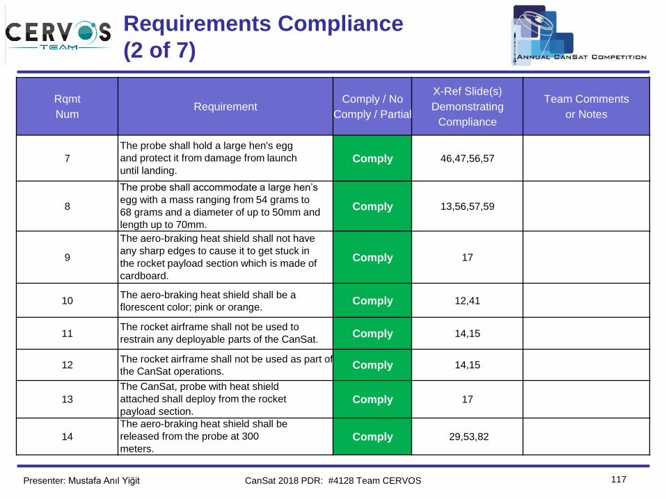
Team Logo
Here
(If You Want)
Requirements Compliance
(2 of 7)
117
Rqmt
NumRequirement
Comply / No
Comply / Partial
X-Ref Slide(s)
Demonstrating
Compliance
Team Comments
or Notes
7
The probe shall hold a large hen's egg
and protect it from damage from launch
until landing.Comply 46,47,56,57
8
The probe shall accommodate a large hen’s
egg with a mass ranging from 54 grams to
68 grams and a diameter of up to 50mm and
length up to 70mm.
Comply 13,56,57,59
9
The aero-braking heat shield shall not have
any sharp edges to cause it to get stuck in
the rocket payload section which is made of
cardboard.
Comply 17
10The aero-braking heat shield shall be a
florescent color; pink or orange.Comply 12,41
11The rocket airframe shall not be used to
restrain any deployable parts of the CanSat.Comply 14,15
12The rocket airframe shall not be used as part of
the CanSat operations.Comply 14,15
13
The CanSat, probe with heat shield
attached shall deploy from the rocket
payload section.Comply 17
14
The aero-braking heat shield shall be
released from the probe at 300
meters.Comply 29,53,82
Presenter: Mustafa Anıl Yiğit CanSat 2018 PDR: #4128 Team CERVOS
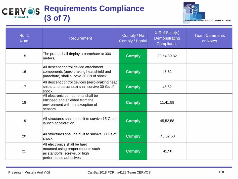
Team Logo
Here
(If You Want)
Requirements Compliance
(3 of 7)
118
Rqmt
NumRequirement
Comply / No
Comply / Partial
X-Ref Slide(s)
Demonstrating
Compliance
Team Comments
or Notes
15The probe shall deploy a parachute at 300
meters.Comply 29,54,80,82
16
All descent control device attachment
components (aero-braking heat shield and
parachute) shall survive 30 Gs of shock.Comply 45,52
17
All descent control devices (aero-braking heat
shield and parachute) shall survive 30 Gs of
shock.Comply 45,52
18
All electronic components shall be
enclosed and shielded from the
environment with the exception of
sensors.
Comply 11,41,58
19All structures shall be built to survive 15 Gs of
launch acceleration.Comply 45,52,58
20All structures shall be built to survive 30 Gs of
shock.Comply 45,52,58
21
All electronics shall be hard
mounted using proper mounts such
as standoffs, screws, or high
performance adhesives.
Comply 41,58
Presenter: Mustafa Anıl Yiğit CanSat 2018 PDR: #4128 Team CERVOS
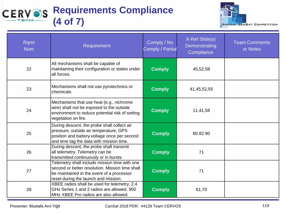
Team Logo
Here
(If You Want)
Requirements Compliance
(4 of 7)
119
Rqmt
NumRequirement
Comply / No
Comply / Partial
X-Ref Slide(s)
Demonstrating
Compliance
Team Comments
or Notes
22
All mechanisms shall be capable of
maintaining their configuration or states under
all forces.Comply 45,52,58
23Mechanisms shall not use pyrotechnics or
chemicals.Comply 41,45,52,55
24
Mechanisms that use heat (e.g., nichrome
wire) shall not be exposed to the outside
environment to reduce potential risk of setting
vegetation on fire.
Comply 11,41,58
25
During descent, the probe shall collect air
pressure, outside air temperature, GPS
position and battery voltage once per second
and time tag the data with mission time.
Comply 80.82.90
26
During descent, the probe shall transmit
all telemetry. Telemetry can be
transmitted continuously or in bursts.Comply 71
27
Telemetry shall include mission time with one
second or better resolution. Mission time shall
be maintained in the event of a processor
reset during the launch and mission.
Comply 71
28
XBEE radios shall be used for telemetry. 2.4
GHz Series 1 and 2 radios are allowed. 900
MHz XBEE Pro radios are also allowed.Comply 61,70
Presenter: Mustafa Anıl Yiğit CanSat 2018 PDR: #4128 Team CERVOS
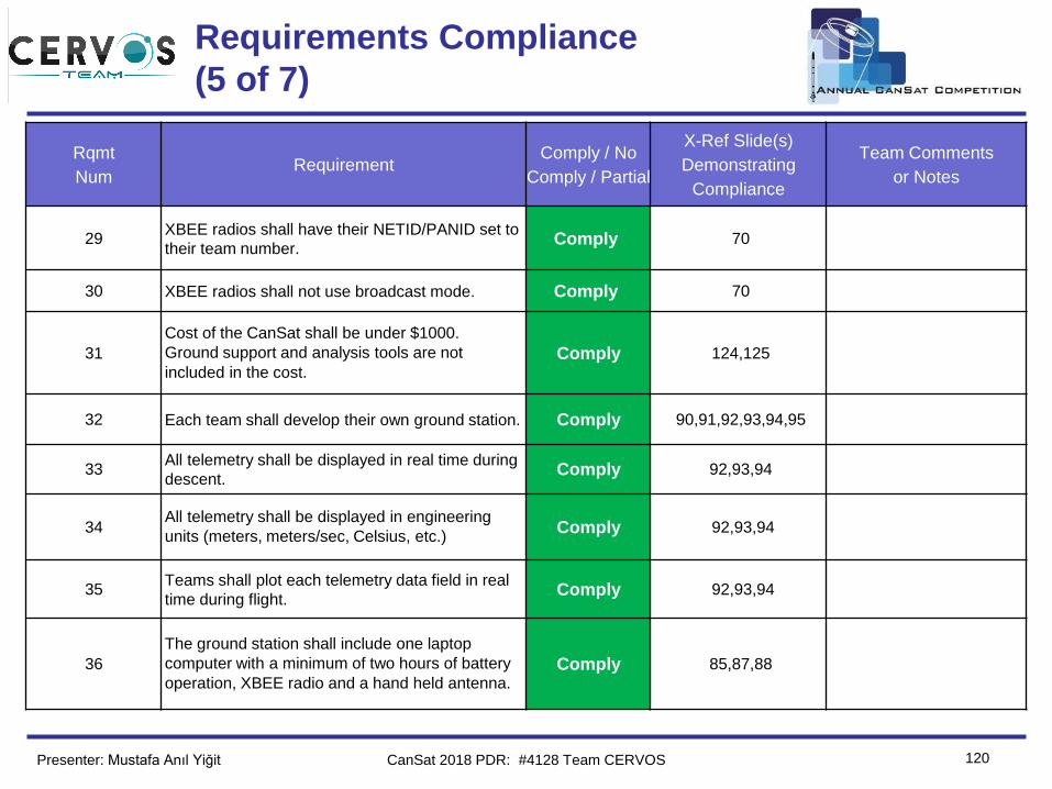
Team Logo
Here
(If You Want)
Requirements Compliance
(5 of 7)
120
Rqmt
NumRequirement
Comply / No
Comply / Partial
X-Ref Slide(s)
Demonstrating
Compliance
Team Comments
or Notes
29XBEE radios shall have their NETID/PANID set to
their team number.Comply 70
30 XBEE radios shall not use broadcast mode. Comply 70
31
Cost of the CanSat shall be under $1000.
Ground support and analysis tools are not
included in the cost.Comply 124,125
32 Each team shall develop their own ground station. Comply 90,91,92,93,94,95
33All telemetry shall be displayed in real time during
descent.Comply 92,93,94
34All telemetry shall be displayed in engineering
units (meters, meters/sec, Celsius, etc.)Comply 92,93,94
35Teams shall plot each telemetry data field in real
time during flight.Comply 92,93,94
36
The ground station shall include one laptop
computer with a minimum of two hours of battery
operation, XBEE radio and a hand held antenna.Comply 85,87,88
Presenter: Mustafa Anıl Yiğit CanSat 2018 PDR: #4128 Team CERVOS
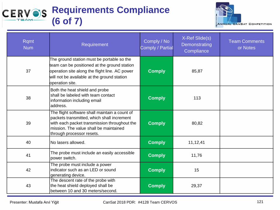
Team Logo
Here
(If You Want)
Requirements Compliance
(6 of 7)
121
Rqmt
NumRequirement
Comply / No
Comply / Partial
X-Ref Slide(s)
Demonstrating
Compliance
Team Comments
or Notes
37
The ground station must be portable so the
team can be positioned at the ground station
operation site along the flight line. AC power
will not be available at the ground station
operation site.
Comply 85,87
38
Both the heat shield and probe
shall be labeled with team contact
information including email
address.
Comply 113
39
The flight software shall maintain a count of
packets transmitted, which shall increment
with each packet transmission throughout the
mission. The value shall be maintained
through processor resets.
Comply 80,82
40 No lasers allowed. Comply 11,12,41
41The probe must include an easily accessible
power switch.Comply 11,76
42
The probe must include a power
indicator such as an LED or sound
generating device.Comply 15
43
The descent rate of the probe with
the heat shield deployed shall be
between 10 and 30 meters/second.Comply 29,37
Presenter: Mustafa Anıl Yiğit CanSat 2018 PDR: #4128 Team CERVOS
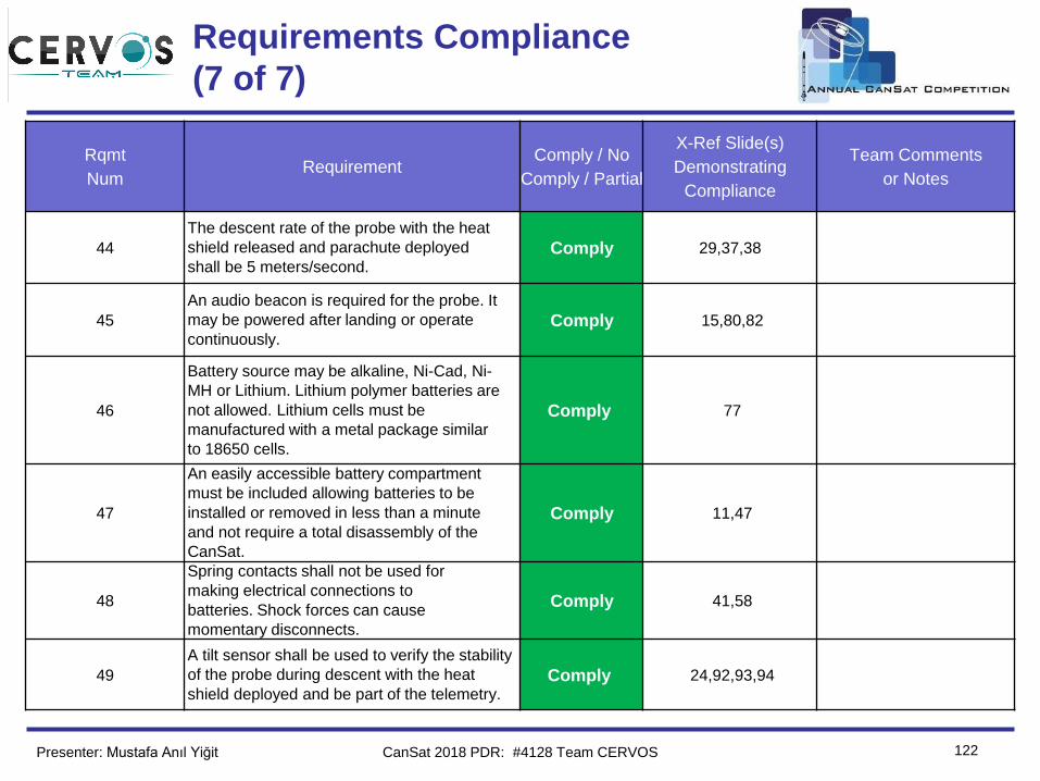
Team Logo
Here
(If You Want)
Requirements Compliance
(7 of 7)
122
Rqmt
NumRequirement
Comply / No
Comply / Partial
X-Ref Slide(s)
Demonstrating
Compliance
Team Comments
or Notes
44
The descent rate of the probe with the heat
shield released and parachute deployed
shall be 5 meters/second.Comply 29,37,38
45
An audio beacon is required for the probe. It
may be powered after landing or operate
continuously.Comply 15,80,82
46
Battery source may be alkaline, Ni-Cad, Ni-
MH or Lithium. Lithium polymer batteries are
not allowed. Lithium cells must be
manufactured with a metal package similar
to 18650 cells.
Comply 77
47
An easily accessible battery compartment
must be included allowing batteries to be
installed or removed in less than a minute
and not require a total disassembly of the
CanSat.
Comply 11,47
48
Spring contacts shall not be used for
making electrical connections to
batteries. Shock forces can cause
momentary disconnects.
Comply 41,58
49
A tilt sensor shall be used to verify the stability
of the probe during descent with the heat
shield deployed and be part of the telemetry.Comply 24,92,93,94
Presenter: Mustafa Anıl Yiğit CanSat 2018 PDR: #4128 Team CERVOS
Team Logo
Here
(If You Want)
123
Management
Melisa İrem Uzun
CanSat 2018 PDR: #4128 Team CERVOS
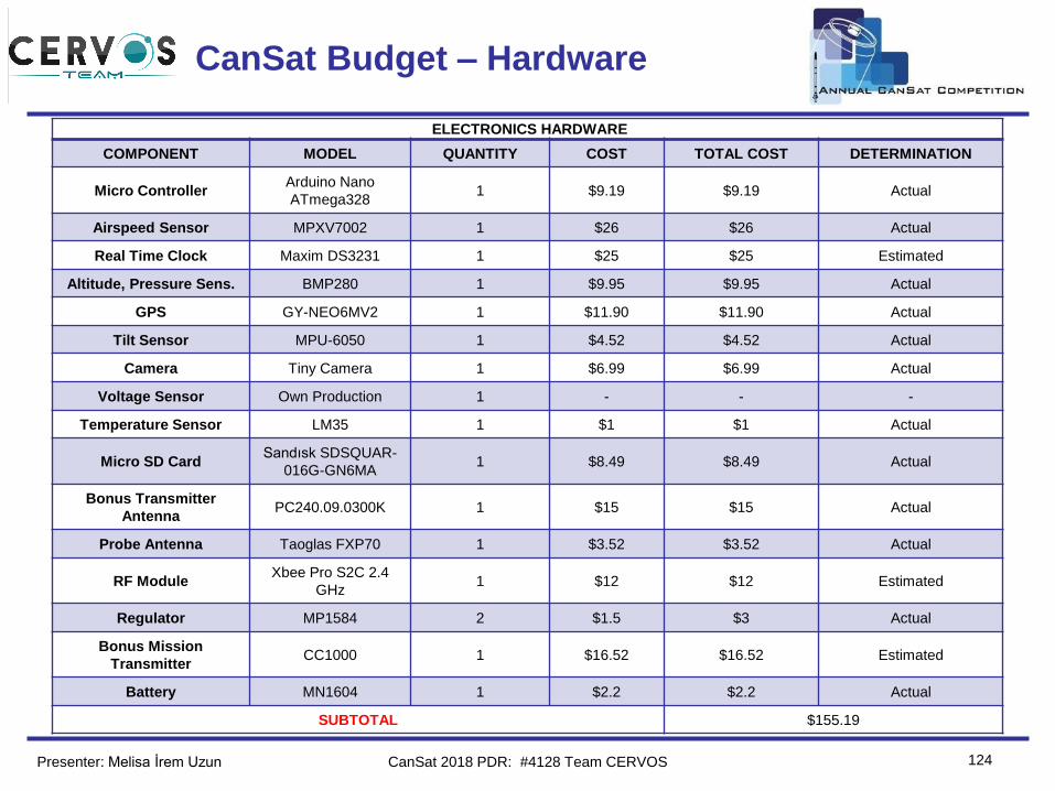
Team Logo
Here
(If You Want)
124
CanSat Budget – Hardware
Presenter: Melisa İrem Uzun
ELECTRONICS HARDWARE
COMPONENT MODEL QUANTITY COST TOTAL COST DETERMINATION
Micro ControllerArduino Nano
ATmega3281 $9.19 $9.19 Actual
Airspeed Sensor MPXV7002 1 $26 $26 Actual
Real Time Clock Maxim DS3231 1 $25 $25 Estimated
Altitude, Pressure Sens. BMP280 1 $9.95 $9.95 Actual
GPS GY-NEO6MV2 1 $11.90 $11.90 Actual
Tilt Sensor MPU-6050 1 $4.52 $4.52 Actual
Camera Tiny Camera 1 $6.99 $6.99 Actual
Voltage Sensor Own Production 1 - - -
Temperature Sensor LM35 1 $1 $1 Actual
Micro SD CardSandısk SDSQUAR-
016G-GN6MA1 $8.49 $8.49 Actual
Bonus Transmitter
AntennaPC240.09.0300K 1 $15 $15 Actual
Probe Antenna Taoglas FXP70 1 $3.52 $3.52 Actual
RF ModuleXbee Pro S2C 2.4
GHz1 $12 $12 Estimated
Regulator MP1584 2 $1.5 $3 Actual
Bonus Mission
TransmitterCC1000 1 $16.52 $16.52 Estimated
Battery MN1604 1 $2.2 $2.2 Actual
SUBTOTAL $155.19
CanSat 2018 PDR: #4128 Team CERVOS
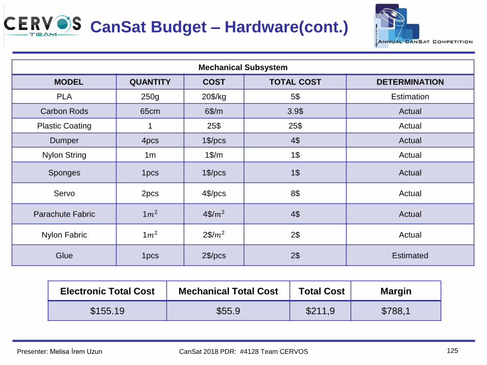
Team Logo
Here
(If You Want)
125
CanSat Budget – Hardware(cont.)
Presenter: Melisa İrem Uzun CanSat 2018 PDR: #4128 Team CERVOS
Mechanical Subsystem
MODEL QUANTITY COST TOTAL COST DETERMINATION
PLA 250g 20$/kg 5$ Estimation
Carbon Rods 65cm 6$/m 3.9$ Actual
Plastic Coating 1 25$ 25$ Actual
Dumper 4pcs 1$/pcs 4$ Actual
Nylon String 1m 1$/m 1$ Actual
Sponges 1pcs 1$/pcs 1$ Actual
Servo 2pcs 4$/pcs 8$ Actual
Parachute Fabric 1𝑚2 4$/𝑚2 4$ Actual
Nylon Fabric 1𝑚2 2$/𝑚2 2$ Actual
Glue 1pcs 2$/pcs 2$ Estimated
Electronic Total Cost Mechanical Total Cost Total Cost Margin
$155.19 $55.9 $211,9 $788,1
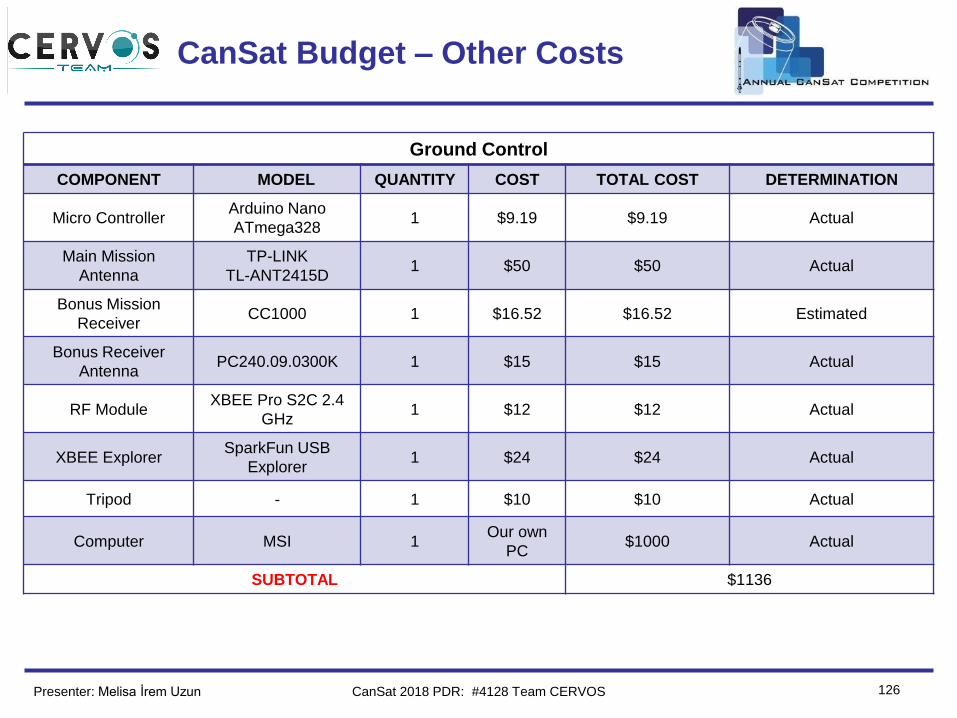
Team Logo
Here
(If You Want)
126
CanSat Budget – Other Costs
Presenter: Melisa İrem Uzun
Ground Control
COMPONENT MODEL QUANTITY COST TOTAL COST DETERMINATION
Micro ControllerArduino Nano
ATmega3281 $9.19 $9.19 Actual
Main Mission
Antenna
TP-LINK
TL-ANT2415D1 $50 $50 Actual
Bonus Mission
ReceiverCC1000 1 $16.52 $16.52 Estimated
Bonus Receiver
AntennaPC240.09.0300K 1 $15 $15 Actual
RF ModuleXBEE Pro S2C 2.4
GHz1 $12 $12 Actual
XBEE ExplorerSparkFun USB
Explorer1 $24 $24 Actual
Tripod - 1 $10 $10 Actual
Computer MSI 1Our own
PC$1000 Actual
SUBTOTAL $1136
CanSat 2018 PDR: #4128 Team CERVOS
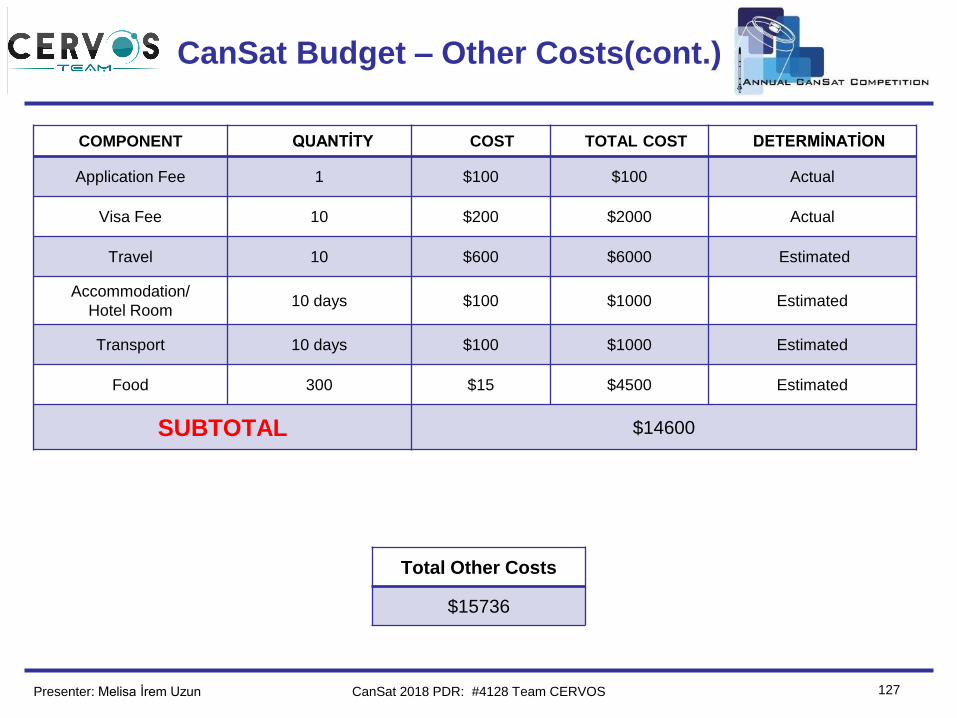
Team Logo
Here
(If You Want)
127
CanSat Budget – Other Costs(cont.)
Presenter: Melisa İrem Uzun
COMPONENT QUANTİTY COST TOTAL COST DETERMİNATİON
Application Fee 1 $100 $100 Actual
Visa Fee 10 $200 $2000 Actual
Travel 10 $600 $6000 Estimated
Accommodation/
Hotel Room10 days $100 $1000 Estimated
Transport 10 days $100 $1000 Estimated
Food 300 $15 $4500 Estimated
SUBTOTAL $14600
Total Other Costs
$15736
CanSat 2018 PDR: #4128 Team CERVOS
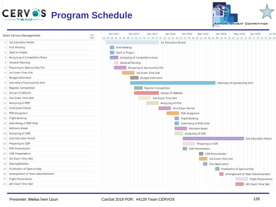
Team Logo
Here
(If You Want)
128
Program Schedule
Presenter: Melisa İrem Uzun CanSat 2018 PDR: #4128 Team CERVOS
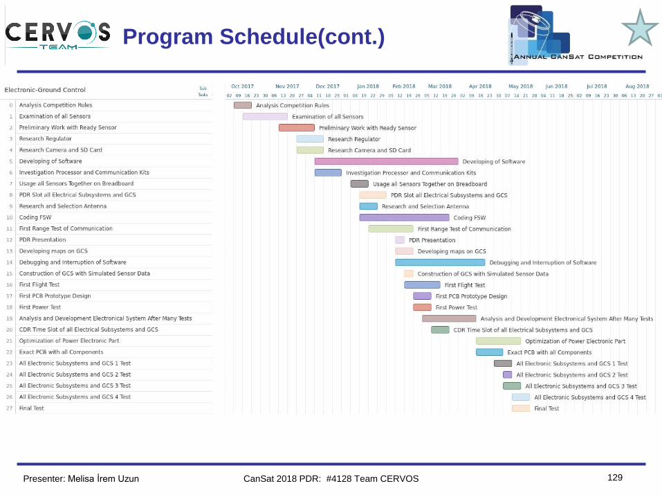
Team Logo
Here
(If You Want)
129
Program Schedule(cont.)
Presenter: Melisa İrem Uzun CanSat 2018 PDR: #4128 Team CERVOS
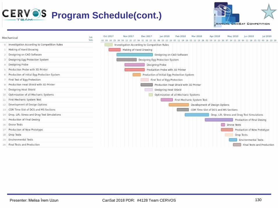
Team Logo
Here
(If You Want)
130
Program Schedule(cont.)
Presenter: Melisa İrem Uzun CanSat 2018 PDR: #4128 Team CERVOS
Team Logo
Here
(If You Want)
131
Conclusions
Presenter: Melisa İrem Uzun
ACCOMPLISHMENT❖ The main circuit board of the probe is printed and tested.
❖ We already developed and fabricated our probes mechanical parts.
❖ Ground Control System software is successfully tested under
extreme cases.
❖ Parachute test performed without any damage to egg or the probe.
UNFINISHED WORK❖ The antenna has been ordered but did not receive, so we could not
test range of the communication system.
❖ We did not receive RF modules for custom transmitter bonus mission
but we already designed the circuit board of it. We will print the circuit
board after we receive RF modules.
CanSat 2018 PDR: #4128 Team CERVOS
Team Logo
Here
(If You Want)
132
Conclusions(cont.)
Presenter: Melisa İrem Uzun
CONCLUSION
❖ Together with the experiences that we gained last year,
we have improved the production of CanSat. We strongly
believe that our dedication and hands-on experiences
with model aerodynamic systems and electronics will
make us one of the most challenging teams at the
competition. Our preliminary design with unique and
innovative features are all up and running. With ambition,
hardworking and, team spirit, we are absolutely ready to
the competition for this year.
CanSat 2018 PDR: #4128 Team CERVOS