Embed Size (px)
Citation preview
Part 4
CANTILEVER WALLS
CANTILEVER CANTILEVER WALLSWALLS
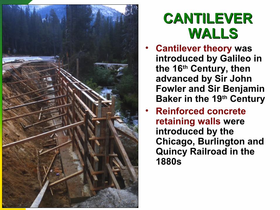
• Cantilever theory was introduced by Galileo in the 16th Century, then advanced by Sir John Fowler and Sir Benjamin Baker in the 19th Century
• Reinforced concrete retaining walls were introduced by the Chicago, Burlington and Quincy Railroad in the 1880s
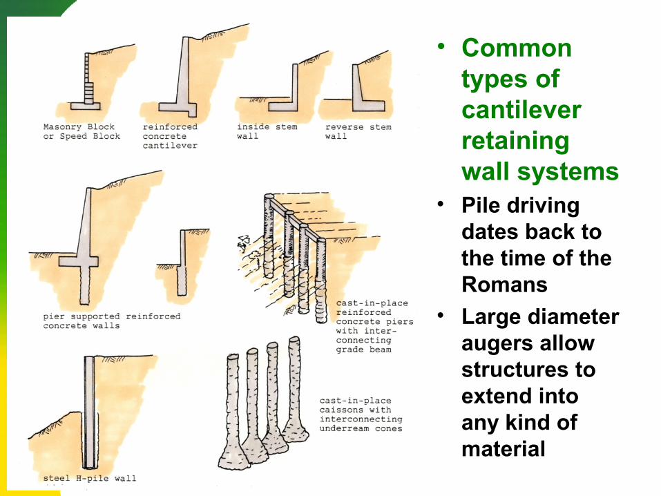
• Common types of cantilever retaining wall systems
• Pile driving dates back to the time of the Romans
• Large diameter augers allow structures to extend into any kind of material
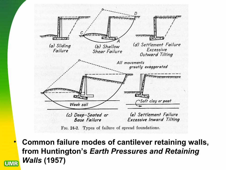
• Common failure modes of cantilever retaining walls, from Huntington’s Earth Pressures and Retaining Walls (1957)
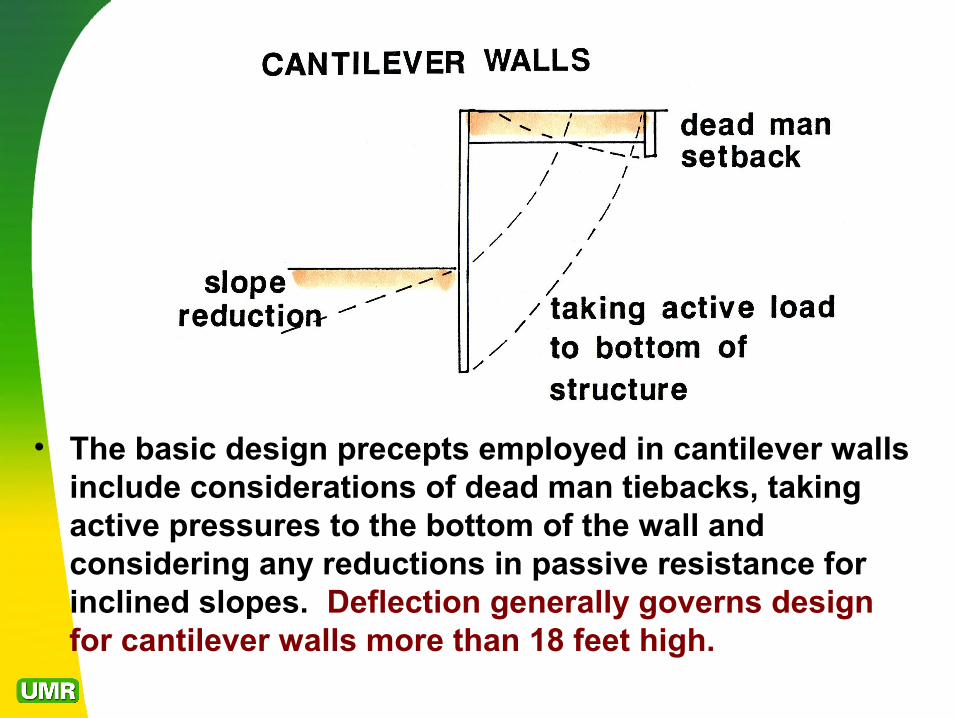
• The basic design precepts employed in cantilever walls include considerations of dead man tiebacks, taking active pressures to the bottom of the wall and considering any reductions in passive resistance for inclined slopes. Deflection generally governs design for cantilever walls more than 18 feet high.
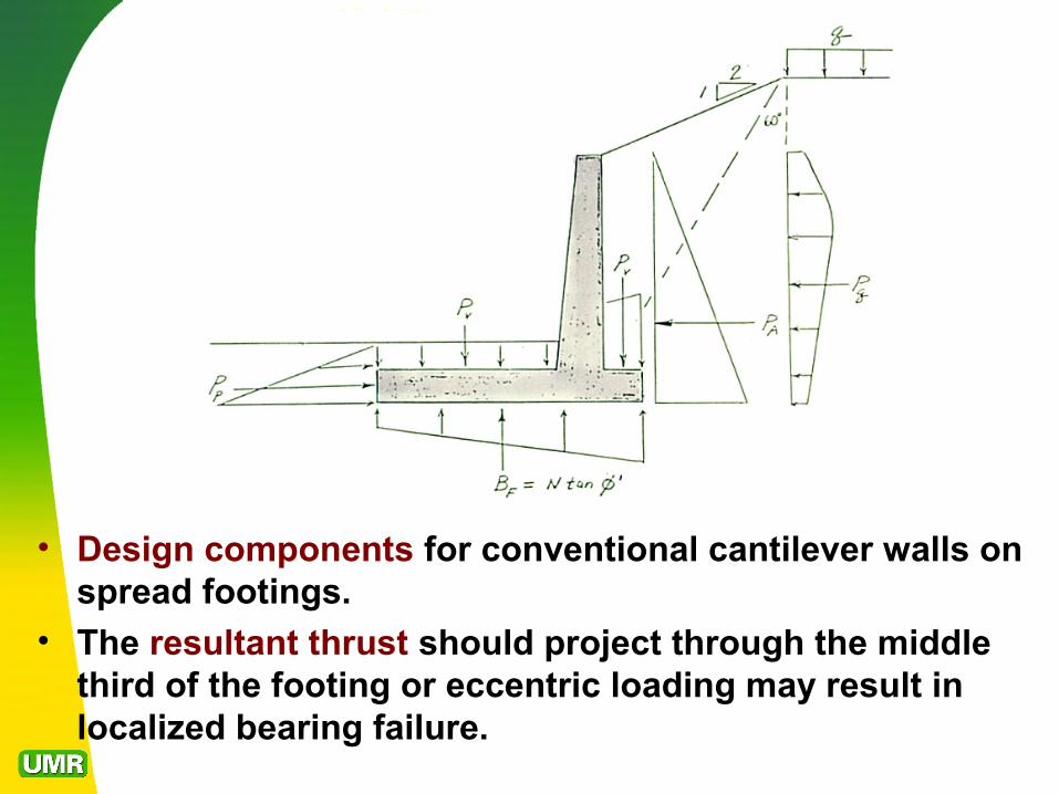
• Design components for conventional cantilever walls on spread footings.
• The resultant thrust should project through the middle third of the footing or eccentric loading may result in localized bearing failure.
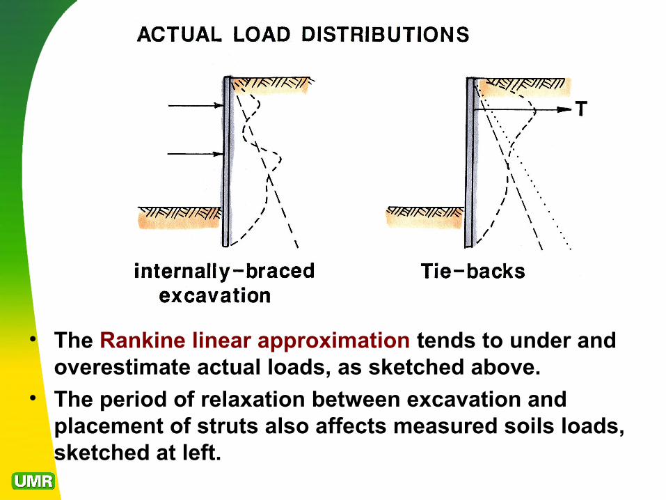
• The Rankine linear approximation tends to under and overestimate actual loads, as sketched above.
• The period of relaxation between excavation and placement of struts also affects measured soils loads, sketched at left.
COMMON ERRORS
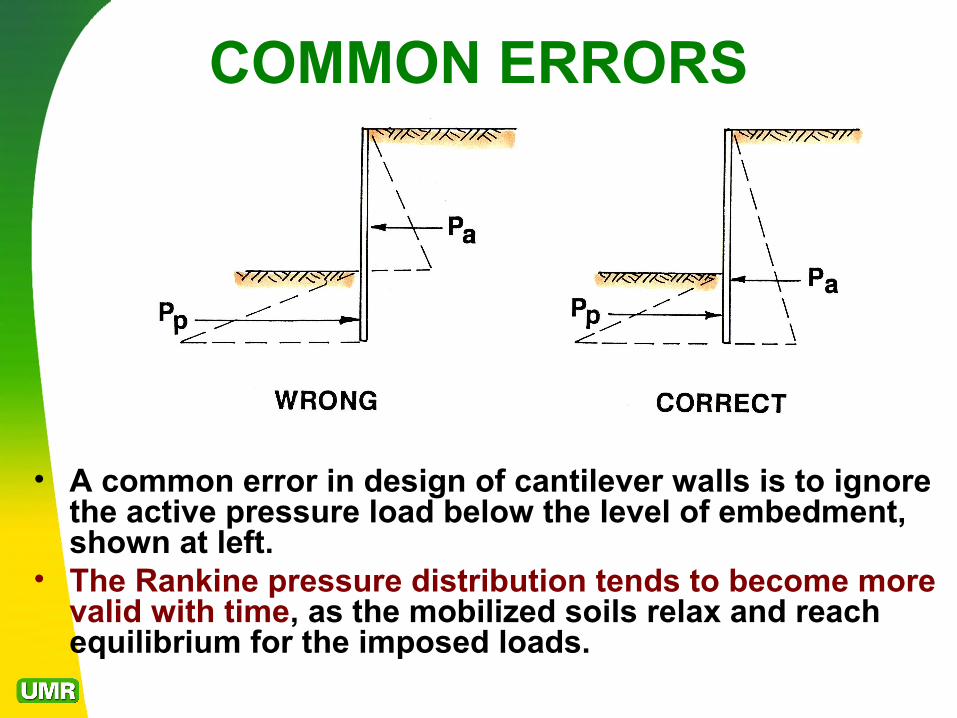
• A common error in design of cantilever walls is to ignore the active pressure load below the level of embedment, shown at left.
• The Rankine pressure distribution tends to become more valid with time, as the mobilized soils relax and reach equilibrium for the imposed loads.
COMMON ERRORS
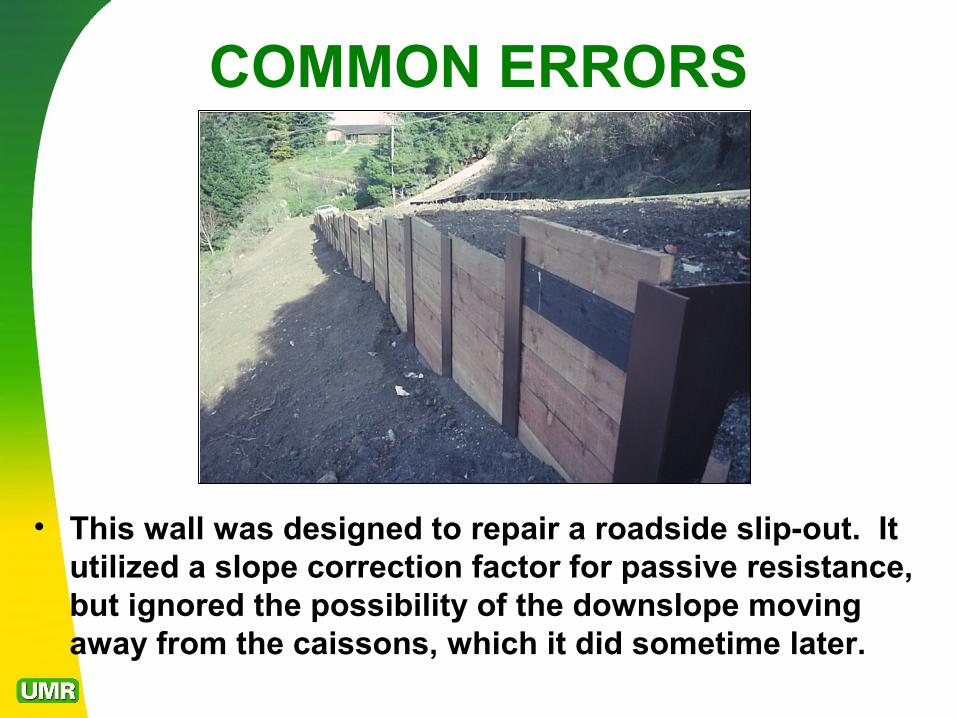
• This wall was designed to repair a roadside slip-out. It utilized a slope correction factor for passive resistance, but ignored the possibility of the downslope moving away from the caissons, which it did sometime later.
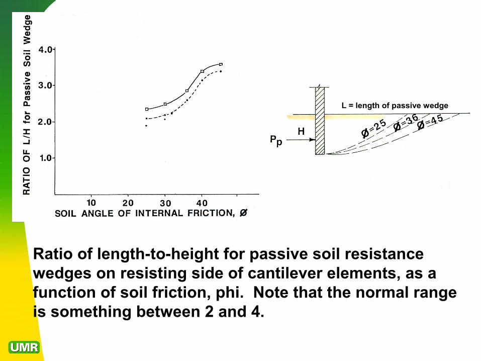
Ratio of length-to-height for passive soil resistance wedges on resisting side of cantilever elements, as a function of soil friction, phi. Note that the normal range is something between 2 and 4.
L = length of passive wedge
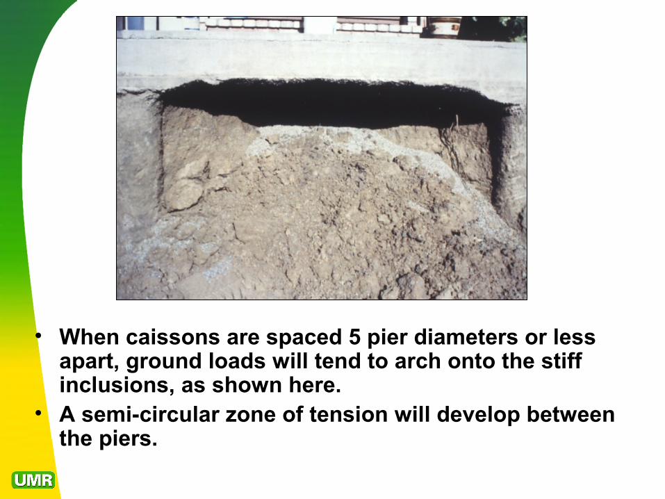
• When caissons are spaced 5 pier diameters or less apart, ground loads will tend to arch onto the stiff inclusions, as shown here.
• A semi-circular zone of tension will develop between the piers.
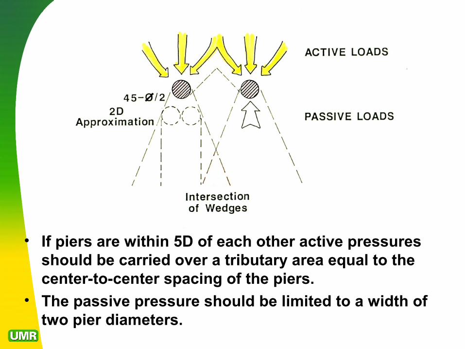
• If piers are within 5D of each other active pressures should be carried over a tributary area equal to the center-to-center spacing of the piers.
• The passive pressure should be limited to a width of two pier diameters.
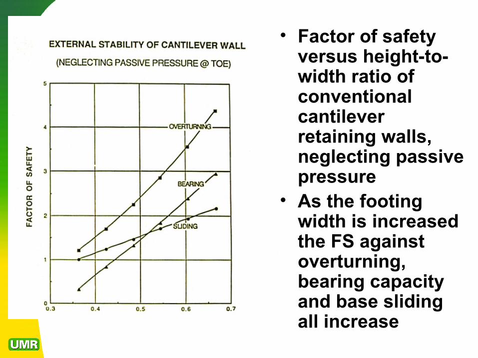
• Factor of safety versus height-to-width ratio of conventional cantilever retaining walls, neglecting passive pressure
• As the footing width is increased the FS against overturning, bearing capacity and base sliding all increase