Embed Size (px)
Citation preview
Owner’s Manual
Document Number
120-146-00
Revision
7
Date
10/15/21
Page
1 of 71
This document is proprietary to Onboard Systems Int’l. Disclosure or reproduction is not allowed. © 2022 Onboard Systems Int’l., all rights reserved.
Owner’s Manual
Cargo Hook
Suspension System Kits On the
Bell 407 Helicopter
STC SR01943SE
Onboard Systems International
13915 NW 3rd Court
Vancouver, WA 98685 United States of America
Cage Code: 1Y921
Toll Free Phone: (800) 275-0883
Phone: (360) 546-3072
Fax: (360) 546-3073
Applicable Equipment Part Numbers
200-412-00
200-412-10
200-413-00
200-413-01
200-413-02
200-413-10
200-413-11
200-413-12
Please check our web site www.onboardsystems.com for the latest revision of this manual.
Owner’s Manual
Document Number
120-146-00
Revision
7
Date
10/15/21
Page
2 of 71
This document is proprietary to Onboard Systems Int’l. Disclosure or reproduction is not allowed. © 2022 Onboard Systems Int’l., all rights reserved.
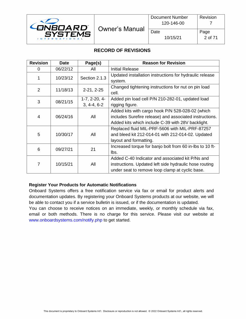
RECORD OF REVISIONS
Revision Date Page(s) Reason for Revision
0 06/22/12 All Initial Release
1 10/23/12 Section 2.1.3 Updated installation instructions for hydraulic release
system.
2 11/18/13 2-21, 2-25 Changed tightening instructions for nut on pin load
cell.
3 08/21/15 1-7, 2-20, 4-
3, 4-4, 6-2
Added pin load cell P/N 210-282-01, updated load
rigging figure.
4 06/24/16 All
Added kits with cargo hook P/N 528-028-02 (which
includes Surefire release) and associated instructions.
Added kits which include C-39 with 28V backlight.
5 10/30/17 All
Replaced fluid MIL-PRF-5606 with MIL-PRF-87257
and bleed kit 212-014-01 with 212-014-02. Updated
layout and formatting.
6 09/27/21 21 Increased torque for banjo bolt from 60 in-lbs to 10 ft-
lbs.
7 10/15/21 All
Added C-40 Indicator and associated kit P/Ns and
instructions. Updated left side hydraulic hose routing
under seat to remove loop clamp at cyclic base.
Register Your Products for Automatic Notifications
Onboard Systems offers a free notification service via fax or email for product alerts and
documentation updates. By registering your Onboard Systems products at our website, we will
be able to contact you if a service bulletin is issued, or if the documentation is updated.
You can choose to receive notices on an immediate, weekly, or monthly schedule via fax,
email or both methods. There is no charge for this service. Please visit our website at
www.onboardsystems.com/notify.php to get started.
Owner’s Manual
Document Number
120-146-00
Revision
7
Date
10/15/21
Page
3 of 71
This document is proprietary to Onboard Systems Int’l. Disclosure or reproduction is not allowed. © 2022 Onboard Systems Int’l., all rights reserved.
CONTENTS
1.0 Introduction ................................................................................................................... 4 1.1 Scope .............................................................................................................. 4 1.2 Safety labels .................................................................................................... 4
2.0 Referenced Documents................................................................................................. 5 3.0 System Overview ........................................................................................................... 5
3.1 Description ....................................................................................................... 5 3.2 Specifications ................................................................................................... 9 3.3 Bill of Materials............................................................................................... 10
4.0 Installation ................................................................................................................... 17 4.1 Fixed Provisions Kit Installation ...................................................................... 17
4.1.1 Electrical Release Wiring Installation ................................................17
4.1.2 Hydraulic Release System Installation ..............................................22
4.1.3 Hydraulic Hose Routing – Left Side ..................................................24
4.1.4 Hydraulic Release Routing – Right Side ...........................................26
4.1.5 Hydraulic Release Routing – Underneath Belly ................................28
4.1.6 Pillow Block Installation ....................................................................32
4.2 Removable Provisions Kit Installation ............................................................ 34 4.3 Load Weigh System Installation ..................................................................... 36
4.3.1 Pin Load Cell Installation ..................................................................37
4.3.2 Load Indicator Installation .................................................................38
4.3.3 Load Weigh Internal Harness Installation for the C-39 ......................38
4.3.4 Load Weigh Internal Harness Installation for the C-40 ......................40
4.4 Hydraulic Hook Upgrade Kit Installation ......................................................... 43 4.5 Hydraulic System Bleed Procedure ................................................................ 45 4.6 Installation Check-Out .................................................................................... 51 4.7 Paper Work .................................................................................................... 52
5.0 Operation Instructions ................................................................................................ 53 5.1 Operating Procedures .................................................................................... 53 5.2 Cargo Hook Loading ...................................................................................... 55 5.3 Cargo Hook Rigging ....................................................................................... 56
6.0 Maintenance ................................................................................................................. 58 6.1 Instructions for Returning Equipment to the Factory ....................................... 58
7.0 System Part Numbers ................................................................................................. 59 8.0 Certification ................................................................................................................. 68
8.1 FAA STC ........................................................................................................ 68 8.2 Transport Canada STC .................................................................................. 70
Owner’s Manual
Document Number
120-146-00
Revision
7
Date
10/15/21
Page
4 of 71
This document is proprietary to Onboard Systems Int’l. Disclosure or reproduction is not allowed. © 2022 Onboard Systems Int’l., all rights reserved.
1.0 Introduction
1.1 Scope
This Owner’s Manual contains installation and operation instructions for cargo
hook kit P/Ns 200-412-00, 200-412-10, 200-413-00, 200-413-01, 200-413-10,
200-413-11 on the Bell 407 model helicopter.
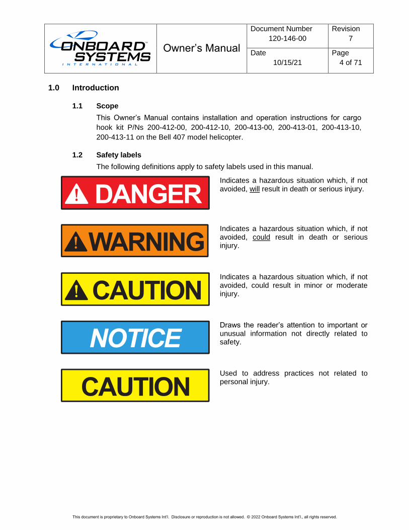
1.2 Safety labels
The following definitions apply to safety labels used in this manual.
Indicates a hazardous situation which, if not avoided, will result in death or serious injury.
Indicates a hazardous situation which, if not avoided, could result in death or serious injury.
Indicates a hazardous situation which, if not avoided, could result in minor or moderate injury.
Draws the reader’s attention to important or unusual information not directly related to safety.
Used to address practices not related to personal injury.
Owner’s Manual
Document Number
120-146-00
Revision
7
Date
10/15/21
Page
5 of 71
This document is proprietary to Onboard Systems Int’l. Disclosure or reproduction is not allowed. © 2022 Onboard Systems Int’l., all rights reserved.
2.0 Referenced Documents
120-039-00 Owner’s Manual C-39 Indicator
121-061-00 Rotorcraft Flight Manual Supplement
122-015-00 Component Maintenance Manual Cargo Hook 528-028-XX
123-040-00 Instructions for Continued Airworthiness
3.0 System Overview
3.1 Description
Kit P/N 200-412 series (also referred to as 200-412-XX) and 200-413 series (also
referred to as 200-413-XX) are cargo hook suspension kits and include fixed
provisions and removable provisions. The cargo hook fixed provisions kit
includes the internal electrical release wiring harness (with the exception of the
cargo hook electrical release switch on the cyclic or the wiring through the cyclic),
fixed hydraulic release system including the release lever for actuation in the
cockpit, and miscellaneous brackets and hardware for supporting these items.
The backup release lever included for this kit can be installed on the left hand or
right hand side cyclic control. The removable provisions include the cargo hook,
a beam which supports the cargo hook and spans the helicopter hard points, and
pillow blocks which attach to the hard points.
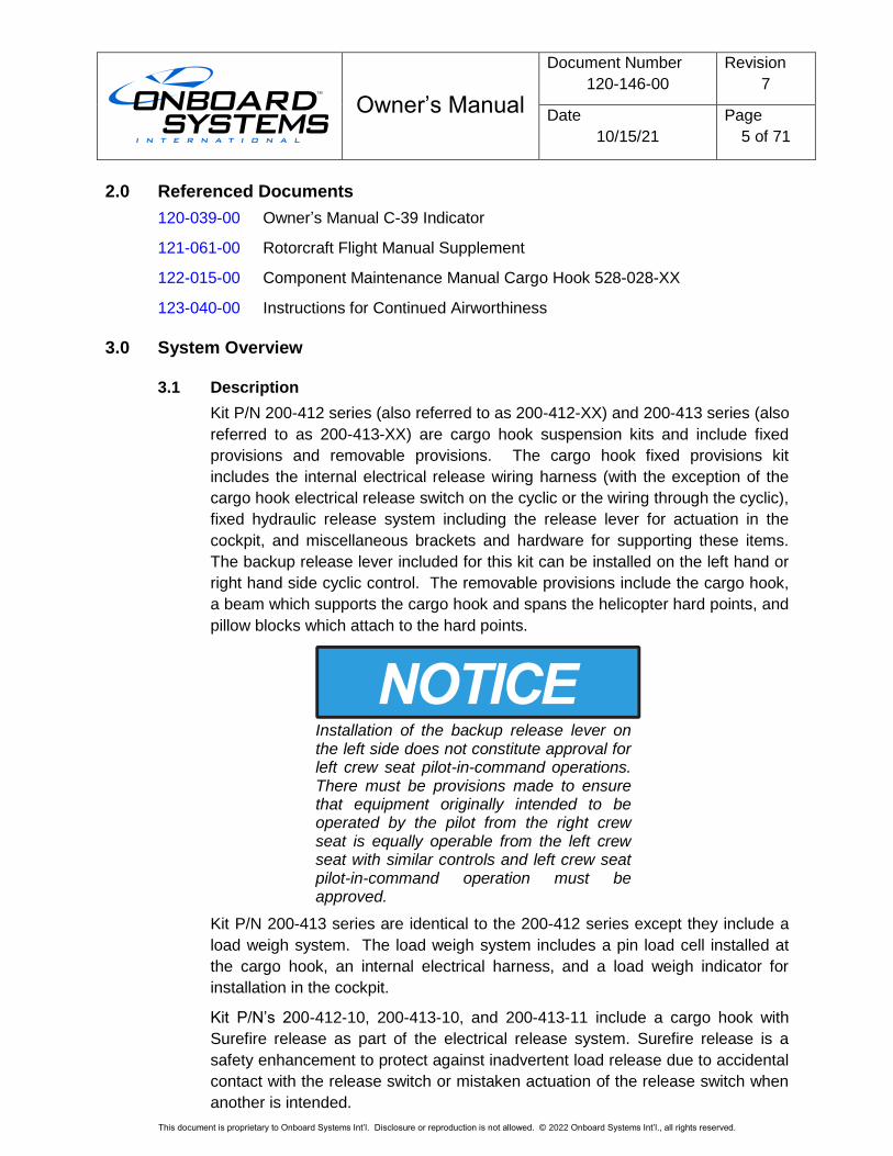
Installation of the backup release lever on the left side does not constitute approval for left crew seat pilot-in-command operations. There must be provisions made to ensure that equipment originally intended to be operated by the pilot from the right crew seat is equally operable from the left crew seat with similar controls and left crew seat pilot-in-command operation must be approved.
Kit P/N 200-413 series are identical to the 200-412 series except they include a
load weigh system. The load weigh system includes a pin load cell installed at
the cargo hook, an internal electrical harness, and a load weigh indicator for
installation in the cockpit.
Kit P/N’s 200-412-10, 200-413-10, and 200-413-11 include a cargo hook with
Surefire release as part of the electrical release system. Surefire release is a
safety enhancement to protect against inadvertent load release due to accidental
contact with the release switch or mistaken actuation of the release switch when
another is intended.
Owner’s Manual
Document Number
120-146-00
Revision
7
Date
10/15/21
Page
6 of 71
This document is proprietary to Onboard Systems Int’l. Disclosure or reproduction is not allowed. © 2022 Onboard Systems Int’l., all rights reserved.
The cargo hook suspension kits are comprised of fixed and removable
provisions.
The fixed provisions include all cargo hook components internal to the helicopter,
the pillow block assemblies, electrical harnesses and hydraulic hose mounted
along the belly, and the connector bracket on the belly which provides the means
for mounting the connectors between the fixed and removable sections of the
release systems and the load weigh system (if installed). These components are
typically left on the helicopter when it is configured for an operation other than
external load operations.
The removable provisions kit includes the components external to the helicopter
which are easily removed when the helicopter is configured for an operation
other than external load operations. It includes:
• The cargo hook and beam assembly. The beam assembly spans the
pillow block assemblies and supports the cargo hook.
• The external (removable) provisions of the electrical release system. The
electrical release system provides means for release by pilot actuation of
the push-button switch in the cockpit. When the push-button switch on the
cyclic is pressed, it energizes the solenoid in the cargo hook, and the
solenoid opens the latch in the internal mechanism of the cargo hook.
• The external (removable) provisions of the manual release system. The
manual release system uses a self-contained hydraulic system to provide
a means of releasing a cargo hook load in the event of an electrical
release system failure. A lever (included with the fixed provisions kit)
mounted on the pilot or co-pilot cyclic, provides the means to actuate it.
A load is attached to the cargo hook by passing a cargo sling ring into the throat
of the load beam and pushing the ring against the upper portion of the load beam
throat, which will cause the hook to close. In the closed position, a latch engages
the load beam and latches it in this position.
To release the load, the latch is disengaged from the load beam. With the latch
disengaged, the weight of the load causes the load beam to swing to its open
position, and the cargo sling ring slides off the load beam. The load beam then
remains in the open position awaiting the next load.
Ground personnel may also release an external load by the actuation of a lever
located on the side of the cargo hook.
The optional load weigh system is comprised of an indicator mounted within the
instrument panel, a pin load cell at the cargo hook, and the interconnecting wire
harness. The indicator displays the weight of the load carried on the cargo hook.
It supplies the precision excitation voltage to the pin load cell, conditions the
return signal, outputs a proportional analog signal and provides the means of
system calibration.
Owner’s Manual
Document Number
120-146-00
Revision
7
Date
10/15/21
Page
7 of 71
This document is proprietary to Onboard Systems Int’l. Disclosure or reproduction is not allowed. © 2022 Onboard Systems Int’l., all rights reserved.
The load weigh indicator included with the P/N 200-464-00 Load Weigh System
and P/N 200-415-02 Fixed Provisions Kit is Onboard Systems next generation
indicator, the C-40 model (P/N 210-293-00). The C-40 Indicator makes several
improvements over its predecessor (the C-39 model, P/N 210-095 series) while
preserving classical features and is generally backwards compatible. Among
others, the C-40 Indicator offers these improvements:
• Full color display
• Load measurement displayed in full, not X 10 (C-39 is X 10)
• Addition of Analog Bar and Maximum Load features
• Simplified user interface
• Addition of Cargo Hook hour meter
• Selectable backlight control voltage, 5 or 28 VDC
• Improved moisture resistance
• Expanded signal input range
• Field-upgradable firmware
The optional cargo hook with Surefire includes a short time delay circuit built into
the cargo hook’s electrical release system (cargo hook P/N 528-028-02). This
feature is a safety enhancement to protect against inadvertent load release due
to accidental contact with the release switch or mistaken actuation of the cargo
hook switch when another is intended. The time delay feature requires that the
release switch be depressed and held for more than a 1/2 second to open the
cargo hook. Surefire makes the electrical release a more deliberate pilot
command. If the cargo hook must be released immediately, use the mechanical
backup release.
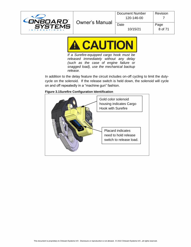
In addition to its P/N, a cargo hook with Surefire can be identified by a gold color
solenoid housing (see Figure 3.1). Also, a placard on the underside of the
solenoid housing indicates that the electrical release is delayed by ½ second.
The 528-028-02 cargo hook includes an electronic delay of approximately ½ second. It is necessary to press and hold the cargo hook release button.
Owner’s Manual
Document Number
120-146-00
Revision
7
Date
10/15/21
Page
8 of 71
This document is proprietary to Onboard Systems Int’l. Disclosure or reproduction is not allowed. © 2022 Onboard Systems Int’l., all rights reserved.
If a Surefire-equipped cargo hook must be released immediately without any delay (such as the case of engine failure or snagged load), use the mechanical backup release.
In addition to the delay feature the circuit includes on-off cycling to limit the duty-
cycle on the solenoid. If the release switch is held down, the solenoid will cycle
on and off repeatedly in a “machine gun” fashion.
Figure 3.1Surefire Configuration Identification
Gold color solenoid
housing indicates Cargo
Hook with Surefire
release.
Placard indicates
need to hold release
switch to release load.
Owner’s Manual
Document Number
120-146-00
Revision
7
Date
10/15/21
Page
9 of 71
This document is proprietary to Onboard Systems Int’l. Disclosure or reproduction is not allowed. © 2022 Onboard Systems Int’l., all rights reserved.
3.2 Specifications
Table 3.1 System Specifications
Design load 2,650 lbs. (1,202 kg)
Design ultimate strength 9,938 lbs. (4,507 kg)
P/N 200-412-00 weight 14.9 lbs (6.76 kg)
P/N 200-413-00 weight 16.4 lbs (7.44 kg)
Table 3.2 Specifications - P/N 528-028-00, 528-028-02 Cargo Hook
Design load 3,500 lb. (1,587 kg.)
Design ultimate strength 13,125 lb. (5,953 kg.)
Electrical release capacity 8,750 lb. (3,968 kg.)
Mechanical release capacity 8,750 lb. (3,968 kg.)
Force required for mechanical
release at 3,500 lb.
14 lbs maximum at master
cylinder lever
Electrical requirements 22-32 VDC, 6.9 - 10 amps
Minimum release load 0 pounds
Unit weight 3.1 pounds (1.4 kg.)
Mating electrical connector PC05A8-2S
The weights and CGs of the Cargo Hook Suspension System kits are listed
below.
Table 3.3 Weight & CGs – Cargo Hook Suspension System Kits
Item Weight
Lbs (kg)
Station
in (mm)
Fixed Provisions Kit
P/N 200-394-00 7.2 (3.27) 109.1 (2772)
Removable Provisions Kit
P/N 200-395-00, -10 7.7 (3.49) 121.0 (3073)
Total Kit Weight (P/N 200-412-XX) 14.9 (6.76) 115.3 (2929)
Fixed Provisions Kit w/ Load Weigh
P/N 200-415-00 8.5 (3.18) 108.6 (2760)
Removable Provisions Kit w/ Load Weigh
P/N 200-416-00, -10 7.9 (4.26) 121.0 (3073)
Total Kit Weight (P/N 200-413-XX) 16.4 (7.44) 114.6 (2911)
Load capacities given are for the equipment described only. Loading limits for your particular helicopter model still apply. Consult your flight manual.
Owner’s Manual
Document Number
120-146-00
Revision
7
Date
10/15/21
Page
10 of 71
This document is proprietary to Onboard Systems Int’l. Disclosure or reproduction is not allowed. © 2022 Onboard Systems Int’l., all rights reserved.
3.3 Bill of Materials
P/N 200-412-00 and 200-412-10 are complete cargo hook suspension kits
(without load weigh systems) and include a fixed provisions kit P/N 200-394-00
and a removable provisions kit (kit P/N 200-395-00 or P/N 200-395-10 which
includes cargo hook with Surefire Release).
Table 3.4 Bill of Materials – Cargo Hook Suspension Kit P/N 200-412-00, -10
Part No. Description Qty
-00 -10
200-394-00 Fixed Provisions Kit 1 1
200-395-00 Removable Provisions Kit 1 -
200-395-10 Removable Provisions Kit - 1
120-146-00 Owner’s Manual 1 1
121-061-00 RFMS 1 1
122-015-00 Component Maintenance Manual, Cargo Hook 1 1
123-040-00 ICA 1 1
The following items are included with the 200-394-00 Fixed Provisions Kit.
Owner’s Manual
Document Number
120-146-00
Revision
7
Date
10/15/21
Page
11 of 71
This document is proprietary to Onboard Systems Int’l. Disclosure or reproduction is not allowed. © 2022 Onboard Systems Int’l., all rights reserved.
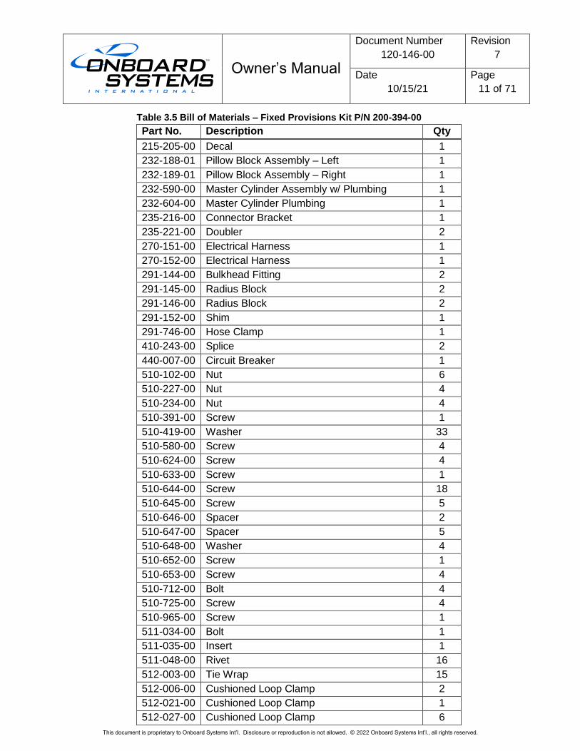
Table 3.5 Bill of Materials – Fixed Provisions Kit P/N 200-394-00
Part No. Description Qty
215-205-00 Decal 1
232-188-01 Pillow Block Assembly – Left 1
232-189-01 Pillow Block Assembly – Right 1
232-590-00 Master Cylinder Assembly w/ Plumbing 1
232-604-00 Master Cylinder Plumbing 1
235-216-00 Connector Bracket 1
235-221-00 Doubler 2
270-151-00 Electrical Harness 1
270-152-00 Electrical Harness 1
291-144-00 Bulkhead Fitting 2
291-145-00 Radius Block 2
291-146-00 Radius Block 2
291-152-00 Shim 1
291-746-00 Hose Clamp 1
410-243-00 Splice 2
440-007-00 Circuit Breaker 1
510-102-00 Nut 6
510-227-00 Nut 4
510-234-00 Nut 4
510-391-00 Screw 1
510-419-00 Washer 33
510-580-00 Screw 4
510-624-00 Screw 4
510-633-00 Screw 1
510-644-00 Screw 18
510-645-00 Screw 5
510-646-00 Spacer 2
510-647-00 Spacer 5
510-648-00 Washer 4
510-652-00 Screw 1
510-653-00 Screw 4
510-712-00 Bolt 4
510-725-00 Screw 4
510-965-00 Screw 1
511-034-00 Bolt 1
511-035-00 Insert 1
511-048-00 Rivet 16
512-003-00 Tie Wrap 15
512-006-00 Cushioned Loop Clamp 2
512-021-00 Cushioned Loop Clamp 1
512-027-00 Cushioned Loop Clamp 6
Owner’s Manual
Document Number
120-146-00
Revision
7
Date
10/15/21
Page
12 of 71
This document is proprietary to Onboard Systems Int’l. Disclosure or reproduction is not allowed. © 2022 Onboard Systems Int’l., all rights reserved.
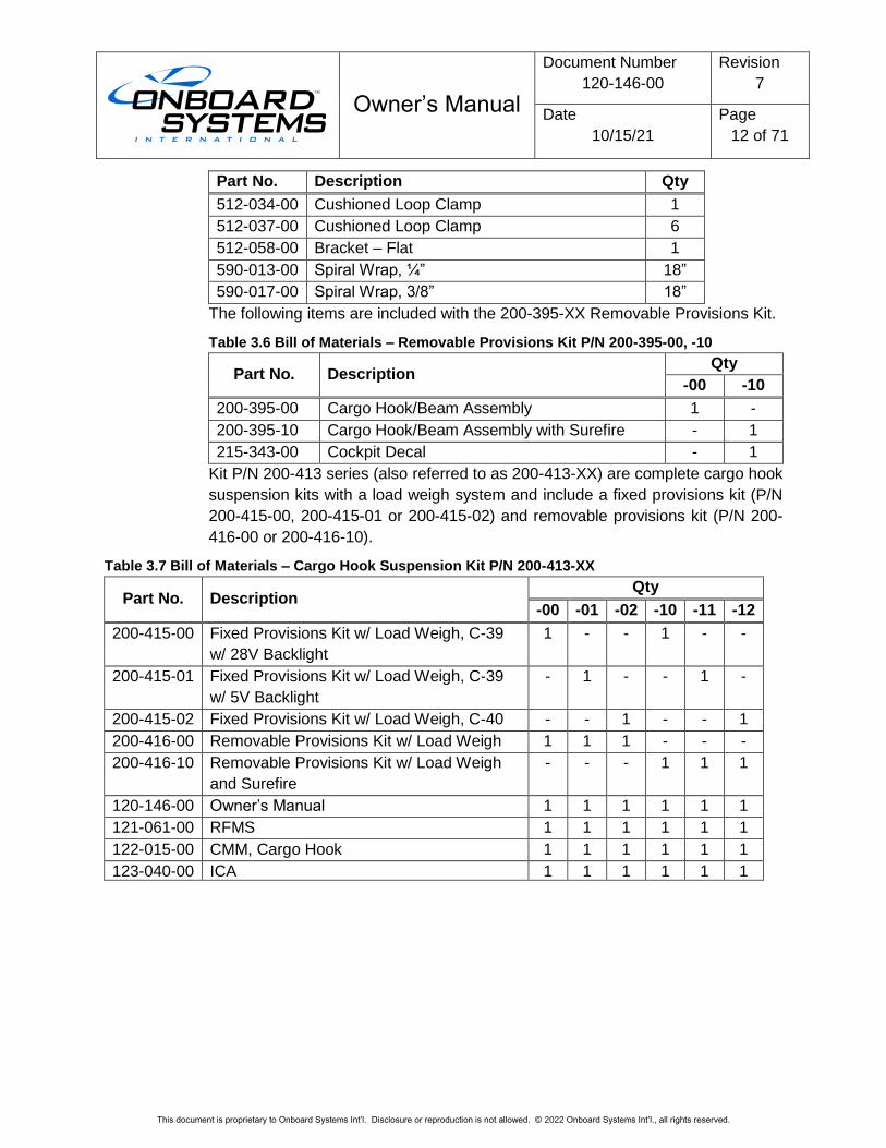
Part No. Description Qty
512-034-00 Cushioned Loop Clamp 1
512-037-00 Cushioned Loop Clamp 6
512-058-00 Bracket – Flat 1
590-013-00 Spiral Wrap, ¼” 18”
590-017-00 Spiral Wrap, 3/8” 18”
The following items are included with the 200-395-XX Removable Provisions Kit.
Table 3.6 Bill of Materials – Removable Provisions Kit P/N 200-395-00, -10
Part No. Description Qty
-00 -10
200-395-00 Cargo Hook/Beam Assembly 1 -
200-395-10 Cargo Hook/Beam Assembly with Surefire - 1
215-343-00 Cockpit Decal - 1
Kit P/N 200-413 series (also referred to as 200-413-XX) are complete cargo hook
suspension kits with a load weigh system and include a fixed provisions kit (P/N
200-415-00, 200-415-01 or 200-415-02) and removable provisions kit (P/N 200-
416-00 or 200-416-10).
Table 3.7 Bill of Materials – Cargo Hook Suspension Kit P/N 200-413-XX
Part No. Description Qty
-00 -01 -02 -10 -11 -12
200-415-00 Fixed Provisions Kit w/ Load Weigh, C-39
w/ 28V Backlight
1 - - 1 - -
200-415-01 Fixed Provisions Kit w/ Load Weigh, C-39
w/ 5V Backlight
- 1 - - 1 -
200-415-02 Fixed Provisions Kit w/ Load Weigh, C-40 - - 1 - - 1
200-416-00 Removable Provisions Kit w/ Load Weigh 1 1 1 - - -
200-416-10 Removable Provisions Kit w/ Load Weigh
and Surefire
- - - 1 1 1
120-146-00 Owner’s Manual 1 1 1 1 1 1
121-061-00 RFMS 1 1 1 1 1 1
122-015-00 CMM, Cargo Hook 1 1 1 1 1 1
123-040-00 ICA 1 1 1 1 1 1
Owner’s Manual
Document Number
120-146-00
Revision
7
Date
10/15/21
Page
13 of 71
This document is proprietary to Onboard Systems Int’l. Disclosure or reproduction is not allowed. © 2022 Onboard Systems Int’l., all rights reserved.
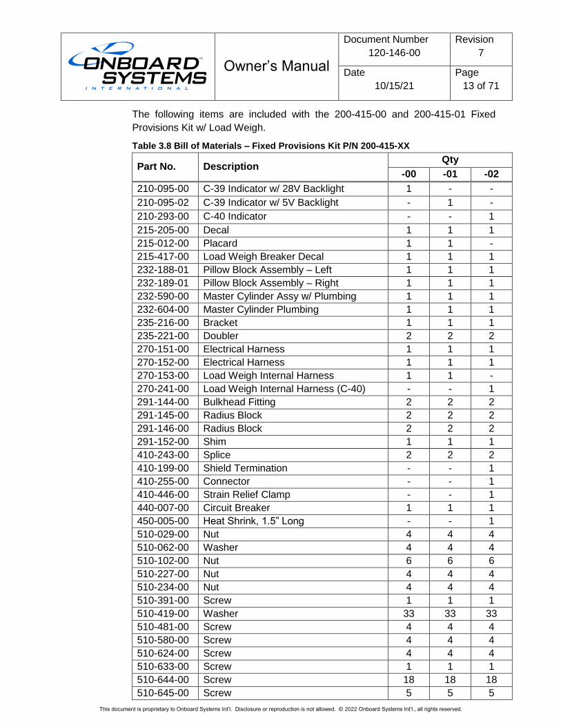
The following items are included with the 200-415-00 and 200-415-01 Fixed
Provisions Kit w/ Load Weigh.
Table 3.8 Bill of Materials – Fixed Provisions Kit P/N 200-415-XX
Part No. Description Qty
-00 -01 -02
210-095-00 C-39 Indicator w/ 28V Backlight 1 - -
210-095-02 C-39 Indicator w/ 5V Backlight - 1 -
210-293-00 C-40 Indicator - - 1
215-205-00 Decal 1 1 1
215-012-00 Placard 1 1 -
215-417-00 Load Weigh Breaker Decal 1 1 1
232-188-01 Pillow Block Assembly – Left 1 1 1
232-189-01 Pillow Block Assembly – Right 1 1 1
232-590-00 Master Cylinder Assy w/ Plumbing 1 1 1
232-604-00 Master Cylinder Plumbing 1 1 1
235-216-00 Bracket 1 1 1
235-221-00 Doubler 2 2 2
270-151-00 Electrical Harness 1 1 1
270-152-00 Electrical Harness 1 1 1
270-153-00 Load Weigh Internal Harness 1 1 -
270-241-00 Load Weigh Internal Harness (C-40) - - 1
291-144-00 Bulkhead Fitting 2 2 2
291-145-00 Radius Block 2 2 2
291-146-00 Radius Block 2 2 2
291-152-00 Shim 1 1 1
410-243-00 Splice 2 2 2
410-199-00 Shield Termination - - 1
410-255-00 Connector - - 1
410-446-00 Strain Relief Clamp - - 1
440-007-00 Circuit Breaker 1 1 1
450-005-00 Heat Shrink, 1.5” Long - - 1
510-029-00 Nut 4 4 4
510-062-00 Washer 4 4 4
510-102-00 Nut 6 6 6
510-227-00 Nut 4 4 4
510-234-00 Nut 4 4 4
510-391-00 Screw 1 1 1
510-419-00 Washer 33 33 33
510-481-00 Screw 4 4 4
510-580-00 Screw 4 4 4
510-624-00 Screw 4 4 4
510-633-00 Screw 1 1 1
510-644-00 Screw 18 18 18
510-645-00 Screw 5 5 5
Owner’s Manual
Document Number
120-146-00
Revision
7
Date
10/15/21
Page
14 of 71
This document is proprietary to Onboard Systems Int’l. Disclosure or reproduction is not allowed. © 2022 Onboard Systems Int’l., all rights reserved.
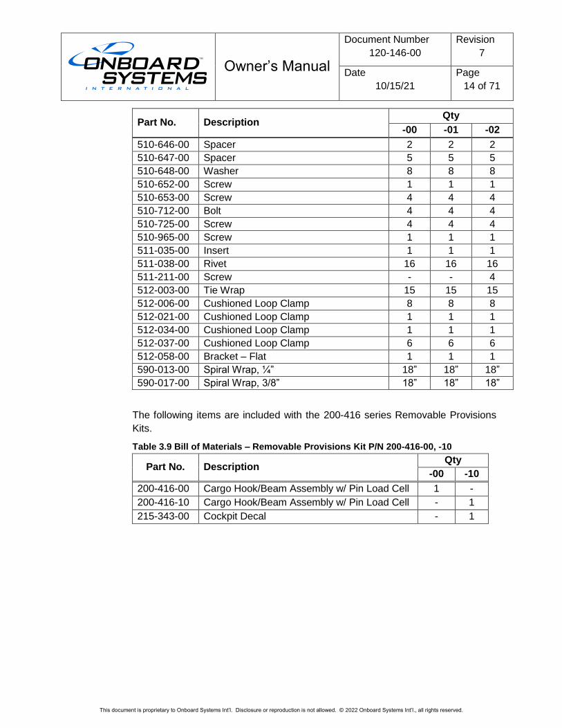
Part No. Description Qty
-00 -01 -02
510-646-00 Spacer 2 2 2
510-647-00 Spacer 5 5 5
510-648-00 Washer 8 8 8
510-652-00 Screw 1 1 1
510-653-00 Screw 4 4 4
510-712-00 Bolt 4 4 4
510-725-00 Screw 4 4 4
510-965-00 Screw 1 1 1
511-035-00 Insert 1 1 1
511-038-00 Rivet 16 16 16
511-211-00 Screw - - 4
512-003-00 Tie Wrap 15 15 15
512-006-00 Cushioned Loop Clamp 8 8 8
512-021-00 Cushioned Loop Clamp 1 1 1
512-034-00 Cushioned Loop Clamp 1 1 1
512-037-00 Cushioned Loop Clamp 6 6 6
512-058-00 Bracket – Flat 1 1 1
590-013-00 Spiral Wrap, ¼” 18” 18” 18”
590-017-00 Spiral Wrap, 3/8” 18” 18” 18”
The following items are included with the 200-416 series Removable Provisions
Kits.
Table 3.9 Bill of Materials – Removable Provisions Kit P/N 200-416-00, -10
Part No. Description Qty
-00 -10
200-416-00 Cargo Hook/Beam Assembly w/ Pin Load Cell 1 -
200-416-10 Cargo Hook/Beam Assembly w/ Pin Load Cell - 1
215-343-00 Cockpit Decal - 1
Owner’s Manual
Document Number
120-146-00
Revision
7
Date
10/15/21
Page
15 of 71
This document is proprietary to Onboard Systems Int’l. Disclosure or reproduction is not allowed. © 2022 Onboard Systems Int’l., all rights reserved.
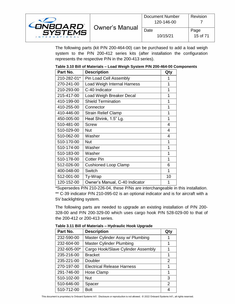
The following parts (kit P/N 200-464-00) can be purchased to add a load weigh
system to the P/N 200-412 series kits (after installation the configuration
represents the respective P/N in the 200-413 series).
Table 3.10 Bill of Materials – Load Weigh System P/N 200-464-00 Components
Part No. Description Qty
210-282-01* Pin Load Cell Assembly 1
270-241-00 Load Weigh Internal Harness 1
210-293-00 C-40 Indicator 1
215-417-00 Load Weigh Breaker Decal 1
410-199-00 Shield Termination 1
410-255-00 Connector 1
410-446-00 Strain Relief Clamp 1
450-005-00 Heat Shrink, 1.5” Lg. 1
510-481-00 Screw 4
510-029-00 Nut 4
510-062-00 Washer 4
510-170-00 Nut 1
510-174-00 Washer 1
510-183-00 Washer 1
510-178-00 Cotter Pin 1
512-026-00 Cushioned Loop Clamp 6
400-048-00 Switch 1
512-001-00 Ty-Wrap 10
120-152-00 Owner’s Manual, C-40 Indicator 1
*Supersedes P/N 210-226-04, these P/Ns are interchangeable in this installation.
** C-39 indicator P/N 210-095-02 is an optional indicator and is for aircraft with a
5V backlighting system.
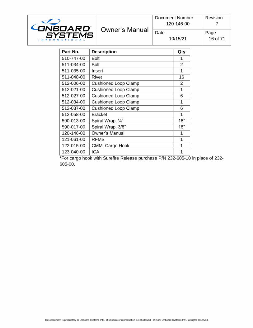
The following parts are needed to upgrade an existing installation of P/N 200-
328-00 and P/N 200-329-00 which uses cargo hook P/N 528-029-00 to that of
the 200-412 or 200-413 series.
Table 3.11 Bill of Materials – Hydraulic Hook Upgrade
Part No. Description Qty
232-590-00 Master Cylinder Assy w/ Plumbing 1
232-604-00 Master Cylinder Plumbing 1
232-605-00* Cargo Hook/Slave Cylinder Assembly 1
235-216-00 Bracket 1
235-221-00 Doubler 2
270-197-00 Electrical Release Harness 1
291-746-00 Hose Clamp 1
510-102-00 Nut 3
510-646-00 Spacer 2
510-712-00 Bolt 4
Owner’s Manual
Document Number
120-146-00
Revision
7
Date
10/15/21
Page
16 of 71
This document is proprietary to Onboard Systems Int’l. Disclosure or reproduction is not allowed. © 2022 Onboard Systems Int’l., all rights reserved.
Part No. Description Qty
510-747-00 Bolt 1
511-034-00 Bolt 2
511-035-00 Insert 1
511-048-00 Rivet 16
512-006-00 Cushioned Loop Clamp 2
512-021-00 Cushioned Loop Clamp 1
512-027-00 Cushioned Loop Clamp 6
512-034-00 Cushioned Loop Clamp 1
512-037-00 Cushioned Loop Clamp 6
512-058-00 Bracket 1
590-013-00 Spiral Wrap, ¼” 18”
590-017-00 Spiral Wrap, 3/8” 18”
120-146-00 Owner’s Manual 1
121-061-00 RFMS 1
122-015-00 CMM, Cargo Hook 1
123-040-00 ICA 1
*For cargo hook with Surefire Release purchase P/N 232-605-10 in place of 232-
605-00.
Owner’s Manual
Document Number
120-146-00
Revision
7
Date
10/15/21
Page
17 of 71
This document is proprietary to Onboard Systems Int’l. Disclosure or reproduction is not allowed. © 2022 Onboard Systems Int’l., all rights reserved.
4.0 Installation
These procedures are provided for the benefit of experienced aircraft maintenance
facilities capable of carrying out the procedures. Those lacking the necessary expertise
should not attempt them.
This section provides instructions for the installation of the kits outlined in Section 1.0.
4.1 Fixed Provisions Kit Installation
This part of the installation consists of installing the internal cargo hook electrical
release wiring, fixed hydraulic release system, bulkhead fittings, and support
brackets for the hydraulic release lever and connectors.
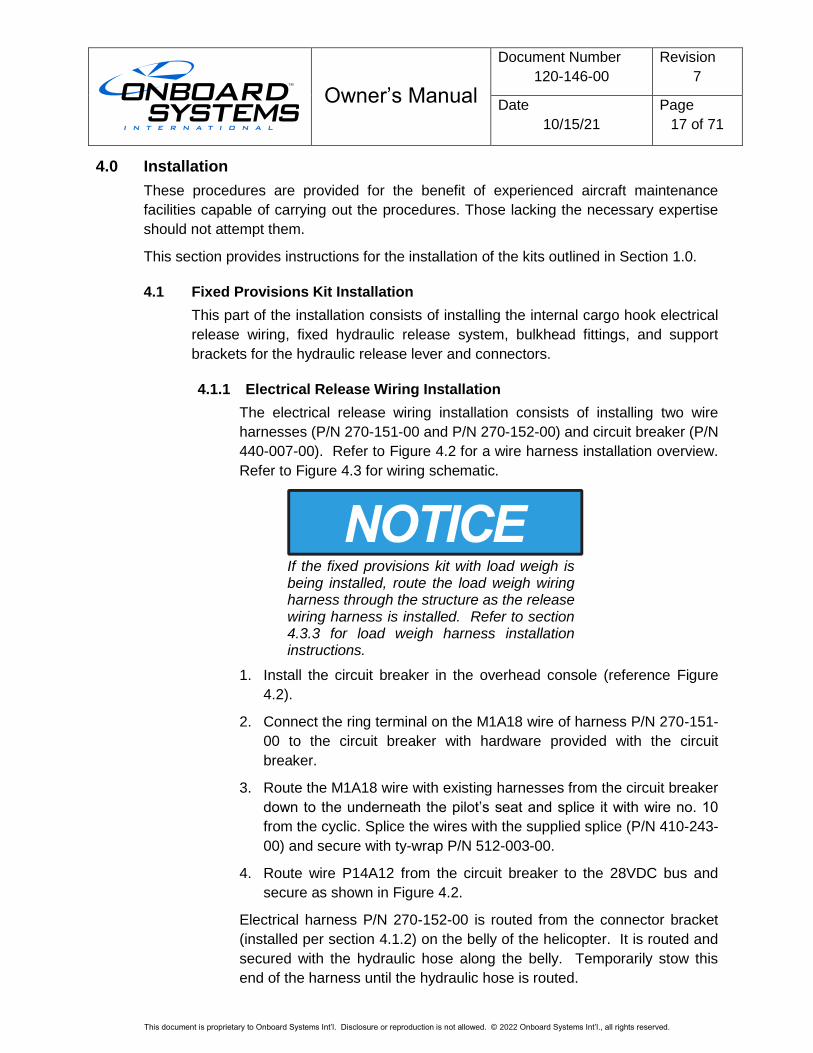
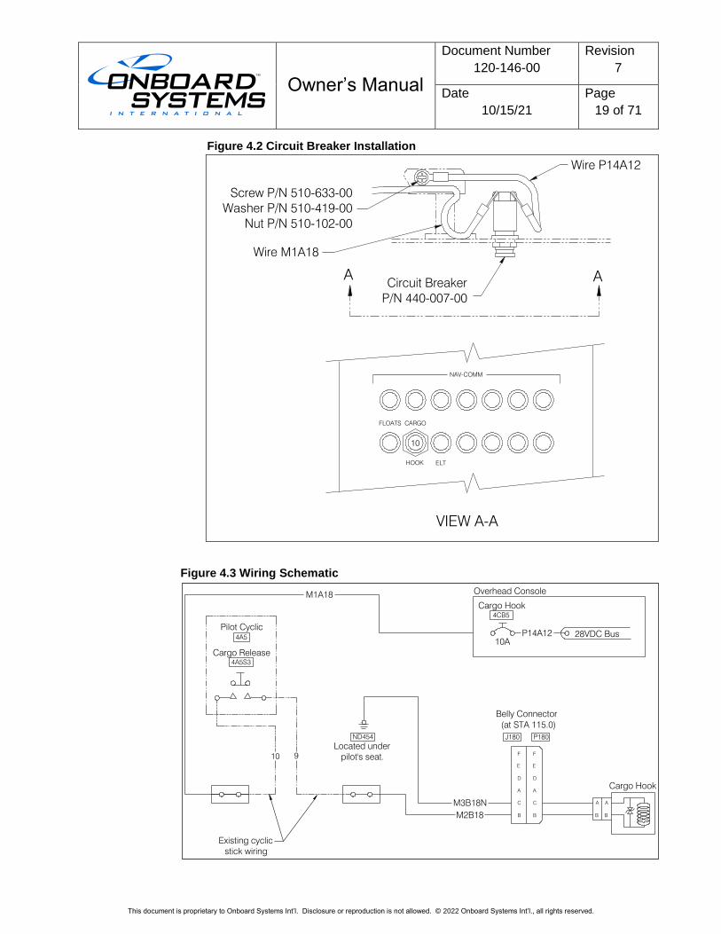
4.1.1 Electrical Release Wiring Installation
The electrical release wiring installation consists of installing two wire
harnesses (P/N 270-151-00 and P/N 270-152-00) and circuit breaker (P/N
440-007-00). Refer to Figure 4.2 for a wire harness installation overview.
Refer to Figure 4.3 for wiring schematic.
If the fixed provisions kit with load weigh is being installed, route the load weigh wiring harness through the structure as the release wiring harness is installed. Refer to section 4.3.3 for load weigh harness installation instructions.
1. Install the circuit breaker in the overhead console (reference Figure
4.2).
2. Connect the ring terminal on the M1A18 wire of harness P/N 270-151-
00 to the circuit breaker with hardware provided with the circuit
breaker.
3. Route the M1A18 wire with existing harnesses from the circuit breaker
down to the underneath the pilot’s seat and splice it with wire no. 10
from the cyclic. Splice the wires with the supplied splice (P/N 410-243-
00) and secure with ty-wrap P/N 512-003-00.
4. Route wire P14A12 from the circuit breaker to the 28VDC bus and
secure as shown in Figure 4.2.
Electrical harness P/N 270-152-00 is routed from the connector bracket
(installed per section 4.1.2) on the belly of the helicopter. It is routed and
secured with the hydraulic hose along the belly. Temporarily stow this
end of the harness until the hydraulic hose is routed.
Owner’s Manual
Document Number
120-146-00
Revision
7
Date
10/15/21
Page
18 of 71
This document is proprietary to Onboard Systems Int’l. Disclosure or reproduction is not allowed. © 2022 Onboard Systems Int’l., all rights reserved.
5. Route the two individual wires (M3B18N and M2B18) forward and up
through the hole in belly at STA 62.80.
6. Route and connect wire no. M3B18N to ground point ND454 under
the pilot seat.
7. Route wire no. M2B18 to underneath the pilot seat and splice it with
wire no. 9 from the cyclic. Splice the wires with the supplied splice
(P/N 410-243-00) and secure with ty-wrap P/N 512-003-00.
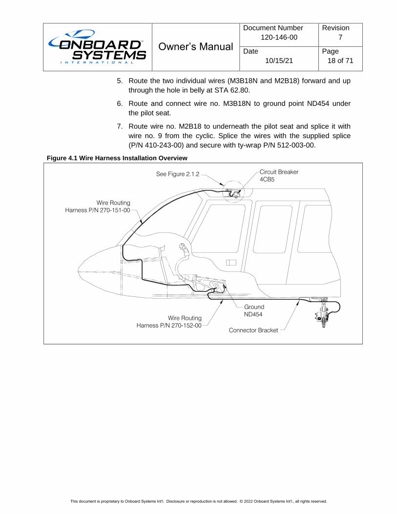
Figure 4.1 Wire Harness Installation Overview
Wire Routing
Harness P/N 270-152-00
Wire Routing
Harness P/N 270-151-00
Ground
ND454
Circuit Breaker
4CB5
See Figure 2.1.2
Connector Bracket
Owner’s Manual
Document Number
120-146-00
Revision
7
Date
10/15/21
Page
19 of 71
This document is proprietary to Onboard Systems Int’l. Disclosure or reproduction is not allowed. © 2022 Onboard Systems Int’l., all rights reserved.
Figure 4.2 Circuit Breaker Installation
Figure 4.3 Wiring Schematic
NAV-COMM
FLOATS CARGO
HOOK ELT
A A
VIEW A-A
10
Circuit Breaker
P/N 440-007-00
Wire M1A18
Wire P14A12
Screw P/N 510-633-00
Washer P/N 510-419-00
Nut P/N 510-102-00
BB
A A
B
C
A
D
E
F
B
C
A
D
E
F
Cargo Release
4A5S3
Pilot Cyclic
10A
28VDC Bus4A5
Cargo Hook
4CB5
Overhead Console
P14A12
M1A18
M3B18N
M2B18
Cargo Hook
Belly Connector
(at STA 115.0)
10
ND454
Located under
pilot's seat.
J180 P180
Existing cyclic
stick wiring
9
Owner’s Manual
Document Number
120-146-00
Revision
7
Date
10/15/21
Page
20 of 71
This document is proprietary to Onboard Systems Int’l. Disclosure or reproduction is not allowed. © 2022 Onboard Systems Int’l., all rights reserved.
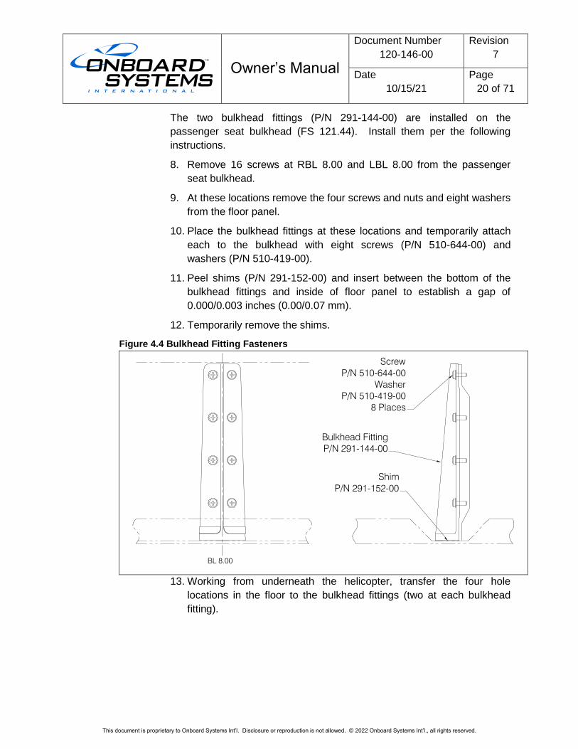
The two bulkhead fittings (P/N 291-144-00) are installed on the
passenger seat bulkhead (FS 121.44). Install them per the following
instructions.
8. Remove 16 screws at RBL 8.00 and LBL 8.00 from the passenger
seat bulkhead.
9. At these locations remove the four screws and nuts and eight washers
from the floor panel.
10. Place the bulkhead fittings at these locations and temporarily attach
each to the bulkhead with eight screws (P/N 510-644-00) and
washers (P/N 510-419-00).
11. Peel shims (P/N 291-152-00) and insert between the bottom of the
bulkhead fittings and inside of floor panel to establish a gap of
0.000/0.003 inches (0.00/0.07 mm).
12. Temporarily remove the shims.
Figure 4.4 Bulkhead Fitting Fasteners
13. Working from underneath the helicopter, transfer the four hole
locations in the floor to the bulkhead fittings (two at each bulkhead
fitting).
Shim
P/N 291-152-00
Screw
P/N 510-644-00
Washer
P/N 510-419-00
8 Places
Bulkhead Fitting
P/N 291-144-00
BL 8.00
Owner’s Manual
Document Number
120-146-00
Revision
7
Date
10/15/21
Page
21 of 71
This document is proprietary to Onboard Systems Int’l. Disclosure or reproduction is not allowed. © 2022 Onboard Systems Int’l., all rights reserved.
14. Remove the bulkhead fittings and drill a Ø0.250/0.255 inch hole
through the flanges at the marked locations.
The bulkhead fittings are heat-treated steel thus it is recommended that they be clamped securely in a vise and that a drill press and new drill bits be used.
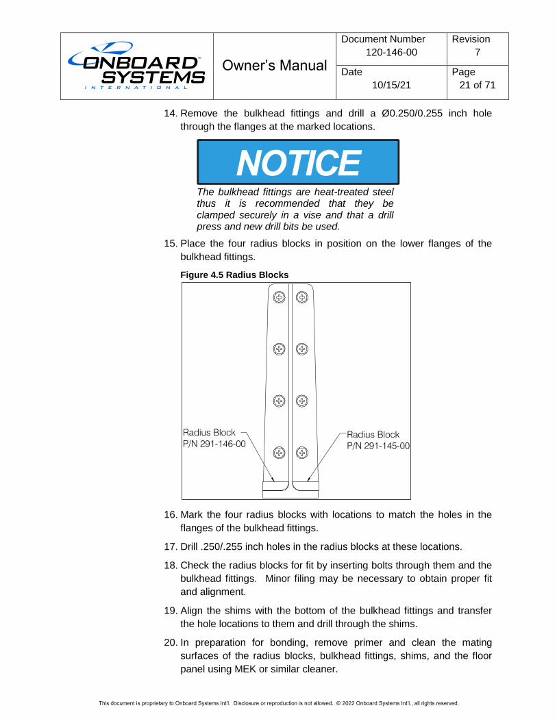
15. Place the four radius blocks in position on the lower flanges of the
bulkhead fittings.
Figure 4.5 Radius Blocks
16. Mark the four radius blocks with locations to match the holes in the
flanges of the bulkhead fittings.
17. Drill .250/.255 inch holes in the radius blocks at these locations.
18. Check the radius blocks for fit by inserting bolts through them and the
bulkhead fittings. Minor filing may be necessary to obtain proper fit
and alignment.
19. Align the shims with the bottom of the bulkhead fittings and transfer
the hole locations to them and drill through the shims.
20. In preparation for bonding, remove primer and clean the mating
surfaces of the radius blocks, bulkhead fittings, shims, and the floor
panel using MEK or similar cleaner.
Radius Block
P/N 291-145-00
Radius Block
P/N 291-146-00
Owner’s Manual
Document Number
120-146-00
Revision
7
Date
10/15/21
Page
22 of 71
This document is proprietary to Onboard Systems Int’l. Disclosure or reproduction is not allowed. © 2022 Onboard Systems Int’l., all rights reserved.
21. Align the holes and bond the shims to the floor panel with Magnobond
6398 adhesive (Bell P/N 299-947-100 Type II, Class 2).
22. Install the bulkhead fittings onto the seat bulkhead with the sixteen
screws and washers.
23. Apply the Magnobond 6398 adhesive and position the four radius
blocks onto the flanges of the bulkhead fittings. Temporarily install
pillow blocks (or work aid) until adhesive cures.
Instructions for installing the pillow blocks are in section 4.1.6.
If the pillow blocks are not to be installed at this time, plug the holes in the
belly with the supplied fasteners. At the forward pairs of holes (#10 size),
use screw P/N 510-580-00 and washer P/N 510-419-00. At the two aft
pairs of holes (1/4”) install screw P/N 510-653-00, washer P/N 510-648-
00 and nut P/N 510-227-00.
4.1.2 Hydraulic Release System Installation
The hydraulic release system is supplied dry. It is recommended that the
system be filled and bled on the bench before installing it on the
helicopter. Refer to section 4.5 for filling and bleeding instructions.
The supplied Release Lever Assembly with Plumbing (P/N 232-590-00) is
for installation on the cyclic on the left-hand side of the aircraft.
Installation of the backup release lever on the left side does not constitute approval for solo left seat operations.
If installation on the cyclic on the right-hand side is desired, a longer
plumbing assembly (P/N 232-604-00) is provided for this option.
Disassemble the plumbing from the release lever assembly and assemble
the longer plumbing assembly onto the release lever assembly referring
to Figure 4.6. Torque the banjo bolt to 10 ft-lbs.
Use best shop practices to keep foreign material out of the hydraulic system. FOD will plug orifices, damage seals and/or scratch sealing surfaces necessitating system rebuild.
Owner’s Manual
Document Number
120-146-00
Revision
7
Date
10/15/21
Page
23 of 71
This document is proprietary to Onboard Systems Int’l. Disclosure or reproduction is not allowed. © 2022 Onboard Systems Int’l., all rights reserved.
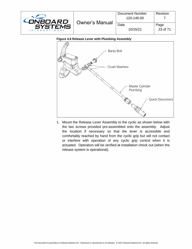
Figure 4.6 Release Lever with Plumbing Assembly
1. Mount the Release Lever Assembly to the cyclic as shown below with
the two screws provided pre-assembled onto the assembly. Adjust
the location if necessary so that the lever is accessible and
comfortably reached by hand from the cyclic grip but will not contact
or interfere with operation of any cyclic grip control when it is
actuated. Operation will be verified at installation check out (when the
release system is operational).
Quick Disconnect
Master Cylinder
Plumbing
Crush Washers
Banjo Bolt
Owner’s Manual
Document Number
120-146-00
Revision
7
Date
10/15/21
Page
24 of 71
This document is proprietary to Onboard Systems Int’l. Disclosure or reproduction is not allowed. © 2022 Onboard Systems Int’l., all rights reserved.
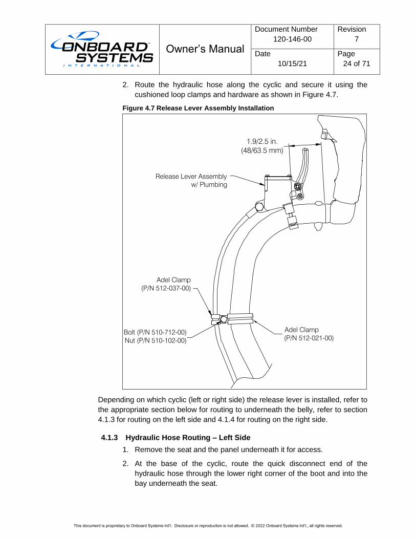
2. Route the hydraulic hose along the cyclic and secure it using the
cushioned loop clamps and hardware as shown in Figure 4.7.
Figure 4.7 Release Lever Assembly Installation
Depending on which cyclic (left or right side) the release lever is installed, refer to
the appropriate section below for routing to underneath the belly, refer to section
4.1.3 for routing on the left side and 4.1.4 for routing on the right side.
4.1.3 Hydraulic Hose Routing – Left Side
1. Remove the seat and the panel underneath it for access.
2. At the base of the cyclic, route the quick disconnect end of the
hydraulic hose through the lower right corner of the boot and into the
bay underneath the seat.
Bolt (P/N 510-712-00)
Nut (P/N 510-102-00)
Adel Clamp
(P/N 512-021-00)
Adel Clamp
(P/N 512-037-00)
1.9/2.5 in.
(48/63.5 mm)
Release Lever Assembly
w/ Plumbing
Owner’s Manual
Document Number
120-146-00
Revision
7
Date
10/15/21
Page
25 of 71
This document is proprietary to Onboard Systems Int’l. Disclosure or reproduction is not allowed. © 2022 Onboard Systems Int’l., all rights reserved.
3. After verifying clearance for the Doublers inside and outside of the
belly panel (see Caution note below), create a Ø.64/.68” (16.3/17.3
mm) hole in the honeycomb panel in a location shown in Figure 4.8
while observing the restrictions in BHT-ALL-SRM Section 3-9-3 to
account for optional equipment and any other aircraft modifications.
Before creating the hole in the belly panel verify that the Doubler will fit on the inside and the outside of the belly panel in the location shown. Check for inserts, antennae, optional equipment, etc on the outside.
4. Install a supplied Doubler P/N 235-221-00* around the hole on the
inside and on the outside using the supplied rivets (P/N 511-048-00).
The eight holes in the Doubler are pilot holes and are to be drilled out
to Ø.143/.146 at installation during match drilling of the panel skins.
Follow instructions in BHT-ALL-SRM section 3-9-3 for modifying the
panel and installing the Doublers and rivets.
* Optionally fabricate and install Doublers per BHT-ALL-SRM section
3-9-3.
5. At 1.63/1.75” (41.4/44.5 mm) outboard and .63/.75” (16.0/19.0 mm)
forward of the hole created above add a 10-32 insert (supplied P/N
511-035-00 or Bell P/N as allowed in the BHT-ALL-SRM) in the panel.
Follow the instructions in the BHT-ALL-SRM for modifying the panel.
6. Route the hose through the hole in the panel to underneath the
helicopter.
Provide enough slack up to the loop clamp on the cyclic to allow full movement of the cyclic and ensure the slack is not in excess to where it has potential to impede or interfere with flight control movement.
7. Place a cushioned loop clamp (P/N 512-037-00) over the hose and
secure it and a spacer (P/N 510-646-00) to the panel insert with screw
(P/N 510-965-00) and washer (P/N 510-419-00).
Owner’s Manual
Document Number
120-146-00
Revision
7
Date
10/15/21
Page
26 of 71
This document is proprietary to Onboard Systems Int’l. Disclosure or reproduction is not allowed. © 2022 Onboard Systems Int’l., all rights reserved.
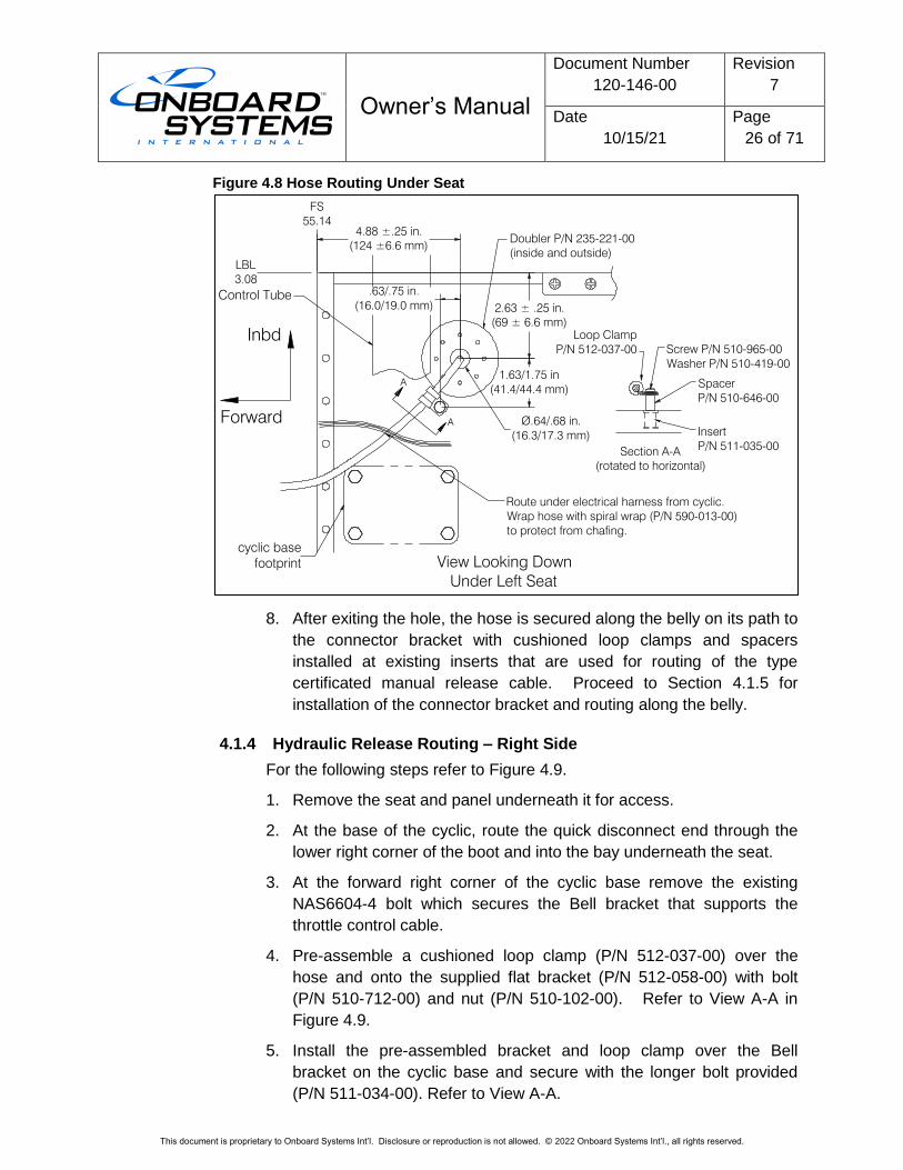
Figure 4.8 Hose Routing Under Seat
8. After exiting the hole, the hose is secured along the belly on its path to
the connector bracket with cushioned loop clamps and spacers
installed at existing inserts that are used for routing of the type
certificated manual release cable. Proceed to Section 4.1.5 for
installation of the connector bracket and routing along the belly.
4.1.4 Hydraulic Release Routing – Right Side
For the following steps refer to Figure 4.9.
1. Remove the seat and panel underneath it for access.
2. At the base of the cyclic, route the quick disconnect end through the
lower right corner of the boot and into the bay underneath the seat.
3. At the forward right corner of the cyclic base remove the existing
NAS6604-4 bolt which secures the Bell bracket that supports the
throttle control cable.
4. Pre-assemble a cushioned loop clamp (P/N 512-037-00) over the
hose and onto the supplied flat bracket (P/N 512-058-00) with bolt
(P/N 510-712-00) and nut (P/N 510-102-00). Refer to View A-A in
Figure 4.9.
5. Install the pre-assembled bracket and loop clamp over the Bell
bracket on the cyclic base and secure with the longer bolt provided
(P/N 511-034-00). Refer to View A-A.
Spacer
P/N 510-646-00
Screw P/N 510-965-00
Washer P/N 510-419-00
Loop Clamp
P/N 512-037-00
A
A
Section A-A
(rotated to horizontal)
View Looking Down
Under Left Seat
Forward
2.63 ± .25 in.
(69 ± 6.6 mm)
4.88 ±.25 in.
(124 ±6.6 mm)
Route under electrical harness from cyclic.
Wrap hose with spiral wrap (P/N 590-013-00)
to protect from chafing.
Inbd
Ø.64/.68 in.
(16.3/17.3 mm)Insert
P/N 511-035-00
Control Tube
LBL
3.08
Doubler P/N 235-221-00
(inside and outside)
FS
55.14
1.63/1.75 in
(41.4/44.4 mm)
.63/.75 in.
(16.0/19.0 mm)
cyclic base
footprint
Owner’s Manual
Document Number
120-146-00
Revision
7
Date
10/15/21
Page
27 of 71
This document is proprietary to Onboard Systems Int’l. Disclosure or reproduction is not allowed. © 2022 Onboard Systems Int’l., all rights reserved.
Provide enough slack up to the loop clamp on the cyclic to allow full movement of the cyclic and ensure the slack is not in excess to where it has potential to impede or interfere with flight control movement.
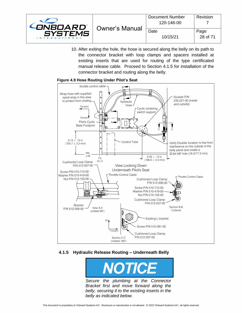
6. Route the hose along the throttle control cable and secure it to the
cable with a pair of loop clamps (P/N 512-037-00 around the hose and
P/N 512-007-00 around the throttle control cable) and bolt (P/N 510-
712-00) and nut (P/N 510-102-00) in two locations. Secure in two
locations with combination of hardware, refer to Figure 4.9 including
Section B-B.
7. On the back wall of the compartment underneath the seat, remove the
lower MS27039 screw at the existing L bracket which support the
throttle control cable assembly and secure the hose with a loop clamp
(P/N 512-037-00) at this location using the longer screw (P/N 510-
391-00) provided. Refer to Section C-C in Figure 4.9.
8. From this location the hose is to be routed through the belly panel.
Create a Ø.64/.68” (16.3/17.3 mm) hole in the honeycomb panel in a
location shown in Figure 4.9 while observing the restrictions in BHT-
ALL-SRM Section 3-9-3 to account for optional equipment and any
other aircraft modifications.
9. Install a Doubler P/N 235-221-00* around the hole on the inside and
the outside of the aircraft using the supplied rivets (P/N 511-048-00).
The eight holes in the Doubler are pilot holes and are to be drilled out
to Ø.143/.146 at installation during match drilling of the panel skin.
Follow instructions in BHT-ALL-SRM section 3-9-3 for modifying the
panel and installing the Doublers and rivets.
*Optionally fabricate and install Doublers per BHT-ALL-SRM section
3-9-3.
Before creating the hole in the belly panel verify that the Doubler will fit on the inside and the outside of the belly panel in the location shown. Check for inserts, antennae, any optional equipment, etc. on the outside.
Owner’s Manual
Document Number
120-146-00
Revision
7
Date
10/15/21
Page
28 of 71
This document is proprietary to Onboard Systems Int’l. Disclosure or reproduction is not allowed. © 2022 Onboard Systems Int’l., all rights reserved.
10. After exiting the hole, the hose is secured along the belly on its path to
the connector bracket with loop clamps and spacers installed at
existing inserts that are used for routing of the type certificated
manual release cable. Proceed to Section 4.1.5 for installation of the
connector bracket and routing along the belly.
Figure 4.9 Hose Routing Under Pilot’s Seat
4.1.5 Hydraulic Release Routing – Underneath Belly
Secure the plumbing at the Connector Bracket first and move forward along the belly, securing it to the existing inserts in the belly as indicated below.
Cyclic centering
switch support
hydraulic
hose
Section C-C
(rotated 180°)
Screw P/N 510-391-00
Forward
Up
Wrap hose with supplied
spiral wrap in this area
to protect from chafing
Existing L bracket
6.56 ± .13 in.
(166.6 ± 3.3 mm)
A
A
View A-A
(rotated 90°)
Throttle Control Cable
View Looking Down
Underneath Pilot's Seat
Bracket
P/N 512-058-00
Screw P/N 510-712-00
Washer P/N 510-419-00
Nut P/N 510-102-00
Cushioned Loop Clamp
P/N 512-037-00
Verify Doubler location is free from
interference on the outside of the
belly panel and create a
Ø.64/.68" hole (16.3/17.3 mm).
Forward
Inboard
6.13 ± .13 in.
(155.7 ± 3.3 mm)
FS
55.14
Doubler P/N
235-221-00 (inside
and outside)
Cushioned Loop Clamp
P/N 512-037-00
C C
B
B
Throttle Control Cable
Cushioned Loop Clamp
P/N 512-037-00
Cushioned Loop Clamp
P/N 512-006-00
Section B-B
2 places
Screw P/N 510-712-00
Washer P/N 510-419-00
Nut P/N 510-102-00
throttle control cable
RBL
5.08
Control Tube
Pilot's Cyclic
Base Footprint
Owner’s Manual
Document Number
120-146-00
Revision
7
Date
10/15/21
Page
29 of 71
This document is proprietary to Onboard Systems Int’l. Disclosure or reproduction is not allowed. © 2022 Onboard Systems Int’l., all rights reserved.
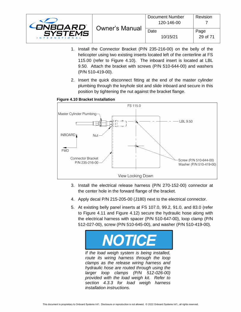
1. Install the Connector Bracket (P/N 235-216-00) on the belly of the
helicopter using two existing inserts located left of the centerline at FS
115.00 (refer to Figure 4.10). The inboard insert is located at LBL
9.50. Attach the bracket with screws (P/N 510-644-00) and washers
(P/N 510-419-00).
2. Insert the quick disconnect fitting at the end of the master cylinder
plumbing through the keyhole slot and slide inboard and secure in this
position by tightening the nut against the bracket flange.
Figure 4.10 Bracket Installation
3. Install the electrical release harness (P/N 270-152-00) connector at
the center hole in the forward flange of the bracket.
4. Apply decal P/N 215-205-00 (J180) next to the electrical connector.
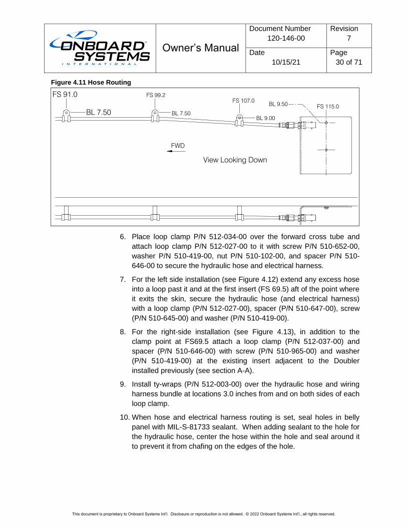
5. At existing belly panel inserts at FS 107.0, 99.2, 91.0, and 83.0 (refer
to Figure 4.11 and Figure 4.12) secure the hydraulic hose along with
the electrical harness with spacer (P/N 510-647-00), loop clamp (P/N
512-027-00), screw (P/N 510-645-00), and washer (P/N 510-419-00).
If the load weigh system is being installed, route its wiring harness through the loop clamps as the release wiring harness and hydraulic hose are routed through using the larger loop clamps (P/N 512-026-00) provided with the load weigh kit. Refer to section 4.3.3 for load weigh harness installation instructions.
FS 115.0
LBL 9.50
View Looking Down
FWD
Connector Bracket
P/N 235-216-00
Screw (P/N 510-644-00)
Washer (P/N 510-419-00)
Nut
Master Cylinder Plumbing
INBOARD
Owner’s Manual
Document Number
120-146-00
Revision
7
Date
10/15/21
Page
30 of 71
This document is proprietary to Onboard Systems Int’l. Disclosure or reproduction is not allowed. © 2022 Onboard Systems Int’l., all rights reserved.
Figure 4.11 Hose Routing
6. Place loop clamp P/N 512-034-00 over the forward cross tube and
attach loop clamp P/N 512-027-00 to it with screw P/N 510-652-00,
washer P/N 510-419-00, nut P/N 510-102-00, and spacer P/N 510-
646-00 to secure the hydraulic hose and electrical harness.
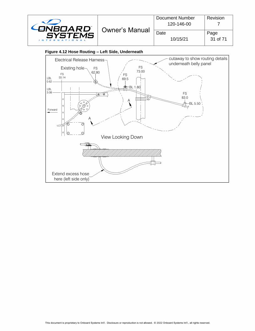
7. For the left side installation (see Figure 4.12) extend any excess hose
into a loop past it and at the first insert (FS 69.5) aft of the point where
it exits the skin, secure the hydraulic hose (and electrical harness)
with a loop clamp (P/N 512-027-00), spacer (P/N 510-647-00), screw
(P/N 510-645-00) and washer (P/N 510-419-00).
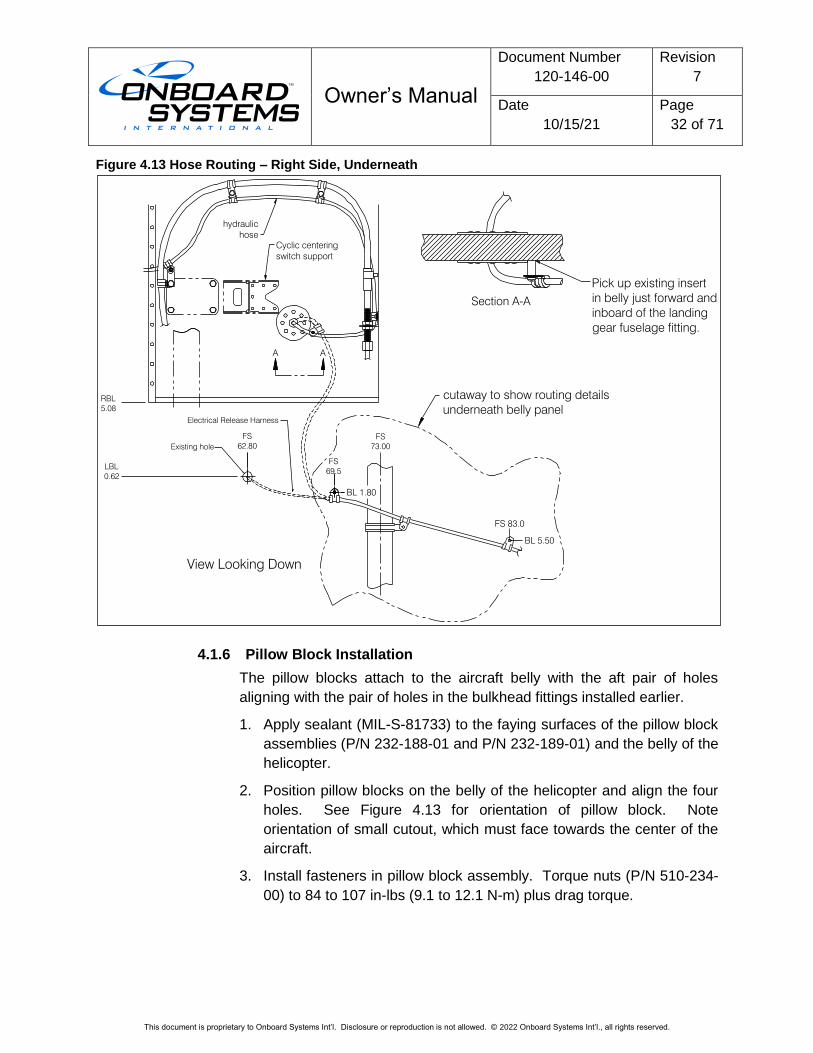
8. For the right-side installation (see Figure 4.13), in addition to the
clamp point at FS69.5 attach a loop clamp (P/N 512-037-00) and
spacer (P/N 510-646-00) with screw (P/N 510-965-00) and washer
(P/N 510-419-00) at the existing insert adjacent to the Doubler
installed previously (see section A-A).
9. Install ty-wraps (P/N 512-003-00) over the hydraulic hose and wiring
harness bundle at locations 3.0 inches from and on both sides of each
loop clamp.
10. When hose and electrical harness routing is set, seal holes in belly
panel with MIL-S-81733 sealant. When adding sealant to the hole for
the hydraulic hose, center the hose within the hole and seal around it
to prevent it from chafing on the edges of the hole.
BL 7.50
FS 99.2
BL 9.00
FS 107.0
FS 115.0BL 9.50
View Looking Down
FWD
BL 7.50
FS 91.0
Owner’s Manual
Document Number
120-146-00
Revision
7
Date
10/15/21
Page
31 of 71
This document is proprietary to Onboard Systems Int’l. Disclosure or reproduction is not allowed. © 2022 Onboard Systems Int’l., all rights reserved.
Figure 4.12 Hose Routing – Left Side, Underneath
View Looking Down
Electrical Release Harnesscutaway to show routing details
underneath belly panel
A
A
Forward
LBL
3.08
FS
55.14
FS
62.80
LBL
0.62
FS
69.5
BL 1.80
FS
73.00
BL 5.50
FS
83.0
Existing hole
Extend excess hose
here (left side only)
Owner’s Manual
Document Number
120-146-00
Revision
7
Date
10/15/21
Page
32 of 71
This document is proprietary to Onboard Systems Int’l. Disclosure or reproduction is not allowed. © 2022 Onboard Systems Int’l., all rights reserved.
Figure 4.13 Hose Routing – Right Side, Underneath
4.1.6 Pillow Block Installation
The pillow blocks attach to the aircraft belly with the aft pair of holes
aligning with the pair of holes in the bulkhead fittings installed earlier.
1. Apply sealant (MIL-S-81733) to the faying surfaces of the pillow block
assemblies (P/N 232-188-01 and P/N 232-189-01) and the belly of the
helicopter.
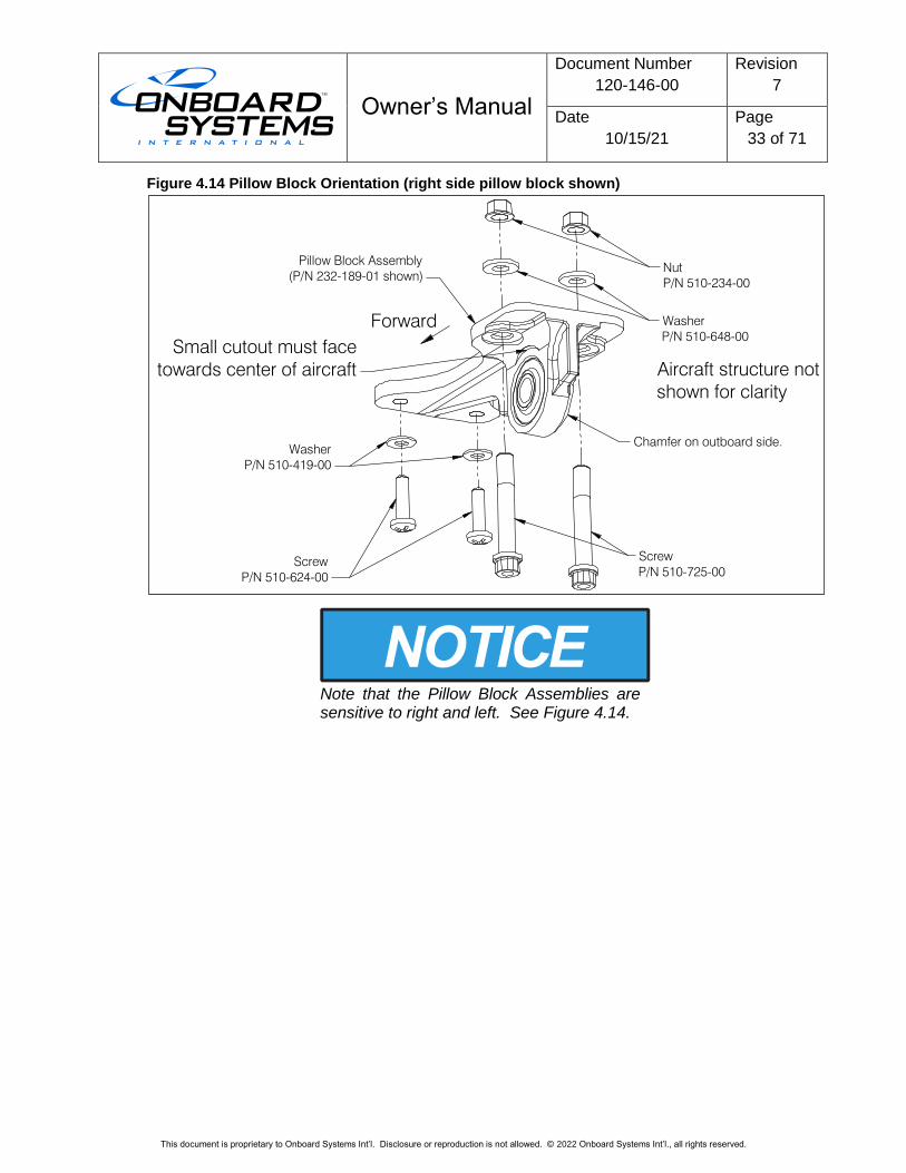
2. Position pillow blocks on the belly of the helicopter and align the four
holes. See Figure 4.13 for orientation of pillow block. Note
orientation of small cutout, which must face towards the center of the
aircraft.
3. Install fasteners in pillow block assembly. Torque nuts (P/N 510-234-
00) to 84 to 107 in-lbs (9.1 to 12.1 N-m) plus drag torque.
Cyclic centering
switch support
hydraulic
hose
A A
Section A-A
Pick up existing insert
in belly just forward and
inboard of the landing
gear fuselage fitting.
View Looking Down
FS
62.80
LBL
0.62
FS
69.5
BL 1.80
FS
73.00
BL 5.50
FS 83.0
Existing hole
Electrical Release Harness
RBL
5.08
cutaway to show routing details
underneath belly panel
Owner’s Manual
Document Number
120-146-00
Revision
7
Date
10/15/21
Page
33 of 71
This document is proprietary to Onboard Systems Int’l. Disclosure or reproduction is not allowed. © 2022 Onboard Systems Int’l., all rights reserved.
Figure 4.14 Pillow Block Orientation (right side pillow block shown)
Note that the Pillow Block Assemblies are sensitive to right and left. See Figure 4.14.
Small cutout must face
towards center of aircraft
Chamfer on outboard side.
Screw
P/N 510-725-00
Screw
P/N 510-624-00
Washer
P/N 510-648-00
Nut
P/N 510-234-00
Aircraft structure not
shown for clarity
Washer
P/N 510-419-00
Pillow Block Assembly
(P/N 232-189-01 shown)
Forward
Owner’s Manual
Document Number
120-146-00
Revision
7
Date
10/15/21
Page
34 of 71
This document is proprietary to Onboard Systems Int’l. Disclosure or reproduction is not allowed. © 2022 Onboard Systems Int’l., all rights reserved.
4.2 Removable Provisions Kit Installation
This section covers the installation of removable provisions kit P/Ns 200-395-00
and 200-395-10 and removable provisions w/ load weight kit P/Ns 200-416-00
and 200-416-10.
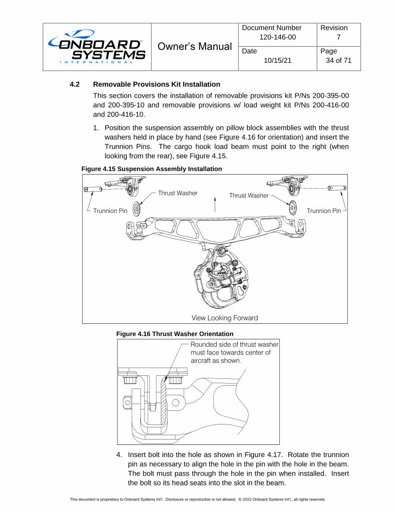
1. Position the suspension assembly on pillow block assemblies with the thrust
washers held in place by hand (see Figure 4.16 for orientation) and insert the
Trunnion Pins. The cargo hook load beam must point to the right (when
looking from the rear), see Figure 4.15.
Figure 4.15 Suspension Assembly Installation
Figure 4.16 Thrust Washer Orientation
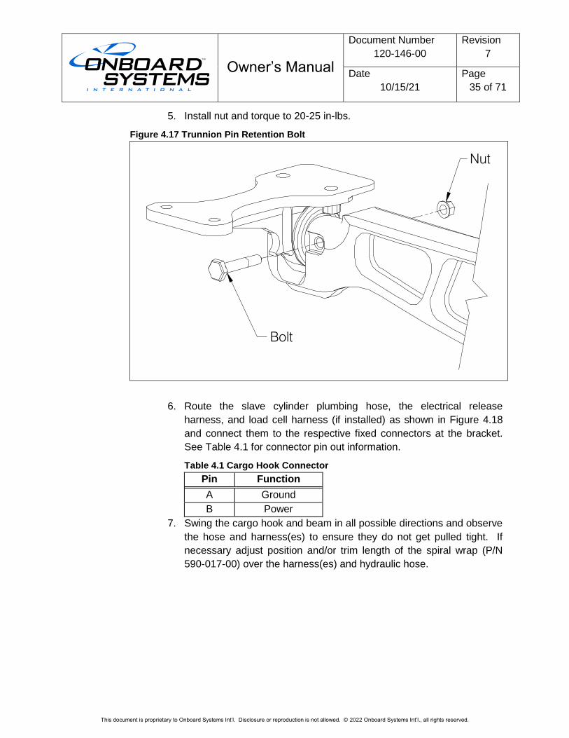
4. Insert bolt into the hole as shown in Figure 4.17. Rotate the trunnion
pin as necessary to align the hole in the pin with the hole in the beam.
The bolt must pass through the hole in the pin when installed. Insert
the bolt so its head seats into the slot in the beam.
Trunnion Pin Trunnion Pin
Thrust WasherThrust Washer
View Looking Forward
Rounded side of thrust washer
must face towards center of
aircraft as shown.
Owner’s Manual
Document Number
120-146-00
Revision
7
Date
10/15/21
Page
35 of 71
This document is proprietary to Onboard Systems Int’l. Disclosure or reproduction is not allowed. © 2022 Onboard Systems Int’l., all rights reserved.
5. Install nut and torque to 20-25 in-lbs.
Figure 4.17 Trunnion Pin Retention Bolt
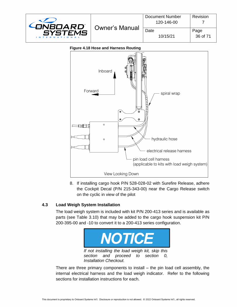
6. Route the slave cylinder plumbing hose, the electrical release
harness, and load cell harness (if installed) as shown in Figure 4.18
and connect them to the respective fixed connectors at the bracket.
See Table 4.1 for connector pin out information.
Table 4.1 Cargo Hook Connector
Pin Function
A Ground
B Power
7. Swing the cargo hook and beam in all possible directions and observe
the hose and harness(es) to ensure they do not get pulled tight. If
necessary adjust position and/or trim length of the spiral wrap (P/N
590-017-00) over the harness(es) and hydraulic hose.
Nut
Bolt
Owner’s Manual
Document Number
120-146-00
Revision
7
Date
10/15/21
Page
36 of 71
This document is proprietary to Onboard Systems Int’l. Disclosure or reproduction is not allowed. © 2022 Onboard Systems Int’l., all rights reserved.
Figure 4.18 Hose and Harness Routing
8. If installing cargo hook P/N 528-028-02 with Surefire Release, adhere
the Cockpit Decal (P/N 215-343-00) near the Cargo Release switch
on the cyclic in view of the pilot
4.3 Load Weigh System Installation
The load weigh system is included with kit P/N 200-413 series and is available as
parts (see Table 3.10) that may be added to the cargo hook suspension kit P/N
200-395-00 and -10 to convert it to a 200-413 series configuration.
If not installing the load weigh kit, skip this section and proceed to section 0, Installation Checkout.
There are three primary components to install – the pin load cell assembly, the
internal electrical harness and the load weigh indicator. Refer to the following
sections for installation instructions for each.
hydraulic hose
spiral wrap
pin load cell harness
(applicable to kits with load weigh system)
electrical release harness
Forward
Inboard
View Looking Down
Owner’s Manual
Document Number
120-146-00
Revision
7
Date
10/15/21
Page
37 of 71
This document is proprietary to Onboard Systems Int’l. Disclosure or reproduction is not allowed. © 2022 Onboard Systems Int’l., all rights reserved.
4.3.1 Pin Load Cell Installation
The pin load cell replaces the cargo hook attach bolt in the suspension
assembly. It is installed per the following instructions.
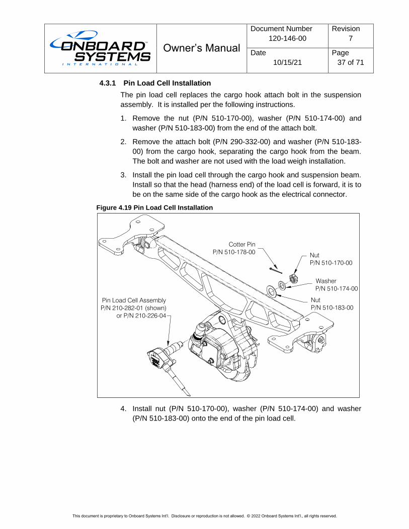
1. Remove the nut (P/N 510-170-00), washer (P/N 510-174-00) and
washer (P/N 510-183-00) from the end of the attach bolt.
2. Remove the attach bolt (P/N 290-332-00) and washer (P/N 510-183-
00) from the cargo hook, separating the cargo hook from the beam.
The bolt and washer are not used with the load weigh installation.
3. Install the pin load cell through the cargo hook and suspension beam.
Install so that the head (harness end) of the load cell is forward, it is to
be on the same side of the cargo hook as the electrical connector.
Figure 4.19 Pin Load Cell Installation
4. Install nut (P/N 510-170-00), washer (P/N 510-174-00) and washer
(P/N 510-183-00) onto the end of the pin load cell.
Pin Load Cell Assembly
P/N 210-282-01 (shown)
or P/N 210-226-04
Nut
P/N 510-183-00
Nut
P/N 510-170-00
Washer
P/N 510-174-00
Cotter Pin
P/N 510-178-00
Owner’s Manual
Document Number
120-146-00
Revision
7
Date
10/15/21
Page
38 of 71
This document is proprietary to Onboard Systems Int’l. Disclosure or reproduction is not allowed. © 2022 Onboard Systems Int’l., all rights reserved.
5. Tighten nut on pin load cell until fully seated, finger tight only. Back
off nut to previous castellation, if needed, when aligning cotter pin for
installation. Install and secure cotter pin.
Do not tighten nut on pin load cell more than finger tight. Over-tightening will damage load cell.
4.3.2 Load Indicator Installation
The C-39 indicator (P/N 210-095-00 (28V backlight) or P/N 210-095-02
(5V backlight)) or C-40 Indicator* (P/N 210-293-00) can be mounted in a
standard 2 ¼” instrument panel hole. It should be mounted in a position
that is convenient, accessible and visible to the pilot. A consideration for
the C-40 model mounting location is access to the USB port on the back,
this USB port is intended for the firmware updates.
The C-40 Indicator kit includes four screws (P/N 511-211-00, MS35214-
26) for mounting it, depending on the thickness of the mounting panel use
another length MS35214 screw as needed.
*The C-40 Indicator is directly interchangeable with the C-39 Indicator
(without changing the internal harness) except it does not support the
optional components (Analog Meter, C-30 Data Recorder).
4.3.3 Load Weigh Internal Harness Installation for the C-39
If installing the C-40 Indicator (P/N 210-293-00) skip to section 4.3.4.
The primary leg of the load weigh harness (P/N 270-153-00) is routed
from the C-39 indicator to the bracket at the belly of the helicopter. Install
the connector at the bracket with screws (P/N 510-481-00), washers (P/N
510-062-00), and nuts (P/N 510-029-00). Route the harness from the pin
load cell as shown in Figure 4.19 and connect to this fixed connector.
Two other legs are routed from the indicator to pick up power and lights
and the fourth leg features a DATA connector, which may be used for
optional equipment such as an analog meter or data recorder (reference
Figure 4.20). Route the wires with existing wire harnesses, securing
them with ty-wraps (P/N 512-001-00).
Owner’s Manual
Document Number
120-146-00
Revision
7
Date
10/15/21
Page
39 of 71
This document is proprietary to Onboard Systems Int’l. Disclosure or reproduction is not allowed. © 2022 Onboard Systems Int’l., all rights reserved.
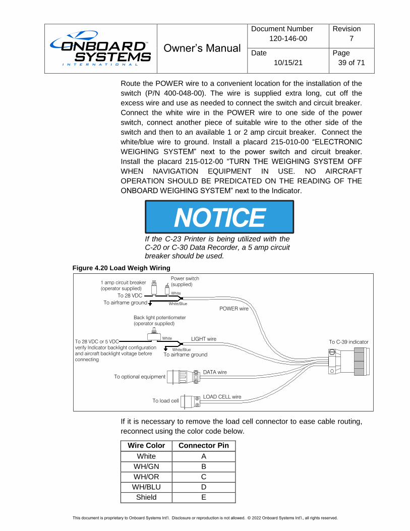
Route the POWER wire to a convenient location for the installation of the
switch (P/N 400-048-00). The wire is supplied extra long, cut off the
excess wire and use as needed to connect the switch and circuit breaker.
Connect the white wire in the POWER wire to one side of the power
switch, connect another piece of suitable wire to the other side of the
switch and then to an available 1 or 2 amp circuit breaker. Connect the
white/blue wire to ground. Install a placard 215-010-00 “ELECTRONIC
WEIGHING SYSTEM” next to the power switch and circuit breaker.
Install the placard 215-012-00 “TURN THE WEIGHING SYSTEM OFF
WHEN NAVIGATION EQUIPMENT IN USE. NO AIRCRAFT
OPERATION SHOULD BE PREDICATED ON THE READING OF THE
ONBOARD WEIGHING SYSTEM” next to the Indicator.
If the C-23 Printer is being utilized with the C-20 or C-30 Data Recorder, a 5 amp circuit breaker should be used.
Figure 4.20 Load Weigh Wiring
If it is necessary to remove the load cell connector to ease cable routing,
reconnect using the color code below.
Wire Color Connector Pin
White A
WH/GN B
WH/OR C
WH/BLU D
Shield E
To 28 VDC
To airframe ground White/Blue
White
POWER wire
LIGHT wire
White/Blue
White
DATA wire
1 amp circuit breaker
(operator supplied)
Power switch
(supplied)
Back light potentiometer
(operator supplied)
To airframe ground
To C-39 indicator
To optional equipment
To load cell
LOAD CELL wire
To 28 VDC or 5 VDC
verify Indicator backlight configuration
and aircraft backlight voltage before
connecting
Owner’s Manual
Document Number
120-146-00
Revision
7
Date
10/15/21
Page
40 of 71
This document is proprietary to Onboard Systems Int’l. Disclosure or reproduction is not allowed. © 2022 Onboard Systems Int’l., all rights reserved.
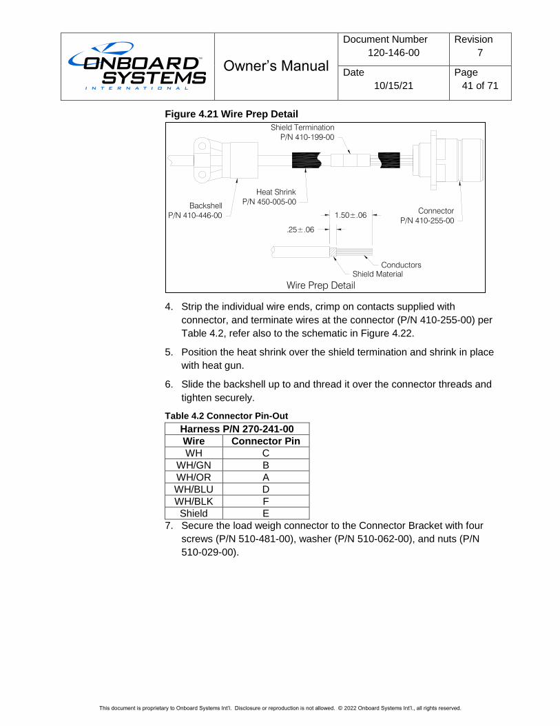
4.3.4 Load Weigh Internal Harness Installation for the C-40
The internal harness (P/N 270-241-00) provided with the C-40 indicator
has an additional wire (TEDS DATA, refer to Figure 4.22) which will be
used on future updates to the C-40 indicator otherwise it’s
interchangeable with the harness for the C-39 indicator. Install it per the
following.
1. Connect the wire harness connector (labeled C-40) to the Indicator.
2. Route the wire labeled POWER to the circuit breaker panel and install
a 1 or 2-amp circuit breaker (not supplied) and connect this wire to it.
Apply the supplied placard P/N 215-417-00 adjacent to the circuit
breaker.
3. Wire numbers BACKLIGHT SIG and BACKLIGHT COM are for the C-
40 Indicator’s backlight control voltage. Connect wire BACKLIGHT
SIG to the instrument panel lighting circuit and wire BACKLIGHT
COM to aircraft ground.
The Indicator does function normally without the Backlight Control Voltage wired, but will just not dim with other instruments. Full brightness of the Indicator is overridden by the aircraft dimming control voltage (if connected).
1. Wire AIRCRAFT GND is to be connected to a suitable aircraft ground
per AC43.13.
2. Route the “LOAD CELL” leg of the harness to the hole in the belly
under the center console (which the original manual release cable
was routed through) and route underneath back to the connector
bracket.
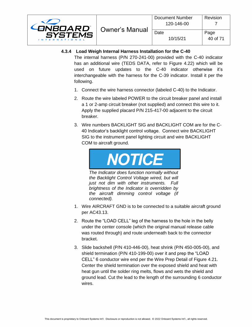
3. Slide backshell (P/N 410-446-00), heat shrink (P/N 450-005-00), and
shield termination (P/N 410-199-00) over it and prep the “LOAD
CELL” 6 conductor wire end per the Wire Prep Detail of Figure 4.21.
Center the shield termination over the exposed shield and heat with
heat gun until the solder ring melts, flows and wets the shield and
ground lead. Cut the lead to the length of the surrounding 6 conductor
wires.
Owner’s Manual
Document Number
120-146-00
Revision
7
Date
10/15/21
Page
41 of 71
This document is proprietary to Onboard Systems Int’l. Disclosure or reproduction is not allowed. © 2022 Onboard Systems Int’l., all rights reserved.
Figure 4.21 Wire Prep Detail
4. Strip the individual wire ends, crimp on contacts supplied with
connector, and terminate wires at the connector (P/N 410-255-00) per
Table 4.2, refer also to the schematic in Figure 4.22.
5. Position the heat shrink over the shield termination and shrink in place
with heat gun.
6. Slide the backshell up to and thread it over the connector threads and
tighten securely.
Table 4.2 Connector Pin-Out
Harness P/N 270-241-00
Wire Connector Pin
WH C
WH/GN B
WH/OR A
WH/BLU D
WH/BLK F
Shield E
7. Secure the load weigh connector to the Connector Bracket with four
screws (P/N 510-481-00), washer (P/N 510-062-00), and nuts (P/N
510-029-00).
.25±.06
1.50±.06
Shield Material
Conductors
Connector
P/N 410-255-00
Heat Shrink
P/N 450-005-00Backshell
P/N 410-446-00
Owner’s Manual
Document Number
120-146-00
Revision
7
Date
10/15/21
Page
42 of 71
This document is proprietary to Onboard Systems Int’l. Disclosure or reproduction is not allowed. © 2022 Onboard Systems Int’l., all rights reserved.
Figure 4.22 Load Weigh Internal Harness Wiring Schematic (C-40)
Load Cell Excitation Return
Load Cell Excitation
Load Cell Signal
Load Cell Signal Return
B
F
E
A
D
C
Load Cell
WH/BLKTEDS Data
POWER
Backlight Signal
1 A
WH/GN
WH/BL
WH/OR
WH
Power
J
R
M
N
P
K
L
C
F
G
H
D
E
C-40
A
B
Owner’s Manual
Document Number
120-146-00
Revision
7
Date
10/15/21
Page
43 of 71
This document is proprietary to Onboard Systems Int’l. Disclosure or reproduction is not allowed. © 2022 Onboard Systems Int’l., all rights reserved.
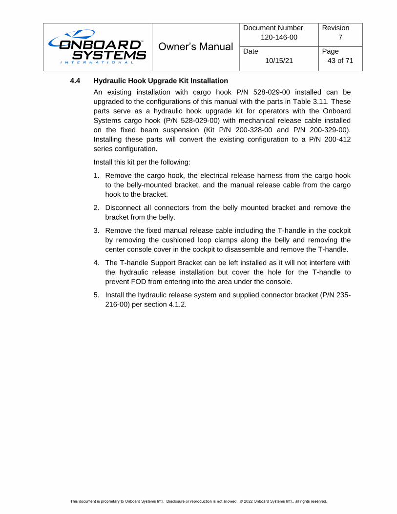
4.4 Hydraulic Hook Upgrade Kit Installation
An existing installation with cargo hook P/N 528-029-00 installed can be
upgraded to the configurations of this manual with the parts in Table 3.11. These
parts serve as a hydraulic hook upgrade kit for operators with the Onboard
Systems cargo hook (P/N 528-029-00) with mechanical release cable installed
on the fixed beam suspension (Kit P/N 200-328-00 and P/N 200-329-00).
Installing these parts will convert the existing configuration to a P/N 200-412
series configuration.
Install this kit per the following:
1. Remove the cargo hook, the electrical release harness from the cargo hook
to the belly-mounted bracket, and the manual release cable from the cargo
hook to the bracket.
2. Disconnect all connectors from the belly mounted bracket and remove the
bracket from the belly.
3. Remove the fixed manual release cable including the T-handle in the cockpit
by removing the cushioned loop clamps along the belly and removing the
center console cover in the cockpit to disassemble and remove the T-handle.
4. The T-handle Support Bracket can be left installed as it will not interfere with
the hydraulic release installation but cover the hole for the T-handle to
prevent FOD from entering into the area under the console.
5. Install the hydraulic release system and supplied connector bracket (P/N 235-
216-00) per section 4.1.2.
Owner’s Manual
Document Number
120-146-00
Revision
7
Date
10/15/21
Page
44 of 71
This document is proprietary to Onboard Systems Int’l. Disclosure or reproduction is not allowed. © 2022 Onboard Systems Int’l., all rights reserved.
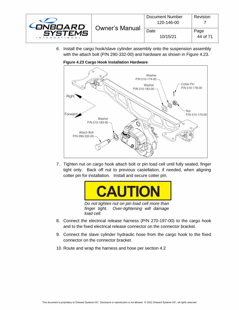
6. Install the cargo hook/slave cylinder assembly onto the suspension assembly
with the attach bolt (P/N 290-332-00) and hardware as shown in Figure 4.23.
Figure 4.23 Cargo Hook Installation Hardware
7. Tighten nut on cargo hook attach bolt or pin load cell until fully seated, finger
tight only. Back off nut to previous castellation, if needed, when aligning
cotter pin for installation. Install and secure cotter pin.
Do not tighten nut on pin load cell more than finger tight. Over-tightening will damage load cell.
8. Connect the electrical release harness (P/N 270-197-00) to the cargo hook
and to the fixed electrical release connector on the connector bracket.
9. Connect the slave cylinder hydraulic hose from the cargo hook to the fixed
connector on the connector bracket.
10. Route and wrap the harness and hose per section 4.2
Washer
P/N 510-183-00
Washer
P/N 510-174-00
Nut
P/N 510-170-00
Cotter Pin
P/N 510-178-00
Washer
P/N 510-183-00
Attach Bolt
P/N 290-332-00
Right
Forward
Owner’s Manual
Document Number
120-146-00
Revision
7
Date
10/15/21
Page
45 of 71
This document is proprietary to Onboard Systems Int’l. Disclosure or reproduction is not allowed. © 2022 Onboard Systems Int’l., all rights reserved.
4.5 Hydraulic System Bleed Procedure
If there is a need to fill and/or bleed the system, follow the procedures listed
below. Proper bleeding is critical to the operation of the hydraulic release system.
An improperly bled system will not release the cargo hook mechanism. If you
need to remove and repair any items in the hydraulic system, refer to 123-040-
00, Instruction for Continued Airworthiness.
Filling and bleeding the hydraulic release system is most easily accomplished on
the bench, prior to installation on the aircraft. This process may also be
accomplished after the system is installed. Filling and bleeding requires two
persons, one to inject hydraulic fluid through the system and the other to observe
the reservoir.
MIL-PRF-5606 and MIL-PRF-87257 fluids are both compatible with the hydraulic system. These fluids are interchangeable and miscible.
Bleeding procedure:
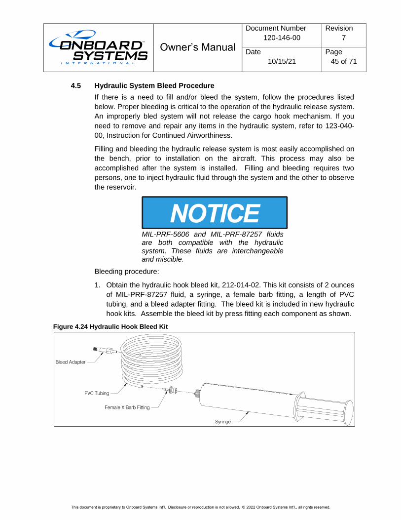
1. Obtain the hydraulic hook bleed kit, 212-014-02. This kit consists of 2 ounces
of MIL-PRF-87257 fluid, a syringe, a female barb fitting, a length of PVC
tubing, and a bleed adapter fitting. The bleed kit is included in new hydraulic
hook kits. Assemble the bleed kit by press fitting each component as shown.
Figure 4.24 Hydraulic Hook Bleed Kit
Bleed Adapter
PVC Tubing
Female X Barb Fitting
Syringe
Owner’s Manual
Document Number
120-146-00
Revision
7
Date
10/15/21
Page
46 of 71
This document is proprietary to Onboard Systems Int’l. Disclosure or reproduction is not allowed. © 2022 Onboard Systems Int’l., all rights reserved.
2. If the system is already installed on the aircraft, place an absorbent towel
under the master cylinder. If the master cylinder is not installed on the
aircraft, lightly clamp the master cylinder in a vise to hold it in a vertical
position and position the slave cylinder so that its level is below that of the
master cylinder.
Use best shop practices to keep foreign material out of the hydraulic system. FOD will plug orifices, damage seals and/or scratch sealing surfaces necessitating system rebuild. Use only clean hydraulic fluid from sealed containers.
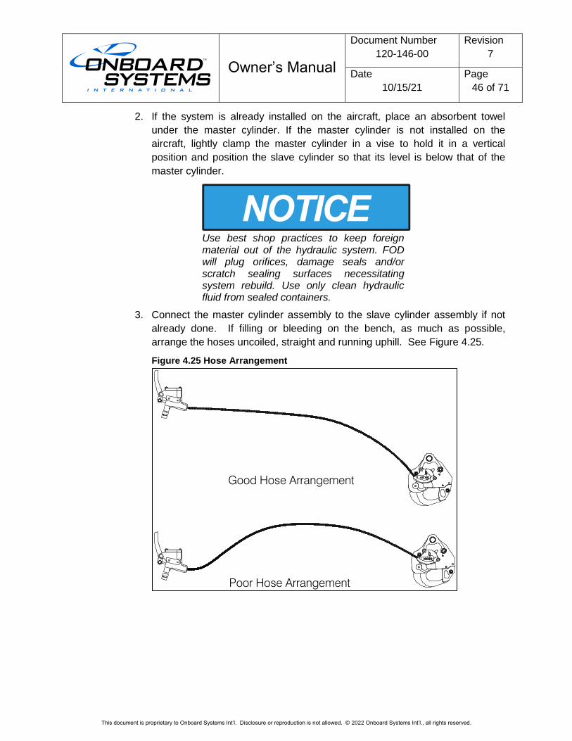
3. Connect the master cylinder assembly to the slave cylinder assembly if not
already done. If filling or bleeding on the bench, as much as possible,
arrange the hoses uncoiled, straight and running uphill. See Figure 4.25.
Figure 4.25 Hose Arrangement
Good Hose Arrangement
Poor Hose Arrangement
Owner’s Manual
Document Number
120-146-00
Revision
7
Date
10/15/21
Page
47 of 71
This document is proprietary to Onboard Systems Int’l. Disclosure or reproduction is not allowed. © 2022 Onboard Systems Int’l., all rights reserved.
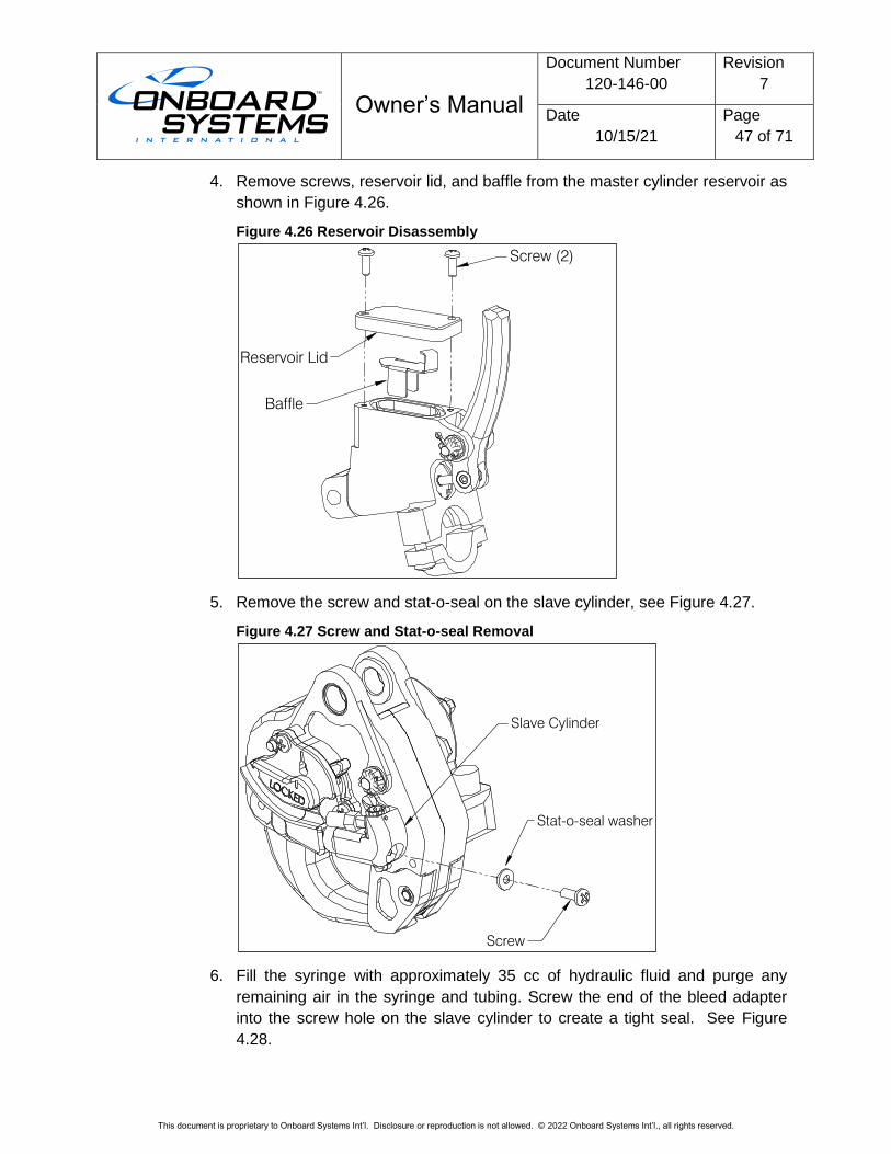
4. Remove screws, reservoir lid, and baffle from the master cylinder reservoir as
shown in Figure 4.26.
Figure 4.26 Reservoir Disassembly
5. Remove the screw and stat-o-seal on the slave cylinder, see Figure 4.27.
Figure 4.27 Screw and Stat-o-seal Removal
6. Fill the syringe with approximately 35 cc of hydraulic fluid and purge any
remaining air in the syringe and tubing. Screw the end of the bleed adapter
into the screw hole on the slave cylinder to create a tight seal. See Figure
4.28.
Screw (2)
Reservoir Lid
Baffle
Stat-o-seal washer
Screw
Slave Cylinder
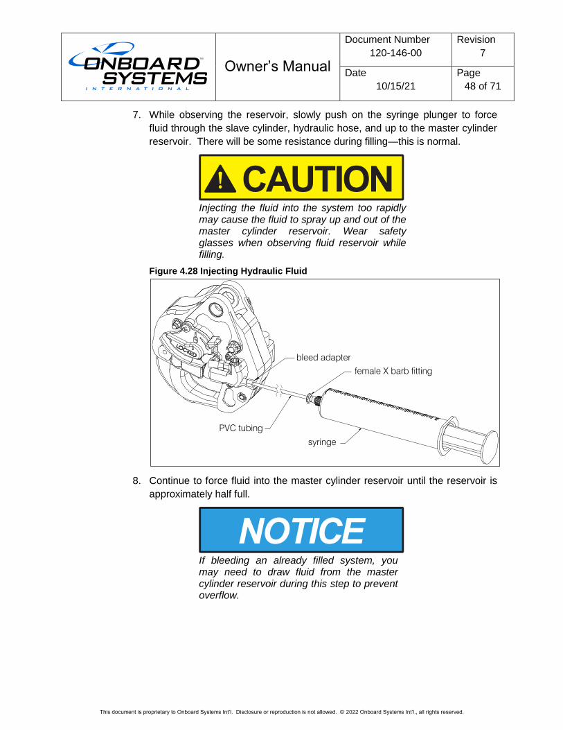
Owner’s Manual
Document Number
120-146-00
Revision
7
Date
10/15/21
Page
48 of 71
This document is proprietary to Onboard Systems Int’l. Disclosure or reproduction is not allowed. © 2022 Onboard Systems Int’l., all rights reserved.
7. While observing the reservoir, slowly push on the syringe plunger to force
fluid through the slave cylinder, hydraulic hose, and up to the master cylinder
reservoir. There will be some resistance during filling—this is normal.
Injecting the fluid into the system too rapidly may cause the fluid to spray up and out of the master cylinder reservoir. Wear safety glasses when observing fluid reservoir while filling.
Figure 4.28 Injecting Hydraulic Fluid
8. Continue to force fluid into the master cylinder reservoir until the reservoir is
approximately half full.
If bleeding an already filled system, you may need to draw fluid from the master cylinder reservoir during this step to prevent overflow.
bleed adapter
female X barb fitting
syringe
PVC tubing
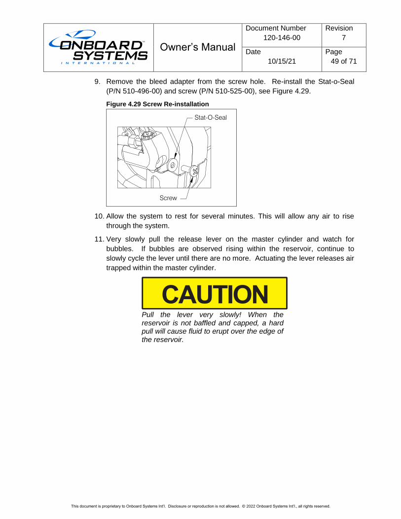
Owner’s Manual
Document Number
120-146-00
Revision
7
Date
10/15/21
Page
49 of 71
This document is proprietary to Onboard Systems Int’l. Disclosure or reproduction is not allowed. © 2022 Onboard Systems Int’l., all rights reserved.
9. Remove the bleed adapter from the screw hole. Re-install the Stat-o-Seal
(P/N 510-496-00) and screw (P/N 510-525-00), see Figure 4.29.
Figure 4.29 Screw Re-installation
Stat-O-Seal
Screw
10. Allow the system to rest for several minutes. This will allow any air to rise
through the system.
11. Very slowly pull the release lever on the master cylinder and watch for
bubbles. If bubbles are observed rising within the reservoir, continue to
slowly cycle the lever until there are no more. Actuating the lever releases air
trapped within the master cylinder.
Pull the lever very slowly! When the reservoir is not baffled and capped, a hard pull will cause fluid to erupt over the edge of the reservoir.
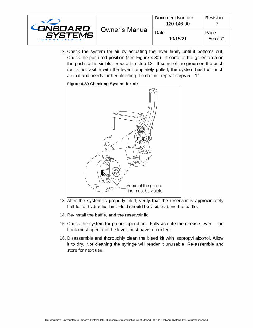
Owner’s Manual
Document Number
120-146-00
Revision
7
Date
10/15/21
Page
50 of 71
This document is proprietary to Onboard Systems Int’l. Disclosure or reproduction is not allowed. © 2022 Onboard Systems Int’l., all rights reserved.
12. Check the system for air by actuating the lever firmly until it bottoms out.
Check the push rod position (see Figure 4.30). If some of the green area on
the push rod is visible, proceed to step 13. If some of the green on the push
rod is not visible with the lever completely pulled, the system has too much
air in it and needs further bleeding. To do this, repeat steps 5 – 11.
Figure 4.30 Checking System for Air
13. After the system is properly bled, verify that the reservoir is approximately
half full of hydraulic fluid. Fluid should be visible above the baffle.
14. Re-install the baffle, and the reservoir lid.
15. Check the system for proper operation. Fully actuate the release lever. The
hook must open and the lever must have a firm feel.
16. Disassemble and thoroughly clean the bleed kit with isopropyl alcohol. Allow
it to dry. Not cleaning the syringe will render it unusable. Re-assemble and
store for next use.
Some of the green
ring must be visible.
Owner’s Manual
Document Number
120-146-00
Revision
7
Date
10/15/21
Page
51 of 71
This document is proprietary to Onboard Systems Int’l. Disclosure or reproduction is not allowed. © 2022 Onboard Systems Int’l., all rights reserved.
4.6 Installation Check-Out
After installation of the system, perform the following functional checks.
1. Swing the installed cargo hook and suspension to their full extremes to
ensure that the hydraulic hose and the electrical harnesses have enough
slack to allow full range of motion without straining or damaging the hose or
harnesses. The hose or harnesses must not be the stops that prevent the
cargo hook and suspension beam from pivoting freely in all directions.
2. With no load on the cargo hook load beam, pull the release lever on the
cyclic, the cargo hook should release. Reset the cargo hook load beam.
3. Provide power to the electrical release system with no load on the load beam.
Electrical release system operation depends on the cargo hook P/N installed.
The following instructions are applicable to cargo hook P/N 528-028-02 which
is equipped with Surefire electrical release.
• Very briefly press the Cargo Release switch, the cargo hook should
not actuate and the load beam should remain closed.
• Press and hold the Cargo Release switch for a few seconds, the load
beam should fall to the open position and the cargo hook solenoid
should continue to cycle repeatedly.
The following instructions are applicable to cargo hook P/N 528-028-00.
• Press and release the Cargo Release switch on the cyclic, the load
beam should immediately fall to the open position.
4. Push up on the load beam and verify that it latches and the hook lock
indicator is aligned with the engraved line on the cover.
5. Perform an EMI ground test per AC 43.13-1b section 11-107. For equipment
that can only be checked in flight an EMI flight test may be required.
The cargo hook is of a class of equipment not known to have a high potential for interference. This class of equipment does not require special EMI installation testing (i.e. FADEC) as required in paragraphs 7 and 8 of FAA policy memorandum ASW-2001-01.
Owner’s Manual
Document Number
120-146-00
Revision
7
Date
10/15/21
Page
52 of 71
This document is proprietary to Onboard Systems Int’l. Disclosure or reproduction is not allowed. © 2022 Onboard Systems Int’l., all rights reserved.
If Load Weigh System with the C-39 Indicator was installed, perform the
following:
6. Power on the Indicator and allow it to warm up for 5 minutes (with no load on
the hook). Press both Indicator buttons at the same time to go to the Setup
Mode. Scroll through the menu until the symbol “0 in” is displayed, then press
the right button. Remove any weight that is not to be zeroed out and press
either button to complete the procedure.
If the C-40 Indicator was installed, refer to steps 7 and 8 below.
7. On startup the C-40 Indicator will display an information screen while
performing a brief self-diagnostic routine and then display the load screen.
Set the Installation Zero for the installation per the instructions contained in
C-40 Indicator’s Owner’s Manual 120-152-00.
8. In the Settings menu adjust units (lb or kg), brightness of the display,
maximum load, and other settings as preferred (refer to the C-40 Indicator
Owner’s Manual 120-152-00 for detailed instructions). One setting that must
be set properly to function is the backlight voltage. If the wire for the backlight
was connected the backlight voltage must be set to the aircraft circuit voltage
(5 VDC or 28 VDC).
4.7 Paper Work
In the US, fill in FAA form 337 for the initial installation. This procedure may vary
in different countries. Make the appropriate aircraft log book entry. Place the
Rotorcraft Flight Manual Supplement in the aircraft Flight Manual.
Owner’s Manual
Document Number
120-146-00
Revision
7
Date
10/15/21
Page
53 of 71
This document is proprietary to Onboard Systems Int’l. Disclosure or reproduction is not allowed. © 2022 Onboard Systems Int’l., all rights reserved.
5.0 Operation Instructions
5.1 Operating Procedures
Refer to Owner’s Manual 120-039-00 for operation instructions for the C-39 load
weigh indicator and Owner’s Manual 120-152-00 for operations instructions for
the C-40 load weigh indicator.
Prior to a flight involving external load operations perform the following:
1. Provide power to the electrical release system. Electrical release system
operation depends on the cargo hook P/N installed. The following instructions
are applicable to cargo hook P/N 528-028-02 which is equipped with Surefire
electrical release. With no load on the cargo hook perform the following.
• Very briefly press the Cargo Release switch, the cargo hook should not
actuate and the load beam should remain closed.
• Press and hold the Cargo Release switch for a few seconds, the load
beam should fall to the open position and the cargo hook solenoid should
continue to cycle repeatedly.
• Push up on the load beam and verify that it latches and the hook lock
indicator is aligned with the engraved line on the manual release cover
(see Figure 5.1).
The following instructions are applicable to cargo hook P/N 528-028-00.
• Press and release the Cargo Release switch on the cyclic, the load beam
should fall to the open position.
• Push up on the load beam and verify that it latches and the hook lock
indicator is aligned with the engraved line on the manual release cover.
The release solenoid is intended to be energized only intermittently. Depressing the release switch continuously in excess of 20 seconds will cause the release solenoid to overheat, possibly causing permanent damage.
2. Pull the backup release lever located on the cyclic to test the cargo hook’s
hydraulic release system. The system should operate smoothly and the
Cargo Hook must release. Reset the cargo hook by hand after release. Verify
that the hook lock indicator on the side of the hook returns to the fully locked
position.
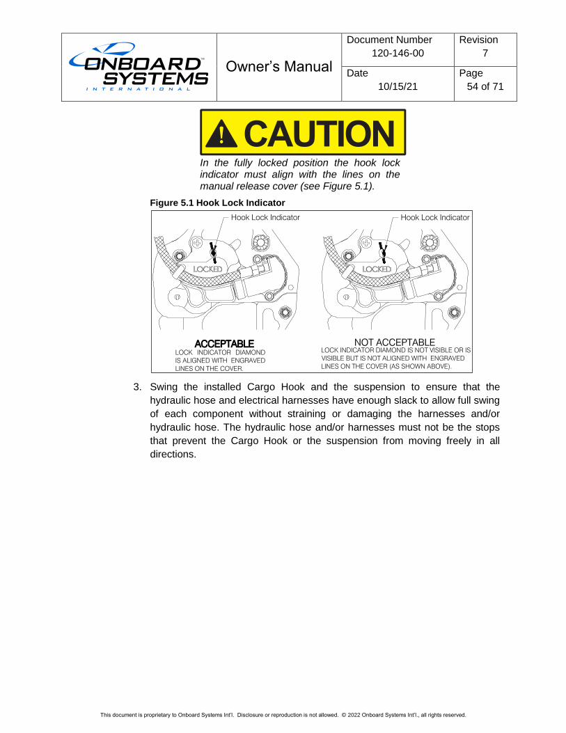
Owner’s Manual
Document Number
120-146-00
Revision
7
Date
10/15/21
Page
54 of 71
This document is proprietary to Onboard Systems Int’l. Disclosure or reproduction is not allowed. © 2022 Onboard Systems Int’l., all rights reserved.
In the fully locked position the hook lock indicator must align with the lines on the manual release cover (see Figure 5.1).
Figure 5.1 Hook Lock Indicator
3. Swing the installed Cargo Hook and the suspension to ensure that the
hydraulic hose and electrical harnesses have enough slack to allow full swing
of each component without straining or damaging the harnesses and/or
hydraulic hose. The hydraulic hose and/or harnesses must not be the stops
that prevent the Cargo Hook or the suspension from moving freely in all
directions.
ACCEPTABLE
Hook Lock Indicator Hook Lock Indicator
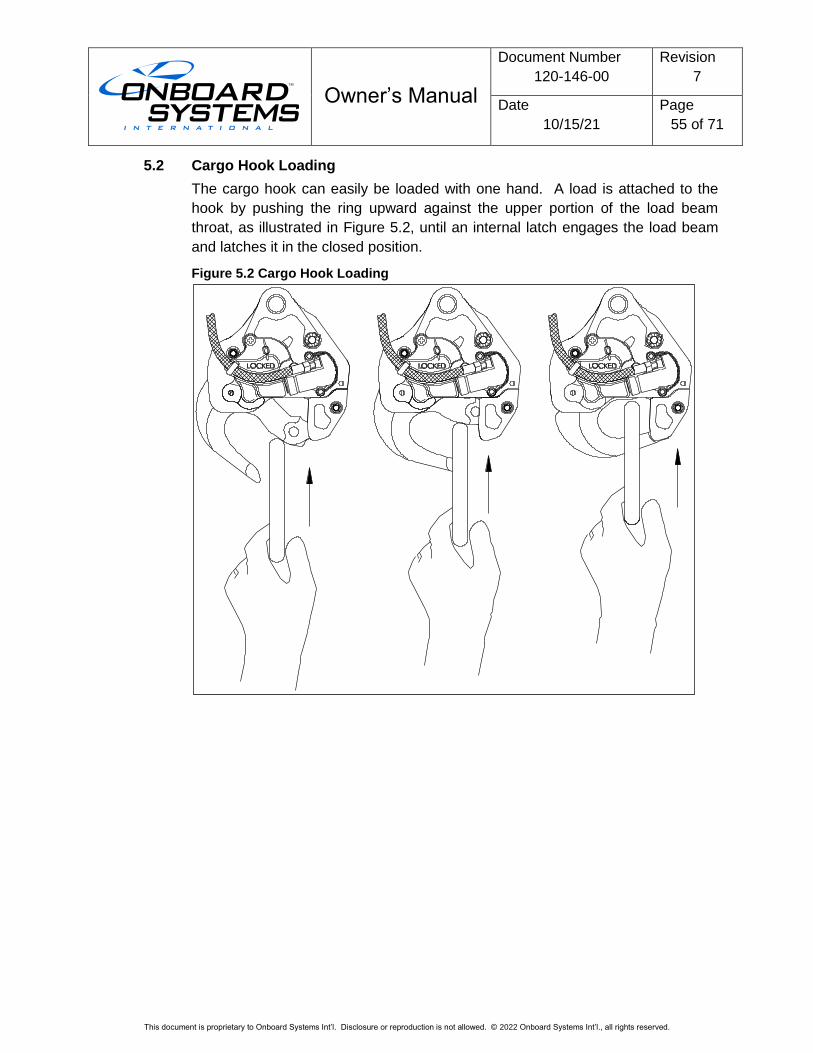
Owner’s Manual
Document Number
120-146-00
Revision
7
Date
10/15/21
Page
55 of 71
This document is proprietary to Onboard Systems Int’l. Disclosure or reproduction is not allowed. © 2022 Onboard Systems Int’l., all rights reserved.
5.2 Cargo Hook Loading
The cargo hook can easily be loaded with one hand. A load is attached to the
hook by pushing the ring upward against the upper portion of the load beam
throat, as illustrated in Figure 5.2, until an internal latch engages the load beam
and latches it in the closed position.
Figure 5.2 Cargo Hook Loading
Owner’s Manual
Document Number
120-146-00
Revision
7
Date
10/15/21
Page
56 of 71
This document is proprietary to Onboard Systems Int’l. Disclosure or reproduction is not allowed. © 2022 Onboard Systems Int’l., all rights reserved.
5.3 Cargo Hook Rigging
Extreme care must be exercised when rigging a load to the Cargo Hook. Steel
load rings are recommended to provide consistent release performance and
resistance to fouling. The following illustration shows the recommended rigging
and rigging to avoid, but is not intended to represent all rigging possibilities.
It is the responsibility of the operator to ensure the cargo hook will function properly with each rigging.
Nylon type straps (or similar material) or rope should not be used directly on the cargo hook load beam. If nylon straps or rope are used they should be first attached to a steel primary ring. Verify that the ring will freely slide off the load beam when it is opened. Only the primary ring should be in contact with the cargo hook load beam.
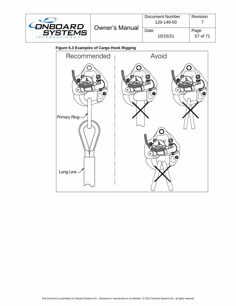
Owner’s Manual
Document Number
120-146-00
Revision
7
Date
10/15/21
Page
57 of 71
This document is proprietary to Onboard Systems Int’l. Disclosure or reproduction is not allowed. © 2022 Onboard Systems Int’l., all rights reserved.
Figure 5.3 Examples of Cargo Hook Rigging
Primary Ring
Long Line
Primary Ring
Long Line
Recommended Avoid
Owner’s Manual
Document Number
120-146-00
Revision
7
Date
10/15/21
Page
58 of 71
This document is proprietary to Onboard Systems Int’l. Disclosure or reproduction is not allowed. © 2022 Onboard Systems Int’l., all rights reserved.
6.0 Maintenance
Refer to the Instructions for Continued Airworthiness (ICA) manual 123-040-00 for
maintenance of the fixed provisions kit, load weigh kit and cargo hook suspension kits.
For maintenance specific to the cargo hook refer to the Cargo Hook Component
Maintenance Manual 122-015-00.
6.1 Instructions for Returning Equipment to the Factory
If an Onboard Systems product must be returned to the factory for any reason
(including returns, service, repairs, overhaul, etc.) obtain an RMA number before
shipping your return.
An RMA number is required for all equipment returns.
To obtain an RMA, please use one of the listed methods.
• Contact Technical Support by phone or e-mail
• Generate an RMA number at our website:
http://www.onboardsystems.com/rma.php
After you have obtained the RMA number, please be sure to:
• Package the component carefully to ensure safe transit.
• Write the RMA number on the outside of the box or on the mailing label.
• Include the RMA number and reason for the return on your purchase or
work order.
• Include your name, address, phone and fax number and email (as
applicable).
• Return the components freight, cartage, insurance and customs prepaid
to:
Onboard Systems International
13915 NW 3rd Court
Vancouver, Washington 98685
USA
Phone: 360-546-3072
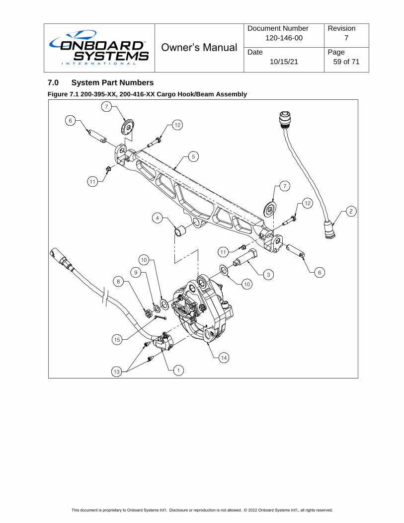
Owner’s Manual
Document Number
120-146-00
Revision
7
Date
10/15/21
Page
59 of 71
This document is proprietary to Onboard Systems Int’l. Disclosure or reproduction is not allowed. © 2022 Onboard Systems Int’l., all rights reserved.
7.0 System Part Numbers
Figure 7.1 200-395-XX, 200-416-XX Cargo Hook/Beam Assembly
12
5
7
6
11
4
7
12
11
63
10
10
9
8
15
13 1
14
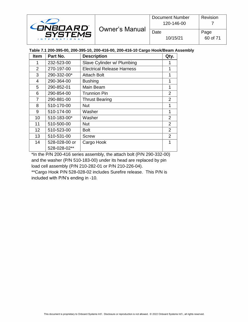
Owner’s Manual
Document Number
120-146-00
Revision
7
Date
10/15/21
Page
60 of 71
This document is proprietary to Onboard Systems Int’l. Disclosure or reproduction is not allowed. © 2022 Onboard Systems Int’l., all rights reserved.
Table 7.1 200-395-00, 200-395-10, 200-416-00, 200-416-10 Cargo Hook/Beam Assembly
Item Part No. Description Qty.
1 232-523-00 Slave Cylinder w/ Plumbing 1
2 270-197-00 Electrical Release Harness 1
3 290-332-00* Attach Bolt 1
4 290-364-00 Bushing 1
5 290-852-01 Main Beam 1
6 290-854-00 Trunnion Pin 2
7 290-881-00 Thrust Bearing 2
8 510-170-00 Nut 1
9 510-174-00 Washer 1
10 510-183-00* Washer 2
11 510-500-00 Nut 2
12 510-523-00 Bolt 2
13 510-531-00 Screw 2
14 528-028-00 or
528-028-02**
Cargo Hook 1
*In the P/N 200-416 series assembly, the attach bolt (P/N 290-332-00)
and the washer (P/N 510-183-00) under its head are replaced by pin
load cell assembly (P/N 210-282-01 or P/N 210-226-04).
**Cargo Hook P/N 528-028-02 includes Surefire release. This P/N is
included with P/N’s ending in -10.
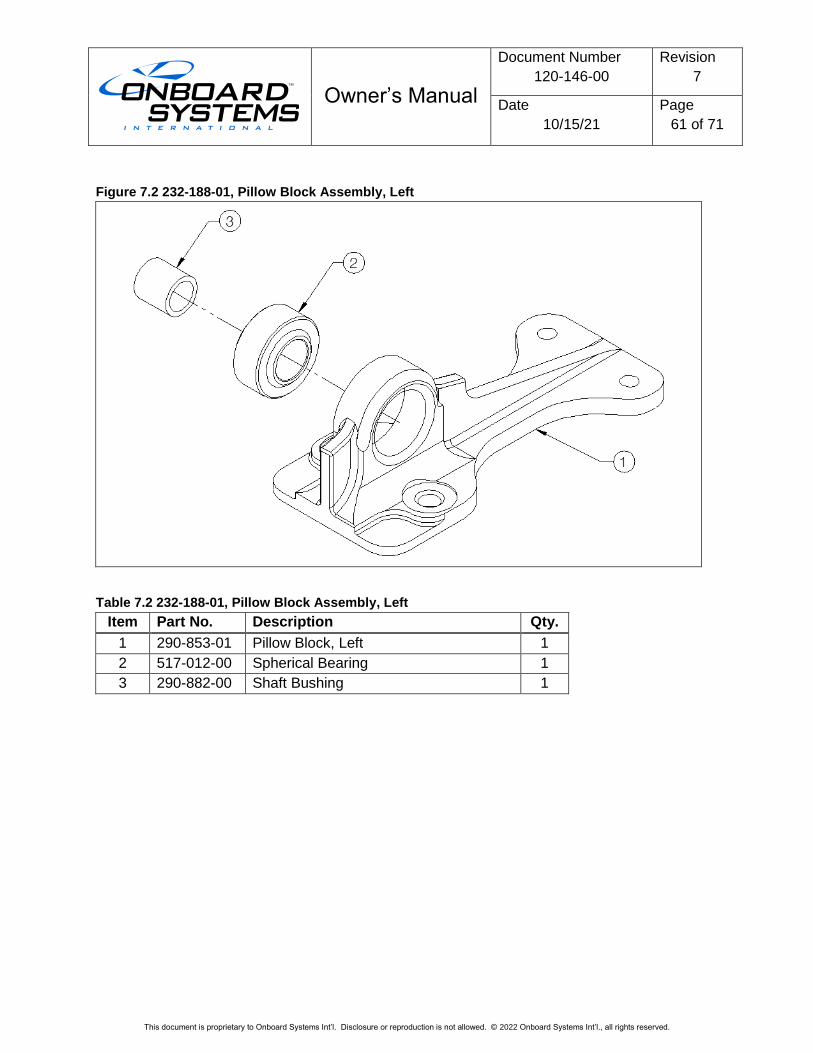
Owner’s Manual
Document Number
120-146-00
Revision
7
Date
10/15/21
Page
61 of 71
This document is proprietary to Onboard Systems Int’l. Disclosure or reproduction is not allowed. © 2022 Onboard Systems Int’l., all rights reserved.
Figure 7.2 232-188-01, Pillow Block Assembly, Left
Table 7.2 232-188-01, Pillow Block Assembly, Left
Item Part No. Description Qty.
1 290-853-01 Pillow Block, Left 1
2 517-012-00 Spherical Bearing 1
3 290-882-00 Shaft Bushing 1
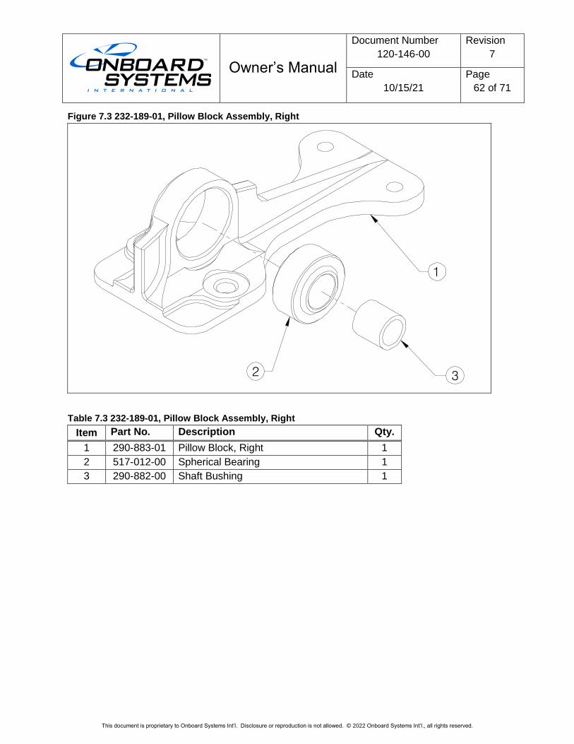
Owner’s Manual
Document Number
120-146-00
Revision
7
Date
10/15/21
Page
62 of 71
This document is proprietary to Onboard Systems Int’l. Disclosure or reproduction is not allowed. © 2022 Onboard Systems Int’l., all rights reserved.
Figure 7.3 232-189-01, Pillow Block Assembly, Right
Table 7.3 232-189-01, Pillow Block Assembly, Right
Item Part No. Description Qty.
1 290-883-01 Pillow Block, Right 1
2 517-012-00 Spherical Bearing 1
3 290-882-00 Shaft Bushing 1
3
1
2
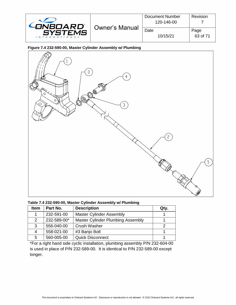
Owner’s Manual
Document Number
120-146-00
Revision
7
Date
10/15/21
Page
63 of 71
This document is proprietary to Onboard Systems Int’l. Disclosure or reproduction is not allowed. © 2022 Onboard Systems Int’l., all rights reserved.
Figure 7.4 232-590-00, Master Cylinder Assembly w/ Plumbing
Table 7.4 232-590-00, Master Cylinder Assembly w/ Plumbing
Item Part No. Description Qty.
1 232-591-00 Master Cylinder Assembly 1
2 232-589-00* Master Cylinder Plumbing Assembly 1
3 556-040-00 Crush Washer 2
4 558-021-00 #3 Banjo Bolt 1
5 560-005-00 Quick Disconnect 1
*For a right hand side cyclic installation, plumbing assembly P/N 232-604-00
is used in place of P/N 232-589-00. It is identical to P/N 232-589-00 except
longer.
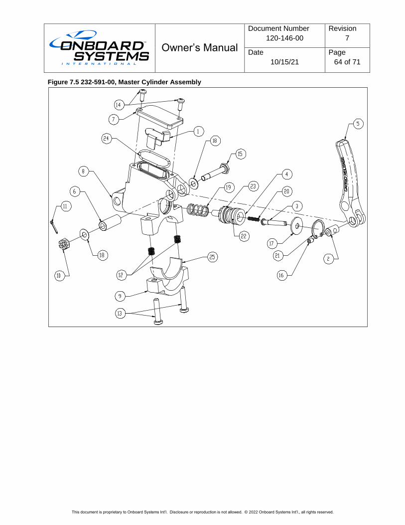
Owner’s Manual
Document Number
120-146-00
Revision
7
Date
10/15/21
Page
64 of 71
This document is proprietary to Onboard Systems Int’l. Disclosure or reproduction is not allowed. © 2022 Onboard Systems Int’l., all rights reserved.
Figure 7.5 232-591-00, Master Cylinder Assembly
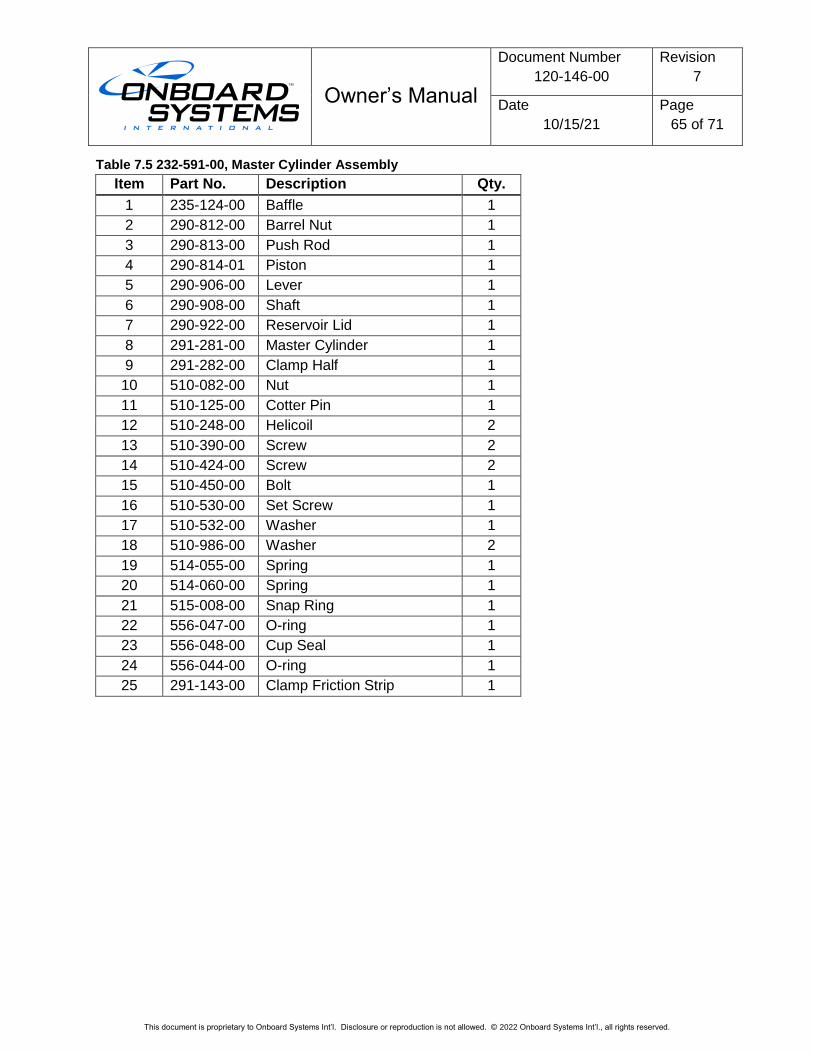
Owner’s Manual
Document Number
120-146-00
Revision
7
Date
10/15/21
Page
65 of 71
This document is proprietary to Onboard Systems Int’l. Disclosure or reproduction is not allowed. © 2022 Onboard Systems Int’l., all rights reserved.
Table 7.5 232-591-00, Master Cylinder Assembly
Item Part No. Description Qty.
1 235-124-00 Baffle 1
2 290-812-00 Barrel Nut 1
3 290-813-00 Push Rod 1
4 290-814-01 Piston 1
5 290-906-00 Lever 1
6 290-908-00 Shaft 1
7 290-922-00 Reservoir Lid 1
8 291-281-00 Master Cylinder 1
9 291-282-00 Clamp Half 1
10 510-082-00 Nut 1
11 510-125-00 Cotter Pin 1
12 510-248-00 Helicoil 2
13 510-390-00 Screw 2
14 510-424-00 Screw 2
15 510-450-00 Bolt 1
16 510-530-00 Set Screw 1
17 510-532-00 Washer 1
18 510-986-00 Washer 2
19 514-055-00 Spring 1
20 514-060-00 Spring 1
21 515-008-00 Snap Ring 1
22 556-047-00 O-ring 1
23 556-048-00 Cup Seal 1
24 556-044-00 O-ring 1
25 291-143-00 Clamp Friction Strip 1
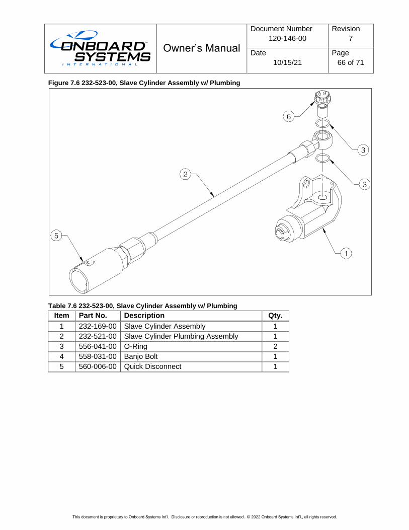
Owner’s Manual
Document Number
120-146-00
Revision
7
Date
10/15/21
Page
66 of 71
This document is proprietary to Onboard Systems Int’l. Disclosure or reproduction is not allowed. © 2022 Onboard Systems Int’l., all rights reserved.
Figure 7.6 232-523-00, Slave Cylinder Assembly w/ Plumbing
Table 7.6 232-523-00, Slave Cylinder Assembly w/ Plumbing
Item Part No. Description Qty.
1 232-169-00 Slave Cylinder Assembly 1
2 232-521-00 Slave Cylinder Plumbing Assembly 1
3 556-041-00 O-Ring 2
4 558-031-00 Banjo Bolt 1
5 560-006-00 Quick Disconnect 1
2
1
3
3
5
6
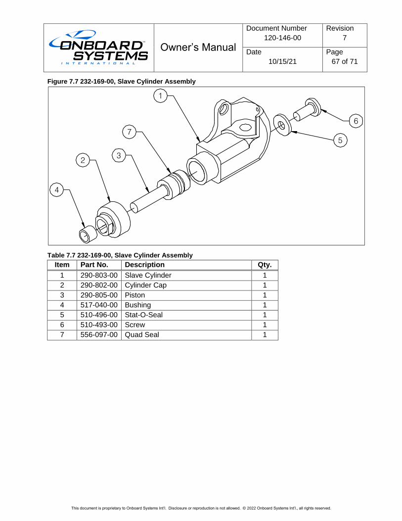
Owner’s Manual
Document Number
120-146-00
Revision
7
Date
10/15/21
Page
67 of 71
This document is proprietary to Onboard Systems Int’l. Disclosure or reproduction is not allowed. © 2022 Onboard Systems Int’l., all rights reserved.
Figure 7.7 232-169-00, Slave Cylinder Assembly
Table 7.7 232-169-00, Slave Cylinder Assembly
Item Part No. Description Qty.
1 290-803-00 Slave Cylinder 1
2 290-802-00 Cylinder Cap 1
3 290-805-00 Piston 1
4 517-040-00 Bushing 1
5 510-496-00 Stat-O-Seal 1
6 510-493-00 Screw 1
7 556-097-00 Quad Seal 1
1
7
32
4
5
6
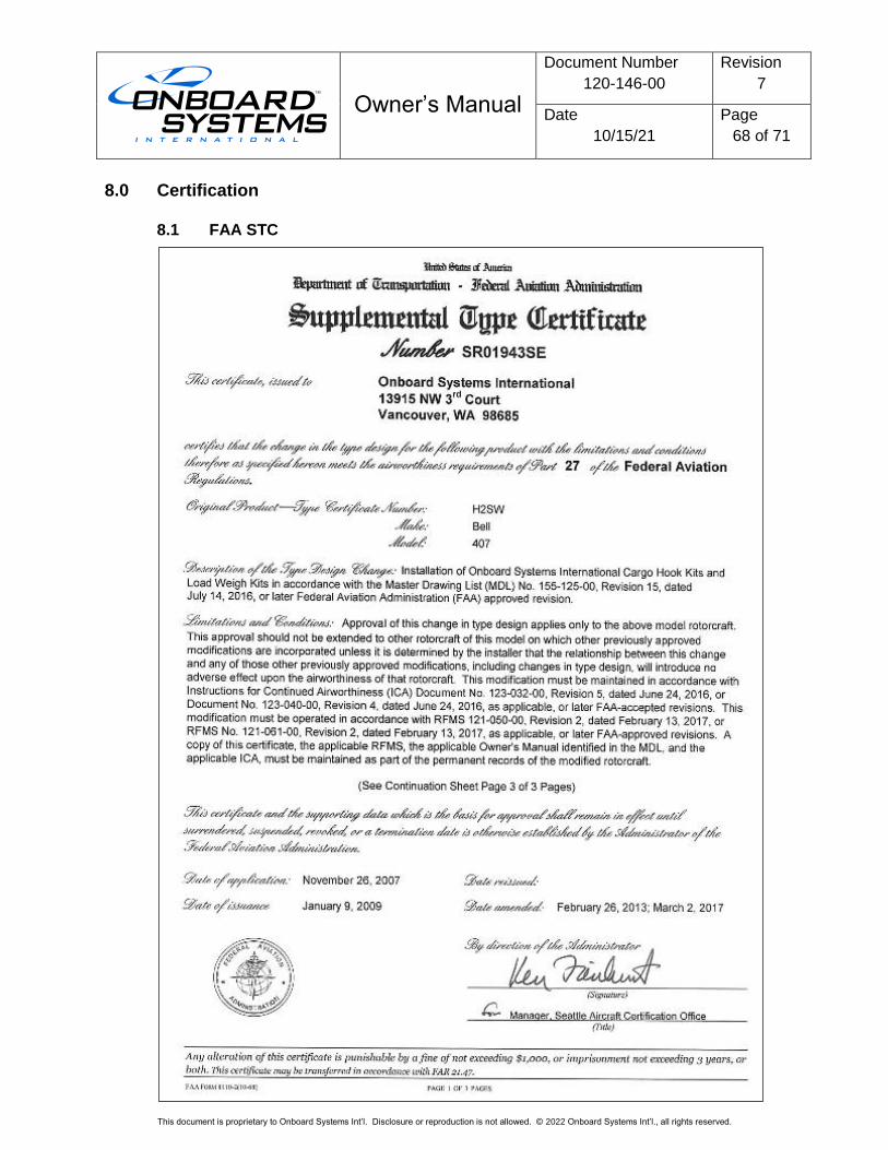
Owner’s Manual
Document Number
120-146-00
Revision
7
Date
10/15/21
Page
68 of 71
This document is proprietary to Onboard Systems Int’l. Disclosure or reproduction is not allowed. © 2022 Onboard Systems Int’l., all rights reserved.
8.0 Certification
8.1 FAA STC
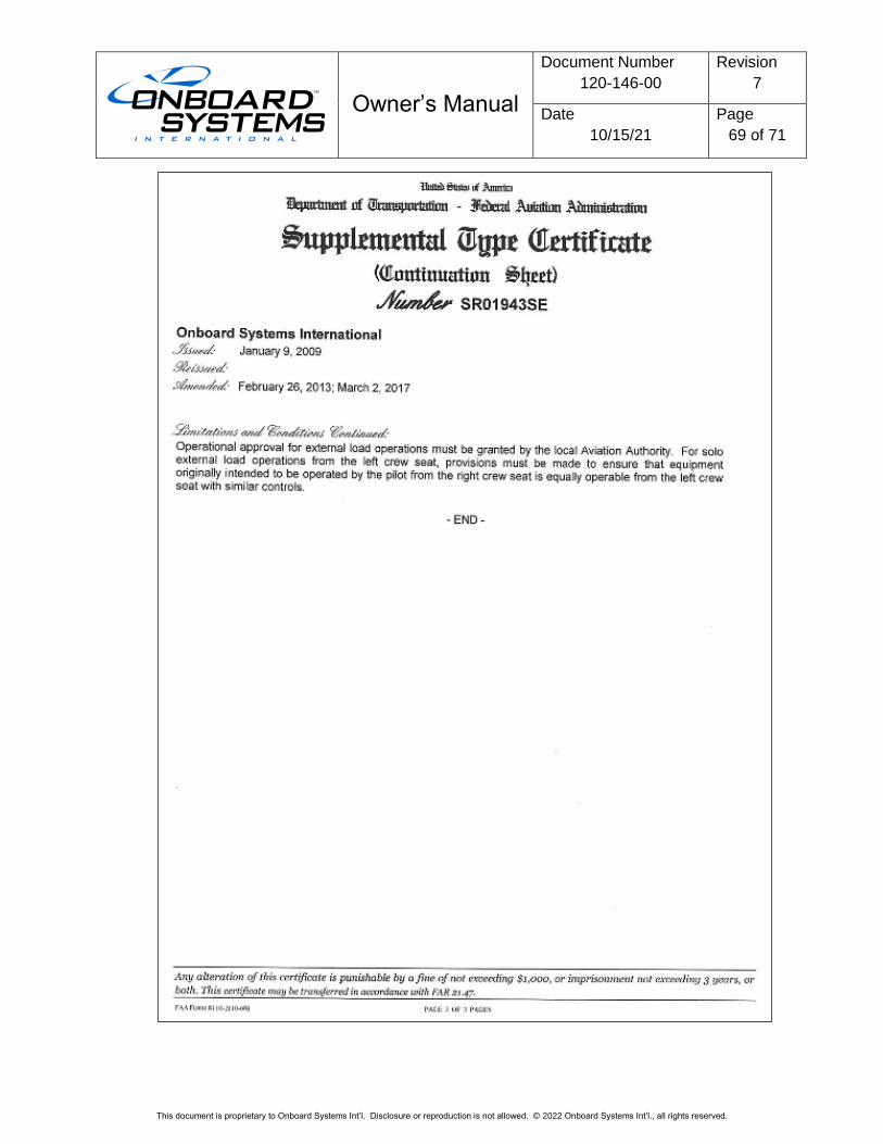
Owner’s Manual
Document Number
120-146-00
Revision
7
Date
10/15/21
Page
69 of 71
This document is proprietary to Onboard Systems Int’l. Disclosure or reproduction is not allowed. © 2022 Onboard Systems Int’l., all rights reserved.
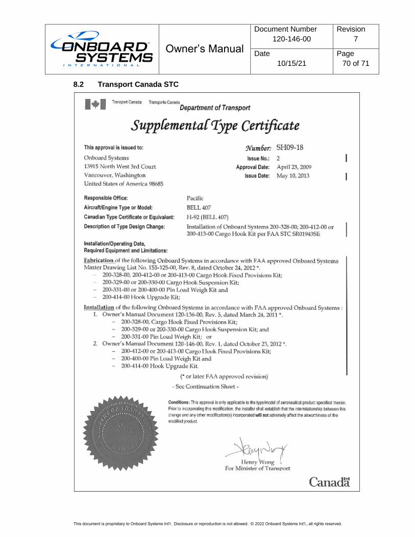
Owner’s Manual
Document Number
120-146-00
Revision
7
Date
10/15/21
Page
70 of 71
This document is proprietary to Onboard Systems Int’l. Disclosure or reproduction is not allowed. © 2022 Onboard Systems Int’l., all rights reserved.
8.2 Transport Canada STC

Owner’s Manual
Document Number
120-146-00
Revision
7
Date
10/15/21
Page
71 of 71
This document is proprietary to Onboard Systems Int’l. Disclosure or reproduction is not allowed. © 2022 Onboard Systems Int’l., all rights reserved.