Embed Size (px)
Citation preview

CASTROVILLE COMMUNITY SERVICES DISTRICT
1. PROCEDURES, GUIDELINES & REQUIREMENTS
2. STANDARD SPECIFICATIONS
3. STANDARD PLANS
FOR
CONSTRUCTION OF WATER, SEWER
& STORM DRAIN FACILITIES
CASTROVILLE COMMUNITY SERVICES DISTRICT
PO BOX 1065
11499 GEIL STREET
CASTROVILLE, CA 95012
(831) 633-2560
Jan 2010

STANDARD SPECIFICATIONS
FOR
CONSTRUCTION OF WATER, SEWER
& STORM DRAIN FACILITIES
CASTROVILLE COMMUNITY SERVICES DISTRICT
PO BOX 1065
11499 GEIL STREET
CASTROVILLE, CA 95012
(831) 633-2560
Jan 2010

Castroville Community Services District P a g e i April 2009
TABLE OF CONTENTS
STANDARD SPECIFICATIONS
Section Description
01045 Existing Facilities
02200 Earthwork
02223 Trenching, Backfilling and Compacting
02315 Jacked Casing
02701 Installation of Gravity Sewer Pipelines
02715 PVC Gravity Sewer Pipe
03300 Concrete
03461 Precast Reinforced Concrete Manholes and Manhole Bases
03462 Precast Concrete Vaults
03463 Grease Interceptors
09900 Painting and Coating
13110 Corrosion Protection and Joint Bonding
15041 Chlorination of Domestic Water Mains and Services for Disinfection
15042 Hydrostatic Testing of Pressure Pipelines
15043 Leakage and Infiltration in Testing of Non-Pressure Pipelines
15050 Hot Tap Connections
15056 Ductile-Iron Pipe and Fittings
15057 Copper, Brass, and Bronze Pipe, Fittings and Appurtenances
15064 PVC Pressure Distribution Pipe
15076 Cement-Mortar Lined and Coated Steel Pipe
15089 Combination Air and Vacuum Release Valve Assembly
15100 Manual Valves
15112 Backflow Preventers
15139 Fire Hydrants
15150 Meters
15151 Domestic & Recycled Water Facilities Identification
15162 Flexible Pipe Couplings and Expansion Joints
15300 Automatic Control Valves
22100 Water Conserving Appliances and Fixtures
23000 Sewer Pump Stations
SECTION 01045
Castroville Community Services District P a g e 1 April 2009
STANDARD SPECIFICATIONS
SECTION 01045
EXISTING FACILITIES
PART 1 - GENERAL
A. Description
This section includes requirements for connection to and abandonment of existing District facilities.
B. Related Work Specified Elsewhere
All related work specified elsewhere, or in other codes or standards, will be as last revised, unless a
specific date of issuance is called out in opposition to later revision date(s).
Other sections of the technical specifications, not referenced below, shall also apply to the extent
required for proper performance of this work.
1. Trenching, Backfilling, and Compacting: 02223
2. Chlorination of Domestic Water Mains and Services for Disinfection: 15041
3. Hydrostatic Testing of Pressure Pipelines: 15042
4. Hot Tap Connections 15050
5. Manual Valves 15100
C. Condition of Existing Facilities
The District does not warranty the condition, size, material, and location of existing facilities.
D. Location
The contractor shall be responsible for potholing and verifying the location of all existing pipelines
and other above-ground and buried facilities whether shown on the plans or not. Discrepancies
shall be reported to the project engineer, prior to the fabrication of, or purchase of material affected
by the discrepancy.
E. Protection of Existing Utilities and Facilities
1. The contractor shall be responsible for the care and protection of all existing sewer pipe,
water pipe, gas mains, culverts, power or communications lines, sidewalks, curbs,
pavement, or other facilities and structures that may be encountered in or near the area of
the work.
2. It shall be the duty of the contractor to notify Underground Service Alert and each utility
agency of jurisdiction and make arrangements for locating their facilities prior to beginning
construction.
3. In the event of damage to any existing facilities during the progress of the work, the
contractor shall pay for the cost of all repairs and protection to said facilities. The
contractor's work may be stopped until repair operations are complete.

SECTION 01045
Castroville Community Services District P a g e 2 April 2009
4. Any existing water and sewer pipe to be abandoned and remain in place shall be allowed
with approval of the CCSD. The contractor shall seek all approvals to allow existing water
and sewer lines to be abandoned in place. Abandoned water and sewer pipe is not the
property of Castroville Community Services District and is the property of the developer or
the property of the fee title owner to the development property.
F. Protection of Landscaping
1. The contractor shall be responsible for the protection of all the trees, shrubs, irrigation
systems, fences, and other landscape items adjacent to or within the work area, unless they
are directed to do otherwise on the plans.
2. In the event of damage to landscape items, the contractor shall replace the damaged items
to the satisfaction of the engineer and the owner, or pay damages to the owner as directed
by the District.
3. When the proposed pipeline is to be within planted or other improved areas in public or
private easements, the contractor shall restore such areas to the original condition after
completion of the work. This restoration shall include grading, a placement of 5 inches of
good topsoil, resoding, and replacement of all landscape items indicated.
4. If the contractor does not proceed with the restoration after completion of the work or does
not complete the restoration in a satisfactory manner, the engineer reserves the right to have
the work done and to charge the contractor for the actual cost of the restoration including
all labor, material, and overhead required for restoration.
G. Permits
All work shall conform to the specifications and requirements of the Castroville Community
Services District, or other agencies having jurisdiction. The contractor shall keep a copy of all the
required permits in the job site and comply with all the terms and conditions of said permits.
Permits shall also include any related to the abandonment of an existing water or sewer pipe.
PART 2 - MATERIALS
All materials used in making the connection or removing the facility from service shall conform to the
applicable sections of these specifications.
A. Grout
Grout shall consist of Portland cement and water or of Portland cement, sand, and water; and all
grout mixtures shall contain 2% of bentonite by weight of the cement. Grout shall be a pump mix
with a minimum of six sacks cement (564 lbs) per cubic yard.
Portland cement, water and sand shall conform to the applicable requirements of the concrete
section (Section 03300), except that sand to be used shall be of such fineness that 100% will pass a
standard 8-mesh sieve and at least 45%, by weight, will pass a standard 40-mesh sieve.
B. Concrete

SECTION 01045
Castroville Community Services District P a g e 3 April 2009
Concrete used for the replacement of damaged or removed facilities shall be in accordance with
Section 03300 and shall match the mix design of the existing facility and per the requirement of the
jurisdictional agency.
PART 3 - EXECUTION
A. Connection to Existing Facilities
1. All connections shall be made by the contractor unless shown otherwise on the plans or
specified herein.
2. If multiple connections to the District’s water/recycled water/sewer system are anticipated,
the contractor shall submit a connection plan developed with the intent of minimizing the
down time to District customers and will be reviewed and approved by the District.
3. When customers are affected, the contractor shall notify the District a minimum of seven
working days prior to any proposed shutdown of existing mains or services. The District
inspector may postpone or reschedule any shutdown operation if for any reason he feels
that the contractor is improperly prepared with competent personnel, equipment, or
materials to proceed with the connection work.
4. When no customers are affected, the contractor shall notify the District a minimum of
two working days prior to any proposed shutdown of existing mains or services. The
District inspector may postpone or reschedule any shutdown operation if for any reason
he feels that the contractor is improperly prepared with competent personnel, equipment,
or materials to proceed with the connection work. Only District staff shall operate
existing valves and shut down the system.
5. Connections shall be made only in the presence of the District, and no connection work
shall proceed until the engineer has given notice to proceed. If progress is inadequate
during the connection operations to complete the connection in the time specified, the
engineer shall order necessary corrective measures. All costs for corrective measures shall
be paid by the contractor.
6. The contractor shall furnish all pipe and materials including furnishing all labor and
equipment necessary to make the connections, all required excavation, backfill, pavement
replacement, lights, and barricades, and may be required to include a water truck, high line
hose, and fittings as part of this equipment for making the connections. In addition, the
contractor shall assist the District in alleviating any hardship incurred during the shutdown
for connections. Standby equipment or materials may be required by the engineer.
7. The contractor shall de-water existing mains, as required, in the presence of the engineer.
8. Connections shall be made with as little change as possible in the grade of the new main. If
the grade of the existing pipe is below that of the new pipeline, a sufficient length of the
new line shall be deepened so as to prevent the creation of any high spot or abrupt changes
in grade of the new line. Where the grade of the existing pipe is above that of the new
pipeline, the new line shall be laid at specified depth, except for the first joint adjacent to

SECTION 01045
Castroville Community Services District P a g e 4 April 2009
the connection, which shall be deflected within the allowances of the pipe manufacturer as
necessary to meet the grade of the existing pipe. If sufficient change in direction cannot be
obtained by the limited deflection of the first joint, a fitting of the proper angle shall be
installed. Where the connection creates a high or low spot in the line, a standard air release
or blow off assembly shall be installed as directed by the engineer.
9. Where connections are made to existing valves, the contractor shall furnish and install all
temporary blocking, steel clamps, shackles, and anchors as required by the District, and he
shall replace the valve riser box and cover and adjust the valve cover to the proper grade in
accordance with these specifications. The District will operate all existing valves. All
valves, existing or newly installed, shall be readily accessible at all times to the District for
emergency operation.
10. New pipelines shall not be connected to existing facilities until the new pipelines have been
successfully tested, disinfected and accepted by the District.
11. Tapping connection can be made to the existing system while it is either in service or shut
down depending on the District’s authorization. A tapping valve shall be used when the
existing system is maintained in service during connection. Tapping shall be in accordance
with the specification requirements for the pipe being tapped. The contractor shall provide
the “cookie” to District staff to confirm that the tap was successfully completed.
12. All saddle connections into existing sewer pipes shall be made with a wye saddle. Saddles
shall conform to the applicable provisions of the section for the existing sewer pipe
material.
B. Removal from Service of Existing Mains and Appurtenances
1. Existing mains and appurtenances shall be removed from service at the locations shown on
the plans or as directed by the engineer.
2. Abandoned pipe shall be filled with grout.
3. Existing pipe and appurtenances removed from the ground will require backfill and repair
of surface in accordance with Section 02223.
4. Removed pipe and appurtenances shall be temporarily stockpiled on the job in a location
that will not disrupt traffic or be a safety hazard, disposed of in a proper manner (as
determined by the engineer). The contractor shall remove and dispose of all removed
pipe at his own expense to a landfill permitted to accept such materials.
5. Before excavating for installing mains that are to replace existing pipes and/or services, the
contractor shall make proper provisions for the maintenance and continuation of service as
directed by the engineer unless otherwise specified.
6. If the meter box is to be removed from an abandoned water service, the service line is to be
removed and the corporation stop closed and capped. If there is no corporation stop on the
service, the adapter is to be removed and a brass plug is to be installed in the service saddle.

SECTION 01045
Castroville Community Services District P a g e 5 April 2009
7. Asbestos Cement Pipe (ACP) shall be cut, removed and disposed of in a proper manner.
The contractor shall be responsible for the proper manifesting of any and all ACP at an
authorized disposal site. See Section 15072 for additional requirements.
C. Cutting and Restoring Street Surfacing.
1. In cutting or breaking up street surfacing, the contractor shall not use equipment that will
damage adjacent pavement.
2. All asphalt and/or Portland cement concrete surfaces shall be scored with sawing
equipment of a type meeting the approval of the District; providing however, that any
cement concrete base under an asphaltic mix surface will not be required to be scored by
sawing. Existing paving surfaces shall be saw cut back beyond the edges of the trenches to
form neat square cuts before repaving is commenced.
3. Pavement, sidewalks, curbs, or gutters removed or destroyed in connection with
performance of the work shall be saw cut to the nearest score marks, if any, and shall be
replaced with pavement sidewalks, curbs, or gutters of the same kind, or better by the
contractor in accordance with the latest specifications, rules, and regulations and subject to
the inspection of the agency having jurisdiction over the street or highway.
4. Aggregate base shall be placed beneath the restored pavement to the thickness required by
the agency having jurisdiction.
END OF SECTION

SECTION 02200
Castroville Community Services District P a g e 6 April 2009
STANDARD SPECIFICATIONS
SECTION 02200
EARTHWORK
PART 1 - GENERAL
A. Description
This section includes excavation, backfilling, materials, testing, and shoring for structures.
B. Related Work Specified Elsewhere
All related work specified elsewhere, or in other codes or standards, will be as last revised, unless a
specific date of issuance is called out in opposition to later revision date(s).
Other sections of the technical specifications, not referenced below, shall also apply to the extent
required for proper performance of this work.
1. Trenching, Backfilling, and Compacting: 02223
2. Concrete: 03300
C. Testing for Compaction
Testing for compaction shall conform to Section 02223.
D. Definition of Zones
1. Pavement and street zones shall be as specified in Section 02223.
2. Backfill zone is the backfill from the bottom of the structure excavation to the bottom of the
street zone in paved areas or to the existing surface in unpaved areas.
E. Permits
All work shall conform to the specifications and requirements of the Castroville Community
Services District, or any other agencies having jurisdiction. The contractor shall keep a copy of
all the required permits in the job site and comply with all the terms and conditions of said
permits.
F. Submittal
For any shoring or sheeting systems to be used for excavation, the contractor shall submit shoring
plans and calculations designed and stamped by a registered structural engineer.

SECTION 02200
Castroville Community Services District P a g e 7 April 2009
PART 2 - MATERIALS
Native earth backfill, imported backfill material, granular material, imported sand, and crushed rock
shall conform to the requirements of Section 02223.
PART 3 - EXECUTION
A. Compaction Requirements
1. Backfill in Street Zone: 95% relative compaction
2. Structural Backfill: 95% relative compaction
3. Gravel Base: 95% relative compaction or as approved
by the engineer
4. Adjacent to existing structures: 95% relative compaction
B. Sidewalk, Pavement, and Curb Removal
1. Saw cut bituminous or concrete pavements regardless of their thickness, and curbs and
sidewalks prior to excavation for the structure in accordance with the requirements of the
County Public Works Department. Curbs and sidewalks that are damaged in the course of
construction are to be cut and removed from joint to joint.
2. Haul removed pavement and concrete materials from the site, to a proper disposal facility.
These materials are not permitted for use as backfill. If the material to be removed exceeds
50 cubic yards, the contractor shall obtain a haul route permit from the County Public
Works Department.
C. De-watering
1. Provide and maintain means and devices to continuously remove and dispose of all water
entering the excavation during construction of the structure and all backfill operations.
2. Dispose of the water in a manner to prevent damage to adjacent property and pipe trenches.
3. Do not allow water to rise in the excavation until backfilling around and above the structure
is completed.
4. Reporting shall conform to the requirements of the District's NPDES permit. A copy of
this permit is available from the District.
5. In no event shall the sewer system be used as a drain for de-watering.
D. Structure Excavation
1. Structure excavation shall include the removal of all material of whatever nature necessary
for the construction of structures and foundations in accordance with the plans and these
specifications.

SECTION 02200
Castroville Community Services District P a g e 8 April 2009
2. The sides of excavations for structures shall be sufficient to leave at least a 2-foot clearance,
as measured from the extreme outside of form work or the structure, as the case may be.
3. Surplus material shall be disposed of by the contractor in accordance with Section 02223.
E. Correction of Over Excavation
1. Where excavation is inadvertently carried below design depths, suitable provision shall be
made by the contractor to adjust construction, as directed by the District representative, to
meet requirements incurred by the deeper excavation.
2. No earth backfill will be permitted to correct over excavation beneath structures.
3. Over excavation shall be corrected by backfilling with crushed rock or concrete, as directed
by the District representative.
F. Bracing
1. The contractor's design and installation of bracing and sheeting shall take the necessary
precautions to be consistent with the rules, orders, and regulations of the State of California
Construction Safety Orders.
2. Excavations shall be so braced, sheeted, and supported that they will be safe, such that the
walls of the excavation will not slide or settle and all existing improvements of any kind,
either on public or private property, will be fully protected from damage.
3. The sheeting, shoring, and bracing shall be arranged so as not to place any stress on
portions of the completed work.
4. Carefully remove sheeting, shoring, bracing, and timbering to prevent the caving or
collapse of the excavation faces being supported.
G. Backfill
1. After structures and foundations are in place, backfill shall be placed to the original ground
line or to the limits designated on the plans.
2. No material shall be deposited against concrete structures until the concrete has reached a
compressive strength of at least 3,000 pounds per square inch as tested per Section 03300.
3. Imported sand or granular material shall be placed in horizontal layers not exceeding 12
inches in depth.
4. Each layer of backfill material shall be moistened and thoroughly tamped, rolled, or
otherwise compacted to the specified relative density.
5. Carefully operate compaction equipment near structures to prevent their displacement or
damage. Structural fill is to be placed and compacted in uniform layers around all sides of
the structure.

SECTION 02200
Castroville Community Services District P a g e 9 April 2009
6. One-sack cement slurry may be used as structural backfill material.
H. Pavement Replacement
Pavement replacement shall be in accordance with the requirements of the County Public Works
Department.
I. Permits
An Encroachment Permit from the County Public Works Department is required prior to any work
within public right-of-way. All traffic control and pavement replacement work shall be in
accordance with the requirements of the permit and agency Inspector.
A permit from OSHA is required of any excavation exceeding 5 feet.
Follow all requirements and conditions of the permits from other agencies.
END OF SECTION

SECTION 02223
Castroville Community Services District Page 10 April 2009
STANDARD SPECIFICATIONS
SECTION 02223
TRENCHING, BACKFILLING, AND COMPACTING
PART 1 - GENERAL
A. Description
This section includes materials, testing, and installation for trench excavation, backfilling, and
compacting.
B. Related Work Specified Elsewhere
All related work specified elsewhere, or in other codes or standards, will be as last revised, unless a
specific date of issuance is called out in opposition to later revision date(s).
Other sections of the technical specifications, not referenced below, shall also apply to the extent
required for proper performance of this work.
C. Testing for Compaction
1. Determine the density of soil in place by the use of a sand cone, drive tube, or nuclear
tester.
2. Determine laboratory moisture-density relations of existing soils by ASTM D 1557.
3. Determine the relative density of cohesion less soils by ASTM D 2049.
4. Sample backfill materials by ASTM D 75.
5. Express "relative compaction" as the ratio, expressed as a percentage, of the in place dry
density to the laboratory maximum dry density.
6. Compaction shall be deemed to comply with the specifications when no test falls below the
specified relative compaction.
7. The developer will secure the services of a soils tester and pay the costs of all compaction
testing. On capital projects, the District will secure the service of a soils tester and pay the
cost of initial testing. The contractor will be responsible for the cost of all retests in failed
areas. Test results will be furnished by the District representative.
D. Pavement Zone
The pavement zone includes the asphalt concrete and aggregate base pavement section placed over
the trench backfill.

SECTION 02223
Castroville Community Services District Page 11 April 2009
E. Street Zone
The street zone is the top 18 inches of the trench or depth determined by the jurisdictional agency
immediately below the pavement zone in paved areas.
F. Trench Zone
The trench zone includes the portion of the trench from the top of the pipe zone to the bottom of the
street zone in paved areas or to the existing surface in unpaved areas.
G. Pipe Zone
The pipe zone shall include the full width of trench from the bottom of the pipe or conduit to a
horizontal level 12 inches above the top of the pipe. Where multiple pipes or conduits are placed in
the same trench, the pipe zone shall extend from the bottom of the lowest pipes to a horizontal level
12 inches above the top of the highest or topmost pipe.
H. Pipe Bedding
The pipe bedding shall be defined as a layer of material immediately below the bottom of the pipe
or conduit and extending over the full trench width in which the pipe is bedded. Thickness of pipe
bedding shall be as shown on the drawings or as described in these specifications for the particular
type of pipe installed.
I. Excess Excavated Material
1. The contractor shall make the necessary arrangements for and shall remove and dispose of
all excess excavated material unless indicated differently in the special provisions for any
job.
2. All surplus material not required for backfill or fill shall be properly disposed of by the
contractor at his expense at a proper disposal site (approved in advance by the CCSD or
County Public Works Department).
3. No excavated material shall be deposited on private property unless written permission
from the owner thereof is secured by the contractor. Before the District will accept the
work, the contractor shall file a written release signed by all property owners with whom he
has entered into agreements for disposing excess excavated material, absolving the District
from any liability connected therewith.
4. The contractor shall obtain a haul route permit from the County Public Works Department.
J. Safety
1. All excavations shall be performed, protected, and supported as required for safety and in
the manner set forth in the operation rules, orders, and regulations prescribed by the
Division of Industrial Safety of the State of California.

SECTION 02223
Castroville Community Services District Page 12 April 2009
2. Barriers shall be placed at each end of all excavations and at such places as may be
necessary along excavations to warn all pedestrians and vehicular traffic of such
excavations. Lights shall also be placed along excavations from sunset each day to sunrise
of the next day until such excavation is entirely refilled.
3. No trench or excavation shall remain open during non-working hours. The trench or
excavation shall be covered with steel plates, spiked in place, or secured with temporary
A.C. pavement around the edges, or backfilled. A security fence shall be installed around
the work area during non-working hours.
4. The contractor shall notify the District of all work-related accidents which may occur to
persons or property at or near the project site, and shall provide the District with a copy of
all accident reports. All accident reports shall be signed by the contractor or its authorized
representative and submitted to the District’s authorized representative within twenty-four
(24) hours of the accident’s occurrence.
K. Access
Unobstructed access must be provided to all driveways, water valves, hydrants, or other property or
facilities that require routine use.
L. Permits
All work shall conform to the specifications and requirements of the Castroville Community
Services District, or any other agencies having jurisdiction. The contractor shall keep a copy of all
the required permits in the job site and comply with all the terms and conditions of said permits.
M. Slope Protection
Slope protection shall be installed where shown on the plans in accordance with CCSD Standard
Plan S-9, wherever the profile of the ground surface above the water or sewer main exceeds 20%,
and where no pavement of other surfacing is to be laid over the facility. The installation of the
slope protection shall be considered a part of the work, and the contractor shall include the expense
in his cost.
PART 2 - MATERIALS
A. Native Earth Backfill
1. The use of native earth as backfill material will not normally be acceptable to the District.
2. Native earth backfill, acceptable for use, shall be fine-grained material free from roots,
debris, and rocks with a maximum dimension not larger than 4 inches and must be
authorized by the District prior to placement.
3. Native backfill shall not be used as pipe bending material or in the pipe zone.
B. Imported Backfill Material

SECTION 02223
Castroville Community Services District Page 13 April 2009
1. Whenever the excavated material is not suitable for backfill, the contractor shall arrange for
and furnish suitable imported backfill material that is capable of attaining the required
relative density.
2. The contractor shall dispose of the excess trench excavation as specified in the preceding
section. Backfilling with imported material shall be done in accordance with the methods
described herein.
C. Granular Material
Granular material shall be defined as soil having a minimum sand equivalent of 30 as determined in
accordance with Caltrans "California Test 217 Sand Equivalent" with not more than 20% passing a
200-mesh sieve.
D. Imported Sand
Imported sand shall have a minimum sand equivalent of 30 per "California Test 217 Sand
Equivalent" with 100% passing a 3/8-inch sieve and not more than 20% passing a 200-mesh sieve.
Certification that the sand meets this requirement shall be provided.
E. Crushed Rock and Gravel
1. Crushed rock shall be the product of crushing rock or gravel. Fifty percent of the particles
retained on a 3/8-inch sieve shall have their entire surface area composed of faces resulting
from fracture due to mechanical crushing. Not over 5% shall be particles that show no
faces resulting from crushing. Less than 10% of the particles that pass the 3/8-inch sieve
and are retained on the No. 4 sieve shall be weatherworn particles. Gravel shall not be
added to crushed rock.
2. Gravel shall be defined as particles that show no evidence of mechanical crushing, are fully
weatherworn, and are rounded. For pipe bedding, where gravel is specified, crushed rock
may be substituted or added.
3. Where crushed rock or gravel is specified in the bedding details on the plans, the material
shall have the following gradations:
Sieve Size 1-1/2 Inch Max
Gravel % Passing
1-inch Max Gravel
% Passing
¾ Inch Max Crushed
Rock % Passing
2” 100
1-1/2” 90 – 100 100
1” 20 – 55 90 – 100 100
¾” 0 – 15 60 – 80 90-100
½” - - 30 – 60
3/8” 0 –5 0 – 15 0 – 20
No. 4 - 0 – 5 0 – 5
No. 8 - - -
F. Sand-Cement Slurry

SECTION 02223
Castroville Community Services District Page 14 April 2009
Sand-cement slurry shall consist of one sack (94 pounds) of Portland cement per cubic yard of sand
and sufficient moisture for workability.
PART 3 - EXECUTION
A. Compaction Requirements
1. The developer will engage the services of a qualified soils engineering firm to determine
the relative compaction of the trench backfill. On capital projects, the District will engage
the services of a qualified soils engineering firm to determine the relative compaction of the
trench backfill.
2. If the backfill fails to meet the specified relative compaction requirements, the contractor
shall rework the backfill until the requirements are met. The contractor shall make all
necessary excavations for density tests as directed by the District representative. The
compaction requirements of the County Public Works Department or Caltrans shall prevail
in all public roads. The developer or contractor will be responsible for the cost of all
additional compaction tests in the reworked areas.
3. Compaction tests shall be performed at random depths and at 200-foot intervals and as
directed by the District representative.
4. Unless otherwise shown on the drawings or otherwise described in the specifications for the
particular type of pipe installed, relative compaction in pipe trenches shall be as described
below:
a. Pipe zone and pipe base: 95% relative compaction
b. Trench zone not beneath paving: 95% relative compaction
c. Trench zone to street zone in paved areas: 95% relative compaction
d. Street zone in paved areas: per agency requirements or 95% relative compaction.
The most stringent agency requirements shall prevail
e. Rock refill material for foundation stabilization: 90% relative density
f. Rock refill for over excavation: 90% relative density
B. Material Replacement
Removal and replacement of any trench and backfill material which does not meet the
specifications shall be the contractor's responsibility.
C. Clearing and Grubbing
1. Areas where work is to be performed shall be cleared of all trees, shrubs, rubbish, and other
objectionable material of any kind which, if left in place, would interfere with the proper
performance or completion of the contemplated work, would impair its subsequent use, or
would form obstructions therein.
2. Organic material from clearing and grubbing operations will not be incorporated in the
trench backfill.
SECTION 02223
Castroville Community Services District Page 15 April 2009
3. Organic material from clearing and grubbing operations will be disposed of at a proper
waste disposal facility.
D. Sidewalk, Pavement, and Curb Removal
1. Saw cut bituminous or concrete pavements regardless of their thickness, and curbs and
sidewalks prior to excavation for the structure in accordance with the requirements of the
County Public Works Department. Curbs and sidewalks that are damaged in the course of
construction are to be cut and removed from joint to joint.
2. Haul removed pavement and concrete materials from the site, to a proper disposal facility.
These materials are not permitted for use as trench backfill. If the material to be removed
exceeds 50 cubic yards, the contractor shall obtain a haul route permit from the County
Public Works Department.
E. Trenching and Tunneling
1. Excavation for pipe, fittings, and appurtenances shall be open trench to the depth and in the
direction necessary for the proper installation of the facilities as shown on the plans.
2. Trench banks shall be kept as near to vertical as possible and shall be properly braced and
sheeted.
3. Tunneling will not be permitted.
4. The use of a jack and bore or hydraulic ram may be employed.
F. Bracing
1. The contractor's design and installation of bracing and shoring shall be consistent with the
rules, orders, and regulations of the State of California Construction Safety Orders.
2. Excavations shall be so braced, sheeted, and supported that they will be safe such that the
walls of the excavation will not slide or settle and all existing improvements of any kind,
either on public or private property, will be fully protected from damage.
3. The sheeting, shoring, and bracing shall be arranged so as not to place any stress on
portions of the completed work until the general construction thereof has proceeded far
enough to provide ample strength.
4. Care shall be exercised in the drawing or removal of sheeting, shoring, bracing, and
timbering to prevent the caving or collapse of the excavation faces being supported.
G. Trench Widths
1. Excavation and trenching shall be true to line so that a clear space of not more than 8 inches
or less than 6 inches in width is provided on each side of the largest outside diameter of the
pipe in place measured at a point 12 inches above the top of the pipe. For the purpose of

SECTION 02223
Castroville Community Services District Page 16 April 2009
this article, the largest outside diameter shall be the outside diameter of the bell on bell and
spigot pipe or the pipe collar.
2. Where the sewer trench width, measured at a point 12 inches above the top of the bell of
the pipe, is wider than the maximum set forth above, the trench area around the pipe shall
be backfilled with crushed rock, Class B concrete, or slurry to form a cradle for the pipe as
shown on the CCSD Standard Plan S-4 at the discretion of the District representative.
H. Length of Open Trench
The maximum allowable length of open trench shall be 600 feet, or the distance necessary to
accommodate the amount of pipe installed in a single day, whichever is less. Within developed
areas, the length of open trench may be restricted as determined by the encroachment permit from
the County Public Works Department.
I. Grade
1. Excavate the trench to the lines and grades shown on the drawings with allowance for pipe
thickness and for pipe base or special bedding.
2. The trench bottom shall be graded to provide a smooth, firm, and stable foundation that is
free from rocks and other obstructions and shall be at a reasonably uniform grade.
J. Correction of Over Excavation
1. Where excavation is inadvertently carried below the design trench depth, suitable provision
shall be made by the contractor to adjust the excavation, as directed by the District
representative, to meet requirements incurred by the deeper excavation.
2. Over excavations shall be corrected by backfilling with approved graded crushed rock or
gravel and shall be compacted to provide a firm and unyielding subgrade or foundation, as
directed by the District representative.
K. De-watering
1. The contractor shall provide and maintain at all times during construction ample means and
devices with which to promptly remove and properly dispose of all water from any source
entering the excavations or other parts of the work. De-watering shall be done by methods
that will ensure a dry excavation and preservation of the final lines and grades of the
bottoms of excavations. De-watering methods may include well points, sump points,
suitable rock or gravel placed below the required bedding for drainage and pumping,
temporary pipelines, and other means, all subject to the approval of the District
representative. Water shall be discharged in accordance with the requirements of the
Contractor’s NPDES permit.
2. In no event shall the sewer system be used as drains for de-watering the construction
trenches.
SECTION 02223
Castroville Community Services District Page 17 April 2009
3. De-watering shall commence when groundwater is first encountered and shall be
continuous until such times as water can be allowed to rise. No concrete shall be poured
in water, nor shall water be allowed to rise around the concrete or mortar until it has set at
least eight hours.
L. Foundation Stabilization
1. Whenever the trench bottom does not afford a sufficiently solid and stable base to support
the pipe or appurtenances, the contractor shall excavate to a depth below the design trench
bottom, as directed by the District representative, and the trench bottom shall be backfilled
with 3/4-inch rock and compacted to provide uniform support and a firm foundation.
2. Where rock is encountered, it shall be removed to a depth at least 6 inches below grade and
the trench shall be backfilled with 3/4-inch crushed rock to provide a compacted foundation
cushion.
3. If excessively wet, soft, spongy, unstable, or similarly unsuitable material is encountered at
the surface upon which the bedding material is to be placed, the unsuitable material shall
removed to a depth as determined in the field by the District representative and replaced by
crushed rock.
M. Excavated Material
1. All excavated material shall not be stockpiled in a manner that will create an unsafe work
area or obstruct sidewalks or driveways. Gutters shall be kept clear or other satisfactory
measures shall be taken to maintain street or other drainage.
2. In confined work areas, the contractor may be required to stockpile the excavated material
off-site, as determined by the project permits.
N. Placing Pipe Bedding
1. Place the thickness of pipe bedding material over the full width of trench necessary to
produce the required bedding thickness when the material is compacted to the specified
relative density. Grade the top of the pipe bedding ahead of the pipe to provide firm,
uniform support along the full length of pipe.
2. Excavate bell holes at each joint to permit assembly and inspection of the entire joint.
O. Placing Mounds to Support Pipe (DIP Only)
1. As an alternate to placing continuous imported sand pipe bedding material, the ductile iron
pipe may be supported on mounds of imported sand.
2. The mounds shall be of imported sand and extend the full trench width. The mounds shall
provide a minimum of 6 inches of contact with the pipe.
3. The pipe shall be supported to maintain its design line and grade.

SECTION 02223
Castroville Community Services District Page 18 April 2009
4. The mounds shall be located 2½ feet from the bell/spigot of the pipe.
P. Backfilling within Pipe Zone
1. Backfill per the detailed piping specification for the particular type of pipe and per the
following.
2. After pipe has been installed in the trench, place pipe zone material simultaneously on both
sides of the pipe, keeping the level of backfill the same on each side. Carefully place the
material around the pipe so that the pipe barrel is completely supported and that no voids or
uncompacted areas are left beneath the pipe. Use particular care in placing material on the
underside of the pipe to prevent lateral movement during subsequent backfilling.
3. Compact material placed within 12 inches of the outer surface of the pipe by hand tamping
only.
4. All sewer main repairs shall be firmly supported under each point of connection to the
existing main prior to back fill and compaction.
Q. Backfill within Trench Zone
1. Compact per the detailed piping specification for the particular type of pipe and per the
following.
2. Push the backfill material carefully onto the backfill previously placed in the pipe zone. Do
not permit free fall of the material until at least 2 feet of cover is provided over the top of
the pipe. Do not drop sharp, heavy pieces of material directly onto the pipe or the tamped
material around the pipe.
3. The remaining portion of the trench to the street zone or ground surface, as the case may
be, shall be backfilled, compacted and/or consolidated by approved methods to obtain the
specified relative compaction.
foundation materials may be softened or otherwise damaged by the quantities of water applied. The
contractor shall rectify any misalignment of the pipe because of consolidation
operations as directed by the District representative.
R. Backfill within Street Zone
1. The street zone within roadbed areas shall be compacted using approved hand, pneumatic,
or mechanical type tampers to obtain the required relative compaction.
2. All work shall be done in accordance with the requirements and to the satisfaction of the
County Public Works Department.
3. Flooding and jetting will not be permitted in this Zone.

SECTION 02223
Castroville Community Services District Page 19 April 2009
S. Sidewalk, Pavement, and Curb Replacement
Replace bituminous and concrete pavement, curbs, and sidewalks damaged or removed during
construction in accordance with the requirements of the County Public Works Department.
T. Slope Protection
1. Where cutoff walls or concrete anchors are required, they shall be in accordance with
CCSD Standard Plan S-9, with a minimum thickness of 12 inches. The wall shall extend
at least 12 inches to undisturbed material on each side of the trench as excavated.
Cemented rubble and concrete surface slope protection shall be a minimum of 4-inches
thick.
2. Wall or anchors shall be placed with a minimum horizontal spacing of:
a. Not over 36 feet center to center on grades 25% to 35%
b. Not over 24 feet center to center on grades 35% to 50%
c. Not over 16 feet center to center on grades 50% and over
3. Material used for construction of cutoff walls or concrete anchors shall consist of cast-in-
place reinforced concrete or reinforced hollow unit masonry. When reinforced hollow
unit masonry is used, all cells in the block shall be filled solidly with grout. A No. 4
reinforcing bar shall be placed in vertically in each row of cells and No. 9-gage wall
mesh shall be placed in each horizontal joint. In addition, a bond beam shall be placed at
the top with two No. 4 bars.
Where cutoff walls or concrete anchors are constructed of reinforced concrete, they shall
have No. 4 reinforcing bars placed at 6-inches on center each way in the center of the
wall. The bars shall extend full length and height of the wall.
END OF SECTION

SECTION 02315
Castroville Community Services District Page 20 April 2009
STANDARD SPECIFICATIONS
SECTION 02315
JACKED CASING
PART 1 - GENERAL
A. Description
Tunneling method by jacked casing, directional drilling, or a tunnel boring machine, for highway,
railroad, creek, and culvert crossings and other shallow depth tunnels, and carrier pipe installation.
B. Related Work Specified Elsewhere
All related work specified elsewhere, or in other codes or standards, will be as last revised, unless a
specific date of issuance is called out in opposition to later revision date(s).
Other sections of the technical specifications, not referenced below, shall also apply to the extent
required for proper performance of this work.
1. Trenching, Backfilling, and Compacting: 02223
2. Concrete: 03300
3. Hydrostatic Testing of Pressure Pipeline: 15042
C. Permits
All work shall conform to the specifications and requirements of the Castroville Community
Services District, or any other agencies having jurisdiction. The contractor shall keep a copy of all
the required permits in the job site and comply with all the terms and conditions of said permits.
D. Alternative Methods
The contractor may present an alternative detailed proposal in lieu of the methods and materials
specified herein to jack or bore casing pipe at the locations shown on the plans. Any such proposal
shall be presented to the District representative a minimum of 28 calendar days in advance of the
work to allow adequate time for checking, and must be in accordance with all the conditions set
forth in the permits.
E. Safety
The contractor shall obtain from the Division of Industrial Safety a classification for each bore
exceeding 30-inches in diameter. It shall be the contractor’s responsibility to see that the work is
done in conformance with the state requirements. It shall also be the contractor’s responsibility to
call the required safety meeting with representatives from the State Division of Industrial Safety
prior to beginning the construction of each bore.
SECTION 02315
Castroville Community Services District Page 21 April 2009
F. Scheduling
If the pipeline is not installed within the casing as a continuous operation following completion of
jacking, then bulkhead the portals and backfill the approach trenches and later reopen them for pipe
installation.
G. Line and Grade
1. The contractor’s attention is called to the fact that the casing pipe must be installed to the
tolerances listed on the plans so as to permit the construction of the carrier pipe to the lines
and grades shown on the plans.
2. It is the contractor’s responsibility to choose a size of casing at or above the minimum
specified, to insure that the jacking is done with a high degree of accuracy to permit
installation of the carrier pipe to the grades shown on the plans.
H. Design
It is the contractor’s responsibility to retain an engineer to design a casing that meets or exceeds the
minimum specified, and to insure that the casing is compatible with the jacking machine, and the
boring head used. Design must be submitted to and approved by District.
PART 2 – MATERIALS
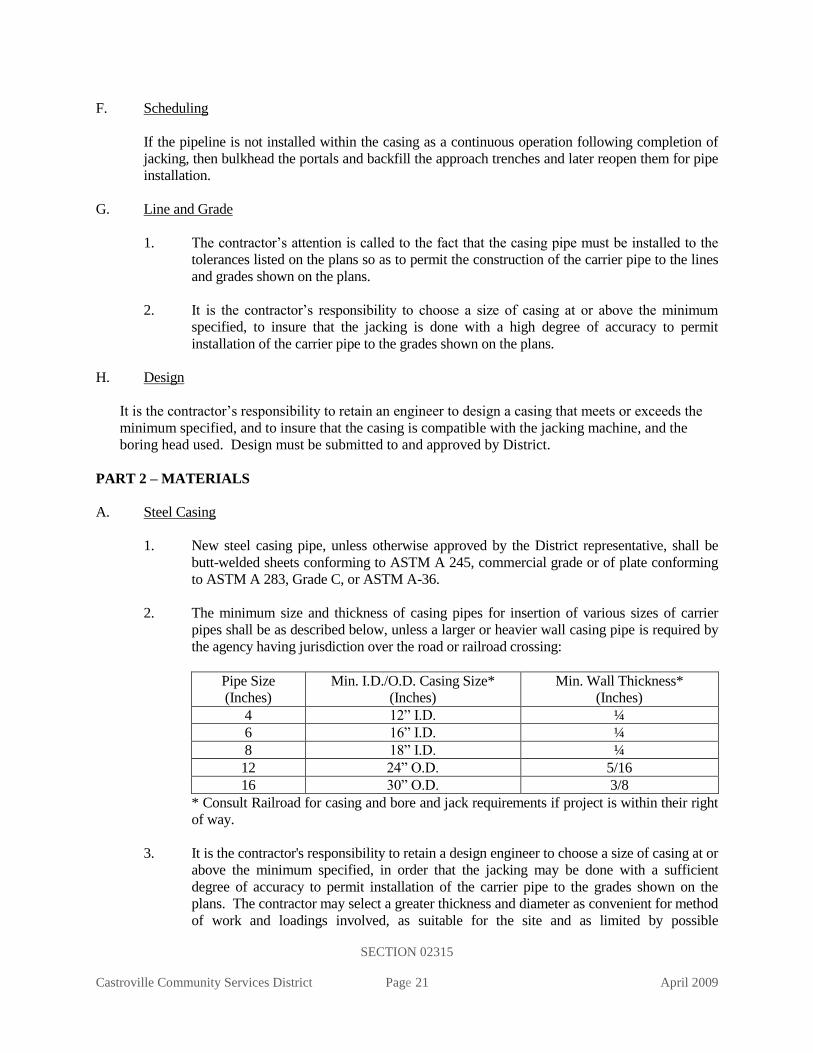
A. Steel Casing
1. New steel casing pipe, unless otherwise approved by the District representative, shall be
butt-welded sheets conforming to ASTM A 245, commercial grade or of plate conforming
to ASTM A 283, Grade C, or ASTM A-36.
2. The minimum size and thickness of casing pipes for insertion of various sizes of carrier
pipes shall be as described below, unless a larger or heavier wall casing pipe is required by
the agency having jurisdiction over the road or railroad crossing:
Pipe Size
(Inches)
Min. I.D./O.D. Casing Size*
(Inches)
Min. Wall Thickness*
(Inches)
4 12” I.D. ¼
6 16” I.D. ¼
8 18” I.D. ¼
12 24” O.D. 5/16
16 30” O.D. 3/8
* Consult Railroad for casing and bore and jack requirements if project is within their right
of way.
3. It is the contractor's responsibility to retain a design engineer to choose a size of casing at or
above the minimum specified, in order that the jacking may be done with a sufficient
degree of accuracy to permit installation of the carrier pipe to the grades shown on the
plans. The contractor may select a greater thickness and diameter as convenient for method
of work and loadings involved, as suitable for the site and as limited by possible

SECTION 02315
Castroville Community Services District Page 22 April 2009
interferences, but at no additional cost to District. If specified on the plans, provide 2-inch
grout connections spaced at the top and bottom for casing 30-inches and larger in diameter
as specified in the contract drawings.
Casing sections shall be joined by full-circumference butt-welding in the field. Prepare
ends of casings for welding by providing ¼-inch X 45 degree chamfer on outside edges.
B. Grout
1. Grout shall consist of Portland cement and water or of Portland cement, sand, and water;
and all grout mixtures shall contain 2% of bentonite by weight of the cement.
2. Portland cement, water and sand shall conform to the applicable requirements of the
concrete section (Section 03300), except that sand to be used shall be of such fineness that
100% will pass a standard 8-mesh sieve and at least 45%, by weight, will pass a standard
40-mesh sieve.
3. Bentonite shall be a commercially processed powdered bentonite, Wyoming type, such as
Imacco-gel, Black Hills or approved equal.
C. Stainless Steel Spacers
Casing spaces shall be bolt on style with a two-piece shell made of 304 stainless steel of a minimum
14-gauge thickness. Each shell section shall have bolt flanges formed with fins for added strength.
Each connection flange shall have a minimum of three 5/16 inch 304 stainless bolts. The shell shall
be lined with a ribbed PVC extrusion with a retaining section that overlaps the edge of the shell and
prevents slippage. Bearing surfaces (runners) made from UHMW polymer with a static coefficient
of friction of 0.11 - 0.13 shall be attached to support structures (risers). The runners shall be
attached mechanically by 304 stainless fasteners that are inserted through the punched riser section
and welded for strength. Risers shall be made of 304 stainless of a minimum 14 gauges. All risers
over 2 inches in height shall be reinforced. Risers shall be welded to the shell. All metal surfaces
shall be fully passivated. Casing spacers shall be as specified on the plans.
D. End Seal
End seals shall be virgin Buna-s or Buna-gis (styrene-butadiene) rubber with 316 stainless steel
bands. End seal kits shall include a bottle of bonding cement. End seals shall be “Link Seal” or
“PSI Model C” end seals.
PART 3 - EXECUTION
A. Sectional Shield or Jacking Head
1. Fit a sectional shield or steel jacking head to the leading section of the casing. The shield
or head shall extend around the outer surface of the upper two-thirds of the casing and
project at least 18 inches beyond the driving end of the casing. It shall not protrude more
than ½ inch beyond the outer casing surface.
2. Anchor the head to prevent any wobble or alignment variation during the jacking operation.

SECTION 02315
Castroville Community Services District Page 23 April 2009
3. To avoid loss of ground outside the casing, carry out excavation entirely within the jacking
head and not in advance of the head. In general, excavated material shall be removed from
the casing as jacking progresses and no accumulation of excavated material within the
casing will be permitted.
4. A jacking band to reinforce the end of the pipe receiving the jacking thrust will be required.
B. Jacking Pit
1. The approach trench for jacking or boring operations shall be adequately shored to
safeguard existing substructures and surface improvements and to ensure against ground
movement in the vicinity of the casing portal.
2. Place in the approach trench of jacking pit and firmly bed on the required line and grade
heavy guide timbers, structural steel, or concrete cradle of sufficient length to provide
accurate control of jacking alignment. Provide adequate space to insert the casing lengths to
be jacked. Anchor the timbers and structural steel sections to ensure action of the jacks in
line with the axis of the casing. Place a timber or structural steel bearing block between the
jacks and the end of the casing to provide uniform bearing upon the casing end evenly
distribute the jacking pressure.
3. Provide bracing, shoring and ladders necessary to meet trench safety requirements.
Confined space testing may be required as conditions dictate.
C. Control of Alignment and Grade
Control the application of jacking pressure and excavation of material ahead of the advancing
casing to prevent it from becoming friction bound or deviating from required line and grade, as
detailed in the plans. Do not encroach upon the minimum annular space detailed. Restrict the
excavation of material to the least clearance necessary to prevent binding in order to avoid
settlement or possible damage to overlying structures or utilities.
D. Grouting
Immediately after completion of the jacking or boring operation, lean grout shall be injected
through the grout connections of casings 30-inches and larger in a manner that will completely fill
all voids outside the casing pipe resulting from the jacking or boring operation. The lean grout shall
consist of one part Portland cement, four parts sand, and sufficient water to produce a workable
mixture. Grout pressure is to be controlled so as to avoid deformation of the casing and/or avoid
movement of the surrounding ground. Sand for grout to be placed outside the casing shall be of
such fineness that 100% will pass a No. 8 sieve and not less than 35% will pass a No. 50 sieve.
After completion of grouting, the grout connections shall be closed with cast-iron threaded plugs.
E. Installation of Carrier Pipe
1. The carrier pipe shall be pushed into the casing pipe using stainless steel casing spacers,
which shall be sized to restrain the pipe from moving within the casing. If the casing has
deviated from the design line and grade; specifically fabricated casing spacers may be used
to correct the problem.

SECTION 02315
Castroville Community Services District Page 24 April 2009
2. The casing pipe spacers shall be place so as to support all of the carrier pipes within two
feet or less of the end of the casing pipe. Unless noted otherwise in the plans, casing pipe
spacers shall be placed at a minimum of one at the bell end and one at the center of each
length of pipe.
3. Before sealing the carrier pipe ends, the carrier pipe shall pass an initial pressure test per
Section 15042 or leakage test per Section 15043.
F. Sand Backfill for Annular Space in Jacked Casing
1. Use air-blown sand to fill the annular space between the casing and the carrier pipe unless
otherwise required by the agency having jurisdiction over the road or railroad crossing.
2. Furnish the necessary sand, air compressor, hoses, pressure gauges, valves, and fittings for
the filling operation.
3. Air blown sand shall conform to the requirements for imported sand in Section 02223.
Sand shall be free of lumps when put into the hopper. Sand shall be of a consistency to
flow unimpeded and completely fill all voids.
4. Place a bulkhead for retaining the sand in the annular space between the casing and the
carrier pipe at each end of the jacked casing. At the start of the sand fill operation, extend
the sand discharge pipe from the placing equipment, through the inside of the casing, and to
the bulkhead at the remote end of the casing. The method used to place the sand shall be
such to ensure complete filling of the annular space. During placement, position the sand
discharge pipe so that its discharge end shall be kept well buried in the sand at all times
after the sand has been built up over the crown of the pipe at the remote end of the section
being filled. Install a riser pipe suitable for a vent in the casing adjacent to the bulkhead at
the near end of the casing. Plug the vent pipe with grout upon completion of sand filling.
G. Sealing Ends of the Casing
The ends of the casing pipe shall be sealed with a rubber shroud, held in place with stainless steel
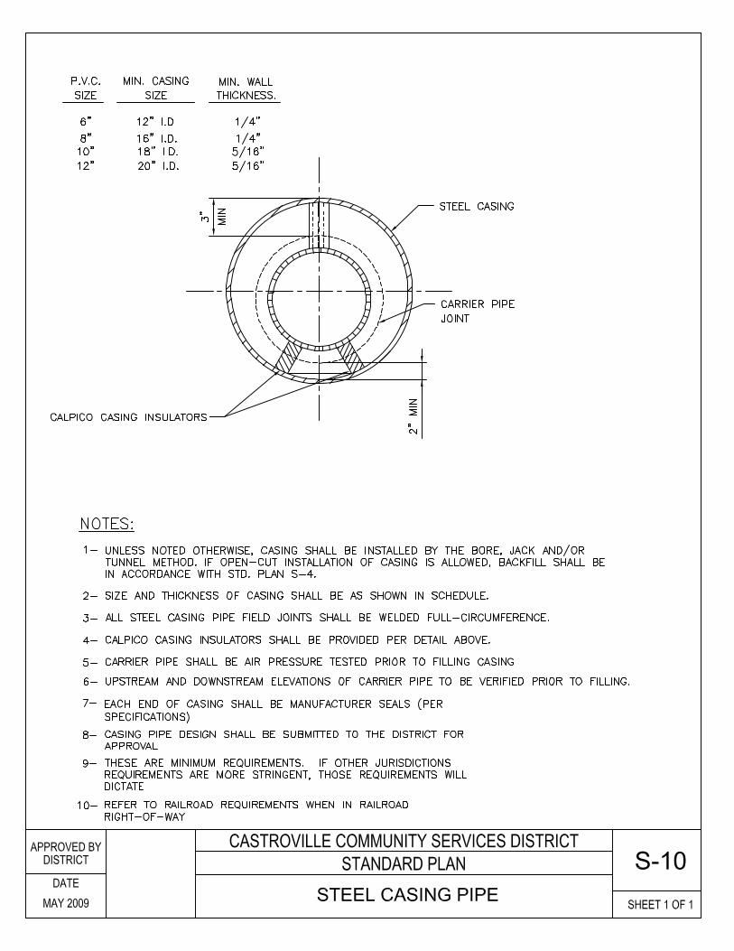
straps, as shown on CCSD Standard Plan W-13 or S-10. The diameters and lengths of the end seals
shall be sized to fit each casing pipe and carrier pipe to assure a positive barrier to backfill debris
and seepage.
END OF SECTION

SECTION 02701
Castroville Community Services District Page 25 April 2009
STANDARD SPECIFICATIONS
SECTION 02701
INSTALLATION OF GRAVITY SEWER PIPELINES
PART 1 - GENERAL
A. Description
This section describes the installation of gravity sewer pipelines fabricated of polyvinyl chloride
(PVC).
B. Related Work Described Elsewhere
1. Trenching, Backfilling and Compacting: 02223
2. Jacked Casing: 02315
3. PVC Gravity Sewer Pipe: 02715
4. Concrete: 03300
5. Precast Concrete Manholes and Manhole Bases: 03461
6. Leakage and Infiltration Testing: 15043
7. Ductile Iron Pipe and Fittings: 15056
PART 2 - MATERIALS
A. Installation Material
Refer to Section 02715, PVC Gravity Sewer Pipe for material requirements.
B. Piping Schedule
Unless noted otherwise on the plans or in the specifications, pipe shall be furnished in accordance
with the following materials schedule.
DIAMETER GRAVITY SEWER
4-inch through 21-inch PVC SDR-35
24-inch through 36-inch DIP with polyethylene lining
Notes: PVC SDR-35 - PVC gravity sewer pipe per Section 02715.
DIP - Ductile iron pipe per Section 15056.
PART 3 - EXECUTION
A. Delivery and Temporary Storage of Pipe at Site
1. Onsite Storage Limitation: Onsite pipe storage shall be limited to a maximum of one
month, unless exception is approved by District.
2. Care of Pipe: At times when the pipe laying is not in progress, the open end of the pipe
shall be closed with a tight-fitting cap or plug to prevent the entrance of foreign matter
into the pipe. These provisions shall apply during the noon hours as well as overnight.
SECTION 02701
Castroville Community Services District Page 26 April 2009
In no event shall the sewers be used as drains for removing water which has infiltrated
into the construction trenches.
B. Handling of Pipe
1. Moving Pipe: Pipes shall be lifted with handling beams or wide belt slings as
recommended by the pipe manufacturer. Cable slings shall not be used. Pipe shall be
handled in a manner to avoid damage to the pipe. Pipe shall not be dropped or dumped
from trucks or into trenches under any circumstances.
2. Inspection of Pipe: The pipe and accessories shall be inspected for defects prior to
lowering into the trench. Any defective, damaged or unsound pipe shall be repaired or
replaced. All foreign matter or dirt shall be removed from the interior of the pipe before
lowering into position in the trench.
C. Placement of Pipe in Trench
1. General: All pipe shall be laid without a break, upgrade from structure to structure, with
the bell end of the pipe upgrade. Pipe shall be laid to the line and grade given so as to
form a close concentric joint with the adjoining pipe and prevent sudden offsets of the
flow line.
2. Trench Excavation: Dewatering, excavation, shoring, sheeting, bracing, backfill material
placement, material compaction, compaction testing, and pipe laying requirements and
limitations shall be in accordance with Section 02223, Trenching, Backfilling, and
Compacting.
3. Pipe Bedding Thickness: Unless shown otherwise on the drawings, pipe bedding
material shall be 3/4-inch crushed rock for PVC pipe specified in Section 02223,
Trenching, Backfilling, and Compacting or compacted backfill material per Section
02223.
4. Subgrade at Joints: At each joint in the pipe, the pipe subgrade shall be recessed in firm
bedding material so as to relieve the bell of the pipe of all load and to ensure continuous
bearing along the pipe barrel.
5. Cleaning: The interior of the sewer pipe shall be cleaned of all dirt and superfluous
materials as the work progresses.
6. Joints: The mating surfaces of the pipe to be joined shall be wiped clean of all dirt and
foreign matter and a lubricant applied that is approved by the pipe manufacturer. Then,
with the surfaces properly lubricated, the spigot end of the pipe shall be positioned inside
the bell and the joint shoved home.
For larger diameter pipe where a lever attachment is required, the necessary precautions
shall be taken to insure an undamaged pipe installation.
7. Pipe Alignment: Unless specified otherwise, pipeline line and grade shall be as shown on
the plans. Grade shall be measured along the pipe invert.
SECTION 02701
Castroville Community Services District Page 27 April 2009
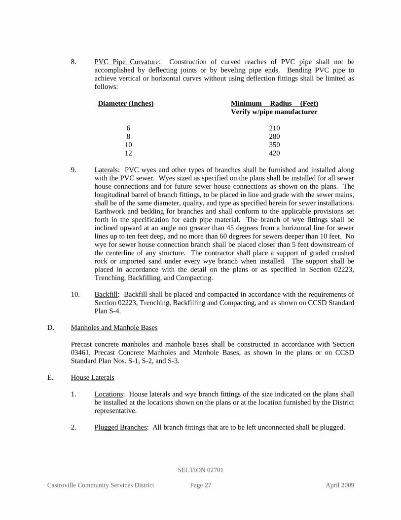
8. PVC Pipe Curvature: Construction of curved reaches of PVC pipe shall not be
accomplished by deflecting joints or by beveling pipe ends. Bending PVC pipe to
achieve vertical or horizontal curves without using deflection fittings shall be limited as
follows:
Diameter (Inches) Minimum Radius (Feet)
Verify w/pipe manufacturer
6 210
8 280
10 350
12 420
9. Laterals: PVC wyes and other types of branches shall be furnished and installed along
with the PVC sewer. Wyes sized as specified on the plans shall be installed for all sewer
house connections and for future sewer house connections as shown on the plans. The
longitudinal barrel of branch fittings, to be placed in line and grade with the sewer mains,
shall be of the same diameter, quality, and type as specified herein for sewer installations.
Earthwork and bedding for branches and shall conform to the applicable provisions set
forth in the specification for each pipe material. The branch of wye fittings shall be
inclined upward at an angle not greater than 45 degrees from a horizontal line for sewer
lines up to ten feet deep, and no more than 60 degrees for sewers deeper than 10 feet. No
wye for sewer house connection branch shall be placed closer than 5 feet downstream of
the centerline of any structure. The contractor shall place a support of graded crushed
rock or imported sand under every wye branch when installed. The support shall be
placed in accordance with the detail on the plans or as specified in Section 02223,
Trenching, Backfilling, and Compacting.
10. Backfill: Backfill shall be placed and compacted in accordance with the requirements of
Section 02223, Trenching, Backfilling and Compacting, and as shown on CCSD Standard
Plan S-4.
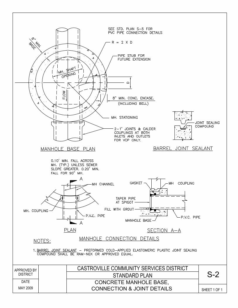
D. Manholes and Manhole Bases
Precast concrete manholes and manhole bases shall be constructed in accordance with Section
03461, Precast Concrete Manholes and Manhole Bases, as shown in the plans or on CCSD
Standard Plan Nos. S-1, S-2, and S-3.
E. House Laterals
1. Locations: House laterals and wye branch fittings of the size indicated on the plans shall
be installed at the locations shown on the plans or at the location furnished by the District
representative.
2. Plugged Branches: All branch fittings that are to be left unconnected shall be plugged.
SECTION 02701
Castroville Community Services District Page 28 April 2009
3. Fittings: House laterals shall be joined to wye branch fittings at the sanitary sewer main
as set forth above by eighth bends. All eighth bends and sixteenth bends are a part of
house lateral sewerline.
4. Alignment: Where possible, all house laterals shall run perpendicular to the sewer main
from the main to the property line, and all house laterals shall be bedded the same as the
sewer main into which they connect.
5. Plugged House Laterals: All house laterals shall be plugged with an approved stopper in
the socket of the last joint of each house lateral so that it will withstand the internal
pressure during the test for leakage, per Section 15013, but also in such a manner that it
may be removed without injury to the socket.
6. Marking: The contractor shall mark the location of each house lateral at its upper end by
chiseling a letter "S" 1-1/2-inches high on the face of the curb.
7. Chimney Connections: Chimney connections are not allowed.
8. Mainline Testing: The mainline sewer shall have passed final testing per Section 15043
before the laterals may be connected to the main.
F. Cleanouts
1. Size: Cleanouts shall be PVC pipe and shall be the same size as the line on which they
are installed. Cleanouts shall be constructed as shown on the CCSD Standard Plan S-7.
G. Saddle Connections
1. General: All saddle connections of new laterals into existing sewerlines shall be made
with a wye saddle.
2. Scoring and Tapping: The sewerline to be saddled shall be scored to the approximate
shape of wye or tee and shall be cut with a hole cutter. The tap holes shall be cleanly
machined and may be further worked by hand to provide a true and neat opening for the
collar wye or tee saddle. Pipe damaged during this operation shall be repaired or
replaced. The District representative shall be the sole judge as to the method of repair or
replacement.
3. Securement: The collar wye shall be secured to the sewer main with a catalytic epoxy
resin. The saddle shall be tied to the main with wire of sufficient strength that no
movement will occur during the setting of the epoxy resin.
4. Encasement: After the connection has set sufficiently long for the epoxy resin to cure,
the District will inspect the connection and, if satisfactory, the contractor shall encase the
fitting with Class B Portland cement concrete to the limits indicated on District Standard
Plan S-8.
5. Cleaning: The saddling operation shall be carried out in a workmanlike manner. Chips,
dirt, epoxy mortar, and concrete shall be kept out of the sewer line being saddled. If

SECTION 02701
Castroville Community Services District Page 29 April 2009
directed by the District representative, the reach of sewer main saddled shall be flushed
and cleaned using a hydrocleaner or vacuum truck.
6. Alternative Connection: In lieu of a saddle connection, a wye connection may be made
by cutting the sewer and installing a wye.
H. Installation Within Jacked Casing
1. General: The sewer pipe shall be installed within the casing pipe to the lines and grades
shown on the plans and in accordance with Section 02315, Jacked Casing.
2. Pipe Support: The carrier pipe shall be supported on cradles such as “PSI” spacers,
Model C8G-2, or approved equal before backfilling, in such a manner as to relieve the
pipe bells from any bearing loads.
3. Fill Within the Casing: The annular space between the casing and the carrier pipe shall
be backfilled per Section 02315, Jacked Casing.
4. Testing: Before backfilling as specified above, the sewer carrier pipe shall pass an initial
test for leakage as provided in Section 15043, Leakage and Infiltration Testing.
I. Pipe Anchorage (For Pipelines Having a Diameter of 10-Inches or Less)
1. General: Concrete slope anchors shall be installed where shown on the plans in
accordance with Section 03300 and District Standard Plan S-9, wherever the profile of
the ground surface above the sewer main exceeds 20 percent, and where no pavement or
other surfacing is to be laid over the facility.
2. Dimensions: Anchors shall be a minimum of 12-inches thick and shall extend at least 12-
inches into undisturbed material on each side of the trench as excavated.
3. Spacing: Spacing between pipe anchors shall not exceed the distances shown on District
Standard Plan S-9.
4. Reinforcement for Concrete Anchors: Anchors constructed of cast-in-place reinforced
concrete shall have No. 4 reinforcing bars placed at 6-inches on center each way in the
center of the anchor thickness. The bars shall extend full length and height of the anchor.
J. Concrete Encasement
Unless shown otherwise, concrete for encasement shall be reinforced or unformed or rough
formed, and of the class as designated on the plans. Concrete shall be in accordance with Section
03300, Concrete. Concrete used for encasing, cradling, bedding, cover for pipe, or other objects
shall be used as shown on the Plans, on District Standard Plan S-9, or as directed by the District
representative.
K. Cleaning

SECTION 02701
Castroville Community Services District Page 30 April 2009
Before testing, each pipe shall be thoroughly cleaned from manhole to manhole with a sewer
scrubbing ball, and all debris and trash shall be removed from each manhole. Screens shall be
placed in the manhole outlet to catch debris.
L. Mandrel Test for PVC Gravity Sewers 10-inch in Diameter and Smaller
Following placement and compaction of backfill for all utilities, and prior to the placement of
permanent pavement, all sewer mains shall be cleaned and mandrelled to verify that the pipeline
is free from obstructions (deflections, joint offsets, lateral pipe intrusions, etc.) in accordance with
Section 15043.
M. Leakage and Infiltration Test
The pipe, manholes, and other appurtenances shall be tested for leakage and infiltration per
Section 15043, Leakage and Infiltration Testing.
N. Closed-Circuit Television Inspection
1. General: In addition to the regular leakage and infiltration test, the entire length of all
new sewer lines shall be inspected by the contractor using closed-circuit television
equipment. The inspection shall be conducted after the line has been successfully tested
and prior to paving. The inspection shall be conducted in the presence of the District
representative. For pipe lengths designed to absolute minimum design slopes (See
Section 500-2 of the Procedural Guidelines), video inspection shall provide a profile of
the sewer line.
2. Responsibility: All labor and equipment necessary to conduct this inspection shall be
furnished by the contractor.
3. Notification: Requests for sewer line inspection shall be made to the District
representative a minimum of two working days in advance of the desired inspection date.
4. Flushing: Each sewer section shall be flushed with water being introduced at the
upstream manhole of each section prior to video recording.
5. Stationing: The video shall show stationing corresponding to sewer stationing shown on
plans for each manholes and Wye location.
6. Submittal: The videotape shall be VHS format and be submitted to the District with two
(2) of the computer printouts showing manhole numbers and stationing, wye stationing
and distance between manholes prior to occupancy release for the dwelling units being
served by the sewer. The tape and printout shall be labeled with the project name, tract
number, street names, and contractor’s name and shall list the station of any defects, dirt,
low spots, etc. in the pipe.
7. Repair of Defects: Even though the sewer line may have successfully passed the leakage
and infiltration tests, any defects or low spots in the line shall be repaired to the
satisfaction of the District.
SECTION 02701
Castroville Community Services District Page 31 April 2009
8. Acceptance: Sewer section having standing water or defects shall be repaired by the
contractor prior to District acceptance and prior to occupancy release for the dwelling
units or commercial site being served by the sewer. Standing water in the system will not
be allowed.
O. Final Inspection
After paving has been completed and all manholes raised to grade, a final visual `inspection shall
be made. The necessary labor shall be furnished to assist the District representative in making the
final inspection. Additional cleaning may be required if the lines are dirty, even though lines
were previously cleaned. The contractor shall furnish a responsible person or supervisor for the
final inspection to remove manhole covers and to note any corrections required by the District
representative in order to obtain final approval. Final District inspection shall be requested
through the District representative by giving at least two day's notice.
END OF SECTION

SECTION 02715
Castroville Community Services District Page 32 April 2009
STANDARD SPECIFICATIONS
SECTION 02715
PVC GRAVITY SEWER PIPE
PART 1 - GENERAL
A. Description
This section includes materials, testing, and installation of polyvinyl chloride (PVC) gravity
sewer pipe and fittings.
B. Related Work Specified Elsewhere
1. Trenching, Backfilling and Compacting 02223
2. Jacked Casing: 02315
3. Installation of Gravity Sewer Pipelines: 02701
4. Concrete: 03300
5. Precast Concrete Manholes and Manhole Bases: 03461
6. PVC Distribution Pipe: 15064
C. Submittals
1. Provide materials list showing material of pipe and fittings with ASTM references and
grade.
2. Provide certificates of compliance with all standards referenced in this section.
D. Application
PVC SDR 35 shall be used for gravity sewer mains up to and including 12-inch in diameter,
except as specifically called out on the project plans.
E. Sewer Force Mains
PVC sewer force mains shall be constructed in accordance with the requirements for PVC
Distribution Pipe, Section 15064.
PART 2 - MATERIALS
A. Pipe and Fittings
1. ASTM Requirements: Pipe, fittings, couplings, and joints shall be in conformance with
the size, material and performance requirements of ASTM D 3034, SDR 35, and shall
have gasketed joints. Pipe shall be made of PVC plastic having a cell classification of
12454-B, 12454-C, or 13364-B as defined in ASTM D 1784. Fittings shall be made of
PVC plastic having a cell classification of 12454-B, 12454-C, or 13343-C. All pipe shall
be of solid wall construction with smooth interior and exterior surfaces.

SECTION 02715
Castroville Community Services District Page 33 April 2009
2. Manufacturer’s Testing Certification: During production of the pipe, the manufacturer
shall perform the specified tests for each pipe marking. A certification by the
manufacturer indicating compliance with specification requirements shall be delivered
with the pipe. The certification shall include the test result data.
3. Pipe Marking: All pipe, fittings, and couplings shall be clearly marked at an interval not
to exceed 5-feet as follows:
a. Nominal pipe diameter
b. PVC cell classification
c. Company, plant, shift, ASTM, SDR, and date designation
d. Service designation or legend
For fittings and couplings, the SDR designation is not required. All pipe shall have a
home mark on the spigot end to indicate proper penetration when the joint is made.
4. Additional Pipe Tests Following Delivery: When pipe is delivered to the jobsite, the
District representative may require additional testing to determine conformance with the
requirements of pipe flattening, impact resistance, pipe stiffness, and extrusion quality.
When testing is required, one test pipe shall be selected at random by the engineer from
each 1,200 feet or fraction thereof of each size of pipe delivered to the jobsite but not less
than one test pipe per lot. A lot shall be defined as pipe having the same identification
marking. The length of specimen for each selected pipe shall be a minimum of 8-feet.
5. Pipe Retest: Pipe which is not installed within 120 days of the latest test shall not be used
without prior approval of the District representative.
6. Fitting and Coupling End Configurations: The socket and spigot configurations for
fittings and couplings shall be compatible with those used for the pipe.
7. Manufacturers: Pipe shall be as manufactured by J-M Manufacturing, Vinyltech, P W
Pipe, Diamond Plastics, Carlon, or approved equal. Fittings shall be as manufactured by
J-M Manufacturing, GPK Products, or approved equal.
B. Gaskets for PVC Pipe
1. General: Unless otherwise specified, gaskets shall be manufactured from a synthetic
elastomer, and shall be extruded or molded and cured in such a manner as to be dense,
homogeneous and of smooth surface, free of pitting, blisters, porosity, and other
imperfections. The compound shall contain not less than 50 percent by volume of first-
grade synthetic rubber. The remainder of the compound shall consist of pulverized fillers
free of rubber substitutes, reclaimed rubber, and deleterious substances. The tolerance
for any diameter measured at any cross section shall be 1/32-inch (.8mm).
2. Gasket Material Requirements: When required by the District representative, the
contractor shall furnish test samples of gaskets from each batch used in the work. Gasket
material shall meet the following requirements:

SECTION 02715
Castroville Community Services District Page 34 April 2009
Property Value ASTM Test
Method
Tensile Strength (min. psi) 2,000 D 412
Elongation at break (% min.) 350 D 412
Shore durometer, Type A
(Pipe manufacturer shall select value suitable for type
of joint)
40 to 65* D 2240
Compression set (constant deflection) max % of
original deflection 16 D 395
Compression strength after oven aging (96 hours,
158F {70C}) % of tensile strength before aging 80 D 573
Increase in Shore durometer hardness after oven aging.
Maximum increase over original Shore durometer 10 D 2240
Physical requirements after exposure to ozone
concentration (150 pphm. 70 hours, 140F {40C}),
20% strain)
No Cracks D 1149
*This applies only to the sealing component of the gasket.
PART 3 - EXECUTION
A. Related Installation Specification
PVC gravity sewer pipe shall be installed in accordance with the requirements of Section 02701,
Installation of Gravity Sewer Pipelines.
END OF SECTION

SECTION 03300
Castroville Community Services District Page 35 April 2009
STANDARD SPECIFICATIONS
SECTION 03300
CONCRETE
PART 1 - GENERAL
A. Description
This section describes concrete materials, mixing, placement, form work, reinforcement and curing.
B. Related Work Specified Elsewhere
All related work specified elsewhere, or in other codes or standards, will be as last revised, unless a
specific date of issuance is called out in opposition to later revision date(s).
Other sections of the technical specifications, not referenced below, shall also apply to the extent
required for proper performance of this work.
Earthwork: 02200
C. Submittals
1. Shop drawings shall be submitted in accordance with the General Provisions, ACI 318, and the
following.
2. Mix design with proof of design by laboratory 7-day and 28-day compressive testes, or test
reports of 7-day and 28-day compressive tests of the mix where the same mix was used on two
previous projects, shall be submitted in writing for review by the District at least 15 days before
placing of any concrete.
3. Certificate that cement used in the concrete complies with ASTM C 150 and these
specifications shall be submitted.
4. Aggregates: Certificate of compliance with ASTM C 33 shall be provided. Weathering region
limits of coarse aggregates: sever, moderate, or negligible shall be stated. Basis of determining
that potential reactivity is negligible shall be stated.
5. Ready Mix Concrete: Delivery tickets or weighmasters certificate per ASTM C 94, including
weights of cement and each size aggregate, volume of water in the aggregate, and volume of
water added at the plant shall aggregate, and volume of water added at the plant shall be
provided. The volume of water added on the job shall be written on the ticket or certificate.
6. Concrete admixtures: Manufacturer’s certificate of compliance with their specification shall be
provided.
7. Epoxy Bonding Compound: Manufacturer’s specific instructions for use shall be provided.
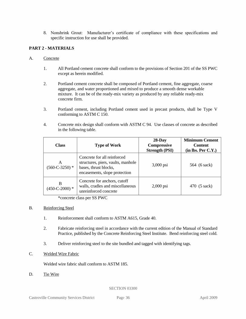
SECTION 03300
Castroville Community Services District Page 36 April 2009
8. Nonshrink Grout: Manufacturer’s certificate of compliance with these specifications and
specific instruction for use shall be provided.
PART 2 - MATERIALS
A. Concrete
1. All Portland cement concrete shall conform to the provisions of Section 201 of the SS PWC
except as herein modified.
2. Portland cement concrete shall be composed of Portland cement, fine aggregate, coarse
aggregate, and water proportioned and mixed to produce a smooth dense workable
mixture. It can be of the ready-mix variety as produced by any reliable ready-mix
concrete firm.
3. Portland cement, including Portland cement used in precast products, shall be Type V
conforming to ASTM C 150.
4. Concrete mix design shall conform with ASTM C 94. Use classes of concrete as described
in the following table.
Class Type of Work
28-Day
Compressive
Strength (PSI)
Minimum Cement
Content
(in lbs. Per C.Y.)
A
(560-C-3250) *
Concrete for all reinforced
structures, piers, vaults, manhole
bases, thrust blocks,
encasements, slope protection
3,000 psi 564 (6 sack)
B
(450-C-2000) *
Concrete for anchors, cutoff
walls, cradles and miscellaneous
unreinforced concrete
2,000 psi 470 (5 sack)
*concrete class per SS PWC
B. Reinforcing Steel
1. Reinforcement shall conform to ASTM A615, Grade 40.
2. Fabricate reinforcing steel in accordance with the current edition of the Manual of Standard
Practice, published by the Concrete Reinforcing Steel Institute. Bend reinforcing steel cold.
3. Deliver reinforcing steel to the site bundled and tagged with identifying tags.
C. Welded Wire Fabric
Welded wire fabric shall conform to ASTM 185.
D. Tie Wire
SECTION 03300
Castroville Community Services District Page 37 April 2009
Tie wire shall be 16-gage minimum, black, soft annealed.
E. Bar Supports
Bar supports in beams and slabs exposed to view after form stripping shall be galvanized or plastic
coated. Use concrete supports for reinforcing in concrete placed on grade.
F. Forms
1. Forms shall be accurately constructed of clean lumber and shall be of sufficient strength
and rigidity to hold the concrete and to withstand the necessary pressure and tamping
without deflection from the prescribed lines.
2. The surface of forms against which concrete is placed shall be smooth and free from
irregularities, dents, sags, or holes. The surface shall leave uniform form marks
conforming to the general lines of the structure.
PART 3 - EXECUTION
A. Excavation
Excavation for structures shall be in accordance with Section 02200.
B. Form Work
1. The contractor shall notify the District representative a minimum of one working day
before the placement of concrete to enable the District representative to check the form
lines, grades, and other required items for approval before placement of concrete.
2. Unless otherwise indicated on the plans, all exposed sharp edges shall be chamfered with at
least 3/4 - by 3/4-inch triangular fillets.
3. Before placing concrete, the form surface shall be clean and coated with form oil of high
penetrating qualities.
C. Reinforcement
1. Place reinforcing steel in accordance with the current edition of “Recommended Practice
for Placing Reinforcing Bars,” published by the Concrete Reinforcing Steel Institute.
2. All reinforcing steel shall be of the required sizes and shapes and placed where shown on
the drawings or prescribed by the District representative.
3. Do not straighten or rebend reinforcing steel in a manner that will injure the material. Do
not use bars with bends not shown on the drawings.
4. All bars shall be free from rust, scale, oil, or any other coating which would reduce or
destroy the bond between concrete and steel.

SECTION 03300
Castroville Community Services District Page 38 April 2009
5. Position reinforcement steel in accordance with the drawings and secure by using
annealed wire ties or clips at intersections and support by concrete or metal supports,
spacers, or metal hangers. Do not place metal clips or supports in contact with the forms.
Bend tie wires away from the forms in order to provide the specified concrete coverage.
Bars additional to those shown on the drawings, which may be found necessary or
desirable by the contractor for the purpose of securing reinforcement in position, shall be
provided and paid for by the contractor.
6. Place reinforcement a minimum of 2 inches clear of any metal pipe or fittings.
7. The reinforcement shall be so secured in position that it will not be displaced during the
placement of concrete.
8. All reinforcing steel and wire mesh shall be completely encased in concrete.
9. Secure reinforcing dowels in place prior to placing concrete. Do not press dowels into the
concrete after the concrete has been placed.
10. Minimum lap for all reinforcement shall be 20 bar diameters.
11. Place additional reinforcement around the pipe or opening as indicated in the drawings.
12. Wire mesh reinforcement is to be rolled flat before being placed in the form. Support and
tie wire mesh to prevent movement during concrete placement.
13. Extend welded wire fabric to within 2 inches of the edges of the slab. Lap splices at least
1-1/2 courses of the fabric and a minimum of 6 inches. Tie laps and splices securely at ends
and at least every 24 inches with 16-gage black annealed steel wire. Pull the fabric into
position as the concrete is placed by means of hooks, and work concrete under the steel to
ensure that it is at the proper distance above the bottom of the slab.
D. Embedded Items
All embedded bolts, dowels, anchors, and other embedded items shall be held correctly in place in
the forms before concrete is placed.
E. Mixing and Placing Concrete
1. Concrete, either commercial of on-site ready mix or batch mixed, shall be placed in the
forms before taking its initial set.
2. No concrete shall be placed in water except with permission of the District representative.
3. As the concrete is placed in the forms, or in excavations to be filled with concrete, it shall
be thoroughly settled and compacted throughout the entire layer by internal vibration and
tamping bars.

SECTION 03300
Castroville Community Services District Page 39 April 2009
4. All concrete surfaces upon which or against which the concrete is to be placed, and to
which new concrete is to adhere, shall be roughened, thoroughly cleaned, wet, and grouted
before the concrete is deposited.
F. Concrete Finishing
1. Immediately upon the removal of forms, all voids shall be neatly filled with cement mortar.
2. The surfaces of concrete to be permanently exposed to view must be smooth, free from
projections, and thoroughly filled with mortar.
3. Exposed surfaces of concrete not finished against forms, such as horizontal or sloping
surfaces, shall be screened to a uniform surface and worked with suitable tools to a smooth
mortar finish.
G. Protection and Curing of Concrete
The contractor shall protect all concrete against damage. Exposed surfaces of new concrete shall be
protected from the direct rays of the sun and from frost by being kept damp for at least two weeks
after the concrete has been placed, or by using the "Hunt White Coverage" process or approved
equal.
H. Backfill
Backfill around structures shall be in accordance with Section 02200.
END OF SECTION

SECTION 03461
Castroville Community Services District Page 40 April 2009
STANDARD SPECIFICATIONS
SECTION 03461
PRECAST REINFORCED CONCRETE MANHOLES AND MANHOLE BASES
PART 1 - GENERAL
A. Description
This section includes materials, testing, and installation of precast concrete manholes, manhole
bases, manhole frames and covers.
B. Related Work Specified Elsewhere
1. Structure Earthwork: 02200
2. Trenching, Backfilling, and Compacting: 02223
3. Concrete: 03300
4. Leakage and Infiltration Testing: 15043
C. Submittals
1. Submit manufacturer's catalog and test data on precast concrete manholes, frames, and
covers along with installation recommendations for inlet and outlet seals and watertight
caulking. Show dimensions and materials of construction by ASTM reference and grade.
Show manhole cover lettering and pattern.
PART 2 - MATERIALS
A. Precast Concrete Manholes
1. General: Precast reinforced concrete manholes shall comply with ASTM C 478, with a
minimum wall thickness of 5-inches.
2. Design Load: Manhole components shall be designed for H-20 highway loads and site
soil conditions.
3. Concrete: Precast reinforced concrete manhole risers and tops shall be constructed of
Class A concrete with Type V cement per Section 03300, Concrete.
4. Manhole Section Configuration: Manholes shall be fabricated only from concentric taper
sections and standard cylinder units of the proper internal diameter.
5. Manhole Section Dimensions: Unless noted otherwise, minimum diameter and wall
thickness of manholes and manhole sections shall be as follows:

SECTION 03461
Castroville Community Services District Page 41 April 2009
Depth, feet Manhole Diameter
(inches)
Manhole Section
Wall Thickness, inches
0 – 6.0 48 5
6.1 – 15.9 60 6
16 - 22 72 9
Depth of cover shall be measured from proposed finish surface elevation to the lowest
pipe invert.
6. Steps: Manhole sections shall be cast without steps.
7. Drop Manholes: Drop manholes of greater than 1-foot are not permitted without the
District’s approval.
8. Manufacturers: Precast reinforced concrete manholes shall be manufactured by Jensen
Precast, Hansen, Precon Products, or approved equal.
B. Manhole Frames and Covers
1. General Requirements: Manhole frames and covers shall be made of ductile iron
conforming to ASTM A 536, Class 400, or cast iron conforming to ASTM A 48, Class
30. Casting shall be smooth, clean, and free from blisters, blowholes, and shrinkage.
Frames and covers shall be of the traffic type, designed for H-20 loading.
2. Fit and Matchmarking: Each manhole cover shall be ground or otherwise finished so that
it will fit in its frame without rocking. Frames and covers shall be matchmarked in sets
before shipping to the site.
3. Cover Inscription: Covers shall have the words “SANITARY SEWER” cast thereon as
shown in CCSD Standard Plan S-3 or on the plans. No other lettering on the top side
shall be permitted.
4. Inspection and Coating: Before leaving the foundry, castings shall be cleaned and
subjected to a hammer inspection. Castings shall then be dipped twice in a preparation of
asphalt or coal tar and oil applied at a temperature of not less than 290°F, not more than
310°F, and in such a manner as to form a firm and tenacious coating.
5. Manufacturers: Manhole frames and covers shall be manufactured by Neenah Foundry,
Long Beach Iron Works, Alhambra Foundry, South Bay Foundry or approved equal.
C. Imported Sand
Imported sand shall comply with Section 02223, Trenching, Backfilling, and Compacting.

SECTION 03461
Castroville Community Services District Page 42 April 2009
D. Crushed Rock
Crushed rock shall comply with Section 02223, Trenching, Backfilling, and Compacting.
Crushed rock base material shall extend 1 foot beyond the outside edge of the concrete manhole
base.
E. Manhole Bases
Concrete used in pouring the manhole base shall be Class A concrete, Type V cement per Section
03300, Concrete. Precast manhole bases and acceptable in lieu of field formed manhole bases
with the approval of the District.
F. Manhole Linings
When required by the District, manholes shall be lined with PVC “T-Loc” liners installed per
manufacturer’s guidelines and as required by the Engineer. Inside of PCC manholes without
liners shall be coated with “Thoro Seal” or equal.
G. Cement-Mortar Grout
Grout for watertight joints between precast sections shall be composed of one part Portland
cement to two parts of clean well-graded sand of such size that all pass a No. 8 sieve. Cement,
aggregate, and water for mortar shall conform to the applicable provisions of Section 03300,
Concrete.
H. Epoxy Grout
Epoxy grout shall be used in repairing manhole and manhole base surfaces. Epoxy grout shall be
made with epoxy and sand. The sand shall be clean, bagged, graded, and kiln dried silica sand.
The prepared grout shall wet the contact surface and provide proper adhesion, or a coat of epoxy
shall be applied prior to placing the epoxy grout. The epoxy bonding compound shall be as
specified in Section 03300, Concrete.
I. Plastic Joint Sealing Compound
Preformed cold-applied ready-to-use plastic joint sealing compound shall be “Ram-nek”, or
approved equal.
PART 3 - EXECUTION
A. Work Within Existing Manholes
Any proposed work inside an existing manhole that is part of a sewerage system in service, shall
not be undertaken until all the tests and safety provisions of Article 4, Section 1532 "Confined
Spaces" State of California Construction Safety Orders have been made.
B. Excavation

SECTION 03461
Castroville Community Services District Page 43 April 2009
Excavation for the precast concrete manhole shall be in accordance with Section 02223,
Trenching, Backfilling, and Compacting.
C. Manhole Base
1. General: Manhole bases shall be poured in place against undisturbed soil with Class A
concrete having 3/4-inch-maximum size aggregate and a slump of not greater than 2-
inches. The manhole base shall be poured as one monolithic pour. Limitations for site-
mixed and ready-mixed concrete set forth in Section 03300, Concrete, shall be observed.
A 12-inch thick base of 3/4-inch crushed rock shall be placed prior to the placement of
concrete for all installations.
2. Manhole Stub Placement: The manhole stubs and sewer main shall be set before the
concrete is placed and shall be rechecked for alignment and grade before the concrete has
set. The various sized inlets and outlets to the manhole shall be located as indicated on
the plans and as detailed in the detail drawings. A neoprene water stop gasket shall be
placed around the pipe and at ½ the wall thickness prior to placing concrete.
3. Matching Pipe Crown Elevations: Invert elevations of connecting sewers many vary
depending upon sizes. The crown elevation of all pipes shall be the same as the crown
elevation of the largest pipe unless otherwise indicated on the plans.
4. Channel Configuration: The invert of the manhole base shall be formed so as to provide
smooth channels conforming in size and shape to the lower portions of the inlet and
outlet pipes. The channel shall vary uniformly in size and shape from inlet to outlet, and
a shelf shall be constructed higher than the pipe as indicated on the drawings. The
manhole base shall extend 12-inches below the bottom of the lowest pipe.
5. Transitions: All transitions shall be smooth and of the proper radius to give an
uninterrupted transition of flow.
6. Finishing: The concrete base shall be shaped with a wood float and shall receive a hard
steel trowel finish before the concrete sets.
7. Placement of Additional Mortar: In the event additional mortar is required after initial set
has taken place, the surface to receive the mortar shall be primed, and the mortar mixed
with "Willhold Concrete Adhesive" in the amounts and proportions recommended by the
manufacturer and as directed by the District representative in order to secure as chip-
proof a result as possible.
8. Curing Time Before Further Construction: Unless approved otherwise by the District, in
advance, the bases shall set a minimum of 24 hours before the manhole construction is
continued.
9. Manhole Barrel Impression Ring shall be used to mold a groove into the base to match
the manhole barrel.
D. Pre-Cast Manhole Base: All pipe entrance and exit locations shall have water tight compression
joints made of rubber which are integrally cast into the manhole wall. The flexible joints shall

SECTION 03461
Castroville Community Services District Page 44 April 2009
meet ASTM C 923 for manufacture and ASTM C969 or C1244 performance and test
requirements. All pipe entrance and exit points shall be precast to the elevations and deflection
angle as shown on the plans. Pipes shall not be laid through manholes when utilizing precast
manhole bases. Following placement of the base and insertion of pipes through manhole wall,
the manhole floor and concrete fillet work shall proceed as shown on the plans.
E. Installing Manholes
1. General: Manholes for sewers of diameter 12-inches or less shall be constructed as
shown on CCSD Standard Plans S-1, S-2, and S-3. Manholes for larger diameter sewers
shall be constructed as shown on the project construction plans.
2. Joints: Precast concrete manhole units shall be set in a bed of grout to make a watertight
joint at least 1/2 inch thick with the concrete base or with the preceding unit. Manhole
sections shall be set perfectly plumb. Inside joints shall be pointed and the excess sealant
cut wiped off. Preformed, cold-applied, ready-to-use, plastic joint sealing compound
may be substituted for grout between units and must be used when groundwater is
encountered.
3. Finish Elevation of Manhole Covers: Precast sections shall be assembled so that the
cover conforms to the elevation determined by the manhole location as follows, but
limited to a maximum of 18-inches from the top of the manhole cone to the top of the
ring and cover, unless otherwise instructed by the District representative.
a. In Paved Area: Top of cover shall be flush with the paving surface.
b. In Shoulder Areas: Top of cover shall be flush with existing surface where it is in
traveled way or shoulder and 0.1 foot above existing surface where outside limits of
traveled way but not in the existing roadside ditch.
c. In Roadside Ditch or Unpaved Open Areas: Top of cover shall be a minimum of 6-
inches above the ground surface and surrounded with a concrete collar, per CCSD
Standard Plan S-1. In special instances, as designated by the District representative
or as shown on the plans, the top of the cover shall be flush with the surrounding
ground surface and within a square concrete pad 2 feet larger than the manhole
frame. Guard posts or paddle boards may be required adjacent to manholes in open
areas.
4. Manhole Frame and Cover: Manhole frame and grade rings shall be secured in a
concrete collar. Frames and collars shall be installed after paving and 2” deep hot asphalt
shall be placed around frame and concrete collar.
5. Watertightness: It is the intent of these specifications that manholes and appurtenances
be watertight and free from infiltration. All manholes are to be banded both inside and
outside with cement-mortar grout. Where called for in the plans or supplemental
specifications, manholes that are to be given a protective lining or coating shall be free of
any seeping or surface moisture. The adequacy of manholes and appurtenances as to
watertightness shall be determined by the District representative and shall be tested in
accordance with Section 15043, Leakage and Infiltration Testing.

SECTION 03461
Castroville Community Services District Page 45 April 2009
6. Stubs: Sewer pipe shall be furnished and installed in manholes at the locations shown
and in conformance with the detail drawings and plans. All stubs shall be plugged with
stoppers as shown on the plans for various sizes of pipe.
7. Bulkheads: Brick and mortar bulkheads shall be installed at the downstream end of all
unused stub channels over 5 feet long to prevent the creation of a septic condition
resulting from ponding of sewage and debris in the unused channels, and until such time
as the manhole stub is connected and normal sewage flow can occur. A plug shall be
required for all downstream stubs.
8. New Connections to Existing Manholes: New connections to existing manholes wherein
stubs have not been provided shall be made as directed by the District.
9. Backfill: Backfill around the precast concrete manhole shall be imported sand, and shall
be placed and compacted in accordance with Section 02223, Trenching, Backfilling, and
Compacting.
10. Grade Rings: Class B concrete rings shall be cast around manhole frames that are flush
with the surface, as necessary per Standard Plans S-1 and S-3. The ring shall be placed
after final grading or paving together with final cleanup.
11. Pavement Replacement: Replacement of bituminous or concrete pavement shall be in
accordance with the requirements of the governmental agency having jurisdiction.
E. Manhole and Manhole Base Repairs
Manhole sections and bases that exhibit defects in the concrete surface may be rejected.
Defective concrete surfaces of manhole sections and bases not rejected shall be repaired by
chipping away unsound or imperfect concrete. Edges shall be left sharp and square with the
surface. Loose material and dust remaining after chipping shall be removed by means of an air
jet. Epoxy grout shall be applied to the surface to be repaired in accordance with the
manufacturer's instructions. The grout shall wet the contact surface and provide proper adhesion,
or a coat of epoxy shall be applied prior to placing the epoxy grout.
END OF SECTION

SECTION 03462
Castroville Community Services District Page 46 April 2009
STANDARD SPECIFICATIONS
SECTION 03462
PRECAST CONCRETE VAULTS
PART 1 - GENERAL
A. Description
This section includes the materials, manufacture, and installation of precast concrete vaults, vault
frames and covers.
B. Related Work Specified Elsewhere
All related work specified elsewhere, or in other codes or standards, will be as last revised, unless a
specific date of issuance is called out in opposition to later revision date(s).
Other sections of the technical specifications, not referenced below, shall also apply to the extent
required for proper performance of this work.
1. Earthwork: 02200
2. Concrete: 03300
C. Approved Manufacturers
1. Precast Vaults
Utility Vault
J & R Products
Jensen Precast
2. Meter Boxes
Christy
Old castle
Fiber light
3. Joint Sealing Compound
Conseal
4. Waterproofing
Grace Dehydratine 4
5. Frames and Covers
Bilco
Syracuse Castings
D. Frames and Covers

SECTION 03462
Castroville Community Services District Page 47 April 2009
All precast sections shall be provided with fabricated aluminum or steel frames and covers as
specified or shown on the drawings and shall be built up so that the cover is flush with the
surrounding surface unless otherwise specified on the drawings or by the District representative in
the field.
E. Meter Boxes
1. Fiber light meter boxes shall be purchased and installed by the contractor unless noted
otherwise. Meter box lid shall be fiber light.
2. Sizes shall be as specified on the standard drawings for the various sizes and types of
services.
F. Purchase of Vaults
The contractor shall purchase precast concrete vaults for meter installations 3-inch and larger and
other applications.
PART 2 - MATERIALS
A. Precast Concrete Vault
1. Precast concrete vaults and covers shall be manufactured in a plant especially designed for
that purpose and shall conform to the shapes and dimensions indicated on the plans.
2. Design loads shall consist of dead load, live load, impact, and in addition, loads due to
water table and any other loads which may be imposed upon the structure. Live loads shall
be for H-20 per AASHTO standard specifications for highway bridges. Design wheel load
shall be 16 kips. The live load shall be that which produces the maximum shears and
bending moments in the structure.
3. Concrete shall be Class A conforming to Section 03300.
4. Vault floor shall be treated such that a non-skid surface is provided.
5. Vault floor shall contain grooved channels to convey drainage to a sump area.
B. Meter Box Covers
1. Fiber light meter box covers shall be installed in all locations. Where required, traffic rated
(H20 or greater) covers shall be provided.
C. Vault Frames and Covers
1. Vault frames and covers shall be fabricated aluminum with stainless steel hardware.
2. Covers shall be fabricated with supports to resist deflection.

SECTION 03462
Castroville Community Services District Page 48 April 2009
3. All covers shall be hinged providing access to the entire vault. Covers shall have spring
assists.
4. All covers shall be equipped with a hold-open mechanism with safety chains
5. All covers shall be equipped with a flush locking devices with locking eyes up.
6. All frames and covers shall be equipped with a “ladder up” to provide access assistance.
7. All covers must be H20 traffic rated for equipment or vehicle loading, unless specified
otherwise by the Engineer.
D. Joint Sealing Compound
The joint sealing compound shall be a permanently flexible plastic material complying in every
detail to Federal Specification SS S-00210 (GSA-FSS) dated July 26, 1965. "Quickseal", or
approved equal.
PART 3 - EXECUTION
A. Earthwork
1. Excavation and backfill for precast concrete vaults shall be in accordance with Section
02200 and the requirements herein.
2. The contractor shall prepare an excavation large enough to accommodate the structure and
permit grouting of openings and backfilling operations.
3. The bottom of the structure shall be placed on 6- inches of compacted, crushed rock sub-
base, graded level and to the proper elevation as shown on the plans, unless otherwise
indicated by the Engineer.
B. Installation
1. Openings or "knockouts" in precast concrete vaults shall be located as shown on the
drawings and shall be sized sufficiently to permit passage of the largest dimension of pipe
and/or coupling flange. Upon completion of installation, all voids or openings in the vault
walls around pipes shall be filled with 3,000-psi concrete or mortar, using an approved
epoxy for bonding concrete surfaces.
2. After the structure and all appurtenances are in place and approved, backfill shall be placed
such that finished grade is sloped away from vault (in unpaved areas) or such that vault is
flush with finished grade (in paved areas), unless otherwise indicated by the Engineer.
3. All joints between precast concrete vault sections shall be made watertight using preformed
mastic material. The sealing compound shall be installed according to the manufacturer's
recommendations to provide a watertight joint which remains impermeable throughout the
design life of the structure. All joints shall be filled with dry-pack non-shrink grout.

SECTION 03462
Castroville Community Services District Page 49 April 2009
4. Frames and covers shall be built up so that the cover is flush with the surrounding surface
unless otherwise specified on the drawings or by the District representative in the field.
The contractor is responsible for placing the cover at the proper elevation where paving is
to be installed and shall make all necessary adjustments so that the cover meets these
requirements.
C. Meter Boxes
1. Boxes shall be set true to line and to the grade of the top of the curb, sidewalk, or
surrounding graded area.
2. Meter boxes are not to be set until fine grading for landscape grading has been completed
by the developer.
3. Retaining walls may be required around meter boxes installed on slopes as determined by
the District representative.
END OF SECTION

SECTION 03463
Castroville Community Services District Page 50 April 2009
STANDARD SPECIFICATIONS
SECTION 03463
GREASE INTERCEPTORS
PART 1 - GENERAL
A. Description
This section includes materials and installation of precast concrete grease interceptors on
commercial sanitary sewer conditions.
B. Related Work Specified Elsewhere
1. Installation of Gravity Sewer Pipelines 02701
2. Precast Concrete Vaults 03462
C. Approved Manufacturers
GT series as manufactured by Jay R. Smith Manufacturing Company
Pro-Cast
Jensen Precast
Pyramid Precast
D. Application
Grease interceptors are to be installed on the sewer laterals from all restaurants and other
commercial sewer connections as designated by the District in the Procedures Guidelines and
Design Requirements manual
E. Responsibility
It is the responsibility of the owner of each facility to maintain the grease interceptor in proper
operating order and to remove accumulated grease at suitable intervals to avoid excessive build-
up in the unit.
PART 2 – MATERIALS
A. Precast Vault
1. Precast vault shall meet the requirements of Section 03462.
2. The interior of the precast unit shall be sealed with a protective coating.
3. The interceptor shall have an interior baffle for full separation of the interceptor into two
(2) sections. The interior baffle shall have two (2) openings of the same diameter and at
the same invert height as the outlet pipe. The baffle openings shall be staggered from the
inlet and outlet pipes to prevent straight line flow through the unit.

SECTION 03463
Castroville Community Services District Page 51 April 2009
4. The outlet pipe shall be the same diameter as the inlet pipe.
5. The interceptor shall have an adequate number of manholes to provide access for
cleaning all areas of the interceptor. A minimum of one manhole per ten (10) feet of
interceptor length shall be provided. Manholes shall be gas-tight in construction with a
minimum opening dimension of twenty (20) inches.
6. Each grease interceptor shall be permanently and legibly marked with the Manufacturer’s
name or trademark, model number and UPC certification mark.
PART 3 – EXECUTION
A. Location
1. The grease interceptor shall be located on private commercial sewer laterals upstream of
the connection to the CCSD sewer main.
2. The interceptor shall be located where it is easily accessible for inspection, cleaning and
removal of intercepted grease.
B. Installation
1. Grease interceptors shall be installed per Section 03462.
2. Sewer laterals connections to the grease interceptor shall be per Section 02701.
END OF SECTION

SECTION 09900
Castroville Community Services District Page 52 April 2009
STANDARD SPECIFICATIONS
SECTION 09900
PAINTING AND COATING
PART 1 - GENERAL
A. Description
This section includes the materials and application of painting and coating systems for buried and
exposed surfaces.
All articles to be painted or coated will be painted or coated in the place of manufacture, unless field
painting and coating is absolutely necessary. The District representative will make the
determination. In the event that the paint or coating is damaged in the field, it will be touched up in
the same manner as the original paint or coating applied in the place of manufacture.
B. Related Work Described Elsewhere
All related work specified elsewhere, or in other codes or standards, will be as last revised, unless a
specific date of issuance is called out in opposition to later revision date(s).
Other sections of the technical specifications, not referenced below, shall also apply to the extent
required for proper performance of this work.
1. Ductile-Iron Pipe and Fittings: 15056
2. Manual Valves: 15100
3. Fire Hydrants: 15139
4. Domestic and Recycled Water Facilities Identification: 15151
C. Submittals
Submit a Paint Plan for all proposed surfaces. The plan shall identify all materials and
procedures, including proposed paint systems, names and experience of personnel to perform the
work, proposed surface preparation specifications, required physical and environmental
conditions to perform the work and proposed test methods and reporting for both factory and field
applications. The plan shall also include proposed maintenance requirements for all surfaces.
Samples of field applied paint and coating finishes, colors, and covering shall also be provided.
The paint plan and all samples shall be provided at least 60 days prior to start of such finishing
operations.
D. Approved Manufacturers
All materials shall be as manufactured by the companies listed herein or approved equal.
Tnemec, Carboline, Dunn-Edwards, International Protective Coatings, Rust-Oleum Corporation,
3M Minnesota Mining and Manufacturer
E. Coatings

SECTION 09900
Castroville Community Services District Page 53 April 2009
All specified materials must meet and comply with National Sanitation Foundation (NSF) and
California current air quality regulations governing architectural and industrial coatings.
1. Organic Zinc Primer
Tnemec 90-97
Carboline 621
Devoe CC 302V
International Protective Coatings – Interzinc 52
2. Epoxy Coating
a. Field Applied
Carboline 187
Devoe BR235H
International Protective Coatings – Interguard 475HS
b. Field or Factory Applied
Tnemec Series 140 NSF 61
International Protective Coatings – Interline 850 or 925
Devoe BR235H
c. Factory Applied
3M Scotchkote 206N Fusion Bonded Epoxy
3. Polyurethane
Tnemec Series 75 & 175
Carboline 134 HS VOC
Devoe 379H
4. Bituminous Mastic Epoxy
Carboline 300M
Tnemec Series 46H413
Devoe Devtar SA
5. Acrylic Primer
International Intercryl 520
Tnemec Series 26 TyCRYL
Devoe Devflex 4020
F. Paint Schedule
Aboveground or exposed facilities shall be color-coded as follows:
1. Domestic Water System

SECTION 09900
Castroville Community Services District Page 54 April 2009
a. Piping and Equipment: Safety Blue
Tnemec Series 79 SC06
b. Public Fire Hydrants: Safety Yellow
Tnemec Series 20 SC01
Rust-Oleum No. 5244402
c. Private Fire System: Safety Red
Tnemec Series 20 SC09
Dunn-Edwards No. 10-19
d. Steel Reservoir Exterior: Desert Sands EN04
Tnemec Series 75
1. Sewer System
Lift Station Piping and Equipment: Safety Tan or Brown
Tnemec 7-S0356 Tneme-Cryl SB
Tnemec 7-S0355 Tneme-Cryl SB
Dunn-Edwards Syn-Lustro 10-5 (Safety Tan)
Dunn-Edwards Syn-Lustro 10-25 (Brown)
G. Permits
All work shall conform to the specifications and requirements of the Castroville Community
Services District, or any other agencies having jurisdiction. The contractor shall keep a copy of all
the required permits in the job site and comply with all the terms and conditions of said permits.
PART 2 – MATERIALS
A. Zinc Primer
1. All primer shall contain not less than 60% zinc in dry film.
B. Bituminous Mastic
1. Bituminous mastic shall be coal-tar pitch based.
2. Bituminous mastic shall have a minimum of 68% solids by volume.
D. Epoxy Coating
1. Epoxy shall meet current local air quality standards and shall not be less than 65% solids by
volume.

SECTION 09900
Castroville Community Services District Page 55 April 2009
2. All coatings and pigments in contact with potable water to be used on domestic water
services shall have NSF approval for use with potable water.
PART 3 – EXECUTION
A. Surface Preparation
1. Do not sandblast or prepare more surface area than can be coated in one day. Remove all sharp
edges, burrs, and weld spatter. Do not sandblast epoxy-coated pipe that has already been factory
coated.
2. Surface preparation shall conform with the SSPC specifications as described below:
Solvent Cleaning SP-1
Hand Tool Cleaning SP-2
Power Tool Cleaning SP-3
White Metal Blast Cleaning SP-5
Commercial Blast Cleaning SP-6
Brush-Off Blast Cleaning SP-7
Pickling SP-8
Near-White Blast Cleaning SP-10
3. Wherever the words “solvent cleaning,” “hand tool cleaning,” “wire brushing,” or “blast
cleaning” or similar words are used in these specifications or in paint manufacturer’s
specifications, they shall be understood to refer to the applicable SSPC (Steel Structure Painting
Council, Surface Preparation Specifications, ANSI A159.1) specifications listed above.
B. Painting Systems
1. All materials of a specified painting system, including primer, intermediate, and finish
coats, shall be produced by the same manufacturer. Thinners, cleaners, driers, and other
additives shall be as recommended by the paint manufacturer for the particular coating
system.
2. Deliver all paints to the job site in the original, unopened containers.
C. Surfaces Not To Be Coated
The following surfaces shall not be painted and shall be protected during the painting of adjacent
areas:
Mortar-coated pipe and fittings
Stainless steel
Metal letters
Nameplates
Grease fittings
Brass and copper, submerged

SECTION 09900
Castroville Community Services District Page 56 April 2009
Buried pipe, unless specifically required in the piping specifications
Bronze meters and strainers
D. Protection of Surfaces Not To Be Painted
Remove, mask, or otherwise protect hardware, lighting fixtures, switch plates, aluminum surfaces,
machined surfaces, couplings, shafts, bearings, nameplates on machinery, and other surfaces not
intended to be painted. Provide drop cloths to prevent paint materials from falling on or marring
adjacent surfaces. Protect working parts of mechanical and electrical equipment from damage
during surface preparation and painting process. Mask openings in motors to prevent paint and
other materials from entering the motors.
E. Field Touch Up of Manufacturer-Applied Prime Coats
Surfaces that are primed at the place of manufacture shall receive a field touch-up of organic zinc
primer to cover all scratches or abraded areas.
F. Bituminous Mastic
1. Buried metal (flanges, non-stainless steel nuts and bolts, flexible couplings, exposed
reinforcing steel, etc.) shall be coated with a minimum of 20 mils of bituminous mastic.
2. All surfaces coated with bituminous mastic shall be covered with 8 mil polyethylene wrap
per Section 15056, after applying the bitumastic
G. Epoxy Coating
1. Only those metal surfaces specifically called out shall be epoxy coated.
2. Epoxy lining and coating of valves shall be per AWWA C550 and Section 15100 Manual
Valves. All valves shall be lined and coated by manufacturer.
3. Surfaces to be epoxy coated shall follow the surface preparation requirements as
recommended by the manufacturer.
4. Surfaces shall be coated with organic zinc primer to a dry film thickness of 3 mils.
5. Apply two coats of epoxy paint (4 mils each) to the primed surface. The manufacturer's
recommended drying time between coats shall be followed.
6. Prepare multiple-component coatings using all of the contents of the container for each
component as packaged by the paint manufacturer. Do not use partial batches. Do not use
multiple-component coatings that have been mixed beyond their pot life. Provide small
quantity kits for touch up painting and for painting other small areas. Mix only the
components specified and furnished by the paint manufacturer. Do not intermix additional
components for reasons of color or otherwise, even within the same generic type of coating.
H. Dry-Film Thickness Testing
SECTION 09900
Castroville Community Services District Page 57 April 2009
1. Measure coating thickness specified for metal surfaces with a majestic-type dry-film
thickness gage. Test the finish coat (except zinc primer and galvanizing) for holidays and
discontinuities with an electrical holiday detector, low-voltage, wet-sponge type.
Measuring equipment shall be provided by the contractor. Provide detector as
manufactured by Tinker and Rasor or K-D Bird Dog. Provide dry-film thickness gage as
manufactured by Mikrotest or Elcometer. Check each coat for the correct dry-film
thickness. Do not measure within eight hours after application of the coating.
2. If the item has an improper finish color or insufficient film thickness, the surface shall be
cleaned and topcoated with the specified paint material to obtain the specified color and
coverage. Visible areas of chipped, peeled, or abraded paint shall then be primed and
finish coated in accordance with the specifications. Work shall be free of runs, bridges,
shiners, laps, or other imperfections.
I. Warranty Inspection
Warranty inspections shall be conducted during the eleventh (11th) month following completion
of all coating work. Personnel present during the pre-construction meeting shall be present at this
inspection. All defective work shall be repaired per the approved work plan as submitted by the
contractor.
END OF SECTION

SECTION 03110
Castroville Community Services District Page 58 April 2009
STANDARD SPECIFICATIONS
SECTION 13110
CORROSION PROTECTION AND JOINT BONDING
PART 1 - GENERAL
A. Description
This section describes the materials, installation and testing requirements for corrosion protection
and monitoring facilities for buried piping and appurtenances. The facilities addressed below
include: corrosion test stations; reference cells; insulating flange kits, casing insulators and seals;
bonding for pipe and mechanical joints; alumino-thermic welds and sacrificial anodes for new
water services and air/vacuum assemblies. Pipeline cathodic protection requirements are not
included unless otherwise specified on plans by the District.
Corrosion protection shall be provided according to corrosion study recommendations as
specified in the Procedures Guidelines and Design Requirements manual.
B. Related Documents
1. Trenching, Backfilling, and Compacting: 02223
2. Concrete: 03300
3. Painting and Coating: 09900
C. Specifications and Standards
The publications listed below form a part of this specification to the extent referenced. The
publications are referred to in the text by the basic designations only.
ANSI/ASME B16.21 Nonmetallic Flat Gaskets for Pipe Flanges
(Rev 1992)
ASTM B3-90 Soft of Annealed Copper Wire
ASTM B8-86 Concentric-Lay-Stranded Copper Conductors
ASTM B 418 Standard Specification for Cast and Wrought Galvanic Zinc Anodes
ASTM D 1248-84 Polyethylene Plastics Molding and Extrusion Materials
(Rev 89)
AWWA C-217 Wax Coating Systems for Underground Piping Systems
MIL-C-18480B Coating Compound, Bituminous, Solvent, Coal Tar Base
NACE RP0169-96 Recommended Practice, Control of External Corrosion on Underground
or Submerged Metallic Piping Systems

SECTION 03110
Castroville Community Services District Page 59 April 2009
NACE RP0286-97 Electrical Isolation of Cathodically Protected Pipelines
NEMA LI 1 –1989 Industrial Laminated Thermosetting Products
(Rev 1995)
UL 83-80 Thermoplastic-Insulated Wires
D. Submittals
1. Manufacturer's catalog cuts including:
a. Post-mounted test enclosure
b. Enclosure components
c. Conduit
d. At-grade test boxes
e. Brass tags
f. Insulating flange kits
g. Wax tape wrap system
h. Wire and cable
i. Plastic warning tape
j. Casing seals
k. Casing insulators
l. Zinc water service anodes
2. As-built Drawings: The contractor shall maintain as-built drawings showing the exact
locations of all corrosion monitoring test stations, insulators, and wire trenching runs.
Location changes from the design drawings shall be legibly indicated in red on a blue line
copy of the design drawings. These drawings shall be submitted to the District’s
representative before the work is considered complete.
3. Test Results: The following test results shall be submitted to the District representative.
a. Continuity test report
b. Insulator test results
c. Initial pipe-to-soil potential survey
4. Notification for Testing: The contractor shall notify the District representative at least
five days in advance of installation of anodes and completion of wrapping of buried
flanges and couplings. The contractor shall also notify the District representative when
test leads, continuity bonding and test boxes are installed and ready for inspection.
PART 2 - MATERIALS
A. Test Stations
1. Post Mounted Test Boxes:
a. Enclosure: The enclosure for a post mounted shunt box shall be approximately
7.5 inches x 6 inches x 5.28 inches and suitable for mounting on a post.
SECTION 03110
Castroville Community Services District Page 60 April 2009
Enclosure shall be constructed of one piece molded fiberglass and conform to
NEMA 3R. The enclosure shall be constructed of fiberglass-reinforced resins that
are chemically resistant to a wide range of corrosive atmospheres. The enclosure
shall have non-metallic hinges and lockable quick release latches. Enclosure shall
be Hoffman, Catalogue No. A-865JFGQRR or approved equal.
b. Panel: The mounting panel shall be fiberglass, micarta, or laminated phenolic
sheet cross-laminated for resistance to warpage and weathering. Minimum panel
thickness shall be 3/16-inch. Panel shall be mounted off of the back of the
enclosure to allow sufficient space for terminal connectors.
c. Components: All terminal lugs and fasteners shall be solid brass. Provide a
properly sized terminal lug for all wires. See District Standard Drawings for
wiring configuration and wire labels
d. Post: Post shall be seasoned, construction heart garden grade redwood, 4 inches
by 4 inches, and surfaced on four sides. Cut a ¾-inch chamfer in all 4 top edges.
Posts shall be 66-inches in length.
e. Conduit: Conduit for the post mounted test boxes shall be 2-inch diameter
galvanized steel approximately 4-feet long.
f. Panel Labels. All wire terminations on test station panel shall be identified by
permanent marking. A self-adhesive aluminum tape permanently embossed with
the required identification shall be fixed to the terminal board. Identify leads
using an identification device by Dymo Products Company of Augusta, Georgia
or approved equal.
2. At-Grade Test Box:
a. Test Box: At-grade test boxes shall be round, pre-cast concrete with dimensions of
13-1/2-inch O.D. by 8-inch I.D. by 12-inches high, similar to Christy G5 Utility
Box with a cast iron supporting ring and lid, and shall have sufficient strength to
support occasional vehicular traffic. The lid shall be 11 inches O.D. and cast with
the legend "CP Test" using letters not less than 1-1/2-inches high.
b. Concrete Pad: Test boxes mounted in unpaved areas shall be mounted in a
reinforced 26-inch square by 4-inches thick concrete pad (Class B concrete per
Section 03300). Rebar shall be No. 4. A concrete pad is not required where the
test box is placed in pavement.
c. Brass Identification Tags: Wire identification tags shall be 1-1/2-inch diameter
brass discs with a 3/16-inch diameter hole and die stamped with 1/4-inch
characters. Tags shall be attached to test wires with un-insulated AWG No. 14
solid copper wire.

SECTION 03110
Castroville Community Services District Page 61 April 2009
B. Insulating Flange Kits
Insulating flange kits shall contain full-face gaskets, full-length sleeves and double washers (steel and
phenolic) on each end. Flange insulation kits shall consist of:
1. Insulating Gaskets: Gaskets for flanges 16-inches or greater shall be Type E fullfaced
Phenolic with Rectangular Nitrile or Viton O-Ring Seal (PSI Linebacker or equal). For
flanges less than 16-inches, gaskets shall be Type E fullfaced neoprene faced phenolic.
2. Insulating Stud Sleeves for Bolts: Insulating sleeves shall be 1/32-inch thick, G10
laminated glass tube. For installation on threaded studs use full-length sleeves. For
installation on threaded bolts, i.e., at butterfly valve flange bonnets and bases, the sleeves
shall be half-length.
3. Insulating Washers for Bolts: Insulating washers shall be 1/8-inch G10 laminated glass.
4. Steel Washers Over Insulating Washer: 1/8-inch thick cadmium plated steel to be placed
between the nut and the insulating washer.
C. Wire and Cable
1. General: All DC wires shall be stranded copper with high molecular weight polyethylene
(HMWPE) or thermal plastic (THWN) insulation suitable for direct burial in corrosive
soil and water, conforming to UL 83 and ASTM Standards B3 or B8. HMWPE insulation
and shall conform to the requirements of ASTM D1248 Type 1, Class C. THWN
insulation shall conform to the requirements of ASTM D-2220
2. Test Leads: Test wires shall be sized as shown in the District Standard Drawings. Each
test lead shall be of sufficient length to extend from the attachment to the pipe or casing
to the test box without a splice. Wires with cut or damaged insulation will not be
accepted and replacement of the entire lead will be required at the contractor’s expense.
3. Bond Wires: Bond wires shall be AWG No. 2, No. 4, or No. 6 HMWPE depending on
the pipe diameter and as described in the District Standard Drawing W-31. Bond wires
shall have minimal slack wire at each weld but otherwise be as short as possible.
D. Alumino-Thermic Welds
1. Weld Process: Cable-to-metal connections shall be made by the alumino-thermic welding
process. Weld charge size, alloy and mold size shall be as specified by the manufacturer
of the weld kit for use on steel or ductile iron pipe.
2. Weld Cap Primer: Weld cap primer shall be an elastomer-resin based corrosion resistant
primer for underground services such as Royston Roybond Primer 747 or approved
equal.
3. Weld Caps: Alumino-thermic welds shall be sealed with a pre-fabricated plastic cap
filled with formable mastic compound on a base of elastomeric tape. Weld caps shall be
Royston Handy Cap 2 or approved equal.

SECTION 03110
Castroville Community Services District Page 62 April 2009
4. Weld Coating: All buried alumino-thermic welds and weld caps shall be coated with
cold-applied fast-drying mastic consisting of bituminous resin and solvents per Mil. Spec
MIL-C-18480B such as Carboline 300M, Tnemec 40-H-413, Tape-coat TC Mastic or 3M
Scotch Clad 244. The minimum coating thickness shall be 25 mils (0.025 inch).
E. Plastic Warning Tape
The plastic warning tape shall be 3 inches wide and shall have a printed warning - “Caution -
Cathodic Protection Cable Buried Below” or similar.
F. Mortar
Mortar used to repair concrete coated pipe after attachment of bond or pipe test lead wires shall
be the fast drying, non-shrinkable type.
G. Casing Seals
Casing seals used to prevent moisture intrusion into the casing annular space shall be pull-on
sleeve type.
1. “Sleeve” casing seals are made of 1/8-inch thick, synthetic rubber. The sleeve is fastened
to the exterior of the casing and carrier pipe using stainless steel strapping. These types of
casing seals shall be PSI Model "C" - Custom Pull-On seals, or approved equal.
H. Casing Insulators
Casing insulators used to prevent contact between the casing and carrier pipe shall be comprised
of a fusion coated, 8-inch wide steel band with 2-inch wide glass reinforced plastic runners.
These types of casing insulators shall be Calpico polyethelene spacer, PSI Spacer Model C8G-2,
or approved equal.
PART 3 - EXECUTION
A. General
Corrosion protection and monitoring installation shall conform to NACE Publication RP-0169
(Latest Revision) - Recommended Practice, Control of External Corrosion on Underground and
Submerged Metallic Piping Systems.
B. Post Mounted Test Boxes:
1. Location: Locate redwood post directly above the pipeline, if possible, but not in a
roadway or in a location that is particularly susceptible to damage. The District
representative shall approve test station locations.
2. Test Box and Conduit: Connect 2-inch galvanized conduit to the anode test box with a
threaded screw connection. Attach conduit to the post with two galvanized pipe straps
and threaded fasteners. Insert all test leads in the galvanized conduit and run into test box
prior to setting the post in concrete.

SECTION 03110
Castroville Community Services District Page 63 April 2009
3. Post: Post shall be 5-feet in length with a chamfered top. Excavate a 16-inch diameter
by 20-inch deep hole. Center the post and test box in the hole and fill the hole with
concrete. The concrete shall be Class B per Section 03300.
4. Wire Identification: The self-adherent identification tape shall be attached to the micarta
panel at the termination point of each wire. The tape shall identify the owner-size-service
of the pipe to which the test leads are attached. For example: CCSD 18” RW. For wires
attached to insulating flanges, an additional “N”, “S”, “E”, or “W” for North, South, East
or West shall be included on the identification tape to indicate on which side of the
insulating flange the wires are attached.
C. At-Grade Test Boxes
1. Location: The at-grade test boxes shall be installed adjacent to paved roadways behind
the curb; in the sidewalk, beyond the edge of the sidewalk, or in a planter. If no curb
exists, locate the test box just off the paved surface. In unpaved areas or parking lots,
locate the test box directly over pipe (but not in parking spaces). The District
representative shall approve all test box locations.
2. Installation: All wire shall be properly identified, with approximately 18 inches of slack
wire above finish grade and coiled inside the test box. Keep the inside of the test box
clear of all debris and other foreign material. Top of box shall be flush with finish grade.
3. Wire Identification: Brass identification tags shall be securely attached to each of the
wires in the test box with un-insulated AWG No. 14 solid copper wire. Tags shall be
stamped with the owner-size-service of the pipe to which the test leads are attached. For
example: CCSD 18” RW. Brass tags on wires in insulating flange test boxes shall be
stamped with the additional identification of “N”, “S”, “E”, or “W” for North, South,
East or West to indicate on which side of the insulating flange the wires are attached.
D. Test and Bond Wire
1. Test Wires: Test wires shall be attached to the pipe and terminate in a test box without a
splice as shown in the District Standard Drawings. A minimum of 18 inches of slack
wire shall be coiled at each pipe connection and in each test box for each wire.
2. Bond Wires: Two or three bond wires shall be installed on steel pipe across each buried,
unwelded pipe joint or mechanical joint including valves, couplings, special fittings and
flanges except insulating flanges. Bond wires shall not be attached to valve bodies, but
instead to the flange of the valve.
3. Connection to Pipe: Connections of copper wire to the pipeline shall be made with
alumino-thermic weld charges or by brazing. Welding charges shall be the product of a
manufacturer regularly engaged in the manufacture of the material. Manufacturer’s
recommend cartridge size and type shall be used. Only one wire shall be connected with
each weld. Welds shall be no closer than 3-inches. Each completed weld shall be coated
as described below.

SECTION 03110
Castroville Community Services District Page 64 April 2009
a. Preparation of Wire: Use a cutter to prevent deforming wire ends. Remove only
enough insulation from the wire to allow the weld connection to be made. Do not
use a hacksaw for cutting.
b. Preparation of Metal: Remove all coating, dirt, grime and grease from the metal
pipe at weld location by wire brushing and/or use of suitable safe solvents. Clean
the pipe to a bright, shiny surface free of all serious pits and flaws by use of
mechanical grinder or a file. The area of the pipe where the attachment is to be
made must be absolutely dry. Failure to provide a dry surface for welding will
result in a poor quality weld and could result in serious injury to the workman.
c. Attachment of Wire to Pipe: The attachment of copper wire shall be made using
an alumino-thermic weld. The wire is to be held at 30 to 45 angles to the
surface when welding. One wire only shall be attached with each weld.
d. Testing of All Completed Welds: As soon as the weld has cooled, the weldment
shall be tested for strength by striking a sharp blow with a two-pound hammer
while pulling firmly on the wire. All unsound welds are to be re-welded and
re-tested. All weld slag shall be removed from the weldment.
e. Coating of All Completed Welds: Thoroughly clean by wire brushing the area to
be coated. The area must be completely dry. Apply the weld cap primer and the
weld cap. Overcoat the weld cap with a bituminous mastic coating material in
accordance with the manufacturer’s recommendations. Completely coat the weld,
all bare pipe surfaces around the weld and any exposed copper wire. For non-
mortar coated pipe, extend coating 3 inches beyond weld cap. For mortar-coated
pipe, apply coating up to but not over mortar. Allow sufficient time to dry prior
to repair of the mortar coating on steel pipe.
f. Mortar Repair: On mortar-coated pipe, the mortar coating shall be repaired after
the bituminous weld coating has dried, using fast-setting, non-shrinkable mortar
to restore the original outside diameter of the pipe at each weld location.
4. Wire Trenching and Backfill
a. Depth: All buried wiring shall be installed at a minimum depth of 24 inches.
b. Backfill: The bottom 2 inches of the finished trench shall be sand or stone-free
earth. The first 3 inches of the backfill shall be sand or stone-free earth placed
directly on the wires. The remainder of the trench shall be backfilled with native
earth with a maximum stone size of 2 inches and compacted as specified in
Section 02223. Care shall be taken when installing wire and backfilling trench so
that insulation is not broken, cut, nicked, or bruised. If wire insulation is
damaged during installation, it shall be replaced completely at the contractor’s
expense.
c. Plastic Warning Tape: Plastic warning tape shall be run in the wire trench at a
depth of 12-inches and above each buried wire
SECTION 03110
Castroville Community Services District Page 65 April 2009
E. Flange Insulation Kits
1. General: A four-wire test station shall be installed at each buried insulating flange. Two
test wires shall be installed on each side of the buried insulator according to this
specification.
2. Flange Kits: Insulating kits shall be installed as recommended by the manufacturer.
Moisture, soil, or other foreign matter must be carefully prevented from contacting any
portion of the mating surfaces prior to installing insulator gasket. If moisture, soil or
other foreign matter contacts any portion of these surfaces, the entire joint shall be
disassembled, cleaned with a suitable solvent and dried prior to reassembly.
3. Handling of Gasket: Care shall be taken to prevent any excessive bending or flexing of
the gasket.
4. Alignment: Alignment pins shall be used to properly align the flange and gasket.
5. Bolt Tightening: The manufacturer's recommended bolt-tightening sequence shall be
followed. Bolt insulating sleeves shall be centered within the insulation washers so that
the insulating sleeve is not compressed and damaged.
6. Paint Pigments: Neither aluminum, graphite, nor any other electronically conductive
pigment shall be used in paints or coatings on the flanges, bolts, or washers of any
insulating device.
7. Testing: All insulating flanges must be inspected, tested and approved by the Corrosion
Engineer retained by the District as described in this specification section. All buried
insulating flanges must be tested prior to wax tape wrap coating and backfilling.
F. Casing Seals
The casing end seal (“sleeve” type) shall be installed wherever a metallic pipeline passes through
a steel casing in order to restrict water intrusion into the casing annular space. The casing seal
shall be installed according to the manufacturer's recommendations.
G. Casing Isolation
The encased sections of metallic piping shall be electrically isolated from the casing. Use casing
insulators to prevent metallic contact and ensure a minimum amount of standoff between casing
and carrier pipe. Distance between spacers shall be small enough to prevent excessive sagging of
the line.
PART 4 - REQUIRED TESTING AND RECORD KEEPING
A. Test Lead And Bond Wire Welds

SECTION 03110
Castroville Community Services District Page 66 April 2009
1. Responsibility: The contractor shall be responsible for inspection all wire insulation for
damage and for testing all test lead and bond wire welds.
2. Test Method: All wire insulation shall be visually inspected. All completed wire
connection welds shall be tested for strength by striking the weld with a sharp blow with
a 2-pound hammer while pulling firmly on the wire. Welds failing this test shall be re-
welded and re-tested. Wire welds shall be spot tested by the District representative.
After backfilling pipe, all test lead pairs shall be tested using a standard ohmmeter for
broken welds.
3. Acceptance: The resistance between each pair of test leads shall not exceed 150% of the
total wire resistance as determined from published wire data.
B. Test Lead Trenching And Backfill
1. Responsibility: The District representative, at his discretion, shall inspect wire trenches,
backfill material and compaction methods.
2. Method: The trench depth, bottom padding, and backfill material shall be visually
inspected prior to backfilling. Compaction and surface finish inspection shall be per
Section 02223.
3. Acceptance: Conformance with the specifications and good workmanship.
C. Insulating Flange Kits
1. Responsibility: Insulating flanges shall be inspected and tested by an Engineer retained
by the District. Buried insulators must be tested and approved prior to application of wax
tape and backfilling.
2. Method: The assembled flange shall be tested with a Gas Electronics Model 601
Insulator Checker or equivalent instrument that is specifically designed for the testing of
insulating flanges. The testing shall be done in accordance with NACE RP0286-97. If a
short is indicated, each bolt shall be tested to verify the integrity of each insulating sleeve
before the flange is disassembled. The contractor shall provide assistance in finding any
and all shorts or shorted bolts.
3. Acceptance: The installation of the insulating flange kit shall be shall be considered
complete when the testing instrument indicates that no shorts or partial shorts are present.
Any deflection of the meter, no matter how small, indicates a short. All disassembly and
re-assembly necessary for acceptance shall be done at no additional cost to the District.
4. Retest: All repaired insulating flanges shall be re-tested as indicated above until they
pass. All re-testing shall be done at no additional cost to the District.
D. Pipeline Continuity Through Bonded Or Mechanical Joints
1. Responsibility: The Corrosion Engineer retained by the District shall verify the
continuity of buried metallic pipe where continuity is required. All sections that contain

SECTION 03110
Castroville Community Services District Page 67 April 2009
non-welded (bonded) joints, in-line mechanical joints, i.e., flanges, valves couplings and
flex joints shall be tested.
2. Method: Continuity is verified when the measured linear resistance of section of pipe
being tested is approximately equal its theoretical value. Resistance shall be measured by
the linear resistance method. A direct current shall be impressed from one end of the test
section to the other (test station to test station) using a DC power supply (battery). A
voltage drop is measured through the test section at several current levels. The resistance
(R) is calculated using the equation R = dV/I, where dV is the voltage drop and I is the
current. The resistance shall be calculated for three or four different current levels.
3. Acceptance: Acceptance is reasonable comparison of the measured resistance with the
calculated or theoretical resistance. The measured resistance shall not exceed the
theoretical resistance by more than 130%. The theoretical resistance is the sum of the
pipe resistance and the bond (wire or clip) resistance.
4. Deficiencies: If a discontinuity or a high resistance is found within a section of pipe that
section is defective. It is the contractor’s responsibility to locate, excavate, and repair or
replace all bonds that are found to be damaged or missing. Continuity tests shall be
repeated after repairs are made. All continuity repairs and re-testing shall be done at no
additional cost to the District.
5. Test Scheduling: Continuity testing shall be scheduled as soon as possible after the pipe is
installed and fully backfilled. Early testing will allow excavations and repairs to be made,
if needed, before the surface is paved or finished.
E. Casing Isolation
1. Responsibility: The Corrosion Engineer retained by the District shall test all casings to
verify that they are metallically isolated from the pipe.
2. Method: The casing shall be considered fully isolated if the difference between the
structure-to-soil potential of the casing and the pipe is more than 30 millivolts. If this
potential difference is less than 30 millivolts the casing and the pipe may still be
adequately isolated. In this case the Corrosion Engineer shall submit a test approach and
test data to verify isolation.
3. Acceptance: A potential difference of 30 millivolts or greater or the District’s
representative acceptance of the Corrosion Engineer’s test report.
F. Potential Pipe-To-Soil Performance Summary
1. Responsibility: The Corrosion Engineer retained by the District shall conduct a pipe-to-
soil potential survey after all test stations are installed.
2. Method: Native or initial pipe-to-soil potential shall be measured at all test stations and
with all wires in each test station. All potentials shall be measured using a high
impedance digital voltmeter and suitable leads with respect to a standard, recently-
calibrated copper\copper sulfate reference electrode.

SECTION 03110
Castroville Community Services District Page 68 April 2009
3. Report: The potential data shall be submitted in tabular form. The as-built location of each
test reading shall be fully described.
4. Acceptance: A complete report and certification by the Corrosion Engineer that the test
method was in accordance with industry standards and NACE RP0169.
G. Report
1. Verbal Report: All deficiencies found during testing or inspection shall be reported
immediately to the District representative.
2. Written Report: The Corrosion Engineer retained by the District shall prepare a final
report that contains the following:
a. Verification that all test stations have been installed and installed properly.
b. Verification that all insulating flanges have been tested with an approved test
instrument and that all have passed.
c. Field continuity test data, calculations of actual (measured) pipe resistance from
the data and calculations of the theoretical resistance for each section of pipe
tested. The report shall include a statement that each section of pipe that contains
a bonded or mechanical joint was tested and that the resistance of each section
tested was less than or equal to 130% of the theoretical resistance.
d. Verification that all casings are isolated from the pipe.
e. Tabulation of all pipe-to-soil potential survey data.
f. Other information that the Corrosion Engineer believes is pertinent with respect
to the corrosion status or long-term performance of the pipeline or structure
installed.
H. Compliance With Specifications
1. Deficiencies: Any deficiencies or omissions in materials or workmanship found by these
tests shall be rectified by the contractor at his expense. Deficiencies shall include but are
not limited to: damaged wire; broken or missing test leads; improper or unclean wire
trench backfill; lack of 18-inch slack wire in test boxes; improperly mounted or located
test boxes; shorted insulators; discontinuous pipe; shorted casings; and other deficiencies
associated with the workmanship, installation and non-functioning equipment.
END OF SECTION

SECTION 05041
Castroville Community Services District Page 69 April 2009
STANDARD SPECIFICATIONS
SECTION 15041
CHLORINATION OF DOMESTIC WATER MAINS
AND SERVICES FOR DISINFECTION
PART 1 - GENERAL
A. Description
This section describes requirements for disinfection of domestic water mains, services,
appurtenances and connections by chlorination and all requirements for bacterial testing of the
facilities, and obtaining subsequent clearances for operations issued by the District and all state and
local health agencies having jurisdiction.
B. Related Work Specified Elsewhere
All related work specified elsewhere, or in other codes or standards, will be as last revised, unless a
specific date of issuance is called out in opposition to later revision date(s).
Other sections of the technical specifications, not referenced below, shall also apply to the extent
required for proper performance of this work.
Hydrostatic Testing of Pressure Pipelines: 15042
C. Referenced Standard
All domestic water mains, water services, attached appurtenances, and connections, if any, shall be
disinfected in accordance with AWWA C601, C651-99 and as specified herein.
D. Application
Before being placed in service or connected to existing facilities, all facilities shall be chlorinated.
Chlorine may be applied by either direct liquid chlorine feed, or calcium hypochlorite tablets.
Liquid chlorine shall be applied per AWWA C651 Section 4.4.3.
E. Retesting
Retesting of the system may be required if 90 days have passed between the date of testing and
acceptance by the District.
F. Submittals
The Contractor shall submit a Disinfection Plan per Section 1300. The Disinfection Plan shall
address trench treatment, flushing, chlorination, sampling and bacteriological testing procedures,
and dechlorination procedures per Section 15041 and AWWA C651. The Contractor shall submit
this plan to the District 7 working days prior to beginning this work.

SECTION 05041
Castroville Community Services District Page 70 April 2009
PART 2 - MATERIALS
A. Calcium Hypochlorite Tablets
Calcium hypochlorite tablets shall have an average weight of 0.009 pounds each and shall contain
not less than 70% of available chlorine.
B. Liquid Chlorine
Liquid Chlorine shall conform to AWWA C651 4.1.1 or AWWA C651 4.1.2.
PART 3 - EXECUTION
A. Procedure
1. Contractor shall notify the District two (2) working days prior to chlorination of facilities.
2. All required corporation stops and other plumbing materials necessary for chlorination or
flushing of the main shall be installed by the contractor.
3. Every service connection served by a main being disinfected shall be tightly shutoff at the
curb stop before water is turned into the main. Care shall be taken to expel all air from the
main and services during the filling operation.
4. Clean all pipe, fittings and valves and swab with chlorine disinfection prior to assembly.
5. Water shall be fed slowly into the pipeline with chlorine applied in amounts to produce a
dosage of not less than 50 ppm nor more than 100 ppm in all sections of the pipeline and
appurtenances.
6. Treated water shall be retained in the system for a minimum of 24 hours and shall contain a
chlorine residual of not less than 25 ppm at the end of the retention period in all sections
being disinfected.
B. Concurrent Testing
Disinfecting the mains and appurtenances, hydrostatic testing, and preliminary retention may run
concurrently for the required 24-hour period, but in the event there is leakage and repairs are
necessary, additional disinfection shall be made by injection of chlorine solution into the line as
provided hereinafter.
C. Additional Disinfection
If the tests fail, the contractor shall provide additional disinfection as required by AWWA C651
D. Flushing

SECTION 05041
Castroville Community Services District Page 71 April 2009
After chlorination, the water shall be flushed from the line, in accordance with AWWA C651, at
its extremities until the replacement water tests are equal chemically and bacteriologically to
those of the permanent source of supply. The chlorinated water may be used later for testing
other lines, or if not so used, shall be disposed of by the contractor, as designated in AWWA
C651, Section 6.2. The contractor shall be responsible for all costs to dechlorinate the water and
shall obtain all permits before discharging water into storm drain or watercourse. Flushing shall
be in accordance with State and local regulations. The District will not be responsible for loss or
damage resulting from such disposal.
E. Water Disinfection Method
After being tested and before being placed into service, the entire potable water system shall be
disinfected with chlorine. The system shall be filled with a chlorine solution of 50 parts per million
chlorine and left to stand a minimum of 24 hours.
After 24 hours, the water in the system shall be tested. If the free chlorine residual is under 25 parts
per million, the system shall be drained and disinfected again as described above. The process shall
continue until 25 parts per million residual free chlorine count is obtained after a 24 hour period.
F. Final Flushing
Following chlorination, all treated water shall be thoroughly flushed from the newly laid water line,
flushing shall continue until the free available chlorine level is one milligram per liter or less.
Bacteriological samples shall be taken from the hose bib following disinfection to test the
effectiveness of the process. Samples shall be processed by a state certified lab and lab results
presented to the contracting officer’s representative within 48 hours.
Contractor will be required to prepare a disinfection plan for all projects involving water main
installation. This will be submitted for prior approval.
At least 25% of the water services must be tested for presence of coliform including at all blow-offs
and ends of mains for subdivisions.
Contractor is required to provide a map identifying the test locations by address or other means so
tested samples can correlated with the location where the sample was taken.
An independent testing lab, pre-approved by the District, will be responsible for taking the samples
to insure the chain of custody is maintained.
Refer to the American Water Works Association current revision to Standard Specification
ANSI/AWWA C651-99.
G. Bacteriological Testing
The sampling and bacteriological testing procedure for the newly disinfected facilities shall be in
accordance with AWWA C651-99, Section 5.1. The sampling and bacteriological testing procedure
for main repairs shall be in accordance with AWWA C651-99, Section 4.7. The contractor shall
provide sampling containers approved by the District and the contractor shall notify the District two
(2) working days prior to collecting samples. A District representative shall be present during the

SECTION 05041
Castroville Community Services District Page 72 April 2009
collection of the samples. The contractor shall deliver the samples to a DOHS State of California
approved testing laboratory. The contractor shall be required to provide the District with signed
copies of all test results and chain of custody documents.
All mains and services must successfully pass bacteriological tests prior to connecting to the
existing system. Services must be tested per the following procedure. A minimum of 25 percent of
water services or 1 water service lateral, whichever is greater, must be tested. If this first water
service test fails, then a minimum of 20 percent of water services or 2 water service laterals,
whichever is greater, must be tested.
H. Cutting Into Existing Mains
Following the opening of an existing domestic water main, the interior of all accessible pipes and
fittings shall be swabbed with a hypochlorite solution. The drained portion of the existing line and
any new section shall be flushed from two directions toward the cut-in, if possible.
END OF SECTION

SECTION 05042
Castroville Community Services District Page 73 April 2009
STANDARD SPECIFICATIONS
SECTION 15042
HYDROSTATIC TESTING OF PRESSURE PIPELINES
PART 1 - GENERAL
A. Description
This section describes the requirements and procedures for pressure and leakage testing of pressure
distribution mains in accordance with AWWA Specification C600-93 or C900-89.
B. Related Work Specified Elsewhere
All related work specified elsewhere, or in other codes or standards, will be as last revised, unless a
specific date of issuance is called out in opposition to later revision date(s).
Other sections of the technical specifications, not referenced below, shall also apply to the extent
required for proper performance of this work.
C. Connection to Existing Mains
The test shall be made before connecting the new line with the existing District pipes and mains.
D. Test Procedure Plan
Contractor shall submit to the District a Test Procedure Plan for approval. All testing shall be
observed by a District representative. Tester will have a gage and meter, calibrated annually.
E. Requirements Prior to Testings
1. Before testing, the pipe trench shall be backfilled and compacted to the ground surface per
Section 02223.
2. Concrete anchor blocks shall cure a sufficient time to develop a minimum strength of 2,000
PSI before testing, unless otherwise directed by the District representative.
3. Steel pipelines shall not be tested before the mortar lining and coating on all pipe lengths
have attained an age of 14 days. Cement-mortar lined pipe shall not be filled with water
until a minimum period of eight hours has elapsed after the last joint in any section has
been made.
F. Testing before Final Pavement
All pipelines shall be satisfactorily pressure tested prior to the placement of final pavement.
PART 2 - MATERIALS
A. Water

SECTION 05042
Castroville Community Services District Page 74 April 2009
1. The same water used for chlorination of the pipeline may be used to fill the line for pressure
testing.
2. Make up water for testing shall be potable water. Contractor shall pay for all make up
water.
3. Temporary manual air release valves shall be utilized when requested by the District.
PART 3 - EXECUTION
A. General
1. All labor, materials, tools, and equipment for testing shall be furnished by the contractor.
2. The pipeline shall be subjected to a field hydrostatic pressure of 200 psi for pipe 12 inches
or greater for a period of four hours. For pipelines 10 inches or smaller, the pipe shall be
subjected to a field hydrostatic pressure of 150 psi for a period of four hours.
3. The water necessary to maintain test pressure shall be measured through a meter. The
leakage shall be considered as the amount of water entering the pipe during the test.
Leakage shall not exceed the rate specified below. Any noticeable leaks shall be repaired,
and any defective pipe shall be replaced with new sections.
4. The test shall further be conducted with valves open, and the open ends of pipes, valves,
and fittings suitably closed. Valves shall be operated during the test period.
5. In hilly areas, it may be necessary to conduct the test in segments so that no pipe section is
tested at less than the pipe pressure class plus 50 psi, no more than 1½ times the pipe
pressure class.
B. Field Test Procedure
1. The pipeline shall be filled at a rate such that the average velocity of flow is less than 1
fps. At no time shall the maximum velocity of flow exceed 2 fps. The following table
has been provided to relate the velocity filling rate to an equivalent volume flow rate.
Filling Rate in gpm equivalent to filling velocities of 1 fps
Normal Size
(inches)
Flow Rate Q
(gpm)
4 38
6 88
8 158
12 353
16 624

SECTION 05042
Castroville Community Services District Page 75 April 2009
2. All air should be purged from the pipeline before checking for leaks or performing
pressure or acceptance tests on the system. To accomplish this install a permanent air
relief valve.
3. After the pipeline has been filled and allowed to sit a minimum of 24 hours (48 hours for
mortar-lined pipelines), the pressure in the pipeline shall then be pumped up to the specified
test pressure. If a large quantity of water is required to maintain pressure during testing,
entrapped air, leakage at joints, or a broken pipe can be suspected. Tests should be
discontinued until the source of trouble is identified and corrected.
4. When the test pressure has been reached, the pumping shall be discontinued until the
pressure in the line has dropped 25 psi, at which time the pressure shall again be pumped to
the specified test pressure. For HDPE pipe, a resting period of a minimum of 30 hours shall
be used. This procedure shall be repeated until four hours have elapsed from the time the
specified test pressure was first applied. At the end of the four-hour period, the pressure
shall be pumped up to the test pressure for the last time.
5. The leakage shall be considered as the total amount of water pumped into the pipeline
during the four-hour period, including the amount required in reaching the test pressure for
the final time. Leakage shall not exceed the rates in the tables below. If the size, pipe
material, or pressure fall outside of the table listed below, the leakage amount will be
determined by the engineer.
DIP LEAKAGE ALLOWANCE
Pipe Size
(inches)
Test Pressure
(psi)
Allowable Leakage Gallons per
four hours per 1,000 feet of pipe
4 150 1.7
6 150 2.6
8 150 3.4
12 150 5.4
16 150 7.2
20 150 9.0
24 150 10.8
PVC LEAKAGE ALLOWANCE
Test Pressure Allowable Leakage Gallons per four hours
per 1,000 feet of pipe
Pipe Size
(inches)
Class 150
(psi)
Class 200
(psi) Class 150 Class 200
4 150 200 1.5 1.7
6 150 200 2.3 2.6
8 150 200 3.0 3.4
12 150 200 5.1 5.7
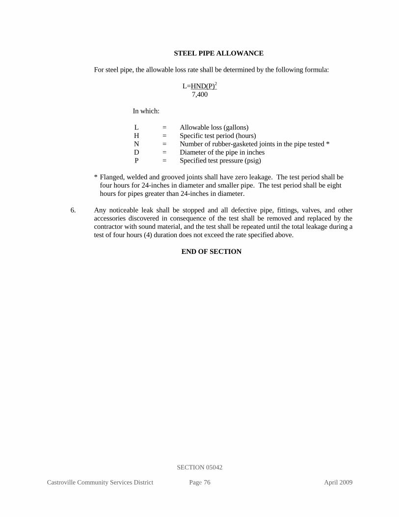
SECTION 05042
Castroville Community Services District Page 76 April 2009
STEEL PIPE ALLOWANCE
For steel pipe, the allowable loss rate shall be determined by the following formula:
L=HND(P)2
7,400
In which:
L = Allowable loss (gallons)
H = Specific test period (hours)
N = Number of rubber-gasketed joints in the pipe tested *
D = Diameter of the pipe in inches
P = Specified test pressure (psig)
* Flanged, welded and grooved joints shall have zero leakage. The test period shall be
four hours for 24-inches in diameter and smaller pipe. The test period shall be eight
hours for pipes greater than 24-inches in diameter.
6. Any noticeable leak shall be stopped and all defective pipe, fittings, valves, and other
accessories discovered in consequence of the test shall be removed and replaced by the
contractor with sound material, and the test shall be repeated until the total leakage during a
test of four hours (4) duration does not exceed the rate specified above.
END OF SECTION

SECTION 05043
Castroville Community Services District Page 77 April 2009
STANDARD SPECIFICATIONS
SECTION 15043
LEAKAGE & INFILTRATION TESTING OF NON-PRESSURE PIPELINES
PART - 1 GENERAL
A. Description
This section describes the requirements and procedures for leakage and infiltration testing of
gravity sewer systems, in accordance with ANSI/ASTM C828, Low Pressure Air Test.
B. Related Work Specified Elsewhere
1. PVC Sewer Pipe: 02715
2. Hydrostatic Testing of Pressure Pipelines: 15042
C. Testing
1. General: All tests shall be made in the presence of the District representative.
2. Leakage: Each section of sewer between two successive manholes shall be tested for
leakage and the leakage test shall be made on all manholes.
3. Infiltration: The infiltration test shall be made where excessive groundwater is
encountered in the trench
4. Retesting: Even though a section may have previously passed the leakage or infiltration
test, each section of sewer shall be tested subsequent to the last backfill compacting
operation if, in the opinion of the District representative, heavy compaction equipment or
any of the operations of the contractor or others may have damaged or affected the
structural integrity or watertightness of the pipe, structure, and appurtenances.
5. Other Utilities: Official District tests will not be made until after all the other utilities
have been installed and their trench compaction verified.
6. Excessive Leakage or Infiltration: If the leakage or infiltration rate is greater than the
amount specified, the pipe joints shall be repaired or, if necessary, the pipe shall be
removed and relaid by the contractor.
7. Acceptance: The sewer will not be accepted until the leakage or infiltration rate, as
determined by test, is less than the maximum allowable.
8. House Laterals: House laterals are not to be connected until after the sewer main has
been successfully tested.
9. Force Mains: Force mains shall be pressure tested per section 15042.

SECTION 05043
Castroville Community Services District Page 78 April 2009
PART 2 - MATERIALS
The contractor shall furnish all equipment and materials required for testing.
PART 3 - EXECUTION
A. Leakage Test for PVC Gravity Sewers
1. Test Section: Each section of sewer between two successive manholes shall be tested by
plugging all pipe outlets with suitable test plugs.
2. Addition of Air: Air shall be slowly added until the internal pressure is raised to 4.0
pounds per square inch gage (psig). The compressor used to add air to the pipe shall have
a blowoff valve set at 5 psig to ensure that at no time the internal pressure in the pipe
exceeds 5 psig.
3. Internal Pressure: The internal pressure of 4 psig shall be maintained for at least two
minutes to allow the air temperature to stabilize, after which the air supply shall be
disconnected and the pressure allowed to decrease to 3.5 psig.
4. Minimum Duration for Allowable Pressure Drop: The time in minutes that is required
for the internal air pressure to drop from 3.5 psig to 3.0 psig shall be measured. The
results shall not be less than the minimum permissible duration for air test pressure drop
shown in the following table.
MINIMUM DURUATION FOR AIR TEST PRESSURE DROP
Pipe Size
(Inches)
Time
(Minutes)
4 2-1/2
6 4
8 5
10 6-1/2
12 7-1/2
15 9-1/2
5. Retest: If the pressure drop from 3.5 psig to 3.0 psig occurs in less time than the above-
tabulated or calculated values, the pipe shall be overhauled and, if necessary, replaced
and relaid until the joints and pipe shall hold satisfactorily under this test.
B. Infiltration Test
1. Preparation of Test Section: The upper end of the pipe section to be tested and the outlet
of the pipe of the downstream manhole shall be plugged to catch any infiltration water in
the manhole, and pumping of groundwater shall be discontinued for at least three days,
after which the section shall be tested for infiltration.

SECTION 05043
Castroville Community Services District Page 79 April 2009
2. Allowable Infiltration Rate: The infiltration shall not exceed 0.025 gpm per inch of
diameter per 1,000 feet of main line sewer being tested, not including the length of
laterals entering that section.
3. Excessive Infiltration: Pipe infiltration in excess of the allowable amount shall be
repaired immediately and the amount of the infiltration reduced to within the specified
amount of infiltration, before the sewer is accepted.
4. Individual Leaks: Even if the infiltration is less than the allowable amount, any
individual leaks that may be observed shall be stopped as ordered by the District
representative.
5. Completion of Tests: All tests must be completed before the street or trench is
resurfaced, unless otherwise directed by the District representative.
C. Deflection Test
1. General: All PVC sewer pipe shall be tested for deflection, joint displacement, or other
obstruction by passing a rigid mandrel through the pipe by hand, but prior paving to
permanent resurfacing. The mandrel shall be a full circle, solid cylinder, or a cylinder,
approved by the District as to design and manufacture. The circular cross section of the
mandrel shall have a diameter of at least 95 percent of the specified average inside pipe
diameter of the pipe, as follows:
Pipe Material Nominal Size
inches
Minimum Mandrel
Diameter (inches)
PVC-ASTM D 3033 6 5.169
(SDR 35) 8 7.309
10 9.137
12 10.963
D. Manhole Test
1. General: Water tightness of manholes shall be tested in connection with tests of sanitary
sewers, or at the time the manhole is completed and backfilled.
2. Plugs: All manhole inlets and outlets shall be plugged with approved stoppers or plugs.
3. Fill Level: The manhole shall be filled with water to 2-inches below the bottom of the
tapered cone section, with a minimum depth of 4 feet and a maximum depth of 20 feet.
The water shall stand in the manhole for a minimum of one hour to allow the manhole
material to reach maximum absorption. Before the test is begun, the manhole shall be
refilled to the original depth as needed.
4. Test Requirements: The drop in water surface shall be recorded after a period of from 15
minutes to one hour. The time of the test shall be determined by the District
representative and may be varied to fit the various field conditions. The maximum
allowable drop in the water surface shall be 1/2 inch for each 15-minute period of testing.

SECTION 05043
Castroville Community Services District Page 80 April 2009
5. Visible Leaks: Even though the leakage is less than the specified amount, the contractor
shall stop any leaks that may be observed, to the satisfaction of the District
representative.
END OF SECTION

SECTION 05050
Castroville Community Services District Page 81 April 2009
STANDARD SPECIFICATIONS
SECTION 15050
HOT TAP CONNECTIONS
PART 1 - GENERAL
A. Description
This section describes materials, requirements and procedures for hot tap (system under pressure)
connections to existing distribution systems.
B. Related Work Specified Elsewhere
1. Existing Facilities 01045
2. Chlorination of Domestic Water Mains for Disinfection 15041
3. Hydrostatic Testing of Pressure Pipelines 15042
4. Copper, Brass and Bronze Pipe, Fittings and Appurtenances 15057
5. Cement-Mortar Lined and Coated Steel Pipe 15076
6. Manual Valves 15100
C. Approved Manufacturers
1. Service Saddles and Corporation Stops
See Section 15057
2. Tapping Sleeves
JCM 432
3. Tapping Valves
See Resilient Seated Wedge Gate Valves Section 15100
D. Direct Tap
All taps into existing pipes will be made through a service saddle, tapping sleeve, welded nozzle
or welded coupling. Taps of the same size as the pipe are not permitted. Size on size connections
shall be tees. Saddles are required for all taps. Direct taps are not permitted.
PART 2 – MATERIALS
A. Service Saddles and Corporation Stops
Service saddles and corporation stops shall comply with Section 15057.

SECTION 05050
Castroville Community Services District Page 82 April 2009
B. Tapping Sleeves
1. Tapping sleeves onto pipelines shall be fabricated stainless steel with full circumferential
gasket or as approved by District.
2. Gaskets shall be Bunz-N rubber with a wide cross section.
3. Tapping sleeve shall meet or excel ANSI/AWWA C-223, latest revision.
C. Tapping Valves
Tapping valves shall be flanged resilient seat wedge gate valves per Section 15100.
D. Weld Nozzles
Weld nozzles and reinforcing plates shall be fabricated steel per Section 15076.
PART 3 – EXECUTION
A. Notification
The contractor shall provide proper notification to the District inspector prior to making a hot tap
connection per Section 01045 prior to ordering tapping materials.
B. Verification
The contractor shall pothole the proposed connection to verify the outside diameter, location and
type of pipe to be tapped.
C. Surface Preparation
The pipe barrel to be tapped shall be thoroughly cleaned with a scraper and provide a smooth, hard
surface for the saddle, sleeve or nozzle.
D. Service Saddle and Corporation Stop
Service saddles and corporation stops will be installed onto ACP, DIP OR PVC mains in
accordance with the manufacturer’s accordance and Section 15057. The outlet shall be oriented to
comply with the intended use of the service connection.
E. Weld Nozzles
Nozzles and reinforcing plates are to be welded onto steel pipe shells in accordance with Section
15076. The connection is to be air tested in the presence of the District inspector prior to making
the tap.

SECTION 05050
Castroville Community Services District Page 83 April 2009
F. Tapping Sleeves
Tapping sleeves shall be installed per District CCSD Standard Plan W-6, and as modified below.
1. The tapping sleeve shall be installed in accordance with the manufacturer's instructions
and to the satisfaction of the District representative.
2. The sleeve shall be supported independent of the pipe during the tapping operation.
3. The sleeve shall be pressure tested in the presence of the District representative prior to
tapping.
4. Thrust blocks shall be provided at the tapping sleeve per Standard Plan W-11, if required.
G. Tapping Valve
The tapping valve shall be installed on the tapping sleeve or weld nozzle per Section 15100. All
flange bolts shall be Type 316 stainless steel.
H. Hot Tap
1. The hot tap into the existing pipe shall be made using the appropriate type of cutting
machine and shell cutting bit for the material being tapped.
2. The company performing the hot tap must be approved by the District. The tapping
machine shall be operated per the manufacturer’s operating instructions.
3. Proper care shall be taken to prevent cutting material from entering the pipeline. The
tapping coupon must be extracted.
I. Mortar Coating Repair
The exterior mortar coating on welded steel pipe shall be repaired in accordance with Section
15076.
J. Disinfection
The interior of the tapping valve and connecting piping shall be sprayed with a sodium hypochlorite
solution prior to connection.
END OF SECTION

SECTION 05056
Castroville Community Services District Page 84 April 2009
STANDARD SPECIFICATIONS
SECTION 15056
DUCTILE-IRON PIPE AND FITTINGS
PART 1 - GENERAL
A. Description
This section includes materials, installation, and testing of ductile-iron pipe and fittings.
B. Related Work Specified Elsewhere
All related work specified elsewhere, or in other codes or standards, will be as last revised, unless a
specific date of issuance is called out in opposition to later revision date(s).
Other sections of the technical specifications, not referenced below, shall also apply to the extent
required for proper performance of this work.
1. Trenching, Backfilling, and Compacting: 02223
2. Concrete: 03300
3. Corrosion Protection and Joint Bonding 13110
4. Chlorination of Domestic water Mains for Disinfection: 15041
5. Hydrostatic Testing of Pressure Pipelines: 15042
C. Approved Manufacturers
1. Fittings
Tyler
Sigma
US Pipe
Or equal
2. Pipe
American Ductile Iron Pipe
Pacific States
U.S. Pipe
Or equal
3. Gaskets
American Ductile Iron Pipe
Champion
Garlock
Johns Manville
Newby
US Pipe
Or equal

SECTION 05056
Castroville Community Services District Page 85 April 2009
D. Submittals
Contractor shall provide submittals for review and approval by the engineer in accordance with
these specifications.
PART 2 - MATERIALS
A. Ductile-Iron Pipe
1. Pressure class or thickness class of DIP shall be determined by the design method
detailed in AWWA C150. Minimum pressure class 350 shall be required for 12 inch and
smaller pipe. Minimum pressure class 250 shall be required for 16 inch and larger pipe.
Thickness class 53 shall be required for flanged spools unless indicated otherwise.
2. Ductile-iron pipe shall be manufactured in accordance with AWWA C151.
3. Unless otherwise called out on the plans, a "push-on" bell and spigot type joint shall be
used. The joint dimensions and gasket shall be as specified in AWWA C111.
4. Joints between pipes adjacent to fittings may require restraint. In this case pipe joints
shall be restrained with a restraining gasket rated for operating pressures of 350 psi for 4”
through 18” pipe and 250 psi for 20” and 24” pipe or by a bell and spigot restraining
harness on existing pipe.
Acceptable products:
US Pipe Field Lock 350
American Ductile Iron Pipe Fast-Grip
5. Flanged pipe shall have the flanges attached to the pipe by threading in accordance with
AWWA C115. Field installed mechanically attached flanges shall only be substituted in
lieu of threaded flanges with District approval.
6. Outlets for DIP shall be as follows:
2” or smaller: bronze service saddle
2-1/2”: tapped tee or service saddle
4” to 8”: D.I. tee fitting or D.I. saddle outlet
12” and larger D.I. tee fitting
7. All ductile iron pipe used in potable water applications shall be cement lined in accordance
with AWWA C104. Lining thickness shall be the double thickness listed in AWWA C104,
Section 4.8. All ductile iron pipe and fittings used in sewer applications shall be ceramic
epoxy lined (Protecto 401 or approved equal). All buried ductile iron pipe shall have a
factory applied bituminous coating of not less than 1 mil. thickness.
8. All ductile-iron pipe shall be installed with CHRISTY’S ANSI/AWWA C105/A21.5-05
8MIL-LLDPE plastic sheeting around the pipe with tracing wire.
B. Ductile-Iron Fittings for PVC and Ductile Iron Pipe

SECTION 05056
Castroville Community Services District Page 86 April 2009
1. Ductile-iron fittings shall be manufactured in accordance with AWWA C110 or C153.
Gray-iron fittings may not be substituted for ductile iron fittings. All ductile iron fittings
shall be cement lined have a factory applied bituminous coating not less than 1 mil
thickness.
2. Joint Restraint
All mechanical joint and push-on fittings shall be restrained by installing restraining
glands or other approved mechanical restraining devices. Concrete thrust blocks may be
used in lieu of fitting restraints only with District approval. Restraining devices shall be
furnished and installed in accordance with the manufacturer’s instructions pursuant to the
type of pipe (DI or PVC), the type of joint (mechanical or push-on), the application (pipe
to pipe or pipe to fitting) and the type of installation (new or existing). The installing
contractor shall submit manufacturer’s literature for District approval for all restraining
devices.
Fittings shall be restrained with the following products:
a. Megalug manufactured by EBAA Iron, Inc.
b. OneLok and Series SLDH manufactured by Sigma .
c. GripRing and RomaGrip manufactured byRomac Industries, Inc.
d. Or other approved equal.
3. All flanged fittings shall be ductile iron manufactured in accordance with AWWA C-110.
Flanged fittings shall have flanges rated for 250 psi working pressure. Flanges bolt holes
and bolt circle shall match those of ANSI/AWWA C115/A21.15 and Class 125 B16.1.
Note that although the flanges shall be rated for 250 psi pressure, they cannot be joined to
Class 250 flanges.
C. Polyethylene Pipe Encasement
All ductile-iron pipe and fittings buried underground shall be protected with plastic film wrap in
accordance with AWWA C105, unless noted otherwise below. Wrap shall be a loose 8-mil-thick
polyethylene tube. All joints between plastic tubes shall be wrapped with 2-inch-wide polyethylene
adhesive tape, Polyken 900, Scotch wrap 50, or approved equal.
D. Gaskets
Gaskets for mechanical joint and push-on joints shall be synthetic rubber manufactured in
accordance with AWWA C111. Gaskets for flanged joints shall be full-face, cloth-inserted
rubber or non-asbestos ring style.
E. Bolts and Nuts
Bolts and nuts shall be stainless steel manufactured in accordance with AWWA C111. The
length of each bolt or stud shall be such that between 1/4 inch and 3/8 inch will project through
the nut when drawn tight. (Only mega lug kits will be allowed to have alloy bolts in place of

SECTION 05056
Castroville Community Services District Page 87 April 2009
stainless steal bolts if (metal gard grease and wrap are thoroughly applied to all exposed bolts and
nuts)
F. Lubricants
Lubricant for pipe gaskets shall be food grade, and biodegradable.
PART 3 - EXECUTION
A. General
Ductile-iron pipe and ductile iron fittings shall be installed in accordance with the applicable
Sections of AWWA C600, the manufacturer’s recommendations and as specified herein.
B. Trenching, Backfilling, and Compacting
1. Trenching, backfilling, and compacting shall be in accordance with Section 02223 and as
specified herein.
2. Backfill within the pipe zone, including the pipe base, shall be imported sand placed and
compacted in accordance with Section 02223. Where the installation is in existing sandy
soils, this requirement for imported sand may be waived only with District approval.
3. Backfill within the trench zone shall be native earth placed and compacted in accordance
with Section 02223.
C. Placement of Pipe in Trench
1. The pipe shall be laid true to the line and grade shown on the plans within acceptable
tolerances. The tolerance on grade is 1 inch. The tolerance on line is 2 inches.
2. The radius of curvature of the pipe shall not exceed the manufacturer’s specification.
D. Thrust Blocks
Movement of pipe and fittings should be prevented by the installation of approved restraining
devices. Thrust blocks are permitted in lieu of restrained fittings only with District approval. When
used, thrust blocks shall be poured against wetted undisturbed soil in accordance with Section
03300 and District Standard Plans W-11 and W-12. CHRISTY’S 8MIL Plastic wrap shall be
applied to the pipe where the thrust block is to be installed.
E. Flanged Connections
1. Bolt holes of flanges shall straddle the horizontal and vertical centerlines of the pipe run.
2. Clean flanges by wire brushing before installing gaskets. Protective epoxy coatings on
flanges shall not be removed.

SECTION 05056
Castroville Community Services District Page 88 April 2009
3. Clean flange bolts and nuts by wire brushing and tighten nuts uniformly. Between 1/4 inch
and 3/8 inch of the bolt threads shall project through the nut when drawn tight.
4. Joints shall be watertight. If flanges leak under pressure testing, loosen or remove the nuts
and bolts, reseat or replace the gasket, reinstall or retighten the bolts and nuts, and retest the
joints.
F. Pipe Support
All unburied pipe shall be supported as detailed in the project plans and in accordance with the
manufacturer’s recommendations..
G. Disinfection
All potable water piping shall be disinfected by chlorination in accordance with Section 15041.
H. Testing
All water piping shall be hydrostatically pressure tested in accordance with Section 15042.
I. Bonding
Joints between pipes and fittings shall be bonded to provide continuity for cathodic protection
when specifically shown on the project plans, or directed by the District. Bonding of joints shall
be per Section 13110.
END OF SECTION

SECTION 05057
Castroville Community Services District Page 89 April 2009
STANDARD SPECIFICATIONS
SECTION 15057
COPPER, BRASS, & BRONZE PIPE FITTINGS & APPURTENANCES
PART 1 - GENERAL
A. Description
This section includes materials and installation of copper, brass, and bronze pipe, fittings and
appurtenances.
B. Approved Manufacturers
1. All materials shall be the appropriate model number specified on CCSD Standard Plans
W-1, W-2, and W-3 as manufactured by the companies listed herein or approved equal.
2. Copper Tubing
Cambridge Lee
3. Service Saddle
Jones
Mueller
Ford
4. Corporation Stop
Jones
Mueller
Ford
5. Insulating Pipe Bushings, Unions, or Couplings
Pipeline Coating and Engineering Co.
1566 East Slauson Avenue, Los Angeles
Smith Blair
Pipe Seal and Insulator Company
PART 2 - MATERIALS
A. Copper Tubing
1. Copper tubing shall conform to the requirements of ASTM B 88 for seamless copper water
tube. Piping located aboveground or suspended within vaults shall be Type L. Buried
piping shall be Type K. Copper pipe
2. If indicated in soils report, all copper lines shall be encased within an 8-mil polyethylene
sleeve. Sleeves shall be color coded per Section 15151.

SECTION 05057
Castroville Community Services District Page 90 April 2009
B. Brass Pipe, Nipples, and Fittings
Short threaded nipples, brass pipe and fittings shall conform to ASTM B 43, regular wall thickness,
except that nipples and pipe of sizes 1-inch and smaller shall be extra strong. Threads shall
conform to ANSI B2.1, National Pipe Thread.
C. Bronze Appurtenances
1. All items specified herein shall be manufactured of bronze conforming to , ‘’LED FREE’’
2. All size service saddles shall be of the double-strap type for any type of pipe. The straps
(or bails) shall be flat and shall be manufactured of silnic bronze for ACP and of stainless
steel for C900 PVC and ductile iron pipe. The body shall be manufactured of bronze and
shall be tapped for an iron pipe thread. The seal with the pipe shall be an O-ring.
3. Corporation stops shall be ball valve type and shall be manufactured of bronze. The inlet
fitting shall be a male iron pipe thread when used with saddle and the outlet connection
shall be a compression type.
D. Meter setters shall be for 1-inch and 2-inch meter sizes or as approved by the District. The inlet and
outlet service line connections shall be compression type connections. The meter connection shall
have a key type inlet and outlet valve. When using a meter setter that is sized larger than the meter,
use appropriate adaptors as approved by the Engineer. Meter setters shall be 15-inches in height
with a lock wing.
PART 3 - EXECUTION
A. Copper Tubing and Fittings
1. Cut tubing square using a cutter designed for cutting copper tubing and remove burrs.
Clean both the inside and outside of fitting and pipe ends with steel wool and muriatic acid.
Prevent annealing of fittings and tubing when making connections.
2. Threads of fittings shall receive a liberal coating of pipe thread compound conforming with
the requirements of ASTM B88, Type K.
3. Any damage to the fitting including but not limited to evidence of overtightening,
misaligned threads, burring or scarring of machined faces, or any evidence of leakage shall
be cause for rejection. If a leak is found to be caused by debris, the debris shall be cleared
and the fitting visually inspected for damage before being charged. If the leak recurs upon
charging of the line, the fitting shall be removed and replaced whether or not the cause can
be determined.
4. Bends in soft copper tubing shall be long sweep, not greater than 30 degrees. Shape bends
with shaping tools. Form bends without flattening, buckling, or thinning the tubing wall at
any point.
5. Buried piping shall be installed with some slack to provide flexibility in the event of a load
due to settlement, expansion or contraction. A MINIMUM COVER OF 24 INCHES
BELOW THE FINISHED STREET GRADE SHALL BE ADHERED TO. The tubing is
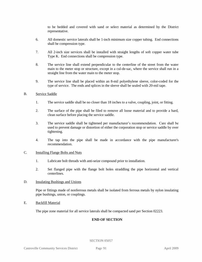
SECTION 05057
Castroville Community Services District Page 91 April 2009
to be bedded and covered with sand or select material as determined by the District
representative.
6. All domestic service laterals shall be 1-inch minimum size copper tubing. End connections
shall be compression type.
7. All 2-inch size services shall be installed with straight lengths of soft copper water tube
Type K. End connections shall be compression type.
8. The service line shall extend perpendicular to the centerline of the street from the water
main to the meter stop or structure, except in a cul-de-sac, where the service shall run in a
straight line from the water main to the meter stop.
9. The service line shall be placed within an 8-mil polyethylene sleeve, color-coded for the
type of service. The ends and splices in the sleeve shall be sealed with 20-mil tape.
B. Service Saddle
1. The service saddle shall be no closer than 18 inches to a valve, coupling, joint, or fitting.
2. The surface of the pipe shall be filed to remove all loose material and to provide a hard,
clean surface before placing the service saddle.
3. The service saddle shall be tightened per manufacturer’s recommendation. Care shall be
used to prevent damage or distortion of either the corporation stop or service saddle by over
tightening.
4. The tap into the pipe shall be made in accordance with the pipe manufacturer's
recommendation.
C. Installing Flange Bolts and Nuts
1. Lubricate bolt threads with anti-seize compound prior to installation.
2. Set flanged pipe with the flange bolt holes straddling the pipe horizontal and vertical
centerlines.
D. Insulating Bushings and Unions
Pipe or fittings made of nonferrous metals shall be isolated from ferrous metals by nylon insulating
pipe bushings, union, or couplings.
E. Backfill Material
The pipe zone material for all service laterals shall be compacted sand per Section 02223.
END OF SECTION

SECTION 15064
Castroville Community Services District Page 92 April 2009
STANDARD SPECIFICATIONS
SECTION 15064
PVC PRESSURE DISTRIBUTION PIPE
PART 1 - GENERAL
A. Description
This section includes materials, installation, and testing of polyvinyl chloride (PVC) distribution
pipe.
B. Related Work Specified Elsewhere
All related work specified elsewhere, or in other codes or standards, will be as last revised, unless a
specific date of issuance is called out in opposition to later revision date(s).
Other sections of the technical specifications, not referenced below, shall also apply to the extent
required for proper performance of this work.
1. Trenching, Backfilling, and Compacting: 02223
2. Jacked Casing: 02315
3. Concrete: 03300
4. Painting and Coating: 09900
5. Chlorination of Domestic Water Mains for Disinfection: 15041
6. Hydrostatic Testing of Pressure Pipe: 15042
7. Ductile-Iron Pipe and Fittings: 15056
8. Copper, Brass and Bronze Pipe, Fittings, and Appurtenances: 15057
9. Combination Air and Vacuum Release Assembly: 15089
10. Manual Valves: 15100
11. Domestic and Recycled Facilities Identification: 15151
C. Approved Manufacturers
1. J-M Manufacturing
2. Vinyltech
3. P W Pipe
4. Certainteed
5. Diamond Plastics
D. Application
1. Class 150 PVC Pipe shall be used unless specifically shown otherwise on the plans.
2. PVC pipe shall be used as a valve riser.
E. Reference Standard
Conform to AWWA C900, "Polyvinyl Chloride (PVC) Pressure Pipe, 4-inch through 12-inch for
Water," unless noted otherwise below.
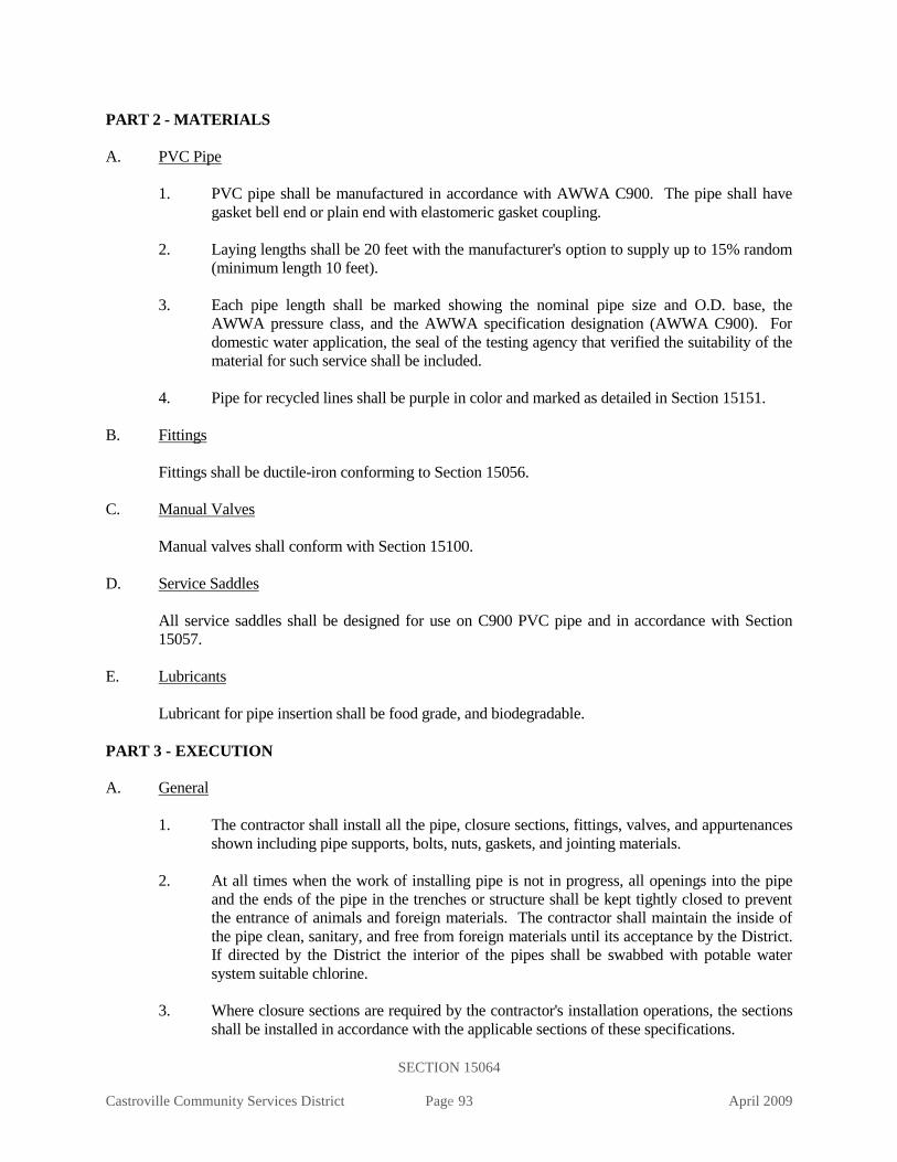
SECTION 15064
Castroville Community Services District Page 93 April 2009
PART 2 - MATERIALS
A. PVC Pipe
1. PVC pipe shall be manufactured in accordance with AWWA C900. The pipe shall have
gasket bell end or plain end with elastomeric gasket coupling.
2. Laying lengths shall be 20 feet with the manufacturer's option to supply up to 15% random
(minimum length 10 feet).
3. Each pipe length shall be marked showing the nominal pipe size and O.D. base, the
AWWA pressure class, and the AWWA specification designation (AWWA C900). For
domestic water application, the seal of the testing agency that verified the suitability of the
material for such service shall be included.
4. Pipe for recycled lines shall be purple in color and marked as detailed in Section 15151.
B. Fittings
Fittings shall be ductile-iron conforming to Section 15056.
C. Manual Valves
Manual valves shall conform with Section 15100.
D. Service Saddles
All service saddles shall be designed for use on C900 PVC pipe and in accordance with Section
15057.
E. Lubricants
Lubricant for pipe insertion shall be food grade, and biodegradable.
PART 3 - EXECUTION
A. General
1. The contractor shall install all the pipe, closure sections, fittings, valves, and appurtenances
shown including pipe supports, bolts, nuts, gaskets, and jointing materials.
2. At all times when the work of installing pipe is not in progress, all openings into the pipe
and the ends of the pipe in the trenches or structure shall be kept tightly closed to prevent
the entrance of animals and foreign materials. The contractor shall maintain the inside of
the pipe clean, sanitary, and free from foreign materials until its acceptance by the District.
If directed by the District the interior of the pipes shall be swabbed with potable water
system suitable chlorine.
3. Where closure sections are required by the contractor's installation operations, the sections
shall be installed in accordance with the applicable sections of these specifications.

SECTION 15064
Castroville Community Services District Page 94 April 2009
4. The pipe sections shall be laid in the trench to true alignment and grade in accordance with
the drawings. The pipe grade shall be approved by the District.
5. The pipe shall not be laid along curves at a radius less than that listed below:
The minimum-radius curves are determined by the limit of 2-degree deflection for PVC
pipe joints with factory-assembled bell couplings:
Length of Pipe Section Minimum Curve Radius
(verify with pipe manufacturer)
20 feet 573 feet
10 feet 287 feet
For curves of smaller radius, use high- deflection couplings or ductile-iron fittings.
B. Installation
1. Trenching, backfilling, and compacting shall be in accordance with Section 02223 and as
specified herein. Compacted pipe bedding material conforming to Section 02223 shall be
installed in the bottom of the trench and compacted prior to placing pipe in the trench.
Excavate bell holes at each joint to permit proper assembly and inspection of the entire joint
and to assure the pipe is fully supported by the pipe barrel.
2. Proper care shall be used to prevent damage in handling, moving, and placing the pipe.
Tools and equipment satisfactory to the District representative shall be provided and used
by the contractor.
3. The contractor shall take all necessary precautions to prevent the pipe from floating due to
water entering the trench from any source; shall assume full responsibility for any damage
due to this cause; and shall pay for and perform the work to restore and replace the pipe to
its specified condition and grade if any displacement occurs due to floating.
4. Pipe shall be cut by a method recommended in the pipe manufacturer's installation guide, as
approved by the District representative. Cut pipe ends shall be beveled for insertion into
pipe bells or push-on fittings. It is not necessary to bevel ends for mechanical joint fittings.
When pipe is cut and is to be joined to a cast-iron fitting or another piece of pipe the end
shall be beveled in the field or place of manufacture to create a beveled end equal in quality
to the machined ends of the pipe as furnished by the manufacturer. Such machining shall
not result in undercutting the wall thickness and must be approved by the District
representative before installation.
5. All connecting parts of pipe, rings, couplings, and castings shall be cleaned before
assembly. After bearing has been obtained, couplings shall be assembled in a proper
manner (as determined by the District representative). The use of excessive lubricant will
not be permitted, and the assembly of the couplings and rings shall be in accordance with
the manufacturer's recommendations. Lubricant and rubber rings shall be supplied by the
pipe manufacturer. All fittings and valves shall have joints that match the type of adjoining
pipe.

SECTION 15064
Castroville Community Services District Page 95 April 2009
6. All fittings and valves shall be supported so that the pipe is not subjected to the weight of
these appurtenances.
7. End of line fittings shall be restrained by thrust blocks.
7. Joint restraints shall be provided at the location of all cast-iron fittings, valves and fire
hydrants. Thrust blocks are acceptable in lieu of restrained joints only with permission
from the District
8. Imported sand shall be used for backfill within the pipe zone per Section 02223.
9. Manual valves shall be installed in accordance with Section 15100.
10. Native earth backfill shall be placed and compacted within the trench zone in accordance
with Section 02223, with approval of the District. All backfill within 24 inches of a valve
shall be clean, washed sand.
C. Installations within Jacked Casing
1. Certain portions of the project, such as crossings of some roads, highways, and railroads,
may be required to be installed within a jacked casing pipe.
2. The casing size and type shall be in accordance with Section 02315.
3. Work shall not proceed without permission of the District representative. Refer to CCSD
Standard Plan W-13.
2. All pipe installed within a casing shall have restrained joints.
D. Combination Air and Vacuum Relief Valves
1. Air release valve assemblies and combination air and vacuum valves shall be installed at
each point in the pipeline as shown on the drawings or as specified by the District
representative.
2. The tap for the air valves shall be made in a level section of pipe no closer than 18 inches to
a bell, coupling, joint, or fitting.
3. Air release valve assemblies shall be installed in accordance with CCSD Standard Plan W-
8 and Section 15089.
E. Blow Off Assemblies
1. Either in-line type or the end-of-line type blow off assemblies shall be installed in
accordance with the standard drawings at locations noted on the plans and at such
additional locations as required by the District representative for removing water or
sediment from the pipeline.
2. The assembly shall be installed in a level section of pipe.

SECTION 15064
Castroville Community Services District Page 96 April 2009
3. The tap for blow off in the line shall be no closer than 18 inches to a valve, coupling, joint,
or fitting.
4. Blow offs shall not be connected to any sewer, submerged in any stream, or installed in any
manner that will permit back siphoning into the distribution system.
5. Blow offs shall be installed in accordance with CCSD Standard Plans W-9 and the
applicable sections of these specifications.
F. Pipe Identification
Warning and locator tape shall be installed on all domestic water piping installed within the limits
of a non-potable irrigation system. The pipe identification shall be in accordance with Section
15151.
G. Locator Wire
A bare 10-gauge solid copper wire shall be placed continuously on the top center of the pipe. The
wire shall not be spliced at any point, and shall be continuous from riser to riser. The wire shall be
brought to the surface at valve locations and shall be accessible by removing the valve box cover.
The wire shall be brought up the outside of the valve riser and folded over between the inside of the
valve box and the valve riser. The wire shall be brought to within 6 inches of finish grade. The
wire shall also be tapped in place by means of a plastic adhesive tape, placed at 10 foot intervals.
H. Thrust Blocks
1. Thrust blocks shall be constructed only where shown on the drawings, or where directed
by the District representative and as specified herein. In general, thrust blocks will be
placed at end of line fittings and existing pipe tie-ins.
2. If permission to use thrust blocks is granted by the District, the area and design of the
bearing surface shall be per CCSD Standard Plans W-11 and W-12.
3. The bearing surface shall be against undisturbed ground in all cases, except where unstable
conditions are encountered. In unstable conditions, the bearing surface shall be as directed
by the District representative.
4. Unless otherwise directed by the District representative, the blocking shall be placed so that
the pipe and fitting joints are accessible for repair.
5. Exposed non-steel rods and clamps shall be coated with bituminous mastic per Section
09900.
6. Concrete for thrust blocks shall be Class "A" per Section 03300.

SECTION 15064
Castroville Community Services District Page 97 April 2009
I. Slope Protection
1. Slope protection shall be installed where shown on the plans in accordance with Section
02223, wherever the profile of the ground surface above the pipeline exceeds 20% and
where no pavement or other surfacing is to be laid over the facility.
2. The installation of the slope protection shall be considered a part of the work, and the
contractor shall include the expense in the contract cost.
3. A reinforced concrete encasement may be used as directed by the District representative.
The encasement shall extend to within 1-foot of the ground surface and to within 1-foot of
the toe of slope in which the pipe is constructed.
J. Chlorination
All domestic water pipelines shall successfully be chlorinated in accordance with Section 15041
prior to connection to the existing distribution system.
K. Hydrostatic Testing
All pipelines shall pass a hydrostatic pressure test in accordance with Section 15042.
END OF SECTION
SECTION 15076
Castroville Community Services District Page 98 April 2009
STANDARD SPECIFICATIONS
SECTION 15076
CEMENT-MORTAR LINED AND COATED STEEL PIPE
PART 1 - GENERAL
A. Description
This section describes materials, fabrication, installation, and testing of cement-mortar lined and
coated steel pipe, in accordance with the applicable requirements of AWWA C200, C205, and
C208.
B. Related Work Specified Elsewhere
1. Trenching, Backfilling, and Compacting: 02223
2. Painting and Coating: 09900
3. Corrosion Protection and Joint Bonding: 13310
4. Chlorination of Domestic Water Mains for Disinfection: 15041
5. Hydrostatic Testing of Pressure Pipelines: 15042
C. Submittals
Shop drawings shall be submitted in accordance with the following:
1. Piping layout drawings showing location and dimensions of all pipe and fittings. Include
laying lengths of valves, meters, and other equipment which determine piping
dimensions. Label or number each fitting or piece of pipe and provide the following
information for each item:
a. Materials of construction, including references to industry standards being met
(i.e. ASTM, ANSI, AWWA, etc.)
b. Inside diameter, steel wall thickness, internal design pressure (cement-mortar
lining and coating thicknesses) for each class of pipe to be furnished
c. Order of installation and closure locations for length adjustment and for
construction convenience
d. Pipe invert station and elevation of each change of grade and alignment
e. Elements of curves and bends, both in horizontal and vertical alignment,
including elements of the resultant true angular deflections in cases of combined
curvature
f. Paint primer type and thickness where joints and other cement-mortar holdbacks
occur
g. Call out types and sizes, and dimensions of grooved-end collars, flanges,
reinforcing collars, wrapper plates, and crotch plates
h. Limits of each reach of field-welded joints and of concrete encasement
i. Locations of manholes and other points of access
j. Location of valves and other mechanical equipment
k. Locations of bulkheads for field hydrostatic testing of pipeline

SECTION 15076
Castroville Community Services District Page 99 April 2009
2. Manufacturer's certificates of compliance with prescribed industry standards (i.e. AWWA
C200, C205, and C208, ASTM C150, etc.)
3. Detail drawings of:
a. Fittings
b. Joints
c. Butt Straps
d. Bulkheads and means of attachment to pipe
4. Mill test reports on each heat from which steel is rolled
5. Test reports on physical properties of rubber used in gaskets
D. Qualifications of Manufacturers
Only manufacturers who manufacture a complete lined and coated pipe can be qualified for this
work. All pipe manufacturing operations shall be performed at the same location for all pieces of
pipe. Supervisors of cement-mortar coating operations shall have at least two years continuous
recent experience in the application of cement-mortar coating systems for steel pipe.
E. Design Criteria
1. The nominal diameter or inside diameter of the pipe and other fabricated steel sections as
shown on the plans is the clear diameter of the lined pipe after the application of the
interior mortar lining.
2. Obtain the following information from the plans: elevation of the pipe invert and of the
final ground surface; alignment of the pipeline; nominal internal diameter, after cement-
mortar lining; minimum pipe wall thickness; and location of welded, double-welded and
butt-welded joints.
3. The design pressure is the pressure class shown on the construction plans.
F. Inspection
The District reserves the right to inspect materials, production, or testing of pipe at the
manufacturer's plant.
PART 2 - MATERIALS
A. Steel Pipe
Steel shall be ASTM A 36, ASTM A 283 Grade C or D, ASTM A 570 Grade 30 or 33, having a
0.25% maximum carbon content. Spigot material shall be ASTM A 476, Grade 1012 or 1020.
B. Cement
Cement for cement-mortar lining shall be ASTM C 150, Type II or V. Cement for cement-mortar
coating shall be ASTM C 150, Type V.

SECTION 15076
Castroville Community Services District Page 100 April 2009
C. Fittings
1. Definition: A fitting shall be defined as a piece of pipe other than a straight full length
joint. Elbows, manhole sections, reducers, and sections of pipe with outlets shall be
considered fittings.
2. Pressure Rating: Fittings 4 through 10-inches diameter shall be designed for 250 psi (or
50 psi greater than the class of pipe, whichever is greater) and conform to ANSI B16.9.
Fittings 12-inches diameter and larger shall comply with AWWA C208.
3. Materials: Material for fittings 4 through 10-inches shall comply with ASTM A 234,
Grade WPB. Material for fittings larger than 10-inches but less than or equal to 30-
inches in diameter shall be the same as the pipe or shall comply with ASTM A 283
(Grade D), ASTM A 36, or ASTM A 570 (all grades). Cement-mortar lining and I.D.
dimensions shall be the same as the specified pipe.
4. Allowable Stresses: Allowable circumferential stress at the design internal pressure shall
not be greater than 40% of minimum yield stress. Minimum wall thickness of steel
fitting shall be the same as the pipe of same size per ANSI B36.10.
5. Grooved End Fittings: Fittings smaller than 24-inches diameter with grooved ends shall
have square cut grooves, flexible type, with dimensions as shown in AWWA C606, Table
3. Steel wall thickness shall be standard weight, ANSI B36.10. Cement-mortar lining
and I.D. dimensions shall be the same as for the specified pipe.
6. Welding Fittings: Welding fittings shall be standard weight, Ladish Co., or approved
equal.
D. Flanges
Flanges shall be AWWA C207, Class D, flat face, except where Class E or Class F flanges are
required. Weld-neck flanges (conforming to ANSI B16.5) shall be provided for piping 4-inches
in diameter and smaller to connect to flanged valves, fittings and equipment. Slip-on or weld-
neck flanges shall be provided for piping 4-inches in diameter. Flanges shall match the
connecting flanges on adjacent fitting, valve or piece of equipment.
E. Bolts, Nuts, and Gaskets for Joints and Flanges
Rubber gaskets shall be furnished for all joints, along with other parts, including flange gaskets,
bolts, nuts, washers, jumper rods, and flange insulation kits. One bolt/gasket set shall be provided
for each flange.
1. Materials: Bolts and nuts for flanges shall be Type 316 stainless steel with Tripac 2000
blunut coating system or red brass 651 conforming to ASTM A 193, Grade B8M for
bolts, and ASTM A 194, Grade 8M for nuts.
2. Washers: A washer shall be provided for each nut. Washers shall be of the same
material as the nuts.

SECTION 15076
Castroville Community Services District Page 101 April 2009
3. Gaskets: Gaskets shall be composed of synthetic fiber with rubber binder and shall be
fullface, 1/16-inch-thick Garlock 3400, Anchor 441, or approved equal.
4. Bolts for Flange Insulation Kits: Bolts for flange insulation kits shall conform to ASTM
A 193, Grade B7. Nuts shall conform to ASTM A 194, Grade 2H.
F. Flange Insulation Kits
Flange insulation kits suitable for the design pressure of the pipeline shall be provided where
shown on the drawings and shall be as specified in Section 13110, Corrosion Protection and Joint
Bonding.
G. Grooved-End Couplings
Grooved-end couplings shall be malleable iron, ASTM A 47, or ductile iron, ASTM A 536. Bolts
shall conform to ASTM A 183, 110,000 psi tensile strength. Gaskets shall be EPDM and shall
conform to ASTM D 2000. Couplings for pipe 24-inches in diameter and smaller shall be
flexible type, square cut groove, per AWWA C606, and shall be Victaulic Style 77, Gustin-Bacon
Figure 100, or approved equal.
H. Outlets
1. Outlets 2-1/2-inches in Diameter and Smaller: Outlets of sizes 2-1/2-inches in diameter
and smaller shall be of the thredolet type, per AWWA Manual M-11, Figure 13.23.
Outlets shall be 3,000 pound WOG forged steel per ASTM A 105 or ASTM A 216,
Grade WCB. Threads shall comply with ASNI B2.1. Outlets shall be Bonney Forge Co.
"Thredolet," Allied Piping Products Co. "Branchlet," or for contracts between District
and contractor, approved equal.
2. Outlets larger than 2-1/2-inches in Diameter: For outlets larger than 2-1/2-inches in
diameter, flanged tees shall be used.
I. Length of Pipe Sections
Pipe sections shall be limited to 40 feet or less. For sections longer than 30 feet, spreader beams,
and lifting straps shall be used to lift pipe sections at the third points.
J. Joints
1. Above Ground Joints: Joints above ground or in vaults and structures shall be flanged or
grooved end.
2. Buried Joints: Buried joints shall be:
a. Bell and Carnegie shape spigot with rubber gasket
b. Bell-and-spigot lap welded
c. Butt-strap joints may also be used for closures
3. Grooved-End Joints: Grooved-end joints shall be flexible, square-cut grooved, per
AWWA C606.

SECTION 15076
Castroville Community Services District Page 102 April 2009
K. Product Marking
Each length of straight pipe and each special shall be plainly marked at the bell end to identify the
design pressure or head, the steel wall thickness, the date of manufacture, and the proper location
of the pipe item by reference to the layout schedule. For beveled pipe, the degree of bevel and
the point on the circumference to be laid uppermost shall be shown.
L. Painting and Coating
1. General: Unless noted otherwise, buried pipe shall be cement-mortar coated per AWWA
C205.
2. Exposed Pipe: Pipe located above ground or in vaults and structures shall be epoxy lined
and coated in accordance with Section 09900, Painting and Coating. Primer shall be shop
applied.
3. Grooved-End Couplings: Grooved-end couplings shall be coated the same as the
adjacent pipe.
M. Lining
Unless noted otherwise, pipe and fittings shall be cement-mortar lined per AWWA C205.
PART 3 - EXECUTION
A. General
1. Steel Cylinder Thickness: Steel cylinder thickness shall be minimum 10 gauge. Steel
cylinder thickness shall be as called for on the construction plans. Pipe 12-inches in
diameter and smaller shall be standard steel pipe per ASTM A53 “Welded and Seamless
Steel Pipe”. It shall have a wall thickness known as standard weight per ANSI B36.10.
2. Fittings:
a. Dimensions shall be per AWWA C208.
b. Allowable circumferential stress at the design internal pressure shall not exceed
40% of minimum yield stress.
c. Outlet reinforcement at branches and openings shall be determined by the
procedure given in ANSI B31.3, paragraph 304.3. If reinforcement is required, it
shall be accomplished as described below:
1) The type of reinforcement for fittings with outlets shall be selected from
the following table:
Steel Pipe Reinforcement Type of Reinforcement
Max. 0.5 Collar
Max 0.7 Wrapper Plate
To 1.0 Crotch Plate

SECTION 15076
Castroville Community Services District Page 103 April 2009
Where R = ID outlet
I.D. cyl. x sin B
Where B = Angle between the longitudinal axis of the main run and the
branch.
2) For collar reinforcement, select an effective shoulder width "W" of a
collar from the inside surface of the steel outlet to the outside edge of the
collar, measured on the surface of the cylinder of the main run, shall be
selected such that:
W = (1/3 to 1/2) x I.D. outlet
sinB
The minimum thickness "T" of the collar is determined by:
T = P x I.D. main run x I.D. outlet x (2 - sinB)
4 x F x W x sinB
Where P = Design internal pressure
F = Allowable design stress = 40% of minimum yield stress
B = As in part c.1 above
Collars may be oval in shape or rectangular with rounded corners.
3) For a wrapper plate, the above collar formula shall be used except that
the wrapper is of thickness "T", its total width is (2W + ID outlet/sinB),
and it wraps entirely around the main pipe.
4) Base crotch plate design on Swanson, H. S. et al., DESIGN OF WYE
BRANCHES FOR STEEL PIPES, summarized in AWWA Manual M
11, Chapter 13.
5) Long Radius Curves and Vertical Curves:
For curved alignment, straight or beveled pipe of normal or one-half
normal lengths pulled partially open on one side of the joint may be used
with a welded mitered bend of up to 10 degrees next to the joint ring.
Pipes with a bend in excess of 10 degrees shall be designed as fittings.
Joints shall not be pulled more than one-half of the watertight
extensibility provided by the bell and spigot design.
B. Fabrication
1. Reference Standards: Fabrication shall comply with ANSI B31.3, Chapter V. Welding
procedure and performance qualifications shall be in accordance with Section IX,
Articles II and III, respectively, of the ASME Boiler and Pressure Vessel Code.
2. Welding

SECTION 15076
Castroville Community Services District Page 104 April 2009
a. The pipe cylinder shall be fabricated by butt welding, spiral seam, or straight
seam. Girth welds shall be limited to two per pipe section, butt welded.
Longitudinal welds shall be limited to one seam. Longitudinal joints of adjacent
shell courses shall be staggered.
b. The shielded metal arc welding (SMAW) process shall be used for welding. All
welding shall be done by qualified, certified welders.
c. Welds shall be in accordance with ANSI B31.3, paragraph 327.4.
d. Welding preparation shall comply with ANSI B31.3, paragraph 327.3.
Limitations on imperfections in welds shall conform to the requirements in ANSI
B31.3.
e. Welding electrodes shall comply with AWS A5.1.
f. Each layer of deposited weld metal shall be cleaned using a power-driven wire
brush prior to depositing the next layer of weld metal. The final pass shall be
cleaned by a power-driven wire brush.
g. A minimum of three passes shall be used for welded joints. Welds shall be full
circumferential.
h. Beveled ends for butt welding shall conform to ANSI B16.25. Slag shall be
removed by chipping or grinding. Surfaces shall be clean of paint, oil, rust,
scale, slag, and other material detrimental to welding. When welding the reverse
side, slag shall be chipped out before welding.
C. Joint Ring Protective Coating
The exposed portion of joint rings shall be coated with a 3-mil minimum thickness organic zinc
pigmented coating meeting U.S. Federal Specification TT-P-641.
D. Shop Hydrostatic Test
The steel cylinder with joint rings shall be stressed to 75% of the minimum yield stress of the
steel.
E. Shop Testing of Fittings
1. Dye Penetrant Test: Seams in fittings which have not been previously shop
hydrostatically tested shall be tested by the dye penetrant method.
2. Air-Soap Test: In addition to the dye penetrant method of testing, the air-soap method
with air at 5 psi shall be used on joints susceptible to being tested by such a method.
3. Pressure Test in Lieu of Dye Penetrant Test: In lieu of the dye penetrant method of
testing, completed fittings may be hydrostatically tested using the field hydrostatic test
pressure or 125% of the design pressure, whichever is higher.
F. Delivery of Small Parts
Small parts, consisting of gaskets, bolts, nuts, washers, jumper rods, and flange insulation kits,
shall be delivered to the job site in suitable containers, each marked to identify the contents.
G. Installation

SECTION 15076
Castroville Community Services District Page 105 April 2009
1. Delivery and Temporary Storage of Pipe at Site
a. Onsite Storage Limitation: Onsite pipe storage shall be limited to a maximum of
one week, unless exception is approved by District.
b. Care of Pipe: Care shall be taken to avoid cracking of the cement mortar coating
and/or lining on steel pipe. Plastic sheet caps shall be used to close pipe ends and
keep coatings and linings moist.
2. Handling of Pipe
a. Moving Pipe: Pipes shall be lifted with handling beams or wide belt slings as
recommended by the pipe manufacturer. Cable slings shall not be used. Pipe
shall be handled in a manner to avoid damage to the pipe. Pipe shall not be
dropped or dumped from trucks or into trenches under any circumstances.
b. Internal Pipe Braces: Internal braces placed in steel pipes shall be maintained
until backfilling is completed.
c. Pipe Caps: Plastic caps placed over the ends of steel pipe shall not be removed
until the pipe is ready to be placed in the trench. Plastic caps may be opened
temporarily to spray water inside the pipe for moisture control.
d. Inspection of Pipe: The pipe and accessories shall be inspected for defects prior
to lowering into the trench. Any defective, damaged or unsound pipe shall be
repaired or replaced. All foreign matter or dirt shall be removed from the interior
of the pipe before lowering into position in the trench.
3. Placement of Pipe in Trench
a. General: Dewatering, excavation, shoring, sheeting, bracing, backfilling material
placement, material compaction, compaction testing, and pipe laying
requirements and limitations shall be in accordance with Section 02223:
Trenching, Backfilling and Compacting.
b. Sanitation of Pipe Interior: During laying operations, tools, clothing, or other
materials shall not be placed in the pipe.
c. Prevention of Entry into Pipe: When pipe laying is not in progress, including
lunch-hour, the ends of the pipe shall be closed using vermin-proof plugs
constructed in a manner to also prevent entry by children.
d. Laying Pipe on Grades over 10 Percent: Pipes shall be laid uphill whenever the
grade exceeds 10 percent.
e. Pipe Bedding Thickness: Pipe bedding thickness shall be as specified in Section
02223, Trenching, Backfilling, and Compacting.
f. Depressions at Joints and Pipe Sling Points: Depressions shall be dug into pipe
base material to accommodate the pipe bell and external joint filler form, and to
permit removal of the pipe handling slings.
g. Placement of Pipe on Pipe bedding: Pipe shall be lowered onto the bedding and
installed to line and grade its full length on firm bearing except at the bell and at
sling depressions. Unless specified otherwise, the tolerance on grade shall be ¼-
inch; the tolerance on line shall be 1-inch. Grade shall be measured along the
pipe invert.
SECTION 15076
Castroville Community Services District Page 106 April 2009
h. Pipe Installation: Pipe shall be installed without springing, forcing, or stressing
the pipe or any adjacent connecting valves or equipment. Precautions shall be
taken to prevent pipe from being displaced by water entering trench. Damaged
or displaced pipe shall be replaced or returned to specified condition and grade.
i. Trench Curvature and Pipe Deflection: The radius of curvature of the trench
shall be determined by the maximum length of pipe section that can be used
without exceeding the allowable deflection at a coupling. Refer to the various
referenced sections on pipe by type for allowable deflection. The deflection at
any flexible joint shall not exceed that prescribed by the manufacturer of the
pipe. The manufacturer's printed installation guide outlining the radius of
curvature that can be negotiated with pipe sections of various lengths shall be
followed.
j. Equipment for Installation of Pipe: Proper implements, tools, and facilities as
recommended by the pipe manufacturer's standard printed installation
instructions shall be provided and used by the contractor for safe and efficient
execution of the work. All pipe, fittings, valves, and accessories shall be
carefully lowered into the trench using suitable equipment in such a manner as to
prevent damage to pipe and fittings. Under no circumstances shall pipe or
accessories be dropped or dumped into the trench.
k. Cutting and Machining Pipe: Cutting and machining of the pipe shall be
accomplished in accordance with the pipe manufacturer's standard procedures for
this operation. Pipe shall not be cut with a cold chisel, standard iron pipe cutter,
nor any other method that may fracture the pipe or produce ragged, uneven
edges.
4. Assembling Rubber Ring Joints
a. Cleaning Ends of Pipe: The ends of the pipe to be joined shall be cleaned of
foreign material.
b. Lubrication: After placing pipe in trench, a nontoxic water soluble vegetable
soap solution shall be applied to the inside of the bell of the pipe in the trench
and to the rubber gasket and spigot groove of the pipe to be installed. The rubber
gasket shall be stretched into the groove of the spigot end of the pipe and
distributed uniformly around the circumference.
c. Joint Assembly: Without tilting the pipe to be installed, the spigot shall be
inserted into the bell of the pipe. Come-a-longs or pipe jacks shall be used to
drive spigot end home horizontally. The joint recess recommended by pipe
manufacturer for made-up joints shall be maintained. Where deflections at joints
are required for curved alignment, the allowable joint opening on one side shall
not be exceeded. A feeler gauge shall be used to verify proper placement of each
gasket.
5. Flanged Connections
a. Bolthole Alignment: Pipe shall be set with flange boltholes straddling the pipe
horizontal and vertical centerlines.
b. Nuts and Bolts: Nuts and bolts shall be lubricated with anti-seize graphite prior
to installation.

SECTION 15076
Castroville Community Services District Page 107 April 2009
c. Flange Wrapping: Flanges which connect with buried valves or other equipment
shall be wrapped with sheet polyethylene film as specified for the valves and
equipment. The wrap shall be extended over the flanges and bolts and secured
around the adjacent pipe circumference with tape.
d. Coating: Flanges and non-stainless steel bolts shall be completely coated as
specified in Section 09900, Painting and Coating.
6. Installation of Bends, Tees, and Reducers
Fittings shall be installed utilizing standard installation procedures. Fittings shall be
lowered into trench by means of rope, cable, chain, or other acceptable means without
damage to the fittings. Cable, rope, or other devices used for lowering fitting into trench,
shall be attached around exterior of fitting for handling. Under no circumstances shall
the cable, rope or other device be attached through the fittings interior for handling.
Fittings shall be carefully connected to pipe or other facility, and joint shall be checked to
insure a sound and proper joint.
7. Installing Threaded Piping
Threaded piping shall be reamed, deburred, and cleaned before making up joints. Thread
lubricant shall be applied to threaded pipe ends before installing fittings, couplings,
unions, or joints.
8. Completion of Interior Joints for Mortar-Lined Pipes - 20-Inches in Diameter and Smaller
The contractor shall install an extruded botyl rubber pipe joint sealant, G5-79 as
manufactured by General Sealants, Inc., or approved equal. The pipe joint sealant shall
be applied per the manufacturer’s instructions.
9. Completion of Interior Joints for Mortar-Lined Pipes Greater Than 24-Inches in Diameter
a. Backfill Requirement: The trench shall be backfilled before applying mortar at
joints.
b. Cleaning and Application of Cement Mortar: Working inside the pipe, foreign
substances which adhere to the steel joint rings shall be removed, the surface
cleaned, and stiff cement mortar packed into each joint. The mortar shall be
finished with a steel trowel to match the lining in the adjoining pipes.
c. Removal of Excess Mortar: Excess mortar and other construction debris shall be
removed from the pipe interior.
10. Pipeline Closure Assemblies
a. General: Pipeline closure assemblies shall be employed to unite sections of
pipeline laid from opposite directions; to adjust the field length of the pipeline to
meet structures, other pipelines, and points established by design stations; and to
close areas left open to accommodate temporary test bulkheads for hydrostatic
testing. Either follower ring design or butt strap design shall be used. Follower
ring closures shall be installed as recommended by the pipe manufacturer.

SECTION 15076
Castroville Community Services District Page 108 April 2009
b. Butt Straps: Shaped steel butt straps shall be centered over the ends of the pipe
sections they are to join. On pipes 39 inches in diameter and smaller, butt straps
shall be welded to the outside of the pipes with complete circumferential fillet
welds equal in size to the thinnest part being joined. The details shown on the
drawings shall be referred to when joining larger pipes.
c. General Requirements for Cement Mortar Lining for Closure Assemblies:
Closure assemblies shall be cement-mortar lined to a mortar thickness at least
equal to the adjoining standard pipe sections. The steel shall be cleaned with
wire brushes and a cement and water wash coat applied prior to applying the
cement mortar. Where more than a 4-inch joint strip of mortar is required,
welded wire mesh reinforcement having a 2-inch by 4-inch pattern of No. 13
gage shall be placed over the exposed steel. The mesh shall be installed so that
the wires on the 2-inch spacing run circumferentially around the pipe. The wires
on the 4-inch spacing shall be crimped to support the mesh 3/8 inch from the
metal surface. The interior mortar shall have a steel-trowled finish to match
adjoining mortar lined pipe sections.
d. Lining Closure Assemblies for Pipes 24-Inches in Diameter and Smaller: For
lining of closure assemblies on pipelines 24-inches in diameter and smaller,
threaded 5-inch nipples with galvanized plugs shall be provided around the
perimeter of the closure at third-point intervals to facilitate mortar lining of the
interior surface.
e. Mortar Coating Exterior Surfaces of Closure Assemblies: The exterior of closure
assemblies shall be reinforced with wire mesh as described in Paragraph 3 above.
The surface shall be coated with mortar, or a poured concrete encasement to
cover all steel to a minimum thickness of 1-1/2 inches. Exterior mortar shall be
protected to retard drying while curing. Concrete shall be poured and vibrated on
one side of the closure assembly only, until mortar is visible on the opposite side,
after which the coating can be completed over the top of the assembly.
11. Welded Joints
a. Locations: Welded joints shall be provided where detailed on the plans.
b. Reference Standard: Welding shall be in accordance with AWWA C206.
Welder's qualification shall be in accordance with Section IX of the ASME
Boiler and Pressure Vessel Code. Current certifications shall be provided for all
welders.
c. Sequence: Interior joints shall not be welded before completing the backfilling
operations.
d. Joint Rings: Joint rings that are rusted or pitted where weld metal is to be
deposited shall be cleaned by brushing or sand blasting.
e. Restrictions: Concrete or other coating adjacent to the joint rings shall not be
heated.
f. Cleaning Requirements: Each layer of deposited weld metal shall be cleaned
using a power-driven wire brush prior to depositing the next layer of weld metal.
12. Operations Incidental to Joint Completion
a. Hydrostatic Testing: Joint completion shall be planned to accommodate
temporary test bulkheads for hydrostatic testing.
SECTION 15076
Castroville Community Services District Page 109 April 2009
b. Bonding Pipe: Metallic jumper bonds or bars shall be installed on all non-
welded pipe, as shown on plans and as specified within Section 13110: Corrosion
Protection and Joint Bonding.
13. Completion of Exterior Pipe Joint for Cement-Mortar Coated Pipe
Outside joint recess shall be filled with cement-mortar grout using a fabric form placed
around the joint and secured with steel straps. Grout shall be poured and rodded from
one side only until it is visible on the opposite side. After approximately one hour, the
joint shall be topped off with additional grout.
14. Thrust Restraint and Anchor Blocks
a. Location: Thrust restraint and anchor blocks shall be provided on all pressure
pipelines, and shall be installed as shown on the plans and at all rubber gasketed
fittings that are not otherwise restrained. Thrust restraint blocks or anchor blocks
shall be installed at all valves, tees, crosses, ends of pipelines, and at all changes
of direction of the pipeline greater than 10 degrees deflection either vertically or
horizontally when joints are not otherwise restrained.
b. General Requirements: Thrust restraint and anchor blocks shall be of not less
than 3,250 psi concrete (Class A); and shall provide a thrust bearing area to resist
horizontal or downward thrust; and shall be of sufficient gross weight and area to
give bearing against undisturbed vertical earth banks sufficient to absorb the
thrust, allowing an earth bearing of 1,500 pounds per square foot maximum.
c. Thrust Restraint not called for on the Plans: Thrust restraint elements, where not
called for on the plans, shall be sized for 150 percent of operating pipeline
pressure. Prior to construction, thrust and anchor block sizing shall be submitted
to the District for approval. Pipe clamps, tie-rods, and their assembly shall meet
the requirements of the National Fire Protection Association Bulletin No. 24,
latest edition.
d. Concrete Placement: Concrete shall be placed against wetted and undisturbed
soil, and the exterior of the fitting shall be cleaned and wetted to provide a good
bond with the concrete. The concrete interface with the fitting shall be an area of
not less than the projected area of the fitting normal to the thrust resultant and
centered on the resultant.
e. Accessibility to Joints and Fittings: Unless otherwise directed by the District,
thrust restraint and anchor blocks shall be placed so that the pipe and fitting joints
are accessible for repair. Placement shall include isolation of adjacent utilities
and shall ensure that bearing is against undisturbed soil.
f. Harness and Tie-Rods: Metal harness or tie-rods and pipe clamps shall be used
to prevent movement if shown on the plans or directed by the District. The rods
and clamp harnessing arrangement shall be installed utilizing flanged harness
hold-downs or lugged fittings and pipe with saddle clamps placed to bear against
the pipe bells. Saddle clamps around the barrel of the pipe, which depend on
friction or setscrews to prevent sliding of the clamp, are not acceptable. The pipe
clamps, tie rods and their assembly shall meet the requirements of the National
Fire Protection Association Bulletin No. 24, 1981 Edition. All surfaces of
exposed and buried steel rods, reinforcing steel, bolts, clamps, and other metal
work shall be coated before installation and touched up after assembly as
specified in Section 09900, Painting and Coating.

SECTION 15076
Castroville Community Services District Page 110 April 2009
g. In-line Valves: Reinforcing steel tiedown rods shall be used on all in-line valves.
15. Blowoff Assemblies
a. General: End-of-line type blowoff assemblies per CCSD Standard Plans W-9
and shall be installed in accordance with the plans at locations noted, and at such
additional locations as required by the District for removing water or sediment
from the pipeline.
b. Location: The assembly shall be installed in a level section of pipe. The tap for
blowoff in the line shall be no closer than 18 inches to a valve, coupling, joint, or
fitting unless it is at the end of the main. No tap will be permitted in any
machined section of asbestos cement pipe.
c. Restrictions: Blowoffs shall not be connected to any sewer, submerged in any
stream, or installed in any manner that will permit back siphoning into the
distribution system.
16. Combination Air and Vacuum Release Valves
a. General: Air release valve assemblies and combination air and vacuum valves
per CCSD Standard Plan W-8 shall be installed at each point in the pipeline as
shown on the drawings or as specified by the District, and in accordance with
Section 15089: Air-Release and Vacuum-Release.
b. Location: The tap for the air valves shall be made in a level section of pipe no
closer than 18 inches to a bell, coupling, joint, or fitting. No tap shall be
permitted in any machined section of asbestos cement pipe.
17. Aboveground Piping Installation/Support
a. General: Installation of aboveground pipeline materials and appurtenances
include requirements for buried pipeline materials and appurtenances as
applicable.
b. Supports: All exposed pipe shall be adequately supported with devices of
appropriate design. Where details are shown, the supports shall conform thereto
and shall be placed as indicated; provided, that the support for all piping shall be
complete and adequate as herein specified, whether or not supporting devices are
specifically called for. Pipe hangers and supports shall conform to the
requirements of the latest editions of the MSS-SP58 and SP69 and ANSI/ASME
B31.1.
c. Grooved-End Pipe and Fittings: Grooved-end pipe and fittings shall be installed
in accordance with the coupling manufacturer's recommendations and the
following:
1. Loose scale, rust, oil, grease, and dirt shall be cleaned from the pipe or
fitting groove. The coupling manufacturer's gasket lubricant shall be
applied to the gasket exterior including lips, pipe ends, and housing
interiors.
2. Coupling shall be fastened alternately and evenly until coupling halves
are seated.

SECTION 15076
Castroville Community Services District Page 111 April 2009
18. Cathodic Protection and Joint Bonding
All ferrous metal pipes and all pipes specified or shown on the plans to be cathodically
protected shall be completed in accordance with Section 13110: Corrosion Protection and
Joint Bonding.
19. Warning and Locator Tape
Warning and locator tape shall be installed on all recycled water pipelines. The pipe
identification shall be in accordance with Section 15151, Domestic and Recycled Water
Facilities Identification.
20. Disinfection
All potable water pipelines shall be disinfected in accordance with Section 15041,
Chlorination of Domestic Water Mains and Services for Disinfection.
21. Testing
All piping shall be hydrostatically pressure tested in accordance with Section 15042,
Hydrostatic Testing of Pressure Pipelines.
END OF SECTION

SECTION 15089
Castroville Community Services District Page 112 April 2009
STANDARD SPECIFICATIONS
SECTION 15089
COMBINATION AIR VACUUM / AIR-RELEASE VALVE ASSEMBLY
PART 1 - GENERAL
A. Description
This section includes materials and installation of combination air vacuum/air-release valves.
Valves are to be provided and installed per AWWA C 512, unless noted otherwise in this section.
B. Application
1. Combination valves shall be installed at high points on the line or as shown on the plans.
2. If the profile changes during construction from that shown on the drawings, valve
assemblies shall be installed at the high points in lines as constructed.
3. The installation shall be complete as shown on CCSD Standard Plan W-8.
4. Combination valve assemblies shall function to slowly release pockets of air which
accumulate at high points, or changes in line gradient, exhaust large quantities of air from
pipeline while being filled and admit large quantities of air into pipeline when being
drained to prevent air lock or vacuum collapse of the pipe.
C. Related Work Specified Elsewhere
All related work specified elsewhere, or in other codes or standards, will be as last revised, unless a
specific date of issuance is called out in opposition to later revision date(s).
Other sections of the technical specifications, not referenced below, shall also apply to the extent
required for proper performance of this work.
1. Concrete: 03300
2. Painting and Coating: (item C-3.C.) 09900
3. Hydrostatic Testing of Pressure Pipelines: 15042
4. Copper, Brass and Bronze Pipe, Fittings and Appurtenances: 15057
5. Manual Valves: 15100
D. Approved Manufacturers
1. APCO
2. Val-Matic
3. Crispin
PART 2 - MATERIALS
A. Combination Air Release Valves

SECTION 15089
Castroville Community Services District Page 113 April 2009
1. Materials of construction for combination air and vacuum release valves shall be as
described below:
Item Material Specification
Body and Cover Cast Iron ASTM A126, Class B
Float, Lever Poppet Stainless Steel ANSI Type 316
(ASTM A240 or A276)
Seat Rubber Buna-N (Chlorine Resistant)
Drain Plug Bronze 85,5,5,5 Alloy
Casing bolts/nuts Stainless Steel ANSI Type 316
2. Interior of valve shall be epoxy lined per Section 09900 item C-3.C. Internal lining for
domestic water facilities shall be NSF 61 approved epoxy to a minimum thickness of 12
mils (DFT) and Holiday tested.
3. All valves 2-inch and smaller shall have threaded inlets. All valves 3-inch and larger
shall have flanged inlets.
4. For valves 4-inch and smaller, both air-vacuum and air-release functions shall be
contained in one valve body. On valves 6-inch and larger, separate valves for each
function piped together to function as one unit is permitted. An isolation valve shall be
installed between the two units.
B. Fiberglass Air Release Valve Enclosure
The fiberglass enclosure shall be pipeline products VCSP 1530.
C. Service Piping
Water service piping utilized in the installation of the combination air and vacuum relief valve shall
be Type K copper with bronze accessories per Section 15057.
D. PVC Pipe Sleeve
PVC pipe fittings, Schedule 80.
PART 3 - EXECUTION
A. Location
1. Combination air-vacuum/air-release valves shall be installed at each point in the pipeline as
shown on the drawings or as specified by the District representative.
2. The tap for the air valves shall be made in a level section of pipe no closer than 18 inches to
a bell, coupling, joint, or fitting. No tap shall be permitted in any machined section of
ACP.

SECTION 15089
Castroville Community Services District Page 114 April 2009
3. The center of the PVC sleeve shall be, except as otherwise approved by the District
representative, located as shown on CCSD Standard Plan W-8 as described below:
a. Where concrete curb or asphalt concrete (A.C.) berm exists or is to be constructed,
and the sidewalk is next to the property line; 40 inches back of the face of the curb.
b. Where 6-foot wide or narrower sidewalk is to be installed or exist next to the curb;
12 inches back of sidewalk edge. Where there is insufficient public right-of-way
behind of the sidewalk, an easement will be required.
c. Where there is no curb or berm, the location shall be designated by the District.
B. Installation
1. Combination valves shall be installed in accordance with CCSD Standard Plan W-18.
2. The tap and piping shall be installed per Section 15057.
3. The concrete pad and support shall be constructed per Section 03300. Riser piping shall
extend through concrete slab within a 4-inch diameter PVC sleeve.
4. Clean threaded joints by wire brushing or swabbing. Apply Teflon joint compound or
Teflon tape to pipe threads before installing threaded valves. Joints shall be watertight.
5. The combination valve and the steel vented pipe cover shall be painted in accordance with
Section 09900. The final coat of paint shall be applied immediately prior to the final
inspection.
6. A bronze ball valve with handle shall be installed on the copper service line above the
concrete slab.
7. Stainless steel nipple shall be installed between the shutoff valve and the air release valve.
C. Valve Pressure Testing
1. Test valves at the same time that the connecting pipelines are pressure tested. See Section
15042 for pressure testing requirements.
2. Protect or isolate any parts whose pressure rating is less than the test pressure.
END OF SECTION
SECTION 15100
Castroville Community Services District Page 115 April 2009
STANDARD SPECIFICATIONS
SECTION 15100
MANUAL VALVES
PART 1 - GENERAL
A. Description
This section includes materials, testing, and installation of manually operated valves.
Manual valves to be supplied and installed per AWWA C 507, and C 509, unless noted otherwise
below.
B. Related Work Specified Elsewhere
All related work specified elsewhere, or in other codes or standards, will be as last revised, unless a
specific date of issuance is called out in opposition to later revision date(s).
Other sections of the technical specifications, not referenced below, shall also apply to the extent
required for proper performance of this work.
1. Trenching, Backfilling, and Compacting: 02223
2. Concrete: 03300
3. Painting and Coating: 09900
4. Hydrostatic Testing of Pressure Pipelines: 15042
5. Ductile-Iron Pipe and Fittings: 15056
6. Domestic and Recycled Water Facilities Identification. 15151
C. Approved Manufacturers
1. Gate Valves - Aboveground Smaller Than 2 Inch
Red & White
Milwaukee
2. Ball Valves Smaller than 3-inch
Nibco
3. Resilient - Seated Gate Valves: 4 Inch through 12 Inch
Clow
Mueller
AFC
4. Butterfly Valves
Henry Pratt Company
Dezurik
AFC
4. Valve Boxes
Christy G5 with cast iron cover
SECTION 15100
Castroville Community Services District Page 116 April 2009
D. Reference Standards
Valves shall conform, as applicable, to the latest editions of the following codes and standards.
AWWA C504 Rubber-Seated Butterfly Valves
AWWA C509 & C515 Resilient Seated Gate Valves
ASTM B62 Composition Brass or Ounce Metal Castings
Ductile Iron Castings for Valves
Ductile Iron Pipe Flanges
ASTM D 429 Tests for Rubber Property – Adhesion to Rigid Substrates
E. Flanged End
All valves connecting to mains shall be flanged on at least one side and bolted to the fitting on the
main.
F. Single Type of Valve
The developer shall choose an approved valve and use only that valve throughout the project.
G. Detector Check and Backflow Prevention Assembly
Isolation valves on a detector check or backflow prevention assembly are to be part of an integral
unit, furnished and assembled by the manufacturer of the device.
H. Butterfly Valves
Butterfly valves shall only be used on lines 14 inches and larger or as specifically shown on the
plans.
I. Resilient Wedge Gate Valves
Resilient gate wedge valves shall be used on all pressure class 150 lines 4 inch through 12 inch.
J. Field Hydrostatic Test
All valves 16-inch and larger shall be field hydrostatically tested to the valves working pressure in
the presence of the District inspector. Each side of the valve shall be tested independently.
PART 2 - MATERIALS
A. General
1. Product data shall be shop drawings, manufacturer’s product data and installation
instructions demonstrating that the proposed valve is in compliance with the reference
standards as well as the intended service. If drawings are returned disapproved or not
stamped, they shall be revised or corrected as necessary and resubmitted for review,
acceptance, and stamping.

SECTION 15100
Castroville Community Services District Page 117 April 2009
2. Certified test reports shall be provided with each delivery that the valve(s) delivered
complies with this specification.
3. Valves shall be installed complete with operating hand wheels or levers, extension stems,
worm gear operators, operating nuts, and wrenches required for operation.
4. Valves shall have the name of the manufacturer and the size of the valve cast or molded
onto the valve body or bonnet or shown on a permanently attached plate.
5. Valve body and trim casting shall be of domestic origin.
6. Bolts for all valves shall be 316 stainless steel. Bolts consisting of 304 stainless steel shall
not be permitted.
7. Suitable valves shall be provided to connect to adjoining piping as specified for pipe joints.
B. Valve Operators
1. Provide lever or wrench operators having adjustable, "position indicator" for exposed
butterfly valves smaller than 6 inches and hand wheels for above ground gate valves
2. Provide 2-inch AWWA operating nuts for buried and submerged valves.
3. Provide gear operators on butterfly valves 6 inches and larger. Gear operators for valves 8
inches and larger shall be of the traveling nut type. For large valves, worm gears shall be
used with the approval by the Engineer.
4. Gear operators shall be enclosed with seals provided on shafts to prevent entry of dirt and
water into the operator. Gear operators for valves located above ground or in vaults and
structures shall have hand wheels. Minimum hand wheel diameter shall be 12 inches. The
operator shall contain a dial indicating the position of the valve disc or plug. Gear
operators for buried or submerged valves shall have 2-inch square AWWA operating nuts.
5. For buried or submerged service, provide watertight shaft seals and watertight valve and
actuator cover gaskets. Provide totally enclosed operators designed for buried or
submerged service.
6. Traveling nut and worm gear operators shall be of the totally enclosed design so
proportioned as to permit operation of the valve under full operating head with a maximum
pull of 80 pounds on the hand wheel. Provide stop limiting devices in the operators in the
open and closed positions. Operators shall be of the self-locking type to prevent the disc or
plug from creeping. Design operator components between the input and the stop-limiting
devices to withstand without damage a pull of 200 pounds for hand wheel or chain wheel
operators and an input torque of 300 foot-pounds for operating nuts when operating against
the stops.
7. Operators on buried valves shall produce the required torque on the operating nut with a
maximum input of 150 foot-pounds.
8. Valve operators, hand wheels, or levers shall open by turning counterclockwise.

SECTION 15100
Castroville Community Services District Page 118 April 2009
C. Painting and Coating
1. Coat metal valves (except bronze and stainless-steel valves) located above ground or in
vaults and structures in accordance with Section 09900. Apply the specified prime coat at
the place of manufacture. Apply finish coat in field. Finish coat shall match the color of the
adjacent piping. Coat hand wheels the same as the valves.
2. Coat buried metal valves at the place of manufacture per Section 09900.
3. Valves 4 inches and larger shall be coated on their interior metal surfaces excluding seating
areas and bronze and stainless steel pieces in accordance with AWWA C550 and these
specifications. Sandblast surfaces in accordance with SSPC SP-5. Remove all
protuberances which may produce pinholes in the lining. Round all sharp edges to be
coated. Remove any contaminants which may prevent bonding of the lining. Coat the
interior ferrous surfaces using one of the following methods:
a. Apply powdered thermosetting epoxy (3M Scotchkote 6251 Fusion Bonded Epoxy
or equal) per the manufacturer's application recommendations to a thickness of 7 to
9 mils. All gaskets and seals must be removed prior to applying coating.
b. Apply two coats of catalytically setting epoxy (Tnemec Series N140, or equal) to a
dry-film thickness of 7 to 9 mils total. Follow the paint manufacturer's application
recommendations including minimum and maximum drying time between the
required coats.
All valve coatings shall be factory applied or by the manufacturer’s qualified distributor.
Touch up and repair of valve coatings shall be only done by authorized factory distributors.
D. Valves
Aboveground Ball Valves 2 Inches and Smaller
1. Aboveground threaded end ball valves, 1/4 inch through 3 inches, for water service shall be
full bore port ball type having a minimum working pressure of 200 psi WOG. Valves shall
have plastic coated lever operators.
2. Materials of construction shall be as described below:
Component Material Specification
Body Bronze ASTM B 62
Ball Stainless Steel ASTM B 62
Seat, Seals Teflon
Stem Bronze or Copper silicon ASTM b 62, B 99
(Alloy 651), B 584
B 371 (Alloy 694)
3. Stem material shall have a minimum tensile strength of 60,000 psi and a minimum yield
strength of 30,000 psi.

SECTION 15100
Castroville Community Services District Page 119 April 2009
Resilient-Seated Wedge Gate Valves
1. Valves shall conform to AWWA C509 and C515 and the requirements listed herein.
2. All valves shall be bubble tight at 200 psi working pressure.
3. Valves shall have non-rising low zinc stems, opening by turning left and provided with 2-
inch-square operating nut. Outside stem and yolk valves shall be used on backflow device
shutoff valves.
4. Each valve shall have a smooth unobstructed waterway free from any sediment pockets.
5. Stuffing boxes shall by O-ring seal type with two rings located in stem.
6. Low friction torque reduction thrust bearings shall be located both above and below the
stem collar.
7. Materials shall be as described below:
Component Material Specification
Body, Operating Nut
Bonnet, Seal Plate
Cast Iron of
Ductile Iron
ASTM A 126
Class B
Gate Cast Iron
Ductile Iron
Type 316
Bonnet and Seal
Bolts
Stainless Steel Type 316
O-Rings Synthetic Rubber ASTM D2000
8. All internal working parts (excluding gate) shall be all bronze containing not more than
2 percent aluminum or more than 7 percent zinc. Valve stems shall be cast or forged
from bronze having a tensile strength of not less than 60,000 psi, a yield point of not less
than 30,000 psi, and an elongation of not less than 10 percent in 2 inches.
9. All gates shall be encapsulated in Buna-N rubber or a nitrile elastomer.
Tapping Valves
1. Special tapping valves are not required. Resilient wedge valves may be used as tapping
valves. Provided that the disk fully retracts to produce a full port opening.
Butterfly Valves
1. Butterfly valves shall be short body, conforming to AWWA C504, Class 150. Minimum
working differential pressure across the valve disc shall be 150 psi unless specified
otherwise on the drawing.
2. Butterfly valves shall be furnished and installed with the type of ends as shown on the plans
and as herein specified. Wafer style valves will not be permitted.
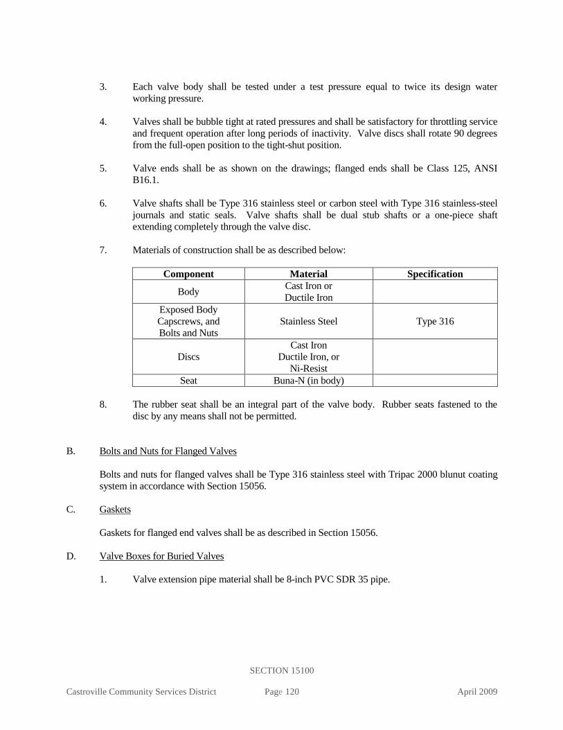
SECTION 15100
Castroville Community Services District Page 120 April 2009
3. Each valve body shall be tested under a test pressure equal to twice its design water
working pressure.
4. Valves shall be bubble tight at rated pressures and shall be satisfactory for throttling service
and frequent operation after long periods of inactivity. Valve discs shall rotate 90 degrees
from the full-open position to the tight-shut position.
5. Valve ends shall be as shown on the drawings; flanged ends shall be Class 125, ANSI
B16.1.
6. Valve shafts shall be Type 316 stainless steel or carbon steel with Type 316 stainless-steel
journals and static seals. Valve shafts shall be dual stub shafts or a one-piece shaft
extending completely through the valve disc.
7. Materials of construction shall be as described below:
Component Material Specification
Body Cast Iron or
Ductile Iron
Exposed Body
Capscrews, and
Bolts and Nuts
Stainless Steel Type 316
Discs
Cast Iron
Ductile Iron, or
Ni-Resist
Seat Buna-N (in body)
8. The rubber seat shall be an integral part of the valve body. Rubber seats fastened to the
disc by any means shall not be permitted.
B. Bolts and Nuts for Flanged Valves
Bolts and nuts for flanged valves shall be Type 316 stainless steel with Tripac 2000 blunut coating
system in accordance with Section 15056.
C. Gaskets
Gaskets for flanged end valves shall be as described in Section 15056.
D. Valve Boxes for Buried Valves
1. Valve extension pipe material shall be 8-inch PVC SDR 35 pipe.

SECTION 15100
Castroville Community Services District Page 121 April 2009
PART 3 - EXECUTION
A. Joints
1. Bolt holes of flanged valves shall straddle the horizontal and vertical centerlines of the pipe
run to which the valves are attached. Clean flanges by wire brushing before installing
flanged valves. Clean flange bolts and nuts by wire brushing, lubricate threads with oil and
graphite, and tighten nuts uniformly and progressively. If flanges leak under pressure
testing, loosen or remove the nuts and bolts, reseat or replace the gasket, reinstall or
retighten the bolts and nuts, and retest the joints. Joints shall be watertight.
2. Clean threaded joints by wire brushing or swabbing. Apply Teflon joint compound to
Teflon tape to pipe threads before installing threaded valves. Joints shall be watertight.
3. Rubber ring grooves of valves shall be inspected before installation by the contractor for
ridges or holes that would interfere with the rubber ring. Interferences with the rubber ring
shall be corrected to a satisfactory connection or the valves replaced, as required by the
District. (All valves shall have the same rubber-ring groove profile as the groove of the
pipe couplings furnished with the pipe.)
B. Butterfly Valve Operators
Butterfly valves shall be installed with the operators on the street centerline side of the pipeline.
C. Exterior Protection
1. All exposed flanges and other metal surfaces and all damaged coatings shall be coated after
assembly with bituminous mastic per Section 09900. Coating of stainless steel flange bolts
is not required.
2. Wrap buried valves with 8-mil polyethylene wrap per AWWA C105.
D. Concrete Supports
1. Valves shall be anchored in concrete as shown in CCSD Standard Plan W-7.
2. Concrete supports will not be required under valves bolted to flanged fittings.
3. Until supports are poured, valves shall be temporarily supported by placing wooden skids
underneath the valve so that the pipe is not subjected to the weight of the valve.
4. All concrete anchors and thrust blocks specified or required by the District representative
are considered as part of the pipeline installation.
E. Valve Boxes
1. Valve boxes shall be firmly supported and shall be kept centered and plumb over the
operating nut of the valve.
2. Beveled sections of pipe will not be allowed at the top of the valve extension pipe. The top
cut shall be square and machine made.

SECTION 15100
Castroville Community Services District Page 122 April 2009
3. During the construction of new tracts, the valve extension pipes for "key valves" shall
extend well above the ground level to permit ease of location in case of emergency
shutoffs.
4. The box cover shall be flush with the surface of the finished pavement or at any other level
designated by the District representative.
5. Top of all valves shall be within 4 feet of finish grade or must install a valve extension to
within 2 feet of finish grade
F. Backfill
1. All backfill within 24 inches of a valve shall be clean, washed sand.
2. Backfill is to be placed and compacted in accordance with Section 02223.
G. Valve Leakage Testing
1. Test valves for leakage at the same time that the connecting pipelines are tested. See
Section 15042 for pressure testing requirements.
2. Valves shall have a pressure rating higher than or equal to the test pressure.
H. Valve Location
The location of all valves shall be marked with a 2-inch “V” chiseled in the curb face perpendicular
to the valve. The offset distance, in feet, from the curb face to the valve shall be chiseled next to the
“V”. Where a perpendicular offset is not possible, multiple tangential offsets will be required to
allow triangulation of the valve location.
END OF SECTION

SECTION 15112
Castroville Community Services District Page 123 April 2009
STANDARD SPECIFICATIONS
SECTION 15112
BACKFLOW PREVENTERS
PART 1 - GENERAL
A. Description
This section includes materials, installation, and testing of backflow prevention assemblies.
B. Related Work Specified Elsewhere
All related work specified elsewhere, or in other codes or standards, will be as last revised, unless a
specific date of issuance is called out in opposition to later revision date(s).
Other sections of the technical specifications, not referenced below, shall also apply to the extent
required for proper performance of this work.
1. Concrete: 03300
2. Ductile-Iron Pipe and Fittings: 15056
3. Copper, Brass, and Bronze pipe, Fittings, and Appurtenances: 15057
4. Manual Valves: 15100
5. Meters: 15150
C. Approved Assemblies
The backflow prevention assembly shall be included in the latest edition of the "List of Approved
Backflow Prevention Assemblies," Foundation for Cross-Connection Control and Hydraulic
Research, University of Southern California, School of Engineering.
D. Application
1. A backflow prevention device shall be installed at all locations where the potential for a
backflow condition into the District's domestic water mains exists. The device shall be
located immediately behind the meter assembly.
2. The type of device required will depend on the level of potential hazard which exists. The
District shall make the final determination of what type of backflow device is required.
3. Any service providing domestic water to anything other than a private residential dwelling
shall have backflow protection.
4. A double check detector check assembly is required on a private on-site fire protection
system or a private on-site distribution system with two or more separate connections to
the District's domestic water mains.
SECTION 15112
Castroville Community Services District Page 124 April 2009
E. Responsibility
The District will maintain only the upstream mainline valve and service to the point of connection
of the assembly and the by-pass meter. The owner is responsible for the testing, maintenance and
repair or replacement of the device.
PART 2 - MATERIALS
A. Shut-Off Valves
1. The shut-off valves for assemblies 3-inch and larger shall be resilient seat gate valves
conforming to Section 15100. Ball valves shall be used on assemblies smaller than 3-
inch.
2. Shut-off valves shall have outside stems and yokes.
B. Ductile Iron Piping and Fittings
Ductile iron piping and fittings shall be furnished and installed in accordance with Section 15056.
C. Concrete
Concrete thrust blocks and supports shall be in conformance with Section 03300.
D. By-Pass Piping
By-pass piping shall be copper or brass conforming to Section 15057.
E. Backflow Prevention Assembly
All backflow prevention assemblies shall conform to the latest edition of AWWA C506 and the
"Manual of Cross-Connection Control," Foundation for Cross-Connection Control and Hydraulic
Research, University of Southern California, School of Engineering.
F. By-Pass Meter
The by-pass meter shall conform to the requirements of Section 15150 and shall be compatible with
the backflow device on which it is installed. The backflow prevention assembly and the by-pass
meter shall be furnished as one complete unit. All by-pass meters shall be 5/8-inch by 3/4-inch,
manufactured by Master Meters, with registers reading in cubic feet.
PART 3 - EXECUTION
A. Installation
Installation of the double detector check assembly or a reduced pressure principle assembly will be
per CCSD Standard Plan W-4 and as noted below.

SECTION 15112
Castroville Community Services District Page 125 April 2009
1. Installation shall comply with the latest plumbing codes and applicable local agency
requirements.
2. Installation shall comply with the requirements of the latest edition of the Manual
of Cross-Connection Control.
B. Testing
Upon completion of the installation of the device, a test shall be performed and a certificate of the
adequacy and operational compliance shall be furnished to the District. The tests shall be
performed by a testing agency approved by the AWWA California-Nevada Section and CDHS.
END OF SECTION
SECTION 15139
Castroville Community Services District Page 126 April 2009
STANDARD SPECIFICATIONS
SECTION 15139
FIRE HYDRANTS
PART 1 - GENERAL
A. Description
This section includes the materials, installation and testing of fire hydrants.
Hydrants shall be supplied and installed per CCSD Standard Plan W-5, AWWA C 503 and as
described herein.
B. Related Work Described Elsewhere
All related work specified elsewhere, or in other codes or standards, will be as last revised, unless a
specific date of issuance is called out in opposition to later revision date(s).
Other sections of the technical specifications, not referenced below, shall also apply to the extent
required for proper performance of this work.
1. Trenching, Backfilling, and Compacting: 02223
2. Concrete: 03300
3. Painting and Coating: 09900
4. Hydrostatic Testing of Pressure Pipelines: 15042
5. Ductile Iron Pipe and Fittings: 15056
6. Manual Valves: 15100
C. Approved Wet Barrel Hydrants
1. Residential Use
James Jones 3760 (Hydrant Head and Fluted Spool)
2. Commercial and Industrial Use
James Jones 3770 (Hydrant Head and Fluted Spool)
PART 2 - MATERIALS
A. Wet Barrel Hydrant
1. Hydrant Top Section
a. Fire hydrants shall have individual valves for each outlet opening counter
clockwise. Fire hydrants for residential use shall have two 2-1/2 inch hose nozzle
and one 4-1/2-inch pumper nozzle. Fire hydrants for commercial or industrial
developments shall have one 2-1/2 inch hose nozzle and two (2) 4-1/2-inch pumper
nozzles.

SECTION 15139
Castroville Community Services District Page 127 April 2009
b. All outlets shall have National Standard Hose Threads.
c. The hydrant top section shall be manufactured of bronze conforming to ASTM B
62.
d. All interior working parts, including stems, shall be of bronze containing no more
than 7% zinc or 2% aluminum.
e. Hydrants are to be provided with:
1-1/8-inch sized pentagon-shaped operating nut, and
1-1/8-inch capnuts.
f. All fire hydrants shall have the name of the manufacturer cast onto the hydrant
body or shown on a permanently attached plate.
g. Brass outlet nozzle caps shall be provided for all outlets. Caps shall be securely
chained to the barrel with non-kinking metal chain in a manner to permit free
rotation of the cap.
h. All hydrant flanges shall be eight-hole regular, Class 125, American Standard cast
iron flange drilling.
i. All hydrants to be James Jones.
2. Bury Section
a. The bury section shall be 6-inch cast iron long radius bury elbow and shall be
cement lined in conformance with Section 15056. Bury inlet shall be 6-inch
mechanical joint connection for C900 PVC pressure pipe.
b. A flanged ductile iron spool shall be installed to position the hydrant flange 4
inches above the concrete pad (finish grade).
c. All wet-barrel fire hydrant cast-iron buries are to be cement lined.
d. When using a riser spool, bolts shall be stainless steel 316, standard break-away.
e. Bury section outlet and riser spool flanges shall be eight-hole regular, Class 125,
American Standard cast-iron flange drilling.
C. Break-Away Bolts
1. Break-away bolts shall be used to join the spool section to the hydrant top section.
2. All bolts, and nuts, shall be stainless steel 316.

SECTION 15139
Castroville Community Services District Page 128 April 2009
D. Valve
The shut-off valve shall be a resilient-seated gate valve per Section 15100, including the valve box.
Butterfly valves will not be permitted on fire hydrant laterals.
E. Ductile Iron Pipe
Ductile iron pipe shall be per Section 15056.
F. Ductile Iron Pipe and Fittings
Ductile-iron Pipe and fittings shall be in accordance with Section 15056.
G. Concrete
Concrete pads and supports shall be Class B concrete conforming with Section 03300.
H. Gaskets
Gaskets shall be of rubber composition per Section 15056.
PART 3 - EXECUTION
A. General
1. Fire hydrant assemblies shall be installed in accordance with the standard drawing and as
specified herein, and shall include the connection to the main, the fire hydrant, hydrant
bury, shutoff valve, valve well and valve box, connection piping, concrete thrust blocks,
and appurtenances.
2. Refer to CCSD Standard Plan W-5.
B. Location
Fire hydrant assemblies shall be located as shown on the plans or as approved by the District
representative. The center of the fire hydrant shall be, except as otherwise approved by the District
representative, located as described below:
1. Where concrete curb or asphalt concrete (A.C.) berm exists or is to be constructed, and the
sidewalk is next to the property line; 1 feet 6 inches back of the back edge of the curb.
2. Where 6-foot-wide or narrower sidewalk is to be installed or exists next to the curb; 12
inches back of sidewalk edge. Where there is insufficient public right-of-way behind the
sidewalk, an easement will be required. For sidewalks wider than 6 feet; 18 inches back
of the curb face.
3. Where there is no curb or berm, the location shall be designated by the District
representative.
SECTION 15139
Castroville Community Services District Page 129 April 2009
4. The flange elevation at the base of the hydrant shall be set 4-inches above the curb or
sidewalk, or the surrounding graded area, or as approved by the District representative.
Spools additional will not be permitted when correcting the flange elevation.
C. Trenching, Backfilling, and Compacting
1. All trenching, backfilling, compaction and other excavation shall be in accordance with
Section 02223.
2. All backfill within 24 inches of a valve shall be imported sand.
D. Valve and Valve Box
The valve and valve box shall be installed in accordance with Section 15100.
E. Ductile Iron Pipe
Ductile iron pipe shall be installed in conformance with Section 15056.
F. Break-Away Bolts
Break-away bolts shall be installed with the threads away from the top of the hydrant.
G. Concrete
The concrete pad shall be Class B concrete and thrust blocker shall be Class A concrete and shall be
placed per Section 03300.
H. Painting
All public fire hydrants shall be painted with one prime coat and two finish coats of safety yellow
paint at the place of manufacture. Before the fire hydrant has been installed in accordance with
Section 09900. A final touch-up coat shall be applied just prior to the final inspection.
I. Testing
Test hydrants at the same time that the connecting pipeline is pressure tested. See Section 15042 for
pressure testing requirements.
END OF SECTION

SECTION 15150
Castroville Community Services District Page 130 April 2009
STANDARD SPECIFICATIONS
SECTION 15150
METERS
PART 1 - GENERAL
A. Description
This section describes the purchase, materials, installation and testing of meter assemblies.
B. Related Work Specified Elsewhere
All related work specified elsewhere, or in other codes or standards, will be as last revised, unless a
specific date of issuance is called out in opposition to later revision date(s).
Other sections of the technical specifications, not referenced below, shall also apply to the extent
required for proper performance of this work.
1. Earthwork: 02200
2. Concrete: 03300
3. Precast Concrete Vaults: 03462
4. Painting and Coating: 09900
5. Ductile-Iron Pipe and Fittings: 15056
6. Copper, Brass, and Bronze Pipe, Fittings, and Appurtenances: 15057
7. Manual Valves: 15100
8. Flexible Pipe Couplings and Expansion Joints 15162
C. Approved Manufacturers
1. Displacement Type – 3/4 inch through 2-inch
Master Meter
2. Turbine Meters
Master Meter
3. Compound Meters
Master Meter
4. Propeller Meters
Master Meter
5. Fire Service Meter Assembly
Master Meter
6. V-Cone Flow Meters
McCrometer V-cone flow meter

SECTION 15150
Castroville Community Services District Page 131 April 2009
D. Residential Meters
1. The District shall furnish and install the meters. The fee to furnish and install the meter will
be established by the District per the Water Code or the Construction and Transfer of
Ownership Agreement.
2. The developer shall expose and set to grade all coppersetters prior to requesting meters.
3. The developer is responsible for the installation of the meter box, coppersetters, meter (as
required by the District) and customer service valve.
4. Prior to occupancy, the District will, upon finding the installation to be acceptable, record
all meter account information and padlock the curb stop in the off position. The developer
will subsequently be relieved of any additional responsibility for consumption or service
charges for this service.
5. Subsequent applications for permanent service shall be made in accordance with the
District's Rules and Regulations.
E. By-Pass Line
1. A by-pass line shall be installed on all meter assemblies 3-inch and larger. A by-pass line is
not required on irrigation services, or as determined by the District.
2. A lockable valve shall be installed in all by-pass lines.
3. A by-pass line may be required on smaller installations which require continuous service.
PART 2 - MATERIALS
A. General
1. All meters shall be new and of current manufacture design.
2. All parts of the meters of the same size and model shall be interchangeable.
B. Registers
1. The registers on all meters shall have straight reading dials with full sweep test circles.
2. All registers are to be calibrated to read in cubic feet.
3. All registers are to be direct read. This may require the stamping of a zero or zeros on the
register dial face. The last two digits including the zero or zeros stamped on the register
dial face shall be easily distinguishable from the balance of the digits either by contract of
white numbers on black or red numbers on white.
4. Registers for positive displacement, compound, and turbine meters are to be hermetically
roll sealed.

SECTION 15150
Castroville Community Services District Page 132 April 2009
5. Register gears shall be self-lubricating molded plastic unless stated otherwise. Register
gears for propeller meters may be bronze.
6. Registers for positive displacement and turbine meters shall not have replaceable change
gears.
7. Registers shall be driven by a magnetic coupling.
8. All register lenses shall be tempered glass.
9. All registers shall be provided with low flow detectors.
10. All registers shall be oriented to read from the inlet side of the meter.
11. The register must be attached to the meter case by a bayonet attachment. The register
assembly shall be able to mount any of four positions. On positive displacement meters the
standard mount position shall read from the meter inlet side.
C. Remote Reading Device
1. Meter shall be equipped with radio read registers manufactured by Master Meter.
2. All meters 3-inch and larger and double check detector check meters shall be supplied with
a remote read meter interpreter register.
D. Stainless Steel Hardware
All bolts, nuts, capscrews, studs, and washers shall be Type 316 stainless steel ASTM A 193 B8M
for bolts, and ASTM A 194 8M for nuts (red brass 651 or blue treated Tripac).
E. Displacement Type Meters (3/4 inch through 2 inch)
1. Meters shall conform to the material and performance requirements of AWWA C700, as
most recently revised, and as specified herein.
2. The manufacturer shall furnish certified results for each meter showing that it has been
tested for accuracy of registration and that it complies with accuracy and capacity
requirements of AWWA C700 when tested in accordance with AWWA Manual M6.
3. All meters body components resisting pressure shall be bronze.
4. All register boxes and covers shall be synthetic polymer or bronze.
5. Casing bolts shall be stainless steel or bronze.
6. All internal hardware shall be stainless steel.
7. 3/4-inch through 1-inch meters shall have external straight threads. 1½-inch and 2-inch
meters shall have flanges on ends.

SECTION 15150
Castroville Community Services District Page 133 April 2009
8. The face-to-face length and maximum profile height of the meter shall be as described
below:
Meter Size
(inches)
Face-to-Face Dimension
(inches)
Maximum Profile
Height Centerline Inlet
to Register Cover
(inches)
3/4 7-1/2 3-1/4
3/4 9-1/2 3-1/4
1 10-3/4 3-1/4
1-1/2 13 4-1/4
2 17 5
9. All meters shall have plastic or stainless steel internal strainers.
10. All registers and register boxes shall be secured to the main casing by acceptable tamper-
proof means. Safety wiring of standard bolts and screws is NOT considered an acceptable
method of tamper-proofing.
11. The serial number of each meter shall be imprinted on the register box cover, and the main
case.
12. Register shall be removable without reducing pressure or removing the main case from the
installation.
13. All positive displacement meters shall be supplied with the following warranty, which shall
not be prorated under any conditions:
a. All meters shall be guaranteed to maintain new-meter accuracy (±1½%) for five
years.
b. All measuring chambers and disks or pistons shall be guaranteed against
malfunction for fifteen years.
c. All registers shall be guaranteed for twenty-five years.
F. Turbine Meters (1½-inch and larger)
1. All meters shall conform with AWWA C701 Class II and the requirements specified
herein.
2. The manufacturer shall furnish certified test results for each meter showing that it has been
tested for accuracy of registration and that it complies with accuracy and capacity
requirements of AWWA C701 when tested in accordance with AWWA Manual M6.
3. Turbine meters shall have all bronze main cases.
4. Straightening vanes shall be provided in the main case of all meters.

SECTION 15150
Castroville Community Services District Page 134 April 2009
5. A calibration adjusting vane located in the measuring chamber shall be provided on all
meters.
6. All rotors shall be thermoplastic with graphite bearings (PTFE) rotating on a stainless steel
or tungsten carbide shaft.
7. All motion shall be transmitted from the rotor to the register through a magnetic coupling.
8. All register boxes and covers shall be bronze.
9. All registers and register boxes shall be secured to the measuring chamber by acceptable
tamper-proof means. Safety wiring of standard bolts and screws is NOT considered an
acceptable method of tamper-proofing.
10. All turbine meters shall be equipped with strainers. The strainer body and cover shall be
cast bronze for meters 2-inch through 6-inch. Ductile iron will be permitted only on 8-inch
and larger or fire service strainers. All ductile iron strainers shall be epoxy lined in
accordance with Section 09900. All strainers shall be furnished with bronze or stainless
steel screens with an effective open area at least double the area of the meter. On metered
fire service installations, a U.L. approved strainer with an effective open area at least 4
times the equivalent open area of the meter will be required.
11. All measuring chamber, strainer cover, and flange bolts shall be Type 316 stainless steel.
12. The serial number of each meter shall be imprinted on the register cover, and the main case.
13. All meter registers shall be provided with a remote touchread device.
G. Compound Meters (3-inch and larger)
1. All meters shall conform with AWWA C702 and the requirements specified herein.
2. The manufacturer shall furnish certified test results for each meter showing that it has been
tested for accuracy of registration and that it complies with accuracy and capacity
requirements of AWWA C702 when tested in accordance with AWWA Manual M6.
3. Compound meters shall have all bronze main cases.
4. All compound meters shall have flanged connections.
5. A test plug shall be provided in the outlet side of the main case of all meters.
6. The measuring chamber shall be capable of operating within the specified AWWA
accuracy limits without recalibration when transferred from one main case to another.
7. A calibration adjusting vane located in the measuring chamber shall be provided on all
meters.
8. All rotors shall be thermoplastic with graphite bearings rotating on a stainless steel shaft.

SECTION 15150
Castroville Community Services District Page 135 April 2009
9. All motion shall be transmitted from the rotor to the register through a magnetic coupling.
Worm gears will NOT be permitted.
10. All register boxes and covers shall be bronze, or synthetic polymer.
11. All registers and register boxes shall be secured to the measuring chamber by acceptable
tamper-proof means. Safety wiring of standard bolts and screws is NOT considered an
acceptable method of tamper-proofing.
12. All compound meters shall be equipped with strainers. The strainer body and cover shall
be bronze for 2-inch through 6-inch meters. Ductile iron will be permitted only on 10-inch
and larger or fire service strainers. All ductile iron strainers shall be epoxy lined in
accordance with Section 09900. All strainers shall be furnished with bronze or stainless
steel screens with an effective open area at least double the area of the meter.
13. All measuring chamber, strainer cover, and flange bolts shall be Type 316 stainless steel.
14. The serial number of each meter shall be imprinted on the register cover, and main case.
15. All meter registers shall be provided with remote touchread devices.
H. Fire Line Meter Assembly
1. A fire line meter assembly may be required for residential structures and commercial and
industrial installations where separate fire service installations are not provided.
2. Fire line meter assemblies shall be furnished as complete units by the manufacturer. Each
fire line meter assembly shall consist of a U.L. approved strainer with a stainless steel
strainer basket, a turbine meter sized for fire flow, a positive displacement or turbine meter
sized for maximum demand without fire flow, positive displacement meter piping, lockable
ball valves to isolate the positive displacement meter, a check valve downstream of the
positive displacement meter, and an internally weighted or spring loaded check valve
adjusted to open prior to exceeding the maximum flow range of the positive displacement
meter. The positive displacement meter piping shall extend from the outlet of the strainer
to the downstream side of the swing check valve.
3. Each fire line meter assembly shall be constructed of components conforming to the
appropriate sections of these specifications.
4. Cast iron or steel components shall be epoxy lined and coated per Section 09900.
5. Each fire line meter assembly shall conform the AWWA C703 and shall be U.L listed, and
shall be F.M. approved for fire service use.
6. All meter registers shall be provided with remote radio read devices.
I. Propeller Meters
1. All propeller meters shall conform with AWWA C704 and the requirements specified
herein.

SECTION 15150
Castroville Community Services District Page 136 April 2009
2. The main casing may be steel or cast-iron and shall be epoxy lined and coated.
3. The main casing may be flanged or plain end as specified by the engineer.
4. Meter head shall be mounted on a flanged connection for easy removal of all interior parts
from the pipe tee without disturbing the connections to the pipeline.
5. The drive mechanism shall be by means of stainless steel gears and shafting or flexible
cable drives.
6. All meters shall be polyethylene propellers.
7. Bronze gearboxes on the propeller drive shafts are required.
8. Each meter tube shall be equipped with straightening vanes mounted immediately
preceding the propeller.
J. Precast Vaults
Precast meter vaults and boxes shall conform with Section 03462 and the standard drawings.
K. Copper, Brass, and Bronze Pipe, Fittings, and Appurtenances
All service connection and by-pass piping shall conform with Section 15057.
L. Ductile-Iron Pipe and Fittings
All piping for meter assemblies 3-inch and larger shall conform with Section 15056.
M. Manual Valves
1. All valves shall conform with Section 15100.
2. All valves on by-pass lines shall be lockable in the closed position. On 3-inch and larger
by-pass lines, resilient seat gate valves with hand wheels and a chain and lock are
permitted.
PART 3 - EXECUTION
A. Meter Installations
1. All residential meters shall be installed by the contractor per MCCSD Standard Plans W-1,
W-2, or W-3.
2. All 3-inch and larger meter installations shall conform with MCCSD Standard Plans W-15.
B. Excavation and Backfill
Excavation and backfill for the meter installation shall be in accordance with Section 02200.
SECTION 15150
Castroville Community Services District Page 137 April 2009
C. Service Piping
1. All piping for service lines and by-pass lines up to 2-inch shall be installed in conformance
with Section 15057.
2. The piping for all service installations 3-inch and larger shall be in accordance with Section
15056 and the applicable standard drawing.
D. Test Tap
On services 3 inches and larger, a 2-inch service saddle or welded coupling and corporation stop
shall be installed on the spool downstream of the meter. The tap shall be located a minimum of
three (3) pipe diameters downstream of the meter. On propeller meter installations, the location of
the test tap will be determined by the District representative.
E. Meter Vault
The District prefers that all new meter boxes and vaults are fiberglass. All precast concrete meter
vaults shall be installed in accordance with Section 03462 and the MCCSD Standard Plans W-1
through W-3 and W-15.
F. Concrete Work
All thrust blocks, foundations, and supports shall be of the sizes shown in the applicable standard
drawings and conform with Section 03300.
G. Valves
All valves installed shall conform with the Section 15100.
H. Painting and Coating
1. All exposed and buried piping shall be painted or coated in accordance with Section 09900.
2. The meter reading lids on all recycled water services shall be painted in accordance with
Section 09900.
I. Testing
1. All meter services shall be hydrostatically pressure tested during the testing of pipeline in
accordance with Section 15042.
END OF SECTION

SECTION 15151
Castroville Community Services District Page 138 April 2009
STANDARD SPECIFICATIONS
SECTION 15151
DOMESTIC WATER FACILITIES IDENTIFICATION
PART 1 - GENERAL
A. Description
All domestic water systems and appurtenances shall be identified as herein described.
This section describes special identification, markings, materials and their installation procedures
for potable water facilities.
All water systems and appurtenances must be marked as described herein to avoid confusion with
other utilities and between each other.
B. Related Work Specified Elsewhere
All related work specified elsewhere, or in other codes or standards, will be as last revised, unless a
specific date of issuance is called out in opposition to later revision date(s).
Other sections of the technical specifications, not referenced below, shall also apply to the extent
required for proper performance of this work.
1. Painting and Coating: 09900
2. Ductile Iron Pipe & Fittings: 15056
3. PVC Pressure Distribution Pipe: 15064
4. Combination Air and Vacuum Release Valves: 15089
5. Manual Valves: 15100
6. Fire Hydrants: 15139
7. Water Meters: 15150
C. Approved Manufacturers
1. Warning Tape and Pipe Sleeves
a. Griffolyn Company, Inc.
10020 Mykawa Road
P.O. Box 33248
Houston, TX 77033
Phone: (713) 943-0070 or (800) 231-6074
b. Terra Tape, Division of Reef Industries
P. O. Box 33310
Houston, TX 77233
Phone: (800) 231-2417

SECTION 15151
Castroville Community Services District Page 139 April 2009
c. T. Christy Enterprises, Inc.
655 E. Ball Road
Anaheim, CA 92805
Phone: (714) 507-3300
2. Warning Labels and Signs
In all cases the warning labels or signs must be approved prior to installation. Failure to
receive prior approval may result in the owner, applicant, or customer removing such
sign(s) and providing approved replacement(s). All costs will be at the applicant's, owner's
or customer's expense. Failure to comply with these requirements as set forth herein will
result in termination of service as provided for in the District's Rules and Regulations,
Sections 600.
3. Witness Markers
Carsonite Water line Markers
Carsonite International
1301 Hot Springs Road
Carson City, NV 89706
Phone (800) 648-7974
D. Identification
1. The use of stenciled pipe will be accepted as an alternative to the use of warning tape.
2. PVC or DIP carrying domestic water, and located in the vicinity of recycled water piping,
shall have the words "DOMESTIC WATER" stenciled with 2-inch blue letters. Lettering
shall be on both sides of the pipe in at least three places in an 18-foot section of pipe (total
six places per section of pipe).
3. All service lines shall be encased within a color-coded 8-mil polyethylene sleeve. Sleeve
shall be blue in color for all domestic water.
E. Valve Boxes
1. All valve boxes installed in unpaved areas (open space areas) shall be marked with a
witness pole; in addition to the above referenced markings.
F. Color and Painting Schedule
1. Domestic water facilities shall be blue, with the exception of fire hydrants which shall be
painted as specified in Section 15139.
2. Witness poles for recycled water lines, valves and appurtenances shall be purple.

SECTION 15151
Castroville Community Services District Page 140 April 2009
G. Warning Signs and Labels
1. The District requires warning labels to be installed on all appurtenances in vaults, such as,
but not limited to, air release valves, blow offs, and meters, and on designated facilities,
such as, but not limited to, controller panels and wash down or blow off hydrants on water
trucks and temporary construction services.
2. Each pump and every pipe shall be identified with a painted label. In the fenced pump
station area, at least one sign shall be posted on the fence which can be readily seen by all
operations personnel utilizing the facilities.
3. Painted labels may, at the District representative's discretion be acceptable in lieu of plastic
labels.
H. Domestic Water Piping
1. All domestic water piping shall be installed with domestic water identification.
2. All PVC domestic water piping shall be blue or shall be white with blue stenciling
appearing on both sides of the pipe with the marking "DOMESTIC WATER" in 5/8-inch
letters repeated every 12 inches.
3. Blue warning tape identifying it as a domestic water line and stating "CAUTION:
DOMESTIC WATER-LINE BURIED BELOW" may be used as an alternate to blue or
stenciled pipe. The tape shall run continuously for the entire length of the main line piping.
The tape shall be attached to the top of the pipe with plastic tape banded around the
warning tape and pipe every 5 feet on center.
PART 2 - MATERIALS
A. Buried Piping Warning Tape
Warning tape for domestic water pipeline shall be blue with black printing having the words,
"CAUTION: DOMESTIC WATER-LINE BURIED BELOW." The minimum thickness shall be 4
mils and the overall width of the tape shall be 12 inches (for 8-inch pipe) and 6 inches (for 6-inch
and smaller pipe).
PART 3 - EXECUTION
A. Installation of Pipe Warning Tape
Warning tapes shall be installed 12” above pipe longitudinally and shall be centered, to warn
contractors excavating in the area. The warning tape shall be installed continuously for the length
of the pipe and shall be fastened to each pipe length by plastic adhesive tape banded around the pipe
and warning tape at no more than 5-foot intervals. Taping attached to the sections of pipe before
installing in the trench shall have 5-foot minimum overlap for continuous coverage.

SECTION 15151
Castroville Community Services District Page 141 April 2009
B. Installation of Warning Labels
Warning labels shall be firmly attached to all appurtenances using heavy-duty nylon fasteners.
C. Installation of Witness Markers
Witness markers shall be installed over pipe in unpaved areas, open space areas, at appurtenances,
including but not limited to valves, air release/vacuum breaks, dead ends, inflection points, tees, and
at intervals not greater than 200 feet.
Witness markers shall be embedded into the soil at least 18-inches and shall be equipped with a
barb or other such device to secure it in the surrounding soil.
END OF SECTION

SECTION 15162
Castroville Community Services District Page 142 April 2009
STANDARD SPECIFICATIONS
SECTION 15162
FLEXIBLE PIPE COUPLINGS AND EXPANSION JOINTS
PART 1 - GENERAL
A. Description
This section includes materials and installation of flexible gasketed sleeve-type compression pipe
couplings and expansion joints.
B. Related Work Specified Elsewhere
All related work specified elsewhere, or in other codes or standards, will be as last revised, unless a
specific date of issuance is called out in opposition to later revision date(s).
Other sections of the technical specifications, not referenced below, shall also apply to the extent
required for proper performance of this work.
1. Painting and Coating: 09900
2. Hydrostatic Testing of Pressure Pipelines: 15042
C. Approved Manufacturers
1. Flexible Couplings
Dresser Style 253
Smith Blair Type 431
Baker Series 200
2. Transition Couplings
Dresser Style 38
Smith Blair Series 413
Baker Series 220
3. Flanged Coupling Adapters
Smith Blair Type 912
Dresser Style 227 (to 12-inches), Style 128 (above 12-inches)
Baker Series 601
PART 2 - MATERIALS
A. Coupling Sleeve and Flanges
Coupling sleeves and flanges shall be ductile iron.

SECTION 15162
Castroville Community Services District Page 143 April 2009
B. Bolts and Nuts for Flanges
1. Bolts and nuts for buried and submerged flanges, flanges in underground vaults and
structures, and flanges located outdoors above ground shall be Type 316 stainless steel
conforming to ASTM A 193 (Grade B8M) for bolts and ASTM A 194 (Grade 8M) for
nuts.
2. Provide one washer for each nut. Each washer shall be of the same material as the nut.
C. Painting and Coating
All cast components shall be epoxy lined and coated per Section 09900.
PART 3 - EXECUTION
A. Installation of Flexible Pipe Couplings
1. Clean oil, scale, rust, and dirt from pipe ends. Clean gaskets in flexible pipe couplings
before installing. Install expansion joints per manufacturer's recommendations. Install
expansion joints so that 50% of total travel is available for expansion and 50% is available
for contraction.
2. Lubricate bolt threads with graphite and oil prior to installation.
B. Field Coating
1. Coat buried flexible pipe couplings, transition couplings, and flanged coupling adapters per
Section 09900. Then wrap the couplings with 8-mil polyethylene wrap per AWWA C105.
2. Coat flexible pipe couplings (including joint harness assemblies), transition couplings, and
flanged coupling adapters located indoors, in vaults and structures, and above ground with
the same coating system as specified for the adjacent pipe. Apply prime coat at factory.
C. Hydrostatic Testing
Hydrostatically test flexible pipe couplings, expansion joints, and expansion compensators in place
with the pipe being tested. Test in accordance with in Section 15042.
END OF SECTION
SECTION 15130
Castroville Community Services District Page 144 April 2009
STANDARD SPECIFICATIONS
SECTION 15300
AUTOMATIC CONTROL VALVES
PART I - GENERAL
A. Description
This section describes the materials and installation of self-contained automatic control valves. The
various applications of these control valves are described herein. The various applications shall be
achieved through specialized pilot control applications on hydraulically operated, diaphragm-
actuated, globe pattern valves.
Items of equipment specified herein shall be the end products of a limited number of manufacturers
in order to achieve standardization for operation, maintenance, spare parts, and manufacturer's
service.
B. Related Work
1. Painting and Coating: 09900
2. Hydrostatic Testing of Pressure Pipelines: 15042
3. Ductile-Iron Pipe and Fittings: 15056
4. Copper, Brass and Bronze Pipe, Fittings and Appurtenances: 15057
5. Cement-Mortar-Lined and Coated Steel Pipe: 15076
6. Domestic and Recycled Water Facilities Identification: 15151
C. Approved Manufacturer's
1. Cla-Val Company
2. Singer Valve Inc.
D. Application Model Number
1. Check Valves
Cla-Val model 81G-02KC with X101 Valve Position Indicator (installed by valve
manufacturer)
2. Solenoid Control Valves
Cla-Val model 136G-03YBCSFKC with Limit Switch Assembly Model X105LCW
(installed by valve manufacturer).
3. Pressure Reducing Valves
Cla-Val model 90G-01YBKC (90G-01YSFC for valves 3 inches and smaller), with X101
Valve Position Indicator (installed by valve manufacturer).

SECTION 15130
Castroville Community Services District Page 145 April 2009
4. Pressure Relief Valves
Cla-Val model 50G-01SBKC with Limit Switch Assembly Model X105LOW (installed by
valve manufacturer).
5. Surge Anticipator Valves
Cla-Val model 52G-01BKC with Limit Switch Assembly Model X105LOW (installed by
valve manufacturer).
6. Pump Controller Valves
Cla-Val model 60G-11 BKC with Limit Switch Assembly Model X105LCW (installed by
valve manufacturer).
7. Two-Way Flow Altitude Valves with Differential Control
Cla-Val model 201-01 with X-101 position indicator.
PART 2 - MATERIALS
A. Complete Assemblies
All valves shall be complete, with all necessary operating appurtenances included in the work under
this section.
B. Interior Lining and Exterior Coating
An epoxy coating shall be applied to internal and external ferrous valve surfaces. Coating shall be
per AWWA C550. Unless specified otherwise, herein.
C. Globe Valve
All control valve applications shall be based on a hydraulically operated, diaphragm-actuated, globe
pattern valve. It shall contain a resilient, synthetic rubber disc, having a rectangular cross-section,
contained on three and one-half sides by a disc retainer and forming a tight seal against a single
removable seat insert. The diaphragm assembly contacting a valve stem shall be fully guided at
both ends by a bearing in the valve cover and an integral bearing in the valve seat. This diaphragm
assembly shall be the only moving part and shall form a sealed chamber in the upper portion of the
valve, separating operating pressure from line pressure. The diaphragm shall consist or nylon fabric
bonded with synthetic rubber and shall not be used as a seating surface. Packing glands and/or
stuffing boxes are not permitted and there shall be not pistons operating the valve.
Valve shall be of indicated size and shall be of manufacturer's standard ductile iron with stainless
steel trim (seat, disc guide, cover bearing, stem nut, and stem). Valve shall have a pressure rating of
150 or 300 psi, depending on the service application, with the appropriate class ductile iron flanges.
Interior ferrous surfaces shall be lined with factory-applied epoxy and exterior ferrous surfaces shall
be coated with alkyd enamel per Section 09900.

SECTION 15130
Castroville Community Services District Page 146 April 2009
The design shall precluded cavitation erosion, fouling of working surfaces, and other effects adverse
to reliability. Seats and other trim shall be secured by means precluding their loosening by
hydraulically induced vibrations; and the fit of stems in guides and guide lengths shall preclude any
binding, scraping, or deviation from true alignment affecting the free movement of working parts.
All repairs shall be possible without removing the valve from the line.
D. Check Valve
The check valve shall consist of a globe valve with the appropriate pilot system.
The pilot shall contain auxiliary controls which permit the adjustment of the opening and closing
speeds, and shall be set for fast opening and slow closing.
Pilot valves shall be all bronze conforming to ASTM B62 with stainless steel trim. Hydraulic
control and sensing lines shall be copper, conforming to Section 15057, herein.
E. Solenoid Control Valve
The solenoid control valve shall consist of a globe valve with the appropriate pilot system.
The pilot control shall be a solenoid valve controlling a diaphragm-operated three-way auxiliary
valve. The control system shall include opening and closing speed controls, a wye strainer and limit
switch Model X105LCW.
Pilot valves shall be all bronze conforming to ASTM B62 with stainless steel trim. Hydraulic
control and sensing lines shall be copper, conforming to Section 15057, herein.
F. Pressure Reducing Valve
The pressure-reducing valve shall consist of a globe valve with the appropriate pilot system.
The pilot control shall be a direct-acting, adjustable, spring-loaded, diaphragm valve, designed to
permit flow when controlled pressure is less that the spring setting. The control system shall
include a fixed orifice.
The pilot valve system shall have a direct acting, adjustable, spring-loaded pilot, diaphragm
actuated valve, designed to permit flow in the pilot valve system whenever the controlling pressure
exceeds the spring setting. The pilot valve system shall also contain a strainer needle valve
assembly that shall control the opening or the main valve.
Pilot valves shall be all bronze conforming to ASTM B62 with stainless steel trim. Hydraulic
control and sensing lines shall be copper, conforming to Section 15057, herein.

SECTION 15130
Castroville Community Services District Page 147 April 2009
G. Pressure Relief Valve
The pressure relief valve shall consist of a globe valve with the appropriate pilot system.
The pilot valve system shall have a direct acting, adjustable, spring-loaded pilot, diaphragm
actuated valve, designed to permit flow in the pilot valve system whenever the controlling pressure
exceeds the spring setting. The pilot valve system shall also contain a strainer needle valve
assembly that shall control that closing of the main valve.
Pilot valves shall be all bronze conforming to ASTM B62 with stainless steel trim. Hydraulic
control and sensing lines shall be copper, conforming to Section 15057, herein.
H. Surge Anticipator Valve
The surge anticipator valve shall consist of a globe valve with the appropriate pilot system.
The pilot control shall be a direct-acting, adjustable, spring-loaded, diaphragm valve. The pilot
valve system shall contain a strainer needle valve assembly that shall control the closing of the main
valve. The pilot valve system shall also contain a check valve that is installed on one of the main
valve cover connections. This check valve shall be so installed that if low pressure occurs at the
inlet of the valve, it will open and relieve the cover pressure to the inlet side of the valve.
Pilot valves shall be all bronze conforming to ASTM B62 with stainless steel trim. Hydraulic
control and sensing lines shall be copper, conforming to Section 15057, herein.
I. Pump Control Valve - Booster Type
This valve shall be a hydraulically operated, single seated, diaphragm actuated, composition disc,
dual-port globe style valve with solenoid valve control. The valve shall have a built-in check
feature; designed to operate with pump controls to start and stop pump against a closed valve.
Valves shall have emergency shutdown power check features for surge protection as described
below: upon power failure, solenoids de-energize and a check valve in the diaphragm unit shall
release to effect closure under spring action when flow stops before flow reversal can occur.
Pilot valves shall be all bronze conforming to ASTM B62 with stainless steel trim. Hydraulic
control and sensing lines shall be copper, conforming to Section 15057, herein.
A manual control override shall be provided on the valve assembly. The design shall preclude
cavitation erosion, fouling of working surfaces, and other effects adverse to reliability. Seats and
other trim shall be secured by means precluding their loosening by hydraulically induced vibrations;
and the fit of stems in guides and guide lengths shall preclude any binding, scraping, or deviation
from true alignment affecting the free movement of working parts.
The valve shall be provided with a SPDT limit switch actuated by the control rod. The switch shall
indicate: 1) When the valve is fully closed; 2) When the valve is not fully closed.

SECTION 15130
Castroville Community Services District Page 148 April 2009
J. Altitude Valve
The altitude valve shall consist of globe valve with the appropriate control system.
The control system shall consist of auxiliary valves working in conjunction with the pilot valve to
control the main valve. The pilot valve is to be controlled by the difference between the reservoir
pressure and an adjustable spring pressure with a spring range of 5-40 feet of water. The entire
valve and control assembly shall be designed so that no surface water can be drawn into the pilot
system or the main valve at any time.
PART 3- EXECUTION
A. Manufacturer's Services
A manufacturer's representative for the equipment specified herein shall be present at the job site
and/or classroom designated by the District for that minimum personnel days listed for the services
hereunder, travel time excluded:
One (1) personnel day for equipment start up and one (1) personnel-day for post start-up training.
Start up services and training of District’s personnel shall be at such times as requested by the
District.
B. Installation
1. Automatic control valves shall be installed above ground or within a vault to provide for
adjustment, maintenance and repair. Direct burial of a control valve will not be permitted
under any circumstance.
2. Automatic control valves are to be installed with ductile iron piping per Section 15056 or
cement-mortar lined and coated steel pipes per Section 15076.
3. Prior to purchase of material, inspect valve to confirm valve size, manufacturer, and part
number.
C. Valve Refurbishment
1. Provide refurbishment parts recommended by valve manufacturer for complete
refurbishment of valve.
2. Refurbishment shall be performed by technician certified or approved by the valve
manufacturer.
D. Valve Adjustment and Testing
1. All valves installed, replaced, refurbished, or adjusted shall be tested.
2. Valves shall be adjusted to operate at set pressures as determined by the Engineer.
SECTION 15130
Castroville Community Services District Page 149 April 2009
3. Set pressures shall be tested by operating downstream system to reduce pressure below set
point and observing operation of the valves. Pressure gauges shall be provided along with
other test equipment. District will operate the downstream system.
4. Valves shall be readjusted if necessary, to get operation at the designated pressure.
END OF SECTION

SECTION 16120
Castroville Community Services District Page 150 April 2009
STANDARD SPECIFICATIONS
SECTION 16120
BUILDING WIRE AND CABLE - 600V AND BELOW
PART 1 GENERAL
1.01 SUMMARY
A. Section includes: Building wire and cable, nonmetallic-sheathed cable, underground feeder and
branch circuit cable, and service entrance cable.
1.02 RELATED SECTIONS
A. Section 16111, Conduit and Fittings.
B. Section 16127, Splices and Terminations - 600 V and Below.
C. Section 16131, Boxes.
D. Section 16196, Electrical Identification.
E. Section 16960, Electrical Testing.
1.03 REFERENCES
A. NFPA 70-1999, National Electrical Code.
B. NEMA WC5-1973, Thermoplastic-Insulated Wire and Cable.
1.04 SUBMITTALS
A. Submit test reports for approval.
1.05 REGULATORY REQUIREMENTS
A. Furnish products listed and classified by UL.
PART 2 PRODUCTS
2.01 BUILDING WIRE
A. Description: Single conductor insulated wire.
B. Conductor: Copper or aluminum except copper for sizes No. 4 AWG and smaller.
C. Stranding:
1. Wire No. 8 and larger: Stranded.
2. Wire No. 10 AWG and smaller feeding lights and receptacles: Solid.
3. Wire No. 10 AWG and smaller for motor leads and control wiring: Stranded.

SECTION 16120
Castroville Community Services District Page 151 April 2009
4. Standard stranding for cable sizes as follows: 7 strands up through No. 2; 19 strands from
No. 1 through No. 4/0; 37 strands from 250 MCM through 500 MCM; and 61 strands from
600 MCM through 1000 MCM.
D. Insulation Voltage Rating: 600V.
E. Insulation: Conductors in raceways; NFPA 70:
1. THW or XHHW for sizes larger than No. 10 AWG.
2. THHN/THWN for sizes No. 10 AWG and smaller.
3. THHN/THWN for conductors enclosed in fluorescent lighting fixtures.
F. Color Coding:
1. Grounding conductors may be bare or insulated. Identify insulated conductors intended
solely for grounding purposes by a continuous green color; a continuous green color with
one or more yellow stripes; or by wrapping with green self-adhesive, vinyl plastic
electrical tape, Scotch 35, at terminal or junction points. Tape sufficient length of
conductor nearest terminal or junction point so that grounding conductors are identifiable
when covers are removed.
2. Grounded (neutral) Conductors No. 2 AWG and Smaller: White insulation. Identify
grounded conductors larger than No. 2 AWG at terminal or junction points by wrapping
with white, self-adhesive, vinyl plastic electrical tape, Scotch 35. Tape sufficient length of
cable nearest terminal or junction point so that neutral conductors are identifiable when
covers are removed.
3. Color code system conductors as follows:
a. Color and Number Coding for 120-V, Single-Phase, Two-Wire Systems
1) Grounded neutral, white (first or only neutral in raceway, box, auxiliary
gutter, or other types of enclosures).
2) Grounded neutral, white with black stripe running entire length of insulation
(when neutral is installed in raceway, box, auxiliary gutter, or other types of
enclosures with another neutral).
3) Grounding conductor, green, green with one or more yellow stripes, green
tape, or bare.
4) Ungrounded conductor, black with marker "120V-1PH."
b. Color and Number Coding for 240/120-V, Single-Phase, Three-Wire Systems
1) Grounded neutral, white (first or only neutral in raceway, box, auxiliary
gutter, or other types of enclosures).
SECTION 16120
Castroville Community Services District Page 152 April 2009
2) Grounded neutral, white with brown stripe running entire length of insulation
(when neutral is installed in raceway, box, auxiliary gutter, or other types of
enclosures with another neutral).
3) Grounding conductor, green, green with one or more yellow stripes, green
tape, or bare.
4) Ungrounded conductor, black with marker "240/120V-1PH-A."
5) Ungrounded conductor, red with marker "240/120V-1PH-B."
c. Color and Number Coding for 208Y/120-V, Three-Phase, Four-Wire Systems
1) Grounded neutral, white (first or only neutral in raceway, box, auxiliary
gutter, or other types of enclosures).
2) Grounded neutral, white with red stripe running entire length of insulation
(when neutral is installed in raceway, box, auxiliary gutter, or other types of
enclosures with another neutral).
3) Grounding conductor, green, green with one or more yellow stripes, green
tape, or bare.
4) Phase A (ungrounded) conductor, black with marker "208Y/120V-3PH-A."
5) Phase B (ungrounded) conductor, red with marker "208Y/120V-3PH-B."
6) Phase C (ungrounded) conductor, blue with marker "208Y/120V-3PH-C."
d. Color and Number Coding for 240-V, Delta, Three-Phase, Three-Wire Systems
1) Grounding conductor, green, green with one or more yellow stripes, green
tape, or bare.
2) Phase A (ungrounded) conductor, black with marker "240VD-3PH-A."
3) Phase B (ungrounded) conductor, black with marker "240VD-3PH-B."
4) Phase C (ungrounded) conductor, black with marker "240VD-3PH-C."
e. Color and Number Coding for 480Y/277-V, Three-Phase, Four-Wire Systems
1) Grounded neutral, white (first or only neutral in raceway, box, auxiliary
gutter, or other types of enclosures).
2) Grounded neutral, white with yellow stripe running entire length of insulation
(when neutral is installed in raceway, box, auxiliary gutter, or other types of
enclosures with another neutral).
SECTION 16120
Castroville Community Services District Page 153 April 2009
3) Grounding conductor, green, green with one or more yellow stripes, green
tape, or bare.
4) Phase A (ungrounded) conductor, brown with marker "480Y/277V-3PH-A."
5) Phase B (ungrounded) conductor, orange with marker "480Y/277V-3PH-B."
6) Phase C (ungrounded) conductor, yellow with marker "480Y/277V-3PH-C."
f. Color and Number Coding for 480-V, Delta, Three-Phase, Three-Wire Systems
1) Grounding conductor, green, green with one or more yellow stripes, green
tape, or bare.
2) Phase A (ungrounded) conductor, brown with marker "480VD-3PH-A."
3) Phase B (ungrounded) conductor, orange with marker "480VD-3PH-B."
4) Phase C (ungrounded) conductor, yellow with marker "480VD-3PH-C."
4. Furnish ungrounded single-conductor control circuit wiring a combination of colors other
than white, gray, or green.
2.02 NONMETALLIC-SHEATHED CABLE
A. Description: NFPA 70; Type NMC or NM.
B. Conductor: Copper or aluminum except copper for sizes smaller than No. 4 AWG.
C. Insulation Voltage Rating: 600V.
2.03 UNDERGROUND FEEDER AND BRANCH CIRCUIT CABLE
A. Description: NFPA 70; Type UF.
B. Conductor: Copper or aluminum except copper for sizes smaller than No. 4 AWG.
C. Insulation Voltage Rating: 600V
D. Insulation Temperature Rating: 90 deg C
2.04 SERVICE ENTRANCE CABLE
A. Description: NFPA 70; Type SE or USE.
B. Conductor: Copper or aluminum except copper for sizes smaller than No. 4 AWG.
C. Insulation Voltage Rating: 600V.
D. Insulation: Type RHW, RHH, or XHHW.
2.05 600-V CONTROL CABLE
A. Multiconductor Control Cables: NEMA WC5; moisture resistant, small diameter, Type TC,
600
B. Conductors: Stranded copper with heat- and moisture-resistant PVC insulation, 15 mils thick
min, and covered with clear nylon jacket, 5 mils thick min.
SECTION 16120
Castroville Community Services District Page 154 April 2009
C. Color Coding: NEMA WC5, Appendix I, Table I-1 for NEC applications or Table I-2 for
control circuit applications.
D. Sheath: Flame-resistant PVC.
PART 3 EXECUTION
3.01 EXAMINATION
A. Verify interior of building is protected from weather.
B. Verify mechanical work likely to damage wire and cable is complete.
3.02 PREPARATION
A. Pull wire and cable after conduit system is complete from pull point to pull point.
B. Swab raceway before installing wire.
C. Use Ideal Industries' "POLY-WATER" compound to pull non-armored conductors.
3.03 APPLICATION
A. Concealed Dry Interior Locations: Use building wire (Type THHN/THWN insulation) in
raceway or nonmetallic sheathed cable.
B. Exposed Dry Interior Locations: Use building wire (Type THHN/THWN insulation) in
raceway nonmetallic sheathed cable.
C. Above Accessible Ceilings: Use building wire (Type THHN/THWN insulation) in raceway or
nonmetallic sheathed cable.
D. Wet or Damp Interior Locations: Use building wire (Type THHN/THWN insulation) in
raceway or underground feeder and branch circuit cable.
E. Exterior Locations: Use building wire (Type THHN/THWN insulation) in raceway,
underground feeder and branch circuit cable, or service-entrance cable.
F. Underground Installations: Use building wire (Type THHN/THWN insulation) in raceway,
underground feeder and branch circuit cable, or service entrance cable.
3.04 INSTALLATION
A. Wiring
1. Install products according to manufacturer's instructions.
2. Pull conductors into raceway at same time.
3. Use no wire smaller than No. 12 AWG for power and lighting circuits and no smaller than
No. 16 AWG for control wiring.
4. Use No. 10 AWG conductors for 20-A, 120-V branch circuit home runs longer than 75 ft
and for 20-A, 277-V branch circuit home runs longer than 200 ft.
5. Place equal number of conductors for each phase of a circuit in same raceway or cable.
6. Splice in junction or outlet boxes.

SECTION 16120
Castroville Community Services District Page 155 April 2009
7. Train and lace wiring inside boxes, equipment, and panel boards.
8. Make conductor lengths for parallel circuits equal.
9. Bending Radius of Wire or Cable: Not less than minimum recommended by manufacturer.
10. Maximum Pulling Tension and Sidewall Pressure of Wire or Cable: Not to exceed
manufacturer's recommended values.
B. Cable
1. Protect exposed cables from damage.
2. Support cables above accessible ceilings from structure or ceiling suspension system with
spring metal clips or plastic cable ties. Include bridle rings or drive rings.
3. Use suitable cable fittings and connectors.
4. Where specified, Type NM cable in sizes up to and including No. 10 AWG may be utilized
for circuit runs within stud walls, above ceilings, or in locations where it would not be
subject to mechanical damage or weather exposure.
5. Install Type UF cable for direct buried underground feeder and branch circuit conductors.
3.05 FIELD QUALITY CONTROL
A. Visually check wire and cable for physical damage and proper connection.
B. Check for continuity and correctness of wiring and identification.
C. Perform check with direct current test device, such as bell, buzzer, or light.
D. For 600-V, insulated cables No. 4 AWG and larger installed as branch circuit conductors from
480-V switchgear, perform an "Insulation Resistance Test" using a Simpson Model 405 1000-V
insulation tester.
E. Test with conductors disconnected at the equipment. Test between one conductor and ground,
with the other conductors grounded. Test each conductor in same manner. Apply voltage for a
minimum of 3 min until reading reaches a constant value.
F. Replace conductor if resistance readings are less than 50 megohms and test replacement
conductor.
G. More than one conductor may be listed on same cable test report if conductors listed are tested
and accepted on same date. Include complete identification of feeder, Megger readings vs time
data, ambient temperature, and weather conditions on reports.
END OF SECTION

SECTION 22100
Castroville Community Services District Page 156 April 2009
STANDARD SPECIFICATIONS
SECTION 22100
WATER CONSERVING APPLIANCES & FIXTURES
PART 1 - GENERAL
A. Description
This section includes requirements for High Efficiency Toilets (HET), High Efficiency Clothes
Washers and Zero Water Use Urinals.
B. Submittals
1. Provide materials list to CCSD.
2. Provide Certificates of Compliance with applicable Uniform Plumbing Code and California
Building Code standards.
PART 2 - MATERIALS
A. High Efficiency Toilets
HETs shall have a maximum flush of 1.3 gallons per flush or dual flush toilets (0.8 gallons gallon
and 1.6 gallons per flush.) and conform to ASME A112.19.2-2003
B. Approved Manufacturers
High Efficiency Clothes Washers
a. Shall utilize 8.5 gallons of water to wash one cubic foot of clothes per load
b. Acceptable HET models shall be as follows or equal as approved by CCSD:
Kenmore Model 4292, 4282, 431
Maytag Model 6500
Whirlpool Model 9100, 9200
Zero Water Use Urinal
a. Shall utilize no water to flush waste
b. Acceptable models shall be as follows or equal as approved by the District:
-Falcon Water Free Model U1P5001, U2A4001
-Waterless No Flush Model 2003, 2004
- Zero Flush
PART 3 - EXECUTION
A. HETs and High Efficiency Clothes Washer shall be installed in accordance with manufacturer’s
instructions.
END OF SECTION

SECTION 23000
Castroville Community Services District Page 157 April 2009
STANDARD SPECIFICATIONS
SECTION 23000
SEWER PUMP STATION STANDARDS
The standards outlined herein are limited to smaller pump stations that provide adequate capacity
with only one pump in operation, this type of pump station is usually limited by available structure
size and overall pump station efficiency. The majority of pump stations required within CCSD
service area should fall under the following pump station standards.
1. General Design
Pump stations will not be allowed if gravity sewer design and construction is feasible.
Pump station shall be a duplex station comprised of a precast concrete circular
manhole wet well and adjacent valve vault, submersible wastewater pumps,
automatic discharge connections, pump guide bars, and access hatch.
Lift station shall be fenced or otherwise protected from vandalism.
District shall be granted, at minimum, a permanent easement for the pump station site
a minimum of ten (10) feet beyond any associated pump station structures.
Easements shall be provided to allow access of maintenance vehicles to the pump
station.
Lift station shall be positioned to facilitate District maintenance access (i.e., do not
abut buildings or structures, do not locate wet well in traffic area).
2. Pump Station Structures
All structures shall be designed to withstand H-20 loading.
Wetwell shall be constructed of precast concrete sections installed between a bottom
slab and top slab. Precast concrete sections shall be manufactured in compliance with
ASTM C478. Top slab shall include a cast in access hatch. The bottom slab shall be
designed to account for allowable soil bearing pressure and resist structure uplift due
to hydrostatic forces.
Precast valve vault shall be constructed with adequate clearance to house the pump
check valves and isolation valves. An access hatch similar to the wetwell shall be
provided as part of the precast structure.
Access hatches shall be extruded aluminum frames with diamond plate type covers.
Access hatches shall be supplied with hold open arm capable of locking hatch in the
90-degree open position, recessed lift handle, heavy-duty lift assist spring, slam lock,
rim seal gasket, and hinged safety grate to aid in fall prevention. Design of access
hatch shall conform to OSHA Standard 1910.23. All hardware shall be stainless steel
Type 316. Hatch shall be rated for minimum 300 PSF loading in non-traffic areas

SECTION 23000
Castroville Community Services District Page 158 April 2009
and H-20 loading in light-traffic areas.
Valve vault shall include an FRP ladder or polypropylene steps to provide adequate
access to valves. Ladder or steps shall be installed to conform with OSHA standards.
Valve vault shall include a floor drain routed to the wetwell. The drain pipe shall be
provided with a flap gate or be extended 6-inches below the minimum water level in
wetwell.
3. Sewage Pumps
Pump station shall be a duplex system comprised of two pumps, one primary and one
back-up.
Pumps shall be submersible centrifugal type with self cleaning semi open impeller
design. Pumps shall be for semi-permanent wetwell installations with twin guide
bars and automatic discharge connections. Pump and motor shall have Factory
Mutual explosion-proof rating and be suitable for hazardous locations as defined by
the National Electrical Code (NEC) and conform to the latest edition of the NEC.
Pumps shall be Flygt Series NP, sized to adequately convey the peak wet weather
inflow per CWD Design Requirements Section 500.2.3. Pump station capacity shall
be provided assuming one pump out of service.
Pump station depth and pump level settings shall be designed to reduce excessive
pump cycling, the pump manufacturer shall be consulted with respects to allowable
pump starts per hour.
All pump accessory hardware including anchor bolts, lifting chain, guide rails, and
brackets shall be stainless steel Type 316.
4. Piping and Appurtenances
Each pump discharge header shall have a check valve and isolation valve before
joining into a single force main.
Check valves shall be flanged swing type check valves specifically designed for
wastewater service with an exterior lever and adjustable counterweight to initiate
valve closure. Valve shall meet or exceed requirements of AWWA C508 and be
epoxy coated per AWWA C550.
Isolation valves shall be flanged resilient wedge gate valves, OS&Y with handwheel
in accordance with AWWA C509 and be epoxy coated per AWWA C550.
Pump discharge piping and fittings shall be ductile iron with fusion-bonded epoxy
coating and lining in accordance with AWWA C116.

SECTION 23000
Castroville Community Services District Page 159 April 2009
All bolts, nuts, and washers used for connecting valves, fittings, pumps, and other
appurtenances shall be stainless steel Type 316. All nuts shall be provided with
Xylan fluoropolymer coating.
Discharge piping within the wetwell shall be braced with supports that anchor into
the concrete walls every five (5) feet on center of pipe length.
All discharge piping and fittings shall be thrust restrained. All buried fittings shall be
ductile iron mechanical joint type with thrust restraint glands.
Force main shall be C900 PVC Class 150 minimum. Pipe diameter shall be designed
to maintain a minimum velocity of 2 feet per second under normal operating
conditions, minimum pipe diameter shall be 4-inches.
Force main shall be designed and constructed without any intermediate high points in
the pipe between the pump station and the discharge manhole to avoid the use of air
release valves.
Gravity inlet pipe shall have a deflector panel or wye pipe fitting to direct influent
sewage downward to reduce off-gassing and turbulence.
5. Controls
Pump supplier shall provide all control equipment to ensure compatibility with the
pumps. Control equipment shall be coordinated with CCSD to allow standardization.
Pumps shall have automatic monitoring for motor temperature and leakage detection.
The control panel shall include an automatic sump cleaning module with adjustable
cleaning interval.
Control cabinet shall be NEMA 3X.
Primary level sensor shall be pressure transducer, with conductive actuated probes as
back-up.
Maximum operating level in wetwell shall be below invert of inlet pipe.
Controls shall provide the option for automatic lead-lag pump alteration.
In case of lead pump start failure, lag pump shall be called to start.
5. SCADA
Provide CCSD standard RTU.
SECTION 23000
Castroville Community Services District Page 160 April 2009
Provide the following alarms and signals through the RTU to the SCADA system:
Pump running, pump start/stop failure, high water, power failure, pump monitoring
for over-temp and leakage.
CCSD shall be able to operate the pumps remotely if HOA switch is in the Auto
position on the control panel.
6. Power
Pump station shall have separate PG&E meter from the property being served.
Provide transformer, if needed.
Electrical service shall be sized to meet the peak station demands.
Emergency diesel electric generator and automatic transfer switch shall be provided.
If space limitations preclude the provision of a generator, a manual transfer switch
and termination point for a portable diesel electric generator shall be provided.
Wetwell cable termination cabinet shall be provided adjacent to the wetwell structure.
Within the cabinet shall be an individual terminal block for each pump and level
sensor.
7. Funding
In lieu of improving an existing lift station to meet these standards, the property
owner may opt to allow the District to make the needed modifications, and reimburse
the District its actual cost, including the cost of District staff and Consultant time.
New lift stations required as part of new development shall be designed and funded
by the land developer. Pump station design will require CCSD review for
compliance with District standards.
END OF SECTION

1
PROCEDURES, GUIDELINES & REQUIREMENTS
CASTROVILLE COMMUNITY SERVICES DISTRICT
PO BOX 1065 11499 GEIL STREET
CASTROVILLE, CA 95012 (831) 633-2560
Jan 2010
Produced with a Trial Version of PDF Annotator - www.PDFAnnotator.com

Page 2
FOREWORD
The Castroville Community Services District (CCSD) adopted these Procedures, Guidelines &
Requirements and the Standard Plans & Specifications for Construction on May 19, 2009. The purpose
of these documents is to ensure that construction of all facilities to be operated and maintained by CCSD
is standardized wherever possible.
These documents may contain minor errors, discrepancies or omissions. CCSD reserves the right to
make changes to these documents at any time. If users of these documents identify recommended
changes, we ask you to notify the CCSD in writing at the following address:
Castroville Community Services District
PO Box 1065
11499 Geil Street
Castroville, CA 95012
PH: (831) 633-2560
FAX: (831) 633-3103
REVISIONS
The Procedures, Guidelines & Requirements and the Standard Plans & Specifications for Construction
will be reviewed for possible revisions and may be revised periodically as needed. Such revisions will
bear the date of the revision and that data shall be the considered the latest edition as referred to the
herein and in all subsequent advertisements, permits, and Contract Documents.
Each holder shall be responsible for verifying that he/she has the latest revised edition of these
documents and shall be responsible for conformance with all provisions therein.

Page i
TABLE OF CONTENTS
PROCEDURES, GUIDELINES & REQUIREMENTS
Section Description
100 Procuring Service from the Castroville Community Services District
200 District Charges, Connection Fees, and Other Costs
300 Design and Inspection Procedures
400 Design Criteria for Domestic Water Facilities
500 Design Criteria for Sewer Facilities
600 Design Criteria for Storm Drain Facilities
Appendix 1 Application for Water Service Where No Main Extension is Required –
Interruptible Water Service
Appendix 2 Construction and Transfer of Water and Sewer Infrastructure Agreement
Appendix 3 Sample “Can & Will Serve” Letter
Appendix 4 Checklist for Plan Check
Appendix 5 Required Items Checklist
Appendix 6 Construction Permit Application
Appendix 7 Cost of Construction Statement –Water, Sewer and Storm Drain Systems
Appendix 8A Bill of Sale – Domestic Water System Facilities
Appendix 8B Bill of Sale – Sewer System Facilities
Appendix 8C Bill of Sale – Storm Drain Facilities
Appendix 9 Summary of Fees and Charges
Appendix 10 Requirements for the Design, Installation, and Maintenance for Grease Traps,
Grease Interceptors and Other Devices
Appendix 11A Sample Easement
Appendix 11B Sample Easement Certificate of Acceptance
Appendix 11C Sample Subordination of Deed of Trust to Easement Deed
Appendix 12 Plan Review Fees Worksheet

Page 1
SECTION 100
GENERAL STEPS FOR PROCURING DOMESTIC WATER AND SEWER
SERVICE FROM CASTROVILLE COMMUNITY SERVICES DISTRICT
100.1 PURPOSE
The purpose of the Procedures, Guidelines and Requirements (Guidelines) is to provide Castroville
Community Services District (District) customers with a guide to the District procedures for handling the
multitude of service requests received. These Guidelines will also provide a listing of the general design
criteria for each of the three (3) types of systems the District operates and maintains domestic water,
sewer and storm drain. These guidelines are to be used in conjunction with the District's Code and the
"CCSD Standard Plans and Specifications".
100.2 WATER AND SEWER SERVICE
If the applicant is applying for a business license, a building permit, or seeking approval of any planning
documents and maps from a land use agency, then the applicant must apply for water and sewer service.
The applicant must complete the Application for Regular Water Service (See Appendix 1) or enter into a
Construction and Transfer of Water and Sewer Infrastructure Agreement (See Appendix 2) with the District.
This includes all entities that may or may not propose structural improvements to its business, structure, or
property. This includes all applicants with or without an existing water meter or sewer lateral to its
business, structure, or property. The applicant must pay all applicable fees and charges, and if required,
capacity charges prior to receiving service. The applicant must also comply with all other applicable design,
construction and District Code requirements prior to receiving service.
100.3 ANNEXATION TO EXISTING DISTRICT AREA
If the proposed development is not included within the existing CCSD service area, the applicant must
file a formal application for annexation to the District. The request for annexation must be submitted to
the District's General Manager for action by the District’s Board of Directors. The request must be
accompanied by a complete legal description of the property to be annexed, three (3) copies of the
property map, and the appropriate fees as determined by the District. The applicant should allow a
minimum of 180 days for processing the annexation request.
100.4 CAN & WILL SERVE LETTERS
For proposed developments within the District’s boundaries, the applicant must request a "Can & Will
Serve" letter from the District. These documents are required by the local jurisdictional agencies for
processing Tentative Tract Maps or development reviews. For a copy of a sample letter, see Appendix 3.
100.5 APPLICATION PROCESSING
The approval process prior to receiving water and sewer service varies slightly. There are generally three
categories of projects. The first category is for subdivisions. The second category is for single lot
projects, like the construction or modification of residential and/or commercial units. The third category
is for the use of existing structures where none to minor structural or plumbing fixture changes are
proposed. The specific information required for each submittal is included in Section 200.

Page 2
100.6 SUBDIVISION APPROVAL PROCESS
For subdivisions, the applicant must design water and sewer improvements to comply with the District
design standards prior to submitting the improvement plans and other required information to the
District’s Plan Check Engineer for processing. The Plan Check Engineer will review all water and sewer
conceptual plans or construction plans and specifications and may require revision, modifications, or
redesign of any concepts, drawings, details or specifications submitted. Construction must begin within
one year of the approved water and/or sewer construction drawings. If more than one year has elapsed,
the project must go through plan check procedure again before starting construction. The steps to obtain
plan or project site map approval are as follows:
100.6.1 Preliminary Planning Meetings.
The applicant must call to meet with District staff to discuss its proposal. The applicant must provide the
District preliminary planning documents for review and comment. Planning documents include the
conceptual plans, subdivision water master plans and subdivision sewer and storm drain master plans,
tentative maps, a project site map with water, sewer, storm drain, and surface improvement facilities
shown or any other maps or drawings as may be required by the Plan Check Engineer. In addition, the
applicant must enter into the District’s Construction and Transfer of Infrastructure Agreement prior to
submitting its first plan check.
100.6.2 Submit Preliminary Plan Review Fees (if required)
Depending on the extent of preliminary plan review required, District staff may require a fee to cover
staff time before preliminary level or concept level plan check begins. In any case, the Plan Review Fee
must be submitted prior to District’s staff reviewing any preliminary planning documents.
100.6.3 Submit First Plan Check with Plan Review Fees
After review and approval of any planning documents and execution of the District’s Construction and
Transfer of Infrastructure Agreement, the applicant may submit for first plan check. The District will
attempt to complete the first plan check within fifteen (15) working days of the submittal date, providing
that the submittal meets the First Plan Check Requirements (See Section 300) and all fees have been
paid. There may be variances in this schedule due to a number of factors, the District cannot guarantee
these processing intervals, but they are general guidelines. See Appendix 4 for the Plan Check Checklist.
For a discussion of the plan review fees, please see Section 200.3.1.
Each submittal shall include a transmittal listing all items submitted. Details regarding design criteria are
included in Section 400 for water and Section 500 for sewer.
After District staff reviews the first plan check submittal for completeness, the plans may be sent to
District’s consultants for detailed review. The applicant will address all District comments.
100.6.4 Submit Subsequent Plan Checks
For each subsequent plan check, the applicant must submit the following: Previous District plan check,
designer’s addressing of all plan review comments, two sets of revised construction drawings and
specifications, and any additional material requested. If the submittal is incomplete, they will be rejected
and returned. This procedure will be repeated as necessary until drawings are complete.

Page 3
The District should complete the second plan check within fifteen (15) working days, and any subsequent
check, without significant changes, should take no more than seven (7) working days each. There may be
variances in this schedule due to a number of factors, the District cannot guarantee these processing
intervals, but they are general guidelines.
100.6.5 Bond Estimates and Agreements
At the completion of the second plan check, the plans should be complete enough that the required bond
estimates can be determined. The completed bond estimate will be sent to the applicant for execution.
The bonds and required fees must all be executed and endorsed properly by the applicant and returned to
the District before the final plans can be signed by the District. All corrections must be made on the final
plans before approval. Should the required corrections after second plan check be extensive enough to
affect the quantities of the facilities to be constructed, the District reserves the right to postpone the
preparation of the agreements and bonds until such time as the quantity of work is finalized.
100.6.6 Final Plan Approval
After all plan checks are complete, bond estimates, and the plans are acceptable to the District staff, the
original mylars will be signed. Prior to final approval of the construction drawings, the applicant must
pay any outstanding balance for the plan check work and meet the requirements on the “Required Items
Checklist” (See Appendix 5).
100.6.7 District Signs Plans
The applicant is required to obtain signatures from all other agencies prior to District signature. Original
water and sewer plan mylars become the property of the District. After the District approves the plans
they will be returned to the applicant. After all signatures are received, the applicant or their engineer
must provide the District with two (2) set of blueprints and one (1) set of mylar of the approved plans and
a digital copy of the plans per the submission criteria described in Section 300.15.2.1. After the
blueprints, mylars and the submittal items are received by the District the project will be released for
construction, and the inspection by the District can be coordinated by the District’s Plan Check Engineer.
100.6.8 Acceptance
When construction has been successfully completed and the final inspections have been performed, the
District’s Plan Check Engineer will notify the applicant. Following final inspection, the applicant will be
required to prepare the Bills of Sale, and Statements of Construction Cost in the Districts required GASB
34 compliant format, to provide for the transferring of the facilities to the District. Details of this
procedure are included in Section 100.11, herewith.
The applicant is responsible for the installation of all water and sewer facilities within and/or adjacent to
the project. All construction shall meet District's standards. The applicant and/or contractor, where the
District contracts directly with the contractor, shall be responsible for any and all repairs or replacements
required to the installed systems for a period of one year from the date of formal acceptance by the
District.
100.7 SINGLE LOT PROJECTS
Single lot developments are handled in a manner similar to Section 100.6, and may not include the

Page 4
transferring of facilities to CCSD. Single lot projects principally involve the submittal of an
“Application for Regular Water Service Where No Main Extension is Required” (See Appendix 1) be
accompanied by the appropriate plans and required fees. When the plans depicting the service
connections are approved, the Construction Permit Application (See Appendix 6) will be prepared in
preparation for construction inspection. In addition, the applicant will receive a statement of all
applicable connection fees, meter fees, capacity charges, plan review, inspection fees and any other
required fees and charges, including, if applicable, bonds and insurance.
Once the Application for Regular Water Service is approved and the installation cost has been estimated
by the District and paid by the applicant, the meter request is forwarded to the District's Field Personnel
for installation of the meter. The District will inspect the completed installation of all water main
improvements and determine if it meets with District requirements.
100.8 EXISTING STRUCTURES
Prior to receiving water and sewer service, all new customers must complete the Application for Regular
Water Service. The applicant must pay all applicable fees and charges, and if required, capacity charges
prior to receiving service. The applicant must also comply with all other applicable design, construction and
District Code requirements prior to receiving service.
100.9 RESPONSIBILITY FOR FURNISHING MATERIAL AND INSTALLATION
Installation of a development's domestic water, sewer, and storm drain facilities and any other required off-
site facilities will be the obligation of, and at, the applicant’s expense. All work shall comply with the
District's "Standard Plans and Specifications" and upon final acceptance; the applicant shall convey all off-
site facilities to the District.
100.10 GUARANTEES
As set forth in the Agreement, the applicant shall be responsible for any and all repairs and replacements for
a period of one year from the date of acceptance by the District Board of Directors without expense
whatsoever to the District; ordinary wear and tear and unusual abuse or neglect excepted. In the event of
failure to comply with the aforementioned conditions, the District will use securities posted by the applicant
to have the defects repaired and made good. The cost and charges shall include attorney fees and other
incidental costs involved thereof.
100.11 DEDICATION OF FACILITIES
Upon completion and final inspection of all work, the applicant shall file a request at least 30 days prior to a
regular Board of Directors meeting for dedication and formal acceptances. The applicant shall also furnish
the District a report of actual costs (Appendices 7A and 7B) of said facilities, a proper bill of sale
(Appendices 8A, 8B and 8C), and record drawings ("as-builts" reproducible mylars) of the facilities upon
compliance with these requirements. Upon said acceptance, the District will give approval for the release of
bonds held by the District or posted to the county for the construction of domestic water, sewer, and storm
drain facilities.
END OF SECTION

Page 5
SECTION 200
DISTRICT CHARGES
CONNECTION FEES, AND OTHER COSTS
200.1 GENERAL
Fees and charges for connection to District facilities are detailed in Appendix 9. All applicable fees and
charges shall be paid by the applicant prior to the approval of plans, installation of individual services, or
at other times as requested by the District.
200.2 WATER AND SEWER RATES
These charges will be billed for water, sewer, construction water and meter use as listed in the District’s
schedule of rates and charges available for review at the District office.
200.3 PLAN REVIEW AND CONSTRUCTION INSPECTION FEES
Plan review fees are determined based on the type and size of the proposed project. The plan check and
construction inspection fees are as determined by the District and subject to confirmation and adjustment
prior to meter installation.
200.3.1 Plan Review Fees
For single lot projects, which includes only modified structures; the fee is $250 per residential unit and $500
per commercial unit (refer to Appendix 12) minimum deposit.
For small single lot projects that include new residential or commercial structures, the fee is $500 per unit
(refer to Appendix 12) minimum deposit.
For large projects that include large residential or commercial structures and subdivisions, the fee is $500
(refer to Appendix 12) minimum deposit plus additional fees.
For subdivisions and large projects, the minimum plan check fee is 2 percent of CCSD facility construction
costs based on the preliminary plan submittal information.
Additional plan review fees are determined by the District and based on reimbursing the District for
consultant time and materials. Refer to Appendix 12 for more information.
200.3.2 Construction Inspection Fees
For small residential or commercial single lot projects, the CCSD inspection fee rate is $65 per hour
(assumes use of CCSD staff), billed as actual time expended at the District office (reviewing plans,
preparing inspection reports, coordination meetings, etc) and at the site.
For larger residential or commercial single lot projects and subdivisions, an initial construction deposit will
be determined during plan review phase and will vary depending on whether the project in inspected by
CCSD staff or an outside consultant. Should the District not have personnel available for inspection, the
District will contract for the inspection services, with the Applicant reimbursing the District for costs.

Page 6
200.4 METER CHARGES
The Applicant of all residential or commercial/industrial properties will be required to connect to the
District’s infrastructure and utilize District water meters.
The applicant will pay for and the District will furnish all meters up to and including 3-inch in size. All
meters must be applied for through the District's Customer Service Department. The schedule and cost of
these meters is available upon request at the District office.
200.5 TEMPORARY WATER SERVICE
For certain areas as approved by CCSD, construction water may be used from a fire hydrant provided the
Applicant contacts the District a minimum of 24 hours in advance. See Section 300.20.4 for more details.
The location of the fire hydrant must be approved by the District.
200.6 OTHER FEES AND CHARGES
Other fees and charges include, but are not limited to:
CCSD meter connection fees
LAFCO charges
Private fire hydrant charges
Temporary water service charges
MRWPCA Residential Sewer Capacity charges
CCSD Sewer Connection fees, and
Backflow/cross connection control fees
END OF SECTION

Page 7
SECTION 300
DESIGN AND INSPECTION PROCEDURES
300.1 GENERAL
The District reviews plans for a wide array of developments. Developments include a single lot
development, like a residence or a commercial building, or a sub-division development. All proposed
developments may include the need to review conceptual or preliminary plans. This section outlines the
submittal requirements for various plans.
300.2 CONCEPTUAL PLANS
Two sets of conceptual development plans are to be submitted to the District by the applicant at least 30
days before filing any tentative map.
It is the recommendation of the District, but not a requirement, that North Monterey County Fire Protection
Agency review and provide comments on the conceptual development plans.
300.2 SUBDIVISION MASTER PLANS
Subdivision Master Plans include the Water, Sewer, and Storm Drain Master Plans as noted below. These
plans are required for all projects that require use of an existing or use of a proposed infrastructure.
300.3.1 Subdivision Water Master Plan
300.3.1.1 Subdivision Water Master Plan Approval: CCSD will review for approval the water system
master plan for the tentatively planned development. The major elements to the Subdivision Water Master
Plan are:
1. Condition Assessment. This is applicable if existing water, sewer, and storm drain of
infrastructure is planned for reuse. This assessment must identify the useful life of the
existing infrastructure and propose corrective action to extend the useful life of the
infrastructure.
2. Existing transmission main locations and sizes
3. District’s design criteria (Section 400)
4. Hydraulic Model
5. North Monterey County Fire Protection District’s fire flow requirements. Whether or not
general North Monterey County Fire Protection District criteria have been met it is the
responsibility of the applicant to meet with the North Monterey County Fire Protection
District separately, to determine specific Fire Authority concerns
6. Improvement Plans. These plans describe the improvements necessary as a result of the
project requirements and may address both in-tract and off-site improvements. These
plans must be signed and stamped by a registered professional engineer.
7. Phasing Plan (if applicable).
CCSD reserves the right to change proposed domestic water main sizes after considering the above criteria.
The applicant will be required to improve the existing distribution system, if necessary, to support the
proposed project.

Page 8
300.3.2 Subdivision Sewer and Storm Drain Master Plan
300.3.2.1 Subdivision Sewer Master Plan Approval: CCSD will review for approval the sewer system
and storm drain master plans for the tentatively planned development. The major elements of the
subdivision sewer master plan are:
1. Condition Assessment. This is applicable if existing water, sewer, and storm drain
infrastructure is planned for use. This assessment must identify the useful life of the
existing infrastructure and propose corrective action to extend the useful life of the
infrastructure.
2. Existing trunk sewer and storm drain locations
3. District’s design criteria (Section 500)
4. Slope and size of sewer and storm collection mains and number of lots to be served for
sewer and areas to be served
5. Sewer and storm drain Hydraulic Models
6. Improvement Plans. These plans describe the improvements necessary as a result of the
project requirements and may address both in-tract and off-site improvements.
7. Phasing Plan (if needed).
300.4 SUBDIVISION CONSTRUCTION PLANS
300.4.1 First Plan Check Requirements (Refer to Appendices 4 and 5, checklist for additional
requirements)
The applicant/engineer shall submit the following items for first review of residential/ commercial/industrial
subdivisions:
1. 2 sets of water/sewer/storm drain utility and surface improvement plans with general
notes, project specific notes and any technical specifications.
2. 2 sets of Tract/Parcel Map showing gross acreage and complying with State Subdivision
Map Act and Land Surveyor’s Act.
3. 1 set of grading plans.
4. Engineer's quantity estimate for water, sewer, storm drain, and surface improvements.
Each item of work shall be listed separately.
5. Transmittal from applicant's engineer requesting the commencement of District plan
check procedure. The transmittal shall be signed by the responsible engineer in charge,
showing the registration number. Attach plan check fee and deposit.
6. Improvement plans shall be prepared for domestic water, sewer, storm drain, and surface
improvement facilities. Sheet size 24-inch by 36-inch (no exceptions). Scale shall be 1-
inch = 40-feet or larger scale sufficient to easily interpret the improvements proposed.
The improvement plans will be checked against the tentatively approved master water, sewer, storm drain,
and surface improvement plans and the design standards. Tract maps and parcel maps will be checked
against improvement plans for the required easements. After the first plan check, District will return one
Page 9
red-lined set each of the utility improvement plan and the tract/parcel map. The returned sets will note any
specific variations from the basic requirements. Applicant/Engineer shall return the District’s red-line set.
300.4.2 Detailed Plan Requirements
All plans submitted to the District’s Plan Review section for plan checking and approval of domestic water
and sewer facilities will be submitted on 24-inch by 36-inch overall size. These plans shall also conform to
the jurisdiction having authority over the project; and the following requirements.
300.4.2.1 Required Details
1. Title Sheet:
A. Project Title or Development Tract
B. Index Maps
1) Scale – 1-inch = 100-feet
2) Show: Water mains - size, fire hydrant, and valves and existing facilities
Sewer and Storm mains -size, flow direction, manholes, (number M.H.) and
existing facilities, building/D.U./lots/"footprints.”
3) North arrow
4) Street names
5) Legend of symbols and lines
6) Show easements for water, sewer, storm drain, irrigation, and surface
improvement facilities
C. Location map; showing general area with project site.
D. Signature block - the District's approval of facilities (form as provided by the
District).
E. Fire Marshal approval block
F. Bench Mark; description and latest elevations (NAVD 88 and NAD 83 datum)
G. District Manager signature block
H. Survey horizontal control (include Calif coordinates on monuments)
I. Name, address, and phone number of engineering firm(s) preparing plans
Name, address, and phone no. of applicant
Legal description of property (Tract/Lot, Parcel Map No.)
J. Quantity estimates may appear on Title Sheet. Water, sewer, storm drain and
surface improvement facilities to be called out separately, labeled and not mixed
together.
K. Index of sheets

Page 10
L. Revision block
M. General notes
N. Utility, addresses, and phone numbers, including but not limited to - Gas,
Telephone, Power, Cable T.V., Water, Sewer, and Storm Drain
O. USA Dig Alert notice per Section 4212/5217 of the Government code
P. Pothole and verifying note
Q. Statement signed by the design engineer that they are solely responsible for the
accuracy and completeness of the plans and compliance with all applicable
standards and the CCSD and agents are not therefore responsible.
2. Second Sheet (Normally Sheet 2 includes):
A. Quantity estimates (if not shown on Title Sheet)
B. CCSD Standard Notes (See Sections 400.11, 500.18 and 600.5.7)
C. Construction notes
D. Detail drawings
3. Plan and Profile Sheets:
In addition to CCSD standard plan S-12, plan and profile sheets are required for all water,
sewer, and storm drain pipelines and surface improvement profiles, as follows:
A. Scale of 1-inch = 40-feet or larger scale
B. The plan and profile should be on same sheet if possible and aligned. Sewer
profile may appear on a separate sheet.
C. Existing domestic water, sewer, storm drain and surface improvement facilities
adjacent to development must be shown
D. Easements dedicated to the District for domestic water, sewer, storm drain and
surface improvement facilities must appear on plans
E. Building/Dwelling Unit pad elevation
F. Water, sewer and storm drain crossing elevations (show clearance, mandatory
CDPH required separation and pipeline materials)
G. Provide a key map on each sheet at a scale of 1-inch = 400 feet
4. Storm Water Pollution Prevention Plan (SWPPP) and Erosion Control Plans

Page 11
A. SWPPP and Notice of Intent (NOI) including RWQCB WDID
B. Erosion Control Plan if site is less than 1.0 acre.
300.5 COMMERCIAL/INDUSTRIAL CONSTRUCTION PLANS AND RESIDENTIAL
BUILDINGS
In addition to the requirements described in Section 300.4, the following is required for all commercial or
industrial development:
300.5.1 Domestic Water Services
1. Site Utility Plans Showing:
A. Property lines
B. "Footprint" of building
C. All on-site public and private fire hydrants
D. Stamped/signed by the Fire Marshal
1) Services for other than residential development, may be required to have
back flow prevention devices (minimum double check valve), as
determined by the District.
2) Items required to make application for domestic service.
E. Either two complete sets of Plumbing Plans stamped by the County Building
Department, or two complete sets of Plumbing Plans, along with a letter from the
applicant or his agent requesting a meter, not to exceed gpm, to serve
(Company Name) at (Address) .
F. Domestic irrigation requires a site utility plan and a letter similar to above. It
may be included in letter for domestic service.
G. Address to be served
H. All fees, stipulated in the agreement, must have been paid.
300.5.2 Fire Service Requirements
1. All fire services will require an approved backflow prevention assembly per CCSD
Standard Plan W-4 and CDPH requirements.
300.5.3 Grease Traps, Grease Interceptors or Other Devices
A food service establishment or any other business discharging grease, oil or other similar material shall
have an operable grease trap, interceptor or other comparable device(s) as determined by the District.
The requirements for design, installation, and maintenance of grease traps, interceptors, or other devices

Page 12
are found in Appendix 10. A properly sized interceptor or trap shall be considered first, in conformity
with the sizing chart set forth in the Appendix 10. Should space limitations or other exceptional
circumstances prevent their installation, the District may grant exceptions to the requirement of grease
traps or grease interceptors in this section.
All drains from food preparation and clean up areas including, but not limited to, pre-wash sinks, floor
drains, food waste disposal units, pots and pans sinks, scullery sinks, and garbage can wash areas shall be
connected to such trap or interceptor. Toilets, lavatories, and other sanitary fixtures shall not be
connected to any grease trap, grease interceptor, or comparable device.
Oil/water separators or similar devices conforming to NPDES BMP’s and requirements shall also be
included, as well as MRWPCA Guidelines.
The District shall have the discretion to request the Monterey County Health Department to terminate or
cause to be terminated the health permit of any user if a violation of any provision of this chapter is
found to cause a condition of contamination, pollution, nuisance, or other threat to public health or
safety.
300.6 ADDITIONAL REQUIREMENTS, STANDARDS, AND FEES
300.6.1 License Requirements
1. The applicant’s contractor and subcontractors shall have a Class A or C-34 license or
other license as required to perform their scope of work.
2. The applicant’s contractor and subcontractor’s shall have a business license to operate
within Monterey County.
300.6.2 Standards for Application
1. The District will install all domestic water meters.
2. The applicant shall determine the meter size required for its project. The Plan Check
Engineer shall review and accept the meter size as determined by the applicant. All
calculations, worksheets, figures, correspondence for North Monterey County Fire
Protection Agency, must be submitted to the Plan Check Engineer. A worksheet to assist
with the determination of a meter size is available at the District offices. Below are the
District’s flow criteria for various meter sizes.
Meter Size GPM - MAXIMUM
5/8" X 3/4" - 15
1" - 37
1½" - 75
2" Disc - 120
2" Turbine - 160
2" Compound - 160
3" Turbine - 350
3" Compound - 320
4" Turbine - 1000
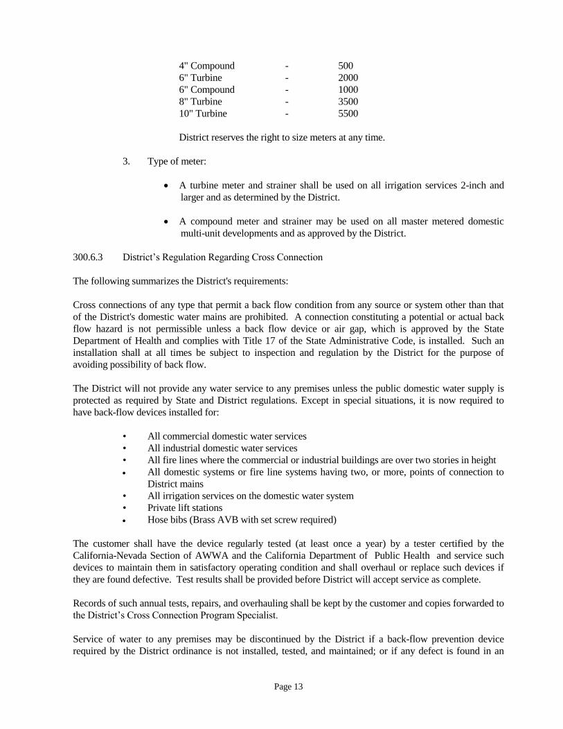
Page 13
4" Compound - 500
6" Turbine - 2000
6" Compound - 1000
8" Turbine - 3500
10" Turbine - 5500
District reserves the right to size meters at any time.
3. Type of meter:
A turbine meter and strainer shall be used on all irrigation services 2-inch and
larger and as determined by the District.
A compound meter and strainer may be used on all master metered domestic
multi-unit developments and as approved by the District.
300.6.3 District’s Regulation Regarding Cross Connection
The following summarizes the District's requirements:
Cross connections of any type that permit a back flow condition from any source or system other than that
of the District's domestic water mains are prohibited. A connection constituting a potential or actual back
flow hazard is not permissible unless a back flow device or air gap, which is approved by the State
Department of Health and complies with Title 17 of the State Administrative Code, is installed. Such an
installation shall at all times be subject to inspection and regulation by the District for the purpose of
avoiding possibility of back flow.
The District will not provide any water service to any premises unless the public domestic water supply is
protected as required by State and District regulations. Except in special situations, it is now required to
have back-flow devices installed for:
• All commercial domestic water services
• All industrial domestic water services
• All fire lines where the commercial or industrial buildings are over two stories in height
All domestic systems or fire line systems having two, or more, points of connection to
District mains
• All irrigation services on the domestic water system
• Private lift stations
Hose bibs (Brass AVB with set screw required)
The customer shall have the device regularly tested (at least once a year) by a tester certified by the
California-Nevada Section of AWWA and the California Department of Public Health and service such
devices to maintain them in satisfactory operating condition and shall overhaul or replace such devices if
they are found defective. Test results shall be provided before District will accept service as complete.
Records of such annual tests, repairs, and overhauling shall be kept by the customer and copies forwarded to
the District’s Cross Connection Program Specialist.
Service of water to any premises may be discontinued by the District if a back-flow prevention device
required by the District ordinance is not installed, tested, and maintained; or if any defect is found in an
Page 14
installed back-flow prevention device; or if it is found that a back-flow prevention device has been removed
or bypassed; or if unprotected cross-connections exist on the premises. Services will be restored only when
such conditions or defects are corrected to the satisfaction of the District.
The District will further define how water lines must be marked where multiple water systems are in use and
outline the duties and responsibilities of a property's water supervisor.
Additional reference for guidelines to when, why, and what types of back-flow and cross-connection control
devices are approved may be found in:
1. Regulations Relating to Cross-Connections, California Administrative Code - Title 17 -
Public Health.
2. Manual of Procedures and Practices for Public Water Suppliers California Department of
Public Health - Public Water Supply Branch
3. Manual of Cross-Connection Control, published by Foundation for Cross-Connection
Control and Hydraulic Research, University of Southern California, University Park, Los
Angeles, California 90007.
300.6.4 On-Site Irrigation Systems
On-site recycled water systems are not permissible for use as irrigation systems.
300.6.5 Domestic Water Facilities
See Section 400 for detailed specifications regarding the construction of domestic water facilities.
300.7 PROVIDING REQUIRED EASEMENTS
For water facilities, an easement outside of the public right-of-way is required for construction and/or
maintenance of water facilities, including but not limited to, water mains, hydrants, meter vaults, and
detector check vaults; its minimum width shall be 20 feet for single water mains, 30 feet for dual water
mains, 5 feet on all sides for meters, fire hydrants, meter vaults, detector check vaults, and other
appurtenances, unless otherwise determined by the District.
For sewer facilities, an easement outside of the public right-of-way is required for construction and/or
maintenance of sewer facilities, including but not limited to, sewer lines, manholes, and lift stations. Sewer
lines will not be allowed within easements in residential lots. A separate lettered lot, minimum 20 feet wide,
must be created for these situations. Wider easements may be necessary if sewer depths are greater than 8
feet.
An easement running parallel with a lot line shall not be split so as to occur on two lots. The easement, title
report, and legal descriptions with accompanying plat for recordation plans shall be prepared by the
applicant's engineer, two copies of which shall be sent to the District, or easements for the District shall be
shown on a tract or parcel map. Easement descriptions and plats shall be in a form acceptable to the District
and will be checked by the District. Easements shall also be shown on the construction plans. The District
will approve the plans only after all required easements have been deeded to the District together with any
necessary partial reconveyance or subordination agreements. Exhibits will be 8-1/2-inch by 11-inch, no
exceptions.

Page 15
Along public streets a three or five foot utility parallel easement on private property for District may be
required depending upon public right-of-way widths and sidewalk locations.
Applicant shall submit two copies of the easement description and plat to the District for review. If
acceptable, the applicant shall furnish two additional copies of the description and plat, signed by an
engineer registered in California prior to 1982 or land surveyor licensed to practice in the state of California.
along with a completed "Dedication of Easement to Castroville Community Services District" form (see
Appendix 11A for sample), a current (within 30 days) title report of the property reflecting all deeds of trust
and encumbrances, and subordinations signed by the trustees shown on the title report. If not acceptable,
the District will return the documents with the required corrections noted.
All blanks in the documents, such as project identifications, title report number, map and book numbers and
pages, dates, etc., must be filled in. The plat must contain a vicinity map showing the location of the
easement in relation to major streets and highways, and depicting the easement boundaries with bearings,
distances, points of beginning, north arrow, and any other information required by the District.
Any required temporary construction easements shall also be required and dedicated. All easement widths
shall be sufficient for installation of facilities including, removal and replacement in the future and width
may depend on facility depth. No obstructions, such as building overhangs, will be allowed within the
easements.
NOTE: Approval by the District will not be given for the tract water, sewage systems, storm or other CCSD
facilities until all easements have been recorded.
300.8 COST ESTIMATE
The applicant's engineer shall provide the quantities and unit prices, to allow the District to check costs for
the water, sewer, storm drain and surface improvement facilities to be dedicated to the District. The items
listed will include, but will not be limited to pipes, valves, meters & appurtenances, connections, hot taps,
and facilities construction including all items to be dedicated to and maintained by CCSD.
300.9 NORTH MONTEREY COUNTY FIRE PROTECTION AGENCY APPROVAL
After the first utility plan check by the District, it is the responsibility of the applicant's engineer to have
North Monterey County Fire Protection Agency approval before submitting them for a second plan check.
Fire flow requirements for the development shall be submitted with the second plan check submitted. The
District reserves the right to require additional fire protection or modify water facility sizes as deemed
necessary.
300.10 SECOND PLAN CHECK
Upon satisfactory completion of items 300.1 through 300.9 the applicant's engineer shall submit plans for
the second plan check along with the District’s red-line set and designer’s response letter to review
comments from the first plan check. This submittal will be checked against the corrections requested in the
first plan check and the District’s minimum design standards. Failure to return the district’s red-line set will
result in additional review and fees.
300.10.1 Corrected Plans Returned To Applicant's Engineer

Page 16
Upon review of the improvement plans, one red lined copy will be returned to the applicant's engineer,
showing corrections and/or comments.
300.11 FINAL ESTIMATE OF FEES AND CHARGES
Upon receiving the corrected utility plans for a second plan check, quantities and unit prices for the bond
worksheet and the applicant’s letter requesting domestic water and sewer service, the Plan Check Engineer
will compute the required development fees, based on the then governing District Code.
The District will send a draft copy of the final fee and charge estimate to the applicant.
300.11.1 Surety
The Applicant will provide a surety bond, a letter of credit, a certificate of deposit, or other form of security
acceptable to the District. This security shall be of a type which is automatically renewed every year, at the
applicant’s expense, until released by the District.
300.12 FINAL PLANS
Upon completion of any remaining items noted in the plan check, the applicant's engineer shall submit two
blue line sets of improvement plans, along with the red line mark up, for final verification.
300.13 FINAL EASEMENTS
300.13.1 Submittal
The applicant/applicant’s engineer or surveyor shall submit easement documents, which incorporate all
changes caused by the review process, in accordance with Section 300.73.
300.13.2 Verification
The applicant's engineer/surveyor will verify that the easements as listed in the easement documents remain
valid. The engineer will then submit the final easement documents and the final title report for recordation.
300.14 FEES
The applicant shall pay all fees as determined in the "AGREEMENT” between the applicant and the District
and as specified in the District’s Water Code which is outlined in Section 200.
300.15 SIGNED PLANS
Utility improvement plans must have the District's signature before any construction by the applicant begins.
300.15.1 Prerequisites for Signing Plans
1. AGREEMENT FOR THE CONSTRUCTION OF WATER, SEWER, STORM DRAIN
AND SURFACE IMPROVEMENT FACILITIES must be signed by applicant, and
approved by the District's Board of Directors.

Page 17
2. Required signed easement documents or the Tract/Parcel map must have been accepted
for dedication by the District. The District will prepare an easement Certificate of
Acceptance (Appendix 11B). The easement documents must have been recorded.
3. All fees and charges must be paid in full by the applicant.
4. Signatures from Monterey County, North Monterey Count Fire District Fire Marshall,
when required, shall be on the original plans.
300.15.2 District Signing Plans.
300.15.2.1 Submittal for Signature: Once the requirements detailed in Sections 300.1 through 300.14 are
satisfied, the applicant shall submit to the District the following:
1. Improvement plan original 4-mil mylars shall be delivered to the District with two
revised blue line sets.
2. One set of final development plans including:
A. Horizontal control plot plan
B. Street improvement plans
3. A copy of the AutoCAD drawings on a compact disc (CD).
300.15.2.2 Notification: District will notify applicant's engineer once the plans have been signed.
300.15.3 Validity of Signed Plans
Plans will be valid for one year from the date of District approval. If construction has not started within two
year from date of approval, the signed plans shall become "null and void." The District will require
rechecking of the plans and it reserves the right to charge additional plan check fees.
300.15.4 Re-permit Letter
In the event that construction does not start, and the approval could become null and void, as described in
Section 300.15.3; the applicant's engineer shall submit a letter, by registered mail, to request a one-year
extension of the approval.
300.16 ORDER OF PRECEDENCE OF STANDARDS
In the case of conflict between the specifications, drawings, and permit requirements, with regard to
construction of facilities, the following order of precedence will apply: The permit requirements of other
agencies, special details, plans, special conditions, District standard plans, technical specifications, general
conditions, the Standard Specifications for Public Works Construction, Caltrans Standards and CA
MUTCD.
Figured dimensions of the drawings shall govern, but work not dimensioned shall be as directed. Work not
particularly shown or specified shall be the same as similar parts that are shown or specified or as directed.
Full-size details shall take precedence over scale drawings as to shape and details to construction. Scale
drawings, full-size details, and specifications are intended to be fully cooperative and to agree; but should

Page 18
any discrepancy or apparent difference occur between plans and specifications, or should errors occur in
projects being constructed by others affecting the work, and the contractor proceeds with the work affected
without instruction from the District, the project engineer along with the contractor shall be fully
responsible for any resultant damage or defect.
300.16.1 Permit Requirements
The permit requirements, as approved by the agency having jurisdiction, will take precedence over the
below listed details and standards with regard to the construction of all facilities.
300.16.2 Special Details
The special details, as approved by the signature of the District, will take precedence over the below listed
details and standards with regard to the construction of all facilities.
300.16.3 Plans
The plans, as approved by the signature of the District, will take precedence over the below listed details
and standards with regard to the construction of all facilities.
300.16.4 Special Conditions
The special conditions, for the specific project and incorporated into the project contract documents, as
approved by the Districts Board of Directors, will take precedence over the below listed standards with
regard to the construction of all facilities.
300.16.5 District Standard Plans
The latest version District’s Standard Plans, as approved by the District Board, will take precedence over
the below listed details and standards with regard to the construction of all facilities.
300.16.6 District Standard Specifications
The District’s Standard Specifications as approved by the CCSD Board, will take precedence over the
below listed standards with regard to the construction of all facilities.
The "Standard Plans and Specifications for Construction” are incorporated herein by this reference. Copies
may be obtained from the Castroville Community Services District, PO Box 1065, Castroville, CA 95012.
300.16.7 Technical Specifications
The technical specifications, of the District’s "Standard Plans and Specifications of Construction" and
updates including storm and surface improvements as detailed above and included herby as part, of the
contract documents, as approved by the District’s Board of Directors, will take precedence over the below
listed standards with regard to the construction of all facilities.
300.16.8 Caltrans Standards and CA MUTCD
The Caltrans Manual, as referenced by the District’s details, standards and specifications, will take
precedence over other standards, other than the District’s standards, with regard to the construction of all

Page 19
facilities.
The Caltrans "Standard Specifications," and California Manual of Uniform Traffic Control Devices, are
incorporated herein by this reference, copies of which may be purchased from Caltrans, Central Publications
Distribution Unit, PO Box 1015, North Highlands, California 95660 and are also available online.
300.17 RECORD DRAWINGS
Record drawings documenting “as-built” conditions shall be provided to the District as detailed in Section
400.12 for domestic water and sewer off-site facilities.
300.18 SIGNED UTILITY PLANS BY DISTRICT & COUNTY
The District shall have two sets of blue prints and one set of mylars improvement plans (signed and
approved) at least two working days before the preconstruction conference and commencing work.
300.19 USE OF DISTRICT SEWAGE AND STORM DRAIN FACILITIES
The District has regulations on the types of wastes that are allowed to be discharged into its sewers and
storm drains in order to protect the facilities of the District and its operations to meet its discharge
requirements. The section on the use of District sewerage facilities in the District's Code, including a
separate supplement, sets forth these requirements. These provisions establish conditions under which
certain users are required to obtain permits for use of District sewerage facilities.
Applicants whose sewage and storm drain discharges qualify them for a permit shall not be allowed to
connect the building sewer/storm drain to a District sewer lateral/storm drain or sewer main/storm drain
main until a written notification is provided by the District allowing the hookup. All users must comply
with the discharge prohibitions established in the District's Code.
300.20 PROJECT CONSTRUCTION
300.20.1 Notification
Notice shall be given to the District inspector at least two working days before starting construction. Signed
utility plans must be delivered to the inspector at least two working days before the contractor will be
allowed to start construction. The County Public Works Inspector or Caltrans Permit staff shall be notified
prior to work within public right-of-way.
300.20.2 Preconstruction Meeting
A preconstruction conference shall be held at least two working days before starting construction. The
purpose of this meeting will be to answer any questions on District specification requirements, to obtain the
contractor's construction schedule, and to discuss any known circumstances that might affect job
installation. The contractor's superintendent and foreman, the applicant's engineer, and the District
inspector shall attend this meeting.
300.20.2.1 Preconstruction Meeting Agenda: Without relieving the applicant of responsibilities outlined
elsewhere in the specifications; the District will present to the applicant a list of requirements that may
contain, but will not be limited to, the following items:

Page 20
1. Order of work
2. Working hours
3. Operation manuals
4. Manufacturer’s specifications
5. Pressure test results
6. Bacterial test results
7. Record Drawings
8. Encroachment permit(s)
300.20.2.2 Order of Precedence: The order of precedence as defined in Section 300.16 will be reviewed
in the pre-construction meeting.
300.20.3 Curbs Installed Before Starting Water Facilities
It is a basic requirement of the District that horizontal and vertical control be established prior to starting
the installation of any improvements. They provide as positive grade control for all facilities. Also:
1. All requirements shall be met before the excavation of pipeline trenches.
2. The owner is to submit engineered drawings showing both the plan and profile of the
proposed pipelines for District review and acceptance.
3. The applicant is to provide all control and construction staking. The proposed pipelines
per the profile with cuts to flow line at a maximum of 25-foot stationing showing all
horizontal and vertical grades breaks, tees, and valves, fire hydrant, blow-offs, air vacs,
services, and all other appurtenances indicated on the plans.
4. Prior to backfill, the applicant’s engineer shall certify line and grade of the pipeline and
all the appurtenances and provide the District inspector with a copy of the certification.
5. In the event that a portion or any part of any improvements and its appurtenances is not
installed to the satisfaction of the District inspector, the applicant shall reinstall the
improvement.
300.20.4 Water for Construction Purposes
Water for construction purposes will be provided a connection to the District’s water system. Connections
can be from a fire hydrant or other direct connection as approved by the District. Below is the District’s
process to respond to and provide to requests for temporary water service from a fire hydrant.
Any customer that requires use of water from a fire hydrant must contact the District at least two working
days before starting construction. If the District deems the request acceptable, then a fire hydrant meter
will be provided to the applicant. The District may install the fire hydrant meter, but the security of the
hydrant meter is the applicant’s responsibility. The District will inspect the installation of the hydrant
meter to confirm it is installed correctly and that it has the proper backflow device, if required. The water
shall be taken through a metered delivery and the applicant shall pay all costs related thereto, including (but
not limited to) District's standard deposit for temporary meter and actual costs of water used, pumping costs,
loading, hauling and the use thereof. The applicant shall make all arrangements for transporting the water to
the construction site.
The District will read the hydrant meters.
At the conclusion of the temporary water service, the applicant must return the fire hydrant meter and the
gate valve in good condition. Once the District inspects the fire hydrant to make sure it is in good

Page 21
working order, the hydrant meter and any other pertinent appurtenance and has received all payments for
temporary water service fees and charges, then deposits may be returned to the applicant.
300.20.5 Inspection of Work
300.20.5.1 Access: All work shall be subject to inspection by the District and shall be left open and
uncovered until approved by appropriate District personnel.
300.20.5.2 Improvement Inspections: The Contractor shall not proceed with any subsequent phase of
work until the previous phase has been inspected and approved by the District. Inspection
may be made at the following intervals of work.
.
1. Domestic Water System:
A. Submit material list to District for approval.
B. Delivery of materials to job site and provide certificate of compliance to District.
C. Trench excavation and bedding.
D. Placing of pipe, fittings, and structures, including warning tape on irrigation
water main and service lines.
E. Pouring all concrete anchors and thrust blocks, if used.
F. Placing and compacting the pipe zone back fill.
G. Backfilling balance of trench to grade - Compaction tests shall be performed by a
geotechnical consultant acceptable to the District and retained by the applicant.
Copies of test results shall be given to the District by the applicant for approval
before final acceptance of the work. Backfilling and repaving with the public
right-of-way shall be in accordance with the requirements of the County.
H. Pressure testing all mains and services.
I. Disinfecting and flushing.
J. Health samples.
K. Repaving trench cuts.
L. Raising valve box covers to finish grade, installing concrete collars around the
box and paint to District standards.
M. Fire hydrants - painted and pads poured.
N. Installation of service lines, appurtenances meter boxes, and customer service
valves.
O. Connection to the existing system.

Page 22
2. Sewer and Storm Drain Inspections:
A. Trench excavation and bedding.
B. Placing of pipe, fittings, and structures.
C. Placing and compacting of the pipe zone backfill.
D. Backfilling of the balance of the trench to grade. Compaction tests to be taken by
the County Public Works Departments in public right-of-way and by a
geotechnical consultant acceptable to the District and retained by the applicant
for work in any private streets and easements. Copies of tests shall be given to
the District by the applicant before final acceptance of the work.
E. Testing after backfill compaction of all utilities is approved by the County Public
Works Departments and must be obtained before paving.
3. Surface Improvements
300.20.6 District Authority
300.20.6.1 Access: During construction the District shall have access to the work and shall be furnished
with every reasonable facility for ascertaining full knowledge respecting the progress, quality of labor, and
character of materials used and employed in the work. No pipe, fittings, or other materials shall be installed
or backfilled until inspected and approved by the District or its representative. The contractor shall give due
notice in advance of backfilling to the District so that proper inspection may be provided.
300.20.6.2 Obligation: Inspection of the work shall not relieve the contractor of any obligations to
complete the work as prescribed by the Standard Specifications. Any known defective work shall be
corrected before testing or final inspection will be permitted. Unsuitable materials may be rejected, even
though they may have been previously overlooked by the inspector.
300.20.6.3 Suspension of Work: The District shall have the authority to suspend the work wholly or in
part for such time as it may deem necessary if the contractor fails to carry out directives given by the
District's inspector, or to perform any required provisions of the plans and specifications. The contractor
shall immediately comply with a written order of the District to suspend the work wholly or in part. The
work shall be resumed when methods or defective work are corrected as ordered and approved in writing
by the District.
300.20.7 Pressure Test
A pressure test of the newly constructed domestic water and sewer lines shall be conducted as detailed in
Section 15042 and 15043 of the District’s Standard Specifications.
300.20.8 Water for Flushing, Testing and Disinfection
Domestic water for flushing, testing and disinfection of the completed pipelines or sections thereof will be
available from the District at the point, or points, of connection with the existing domestic water mains via
the construction water connection.
Page 23
The applicant shall make all arrangements for this water with the Castroville Community Services District,
which shall designate the exact location of the outlet or outlets and the time periods these connections may
be used.
If, due to construction problems or for any other reason, the applicant desires to use water from some other
source for testing, flushing, or chlorination, it shall be the responsibility of the applicant to obtain the source
of water, which water shall be tested and approved by the County Health Department prior to the use
thereof. All expenses for obtaining and using another source of water shall be paid by the applicant.
Cannon flushing operations shall be conducted with a residual line pressure not less than 30 psi and a
District representative will be present. Adequate connections to conduct the flushing, testing and
disinfection operations shall be furnished by the contractor and reviewed by the engineer, at no added cost
to the District, and the applicant shall pay for any and all costs for flushing, testing and disinfection.
300.20.9 Chlorination and Bacteriological Testing
After a passing pressure test, the domestic water lines shall be chlorinated and tested for bacteria as detailed
in Section 15041 of the District’s Standard Specifications.
300.20.10 Final Domestic Water Facilities Inspection
Before final acceptance, the District's inspector will make a final inspection of all work, accompanied by the
contractor's superintendent or representative, to verify that:
1. All phases of the project are complete in accordance with plans and specifications
2. All valve boxes are raised to finish grade and that all repairs are completed
3. All valves are referenced and the inspector has been given all reference measurements.
Valves shall be located by a 2-inch "V" chiseled in the adjacent curb face
4. All right-angle meter stops, and the meters, are properly positioned and all meter boxes
are positioned and raised to proper grade
5. Fire hydrants are raised to proper grade, are in a vertical position, painted; and its
concrete pad is poured
6. Backfill has passed all compaction testing
7. All system valves are turned and left open (except those specifically required to be
normally closed), turns required for complete open/close cycle are recorded on the record
drawings
8. Domestic water lines have been chlorinated and disinfected
9. Water line pressure testing and flushing have been completed
10. The job site is clean and cleared of all the contractor's equipment and materials
11. All service lateral locations have been marked on curbs
12. Certified test results have been provided for all backflow prevention devices
13. A mylar and a blue line copy of the water facility plans labeled "RECORD
DRAWINGS" with the "As-Built" revisions have been delivered to the District
14. Digital submittal of plan information in a format acceptable to the District
300.20.11 Final Sewer and Storm Drain Inspection
Contractor shall pressure test the sewers prior to final acceptance. Before final acceptance, the District
accompanied by the contractor's foreman or superintendent, will make a final inspection of all work to
check the following items:

Page 24
1. That all plugs have been removed
2. The concrete base and channels in manholes are smooth
3. Manhole interiors are clean of all debris and excess concrete mortar
4. All manhole concrete grade rings are adequately grouted and properly set
5. Pavement around manhole cover has been properly blacktopped to correct grade
6. That proper field tests have been made on all sewer main sections and manholes,
particularly where sections of manholes had to be repaired
7. Backfill has passed all compaction requirements
8. Sewer lateral locations have been marked with a "S" on curb
9. Video inspection of both sewers and storm drains will be required and is the
responsibility of the contractor and the inspector shall be present.
300.20.12 Raising of Valve Boxes and Manhole Rims
For paved areas, the contractor shall raise all valves and manholes for District constructed facilities for each
lift of pavement.
300.21 RECORD MYLARS
Record drawings shall be completed and submitted by the applicant's engineer as detailed in Section
400.132. The applicant shall furnish to the District record drawings (1 set of bluelines, 1 set of mylars and
the CADD files on a CD) showing all revisions to the original approved plans. The CADD files for the
project shall use “World Coordinate System”.
All future extension of water mains will have the invert elevation of the terminal pipe verified by the
applicant and posted on the drawings. Failure to comply with these requirements will necessitate
withholding the letter of acceptance.
300.22 EASEMENT VERIFICATION
The applicant's engineer will verify in writing that the facilities to be accepted by the District were
constructed within the easements as listed in the easement documents. In the event the facilities were not
constructed within the designated easement, the engineer will submit revised easement documents,
quitclaim documents, and a final title report for recordation.
300.23 METER USE AND FEE VERIFICATION
With the record drawings, the applicant is to furnish the District a cost breakdown of the newly installed
facilities for District accounting purposes (refer to Appendices 9A, 9B and 9C). This is to be furnished to
the District before an acceptance letter- releasing bond will be written (refer to Appendices 10A, 10B and
10C). The District will verify the quantities used in the calculation of the fees for the “AGREEMENT.” Any
adjustments to the fees will be made at this time.
300.24 BOARD ACCEPTANCE
After satisfactory completion of the items in Section 300.1 through 300.23, the District will, upon the
request of the applicant, petition the District's governing board for acceptance of the project, and the
commencement of the one year warranty period.

Page 25
The District will also re-evaluate the plans for compliance with the "AGREEMENT” and reserves the right
to re-assess the development impact fees if deviations from the originally approved plans have been made.
Changes include, but are not limited to: the number of service connections, meter sizes, building square
footage, the irrigated area, the number of dwelling units, and any other measure used to calculate the
original impact fees.
300.25 RELEASE GIVEN TO COUNTY
300.25.1 Bond Release
All final inspection requirements shall be fulfilled before the District will give its final acceptance notice
to the County for release of the applicant's bond to those agencies. The applicant's bond with the District
shall remain in effect in accordance with Section 100.6.5 and the Agreement.
300.25.2 Domestic Water and Sewer Service in service prior to Acceptance
District may approve putting newly installed domestic water and sewer system into service prior to Board
acceptance after compaction has been approved by the governing agency and the portions have been
pressure tested, chlorinated, flushed, and have passed the bacteriological test and inspection for domestic
water mains. This partial acceptance shall be granted only upon written request from the applicant and
subsequent approval by the District. Upon this written approval for partial acceptance of facilities, the
applicant shall be relieved of the duty to maintain the portions so used or place into operation provided,
however, that nothing in this section shall be construed as relieving the applicant of full responsibility for
completing the work in its entirety, for making good any defective work and materials, for protecting the
work from damage, and for being responsible for damage and for work as set forth in the agreement and
other contractual documents; nor shall such action by the District be deemed completion and acceptance,
and such action shall not relieve the applicant of the guarantee provision of the Agreement with the
District.
300.26 SECURITY RELEASE
If in the time period of one year from the date of Board acceptance no failure of the system has occurred,
which has gone unrepaired by the applicant, to the satisfaction of the District: the applicant may petition the
District to request final acceptance of the project by the Board and release of the surety.
END OF SECTION

Page 26
SECTION 400
DESIGN CRITERIA
DOMESTIC WATER FACILITIES
400.1 ALLOWABLE SIZE FOR WATER MAINS
The normal minimum diameter for a water line shall be 6-inches for distribution mains, short street
configurations, and dead-end streets. The next allowable water line diameter is 8 inches, then 12-inches for
distribution mains. The applicant must determine the pipe diameter requirements above 12-inches, which
shall be approved by the District. Hydraulic design calculations shall be provided to support sizing and
verify fire flow requirements are met.
400.2 DESIGN FLOW AND PIPE VELOCITY CRITERIA
The criteria for velocity shall be as described herein. The maximum velocity in a line shall not exceed 5 fps
(feet per second) during the peak hour condition. The peak hour is defined as 4 times the average day
demand. The maximum velocity in a line shall not exceed 7 fps during the maximum day plus fire demand
condition. The maximum day is defined as 2 times the average day demand. Residential design flows shall
be based on 130 gallons per capita per day. Commercial/Industrial design flows shall be calculated based
on the applicant’s estimated water demands for the proposed development.
400.3 TYPE OF MAIN PIPE
Only AWWA C-900 PVC pipe, Class 150 or higher is to be used for distribution mains of 12 inches in
diameter or less, or as directed by the District. For 16-inch to 24-inch diameter pipe, pipe must be ductile-
iron pipe (pressure class 250).
DIP, 16-inches to 24-inches in diameter, will be pressure class 250 unless a higher-pressure class is required
for special installations. DIP shall be provided and installed per Section 15056 of the District’s Standard
Specifications. Fully restrained DIP shall be used within easements with restricted access and slopes
exceeding 10%.
400.4 MINIMUM DEPTH TO TOP OF WATER MAIN PIPE
400.4.1 Residential Areas (Usually 12-Inch and Smaller)
The top of the pipe is to be a minimum of 36 inches below finish grade or 24 inches minimum below
pavement section subgrade, whichever is greater, unless indicated otherwise on project plans or directed
otherwise by the District inspector because of field conditions. The top of pipe is to be a minimum of 42
inches below finish grade in unpaved areas.
400.4.2 Transmission Mains. (Usually Larger than 12-Inch)
The top of the pipe is to be a minimum of 42 inches below finish grade, or 30 inches minimum below
pavement section subgrade, whichever is greater, unless indicated otherwise on job plans or directed
otherwise by the District inspector because of unusual field conditions. The top of pipe is to be a minimum
of 60 inches below finish grade in unpaved areas.

Page 27
400.4.3 Storm Drains
Storm drain and sanitary sewer systems must be designed with sufficient cover so that the water mains and
service laterals can be built over the top of the storm drain mainline and laterals with sufficient vertical and
horizontal clearance, and proper class of pipe and location of joints in compliance with California
Department of Public Health (DHS) requirements and standards.
400.5 STANDARD LOCATION
Domestic water main centerlines shall normally be located 6 feet from the outside travel lane line and may
be deflected to avoid cross gutters, concrete bus lanes or other interferences. Water lines will not be
allowed within easements in residential lots. There must be dedicated, exclusive easement, minimum width
20 feet for one line, 30 feet for two lines if a water line needs to go outside streets from cul-de-sac to cul-de-
sac to loop the water system (required).
400.6 WATER VALVE SPACING
As a general rule, there should be three (3) isolation valves where one main ties into another (i.e. at tees).
Where two mains cross (i.e. at a cross), there shall be four valves. On long blocks, intermediate valves
should be installed so that a maximum of 500 feet valve separation exists and a minimum of 500 feet of
main would have to be shut off at any one time.
Valves should also be spaced so that not more than two fire hydrants should be out of service at any time. If
hydrants are temporarily taken out of service, NMCFPA and the District shall be notified.
In most cases where water mains pass through easements outside traveled streets, a valve shall be located at
each end of the easement. The final determination of valves and locations shall be per the District.
400.7 SEPARATION OF DOMESTIC WATER AND SEWER LINES
400.7.1 Horizontal Separation
DPH regulations require a 10-foot-minimum clear separation between water and sewer water mains.
However, in special situations where there is no alternative but to install the mains with less than the
required separation, special construction will be considered on an individual basis by DPH and the District
for approval. (See Standard Plan W-14). Minimum separation of domestic water service line and sewer
lateral shall be 5 feet clear. Minimum separation of water and dry utilities shall be 5 feet clear.
400.7.2 Vertical Separation
In general, water, sewer, and recycled water shall be located vertically from the street surface in order of the
higher quality, i.e., domestic water shall be above recycled water and recycled water shall be above sewer.
Whenever a crossing must occur where a sewer main passes within 1 foot of a domestic water main or
where a sewer main passes within 1 foot of a recycled water main, special construction will be required as
shown on CCSD Standard Plan W-14.
If the conditions of Standard Plan W-14 cannot be met, then one of the following types of alternates may be
required:

Page 28
1. Reinforced concrete encasement, a minimum thickness of 6 inches.
2. Piping within a continuous steel casing, per Standard Plan W-13, which shall have a
thickness of not less than 1/4 inch.
If a sewer is above a water main, the special construction shall extend a sufficient distance on both sides of
the crossing to provide a minimum of 10 feet of horizontal clearance from edge of water main to end of
casing or pipe joint. If a sewer is located below a water main, and within a vertical distance of a 1-foot
clearance distance, the special construction shall extend a sufficient distance on both sides of the crossing to
provide 4 feet of horizontal clearance from edge of water main to end of casing or pipe joint. These
construction requirements shall not apply to house laterals that cross perpendicular less than 1 foot below a
pressure water main.
400.8 FIRE HYDRANTS
400.8.1 Fire Hydrant Spacing
The maximum fire hydrant separation shall be 300 feet (clear hose laying length) from fire hydrant to fire
hydrant. The only exceptions will be at the discretion of the Fire Marshal. Bollards to protect the hydrant
may be required at the discretion of the District
Fire hydrants shall be located near the beginning of curb return (BCR) or lot lines.
No fire hydrant shall be located within 3 feet of a driveway, or closer than 40 feet to any structure (unless
approved by the Fire Marshal.
Where a fire hydrant run is over 20 feet, the size of the hydrant lateral shall be 8-inches.
400.8.2 Types of Hydrants
Wet barrel all-bronze type hydrants, with check valve, as specified by the District, are to be used.
400.8.3 Plan Requirements
Fire hydrants shall be shown on the plans where the hydrant is to be located with respect to the property
line, and what easements will be provided. The building foot prints or building pad areas are also to be
shown.
400.9 SERVICE MATERIALS AND MINIMUM SERVICE SIZE
400.9.1 General
Approved materials and manufacturers for various service material tubing and connections are as listed in
District's Standard Specifications, herein.
400.9.2 Minimum Domestic Service Size
Minimum domestic service line size shall be 1-inch with a 1-inch meter. The sizing of the service shall be
specified on the plans designated by lot numbers. Services for commercial or industrial developments are to

Page 29
be as shown on plans or as directed by the District.
For industrial, commercial, private-street residential, and other nonresidential development, the District may
require a detail on the plans of the location of the proposed service.
400.9.3 Type of Service Line
Acceptable service line material is as described below:
1. 1-inch through 2-inch service line shall be copper tubing.
2. 4 inches and larger, use DIP per Section 15056, or PVC per Section 15064 of the
District’s Standard Specifications, as determined by the District. (3-inch is not
permitted).
400.9.4 Meters
All water meters will be furnished by the District, subsequent to payment of all applicable charges and
posting of all required bonds and insurance. The District will install all meters. All residential
developments utilizing 2-inch meters shall be limited to 8 dwelling units per meter and one building per
meter.
A by-pass line shall be installed on all meter assemblies, 3 inches and larger, as shown on Standard Plans
W-15. A by-pass line is not required for the following conditions, as determined by the District:
1. Multiple metered connections for a single building
2. Irrigation services
A lockable corporation stop or valve shall be installed on all by-pass lines. A by-pass line may be required
on smaller installations, which require continuous service.
400.9.5 Pressure Reducing Valves
The District’s system pressure is such that pressure regulators or reducing valves are not necessary.
400.10 STANDARD WATER NOTES
The following standard water notes shall be included on all water system construction plans.
1. All water system work shall conform to the current edition of the District's "Standard Plans and
Specifications”. The contractor shall have a copy of these standard plans and specifications on site at
all times.
2. The Inspector shall be notified at least two working days prior to start of any construction or any
inspection. To arrange for an inspection please call (831) 633-2560.
3. The District shall be furnished with three (3) copies of approved construction plans prior to starting
construction. A preconstruction conference of representatives from affected agencies and the
contractor shall be held on the job site 2 working days minimum prior to start of work.

Page 30
4. Domestic water mains shall be installed after the installation of curb and gutter at six feet off of curb
face, or as staked by the applicant's surveyor and approved by the District at a minimum 50-foot
stationing, if there are no existing curbs.
5. All nuts and bolts shall be grade 316 stainless steel with Xylan Tripac 2000 coating system. All
buried flanges, valves and fittings shall be wrapped with 10-mil polyethylene sheet and securely taped
at all ends.
6. Any water service placed within a driveway or sidewalk shall be removed and reinstalled at the
proper location, at no cost to the District.
7. All main line valves shall be maintained so as to be accessible during construction, and all valve stem
tops having over 48 inches of cover may require an extension as per note 1 on CCSD Standard Plan
W-7.
8. The top of the pipe shall have adequate cover per Sections 400.4, a minimum of 36 inches of cover
from the finished grade in paved sections, unless indicated otherwise on the job plans or directed
otherwise by the District because of unusual conditions. Pipe shall be bedded and backfilled per
CCSD Standard Plan W-10.
9. Fire hydrants shall be installed in accordance with the appropriate details herein and installed behind
curbs and sidewalks where the sidewalks are adjacent to the curbs. Fire hydrants shall be per the
District's specifications and shall have a concrete pad poured around them. All fire hydrants shall be
set with the bottom flange 4 inches above the concrete pad or sidewalk.
11. No facility shall be backfilled until inspected by the District.
12. Shut down or tapping of existing domestic waterlines to facilitate connection to existing facilities
shall be coordinated with the District. Any relocations of existing facilities are subject to approval of
the District.
13. No taps or other connections shall be made to existing District water mains prior to conducting an
approved pressure and bacteriological test on the new water distribution system. Tapping sleeves
shall be pressure tested in an approved manner in the field in the presence of the District inspector,
prior to tapping the main line. Tapping of the main line shall not proceed unless a District inspector is
present.
14. All water services shall be installed per the District's standard specifications. All meters shall be
installed in grass or planter areas and accessible by vehicle. Any services located in sidewalks are
subject to the appropriate governing agency and District approval. Any meters located in banks of 3
shall be manifolded per CCSD Standard Plan W-3. All meter registers and lids shall be marked with
address identification.
15. Where meters and meter boxes are located within slopes, the angle meter stops shall be so located that
the meters and boxes will be parallel and flush, respectively, with the finished street surface. A
retaining wall may be required around the meter box.
16. The applicant shall furnish and install the service connections between water mains and meters and
meter boxes. Water services shall be installed to the property line prior to paving of the street.
Page 31
17. Curbs shall be inscribed with a "W" indicating locations of all domestic water services.
18. Low-flow water devices shall be installed on all fixtures within this development in accordance with
rules and regulations of the District and the County.
19. All valves shall be located off the tee unless otherwise approved by the District. At intersections and
bus stops with concrete pads, the main line shall be roped to avoid cross gutter conflict.
20. Individual pressure regulators will be required if static pressure reaches 80 psi or more.
21. All water meters will be furnished by the Castroville Community Services District following receipt
of application and deposit. The District will install all water meters. The contractor shall place all
piping per District plans and properly locate the meter boxes to grade prior to installation of the
meters by the District.
22. Any District water used for construction will be obtained through a construction meter obtained from
the District.
23. An Encroachment Permit from the County is required prior to any work within public right-of-way or
public easement.
24. The existence and location of any underground utilities or structures shown on these plans were
obtained by a search of the available records. Approval of these plans by the District does not
guarantee the accuracy, completeness, location, or the existence or non-existence of any utility pipe or
structure within the limits of this project. The contractor is required to take all due precautionary
means necessary to protect those utility lines shown or not shown on these plans. Include this note
on the cover sheet of all plans.
25. The applicant shall remove to the satisfaction of the CCSD inspector all unused water stubs and/or
services that were provided to the project site.
400.11 MISCELLANEOUS STANDARD GUIDELINES
1. Quantity estimates, for the domestic water systems, are to be included on the plans
indicating quantity of pipe, valves, fire hydrants, domestic water services, etc.
2. The drawing shall show on plan and profile the position of all other known underground
utilities or proposed underground utilities. (Top and bottom of pipe elevations may be
required in addition.).
3. Blow-off assemblies shall be installed at end and at low points of all mains. Temporary
blow-offs shall be installed as service stub-outs for testing and flushing purposes.
4. Air and vacuum valves are to be installed at all high points in the line for 12-inch size
pipe and larger, or as directed by the District.
5. Generally the District requires all fittings and valves to have ”mechanical joint” type
ends, except at tees and crosses where valves are required. Valve and fitting are to be
joined by a flange.

Page 32
6. The contractor shall restore or replace all removed or damaged or otherwise disturbed
existing surfaces or structures not otherwise noted on the plans or specified herein to a
condition equal to that before the work began and to the satisfaction of District's
Engineer. All excess earth and all other debris shall be removed and disposed of by the
Contractor and the entire site of the work shall be left in a condition acceptable to the
Engineer prior to final acceptance of the work. All restoration and cleanup shall be
performed in accordance with the District's Standard Specifications.
400.12 RECORD “AS-BUILT” DRAWINGS
400.12.1 Record Drawings
Record drawings shall be based on an “as built” review and shall show all changes in the work constituting
departures from the approved contract drawings.
Upon completion of each increment of work, all required information and dimensions shall be transferred to
the record drawings. Facilities and items to be located and verified on the record drawings shall include the
following:
1. Point of connection
2. Location and elevation of all valves, bends and tees
3. Location of all services
4. Type, manufacturer, and model of valves & fire hydrant. The number of turns required
for complete open/close cycle shall be provided for all valves.
5. Location of buried conduit and sensor line assemblies
6. Items located and constructed as called out in the plans need not be noted as such.
7. Final settings of instrumentation and control equipment.
Prior to submission of the record mylars, two sets of blue lines will be submitted for review by the District.
One set will be returned with comments if necessary. Final mylar record drawings are to be submitted only
upon incorporation of the District's comments.
400.12.2 “As-Built” Review
An "as-built" survey of the completed water line and appurtenances shall be made by the applicant's
engineer prior to placement of final paving. Markers or monuments shall be set during the placement of
backfill so that all connection points, horizontal and vertical angle points, utility crossings, service
connections and any other features and/or appurtenances designated by the engineer may be located.
The contractor shall submit to the engineer for review, prior to the start of construction of the project, a
program for installing the markers or monuments and shall comply with any recommendations of the
engineer to modify such a program. It shall be the responsibility of the contractor to re-establish any lost
markers or monuments.
400.12.3 Record Drawings Requirements
400.12.3.1 General Requirements: Keep accurate and legible records on a single set of full size project
blue line prints of the drawings.

Page 33
1. Make the record drawings available for review by District's representative in contractor's
field office.
2. Maintain record drawings on an up-to-date basis with all entries reviewed by District's
representative.
3. Protect the record set from damage or loss.
400.12.3.2 Detailed Requirements:
1. Mark on the drawings all changes in the work which occur during construction,
including adding approved changes.
2. Show locations by key dimensions, depths, elevations of all underground lines, conduit
runs, sensor lines, valves, capped ends, branch fittings, pull boxes, etc.
3. Record information on maintenance access and/or concealed work.
4. Make a record of finalized hydraulic and electrical equipment control settings in the
tables and spaces provided on the drawings.
Deliver the marked record set of drawings to the District prior to acceptance of the work.
END OF SECTION

Page 34
SECTION 500
DESIGN CRITERIA
SEWER FACILITIES
500.1 MINIMUM SIZE
The District will not accept for maintenance sewer lines smaller than 8 inches or any sewer line that is
within a common trench (two or more utilities in the same trench). Adequate horizontal and vertical spacing
shall be maintained in accordance with CCSD Standard Plan W-14.
500.2 MINIMUM AND MAXIMUM SLOPE DESIGN
500.2.1 Slopes
All sewers shall be designed and constructed to give mean velocities, when flowing half full, of not less than
2.0 fps, based on Manning’s formula using an “n” value of 0.013. The following are minimum slopes;
however, slopes greater than these are desirable:
Sewer Size (inches) Minimum Slope in Feet per 100 Feet
8 0.40
10 0.32
12 0.28
15 0.15
18 0.12
21 0.10
These are absolute minimum slopes. Sewers should be designed to provide steeper slopes whenever
possible but not to exceed the maximum velocity stated below.
Under special conditions, the applicant’s engineer may request slopes flatter than the above stated
minimums. The engineer must submit this request along with back-up data and calculations to show that the
depth of flow at design average flow will be 0.3 of the pipe diameter or greater. The engineer must also
submit computations to show the depths of flow at minimum and average rates of flow. The request shall
also detail the reasons why the normal minimum slopes cannot be achieved. The request and supporting
data will be reviewed by the District and his decision will be conveyed to the applicant.
The maximum allowable slope shall be the slope which generates a maximum flow velocity of 8 fps at the
peak flow rate as calculated using Manning's equation and an "n" value of 0.013.
500.2.2 Peak Flows
The design peak flow rate in pipes 12-inches and smaller will be limited by the depth ratio of d/D = 0.67;
and 15-inches and larger d/D = 0.75, where "d/D" is the ratio of calculated flow depth to pipe diameter.

Page 35
500.2.3 Generation Rates
The flow rate for residential sewer mains should be calculated using a base generation rate of 90 gallons per
capita per day (gpcpd) and the density and peaking factors contained in Figure 500-1. Commercial/industrial
flow design criteria should be calculated by the applicant's engineer based on projected generation rates for
the specific development.
The August 2006 “Focused Wastewater Mater Plan” by RBF Consulting presented the following design
criteria:
Average Dry Weather Peaking Factor (ADWF) is 2.1
Infiltration and inflow factor for new sewers is 0.44 times the ADWF
Infiltration and inflow factor for existing sewers is 0.67 times the ADWF
500.3 STANDARD LOCATION AND ALIGNMENT
500.3.1 Location
Wherever possible, in local residential and industrial streets, pipe is to be located 5 feet off the street
centerline, pursuant to standard detail S-15. In major, primary, and secondary highways, pipe will be
located in the center of the driving lane nearest to the center of the street. Pipe will not be located in median
strips or parking lanes. On curvilinear streets, pipe shall parallel as nearly as possible the street centerline
by means of horizontal curves but not exceed manufacturer’s minimum allowed bending radius.
500.3.2 Alignment
Barring other limiting design and construction considerations, a maximum separation between sewer and
domestic water mains in new subdivisions shall be achieved by the following construction procedures:
1. On curvilinear streets, the sewers shall parallel as nearly as possible the street centerline
by means of horizontal curves.
2. Sewer mains should be installed on the opposite side of the centerline from the domestic
water mains.
500.3.3 Radius of Curvature
Minimum radius of curvature in feet (horizontal) per type of pipe:
PLASTIC PIPE
Nominal Pipe Size
(inches)
Minimum Radius of Curvature
(For Standard Joint Length)
8 280 feet
10 350 feet
12 420 feet
500.4 SEWER PIPE MATERIAL

Page 36
All gravity sewers shall be SDR-35 PVC as detailed in the Technical Specifications. All sewer force mains
shall be PVC pipe meeting AWWA C-900 and Class 150 pipe standards and shall be marked in the field
every 2 feet with (SSFM) painted on top of pipe. All sewer service laterals shall be SDR-35 PVC pipe.
500.5 STATIONING PROCEDURE
Centerline stationing shall be shown (example: 10+00.00) and may be independent of street stationing with
the stationing starting at the most downstream manhole or connection to existing sewer.
Sewer stations starts at the downstream point of connection and increases upstream to the last manhole on a
sewer line. Intersecting sewer lines will be independently stationed from their downstream point of
connection and increase upstream to the last manhole or clean-out. Each line shall be independently labeled
for identification as "Sewer Line A", "Sewer Line B", etc.
500.6 MINIMUM COVER
Minimum cover from finish street grade to top of sewer main pipe is to be 6 feet unless approved by the
District.
500.7 MANHOLE SPACING AND LOCATION
Manholes shall be installed at:
The end of each line
At all changes in grade, size, or alignment
At all intersections
At distances not greater than 400 feet for 8- through 15-inch sewers and 500 feet for 18- to 30-
inch sewers.
If sewer is curved, closer spacing of manholes will be required. Greater spacing may be permitted in larger
sewers. Only one curve (horizontal or vertical) shall be allowed between any two manholes.
500.8 MANHOLE TYPE, MINIMUM SIZE AND DEPTH
500.8.1 Manhole Type, Size, and Depth
Manhole depth is calculated from finish grade to lowest pipe invert. Minimum manhole depth is to be 7 feet
unless approved otherwise by the District. The standards for the District sewers call for a depth criteria of
about 7 feet to 12 feet for manholes. However, if larger-depth manholes are required and approved by the
District, the following criteria will govern. Manholes shall be pre-cast reinforced concrete with eccentric
cone style. The minimum diameter of manholes shall be as follows:
Depth Size
< 6 ft 48 in
6 ft to 16 ft 60 in
16 ft to 22 ft (max) 72 in
Depth of manhole shall be measured from the pipe invert to the finished surface of the street with a
tolerance of 6 inches.

Page 37
For larger sized sewer mains or special circumstances, the manhole size will be as shown on plans.
Manholes shall have a 5-inch minimum wall thickness.
500.8.2 Minimum Head Losses
Minimum head loss in manholes shall be as follows:
1. Straight run through manholes based on 0.10 foot loss
2. Right angle turn in manholes based on 0.5 velocity head loss or 0.20 foot, whichever is
greater
500.8.3 T-Lock Lined Manholes
The District has experienced substantial deterioration in manholes at certain locations due to hydrogen
sulfide gases released from the sewage flow. In order to mitigate this on future sewers, the following criteria
have been established to govern the requirement to line manholes with a PVC T-Lock liner:
1. If the sewer has a slope of 7% or greater, then all manholes will be lined with T-Lock.
2. Where there is a change in slope, from steep to flat, of 5% or greater, the manhole at the
grade change and the next manhole upstream will be lined with T-Lock.
3. As required in District Standard Plan S-11 all drop manholes, including force main
terminal manholes, will be lined with T-Lock.
4. The approved T-Lock liners are Ameron T-Lock liner.
Alternative manhole materials will be considered by the District on a case by case basis.
500.9 MANHOLE COVERS
500.9.1 Type of Covers
Cast-iron covers and frames shall be 24 inches in diameter with the words “Sanitary Sewer” cast in the
cover. Larger size covers may be specified for special conditions. See Standard Plan S-3.
500.9.2 Position of Covers
At the completion of final paving, the manholes shall be raised to final grade by using grade rings.
500.10 CLEAN-OUTS
Use of clean-outs as shown in District Standard Plan S-7 shall be limited to the following instances unless
approved otherwise by the District.
1. Short sections of sewer main, less than 250-feet, that will be extended.
2. All residential, commercial and industrial sewer lateral installations at the property line.

Page 38
3. Between manholes, if there is a reverse curve in the sewer main, to facilitate cleaning of
the main line.
4. Special instances such as on a sewer lateral to a single family residential lot where the
dwelling unit is set back more than 100-feet from the property line, where there is a large
slope up to the building pad from the property line and a grade change in the lateral is
necessary, or where the sewer lateral enters the rear of the lot from a public right-of-way.
5. On a lateral where the overflow level of the lowest wastewater fixture in the building is
below the rim elevation of the uphill sewer manhole on the main line. In this situation
the rim elevation of the clean-out installed at the property line shall be at least 6-inches
below the overflow elevation of the lowest wastewater fixture on the lateral. A backflow
prevention device is required on the lateral per Section 4.11 of the District‘s Code.
500.11 FORCE MAINS CRITERIA
The size of sewer force mains shall be determined during the design phase of the project and only after a
comparative study of the construction cost and pumping costs for several alternative sizes. In no case shall a
force main be less than 4-inches in diameter. The capacity of the force main shall be the design peak flow
from the pump station . The nominal design velocity for a force main should be 3.0 fps, with minimum
velocity of 2.0 fps, and maximum allowed 6.0 fps. The discharge shall be into a manhole with a smooth
flow transition to a gravity sewer. The manhole shall be epoxy coated on the interior or PVC lined for
corrosion protection.
500.12 ACCESS TO MANHOLE
All sewer manholes shall be designed and constructed with a direct access to them. Unpaved access may be
permitted as determined by the District (will require “all weather access”).
500.13 SEPARATION BETWEEN WATERLINES AND SEWERLINES
See Subsection 500.3 herewith, and Section 400.7.
500.14 HOUSE LATERALS AND MINIMUM DEPTH AT CURB
All sewer laterals shall be located by the applicant and shown (with stationing) on the improvement plans.
House connections shall be constructed to the property line. There shall be one house sewer lateral
constructed for each individually owned dwelling unit and it shall have a minimum diameter of 4 inches.
Four-inch sewer house connections shall be laid to the grade as established by the applicant so that the 4-
inch house connection will have a minimum cover of 3 feet from the top of the curb to the top of the pipe
per Standard Plan S-6. The sewer laterals from the main to the building, and inside the buildings are
governed by the Uniform Plumbing Code and enforced by the local building authority.
500.15 TOWNHOUSES AND CONDOMINIUM LATERALS
For buildings containing two to four units, either one 4-inch diameter lateral to each unit or one 6-inch
diameter, or larger, lateral to the building shall be used. For buildings containing more than four units,
either one 4-inch diameter lateral to each unit or one 8-inch diameter, or larger, lateral to the building shall

Page 39
be used. A lateral shall serve only one building regardless of number of units per building.
500.16 INDUSTRIAL PRETREATMENT
Requirements for industrial pretreatment will be determined by the Monterey Regional Water Pollution
Control Agency (MRWPCA). Design requirements will be dependent upon those industrial pretreatment
requirements.
500.17 GREASE INTERCEPTORS
All restaurants and other facilities which discharge grease into the District’s sewers shall be required to use
grease interceptors to minimize grease problems in collection systems and treatment plants. The minimum
interceptor size shall be 750 gallons. All interceptors shall be equipped with automatic draw-off devices for
easier removal of accumulated grease.
It will be the responsibility of the owner of each facility to maintain proper operating order of the interceptor
unit and to remove accumulated grease at suitable intervals to avoid excessive buildup in the unit. The
Castroville Community Services District approves the location of the interceptor unit.
500.18 STANDARD SEWER NOTES
Standard notes to be included on all sewer system construction plans shall be as follows:
1. The sewer system as shown on these plans shall be constructed in accordance with the standard plans
and specifications of the Castroville Community Services District. Contractor shall keep a copy of
the standard specifications and drawings and drawings on the jobsite at all times.
2. Sewer Connection: 4-inch house connection is to be constructed from the sewer main to the property
line for each lot.
3. All sewer house connections shall be placed prior to surfacing of streets.
4. The District shall be notified at a minimum of two working days prior to commencing work. Phone
(831) 633-2560 for inspection. A preconstruction meeting shall be held a minimum of two working
days prior to before starting construction.
5. All sewer lengths are calculated on horizontal distances along the centerline of the sewer.
6. Pressure testing of sewers shall be in accordance with the standard specifications of the Castroville
Community Services District.
7. 10+00.00 shown on sewer profile denotes stationing along centerline sewer from downstream
manhole.
8. In order to prevent accidental use of the new sewer prior to completion and acceptance, the outlet or
inlet to existing tie-in manhole(s) shall be sealed with broken brick and mortar. Installation of these
plugs shall be approved by the District. Plugs shall be removed at the time of final acceptance.
9. Contractor shall verify the horizontal and vertical location of all utility crossings before constructing
any sewers in this project.

Page 40
Page 41
10. Contractor’s surveyor shall stake the location of all wye fittings. All house laterals not normal to
street sewer to have end of lateral at property line staked and tied to a property corner as shown on
the plans.
11. The Castroville Community Services District will inspect and maintain all 8-inch main line sewers
and manholes. The District will not inspect nor maintain 4, 6, or 8-inch laterals to the buildings.
The County Building Department or appropriate governing agency will inspect and verify all 4, 6,
and 8-inch laterals to the buildings.
12. The Contractor shall conduct all tests as required in the presence of a District representative.
13. Any work to be performed inside a live manhole shall be done in accordance with Cal OSHA
"Confined Spaces" and District manhole entry regulations. Manhole entry without District personnel
present is not allowed.
14. The applicant is to provide the Castroville Community Services District with a record drawings set of
job prints with tie-down measurements for all laterals and manholes.
15. Face of curb shall be inscribed with an "S" indicating location of all sewer laterals.
END OF SECTION

Page 42
SECTION 600
DESIGN CRITERIA
STORM DRAIN FACILITIES
600.1 DESIGN CRITERIA
All storm drain facilities constructed within the public right-of-way that are intended to be accepted by the
Castroville Community Services District for ownership and maintenance shall be designed using the latest
version of the City of Salinas Design Specifications and Standard Plans for storm drain facilities.
All storm drain facilities, including detention, constructed on private property shall be designed using the
specifications and standard plans for storm drain facilities from the Monterey County WRA and will not be
accepted by CCSD without having been approved by Monterey County Water Resource Agency
(MCWRA).
APPENDIX 1
APPLICATION FOR WATER SERVICE WHERE NO MAIN EXTENSION IS REQUIRED –
INTERRUPTABLE WATER SERVICE

APPENDIX 2
SAMPLE CONSTRUCTION AND TRANSFER OF WATER AND SEWER INFRASTRUCTURE AGREEMENT

SAMPLE COVER LETTER
Applicant
Address
________________
Project: ___________________________________________
Subject: Agreement Regarding Construction & Transfer of Water and Sewer Infrastructure
Dear Applicant:
This Agreement pertains to the construction and transfer of water and sewer infrastructure. The Agreement
is between the Castroville Community Services District ("District") and {Add Applicant Name},
("Applicant").
The Applicant owns and is developing an acre parcel of land on an existing parcel APN-
________________________, in Castroville, Monterey County hereafter referred to as the "Development".
See Attachment A for the legal description of the Development boundaries. See Attachment B for a map
showing the planned Development.
The Applicant is proposing to construct water and sewer systems to serve the Development and desires to
transfer the same to the District upon completion of construction. The District is agreeable to accepting the
transfer, operation and maintenance of the systems and to provide service on the terms provided herein and
their performance by Applicant.
Enclosed are the Standard Provisions for this Agreement.
If you have any questions pertaining to this Agreement, please contact us at (831) 633-2560.
Sincerely,
Castroville Community Services District

Page 44
CONSTRUCTION AND TRANSFER OF WATER
AND SEWER INFRASTRUCTURE AGREEMENT
1. General Requirements
2. Design and Construction Requirements
3. Existing Water and Sewer Infrastructure
4. District to Serve Development
5. Initial and Additional Deposits
6. Licensed Contractor
7. Permits, Easements, and Related Costs
8. Final Inspection and Reimbursement of District Costs
9. Underground Obstructions
10. As-Built Plans, Specifications, Values, Etc.
11. Indemnity, Insurance, and Sureties
12. Transfer of System to District after Completion
13. Applicant Assistance
14. Warranties
15. No Water and Sewer Service Prior to Completion and Transfer
16. Performance
17. Assignment
18. Dispute Resolution Procedure
19. Waiver Of Rights
20. Notices
21. Severability
22. Paragraph Headings
23. Successors And Assigns
24. Integrated Agreement
25. Negotiated Agreement
26. Attorneys Fees
27. Exhibits
28. Disclaimer/Indemnity Regarding Public Works
29. No Third Party Beneficiaries
30. Compliance with Laws

Page 44
31. Counterparts

Page 44
CONSTRUCTION AND TRANSFER OF WATER
AND SEWER INFRASTRUCTURE AGREEMENT
1. General Requirements
In general, the County’s role is to approve the allocation of water and sewer capacity for an applicant and
the District’s role is to approve the plans for, and inspect the construction of the water and sewer facilities
and to maintain and operate the systems, including the billing of customers for water and sewer usage.
The District will only serve the Development if the Applicant delivers to the District a certified copy of a
resolution from the County approving the Development, with the following specifications:
(a) The County authorizes the District to provide water and sewer service to the (Development).
The District acknowledges it has received the resolution satisfying the requirements of this Section.
2. Design and Construction Requirements
The water and sewer facilities shall be designed, constructed and be operable to the District's requirements,
which shall be a condition of the District's acceptance of the system under this Agreement. District re-
quirements shall include, but not be limited to the following:
A. Applicant shall design and construct the water and sewer facilities in accordance with the District's
standards and any other applicable State Regulatory Agency requirements, whichever are most
stringent. A licensed civil engineer registered in the State of California shall prepare all plans and
specifications.
B. The Applicant shall comply with the District’s Procedure Guidelines and Design Requirements and
the District’s Standard Plans and Specifications when submitting project plans and specifications to
the District for review and consideration of approval. District’s review shall commence after
determining compliance with District's Procedure Guidelines and Design Requirements regarding
the submittals and any other applicable State Regulatory Agency requirements, whichever are most
stringent. District review of the project plans and specifications shall commence after receipt of the
initial deposit (see Paragraph 2E). District may approve plans concurrent with City/County’s
Approval.
C. The District will have the sole responsibility for inspecting the construction of water and sewer
facilities and assuring that construction conforms to approved project plans and specifications. The
District will inform the Applicant of changes that are required in the field and will contact the
Applicant or the City regarding easements. Upon receipt of recorded easements to serve the
Development in accordance with the plans and specifications approved by the District, the District
will quitclaim any easements not required to serve the Development and not required by the District
for service to others. The Applicant shall be responsible for replacing or repairing any existing
water and sewer facilities within its project limits in order for the District to maintain service to its
customers.
D. All facilities in the system shall be tested to meet District requirements. No system or portion
thereof will be accepted without meeting District test requirements. The District shall have the
right at any time or from time to time to inspect work in progress in the construction of the water
and sewer system facilities.
E. Plan Review Fees. The District shall require a deposit of one thousand dollars ($1,000.00) before

Page 44
undertaking a preliminary plan review of the proposed plans for the water and sewer facilities. If
the District Engineer determines consultant assistance is required for plan check review, then the
Applicant agrees to pay the additional plan check fees equal to 2 percent of the estimated
construction cost for the project. The estimated construction cost shall be as determined by the
Applicant’s infrastructure plans and the District’s Procedure Guidelines and Design Requirements.
The District may seek the Applicant’s written approval for any costs in excess of this amount, for
which approval shall not be unreasonably withheld.
F. Construction Inspection Deposit. As a condition precedent to the District’s obligation to undertake
a construction inspection review of the proposed water, sewer and storm drain facilities, the
Applicant shall provide an initial construction inspection deposit to the District of $400 per unit
plus 3.0% of estimated construction cost for the water, sewer and storm drain facilities. The
Applicant shall provide this deposit before undertaking construction of the proposed project. If
inspection efforts exceed the deposit, the applicant shall be advised before additional costs are
incurred and shall be given the option of withdrawing the plans or being billed for the additional
cost.
G. The Applicant will submit actual construction bid data. The submitted data shall be in a unit cost
format and shall be certified by both the contractor and the Applicant as being the actual costs
incurred in furnishing and installing the water and sewer facilities. The water and sewer
construction costs must be reviewed and accepted by the District. The District shall maintain all
such information confidential and not disclose the same to any third party.
3. Existing Water and Sewer Infrastructure
The Applicant shall comply with the District’s In-Tract Policy regarding any water and sewer mains or
appurtenances existing within the Development. Applicant, or its successors or assignees, shall assume all
responsibility, and will hold CCSD harmless, for all water/sewer infrastructure within the Development
boundaries that will be removed or abandoned by Applicant. The Applicant is responsible to repair or
replace water and sewer facilities within its project limits during the construction of the Development.
Other than pipeline or related appurtenances that are repaired or replaced by the Applicant, if the Applicant
repairs or replaces facilities that benefit properties other than the Development, the District will provide a
portion of the replacement costs through a cost sharing agreement or other agreement acceptable to the
District and the Applicant, or as determined pursuant to the dispute resolution procedure in paragraph 20 if
the parties cannot agree.
4. District to Serve Development
Provided that Applicant complies with the provisions of this Agreement, District will, after acceptance of
the Deed conveying the water and sewer system, provide water and sewer service to the Development as
shown on Exhibit B and will bill and serve them in accordance with all rules and regulations of the District,
including the prepayment of applicable meter fees and charges, cross connection charges, and other
applicable fees and. Once the applicable fees and charges are made, the District will immediately begin
service with the installation of the water meter(s).
5. Initial and Additional Deposits
Upon the execution of this Agreement by both parties, the Applicant shall deposit with the District the
applicable administration and plan check fees. The Applicant agrees to pay all fees and charges, including
additional plan check fees and construction inspection fees as required by the District.
6. Licensed Contractor
The Applicant, or contractor(s) performing the work, shall be licensed under the provisions of the Business

Page 44
and Professions Code of the State of California to do the type of work called for in the proposed project.
The Applicant, or his contractor, shall be skilled and regularly engaged in the installation of water and sewer
systems. The District may request evidence that the constructing party has satisfactorily installed other
projects of like magnitude or comparable difficulty. It is the intent of the District that a contractor who
furnishes satisfactory evidence of the qualifications to do the work performs the work.
7. Permits, Easements, and Related Costs
The Applicant shall obtain all necessary local, county and state permits (including encroachment permits)
and conform to requirements thereof and shall arrange for inspection and pay any necessary fees and
deposits.
Applicant shall obtain all permanent and temporary easements necessary for ingress and egress to and from
the facilities for the purpose of installation, operation, maintenance and removal of said facilities (pipeline
easements shall be minimum 20 feet in width), and said easements shall be in a form reasonably approved
by the District and shall be submitted/conveyed to the District in recordable form prior to District a-
cceptance of the facilities.
8. Final Inspection and Reimbursement of District Costs
Upon completion of construction of the water and sewer system, or portion thereof, it shall be finally
inspected and approved as completed, only with the written concurrence of the District's District Engineer,
which shall be a condition precedent to District's obligations hereunder. Applicant shall be responsible for
all costs incurred by the District that are associated with interim and final inspection, completion, additional
construction, and testing of the system as needed or required for the approval of the water and sewer system
by the District and any other regulatory agency having jurisdiction (such as the State Department of Health
Services or California Regional Water Quality Control Board), subject to the limitations set forth in
Paragraph 2 above.
Within the warranty period the Applicant shall reimburse District for costs to correct any damages to on or
off-site existing facilities solely related to the construction of the existing water and sewer system.
Applicant shall remit to District prior to the delivery of the Deed to the District, payment of reimbursable
costs incurred for inspection, administration and plan review, over and above deposits previously paid to the
District in accordance with the terms of this Agreement.
9. Underground Obstructions
The District does not assume any responsibility or liability whatsoever for Applicant’s (or Applicant’s
contractor’s) acts and omissions during the construction of the water and sewer facilities. Any location of
underground utility lines or surface obstructions given to the Applicant or placed on the project drawing by
District are for the Applicant's convenience, and must be verified by Applicant in the field. The District
assumes no responsibility for the sufficiency or accuracy of such information, lines, or obstructions.
10. As-Built Plans, Specifications, Values, Etc.
Applicant shall, as a condition of District's acceptance of the water, sewer and storm drain systems and its
obligations under this Agreement, provide to the District:
A. A complete and final set of photo mylar as-built plans and AutoCADD digitized files for the
project, satisfactory to the District Engineer, together with a copy of the specifications and any
contract documents used for the construction of the water and sewer system. The AutoCADD files
shall be in “World Coordinate System”.

Page 44
B. A complete, detailed statement of account, satisfactory to the District Auditor, of the amounts
expended for the installation and construction of the system, with values applicable to the various
components thereof, together with a list of any other materials and equipment (and their values)
being transferred.
11. Indemnity, Insurance, and Sureties
Insurance and Liability - The Applicant agrees to have its contractor provide the indemnity, defense, and
save harmless agreement to the District, its officers, agents, and employees as provided in Exhibit C,
attached hereto and hereby incorporated by reference. Insurance policies shall provide that such insurance
is primary insurance. Coverages described in Exhibit C shall be maintained through the term of this
Agreement, and the Applicant’s contractor shall file with the District prior to the execution of this
Agreement, and as policy renewals occur, a Certificate of Insurance evidencing that the insurance coverages
required herein have been obtained and are currently in effect.
Performance and Payment Surety - Applicant or its authorized representative to do the work (contractor)
shall furnish the District with a surety in the amount of the District's estimate of the project construction cost
to secure the completion of and payment for the work. The surety shall be in a form satisfactory to the
District such as a performance and payment bond, irrevocable letter of credit, cash deposit, or construction
"set-aside" loan. Such surety may not be required if evidence is provided to show that surety of an
equivalent or greater amount covering the work to be done under this Agreement has been provided to
another public entity.
Submittal of Insurance Certificates and Surety - The required insurance certificates shall be delivered prior
to commencement of construction and performance and payment surety shall be delivered to the District and
prior to District approval of plans and specifications.
12. Transfer of System to District after Completion
Applicant will execute and obtain all signatures of any other parties having any interest (including any Deed
of Trust), and deliver a Deed satisfactory in form and content to District. This deed shall transfer absolute
and unencumbered ownership of the completed water and sewer system to the District together with all real
property, interest in real property, easements and rights-of-ways (including any off-site easements or real
property), and all overlying and other underground water rights that are a part of, appurtenant to, or
belonging to any parcels now or hereafter served by the water and sewer system that are necessary or appro-
priate in the opinion of the District for the ownership and operation of the system.
Provided all other conditions set forth herein are satisfied, the District shall accept the Deed. All costs of
construction of the system shall have been paid for by Applicant, the time for filing mechanics liens shall
have expired (or Applicant shall provide other security to protect against liens, such as a title endorsement),
and the title to the water and sewer system and the interests in real property transferred shall be good, clear
and marketable title, free and clear of all encumbrances, liens or charges.
Applicant shall pay costs of title insurance deemed necessary by the District. All construction, including
final inspection punch list items must be completed prior to transfer, and the transfer shall not be completed
until the Deed transferring the water and sewer system has been formally accepted by the District. After
transfer, the District shall own and be free in every respect to operate and manage the water and sewer
system and to expand or improve, or interconnect with adjacent facilities, as it deems appropriate.
13. Applicant Assistance
Applicant shall, both before and after the transfer, secure and provide any information or data reasonably

Page 44
needed by District to take over the ownership, operation and maintenance of the system.
14. Warranties.
The Applicant hereby warrants that as of the time of the District’s acceptance of the Deed to the
Development (or when Applicant thereafter completed the installation of any works or components
subsequently installed, repaired, or replaced) the water and sewer system and all components thereof, will
be in satisfactory working order and quality; and that the water and sewer systems and all components
thereof have been constructed and installed in compliance with specifications and as-built plans being
provided to the District, and in accordance with applicable requirements of any governmental agency having
jurisdiction.
The Applicant also warrants that as of the time of the District’s acceptance of the Deed to the Development
(or when Applicant thereafter completed the installation of any works or components subsequently installed,
repaired, or replaced) the system will operate in good and sufficient manner for the purpose intended for one
(1) year after the date of transfer and the Applicant shall indemnify District for any costs or expenses
(including District’s own labor costs) incurred by reason of failure, malfunction, replacements, repairs or
any other expenses incurred by District during the one (1) year warranty period.
Applicant shall furnish the District with a Bond (or other instrument satisfactory to the District) in the
amount of twenty percent (20%) of the actual construction costs to protect the District against any failure of
the work due to faulty materials, poor workmanship or defective equipment within a period of one (1) year
following the date of acceptance.
15. No Water and Sewer Service Prior to Completion and Transfer
The Applicant shall not allow any occupant or person to commence operations or use of any part of the
water and sewer system within the Development prior to the transfer and acceptance by the District of the
water and sewer system (or portion thereof) without the express written consent of the District. Such
consent will normally not be given, and without limiting in any way District’s right to refuse such
consent, District may impose conditions or restrictions upon any consent to such prior service, including
but not limited to the posting of satisfactory surety to assure the completion and transfer of the water and
sewer system within a period of time specified by the District.
District recognizes and acknowledges that the Development, and hence the water and sewer system, will
be built and shall be accepted and transferred in multiple phases. Notwithstanding the foregoing,
Applicant may use the sewer and water system before it is accepted for fire protection and construction
purposes in all phases, subject to satisfaction of applicable testing.
16. Performance
Applicant agrees to promptly design and construct the water and sewer system and to transfer the same to
the District in accordance with the terms of this Agreement. If construction of the water and sewer system
of the Development has not been completed and accepted by District within twenty four (24) months from
the date of execution of this Agreement (such date to be extended for delays beyond Applicant’s control, but
in no event shall such delay exceed 12 additional months), the District shall have the option to terminate this
Agreement. If construction is anticipated to occur in phases, then an additional Agreement may be necessary
to address each phase.
17. Assignment
Neither this agreement nor any of the Applicant's rights or District’s obligations under it shall be
transferable or assignable without the express written consent of the other party, but in the event of any
Page 44
assignment, all terms, conditions and obligations herein shall be binding upon the assignee.
Notwithstanding the foregoing, the benefits accruing to Applicant shall automatically be deemed assigned to
homeowners upon acquisition of a residential unit in the Development.
18. Dispute Resolution Procedure
If any dispute arises between the parties as to the proper interpretation or application of this agreement, the
parties shall first seek to resolve the dispute in accordance with the terms of this paragraph, and the parties
must proceed through arbitration as herein described before filing any court action.
A. If any dispute arises, the parties shall first meet and confer in an attempt to resolve the matter
between themselves. Each party shall make all reasonable efforts to provide to the other party with
all the information that the party has in its possession that is relevant to the dispute, so that both
parties have all available information upon which to base a decision.
B. If the dispute cannot be negotiated between the parties, the matter shall be submitted to arbitration.
The parties shall jointly select a single arbiter, or, if the parties are unable to agree, they shall each
select an arbiter and the matter shall be resolved by two arbiters. The two arbiters may, if they deem
it appropriate and warranted and after consultation with the parties, themselves select a third arbiter.
Any person selected as an arbiter shall be a qualified professional with expertise in the area that is
subject of the dispute, unless the parties otherwise agree. Before commencement of the arbitration
the parties may agree upon procedures for the arbitration; however, if the parties are unable to
agree, then the arbitration shall be conducted in accordance with Code of Civil Procedure, Sections
1280, et seq., and to the extent that procedural issues are not there resolved, in accordance with the
rules of American Arbitration Association. The decision of the arbiter or arbiters shall be binding.
Discovery shall be available to the parties pursuant to Code of Civil Procedure, Section 1283.05.
C. If, for any reason outside the control of a party requesting, in writing, the resolution of a dispute
under this agreement, a dispute remains unresolved 61 days after delivery of the request to the other
party, the party requesting resolution of the dispute may file suit for legal or equitable relief, in-
cluding specific performance, if appropriate.
19. Waiver of Rights
Any waiver, at any time, by either party hereto, of its rights with respect to a default or any other matter
pertaining to this agreement shall not be deemed a waiver with respect to any other default or matter. None
of the covenants or agreements herein contained can be waived except by written consent of the waiving
party.
20. Notices
All notices and demands required under this agreement shall be deemed given by one party when delivered
personally to the principal office of the other party; when faxed or emailed (with confirmation of receipt) to
the other party; or five (5) days following mailing by US Postal service, first class postage prepaid,
addressed to the other party as follows:
To District: Castroville Community Services District
Attn: General Manager
P.O. Box 1065
Castroville, CA 95012
To Applicant: Name
Street Address

Page 44
City, CA Zip Code
The address to which notice may be sent may be changed by written notification of each party to the other
as above provided.
21. Severability
If any portion or provision of this agreement is found to be contrary to law or policy of the law or
unenforceable in a court of competent jurisdiction, then the portion so found shall be null and void, but all
other portions of the Agreement shall remain in full force and effect.
22. Paragraph Headings
Paragraph headings are for convenience only and are not to be construed as limiting or amplifying the terms
of this Agreement in any way.
23. Successors and Assignees
This Agreement shall be binding on and benefit the assignees or successors to this Agreement in the same
manner as the original parties hereto.
24. Integrated Agreement
This Agreement integrates and supersedes all prior and contemporaneous agreements and understandings
concerning the subject matter herein. This Agreement may be changed only by written amendment approved
by all the parties’ signatures hereto.
25. Negotiated Agreement
This Agreement has been arrived at through negotiation between the parties. Neither party is deemed the
party that prepared the Agreement within the meaning of Civil Code Section 1654.
26. Attorneys Fees
In the event of arbitration or litigation proceedings to enforce or interpret this Agreement, the prevailing
party shall be entitled to reasonable attorney’s fees and costs, including the costs and fees of experts
engaged for the proceedings, in addition to any other relief granted. A party who incurs fees or costs in
enforcing a judgment or arbitration award on this agreement shall be entitled to collect such fees and costs
from the party against whom the judgment is entered, including all fees and costs for post-judgment or post-
award collection activities. The parties hereto waive the benefits of the Code of Civil Procedure Section
685.080. The parties specifically intend and agree that this provision shall survive any judgment on this
Agreement and shall not be extinguished by merger with the judgment or arbitration award. The phrase
"prevailing party" shall include a party who receives substantially the relief desired, whether by settlement,
dismissal, summary judgment, or otherwise.
27. Exhibits
All exhibits referred to in this agreement and attached to this agreement are incorporated in this agreement
by reference.
28. Disclaimer/Indemnity Regarding Public Works
District has not determined whether the project would be considered a “Public Works” project for the
purposes of California law, and makes no warranties or representations to Applicant about whether the
project would be considered of “Public Works” project. Applicant is aware that if the project is
considered a “Public Works” project, then Applicant would have to pay “prevailing wages” under
California Labor Code section 1771. If Applicant fails to pay such prevailing wages, Applicant

Page 44
acknowledges that it will be liable to, among other things, pay any shortfall owed as well as any penalties
that might be assessed for failure to comply with the law. If Applicant does not pay prevailing wages,
and an action or proceeding of any kind or nature is brought against the District based on such failure,
Applicant will defend and indemnify District in the action or proceeding.
29. No Third Party Beneficiaries
There are no intended third party beneficiaries to this Agreement.
30. Compliance with Laws
Applicant will comply with all laws, rules and regulations in carrying out its obligations under this
Agreement.
31. Counterparts
This Agreement may be executed in counterparts, and each fully executed counterpart shall be deemed an
original document.
Signature Page
By: APPLICANT (Property Owner/Corporate Name/LLC)
__________________________________
Owner/Partner/Principal
__________________________________
Co-Owner/Partner/Principal
By CASTROVILLE COMMUNITY SERVICES DISTRICT
__________________________________
General Manager
Castroville Community Services District

Page 44
EXHIBIT A
LEGAL DESCRIPTION
Page 44
EXHIBIT B
MAP OF DEVELOPMENT

Page 44
EXHIBIT C
INDEMNIFICATION AGREEMENTS
INSURANCE REQUIREMENTS
Workers' Compensation Insurance - By its signature hereunder, Contractor certifies that it is aware of the
provisions of Section 3700 of the California Labor Code which require every employer to be insured against
liability for workers' compensation or to undertake self-insurance in accordance with the provisions of that
code, and he/she will comply with such provisions before commencing the performance of the work of this
contract.
Indemnification - To the fullest extent permitted by law, Contractor shall indemnify and hold harmless and
defend CCSD, its directors, officers, employees, consultants or authorized volunteers, and each of them
from and against:
a. Any and all claims, demands, causes of action, damages, costs, expenses, losses or liabilities, in law
or in equity, of every kind and nature whatsoever for, but not limited to, injury to or death of any
person including District and/or Contractor, or any directors, officers, employees, or authorized
volunteers of District or Contractor, and damages to or destruction of property of any person,
including but not limited to, CCSD and/or Contractor or their directors, officers, employees,
consultants or authorized volunteers, arising out of or in any manner directly or indirectly connected
with the work to be performed under this agreement, however caused, regardless of any negligence
of CCSD or its directors, officers, employees, or authorized volunteers, except the sole negligence
or willful misconduct or active negligence of CCSD or its directors, officers, employees, or
authorized volunteers;
b. Any and all actions, proceedings, damages, costs, expenses, penalties or liabilities, in law or equity,
of every kind or nature whatsoever, arising out of, resulting from, or on account of the violation of
any governmental law or regulation, compliance with which is the responsibility of Contractor;
c. Any and all losses, expenses, damages (including damages to the work itself), attorneys’ fees, and
other costs, including all costs of defense, which any of them may incur with respect to the failure,
neglect, or refusal of Contractor to faithfully perform the work and all of the Contractor’s
obligations under the contract. Such costs, expenses, and damages shall include all costs, including
attorneys’ fees, incurred by the indemnified parties in any lawsuit to which they are a party.
Contractor shall defend, at Contractor's own cost, expense and risk, any and all such aforesaid suits, actions
or other legal proceedings of every kind that may be brought or instituted against CCSD or CCSD's
directors, officers, employees, consultants or authorized volunteers.
Contractor shall pay and satisfy any judgment, award or decree that may be rendered against CCSD or its
directors, officers, employees, consultants or authorized volunteers, in any such suit, action or other legal
proceeding.
Contractor shall reimburse CCSD or its directors, officers, employees, consultants or authorized volunteers,
for any and all legal expenses and costs incurred by each of them in connection therewith or in enforcing the
indemnity herein provided.

Page 44
Contractor agrees to carry insurance for this purpose as set out in the specifications. Contractor’s obligation
to indemnify shall not be restricted to insurance proceeds, if any, received by the CCSD, or its directors,
officers, employees, consultants or authorized volunteers.
Commercial General Liability and Automobile Liability Insurance - The Contractor shall provide and
maintain the following commercial general liability and automobile liability insurance:
Coverage - Coverage for commercial general liability and automobile liability insurance
shall be at least as broad as the following:
1. Insurance Services Office Commercial General Liability Coverage
(Occurrence Form CG 0001)
2. Insurance Services Office Automobile Liability Coverage (Form CA
0001), covering Symbol 1 (any auto) (owned, non-owned and hired
automobiles)
Limits - The Consultant shall maintain limits no less than the following:
General Liability - Two million dollars ($2,000,000) per occurrence for bodily injury,
personal injury and property damage. If Commercial General Liability Insurance or other
form with a general aggregate limit or products-completed operations aggregate limit is
used, either the general aggregate limit shall apply separately to the project/location (with
the ISO CG 2503, or ISO CG 2504, or insurer's equivalent endorsement provided to the
CCSD) or the general aggregate limit and products-completed operations aggregate limit
shall be twice the required occurrence limit.
Automobile Liability - One million dollars ($1,000,000) for bodily injury and property
damage each accident limit.
Required Provisions - The general liability and automobile liability policies are to contain,
or be endorsed to contain the following provisions:
1. The CCSD, its directors, officers, employees, consultants or authorized volunteers are to be
given insured status (via ISO endorsement CG 2010, CG 2033, or insurer’s equivalent for
general liability coverage) as respects: liability arising out of activities performed by or on
behalf of the Contractors; products and completed operations of the Contractor; premises
owned, occupied or used by the Contractor; or automobiles owned, leased, hired or
borrowed by the Contractor. The coverage shall contain no special limitations on the scope
of protection afforded to the CCSD, its directors, officers, employees, or authorized
volunteers.
2. For any claims related to this project, the Contractor's insurance shall be primary insurance
as respects the CCSD, its directors, officers, employees, consultants or authorized
volunteers. Any insurance, self-insurance, or other coverage maintained by the CCSD, its
directors, officers, employees, or authorized volunteers shall not contribute to it.
3. Any failure to comply with reporting or other provisions of the policies including breaches
of warranties shall not affect coverage provided to the CCSD, its directors, officers,

Page 44
employees, consultants or authorized volunteers.
4. The Contractor's insurance shall apply separately to each insured against whom claim is
made or suit is brought, except with respect to the limits of the insurer's liability.
5. Each insurance policy required by this clause shall state or be endorsed to state that
coverage shall not be canceled by either party, except after thirty (30) days (10 days for
non-payment of premium) prior written notice by U.S. mail has been given to the CCSD.
Such liability insurance shall indemnify the Contractor and his/her sub-contractors against loss from liability
imposed by law upon, or assumed under contract by, the Contractor or his/her sub-contractors for damages
on account of such bodily injury (including death), property damage, personal injury and completed
operations and products liability.
The general liability policy shall cover bodily injury and property damage liability, owned and non-owned
equipment, blanket contractual liability, completed operations liability, explosion, collapse, underground
excavation and removal of lateral support.
The automobile liability policy shall cover all owned, non-owned, and hired automobiles.
All of the insurance shall be provided on policy forms and through companies satisfactory to the CCSD.
Deductibles and Self-Insured Retentions - Any deductible or self-insured retention must be declared to
and approved by the CCSD. At the option of the CCSD, the insurer shall either reduce or eliminate such
deductibles or self-insured retentions.
Acceptability of Insurers - Insurance is to be placed with insurers having a current A.M. Best rating of no
less than A-:VII or equivalent or as otherwise approved by the CCSD.
Workers' Compensation and Employer's Liability Insurance - The Contractor and all sub-contractors
shall insure (or be a qualified self-insured) under the applicable laws relating to workers' compensation
insurance, all of their employees working on or about the construction site, in accordance with the
"Workers' Compensation and Insurance Act," Division IV of the Labor Code of the State of California and
any Acts amendatory thereof. The Contractor shall provide employer's liability insurance in the amount of
at least $1,000,000 per accident for bodily injury and disease.
Responsibility for Work - Until the completion and final acceptance by the CCSD of all the work under
and implied by this Agreement, the work shall be under the Contractor’s responsible care and charge. The
Contractor shall rebuild, repair, restore and make good all injuries, damages, re-erections, and repairs
occasioned or rendered necessary by causes of any nature whatsoever.
The Contractor shall provide and maintain builder’s risk insurance (or installation floater) covering all risks
of direct physical loss, damage or destruction to the work in the amount specified in the General Conditions,
to insure against such losses until final acceptance of the work by the CCSD. Such insurance shall include1
explosion, collapse, underground excavation and removal of lateral support. The CCSD shall be a named
insured on any such policy. The making of progress payments to the Contractor shall not be construed as
creating an insurable interest by or for the CCSD or be construed as relieving the Contractor or his/her
subcontractors of responsibility for loss from any direct physical loss, damage or destruction occurring prior
to final acceptance of the work by the CCSD.

Page 44
The insurer shall waive all rights of subrogation against the CCSD, its directors, officers, employees,
consultants or authorized volunteers.
Evidences of Insurance - Prior to execution of the contract, the Contractor shall file with the CCSD a
certificate of insurance (Accord Form 25-S or equivalent) signed by the insurer’s representative. Such
evidence shall include an original copy of the additional insured endorsement signed by the insurer's
representative. Such evidence shall also include confirmation that coverage includes or has been modified
to include Required Provisions 1-5.
The Contractor shall, upon demand of the CCSD, deliver to the CCSD such policy or policies of insurance
and the receipts for payment of premiums thereon.
All insurance correspondence, certificates, binders, etc., shall be mailed to:
Castroville Community Services District
Attn: Administrative Services Manager
P.O. Box 1065
Castroville, CA 95012
Sub-Contractors - In the event that the Contractor employs other contractors (sub-contractors) as part of
the work covered by this agreement, it shall be the Contractor’s responsibility to require and confirm that
each sub-contractor meets the minimum insurance requirements specified above.

Page 44
APPENDIX 3
SAMPLE CAN &WILL SERVE LETTER

Page 44
APPENDIX 4
CHECKLIST FOR PLAN CHECK

CASTROVILLE COMMUNITY SERVICES DISTRICT
P.O. Box 1065
Castroville, CA 95012
(831) 633-2560
PLAN REVIEW CHECKLIST
APPLICANT: Please complete the checklist below. A complete review package, as stated below, must
be submitted before the review time begins.
ADDRESS: APN:
DESCRIPTION: PROJECT NO. .
The satisfied items, where applicable, are indicated by checkmarks. Items not applicable, or not required,
are indicated by “N/A” or “N/R”. Unmarked items denote existing deficiencies which must yet be satisfied.
PART A: ADMINISTRATIVE REQUIREMENTS ( ) A-01 3 blueline copies of public improvement plans (street/sewer/water/storm drain) submitted to
the District.
( ) A-02 2 blueline copies of the Subdivision (Tract or Parcel) Map submitted to CCSD for review, all
pages intact?
( ) A-03 1 set of grading plans (for information purposes – 1st Check Only) submitted to CCSD?
(Check pad elev vs. service elev in Zone-can minimum pressure be provided to each lot?)
( ) A-04 Engineer’s cost estimate of proposed water, sewer and storm drain facilities?
( ) A-05 Plan check and inspection fees paid to CCSD?
( ) A-06 Base connection fees paid to CCSD?
( ) A-07 Meter fees paid to CCSD?
A-08 Supporting calculations submitted (for the following items)?
( ) a)
( ) b)
( ) c)
( ) A-09 Will serve letters: requested? Issued?
( ) A-10 Conceptual Project Review held with CCSD?
( ) A-11 Comprehensive legal description (metes and bounds, with exhibit diagram) submitted to
CCSD for any newly proposed easements not already recorded on subdivision map?
( ) A-12 The applicant is responsible for obtaining street addresses from the County agency having

Page 44
jurisdiction, prior to making application for meters. Have street addresses been assigned for
each proposed water meter and detector check location?
( ) A-13 (1) blueline print, (1) record mylar copy, and CD of AutoCADD files (in World Coordinate
System) of “as-built” improvement plans, submitted to CCSD upon completion of all work?
( ) A-14 (1) blueline prints and (1) record mylar copy and digital diskette of the final recorded
Tract/Parcel map submitted to CCSD upon recordation?
( ) A-15 Preparer aware that a letter of transmittal must accompany all submittals?
A-16 Additional requirements satisfied (as follows)?
( ) a.)
( ) b.)
( ) c.)
( ) d.)
( ) e.)
( ) f.)
PART B: FORMAT REQUIREMENTS
( ) B-01 Plans submitted for review and approval of proposed construction must be blueline prints of
public improvement drawings pertaining to the construction of underground utilities (i.e.,
sewer, water, storm drain) in a public street, public right-of-way, or dedicated CCSD
easement. In general, architectural plans, grading plans, and on-site fire sprinkler plans
are unacceptable for this purpose, but may be provided as additional information. Are the
proper types of plans submitted?
( ) B-02 Does each sheet of plans identify the responsible engineer and valid stamp (with license
number and expiration date) of a Registered Civil Engineer licensed in the State of
California?
( ) B-03 Are the originals to the plans prepared on 24” wide by 36” long plastic mylar sheets?
( ) B-04 Do the plans clearly distinguish between existing facilities and proposed construction?
( ) B-05 Do the plans clearly identify the type of project and the relative size or scale of the
development?
( ) B-06 Does each sheet have edge borders, minimum 1.5” on left side, and minimum 0.5” on the 3
remaining sides?
( ) B-07 Are multiple sheet plans stapled or bound on the left hand side?
( ) B-08 Is the proposed construction depicted in conformance with the “CCSD PROCEDURAL
GUIDELINES AND GENERAL REQUIREMENTS” and “CONSTRUCTION MANUAL” as
well as the “CCSD WATER CODE”? Do the plans reference specific CCSD Standards
when applicable?
( ) B-09 If the plans are for a municipal project, are the plans prepared on an official County title
block mylar?
( ) B-10 If the plans are for a CCSD Capital Project, are the plans prepared on a CCSD title block

Page 44
mylar?
( ) B-11 Do all sheets have a preparer’s logo block, which includes the firm’s name, address, city,
state, zip code, phone number (with area code), and the name of a contact person?
( ) B-12 Does the front sheet have standard Castroville Community Services District approval
signature block for Domestic (Potable) Water Facilities and Sanitary Sewer Facilities, as
applicable? (see Figure 1)
( ) B-13 Does the front sheet provide a signature block for the local fire safety jurisdiction?
( ) B-14 If the project involves building construction and/or installation of fire protection facilities (such
as fire hydrants and detector check assemblies), the fire marshal must sign the plans before
CCSD signs the plans (preferably before 2nd
plan check with CCSD). Has the Fire Marshall
signature been obtained?
( ) B-17 Are all sheets numbered sequentially and indicate the total number of sheets? (Example:
Page 1 of 20, Page 2 of 20, Page 3 of 20, etc.)
B-18 Are the following CCSD Standard Notes shown (when applicable)?
( ) a.) Domestic (Potable) Water Notes (Section 400.11 of CCSD Procedures Guide)?
( ) b.) Sanitary Sewer Notes (Section 500.18 of CCSD Procedures Guide)?
( ) B-19 On CCSD’s Standard Notes, is CCSD’s phone number correct? It should appear as (831)
633-2560.
( ) B-20 On CCSD’s Standard Notes, are the geographical references in agreement with where the
project is located
( ) B-21 Are all misspellings and typos corrected?
( ) B-22 On every sheet, is there an approval section for “REVISIONS”, with lines numbered 1, 2, 3,
4, etc. (with a triangle around each number), and vertical columns headed as
“DESCRIPTION”, “APPROVED BY”, and “DATE”?
( ) B-23 Is there a fully completed “BASIS OF BEARINGS” information block near the bottom of the
front sheet?
( ) B-24 Is there a fully completed “BENCHMARK” information block near the bottom of the front
sheet?
( ) B-25 Are all lot lines and subdivision boundaries clearly shown?
( ) B-26 Are all existing and proposed easements clearly shown, including CCSD easements?
( ) B-27 Is there a fully completed “LEGAL DESCRIPTION OF PROPERTY” information block near
the bottom of the front sheet?
( ) B-28 Does the front sheet provide a vicinity map with the project location clearly shown, giving
names of adjacent cross street, nearest boulevards and nearest freeways?
( ) B-29 Does the front sheet clearly give the project location in writing? (See example below.)

Page 44
The information shall include the following:
a.) The Tract Map Number and Lot Number(s), or Parcel Map Number and
Parcel Number(s), or Assessor Parcel Number(s), as applicable.
b.) The official street address (if known, or location described in terms of
cross-streets.
c.) City/Postal Zone, State and Zip Code.
d.) If located in Unincorporated Monterey County, so state.
( ) B-30 Is there a County Engineer signature block, as applicable, near the bottom of the front
sheet?
( ) B-31 Is there a fully completed “APPLICANT” information block near the bottom of the front
sheet? It shall provide the applicant’s name, address, city, state, zip code, phone number
(with area code), and the name of a contact person.
( ) B-32 If the property owner is different than the applicant, is there a legal owner information block
near the bottom of the front sheet? It shall provide the owner’s name, address, city, state,
zip code, phone number (with area code), and the name of a contact person.
( ) B-33 Is there an ‘UNDERGROUND SERVICE ALERT” note on the cover sheet?
( ) B-34 On Sheet #1 (space permitting) or Sheet #2, is there an itemized materials list entitled
“CONSTRUCTION NOTES”? each item shall be sequentially numbered, accurately
described, and specify quantity, linear footage, area or volume. Items shall be broken down
into the following categories:
1.) Domestic Water
2.) Sewer
3.) Storm Drain
( ) B-35 On Sheet #1 (space permitting) or Sheet #2, is there an “INDEX MAP” (Scale 1 inch = 100
feet) of the project site? It shall show names of all streets within and bordering the project,
existing and proposed utilities, pipelines sizes, and type (material) of pipe. (see Section
2.3.1.D for full requirements.)
( ) B-36 If the project is for multi-family residential development, is there a descriptive information
table on Sheet #2? The table shall list each assigned building number (#1, #2, #3, etc.), the
proposed use of each building (e.g., rental apartment, condominium, recreation building,
etc.), the number of stories of each building, the number of dwelling units of each building,
the gross square footage of each building, the average square footage per dwelling unit, and
the overall gross acreage of the property.
( ) B-37 If the project is for non-residential development, do the plans show the footprint of each
building pad, along with descriptive information? The descriptive information shall include
the building’s proposed use, the building’s gross square footage, the number of actual
dwelling units (or the number of equivalent dwelling units (EDU’s), and the gross acreage of
the property.
( ) B-38 If the project is for multiple family residential development, do the plans clearly specify
whether the project involves construction of rental apartments, condominiums, or
townhomes?
( ) B-39 Are north arrows shown on all maps and drawings, including vicinity maps, index maps, and
plan views? North arrows shall point vertically upward, where possible, and be aligned

Page 44
toward “True North”, not “Magnetic North”.
( ) B-40 Does Sheet #1 (space permitting) or Sheet #2 contain a legend which defines all shorthand
nomenclature?
B-41 Additional requirements satisfied (as follows)?
( ) a.)
( ) b.)
( ) c.)
( ) d.)
( ) e.)
PART C: REQUIREMENTS FOR DOMESTIC (POTABLE) WATER FACILITIES
( ) C-01 Is the preparer aware that public domestic water mains must be approved in the Subdivision
master plan. Check the subdivision master plan for sizes and verify service elevation as
compared to pad elevation to confirm minimum pressure for each lot.
( ) C-02 Is it stated whether the domestic water system within the project is “public” (CCSD owned
and maintained) or “private” (property owner owned and maintained)? The jurisdictional
boundary must be clearly delineated.
( ) C-03 If the domestic water system is “private”, is it depicted as showing one or more master-
meters for the entire site, located in the public right-of-way or in an CCSD easement at the
property entrance?
( ) C-04 Are crossing (invert) elevations given when a domestic waterline crosses another pipeline?
( ) C-05 Are section views of all domestic water mains (which cross sewer mains) shown in the
profile view of the sewer main?
C-06 Do domestic water mains and water service laterals conform to CCSD Standards (with
respect to following)?
( ) a.) Correct size (Mains: 6”, 8”, 120”; Service Laterals: 1”, 2”, 4”, 6”, 8”, or 10”).
( ) b.) Correct material (See standard specifications).
( ) c.) Acceptable radius of curvature of pipeline layout (for main lines, allowable
curvature dependent on pipe size and material; service laterals must be straight).
( ) d.) Minimum amount of overhead cover (3642” below finish grade in paved
areas; Private Facilities: governed by local building codes or by Uniform Plumbing Code).
( ) e.) Horizontal clearance with other utilities (minimum 10 feet from sewer, storm
drain, recycled water, and hydrocarbon; otherwise, protective encasing or higher grade pipe material
required).
( ) f.) Vertical clearance with other utilities (minimum 1 foot without joints, with
domestic waterlines above all other pipelines). If storm drain must be above the domestic water, add
the note “Center one joint of pipe underneath the Storm drain”.
( ) g.) Distance off curb face or outside traveled lane line (6 feet for domestic
waterlines, where possible, but never at 4 feet).
( ) C-07 Are street station numbers shown for appurtenances coming off of main line (e.g., for fire
hydrants, blow-offs, service laterals, valves, etc.) where applicable?
( ) C-08 Are easements for domestic water facilities properly sized? Domestic waterline easements

Page 44
to CCSD must be a minimum of 20 feet wide, and must provide at least 510 feet of
clearance around all above-ground facilities. Actual easement width shall be twice the
average pipe depth, rounded upward to the nearest 10 feet.
( ) C-09 A minimum of 3 meters is required for manifolding domestic water meters. Otherwise, each
meter must come off the main line with individual service laterals. Do the manifolds
depicted on the plans each have a minimum of 34 meters?
( ) C-10 CCSD does not allow water service laterals connected to firelines. Do plans reflect this
requirement?
( ) C-11 Are domestic water shut-off valves spaced such that no more than 2 fire hydrants are shut
off at one time?
( ) C-12 Dead-end waterlines are limited to 28 dwelling units or 600 feet (whichever comes first).
Otherwise a looped water system with at least 2 points of connection is required.
( ) C-13 Are service laterals for fire hydrants straight? They cannot be bent, curved, or elbowed.
( ) C-14 Do all non-residential domestic (potable) water service laterals have reduced pressure
backflow devices on the customer side of the meter?
( ) C-15 Domestic water service laterals cannot be run across an adjacent property line (except
under certain hardship cases). Is this requirement met?
( ) C-16 Each building must have at least one water service lateral, coming directly off the main line,
or off of a manifolded service assembly. Is this requirement met?
( ) C-17 Water service laterals cannot come off of other water service laterals. Is this requirement
met?
( ) C-18 On single-family residences water service laterals may be dimensioned from the property
line or by street stations. Is this requirement met?
( ) C-19 Are the proper types of fire hydrants installed? (See Standard Specifications)
( ) C-20 On single family residences, water service laterals shall not go under driveway approaches.
Is this requirement met?
( ) C-21 Are blowoffs installed at the end of all mains and large water service stubouts? They are
required for testing and flushing purposes.
( ) C-22 Are air vacuum release valves installed at all water main summits for 12-inch pipe and
larger?
( ) C-23 Do fire hydrant spacing and coverage comply with CCSD Standards and with the
requirements of the local Fire Marshal?
( ) C-24 If project is residential or medium to large-scale commercial/industrial, are there at least 2
points of connection to CCSD’s water system?
( ) C-25 Are all existing CCSD domestic water facilities completely and correctly depicted?
( ) C-26 Are all existing and proposed points of connection to existing domestic water facilities
properly depicted?

Page 44
( ) C-27 Are all proposed domestic water facilities in conformance with the appropriate CCSD
Subdivision Master Plan?
( ) C-28 Are CCSD’s conditions of approval on the subdivision map and “can and will-serve” letter
satisfied?
( ) C-29 Cross-connections between recycled water facilities and potable water facilities are
forbidden. Is this requirement complied with?
( ) C-30 All valves must be within 4 feet of finish grade or install a valve extension to bring within 2
feet of finish grade
C-31 Additional requirements satisfied (as follows)?
( ) a.)
( ) b.)
( ) c.)
( ) d.)
PART D: REQUIREMENTS FOR SEWER FACILITIES
( ) D-01 Is the preparer aware that public sewer mains must be approved in the subdivision master
plan?
( ) D-02 Is it stated whether the sanitary sewer system within the project is “public” (CCSD owned
and maintained) or “private” (property owner owned and maintained)? The jurisdictional
boundary must be clearly delineated.
( ) D-03 CCSD requires a terminal manhole (for 8-inch laterals and larger) or a terminal cleanout (for
laterals smaller than 8-inch) at the property line or jurisdictional boundary of CCSD.
( ) D-04 Drop manholes are not allowed. Is this requirement complied with?
( ) D-05 Reverse horizontal curves are not allowed. Is this requirement complied with?
( ) D-06 Vertical concave or convex curves are not allowed. Is this requirement complied with?
( ) D-07 Slopes in excess of 45 degrees to the horizontal are not allowed. Is this requirement
complied with?
( ) D-08 Trees and buildings are not allowed over sewer easements. Is this requirement complied
with?
( ) D-09 Except in special cases, block walls are not allowed over sewer easements. Is this
requirement complied with?
( ) D-10 Are crossing (invert) elevations given when a sanitary sewerline crosses another pipeline?
( ) D-11 Are section views of all pipelines crossing sewer mains shown in the profile view of the
sewer main?
D-12 Do sanitary sewer mains and laterals conform to CCSD Standards (with respect to the
following)?

Page 44
( ) a.) Correct size (Mains: 8”, 10”; and Laterals: 4”, 6”).
( ) b.) Correct material (See standards specifications).
( ) c.) Acceptable radius of curvature of pipeline layout (for main lines, allowable
curvature dependent upon pipe size and material; service laterals must be straight).
( ) d.) Minimum amount of overhead cover (Public Facilities: 6 feet; Private
Facilities: 6 feet under sidewalk, with 2 percent pipe slope up to property line or terminal cleanout).
( ) e.) Horizontal clearance with other utilities (Minimum 10 feet from domestic
water, recycled water, storm drain, and hydrocarbon. Otherwise, protective encasement or higher
grade pipe material required).
( ) f.) Vertical clearance with other utilities (minimum 1 foot without joints, with
sewerlines being below all other pipelines).
( ) g.) Distance off street centerline (6 feet where possible, preferably at or near
center of driving lane).
( ) D-13 Are sewer station numbers XX+XX.XX, independent of street station numbers, given for all
appurtenances (e.g., manholes, laterals, etc.) along the path of the sewerline?
( ) D-14 Are easements for sewer facilities properly sized? Sewer easements to CCSD must be a
minimum of 20 feet wide. Actual width should be twice the average pipe depth, rounded
upward to the nearest 105 feet.
( ) D-15 Does each building have at least one (1) separate lateral coming off the main line?
( ) D-16 Sewer laterals cannot run across an adjacent property line (except under certain hardship
cases, such as “landlocked” properties). Is this requirement met?
( ) D-17 Sewer laterals cannot come off of other sewer laterals. Is this requirement met?
( ) D-18 On single family residences, sewer laterals must be either stationed or dimensioned from
the property line. Is this requirement met?
( ) D-19 On single family residences, sewer laterals and water service laterals should be at least 10
feet apart.
( ) D-20 A sampling manhole is required when a common sewer lateral has branches going to more
than one building. A manhole is required at each junction point, along with a CCSD strip
easement around the common lateral and manhole(s). Is this requirement met?
( ) D-21 If a sewer lateral serves one building only, is a cleanout (rather than a manhole) installed at
the property line, or at the end of CCSD’s sewer easement?
( ) D-22 Are all existing CCSD sewer facilities completely and correctly depicted?
( ) D-23 Are all existing and proposed points of connection to existing sewer facilities correctly
depicted?
( ) D-24 Are all proposed sewer facilities in conformance with all applicable CCSD Master Plans?
( ) D-25 Are CCSD’s conditions of approval on the subdivision map and “will-serve” letter satisfied?
D-26 Are elevation differentials across manholes correct?
( ) a.) 0.10 foot minimum for straight runs.
( ) b.) 0.20 foot minimum for right angle turns.

Page 44
( ) D-27 Residential sewer laterals must have backflow prevention devices if the nearest upstream
manhole rim elevation is higher than the pad elevation. Is this requirement complied with?
D-28 Additional requirements satisfied (as follows)?
( ) a.)
( ) b.)
( ) c.)
( ) d.)
( ) e.)
( ) f.)
PART E: REQUIREMENTS FOR SUBDIVISION (TRACT/PARCEL) MAPS
( ) E-01 Are streets appropriately labeled as “PUBLIC” or “PRIVATE”?
( ) E-02 Does the map have standard CCSD conveyance/acceptance and notary certificates?
( ) E-03 Does the map have the proper acknowledgements?
( ) E-04 Are CCSD easements shown properly sized?
( ) E-05 Do CCSD easements agree with those depicted on the improvement plans?
( ) E-06 Has a copy of the title report been submitted to CCSD?
( ) E-07 Have other legal descriptions of easements (recorded after subdivision map) been
submitted for review?
( ) E-08 Have Tentative Map Conditions of Approval been submitted to CCSD for review?
( ) E-09 Have blueline copies, record (contact) mylar copy and digital diskette of the final recorded
Tract/Parcel Map been submitted to CCSD?
E-10 Additional requirements satisfied (as follows)?
( ) a.)
( ) b.)
( ) c.)
( ) d.)
( ) e.)
( ) f.)
APPENDIX 5
APPLICANT’S REQUIRED ITEMS CHECKLIST

Page 44
REQUIRED ITEMS CHECKLIST
Date: _________________________ Phone: ____________________
To: _________________________ Fax: ____________________
_________________________
Track/PM#: ___________________
CCSD must receive the following items (of the checked boxes only) prior to CCSD plan approval.
Required/Date Received
□__________ ENGINEER’S FIRE FLOW CALCULATIONS: Provide fire flow calculations per
requirements of North Monterey County Fire District. Due before 2nd
plan check.
□__________ SOILS REPORT: Provide a soils report from a geotechnical firm.
□__________ FEE TITLE PARCEL: A Grant Deed to CCSD for Fee title parcel(s) will be required for
locations where CCSD’s facilities are not in a dedicated public right of way. Fee title
document(s) shall include the legal description, a plat and the Grantor’s signature.
□__________ QUITCLAIM DEED: At the request of the Applicant, CCSD will prepare and process
Quitclaim Deeds for the Applicant in order to abandon existing easements.
□__________ ENGINEER’S COST ESTIMATE: Submit and updated Engineer’s Cost Estimate. The
Engineer’s Cost Estimate shall include a unit cost for each item listed on the quantity
estimate on plans.
□__________ AutoCAD Drawings on CD: Submit a CD with all project design plans ready for approval
with all plan check comments are reflected. Submit in AutoCAD 2000 or earlier. Design
plans must be in “World Coordinate System”. Must be provided when mylars are
submitted for signature.
□__________ RECORD MAP: Provide a copy of the Record Map to CCSD. A Copy of the Recorded
Record Map will be required as a condition of CCSD’s final acceptance of the water
facilities. If the Tract Map has not been recorded, then a blanket easement will be
required. Must be provided for final acceptance of water system.
NOTE: The Plan Check/Work Order balance must be current prior to CCSD’s signature on plans.
CC: □ Applicant/Owner______________________
□ CCSD- Tract File
Page 44
APPENDIX 6
CONSTRUCTION PERMIT APPLICATION

Page 44
CASTROVILLE COMMUNITY SERVICES DISTRICT
P.O. Box 1065
Castroville, CA 95012
(831) 633-2560
Date
Issued
CCSD
Number
Residential/C
ommercial
Local Agency
Local Agency
Approval Date
Agency Permit Number
Type of Improvement
Street Address
APN
Owner
Phone
Contractor
Phone
CCSD APPLICATION APPROVED BY _________________________________
THE ABOVE APPROVAL GRANTS PERMISSION TO DO THE WORK COVERED BY THIS APPLICATION
IN ACCORDANCE WITH PLANS AS APPROVED AND ALL APPLICABLE DISTRICT AND STATE
ORDINANCES, REGULATIONS AND LAWS GOVERNING LOCATION, CONSTRUCTION AND
OCCUPANCY OF BUILDING.
EXPIRATION OF PERMIT
This permit expires if the building or work authorized herein is not commenced within 180 days from date of
approval, or if work is suspended for a permit of 180 days or abandoned, after expiration, this permit must be
renewed before the work may be commenced again.
Job Inspection Record
Inspection Date Inspector Remarks
Mark & Locate
Pre-Construction Mtg
Pipe Abandonment
Water
Foundation Prep
Mainline (Pipeline & Testing)
Service Lateral Plumbing &
Connection to Main
Service Lateral Pressure Test
Backflow Devices
Bacti Tests
Backfill
Sewer
Foundation Prep
Mainline (Pipeline & Testing)
Building Lateral, Connection &
PERMIT APPLICATION

Page 44
Cleanout
Sewer Lateral & Connection
Pressure or Water Testing
Backfill
Storm Drain
Trench and Bedding Prep
Joint Inspection
Backfill
Final Inspection

Page 44
APPENDIX 7
COST OF CONSTRUCTION STATEMENT
(DOMESTIC WATER, SEWER & STORM DRAIN SYSTEMS)

Page 44
APPENDIX 7
COST OF CONSTRUCTION STATEMENT WATER, SEWER & STORM DRAIN SYSTEMS
Applicant’s Name ________________________
Tract No. Date Prepared
DOMESTIC WATER SYSTEM
No. Description Quantity Units Unit
Cost
Extension
Subtotal = $
SEWER SYSTEM
No. Description Quantity Units Unit
Cost
Extension
Subtotal = $
STORM DRAIN SYSTEM
No. Description Quantity Units Unit
Cost
Extension
Subtotal = $
Total = $___________________
Prepared by
My signature as witnessed here below attests that under penalty of perjury, the above statement is true and
correct to the best of my knowledge.
Date: Applicant
Official Title

APPENDIX 8
BILL OF SALE
(DOMESTIC WATER, SEWER & STORM DRAIN SYSTEMS)

APPENDIX 8A
BILL OF SALE
DOMESTIC WATER SYSTEM FACILITIES For good and valuable consideration, receipt of which is hereby acknowledged, the undersigned does
hereby transfer and convey to the Castroville Community Services District, a California Community
Services District organized under State Law, and its successors and assigned, all right, title, and
interest in and to the domestic water installation, including pipelines, valves, service connections, fire
hydrants, meters, and other appurtenances to said domestic water installation, constructed, installed,
and located in the property described below, and further warrants that the same is free and clear of
any encumbrances.
Said property is described as follows:
Executed this day of , 20___.
Company or Corporation Name:
By
President
By
Secretary
CERTIFICATE OF ACCEPTANCE
As per Resolution No. as set forth in the minutes of a meeting of the Board of Directors
of the Castroville Community Services District held on , the above Bill of Sale
of Domestic Water System Facilities, dated ______________, is hereby accepted by order of
the Board of Directors of the Castroville Community Services District, a California Community
Services District organized under State Law.
Date of Acceptance .
By
General Manager
CASTROVILLE COMMUNITY SERVICES
DISTRICT

IN WITNESS WHEREOF, the other parties have duly caused their authorized
signatures to be attached hereto, SIGNATURES MUST BE NOTARIZED.
APPLICANT: PROPERTY OWNER
By By
By By
Date Date
CASTROVILLE COMMUNITY SERVICES
DISTRICT
By
General Manager
Date

APPENDIX 8B
BILL OF SALE
SEWER SYSTEM FACILITIES For good and valuable consideration, receipt of which is hereby acknowledged, the undersigned
does hereby transfer and convey to the Castroville Community Services District, a California
Community Services District organized under State Law, and its successors and assigned, all right,
title, and interest in and to the sewer installation, including mains, manholes, laterals, and other
appurtenances to said sewer installation, constructed, installed, and located in the property
described below, and further warrants that the same is free and clear of any encumbrances.
Said property is described as follows:
Executed this day of , 20 .
Company or Corporation Name:
By
President
By
Secretary
CERTIFICATE OF ACCEPTANCE
As per Resolution No. as set forth in the minutes of a meeting of the Board of Directors
of the Castroville Community Services District held on , the above Bill of Sale
of Sewer System Facilities, dated , is hereby accepted by order of the Board of
Directors of the Castroville Community Services District, a California Community Services
District organized under State Law.
Date of Acceptance .
By
General Manager
CASTROVILLE COMMUNITY
SERVICES DISTRICT
IN WITNESS WHEREOF, the other parties have duly caused their authorized
signatures to be attached hereto, SIGNATURES MUST BE NOTARIZED.

APPLICANT: PROPERTY OWNER
By By
By By
Date Date
CASTROVILLE COMMUNITY SERVICES
DISTRICT
By
General Manager
Date

APPENDIX 8C
BILL OF SALE
STORM DRAIN FACILITIES For good and valuable consideration, receipt of which is hereby acknowledged, the undersigned does
hereby transfer and convey to the Castroville Community Services District, a California Community
Services District organized under State Law, and its successors and assigned, all right, title, and
interest in and to the storm drain system, including pipelines, laterals, and other appurtenances to said
storm drain system, constructed, installed, and located in the property described below, and further
warrants that the same is free and clear of any encumbrances.
Said property is described as follows:
Executed this day of , 20___.
Company or Corporation Name:
By
President
By
Secretary
CERTIFICATE OF ACCEPTANCE
As per Resolution No. as set forth in the minutes of a meeting of the Board of Directors
of the Castroville Community Services District held on , the above Bill of Sale
of Storm Drain Facilities, dated ______________, is hereby accepted by order of the Board of
Directors of the Castroville Community Services District, a California Community Services
District organized under State Law.
Date of Acceptance .
By
General Manager
CASTROVILLE COMMUNITY
SERVICES DISTRICT

IN WITNESS WHEREOF, the other parties have duly caused their authorized
signatures to be attached hereto, SIGNATURES MUST BE NOTARIZED.
APPLICANT: PROPERTY OWNER
By By
By By
Date Date
CASTROVILLE COMMUNITY SERVICES DISTRICT
By
General Manager
Date

APPENDIX 9
SUMMARY OF FEES AND CHARGES

APPENDIX 10
REQUIREMENTS FOR THE DESIGN, INSTALLATION AND MAINTENANCE OF GREASE TRAPS, INTERCEPTORS
OR OTHER DEVICES

APPENDIX 10
REQUIREMENTS FOR THE DESIGN, INSTALLATION, AND MAINTENANCE OF
GREASE TRAPS, INTERCEPTORS, OR OTHER DEVICES
Design Requirements
Sizing Formula. The size of a grease trap or interceptor shall be as determined by the District.
Notwithstanding the foregoing, grease traps shall be no smaller than an 80-gallon capacity trap with a 75-
gallon per minute flow rate.
Location of Grease Traps, and Grease Interceptors. They shall be located outside buildings, unless a
finding is made by the District inspector that the location of the building on the site or some other aspect
of the use prevents an outside location and that placement within a building is not hazardous to public
health and safety; They shall be located and maintained at all times so as to prevent the entrance of
foreign materials, shall be easily accessible for cleaning inspection and removal of intercepted grease,
and shall pose no hazard to public health or safety; If they are not designed in accordance with Uniform
Plumbing Code (UPC) Section 711 and/or Appendix H, they must be designed by a professional
engineer, must be consistent with the District standards, and must be approved by the District.
Related Equipment. They shall be fitted with a standard service access cover or manhole. If a manhole is
required, it shall be brought to grade and finished with standard manhole cover and ring. A sampling box
shall be located on the discharge side.
All discharging fixtures shall be individually trapped and vented in accordance with the UPC.
They shall be constructed of durable materials and shall have a full-size gas-tight cover which can easily
be removed.
Installation
An approved grease trap or grease interceptor shall be installed in the waste line leading from sinks,
drains, and other fixtures or equipment. A permit shall be obtained from the District inspector prior to
the installation of a grease trap or grease interceptor.
They shall not be installed until the type and/or model has been subjected to, and has fully complied
with, tests acceptable to the District inspector. Where an existing grease trap or grease interceptor is
found acceptable by the District inspector, such equipment will be allowed to remain in use. Whenever a
grease trap or grease interceptor does not comply with these provisions, the District inspector shall
require corrective measures.
Prohibited and/or Restricted Equipment. The installation and use of garbage grinders (disposals) in
commercial-food establishments is prohibited, except where a 1000 gallon-plus interceptor is in use; The
connection of high-temperature/high-flow dishwashers to a grease trap or grease interceptor is
prohibited; The use of enzymes or bacterial cultures designed to disperse grease is prohibited unless
specifically approved in writing by the Monterey County health department and the MRWPCA.

Maintenance
Traps and interceptors shall be maintained in efficient operating condition by periodic removal of the
accumulated grease. No collected grease shall be introduced into any public or private drainage piping.
Any grease trap or grease interceptor required by this chapter shall be readily accessible for inspection
and properly maintained to assure that accumulations of grease or oil do not impair its efficiency or
transport grease or oil into the sewer system.
All food service establishments or businesses required under this chapter to install and maintain a grease
trap or grease interceptor shall maintain a maintenance record for the grease trap or grease interceptor,
which shall be transmitted to the District on a quarterly basis. This record shall include the date, the
name of the person who performed cleaning and the disposal site of the waste. The record shall be posted
in a conspicuous location and be available for review by the District's inspector or designee at each
routine inspection and at such other time as necessary for the District to determine whether a particular
establishment may be performing maintenance contrary to the provisions of this chapter.
The District inspector or its designee shall perform grease trap and grease interceptor inspections bi-
annually, or more often at the discretion of the District should maintenance reports not be received or
should a grease trap or interceptor fail to operate properly.
In the event the CCSD determines that a food service establishment or business required to install and
maintain a grease trap either fails to maintain the maintenance record required by this section, or fails to
maintain the grease trap as required by this section, the city may require the immediate installation of a
grease interceptor.

CASTROVILLE CSD
GREASE PROGRAM
GREASE INTERCEPTOR SIZING MATRIX
(For New Construction & Remodel Projects and Business Change of Ownership)
Type of Business
Number of Meals
Per Peak Hour/Seating
Capacity
MINIMUM Grease
Interceptor Size
(gallons)
Food Service Take-Out
No Cooking
(Sandwich Shops,
Delis, etc.)
1 - 50 300
51 - 80 500
81 - 120 700
121+ 1,000
Food Service Take-Out
Cooking
(Major Fast Food
Establishments)
1 - 50 700
51 - 80 1,200
81+ 1,500
Restaurant Sit-Down
Full Service
(without dishwasher
and disposer)
1 - 30 700
31 - 40 1,000
41 - 50 1,200
51 - 60 1,500
61+ 2,000
Restaurant Sit-Down
Full Service
(with dishwasher
and / or disposer)
1 - 20 700
21 - 30 1,000
31 - 45 1,500
46 - 60 2,000
61+ 2,500
Bakeries/Donut Shops
Cooking
small facility 300
medium facility 700
large facility 1,500
Butcher/Poultry Shops
NA 700
Meeting Halls/Community Centers
NA 700
Conference Centers
Industrial Food Processing
NA 2,500

APPENDIX 11A
SAMPLE EASEMENT

APPENDIX 11A
SAMPLE EASEMENT
Recording Requested by:
CASTROVILLE COMMUNITY SERVICES DISTRICT
Return to:
General Manager
CASTROVILLE COMMUNITY SERVICES DISTRICT
P.O. Box 1065
Castroville, CA 95012
--------------------------------------------------------------------------------------------------------------------- NO CONSIDERATION
EASEMENT GRANT TO
CASTROVILLE COMMUNITY SERVICES DISTRICT
OF EASEMENT FOR WATER, STORM DRAIN
AND SEWER FACILITIES Exempt Govt.
Code Sec. 6103
FOR VALUABLE CONSIDERATION, receipt of which is hereby acknowledged,
________________________________________________, a California _________________,
(“Grantor”) hereby grants and conveys to CASTROVILLE COMMUNITY SERVICES
DISTRICT(“Grantee”), and its successors and assigns, a perpetual non-exclusive easement and right-of-
way for sewer, water, and reclaimed water pipelines and appurtenant facilities for transmission purposes, including, specifically, but not by way of limitation, the right to install, construct,
reconstruct, remove and replace, renew, inspect, maintain, repair, improve, relocate and
otherwise use water, reclaimed water or sewer pipeline or pipelines together with incidental
appurtenances, connections, and structures in, over, under, upon, along, through and across the
real property hereinafter described.
Said easement shall lie in, over, under, upon, along, through and across that certain real property
situated in the County of Monterey, State of California, described in Exhibit “A” and depicted in
Exhibit “B” (the “Easement Area”) both of which are attached hereto and by this reference
incorporated herein, together with the right to enter upon and to pass and re-pass over and along
the Easement Area for the construction, operation and maintenance of the facilities to be
constructed in the Easement Area by Grantee or its successors and assigns, its officers, agents
and employees and by persons under contract with Grantee or its successors and assigns.
It is understood and agreed that the easements and rights-of-way acquired herein are
acquired subject to the rights of the Grantor, and its successors and assigns, to use the surface of
the Easement Area to the extent that such use is compatible with the full and free exercise of said
easement and rights-of-way by the Grantee; provided, however, that no streets, alleys, roadways,
fences, block walls, or other structures or other improvements shall be constructed upon, over,
and along the Easement Area without first obtaining the prior written consent of Grantee.
Grantee does hereby agree that it will not unreasonably withhold such consent.
No earth, dirt, fill or any other material shall be deposited, placed or maintained on or
over the surface of the ground, nor shall any earth be removed from the cover of said pipeline or

pipelines and incidental facilities without first obtaining the prior written consent of Grantee.
Grantee does agree that it will not unreasonably withhold such consent. It is understood and
agreed that Grantee shall bear no responsibility nor assume any cost for the maintenance, repair
or replacement of any trees, shrubbery, fences, walls or other plantings or structures situated
within the Easement Area that may be injured, damaged or destroyed by Grantee’s use of the
Easement Area.
In consideration of Grantee’s acceptance and recordation of this Grant of Easement,
Grantor covenants and agrees for itself and its successors and assigns that any future relocation
of the water, reclaimed water or sewer pipeline or pipelines and incidental facilities described
herein, if Grantee in its sole discretion consents in writing to such relocation, shall be at the sole
expense of Grantor or its successors and assigns and that Grantee shall have no responsibility for
such costs.
The Grantor and persons or concerns executing this Grant of Easement represent and
warrant to Grantee that Grantor is the owner in fee title of the herein described property, or has
the right to make this conveyance, and that it has advised the Grantee in writing of any and all
outstanding easements, encumbrances, or deeds of trust.
This Easement Deed and the provisions contained herein shall be binding upon Grantor,
Grantee, and their respective successors and assigns.
IN WITNESS WHEREOF, this Grant of Easement has been executed this ________ day
of ___________________________________, 20____ .
____________________________________
Grantor
By _________________________________
Title: _______________________________
By _________________________________
Title: _______________________________
PLEASE NOTARIZE ALL SIGNATURES
Project:
Title Company:
Title Report No.

APPENDIX 11B
SAMPLE EASEMENT CERTIFICATE OF ACCEPTANCE

APPENDIX 11B
SAMPLE EASEMENT CERTIFICATE OF ACCEPTANCE
CASTROVILLE COMMUNITY SERVICES DISTRICT
This is to certify that the interest in real property conveyed by Deed of Grant of Easement dated
__________________, 20_____, from ______________________________, a California
__________________________ to the CASTROVILLE COMMUNITY SERVICES DISTRICT, a
California Community Services District organized under State Law, is hereby accepted by the
undersigned officer on behalf of the Board of Directors, pursuant to authority conferred by Resolution
No. XX-XX of the Board of Directors, adopted on the ___th day of _________, 20____, and the
CASTROVILLE COMMUNITY SERVICES DISTRICT consents to recordation thereof by its duly
authorized officer.
Dated this ________ day of ______________________________, 20_______.
________________________________________________
(Board Secretary)
CASTROVILLE COMMUNITY SERVICES DISTRICT and of
the Board of Directors hereof
Project:
Title Company:
Title Report No.

APPENDIX 11C
SAMPLE SUBORDINATION OF DEED OF TRUST TO EASEMENT DEED

APPENDIX 11C
SAMPLE SUBORDINATION OF DEED OF TRUST TO EASEMENT DEED
Recording Requested by:
CASTROVILLE COMMUNITY SERVICES DISTRICT
Return to:
General Manager
CASTROVILLE COMMUNITY SERVICES DISTRICT
P.O. Box 1065
Castroville, CA 95012
------------------------------------------------------------------------------------------------------------------------------------- NO CONSIDERATION
SUBORDINATION OF DEED OF TRUST
TO
EASEMENT DEED
Exempt Govt.
Code Sec. 6103
Beneficiary under that certain Deed of Trust recorded on _________________, in
Book , Page(s) , Official Records of Monterey County, California,
agree that the easement granted to CASTROVILLE COMMUNITY SERVICES DISTRICT by ,
dated , recorded concurrently herewith, shall be and remain paramount,
prior, and superior to and forever bind the interests of the undersigned under said Deed of Trust, for all
purposes as fully as though said easement had been executed and delivered prior to the creation of said
Deed of Trust and the latter made and accepted specifically subject to
and subordinate thereto.
DATED:
(Beneficiary)
By
By
PLEASE NOTARIZE ALL SIGNATURES
Project:
Title Company:
Title Report No.

APPENDIX 12
PLAN REVIEW FEES WORKSHEET
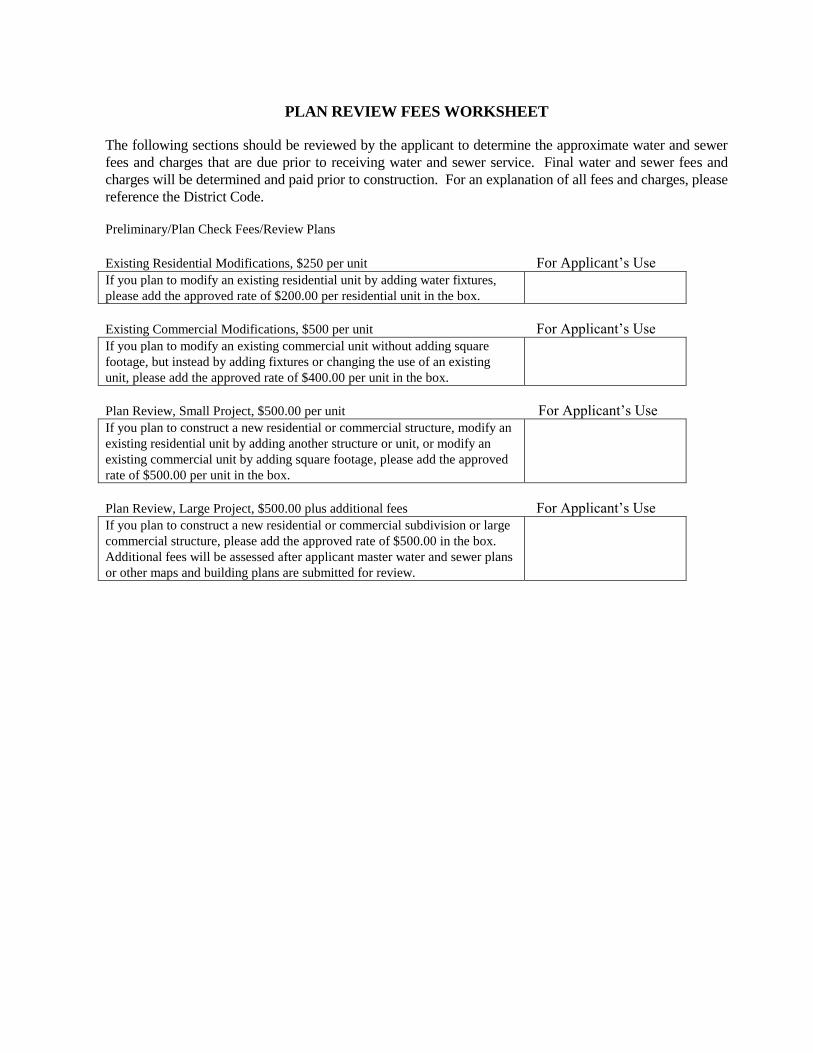
PLAN REVIEW FEES WORKSHEET
The following sections should be reviewed by the applicant to determine the approximate water and sewer
fees and charges that are due prior to receiving water and sewer service. Final water and sewer fees and
charges will be determined and paid prior to construction. For an explanation of all fees and charges, please
reference the District Code.
Preliminary/Plan Check Fees/Review Plans
Existing Residential Modifications, $250 per unit For Applicant’s Use
If you plan to modify an existing residential unit by adding water fixtures,
please add the approved rate of $200.00 per residential unit in the box.
Existing Commercial Modifications, $500 per unit For Applicant’s Use
If you plan to modify an existing commercial unit without adding square
footage, but instead by adding fixtures or changing the use of an existing
unit, please add the approved rate of $400.00 per unit in the box.
Plan Review, Small Project, $500.00 per unit For Applicant’s Use
If you plan to construct a new residential or commercial structure, modify an
existing residential unit by adding another structure or unit, or modify an
existing commercial unit by adding square footage, please add the approved
rate of $500.00 per unit in the box.
Plan Review, Large Project, $500.00 plus additional fees For Applicant’s Use
If you plan to construct a new residential or commercial subdivision or large
commercial structure, please add the approved rate of $500.00 in the box.
Additional fees will be assessed after applicant master water and sewer plans
or other maps and building plans are submitted for review.