Embed Size (px)
Citation preview

2005 CATALOG
“Innovations in video, voice and data”

Over two decades of excellence in video, voice, and data products.For over 20 years, the ChannelPlus product line has been acknowledged as the premier brand in multi-roomaudio/video distribution systems. Innovative design and dependable performance have made ChannelPlus thenumber one choice of professional installers.
ChannelPlus products are used in residential homes and commercial installations such as restaurants, sports bars, training facilities, and schools. Homeowners can enjoy an advanced integrated home network thatprovides outstanding picture quality to every TV, clear telephone connections, easy satellite access, a residentialgateway for data networking, and the ability to watch a front door camera, DVD, and VCR from every TV in thehouse. Why limit home theater to one room? With the addition of a ChannelPlus stereo modulator, homeownerscan distribute home theater all throughout the house.
ChannelPlus products include a complete line of modulators, cameras, enclosures, RF amplifiers, distributionpanels, and telephone products. And ChannelPlus is one of the many household technology brands of Linear LLC.
No strings attached 2/5/15 warranty.Don’t worry about fine print on a ChannelPlus warranty. There is none. We do not require that the installation be done by a certified installer (although we do recommend it). We do not void our warranty if other products are used with ours in the same systems. We offer two years on audio amplifiers and data products, and five yearson active products* (such as amplifiers, modulators, and infrared receivers). On passive products, we offer a full 15 years* (passive products include rack mount accessories, filters, and splitters).
*All products in this literature are protected by one or more US and international patents, issued or pending.
All product brands mentioned in this catalog are trademarks or registered trademarks of their respective manufacturers.
ChannelPlus products delivered direct to you.MTExpress® is our full-line ChannelPlus, Linear, and OpenHouse product distributor.
Mail order sales are available from 7 am to 4:30 pm Pacific Time weekdays:By Phone: 888-996-4949
By Fax: 888-996-4950
Internet sales are available 24 hours a day.www.mtx-sales.com
Telephone support for dealers and installers.
Call 800-999-5225 for toll-free, US-based technical assistance 7 am to 4:30 pm Pacific Time every business day.
CONTENTSINTRODUCTION
ChannelPlus and Structured Wiring 2New Product Highlights 3
PRE-WIRE AND INTEGRATED SYSTEMSPre-Wire Cabling 4Pre-Wire for Audio, Video, and Television 5Pre-Wire for Telecommunications and Cameras 6Pre-Wire for Data 7
S-VIDEO DISTRIBUTIONTrue 8x8 Audio/Video Matrix Switcher 8Audio/Video Switcher 10Video Distribution Over CAT-5 Cable 12Video Distribution Panel 13S-Video Modulators 14
STRUCTURED WIREData and Telephone Distribution Modules 16Ethernet Router and Switch 17TAP (Total Access Port) Wall Plates 18Rack Mount Accessories 19
RF-DISTRIBUTIONRF Distribution Amplifiers 20Distribution Amplifiers 22RF Amplifiers 24
MODULATIONModulators 26Modulator Starter Kits 28All-In-One Video Distribution 30
IR ACCESSORIESInfrared Accessories 32
MUSIC DISTRIBUTIONMulti-Source, Multi-Zone Music Distribution 34
CAMERASBlack and White; Color Cameras 36
COMBINERS AND SPLITTERSSplitters, Combiners, and Taps 38
ACCESSORIESAccessories and Filters 40
REFERENCE GUIDESDigital Television 41RF Troubleshooting 42RF System Design 43Power Supply Chart 44International Standards 45Frequency Spectrum 46Glossary of RF and Data Terms 47
INDEX 49
800.999.5225 • www.channelplus.com 1

2 800.999.5225 • www.channelplus.com
STRUCTURED WIRE FOR THE CUSTOM HOME
SVS-52Five source A/V switcher
SVC-10Delivers S-video and audio over CAT-5 to a remote location up to 1,000’ away
SVM-222-channel S-video stereo modulator
SVM-244-channel S-video stereo modulator
MDS-6AMusic distribution for six audio sources to six rooms
DMT-24Telephone distribution for four lines to 24 locations
DMT-16Telephone distribution for four lines to 16 locations
DMD-1616-port CAT-5e termination panel for data,telephone, or A/V
DA-550HHR/BIDRF Distribution Amplifier to eight locations
DA-506BIDRF Distribution Amplifier to six locations
DA-8200HHR/BIDRF Distribution Amplifier to eight locations
H638Ethernet Switch networks home computers, printers, etc.
H634Ethernet broadband residential gatewayroutes data from DSL or cable modem
261910-space rack mount grid system
•
•
•
•
•
•
•
•
• •
•
•
•
•
•

800.999.5225 • www.channelplus.com 3
Audio/Video DistributionSVS-88True 8x8 switching of S-video, composite video, stereo audio, andDolby® digital audio, plus IR control.
See pages 10-11 for details
Music DistributionMDS-6A; MCS-1A; MCS-2AMulti-room, multi-source, 6x6 music distribution system with 40 watts/channel and keypad control.
See pages 34-35 for details
Modulation5415; 5425; 5435; 5445Economically priced, one, two, three,and four channel mono modulatorswith loop-through capabilities.
See pages 26-27 for details
AccessoriesTAP (Total Access Port) Wall PlatesSelf-mapping, easy-to-terminate wallplates — dual data, data/telephone,data/telephone/coax, and telephone/coax models available in three colors.
See page 18 for details.
CHANNELPLUS® NEW PRODUCTS 2005
4 800.999.5225 • www.channelplus.com
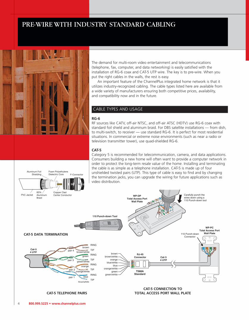
The demand for multi-room video entertainment and telecommunications (telephone, fax, computer, and data networking) is easily satisfied with the installation of RG-6 coax and CAT-5 UTP wire. The key is to pre-wire. When you put the right cables in the walls, the rest is easy.
An important feature of the ChannelPlus integrated home network is that it utilizes industry-recognized cabling. The cable types listed here are available from a wide variety of manufacturers ensuring both competitive prices, availability, and compatibility now and in the future.
CABLE TYPES AND USAGE
RG-6RF sources like CATV, off-air NTSC, and off-air ATSC (HDTV) use RG-6 coax withstandard foil shield and aluminum braid. For DBS satellite installations — from dish,to multi-switch, to receiver — use standard RG-6. It is perfect for most residentialsituations. In commercial or extreme noise environments (such as near a radio or television transmitter tower), use quad-shielded RG-6.
CAT-5Category 5 is recommended for telecommunication, camera, and data applications.Consumers building a new home will often want to provide a computer network inorder to protect the long-term resale value of the home. Installing and terminatingthe cable is as simple as a telephone installation. CAT-5 is made up of four unshielded twisted pairs (UTP). This type of cable is easy to find and by changingthe termination jacks, you can upgrade the wiring for future applications such asvideo distribution.
PRE-WIRE WITH INDUSTRY STANDARD CABLING
CAT-5 TELEPHONE PAIRSCAT-5 CONNECTION TO
TOTAL ACCESS PORT WALL PLATE
CAT-5 DATA TERMINATION

800.999.5225 • www.channelplus.com 5
PRE-WIRE AUDIO/VIDEO AND TELEVISION WITH RG-6 COAX
PRE-WIRE GUIDE
Using RG-6 white and black coaxialcable, install the following cable runsfrom the network enclosure:
• One black coax from each TV or computer location.
• One white coax from everywhereone or more video sources mightbe located.
• Video sources include VCRs, satel-lite receivers, TiVo, DVD players,cameras, computers, and InternetTV products.
• One white coax from the CATVdemarcation point.
• One white coax to a place wherean off-air antenna might be located.
• Four white coax to a place where asatellite dish with a dual LNB mightbe mounted.
cable: coaxial cable type RG-6 75Ωconnectors: type Fapplications: CATV, antenna,audio/video, and satellite.
COLOR CODING
white RG-6 coax: use as a “send”or “upstream” cable from modulatorsto distribution panel black RG-6 coax: use as “receive” or “downstream” cable from distribution panel to TVs

6 800.999.5225 • www.channelplus.com
PRE-WIRE TELEPHONE, MULTI-ROOM AUDIO,AND SECURITY CAMERAS with CAT-5 or CAT-5e
PRE-WIRE GUIDE
Using gray or white Category 5 orCategory 5e cable, install the following cable runs from the net-work enclosure:
• One from each telephone location.• One from the location(s) where
a satellite receiver might be located.• One from each video camera
location (front door, back door,baby’s room, backyard).
• One from the telephone company’sdemarcation point.
• One from the front door forinstalling an intercom.
• Two from the media center for videoand audio distribution and control.
cable: Category 5 or Category 5econnectors: jacks and plugs type RJ-11 (1 pair), type RJ-14 (2 pair),and type RJ-25 (3 pair)applications: telephone, fax, com-puter modem, and video cameras
COLOR CODING
gray or white: telephoneyellow: demarc and gateway

800.999.5225 • www.channelplus.com 7
PRE-WIRE DATA NETWORKING AND INTERNETwith CAT-5e
PRE-WIRE GUIDE
Using Category 5e cable, install thefollowing cable runs from the net-work enclosure:
• One from each computer location.• One from any location(s) where a
computer peripheral (such as aprinter) might be located separatelyfrom the computer.
• One at any location where accessto the network is desired (kitchen,bedroom, or den).
cable: Category 5econnectors: jacks and plugs areCategory 5e, type RJ-45 (4 pair)applications: printer sharing, 10BASE-T (Ethernet) or 100 BASE-T(Fast Ethernet)
COLOR CODING
blue: data

8 800.999.5225 • www.channelplus.com
VIDEO DISTRIBUTION
TRUE 8x8 AUDIO/VIDEO MATRIX SWITCHER
Our SVS-88 is an industry leader in solid 8x8 switching with volume control, S-video, stereo, or digital audio options, plus IR control. Up to 8 S-video (or composite video with an external adapter) sources can be switched using theSVS-88. Composite is up converted to S-video. DVRs, VCRs, DVD players, cableboxes, and satellite receivers, including digital audio, can be converted to CAT-5and transmitted up to 1,000 feet by adding our SVC-10 to the system. Inputs canbe switched at the remote locations using an IR remote. IR is passed back down the same CAT-5 cabling from the remote location.
When multiple locations are needed, ourSVD-8 can expand the output to eight differentlocations up to 1,000 feet away. For more locations, additional SVD-8s can be added.
SVS-88 FEATURES• Audio/video matrix switcher• Any eight A/V inputs switched to any eight
A/V outputs• All video connections are S-video type (composite video can be used with an
external adapter)• Stereo audio analog and digital inputs and outputs• Linear or logarithmic volume control for each output• Simple text based commands for PC control• Compatible with Crestron®, Elan™, AMX® and other home control systems• RS-232 and RS-485 interface• Switches PAL, SECAM, NTSC• Front panel controls with pushbuttons and 7-segment displays• IR control with built-in command set• Set-top or rack mount• International power supply
SUGGESTED USES• Home theaters, whole-house video systems, sports bars, stadiums, casinos,
schools• Any place that needs quality video to multiple locations up to 2,000 feet using
SVC-10, SVD-8, and SVC-10R components
model SVS-88
NEW!
800.999.5225 • www.channelplus.com 9
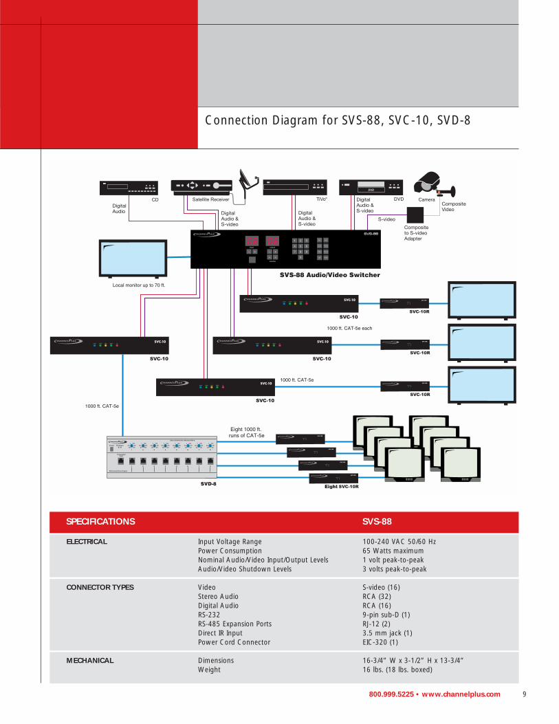
SPECIFICATIONS SVS-88
ELECTRICAL Input Voltage Range 100-240 VAC 50/60 HzPower Consumption 65 Watts maximumNominal Audio/Video Input/Output Levels 1 volt peak-to-peakAudio/Video Shutdown Levels 3 volts peak-to-peak
CONNECTOR TYPES Video S-video (16)Stereo Audio RCA (32)Digital Audio RCA (16)RS-232 9-pin sub-D (1)RS-485 Expansion Ports RJ-12 (2)Direct IR Input 3.5 mm jack (1)Power Cord Connector EIC-320 (1)
MECHANICAL Dimensions 16-3/4” W x 3-1/2” H x 13-3/4”Weight 16 lbs. (18 lbs. boxed)
Connection Diagram for SVS-88, SVC-10, SVD-8
10 800.999.5225 • www.channelplus.com
VIDEO DISTRIBUTION
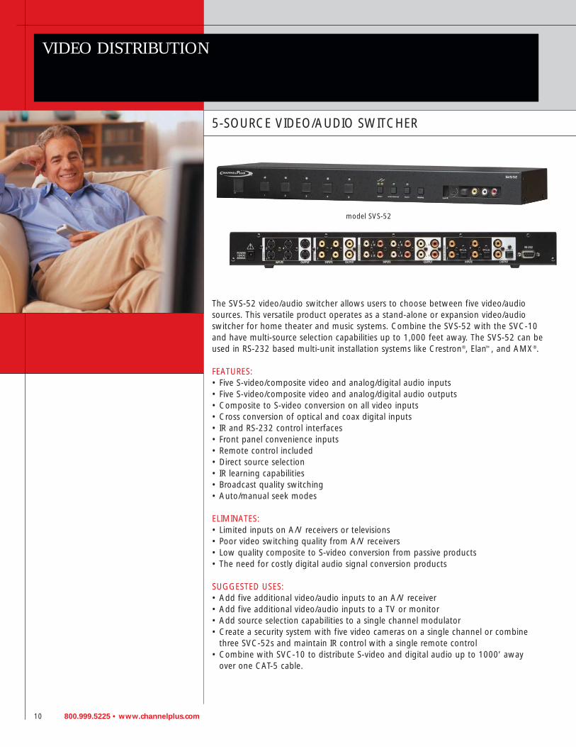
5-SOURCE VIDEO/AUDIO SWITCHER
The SVS-52 video/audio switcher allows users to choose between five video/audiosources. This versatile product operates as a stand-alone or expansion video/audioswitcher for home theater and music systems. Combine the SVS-52 with the SVC-10and have multi-source selection capabilities up to 1,000 feet away. The SVS-52 can beused in RS-232 based multi-unit installation systems like Crestron®, Elan™, and AMX®.
FEATURES:• Five S-video/composite video and analog/digital audio inputs• Five S-video/composite video and analog/digital audio outputs• Composite to S-video conversion on all video inputs• Cross conversion of optical and coax digital inputs• IR and RS-232 control interfaces• Front panel convenience inputs• Remote control included• Direct source selection• IR learning capabilities• Broadcast quality switching• Auto/manual seek modes
ELIMINATES:• Limited inputs on A/V receivers or televisions• Poor video switching quality from A/V receivers• Low quality composite to S-video conversion from passive products• The need for costly digital audio signal conversion products
SUGGESTED USES:• Add five additional video/audio inputs to an A/V receiver• Add five additional video/audio inputs to a TV or monitor• Add source selection capabilities to a single channel modulator• Create a security system with five video cameras on a single channel or combine
three SVC-52s and maintain IR control with a single remote control• Combine with SVC-10 to distribute S-video and digital audio up to 1000’ away
over one CAT-5 cable.
model SVS-52

800.999.5225 • www.channelplus.com 11
SPECIFICATIONS: SVS-52 typical @ 25oC +_ 5o
INPUTS & OUTPUTS S-video/composite video 5 inputs x 2 outputsoptical digital audio 3 inputs x 1 outputaudio digital/analog 5 inputs x 2 outputsgain 1.0 nominal (2 ports)video level 1 V p-p @ 75Ωaudio level 1 V rms @ 47kΩ
VIDEO PERFORMANCE video bandwidth <0.1 dB (0-4 MHz)crosstalk (0-4 MHz) >70 dB
RS-232 pin out 2 TX, 3 RX, 5 GNDprotocol 9600 baud, 8 bit, 1 stop, no parity
POWER SUPPLY model number 350-103output current 600mAoutput voltage 15 Vdcinput power 105-125 Vacpower consumption 8 watts typical
PHYSICAL height 1.75” (4.4 cm)width 17” (43.2 cm)depth 6.5” (16.5 cm)weight 2 lbs, 10 oz (1.19 kg)
Distributed Multi-Source Home Theater Installation
EXPORT MODELS AVAILABLE(SEE PAGE 49)

12 800.999.5225 • www.channelplus.com
VIDEO DISTRIBUTION
POINT-TO-POINT S-VIDEO DISTRIBUTION SYSTEM
The SVC-10 delivers true, unconverted S-video or composite video, digital audio oranalog audio over CAT-5 up to 1,000 feet away. Simply place the SVC-10 transmitterat the source and the SVC-10R receiver at a remote location. The integrated IRmakes it possible to control the source with a click of the remote*. Use the SVC-10to distribute both audio and video or distribute audio alone.
*Target and emitter required
FEATURES:
Transmitter• Composite and S-video inputs• Digital, optical digital 5.1, and analog stereo audio inputs• Auto termination loop-through• IR emitter and RJ-45 CAT-5 outputs• 19-inch rack mountable (one space)• Automatic optical to coax digital audio conversion• Adjustable picture compensation for length of wire run
Receiver• Composite and S-video outputs• Coax digital and analog audio outputs• 12 volt IR target input• RJ-45 CAT-5 input• Compact size
ELIMINATES:• Ground loop problems• Stacks of components in remote rooms• Lack of signal integrity from sending S-video over long runs• Need for coax or multiple video and audio cables to remote locations
SUGGESTED USES:• Distribute unconverted audio and video from music management system over single
CAT-5 cable• Provide video and audio access to distant location such as pool house with no
ground looping problems or coax required• Create cost effective single-zone audio distribution system with unlimited power
and simplified wiring• Loop several units together for whole house distribution• Deliver high quality audio and video to box seats in sports arena• Access home theater from bedroom with full IR remote control• Combine SVS-52 or SVS-88 (previous pages) to switch between multiple sources
model SVC-10R(included with SVC-10)
model SVC-10
800.999.5225 • www.channelplus.com 13
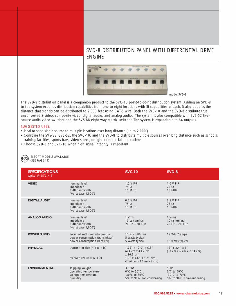
SPECIFICATIONS SVC-10 SVD-8typical @ 25oC +_ 5o
VIDEO nominal level 1.0 V P-P 1.0 V P-Pimpedence 75 Ω 75 Ω3 dB bandwidth 15 MHz 15 MHz(worst case 1,000’)
DIGITAL AUDIO nominal level 0.5 V P-P 0.5 V P-Pimpedence 75 Ω 75 Ω3 dB bandwidth 15 MHz 15 MHz(worst case 1,000’)
ANALOG AUDIO nominal level 1 Vrms 1 Vrmsimpedence 10 Ω nominal 10 Ω nominal3 dB bandwidth 20 Hz – 20 KHz 20 Hz – 20 KHz(worst case 1,000’)
POWER SUPPLY included with domestic product 15 Vdc 600 mA 12 Vdc 2 ampspower consumption (transmitter) 5 watts typicalpower consumption (receiver) 5 watts typical 18 watts typical
PHYSICAL transmitter size (H x W x D) 1.75” x 17.0” x 6.5” 12” x 2.4” x 1”(4.4 cm x 43.2 cm (30 cm x 6 cm x 2.54 cm)x 16.5 cm)
receiver size (H x W x D) 1.0” x 4.6” x 3.2” N/A(2.54 cm x 12 cm x 8 cm)
ENVIRONMENTAL shipping weight 3.5 lbs 5 lbsoperating temperature 0°C to 50°C 0°C to 50°Cstorage temperature -30°C to 70°C -30°C to 70°Chumidity 5% to 90% non-condensing 5% to 90% non-condensing
SVD-8 DISTRIBUTION PANEL WITH DIFFERENTIAL DRIVEENGINE
The SVD-8 distribution panel is a companion product to the SVC-10 point-to-point distribution system. Adding an SVD-8 to the system expands distribution capabilities from one to eight locations with IR capabilities at each. It also doubles the distance that signals can be distributed to 2,000 feet using CAT-5 wire. Both the SVC-10 and the SVD-8 distribute true,unconverted S-video, composite video, digital audio, and analog audio. The system is also compatible with SVS-52 five-source audio video switcher and the SVS-88 eight-way matrix switcher. The system is expandable to 64 outputs.
SUGGESTED USES:• Ideal to send single source to multiple locations over long distance (up to 2,000’)• Combine the SVS-88, SVS-52, the SVC-10, and the SVD-8 to distribute multiple sources over long distance such as schools,
training facilities, sports bars, video stores, or light commercial applications• Choose SVD-8 and SVC-10 when high signal integrity is important
model SVD-8
EXPORT MODELS AVAILABLE(SEE PAGE 49)

14 800.999.5225 • www.channelplus.com
VIDEO DISTRIBUTION
S-VIDEO MODULATORS WITHTHE ULTIMATE IN MTS STEREO
SVM modulators offer complete MTS stereo encoding and S-video inputs in a full component size rack mountable case.The SVM-22 and SVM-24 are two andfour-channel stereo modulators with 25 dBmV of output and easy push button digital programming. The SVM series incorporates S-video inputs that support both S-video and composite video feeds with included adapters. Offering full MTS stereo with dbx noise reduction and compatibility with Dolby Pro Logic®, the SVMs are ideal for integration into any home theater system.
INTEGRATED IR CONTROLEach SVM modulator has IR emitter output jacks and is compatible with both 12-volt or 5-volt IR systems. With new desktop power supplies, SVM modulatorscan remotely power a DA-550 or DA-8200 series distribution panel from up to 75 feet away.
AUTO-TERMINATIONThe SVM series offers full loop-through outputs with 75-ohm auto-termination. By connecting video/audio cables to the output jacks, you can have all video andaudio signals pass through for use with a local monitor, VCR, or DVR.
RACK SIZESVM modulators will fit any 19-inch EIA rack (mounting ears included). The SVM-22and SVM-24 are one rack space high.
SUGGESTED USES• When quality video and the ability to distribute S-video are important• For remotely powering DA series amplifiers• For installation with other home theater components in a 19-inch EIA rack
model SVM-24
model SVM-22

800.999.5225 • www.channelplus.com 15
SPECIFICATIONS SVM-22 SVM-24typical @ 25oC +_ 5oC
INPUTS video: baseband 1.0 V P-P @ 75 Ω 1.0 V P-P @ 75 Ωvideo standard NTSC NTSCvideo connector type mini DIN (2) mini DIN (4)audio: left and right 1.0 Vrms @ 10 k Ω 1.0 Vrms @ 10 k Ωaudio connector type RCA (4) RCA (8)
RF OUTPUTS number of modulators 2 4tuning range: UHF 14-64 14-64
CATV 65-125 excluding 95-99 65-125 excluding 95-99maximum output 25 dBmV 25 dBmVfrequency stability +_ 5 KHz +_ 5 KHz
OUTPUTS S-video mini DIN (2) mini DIN (4)audio connector type RCA (4) RCA (8)mts stereo yes yesdbx noise reduction yes yes5.1 surround sound support yes yessignal to noise ratio >65 dB >65 dBseparation @ 1000 Hz >25 dB >25 dBaudio frequency range 20Hz to 12 KHz 20Hz to 12 KHzIR emitter connectors mini jack (2) mini jack (4)
POWER SUPPLY included with product 15 Vdc 900 mA 15 Vdc 900 mA
GENERAL width x height x depth 1.75” x 17” x 6.5” 1.75” x 17” x 6.5”(4.4 cm x 43.2 cm x 16.5 cm) (4.4 cm x 43.2 cm x 16.5 cm)
shipping weight 2 lbs (1 kg) 2 lbs (1 kg)operating temperature 32oF to 122oF (0oC to 50oC) 32oF to 122oF (0oC to 50oC)
Model SVM-22 and SVM-24

16 800.999.5225 • www.channelplus.com
DATA AND TELEPHONE DISTRIBUTION MODULES
ChannelPlus DMD-16 Data Termination Hub provides a superior way to terminatedata connections. Each unit has 16 unbridged 110 punch-down terminationpoints that are aligned with a corresponding RJ-45 connector. Rated for CAT-5eperformance in data networks, the DMD-16 is an excellent data termination hubfor use with an Ethernet hub for LANs. The DMD-16 can also be used as a termination point for control signals over CAT-5, video and audio signals, home control signals, security camera video, and KSU and PBX phone systems.
STRUCTURED WIRE
Telephone Distribution ModuleMODEL DMT-16• Four lines to 16 locations• Four line surge protection• Labeling system• RJ-31X• Disconnect/test service
Telephone Distribution ModuleMODEL DMT-24• Four lines to 24 locations• Four line surge protection• Labeling system• RJ-31X• Disconnect/test service
Data Distribution ModuleMODEL DMD-16• CAT-5 certified• Unbridged termination hub• 16 data locations• Labeling system
800.999.5225 • www.channelplus.com 17
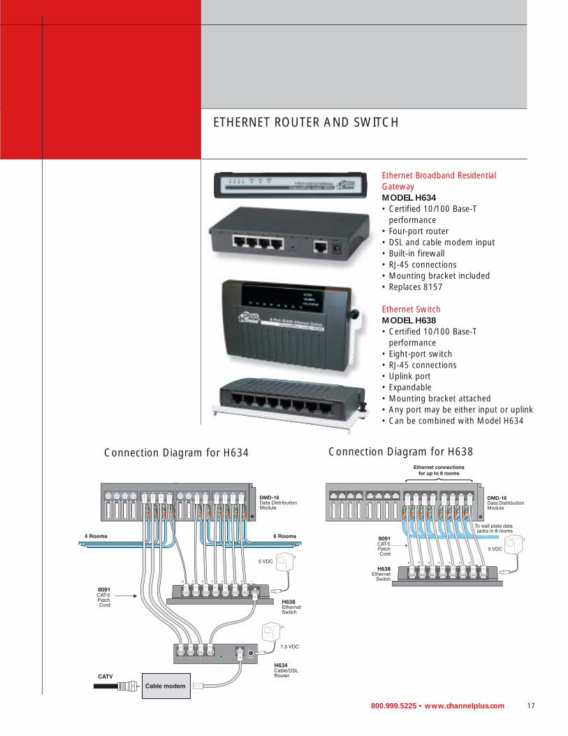
ETHERNET ROUTER AND SWITCH
Connection Diagram for H634 Connection Diagram for H638
Ethernet Broadband Residential GatewayMODEL H634• Certified 10/100 Base-T
performance• Four-port router• DSL and cable modem input• Built-in firewall• RJ-45 connections• Mounting bracket included• Replaces 8157
Ethernet SwitchMODEL H638• Certified 10/100 Base-T
performance• Eight-port switch• RJ-45 connections• Uplink port• Expandable• Mounting bracket attached• Any port may be either input or uplink• Can be combined with Model H634
18 800.999.5225 • www.channelplus.com
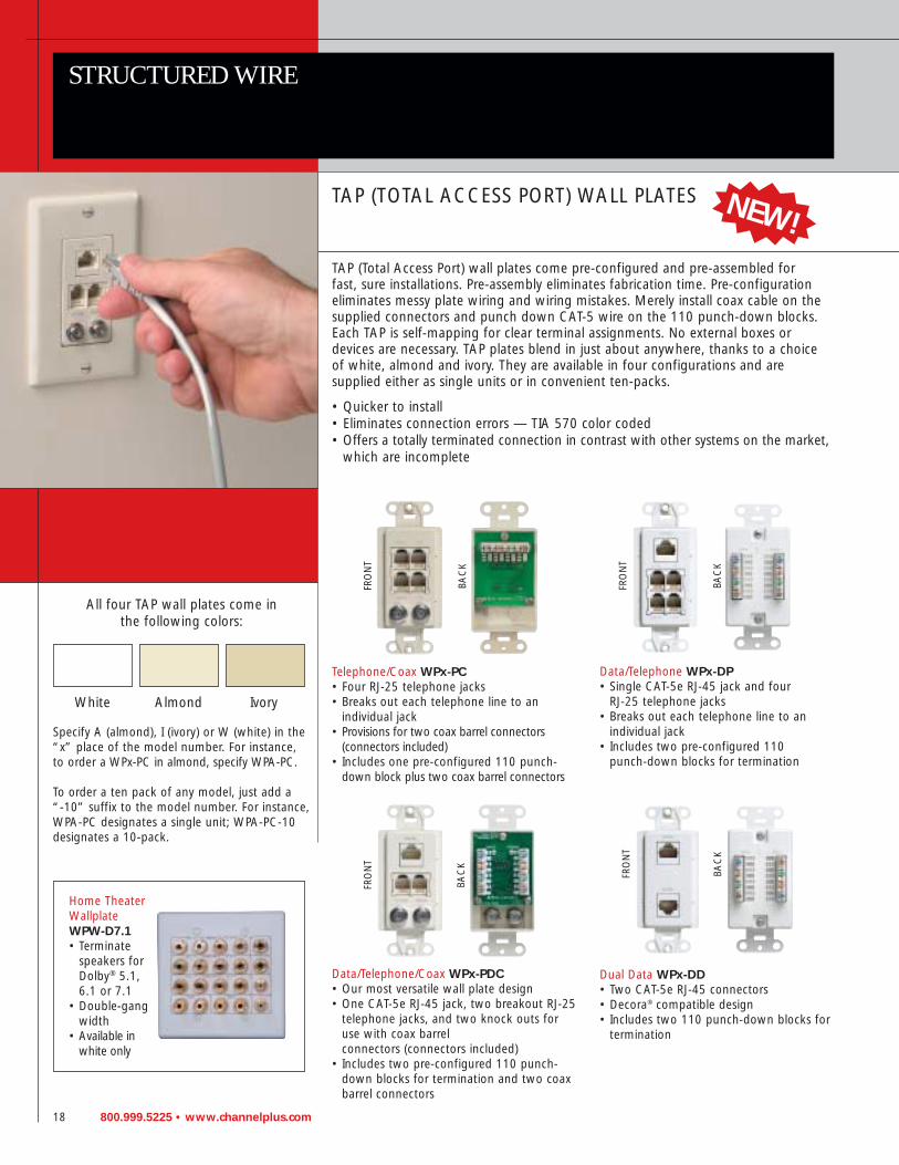
TAP (TOTAL ACCESS PORT) WALL PLATES
TAP (Total Access Port) wall plates come pre-configured and pre-assembled for fast, sure installations. Pre-assembly eliminates fabrication time. Pre-configurationeliminates messy plate wiring and wiring mistakes. Merely install coax cable on thesupplied connectors and punch down CAT-5 wire on the 110 punch-down blocks.Each TAP is self-mapping for clear terminal assignments. No external boxes or devices are necessary. TAP plates blend in just about anywhere, thanks to a choice of white, almond and ivory. They are available in four configurations and are supplied either as single units or in convenient ten-packs.
• Quicker to install• Eliminates connection errors — TIA 570 color coded• Offers a totally terminated connection in contrast with other systems on the market,
which are incomplete
STRUCTURED WIRE
Telephone/Coax WPx-PC• Four RJ-25 telephone jacks• Breaks out each telephone line to an
individual jack• Provisions for two coax barrel connectors
(connectors included)• Includes one pre-configured 110 punch-
down block plus two coax barrel connectors
Home Theater Wallplate WPW-D7.1• Terminate
speakers forDolby® 5.1, 6.1 or 7.1
• Double-gangwidth
• Available inwhite only
Data/Telephone WPx-DP• Single CAT-5e RJ-45 jack and four
RJ-25 telephone jacks• Breaks out each telephone line to an
individual jack• Includes two pre-configured 110
punch-down blocks for termination
Data/Telephone/Coax WPx-PDC• Our most versatile wall plate design• One CAT-5e RJ-45 jack, two breakout RJ-25
telephone jacks, and two knock outs foruse with coax barrel connectors (connectors included)
• Includes two pre-configured 110 punch-down blocks for termination and two coaxbarrel connectors
Dual Data WPx-DD• Two CAT-5e RJ-45 connectors• Decora® compatible design• Includes two 110 punch-down blocks for
termination
FRO
NT
BAC
K
FRO
NT
BAC
K
FRO
NT
BAC
K
FRO
NT
BAC
K
All four TAP wall plates come in the following colors:
White Almond Ivory
Specify A (almond), I (ivory) or W (white) in the“x” place of the model number. For instance,to order a WPx-PC in almond, specify WPA-PC.
To order a ten pack of any model, just add a “-10” suffix to the model number. For instance,WPA-PC designates a single unit; WPA-PC-10designates a 10-pack.
NEW!
800.999.5225 • www.channelplus.com 19
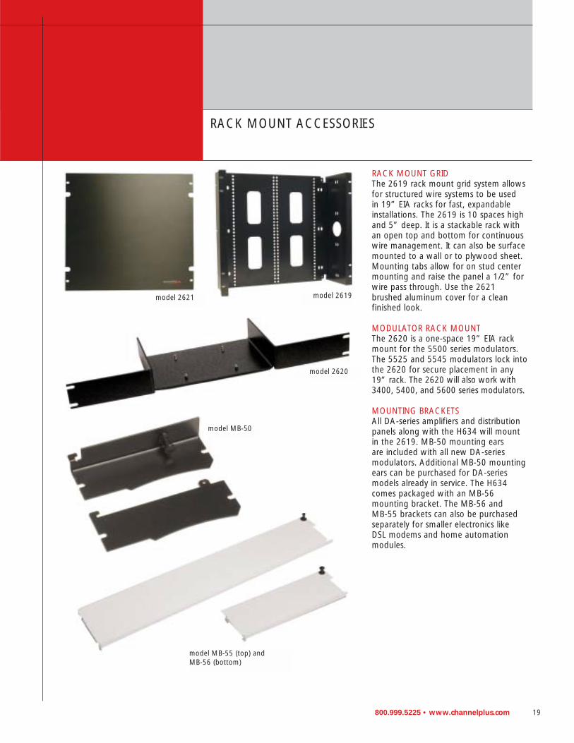
RACK MOUNT GRIDThe 2619 rack mount grid system allowsfor structured wire systems to be used in 19” EIA racks for fast, expandableinstallations. The 2619 is 10 spaces highand 5” deep. It is a stackable rack withan open top and bottom for continuouswire management. It can also be surfacemounted to a wall or to plywood sheet.Mounting tabs allow for on stud centermounting and raise the panel a 1/2” forwire pass through. Use the 2621brushed aluminum cover for a clean finished look.
MODULATOR RACK MOUNTThe 2620 is a one-space 19” EIA rackmount for the 5500 series modulators.The 5525 and 5545 modulators lock intothe 2620 for secure placement in any19” rack. The 2620 will also work with3400, 5400, and 5600 series modulators.
MOUNTING BRACKETSAll DA-series amplifiers and distributionpanels along with the H634 will mountin the 2619. MB-50 mounting ears are included with all new DA-series modulators. Additional MB-50 mountingears can be purchased for DA-seriesmodels already in service. The H634comes packaged with an MB-56 mounting bracket. The MB-56 and MB-55 brackets can also be purchasedseparately for smaller electronics like DSL modems and home automationmodules.
RACK MOUNT ACCESSORIES
model MB-55 (top) and MB-56 (bottom)
model MB-50
model 2621 model 2619
model 2620

20 800.999.5225 • www.channelplus.com
RF DISTRIBUTION
RF DISTRIBUTION AMPLIFIERMODELS DA-8200HHR AND DA-8200BID—5-VOLT IR
Ease of Installation with Standard 5 Volt IR Remote ControlThe DA-8200 series provides outputs to eight televisions, with one input for off-airantenna or CATV and two for modulator inputs. The compact design ensures aquick installation for surface mount applications or installation in a structured wireenclosure such as the 2619.
Remote or Local PowerNo additional power outlets are required when using the DA-8200 series. It may be remotely powered from up to 75 feet away by using a remote wall plate Model2010 or any 5500 series or SVM series modulator.
IR ControlThe DA-8200 series offers optional IR control of connected video sources andwhole house IR integration with a 5-volt IR engine. The easy-to-use 2133 targetconnects directly to the coax and allows IR signals to be routed to an optional 2010wall plate, or back to the amplifier and to a 5500 series or SVM series modulator.
SUGGESTED USES• Works with 5-volt IR systems — no special interface required• Expandable to 64 locations for large systems such as schools or sports bars• DA-8200 BID is perfect for bi-directional interactive cable systems• DA-8200HHR can be used with off-air antennas• Use in locations without electrical access, such as closet; power remotely with
ChannelPlus modulator or Model 2010 wall plate• For homes with up to eight TV outlets and cable lengths up to 150’
Accessories used with DA-8200HHR/BID:
5-VOLT IRmodel DA-8200HHR
5-VOLT IRmodel DA-8200BID
model 2010model 2171 model 2133

800.999.5225 • www.channelplus.com 21
SPECIFICATIONS typical @ 25oC +_ 5oC DA-8200HHR DA-8200BID
INFRARED IR remote control 5-volt 5-volt
INPUTS antenna, HDTV, 5 MHz – 1 GHz 54 MHz – 1 GHz (CATV only) or CATV reverse 5-42 MHz
maximum input level +20 dBmV (+80 dBµV) +20 dBmV (+80 dBµV)
modulator/inputs 2 2
OUTPUTS runs up to 150’ (46 m) 8 8
POWER SUPPLY included with domestic product 15 Vdc 300 mA 15 Vdc 300 mA
GENERAL width x height x depth 6.3” x 1.25” x 4.5” 6.3” x 1.25” x 4.5” (16.3 cm x 11.5 cm (16.3cm x 11.5 cm x 6.35 cm) x 6.35 cm)
shipping weight 3 lbs (1.36 kg) 3 lbs (1.36 kg)
Sports Bar Connection Diagram
EXPORT MODELS AVAILABLE(SEE PAGE 49)

22 800.999.5225 • www.channelplus.com
RF DISTRIBUTION
DISTRIBUTION AMPLIFIERMODELS DA-550HHR AND DA-550BID—12-VOLT IR
High Headroom Video Distribution AmplifiersThe DA-550 series is designed with the highest headroom available in a distributionamplifier. Traditional panels are not equipped to handle the large variations in signal strengths associated with systems having both analog TV and HDTV. Newtechnologies, such as HDTV, create special problems for current video distributionpanels. The DA-550s can handle an extremely wide range of input signals fromtoday’s NTSC and tomorrow’s digital TV. The DA-550 is the heart of a multi-roomdistribution system with outputs to eight televisions, coax runs up to 150’, andthree inputs (one from a CATV or antenna and two from modulators).
BID and HHR ModelsThe DA-550BID offers a 5-42 MHz return path for bi-directional communicationswith digital cable interactive set-up boxes. The DA-550 HHR is for use in high performance antenna applications for off-air digital and NTSC signals.
Remote or Local PowerIf power is unavailable, the DA-550 can be remotely powered from the media center using wall plate Model 2010 or a 5500 or SVM series modulator.
Infrared Remote ControlThe DA-550 is equipped with a 12-volt IR engine IR that allows any infrared controllable video product (DVD, satellite) to be operated from any of the eight television locations using 2100A wall plates and 2132 IR targets. IR control signals can be sent to additional DA-550 units by using the 2181 IR expander (see page 32). Use 2501 DC block when 2100A is not used on all outputs.
Expandable TV OutputsThe DA-550 is expandable up to 64 TV outputs with the addition of up to eight DA-550s. Each additional DA-550 adds its own modulator inputs for increased flexibility.
SUGGESTED USES• Works with most 12-volt IR systems• Expandable to 64 locations for large systems such as schools or sports bars• DA-550BID is perfect for bi-directional interactive cable systems• DA-550HHR is for use with off-air antennas or satellite systems• Use in locations without electrical access, such as a closet; power remotely with a
ChannelPlus 5500 series modulator or 2010 wall plate
12-VOLT IRmodel DA-550BID
12-VOLT IRmodel DA-550HHR

800.999.5225 • www.channelplus.com 23
Connection Diagram for 12-Volt IR and DA-550HHR
SPECIFICATIONS typical @ 25oC +_ 5oC DA-550HHR DA-550BID
INFRARED IR remote control 12-volt 12-volt
INPUTS antenna, HDTV, or CATV 5 MHz – 1 GHz 54 MHz – 1 GHz (CATV only)reverse 5-42 MHz
maximum input level +20 dBmV (+80 dBµV) +20 dBmV (+80 dBµV) modulator/inputs 2 2
OUTPUTS runs up to 150’ (46 m) 8 8
POWER SUPPLY included with domestic product 15 Vdc 300 mA 15 Vdc 300 mA
GENERAL width x height x depth 6.3” x 1.25” x 4.5” 6.3” x 1.25” x 4.5”(16.3 cm x 11.5 cm (16.3 cm x 11.5 cm x 6.35 cm) x 6.35 cm)
shipping weight 3 lbs (1.36 kg) 3 lbs (1.36 kg)
Accessories used with DA-550HHR/BID:
model 2172 model 2132 model 2100AEXPORT MODELS AVAILABLE(SEE PAGE 49)

24 800.999.5225 • www.channelplus.com
RF DISTRIBUTION
DA-500 SERIES RF AMPLIFIERS
DA-500AThis amplifier has 18 dB of gain and is ideal for residential analog cable systems oras an antenna pre-amplifier. The DA-500A offers a robust power supply and greatEMI rejection. It includes grid mounting ears for the 2619 (page 19).
DA-506BIDThis RF distribution panel creates an ideal entry-level product for broadband distribution. Encased in an extruded aluminum shell, the DA-506BID meets theneeds of small distribution systems that do not require IR control or modulatorinputs. It has one input for CATV or off-air antenna and six outputs to television.Four outputs are for televisions up to 75’ away and two outputs can be used up to150’ away. The DA-506BID has bi-directional capabilities, using a 5-42 MHz returnpath on the ant/CATV input. This allows compatibility with interactive CATV set topboxes. Grid mount ears are included for mounting in the 2619 (page 19).
DA-520AThe DA-520A is a bi-directional amplifier with a 5-40 MHz return path. It provides20 dB of gain in a CATV or antenna system. A 12 Vdc power supply is included.

800.999.5225 • www.channelplus.com 25
SPECIFICATIONS DA-500A DA-520A DA-506BIDtypical @ 25oC +_ 5oC
BANDWIDTH all antenna and 50 MHz 54 MHz – 1 GHz 54 MHz CATV bands to 1 GHz reverse 5-40 MHz to 806 MHz
reverse 5-42 MHz
MAX INPUT all frequencies 40 dBmv 30 dBmv 20 dBmvLEVEL (100 dBµV) (90 dBµV) (80 dBµV)
GAIN nominal 18 dB 20 dB short runs +1 dBlong runs +4 dB
gain flatness ±1.0 dB from ±1.0 dB from ±1.5 dB40 MHz 54-806 MHz from 54 MHzto 1 GHz to 806 MHz
POWER SUPPLY included with domestic product 15 Vdc 600 mA 12 Vdc 200 mA 15 Vdc 300 mA
GENERAL width x height 6.3” x 1.25” 3.5” x 1.2” x 6.3” x 1.25”x depth x 4.5” (16.3 cm 2.5” (9 cm x x 4.5”(16.3 cm
x 11.5 cm x 3 cm x 6.3 cm) x 11.5 cm6.35 cm) x 6.35 cm)
shipping weight 3 lbs (1.36 kg) 3.2 lbs (1.45 kg) 3 lbs (1.36 kg)operating temperature 32°F to 122°F 32°F to 122°F 32°F to 122°F
(0° C to 50°C) (0° C to 50°C) (0° C to 50°C)
Connection Diagram for Model DA-500A
EXPORT MODELS AVAILABLE(SEE PAGE 49)

26 800.999.5225 • www.channelplus.com
MULTI-CHANNEL MODULATORS
The ChannelPlus 5400 and 5500 Series products are frequency-agile, installer friendly, audio/video modulators. Each offers easy pushbutton TV channel selectionfor programming the modulated RF output.The RF output level for all models is 25 dBmV (85 dBµv). Both series feature stereo audio inputs and provide monauralaudio output on the modulated channel(s). The 5415 and 5515 single channel modulators are one quarter of the size of the two, three, and four channel companion products while providing all the power output of the companion products.
5400 Series ModelsThe Models 5415,5425,5435, and 5445 are economically priced one, two, three, andfour channel modulators with video loop-through capabilities. The modulators offerremovable 75-ohm video termination jumpers for each channel. When installed, thetermination jumpers provide a 75-ohm balanced load to thevideo input signals. Whenremoved,the modulator videoinputs are high impedance,allowing use of a Model 2743cable set or "Y" adapter to"loop through" the video at themodulator, applying no load toa video signal that will be terminated downstream by alocal video monitor or VCR.
5500 Series ModelsThe Models 5515, 5525, and5545 are one, two, and fourchannel modulators that offerthe same specifications as the 5400 Series plus integrated IR control. The modulator'sIR output jacks connect to IR emitters affixed to the modulator's audio/video sourcedevices, providing upstream IR remote control from each viewing location to the source
devices. Infrared remote control signals arereceived at IR targets connected between the outputs of the modulator's distribution amplifierand the viewer's television sets. The IR remotecontrol signals pass back through the coax cableand will be repeated at the modulator's IR emitteroutput jacks. The 5500 Series is compatible with
5-volt or 12-volt IR systems. The 5500 Series modulators can remotely power
DA-550 or DA-8200 Series distribution amplifiers through themodulator's RF output coax cablefrom up to 75' away.
model 5415, 5425, 5435, 5445
MODULATION
model 5515
model 5545
NEW!
800.999.5225 • www.channelplus.com 27
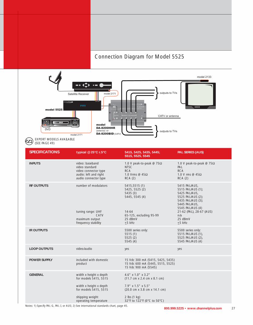
SPECIFICATIONS typical @ 25°C +_5°C 5415, 5425, 5435, 5445; PAL SERIES (AUS)5515, 5525, 5545
INPUTS video: baseband 1.0 V peak-to-peak @ 75Ω 1.0 V peak-to-peak @ 75Ωvideo standard NTSC PALvideo connector type RCA RCAaudio: left and right 1.0 Vrms @ 45Ω 1.0 V rms @ 45Ωaudio connector type RCA (2) RCA (2)
RF OUTPUTS number of modulators 5415,5515 (1) 5415 PAL/AUS,5425, 5525 (2) 5515 PAL/AUS (1);5435 (3) 5425 PAL/AUS,5445, 5545 (4) 5525 PAL/AUS (2);
5435 PAL/AUS (3);5445 PAL/AUS,5545 PAL/AUS (4)
tuning range: UHF 14-64 21-62 (PAL), 28-67 (AUS)CATV 65-125, excluding 95-99 n/a
maximum output 25 dBmV 25 dBmVfrequency stability +_5 kHz +_5 kHz
IR OUTPUTS 5500 series only: 5500 series only: 5515 (1) 5515 PAL/AUS (1),5525 (2) 5525 PAL/AUS (2),5545 (4) 5545 PAL/AUS (4)
LOOP OUTPUTS video/audio yes yes
POWER SUPPLY included with domestic 15 Vdc 300 mA (5415, 5425, 5435)product 15 Vdc 600 mA (5445, 5515, 5525)
15 Vdc 900 mA (5545)
GENERAL width x height x depth 4.6” x 1.0” x 3.2”for models 5415, 5515 (11.7 cm x 2.4 cm x 8.1 cm)
width x height x depth 7.9” x 1.5” x 5.5” for models 5415, 5515 (20.0 cm x 3.8 cm x 14.1 cm)
shipping weight 2 lbs (1 kg)operating temperature 32°F to 122°F (0°C to 50°C)
Connection Diagram for Model 5525
Notes: 1) Specify PAL G, PAL I, or AUS; 2) See international standards chart, page 45.
EXPORT MODELS AVAILABLE(SEE PAGE 49)

28 800.999.5225 • www.channelplus.com
MODULATION
MODULATOR STARTER KITS
Pre-designed Systems
DA-550HHR or DA-550BID RF Distribution Amplifier
5545 4-Channel Modulator
2172 (2) Dual IR Emitter
2172 (2) Dual IR Emitter
2100A (3)In-WallInterface
5525: 2-Channel Modulator 2172: Dual IR Emitter 2133: IR Target (2)
5545: 4-Channel Modulator
DA-8200BID or DA-8200HHR:RF Distribution Amplifier
2133: IR Target (3)
2501 (5)BlockingCapacitor
1
2
3
5555BID or 5555HHR RF Distribution Kit with 12-volt IR
5557BID or 5557HHR RF Distribution Kit with 5-volt IR
5558BID or 5558HHR RF Distribution Kit with 5-volt IR
• Four channels of modulation (5545)• Eight rooms of distribution
(DA-550HHR or DA-550BID)• Three rooms with IR interface,
expandable to eight rooms (2100Aand 2501s)
• IR control of four video sources(2172s)
• Two channels of modulation (5525)• Eight rooms of distribution
(DA-8200HHR or DA-8200BID)• Two rooms with IR interface,
expandable to eight rooms (2133s)• IR control of two video sources
(2172)
The 5558 distributes four sources,such as DVD, surveillance camera,VCR, and satellite, to eight TVs withIR control to three TVs. The systemcan be expanded to include IR controlof all eight TVs with the purchase ofadditional emitters and targets.
• Four channels of modulation (5545)• Eight rooms of distribution
(DA-8200HHR or DA-8200BID)• Three rooms with IR interface,
expandable to eight rooms (2133s)• IR control of four video sources
(2172s)
DA-8200BID or DA-8200HHR:RF Distribution Amplifier
EXPORT MODELS AVAILABLE(SEE PAGE 49)

800.999.5225 • www.channelplus.com 29
Connection Diagram for Model 5558 RF Distribution System
5-VOLT IR SYSTEM VS 12-VOLT IR SYSTEM
• Easy to install • Versatile• Limited target choice • Multiple target choices• No special interface required • Requires wall plate interface• Compatible with any style emitter • Allows for complex control signals or• Operates through existing coax integration of existing systems
• Operates through existing coax• Requires 2501 DC block on outputs
not using IR

30 800.999.5225 • www.channelplus.com
MODULATION
ALL-IN-ONES
WHOLE-HOUSE VIDEO DISTRIBUTIONChannelPlus 3000 SeriesWhole-House VideoDistribution Systems areeasy to install and operate.The Model 3015 is a dualinput system that accepts a CATV or antenna input,audio/video signals from one video source and modulates it to a user-selected channel thatcan be seen at four TV locations. Model 3025 is a triple input system that accepts a CATV or antennainput, audio/video signals from two sources and modulates them to user-selectedchannels that can be seen at up to five TV locations.
FREQUENCY-AGILE MODULATORSAll models feature modulatorsthat are frequency-agile. Pushthe channel button to choosethe desired unused channeland the internal microprocessordigitally sets the modulator to the exact FCC channel specification. Channel settingsare retained in memory duringa power failure.
WHOLE-HOUSE INFRAREDREMOTE CONTROLModel 3025 allows the viewer to control two video products (VCR, satellite receiver, DVD, etc.) from any distant TV location in the house. The viewer simplyaims the IR remote control directly at an optional Model 2133 target. Infraredinformation from the remote control is instantly transmitted through the Model3025 and repeated by an optional Model 2171 repeater/emitter. Model 2133 target is sold separately (see page 32).
model 3015
model 30255-Volt IR
model 2133 IR Target
model 2171 IR Emitter

800.999.5225 • www.channelplus.com 31
Simple Video Distribution
SPECIFICATIONS typical @ 25°C +_5°C 3015, 3025 PAL SERIES (AUS)
INPUT -RF antenna or cable service 40 MHz to 1 GHz 40 MHz to 1 GHzmaximum input level +10 dBmV +70 dBmV
INPUTS video baseband 1.0V peak-to-peak @ 75 Ω 1.0V peak-to-peak @ 75 Ωvideo standard NTSC PAL/AUSaudio left and audio right 1.0 Vrms @ 47 k Ω 1.0 Vrms @ 47 k Ω
INFRARED (3015) n/a (3025) 5-Volt (3105) n/a (3025) 5-VoltREPEATER SYSTEM
OUTPUTS – MODULATORS number of modulators (3015) 1 (3025) 2 (3015) 1 (3025) 2tuning range – UHF 14-64 21-62 (28-67)
CATV 65-125 except 95-99 n/aRF output level +12 dBmV +72 dBmVfrequency stability +_5 KHz +_5 KHz
OUTPUTS TO TVs local – TVs within 35’ (3015) 0 (3025) 2 (3015) 0 (3025) 2distant – TVs within 150’ (3015) 4 (3025) 3 (3015) 4 (3025) 3
POWER SUPPLY included withdomestic product 15 Vdc 300 mA
GENERAL width x height x depth 5.5” x 6.8” x 2.0” 5.5” x 6.8” x 2.0” (14 cm x 17.3 cm x 5.1 cm) (14 cm x 17.3 cm x 5.1 cm)
shipping weight 3 lbs (1.4 kg) 3 lbs (1.4 kg)operating temperature 32°F to 122°F (0°C to 50°C) 32°F to 122°F (0°C to 50°C)
EXPORT MODELS AVAILABLE(SEE PAGE 49)

32 800.999.5225 • www.channelplus.com
IR ACCESSORIES
WHOLE-HOUSE INFRARED REMOTE CONTROL
System ComponentsFor setting up infrared remote control, the 2100 series is available in numerousmodels and configurations. Users can select from infrared interfaces, targets, emitters, and expansion blocks. An infrared interface wall plate — Model 2100A —must be used at each location where a target or an emitter is to be used in 12-voltIR systems.
Infrared via Coax CablesControl any video or audio product (VCR, satellite receiver, DVD, etc.) from any location in the house. Regardless of where the product is, the user simply aims aninfrared remote control at the target and presses a button. The infrared codes emitted from the remote control are transmitted through the home’s coaxial cableand instantly repeated by each infrared emitter connected to the system. Infraredcodes sent via the coax are far more reliable and free of interference than infraredtransmitted through the air. In addition, all of the infrared components are poweredcentrally from the coaxial cable panel. There is no need for power supplies in any ofthe rooms where TVs or audio/video products are located. There is no need for anyadditional wires.
Compatible with ChannelPlus Coaxial Cable PanelsTo use the 2100 series 12-volt components, it is necessary that a ChannelPlus Model DA-550 coaxial cable panel be used in the system. It provides power to all of the system IR components and ensures that the signals are passed from targets to emitters.
Expand IR SignalsThe Model 2181 IR expander should be used to send IR control signals to slave DA-550s or DA-8200s. With a master DA-550 or DA-8200 and adding up to eightslave units, you must utilize a 2181 at each slave DA-550 or DA-8200 panel toensure IR control signals are passed from master to slave units. This configurationallows each TV with a target that is connected to a slave unit to send IR signals backto the audio/video devices connected to the master DA-550 or DA-8200.
model 2010 model 2131model 2100A
target model 2133 5-volttarget model 2130A 12-volt
model 2174 model 2181 model 2184
emitter model 2171
emitter model 2172target model 2132 12-volt target model 2133 (back side)

800.999.5225 • www.channelplus.com 33
INFRARED COMPONENT SPECIFICATIONS
INTERFACE DESCRIPTION WIDTH x HEIGHT SHIPPING WEIGHT XANTECH IR x DEPTH REMOTE CONTROL
REFERENCE
2010 in-wall interface: RF output • two IR 1.3” x 4.0” x 2.2” (3.3 0.5 lb (0.2 kg) n/aemitter ports • power jack for remote cm x 10.1 cm x 5.6 cm)power of DA-8200 and DA-550• Decora® style wall plate
2100A in-wall interface: RF output • one IR 1.3” x 4.0” x 2.2” (3.3 target port • Decora® style wall plate cm x 10.1 cm x 5.6 cm) 0.5 lb (0.2 kg) n/a• 12 volt IR systems only
12-VOLT DESCRIPTION WIDTH x HEIGHT SHIPPING WEIGHT XANTECH IR TARGETS not for use with 3025, 3025XA, and x DEPTH REMOTE CONTROL
DA-8200 • 2100A interface must be REFERENCEused at all target locations • 2501 DC blocker must be used at coax locations not using 2100As
2130A mini target: 7’ cord with mini stereo 2.2” x 0.4” x 0.3” 0.5 lb (0.2 kg) 480B-30plug • talk back LED • double sided (5.6 cm x 1 cm x 0.7 cm)adhesive
2131 in-wall target: Decora® style wall 1.3” x 4.0” x 2.2” (3.3 0.5 lb (0.2 kg) 780-10plate • talk back LED cm x 10.1 cm x 5.6 cm)
2132 set top target: 7’ cord with stereo 3.3” x 1.0” x 2.0” (8.3 0.5 lb (0.2 kg) 291-100mini plug • talk back LED cm x 2.5 cm x 5.1 cm)
5-VOLT DESCRIPTION WIDTH x HEIGHT SHIPPING WEIGHT XANTECH IR TARGET for use only with: 3025, 3025XA, x DEPTH REMOTE CONTROL
and DA-8200 • no interface required REFERENCE• no DC blocker required
2133 set top target: dual F connectors 3.3” x 1.0” x 2.0” (8.3 0.5 lb (0.2 kg) n/a• 5-volt systems only cm x 2.5 cm x 5.1 cm)
EMITTERS DESCRIPTION WIDTH x HEIGHT SHIPPING WEIGHT XANTECH IR for use with 5 and 12-volt systems x DEPTH REMOTE CONTROL
REFERENCE
2171 emitter: single head • 5’ cord 0.3” x 0.5” x 0.3” 0.5 lb (0.2 kg) 283-MWwith mini plug (0.7 cm x 1.3 cm x 0.7 cm)
2172 emitter: dual head 5’ cord with 0.3” x 0.5” x 0.3” 0.5 lb (0.2 kg) 284-10mini plug (0.7 cm x 1.3 cm x 0.7 cm)
2174 expansion block: 1 mini plug input with 1.3” x 3.0” x 0.8” 0.5 lb (0.2 kg) n/a4 output jacks for emitters (3.3 cm x 7.6 cm x 2 cm)
2181 IR expansion module: dual “F” 2.3” x 1.0” x 0.7” 0.5 lb (0.2 kg) n/aconnectors• for use with DA-550 and 8200 (5.8 cm x 2.54 cm x 2 cm)
2184 IR breakout: expansion block 1.3” x 3.0” x 0.8” 0.5 lb (0.2 kg) n/adrives up to four IR emitters (3.3 cm x 7.6 cm x 2 cm)• for DA-8200s and DA-550s
34 800.999.5225 • www.channelplus.com
MUSIC DISTRIBUTION
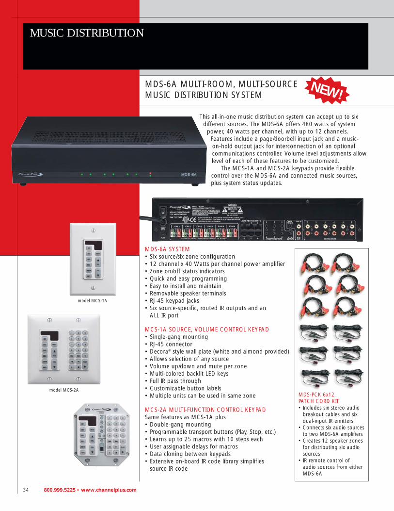
MDS-6A MULTI-ROOM, MULTI-SOURCE MUSIC DISTRIBUTION SYSTEM
This all-in-one music distribution system can accept up to sixdifferent sources. The MDS-6A offers 480 watts of system
power, 40 watts per channel, with up to 12 channels.Features include a page/doorbell input jack and a music-on-hold output jack for interconnection of an optionalcommunications controller. Volume level adjustments allowlevel of each of these features to be customized.
The MCS-1A and MCS-2A keypads provide flexiblecontrol over the MDS-6A and connected music sources,plus system status updates.
MDS-6A SYSTEM• Six source/six zone configuration• 12 channel x 40 Watts per channel power amplifier• Zone on/off status indicators• Quick and easy programming• Easy to install and maintain• Removable speaker terminals• RJ-45 keypad jacks• Six source-specific, routed IR outputs and an
ALL IR port
MCS-1A SOURCE, VOLUME CONTROL KEYPAD• Single-gang mounting• RJ-45 connector• Decora® style wall plate (white and almond provided)• Allows selection of any source• Volume up/down and mute per zone• Multi-colored backlit LED keys• Full IR pass through• Customizable button labels• Multiple units can be used in same zone
MCS-2A MULTI-FUNCTION CONTROL KEYPADSame features as MCS-1A plus• Double-gang mounting• Programmable transport buttons (Play, Stop, etc.)• Learns up to 25 macros with 10 steps each• User assignable delays for macros• Data cloning between keypads• Extensive on-board IR code library simplifies
source IR code
model MCS-2A
model MCS-1A
NEW!
MDS-PCK 6x12 PATCH CORD KIT• Includes six stereo audio
breakout cables and six dual-input IR emitters
• Connects six audio sources to two MDS-6A amplifiers
• Creates 12 speaker zones for distributing six audiosources
• IR remote control of audio sources from eitherMDS-6A

800.999.5225 • www.channelplus.com 35
SPECIFICATIONS MDS-6A
INPUTS source inputs 6 RCA type stereo pairskeypad inputs 6 RJ-45 type, 1 for each speaker zonepage and doorbell input mini-jack, input impedance 47 kΩ (for future use)
SOURCE INPUTS sensitivity 2 volts RMS maximpedance 47 kΩ
OUTPUTS speaker connectors six sets on removable quick-connect terminalsIR outputs seven mini-jacks, one per zone plus one ALL IR outputmusic on hold mini-jack, impedance 1 kΩ
AMPLIFIER OUTPUT output power/channel 40 W @ 8 Ωnumber of channels 12 (six stereo pairs)total output power 480 W @ 8 Ωspeaker impedance 8 Ωfrequency response 20 Hz to 20 kHz +/-1 dBTHD + noise (@ 1 kHz) 0.02%signal-to-noise >95 dBcrosstalk (zone to zone) >70 dB
FRONT PANEL music on hold gain adjustment hidden volume controlINDICATORS/CONTROLS page and doorbell gain adjustment hidden volume control
zone status indicators 6, indicator on when speaker zone is active
POWER LED IR activity indicator LED blinks when IR data being received from keypad

36 800.999.5225 • www.channelplus.com
CAMERAS
HIGH-PERFORMANCE INDOOR/OUTDOOR VIDEO CAMERAS
ChannelPlus in-wall and surface-mount high-performance video cameras are designedto provide a high-quality color or black & white video signal for individual videomonitors or for single or multi-television modulated RF video distribution systems.
Low-light Black & White and Color ModelsFour models of low-light black & white cameras and six models of color cameras areavailable. Two models are in-wall mounting style, two models are surface mountingball-style, and six “bullet” style models are supplied with a universal mountingbracket. The Model 7430B (black case) and 7430S (silver case) color cameras featurean automatic night time infrared lighting source that switches on after dark to givethe camera black & white “night vision” capabilities.
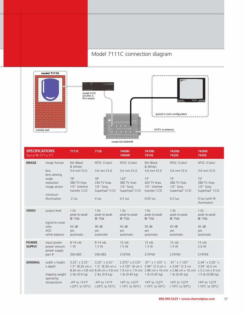
IN-WALL CAMERASThe Models 7111C and 7120 in-wall cameras are designed not to attract attention.Created to look down from a door top height, they appear more like passiveinfrared sensors than cameras. This makes them ideal for placement at a front orback door for screening visitors, or in a child’s room for baby monitoring.
Easy Pre-wire and Installation for In-wall CamerasFor interior installations, cut a hole in the drywall using the template and the low-voltage mounting clip (included). Pre-wire with RG-59 or RG-6 coax for thevideo and 22 AWG bell wire for power. For new construction, install a double-gangmud ring. For exterior installations, mount the 7111C or 7120 inside a deep double-gang, weather-proof junction box.
SURFACE-MOUNT CAMERASThe Models 7400B (black case) and 7400W (white case) surface mount cameras feature a unique ball-mounting design. The cameras can be rotated in their surface-mount retaining rings to point to almost any location. For security, the ball-style design conceals the camera in installations where a standard camera would attract unwanted attention.
BULLET STYLE CAMERASThe “bullet” style cameras are supplied with a thumbscrew locking universal mounting bracket. Each model has an adjustable sun shield that can be removed for indoor use. TheModels 7410B (black case) and 7410S (silver case) are low-light black & white cam-eras. The Models 7420B (black case) and 7420S (silver case) are color cameras. TheModels 7430B (black case) and 7430S (silver case) are color cameras with automaticnight time infrared lighting for black & white “night vision” capabilities.
model 7430B
model 7111C
model 7410B*
model 7120
model 7420S*
model 7400W
model 7430S
* Shown without sun shield
NEW!
NEW!
800.999.5225 • www.channelplus.com 37
SPECIFICATIONS 7111C 7120 7400B/ 7410B/ 7420B/ 7430B/Typical @ 25ºC± 5ºC 7400W 7410S 7420S 7430S
IMAGE image format EIA (Black NTSC (Color) NTSC (Color) EIA (Black NTSC (Color) NTSC (Color)& White) & White)
lens 3.6 mm F2.0 3.6 mm F2.0 3.6 mm F2.0 3.6 mm F2.0 3.6 mm F2.0 3.6 mm F2.0lens viewing angle 78o 78o 120o 73o 73o 73o
resolution 380 TV lines 330 TV lines 380 TV lines 420 TV lines 380 TV lines 380 TV linesimage sensor 1/3” interline 1/3” Sony 1/3” Sony 1/3” interline 1/3” Sony 1/3” Sony
transfer CCD Superhad™ CCD Superhad™ CCD transfer CCD Superhad™ CCD Superhad™ CCDminimum illumination .2 lux 4 lux 0.5 lux 0.05 lux 0.5 lux 0 lux (with IR
illuminator)
VIDEO output level 1.0v 1.0v 1.0v 1.0v 1.0v 1.0vpeak-to-peak peak-to-peak peak-to-peak peak-to-peak peak-to-peak peak-to-peak@ 75Ω @ 75Ω @ 75Ω @ 75Ω @ 75Ω @ 75Ω
signal-to-noiseratio 50 dB 46 dB 45 dB 50 dB 45 dB 45 dBAGC yes yes yes yes yes yeswhite balance automatic automatic automatic automatic automatic automatic
POWER input power 8-14 vdc 8-14 vdc 12 vdc 12 vdc 12 vdc 12 vdcSUPPLY power consum. 1 W 1.5 W 1.5 W 1.3 W 1.5 W 2.6 W
power supply part # 350-083 350-083 219704 219704 219704 219704
GENERAL width x height 3.25” x 3.25” 3.25” x 3.25” 2.375” x 3.125” .91” x 1.125” x .91” x 1.125” 2.44” x 2.05” xx depth 1.5” (8.26 cm x 1.5” (8.26 cm x x 3.125” (6 cm x 3.94” (2.3 cm x x 3.94” (2.3 cm 3.54” (6.2 cm
8.26 cm x 3.8 cm) 8.26 cm x 3.8 cm) 7.9 cm x 7.9 cm) 2.86 cm x 10 cm) x 2.86 cm x 10 cm) x 5.2 cm x 9 cm)shipping weight 2 lbs (0.9 kg) 2 lbs (0.9 kg) 1 lb (0.45 kg) 1 lb (0.45 kg) 1 lb (0.45 kg) 1.5 lb (0.68 kg)operatingtemperature -4ºF to 131ºF -4ºF to 131ºF 14ºF to 122ºF 14ºF to 122ºF 14ºF to 122ºF 14ºF to 122ºF
(-20ºC to 55ºC) (-20ºC to 55ºC) (-10ºC to 50ºC) (-10ºC to 50ºC) (-10ºC to 50ºC) (-10ºC to 50ºC)
Model 7111C connection diagram

38 800.999.5225 • www.channelplus.com
SPLITTERS AND ACCESSORIES
SPLITTER/COMBINER
models 2509
model TC-200
model 2507
model 2538
models 2532, 2534
models 2514, 2512
ChannelPlus bi-directional 2-way, 4-way, and 8-way splitter/combiners provide a 1 GHz bandwidth and are ideal for antenna and coaxial cable operations. The splitter/combiner is one product that can be used for two applications. It can split asignal from a source or combine signals from multiple sources onto one coax run.
9 dB TapThe 2509 9 dB tap provides a bandwidth of 1 GHz and minimal insertion lossthrough the tap, while allowing a signal to be tapped from the original source. Thetap works asymmetrically by splitting the signal unevenly. The output has minimalloss (1 dB), while the other output has high loss (9 dB). The tap can be used inreverse to combine very high signals with low to normal signals.
Tilt CompensatorCoaxial cable attenuates high frequencies more than low frequencies. The TC-200creates an attenuation loss equal and opposite to cable loss. This problem is mostsevere when cascading amplifiers one after another. The signal differences areamplified to a point where the higher frequency signals are so small compared tothe low frequency signals that they can no longer be received. The TC-200 providesa balanced signal level by compensating for 200 feet of cable loss for the high frequency attenuation and allowing all signal levels on all channels to be of equalamplitude at distant locations. Therefore, the picture quality on higher channels will be maintained.
75 Ohm TerminatorThe 2507 terminator provides a 75 ohm load that can be used on unused splitteroutput ports to maintain uniform signal levels.

800.999.5225 • www.channelplus.com 39
MODEL AS A SPLITTER AS A COMBINER INSERTION DC AND IR LOSS PASSING
2512 3.5 yes
2532 4.0 no
2514 8.0 yes
2534 9.0 no
2509 through 1.0 notap 9.0
2538 12.0 no
Applications for Splitter/Combiners and Taps
40 800.999.5225 • www.channelplus.com
SPLITTERS AND ACCESSORIES
ACCESSORIES FOR SATELLITE AND DISTRIBUTION SYSTEMS
model 2501
model C-BCK
model 8091
model 8092
model V902
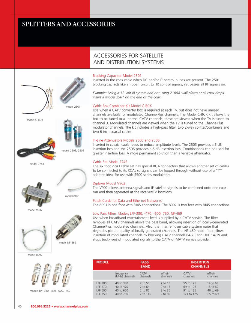
MODEL PASS INSERTION BAND CHANNELS
frequency CATV off-air CATV off-air (MHz) channels channels channels channels channels
LPF-380 40 to 380 2 to 50 2 to 13 55 to 125 14 to 69LPF-470 40 to 470 2 to 64 2 to 13 69 to 125 18 to 69LPF-600 40 to 600 2 to 86 2 to 35 91 to 125 40 to 69LPF-750 40 to 750 2 to 116 2 to 60 121 to 125 65 to 69
Blocking Capacitor Model 2501Inserted in the coax cable when DC and/or IR control pulses are present. The 2501 blocking cap acts like an open circuit to IR control signals, yet passes all RF signals on.
Example: Using a 12-volt IR system and not using 2100A wall plates at all coax drops,insert a Model 2501 on the end of the coax.
Cable Box Combiner Kit Model C-BCKUse when a CATV converter box is required at each TV, but does not have unused channels available for modulated ChannelPlus channels. The Model C-BCK kit allows thebox to be tuned to all normal CATV channels; these are viewed when the TV is tuned tochannel 3. Modulated channels are viewed when the TV is tuned to the ChannelPlusmodulator channels. The kit includes a high-pass filter, two 2-way splitter/combiners andtwo 6-inch coaxial cables.
In-Line Attenuators Models 2503 and 2506Inserted in coaxial cable feeds to reduce amplitude levels. The 2503 provides a 3 dBinsertion loss and the 2506 provides a 6 dB insertion loss. Combinations can be used forgreater insertion loss. A more permanent solution than a variable attenuator.
Cable Set Model 2743The six foot 2743 cable set has special RCA connectors that allows another set of cablesto be connected to its RCAs so signals can be looped through without use of a “Y”adapter. Ideal for use with 5500 series modulators.
Diplexer Model V902The V902 allows antenna signals and IF satellite signals to be combined onto one coaxrun and then separated at the receiver/TV locations.
Patch Cords for Data and Ethernet NetworksThe 8091 is one foot with RJ45 connections. The 8092 is two feet with RJ45 connections.
Low Pass Filters Models LPF-380, -470, -600, 750, NF-469Use when broadband entertainment feed is supplied by a CATV service. The filterremoves all CATV channels above the pass band, allowing insertion of locally-generatedChannelPlus modulated channels. Also, the filter removes cable system noise thatdegrades picture quality of locally-generated channels. The NF-469 notch filter allowsinsertion of modulated channels by blocking CATV channels 64-70 and UHF 14-19 andstops back-feed of modulated signals to the CATV or MATV service provider.
model 2743
models 2503, 2506
models LPF-380, -470, -600, -750
model NF-469
800.999.5225 • www.channelplus.com 41
FAQS — DTV COMPATIBLE AMPLIFIERS
FREQUENTLY ASKED QUESTIONS ABOUT DTV COMPATIBLE AMPLIFIERS
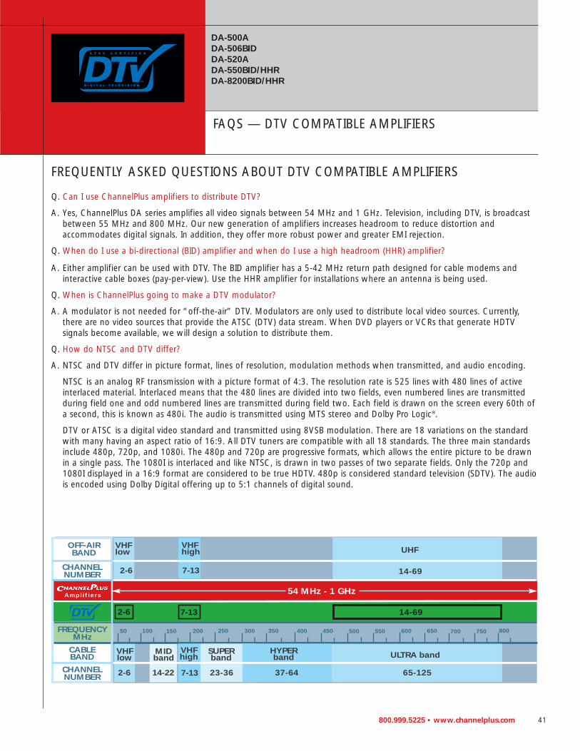
Q. Can I use ChannelPlus amplifiers to distribute DTV?
A. Yes, ChannelPlus DA series amplifies all video signals between 54 MHz and 1 GHz. Television, including DTV, is broadcastbetween 55 MHz and 800 MHz. Our new generation of amplifiers increases headroom to reduce distortion and accommodates digital signals. In addition, they offer more robust power and greater EMI rejection.
Q. When do I use a bi-directional (BID) amplifier and when do I use a high headroom (HHR) amplifier?
A. Either amplifier can be used with DTV. The BID amplifier has a 5-42 MHz return path designed for cable modems andinteractive cable boxes (pay-per-view). Use the HHR amplifier for installations where an antenna is being used.
Q. When is ChannelPlus going to make a DTV modulator?
A. A modulator is not needed for “off-the-air” DTV. Modulators are only used to distribute local video sources. Currently,there are no video sources that provide the ATSC (DTV) data stream. When DVD players or VCRs that generate HDTV signals become available, we will design a solution to distribute them.
Q. How do NTSC and DTV differ?
A. NTSC and DTV differ in picture format, lines of resolution, modulation methods when transmitted, and audio encoding.
NTSC is an analog RF transmission with a picture format of 4:3. The resolution rate is 525 lines with 480 lines of activeinterlaced material. Interlaced means that the 480 lines are divided into two fields, even numbered lines are transmittedduring field one and odd numbered lines are transmitted during field two. Each field is drawn on the screen every 60th ofa second, this is known as 480i. The audio is transmitted using MTS stereo and Dolby Pro Logic®.
DTV or ATSC is a digital video standard and transmitted using 8VSB modulation. There are 18 variations on the standardwith many having an aspect ratio of 16:9. All DTV tuners are compatible with all 18 standards. The three main standardsinclude 480p, 720p, and 1080i. The 480p and 720p are progressive formats, which allows the entire picture to be drawnin a single pass. The 1080I is interlaced and like NTSC, is drawn in two passes of two separate fields. Only the 720p and1080I displayed in a 16:9 format are considered to be true HDTV. 480p is considered standard television (SDTV). The audiois encoded using Dolby Digital offering up to 5:1 channels of digital sound.
DA-500ADA-506BIDDA-520ADA-550BID/HHRDA-8200BID/HHR
50 100 150 200 250 300 350 400 450 500 550 600 650 700 750 800
2-6
UHF
ULTRA bandSUPER band
23-36
HYPERband
7-1314-22 37-64 65-125
Amplif iers
7-13 14-69
54 MHz - 1 GHz
OFF-AIRBAND
CHANNELNUMBER
FREQUENCYMHz
CABLEBAND
CHANNELNUMBER
VHFlow
MIDband
VHFhigh
14-69
VHFhigh
7-132-6
VHFlow
2-6

42 800.999.5225 • www.channelplus.com
RF TROUBLESHOOTING WITH CHANNELPLUS
Problem: NO PICTUREVerify that the video source is on and is producing a video signal. Check that the TV and the modulator are tuned to the same channel. For example, if the modulator isbroadcasting on UHF channel 16, make sure the TV is on UHF 16 rather than CATV 16.UHF 16 and CATV 16 are at different frequencies.
Problem: WEAK CHANNELPLUS UHF CHANNELIf the TV has a separate UHF input, be sure that it is connected.
Problem: LEDS ON THE MODULATOR BLINKThe display will blink if you have assigned the same channel to multiple inputs. You needto have one unused channel space between channels.
Problem: DIAGONAL LINES KNOWN AS HERRINGBONE INTERFERENCE ON CHANNELPLUS CHANNELS
You may have chosen a channel number that is not completely vacant. Distant UHF stations may be unviewable, but will cause interference if you try to create a new channel at the same frequency. Also, cable companies often have extra signals wherethere should be none. Move the modulated channel to another number. You may haveto add a low pass filter to remove cable company noise. If a filter does not work, tryadding a DC-block to remove common mode interference.
Problem: HERRINGBONE INTERFERENCE ON MULTIPLE CHANNELS, INCLUDING MODULATED CHANNELS
If the problem disappears when you remove the CATV/Ant feed, then the RF amplifier isover loaded by abnormally strong signals. Often, you can cure the problem with a simpleattenuator. Use a variable attenuator and try to find a signal level where the interferencejust disappears. Sometimes, the problem is one station that is far stronger than the rest.Attenuating all of the signals with a simple attenuator will cause the desired stations to be weak (snowy). In this case you must reduce the strength of only the offending station. A common FM trap will help if the problem is a nearby FM tower. If the problemis a nearby TV station, often the station management can provided suitable filters.
Problem: AUDIO VOLUME IS LOWThe left and right audio inputs are combined for monaural. For proper audio level, bothright and left inputs must be used. If you have a mono source, connect it to both right and left inputs using an RCA ‘Y’ connector.
Problem: NO COLOR ON CHANNELPLUS CHANNELSYou may have chosen the incorrect cable standard. Not all televisions can accommodatethe 1.25 MHz frequency difference between the H and I cable standards.
Problem: TROUBLE WITH THE INFRARED REMOTE CONTROLUse the red IR DATA light on the modulator as a trouble-shooting aid. This light will blinkas remote control signals are relayed. If the light is constantly on, one or more of the IRtargets is receiving electrical or optical noise. At the distribution unit, begin to disconnectthe outputs to the TVs until the IR DATA light goes off. This will tell you which IR targetis the source of the noise. Next cover the front of the offending IR target. If the IR DATAlight turns off, the IR target is “seeing” a source of IR noise, such as a solid-state fluorescent lamp. If the light does not go out, the problem may be radiated electricalnoise from the Plasma or direct view TV. Reposition this IR target. On 5-volt systems, if repositioning the IR target does not help, the TV may be conducting noise from its input. Place a DC block between the IR target and the TV. If the IR DATA light seems toindicate a proper operation, but the component is not being controlled, the IR emittermay be mislocated. Be sure the emitters are in front of the IR sensor on the video source.
REFERENCE

800.999.5225 • www.channelplus.com 43
RF SYSTEM DESIGN
1. Layout system noting lengths of runs,locations of splitters, taps, combiners, and TV sets. Where cable runs exceed200’ (60 m), add a tilt compensatorwhenever an amplifier stage follows.
2. Determine cable type to be used andenter all system losses using the chartbelow.
3. Add amplifiers when necessary to ensure that the signal level never fallsbelow 0 dBmV (60 dBmV) at any point in the system and that TVs get at least 5 dBmV (65 dBmV) of signal.
4. Add attenuators when necessary toensure that the signal level at the TVs does not exceed 15 dBmV (75 dBµV).
5. Study the example below. If you needhelp call Linear Technical Support at 800-999-5225.
EXAMPLE: 68 TV SCHOOL SYSTEMThe head end is located in the media center. A CATV feed is combined with the output of two modulators (typically connected to an assortment of VCRs, satellite receivers, and DVD players). There are four TVs located in the media center andup to 64 TVs located in distant classrooms (up to 650’ from the media center). The small numbers in red indicate the signallevel in dBmV (add 60 dBmV) at various locations in the system. For the gains and losses associates with the various RF components (see the chart below).
Component Description Model Gain Loss Your System
coaxial cable 75Ω impedance RG59 7.6 dB/100’ (24.9 dB/100m)
RG6 6.0 dB/100’ (19.7 dB/100 m)
RG11 4.0 dB/100’ (13.1 dB/100 m)
splitters and combiners see page 38 2512 3.5 dB
2532 4.0 dB
2514 8.0 dB
2534 9.0 dB
Tap see page 38 2509 1.0 dB through 9.0 dB tap
tilt compensator see page 38 TC-200 4.0 dB
Attenuator see page 40 2503 3.0 dB
see page 40 2506 6.0 dB
RF amplifier see page 24 DA-500 18.0 dB
total gain
total loss

44 800.999.5225 • www.channelplus.com
POWER SUPPLY CHART
REFERENCE
DOMESTIC PART INPUT OUTPUT CONNECTOR REGULATEDMODELS NUMBER
7111C, 7120 350-083 110 250 mA/12 VDC F No
7400, 7410, 7420, 7430 219704 110 300mA/12 VDC E No
3015, 3025 350-086 110 300 mA/15 VDC G No
5415, 5425, 5435 350-086 110 300 mA/15 VDC G No
DA-8200HHR, DA-8200BID 350-086 110 300 mA/15 VDC G No
DA-506BID, DA-550BID, 350-086 110 300 mA/15 VDC G NoDA-550HHR
DA-500A 350-100 110 600 mA/15 VDC G No
5445, 5515, 5525 350-100 110 600 mA/15 VDC G No
5545 350-101 110 900 mA/15 VDC G No
DESKTOP STYLE POWER SUPPLIES
SVM-22, SVM-24 350-102 110 900 mA/15 VDC G No
SVC-10, SVC-10R, SVS-52 350-103 110 600 mA/15 VDC G No
SVD-8 219558 110 2 A/12 VDC E Yes
DA-520A 350-088 110 200 mA/12 VDC H No
INTERNATIONAL MODELS (PALNPS) (AUSNPS) INPUT OUTPUT CONNECTOR REGULATED
3015, 3025 230 300mA/15 VDC G NoDA-8200HHR 230 300mA/15 VDC G NoDA-550HHR 230 300mA/15 VDC G NoDA-500A 230 600mA/15 VDC G No5515, 5525 230 600mA/15 VDC G No5545 230 900mA/15 VDC G NoSVC-10, SVC-10R, SVS-52 230 600mA/15 VDC G No
E F G H
800.999.5225 • www.channelplus.com 45
INTERNATIONAL STANDARDS
COUNTRY COLOR SYSTEM USE
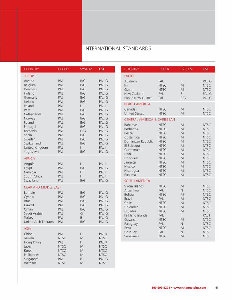
EUROPEAustria PAL B/G PAL GBelgium PAL B/H PAL GDenmark PAL B/G PAL GFinland PAL B/G PAL GGermany PAL B/G PAL GIceland PAL B/G PAL GIreland PAL I PAL IItaly PAL B/G PAL GNetherlands PAL B/G PAL GNorway PAL B/G PAL GPoland PAL B/G PAL GPortugal PAL B/G PAL GRomania PAL D/G PAL GSpain PAL B/G PAL GSweden PAL B/G PAL GSwitzerland PAL B/G PAL GUnited Kingdom PAL I PAL IYugoslavia PAL B/G PAL G
AFRICA
Angola PAL I PAL IEgypt PAL B/G PAL GNamibia PAL I PAL ISouth Africa PAL I PAL ISwaziland PAL B/G PAL G
NEAR AND MIDDLE EAST
Bahrain PAL B/G PAL GCyprus PAL B/G PAL GIsrael PAL B/G PAL GKuwait PAL B/G PAL GOman PAL B/G PAL GSaudi Arabia PAL G PAL GTurkey PAL B PAL GUnited Arab Emirates PAL B/G PAL G
ASIA
China PAL D PAL KTaiwan NTSC M NTSCHong Kong PAL I PAL KJapan NTSC M NTSCKorea NTSC M NTSCPhilippines NTSC M NTSCSingapore PAL B PAL GVietnam NTSC M NTSC
COUNTRY COLOR SYSTEM USE
PACIFIC
Australia PAL B PAL GFiji NTSC M NTSCGuam NTSC M NTSCNew Zealand PAL B PAL GPapua New Guinea PAL B/G PAL G
NORTH AMERICA
Canada NTSC M NTSCUnited States NTSC M NTSC
CENTRAL AMERICA & CARIBBEAN
Bahamas NTSC M NTSCBarbados NTSC M NTSCBelize NTSC M NTSCCosta Rica NTSC M NTSCDominican Republic NTSC M NTSCEl Salvador NTSC M NTSCGuatemala NTSC M NTSCHaiti NTSC M NTSCHonduras NTSC M NTSCJamaica NTSC M NTSCMexico NTSC M NTSCNicaragua NTSC M NTSCPanama NTSC M NTSC
SOUTH AMERICA
Virgin Islands NTSC M NTSCArgentina PAL N NTSCBolivia NTSC M NTSCBrazil PAL M NTSCChile NTSC M NTSCColombia NTSC M NTSCEcuador NTSC M NTSCFalkland Islands PAL I PAL IGuyana NTSC M NTSCParaguay PAL N NTSCPeru NTSC M NTSCUruguay PAL N NTSCVenezuela NTSC M NTSC
46 800.999.5225 • www.channelplus.com
FREQUENCY SPECTRUM
REFERENCE
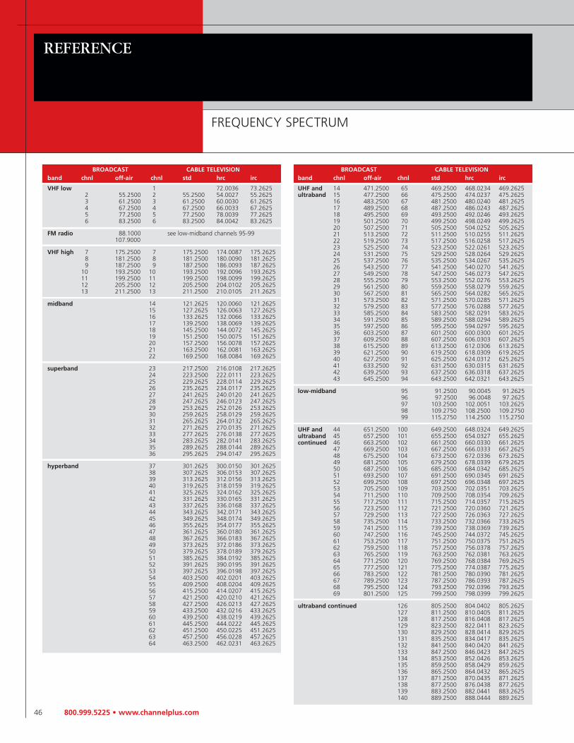
BROADCAST CABLE TELEVISIONband chnl off-air chnl std hrc irc
VHF low 1 72.0036 73.26252 55.2500 2 55.2500 54.0027 55.26253 61.2500 3 61.2500 60.0030 61.26254 67.2500 4 67.2500 66.0033 67.26255 77.2500 5 77.2500 78.0039 77.26256 83.2500 6 83.2500 84.0042 83.2625
FM radio 88.1000 see low-midband channels 95-99107.9000
VHF high 7 175.2500 7 175.2500 174.0087 175.26258 181.2500 8 181.2500 180.0090 181.26259 187.2500 9 187.2500 186.0093 187.2625
10 193.2500 10 193.2500 192.0096 193.262511 199.2500 11 199.2500 198.0099 199.262512 205.2500 12 205.2500 204.0102 205.262513 211.2500 13 211.2500 210.0105 211.2625
midband 14 121.2625 120.0060 121.262515 127.2625 126.0063 127.262516 133.2625 132.0066 133.262517 139.2500 138.0069 139.262518 145.2500 144.0072 145.262519 151.2500 150.0075 151.262520 157.2500 156.0078 157.262521 163.2500 162.0081 163.262522 169.2500 168.0084 169.2625
superband 23 217.2500 216.0108 217.262524 223.2500 222.0111 223.262525 229.2625 228.0114 229.262526 235.2625 234.0117 235.262527 241.2625 240.0120 241.262528 247.2625 246.0123 247.262529 253.2625 252.0126 253.262530 259.2625 258.0129 259.262531 265.2625 264.0132 265.262532 271.2625 270.0135 271.262533 277.2625 276.0138 277.262534 283.2625 282.0141 283.262535 289.2625 288.0144 289.262536 295.2625 294.0147 295.2625
hyperband 37 301.2625 300.0150 301.262538 307.2625 306.0153 307.262539 313.2625 312.0156 313.262540 319.2625 318.0159 319.262541 325.2625 324.0162 325.262542 331.2625 330.0165 331.262543 337.2625 336.0168 337.262544 343.2625 342.0171 343.262545 349.2625 348.0174 349.262546 355.2625 354.0177 355.262547 361.2625 360.0180 361.262548 367.2625 366.0183 367.262549 373.2625 372.0186 373.262550 379.2625 378.0189 379.262551 385.2625 384.0192 385.262552 391.2625 390.0195 391.262553 397.2625 396.0198 397.262554 403.2500 402.0201 403.262555 409.2500 408.0204 409.262556 415.2500 414.0207 415.262557 421.2500 420.0210 421.262558 427.2500 426.0213 427.262559 433.2500 432.0216 433.262560 439.2500 438.0219 439.262561 445.2500 444.0222 445.262562 451.2500 450.0225 451.262563 457.2500 456.0228 457.262564 463.2500 462.0231 463.2625
BROADCAST CABLE TELEVISIONband chnl off-air chnl std hrc irc
UHF and 14 471.2500 65 469.2500 468.0234 469.2625ultraband 15 477.2500 66 475.2500 474.0237 475.2625
16 483.2500 67 481.2500 480.0240 481.262517 489.2500 68 487.2500 486.0243 487.262518 495.2500 69 493.2500 492.0246 493.262519 501.2500 70 499.2500 498.0249 499.262520 507.2500 71 505.2500 504.0252 505.262521 513.2500 72 511.2500 510.0255 511.262522 519.2500 73 517.2500 516.0258 517.262523 525.2500 74 523.2500 522.0261 523.262524 531.2500 75 529.2500 528.0264 529.262525 537.2500 76 535.2500 534.0267 535.262526 543.2500 77 541.2500 540.0270 541.262527 549.2500 78 547.2500 546.0273 547.262528 555.2500 79 553.2500 552.0276 553.262529 561.2500 80 559.2500 558.0279 559.262530 567.2500 81 565.2500 564.0282 565.262531 573.2500 82 571.2500 570.0285 571.262532 579.2500 83 577.2500 576.0288 577.262533 585.2500 84 583.2500 582.0291 583.262534 591.2500 85 589.2500 588.0294 589.262535 597.2500 86 595.2500 594.0297 595.262536 603.2500 87 601.2500 600.0300 601.262537 609.2500 88 607.2500 606.0303 607.262538 615.2500 89 613.2500 612.0306 613.262539 621.2500 90 619.2500 618.0309 619.262540 627.2500 91 625.2500 624.0312 625.262541 633.2500 92 631.2500 630.0315 631.262542 639.2500 93 637.2500 636.0318 637.262543 645.2500 94 643.2500 642.0321 643.2625
low-midband 95 91.2500 90.0045 91.262596 97.2500 96.0048 97.262597 103.2500 102.0051 103.262598 109.2750 108.2500 109.275099 115.2750 114.2500 115.2750
UHF and 44 651.2500 100 649.2500 648.0324 649.2625ultraband 45 657.2500 101 655.2500 654.0327 655.2625continued 46 663.2500 102 661.2500 660.0330 661.2625
47 669.2500 103 667.2500 666.0333 667.262548 675.2500 104 673.2500 672.0336 673.262549 681.2500 105 679.2500 678.0339 679.262550 687.2500 106 685.2500 684.0342 685.262551 693.2500 107 691.2500 690.0345 691.262552 699.2500 108 697.2500 696.0348 697.262553 705.2500 109 703.2500 702.0351 703.262554 711.2500 110 709.2500 708.0354 709.262555 717.2500 111 715.2500 714.0357 715.262556 723.2500 112 721.2500 720.0360 721.262557 729.2500 113 727.2500 726.0363 727.262558 735.2500 114 733.2500 732.0366 733.262559 741.2500 115 739.2500 738.0369 739.262560 747.2500 116 745.2500 744.0372 745.262561 753.2500 117 751.2500 750.0375 751.262562 759.2500 118 757.2500 756.0378 757.262563 765.2500 119 763.2500 762.0381 763.262564 771.2500 120 769.2500 768.0384 769.262565 777.2500 121 775.2500 774.0387 775.262566 783.2500 122 781.2500 780.0390 781.262567 789.2500 123 787.2500 786.0393 787.262568 795.2500 124 793.2500 792.0396 793.262569 801.2500 125 799.2500 798.0399 799.2625
ultraband continued 126 805.2500 804.0402 805.2625127 811.2500 810.0405 811.2625128 817.2500 816.0408 817.2625129 823.2500 822.0411 823.2625130 829.2500 828.0414 829.2625131 835.2500 834.0417 835.2625132 841.2500 840.0420 841.2625133 847.2500 846.0423 847.2625134 853.2500 852.0426 853.2625135 859.2500 858.0429 859.2625136 865.2500 864.0432 865.2625137 871.2500 870.0435 871.2625138 877.2500 876.0438 877.2625139 883.2500 882.0441 883.2625140 889.2500 888.0444 889.2625

800.999.5225 • www.channelplus.com 47
GLOSSARY OF RF AND DATA TERMS
Adjacent Channels: Two television channels having video carriers 6 Mhz apart or two FM channels having carriers occupyingneighboring channel allocations
Amplifier: A device used to increase the power and voltage level of a signal
Attenuator: A passive device used to reduce signal strength
Baseband: A data signal that has not been modulated onto a carrier (i.e., Hi-Fi Audio, NTSC Video, or RS-232 Data)
BID: Bi-directional, as in systems used with CATV services using pay-per-view or cable modems; BID is not for use with off-airantennas
Cable Back-Feed: Signals from an inserted modulated channel that travel back into the cable source. Using a modulator on acable service provider’s system (CATV or MATV) requires a mixing amplifier or filter (NF-469) to prevent the signal from back-feeding into the cable or antenna system.
Category Rated: Twisted pair communications circuits are rated by category, whose specifications are covered under EIA/TIA568; the higher the category number, the higher the information capacity of the circuit
CATV (Community Antenna Television): An RF distribution system that distributes television broadcast programs, original programs, premium programming, and other services using a network of coaxial cable
Channel: In television, a portion of the RF spectrum, 6 MHz wide that carries the audio and video carriers of the television signal
CO (Central Office): A reference to the local telephone exchange carrier
Coaxial Cable: A concentric cable consisting of a center conductor, a dielectric, and a shield; coax used for most MATV andCATV work has a characteristic impedance of 75 ohms
Composite Video Signal: The composite video signal including the picture (luminance) signal, the blanking and sync pulses,and the color (chrominance)
Cross Connect: The physical connection between patch panels or punch-down blocks that facilitates connections from systems and feeds to drops
Crosstalk: The unwanted introduction of signals from one channel to another
Decibel: Abbreviation dB; a logarithmic function used to simplify MATV calculations; decibels can be added or subtracted; 0 dB is the standard reference level for all MATV calculations
dBmV: An absolute signal level where 0 dBmV is equal to 1000 µV across 75 ohms
Egress: A condition often called “signal leakage” in which signals carried by the distribution system radiate into the air
Filter: Fibers are used to block out undesired frequencies; there are two types of filters — band pass and rejection; a bandpass filter permits only the desired range to pass through, while the rejection filter attenuates an undesired range of frequencies
Gain: A measure of amplification of a device, usually expressed in dB at the highest frequency of operation
Ghosting: A signal interference condition producing positive or negative pictures displaced in time from the desired picture,caused by multi-path signal reception; ghost pictures also result from cable ringing
HDTV (High Definition Television): A high resolution, wide-screen common picture format and transmission standard for bringing broadcast television to the home
Head End: The equipment located at the start of a CATV system; the place where the signals are processed and combinedprior to distribution
continued on page 48

48 800.999.5225 • www.channelplus.com
GLOSSARY OF RF AND DATA TERMS (cont’d)
REFERENCE
HHR: A high head room amplifier used in high performance off-air antenna or non bi-directional CATV systems
Ingress: A condition where unwanted RF signal leaks into a distribution system
Insertion Loss: Also called “feed through loss”; this is the loss that occurs as signals pass through a passive device; insertion lossoccurs in all devices that do not amplify the signal
MATV (Master Antenna Television System): A distribution system that is usually contained within a single building and receivesits signals from an antenna or CATV system
Modulation: Placing information, audio/video, onto a higher frequency carrier by means of amplitude, frequency, or phase adjustment
Off-Air: Any channel that can be received by a conventional antenna system, including VHF and UHF broadcasts
Patch Cords: The cords interconnecting terminations at the central distribution panel; typically these cords are terminated withmodular plugs
RG6 Cable: A coaxial cable used for broadband video applications; RG6 has an 18 gauge center conductor, allowing a higher bandwidth than the RG59 cable, which has a smaller 20 gauge center conductor; RG6 uses standard “F” connectorsfor video equipment connections
RF (Radio Frequency): Generally refers to data modulated over a high-frequency carrier for wireless transmission
Signal-to-Noise Ratio (S/N): The ratio of desired signal level to the undesired noise level expressed in dB
Signal Strength: The intensity of an RF signal measured in volts (V), millivolts (mV), microvolts (mV), or dBmV
Snow: A large quantity of random noise in a television picture that results from a poor CON (earner-to-noise) ratio
Tap: A device inserted into a feeder line that allows a specific amount of signal to be removed from the feeder line and isolatesthe TAP port from the main through line
Terminator: A resistive device that matches a cable or the unused output of an active or passive system component to its characteristic impedance; proper termination is required to prevent unused portions from causing reflections back down tothe line
Tilt: A linearized change in the frequency response of the CATV system, caused primarily by the frequency dependent cable loss;tilt is quantified by comparing the difference between the level of the highest channel’s video carrier and that of the lowestchannel
UHF (Ultra High Frequency): Off-air television channels 14 to 83
UTP (Unshielded Twisted Pair): Twisted pair cable without either individual or overall shielding
VHF (Very High Frequency): Off-air television channels 2 to 13
100BASE-T: 100 Mbps 802.3/Ethernet over standard unshielded twisted pair cable specification; 100BASE-T supports networkconfigurations over twisted pair transmission systems up to 100 meters in length without the use of a repeater

800.999.5225 • www.channelplus.com 49
INDEX
Model Number Pages
2010 In-Wall Interface 32-332100A In-Wall Interface 32-332130A Mini Target 32-332131 In-Wall Target 32-332132 Set Top Target 32-332133 Set Top Target 32-332171 Emitter, Single Head 32-332172 Emitter, Dual Head 32-332174 Expansion Block 32-332181 Expansion Module 32-332184 IR Breakout 32-33219558 Power Supply, 2A/12 Vdc 44219704 Power Supply, 300mA/12 Vdc 44
2501 Blocking Capacitor 402503 In-Line Attenuators 402506 In-Line Attenuators 40
2507 75 Ohm Terminator 38-392509 9 dB Tap 38-392512 Splitter/Combiner 38-392514 Splitter/Combiner 38-39
2532 Splitter/Combiner 38-392534 Splitter/Combiner 38-392538 Splitter/Combiner 38-39
2619 Rack Mount Grid System 192620 Modulator Rack Mount 192621 Rack Mount Grid Cover 19
2743 Cable Set 40
3015 5 Volt IR Dual Input Whole-House Video Distribution 303025 5-Volt IR Whole-House Video Distribution 30
350-083 Power Supply, 250 mA/12 Vdc 44350-086 Power Supply, 300 mA/15 Vdc 44350-088 Power Supply, 200mA/12 Vdc 44350-100 Power Supply, 600 mA/15 Vdc 44350-101 Power Supply, 900 mA/15 Vdc 44350-102 Power Supply, 900 mA/15 Vdc 44350-103 Power Supply, 600 mA/15 Vdc 44
5415 1-Channel Modulator 26-27
5425 2-Channel Modulator 26-275435 3-Channel Modulator 26-275445 4-Channel Modulator 26-275515 5 or 12 Volt IR 1-Channel Modulator 26-275525 5 or 12 Volt IR 2-Channel Modulator 26-275545 5 or 12 Volt IR 4-Channel Modulator 26-27
5555BID RF DistributionKit with 12-Volt IR, Bi-directional 28-295555HHR RF DistributionKit with 12-Volt IR, High Headroom 28-295557BID RF Distribution Kit with5-volt IR, Bi-directional 28-295557HHR RF Distribution Kitwith 5-Volt IR, High Headroom 28-295558BID RF Distribution Kitwith 5-Volt IR, Bi-directional 28-295558HHR RF Distribution Kit,with 5-Volt IR, High Headroom 28-29
7111C B/W In-Wall Camera 36-377120Color In-Wall Camera 36-377400B Color Surface Mount Camera (Black) 36-377400W Color Surface Mount Camera (White) 36-377410B B/W Bullet Camera (Black) 36-377410S B/W Bullet Camera (Silver) 36-377420B Color Bullet Camera (Black) 36-377420S Color Bullet Camera (Silver) 36-377430B Color Bullet Camera (Black) 36-377430S Color Bullet Camera (Silver) 36-37
8091 Patch Cord, 1 Foot 408092 Patch Cord, 2 Feet 40
C-BCK Cable Box Combiner Kit 40
DA-500A RF Amplifier 24-25DA-506BID RF Amplifier, Bi-directional 24-25DA-520A RF Amplifier, Bi-directional 24-25DA-550BID RF Amplifier, Bi-directional 22-23DA-550HHR RF Amplifier,High Headroom 22-23
DA-8200BID RF Amplifier, Bi-directional 20-21DA-8200HHR RF Amplifier, High Headroom 20-21
DMD-16 Data Distribution Modules 16
DMT-16 Telephone Distribution Modules,4 Lines to 16 Locations 16DMT-24 Telephone Distribution Modules,4 Lines to 24 Locations 16
H634 Ethernet Broadband Residential Gateway 17H638 Ethernet Switch 17
LPF-380 Low Pass Filter, 40 to 380 MHz 40LPF-470 Low Pass Filter, 40 to 470 MHz 40LPF-600 Low Pass Filter, 40 to 600 MHz 40LPF-750 Low Pass Filter, 40 to 750 MHz 40
MB-50 Mounting Ears, DA-Series 19MB-55 Mounting Bracket 19MB-56 Mounting Bracket 19
MCS-1A Source,Volume Control Keypad, Single-Gang 34-35MCS-2A Multi-Function ControlKeypad, Double-Gang 34-35MDS-6A Music Distribution System 34-35MDS-PCK 6x12 Patch Cord Kit 34
NF-469 Notch Filter 40
SVC-10 S-Video Distribution System 12SVC-10R S-Video Distribution Remote 12
SVD-8 Distribution Panel 13
SVM-22 S-Video Modulator (2) 14-15SVM-24 S-Video Modulator (4) 14-15
SVS-52 5 Source Video/Audio Switcher 10-11SVS-88 True 8x8 Audio/Video Matrix Switcher 8-9
TC-200 Tilt Compensator 38-39
V902 Diplexer 40
WPW-D7.1 Home Theater Wallplate 18WPx-DD Dual Data TAP Wall Plate 18WPx-DP Data/Telephone TAP Wall Plate 18WPx-PC Telephone/Coax TAP Wall Plate 18WPx-PDC Data/Telephone/CoaxTAP Wall Plate 18
Model Number Pages Model Number Pages
Domestic Model PALG Format Export Model PALI Format Export Model PAL Australia Export Model
3015 3015PALG NPS 3015PALI NPS 3015AUS NPS
3025 3025PALG NPS 3025PALI NPS 3025AUS NPS
5515 5515PALG NPS 5515PALI NPS 5515AUS NPS
5525 5525PALG NPS 5525PALI NPS 5525AUS NPS
5545 5545PALG NPS 5545PALI NPS 5545AUS NPS
5555BID 5555BIDPALG NPS 5555BIDPALI NPS
5555HHR 5555HHRPALG NPS 5555HHRPALI NPS 5555HHRAUS NPS
Domestic Model Standard Export Model
SVC-10 SVC-10 NPS
SVC-10R SVC-10R NPS
SVD-8 SVD-8 NPS
SVS-52 SVS-52 NPS
DA-500A DA-500A NPS
DA-550BID DA-550BID NPS
DA-550HHR DA-550HHR NPS
DA-8200HHR DA-8200HHR NPS
ChannelPlus offers several models that are configured for international use. Models designated as NPS are packaged without a power supply to reduce shipping weightand so a power supply compatible with the local line voltage can be used. Standard PAL and Australian PAL video format models are also available.
EXPORT MODELS AVAILABLE NPS = No Power Supply

ChannelPlus.Part of the family of Linear residential products.
ChannelPlus voice, video, and
data products are made by Linear
LLC, a subsidiary of Nortek, one
of the nation’s leading makers
of building products. As a
top brand of Linear, ChannelPlus
helps make up one of the
broadest offerings in the
household technology market.
Other brands include OpenHouse
structured wire products, Xantech
remote controls, Elan amplifiers
and speakers, Speakercraft
speakers, OmniMount mounting
products, Linear home security,
access control, garage door
openers, garage door opener
remote controls, and Linear/OSCO
gate operators.
Linear LLC, 2055 Corte Del Nogal Carlsbad, CA 92009760.438.7000 • 800.999.5225 Fax 800.468.1340www.channelplus.com
Copyright 2004, Linear LLC 04-200 P/N 223810 A Printed in U.S.A.


