Embed Size (px)
Citation preview

Catalogue
COSTER
Website: www.coster.info
E-mail: [email protected]
Customer care E-mail:[email protected]
UK Branch E-mail:[email protected]
WARRANTY1. Coster warrants that its products are free from faults and defects. The warranty is strictly limited to devices constructed
by COSTER T.E. and does not cover the overall functioning of the system.
2. The warranty is valid for 3 (three) years following the year of construction, as impressed on each device.
3. With no compromise to the contents of point 4 below, Coster undertakes to repair, and when this is not possible, to replace the products acknowledged as defective and under warranty. In any case, the choice whether to repair or replace the products is at the sole discretion of Coster.
4. With regards to volume meters and LGU sensors under warranty, Coster undertakes only to repair defective devi-ces, explicitly excluding their replacement.
5. Work covered by warranty to be carried out in the Coster laboratories is free of charge. The cost of all external technical assistance work will be charged to the Client. Expenses will be charged in the amount and in the manner decided in each case by Coster.
The warranty is not valid.a) – if payment of invoices is not made within the terms agreed;b) – if the devices have been tampered with, without authorisation;c) – if devices have been used in ways not compatible with the performance features indicated in the product’s Tech-
nical Specifi cations;d) – if the original plaques have in any case been modifi ed, removed or replaced;e) – if, in case of complaints, the Client has not suspended installation of the material the complaint is about.
6. Coster does not guarantee the suitability of its products for particular uses if not to the extent that such characteristi-cs have been explicitly agreed in writing in the contract or documents referred to, to this end, in the contract;
7. Coster does not guarantee the correspondence of its products to particular standards and regulations in force in the Client’s country;
8. Client loses warranty rights if Client fails to notify Seller of faults (hidden faults), specifying their nature by means of registered mail or fax within eight days of detection of the fault.In any case, action is limited to within the warranty’s terms of validity

COSTER
AUTOMATIONBOILER & BURNERS 1
HEATING 2
THERMOSTATIC MIXING VALVES 3CONTROLLERS & INSTRUMENTS FOR VARIOUS USES 4
AIR CONDITIONING 5
GAS SAFETYALARM SYSTEM 6ENERGY METERINGALLOCATION OF CHARGES 7VALVESACTUATORS 8SENSORS, REMOTE CONTROLSMISCELLANEOUS ACCESSORIES 9TELEMANAGEMENT SYSTEM“TELECOSTER” INSTALLATIONS 10
PRODUCT INDEX, SUITABLE REPLACE-MENTS FOR DISCONTINUED PRODUCTS
CO
STER
A

COSTER
AALPHANUMERIC INDEX
code page
AABE 301 6.2ACB 144 10.12ACB 232 10.11ACB 232/S1 10.11ACB 332 10.11ACB 4.. 10.13ACC ... 6.6ACD 31. - 61. 9.9ACD 644 9.9ACD 655 9.9ACM 103 9.4ACR 24. 4.7ACS 232 10.11ACT 24. 4.6ACX 232 10.13AFC ... 8.9AH - .. 5.9AIC 240 4.6ALC 318 2.18ALH 835 6.3ALI 310 6.6ALM 688 10.7ALP 1.. ... 6.6ALP 418 2.18APA 812C1 10.4APS 150 9.4APV 100 9.4ARE 338 10.6ARS ... 8.12ART 0.. 7.5 e 9.5ASA 010 4.4ASA 050 9.2ASA 24. 4.6ASA 2418 2.21ASA 420 4.3AVA 101 8.10AVF 17. 8.10AVS 10. 8.10
CCAP 328 4.7CBR 118 10.8CCB 332 10.12CDB ... 9.8CDK 06.-03. 8.4CDR 064 8.3CFS 4.. 5.8CFL 1.. 5.8CFT 0.. 5.8CLAV ... 8.17CLNF ... 8.17CLNV ... 8.17CMC 328 10.12CRB ... 8.10CSA 344 4.5CSC 328 4.7CSG 8.. 5.8CSL 882 6.6CSL 1.. 5.8CSN 2.. 5.8CSS 4.. 5.8CSV 328 4.7CTB 334 2.23CVC ... 8.10CVF ... 8.11CVH ... 8.11CVHR ... 8.13CVLR ... 8.13CVS 808 8.7CVSR ... 8.13CVTR ... 8.13
code page
DDAM 675 4.3DDM 328 4.8DEP 658 2.20DPS 638 4.11DRU 414-418 4.12DRU 614-618 4.12DTC 648 1.5DTF 31. 4.9DTT 318 2.15
FFCF 223 5.9FCM ... 6.11FCR ... 6.11FCS .23 5.9FTR 101 4.6
GGAR ... 6.10GARO ... 6.7GCA ... 6.8GCAO 6.7GCR ... 6.9GCRO 6.7GIS ... 7.5 e 9.4GSM 648 10.6GSM 723 10.5GSM 724 10.5
HHGM ... 8.4HGT ... 8.3HMM ... 8.4
IICM 674 5.6IET 7.. 7.5IPG 318 4.5IPG 658 4.5ISC 648 1.5
KKCC ... 7.8KG 10 5.9KH .. 5.9KMF / S ... 7.7KUF / C ... 7.8KWP / S ... 7.9KSHG-KSHF 7.10
LLCR 348 4.6
MMAS ... 3.2MCV 712 10.4MPD 412 10.6MRL 608 2.17MULTIZONE 2.13
OOCR 34. 4.6
PPCB 332 10.7PCB 432 10.7PCR 308 4.5PCS 104 5.9PDF 795 5.7PLE 608 4.3
RRFG 361 6.4RFG 65. 6.4RFG 782 6.5RGH ... 6.3RGS ... 6.2RGS 328 6.3RJS 232 10.13RPS 638 4.11
code page
RQA 410 5.6RTB ... 2.23RTE 643 2.4RTE 98. 2.5RTE 955 2.5RTF 31. 4.9RTL 110 - 510 2.19RTL 111 - 511 2.20RTL 120-520 2.21RTP 318 4.8
SSAA ... 9.3SAB ... 9.3SAE 001 9.3SAF ... 9.4SAI 010 9.3SAL 881 6.6SAR 010 9.2SAS 880 6.6SAU 724 9.7SAU 914 9.7SCB .. 9.3SCH 010 9.5SCI 110 9.3SDA 7.. 9.7SDW 2.. 9.8SER 001 9.2SGC 30. 6.5SGE 001 9.3SGG 001 9.3SGR 30. 6.5SIH ... 9.4SIR 010 9.4SHF 0.. 9.4SMP 7.. 8.10SPW 2.. 9.8SPT ... 9.5SQC 954 5.6SQS 954 5.6SRD - SRS 6.4SRS ... 6.2STA 0.. 9.6STF 001 9.6STH 001 9.4STT 010 9.5STV 010 9.6SUR 704 9.6SUT 714 9.7SWC 701 10.4
TTAG 797 5.7TCB 908 10.6TED 913 2.24TVG ... 8.14
UUAC 32. 10.9UAF 322 10.8UBF 348 10.8UCA 668 7.6UCI 328 7.6UCP 664 2.22ULA 348 10.10ULT 3.. 10.10UMC 73. 7.4UML 318 10.9UMT 704 2.22UPA 798 5.7UPC 799 5.7UPM 678 2.21URX 918 9.2
code page
UTR 908 9.2V
VDM ... 8.4VFG / F 8.8VOBG 3 ... 8.14VORF 3 ... 8.15VONF 3 ... 8.16VSG / F 8.8VYG 3.. 8.12VZG 2.. 8.12
WWDM 318 10.4
XXCC 602 1.4XCC 618 1.8XCC 638 1.7XDG 2.. 8.5XDG 3.. 8.6XCO 428 4.4XCO 428/GSM 713 4.4XCS 633 2.12XGG 618 7.3XLG 3.. 8.6XPT 678 4.4XSE 600 2.12XSE 602 2.12XTA 624 5.2XTC 638 1.6XTE 600 2.6XTE 602 2.7XTE 611 2.9XTP 600 2.8XTR 628 4.10XTT 608 2.16XTT 618 2.15XTU 614 5.4XTU 644 5.5XTU 614/644 5.5XTU 618 5.3
YYDG 2.. 8.5
ZZG - ... 5.9
22F ... 8.92S ... 8.7

1
COSTER
1.1
Description Code Communication Page
AUTOMATION OF BOILERS & BURNERSICOMPENSATING CONTROLLER FOR SEQUENCING TWO BOILERSWITH OR WITHOUT SHUT-OFF VALVESOPTIONAL TELEMANAGEMENTSEQUENCING OF TWO SINGLE-OR TWO-STAGE BOILERS WITH SHUT-OFF VALVES.
XCC 602OPTIONAL
BUSC C RING 1.4
CONTROL SYSTEM FOR SEQUENCING 3 ... 24 BOILERS WITH ORWITHOUT SHUT-OFF VALVESESEQUENCING OF SERVERAL SINGLE- OR TWO-STAGE BOILERS WITH OR WITHOUTSHUT-OFF VALVESCOMPRISING:- 1 COMPENSATING CONTROLLER FOR SEQUENCING BOILERS- 1 ... 3 RELAY CONTROL MODULES FOR SINGLE- OR TWO-STAGE BURNERS &SHUT-OFF VALVES.
DTC 648ISC 648
BUSC C RING1.51.5
COMPENSASTING OPTIMISER FOR BURNERS OF ANY TYPEINCLUDING SEQUENCING, OF SEVERAL BOILERS XTC 638
OPTIONAL
BUSC C RING 1.6
CONTROLLER FOR 1, 2-STAGE BURNERS, MODULATINGOR WITH 0…10 V– INPUT XCC 618
OPTIONAL
BUSC C RING 1.8
COMPENSATING OPTIMISER FOR 1, 2-STAGE MODULATINGBURNERS WITH 0…10 V– INPUT XCC 638
OPTIONAL
BUSC C RING 1.7
BUSC = communication with telemanagement OPTIONAL
BUSC = optional telemanagement C RING = data exchange between controllers

COSTER
1.2
FEATURES
XCC 602 DTC 648 + 1 ISC 648
DTC 648 +
2 ISC 648
DTC 648 +
3 ISC 648
Controls
boilers without valves & 1-stage burners 2 2 ... 8 9 ... 16 17 ... 24
boilers with valves & 1-stage burners 2 2 ... 4 5 ... 8 9 ... 12
boilers without valves & 2-stage burners 2 2 ... 4 5 ... 8 9 ... 12
boilers with valves & 2-stage burners 2 2 ... 4 5 ... 8 9 ... 12
heating pump – 1 1 1
DHW pump – 1 1 1
Type of control
compensated Yes Yes Yes Yes
fi xed point Yes Yes Yes Yes
according thermal demand (C-Ring) Yes Yes Yes Yes
Sensor
heating fl ow temperature – 1 1 1
boiler manifold temperature 1 1 1 1
boiler temperature 2 – – –
outside temperature 1 1 1 1
ambient temperature – – – –
DHW temperature – 1 1 1
fl ue gases temperature 2 – – –
with 4 ... 20 mA output signal – 1 1 1
Remote controls
modifi cation of programme in use – – – –
switch on by external contact Yes Yes Yes Yes
reduce number boilers On by external contact – Yes Yes Yes
Programmes
24-hour 7 7 7 7
7-day 2 2 2 2
emergency 1 – – –
Periods with date setting
holidays 25 25 25 25
special 1 1 1 1
heating season Yes Yes Yes Yes
GMT - BST Yes Yes Yes Yes
Functions
choice number of boilers to sequence – Yes Yes Yes
boiler sequence automatic changeover Yes Yes Yes Yes
delay closure of boiler valves Yes Yes Yes Yes
burner start / stop differential temperature Yes Yes Yes Yes
boiler start differential temperature Yes Yes Yes Yes
integral time – Yes Yes Yes
minimum burner(s) run and/or stop time Yes Yes Yes Yes
correction heating curve origin (t°o = 20°C) Yes Yes Yes Yes
maximum & minimum limits fl ow temperature Yes Yes Yes Yes
ambient authority over compensated control – – – –
Eco Off – Yes Yes Yes
delayed stop haeting pump – Yes Yes Yes
DHW dedicated boilers (with 3-way diverting valve) – Yes Yes Yes
DHW priority – – – –
antibacteria DHW – Yes Yes Yes
summer plant exercise – Yes Si Yes
Alarms
On-Off contacts 5 1 1 1
functional 8 5 5 5
short or open sensor circuits 6 3 3 3
Transmission Data
C-Bus for telemanag’nt from local and/or remote PC Yes Yes Yes Yes
C-Ring for data exchange among controllers Yes Yes Yes Yes
: alternative
1
COSTER
1.3
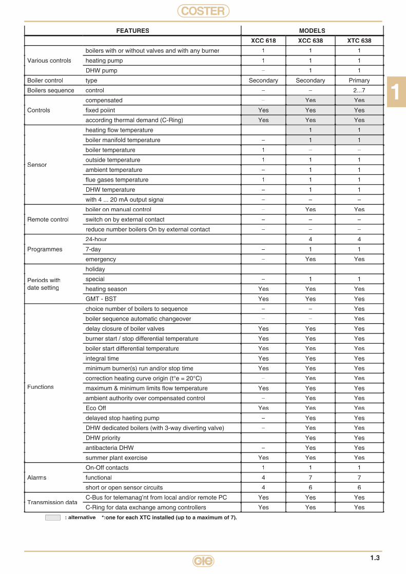
FEATURES MODELSXCC 618 XCC 638 XTC 638
Various controls
boilers with or without valves and with any burner 1 1 1
heating pump 1 1 1
DHW pump – 1 1
Boiler control type Secondary Secondary Primary
Boilers sequence control – – 2...7
Controls
compensated – Yes Yes
fi xed poiint Yes Yes Yes
according thermal demand (C-Ring) Yes Yes Yes
Sensor
heating fl ow temperature – 1 1
boiler manifold temperature – 1 1
boiler temperature 1 – –
outside temperature 1 1 1
ambient temperature – 1 1
fl ue gases temperature 1 1 1
DHW temperature – 1 1
with 4 ... 20 mA output signal – – –
Remote control
boiler on manual control – Yes Yes
switch on by external contact – – –
reduce number boilers On by external contact – – –
Programmes
24-hour – 4 4
7-day – 1 1
emergency – Yes Yes
Periods withdate setting
holiday – – –
special – 1 1
heating season Yes Yes Yes
GMT - BST Yes Yes Yes
Functions
choice number of boilers to sequence – – Yes
boiler sequence automatic changeover – – Yes
delay closure of boiler valves Yes Yes Yes
burner start / stop differential temperature Yes Yes Yes
boiler start differential temperature Yes Yes Yes
integral time Yes Yes Yes
minimum burner(s) run and/or stop time Yes Yes Yes
correction heating curve origin (t°e = 20°C) – Yes Yes
maximum & minimum limits fl ow temperature Yes Yes Yes
ambient authority over compensated control – Yes Yes
Eco Off Yes Yes Yes
delayed stop haeting pump – Yes Yes
DHW dedicated boilers (with 3-way diverting valve) – Yes Yes
DHW priority – Yes Yes
antibacteria DHW – Yes Yes
summer plant exercise Yes Yes Yes
Alarms
On-Off contacts 1 1 1
functional 4 7 7
short or open sensor circuits 4 6 6
Transmission dataC-Bus for telemanag’nt from local and/or remote PC Yes Yes Yes
C-Ring for data exchange among controllers Yes Yes Yes
: alternative *:one for each XTC installed (up to a maximum of 7).

COSTER
1.4
CONTROLLER FOR SEQUENCING TWO SINGLE- OR TWO-STAGE BOILERSWITH OR WITHOUT SHUT-OFF VALVESOPTIONAL TELEMANAGEMENT
XCC 602TELEMANAGEMENT C-Bus: Enabled using ACB 400 accessory..APPLICATIONDesigned for sequencing two boilers with one- or two-stage burners and shut-off valves.Control of primary manifold temperature with temperature measurement by means of a sensoron manifold or two sensors on the boilers.Communication with other controllers via serial C-Ring protocol..Essential sensors: 1 temperature sensor on manifold or 2 boiler sensorsOptional sensors: 1 outside sensor..FEATURES• Power supply: 230V~; Consumption: 5VA; DIN 105 X 115 modular enclosure; Protection: IP 40.• Digital programming by means of four keys and alphanumeric display.• Setting dates of heating season and automatic switching GMT – BST.• Seven 24hour periods and two 7day programs.• 25 holiday programs and one special period with dates.• Control of zone temperature:
– Fixed point;– Variable in relation to outside temperature;– Variable in relation to temperature requested by consumer zones.
• Sequencing: manual switching from display or timed automatic.• Automatic inversion of sequence in event of lockout of lead boiler.• Enabling of lag boiler according to mean temperature of zone.• Digital control of burners and of valves with adjustable delay closure.• Theoretical metering of burner operating hours.• Two inputs for measurement and alarms for fl ue gas temperature and for lockout burners.• Three digital alarm inputs.• Alarms for plant faults and for open or short sensor circuit.
C RINGSBUCOPTIONAL
SENSORS AND ACCESSORIESCode Description Application
rangeSensor Data
sheet
ACB 400SAE 001SIH 010STF 001
Plug-in for C-Bus communication.Outside temperature sensor.Immersion temperature sensor.Flue gases temperature sensor.
–– 40 ... 40 °C
0 ... 99 °C0 ... 500 °C
–NTC 1 kΩNTC 10 kΩ
Pt 1 kΩ
T 433N 120N 140N 710
Code Description Datasheet
XCC 602 Controller for sequencing two boilers with N.C. relay lag boiler. A 312
1
COSTER
1.5
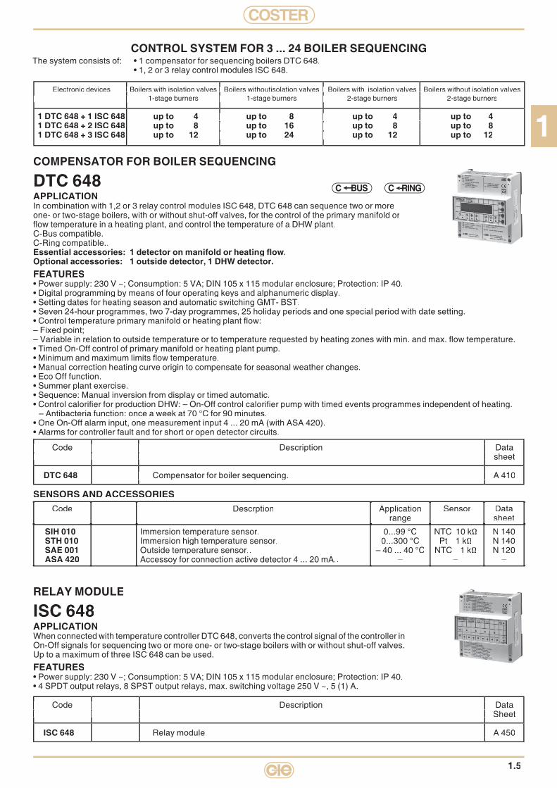
COMPENSATOR FOR BOILER SEQUENCING
DTC 648APPLICATIONIn combination with 1,2 or 3 relay control modules ISC 648, DTC 648 can sequence two or moreone- or two-stage boilers, with or without shut-off valves, for the control of the primary manifold orfl ow temperature in a heating plant, and control the temperature of a DHW plant.C-Bus compatible.C-Ring compatible..Essential accessories: 1 detector on manifold or heating fl ow.Optional accessories: 1 outside detector, 1 DHW detector.FEATURES• Power supply: 230 V ~; Consumption: 5 VA; DIN 105 x 115 modular enclosure; Protection: IP 40.• Digital programming by means of four operating keys and alphanumeric display.• Setting dates for heating season and automatic switching GMT- BST.• Seven 24-hour programmes, two 7-day programmes, 25 holiday periods and one special period with date setting.• Control temperature primary manifold or heating plant fl ow:– Fixed point;– Variable in relation to outside temperature or to temperature requested by heating zones with min. and max. fl ow temperature.• Timed On-Off control of primary manifold or heating plant pump.• Minimum and maximum limits fl ow temperature.• Manual correction heating curve origin to compensate for seasonal weather changes.• Eco Off function.• Summer plant exercise.• Sequence: Manual inversion from display or timed automatic.• Control calorifi er for production DHW: – On-Off control calorifi er pump with timed events programmes independent of heating.
– Antibacteria function: once a week at 70 °C for 90 minutes.• One On-Off alarm input, one measurement input 4 ... 20 mA (with ASA 420).• Alarms for controller fault and for short or open detector circuits.
CONTROL SYSTEM FOR 3 ... 24 BOILER SEQUENCING
Electronic devices Boilers with isolation valves Boilers withoutisolation valves Boilers with isolation valves Boilers without isolation valves 1-stage burners 1-stage burners 2-stage burners 2-stage burners 1-stage burners 1-stage burners 2-stage burners 2-stage burners
1 DTC 648 + 1 ISC 648 up to 4 up to 8 up to 4 up to 41 DTC 648 + 2 ISC 648 up to 8 up to 16 up to 8 up to 81 DTC 648 + 3 ISC 648 up to 12 up to 24 up to 12 up to 12
Electronic devices Boilers with isolation valves Boilers withoutisolation valves Boilers with isolation valves Boilers without isolation valves 1-stage burners 1-stage burners 2-stage burners 2-stage burners
Electronic devices Boilers with isolation valves Boilers withoutisolation valves Boilers with isolation valves Boilers without isolation valves 1-stage burners 1-stage burners 2-stage burners 2-stage burners
up to 4 up to 8 up to 4 up to 4up to 8 up to 16 up to 8 up to 8up to 12 up to 24 up to 12 up to 12
The system consists of: • 1 compensator for sequencing boilers DTC 648. • 1, 2 or 3 relay control modules ISC 648.
Code Description Data sheet
DTC 648 Compensator for boiler sequencing. A 410
Code Description Data sheet Code Description Data sheet
Compensator for boiler sequencing. A 410
Code Description Data sheet
Compensator for boiler sequencing. A 410
Code Description Data sheet
RELAY MODULE
ISC 648APPLICATIONWhen connected with temperature controller DTC 648, converts the control signal of the controller in On-Off signals for sequencing two or more one- or two-stage boilers with or without shut-off valves. Up to a maximum of three ISC 648 can be used.
FEATURES• Power supply: 230 V ~; Consumption: 5 VA; DIN 105 x 115 modular enclosure; Protection: IP 40.• 4 SPDT output relays, 8 SPST output relays, max. switching voltage 250 V ~, 5 (1) A.
Code Description Data Sheet
ISC 648 Relay module A 450
Code Description Data Sheet Code Description Data Sheet
Relay module A 450
Code Description Data Sheet
Relay module A 450
Code Description Data Sheet
BUSC C RING
SENSORS AND ACCESSORIESCode Descrption Application
rangeSensor Data
sheet
SIH 010STH 010SAE 001ASA 420
Immersion temperature sensor.Immersion high temperature sensor.Outside temperature sensor..Accessoy for connection active detector 4 ... 20 mA..
0...99 °C0...300 °C
– 40 ... 40 °C–
NTC 10 kΩPt 1 kΩ
NTC 1 kΩ–
N 140N 140N 120
–
COSTER
1.6
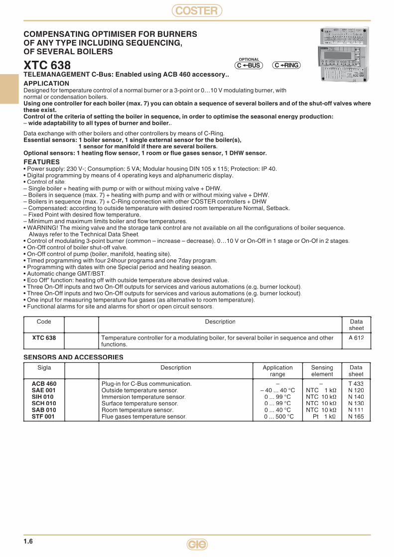
COMPENSATING OPTIMISER FOR BURNERSOF ANY TYPE INCLUDING SEQUENCING,OF SEVERAL BOILERS
XTC 638TELEMANAGEMENT C-Bus: Enabled using ACB 460 accessory..APPLICATIONDesigned for temperature control of a normal burner or a 3-point or 0…10 V modulating burner, with normal or condensation boilers.Using one controller for each boiler (max. 7) you can obtain a sequence of several boilers and of the shut-off valves where these exist.Control of the criteria of setting the boiler in sequence, in order to optimise the seasonal energy production: – wide adaptability to all types of burner and boiler..
Data exchange with other boilers and other controllers by means of C-Ring.Essential sensors: 1 boiler sensor, 1 single external sensor for the boiler(s),
1 sensor for manifold if there are several boilers.Optional sensors: 1 heating fl ow sensor, 1 room or fl ue gases sensor, 1 DHW sensor.FEATURES• Power supply: 230 V-; Consumption: 5 VA; Modular housing DIN 105 x 115; Protection: IP 40.• Digital programming by means of 4 operating keys and alphanumeric display.• Control of site:– Single boiler + heating with pump or with or without mixing valve + DHW.– Boilers in sequence (max. 7) + heating with pump and with or without mixing valve + DHW.– Boilers in sequence (max. 7) + C-Ring connection with other COSTER controllers + DHW– Compensated: according to outside temperature with desired room temperature Normal, Setback.– Fixed Point with desired fl ow temperature.– Minimum and maximum limits boiler and fl ow temperatures.• WARNING! The mixing valve and the storage tank control are not available on all the confi gurations of boiler sequence.
Always refer to the Technical Data Sheet.• Control of modulating 3-point burner (common – increase – decrease). 0…10 V or On-Off in 1 stage or On-Of in 2 stages.• On-Off control of boiler shut-off valve.• On-Off control of pump (boiler, manifold, heating site).• Timed programming with four 24hour programs and one 7day program.• Programming with dates with one Special period and heating season.• Automatic change GMT/BST.• Eco Off” function: heating off with outside temperature above desired value.• Three On-Off inputs and two On-Off outputs for services and various automations (e.g. burner lockout).• Three On-Off inputs and two On-Off outputs for services and various automations (e.g. burner lockout).• One input for measuring temperature fl ue gases (as alternative to room temperature).• Functional alarms for site and alarms for short or open circuit sensors.
C RINGSBUCOPTIONAL
Code Description Datasheet
XTC 638 Temperature controller for a modulating boiler, for several boiler in sequence and otherfunctions.
A 612
SENSORS AND ACCESSORIESSigla Description Application
rangeSensingelement
Datasheet
ACB 460SAE 001SIH 010SCH 010SAB 010STF 001
Plug-in for C-Bus communication.Outside temperature sensor.Immersion temperature sensor.Surface temperature sensor.Room temperature sensor.Flue gases temperature sensor.
–– 40 ... 40 °C
0 ... 99 °C0 ... 99 °C0 ... 40 °C0 ... 500 °C
–NTC 1 kΩNTC 10 kΩNTC 10 kΩNTC 10 kΩ
Pt 1 kΩ
T 433N 120N 140N 130N 111N 165

1
COSTER
1.7
COMPENSATING OPTIMISER FOR 1, 2-STAGEMODULATING BURNERS WITH 0…10 V– INPUT
XCC 638TELEMANAGEMENT C-Bus: Enabled by ACB 400 accessory.APPLICATIONDesigned for the compensated control of winter heating in centralised sites, with power supply directly from the boiler (without mixing valve), whether condensation or not.The burner with 1, 2 stages or modulating can be controlled by switches or by means of the 0…10V input...By equipping all the boilers on site with XCC 638, with a single boiler provided with XTC 638, you can set up asophisticated sequence among the various 1, 2-stage or MODULATING BURNERS and thereby achieve the ma-ximum SEASONAL OUTPUT.The whole system has been especially designed also for CONDENSATION BOILERS.
Data exchange with other boilers and other controllers by means of C-Ring.Essential sensors: 1 boiler sensor, 1 outside sensor.Optional sensors: 1 anticondensing sensor, 1 room or fl ue gases sensor, 1 storage tank sensor.FEATURES• Power supply: 230 V~; Consumption: 5 VA; Modular enclosure DIN 105 x 115; Protection: IP 40.• Digital programming by means of 4 operating keys and alphanumeric display.• Control of boiler temperature at fi xed point or variable in relation to outside temperature or to the demand
of the various users (if the controllers are COSTER).• Control of 1, 2-stage or modulating burner.• Option of sequence under control of XTC 638.• Compensated control of boiler temperature– all the optimum starts and stops of heating and of the site circulation pump– complete range of choices for room temperature,– 24hour and 7day clock (four 24hour programs, one 7day program)
• Control of temperature of DHW storage tank (one for each site)– own independent clock; 24hour, 7day (four 24hour programs, one 7day program).– priority and antibacterial functions
• Automatic switching GMT/BST.• Periodic operation of summer plant exercise of valves and pumps.• Metering of degree-days, of burner operating hours and or number of starts.• Alarms for short and open sensor circuits and for abnormal operation of site and devices.• C-Ring connection for local transmission of data to other COSTER controllers.• Optional C-Bus connection for transmitting data to local PCs or remote Telemanagement PC..
XCC 638 is already provided with 0…10 V output adaptable to any generator provided with this input.
C RINGSBUCOPTIONAL
SENSORS AND ACCESSORIESCode Description Application
rangeSensingelement
Datasheet
ACB 400SAE 001SIH 010SCH 010SAB 010STF 001
Plug-in for C-Bus comunicationOutside temperature sensor.Immersion temperature sensor.Surface temperature sensor.Room temperature sensor.Flue gases temperature sensor.
–– 40 ... 40 °C
0 ... 99 °C0 ... 99 °C0 ... 40 °C
0 ... 500 °C
–NTC 1 kΩNTC 10 kΩNTC 10 kΩNTC 10 kΩ
Pt 1 kΩ
T 433N 120N 140N 130N 111N 165
Code Description Datasheet
XCC 638 Optimising compensator for modulating burners. A 620

COSTER
1.8
C RINGSBUCOPTIONAL
Code Description Datasheet
XCC 618 Controller for modulating burners, slaves of XTC 638 A 621
SENSORS AND ACCESSORIESCode Description Application
rangeSensor Data
sheet
ACB 400SAE 001SIH 010SCH 010STF 001
Plug-in for C-Bus communication.Outside temperature detector.Immersion temperature sensor.Surface temperature sensor.Flue gases temperature sensor.
–– 40 ... 40 °C
0 ... 99 °C0 ... 99 °C0 ... 500 °C
–NTC 1 kΩNTC 10 kΩNTC 10 kΩ
Pt 1 kΩ
T 433N 120N 140N 130N 165
COMPENSATING OPTIMISER FOR 1, 2-STAGEMODULATING BURNERS WITH 0…10 V– INPUT
XCC 618TELEMANAGEMENT C-Bus: Enabled by ACB 400 accessory.APPLICATIONDesigned for the total control of burner/boiler (condensation or not).The 1, 2-stage or modulating burner can be controlled by switches or via the 0…10 V input.By equipping all the boilers present on site with XCC 618, and a single boiler with XTC 638,you can achieve a sophisticated sequence with 1, 2-stage or MODULATING BURNERS and so obtain the maximum SEASONAL OUTPUT. The whole system is especially suitable also for CONDENSATION BOILERS.Data communication with other boilers and other controllers via C-Ring connection..Essential sensors: 1 boiler sensor..Optional sensor: 1 anticondensing sensor, 1 fl ue gases sensor, 1 outside sensor...FEATURES• Power supply: 230 V~: Consumption: 5 VA; Modular housing DIN 105 x 115; Protection: IP 40• Digital programming by means of 4 keys and alphanumeric display.• Control of boiler temperature at set point or according to the request of the various users via C-Ring
(if the controllers are COSTER) or by a 0…10 V– signal.• Control of a 1- or 2-stage or modulating burner.• Option of sequence under control of XTC 638.• Automatic change GMT/BST• Periodic operation of summer site exercise of valves and pumpse.• Metering of degree-days, of burner operating hours and of number of starts.• Alarms for short or open circuits to sensors and for functional faults site and devices.• C-Ring connection for local exchange of data with other COSTER controllers.• Option of C-Bus connection for exchange data with local PC or remote Telemanagement PC..XCC 618 is provided with a 0…10 V output adaptable to any generator fi tted with this input.XCC 618 is also provided with a 0…10 V input for control AS POWER or AS TEMPERATURE.

2
COSTER
2.1
Description Code Communication Page
CONDENSATED CONTRLLERCOMPENSATING CONTROLLER WITH AUXILIARY OUTPUT RTE 643 2.4ANALOGUE COMPENSATED CONTROLLER FOR CONTROLOF MIXINGVALVE OR BURNERCOMPENSATED CONTROL OF 1 CENTRAL HEATING PLANT
RTE 98. 2.5
DIGITAL WEATHER WITH OPTIMUM START FUNCTION. RTE 955 2.5
OPTIMISING CONPENSATOROPTIMISING COMPENSATOR WITH AUXILIARY CONTROLOPTIONAL TELEMANAGEMENT OPTIMISING COMPENSATION ONE CENTRAL PLANT ROOMCONTROL OF ONE DHW STORAGE TANK.
XTE 600OPTIONAL
BUSC C RING 2.6
DUAL OPTIMISING COMPENSATOR OPTIONAL TELEMANAGEMENT OPTIMISING COMPENSATION OF TWO CENTRALISED PLANTS.. XTE 602
OPTIONAL
BUSC C RING 2.7
OPTIMISING COMPENSATOR CENTRALISED PLANT ROOMOPTIONAL TELEMANAGEMENTE OPTIMISATION OF CENTRALISED PLANT ROOM COMPRISING:1 BOILER - 1 HEATING ZONE – 1 AUXILIARY (e.g. DHW STORAGE).
XTE 611OPTIONAL
BUSC C RING 2.8
COMPENSATING OPTIMISER FOR TEMPERATURE & FLOW SUITABLE FOR COMPENSATED CONTROL OF ONE CENTRAL HEATING SITE.OPTIMISES THE USE OF CONDENSATION BOILERS.
XTP 600OPTIONAL
BUSC C RING 2.9
COMPENSASTING OPTIMISER FOR BURNERS OF ANY TYPEINCLUDING SEQUENCING, OF SEVERAL BOILERS XTC 638
OPTIONAL
BUSC C RING 2.10
OCOMPENSATING OPTIMISER FOR 1, 2-STAGE MODULATINGBURNERS WITH 0…10 V– INPUT XCC 638
OPTIONAL
BUSC C RING 2.11
OPTIMISING COMPENSATOR WITH SEASON SWITCHINGOPTIONAL TELEMANAGEMENTEDESIGN FOR COMPENSATED OR FIXED POINT CONTROL, WINTER AND SUMMER, OF FLOW WATER TEMPERATURE IN A FAN COIL OR UNDERFLOOR PANELS INSTALLATION
XCS 633PREDISPOSTO
BUSC C RING 2.12
“MULTICOSTER” MULTIPLE OPTIMISING COMPENSATED SYSTEMTHE SYSTEM COMPRISES 1 “MASTER” (e.g. XCC 602 or XTE 611) & 1 OR MORE “SLAVES” CONNECTED IN C-RING
OPTIMISING COMPENSATOR “SLAVE” OPTIONAL TELEMANAGEMENTOPTIMISING COMPENSATION OF 1 CENTRALISED PLANT ROOMCONTROL OF 1 DHW STORAGE TANK..
XSE 600OPTIONAL
BUSC C RING 2.13
DUAL OPTIMISING COMPENSATOR “SLAVE”OPTIONAL TELEMANAGEMENTOPTIMISING COMPENSATION OF TWO CENTRALISED PLANT ROOMS.
XSE 602OPTIONAL
BUSC C RING 2.13
“DISTRICT HEATING”INCLUSES ALL THE COMPONENTS NECESSARY FOR A DISTRICT HEATING PLANT
CONTROLLER FOR DISTRICT HEATING SUBSTATIONSREGOLAZIONE A PUNTO FISSO DELLA TEMPERATURA SECONDARIA DELLE SOTTOSTAZIONI DI TELERISCALDAMENTO COMPOSTA DA: 1 SCAMBIATORE CON VALVOLA MISCELATRICE SUL PRIMARIO.
DTT 318 BUSC 2.15
CONTROLLER FOR DISTRICT HEATING SUBSTATIONS WITH ONE HEAT EXCHANGER CONTROL OF A DISTRICT HEATING SUBSTATION COMPRISING11 HEAT EXCHANGER WITH VALVE & SECONDARY CIRCUIT PUMP..
XTT 618OPTIONAL
BUSC C RING 2.15
COMPENSATING CONTROLLER FOR DISTRICT HEATINGSUB-STATIONS WITH TWO HEAT EXCHANGERS.
XTT 608OPTIONAL
BUSC C RING 2.16
BUSC = telemanagement OPTIONAL
BUSC = optional telemanagement C RING = data exchange between controllers CODE= news
COSTER
2.2
Description code Communication Page
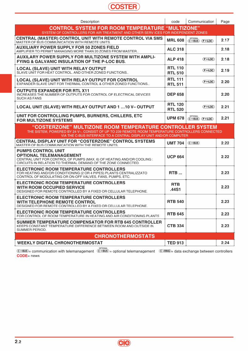
CONTROL SYSTEM FOR ROOM TEMPERATURE “MULTIZONE”SYSTEM OF CONTROLLERS FOR AIR TREATMENT AND OTHER SERV ICES FOR INDEPENDENT ZONES
CENTRAL (MASTER) CONTROL UNIT WITH REMOTE CONTROL VIA SMS MASTER OF BUS COMMUNICATION WITH REMOTE UNITS.. MRL 608
OPTIONAL
BUSC LOCP 2.17
AUXILIARY POWER SUPPLY FOR 50 ZONES FIELD AMPLIFIER TO PERMIT MANAGING MORE THAN 20 ZONES FROM MASTER.. ALC 318 2.18
AUXILARY POWER SUPPLY FOR MULTIZONE SYSTEM WITH AMPLI-FYING & GALVANIC INSULATION OF THE P-LOC BUS. ALP 418 LOCP 2.18
LOCAL (SLAVE) UNIT WITH RELAY OUTPUT SLAVE UNIT FOR HEAT CONTROL. AND OTHER ZONED FUNCTIONS..
RTL 110RTL 510
LOCP 2.19
LOCAL (SLAVE) UNIT WITH RELAY OUTPUT FOR CONTROL EXPANDER SLAVE UNIT FOR THERMAL CONTROL & OTHER ZONED FUNCTIONS..
RTL 111RTL 511
LOCP 2.20
OUTPUTS EXPANDER FOR RTL X11INCREASES THE NUMBER OF OUTPUTS FOR CONTROL OF ELECTRICAL DEVICESSUCH AS FANS
DEP 658 2.20
LOCAL UNIT (SLAVE) WITH RELAY OUTPUT AND 1 …10 V– OUTPUT RTL 120RTL 520
LOCP 2.21
UNIT FOR CONTROLLING PUMPS, BURNERS, CHILLERS, ETCFOR MULTIZONE SYSTEMS UPM 678
OPTIONAL
BUSC LOCP 2.21
“COSTERZONE” MULTIZONE ROOM TEMPERATURE CONTROLLER SYSTEMTHE SISTEM, POWERED BY 24 V~, CONSIST OF UP TO 239 REMOTE ROOM TEMPERATURE CONTROLLERS CONNECTED
VIA THE C-BUS INTERFACE TO A CENTRAL DISPLAY UNIT AND/OR COMPUTER
CENTRAL DISPLAY UNIT FOR “COSTERZONE” CONTROL SYSTEMSMASTER OF BUS COMMUNICATION WITH THE REMOTE UNITS. UMT 704 BUSC 2.22
PUMPS CONTROL UNITOPTIONAL TELEMANAGEMENTCENTRAL UNIT FOR CONTROL OF PUMPS (MAX. 6) OF HEATING AND/OR COOLING :CIRCUITS IN RELATION TO THERMAL DEMAND OF THE ZONE CONNECTED.
UCP 664 2.22
ELECTRONIC ROOM TEMPERATURE CONTROLLERSFOR HEATING AND/OR CONDITIONING (2 OR 4 PIPES) PLANTS CENTRALIZZATOCONTROL OF MODULATING OR ON-OFF VALVES, FANS, PUMPS, ETC.
RTB ... 2.23
ELECTRONIC ROOM TEMPERATURE CONTROLLERSWITH ROOM OCCUPIED SERVICEDESIGNED FOR REMOTE CONTROLLED BY A FIXED OR CELLULAR TELEPHONE.
RTB .44S1 2.23
ELECTRONIC ROOM TEMPERATURE CONTROLLERS WITH TELEPHONE REMOTE CONTROLDESIGNED FOR REMOTE CONTROLLED BY A FIXED OR CELLULAR TELEPHONE.
RTB 540 2.23
ELECTRONIC ROOM TEMPERATURE CONTROLLERS FOR CONTROL OF ROOM TEMPERATURE IN HEATING AND AIR CONDITIONING PLANTS RTB 645 2.23
SUMMER TEMPERATURE COMPENSATOR FOR RTB 645 CONTROLLERKEEPS CONSTANT TEMPERATURE DIFFERENCE BETWEEN ROOM AND OUTSIDE INSUMMER PERIOD.
CTB 334 2.23
CHRONOTHERMOSTATSWEEKLY DIGITAL CHRONOTHERMOSTAT TED 913 2.24
BUSC = communication with telemanagement OPTIONAL
BUSC = optional telemanagement C RING = data exchange between controllers CODE= news

2
COSTER
2.3
FEATURES MODELSRTE982
RTE 983
X.E 600
X.E 602
XTE 611
XTP 600
XCS 633
Elettronicanalogue Yes Yes – – – – –
digital – – Yes Yes Yes Yes Yes
Control
modulating valve 1 1 1 2 1 1 1
burner 1 1 – – 1 1 –
heating pump 1 1 2 2 1 1 1
DHW or auxiliary circuit pump – – – – 1 1 –
Heatingcontrol.
compensated Yes Yes Yes Yes Yes Yes Yes
fi xed point – – Yes Yes Yes Yes Yes
Flowcontrol
compensated Yes
fi xed point Yes
Coolingcontrol
compensated – – – – – – Yes
fi xed point – – – – – – Yes
Boilercontrol
fi xed point – – – – Yes Yes –
Compensation according to thermal demand (via C-Ring) – – – – Yes Yes –
Sensors
fl ow temperature 1 1 2 2 1 1 1
outside temperature 1 1 1 1 1 1 1
room temperature – – 2 2 1 1 1
boiler temperature – – – – 1 1 –
anticondensing boiler temperature – – 1 1 – – 1
room humidity (summer time dew point control) – – – – – – 1
DHW or auxiliary circuit temperature – – – – 1 1 –
Remote controls
setpoint adjuster 1 1 – – – – –
modifi cation of programme in use – – 1 2 1 1 1
season switching (by external contact) – – – – – – Yes
Programmes24-hour 1 – 7 7 7 7 3 + 3
7-day – 1 2 2 2 2 1 + 1
Periods with dates GMT-BST – – Yes Yes Yes Yes Yes
Functions
K heating curve setting Yes Yes – – – – –
design outside and fl ow temperature setting – – Yes Yes Yes Yes Yes
correction heating curve origin (t°e = 20 °C) Yes Yes Yes Yes Yes Yes Yes
max & min fl ow temperature limits – – Yes Yes Yes Yes Yes
ambient authority over compensated control – – Yes Yes Yes Yes Yes
Eco Off – – Yes Yes Yes Yes Yes
heating pump delay Off – – Yes Yes Yes Yes Yes
anticondensing boiler (heating Off) – – Yes Yes Yes Yes Yes
DHW priority – – – – Yes Yes –
antibacterial DHW – – – – Yes Yes –
boiler differential – – – – Yes Yes –
increase temp. boiler on heating and/or DHW demand. – – – – Yes Yes –
max & min boiler temperature limits – – – – Yes Yes –
Data transmissionC-Ring for data exchange among controllers – – Yes Yes Yes Yes Yes
C-Bus for telemanagement from local and/or remote PC – – Yes Yes Yes Yes Yes
: alternative

COSTER
2.4
COMPENSATING CONTROLLER WITH AUXILIARY OUTPUT
RTE 643APPLICATIONDesigned for compensated control of one heating zone and for On-Off control of a DHW calorifi er.C-Ring compatible.Essential accessories: 1 outside sensor, 1 heating fl ow sensor.Optional accessories: 1 room sensor, 1 sensor auxiliary plant, 1 anticondensing sensor, 1 remote control.FEATURES• Power supply: 230 V ~; Consumption: 5 VA; DIN 105 x 115 modular enclosure; Protection: IP 40.• Digital programming by means of four operating keys and alphanumeric display.• Automatic changeover GMT - BST.• Seven 24-hour programmes, two 7-day programmes.• Compensated control of heating zone:
- Modulating control of valve by three-wire reversible actuator or On-Off burner in two stages.- Control heating pump in relation to timed events and thermal demand.- Minimum and maximum limits fl ow temperature.- Manual correction of heating curve origin to compensate for seasonal weather changes.- Ambient authority.- Eco Off.- Control boiler anticondensing temperature (closure heating valve).- Remote control for modifying timed programme in use (as alternative to input fl ue gases temperature and On-Off alarm).
• On-Off control temperature of auxiliary zone (eg : production DHW) or timed On-Off control:- On-Off control with programme timed events independent of heating.- DHW priority function (closure heating valve so as to give precedence to DHW production).- Antibacteria function : once a week at 70 °C for 90 minutes (for production DHW in storage tank).
Code Description Data Code Description Data sheet sheet
RTE 643 Compensating controller and DHW production controller B 222
Code Description Data sheet
Compensating controller and DHW production controller B 222
Code Description Data sheet
Compensating controller and DHW production controller B 222
Code Description Data sheet
C RING
SENSORS AND ACCESSORIESCode Description Application
rangeSensingelement
Datasheet
SAE 001SIH 010SCH 010SAB 010CDB 300
Outside temperature sensor.Immersion temperature sensor.Surface temperature sensor.Room temperature sensor.Remote control to modify program in use.
– 40 ... 40 °C0 ... 99 °C0 ... 99 °C0 ... 40 °C
–
NTC 1 kΩNTC 10 kΩNTC 10 kΩNTC 10 kΩ
–
N 120N 140N 130N 111N 710

2
COSTER
2.5
ANALOGUE COMPENSATOR FOR CONTROL OF VALVE OR BURNER
RTE 982 - 983APPLICATIONFor compensated control of 1 central heating plant.Suitable for all climates and any type of heat emitters, including radiating panels, radiators, convectors and unit heaters. The device is designed to control mixing or switching valves driven by electric reversible actuators, or to control the boiler burner directly.Essential sensors: 1 outside sensor,1 plant fl ow sensor.Optional accessories: 1 remote control.FEATURES• Power supply: 230 V ~; Consumption: 4 VA; Case: DIN 144 x 144; Protection: IP 40.• Voltage-free output contacts: rating: 250 V ~, 5 (1) A.• PI control action with valve position memorisation.• Setting of heating curve by means of K factor calculated in relation to climatic zone.• Correction of heating curve to compensate for seasonal weather changes.• Possibility of adjusting value of room temperature by means of remote control.• Time switch for selecting “Normal” and “Setback” room temperature.• Auxiliary control (plant pump) in relation to programme times.
Code Description Data Code Description Data sheet sheet
RTE 982 Analogue compensator with 24-hour time switch. B 217RTE 983 Analogue compensator with 7-day time switch. B 217
Code Description Data sheet
Analogue compensator with 24-hour time switch. B 217 Analogue compensator with 7-day time switch. B 217
Code Description Data sheet
Analogue compensator with 24-hour time switch. B 217 Analogue compensator with 7-day time switch. B 217
Code Description Data sheet
Analogue compensator with 24-hour time switch. B 217 Analogue compensator with 7-day time switch. B 217
SENSORS AND ACCESSORIES
Code Description Application Sensing Data Code Description Application Sensing Data range element sheet range element sheet
SAE 001 Outside temperature sensor. –40 ... 40 °C NTC 1 kΩ N 120 SIH 010 SIH 010 Immersion temperature sensor. 0 ... 99 °C NTC 10 kΩ N 140 SCH 010 SCH 010 Surface temperature sensor. 0 ... 99 °C NTC 10 kΩ N 130 CDB 340 CDB 340 Temperature setpoint adjuster –5 ... +5 °C – –
Code Description Application Sensing Data range element sheet
Outside temperature sensor. Immersion temperature Surface temperature
Temperature setpoint adjuster –5 ... +5 °C – –
Code Description Application Sensing Data range element sheet
NTC 1 kΩ N 120r. 0 ... 99 °C NTC 10 kΩ N 140
r. 0 ... 99 °C NTC 10 kΩ N 130 Temperature setpoint adjuster –5 ... +5 °C – –
Code Description Application Sensing Data range element sheet
Temperature setpoint adjuster –5 ... +5 °C – –
Code Description Application Sensing Data range element sheet
NTC 1 kΩ N 120r. 0 ... 99 °C NTC 10 kΩ N 140
r. 0 ... 99 °C NTC 10 kΩ N 130 Temperature setpoint adjuster –5 ... +5 °C – –
Code Description Application Sensing Data range element sheet
r. 0 ... 99 °C NTC 10 kΩ N 140r. 0 ... 99 °C NTC 10 kΩ N 130
Temperature setpoint adjuster –5 ... +5 °C – –
DIGITAL WEATHER COMPENSATOR WITH OPTIMUMSTART FUNCTION
RTE 955APPLICATIONDor compensated control of 1 variable temperature (VT) heating circuit. Suitable for all typesof heat emitters, such as panel heaters, radiators or fan convectors. The device controls themixed water temperature in the heating circuit via proportional or on/off control. There are timedoutputs for a single stage boiler and heating pump (with a programmable delay off function)..Essential accessories: 1 outside sensor, 1 heating fl ow sensor,1 ambient space sensor and 1 boiler return temperature sensor.Optional accessories: 1 remote control.FEATURES• Power supply: 230 V ~; Consumption: 5 VA; Case: DIN 144 x 144; Protection: IP 40.• Voltage-free output contacts: rating: 250 V ~, 10 (2.5) A.• Setting of heating curve by means designed outside and fl ow temperatures.• Remote override for permanent frost protection or day temperature.• Fully adjustable Normal and Setback room temperatures.• 2 x auxillary control outputs (heating pump and boiler) in relation to program times.
Code Description Data Code Description Data sheet sheet
RTE 955 Digital optimising compensator with ECO OFF B 226
Code Description Data sheet
Digital optimising compensator with ECO OFF B 22
Code Description Data sheet
Digital optimising compensator with ECO OFF B 22
Code Description Data sheet
SENSORS AND ACCESSORIES
Code Description Application Sensing Data Code Description Application Sensing Data range element sheet range element sheet
SAE 001 Outside temperature sensor. –40 ... 40 °C NTC 1 kΩ N 120 SIH 010 SIH 010 Immersion temperature sensor. 0 ... 99 °C NTC 10 kΩ N 140 SCH 010 SCH 010 Surface temperature sensor. 0 ... 99 °C NTC 10 kΩ N 130 CDB 340 CDB 340 Temperature setpoint adjuster. –5 ... +5 °C – –
Code Description Application Sensing Data range element sheet
Outside temperature Immersion temperature Surface temperature Temperature setpoint adjuster. –5 ... +5 °C – –
Code Description Application Sensing Data range element sheet
r. –40 ... 40 °C NTC 1 kΩ N 120r. 0 ... 99 °C NTC 10 kΩ N 140
r. 0 ... 99 °C NTC 10 kΩ N 130 Temperature setpoint adjuster. –5 ... +5 °C – –
Code Description Application Sensing Data range element sheet Code Description Application Sensing Data range element sheet
r. –40 ... 40 °C NTC 1 kΩ N 120r. 0 ... 99 °C NTC 10 kΩ N 140
r. 0 ... 99 °C NTC 10 kΩ N 130 Temperature setpoint adjuster. –5 ... +5 °C – –
Code Description Application Sensing Data range element sheet
r. –40 ... 40 °C NTC 1 kΩ N 120r. 0 ... 99 °C NTC 10 kΩ N 140
r. 0 ... 99 °C NTC 10 kΩ N 130 Temperature setpoint adjuster. –5 ... +5 °C – –
C RING

COSTER
2.6
Code Description Data Code Description Data sheet sheet
XTE 600 Optimising compensator. B 241
Code Description Data sheet Code Description Data sheet Code Description Data sheet
C RINGSBUCOPTIONAL
OPTIMISING COMPENSATOROPTIONAL TELEMANAGEMENT
XTE 600TELEMANAGEMENT C-Bus: Enabled with ACB 468 accessory.APPLICATIONDesigned for compensated control of one centralized heating plant room and for On-Off controlof a calorifi er for DHW production,Exchange of data with other controllers by means of C-Ring serial connection.Essential sensors: 1 outside sensor, 1 heating fl ow sensor.Optional sensors: 1 room sensor, 1 DHW sensor, 1 fl ue gases sensor, one 4 ... 20 mA sensor, 1 remote control.FEATURES• Power supply: 230V~; Consumption: 5VA; DIN 105 x 115 modular enclosure; Protection: IP 40.• Digital programming by means of 4 keys and alphanumeric display.• Entering dates of heating season and automatic switching BST - GMT.• Seven 24hour programs, two 7day programs, 25 holiday periods and one special period with dates. • Compensated control of heating plant room:
– Modulating control of valve with 3-wire reversible actuator or On-Off burner in two stages.– Control heating pump according to times and demand for heat.– Optimisation switching on and off times.– Minimum and maximum limits fl ow temperature.– Manual correction heating curve origin (compensation intermediate seasons).– Automatic correction of heating curve in relation to room temperature (ambient authority).– Eco Off function: shutdown of plant when weather mild.– Control boiler anticondensing temperature (closure heating valve).– Summer plant exercise valve and pump.– Remote control for changing timed program in use (as alternative to input fl ue gases temperature and On-Off alarm).
• Control DHW production:– On-Off control DHW loading pump with timed programs independent of heating.– “Priority DHW” function (closure heating valve).– “Antibacteria” function: once a week 70° for 90 minutes.
• Three On-Off alarm inputs.• One 4 ... 20 mA measurement input.• One confi gurable input: remote control or temperature fl ue gases Pt 1 kΩ and On-Off alarm.• Alarms for plant faults and for open or short sensor circuit.• Metering degree-days.
SENSORS AND ACCESSORIESCode Description Application
rangeSensingelement
Datasheet
ACB 468SAE 001SIH 010SCH 010SAB 010STF 001CDB 300
Plug-in for communication via C-Bus.Outside temperature sensor.Immersion temperature sensor.Surface temperature sensor.Room temperature sensor.Flue gases temperature sensor..Remote control to modify program in use.
–– 40 ... 40 °C
0 ... 99 °C0 ... 99 °C0 ... 40 °C
0 ... 500 °C–
–NTC 1 kΩNTC 10 kΩNTC 10 kΩNTC 10 kΩ
Pt 1 kΩ–
T 433N 120N 140N 130N 111N 165N 710

2
COSTER
2.7
SENSORS AND ACCESSORIESCode Description Application
rangeSensingelement
Datasheet
ACB 468SAE 001SIH 010SCH 010SAB 010CDB 300
Plug-in for communication via C-Bus.Outside temperature sensor.Immersion temperature sensor.Surface temperature sensor.Room temperature sensor.Remote control to modify program in use.
–– 40 ... 40 °C
0 ... 99 °C0 ... 99 °C0 ... 40 °C
–
–NTC 1 kΩNTC 10 kΩNTC 10 kΩNTC 10 kΩ
–
T 433N 120N 140N 130N 111N 710
DUAL OPTIMISING COMPENSATOROPTIONAL TELEMANAGEMENT
XTE 602TELEMANAGEMENT C-Bus: Enabled with ACB 468 accessory.APPLICATIONDesigned for the compensating control of two central heating sites.Exchange of data with other controllers by means of C-Ring serial connection.Essential sensors: 1 outside sensor, 2 heating fl ow sensors. Optional sensors: 1 or 2 room sensors, 1 remote control.FEATURES• Power supply: 230V~; Consumption: 5VA; DIN 105 x 115 modular enclosure; Protection: IP 40.• Digital programming by means of 4 keys and alphanumeric display.• Entering dates of heating season and automatic switching GMT – BST.• Seven 24hour programs, two 7day programs, 25 holiday periods and one special period with dates.• Two compensated controls of plant rooms:
– Modulating control of valves with 3-wire reversible actuator.– Control heating pumps according to times and demand for heat.– Optimisation switching on and off times.– Minimum and maximum limits fl ow temperature.– Manual correction heating curve origin (compensation intermediate seasons).– Automatic correction of heating curve in relation to room temperature (ambient authority).– Eco Off function: shutdown of site when weather mild– Control anticondensing temperature boiler (closure heating valve).– Summer plant exercise valves and pumps.– One remote control for adjusting from a distance the timed program in use (one for control 1 or 2 or for both).
• Three On-Off alarm inputs.• Alarms for plant faults and for open or short sensor circuit.• Metering degree-days.
Code De scription Data Code De scription Data sheet sheet
XTE 602 Dual optimising compensator. B 242
Code De scription Data sheet
Dual optimising compensator. B 242
Code De scription Data sheet
Dual optimising compensator. B 242
Code De scription Data sheet
C RINGSBUCOPTIONAL

COSTER
2.8
OPTIMISING COMPENSATOR FOR HEATING PLANT ROOMOPTIONAL TELEMANAGEMENT
XTE 611TELEMANAGEMENT C-Bus: Enabled with ACB 468 accessory.APPLICATIONDesigned for control of small and medium-size heating plant rooms comprising:• 1 single- or two-stage boiler, or double furnace (two single-stage burners).• 1 centralised heating plant room.• 1 calorifi er for DHW.Communications with other controllers via C-Ring serial connection. Essential sensors: 1 outside sensor, 1 heating fl ow sensor, 1 boiler sensor. Optional accessories: 1 room sensor, 1 DHW sensor, 1 or 2 fl ue gas sensors, 1 remote control.FEATURES• Power supply: 230V~; Consumption: 5VA; DIN 105 x 115 modular enclosure; Protection: IP 40.• Digital programming by means of 4 keys and alphanumeric display.• Setting dates for heating season and automatic switching between GMT – BST.• Seven 24hour programs, two 7day programs, 25 holiday periods and one special period with dates.• Fixed point or variable control of boiler according to max. temperature requested by heating, etc zones:
– On-Off control of one single- or two-stage burner or 2 single-stage burners.– Control boiler anticondensing (closure of heating valve).– Theoretical metering of operating hours of the two burner stages.
• Compensated control of centralised heating plant room:– Modulating control of valve by 3-wire reversible actuator.– Control of heating pump in relation to times and demand for heat.– Optimisation of start and stop times.– Minimum and maximum limits of fl ow temperature.– Manual correction heating curve point of origin (compensation for intermediate seasons).– Automatic adjustment of heating curve in relation to room temperature (ambient authority).– Eco Off function: switching off heating zones when weather mild.– Remote control for changing program in use (as alternative to temperature fl ue gases & On-Off alarm).
• Control production of DHW:– On-Off control of calorifi er pump by timed programs independent of heating.– “DHW priority” (closure heating valve).– Antibacteria function: once a week at 70°C for 90 minutes.
• Summer exercise function for valves and pumps.• Three inputs On-Off alarms.• One confi gurable input: remote control or fl ue gases temperature Pt 1kΩ and On-Off alarm.• One confi gurable input: measurement 4 ... 20mA or fl ue gases temperature Pt 1 kΩ and On-Off alarm. • Alarms for plant malfunctioning and for open or short sensor circuit.• Degree-days metering.
Code Description Data Code Description Data sheet sheet
XTE 611 Optimising compensator with N.C. relay for control boiler. B 252
Code Description Data sheet
Optimising compensator with N.C. relay for control boiler. B 2
Code Description Data sheet
Optimising compensator with N.C. relay for control boiler. B 2
Code Description Data sheet
C RINGSBUCOPTIONAL
SENSORS AND ACCESSORIESCode Description Application
rangeSensingelement
Datasheet
ACB 468SAE 001SIH 010SCH 010SAB 010STF 001CDB 300
Plug-in for communication via C-Bus.Outside temperature sensor.Immersion temperature sensor.Surface temperature sensor.Room temperature sensor.Flue gases temperature sensor..Remote control to modify program in use.
–– 40 ... 40 °C
0 ... 99 °C0 ... 99 °C0 ... 40 °C
0 ... 500 °C–
–NTC 1 kΩNTC 10 kΩNTC 10 kΩNTC 10 kΩ
Pt 1 kΩ–
T 433N 120N 140N 130N 111N 165N 710
2
COSTER
2.9
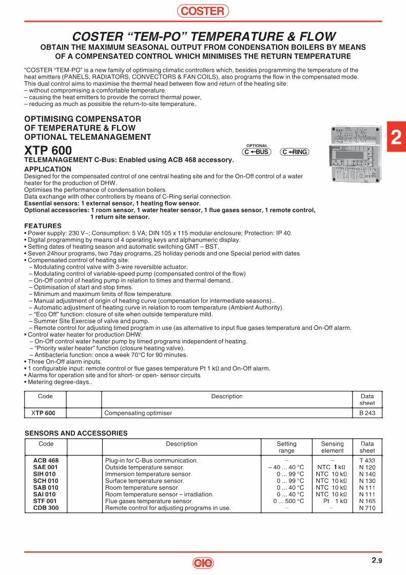
COSTER “TEM-PO” TEMPERATURE & FLOWOBTAIN THE MAXIMUM SEASONAL OUTPUT FROM CONDENSATION BOILERS BY MEANS
OF A COMPENSATED CONTROL WHICH MINIMISES THE RETURN TEMPERATURE
“COSTER “TEM-PO” is a new family of optimising climatic controllers which, besides programming the temperature of theheat emitters (PANELS, RADIATORS, CONVECTORS & FAN COILS), also programs the fl ow in the compensated mode.This dual control aims to maximise the thermal head between fl ow and return of the heating site:– without compromising a comfortable temperature,– causing the heat emitters to provide the correct thermal power,– reducing as much as possible the return-to-site temperature..
OPTIMISING COMPENSATOROF TEMPERATURE & FLOWOPTIONAL TELEMANAGEMENT
XTP 600TELEMANAGEMENT C-Bus: Enabled using ACB 468 accessory.APPLICATIONDesigned for the compensated control of one central heating site and for the On-Off control of a waterheater for the production of DHW.Optimises the performance of condensation boilers.Data exchange with other controllers by means of C-Ring serial connection.Essential sensors: 1 external sensor, 1 heating fl ow sensor.Optional accessories: 1 room sensor, 1 water heater sensor, 1 fl ue gases sensor, 1 remote control,
1 return site sensor.FEATURES• Power supply: 230 V~; Consumption: 5 VA; DIN 105 x 115 modular enclosure; Protection: IP 40.• Digital programming by means of 4 operating keys and alphanumeric display.• Setting dates of heating season and automatic switching GMT – BST.• Seven 24hour programs, two 7day programs, 25 holiday periods and one Special period with dates.• Compensated control of heating site:
– Modulating control valve with 3-wire reversible actuator.– Modulating control of variable-speed pump (compensated control of the fl ow)– On-Off control of heating pump in relation to times and thermal demand..– Optimisation of start and stop times.– Minimum and maximum limits of fl ow temperature.– Manual adjustment of origin of heating curve (compensation for intermediate seasons)..– Automatic adjustment of heating curve in relation to room temperature (Ambient Authority).– “Eco Off” function: closure of site when outside temperature mild.– Summer Site Exercise of valve and pump.– Remote control for adjusting timed program in use (as alternative to input fl ue gases temperature and On-Off alarm.
• Control water heater for production DHW:– On-Off control water heater pump by timed programs independent of heating.– “Priority water heater” function (closure heating valve).– Antibacteria function: once a week 70°C for 90 minutes.
• Three On-Off alarm inputs.• 1 confi gurable input: remote control or fl ue gases temperature Pt 1 kΩ and On-Off alarm.• Alarms for operation site and for short- or open- sensor circuits.• Metering degree-days..
C RINGSBUCOPTIONAL
SENSORS AND ACCESSORIESCode Description Setting
rangeSensingelement
Datasheet
ACB 468SAE 001SIH 010SCH 010SAB 010SAI 010STF 001CDB 300
Plug-in for C-Bus communication.Outside temperature sensor.Immersion temperature sensor.Surface temperature sensor.Room temperature sensor.Room temperature sensor – irradiation.Flue gases temperature sensor.Remote control for adjusting programs in use.
–– 40 ... 40 °C
0 ... 99 °C0 ... 99 °C0 ... 40 °C0 ... 40 °C
0 ... 500 °C–
–NTC 1 kΩNTC 10 kΩNTC 10 kΩNTC 10 kΩNTC 10 kΩ
Pt 1 kΩ–
T 433N 120N 140N 130N 111N 111N 165N 710
Code Description Datasheet
XTP 600 Compensating optimiser B 243

COSTER
2.10
COMPENSASTING OPTIMISER FOR BURNERSOF ANY TYPE INCLUDING SEQUENCING,OF SEVERAL BOILERS
XTC 638TELEMANAGEMENT C-Bus: Enabled using ACB 460 accessory..APPLICATIONDesigned for temperature control of a normal burner or a 3-point or 0…10 V modulating burner, with normal or condensation boilers.Using one controller for each boiler (max. 7) you can obtain a sequence of several boilers and of the shut-off valves where these exist.Control of the criteria of setting the boiler in sequence, in order to optimise the seasonal energy production: – wide adaptability to all types of burner and boiler..
Data exchange with other boilers and other controllers by means of C-Ring.Essential sensors: 1 boiler sensor, 1 single external sensor for the boiler(s),
1 sensor for manifold if there are several boilers.Optional sensors: 1 heating fl ow sensor, 1 room or fl ue gases sensor, 1 DHW sensor.FEATURES• Power supply: 230 V-; Consumption: 5 VA; Modular housing DIN 105 x 115; Protection: IP 40.• Digital programming by means of 4 operating keys and alphanumeric display.• Control of site:– Single boiler + heating with pump or with or without mixing valve + DHW.– Boilers in sequence (max. 7) + heating with pump and with or without mixing valve + DHW.– Boilers in sequence (max. 7) + C-Ring connection with other COSTER controllers + DHW– Compensated: according to outside temperature with desired room temperature Normal, Setback.– Fixed Point with desired fl ow temperature.– Minimum and maximum limits boiler and fl ow temperatures.• WARNING! The mixing valve and the storage tank control are not available on all the confi gurations of boiler sequence.
Always refer to the Technical Data Sheet.• Control of modulating 3-point burner (common – increase – decrease). 0…10 V or On-Off in 1 stage or On-Of in 2 stages.• On-Off control of boiler shut-off valve.• On-Off control of pump (boiler, manifold, heating site).• Timed programming with four 24hour programs and one 7day program.• Programming with dates with one Special period and heating season.• Automatic change GMT/BST.• Eco Off” function: heating off with outside temperature above desired value.• Three On-Off inputs and two On-Off outputs for services and various automations (e.g. burner lockout).• Three On-Off inputs and two On-Off outputs for services and various automations (e.g. burner lockout).• One input for measuring temperature fl ue gases (as alternative to room temperature).• Functional alarms for site and alarms for short or open circuit sensors.
C RINGSBUCOPTIONAL
Code Description Datasheet
XTC 638 Temperature controller for a modulating boiler, for several boiler in sequence and otherfunctions.
A 612
SENSORS AND ACCESSORIESSigla Description Application
rangeSensingelement
Datasheet
ACB 460SAE 001SIH 010SCH 010SAB 010STF 001
Plug-in for C-Bus communication.Outside temperature sensor.Immersion temperature sensor.Surface temperature sensor.Room temperature sensor.Flue gases temperature sensor.
–– 40 ... 40 °C
0 ... 99 °C0 ... 99 °C0 ... 40 °C0 ... 500 °C
–NTC 1 kΩNTC 10 kΩNTC 10 kΩNTC 10 kΩ
Pt 1 kΩ
T 433N 120N 140N 130N 111N 165
2
COSTER
2.11
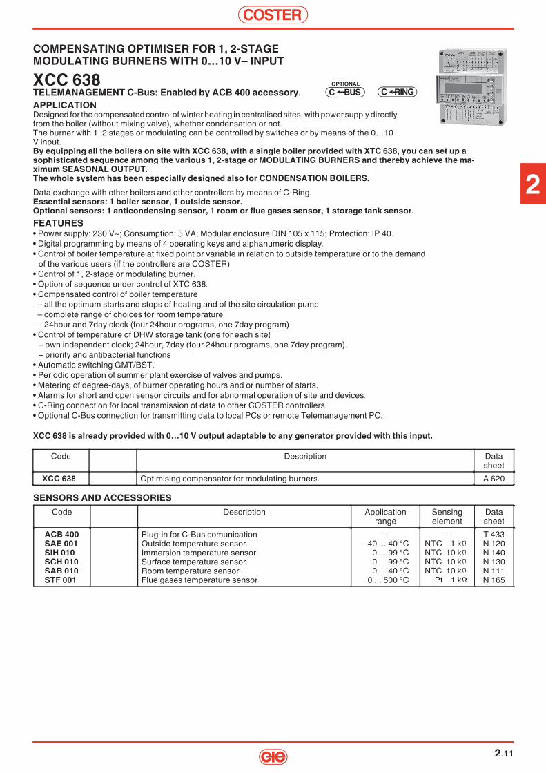
COMPENSATING OPTIMISER FOR 1, 2-STAGEMODULATING BURNERS WITH 0…10 V– INPUT
XCC 638TELEMANAGEMENT C-Bus: Enabled by ACB 400 accessory.APPLICATIONDesigned for the compensated control of winter heating in centralised sites, with power supply directly from the boiler (without mixing valve), whether condensation or not.The burner with 1, 2 stages or modulating can be controlled by switches or by means of the 0…10V input.By equipping all the boilers on site with XCC 638, with a single boiler provided with XTC 638, you can set up asophisticated sequence among the various 1, 2-stage or MODULATING BURNERS and thereby achieve the ma-ximum SEASONAL OUTPUT.The whole system has been especially designed also for CONDENSATION BOILERS.
Data exchange with other boilers and other controllers by means of C-Ring.Essential sensors: 1 boiler sensor, 1 outside sensor.Optional sensors: 1 anticondensing sensor, 1 room or fl ue gases sensor, 1 storage tank sensor.FEATURES• Power supply: 230 V~; Consumption: 5 VA; Modular enclosure DIN 105 x 115; Protection: IP 40.• Digital programming by means of 4 operating keys and alphanumeric display.• Control of boiler temperature at fi xed point or variable in relation to outside temperature or to the demand
of the various users (if the controllers are COSTER).• Control of 1, 2-stage or modulating burner.• Option of sequence under control of XTC 638.• Compensated control of boiler temperature– all the optimum starts and stops of heating and of the site circulation pump– complete range of choices for room temperature,– 24hour and 7day clock (four 24hour programs, one 7day program)
• Control of temperature of DHW storage tank (one for each site)– own independent clock; 24hour, 7day (four 24hour programs, one 7day program).– priority and antibacterial functions
• Automatic switching GMT/BST.• Periodic operation of summer plant exercise of valves and pumps.• Metering of degree-days, of burner operating hours and or number of starts.• Alarms for short and open sensor circuits and for abnormal operation of site and devices.• C-Ring connection for local transmission of data to other COSTER controllers.• Optional C-Bus connection for transmitting data to local PCs or remote Telemanagement PC..
XCC 638 is already provided with 0…10 V output adaptable to any generator provided with this input.
C RINGSBUCOPTIONAL
SENSORS AND ACCESSORIESCode Description Application
rangeSensingelement
Datasheet
ACB 400SAE 001SIH 010SCH 010SAB 010STF 001
Plug-in for C-Bus comunicationOutside temperature sensor.Immersion temperature sensor.Surface temperature sensor.Room temperature sensor.Flue gases temperature sensor.
–– 40 ... 40 °C
0 ... 99 °C0 ... 99 °C0 ... 40 °C
0 ... 500 °C
–NTC 1 kΩNTC 10 kΩNTC 10 kΩNTC 10 kΩ
Pt 1 kΩ
T 433N 120N 140N 130N 111N 165
Code Description Datasheet
XCC 638 Optimising compensator for modulating burners. A 620
COSTER
2.12
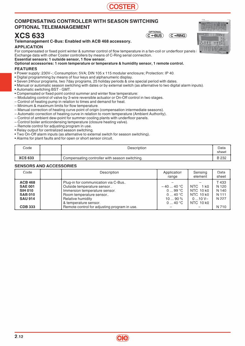
COMPENSATING CONTROLLER WITH SEASON SWITCHINGOPTIONAL TELEMANAGEMENT
XCS 633Telemanagement C-Bus: Enabled with ACB 468 accessory.APPLICATIONFor compensated or fi xed point winter & summer control of fl ow temperature in a fan-coil or underfl oor panels installation.Exchange data with other Coster controllers by means of C-Ring serial connection.Essential sensors: 1 outside sensor, 1 fl ow sensor.Optional accessories: 1 room temperature or temperature & humidity sensor, 1 remote control.FEATURES• Power supply: 230V~; Consumption: 5VA; DIN 105 x 115 modular enclosure; Protection: IP 40.• Digital programming by means of four keys and alphanumeric display.• Seven 24hour programs, two 7day programs, 25 holiday periods & one special period with dates.• Manual or automatic season switching with dates or by external switch (as alternative to two digital alarm inputs).• Automatic switching BST - GMT.• Compensated or fi xed point control summer and winter fl ow temperature:– Modulating control of valve by 3-wire reversible actuator or On-Off control in two stages.– Control of heating pump in relation to times and demand for heat.– Minimum & maximum limits for fl ow temperature.– Manual correction of heating curve point of origin (compensation intermediate seasons).– Automatic correction of heating curve in relation to room temperature (Ambient Authority).– Control of ambient dew-point for summer cooling plants with underfl oor panels.– Control boiler anticondensing temperature (closure heating valve).– Remote control for adjusting program in use.• Relay output for centralized season switching.• Two On-Off alarm inputs (as alternative to external switch for season switching).• Alarms for plant faults and for open or short sensor circuit.
C RINGSBUCOPTIONAL
SENSORS AND ACCESSORIESCode Description Application
rangeSensingelement
Datasheet
ACB 468SAE 001SIH 010SAB 010SAU 914
CDB 333
Plug-in for communication via C-Bus..Outside temperature sensor..Immersion temperature sensor.Room temperature sensor..Relative humidity& temperature sensor.Remote control for adjusting program in use.
–– 40 ... 40 °C
0 ... 99 °C0 ... 40 °C
10 ... 90 %0 ... 40 °C
–
–NTC 1 kΩNTC 10 kΩNTC 10 kΩ
0 ...10 V–NTC 10 kΩ
–
T 433N 120N 140N 111N 227
N 710
Code Description Datasheet
XCS 633 Compensating controller with season switching. B 232

2
COSTER
2.13
DUAL OPTIMISING COMPENSATOR “SLAVE”OPTIONAL TELEMANAGEMENT
XSE 602TELEMANAGEMENT C-Bus: Enabled with ACB 400 accessory.APPLICATIONOperates only if connected via C-Ring to a “PRIMARY” controller.Suitable for compensated control of two central heating zones.Essential sensors: 1 outside sensor, 2 fl ow sensors.Optional accessories: 1 or 2 room sensors, 1 remote control.TECHNICAL & FUNCTIONAL FEATURES SAME AS THOSE OF XTE 602.
OPTIMISING COMPENSATOR “SLAVE”OPTIONAL TELEMANAGEMENT
XSE 600TELEMANAGEMENT C-Bus: Enabled with ACB 400 accessory.APPLICATIONOperates only if connected via C-Ring to a “PRIMARY” controller.Suitable for compensated control of one centralised heating plant roomand for the On-Off control of a DHW calorifi er.Essential sensors: 1 outside sensor, 1 fl ow sensor.Optional accessories: 1 room sensor, 1 measurement 4 ... 20 mA sensor, 1 remote control.TECHNICAL & FUNCTIONAL FEATURES SAME AS THOSE OF XTE 600.
SYSTEM FOR MULTIPLE OPTIMISING COMPENSATORS
"MULTICOSTER"The system comprises one “Master” controller and one or more “Slave” controllers connected together via the C-Ring serial connection.As “Master” any controller with C-Ring which can be confi gured as “Primary” can be used (e.g. XCC 602, DTC 648, XTE 611, XTE 600, XTE 602, XCS 633, XTR 628).The slave controllers (XSE 600 and XSE 602) are automatically confi gured only as “Secondary” and can operate only if connected to a Master controller.Each controller carries out independently its own functions and can be connected, via the C-Bus parallel connection, to a Telema-nagement system.
C RING
C RING
SBUCOPTIONAL
SBUCOPTIONAL
SENSORS AND ACCESSORIES FOR XSE 600 AND XSE 602Code Description Application
rangeSensingelement
Datasheet
ACB 400SAE 001SIH 010SCH 010SAB 010STF 001CDB 300
Plug-in for C-Bus comunicationOutside temperature sensor.Immersion temperature sensor.Surface temperature sensor.Room temperature sensor.Flue gases temperature sensor only for XSE 600)Remote control to modify program in use.
–– 40 ... 40 °C
0 ... 99 °C0 ... 99 °C0 ... 40 °C
0 ... 500 °C–
–NTC 1 kΩNTC 10 kΩNTC 10 kΩNTC 10 kΩ
Pt 1 kΩ–
T 433N 120N 140N 130N 111N 165N 710
Code Description Datasheet
XSE 600 Optimising compensator. A 620
Code Description Datasheet
XSE 602 Dual optimising compensator. A 620

COSTER
2.14
FEATURES MODELSDTT 318 XTT 618 XTT 608
Controls
3-wire modulating control of primary heating valve 1 1 1
On-Off heating pump 1 1 1
3-wire modulating control or on-off primary DHW valve – – 1
3-wire modulating control DHW distribution valve 1 – 1
storage tank pump on-off control 1 – 1
timed on-off DHW circulation pump – – 1
Heating control
compensated – Yes Yes
fi xed point Yes Yes Yes
systems (C-Ring) – Yes Yes
DHW control fi xed point – Yes
Sensors
primary fl ow temperature (reading only) – 1 –
primary return temperature 1 1 1
outside temperature – 1 1
heating fl ow temperature 1 1 1
heating return temperature – 1 1
room temperature – – 1
DHW storage temperature – – 1
DHW distribution temperature – – 1
Remote controlmodifi cation of heating programme in use – 1 1
outside contact for program switching 1 – 1
Programs
24-hour – – 7
7-day – – 2
emergency – – 1
Periods with dates
holidays (from-to) – – 25
special – – 1
heating season – – Yes
GMT / BST – – Yes
Functions
set default outside and fl ow temperature – Yes Yes
correct heating curve origin (t°e = 20°C) – Yes Yes
max. & min. fl ow temperature limits – Yes Yes
ambient authority over compensated controla – – Yes
optimization (system on and off) – – Yes
Eco Off based on outside temperature – – Yes
frost protection – – Yes
heating pump off delay – Yes Yes
DHW priority – – Yes
hot water antibacterial action – – Yes
summer plant exercise – – Yes
TRL functions
max. primary return temperature Yes Yes Yes
max. difference between primary and secondary return temp. (peak reduction)
– Yes Yes
max. primary rate or power – Yes Yes
max. valve opening – Yes Yes
Alarms
On-Off contacts – 3 2
functional – 5 7
short and open sensor circuits – 7 7
Transmission dataC-Bus for remote management from local and/or remote PC Yes Yes Yes
C-Ring for data exchange between controllers – Yes Yes
: alternative

2
COSTER
2.15
FIXED POINT CONTROLLER FOR DISTRICT HEATING
DTT 318APPLICATIONDesigned for fi xed point control of secondary temperature in district heating sub-stations comprising one heat exchanger with mixing valve on primary.Communication with telemanagement systems via C-Bus parallel connection.Essential sensors: 1 sensor secondary fl ow.Optional accessories: 1 sensor promary return.FEATURES• Power supply: 230 V~; Consumption: 3 VA; DIN 53 x 115 modular enclosure; Protection: IP 40. • Digital programming by means of four operating keys and 3-fi gure display.• Control secondary fl ow temperature at fi xed point.
– Modulating control (3-wire) or On-Off in two stages or On-Off proportional in one stage.– Valve opening limitation for maximum limit return temperature primary return circuit.
• Season switching by external swith.
Code Description Data Code Description Data sheet sheet
DTT 318 Fixed point controller for district heating sub-stations. B 282
Code Description Data sheet
Fixed point controller for district heating sub-stations. B 282
Code Description Data sheet
Fixed point controller for district heating sub-stations. B 282
Code Description Data sheet
BUSC
SENSORS AND ACCESSORIES FOR DTT 318 E XTT 618 Code Description Application Sensing Data Code Description Application Sensing Data range element sheet range element sheet
ACB 400 Plug-in for communicating via C-Bus. – – T 433 SAE 001 SAE 001 Outside temperature sensor (only for XTT 618). –40 ... 40 °C NTC 1 kΩ N 120 SIH 010 SIH 010 Immersion temperature sensor (secondary fl ow, 0 ... 99 °C NTC 10 kΩ N 140 primary return). primary return). SAF 010 SAF 010 or cable-type (only for DTT 318). 0 ... 99 °C NTC 10 kΩ N 145 STH 001 STH 001 Immersion temperature sensor(primary fl ow, primary return) (only for XTT 618). 0 ... 300 °C Pt 1 kΩ N 140 (only for XTT 618). 0 ... 300 °C Pt 1 kΩ N 140 SHF 001 SHF 001 Cable-type temperature sensor (primary fl ow & return) 0 ... 180 °C Pt 1 kΩ N 145 0 ... 180 °C Pt 1 kΩ N 145 (only for XTT 618). (only for XTT 618).
CDB 100 Set-point adjuster (only for DTT 318). –20...+20°C – N 710
Code Description Application Sensing Data range element sheet
Outside temperature sensor (only for XTT 618). –40 ... 40 °C Immersion temperature sensor (secondary fl ow, 0 ... 99 °C NTC 10 kΩ N 140
primary return). or cable-type (only for DTT 318). 0 ... 99 °C NTC 10 kΩ N 145 Immersion temperature sensor(primary fl ow,
(only for XTT 618). 0 ... 300 °C Pt 1 kΩ N 140 Cable-type temperature sensor (primary fl ow &
(only for XTT 618). Set-point adjuster (only for DTT 318). –20...+20°C –
Code Description Application Sensing Data range element sheet
NTC 1 kΩ Immersion temperature sensor (secondary fl ow, 0 ... 99 °C NTC 10 kΩ N 140
or cable-type (only for DTT 318). 0 ... 99 °C NTC 10 kΩ N 145
(only for XTT 618). 0 ... 300 °C Pt 1 kΩ N 140 0 ... 180 °C Pt 1 kΩ N 145
Code Description Application Sensing Data range element sheet
primary return).
(only for XTT 618). 0 ... 300 °C Pt 1 kΩ N 140
(only for XTT 618).
Code Description Application Sensing Data range element sheet
– –
Immersion temperature sensor (secondary fl ow, 0 ... 99 °C NTC 10 kΩ N 140
or cable-type (only for DTT 318). 0 ... 99 °C NTC 10 kΩ N 145
(only for XTT 618). 0 ... 300 °C Pt 1 kΩ N 140 0 ... 180 °C Pt 1 kΩ N 145
Set-point adjuster (only for DTT 318). –20...+20°C –
Code Description Application Sensing Data range element sheet
– – Outside temperature sensor (only for XTT 618). –40 ... 40 °C Immersion temperature sensor (secondary fl ow, 0 ... 99 °C NTC 10 kΩ N 140
or cable-type (only for DTT 318). 0 ... 99 °C NTC 10 kΩ N 145
(only for XTT 618). 0 ... 300 °C Pt 1 kΩ N 140 0 ... 180 °C Pt 1 kΩ N 145
Set-point adjuster (only for DTT 318). –20...+20°C –
CONTROLLER FOR DISTRICT HEATING SUB-STATIONSWITH A SINGLE HEAT EXCHANGER OPTIONAL TELEMANAGEMENT
XTT 618TELEMANAGEMENT C-Bus: Enabled with ACB 400 accessory.APPLICATIONSuitable for the control of district heating sub-stations comprising one heat exchanger with valve and secondary circuit pump.Data communication with other controllers via C-Ring connection.Essential sensors: 1 secondary fl ow sensor.Optional accessories: 1 outside sensor, 1 primary fl ow sensor, 1 primary return sensor, 1 secondary return sensor.FEATURES• Power supply: 230V~; Consumption: 5VA; DIN 105 x 115 modular enclosure; Protection: IP 40.• Digital programming by means of 4 keys and alphanumeric display.• Control of secondary fl ow temperature: - At fi xed point. - Compensated with correction of origin of heating curve. - Variable in relation to desired temp. pf heating zones (C Ring).
– Modulating control (3-wire) of control valve of primary circuit heat exchanger.– Forced valve closure for: - Minimum opening limit. - Minimum fl ow or heat limit in primary circuit (from heat meter).– Limited valve opening for: - Maximum opening limit. - Maximum fl ow or heat limit in the primary circuit (from heat meter). - Maximum limit temperature return primary circuit.– Minimum and maximum limit of secondary fl ow temperature.– On-Off control of secondary pump in relation to demand for heat.
• Input for metering fl ow or energy for limits or On-Off alarm.• Input for measuring water loss or On-Off alarm.• Input for TeleOn or On-Off alarm.• Alarms for plant faults and for open or short sensor circuit.• Data recorder.
Code Description Data Code Description Data sheet sheet
XTT 618 Controller for district heating sub-stations. B 283XTT 618/S1 Controller for hight temperature in district heating sub-stations. B 283
Code Description Data sheet
Controller for district heating sub-stations. B 283 Controller for hight temperature in district heating sub-stations. B 283
Code Description Data sheet
Controller for district heating sub-stations. B 283 Controller for hight temperature in district heating sub-stations. B 283
Code Description Data sheet
C RINGSBUCOPTIONAL

COSTER
2.16
SENSORS AND ACCESSORIES
Code Description Application Sensing Data Code Description Application Sensing Data range element sheet range element sheet
ACB 460 Plug-in for C-Bus communication. – – T 433 SAE 001 SAE 001 Outside temperature sensor. –40 ... 40 °C NTC 1 k N 120 SIH 010 SIH 010 Immersion temperature sensor (heating fl ow & return, 0 ... 99 °C NTC 10 kΩ N 140 DHW storage & distribution). DHW storage & distribution). SHF 001 SHF 001 Immersion temperature sensor (primary return). 0 ... 180 °C Pt 1 kΩ N 145 SAB 010 SAB 010 Room temperature sensor. 0 ... 40 °C NTC 10 kΩ N 111
CDB 300 Remote control for changing program in use. – – N 710
COMPENSATING CONTROLLER FOR DISTRICT HEATING SUB-STATIONSWITH TWO HEAT EXCHANGERS OPTIONAL TELEMANAGEMENT
XTT 608TELEMANAGEMENT C-Bus: Enabled with ACB 460 accessory.APPLICATIONDesigned for the control of district heating substations comprising one heat exchanger Heating (modulating control) and one DHW heat exchanger (On-Off or modulating).Data communication with other controllers via serial C-Ring connection.Essential sensors: 1 heating fl ow sensor, 1 DHW storage tank sensor.Optional accessories: 1 outside sensor, 1 room sensor, 1 primary return sensor, 1 heating return sensor, 1 DHW distribution sensor.FEATURES• Power supply: 230V~; Consumption: 5VA; DIN 105 x 115 modular enclosure; Protection: IP 40.• Digital programming by means of 4 keys and alphanumeric display.• Control of heating fl ow temperature: - At fi xed point with desired fl ow temperatures Fixed Point 1-2. - Compensated with desired room temp. Normal 1…5, Setback 1-2, Frosprot. - Variable in relation to temperature requested by heating zones (C-Ring).
– Modulating control (3-wire) of control valve of primary circuit exchanger Heating.– Forced closure of valve for: - minimum opening limit. - minimum limit primary circuit fl ow.– Valve opening limits for: - maximum opening limit.
- maximum limit primary circuit return temperature. - maximum limit primary circuit fl ow. - maximum limit temperature difference between primary and secondary returns.
– On-Off control heating pump in relation to demand for heat.– Timed programming with seven 24hour programs and two 7day programs.– Functions: - optimized start and stop; Eco off; Frosprot.
• Control of temperature DHW at fi xed point (storage or distribution or storage & distribution):– Three-wire modulating control or On-Off valve primary circuit heat exchanger DHW.– Timed control DHW circulation pump.– Timed programming with seven 24hour programs and two 7day programs.– Antibacteria function.
• 25 annual periods with dates and separate programming for heating and DHW.• Summer exercise function for valves and pumps.• Automatic switching GMT – BST and summer/winter switching.• Metering degree-days.• Input for measurement fl ow or input for On-Off alarm• Input for program changing switch or input for On-Off alarm.• Alarms for plant faults and for open or short sensor circuit.• Data recorder.
Code Description Data Code Description Data Sheet Sheet
XTT 608 Optimising compensator for district heating.. B 284
Code Description Data Sheet
Optimising compensator for district heating.. B 284
Code Description Data Sheet
Optimising compensator for district heating.. B 284
Code Description Data Sheet
Code Description Application Sensing Data range element sheet
Outside temperature sensor. –40 ... 40 °C Immersion temperature sensor (heating fl ow & return, 0 ... 99 °C NTC 10 kΩ N 140
DHW storage & distribution). Immersion temperature sensor (primary return). 0 ... 180 °C Pt 1 kΩ N 145 Room temperature sensor. 0 ... 40 °C NTC 10 kΩ N 111 Remote control for changing program in use. – – N 710
Code Description Application Sensing Data range element sheet
– – T 433 N 120
Immersion temperature sensor (heating fl ow & return, 0 ... 99 °C NTC 10 kΩ N 140
Immersion temperature sensor (primary return). 0 ... 180 °C Pt 1 kΩ N 145 Room temperature sensor. 0 ... 40 °C NTC 10 kΩ N 111 Remote control for changing program in use. – – N 710
Code Description Application Sensing Data range element sheet
DHW storage & distribution).
Code Description Application Sensing Data range element sheet
– – T 433
Immersion temperature sensor (heating fl ow & return, 0 ... 99 °C NTC 10 kΩ N 140
Immersion temperature sensor (primary return). 0 ... 180 °C Pt 1 kΩ N 145 Room temperature sensor. 0 ... 40 °C NTC 10 kΩ N 111 Remote control for changing program in use. – – N 710
Code Description Application Sensing Data range element sheet
Outside temperature sensor. –40 ... 40 °C Immersion temperature sensor (heating fl ow & return, 0 ... 99 °C NTC 10 kΩ N 140
Immersion temperature sensor (primary return). 0 ... 180 °C Pt 1 kΩ N 145 Room temperature sensor. 0 ... 40 °C NTC 10 kΩ N 111 Remote control for changing program in use. – – N 710
C RINGSBUCOPTIONAL

2
COSTER
2.17
CONTROL SYSTEM FOR ROOM TEMPERATURE
"MULTIZONE"SYSTEM OF CONTROLLERS FOR AIR TREATMENT AND OTHER SERV ICES FOR INDEPENDENT ZONES..
• Control of room temperature for heating and/or conditioning of several zonesEach zone is controlled for temperature by a local unit which communicates with a central unit for further functions• Option of controlling many types of local thermal units.• Three service inputs for each local unit
Each local unit is provided with three service inputs (electronic or mechanical switches) which can be dedicated to any function,such as :– Alarm or call for help– Occupation or not of the room to control special conditioning programs (e.g.: presence or not of persons)– Special requirements for the zone with special programs (e.g. windows open)– Centralised electric control by a zone switch (e.g. lights in a common corridor)– General alarm (e.g. fl ooding of zone, gas escape)
• Personalised functions for each local unitEach local unit can be personalised independently to adapt it to the user requirements (e.g. choice of programs)• MASTER centralised unitThe centralised unit can control up to 239 remote units:
– choice of functions to assign to each remote unit– control of common site devices– control of common site deviceso– contact with and supervision of all the 239 units– powering of up to 20 units; over this number an external power supply is used– dialogue with PC and/or modem
CENTRAL (MASTER) CONTROL UNITWITH REMOTE CONTROL VIA SMS
MRL 608TELEMANAGEMENT C-Bus: Activated using ACB 400 accessory.APPLICATION• MRL 608 is the central unit of the MULTIZONE system.• Controls up to 239 local units type RTL 110/510, RTL 111/511 and RTL 120/520• On its own powers up to 20 local units (RTL 120/520 use a dedicated power supply)• For over 20 units power supply ALC 318 is required for every further 50 units• Controls all the functions to harmonise the zone units:
– communication with Bus P-Loc up to a maximum of 239 zones– transmission exact time to local clock so as to put all the zones in step– transmission of outside temperature to be used and read by zones– remote control of all the functions of the zones– reception and centralising of all the alarms of the zones– remote confi guration of all the zones– capacity of dialogue at levels single zone, groups of zones or all the zones.– centralised control of common electric and/or thermal organs of the site– communicates to the individual zone whether it must provide heating or conditioning– dialogue with modem or PC via C-Bus using accessory Plug-in C-Bus ACB 400– dialogue with local PC via Test Plug-in ACX 232
• Manages communication via “SMS” with the zones for :– Sending to an enabled cellular phone the zone status (alarm or other) up to a maximum of 48 zones– Remote control via SMS of the operating programs for the zone (timed or other programs) up to a maximum of 239 zones– Remote control via SMS of the operating programs for groups of zones (timed or other programs) up to a maximum of 9 groups
• Power supply 230 V~; mounting on DIN 6 unit rail
SBUCOPTIONAL
LOCP
Code Description Datasheet
MRL 608 System Master. B 551
ACCESSORY FOR TELEMANAGEMENTCode Description Data
sheet
ACB 400 Plug-in for C-Bus communication. –
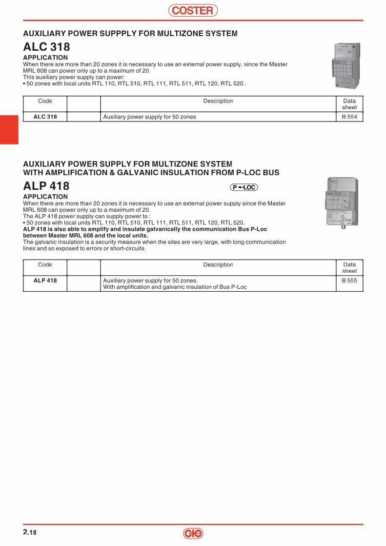
COSTER
2.18
AUXILIARY POWER SUPPPLY FOR MULTIZONE SYSTEM
ALC 318APPLICATIONWhen there are more than 20 zones it is necessary to use an external power supply, since the MasterMRL 608 can power only up to a maximum of 20.This auxiliary power supply can power:• 50 zones with local units RTL 110, RTL 510, RTL 111, RTL 511, RTL 120, RTL 520..
AUXILIARY POWER SUPPLY FOR MULTIZONE SYSTEMWITH AMPLIFICATION & GALVANIC INSULATION FROM P-LOC BUS
ALP 418APPLICATIONWhen there are more than 20 zones it is necessary to use an external power supply since the MasterMRL 608 can power only up to a maximum of 20.The ALP 418 power supply can supply power to :• 50 zones with local units RTL 110, RTL 510, RTL 111, RTL 511, RTL 120, RTL 520.ALP 418 is also able to amplify and insulate galvanically the communication Bus P-Locbetween Master MRL 608 and the local units.The galvanic insulation is a security measure when the sites are very large, with long communicationlines and so exposed to errors or short-circuits.
LOCP
Code Description Datasheet
ALP 418 Auxiliary power supply for 50 zones.With amplifi cation and galvanic insulation of Bus P-Loc
B 555
Code Description Datasheet
ALC 318 Auxiliary power supply for 50 zones B 554

2
COSTER
2.19
LOCAL UNIT (SLAVE) WITH RELAY OUTPUT
RTL 110 - 510APPLICATION• RTL x10 is the unit (SLAVE) for the control of heating and other functions in a single zoneThis unit can be housed in a standard built-in 503 enclosure or mounted on the wall.It is compatible with the switchboards and plates commonly on sale.• receives power from the Master or from an auxiliary power supply• controls the local thermal unit by the control of:
– On-Off zone valve with 230 V~ motor– On-Off zone valve with 24 V~ (or other voltages) motor– zone valve with 24 V~ (or other voltages) thermal motor– zone circulation pump– zone burner or small boiler– On-Off control of a fan-coil fan (manual choice of speed)– any other device controllable by three-point relay.
• Room sensor (internal or external)• complete confi guration of the limits and method of use permitted to user• three On-Off inputs to program as required• large display with simplifi ed readout for less expert users• three operational push-button switches with “intuitive” use, again for the less expert users• ability to function in event of breakdown of centralised conversation
LOCP
ACCESSORIESCode Description Data
sheet
ASA 2418 Cable for powering RTL110 & RTL 510 directly with 24 V~ B 552
Code Description Datasheet
RTL 110RTL 510
Local unit with relay output – fl ush mountingLocal unit with relay output – wall-mounting (standard white colour)
B 552B 552
SPECIAL VERSIONSigla Description Data
sheet
RTL 510/AGRTL 510/ALRTL 510/B RTL 510/GY
Local unit with relay output, wall-mounting; enclosure silver fi nishLocal unit with relay output, wall-mounting; enclosure aluminium fi nishLocal unit with relay output, wall-mounting; enclosure black fi nishLocal unit with relay output, wall-mounting; enclosure grey fi nish
––––
FOR SPECIAL VERSIONS MINIMUM BATCH 10 PIECES FOR AVAILABILITY & DELIVERY TIMES ASK COMMERCIAL NETWORK

COSTER
2.20
OUTPUTS EXPANDER FOR RTL 111 - RTL 511
DEP 658 APPLICATION• The main functions are:
– dialogue with local unit via a dedicated Bus– can power its local unit– has On-Off or modulating output for control of valve or other– control fan at up to three speeds– provided with test for local connections
Code Description Schedatecnica
DEP 658 Outputs expander for RTL 111-511. B 553
LOCAL UNIT (SLAVE) FOR CONTROL EXPANDER
RTL 111 - RTL 511APPLICATION• RTL 111 has all the features of RTL X10 except that instead of having a relay output it has the capacity
to control an expander unit (DEP 658) which permits the control of more complex thermal units:– zone fan-coil with On-Off valve and three-speed fan– zone fan-coil with modulating valve and three-speed fan– simple local unit for air treatment with a battery and fan
• All the functions are similar to those of RTL X10 but with the addition of :– local control of maximum or desired speed of fan
LOCP
Code Description Datasheet
RTL 111RTL 511
Local unit for control of built-in expanderLocal unit for control of wall-mounted expander.
B 553B 553
FOR SPECIAL VERSIONS MINIMUM BATCH 10 PIECESFOR AVAILABILITY & DELIVERY TIMES ASK COMMERCIAL NETWORK
SPECIAL VERSIONCode Description Data
sheet
RTL 511/AGRTL 511/ALRTL 511/B RTL 511/GY
Local unit for control of wall-mounted expander; enclosure silver fi nishLocal unit for control of wall-mounted expander; enclosure aluminium fi nishLocal unit for control of wall-mounted expander; enclosure black fi nishLocal unit for control of wall-mounted expander; enclosure grey fi nish
––––
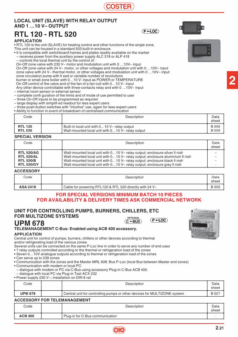
2
COSTER
2.21
UNIT FOR CONTROLLING PUMPS, BURNERS, CHILLERS, ETCFOR MULTIZONE SYSTEMS
UPM 678TELEMANAGEMENT C-Bus: Enabled using ACB 400 accessory.APPLICATIONCentral unit for control of pumps, burners, chillers or other devices according to thermaland/or refrigerating load of the various zones.Several units can be connected on the same P-Loc line in order to serve any number of end uses• 7 relay outputs controlled according to the thermal or refrigeration load of the zones• Seven 0…10V analogue outputs according to thermal or refrigeration load of the zones• Can serve up to 239 zones• Communication with the zones and the Master MRL 608: Bus P-Loc (local Bus between Master and zones)• Communication with modem or local PC:
– dialogue with modem or PC via C-Bus using accessory Plug-in C-Bus ACB 400.– dialogue with local PC via Plug-in Test ACX 232
• Power supply 230 V~; installation on DIN 6 rail
SBUCOPTIONAL
LOCP
Code Description Datasheet
UPM 678 Central unit for controlling pumps or other devices for MULTIZONE system . B 557
LOCAL UNIT (SLAVE) WITH RELAY OUTPUTAND 1 …10 V– OUTPUT
RTL 120 - RTL 520APPLICATION• RTL 120 is the unit (SLAVE) for heating control and other functions of the single zone.This unit can be housed in a standard 503 built-in enclosure.• It is compatible with switchboard frames and plates readily available on the market
– receives power from the auxiliary power supply ALC 318 or ALP 418– controls the local thermal unit by the control of: :On-Off zone valve with 230 V~ motor and modulation unit with 0 …10V– inputOn-Off zone valve with 24 V~ motor, or other voltages and modulation unit with 0 …10V– inputzone valve with 24 V~ thermal motor, or other voltages and modulation unit with 0 …10V– inputzone circulation pump with fi xed or variable number of revolutionsburner or small zone boiler with 0…10 V- input as POWER or TEMPERATUREOn-Off control of the valve and of the fan of a fan-coil with 0…10 V– inputAny other device controllable with three-contacts relay and with 0 …10V– input
– internal room sensor or external sensor– complete confi guration of the limits and of mode of use permitted to user– three On-Off inputs to be programmed as required– large display with simplifi ed readout for less expert users– three push-button switches with “intuitive” use, again for less-expert users• Ability to function in event of breakdown of centralised communication
LOCP
Code Description Datasheet
RTL 120RTL 520
Built-in local unit with 0…10 V– relay outputWall-mounted local unit with 0…10 V– relay output
B 556B 556
ACCESSORYCode Description Data
sheet
ASA 2418 Cable for powering RTL120 & RTL 520 directly with 24 V~ B 556
SPECIAL VERSIONCode Description Data
sheet
RTL 520/AGRTL 520/ALRTL 520/B RTL 520/GY
Wall-mounted local unit with 0…10 V– relay output; enclosure silver fi nishWall-mounted local unit with 0…10 V– relay output; enclosure aluminium fi nishWall-mounted local unit with 0…10 V– relay output; enclosure black fi nishWall-mounted local unit with 0…10 V– relay output; enclosure grey fi nish
––––
FOR SPECIAL VERSIONS MINIMUM BATCH 10 PIECES FOR AVAILABILITY & DELIVERY TIMES ASK COMMERCIAL NETWORK
ACCESSORY FOR TELEMANAGEMENTCode Description Data
sheet
ACB 400 Plug-in for C-Bus communication –
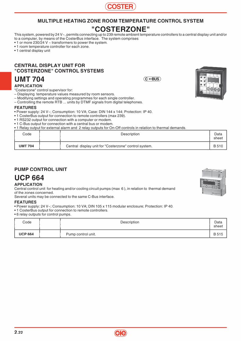
COSTER
2.22
CENTRAL DISPLAY UNIT FOR"COSTERZONE" CONTROL SYSTEMS
UMT 704APPLICATION"Costerzone" control supervisor for:– Displaying temperature values measured by room sensors. – Modifying settings and operating programmes for each single controller. – Controlling the remote RTB ... units by DTMF signals from digital telephones.
FEATURES• Power supply: 24 V~; Consumption: 10 VA; Case: DIN 144 x 144; Protection: IP 40.• 1 CosterBus output for connection to remote controllers (max 239).• 1 RS232 output for connection with a computer or modem.• 1 C-Bus output for connection with a central bus or modem.• 1 Relay output for external alarm and 2 relay outputs for On-Off controls in relation to thermal demands.
MULTIPLE HEATING ZONE ROOM TEMPERATURE CONTROL SYSTEM
"COSTERZONE"This system, powered by 24 V~, permits connecting up to 239 remote ambient temperature controllers to a central display unit and/or to a computer, by means of the CosterBus interface. The system comprises:• 1 or more 230/24 V ~ transformers to power the system.• 1 room temperature controller for each zone.• 1 central display unit
PUMP CONTROL UNIT
UCP 664APPLICATIONCentral control unit for heating and/or cooling circuit pumps (max 6 ), in relation to thermal demand of the zones concerned. Several units may be connected to the same C-Bus interface.
FEATURES• Power supply: 24 V~; Consumption: 10 VA; DIN 105 x 115 modular enclosure; Protection: IP 40.• 1 CosterBus output for connection to remote controllers.• 6 relay outputs for control pumps.
Code Description Data sheet
UCP 664 Pump control unit. B 515
Code Description Data sheet Code Description Data sheet
Pump control unit. B 515
Code Description Data sheet
Pump control unit. B 515
Code Description Data sheet
Pump control unit. B 515
Code Description Data sheet
UMT 704 Central display unit for "Costerzone" control system. B 510
Code Description Data sheet Code Description Data sheet
Central display unit for "Costerzone" control system. B 510
Code Description Data sheet
Central display unit for "Costerzone" control system. B 510
Code Description Data sheet
Central display unit for "Costerzone" control system. B 510
BUSC

2
COSTER
2.23
SENSORS AND ACCESSORIES
Code Description Application Sensing Data Code Description Application Sensing Data range element sheet range element sheet
SAB 010 SAB 010 Room temperature sensor. 0 ... 40 °C NTC 10 kΩ N 111 SAB 210 SAB 210 Room temperature sensor with +1 hour key. 0 ... 40 °C NTC 10 kΩ N 111 Room temperature sensor with +1 hour key. 0 ... 40 °C NTC 10 kΩ N 111
SAA 010 Industrial type temperature sensor 0 ... 100 °C NTC 10 kΩ N 115 (used as outside temperature sensor. Only for CTB 334)
SCB 110 Room temperature sensor 0 ... 40 °C NTC 10 kΩ N 111 with setpoint adjuster. –5 ... +5 °C – with setpoint adjuster. –5 ... +5 °C –
SCB 210 Room temperature sensor with +1 hour key 0 ... 40 °C NTC 10 kΩ N 111 and setpoint adjuster. –5 ... +5 °C – and setpoint adjuster. –5 ... +5 °C –
STT 010 Temperature sensor for fan coils. 0 ... 40 °C NTC 10 kΩ N 155Temperature sensor for fan coils. 0 ... 40 °C NTC 10 kΩ N 155STA 010 Air duct temperature sensor. 0 ... 40 °C NTC 10 kΩ N 150 Air duct temperature sensor. 0 ... 40 °C NTC 10 kΩ N 150 Air duct temperature sensor. 0 ... 40 °C NTC 10 kΩ N 150
AIC 240 AIC 240 Inverts status of window switch. – – D 615 Inverts status of window switch. – – D 615 Inverts status of window switch. – – D 615
Code Description Application Sensing Data range element sheet
with setpoint adjuster. –5 ... +5 °C –
and setpoint adjuster. –5 ... +5 °C –
Air duct temperature sensor. 0 ... 40 °C NTC 10 kΩ N 150
Inverts status of window switch. – – D 615
Code Description Application Sensing Data range element sheet
Room temperature sensor. 0 ... 40 °C NTC 10 kΩ N 111Room temperature sensor with +1 hour key. 0 ... 40 °C NTC 10 kΩ N 111
N
Room temperature sensor 0 ... 40 °C NTC 10 kΩ N 111
Room temperature sensor with +1 hour key 0 ... 40 °C NTC 10 kΩ N 111
Temperature sensor for fan coils. 0 ... 40 °C NTC 10 kΩ N 155 Air duct temperature sensor. 0 ... 40 °C NTC 10 kΩ N 150
Inverts status of window switch. – – D 615
Code Description Application Sensing Data range element sheet
SAB 010 SAB 210
SAA 010
SCB 110 with setpoint adjuster. –5 ... +5 °C –
SCB 210 and setpoint adjuster. –5 ... +5 °C –
STT 010 Air duct temperature sensor. 0 ... 40 °C NTC 10 kΩ N 150
Code Description Application Sensing Data range element sheet
Room temperature sensor. 0 ... 40 °C NTC 10 kΩ N 111Room temperature sensor with +1 hour key. 0 ... 40 °C NTC 10 kΩ N 111
Room temperature sensor 0 ... 40 °C NTC 10 kΩ N 111 with setpoint adjuster. –5 ... +5 °C –
Room temperature sensor with +1 hour key 0 ... 40 °C NTC 10 kΩ N 111 and setpoint adjuster. –5 ... +5 °C –
Temperature sensor for fan coils. 0 ... 40 °C NTC 10 kΩ N 155 Air duct temperature sensor. 0 ... 40 °C NTC 10 kΩ N 150
Inverts status of window switch. – – D 615
Code Description Application Sensing Data range element sheet
Room temperature sensor. 0 ... 40 °C NTC 10 kΩ N 111Room temperature sensor with +1 hour key. 0 ... 40 °C NTC 10 kΩ N 111
0 ... 100
Room temperature sensor 0 ... 40 °C NTC 10 kΩ N 111 with setpoint adjuster. –5 ... +5 °C –
Room temperature sensor with +1 hour key 0 ... 40 °C NTC 10 kΩ N 111 and setpoint adjuster. –5 ... +5 °C –
Temperature sensor for fan coils. 0 ... 40 °C NTC 10 kΩ N 155 Air duct temperature sensor. 0 ... 40 °C NTC 10 kΩ N 150
Inverts status of window switch. – – D 615
SUMMER TEMPERATURE COMPENSATOR FOR RTB 645 CONTROLLERS
CTB 334APPLICATIONMaintains a constant difference between room and outside temperatures in the summer period.
FEATURES• Power suppy: 24 V~; Consumption: 3 VA; DIN 53 x 115 modular enclosure; Protection: IP 40.• Can compensate up to maximum 30 RTB 645 controllers connected in parallel.
Code Description Data Code Description Data Code Description Data Code Description Data Code Description Data Code Description Data sheet sheet sheet sheet sheet
CTB 334 Summer tempersture compensator for RTB 645 controllers. B 524 Summer tempersture compensator for RTB 645 controllers. B 524 Summer tempersture compensator for RTB 645 controllers. B 524
ROOM TEMPERATURE CONTROLLERS
RTB ...APPLICATIONRoom temperature controllers for heating/cooling coils or for zone heating,supplied with an NTC 10 kΩ internal sensing element. Designed for On-Off control of fans and zone valves or for modulating control of reversible control valves with 3-wire electric control.Individual or centralised season switching.C-Bus compatible.RTB 040 can be used as a time switch for 24-hour or 7-day programming.RTB 540 is provided with a display for modifying programme in use and desired temperature.Optional sensors: 1 room temperature sensor for fan coils or air duct.FEATURES• Power supply: 24 V ~; Consumption: 4 VA; Protection: IP 30.• Setting range: - From central unit: 0 ... 40 °C; - From local setpoint adjuster: ± 5 (± 15) °C.• On-Off output: Voltage-free contacts: rating 250 V ~, 5 (3) A. P control action; Proportional Band: ± 1 °C (adjustable from central unit).• Modulating outputs: Triac type 24 V ~, rating 300 mA (7W). PI control action; Proportional Band: ± 1 °C (adjustable from central unit). Control of actuators with run time: 100 seconds (adjustable from central unit).
RTB ...
RTB 540
RTB 645
Code Control outputs Setpoint Data Code Control outputs Setpoint Data adjuster sheet adjuster sheet
RTB 040 1 On-Off hot or cold (fan or 2-3 wire valve). – B 520RTB 140 1 On-Off hot or cold (fan or 2-3 wire valve). ± 15 °C B 520RTB 540 1 On-Off hot or cold (fan or 2-3 wire valve). ± 15 °C B 522RTB 044 4 On-Off hot or cold (3 fan speeds plus 2-3 wire valve). – B 521RTB 044S1 As RTB 044 with room occupied service (without sensor control). ± 15 °C B 521RTB 144 4 On-Off hot or cold (3 fan speeds plus 2-3 wire valve). ± 15 °C B 521RTB 144S1 As RTB 144 with room occupied service (without sensor control). ± 15 °C B 521RTB 041 1 modulating hot or cold (3-wire valve) + 1 On-Off (fan). – B 520RTB 141 1 modulating hot or cold (3-wire valve) + 1 On-Off (fan). ± 15 °C B 520RTB 042 2 modulating hot and cold (2 3-wire valve). – B 520RTB 142 2 modulating hot and cold (2 3-wire valve). ± 15 °C B 520RTB 045 4 simultaneous On-Off hot or cold (4 2-wire valves). – B 520RTB 145 4 simultaneous On-Off hot or cold (4 2-wire valves). ± 15 °C B 520RTB 645 3 On-Off hot or cold (3 fan speeds). ± 15 °C B 523
+ 2 modulating hot and cold (2 3-wire valve). – + 2 modulating hot and cold (2 3-wire valve). – –
Code Control outputs Setpoint Data adjuster sheet
1 On-Off hot or cold (fan or 2-3 wire valve). – B 520 1 On-Off hot or cold (fan or 2-3 wire valve). ± 15 °C B 520 1 On-Off hot or cold (fan or 2-3 wire valve). ± 15 °C B 522 4 On-Off hot or cold (3 fan speeds plus 2-3 wire valve). – B 521
As RTB 044 with room occupied service (without sensor control). ± 15 °C B 521 4 On-Off hot or cold (3 fan speeds plus 2-3 wire valve). ± 15 °C B 521
As RTB 144 with room occupied service 1 modulating hot or cold (3-wire valve) + 1 On-Off (fan). – B 520 1 modulating hot or cold (3-wire valve) + 1 On-Off (fan). ± 15 °C B 520 2 modulating hot and cold (2 3-wire valve). – B 520 2 modulating hot and cold (2 3-wire valve). ± 15 °C B 520 4 simultaneous On-Off hot or cold (4 2-wire valves). – B 520 4 simultaneous On-Off hot or cold (4 2-wire valves). ± 15 °C B 520 3 On-Off hot or cold (3 fan speeds). ± 15 °C B 523
+ 2 modulating hot and cold (2 3-wire valve). –
Code Control outputs Setpoint Data adjuster sheet
1 On-Off hot or cold (fan or 2-3 wire valve). – B 520 1 On-Off hot or cold (fan or 2-3 wire valve). ± 15 °C B 520 1 On-Off hot or cold (fan or 2-3 wire valve). ± 15 °C B 522 4 On-Off hot or cold (3 fan speeds plus 2-3 wire valve). – B 521
As RTB 044 with room occupied service (without sensor control). ± 15 °C B 521 4 On-Off hot or cold (3 fan speeds plus 2-3 wire valve). ± 15 °C B 521
± 15 °C B 521 1 modulating hot or cold (3-wire valve) + 1 On-Off (fan). – B 520 1 modulating hot or cold (3-wire valve) + 1 On-Off (fan). ± 15 °C B 520 2 modulating hot and cold (2 3-wire valve). – B 520 2 modulating hot and cold (2 3-wire valve). ± 15 °C B 520 4 simultaneous On-Off hot or cold (4 2-wire valves). – B 520 4 simultaneous On-Off hot or cold (4 2-wire valves). ± 15 °C B 520 3 On-Off hot or cold (3 fan speeds). ± 15 °C B 523
Code Control outputs Setpoint Data adjuster sheet
1 On-Off hot or cold (fan or 2-3 wire valve). – B 520 1 On-Off hot or cold (fan or 2-3 wire valve). ± 15 °C B 520 1 On-Off hot or cold (fan or 2-3 wire valve). ± 15 °C B 522 4 On-Off hot or cold (3 fan speeds plus 2-3 wire valve). – B 521
As RTB 044 with room occupied service (without sensor control). ± 15 °C B 521 4 On-Off hot or cold (3 fan speeds plus 2-3 wire valve). ± 15 °C B 521
As RTB 144 with room occupied service 1 modulating hot or cold (3-wire valve) + 1 On-Off (fan). – B 520 1 modulating hot or cold (3-wire valve) + 1 On-Off (fan). ± 15 °C B 520 2 modulating hot and cold (2 3-wire valve). – B 520 2 modulating hot and cold (2 3-wire valve). ± 15 °C B 520 4 simultaneous On-Off hot or cold (4 2-wire valves). – B 520 4 simultaneous On-Off hot or cold (4 2-wire valves). ± 15 °C B 520 3 On-Off hot or cold (3 fan speeds). ± 15 °C B 523
+ 2 modulating hot and cold (2 3-wire valve). –
Code Control outputs Setpoint Data adjuster sheet
1 On-Off hot or cold (fan or 2-3 wire valve). – B 520 1 On-Off hot or cold (fan or 2-3 wire valve). ± 15 °C B 520 1 On-Off hot or cold (fan or 2-3 wire valve). ± 15 °C B 522 4 On-Off hot or cold (3 fan speeds plus 2-3 wire valve). – B 521
As RTB 044 with room occupied service (without sensor control). ± 15 °C B 521 4 On-Off hot or cold (3 fan speeds plus 2-3 wire valve). ± 15 °C B 521
± 15 °C B 521 1 modulating hot or cold (3-wire valve) + 1 On-Off (fan). – B 520 1 modulating hot or cold (3-wire valve) + 1 On-Off (fan). ± 15 °C B 520 2 modulating hot and cold (2 3-wire valve). – B 520 2 modulating hot and cold (2 3-wire valve). ± 15 °C B 520 4 simultaneous On-Off hot or cold (4 2-wire valves). – B 520 4 simultaneous On-Off hot or cold (4 2-wire valves). ± 15 °C B 520 3 On-Off hot or cold (3 fan speeds). ± 15 °C B 523
+ 2 modulating hot and cold (2 3-wire valve). –
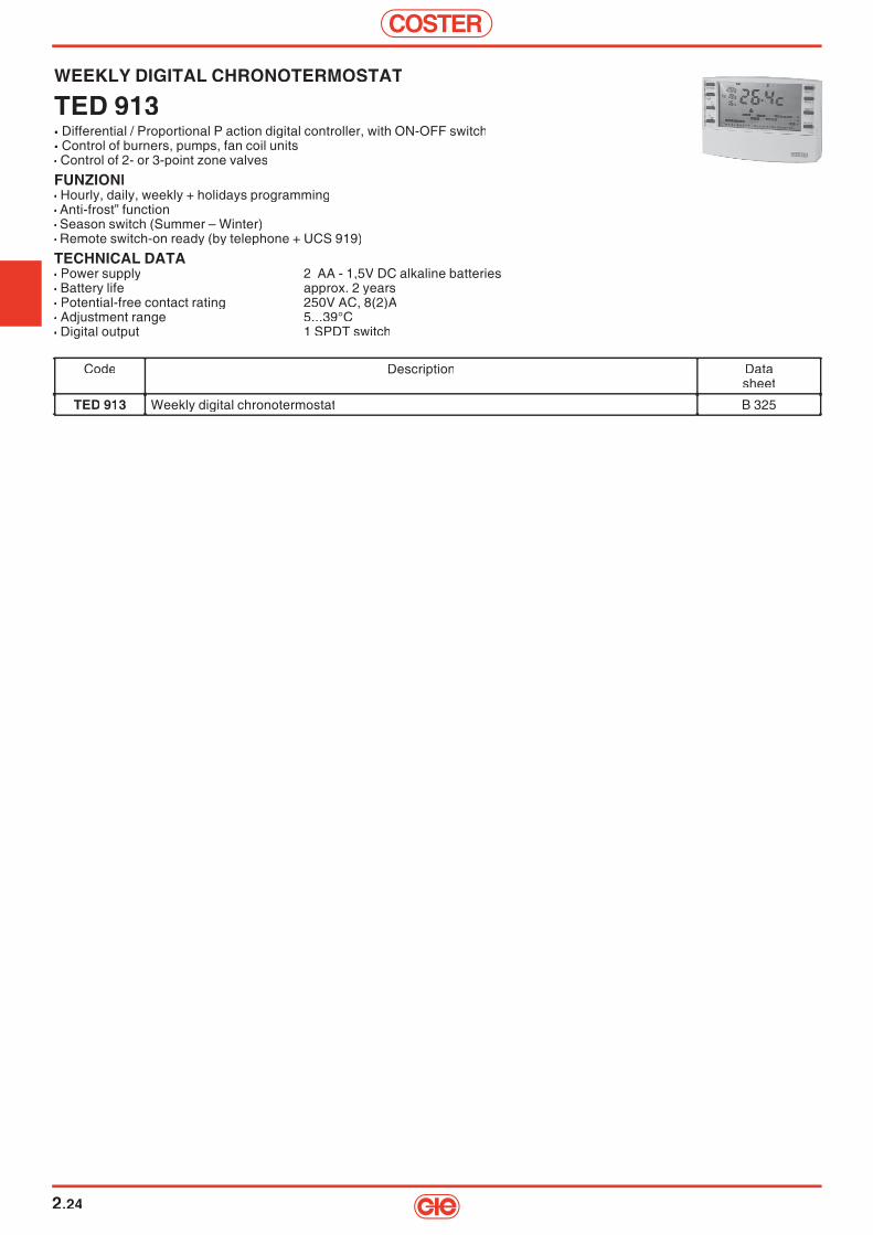
COSTER
2.24
WEEKLY DIGITAL CHRONOTERMOSTAT
TED 913• Differential / Proportional P action digital controller, with ON-OFF switch• Control of burners, pumps, fan coil units• Control of 2- or 3-point zone valves
FUNZIONI• Hourly, daily, weekly + holidays programming• Anti-frost” function• Season switch (Summer – Winter)• Remote switch-on ready (by telephone + UCS 919)
TECHNICAL DATA• Power supply 2 AA - 1,5V DC alkaline batteries• Battery life approx. 2 years• Potential-free contact rating 250V AC, 8(2)A• Adjustment range 5...39°C• Digital output 1 SPDT switch
Code Description Datasheet
TED 913 Weekly digital chronotermostat B 325
3
COSTER
3.1
Description Code Communication Page
COMPACT DHW MIXERSELECTRONIC MIXERS FOR DHW COMPACT UNIT FOR FIXED-POINT TEMPERATURE CONTROL IN DHW DISTRIBUTION CIRCUITS.
MAS ... 3.2
ELECTRONIC MIXERS FOR DHW WITH ANTILEGIONNAIRE FUNCTIONCOMPACT UNITS FOR CONTROL OF TEMPERATURE AT FIXED POINT IN DHW DISTRIBU-TION CIRCUITS. THE ANTILEGIONNAIRE FUNCTION COMES INTO OPERATION ONCE A WEEK ( ADJUSTABLE DAY & TIME).
MAS .../AL 3.2
BUSC = communication via telemanagemet PREDISPOSTO
BUSC = optional telemanagement C RING = data exchange between controllers

COSTER
3.2
ELECTRONIC MIXING VALVES FOR DHW
MAS 6.. - 7..APPLICATIONCompact units for maintaining a constant temperature in DHW distribution circuits. Consist of: a three-port ball valve, a reversible electric actuator with an electronic controller and a temperature detector with an NTC 10 kΩ sensing element incorporated in the valve.
FEATURES• Power supply: 230 V~; Protection: IP 55; Consumption: MAS 6.. = 6 VA; MAS 7.. = 9 VA.• Working pressure and maximum differential: 6 bar.• Proportional band: ± 5 ... ± 20 °C.
Code DN Flow rate Kvs Code DN Flow rate Kvs (2) Settinfg Data inches mm. l/min. inches mm. l/min. (1) m3/h range sheet
MAS 615 1/2" 15 40 2.5 30 ... 70 °C C 511MAS 620 3/4" 20 70 5 30 ... 70 °C C 511MAS 625 1" 25 130 9 30 ... 70 °C C 511MAS 632 1 1/4" 32 180 13.5 30 ... 70 °C C 511
MAS 740 1 1/2" 40 270 19.2 30 ... 70 °C C 511MAS 750 2" 50 390 28.9 30 ... 70 °C C 511
Code DN Flow rate Kvs inches mm. l/min.
1/2" 15 40 2.5 30 ... 70 °C C 511 3/4" 20 70 5 30 ... 70 °C C 511 1" 25 130 9 30 ... 70 °C C 511 1 1/4" 32 180 13.5 30 ... 70 °C C 511
1 1/2" 40 270 19.2 30 ... 70 °C C 511 2" 50 390 28.9 30 ... 70 °C C 511
Settinfg Data/h range sheet
1/2" 15 40 2.5 30 ... 70 °C C 511 3/4" 20 70 5 30 ... 70 °C C 511 1" 25 130 9 30 ... 70 °C C 511 1 1/4" 32 180 13.5 30 ... 70 °C C 511
1 1/2" 40 270 19.2 30 ... 70 °C C 511 2" 50 390 28.9 30 ... 70 °C C 511
Code DN Flow rate Kvs inches mm. l/min.
Settinfg Data/h range sheet
1/2" 15 40 2.5 30 ... 70 °C C 511 3/4" 20 70 5 30 ... 70 °C C 511 1" 25 130 9 30 ... 70 °C C 511 1 1/4" 32 180 13.5 30 ... 70 °C C 511
1 1/2" 40 270 19.2 30 ... 70 °C C 511 2" 50 390 28.9 30 ... 70 °C C 511
Code DN Flow rate Kvs m
1/2" 15 40 2.5 30 ... 70 °C C 511 3/4" 20 70 5 30 ... 70 °C C 511 1" 25 130 9 30 ... 70 °C C 511 1 1/4" 32 180 13.5 30 ... 70 °C C 511
1 1/2" 40 270 19.2 30 ... 70 °C C 511 2" 50 390 28.9 30 ... 70 °C C 511
Code DN Flow rate Kvs inches mm. l/min.
1/2" 15 40 2.5 30 ... 70 °C C 511 3/4" 20 70 5 30 ... 70 °C C 511 1" 25 130 9 30 ... 70 °C C 511 1 1/4" 32 180 13.5 30 ... 70 °C C 511
1 1/2" 40 270 19.2 30 ... 70 °C C 511 2" 50 390 28.9 30 ... 70 °C C 511
inches mm. l/min.
1/2" 15 40 2.5 30 ... 70 °C C 511 3/4" 20 70 5 30 ... 70 °C C 511 1" 25 130 9 30 ... 70 °C C 511 1 1/4" 32 180 13.5 30 ... 70 °C C 511
1 1/2" 40 270 19.2 30 ... 70 °C C 511 2" 50 390 28.9 30 ... 70 °C C 511
(1) – Flow rate based on 4 bar average pressure and pressure drop of about 20%.(2) – Flow rate coeffi cient: fl ow in m3 with valve open and pressure drop of 100 kPa.
ELECTRONINC MIXERS FOR DHW WITH ANTILEGIONNAIRE FUNCTION
MAS 6.. - 7.. / ALAPPLICATIONCompact units for control of temperature at fi xed point in DHW distribution circuits, provided with recycle pump.The Antilegionnaire function comes into operation once a week (adjustable day and time).Increases the temperature of the distribution circuit (valve completely open) for a period of time proportional to the temperature itself: high temperature (> 65 °C) = short period (30 min.);low temperature (< 55 °C) = long period (7 hours).Comprises : three-port ball valve, a reversible electric actuator with electronic controller and a temperature detector with an NTC 10 kΩ sensing element incorporated in the valve.
FEATURES• Power supply: 230 V~; Protection: IP 55; Consumption: MAS 6.. = 6 VA; MAS 7.. = 9 VA.• Working pressure and maximum differential: 6 bar.• Proportional band: ± 5 ... ± 20 °C.
Code DN Flow rate Kvs Code DN Flow rate Kvs (2) Settinfg Data inches mm. l/min. inches mm. l/min. (1) m3/h range sheet
MAS 615/AL 1/2" 15 40 2.5 30 ... 70 °C C 512MAS 620/AL 3/4" 20 70 5 30 ... 70 °C C 512MAS 625/AL 1" 25 130 9 30 ... 70 °C C 512MAS 632/AL 1 1/4" 32 180 13.5 30 ... 70 °C C 512
MAS 740/AL 1 1/2" 40 270 19.2 30 ... 70 °C C 512MAS 750/AL 2" 50 390 28.9 30 ... 70 °C C 512
Code DN Flow rate Kvs inches mm. l/min.
1/2" 15 40 2.5 30 ... 70 °C C 512 3/4" 20 70 5 30 ... 70 °C C 512 1" 25 130 9 30 ... 70 °C C 512 1 1/4" 32 180 13.5 30 ... 70 °C C 512
1 1/2" 40 270 19.2 30 ... 70 °C C 512 2" 50 390 28.9 30 ... 70 °C C 51
Settinfg Data/h range sheet
1/2" 15 40 2.5 30 ... 70 °C C 512 3/4" 20 70 5 30 ... 70 °C C 512 1" 25 130 9 30 ... 70 °C C 512 1 1/4" 32 180 13.5 30 ... 70 °C C 512
1 1/2" 40 270 19.2 30 ... 70 °C C 512 2" 50 390 28.9 30 ... 70 °C C 51
Code DN Flow rate Kvs inches mm. l/min.
Settinfg Data/h range sheet
1/2" 15 40 2.5 30 ... 70 °C C 512 3/4" 20 70 5 30 ... 70 °C C 512 1" 25 130 9 30 ... 70 °C C 512 1 1/4" 32 180 13.5 30 ... 70 °C C 512
1 1/2" 40 270 19.2 30 ... 70 °C C 512 2" 50 390 28.9 30 ... 70 °C C 51
Code DN Flow rate Kvs m
1/2" 15 40 2.5 30 ... 70 °C C 512 3/4" 20 70 5 30 ... 70 °C C 512 1" 25 130 9 30 ... 70 °C C 512 1 1/4" 32 180 13.5 30 ... 70 °C C 512
1 1/2" 40 270 19.2 30 ... 70 °C C 512 2" 50 390 28.9 30 ... 70 °C C 51
Code DN Flow rate Kvs inches mm. l/min.
1/2" 15 40 2.5 30 ... 70 °C C 512 3/4" 20 70 5 30 ... 70 °C C 512 1" 25 130 9 30 ... 70 °C C 512 1 1/4" 32 180 13.5 30 ... 70 °C C 512
1 1/2" 40 270 19.2 30 ... 70 °C C 512 2" 50 390 28.9 30 ... 70 °C C 51
inches mm. l/min.
1/2" 15 40 2.5 30 ... 70 °C C 512 3/4" 20 70 5 30 ... 70 °C C 512 1" 25 130 9 30 ... 70 °C C 512 1 1/4" 32 180 13.5 30 ... 70 °C C 512
1 1/2" 40 270 19.2 30 ... 70 °C C 512 2" 50 390 28.9 30 ... 70 °C C 51
(1) – Flow rate based on 4 bar average pressure and pressure drop of about 20%.(2) – Flow rate coeffi cient: fl ow in m3 with valve open and pressure drop of 100 kPa.
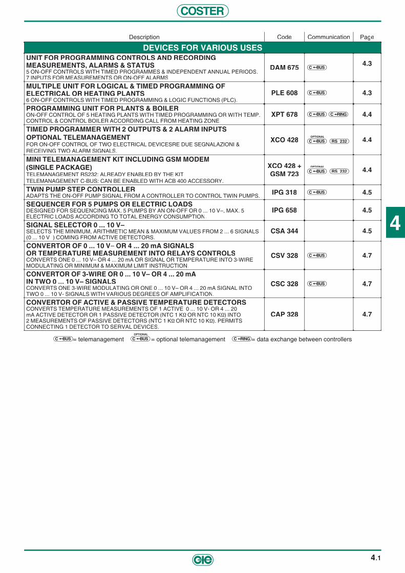
4
COSTER
4.1
Description Code Communication Page
DEVICES FOR VARIOUS USESUNIT FOR PROGRAMMING CONTROLS AND RECORDING MEASUREMENTS, ALARMS & STATUS 5 ON-OFF CONTROLS WITH TIMED PROGRAMMES & INDEPENDENT ANNUAL PERIODS.7 INPUTS FOR MEASUREMENTS OR ON-OFF ALARMS
DAM 675 BUSC4.3
MULTIPLE UNIT FOR LOGICAL & TIMED PROGRAMMING OF ELECTRICAL OR HEATING PLANTS 6 ON-OFF CONTROLS WITH TIMED PROGRAMMING & LOGIC FUNCTIONS (PLC).
PLE 608 BUSC 4.3
PROGRAMMING UNIT FOR PLANTS & BOILER ON-OFF CONTROL OF 5 HEATING PLANTS WITH TIMED PROGRAMMING OR WITH TEMP. CONTROL & CONTROL BOILER ACCORDING CALL FROM HEATING ZONE.
XPT 678 BUSC C RING 4.4
TIMED PROGRAMMER WITH 2 OUTPUTS & 2 ALARM INPUTSOPTIONAL TELEMANAGEMENTFOR ON-OFF CONTROL OF TWO ELECTRICAL DEVICESRE DUE SEGNALAZIONI &RECEIVING TWO ALARM SIGNALS.
XCO 428OPTIONAL
BUSC RS 232 4.4
MINI TELEMANAGEMENT KIT INCLUDING GSM MODEM(SINGLE PACKAGE)TELEMANAGEMENT RS232: ALREADY ENABLED BY THE KITTELEMANAGEMENT C-BUS: CAN BE ENABLED WITH ACB 400 ACCESSORY.
XCO 428 + GSM 723
OPTIONAL
BUSC RS 232 4.4
TWIN PUMP STEP CONTROLLER ADAPTS THE ON-OFF PUMP SIGNAL FROM A CONTROLLER TO CONTROL TWIN PUMPS. IPG 318 BUSC 4.5
SEQUENCER FOR 5 PUMPS OR ELECTRIC LOADS DESIGNED FOR SEQUENCING MAX. 5 PUMPS BY AN ON-OFF OR 0 ... 10 V–, MAX. 5 ELECTRIC LOADS ACCORDING TO TOTAL ENERGY CONSUMPTION.
IPG 658 4.5
SIGNAL SELECTOR 0 ... 10 V– SELECTS THE MINIMUM, ARITHMETIC MEAN & MAXIMUM VALUES FROM 2 ... 6 SIGNALS (0 ... 10 V–) COMING FROM ACTIVE DETECTORS.
CSA 344 4.5
CONVERTOR OF 0 ... 10 V– OR 4 ... 20 mA SIGNALSOR TEMPERATURE MEASUREMENT INTO RELAYS CONTROLSCONVERTS ONE 0 ... 10 V– OR 4 ... 20 mA OR SIGNAL OR TEMPERATURE INTO 3-WIRE MODULATING OR MINIMUM & MAXIMUM LIMIT INSTRUCTION.
CSV 328 BUSC 4.7
CONVERTOR OF 3-WIRE OR 0 ... 10 V– OR 4 ... 20 mAIN TWO 0 ... 10 V– SIGNALS CONVERTS ONE 3-WIRE MODULATING OR ONE 0 ... 10 V– OR 4 ... 20 mA SIGNAL INTO TWO 0 ... 10 V- SIGNALS WITH VARIOUS DEGREES OF AMPLIFICATION.
CSC 328 BUSC 4.7
CONVERTOR OF ACTIVE & PASSIVE TEMPERATURE DETECTORS CONVERTS TEMPERATURE MEASUREMENTS OF 1 ACTIVE 0 ... 10 V- OR 4 ... 20 mA ACTIVE DETECTOR OR 1 PASSIVE DETECTOR (NTC 1 KΩ OR NTC 10 KΩ) INTO 2 MEASUREMENTS OF PASSIVE DETECTORS (NTC 1 KΩ OR NTC 10 KΩ). PERMITS CONNECTING 1 DETECTOR TO SERVAL DEVICES.
CAP 328 4.7
BUSC = telemanagement OPTIONAL
BUSC = optional telemanagement C RING = data exchange between controllers
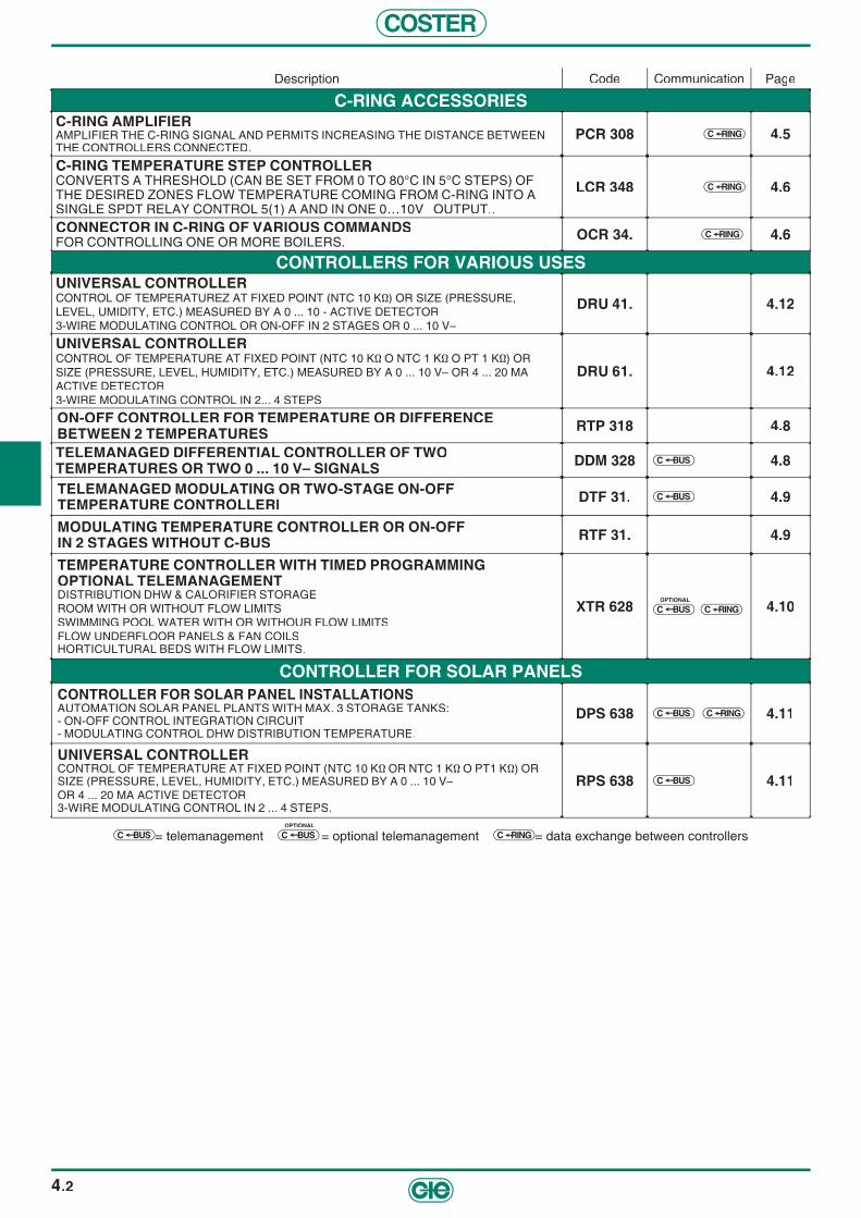
COSTER
4.2
Description Code Communication Page
C-RING ACCESSORIES C-RING AMPLIFIER AMPLIFIER THE C-RING SIGNAL AND PERMITS INCREASING THE DISTANCE BETWEENTHE CONTROLLERS CONNECTED.
PCR 308 C RING 4.5
C-RING TEMPERATURE STEP CONTROLLERCONVERTS A THRESHOLD (CAN BE SET FROM 0 TO 80°C IN 5°C STEPS) OF THE DESIRED ZONES FLOW TEMPERATURE COMING FROM C-RING INTO A SINGLE SPDT RELAY CONTROL 5(1) A AND IN ONE 0…10V– OUTPUT..
LCR 348 C RING 4.6
CONNECTOR IN C-RING OF VARIOUS COMMANDSFOR CONTROLLING ONE OR MORE BOILERS. OCR 34. C RING 4.6
CONTROLLERS FOR VARIOUS USES UNIVERSAL CONTROLLERCONTROL OF TEMPERATUREZ AT FIXED POINT (NTC 10 KΩ) OR SIZE (PRESSURE,LEVEL, UMIDITY, ETC.) MEASURED BY A 0 ... 10 - ACTIVE DETECTOR3-WIRE MODULATING CONTROL OR ON-OFF IN 2 STAGES OR 0 ... 10 V–
DRU 41. 4.12
UNIVERSAL CONTROLLERCONTROL OF TEMPERATURE AT FIXED POINT (NTC 10 KΩ O NTC 1 KΩ O PT 1 KΩ) ORSIZE (PRESSURE, LEVEL, HUMIDITY, ETC.) MEASURED BY A 0 ... 10 V– OR 4 ... 20 MAACTIVE DETECTOR3-WIRE MODULATING CONTROL IN 2... 4 STEPS
DRU 61. 4.12
ON-OFF CONTROLLER FOR TEMPERATURE OR DIFFERENCEBETWEEN 2 TEMPERATURES RTP 318 4.8
TELEMANAGED DIFFERENTIAL CONTROLLER OF TWOTEMPERATURES OR TWO 0 ... 10 V– SIGNALS DDM 328 BUSC 4.8
TELEMANAGED MODULATING OR TWO-STAGE ON-OFFTEMPERATURE CONTROLLERI DTF 31. BUSC 4.9
MODULATING TEMPERATURE CONTROLLER OR ON-OFF IN 2 STAGES WITHOUT C-BUS RTF 31. 4.9
TEMPERATURE CONTROLLER WITH TIMED PROGRAMMINGOPTIONAL TELEMANAGEMENTDISTRIBUTION DHW & CALORIFIER STORAGEROOM WITH OR WITHOUT FLOW LIMITSSWIMMING POOL WATER WITH OR WITHOUR FLOW LIMITSFLOW UNDERFLOOR PANELS & FAN COILSHORTICULTURAL BEDS WITH FLOW LIMITS.
XTR 628OPTIONAL
BUSC C RING 4.10
CONTROLLER FOR SOLAR PANELSCONTROLLER FOR SOLAR PANEL INSTALLATIONSAUTOMATION SOLAR PANEL PLANTS WITH MAX. 3 STORAGE TANKS:- ON-OFF CONTROL INTEGRATION CIRCUIT- MODULATING CONTROL DHW DISTRIBUTION TEMPERATURE.
DPS 638 BUSC C RING 4.11
UNIVERSAL CONTROLLERCONTROL OF TEMPERATURE AT FIXED POINT (NTC 10 KΩ OR NTC 1 KΩ O PT1 KΩ) OR SIZE (PRESSURE, LEVEL, HUMIDITY, ETC.) MEASURED BY A 0 ... 10 V– OR 4 ... 20 MA ACTIVE DETECTOR3-WIRE MODULATING CONTROL IN 2 ... 4 STEPS.
RPS 638 BUSC 4.11
BUSC = telemanagement OPTIONAL
BUSC = optional telemanagement C RING = data exchange between controllers
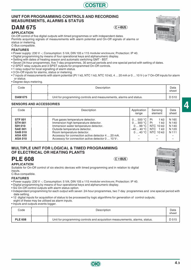
4
COSTER
4.3
UNIT FOR PROGRAMMING CONTROLS AND RECORDINGMEASUREMENTS, ALARMS & STATUS
DAM 675APPLICATIONOn-Off control of fi ve digital outputs with timed programmes or with independent dates.Permits acquiring signals of measurements with alarm potential and On-Off signals of alarms or status or metering. C-Bus compatible.
FEATURES• Power supply: 230 V ~; Consumption: 5 VA; DIN 105 x 115 modular enclosure; Protection: IP 40.• Digital programming by means of four operational keys and alphanumeric display.• Setting with dates of heating season and automatic switching GMT - BST.• Seven 24-hour programmes, fi ve 7-day programmes, 30 annual periods and one special period with setting of dates.• 2 SPDT relay outputs and 3 SPST outputs for programmed On-Off controls.• 1 relay output for local signalling of alarm status.• 3 On-Off inputs for alarms, status or metering.• 7 inputs of measurements with alarm potential (Pt 1 kΩ, NTC 1 kΩ, NTC 10 kΩ, 4 ... 20 mA or 0 ... 10 V-) or 7 On-Off inputs for alarm
or status.• Degree days metering.
Code Description Data sheet
DAM 675 Unit for programming controls and measurements, alarms and status. D 510
Code Description Data sheet Code Description Data sheet
Unit for programming controls and measurements, alarms and status. D 510
Code Description Data sheet
Unit for programming controls and measurements, alarms and status. D 510
Code Description Data sheet
SENSORS AND ACCESSORIES
Code Description Application Sensing Data Code Description Application Sensing Data range element sheet range element sheet
STF 001 Flue gases temperature detector. 0 ... 500 °C Pt 1 kΩ N 165STH 001 Immersion high temperature detector. 0 ... 300 °C Pt 1 kΩ N 140SIH 010 Immersion water temperature detector. 0 ... 99 °C NTC 10 kΩ N 140SAE 001 Outside temperature detector. –40 ... 40 °C NTC 1 kΩ N 120SAB 010 Room temperature detector. 0 ... 40 °C NTC 10 kΩ N 111ASA 420 Accessoy for connection active detector 4 ... 20 mA. – – –ASA 010 Accessoy for connection active detector 0 ... 10 V-. – – –
Code Description Application Sensing Data range element sheet
Flue gases temperature detector. 0 ... 500 °C Pt 1 kΩ N 165 Immersion high temperature detector. 0 ... 300 °C Pt 1 kΩ N 140
Immersion water temperature detector. 0 ... 99 °C NTC 10 kΩ N 140 Outside temperature detector. Room temperature detector. 0 ... 40 °C NTC 10 kΩ N 111 Accessoy for connection active detector 4 ... 20 mA. – – – Accessoy for connection active detector 0 ... 10 V-. – – –
Code Description Application Sensing Data range element sheet
Flue gases temperature detector. 0 ... 500 °C Pt 1 kΩ N 165 Immersion high temperature detector. 0 ... 300 °C Pt 1 kΩ N 140
Immersion water temperature detector. 0 ... 99 °C NTC 10 kΩ N 140 NTC 1 kΩ N 120
Room temperature detector. 0 ... 40 °C NTC 10 kΩ N 111 Accessoy for connection active detector 4 ... 20 mA. – – – Accessoy for connection active detector 0 ... 10 V-. – – –
Code Description Application Sensing Data range element sheet
Flue gases temperature detector. 0 ... 500 °C Pt 1 kΩ N 165 Immersion high temperature detector. 0 ... 300 °C Pt 1 kΩ N 140
Immersion water temperature detector. 0 ... 99 °C NTC 10 kΩ N 140
Code Description Application Sensing Data range element sheet
Flue gases temperature detector. 0 ... 500 °C Pt 1 kΩ N 165 Immersion high temperature detector. 0 ... 300 °C Pt 1 kΩ N 140
Immersion water temperature detector. 0 ... 99 °C NTC 10 kΩ N 140 NTC 1 kΩ N 120
Room temperature detector. 0 ... 40 °C NTC 10 kΩ N 111 Accessoy for connection active detector 4 ... 20 mA. – – – Accessoy for connection active detector 0 ... 10 V-. – – –
Code Description Application Sensing Data range element sheet
Flue gases temperature detector. 0 ... 500 °C Pt 1 kΩ N 165 Immersion high temperature detector. 0 ... 300 °C Pt 1 kΩ N 140
Immersion water temperature detector. 0 ... 99 °C NTC 10 kΩ N 140
Room temperature detector. 0 ... 40 °C NTC 10 kΩ N 111 Accessoy for connection active detector 4 ... 20 mA. – – – Accessoy for connection active detector 0 ... 10 V-. – – –
BUSC
MULTIPLE UNIT FOR LOGICAL & TIMED PROGRAMMINGOF ELECTRICAL OR HEATING PLANTS
PLE 608APPLICATIONSuitable for On-Off control of six electric devices with timed programming and in relation to digital inputs. C-Bus compatible.
FEATURES• Power supply: 230 V ~; Consumption: 5 VA; DIN 105 x 115 modular enclosure; Protection: IP 40.• Digital programming by means of four operational keys and alphanumeric display.• Six On-Off control outputs with alarm status option.• Independent programming for each output with seven 24-hour programmes, two 7-day programmes and one special period with
date setting.• 12 digital inputs for acquisition of status to be processed by logic algorithms for generation of control outputs; eight of these may be utilised as alarm inputs.• Inputs and outputs events logger.
Code Description Data sheet
PLE 608 Unit for programming controls and acquisition measurements, alarms, status. D 515
Code Description Data sheet Code Description Data sheet
Unit for programming controls and acquisition measurements, alarms, status. D 515
Code Description Data sheet
Unit for programming controls and acquisition measurements, alarms, status. D 515
Code Description Data sheet
BUSC

COSTER
4.4
PROGRAMMING UNIT FOR PLANTS & BOILER
XPT 678APPLICATIONDesigned for:- On-Off control of fi ve heating and/or DHW zones by timed events programme.- as above but with addition of temperature control.- control boiler according to heat demand from heating/DHW zones.C-Bus enabled using ACB 460 C1 accessoryC-Ring compatible.
FEATURES• Power supply: 230 V ~; Consumption: 5 VA; DIN 105 x 115 modular enclosure; Protection: IP 40.• Digital programming by means of four operating keys and alphanumeric display.• Setting with dates of heating season and automatic switching GMT-BST.• Five On-Off outputs for heating, etc plants• Independent programming for each output with seven 24-hour programmes, two 7-day programmes, 15 annual periods and one special period with date setting. • One On-Off output for control boiler.• Three On-Off inputs for alarm or status.
Code Description Data sheet
XPT 678 Programming unit for heating zones and boiler. D 511
Code Description Data sheet Code Description Data sheet
Programming unit for heating zones and boiler. D 511
Code Description Data sheet
Programming unit for heating zones and boiler. D 511
Code Description Data sheet
SENSORS AND ACCESSORIES
Code Description Application Sensing Data Code Description Application Sensing Data range element sheet range element sheet
ACB 460 Plug-in for C-Bus communicationSIH 010 Immersion water temperature detector. 0 ... 99 °C NTC 10 kΩ N 140SAE 001 Outside temperature detector. –40 ... 40 °C NTC 1 kΩ N 120SAB 010 Room temperature detector. 0 ... 40 °C NTC 10 kΩ N 111
Code Description Application Sensing Data range element sheet
Immersion water temperature detector. 0 ... 99 °C NTC 10 kΩ N 140 Outside temperature detector. Room temperature detector. 0 ... 40 °C NTC 10 kΩ N 111
Code Description Application Sensing Data range element sheet
Immersion water temperature detector. 0 ... 99 °C NTC 10 kΩ N 140 NTC 1 kΩ N 120
Room temperature detector. 0 ... 40 °C NTC 10 kΩ N 111
Code Description Application Sensing Data range element sheet
ACB 460 Immersion water temperature detector. 0 ... 99 °C NTC 10 kΩ N 140
Code Description Application Sensing Data range element sheet
Immersion water temperature detector. 0 ... 99 °C NTC 10 kΩ N 140 NTC 1 kΩ N 120
Room temperature detector. 0 ... 40 °C NTC 10 kΩ N 111
Code Description Application Sensing Data range element sheet
Immersion water temperature detector. 0 ... 99 °C NTC 10 kΩ N 140
Room temperature detector. 0 ... 40 °C NTC 10 kΩ N 111
BUSC C RING
PROGRAMMMER WITH 2 OUTPUTS & 2 ALARM INPUTSOPTIONAL TELEMANAGEMENT WITH SMS COMMUNICATION
XCO 428 TELEMANAGEMENT C-Bus: Enabled with ACB 400 accessory.APPLICATIONFor On-Off control of two electrical devices with timed programming and local remote controls and remote controls with timed programming and two alarm signalsFEATURES• Power supply: 230V~; Consumption: 3VA; DIN 71 x 116 modular enclosure; Protection: IP 40.• Two relay outputs with 5(1)A SPDT switches.• Two On-Off switches.• Two inputs for remote extension switches.• Two programmable inputs for changing program or signalling alarm.• Programmable via SMS
Code Description Data Code Description Data sheet sheet
XCO 428 Time programmer with two outputs and two alarm inputs. D 512
Code Description Data sheet
Time programmer with two outputs and two alarm inputs. D 512
Code Description Data sheet
Time programmer with two outputs and two alarm inputs. D 512
Code Description Data sheet
SBUCOPTIONAL
RS 232
ACCESSORY FOR TELEMANAGEMENTCode Description Data
sheet
ACB 400 Plug-in for communication via C-Bus T 433
Code Description Data Code Description Data sheet sheet
XCO 428+GSM Mini kit for Telemanagement via RS 232, including program. timer with two outputs. (Page 10.5). –
Code Description Data sheet Code Description Data sheet Code Description Data sheet
KIT OF MINI TELEMANAGEMENT INCLUDING TIMED PROGRAM
XCO 428 + GSM 723 (SINGLE PACKAGE)TELEMANAGEMENT RS 232: already enabled by kit.TELEMANAGEMENT C-Bus: Enabled with ACB 400 accessory.
SBUCOPTIONAL
RS 232

4
COSTER
4.5
SEQUENCER FOR 5 PUMPS OR ELECTRIC LOADS
IPG 658APPLICATIONDesigned for:
– Sequencing max 5 pumps by an On-Off or 0 ... 10 V– control signal with timed rotation of the pumps used and automatic replacement of faulty ones.
– Sequency max 5 electric loads according to total energy consumption (0 ... 10 V– control). Option of increasing number of loads controlled by using several IPG 658 and multiplying the control signal by means of CSC 328 convertors.
Communication by telemanagement system using parallel C-Bus connection.
FEATURES• Power supply: 230 V~; Consumption: 5 VA; DIN 105 x 115 modular enclosure; Protection: IP 40. • Digital programming by means of 4 operating keys and 3-fi gure display.• 5 On-Off relay outputs to control pumps or electric loads.• 1 On-Off relay output for signalling alarm.• 1 input for On-Off or 0 ... 10 V– control signal.• 2 On-Off inputs for each output used for acquisition lockout and confi rmation operation.
The inputs regarding possible unused outputs can be used to signal alarms or status.
Code Description Data Code Description Data sheet sheet
IPG 658 Sequencer for max 5 pumps or electric charges. D 614
Code Description Data sheet
Sequencer for max 5 pumps or electric charges. D 614
Code Description Data sheet
Sequencer for max 5 pumps or electric charges. D 614
Code Description Data sheet
TWIN PUMP STEP CONTROLLER
IPG 318APPLICATIONAdapts the On-Off pump signal from a controller to control twin pumps.Automatically alternates the operation of the two pumps every week o r every month.Automatically inserts the lag pump in case of a lockout in the lead pump.C-Bus compatible.
FEATURES• Power supply: 230 V ~; Consumption: 2 VA; DIN 53 x 115 modular enclosure; Protection: IP 40.
Code Description Data sheet
IPG 318 Changeover controller for twin pumps. D 610
Code Description Data sheet Code Description Data sheet Code Description Data sheet
Changeover controller for twin pumps. D 610
Code Description Data sheet
BUSC
BUSC
0 ... 10 V– SIGNALS SELECTOR
CSA 344APPLICATIONSelects the minimum, arithmetic mean and maximum valves from 2 ... 6 signals 0 ... 10 V– coming from active detectors (humidity, pressure, temperature) or from progressive controls.
FEATURES• Power supply: 24 V~; Consumption: 3VA; DIN 53 x 115 modular enclosure; Protection: IP 40.
Code Description Data sheet
CSA 344 Selector of minimum, arithmetic mean & maximum values of 0 ... 10 V– active signals. D 655
Code Description Data sheet Code Description Data sheet
Selector of minimum, arithmetic mean & maximum values of 0 ... 10 V– active signals. D 655
Code Description Data sheet
Selector of minimum, arithmetic mean & maximum values of 0 ... 10 V– active signals. D 655
Code Description Data sheet
C-RING AMPLIFIER
PCR 308APPLICATIONAmplifi es the C-Ring signal and permits increasing the distance between the controllers connected.One PCR 308 required for each group of controllers.
FEATURES• Power supply: 230 V ~; Consumption: 4 VA; DIN 53 x 115 modular enclosure; Protection: IP 40.
Code Description Data Code Description Data sheet sheet
PCR 308 Low-power C-Ring amplifi er. T 424
Code Description Data sheet Code Description Data sheet
T 424
Code Description Data sheet
C RING

COSTER
4.6
Code Description Data Code Description Data sheet sheet
ASA 241 ASA 241 Connector for converting a switch powered by 24 V~ or 12 V– in an optoisolator control. D 615 ASA 248 ASA 248 Connector for converting a switch powered by 230 V~ in an optoisolator control. D 615
ACT 248 Connector for converting a power supply of 24 V~ to 230 V~ - 10 W. D 615ACR 245 Connector for converting a power supply of 24 V~ to 1 SPTD switch max. 5 (1) A. D 615ACR 242 Connector for converting a power supply of 24 V~ to 2 SPTD switchs max. 1 A (24 V~). D 615AIC 240 Connector for invert the state of a generic contact. D 615FTR 101 Universal fi lter for 24 ... 23o Volt~ switches or inputs. D 615
Code Description Data sheet
Connector for converting a switch powered by 24 V~ or 12 V Connector for converting a switch powered by 230 V~ in an optoisolator control.
Connector for converting a power supply of 24 V~ to 230 V~ - 10 W. Connector for converting a power supply of 24 V~ to 1 SPTD switch max. 5 (1) A. Connector for converting a power supply of 24 V~ to 2 SPTD switchs max. 1 A (24 V~). D 615
Connector for invert the state of a generic contact. D 615 Universal fi lter for 24 ... 23o Volt
Code Description Data sheet
Connector for converting a power supply of 24 V~ to 2 SPTD switchs max. 1 A (24 V~). D 615 Connector for invert the state of a generic contact. D 615
. D 615
Code Description Data sheet
Connector for converting a power supply of 24 V~ to 230 V~ - 10 W. Connector for converting a power supply of 24 V~ to 1 SPTD switch max. 5 (1) A. Connector for converting a power supply of 24 V~ to 2 SPTD switchs max. 1 A (24 V~). D 615
Connector for invert the state of a generic contact. D 615 Universal fi lter for 24 ... 23o Volt
C-RING TEMPERATURE STEP CONTROLLER
LCR 348APPLICATIONConverts a threshold (can be set from 0 to 80°C in 5°C steps) of the desired zones fl ow temperature coming from C-Ring into a single SPDT relay control 5(1) A and in one 0 ... 10V- output.
FEATURES• Power supply: 230 V~; Consumption: 3VA; DIN 53 x 115 modular container; Protection: IP 40.
Code Description Data Code Description Data sheet sheet
LCR 348 C-Ring threshold temperature step controller. D 661
Code Description Data sheet
C-Ring threshold temperature step controller. D 66
Code Description Data sheet
C-Ring threshold temperature step controller. D 66
Code Description Data sheet
C RING
GENERAL ACCESSORIES FOR ELECTRIC CONNECTIONSGENERAL ACCESSORIES FOR ELECTRIC CONNECTIONS
CONNECTOR IN C-RING OF VARIOUS COMMANDSFOR CONTROLLING ONE OR MORE BOILERS
OCR 34.APPLICATIONConnects in C-Ring to control the temperature required by the boiler(s):– a temperature measured by a standard sensor– a 0…10V– input which can be set with any scale– a remote control type CBD 100– a general-use switch
FEATURES• Power supply: 230 V~/24 V~; Consumption: 3 VA; DIN 53 x 115 modular housing; Protection: IP 40. • Output relay switch: - maximum applicable voltage250 V~ - maximum switching current 5 (1) A
Code Description Power Data Code Description Power Data supply sheet supply sheet
OCR 348 Connector to C-Ring of various commands for controlling one or more boilers 230 V~ D 662OCR 344 Connector to C-Ring of various commands for controlling one or more boilers 24 V~ D 662
Code Description Power Data supply sheet Code Description Power Data supply sheet
D 66 D 66
Code Description Power Data supply sheet
C RING
Code Description Power Data supply sheet

4
COSTER
4.7
ACTIVE AND PASSIVE TEMPERATURE DETECTOR CONVERTER
CAP 328APPLICATIONThe device is designed to convert the temperature measurement of one 0 ... 10 V– or 4 ... 20 mA active detector or one NTC 1 KΩ or NTC 10 KΩ passive detector into two NTC 1 KΩ or NTC 10 KΩ passive detector measurements.Each measurement output can be used in parallel on several controllers (up to 5) whose measurement inputs have the same features.
FEATURES• Power supply: 230 V~; Consumption: 2 VA; DIN 53 x 115 modular enclosure; Protection: IP 40.
CONVERTOR OF 3-WIRE OR 0 ... 10 V– OR 4 ... 20 mAIN TWO 0 ... 10 V– SIGNALS
CSC 328APPLICATIONThe device is designed to transform one 3-wire modulating signal or one 0 ... 10 V– oR 4 ... 20 mA signal into two 0 ... 10 V– signals. C-Bus compatible.
FEATURES• Power supply: 230 V~; Consumption: 2 VA; DIN 53 x 115 modular enclosure; Protection: IP 40.
CONVERTOR OF 0 ... 10V– OR 4 ... 20 mA SIGNALS ORTEMPERATURE MEASUREMENT INTO RELAY CONTROLS
CSV 328APPLICATIONThe device is designed to convert one 0 ... 10V~ or 4 ... 20 mA or temperature measurement (NTC 1 kΩ or NTC 10 kΩ) signal into a 3-wire modulating control or 2-stage On-Off control or max-min limit On-Off control. C-Bus compatible.
FEATURES• Power supply: 230 V~; Consumption: 2VA; DIN 53 x 115 modular enclosure; Protection: IP 40.
Code Description Data Code Description Data sheet sheet
CSV 328 Converter of 0 ... 10 V– or 4 ... 20 mA or temperature measurement signal to relay controls. D 652
Code Description Data Code Description Data sheet sheet
CSC 328 Converter of 3-wire 0 ... 10 V– or 4 ... 20 mA signal to two 0 ... 10 V– signals. D 653
Code Description Data sheet
CAP 328 Active and passive temperature detector. D 654
Code Description Data sheet
Code Description Data sheet Code Description Data sheet
D 652
Code Description Data sheet
Code Description Data sheet
Converter of 3-wire 0 ... 10 V– or 4 ... 20 mA signal to two 0 ... 10 V– signals. D 653
Code Description Data sheet
Converter of 3-wire 0 ... 10 V– or 4 ... 20 mA signal to two 0 ... 10 V– signals. D 653
Code Description Data sheet
Code Description Data sheet
Active and passive temperature detector. D 654
Code Description Data sheet
Active and passive temperature detector. D 654
Code Description Data sheet
BUSC
BUSC
Temperature measurement Groups of controllers with identical measurement features
NTC 1 kΩ - NTC 1 kΩ - Outside (-30 ... 40 °C)
NTC 10 kΩ - NTC 10 kΩ - Room (0 ... 40 °C)
NTC 10 kΩ - Discharge air (0 ... 60 °C)
NTC 10 kΩ - NTC 10 kΩ - Water (0 ... 100 °C)
Check on CAP 328 Technical Data Sheet (D 654)

COSTER
4.8
DIFFERENTIAL CONTROLLER FOR TWO TEMPERATURESOR TWO 0 ... 10 V– SIGNALS
DDM 328APPLICATIONSuitable for (example): - Control diffusors according to fl ow/room temperature differential. - Control dampers according to outside/room humidity differential. - Control pump according to fl ow/room temperature differential.Communication with telemanagement systems via C-Bus parallel connction.Essential detectors: two NTC 10 kΩ temperature detectors or two 0 ... 10 V– detectors.
FEATURES• Power supply: 230 V~; Consumption: 3 VA; DIN 53 x 115 modular enclosure; Protection: IP 40. • Digital programming by means of 4 operating keys and three-fi gure display.• Modulating control (three-wire) or On-Off in two stages or On-Off for minimum and maximum limits.• Progressive 0 ... 10 V– control.
Code Description Data Code Description Data sheet sheet
DDM 328 DDM 328 Controller for differential between two temperatures or two 0 ... 10 V– signals. D 156
Code Description Data sheet Code Description Data sheet
Controller for differential between two temperatures or two 0 ... 10 V– signals. D 156
Code Description Data sheet
DDM 328
SENSORS AND ACCESSORIES
Code Description Application Sensing elem. Data Code Description Application Sensing elem. Data range or signal sheet range or signal sheet
SIH 010 Immersion temperature detector. 0 ... 99 °C NTC 10 kΩ N 140 SAB 010 SAB 010 Room temperature detector. 0 ... 40 °C NTC 10 kΩ N 111 STA 010 STA 010 Air duct temperature detector. 0 ... 99 °C NTC 10 kΩ N 150
SUR 704 Relative humidity detector. 10 ... 90 % 0 ... 10 V– N 221 SUT 714 SUT 714 Relative humidity and temperature detector. 10 ... 90 % 0 ... 10 V– N 222
SAU 914 Relative humidity & 20 ... 80 % 0 ... 10 V– N 227 temperature sensor. temperature sensor. 0 ... 40 °C NTC 10 kΩ –
Code Description Application Sensing elem. Data range or signal sheet
Room temperature detector. 0 ... 40 °C NTC 10 kΩ N 111
temperature sensor.
Code Description Application Sensing elem. Data range or signal sheet
Immersion temperature detector. 0 ... 99 °C NTC 10 kΩ N 140 Room temperature detector. 0 ... 40 °C NTC 10 kΩ N 111
Air duct temperature detector. 0 ... 99 °C NTC 10 kΩ N 150 10 ... 90 % 0 ... 10 V– N 221
10 ... 90 % 0 ... 10 V– N 22 20 ... 80 % 0 ... 10 V– N 22
Code Description Application Sensing elem. Data range or signal sheet
SIH 010
STA 010 SUR 704
SUT 714 SAU 914
temperature sensor.
Code Description Application Sensing elem. Data range or signal sheet
Immersion temperature detector. 0 ... 99 °C NTC 10 kΩ N 140 Room temperature detector. 0 ... 40 °C NTC 10 kΩ N 111
Air duct temperature detector. 0 ... 99 °C NTC 10 kΩ N 150 10 ... 90 % 0 ... 10 V– N 221
10 ... 90 % 0 ... 10 V– N 22 20 ... 80 % 0 ... 10 V– N 22
Code Description Application Sensing elem. Data range or signal sheet
Immersion temperature detector. 0 ... 99 °C NTC 10 kΩ N 140 Room temperature detector. 0 ... 40 °C NTC 10 kΩ N 111
Air duct temperature detector. 0 ... 99 °C NTC 10 kΩ N 150 10 ... 90 % 0 ... 10 V– N 221
10 ... 90 % 0 ... 10 V– N 22 20 ... 80 % 0 ... 10 V– N 22
BUSC
DETECTORS & ACCESSORIES
Code Description Application Sensing elem. Data Code Description Application Sensing elem. Data range or signal sheet range or signal sheet
SIH 010 Immersion temperature detector. 0 ... 99 °C NTC 10 kΩ N 140SCH 010 Surface temperature detector. 0 ... 99 °C NTC 10 kΩ N 130
SAB 010 SAB 010 Room temperature detector. 0 ... 40 °C NTC 10 kΩ N 111 STA 010 STA 010 Air duct temperature detector. 0 ... 99 °C NTC 10 kΩ N 150
SAF 010 Cable-type temperature detector. 0 ... 99 °C NTC 10 kΩ N 145SAE 001 Outside temperature detector. – 30 ... 40 °C NTC 1 kΩ N 120SAF 001 Cable-type temperature detector. – 40 ... 40 °C NTC 1 kΩ N 145
ON - OFF OR DIFFERENTIAL TEMPERATURE CONTROLLER
RTP 318APPLICATIONFor control temperature at a fi xed point or to control the difference between two temperatures, by means of one stage On-Off.Essential detectors: 1 detector for fi xed point control. 2 detectors for control temperature difference.FEATURES• Power supply: 230 V~; Consumption: 3 VA; DIN 53 x 115 modular enclosure; Protection: IP 40. • Digital programming by means of 3 operating keys and 3-fi gures alphanumeric display.• One-stage On-Off SPDT.
Code Description Data sheet
RTP 318 On-Off or differential temperature controller. D 112
Code Description Data sheet Code Description Data sheet
On-Off or differential temperature controller. D 112
Code Description Data sheet Code Description Data sheet
On-Off or differential temperature controller. D 112
Code Description Application Sensing elem. Data range or signal sheet
Surface temperature detector. 0 ... 99 °C NTC 10 kΩ N 130 Room temperature detector. 0 ... 40 °C NTC 10 kΩ N 111
Cable-type temperature detector. 0 ... 99 °C NTC 10 kΩ N 145 Outside temperature detector. Cable-type temperature detector.
Code Description Application Sensing elem. Data range or signal sheet
Immersion temperature detector. 0 ... 99 °C NTC 10 kΩ N 140 Surface temperature detector. 0 ... 99 °C NTC 10 kΩ N 130
Room temperature detector. 0 ... 40 °C NTC 10 kΩ N 111Air duct temperature detector. 0 ... 99 °C NTC 10 kΩ N 150
Cable-type temperature detector. 0 ... 99 °C NTC 10 kΩ N 145 NTC 1 kΩ N 120 NTC 1 kΩ N 145
Code Description Application Sensing elem. Data range or signal sheet
SIH 010 Surface temperature detector. 0 ... 99 °C NTC 10 kΩ N 130
STA 010 Cable-type temperature detector. 0 ... 99 °C NTC 10 kΩ N 145 Outside temperature detector. Cable-type temperature detector.
Code Description Application Sensing elem. Data range or signal sheet
Immersion temperature detector. 0 ... 99 °C NTC 10 kΩ N 140 Surface temperature detector. 0 ... 99 °C NTC 10 kΩ N 130
Room temperature detector. 0 ... 40 °C NTC 10 kΩ N 111Air duct temperature detector. 0 ... 99 °C NTC 10 kΩ N 150
Cable-type temperature detector. 0 ... 99 °C NTC 10 kΩ N 145 NTC 1 kΩ N 120 NTC 1 kΩ N 145
Code Description Application Sensing elem. Data range or signal sheet
Immersion temperature detector. 0 ... 99 °C NTC 10 kΩ N 140 Surface temperature detector. 0 ... 99 °C NTC 10 kΩ N 130
Room temperature detector. 0 ... 40 °C NTC 10 kΩ N 111Air duct temperature detector. 0 ... 99 °C NTC 10 kΩ N 150
Cable-type temperature detector. 0 ... 99 °C NTC 10 kΩ N 145
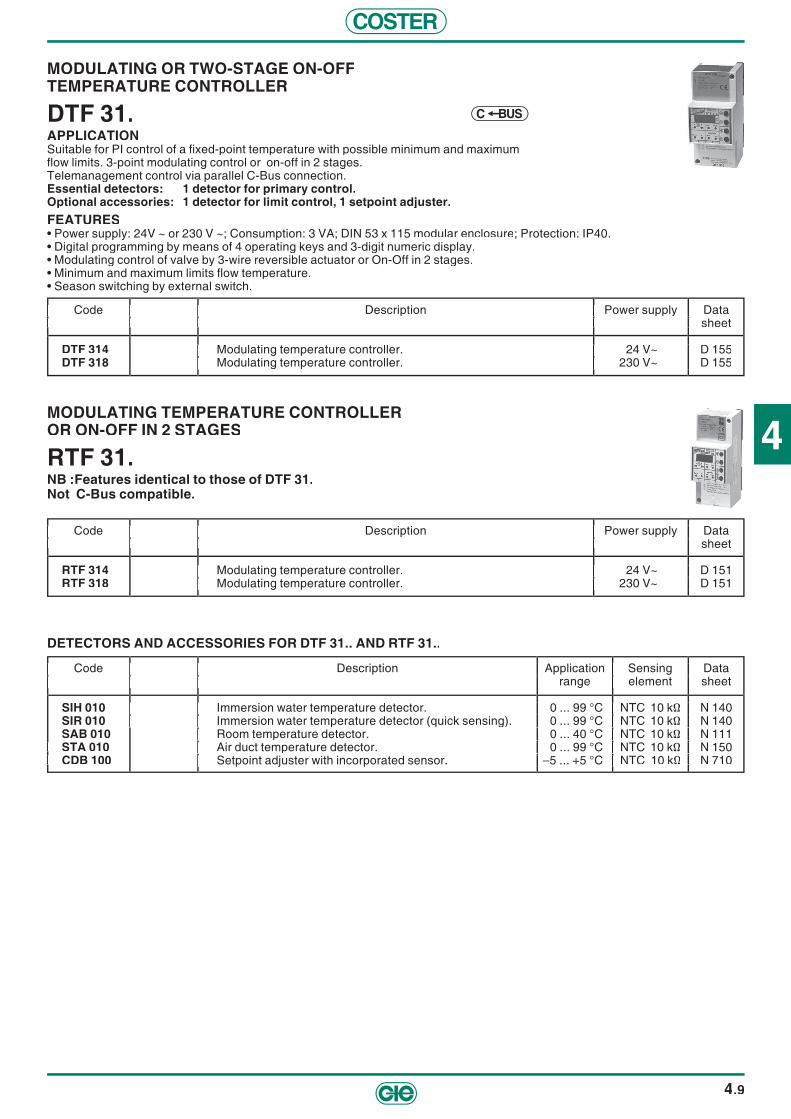
4
COSTER
4.9
MODULATING OR TWO-STAGE ON-OFFTEMPERATURE CONTROLLER
DTF 31.APPLICATIONSuitable for PI control of a fi xed-point temperature with possible minimum and maximum fl ow limits. 3-point modulating control or on-off in 2 stages. Telemanagement control via parallel C-Bus connection. Essential detectors: 1 detector for primary control.Optional accessories: 1 detector for limit control, 1 setpoint adjuster.FEATURES• Power supply: 24V ~ or 230 V ~; Consumption: 3 VA; DIN 53 x 115 modular enclosure; Protection: IP40.• Digital programming by means of 4 operating keys and 3-digit numeric display.• Modulating control of valve by 3-wire reversible actuator or On-Off in 2 stages.• Minimum and maximum limits fl ow temperature.• Season switching by external switch.
MODULATING TEMPERATURE CONTROLLER OR ON-OFF IN 2 STAGES
RTF 31.NB :Features identical to those of DTF 31.Not C-Bus compatible.
Code Description Power supply Data sheet
RTF 314 Modulating temperature controller. 24 V~ D 151RTF 318 Modulating temperature controller. 230 V~ D 151
Code Description Power supply Data sheet Code Description Power supply Data sheet
Modulating temperature controller. 24 V~ D 151 Modulating temperature controller. 230 V~ D 151
Code Description Power supply Data sheet
Modulating temperature controller. 24 V~ D 151 Modulating temperature controller. 230 V~ D 151
Code Description Power supply Data sheet Code Description Power supply Data sheet
Modulating temperature controller. 24 V~ D 151 Modulating temperature controller. 230 V~ D 151
DETECTORS AND ACCESSORIES FOR DTF 31.. AND RTF 31..
Code Description Application Sensing Data Code Description Application Sensing Data range element sheet range element sheet
SIH 010 Immersion water temperature detector. 0 ... 99 °C NTC 10 kΩ N 140SIR 010 Immersion water temperature detector (quick sensing). 0 ... 99 °C NTC 10 kΩ N 140SAB 010 Room temperature detector. 0 ... 40 °C NTC 10 kΩ N 111
STA 010 STA 010 Air duct temperature detector. 0 ... 99 °C NTC 10 kΩ N 150 CDB 100 CDB 100 Setpoint adjuster with incorporated sensor. –5 ... +5 °C NTC 10 kΩ N 710
Code Description Power supply Data sheet
DTF 314 Modulating temperature controller. 24 V~ D 155DTF 318 Modulating temperature controller. 230 V~ D 155
Code Description Power supply Data sheet Code Description Power supply Data sheet
Modulating temperature controller. 24 V~ D 155 Modulating temperature controller. 230 V~ D 155
Code Description Power supply Data sheet
Modulating temperature controller. 24 V~ D 155 Modulating temperature controller. 230 V~ D 155
Code Description Power supply Data sheet Code Description Power supply Data sheet
Modulating temperature controller. 24 V~ D 155 Modulating temperature controller. 230 V~ D 155
Code Description Application Sensing Data range element sheet
Immersion water temperature detector. 0 ... 99 °C NTC 10 kΩ N 140 Immersion water temperature detector (quick sensing). 0 ... 99 °C NTC 10 kΩ N 140
Room temperature detector. 0 ... 40 °C NTC 10 kΩ N 111 Air duct temperature detector. 0 ... 99 °C NTC 10 kΩ N 150 Setpoint adjuster with incorporated sensor. –5 ... +5 °C
Code Description Application Sensing Data range element sheet
Immersion water temperature detector. 0 ... 99 °C NTC 10 kΩ N 140 Immersion water temperature detector (quick sensing). 0 ... 99 °C NTC 10 kΩ N 140
Room temperature detector. 0 ... 40 °C NTC 10 kΩ N 111 Air duct temperature detector. 0 ... 99 °C NTC 10 kΩ N 150
N 710
Code Description Application Sensing Data range element sheet
Immersion water temperature detector. 0 ... 99 °C NTC 10 kΩ N 140 Immersion water temperature detector (quick sensing). 0 ... 99 °C NTC 10 kΩ N 140
Code Description Application Sensing Data range element sheet
Immersion water temperature detector. 0 ... 99 °C NTC 10 kΩ N 140 Immersion water temperature detector (quick sensing). 0 ... 99 °C NTC 10 kΩ N 140
Room temperature detector. 0 ... 40 °C NTC 10 kΩ N 111 Air duct temperature detector. 0 ... 99 °C NTC 10 kΩ N 150 Setpoint adjuster with incorporated sensor. –5 ... +5 °C
Code Description Application Sensing Data range element sheet
Immersion water temperature detector. 0 ... 99 °C NTC 10 kΩ N 140 Immersion water temperature detector (quick sensing). 0 ... 99 °C NTC 10 kΩ N 140
Room temperature detector. 0 ... 40 °C NTC 10 kΩ N 111 Air duct temperature detector. 0 ... 99 °C NTC 10 kΩ N 150 Setpoint adjuster with incorporated sensor. –5 ... +5 °C
BUSC

COSTER
4.10
TEMPERATURE CONTROLLER WITH TIMED PROGRAMMINGOPTIONAL TELEMANAGEMENT
XTR 628TELEMANAGEMENT C-Bus: Enabled with ACB 460 accessory.APPLICATIONSuitable for temperature control:– DHW & storage calorifi er.– Swimming pool water with or without fl ow limits.– Flow underfl oor panels and fan-coils.– Greenhouse beds with fl ow limits.– Room with or without fl ow limits for heating zones with radiators, panels, hot air generators.Data communication with other controllers via C-Ring connection.Essential sensors: 1, 2 or 3 temperature sensors.Optional accessories: 1 fl ow temperature sensor, 1 set-point adjuster.FEATURES• Power supply: 230V~; Consumption: 5VA; DIN 105 x 115 modular enclosure; Protection: IP 40.• Digital programming by means of 4 keys and alphanumeric display.• 1 primary temperature control with: – Control of temperature with one primary sensor or with one primary sensor and one fl ow sensor (minimum & maximum limits). – Modulating 3-wire control of valve or On-Off in 1 or 2 stages Proportional/Integral or differential.• 2 On-Off temperature or timed controls with: – Control temperature with one sensor. – On-Off PI or differential control.• Autonomous timed programming for the three controls with seven 24hour programs, two 7day programs and 2 5 annual periods with dates.• Autonomous functions usable by the three types of control: – Priority and control anticondensing boiler. – Antibacteria.• Automatic switching GMT – BST.• 1 input for changing programs primary control.• 2 inputs for changing programs On-Off control or On-Off alarm inputs.• 1 On-Off alarm input.• Alarms for plant faults and for open or short sensor circuit.
Code Description Data Code Description Data sheet sheet
XTR 628 Temperature controller. D 212
Code Description Data sheet
Temperature controller. D 212
Code Description Data sheet
Temperature controller. D 212
Code Description Data sheet
SONDE E ACCESSORI
Code Description Application Sensing Data Code Description Application Sensing Data range element sheet range element sheet
ACB 460 Plug-in for C-Bus communication. – SIH 010 SIH 010 Immersion temperature sensor (Normal). 0 ... 99 °C NTC 10 kΩ N 140 SIR 010 SIR 010 Immersion temperature sensor (Rapid). 0 ... 99 °C NTC 10 kΩ N 140 SAB 010 SAB 010 Room temperature sensor. 0 ... 40 °C NTC 10 kΩ N 111 S STA 010 Air duct temperature sensor. 0 ... 99 °C NTC 10 kΩ N 150
CDB 100 Setpoint adjuster with incorporated sensor. –5 ... +5 °C NTC 10 kΩ N 710
Code Description Application Sensing Data range element sheet
Plug-in for C-Bus communication. – Immersion temperature sensor (Normal). 0 ... 99 °C NTC 10 kΩ N 140 Immersion temperature sensor (Rapid). 0 ... 99 °C NTC 10 kΩ N 140 Room temperature sensor. 0 ... 40 °C NTC 10 kΩ N 111 Air duct temperature sensor. 0 ... 99 °C NTC 10 kΩ N 150 Setpoint adjuster with incorporated sensor. –5 ... +5 °C
Code Description Application Sensing Data range element sheet
Plug-in for C-Bus communication. – Immersion temperature sensor (Normal). 0 ... 99 °C NTC 10 kΩ N 140 Immersion temperature sensor (Rapid). 0 ... 99 °C NTC 10 kΩ N 140 Room temperature sensor. 0 ... 40 °C NTC 10 kΩ N 111 Air duct temperature sensor. 0 ... 99 °C NTC 10 kΩ N 150
N 710
Code Description Application Sensing Data range element sheet Code Description Application Sensing Data range element sheet
Plug-in for C-Bus communication. – Immersion temperature sensor (Normal). 0 ... 99 °C NTC 10 kΩ N 140 Immersion temperature sensor (Rapid). 0 ... 99 °C NTC 10 kΩ N 140 Room temperature sensor. 0 ... 40 °C NTC 10 kΩ N 111 Air duct temperature sensor. 0 ... 99 °C NTC 10 kΩ N 150 Setpoint adjuster with incorporated sensor. –5 ... +5 °C
Code Description Application Sensing Data range element sheet
Plug-in for C-Bus communication. – Immersion temperature sensor (Normal). 0 ... 99 °C NTC 10 kΩ N 140 Immersion temperature sensor (Rapid). 0 ... 99 °C NTC 10 kΩ N 140 Room temperature sensor. 0 ... 40 °C NTC 10 kΩ N 111 Air duct temperature sensor. 0 ... 99 °C NTC 10 kΩ N 150 Setpoint adjuster with incorporated sensor. –5 ... +5 °C
C RINGSBUCOPTIONAL

4
COSTER
4.11
CONTROLLER FOR SOLAR PANEL INSTALLATIONS
DPS 638APPLICATIONDesigned for automation of solar panel installations wiith a maximum of three storage tanks with On-Off control of integration circuit and modulating control of DHW distribution circuit.C-Bus compatible.C-Ring compatible.Essential detectors: 1 solar panel temperature detector; from 1 to 3 storage tank detectors.Optional detectors: 1 integration temperature detector, 1 DHW temperature detector.FEATURES• Power supply: 230 V ~; Consumption: 5VA; DIN 105 x 115 modular enclosure; Protection: IP 40.• Digital programming by means of four operating keys and alphanumeric display.• Setting dates of heating season and automatic switching GMT - BST.• Seven 24-hour programmes, two 7-day programmes, 25 holiday periods and one special period with date setting.• Management of heat exchange between solar panels and storage tanks (max. three) in relation to temperature differential with
control panels circuit pump and automatic switching between three storage tanks.• Control of integration circuit temperature by programmed events On-Off control and antibacterial function.• Regulation of temperature by modulating three-wire control of DHW distribution tem pe ra tu re or of minimum solar panels tem pe -
ra tu re.• 3 On-Off inputs for alarms or status.• Alarm functioning of plant and alarms for closed or open detector circuits.
Code Description Data sheet
DPS 638 Temperature controller for solar panel installations. D 310
Code Description Data sheet Code Description Data sheet
Temperature controller for solar panel installations. D 310
Code Description Data sheet
Temperature controller for solar panel installations. D 310
Code Description Data sheet
C RINGBUSC
CONTROLLER FOR SOLAR PANEL INSTALLATIONS
RPS 638Technical and functional features same as DPS 638.Not C-Bus compatible.
DETECTORS AND ACCESSORIES FOR RPS 638 AND DPS 638
Code Description Application Sensing Data Code Description Application Sensing Data range element sheet range element sheet
SIH 010 Immersion detector (1/2” x 80 mm). 0 ... 99 °C NTC 10 kΩ N 140SAF 010 Cable-type detector. 0 ... 99 °C NTC 10 kΩ N 145SHF 001 Cable-type temperature detector with 3-metre cable. 0 ... 180 °C Pt 1 kΩ N 145GIS 090 Cable-type detector pocket (1/2” x 90 mm). – – N 145GIS 160 Cable-type detector pocket (1/2” x 160 mm). – – N 145GIS 500 Cable-type detector pocket (1/2” x 500 mm). – – N 145
Code Description Data sheet
RPS 638 Temperature controller for solar panel installations. D 315
Code Description Data sheet Code Description Data sheet
Temperature controller for solar panel installations. D 315
Code Description Data sheet
Temperature controller for solar panel installations. D 315
Code Description Data sheet
Code Description Application Sensing Data range element sheet
Immersion detector (1/2” x 80 mm). 0 ... 99 °C NTC 10 kΩ N 140 Cable-type detector. 0 ... 99 °C NTC 10 kΩ N 145
Cable-type detector pocket (1/2” x 90 mm). – – N 145 Cable-type detector pocket (1/2” x 160 mm). – – N 145 Cable-type detector pocket (1/2” x 500 mm). – – N 145
Code Description Application Sensing Data range element sheet
Immersion detector (1/2” x 80 mm). 0 ... 99 °C NTC 10 kΩ N 140 Cable-type detector. 0 ... 99 °C NTC 10 kΩ N 145
1 kΩ N 145 Cable-type detector pocket (1/2” x 90 mm). – – N 145 Cable-type detector pocket (1/2” x 160 mm). – – N 145 Cable-type detector pocket (1/2” x 500 mm). – – N 145
Code Description Application Sensing Data range element sheet
Immersion detector (1/2” x 80 mm). 0 ... 99 °C NTC 10 kΩ N 140 Cable-type detector. 0 ... 99 °C NTC 10 kΩ N 145
SHF 001 Cable-type detector pocket (1/2” x 90 mm). – – N 145 Cable-type detector pocket (1/2” x 160 mm). – – N 145 Cable-type detector pocket (1/2” x 500 mm). – – N 145
Code Description Application Sensing Data range element sheet
Immersion detector (1/2” x 80 mm). 0 ... 99 °C NTC 10 kΩ N 140 Cable-type detector. 0 ... 99 °C NTC 10 kΩ N 145
Cable-type detector pocket (1/2” x 90 mm). – – N 145 Cable-type detector pocket (1/2” x 160 mm). – – N 145 Cable-type detector pocket (1/2” x 500 mm). – – N 145
Code Description Application Sensing Data range element sheet
Immersion detector (1/2” x 80 mm). 0 ... 99 °C NTC 10 kΩ N 140 Cable-type detector. 0 ... 99 °C NTC 10 kΩ N 145
Cable-type detector pocket (1/2” x 90 mm). – – N 145 Cable-type detector pocket (1/2” x 160 mm). – – N 145 Cable-type detector pocket (1/2” x 500 mm). – – N 145
C RING

COSTER
4.12
UNIVERSAL CONTROLLER
DRU 414 - 418APPLICATIONSuitable for control at fi xed point of a temperature measured by a thermistor-type detector NTC 10 kΩ or of another variable (humidity, pressure, level, etc.) measured by a detector with 0 ... 10 V– output signals. C-Bus compatible.Essential detectors: 1 thermistor or voltage type.Optional detectors: 1 setpoint adjuster.FEATURES• Power supply: 24 V ~ (DRU 414), 230 V ~ (DRU 418); Consumption: 3 VA; DIN 53 x 115 modular enclosure; Protection: IP 40.• Digital programming by means of four operating keys and 3-fi gure numerical display.• Three-wire modulating control or two-stage On-Off or 0 ... 10 V control signal.
UNIVERSAL CONTROLLER
DRU 614 - 618APPLICATIONSuitable for control of at fi xed point of a temperature measured by a thermistor-type detector (NTC 10 kΩ or NTC 1 kΩ or PT 1kΩ) or of another variable (pressure, level, etc.) measured by a detector with 0 ... 10 V– or 4 ... 20 mA output signals. C-Bus compatible.Essential detectors: 1 thermistor type or voltage/current type.Optional detectors: 1 setpoint adjuster.FEATURES• Power supply: 24 V ~ (DRU 614), 230 V ~ (DRU 618); Consumption: 5 VA; DIN 105 x 115 modular enclosure; Protection: IP 40.• Digital programming by means of four operating keys and alphanumeric display.• Control at fi xed point:
– Three-wire modulating control or On-Off control in sequence of 2, 3 or 4 stages.– Two On-Off controls in relation to two adjustable thresholds of output signal or of measurement range.– Adjustment of set point by means of remote control.
• One On-Off alarm input.• Two confi gurable inputs : remote control for inversion of control action or On-Off alarms.• Alarms for operational controller fault for short or open detector circuits.
DETECTORS AND ACCESSORIES FOR DRU 41. AND DRU 61.
Code Description Application Sensor or Data Code Description Application Sensor or Data range signal sheet range signal sheet
SIH 010 Immersion temperature sensor. 0 ... 99 °C NTC 10 kΩ N 140 SAF 001 SAF 001 Cable-type temperature sensor (only for DRU 614). –40 ... 40°C NTC 1 kΩ N 145 STH 001 STH 001 Immersion water temp. sensor (only for DRU 614). 0 ... 300 °C PT 1 kΩ N 140
SAB 010 Room temperature sensor. 0 ... 40 °C NTC 10 kΩ N 111SUR 704 Relative humidity sensor. 10 ... 90 % 0 ... 10 V– N 221
SUT 714 SUT 714 Relative humidity and temperature sensor. 10 ... 90 % 0 ... 10 V– N 222SAU 914 Relative humidity. 20 ... 80 % 0 ... 10 V– N 227
& temperature sensor. 0 ... 40 °C NTC 10 kΩSPW 204 Absolute pressure sensor for liquids. 0 ... 4 bar 0 ... 10 V– N 412SPW 210 Absolute pressure sensor for liquids. 0 ... 10 bar 0 ... 10 V– N 412SPW 216 Absolute pressure sensor for liquids. 0 ... 16 bar 0 ... 10 V– N 412
SDW 201 SDW 201 Differential pressure sensor for liquids. 0 ... 1 bar 0 ... 10 V– N 422 SDW 202 SDW 202 Differential pressure sensor for liquids. 0 ... 2,5 bar 0 ... 10 V– N 422 SDW 206 SDW 206 Differential pressure sensor for liquids. 0 ... 6 bar 0 ... 10 V– N 422
SDA 701 Differential pressure sensor for air. 0 ... 1 mbar 0 ... 10 V– N 430SDA 703 Differential pressure sensor for air. 0 ... 3 mbar 0 ... 10 V– N 430SDA 705 Differential pressure sensor for air. 0 ... 5 mbar 0 ... 10 V– N 430SDA 730 Differential pressure sensor for air. 0 ... 30 mbar 0 ... 10 V– N 430
CDB 100 CDB 100 Setpoint adjuster with incorporated sensor. –5 ... +5 °C NTC 10 kΩ N 710
Code Description Data sheet Code Description Data sheet
DRU 614 Universal controller. Power supply 24 V~. D 410DRU 618 Universal controller. Power supply 230 V~ D 410
Code Description Data sheet
Universal controller. Power supply 24 V Universal controller.
Code Description Data sheet
D 410 D 410
Code Description Data sheet
Code Description Application Sensor or Data range signal sheet
Immersion water temp. Room temperature
SUR 704 SUT 714
Relative humidity. 20 ... 80 % 0 ... 10 V– N 22
Absolute pressure Absolute pressure Absolute pressure
SDW 201 SDW 202 SDW 206
SDA 701 Differential pressure Differential pressure
SDA 730 Setpoint adjuster with incorporated sensor.
Code Description Application Sensor or Data range signal sheet
NTC 10 kΩ N 140 (only for DRU 614). –40 ... 40°C NTC 1 kΩ N 145
(only for DRU 614). 0 ... 300 °C PT 1 kΩ N 140. 0 ... 40 °C NTC 10 kΩ N 111
10 ... 90 % 0 ... 10 V– N 221 10 ... 90 % 0 ... 10 V– N 22
Relative humidity. 20 ... 80 % 0 ... 10 V– N 22
for liquids. 0 ... 4 bar 0 ... 10 V– N 41 for liquids. 0 ... 10 bar 0 ... 10 V– N 412 for liquids. 0 ... 16 bar 0 ... 10 V– N 412
for liquids. 0 ... 1 bar 0 ... 10 V– N 422 for liquids. 0 ... 2,5 bar 0 ... 10 V– N 422 for liquids. 0 ... 6 bar 0 ... 10 V– N 422 for air. 0 ... 1 mbar 0 ... 10 V– N 430 for air. 0 ... 3 mbar 0 ... 10 V– N 430 for air. 0 ... 5 mbar 0 ... 10 V– N 430 for air. 0 ... 30 mbar 0 ... 10 V– N 430
Code Description Application Sensor or Data range signal sheet
SIH 010 SAF 001
SUR 704 SUT 714
Absolute pressure
SDW 201 SDW 202 SDW 206
SDA 701
SDA 730
Code Description Application Sensor or Data range signal sheet
NTC 10 kΩ N 140 (only for DRU 614). –40 ... 40°C NTC 1 kΩ N 145
(only for DRU 614). 0 ... 300 °C PT 1 kΩ N 140. 0 ... 40 °C NTC 10 kΩ N 111
10 ... 90 % 0 ... 10 V– N 221 10 ... 90 % 0 ... 10 V– N 22
Relative humidity. 20 ... 80 % 0 ... 10 V– N 22
for liquids. 0 ... 4 bar 0 ... 10 V– N 41 for liquids. 0 ... 10 bar 0 ... 10 V– N 412 for liquids. 0 ... 16 bar 0 ... 10 V– N 412
for liquids. 0 ... 1 bar 0 ... 10 V– N 422 for liquids. 0 ... 2,5 bar 0 ... 10 V– N 422 for liquids. 0 ... 6 bar 0 ... 10 V– N 422 for air. 0 ... 1 mbar 0 ... 10 V– N 430 for air. 0 ... 3 mbar 0 ... 10 V– N 430 for air. 0 ... 5 mbar 0 ... 10 V– N 430 for air. 0 ... 30 mbar 0 ... 10 V– N 430
Code Description Application Sensor or Data range signal sheet
(only for DRU 614). –40 ... 40°C NTC 1 kΩ N 145 (only for DRU 614). 0 ... 300 °C PT 1 kΩ N 140
. 0 ... 40 °C NTC 10 kΩ N 111 10 ... 90 % 0 ... 10 V– N 221
10 ... 90 % 0 ... 10 V– N 22 Relative humidity. 20 ... 80 % 0 ... 10 V– N 22
& temperature sensor. 0 ... 40 °C for liquids. 0 ... 4 bar 0 ... 10 V– N 41 for liquids. 0 ... 10 bar 0 ... 10 V– N 412 for liquids. 0 ... 16 bar 0 ... 10 V– N 412
for liquids. 0 ... 1 bar 0 ... 10 V– N 422 for liquids. 0 ... 2,5 bar 0 ... 10 V– N 422 for liquids. 0 ... 6 bar 0 ... 10 V– N 422 for air. 0 ... 1 mbar 0 ... 10 V– N 430 for air. 0 ... 3 mbar 0 ... 10 V– N 430 for air. 0 ... 5 mbar 0 ... 10 V– N 430 for air. 0 ... 30 mbar 0 ... 10 V– N 430
Setpoint adjuster with incorporated sensor.
BUSC
BUSC
Code Description Data sheet Code Description Data sheet Code Description Data sheet Code Description Data sheet Code Description Data sheet
DRU 414 Universal controller. Power supply 24 V Universal controller. Power supply 24 V~. D 412 D 412DRU 418 Universal controller. Universal controller. Power supply 230 V~ D 41 D 412
100 kPa = 10 mWG = 1 bar

5
COSTER
5.1
Description Code Communication Page
CONTROLLERSTEMP. CONTROLLER FOR TWO-BATTERY AIR-HANDLING UNITOPTIONAL TELEMANAGEMENT CONTROL OF TEMPERATURE ROOM AND/0R DISCHARGE AIR.
XTA 624OPTIONAL
BUSC 5.2
TEMPERATURE & HUMIDITY CONTROLLER FOR FAN COILSOPTIONAL TELEMANAGEMENT WINTER & SUMMER CONTROL OF TEMPERATURE & HUMIDITY OF ROOM AND/OR DISCHARGE AIR.
XTU 618OPTIONAL
BUSC 5.3
TEMPERATURE & HUMIDITY CONTROLLER FOR ONE-BATTERYAIR-HANDLING UNIT OPTIONAL TELEMANAGEMENT CONTROL OF TEMPERATURE & HUMIDITY OF ROOM AND/OR DISCHARGE AIR & OPTIMISATION OF DAMPERS.
XTU 614OPTIONAL
BUSC 5.4
TEMPERATURE & HUMIDITY CONTROLLER FOR TWO-BATTERYAIR-HANDLING UNIT OPTIONAL TELEMANAGEMENT CONTROL OF TEMPERATURE & HUMIDITY OF ROOM AND/OR OF DISCHARGE AIR & OPTIMISATION OF DAMPERS.
XTU 644OPTIONAL
BUSC 5.5
PAIR OF TEMPERATURE & HUMIDITY CONTROLLERS FOR A 3 THREE-BATTERY AIR-HANDLING UNIT OPTIONAL TELEMANAGEMENT (SINGLE PACKAGE TELEMANAGEMENT C-BUS: ENABLED BY 2 ACB 460 ACCESSORIES.
XTU 614 + XTU 644
OPTIONAL
BUSC 5.5
AIR QUALITY CONTROLLERCONTROL PERCENTAGE OF OUTSIDE AIR RELEASED IN ROOM IN RELATION TO AIR QUALITY MONITORED BY 1 OR MORE DETECTORS..
RQA 410 5.6
AMBIENT AIR QUALITY DETECTOR AIR DUCT QUALITY DETECTORTRANSMIT TO RQA 410 CONTROLLER THE AIR POLLUTION LEVEL.
SQC 954SQS 954 5.6
ACCESSORIES FOR AIR CONDITIONINGSEQUENCE CONTROLLERSCONVERTS A 3-WIRE MODULATING SIGNAL IN ON-OFF INSTRUCTIONS FOR SEQUEN-CING ELECTRIC DEVICES IN SEVERAL STAGES (MAX. 7).
ICM 674 5.6
ELECTROMECHANICAL ROOM HUMIDOSTAT UPA 798 5.7ELECTROMECHANICAL AIR DUCT HUMIDOSTAT UPC 799 5.7ELECTROMECHANICAL FROST PROTECTION THERMOSTAT FROST PROTECTION OF BATTERIES AND DHW. TAG 797 5.7
DIFFERENTIAL PRESSURE SWITCHFOR SIGNALLING DIRTY FILTERS OR OPERATION OF FANS PDF 795 5.7
DAMPER ACTUATORS CSL - CSNCSS - CSG 5.8
DAMPER ACTUATORS WITH SPRING RETURN CFT - CFL CFS ... 5.8
BUSC = communication with telemanagement OPTIONAL
BUSC = optional telemanagement C RING = data exchange between controller

COSTER
5.2
TEMPERATURE CONTROLLER FOR 2-BATTERY AIR-HANDLING UNITOPTIONAL TELEMANAGEMENT
XTA 624TELEMANAGEMENT C-Bus: Enabled with ACB 400 accessory.APPLICATIONDesigned for the control of ambient temperature and/or of the discharge air in air-handling units comprising:– 1 or 2 heating and/or cooling battery units.– 1 air mixing unit or 1 heat regenerator.Essential sensors: 1 room or air duct temperature sensor.Optional accessories: 1 fl ow temperature sensor, 1 pre-heating temperature sensor 1 outside temperature sensor, 1 set-point adjuster.FEATURES• Power supply: 24V~; Consumption: 5VA; DIN 105 x 115 modular enclosure; Protection: IP 40.• Digital programming by means of 4 keys and alphanumeric display.• Two 3-wire modulating outputs or On-Off in two stages (2 equal loads) or three stages (2 unequal loads) confi gurable for: – control of room temperature according to the heating and cooling values requested with summer outside compensation, minimum and maximum limits of fl ow in order to avoid current of cold air. – control of fl ow temperature in relation to values requested by heating and by cooling with, if required, winter and summer compensation. – control of fi xed point pre-heating temperature.• One progressive 0…10 V- output confi gurable for: – control of air mixing in comparison with room – outside temperature (free cooling). – control of heat regenerator in relation to room – outside temperature.• Manual or automatic season switching of the controller functions.• Adjustment of temperature setting by means of remote control.• Alarms for plant faults and for open or short sensor circuit.
Code Description Data Code Description Data sheet sheet
XTA 624 Temperature controller for two-battery air-handling units. E 136
Code Description Data sheet
Temperature controller for two-battery air-handling units. E 136
Code Description Data sheet
Temperature controller for two-battery air-handling units. E 136
Code Description Data sheet
SENSORS AND ACCESSORIES
Code Description Application Sensing Data Code Description Application Sensing Data range element sheet range element sheet
ACB 400 Plug-in for C-Bus communication. – – T433 STA 010 STA 010 Air duct temperature sensor 0 ... 60 °C NTC 10 kΩ N 150 (extract, discharge, condensation). (extract, discharge, condensation).
SAB 010 Room temperature sensor. 0 ... 40 °C NTC 10 kΩ N 111STA 001 Air duct temperature sensor (external). –40 ... 40 °C NTC 1 kΩ N 150SAE 001 External temperature sensor. –40 ... 40 °C NTC 1 kΩ N 120CDB 100 Temperature setpoint adjuster with incorporated sensor. – 5 ... +5 °C NTC 10 kΩ N 710
Code Description Application Sensing Data range element sheet
Plug-in for C-Bus communication. – – T433 Air duct temperature sensor 0 ... 60 °C NTC 10 kΩ N 150
(extract, discharge, condensation). Room temperature sensor. 0 ... 40 °C NTC 10 kΩ N 111 Air duct temperature sensor (external). –40 ... 40 °C External temperature sensor. –40 ... 40 °C Temperature setpoint adjuster with incorporated sensor. – 5 ... +5 °C
Code Description Application Sensing Data range element sheet
Plug-in for C-Bus communication. – – T433 Air duct temperature sensor 0 ... 60 °C NTC 10 kΩ N 150
Room temperature sensor. 0 ... 40 °C NTC 10 kΩ N 111 N 150 N 120
Code Description Application Sensing Data range element sheet
(extract, discharge, condensation).
Code Description Application Sensing Data range element sheet
Plug-in for C-Bus communication. – – T433 Air duct temperature sensor 0 ... 60 °C NTC 10 kΩ N 150
Room temperature sensor. 0 ... 40 °C NTC 10 kΩ N 111
Code Description Application Sensing Data range element sheet
Plug-in for C-Bus communication. – – T433 Air duct temperature sensor 0 ... 60 °C NTC 10 kΩ N 150
Room temperature sensor. 0 ... 40 °C NTC 10 kΩ N 111 Air duct temperature sensor (external). –40 ... 40 °C External temperature sensor. –40 ... 40 °C Temperature setpoint adjuster with incorporated sensor. – 5 ... +5 °C
SBUCOPTIONAL
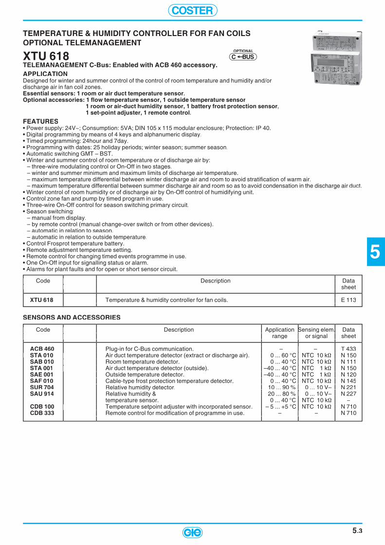
5
COSTER
5.3
TEMPERATURE & HUMIDITY CONTROLLER FOR FAN COILSOPTIONAL TELEMANAGEMENT
XTU 618TELEMANAGEMENT C-Bus: Enabled with ACB 460 accessory.APPLICATIONDesigned for winter and summer control of the control of room temperature and humidity and/or discharge air in fan coil zones.Essential sensors: 1 room or air duct temperature sensor.Optional accessories: 1 fl ow temperature sensor, 1 outside temperature sensor 1 room or air-duct humidity sensor, 1 battery frost protection sensor, 1 set-point adjuster, 1 remote control.FEATURES• Power supply: 24V~; Consumption: 5VA; DIN 105 x 115 modular enclosure; Protection: IP 40.• Digital programming by means of 4 keys and alphanumeric display.• Timed programming: 24hour and 7day.• Programming with dates: 25 holiday periods; winter season; summer season.• Automatic switching GMT – BST.• Winter and summer control of room temperature or of discharge air by: – three-wire modulating control or On-Off in two stages. – winter and summer minimum and maximum limits of discharge air temperature. – maximum temperature differential between winter discharge air and room to avoid stratifi cation of warm air. – maximum temperature differential between summer discharge air and room so as to avoid condensation in the discharge air duct.• Winter control of room humidity or of discharge air by On-Off control of humidifying unit.• Control zone fan and pump by timed program in use.• Three-wire On-Off control for season switching primary circuit.• Season switching: – manual from display. – by remote control (manual change-over switch or from other devices). – automatic in relation to season. – automatic in relation to outside temperature.• Control Frosprot temperature battery.• Remote adjustment temperature setting.• Remote control for changing timed events programme in use.• One On-Off input for signalling status or alarm.• Alarms for plant faults and for open or short sensor circuit.
Code Description Data Code Description Data sheet sheet
XTU 618 Temperature & humidity controller for fan coils. E 113
Code Description Data sheet
Temperature & humidity controller for fan coils. E 113
Code Description Data sheet
Temperature & humidity controller for fan coils. E 113
Code Description Data sheet
SENSORS AND ACCESSORIES
Code Description Application Sensing elem. Data Code Description Application Sensing elem. Data range or signal sheet range or signal sheet
ACB 460 Plug-in for C-Bus communication. – – T 433 STA 010 STA 010 Air duct temperature detector (extract or discharge air). 0 ... 60 °C NTC 10 kΩ N 150
SAB 010 Room temperature detector. 0 ... 40 °C NTC 10 kΩ N 111STA 001 Air duct temperature detector (outside). –40 ... 40 °C NTC 1 kΩ N 150SAE 001 Outside temperature detector. –40 ... 40 °C NTC 1 kΩ N 120SAF 010 Cable-type frost protection temperature detector. 0 ... 40 °C NTC 10 kΩ N 145SUR 704 Relative humidity detector. 10 ... 90 % 0 ... 10 V– N 221SAU 914 Relative humidity & 20 ... 80 % 0 ... 10 V– N 227
temperature sensor. 0 ... 40 °C NTC 10 kΩ –CDB 100 Temperature setpoint adjuster with incorporated sensor. – 5 ... +5 °C NTC 10 kΩ N 710CDB 333 Remote control for modifi cation of programme in use. – – N 710
Code Description Application Sensing elem. Data range or signal sheet
Plug-in for C-Bus communication. – – Air duct temperature detector (extract or discharge air). 0 ... 60 °C NTC 10 kΩ N 150 Room temperature detector. 0 ... 40 °C NTC 10 kΩ N 111 Air duct temperature detector (outside). –40 ... 40 °C NTC 1 kΩ N 150
Outside temperature detector. –40 ... 40 °C NTC 1 kΩ N 120 Cable-type frost protection temperature detector. 0 ... 40 °C NTC 10 kΩ N 145
Temperature setpoint adjuster Remote control for modifi cation of programme in use. – –
Code Description Application Sensing elem. Data range or signal sheet
Air duct temperature detector (extract or discharge air). 0 ... 60 °C NTC 10 kΩ N 150 Room temperature detector. 0 ... 40 °C NTC 10 kΩ N 111 Air duct temperature detector (outside). –40 ... 40 °C NTC 1 kΩ N 150
Outside temperature detector. –40 ... 40 °C NTC 1 kΩ N 120 Cable-type frost protection temperature detector. 0 ... 40 °C NTC 10 kΩ N 145
10 ... 90 % 0 ... 10 V– N 221 20 ... 80 % 0 ... 10 V– N 22
N 710
Code Description Application Sensing elem. Data range or signal sheet
Air duct temperature detector (extract or discharge air). 0 ... 60 °C NTC 10 kΩ N 150 Room temperature detector. 0 ... 40 °C NTC 10 kΩ N 111 Air duct temperature detector (outside). –40 ... 40 °C NTC 1 kΩ N 150
Temperature setpoint adjuster
Code Description Application Sensing elem. Data range or signal sheet
Plug-in for C-Bus communication. – – Air duct temperature detector (extract or discharge air). 0 ... 60 °C NTC 10 kΩ N 150 Room temperature detector. 0 ... 40 °C NTC 10 kΩ N 111 Air duct temperature detector (outside). –40 ... 40 °C NTC 1 kΩ N 150
Outside temperature detector. –40 ... 40 °C NTC 1 kΩ N 120 Cable-type frost protection temperature detector. 0 ... 40 °C NTC 10 kΩ N 145
10 ... 90 % 0 ... 10 V– N 221 20 ... 80 % 0 ... 10 V– N 22
Remote control for modifi cation of programme in use. – –
Code Description Application Sensing elem. Data range or signal sheet
Plug-in for C-Bus communication. – – Air duct temperature detector (extract or discharge air). 0 ... 60 °C NTC 10 kΩ N 150 Room temperature detector. 0 ... 40 °C NTC 10 kΩ N 111 Air duct temperature detector (outside). –40 ... 40 °C NTC 1 kΩ N 150
Outside temperature detector. –40 ... 40 °C NTC 1 kΩ N 120 Cable-type frost protection temperature detector. 0 ... 40 °C NTC 10 kΩ N 145
10 ... 90 % 0 ... 10 V– N 221 20 ... 80 % 0 ... 10 V– N 22
. – 5 ... +5 °C Remote control for modifi cation of programme in use. – –
SBUCOPTIONAL

COSTER
5.4
SENSORS AND ACCESSORES
Code Description Application Code Description Application Sensing elem. Data range range or signal sheet
ACB 460 Plug-in for C-Bus communication. – – T 433STA 010 Air duct temperature detector 0 ... 60 °C NTC 10 kΩ N 150
(extract, discharge, dew point). (extract, discharge, dew point).SAB 010 Room temperature detector. 0 ... 40 °C NTC 10 kΩ N 111STA 001 Air duct temperature detector (outside air). –40 ... 40 °C NTC 1 kΩ N 150SAE 001 Outside temperature detector. –40 ... 40 °C NTC 1 kΩ N 120
SAF 010 SAF 010 Cable-type temperature detector (frost protection). 0 ... 40 °C NTC 10 kΩ N 145STV 010 Window glass dew point detector. 0 ... 40 °C NTC 10 kΩ N 160SUR 704 Relative humidity detector. 10 ... 90 % 0 ... 10 V– N 221
SUT 714 SUT 714 Relative humidity and temperature detector. 10 ... 90 % 0 ... 10 V– N 222SAU 914 Relative humidity & 20 ... 80 % 0 ... 10 V– N 227
temperature sensor. 0 ... 40 °C NTC 10 kΩ –CDB 100 Temperature setpoint adjuster with incorporated sensor. – 5 ... +5 °C NTC 10 kΩ N 710
CDB 200 CDB 200 Humidity setpoint adjuster. –10 ... +10 % – N 710
TEMPERATURE & HUMIDITY CONTROLLER FOR ONE-BATTERYAIR-HANDLING UNITSOPTIONAL TELEMANAGEMENT
XTU 614TELEMANAGEMENT C-Bus: Enabled with ACB 460 accessory.APPLICATIONFor control of room temperature and humidity and/or discharge air in air-handling units compri-sing:– 1 battery for heating and/or cooling or pre-heating.– 1 On-Off humidifi cation battery.– 1 air mixing unit or 1 heat regenerator.Essential sensors: 1 room or air duct temperature sensor.Optional sensors: 1 fl ow or pre-heating temperature sensor, 1 window dew-point sensor, 1 battery Frosprot sensor, 1 temperature set-point adjuster, 1 humidity set-point adjuster.FEATURES• Power supply: 24V~; Consumption: 5VA; DIN 105 x 115 modular enclosure; Protection: IP 40.• Digital programming by means of 4 keys and alphanumeric display.• Timed programming: 24hour and 7day.• Programming with dates: 25 holiday periods; winter season; summer season.• Automatic switching GMT – BST.• One 3-wire modulating output or On-Off in 2 stages (2 equal loads) or in 3 stages (2 unequal loads) confi gurable for: – control of winter & summer room temperature with, if required, summer outside compensation, minimum. & maximum limits of fl ow in order to avoid cold air currents, stratifi cation of hot air and condensing in the air ducts. – control of fl ow temperature at fi xed point with, if required, winter & summer compensation. – control of pre-heating temperature at a variable value in relation to room temperature & humidity.• 1 On-Off output for control humidifying unit for control of relative humidity at fi xed point.• 1 progressive 0…10 V- output confi gurable for: – control of mixture outside air in relation to comparison room - outside temperatures. – control outside air for control of room dehumidifi cation with compensation for windows dew point. – control of heat regenerator in relation to comparison room – outside temperatures.• Two On-Off outputs for control of fan and pump according to timed program in use.• Control Frosprot temperature battery.• Manual or automatic season switching of controller functions and of On-Off 3-wire season switch.• Variation of temperature & humidity set points by means of remote control.• Alarms for plant faults and for open or short sensor circuit.
Code Description Data Code Description Data sheet sheet
XTU 614 Temperature & humidity controller for 1 battery air-handling unit. E 134
Code Description Data sheet
Temperature & humidity controller for 1 battery air-handling unit. E 134
Code Description Data sheet
Temperature & humidity controller for 1 battery air-handling unit. E 134
Code Description Data sheet
Code Description Application range
Plug-in for C-Bus communication. – – Air duct temperature detector 0 ... 60 °C NTC 10 kΩ N 150
(extract, discharge, dew point). Room temperature detector. 0 ... 40 °C NTC 10 kΩ N 111 Air duct temperature detector (outside air). –40 ... 40 °C NTC 1 kΩ N 150
Outside temperature detector. –40 ... 40 °C NTC 1 kΩ N 120 Cable-type temperature detector (frost protection). 0 ... 40 °C NTC 10 kΩ N 145 Window glass dew point detector. 0 ... 40 °C NTC 10 kΩ N 160
Temperature setpoint adjuster Humidity setpoint adjuster.
Sensing elem. Data sheet
Air duct temperature detector 0 ... 60 °C NTC 10 kΩ N 150
Room temperature detector. 0 ... 40 °C NTC 10 kΩ N 111 Air duct temperature detector (outside air). –40 ... 40 °C NTC 1 kΩ N 150
Outside temperature detector. –40 ... 40 °C NTC 1 kΩ N 120 Cable-type temperature detector (frost protection). 0 ... 40 °C NTC 10 kΩ N 145 Window glass dew point detector. 0 ... 40 °C NTC 10 kΩ N 160
10 ... 90 % 0 ... 10 V– N 221 10 ... 90 % 0 ... 10 V– N 22
20 ... 80 % 0 ... 10 V– N 22
N 710
Code Description Application range
Air duct temperature detector 0 ... 60 °C NTC 10 kΩ N 150 (extract, discharge, dew point).
Room temperature detector. 0 ... 40 °C NTC 10 kΩ N 111 Air duct temperature detector (outside air). –40 ... 40 °C NTC 1 kΩ N 150
SUR 704 SUT 714
Temperature setpoint adjuster
Sensing elem.
Plug-in for C-Bus communication. – – Air duct temperature detector 0 ... 60 °C NTC 10 kΩ N 150
Room temperature detector. 0 ... 40 °C NTC 10 kΩ N 111 Air duct temperature detector (outside air). –40 ... 40 °C NTC 1 kΩ N 150
Outside temperature detector. –40 ... 40 °C NTC 1 kΩ N 120 Cable-type temperature detector (frost protection). 0 ... 40 °C NTC 10 kΩ N 145 Window glass dew point detector. 0 ... 40 °C NTC 10 kΩ N 160
10 ... 90 % 0 ... 10 V– N 221 10 ... 90 % 0 ... 10 V– N 22
20 ... 80 % 0 ... 10 V– N 22
–
Code Description Application range
Plug-in for C-Bus communication. – – Air duct temperature detector 0 ... 60 °C NTC 10 kΩ N 150
Room temperature detector. 0 ... 40 °C NTC 10 kΩ N 111 Air duct temperature detector (outside air). –40 ... 40 °C NTC 1 kΩ N 150
Outside temperature detector. –40 ... 40 °C NTC 1 kΩ N 120 Cable-type temperature detector (frost protection). 0 ... 40 °C NTC 10 kΩ N 145 Window glass dew point detector. 0 ... 40 °C NTC 10 kΩ N 160
10 ... 90 % 0 ... 10 V– N 221 10 ... 90 % 0 ... 10 V– N 22
20 ... 80 % 0 ... 10 V– N 22
. – 5 ... +5 °C
SBUCOPTIONAL

5
COSTER
5.5
SENSORS AND ACCESSORIES
Code Description Application Sensing elem. Data Code Description Application Sensing elem. Data range or signal sheet range or signal sheet
ACB 460 Plug-in for C-Bus communication. – – T 433STA 010 Air duct temperature detector 0 ... 60 °C NTC 10 kΩ N 150
(extract, discharge, dew point). (extract, discharge, dew point).SAB 010 Room temperature detector. 0 ... 40 °C NTC 10 kΩ N 111STA 001 Air duct temperature detector (outside air). –40 ... 40 °C NTC 1 kΩ N 150SAE 001 Outside temperature detector. –40 ... 40 °C NTC 1 kΩ N 120STV 010 Window glass dew point detector. 0 ... 40 °C NTC 10 kΩ N 160SUR 704 Relative humidity detector. 10 ... 90 % 0 ... 10 V– N 221
SUT 714 SUT 714 Relative humidity and temperature detector. 10 ... 90 % 0 ... 10 V– N 222SAU 914 Relative humidity & 20 ... 80 % 0 ... 10 V– N 227
temperature sensor. 0 ... 40 °C NTC 10 kΩ –CDB 100 Temperature setpoint adjuster with incorporated sensor. – 5 ... +5 °C NTC 10 kΩ N 710
CDB 200 CDB 200 Humidity setpoint adjuster. –10 ... +10 % – N 710
TEMPERATURE & HUMIDITY CONTROLLER FOR 2-BATTERYAIR-HANDLING UNITSOPTIONAL TELEMANAGEMENT
XTU 644TELEMANAGEMENT C-Bus: Enabled with ACB 460 accessory.APPLICATIONFor control of temperature and humidity of room and/or discharge air in air-handling units compri-sing:– 1 or 2 batteries for heating and/or cooling.– 1 modulating or On-Off humidifi cation battery.– 1 air mixing unit or 1 heat regenerator.Essential sensors: 1 room or air duct temperature sensor.Optional sensors: 1 fl ow temperature sensor, 1 pre-heating temperature sensor, 1 outside temperature sensor, 1 room or air duct humidity sensor, 1 outside humidity sensor, 1 window dew-point sensor, 1 temperature set-point adjuster, 1 humidity set-point adjuster.FEATURES• Power supply: 24V~; Consumption: 5VA; DIN 105 x 115 modular enclosure; Protection: IP 40.• Digital programming by means of 4 keys and alphanumeric display.• Three outputs: 3-wire modulating or On-Off in two stages (2 equal loads) or in three stages (2 unequal loads) confi gurable for: – control of room temperature in relation to heating and cooling values requested with, if required, summer outside compensation, minimum and maximum limits of fl ow in order to avoid cold air currents, stratifi cation of warm air and condensing in the air ducts. – control of fl ow temperature in relation to heating and cooling values requested with, if required, winter and summer compensation. – control of pre-heating temperature at a value variable in relation to room temperature and humidity. – control of room relative humidity in relation to humidifi cation & dehumidifi cation values requested.• One progressive 0…10V- output confi gurable for: – control of air mixture in relation to room-outside temperature (free cooling) or an enthalpic comparison. – control of outside air for controlling room dehumidifi cation with compensation for window dew point. – control of heat regenerator in relation comparison room – outside temperatures.• Manual or automatic season switching of the controller functions and of the three-wire On-Off season control.• Variation of temperature & humidity set points by means of remote control.• Alarms for plant faults and for open or short sensor circuit.
Code Description Data Code Description Data sheet sheet
XTU 644 Temperature & humidity controller for 2-battery air-handling unit. E 135
Code Description Data sheet
Temperature & humidity controller for 2-battery air-handling unit. E 135
Code Description Data sheet
Temperature & humidity controller for 2-battery air-handling unit. E 135
Code Description Data sheet
Code Description Application Sensing elem. Data range or signal sheet
Plug-in for C-Bus communication. – – Air duct temperature detector 0 ... 60 °C NTC 10 kΩ N 150
(extract, discharge, dew point). Room temperature detector. 0 ... 40 °C NTC 10 kΩ N 111 Air duct temperature detector (outside air). –40 ... 40 °C NTC 1 kΩ N 150
Outside temperature detector. –40 ... 40 °C NTC 1 kΩ N 120 Window glass dew point detector. 0 ... 40 °C NTC 10 kΩ N 160
Temperature setpoint adjuster Humidity setpoint adjuster.
Code Description Application Sensing elem. Data range or signal sheet
Air duct temperature detector 0 ... 60 °C NTC 10 kΩ N 150
Room temperature detector. 0 ... 40 °C NTC 10 kΩ N 111 Air duct temperature detector (outside air). –40 ... 40 °C NTC 1 kΩ N 150
Outside temperature detector. –40 ... 40 °C NTC 1 kΩ N 120 Window glass dew point detector. 0 ... 40 °C NTC 10 kΩ N 160
10 ... 90 % 0 ... 10 V– N 221 10 ... 90 % 0 ... 10 V– N 22
20 ... 80 % 0 ... 10 V– N 22
Code Description Application Sensing elem. Data range or signal sheet
Air duct temperature detector 0 ... 60 °C NTC 10 kΩ N 150 (extract, discharge, dew point).
Room temperature detector. 0 ... 40 °C NTC 10 kΩ N 111 Air duct temperature detector (outside air). –40 ... 40 °C NTC 1 kΩ N 150
SUR 704 SUT 714
Temperature setpoint adjuster
Code Description Application Sensing elem. Data range or signal sheet
Plug-in for C-Bus communication. – – Air duct temperature detector 0 ... 60 °C NTC 10 kΩ N 150
Room temperature detector. 0 ... 40 °C NTC 10 kΩ N 111 Air duct temperature detector (outside air). –40 ... 40 °C NTC 1 kΩ N 150
Outside temperature detector. –40 ... 40 °C NTC 1 kΩ N 120 Window glass dew point detector. 0 ... 40 °C NTC 10 kΩ N 160
10 ... 90 % 0 ... 10 V– N 221 10 ... 90 % 0 ... 10 V– N 22
20 ... 80 % 0 ... 10 V– N 22
–
Code Description Application Sensing elem. Data range or signal sheet
Plug-in for C-Bus communication. – – Air duct temperature detector 0 ... 60 °C NTC 10 kΩ N 150
Room temperature detector. 0 ... 40 °C NTC 10 kΩ N 111 Air duct temperature detector (outside air). –40 ... 40 °C NTC 1 kΩ N 150
Outside temperature detector. –40 ... 40 °C NTC 1 kΩ N 120 Window glass dew point detector. 0 ... 40 °C NTC 10 kΩ N 160
10 ... 90 % 0 ... 10 V– N 221 10 ... 90 % 0 ... 10 V– N 22
20 ... 80 % 0 ... 10 V– N 22
. – 5 ... +5 °C
SBUCOPTIONAL
Code Description Data Code Description Data sheet sheet
XTU 614+644 Two temperature & humidity controllers (1 XTU 614 + 1 XTU 644) for 3-battery air-handling unit. –ACB 460 Plug-in for communication via C-Bus (use two plugs, one per controller). T 433
Code Description Data sheet Code Description Data sheet Code Description Data sheet
PAIR OF TEMPERATURE & HUMIDITY CONTROLLERS 3-BATTERY FORAIR-HANDLING UNITS OPTIONAL TELEMANAGEMENT
XTU 614 + XTU 644 (SINGLE PACKAGE)TELEMANAGEMENT C-Bus: Enabled with ACB 460 accessory.
SBUCOPTIONAL

COSTER
5.6
SEQUENCE CONTROLLERS
ICM 674APPLICATIONConverts a 3-wire modulating signal to On-Off instructions for sequencing electrical devices having several stages: burners, resistances, refrigerators, humidifi ers.
FEATURES• Power supply: 24 V~; Consumption: 1 VA; DIN 105 x 115 modular enclosure; Protection: IP 40.• Input: 3-wire 24 V~ modulating signal (neutral, opens, closes).• 7 voltage-free SPDT output contacts: rating 250 V ~, 5 (1) A.
AIR QUALITY CONTROLLER
RQA 410APPLICATIONControls the percentage of outside air entering the premises in relation to the quality of air monitored by one or more SQC 954 sensors. Controls, with a progressive 0 ... 10 V – signal, the outside air damper and/or, by means of a relay, the switching on or increased speed of a fan. Supplied with potentiometers for minimum % outside air and air quality set point.THE UNIT CANNOT BE USED FOR SAFETY SYSTEMS.Essential detectors: 1 or more room air duct air quality detectors.FEATURES• Power supply: 24 V~; Consumption: 5 VA; Wall-mounting case 130 x 80 x 35; Protection: IP 30.• 2 setting potentiometers: - Minimum opening % outside air; - Air quality value requested.
Code Description Data sheet
ICM 674 7-step sequencer. E 812
Code Description Data sheet Code Description Data sheet
7-step sequencer. E 812
Code Description Data sheet
7-step sequencer. E 812
Code Description Data sheet
7-step sequencer. E 812
Code Description Data sheet
SQC 954 Room air quality detector. E 310SQS 954 Air quality detector for air duct. E 310
Code Description Data sheet Code Description Data sheet
Room air quality detector. E 310 Air quality detector for air duct. E 310
Code Description Data sheet
Room air quality detector. E 310 Air quality detector for air duct. E 310
Code Description Data sheet
Code Description Output Relay Data 0 ... 10 V– output sheet
RQA 410 Air quality controller. 1 1 E 310
Code Description Output Relay Data 0 ... 10 V– output sheet Code Description Output Relay Data 0 ... 10 V– output sheet
Air quality controller. 1 1 E 310
Code Description Output Relay Data 0 ... 10 V– output sheet
Air quality controller. 1 1 E 310
Code Description Output Relay Data 0 ... 10 V– output sheet
Air quality controller. 1 1 E 310
Code Description Output Relay Data 0 ... 10 V– output sheet
Air quality controller. 1 1 E 310
Code Description Output Relay Data 0 ... 10 V– output sheet
Air quality controller. 1 1 E 310
AIR QUALITY DETECTORS
SQC 954 - SQS 954APPLICATIONMonitor the room air pollution level and transfer to the RQA 410 controller a signal proportionalto the pollution value.THE UNIT CANNOT BE USED FOR SAFETY SYSTEMS.FEATURES• Power supply: 24 V ~; Consumption: 5 VA; Wall-mounting case 130 x 80 x 37; Protection: IP 42.

5
COSTER
5.7
ELECTROMECHANICAL FROST PROTECTION THERMOSTAT
TAG 797 APPLICATIONFor frost protection of water battery heater units.
FEATURES• Protection: IP 54; Voltage-free SPDT output: rating: 250 V ~, 15 (8) A.
ELECTROMECHANICAL ROOM HUMIDISTAT
UPA 798APPLICATIONOn-Off switching of humidifi cation or dehumidifi cation units. Wall mounting.
FEATURES• Sensing element in synthetic fi bre; Protection: IP 20; SPDT output: rating: 250 V ~, 10 (3) A.
AIR DUCT ELECTROMECHANICAL HUMIDISTAT
UPC 799APPLICATIONOn-Off switching of humidifi cation or dehumidifi cation units. Mounted in air duct.
FEATURES• Sensing element in synthetic fi bre; Protection: IP 65; SPDT output: rating: 250 V ~, 15 (8) A.
DIFFERENTIAL PRESSURE SWITCH
PDF 795APPLICATIONFor signalling state of cleanliness of fi ltering units or of operation of fans.
FEATURES• Protection: IP 54; Voltage-free SPDT output: rating: 250 V ~, 1,5 (0,4) A.
Code Description Setting ∆ H% Data range sheet
UPC 799 On-Off air duct humidistat. 35 ... 100 % 5% -
Code Description Setting ∆ H% Data range sheet
UPA 798 On-Off room humidistat. 30 ... 100 % 4% –
Code Description Setting ∆p Max p Data Code Description Setting ∆p Max p Data range sheet range sheet
PDF 795 Differential pressure switch. 50 ... 500 Pa 20 Pa ±15% 5 k Pa E 730
Code Description Setting ∆p Max p Data range sheet
Differential pressure switch. 50 ... 500 Pa 20 Pa ±15% 5 k Pa E 730
Code Description Setting ∆p Max p Data range sheet
Differential pressure switch. 50 ... 500 Pa 20 Pa ±15% 5 k Pa E 730
Code Description Setting ∆p Max p Data range sheet
Differential pressure switch. 50 ... 500 Pa 20 Pa ±15% 5 k Pa E 730
Code Description Setting ∆p Max p Data range sheet
Differential pressure switch. 50 ... 500 Pa 20 Pa ±15% 5 k Pa E 730
Code Description Setting ∆p Max p Data range sheet
Differential pressure switch. 50 ... 500 Pa 20 Pa ±15% 5 k Pa E 730
Code Description Setting ∆p Max p Data range sheet
Differential pressure switch. 50 ... 500 Pa 20 Pa ±15% 5 k Pa E 730
Code Description Setting Max ∆t Data Code Description Setting Max ∆t Data range Temp sheet range Temp sheet
TAG 797 Electromech. frost protection thermostat. – 10 ... + 12 °C 150 °C 1 °C E 710
Code Description Setting Max ∆t Data range Temp sheet
Electromech. frost protection thermostat. – 10 ... + 12 °C 150 °C 1 °C E 710
Code Description Setting Max ∆t Data range Temp sheet
Electromech. frost protection thermostat. – 10 ... + 12 °C 150 °C 1 °C E 710
Code Description Setting Max ∆t Data range Temp sheet
Electromech. frost protection thermostat. – 10 ... + 12 °C 150 °C 1 °C E 710
Code Description Setting Max ∆t Data range Temp sheet
Electromech. frost protection thermostat. – 10 ... + 12 °C 150 °C 1 °C E 710
Code Description Setting Max ∆t Data range Temp sheet
Electromech. frost protection thermostat. – 10 ... + 12 °C 150 °C 1 °C E 710
Code Description Setting Max ∆t Data range Temp sheet
Electromech. frost protection thermostat. – 10 ... + 12 °C 150 °C 1 °C E 710
Code Description Setting ∆ H% Data range sheet Code Description Setting ∆ H% Data range sheet
On-Off air duct humidistat. 35 ... 100 % 5% -
Code Description Setting ∆ H% Data range sheet
On-Off air duct humidistat. 35 ... 100 % 5% -
Code Description Setting ∆ H% Data range sheet
On-Off air duct humidistat. 35 ... 100 % 5% -
Code Description Setting ∆ H% Data range sheet
On-Off air duct humidistat. 35 ... 100 % 5% -
Code Description Setting ∆ H% Data range sheet
On-Off air duct humidistat. 35 ... 100 % 5% -
Code Description Setting ∆ H% Data range sheet Code Description Setting ∆ H% Data range sheet
On-Off room humidistat. 30 ... 100 % 4% –
Code Description Setting ∆ H% Data range sheet
On-Off room humidistat. 30 ... 100 % 4% –
Code Description Setting ∆ H% Data range sheet
On-Off room humidistat. 30 ... 100 % 4% –
Code Description Setting ∆ H% Data range sheet
On-Off room humidistat. 30 ... 100 % 4% –
Code Description Setting ∆ H% Data range sheet
On-Off room humidistat. 30 ... 100 % 4% –

COSTER
5.8
Code Power supply Control Auxiliary Dampers Torque Run Data Code Power supply Control Auxiliary Dampers Torque Run Data V V~ (VA) contacts m2 N/m sec. sheet
CSL 138 230 V~ (4) 2 or 3 points No 1 5 150 E 921CSL 138/C 230 V~ (4) 2 or 3 points 1 1 5 150 E 921CSL 134 24 V~/– (2) 2 or 3 points No 1 5 150 E 921CSL 134/C 24 V~/– (2) 2 or 3 points 1 1 5 150 E 921CSL 104 24 V~/– (2) 2 ... 10 V– No 1 5 150 E 921
CSN 238 230 V~ (6) 2 or 3 points No 2 10 150 E 922CSN 238/C 230 V~ (6) 2 or 3 points 1 2 10 150 E 922CSN 234 24 V~/– (4) 2 or 3 points No 2 10 150 E 922CSN 234/C 24 V~/– (4) 2 or 3 points 1 2 10 150 E 922CSN 204 24 V~/– (4) 2 ... 10 V– No 2 10 150 E 922
CSS 438 230 V~ (6) 2 or 3 points No 4 20 150 E 931CSS 438/C 230 V~ (6) 2 or 3 points 1 4 20 150 E 931CSS 434 24 V~/– (4) 2 or 3 points No 4 20 150 E 931CSS 434/C 24 V~/– (4) 2 or 3 points 1 4 20 150 E 931CSS 404 24 V~/– (4) 2 ... 10 V– No 4 20 150 E 931
CSG 838 230 V~ (8) 2 or 3 points No 8 40 150 E 940CSG 838/C 230 V~ (8) 2 or 3 points 1 8 40 150 E 940CSG 834 24 V~/– (7) 2 or 3 points No 8 40 150 E 940CSG 834/C 24 V~/– (7) 2 or 3 points 1 8 40 150 E 940CSG 804 24 V~/– (7) 2 ... 10 V– No 8 40 150 E 940
Code Power supply Control Auxiliary Dampers Torque Run Data V
230 V~ (4) 2 or 3 points No 1 5 150 E 921 230 V~ (4) 2 or 3 points 1 1 5 150 E 921 24 V~/– (2) 2 or 3 points No 1 5 150 E 921 24 V~/– (2) 2 or 3 points 1 1 5 150 E 921 24 V~/– (2) 2 ... 10 V– No 1 5 150 E 921
230 V~ (6) 2 or 3 points No 2 10 150 E 922 230 V~ (6) 2 or 3 points 1 2 10 150 E 922 24 V~/– (4) 2 or 3 points No 2 10 150 E 922 24 V~/– (4) 2 or 3 points 1 2 10 150 E 922 24 V~/– (4) 2 ... 10 V– No 2 10 150 E 922
230 V~ (6) 2 or 3 points No 4 20 150 E 931 230 V~ (6) 2 or 3 points 1 4 20 150 E 931 24 V~/– (4) 2 or 3 points No 4 20 150 E 931 24 V~/– (4) 2 or 3 points 1 4 20 150 E 931 24 V~/– (4) 2 ... 10 V– No 4 20 150 E 931
230 V~ (8) 2 or 3 points No 8 40 150 E 940 230 V~ (8) 2 or 3 points 1 8 40 150 E 940 24 V~/– (7) 2 or 3 points No 8 40 150 E 940 24 V~/– (7) 2 or 3 points 1 8 40 150 E 940 24 V~/– (7) 2 ... 10 V– No 8 40 150 E 940
Code Power supply Control Auxiliary Dampers Torque Run Data N/m sec. sheet
230 V~ (4) 2 or 3 points No 1 5 150 E 921 230 V~ (4) 2 or 3 points 1 1 5 150 E 921 24 V~/– (2) 2 or 3 points No 1 5 150 E 921 24 V~/– (2) 2 or 3 points 1 1 5 150 E 921 24 V~/– (2) 2 ... 10 V– No 1 5 150 E 921
230 V~ (6) 2 or 3 points No 2 10 150 E 922 230 V~ (6) 2 or 3 points 1 2 10 150 E 922 24 V~/– (4) 2 or 3 points No 2 10 150 E 922 24 V~/– (4) 2 or 3 points 1 2 10 150 E 922 24 V~/– (4) 2 ... 10 V– No 2 10 150 E 922
230 V~ (6) 2 or 3 points No 4 20 150 E 931 230 V~ (6) 2 or 3 points 1 4 20 150 E 931 24 V~/– (4) 2 or 3 points No 4 20 150 E 931 24 V~/– (4) 2 or 3 points 1 4 20 150 E 931 24 V~/– (4) 2 ... 10 V– No 4 20 150 E 931
230 V~ (8) 2 or 3 points No 8 40 150 E 940 230 V~ (8) 2 or 3 points 1 8 40 150 E 940 24 V~/– (7) 2 or 3 points No 8 40 150 E 940 24 V~/– (7) 2 or 3 points 1 8 40 150 E 940 24 V~/– (7) 2 ... 10 V– No 8 40 150 E 940
Code Power supply Control Auxiliary Dampers Torque Run Data V Code Power supply Control Auxiliary Dampers Torque Run Data
N/m sec. sheet
230 V~ (4) 2 or 3 points No 1 5 150 E 921 230 V~ (4) 2 or 3 points 1 1 5 150 E 921 24 V~/– (2) 2 or 3 points No 1 5 150 E 921 24 V~/– (2) 2 or 3 points 1 1 5 150 E 921 24 V~/– (2) 2 ... 10 V– No 1 5 150 E 921
230 V~ (6) 2 or 3 points No 2 10 150 E 922 230 V~ (6) 2 or 3 points 1 2 10 150 E 922 24 V~/– (4) 2 or 3 points No 2 10 150 E 922 24 V~/– (4) 2 or 3 points 1 2 10 150 E 922 24 V~/– (4) 2 ... 10 V– No 2 10 150 E 922
230 V~ (6) 2 or 3 points No 4 20 150 E 931 230 V~ (6) 2 or 3 points 1 4 20 150 E 931 24 V~/– (4) 2 or 3 points No 4 20 150 E 931 24 V~/– (4) 2 or 3 points 1 4 20 150 E 931 24 V~/– (4) 2 ... 10 V– No 4 20 150 E 931
230 V~ (8) 2 or 3 points No 8 40 150 E 940 230 V~ (8) 2 or 3 points 1 8 40 150 E 940 24 V~/– (7) 2 or 3 points No 8 40 150 E 940 24 V~/– (7) 2 or 3 points 1 8 40 150 E 940 24 V~/– (7) 2 ... 10 V– No 8 40 150 E 940
Code Power supply Control Auxiliary Dampers Torque Run Data N/m sec. sheet
230 V~ (4) 2 or 3 points No 1 5 150 E 921 230 V~ (4) 2 or 3 points 1 1 5 150 E 921 24 V~/– (2) 2 or 3 points No 1 5 150 E 921 24 V~/– (2) 2 or 3 points 1 1 5 150 E 921 24 V~/– (2) 2 ... 10 V– No 1 5 150 E 921
230 V~ (6) 2 or 3 points No 2 10 150 E 922 230 V~ (6) 2 or 3 points 1 2 10 150 E 922 24 V~/– (4) 2 or 3 points No 2 10 150 E 922 24 V~/– (4) 2 or 3 points 1 2 10 150 E 922 24 V~/– (4) 2 ... 10 V– No 2 10 150 E 922
230 V~ (6) 2 or 3 points No 4 20 150 E 931 230 V~ (6) 2 or 3 points 1 4 20 150 E 931 24 V~/– (4) 2 or 3 points No 4 20 150 E 931 24 V~/– (4) 2 or 3 points 1 4 20 150 E 931 24 V~/– (4) 2 ... 10 V– No 4 20 150 E 931
230 V~ (8) 2 or 3 points No 8 40 150 E 940 230 V~ (8) 2 or 3 points 1 8 40 150 E 940 24 V~/– (7) 2 or 3 points No 8 40 150 E 940 24 V~/– (7) 2 or 3 points 1 8 40 150 E 940 24 V~/– (7) 2 ... 10 V– No 8 40 150 E 940
Code Power supply Control Auxiliary Dampers Torque Run Data (VA) contacts m
230 V~ (4) 2 or 3 points No 1 5 150 E 921 230 V~ (4) 2 or 3 points 1 1 5 150 E 921 24 V~/– (2) 2 or 3 points No 1 5 150 E 921 24 V~/– (2) 2 or 3 points 1 1 5 150 E 921 24 V~/– (2) 2 ... 10 V– No 1 5 150 E 921
230 V~ (6) 2 or 3 points No 2 10 150 E 922 230 V~ (6) 2 or 3 points 1 2 10 150 E 922 24 V~/– (4) 2 or 3 points No 2 10 150 E 922 24 V~/– (4) 2 or 3 points 1 2 10 150 E 922 24 V~/– (4) 2 ... 10 V– No 2 10 150 E 922
230 V~ (6) 2 or 3 points No 4 20 150 E 931 230 V~ (6) 2 or 3 points 1 4 20 150 E 931 24 V~/– (4) 2 or 3 points No 4 20 150 E 931 24 V~/– (4) 2 or 3 points 1 4 20 150 E 931 24 V~/– (4) 2 ... 10 V– No 4 20 150 E 931
230 V~ (8) 2 or 3 points No 8 40 150 E 940 230 V~ (8) 2 or 3 points 1 8 40 150 E 940 24 V~/– (7) 2 or 3 points No 8 40 150 E 940 24 V~/– (7) 2 or 3 points 1 8 40 150 E 940 24 V~/– (7) 2 ... 10 V– No 8 40 150 E 940
DAMPER ACTUATORS
CSL ... - CSN ... - CSS ... - CSG ...APPLICATIONActuators suitable for operating dampers in air handling sites.Rotary movement with 90° rotation angle. Mounted directly on damper rod.
FEATURES• Power supply: 230 V~ or 24 V~/-; Protection: IP 54.
DAMPER ACTUATORS WITH SPRING RETURN
CFT ... - CFL ... - CFS ...APPLICATIONActuators suitable for operating dampers in air handling sites.Rotary movement with 90° rotation angle. Mounted directly on damper rod.Spring return in absence of power.
FEATURES• Power supply: 230 V~ or 24 V~/-; Protection: CFT …IP42; CFL …/CF …: IP 54.
Code Code Power supply Control Auxiliary Dampers Torque Run Emerg. Data V V~ (VA) contacts m2 N/m sec. sec. sheet
CFT 028 230 V~ (5) 2 points No 0.4 2 75 25 E 951CFT 028/C 230 V~ (5) 2 points 1 0.4 2 75 25 E 951CFT 024 24 V~/– (5) 2 points No 0.4 2 75 25 E 951CFT 024/C 24 V~/– (5) v 1 0.4 2 75 25 E 951CFT 004 24 V~/– (4) 2 ... 10 V– No 0.4 2 150 25 E 951
CFL 128 230 V~ (7) 2 points No 0.8 4 75 20 E 952CFL 128/C 230 V~ (7) 2 points 1 0.8 4 75 20 E 952CFL 124 24 V~/– (7) 2 points No 0.8 4 75 20 E 952CFL 124/C 24 V~/– (7) 2 points 1 0.8 4 75 20 E 952CFL 134 24 V~/– (5) 3 points No 0.8 4 150 20 E 952CFL 104 24 V~/– (5) 2 ... 10 V– No 0.8 4 150 20 E 952
CFS 428 230 V~ (18) 2 points No 4 20 75 20 E 954CFS 428/C 230 V~ (18) 2 points 2 4 20 75 20 E 954CFS 424 24 V~/– (7,5) 2 points No 4 20 75 20 E 954CFS 424/C 24 V~/– (7,5) 2 points 2 4 20 75 20 E 954CFS 404 24 V~/– (7) 2 ... 10 V– No 4 20 150 20 E 954CFS 404/C 24 V~/– (7) 2 ... 10 V– 2 4 20 150 20 E 954
V
230 V~ (5) 2 points No 0.4 2 75 25 E 951 230 V~ (5) 2 points 1 0.4 2 75 25 E 951 24 V~/– (5) 2 points No 0.4 2 75 25 E 951 24 V~/– (5) v 1 0.4 2 24 V~/– (4) 2 ... 10 V– No 0.4 2 150 25 E 951
230 V~ (7) 2 points No 0.8 4 75 20 E 952 230 V~ (7) 2 points 1 0.8 4 75 20 E 952 24 V~/– (7) 2 points No 0.8 4 75 20 E 952 24 V~/– (7) 2 points 1 0.8 4 75 20 E 952 24 V~/– (5) 24 V~/– (5) 2 ... 10 V– No 0.8 4 150 20
230 V~ (18) 2 points No 4 20 75 20 E 954 230 V~ (18) 2 points 2 4 20 75 20 E 954 24 V~/– (7,5) 2 points No 4 20 75 20 E 954 24 V~/– (7,5) 2 points 2 4 20 75 20 E 954 24 V~/– (7) 2 ... 10 V– No 4 20 150 20 E 954 24 V~/– (7) 2 ... 10 V– 2 4 20 150 20 E 95
230 V~ (5) 2 points No 0.4 2 75 25 E 951 230 V~ (5) 2 points 1 0.4 2 75 25 E 951 24 V~/– (5) 2 points No 0.4 2 75 25 E 951
75 25 E 951 24 V~/– (4) 2 ... 10 V– No 0.4 2 150 25 E 951
230 V~ (7) 2 points No 0.8 4 75 20 E 952 230 V~ (7) 2 points 1 0.8 4 75 20 E 952 24 V~/– (7) 2 points No 0.8 4 75 20 E 952 24 V~/– (7) 2 points 1 0.8 4 75 20 E 952
No 0.8 4 150 20 E 952
230 V~ (18) 2 points No 4 20 75 20 E 954 230 V~ (18) 2 points 2 4 20 75 20 E 954 24 V~/– (7,5) 2 points No 4 20 75 20 E 954 24 V~/– (7,5) 2 points 2 4 20 75 20 E 954 24 V~/– (7) 2 ... 10 V– No 4 20 150 20 E 954 24 V~/– (7) 2 ... 10 V– 2 4 20 150 20 E 95
Code V
Emerg. N/m sec. sec.
230 V~ (5) 2 points No 0.4 2 75 25 E 951 230 V~ (5) 2 points 1 0.4 2 75 25 E 951 24 V~/– (5) 2 points No 0.4 2 75 25 E 951
75 25 E 951 24 V~/– (4) 2 ... 10 V– No 0.4 2 150 25 E 951
230 V~ (7) 2 points No 0.8 4 75 20 E 952 230 V~ (7) 2 points 1 0.8 4 75 20 E 952 24 V~/– (7) 2 points No 0.8 4 75 20 E 952 24 V~/– (7) 2 points 1 0.8 4 75 20 E 952
No 0.8 4 150 20 E 952 24 V~/– (5) 2 ... 10 V– No 0.8 4 150 20
230 V~ (18) 2 points No 4 20 75 20 E 954 230 V~ (18) 2 points 2 4 20 75 20 E 954 24 V~/– (7,5) 2 points No 4 20 75 20 E 954 24 V~/– (7,5) 2 points 2 4 20 75 20 E 954 24 V~/– (7) 2 ... 10 V– No 4 20 150 20 E 954 24 V~/– (7) 2 ... 10 V– 2 4 20 150 20 E 95
N/m sec. sec.
230 V~ (5) 2 points No 0.4 2 75 25 E 951 230 V~ (5) 2 points 1 0.4 2 75 25 E 951 24 V~/– (5) 2 points No 0.4 2 75 25 E 951
24 V~/– (4) 2 ... 10 V– No 0.4 2 150 25 E 951
230 V~ (7) 2 points No 0.8 4 75 20 E 952 230 V~ (7) 2 points 1 0.8 4 75 20 E 952 24 V~/– (7) 2 points No 0.8 4 75 20 E 952 24 V~/– (7) 2 points 1 0.8 4 75 20 E 952
No 0.8 4 150 20 E 952 24 V~/– (5) 2 ... 10 V– No 0.8 4 150 20
230 V~ (18) 2 points No 4 20 75 20 E 954 230 V~ (18) 2 points 2 4 20 75 20 E 954 24 V~/– (7,5) 2 points No 4 20 75 20 E 954 24 V~/– (7,5) 2 points 2 4 20 75 20 E 954 24 V~/– (7) 2 ... 10 V– No 4 20 150 20 E 954 24 V~/– (7) 2 ... 10 V– 2 4 20 150 20 E 95
(VA)
230 V~ (5) 2 points No 0.4 2 75 25 E 951 230 V~ (5) 2 points 1 0.4 2 75 25 E 951 24 V~/– (5) 2 points No 0.4 2 75 25 E 951 24 V~/– (5) v 1 0.4 2 24 V~/– (4) 2 ... 10 V– No 0.4 2 150 25 E 951
230 V~ (7) 2 points No 0.8 4 75 20 E 952 230 V~ (7) 2 points 1 0.8 4 75 20 E 952 24 V~/– (7) 2 points No 0.8 4 75 20 E 952 24 V~/– (7) 2 points 1 0.8 4 75 20 E 952
24 V~/– (5) 2 ... 10 V– No 0.8 4 150 20
230 V~ (18) 2 points No 4 20 75 20 E 954 230 V~ (18) 2 points 2 4 20 75 20 E 954 24 V~/– (7,5) 2 points No 4 20 75 20 E 954 24 V~/– (7,5) 2 points 2 4 20 75 20 E 954 24 V~/– (7) 2 ... 10 V– No 4 20 150 20 E 954 24 V~/– (7) 2 ... 10 V– 2 4 20 150 20 E 95
230 V~ (5) 2 points No 0.4 2 75 25 E 951 230 V~ (5) 2 points 1 0.4 2 75 25 E 951 24 V~/– (5) 2 points No 0.4 2 75 25 E 951 24 V~/– (5) v 1 0.4 2 24 V~/– (4) 2 ... 10 V– No 0.4 2 150 25 E 951
230 V~ (7) 2 points No 0.8 4 75 20 E 952 230 V~ (7) 2 points 1 0.8 4 75 20 E 952 24 V~/– (7) 2 points No 0.8 4 75 20 E 952 24 V~/– (7) 2 points 1 0.8 4 75 20 E 952
No 0.8 4 150 20 E 952 24 V~/– (5) 2 ... 10 V– No 0.8 4 150 20
230 V~ (18) 2 points No 4 20 75 20 E 954 230 V~ (18) 2 points 2 4 20 75 20 E 954 24 V~/– (7,5) 2 points No 4 20 75 20 E 954 24 V~/– (7,5) 2 points 2 4 20 75 20 E 954 24 V~/– (7) 2 ... 10 V– No 4 20 150 20 E 954 24 V~/– (7) 2 ... 10 V– 2 4 20 150 20 E 95
N/m sec. sec.
230 V~ (5) 2 points No 0.4 2 75 25 E 951 230 V~ (5) 2 points 1 0.4 2 75 25 E 951 24 V~/– (5) 2 points No 0.4 2 75 25 E 951 24 V~/– (5) v 1 0.4 2 24 V~/– (4) 2 ... 10 V– No 0.4 2 150 25 E 951
230 V~ (7) 2 points No 0.8 4 75 20 E 952 230 V~ (7) 2 points 1 0.8 4 75 20 E 952 24 V~/– (7) 2 points No 0.8 4 75 20 E 952 24 V~/– (7) 2 points 1 0.8 4 75 20 E 952
No 0.8 4 150 20 E 952 24 V~/– (5) 2 ... 10 V– No 0.8 4 150 20
230 V~ (18) 2 points No 4 20 75 20 E 954 230 V~ (18) 2 points 2 4 20 75 20 E 954 24 V~/– (7,5) 2 points No 4 20 75 20 E 954 24 V~/– (7,5) 2 points 2 4 20 75 20 E 954 24 V~/– (7) 2 ... 10 V– No 4 20 150 20 E 954 24 V~/– (7) 2 ... 10 V– 2 4 20 150 20 E 95
Dampers m
230 V~ (5) 2 points No 0.4 2 75 25 E 951 230 V~ (5) 2 points 1 0.4 2 75 25 E 951 24 V~/– (5) 2 points No 0.4 2 75 25 E 951 24 V~/– (5) v 1 0.4 2 24 V~/– (4) 2 ... 10 V– No 0.4 2 150 25 E 951
230 V~ (7) 2 points No 0.8 4 75 20 E 952 230 V~ (7) 2 points 1 0.8 4 75 20 E 952 24 V~/– (7) 2 points No 0.8 4 75 20 E 952 24 V~/– (7) 2 points 1 0.8 4 75 20 E 952
No 0.8 4 150 20 E 952 24 V~/– (5) 2 ... 10 V– No 0.8 4 150 20
230 V~ (18) 2 points No 4 20 75 20 E 954 230 V~ (18) 2 points 2 4 20 75 20 E 954 24 V~/– (7,5) 2 points No 4 20 75 20 E 954 24 V~/– (7,5) 2 points 2 4 20 75 20 E 954 24 V~/– (7) 2 ... 10 V– No 4 20 150 20 E 954 24 V~/– (7) 2 ... 10 V– 2 4 20 150 20 E 95
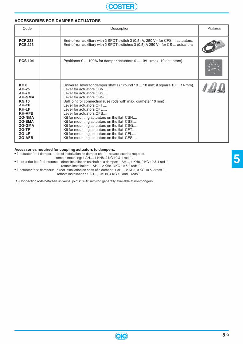
5
COSTER
5.9
ACCESSORIES FOR DAMPER ACTUATORS
Code Description Code Description Pictures
FCF 223 End-of-run auxiliary with 2 SPDT switch 3 (0.5) A, 250 V~ for CFS ... actuators.FCS 223 End-of-run auxiliary with 2 SPDT switches 3 (0.5) A 250 V~ for CS ... actuators.
PCS 104 Positioner 0 ... 100% for damper actuators 0 ... 10V– (max. 10 actuators).
KH 8 Universal lever for damper shafts (if round 10 ... 18 mm; if square 10 ... 14 mm).AH-25 Lever for actuators CSN....AH-20 Lever for actuators CSS....AH-GMA Lever for actuators CSG....KG 10 Ball joint for connection (use rods with max. diameter 10 mm).AH-TF Lever for actuators CFT....KH-LF Lever for actuators CFL....KH-AFB Lever for actuators CFS....ZG-NMA Kit for mounting actuators on the fl at CSN....ZG-SMA Kit for mounting actuators on the fl at CSS....ZG-GMA Kit for mounting actuators on the fl at CSG....ZG-TF1 Kit for mounting actuators on the fl at CFT....ZG-LF1 Kit for mounting actuators on the fl at CFL....ZG-AFB Kit for mounting actuators on the fl at CFS....
Accessories required for coupling actuators to dampers.• 1 actuator for 1 damper: - direct installation on damper shaft – no accessories required. - remote mounting: 1 AH..., 1 KH8, 2 KG 10 & 1 rod (1).• 1 actuator for 2 dampers: - direct installation on shaft of a damper: 1 AH..., 1 KH8, 2 KG 10 & 1 rod (1). - remote installation: 1 AH..., 2 KH8, 3 KG 10 & 2 rods (1).• 1 actuator for 3 dampers: - direct installation on shaft of a damper: 1 AH..., 2 KH8, 3 KG 10 & 2 rods (1). - remote installation : 1 AH..., 3 KH8, 4 KG 10 and 3 rods(1).
(1) Connection rods between universal joints: 8 -10 mm rod generally available at ironmongers.
Code Description
Positioner 0 ... 100%
Universal lever for damper shafts (if round 10 ... 18 mm; if square 10 ... 14 mm).
Ball joint for connection (use rods with max. diameter 10 mm)
Code Description

COSTER
NOTES
5.10
6
COSTER
6.1
Description Code Communication Page
GAS DETECTORMICROPROCESSOR-BASED DOMESTIC GAS DETECTORS WITH RELAY OUTPUTSUPPLIED WITH INTERNAL METHANE OR LPG DETECTOR
RGS .2. 6.2
MICROPROCESSOR-BASED DOMESTIC GAS DETECTORS WITH NORMALLY-OPEN VALVE & MANUAL RESET SUPPLIED WITH INTERNAL METHANE OR LPG DETECTOR
RGS .4. 6.2
GAS SENSOR FOR RGS ... GAS DETECTORS RI VE LA TO RI RGS MEASURE THE GAS CONCENTRATION & SEND VALUE TO DETECTOR. SRS ... 6.2
DOMESTIC GAS DETECTORS WITH BACK-UP BATTERYMONOXIDE DETECTOR WITH RELAY OUTPUT INCLUDES INTERNAL SELECTIVE CO SENSOR.
RGS 328 6.3
DOMESTIC GAS DETECTORS WITH BACK-UP BATTERY INCLUDING NORMALLY-CLOSED VALVE WITH MANUAL RESET INCLUDE INTERNAL METHANE OR LPG SENSOR AND BACK-UP BATTERY (LAST ABOUT ONE HOUR).
RGH ... 6.3
GAS DETECTORS IN DIN 6 UNITS MONITOR THE GAS CONCENTRATION WITH 1, 2 OR 3 EXTERNAL SENSORS RFG 65. 6.4
GAS DETECTORS IN DIN 3 UNITSMONITOR THE GAS CONCENTRATION WITH 1 EXTERNAL SENSORS. RFG 361 6.4
GAS DETECTION SENSORS FOR RFG 65. & RFG 361 RILEVANO LA CONCENTRAZIONE DI GAS ED INVIANO IL VALORE AL RI VE LA TO RE. SRD - SRS 6.4
GAS DETECTOR WITH PREALARM 144 X 144 PANEL MOUNTING MONITOR THE GAS CONCENTRATION BY 1 OR 2 EXTERNAL SENSORS. RFG 782 6.5
GAS MONITORING SENSORS FOR RFG 100MONITOR THE GAS CONCENTRATION & SEND VALUE TO DETECTOR.
SGC - SGR 6.5
ACCESSORIES FOR GAS DETECTION PLANTSBACK-UP BATTERIES FOR GAS DETECTION SYSTEMSUSED TO POWER 12 V- GAS SAFETY SYSTEMS ALSO IN EVENT OF MAINS SUPPLY FAILURE.
STABILIZED (STANDBY) POWER BACK-UP UNITSUNITS FOR KEEPING BATTERIES CHARGED.
WEATHERPROOF BATTERIES LONG-LIFE LEAD-SEALED RECHARGEABLE BATTERIES.
AL ...
ACC ...
6.6
REMOTE AUDIBLE ALARMREMOTE VISUAL ALARMREMOTE AUDIBLE AND VISUAL ALARM
SAS 880SAL 881CSL 882
6.6
GAS SOLENOID VALVES & ACCESSORIESNORMALLY-CLOSED BRASS GAS SOLENOID VALVESTHREADED DN 1/2", GASTEC CERTIFICATE GCAO ... 6.7
ENORMALLY-CLOSED BRASS GAS SOLENOID VALVES WITH MANUAL RESETTHREADED DN 1/2" - 3/4" - 1".
GCRO ... 6.7
NORMALLY-OPEN GAS SOLENOID VALVES WITH MANUAL RESET GARO ... 6.7AUTOMATIC NORMALLY-CLOSED GAS SOLENOID VALVESALUMINIUM BODY, THREADED DN 1/2" ... 2", FLANGED DN 65 ... 100. GCA ... 6.8
NORMALLY-CLOSED GAS SOLENOID VALVES WITH MANUAL RESETALUMINIUM BODY, THREADED DN 1/2" ... 2", FLANGED DN 65 ... 100.
GCR ... 6.9
NORMALLY-OPEN GAS SOLENOID VALVES WITH MANUAL RESET GAR ... 6.10
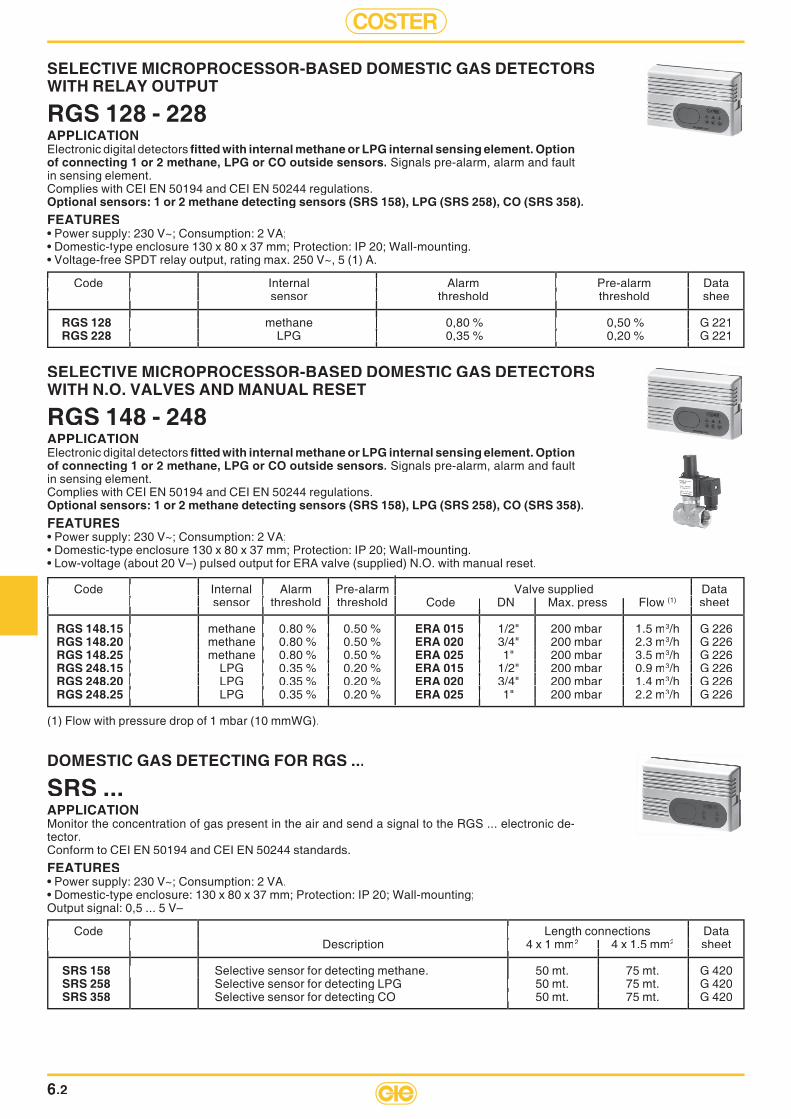
COSTER
6.2
SELECTIVE MICROPROCESSOR-BASED DOMESTIC GAS DETECTORSWITH RELAY OUTPUT
RGS 128 - 228APPLICATIONElectronic digital detectors fi tted with internal methane or LPG internal sensing element. Option of connecting 1 or 2 methane, LPG or CO outside sensors. Signals pre-alarm, alarm and fault in sensing element.Complies with CEI EN 50194 and CEI EN 50244 regulations.Optional sensors: 1 or 2 methane detecting sensors (SRS 158), LPG (SRS 258), CO (SRS 358).FEATURES• Power supply: 230 V~; Consumption: 2 VA;• Domestic-type enclosure 130 x 80 x 37 mm; Protection: IP 20; Wall-mounting.• Voltage-free SPDT relay output, rating max. 250 V~, 5 (1) A.
Code Internal Alarm Pre-alarm Data Code Internal Alarm Pre-alarm Data sensor threshold threshold sensor threshold threshold shee
RGS 128 methane 0,80 % 0,50 % G 221RGS 228 LPG 0,35 % 0,20 % G 221
Code Internal Alarm Pre-alarm Data sensor threshold threshold
methane 0,80 % 0,50 % G 221 LPG 0,35 % 0,20 % G 221
Code Internal Alarm Pre-alarm Data
methane 0,80 % 0,50 % G 221 LPG 0,35 % 0,20 % G 221
Code Internal Alarm Pre-alarm Data sensor threshold threshold
methane 0,80 % 0,50 % G 221 LPG 0,35 % 0,20 % G 221
Code Internal Alarm Pre-alarm Data sensor threshold threshold
methane 0,80 % 0,50 % G 221 LPG 0,35 % 0,20 % G 221
Code Internal Alarm Pre-alarm Data sensor threshold threshold
methane 0,80 % 0,50 % G 221 LPG 0,35 % 0,20 % G 221
DOMESTIC GAS DETECTING FOR RGS ...
SRS ...APPLICATIONMonitor the concentration of gas present in the air and send a signal to the RGS ... electronic de-tector.Conform to CEI EN 50194 and CEI EN 50244 standards.
FEATURES• Power supply: 230 V~; Consumption: 2 VA.• Domestic-type enclosure: 130 x 80 x 37 mm; Protection: IP 20; Wall-mounting;Output signal: 0,5 ... 5 V–
Code Length connections Data Code Length connections Data Description 4 x 1 mm Description 4 x 1 mm2 4 x 1.5 mm2 sheet
SRS 158 Selective sensor for detecting methane. 50 mt. 75 mt. G 420SRS 258 Selective sensor for detecting LPG 50 mt. 75 mt. G 420SRS 358 Selective sensor for detecting CO 50 mt. 75 mt. G 420
Code Length connections Data Description 4 x 1 mm
Selective sensor for detecting methane.
Code Length connections Data sheet
50 mt. 75 mt. G 420 50 mt. 75 mt. G 420
50 mt. 75 mt. G 420
Code Length connections Data Description 4 x 1 mm
Selective sensor for detecting methane.
Code Length connections Data Description 4 x 1 mm
50 mt. 75 mt. G 420 50 mt. 75 mt. G 420
4 x 1.5 mm
50 mt. 75 mt. G 420 50 mt. 75 mt. G 420
50 mt. 75 mt. G 420
SELECTIVE MICROPROCESSOR-BASED DOMESTIC GAS DETECTORSWITH N.O. VALVES AND MANUAL RESET
RGS 148 - 248APPLICATIONElectronic digital detectors fi tted with internal methane or LPG internal sensing element. Option of connecting 1 or 2 methane, LPG or CO outside sensors. Signals pre-alarm, alarm and fault in sensing element.Complies with CEI EN 50194 and CEI EN 50244 regulations.Optional sensors: 1 or 2 methane detecting sensors (SRS 158), LPG (SRS 258), CO (SRS 358).FEATURES• Power supply: 230 V~; Consumption: 2 VA;• Domestic-type enclosure 130 x 80 x 37 mm; Protection: IP 20; Wall-mounting.• Low-voltage (about 20 V–) pulsed output for ERA valve (supplied) N.O. with manual reset.
Code Internal Alarm Pre-alarm Valve supplied Data Code Internal Alarm Pre-alarm Valve supplied Data sensor threshold threshold sensor threshold threshold Code DN Max. press Flow (1) sheet
RGS 148.15 methane 0.80 % 0.50 % ERA 015 1/2" 200 mbar 1.5 m3/h G 226RGS 148.20 methane 0.80 % 0.50 % ERA 020 3/4" 200 mbar 2.3 m3/h G 226RGS 148.25 methane 0.80 % 0.50 % ERA 025 1" 200 mbar 3.5 m3/h G 226RGS 248.15 LPG 0.35 % 0.20 % ERA 015 1/2" 200 mbar 0.9 m3/h G 226RGS 248.20 LPG 0.35 % 0.20 % ERA 020 3/4" 200 mbar 1.4 m3/h G 226RGS 248.25 LPG 0.35 % 0.20 % ERA 025 1" 200 mbar 2.2 m3/h G 226
(1) Flow with pressure drop of 1 mbar (10 mmWG).
Code Internal Alarm Pre-alarm Valve supplied Data sensor threshold threshold
methane 0.80 % 0.50 % methane 0.80 % 0.50 % methane 0.80 % 0.50 % LPG 0.35 % 0.20 % LPG 0.35 % 0.20 % LPG 0.35 % 0.20 %
Code Internal Alarm Pre-alarm Valve supplied Data sheet
/h G 226/h G 226/h G 226/h G 226/h G 226/h G 226
Code Internal Alarm Pre-alarm Valve supplied Data sensor threshold threshold
methane 0.80 % 0.50 % methane 0.80 % 0.50 % methane 0.80 % 0.50 % LPG 0.35 % 0.20 % LPG 0.35 % 0.20 % LPG 0.35 % 0.20 %
Code DN Max. press Flow
1/2" 200 mbar 1.5 m 3/4" 200 mbar 2.3 m 1" 200 mbar 3.5 m 1/2" 200 mbar 0.9 m 3/4" 200 mbar 1.4 m 1" 200 mbar 2.2 m
Code Internal Alarm Pre-alarm Valve supplied Data Code Internal Alarm Pre-alarm Valve supplied Data sensor threshold threshold
methane 0.80 % 0.50 % methane 0.80 % 0.50 % methane 0.80 % 0.50 % LPG 0.35 % 0.20 % LPG 0.35 % 0.20 % LPG 0.35 % 0.20 %
Code Internal Alarm Pre-alarm Valve supplied Data sensor threshold threshold
methane 0.80 % 0.50 % methane 0.80 % 0.50 % methane 0.80 % 0.50 % LPG 0.35 % 0.20 % LPG 0.35 % 0.20 % LPG 0.35 % 0.20 %
Code DN Max. press Flow
1/2" 200 mbar 1.5 m 3/4" 200 mbar 2.3 m 1" 200 mbar 3.5 m 1/2" 200 mbar 0.9 m 3/4" 200 mbar 1.4 m 1" 200 mbar 2.2 m
Code DN Max. press Flow
1/2" 200 mbar 1.5 m 3/4" 200 mbar 2.3 m 1" 200 mbar 3.5 m 1/2" 200 mbar 0.9 m 3/4" 200 mbar 1.4 m 1" 200 mbar 2.2 m

6
COSTER
6.3
ACCESSORIES
Code Description Back-up Data Code Description Back-up Data period sheet period sheet
ALH 835 Auxiliary power supply for RGH ... gas detectors with power backup. 5 hours G 310ABE 301 Emergency power supply for ERC ... valves. 20 hours –
(1) Flow with pressure drop of 1 mbar (10 mmWG)
DOMESTIC GAS DETECTORS WITH BACKUP BATTERY AND N.C. MANUALLY-RESET VALVE
RGH ...APPLICATIONGas detectors for domestic use supplied with internal methane or LPG sensor, battery backup having an autonomy of about one hour, and N.C. gas valve ERC 3.. with manual reset. Monitor the concentration of gas in the air and, when this exceeds the threshold value, cuts off the 3 V – power supply to the valve. Indicates by means of LEDs and internal buzzer the states of pre-alarm, alarm and sensor fault.Complies with CEI EN 50194 and CEI EN 50244 regulations.
FEATURES• Power supply: 230 V~; Consumption: 2 VA;• Domestic-type enclosure: 130 x 80 x 37 mm; Protection: IP 20; Wall-mounting;• 3 V– output for N.C. ERC valve (supplied) with manual reset.• ERC valves: Protection: IP 55.
Code Internal Alarm Valve supplied Data sensor threshold Code DN Max. press. Flow rate (1) sheet
RGH 138.15 methane 0,80 % ERC 315 1/2" 500 mbar 1.5 m3/h G 310RGH 138.20 methane 0,80 % ERC 320 3/4" 500 mbar 2.3 m3/h G 310RGH 138.25 methane 0,80 % ERC 325 1" 500 mbar 3.5 m3/h G 310RGH 238.15 LPG 0,35 % ERC 315 1/2" 500 mbar 0.9 m3/h G 310RGH 238.20 LPG 0,35 % ERC 320 3/4" 500 mbar 1.4 m3/h G 310RGH 238.25 LPG 0,35 % ERC 325 1" 500 mbar 2.2 m3/h G 310
Code Internal Alarm Valve supplied Data sensor threshold Code DN Max. press. Flow rate Code Internal Alarm Valve supplied Data sensor threshold Code DN Max. press. Flow rate
methane 0,80 % methane 0,80 % methane 0,80 % LPG 0,35 % LPG 0,35 % LPG 0,35 %
Code Internal Alarm Valve supplied Data sheet
/h G 310/h G 310/h G 310/h G 310/h G 310/h G 310
Code Internal Alarm Valve supplied Data sensor threshold Code DN Max. press. Flow rate Code Internal Alarm Valve supplied Data sensor threshold Code DN Max. press. Flow rate Code Internal Alarm Valve supplied Data sensor threshold Code DN Max. press. Flow rate
methane 0,80 % methane 0,80 % methane 0,80 % LPG 0,35 % LPG 0,35 % LPG 0,35 %
sensor threshold Code DN Max. press. Flow rate
1/2" 500 mbar 1.5 m 3/4" 500 mbar 2.3 m 1" 500 mbar 3.5 m 1/2" 500 mbar 0.9 m 3/4" 500 mbar 1.4 m 1" 500 mbar 2.2 m
sensor threshold Code DN Max. press. Flow rate
1/2" 500 mbar 1.5 m 3/4" 500 mbar 2.3 m 1" 500 mbar 3.5 m 1/2" 500 mbar 0.9 m 3/4" 500 mbar 1.4 m 1" 500 mbar 2.2 m
sensor threshold Code DN Max. press. Flow rate
1/2" 500 mbar 1.5 m 3/4" 500 mbar 2.3 m 1" 500 mbar 3.5 m 1/2" 500 mbar 0.9 m 3/4" 500 mbar 1.4 m 1" 500 mbar 2.2 m
Code Description Back-up Data period sheet
Auxiliary power supply for RGH ... gas detectors with power backup. 5 hours G 310
Code Description Back-up Data period sheet
Auxiliary power supply for RGH ... gas detectors with power backup. 5 hours G 310Emergency power supply for ERC ... valves. 20 hours –
Code Description Back-up Data period sheet
ABE 301
Code Description Back-up Data period sheet
Auxiliary power supply for RGH ... gas detectors with power backup. 5 hours G 310Emergency power supply for ERC ... valves. 20 hours –
MICROPROCESSOR-BASED DOMESTIC SELECTIVECARBON MONOXIDE DETECTOR WITH RELAY OUTPUT
RGS 328APPLICATIONDigital electronic detector supplied with internal selective CO sensor.Pre-alarm, alarm and sensor fault signals.Conform to CEI EN 50194 and CEI EN 50244 standards.
FEATURES• Power supply: 230 V ~; Consumption: 2 VA;• Domestic-type enclosure: 130 x 80 x 37 mm; Protection: IP 20; Wall-mounting;• Alarm threshold in relation to CO concentration and time gas persists.• SPDT voltage-free output relay: maximum switching 250 V~, 5 (1) A.
Code Description Data sheet
RGS 328 Selective detector for carbon monoxide. G 227
Code Description Data sheet Code Description Data sheet
Selective detector for carbon monoxide. G
Code Description Data sheet
Selective detector for carbon monoxide. G
Code Description Data sheet
Selective detector for carbon monoxide. G

COSTER
6.4
GAS SENSORS FOR RFG 651/2/3 AND RFG 361
SRD ... - SRS ...APPLICATIONMonitor the concentration of combustible gas or carbon monoxide in the air and activate a voltage output to the electronic detector. Housing in plastic material. Wall mounting.Complies with CEI EN 50194 and CEI EN 50244 regulations.
FEATURES• Power supply: 12 V– (from the detector); Consumption: 150 mA; Output signal: 0 ... 5 V–.
GAS DETECTORS IN DIN 6 MODULE CASE
RFG 651 - 652 - 653APPLICATIONMonitor, by means of remote sensors, the concentration of gas in the air, and, when this exceeds the threshold level, activate the operational relay and the external alarms.Complies with CEI EN 50194 and CEI EN 50244 regulations.Essential sensors: 1, 2 or 3 sensors for methane, LPG and carbon monoxide.FEATURES• Power supply: 230 V ~ or 12 V –; Consumption: 6 VA; DIN 105 x 115 modular enclosure; Protection: IP 40.• Adjustable alarm threshold: methane = 0.5 ... 1.25 %; propane = 0.22 ... 0.56 %; CO = 0.02 ... 0.05 %.• Pre-alarm ( 63 %)alarm and fault sensors alarm.• Voltage-free SPDT output; rating 250 V ~, 5 (1) A for control N.O. or N.C. valves.
GAS DETECTORS IN DIN 3 MODULE CASE
RFG 361APPLICATIONMonitor, by means of a remote sensor, the concentration of gas in the air, and, when this exceeds the threshold level, activate the operational relay.Complies with CEI EN 50194 and CEI EN 50244 regulations.Essential sensors: 1 sensor for methane, LPG, carbon monoxide.FEATURES• Power supply: 230 V ~; Consumption: 3 VA; DIN 53 x 115 modular enclosure; Protection: IP 40.• Adjustable alarm threshold: methane = 0.5 ... 1.25 %; propane = 0.22 ... 0.56 %; CO = 0.02 ... 0.05 %.• Pre-alarm threshold about 63 % of alarm threshold.• Voltage-free SPDT output; rating 250 V ~, 5 (1) A for control N.O. or N.C. valves.
Code Description Data sheet
RFG 651 Gas detector for one remote sensor. G 512RFG 652 Gas detector for two remote sensors. G 512RFG 653 Gas detector for three remote sensors. G 512
Code Description Data sheet Code Description Data sheet
Gas detector for one remote sensor. G 512 Gas detector for two remote sensors. G 512 Gas detector for three remote sensors. G 512
Code Description Data sheet
Gas detector for one remote sensor. G 512 Gas detector for two remote sensors. G 512 Gas detector for three remote sensors. G 512
Code Description Data sheet
Gas detector for one remote sensor. G 512 Gas detector for two remote sensors. G 512 Gas detector for three remote sensors. G 512
Code Description Data sheet
RFG 361 Gas detector for one remote sensor. G 521
Code Description Data sheet Code Description Data sheet
Gas detector for one remote sensor. G 521
Code Description Data sheet
Gas detector for one remote sensor. G 521
Code Description Data sheet
Gas detector for one remote sensor. G 521
Code Gas Case Protect. Connection length Data Code Gas Case Protect. Connection length Data 3 x 1 mm 3 x 1 mm2 3 x 1.5 mm2 sheet
SRD 150 methane Domestic (80 x 80 x 35 mm) IP 20 50 m 75 m –SRD 250 LPG Domestic (80 x 80 x 35 mm) IP 20 50 m 75 m –SRD 350 CO Domestic (80 x 80 x 35 mm) IP 20 50 m 75 m –SRS 150 methane Commercial (80 x 80 x 42 mm) IP 44 50 m 75 m –SRS 250 LPG Commercial (80 x 80 x 42 mm) IP 44 50 m 75 m –SRS 350 CO Commercial (80 x 80 x 42 mm) IP 44 50 m 75 m –
Code Gas Case Protect. Connection length Data 3 x 1 mm
methane Domestic (80 x 80 x 35 mm) IP 20 50 m 75 m – LPG Domestic (80 x 80 x 35 mm) IP 20 50 m 75 m – CO Domestic (80 x 80 x 35 mm) IP 20 50 m 75 m – methane Commercial (80 x 80 x 42 mm) IP 44 50 m 75 m – LPG Commercial (80 x 80 x 42 mm) IP 44 50 m 75 m – CO Commercial (80 x 80 x 42 mm) IP 44 50 m 75 m –
Code Gas Case Protect. Connection length Data sheet
methane Domestic (80 x 80 x 35 mm) IP 20 50 m 75 m – LPG Domestic (80 x 80 x 35 mm) IP 20 50 m 75 m – CO Domestic (80 x 80 x 35 mm) IP 20 50 m 75 m – methane Commercial (80 x 80 x 42 mm) IP 44 50 m 75 m – LPG Commercial (80 x 80 x 42 mm) IP 44 50 m 75 m – CO Commercial (80 x 80 x 42 mm) IP 44 50 m 75 m –
Code Gas Case Protect. Connection length Data 3 x 1 mm
methane Domestic (80 x 80 x 35 mm) IP 20 50 m 75 m – LPG Domestic (80 x 80 x 35 mm) IP 20 50 m 75 m – CO Domestic (80 x 80 x 35 mm) IP 20 50 m 75 m – methane Commercial (80 x 80 x 42 mm) IP 44 50 m 75 m – LPG Commercial (80 x 80 x 42 mm) IP 44 50 m 75 m – CO Commercial (80 x 80 x 42 mm) IP 44 50 m 75 m –
3 x 1.5 mm
methane Domestic (80 x 80 x 35 mm) IP 20 50 m 75 m – LPG Domestic (80 x 80 x 35 mm) IP 20 50 m 75 m – CO Domestic (80 x 80 x 35 mm) IP 20 50 m 75 m – methane Commercial (80 x 80 x 42 mm) IP 44 50 m 75 m – LPG Commercial (80 x 80 x 42 mm) IP 44 50 m 75 m – CO Commercial (80 x 80 x 42 mm) IP 44 50 m 75 m –
Code Gas Case Protect. Connection length Data 3 x 1 mm
methane Domestic (80 x 80 x 35 mm) IP 20 50 m 75 m – LPG Domestic (80 x 80 x 35 mm) IP 20 50 m 75 m – CO Domestic (80 x 80 x 35 mm) IP 20 50 m 75 m – methane Commercial (80 x 80 x 42 mm) IP 44 50 m 75 m – LPG Commercial (80 x 80 x 42 mm) IP 44 50 m 75 m – CO Commercial (80 x 80 x 42 mm) IP 44 50 m 75 m –

6
COSTER
6.5
Code Gas Case Protect. Connection length Data Code Gas Case Protect. Connection length Data 3 x 1 mm 3 x 1 mm2 3 x 1.5 mm2 sheet
SGC 300/M methane Domestic (90 x 65 x 42 mm) IP 20 50 m 75 m –SGC 300/P LPG Domestic (90 x 65 x 42 mm) IP 20 50 m 75 m –SGC 301 CO Domestic (90 x 65 x 42 mm) IP 20 50 m 75 m –SGR 300/M methane Commercial (80 x 80 x 42 mm) IP 44 50 m 75 m –SGR 300/P LPG Commercial (80 x 80 x 42 mm) IP 44 50 m 75 m –SGR 301 CO Commercial (80 x 80 x 42 mm) IP 44 50 m 75 m –
GAS SENSORS FOR RFG 782
SGC 3.. - SGR 3..APPLICATIONMonitor infl ammable gas or carbon monoxide concentration in the air and process a voltage output to the electronic detector RFG 782. Housing in plastic material. Wall mounting.Complies with CEI EN 50194 and CEI EN 50244 regulations.
FEATURES• Power supply: 12 V– (from the detector); Consumption: 150 mA; Output signal: 0 ... 5 V–.
GAS DETECTOR 144 x 144 WITH PRE-ALARM FOR PANEL MOUNTING
RFG 782APPLICATIONMonitors, by means of one or two remote sensors, the concentration of gas in the air. When this concentration exceeds the 1st threshold, the detector activates the pre-alarm relay and when the concentration exceeds the 2nd threshold it activates the operational relay and the external alarms.Complies with CEI EN 50194 and CEI EN 50244 regulations.Essential sensors : 1 or 2 sensors for methane, LPG, carbon monoxide.FEATURES• Power supply: 230 V ~ or 12 V –; Consumption: 6 VA; Case: DIN 144 x 144; Protection: IP 40.• Adjustable pre-alarm and alarm thresholds: methane = 0.25 ... 0.8 %; LPG = 0.06 ... 0.35 %; CO = 0.005 ... 0.05 %.• Signals pre-alarm, alarm and fault in sensors.• Voltage-free SPDT outputs: rating: 250 V~, 10 (2.5) A for control of N.O. or N.C. valves.
Code Gas Case Protect. Connection length Data 3 x 1 mm
methane Domestic (90 x 65 x 42 mm) IP 20 50 m 75 m – LPG Domestic (90 x 65 x 42 mm) IP 20 50 m 75 m –
CO Domestic (90 x 65 x 42 mm) IP 20 50 m 75 m – methane Commercial (80 x 80 x 42 mm) IP 44 50 m 75 m – LPG Commercial (80 x 80 x 42 mm) IP 44 50 m 75 m –
CO Commercial (80 x 80 x 42 mm) IP 44 50 m 75 m –
Code Gas Case Protect. Connection length Data sheet
methane Domestic (90 x 65 x 42 mm) IP 20 50 m 75 m – LPG Domestic (90 x 65 x 42 mm) IP 20 50 m 75 m –
CO Domestic (90 x 65 x 42 mm) IP 20 50 m 75 m – methane Commercial (80 x 80 x 42 mm) IP 44 50 m 75 m – LPG Commercial (80 x 80 x 42 mm) IP 44 50 m 75 m –
CO Commercial (80 x 80 x 42 mm) IP 44 50 m 75 m –
Code Gas Case Protect. Connection length Data 3 x 1 mm
methane Domestic (90 x 65 x 42 mm) IP 20 50 m 75 m – LPG Domestic (90 x 65 x 42 mm) IP 20 50 m 75 m –
CO Domestic (90 x 65 x 42 mm) IP 20 50 m 75 m – methane Commercial (80 x 80 x 42 mm) IP 44 50 m 75 m – LPG Commercial (80 x 80 x 42 mm) IP 44 50 m 75 m –
CO Commercial (80 x 80 x 42 mm) IP 44 50 m 75 m –
3 x 1.5 mm
methane Domestic (90 x 65 x 42 mm) IP 20 50 m 75 m – LPG Domestic (90 x 65 x 42 mm) IP 20 50 m 75 m –
CO Domestic (90 x 65 x 42 mm) IP 20 50 m 75 m – methane Commercial (80 x 80 x 42 mm) IP 44 50 m 75 m – LPG Commercial (80 x 80 x 42 mm) IP 44 50 m 75 m –
CO Commercial (80 x 80 x 42 mm) IP 44 50 m 75 m –
Code Gas Case Protect. Connection length Data 3 x 1 mm
methane Domestic (90 x 65 x 42 mm) IP 20 50 m 75 m – LPG Domestic (90 x 65 x 42 mm) IP 20 50 m 75 m –
CO Domestic (90 x 65 x 42 mm) IP 20 50 m 75 m – methane Commercial (80 x 80 x 42 mm) IP 44 50 m 75 m – LPG Commercial (80 x 80 x 42 mm) IP 44 50 m 75 m –
CO Commercial (80 x 80 x 42 mm) IP 44 50 m 75 m –
Code Description Data sheet
RFG 782 Gas leak detector with pre-alarm for 1 or 2 remote sensors. G 610
Code Description Data sheet Code Description Data sheet
Gas leak detector with pre-alarm for 1 or 2 remote sensors. G 610
Code Description Data sheet
Gas leak detector with pre-alarm for 1 or 2 remote sensors. G 610
Code Description Data sheet
Gas leak detector with pre-alarm for 1 or 2 remote sensors. G 610

COSTER
6.6
BACK-UP POWER UNITS FOR GAS SAFETY SYSTEMSFor supplying 12 V– to gas safety systems in event of mains failure.Consists of:• 1 Stabilized (standby) back-up power unit.• 1 Weatherproof battery.
STABILIZED (STANDBY) POWER BACK-UP UNITS
ALI 310 - ALP 1..APPLICATIONStabilized back-up units for keeping batteries charged.
METHOD OF CHOOSING POWER SUPPLY IN RELATION TO SYSTEM TO BE ENERGISED• Calculate the total power absorbed Pt in VA by the system which has to be energised by adding together all the consumptions
of the single components of the system: detectors Pr, sensors Ps (only SRS 158-258, SRC 358), valves Pv, external alarms Pa. Power consumption by sensors SGC ..., SGR ... must not be added since this is already included in that of the detectors which energise them.
Pt = Pr + Ps + Pv + Pa. The power of the power unit must be greater than or equal to Pt.• By multiplying the power absorbed, Pt, by the number of hours h for which it is necessary to keep the system running effi ciently
without mains supply, the power effectively necessary, Pe, is obtained. Pe = Pt x h. The power of the battery must not be less than Pe. If a single battery is not suffi cient, use two or more batteries in parallel.
WEATHERPROOF BATTERIES
ACC ...APPLICATIONLong-life lead-sealed rechargeable batteries. Withstand demanding operating conditions such as overloading and very low discharge. Do not require any maintenance.
GENERAL ACCESSORIES FOR GAS DETECTION SYSTEMS Code Description Power Consumption Protection supply
SAS 880 Remote audible alarm. 230 V~ 10 VA IP 22SAL 881 Remote visual alarm. 230 V~ 4 VA IP 54CSL 882 Remote audible and visual alarm. 230 V~ 10 VA IP 30
Code Description Power Consumption Protection supply Code Description Power Consumption Protection supply
Remote audible alarm. 230 V~ 10 VA IP 22 Remote visual alarm. 230 V~ 4 VA IP 54 Remote audible and visual alarm. 230 V~ 10 VA IP 30
Code Description Power Consumption Protection
Remote audible alarm. 230 V~ 10 VA IP 22 Remote visual alarm. 230 V~ 4 VA IP 54 Remote audible and visual alarm. 230 V~ 10 VA IP 30
Code Description Power Consumption Protection supply
Remote audible alarm. 230 V~ 10 VA IP 22 Remote visual alarm. 230 V~ 4 VA IP 54 Remote audible and visual alarm. 230 V~ 10 VA IP 30
Code Power Input Output Dimensions Weight VA V ~ V ~ A L x P x H mm. Kg
ALI 310 24 230 13.8 3 140 x 120 x 42 0.5ALP 114 84 230 13.5 10 200 x 240 x 110 6.7ALP 120 180 230 13.5 20 200 x 275 x 130 7.5
Code Power Input Output Dimensions Weight VA V ~ V ~ A L x P x H mm. Kg Code Power Input Output Dimensions Weight VA V ~ V ~ A L x P x H mm. Kg
24 230 13.8 3 140 x 120 x 42 0.5 84 230 13.5 10 200 x 240 x 110 6.7 180 230 13.5 20 200 x 275 x 130 7.5
Code Power Input Output Dimensions Weight VA V ~ V ~ A L x P x H mm. Kg
24 230 13.8 3 140 x 120 x 42 0.5 84 230 13.5 10 200 x 240 x 110 6.7 180 230 13.5 20 200 x 275 x 130 7.5
Code Power Input Output Dimensions Weight VA V ~ V ~ A L x P x H mm. Kg
24 230 13.8 3 140 x 120 x 42 0.5 84 230 13.5 10 200 x 240 x 110 6.7 180 230 13.5 20 200 x 275 x 130 7.5
Code Power Input Output Dimensions Weight VA V ~ V ~ A L x P x H mm. Kg
24 230 13.8 3 140 x 120 x 42 0.5 84 230 13.5 10 200 x 240 x 110 6.7 180 230 13.5 20 200 x 275 x 130 7.5
Code Power Input Output Dimensions Weight VA V ~ V ~ A L x P x H mm. Kg
24 230 13.8 3 140 x 120 x 42 0.5 84 230 13.5 10 200 x 240 x 110 6.7 180 230 13.5 20 200 x 275 x 130 7.5
Code Power Input Output Dimensions Weight VA V ~ V ~ A L x P x H mm. Kg
24 230 13.8 3 140 x 120 x 42 0.5 84 230 13.5 10 200 x 240 x 110 6.7 180 230 13.5 20 200 x 275 x 130 7.5
VA V ~ V ~ A L x P x H mm. Kg
24 230 13.8 3 140 x 120 x 42 0.5 84 230 13.5 10 200 x 240 x 110 6.7 180 230 13.5 20 200 x 275 x 130 7.5
Code Power Voltage Rating Dimensions Weight Code Power Voltage Rating Dimensions Weight VA V – A/h L x P x H mm. Kg VA V – A/h L x P x H mm. Kg
ACC 019 22 12 2.3 178 x 34 x 65 0.9ACC 060 72 12 7.0 151 x 64.5 x 97.5 2.5
ACC 150 ACC 150 180 12 17 181 x 76 x 167 6ACC 240 288 12 24 175 x 166 x 125 8.1ACC 400 480 12 40 197 x 165 x 170 14
Code Power Voltage Rating Dimensions Weight VA V – A/h L x P x H mm. Kg
22 12 2.3 178 x 34 x 65 0.9 72 12 7.0 151 x 64.5 x 97.5 2.5 180 12 17 181 x 76 x 167 6 288 12 24 175 x 166 x 125 8.1 480 12 40 197 x 165 x 170 14
Code Power Voltage Rating Dimensions Weight VA V – A/h L x P x H mm. Kg
22 12 2.3 178 x 34 x 65 0.9 72 12 7.0 151 x 64.5 x 97.5 2.5 180 12 17 181 x 76 x 167 6 288 12 24 175 x 166 x 125 8.1 480 12 40 197 x 165 x 170 14
Code Power Voltage Rating Dimensions Weight VA V – A/h L x P x H mm. Kg
22 12 2.3 178 x 34 x 65 0.9 72 12 7.0 151 x 64.5 x 97.5 2.5 180 12 17 181 x 76 x 167 6 288 12 24 175 x 166 x 125 8.1 480 12 40 197 x 165 x 170 14
Code Power Voltage Rating Dimensions Weight VA V – A/h L x P x H mm. Kg
22 12 2.3 178 x 34 x 65 0.9 72 12 7.0 151 x 64.5 x 97.5 2.5 180 12 17 181 x 76 x 167 6 288 12 24 175 x 166 x 125 8.1 480 12 40 197 x 165 x 170 14
Code Power Voltage Rating Dimensions Weight VA V – A/h L x P x H mm. Kg
22 12 2.3 178 x 34 x 65 0.9 72 12 7.0 151 x 64.5 x 97.5 2.5 180 12 17 181 x 76 x 167 6 288 12 24 175 x 166 x 125 8.1 480 12 40 197 x 165 x 170 14
Code Power Voltage Rating Dimensions Weight VA V – A/h L x P x H mm. Kg
22 12 2.3 178 x 34 x 65 0.9 72 12 7.0 151 x 64.5 x 97.5 2.5 180 12 17 181 x 76 x 167 6 288 12 24 175 x 166 x 125 8.1 480 12 40 197 x 165 x 170 14

6
COSTER
6.7
(1) – Maximum working pressure.(2) – Flow of methane with pressure drop of 0.5 mbar (5mmWG) and 1 mbar (10 mmWG). 100 mbar = 10 kPa = 1.000 mm WG
N. O. GAS SOLENOID VALVES WITH MANUAL RE-SET
GCRO ...APPLICATIONWithout power they are closed; they have to be re-opened manually and remain open when powered.Approved Class A Group 2.FEATURES• Construction : brass body• Linkage : screwed female EN 10226• Protection : IP 65• Working temperature :– 15...+ 60°C
Code Code DN Power supply P.max (1) Flow rate m3/h (2) Data V VA mbar 0.5 mbar 1 mbar sheet
GCRO 815 GCRO 815 1/2" 230 VAC 9 500 1.8 2.6 G 924GCRO 415 1/2" 24 VAC 8 500 1.8 2.6 G 924GCRO 215 1/2" 12 VDC 8 500 1.8 2.6 G 924GCRO 820 3/4" 230 VAC 9 500 3 4.5 G 924GCRO 420 3/4" 24 VAC 8 500 3 4.5 G 924GCRO 220 3/4" 12 VDC 8 500 3 4.5 G 924GCRO 825 1" 230 VAC 9 500 4.5 6.6 G 924GCRO 425 1" 24 VAC 8 500 4.5 6.6 G 924GCRO 225 1" 12 VDC 8 500 4.5 6.6 G 924
DN V VA mbar 0.5 mbar 1 mbar
230 VAC 9 500 1.8 2.6 G 2.6 G 2.6 G
3 4.5 G G G
4.5 6.6 G G G
P.max V VA mbar 0.5 mbar 1 mbar
230 VAC 9 500 1.8 2.6 G 8 500 8 500 9 500
8 500 8 500 9 500
8 500 8 500
DN V VA mbar 0.5 mbar 1 mbar
230 VAC 9 500 1.8 2.6 G 24 VAC 12 VDC 230 VAC 24 VAC 12 VDC
230 VAC 24 VAC 12 VDC
V VA mbar 0.5 mbar 1 mbar
230 VAC 9 500 1.8 2.6 G 8 500 8 500 9 500
8 500 8 500 9 500
8 500 8 500
V VA mbar 0.5 mbar 1 mbar
230 VAC 9 500 1.8 2.6 G
3 4.5 G
4.5 6.6 G
V VA mbar 0.5 mbar 1 mbar
230 VAC 9 500 1.8 2.6 G 2.6 G 2.6 G
3 4.5 G
4.5 6.6 G
AUTOMATIC N. C. GAS SOLENOID VALVE
GCAO ...APPLICATIONWithout power they are closed, when powered they are open. Approved Class A Group 2.FEATURES• Construction : brass body• Linkage : screwed female EN 10226• Protection : IP 65• Working temperature :– 15...+ 60°C
Code Code DN Power supply P.max (1) Flow rate m3/h (2) Data V VA mbar 0.5 mbar 1 mbar sheet
GCAO 810 GCAO 810 3/8" 230 VAC 12 200 0.92 1.4 G 914GCAO 410 3/8" 24 VAC 19 200 0.92 1.4 G 914GCAO 210 3/8" 12 VDC 8 200 0.92 1.4 G 914GCAO 815 1/2" 230 VAC 12 200 0.92 1.4 G 914GCAO 415 1/2" 24 VAC 19 200 0.92 1.4 G 914GCAO 215 1/2" 12 VDC 8 200 0.92 1.4 G 914GCAO 820 3/4" 230 VAC 12 200 0.92 1.4 G 914GCAO 420 3/4" 24 VAC 19 200 0.92 1.4 G 914GCAO 220 3/4" 12 VDC 8 200 0.92 1.4 G 914
DN V VA mbar 0.5 mbar 1 mbar sheet
Data V VA mbar 0.5 mbar 1 mbar sheet
230 VAC 12 200 0.92 1.4 G 0.92 1.4 G 0.92 1.4 G 0.92 1.4 G 0.92 1.4 G 0.92 1.4 G 0.92 1.4 G 0.92 1.4 G 0.92 1.4 G
P.max V VA mbar 0.5 mbar 1 mbar sheet
230 VAC 12 200 0.92 1.4 G 19 200 8 200 12 200
19 200 8 200 12 200
19 200 8 200
DN V VA mbar 0.5 mbar 1 mbar sheet
230 VAC 12 200 0.92 1.4 G 24 VAC 12 VDC 230 VAC 24 VAC 12 VDC 230 VAC 24 VAC 12 VDC
V VA mbar 0.5 mbar 1 mbar sheet
230 VAC 12 200 0.92 1.4 G 19 200 8 200 12 200
19 200 8 200 12 200
19 200 8 200
V VA mbar 0.5 mbar 1 mbar sheet
230 VAC 12 200 0.92 1.4 G 0.92 1.4 G 0.92 1.4 G 0.92 1.4 G 0.92 1.4 G 0.92 1.4 G 0.92 1.4 G 0.92 1.4 G 0.92 1.4 G
V VA mbar 0.5 mbar 1 mbar sheet
230 VAC 12 200 0.92 1.4 G 0.92 1.4 G 0.92 1.4 G 0.92 1.4 G 0.92 1.4 G 0.92 1.4 G 0.92 1.4 G 0.92 1.4 G 0.92 1.4 G
N.O. GAS SOLENOID VALVES WITH MANUAL RE-SET
GARO ...APPLICATIONWithout power they are open; when powered they are closed. They have to be re-opened manually and remain open if not powered.FEATURES• Construction : Brass body• Linkage : screwed female EN 10226• Protection : IP 65• Working temperature : – 15...+ 60°C
Code DN Power supply P.max Code DN Power supply P.max (1) Flow rate m3/h (2) Data V VA mbar 0.5 mbar 1 mbar sheet V VA mbar 0.5 mbar 1 mbar sheet
GARO 815 1/2" 230 VAC 7 500 1.8 2.6 G 934GARO 415 1/2" 24 VAC 4 500 1.8 2.6 G 934GARO 215 1/2" 12 VDC 6 500 1.8 2.6 G 934GARO 820 3/4" 230 VAC 7 500 3 4.5 G 934GARO 420 3/4" 24 VAC 4 500 3 4.5 G 934GARO 220 3/4" 12 VDC 6 500 3 4.5 G 934GARO 825 1" 230 VAC 8 500 4.5 6.6 G 934GARO 425 1" 24 VAC 22 500 4.5 6.6 G 934GARO 225 1" 12 VDC 8 500 4.5 6.6 G 934
Code DN Power supply P.max V VA mbar 0.5 mbar 1 mbar sheet
Data V VA mbar 0.5 mbar 1 mbar sheet
230 VAC 7 500 1.8 2.6 G 2.6 G 2.6 G
3 4.5 G G G
4.5 6.6 G G G
Code DN Power supply P.max V VA mbar 0.5 mbar 1 mbar sheet Code DN Power supply P.max V VA mbar 0.5 mbar 1 mbar sheet
230 VAC 7 500 1.8 2.6 G 4 500 6 500 7 500
4 500 6 500 8 500
22 500 8 500
Code DN Power supply P.max V VA mbar 0.5 mbar 1 mbar sheet
230 VAC 7 500 1.8 2.6 G 24 VAC 12 VDC 230 VAC 24 VAC 12 VDC
230 VAC 24 VAC 12 VDC
V VA mbar 0.5 mbar 1 mbar sheet
230 VAC 7 500 1.8 2.6 G 4 500 6 500 7 500
4 500 6 500 8 500
22 500 8 500
Flow rate m V VA mbar 0.5 mbar 1 mbar sheet
230 VAC 7 500 1.8 2.6 G
3 4.5 G
4.5 6.6 G
V VA mbar 0.5 mbar 1 mbar sheet
230 VAC 7 500 1.8 2.6 G 2.6 G 2.6 G
3 4.5 G
4.5 6.6 G
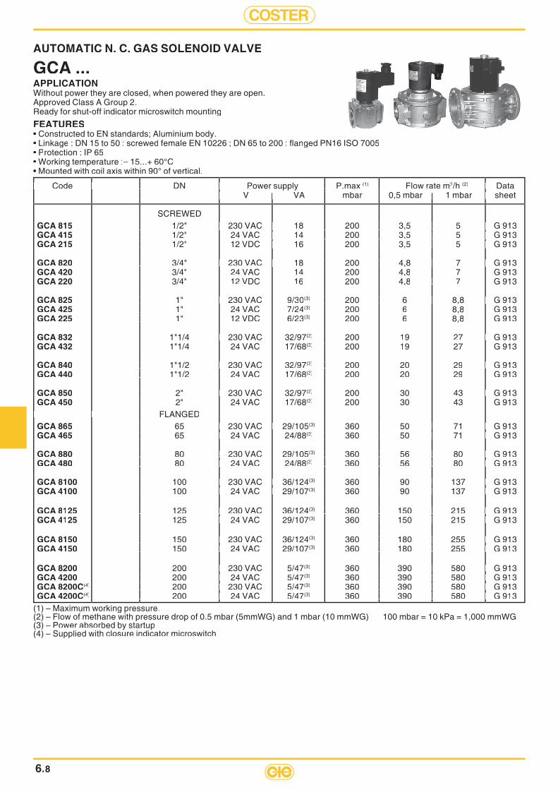
COSTER
6.8
AUTOMATIC N. C. GAS SOLENOID VALVE
GCA ...APPLICATIONWithout power they are closed, when powered they are open. Approved Class A Group 2.Ready for shut-off indicator microswitch mounting
FEATURES• Constructed to EN standards; Aluminium body.• Linkage : DN 15 to 50 : screwed female EN 10226 ; DN 65 to 200 : fl anged PN16 ISO 7005• Protection : IP 65• Working temperature :– 15...+ 60°C• Mounted with coil axis within 90° of vertical.
(1) – Maximum working pressure.(2) – Flow of methane with pressure drop of 0.5 mbar (5mmWG) and 1 mbar (10 mmWG) 100 mbar = 10 kPa = 1,000 mmWG(3) – Power absorbed by startup(4) – Supplied with closure indicator microswitch
Code DN Code DN Code DN Code DN Code DN Power supply P.max P.max (1) Flow rate m3/h (2) Data Data V VA mbar 0,5 mbar 1 mbar sheet V VA mbar 0,5 mbar 1 mbar sheet V VA mbar 0,5 mbar 1 mbar sheet V VA mbar 0,5 mbar 1 mbar sheet V VA mbar 0,5 mbar 1 mbar sheet V VA mbar 0,5 mbar 1 mbar sheet V VA mbar 0,5 mbar 1 mbar sheet V VA mbar 0,5 mbar 1 mbar sheet V VA mbar 0,5 mbar 1 mbar sheet
SCREWEDGCA 815 1/2" 230 VAC 18 200 3,5 5 G 913 1/2" 230 VAC 18 200 3,5 5 G 913 1/2" 230 VAC 18 200 3,5 5 G 913 1/2" 230 VAC 18 200 3,5 5 G 913 1/2" 230 VAC 18 200 3,5 5 G 913 1/2" 230 VAC 18 200 3,5 5 G 913 1/2" 230 VAC 18 200 3,5 5 G 913 1/2" 230 VAC 18 200 3,5 5 G 913GCA 415 1/2" 1/2" 24 VAC 14 200 3,5 5 G 91324 VAC 14 200 3,5 5 G 91324 VAC 14 200 3,5 5 G 91324 VAC 14 200 3,5 5 G 91324 VAC 14 200 3,5 5 G 91324 VAC 14 200 3,5 5 G 913GCA 215 1/2" 1/2" 12 VDC 16 200 3,5 5 G 91312 VDC 16 200 3,5 5 G 91312 VDC 16 200 3,5 5 G 91312 VDC 16 200 3,5 5 G 91312 VDC 16 200 3,5 5 G 91312 VDC 16 200 3,5 5 G 913
GCA 820 3/4" 230 3/4" 230 3/4" 230 VAC 18 200 4,8 7 G 913 18 200 4,8 7 G 913 18 200 4,8 7 G 913 18 200 4,8 7 G 913 18 200 4,8 7 G 913 18 200 4,8 7 G 913GCA 420 3/4" 3/4" 24 VAC 14 200 4,8 7 G 913GCA 220 3/4" 3/4" 12 VDC 16 200 4,8 7 7 G 913
GCA 825 1" 230 1" 230 1" 230 VAC 9/30(3) 200 6 8,8 G 913 200 6 8,8 G 913 200 6 8,8 G 913 200 6 8,8 G 913 200 6 8,8 G 913GCA 425 1" 1" 24 VAC 7/24(3) 200 6 8,8 G 913GCA 225 1" 1" 12 VDC 6/23(3) 200 6 8,8 G 913
GCA 832 1"1/4 230 1"1/4 230 1"1/4 230 VAC 32/97(3) 200 200 19 27 G 913 G 913GCA 432 1"1/4 1"1/4 24 VAC 17/68(3) 200 200 19 27 G 913
GCA 840 1"1/2 230 1"1/2 230 1"1/2 230 VAC 32/97(3) 200 200 20 29 G 913 G 913GCA 440 1"1/2 1"1/2 24 VAC 17/68(3) 200 20 29 G 913
GCA 850 2" 230 2" 230 2" 230 VAC 32/97(3) 200 200 30 43 G 913 G 913GCA 450 2" 2" 24 VAC 17/68(3) 200 30 43 G 913
FLANGED FLANGED FLANGED FLANGEDGCA 865 65 230 65 230 65 230 VAC 29/105 29/105(3) 360 50 71 G 913 360 50 71 G 913 360 50 71 G 913 360 50 71 G 913 360 50 71 G 913GCA 465 65 24 65 24 65 24 VAC 24/88(3) 360 50 71 G 913 360 50 71 G 913 360 50 71 G 913 360 50 71 G 913 360 50 71 G 913
GCA 880 80 230 80 230 80 230 VAC 29/105(3) 360 56 80 G 913 360 56 80 G 913 360 56 80 G 913 360 56 80 G 913 360 56 80 G 913GCA 480 80 24 80 24 80 24 VAC 24/88(3) 360 56 80 G 913 360 56 80 G 913 360 56 80 G 913 360 56 80 G 913 360 56 80 G 913
GCA 8100 100 230 100 230 100 230 VAC 36/ 36/124(3) 360 90 137 G 913 360 90 137 G 913 360 90 137 G 913 360 90 137 G 913 360 90 137 G 913GCA 4100 100 24 100 24 100 24 VAC 29/ 29/107(3) 360 90 137 G 913 360 90 137 G 913 360 90 137 G 913 360 90 137 G 913 360 90 137 G 913
GCA 8125 125 230 125 230 125 230 VAC 36/124(3) 360 150 215 G 913 360 150 215 G 913 360 150 215 G 913 360 150 215 G 913 360 150 215 G 913GCA 4125 125 24 125 24 125 24 VAC 29/107(3) 360 150 215 G 913 150 215 G 913 150 215 G 913 150 215 G 913
GCA 8150 150 230 150 230 150 230 VAC 36/124(3) 360 180 255 G 913 180 255 G 913 180 255 G 913 180 255 G 913GCA 4150 150 24 150 24 150 24 VAC 29/107(3) 360 180 255 G 91 180 255 G 91 180 255 G 91 180 255 G 913
GCA 8200 200 230 200 230 200 230 VAC 5/47(3) 360 390 580 G 913 390 580 G 913 390 580 G 913 390 580 G 913GCA 4200 200 24 200 24 200 24 VAC 5/47(3) 360 390 580 G 91 390 580 G 91 390 580 G 91 390 580 G 913GCA 8200C(4) 200 230 200 230 200 230 VAC 5/47(3) 360 390 580 G 913 390 580 G 913 390 580 G 913 390 580 G 913GCA 4200C(4) 200 24 200 24 200 24 VAC 5/47(3) 360 390 580 G 91 390 580 G 91 390 580 G 91 390 580 G 913

6
COSTER
6.9
N.C. GAS SOLENOID VALVES WITH MANUAL RE-SET
GCR ...APPLICATIONWithout power they are closed; they have to be re-opened manually and remain open when powered.Approved Class A Group 2.FEATURES• Constructed to EN standards; Aluminium body.• Linkage : DN 15 to 50 : screwed female EN 10226 ; DN 65 to 300 : fl anged PN16 ISO 7005• Protection : IP 65• Working temperature : –15...+ 60°C• Mounted with coil axis within 90° of vertical.
(1) – Maximum working pressure.(2) – Flow of methane with pressure drop of 0.5 mbar (5mmWG) and 1 mbar (10 mmWG) 100 mbar = 10 kPa = 1,000 mmWG
Code DN DN DN Power supply P.max P.max (1) Flow rate m3/h (2) Data V VA mbar 0.5 mbar 1 mbar sheet V VA mbar 0.5 mbar 1 mbar sheet V VA mbar 0.5 mbar 1 mbar sheet V VA mbar 0.5 mbar 1 mbar sheet V VA mbar 0.5 mbar 1 mbar sheet V VA mbar 0.5 mbar 1 mbar sheet V VA mbar 0.5 mbar 1 mbar sheet V VA mbar 0.5 mbar 1 mbar sheet
SCREWEDGCR 815 1/2" 230 VAC 9 500 6,6 8,7 G 923 1/2" 230 VAC 9 500 6,6 8,7 G 923 1/2" 230 VAC 9 500 6,6 8,7 G 923 1/2" 230 VAC 9 500 6,6 8,7 G 923 1/2" 230 VAC 9 500 6,6 8,7 G 923 1/2" 230 VAC 9 500 6,6 8,7 G 923 1/2" 230 VAC 9 500 6,6 8,7 G 923 1/2" 230 VAC 9 500 6,6 8,7 G 923GCR 415 1/2" 1/2" 24 VAC 8 500 6,6 8,7 G 924 VAC 8 500 6,6 8,7 G 924 VAC 8 500 6,6 8,7 G 924 VAC 8 500 6,6 8,7 G 924 VAC 8 500 6,6 8,7 G 924 VAC 8 500 6,6 8,7 G 923GCR 215 1/2" 1/2" 12 VDC 8 500 6,6 8,7 G 912 VDC 8 500 6,6 8,7 G 912 VDC 8 500 6,6 8,7 G 912 VDC 8 500 6,6 8,7 G 912 VDC 8 500 6,6 8,7 G 912 VDC 8 500 6,6 8,7 G 923
GCR 820 3/4" 230 3/4" 230 3/4" 230 VAC 9 500 9,8 14 G 9 9 500 9,8 14 G 9 9 500 9,8 14 G 9 9 500 9,8 14 G 9 9 500 9,8 14 G 9 9 500 9,8 14 G 923GCR 420 3/4" 3/4" 24 VAC 8 500 9,8 14 G 923GCR 220 3/4" 3/4" 12 VDC 8 500 9,8 14 G 923
GCR 825 1" 230 1" 230 1" 230 VAC 9 500 15 19 G 9 9 500 15 19 G 9 9 500 15 19 G 9 9 500 15 19 G 9 9 500 15 19 G 9 9 500 15 19 G 923GCR 425 1" 1" 24 VAC 8 500 15 1 19 G 923GCR 225 1" 1" 12 VDC 8 500 15 1 19 G 923
GCR 832 1"1/4 230 1"1/4 230 1"1/4 230 VAC 9 500 18 27 G 9 500 18 27 G 9 500 18 27 G 9 500 18 27 G 9 500 18 27 G 923GCR 432 1"1/4 1"1/4 24 VAC 8 500 500 18 218 27 G 923GCR 232 1"1/4 1"1/4 12 VDC 8 500 500 18 218 27 G 923
GCR 840 1"1/2 230 1"1/2 230 1"1/2 230 VAC 9 500 20 30 G 9 500 20 30 G 9 500 20 30 G 9 500 20 30 G 9 500 20 30 G 923GCR 440 1"1/2 1"1/2 24 VAC 8 500 20 30 G 923GCR 240 1"1/2 1"1/2 12 VDC 8 500 20 30 G 923
GCR 850 2" 230 2" 230 2" 230 VAC 9 500 25 37 G 9 500 25 37 G 9 500 25 37 G 9 500 25 37 G 9 500 25 37 G 923GCR 450 2" 2" 24 VAC 8 500 25 37 G 923GCR 250 2" 2" 12 VDC 8 500 25 37 G 923
FLANGEDGCR 865 65 230 65 230 65 230 VAC 18 500 53 78 G 9 500 53 78 G 9 500 53 78 G 9 500 53 78 G 9 500 53 78 G 923GCR 465 65 24 65 24 65 24 VAC 20 500 53 78 G 9 500 53 78 G 9 500 53 78 G 9 500 53 78 G 9 500 53 78 G 923GCR 265 65 12 65 12 65 12 VDC 18 500 53 78 G 9 500 53 78 G 9 500 53 78 G 9 500 53 78 G 9 500 53 78 G 923
GCR 880 80 230 80 230 80 230 VAC 18 500 53 78 G 9 500 53 78 G 9 500 53 78 G 9 500 53 78 G 9 500 53 78 G 923GCR 480 80 24 80 24 80 24 VAC 20 500 53 78 G 9 500 53 78 G 9 500 53 78 G 9 500 53 78 G 9 500 53 78 G 923GCR 280 80 12 80 12 80 12 VDC 18 500 53 78 G 9 500 53 78 G 9 500 53 78 G 9 500 53 78 G 9 500 53 78 G 923
GCR 8100 100 230 100 230 100 230 VAC 18 500 83 130 G 9 500 83 130 G 9 500 83 130 G 9 500 83 130 G 9 500 83 130 G 923GCR 4100 100 24 100 24 100 24 VAC 20 500 83 130 G 9 500 83 130 G 9 500 83 130 G 9 500 83 130 G 9 500 83 130 G 923GCR 2100 100 12 100 12 100 12 VDC 18 500 83 130 G 9 500 83 130 G 9 500 83 130 G 9 500 83 130 G 9 500 83 130 G 923
GCR 8125 125 230 125 230 125 230 VAC 18 500 230 335 G 9 500 230 335 G 9 500 230 335 G 9 500 230 335 G 9 500 230 335 G 923GCR 4125 125 24 125 24 125 24 VAC 20 500 230 335 G 9 500 230 335 G 9 500 230 335 G 9 500 230 335 G 9 500 230 335 G 923GCR 2125 125 12 125 12 125 12 VDC 18 500 230 335 G 9 500 230 335 G 9 500 230 335 G 9 500 230 335 G 9 500 230 335 G 923
GCR 8150 150 230 150 230 150 230 VAC 18 500 230 335 G 9 500 230 335 G 9 500 230 335 G 9 500 230 335 G 9 500 230 335 G 923GCR 4150 150 24 150 24 150 24 VAC 20 500 230 335 G 9 500 230 335 G 9 500 230 335 G 9 500 230 335 G 9 500 230 335 G 923GCR 2150 150 12 150 12 150 12 VDC 18 500 230 335 G 9 500 230 335 G 9 500 230 335 G 9 500 230 335 G 9 500 230 335 G 923
GCR 8200 200 230 200 230 200 230 VAC 18 500 360 525 G 9 500 360 525 G 9 500 360 525 G 9 500 360 525 G 9 500 360 525 G 923GCR 4200 200 24 200 24 200 24 VAC 20 500 360 525 G 9 500 360 525 G 9 500 360 525 G 9 500 360 525 G 9 500 360 525 G 923GCR 2200 200 12 200 12 200 12 VDC 18 500 360 525 G 9 500 360 525 G 9 500 360 525 G 9 500 360 525 G 9 500 360 525 G 923
GCR 8300 300 230 300 230 300 230 VAC 18 500 800 1200 G 9 500 800 1200 G 9 500 800 1200 G 9 500 800 1200 G 9 500 800 1200 G 923GCR 4300 300 24 300 24 300 24 VAC 20 500 800 500 800 500 800 1200 G 90 G 923GCR 2300 300 12 300 12 300 12 VDC 18 500 800 500 800 500 800 1200 G 90 G 923
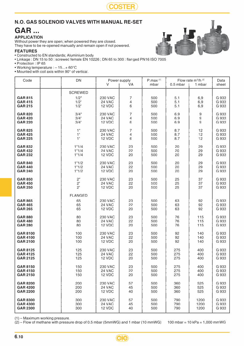
COSTER
(1) – Maximum working pressure.(2) – Flow of methane with pressure drop of 0.5 mbar (5mmWG) and 1 mbar (10 mmWG) 100 mbar = 10 kPa = 1,000 mmWG
Code DN Power supply P.max Code DN Power supply P.max Code DN Power supply P.max Code DN Power supply P.max Code DN Power supply P.max Code DN Power supply P.max Code DN Power supply P.max (1) Flow rate m Flow rate m3/h (2) Data Data V VA mbar 0.5 mbar 1 mbar sheet V VA mbar 0.5 mbar 1 mbar sheet V VA mbar 0.5 mbar 1 mbar sheet V VA mbar 0.5 mbar 1 mbar sheet V VA mbar 0.5 mbar 1 mbar sheet V VA mbar 0.5 mbar 1 mbar sheet V VA mbar 0.5 mbar 1 mbar sheet V VA mbar 0.5 mbar 1 mbar sheet V VA mbar 0.5 mbar 1 mbar sheet V VA mbar 0.5 mbar 1 mbar sheet V VA mbar 0.5 mbar 1 mbar sheet
SCREWEDGAR 815 1/2" 230 VAC 7 500 5.1 6,9 G 933 1/2" 230 VAC 7 500 5.1 6,9 G 933 1/2" 230 VAC 7 500 5.1 6,9 G 933 1/2" 230 VAC 7 500 5.1 6,9 G 933 1/2" 230 VAC 7 500 5.1 6,9 G 933 1/2" 230 VAC 7 500 5.1 6,9 G 933 1/2" 230 VAC 7 500 5.1 6,9 G 933 1/2" 230 VAC 7 500 5.1 6,9 G 933GAR 415 1/2" 1/2" 24 VAC 4 500 5.1 6,9 G 924 VAC 4 500 5.1 6,9 G 924 VAC 4 500 5.1 6,9 G 924 VAC 4 500 5.1 6,9 G 924 VAC 4 500 5.1 6,9 G 924 VAC 4 500 5.1 6,9 G 933GAR 215 1/2" 1/2" 12 VDC 6 500 5.1 6,9 G 912 VDC 6 500 5.1 6,9 G 912 VDC 6 500 5.1 6,9 G 912 VDC 6 500 5.1 6,9 G 912 VDC 6 500 5.1 6,9 G 912 VDC 6 500 5.1 6,9 G 933
GAR 820 3/4" 230 3/4" 230 3/4" 230 VAC 7 500 6.9 9 G 9 7 500 6.9 9 G 9 7 500 6.9 9 G 9 7 500 6.9 9 G 9 7 500 6.9 9 G 9 7 500 6.9 9 G 933GAR 420 3/4" 3/4" 24 VAC 4 500 6.9 9 G 933GAR 220 3/4" 3/4" 12 VDC 6 500 6.9 9 G 933
GAR 825 1" 230 1" 230 1" 230 VAC 7 500 8.7 12 G 9 7 500 8.7 12 G 9 7 500 8.7 12 G 9 7 500 8.7 12 G 9 7 500 8.7 12 G 9 7 500 8.7 12 G 933GAR 425 1" 1" 24 VAC 4 500 8.7 18.7 12 G 933GAR 225 1" 1" 12 VDC 6 500 8.7 18.7 12 G 933
GAR 832 1"1/4 230 1"1/4 230 1"1/4 230 VAC 23 500 20 29 G 9 500 20 29 G 9 500 20 29 G 9 500 20 29 G 9 500 20 29 G 933GAR 432 1"1/4 1"1/4 24 VAC 22 500 500 20 29 G 933GAR 232 1"1/4 1"1/4 12 VDC 20 500 500 20 29 G 933
GAR 840 1"1/2 230 1"1/2 230 1"1/2 230 VAC 23 500 20 29 G 9 500 20 29 G 9 500 20 29 G 9 500 20 29 G 9 500 20 29 G 933GAR 440 1"1/2 1"1/2 24 VAC 22 500 20 29 G 933GAR 240 1"1/2 1"1/2 12 VDC 20 500 20 29 G 933
GAR 850 2" 230 2" 230 2" 230 VAC 23 500 25 37 G 9 500 25 37 G 9 500 25 37 G 9 500 25 37 G 9 500 25 37 G 933GAR 450 2" 2" 24 VAC 22 500 25 37 G 933GAR 250 2" 2" 12 VDC 20 500 25 37 G 933
FLANGEDGAR 865 65 230 65 230 65 230 VAC 23 500 63 92 G 9 500 63 92 G 9 500 63 92 G 9 500 63 92 G 9 500 63 92 G 933GAR 465 65 24 65 24 65 24 VAC 22 500 63 92 G 9 500 63 92 G 9 500 63 92 G 9 500 63 92 G 9 500 63 92 G 933GAR 265 65 12 65 12 65 12 VDC 20 500 63 92 G 9 500 63 92 G 9 500 63 92 G 9 500 63 92 G 9 500 63 92 G 933
GAR 880 80 230 80 230 80 230 VAC 23 500 76 115 G 9 500 76 115 G 9 500 76 115 G 9 500 76 115 G 9 500 76 115 G 933GAR 480 80 24 80 24 80 24 VAC 22 500 76 115 G 9 500 76 115 G 9 500 76 115 G 9 500 76 115 G 9 500 76 115 G 933GAR 280 80 12 80 12 80 12 VDC 20 500 76 115 G 9 500 76 115 G 9 500 76 115 G 9 500 76 115 G 9 500 76 115 G 933
GAR 8100 100 230 100 230 100 230 VAC 23 500 92 140 G 9 500 92 140 G 9 500 92 140 G 9 500 92 140 G 9 500 92 140 G 933GAR 4100 100 24 100 24 100 24 VAC 22 500 92 140 G 9 500 92 140 G 9 500 92 140 G 9 500 92 140 G 9 500 92 140 G 933GAR 2100 100 12 100 12 100 12 VDC 20 500 92 140 G 9 500 92 140 G 9 500 92 140 G 9 500 92 140 G 9 500 92 140 G 933
GAR 8125 125 230 125 230 125 230 VAC 23 500 275 400 G 9 500 275 400 G 9 500 275 400 G 9 500 275 400 G 9 500 275 400 G 933GAR 4125 125 24 125 24 125 24 VAC 22 500 275 400 G 9 500 275 400 G 9 500 275 400 G 9 500 275 400 G 9 500 275 400 G 933GAR 2125 125 12 125 12 125 12 VDC 20 500 275 400 G 9 500 275 400 G 9 500 275 400 G 9 500 275 400 G 9 500 275 400 G 933
GAR 8150 150 230 150 230 150 230 VAC 23 500 275 400 G 9 500 275 400 G 9 500 275 400 G 9 500 275 400 G 9 500 275 400 G 933GAR 4150 150 24 150 24 150 24 VAC 22 500 275 400 G 9 500 275 400 G 9 500 275 400 G 9 500 275 400 G 9 500 275 400 G 933GAR 2150 150 12 150 12 150 12 VDC 20 500 275 400 G 9 500 275 400 G 9 500 275 400 G 9 500 275 400 G 9 500 275 400 G 933
GAR 8200 200 230 200 230 200 230 VAC 57 500 360 525 G 9 500 360 525 G 9 500 360 525 G 9 500 360 525 G 9 500 360 525 G 933GAR 4200 200 24 200 24 200 24 VAC 45 500 360 525 G 9 500 360 525 G 9 500 360 525 G 9 500 360 525 G 9 500 360 525 G 933GAR 2200 200 12 200 12 200 12 VDC 40 500 360 525 G 9 500 360 525 G 9 500 360 525 G 9 500 360 525 G 9 500 360 525 G 933
GAR 8300 300 230 300 230 300 230 VAC 57 500 790 1200 G 9 500 790 1200 G 9 500 790 1200 G 9 500 790 1200 G 9 500 790 1200 G 933GAR 4300 300 24 300 24 300 24 VAC 45 500 500 790 1200 G 9 G 933GAR 2300 300 12 300 12 300 12 VDC 40 500 500 790 1200 G 9 G 933
N.O. GAS SOLENOID VALVES WITH MANUAL RE-SET
GAR ...APPLICATIONWithout power they are open; when powered they are closed. They have to be re-opened manually and remain open if not powered.
FEATURES• Constructed to EN standards; Aluminium body• Linkage : DN 15 to 50 : screwed female EN 10226 ; DN 65 to 300 : fl anged PN16 ISO 7005• Protection : IP 65• Working temperature : – 15...+ 60°C• Mounted with coil axis within 90° of vertical.
6.10

6
COSTER
6.11
ACCESSORIES FOR GCR ... Code Code Description Description Description Description
FCR 65 - 80 Microswitch shut-off indicator kit for GCR DN 65 - DN 80 solenoid valvesFCR 100 - 125 -150 Microswitch shut-off indicator kit for GCR DN 100 - DN 125 - DN 150 solenoid valvesFCR 200 Microswitch shut-off indicator kit for GCR DN 200 solenoid valvesFCR 300 Microswitch shut-off indicator kit for GCR DN 300 solenoid valves
ACCESSORIES FOR GCA ... Code Code Description Description
FCM 15-20-25 FCM 15-20-25 FCM 15-20-25 Microswitch shut-off indicator kit for GCA DN 15-20-25 solenoid valvesFCM 32-40 Microswitch shut-off indicator kit for GCA DN 32-40 solenoid valvesFCM 50 Microswitch shut-off indicator kit for GCA DN 50 solenoid valvesFCM 65-80 Microswitch shut-off indicator kit for GCA DN 65-80 solenoid valvesFCM 100 Microswitch shut-off indicator kit for GCA DN 100 solenoid valvesFCM 125-150 Microswitch shut-off indicator kit for GCA DN 125-150 solenoid valves

COSTER
PRESSURE DROPGCAO, GCRO, GARO
PRESSURE DROPGCR
100 mbar = 10 kPa = 1.000 mm.WG
1/2” 3/4”
1” 1”1/
41”
1/2
2” DN 65
- DN 8
0
DN 200
DN 100
DN 125
- DN
150
12 3 4 5 6 8
1020 30 50 80
10040 200 300 500 800
10002000 5000 8000
10000
12 3 4 5 6 8
1020 30 50 80
10040 200 300 500 800
10002000 5000 8000
10000
12 3 4 5 6 8
1020 30 50 80
10040 200 300 500 800
10002000 5000 8000
10000
Propanedv = 1.56
Methanedv = 0.64
Airdv = 1 0.8
0.8
0.1
0.20.3
0.50.7
1
2
3
57
10
2030
5070
100
200
20000
20000
20000
DN 3
00
Flow m3/h
Pre
ssur
e dr
op m
bar
0.10.2 0.3 0.5 0.8
12 3 5 8
104 20 30 50 80
1000.08
0.10.2 0.3 0.5 0.8
12 3 5 8
104 20 30 50 80
1006
0.10.2 0.3 0.5 0.8
12 3 5 8
1020 30 50 80
10040.08
Propanedv = 1.56
Methanedv = 0,64
Airdv = 1
1/2”3/4”
0.1
0.20.3
0.50.7
1
2
3
57
10
2030
5070
100
200 3/8”
Flow m3/h
Pre
ssur
e dr
op m
bar
1/2”
3/4”
1”
6.12

6
COSTER
PRESSURE DROPGAR
PRESSURE DROPGCA
100 mbar = 10 kPa = 1.000 mm.WG
1/2” 3/4”
1” 1”1/
4 - 1
”1/2
2” DN 65
DN 200
DN 100
DN 125
- DN 1
50DN 3
00
12 3 4 5 6 8
1020 30 50 80
10040 200 300 500 800
10002000 5000 8000
10000Propanedv = 1.56
Methanedv = 0.64
Airdv = 1
0.1
0.20.3
0.50.7
1
2
3
57
10
2030
5070
100
200
20000
12 3 4 5 6 8
1020 30 50 80
100200 300 500 800
10002000 500080008000
100000.8 20000
12 3 4 5 6 8
1020 30 50 80
10040 200 300 500 800
10002000 5000 8000
100000.8 20000
DN 80
Flow m3/h
Pre
ssur
e dr
op m
bar
12 3 4 5 6 8
1020 30 50 80
10040 200 300 500 800
10002000 5000 8000
10000
12 3 4 5 6 8
1020 30 50 80
10040 200 300 500 800
10002000 5000 8000
10000
12 3 4 5 6 8
1020 30 50 80
10040 200 300 500 800
10002000 5000 8000
10000
Propanedv = 1.56
Methanedv = 0.64
Airdv = 1 0.8
0.8
0.1
0.20.3
0.50.71
23
57
10
2030
5070
100
200
1/2”
3/4”
1” 1”1/4
1”1/2
2” DN 65DN 80DN 10
0DN 12
5DN 15
0
Flow m3/h
Pre
ssur
e dr
op m
bar
6.13
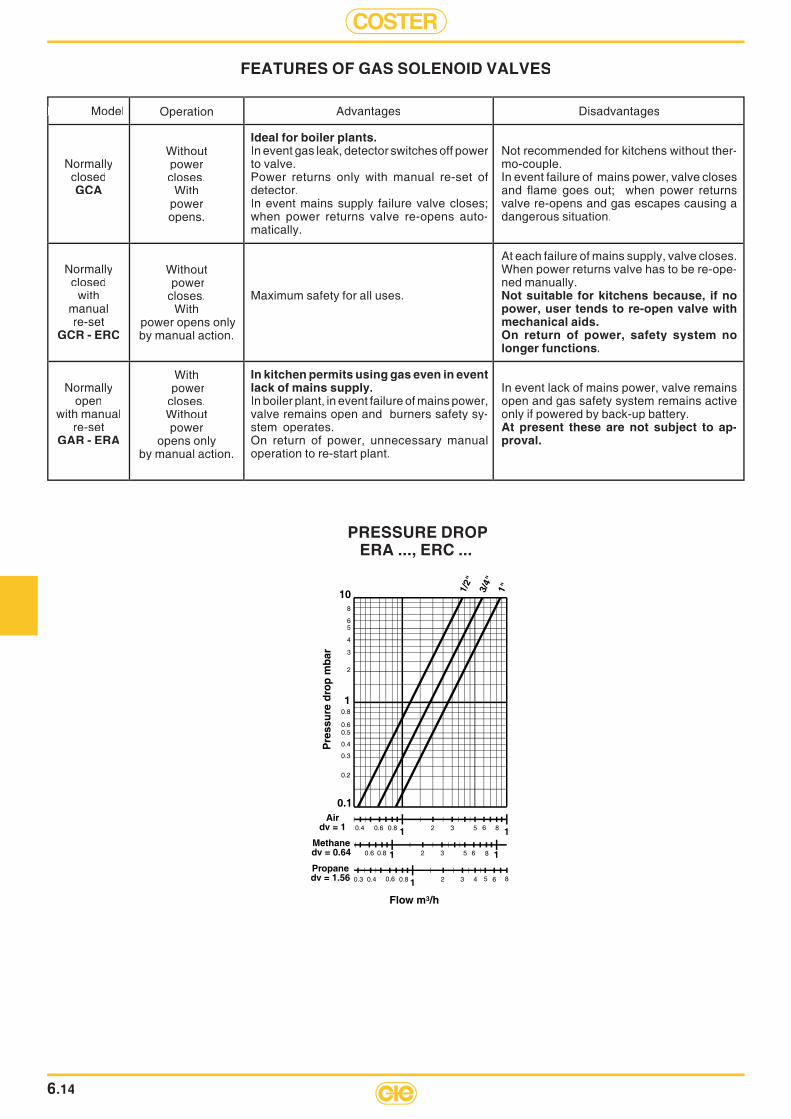
COSTER
6.14
PRESSURE DROP ERA ..., ERC ...
Model Model
NormallyclosedGCA
Normallyclosed
withmanualre-set
GCR - ERC
Normallyopen
with manualre-set
GAR - ERA
Disadvantages
Not recommended for kitchens without ther-mo-couple.In event failure of mains power, valve closes and fl ame goes out; when power returns valve re-opens and gas escapes causing a dangerous situation.
At each failure of mains supply, valve closes. When power returns valve has to be re-ope-ned manually. Not suitable for kitchens because, if no power, user tends to re-open valve with mechanical aids. On return of power, safety system no longer functions.
In event lack of mains power, valve remains open and gas safety system remains active only if powered by back-up battery.At present these are not subject to ap-proval.
Advantages
Ideal for boiler plants.In event gas leak, detector switches off power to val ve.Power returns only with manual re-set of detector.In event mains supply failure valve closes; when power returns valve re-opens auto-matically.
Maximum safety for all uses.
In kitchen permits using gas even in event lack of mains supply.In boiler plant, in event failure of mains power, valve remains open and burners safety sy-stem operates. On return of power, unnecessary manual operation to re-start plant.
FEATURES OF GAS SOLENOID VALVES
Operation
Withoutpowercloses.
Withpoweropens.
Without powercloses.
With power opens onlyby manual action.
With powercloses.Withoutpower
opens onlyby manual action.
8
8
5 8
Flow m3/h
0.1
1
0.3
0.4
0.50.6
0.8
10
Pre
ssur
e dr
op m
bar
0.6 0.8 1 2 3 5
1 1
0.2
Airdv = 1
Methanedv = 0.64
Propanedv = 1.56
2
3
4
56
8
0.6 0.8
0.3 0,6 0.8
2 3 5
2 3
1
1
6
6
4 6
0.4
0.4
1/2"
3/4"
1"
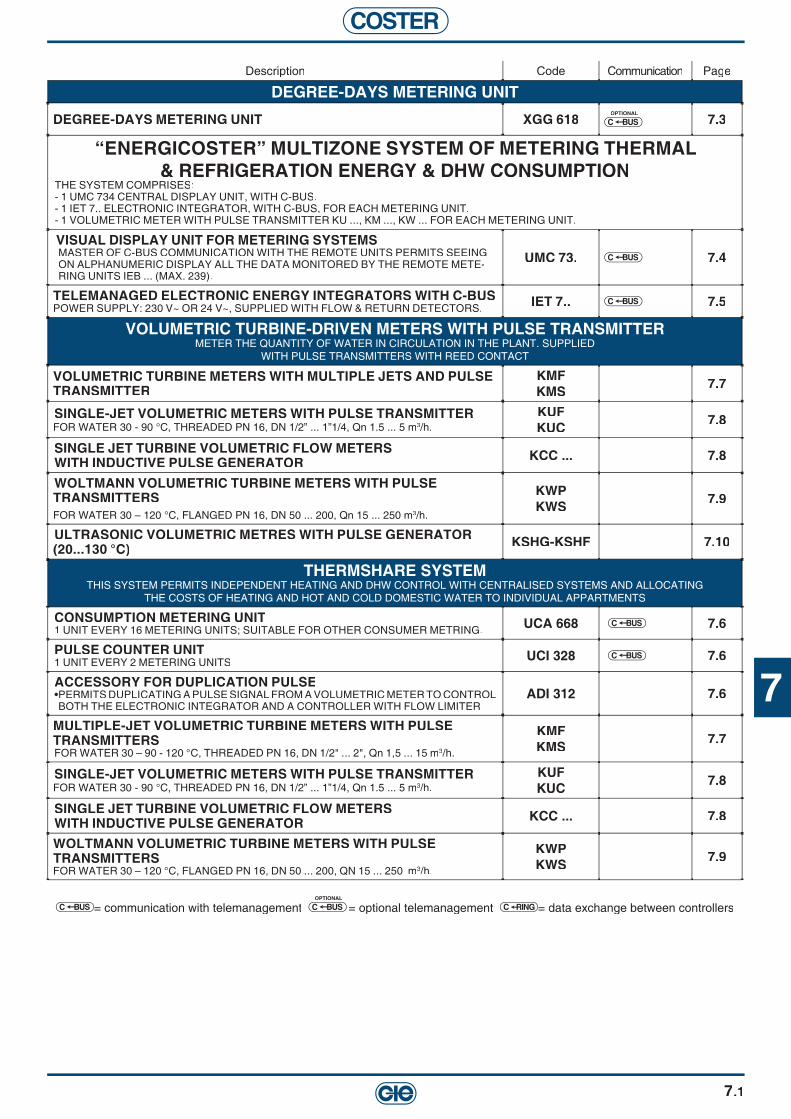
7
COSTER
7.1
Description Code Communication Page
DEGREE-DAYS METERING UNIT
DEGREE-DAYS METERING UNIT XGG 618OPTIONAL
BUSC 7.3
“ENERGICOSTER” MULTIZONE SYSTEM OF METERING THERMAL& REFRIGERATION ENERGY & DHW CONSUMPTION
THE SYSTEM COMPRISES:- 1 UMC 734 CENTRAL DISPLAY UNIT, WITH C-BUS.- 1 IET 7.. ELECTRONIC INTEGRATOR, WITH C-BUS, FOR EACH METERING UNIT.- 1 VOLUMETRIC METER WITH PULSE TRANSMITTER KU ..., KM ..., KW ... FOR EACH METERING UNIT.
VISUAL DISPLAY UNIT FOR METERING SYSTEMSMASTER OF C-BUS COMMUNICATION WITH THE REMOTE UNITS PERMITS SEEING ON ALPHANUMERIC DISPLAY ALL THE DATA MONITORED BY THE REMOTE METE-RING UNITS IEB ... (MAX. 239).
UMC 73. BUSC 7.4
TELEMANAGED ELECTRONIC ENERGY INTEGRATORS WITH C-BUSPOWER SUPPLY: 230 V~ OR 24 V~, SUPPLIED WITH FLOW & RETURN DETECTORS. IET 7.. BUSC 7.5
VOLUMETRIC TURBINE-DRIVEN METERS WITH PULSE TRANSMITTERMETER THE QUANTITY OF WATER IN CIRCULATION IN THE PLANT. SUPPLIED
WITH PULSE TRANSMITTERS WITH REED CONTACT
VOLUMETRIC TURBINE METERS WITH MULTIPLE JETS AND PULSE TRANSMITTER
KMFKMS 7.7
SINGLE-JET VOLUMETRIC METERS WITH PULSE TRANSMITTERFOR WATER 30 - 90 °C, THREADED PN 16, DN 1/2” ... 1”1/4, Qn 1.5 ... 5 m3/h.
KUFKUC 7.8
SINGLE JET TURBINE VOLUMETRIC FLOW METERS WITH INDUCTIVE PULSE GENERATOR KCC ... 7.8
WOLTMANN VOLUMETRIC TURBINE METERS WITH PULSE TRANSMITTERSFOR WATER 30 – 120 °C, FLANGED PN 16, DN 50 ... 200, Qn 15 ... 250 m3/h.
KWPKWS 7.9
ULTRASONIC VOLUMETRIC METRES WITH PULSE GENERATOR (20...130 °C) KSHG-KSHF 7.10
THERMSHARE SYSTEMTHIS SYSTEM PERMITS INDEPENDENT HEATING AND DHW CONTROL WITH CENTRALISED SYSTEMS AND ALLOCATING
THE COSTS OF HEATING AND HOT AND COLD DOMESTIC WATER TO INDIVIDUAL APPARTMENTS
CONSUMPTION METERING UNIT1 UNIT EVERY 16 METERING UNITS; SUITABLE FOR OTHER CONSUMER METRING. UCA 668 BUSC 7.6
PULSE COUNTER UNIT1 UNIT EVERY 2 METERING UNITS UCI 328 BUSC 7.6
ACCESSORY FOR DUPLICATION PULSE•PERMITS DUPLICATING A PULSE SIGNAL FROM A VOLUMETRIC METER TO CONTROL BOTH THE ELECTRONIC INTEGRATOR AND A CONTROLLER WITH FLOW LIMITER
ADI 312 7.6
MULTIPLE-JET VOLUMETRIC TURBINE METERS WITH PULSE TRANSMITTERSFOR WATER 30 – 90 - 120 °C, THREADED PN 16, DN 1/2" ... 2", Qn 1,5 ... 15 m3/h.
KMFKMS 7.7
SINGLE-JET VOLUMETRIC METERS WITH PULSE TRANSMITTERFOR WATER 30 - 90 °C, THREADED PN 16, DN 1/2” ... 1”1/4, Qn 1.5 ... 5 m3/h.
KUFKUC 7.8
SINGLE JET TURBINE VOLUMETRIC FLOW METERS WITH INDUCTIVE PULSE GENERATOR KCC ... 7.8
WOLTMANN VOLUMETRIC TURBINE METERS WITH PULSE TRANSMITTERSFOR WATER 30 – 120 °C, FLANGED PN 16, DN 50 ... 200, QN 15 ... 250 m3/h.
KWPKWS 7.9
BUSC = communication with telemanagement OPTIONAL
BUSC = optional telemanagement C RING = data exchange between controllers

COSTER
7.2
Plants
Centralised with horizontal distribution (zoned)
• Thermal energy metering by “ENERGICOSTER” system.
• Thermal energy metering and DHW consumption.
District heating sustations
• District heating network for hot water (max. 100°C) with volumetric turbine-édriven.
Products required
For each apartment:- 1 zone valve HGM ... or HMM ...- 1 actuator CDK 064 or CDK 068- 1 chronothermostat - 1 integrator IEB 7..- 1 volumetric meter KUC ..., KMR ...For plant: - 1 central display unit UMC 734
For each apartment:- 1 zone valve HGM ... or HMM ...- 1 actuator CDK 064 or CDK 068- 1 chronothermostat CMD 91- 1 Integrator - 1 volumetric fl ow meter KUC, KMC (heating)- 1 volumetric fl ow meter KUC ..., KMR ... (DHW)For plant: - 1 central display unit UMC 734
For each substation:- 1 integrator - 1 volumetric meter KMS, KWS
EXAMPLES OF CONSUMPTION METERING PLANTS
Products required

7
COSTER
7.3
DEGREE-DAYS METERING UNITOPTIONAL TELEMANAGEMENT
XGG 618TELEMANAGEMENT C-Bus: Enabled using ACB 460 accessory.APPLICATIONMeters winter degree-days in each individual building and permits:– calculating heating costs.– keeping under control the overall effi ciency of the plants.– program fuel requirements.Essential sensors: 1 outside sensor for metering degree-days.FEATURES• Power supply: 230 V~; Consumption: 5 VA; DIN 105 x 115 modular enclosure; Protection: IP 40. • Digital programming by means of four keys and alphanumeric display.• Automatic switching GMT - BST.• Accuracy: Better than required by regulation EN 1434, Class 2.• Metering: - standard degree-days: difference between mean daily (24 hour) outside temperature and the reference room temperature of 20°C. - room degree-days: difference between the mean daily (24hour) outside temperature and a room temperature which can be set. Metering enabled by external control. - hours of operation: hours devices switched on (presence of power).• Data logger: One daily recording of all counts; max. 366 recordings; display with dates.
ACCESSORIES
Code Description Campo di Sensore Data Code Description Campo di Sensore Data impiego sheet impiego sheet
ACB 460 Plug-in for communication via C-Bus. – – T 433 SGG 001 SGG 001 Outside temperature sensor for measuring degree-days. – 50 ... 40 °C Pt 1 kΩ N 121
Code De scription Data Code De scription Data sheet sheet
XGG 618 Degree-days metering unit. H 111
Code De scription Data sheet
Degree-days metering unit.
Code De scription Data sheet Code De scription Data sheet
Code Description Campo di Sensore Data impiego sheet
Plug-in for communication via C-Bus. – Outside temperature sensor for measuring degree-days. – 50 ... 40 °C Pt 1 k
Code Description Campo di Sensore Data impiego sheet
N 12
Code Description Campo di Sensore Data impiego sheet Code Description Campo di Sensore Data impiego sheet
Outside temperature sensor for measuring degree-days. – 50 ... 40 °C Pt 1 k
Code Description Campo di Sensore Data impiego sheet
Plug-in for communication via C-Bus. – Outside temperature sensor for measuring degree-days. – 50 ... 40 °C Pt 1 k
SBUCOPTIONAL

COSTER
7.4
VISUAL DISPLAY UNIT FOR METERING SYSTEMS
UMC 73.APPLICATIONSupervisor for Bus communication with remote units. Permits viewing on alphanumeric display all the data monitored by the remote metering units IEB ... and IET 7.. (max. 239).Communication with Telemanagement systems via parallel C-Bus connection..
FEATURES• Power supply: 230 or 24 V~; Consumption: 10 VA; Case 144 x 144; Protection: IP 40.
MULTIZONE SYSTEM FOR METERING HEAT AND COLD ENERGY AND DHW CONSUMPTION
"ENERGICOSTER"The system comprises:• 1 visual display unit UMC 734 with C-Bus • 1 electronic integrator IEB 7.. or IET 7.. with C-Bus complete with fl ow and return sensors for each metering unit• 1 volumetric hour run meter with pulse transmitter KU ..., KM ..., KW ..., KS ... for each metering unit.
Code Description Data sheet
UMC 734 Central display unit for metering systems 24 Volt ~. H 310UMC 738 Central display unit for metering systems 230 Volt ~. H 310
Code Description Data sheet Code Description Data sheet
Central display unit for metering systems 24 Volt Central display unit for metering systems
Code Description Data sheet
. H 310
Code Description Data sheet
BUSC
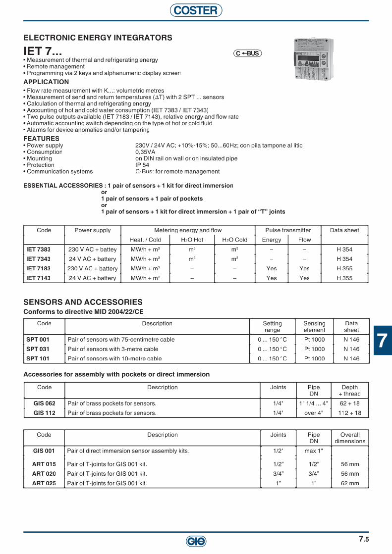
7
COSTER
7.5
BUSC
ESSENTIAL ACCESSORIES : 1 pair of sensors + 1 kit for direct immersionor1 pair of sensors + 1 pair of pocketsor 1 pair of sensors + 1 kit for direct immersion + 1 pair of “T” joints
ELECTRONIC ENERGY INTEGRATORS
IET 7...• Measurement of thermal and refrigerating energy• Remote management • Programming via 2 keys and alphanumeric display screen
APPLICATION • Flow rate measurement with K...: volumetric metres• Measurement of send and return temperatures (∆T) with 2 SPT ... sensors• Calculation of thermal and refrigerating energy• Accounting of hot and cold water consumption (IET 7383 / IET 7343)• Two pulse outputs available (IET 7183 / IET 7143), relative energy and fl ow rate• Automatic accounting switch depending on the type of hot or cold fl uid• Alarms for device anomalies and/or tampering
FEATURES• Power supply 230V / 24V AC; +10%-15%; 50...60Hz; con pila tampone al litio• Consumption 0,35VA• Mounting on DIN rail on wall or on insulated pipe• Protection IP 54• Communication systems C-Bus: for remote management
SENSORS AND ACCESSORIESConforms to directive MID 2004/22/CE
Code Description Joints PipeDN
Overall dimensions
GIS 001 Pair of direct immersion sensor assembly kits. 1/2" max 1" –
ART 015 Pair of T-joints for GIS 001 kit. 1/2” 1/2” 56 mm
ART 020 Pair of T-joints for GIS 001 kit. 3/4” 3/4” 56 mm
ART 025 Pair of T-joints for GIS 001 kit. 1” 1” 62 mm
Code Power supply Metering energy and fl ow Pulse transmitter Data sheet
Heat. / Cold H2O Hot H2O Cold Energy Flow
IET 7383 230 V AC + battey MW/h + m3 m3 m3 – – H 354
IET 7343 24 V AC + battery MW/h + m3 m3 m3 – – H 354
IET 7183 230 V AC + battery MW/h + m3 – – Yes Yes H 355
IET 7143 24 V AC + battery MW/h + m3 – – Yes Yes H 355
Code Description Settingrange
Sensingelement
Datasheet
SPT 001 Pair of sensors with 75-centimetre cable 0 ... 150 °C Pt 1000 N 146
SPT 031 Pair of sensors with 3-metre cable 0 ... 150 °C Pt 1000 N 146
SPT 101 Pair of sensors with 10-metre cable 0 ... 150 °C Pt 1000 N 146
Accessories for assembly with pockets or direct immersion
Code Description Joints PipeDN
Depth + thread
GIS 062 Pair of brass pockets for sensors. 1/4" 1" 1/4 ... 4" 62 + 18
GIS 112 Pair of brass pockets for sensors. 1/4" over 4" 112 + 18
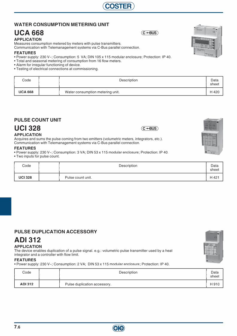
COSTER
7.6
WATER CONSUMPTION METERING UNIT
UCA 668APPLICATIONMeasures consumption metered by meters with pulse transmitters.Communication with Telemanagement systems via C-Bus parallel connection.
FEATURES• Power supply: 230 V~; Consumption: 5 VA; DIN 105 x 115 modular enclosure; Protection: IP 40. • Total and seasonal metering of consumption from 16 fl ow meters.• Alarm for irregular functioning of device.• Testing of electrical connections at commissioning.
Code Description Data sheet
UCA 668 Water consumption metering unit. H 420
Code Description Data sheet Code Description Data sheet
Water consumption metering unit. H 420
Code Description Data sheet
Water consumption metering unit. H 420
Code Description Data sheet
PULSE COUNT UNIT
UCI 328APPLICATIONAcquires and sums the pulse coming from two emitters (volumetric meters, integrators, etc.).Communication with Telemanagement systems via C-Bus parallel connection.
FEATURES• Power supply: 230 V~; Consumption: 3 VA; DIN 53 x 115 modular enclosure; Protection: IP 40.• Two inputs for pulse count.
Code Description Data sheet
UCI 328 Pulse count unit. H 421
Code Description Data sheet Code Description Data sheet
Pulse count unit. H 421
Code Description Data sheet
Pulse count unit. H 421
Code Description Data sheet
BUSC
BUSC
PULSE DUPLICATION ACCESSORY
ADI 312APPLICATIONThe device enables duplication of a pulse signal. e.g.: volumetric pulse transmitter used by a heat integrator and a controller with fl ow limit.
FEATURES• Power supply: 230 V~; Consumption: 2 VA; DIN 53 x 115 modular enclosure; Protection: IP 40.
Code Description Data sheet
ADI 312 Pulse duplication accessory. H 910
Code Description Data sheet Code Description Data sheet
Pulse duplication accessory. H 910
Code Description Data sheet
Pulse duplication accessory. H 910
Code Description Data sheet

7
COSTER
7.7
VOLUMETRIC TURBINE METERS WITH MULTIPLE JETS AND PULSE TRANSMITTERS
KMF ... - KMS ...APPLICATIONVolumetric turbine meter with multiple jet for use in combination with IEB ... and IET ... integrators for metering thermal and/or cooling energy or for metering consumption of hot or cold water..
FEATURES• PN 16. Includes male threaded unions; KMF 50CF, KMS 50CF are fl anged.• KMS ..., KMS U..., KMS D... are approved for class A; KMF approved for cold water (CEE 75/33)• Other non-specifi ed meters have not been offi cially approved• Includes reed pulse transmitter, Connection cable 2 x 0.5 mm 2 x 2 m, Protection : IP68.
(1) – Length without unions.(2) – PN 16 fl anged connections.Qn – Nominal fl ow: Maximum continuous fl ow measurable by the meter.Qmax – Maximum temporary fl ow bearable by the meter.Qt – Transition fl ow: minimum limit with error less than ±3%.Qmin – Minimum fl ow limit: minimum limit with error less than ±5%.Kvs – Flow coeffi cient: Flow in m³/h with pressure drop of 100 kPa = 10 mWG = 1 bar.∆p Qn – Pressure drop at nominal fl ow Qn.
Code DN Code DN Lenght.(1) Qn Qmax Qt Qmin Kvs ∆p Qn Pulse transmitter Data mm. m mm. m3/h m3/h l/h l/h m3/h kPa pul/l (K) pul/m3 l/pul sheet
Tmax 30°C Tmax 30°C horizzontal horizzontalKMF 15D 1/2" 165 1.5 3 120 30 4.5 10.5 0.1 100 10 H 621KMF 20D 3/4" 190 2.5 5 200 50 6.7 14.5 0.1 100 10 H 621KMF 25C 1" 260 3.5 7 280 70 7.2 23 0.01 10 100 H 621KMF 32C 1"1/4 260 5 12 400 100 12.8 24 0.01 10 100 H 621KMF 40C 1"1/2 300 10 20 800 200 22 21 0.01 10 100 H 621KMF 50C 2" 300 15 30 3,000 450 30.5 22 0.01 10 100 H 621
Tmax 120°C horizzontal horizzontalKMS 15D 1/2" 165 1.5 3 150 30 3 10.5 0.1 100 10 H 622KMS 20D 3/4" 190 2.5 5 250 50 5 14.5 0.1 100 10 H 622KMS 25C 1" 260 3.5 7 280 65 7 23 0.01 10 100 H 622KMS 32C 1"1/4 260 6 12 480 90 12 24 0.01 10 100 H 622KMS 40C 1"1/2 300 10 20 1,000 160 20 21 0.01 10 100 H 622KMS 50C 2" 270 15 30 1,200 200 30 22 0.01 10 100 H 622KMS 50CF (2) 50 mm. 270 15 30 1,200 200 30 22 0.01 10 100 H 622
Tmax 120°C Tmax 120°C vertical vertical upKMS U15D 1/2" 105 1.5 3 150 30 3 10.5 0.1 100 10 H 622KMS U20D 3/4" 105 2.5 5 250 50 5 14.5 0.1 100 10 H 622KMS U25C 1" 150 3.5 7 280 65 7 23 0.01 10 100 H 622KMS U32C 1"1/4 150 6 12 480 90 12 24 0.01 10 100 H 622KMS U40C 1"1/2 150 10 20 1,000 160 20 21 0.01 10 100 H 622
Tmax 120°C Tmax 120°C vertical vertical downKMS D15D 1/2" 105 1.5 3 150 30 3 10.5 0.1 100 10 H 622KMS D20D 3/4" 105 2.5 5 250 50 5 14.5 0.1 100 10 H 622KMS D25C 1" 150 3.5 7 280 65 7 23 0.01 10 100 H 622KMS D32C 1"1/4 150 6 12 480 90 12 24 0.01 10 100 H 622
KMS D40C KMS D40C 1"1/2 150 10 20 1.000 160 20 21 0.01 10 100 H 622
Code DN mm. m
1/2" 165 3/4" 190 1" 260 1"1/4 260 1"1/2 300 2" 300
1/2" 165 3/4" 190 1" 260 1"1/4 260 1"1/2 300 2" 270 50 mm. 270
1/2" 105 3/4" 105 1" 150 1"1/4 150 1"1/2 150
1/2" 105 3/4" 105 1" 150 1"1/4 150 1"1/2 150
Qmax Qt Qmin Kvs ∆p Qn Pulse transmitter Data l/pul sheet
H 621 H 621 H 621 H 621 H 621 H 621
H 622 H 622 H 622 H 622 H 622 H 622 H 622
H 622 H 622 H 622 H 622 H 622
H 622 H 622 H 622 H 622 H 622
Code DN mm. m
Qmax Qt Qmin Kvs ∆p Qn Pulse transmitter Data /h m
3 120 30 4.5 10.5 0.1 100 5 200 50 6.7 14.5 0.1 100 7 280 70 7.2 23 0.01 10
12 400 100 12.8 24 0.01 10 20 800 200 22 21 0.01 10 30 3,000 450 30.5 22 0.01 10
3 150 30 3 10.5 0.1 100 5 250 50 5 14.5 0.1 100 7 280 65 7 23 0.01 10
12 480 90 12 24 0.01 10 20 1,000 160 20 21 0.01 10 30 1,200 200 30 22 0.01 10 30 1,200 200 30 22 0.01 10
3 150 30 3 10.5 0.1 100 5 250 50 5 14.5 0.1 100 7 280 65 7 23 0.01 10
20 1,000 160 20 21 0.01 10
3 150 30 3 10.5 0.1 100 5 250 50 5 14.5 0.1 100 7 280 65 7 23 0.01 10
12 480 90 12 24 0.01 10 20 1.000 160 20 21 0.01 10
mm. m
1/2" 165 3/4" 190 1" 260 1"1/4 260 1"1/2 300 2" 300
1/2" 165 3/4" 190 1" 260 1"1/4 260 1"1/2 300 2" 270 50 mm. 270
1/2" 105 3/4" 105 1" 150 1"1/4 150 1"1/2 150
1/2" 105 3/4" 105 1" 150 1"1/4 150 1"1/2 150
Qmax Qt Qmin Kvs ∆p Qn Pulse transmitter Data /h l/h l/h m
3 120 30 4.5 10.5 0.1 100 5 200 50 6.7 14.5 0.1 100 7 280 70 7.2 23 0.01 10
12 400 100 12.8 24 0.01 10 20 800 200 22 21 0.01 10 30 3,000 450 30.5 22 0.01 10
3 150 30 3 10.5 0.1 100 5 250 50 5 14.5 0.1 100 7 280 65 7 23 0.01 10
12 480 90 12 24 0.01 10 20 1,000 160 20 21 0.01 10 30 1,200 200 30 22 0.01 10 30 1,200 200 30 22 0.01 10
3 150 30 3 10.5 0.1 100 5 250 50 5 14.5 0.1 100 7 280 65 7 23 0.01 10
12 480 90 12 24 0.01 10 20 1,000 160 20 21 0.01 10
3 150 30 3 10.5 0.1 100 5 250 50 5 14.5 0.1 100 7 280 65 7 23 0.01 10
12 480 90 12 24 0.01 10 20 1.000 160 20 21 0.01 10
(1)
mm. m Qmax Qt Qmin Kvs ∆p Qn Pulse transmitter Data
/h kPa pul/l (K) pul/m
3 120 30 4.5 10.5 0.1 100 5 200 50 6.7 14.5 0.1 100 7 280 70 7.2 23 0.01 10
12 400 100 12.8 24 0.01 10 20 800 200 22 21 0.01 10 30 3,000 450 30.5 22 0.01 10
3 150 30 3 10.5 0.1 100 5 250 50 5 14.5 0.1 100 7 280 65 7 23 0.01 10
12 480 90 12 24 0.01 10 20 1,000 160 20 21 0.01 10 30 1,200 200 30 22 0.01 10 30 1,200 200 30 22 0.01 10
3 150 30 3 10.5 0.1 100 5 250 50 5 14.5 0.1 100 7 280 65 7 23 0.01 10
12 480 90 12 24 0.01 10 20 1,000 160 20 21 0.01 10
3 150 30 3 10.5 0.1 100 5 250 50 5 14.5 0.1 100 7 280 65 7 23 0.01 10
12 480 90 12 24 0.01 10 20 1.000 160 20 21 0.01 10
Qmax Qt Qmin Kvs ∆p Qn Pulse transmitter Data /h l/h l/h m
3 120 30 4.5 10.5 0.1 100 5 200 50 6.7 14.5 0.1 100 7 280 70 7.2 23 0.01 10
12 400 100 12.8 24 0.01 10 20 800 200 22 21 0.01 10 30 3,000 450 30.5 22 0.01 10
3 150 30 3 10.5 0.1 100 5 250 50 5 14.5 0.1 100 7 280 65 7 23 0.01 10
12 480 90 12 24 0.01 10 20 1,000 160 20 21 0.01 10 30 1,200 200 30 22 0.01 10 30 1,200 200 30 22 0.01 10
3 150 30 3 10.5 0.1 100 5 250 50 5 14.5 0.1 100 7 280 65 7 23 0.01 10
12 480 90 12 24 0.01 10 20 1,000 160 20 21 0.01 10
3 150 30 3 10.5 0.1 100 5 250 50 5 14.5 0.1 100 7 280 65 7 23 0.01 10
12 480 90 12 24 0.01 10 20 1.000 160 20 21 0.01 10
Qmax Qt Qmin Kvs ∆p Qn Pulse transmitter Data /h kPa pul/l (K) pul/m
3 120 30 4.5 10.5 0.1 100 5 200 50 6.7 14.5 0.1 100 7 280 70 7.2 23 0.01 10
12 400 100 12.8 24 0.01 10 20 800 200 22 21 0.01 10 30 3,000 450 30.5 22 0.01 10
3 150 30 3 10.5 0.1 100 5 250 50 5 14.5 0.1 100 7 280 65 7 23 0.01 10
12 480 90 12 24 0.01 10 20 1,000 160 20 21 0.01 10 30 1,200 200 30 22 0.01 10 30 1,200 200 30 22 0.01 10
3 150 30 3 10.5 0.1 100 5 250 50 5 14.5 0.1 100 7 280 65 7 23 0.01 10
12 480 90 12 24 0.01 10 20 1,000 160 20 21 0.01 10
3 150 30 3 10.5 0.1 100 5 250 50 5 14.5 0.1 100 7 280 65 7 23 0.01 10
12 480 90 12 24 0.01 10 20 1.000 160 20 21 0.01 10
FOR APPLICATION ON DISTRICT HEATING SITES,THE USE OF MECHANICAL VOLUMETRIC METERS IS NOT RECOMENDED
VOLUMETRIC METERS WITH PULSE TRANSMITTERSMeasure the quantity of water in circulation in the plant. Complete with pulse transmitters with reed contact.Connected to electronic integrators permit energy metering.They must be installed on the return pipe with, upstream, a fi lter for collecting impurities.Their size must be in relation to the nominal fl ow Qn and not according to the diameter of the pipework.Manufactured in accordance with current regulations.

COSTER
7.8
SINGLE-JET VOLUMETRIC METERS WITH PULSE TRANSMITTER
KUF ... - KUC ...APPLICATIONVolumetric turbine meter with multiple jet for use in combination with IEB ... and IET ... integrators for metering thermal and/or refrigeration energy or for metering consumption of hot or cold water.
FEATURES• PN 16. Includes male threaded unions.• Mounting: Horizontal in Class B, Vertical in Classe A.• Includes reed pulse transmitter; Connection cable 2 x 0.5 mm² x 2 m; Protection: IP 68.
Code DN Code DN Length(1) Qn Qmax Qt Qmin Kvs ∆p Qn Pulse transmitter Data mm. m mm. m3/h m3/h l/h l/h m3/h kPa pul/l (K) pul/m3 l/pul sheet
Tmax 30 °C Tmax 30 °CKUF 15D (2) 1/2" 110 1.5 3 120 30 3 24 0.1 100 10 H 611KUF 20D (2) 3/4" 130 2.5 5 200 50 6 17 0.1 100 10 H 611KUF 25C (2) 1" 160 3.5 7 280 70 7 25 0.01 10 100 H 611
Tmax 90 °C Tmax 90 °CKUC 15D (3) 1/2" 110 1.5 3 120 30 3 24 0.1 100 10 H 611KUC 20D (3) 3/4" 130 2.5 5 200 50 6 17 0.1 100 10 H 611
Code DN mm. m
1/2" 110 3/4" 130 1" 160
1/2" 110 3/4" 130
Datal/pul sheet
H 611 H 611 H 611
H 611 H 611
Code DN mm. m
Qmax Qt Qmin Kvs ∆p Qn /h m
3 120 30 3 24 0.1 100 5 200 50 6 17 0.1 100 7 280 70 7 25 0.01 10
3 120 30 3 24 0.1 100 5 200 50 6 17 0.1 100
mm. m
1/2" 110 3/4" 130 1" 160
1/2" 110 3/4" 130
Qmax Qt Qmin Kvs ∆p Qn /h l/h l/h m
3 120 30 3 24 0.1 100 5 200 50 6 17 0.1 100 7 280 70 7 25 0.01 10
3 120 30 3 24 0.1 100 5 200 50 6 17 0.1 100
Qmax Qt Qmin Kvs ∆p Qn /h l/h l/h m
3 120 30 3 24 0.1 100 5 200 50 6 17 0.1 100 7 280 70 7 25 0.01 10
3 120 30 3 24 0.1 100 5 200 50 6 17 0.1 100
mm. m Qmax Qt Qmin Kvs ∆p Qn
/h kPa
3 120 30 3 24 0.1 100 5 200 50 6 17 0.1 100 7 280 70 7 25 0.01 10
3 120 30 3 24 0.1 100 5 200 50 6 17 0.1 100
pul/m
3 120 30 3 24 0.1 100 5 200 50 6 17 0.1 100 7 280 70 7 25 0.01 10
3 120 30 3 24 0.1 100 5 200 50 6 17 0.1 100
Qmax Qt Qmin Kvs ∆p Qn /h l/h l/h m
3 120 30 3 24 0.1 100 5 200 50 6 17 0.1 100 7 280 70 7 25 0.01 10
3 120 30 3 24 0.1 100 5 200 50 6 17 0.1 100
Qmax Qt Qmin Kvs ∆p Qn
3 120 30 3 24 0.1 100 5 200 50 6 17 0.1 100 7 280 70 7 25 0.01 10
3 120 30 3 24 0.1 100 5 200 50 6 17 0.1 100
FOR APPLICATION ON DISTRICT HEATING SITES,THE USE OF MECHANICAL VOLUMETRIC METERS IS NOT RECOMENDED
SINGLE JET TURBINE VOLUMETRIC FLOW METERS WITH INDUCTIVE PULSE GENERATOR
KCC .....• Measures water fl ow in the system.• For use with IET 7… electronic integrators for the measurement of thermal and/or refrigeration energy, and hot and/or water consumption.
• Assembly: horizontal, vertical, reversed.• Precision class : 3• MID TMC 142/11 – 4829 certifi cationFEATURES• Nominal pressure PN16• Fluid temperature 5÷90 ºC• Protection IP 65• Pulse generator open collector max 30Vcc, 200mA, duration 10ms,• Battery life 15 yars• Connection cable 2 x 0,5 mm2 x 2 m• Connectors Threaded male mouths
Code DN Lung.(1)
mm.Qp
m3/hQmaxm3/h
Qminl/h
Kvsm3/h
∆p QpkPa
Pulse generator Datasheetpul/lt (K) pul/m3 lt/pul
KCC 15-0,6 1/2" 110 0.6 1.2 12 1.3 25 0.1 100 10 H 613
KCC 15-1,5 1/2" 110 1.5 3 30 3 25 0.1 100 10 H 613
KCC 20-2,5 3/4" 130 2.5 5 60 5 25 0.1 100 10 H 613
(1) – Length without unions.Qp – Permament fl owQmax – Maximum temporary fl ow bearable by the meter.Qmin – Minimum fl ow limit: minimum limit with error less than ±5%.Kvs – Flow coeffi cient: Flow in m³/h with pressure drop of 100 kPa = 10 mWG = 1 bar.∆p Qp – Pressure drop at permanent fl ow Qn.
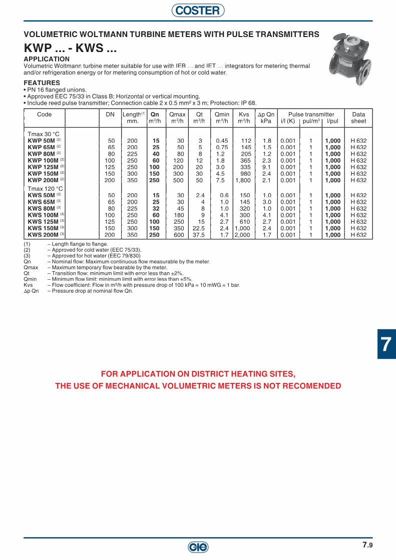
7
COSTER
7.9
(1) – Length fl ange to fl ange.(2) – Approved for cold water (EEC 75/33).(3) – Approved for hot water (EEC 79/830)Qn – Nominal fl ow: Maximum continuous fl ow measurable by the meter.Qmax – Maximum temporary fl ow bearable by the meter.Qt – Transition fl ow: minimum limit with error less than ±2%.Qmin – Minimum fl ow limit: minimum limit with error less than ±5%.Kvs – Flow coeffi cient: Flow in m³/h with pressure drop of 100 kPa = 10 mWG = 1 bar.∆p Qn – Pressure drop at nominal fl ow Qn.
VOLUMETRIC WOLTMANN TURBINE METERS WITH PULSE TRANSMITTERS
KWP ... - KWS ...APPLICATIONVolumetric Woltmann turbine meter suitable for use with IEB … and IET … integrators for metering thermal and/or refrigeration energy or for metering consumption of hot or cold water.
FEATURES• PN 16 fl anged unions. • Approved EEC 75/33 in Class B; Horizontal or vertical mounting.• Include reed pulse transmitter; Connection cable 2 x 0.5 mm² x 3 m; Protection: IP 68.
Code DN L Code DN Length(1) Qn Qmax Qt Qmin Kvs ∆p Qn Pulse transmitter Data mm. m mm. m3/h m3/h m3/h m3/h m3/h kPa i/l (K) pul/m3 l/pul sheet
Tmax 30 °C Tmax 30 °CKWP 50M (2) 50 200 15 30 3 0.45 112 1.8 0.001 1 1,000 H 632KWP 65M (2) 65 200 25 50 5 0.75 145 1.5 0.001 1 1,000 H 632KWP 80M (2) 80 225 40 80 8 1.2 205 1.2 0.001 1 1,000 H 632KWP 100M (2) 100 250 60 120 12 1.8 365 2.3 0.001 1 1,000 H 632KWP 125M (2) 125 250 100 200 20 3.0 335 9.1 0.001 1 1,000 H 632KWP 150M (2) 150 300 150 300 30 4.5 980 2.4 0.001 1 1,000 H 632KWP 200M (2) 200 350 250 500 50 7.5 1,800 2.1 0.001 1 1,000 H 632
Tmax 120 °C Tmax 120 °CKWS 50M (3) 50 200 15 30 2.4 0.6 150 1.0 0.001 1 1,000 H 632KWS 65M (3) 65 200 25 30 4 1.0 145 3.0 0.001 1 1,000 H 632KWS 80M (3) 80 225 32 45 8 1.0 320 1.0 0.001 1 1,000 H 632KWS 100M (3) 100 250 60 180 9 4.1 300 4.1 0.001 1 1,000 H 632KWS 125M (3) 125 250 100 250 15 2.7 610 2.7 0.001 1 1,000 H 632KWS 150M (3) 150 300 150 350 22.5 2.4 1,000 2.4 0.001 1 1,000 H 632KWS 200M (3) 200 350 250 600 37.5 1.7 2,000 1.7 0.001 1 1,000 H 632
Code DN L mm. m
50 200 65 200 80 225 100 250 125 250 150 300 200 350
50 200 65 200 80 225 100 250 125 250 150 300 200 350
Datal/pul sheet
H 632 H 632 H 632 H 632 H 632 H 632 H 632
H 632 H 632 H 632 H 632 H 632 H 632 H 632
Code DN L mm. m
Qmax Qt Qmin Kvs ∆p Qn /h m
30 3 0.45 112 1.8 0.001 1 50 5 0.75 145 1.5 0.001 1 80 8 1.2 205 1.2 0.001 1 120 12 1.8 365 2.3 0.001 1 200 20 3.0 335 9.1 0.001 1 300 30 4.5 980 2.4 0.001 1 500 50 7.5 1,800 2.1 0.001 1
30 2.4 0.6 150 1.0 0.001 1 30 4 1.0 145 3.0 0.001 1 45 8 1.0 320 1.0 0.001 1 180 9 4.1 300 4.1 0.001 1 250 15 2.7 610 2.7 0.001 1 350 22.5 2.4 1,000 2.4 0.001 1 600 37.5 1.7 2,000 1.7 0.001 1
Code DN L mm. m
50 200 65 200 80 225 100 250 125 250 150 300 200 350
50 200 65 200 80 225 100 250 125 250 150 300 200 350
Qmax Qt Qmin Kvs ∆p Qn
30 3 0.45 112 1.8 0.001 1 50 5 0.75 145 1.5 0.001 1 80 8 1.2 205 1.2 0.001 1 120 12 1.8 365 2.3 0.001 1 200 20 3.0 335 9.1 0.001 1 300 30 4.5 980 2.4 0.001 1 500 50 7.5 1,800 2.1 0.001 1
30 2.4 0.6 150 1.0 0.001 1 30 4 1.0 145 3.0 0.001 1 45 8 1.0 320 1.0 0.001 1 180 9 4.1 300 4.1 0.001 1 250 15 2.7 610 2.7 0.001 1 350 22.5 2.4 1,000 2.4 0.001 1 600 37.5 1.7 2,000 1.7 0.001 1
Qmax Qt Qmin Kvs ∆p Qn m
30 3 0.45 112 1.8 0.001 1 50 5 0.75 145 1.5 0.001 1 80 8 1.2 205 1.2 0.001 1 120 12 1.8 365 2.3 0.001 1 200 20 3.0 335 9.1 0.001 1 300 30 4.5 980 2.4 0.001 1 500 50 7.5 1,800 2.1 0.001 1
30 2.4 0.6 150 1.0 0.001 1 30 4 1.0 145 3.0 0.001 1 45 8 1.0 320 1.0 0.001 1 180 9 4.1 300 4.1 0.001 1 250 15 2.7 610 2.7 0.001 1 350 22.5 2.4 1,000 2.4 0.001 1 600 37.5 1.7 2,000 1.7 0.001 1
mm. m Qmax Qt Qmin Kvs ∆p Qn
/h kPa i/l (K) pul/m
30 3 0.45 112 1.8 0.001 1 50 5 0.75 145 1.5 0.001 1 80 8 1.2 205 1.2 0.001 1 120 12 1.8 365 2.3 0.001 1 200 20 3.0 335 9.1 0.001 1 300 30 4.5 980 2.4 0.001 1 500 50 7.5 1,800 2.1 0.001 1
30 2.4 0.6 150 1.0 0.001 1 30 4 1.0 145 3.0 0.001 1 45 8 1.0 320 1.0 0.001 1 180 9 4.1 300 4.1 0.001 1 250 15 2.7 610 2.7 0.001 1 350 22.5 2.4 1,000 2.4 0.001 1 600 37.5 1.7 2,000 1.7 0.001 1
Qmax Qt Qmin Kvs ∆p Qn
30 3 0.45 112 1.8 0.001 1 50 5 0.75 145 1.5 0.001 1 80 8 1.2 205 1.2 0.001 1 120 12 1.8 365 2.3 0.001 1 200 20 3.0 335 9.1 0.001 1 300 30 4.5 980 2.4 0.001 1 500 50 7.5 1,800 2.1 0.001 1
30 2.4 0.6 150 1.0 0.001 1 30 4 1.0 145 3.0 0.001 1 45 8 1.0 320 1.0 0.001 1 180 9 4.1 300 4.1 0.001 1 250 15 2.7 610 2.7 0.001 1 350 22.5 2.4 1,000 2.4 0.001 1 600 37.5 1.7 2,000 1.7 0.001 1
Qmax Qt Qmin Kvs ∆p Qn /h kPa i/l (K) pul/m
30 3 0.45 112 1.8 0.001 1 50 5 0.75 145 1.5 0.001 1 80 8 1.2 205 1.2 0.001 1 120 12 1.8 365 2.3 0.001 1 200 20 3.0 335 9.1 0.001 1 300 30 4.5 980 2.4 0.001 1 500 50 7.5 1,800 2.1 0.001 1
30 2.4 0.6 150 1.0 0.001 1 30 4 1.0 145 3.0 0.001 1 45 8 1.0 320 1.0 0.001 1 180 9 4.1 300 4.1 0.001 1 250 15 2.7 610 2.7 0.001 1 350 22.5 2.4 1,000 2.4 0.001 1 600 37.5 1.7 2,000 1.7 0.001 1
FOR APPLICATION ON DISTRICT HEATING SITES,THE USE OF MECHANICAL VOLUMETRIC METERS IS NOT RECOMENDED

COSTER
ULTRASONIC VOLUMETRIC METERSWITH PULSE GENERATOR (20...130 °C)
KSHG ... - KSHF ...APPLICATIONUltrasonic volumetric meter suited for use with IET... integrators for the measurement of thermal energy.
FEATURES• Power supply : 3.6 VDC from IET 7... integrator• Nominal pressure : See table• Connectors :KSHG.. : PN16 threaded male mouths ; KSHF.. : PN25 fl anged• Fluid temperature : 20÷130°C• Protection : IP 54• Connection cable : 4 x 0.5 mm2 x 2.5 m• Assembly Indifferent• Certifi cation : MID DE-07-MI004-PTB022• Precision class : EN 1434 classe 2 e 3
(1) – Length without mouths, or fl ange to fl ange.Qn – Nominal fl ow rate: maximum constant fl ow rate measurable by the metre.Qmax – Temporary maximum fl ow rate bearable by the metre.Qmin – Minimum fl ow rate, tolerance ± 3%.Qstart – Minimum fl ow rate for reading..Kvs – Flow rate coeffi cient: fl ow rate in m3/h with loss of head of 100 kPa = 10 mCA = 1 bar.∆p Qn – Loss of head at nominal fl ow rate Qn.
Code DNbody
Threadbody
PN Length.mm.(1)
Qnm3/h
Qmaxm3/h
Qminlt./h
Qstartlt./h
Kvsm3/h
∆p QnkPa
l/pul Datasheet
threaded inches male
KSHG 15-0,6 1/2" 3/4" 16 110 0,6 1,2 6 1 2,1 8,5 1 H 651
KSHG 15-1,5 1/2" 3/4" 16 110 1,5 3 6 2,5 5,2 7,5 1 H 651
KSHG 20-2,5 3/4" 1" 16 130 2,5 5 10 4 7,8 10,0 10 H 651
KSHG 25-3,5 1" 1"1/4 16 260 3,5 7 35 7 17 4,4 10 H 651
KSHG 25-6 1" 1"1/4 16 260 6 12 24 7 17 12,8 10 H 651
KSHG 40-10 1"1/2 2" 16 300 10 20 100 15 34 9,5 10 H 651
fl anged mm
KSHF 25-3,5 25 – 25 260 3,5 7 35 7 17 4,4 10 H 651
KSHF 25-6 25 – 25 260 6 12 24 7 17 12,8 10 H 651
KSHF 32-6 32 – 25 260 6 12 24 7 17 12,8 10 H 651
KSHF 40-10 40 – 25 300 10 20 100 15 34 9,5 10 H 651
KSHF 50-15 50 – 25 270 15 30 150 40 52 8,0 10 H 651
KSHF 65-25 65 – 25 300 25 50 250 50 90 7,5 100 H 651
KSHF 80-40 80 – 25 300 40 80 400 80 145 8,0 100 H 651
KSHF 100-60 100 – 25 360 60 120 600 120 210 9,0 100 H 651
7.10

7
COSTER
7.11
PRESSURE DROP IN VOLUMETRIC TURBINE-DRIVEN METERS WITH PULSE TRANSMITTER
MULTIPLE-JET KMF... MULTIPLE-JET KMS ...
SINGLE-JET KU... WOLTMANN KWP ...
100 kPa = 10 mWG = 1 bar
1
3 4
2
3
4
56
810
20
30
40
5060
80100
5 6 8
200 KMF
15D
KMF
32C
KMF
40C
KMF
50 C
KMF
20D
KMF
25C
0.1
10.3 0.4 0.5 0.6 0.8 2
0.3
100.10.2 20 30
0.2
40 50 60 80
100
0.8
0.60.50.4
Flow m3/h3/h3
Pre
ssur
e dr
op k
Pa
1
3 4
2
3
4
56
810
20
30
40
5060
80100
5 6 8
200
0.1
10.3 0.40.50.6 0.8 2
0.3
0.2
100.1 0.2
KMS
15D
- U/D
20 30
KMS
32C
- U/D
KMS
40C
- U/D
KMS
50C
/ CF
40 50 60 80
100
KMS
20D
- U/D
KMS
25C
- U/D
0.8
0.60.50.4
Flow m3/h3/h3
Pre
ssur
e dr
op k
Pa
0.1
1
32 4
2
0.8
0.60.50.4
0.3
0.2
3
4
56
810
20
30
40
5060
80100
5 6 8 3020 40 50 60 80
200
0.1 0.2 0.3 0.40.5 0.6 0.81 10 100
KU..
15 D
KU..
20 D
KU..
25 C
KU..
32 C
Flow m3/h3/h3
Pre
ssur
e dr
op k
Pa
1
0.4
0.5
0.2
0.3
0.6
0.8
2
3
4
56
810
0.1
20
30
40
5060
80
4 5 6 8 20 200 300 400 600 2,000 3,00080030 40 50 60 803 10 100
100
1,000
KWP
50KW
P 65
KWP
125
KWP
80/1
00KW
P 15
0KW
P 20
0
Flow m3/h3/h3
Pre
ssur
e dr
op k
Pa

COSTER
7.12
KWS ... WOLTMANN
PRESSURE DROP IN ULTRASOUND STATIC VOLUMETRIC METERS KS ...
1
0.4
0.5
0.2
0.3
0.6
0.8
2
3
4
56
810
0.1
20
30
40
5060
80
4 5 6 8 20 200 300 400 600 2,000 3,00080030 40 50 60 803 10 100
100
1,000
KWS
65KW
S 50
KWS
100
KWS
80
KWP
150
KWP
125
KWS
200
0.2
1
10.8 2 3 4
0.3
0.4
0.50,6
0.8
2
3
456
810
20
30
40
5060
80100
200
5 610
20 30 40 50 60 80100
200 3000.2 0.3 0.50.10.05
KSG
15-0
.6KS
G 15
-1.5
KSG
/ KSF
25-3
.5
KSG
/ KSF
25-6
KSG
/ KSF
40-1
0
KSF 50
-15
KSF 65
-25
KSF 80
-40
KSF 10
0-60
KSG
20-2
.5
100 kPa = 10 mWG = 1 bar
Flow m3/h3/h3
Pre
ssur
e dr
op k
Pa
Flow m3/h3/h3
Pre
ssur
e dr
op k
Pa

8
COSTER
8.1
Description Code Page
VALVES FOR RADIATORS FOR ZONES 2-PORT RADIATOR BALL VALVES PN 10 (5 ... 90 °C) BY PASS OR THROUGPORT, 3/8" ... 1". HGT ... 8.3
ACTUATOR FOR HGT ... VALVES POWER SUPPLY 24 V~ , 3-WIRE CONTROL WITH I WIRE + HEART. CDR 064 8.3
2, 3 AND 4-PORT BALL ZONE VALVES PN 10 (5 ... 90 °C) THREADED DN 3/8"-1".
HMM ...HGM ... 8.4
V2, 3 AND 4-PORT CERAMIC DISK CONTROL VALVES PN 10 (1 ... 95 °C) HOT/COLD FAN-COIL CONTROL..
VDM ... 8.4
REVERSIBLE 90° ROTARY ACTUATORS FOR HGM ... - HMM ... - VDM ... VALVESPOWER SUPPLY 230 - 24 - 12 V~, 3-WIRE CONTROL.
CDK 06.CDK 03. 8.4
BALL VALVES 2-PORT THREADED BALL VALVES FEMALE PN 6 (-15 ... +120 °C)HOT/COLD ZONED PLANTS. SOLAR, DHW, ETC.THREADED DN 1/2" ... 1"1/4
XDG 2.. 8.5
2-PORT THREADED BALL VALVES FEMALE (-15 ... +120 °C TIGHT SHUT-OFF HOT/COLD PLANTS.THREADED DN 1/2" ... 4"
YDG 2.. 8.5
3-PORT SCREWED FEMALE BALL VALVES PN 6 (-15 ... +120 °C) HOT/COLD ZONED PLANTS. SOLAR, DHW, ETC.THREADED DN 1/2" ... 2".
XLG 3.. 8.6
3-PORT SCREWED FEMALE BALL VALVES PN 6 (-15 ... +120 °C) HOT/COLD ZONED PLANTS. SOLAR, DHW, ETC.THREADED DN 1/2" ... 2".
XDG 3.. 8.6
2-PORT FLANGED BALL VALVES PN 16 (-15 ... 120 °C) TIGHT SHUT-OFF HOT/COLD PLANTS..FLANGED DN 40 ... 200
2S ... 8.7
BUTTERFLY & SLIPPER VALVES 3 -AND 4-PORT SLIPPER & BUTTERFLY VALVES PN 6 (10 ... 110 °C) FOR HEATING PLANTS, DN 15 ... 150.
VSG-F - VFG-F 8.8
V2-PORT BUTTERFLY VALVES PN 6 (10 ... 110 °C) SHUT-OFF IN PLANTS WHERE TIGHT CLOSURE NOT REQUIRED, DN 50...200 2F ... 8.9
ROTARY 90° ACTUATORS FOR BALL, BUTTERFLY & SLIPPER VALVES REVERSIBLE 90° ROTARY ACTUATORS FOR HGM ... - HMM ... - VDM ... VALVESPOWER SUPPLY 230 - 24 - 12 V~, 3-WIRE CONTROL.
CDK 06.CDK 03. 8.4
REVERSIBLE 90° ROTARY ACTUATOR FOR 2-WAY FLANGED BALL VALVES 2S DN 150 – 200 POWER SUPPLY 230 ~, 3-WIRE CONTROL, TORQUE 800 Nm
CVS 808 8.7
ROTARY 90° REVERSIBLE ACTUATOR FOR BALL VALVES (PRE-WIRED) POWER SUPPLY 230 - 24 V~, 3-WIRE CONTROL, TORQUE 6 Nm. CRB 09. 8.10
ROTARY 90° REVERSIBLE ACTUATOR FOR XDG ... - YDG ... - 2S ... - 2F ... VALVES (MAX. DN 1"1/4)POWER SUPPLY 230 - 24 V~, 3-WIRE CONTROL.
CVC ... 8.10
ROTARY 90° REVERSIBLE ACTUATOR WITH MANUAL RELEASEPOWER SUPPLY 230 - 24 V~, 3-WIRE CONTROL, TORQUE 15 Nm.
CVH ... 8.11
ROTARY 90° REVERSIBLE ACTUATOR FOR BALL, BATTERFLY, & SLIPPER VALVES WITH MANUAL RELEASEPOWER SUPPLY 230 - 24 V~, 3-WIRE CONTROL, TORQUE 120 Nm.
CVF... 8.11

COSTER
Description Code Page
VALVES FOR RADIATORS FOR ZONES
3-WAY THREADED SEAT VALVES PN 16 (–10 ... 120 °C) VOBG 3.. 8.14
FEMALE CAPS TO TRANSFORM THE VOBG... VALVES FROM 3-WAY TO 2-WAY TVG ... 8.143-WAY FLANGED SEAT VALVES PN 6 (–10 ... 120 °C) VORF 3... 8.153-WAY FLANGED SEAT VALVES PN 16 (–10 ... 120 °C) VONF 3... 8.16LINEAR ACTUATORS FOR VOBG ... - VORF ... - VONF ... CLNV ... 8.17LINEAR ACTUATORS FOR VORF ... - VONF ... CLAV ... 8.17LINEAR ACTUATORS FOR VOBG ... - VORF ... - VONF ...WITH EMERGENCY CLOSURE CLNF ... 8.17
BALL VALVES 2-PORT THREADED BALL VALVES FEMALE PN 6 (-15 ... +120 °C)HOT/COLD ZONED PLANTS. SOLAR, DHW, ETC.THREADED DN 1/2" ... 1"1/4
XDG 2.. 8.7
2-PORT THREADED BALL VALVES FEMALE (-15 ... +120 °C TIGHT SHUT-OFF HOT/COLD PLANTS.THREADED DN 1/2" ... 4"
YDG 2.. 8.7
3-PORT SCREWED FEMALE BALL VALVES PN 6 (-15 ... +120 °C) HOT/COLD ZONED PLANTS. SOLAR, DHW, ETC.THREADED DN 1/2" ... 2".
XLG 3.. 8.8
3-PORT SCREWED FEMALE BALL VALVES PN 6 (-15 ... +120 °C) HOT/COLD ZONED PLANTS. SOLAR, DHW, ETC.THREADED DN 1/2" ... 2".
XDG 3.. 8.8
2-PORT FLANGED BALL VALVES PN 16 (-15 ... 120 °C) TIGHT SHUT-OFF HOT/COLD PLANTS..FLANGED DN 40 ... 200
2S ... 8.8
BUTTERFLY & SLIPPER VALVES 3 -AND 4-PORT SLIPPER & BUTTERFLY VALVES PN 6 (10 ... 110 °C) FOR HEATING PLANTS, DN 15 ... 150.
VSG-F VFG-F 8.9
V2-PORT BUTTERFLY VALVES PN 6 (10 ... 110 °C) SHUT-OFF IN PLANTS WHERE TIGHT CLOSURE NOT REQUIRED, DN 50...200 2F ... 8.10
ROTARY 90° ACTUATORS FOR BALL, BUTTERFLY & SLIPPER VALVES REVERSIBLE 90° ROTARY ACTUATORS FOR HGM ... - HMM ... - VDM ... VALVESPOWER SUPPLY 230 - 24 - 12 V~, 3-WIRE CONTROL.
CDK 06.CDK 03. 8.5
REVERSIBLE 90° ROTARY ACTUATOR FOR 2-WAY FLANGED BALL VALVES 2S DN 150 – 200 POWER SUPPLY 230 ~, 3-WIRE CONTROL, TORQUE 800 Nm
CVS 808 8.6
ROTARY 90° REVERSIBLE ACTUATOR FOR BALL VALVES (PRE-WIRED) POWER SUPPLY 230 - 24 V~, 3-WIRE CONTROL, TORQUE 6 Nm. CRB 09. 8.12
ROTARY 90° REVERSIBLE ACTUATOR FOR XDG ... - YDG ... - 2S ... - 2F ... VALVES (MAX. DN 1"1/4)POWER SUPPLY 230 - 24 V~, 3-WIRE CONTROL.
CVC ... 8.12
ROTARY 90° REVERSIBLE ACTUATOR WITH MANUAL RELEASEPOWER SUPPLY 230 - 24 V~, 3-WIRE CONTROL, TORQUE 15 Nm.
CVH ... 8.13
ROTARY 90° REVERSIBLE ACTUATOR FOR BALL, BATTERFLY, & SLIPPER VALVES WITH MANUAL RELEASEPOWER SUPPLY 230 - 24 V~, 3-WIRE CONTROL, TORQUE 120 Nm.
CVF... 8.13
BALL VALVES
3-WAY BALL VALVES PN 16 (–10 ... 120 °C) VYG 3.. 8.12
2-WAY CONSTANT FLOW BALL VALVES PN 16/25 (5 ... 100 °C) VZG 2.. 8.12
ROTARY ACTUATORS WITH MANUAL OPERATION
CVTR ...CVLR ...CVHR ...CVSR ...
8.13
8.2

8
COSTER
8.3
2-PORT RADIATOR BALL VALVES PN 10 (5 ... 90 °C)
HGT ...APPLICATIONRotary ball valves designed for On-Off or modulating control of radiators.
FEATURES• Body and ball in chromed brass.
(1) : Kvs = Flow coeffi cient: Flow in m3/h with valve open and pressure drop of 100 kPa. 100 kPa = 10 mWG = 1 bar(2) : bar = Maximum pressure differential (∆p max) permitted by actuator.(3) : s = Time (seconds) necessary for actuator to make the complete valve run.
Code DN Kvs Code DN Kvs (1) Connections Radiator Suitable actuator Data body m body m3/h entry outlet union CDR 06. sheet
throughport female rafi t male bar throughport female rafi t male bar (2) s (3)
HGT 110 3/8" 5,4 3/8" 1/2" 3/8" 1.2 60 M 811 HGT 115 HGT 115 1/2" 6 1/2" 3/4" 1/2" 1.2 60 M 811
HGT 120 3/4" 11 3/4" 1" 3/4" 1.2 60 M 811HGT 125 1" 25,7 1" 1"1/4 1" 1.2 60 M 811
by pass HGT 210 HGT 210 3/8" 2,4 3/8" 1/2" 3/8" 1.2 60 M 811 HGT 215 HGT 215 1/2" 2,6 1/2" 3/4" 1/2" 1.2 60 M 811
HGT 220 3/4" 5 3/4" 1" 3/4" 1.2 60 M 811HGT 225 1" 11,7 1" 1"1/4 1" 1.2 60 M 811
Code DN Kvs body m
throughport female rafi t male bar 3/8" 5,4 3/8" 1/2" 3/8" 1.2 60 M 811
1/2" 6 1/2" 3/4" 1/2" 1.2 60 M 811 3/4" 11 3/4" 1" 3/4" 1.2 60 M 811
1" 25,7 1" 1"1/4 1" 1.2 60 M 811
3/8" 2,4 3/8" 1/2" 3/8" 1.2 60 M 811 1/2" 2,6 1/2" 3/4" 1/2" 1.2 60 M 811 3/4" 5 3/4" 1" 3/4" 1.2 60 M 811 1" 11,7 1" 1"1/4 1" 1.2 60 M 811
Connections Radiator Suitable actuator Data
3/8" 5,4 3/8" 1/2" 3/8" 1.2 60 M 811 1/2" 6 1/2" 3/4" 1/2" 1.2 60 M 811 3/4" 11 3/4" 1" 3/4" 1.2 60 M 811
1" 25,7 1" 1"1/4 1" 1.2 60 M 811
3/8" 2,4 3/8" 1/2" 3/8" 1.2 60 M 811 1/2" 2,6 1/2" 3/4" 1/2" 1.2 60 M 811 3/4" 5 3/4" 1" 3/4" 1.2 60 M 811 1" 11,7 1" 1"1/4 1" 1.2 60 M 811
Code DN Kvs body m
throughport female rafi t male bar 3/8" 5,4 3/8" 1/2" 3/8" 1.2 60 M 811
1" 25,7 1" 1"1/4 1" 1.2 60 M 811
3/8" 2,4 3/8" 1/2" 3/8" 1.2 60 M 811
Connections Radiator Suitable actuator Data/h entry outlet union
throughport female rafi t male bar 3/8" 5,4 3/8" 1/2" 3/8" 1.2 60 M 811
1/2" 6 1/2" 3/4" 1/2" 1.2 60 M 811 3/4" 11 3/4" 1" 3/4" 1.2 60 M 811
1" 25,7 1" 1"1/4 1" 1.2 60 M 811
3/8" 2,4 3/8" 1/2" 3/8" 1.2 60 M 811 1/2" 2,6 1/2" 3/4" 1/2" 1.2 60 M 811 3/4" 5 3/4" 1" 3/4" 1.2 60 M 811 1" 11,7 1" 1"1/4 1" 1.2 60 M 811
Code DN Kvs body m
throughport female rafi t male bar 3/8" 5,4 3/8" 1/2" 3/8" 1.2 60 M 811
1/2" 6 1/2" 3/4" 1/2" 1.2 60 M 811 3/4" 11 3/4" 1" 3/4" 1.2 60 M 811
1" 25,7 1" 1"1/4 1" 1.2 60 M 811
3/8" 2,4 3/8" 1/2" 3/8" 1.2 60 M 811 1/2" 2,6 1/2" 3/4" 1/2" 1.2 60 M 811 3/4" 5 3/4" 1" 3/4" 1.2 60 M 811 1" 11,7 1" 1"1/4 1" 1.2 60 M 811
Connections Radiator Suitable actuator Data
throughport female rafi t male bar 3/8" 5,4 3/8" 1/2" 3/8" 1.2 60 M 811
1/2" 6 1/2" 3/4" 1/2" 1.2 60 M 811 3/4" 11 3/4" 1" 3/4" 1.2 60 M 811
1" 25,7 1" 1"1/4 1" 1.2 60 M 811
3/8" 2,4 3/8" 1/2" 3/8" 1.2 60 M 811 1/2" 2,6 1/2" 3/4" 1/2" 1.2 60 M 811 3/4" 5 3/4" 1" 3/4" 1.2 60 M 811 1" 11,7 1" 1"1/4 1" 1.2 60 M 811
Connections Radiator Suitable actuator Data/h entry outlet union
throughport female rafi t male bar 3/8" 5,4 3/8" 1/2" 3/8" 1.2 60 M 811
1/2" 6 1/2" 3/4" 1/2" 1.2 60 M 811 3/4" 11 3/4" 1" 3/4" 1.2 60 M 811
1" 25,7 1" 1"1/4 1" 1.2 60 M 811
3/8" 2,4 3/8" 1/2" 3/8" 1.2 60 M 811 1/2" 2,6 1/2" 3/4" 1/2" 1.2 60 M 811 3/4" 5 3/4" 1" 3/4" 1.2 60 M 811 1" 11,7 1" 1"1/4 1" 1.2 60 M 811
REVERSIBLE 90° ROTARY ACTUATOR FORHGT ... / HGM ... / HMM ... / VDM ... VALVES
CDR 064APPLICATIONReversible rotary actuator with rotation angle fi xed at 90°.
FEATURES• Power supply: 24 V~; Protection: IP 54.
Code Power supply Control Time Normal Torque StartingTorque Data V~ (VA) s kg/cm.(Nm) kg/cm. (Nm) sheet V~ (VA) s kg/cm.(Nm) kg/cm. (Nm) sheet
CDR 064 24 (1) 3 wire 60 15 (1.5) 30 (3) M 322
Code Power supply Control Time Normal Torque StartingTorque Data V~ (VA) s kg/cm.(Nm) kg/cm. (Nm) sheet
24 (1) 3 wire 60 15 (1.5) 30 (3) M 322
Code Power supply Control Time Normal Torque StartingTorque Data V~ (VA) s kg/cm.(Nm) kg/cm. (Nm) sheet
24 (1) 3 wire 60 15 (1.5) 30 (3) M 322
Code Power supply Control Time Normal Torque StartingTorque Data V~ (VA) s kg/cm.(Nm) kg/cm. (Nm) sheet
24 (1) 3 wire 60 15 (1.5) 30 (3) M 322
Code Power supply Control Time Normal Torque StartingTorque Data V~ (VA) s kg/cm.(Nm) kg/cm. (Nm) sheet
24 (1) 3 wire 60 15 (1.5) 30 (3) M 322
Code Power supply Control Time Normal Torque StartingTorque Data V~ (VA) s kg/cm.(Nm) kg/cm. (Nm) sheet
24 (1) 3 wire 60 15 (1.5) 30 (3) M 322
Code Power supply Control Time Normal Torque StartingTorque Data V~ (VA) s kg/cm.(Nm) kg/cm. (Nm) sheet
24 (1) 3 wire 60 15 (1.5) 30 (3) M 322
Code Power supply Control Time Normal Torque StartingTorque Data V~ (VA) s kg/cm.(Nm) kg/cm. (Nm) sheet
24 (1) 3 wire 60 15 (1.5) 30 (3) M 322

COSTER
8.4
2-, 3- AND 4-PORT PN 10 CERAMIC DISK CONTROL VALVES (1 ... 95°C)
VDM ...APPLICATIONDesigned for hot/cold fan coil regulation.
FEATURES• Brass body; ceramic disk shutter; threaded male connections for fl at unions.
2-, 3- AND 4- PORT ZONE BALL VALVES PN 10 (5 ... 90 °C)
HGM ... - HMM ...APPLICATIONRotary ball valves for shut-off in zoned installations. Suitable for mounting on modular manifolds.
FEATURES• Body and ball in chromed brass; supplied with male connections for fl at unions; HMM 4.. : with adjustable
Code DN Kvs Code DN Kvs (1) Connections Suitable actuator Data body thr-port by-pass body thr-port by-pass CDK 06. - CDR 06. sheet
2-port m 2-port m3/h m3/h female male bar (2) s (3)
HGM 210 3/8" 5.4 – 3/8" 3/8" 6 60 M 812HGM 215 1/2" 6 – 1/2" 1/2" 6 60 M 812HGM 220 3/4" 11 – 3/4" 3/4" 6 60 M 812HGM 225 1" 25.7 – 1" 1" 6 60 M 812 1" 25.7 – 1" 1" 6 60 M 812
2-port male male 2-port male maleHMM 210 3/8" 5.4 – 3/8" 3/8" 6 60 M 812HMM 215 1/2" 6 – 1/2" 1/2" 6 60 M 812HMM 220 3/4" 11 – 3/4" 3/4" 6 60 M 812HMM 225 1" 25.7 – 1" 1" 6 60 M 812
3-port 3 males 3-port 3 malesHMM 320 3/4" 11 3 3/4" 6 60 M 813HMM 325 1" 25.7 6.5 1" 6 60 M 813
4-port 4 males 4-port 4 malesHMM 410 3/8" 5.4 1.3 3/8" 6 60 M 814HMM 415 1/2" 6 1.5 1/2" 6 60 M 814HMM 420 3/4" 11 3 3/4" 6 60 M 814HMM 425 1" 25.7 6.5 1" 6 60 M 814
Code DN Kvs Code DN Kvs (1) Connections Suitable actuator Data body thr-port by-pass body thr-port by-pass CDK 06. - CDR 06. sheet
2-port m 2-port m3/h m3/h bar (2) s (3)
VDM 210 3/8" 1.6 – 2 males 3/8" 6 60 M 821VDM 215 1/2" 1.8 – 2 males 1/2" 6 60 M 821
3-port throughport by pass 3-port throughport by passVDM 310 3/8" 1.6 1.1 male 3/8" female 1/2" 6 60 M 822VDM 315 1/2" 1.8 1.2 male 1/2" female 1/2" 6 60 M 822
4-port 4-portVDM 410 3/8" 1.6 1.1 4 males 3/8" 6 60 M 823VDM 415 1/2" 1.8 1.2 4 males 1/2" 6 60 M 823
Code DN Kvs body thr-port by-pass
2-port m 3/8" 5.4 – 3/8" 3/8" 6 60 M 812 1/2" 6 – 1/2" 1/2" 6 60 M 812 3/4" 11 – 3/4" 3/4" 6 60 M 812 1" 25.7 – 1" 1" 6 60 M 812
2-port male male 3/8" 5.4 – 3/8" 3/8" 6 60 M 812 1/2" 6 – 1/2" 1/2" 6 60 M 812 3/4" 11 – 3/4" 3/4" 6 60 M 812 1" 25.7 – 1" 1" 6 60 M 812
3-port 3 males 3/4" 11 3 3/4" 6 60 M 813 1" 25.7 6.5 1" 6 60 M 813
4-port 4 males 3/8" 5.4 1.3 3/8" 6 60 M 814 1/2" 6 1.5 1/2" 6 60 M 814 3/4" 11 3 3/4" 6 60 M 814 1" 25.7 6.5 1" 6 60 M 814
Connections Suitable actuator Data
3/8" 5.4 – 3/8" 3/8" 6 60 M 812 1/2" 6 – 1/2" 1/2" 6 60 M 812 3/4" 11 – 3/4" 3/4" 6 60 M 812 1" 25.7 – 1" 1" 6 60 M 812
3/8" 5.4 – 3/8" 3/8" 6 60 M 812 1/2" 6 – 1/2" 1/2" 6 60 M 812 3/4" 11 – 3/4" 3/4" 6 60 M 812 1" 25.7 – 1" 1" 6 60 M 812
3/4" 11 3 3/4" 6 60 M 813 1" 25.7 6.5 1" 6 60 M 813
3/8" 5.4 1.3 3/8" 6 60 M 814 1/2" 6 1.5 1/2" 6 60 M 814 3/4" 11 3 3/4" 6 60 M 814 1" 25.7 6.5 1" 6 60 M 814
Code DN Kvs body thr-port by-pass
2-port m
2-port male male
3-port 3 males
4-port 4 males
Connections Suitable actuator Data
/h female male bar 3/8" 5.4 – 3/8" 3/8" 6 60 M 812 1/2" 6 – 1/2" 1/2" 6 60 M 812 3/4" 11 – 3/4" 3/4" 6 60 M 812 1" 25.7 – 1" 1" 6 60 M 812
2-port male male 3/8" 5.4 – 3/8" 3/8" 6 60 M 812 1/2" 6 – 1/2" 1/2" 6 60 M 812 3/4" 11 – 3/4" 3/4" 6 60 M 812 1" 25.7 – 1" 1" 6 60 M 812
3-port 3 males 3/4" 11 3 3/4" 6 60 M 813 1" 25.7 6.5 1" 6 60 M 813
4-port 4 males 3/8" 5.4 1.3 3/8" 6 60 M 814 1/2" 6 1.5 1/2" 6 60 M 814 3/4" 11 3 3/4" 6 60 M 814 1" 25.7 6.5 1" 6 60 M 814
Code DN Kvs body thr-port by-pass
2-port m 3/8" 5.4 – 3/8" 3/8" 6 60 M 812 1/2" 6 – 1/2" 1/2" 6 60 M 812 3/4" 11 – 3/4" 3/4" 6 60 M 812 1" 25.7 – 1" 1" 6 60 M 812
2-port male male 3/8" 5.4 – 3/8" 3/8" 6 60 M 812 1/2" 6 – 1/2" 1/2" 6 60 M 812 3/4" 11 – 3/4" 3/4" 6 60 M 812 1" 25.7 – 1" 1" 6 60 M 812
3-port 3 males 3/4" 11 3 3/4" 6 60 M 813 1" 25.7 6.5 1" 6 60 M 813
4-port 4 males 3/8" 5.4 1.3 3/8" 6 60 M 814 1/2" 6 1.5 1/2" 6 60 M 814 3/4" 11 3 3/4" 6 60 M 814 1" 25.7 6.5 1" 6 60 M 814
Connections Suitable actuator Data
/h female male bar 3/8" 5.4 – 3/8" 3/8" 6 60 M 812 1/2" 6 – 1/2" 1/2" 6 60 M 812 3/4" 11 – 3/4" 3/4" 6 60 M 812 1" 25.7 – 1" 1" 6 60 M 812
3/8" 5.4 – 3/8" 3/8" 6 60 M 812 1/2" 6 – 1/2" 1/2" 6 60 M 812 3/4" 11 – 3/4" 3/4" 6 60 M 812 1" 25.7 – 1" 1" 6 60 M 812
3/4" 11 3 3/4" 6 60 M 813 1" 25.7 6.5 1" 6 60 M 813
3/8" 5.4 1.3 3/8" 6 60 M 814 1/2" 6 1.5 1/2" 6 60 M 814 3/4" 11 3 3/4" 6 60 M 814 1" 25.7 6.5 1" 6 60 M 814
body thr-port by-pass
/h m 3/8" 5.4 – 3/8" 3/8" 6 60 M 812 1/2" 6 – 1/2" 1/2" 6 60 M 812 3/4" 11 – 3/4" 3/4" 6 60 M 812 1" 25.7 – 1" 1" 6 60 M 812
2-port male male 3/8" 5.4 – 3/8" 3/8" 6 60 M 812 1/2" 6 – 1/2" 1/2" 6 60 M 812 3/4" 11 – 3/4" 3/4" 6 60 M 812 1" 25.7 – 1" 1" 6 60 M 812
3-port 3 males 3/4" 11 3 3/4" 6 60 M 813 1" 25.7 6.5 1" 6 60 M 813
4-port 4 males 3/8" 5.4 1.3 3/8" 6 60 M 814 1/2" 6 1.5 1/2" 6 60 M 814 3/4" 11 3 3/4" 6 60 M 814 1" 25.7 6.5 1" 6 60 M 814
Code DN Kvs body thr-port by-pass
2-port m 3/8" 1.6 – 2 males 3/8" 6 60 M 821 1/2" 1.8 – 2 males 1/2" 6 60 M 821
3-port throughport by pass 3/8" 1.6 1.1 male 3/8" female 1/2" 6 60 M 822 1/2" 1.8 1.2 male 1/2" female 1/2" 6 60 M 822
3/8" 1.6 1.1 4 males 3/8" 6 60 M 823 1/2" 1.8 1.2 4 males 1/2" 6 60 M 823
Connections Suitable actuator Data
3/8" 1.6 – 2 males 3/8" 6 60 M 821 1/2" 1.8 – 2 males 1/2" 6 60 M 821
3/8" 1.6 1.1 male 3/8" female 1/2" 6 60 M 822 1/2" 1.8 1.2 male 1/2" female 1/2" 6 60 M 822
3/8" 1.6 1.1 4 males 3/8" 6 60 M 823 1/2" 1.8 1.2 4 males 1/2" 6 60 M 823
Code DN Kvs body thr-port by-pass
2-port m
3-port throughport by pass
Connections Suitable actuator Data
/h bar 3/8" 1.6 – 2 males 3/8" 6 60 M 821 1/2" 1.8 – 2 males 1/2" 6 60 M 821
3-port throughport by pass 3/8" 1.6 1.1 male 3/8" female 1/2" 6 60 M 822 1/2" 1.8 1.2 male 1/2" female 1/2" 6 60 M 822
3/8" 1.6 1.1 4 males 3/8" 6 60 M 823 1/2" 1.8 1.2 4 males 1/2" 6 60 M 823
body thr-port by-pass
/h m 3/8" 1.6 – 2 males 3/8" 6 60 M 821 1/2" 1.8 – 2 males 1/2" 6 60 M 821
3-port throughport by pass 3/8" 1.6 1.1 male 3/8" female 1/2" 6 60 M 822 1/2" 1.8 1.2 male 1/2" female 1/2" 6 60 M 822
3/8" 1.6 1.1 4 males 3/8" 6 60 M 823 1/2" 1.8 1.2 4 males 1/2" 6 60 M 823
Connections Suitable actuator Data
/h bar 3/8" 1.6 – 2 males 3/8" 6 60 M 821 1/2" 1.8 – 2 males 1/2" 6 60 M 821
3/8" 1.6 1.1 male 3/8" female 1/2" 6 60 M 822 1/2" 1.8 1.2 male 1/2" female 1/2" 6 60 M 822
3/8" 1.6 1.1 4 males 3/8" 6 60 M 823 1/2" 1.8 1.2 4 males 1/2" 6 60 M 823
Code DN Kvs body thr-port by-pass
2-port m 3/8" 1.6 – 2 males 3/8" 6 60 M 821 1/2" 1.8 – 2 males 1/2" 6 60 M 821
3-port throughport by pass 3/8" 1.6 1.1 male 3/8" female 1/2" 6 60 M 822 1/2" 1.8 1.2 male 1/2" female 1/2" 6 60 M 822
3/8" 1.6 1.1 4 males 3/8" 6 60 M 823 1/2" 1.8 1.2 4 males 1/2" 6 60 M 823
(1) : Kvs = Flow coeffi cient: Flow in m3/h with valve open and pressure drop of 100 kPa. 100 kPa = 10 mWG = 1 bar(2) : bar = Maximum pressure differential (∆p max) permitted by actuator.(3) : s = Time (seconds) necessary for actuator to make the whole valve run.
ROTARY REVERSIBLE 90° ACTUATORS FOR HGM - HMM - VDM VALVES
CDK 06. - CDK 03.APPLICATIONRotary reversible actuator with fi xed 90° rotation angle. Three-wire electric control (Common, Opens, Closes).
FEATURES• Power supply: 230 - 24 - 12 V~; Protection: IP 53; Run time: 60 s.• Supplied with auxiliary end-of-run with SPDT switch, intervention at 50% of run.
Code Power supply Control Run time Nominal Torque Starting Torque Data Code Power supply Control Run time Nominal Torque Starting Torque Data Code Power supply Control Run time Nominal Torque Starting Torque Data Code Power supply Control Run time Nominal Torque Starting Torque Data Code Power supply Control Run time Nominal Torque Starting Torque Data Code Power supply Control Run time Nominal Torque Starting Torque Data Code Power supply Control Run time Nominal Torque Starting Torque Data Code Power supply Control Run time Nominal Torque Starting Torque Data Code Power supply Control Run time Nominal Torque Starting Torque Data Code Power supply Control Run time Nominal Torque Starting Torque Data Code Power supply Control Run time Nominal Torque Starting Torque Data Code Power supply Control Run time Nominal Torque Starting Torque Data V~ (VA) (s) kg/cm. (Nm) kg/cm. (Nm) V~ (VA) (s) kg/cm. (Nm) kg/cm. (Nm) V~ (VA) (s) kg/cm. (Nm) kg/cm. (Nm) V~ (VA) (s) kg/cm. (Nm) kg/cm. (Nm) V~ (VA) (s) kg/cm. (Nm) kg/cm. (Nm) V~ (VA) (s) kg/cm. (Nm) kg/cm. (Nm) V~ (VA) (s) kg/cm. (Nm) kg/cm. (Nm) V~ (VA) (s) kg/cm. (Nm) kg/cm. (Nm) V~ (VA) (s) kg/cm. (Nm) kg/cm. (Nm) V~ (VA) (s) kg/cm. (Nm) kg/cm. (Nm) sheet
CDK 068 230 (4) 3 punti 60 15 (1,5) 30 (3) M 324 230 (4) 3 punti 60 15 (1,5) 30 (3) M 324 230 (4) 3 punti 60 15 (1,5) 30 (3) M 324 230 (4) 3 punti 60 15 (1,5) 30 (3) M 324 230 (4) 3 punti 60 15 (1,5) 30 (3) M 324 230 (4) 3 punti 60 15 (1,5) 30 (3) M 324 230 (4) 3 punti 60 15 (1,5) 30 (3) M 324CDK 064 24 (1) 3 punti 60 15 (1,5) 30 (3) M 324 24 (1) 3 punti 60 15 (1,5) 30 (3) M 324 24 (1) 3 punti 60 15 (1,5) 30 (3) M 324 24 (1) 3 punti 60 15 (1,5) 30 (3) M 324 24 (1) 3 punti 60 15 (1,5) 30 (3) M 324 24 (1) 3 punti 60 15 (1,5) 30 (3) M 324 24 (1) 3 punti 60 15 (1,5) 30 (3) M 324CDK 062 12 (4) 3 punti 60 15 (1,5) 30 (3) M 325 12 (4) 3 punti 60 15 (1,5) 30 (3) M 325 12 (4) 3 punti 60 15 (1,5) 30 (3) M 325 12 (4) 3 punti 60 15 (1,5) 30 (3) M 325 12 (4) 3 punti 60 15 (1,5) 30 (3) M 325 12 (4) 3 punti 60 15 (1,5) 30 (3) M 325 12 (4) 3 punti 60 15 (1,5) 30 (3) M 325CDK 038 230 (4) 3 punti 30 10 (1) 20 (2) M 324 230 (4) 3 punti 30 10 (1) 20 (2) M 324 230 (4) 3 punti 30 10 (1) 20 (2) M 324 230 (4) 3 punti 30 10 (1) 20 (2) M 324 230 (4) 3 punti 30 10 (1) 20 (2) M 324 230 (4) 3 punti 30 10 (1) 20 (2) M 324 230 (4) 3 punti 30 10 (1) 20 (2) M 324CDK 034 24 (1) 3 punti 30 10 (1) 20 (2) M 324 24 (1) 3 punti 30 10 (1) 20 (2) M 324 24 (1) 3 punti 30 10 (1) 20 (2) M 324 24 (1) 3 punti 30 10 (1) 20 (2) M 324 24 (1) 3 punti 30 10 (1) 20 (2) M 324 24 (1) 3 punti 30 10 (1) 20 (2) M 324 24 (1) 3 punti 30 10 (1) 20 (2) M 324CDK 032 12 (4) 3 punti 30 10 (1) 20 (2) M 325 12 (4) 3 punti 30 10 (1) 20 (2) M 325 12 (4) 3 punti 30 10 (1) 20 (2) M 325 12 (4) 3 punti 30 10 (1) 20 (2) M 325 12 (4) 3 punti 30 10 (1) 20 (2) M 325 12 (4) 3 punti 30 10 (1) 20 (2) M 325 12 (4) 3 punti 30 10 (1) 20 (2) M 325
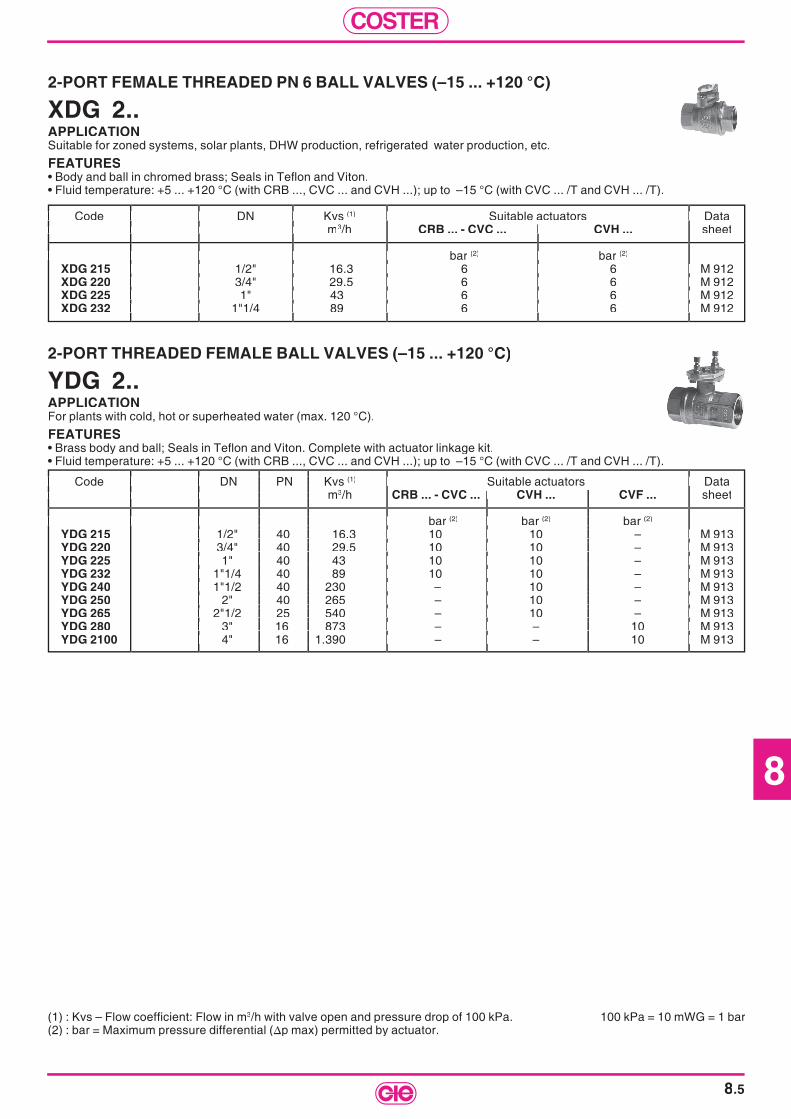
8
COSTER
8.5
2-PORT FEMALE THREADED PN 6 BALL VALVES (–15 ... +120 °C)
XDG 2..APPLICATIONSuitable for zoned systems, solar plants, DHW production, refrigerated water production, etc.
FEATURES• Body and ball in chromed brass; Seals in Tefl on and Viton.• Fluid temperature: +5 ... +120 °C (with CRB ..., CVC ... and CVH ...); up to –15 °C (with CVC ... /T and CVH ... /T).
(1) : Kvs – Flow coeffi cient: Flow in m3/h with valve open and pressure drop of 100 kPa. 100 kPa = 10 mWG = 1 bar(2) : bar = Maximum pressure differential (∆p max) permitted by actuator.
Code DN Kvs Code DN Kvs (1) Suitable actuators Data m m3/h CRB ... - CVC ... CVH ... sheet
bar bar (2) bar (2)
XDG 215 1/2" 16.3 6 6 M 912XDG 220 3/4" 29.5 6 6 M 912XDG 225 1" 43 6 6 M 912XDG 232 1"1/4 89 6 6 M 912
Code DN Kvs m
bar 1/2" 16.3 6 6 M 912 3/4" 29.5 6 6 M 912 1" 43 6 6 M 912 1"1/4 89 6 6 M 912
Suitable actuators Data
1/2" 16.3 6 6 M 912 3/4" 29.5 6 6 M 912 1" 43 6 6 M 912 1"1/4 89 6 6 M 912
Code DN Kvs m
bar 1/2" 16.3 6 6 M 912 3/4" 29.5 6 6 M 912 1" 43 6 6 M 912 1"1/4 89 6 6 M 912
Code DN Kvs m
bar 1/2" 16.3 6 6 M 912 3/4" 29.5 6 6 M 912 1" 43 6 6 M 912 1"1/4 89 6 6 M 912
Suitable actuators Data
bar 1/2" 16.3 6 6 M 912 3/4" 29.5 6 6 M 912 1" 43 6 6 M 912 1"1/4 89 6 6 M 912
CRB ... - CVC ... CVH ...
bar 1/2" 16.3 6 6 M 912 3/4" 29.5 6 6 M 912 1" 43 6 6 M 912 1"1/4 89 6 6 M 912
2-PORT THREADED FEMALE BALL VALVES (–15 ... +120 °C)
YDG 2..APPLICATIONFor plants with cold, hot or superheated water (max. 120 °C).
FEATURES• Brass body and ball; Seals in Tefl on and Viton. Complete with actuator linkage kit.• Fluid temperature: +5 ... +120 °C (with CRB ..., CVC ... and CVH ...); up to –15 °C (with CVC ... /T and CVH ... /T).
Code DN PN Kvs Code DN PN Kvs (1) Suitable actuators Data m m3/h CRB ... - CVC ... CVH ... CVF ... sheet
bar bar (2) bar (2) bar (2)
YDG 215 1/2" 40 16.3 10 10 – M 913YDG 220 3/4" 40 29.5 10 10 – M 913YDG 225 1" 40 43 10 10 – M 913YDG 232 1"1/4 40 89 10 10 – M 913YDG 240 1"1/2 40 230 – 10 – M 913YDG 250 2" 40 265 – 10 – M 913YDG 265 2"1/2 25 540 – 10 – M 913YDG 280 3" 16 873 – – 10 M 913YDG 2100 4" 16 1.390 – – 10 M 913
Code DN PN Kvs m
bar 1/2" 40 16.3 10 10 – M 913 3/4" 40 29.5 10 10 – M 913 1" 40 43 10 10 – M 913 1"1/4 40 89 10 10 – M 913 1"1/2 40 230 – 10 – M 913 2" 40 265 – 10 – M 913 2"1/2 25 540 – 10 – M 913 3" 16 873 – – 10 M 913 4" 16 1.390 – – 10 M 913
Suitable actuators Data
1/2" 40 16.3 10 10 – M 913 3/4" 40 29.5 10 10 – M 913 1" 40 43 10 10 – M 913 1"1/4 40 89 10 10 – M 913 1"1/2 40 230 – 10 – M 913 2" 40 265 – 10 – M 913 2"1/2 25 540 – 10 – M 913 3" 16 873 – – 10 M 913 4" 16 1.390 – – 10 M 913
Code DN PN Kvs m
bar
Code DN PN Kvs m
bar 1/2" 40 16.3 10 10 – M 913 3/4" 40 29.5 10 10 – M 913 1" 40 43 10 10 – M 913 1"1/4 40 89 10 10 – M 913 1"1/2 40 230 – 10 – M 913 2" 40 265 – 10 – M 913 2"1/2 25 540 – 10 – M 913 3" 16 873 – – 10 M 913 4" 16 1.390 – – 10 M 913
Suitable actuators Data
bar 1/2" 40 16.3 10 10 – M 913 3/4" 40 29.5 10 10 – M 913 1" 40 43 10 10 – M 913 1"1/4 40 89 10 10 – M 913 1"1/2 40 230 – 10 – M 913 2" 40 265 – 10 – M 913 2"1/2 25 540 – 10 – M 913 3" 16 873 – – 10 M 913 4" 16 1.390 – – 10 M 913
CRB ... - CVC ... CVH ... CVF ...
bar 1/2" 40 16.3 10 10 – M 913 3/4" 40 29.5 10 10 – M 913 1" 40 43 10 10 – M 913 1"1/4 40 89 10 10 – M 913 1"1/2 40 230 – 10 – M 913 2" 40 265 – 10 – M 913 2"1/2 25 540 – 10 – M 913 3" 16 873 – – 10 M 913 4" 16 1.390 – – 10 M 913
CRB ... - CVC ... CVH ... CVF ...
bar 1/2" 40 16.3 10 10 – M 913 3/4" 40 29.5 10 10 – M 913 1" 40 43 10 10 – M 913 1"1/4 40 89 10 10 – M 913 1"1/2 40 230 – 10 – M 913 2" 40 265 – 10 – M 913 2"1/2 25 540 – 10 – M 913 3" 16 873 – – 10 M 913 4" 16 1.390 – – 10 M 913
Code DN PN Kvs m
bar 1/2" 40 16.3 10 10 – M 913 3/4" 40 29.5 10 10 – M 913 1" 40 43 10 10 – M 913 1"1/4 40 89 10 10 – M 913 1"1/2 40 230 – 10 – M 913 2" 40 265 – 10 – M 913 2"1/2 25 540 – 10 – M 913 3" 16 873 – – 10 M 913 4" 16 1.390 – – 10 M 913

COSTER
8.6
3-PORT SCREWED FEMALE BALL VALVES PN 6 (–15 ... +120 °C)
XDG 3..APPLICATIONDesigned for zoned, solar, DHW production, chilled water, etc plants.
FEATURES• Chromed brass body and ball; Tefl on and Viton seals.• Fluid temperature: +5 ... +120 °C (with CRB ..., CVC ... & CVH ...); down to –15 °C (with CVC .../T & CVH .../T).
3-PORT SCREWED FEMALE BALL VALVES PN 6 (–15 ... +120 °C)
XLG 3..APPLICATIONDesigned for zoned, solar, DHW production, chilled water, etc plants.
FEATURES• Chromed brass body and ball; Tefl on and Viton seals.• Fluid temperature: +5 ... +120 °C (with CRB ..., CVC ... & CVH ...); down to –15 °C (with CVC ... /T & CVH .../T).
Code DN Kvs Code DN Kvs (1) Suitable actuators Data m m3/h CRB ... - CVC ... CVH 11. CVH 63./21./05. sheet
thr-port by-pass bar thr-port by-pass bar (2) bar (2) bar (2)
XLG 315 1/2" 16.3 1.5 6 6 6 M 916XLG 320 3/4" 29.5 1.8 6 6 6 M 916XLG 325 1" 43 3.9 6 6 6 M 916XLG 332 1"1/4 89 7.9 6 6 6 M 916XLG 341 1"1/2 160 14.8 – 6 6 M 916XLG 351 2" 265 24.5 – – 6 M 916
Code DN Kvs m
thr-port by-pass bar 1/2" 16.3 1.5 6 6 6 M 916 3/4" 29.5 1.8 6 6 6 M 916 1" 43 3.9 6 6 6 M 916 1"1/4 89 7.9 6 6 6 M 916 1"1/2 160 14.8 – 6 6 M 916 2" 265 24.5 – – 6 M 916
Suitable actuators Data
1/2" 16.3 1.5 6 6 6 M 916 3/4" 29.5 1.8 6 6 6 M 916 1" 43 3.9 6 6 6 M 916 1"1/4 89 7.9 6 6 6 M 916 1"1/2 160 14.8 – 6 6 M 916 2" 265 24.5 – – 6 M 916
Code DN Kvs m
thr-port by-pass bar 1/2" 16.3 1.5 6 6 6 M 916 3/4" 29.5 1.8 6 6 6 M 916 1" 43 3.9 6 6 6 M 916 1"1/4 89 7.9 6 6 6 M 916 1"1/2 160 14.8 – 6 6 M 916 2" 265 24.5 – – 6 M 916
Code DN Kvs m
thr-port by-pass bar 1/2" 16.3 1.5 6 6 6 M 916 3/4" 29.5 1.8 6 6 6 M 916 1" 43 3.9 6 6 6 M 916 1"1/4 89 7.9 6 6 6 M 916 1"1/2 160 14.8 – 6 6 M 916 2" 265 24.5 – – 6 M 916
Suitable actuators Data
thr-port by-pass bar 1/2" 16.3 1.5 6 6 6 M 916 3/4" 29.5 1.8 6 6 6 M 916 1" 43 3.9 6 6 6 M 916 1"1/4 89 7.9 6 6 6 M 916 1"1/2 160 14.8 – 6 6 M 916 2" 265 24.5 – – 6 M 916
CRB ... - CVC ... CVH 11. CVH 63./21./05.
bar 1/2" 16.3 1.5 6 6 6 M 916 3/4" 29.5 1.8 6 6 6 M 916 1" 43 3.9 6 6 6 M 916 1"1/4 89 7.9 6 6 6 M 916 1"1/2 160 14.8 – 6 6 M 916 2" 265 24.5 – – 6 M 916
CRB ... - CVC ... CVH 11. CVH 63./21./05.
1/2" 16.3 1.5 6 6 6 M 916 3/4" 29.5 1.8 6 6 6 M 916 1" 43 3.9 6 6 6 M 916 1"1/4 89 7.9 6 6 6 M 916 1"1/2 160 14.8 – 6 6 M 916 2" 265 24.5 – – 6 M 916
Code DN Kvs Code DN Kvs (1) Suitable actuators Data m m3/h CRB ... - CVC ... CVH 11. CVH 63./21./05. sheet
bar bar (2) bar (2) bar (2)
XDG 315 1/2" 3.9 6 6 6 M 918XDG 320 3/4" 7.9 6 6 6 M 918XDG 325 1" 13 6 6 6 M 918XDG 332 1"1/4 20.7 6 6 6 M 918 1"1/4 20.7 6 6 6 M 918 1"1/4 20.7 6 6 6 M 918 XDG 340 1"1/2 38.7 – 6 6 M 918 – 6 6 M 918 – 6 6 M 918 XDG 350 2" 54 – – 6 M 918
Code DN Kvs m
bar 1/2" 3.9 6 6 6 M 918 3/4" 7.9 6 6 6 M 918
1" 13 6 6 6 M 918 1"1/4 20.7 6 6 6 M 918
Suitable actuators Data
1/2" 3.9 6 6 6 M 918 3/4" 7.9 6 6 6 M 918
1" 13 6 6 6 M 918 1"1/4 20.7 6 6 6 M 918
– 6 6 M 918 – 6 M 918
Code DN Kvs m
bar 1/2" 3.9 6 6 6 M 918 3/4" 7.9 6 6 6 M 918
XDG 350
Code DN Kvs m
bar 1/2" 3.9 6 6 6 M 918 3/4" 7.9 6 6 6 M 918
1" 13 6 6 6 M 918 1"1/4 20.7 6 6 6 M 918
2 38.7 2" 54
Suitable actuators Data
bar 1/2" 3.9 6 6 6 M 918 3/4" 7.9 6 6 6 M 918
1" 13 6 6 6 M 918 1"1/4 20.7 6 6 6 M 918
bar 1/2" 3.9 6 6 6 M 918 3/4" 7.9 6 6 6 M 918
1" 13 6 6 6 M 918 1"1/4 20.7 6 6 6 M 918
– 6 6 M 918
CVH 63./21./05.
1/2" 3.9 6 6 6 M 918 3/4" 7.9 6 6 6 M 918
1" 13 6 6 6 M 918 1"1/4 20.7 6 6 6 M 918
– 6 6 M 918 – 6 M 918
(1) : Kvs – Flow coeffi cient: Flow in m3/h with valve open and pressure drop of 100 kPa. 100 kPa = 10 mWG = 1 bar(2) : bar = Maximum pressure differential (∆p max) permitted by actuator.
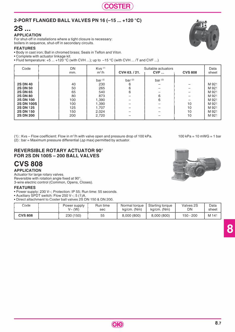
8
COSTER
8.7
REVERSIBLE ROTARY ACTUATOR 90°FOR 2S DN 100S – 200 BALL VALVES
CVS 808APPLICATIONActuator for large rotary valves.Reversible with rotation angle fi xed at 90°.3-wire electric control (Common, Opens, Closes).
FEATURES• Power supply: 230 V~; Protection: IP 55; Run time: 55 seconds.• Auxiliary SPDT switch: Flow 250 V~; 5 (1)A.• Direct attachment to Coster ball valves 2S DN 150 & DN 200.
Code Code Power supply Run time Normal torque Starting torque Valves 2S Data V~ (W) sec kg/cm. (Nm) kg/cm. (Nm) DN sheet V~ (W) sec kg/cm. (Nm) kg/cm. (Nm) DN sheet
CVS 808 230 (150) 55 8,000 (800) 8,000 (800) 150 - 200 M 141
Power supply Run time Normal torque Starting torque Valves 2S Data V~ (W) sec kg/cm. (Nm) kg/cm. (Nm) DN sheet
230 (150) 55 8,000 (800) 8,000 (800) 150 - 200 M 141
Power supply Run time Normal torque Starting torque Valves 2S Data V~ (W) sec kg/cm. (Nm) kg/cm. (Nm) DN sheet
230 (150) 55 8,000 (800) 8,000 (800) 150 - 200 M 141
Power supply Run time Normal torque Starting torque Valves 2S Data V~ (W) sec kg/cm. (Nm) kg/cm. (Nm) DN sheet
Power supply Run time Normal torque Starting torque Valves 2S Data V~ (W) sec kg/cm. (Nm) kg/cm. (Nm) DN sheet
230 (150) 55 8,000 (800) 8,000 (800) 150 - 200 M 141
Power supply Run time Normal torque Starting torque Valves 2S Data V~ (W) sec kg/cm. (Nm) kg/cm. (Nm) DN sheet
230 (150) 55 8,000 (800) 8,000 (800) 150 - 200 M 141
Power supply Run time Normal torque Starting torque Valves 2S Data V~ (W) sec kg/cm. (Nm) kg/cm. (Nm) DN sheet
230 (150) 55 8,000 (800) 8,000 (800) 150 - 200 M 141
Power supply Run time Normal torque Starting torque Valves 2S Data V~ (W) sec kg/cm. (Nm) kg/cm. (Nm) DN sheet
230 (150) 55 8,000 (800) 8,000 (800) 150 - 200 M 141
2-PORT FLANGED BALL VALVES PN 16 (–15 ... +120 °C)
2S ...APPLICATIONFor shut-off in installations where a tight closure is necessary: boilers in sequence, shut-off in secondary circuits.
FEATURES• Body in cast iron; Ball in chromed brass; Seals in Tefl on and Viton.• Complete with actuator linkage kit.• Fluid temperature: +5 ... +120 °C (with CVH ...); up to –15 °C (with CVH ... /T and CVF ...).
Code DN Kvs Code DN Kvs (1) Suitable actuators Data mm. m mm. m3/h CVH 63. / 21. CVF ... CVS 808 sheet
bar bar (2) bar (2) bar (2)
2S DN 40 40 230 6 – – M 9212S DN 50 50 265 6 – – M 9212S DN 65 65 540 6 – – M 9212S DN 80 80 873 – 6 – M 9212S DN 100 100 1,390 – 6 – M 9212S DN 100S 100 1,390 – – 10 M 9212S DN 125 125 1,707 – – 10 M 9212S DN 150 150 2,024 – – 10 M 9212S DN 200 200 2,720 – – 10 M 921
Code DN Kvs mm. m
bar 40 230 6 – – M 921 50 265 6 – – M 921 65 540 6 – – M 921 80 873 – 6 – M 921 100 1,390 – 6 – M 921 100 1,390 – – 10 M 921 125 1,707 – – 150 2,024 – – 200 2,720 – – 10 M 921
Data sheet
40 230 6 – – M 921 50 265 6 – – M 921 65 540 6 – – M 921 80 873 – 6 – M 921 100 1,390 – 6 – M 921 100 1,390 – – 10 M 921
M 921 M 921
200 2,720 – – 10 M 921
Code DN Kvs mm. m
bar
Code DN Kvs mm. m
bar 40 230 6 – – M 921 50 265 6 – – M 921 65 540 6 – – M 921 80 873 – 6 – M 921 100 1,390 – 6 – M 921 100 1,390 – – 10 M 921 125 1,707 – – 150 2,024 – – 200 2,720 – – 10 M 921
bar 40 230 6 – – M 921 50 265 6 – – M 921 65 540 6 – – M 921 80 873 – 6 – M 921 100 1,390 – 6 – M 921 100 1,390 – – 10 M 921 125 1,707 – – 150 2,024 – – 200 2,720 – – 10 M 921
CVH 63. / 21. CVF ... CV
40 230 6 – – M 921 50 265 6 – – M 921 65 540 6 – – M 921 80 873 – 6 – M 921 100 1,390 – 6 – M 921 100 1,390 – – 10 M 921 125 1,707 – – 150 2,024 – – 200 2,720 – – 10 M 921
CVH 63. / 21. CVF ... CV
40 230 6 – – M 921 50 265 6 – – M 921 65 540 6 – – M 921 80 873 – 6 – M 921 100 1,390 – 6 – M 921 100 1,390 – – 10 M 921
200 2,720 – – 10 M 921
(1) : Kvs – Flow coeffi cient: Flow in m3/h with valve open and pressure drop of 100 kPa. 100 kPa = 10 mWG = 1 bar(2) : bar = Maximum pressure differential (∆p max) permitted by actuator.

COSTER
8.8
3- AND 4-PORT SLIPPER & BUTTERFLY VALVES PN 6 (10 ... 110 °C)
VSG ... - VSF ... - VFG ... - VFF ...APPLICATIONUsed as mixing or diverting valves to control temperature of circulating water in heating plants.
FEATURES• Body and rotor in GG25 cast iron; spindle in stainless steel.• Connections: DN 3/4" ... 2" threaded female; DN 40 ... 150 fl anged.• Rotation angle 90°; Linear control; Let by ≤ 1.5 % Kvs.
(1) : Kvs – Flow coeffi cient: Flow in m3/h with valve open and pressure drop of 100 kPa. 100 kPa = 10 mWG = 1 bar (2) : bar = Maximum pressure differential (∆p max) permitted by actuator.(3) : Type of rotor. For 3-port valves: slipper = left or right lateral port always open; butterfl y = central port always open.(4) : Length fl ange to fl ange.(5) : Coupling possible only with AVF 171 linkage.
Code DN Kvs Code DN Kvs (1) Rotor (3) Length.(4) Suitable actuators Data m m3/h mm. CVC ... CVH ... CVF ... sheet
3-port thre.d inches bar 3-port thre.d inches bar (2) bar (2) bar (2)
VSG 320 3/4" 13 slipper 130 0.3 0.5 – M 931VSG 325 1" 13 slipper 130 0.3 0.5 – M 931VSG 332 1"1/4 19 slipper 142 0.2 0.5 – M 931VSG 340 1"1/2 29 slipper 160 0.2 0.5 – M 931VSG 350 2" 57 slipper 190 0.2 0.5 – M 931
VFG 320 3/4" 13 butterfl y 130 0.3 0.5 – M 931VFG 325 1" 13 butterfl y 130 0.3 0.5 – M 931VFG 332 1"1/4 19 butterfl y 142 0.2 0.5 – M 931VFG 340 1"1/2 29 butterfl y 160 0.2 0.5 – M 931VFG 350 2" 57 butterfl y 190 0.2 0.5 – M 931
3-port fl anged mm 3-port fl anged mmVSF 340 40 29 slipper 180 0.2 0.5 – M 931VSF 350 50 57 slipper 200 0.2 0.5 – M 931VSF 365 65 81 slipper 230 – 0.4 – M 931VSF 380 80 170 slipper 250 – 0.4 – M 931VSF 3100 100 240 slipper 280 – 0.3 0.5 (5) M 931VSF 3125 125 470 slipper 300 – – 0.5 M 931VSF 3150 150 700 slipper 350 – – 0.5 M 931
VFF 340 40 29 butterfl y 180 0.2 0.5 – M 931VFF 350 50 57 butterfl y 200 0.2 0.5 – M 931VFF 365 65 81 butterfl y 230 – 0.4 – M 931VFF 380 80 170 butterfl y 250 – 0.4 – M 931VFF 3100 100 240 butterfl y 280 – 0.3 0.5 (5) M 931VFF 3125 125 470 butterfl y 300 – – 0.5 M 931VFF 3150 150 700 butterfl y 350 – – 0.5 M 931
4-port thre.d inches 4-port thre.d inchesVFG 420 3/4" 13 butterfl y 130 0.3 0.5 – M 931VFG 425 1" 13 butterfl y 130 0.3 0.5 – M 931VFG 432 1"1/4 19 butterfl y 142 0.2 0.5 – M 931VFG 440 1"1/2 29 butterfl y 160 0.2 0.5 – M 931VFG 450 2" 57 butterfl y 190 0.2 0.5 – M 931
4-port fl anged mm 4-port fl anged mm VFF 440 40 29 butterfl y 180 0.2 0.5 – M 931VFF 450 50 57 butterfl y 200 0.2 0.5 – M 931
VFF 465 VFF 465 65 81 butterfl y 230 – 0.4 – M 931 VFF 480 VFF 480 80 170 butterfl y 250 – 0.4 – M 931 VFF 4100 VFF 4100 100 240 butterfl y 280 – 0.3 0.5 (5) M 931 VFF 4125 VFF 4125 125 470 butterfl y 300 – – 0.5 M 931 VFF 4150 VFF 4150 150 700 butterfl y 350 – – 0.5 M 931
Code DN Kvs m
3-port thre.d inches bar 3/4" 13 slipper 130 0.3 0.5 – M 931
1" 13 slipper 130 0.3 0.5 – M 931 1"1/4 19 slipper 142 0.2 0.5 – M 931 1"1/2 29 slipper 160 0.2 0.5 – M 931 2" 57 slipper 190 0.2 0.5 – M 931
3/4" 13 butterfl y 1" 13 butterfl y 130 0.3 0.5 – M 931 1"1/4 19 butterfl y 142 0.2 0.5 – M 931 1"1/2 29 butterfl y 160 0.2 0.5 – M 931
2" 57 butterfl y 190 0.2 0.5 – M 931
3-port fl anged mm 40 29 slipper 180 0.2 0.5 – M 931 50 57 slipper 200 0.2 0.5 – M 931 65 81 slipper 230 – 0.4 – M 931 80 170 slipper 250 – 0.4 – M 931
100 240 slipper 280 – 0.3 0.5 125 470 slipper 300 – – 0.5 M 931 150 700 slipper 350 – – 0.5 M 931
40 29 butterfl y 180 0.2 0.5 – M 931 50 57 butterfl y 200 0.2 0.5 – M 931 65 81 butterfl y 230 – 0.4 – M 931 80 170 butterfl y 250 – 0.4 – M 931
100 240 butterfl y 280 – 0.3 0.5 125 470 butterfl y 300 – – 0.5 M 931 150 700 butterfl y 350 – – 0.5 M 931
4-port thre.d inches 3/4" 13 butterfl y 130 0.3 0.5 – M 931 1" 13 butterfl y 130 0.3 0.5 – M 931 1"1/4 19 butterfl y 142 0.2 0.5 – M 931 1"1/2 29 butterfl y 160 0.2 0.5 – M 931 2" 57 butterfl y 190 0.2 0.5 – M 931
4-port fl anged mm 40 29 butterfl y 180 0.2 0.5 – M 931 50 57 butterfl y 200 0.2 0.5 – M 931
Suitable actuators Data sheet
3/4" 13 slipper 130 0.3 0.5 – M 931 1" 13 slipper 130 0.3 0.5 – M 931 1"1/4 19 slipper 142 0.2 0.5 – M 931 1"1/2 29 slipper 160 0.2 0.5 – M 931 2" 57 slipper 190 0.2 0.5 – M 931
130 0.3 0.5 – M 931 1" 13 butterfl y 130 0.3 0.5 – M 931 1"1/4 19 butterfl y 142 0.2 0.5 – M 931 1"1/2 29 butterfl y 160 0.2 0.5 – M 931
2" 57 butterfl y 190 0.2 0.5 – M 931
40 29 slipper 180 0.2 0.5 – M 931 50 57 slipper 200 0.2 0.5 – M 931 65 81 slipper 230 – 0.4 – M 931 80 170 slipper 250 – 0.4 – M 931
M 931 125 470 slipper 300 – – 0.5 M 931 150 700 slipper 350 – – 0.5 M 931
40 29 butterfl y 180 0.2 0.5 – M 931 50 57 butterfl y 200 0.2 0.5 – M 931 65 81 butterfl y 230 – 0.4 – M 931 80 170 butterfl y 250 – 0.4 – M 931
M 931 125 470 butterfl y 300 – – 0.5 M 931 150 700 butterfl y 350 – – 0.5 M 931
3/4" 13 butterfl y 130 0.3 0.5 – M 931 1" 13 butterfl y 130 0.3 0.5 – M 931 1"1/4 19 butterfl y 142 0.2 0.5 – M 931 1"1/2 29 butterfl y 160 0.2 0.5 – M 931 2" 57 butterfl y 190 0.2 0.5 – M 931
40 29 butterfl y 180 0.2 0.5 – M 931 50 57 butterfl y 200 0.2 0.5 – M 931
65 81 butterfl y 230 – 0.4 – M 93180 170 butterfl y 250 – 0.4 – M 931
M 931125 470 butterfl y 300 – – 0.5 M 931150 700 butterfl y 350 – – 0.5 M 931
Code DN Kvs m
3-port thre.d inches bar
1" 13 slipper 130 0.3 0.5 – M 931 1"1/4 19 slipper 142 0.2 0.5 – M 931 1"1/2 29 slipper 160 0.2 0.5 – M 931 2" 57 slipper 190 0.2 0.5 – M 931
3/4" 13 butterfl y 1" 13 butterfl y 130 0.3 0.5 – M 931 1"1/4 19 butterfl y 142 0.2 0.5 – M 931 1"1/2 29 butterfl y 160 0.2 0.5 – M 931
3-port fl anged mm 40 29 slipper 180 0.2 0.5 – M 931 50 57 slipper 200 0.2 0.5 – M 931 65 81 slipper 230 – 0.4 – M 931 80 170 slipper 250 – 0.4 – M 931
100 240 slipper 280 – 0.3 0.5 125 470 slipper 300 – – 0.5 M 931 150 700 slipper 350 – – 0.5 M 931
40 29 butterfl y 180 0.2 0.5 – M 931 50 57 butterfl y 200 0.2 0.5 – M 931 65 81 butterfl y 230 – 0.4 – M 931 80 170 butterfl y 250 – 0.4 – M 931
100 240 butterfl y 280 – 0.3 0.5 125 470 butterfl y 300 – – 0.5 M 931 150 700 butterfl y 350 – – 0.5 M 931
4-port thre.d inches 3/4" 13 butterfl y 130 0.3 0.5 – M 931 1" 13 butterfl y 130 0.3 0.5 – M 931 1"1/4 19 butterfl y 142 0.2 0.5 – M 931 1"1/2 29 butterfl y 160 0.2 0.5 – M 931 2" 57 butterfl y 190 0.2 0.5 – M 931
4-port fl anged mm 40 29 butterfl y 180 0.2 0.5 – M 931 50 57 butterfl y 200 0.2 0.5 – M 931
VFF 465 VFF 480 VFF 4100 VFF 4125 VFF 4150
Code DN Kvs m
3-port thre.d inches bar 3/4" 13 slipper 130 0.3 0.5 – M 931
1" 13 slipper 130 0.3 0.5 – M 931 1"1/4 19 slipper 142 0.2 0.5 – M 931 1"1/2 29 slipper 160 0.2 0.5 – M 931 2" 57 slipper 190 0.2 0.5 – M 931
3/4" 13 butterfl y 1" 13 butterfl y 130 0.3 0.5 – M 931 1"1/4 19 butterfl y 142 0.2 0.5 – M 931 1"1/2 29 butterfl y 160 0.2 0.5 – M 931
2" 57 butterfl y 190 0.2 0.5 – M 931
40 29 slipper 180 0.2 0.5 – M 931 50 57 slipper 200 0.2 0.5 – M 931 65 81 slipper 230 – 0.4 – M 931 80 170 slipper 250 – 0.4 – M 931
100 240 slipper 280 – 0.3 0.5 125 470 slipper 300 – – 0.5 M 931 150 700 slipper 350 – – 0.5 M 931
40 29 butterfl y 180 0.2 0.5 – M 931 50 57 butterfl y 200 0.2 0.5 – M 931 65 81 butterfl y 230 – 0.4 – M 931 80 170 butterfl y 250 – 0.4 – M 931
100 240 butterfl y 280 – 0.3 0.5 125 470 butterfl y 300 – – 0.5 M 931 150 700 butterfl y 350 – – 0.5 M 931
3/4" 13 butterfl y 130 0.3 0.5 – M 931 1" 13 butterfl y 130 0.3 0.5 – M 931 1"1/4 19 butterfl y 142 0.2 0.5 – M 931 1"1/2 29 butterfl y 160 0.2 0.5 – M 931 2" 57 butterfl y 190 0.2 0.5 – M 931
4-port fl anged mm 40 29 butterfl y 180 0.2 0.5 – M 931 50 57 butterfl y 200 0.2 0.5 – M 931
65 81 butterfl y 230 – 0.4 – M 93180 170 butterfl y 250 – 0.4 – M 931
100 240 butterfl y 280 – 0.3 0.5 125 470 butterfl y 300 – – 0.5 M 931150 700 butterfl y 350 – – 0.5 M 931
Suitable actuators Data
3-port thre.d inches bar 3/4" 13 slipper 130 0.3 0.5 – M 931
1" 13 slipper 130 0.3 0.5 – M 931 1"1/4 19 slipper 142 0.2 0.5 – M 931 1"1/2 29 slipper 160 0.2 0.5 – M 931 2" 57 slipper 190 0.2 0.5 – M 931
130 0.3 0.5 – M 931 1" 13 butterfl y 130 0.3 0.5 – M 931 1"1/4 19 butterfl y 142 0.2 0.5 – M 931 1"1/2 29 butterfl y 160 0.2 0.5 – M 931
2" 57 butterfl y 190 0.2 0.5 – M 931
40 29 slipper 180 0.2 0.5 – M 931 50 57 slipper 200 0.2 0.5 – M 931 65 81 slipper 230 – 0.4 – M 931 80 170 slipper 250 – 0.4 – M 931
100 240 slipper 280 – 0.3 0.5 125 470 slipper 300 – – 0.5 M 931 150 700 slipper 350 – – 0.5 M 931
40 29 butterfl y 180 0.2 0.5 – M 931 50 57 butterfl y 200 0.2 0.5 – M 931 65 81 butterfl y 230 – 0.4 – M 931 80 170 butterfl y 250 – 0.4 – M 931
100 240 butterfl y 280 – 0.3 0.5 125 470 butterfl y 300 – – 0.5 M 931 150 700 butterfl y 350 – – 0.5 M 931
3/4" 13 butterfl y 130 0.3 0.5 – M 931 1" 13 butterfl y 130 0.3 0.5 – M 931 1"1/4 19 butterfl y 142 0.2 0.5 – M 931 1"1/2 29 butterfl y 160 0.2 0.5 – M 931 2" 57 butterfl y 190 0.2 0.5 – M 931
4-port fl anged mm 40 29 butterfl y 180 0.2 0.5 – M 931 50 57 butterfl y 200 0.2 0.5 – M 931
65 81 butterfl y 230 – 0.4 – M 93180 170 butterfl y 250 – 0.4 – M 931
100 240 butterfl y 280 – 0.3 0.5 125 470 butterfl y 300 – – 0.5 M 931150 700 butterfl y 350 – – 0.5 M 931
CVC ... CVH ... CVF ...
bar 3/4" 13 slipper 130 0.3 0.5 – M 931
1" 13 slipper 130 0.3 0.5 – M 931 1"1/4 19 slipper 142 0.2 0.5 – M 931 1"1/2 29 slipper 160 0.2 0.5 – M 931 2" 57 slipper 190 0.2 0.5 – M 931
130 0.3 0.5 – M 931 1" 13 butterfl y 130 0.3 0.5 – M 931 1"1/4 19 butterfl y 142 0.2 0.5 – M 931 1"1/2 29 butterfl y 160 0.2 0.5 – M 931
2" 57 butterfl y 190 0.2 0.5 – M 931
40 29 slipper 180 0.2 0.5 – M 931 50 57 slipper 200 0.2 0.5 – M 931 65 81 slipper 230 – 0.4 – M 931 80 170 slipper 250 – 0.4 – M 931
100 240 slipper 280 – 0.3 0.5 125 470 slipper 300 – – 0.5 M 931 150 700 slipper 350 – – 0.5 M 931
40 29 butterfl y 180 0.2 0.5 – M 931 50 57 butterfl y 200 0.2 0.5 – M 931 65 81 butterfl y 230 – 0.4 – M 931 80 170 butterfl y 250 – 0.4 – M 931
100 240 butterfl y 280 – 0.3 0.5 125 470 butterfl y 300 – – 0.5 M 931 150 700 butterfl y 350 – – 0.5 M 931
3/4" 13 butterfl y 130 0.3 0.5 – M 931 1" 13 butterfl y 130 0.3 0.5 – M 931 1"1/4 19 butterfl y 142 0.2 0.5 – M 931 1"1/2 29 butterfl y 160 0.2 0.5 – M 931 2" 57 butterfl y 190 0.2 0.5 – M 931
40 29 butterfl y 180 0.2 0.5 – M 931 50 57 butterfl y 200 0.2 0.5 – M 931
65 81 butterfl y 230 – 0.4 – M 93180 170 butterfl y 250 – 0.4 – M 931
100 240 butterfl y 280 – 0.3 0.5 125 470 butterfl y 300 – – 0.5 M 931150 700 butterfl y 350 – – 0.5 M 931
CVC ... CVH ... CVF ...
bar 3/4" 13 slipper 130 0.3 0.5 – M 931
1" 13 slipper 130 0.3 0.5 – M 931 1"1/4 19 slipper 142 0.2 0.5 – M 931 1"1/2 29 slipper 160 0.2 0.5 – M 931 2" 57 slipper 190 0.2 0.5 – M 931
130 0.3 0.5 – M 931 1" 13 butterfl y 130 0.3 0.5 – M 931 1"1/4 19 butterfl y 142 0.2 0.5 – M 931 1"1/2 29 butterfl y 160 0.2 0.5 – M 931
2" 57 butterfl y 190 0.2 0.5 – M 931
40 29 slipper 180 0.2 0.5 – M 931 50 57 slipper 200 0.2 0.5 – M 931 65 81 slipper 230 – 0.4 – M 931 80 170 slipper 250 – 0.4 – M 931
100 240 slipper 280 – 0.3 0.5 125 470 slipper 300 – – 0.5 M 931 150 700 slipper 350 – – 0.5 M 931
40 29 butterfl y 180 0.2 0.5 – M 931 50 57 butterfl y 200 0.2 0.5 – M 931 65 81 butterfl y 230 – 0.4 – M 931 80 170 butterfl y 250 – 0.4 – M 931
100 240 butterfl y 280 – 0.3 0.5 125 470 butterfl y 300 – – 0.5 M 931 150 700 butterfl y 350 – – 0.5 M 931
3/4" 13 butterfl y 130 0.3 0.5 – M 931 1" 13 butterfl y 130 0.3 0.5 – M 931 1"1/4 19 butterfl y 142 0.2 0.5 – M 931 1"1/2 29 butterfl y 160 0.2 0.5 – M 931 2" 57 butterfl y 190 0.2 0.5 – M 931
4-port fl anged mm 40 29 butterfl y 180 0.2 0.5 – M 931 50 57 butterfl y 200 0.2 0.5 – M 931
65 81 butterfl y 230 – 0.4 – M 93180 170 butterfl y 250 – 0.4 – M 931
100 240 butterfl y 280 – 0.3 0.5 125 470 butterfl y 300 – – 0.5 M 931150 700 butterfl y 350 – – 0.5 M 931
Rotor /h mm.
3-port thre.d inches bar 3/4" 13 slipper 130 0.3 0.5 – M 931
1" 13 slipper 130 0.3 0.5 – M 931 1"1/4 19 slipper 142 0.2 0.5 – M 931 1"1/2 29 slipper 160 0.2 0.5 – M 931 2" 57 slipper 190 0.2 0.5 – M 931
3/4" 13 butterfl y 1" 13 butterfl y 130 0.3 0.5 – M 931 1"1/4 19 butterfl y 142 0.2 0.5 – M 931 1"1/2 29 butterfl y 160 0.2 0.5 – M 931
2" 57 butterfl y 190 0.2 0.5 – M 931
40 29 slipper 180 0.2 0.5 – M 931 50 57 slipper 200 0.2 0.5 – M 931 65 81 slipper 230 – 0.4 – M 931 80 170 slipper 250 – 0.4 – M 931
100 240 slipper 280 – 0.3 0.5 125 470 slipper 300 – – 0.5 M 931 150 700 slipper 350 – – 0.5 M 931
40 29 butterfl y 180 0.2 0.5 – M 931 50 57 butterfl y 200 0.2 0.5 – M 931 65 81 butterfl y 230 – 0.4 – M 931 80 170 butterfl y 250 – 0.4 – M 931
100 240 butterfl y 280 – 0.3 0.5 125 470 butterfl y 300 – – 0.5 M 931 150 700 butterfl y 350 – – 0.5 M 931
3/4" 13 butterfl y 130 0.3 0.5 – M 931 1" 13 butterfl y 130 0.3 0.5 – M 931 1"1/4 19 butterfl y 142 0.2 0.5 – M 931 1"1/2 29 butterfl y 160 0.2 0.5 – M 931 2" 57 butterfl y 190 0.2 0.5 – M 931
4-port fl anged mm 40 29 butterfl y 180 0.2 0.5 – M 931 50 57 butterfl y 200 0.2 0.5 – M 931
65 81 butterfl y 230 – 0.4 – M 93180 170 butterfl y 250 – 0.4 – M 931
100 240 butterfl y 280 – 0.3 0.5 125 470 butterfl y 300 – – 0.5 M 931150 700 butterfl y 350 – – 0.5 M 931
Length./h mm.
3-port thre.d inches bar 3/4" 13 slipper 130 0.3 0.5 – M 931
1" 13 slipper 130 0.3 0.5 – M 931 1"1/4 19 slipper 142 0.2 0.5 – M 931 1"1/2 29 slipper 160 0.2 0.5 – M 931 2" 57 slipper 190 0.2 0.5 – M 931
1" 13 butterfl y 130 0.3 0.5 – M 931 1"1/4 19 butterfl y 142 0.2 0.5 – M 931 1"1/2 29 butterfl y 160 0.2 0.5 – M 931
2" 57 butterfl y 190 0.2 0.5 – M 931
40 29 slipper 180 0.2 0.5 – M 931 50 57 slipper 200 0.2 0.5 – M 931 65 81 slipper 230 – 0.4 – M 931 80 170 slipper 250 – 0.4 – M 931
100 240 slipper 280 – 0.3 0.5 125 470 slipper 300 – – 0.5 M 931 150 700 slipper 350 – – 0.5 M 931
40 29 butterfl y 180 0.2 0.5 – M 931 50 57 butterfl y 200 0.2 0.5 – M 931 65 81 butterfl y 230 – 0.4 – M 931 80 170 butterfl y 250 – 0.4 – M 931
100 240 butterfl y 280 – 0.3 0.5 125 470 butterfl y 300 – – 0.5 M 931 150 700 butterfl y 350 – – 0.5 M 931
3/4" 13 butterfl y 130 0.3 0.5 – M 931 1" 13 butterfl y 130 0.3 0.5 – M 931 1"1/4 19 butterfl y 142 0.2 0.5 – M 931 1"1/2 29 butterfl y 160 0.2 0.5 – M 931 2" 57 butterfl y 190 0.2 0.5 – M 931
4-port fl anged mm 40 29 butterfl y 180 0.2 0.5 – M 931 50 57 butterfl y 200 0.2 0.5 – M 931
65 81 butterfl y 230 – 0.4 – M 93180 170 butterfl y 250 – 0.4 – M 931
100 240 butterfl y 280 – 0.3 0.5 125 470 butterfl y 300 – – 0.5 M 931150 700 butterfl y 350 – – 0.5 M 931

8
COSTER
8.9
FLANGES WITH NECK FOR FLANGED VALVES PN 6
AFC ...APPLICATION• PN 6 UNI 2280.• Packs containing1 fl ange and including seals, bolts, nuts and washers.
Code Including: Code Including: Seal Bolts (2-port) Bolts (3-and 4-port) Nuts Washers Seal Bolts (2-port) Bolts (3-and 4-port) Nuts Washers
No. mm No. mm No. mm No. mm No. mm No. mm No. mm No. mm No. mm No. mmAFC 040 1 85 x 45 x 2 0 – 4 12 M x 55 4 12 M 8 ø 12AFC 050 1 95 x 57 x 2 2 12 M x 80 4 12 M x 55 4 12 M 8 ø 12AFC 065 1 115 x 76 x 2 2 12 M x 80 4 12 M x 55 4 12 M 8 ø 12AFC 080 1 132 x 89 x 2 2 16 M x 100 4 16 M x 60 4 16 M 8 ø 16AFC 100 1 152 x 108 x 2 2 16 M x 100 4 16 M x 60 4 16 M 8 ø 16AFC 125 1 182 x 133 x 2 4 16 M x 120 8 16 M x 60 8 16 M 16 ø 16AFC 150 1 207 x 159 x 2 4 16 M x 120 8 16 M x 60 8 16 M 16 ø 16AFC 175 1 230 x 185 x 3 8 16 M x 140 – – 8 16 M 16 ø 16AFC 200 1 255 x 210 x 3 8 16 M x 140 – – 8 16 M 16 ø 16
Code Including: Seal Bolts (2-port) Bolts (3-and 4-port) Nuts Washers
No. mm No. mm No. mm No. mm No. mm 1 85 x 45 x 2 0 – 4 12 M x 55 4 12 M 8 ø 12 1 95 x 57 x 2 2 12 M x 80 4 12 M x 55 4 12 M 8 ø 12 1 115 x 76 x 2 2 12 M x 80 4 12 M x 55 4 12 M 8 ø 12
1 182 x 133 x 2 4 16 M x 120 8 16 M x 60 8 16 M 16 ø 16 1 207 x 159 x 2 4 16 M x 120 8 16 M x 60 8 16 M 16 ø 16 1 230 x 185 x 3 8 16 M x 140 – – 8 16 M 16 ø 16 1 255 x 210 x 3 8 16 M x 140 – – 8 16 M 16 ø 16
Code Including: Seal Bolts (2-port) Bolts (3-and 4-port) Nuts Washers
No. mm No. mm No. mm No. mm No. mm
AFC 080 AFC 100
Seal Bolts (2-port) Bolts (3-and 4-port) Nuts Washers
No. mm No. mm No. mm No. mm No. mm 1 85 x 45 x 2 0 – 4 12 M x 55 4 12 M 8 ø 12 1 95 x 57 x 2 2 12 M x 80 4 12 M x 55 4 12 M 8 ø 12 1 115 x 76 x 2 2 12 M x 80 4 12 M x 55 4 12 M 8 ø 12
1 132 x 89 x 2 2 16 M x 100 4 16 M x 60 4 16 M 8 ø 161 152 x 108 x 2 2 16 M x 100 4 16 M x 60 4 16 M 8 ø 16
1 182 x 133 x 2 4 16 M x 120 8 16 M x 60 8 16 M 16 ø 16 1 207 x 159 x 2 4 16 M x 120 8 16 M x 60 8 16 M 16 ø 16 1 230 x 185 x 3 8 16 M x 140 – – 8 16 M 16 ø 16 1 255 x 210 x 3 8 16 M x 140 – – 8 16 M 16 ø 16
(1) : Kvs – Flow coeffi cient: Flow in m3/h with valve open and pressure drop of 100 kPa. 100 kPa = 10 mWG = 1 bar(2) : bar = Maximum pressure differential (∆p max) permitted by actuator.
2-PORT BUTTERFLY VALVES PN 6 (10 ... 110 °C)
2F ...APPLICATIONAs shut-off valves with 2-position control, in systems where tight shut-off is not necessary: - boilers in sequence; - shut-off in secondary circuits.
FEATURES• PN 6 fl anged connections; Working temperature: 10 ... 110 °; Rotation angle 90°.• Cast iron body; Brass butterfl y with ring seal in Tefl on; Stainless steel spindle.
Code DN Kvs Code DN Kvs (1) Suitable actuators Data m m3/h CVC ... CVH ... sheet
bar bar (2) bar (2)
2F DN 50 50 100 1.5 3 M 9202F DN 65 65 160 1.5 3 M 9202F DN 80 80 280 – 3 M 9202F DN 100 100 450 – 3 M 9202F DN 125 125 700 – 2 M 9202F DN 150 150 1.200 – 2 M 9202F DN 175 175 1.800 – 2 M 9202F DN 200 200 2.300 – 2 M 920
Code DN Kvs m
bar 50 100 1.5 3 M 920 65 160 1.5 3 M 920 80 280 – 3 M 920
100 450 – 3 M 920 125 700 – 2 M 920 150 1.200 – 2 M 920 175 1.800 – 2 M 920 200 2.300 – 2 M 920
Suitable actuators Data
50 100 1.5 3 M 920 65 160 1.5 3 M 920 80 280 – 3 M 920
100 450 – 3 M 920 125 700 – 2 M 920 150 1.200 – 2 M 920 175 1.800 – 2 M 920 200 2.300 – 2 M 920
Code DN Kvs m
bar 50 100 1.5 3 M 920 65 160 1.5 3 M 920 80 280 – 3 M 920
100 450 – 3 M 920 125 700 – 2 M 920 150 1.200 – 2 M 920 175 1.800 – 2 M 920 200 2.300 – 2 M 920
Code DN Kvs m
bar 50 100 1.5 3 M 920 65 160 1.5 3 M 920 80 280 – 3 M 920
100 450 – 3 M 920 125 700 – 2 M 920 150 1.200 – 2 M 920 175 1.800 – 2 M 920 200 2.300 – 2 M 920
Suitable actuators Data
bar 50 100 1.5 3 M 920 65 160 1.5 3 M 920 80 280 – 3 M 920
100 450 – 3 M 920 125 700 – 2 M 920 150 1.200 – 2 M 920 175 1.800 – 2 M 920 200 2.300 – 2 M 920
CVC ... CVH ...
bar 50 100 1.5 3 M 920 65 160 1.5 3 M 920 80 280 – 3 M 920
100 450 – 3 M 920 125 700 – 2 M 920 150 1.200 – 2 M 920 175 1.800 – 2 M 920 200 2.300 – 2 M 920

COSTER
8.10
Code Code Power Run time Nominal torque Starting torque Valves (up to DN) Data V~ (VA) sec kg/cm. (Nm) kg/cm. (Nm) mixing V~ (VA) sec kg/cm. (Nm) kg/cm. (Nm) mixing butterfl y ball sheet VSG / VFG / VSF 2F XDG/XLG/YDG
CVC 188 230 (2.5) 180 60 (6) 90 (9) 50 65 1”1/4 M 110CVC 184 24 (2.5) 180 60 (6) 90 (9) 50 65 1”1/4 M 110CVC 098 230 (4.5) 90 60 (6) 90 (9) 50 65 1”1/4 M 110CVC 094 24 (4.5) 90 60 (6) 90 (9) 50 65 1”1/4 M 110CVC 038 230 (5) 30 60 (6) 90 (9) 50 65 1”1/4 M 110CVC 034 24 (5) 30 60 (6) 90 (9) 50 65 1”1/4 M 110CVC 018 230 (7) 15 60 (6) 90 (9) 50 – 1”1/4 M 110CVC 014 24 (7) 15 60 (6) 90 (9) 50 – 1”1/4 M 110
REVERSIBLE 90° ROTARY ACTUATOR (PRE-WIRED)
CRB ...APPLICATIONActuator for rotary ball valves. Reversible with rotation angle fi xed at 90°.3-wire electrical control (Common, Opens, Closes).
FEATURES• Power supply: 230 - 24 V ~; Protection: IP 54; Run time: 90 seconds.• Two SPDT auxiliary microswitches at extremities of run: rating: 250 V, ~ 5 (1) A.• Direct linkage with all Coster rotary valves.
REVERSIBLE 90° ROTARY ACTUATOR WITH CONNECTIONTO TERMINAL BLOCK
CVC ...APPLICATIONActuator for rotary slipper and ball valves. Reversible with rotation angle fi xed at 90°. Three-wire electric control (Common, Opens, Closes).
FEATURES• Power supply: 230 - 24 V ~; Protection: IP 55; Run times: 180 - 90 - 30 - 15 seconds.• Two SPDT auxiliary microswitches at extremities of run: rating: 250 V ~, 5 (1) A.• Direct linkage with all Coster rotary valves.
SPECIAL MODELS
Code Description Code Description
CVC ... / T With 6 W internal heater for applications with fl uid temperature down to – 15 °C (without auxiliary micro) With 6 W internal heater for applications with fl uid temperature down to – 15 °C (without auxiliary micro) With 6 W internal heater for applications with fl uid temperature down to – 15 °C (without auxiliary micro)CVC ... / T/S1 Including 2 W internal heater for applications with fl uid temperature down to – 15 °C (with auxiliary micro)(with auxiliary micro)CVC ..8 / S2 Including relay for On-Off control with two wires (only 230 V ~).
Code Description
With 6 W internal heater for applications with fl uid temperature down to – 15 °C (without auxiliary micro) Including 2 W internal heater for applications with fl uid temperature down to – 15 °C
Including relay for On-Off control with two wires (only 230 V ~).
Code Description
With 6 W internal heater for applications with fl uid temperature down to – 15 °C (without auxiliary micro) Including 2 W internal heater for applications with fl uid temperature down to – 15 °C
Including relay for On-Off control with two wires (only 230 V ~).
ACCESSORIES FOR CRB ... AND CVC ...
Code Description Code Description
SMP 750 Manual release, for VSG/VFG/VSF/VFF mizing valves, for 2F butterfky and XDG/YDG ball valves.SMP 760 Manual release for YDG 2.. valves up to 1"1/4.AVA 101 Linkage for: Honeywell-Mut 2 (Con trol li, Caleffi , Sara); Zentra;
Buche (Cazzaniga, Sauter, Ari-Fasoli,Chibro-Muller, Vilb up to 2", Mastermann); Landis & Gyr Landis & Gyr(Lazzari, Tonon, Casem); Stark (Besser, Errevi, Intermes, Ari-Fasoli).
AVS 102 Special linkage kits with unperforated plate for: Viessman (Lazzari, Tonon, Casem); Wema Warmeteknik Warmeteknik (Billman, Mixette, Thermia, Firix, Esbe); Vilb (Termoregler); Besser.
AVS 103 Linkage for screwed old model Honeywell-Mut 3 (Controlli, Caleffi , Sara).AVS 104 Linkage for Landis & Gyr SN3-SN4.AVS 105 Linkage for Centra DR-ZR.
Code Description
Manual release, for Manual release for YDG 2.. valves up to 1"1/4. Linkage for:
Landis & Gyr Special linkage kits with unperforated plate for:
Warmeteknik Linkage for screwed old model Linkage for Linkage for
Code Description
Manual release, for Manual release for YDG 2.. valves up to 1"1/4. Linkage for:
Landis & Gyr
Special linkage kits with unperforated plate for: Warmeteknik
Linkage for screwed old model Linkage for Linkage for
Code Power supply Run time Nomimal torque Starting torque Valves (up to DN) Data Code Power supply Run time Nomimal torque Starting torque Valves (up to DN) Data V~ (VA) s kg/cm. (Nm) kg/cm. (Nm) V~ (VA) s kg/cm. (Nm) kg/cm. (Nm) XDG / XLG / YDG sheet
CRB 098 230 (4.5) 90 60 (6) 90 (9) 1"1/4 M 116CRB 094 24 (4.5) 90 60 (6) 90 (9) 1"1/4 M 116
Code Power supply Run time Nomimal torque Starting torque Valves (up to DN) Data V~ (VA) s kg/cm. (Nm) kg/cm. (Nm)
230 (4.5) 90 60 (6) 90 (9) 1"1/4 M 116 24 (4.5) 90 60 (6) 90 (9) 1"1/4 M 116
Code Power supply Run time Nomimal torque Starting torque Valves (up to DN) Data sheet
230 (4.5) 90 60 (6) 90 (9) 1"1/4 M 116 24 (4.5) 90 60 (6) 90 (9) 1"1/4 M 116
Code Power supply Run time Nomimal torque Starting torque Valves (up to DN) Data V~ (VA) s kg/cm. (Nm) kg/cm. (Nm) Code Power supply Run time Nomimal torque Starting torque Valves (up to DN) Data V~ (VA) s kg/cm. (Nm) kg/cm. (Nm)
230 (4.5) 90 60 (6) 90 (9) 1"1/4 M 116 24 (4.5) 90 60 (6) 90 (9) 1"1/4 M 116
Code Power supply Run time Nomimal torque Starting torque Valves (up to DN) Data V~ (VA) s kg/cm. (Nm) kg/cm. (Nm)
230 (4.5) 90 60 (6) 90 (9) 1"1/4 M 116 24 (4.5) 90 60 (6) 90 (9) 1"1/4 M 116
Code Power supply Run time Nomimal torque Starting torque Valves (up to DN) Data
230 (4.5) 90 60 (6) 90 (9) 1"1/4 M 116 24 (4.5) 90 60 (6) 90 (9) 1"1/4 M 116
Code Power supply Run time Nomimal torque Starting torque Valves (up to DN) Data V~ (VA) s kg/cm. (Nm) kg/cm. (Nm)
230 (4.5) 90 60 (6) 90 (9) 1"1/4 M 116 24 (4.5) 90 60 (6) 90 (9) 1"1/4 M 116
SPECIAL MODELS Code Description Code Description
CRB 098/S2 Including relay for On-Off control with two wires (only 230 V ~).
Code Description
Including relay for On-Off control with two wires (only 230 V ~).
Code Description
Power Run time Nominal torque Starting torque Valves (up to DN) Data V~ (VA) sec kg/cm. (Nm) kg/cm. (Nm) mixing
230 (2.5) 180 60 (6) 90 (9) 50 65 1”1/4 M 110 24 (2.5) 180 60 (6) 90 (9) 50 65 1”1/4 M 110 230 (4.5) 90 60 (6) 90 (9) 50 65 1”1/4 M 110 24 (4.5) 90 60 (6) 90 (9) 50 65 1”1/4 M 110 230 (5) 30 60 (6) 90 (9) 50 65 1”1/4 M 110 24 (5) 30 60 (6) 90 (9) 50 65 1”1/4 M 110 230 (7) 15 60 (6) 90 (9) 50 24 (7) 15 60 (6) 90 (9) 50
Power Run time Nominal torque Starting torque Valves (up to DN) Data ball sheet
230 (2.5) 180 60 (6) 90 (9) 50 65 1”1/4 M 110 24 (2.5) 180 60 (6) 90 (9) 50 65 1”1/4 M 110 230 (4.5) 90 60 (6) 90 (9) 50 65 1”1/4 M 110 24 (4.5) 90 60 (6) 90 (9) 50 65 1”1/4 M 110 230 (5) 30 60 (6) 90 (9) 50 65 1”1/4 M 110 24 (5) 30 60 (6) 90 (9) 50 65 1”1/4 M 110
1”1/4 M 110 1”1/4 M 110
Power Run time Nominal torque Starting torque Valves (up to DN) Data V~ (VA) sec kg/cm. (Nm) kg/cm. (Nm) mixing
230 (2.5) 180 60 (6) 90 (9) 50 65 1”1/4 M 110 24 (2.5) 180 60 (6) 90 (9) 50 65 1”1/4 M 110 230 (4.5) 90 60 (6) 90 (9) 50 65 1”1/4 M 110 24 (4.5) 90 60 (6) 90 (9) 50 65 1”1/4 M 110 230 (5) 30 60 (6) 90 (9) 50 65 1”1/4 M 110 24 (5) 30 60 (6) 90 (9) 50 65 1”1/4 M 110 230 (7) 15 60 (6) 90 (9) 50 24 (7) 15 60 (6) 90 (9) 50
ball sheet
230 (2.5) 180 60 (6) 90 (9) 50 65 1”1/4 M 110 24 (2.5) 180 60 (6) 90 (9) 50 65 1”1/4 M 110 230 (4.5) 90 60 (6) 90 (9) 50 65 1”1/4 M 110 24 (4.5) 90 60 (6) 90 (9) 50 65 1”1/4 M 110 230 (5) 30 60 (6) 90 (9) 50 65 1”1/4 M 110 24 (5) 30 60 (6) 90 (9) 50 65 1”1/4 M 110
1”1/4 M 110 1”1/4 M 110
230 (2.5) 180 60 (6) 90 (9) 50 65 1”1/4 M 110 24 (2.5) 180 60 (6) 90 (9) 50 65 1”1/4 M 110 230 (4.5) 90 60 (6) 90 (9) 50 65 1”1/4 M 110 24 (4.5) 90 60 (6) 90 (9) 50 65 1”1/4 M 110 230 (5) 30 60 (6) 90 (9) 50 65 1”1/4 M 110 24 (5) 30 60 (6) 90 (9) 50 65 1”1/4 M 110 230 (7) 15 60 (6) 90 (9) 50 24 (7) 15 60 (6) 90 (9) 50

8
COSTER
8.11
Code Power Run Nominal Starting Valves (up to DN) DataV~ (VA) time torque torque mixing butterfl y ball ball sheet
s kg/cm. (Nm) kg/cm. (Nm) s kg/cm. (Nm) kg/cm. (Nm) VSG / VFG / VSF 2F XDG/XLG YDG 2 2S
CVH 638 230 (4,5) 630 150 (15) 200 (20) 100 200 2” 2”1/2 65 M 121 CVH 634 CVH 634 24 (4,5) 630 150 (15) 200 (20) 100 200 2” 2”1/2 65 M 121 CVH 218 CVH 218 230 (4,5) 210 150 (15) 200 (20) 100 200 2” 2”1/2 65 M 121 CVH 214 CVH 214 24 (4,5) 210 150 (15) 200 (20) 100 200 2” 2”1/2 65 M 121 CVH 118 CVH 118 230 (4,5) 105 150 (15) 200 (20) 100 200 1”1/2 2”1/2 – M 121 CVH 114 CVH 114 24 (4,5) 105 150 (15) 200 (20) 100 200 1”1/2 2”1/2 – M 121 CVH 058 CVH 058 230 (5) 52 150 (15) 200 (20) 100 200 2” 2”1/2 – M 121 CVH 054 CVH 054 24 (5) 52 150 (15) 200 (20) 100 200 2” 2”1/2 – M 121
Code Code Power Run time Nominal torque Starting torque Valves (up to DN) Data V~ (VA) s kg/cm. (Nm) kg/cm. (Nm) mixing ball ball V~ (VA) s kg/cm. (Nm) kg/cm. (Nm) mixing ball ball sheet VSF 2S ... YDG 2..
CVF 458 230 (6) 450 1,200 (120) 1,200 (120) 100 ... 150 80 / 100 3” - 4” M 140 CVF 454 CVF 454 24 (6) 450 1,200 (120) 1,200 (120) 100 ... 150 80 / 100 3” - 4” M 140 CVF 158 CVF 158 230 (7) 150 1,000 (100) 1,000 (100) 100 ... 150 80 / 100 3” - 4” M 140 CVF 154 CVF 154 24 (7) 150 1,000 (100) 1,000 (100) 100 ... 150 80 / 100 3” - 4” M 140
REVERSIBLE 90° ROTARY ACTUATORWITH MANUAL RELEASE
CVH ...APPLICATIONActuator for rotary slipper and ball valves. Reversible with rotation angle fi xed at 90°.3-wire electrical control (Common, Opens, Closes). Manual release is built-in.
FEATURES• Power supply: 230 - 24 V ~; Protection: IP 54; Run time: 630 - 210 - 105 - 52 seconds.• Adjustable SPDT auxiliary switch: rating 250 V, 5 (1) A; may be fi tted on all the Coster rotary valves.• Direct linkage to all Coster rotary valves.
REVERSIBLE 90° ROTARY ACTUATOR FOR VALVES DN 100 ... 150
CVF ...APPLICATIONActuator for large sized rotary valves. Reversible with rotation angle fi xed at 90°.3-wire electrical control (Common, Opens, Closes). Manual release is built-in.
FEATURES• Power supply: 230 - 24 V ~; Protection: IP 54; Run time: 450 - 150 seconds.• Auxiliary SPDT switch: rating 250 V, 5 (1) A; may be fi tted on all the Coster rotary valves.• Direct linkage to Coster rotary valves.• Linkage for Coster VFF 3100 / VFF 4100 use AVF 171.
ACCESSORIES FOR CVH ... AND CVF ...
Code Description Code Description
AVA 101 Linkage for: Honeywell-Mut 2 (Controlli, Caleffi , Sara); Zentra; Buche (Cazzaniga, Sauter, Ari-Fasoli,Chibro-Muller, Vilbup to a 2", Mastermann); Landis & Gyr Landis & Gyr (Lazzari, Tonon, Casem); Stark (Besser, Errevi, Intermes, Ari - Fasoli).
AVS 102 Special linkage kits with unperforated plate for: Viessman (Lazzari, Tonon, Casem); Wema; Warmeteknik Warmeteknik (Billman, Mixette, Thermia, Firix, Esbe); Vilb (Termoregler); Besser.
AVS 103 Linkage for Honeywell-Mut 3 screwed old model (Controlli, Caleffi , Sara).AVS 104 Linkage for Landis & Gyr SN3-SN4.AVS 105 Linkage for Centra DR-ZR.AVF 171 CVF linkage for Coster VFF 3100 / VFF 4100.AVF 172 CVF linkage for Honeywell-Mut 2 fl anged (Controlli, Caleffi , Sara);
Jucker; Zentra; Landis & Gyr (Lazzari, Tonon, Casem); Stark (Besser, Errevi, Intermes, Ari fasoli); (Besser, Errevi, Intermes, Ari fasoli); Buche (Cazzaniga, Sauter, Ari-Fasoli,Chibro-Muller, Vilb up to 2", Mastermann).
Code Description
Linkage for:
Landis & Gyr Special linkage kits with unperforated plate for:
Warmeteknik Linkage for Linkage for Linkage for CVF linkage for CVF linkage for
Code Description
Linkage for: Landis & Gyr
Special linkage kits with unperforated plate for: Warmeteknik
Linkage for Linkage for Linkage for CVF linkage for CVF linkage for
V~ (VA) s kg/cm. (Nm) kg/cm. (Nm) mixing ball ball
230 (6) 450 1,200 (120) 1,200 (120) 100 ... 150 80 / 100 3” - 4” M 14024 (6) 450 1,200 (120) 1,200 (120) 100 ... 150 80 / 100 3” - 4” M
230 (7) 150 1,000 (100) 1,000 (100) 100 ... 150 80 / 100 3” - 4” M 14024 (7) 150 1,000 (100) 1,000 (100) 100 ... 150 80 / 100 3” - 4” M
V~ (VA) s kg/cm. (Nm) kg/cm. (Nm) mixing ball ball V~ (VA) s kg/cm. (Nm) kg/cm. (Nm) mixing ball ball
230 (6) 450 1,200 (120) 1,200 (120) 100 ... 150 80 / 100 3” - 4” M 14024 (6) 450 1,200 (120) 1,200 (120) 100 ... 150 80 / 100 3” - 4” M
230 (7) 150 1,000 (100) 1,000 (100) 100 ... 150 80 / 100 3” - 4” M 14024 (7) 150 1,000 (100) 1,000 (100) 100 ... 150 80 / 100 3” - 4” M
V~ (VA) s kg/cm. (Nm) kg/cm. (Nm) mixing ball ball
230 (6) 450 1,200 (120) 1,200 (120) 100 ... 150 80 / 100 3” - 4” M 14024 (6) 450 1,200 (120) 1,200 (120) 100 ... 150 80 / 100 3” - 4” M
230 (7) 150 1,000 (100) 1,000 (100) 100 ... 150 80 / 100 3” - 4” M 14024 (7) 150 1,000 (100) 1,000 (100) 100 ... 150 80 / 100 3” - 4” M
V~ (VA) s kg/cm. (Nm) kg/cm. (Nm) mixing ball ball VSF 2S ... YDG 2..
230 (6) 450 1,200 (120) 1,200 (120) 100 ... 150 80 / 100 3” - 4” M 14024 (6) 450 1,200 (120) 1,200 (120) 100 ... 150 80 / 100 3” - 4” M
230 (7) 150 1,000 (100) 1,000 (100) 100 ... 150 80 / 100 3” - 4” M 14024 (7) 150 1,000 (100) 1,000 (100) 100 ... 150 80 / 100 3” - 4” M
V~ (VA) s kg/cm. (Nm) kg/cm. (Nm) mixing ball ball
230 (6) 450 1,200 (120) 1,200 (120) 100 ... 150 80 / 100 3” - 4” M 14024 (6) 450 1,200 (120) 1,200 (120) 100 ... 150 80 / 100 3” - 4” M
230 (7) 150 1,000 (100) 1,000 (100) 100 ... 150 80 / 100 3” - 4” M 14024 (7) 150 1,000 (100) 1,000 (100) 100 ... 150 80 / 100 3” - 4” M
s kg/cm. (Nm) kg/cm. (Nm)
CVH 634
CVH 214
CVH 114
CVH 054
65 M 121 65 M 121 65 M 121 65 M 121 – M 121 – M 121 – M 121 – M 121
s kg/cm. (Nm) kg/cm. (Nm)
CVH 634
CVH 214
CVH 114
CVH 054
s kg/cm. (Nm) kg/cm. (Nm)
230 (4,5) 630 150 (15) 200 (20) 100 200 2” 24 (4,5) 630 150 (15) 200 (20) 100 200 2”
230 (4,5) 210 150 (15) 200 (20) 100 200 2” 24 (4,5) 210 150 (15) 200 (20) 100 200 2”
230 (4,5) 105 150 (15) 200 (20) 100 200 1”1/2 24 (4,5) 105 150 (15) 200 (20) 100 200 1”1/2
230 (5) 52 150 (15) 200 (20) 100 200 2” 24 (5) 52 150 (15) 200 (20) 100 200 2”
2F
230 (4,5) 630 150 (15) 200 (20) 100 200 2” 24 (4,5) 630 150 (15) 200 (20) 100 200 2”
230 (4,5) 210 150 (15) 200 (20) 100 200 2” 24 (4,5) 210 150 (15) 200 (20) 100 200 2”
230 (4,5) 105 150 (15) 200 (20) 100 200 1”1/2 24 (4,5) 105 150 (15) 200 (20) 100 200 1”1/2
230 (5) 52 150 (15) 200 (20) 100 200 2” 24 (5) 52 150 (15) 200 (20) 100 200 2”
65 M 121 65 M 121 65 M 121 65 M 121 – M 121 – M 121 – M 121 – M 121
XDG/XLG YDG 2
SPECIAL VERSION
Code Description Code Description
CVH ... / T Includes 2W internal heater for application with fl ow down to –15 °C.
Code Description Code Description

COSTER
(1) : Kvs– Flow rate m3/h with open valve with ∆p from 0.3 to 3.5 bar 100 kPa = 10 mWG = 1 bar(2) : bar – Maximum pressure differential ∆p max. permitted by the actuator(3) : s – Time in seconds required by actuator to complete valve excursion
2-WAY CONSTANT FLOW BALL VALVESPN 16/25 (5 ... 100 °C)
VZG 2...• Rotary valves; constant fl ow with ∆p of between 0.3 and 3.5 barAPPLICATION• Flow adjustment in heating systems max 100°C• Flow adjustment in refrigerated water systems up to 5°C; glycol-water max 50%FEATURES• Valve body nickel-plated brass• Ball + shaft chrome-plated brass• Joints female thread (ISO 7/1)• Adjustment features equal-percentage• Drawing sealing (class IV, DIN IEC 534 at 350 kPa• Static pressure max 41 bar (DN 15÷25) , max 27 (DN 32÷50) ; ∆pmax 3.5 bar
(1) : Kvs – Flow coeffi cient: Flow rate in m3/h with open valve and pressure drops of 100 kPa 100 kPa = 10 mWG = 1 bar(2) : bar – Maximum pressure differential ∆p max. permitted by the actuator(3) : s – Time in seconds required by actuator to complete valve excursion
3-WAY BALL VALVES PN 16 (–10...120 °C)
VYG 3...• Rotary mixer or deviator valvesAPPLICATION• Flow adjustment in heating systems max 120°C (max 100°C with CVTR... actuators)• Flow adjustment in refrigerated water systems up to –10°C; glycol-water max 50%FEATURES• Valve body nickel-plated brass• Ball + shaft stainless steel• Joints female thread (ISO 7/1)• Adjustment features straight way A-AB = equal-percentage
angle way B-AB = linear with Kvs 70% of straight way• Drawing straight way A-AB seal (EN12266-1), angle way B-AB < 2% Kvs• Differential pressure ∆pmax 3.5 bar
BALL VALVESEQUAL-PERCENTAGE
Code DNcorpo
DNconnection
Kvs (1)
m3/hActuator
connectorISO5211
Suitable actuators Datasheet
CVLR...90 s(3)
CVSR...90 s(3)
mm femm. bar(2) bar(2)
VZG 215-0,32 15 1/2" 0,32 F04 3.5 3.5 M 860VZG 215-1,3 15 1/2" 1,3 F04 3.5 3.5 M 860VZG 220-2,4 20 3/4" 2,4 F04 3.5 3.5 M 860VZG 225-3,5 25 1" 3,5 F04 3.5 3.5 M 860VZG 232-5,4 32 1"1/4 5,4 F04 – 3.5 M 860VZG 240-7,5 40 1"1/2 7,5 F04 – 3.5 M 860VZG 250-9,1 50 2" 9,1 F04 – 3.5 M 860
Code DNbody
DNconnection
Kvs (1)
m3/h
ActuatorconnectorISO5211
Suitable actuatorsDatasheetCVTR...
100 s(3)CVLR...90 s(3)
CVHR...140 s(3)
CVSR...90 s(3)
mm female bar(2) bar(2) bar(2) bar(2)
VYG 315-0,63 15 1/2" 0,63 F04 3.5 3.5 3.5 3.5 M 850VYG 315-1 15 1/2" 1,0 F04 3.5 3.5 3.5 3.5 M 850
VYG 315-1,6 15 1/2" 1,6 F04 3.5 3.5 3.5 3.5 M 850VYG 315-2,5 15 1/2" 2,5 F04 3.5 3.5 3.5 3.5 M 850VYG 315-4 15 1/2" 4,0 F04 3.5 3.5 3.5 3.5 M 850
VYG 320-6,3 20 3/4" 6,3 F04 3.5 3.5 3.5 3.5 M 850VYG 325-10 25 1" 10 F04 – 3.5 3.5 3.5 M 850VYG 332-16 32 1"1/4 16 F04 – – 3.5 3.5 M 850VYG 340-25 40 1"1/2 25 F04 – – 3.5 3.5 M 850VYG 350-40 50 2" 40 F04 – – – 3.5 M 850VYG 350-58 50 2" 58 F04 – – – 3.5 M 850
8.12

8
COSTER
ROTARY ACTUATOR WITH MANUAL OPERATION OPTION, 2 Nm TORQUE
CVTR ...• Reversible actuator with direct coupling to VYG3... valves• 3-terminal switch, fi xed 90° rotation angleFEATURES• Power supply see table• Protection IP 40
ROTARY ACTUATOR WITH MANUAL OPERATION OPTION, 10 Nm TORQUE
CVHR ... • Reversible actuator with direct coupling to VYG3... valves• 3-terminal switch, fi xed 90° rotation angleFEATURES• Power supply see table• Protection IP 40
ROTARY ACTUATOR WITH MANUAL OPERATION OPTION, 20 Nm TORQUE
CVSR ...• Reversible actuator with direct coupling to VZG 2... and VYG3... valves• 3-terminal switch, fi xed 90° rotation angleFEATURES• Power supply see table• Protection IP 54
ROTARY ACTUATOR WITH MANUAL OPERATION OPTION, 5 Nm TORQUEROTARY ACTUATOR WITH MANUAL OPERATION OPTION, 5 Nm TORQUE
CVLR ...• Reversible actuator with direct coupling to VZG 2... and VYG3... valves• 3-terminal switch, fi xed 90° rotation angleDATI TECNICI• Power supply see table• Protection IP 54
Code Power supplyV (VA)
Run timesec.
Torque Nm
End of run(accessory)
Valvejoint
Valves (DN)VYG 3..
Datasheet
CVTR 108 230 V AC(1) 105 2 No F04 1/2"÷3/4" M 410CVTR 104 24 V AC/DC (1) 105 2 No F04 1/2"÷3/4" M 410
Code Power supplyV (VA)
Run timesec.
Torque Nm
End of run(accessory)
Valvejoint
Valves (DN) Datasheet
VZG 2.. VYG 3..
CVLR 097 100÷240 V AC (4) 90 5 1 or 2 F04 1/2"÷1" 1/2"÷1" M 411CVLR 095 24 V AC/DC (2) 90 5 1 or 2 F04 1/2"÷1" 1/2"÷1" M 411
Code Power supplyV (VA)
Run timesec.
Torque Nm
End of run(accessory)
Valvejoint
Valves (DN) Datasheet
VZG 2.. VYG 3..
CVSR 097 100÷240 VAC (6 90 20 1 or 2 F04 1/2"÷2" 1/2"÷2" M 413CVSR 095 24 VAC/DC (4) 90 20 1 or 2 F04 1/2"÷2" 1/2"÷2" M 413
ACCESSORIES FOR CVLR , CVSR ACTUATORSCode Description
FCS 123 Auxiliary stop with 1 comm. terminal 3 (0.5) A, 250 VAC, adjustable 0÷100%FCS 223 Auxiliary stop with con 2 comm. terminal 3 (0.5) A, 250 VAC, independently adjustable 0÷100 %
Sigla Power supplyV (VA)
Run timesec.
TorqueNm
End of run(accessory)
Valvejoint
Valves (DN)VYG 3..
Datasheet
CVHR 148 230 V AC(3,5) 140 10 No F04 1/2"÷1"1/2 M 412CVHR 144 24 V AC/DC (1,5) 140 10 No F04 1/2"÷1"1/2 M 412
8.13

COSTER
3-WAY THREADED SEAT VALVES PN 16 (–10 ... 120 °C)
VOBG 3...GENERAL• Regulation in systems with hot water at max 120°C or cooled to min 2°C (max glycol 50%).
TECHNICAL SPECIFICATIONS• Valve body Rg5 bronze• Stem steel• Shutter steel• Joints with ISO 228/1 female threaded mouths• Control feature straight way = equipercentage, angle way = linear• Control range DN 15 = 50 : 1 , DN 20÷50 = 100 : 1• Internal leakage straight way ≤ 0,05% Kvs ; PH fl uid : 7 ÷ 10
Code DN DN DN Kvs (1) Run S uitable Actuators Data body valve pipe m body valve pipe m3/h mm CLNV... CLNF U...(4) sheet mm joint joint 3.75/7.5 s. mm joint joint 3.75/7.5 s./mm 7.5 s./mm
male female male female bar (2) sec (3) bar (2) sec (3)
VOBG 31 VOBG 311 15 1"1/8 1/2" 0.63 15 4 56/112 4 112 M 984 V VOBG 312 15 1"1/8 1/2" 1.0 15 4 56/112 4 112 M 984 V VOBG 313 15 1"1/8 1/2" 1,6 15 4 56/112 4 112 M 984 V VOBG 314 15 1"1/8 1/2" 2.5 15 4 56/112 4 112 M 984 V VOBG 315 15 1"1/8 1/2" 4.0 15 4 56/112 4 112 M 984 V VOBG 320 20 1"1/4 3/4" 6.3 15 4 56/112 4 112 M 984 V VOBG 325 25 1"1/2 1" 10 15 4 56/112 4 112 M 984 V VOBG 332 32 2" 1"1/4 16 15 4 56/112 4 112 M 984 V VOBG 340 40 2"1/4 1"1/2 25 15 4 56/112 4 112 M 984 V VOBG 350 50 2"3/4 2" 40 15 3.5 56/112 2.8 112 M 984
Code DN DN DN Kvs body valve pipe m mm joint joint 3.75/7.5 s.
male female 15 1"1/8 1/2" 0.63 15 15 1" 15 1" 15 1" 15 1" 20 1"1/4 3/4" 6.3 25 1"1/2 1" 10 32 2" 1"1/4 16 40 2"1/4 1"1/2 25
sheet
M 984 M 9 M 9 M 9 M 9 M 9 M 9 M 9 M 9 M 9
Code DN DN DN Kvs body valve pipe m mm joint joint 3.75/7.5 s.
male female
Code DN DN DN Kvs body valve pipe m mm joint joint 3.75/7.5 s.
male female 15 1"1/8 1/2" 0.63 15
1/2" 1.0 1/2" 1,6 1/2" 2.5 1/2" 4.0
20 1"1/4 3/4" 6.3 25 1"1/2 1" 10 32 2" 1"1/4 16 40 2"1/4 1"1/2 25
50 2"3/4 2" 40
Run S uitable Actuators/h mm
mm joint joint 3.75/7.5 s.
male female 15 1"1/8 1/2" 0.63 15
1 1 1 1 1
1 1 1 1
Code DN DN DN Kvs body valve pipe m mm joint joint 3.75/7.5 s.
male female 15 1"1/8 1/2" 0.63 15 15 1" 15 1" 15 1" 15 1" 20 1"1/4 3/4" 6.3 25 1"1/2 1" 10 32 2" 1"1/4 16 40 2"1/4 1"1/2 25
50 2"3/4 2" 40
bar 4 4 4 4 4 4 4 4 4 2.8
Run S uitable Actuators
mm joint joint 3.75/7.5 s.
(1) : Kvs = Flow coeffi cient: Flow in m3/h with valve open and pressure drop of 100 kPa. 100 kPa = 10 mWG = 1 bar(2) : bar = Maximum pressure differential (∆p max) permitted by actuator.(3) : sec = Time (seconds) necessary for actuator to make the whole valve run.(4) : actuator with emergency closure
Code DN DN DN Kvs body valve pipe m mm joint joint 3.75/7.5 s.
male female 15 1"1/8 1/2" 0.63 15
1/2" 1.0 1/2" 1,6 1/2" 2.5 1/2" 4.0
20 1"1/4 3/4" 6.3 25 1"1/2 1" 10 32 2" 1"1/4 16 40 2"1/4 1"1/2 25
50 2"3/4 2" 40
FEMALE CAPS TO TRANSFORM THEVOBG... VALVES FROM 3-WAY TO 2-WAY
TVG ...• GG25. cast iron. Made up of female cap and washer.• Pack of 3 items.
TVG G15 1”1/8 female cap with washer. 311 ÷ 315 (15)TVG G20 1"1/4 female cap with washer. 320 (20)TVG G25 1"1/2 female cap with washer. 325 (25)TVG G32 2" female cap with washer. 332 (32)TVG G40 2"1/4 female cap with washer. 340 (40)TVG G50 2"3/4 female cap with washer. 350 (50)
Code Description Valves Code Description Valves Code Description Valves Code Description Valves VOBG (DN)
. 320
. 325. 332
. 340
. 350
Code Description Valves
ARS 454 ARS 454 Stem heaters for fl uid temperatures up to –10 °C , 24 VAC , 45 W (DN15÷50)
ACCESSORIES FOR VOBG 3....
Code Description Code Description Code Description Code Description Code Description
8.14

8
COSTER
3-WAY FLANGED SEAT VALVES PN 6 (–10 ... 120 °C)
VORF 3...GENERAL• Regulation in systems with hot water at max 120°C or cooled to min 2°C (max glycol 50%)
TECHNICAL SPECIFICATIONS• Valve body GG 25 cast iron• Stem stainless steel• Shutter stainless steel• Joints PN 6 fl anged (ISO 7005/2)• Control feature straight way = equipercentage, angle way = linear• Control range DN 15 = 50 : 1 , DN 20÷100 = 100 : 1• Internal leakage straight way ≤ 0,05% Kvs, angle way ≤ 1% Kvs ; PH fl uid 7 ÷ 10
Code DN Kvs Code DN Kvs (1) Run Suitable actuators Datal mm m mm m3/h mm CLNV... CLNF U...(4) CLAV... sheet 3,75/7,5 s./mm 7,5 s./mm 3,75/7,5 s./mm
bar bar (2) sec (3) bar (2) sec (3) bar (2) sec (3)
VORF 314 VORF 314 15 1,6 15 4 56/112 4 112 – – M 985VORF 315 15 4,0 15 4 56/112 4 112 – – M 985VORF 320 20 6,3 15 4 56/112 4 112 – – M 985VORF 325 25 10 15 4 56/112 4 112 – – M 985VORF 332 32 16 15 4 56/112 4 112 – – M 985VORF 340 40 25 15 4 56/112 4 112 – – M 985VORF 350 50 40 15 3,5 56/112 2,8 112 – – M 985VORF 364 65 58 18 2,0 67/135 1,6 135 – – M 985VORF 379 80 90 18 1,35 67/135 1,0 135 – – M 985VORF 3100 100 145 30 – – – – 1,6 112/225 M 985
Code DN Kvs mm m
bar 15 1,6 15 4 15 4,0 15 20 6,3 25 10 32 16 40 25 50 40 65 58 80 90 100 145 30
Run Suitable actuators Datal sheet
– – M 9
1,6 112/225 M 9
Code DN Kvs mm m
bar
Code DN Kvs mm m
bar 15 1,6 15 4 15 4,0 15 20 6,3 25 10 32 16 40 25 50 40 65 58 80 90 100 145 30
Run Suitable actuators Datal/h mm
bar 15 1,6 15 4 15 4,0 15
100 145 30
Run Suitable actuators Datal
bar 15 1,6 15 4
2,
– – – –
bar 4 4 4 4 4 4 2,8
– – – –
– – M 9 – – – – – – – – – –
– – – –
1,6 112/225 M 9
ARS 454 ARS 454 Stem heaters for fl uid temperatures up to –10 °C , 24 VAC , 45 W (DN15÷50) ARS 604C ARS 604C Stem heaters for fl uid temperatures up to –10 °C , 24 VAC , 60 W (DN65÷100)
ACCESSORIES FOR VORF 3....
Code Description Code Description Code Description Code Description
(1) : Kvs = Flow coeffi cient: Flow in m3/h with valve open and pressure drop of 100 kPa. 100 kPa = 10 mWG = 1 bar(2) : bar = Maximum pressure differential (∆p max) permitted by actuator.(3) : sec = Time (seconds) necessary for actuator to make the whole valve run.(4) : actuator with emergency closure
8.15

COSTER
Code DN Kvs Code DN Kvs (1) Run Suitable actuators Data mm. m mm. m3/h mm. CLNV... CLNF U...(4) CLAV... sheet 3,75/7,5 s./mm 7,5 s./mm 3,75/7,5 s./mm
bar bar (2) sec (3) bar (2) sec (3) bar (2) sec (3)
VONF 314 VONF 314 15 1,6 15 4 56/112 4 112 – – M 986VONF 315 15 4,0 15 4 56/112 4 112 – – M 986VONF 320 20 6,3 15 4 56/112 4 112 – – M 986VONF 325 25 10 15 4 56/112 4 112 – – M 986VONF 332 32 16 15 4 56/112 4 112 – – M 986VONF 340 40 25 15 4 56/112 4 112 – – M 986VONF 350 50 40 15 3,5 56/112 2,8 112 – – M 986VONF 364 65 58 18 2,0 67/135 1,6 135 – – M 986VONF 365 65 63 30 – – – – 4,0 112/225 M 986VONF 379 80 90 18 1,35 67/135 1,0 135 – – M 986VONF 380 80 100 30 – – – – 2,7 112/225 M 986VONF 3100 100 145 30 – – – – 1,6 112/225 M 986VONF 3125 125 220 40 – – – – 0,9 150/300 M 986VONF 3150 150 320 40 – – – – 0,6 150/300 M 986
Code DN Kvs mm. m
bar 15 1,6 15 4 15 4,0 15 20 6,3 25 10 32 16 40 25 50 40 65 58 65 63 80 90 80 100 100 145 30 125 220 40 150 320 40
Data
– – M 9
1,6 112/225 M 9 0,9 150/300 M 9 0,6 150/300 M 9
Code DN Kvs mm. m
bar
Code DN Kvs mm. m
bar 15 1,6 15 4 15 4,0 15 20 6,3 25 10 32 16 40 25 50 40 65 58 65 63 80 90 80 100 100 145 30 125 220 40 150 320 40
Run /h mm.
bar 15 1,6 15 4 15 4,0 15
100 145 30 125 220 40 150 320 40
Run
bar 15 1,6 15 4
2,
– – – – – – – – – – – –
bar 4 4 4 4 4 4 2,8
– – – –
– – – – – – – – – – – – – – – –
– – M 9 – – – – – – – – – –
– – 4,0
– – 2,7 1,6 112/225 M 9 0,9 150/300 M 9 0,6 150/300 M 9
ACCESSORIES FOR VONF 3....
ARS 454 ARS 454 Stem heaters for fl uid temperatures up to –10 °C , 24 VAC , 45 W (DN15÷50) ARS 604C ARS 604C Stem heaters for fl uid temperatures up to –10 °C , 24 VAC , 60 W (DN65÷100) ARS 604D ARS 604D Stem heaters for fl uid temperatures up to –10 °C , 24 VAC , 60 W. (DN125-150)
Code Description Code Description Code Description Code Description Code Description
3-WAY FLANGED SEAT VALVES PN 16 (–10 ... 120 °C)
VONF 3...GENERAL• Regulation in systems with hot water at max 120°C or cooled to min 2°C (max glycol 50%)
TECHNICAL SPECIFICATIONS• Valve body GG 25 cast iron• Stem stainless steel• Shutter stainless steel• Joints PN 16 fl anged (ISO 7005/2)• Control feature straight way = equipercentage, angle way = linear• Control range DN 15 = 50 : 1 , DN 20÷100 = 100 : 1• Internal leakage straight way ≤ 0,05% Kvs, angle way ≤ 1% Kvs ; PH fl uid 7 ÷ 10
(1) : Kvs = Flow coeffi cient: Flow in m3/h with valve open and pressure drop of 100 kPa. 100 kPa = 10 mWG = 1 bar(2) : bar = Maximum pressure differential (∆p max) permitted by actuator.(3) : sec = Time (seconds) necessary for actuator to make the whole valve run.(4) : actuator with emergency closure
8.16

8
COSTER
LINEAR ACTUATORS FOR VOBG ... - VORF ... - VONF ...
CLNV ...GENERAL• Linear actuators with direct coupling to the valves and manual drive.
TECHNICAL SPECIFICATIONS• Power supply see table• Electric control see table• Auxiliary microswitches see table• Protection IP 54
LINEAR ACTUATORS FOR VOBG ... - VORF ... - VONF ... WITH EMERGENCY CLOSURE
CLNF ...GENERAL• Linear actuators with direct coupling to the valves and manual drive and stoppage
when no power available
TECHNICAL SPECIFICATIONS• Power supply see table• Electric control see table• Emergency closure up• Protection IP 54
LINEAR ACTUATORS FOR VORF ... - VONF ...
CLAV ...GENERAL• Linear actuators with direct coupling to the valves and manual drive.
TECHNICAL SPECIFICATIONS• Power supply see table• Electric control see table• Auxiliary microswitches see table• Protection IP 54
Code Power supply Control Position Aux Max run For Code Power supply Control Position Aux Max run Force Speed Data V (VA) signal V (VA) signal microswitches mm. N sec./mm sheet
CLNV 118 CLNV 118 230 VAC (7) 3 points No No 20 1.000 3,75 - 7,5 M 510 CLNV 114 CLNV 114 24 VAC (5) 3 points No No 20 1.000 3,75 - 7,5 M 510 CLNV CLNV 154/C 24 VAC (5) 3 points 2÷10 V 2 20 1.000 7,5 M 510 CLNV CLNV 150 24 VAC (5) 0÷10 V 2÷10 V No 20 1.000 7,5 M 510 CLNV CLNV 150/C 24 VAC (5) 0÷10 V 2÷10 V 2 20 1.000 7,5 M 510
Code Power supply Control Position Aux Max run For V (VA) signal
230 24 24 24 24
Data sheet
M 510 M
M M M
Code Power supply Control Position Aux Max run For V (VA) signal Code Power supply Control Position Aux Max run For
mm. N
20 1.000 20 1.000
20 1.000 20 1.000
20 1.000
Code Power supply Control Position Aux Max run For V (VA) signal
(7) 3 points No No (5) 3 points No No
(5) 0 (5) 0
Code Power supply Control Position Aux Max run Formicroswitches mm. N
20 1.000 20 1.000
20 1.000 20 1.000
20 1.000
Code Power supply Control Position Aux Max run For
(7) 3 points No No (5) 3 points No No
10 V 210 V No10 V 2
Code Power supply Control Position Aux Max run For V (VA) signal
(7) 3 points No No (5) 3 points No No
sec./mm
3,75 -
Code Power supply Control Position Aux Max. run For Code Power supply Control Position Aux Max. run For Code Power supply Control Position Aux Max. run For Code Power supply Control Position Aux Max. run For Code Power supply Control Position Aux Max. run For Code Power supply Control Position Aux Max. run For Code Power supply Control Position Aux Max. run For Code Power supply Control Position Aux Max. run For Code Power supply Control Position Aux Max. run For Code Power supply Control Position Aux Max. run Force Speed Data Data V (VA) signal microswitch mm. N V (VA) signal microswitch mm. N V (VA) signal microswitch mm. N V (VA) signal microswitch mm. N V (VA) signal microswitch mm. N V (VA) signal microswitch mm. N V (VA) signal microswitch mm. N V (VA) signal microswitch mm. N V (VA) signal microswitch mm. N V (VA) signal microswitch mm. N sec./mm sec./mm sheet sheet
CLAV 118 CLAV 118 230 230 VAC (15) 3 points No No (15) 3 points No No (15) 3 points No No (15) 3 points No No 40 2.000 40 2.000 40 2.000 3,75 - 3,75 - 7,5 M 511 M 511 CLAV 114 CLAV 114 24 24 VAC (10) 3 points No No (10) 3 points No No (10) 3 points No No (10) 3 points No No 40 2.000 40 2.000 40 2.000 3,75 - 7,5 M M 511 CLAV CLAV 154/C 24 24 VAC (12) 3 points 2÷10 V 210 V 2 40 2.500 40 2.500 40 2.500 3,75 M M 511 CLAV CLAV 150 24 24 VAC (12) 0 (12) 0÷10 V 2÷10 V No10 V No 40 2.500 40 2.500 40 2.500 3,75 M M 511CLAV 150/C 24 24 VAC (12) 0 (12) 0÷10 V 2÷10 V 210 V 2 40 2.500 40 2.500 40 2.500 3,75 M M 511
Code Power supply Control Position Code Power supply Control Position Code Power supply Control Position Code Power supply Control Position Code Power supply Control Position Aux Max run For Max run For Max run Force Speed Speed Emer. speedEmer. speedEmer. speed Data V (VA) Signal V (VA) Signal V (VA) Signal V (VA) Signal V (VA) Signal microswitchmicroswitchmicroswitch mm. Nmm. N sec./mm sec./mm sec./mm sheet sheet
CLNF U154 CLNF U154 24 24 VAC (10) 3 p (10) 3 points 2÷10 V No10 V No 20 800 20 800 20 800 7,5 1,57,5 1,5 M M 512CLNF U154/C 24 24 VAC (10) 3 p (10) 3 points 2÷10 V 2 20 800 20 800 20 800 7,5 1,57,5 1,5 M M 512
CLNF U CLNF U150 24 24 VAC (10) 0 (10) 0÷10 V 2÷10 V No10 V No 20 800 20 800 20 800 7,5 1,5 M M 512CLNF U150/C 24 24 VAC (10) 0 (10) 0÷10 V 2÷10 V 2 20 800 20 800 20 800 7,5 1,5 M M 512
Code Power supply Control Position V (VA) Signal
8.17

COSTER
COUPLING BRACKETS FOR LINEAR ACTUATORS WITH SEAT VALVES: OTHER BRANDS
Actuator + joint ValvesBrand and type
DN
CLNV... ÷ CLNF... standard actuator Coster RV3P - RV3F - RV3B (1992÷1999) 15÷65CLAV... standard actuator Coster RV3B (1992÷1999) 80-100CLAV... standard actuator Coster VL - VF (2000÷2010) 65÷150
CLNV... ÷ CLNF... / UNV038 Coster VRG - VRB - VL - VF - VE - VS (2000÷2009) 15÷50CLNV...÷ CLNF... / UNV032 Coster VRGN - VRBN - VLN - VFN (2010) 15÷50CLNV... ÷ CLNF... / UNV031 Coster VLN - VFN (2010) 65-80
CLNV... ÷ CLNF... / UNV036 Controlli VSB - VMB - VSB..F - VMB..F 15÷50
CLNV... ÷ CLNF... / UNV015
Honeywell V5011R - V5013R 15÷50Honeywell V5015 25÷80Honeywell V5049A - V5050A 15÷65Honeywell V5095A 20÷80Honeywell V5328A - V5329A - V5329C 15÷80
CLAV... ÷ ZAV015 Honeywell V5015A 100÷150CLAV... ÷ ZAV044 Honeywell V5049A - 5050A 80÷150
CLNV... ÷ CLNF... / UNV003
Siemens VVF61 - VXF61 15÷25Siemens VPF52E/F - VVF52 - VXF41 15÷40Siemens VVG41 - VXG41 15÷50Siemens VVF21 - VVF40 15÷80Siemens VXF21 - VVF31 - VXF31 25÷80
CLAV... ÷ ZAV003
Siemens VVF21 - VXF21 100Siemens VVF31 - VXF31 - VVF40 - VXF40 100÷150Siemens VVF41 - VVF45 50÷150Siemens VVF61 40÷150Siemens VXF41 65÷150Siemens VXF61 32÷150
CLNV... ÷ CLNF... / UNV041Johnson VB7216 15÷25Johnson VG7201 - VG7401 -VG7804 15Johnson VG7203 - VG7403 - VG7802 15÷20
CLNV... ÷ CLNF... / UNV045 Johnson VB7816 15÷25
CLNV... ÷ CLNF... / UNV030Johnson VB7216 - VB7816 32÷50Johnson VB7201-VG7203-VG7401-VG7403-VG7802-VG7804 25÷50
CLNV... ÷ CLNF... / UNV034Johnson VBD-4xx 4 - VBD-4xx 8 - VG82/84/88/89 15÷40Johnson VBF-0xx 4 - VBF-0xx 8 - VBF-2xx 4 - VBF-2xx 8 15÷50
CLAV... / ZAV034Johnson VBD-4xx 4 - VBD-4xx 8 - VG82/84/88/89 50÷150Johnson VBF-0xx 4 - VBF-0xx 8 - VBF-2xx 4 - VBF-2xx 8 65÷100
CLNV... ÷ CLNF... / UNV018Sauter B6F..F - B6G..F - B6R..F - B6S..F - BXD..F - BXE..F 15÷50Sauter V6F..F - V6G..F - V6R..F - V6S..F - VXD..F - VXE..F 15÷50Sauter B4F..F 20÷32
CLNV... ÷ CLNF... / UNV043Sauter BT43B 15÷40Sauter V1T 15
CLAV... / ZAV018Sauter B6F..F - B6S..F - BXD..F - BXE..F 65÷150Sauter V6F..F - V6S..F - VXD..F - VXE..F 65÷150
CLNV.../CLNF... + UNV023Satchwell MJF - VSF 15÷25Satchwell VZ - MZ 15÷50
CLAV... / ZAV031 Satchwell MZF - VZF (fi letto perno 3/8") 65÷150CLAV... / ZAV023 Satchwell MZF - VZF (fi letto perno 1/4") 65÷150
CLNV... ÷ CLNF... / UNV017TAC V241- V341 - V348 15÷50TAC V294 20÷32
CLNV... ÷ CLNF... / UNV050 TAC V294 15
CLAV... ÷ ZAV017
TAC V241 65÷150TAC V265 40÷65TAC V295 40÷65TAC V395-1 40÷100
8.18

8
COSTER
L
h
Comparison table of dimensions
L
h
G
COSTER codesup to 2009 price list
COSTER codesfor 2010 price list
New COSTERcodes
DNinches
Ginches
Lmm
hmm
VR.. 311÷315 1/2" 1" 80 40VR..N 311÷315 1/2" 1" 80 40
VOBG 311÷315 1/2" 1" 1/8 80 55VR.. 320 3/4" 1"1/4 80 55
VR..N 320 3/4" 1"1/4 80 45VOBG 320 3/4" 1"1/4 90 55
VR.. 325 1" 1"1/2 95 60VR..N 325 1" 1"1/2 95 50
VOBG 325 1" 1"1/2 110 55VR.. 332 1"1/4 2" 112 66
VR..N 332 1"1/4 2" 112 58VOBG 332 1"1/4 2" 120 55
VR.. 340 1"1/2 2"1/4 132 75VR..N 340 1"1/2 2"1/4 132 75
VOBG 340 1"1/2 2"1/4 130 60VR.. 350 2" 2"3/4 160 85
VR..N 350 2" 2"3/4 160 83VOBG 350 2" 2"3/4 150 65
COSTER codesup to 2009 price listprice list
COSTER codesfor 2010 prprice list
New COSTERcodes
DNmm
Lmm
hmm
VL/F 314-315 15 130 65VL/F N 311÷315 15 130 63
VORF/NF 315 15 130 65VL/F 320 20 150 70
VL/F N 320 20 150 70VORF/NF 320 20 150 70
VL/F 325 25 160 75VL/F N 325 25 160 75
VORF/NF 325 25 160 75VL/F 332 32 180 80
VL/F N 332 32 180 80VORF/NF 332 32 180 95
VL/F 340 40 200 90VL/F N 340 40 200 90
VORF/NF 340 40 200 100VL/F 350 50 230 100
VL/F N 350 50 230 100VORF/NF 350 50 230 100
VL/F 365 65 290 120VL/F N 365 65 290 120
VORF/NF 365 65 290 120VL/F 380 80 310 155
VL/F N 380 80 310 155VORF/NF 380 80 310 130
VL/F 3100 VL/F 3100 100 350 175VORF/NF 3100 100 350 150
VL/F 3125 VL/F 3125 125 400 250VORF/NF 3125 125 400 200
VL/F 3150 VL/F 3150 150 480 300VORF/NF 3150 150 480 210
8.19

COSTER
CLNV... AND CLNF... OVERALL DIMENSIONSWITH STANDARD BRACKET
CLNV... E CLNF... OVERALL DIMENSIONSWITH UNV031 - UNV032 - UNV038 BRACKETS
CLAV.. OVERALL DIMENSIONS
502
179
55
110
72
179
55
110
78
340
179
55
110
78
340
8.20

8
COSTER
8.21
PRESSURE DROP IN BALL VALVES AND CERAMIC DISC VALVES
PRESSURE DROP IN SLIPPER VALVES
Kvs = Flow coeffi cient: Flow in m3/h with valve open and pressure drop of 100kPa 100 kPa = 10mWG = 1 bar
0.20.8 2 3 4
0.3
0.4
0.50.6
.8
10
Pre
ssur
e dr
op k
Pa
20
30
40
5060
80100
200
5 6 810
20 30 40 50 60 80100
200 300 3,000 5,000400 6000.2 0.3 0.4 0.60.1
0.08
Flow m3/hKv
s =
89
Kvs
= 1.
6Kv
s =
1.8
Kvs
= 3.
9Kv
s =
6Kv
s =
7.9
Kvs
= 16
.3Kv
s =
20.7
Kvs
= 25
.7Kv
s =
43
Kvs
= 38
.7
Kvs
= 23
0Kv
s =
265
Kvs
= 13
Kvs
= 29
.5
Kvs
= 54
0Kv
s =
873
Kvs
= 1,
390
Kvs
= 1,
707
Kvs
= 2,
024
Kvs
= 2,
720
800
1,0000.05 2,0000.02 0.03
Kvs
= 5.
4
Kvs
= 11
Kvs
= 54
Flow m3/h
Pre
ssur
e dr
op k
P a
0.2
10.8 2 3 4
0.7
0.3
0.4
0.50.6
0.8
2
3
4
5
6
8
10
7
20
30
40
5060
8070
100
200
5 6 810
20 30 40 50 60 80100
300 400 500 600
Kvs
= 13
Kvs
= 19
Kvs
= 29
8000.60.6 0.6 0.6 200
Kvs
= 81
Kvs
= 57
Kvs
= 24
0
Kvs
= 70
0
1,000
Kvs
= 17
0
Kvs
= 47
0
0.50.1

COSTER
8.22
PRESSURE DROP IN BATTERFLY VALVES
Flow rate m³/h
Pre
ssur
e dr
op k
Pa
0,2
1
4
0,3
0,4
0,50,6
0,8
2
3
4
56
810
20
30
40
5060
80100
200
5 6 8 20 30 40 50 60 80100
300 500 80010
200
Kvs
= 70
0
1.0002.000 3.000
Kvs
= 10
0Kv
s =
160
Kvs
= 28
0Kv
s =
450
Kvs
= 1.
200
Kvs
= 1.
800
Kvs
= 2.
300
0.20.8 2 3
0.3
0.4
0.50.6
0.8
2
3
456
810
Flow rate m3/h
Pre
ssur
e dr
op k
Pa 20
30
40
5060
80100
200
610
20 30 40 50 60 80100
200 300 400 600 8001000
0.2 0.3 0.50.10.01
0.080.02 0.03 0.05
Kvs
= 10
0
Kvs
= 0.
25Kv
s =
0.4
Kvs
= 0.
63Kv
s =
1Kv
s =
1.6
Kvs
= 2.
5Kv
s =
4Kv
s =
6.3
Kvs
= 10
Kvs
= 16
Kvs
= 25
Kvs
= 40
Kvs
= 63
Kvs
= 14
5Kv
s =
220
Kvs
= 32
0
PRESSURE DROP IN SEAT VALVES

8
COSTER
USING SIZING CHART FOR STEAM VALVES (page 8.21).SATURATED STEAM
Known data: Absolute pressure at valve entry Pv = 6.5 bar; Flow of saturated steam Gv = 1,200 kg/h; Desired pressure drop: ∆p = 1 bar.Data to be found: Diameter and Kv of valve.Draw a vertical straight line from the value 6.5 bar on the scale Pv until it meets the sloping straight line corresponding to the value of ∆p = 1 bar. From this point draw a horizontal straight line until it meets the vertical straight line corresponding to the value1,200 kg/h on the scale Gv. This point corresponds to the required Kv value; in case of an intermediate value, choose the valve with the greater DN: Kv = 25; DN = 40.SUPERHEATED STEAM
Known data: Absolute pressure at valve entry Pv = 2.8 bar; Flow of superheated steam Gs = 100 kg/h; Temperature of superheated steam Ts = 190 °C; Desired pressure drop ∆p = 0.8 bar;Data to be found: Diameter and Kv of valve.In correspondence with value of absolute pressure on scale Pv fi nd value of temperature on scale Tv (or use the pressure - tempe-rature diagram on page 8.25): Tv = 131 °C.Find the degree of superheating ∆ts = Ts - Tv = 190 - 131 = 59 °C.Draw a vertical straight line from the value 2.8 bar on the Pv scale until it meets the sloping straight line at the value of ∆p = 0.8 bar. From this point draw a horizontal straight line until it meets the vertical straight line generated from the meeting point of the horizontal straight line with the value of 59 °C on the ∆ts scale and the sloping straight line with the value Gs = 100 kg/h.This point corresponds to the required value of Kv; in case of an intermediate value choose the valve with the greater DN: Kv = 4=; DN = 15.
PRESSURE - TEMPERATURE DIAGRAM FOR SATURATED STEAM
100 ( kPa )
Tem
pera
ture
°C
40
50
60
70
80
90
100
120
110
130
140
150
160
170
180
190
200
210
0 200 300 4005
600 700 800 900 1000 1100 1200 1300 1400 1500 1600 1700 18000 1 2 3 4
5006 7 8 9 10 11 12 13 14 15 16 17 18 ( bar )
Vapour pressure
8.23

COSTER
SIZING CHART FOR STEAM VALVES
Pv – Absolute pressure of saturated steam in bar at valve entry.Tv – Temperature of saturated steam in °C at valve entry.Gv – Flow of saturated steam in kg/h.Gs – Flow of superheated steam in kg/h.Qv – Quantity of heat contained in saturated steam in kW.∆ts – Overtemperature of superheated steam in °C.∆p – Pressure drop of valve in bar.
Pv bar Gv kg/h20 30 40 60 80
100200 300 40015 600 800 2000 3000 5000 8000 20000 30000 5000030201586543 15021.5
1 1000 1000010
50
100
150
20020 30 40 60 80
100200 300 40015 600 800 2000 3000 5000 8000 20000 30000150
1000 10000
Critica
l pre
ssur
e
drop
151.8143.6133.5
127.4120.2111.499.6 158.8
165170.4
175.4179.9 198.3 212.4
223.9233.8
242.520 30 40 60 80108 100 200 300 400 600 1000 2000 3000 5000 100007000 20000 30000
Tv °C Qv kW
ts °
C
p bar
Gs kg/h
Kv
0.63
Kv
1.6
Kv
4 K
v 6.
3 K
v 10
Kv
16
Kv
63
Kv
130
Kv
200
Kv
100
Kv
300
Kv
40
Kv
25 K
v 20
0.001
0.01
0.1
1
8.24

9
COSTER
9.1
Descrption Code Communication Page
"COSTERWIRELESS"WIRELESS TEMPERATURE SENSORS
ROOM TEMPERATURE SENSORS SAR 010 9.2WIRELESS EXTERNAL SENSOR SER 001 9.2UNIVERSAL WIRELESS RECEIVER URX 918 9.2UNIVERSAL WIRELESS REPEATER UTR 908 9.2
TEMPERATURE & HUMIDTY SENSORSROOM TEMPERATURE SENSORSINDUSTRIAL-TYPE ROOM TEMPERATURE SENSORS
SAB - SCBSAA 9.3
IRRADIATED TEMPERATURE SENSOR SAI ...SCI ... 9.3
OUTSIDE TEMPERATURE SENSOR SAE 001 9.3OUTSIDE TEMPERATURE SENSOR WITH METERINGDEGREE-DAYS NTC 1 kΩ SGE 001 9.3
OUTSIDE TEMPERATURE SENSOR WITH METERINGDEGREE-DAY Pt 1 KΩ
SGG 001 9.3
IMMERSION TEMPERATURE SENSOR S SIH - STHSIR ... 9.4
CABLE-TYPE TEMPERATURE SENSOR SAF - SHF 9.4TEMPERATURE SENSOR FOR IET 7... INTEGRATORS. SPT ... 9.5SURFACE TEMPERATURE SENSOR SCH 010 9.5FAN-COILS AIR TEMPERATURE SENSOR STT 010 9.5AIR DUCT TEMPERATURE SENSOR S STA ... 9.6GLAZED SURFACES TEMPERATURE SENSOR STV 010 9.6FLUE GASES TEMPERATURE SENSOR STF 001 9.6RELATIVE HUMIDITY SENSOR S FOR AIR DUCTS SUR 704 9.6RELATIVE HUMIDITY & TEMPERATURE SENSOR FOR AIR DUCTS SUT 714 9.7ROOM TEMPERATURE & RELATIVE HUMIDITY SENSOR SAU 914 9.7ROOM TEMPERATURE & RELATIVE HUMIDITY SENSOR SAU 724 9.7
SENSORS FOR PRESSURE, LEVELS & WATER LOSSACTIVE PRESSURE SENSORS FOR LIQUIDS SPW ... 9.8ACTIVE DIFFERENTIAL PRESSURE SENSORS FOR LIQUIDS SDW ... 9.8ACTIVE DIFFERENTIAL PRESSURE SENSORS FOR AIR SDA ... 9.7
REMOTE CONTROLS & VARIOUS ACCESSORIESREMOTE CONTROLS PERMIT MODIFYING THE DESIRED PHYSICAL VALUES CONTROLLED OR CHANGING THE PROGRAMMES IN USE.
CDB ... 9.8
ACCESSORY FOR MOUNTING ON FACE OF DIN MODULAR CONTAINERSPERMITS MOUNTING DIN 6 UNIT OR 3 UNIT MODULAR DEVICES IN FRONT OF CABINET IN REPLACEMENT OF 144 x 144 TYPE.
ACD 644 9.9
ACCESSORY FOR MOUNTING ON FACE OF DIN MODULAR CONTAINERS PERMITS MOUNTING DIN 6 UNIT OR 3 UNIT MODULAR DEVICES IN FRONT OF CABINET IN REPLACEMENT OF 144 x 144 TYPE.
ACD 655 9.9
ACCESSORY FOR MOUNTING ON FACE OF DIN MODULAR CONTAINERS PERMITS MOUNTING DIN 6 UNIT OR 3 UNIT MODULAR DEVICES IN FRONT OF CABINET IN REPLACEMENT OF 144 x 144 TYPE.
ACD 31. 61 9.9
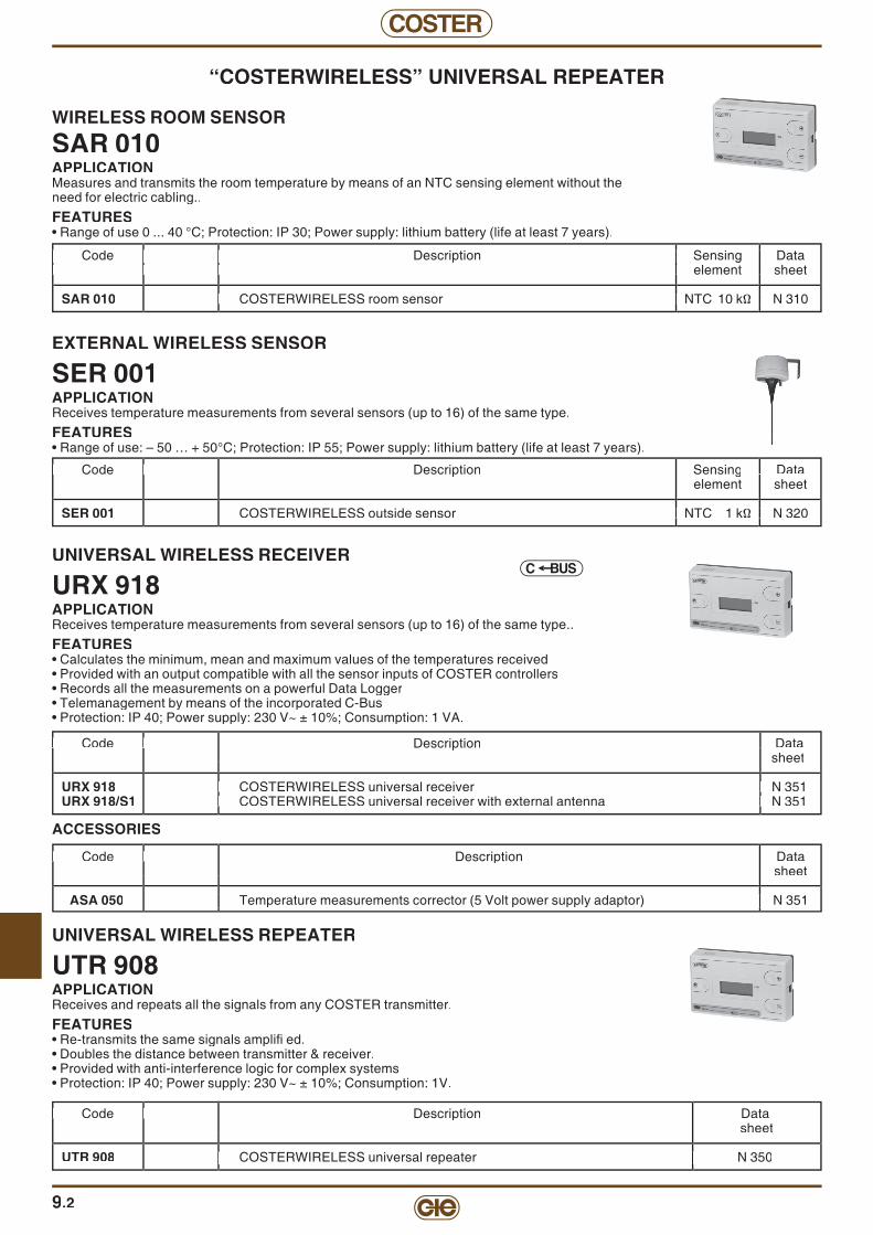
COSTER
9.2
“COSTERWIRELESS” UNIVERSAL REPEATER
WIRELESS ROOM SENSOR
SAR 010APPLICATIONMeasures and transmits the room temperature by means of an NTC sensing element without theneed for electric cabling..
FEATURES• Range of use 0 ... 40 °C; Protection: IP 30; Power supply: lithium battery (life at least 7 years).
Code Description Sensing Data Code Description Sensing Data element sheet element sheet
SAR 010 COSTERWIRELESS room sensor NTC 10 kΩ N 310
Code Description Sensing Data element sheet
COSTERWIRELESS room sensor NTC 10 kΩ N 310
Code Description Sensing Data element sheet
COSTERWIRELESS room sensor NTC 10 kΩ N 310
Code Description Sensing Data element sheet Code Description Sensing Data element sheet
COSTERWIRELESS room sensor NTC 10 kΩ N 310
EXTERNAL WIRELESS SENSOR
SER 001APPLICATIONReceives temperature measurements from several sensors (up to 16) of the same type.
FEATURES• Range of use: – 50 … + 50°C; Protection: IP 55; Power supply: lithium battery (life at least 7 years).
Code Code Description Sensing Data element sheet
SER 001 COSTERWIRELESS outside sensor NTC 1 kΩ N 320
Data
NTC 1 kΩ N 320
Code
NTC 1 kΩ N 320
UNIVERSAL WIRELESS RECEIVER
URX 918APPLICATIONReceives temperature measurements from several sensors (up to 16) of the same type..
FEATURES• Calculates the minimum, mean and maximum values of the temperatures received• Provided with an output compatible with all the sensor inputs of COSTER controllers• Records all the measurements on a powerful Data Logger• Telemanagement by means of the incorporated C-Bus• Protection: IP 40; Power supply: 230 V~ ± 10%; Consumption: 1 VA.
Code Code Description Data sheet
URX 918 COSTERWIRELESS universal receiver N 351URX 918/S1 COSTERWIRELESS universal receiver with external antenna N 351
COSTERWIRELESS universal receiver N 351 COSTERWIRELESS universal receiver with external antenna N 351
Code
COSTERWIRELESS universal receiver N 351 COSTERWIRELESS universal receiver with external antenna N 351
UNIVERSAL WIRELESS REPEATER
UTR 908APPLICATIONReceives and repeats all the signals from any COSTER transmitter.
FEATURES• Re-transmits the same signals amplifi ed.• Doubles the distance between transmitter & receiver.• Provided with anti-interference logic for complex systems• Protection: IP 40; Power supply: 230 V~ ± 10%; Consumption: 1V.
Code Code Description Data sheet
UTR 908 COSTERWIRELESS universal repeater N 350
COSTERWIRELESS universal repeater N 350
Code
COSTERWIRELESS universal repeater N 350
BUSC
ACCESSORIES
Code Code Description Data sheet
ASA 050 Temperature measurements corrector (5 Volt power supply adaptor) N 351
Temperature measurements corrector (5 Volt power supply adaptor) N 351 Temperature measurements corrector (5 Volt power supply adaptor) N 351
Code

9
COSTER
9.3
ROOM TEMPERATURE SENSORS
SAB ... - SCB ... - SCI 110APPLICATIONMonitor room temperature by means of a NTC sensor.N.B : SCB ...and SCI ... sensors must be used with COSTERZONE sysem (RTB ...)FEATURES• Operating range: 0 ... 40 °C; Protection: IP 30.
INDUSTRIAL-TYPE TEMPERATURE SENSORS
SAA ...APPLICATIONMonitor room temperature by means of a NTC sensor. Wall mounting.
FEATURES• Case in shockproof plastic material: 45 x 80 x 35 mm.; Protection: IP 54; Cable entry gland: PG 11.
Code Description Application Sensing Data Code Description Application Sensing Data range element sheet range element sheet
SAA 010 Industrial type temperature sensor. 0 ... 100 °C NTC 10 kΩ N 115SAA 001 Industrial type temperature sensor. – 40 ... 40 °C NTC 1 kΩ N 115
Code Description Application Sensing Data range element sheet
Industrial type temperature Industrial type temperature
Code Description Application Sensing Data range element sheet
. 0 ... 100 °C NTC 10 kΩ N 115 NTC 1 kΩ N 115
Code Description Application Sensing Data range element sheet
Industrial type temperature Industrial type temperature
Code Description Application Sensing Data range element sheet
. 0 ... 100 °C NTC 10 kΩ N 115 NTC 1 kΩ N 115
Code Description Application Sensing Data range element sheet
. 0 ... 100 °C NTC 10 kΩ N 115
Code Description Sensing Data Code Description Sensing Data element sheet element sheet
SAB 010 In wall mounting case 80 x 80 x 32. NTC 10 kΩ N 111SAB 020 With double sensor in wall mounting case 80 x 80 x 32. NTC 20 kΩ N 111SAB 011 With internal setting in wall mounting case 80 x 80 x 32. NTC 10 kΩ N 111SAB 210 With key + 1 hour in wall mounting case 80 x 80 x 32. NTC 10 kΩ N 111SCB 110 With adjuster (–5 ... +5 °C) in wall mountig case 80 x 80 x 32. NTC 10 kΩ N 111SCB 210 With adjuster and key + 1 hour in wall mounting case 80 x 80 x 32. NTC 10 kΩ N 111SAI 010 Irradiated sensor in 80 x 80 x 26 housing for wall mounting NTC 10 kΩ N 111SCI 110 Irradiated sensor + adjuster, in 80 x 80 x 32 housing for wall NTC 10 kΩ N 111
Code Description Sensing Data element sheet
In wall mounting case 80 x 80 x 32. NTC 10 kΩ N 111 With double With internal setting in wall mounting case 80 x 80 x 32. NTC 10 kΩ N 111 With key + 1 hour in wall mounting case 80 x 80 x 32. NTC 10 kΩ N 111 With adjuster (–5 ... +5 °C) in wall mountig case 80 x 80 x 32. NTC 10 kΩ N 111 With adjuster and key + 1 hour in wall mounting case 80 x 80 x 32. NTC 10 kΩ N 111
Irradiated sensor in 80 x 80 x 26 housing for wall mounting NTC 10 kΩ N 111 Irradiated sensor + adjuster, in 80 x 80 x 32 housing for wall NTC 10 kΩ N 111
Code Description Sensing Data element sheet
In wall mounting case 80 x 80 x 32. NTC 10 kΩ N 111 in wall mounting case 80 x 80 x 32. NTC 20 kΩ N 111
With internal setting in wall mounting case 80 x 80 x 32. NTC 10 kΩ N 111 With key + 1 hour in wall mounting case 80 x 80 x 32. NTC 10 kΩ N 111 With adjuster (–5 ... +5 °C) in wall mountig case 80 x 80 x 32. NTC 10 kΩ N 111 With adjuster and key + 1 hour in wall mounting case 80 x 80 x 32. NTC 10 kΩ N 111
Irradiated sensor in 80 x 80 x 26 housing for wall mounting NTC 10 kΩ N 111 Irradiated sensor + adjuster, in 80 x 80 x 32 housing for wall NTC 10 kΩ N 111
Code Description Sensing Data element sheet
In wall mounting case 80 x 80 x 32. NTC 10 kΩ N 111 With double With internal setting in wall mounting case 80 x 80 x 32. NTC 10 kΩ N 111 With key + 1 hour in wall mounting case 80 x 80 x 32. NTC 10 kΩ N 111 With adjuster (–5 ... +5 °C) in wall mountig case 80 x 80 x 32. NTC 10 kΩ N 111 With adjuster and key + 1 hour in wall mounting case 80 x 80 x 32. NTC 10 kΩ N 111
Irradiated sensor in 80 x 80 x 26 housing for wall mounting NTC 10 kΩ N 111 Irradiated sensor + adjuster, in 80 x 80 x 32 housing for wall NTC 10 kΩ N 111
Code Description Sensing Data element sheet
In wall mounting case 80 x 80 x 32. NTC 10 kΩ N 111 in wall mounting case 80 x 80 x 32. NTC 20 kΩ N 111
With internal setting in wall mounting case 80 x 80 x 32. NTC 10 kΩ N 111 With key + 1 hour in wall mounting case 80 x 80 x 32. NTC 10 kΩ N 111 With adjuster (–5 ... +5 °C) in wall mountig case 80 x 80 x 32. NTC 10 kΩ N 111 With adjuster and key + 1 hour in wall mounting case 80 x 80 x 32. NTC 10 kΩ N 111
Irradiated sensor in 80 x 80 x 26 housing for wall mounting NTC 10 kΩ N 111 Irradiated sensor + adjuster, in 80 x 80 x 32 housing for wall NTC 10 kΩ N 111
OUTSIDE TEMPERATURE SENSOR
SAE 001APPLICATIONMonitors room temperature by means of a NTC sensor. Wall mounting.
FEATURES• Case in shockproof plastic material: 45 x 80 x 35 mm.; Protection: IP 54; Cable entry gland: PG 11.
Code Description Application Sensing Data Code Description Application Sensing Data range element sheet range element sheet
SAE 001 Outside temperature sensor. – 40 ... 40 °C NTC 1 kΩ N 120
Code Description Application Sensing Data range element sheet
Outside temperature
Code Description Application Sensing Data range element sheet
NTC 1 kΩ N 120
Code Description Application Sensing Data range element sheet
Outside temperature
Code Description Application Sensing Data range element sheet
NTC 1 kΩ N 120
Code Description Application Sensing Data range element sheet
OUTSIDE TEMPERATURE SENSORS FOR METERING DEGREE-DAYSWITH ANTI-RADIATION THERMAL SCREEN
SGE 001 - SGG 001APPLICATIONMeasurements of outside temperature for metering degree-days. Not infl uenzed by thermal conditions of wall on which installed.Wall mounting with spacer.
FEATURES• Shock-proof plastic enclosure; Protection: IP 54; Cable entry gland: PG 11.
Code Description Range Sensing Data Code Description Range Sensing Data element sheet element sheet
SGE 001 Outside temperature sensor for measurement degree-days. – 40 ... 40 °C– 40 ... 40 °C– NTC 1 kΩ N 121 Compatible with all compensating controllers. Compatible with all compensating controllers.
SGG 001 Outside temp. sensor for measuring degree-days (XGG 618). – 50 ... 40 °C– 50 ... 40 °C– Pt 1 kΩ N 121
Code Description Range Sensing Data element sheet
Compatible with all compensating controllers.
Code Description Range Sensing Data element sheet
Compatible with all compensating controllers.
Code Description Range Sensing Data element sheet
N 121
N
Code Description Range Sensing Data element sheet Code Description Range Sensing Data element sheet

COSTER
9.4
CABLE-TYPE TEMPERATURE SENSOR (WITHOUT POCKET)
SAF ... - SHF ...APPLICATIONMeasures the temperature by means of an NTC sensing element protected by a brass sheath and connected directly to a bipolar cable.THESE SENSORS MUST BE FITTED WITH TYPE GIS ... POCKETS AND WITH TYPE ACM 103 TERMONAL BLOCK.FEATURES• Standard connecting cable: 2 x 0.5 mm2 x 1.5 m.
Code Description Application Sensing Data Code Description Application Sensing Data range element sheet range element sheet
SAF 010 Cable-type temperature sensor. 0 ... 100 °C NTC 10 kΩ N 145SAF 110 Duble cable-type temperature sensor (2 sensors-4 wires). 0 ... 100 °C 2 NTC 10 kΩ N 145SAF 001 Cable-type temperature sensor. –40 ... 40 °C NTC 1 kΩ N 145SHF 001 Cable-type temperature sensor with 3-metre cable. 0 ... 180 °C Pt 1 kΩ N 145
Code Description Application Sensing Data range element sheet
Cable-type temperature sensor. 0 ... 100 °C NTC 10 kΩ N 145 Duble cable-type temperature sensor (2 sensors-4 wires). 0 ... 100 °C 2 NTC 10 kΩ N 145 Cable-type temperature sensor. Cable-type temperature sensor with 3-metre cable. 0 ... 180 °C Pt 1 kΩ N 145
Code Description Application Sensing Data range element sheet
Cable-type temperature sensor. 0 ... 100 °C NTC 10 kΩ N 145 Duble cable-type temperature sensor (2 sensors-4 wires). 0 ... 100 °C 2 NTC 10 kΩ N 145
NTC 1 kΩ N 145 Cable-type temperature sensor with 3-metre cable. 0 ... 180 °C Pt 1 kΩ N 145
Code Description Application Sensing Data range element sheet
Cable-type temperature sensor. 0 ... 100 °C NTC 10 kΩ N 145 Duble cable-type temperature sensor (2 sensors-4 wires). 0 ... 100 °C 2 NTC 10 kΩ N 145
Cable-type temperature sensor with 3-metre cable. 0 ... 180 °C Pt 1 kΩ N 145
IMMERSION TEMPERATURE SENSORS (WITHOUT POCKET)
SIH 010 - STH 001 - SIR 010APPLICATIONMeasure the temperature of the circulating fl uid in a pipe by means of a sensor housed in a brass sheath immersed in a threaded pocket insert in the pipe.
FEATURES• Shock-proof plastic case: 45 x 80 x 35; Protection: IP54; Cable entry gland: PG11.• Brass or stainless steel well: 1/2" x 80 mm (*); Sensor pocket: Ø 7 x 68 mm.(*) Length shown includes 15 mm threading.
Code Description Application Sensing Data Code Description Application Sensing Data range element sheet range element sheet
SIH 010 Immersion sensor with brass pocket. 0 ... 100 °C NTC 10 kΩ N 140SIH 010/Inox Immersion sensor with stain. steel pocket. 0 ... 100 °C NTC 10 kΩ N 140SIR 010 Direct immersion rapid sensor. 0 ... 100 °C NTC 10 kΩ N 140STH 001 Immersion sensor with stain. steel pocket. 0 ... 300 °C Pt 1 kΩ N 140
Code Description Application Sensing Data range element sheet
Immersion sensor with brass pocket. 0 ... 100 °C NTC 10 kΩ N 140 Immersion sensor with stain. steel pocket. 0 ... 100 °C NTC 10 kΩ N 140
Direct immersion rapid sensor. 0 ... 100 °C NTC 10 kΩ N 140 Immersion sensor with stain. steel pocket. 0 ... 300 °C Pt 1 kΩ N 140
ACCESSORIES
Code Description Data Code Description Data sheet sheet
GIS 090 Brass pocket 1/2” x 90 mm (*) including grommet. N 145GIS 090/Inox Stainless steel pocket 1/2” x 90 mm (*) including grommet. N 145GIS 160 Brass pocket 1/2” x 160 mm (*) including grommet. N 145GIS 160/Inox Stainless steel pocket 1/2” x 160 mm (*) including grommet. N 145GIS 500 Brass pocket 1/2” x 500 mm (*) including grommet. N 145GIS 500/Inox Stainless steel pocket 1/2” x 500 mm (*) including grommet. N 145
(*) Length shown includes 15 mm threading.APS 150 Extension pocket (15 cm) for fl uid temperature > 130 °C. –ACM 103 Housing terminal block and adapter for old-type Coster pockets. –
Code Description Data sheet
including grommet. N 145 N 145
N 145 N 145
N 145 N 145
Code Description Data sheet
Brass pocket 1/2” x 90 mm Stainless steel pocket 1/2” x 90 mm
Brass pocket 1/2” x 160 mm Stainless steel pocket 1/2” x 160 mm
Brass pocket 1/2” x 500 mm Stainless steel pocket 1/2” x 500 mm
Extension pocket (15 cm) for fl uid temperature > 130 °C. Housing terminal block and adapter for old-type Coster pockets.
ACCESSORIES
Code Description Data Code Description Data sheet sheet
APV 100 Accessory for adapting to old Coster pockets. –
Code Description Data sheet
Accessory for adapting to old Coster pockets.
Code Description Data sheet Code Description Data sheet
Accessory for adapting to old Coster pockets.
SPECIAL VERSIONS
Code Description Code Description
– ALL THE CABLE TYPE TEMPERATURE SensorS (EXCEPT SHF 001) HAVE A STANDARD ALL THE CABLE TYPE TEMPERATURE SensorS (EXCEPT SHF 001) HAVE A STANDARD CABLE LENGTH OF 1.5 METRES. CABLE LENGTH OF 1.5 METRES. FOR LONGER CABLES (UP FOR LONGER CABLES (UP TO 10 METRES) THE EXTRA CHARGE.
Code Description
CABLE LENGTH OF 1.5 METRES. FOR LONGER CABLES (UP
Code Description
CABLE LENGTH OF 1.5 METRES. FOR LONGER CABLES (UP

9
COSTER
TEMPERATURE SENSOR FOR IET 7... INTEGRATORS
SPT ...Connected to IET 7... integrators, SPT… sensors measure send and return temperatures (T° delta) in hydraulic circuits, to calculate heating and cooling energySensors and accessories compliant with directive MID 2004/22/CESensor cables must not be lengthened or shortenedTECHNICAL DATA• Conductor sections 2 x 0,35 mm2
• Cable length See table• Protection IP 54• Time constant : 25 seconds with pockets
4 seconds with direct immersion
Code Description Application range
Sensings element
Datasheet
SPT 001 Pair of sensors with 75-centimetre cable 0 ... 150 °C Pt 1000 N 146
SPT 031 Pair of sensors with 3-metre cable 0 ... 150 °C Pt 1000 N 146
SPT 101 Pair of sensors with 10-metre cable 0 ... 150 °C Pt 1000 N 146
Accessories for assembly with pockets or direct immersion Code Description Attacchi Tubazione
DNProfondità
+ fi letto
GIS 062 Pair of brass pockets for sensors.. 1/4" 1" 1/4 ... 4" 62 + 18
GIS 112 Pair of brass pockets for sensors. 1/4" oltre i 4" 112 + 18
Code Description Joints DNpipe
Overall dimensions
GIS 001 Pair of kits for direct immersion sensor assembly. 1/2" max 1" –
ART 015 Pair of T-joints for kit GIS 001. 1/2” 1/2” 56 mm
ART 020 Pair of T-joints for kit GIS 001. 3/4” 3/4” 56 mm
ART 025 Pair of T-joints for kit GIS 001. 1” 1” 62 mm
ACCESSORIES FOR DIRECT IMMERSION ASSEMBLY• GIS 001 + ART ... Pair of direct immersion sensor assembly kits using T-joints (see N 146 data sheet)
9.5
TEMPERATURE SENSORS FOR HEATING/COOLING COILS
STT 010APPLICATIONMonitors temperature of the air intake of fan coils by means of a NTC sensor directly connected with a dual pole cable. For easy mounting a fl exible support is provided.
FEATURES• Connecting cable: 2 x 0.5 mm2 x 1.5 m.
Code Description Application Sensing Data Code Description Application Sensing Data range element sheet range element sheet
STT 010 Temperature sensor for fan-coil. 0 ... 40 °C NTC 10 kΩ N 155
Code Description Application Sensing Data range element sheet
Temperature sensor for fan-coil. 0 ... 40 °C NTC 10 kΩ N 155
Code Description Application Sensing Data range element sheet
Temperature sensor for fan-coil. 0 ... 40 °C NTC 10 kΩ N 155
Code Description Application Sensing Data range element sheet
Temperature sensor for fan-coil. 0 ... 40 °C NTC 10 kΩ N 155
Code Description Application Sensing Data range element sheet
Temperature sensor for fan-coil. 0 ... 40 °C NTC 10 kΩ N 155
Code Description Application Sensing Data range element sheet
Temperature sensor for fan-coil. 0 ... 40 °C NTC 10 kΩ N 155
SURFACE TEMPERATURE SENSOR
SCH 010APPLICATIONMeasures the temperature in a pipe with a NTC sensing element housed in a brass plate fi xed in contact with the pipe.
FEATURES• Shock-proof plastic case: 45 x 80 x 32 mm.; Protection: IP 54; Cable entry gland: PG 11.
Code Description Application Sensing Data Code Description Application Sensing Data range element sheet range element sheet
SCH 010 Surface temperature sensor. 0 ... 100 °C NTC 10 kΩ N 130
Code Description Application Sensing Data range element sheet
Surface temperature sensor. 0 ... 100 °C NTC 10 kΩ N 130
Code Description Application Sensing Data range element sheet
Surface temperature sensor. 0 ... 100 °C NTC 10 kΩ N 130
Code Description Application Sensing Data range element sheet
Surface temperature sensor. 0 ... 100 °C NTC 10 kΩ N 130
Code Description Application Sensing Data range element sheet
Surface temperature sensor. 0 ... 100 °C NTC 10 kΩ N 130
Code Description Application Sensing Data range element sheet
Surface temperature sensor. 0 ... 100 °C NTC 10 kΩ N 130
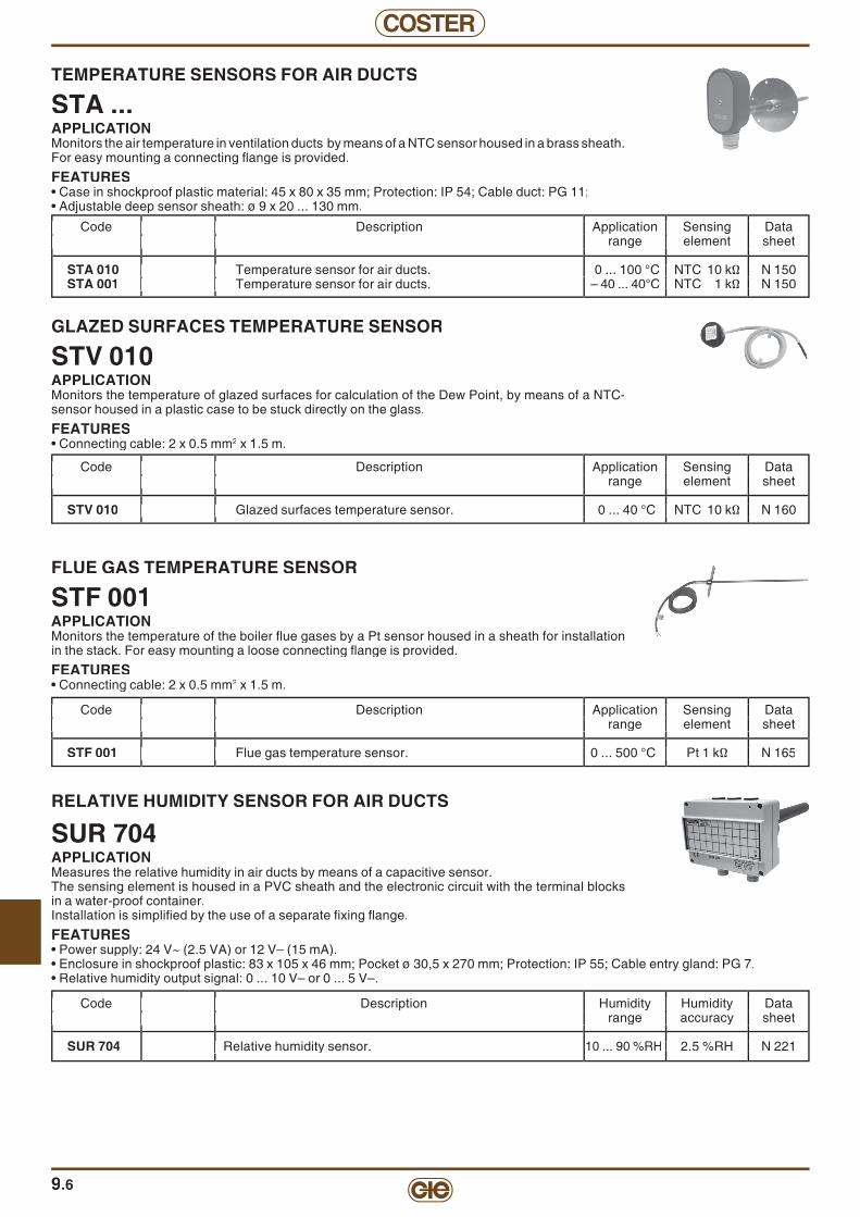
COSTER
9.6
GLAZED SURFACES TEMPERATURE SENSOR
STV 010APPLICATIONMonitors the temperature of glazed surfaces for calculation of the Dew Point, by means of a NTC-sensor housed in a plastic case to be stuck directly on the glass.
FEATURES• Connecting cable: 2 x 0.5 mm2 x 1.5 m.
FLUE GAS TEMPERATURE SENSOR
STF 001APPLICATIONMonitors the temperature of the boiler fl ue gases by a Pt sensor housed in a sheath for installation in the stack. For easy mounting a loose connecting fl ange is provided.
FEATURES• Connecting cable: 2 x 0.5 mm2 x 1.5 m.
TEMPERATURE SENSORS FOR AIR DUCTS
STA ...APPLICATIONMonitors the air temperature in ventilation ducts by means of a NTC sensor housed in a brass sheath.For easy mounting a connecting fl ange is provided.
FEATURES• Case in shockproof plastic material: 45 x 80 x 35 mm; Protection: IP 54; Cable duct: PG 11;• Adjustable deep sensor sheath: ø 9 x 20 ... 130 mm.
Code Description Application Sensing Data Code Description Application Sensing Data range element sheet range element sheet
STA 010 Temperature sensor for air ducts. 0 ... 100 °C NTC 10 kΩ N 150STA 001 Temperature sensor for air ducts. – 40 ... 40°C NTC 1 kΩ N 150
Code Description Application Sensing Data range element sheet
Temperature sensor for air ducts. 0 ... 100 °C NTC 10 kΩ N 150 Temperature sensor for air ducts.
Code Description Application Sensing Data range element sheet
Temperature sensor for air ducts. 0 ... 100 °C NTC 10 kΩ N 150 NTC 1 kΩ N 150
Code Description Application Sensing Data range element sheet
Temperature sensor for air ducts. 0 ... 100 °C NTC 10 kΩ N 150 Temperature sensor for air ducts.
Code Description Application Sensing Data range element sheet
Temperature sensor for air ducts. 0 ... 100 °C NTC 10 kΩ N 150 NTC 1 kΩ N 150
Code Description Application Sensing Data range element sheet
Temperature sensor for air ducts. 0 ... 100 °C NTC 10 kΩ N 150
Code Description Application Sensing Data Code Description Application Sensing Data range element sheet range element sheet
STV 010 Glazed surfaces temperature sensor. 0 ... 40 °C NTC 10 kΩ N 160
Code Description Application Sensing Data range element sheet
Glazed surfaces temperature sensor. 0 ... 40 °C NTC 10 kΩ N 160
Code Description Application Sensing Data range element sheet
Glazed surfaces temperature sensor. 0 ... 40 °C NTC 10 kΩ N 160
Code Description Application Sensing Data range element sheet
Glazed surfaces temperature sensor. 0 ... 40 °C NTC 10 kΩ N 160
Code Description Application Sensing Data range element sheet
Glazed surfaces temperature sensor. 0 ... 40 °C NTC 10 kΩ N 160
Code Description Application Sensing Data range element sheet
Glazed surfaces temperature sensor. 0 ... 40 °C NTC 10 kΩ N 160
Code Description Application Sensing Data Code Description Application Sensing Data range element sheet range element sheet
STF 001 Flue gas temperature sensor. 0 ... 500 °C Pt 1 kΩ N 165
Code Description Application Sensing Data range element sheet
Flue gas temperature sensor. 0 ... 500 °C Pt 1 kΩ N 165
Code Description Application Sensing Data range element sheet
Flue gas temperature sensor. 0 ... 500 °C Pt 1 kΩ N 165
Code Description Application Sensing Data range element sheet
Flue gas temperature sensor. 0 ... 500 °C Pt 1 kΩ N 165
Code Description Application Sensing Data range element sheet
Flue gas temperature sensor. 0 ... 500 °C Pt 1 kΩ N 165
Code Description Application Sensing Data range element sheet
Flue gas temperature sensor. 0 ... 500 °C Pt 1 kΩ N 165
RELATIVE HUMIDITY SENSOR FOR AIR DUCTS
SUR 704APPLICATIONMeasures the relative humidity in air ducts by means of a capacitive sensor. The sensing element is housed in a PVC sheath and the electronic circuit with the terminal blocks in a water-proof container.Installation is simplifi ed by the use of a separate fi xing fl ange.
FEATURES• Power supply: 24 V~ (2.5 VA) or 12 V– (15 mA).• Enclosure in shockproof plastic: 83 x 105 x 46 mm; Pocket ø 30,5 x 270 mm; Protection: IP 55; Cable entry gland: PG 7.• Relative humidity output signal: 0 ... 10 V– or 0 ... 5 V–.
Code Description Humidity Humidity Data Code Description Humidity Humidity Data range accuracy sheet range accuracy sheet
SUR 704 Relative humidity sensor. 10 ... 90 %RH 2.5 %RH N 221
Code Description Humidity Humidity Data range accuracy sheet
Relative humidity sensor.
Code Description Humidity Humidity Data range accuracy sheet
2.5 %RH N 221
Code Description Humidity Humidity Data range accuracy sheet Code Description Humidity Humidity Data range accuracy sheet
2.5 %RH N 221
Code Description Humidity Humidity Data range accuracy sheet
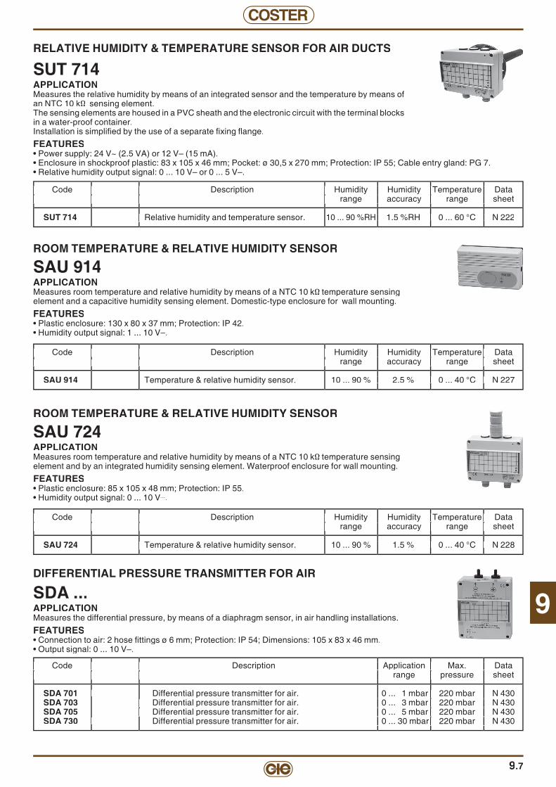
9
COSTER
9.7
RELATIVE HUMIDITY & TEMPERATURE SENSOR FOR AIR DUCTS
SUT 714APPLICATIONMeasures the relative humidity by means of an integrated sensor and the temperature by means of an NTC 10 kΩ sensing element. The sensing elements are housed in a PVC sheath and the electronic circuit with the terminal blocks in a water-proof container.Installation is simplifi ed by the use of a separate fi xing fl ange.
FEATURES• Power supply: 24 V~ (2.5 VA) or 12 V– (15 mA).• Enclosure in shockproof plastic: 83 x 105 x 46 mm; Pocket: ø 30,5 x 270 mm; Protection: IP 55; Cable entry gland: PG 7.• Relative humidity output signal: 0 ... 10 V– or 0 ... 5 V–.
Code Description Humidity Humidity Temperature Data Code Description Humidity Humidity Temperature Data range accuracy range sheet range accuracy range sheet
SUT 714 Relative humidity and temperature sensor. 10 ... 90 %RH 1.5 %RH 0 ... 60 °C N 222
Code Description Humidity Humidity Temperature Data range accuracy range sheet
Relative humidity and temperature sensor.
Code Description Humidity Humidity Temperature Data range accuracy range sheet
1.5 %RH 0 ... 60 °C N 222
Code Description Humidity Humidity Temperature Data range accuracy range sheet Code Description Humidity Humidity Temperature Data range accuracy range sheet
1.5 %RH 0 ... 60 °C N 222
Code Description Humidity Humidity Temperature Data range accuracy range sheet
1.5 %RH 0 ... 60 °C N 222
Code Description Humidity Humidity Temperature Data range accuracy range sheet
ROOM TEMPERATURE & RELATIVE HUMIDITY SENSOR
SAU 914APPLICATIONMeasures room temperature and relative humidity by means of a NTC 10 kΩ temperature sensing element and a capacitive humidity sensing element. Domestic-type enclosure for wall mounting.
FEATURES• Plastic enclosure: 130 x 80 x 37 mm; Protection: IP 42.• Humidity output signal: 1 ... 10 V–.
ROOM TEMPERATURE & RELATIVE HUMIDITY SENSOR
SAU 724APPLICATIONMeasures room temperature and relative humidity by means of a NTC 10 kΩ temperature sensing element and by an integrated humidity sensing element. Waterproof enclosure for wall mounting.
FEATURES• Plastic enclosure: 85 x 105 x 48 mm; Protection: IP 55.• Humidity output signal: 0 ... 10 V–.
Code Description Humidity Humidity Temperature Data Code Description Humidity Humidity Temperature Data range range accuracy range sheet
SAU 914 Temperature & relative humidity sensor. 10 ... 90 % 2.5 % 0 ... 40 °C N 227
Code Description Humidity Humidity Temperature Data range Code Description Humidity Humidity Temperature Data
range sheet
2.5 % 0 ... 40 °C N 22
Code Description Humidity Humidity Temperature Data range Code Description Humidity Humidity Temperature Data
range sheet
2.5 % 0 ... 40 °C N 22
Code Description Humidity Humidity Temperature Data
2.5 % 0 ... 40 °C N 22
Code Description Humidity Humidity Temperature Data range
Code Description Humidity Code Description Humidity Humidity Temperature Data range accuracy range sheet range accuracy range sheet
SAU 724 Temperature & relative humidity sensor. 10 ... 90 % 1.5 % 0 ... 40 °C N 228
Code Description Humidity range accuracy range sheet
Temperature & relative humidity sensor.
Temperature Data range accuracy range sheet
1.5 % 0 ... 40 °C N 22
Code Description Humidity range accuracy range sheet
Temperature Data range accuracy range sheet
1.5 % 0 ... 40 °C N 22
range accuracy range sheet
1.5 % 0 ... 40 °C N 22
Code Description Humidity range accuracy range sheet
DIFFERENTIAL PRESSURE TRANSMITTER FOR AIR
SDA ...APPLICATIONMeasures the differential pressure, by means of a diaphragm sensor, in air handling installations.
FEATURES• Connection to air: 2 hose fi ttings ø 6 mm; Protection: IP 54; Dimensions: 105 x 83 x 46 mm.• Output signal: 0 ... 10 V–.
Code Description Application Max. Data Code Description Application Max. Data range pressure sheet range pressure sheet
SDA 701 Differential pressure transmitter for air. 0 ... 1 mbar 220 mbar N 430SDA 703 Differential pressure transmitter for air. 0 ... 3 mbar 220 mbar N 430SDA 705 Differential pressure transmitter for air. 0 ... 5 mbar 220 mbar N 430SDA 730 Differential pressure transmitter for air. 0 ... 30 mbar 220 mbar N 430
Code Description Application Max. Data range pressure sheet
Differential pressure transmitter for air. 0 ... 3 mbar 220 mbar N 430 Differential pressure transmitter for air. 0 ... 5 mbar 220 mbar N 430
Code Description Application Max. Data range pressure sheet
Differential pressure transmitter for air. 0 ... 1 mbar 220 mbar N 430 Differential pressure transmitter for air. 0 ... 3 mbar 220 mbar N 430 Differential pressure transmitter for air. 0 ... 5 mbar 220 mbar N 430
Differential pressure transmitter for air. 0 ... 30 mbar 220 mbar N 430
Code Description Application Max. Data range pressure sheet
SDA 701
SDA 730
Code Description Application Max. Data range pressure sheet
Differential pressure transmitter for air. 0 ... 1 mbar 220 mbar N 430 Differential pressure transmitter for air. 0 ... 3 mbar 220 mbar N 430 Differential pressure transmitter for air. 0 ... 5 mbar 220 mbar N 430
Differential pressure transmitter for air. 0 ... 30 mbar 220 mbar N 430
Code Description Application Max. Data range pressure sheet
Differential pressure transmitter for air. 0 ... 1 mbar 220 mbar N 430 Differential pressure transmitter for air. 0 ... 3 mbar 220 mbar N 430 Differential pressure transmitter for air. 0 ... 5 mbar 220 mbar N 430
Differential pressure transmitter for air. 0 ... 30 mbar 220 mbar N 430

COSTER
9.8
PRESSURE TRANSMITTER FOR LIQUIDS AND STEAM
SPW ...APPLICATIONFor pressure detection in liquid mediums for the airconditioning,heating and water technic.
FEATURES• Pipe connection: male 1/2"; • Protection: IP 65; Output signal: 0 ... 10 V–.
DIFFERENTIAL PRESSURE TRANSMITTER FOR LIQUIDS
SDW ...APPLICATIONMeasures the differential pressure, by means of a ceramic sensor, in hot or cold water plants.
FEATURES• Piping connection: two 1/8" screwed female; When the fl uid temperature is higher than 80 °C a spiral spacer has to be used.• Protection: IP 54; Output signal: 0 ... 10 V–.
Code Description Application Max. Data Code Description Application Max. Data range pressure sheet range pressure sheet
SPW 204 Pressure transmitter for liquids and steam. 0 ... 4 bar ??? N ...SPW 210 Pressure transmitter for liquids and steam. 0 ... 10 bar ??? N ...SPW 216 Pressure transmitter for liquids and steam. 0 ... 16 bar ??? N ...
Code Description Application Max. Data range pressure sheet
Pressure transmitter for liquids and steam. 0 ... 4 bar ??? N ... Pressure transmitter for liquids and steam. 0 ... 10 bar ??? N ... Pressure transmitter for liquids and steam. 0 ... 16 bar ??? N
Code Description Application Max. Data range pressure sheet
Pressure transmitter for liquids and steam. 0 ... 4 bar ??? N ... Pressure transmitter for liquids and steam. 0 ... 10 bar ??? N ... Pressure transmitter for liquids and steam. 0 ... 16 bar ??? N
Code Description Application Max. Data range pressure sheet Code Description Application Max. Data range pressure sheet
Pressure transmitter for liquids and steam. 0 ... 4 bar ??? N ... Pressure transmitter for liquids and steam. 0 ... 10 bar ??? N ... Pressure transmitter for liquids and steam. 0 ... 16 bar ??? N
Code Description Application Max. Data range pressure sheet
Pressure transmitter for liquids and steam. 0 ... 4 bar ??? N ... Pressure transmitter for liquids and steam. 0 ... 10 bar ??? N ... Pressure transmitter for liquids and steam. 0 ... 16 bar ??? N
Code Description Application Max. Data Code Description Application Max. Data range pressure sheet range pressure sheet
SDW 201 SDW 201 Differential pressure transmitter for liquids. 0 ... 1 bar ???? N ... SDW 202 SDW 202 Differential pressure transmitter for liquids. 0 ... 2.5 bar ???? N ... SDW 206 SDW 206 Differential pressure transmitter for liquids. 0 ... 6 bar ???? N ...
Code Description Application Max. Data range pressure sheet Code Description Application Max. Data range pressure sheet
Differential pressure transmitter for liquids. 0 ... 1 bar ???? N ...Differential pressure transmitter for liquids. 0 ... 2.5 bar ???? N ...Differential pressure transmitter for liquids. 0 ... 6 bar ???? N
Code Description Application Max. Data range pressure sheet
SDW 201 SDW 202 SDW 206
Code Description Application Max. Data range pressure sheet
Differential pressure transmitter for liquids. 0 ... 1 bar ???? N ...Differential pressure transmitter for liquids. 0 ... 2.5 bar ???? N ...Differential pressure transmitter for liquids. 0 ... 6 bar ???? N
Code Description Application Max. Data range pressure sheet
Differential pressure transmitter for liquids. 0 ... 1 bar ???? N ...Differential pressure transmitter for liquids. 0 ... 2.5 bar ???? N ...Differential pressure transmitter for liquids. 0 ... 6 bar ???? N
REMOTE CONTROLS
CDB ...APPLICATIONResetting units for physical values control and change of programme in use.
FEATURES• Case in shockproof plastic material: 80 x 80 x 26 mm. Wall mounting.
Code Description Compatible controllers Application Data range sheet range sheet
CDB 100 Temperature setpoint adjuster with DRU 314 / 614; DTF / RTF 31; –5 ... +5 °C N 710 NTC 10 kΩ room sensor. DTT 318; RTB 645; XTU 614 / 618; XTU 644; XTU 664 XTA 624; XTR 628;
CDB 200 Humidity setpoint adjuster NTC 10 kΩ room sensor. XTU 614; XTU 644; XTU 664. –10 ... +10 % N 710
CDB 300 Change of programme in use. RTC 604; RTE 643; XTP 600. – N 710 XTT 608; XTE 611; XTE 600 / 602; XSE 600 / 602.
CDB 300/ CDB 300/S1 Change of programme in use with RTC 604; RTE 643; XTP 600. NTC 10 kΩ room sensor XTT 608; XTE 611; – N 710 XTE 600 / 602; XSE 600 / 602.
CDB 301 Change of programme (DIN 3 units). RTC 604; RTE 643; XTP 600. – N 711 XTT 608; XTE 611; XTE 600 / 602; XSE 600 / 602.
CDB 333 Change of programme in use. XCS 633; XSS 633; XTU 618. – N 710
CDB 340 Temperature setpoint adjuster. RTE 98. –5 ... +5 °C N 710
Description range sheet
Application Data range sheet
–5 ... +5 °C N 710
– N 711
Description range sheet
Application Data range sheet
–5 ... +5 °C N 710
–10 ... +10 %
–
– N 711
–
–5 ... +5 °C
range sheet
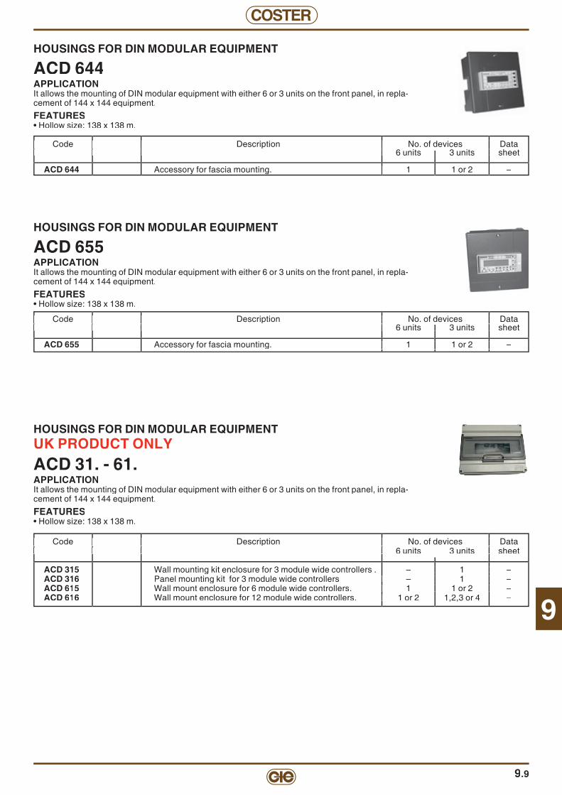
9
COSTER
HOUSINGS FOR DIN MODULAR EQUIPMENT
ACD 655APPLICATIONIt allows the mounting of DIN modular equipment with either 6 or 3 units on the front panel, in repla-cement of 144 x 144 equipment.
FEATURES• Hollow size: 138 x 138 m.
Code Description No. of devices Data Code Description No. of devices Data 6 units 3 units sheet 6 units 3 units sheet
ACD 655 Accessory for fascia mounting. 1 1 or 2 –
Code Description No. of devices Data 6 units 3 units sheet Code Description No. of devices Data 6 units 3 units sheet
Accessory for fascia mounting. 1 1 or 2 –
Code Description No. of devices Data 6 units 3 units sheet 6 units 3 units sheet
Accessory for fascia mounting. 1 1 or 2 –
Code Description No. of devices Data 6 units 3 units sheet
Accessory for fascia mounting. 1 1 or 2 –
9.9
HOUSINGS FOR DIN MODULAR EQUIPMENT
ACD 644APPLICATIONIt allows the mounting of DIN modular equipment with either 6 or 3 units on the front panel, in repla-cement of 144 x 144 equipment.
FEATURES• Hollow size: 138 x 138 m.
Code Description No. of devices Data Code Description No. of devices Data 6 units 3 units sheet 6 units 3 units sheet
ACD 644 Accessory for fascia mounting. 1 1 or 2 –
Code Description No. of devices Data 6 units 3 units sheet Code Description No. of devices Data 6 units 3 units sheet
Accessory for fascia mounting. 1 1 or 2 –
Code Description No. of devices Data 6 units 3 units sheet 6 units 3 units sheet
Accessory for fascia mounting. 1 1 or 2 –
Code Description No. of devices Data 6 units 3 units sheet
Accessory for fascia mounting. 1 1 or 2 –
HOUSINGS FOR DIN MODULAR EQUIPMENT UK PRODUCT ONLYACD 31. - 61.APPLICATIONIt allows the mounting of DIN modular equipment with either 6 or 3 units on the front panel, in repla-cement of 144 x 144 equipment.
FEATURES• Hollow size: 138 x 138 m.
Code Description No. of devices Data Code Description No. of devices Data 6 units 3 units sheet 6 units 3 units sheet
ACD 315 Wall mounting kit enclosure for 3 module wide controllers . – 1 –ACD 316 Panel mounting kit for 3 module wide controllers – 1 –ACD 615 Wall mount enclosure for 6 module wide controllers. 1 1 or 2 –ACD 616 Wall mount enclosure for 12 module wide controllers. 1 or 2 1,2,3 or 4 –
Code Description No. of devices Data 6 units 3 units sheet Code Description No. of devices Data 6 units 3 units sheet
1 – – 1 –
. 1 1 or 2 –
Code Description No. of devices Data 6 units 3 units sheet
1 – – 1 –
. 1 1 or 2 –
Code Description No. of devices Data 6 units 3 units sheet
– 1 –. 1 1 or 2 –
. 1 or 2

COSTER
9.10
TEMPERATURE - RESISTANCE DIAGRAM FOR Ni 100 Ω SENSORS
TEMPERATURE - RESISTANCE DIAGRAM FOR Pt 1 kΩ SENSORS
IS NOT LONGER MANUFACTUR
CODE:
SAA 100SAB 100SAC 100SAE 100SAF 100SCH 100SIH 100STA 100
CODE:
SGG 001SHF 001STF 001STH 001
-1590
-20 -10 0-5 5 1510 20 3025 35 4540 50
95
100
105
110
115
120
125
130
135
140
145
150
155
160
165
55 60 65 70 75 80 85 90 95 100
Temperature °C
1,000250 50 10075 125 175150 200 250225 275 325300 350 375 425400 450 475 500
1,100
1,200
1,300
1,400
1,500
1,600
1,700
1,800
1,900
2,000
2,100
2,200
2,300
2,400
2,500
2,600
2,700
2,800
2,900
3,000
Temperature °C

9
COSTER
9.11
TEMPERATURE - RESISTANCE DIAGRAM FOR NTC 1 kΩ SENSORS
TEMPERATURE - RESISTANCE DIAGRAM FOR NTC 10 kΩ SENSORS
CODE:
SAA 001SAE 001SAF 001SGE 001STA 001
CODE:
SAA 010SAB 010SAB 011SAB 210SAF 010SAF 110SAU 012SCB 110SCB 210SCH 010SHF 010SIH 010SIR 010STA 010STT 010STV 010
-25500
-30 -20 -10-15 -5 50 10 2015 25 3530 40
1,000
1,500
2,000
2,500
3,000
3,500
4,000
4,500
5,000
5,500
6,000
6,500
7,000
7,500
8,000
8,500
9,000
Temperature °C
50 10 2015 25 3530 40 5045 55 6560 70 75 8580 90 95 1000
2
4
6
8
10
12
14
16
18
20
22
24
26
28
30
k
Temperature °C

COSTER
NOTES
9.12

10
COSTER
10.1
Description Code Communication Page
"TELECOSTER" TELEMANAGEMENT SYSTEM FOR BOILER PLANTS"THE SYSTEM PERMITS TELEMANAGING, FROM A CENTRAL COMPUTER, ALL THE CONTROL DEVICES IN THE PLANTS AND FACILITATES THE PROVISION OF A COMFORTABLE TEMPERATURE & HUMIDITY IN ALL THE OFFICES AND/OR DWELLINGS
CONCERNED. ALL ALARMS ARE ACQUIRED AND LOGGED AND CAN BE FORWARDED VOCALLY TO CELLULAR TELEPHONESON THE MONITORE ARE DISPLAYED ALL IMPORTANT VALUES E.G. TEMPERATURE, GAS OIL LEVEL, PLANT PRESSURE, ETC.
TELEMANAGEMENT SOFTWAREAPPLICATION SOFTWARE FOR MANAGING COMMUNICATIONS BETWEEN THECENTRAL COMPUTER AND THE BOILER PLANTS CONNECTED VIA MODEM - TELEPHONE LINE OR DIRECTLY.
SWC 701 10.4
MODEM ANALOGUE LINES, GSM & UNITS FOR ETHERNETCENTRAL DESKTOP MODEM: WITH VOCAL FORWARDING CONNECTS CENTRAL COMPUTER TO ANALOGUE TELEPHONE LINE. MCV 712 RS 232 10.4
GSM CENTRAL OR REMOTE MODEM CONNECTS DIRECTLY THE CENTRAL TELEMANAGEMENT COMPUTER TO THE GSMTELEPHONE LINE OR, BY MEANS OF AN RS 232 / C-BUS CONVERTOR, THE REMOTECOSTER DEVICES WITH C-BUS AND/OR RS 232.
GSM 723 RS 232 10.5
MINI TELEMANAGEMENT KIT INCLUDING GSM MODEM (SINGLE PACKAGE) TELEMANAGEMENT RS232: ALREADY ENABLED BY THE KIT. TELEMANAGEMENT C-BUS: CAN BE ENABLED WITH ACB 400 ACCESSORY.
XCO 428 +GSM 723
OPTIONAL
BUSC RS 232 10.5
GSM DESKTOP MODEM FOR USB CONNECTION CONNECTS THE CENTRAL COMPUTER, VIA USB CABLE, TO GSM TELEPHONE LINE. GSM 724 RS 232 10.5
REMOTE GSM DUAL BAND MODEM CONNECTS COSTER REMOTE DEVICES WITH C-BUS AND/OR RS 232 TO TE GSM (900/1, 800 MHz).
GSM 648 BUSC RS 232 10.6
REMOTE PANEL-MOUNTING MODEM CONNECTS COSTER REMOTE DEVICES BY C-BUS AND/OR RS 232 TO A DEDICATED ANALOGUE TELEPHONE LINE.
MPD 412 BUSC RS 232 10.6
AMPLIFIER & CONVERTORS FOR C-BUSMEDIUM-POWER C-BUS AMPLIFIER & INTERFACE CONVERTOR AMPLIFIES C-BUS SIGNAL (MAX. 239 DEVICES IN MAX. IN 7 Km LINE). PCB 332 BUSC RS 232 10.8
HIGH-POWER C-BUS AMPLIFIER & INTERFACE CONVERTOR AMPLIFIES C-BUS SIGNAL (MAX. 239 DEVICES IN MAX. IN 7 Km LINE). PCB 432 BUSC RS 232 10.8
CONVERTOR C-BUS - "SLAVE" TO RS 232 (3 DIN ENCLOSURE) A UNIT MOUNTED, ON 3 DIN ENCLOSURE, WHICH PERMITS CONNECTION OF ANY DEVICE WITH C-BUS TO A MODEM OR A PC..
ACB 332 BUSC RS 232 10.14
ETHERNET - C-BUS CONVERTOR CONNECTS COSTER REMOTE DEVICES WITH C-BUS TO ETHERNET NETWORK ARE 338 BUSC 10.6
RADIO MODEM WIRELESS BLUETOOTH CONVERTS C-BUS TO BLUETOOTH MODE & PERMITS EXTENDING THE C-BUS NETWORK VIA RADIO.
CBR 118 BUSC 10.8
CONVERTOR CABLE C-BUS - "SLAVE" TO RS 232 FOR PC)A UNIT, ATTACHED TO A CABLE, WHICH PERMITS CONNECTING ANY DEVICE WITH C-BUS TO A PC (NOT TO A MODEM).
ACB 232 BUSC RS 232 10.13
CONVERTOR CABLE C-BUS - "SLAVE" TO RS 232 FOR MODEM A UNIT, ATTACHED TO A CABLE, WHICH PERMITS CONNECTION TO ANY DEVICE WITH C-BUS AND WITH AN AUXILIARY POWER OUTPUT (e.g. UCO 318), TO A MODEM WITH SUITABLE ACCESSORY CONNECTORS CAN BE USED ALSO FOR PC.
ACB 232/S1 M-BUSBUSC RS 232 10.13
CONVERTOR M-BUS - "SLAVE" TO C-BUS (3 DIN ENCLOSURE) A UNIT THAT PERMITS CONNECTING M-BUS OUTPUT OF COMMONEST TYPES OF COMMERCIAL HEAT METERS TO C-BUS. MAKES DEVICE COMPATIBLE WITH COSTER TELEMANAGEMENT SYSTEM.
CMC 328 BUSC RS 232 10.12
CONVERTOR RS 232 - "SLAVE" TO C-BUS (3 DIN ENCLOSURE)A UNIT THAT PERMITS CONNECTING ANY DEVICE WITH RS 232 OUTPUT TO C-BUS. CAN BE USED BOTH FOR PC AND FOR MODEM, PROVIDED DEVICE IN QUESTION IS ALREADY INCLUDED IN COSTER TELEMANAGEMENT PROGRAM.
CCB 332 BUSC RS 232 10.12
BUSC = communication with telemanagement OPTIONAL
BUSC = optional telemanagement C RING = data exchange between controllers
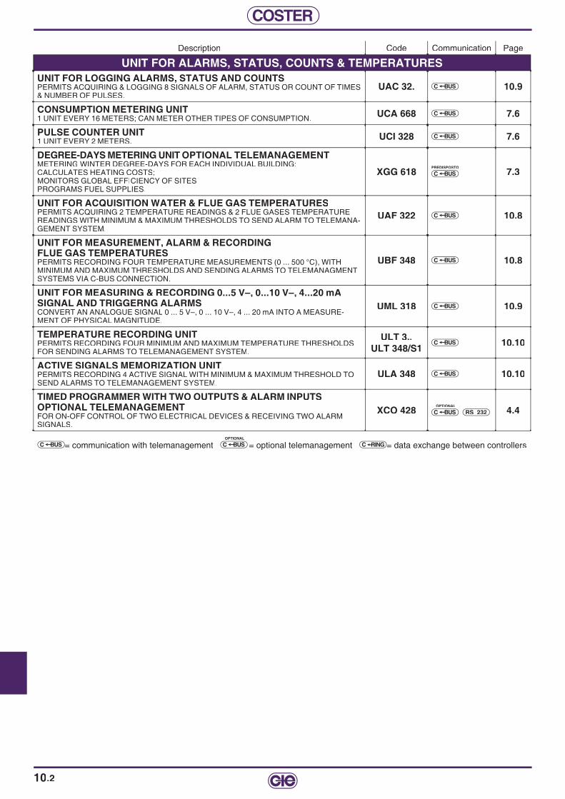
COSTER
10.2
Description Code Communication Page
UNIT FOR ALARMS, STATUS, COUNTS & TEMPERATURESUNIT FOR LOGGING ALARMS, STATUS AND COUNTS PERMITS ACQUIRING & LOGGING 8 SIGNALS OF ALARM, STATUS OR COUNT OF TIMES & NUMBER OF PULSES.
UAC 32. BUSC 10.9
CONSUMPTION METERING UNIT 1 UNIT EVERY 16 METERS; CAN METER OTHER TIPES OF CONSUMPTION. UCA 668 BUSC 7.6
PULSE COUNTER UNIT 1 UNIT EVERY 2 METERS. UCI 328 BUSC 7.6
DEGREE-DAYS METERING UNIT OPTIONAL TELEMANAGEMENT METERING WINTER DEGREE-DAYS FOR EACH INDIVIDUAL BUILDING:CALCULATES HEATING COSTS;MONITORS GLOBAL EFFICIENCY OF SITESPROGRAMS FUEL SUPPLIES.
XGG 618PREDISPOSTO
BUSC 7.3
UNIT FOR ACQUISITION WATER & FLUE GAS TEMPERATURESPERMITS ACQUIRING 2 TEMPERATURE READINGS & 2 FLUE GASES TEM PE RA TU RE READINGS WITH MINIMUM & MAXIMUM THRESHOLDS TO SEND ALARM TO TELEMANA-GEMENT SYSTEM.
UAF 322 BUSC 10.8
UNIT FOR MEASUREMENT, ALARM & RECORDING FLUE GAS TEMPERATURES PERMITS RECORDING FOUR TEMPERATURE MEASUREMENTS (0 ... 500 °C), WITH MINIMUM AND MAXIMUM THRESHOLDS AND SENDING ALARMS TO TELEMANAGMENT SYSTEMS VIA C-BUS CONNECTION.
UBF 348 BUSC 10.8
UNIT FOR MEASURING & RECORDING 0...5 V–, 0...10 V–, 4...20 mASIGNAL AND TRIGGERNG ALARMSCONVERT AN ANALOGUE SIGNAL 0 ... 5 V–, 0 ... 10 V–, 4 ... 20 mA INTO A MEASURE-MENT OF PHYSICAL MAGNITUDE.
UML 318 BUSC 10.9
TEMPERATURE RECORDING UNIT PERMITS RECORDING FOUR MINIMUM AND MAXIMUM TEMPERATURE THRESHOLDS FOR SENDING ALARMS TO TELEMANAGEMENT SYSTEM.
ULT 3..ULT 348/S1
BUSC 10.10
ACTIVE SIGNALS MEMORIZATION UNIT PERMITS RECORDING 4 ACTIVE SIGNAL WITH MINIMUM & MAXIMUM THRESHOLD TO SEND ALARMS TO TELEMANAGEMENT SYSTEM.
ULA 348 BUSC 10.10
TIMED PROGRAMMER WITH TWO OUTPUTS & ALARM INPUTSOPTIONAL TELEMANAGEMENT FOR ON-OFF CONTROL OF TWO ELECTRICAL DEVICES & RECEIVING TWO ALARM SIGNALS.
XCO 428OPTIONAL
BUSC RS 232 4.4
BUSC = communication with telemanagement OPTIONAL
BUSC = optional telemanagement C RING = data exchange between controllers

10
COSTER
10.3
Description Code Communication Page
ACCESSORIES3-CORE CABLE WITH DB MALE RS 232 (FOR MODEM)A 0.5 m CABLE THAT HAS AT ONE END 3 WIRES FOR CONNECTION TO AN RS 232 TER-MINAL, AND AT THE OTHER A DB 9 MALE CONNECTOR FOR DIRECTLY CONNECTION TO A MODEM, WITH SUITABLE ACCESSORY CONNECTORS CAN ALSO BE USED FOR A PC.
ACS 232 RS 232 10.11
TEST PLUG-IN FOR DIN WITH SLOT FOR COMMUNICATION BUS A PLUG-IN WHICH IS INSERTED IN THE SLOT OF DEVICES ENABLED FOR PLUG-IN COMMUNICATION (E.G. XGG 618).THE PLUG-IN TEST OUTPUT IS A DB 9 FEMALE CONNECTOR WHICH CAN BE CON-NECTED DIRECTLY TO A PC USING A STANDARD CABLE FOR DB 9 OR USB SOCKET. WITH SUITABLE ACCESSORY CONNECTORS CAN ALSO BE USED FOR MODEM.
ACX 232 RS 232 10.13
TEST CABLE FOR CONVERTING RJ PLUG TO RS 232 FOR PC OR MODEM.INSERTED IN RJ SOCKET ON FACIA OF SERIES F… (144 x 96) DEVICES PERMITS REMOTE OR LOCAL TELEMANAGEMENT WITH A PC OR MODEM.
RJS 232 RS 232 10.13
PLUG-IN C-BUS FOR SERIES X ... DEVICESINSERTED IN THE SLOT OF SERIES X … DEVICES PERMITS TELEMANAGEMENT VIA C-BUS OF THE SAME.
ACB 4.. BUSC 10.13
TESTER CABLE WITH ROUND SOCKET A CABLR THAT IS CONNECTED WITH ROUND SOCKET ON FRONT PANEL. CAN TEST THE TELEPHONE LINE, THE ETHERNET LINE AND THE C-BUS LINE. CAN BE CONNECTED ONLY TO A PC.
TCB 908 RS 232 10.13
GALVANIC INSULATOR FOR RS 232 LINES (3 DIN ENCLOSURE) A UNIT THAT IS INSERTED BETWEEN TWO RS 232 SOCKETS TO INSULATE GALVANI-CALLY THE UPSTREAM ZONE FROM THE DOWNSTREAM ZONE. THE OUTPUTS ARE TERMINALS AND SO PRS 332 CAN BE USED FOR EITHER PC OR MODEM.
PRS 332 RS 232 10.16
GALVANIC INSULATING CABLE FOR RS 232 LINES A UNIT WHICH IS INSERTED BETWEEN TWO RS 232 SOCKETS IN ORDER TO INSULATE GALVANICALLY THE UPSTREAM ZONE FROM THE DOWNSTREAM ZONE. THE UNIT CAN BE USED ONLY TOWARDS THE PC AND NOT TOWARDS THE MODEM.
PRS 232 RS 232 10.16
POWER BACK-UP FOR MODEM PERMITS TELEMANAGED SITES TO SEND ALARM SIGNAL FOR LACK OF POWER.. ALM 688 10.7
AERIAL EXTENSION CABLE APA 812 C1 10.5/6
BUSC = communication with telemanagement OPTIONAL
BUSC = optional telemanagement C RING = data exchange between controllers

COSTER
10.4
TELEMANAGEMENT OF PLANTS FOR AMBIENTAL COMFORT
"TELECOSTER"With this system, from a central computer, you can:• Telemanage (remote control) all the control equipment running the boiler plants in the buildings concerned.• Receive and log alarm situation and forward the alarms in voice mode to cellular phones.• See displayed the following values: temperature, fuel level, plant pressure, etc.The system comprises:• 1 Desk Modem MCT 710, MCV 711 or GSM 724 for connecting central computer to telephone line.• 1 Panel-mounted modem MPD 612, MPF 612, GSM 723 o GSM 648 for connecting each remote unit to the telephone line.• From 1 to 239 C-Bus compatible devices for each remote unit.
TELEMANAGEMENT SOFTWARE
SWC 701APPLICATIONApplication software for managing communication between the central computer and the remote boiler plants linked by modem and telephone line.
FEATURES• Supplied on CD.• Minimum recommended: Microsoft (TM) Windows 98SE, PC Pentium III 800 Mhz, RAM 256 HD, 500 HD free.
CENTRAL DESKTOP MODEM
MCV 712APPLICATIONConnects central computer to the analogue telephone line.Permits voice forwarding of alarm calls and connection with outlying GSM modems..
FEATURES• Power supply: 230 V~; Consumption: 5 VA; Desktop enclosure; Protection: IP 40.
Code Description Data Code Description Data sheet sheet
SWC 701 Telemanagement programs via protocols RS 232 and C-Bus. –
Code Description Data sheet Code Description Data sheet
Telemanagement programs via protocols RS 232 and C-Bus. –
Code Description Data sheet
SWC 701
Code Description Data sheet Code Description Data sheet
MCV 712 Desktop modem with voice forwarding. Permits connection with GSM modem. T 323
Code Description Data sheet
Desktop modem with voice forwarding. Permits connection with GSM modem. T 32
Code Description Data sheet
Desktop modem with voice forwarding. Permits connection with GSM modem. T 32
Code Description Data sheet
Desktop modem with voice forwarding. Permits connection with GSM modem. T 32
ACCESSORIES Code Description Data sheet Code Description Data sheet
WDM 318 Modem protector in DIN 53 x 115 enclosure. T 351
Code Description Data sheet Code Description Data sheet
. T 3
Code Description Data sheet
RS 232

10
COSTER
ACCESSORIES Code Description Data Code Description Data sheet sheet
ACB 332 RS 232 / C-Bus low-power convertor for connection to C-Bus line. T 423PCB 332 RS 232 / C-Bus medium-power convertor for connection to C-Bus line. T 422PCB 432 Hight-power C-Bus amplifi er and convertor T 428
APA 812 c1 APA 812 c1 Cable (4 metres) for antenna extension for GSM723 c1. –
Code Description Data Code Description Data sheet sheet
GSM 723 GSM central modem (telemanagement PC) or remote (plant sites). T 332
GSM CENTRAL OR REMOTE MODEM
GSM 723APPLICATIONConnects the central telemanagement computer to the GSM telephone line.Connects the remote Coster device to the GSM telephone line with ACB 332 or ACB 332 convertors.Supplied with: 230V~/12V– power supply; 1 cable for modem; 1 RF Dual Band antenna; 1 Linkage for mounting on wall or on DIN rail.FEATUIRES• Power supply: 12 V~ ; Protection: IP 40.• Consumption : 12 W
Code Description Data sheet Code Description Data sheet
GSM central modem (telemanagement PC) or remote (plant sites). T 332
Code Description Data sheet
Code Description Data sheet Code Description Data sheet
RS 232 / C-Bus low-power convertor for connection to C-Bus line. T 423RS 232 / C-Bus medium-power convertor for connection to C-Bus line. T 422Hight-power C-Bus amplifi er and convertor T 428
–
Code Description Data sheet
RS 232
Code Description Data Code Description Data sheet sheet
XCO 428+GSM Mini kit for Telemanagement via RS 232, including program. timer with two outputs. (Page 4.4). –
Code Description Data sheet Code Description Data sheet Code Description Data sheet
KIT OF MINI TELEMANAGEMENT INCLUDING TIMED PROGRAM
XCO 428 + GSM 723 (SINGLE PACKAGE)TELEMANAGEMENT RS 232: already enabled by kit.TELEMANAGEMENT C-Bus: Enabled with ACB 400 accessory.
SBUCOPTIONAL
RS 232
GSM MODEM FOR GSM LAPTOP PCs
GSM 724• Connection of peripheral unit devices to GSM telephone line• Built-in RF Dual Band antenna• Complete with 1 CD ROM for computer confi guration
DATI TECNICI• Power supply : from USB port;• Protection : IP 40
RS 232
Sigla Descrizione Schedatecnica
GSM 724 GSM Modem for GSM laptop PCs. T 339
10.5

COSTER
10.6
REMOTE PANEL-MOUNTING MODEM WITHOUT DISCRIMINATORWITH CONFIGURABLE TRANSMISSION SPEED
MPD 412APPLICATIONFor connecting Coster remote devices with C-Bus and/or RS 232 to the analogue telephone line.Confi gurable transmission speed (default: 1200 bauds).
FEATURES• Power supply: 230 V~; Consumption: 3 VA; Modular enclosure: DIN 71 x 116; Protection: IP 40.• Data transmission speed: confi gurable as required.
Code Description RS 232 C-Bus Data Code Description RS 232 C-Bus Data Inputs Inputs sheet Inputs Inputs sheet
MPD 412 Panel-mounting modem. 1 1 T 337
Code Description RS 232 C-Bus Data Inputs Inputs sheet
Panel-mounting modem. 1 1 T 3
Code Description RS 232 C-Bus Data Inputs Inputs sheet
Panel-mounting modem. 1 1 T 3
Code Description RS 232 C-Bus Data Inputs Inputs sheet
Panel-mounting modem. 1 1 T 3
Code Description RS 232 C-Bus Data Inputs Inputs sheet
Panel-mounting modem. 1 1 T 3
Code Description RS 232 C-Bus Data Inputs Inputs sheet
Panel-mounting modem. 1 1 T 3
BUSC
ACCESSORIES
Code Description Data Code Description Data sheet sheet
ACX 232 Test plug-in to connect PC or modem to series X… devices. T 432 ACS 232 ACS 232 RS 232 cable with male DB 9. T 440 ALM 688 ALM 688 Backup power supply. T 350 WDM 318 WDM 318 Modem protector in DIN 53 x 115 enclosure. T 351
Code Description Data sheet Code Description Data sheet
Test plug-in to connect PC or modem to series X… devices. T 432RS 232 cable with male DB 9. T 440Backup power supply. T 350Modem protector in DIN 53 x 115 enclosure. T 351
Code Description Data sheet
ACX 232 ACS 232 ALM 688 WDM 318
ACCESSORIES
Code Description Data sheet Code Description Data sheet
TCB 908 Tester for connections and telephone call-up. –
ETHERNET / C-BUS CONVERTOR
ARE 338APPLICATIONConnects Coster remote units with C-Bus to Ethernet network.
FEATURES• Power supply: 230 V~; Consumption: 3 VA; DIN 53 x 115 modular enclosure; Protection: IP 40.• Transmission speed: 1,200 bps.
Code Description Data sheet
Tester for connections and telephone call-up.
Code Description Data sheet Code Description Data sheet
Code Description Data sheet Code Description Data sheet Code Description Data sheet Code Description Data sheet Code Description Data sheet
ARE 338 Ethernet / C-Bus convertor. T 33Ethernet / C-Bus convertor. T 336
BUSC
ACCESSORIES
Code Description Data sheet
TCB 908 Tester for connections and telephone call-up. –ACS 232 RS 232 cable with male DB 9. –ALM 688 Back-up power supply. T 350
APA 812 c1 Cable (4 metres) for antenna extension for GSM 648. –
Code Description Data sheet
Code Description Data sheet
Tester for connections and telephone call-up. – RS 232 cable with male DB 9.
Back-up power supply. T 350 Cable (4 metres) for antenna extension
Code Description Data sheet
Tester for connections and telephone call-up. –
Back-up power supply. T 350. –
Code Description Data sheet
RS 232 cable with male DB 9.
REMOTE GSM DUAL BAND MODEM
GSM 648APPLICATIONConnects Coster remote devices with C-Bus and/or RS 232 to the GSM (900/1,800 MHz). Communicates with central modems MCV 711 or GSM 723 or GSM 724.Supplied with RF Dual Band antenna.
FEATURES• Power supply: 230 V~; Consumption: 11 VA; DIN 105 x 115 modular enclosure; Protection: IP 40.• Transmission speed on line: 2,400 ... 14,400 bps in non-transparent mode.
Code Description Inputs Inputs Data Code Description Inputs Inputs Data RS 232 C-Bus sheet RS 232 C-Bus sheet
GSM 648 Remore GSM Dual Band modem. 1 1 T 334
Code Description Inputs Inputs Data RS 232 C-Bus sheet Code Description Inputs Inputs Data RS 232 C-Bus sheet
Remore GSM Dual Band modem. 1 1 T 334
Code Description Inputs Inputs Data RS 232 C-Bus sheet
GSM 648
Code Description Inputs Inputs Data RS 232 C-Bus sheet
Remore GSM Dual Band modem. 1 1 T 334
Code Description Inputs Inputs Data RS 232 C-Bus sheet
Remore GSM Dual Band modem. 1 1 T 334
BUSC RS 232
RS 232

10
COSTER
10.7
MEDIUM-POWER C-BUS AMPLIFIER AND INTERFACE CONVERTOR
PCB 332APPLICATIONAmplifi es signal (max. 130 devices distributed over 5 km of 1.5 mm2 line) and permits connecting to the C-Bus line:– 1 local telemanagement PC.– 1 MCV 711 modem with voice mode.– 1 non-Coster modem with RS 232 input.– Electronic devices with RS 232 interface.
FEATURES• Power supply: 230 V ~; Consumption: 4 VA; DIN 53 x 115 modular enclosure; Protection: IP 40.• Supplied with 9-pole female plug.
Code Description Data sheet
PCB 332 Medium-power C-Bus amplifi er and convertor. T 422
Code Description Data sheet Code Description Data sheet
Medium-power C-Bus amplifi er and convertor. T 422
Code Description Data sheet
Medium-power C-Bus amplifi er and convertor. T 422
Code Description Data sheet
Medium-power C-Bus amplifi er and convertor. T 422
BUSC
HIGH-POWER AMPLIFIER & C-BUS CONVERTOR
PCB 432APPLICATIONAmplifi es C-Bus and permits connecting following to C-Bus line:– 1 local PC for Telemanagement;– 1 COSTER modem– 1 commercial-type modem with RS 232 input;– Devices with RS 232 communication system..
FEATURES• Power supply: 230 V~; Consumption: 5 VA; Modular enclosure DIN 71 x 116; Protection: IP 40.
Code Description Data sheet
PCB 432 Hight-power C-Bus amplifi er and convertor. Speeds up to 9600 baud. T 428
Code Description Data sheet Code Description Data sheet
Hight-power C-Bus amplifi er and convertor. Speeds up to 9600 baud. T 42
Code Description Data sheet
Hight-power C-Bus amplifi er and convertor. Speeds up to 9600 baud. T 42
Code Description Data sheet
Hight-power C-Bus amplifi er and convertor. Speeds up to 9600 baud. T 42
BUSC
BACKUP POWER SUPPLY FOR MODEM
ALM 688APPLICATIONPower supply backup for permit telemanaged plants to send alarm in event of power failure.It can be used with:– 1 MPD 612 or MPF 612 or GSM 622 modem and a C-Bus device with On-Off alarm.FEATURES• Power supply: 230 V~; Consumption: 3 VA; DIN 105 x 115 modular enclosure; Protection: IP 40.• Can power two C-Bus devices for about 15 minutes.• 1 On-Off output for power failure alarm.
Code Description Data sheet
ALM 688 Backup power supply for modem. T 350
Code Description Data sheet Code Description Data sheet Code Description Data sheet
ower supply for modem. T 350
Code Description Data sheet
RS 232
RS 232
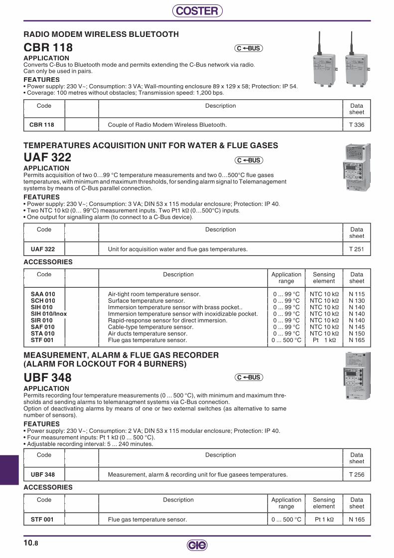
COSTER
10.8
TEMPERATURES ACQUISITION UNIT FOR WATER & FLUE GASES
UAF 322APPLICATIONPermits acquisition of two 0…99 °C temperature measurements and two 0…500°C fl ue gasestemperatures, with minimum and maximum thresholds, for sending alarm signal to Telemanagement systems by means of C-Bus parallel connection.
FEATURES• Power supply: 230 V~; Consumption: 3 VA; DIN 53 x 115 modular enclosure; Protection: IP 40.• Two NTC 10 kΩ (0… 99°C) measurement inputs. Two Pt1 kΩ (0…500°C) inputs.• One output for signalling alarm (to connect to a C-Bus device).
Code Description Data sheet
UAF 322 Unit for acquisition water and fl ue gas temperatures. T 251
Code Description Data sheet Code Description Data sheet
Unit for acquisition water and fl ue gas temperatures. T 251
Code Description Data sheet
Unit for acquisition water and fl ue gas temperatures. T 251
Code Description Data sheet
BUSC
ACCESSORIES
Code Code Description Application Sensing Data range element sheet range element sheet
SAA 010 Air-tight room temperature sensor. 0 ... 99 °C NTC 10 kΩ N 115SCH 010 Surface temperature sensor. 0 ... 99 °C NTC 10 kΩ N 130SIH 010 Immersion temperature sensor with brass pocket.. 0 ... 99 °C NTC 10 kΩ N 140SIH 010/Inox Immersion temperature sensor with inoxidizable pocket. 0 ... 99 °C NTC 10 kΩ N 140SIR 010 Rapid-response sensor for direct immersion. 0 ... 99 °C NTC 10 kΩ N 140SAF 010 Cable-type temperature sensor. 0 ... 99 °C NTC 10 kΩ N 145STA 010 Air ducts temperature sensor. 0 ... 99 °C NTC 10 kΩ N 150STF 001 Flue gas temperature sensor. 0 ... 500 °C Pt 1 kΩ N 165
range element sheet
Air-tight room temperature sensor. 0 ... 99 °C NTC 10 kΩ N 115 Surface temperature sensor. 0 ... 99 °C NTC 10 kΩ N 130 Immersion temperature sensor with brass pocket.. 0 ... 99 °C NTC 10 kΩ N 140 Immersion temperature sensor with inoxidizable pocket. 0 ... 99 °C NTC 10 kΩ N 140 Rapid-response sensor for direct immersion. 0 ... 99 °C NTC 10 kΩ N 140 Cable-type temperature sensor. 0 ... 99 °C NTC 10 kΩ N 145 Air ducts temperature sensor. 0 ... 99 °C NTC 10 kΩ N 150
Flue gas temperature sensor. 0 ... 500 °C Pt 1
Application Sensing Data range element sheet
Air-tight room temperature sensor. 0 ... 99 °C NTC 10 kΩ N 115 Surface temperature sensor. 0 ... 99 °C NTC 10 kΩ N 130 Immersion temperature sensor with brass pocket.. 0 ... 99 °C NTC 10 kΩ N 140 Immersion temperature sensor with inoxidizable pocket. 0 ... 99 °C NTC 10 kΩ N 140 Rapid-response sensor for direct immersion. 0 ... 99 °C NTC 10 kΩ N 140 Cable-type temperature sensor. 0 ... 99 °C NTC 10 kΩ N 145 Air ducts temperature sensor. 0 ... 99 °C NTC 10 kΩ N 150
kΩ N 165
Code range element sheet
Application Sensing Data range element sheet
Air-tight room temperature sensor. 0 ... 99 °C NTC 10 kΩ N 115 Surface temperature sensor. 0 ... 99 °C NTC 10 kΩ N 130 Immersion temperature sensor with brass pocket.. 0 ... 99 °C NTC 10 kΩ N 140 Immersion temperature sensor with inoxidizable pocket. 0 ... 99 °C NTC 10 kΩ N 140 Rapid-response sensor for direct immersion. 0 ... 99 °C NTC 10 kΩ N 140 Cable-type temperature sensor. 0 ... 99 °C NTC 10 kΩ N 145 Air ducts temperature sensor. 0 ... 99 °C NTC 10 kΩ N 150
Flue gas temperature sensor. 0 ... 500 °C Pt 1
Application Sensing Data range element sheet
Air-tight room temperature sensor. 0 ... 99 °C NTC 10 kΩ N 115 Surface temperature sensor. 0 ... 99 °C NTC 10 kΩ N 130 Immersion temperature sensor with brass pocket.. 0 ... 99 °C NTC 10 kΩ N 140 Immersion temperature sensor with inoxidizable pocket. 0 ... 99 °C NTC 10 kΩ N 140 Rapid-response sensor for direct immersion. 0 ... 99 °C NTC 10 kΩ N 140 Cable-type temperature sensor. 0 ... 99 °C NTC 10 kΩ N 145 Air ducts temperature sensor. 0 ... 99 °C NTC 10 kΩ N 150
Flue gas temperature sensor. 0 ... 500 °C Pt 1
ACCESSORIES
Code Description Application Sensing Data Code Description Application Sensing Data range element sheet range element sheet
STF 001 Flue gas temperature sensor. 0 ... 500 °C Pt 1 kΩ N 165
MEASUREMENT, ALARM & FLUE GAS RECORDER (ALARM FOR LOCKOUT FOR 4 BURNERS)
UBF 348APPLICATIONPermits recording four temperature measurements (0 ... 500 °C), with minimum and maximum thre-sholds and sending alarms to telemanagment systems via C-Bus connection. Option of deactivating alarms by means of one or two external switches (as alternative to same number of sensors).
FEATURES• Power supply: 230 V~; Consumption: 2 VA; DIN 53 x 115 modular enclosure; Protection: IP 40. • Four measurement inputs: Pt 1 kΩ (0 ... 500 °C).• Adjustable recording interval: 5 ... 240 minutes.
Code Description Data Code Description Data Code Description Data Code Description Data Code Description Data Code Description Data sheet sheet sheet sheet sheet sheet
UBF 348 Measurement, alarm & recording unit for fl ue gasees temperatures. T 256 Measurement, alarm & recording unit for fl ue gasees temperatures. T 256 Measurement, alarm & recording unit for fl ue gasees temperatures. T 256
Code Description Application Sensing Data range element sheet
Flue gas temperature sensor. 0 ... 500 °C Pt 1 kΩ N 165
Code Description Application Sensing Data range element sheet
Flue gas temperature sensor. 0 ... 500 °C Pt 1 kΩ N 165
Code Description Application Sensing Data range element sheet
Flue gas temperature sensor. 0 ... 500 °C Pt 1 kΩ N 165
Code Description Application Sensing Data range element sheet
Flue gas temperature sensor. 0 ... 500 °C Pt 1 kΩ N 165
Code Description Application Sensing Data range element sheet
Flue gas temperature sensor. 0 ... 500 °C Pt 1 kΩ N 165
BUSC
Flue gas temperature sensor. 0 ... 500 °C Pt 1
RADIO MODEM WIRELESS BLUETOOTH
CBR 118APPLICATIONConverts C-Bus to Bluetooth mode and permits extending the C-Bus network via radio.Can only be used in pairs.
FEATURES• Power supply: 230 V~; Consumption: 3 VA; Wall-mounting enclosure 89 x 129 x 58; Protection: IP 54.• Coverage: 100 metres without obstacles; Transmission speed: 1,200 bps.
Code Description Data Code Description Data Code Description Data Code Description Data Code Description Data Code Description Data sheet sheet sheet sheet sheet sheet
CBR 118 Couple of Radio Modem Wireless Bluetooth. T 336 Couple of Radio Modem Wireless Bluetooth. T 336 Couple of Radio Modem Wireless Bluetooth. T 336
BUSC

10
COSTER
10.9
UNIT FOR MEASUREMENT, ALARM & RECORDING0 ... 5 V–, 0 ... 10 V–, 4 ... 20 mA SIGNALS
UML 318APPLICATIONConvert an analogue signal 0 ... 5 V– o 0 ... 10 V– o 4 ... 20 mA into a measurement of physical ma-gnitude. In conjunction with a liquid level pressure sensor it is possible to:– Power the sensor (12 V–).– Calibrate the measurement range off the physical magnitude and display the actual measurement.– Set two limit values (Min. and Max.) for control of two relays.– Record 400 measurements at the pre-set intervals (5 min ... 24 hours).– Telemanage via C-Bus connection.
FEATURES• Power supply: 230 V~; Consumption: 2 VA; DIN 53 x 115 modular enclosure; Protection: IP 40. • One input for analogue signal 0 ... 5 V– or 0 ... 10 V– or 4 ... 20 mA.• Two relay outputs for signalling alarm.
Code Description Data Code Description Data Code Description Data Code Description Data Code Description Data Code Description Data sheet sheet sheet sheet sheet sheet
UML 318 Unit for measurement & recording signals 0 ... 5 V– or 0 ... 10 V– or 4 ... 20 mA, T 258 Unit for measurement & recording signals 0 ... 5 V– or 0 ... 10 V– or 4 ... 20 mA, T 258 Unit for measurement & recording signals 0 ... 5 V– or 0 ... 10 V– or 4 ... 20 mA, T 258 and triggering alarms. and triggering alarms. and triggering alarms. and triggering alarms. and triggering alarms.
BUSC
ALARMS, STATUS & COUNTS RECORDING UNIT
UAC 32.APPLICATIONAllows acquiring eight On-Off signals of alarm, status or time counts and number of pulses.C-Bus compatible.
FEATURES• Power supply: 230 V~ / 24 V~; Consumption: 3 VA; DIN 53 x 115 modular enclosure; Protection: IP 40.• Eight On-Off inputs for voltage-free contacts.
Code Description Power Data Code Description Power Data sheet sheet
UAC 328 Unit for acquisition and logging alarms, status and counts. 230 V~ T 221UAC 324 Unit for acquisition and logging alarms, status and counts. 24 V~ T 221
BUSC
Code Description Power Data sheet
Unit for acquisition and logging alarms, status and counts. Unit for acquisition and logging alarms, status and counts.
Code Description Power Data sheet
T 221 T 221
Code Description Power Data sheet Code Description Power Data sheet

COSTER
10.10
SIGNALS RECORDING UNIT
ULA 348APPLICATIONPermits recording 4 active signals with minimum and maximum thresholds for sending alarms to telemanagement systems via C-Bus interface.
FEATURES• Power supply: 230 V~; Consumption: 3 VA; DIN 53 x 115 modular enclosure; Protection: IP 40.• 4 active signals inputs: two 4 ... 20 mA signals, two 0 ... 10 V– signals.• Adjustable internal between recordings: 5 ... 240 min.
Code Description Data sheet
ULA 348 Active signals logging unit. T 254
Code Description Data sheet Code Description Data sheet
Active signals logging unit. T 254
Code Description Data sheet
Active signals logging unit. T 254
Code Description Data sheet
BUSC
TEMPERATURE RECORDING UNIT
ULT 3..APPLICATIONPermits recording four temperature measurements with minimum and maximum threshold for sending alarms to telemanagement systems via C-Bus.
FEATURES• Power supply: 230 V~; Consumption: 2 VA; DIN 53 x 115 modular enclosure; Protection: IP 40. • Four measurement inputs.• Adjustable recording interval: 5 ... 240 min.
Code Description Suitable sensors Data Code Description Suitable sensors Data NTC 10 kΩ NTC 10 kΩ NTC 1 kΩ sheet NTC 10 kΩ NTC 10 kΩ NTC 1 kΩ sheet 0 ... 99 °C 0 ... 40 °C –40 ... 40 °C 0 ... 99 °C 0 ... 40 °C –40 ... 40 °C
ULT 328 Temperature recording unit. 2 1 1 T 257ULT 348 Temperature recording unit. 4 – – T 257ULT 348/S1 Temperature recording unit – 4 – T 257/S1
for 4 room sensors using in air-handling units for 4 room sensors using in air-handling units
Code Description Suitable sensors Data NTC 10 kΩ NTC 10 kΩ NTC 1 kΩ sheet 0 ... 99 °C 0 ... 40 °C –40 ... 40 °C
Temperature recording unit. 2 1 1 T 257 Temperature recording unit. 4 – – T 257 Temperature recording unit – 4 –
for 4 room sensors using in air-handling units
Code Description Suitable sensors Data NTC 10 kΩ NTC 10 kΩ NTC 1 kΩ sheet
Temperature recording unit. 2 1 1 T 257 Temperature recording unit. 4 – – T 257
Code Description Suitable sensors Data NTC 10 kΩ NTC 10 kΩ NTC 1 kΩ sheet 0 ... 99 °C 0 ... 40 °C –40 ... 40 °C
for 4 room sensors using in air-handling units
NTC 10 kΩ NTC 10 kΩ NTC 1 kΩ sheet 0 ... 99 °C 0 ... 40 °C –40 ... 40 °C
Temperature recording unit. 2 1 1 T 257 Temperature recording unit. 4 – – T 257 Temperature recording unit – 4 –
for 4 room sensors using in air-handling units
NTC 10 kΩ NTC 10 kΩ NTC 1 kΩ sheet 0 ... 99 °C 0 ... 40 °C –40 ... 40 °C
Temperature recording unit. 2 1 1 T 257 Temperature recording unit. 4 – – T 257 Temperature recording unit – 4 –
for 4 room sensors using in air-handling units
Code Description Suitable sensors Data NTC 10 kΩ NTC 10 kΩ NTC 1 kΩ sheet 0 ... 99 °C 0 ... 40 °C –40 ... 40 °C
Temperature recording unit. 2 1 1 T 257 Temperature recording unit. 4 – – T 257 Temperature recording unit – 4 –
for 4 room sensors using in air-handling units
BUSC
SENSORS & ACCESSORIES Code Description Application Sensing Data Code Description Application Sensing Data range element sheet range element sheet
SAA 010 Waterproof room sensor. 0 ... 99 °C NTC 10 kΩ N 115SAA 001 Waterproof room sensor.. –40...+40°C NTC 1 kΩ N 115SAE 001 Outside temperature sensor. –40...+40°C NTC 1 kΩ N 120SCH 010 Surface temperature sensor. 0 ... 99 °C NTC 10 kΩ N 130SIH 010 Immersion temperature sensor with brass pocket. 0 ... 99 °C NTC 10 kΩ N 140SIH 010/Inox Immersion temperature sensor with stainless steel pocket. 0 ... 99 °C NTC 10 kΩ N 140SIR 010 Direct immersion rapid-action temperature sensor. 0 ... 99 °C NTC 10 kΩ N 140SAF 010 Cable-type temperature sensor. 0 ... 99 °C NTC 10 kΩ N 145SAF 001 Cable-type temperature sensor. –40...+40°C NTC 1 kΩ N 145STA 010 Temperature sensor for air ducts. 0 ... 99 °C NTC 10 kΩ N 150
STA 001 STA 001 Temperature sensor for air ducts. –40...+40°C NTC 1 kΩ N 150SAB 010 Room temperature sensor. 0 ... 40 °C NTC 10 kΩ N 111
SAB 210 SAB 210 Room temperature sensor with + 1 hour button. 0 ... 40 °C NTC 10 kΩ N 111SCB 110 Room temperature sensor, 0 ... 40 °C NTC 10 kΩ N 111
with set-point adjuster. –5 ... +5 °C with set-point adjuster. –5 ... +5 °C – – SCB 210 SCB 210 Room temperature sensor with + 1 hour button, 0 ... 40 °C NTC 10 kΩ N 111 and set-point adjuster. –5 ... +5 °C – and set-point adjuster. –5 ... +5 °C – –
STT 010 Temperature sensor for heating/cooling coils. 0 ... 40 °C NTC 10 kΩ N 155STV 010 Window temperature sensor. 0 ... 40 °C NTC 10 kΩ N 160
Code Description Application Sensing Data range element sheet Code Description Application Sensing Data range element sheet
Waterproof room sensor. 0 ... 99 °C NTC 10 kΩ N 115
Outside temperature sensor. –40...+40°C NTC 1 kΩ N 120 Surface Immersion temperature sensor with brass pocket. 0 ... 99 °C NTC 10 kΩ N 140
Direct immersion rapid-action temperature sensor. 0 ... 99 °C NTC 10 kΩ N 140 Cable-type temperature sensor. 0 ... 99 °C NTC 10 kΩ N 145
Temperature sensor for air ducts. 0 ... 99 °C NTC 10 kΩ N 150
Room temperature sensor. 0 ... 40 °C NTC 10 kΩ N 111
with set-point adjuster. –5 ... +5 °C
and set-point adjuster. –5 ... +5 °C –
Code Description Application Sensing Data range element sheet
Waterproof room sensor. 0 ... 99 °C NTC 10 kΩ N 115 –40...+40°C NTC 1 kΩ N 115
Outside temperature sensor. –40...+40°C NTC 1 kΩ N 120. 0 ... 99 °C NTC 10 kΩ N 130
Immersion temperature sensor with brass pocket. 0 ... 99 °C NTC 10 kΩ N 140 0 ... 99 °C NTC 10 kΩ N 140
Direct immersion rapid-action temperature sensor. 0 ... 99 °C NTC 10 kΩ N 140 Cable-type temperature sensor. 0 ... 99 °C NTC 10 kΩ N 145
. –40...+40°C NTC 1 kΩ N 145 Temperature sensor for air ducts. 0 ... 99 °C NTC 10 kΩ N 150
. –40...+40°C NTC 1 kΩ N 150 Room temperature sensor. 0 ... 40 °C NTC 10 kΩ N 111
+ 1 hour button. 0 ... 40 °C NTC 10 kΩ N 111 0 ... 40 °C NTC 10 kΩ N 111
with + 1 hour button, 0 ... 40 °C NTC 10 kΩ N 111
and set-point adjuster. –5 ... +5 °C – . 0 ... 40 °C NTC 10 kΩ N 155
. 0 ... 40 °C NTC 10 kΩ N 160
Code Description Application Sensing Data range element sheet
Waterproof room sensor. 0 ... 99 °C NTC 10 kΩ N 115 –40...+40°C NTC 1 kΩ N 115
Outside temperature sensor. –40...+40°C NTC 1 kΩ N 120. 0 ... 99 °C NTC 10 kΩ N 130
Immersion temperature sensor with brass pocket. 0 ... 99 °C NTC 10 kΩ N 140 0 ... 99 °C NTC 10 kΩ N 140
Direct immersion rapid-action temperature sensor. 0 ... 99 °C NTC 10 kΩ N 140 Cable-type temperature sensor. 0 ... 99 °C NTC 10 kΩ N 145
. –40...+40°C NTC 1 kΩ N 145 Temperature sensor for air ducts. 0 ... 99 °C NTC 10 kΩ N 150
. –40...+40°C NTC 1 kΩ N 150 Room temperature sensor. 0 ... 40 °C NTC 10 kΩ N 111
+ 1 hour button. 0 ... 40 °C NTC 10 kΩ N 111 0 ... 40 °C NTC 10 kΩ N 111
with set-point adjuster. –5 ... +5 °C with + 1 hour button, 0 ... 40 °C NTC 10 kΩ N 111
and set-point adjuster. –5 ... +5 °C – . 0 ... 40 °C NTC 10 kΩ N 155
. 0 ... 40 °C NTC 10 kΩ N 160
SAB 010 SAB 210
SCB 110 with set-point adjuster. –5 ... +5 °C SCB 210 and set-point adjuster. –5 ... +5 °C –
STT 010 STV 010

10
COSTER
10.11
LOW-POWER RS 232 / C-BUS CONVERTOR CABLE FOR PC ONLY
ACB 232APPLICATIONPermits connecting a C-Bus line to a PC (not to a modem).The C-Bus output is of the "Master" type; it can be connected to a maximum of 10 Coster devices fi tted with C-Bus.
FEATURES• Supplied with a 9-pole female plug; Number of C-Bus devices with can be connected: max 10.
Code Description Data Code Description Data sheet sheet
ACB 232 RS 232 / C-Bus convertor cable powered by PC. –
Code Description Data sheet
RS 232 / C-Bus convertor cable powered by PC. –
Code Description Data sheet
RS 232 / C-Bus convertor cable powered by PC. –
Code Description Data sheet
RS 232 / C-Bus convertor cable powered by PC. –
BUSC
THREE-CORE CABLE WITH MALE DB 9 RS 232 (FOR MODEM)
ACS 232APPLICATIONA 0.5 metre cable which at one end has 3 wires for connection to an RS 232 terminal, and at the other a DB 9 male connector.For connecting directly to a modem. With suitable accessory (KIT RS 232) connectors can be used also for PC.
Code Description Data Code Description Data sheet sheet
ACS 232 Three-core cable for RS 232 for modem. Length 0.5 m. –
Code Description Data sheet
Three-core cable for RS 232 for modem. Length 0.5 m. –
Code Description Data sheet
Three-core cable for RS 232 for modem. Length 0.5 m. –
Code Description Data sheet
Three-core cable for RS 232 for modem. Length 0.5 m. –
RS 232
RS 232
LOW-POWER RS 232 / C-BUS CONVERTOR CABLE FOR MODEM OR PC
ACB 232/S1APPLICATIONPermits connecting a C-Bus line to a modem.
At least one of the devices on the C-Bus line must be equipped with a 12 V- power back-up (e.g. UCO 318), otherwise an external power supply will be required.
The C-Bus output is of the "Master" type; it can be connected to a maximum of 10 Coster devices fi tted with C-Bus.With suitable connectors can be used also for a PC.
FEATURES• Supplied with a 9-pole female plug; Number of C-Bus devices with can be connected: max 10.
Code Description Data Code Description Data sheet sheet
ACB 232/S1 Convertor cable RS 232 / C-Bus powered by a Coster device. –
Code Description Data sheet Code Description Data sheet
RS 232 / C-Bus powered by a Coster device. –
Code Description Data sheet
BUSC RS 232
LOW-POWER CONVERTOR C-BUS TO RS 232 FOR PC OR MODEM
ACB 332APPLICATIONPermis connecting a C-Bus line to a modem or a PC.The C-Bus output is of "Master" type; can be connected to a maximum of a 50 Coster C-Bus devices.
FEATURES• Power supply: 230 V~; Consumption: 4 VA; DIN 53 x 115 modular enclosure; Protection: IP 40.
Code Description Data Code Description Data sheet sheet
ACB 332 RS 232 / C-Bus signal convertor. T 423
Code Description Data sheet
RS 232 / C-Bus signal convertor.
Code Description Data sheet Code Description Data sheet
RS 232 / C-Bus signal convertor.
BUSC RS 232

COSTER
10.12
NON TRANSPARENT CONVERTOR FROM M-BUS TO C-BUS "SLAVE"
CMC 328 M-BUSAPPLICATIONConverts M-Bus output of a non-Coster heat meter to a C-Bus "Slave" output.Mode: 1,200 Baud. "NON-TRANSPARENT".Permits connecting: - an M-Bus line (of a non-Coster device) to a C.Bus line with, if present, a local PC.Note: CMC 328 uses the standard M-Bus protocol.
In case of non-compatibility with some products, the specifi c communication protocol must be examined.
FEATURES• Power supply: 230 V~; Consumption: 4 VA; DIN 53 x 115 modular enclosure; Protection: IP 40.
Code Description Inputs Outputs Data Code Description Inputs Outputs Data RS 232 C-Bus M-Bus C-Bus M-Bus sheet RS 232 C-Bus M-Bus C-Bus M-Bus sheet
CMC 328 M-Bus / C-Bus "Slave" convertor. 1 1 1 1 1 T 425
Code Description Inputs Outputs Data RS 232 C-Bus M-Bus C-Bus M-Bus sheet
M-Bus / C-Bus "Slave" convertor. 1 1 1 1 1
Code Description Inputs Outputs Data RS 232 C-Bus M-Bus C-Bus M-Bus sheet Code Description Inputs Outputs Data RS 232 C-Bus M-Bus C-Bus M-Bus sheet
M-Bus / C-Bus "Slave" convertor. 1 1 1 1 1
CMC 328 CMC 328 CMC 328 CMC 328 CMC 328 CMC 328 CMC 328 CMC 328 BUSC
RS 232 C-Bus M-Bus C-Bus M-Bus sheet
M-Bus / C-Bus "Slave" convertor. 1 1 1 1 1
Code Description Inputs Outputs Data RS 232 C-Bus M-Bus C-Bus M-Bus sheet
M-Bus / C-Bus "Slave" convertor. 1 1 1 1 1
RS 232 C-Bus M-Bus C-Bus M-Bus sheet
M-Bus / C-Bus "Slave" convertor. 1 1 1 1 1
RS 232 C-Bus M-Bus C-Bus M-Bus sheet
M-Bus / C-Bus "Slave" convertor. 1 1 1 1 1
Code Description Inputs Outputs Data RS 232 C-Bus M-Bus C-Bus M-Bus sheet
M-Bus / C-Bus "Slave" convertor. 1 1 1 1 1
CONVERTOR FROM RS 232 ON ANY DEVICE TO C-BUS
CCB 332APPLICATIONConverts an RS 232 serial signal from any device to be telemanaged to a C-Bus "Slave" input.Permits connecting a device with RS 232 data communication to C-Bus line.WARNING: in order to connect any NON-COSTER device to COSTER Telemanagement programs it is necessary to have details of the communication protocol.The possibility of establishing communication depends on the characteristics of the device in question and must be examined case by case.
FEATURES• Power supply: 230 V~; Consumption: 4 VA; DIN 53 x 115 modular enclosure; Protection: IP 40.
Code Description Data Code Description Data sheet sheet
CCB 332 RS 232 / C-Bus convertor. T 427
Code Description Data sheet
RS 232 / C-Bus convertor.
Code Description Data sheet Code Description Data sheet
RS 232 / C-Bus convertor.
BUSC RS 232
ACCESSORIES
Code Description Data Code Description Data sheet sheet
ACB 232/S1 Convertor cable RS 232 / C-Bus powered by a Coster device. – ACS 232 ACS 232 RS 232 cable with male DB 9. –
Code Description Data sheet Code Description Data sheet Code Description Data sheet
ACS 232

10
COSTER
10.13
TEST PLUG-IN FOR DIN WITH SLOT FOR COMMUNICATION BUS (TYPE X ... UNIT)
ACX 232APPLICATIONPermits connecting temporarily a PC or a modem to a Coster device of the X ... series.
FEATURES• Inserted into the slot of any device of the X ... sereis, provides an RS 232 output with a 9 pole connector, to connect by means of a standard 9-pole-9-pole cable or a 9-pole-USB, to a local PC.• By means of the PC you can communicate with the controllers for programming or control.• Using suitable accessories a modem also can be connected.
Code Description Data Code Description Data sheet sheet
ACX 232 Plug-in test for connecting PC or modem to devices of series X ... –
Code Description Data sheet
Plug-in test for connecting PC or modem to devices of series X ... –
Code Description Data sheet
Plug-in test for connecting PC or modem to devices of series X ... –
Code Description Data sheet
Plug-in test for connecting PC or modem to devices of series X ... –
RS 232
PLUG-IN C-BUS FOR SERIES X ... DEVICES
ACB 4..APPLICATIONInserted in the appropriate communication slot of series X … controllers enable Telemanagement via the C-Bus of these controllers.
BUSC
Code Description Products Data Code Description Products Data sheet sheet
ACB 400 Plug-in for communication via C-Bus. XCC 602 - XCO 428 - XCC 618 - XCC 638 XPI 438 - XSE 600 - XSE 602 - XTA 624 T 433 XTT 618 - MRL 608.
ACB 460 Plug-in for communication via C-Bus. XGG 618 - XTC 638 - XTR 628 - XTT 608 T 433 XTU 614 -XTU 618 - XTU 644
ACB 468 Plug-in for communication via C-Bus. XCS 633 - XTE 600 - XTE 602 - XTE 611 - T 433 XTP 600 XTP 600.
Code Description Products Data sheet
Plug-in for communication via C-Bus. XCC 602 - XCO 428
XTP 600
Code Description Products Data sheet
Code Description Products Data sheet
XTP 600
TEST CABLE CONVERTOR RJ 6 POLES/RS232 FOR PC OR MODEM
RJS 232APPLICATIONPermits connection of any device fi tted with RJ6 pole socket to a PC or modem equipped with RS232 input (e.g. devices type F … (144 x 96).Permits temporary Telemanagement using the GSM 723 modem for temporary controls.FEATURES• Power via RJ plug.
Code Description Data Code Description Data sheet sheet
RJS 232 Cable converts RJ 6 poles to RS232 for PC or modem. –
Code Description Data sheet
Cable converts RJ 6 poles to RS232 for PC or modem. –
Code Description Data sheet
Cable converts RJ 6 poles to RS232 for PC or modem. –
Code Description Data sheet
RS 232
CABLE TESTER WITH ROUND SOCKET
TCB 908APPLICATIONPermits complete testing of a C-Bus communication line to:- An analogue or GSM telephone line.- An Ethernet network.- The C-Bus network towards the devices.Can be used only with a PC.Fitted with a round plug compatible with modems: GSM 622, MPD 612, MPF 612 and with ARE 338 Ethernet convertor.FEATURES• Supplied with 9-pole female socket, suitable for a PC.
Code Description Data Code Description Data Code Description Data Code Description Data Code Description Data Code Description Data sheet sheet sheet sheet sheet sheet
TCB 908 Tester for connections and telephone call-up or Ethernet. Tester for connections and telephone call-up or Ethernet. –
RS 232

COSTER
10.14
NOTES

COSTER

via San G.B. De La Salle, 4/a 20132 MilanoTel. +39 02 2722121 Fax +39 02 [email protected] www.coster.eu
Fax +39 02 [email protected]
via S. Longanesi, 14 00146 RomaTel. +39 06 5573330 Fax +39 06 [email protected]
via Gen. Treboldi, 190/192 25048 - Edolo (BS)Tel. +39 0364 773202 Tel. +39 0364 [email protected]
COSTER T.E. UK Branch5 Shaftesbury Street South, Sir Francis Ley Indu-strial Park - Derby DE23 8YHTel. +44 (0) 1332 200555 Fax +44 (0) 1332 [email protected]
COSTER TECNOLOGIE ELETTRONICHE S.p.A.
2012
ver
sion
e 00
D31
011
agen
ziaz
elas
chi.i
t