Embed Size (px)
Citation preview
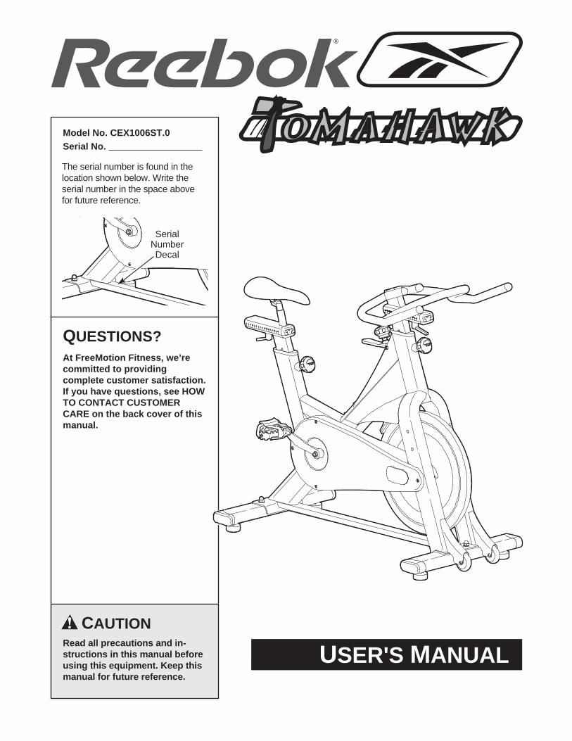
USER'S MANUALCAUTION
Read all precautions and in-structions in this manual beforeusing this equipment. Keep thismanual for future reference.
Model No. CEX1006ST.0Serial No.
The serial number is found in the location shown below. Write the serial number in the space abovefor future reference.
QUESTIONS?At FreeMotion Fitness, we’recommitted to providingcomplete customer satisfaction.If you have questions, see HOWTO CONTACT CUSTOMERCARE on the back cover of thismanual.
SerialNumberDecal

2
REEBOK and the vector logo are registered trademarks and service marks of Reebok.Manufactured and used under license from Reebok. SPD® is a registered trademark of Shimano, Inc.
TOMAHAWK is a registered trademark of Cytech, GmbH.
3
Important Precautions . . . . . . . . . . . . . . . . . . . . . . . . . . . . . . . . . . . . . . . . . . . . . . . . . . . . . . . . . . . . . . . . . . . . . . .4Before You Begin . . . . . . . . . . . . . . . . . . . . . . . . . . . . . . . . . . . . . . . . . . . . . . . . . . . . . . . . . . . . . . . . . . . . . . . . . . .5How to Assemble the Indoor Studio Cycle . . . . . . . . . . . . . . . . . . . . . . . . . . . . . . . . . . . . . . . . . . . . . . . . . . . . . . . .6How to Adjust the Indoor Studio Cycle . . . . . . . . . . . . . . . . . . . . . . . . . . . . . . . . . . . . . . . . . . . . . . . . . . . . . . . . .10
Pedal Strap Adjustment . . . . . . . . . . . . . . . . . . . . . . . . . . . . . . . . . . . . . . . . . . . . . . . . . . . . . . . . . . . . . . . . . .10Saddle Adjustment . . . . . . . . . . . . . . . . . . . . . . . . . . . . . . . . . . . . . . . . . . . . . . . . . . . . . . . . . . . . . . . . . . . . . .10Handlebar Adjustment . . . . . . . . . . . . . . . . . . . . . . . . . . . . . . . . . . . . . . . . . . . . . . . . . . . . . . . . . . . . . . . . . . .11Resistance Adjustment . . . . . . . . . . . . . . . . . . . . . . . . . . . . . . . . . . . . . . . . . . . . . . . . . . . . . . . . . . . . . . . . . .11How to Move the Indoor Studio Cycle . . . . . . . . . . . . . . . . . . . . . . . . . . . . . . . . . . . . . . . . . . . . . . . . . . . . . . .11
Preventive Maintenance . . . . . . . . . . . . . . . . . . . . . . . . . . . . . . . . . . . . . . . . . . . . . . . . . . . . . . . . . . . . . . . . . . . . .12Daily Maintenance . . . . . . . . . . . . . . . . . . . . . . . . . . . . . . . . . . . . . . . . . . . . . . . . . . . . . . . . . . . . . . . . . . . . . .12Weekly Maintenance . . . . . . . . . . . . . . . . . . . . . . . . . . . . . . . . . . . . . . . . . . . . . . . . . . . . . . . . . . . . . . . . . . . .12Biweekly Maintenance . . . . . . . . . . . . . . . . . . . . . . . . . . . . . . . . . . . . . . . . . . . . . . . . . . . . . . . . . . . . . . . . . . .12Monthly Maintenance . . . . . . . . . . . . . . . . . . . . . . . . . . . . . . . . . . . . . . . . . . . . . . . . . . . . . . . . . . . . . . . . . . . .14
Limited Warranty . . . . . . . . . . . . . . . . . . . . . . . . . . . . . . . . . . . . . . . . . . . . . . . . . . . . . . . . . . . . . . . . . . . . . . . . . .16Part List . . . . . . . . . . . . . . . . . . . . . . . . . . . . . . . . . . . . . . . . . . . . . . . . . . . . . . . . . . . . . . . . . . . . . . . . . . . . . . . . .18Exploded Drawing . . . . . . . . . . . . . . . . . . . . . . . . . . . . . . . . . . . . . . . . . . . . . . . . . . . . . . . . . . . . . . . . . . . . . . . . .19How to Contact Customer Care . . . . . . . . . . . . . . . . . . . . . . . . . . . . . . . . . . . . . . . . . . . . . . . . . . . . . . . .Back Cover
TABLE OF CONTENTS
4
1. It is the responsibility of the owner to ensurethat all users of the indoor studio cycle areadequately informed of all warnings and pre-cautions.
2. Operate the indoor studio cycle only as de-scribed in this manual.
3. Do not operate the indoor studio cycle until itis properly assembled (see page 6).
4. Keep the indoor studio cycle indoors, awayfrom moisture and dust. Do not place the in-door studio cycle in a garage or covered patioor near water.
5. Place the indoor studio cycle on a level sur-face. To protect the floor or carpet from dam-age, place a mat beneath the indoor studiocycle. Make sure that there is adequate roomaround the indoor studio cycle to mount, dis-mount, and operate it.
6. Regularly inspect and properly tighten allparts of the indoor studio cycle.
7. Keep children under the age of 14 and petsaway from the indoor studio cycle at all times.
8. The indoor studio cycle must not be used bypersons weighing more than 350 pounds.
9. Always wear appropriate athletic clothes andshoes while operating the indoor studiocycle. Do not wear loose clothes that couldbecome caught on the indoor studio cycle.
10. To stop the flywheel, pull the emergencybrake handle upward. The flywheel shouldquickly come to a complete stop (see RESIS-TANCE ADJUSTMENT on page 11).
11. The indoor studio cycle does not have a free-wheel; the pedals will continue to move untilthe flywheel stops. Reduce pedaling speed ina controlled way.
12. Always regulate the flywheel resistance sothat your pedaling motion is controlled.
13. Keep your back straight while using the in-door studio cycle; do not arch your back.
14. If you feel pain or dizziness while exercising,stop immediately and cool down.
15. If replacement parts are needed, use onlymanufacturer-supplied parts.
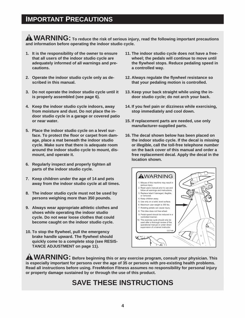
16. The decal shown below has been placed onthe indoor studio cycle. If the decal is missingor illegible, call the toll-free telephone numberon the back cover of this manual and order afree replacement decal. Apply the decal in thelocation shown.
WARNING: To reduce the risk of serious injury, read the following important precautionsand information before operating the indoor studio cycle.
IMPORTANT PRECAUTIONS
WARNING: Before beginning this or any exercise program, consult your physician. Thisis especially important for persons over the age of 35 or persons with pre-existing health problems.Read all instructions before using. FreeMotion Fitness assumes no responsibility for personal injuryor property damage sustained by or through the use of this product.
SAVE THESE INSTRUCTIONS
5
Congratulations for selecting the new REEBOK®
TOMAHAWK indoor studio cycle. The REEBOKTOMAHAWK indoor studio cycle offers an impressivearray of features designed to enhance cardiovascularfitness, tone muscles, and develop endurance.Whether users are beginners or experienced athletes,the indoor studio cycle offers workouts that will helpusers to reach their individual fitness goals.
IMPORTANT: Read this manual carefully before as-sembling or using the indoor studio cycle. If youhave questions after reading this manual, see HOWTO CONTACT CUSTOMER CARE on the back coverof this manual.
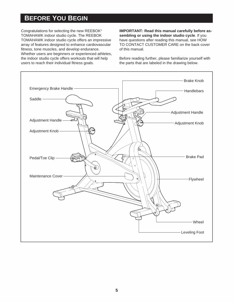
Before reading further, please familiarize yourself withthe parts that are labeled in the drawing below.
Handlebars
Leveling Foot
BEFORE YOU BEGIN
Adjustment Knob
Flywheel
Pedal/Toe Clip
Adjustment Handle
Adjustment Handle
Adjustment Knob
Emergency Brake Handle
Saddle
Brake Knob
Wheel
Brake Pad
Maintenance Cover
6
Due to the weight of the indoor studio cycle, it is recommended that two persons assemble it. Set the in-door studio cycle in a cleared area and remove all packing materials; do not dispose of the packing materials untilassembly is completed.
Note: The numbers in parentheses in the assembly steps are the key numbers of the parts, from the PART LISTon page 18.
HOW TO ASSEMBLE THE INDOOR STUDIO CYCLE
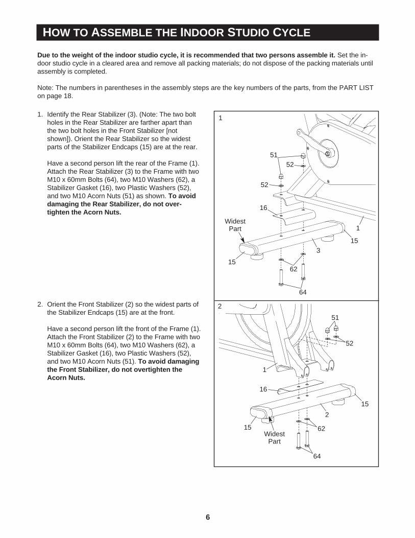
1. Identify the Rear Stabilizer (3). (Note: The two boltholes in the Rear Stabilizer are farther apart thanthe two bolt holes in the Front Stabilizer [notshown]). Orient the Rear Stabilizer so the widestparts of the Stabilizer Endcaps (15) are at the rear.
Have a second person lift the rear of the Frame (1).Attach the Rear Stabilizer (3) to the Frame with twoM10 x 60mm Bolts (64), two M10 Washers (62), aStabilizer Gasket (16), two Plastic Washers (52),and two M10 Acorn Nuts (51) as shown. To avoiddamaging the Rear Stabilizer, do not over-tighten the Acorn Nuts.
315
15
5152
52
16
62
64
1Widest
Part
1
2. Orient the Front Stabilizer (2) so the widest parts ofthe Stabilizer Endcaps (15) are at the front.
Have a second person lift the front of the Frame (1).Attach the Front Stabilizer (2) to the Frame with twoM10 x 60mm Bolts (64), two M10 Washers (62), aStabilizer Gasket (16), two Plastic Washers (52),and two M10 Acorn Nuts (51). To avoid damagingthe Front Stabilizer, do not overtighten theAcorn Nuts.
2
16
15
15
WidestPart
64
62
52
51
1
2
7
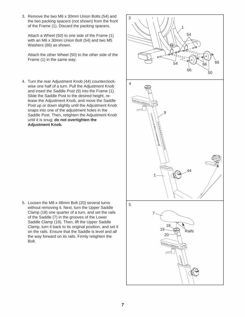
3. Remove the two M6 x 30mm Union Bolts (54) andthe two packing spacers (not shown) from the frontof the Frame (1). Discard the packing spacers.
Attach a Wheel (50) to one side of the Frame (1)with an M6 x 30mm Union Bolt (54) and two M5Washers (66) as shown.
Attach the other Wheel (50) to the other side of theFrame (1) in the same way.
54
541
50
6666
66
4. Turn the rear Adjustment Knob (44) counterclock-wise one half of a turn. Pull the Adjustment Knoband insert the Saddle Post (9) into the Frame (1).Slide the Saddle Post to the desired height, re-lease the Adjustment Knob, and move the SaddlePost up or down slightly until the Adjustment Knobsnaps into one of the adjustment holes in theSaddle Post. Then, retighten the Adjustment Knobuntil it is snug; do not overtighten theAdjustment Knob.
4
144
9
3
5. Loosen the M8 x 48mm Bolt (20) several turnswithout removing it. Next, turn the Upper SaddleClamp (18) one quarter of a turn, and set the railsof the Saddle (7) in the grooves of the LowerSaddle Clamp (19). Then, lift the Upper SaddleClamp, turn it back to its original position, and set iton the rails. Ensure that the Saddle is level and allthe way forward on its rails. Firmly retighten theBolt.
2019
18
7
Rails
5
8
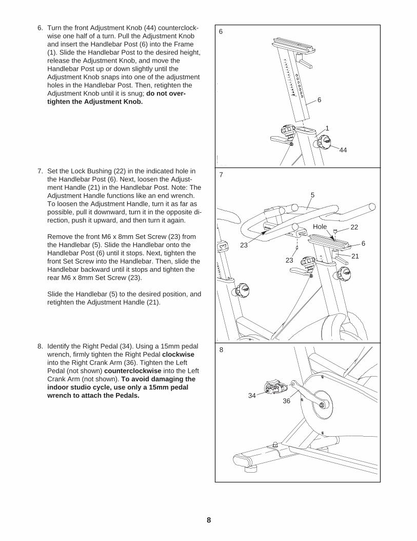
6. Turn the front Adjustment Knob (44) counterclock-wise one half of a turn. Pull the Adjustment Knoband insert the Handlebar Post (6) into the Frame(1). Slide the Handlebar Post to the desired height,release the Adjustment Knob, and move theHandlebar Post up or down slightly until theAdjustment Knob snaps into one of the adjustmentholes in the Handlebar Post. Then, retighten theAdjustment Knob until it is snug; do not over-tighten the Adjustment Knob. 6
44
1
6
7. Set the Lock Bushing (22) in the indicated hole inthe Handlebar Post (6). Next, loosen the Adjust-ment Handle (21) in the Handlebar Post. Note: TheAdjustment Handle functions like an end wrench.To loosen the Adjustment Handle, turn it as far aspossible, pull it downward, turn it in the opposite di-rection, push it upward, and then turn it again.
Remove the front M6 x 8mm Set Screw (23) fromthe Handlebar (5). Slide the Handlebar onto theHandlebar Post (6) until it stops. Next, tighten thefront Set Screw into the Handlebar. Then, slide theHandlebar backward until it stops and tighten therear M6 x 8mm Set Screw (23).
Slide the Handlebar (5) to the desired position, andretighten the Adjustment Handle (21).
7
22
21
5
23
6
Hole
23
8. Identify the Right Pedal (34). Using a 15mm pedalwrench, firmly tighten the Right Pedal clockwiseinto the Right Crank Arm (36). Tighten the LeftPedal (not shown) counterclockwise into the LeftCrank Arm (not shown). To avoid damaging theindoor studio cycle, use only a 15mm pedalwrench to attach the Pedals. 34
36
8

9
9. The Water Bottle Holder (not shown) can be at-tached to the indoor studio cycle in any of the threelocations indicated by the arrows at the right.Attach the Water Bottle Holder in the desired loca-tion with the two M5 x 15mm Screws (68).
9
10. Make sure that all parts are properly tightened before the indoor studio cycle is used. To protect thefloor or carpet, place a mat under the indoor studio cycle. To purchase a REEBOK indoor studio cycle mat(model number RBSD6105.0), see HOW TO CONTACT CUSTOMER CARE on the back cover of this manual.
68
10
HOW TO ADJUST THE INDOOR STUDIO CYCLE
The indoor studio cycle can be adjusted for maximumcomfort and exercise effectiveness. The instructionsbelow describe one approach to adjusting the indoorstudio cycle; you may choose to adjust the indoor stu-dio cycle differently. Note: It may be helpful to have an-other person check your position while you adjust theindoor studio cycle.
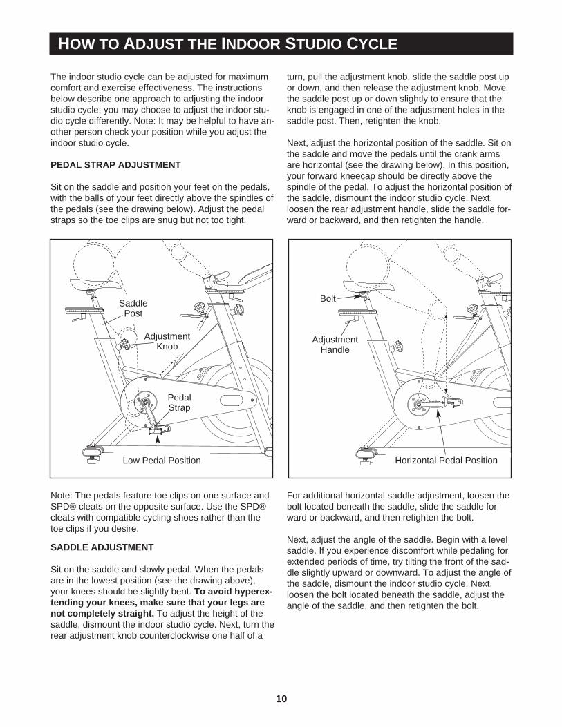
PEDAL STRAP ADJUSTMENT
Sit on the saddle and position your feet on the pedals,with the balls of your feet directly above the spindles ofthe pedals (see the drawing below). Adjust the pedalstraps so the toe clips are snug but not too tight.
Note: The pedals feature toe clips on one surface andSPD® cleats on the opposite surface. Use the SPD®cleats with compatible cycling shoes rather than thetoe clips if you desire.
SADDLE ADJUSTMENT
Sit on the saddle and slowly pedal. When the pedalsare in the lowest position (see the drawing above),your knees should be slightly bent. To avoid hyperex-tending your knees, make sure that your legs arenot completely straight. To adjust the height of thesaddle, dismount the indoor studio cycle. Next, turn therear adjustment knob counterclockwise one half of a
turn, pull the adjustment knob, slide the saddle post upor down, and then release the adjustment knob. Movethe saddle post up or down slightly to ensure that theknob is engaged in one of the adjustment holes in thesaddle post. Then, retighten the knob.
Next, adjust the horizontal position of the saddle. Sit onthe saddle and move the pedals until the crank armsare horizontal (see the drawing below). In this position,your forward kneecap should be directly above thespindle of the pedal. To adjust the horizontal position ofthe saddle, dismount the indoor studio cycle. Next,loosen the rear adjustment handle, slide the saddle for-ward or backward, and then retighten the handle.
For additional horizontal saddle adjustment, loosen thebolt located beneath the saddle, slide the saddle for-ward or backward, and then retighten the bolt.
Next, adjust the angle of the saddle. Begin with a levelsaddle. If you experience discomfort while pedaling forextended periods of time, try tilting the front of the sad-dle slightly upward or downward. To adjust the angle ofthe saddle, dismount the indoor studio cycle. Next,loosen the bolt located beneath the saddle, adjust theangle of the saddle, and then retighten the bolt.
Low Pedal Position
PedalStrap
SaddlePost
AdjustmentKnob
Bolt
AdjustmentHandle
Horizontal Pedal Position
11
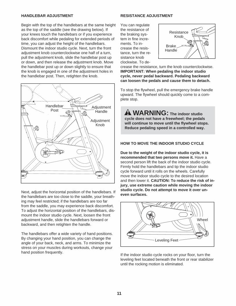
HANDLEBAR ADJUSTMENT
Begin with the top of the handlebars at the same heightas the top of the saddle (see the drawing below). Ifyour knees touch the handlebars or if you experienceback discomfort while pedaling for extended periods oftime, you can adjust the height of the handlebars.Dismount the indoor studio cycle. Next, turn the frontadjustment knob counterclockwise one half of a turn,pull the adjustment knob, slide the handlebar post upor down, and then release the adjustment knob. Movethe handlebar post up or down slightly to ensure thatthe knob is engaged in one of the adjustment holes inthe handlebar post. Then, retighten the knob.
Next, adjust the horizontal position of the handlebars. Ifthe handlebars are too close to the saddle, your breath-ing may feel restricted; if the handlebars are too farfrom the saddle, you may experience back discomfort.To adjust the horizontal position of the handlebars, dis-mount the indoor studio cycle. Next, loosen the frontadjustment handle, slide the handlebars forward orbackward, and then retighten the handle.
The handlebars offer a wide variety of hand positions.By changing your hand position, you can change theangle of your back, neck, and arms. To minimize thestress on your muscles during workouts, change yourhand position frequently.
RESISTANCE ADJUSTMENT
You can regulatethe resistance ofthe braking sys-tem in fine incre-ments. To in-crease the resis-tance, turn the re-sistance knobclockwise. To de-crease the resistance, turn the knob counterclockwise.IMPORTANT: When pedaling the indoor studiocycle, never pedal backward. Pedaling backwardcan loosen the pedals and cause them to detach.
To stop the flywheel, pull the emergency brake handleupward. The flywheel should quickly come to a com-plete stop.
HOW TO MOVE THE INDOOR STUDIO CYCLE
Due to the weight of the indoor studio cycle, it isrecommended that two persons move it. Have asecond person lift the back of the indoor studio cycle.Firmly hold the handlebars and tip the indoor studiocycle forward until it rolls on the wheels. Carefullymove the indoor studio cycle to the desired locationand then lower it. CAUTION: To reduce the risk of in-jury, use extreme caution while moving the indoorstudio cycle. Do not attempt to move it over un-even surfaces.
If the indoor studio cycle rocks on your floor, turn theleveling feet located beneath the front or rear stabilizeruntil the rocking motion is eliminated.
WARNING: The indoor studiocycle does not have a freewheel; the pedalswill continue to move until the flywheel stops.Reduce pedaling speed in a controlled way.
AdjustmentKnob
AdjustmentHandle
HandlebarPost
BrakeHandle
ResistanceKnob
Leveling Feet
Wheel
12
Regular maintenance must be performed on the indoor studio cycle for optimal performance andlongevity. Please read and follow all instructions below. If the indoor studio cycle is not maintained as described,components may wear excessively and the indoor studio cycle may become damaged. If you have questionsabout maintenance, see HOW TO CONTACT CUSTOMER CARE on the back cover of this manual.
Note: Many maintenance procedures require maintenance spray. FreeMotion Fitness recommends CRC Food Grade Silicone. CRC Food Grade Silicone is available at many industrial supply and hardwarestores.
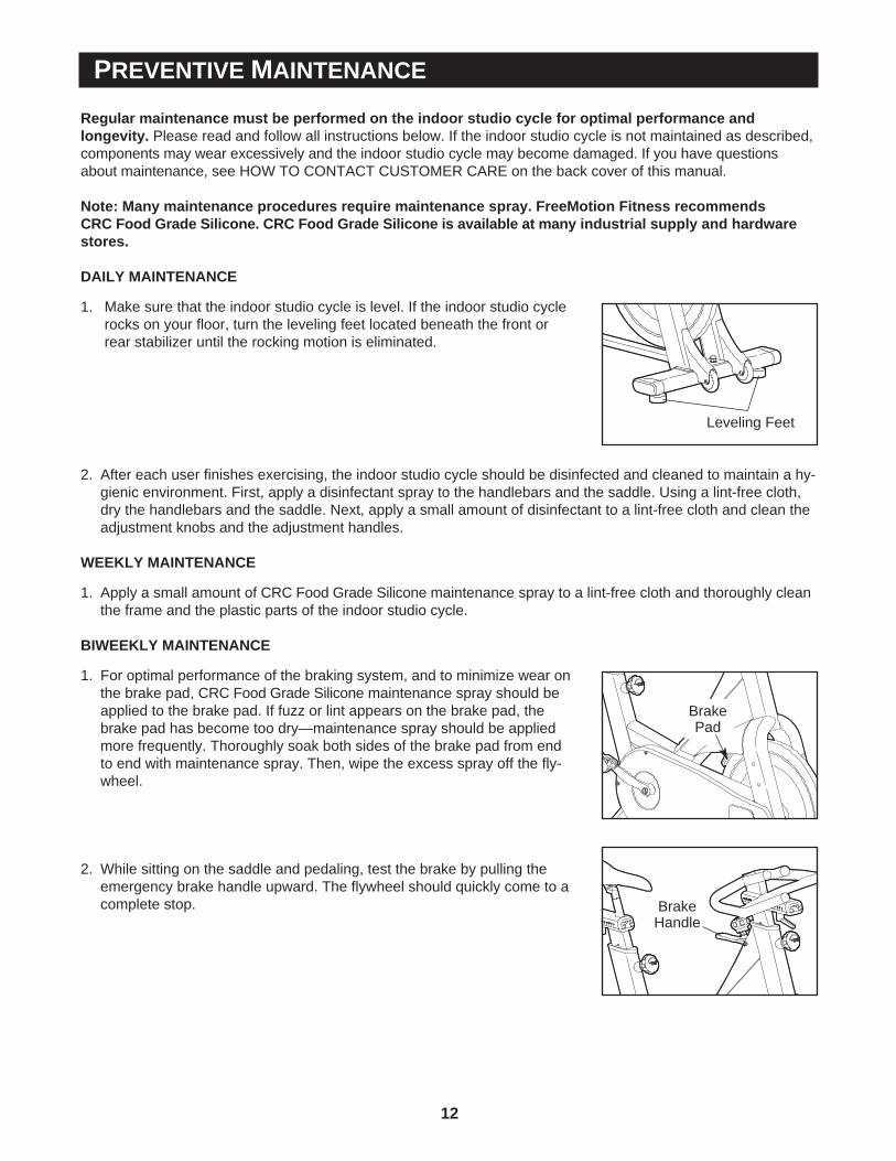
DAILY MAINTENANCE
1. Make sure that the indoor studio cycle is level. If the indoor studio cyclerocks on your floor, turn the leveling feet located beneath the front orrear stabilizer until the rocking motion is eliminated.
2. After each user finishes exercising, the indoor studio cycle should be disinfected and cleaned to maintain a hy-gienic environment. First, apply a disinfectant spray to the handlebars and the saddle. Using a lint-free cloth,dry the handlebars and the saddle. Next, apply a small amount of disinfectant to a lint-free cloth and clean theadjustment knobs and the adjustment handles.
WEEKLY MAINTENANCE
1. Apply a small amount of CRC Food Grade Silicone maintenance spray to a lint-free cloth and thoroughly cleanthe frame and the plastic parts of the indoor studio cycle.
BIWEEKLY MAINTENANCE
1. For optimal performance of the braking system, and to minimize wear onthe brake pad, CRC Food Grade Silicone maintenance spray should beapplied to the brake pad. If fuzz or lint appears on the brake pad, thebrake pad has become too dry—maintenance spray should be appliedmore frequently. Thoroughly soak both sides of the brake pad from endto end with maintenance spray. Then, wipe the excess spray off the fly-wheel.
2. While sitting on the saddle and pedaling, test the brake by pulling theemergency brake handle upward. The flywheel should quickly come to acomplete stop.
PREVENTIVE MAINTENANCE
BrakePad
BrakeHandle
Leveling Feet
13
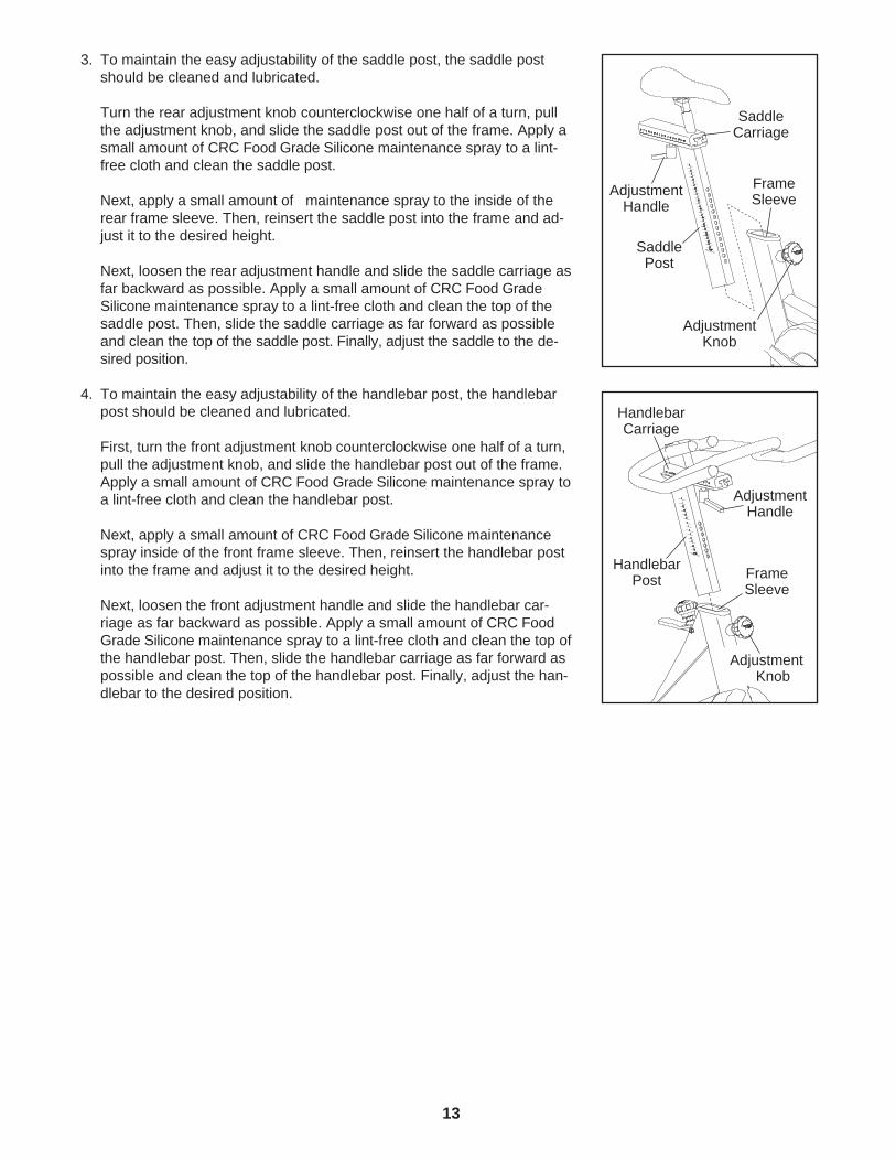
3. To maintain the easy adjustability of the saddle post, the saddle postshould be cleaned and lubricated.
Turn the rear adjustment knob counterclockwise one half of a turn, pullthe adjustment knob, and slide the saddle post out of the frame. Apply asmall amount of CRC Food Grade Silicone maintenance spray to a lint-free cloth and clean the saddle post.
Next, apply a small amount of maintenance spray to the inside of therear frame sleeve. Then, reinsert the saddle post into the frame and ad-just it to the desired height.
Next, loosen the rear adjustment handle and slide the saddle carriage asfar backward as possible. Apply a small amount of CRC Food GradeSilicone maintenance spray to a lint-free cloth and clean the top of thesaddle post. Then, slide the saddle carriage as far forward as possibleand clean the top of the saddle post. Finally, adjust the saddle to the de-sired position.
4. To maintain the easy adjustability of the handlebar post, the handlebarpost should be cleaned and lubricated.
First, turn the front adjustment knob counterclockwise one half of a turn,pull the adjustment knob, and slide the handlebar post out of the frame.Apply a small amount of CRC Food Grade Silicone maintenance spray toa lint-free cloth and clean the handlebar post.
Next, apply a small amount of CRC Food Grade Silicone maintenancespray inside of the front frame sleeve. Then, reinsert the handlebar postinto the frame and adjust it to the desired height.
Next, loosen the front adjustment handle and slide the handlebar car-riage as far backward as possible. Apply a small amount of CRC FoodGrade Silicone maintenance spray to a lint-free cloth and clean the top ofthe handlebar post. Then, slide the handlebar carriage as far forward aspossible and clean the top of the handlebar post. Finally, adjust the han-dlebar to the desired position.
SaddlePost
SaddleCarriage
AdjustmentKnob
FrameSleeve
HandlebarPost
HandlebarCarriage
FrameSleeve
AdjustmentHandle
AdjustmentHandle
AdjustmentKnob
14
MONTHLY MAINTENANCE
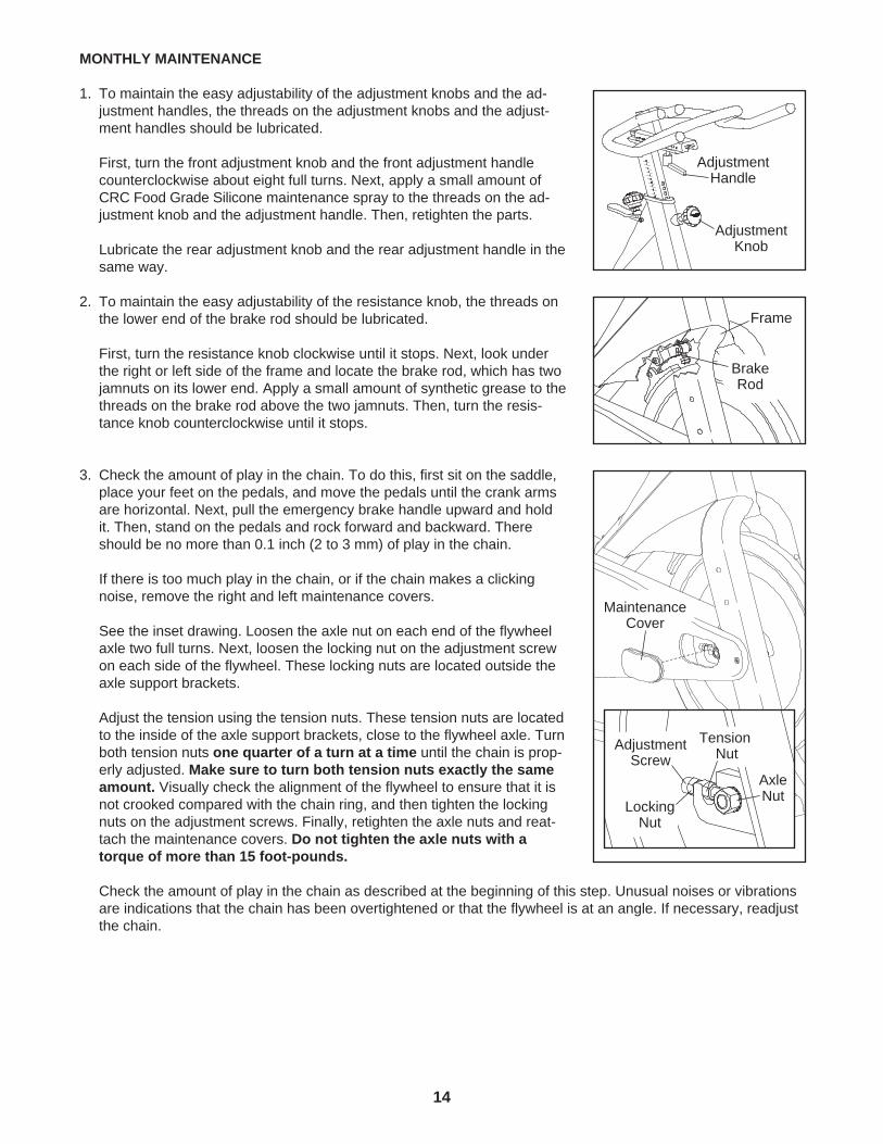
1. To maintain the easy adjustability of the adjustment knobs and the ad-justment handles, the threads on the adjustment knobs and the adjust-ment handles should be lubricated.
First, turn the front adjustment knob and the front adjustment handlecounterclockwise about eight full turns. Next, apply a small amount ofCRC Food Grade Silicone maintenance spray to the threads on the ad-justment knob and the adjustment handle. Then, retighten the parts.
Lubricate the rear adjustment knob and the rear adjustment handle in thesame way.
2. To maintain the easy adjustability of the resistance knob, the threads onthe lower end of the brake rod should be lubricated.
First, turn the resistance knob clockwise until it stops. Next, look underthe right or left side of the frame and locate the brake rod, which has twojamnuts on its lower end. Apply a small amount of synthetic grease to thethreads on the brake rod above the two jamnuts. Then, turn the resis-tance knob counterclockwise until it stops.
3. Check the amount of play in the chain. To do this, first sit on the saddle,place your feet on the pedals, and move the pedals until the crank armsare horizontal. Next, pull the emergency brake handle upward and holdit. Then, stand on the pedals and rock forward and backward. Thereshould be no more than 0.1 inch (2 to 3 mm) of play in the chain.
If there is too much play in the chain, or if the chain makes a clickingnoise, remove the right and left maintenance covers.
See the inset drawing. Loosen the axle nut on each end of the flywheelaxle two full turns. Next, loosen the locking nut on the adjustment screwon each side of the flywheel. These locking nuts are located outside theaxle support brackets.
Adjust the tension using the tension nuts. These tension nuts are locatedto the inside of the axle support brackets, close to the flywheel axle. Turnboth tension nuts one quarter of a turn at a time until the chain is prop-erly adjusted. Make sure to turn both tension nuts exactly the sameamount. Visually check the alignment of the flywheel to ensure that it isnot crooked compared with the chain ring, and then tighten the lockingnuts on the adjustment screws. Finally, retighten the axle nuts and reat-tach the maintenance covers. Do not tighten the axle nuts with atorque of more than 15 foot-pounds.
Check the amount of play in the chain as described at the beginning of this step. Unusual noises or vibrationsare indications that the chain has been overtightened or that the flywheel is at an angle. If necessary, readjustthe chain.
MaintenanceCover
AxleNut
LockingNut
TensionNutAdjustment
Screw
Frame
BrakeRod
AdjustmentHandle
AdjustmentKnob
15
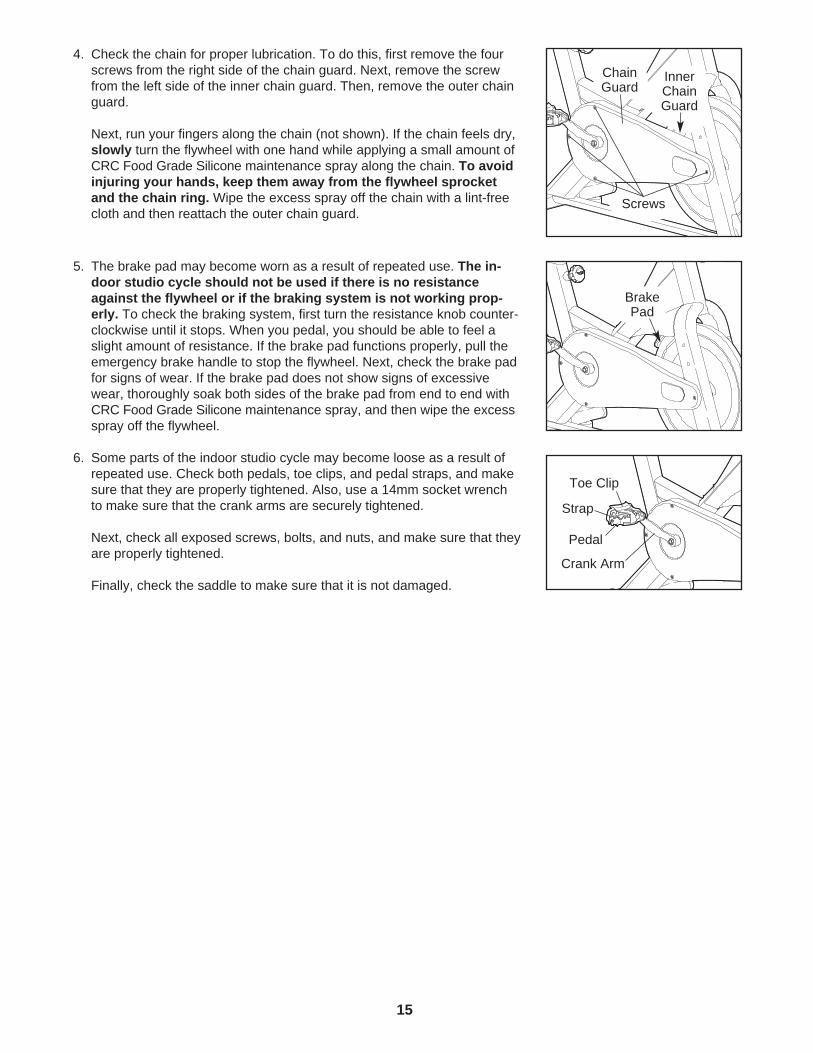
4. Check the chain for proper lubrication. To do this, first remove the fourscrews from the right side of the chain guard. Next, remove the screwfrom the left side of the inner chain guard. Then, remove the outer chainguard.
Next, run your fingers along the chain (not shown). If the chain feels dry,slowly turn the flywheel with one hand while applying a small amount ofCRC Food Grade Silicone maintenance spray along the chain. To avoidinjuring your hands, keep them away from the flywheel sprocketand the chain ring. Wipe the excess spray off the chain with a lint-freecloth and then reattach the outer chain guard.
5. The brake pad may become worn as a result of repeated use. The in-door studio cycle should not be used if there is no resistanceagainst the flywheel or if the braking system is not working prop-erly. To check the braking system, first turn the resistance knob counter-clockwise until it stops. When you pedal, you should be able to feel aslight amount of resistance. If the brake pad functions properly, pull theemergency brake handle to stop the flywheel. Next, check the brake padfor signs of wear. If the brake pad does not show signs of excessivewear, thoroughly soak both sides of the brake pad from end to end withCRC Food Grade Silicone maintenance spray, and then wipe the excessspray off the flywheel.
6. Some parts of the indoor studio cycle may become loose as a result ofrepeated use. Check both pedals, toe clips, and pedal straps, and makesure that they are properly tightened. Also, use a 14mm socket wrenchto make sure that the crank arms are securely tightened.
Next, check all exposed screws, bolts, and nuts, and make sure that theyare properly tightened.
Finally, check the saddle to make sure that it is not damaged.
BrakePad
PedalCrank Arm
Toe Clip
Strap
Screws
ChainGuard
InnerChainGuard
16
LIMITED WARRANTY
Limited Warranty on Commercial EquipmentFreeMotion Fitness, Inc. warrants that all new equipment will be free of manufacturing defects in workmanshipand materials, becoming effective on the date of original installation. Parts repaired or replaced under the terms ofthis warranty will be warranted for the remainder of the original warranty period only.
Terms and Conditions of Coverage1. Warranty applies only while:
(A) it remains in the possession of the original purchaser and proof of purchase is demonstrated, (B) it has not been subject to accident, misuse, abuse, improper service, or modification, and (C) claims are made within the warranty period.
2. All coverage is provided by specific Product according to the guidelines listed below.3. If the Product or any covered part must be returned to a service facility for repairs, we, FreeMotion Fitness,
Inc., will pay all transportation and insurance charges for the first year. We must approve transportation and in-surance previous to shipping. You are responsible for transportation and insurance charges during the remain-ing years.
4. We will ship to you any new or rebuilt replacement part or component, or, at our option, replace the Product.Such replacement parts are warranted for the remaining portion of the original warranty period.
5. This warranty does not cover damage or equipment failure caused by failure to provide reasonable and neces-sary maintenance as outlined in this manual. Any failures or damage caused by unauthorized service, misuse,accident, negligence or improper assembly or installation; debris resulting from any destruction activities in theProduct’s environment; rust or corrosion as a result of the Product’s location; alterations or modifications madewithout written authorization; or failure on your part to use, operate, and maintain the Product as set forth inthis manual will void this warranty. All terms of this warranty are void if the Product is moved beyond thecontinental borders of the United States of America (excluding Alaska, Hawaii, and Canada) and arethen subject to the terms provided by that country’s local authorized FreeMotion Fitness representa-tive.
6. FreeMotion Fitness, Inc. Limited Warranty service can be obtained by calling Customer Care toll-free at1-800-201-2109, Monday through Friday, 8 a.m. to 5 p.m. Mountain Time.
7. The product limited warranty is void when the Product is installed in a country other than where sold.
Limited warranty does not apply to:1. Repairs performed on the Product with missing, altered, or defaced serial numbers. 2. Repair pick-up, delivery, or freight charges other than those specified above.3. Labor costs.
Limited WarrantyParts are warranted to be free from defects in materials and workmanship for the duration of the warranty periodas described below. • 5 years: Frame Construction and Bottom Bracket• 3 years: Mechanical Components• Each indoor studio cycle includes the following extra Wear Items: 1 extra Chain, 1 extra Saddle, 1 extra pair of
Pedal Toe Straps, and 2 extra Brake Pads• There is no Labor Warranty
Your ResponsibilityRetain proof of purchase; use, operate, and maintain the Product as specified in this manual; notify CustomerCare of any defect within 10 days after discovery of the defect; and, if instructed, return any defective part for re-placement, or, if necessary, return the entire Product for repair.
User’s ManualIt is very important that you read this manual before operating the Product. Remember to perform the regularmaintenance requirements specified in this manual to ensure proper operation and your continued satisfaction.
17
Receipt of PartsSimply call Customer Care toll-free at 1-800-201-2109, Monday through Friday, 8 a.m. to 5 p.m. Mountain Time,and give your name, address, and the serial number of your Product. A representative will tell you how to get areplacement part. Before shipping:1. Obtain a Return Authorization Number (RA#) from Customer Care.2. Securely pack your defective part.3. Write the RA# on the outside of the carton.4. Insure the defective part.5. Include a letter explaining the defect or problem and a copy of your proof of purchase if you believe that the
service is covered by warranty.
Exclusive WarrantyFreeMotion Fitness, Inc. is not responsible or liable for indirect, special, or consequential damages arising out of,or in connection with, the use or performance of the Product or damages with respect to any economic loss, lossof property, loss of revenues or profits, loss of enjoyment or use, costs of removal or installation, or other conse-quential damages of whatsoever nature. Some states do not allow the exclusion or limitation of incidental or con-sequential damages. Accordingly, the above limitation may not apply to you. The warranty extended hereunder isin lieu of any and all other warranties and any implied warranties of merchantability or fitness for a particular pur-pose is limited in its scope and duration to the terms set forth herein. Some states do not allow limitations on howlong an implied warranty lasts. Accordingly, the above limitation may not apply to you.
Unauthorized Changes to WarrantyNo one is authorized to change, modify, or extend the terms of this limited warranty.
State LawsThis warranty gives you specific legal rights and you may have other rights which vary from state to state.
18
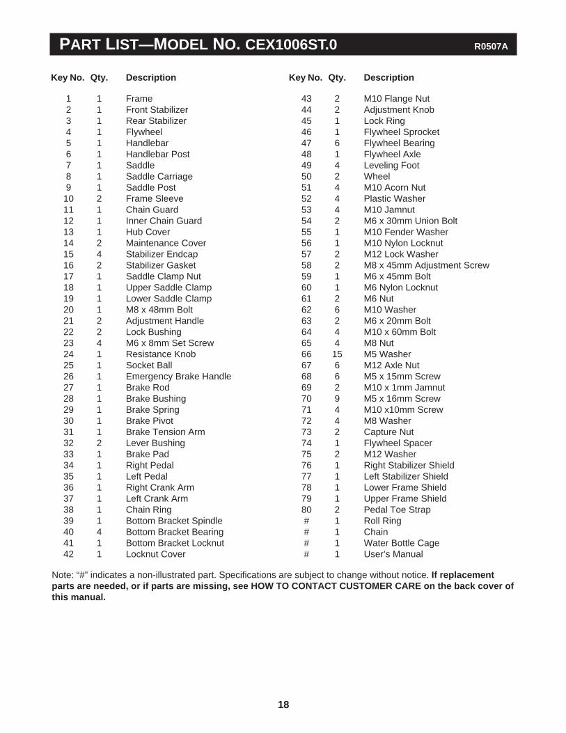
PART LIST—MODEL NO. CEX1006ST.0 R0507A
Note: “#” indicates a non-illustrated part. Specifications are subject to change without notice. If replacementparts are needed, or if parts are missing, see HOW TO CONTACT CUSTOMER CARE on the back cover ofthis manual.
1 1 Frame2 1 Front Stabilizer3 1 Rear Stabilizer4 1 Flywheel5 1 Handlebar6 1 Handlebar Post7 1 Saddle8 1 Saddle Carriage9 1 Saddle Post10 2 Frame Sleeve11 1 Chain Guard12 1 Inner Chain Guard13 1 Hub Cover14 2 Maintenance Cover15 4 Stabilizer Endcap16 2 Stabilizer Gasket17 1 Saddle Clamp Nut18 1 Upper Saddle Clamp19 1 Lower Saddle Clamp20 1 M8 x 48mm Bolt21 2 Adjustment Handle22 2 Lock Bushing23 4 M6 x 8mm Set Screw24 1 Resistance Knob25 1 Socket Ball26 1 Emergency Brake Handle27 1 Brake Rod28 1 Brake Bushing29 1 Brake Spring30 1 Brake Pivot31 1 Brake Tension Arm32 2 Lever Bushing33 1 Brake Pad34 1 Right Pedal35 1 Left Pedal36 1 Right Crank Arm37 1 Left Crank Arm38 1 Chain Ring39 1 Bottom Bracket Spindle40 4 Bottom Bracket Bearing41 1 Bottom Bracket Locknut42 1 Locknut Cover
43 2 M10 Flange Nut44 2 Adjustment Knob45 1 Lock Ring46 1 Flywheel Sprocket47 6 Flywheel Bearing48 1 Flywheel Axle49 4 Leveling Foot50 2 Wheel51 4 M10 Acorn Nut52 4 Plastic Washer53 4 M10 Jamnut54 2 M6 x 30mm Union Bolt55 1 M10 Fender Washer56 1 M10 Nylon Locknut57 2 M12 Lock Washer58 2 M8 x 45mm Adjustment Screw59 1 M6 x 45mm Bolt60 1 M6 Nylon Locknut61 2 M6 Nut62 6 M10 Washer63 2 M6 x 20mm Bolt64 4 M10 x 60mm Bolt65 4 M8 Nut66 15 M5 Washer67 6 M12 Axle Nut68 6 M5 x 15mm Screw69 2 M10 x 1mm Jamnut70 9 M5 x 16mm Screw71 4 M10 x10mm Screw72 4 M8 Washer73 2 Capture Nut74 1 Flywheel Spacer75 2 M12 Washer76 1 Right Stabilizer Shield77 1 Left Stabilizer Shield78 1 Lower Frame Shield79 1 Upper Frame Shield80 2 Pedal Toe Strap# 1 Roll Ring# 1 Chain# 1 Water Bottle Cage# 1 User’s Manual
Key No. Qty. Description Key No. Qty. Description
19
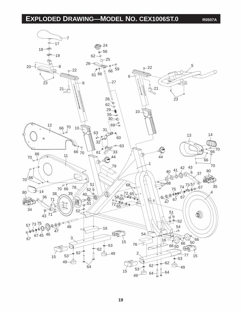
1
2
3
4
5
6
7
8
9
10
10
12
11
13 14
14
15
15
15
15
16
16
17
1918
20
21 21
2222
23
23
24
2526
27
28
29
30
62
55
31
32
33
6360
69
6361
44
34
80
36
37
38 39 40
40 41 42 43
43
44
45 4647
48
67
57 75
4767
676868
5865
49
49
49
49
505066
6666
54
5454
52
51
6256
61 66 66 59
7066
66 70
6670
70 66
70 6651
52
7066
6670
5362 62
53
64
5362
6253
64
52
51
64
71
71
73
5773
67
74
67
7572
6572
65
76
78
79
77
8035
EXPLODED DRAWING—MODEL NO. CEX1006ST.0 R0507A
Part No. 241017 R0507A Printed in USA © 2006 FreeMotion Fitness, Inc.
FreeMotion Fitness, Inc. • 1096 Elkton Drive, Suite 600 • Colorado Springs, CO 80907
If you have questions after reading this manual, or if you require assistance, please contact Customer Care at thephone number or address listed below:
1-800-201-2109, Monday through Friday, 8 a.m. until 5 p.m. Mountain TimeFreeMotion Fitness, Inc., 1096 Elkton Drive, Suite 600, Colorado Springs, CO 80907
When contacting Customer Care, please be prepared to provide the following information:
• the MODEL NUMBER of the product (CEX1006ST.0)
• the NAME of the product (REEBOK® TOMAHAWK indoor studio cycle)
• the SERIAL NUMBER of the product (see the front cover of this manual for the location)
When ordering replacement parts, please also provide the KEY NUMBER and DESCRIPTION of each neededpart (see the PART LIST and the EXPLODED DRAWING on pages 18 and 19).
HOW TO CONTACT CUSTOMER CARE