Embed Size (px)
DESCRIPTION
This is training manual for Compressor Controls Corporation Series 5 vanguard maintenance.
Citation preview
1
2007 C
om
pre
ssor
Contr
ols
Corp
ora
tion
Vanguard Duplex Vanguard Duplex MaintenanceMaintenance
2
2007 C
om
pre
ssor
Contr
ols
Corp
ora
tion
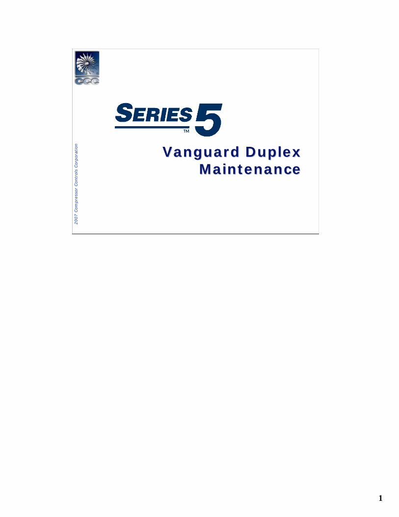
Vanguard System ComponentsVanguard System Components
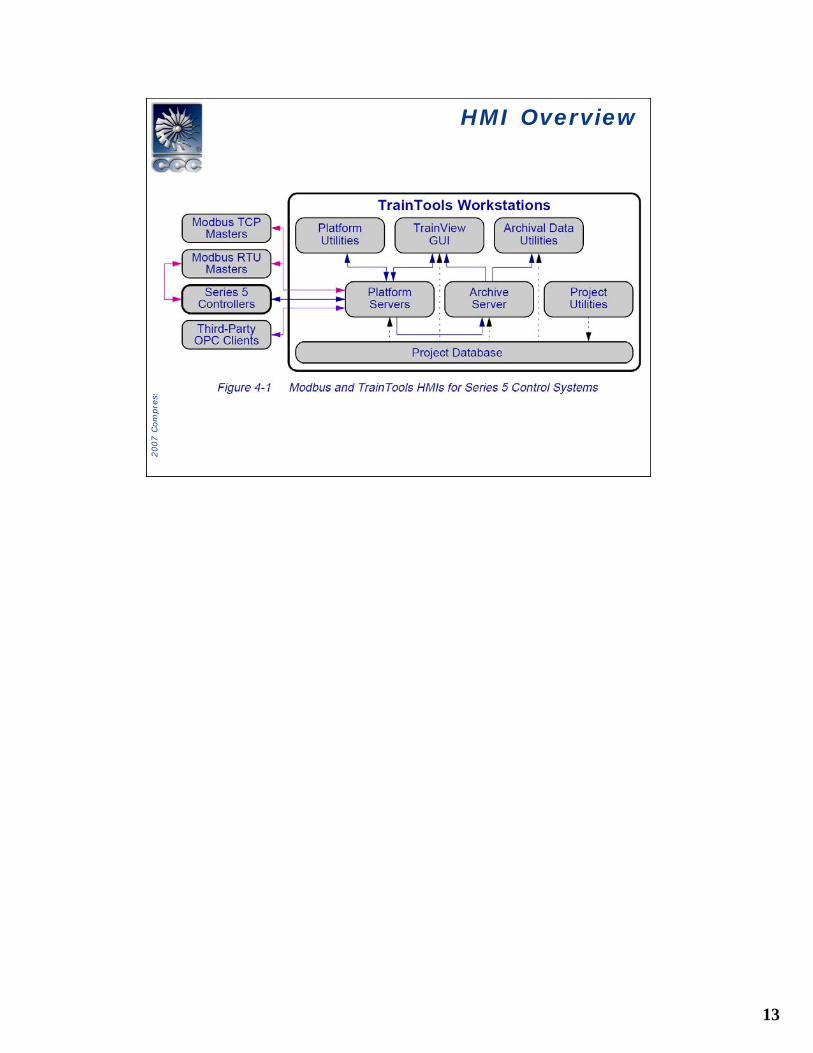
• Duplex ChassisMain Processor Unit (MPU) and Transitional module (TMPU)Universal Power Supply Module (PSMU350)
• Local I/OInput/Output Cards (IOC) and Transitional Modules (TIOC)Duplex Analog Field Termination Assemblies (FTA)Duplex Discrete Field Termination Assemblies (FTA)FTA cables Power Supply (PSMU24)
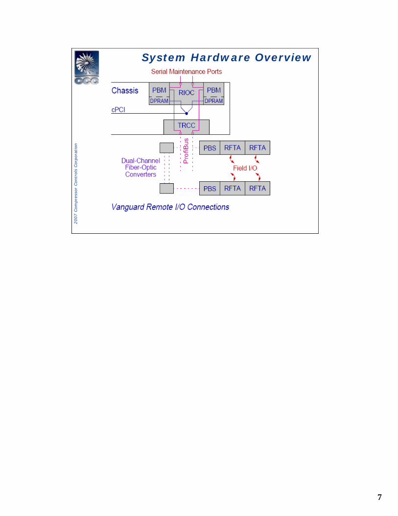
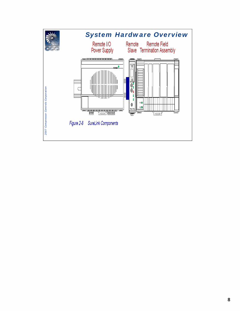
• Remote I/O Subsystem (Sure Link)Remote Carrier Cards (RCC) and Transition Modules (TRCC)Remote Slaves (RSL)Remote Field Termination Assemblies (RFTA)Remote I/O power Supplies
• Ethernet ComponentsTwisted-Pair Hub and cablesFiber Optic HubFiber optic Termination Enclosure
• PC Work Station

3
2007 C
om
pre
ssor
Contr
ols
Corp
ora
tion
System OverviewSystem Overview
4
2007 C
om
pre
ssor
Contr
ols
Corp
ora
tion
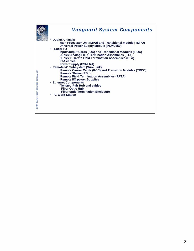
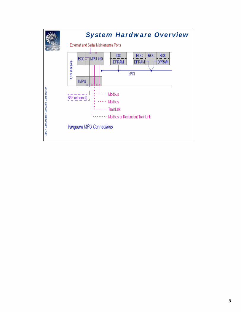
System Hardware OverviewSystem Hardware Overview
5
2007 C
om
pre
ssor
Contr
ols
Corp
ora
tion
System Hardware Overview System Hardware Overview
6
2007 C
om
pre
ssor
Contr
ols
Corp
ora
tion
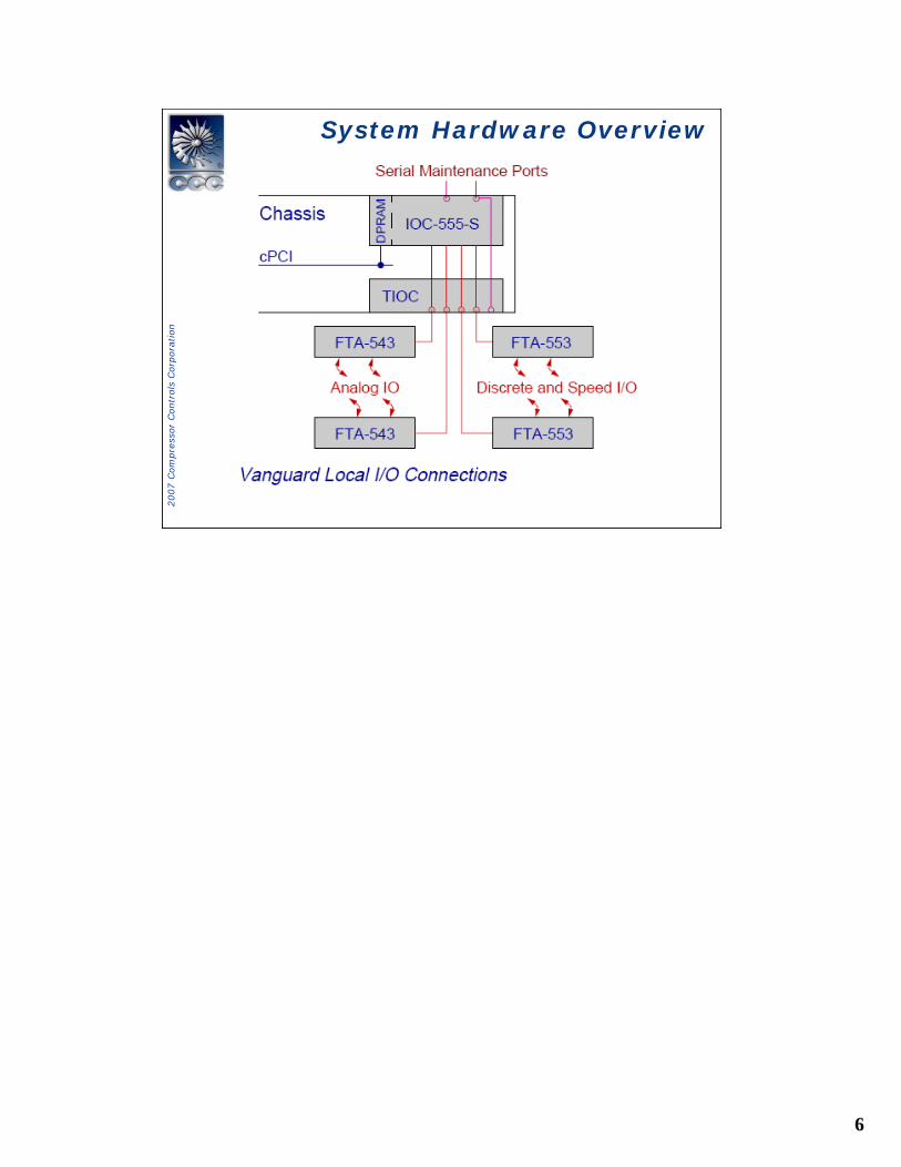
System Hardware OverviewSystem Hardware Overview
7
2007 C
om
pre
ssor
Contr
ols
Corp
ora
tion
System Hardware OverviewSystem Hardware Overview
8
2007 C
om
pre
ssor
Contr
ols
Corp
ora
tion
System Hardware OverviewSystem Hardware Overview
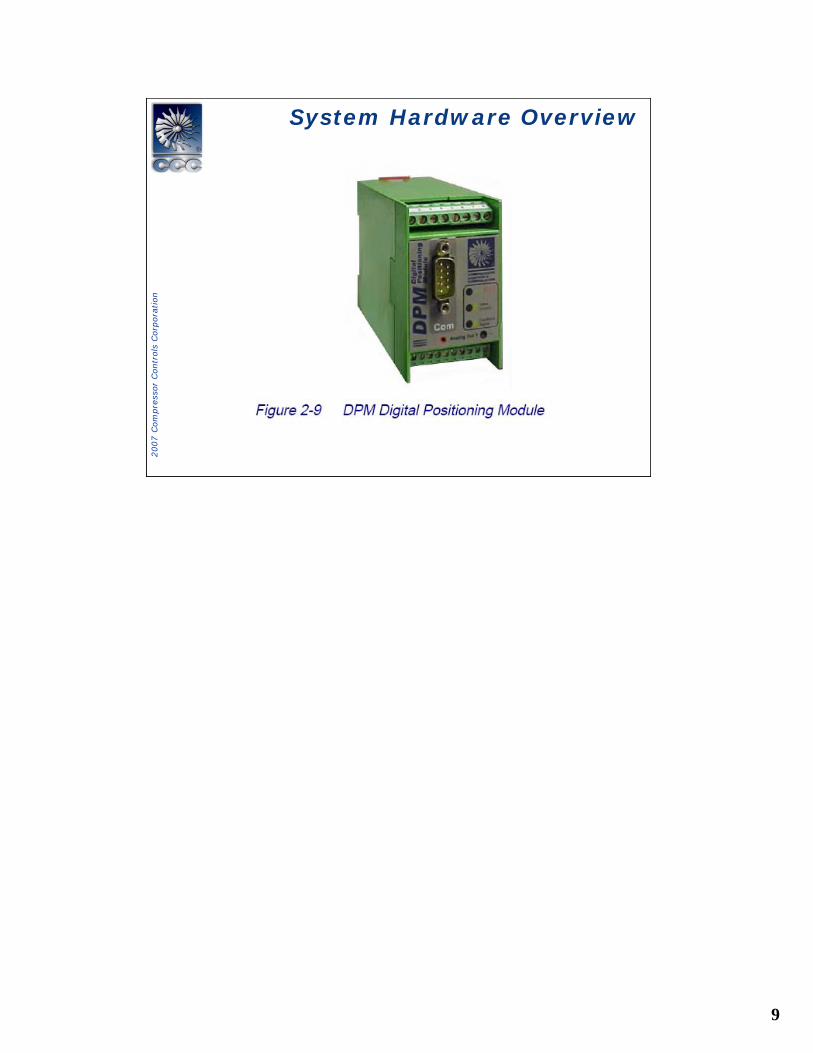
9
2007 C
om
pre
ssor
Contr
ols
Corp
ora
tion
System Hardware OverviewSystem Hardware Overview
10
2007 C
om
pre
ssor
Contr
ols
Corp
ora
tion
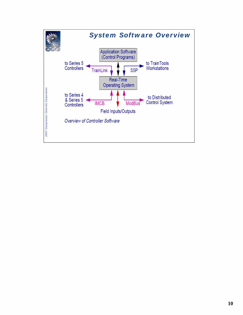
System Software OverviewSystem Software Overview
11
2007 C
om
pre
ssor
Contr
ols
Corp
ora
tion
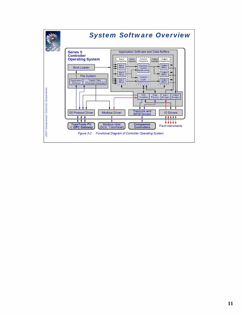
System Software OverviewSystem Software Overview
12
2007 C
om
pre
ssor
Contr
ols
Corp
ora
tion
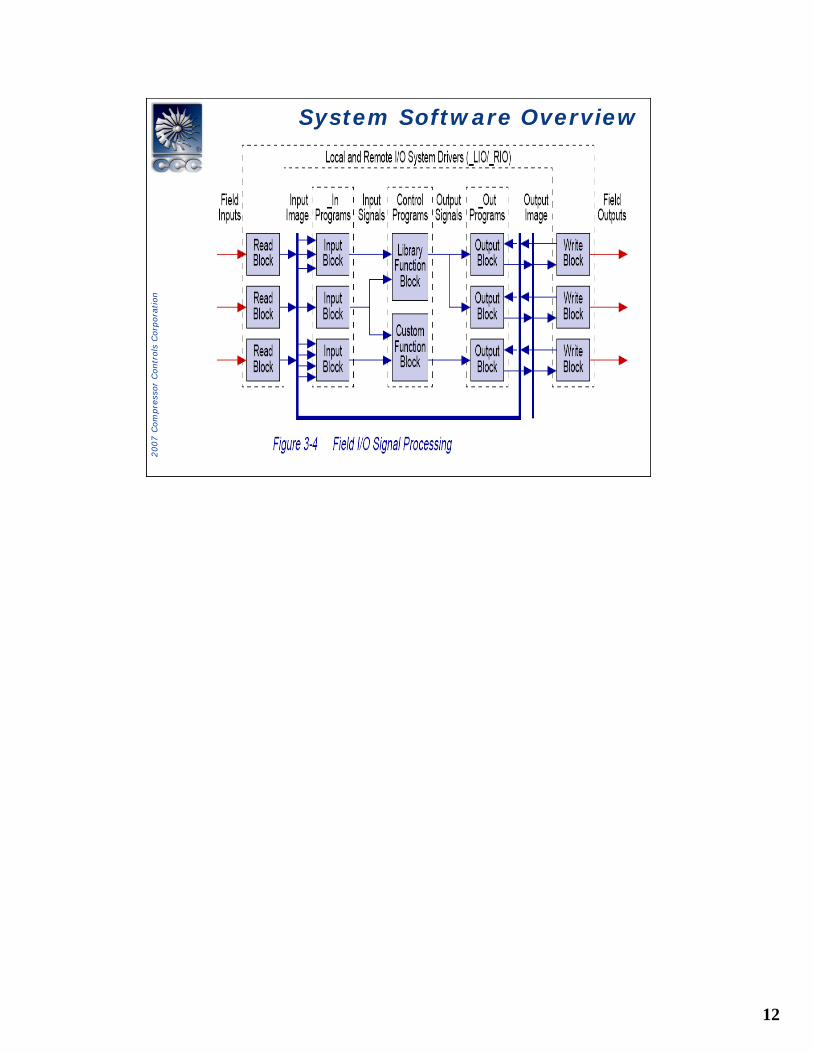
System Software OverviewSystem Software Overview
13
2007 C
om
pre
ssor
Contr
ols
Corp
ora
tion
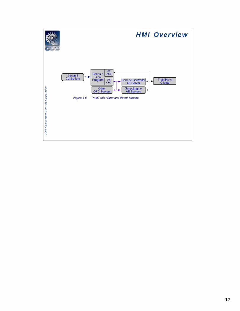
HMI OverviewHMI Overview
14
2007 C
om
pre
ssor
Contr
ols
Corp
ora
tion
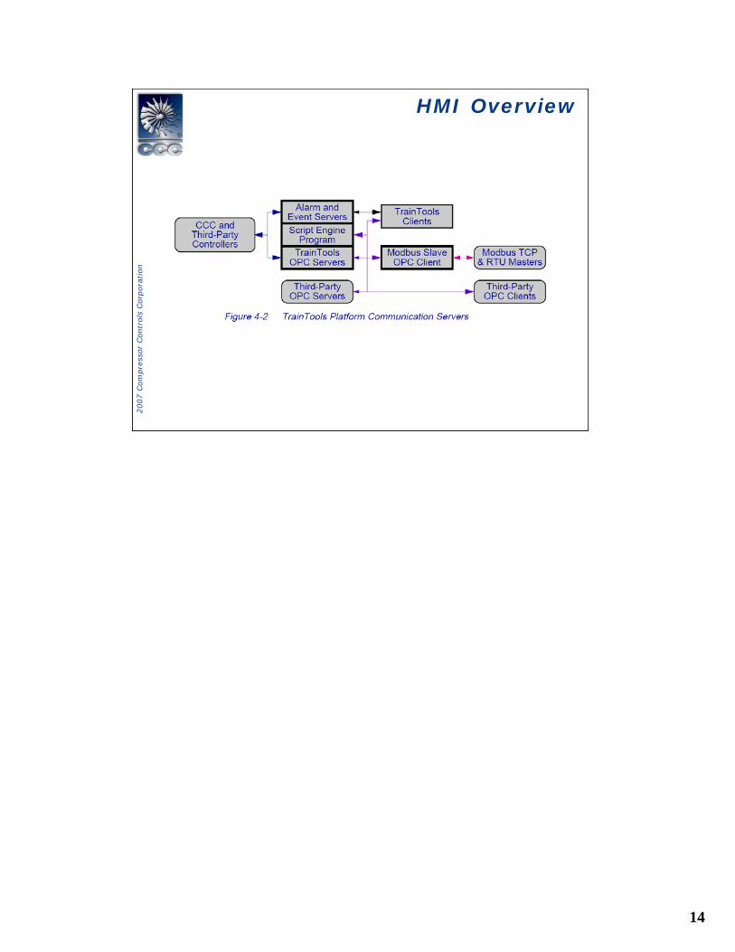
HMI OverviewHMI Overview
15
2007 C
om
pre
ssor
Contr
ols
Corp
ora
tion
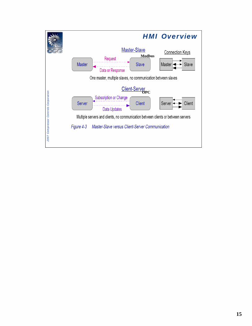
HMI OverviewHMI Overview
Modbus
OPC
16
2007 C
om
pre
ssor
Contr
ols
Corp
ora
tion
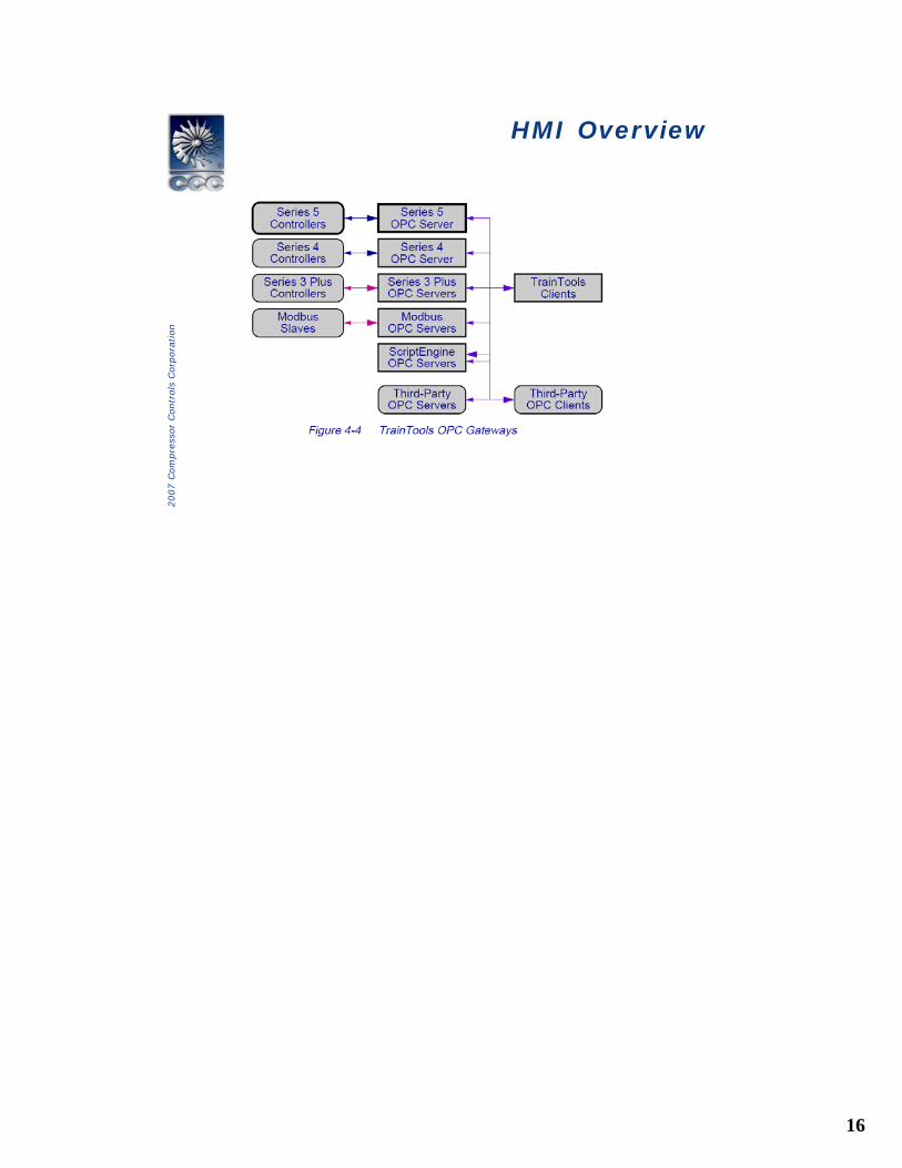
HMI OverviewHMI Overview
17
2007 C
om
pre
ssor
Contr
ols
Corp
ora
tion
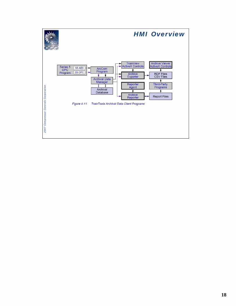
HMI OverviewHMI Overview
18
2007 C
om
pre
ssor
Contr
ols
Corp
ora
tion
HMI OverviewHMI Overview
19
2007 C
om
pre
ssor
Contr
ols
Corp
ora
tion
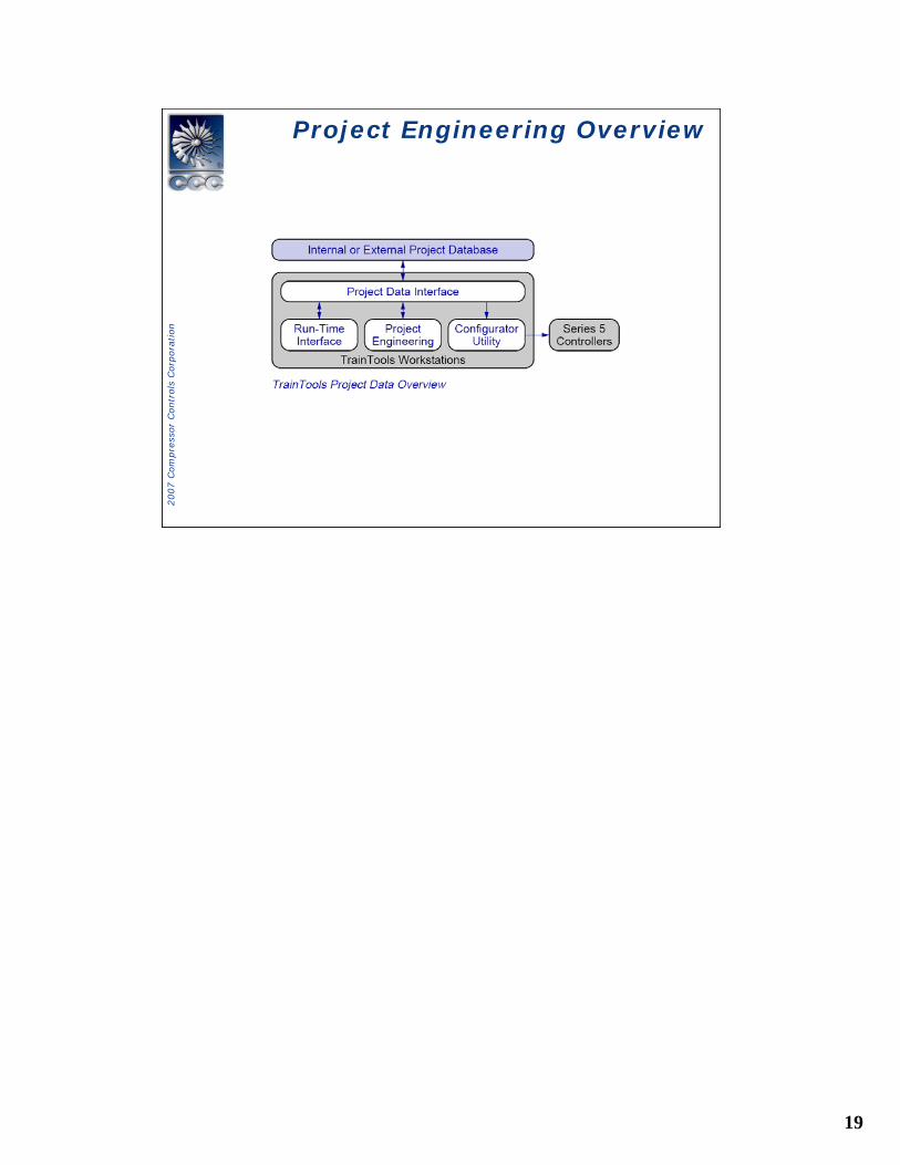
Project Engineering OverviewProject Engineering Overview
20
2007 C
om
pre
ssor
Contr
ols
Corp
ora
tion
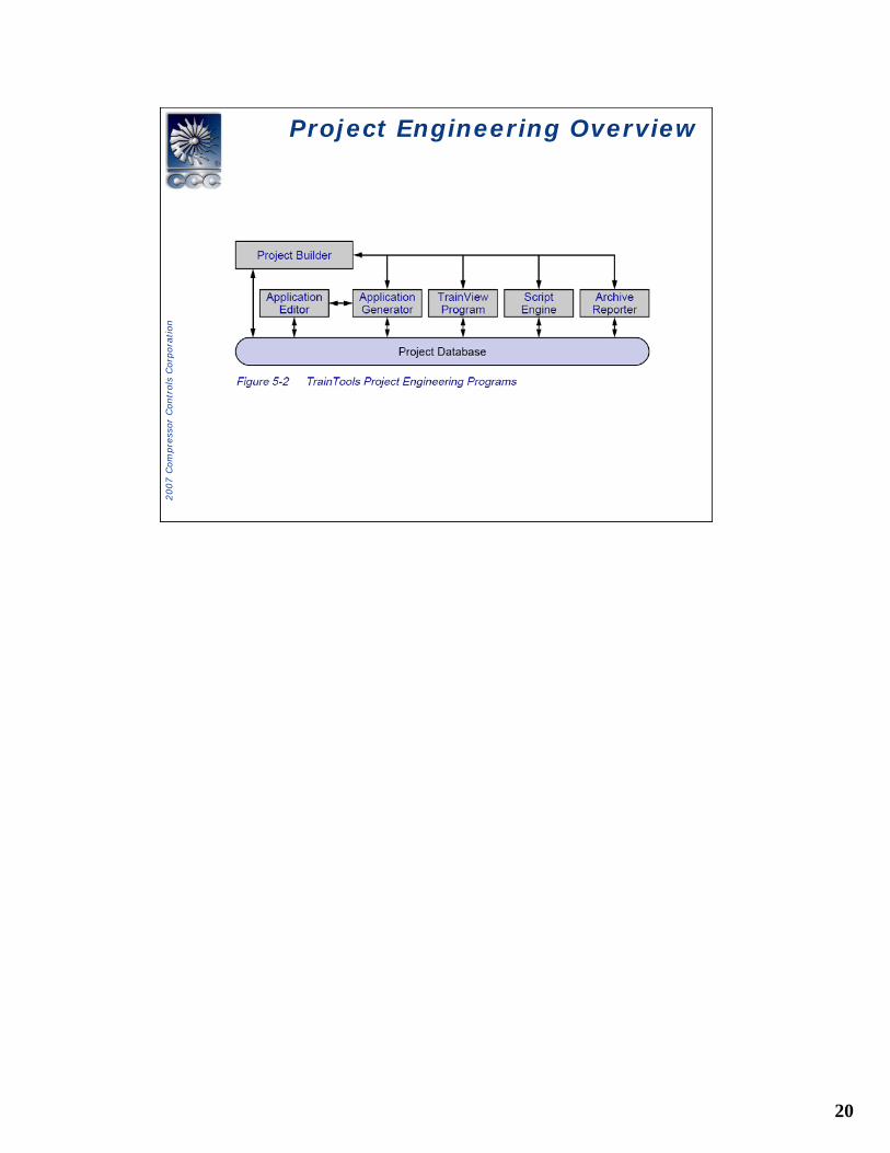
Project Engineering OverviewProject Engineering Overview
21
2007 C
om
pre
ssor
Contr
ols
Corp
ora
tion
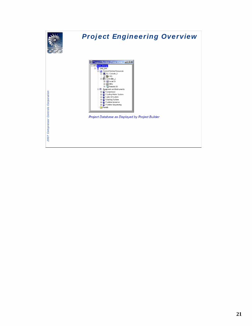
Project Engineering OverviewProject Engineering Overview
22
2007 C
om
pre
ssor
Contr
ols
Corp
ora
tion
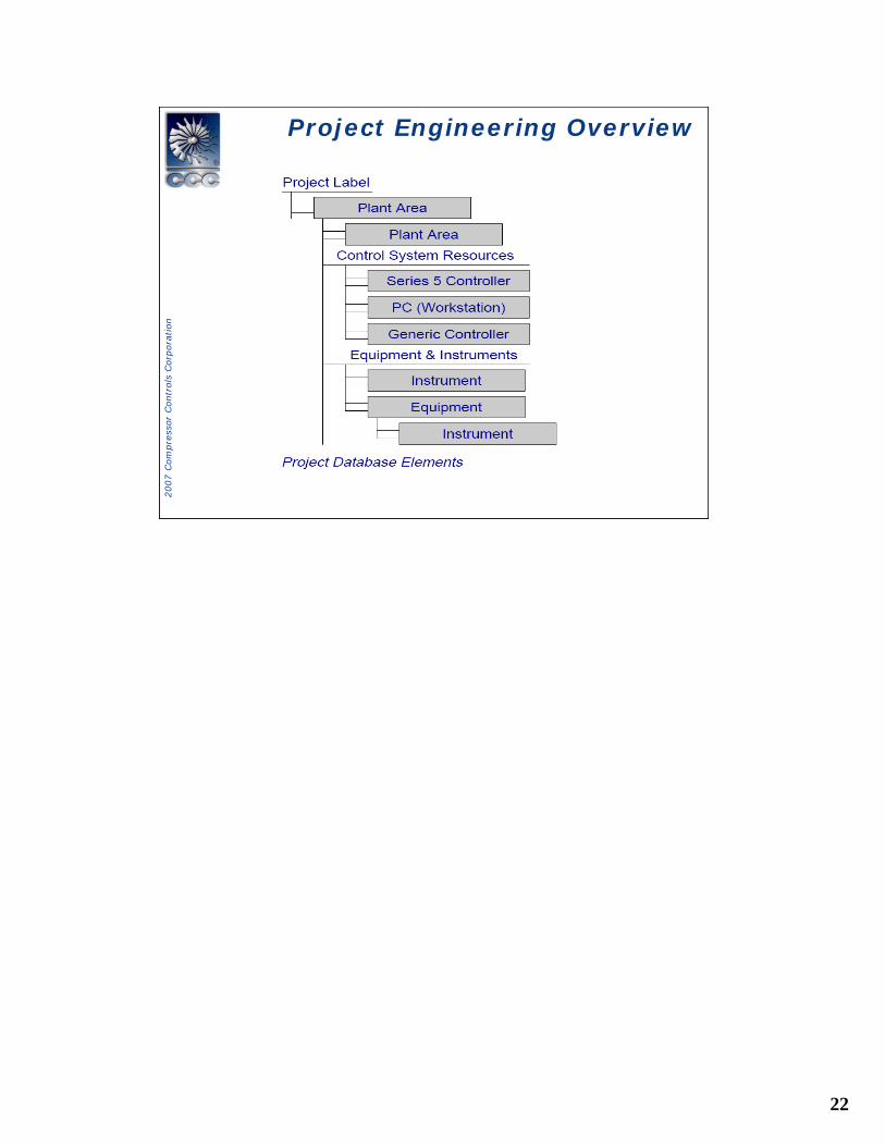
Project Engineering OverviewProject Engineering Overview
23
2007 C
om
pre
ssor
Contr
ols
Corp
ora
tion
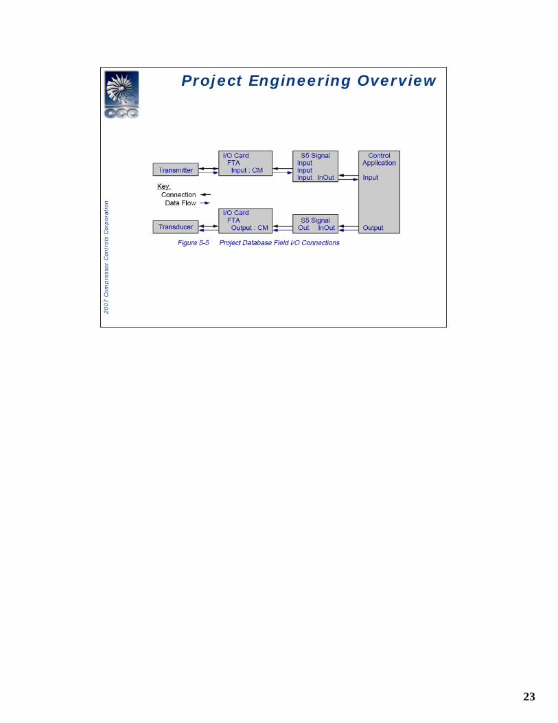
Project Engineering OverviewProject Engineering Overview
24
2007 C
om
pre
ssor
Contr
ols
Corp
ora
tion
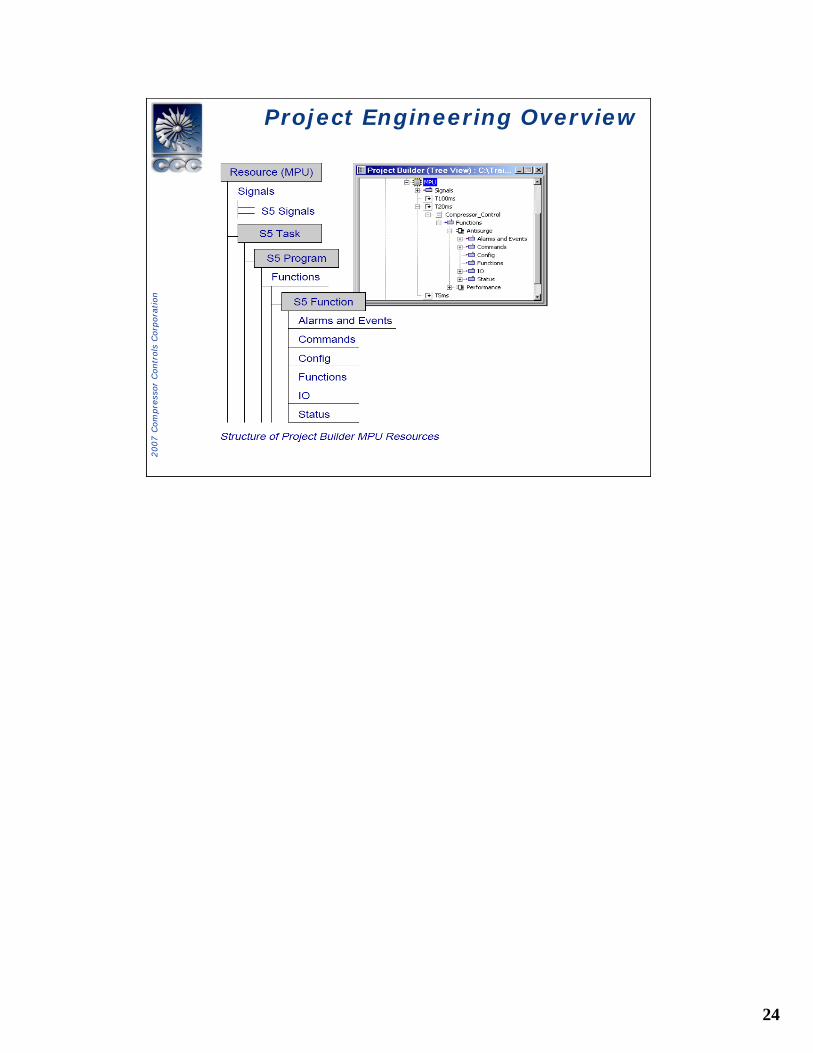
Project Engineering OverviewProject Engineering Overview
25
2007 C
om
pre
ssor
Contr
ols
Corp
ora
tion
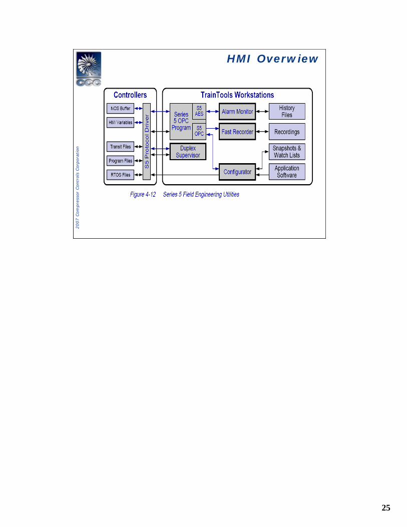
HMI OverwiewHMI Overwiew
26
2007 C
om
pre
ssor
Contr
ols
Corp
ora
tion
System OverviewSystem Overview
Controller Components
• Vanguard System Components• Serial Communication Network• Software Architecture• Hardware Architecture
27
2007 C
om
pre
ssor
Contr
ols
Corp
ora
tion
System OverviewSystem Overview
28
2007 C
om
pre
ssor
Contr
ols
Corp
ora
tion
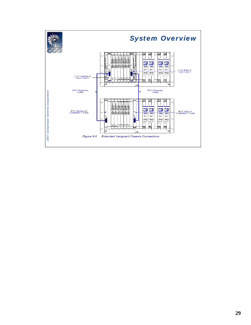
System OverviewSystem Overview
29
2007 C
om
pre
ssor
Contr
ols
Corp
ora
tion
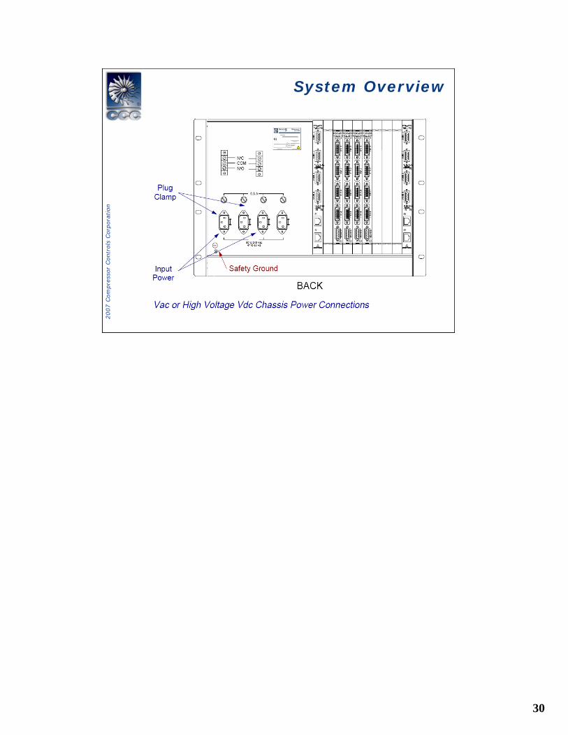
System OverviewSystem Overview
30
2007 C
om
pre
ssor
Contr
ols
Corp
ora
tion
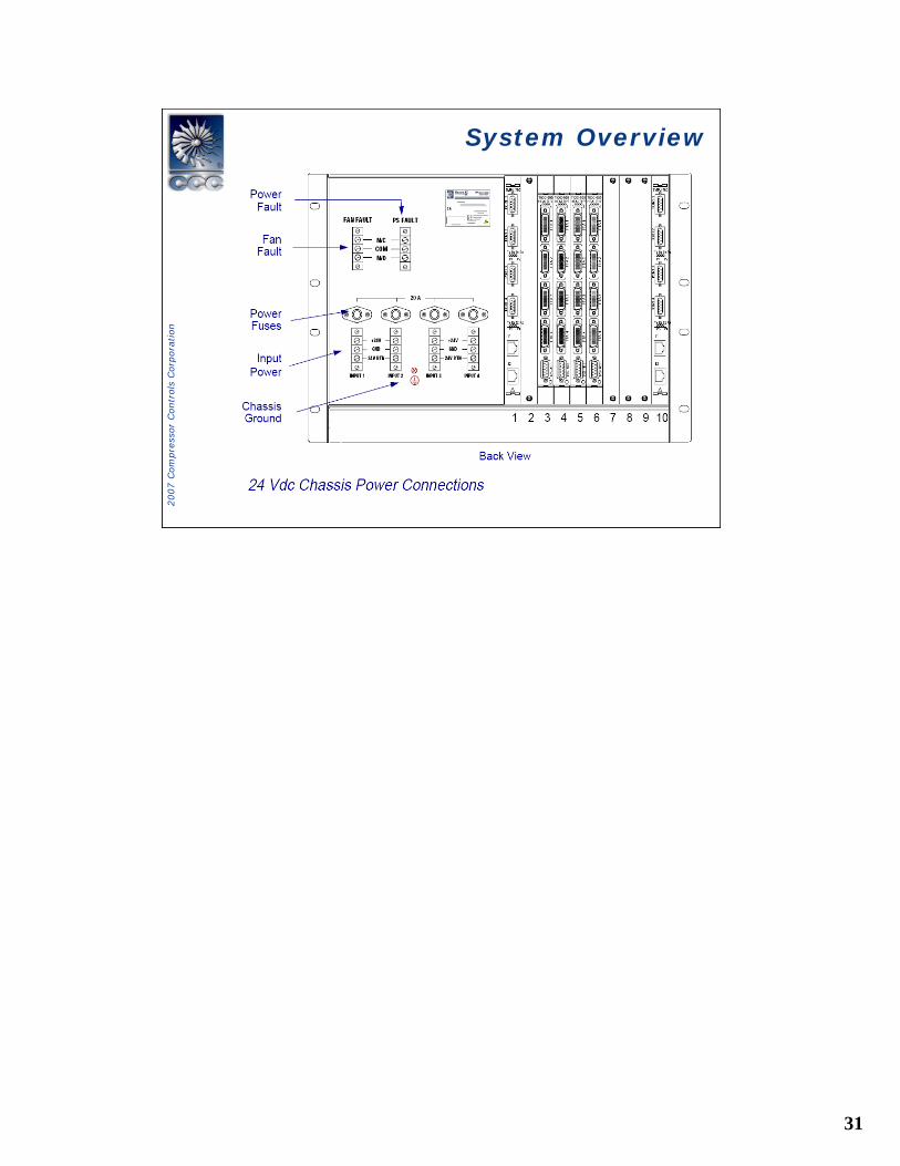
System OverviewSystem Overview
31
2007 C
om
pre
ssor
Contr
ols
Corp
ora
tion
System OverviewSystem Overview
32
2007 C
om
pre
ssor
Contr
ols
Corp
ora
tion
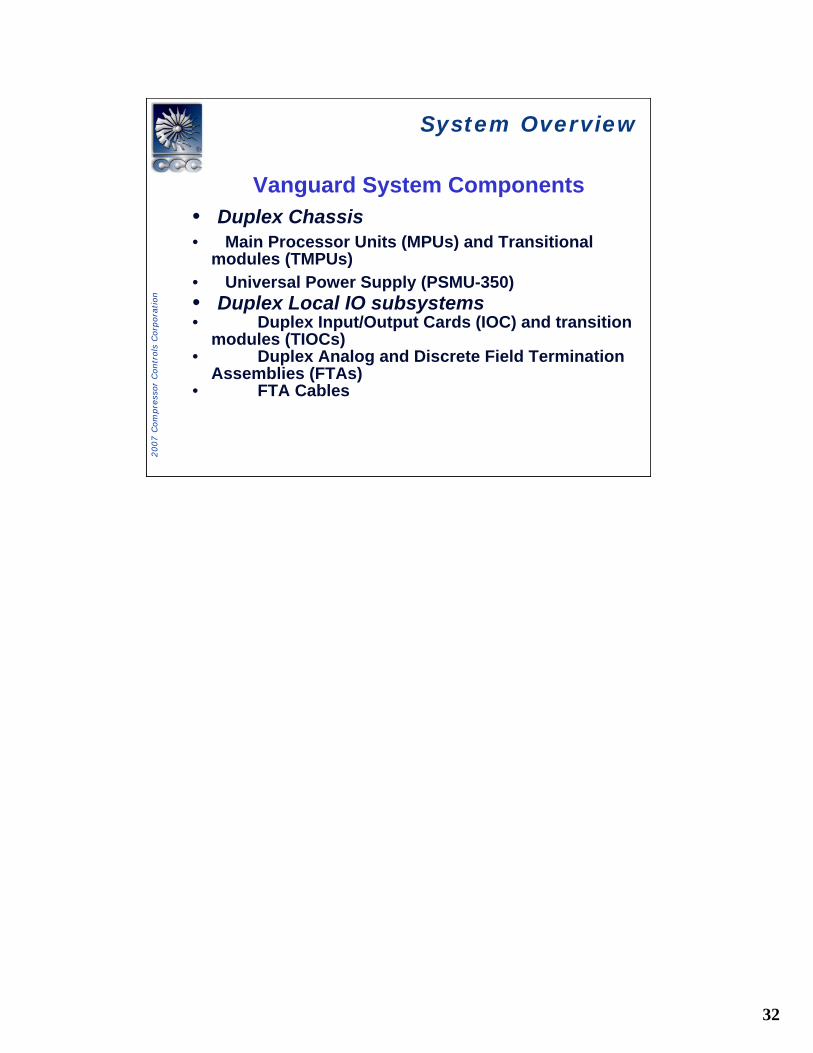
System OverviewSystem Overview
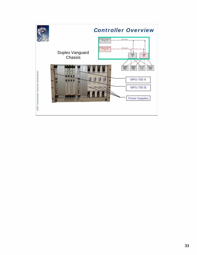
Vanguard System Components• Duplex Chassis• Main Processor Units (MPUs) and Transitional
modules (TMPUs)• Universal Power Supply (PSMU-350)• Duplex Local IO subsystems• Duplex Input/Output Cards (IOC) and transition
modules (TIOCs)• Duplex Analog and Discrete Field Termination
Assemblies (FTAs)• FTA Cables
33
2007 C
om
pre
ssor
Contr
ols
Corp
ora
tion
System ProcessorM PUE-750
A
System ProcessorM PUE-750
B
LocalI /OA
L ocalI/OB
Analo g
cPCI bus A
cPCI bus B
Dup lexFTA
AnalogDuple x
FTA
DiscreteDuplex
FTA
DiscreteDuplex
FTA
LocalI /OA
L ocalI/O
Analo gDup lex
FTADuplex
FTA
AnalogDuple x
FTA
MPU-750 A
Power Supplies
MPU-750 B
Duplex Vanguard Chassis
Controller OverviewController Overview
34
2007 C
om
pre
ssor
Contr
ols
Corp
ora
tion
System ProcessorM PUE-750
A
System ProcessorM PUE-750
B
LocalI /OA
L ocalI/OB
Analo g
cPCI bus A
cPCI bus B
Dup lexFTA
AnalogDuple x
FTA
DiscreteDuplex
FTA
DiscreteDuplex
FTA
LocalI /OA
L ocalI/O
Analo gDup lex
FTADuplex
FTA
AnalogDuple x
FTA
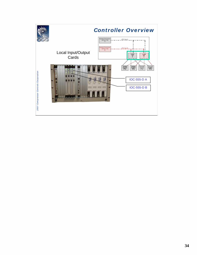
IOC-555-D A
IOC-555-D B
Local Input/Output Cards
Controller OverviewController Overview
35
2007 C
om
pre
ssor
Contr
ols
Corp
ora
tion
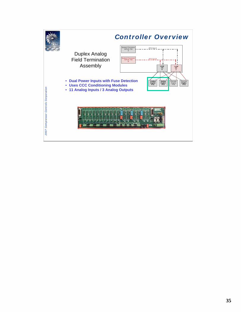
Duplex Analog Field Termination
Assembly
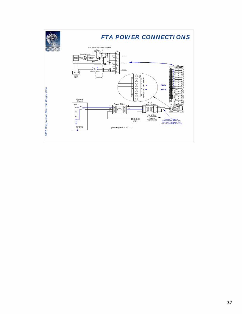
• Dual Power Inputs with Fuse Detection• Uses CCC Conditioning Modules• 11 Analog Inputs / 3 Analog Outputs
System ProcessorM PUE-750
A
System ProcessorM PUE-750
B
LocalI /OA
L ocalI/OB
Analo g
cPCI bus A
cPCI bus B
Dup lexFTA
AnalogDuple x
FTA
DiscreteDuplex
FTA
DiscreteDuplex
FTA
LocalI /OA
L ocalI/O
Analo gDup lex
FTADuplex
FTA
AnalogDuple x
FTA
Controller OverviewController Overview
36
2007 C
om
pre
ssor
Contr
ols
Corp
ora
tion
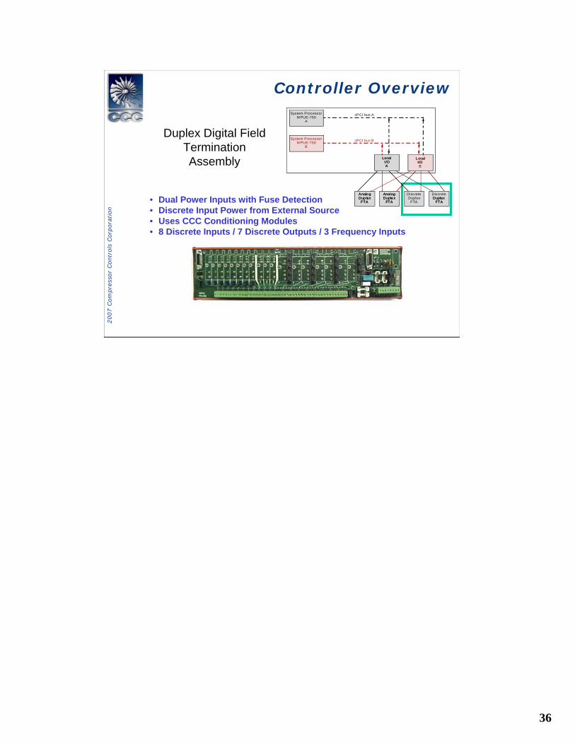
Duplex Digital Field Termination Assembly
• Dual Power Inputs with Fuse Detection• Discrete Input Power from External Source • Uses CCC Conditioning Modules• 8 Discrete Inputs / 7 Discrete Outputs / 3 Frequency Inputs
System ProcessorM PUE-750
A
System ProcessorM PUE-750
B
LocalI /OA
L ocalI/OB
Analo g
cPCI bus A
cPCI bus B
Dup lexFTA
AnalogDuple x
FTA
DiscreteDuplex
FTA
DiscreteDuplex
FTA
LocalI /OA
L ocalI/O
Analo gDup lex
FTADuplex
FTA
AnalogDuple x
FTA
Controller OverviewController Overview
37
2007 C
om
pre
ssor
Contr
ols
Corp
ora
tion
FTA POWER CONNECTIONSFTA POWER CONNECTIONS
38
2007 C
om
pre
ssor
Contr
ols
Corp
ora
tion
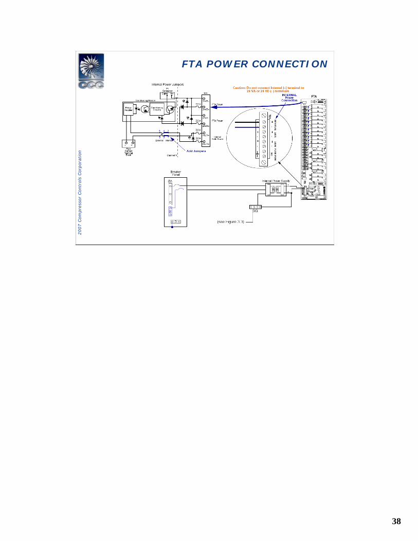
FTA POWER CONNECTIONFTA POWER CONNECTION
39
2007 C
om
pre
ssor
Contr
ols
Corp
ora
tion
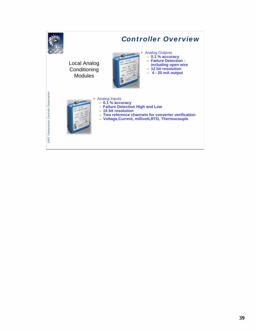
Local Analog Conditioning
Modules
• Analog Inputs– 0.1 % accuracy – Failure Detection High and Low– 15 bit resolution– Two reference channels for converter verification– Voltage,Current, millivolt,RTD, Thermocouple
• Analog Outputs– 0.1 % accuracy– Failure Detection -
including open wire– 12 bit resolution– 4 - 20 mA output
Controller OverviewController Overview
40
2007 C
om
pre
ssor
Contr
ols
Corp
ora
tion
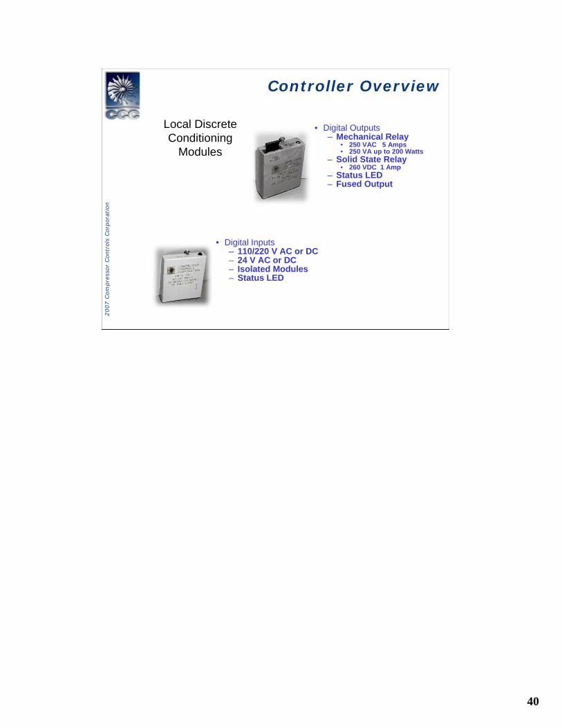
Local Discrete Conditioning
Modules
• Digital Inputs– 110/220 V AC or DC– 24 V AC or DC– Isolated Modules– Status LED
• Digital Outputs– Mechanical Relay
• 250 VAC 5 Amps• 250 VA up to 200 Watts
– Solid State Relay• 260 VDC 1 Amp
– Status LED– Fused Output
Controller OverviewController Overview
41
2007 C
om
pre
ssor
Contr
ols
Corp
ora
tion
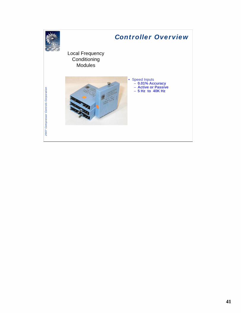
Local Frequency Conditioning
Modules
• Speed Inputs– 0.01% Accuracy– Active or Passive– 5 Hz to 40K Hz
Controller OverviewController Overview

42
2007 C
om
pre
ssor
Contr
ols
Corp
ora
tion
Controller OverviewController Overview
Local Analog Conditioning
Modules
• Analog Inputs– 0.1 % accuracy – Failure Detection High and Low– 15 bit resolution– Two reference channels for converter verification– Voltage,Current, millivolt,RTD, Thermocouple
• Analog Outputs– 0.1 % accuracy– Failure Detection -
including open wire– 12 bit resolution– 4 - 20 mA output
43
2007 C
om
pre
ssor
Contr
ols
Corp
ora
tion
System OverviewSystem Overview
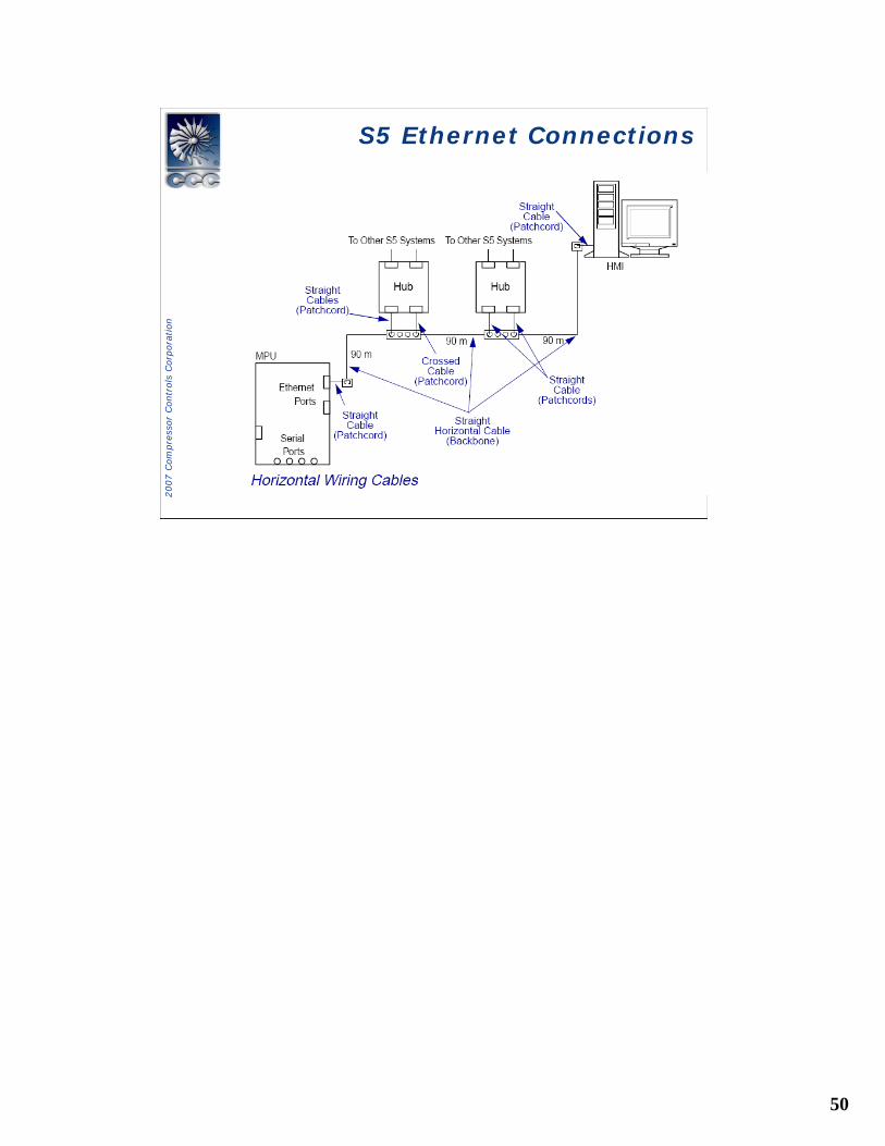
Serial Communication Network
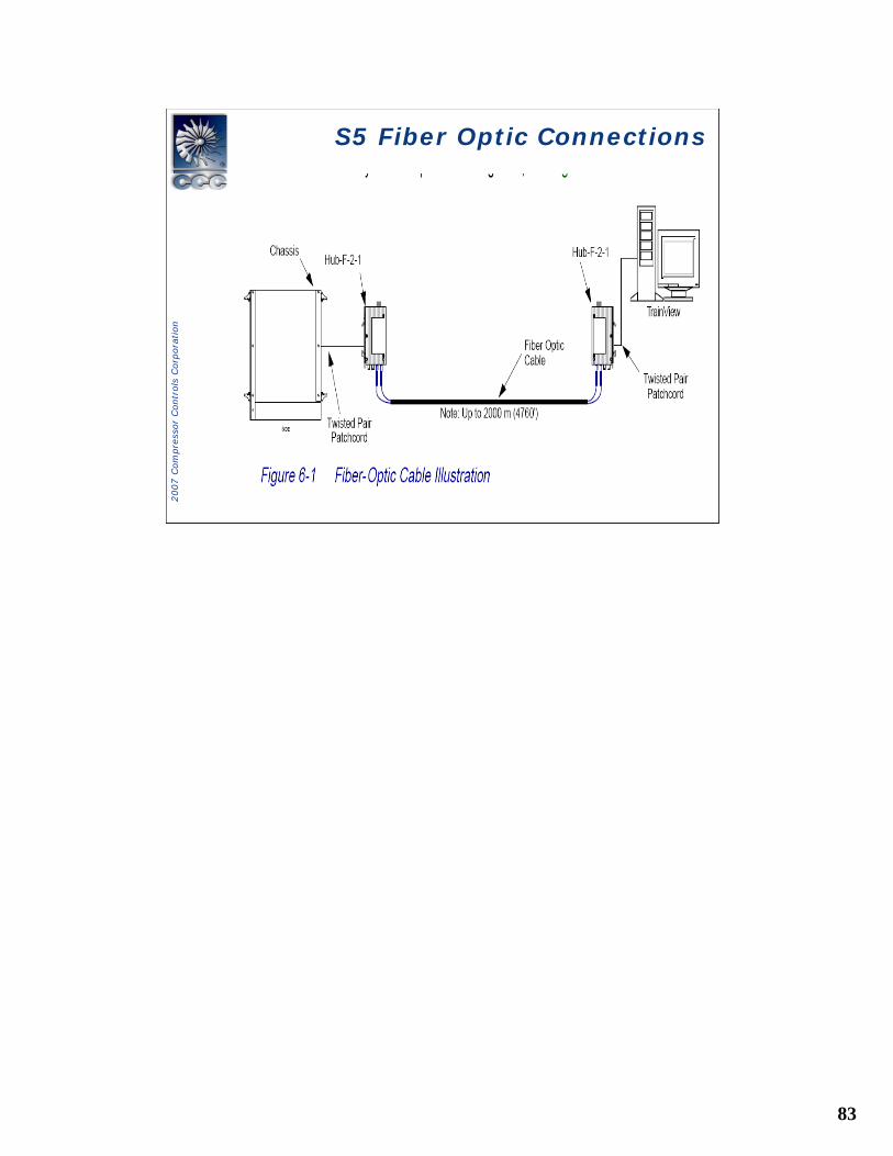
• Ethernet Components• Twisted- Pair Hub and Cables• Fiber Optic Hub and cables• Fiber Optic Termination Enclosure
44
2007 C
om
pre
ssor
Contr
ols
Corp
ora
tion
System OverviewSystem Overview
45
2007 C
om
pre
ssor
Contr
ols
Corp
ora
tion
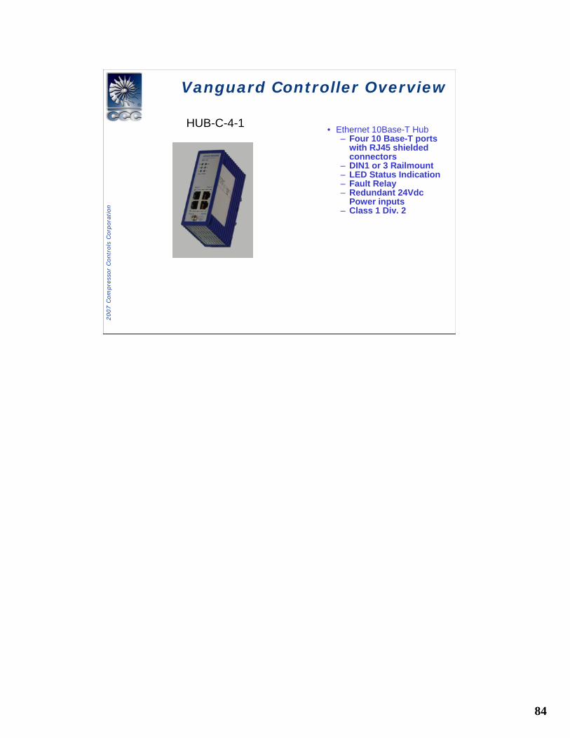
Vanguard HardwareVanguard Hardware
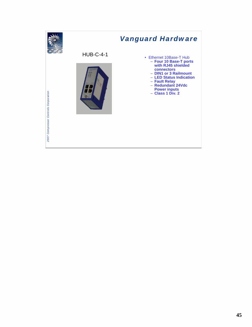
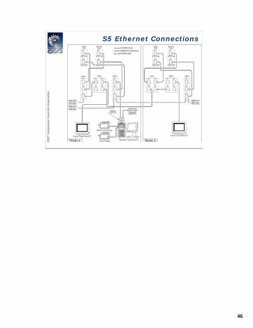
HUB-C-4-1 • Ethernet 10Base-T Hub– Four 10 Base-T ports
with RJ45 shielded connectors
– DIN1 or 3 Railmount– LED Status Indication– Fault Relay– Redundant 24Vdc
Power inputs– Class 1 Div. 2
46
2007 C
om
pre
ssor
Contr
ols
Corp
ora
tion
S5 Ethernet ConnectionsS5 Ethernet Connections
47
2007 C
om
pre
ssor
Contr
ols
Corp
ora
tion
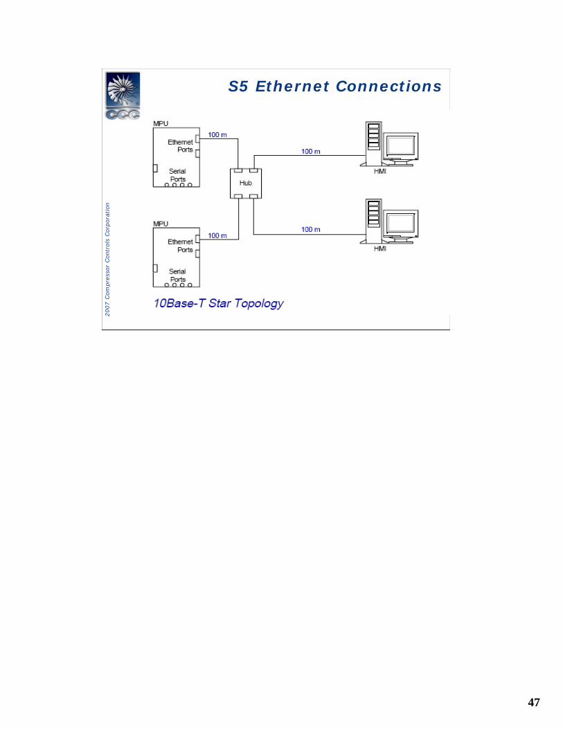
S5 Ethernet ConnectionsS5 Ethernet Connections
48
2007 C
om
pre
ssor
Contr
ols
Corp
ora
tion
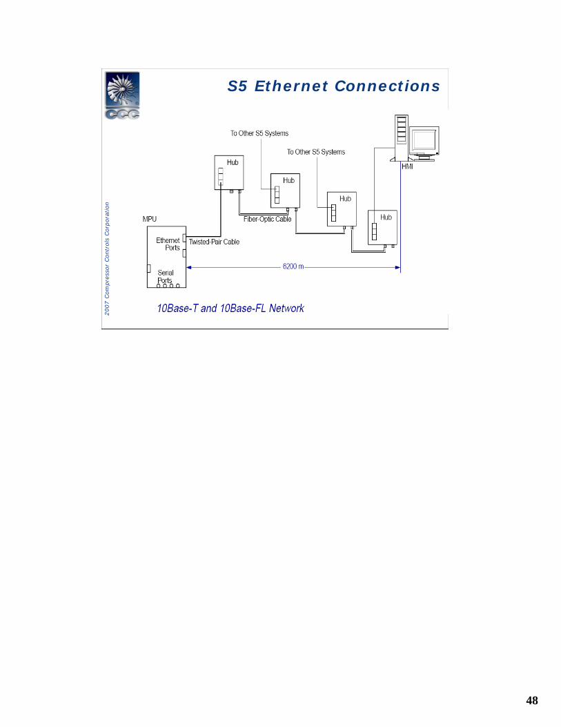
S5 Ethernet ConnectionsS5 Ethernet Connections
49
2007 C
om
pre
ssor
Contr
ols
Corp
ora
tion
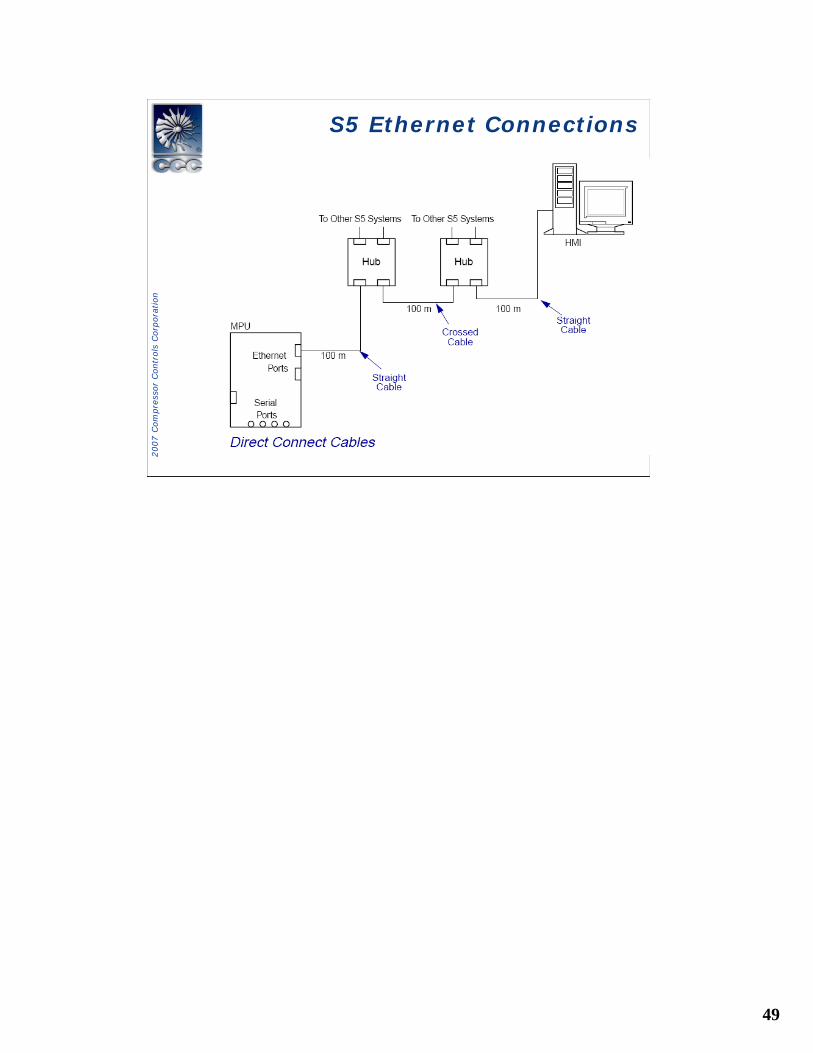
S5 Ethernet ConnectionsS5 Ethernet Connections
50
2007 C
om
pre
ssor
Contr
ols
Corp
ora
tion
S5 Ethernet ConnectionsS5 Ethernet Connections
51
2007 C
om
pre
ssor
Contr
ols
Corp
ora
tion
System OverviewSystem Overview
Software Architecture
• Real-Time Operating System• Control Application Software• Input and Output Data Flows
52
2007 C
om
pre
ssor
Contr
ols
Corp
ora
tion
System OverviewSystem Overview
Software Architecture
• Real-Time Operating System (RTOS)• Field I/O processing• Peer Communication• System Diagnostics• Interface between hardware and control applications
53
2007 C
om
pre
ssor
Contr
ols
Corp
ora
tion
System OverviewSystem Overview
Software Architecture• Control Application Software• Steam Turbine Control • Antisurge Controller• Pressure Controller• Logic Controller• Gas Turbine• Extraction• Power Generator
54
2007 C
om
pre
ssor
Contr
ols
Corp
ora
tion
System OverviewSystem Overview
Software Architecture
• Input and Output Data Flows
55
2007 C
om
pre
ssor
Contr
ols
Corp
ora
tion
System OverviewSystem Overview
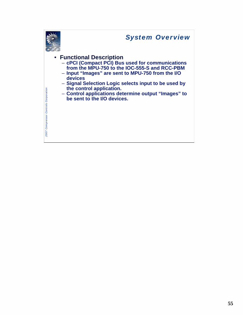
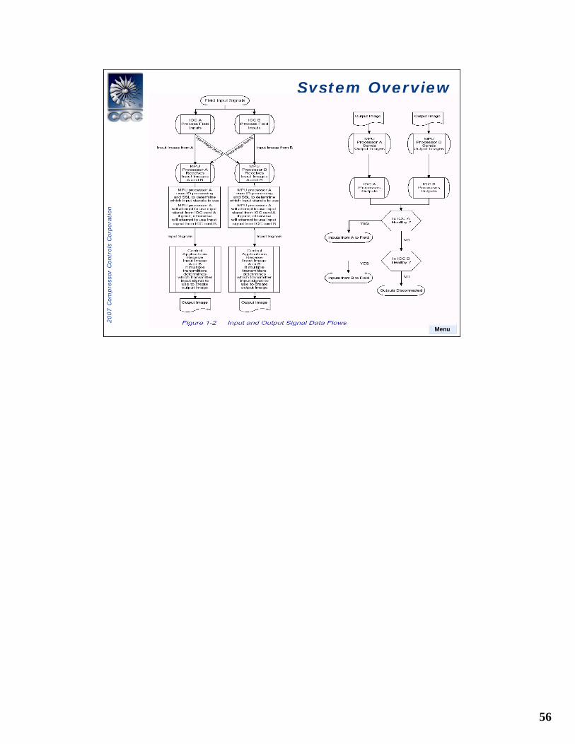
• Functional Description– cPCI (Compact PCI) Bus used for communications
from the MPU-750 to the IOC-555-S and RCC-PBM– Input “Images” are sent to MPU-750 from the I/O
devices– Signal Selection Logic selects input to be used by
the control application.– Control applications determine output “Images” to
be sent to the I/O devices.
56
2007 C
om
pre
ssor
Contr
ols
Corp
ora
tion
System OverviewSystem Overview
Menu
57
2007 C
om
pre
ssor
Contr
ols
Corp
ora
tion
System OverviewSystem Overview
Hardware Architecture
• Hot Swap Concept• Healthy States• Critical Analog Output Failure Mode• Redundant Output Switching
58
2007 C
om
pre
ssor
Contr
ols
Corp
ora
tion
System OverviewSystem Overview
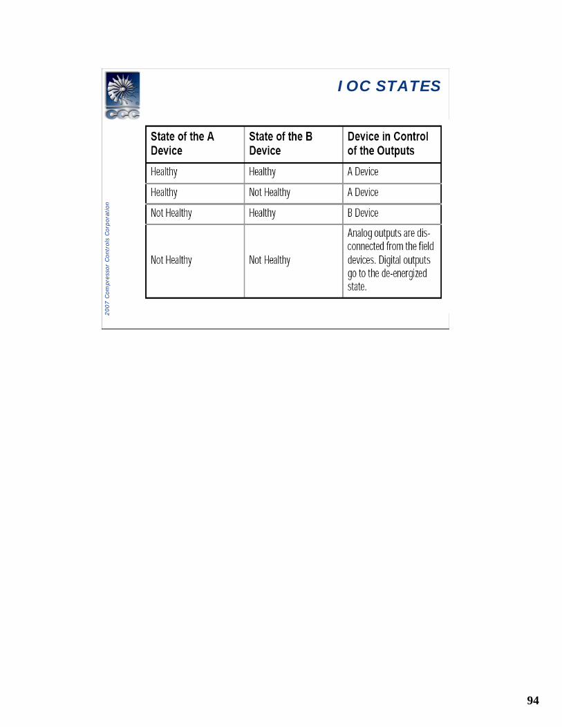
Hardware Architecture – Hot Swap• The duplex system uses an active
“Hot Backup” architecture where there aretwo control devices, one is the preferreddevice and the other is the hot backupdevice.
• The preferred device will be referred to asthe device A (primary) and is in control ofthe process whenever it is healthy.
• The hot backup device will be referred to asthe device B (secondary) and is in virtual control of the process along with the A device when the A device is healthy.
59
2007 C
om
pre
ssor
Contr
ols
Corp
ora
tion
System OverviewSystem Overview
Hardware Architecture - Hot Swap• Both system processors can communicate
with each of the two Local Input Output Cards (LIOCs) over the two cPCI busses(A and B), however each device may onlyoutput to its corresponding LIOC.
• Both LIOC’s can communicate with theduplex Field Termination Assemblies (FTAs) which support redundant outputs.
60
2007 C
om
pre
ssor
Contr
ols
Corp
ora
tion
System OverviewSystem Overview
Hardware Architecture - Hot Swap
• Two blue hot-swap LED indicators (PCI A and PCI B) are controlled by MPU A bus PCI A and MPU B bus PCI B.
61
2007 C
om
pre
ssor
Contr
ols
Corp
ora
tion
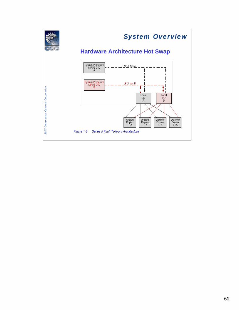
System OverviewSystem Overview
Hardware Architecture Hot Swap
62
2007 C
om
pre
ssor
Contr
ols
Corp
ora
tion
System OverviewSystem Overview
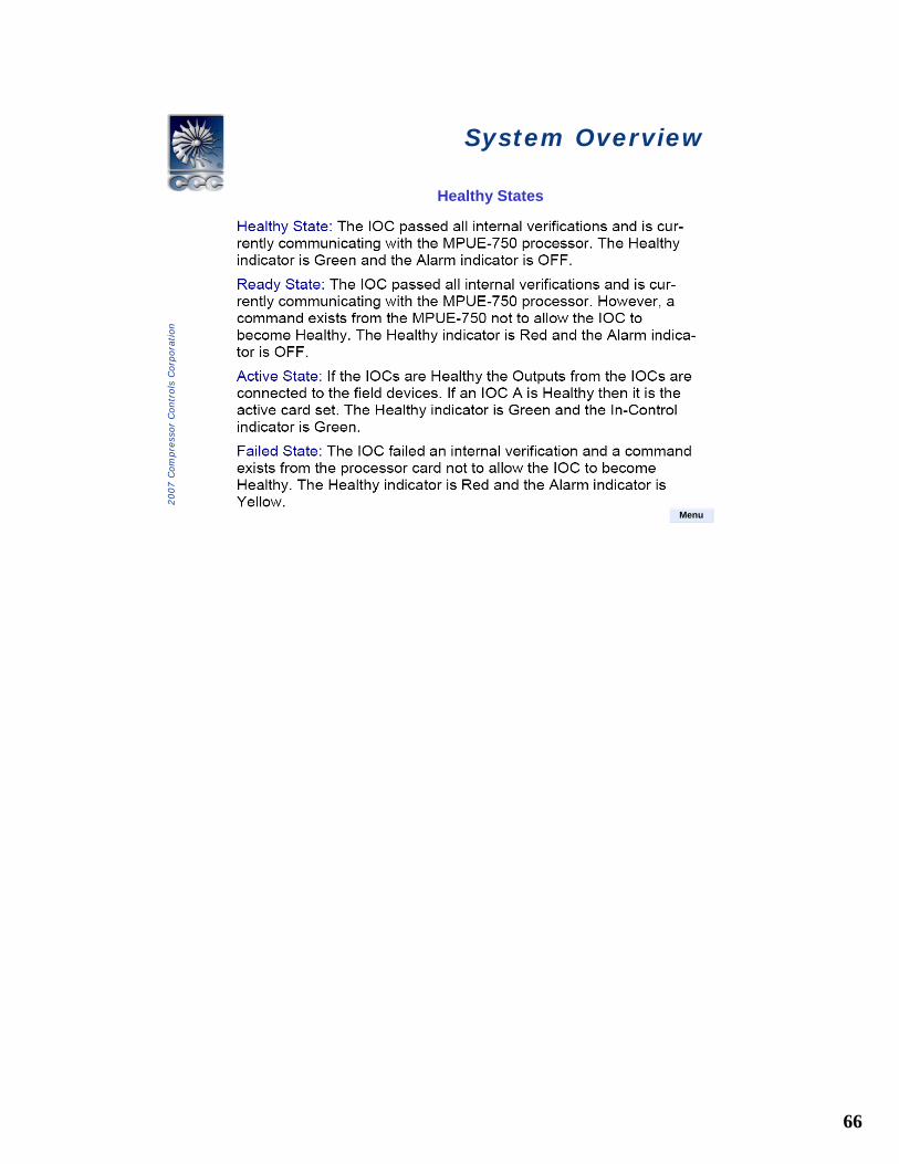
• MPU Healthy • An MPU processor is considered to be in a HEALTHY
state when there are no fatal errors conditions and processor is not forcing the card not Healthy.
• Project is running (loaded)• IOC soft heartbeat is present and IOC is installed
63
2007 C
om
pre
ssor
Contr
ols
Corp
ora
tion
System OverviewSystem Overview
Critical Faults• IOC/MPU communication failure• MPU not running • Communication time out• IOC power supply failure (greater then 15 %
from nominal)• Critical Analog output failure• FTA failure or not configured• Force fault by MPU• IOC watchdog timer not working• Corrupted Data
64
2007 C
om
pre
ssor
Contr
ols
Corp
ora
tion
System OverviewSystem Overview
IOC HEALTHY• IOC/MPU communication working• Calibration data is valid • Communication time • IOC power supply failure (greater then 15 %
from nominal)• IOC watchdog timer working
65
2007 C
om
pre
ssor
Contr
ols
Corp
ora
tion
System OverviewSystem Overview
Menu
66
2007 C
om
pre
ssor
Contr
ols
Corp
ora
tion
System OverviewSystem Overview
Healthy States
Menu
67
2007 C
om
pre
ssor
Contr
ols
Corp
ora
tion
System OverviewSystem Overview
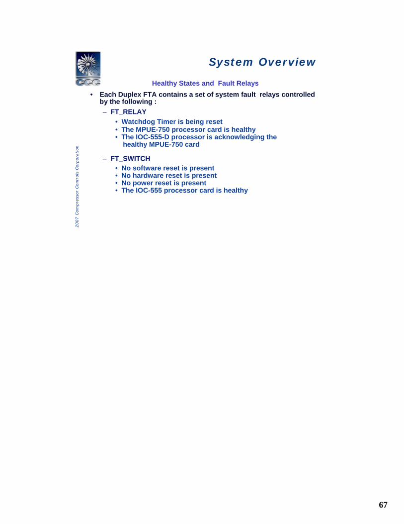
Healthy States and Fault Relays• Each Duplex FTA contains a set of system fault relays controlled
by the following :– FT_RELAY
• Watchdog Timer is being reset• The MPUE-750 processor card is healthy• The IOC-555-D processor is acknowledging the
healthy MPUE-750 card
– FT_SWITCH• No software reset is present• No hardware reset is present• No power reset is present• The IOC-555 processor card is healthy
68
2007 C
om
pre
ssor
Contr
ols
Corp
ora
tion
System OverviewSystem Overview
Healthy States and Fault Relay• FTA’s will Feedback
– IOC connection (A and B) information– FTA is healthy indication– Fault tolerant peer healthy indication
69
2007 C
om
pre
ssor
Contr
ols
Corp
ora
tion
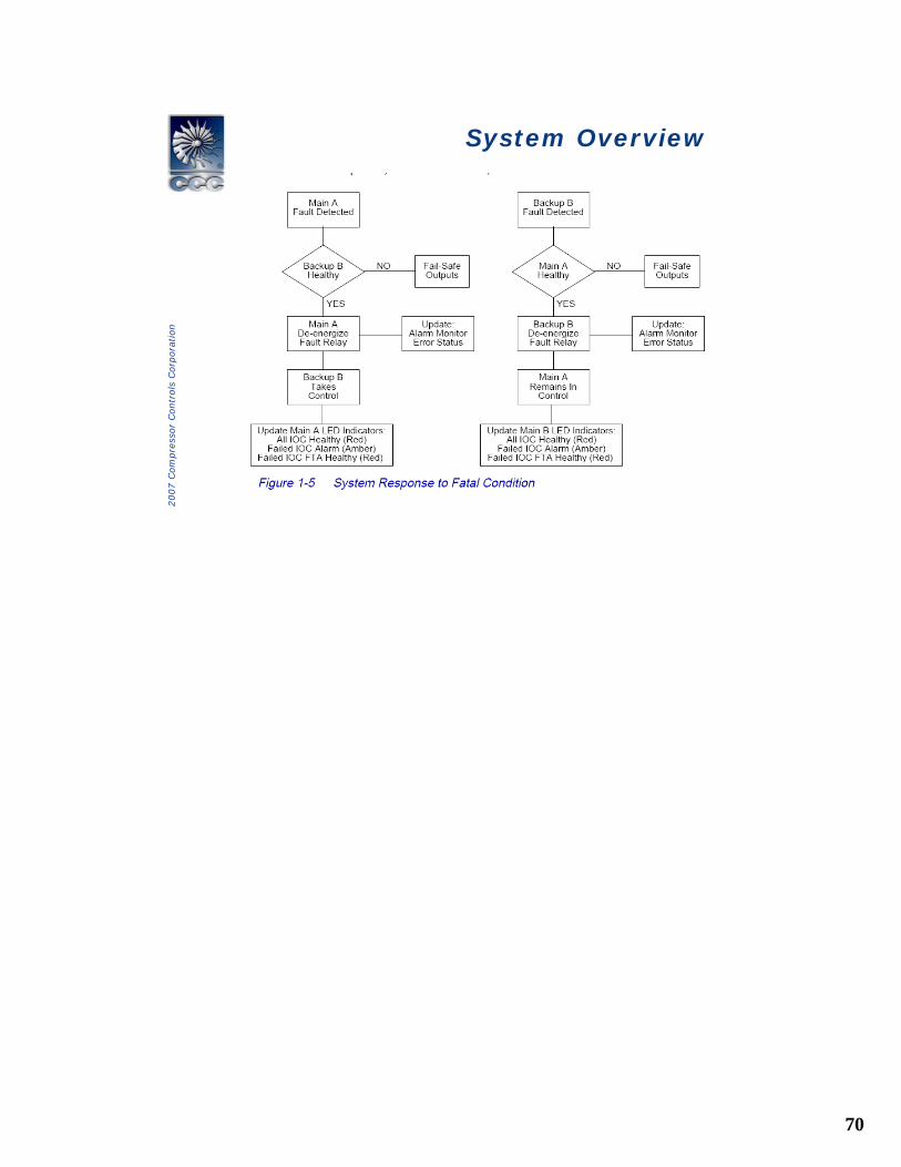
System OverviewSystem Overview
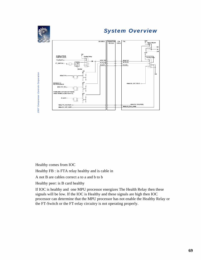
Healthy comes from IOCHealthy FB : is FTA relay healthy and is cable inA not B are cables correct a to a and b to bHealthy peer: is B card healthyIf IOC is healthy and one MPU processor energizes The Health Relay then these signals will be low. If the IOC is Healthy and these signals are high then IOC processor can determine that the MPU processor has not enable the Healthy Relay or the FT-Switch or the FT-relay circuitry is not operating properly.
70
2007 C
om
pre
ssor
Contr
ols
Corp
ora
tion
System OverviewSystem Overview
71
2007 C
om
pre
ssor
Contr
ols
Corp
ora
tion
System Diagnostics System Diagnostics
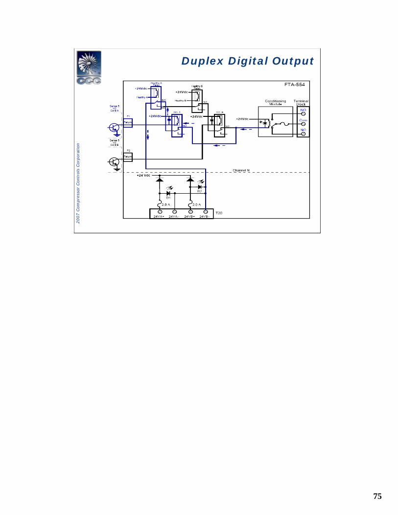
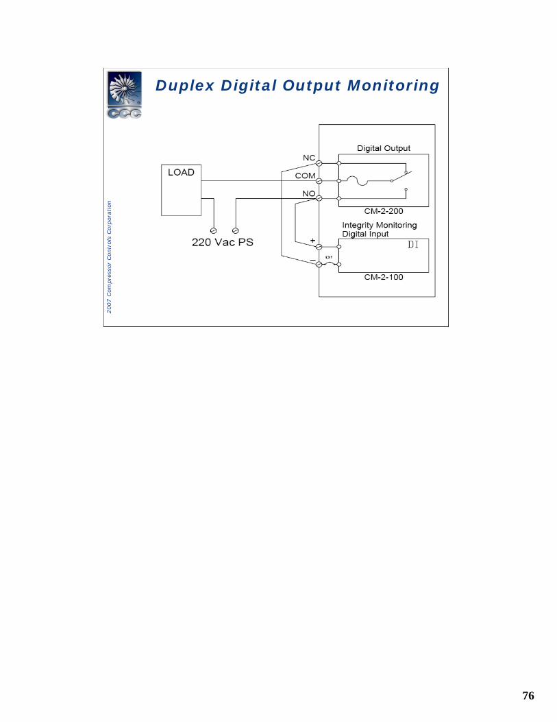
• Self-Diagnostics of Inputs and Outputs– Analog Output (verified to controller output)– Digital Output (verified to controller output)
• Integrity Monitoring Discrete input can be used to verify a critical loop additionally
– Analog Inputs (verified to be within a configurable range)
– Frequency Inputs (verified to be above a configurable low limit)
– Discrete inputs (not verified)• Integrity Monitoring Discrete input can be used to
verify a critical loop if needed

72
2007 C
om
pre
ssor
Contr
ols
Corp
ora
tion
Typical analog input connectionTypical analog input connection
73
2007 C
om
pre
ssor
Contr
ols
Corp
ora
tion
System OverviewSystem Overview
Redundant Output Switching• An analog output loopback error will not cause
controller output switch unles that output is configured to be critical
• Setting a duplex analog output to be critical output affects both IOB A and IOB B.
• They can be set same or different on each card
74
2007 C
om
pre
ssor
Contr
ols
Corp
ora
tion
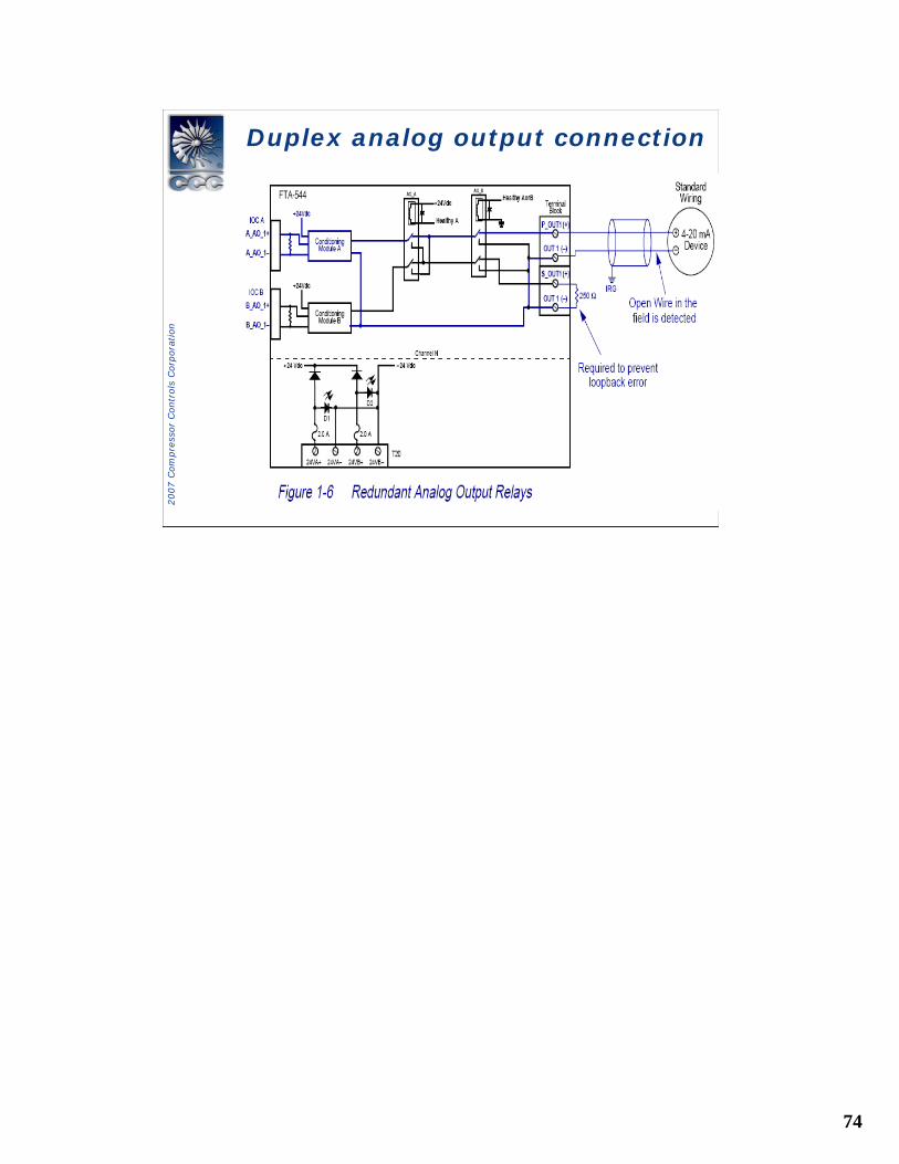
Duplex analog output connectionDuplex analog output connection
75
2007 C
om
pre
ssor
Contr
ols
Corp
ora
tion
Duplex Digital OutputDuplex Digital Output
76
2007 C
om
pre
ssor
Contr
ols
Corp
ora
tion
Duplex Digital Output MonitoringDuplex Digital Output Monitoring
77
2007 C
om
pre
ssor
Contr
ols
Corp
ora
tion
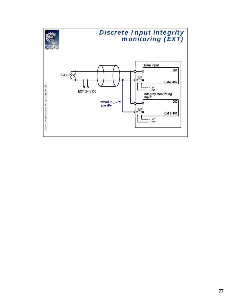
Discrete Input integrity monitoring (EXT)
Discrete Input integrity monitoring (EXT)
78
2007 C
om
pre
ssor
Contr
ols
Corp
ora
tion
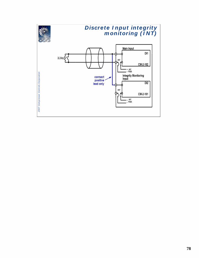
Discrete Input integrity monitoring (INT)
Discrete Input integrity monitoring (INT)
79
2007 C
om
pre
ssor
Contr
ols
Corp
ora
tion
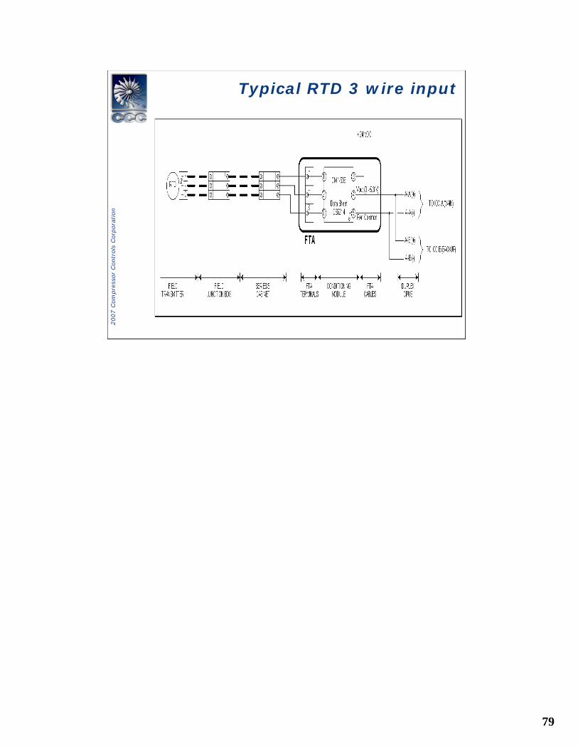
Typical RTD 3 wire inputTypical RTD 3 wire input
80
2007 C
om
pre
ssor
Contr
ols
Corp
ora
tion
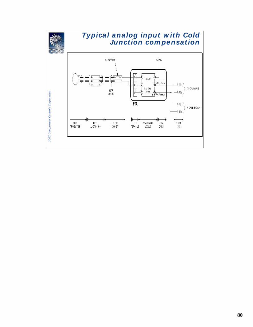
Typical analog input with Cold Junction compensation
Typical analog input with Cold Junction compensation
81
2007 C
om
pre
ssor
Contr
ols
Corp
ora
tion
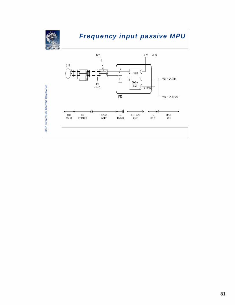
Frequency input passive MPUFrequency input passive MPU
82
2007 C
om
pre
ssor
Contr
ols
Corp
ora
tion
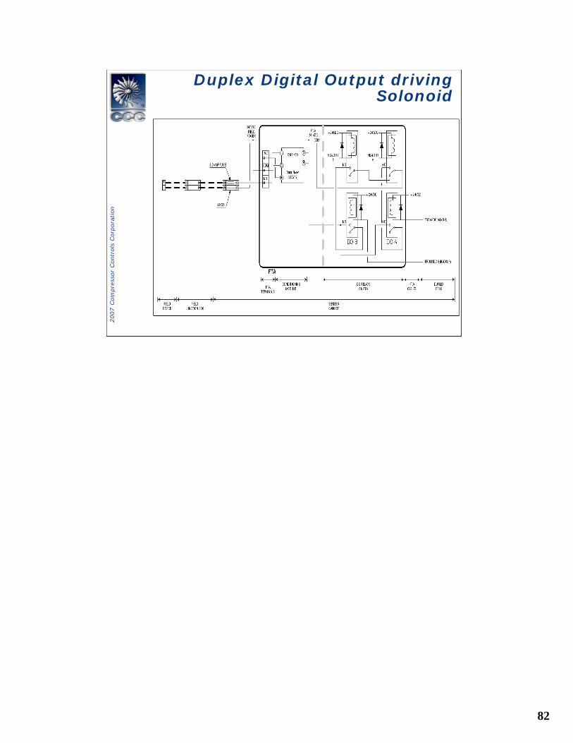
Duplex Digital Output driving Solonoid
Duplex Digital Output driving Solonoid
83
2007 C
om
pre
ssor
Contr
ols
Corp
ora
tion
S5 Fiber Optic ConnectionsS5 Fiber Optic Connections
84
2007 C
om
pre
ssor
Contr
ols
Corp
ora
tion
HUB-C-4-1 • Ethernet 10Base-T Hub– Four 10 Base-T ports
with RJ45 shielded connectors
– DIN1 or 3 Railmount– LED Status Indication– Fault Relay– Redundant 24Vdc
Power inputs– Class 1 Div. 2
Vanguard Controller OverviewVanguard Controller Overview
85
2007 C
om
pre
ssor
Contr
ols
Corp
ora
tion
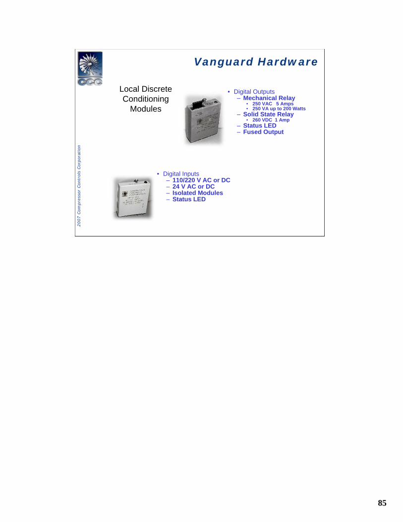
Vanguard HardwareVanguard Hardware
Local Discrete Conditioning
Modules
• Digital Inputs– 110/220 V AC or DC– 24 V AC or DC– Isolated Modules– Status LED
• Digital Outputs– Mechanical Relay
• 250 VAC 5 Amps• 250 VA up to 200 Watts
– Solid State Relay• 260 VDC 1 Amp
– Status LED– Fused Output
86
2007 C
om
pre
ssor
Contr
ols
Corp
ora
tion
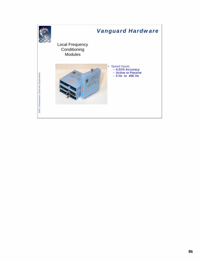
Vanguard HardwareVanguard Hardware
Local Frequency Conditioning
Modules
• Speed Inputs– 0.01% Accuracy– Active or Passive– 5 Hz to 40K Hz

87
2007 C
om
pre
ssor
Contr
ols
Corp
ora
tion
HubsHubs
• Hub types:» 10Base-T Hub (HUB-C-4-1)» Fiber-Optic Hub (HUB-F-2-1)
88
2007 C
om
pre
ssor
Contr
ols
Corp
ora
tion
Local Fault IndicatorsLocal Fault Indicators
• Fan Failed Indicator
• Power Supplies LED indicators
• MPU Processor LED
• IOC Card LED
• TMPU LED
• TIOC LED
• HUB LED
89
2007 C
om
pre
ssor
Contr
ols
Corp
ora
tion
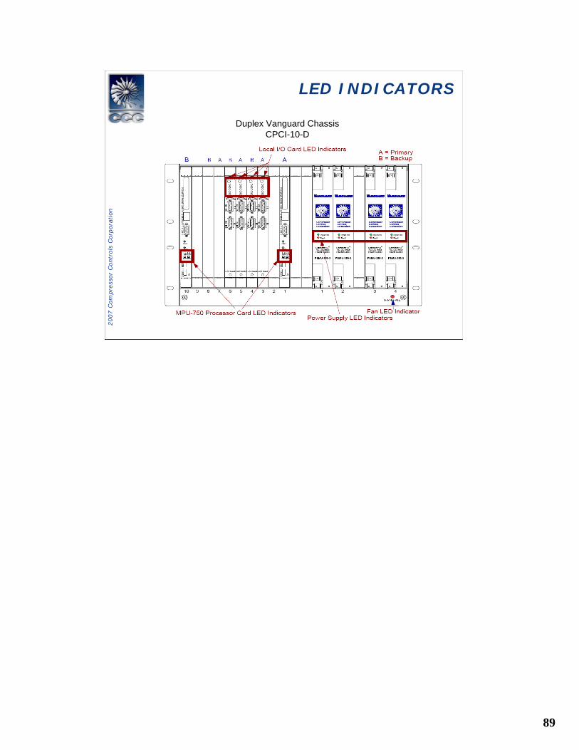
Duplex Vanguard Chassis CPCI-10-D
LED INDICATORSLED INDICATORS
90
2007 C
om
pre
ssor
Contr
ols
Corp
ora
tion
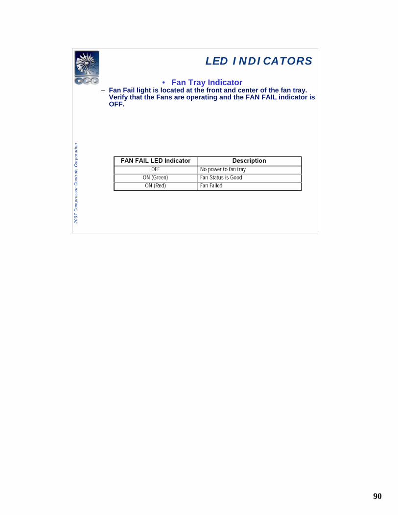
LED INDICATORSLED INDICATORS
• Fan Tray Indicator– Fan Fail light is located at the front and center of the fan tray.
Verify that the Fans are operating and the FAN FAIL indicator isOFF.
91
2007 C
om
pre
ssor
Contr
ols
Corp
ora
tion
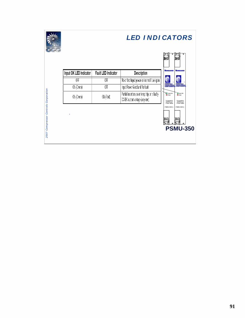
LED INDICATORSLED INDICATORS
Input OKFault
PSMU-350-1
CompactPCI®AC/DC InputPower Supply
Input OKFault
PSMU-350-1
CompactPCI®AC/DC InputPower Supply
LL®
COMPRESSOR
CONTROLS
CORPORATION
®
COMPRESSOR
CONTROLS
CORPORATION
v v
Input OKFault
PSMU-350
.
92
2007 C
om
pre
ssor
Contr
ols
Corp
ora
tion
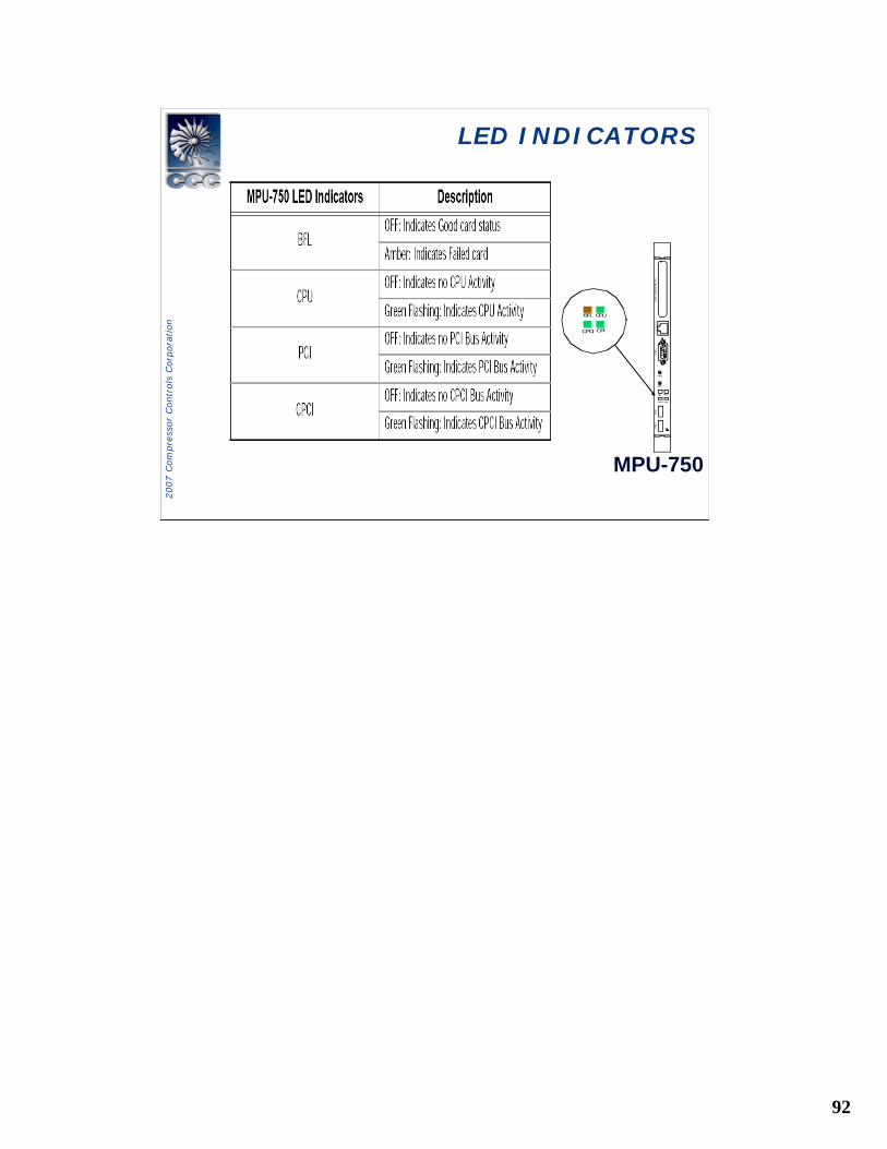
LED INDICATORSLED INDICATORS
MPU-750
10/10
0 BA
SE
TUSB 1
CPI
ABT
BFL
RST
CPU
PCI M
EZZA
NIN
E C
ARD
COM 1
CPCI
USB 0
CPI
BFL CPU
CPCI
93
2007 C
om
pre
ssor
Contr
ols
Corp
ora
tion
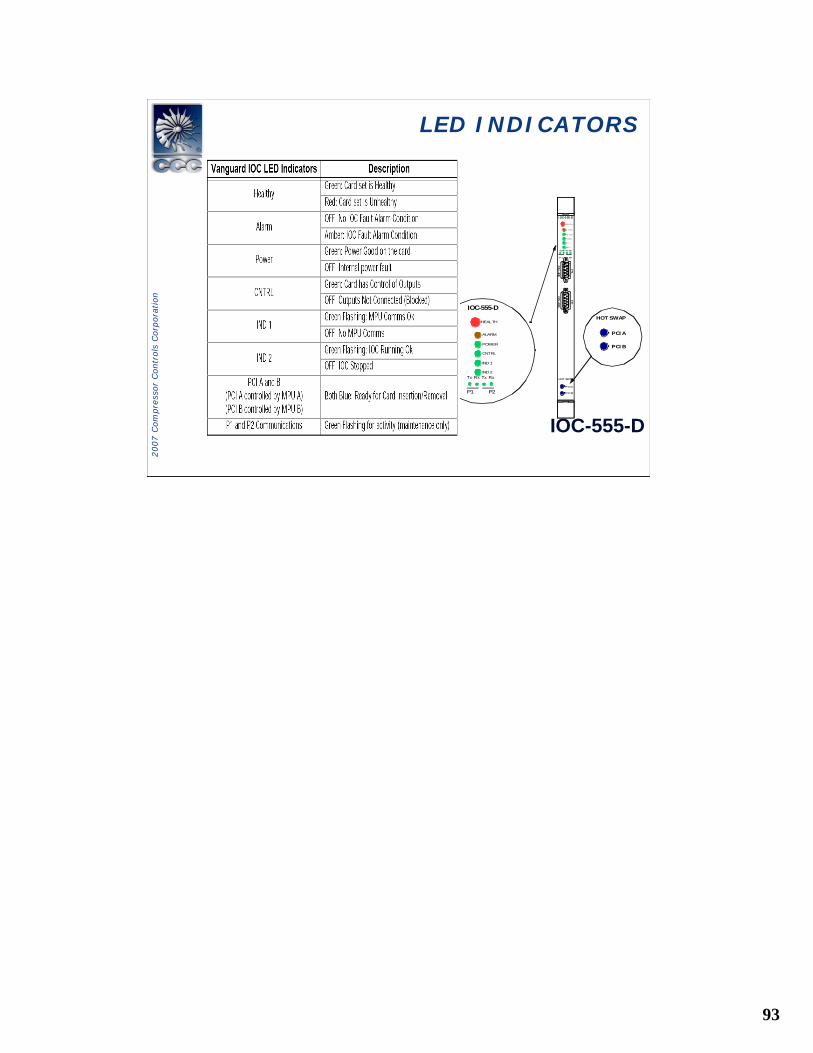
LED INDICATORSLED INDICATORS
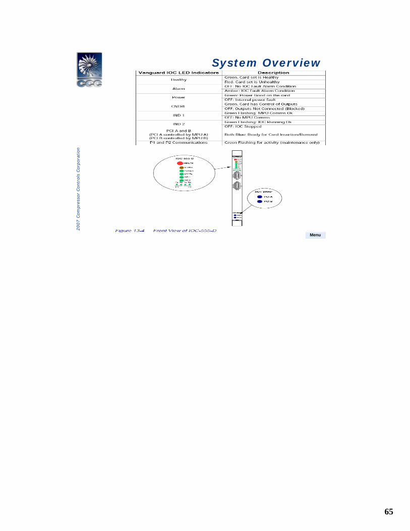
IOC-555-D
IOC-555-D
HEALTH
ALARM
POWER
CNTRL
IND 1
IND 2Tx Rx Tx Rx
P2P1
I OC-5 55-D
H E A LT H
AL A RM
PO WE R
C NTRL
IN D 1
IN D 2
TxRx Tx Rx
P2P1
P1
P2
RS–485
RS–4
85
HOT SWAP
PCI A
PCI B
HOT SWAP
PCI A
PCI B
94
2007 C
om
pre
ssor
Contr
ols
Corp
ora
tion
IOC STATESIOC STATES
95
2007 C
om
pre
ssor
Contr
ols
Corp
ora
tion
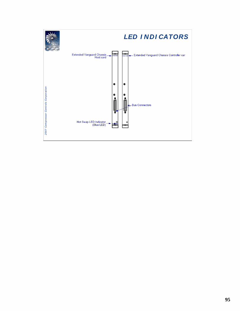
LED INDICATORSLED INDICATORS
96
2007 C
om
pre
ssor
Contr
ols
Corp
ora
tion
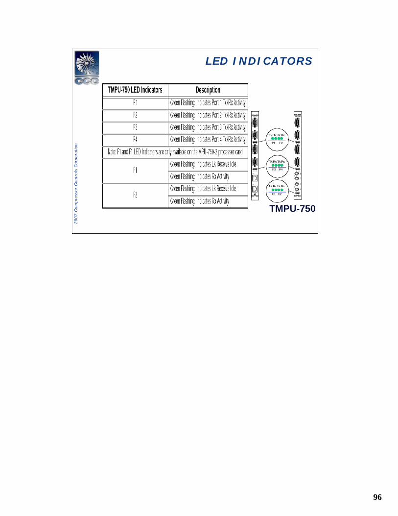
TMPU-750
PORT 1
POR
T 2PO
RT 3
PORT 4
Tx Rx Tx Rx
P1 P2
Tx Rx Tx Rx
P3 P4
E1
E2
Tx Rx Tx Rx
P3 P4
TMPU-750-2
F2F1
PORT
1POR
T 2PO
RT 3
PORT 4
Tx Rx Tx Rx
P1 P2
Tx Rx Tx Rx
P3 P4
Tx Rx Tx Rx
P1 P2
Lk Rx Lk Rx
F1 F2
Lk Rx Lk Rx
F1 F2
Rx
Tx
Rx
Tx
LED INDICATORSLED INDICATORS
TMPU-750
97
2007 C
om
pre
ssor
Contr
ols
Corp
ora
tion
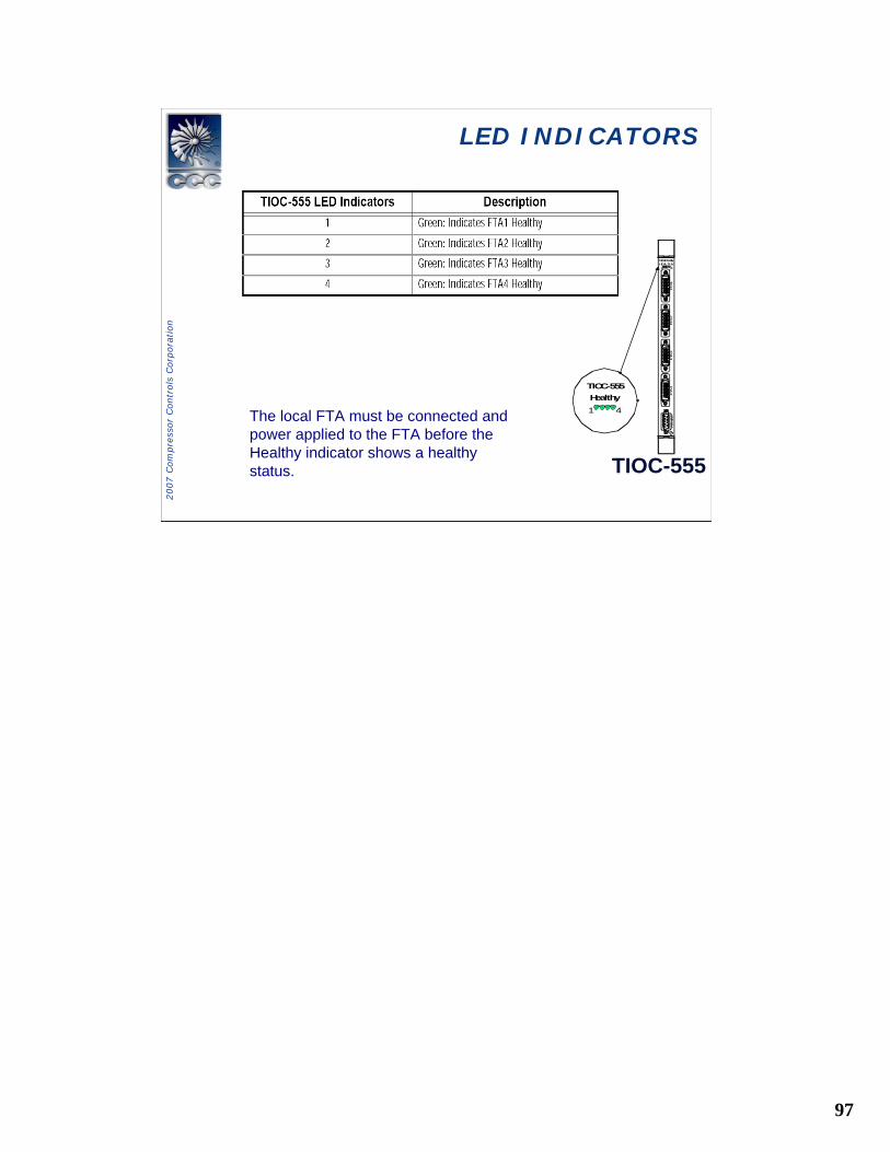
LED INDICATORSLED INDICATORS
TIOC-555
TIOC-555HEALTHY1 4
FTA 1
FTA 2
FTA
3FTA
4RS–4
85
TIOC-555Healthy1 4The local FTA must be connected and
power applied to the FTA before the Healthy indicator shows a healthy status.
98
2007 C
om
pre
ssor
Contr
ols
Corp
ora
tion
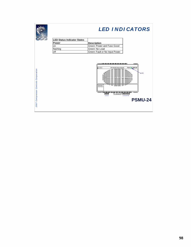
LED INDICATORSLED INDICATORS
PSMU-24
LED Status Indicator StatesPoweron Green: Power and Fuse Goodflashing Green: No Loadoff Green: Fault or No Input Power
Description
LED
1 2 3 1 2 3 4 5
Power
SureLinkRemote I/O System
LCOMPRESSORCONTROLSCORPORATION 24 Volt DC Power Supply PSMU-24-1
99
2007 C
om
pre
ssor
Contr
ols
Corp
ora
tion
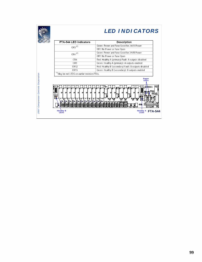
LED INDICATORSLED INDICATORS
FTA-544
PowerLED s
A
Healthy AL EDs
Healthy BLED s
100
2007 C
om
pre
ssor
Contr
ols
Corp
ora
tion
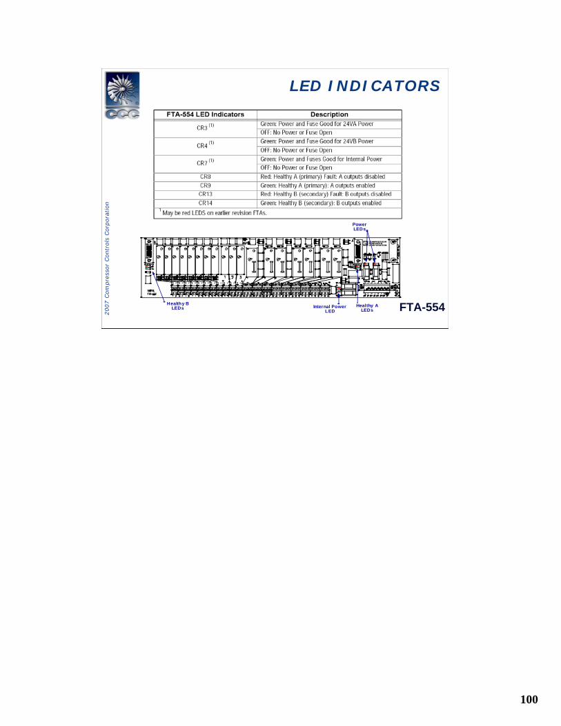
LED INDICATORSLED INDICATORS
FTA-554
A
PowerLEDs
Healthy ALEDs
Healthy BLEDs Internal Power
LED
101
2007 C
om
pre
ssor
Contr
ols
Corp
ora
tion
LED INDICATORSLED INDICATORS
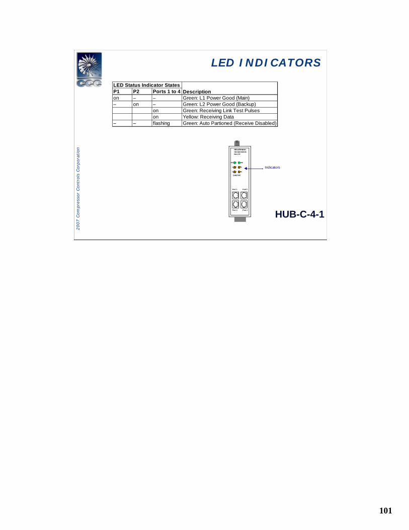
HUB-C-4-1
Port 1 Port 2
Port 3 Port 4
P1 P2
1 2
3 4
DA/STAT
RH1-TPRheinmetall Elektronik
Hirschmann
Indicators
P1 P2 Ports 1 to 4on – – Green: L1 Power Good (Main)– on – Green: L2 Power Good (Backup)
on Green: Receiving Link Test Pulseson Yellow: Receiving Data
– – flashing Green: Auto Partioned (Receive Disabled)
LED Status Indicator StatesDescription
102
2007 C
om
pre
ssor
Contr
ols
Corp
ora
tion
LED INDICATORSLED INDICATORS
103
2007 C
om
pre
ssor
Contr
ols
Corp
ora
tion
Duplex Component ReplacementDuplex Component Replacement
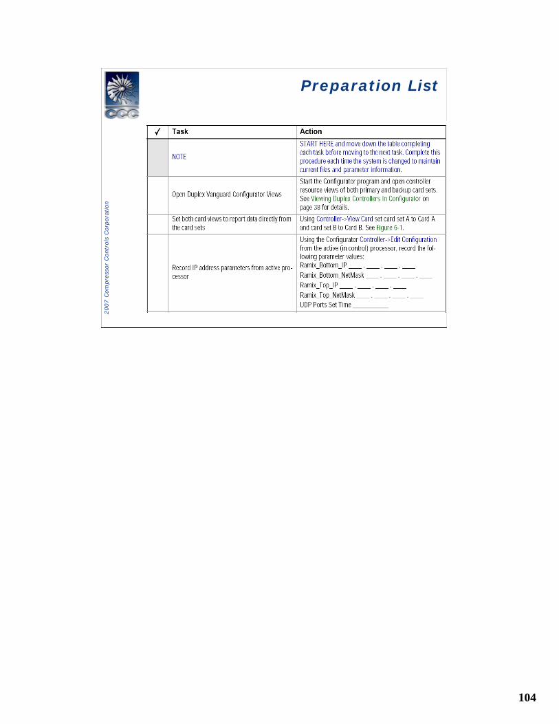
Replacement Preparation Checklist
• Replacement Preparation Checklist identifies items youwill need, and preparation tasks you must complete before starting the replacement procedures, see Table 6-1.
• This preparation checklist should be done each timethe system is changed and archived for use during the replacement process.
• Replacement Preparation Checklist must be completed
104
2007 C
om
pre
ssor
Contr
ols
Corp
ora
tion
Preparation ListPreparation List
105
2007 C
om
pre
ssor
Contr
ols
Corp
ora
tion
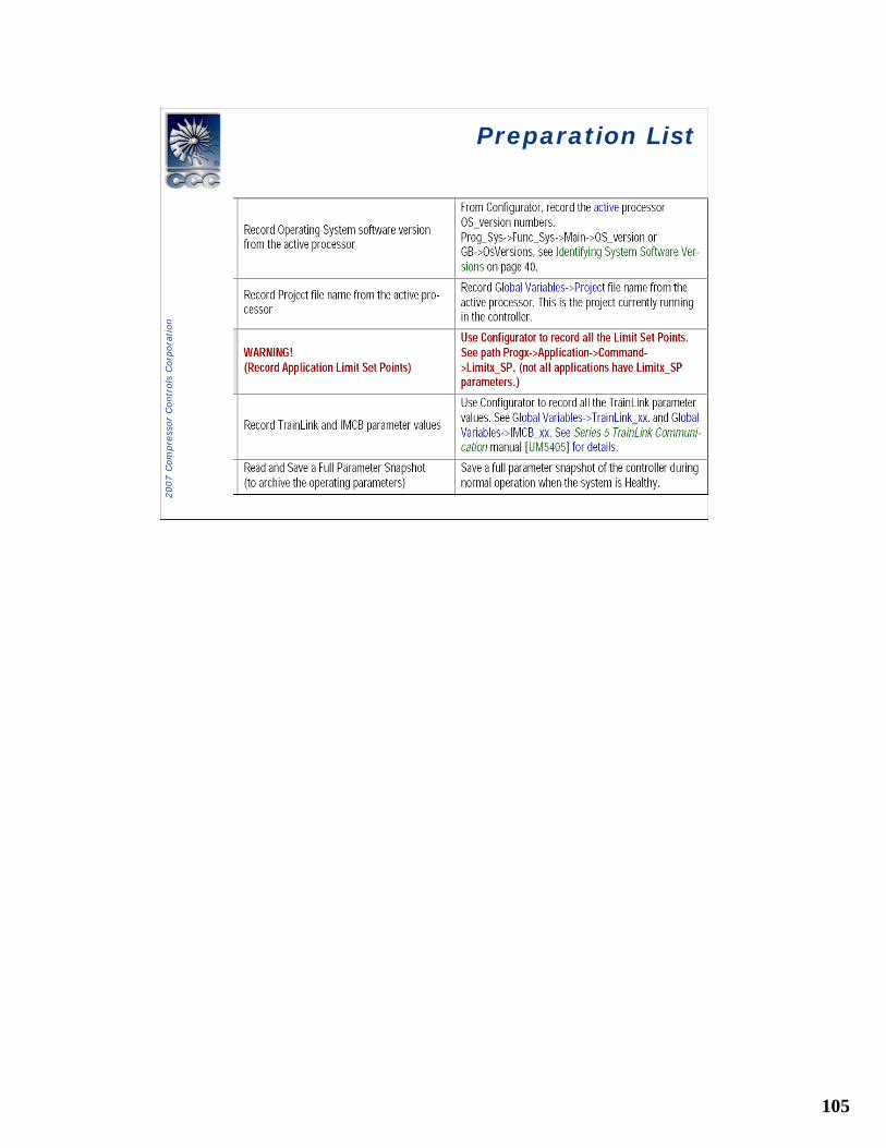
Preparation ListPreparation List
106
2007 C
om
pre
ssor
Contr
ols
Corp
ora
tion
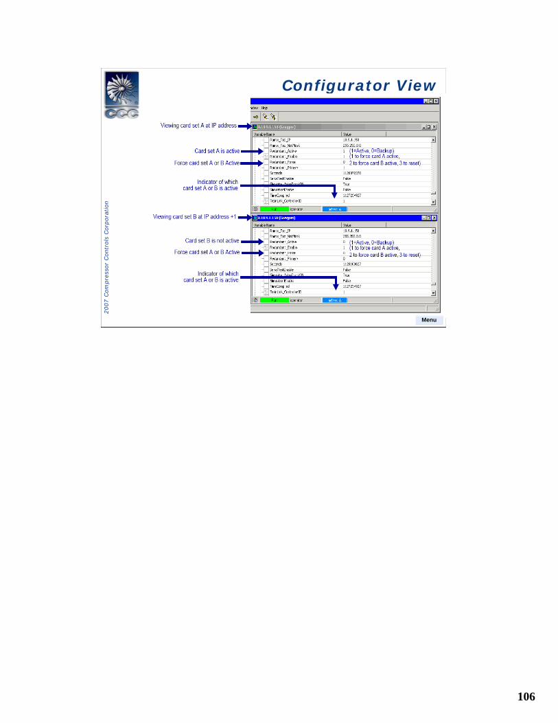
Configurator ViewConfigurator View
Menu
107
2007 C
om
pre
ssor
Contr
ols
Corp
ora
tion
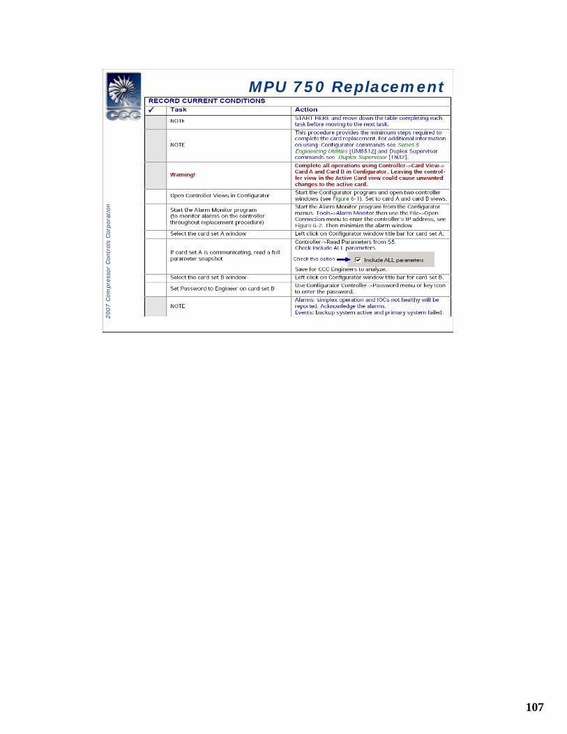
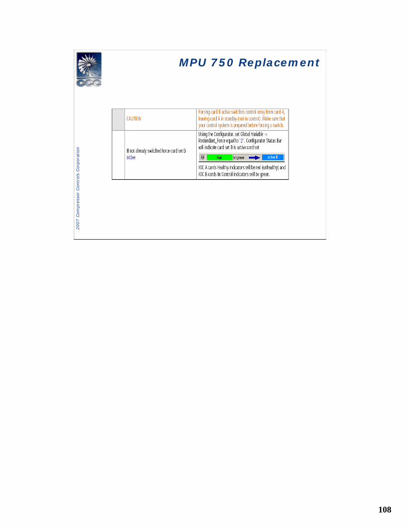
MPU 750 ReplacementMPU 750 Replacement
108
2007 C
om
pre
ssor
Contr
ols
Corp
ora
tion
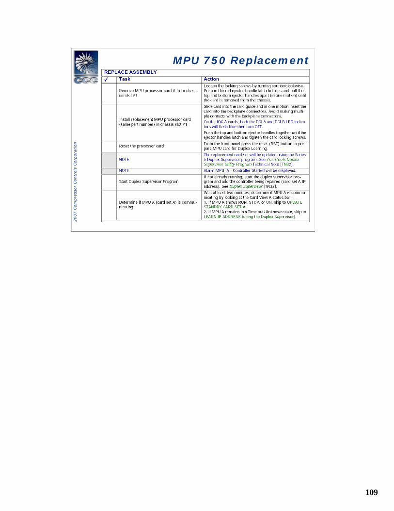
MPU 750 ReplacementMPU 750 Replacement
109
2007 C
om
pre
ssor
Contr
ols
Corp
ora
tion
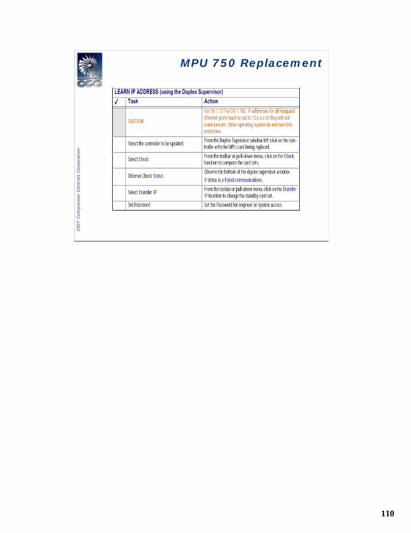
MPU 750 ReplacementMPU 750 Replacement
110
2007 C
om
pre
ssor
Contr
ols
Corp
ora
tion
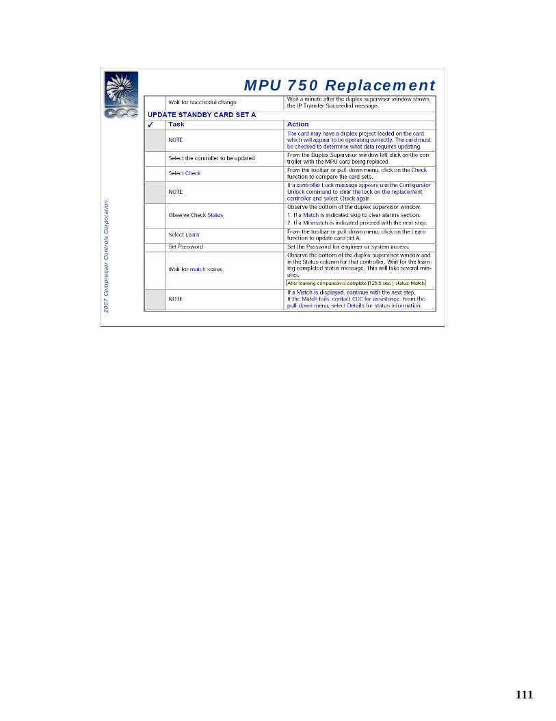
MPU 750 ReplacementMPU 750 Replacement
111
2007 C
om
pre
ssor
Contr
ols
Corp
ora
tion
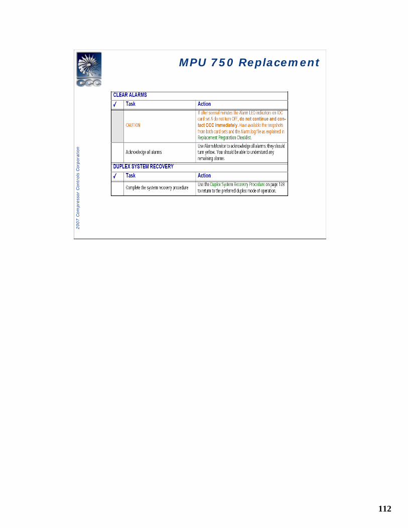
MPU 750 ReplacementMPU 750 Replacement
112
2007 C
om
pre
ssor
Contr
ols
Corp
ora
tion
MPU 750 ReplacementMPU 750 Replacement
113
2007 C
om
pre
ssor
Contr
ols
Corp
ora
tion
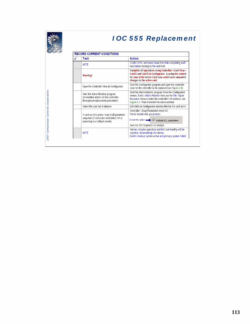
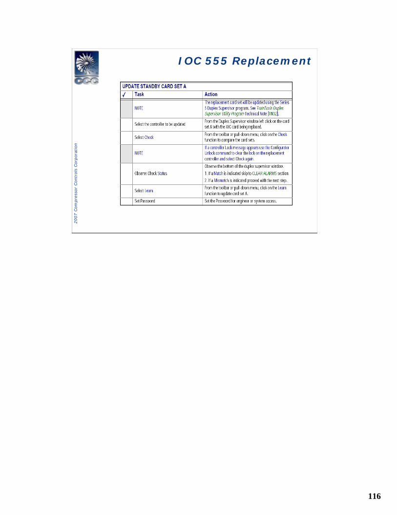
IOC 555 ReplacementIOC 555 Replacement
114
2007 C
om
pre
ssor
Contr
ols
Corp
ora
tion
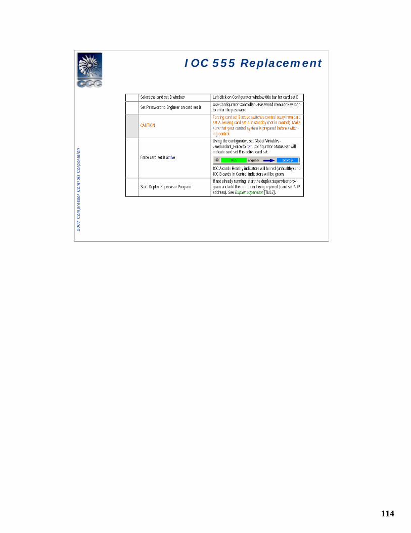
IOC 555 ReplacementIOC 555 Replacement
115
2007 C
om
pre
ssor
Contr
ols
Corp
ora
tion
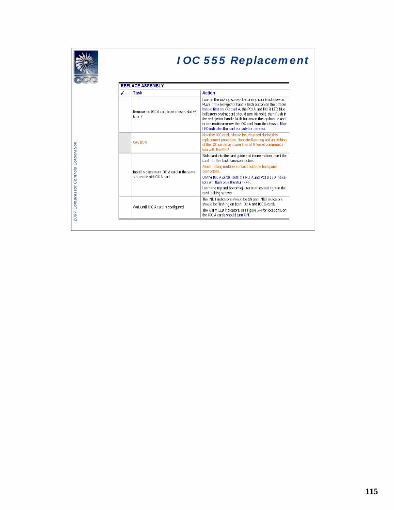
IOC 555 ReplacementIOC 555 Replacement
116
2007 C
om
pre
ssor
Contr
ols
Corp
ora
tion
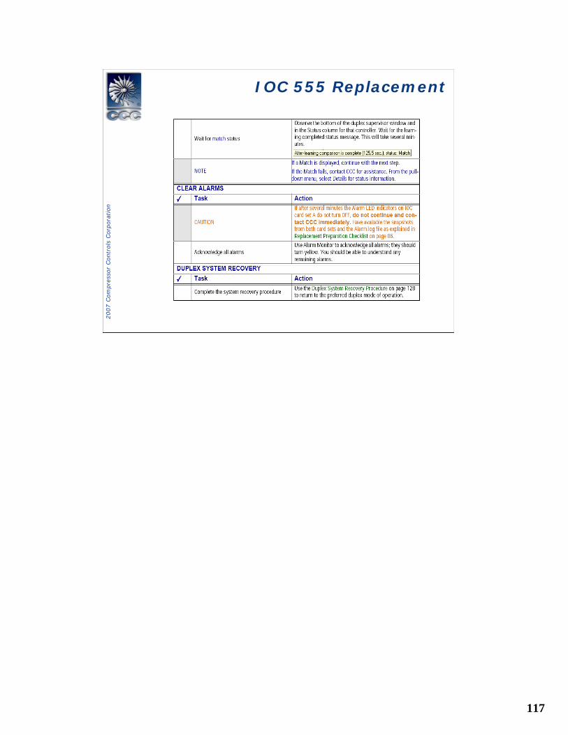
IOC 555 ReplacementIOC 555 Replacement
117
2007 C
om
pre
ssor
Contr
ols
Corp
ora
tion
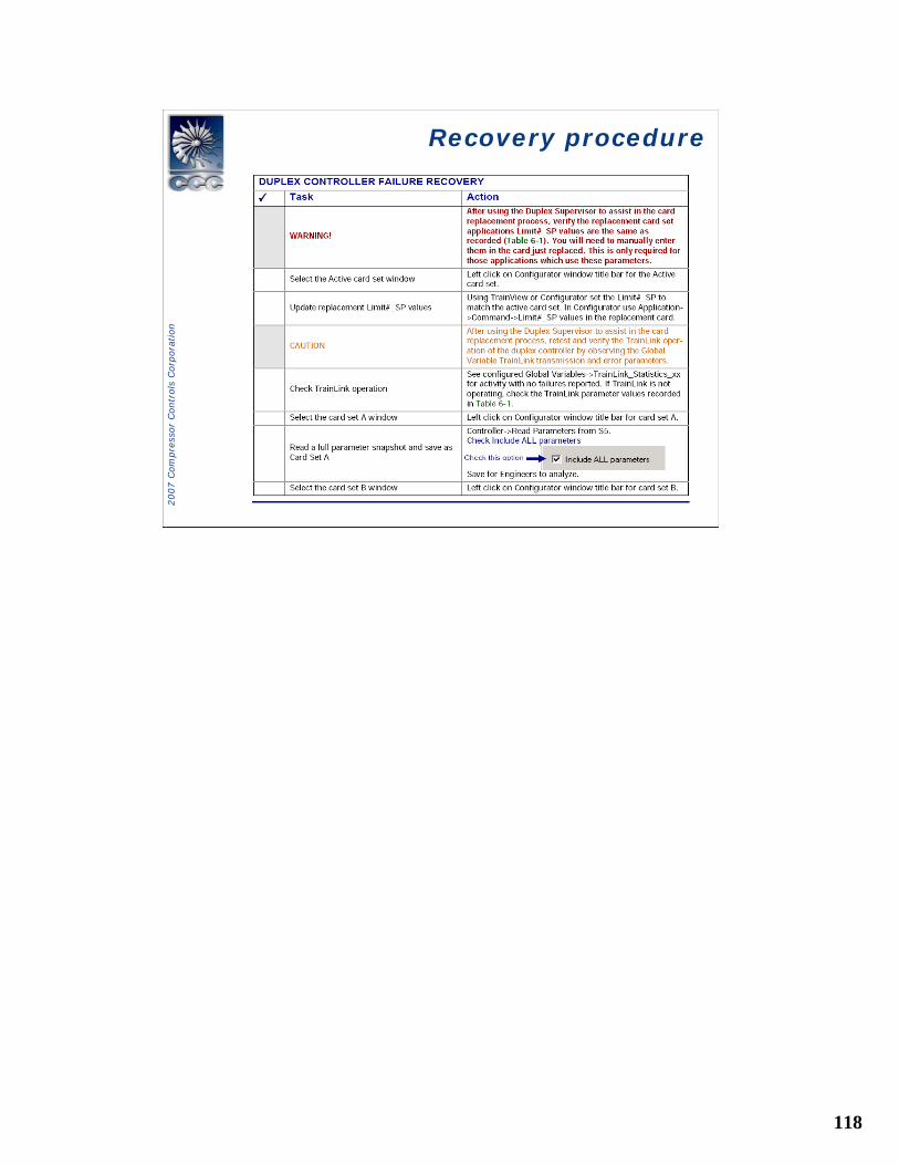
IOC 555 ReplacementIOC 555 Replacement
118
2007 C
om
pre
ssor
Contr
ols
Corp
ora
tion
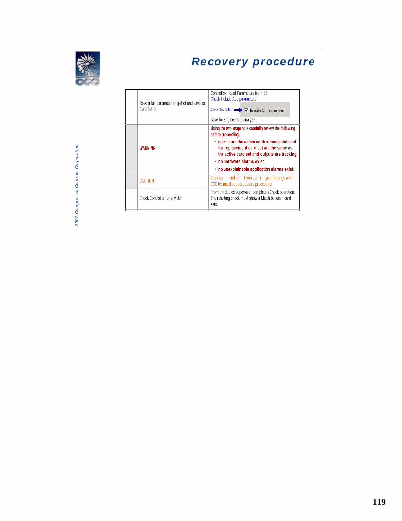
Recovery procedureRecovery procedure
119
2007 C
om
pre
ssor
Contr
ols
Corp
ora
tion
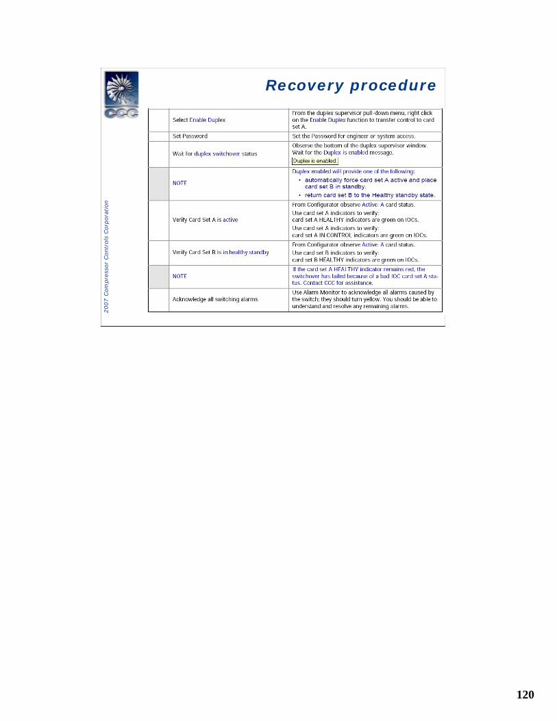
Recovery procedureRecovery procedure
120
2007 C
om
pre
ssor
Contr
ols
Corp
ora
tion
Recovery procedureRecovery procedure
121
2007 C
om
pre
ssor
Contr
ols
Corp
ora
tion
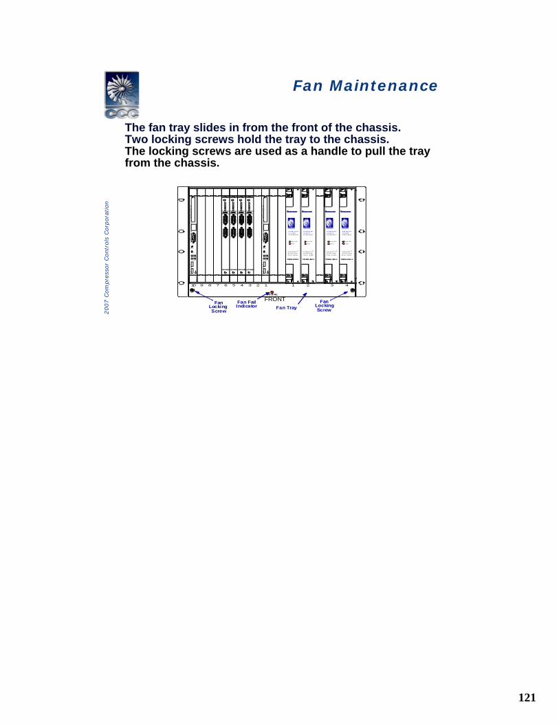
Fan Maintenance Fan Maintenance
The fan tray slides in from the front of the chassis.Two locking screws hold the tray to the chassis.The locking screws are used as a handle to pull the tray from the chassis.
FRONTFan Tray
FanLockingScrew
FanLockingScrew
Fan FailIndicator
FAN FAIL
P2P1
P1
P2
RS–485
RS–485
I np ut OK
F au lt
PSMU-350-1
C omp ac tP C I ®
A C / D C I np utPo w er S up pl y
v
10 9 7 6 5 4 3 2 18
L ®
C om pre ss orC on t rol sC orp o rat i on
I n pu t OK
F au l t
PSMU-350-1
C om pa ct P C I ®
AC / D C I np utP ow e r S u pp ly
v
L ®
C o mp res so rC o nt ro l sC o rpo rat i o n
In pu t OK
Fa ul t
PSMU-350-1
C o mpa ct P C I ®
A C / D C I n pu tP ow e r Su pp ly
v
L ®
C o mp res so rC o nt ro l sC o rpo ra t io n
I np ut OK
Fa ul t
PSMU-350-1
Co mp ac tP C I ®
A C / D C In pu tPo w er S up pl y
v
L ®
C o mp re ss orC o n t rol sC o rp ora t i on
10/100 BASE T
USB 1
C P I
A B T
B FL
R S T
C P U
PCI MEZZANINE CARD
COM 1
C P C I
USB 0
10/100 BASE T
USB 1
C P I
A B T
B FL
R S T
C P U
PCI MEZZANINE CARD
COM 1
C P C I
USB 0
P2P1
P1
P2
RS–485
RS–485
P2P1
P1
P2
RS–485
RS–485
P2P1
P1
P2
RS–485
RS–485
4321
IOC-555-D IOC-555-D IOC-555-D IOC-555-D
HOT SWAPHOT SWAP HOT SWAPHOT SWAP
TxRxTxRxTxRxTxRx TxRxTxRxTxRxTxRx
122
2007 C
om
pre
ssor
Contr
ols
Corp
ora
tion
Fan MaintenanceFan Maintenance
The fan tray assembly provides multiple fans for cooling the cards and power supplies.The tray assembly can be removed under power for no longer than one minute
123
2007 C
om
pre
ssor
Contr
ols
Corp
ora
tion
Fan Maintenance Fan Maintenance
• Follow these steps to inspect the fans. – Inspect the fans by turning the fan impeller
with your finger. The fans should turn freely without dragging.
– Check the impeller for no up-and-down movement which would indicate a bad bearing.
– Use a soft brush or cloth to remove any buildup dust from the fans.
124
2007 C
om
pre
ssor
Contr
ols
Corp
ora
tion
Fan MaintenanceFan Maintenance
• Follow these steps to re-install the old fan tray or install a new fan tray when necessary.– Place the fan tray back in the chassis and push in
the tray until the connector is fully connected (stops moving).
– Listen for the fans to start and verify that the Fan Fail indicator is green. If the indicator is off, replace the fan tray.
– Turn both locking screws clockwise until they are tight (fully connect).
125
2007 C
om
pre
ssor
Contr
ols
Corp
ora
tion
Duplex Power Supply Replacement
Duplex Power Supply Replacement
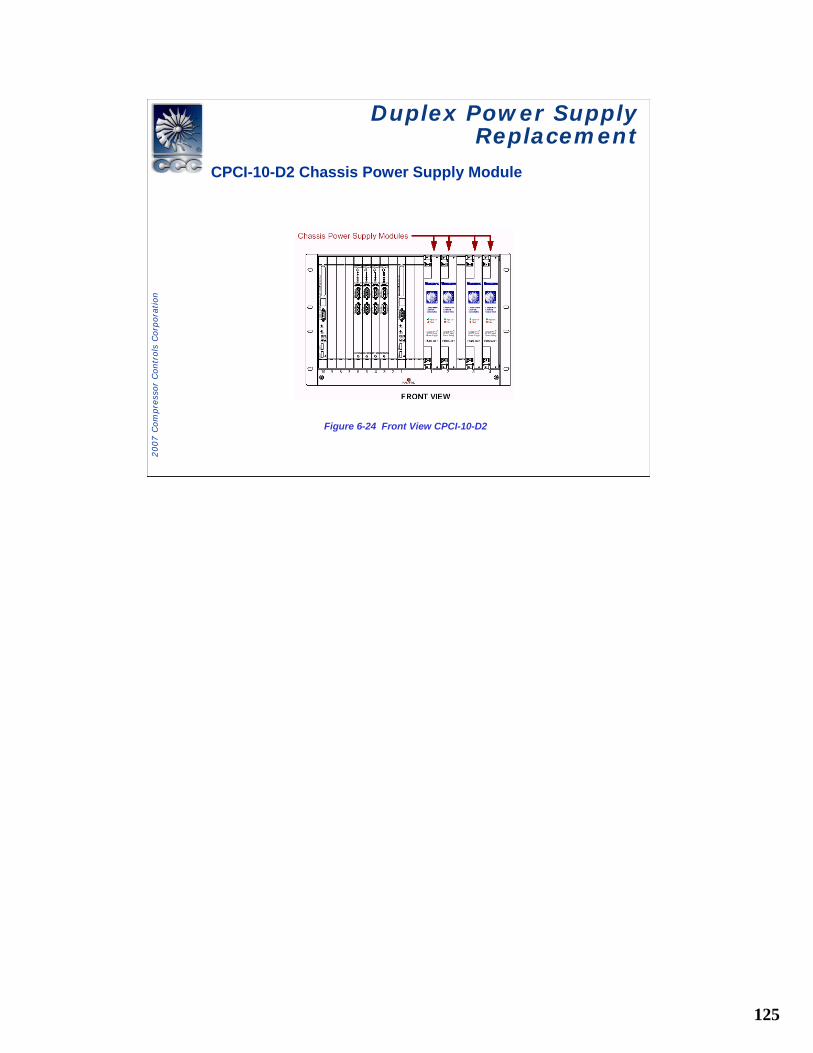
CPCI-10-D2 Chassis Power Supply Module
Figure 6-24 Front View CPCI-10-D2
126
2007 C
om
pre
ssor
Contr
ols
Corp
ora
tion
Duplex Power Supply Replacement
Duplex Power Supply Replacement
Replacing a CPCI-10-D2 Chassis Power Supply Module
• CPCI-10-D2 duplex chassis support four PSMU-350 power supply modules. The first PSMis installed in the left position, closest to the MPU. Thethree remaining PSMs are installed in the adjacent positions.
• Specifications on the power supply (PSMU-350) used inthe CPCI-10-D and CPCI-10-D2 duplex chassis are locatedin Vanguard Power Supply Module [DS5112].
127
2007 C
om
pre
ssor
Contr
ols
Corp
ora
tion
Duplex Power Supply Replacement
Duplex Power Supply Replacement
• If any of the power supplies fail (any voltage output) or if a power supply is not fully inserted, a power fault (red LED) is reported and the fault relay will de-energize.The Power Fault relay is provided with Normally Open (NO) and Normally Closed (NC) contacts .
• Note: A power fault may or may not be reported when a functioning power supply is removed from a redundant group or when input power is removedfrom one of the supplies in a redundant group.Clear this alarm if it should occur.
Replacing a CPCI-10-D2 Chassis Power Supply Module
128
2007 C
om
pre
ssor
Contr
ols
Corp
ora
tion
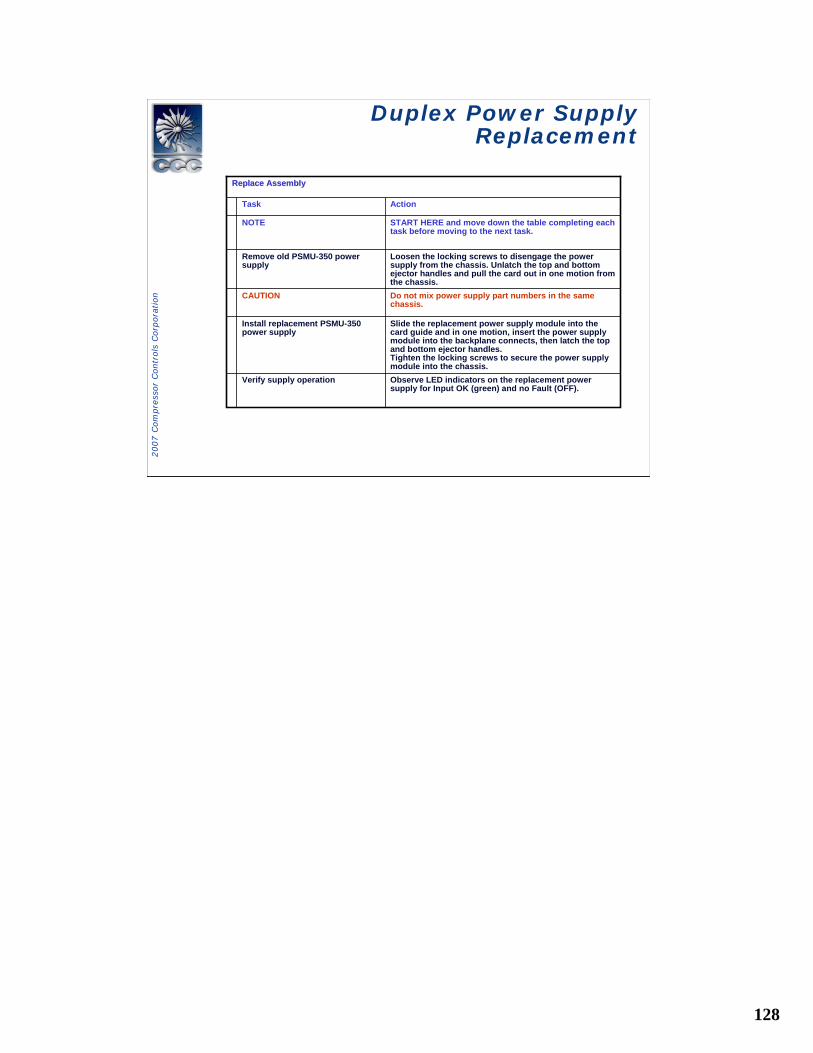
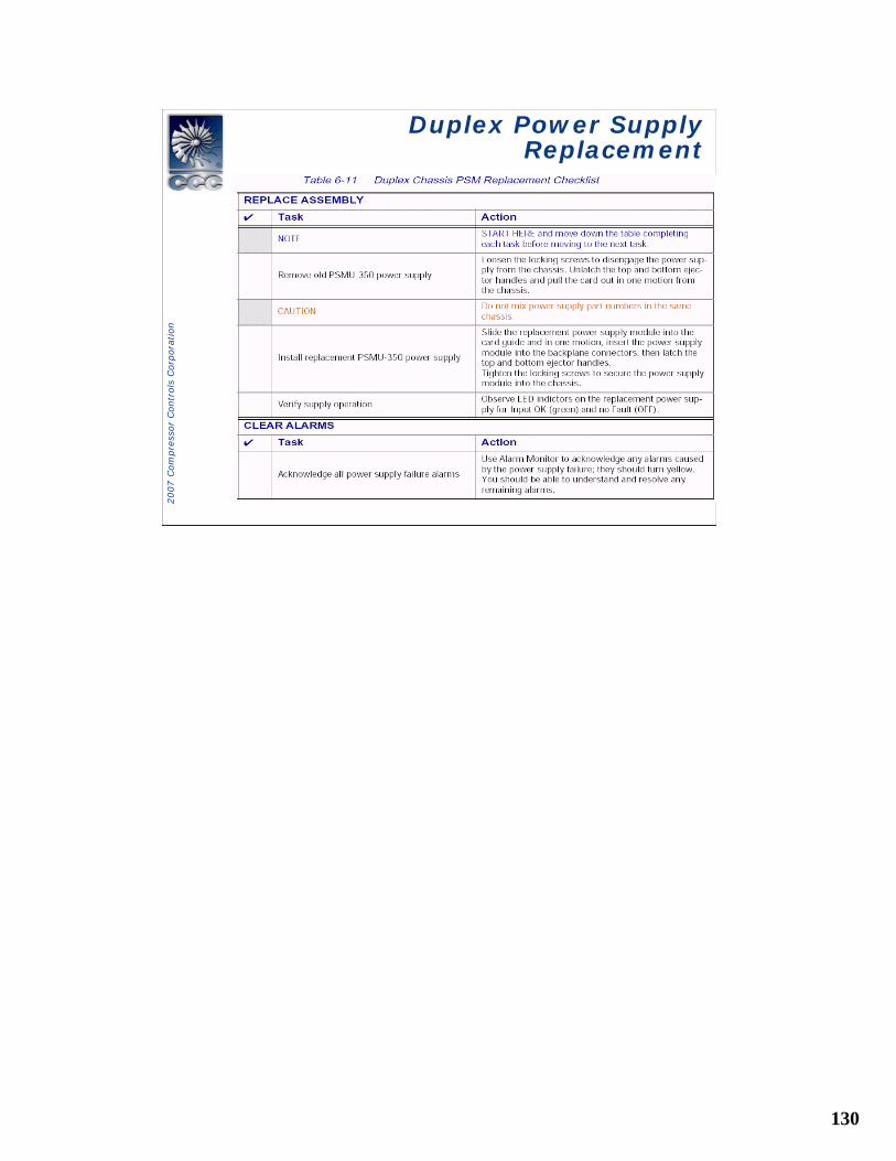
Duplex Power Supply Replacement
Duplex Power Supply Replacement
Loosen the locking screws to disengage the power supply from the chassis. Unlatch the top and bottom ejector handles and pull the card out in one motion from the chassis.
Remove old PSMU-350 power supply
Observe LED indicators on the replacement power supply for Input OK (green) and no Fault (OFF).
Verify supply operation
Slide the replacement power supply module into the card guide and in one motion, insert the power supply module into the backplane connects, then latch the top and bottom ejector handles.Tighten the locking screws to secure the power supply module into the chassis.
Install replacement PSMU-350 power supply
Do not mix power supply part numbers in the same chassis.
CAUTION
START HERE and move down the table completing each task before moving to the next task.
NOTE
ActionTask
Replace AssemblyReplace Assembly
129
2007 C
om
pre
ssor
Contr
ols
Corp
ora
tion
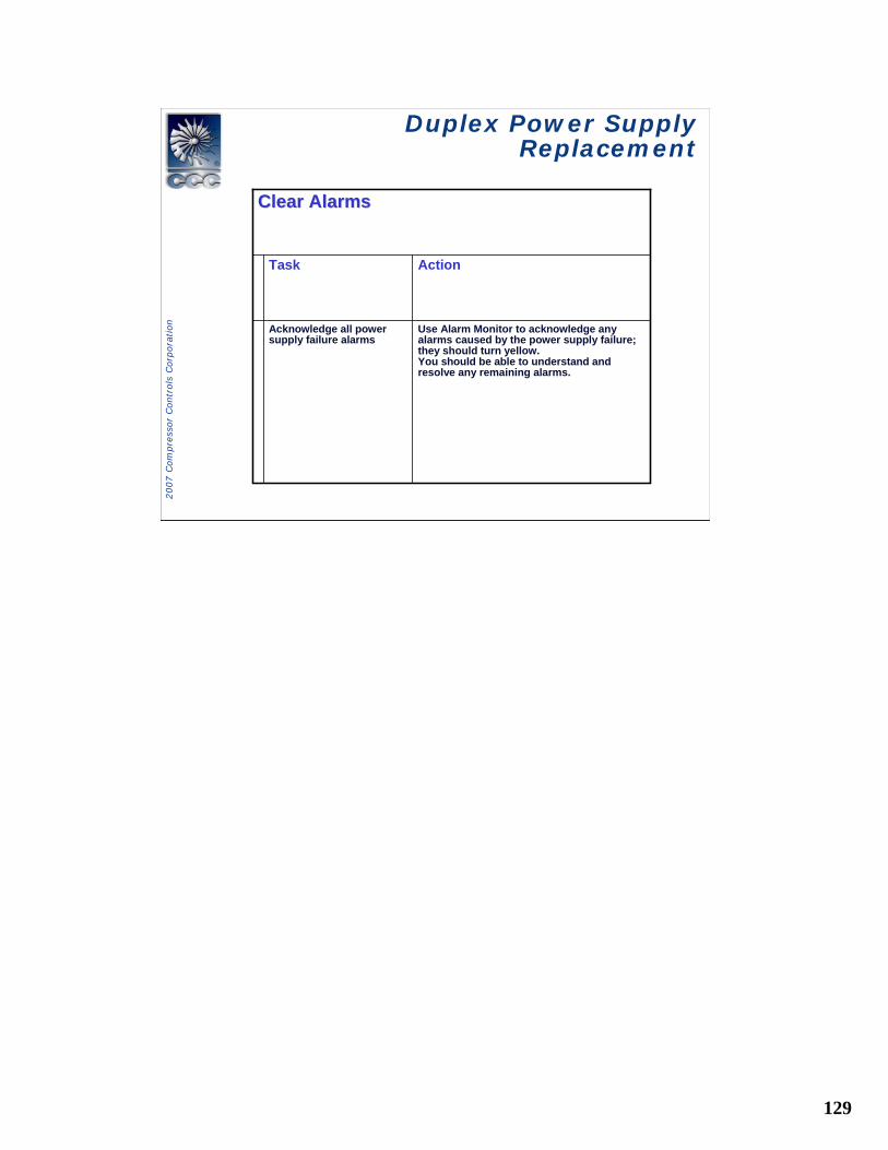
Duplex Power Supply Replacement
Duplex Power Supply Replacement
Use Alarm Monitor to acknowledge any alarms caused by the power supply failure; they should turn yellow.You should be able to understand and resolve any remaining alarms.
Acknowledge all power supply failure alarms
ActionTask
Clear AlarmsClear Alarms
130
2007 C
om
pre
ssor
Contr
ols
Corp
ora
tion
Duplex Power Supply Replacement
Duplex Power Supply Replacement
131
2007 C
om
pre
ssor
Contr
ols
Corp
ora
tion
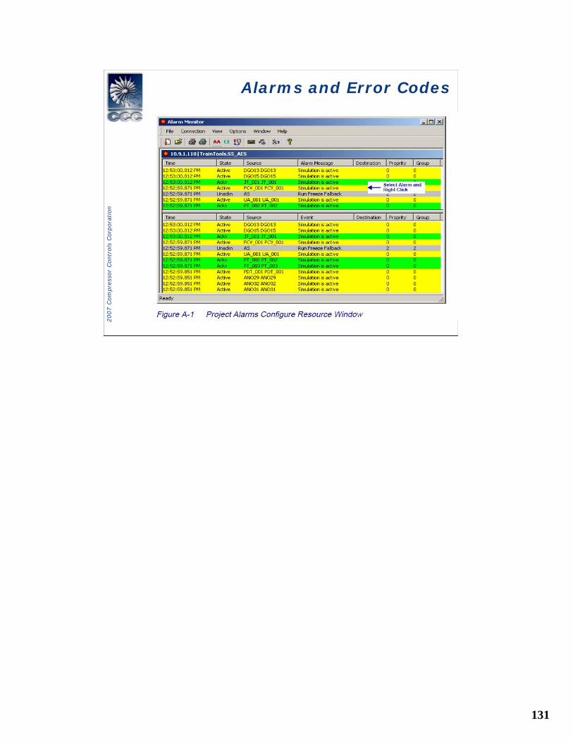
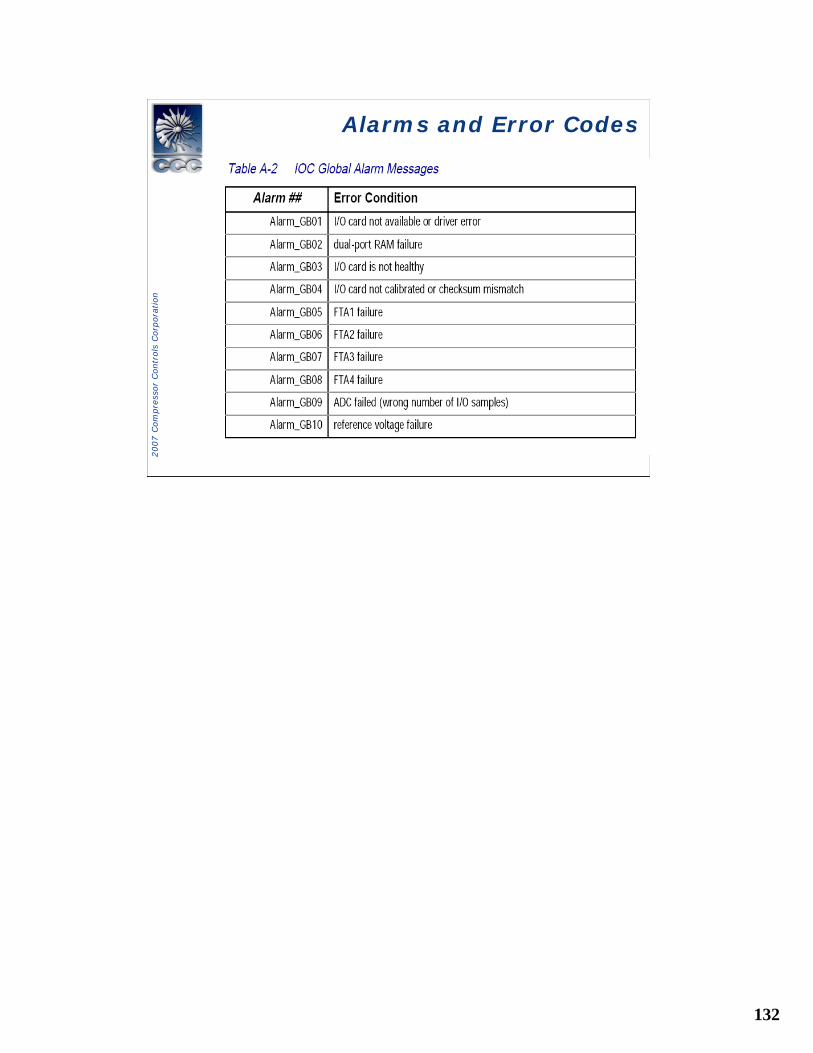
Alarms and Error CodesAlarms and Error Codes
132
2007 C
om
pre
ssor
Contr
ols
Corp
ora
tion
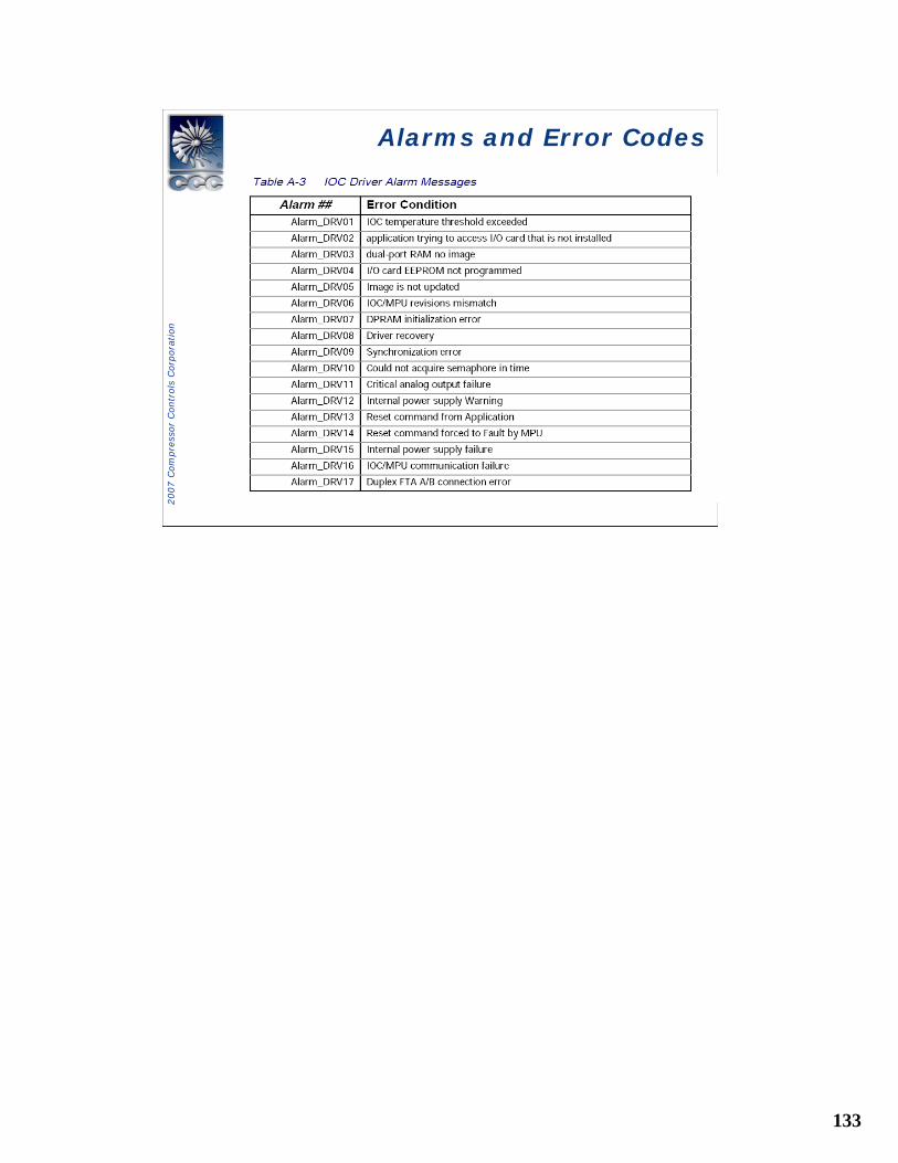
Alarms and Error CodesAlarms and Error Codes
133
2007 C
om
pre
ssor
Contr
ols
Corp
ora
tion
Alarms and Error CodesAlarms and Error Codes
134
2007 C
om
pre
ssor
Contr
ols
Corp
ora
tion
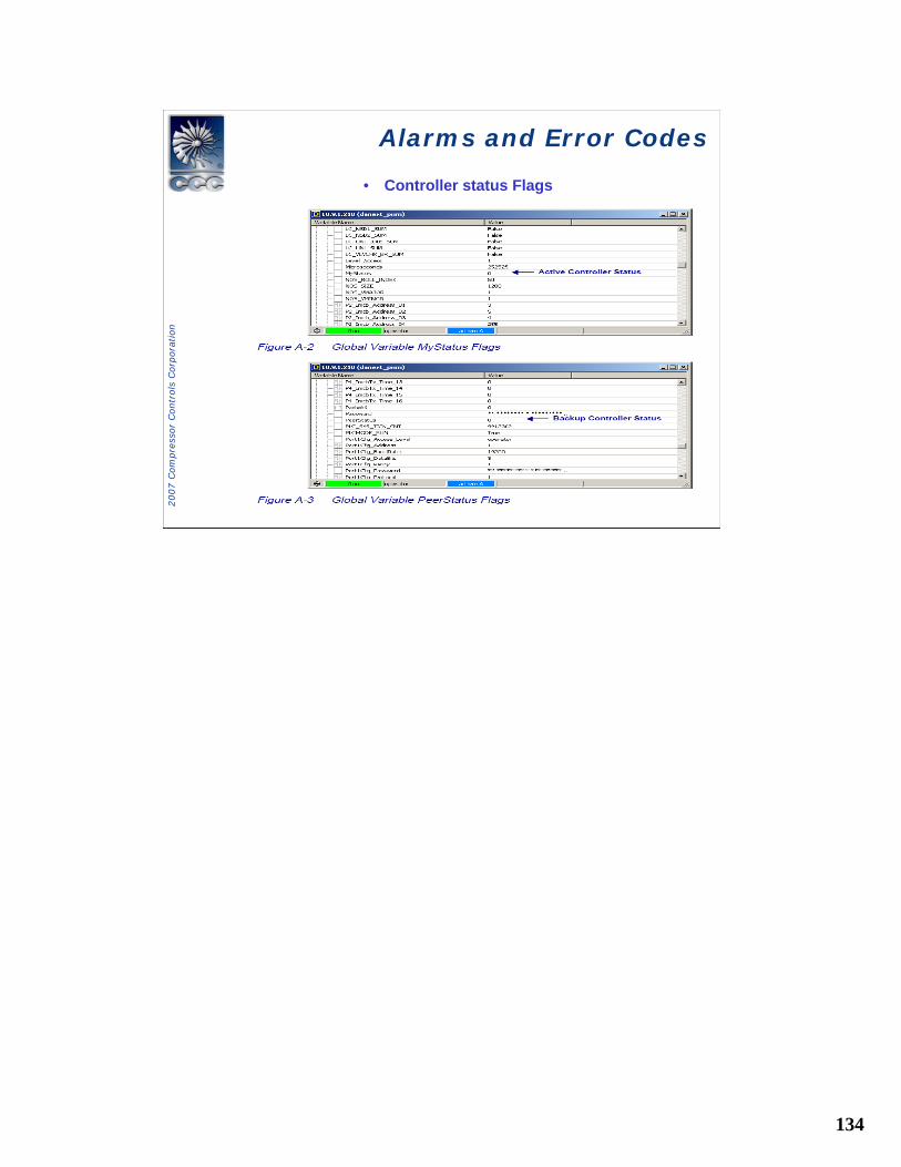
Alarms and Error CodesAlarms and Error Codes
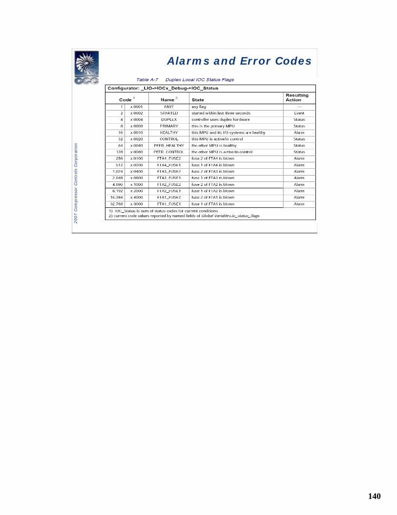
• Controller status Flags
135
2007 C
om
pre
ssor
Contr
ols
Corp
ora
tion
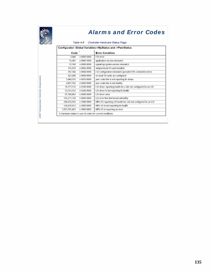
Alarms and Error CodesAlarms and Error Codes
136
2007 C
om
pre
ssor
Contr
ols
Corp
ora
tion
Alarms and Error CodesAlarms and Error Codes
137
2007 C
om
pre
ssor
Contr
ols
Corp
ora
tion
Alarms and Error CodesAlarms and Error Codes
138
2007 C
om
pre
ssor
Contr
ols
Corp
ora
tion
Alarms and Error CodesAlarms and Error Codes
139
2007 C
om
pre
ssor
Contr
ols
Corp
ora
tion
Alarms and Error CodesAlarms and Error Codes
140
2007 C
om
pre
ssor
Contr
ols
Corp
ora
tion
Alarms and Error CodesAlarms and Error Codes
141
2007 C
om
pre
ssor
Contr
ols
Corp
ora
tion
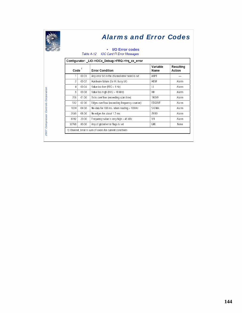
Alarms and Error CodesAlarms and Error Codes
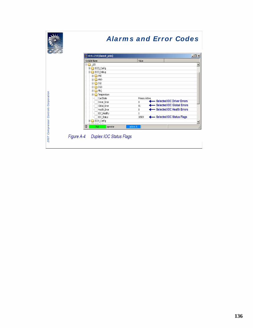
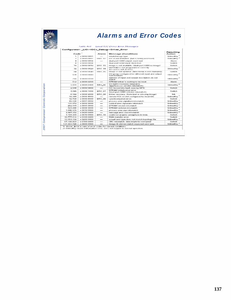
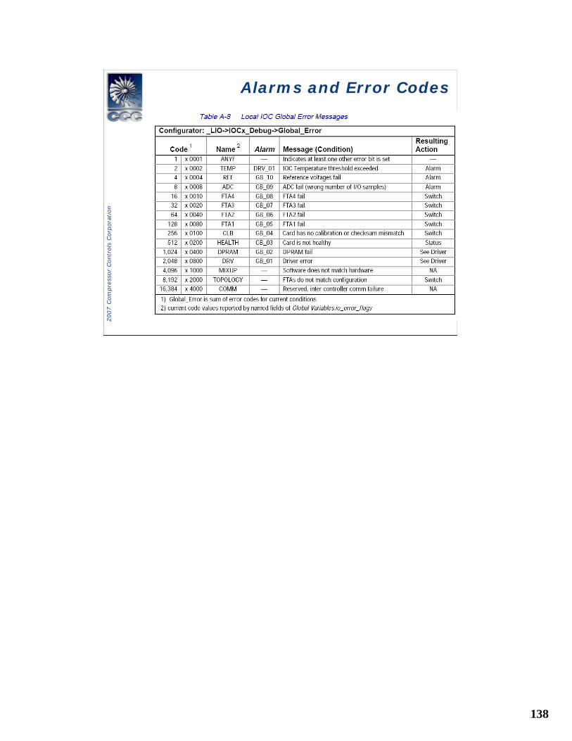
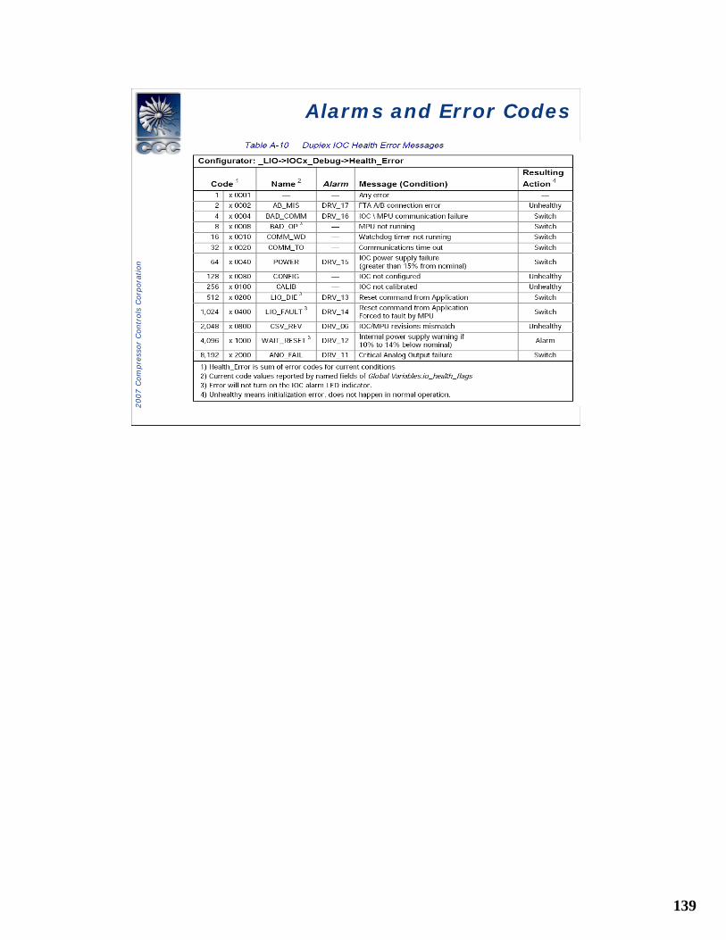
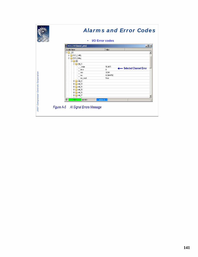
• I/O Error codes
142
2007 C
om
pre
ssor
Contr
ols
Corp
ora
tion
Alarms and Error CodesAlarms and Error Codes
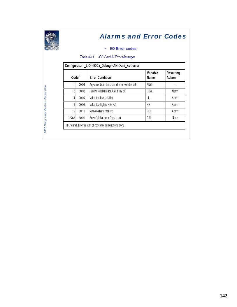
• I/O Error codes
143
2007 C
om
pre
ssor
Contr
ols
Corp
ora
tion
Alarms and Error CodesAlarms and Error Codes
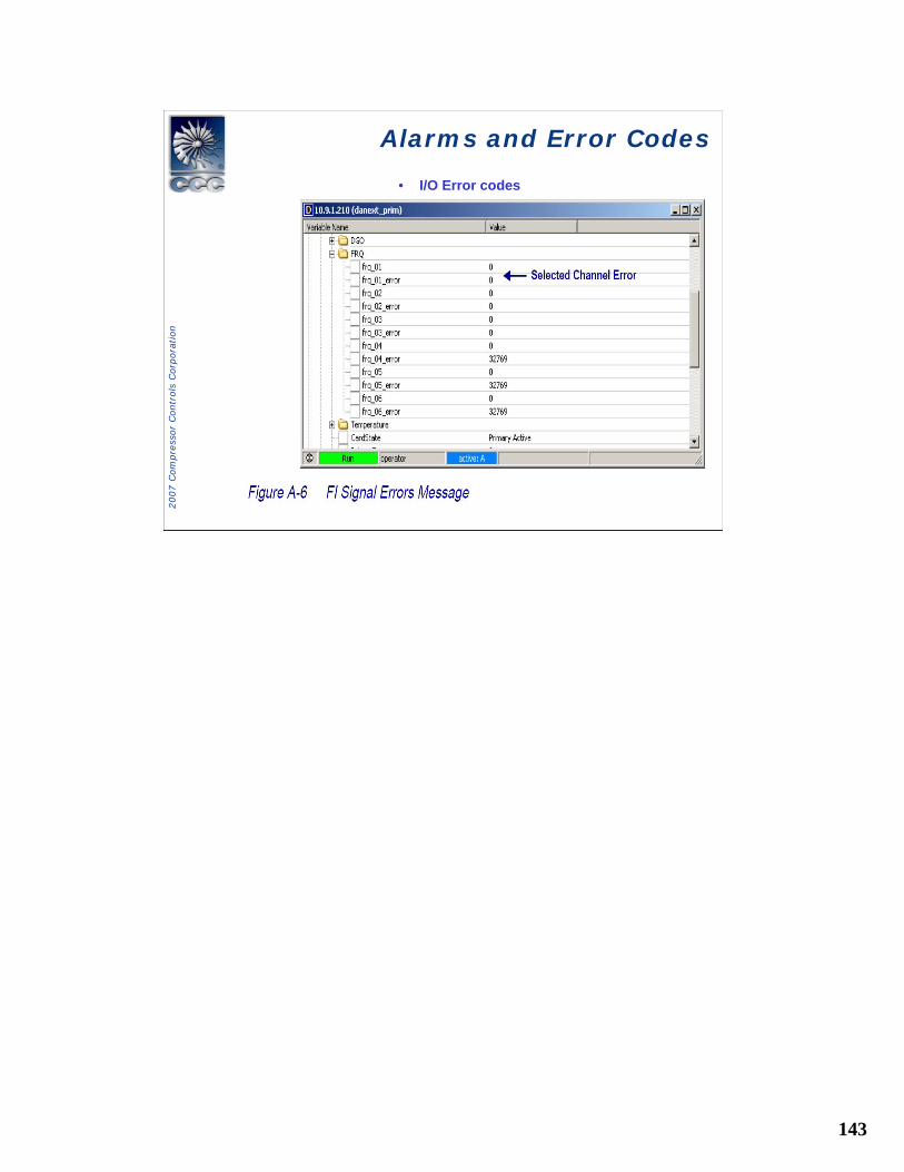
• I/O Error codes
144
2007 C
om
pre
ssor
Contr
ols
Corp
ora
tion
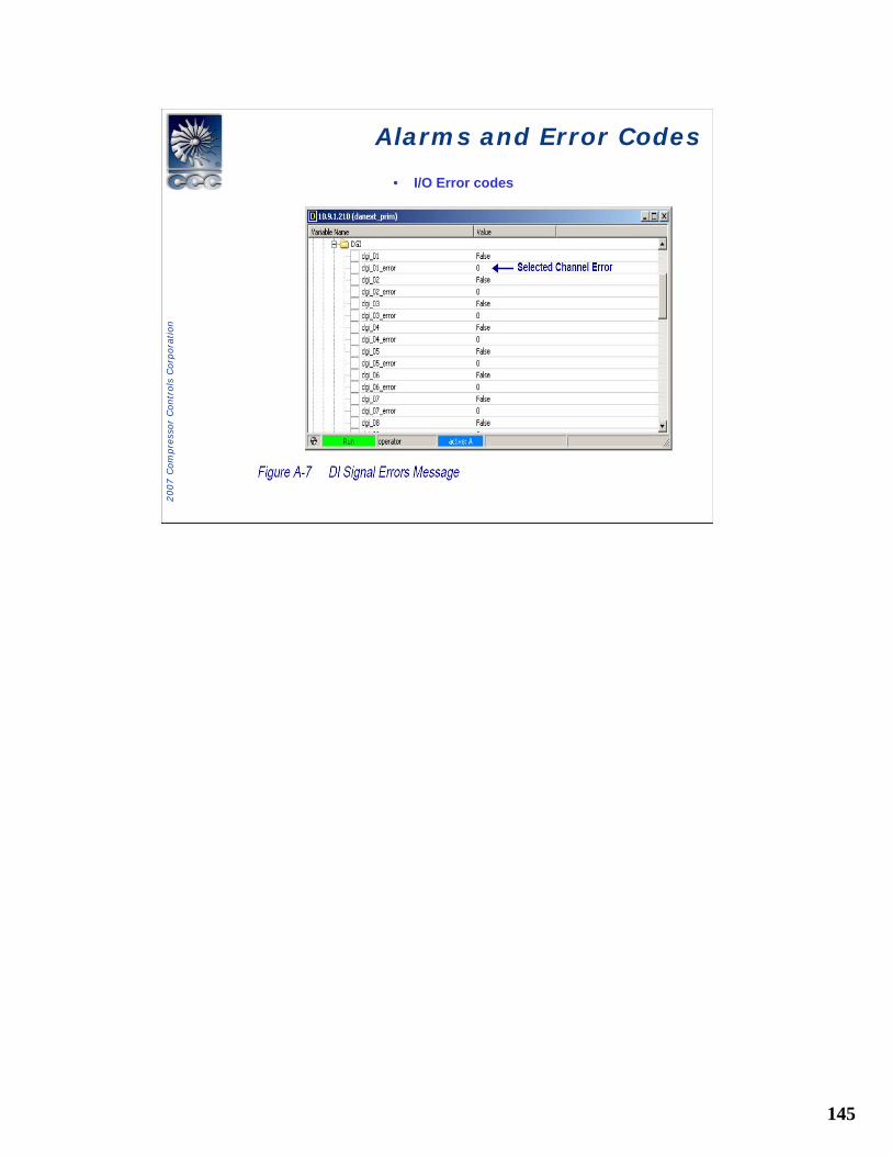
Alarms and Error CodesAlarms and Error Codes
• I/O Error codes
145
2007 C
om
pre
ssor
Contr
ols
Corp
ora
tion
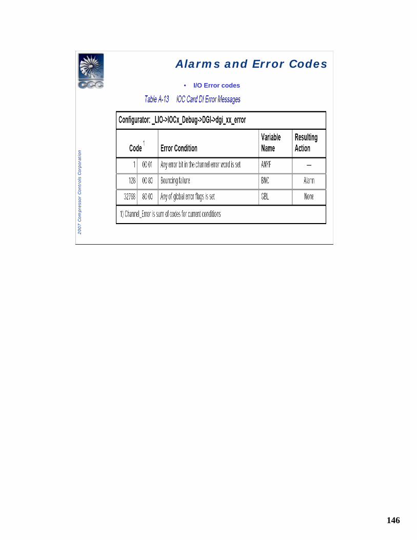
Alarms and Error CodesAlarms and Error Codes
• I/O Error codes
146
2007 C
om
pre
ssor
Contr
ols
Corp
ora
tion
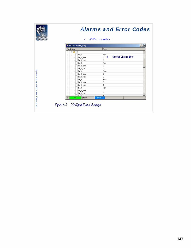
Alarms and Error CodesAlarms and Error Codes
• I/O Error codes
147
2007 C
om
pre
ssor
Contr
ols
Corp
ora
tion
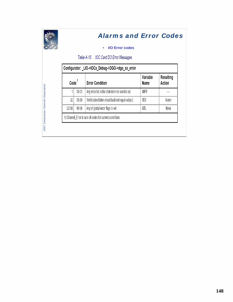
Alarms and Error CodesAlarms and Error Codes
• I/O Error codes
148
2007 C
om
pre
ssor
Contr
ols
Corp
ora
tion
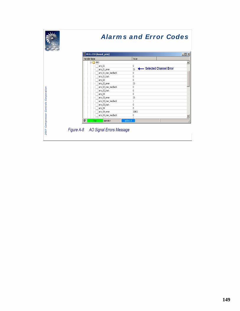
Alarms and Error CodesAlarms and Error Codes
• I/O Error codes
149
2007 C
om
pre
ssor
Contr
ols
Corp
ora
tion
Alarms and Error CodesAlarms and Error Codes

150
2007 C
om
pre
ssor
Contr
ols
Corp
ora
tion
Alarms and Error CodesAlarms and Error Codes