Embed Size (px)
Citation preview
Certification procedures for advanced technology heavy-duty vehicles
Evaluating test methods and opportunities for global alignment
www.theicct.org
White Paper Number 16 | February 2012
Ben Sharpe, International Council on Clean Transportation Dana Lowell, MJ Bradley and Associates
For additional information:1225 I Street NW Suite 900Washington DC 20005+1 202 534 1600
www.theicct.org
© 2012 International Council on Clean Transportation
Funding for this work was generously provided by The ClimateWorks Foundation.
1
CertifiCation proCedures for heavy-duty vehiCles
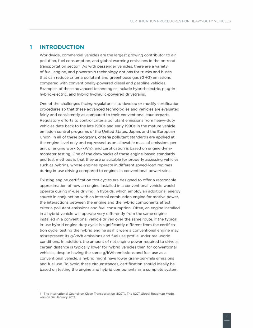
IntroduCtIonWorldwide, commercial vehicles are the largest growing contributor to air pollution, fuel consumption, and global warming emissions in the on-road transportation sector.1 As with passenger vehicles, there are a variety of fuel, engine, and powertrain technology options for trucks and buses that can reduce criteria pollutant and greenhouse gas (GHG) emissions compared with conventionally-powered diesel and gasoline vehicles. Examples of these advanced technologies include hybrid-electric, plug-in hybrid-electric, and hybrid hydraulic-powered drivetrains.
One of the challenges facing regulators is to develop or modify certification procedures so that these advanced technologies and vehicles are evaluated fairly and consistently as compared to their conventional counterparts. Regulatory efforts to control criteria pollutant emissions from heavy-duty vehicles date back to the late 1980s and early 1990s in the mature vehicle emission control programs of the United States, Japan, and the European Union. In all of these programs, criteria pollutant standards are applied at the engine level only and expressed as an allowable mass of emissions per unit of engine work (g/kWh), and certification is based on engine dyna-mometer testing. One of the drawbacks of these engine-based standards and test methods is that they are unsuitable for properly assessing vehicles such as hybrids, whose engines operate in different speed-load regimes during in-use driving compared to engines in conventional powertrains.
Existing engine certification test cycles are designed to offer a reasonable approximation of how an engine installed in a conventional vehicle would operate during in-use driving. In hybrids, which employ an additional energy source in conjunction with an internal combustion engine for motive power, the interactions between the engine and the hybrid components affect criteria pollutant emissions and fuel consumption. Often, an engine installed in a hybrid vehicle will operate very differently from the same engine installed in a conventional vehicle driven over the same route. If the typical in-use hybrid engine duty cycle is significantly different from the certifica-tion cycle, testing the hybrid engine as if it were a conventional engine may misrepresent its g/kWh emissions and fuel use profile under real-world conditions. In addition, the amount of net engine power required to drive a certain distance is typically lower for hybrid vehicles than for conventional vehicles; despite having the same g/kWh emissions and fuel use as a conventional vehicle, a hybrid might have lower gram-per-mile emissions and fuel use. To avoid these circumstances, certification should ideally be based on testing the engine and hybrid components as a complete system.
1 The International Council on Clean Transportation (ICCT). The ICCT Global Roadmap Model, version 34. January 2012.
1
2
ICCT WhITe PaPer No. 16
In an effort to move towards a systems certification approach and a better integration of hybrid vehicles into emissions testing programs, the Working Party on Pollution and Energy (GRPE)2 is in the process of drafting an amendment to Global Technical Regulation No. 4, which established a harmonized type-approval procedure for heavy-duty engine exhaust emissions. The amendment will provide a test procedure and harmonized technical requirements for certifying pollutant emissions and carbon dioxide (CO2) from heavy-duty hybrid vehicles. The GRPE aims to have the test procedure finalized and adopted by June 2014.
This paper seeks to inform policy makers of the alternatives for moving toward more holistic approaches to testing and certifying powertrain systems and complete vehicles. Section 2 describes and compares, from a technical perspective, the options for testing the emissions and fuel effi-ciency performance of heavy-duty vehicles. Section 3 discusses some of the specific regulatory challenges posed by the fact there are a myriad of test method and test cycle options and combinations that could potentially be used in a certification program. Section 4 then examines the opportunities and challenges of developing a “world harmonized” certification procedure for heavy-duty hybrid and advanced technology vehicles.
2 The Working Party on Pollution and Energy (GRPE) is an entity of the United Nations Eco-nomic Commission for Europe (UNECE). The GRPE is a subsidiary body of the World Forum for Harmonization of Vehicle Regulations (WP.29). The GRPE convenes officially twice per year and is comprised of over 120 experts who conduct research and analysis to develop emission and energy requirements for vehicles.
3
CertifiCation proCedures for heavy-duty vehiCles
Methods of CertIfyIng advanCed teChnology heavy-duty vehIClesAdvanced technology heavy-duty vehicles present unique regulatory challenges. One of the difficulties in integrating vehicles such as hybrids into regulatory programs is developing the proper certification test procedures for criteria pollutant and fuel efficiency/GHG emissions. Unlike the light-duty vehicle space, where per-mile vehicle-based standards and chassis dyna-mometer testing are the accepted certification convention for all vehicle types and architectures, the choice of a test method for heavy-duty vehicles is more complicated.
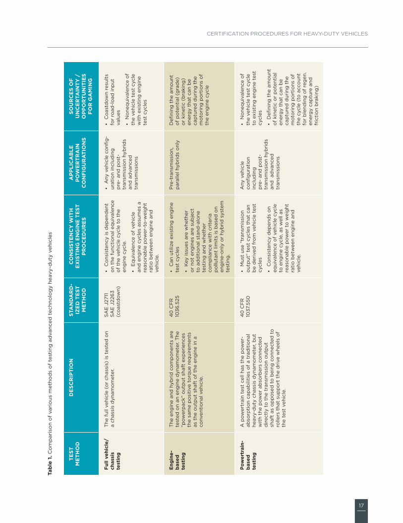
Medium- and heavy-duty vehicles are produced in a much greater range of sizes and configurations than light-duty vehicles, and have a more diverse range of in-use duty cycles. Also, chassis dynamometers and the associated facilities that can accommodate the significant loads and test apparatus of heavy-duty vehicles are often expensive and much less common than light-duty chassis dynamometers. As such, governments and industry have historically opted for work-specific engine-based standards and engine dynamometer testing for criteria pollutant emissions certification. However, because traditional engine dynamometer testing may not be adequate for properly evaluating hybrid systems and vehicles, governments and industry have been formulating different strategies for certifying emissions and fuel consumption performance. Table 1 summarizes the current options for testing hybrids and other advanced technology heavy-duty vehicles. These options include chassis dynamometer-based testing, engine dynamometer-based testing, powertrain test cell-based testing, simulation model-based testing, and test track or in-use testing. All of these options are described further below.
Full vehicle chassis dynamometer testingIn this test method, the full vehicle is mounted on a dynamometer with the drive wheels resting on one or more large cylindrical rolls. The vehicle is stationary during testing, but the drive wheels spin the rolls to simulate driving at different speeds. The dynamometer imparts varying loads to the drive wheels to represent varying vehicle inertial load, rolling resistance, and aerodynamic drag throughout the drive cycle. The vehicle driver follows a specific profile of speed versus time, and is usually given a computerized driver’s aid, which shows actual speed versus target speed in real time. The Society of Automotive Engineers (SAE) has developed a recommended practice for conducting emissions and fuel economy tests of heavy-duty vehicles on chassis dynamometers (SAE J2711), and the Environmental Protection Agency (EPA) has detailed procedures for conducting emissions testing (40 CFR Part 86, 40 CFR Part 1065).
2
2.1
4
ICCT WhITe PaPer No. 16
The most significant benefit of this test method is that it effectively brings the entire drivetrain into the test. As such, it can be used to provide a realistic assessment of distance-specific emissions and fuel use for a wide range of advanced vehicle and drivetrain technologies, including all hybrid configurations.
Chassis dynamometer testing is time consuming and expensive. A further limitation is its method of simulating vehicle aerodynamic loads. Because the vehicle is stationary during the test, the aerodynamic load is not imposed on the vehicle surface as it is during driving. Instead, a simulated aerodynamic load is imposed on the vehicle through the tires by adjusting the load on the dynamometer rolls. In effect, the dynamometer uses inertial and electrically generated loads applied through the vehicle’s tires to simulate aerodynamic load.
The required load is determined by conducting an on-road coastdown test prior to the dynamometer testing. In a coastdown test the vehicle is acceler-ated to some speed and then allowed to coast to a stop without applying the brakes, while vehicle speed versus time is recorded. By calculating the varying deceleration rate of the vehicle over time, one can impute the forces (rolling resistance and aerodynamic drag) that were operating on it at each speed. This information is programmed into the dynamometer so that it will impose the appropriate load on the vehicle at each point in the test cycle. The vehicle is then mounted on the dynamometer, and a dynamometer coastdown test is conducted to ensure that the coastdown profile is the same on the dynamometer as it was on the road.
While this method of evaluating and simulating rolling resistance and aerodynamic drag on a dynamometer is theoretically sound, it is critical that the coastdown test be conducted correctly. The “accuracy” of chassis dynamometer testing is limited by the accuracy of the coastdown data used to calibrate the dynamometer for a specific vehicle. The largest constraint on coastdown testing is finding an appropriate location to conduct the test (a straight and level road of sufficient length where the air is relatively still). The accuracy and repeatability of coastdown tests are significantly affected by test track configuration and ambient conditions.3
Engine dynamometer-based testingIn this testing approach, the engine and the hybrid system components are exercised together using a standard engine dynamometer, in which power and torque are measured from the crankshaft of the engine. The engine and hybrid system act in harmony, as they would under real-world driving conditions.
3 Within a reasonable range of variation, coastdown data can be corrected for differences in ambient temperature and wind speed, as well as changes in elevation over the test track. See SAE J2263, Surface Vehicle Recommended Practice, Road Load Measurement Using Onboard Anemometry and Coast Down Techniques, Oct 1996.
2.2
5
CertifiCation proCedures for heavy-duty vehiCles
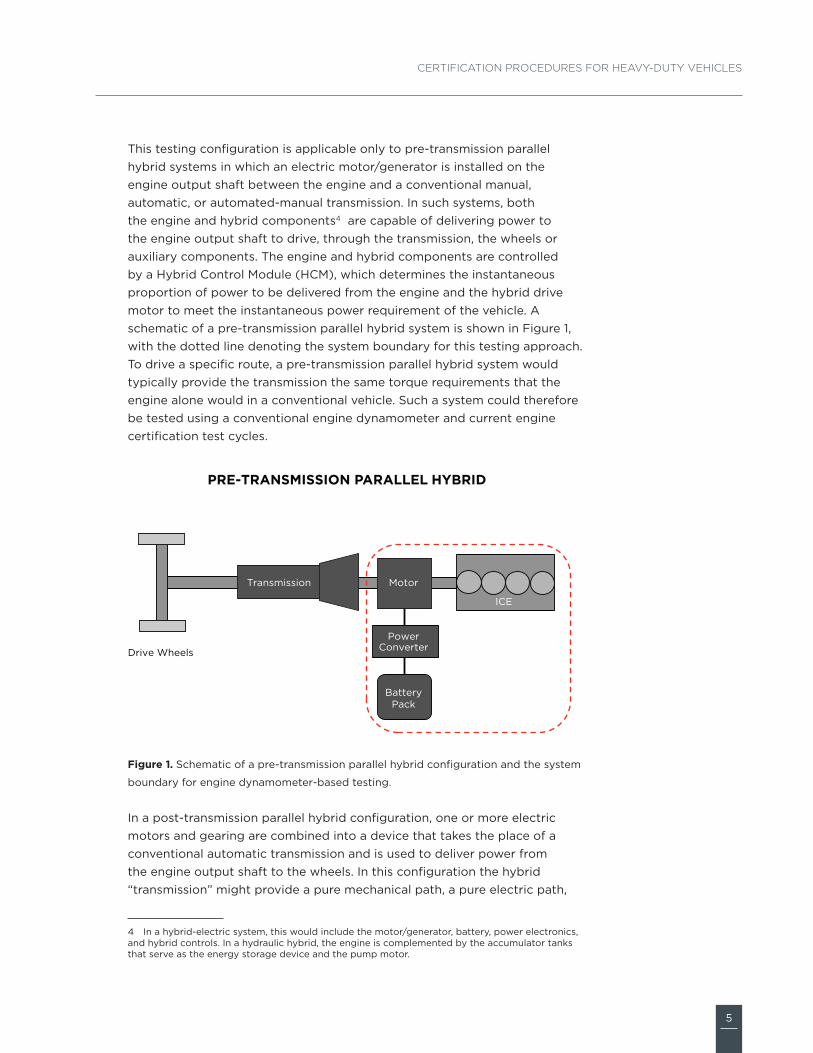
This testing configuration is applicable only to pre-transmission parallel hybrid systems in which an electric motor/generator is installed on the engine output shaft between the engine and a conventional manual, automatic, or automated-manual transmission. In such systems, both the engine and hybrid components4 are capable of delivering power to the engine output shaft to drive, through the transmission, the wheels or auxiliary components. The engine and hybrid components are controlled by a Hybrid Control Module (HCM), which determines the instantaneous proportion of power to be delivered from the engine and the hybrid drive motor to meet the instantaneous power requirement of the vehicle. A schematic of a pre-transmission parallel hybrid system is shown in Figure 1, with the dotted line denoting the system boundary for this testing approach. To drive a specific route, a pre-transmission parallel hybrid system would typically provide the transmission the same torque requirements that the engine alone would in a conventional vehicle. Such a system could therefore be tested using a conventional engine dynamometer and current engine certification test cycles.
figure 1. Schematic of a pre-transmission parallel hybrid configuration and the system
boundary for engine dynamometer-based testing.
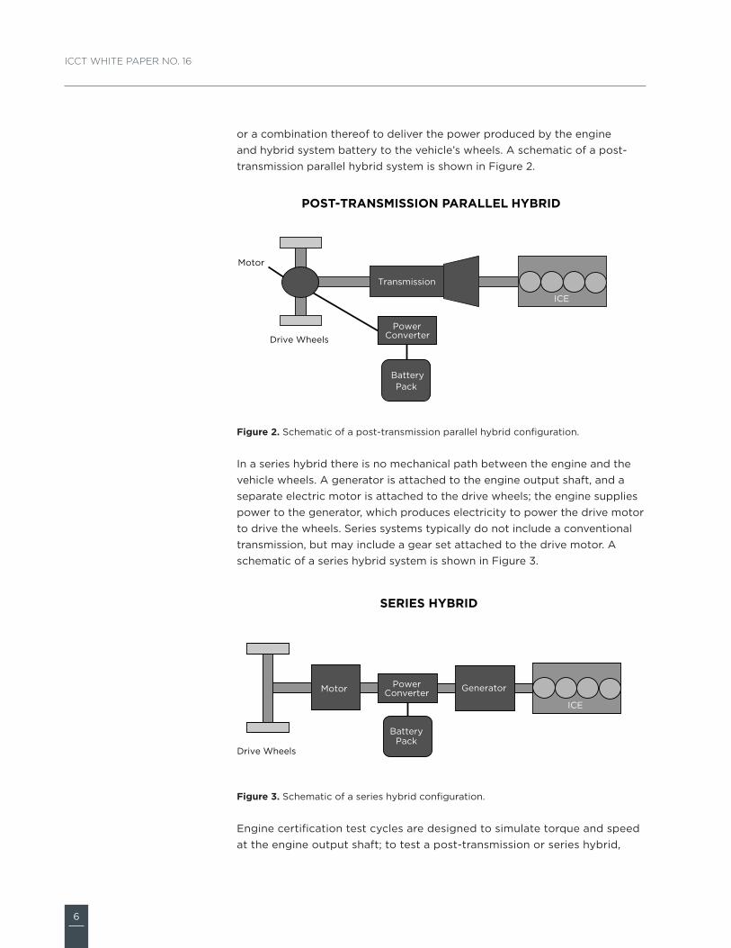
In a post-transmission parallel hybrid configuration, one or more electric motors and gearing are combined into a device that takes the place of a conventional automatic transmission and is used to deliver power from the engine output shaft to the wheels. In this configuration the hybrid “transmission” might provide a pure mechanical path, a pure electric path,
4 In a hybrid-electric system, this would include the motor/generator, battery, power electronics, and hybrid controls. In a hydraulic hybrid, the engine is complemented by the accumulator tanks that serve as the energy storage device and the pump motor.
ICE
Motor
Power Converter
Battery Pack
Transmission
Drive Wheels
PRE-TRANSMISSION PARALLEL HYBRID
FIGURE 1
6
ICCT WhITe PaPer No. 16
or a combination thereof to deliver the power produced by the engine and hybrid system battery to the vehicle’s wheels. A schematic of a post-transmission parallel hybrid system is shown in Figure 2.
figure 2. Schematic of a post-transmission parallel hybrid configuration.
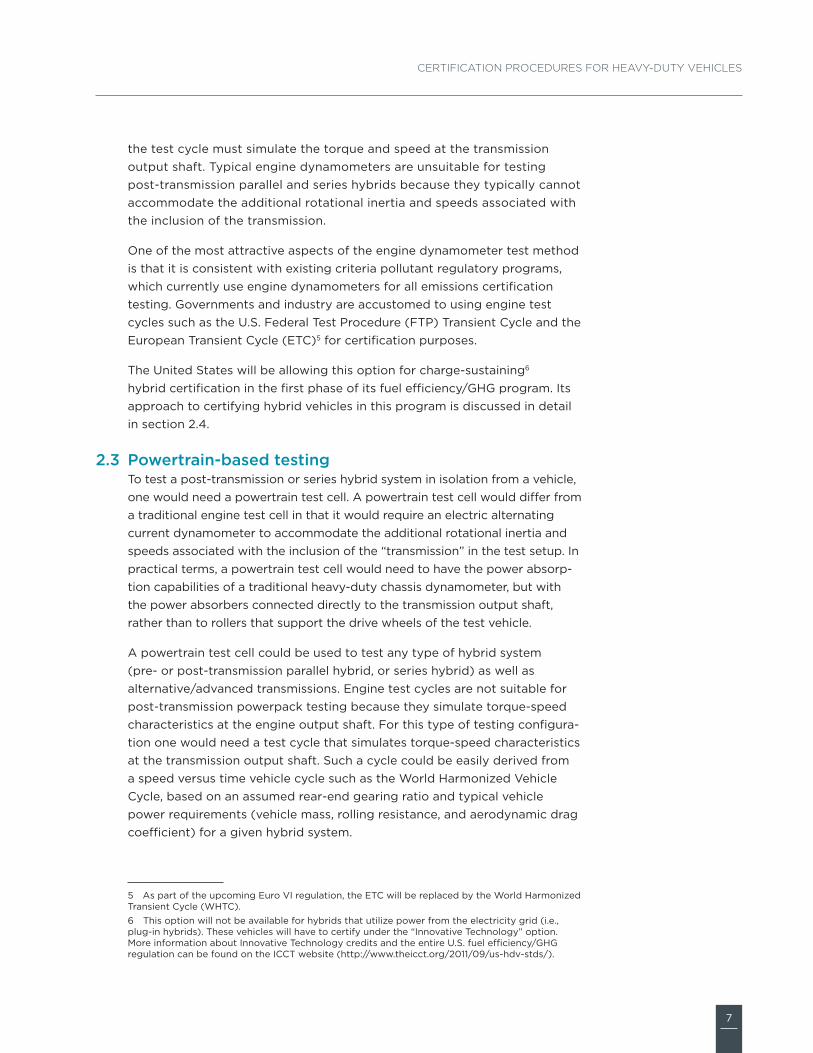
In a series hybrid there is no mechanical path between the engine and the vehicle wheels. A generator is attached to the engine output shaft, and a separate electric motor is attached to the drive wheels; the engine supplies power to the generator, which produces electricity to power the drive motor to drive the wheels. Series systems typically do not include a conventional transmission, but may include a gear set attached to the drive motor. A schematic of a series hybrid system is shown in Figure 3.
figure 3. Schematic of a series hybrid configuration.
Engine certification test cycles are designed to simulate torque and speed at the engine output shaft; to test a post-transmission or series hybrid,
ICE
Power Converter
Battery Pack
Transmission
Drive Wheels
Motor
POST-TRANSMISSION PARALLEL HYBRID
FIGURE 2
ICE
Generator Power Converter
Battery Pack
Drive Wheels
SERIES HYBRID
Motor
FIGURE 3
7
CertifiCation proCedures for heavy-duty vehiCles
the test cycle must simulate the torque and speed at the transmission output shaft. Typical engine dynamometers are unsuitable for testing post-transmission parallel and series hybrids because they typically cannot accommodate the additional rotational inertia and speeds associated with the inclusion of the transmission.
One of the most attractive aspects of the engine dynamometer test method is that it is consistent with existing criteria pollutant regulatory programs, which currently use engine dynamometers for all emissions certification testing. Governments and industry are accustomed to using engine test cycles such as the U.S. Federal Test Procedure (FTP) Transient Cycle and the European Transient Cycle (ETC)5 for certification purposes.
The United States will be allowing this option for charge-sustaining6 hybrid certification in the first phase of its fuel efficiency/GHG program. Its approach to certifying hybrid vehicles in this program is discussed in detail in section 2.4.
Powertrain-based testingTo test a post-transmission or series hybrid system in isolation from a vehicle, one would need a powertrain test cell. A powertrain test cell would differ from a traditional engine test cell in that it would require an electric alternating current dynamometer to accommodate the additional rotational inertia and speeds associated with the inclusion of the “transmission” in the test setup. In practical terms, a powertrain test cell would need to have the power absorp-tion capabilities of a traditional heavy-duty chassis dynamometer, but with the power absorbers connected directly to the transmission output shaft, rather than to rollers that support the drive wheels of the test vehicle.
A powertrain test cell could be used to test any type of hybrid system (pre- or post-transmission parallel hybrid, or series hybrid) as well as alternative/advanced transmissions. Engine test cycles are not suitable for post-transmission powerpack testing because they simulate torque-speed characteristics at the engine output shaft. For this type of testing configura-tion one would need a test cycle that simulates torque-speed characteristics at the transmission output shaft. Such a cycle could be easily derived from a speed versus time vehicle cycle such as the World Harmonized Vehicle Cycle, based on an assumed rear-end gearing ratio and typical vehicle power requirements (vehicle mass, rolling resistance, and aerodynamic drag coefficient) for a given hybrid system.
5 As part of the upcoming Euro VI regulation, the ETC will be replaced by the World Harmonized Transient Cycle (WHTC).6 This option will not be available for hybrids that utilize power from the electricity grid (i.e., plug-in hybrids). These vehicles will have to certify under the “Innovative Technology” option. More information about Innovative Technology credits and the entire U.S. fuel efficiency/GHG regulation can be found on the ICCT website (http://www.theicct.org/2011/09/us-hdv-stds/).
2.3
8
ICCT WhITe PaPer No. 16
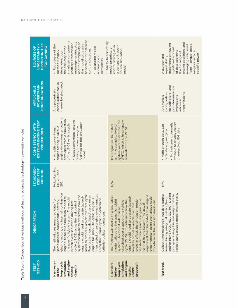
Simulation model-based testingUnlike chassis and engine dynamometer testing, the use of simulation models for heavy-duty vehicle certification is fairly new. Software models vary greatly in complexity and applicability, but, in general, a simulation model uses actual data from physical systems to re-create a virtual vehicle that can mimic, in computational space, its real-world counterpart. Both Japan and the United States have finalized regulatory programs that employ simulation tools, and, as described in Table 1, the GRPE is currently assessing a proposal7 that is also heavily dependent on modeling. China, too, is currently developing a fuel efficiency program that will employ a combination of chassis testing and vehicle simulation. Each of these simulation-based certification approaches is discussed in more detail below.
The Japanese government adopted the world’s first fuel economy require-ments for heavy-duty trucks and buses in 2006. As part of the regulation, Japan developed test procedures for certifying the fuel use and emissions from heavy-duty vehicles. The test methods for both conventional and hybrid-electric vehicles are based on a combination of actual engine testing and simulation modeling. More details regarding the Japanese “Top Runner” fuel economy regulation as well as its test procedure for conventional vehicles can be found in an ICCT fact sheet,8 which is available upon request.
The Japanese method for certifying heavy-duty hybrid vehicles starts with measured data from the engine, battery, and electric motors. Data from these physical systems are then used to tailor a simulation model that is unique to each specific hybrid system. The model is then exercised over the JE05 driving cycle using the real hybrid control system hardware (i.e., the Engine Control Unit or ECU) to determine how the engine would need to operate in terms of speed and torque to propel a vehicle over that cycle. Fuel use is then calculated based on an engine fuel map. The actual engine is then tested on an engine dynamometer, using that unique cycle, to determine criteria pollutant emission levels.
Like Japan, the United States has also finalized a regulatory program that is heavily dependent on simulation modeling for vehicle certification. The Greenhouse Gas Emissions Model (GEM) is an open source MATLAB/Simulink-based software program that is freely available on the EPA’s website (http://www.epa.gov/otaq/climate/gem.htm). In concept, the GEM is similar to many models that have been developed by other research institu-tions and commercial entities in that it uses various inputs to characterize a vehicle’s properties (weight, aerodynamics, and rolling resistance) and predicts how the vehicle would behave second by second when following
7 Informal document No. GRPE-60-12 (60th GRPE, 07-11 June 2010, agenda item 2.3). Proposal for an Emissions Test Procedure for Heavy-Duty Hybrid Vehicles (HD-HV’S).8 The International Council on Clean Transportation. Fact Sheet: Japan’s “Top Runner” Fuel Economy Standards for Heavy-duty Vehicles. February 11, 2008.
2.4
9
CertifiCation proCedures for heavy-duty vehiCles
a specific drive cycle. The inputs in the GEM are associated with many features of the vehicle that have the strongest impact on fuel consumption and CO2 emissions. For tractors, this includes (1) coefficient of drag (Cd), (2) rolling resistance (kg/metric ton) for both steer and drive tires, (3) weight reduction, (4) extended idle-reduction technology, and (5) vehicle speed limiting. The GEM does not include measured inputs about engine characteristics; rather, the simulation is carried out using a standard engine for each vehicle class. A key element of the first phase of the U.S. program is separate standards for engines based on engine dynamometer testing.
As currently configured, GEM can only simulate vehicles with standard drivetrains and cannot be used to certify hybrid vehicles for compliance with fuel economy and GHG emission standards. Therefore, unlike Japan, the United States has devised distinct certification pathways for hybrid vehicles. Manufacturers may choose to certify hybrid vehicles using any of the three aforementioned test methods: (1) full vehicle chassis dynamometer testing, (2) engine (and hybrid system) dynamometer testing, or (3) powertrain testing. As described above, a post-transmission hybrid system can only be tested with a chassis or powertrain dynamometer.
However, while the engine and hybrid system can be certified together for fuel efficiency and GHGs using one of these methods, under the U.S. program in all cases the engine in a hybrid vehicle must also be tested separately on an engine dynamometer for to certify compliance with criteria pollutant emission standards. The engine functions differently when operated independently of the hybrid system, and both fuel consump-tion and emissions performance during certification testing may not be representative of real-world operation. With regard to hybrid vehicles, this is currently a shortcoming of the U.S. program.
The GRPE’s proposed method for certifying hybrid vehicles is similar to the Japanese approach. It starts with developing a model for each unique hybrid system that is based on measured component data (e.g., from the engine, transmission, electric motor, accumulator, etc.). The virtual vehicle is then driven over the World Transient Vehicle Cycle (WTVC). From the simulation, the engine’s speed and load characteristics over the cycle are recorded, in effect enabling the simulation model to determine a unique engine cycle for that hybrid system. Using this unique speed/load data, the actual engine is then exercised on a dynamometer to determine criteria pollutant and CO2 emission levels.
China has recently finalized a test procedure methodology for its upcoming fuel efficiency program, which is expected to be completed in 2013. In their test procedure, base vehicles will be tested on a chassis dynamometer, and all variants of a particular base vehicle will be certified using simulation software. Both chassis and simulation testing will be done using a modified version of the WTVC (C-WTVC), which is meant to better reflect the duty
10
ICCT WhITe PaPer No. 16
cycles of Chinese commercial vehicles. Detailed definitions of a base versus variant vehicle are still in development. Also, the agencies responsible for drafting the regulation are still developing the procedures for certifying advanced vehicles such as hybrids. The chassis and simulation testing protocols will only measure fuel consumption, and certification for criteria pollutants will continue to be performed using engine dynamometer testing.
Test track and in-use testingThis test method involves operating the vehicle on a closed test course (typically a one mile or longer circular or oval track with banked corners). For each test the driver is taught how to operate the vehicle for the target test cycle. This includes parameters such as acceleration rates from each stop and target speeds between specific points on the track, braking rates and stopping points, and idle times at each stop. The Truck Maintenance Council (TMC) and SAE procedures for in-service and dynamometer tests can serve as the basis for a test track test protocol.9
Test tracks are affected by ambient weather conditions such as temperature, humidity, precipitation, and wind, which in some locations could severely limit testing under standardized conditions. Test tracks are also generally constructed to be flat, and cannot incorporate changes in grade as part of the test cycle. There are a limited number of test tracks suitable for testing heavy-duty vehicles; development of additional facilities would be expensive. In addition, test tracks are best suited for testing at a series of steady-state speeds. In practical terms it may not be possible to conduct tests on a test track with sufficient test cycle repeatability for certification using a highly transient test cycle such as the WHTC.
Cycle repeatability on a test track could be improved by binning and weighting time-resolved data to reflect a modal engine cycle, based on actual vehicle-specific power or some other metric. Given enough data, it might even be possible to certify vehicles based on in-use testing on public or semi-public roads without the need for a closed test track. However, there is currently no peer-reviewed methodology or procedure for this type of data collection and analysis; to support certification based on modal data collected in-use or on a test track an appropriate procedure would have to be developed and tested.
9 Society of Automotive Engineers, SAE Surface Vehicle Recommended Practice, Joint SAE/RCCC Fuel Consumption Test Procedure (Short Term In-Service Vehicle) Type I, SAE J1264, Oct 1986. Society of Automotive Engineers, SAE Surface Vehicle Recommended Practice, Joint TMC/SAE Fuel Consumption Test Procedure- Type II, SAE J1321, Oct 1986. Society of Automo-tive Engineers, SAE Surface Vehicle Recommended Practice, Joint TMC/SAE Fuel Consumption In-Service Test Procedure-Type III, SAE J1526, Jun 1987. Truck Maintenance Council, TMC Recom-mended Practice, RP 1109 – Type IV Fuel Economy Test Procedure, March 1996.
2.5
11
CertifiCation proCedures for heavy-duty vehiCles
CoMparIson of test MethodsThere are certain issues and challenges with each of the testing methods that are currently used to certify advanced technology heavy-duty vehicles. As summarized in Tables 1 and 2, none of the methods are clearly superior across all the key regulatory parameters. The following section discusses some areas of concern in terms of consistency with existing criteria pollutant engine test procedures, applicable test configurations, and sources of complexity and uncertainty.
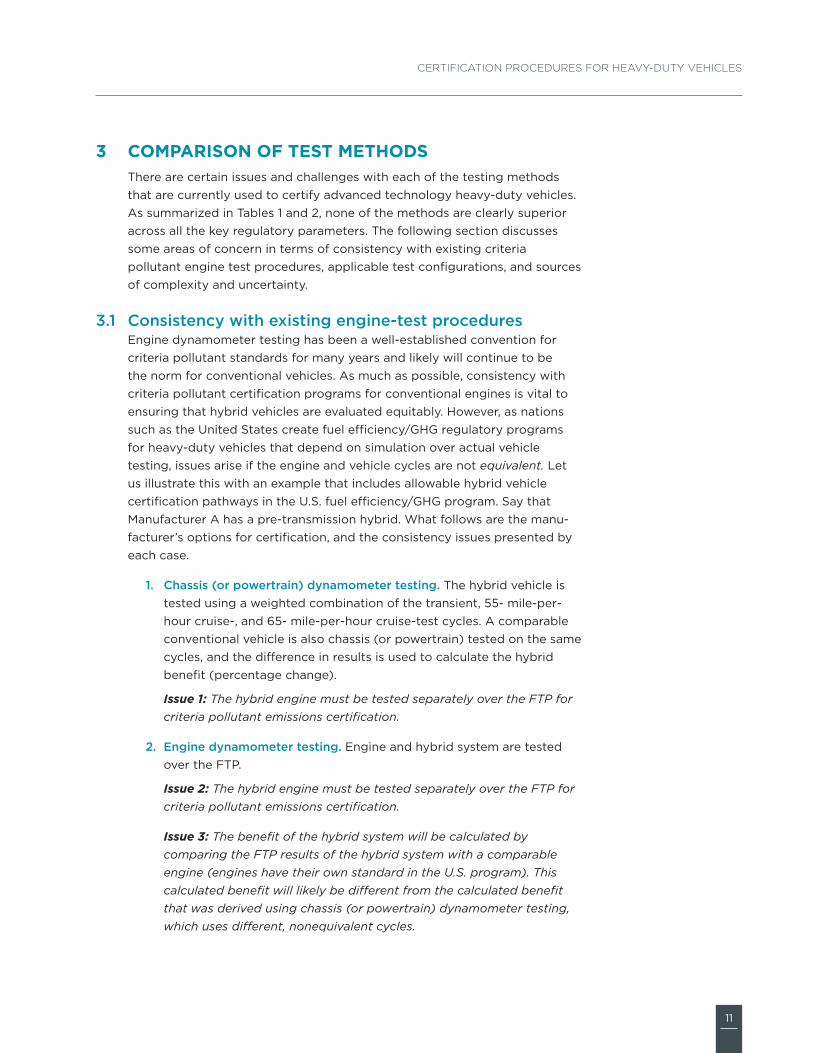
Consistency with existing engine-test proceduresEngine dynamometer testing has been a well-established convention for criteria pollutant standards for many years and likely will continue to be the norm for conventional vehicles. As much as possible, consistency with criteria pollutant certification programs for conventional engines is vital to ensuring that hybrid vehicles are evaluated equitably. However, as nations such as the United States create fuel efficiency/GHG regulatory programs for heavy-duty vehicles that depend on simulation over actual vehicle testing, issues arise if the engine and vehicle cycles are not equivalent. Let us illustrate this with an example that includes allowable hybrid vehicle certification pathways in the U.S. fuel efficiency/GHG program. Say that Manufacturer A has a pre-transmission hybrid. What follows are the manu-facturer’s options for certification, and the consistency issues presented by each case.
1. Chassis (or powertrain) dynamometer testing. The hybrid vehicle is tested using a weighted combination of the transient, 55- mile-per-hour cruise-, and 65- mile-per-hour cruise-test cycles. A comparable conventional vehicle is also chassis (or powertrain) tested on the same cycles, and the difference in results is used to calculate the hybrid benefit (percentage change).
Issue 1: The hybrid engine must be tested separately over the FTP for criteria pollutant emissions certification.
2. Engine dynamometer testing. Engine and hybrid system are tested over the FTP.
Issue 2: The hybrid engine must be tested separately over the FTP for criteria pollutant emissions certification.
Issue 3: The benefit of the hybrid system will be calculated by comparing the FTP results of the hybrid system with a comparable engine (engines have their own standard in the U.S. program). This calculated benefit will likely be different from the calculated benefit that was derived using chassis (or powertrain) dynamometer testing, which uses different, nonequivalent cycles.
3
3.1
12
ICCT WhITe PaPer No. 16
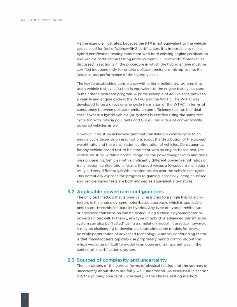
As the example illustrates, because the FTP is not equivalent to the vehicle cycles used for fuel efficiency/GHG certification, it is impossible to make hybrid certification testing consistent with both existing engine certification and vehicle certification testing under current U.S. protocols. Moreover, as discussed in section 2.4, the procedure in which the hybrid engine must be certified independently for criteria pollutant emissions misrepresents the actual in-use performance of the hybrid vehicle.
The key to establishing consistency with criteria pollutant programs is to use a vehicle test cycle(s) that is equivalent to the engine test cycles used in the criteria pollutant program. A prime example of equivalence between a vehicle and engine cycle is the WTVC and the WHTC. The WHTC was developed to be a direct engine cycle translation of the WTVC. In terms of consistency between pollutant emission and efficiency testing, the ideal case is where a hybrid vehicle (or system) is certified using the same test cycle for both criteria pollutants and GHGs. This is true of conventionally powered vehicles as well.
However, it must be acknowledged that translating a vehicle cycle to an engine cycle depends on assumptions about the distribution of the power/weight ratio and the transmission configuration of vehicles. Consequently, for any vehicle-based test to be consistent with an engine-based test, the vehicle must fall within a normal range for the power/weight ratio and trans-mission gearing. Vehicles with significantly different power/weight ratios or transmission configurations (e.g., a 3-speed versus a 10-speed transmission) will yield very different g/kWh emission results over the vehicle test cycle. This potentially exposes the program to gaming, especially if engine-based and vehicle-based tests are both allowed as equivalent alternatives.
Applicable powertrain configurationsThe only test method that is physically restricted to a single hybrid archi-tecture is the engine dynamometer-based approach, which is applicable only to pre-transmission parallel hybrids. Any type of hybrid architecture or advanced transmission can be tested using a chassis dynamometer or powertrain test cell. In theory, any type of hybrid or advanced transmission system can also be “tested” using a simulation model; in practice, however, it may be challenging to develop accurate simulation models for every possible permutation of advanced technology. Another confounding factor is that manufacturers typically use proprietary hybrid control algorithms, which would be difficult to model in an open and transparent way in the context of a certification program.
Sources of complexity and uncertaintyThe limitations of the various forms of physical testing and the sources of uncertainty about them are fairly well understood. As discussed in section 2.2, the primary source of uncertainty in the chassis testing method
3.2
3.3
13
CertifiCation proCedures for heavy-duty vehiCles
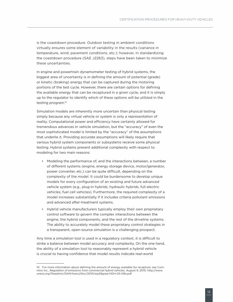
is the coastdown procedure. Outdoor testing in ambient conditions virtually ensures some element of variability in the results (variance in temperature, wind, pavement conditions, etc.); however, in standardizing the coastdown procedure (SAE J2263), steps have been taken to minimize these uncertainties.
In engine and powertrain dynamometer testing of hybrid systems, the biggest area of uncertainty is in defining the amount of potential (grade) or kinetic (braking) energy that can be captured during the motoring portions of the test cycle. However, there are certain options for defining the available energy that can be recaptured in a given cycle, and it is simply up to the regulator to identify which of these options will be utilized in the testing program.10
Simulation models are inherently more uncertain than physical testing simply because any virtual vehicle or system is only a representation of reality. Computational power and efficiency have certainly allowed for tremendous advances in vehicle simulation, but the “accuracy” of even the most sophisticated model is limited by the “accuracy” of the assumptions that underlie it. Providing accurate assumptions will likely require that various hybrid system components or subsystems receive some physical testing. Hybrid systems present additional complexity with respect to modeling for two main reasons:
• Modeling the performance of, and the interactions between, a number of different systems (engine, energy storage device, motor/generator, power converter, etc.) can be quite difficult, depending on the complexity of the model. It could be burdensome to develop unique models for every configuration of an existing and future advanced vehicle system (e.g., plug-in hybrids, hydraulic hybrids, full electric vehicles, fuel cell vehicles). Furthermore, the required complexity of a model increases substantially if it includes criteria pollutant emissions and advanced after-treatment systems.
• Hybrid vehicle manufacturers typically employ their own proprietary control software to govern the complex interactions between the engine, the hybrid components, and the rest of the driveline systems. The ability to accurately model these proprietary control strategies in a transparent, open-source simulation is a challenging prospect.
Any time a simulation tool is used in a regulatory context, it is difficult to strike a balance between model accuracy and complexity. On the one hand, the ability of a simulation tool to reasonably represent a hybrid vehicle is crucial to having confidence that model results indicate real-world
10 For more information about defining the amount of energy available for recapture, see Cum-mins Inc., Regulation of emissions from commercial hybrid vehicles. August 9, 2010. http://www.unece.org/fileadmin/DAM/trans//doc/2010/wp29grpe/HDH-03-09e.pdf

14
ICCT WhITe PaPer No. 16
performance. On the other hand, a model that is overly complicated may reduce transparency and make it such that only a limited number of technical experts fully understand the certification software. Allowing manu-facturers to use proprietary “black box” models for certification introduces a significant opportunity for gaming.
15
CertifiCation proCedures for heavy-duty vehiCles
suMMary and ConsIderatIons
Climate concerns, unstable oil markets, and competition are driving the demand for greater efficiency as well as increasing reliance on nontradi-tional fuels in the heavy-duty vehicle sector. As this demand intensifies, advanced vehicle technologies such as hybrids are increasingly attractive and are gaining market share. From a policy perspective, one of the key issues that regulators are facing is how to modify and/or create certification procedures for these advanced vehicles.
The options for certifying advanced technology commercial trucks and buses include laboratory and virtual testing, as well as combinations thereof. When analyzing the range of testing options in terms of costs, complexity, accuracy, and transparency, no one solution is clearly superior. As such, it’s understandable that different governments have developed different approaches to testing heavy-duty hybrids. In Japan, certification for both criteria pollutant and fuel efficiency is based on a combination of simulation modeling and engine dynamometer testing. In the United States, chassis- and engine-based dynamometer testing are the two options available for certification of hybrid vehicles in the fuel efficiency/GHG program, with the shortcoming that the hybrid engine must be tested separately in the criteria pollutant program.11 In light of the differences in these programs, there is an opportunity for the GRPE working group to create a global test procedure for heavy-duty hybrid vehicles that could harmonize criteria pollutant and fuel efficiency/GHG programs among countries such as Japan, China, the United States, and the members of the European Union. As they draft amendments to Global Technical Regulation No. 4, the GRPE should consider the following high-level issues.
1. harmonizing criteria pollutant and fuel efficiency/ghg test proce-dures and leveraging the WhtC and the WtvC. Testing hybrid vehicles/systems for criteria pollutants and GHGs using the same cycle is advantageous because it decreases the testing burden as well as opportunities for gaming (i.e., optimizing for low criteria emissions at the expense of fuel efficiency during criteria pollutant testing, and vice versa during fuel efficiency testing). As we discussed in section 3.1, the WHTC is an engine cycle that was developed to be function-ally equivalent to the WTVC, which is a vehicle cycle. This functional equivalence allows for consistency between existing criteria pollutant testing using engine dynamometers, and testing of hybrid vehicles/systems, which can be done using engine-based test cycles or vehicle-based test cycles.
11 The same is true of the criteria-pollutant testing program in the European Union. All engines, whether they are used in a conventional or hybrid drivetrain, must be tested on an engine dyna-mometer.
4
16
ICCT WhITe PaPer No. 16
2. accommodating a variety of advanced technologies. The finalized amendments to Global Technical Regulation No. 4 will likely have a lasting influence. Ideally, the test methods should be able to accom-modate a wide range of current and future driveline configurations and fuel types. This would argue against using engine dynamometer testing as the primary certification option for hybrid vehicles/systems, as this method is limited to pre-transmission hybrid systems only.
3. ensuring compliance over vehicle lifetime. This is an especially salient issue for criteria pollutant emissions. Thought should be given to whether the test procedure can be used for both certification and in-use compliance testing.
17
CertifiCation proCedures for heavy-duty vehiCles
tab
le 1
. Co
mp
aris
on
of
vari
ous
met
hod
s o
f te
stin
g a
dva
nced
tec
hno
log
y he
avy-
dut
y ve
hicl
es
test
M
eth
od
de
sCr
IptI
on
sta
nd
ar
d-
Ize
d t
est
M
eth
od
Co
nsI
ste
nC
y W
Ith
e
xIs
tIn
g e
ng
Ine
te
st
pr
oC
ed
ur
es
ap
plI
Ca
ble
p
oW
er
tra
In
Co
nfI
gu
ra
tIo
ns
sou
rC
es
of
un
Ce
rta
Inty
/
op
po
rtu
nIt
Ies
for
ga
MIn
g
full
vehi
cle/
chas
sis
test
ing
The
ful
l veh
icle
(o
r ch
assi
s) is
tes
ted
on
a ch
assi
s d
ynam
om
eter
.S
AE
J27
11S
AE
J22
63
(co
astd
ow
n)
•C
ons
iste
ncy
is d
epen
den
t o
n th
e fu
ncti
ona
l eq
uiva
lenc
e o
f th
e ve
hicl
e cy
cle
to t
he
eng
ine
cycl
e.
•E
qui
vale
nce
of
vehi
cle
and
eng
ine
cycl
es a
ssum
es a
re
aso
nab
le p
ow
er-t
o-w
eig
ht
rati
o b
etw
een
eng
ine
and
ve
hicl
e.
•A
ny v
ehic
le c
onfi
g-
urat
ion
incl
udin
g
pre
- an
d p
ost
-tr
ansm
issi
on
hyb
rid
s an
d a
dva
nced
tr
ansm
issi
ons
•C
oas
tdo
wn
resu
lts
for
road
-lo
ad in
put
va
lues
•N
one
qui
vale
nce
of
the
vehi
cle
test
cyc
le
wit
h ex
isti
ng e
ngin
e te
st c
ycle
s
eng
ine-
bas
ed
test
ing
The
eng
ine
and
hyb
rid
co
mp
one
nts
are
test
ed o
n an
eng
ine
dyn
amo
met
er. T
he
“po
wer
pac
k” o
utp
ut s
haft
exp
erie
nces
th
e sa
me
po
siti
ve t
orq
ue r
equi
rem
ents
as
the
out
put
sha
ft o
f th
e en
gin
e in
a
conv
enti
ona
l veh
icle
.
40
CF
R
1036
.525
•C
an u
tiliz
e ex
isti
ng e
ngin
e te
st c
ycle
s
•K
ey is
sues
are
whe
ther
o
r no
t en
gin
es a
re s
ubje
ct
to a
dd
itio
nal s
tand
-alo
ne
test
ing
and
whe
ther
co
mp
lianc
e w
ith
crit
eria
p
ollu
tant
lim
its
is b
ased
on
eng
ine-
onl
y o
r hy
bri
d s
yste
m
test
ing
.
Pre
-tra
nsm
issi
on,
p
aral
lel h
ybri
ds
onl
yD
efini
ng t
he a
mo
unt
of
po
tent
ial (
gra
de)
o
r ki
neti
c (b
raki
ng)
ener
gy
that
can
be
cap
ture
d d
urin
g t
he
mo
tori
ng p
ort
ions
of
the
eng
ine
cycl
e
pow
ertr
ain-
bas
ed
test
ing
A p
ow
ertr
ain
test
cel
l has
the
po
wer
-ab
sorp
tio
n ca
pab
iliti
es o
f a
trad
itio
nal
heav
y-d
uty
chas
sis
dyn
amo
met
er, b
ut
wit
h th
e p
ow
er a
bso
rber
s co
nnec
ted
d
irec
tly
to t
he t
rans
mis
sio
n o
utp
ut
shaf
t as
op
po
sed
to
bei
ng c
onn
ecte
d t
o
rolle
rs t
hat
sup
po
rt t
he d
rive
whe
els
of
the
test
veh
icle
.
40
CF
R
1037
.550
•M
ust
use
“tra
nsm
issi
on
out
put
” te
st c
ycle
s th
at c
an
be
der
ived
fro
m v
ehic
le t
est
cycl
es
•C
ons
iste
ncy
dep
end
s o
n eq
uiva
lenc
e o
f ve
hicl
e cy
cle
to e
ngin
e cy
cle,
as
wel
l as
reas
ona
ble
po
wer
to
wei
ght
ra
tio
bet
wee
n en
gin
e an
d
vehi
cle.
Any
veh
icle
co
nfig
urat
ion
incl
udin
g
pre
- an
d p
ost
-tr
ansm
issi
on
hyb
rid
s an
d a
dva
nced
tr
ansm
issi
ons
•N
one
qui
vale
nce
of
the
vehi
cle
test
cyc
le
to e
xist
ing
eng
ine
test
cy
cles
•D
efini
ng t
he a
mo
unt
of
kine
tic
or
po
tent
ial
ener
gy
that
can
be
cap
ture
d d
urin
g t
he
mo
tori
ng p
ort
ions
of
the
cycl
e (t
o a
cco
unt
for
ble
ndin
g o
f re
gen
. en
erg
y ca
ptu
re a
nd
fric
tio
n b
raki
ng)
18
ICCT WhITe PaPer No. 16
test
M
eth
od
de
sCr
IptI
on
sta
nd
ar
d-
Ize
d t
est
M
eth
od
Co
nsI
ste
nC
y W
Ith
e
xIs
tIn
g e
ng
Ine
te
st
pr
oC
ed
ur
es
ap
plI
Ca
ble
p
oW
er
tra
In
Co
nfI
gu
ra
tIo
ns
sou
rC
es
of
un
Ce
rta
Inty
/
op
po
rtu
nIt
Ies
for
ga
MIn
g
har
dw
are-
in-t
he-
loo
p c
ycle
si
mul
atio
n an
d e
ngin
e te
stin
g
(Jap
an)
The
met
hod
use
s m
easu
red
dat
a fr
om
so
me
dis
cret
e co
mp
one
nts
(bat
tery
, el
ectr
ic m
oto
rs, a
nd in
tern
al c
om
bus
tio
n en
gin
e) t
o t
ailo
r a
sim
ulat
ion
mo
del
to
th
e sp
ecifi
c hy
bri
d s
yste
m. T
he m
od
el
is t
hen
exer
cise
d o
ver
a d
rivi
ng t
est
cycl
e (J
E 0
5) u
sing
the
rea
l co
ntro
l sy
stem
har
dw
are
to d
eter
min
e ho
w t
he
eng
ine
wo
uld
nee
d t
o o
per
ate
(sp
eed
/lo
ad)
to p
rop
el a
veh
icle
ove
r th
at c
ycle
. F
uel u
se is
the
n ca
lcul
ated
bas
ed o
n an
en
gin
e fu
el m
ap. T
he a
ctua
l eng
ine
is
then
tes
ted
on
an e
ngin
e d
ynam
om
eter
, us
ing
tha
t un
ique
cyc
le, t
o d
eter
min
e cr
iter
ia-
po
lluta
nt e
mis
sio
ns.
Ko
kujik
an N
o.
60
, 28
1, an
d
282
•A
s w
ith
conv
enti
ona
l en
gin
e te
stin
g, a
uni
que
en
gin
e d
ynam
om
eter
cyc
le is
d
evel
op
ed f
rom
a s
imul
atio
n o
f th
e JE
05
vehi
cle
cycl
e.
•U
ses
conv
enti
ona
l eng
ine
test
ing
to
cre
ate
eng
ine
fuel
map
fo
r th
e si
mul
atio
n m
od
el
Any
po
wer
trai
n co
nfig
urat
ion
can,
in
theo
ry, b
e si
mul
ated
.
•R
ob
ustn
ess
of
the
met
hod
is h
ighl
y d
epen
den
t up
on
the
accu
racy
of
the
sim
ulat
ed c
om
po
nent
s (b
atte
ry, t
rans
mis
sio
n,
mo
tor/
gen
erat
or,
etc.
) an
d t
he c
om
ple
xity
of
the
mo
del
to
be
able
to
acc
oun
t fo
r d
iffer
ent
cont
rol s
trat
egie
s.
•B
alan
cing
mo
del
ac
cura
cy a
nd
com
ple
xity
•A
bili
ty t
o a
ccur
atel
y m
od
el p
rop
riet
ary
cont
rol s
trat
egie
s in
a
tran
spar
ent,
op
en-
sour
ce s
imul
atio
n m
od
el
har
dw
are-
in-t
he-
loo
p c
ycle
si
mul
atio
n an
d e
ngin
e te
stin
g
(gr
pe
p
rop
osa
l)
The
met
hod
will
sta
rt w
ith
a si
mul
atio
n m
od
el t
ailo
red
to
the
sp
ecifi
c hy
bri
d
syst
em. T
his
mo
del
will
the
n b
e ex
erci
sed
ove
r a
spee
d-t
ime
vehi
cle
cycl
e (W
TV
C)
to d
eter
min
e ho
w t
he
eng
ine
wo
uld
nee
d t
o o
per
ate
(sp
eed
/lo
ad)
to p
rop
el a
veh
icle
ove
r th
at
cycl
e. In
eff
ect,
the
sim
ulat
ion
mo
del
w
ill d
eter
min
e a
uniq
ue e
ngin
e cy
cle
for
that
hyb
rid
sys
tem
. The
act
ual
eng
ine
will
the
n b
e te
sted
on
an e
ngin
e d
ynam
om
eter
, usi
ng t
hat
uniq
ue c
ycle
, to
det
erm
ine
fuel
use
and
em
issi
ons
.
N/A
The
eng
ine
will
be
test
ed
as if
the
co
mp
lete
hyb
rid
sy
stem
wer
e te
sted
ove
r th
e W
HTC
, whi
ch is
fun
ctio
nally
eq
uiva
lent
to
the
WT
VC
.
test
tra
ckC
olle
ct t
ime-
reso
lved
(1
hz)
dat
a d
urin
g
in-u
se d
rivi
ng u
sing
fue
l met
ers
(fue
l)
and
/or
PE
MS
(C
O2,
NO
x, C
O, H
C).
Dur
ing
p
ost
-pro
cess
ing
, bin
and
wei
ght
dat
a to
re
flec
t st
and
ard
ized
mo
dal
eng
ine
cycl
e.
N/A
•W
ith
eno
ugh
dat
a, c
an
rep
licat
e en
gin
e cy
cle
•N
o in
stru
men
t cu
rren
tly
avai
lab
le t
o r
elia
bly
co
llect
ti
me-
reso
lved
PM
dat
a
Any
veh
icle
co
nfig
urat
ion,
in
clud
ing
pre
- an
d
po
st-t
rans
mis
sio
n hy
bri
ds
and
ad
vanc
ed
tran
smis
sio
ns
Acc
urac
y an
d
rep
eata
bili
ty
dep
end
ent
on
havi
ng
sig
nifi
cant
am
oun
t o
f d
ata
span
ning
th
e fu
ll ra
nge
of
eng
ine
op
erat
ion,
and
av
erag
ing
ove
r sm
all
“bin
s” (
torq
ue-s
pee
d
rang
e o
r ve
hicl
e-sp
ecifi
c p
ow
er)
tab
le 1
co
nt. C
om
par
iso
n o
f va
rio
us m
etho
ds
of
test
ing
ad
vanc
ed t
echn
olo
gy
heav
y-d
uty
vehi
cles
19
CertifiCation proCedures for heavy-duty vehiCles
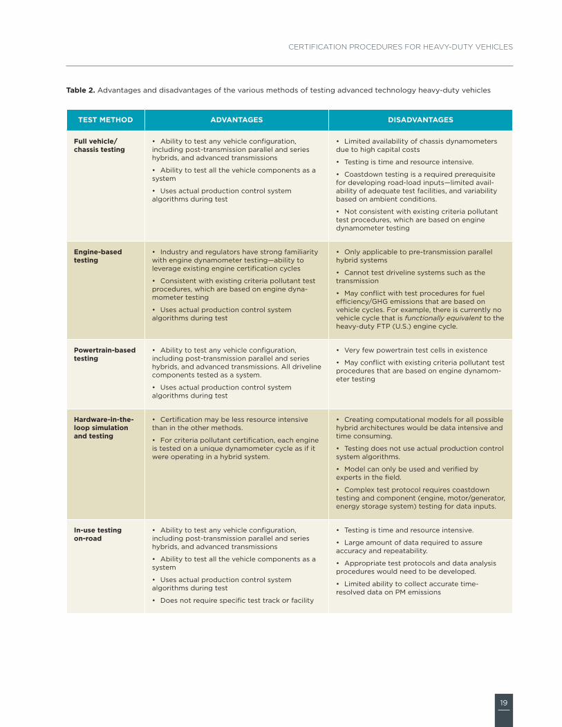
table 2. Advantages and disadvantages of the various methods of testing advanced technology heavy-duty vehicles
test Method advantages dIsadvantages
full vehicle/chassis testing
• Ability to test any vehicle configuration, including post-transmission parallel and series hybrids, and advanced transmissions
• Ability to test all the vehicle components as a system
• Uses actual production control system algorithms during test
• Limited availability of chassis dynamometers due to high capital costs
• Testing is time and resource intensive.
• Coastdown testing is a required prerequisite for developing road-load inputs—limited avail-ability of adequate test facilities, and variability based on ambient conditions.
• Not consistent with existing criteria pollutant test procedures, which are based on engine dynamometer testing
engine-based testing
• Industry and regulators have strong familiarity with engine dynamometer testing—ability to leverage existing engine certification cycles
• Consistent with existing criteria pollutant test procedures, which are based on engine dyna-mometer testing
• Uses actual production control system algorithms during test
• Only applicable to pre-transmission parallel hybrid systems
• Cannot test driveline systems such as the transmission
• May conflict with test procedures for fuel efficiency/GHG emissions that are based on vehicle cycles. For example, there is currently no vehicle cycle that is functionally equivalent to the heavy-duty FTP (U.S.) engine cycle.
powertrain-based testing
• Ability to test any vehicle configuration, including post-transmission parallel and series hybrids, and advanced transmissions. All driveline components tested as a system.
• Uses actual production control system algorithms during test
• Very few powertrain test cells in existence
• May conflict with existing criteria pollutant test procedures that are based on engine dynamom-eter testing
hardware-in-the-loop simulation and testing
• Certification may be less resource intensive than in the other methods.
• For criteria pollutant certification, each engine is tested on a unique dynamometer cycle as if it were operating in a hybrid system.
• Creating computational models for all possible hybrid architectures would be data intensive and time consuming.
• Testing does not use actual production control system algorithms.
• Model can only be used and verified by experts in the field.
• Complex test protocol requires coastdown testing and component (engine, motor/generator, energy storage system) testing for data inputs.
In-use testing on-road
• Ability to test any vehicle configuration, including post-transmission parallel and series hybrids, and advanced transmissions
• Ability to test all the vehicle components as a system
• Uses actual production control system algorithms during test
• Does not require specific test track or facility
• Testing is time and resource intensive.
• Large amount of data required to assure accuracy and repeatability.
• Appropriate test protocols and data analysis procedures would need to be developed.
• Limited ability to collect accurate time-resolved data on PM emissions
1225 I Street NW, Suite 900
Washington DC 20005
One Post Street, Suite 2700
San Francisco, CA 94104
48 Rue de Stassart. bte 6
1050 Brussels
www.theicct.org
The International Council on Clean Transportation is an independent
nonprofit organization founded to provide first-rate objective research
and technical analysis to environmental policy makers. Our mission is
to improve the environmental performance and energy efficiency of
road, marine, and air transportation, in order to benefit public health and
mitigate climate change.