Embed Size (px)
Citation preview
CFD and FEA Consulting Services
FEA and CFD Consulting Services – Safe Design Analysis for Power Plant Gas Turbine Operation Page | 1
CFD and FEA Consulting Services
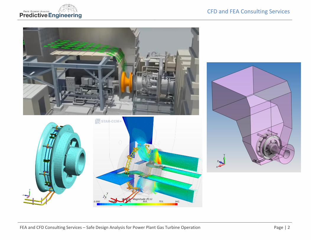
Safe Design Analysis for Power Plant Gas Turbine Operation
CFD and FEA services is our core business and has been for more than 20 years. We are broad generalists in the consulting services business and our differentiator is experience. Recently we just completed a coupled computational fluid dynamics (CFD) and finite element analysis (FEA) project on a water injection system to an existing gas turbine. The energy physics of this turbocharger is to spray water droplets into the inlet of the compressor side of the turbine thereby increasing the density of the already 100% saturated air. This heavy air mixture is then combusted with increased gas flow, yielding a 10% boost in energy output from the turbine. In other words, one can take a 60 kW turbine and boost it to ~65 kW. In the industry, this is known as wet compression and many examples of this technology can be found on the web. The challenge for our client (an electrical utility) is that this wet compression device is bolted onto the flow housing inlet to the gas turbine. If this device fails, then parts would directly enter the turbine, leading to an expensive repair operation plus unexpected disruption to the utility’s power grid. The graphics down below provide a generalized description of the CFD and FEA models. Air inters through the filter house and then around the housing, through some guide vanes and then into the compressor-side of the gas turbine. The CFD analysis (STAR-CCM+) provides us with component pressures over the housing and the water spray system which were then mapped onto a FEA model (FEMAP). The FEA model was then exercised through a static stress, normal modes and modal frequency analyses (NX Nastran). To verify this work, a CFD mesh convergence study was done and the FEA work was checked against hand calculations. Results assured the client that the add-on device was more than structurally adequate and could easily handle the power plant’s dominate 60 Hz vibration plus any multiples.
CFD and FEA Consulting Services
FEA and CFD Consulting Services – Safe Design Analysis for Power Plant Gas Turbine Operation Page | 2
CFD and FEA Consulting Services
FEA and CFD Consulting Services – Safe Design Analysis for Power Plant Gas Turbine Operation Page | 3
CFD Model of Filter House and Turbine Compressor Inlet Section
COMPUTATIONAL FLUID DYNAMICS (CFD) SYSTEM MODELING
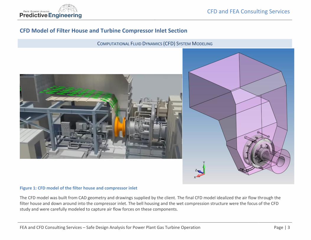
Figure 1: CFD model of the filter house and compressor inlet
The CFD model was built from CAD geometry and drawings supplied by the client. The final CFD model idealized the air flow through the filter house and down around into the compressor inlet. The bell housing and the wet compression structure were the focus of the CFD study and were carefully modeled to capture air flow forces on these components.
CFD and FEA Consulting Services
FEA and CFD Consulting Services – Safe Design Analysis for Power Plant Gas Turbine Operation Page | 4
CFD Results using STAR CCM+
COMPUTATIONAL FLUID DYNAMICS (CFD) SYSTEM MODELING TO EXTRACT AIR DRAG FORCES ON INTERNAL STRUCTURES
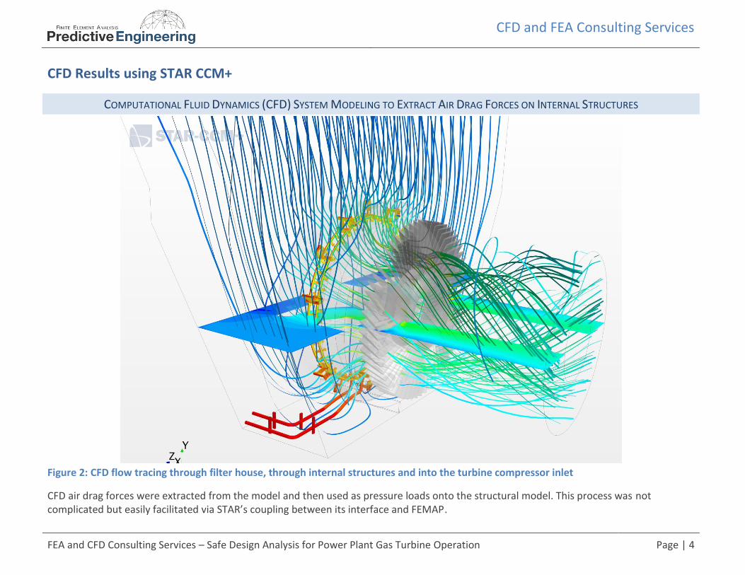
Figure 2: CFD flow tracing through filter house, through internal structures and into the turbine compressor inlet
CFD air drag forces were extracted from the model and then used as pressure loads onto the structural model. This process was not complicated but easily facilitated via STAR’s coupling between its interface and FEMAP.
CFD and FEA Consulting Services
FEA and CFD Consulting Services – Safe Design Analysis for Power Plant Gas Turbine Operation Page | 5
FEA Modeling of Bell Housing and Wet Compression System
CFD FLOW PRESSURES MAPPED ONTO FEA MODEL AND RESULTING STRESS RESULTS
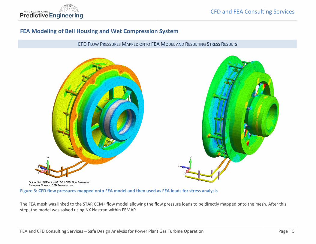
Figure 3: CFD flow pressures mapped onto FEA model and then used as FEA loads for stress analysis
The FEA mesh was linked to the STAR CCM+ flow model allowing the flow pressure loads to be directly mapped onto the mesh. After this step, the model was solved using NX Nastran within FEMAP.

CFD and FEA Consulting Services
FEA and CFD Consulting Services – Safe Design Analysis for Power Plant Gas Turbine Operation Page | 6
Normal Modes and Frequency Analysis Modeling for Safe-Life Design
Normal-Modes (Eigenvalue) Analysis Modal Frequency Sweep based on CFD Sinusoidally Pressure Load
Figure 4: Normal modes analysis and worst-case frequency response based on assumed critical frequency CFD response
To ensure the upmost conservative stress analysis, the CFD loads were assumed to oscillate at the fundamental frequency of the piping system. This worst-case approach assured that the design would be safe under the most extreme conditions. Stress results from the modal frequency sweep demonstrated that the client’s wet compression system was extremely robust. The system is in operation today.