Embed Size (px)
Citation preview
Ch. 25
Electric Current and DC Circuits

Chapter Overview
Definition of Current Ohm’s Law Resistance – Conduction in Metals Kirchhoff’s Laws Analysis of DC Circuits RC Circuits

Current
Up to this point we have been concerned with charges that don’t move – Static
When charges do move, then an electric current flows
Current, usually denoted by the letter i is that rate at which charge moves. In other words how much charges flows past a point per time

Current
i = current q = charge t = time
SI Units – ampere Symbol A Fundamental Unit
t
qi

The ampere is a fundamental unit, so the coulomb is a derived unit. Express the coulomb in terms of fundamental units
1 2 3 4
0% 0%0%0%
1. A/s
2. A·s
3. s/A
4. None of he above
1 2 3 4 5

Batteries are often rated in amp·hours. What type of quantity does an amp∙hour represent?
1 2 3 4 5
0% 0% 0%0%0%
1. Current
2. charge
3. Electric Potential
4. Capacitance
5. None of the above
1 2 3 4 5

Ex. How many coulombs of charge are stored in 60 A·hr battery?

Solution
i=Δq/Δt Δq=iΔt Δq=60 A x 1 hr =60A x 1 hr x 3600 s/1 hr =216000 C

Ex. 10000 protons fIow through a detector every .05 s. What is the current flowing through the detector?

Soln. Current i=Δq/Δt i=10000x1.602x10-19 C/.05 s i= 3.2 x 10⁻¹⁴ A
Protons
Detector
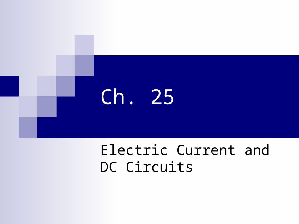
Microscopic View of Current
At the microscopic level, current is made by individual charges moving at a speed vd in the material
A charge will travel the distance x in a time given by t = x/vd
q
vd
x

Microscopic view of current
The total amount of charge that flows through the gray shaded volume in time Δt is ΔQ = nqV where n is the number of charges per volume, V is the volume of the gray shaded area, and q is the charge of an individual charge
V = xA = vdΔtA So ΔQ = nqvdAΔt

Drift Velocity
I = ΔQ/Δt = nqAvd
vd is the drift velocity. It represents the average speed of charges in conductor
Ex. A copper wire has a radius of .50 mm. It carries a current of .25 A. What is the drift velocity of the electrons in the wire. Assume 1 free electron per atom. (ρcu = 8.93 g /cm3)

There will be Avagadro’s number of charges in 1 mole of copper. the molar mass of copper is 63.5 g. The volume of 1 mole of copper is V = 63.5 g/8.93 g/cm3 = 7.31 cm3 = 7.31 x 10⁻⁶ m3

n = NA / Vmol = 6.022 x 10²³/7.31 x 10-6 m3
= 8.24 x 1028 electrons /m3
vd = i/nqA= .25 A/(8.24 x 1028/m3 x
1.602 x 10-19 As x 3.14 x(5 x 10-
4 m)2) = 2.4 x 10⁻⁵ m/s

Ohm’s Law
What factors determine how much current will flow in a circuit (BRST)

Ohm’s Law
Potential Difference and the material properties determine current that flows in a circuit
R
Vi

Ohm’s Law
Current is proportional to potential difference “Resistance” limits the amount of current that
flows Experimental Relationship found by Georg
Simon Ohm Not always true – e.g. diodes, transistors,…
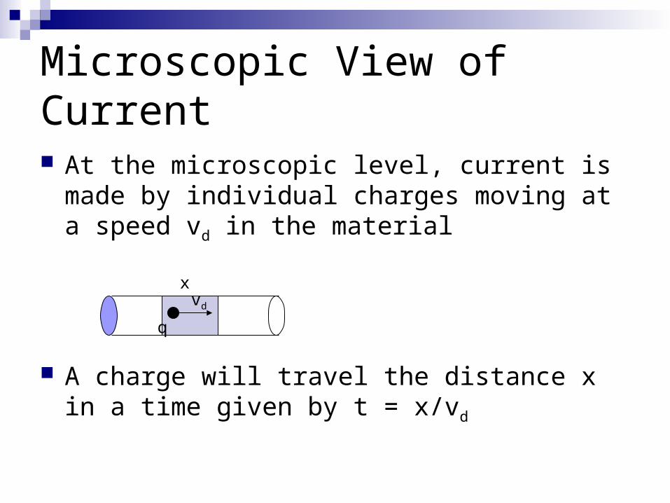
Resistance
Units – ohm denoted by Ω What is the ohm in terms of V and A What is the ohm in terms of fundamental
units
i
VR

Units
Ω=V/A
Ω = kg m2 /(A2 s3 )

Resistivity
What factors determine the resistance of a piece of metal? (BRST)

Resistivity
Length – L Cross sectional Area – A resistivity ρ – material property (see table
in text p. 792)
A
LR

Two different metals with different resistivities have the same length. Which metal will have the higher resistance?
1 2 3 4
0% 0%0%0%
1. The metal with the greater ρ
2. The metal with the smaller ρ
3. The resistances will be the same
4. Cannot be determined
1 2 3 4 5
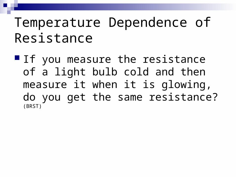
Temperature Dependence of Resistance If you measure the resistance of a light
bulb cold and then measure it when it is glowing, do you get the same resistance? (BRST)

Temperature Dependence of Resistance Resistance increases with increasing
temperature for metals It decreases with increasing temperature for
semiconductors For conductors
R = R20(1 + α(T- 20 C°))
α is the Temperature coefficient of resistance (see p. 792)
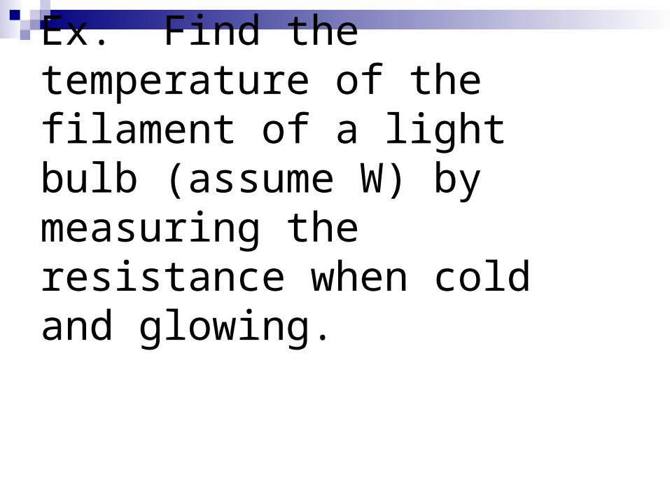
Ex. Find the temperature of the filament of a light bulb (assume W) by measuring the resistance when cold and glowing.

Power
When we apply a potential difference across a resistor, it gets hot
What determines the power given off by a resistor?

Power
Work = qΔV
Power = Work/time
P = qΔV/t but q/t = i
P = iΔV

Power
Combine the expression for electric power P = iΔV with Ohm’s law ΔV = iR
P = iΔV = i2R = (ΔV )2/R

Ex. A 100 W bulb is designed to emit 100 W when connected to a 120 V circuit. a) Draw a sketch and a schematic. b) What is the resistance of the bulb and the current drawn when connected to a 120 V outlet? c) Assuming the resistance doesn’t change, what would be the power output if the bulb was connected to a 240 V circuit?

The electric bill
Power is a rate – it tells you how much energy per time is being used

The electric company bills you in units of kw∙hr. What is a kw∙hr? (TPS)
1 2 3 4 5
0% 0% 0%0%0%
1. It is a unit of power
2. It is a unit of energy
3. It is a unit of current
4. It is a unit of potential difference
5. Not enough information given
1 2 3 4 5

The electric company bills you in units of kw∙hr. What is a kw∙hr? (TPS)
1 2 3 4 5
0% 0% 0%0%0%
1. It is a unit of power
2. It is a unit of energy
3. It is a unit of current
4. It is a unit of potential difference
5. Not enough information given
1 2 3 4 5

EX. How many joules are in a kW∙hr?

For the circuit shown below how does the current flowing through A compare to that flowing through B
1 2 3 4
0% 0%0%0%
1. It is the same
2. It is greater at A
3. It is greater at B
4. It cannot be determined
V
3.0 Ω
6.0 Ω
BA
1 2 3 4 5

You connect two identical resistors in series across a 6.0 V battery. How does the current in the circuit compare to that when a single resistor is connected across the battery
1 2 3 4
0% 0%0%0%
1. There is no difference
2. The current is twice as large
3. The current is ½ as large
4. Cannot be determined
1 2 3 4 5

Resistors in Series
When we add resistors is series, the current decreases since the resistance increases
We define an equivalent resistance as a single resistor which produces the same current when attached to the same potential as the combination of resistors

Series equivalent

Equivalent Series Resistance
We want i to be the same V= iReq
V1 = iR1, V2 = iR2, V3 = iR3
V = V1 + V2 + V3 = iR1 + iR2 + iR3
iR1 + iR2 + iR3 = i(R1 + R2 + R3) = iReq
So Req = R1 + R2 + R3

Equivalent Series Resistance
How would this result change if there were four resistors in series?
In general as more resistors are added in series, the resistance increases so the current decreases
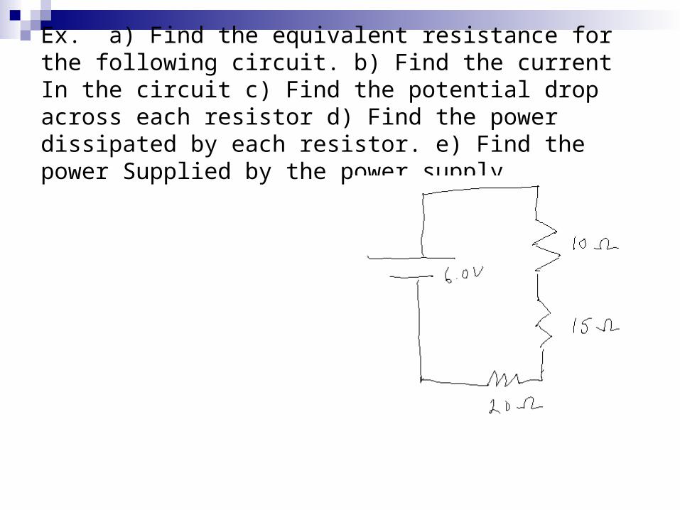
Ex. a) Find the equivalent resistance for the following circuit. b) Find the current In the circuit c) Find the potential drop across each resistor d) Find the power dissipated by each resistor. e) Find the power Supplied by the power supply.

You connect two identical resistors in parallel across a 6.0 V battery. How does the current supplied by the battery compare to that when a single resistor is connected across the battery?
1 2 3 4
0% 0%0%0%
1. There is no difference
2. The current is twice as large
3. The current is ½ as large
4. Cannot be determined
1 2 3 4 5

Resistors in Parallel
When we add resistors is parallel, the current increases
The effective resistance must then decrease
How can that be? (BRST)

Resistors in Parallel
There are more branches for current to follow in a parallel circuit, so current can be larger

Resistors in Parallel
What is the same for the three resistors shown? (GR)

Resistors in Parallel
The potential difference across each resistor is the same
Define i1 = V/R1, i2 = V/R2, i3 = V/R3
How do the currents combine?

Parallel Equivalent Resistance
We define the equivalent resistance as a single resistor that will draw the same current from the power supply
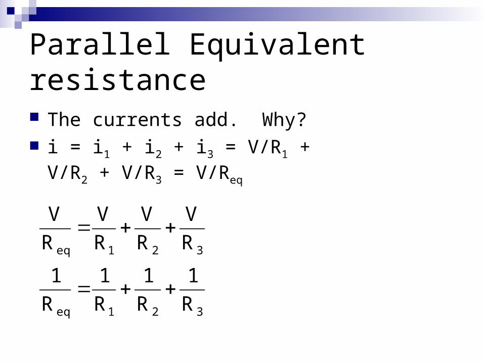
Parallel Equivalent resistance
The currents add. Why? i = i1 + i2 + i3 = V/R1 + V/R2 +
V/R3 = V/Req
321eq
321eq
R
1
R
1
R
1
R
1
R
V
R
V
R
V
R
V

a) Find the equivalent resistance. b) Find the current flowing through each resistor. c) Find the current supplied by the power supply

Find the equivalent resistance for the following network

Kirchhoff’s laws
The rules for series and parallel resistances are examples of Kirchhoff’s Laws
Voltage Law - Sum of the potential differences around a closed loop is 0
Current Law- the sum of currents at a node is 0

Voltage Law
A loop is a closed path in a circuit

Current law
A node is a point in a circuit where several wires join

For the circuit shown below a) choose currents for each branch of the circuit. b) For the choice of currents you’ve made, label the higher potential side of each resistor with a + and the lower potent side with a – c) Use Kirchoff ‘s laws to write a closed system of equations for the currents. d) Solve for the currents. e) Find the potential difference across each resistor. f) Find the power dissipated by each resistor. g) Find the power supplied by each’ power supply


RC Circuits
A resistor in series with a capacitor makes an RC circuit
RC circuits have many applications – e.g. camera flashes

RC Circuits - Charging
Use Kirchhoff’s Voltage Law to analyze the circuit shown below
V R
C

RC Circuits
V – VR – VC = 0 V – iR – Q/C = 0
But i = dQ/dt
V - R dQ/dt – 1/C Q = 0

RC Circuits
Kirchhoff’s Voltage Law gives a differential equation for the charge
dQ/dt = V/R - Q/RC Assuming the capacitor is initially discharged the
solution (You’ll work it out in lab) Q = CV(1 – e-t/(RC))

Charging a CapacitorCharging a Capacitor with V = 6 V andRC =
5 s
01234567
0 5 10 15 20 25
Time (s)
Vc
(V)
When t = RC = 5 s, Vc = .63 * 6V =3.78 V

Current in a Charging RC Circuit i = dq/dt = V/R e-t/RC
The current exponentially decays with the same time constant
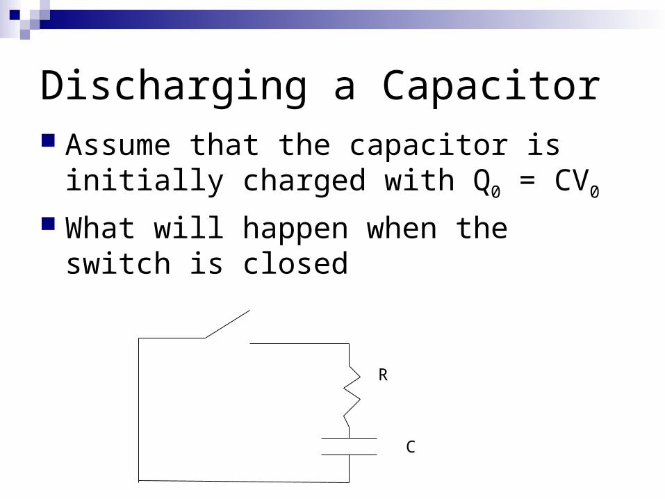
Discharging a Capacitor Assume that the capacitor is initially
charged with Q0 = CV0
What will happen when the switch is closed
R
C

Discharging a Capacitor
-R dq/dt – q/C = 0 dq/dt = -q/(RC)
A solution is q = CV0 e-t/(RC)
Solution is exponential decay RC is the time constant

Ex. a) What fraction of the original charge remains when t = RC? b) At what time is charge reduced to a fraction f of the initial amount?

Current in a Discharging RC Circuit i = dq/dt = -V/R e-t/RC
The current exponentially decays with the same time constant
It flows in the opposite direction