Embed Size (px)
Citation preview
Chapter 16 : Turning Moment Diagrams and Flywheel � 565
16.1.16.1.16.1.16.1.16.1. IntrIntrIntrIntrIntroductionoductionoductionoductionoductionThe turning moment diagram (also known as crank-
effort diagram) is the graphical representation of the turningmoment or crank-effort for various positions of the crank. It isplotted on cartesian co-ordinates, in which the turning momentis taken as the ordinate and crank angle as abscissa.
16.2.16.2.16.2.16.2.16.2. TTTTTurururururning Moment Diagram fning Moment Diagram fning Moment Diagram fning Moment Diagram fning Moment Diagram for a Singleor a Singleor a Singleor a Singleor a SingleCylinder Double Acting Steam EngineCylinder Double Acting Steam EngineCylinder Double Acting Steam EngineCylinder Double Acting Steam EngineCylinder Double Acting Steam EngineA turning moment diagram for a single cylinder
double acting steam engine is shown in Fig. 16.1. The verticalordinate represents the turning moment and the horizontalordinate represents the crank angle.
We have discussed in Chapter 15 (Art. 15.10.) thatthe turning moment on the crankshaft,
P2 2
sin 2sin
2 sinT F r
n
θ = × θ + − θ 565
TTTTTurururururningningningningningMomentMomentMomentMomentMoment
DiagramsDiagramsDiagramsDiagramsDiagramsand Flywheeland Flywheeland Flywheeland Flywheeland Flywheel
16FFFFFeaeaeaeaeaturturturturtureseseseses1. Introduction.
2. Turning Moment Diagramfor a Single CylinderDouble Acting SteamEngine.
3. Turning Moment Diagramfor a Four Stroke CycleInternal CombustionEngine.
4. Turning Moment Diagramfor a Multicylinder Engine.
5. Fluctuation of Energy.
6. Determination of MaximumFluctuation of Energy.
7. Coefficient of Fluctuationof Energy.
8. Flywheel.
9. Coefficient of Fluctuation ofSpeed.
10. Energy Stored in aFlywheel.
11. Dimensions of the FlywheelRim.
12. Flywheel in Punching Press.
566 � Theory of Machines
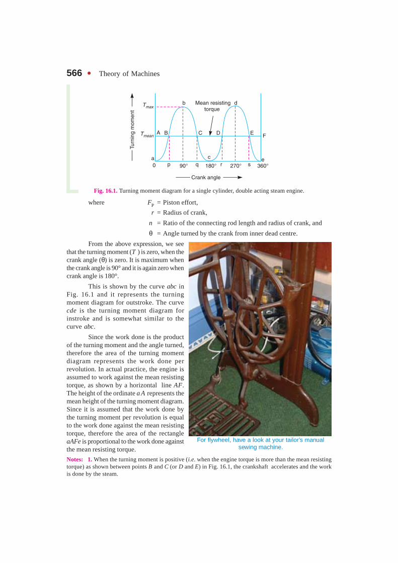
Fig. 16.1. Turning moment diagram for a single cylinder, double acting steam engine.
where FP = Piston effort,
r = Radius of crank,
n = Ratio of the connecting rod length and radius of crank, and
θ = Angle turned by the crank from inner dead centre.
From the above expression, we seethat the turning moment (T ) is zero, when thecrank angle (θ) is zero. It is maximum whenthe crank angle is 90° and it is again zero whencrank angle is 180°.
This is shown by the curve abc inFig. 16.1 and it represents the turningmoment diagram for outstroke. The curvecde is the turning moment diagram forinstroke and is somewhat similar to thecurve abc.
Since the work done is the productof the turning moment and the angle turned,therefore the area of the turning momentdiagram represents the work done perrevolution. In actual practice, the engine isassumed to work against the mean resistingtorque, as shown by a horizontal line AF.The height of the ordinate a A represents themean height of the turning moment diagram.Since it is assumed that the work done bythe turning moment per revolution is equalto the work done against the mean resistingtorque, therefore the area of the rectangleaAFe is proportional to the work done againstthe mean resisting torque.
Notes: 1. When the turning moment is positive (i.e. when the engine torque is more than the mean resistingtorque) as shown between points B and C (or D and E) in Fig. 16.1, the crankshaft accelerates and the workis done by the steam.
For flywheel, have a look at your tailor’s manualsewing machine.
Chapter 16 : Turning Moment Diagrams and Flywheel � 567 2. When the turning moment is negative (i.e. when the engine torque is less than the mean resisting
torque) as shown between points C and D in Fig. 16.1, the crankshaft retards and the work is done on thesteam.
3. If T = Torque on the crankshaft at any instant, and
Tmean = Mean resisting torque.
Then accelerating torque on the rotating parts of the engine
= T – Tmean
4. If (T –Tmean) is positive, the flywheel accelerates and if (T – Tmean) is negative, then the flywheel retards.
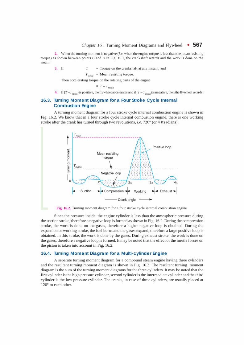
16.3. Turning Moment Diagram for a Four Stroke Cycle InternalCombustion EngineA turning moment diagram for a four stroke cycle internal combustion engine is shown in
Fig. 16.2. We know that in a four stroke cycle internal combustion engine, there is one workingstroke after the crank has turned through two revolutions, i.e. 720° (or 4 π radians).
Fig. 16.2. Turning moment diagram for a four stroke cycle internal combustion engine.
Since the pressure inside the engine cylinder is less than the atmospheric pressure duringthe suction stroke, therefore a negative loop is formed as shown in Fig. 16.2. During the compressionstroke, the work is done on the gases, therefore a higher negative loop is obtained. During theexpansion or working stroke, the fuel burns and the gases expand, therefore a large positive loop isobtained. In this stroke, the work is done by the gases. During exhaust stroke, the work is done onthe gases, therefore a negative loop is formed. It may be noted that the effect of the inertia forces onthe piston is taken into account in Fig. 16.2.
16.4. Turning Moment Diagram for a Multi-cylinder EngineA separate turning moment diagram for a compound steam engine having three cylinders
and the resultant turning moment diagram is shown in Fig. 16.3. The resultant turning momentdiagram is the sum of the turning moment diagrams for the three cylinders. It may be noted that thefirst cylinder is the high pressure cylinder, second cylinder is the intermediate cylinder and the thirdcylinder is the low pressure cylinder. The cranks, in case of three cylinders, are usually placed at120° to each other.

568 � Theory of Machines
Fig. 16.3. Turning moment diagram for a multi-cylinder engine.
16.5. Fluctuation of EnergyThe fluctuation of energy may be determined by the turning moment diagram for one complete
cycle of operation. Consider the turning moment diagram for a single cylinder double acting steamengine as shown in Fig. 16.1. We see that the mean resisting torque line AF cuts the turning momentdiagram at points B, C, D and E. When the crank moves from a to p, the work done by the engine isequal to the area aBp, whereas the energy required is represented by the area aABp. In other words,the engine has done less work (equal to the area a AB) than the requirement. This amount of energyis taken from the flywheel and hence the speed of the flywheel decreases. Now the crank movesfrom p to q, the work done by the engine is equal to the area pBbCq, whereas the requirement ofenergy is represented by the area pBCq. Therefore, the engine has done more work than therequirement. This excess work (equal to the area BbC) is stored in the flywheel and hence the speedof the flywheel increases while the crank moves from p to q.
Similarly, when the crank moves from q to r, more work is taken from the engine than isdeveloped. This loss of work is represented by the area C c D. To supply this loss, the flywheel givesup some of its energy and thus the speed decreases while the crank moves from q to r. As the crankmoves from r to s, excess energy is again developed given by the area D d E and the speed againincreases. As the piston moves from s to e, again there is a loss of work and the speed decreases. Thevariations of energy above and below the mean resisting torque line are called fluctuations ofenergy. The areas BbC, CcD, DdE, etc. represent fluctuations of energy.
A little consideration will show that the engine has a maximum speed either at q or at s. Thisis due to the fact that the flywheel absorbs energy while the crank moves from p to q and from r to s.On the other hand, the engine has a minimum speed either at p or at r. The reason is that the flywheelgives out some of its energy when the crank moves from a to p and q to r. The difference between themaximum and the minimum energies is known as maximum fluctuation of energy.
16.6. Determination of Maximum Fluctuation of EnergyA turning moment diagram for a multi-cylinder engine is shown by a wavy curve in Fig.
16.4. The horizontal line AG represents the mean torque line. Let a1, a3, a5 be the areas above themean torque line and a2, a4 and a6 be the areas below the mean torque line. These areas representsome quantity of energy which is either added or subtracted from the energy of the moving parts ofthe engine.
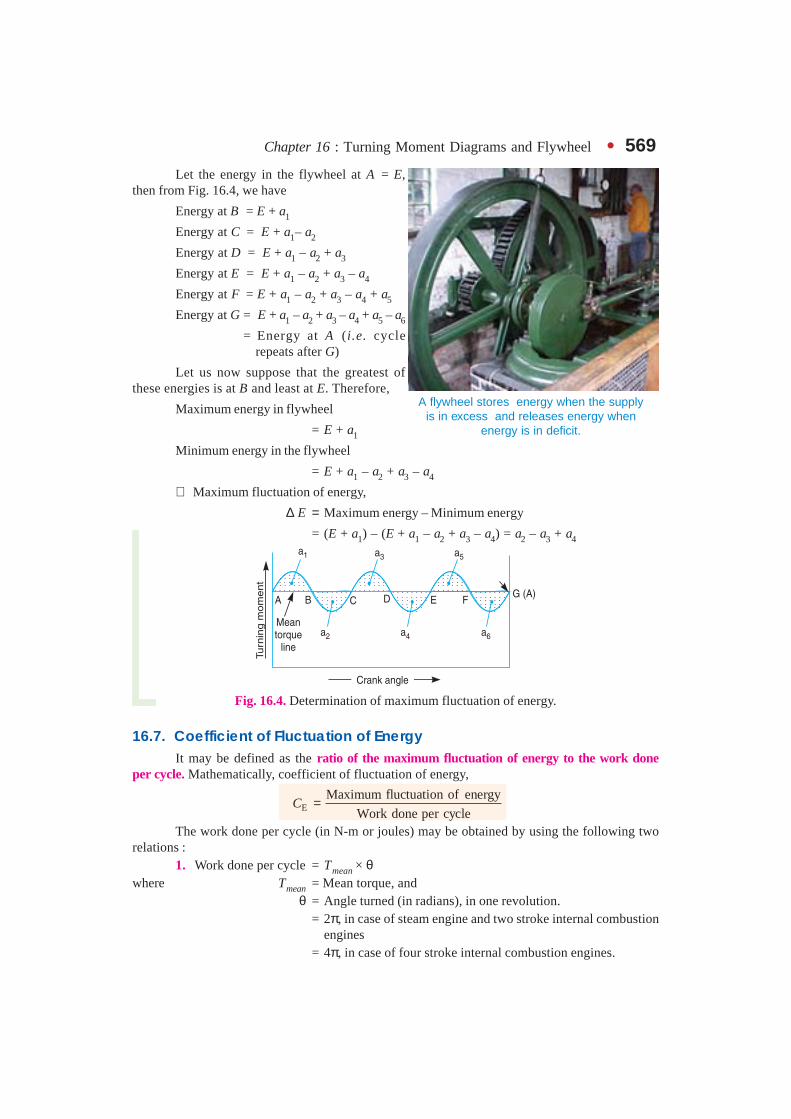
Chapter 16 : Turning Moment Diagrams and Flywheel � 569Let the energy in the flywheel at A = E,
then from Fig. 16.4, we have
Energy at B = E + a1
Energy at C = E + a1– a2
Energy at D = E + a1 – a2 + a3
Energy at E = E + a1 – a2 + a3 – a4
Energy at F = E + a1 – a2 + a3 – a4 + a5
Energy at G = E + a1 – a2 + a3 – a4 + a5 – a6
= Energy at A (i.e. cycle repeats after G)
Let us now suppose that the greatest ofthese energies is at B and least at E. Therefore,
Maximum energy in flywheel
= E + a1
Minimum energy in the flywheel
= E + a1 – a2 + a3 – a4
∴ Maximum fluctuation of energy,
∆ E = Maximum energy – Minimum energy
= (E + a1) – (E + a1 – a2 + a3 – a4) = a2 – a3 + a4
Fig. 16.4. Determination of maximum fluctuation of energy.
16.7. Coefficient of Fluctuation of EnergyIt may be defined as the ratio of the maximum fluctuation of energy to the work done
per cycle. Mathematically, coefficient of fluctuation of energy,
EMaximum fluctuation of energy
Work done per cycleC =
The work done per cycle (in N-m or joules) may be obtained by using the following tworelations :
1. Work done per cycle = Tmean × θwhere Tmean = Mean torque, and
θ = Angle turned (in radians), in one revolution.= 2π, in case of steam engine and two stroke internal combustion
engines= 4π, in case of four stroke internal combustion engines.
A flywheel stores energy when the supplyis in excess and releases energy when
energy is in deficit.

570 � Theory of Machines
The mean torque (Tmean) in N-m may be obtained by using the following relation :
60
2meanP P
TN
×= =π ω
where P = Power transmitted in watts,
N = Speed in r.p.m., and
ω = Angular speed in rad/s = 2 πN/60
2. The work done per cycle may also be obtained by using the following relation :
Work done per cycle 60P
n
×=
where n = Number of working strokes per minute,
= N, in case of steam engines and two stroke internal combustionengines,
= N /2, in case of four stroke internal combustion engines.
The following table shows the values of coefficient of fluctuation of energy for steam enginesand internal combustion engines.
Table 16.1. Coefficient of fluctuation of energy (CE) for steam and internalcombustion engines.
S.No. Type of engine Coefficient of fluctuationof energy (CE)
1. Single cylinder, double acting steam engine 0.21
2. Cross-compound steam engine 0.096
3. Single cylinder, single acting, four stroke gas engine 1.93
4. Four cylinders, single acting, four stroke gas engine 0.066
5. Six cylinders, single acting, four stroke gas engine 0.031
16.8. FlywheelA flywheel used in machines serves as a reservoir, which stores energy during the period
when the supply of energy is more than the requirement, and releases it during the period when therequirement of energy is more than the supply.
In case of steam engines, internal combustion engines, reciprocating compressors and pumps,the energy is developed during one stroke and the engine is to run for the whole cycle on the energyproduced during this one stroke. For example, in internal combustion engines, the energy is developedonly during expansion or power stroke which is much more than the engine load and no energy isbeing developed during suction, compression and exhaust strokes in case of four stroke engines andduring compression in case of two stroke engines. The excess energy developed during power strokeis absorbed by the flywheel and releases it to the crankshaft during other strokes in which no energyis developed, thus rotating the crankshaft at a uniform speed. A little consideration will show thatwhen the flywheel absorbs energy, its speed increases and when it releases energy, the speed decreases.Hence a flywheel does not maintain a constant speed, it simply reduces the fluctuation of speed. Inother words, a flywheel controls the speed variations caused by the fluctuation of the engineturning moment during each cycle of operation.
Chapter 16 : Turning Moment Diagrams and Flywheel � 571In machines where the operation is intermittent like *punching machines, shearing machines,
rivetting machines, crushers, etc., the flywheel stores energy from the power source during the greaterportion of the operating cycle and gives it up during a small period of the cycle. Thus, the energyfrom the power source to the machines is supplied practically at a constant rate throughout theoperation.
Note: The function of a **governor in an engine is entirely different from that of a flywheel. Itregulates the mean speed of an engine when there are variations in the load, e.g., when the load on the engineincreases, it becomes necessary to increase the supply of working fluid. On the other hand, when the loaddecreases, less working fluid is required. The governor automatically controls the supply of working fluid tothe engine with the varying load condition and keeps the mean speed of the engine within certain limits.
As discussed above, the flywheel does not maintain a constant speed, it simply reduces the fluctuationof speed. It does not control the speed variations caused by the varying load.
16.9. Coefficient of Fluctuation of SpeedThe difference between the maximum and minimum speeds during a cycle is called the
maximum fluctuation of speed. The ratio of the maximum fluctuation of speed to the mean speed iscalled the coefficient of fluctuation of speed.
Let N1 and N2 = Maximum and minimum speeds in r.p.m. during the cycle, and
N = Mean speed in r.p.m. 1 2
2
N N+=
∴ Coefficient of fluctuation of speed,
( )1 21 2
1 2
2
s
N NN NC
N N N
−−= =
+
( )1 21 2
1 2
2 ω − ωω − ω= =
ω ω + ω ...(In terms of angular speeds)
( )1 21 2
1 2
2 v vv v
v v v
−−= =
+ ...(In terms of linear speeds)
The coefficient of fluctuation of speed is a limiting factor in the design of flywheel. It variesdepending upon the nature of service to which the flywheel is employed.
Note. The reciprocal of the coefficient of fluctuation of speed is knownas coefficient of steadiness and is denoted by m.
∴ 1 2
1
s
Nm
C N N= =
−
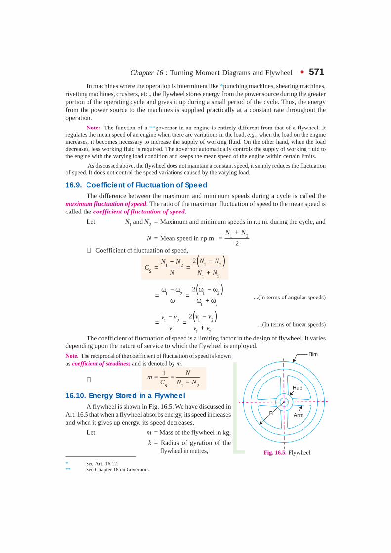
16.10. Energy Stored in a FlywheelA flywheel is shown in Fig. 16.5. We have discussed in
Art. 16.5 that when a flywheel absorbs energy, its speed increasesand when it gives up energy, its speed decreases.
Let m = Mass of the flywheel in kg,
k = Radius of gyration of theflywheel in metres, Fig. 16.5. Flywheel.
* See Art. 16.12.** See Chapter 18 on Governors.
572 � Theory of Machines
I = Mass moment of inertia of the flywheel about its axis of rotationin kg-m2 = m.k2,
N1 and N2 = Maximum and minimum speeds during the cycle in r.p.m.,
ω1 and ω2 = Maximum and minimum angular speeds during the cycle in rad/s,
N = Mean speed during the cycle in r.p.m. 1 2 ,2
N N+=
ω = Mean angular speed during the cycle in rad/s 1 2 ,2
ω + ω=
CS = Coefficient of fluctuation of speed, 1 2 1 2orN N
N
− ω − ω=
ωWe know that the mean kinetic energy of the flywheel,
2 2 21 1. . .
2 2E I m k= × ω = × ω (in N-m or joules)
As the speed of the flywheel changes from ω1 to ω2, the maximum fluctuation of energy,∆E = Maximum K.E. – Minimum K.E.
( ) ( ) ( ) ( )22 2 2
1 2 1 2
1 1 1
2 2 2I I I
= × ω − × ω = × ω − ω
( )( ) ( )1 2 1 2 1 2
1.
2I I= × ω + ω ω − ω = ω ω − ω ...(i)
1 2...2
ω + ω ω =
�
2 1 2.I
ω − ω = ω ω
... (Multiplying and dividing by ω)
= I.ω2.CS = m.k2.ω2.CS ... (∵ I = m.k2) ...(ii)
= 2.E.CS (in N–m or joules)21
... .2
E I = × ω � ... (iii)
The radius of gyration (k) may be taken equal to the mean radius of the rim (R), because thethickness of rim is very small as compared to the diameter of rim. Therefore, substituting k = R, inequation (ii), we have
∆E = m.R2.ω2.CS = m.v2.CS
where v = Mean linear velocity (i.e. at the mean radius) in m/s = ω.R
Notes. 1. Since ω = 2 π N/60, therefore equation (i) may be written as
( )2
1 21 2
2 22 4
60 60 60 3600
N NNE I I N N N
π π π π∆ = × − = × × −
( )2
21 2
. .900
m k N N Nπ= × −
2S
22. . .
900m k N C
π= ×1 2... s
N NC
N
− =
�
-
Chapter 16 : Turning Moment Diagrams and Flywheel � 5732. In the above expressions, only the mass moment of inertia of the flywheel rim (I) is considered
and the mass moment of inertia of the hub and arms is neglected. This is due to the fact that the major portionof the mass of the flywheel is in the rim and a small portion is in the hub and arms. Also the hub and arms arenearer to the axis of rotation, therefore the mass moment of inertia of the hub and arms is small.
Example 16.1. The mass of flywheel of an engine is 6.5 tonnes and the radius of gyrationis 1.8 metres. It is found from the turning moment diagram that the fluctuation of energy is56 kN-m. If the mean speed of the engine is 120 r.p.m., find the maximum and minimum speeds.
Solution. Given : m = 6.5 t = 6500 kg ; k = 1.8 m ; ∆ E = 56 kN-m = 56 × 103 N-m ;N = 120 r.p.m.
Let N1 and N2 = Maximum and minimum speeds respectively.
We know that fluctuation of energy (∆ E),
56 × 103 2
900
π= × m.k2 . N (N1 – N2) 2
900
π= × 6500 (1.8)2 120 (N1 – N2)
= 27 715 (N1 – N2)
∴ N1 – N2 = 56 × 103 /27 715 = 2 r.p.m. ...(i)
We also know that mean speed (N),
1 21 2
120 or 120 2 240 r.p.m.2
N NN N
+= + = × = ...(ii)
From equations (i) and (ii),N1 = 121 r.p.m., and N2 = 119 r.p.m. Ans.
Example 16.2. The flywheel of a steam engine has a radius of gyration of 1 m and mass2500 kg. The starting torque of the steam engine is 1500 N-m and may be assumed constant.Determine: 1. the angular acceleration of the flywheel, and 2. the kinetic energy of the flywheelafter 10 seconds from the start.
Solution. Given : k = 1 m ; m = 2500 kg ; T = 1500 N-m
1. Angular acceleration of the flywheel
Let α = Angular acceleration of the flywheel.
We know that mass moment of inertia of the flywheel,
I = m.k2 = 2500 × 12 = 2500 kg-m2
∴ Starting torque of the engine (T),
1500 = I.α = 2500 × α or α = 1500 / 2500 = 0.6 rad /s2 Ans.
2. Kinetic energy of the flywheel
First of all, let us find out the angular speed of the flywheel after 10 seconds from the start(i.e. from rest), assuming uniform acceleration.
Let ω1 = Angular speed at rest = 0
ω2 = Angular speed after 10 seconds, and
t = Time in seconds.
We know that ω2 = ω1 + α t = 0 + 0.6 × 10 = 6 rad /s
574 � Theory of Machines
∴ Kinetic energy of the flywheel
( )2 22
1 12500 6 45 000 N-m = 45 kN-m
2 2I= × ω = × × = Ans.
Example 16.3. A horizontal cross compound steam engine develops 300 k W at 90 r.p.m.The coefficient of fluctuation of energy as found from the turning moment diagram is to be 0.1 andthe fluctuation of speed is to be kept within ± 0.5% of the mean speed. Find the weight of theflywheel required, if the radius of gyration is 2 metres.
Solution. Given : P = 300 kW = 300 × 103 W; N = 90 r.p.m.; CE = 0.1; k = 2 m
We know that the mean angular speed,
ω = 2 π N/60 = 2 π × 90/60 = 9.426 rad/s
Let ω1 and ω2 = Maximum and minimum speeds respectively.
Since the fluctuation of speed is ± 0.5% of mean speed, therefore total fluctuation of speed,
ω1 – ω2 = 1% ω = 0.01 ωand coefficient of fluctuation of speed,
1 2 0.01sCω − ω
= =ω
We know that work done per cycle
= P × 60 / N = 300 × 103 × 60 / 90 = 200 × 103 N-m
∴ Maximum fluctuation of energy,
∆E = Work done per cycle × CE = 200 × 103 × 0.1 = 20 × 103 N-m
Let m = Mass of the flywheel.
We know that maximum fluctuation of energy ( ∆E ),
20 × 103 = m.k2.ω2.CS = m × 22 × (9.426)2 × 0.01 = 3.554 m
∴ m = 20 × 103/3.554 = 5630 kg Ans.
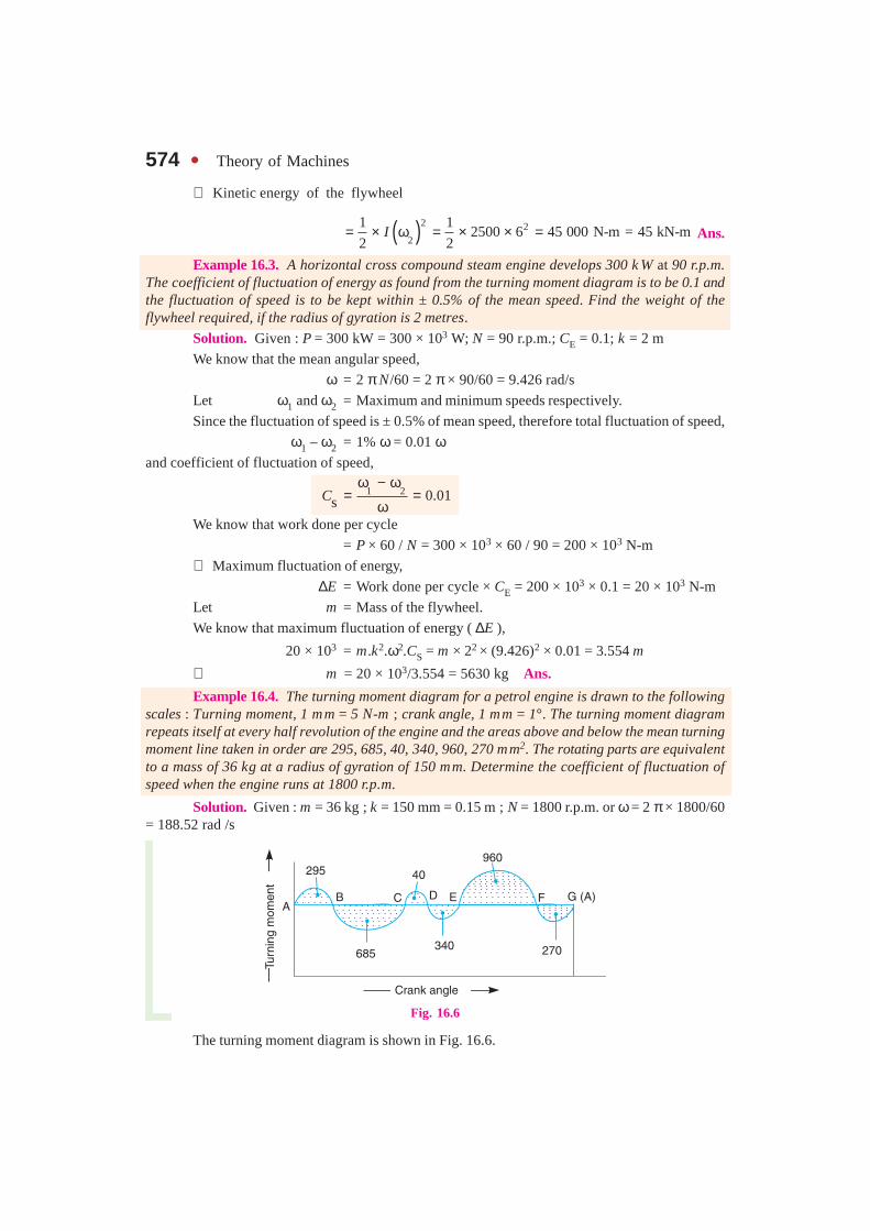
Example 16.4. The turning moment diagram for a petrol engine is drawn to the followingscales : Turning moment, 1 mm = 5 N-m ; crank angle, 1 mm = 1°. The turning moment diagramrepeats itself at every half revolution of the engine and the areas above and below the mean turningmoment line taken in order are 295, 685, 40, 340, 960, 270 mm2. The rotating parts are equivalentto a mass of 36 kg at a radius of gyration of 150 mm. Determine the coefficient of fluctuation ofspeed when the engine runs at 1800 r.p.m.
Solution. Given : m = 36 kg ; k = 150 mm = 0.15 m ; N = 1800 r.p.m. or ω = 2 π × 1800/60= 188.52 rad /s
Fig. 16.6
The turning moment diagram is shown in Fig. 16.6.

Chapter 16 : Turning Moment Diagrams and Flywheel � 575Since the turning moment scale is 1 mm = 5 N-m and
crank angle scale is 1 mm = 1° = π /180 rad, therefore,
1 mm2 on turning moment diagram
5 N-m180 36
π π= × =
Let the total energy at A = E, then referring toFig. 16.6,
Energy at B = E + 295 ... (Maximum energy)
Energy at C = E + 295 – 685 = E – 390
Energy at D = E – 390 + 40 = E – 350
Energy at E = E – 350 – 340 = E – 690 ...(Minimum energy)
Energy at F = E – 690 + 960 = E + 270
Energy at G = E + 270 – 270 = E = Energy at A
We know that maximum fluctuation of energy,
∆ E = Maximum energy – Minimum energy
= (E + 295) – (E – 690) = 985 mm2
985 86 N - m 86 J36
π= × = =
Let CS = Coefficient of fluctuation of speed.
We know that maximum fluctuation of energy (∆ E),
86 = m.k2 ω2.CS = 36 × (0.15)2 × (188.52)2 CS = 28 787 CS
∴ CS = 86 / 28 787 = 0.003 or 0.3% Ans.
Example 16.5. The turning moment diagram for a multicylinder engine has been drawn toa scale 1 mm = 600 N-m vertically and 1 mm = 3° horizontally. The intercepted areas between theoutput torque curve and the mean resistance line, taken in order from one end, are as follows :
+ 52, – 124, + 92, – 140, + 85, – 72 and + 107 mm2, when the engine is running at a speedof 600 r.p.m. If the total fluctuation of speed is not to exceed ± 1.5% of the mean, find the necessarymass of the flywheel of radius 0.5 m.
Solution. Given : N = 600 r.p.m. or ω = 2 π × 600 / 60 = 62.84 rad / s ; R = 0.5 m
Fig. 16.7
Since the total fluctuation of speed is not to exceed ± 1.5% of the mean speed, therefore
ω1 – ω2 = 3% ω = 0.03 ω
Flywheel of an electric motor.
576 � Theory of Machines
and coefficient of fluctuation of speed,
1 2 0.03sCω − ω
= =ω
The turning moment diagram is shown in Fig. 16.7.
Since the turning moment scale is 1 mm = 600 N-m and crank angle scale is 1 mm = 3°= 3° × π/180 = π / 60 rad, therefore
1 mm2 on turning moment diagram
= 600 × π/60 = 31.42 N-m
Let the total energy at A = E, then referring to Fig. 16.7,
Energy at B = E + 52 ...(Maximum energy)
Energy at C = E + 52 – 124 = E – 72
Energy at D = E – 72 + 92 = E + 20
Energy at E = E + 20 – 140 = E – 120 ...(Minimum energy)
Energy at F = E – 120 + 85 = E – 35
Energy at G = E – 35 – 72 = E – 107
Energy at H = E – 107 + 107 = E = Energy at A
We know that maximum fluctuation of energy,
∆ E = Maximum energy – Minimum energy
= (E + 52) – (E – 120) = 172 = 172 × 31.42 = 5404 N-m
Let m = Mass of the flywheel in kg.
We know that maximum fluctuation of energy (∆ E ),
5404 = m.R2.ω2.CS = m × (0.5)2 × (62.84)2 × 0.03 = 29.6 m
∴ m = 5404 / 29.6 = 183 kg Ans.
Example 16.6. A shaft fitted with a flywheel rotates at 250 r.p.m. and drives a machine.The torque of machine varies in a cyclic manner over a period of 3 revolutions. The torque risesfrom 750 N-m to 3000 N-m uniformly during 1/2 revolution and remains constant for the followingrevolution. It then falls uniformly to 750 N-m during the next 1/2 revolution and remains constantfor one revolution, the cycle being repeated thereafter.
Determine the power required to drive the machine and percentage fluctuation in speed, ifthe driving torque applied to the shaft is constant and the mass of the flywheel is 500 kg with radiusof gyration of 600 mm.
Solution. Given : N = 250 r.p.m. or ω = 2π × 250/60 = 26.2 rad/s ; m = 500 kg ;k = 600 mm = 0.6 m
The turning moment diagram for the complete cycle is shown in Fig. 16.8.
We know that the torque required for one complete cycle
= Area of figure OABCDEF
= Area OAEF + Area ABG + Area BCHG + Area CDH
1 1
2 2OF OA AG BG GH CH HD CH= × + × × + × + × ×

Chapter 16 : Turning Moment Diagrams and Flywheel � 577
( ) ( )16 750 3000 750 2 3000 750
2= π × + × π − + π −
( )13000 750
2+ × π −
= 11 250 π N-m ...(i)
If Tmean is the mean torque in N-m, then torque required for one complete cycle
= Tmean × 6 π Ν-m ...(ii)
From equations (i) and (ii),
Tmean = 11 250 π / 6 π = 1875 N-m
Fig. 16.8
Power required to drive the machine
We know that power required to drive the machine,
P = Tmean × ω = 1875 × 26.2 = 49 125 W = 49.125 kW Ans.
Coefficient of fluctuation of speed
Let CS = Coefficient of fluctuation of speed.
First of all, let us find the values of LM and NP. From similar triangles ABG and BLM,
LM BM
AG BG= or
3000 18750.5
3000 750
LM −= =π − or LM = 0.5 π
Now, from similar triangles CHD and CNP,
NP CN
HD CH= or
3000 18750.5
3000 750
NP −= =π −
or NP = 0.5 π
From Fig. 16.8, we find that
BM = CN = 3000 – 1875 = 1125 N-m
Since the area above the mean torque line represents the maximum fluctuation of energy,therefore, maximum fluctuation of energy,
∆E = Area LBCP = Area LBM + Area MBCN + Area PNC
1 1
2 2LM BM MN BM NP CN= × × + × + × ×
578 � Theory of Machines
1 1
0.5 1125 2 1125 0.5 11252 2
= × π × + π × + × π ×
8837 N - m=We know that maximum fluctuation of energy (∆ E),
8837 = m.k2.ω2.CS = 500 × (0.6)2 × (26.2)2 × CS = 123 559 CS
S8837
0.071123559
C = = Ans.
Flywheel of a pump run by a diesel engine.
Example 16.7. During forward stroke of the piston of the double acting steam engine, theturning moment has the maximum value of 2000 N-m when the crank makes an angle of 80° withthe inner dead centre. During the backward stroke, the maximum turning moment is 1500 N-mwhen the crank makes an angle of 80° with the outer dead centre. The turning moment diagram forthe engine may be assumed for simplicity to be represented by two triangles.
If the crank makes 100 r.p.m. and the radius of gyration of the flywheel is 1.75 m, find thecoefficient of fluctuation of energy and the mass of the flywheel to keep the speed within ± 0.75% ofthe mean speed. Also determine the crank angle at which the speed has its minimum and maximumvalues.
Solution. Given : N = 100 r.p.m. or ω = 2π × 100/60 = 10.47 rad /s; k = 1.75 mSince the fluctuation of speed is ± 0.75% of mean speed, therefore total fluctuation of speed,
ω1 – ω2 = 1.5% ωand coefficient of fluctuation of speed,
1 2S
–1.5% 0.015C
ω ω= = =
ωCoefficient of fluctuation of energy
The turning moment diagram for the engine during forward and backward strokes is shownin Fig. 16.9. The point O represents the inner dead centre (I.D.C.) and point G represents theouter dead centre (O.D.C). We know that maximum turning moment when crank makes anangle of 80° (or 80 × π / 180 = 4π/9 rad) with I.D.C.,
∴ AB = 2000 N-m
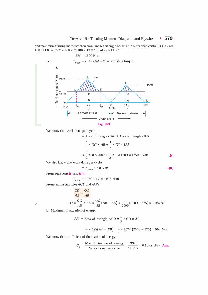
Chapter 16 : Turning Moment Diagrams and Flywheel � 579and maximum turning moment when crank makes an angle of 80° with outer dead centre (O.D.C.) or180° + 80° = 260° = 260 × π /180 = 13 π / 9 rad with I.D.C.,
LM = 1500 N-m
Let Tmean = EB = QM = Mean resisting torque.
Fig. 16.9
We know that work done per cycle
= Area of triangle OAG + Area of triangle GLS
1 1
2 2OG AB GS LM= × × + × ×
1 1
2000 1500 1750 N-m2 2
= × π × + × π × = π ...(i)
We also know that work done per cycle
= Tmean × 2 π N-m ...(ii)
From equations (i) and (ii),
Tmean = 1750 π / 2 π = 875 N-m
From similar triangles ACD and AOG,
CD OG
AE AB=
or ( ) ( )– 2000 875 1.764 rad2000
OG OGCD AE AB EB
AB AB
π= × = = − =
∴ Maximum fluctuation of energy,
1
= Area of triangle2
E ACD CD AE∆ = × ×
( ) ( )1 1– 1.764 2000 875 992 N-m
2 2CD AB EB= × = × − =
We know that coefficient of fluctuation of energy,
E
Max.fluctuation of energy 9920.18 or 18%
Work done per cycle 1750C = = =
π Ans.
580 � Theory of Machines
Mass of the flywheel
Let m = Mass of the flywheel.
We know that maximum fluctuation of energy (∆E),
992 = m.k2.ω2.CS = m × (1.75)2 × (10.47)2 × 0.015 = 5.03 m
∴ m = 992 / 5.03 = 197.2 kg Ans.
Crank angles for the minimum andmaximum speeds
We know that the speed ofthe flywheel is minimum at point Cand maximum at point D (SeeArt. 16.5).
Let θC and θD = Crank angles fromI.D.C., for the minimum and maximumspeeds.
From similar triangles ACE andAOB,
CE AE
OB AB=
or – 2000 875 4
rad2000 9 4
AE AB EBCE OB OB
AB AB
− π π= × = × = × =
∴ C4 7 180
= rad 35°9 4 36 36
π π π 7 πθ − = = × =π Ans.
Again from similar triangles AED and ABG,
ED AE
BG AB=
or ( )–AE AB EBED BG OG OB
AB AB= × = −
2000 875 4 2.8
rad2000 9 9
− π π = π − =
∴ D4 2.8 6.8 6.8 180
= rad 136°9 9 9 9
π π π πθ + = = × =π
Ans.
Example 16.8. A three cylinder single acting engine has its cranks set equally at 120° andit runs at 600 r.p.m. The torque-crank angle diagram for each cycle is a triangle for the power strokewith a maximum torque of 90 N-m at 60° from dead centre of corresponding crank. The torque on thereturn stroke is sensibly zero. Determine : 1. power developed. 2. coefficient of fluctuation of speed,if the mass of the flywheel is 12 kg and has a radius of gyration of 80 mm, 3. coefficient of fluctuationof energy, and 4. maximum angular acceleration of the flywheel.
Solution. Given : N = 600 r.p.m. or ω = 2 π × 600/60 = 62.84 rad /s; Tmax = 90 N-m;m = 12 kg; k = 80 mm = 0.08 m
Flywheel of small steam engine.
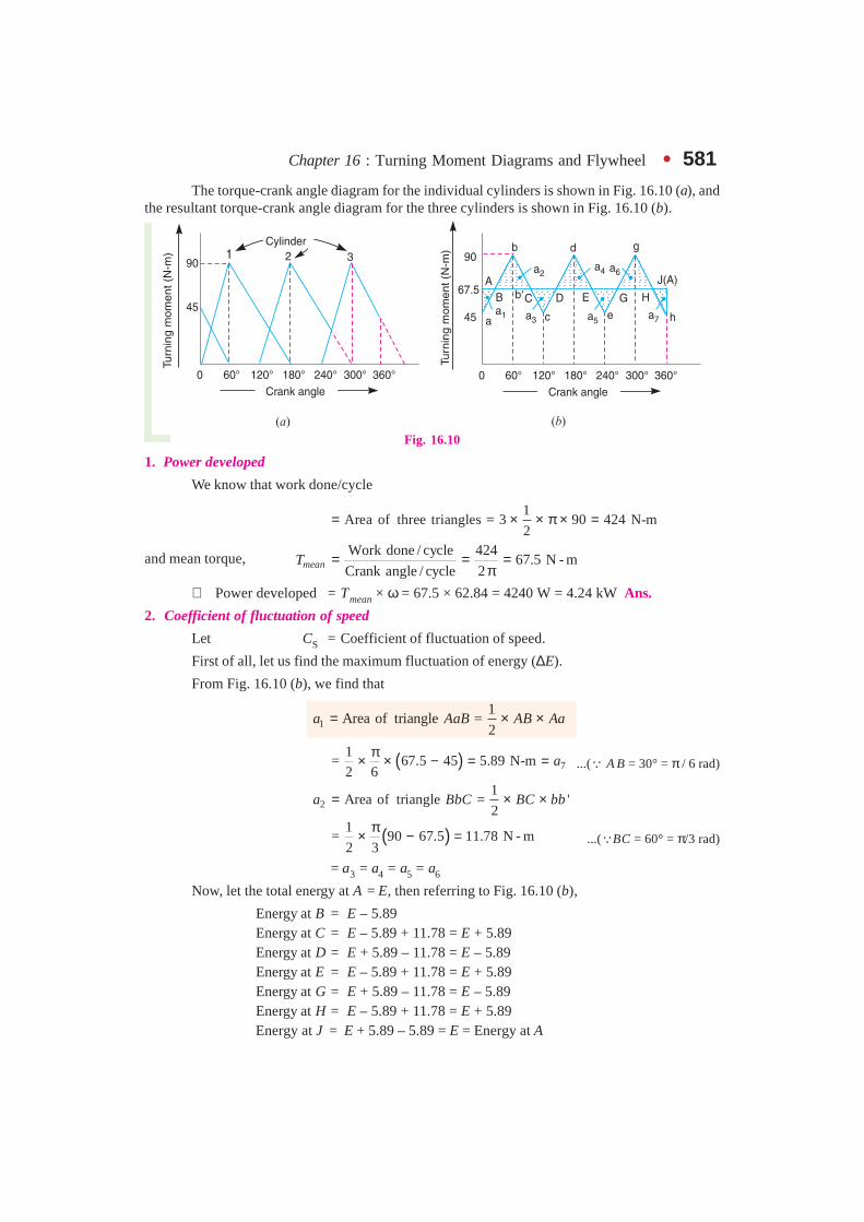
Chapter 16 : Turning Moment Diagrams and Flywheel � 581The torque-crank angle diagram for the individual cylinders is shown in Fig. 16.10 (a), and
the resultant torque-crank angle diagram for the three cylinders is shown in Fig. 16.10 (b).
Fig. 16.10
1. Power developed
We know that work done/cycle
1
Area of three triangles = 3 90 424 N-m2
= × × π × =
and mean torque, Work done / cycle 424
67.5 N - mCrank angle / cycle 2meanT = = =
π∴ Power developed = Tmean × ω = 67.5 × 62.84 = 4240 W = 4.24 kW Ans.
2. Coefficient of fluctuation of speed
Let CS = Coefficient of fluctuation of speed.
First of all, let us find the maximum fluctuation of energy (∆E).
From Fig. 16.10 (b), we find that
11
Area of triangle =2
a AaB AB Aa= × ×
( ) 71
= 67.5 45 5.89 N-m2 6
aπ× × − = = ...(∵ A B = 30° = π / 6 rad)
21
Area of triangle = '2
a BbC BC bb= × ×
( )1= 90 67.5 11.78 N - m
2 3
π× − = ...(∵BC = 60° = π/3 rad)
= a3 = a4 = a5 = a6
Now, let the total energy at A = E, then referring to Fig. 16.10 (b),
Energy at B = E – 5.89Energy at C = E – 5.89 + 11.78 = E + 5.89Energy at D = E + 5.89 – 11.78 = E – 5.89Energy at E = E – 5.89 + 11.78 = E + 5.89Energy at G = E + 5.89 – 11.78 = E – 5.89Energy at H = E – 5.89 + 11.78 = E + 5.89
Energy at J = E + 5.89 – 5.89 = E = Energy at A
582 � Theory of Machines
From above we see that maximum energy
= E + 5.89
and minimum energy = E – 5.89
∴ * Maximum fluctuation of energy,
∆E = (E + 5.89) – (E – 5.89) = 11.78 N-m
We know that maximum fluctuation of energy (∆E),
11.78 = m.k2.ω2.CS = 12 × (0.08)2 × (62.84)2 × CS = 303.3 CS
∴ CS = 11.78 / 303.3 = 0.04 or 4% Ans.
3. Coefficient of fluctuation of energy
We know that coefficient of fluctuation of energy,
EMax. fluctuation of energy 11.78
0.0278 2.78%Work done/cycle 424
C = = = = Ans.
4. Maximum angular acceleration of the flywheel
Let α = Maximum angular acceleration of the flywheel.
We know that,
Tmax – Tmean = I.α = m.k2.α90 – 67.5 = 12 × (0.08)2 × α = 0.077 α
∴ 290 67.5292 rad / s
0.077
−α = = Ans.
Example 16.9. A single cylinder, single acting, four stroke gas engine develops 20 kW at300 r.p.m. The work done by the gases during the expansion stroke is three times the work done onthe gases during the compression stroke, the work done during the suction and exhaust strokesbeing negligible. If the total fluctuation of speed is not to exceed ± 2 per cent of the mean speed andthe turning moment diagram during compression and expansion is assumed to be triangular inshape, find the moment of inertia of the flywheel.
Solution. Given : P = 20 kW = 20 × 103 W; N = 300 r.p.m. or ω = 2π × 300/60 = 31.42 rad/s
Since the total fluctuation of speed (ω1 – ω2) is not to exceed ± 2 per cent of the mean speed(ω), therefore
ω1 – ω2 = 4% ω
and coefficient of fluctuation of speed,
1 2S 4% 0.04C
ω − ω= = =
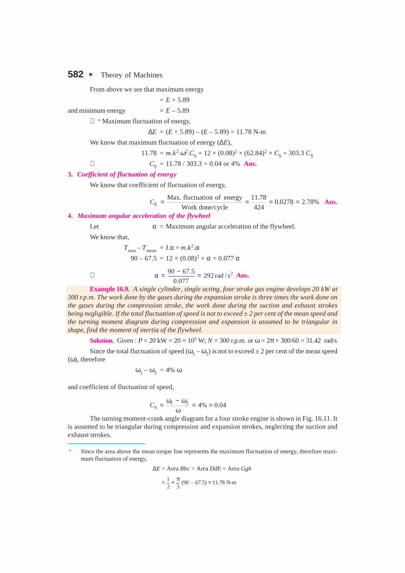
ωThe turning moment-crank angle diagram for a four stroke engine is shown in Fig. 16.11. It
is assumed to be triangular during compression and expansion strokes, neglecting the suction andexhaust strokes.
* Since the area above the mean torque line represents the maximum fluctuation of energy, therefore maxi-mum fluctuation of energy,
∆E = Area Bbc = Area DdE = Area Ggh
1(90 – 67.5) 11.78 N-m
2 3π= × =
Chapter 16 : Turning Moment Diagrams and Flywheel � 583We know that for a four stroke engine, number of working strokes per cycle,
n = N/2 = 300 / 2 = 150
∴ Work done/cycle =P × 60/n = 20 × 103 × 60/150 = 8000 N-m ...(i)
Fig. 16.11
Since the work done during suction and exhaust strokes is negligible, therefore net workdone per cycle (during compression and expansion strokes)
E
E C E E
2– –
3 3
WW W W W= = = ... ( ∵ WE = 3WC) ...(ii)
Equating equations (i) and (ii), work done during expansion stroke,
W E = 8000 × 3/2 = 12 000 N-m
We know that work done during expansion stroke (W E),
1 1
12 000 Area of triangle2 2
ABC BC AG AG= = × × = × π ×
∴ AG = Tmax = 12 000 × 2/π = 7638 N-m
and mean turning moment,
*Work done/cycle 8000
637 N-mCrank angle/cycle 4mean
T FG= = = =π
∴ Excess turning moment,
Texcess = AF = AG – FG = 7638 – 637 = 7001 N-m
Now, from similar triangles ADE and ABC,
DE AF
BC AG= or
70012.88 rad
7638
AFDE BC
AG= × = × π =
Since the area above the mean turning moment line represents the maximum fluctuation ofenergy, therefore maximum fluctuation of energy,
1 1
Area of 2.88 7001 10081 N-m2 2
E ADE DE AF∆ = ∆ = × × = × × =
* The mean turning moment (Tmean) may also be obtained by using the following relation :
P = Tmean × ω or Tmean = P/ω = 20 × 103/31.42 = 637 N-m
584 � Theory of Machines
Let I = Moment of inertia of the flywheel in kg-m2 .
We know that maximum fluctuation of energy (∆ E),10 081 = I.ω2.CS = I × (31.42)2 × 0.04 = 39.5 I
∴ I = 10081/ 39.5 = 255.2 kg-m2 Ans.
Example 16.10. The turning moment diagram for a four stroke gas engine may be assumedfor simplicity to be represented by four triangles, the areas of which from the line of zero pressureare as follows :
Suction stroke = 0.45 × 10⁻³ m2; Compression stroke = 1.7 × 10⁻³ m2; Expansion stroke= 6.8 × 10⁻³ m2; Exhaust stroke = 0.65 × 10⁻³ m2. Each m2 of area represents 3 MN-m of energy.
Assuming the resisting torque to be uniform, find the mass of the rim of a flywheel requiredto keep the speed between 202 and 198 r.p.m. The mean radius of the rim is 1.2 m.
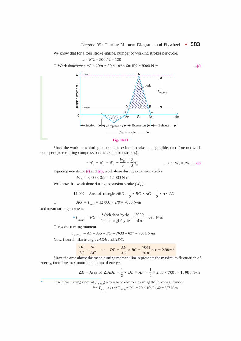
Solution. Given : a1 = 0.45 × 10⁻³ m2 ; a2 = 1.7 × 10⁻³ m2 ; a3 = 6.8 × 10⁻³ m2;a4 = 0.65 × 10⁻³ m2; N 1 = 202 r.p.m; N2 = 198 r.p.m.; R = 1.2 m
The turning moment crank angle diagram for a four stroke engine is shown in Fig. 16.12.The areas below the zero line of pressure are taken as negative while the areas above the zero line ofpressure are taken as positive.
∴ Net area = a3 – (a1 + a2 + a4)
= 6.8 × 10⁻³ – (0.45 × 10⁻³ + 1.7 × 10⁻³ + 0.65 × 10⁻³) = 4 × 10⁻³ m2
Since the energy scale is 1 m2 = 3 MN-m = 3 × 10⁶ N-m, therefore,
Net work done per cycle = 4 × 10–3 × 3 ×106 = 12 × 103 N-m . . . (i)
We also know that work done per cycle,
= Tmean × 4π N-m . . . (ii)
From equations (i) and (ii),
Tmean = FG = 12 × 103/4π = 955 N-m
Fig. 16.12
Work done during expansion stroke
= a3 × Energy scale = 6.8 × 10–3 × 3 × 106 = 20.4 × 10³ N-m ...(iii)
Chapter 16 : Turning Moment Diagrams and Flywheel � 585Also, work done during expansion stroke
= Area of triangle ABC
1 1
1.5712 2
BC AG AG AG= × × = × π × = × . . . (iv)
From equations (iii) and (iv),AG = 20.4 × 10³/1.571 = 12 985 N-m
∴ Excess torque,Texcess = AF = AG – FG = 12 985 – 955 = 12 030 N-m
Now from similar triangles ADE and ABC,
DE AF
BC AG= or
12 0302.9 rad
12 985
AFDE BC
AG= × = × π =
We know that the maximum fluctuation of energy,
1 1
Area of 2.9 12030 N-m2 2
E ADE DE AF∆ = ∆ = × × = × ×
= 17 444 N-m
Mass of the rim of a flywheel
Let m = Mass of the rim of a flywheel in kg, and
N = Mean speed of the flywheel
1 2 202 198200 r .p.m.
2 2
N N+ += = =
We know that the maximum fluctuation of energy (∆E ),
( ) )2 2
221 2
17 444 . . ( – ) 1.2 200 (202 – 198900 900
m R N N Nπ π= × = × ×
= 12.63 m
∴ m = 17 444 /12.36 = 1381 kg Ans.
Example 16.11. The turning moment curve for an engine is represented by the equation,T = (20 000 + 9500 sin 2θ – 5700 cos 2θ) N-m, where θ is the angle moved by the crank frominner dead centre. If the resisting torque is constant, find:
1. Power developed by the engine ; 2. Moment of inertia of flywheel in kg-m2, if the totalfluctuation of speed is not exceed 1% of mean speed which is 180 r.p.m; and 3. Angular accelerationof the flywheel when the crank has turned through 45° from inner dead centre.
Solution. Given : T = (20 000 + 9500 sin 2θ – 5700 cos 2θ) N-m ; N = 180 r.p.m. orω = 2π × 180/60 = 18.85 rad/s
Since the total fluctuation of speed (ω1 – ω2) is 1% of mean speed (ω), therefore coefficientof fluctuation of speed,
1 2S
–1% 0.01C
ω ω= = =
ω1. Power developed by the engine
We know that work done per revolution
( )2 2
20 000 9500sin 2 – 5700cos 20 0
T d dπ π
= θ = + θ θ θ∫ ∫
586 � Theory of Machines
29500cos 2 5700sin 2
20 000 – –2 2 0
πθ θ = θ
= 20 000 × 2π = 40 000 π N-m
and mean resisting torque of the engine,
Work done per revolution 40 000
20000 N-m2 2mean
T = = =π π
We know that power developed by the engine
= Tmean . ω = 20 000 × 18.85 = 377 000 W = 377 kW Ans.
2. Moment of inertia of the flywheel
Let I = Moment of inertia of the flywheel in kg-m2.
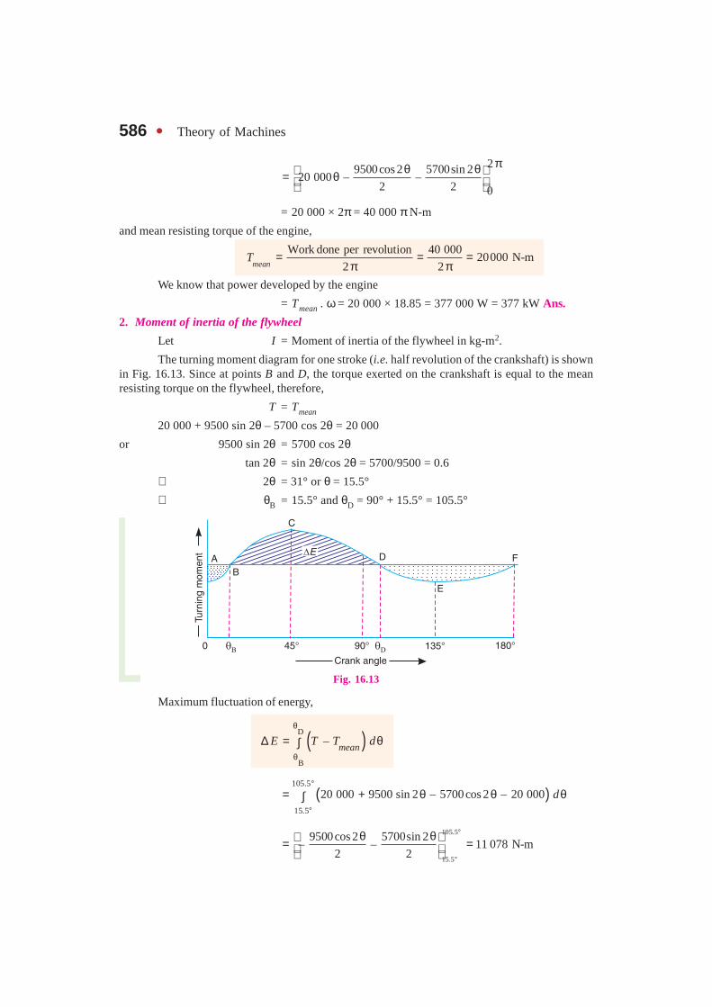
The turning moment diagram for one stroke (i.e. half revolution of the crankshaft) is shownin Fig. 16.13. Since at points B and D, the torque exerted on the crankshaft is equal to the meanresisting torque on the flywheel, therefore,
T = Tmean
20 000 + 9500 sin 2θ – 5700 cos 2θ = 20 000
or 9500 sin 2θ = 5700 cos 2θtan 2θ = sin 2θ/cos 2θ = 5700/9500 = 0.6
∴ 2θ = 31° or θ = 15.5°
∴ θ B = 15.5° and θD = 90° + 15.5° = 105.5°
Fig. 16.13
Maximum fluctuation of energy,
( )D
B
–mean
E T T dθ
θ
∆ = θ∫
( )105.5
15.5
20 000 9500 sin 2 – 5700cos 2 – 20 000 d°
°
= + θ θ θ∫
105.5
15.5
9500cos 2 5700sin 2– – 11 078 N-m
2 2
°
°
θ θ = =

Chapter 16 : Turning Moment Diagrams and Flywheel � 587We know that maximum fluctuation of energy
(∆ E),
11 078 = I.ω2.CS = I × (18.85)2 × 0.01 = 3.55 I
∴ I =11078/3.55 = 3121 kg-m2 Ans.
3. Angular acceleration of the flywheel
Let α = Angular acceleration of the flywheel, and
θ = Angle turned by the crank from inner dead centre = 45° . . . (Given)
The angular acceleration in the flywheel isproduced by the excess torque over the mean torque.We know that excess torque at any instant,
Texcess = T – Tmean
= 20000 + 9500 sin 2θ – 5700 cos 2θ – 20000
= 9500 sin 2θ – 5700 cos 2θ∴ Excess torque at 45°
= 9500 sin 90° – 5700 cos 90° = 9500 N-m . . . (i)
We also know that excess torque
= I.α = 3121 × α . . . (ii)
From equations (i) and (ii),
α = 9500/3121 = 3.044 rad /s2 Ans.
Example 16.12. A certain machine requires a torque of (5000 + 500 sin θ ) N-m to drive it,where θ is the angle of rotation of shaft measured from certain datum. The machine is directlycoupled to an engine which produces a torque of (5000 + 600 sin 2θ) N-m. The flywheel and theother rotating parts attached to the engine has a mass of 500 kg at a radius of gyration of 0.4 m. Ifthe mean speed is 150 r.p.m., find : 1. the fluctuation of energy, 2. the total percentage fluctuation ofspeed, and 3. the maximum and minimum angular acceleration of the flywheel and the correspondingshaft position.
Solution. Given : T1 = ( 5000 + 500 sin θ) N-m ; T2 = (5000 + 600 sin 2θ) N-m ;m = 500 kg; k = 0.4 m ; N = 150 r.p.m. or ω = 2 π × 150/60 = 15.71 rad/s
Fig. 16.14
Nowadays steam turbines like this canbe produced entirely by computer-
controlled machine tools, directly from theengineer’s computer.
Note : This picture is given as additional informa-tion and is not a direct example of the current
chapter.
588 � Theory of Machines
1. Fluctuation of energy
We know that change in torque
= T2 – T1 = (5000 + 600 sin 2θ) – (5000 + 500 sin θ)
= 600 sin 2θ – 500 sin θThis change is zero when
600 sin 2θ = 500 sin θ or 1.2 sin 2θ = sin θ 1.2 × 2 sin θ cos θ = sin θ or 2.4 sin θ cos θ = sin θ . . . (∵sin 2θ = 2 sin θ cos θ)
∴ Either sin θ = 0 or cos θ = 1/2.4 = 0.4167
when sin θ = 0, θ = 0°, 180° and 360°
i.e. θA = 0°, θC = 180° and θE = 360°
when cos θ = 0.4167, θ = 65.4° and 294.6°
i.e. θB = 65.4° and θD = 294.6°
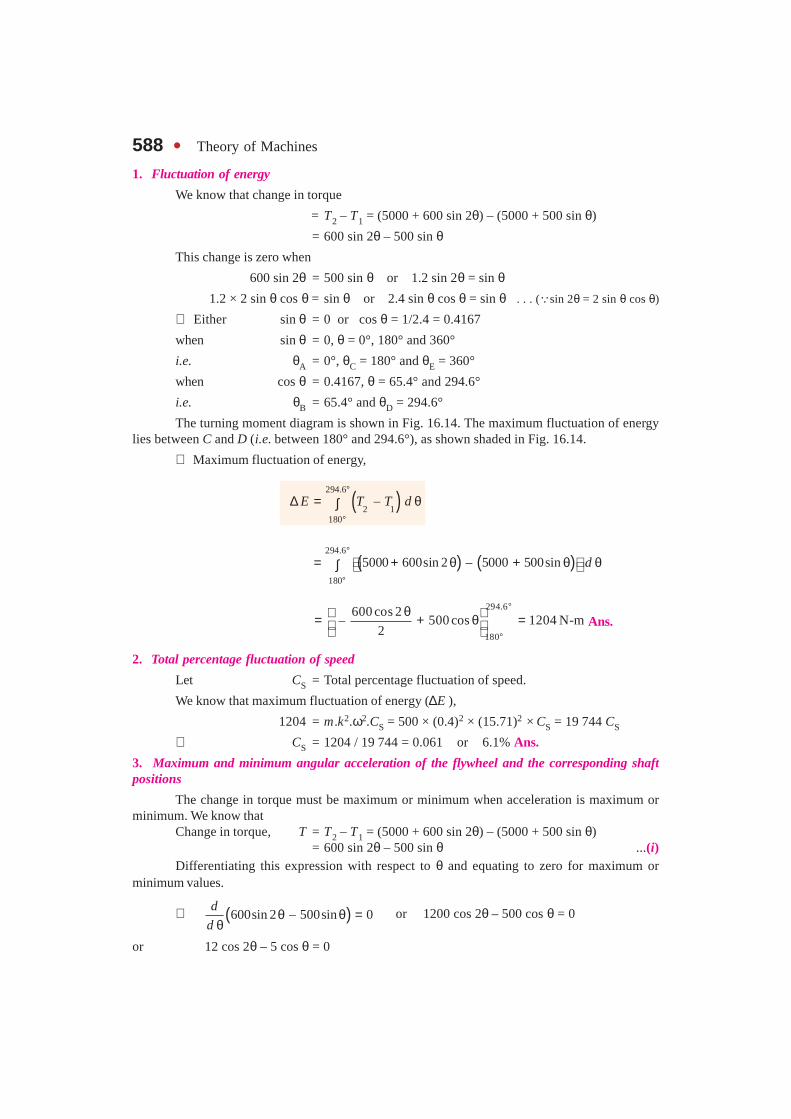
The turning moment diagram is shown in Fig. 16.14. The maximum fluctuation of energylies between C and D (i.e. between 180° and 294.6°), as shown shaded in Fig. 16.14.
∴ Maximum fluctuation of energy,
( )294.6
2 1180
–E T T d°
°
∆ = θ∫
( ) ( )294.6
180
5000 600sin 2 – 5000 500sin d°
°
= + θ + θ θ ∫
294.6
180
600 cos 2– 500 cos 1204 N-m
2
°
°
θ = + θ = Ans.
2. Total percentage fluctuation of speed
Let CS = Total percentage fluctuation of speed.
We know that maximum fluctuation of energy (∆E ),
1204 = m.k2.ω2.CS = 500 × (0.4)2 × (15.71)2 × CS = 19 744 CS
∴ CS = 1204 / 19 744 = 0.061 or 6.1% Ans.
3. Maximum and minimum angular acceleration of the flywheel and the corresponding shaftpositions
The change in torque must be maximum or minimum when acceleration is maximum orminimum. We know that
Change in torque, T = T2 – T1 = (5000 + 600 sin 2θ) – (5000 + 500 sin θ)= 600 sin 2θ – 500 sin θ ...(i)
Differentiating this expression with respect to θ and equating to zero for maximum orminimum values.
∴ ( )600sin 2 – 500sin 0d
dθ θ =
θ or 1200 cos 2θ – 500 cos θ = 0
or 12 cos 2θ – 5 cos θ = 0


![AND MOST EFFECTIVE LOADER FROM KRONOS€¦ · Lifting moment, brutto [kNm] 104 104 Lifting capacity, [kg] 4 m 1740 1630 at max. reach 780 630 Turning angle boom, [°] 380 380 Turning](https://img.pdfslide.net/doc/110x75/5f76b51b8ad5e61d1b3a9087/and-most-effective-loader-from-lifting-moment-brutto-knm-104-104-lifting-capacity.jpg)