Embed Size (px)
Citation preview
7/31/2019 Chapter 1(Edit)
http://slidepdf.com/reader/full/chapter-1edit 1/35
1
CHAPTER 1
INTRODUCTION TO
COMMUNICATION SYSTEM
7/31/2019 Chapter 1(Edit)
http://slidepdf.com/reader/full/chapter-1edit 2/35
2
Introduction
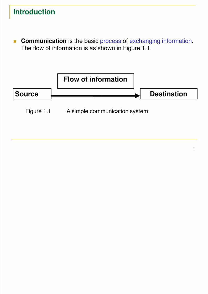
Communication is the basic process of exchanging information.The flow of information is as shown in Figure 1.1.
Source
Flow of information
Destination
Figure 1.1 A simple communication system
7/31/2019 Chapter 1(Edit)
http://slidepdf.com/reader/full/chapter-1edit 3/35
3
Electronic Communication System : the whole mechanism ofsending and receiving as well as processing of information electronically from source to a destination.
Examples : Telephone, radio and television, radar and satellitesystems.
The original source could be in analog form (human voice,music) or digital form (binary-coded numbers).
Analog signals are the time-varying voltages or currents that are
continuously changing (sine or cosine waves) whereas digitalsignals are the time-varying voltages or currents that change insteps or levels (binary). All forms of information must beconverted to electromagnetic energy before being propagatedthrough an electronic communications system.
7/31/2019 Chapter 1(Edit)
http://slidepdf.com/reader/full/chapter-1edit 4/35
4
Elements Of A Communication System
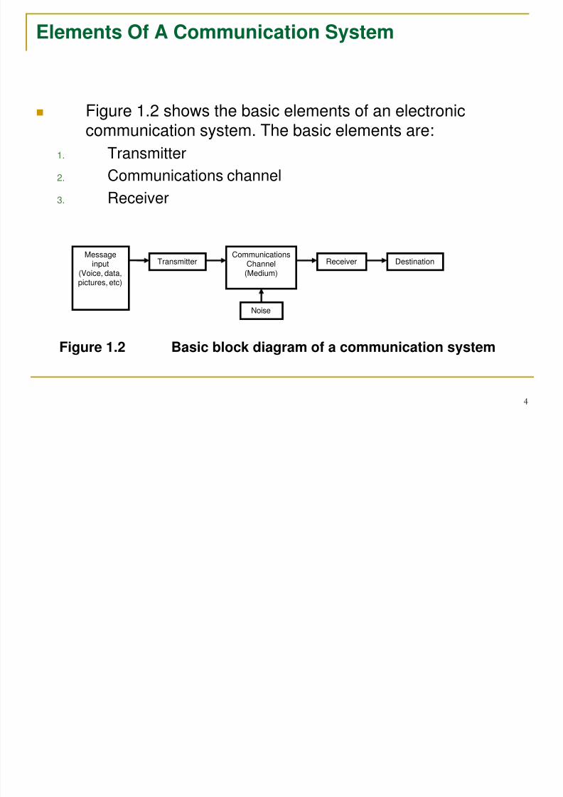
Figure 1.2 shows the basic elements of an electroniccommunication system. The basic elements are:
1. Transmitter
2. Communications channel
3. Receiver
Messageinput
(Voice, data,pictures, etc)
CommunicationsChannel(Medium)
Transmitter Receiver Destination
Noise
Figure 1.2 Basic block diagram of a communication system
7/31/2019 Chapter 1(Edit)
http://slidepdf.com/reader/full/chapter-1edit 5/35
5
Transmitter
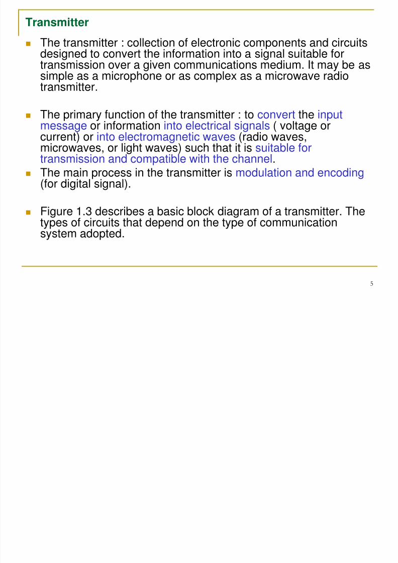
The transmitter : collection of electronic components and circuitsdesigned to convert the information into a signal suitable for
transmission over a given communications medium. It may be assimple as a microphone or as complex as a microwave radiotransmitter.
The primary function of the transmitter : to convert the inputmessage or information into electrical signals ( voltage or
current) or into electromagnetic waves (radio waves,microwaves, or light waves) such that it is suitable fortransmission and compatible with the channel.
The main process in the transmitter is modulation and encoding (for digital signal).
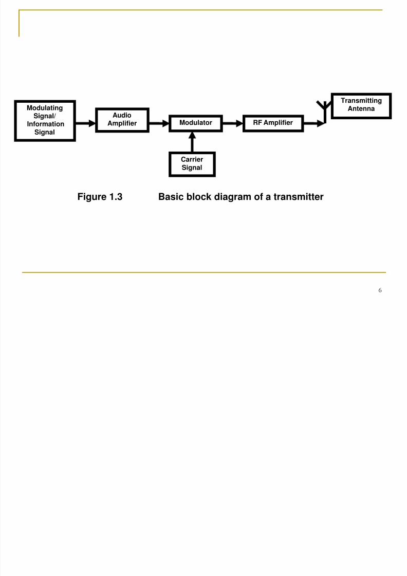
Figure 1.3 describes a basic block diagram of a transmitter. Thetypes of circuits that depend on the type of communicationsystem adopted.
7/31/2019 Chapter 1(Edit)
http://slidepdf.com/reader/full/chapter-1edit 6/35
6
ModulatingSignal/
InformationSignal
ModulatorAudio
Amplifier RF Amplifier
CarrierSignal
TransmittingAntenna
Figure 1.3 Basic block diagram of a transmitter
7/31/2019 Chapter 1(Edit)
http://slidepdf.com/reader/full/chapter-1edit 7/35
7
Communications channel or transmission medium
The communications channel : medium by which the electronicsignal is sent from one place to another either using line (orconducted media) or free space (or radio).
Examples of conducted media are pair of wires that carry a voicesignal from a microphone to a headset or a fiber-optic.
Free space or radio is the general term of wireless communicationwhich makes use of the electromagnetic spectrum where signals arecommunicated from one point to another by converting them intoelectric and magnetic fields that propagate readily over long
distances. There is normally no signal processing in the transmission medium,
it is just the medium where the transmitter is connected to thereceiver. However, each medium introduces losses termed asattenuation, distortion and adds noise to some degree to thetransmitted signal. The amount of attenuation, distortion, and noise
depends on the type of transmission medium used.
Noise Noise is random, undesirable electrical energy that enters the
communications system via the communication medium andinterferes with the transmitted message. Noise may be produced
internally or externally.
7/31/2019 Chapter 1(Edit)
http://slidepdf.com/reader/full/chapter-1edit 8/35
8
Receiver
The receiver is a collection of electronic components and circuits that
accept the transmitted message from the channel and convert it backinto a form understandable by humans. The primary purpose of thereceiver is to separate the information from the received signal orwave and sent the information to the user/ destination. Receivernormally compensates for the attenuation and distortion and reducesnoise caused by the transmission medium. An example of thereceiver is earphone or a complex electronic receiver.
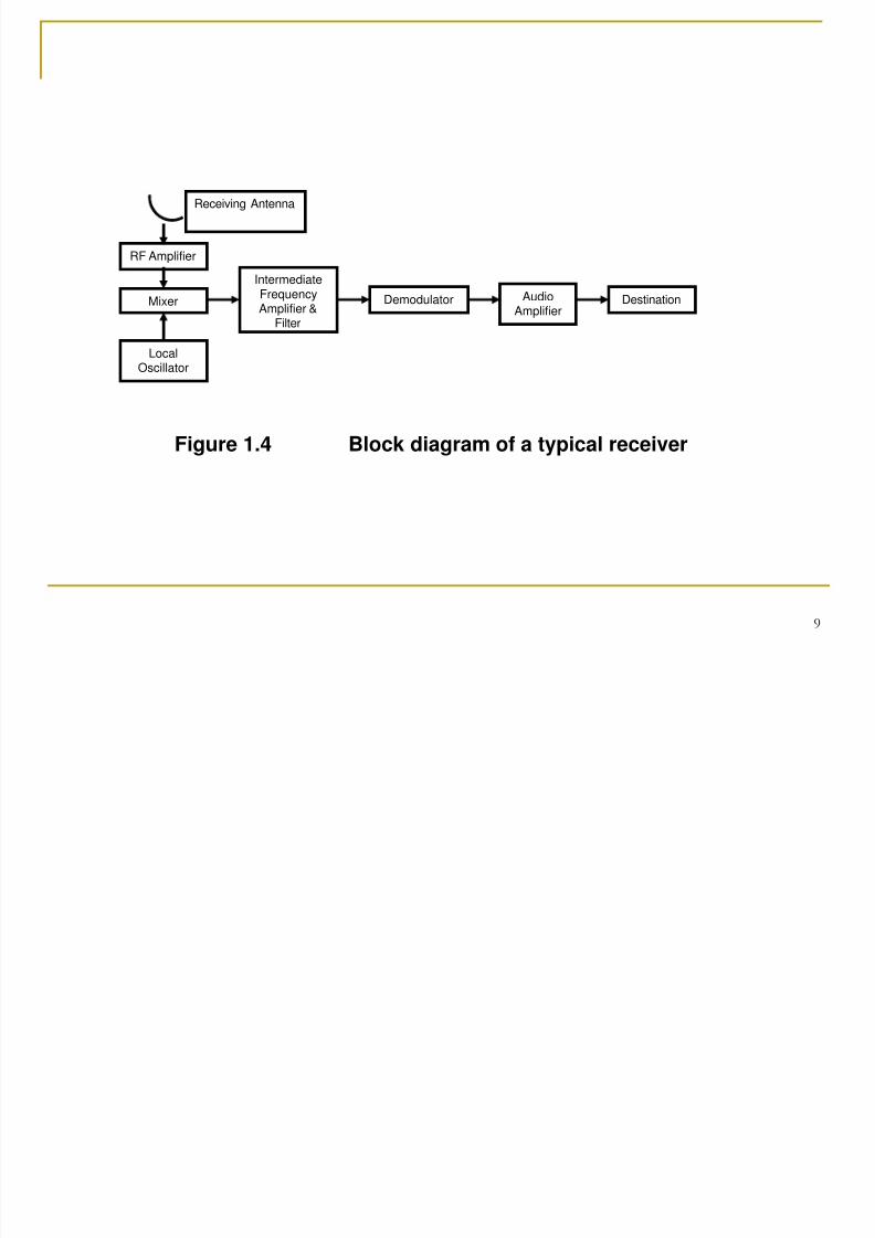
The circuits used in a receiver again depend on the type ofcommunication system used. Basically, a receiver consists of severalstages of amplification, frequency conversion, and filtering. The mainprocess is demodulation or detection of the received signal. Thereceiver must always match the transmitter and the transmissionmedium. Figure 1.4 illustrates a typical block diagram of a receiver.
7/31/2019 Chapter 1(Edit)
http://slidepdf.com/reader/full/chapter-1edit 9/35
9
RF Amplifier
Demodulator
IntermediateFrequency
Amplifier &Filter
DestinationAudio
Amplifier
Receiving Antenna
Mixer
LocalOscillator
Figure 1.4 Block diagram of a typical receiver
7/31/2019 Chapter 1(Edit)
http://slidepdf.com/reader/full/chapter-1edit 10/35
10
Modulation and Demodulation
Baseband signal is the original information signal
either in a digital or analog form. Putting the originalsignal directly into the medium is referred to asbaseband transmission. However, there are manyinstances when the baseband signals are incompatiblewith the media and cannot be transmitted directly. Thisis when the modulation techniques must be used.
Baseband Signals
7/31/2019 Chapter 1(Edit)
http://slidepdf.com/reader/full/chapter-1edit 11/35
11
Modulation
Modulation is the process of modifying or changing one ormore of the properties of the analog carrier by the modulatingsignal (baseband signal or information signal). The carrier isusually a sine wave having a higher frequency than themodulating signal. The changing one or more properties of the
analog carrier is in proportion with the information signal. Thebasic properties of the carrier that can be changed are eitheramplitude, frequency, or phase. A modulator is a circuit whichperforms modulation in a transmitter.
7/31/2019 Chapter 1(Edit)
http://slidepdf.com/reader/full/chapter-1edit 12/35
12
The process of modulation is needed in any communicationsystem. The reasons why modulation is needed are:
To generate modulated signal that is suitable fortransmission and compatible with the channel.
To allow efficient transmission
By using a high frequency carrier signal, the informationsignal e.g. voice can travel and propagate through the air atgreater distances, and shorter transmission time. Also, highfrequency signal is less prone to noise and interference.Certain types of modulation have the useful property ofsuppressing both noise and interference.
For example, FM systems use limiter to reduce noise andkeep the signal amplitude constant. PCM systems userepeaters to regenerate the signal along the transmissionpath.
7/31/2019 Chapter 1(Edit)
http://slidepdf.com/reader/full/chapter-1edit 13/35
13
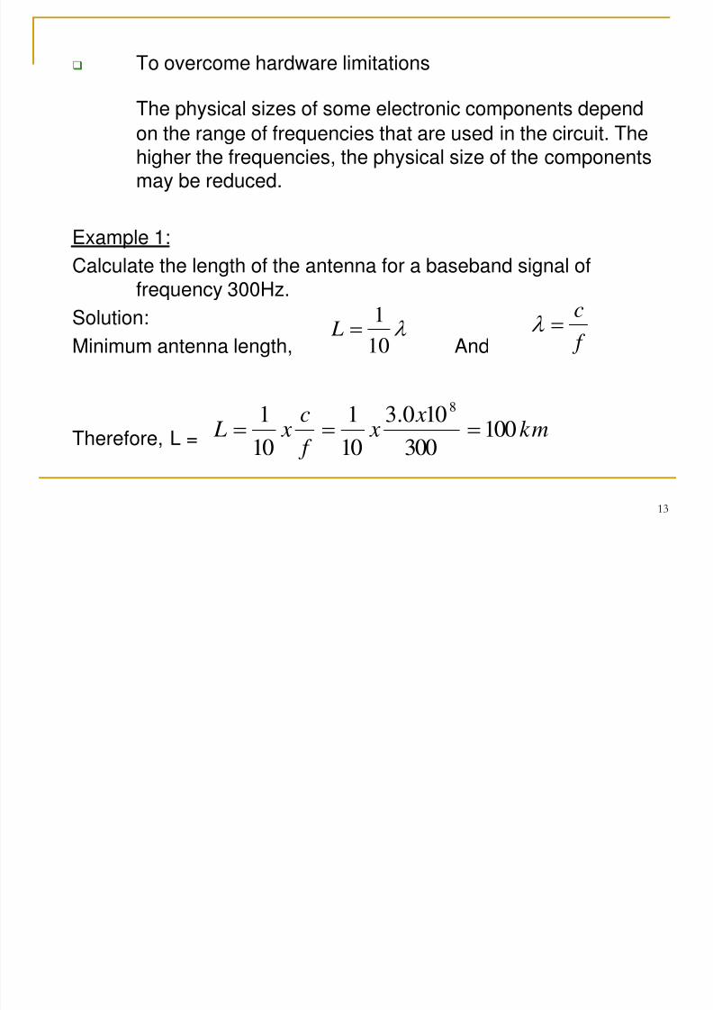
To overcome hardware limitations
The physical sizes of some electronic components depend
on the range of frequencies that are used in the circuit. Thehigher the frequencies, the physical size of the componentsmay be reduced.
Example 1:
Calculate the length of the antenna for a baseband signal offrequency 300Hz.
Solution:
Minimum antenna length, And
Therefore, L =
10
1 L
f
c
km x
x f
c x L 100
300
100.3
10
1
10
18
7/31/2019 Chapter 1(Edit)
http://slidepdf.com/reader/full/chapter-1edit 14/35
14
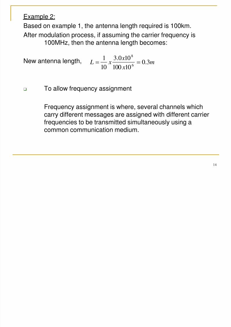
Example 2:
Based on example 1, the antenna length required is 100km.
After modulation process, if assuming the carrier frequency is
100MHz, then the antenna length becomes:
New antenna length,
To allow frequency assignment
Frequency assignment is where, several channels whichcarry different messages are assigned with different carrier
frequencies to be transmitted simultaneously using acommon communication medium.
m x
x x L 3.0
10100
100.3
10
1
6
8
7/31/2019 Chapter 1(Edit)
http://slidepdf.com/reader/full/chapter-1edit 15/35
15
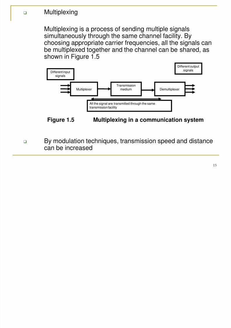
Multiplexing
Multiplexing is a process of sending multiple signalssimultaneously through the same channel facility. By
choosing appropriate carrier frequencies, all the signals canbe multiplexed together and the channel can be shared, asshown in Figure 1.5
By modulation techniques, transmission speed and distancecan be increased
MultiplexerTransmission
medium Demultiplexer
Different inputsignals
Different outputsignals
All the signal are transmitted through the sametransmission facility
Figure 1.5 Multiplexing in a communication system
7/31/2019 Chapter 1(Edit)
http://slidepdf.com/reader/full/chapter-1edit 16/35
16
Demodulation
Demodulation is the reverse process of modulation.
Demodulation will extract the original baseband information signaland transmitted message.
The demodulation process will convert the modulated carrier back tooriginal information (detection of information from the carrier).
A demodulator is a circuit which performs demodulation in areceiver.
7/31/2019 Chapter 1(Edit)
http://slidepdf.com/reader/full/chapter-1edit 17/35
17
Transmission Media
Guided transmission media is a form of conductor that provides aconduit in which electromagnetic signals are contained. Onlydevices physically connected to the medium can receive the signals.
Examples of guided transmission media is metallic cables which
transport signals using electrical current and optical fiber whichpropagating electromagnetic waves through a nonconductivematerial.
There are two basic types of transmission line:
Guided transmission media
7/31/2019 Chapter 1(Edit)
http://slidepdf.com/reader/full/chapter-1edit 18/35
18
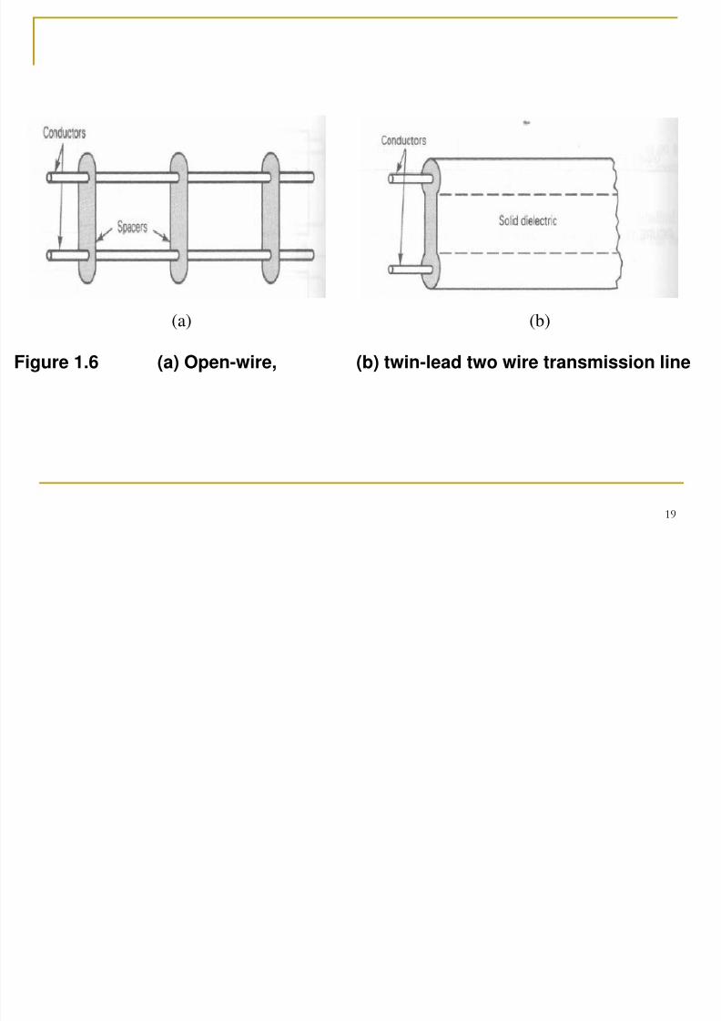
i. Two wire/ balanced line
Balanced line is made up of two parallel conductorsspaced from one another by a distance of ½ inch up toseveral inches. The same current flows in each wire withrespect to ground, but the direction is 180 out of phasewith the current in the other wire. The wires are notconnected to ground.
Insulating spacers normally used to keep the wires
separated, or sometimes the spacing is maintained by acontinuous plastic insulator that is part of the conductorinsulation (called twin lead).
Main application of two-wire lines is in transmission of lowfrequency signal such as in transmitting telephone signal
or low data rate transmission.
For higher frequency signal, two-wire line is not suitabledue to energy loss by radiation from the wire. So, coaxialcable is suitable for higher frequency applications.
7/31/2019 Chapter 1(Edit)
http://slidepdf.com/reader/full/chapter-1edit 19/35
19
(a) (b)
Figure 1.6 (a) Open-wire, (b) twin-lead two wire transmission line
7/31/2019 Chapter 1(Edit)
http://slidepdf.com/reader/full/chapter-1edit 20/35
20
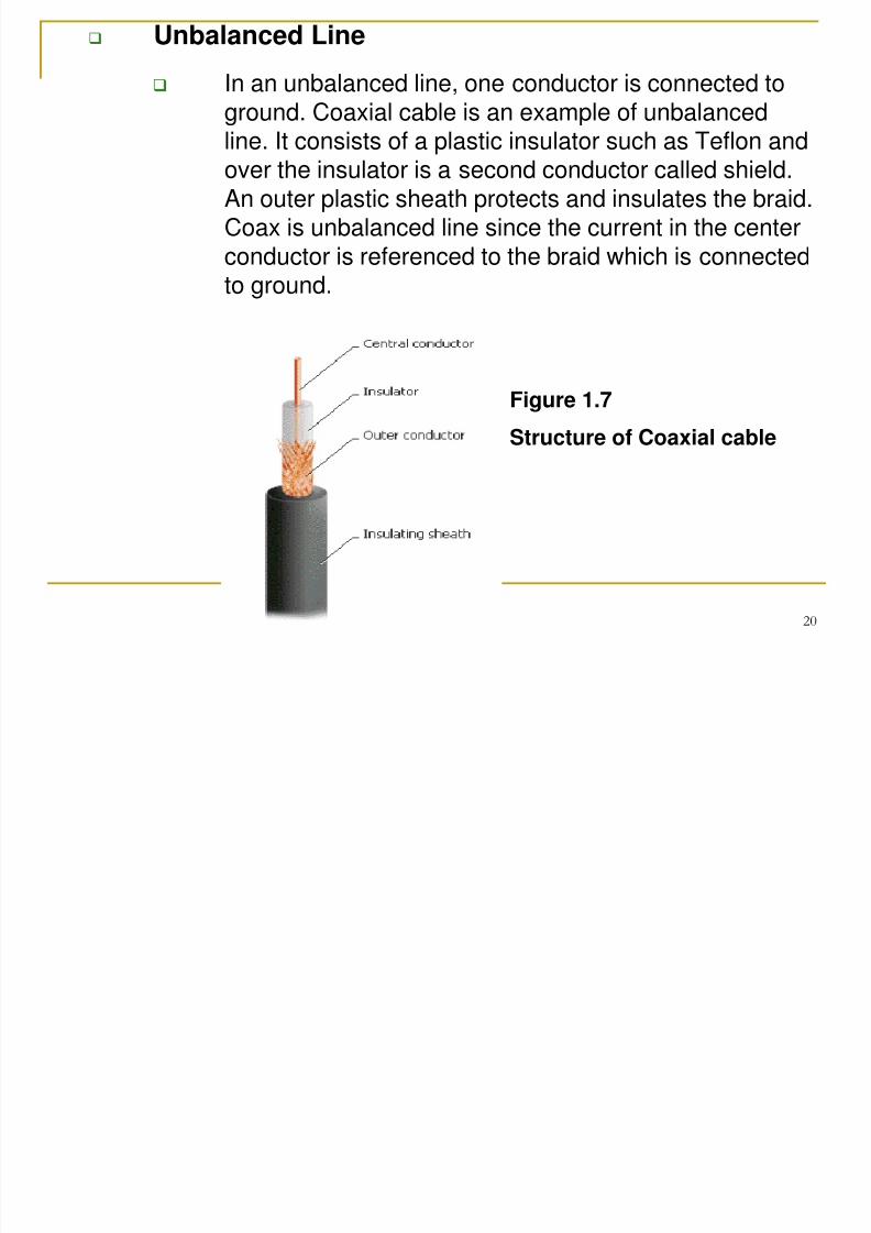
Unbalanced Line
In an unbalanced line, one conductor is connected toground. Coaxial cable is an example of unbalancedline. It consists of a plastic insulator such as Teflon andover the insulator is a second conductor called shield.An outer plastic sheath protects and insulates the braid.Coax is unbalanced line since the current in the centerconductor is referenced to the braid which is connectedto ground.
Figure 1.7
Structure of Coaxial cable
7/31/2019 Chapter 1(Edit)
http://slidepdf.com/reader/full/chapter-1edit 21/35
21
Unguided transmission media
Unguided transmission media is a wireless system. Signals are
emitted then radiated through air or a vacuum (sometimes water).The direction of propagation depends on the direction in which thesignal was emitted and any obstacles the signal may encounterwhile propagating. It is available to anyone who has a devicecapable of receiving them.
Examples of an unguided transmission media are air (Earthatmosphere) and free space (vacuum).
7/31/2019 Chapter 1(Edit)
http://slidepdf.com/reader/full/chapter-1edit 22/35
22
Transmission Modes
Electronic communication systems can be designed to handle
transmission in two transmission modes. They are:
1. Simplex (Sx)
In simplex communications, the information travels inone direction only. Simplex systems are sometimes
called one-way only, receive only, or transmit onlysystems.
Example: radio and television (TV) broadcasting,telemetry system of satellite to earth, pager services
7/31/2019 Chapter 1(Edit)
http://slidepdf.com/reader/full/chapter-1edit 23/35
23
2. Duplex
Full Duplex
Full duplex transmission is when individualscommunicate with one another and each cantransmit and receive simultaneously. Full duplexsystem is sometimes called two-way simultaneous,duplex, or both way lines. With full duplex system,simultaneous transmission is not necessarilybetween the same two locations. One station cantransmit to a second station and receive from a thirdstation at the same time.
Example: telephone
7/31/2019 Chapter 1(Edit)
http://slidepdf.com/reader/full/chapter-1edit 24/35
24
Half Duplex
Half duplex operation is another form of two-waycommunications but not simultaneously. With halfduplex system, the direction alternates which meanstransmission can occur in both directions but not at thesame time.
Example: walkie-talkie
7/31/2019 Chapter 1(Edit)
http://slidepdf.com/reader/full/chapter-1edit 25/35
25
Electromagnetic Spectrum And TransmissionFrequencies
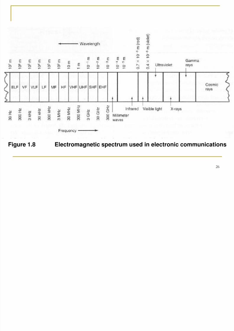
Electromagnetic signals are also referred to as radio-frequency (RF)waves. Electromagnetic waves are waves that travel at the speed oflight and oscillate such that it is made up of an electric field andmagnetic field at right angles to one another and to the direction ofpropagation. These oscillations may occur at a very low frequencyor at an extremely high frequency. This entire range of frequenciesis called electromagnetic spectrum. Figure 1.8 shows the entireelectromagnetic spectrum.
The frequency spectrum is divided into segments for the purpose ofclassifying the various portions and how they are used as shown in
Figure 1.9.
7/31/2019 Chapter 1(Edit)
http://slidepdf.com/reader/full/chapter-1edit 26/35
26
Figure 1.8 Electromagnetic spectrum used in electronic communications
7/31/2019 Chapter 1(Edit)
http://slidepdf.com/reader/full/chapter-1edit 27/35
27
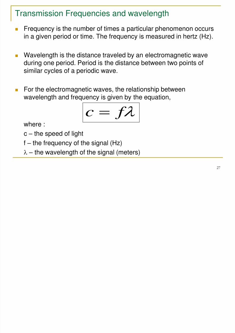
Transmission Frequencies and wavelength
Frequency is the number of times a particular phenomenon occursin a given period or time. The frequency is measured in hertz (Hz).
Wavelength is the distance traveled by an electromagnetic waveduring one period. Period is the distance between two points ofsimilar cycles of a periodic wave.
For the electromagnetic waves, the relationship betweenwavelength and frequency is given by the equation,
where :c – the speed of light
f – the frequency of the signal (Hz)
– the wavelength of the signal (meters)
f c
7/31/2019 Chapter 1(Edit)
http://slidepdf.com/reader/full/chapter-1edit 28/35
28
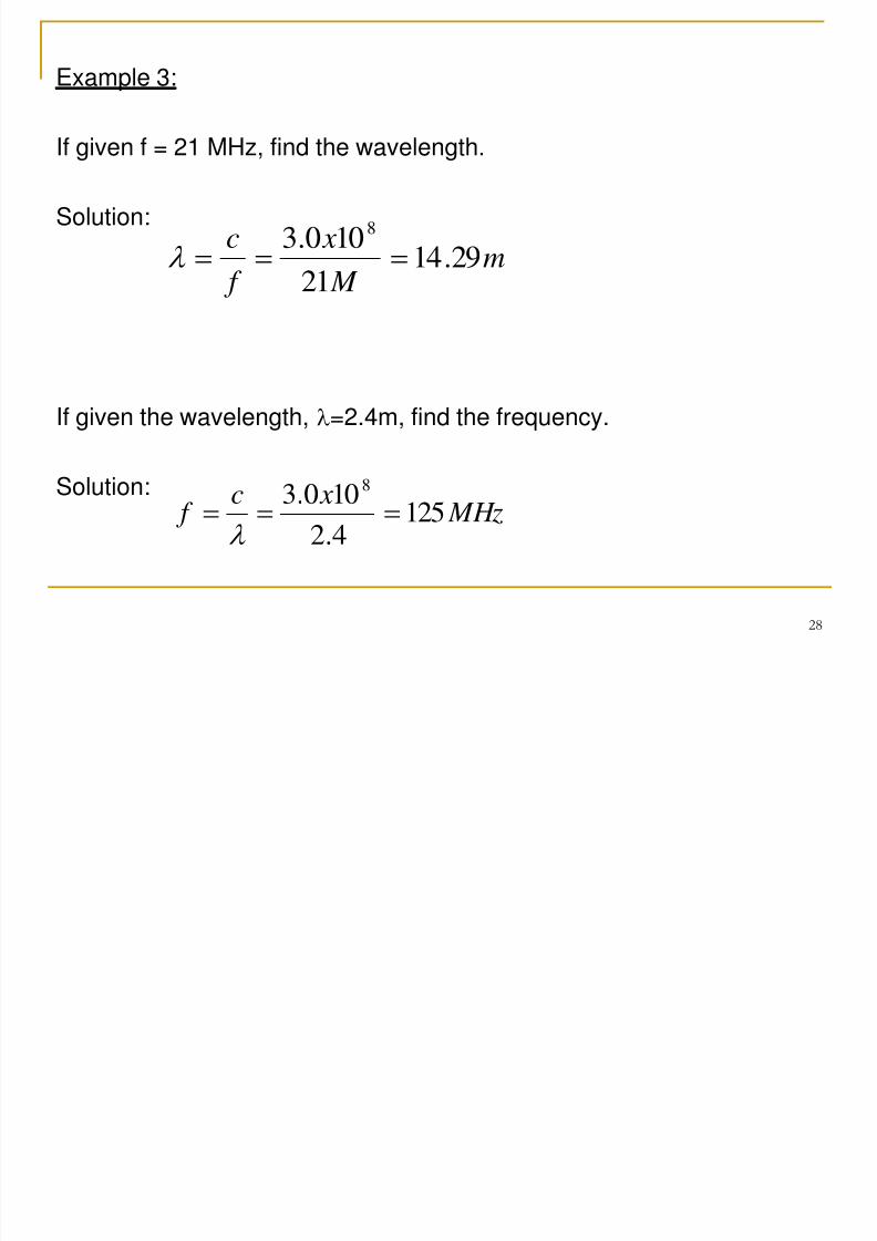
Example 3:
If given f = 21 MHz, find the wavelength.
Solution:
If given the wavelength, =2.4m, find the frequency.
Solution:
m M
x
f
c29.14
21
100.38
MHz xc
f 1254.2
100.38
7/31/2019 Chapter 1(Edit)
http://slidepdf.com/reader/full/chapter-1edit 29/35
29
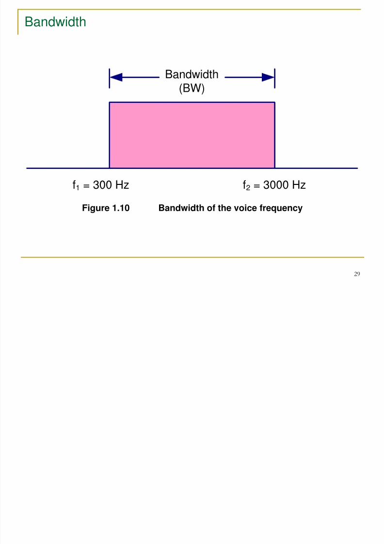
Bandwidth
f1 = 300 Hz f2 = 3000 Hz
Bandwidth
(BW)
Figure 1.10 Bandwidth of the voice frequency
7/31/2019 Chapter 1(Edit)
http://slidepdf.com/reader/full/chapter-1edit 30/35
30
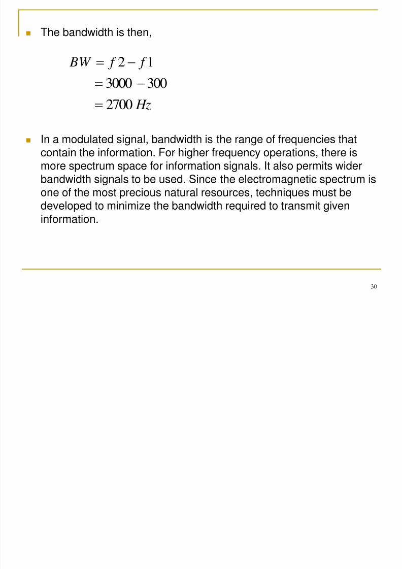
The bandwidth is then,
In a modulated signal, bandwidth is the range of frequencies thatcontain the information. For higher frequency operations, there ismore spectrum space for information signals. It also permits widerbandwidth signals to be used. Since the electromagnetic spectrum isone of the most precious natural resources, techniques must bedeveloped to minimize the bandwidth required to transmit giveninformation.
Hz
f f BW
2700
3003000
12
7/31/2019 Chapter 1(Edit)
http://slidepdf.com/reader/full/chapter-1edit 31/35
31
Information Capacity
Information capacity is a measure of how much information can bepropagated through a communication system. It is expressed in bitrate. Bit rate is the number of bits transmitted within one second andis expressed in bits per second (bps).
7/31/2019 Chapter 1(Edit)
http://slidepdf.com/reader/full/chapter-1edit 32/35
32
Hartley’s Law
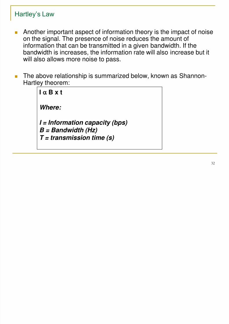
Another important aspect of information theory is the impact of noise
on the signal. The presence of noise reduces the amount ofinformation that can be transmitted in a given bandwidth. If thebandwidth is increases, the information rate will also increase but itwill also allows more noise to pass.
The above relationship is summarized below, known as Shannon-
Hartley theorem:
I B x t
Where:
I = Information capacity (bps) B = Bandwidth (Hz)
T = transmission time (s)
7/31/2019 Chapter 1(Edit)
http://slidepdf.com/reader/full/chapter-1edit 33/35
33
Shannon-Hartley Theorem
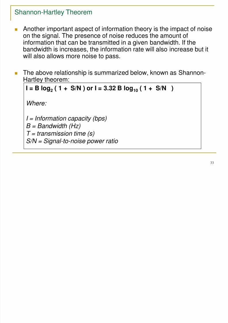
Another important aspect of information theory is the impact of noiseon the signal. The presence of noise reduces the amount of
information that can be transmitted in a given bandwidth. If thebandwidth is increases, the information rate will also increase but itwill also allows more noise to pass.
The above relationship is summarized below, known as Shannon-
Hartley theorem:I = B log2 ( 1 + S/N ) or I = 3.32 B log10 ( 1 + S/N )
Where:
I = Information capacity (bps)B = Bandwidth (Hz)T = transmission time (s)S/N = Signal-to-noise power ratio
7/31/2019 Chapter 1(Edit)
http://slidepdf.com/reader/full/chapter-1edit 34/35
34
Noise
Noise is random, undesirable electric energy that enters thecommunication systems via the communication medium and
interferes with the transmitted message. However, some noiseis also produced in the receiver. It is unavoidable and thus,becomes a problem in communications systems because thereceived signals are so low in amplitude.
Noise comes from many sources. They are:
1. AtmosphereAtmospheric noise originated from electrical disturbances thatoccur naturally in the earth’s atmosphere, referred to as static.Static usually comes from lightning. It has greatest impact atfrequencies less than 30MHz.
7/31/2019 Chapter 1(Edit)
http://slidepdf.com/reader/full/chapter-1edit 35/35
35
2. Cosmic noiseSun and other stars emit various kinds of radiation, whichcauses the greatest disruption in the 15 to 150MHz range.
3. Electrical interferenceIt is created by manufactured equipment such as automotiveignition and electric motors and generators.
4. Electric ignition systems of cars, electric motors, fluorescent
lights, and other types of equipment generate signals.
5. Thermal agitationThermal agitation refers to the random motion of the atoms andelectrons in an electronic component caused by heat.Increasing the temperature causes this motion to increase.
Usually noise signal are low but has great impact on extremelylow-level signals being transmitted over long distance.