Embed Size (px)
Citation preview

w w w . e c o z . c o m . a u
2012
Chapter 2 Project Description
EcOz Environmental Services
Western Desert Resources Limited Roper Bar Iron Ore Project

Document Control Record Prepared by: Justine Shailes Approved by: Ray Hall
Position: Snr Environmental Scientist Position: Principal
Signed:
Signed:
Date: 30 January 2012 Date: 18 June 2012
REVISION STATUS
Revision No. Description of Revision Date Approved
A start
B – C Draft to WDRL to review 6/03/12 EH
D – G RH after WDRL review 15/03/12 RH
H Review 13/04/12 RH
J Submit to Government 16/04/12 RH
2A-F Revision 30/05/12 RH
2G Submit to Government 18/06/12 RH
Recipients are responsible for eliminating all superseded documents in their possession.
EcOz Pty Ltd
trading as EcOz Environmental Services ACN: 143 989 039 Winlow House, 3rd Floor 75 Woods Street DARWIN NT 0800 PO Box 381, Darwin NT 0800 Telephone: +61 8 8981 1100 Facsimile: +61 8 8981 1102 Email: [email protected] Document Reference Number: DW120004-C0301-EIA-R-0050 Version D
RELIANCE, USES and LIMITATIONS This report is copyright and is to be used only for its intended purpose by the intended recipient, and is not to be copied or used in any other way. The report may be relied upon for its intended purpose within the limits of the following disclaimer. This study, report and analyses have been based on the information available to EcOz at the time of preparation. EcOz accepts responsibility for the report and its conclusions to the extent that the information was sufficient and accurate at the time of preparation. EcOz does not take responsibility for errors and omissions due to incorrect information or information not available to EcOz at the time of preparation of the study, report or analyses.

Client: Western Desert Resources Ltd Doc Title: Chapter 2 Project Description
Contents 2 Project Description ............................................................................................................................. 2-1
2.1 Project Planning.............................................................................................................................. 2-1 2.2 Mining ............................................................................................................................................. 2-2 2.3 Overburden and Waste Materials Management ............................................................................. 2-8 2.4 Crushing Circuit ............................................................................................................................ 2-11 2.5 Ancillary Infrastructure .................................................................................................................. 2-14 2.6 Haul Road ..................................................................................................................................... 2-20 2.7 Bing Bong Load Out Facility ......................................................................................................... 2-48 2.8 Transport ...................................................................................................................................... 2-62 2.9 Water ............................................................................................................................................ 2-66 2.10 Waste Management ..................................................................................................................... 2-74 2.11 Workforce and Accommodation ................................................................................................... 2-80 2.12 Decommissioning and Closure ..................................................................................................... 2-83 2.13 Towns River Realignment ............................................................................................................ 2-89
Tables Table 2-1 Project Timeline ....................................................................................................................... 2-1 Table 2-2 Reserve of Ore and Waste in Proposed Pits Area F .............................................................. 2-3 Table 2-3 Reserve of Ore and Waste in Proposed Pit Area E ................................................................ 2-3 Table 2-4 Proposed Pit Dimensions ........................................................................................................ 2-3 Table 2-5 Proposed Waste Rock construction landform dimensions ...................................................... 2-9 Table 2-6 Check Dam Spacing............................................................................................................... 2-31 Table 2-7 Annual Sediment Loss Prediction .......................................................................................... 2-32 Table 2-8 Sediment Basin Configuration ................................................................................................ 2-32 Table 2-9 Major River Crossings ............................................................................................................ 2-33 Table 2-10 Minor Crossings ................................................................................................................... 2-36 Table 2-11 Culvert Configurations .......................................................................................................... 2-39 Table 2-12 Construction Vehicles.......................................................................................................... 2-63 Table 2-13 Average weekly vehicle movements during Construction Period ....................................... 2-63 Table 2-14 Operations transport vehicle numbers ................................................................................ 2-64 Table 2-15 Operations vehicle size breakdown .................................................................................... 2-64 Table 2-16 Size and frequency of haul trucks ....................................................................................... 2-65 Table 2-17. Depth-Capacity of Area F Water Storage Pit 4 (PWS). ..................................................... 2-68 Table 2-18: Potable and Construction Water Requirements. ................................................................ 2-71 Table 2-19: Operational Water Requirements....................................................................................... 2-74 Table 2-20 Construction Waste ............................................................................................................. 2-75

Client: Western Desert Resources Ltd Doc Title: Chapter 2 Project Description
Table 2-21 Operational Waste............................................................................................................... 2-76 Table 2-22 Decommissioning Waste ..................................................................................................... 2-76 Table 2-23 Expected Workforce (number of staff) required for Construction and Operations. ............. 2-80 Table 2-24 Expected Workforce (skills and expertise) required for Construction and Operations. ...... 2-80 Table 2-25 Flood Protection Bunds (see Appendix N2). ........................................................................ 2-90
Figures Figure 2-1 Area F and Area E Pits .......................................................................................................... 2-4 Figure 2-2 General Mine Site Layout ...................................................................................................... 2-6 Figure 2-3 Scenario 1 Direct Shipping Ore Fines Only - Phase 1......................................................... 2-12 Figure 2-4 Scenario 2 Direct Shipping Ore Lump and Fines - Phase 1 ................................................ 2-13 Figure 2-5 Permanent Camp layout ...................................................................................................... 2-17 Figure 2-6 Runway cross section and transitional surface .................................................................... 2-19 Figure 2-7 Aerodrome general arrangement ......................................................................................... 2-20 Figure 2-8 Land Tenures in the Roper Region ...................................................................................... 2-23 Figure 2-9 Mineral Titles Intersected by the Proposed Haul Road ....................................................... 2-24 Figure 2-10 Typical section – 1 in 100 year flood immunity ................................................................... 2-27 Figure 2-11 Typical section for 1 in 10 year flood immunity ................................................................... 2-28 Figure 2-12 Typical section for 1 in 2 year flood immunity ..................................................................... 2-29 Figure 2-13 Proposed Haul Road – Construction and campsite locations ........................................... 2-42 Figure 2-14 Proposed Haul Road and Major River Crossings .............................................................. 2-44 Figure 2-15 Typical construction camp layout ....................................................................................... 2-45 Figure 2-16 Stockyard and Barge Loading Facility Overall Layout ....................................................... 2-51 Figure 2-17 Truck Unloader and Stacker .............................................................................................. 2-52 Figure 2-18 Stockyard Facility ............................................................................................................... 2-54 Figure 2-19 Overland conveyor ............................................................................................................. 2-55 Figure 2-20 Barge Loading Facility ....................................................................................................... 2-56 Figure 2-21 Entrance Channel Utilisation Operational Analysis ........................................................... 2-61 Figure 2-22 Location of Area F Water Storage Pit 4 (PWS). ................................................................ 2-68 Figure 2-23 Proposed Mine Water Management System. .................................................................... 2-72 Figure 2-24 Proposed Bing Bong Water Management System. ........................................................... 2-73 Figure 2-25 Minesite and River Realignment. ........................................................................................ 2-89

Client: Western Desert Resources Ltd Page 2-1 Doc Title: Chapter 2 Project Description
2 Project Description
2.1 Project Planning
2.1.1 Timeline
Table 2-1 Project Timeline
Activity Timing Early preparation works Third Quarter 2012 Contract works First Quarter 2013 Commissioning First Quarter 2013 Operation Second Quarter 2013 Phase 1 2013 – 2021 Decommissioning In 8 years based on 20 Million Tonnes
Phase 1 of the project involves mining and processing of Direct Shipping Ore (DSO) only. This incorporates the mining, crushing, processing and transport/shipment of high grade (>56%) ore only. This phase will operate from years one through to year eight.
2.1.2 Operational Hours
Construction and Operations will both be 24 hours per day for around 325 days a year utilising standard mining machinery and equipment. It is assumed that that up to 40 days production a year will be lost due to delays mainly attributable to high rainfall events.
Shut downs will occur; timing will be dependent on seasonal determinants. All machinery maintenance will be completed in accordance with relevant Australian Industry Standards.
2.1.3 Clearing Footprint
The haul road will be 165km long with a cleared width of 50m, with borrow pits and temporary camps, total clearing is expected to be in the region of 850 hectares. Much of the Port of Bing Bong is cleared for the existing operations, however an area will require clearing for the Stockyard Facility, Conveyor, access tracks and Barge Loading Facility, totalling approximately 50ha. Clearing within the mining tenements will total approximately 450ha, including internal access roads, the airstrip and permanent mine camp. These areas total 1350 hectares but for the purposes of this EIS and to be conservative we will use 1400 hectares as the area to be cleared.

Client: Western Desert Resources Ltd Page 2-2 Doc Title: Chapter 2 Project Description
2.2 Mining
2.2.1 Pit Development and Scheduling
WDRL proposes to develop its open pit iron ore mine in 2013 with a series of open pits of varying depths between 20 and 100 vertical meters. Initial open pit operations will be conducted by a competent open pit mining contractor, under the supervision of WDRL mining personnel and will initially target areas of DSO. Mining will be by conventional open pit methods using selective mining techniques that are scheduled to extract ore and waste material.
The entire project area under exploration and mining lease application by WDRL currently contains an estimated resource of 311 Mt of which it is expected that approximately 200 Mt may be available to be mined. This is expected to increase with further exploration and drilling. The ore is contained in various ore bodies (see Chapter 3 for detailed ore characterisation in all WDRL Exploration Leases).
The initial mining phase for which approvals are being sought will involve MLA 28264 and MLA 28967 which contain a number of deposits including the high grade Area F and Area E. This area features an estimated 65 Mt of ore resource, of which only the direct shipping ore component of this resource is being proposed to be mined as phase 1 of this project. The estimated JORC Mineral Resource estimates for this aspect of the project of approximately 24 Mt will result in an expected mine life for these ML’s of approximately 8 – 10 years.
20.2Mt @ 58.6% Fe is a JORC Inferred and Indicated Mineral Resource estimate. WDRL expect another 4 Mt of DSO from updated JORC-compliant resource estimates.
The known quantities of ore in the ground are described as either a Reserve or a Resource. This is a standard procedure for many mining operations and identified in the JORC Code. In layman’s terms a Reserve is fully identified and currently economically mineable part of the orebody. The existing MLA Reserves are identified in Table 2-2 and Table 2-3. In addition to the Reserves, there is an identified Resource, which includes areas of known ore that haven’t yet been drilled out to the JORC Mineral Reserve Code standard or may be below an existing Reserve and therefore not accessible as a Reserve itself until uncovered. The known amount of DSO in pit F for example is currently not all Reserve according to the JORC Mineral Reserve Code, however it is the same orebody and the confidence levels of the Resource are very high.
Mining is planned to begin in several locations to access surface outcropping ore as well as removing overburden and waste from other mining areas. Area E and Area F pits 1 to 3 will be mined and over time are expected to be progressively backfilled and rehabilitated. Area E stage 1 pit and the small Area F pit 4 are planned for use as potential water storages during the early stages of the project.
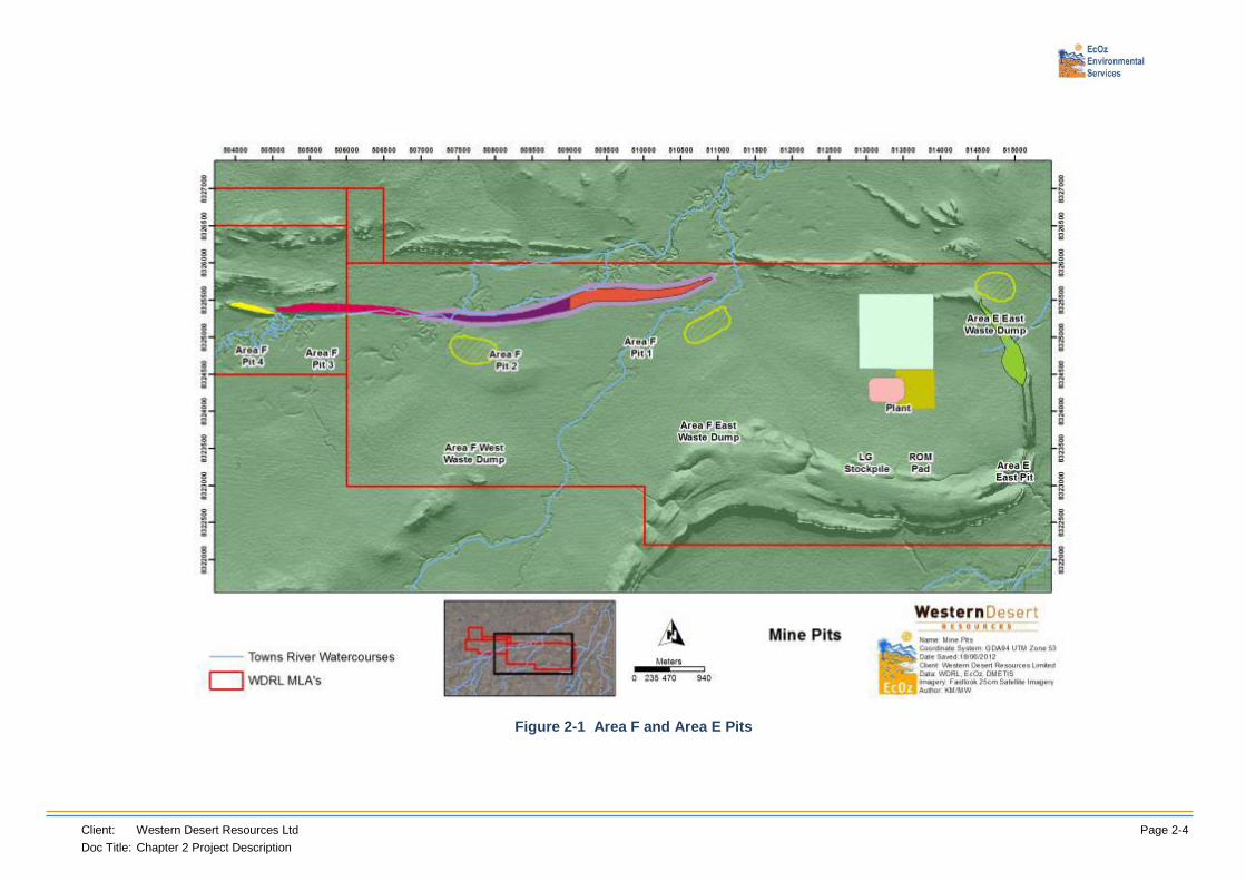
Area F is divided into four pits. The eastern most (and deepest) being pit 1, then moving west to pit 2 and pit 3, and west again to the smaller pit 4. Areas F and E are shown below in Figure 2-1.
• Area F is planned to be mined for the entire strike length at a rate of 20 metres vertically per year;
• Area E is planned to be mined at 10 metres vertically per month; and
• Area F has a number of small and shallow surface outcropping deposits that will be mined out in a single campaign.
An indication of mining and waste volumes is provided in Table 2-2 and Table 2-3.
The ore body is shallow, mostly surface outcropping and often linear, resulting in a mining pit design that will evolve as the mining activities progress along the deposit. The exact mine pit plans will evolve with the project as the depth extent of the resource is not fully determined in all locations.

Client: Western Desert Resources Ltd Page 2-3 Doc Title: Chapter 2 Project Description
Table 2-2 Reserve of Ore and Waste in Proposed Pits Area F Vo
lum
e
AREA F Sandstone Sherwin Ironstone Formation Siltstone Total
Waste High Grade Low Grade Waste Waste Waste
Oxide 53,865 77,000 121,600 332,220 440,160 826,245
Transition 390,390 333,700 422,600 894,600 1,964,760 3,249,750
Fresh 674,625 1,385,100 1,015,100 1,723,785 3,173,625 5,572,035
Total 1,118,880 1,795,800 1,559,300 2,950,605 5,578,545 9,648,030
Tonn
es
Oxide 129,276 219,686 312,508 793,435 1,056,384 1,979,095
Transition 936,936 1,040,096 1,205,956 2,310,494 4,715,424 7,962,854
Fresh 1,619,100 4,846,192 3,155,042 4,889,472 7,616,700 14,125,272 Total 2,685,312 6,105,974 4,673,506 7,993,400 13,388,508 24,067,220
Table 2-3 Reserve of Ore and Waste in Proposed Pit Area E
Volu
me
AREA E
Sandstone Sherwin Ironstone Formation Siltstone Total
Waste High Grade Low Grade Waste Waste Waste
Oxide 171,098 152,075 317,725 151,594 884,468 1,207,159
Transition 15,015 208,150 407,775 92,978 1,204,455 1,312,448
Fresh 353,250 411,275 111,746 163,931 275,678
Total 186,113 713,475 1,136,775 356,318 2,252,854 2,795,284
Tonn
es
Oxide 410,634 455,626 899,174 409,508 2,122,722 2,942,864
Transition 36,036 558,393 956,840 201,770 2,890,692 3,128,498
Fresh - 878,682 891,659 219,876 393,435 613,311 Total 446,670 1,892,701 2,747,673 831,155 5,406,849 6,684,674
Mining is planned to begin in Area F approximately one month prior to beginning in Area E. Clearing for pit development will begin one month prior to mining operations. Clearing will be staged to coincide with mine development. Table 2-4 identifies the planned pit sizes and Figure 2-1 identifies their locations.
Table 2-4 Proposed Pit Dimensions
Measurement Area F Area E
Maximum Length (m) 5366 1175
Maximum Width (m) 200 186
Area (ha) 121.1 31.4
Maximum Pit Depth (m) 100 85
Pit Base RL (m AHD) 920 940
Client: Western Desert Resources Ltd Page 2-4 Doc Title: Chapter 2 Project Description
Figure 2-1 Area F and Area E Pits

Client: Western Desert Resources Ltd Page 2-5 Doc Title: Chapter 2 Project Description
The total area of impact from the proposed activities is approximately 1400 ha. The stages of mine development will occur as follows:
• Clearing and grubbing;
• Topsoil removal and stockpiling;
• Pre-stripping of waste where it covers the ore zone;
• Construction of haul roads, ROM and drainage channels;
• Construction of sediment control devices, and associated water storage facilities;
• Re-alignment of the stream channel that will be impacted by mining of deposit F.
• Mining of free-dig material (ore and waste that does not require blasting);
• Drilling and blasting of ore and waste;
• Loading, hauling and dumping of ore and waste in designated areas;
• Crushing and screening of ore;
• Road haulage of ore to Bing Bong; and
• Stockpiling and barge loading facilities at Bing Bong;
2.2.2 Mining Types and Methods
Initially the project will focus on areas where the deposits have been investigated in detail. Approximately 15 million tonnes per annum (Mtpa) of ore and waste material will be mined during this initial phase, producing approximately four million tonnes of DSO over a two to three year period. During this initial period other known deposits will undergo further resource definition.
Within the pits it is proposed that working bench heights will be maintained at five metres, although ultimately this will be determined by the physical characteristics of the mineralisation. Each bench will consist of free dig or blasted material excavated in two discrete flitches (or levels), each nominally of 2.5m height. This should minimise dilution and maximise ore recovery. It is expected that primary material blast heave will result in a 2.5 - 3m effective mining flitch height.
Ore will be identified visually and the different ore types and grades will be identified with varying degrees of visual inspection and sampling in conjunction with pit geological mapping. Once blasted a hydraulic excavator and fleet of dump trucks will be used for extraction. Ore bearing material will be loaded onto haulage trucks and taken to the ROM stockpile close to the processing plant as shown in Figure 2-2.
Ore processing will have a designed capacity of up to 3 Mtpa to cater for peak production periods.
Equipment Required Excavators and rigid frame off highway rear dump trucks will be used to mine and haul ore and waste within the Mining Leases. The mining equipment suitable for the project will include 100-200t excavators and off-highway diesel haul trucks with a payload capacity of 90t. The pit configuration, bench height and material type suit top hole hammer drill rigs for the drill and blast operations. Drill burden, spacing and sub-drill design will be functions of the varying material types of the deposit.

Client: Western Desert Resources Ltd Page 2-6 Doc Title: Chapter 2 Project Description
Figure 2-2 General Mine Site Layout

Client: Western Desert Resources Ltd Page 2-7 Doc Title: Chapter 2 Project Description
Geotechnical Characterisation An assessment was carried out using available mapping and drill hole logging data in the proximity to the expected pit wall location. Data included historical scanner data collection from boreholes drilled along the alignment of the ore body, mapping data gathered by independent geotechnical consultant’s personnel during their site visit during October 2011 and geotechnical logging data from four geotechnical boreholes drilled between December 2011 and January 2012 in the expected location of the pit walls. The mapping data and geotechnical logging data was interpreted and kinematic analysis was carried out on the characterised defect sets. Indicative rock characteristics were taken from the core logging data and from observations during the consultants site visit. Initial wall face angles, berm widths, and overall pit wall slope angles have been determined to provide a wall angle with an appropriate factor of safety such that the pit walls would remain stable for the life of the pit area. Geotechnical analysis and investigation will continue as the project progresses, and further data is obtained, to further refine the geotechnical parameters used in the pit designs.
Dewatering Requirements Groundwater inflow rates will increase steadily as the pit is developed and more rock is exposed. Hydrogeological modelling predicts that there is a higher drawdown gradient in the weathered rock to depths up to around 30m below the natural surface. The fresh rock is tight and relatively impermeable whereas the ore zone is four times more permeable than the waste rock, therefore, a steady inflow rate through the ore zone and through structures in the waste rock is expected. The inflow will increase as the pit size increases to an estimated maximum of around 12L/sec in the deepest pit of Area F (Pit 1 as shown in Figure 2-1).
Water usage requirements have been estimated at 15 L/sec for haul road dust suppression and running the crushing and screening plant. An initial small pit will be excavated for water storage and it is assumed that with seasonal rainfall and surface runoff as a supplementary source of water, this will be enough to supply the operation.
Hydrogeological modelling has suggested the use of dewatering bores to intercept and control groundwater seepage during the first 30m of vertical pit development is not required because limited available drawdown, and small formation hydraulic conductivity, will cause bore yields to be small and will limit the lateral influence of bores. Dewatering by means of sumps and depressurisation holes in the pit walls is likely to be the most practical method for removing groundwater from the pit walls. It is expected that sumps will be sufficient for dewatering as the pit is developed to greater depths, however this will be reviewed periodically during mining.
Monitoring of groundwater levels around the open pit will be undertaken to assess the progress of dewatering, and also for the ongoing assessments of pit wall stability.
Acid Mine Drainage Potential The preliminary conclusion of the Acid Mine Drainage (AMD) study provided in Appendix K and summarized in Chapter 3, is that AMD is not likely to be an issue with major implications for the Roper Bar Project. However, further more detailed studies are required to understand the extent and distribution of high sulfur zones which pose the greatest risk for acid mine drainage.
AMD refers to the process whereby rock containing sulfides is exposed to air and water; causing the oxidisation of these sulfides. At Roper Bar, the sulfide mineral pyrite, chemical formula FeS2, is visible in variable quantities in the rock material proposed for excavation from the mining pits.
The distribution of sulfur analysed by pit design and within each stratigraphic interval and oxidation level indicates an overall low level of sulfur concentrations in each mining area. An important factor evident in these assessments is that the upper levels of stratigraphy (which represents the initial stages of mining) consist of oxidised rock with lower levels of sulfur as compared to the fresh rock. On a waste management perspective, these oxidised rocks have the potential to be used as buffer materials to offset any issues that may arise from high sulfur zones encountered in the fresh rock.
Client: Western Desert Resources Ltd Page 2-8 Doc Title: Chapter 2 Project Description
The distribution of sulfur within the Roper Bar iron deposits was further examined in cross section. Analysis of the sulfur data in three dimensions reveals that patchy zones exist where sulfur values are relatively high, and they tend to be discontinuous and sporadically developed.
Further work is required to characterise the distribution of high sulfur zones within the areas proposed for excavation and mining. A model is being constructed to ensure that high sulfur zones are predicted and scheduled to ensure appropriate management.
The results of laboratory testing and analysis as part of an acid base accounting (ABA) assessment are summarized in Chapter 3 and the detailed report provided in Appendix K. Overall, the ABA assessment indicates that potentially acid forming (PAF) material is present to a variable degree in all areas proposed for mining. However, its distribution is sporadic and patchy, also, the very high acid neutralising capacity (ANC) of a large proportion of the material means that the net acid producing potential (NAPP) of the total rock mass is reduced, particularly in overburden material.
By applying a conservative approach, the implications for mine waste materials management indicates that careful management of ores and waste rocks will be required. However, significant amounts of lithotypes, particularly near-surface materials have substantial or relatively high ANCs and thus potential to consume acid. These materials will remain near-neutral in pH and through infiltration and seepage interactions, will generate alkaline solutions to offset acidities generated from PAF materials.
In regards to the management of PAF materials during mining, a risk assessment framework will be developed to promote better environmental practice and continuous environmental improvement and awareness of AMD issues as outlined in Chapter 3.
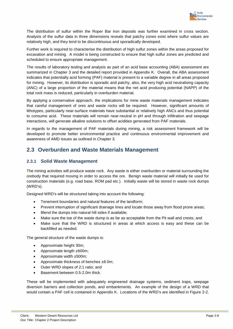
2.3 Overburden and Waste Materials Management
2.3.1 Solid Waste Management
The mining activities will produce waste rock. Any waste is either overburden or material surrounding the orebody that required moving in order to access the ore. Benign waste material will initially be used for construction materials (e.g. road base, ROM pad etc.). Initially waste will be stored in waste rock dumps (WRD’s).
Designed WRD’s will be structured taking into account the following:
• Tenement boundaries and natural features of the landform; • Prevent interruption of significant drainage lines and locate those away from flood prone areas; • Blend the dumps into natural hill sides if available; • Make sure the toe of the waste dump is as far as acceptable from the Pit wall and crests; and • Make sure that the WRD is structured in areas at which access is easy and these can be
backfilled as needed.
The general structure of the waste dumps is:
• Approximate height 30m; • Approximate length ±600m; • Approximate width ±500m; • Approximate thickness of benches ±8.0m; • Outer WRD slopes of 2:1 ratio; and • Basement between 0.5-2.0m thick.
These will be implemented with adequately engineered drainage systems, sediment traps, seepage diversion barriers and collection ponds, and embankments. An example of the design of a WRD that would contain a PAF cell is contained in Appendix K. Locations of the WRD’s are identified in Figure 2-2.

Client: Western Desert Resources Ltd Page 2-9 Doc Title: Chapter 2 Project Description
The processes associated with this project do not produce tailings, so there will not be a tailings storage facility.
2.3.2 Low Grade Storage Facility
A sub grade storage facility will hold material that is below 56% iron so that it can potentially be beneficiated in the future. This facility is adjacent to the ROM pad and crushing circuit. This facility is likely to store ore for several years, so it will require an impervious pad, erosion and sediment control structures and monitoring devices for surface and groundwater.
2.3.3 Overburden
The early works designed to obtain waste material suitable for construction of the project infrastructure to support mining and operations will utilise overburden material. This will reduce the need for any unnecessary clearing to obtain construction materials. Table 2-5 identifies the material requirements for these activities.
Table 2-5 Proposed Waste Rock construction landform dimensions
Infrastructure length width height Volume (m³)
Airstrip 200 30 0.3 1,800
plus 1600 45 0.15 10,800
Camp pad 300 200 0.5 30,000
Airstrip Road 5000 10 0.4 20,000
access tracks 5000 10 0.5 25,000
Savannah Way 10000 10 0.4 40,000
Mine bunds 10000 40 5 2,000,000
Internal Roads 10000 12 2 240,000
Bing Bong haul road 20000 13 2.6 676,000
ROM 600 200 3 360,000
Mine Haul Roads 6000 40 3 720,000
Total Volume (m³) 4,123,600
Once the materials required for construction have been exhausted, overburden will require storage in a waste rock facility. This overburden and oxidised waste material is also likely to be utilised for the construction of a waste storage facility designed to contain and manage potentially acid forming wastes uncovered deeper in the rock profile.
Waste rock dumps containing an estimated 13,500,000 m³ of waste material will require storage prior to pits being potentially available for infill.
Topsoil Management Program Mine planning and design layouts have been developed to:
1. Minimise the amount of disturbance for the area of operations; and
2. Return the land to the agreed rehabilitated condition as soon as practicable.
This is achieved primarily by adopting a mining method that is a variant of the strip mining methods used in surface coal mining. The initial waste dump for the starter pit will be built as a pad for a crushing and screening plant, ROM pad and road haulage truck loading facility. Topsoil will be stored around the

Client: Western Desert Resources Ltd Page 2-10 Doc Title: Chapter 2 Project Description
perimeter of this pad for rehabilitation uses. The topsoil will be in an area that avoids slopes, natural drainage ways and traffic routes and will not be permitted to mix with other materials on site. If necessary, erosion and sediment control measures will be employed including revegetation (and weed control) to assist in stabilisation. Clearing control measures will be implemented during construction and operation to ensure that no unnecessary clearing is undertaken. Conservation of topsoil and progressive rehabilitation of waste landforms and all other disturbed areas will be done as soon as practicable to the appropriate standard and recommended guidelines.
Figure 2-2 shows the location of the Process Plant, ROM pad, topsoil and Low Grade Storage Facility (stockpile) in relation to the rest of the mining areas and camp. Topsoil will initially be stored between the Low Grade Storage Facility zone and the ROM pad. During year 2 and beyond, topsoil management will alter, based on site development and progressive rehabilitation activities, whereby if appropriate, fresh topsoil will be moved from one location and immediately placed on reinstated surfaces to assist with rehabilitation and revegetation. This method will help ensure the viability of the seedbank and the soil organisms.
Further information is available within the Rehabilitation and Closure Management Plan (Appendix P) and Chapter 2.
2.3.4 Post Mining Treatment of Pits
The fundamental pit rehabilitation framework includes progressive refilling of pits with waste rock material. As elsewhere indicated, this plan is preferred but due to surface water and waste rock management processes it is likely that refilling will occur at later stages of the project.
Exploratory drilling has identified that in some areas the ore bodies extend to depths beyond the current economically viable ore bodies. This may change in the future, so to cover the ore with waste would sterilise it and prevent access to it in future. Sterilising an orebody reduces the possibility for future potential operators to equitably access the ore and therefore removes a natural asset from all stakeholders including the general public. From an environmental perspective, continuing to mine an existing resource that is within a pre disturbed area is far more practical than having to access potentially lesser grade resources from undisturbed sites.
An additional consideration is that during pre-mine and mine development there is a need for benign waste to be used for road base, ROM and plant pads and the construction of bunds and other structures around the site. The principal source for this material would be the pre-strip waste from the pits. Amounts of NAF materials to be used for these activities are significant, reducing the quantities of available materials for infilling the pits.
If puts have been mined out of their resources then there are potentially more appropriate future uses for these pits, for such things as
• PAF disposal; or
• BFO wastes.
The AMD investigations (Appendix K) have concluded that about 30% of waste rock and low grade ore has the potential to produce acidity. Thus, on a pit management criterion, where ore resources are not sterilised and where there is no potential for groundwater contamination PAF materials may be best disposed of within the pits. However, as indicated in Appendix K, this option will need to follow proper risk assessment and engineering management approaches such as the construction of proper cover and low conductivity encapsulation layers.
Although this EIS is only seeking approval for a DSO portion of the project, there is a very large BFO resource within and surrounding the current mineral lease application areas. The beneficiation of lower grade ore will involve the physical separation of silicates from the ore so as to produce a high grade

Client: Western Desert Resources Ltd Page 2-11 Doc Title: Chapter 2 Project Description
product. The separated fine grained silicates, which are expected to be benign, will be in a slurry form and would be most appropriately disposed of into the mined out pits.
Area F Pit 4 is planned to be mined first and mined out and then used as a water storage dam for the duration of the project.
Area F Pit 3 will also be mined during the first year’s dry season. This pit footprint currently has the Towns River channel running along it (refer to section 2.13) and the engineering requirements to allow for this channel to be moved so that Area F pits 1 and 2 can be mined has identified the need to allow the stream to flow through this mined pit and then be realigned around the Area F pits 1 and 2 sections of the deposit.
This approach will assist with removing the potential for afflux from the realignment and at the same time will equilibrate upstream velocities and reduce potential impacts on the downstream areas of the river.
Geotechnical profiles of the pits indicate that these will be elongated to follow ore body distribution and benches will have an average thickness of about 12m with pit wall slopes ranging from 35 to 45 degrees.
Pits, as indicated in Appendix P (Rehabilitation and Closure Plan), will be implemented with engineered embankments to prevent flooding, erosion and, where needed, fenced to improve public safety.
It had been requested of this project that it evolve under the philosophy of progressive rehabilitation. Waste rock dumps, including PAF storage areas will be rehabilitated as they become available for rehabilitation, but as these facilities need to be complete before they can be rehabilitated, the ability to progressively rehabilitate them diminishes.
Unless Kinetic or other suitable testing identifies the PAF material as being relatively unreactive then the PAF storage areas will need to be constructed to a standard facilitating long term storage, even if the plan to transfer this material into an empty pit evolves.
2.4 Crushing Circuit
A contract operator will be utilised for the crushing operations. ROM ore will be fed to the crushing plant on a campaigned basis as follows:
• ROM ore is discharged from mining haul trucks to the ROM pad and then fed into a crusher via front end loaders;
• The ore is withdrawn by an apron feeder which discharges onto a vibrating separation screen;
• The oversize material is then crushed by a primary crusher; and
• The primary crushed ore and the screened undersize ore are combined and rescreened.
The secondary crushing and screening equipment has a different configuration depending on the ore types and product as follows and will only be pursued if financially viable at the time:
• Lump and fines DSO products require a double deck screen and one secondary crusher in a closed loop;
• Fines only DSO product require three single deck screens and two secondary crushers operating in two parallel closed loops; and
The DSO products from the screening plant are stockpiled on the stockpile facility and loaded on haul trucks for export to the stockyard near Bing Bong.
The crusher circuit will include the following:
• Primary Crusher with a typical capacity throughput range of 400 to 700 tonnes per hour;
• Scalping Screen powered by a 22kW electric motor;
• Screening Plant powered by two 22kW electric motors;
• Secondary Crusher fitted with standard liners to accept a minus 198mm feed;

Client: Western Desert Resources Ltd Page 2-12 Doc Title: Chapter 2 Project Description
• A Sample Station designed and manufactured in accordance with ISO3082;
• Metal Detection Tectron metal detector;
• Stacking by two 30m radial stackers capable of stacking trapezoidal heaps; and
• Dust Suppression via water misters located throughout the plant on all discharge points as well as on the stockpile conveyor discharge points.
2.4.1 Indicative Process Flow-sheets
Below is the indicative flow diagram showing process from DSO ROM ore input through to marketable product during Phase 1 (Figure 2-3 and Figure 2-4). There are 2 potential scenarios producing either lump (up to 30 mm) and fine (less than 6 mm) material, or only fines. The flow sheets indicate 1.5 Mtpa, and the process is the same for the 3 Mtpa production level.
Figure 2-3 Scenario 1 Direct Shipping Ore Fines Only - Phase 1

Client: Western Desert Resources Ltd Page 2-13 Doc Title: Chapter 2 Project Description
Figure 2-4 Scenario 2 Direct Shipping Ore Lump and Fines - Phase 1
2.4.2 Chemicals
There are no chemicals required in the crushing process, or any other part of the ore mining or processing operations.
2.4.3 Storage and Handling of Product
Prepared ore will be stored as uncovered, open stockpiles and managed through the use of front end loaders (FELs). These stockpiles will be maintained at suitable moisture levels to facilitate ease of transport and dust suppression. Ore at the mine will be conditioned to the Dust Extinction Moisture Level (DEM) prior to being loaded onto trucks.
Ore will be loaded via front end loaders into covered side tipping road trains for transport along the Haul Road. FELs will also shape the stockpiles and remove any spillages.
Once the ore is stockpiled at the stockyard (Port of Bing Bong) it will be maintained at the DEM for barge and shiploading (more information on storage and handling of product at the Port can be found in Chapter 2.7.2.).
Stockpiles will be established at the Bing Bong Loading Facility immediately prior to loading. These stockpiles will contain the necessary amount of ore for shipping requirements. i.e. years one and two, 60,000 tonnes of ore to suit shipping via SupraMax Ocean Going Vessels (OGVs) and for years three to eight, 90,000 tonnes of ore to suit shipping via PanaMax OGVs.

Client: Western Desert Resources Ltd Page 2-14 Doc Title: Chapter 2 Project Description
2.5 Ancillary Infrastructure
2.5.1 Mine Buildings and Services
These will be provided by the mining contractor but additional facilities may be purchased as mining increases. Typically mine buildings and services would consist of an administration building (mine services centre), change rooms, truck service bay, truck tray change bay, mining fleet fuel storage and re‐fuelling building, spares store, and explosives storage. An air compressor is provided for the powering of pneumatic tools used for the maintenance of the mining fleet.
Perimeter fences surround secure buildings. The mining contractor will be responsible for the purchase, transport, storage and use of explosives.
2.5.2 Mine Services Centre
The Mine Services Centre services the administration and messing requirements of mine personnel. The building will provide workspace for around 40 personnel including the mine manager, plant supervisors, administrative staff, and geologists, mining engineers, surveyors, environmental, safety and training personnel and technical assistants. Additional rooms will be provided for as board and conference / training rooms, a first aid room and communication rooms for the entire operation.
2.5.3 Energy Infrastructure
Power would be provided by portable generators. Based on energy requirements the following power generators will be required:
• Accommodation area (site camp) x 3 power generators (2 operational and 1 standby);
• Processing area x 2 power generators (1 operational and 1 standby);
• Stockyard x 2 power generators (1 operational and 1 standby); and
• Conveyance system x 2 power generators (1 operational and 1 standby).
Power will also be made available to other areas as required which may include the aerodrome and borefield. Project energy requirements (estimated diesel fuel consumption for construction and operation phases of the project including generators, plant and equipment) are detailed in Chapter 7 – Noise, Air and Vibration. This includes the type of equipment, fuel consumption and expected air emissions, energy conservation and greenhouse gas mitigation strategies.
2.5.4 Roads
Site Roads and Access Ways A mixture of gravel roads and sealed roads to varying widths and design will be used as appropriate. A preliminary estimate of road requirements was made based on the mine camp, airport and plant being in reasonably close proximity. An estimated 8 km of road stretches between mine areas and dispatch facilities for carrying loaded mining and mobile equipment. Formed roads are also included around the mine services areas and the process plant, see Figure 2-2.
2.5.5 Chemical, Fuel and Explosives Storage
Chemical Storage No chemicals are required for the mining or ore treatment processes. Some chemicals will be required for the servicing and maintenance of machinery and the camp. WDRL will have purpose built HazChem
Client: Western Desert Resources Ltd Page 2-15 Doc Title: Chapter 2 Project Description
containers with internal bunding to catch spills and ventilation to prevent the build-up of fumes. These are used for drum storage of oil, petrol and similar materials. Old waste oils are also to be stored and later removed from site by a suitably licensed contractor and delivered to a licensed depot. Initially WDRL will have a HazChem container sized at 20ft (or 6m) but it is expected that increased storage capacity will eventually be required. All chemical storage will be conducted according to the appropriate Australian Standards and industry best practice.
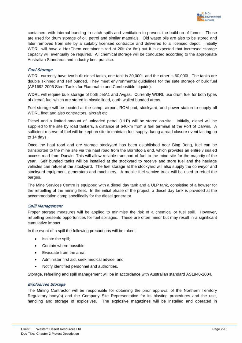
Fuel Storage WDRL currently have two bulk diesel tanks, one tank is 30,000L and the other is 60,000L. The tanks are double skinned and self bunded. They meet environmental guidelines for the safe storage of bulk fuel (AS1692-2006 Steel Tanks for Flammable and Combustible Liquids).
WDRL will require bulk storage of both JetA1 and Avgas. Currently WDRL use drum fuel for both types of aircraft fuel which are stored in plastic lined, earth walled bunded areas.
Fuel storage will be located at the camp, airport, ROM pad, stockyard, and power station to supply all WDRL fleet and also contractors, aircraft etc.
Diesel and a limited amount of unleaded petrol (ULP) will be stored on-site. Initially, diesel will be supplied to the site by road tankers, a distance of 640km from a fuel terminal at the Port of Darwin. A sufficient reserve of fuel will be kept on site to maintain fuel supply during a road closure event lasting up to 14 days.
Once the haul road and ore storage stockyard has been established near Bing Bong, fuel can be transported to the mine site via the haul road from the Borroloola end, which provides an entirely sealed access road from Darwin. This will allow reliable transport of fuel to the mine site for the majority of the year. Self bunded tanks will be installed at the stockyard to receive and store fuel and the haulage vehicles can refuel at the stockyard. The fuel storage at the stockyard will also supply the conveyor and stockyard equipment, generators and machinery. A mobile fuel service truck will be used to refuel the barges.
The Mine Services Centre is equipped with a diesel day tank and a ULP tank, consisting of a bowser for the refuelling of the mining fleet. In the initial phase of the project, a diesel day tank is provided at the accommodation camp specifically for the diesel generator.
Spill Management Proper storage measures will be applied to minimise the risk of a chemical or fuel spill. However, refuelling presents opportunities for fuel spillages. These are often minor but may result in a significant cumulative impact.
In the event of a spill the following precautions will be taken:
• Isolate the spill;
• Contain where possible;
• Evacuate from the area;
• Administer first aid, seek medical advice; and
• Notify identified personnel and authorities.
Storage, refuelling and spill management will be in accordance with Australian standard AS1940-2004.
Explosives Storage The Mining Contractor will be responsible for obtaining the prior approval of the Northern Territory Regulatory body(s) and the Company Site Representative for its blasting procedures and the use, handling and storage of explosives. The explosive magazines will be installed and operated in

Client: Western Desert Resources Ltd Page 2-16 Doc Title: Chapter 2 Project Description
conformance with the Explosives and Dangerous Goods Regulations and their location and protection will comply with AS2187.1.
Converted container type magazines are proposed for storage of packaged explosives and initiating supplies. Explosive storage will cater for peak requirements of explosive product, blasting agents, as well as for packaged explosives, such as a pre-split product for wall control, as required. Detonators and delays will be stored on-site in separate detonator magazine(s). The magazine containers will be fitted with locks, with all containers placed behind earthen bunds and security fencing which will also be locked.
Bulk blasting agent and/or explosive products may also be transported to the mine area in purpose-built trucks, termed a mobile manufacturing unit (MMU). The MMU’s will deliver the products to the pit blast area where they will then be mixed to form explosives or blasting agents, and immediately delivered into the blast holes.
2.5.6 Communications
A satellite communications system will be utilised on site. Negotiations are currently underway with Telstra regarding implementing correct infrastructure (a dish type arrangement) to enable regular telephone systems to be established for site. Two-way radios will also be utilised for site communications.
Communications within site will be by radio using UHF or multichannel frequency which is set by the relevant regulatory body. Repeating stations (radio towers) will be placed at the camp, airport, mine services centre, plant, and port. Repeating stations will be placed at a distance of approximately 10km apart to carry the radio signal between these locations.
It is expected that the Mining Contractor will supply their own communications equipment.
Marine communications will be supplied by the barge and shipping contractors. Marine communications generally use low frequency or satellite systems. An interface between marine and land communications is provided at the Port.
2.5.7 Permanent and Temporary Accommodation Facilities
Mine Accommodation The construction camp will be located about 4km north-west of the proposed Process Plant. The camp will accommodate 150 personnel during the construction and mine establishment period and administered by a camp catering contractor.
The final operations village, to be located close to the air field, will be provided with:
• Mess with associated kitchen;
• Administration building;
• Nursing station;
• Ablution block (shower/toilet);
• Laundry facilities;
• Bar & entertainment area; and
• Fitness & recreation centre.
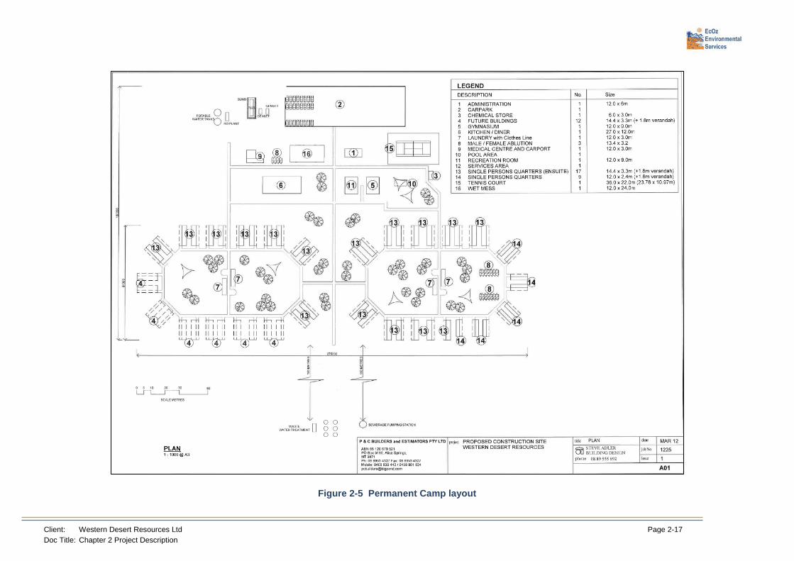
The camp will be laid out in such a way that it is expandable for future operation and construction phases see Figure 2-5.
Client: Western Desert Resources Ltd Page 2-17 Doc Title: Chapter 2 Project Description
Figure 2-5 Permanent Camp layout

Client: Western Desert Resources Ltd Page 2-18 Doc Title: Chapter 2 Project Description
2.5.8 Plant Infrastructure for Construction
Plant buildings for construction will consist of a Plant Administration Building, change rooms, laboratory, workshops, spares store, control room and electrical substations.
The Plant Administration Building services the administration and messing requirements of plant personnel. The building will be designed to hold 57 personnel including the process plant manager, plant metallurgists, chemists, analysts and plant operators, day maintenance personnel and technicians.
Clean and Dirty areas will be provided, separated by showers.
A sample preparation laboratory will be provided to receive samples of ore for grade control. These samples will be flown offsite for analysis.
Maintenance personnel will have at their disposal a fully equipped workshop that includes work benches for various trades, an overhead crane, tool store, supervisors offices, a crib room and equipment such as drill press, milling machine and lathe. It is assumed specialised repairs will be carried out by teams brought to site for the specified purpose or sent off site.
Off site and onsite stores inventory will need to be carefully selected to avoid production loss. As well as parts for machines, equipment and instruments, secure locations for consumables and protective clothing are provided. The movement of spares will be controlled by a database system such as SAP or MIMS. Chemicals and corrosive or toxic materials will be stored in separate, secure HazChem containers as per relevant Australian Standards. A fenced yard will provide for spares which can be stored outside along with discarded equipment and piping.
2.5.9 Airfield and Associated Activities
The existing 1600m x 15m airstrip will be upgraded to a total size of 2000m x 30m strip in accordance with Civil Aviation Safety Authority (CASA) Guidelines – Guidelines for Aeroplane Landing Areas.
Aerodrome Management Services Pty Ltd have been contracted to provide assistance with the construction of the upgrade. The type decided on was for the construction of a Metro/Brasilia type aerodrome.
The Metro 23 is a twin turbo prop aircraft with a capacity of 18 seats (excluding crew). The tail-plane height is 6.0m with a wingspan of 17.4m. The length of the aircraft is 18.1m and the maximum take-off weight is 7,484kg. As the Metro does not exceed 30 seats there will be no requirement for a certified aerodrome.
The construction of the runway will be carried out by standard civil equipment and will be independently assessed and signed off by a relevant authorised representative.
The airstrip will be lengthened to 2000m for operation during hot weather and widened to 30m. The natural surface will be cleared of vegetation then stripped of topsoil. Earthworks will then be carried out to be in accordance with design plans for sub-grade level. The sub-grade will then be water mixed and compacted. The longitudinal gradients will not exceed 1.5%. The lateral gradients will be 1.5% with a central crown.
Once compacted and graded to design sub-grade, selected fill will be imported to a compacted depth of not less than 200mm. The selected fill will meet NT Roads specifications.
The runway strips are an area 33.5m wide along each side of the runway. This area will be graded smooth and not left with any windrows or obstructions. The gradient will be no more than 2.5% in any direction with any change in gradient to be gradual so that they can be travelled comfortably in any direction at 50km/h. The runway strip will be 60m longer than the runway at either end.

Client: Western Desert Resources Ltd Page 2-19 Doc Title: Chapter 2 Project Description
The clearway is an area 60m long and 90m wide at the end of the runway/runway strip. It will be of identical condition to the runway strips. The runway emergency stop area will be an area of 60m x 60m and extends to the end of the runway strip. This will be cleared and graded.
The transitional surface is an imaginary line that extends at a gradient of 1:7 from the outer edge of the runway strip (see Figure 2-6). No object is to protrude through this area (including vehicles).
Figure 2-6 Runway cross section and transitional surface
The take-off and approach gradients are to be cleared to 1.6% from the ends of the clearways at the full 90m width and allowing for a 15% divergence. The apron is to be at least 40m x 60m to allow for the Metro to turn around. Aprons will be located on an area of high ground so they drain well. The edge of the apron closest to the runway will be at least 101m from the edge of the runway strip to allow for the Metro to park without the tail-plane infringing the transitional surface.
The taxiway will be constructed to 15m wide with a total width of 52m cleared. The radius of the fillets on the runway intersection will be 20m and the fillets joining the apron will have a 10m radius. A signal circle and windsock circle have been purchased for the airstrip. The windsock is 6.5m tall. The circle surrounding the windsock will be 15m in diameter and marked with 15 large white cones (see Figure 2-7).
The signal circle is to be located within 5m of the windsock circle. The diameter will be 9m and marked with 6 large white cones. The runway and runway strips are marked to CASA standards. The apron will have 18 large yellow cones and ten small yellow cones. The area will be fenced to ensure no animal collisions occur.
A small terminal type building will provide shelter and an area to properly manage the safety, security and logistics of people and luggage.

Client: Western Desert Resources Ltd Page 2-20 Doc Title: Chapter 2 Project Description
Even though the airport is not certified, there are still regulatory requirements that will need to be met. A small aerodrome manual is required and before the first flight an Aerodrome Safety Inspection will be undertaken. Reporting officers will be trained to carry out inspections of the aerodrome to ensure that it is safe and serviceable before aircraft movements.
The management of erosion and sediment control is identified in the draft ESCP’s at Appendix L.
Figure 2-7 Aerodrome general arrangement
2.6 Haul Road
2.6.1 Alignment
A private, sealed haul road will be constructed for the haulage of ore from the mine site to the proposed Bing Bong Stockyard Facility. The haul road will be approximately 165km in length, between 10 and 12m wide with 1.5m shoulders, and be positioned in a cleared area of approximately 50m width. The ore would then be reclaimed and conveyed to the Bing Bong Barge Loader via an approximately 590m long overland conveyor. Various appendices have been prepared surrounding the design and management of the Haul Road, refer to Appendix L3 (Erosion and Sediment Control – Haul Road), Appendix P (Rehabilitation and Closure Plan), and Appendix T (Haul Road Traffic Management Plan).

Client: Western Desert Resources Ltd Page 2-21 Doc Title: Chapter 2 Project Description
Triple trailer road trains would be used to haul the ore from the mine site with covered right hand side tip trailers. Other traffic on the Haul road would be restricted to project related traffic only and consist of occasional light vehicles, general mine supplies and fuel trucks depending on access.
During construction the majority of vehicles will be travelling to the project area via the Roper Highway and Nathan River Road. Some construction traffic, especially for the Haul Road may enter the area via the Nathan River Road from the south. Refer to Chapter 2.8 for information on transport and refer to the Environmental Management Plan (Appendix C) for further information on transport management.
Alignment Justification WDRL consulted with stakeholders, residents and Traditional Owners to determine the route least likely to cause any impact. Specific consideration was given to potential environmental impacts as well as engineering requirements, particularly with respect to river crossings and water flows. The selected alignment was deemed to have the least amount of potential impact. As discussed in Chapter 1.9 -Alternatives, use of Savannah Way was ruled out due to the poor state of the road, public safety issues and potential disturbance to a wider community.
Identification of Sensitive habitats There are no listed or formally recognised areas of conservation significance along the proposed haul road route. Aside from a number of localities featuring low sandstone ridges, riparian vegetation and wetlands, none of other higher priority vegetation types such as rainforest, monsoon vine thicket, or monsoon forest, were found within the haul road survey area (which included a 6km corridor).
However, a number of localities do present particular value for biodiversity on a regional scale. Surveys along the haul road corridor focused on identifying and assessing the value of sensitive habitat or habitat of higher conservation value that should be avoided, and potentially buffered from the development. These habitats are listed below and described in full in Chapter 4.
• Rocky Sandstone Ridges (includes scattered occurrences of low rocky hills, and also the southern reaches of the Yiyintyi Ranges);
• Waterbodies (includes Melaleuca swamps and seasonally inundated lowlands); and
• Watercourses (includes Cox River, Limmen Rive, Nathan River, Rosie Creek, Pine Creek, Bing Bong Creek, plus many small creek and tributary crossings).
Coordinates for all surveyed locations of sensitive habitat were used in determining the route of lowest environmental impact between the MLA areas and the Port of Bing Bong.
The main areas that were prioritised for environmental consideration for the design and alignment of the haul road alignment are listed below, as these areas displayed area of high biodiversity value:
• Limmen River crossing;
• Ridges and rocky hills to the east of Limmen River; and
• Rocky hills to the west of Rosie Creek crossing.
2.6.2 Tenure
The Haul Road is expected to cross the following land tenure (from the mine site to Bing Bong):
• Crown Lease in Perpetuity 346, NT Portion 819, St Vidgeon’s (Northern Territory Land Corporation);
• Pastoral Lease 756, NT Portion 1334, Nathan River (Northern Territory Land Corporation);
• Pastoral Lease 757, NT Portion 1333, Lorella Station (Maximum No 82 Pty Ltd (1/2 share) and Landmark Developments Pty Limited (1/2 share);
• Crown Lease in Perpetuity 429, NT Portion 2432, Wurrunburru Association Incorporated; and

Client: Western Desert Resources Ltd Page 2-22 Doc Title: Chapter 2 Project Description
• Pastoral Lease 1051, NT Portion 4319, McArthur River (Mount Isa Mines Limited).
See Figure 2-8 for details.
The Haul Road is expected to cross over mineral titles which are predominately exploration licences, for example:
• EL 26837 – Sandfire Resources NL;
• EL 26835 – Sandfire Resources NL;
• EL 24401 – Sandfire Resources NL;
• ELA 28894 – Australian Manganese Resources Pty Ltd;
• EL 28319 – Natural Resources Exploration Pty Ltd; and
• MLN 1126 – Mount Isa Mines Limited (Bing Bong Port mineral lease). See Figure 2-9 for details.
Acquisition requirements An access authority will be obtained by grant from the Minister for Primary Industry, Fisheries and Resources. To obtain this access authority WDRL will, prior to making any application to the Minister:
• Give notice to each landowner of underlying land and title holder of underlying mineral titles; and
• Publish a notice of intention in relevant newspapers.
In addition WDRL, in accordance with regulation 76 of the Mineral Titles Regulations, obtain the consent of the owners of private land (freehold, Crown Leases and Special Purpose Leases):
• the Northern Territory Land Corporation; and
• Wurrunburru Association Incorporated.
The Minister may grant the access authority subject to such conditions as the Minister specifies in the access authority.
Native title has been determined in relation to St Vidgeon’s and it is likely and expected that native title rights and interests will exist over all of the land tenure underlying the Haul Road.
The WDRL proposal originally fell within the boundaries of the proposed Limmen National Park, which is intended to be declared as a park pursuant to the Territory Parks and Wildlife Conservation Act (NT) (TPWCA). At the time of writing the Park announcement was subject to a community consultation period, closing 18 May 2012.
If and when the park is declared, section 73 of the Mineral Title Act provides that no mineral lease is to be granted except in accordance with the conditions (if any) specified by the Minister administering the TPWCA. It should be noted that the WDRL proposal is no longer located within the boundary of the proposed park.

Client: Western Desert Resources Ltd Page 2-23 Doc Title: Chapter 2 Project Description
Figure 2-8 Land Tenures in the Roper Region

Client: Western Desert Resources Ltd Page 2-24 Doc Title: Chapter 2 Project Description
Figure 2-9 Mineral Titles Intersected by the Proposed Haul Road

Client: Western Desert Resources Ltd Page 2-25 Doc Title: Chapter 2 Project Description
2.6.3 Consultation
With specific reference to the Haul Road, WDRL have issued letters of notice to the land/lease holders as required under the Northern Territory Mining Act. Meetings with the landholders and their native title representative body have occurred. Consultations regarding the entire project are detailed in the relevant chapters of this EIS.
2.6.4 Timing and Construction methods
It is anticipated that the haul road and major bridgeworks, culverts and flood ways will take a maximum of five months to construct. Construction works will occur simultaneously on several fronts and will take place in the dry season only. The haul road will be designed to accommodate 380 tonne road trains which will haul iron ore at a frequency of up to one road train every nine minutes per day during peak production. The haul road will have a gentle grade not exceeding 7.5% and have sufficient width to allow safe passing of the road trains at 80 km/hr. For safety requirements the road will maintain a low curvature and maximum gradient of 3% when entering or exiting a bridge.
Horizontal Alignment The preliminary horizontal alignment has been prepared in respect to the LiDAR data received from the surveyor, geotechnical investigations and evaluations of river crossings based on the catchment mapping and hydrological assessment. For safety and risk management, the Haul Road will have minimal curves when entering or exiting a bridge. The following design principles apply to the horizontal alignment of the WDRL Haul Road:
• 80 km/hr design speed requires a radius of curvature no less than 1000m;
• Shortest routes are preferred subject to constraints such as avoidance of sensitive features;
• Maintain a distance at least 0.3km from aboriginal heritage sites such as the Four Archers;
• Minimal curvature when entering or exiting a bridge;
• Locate to have reasonable access to gravel sources for road pavement;
• Locate to minimise the number of river and stream crossings;
• Avoid construction in swampy locations and at elevations below RL 5 m AHD; and
• Avoid steep terrain which would create the need for deep rock cuttings.
Vertical Alignment LiDAR data collected allowed the vertical alignment to be accurately plotted with accuracy ± 300mm, which provides reasonable accuracy for quantities assessment. The longitudinal sections were evaluated to accurately represent the topography of each waterway crossing. The LiDAR contours when compared to hydraulic modelling will determine whether the bridge height can be adjusted to improve flood immunity. The hydraulic modelling can be used to determine whether upstream flooding can become more likely as a result of flow change in the waterway due to the installation of bridge piles to support a higher bridge. The following design criteria will apply to the vertical alignment of the WDRL Haul Road:
• Maximum entry / exit bridge gradient of 3%;
• Vertical design speed of 80 km/hr in accordance with AUSROADS standards;
• Maximum road gradient of 7.5%;
• Vertical curvature no less than 1000m radius; and

Client: Western Desert Resources Ltd Page 2-26 Doc Title: Chapter 2 Project Description
• Generally follow the existing terrain with a cut to fill operation. That is the excavation for the formation of the table drain will provide sufficient material for the road formation, so that haul distances will be short for most of the route.
Geotechnical considerations Traversing swampy areas need particular attention and will be avoided where practicable. Rocky ridges near Limmen Bight River and Cox River will need to be rock blasted. The rock face will need to be stabilised with gabion cages, crib walls, or rock bolts.
Stormwater drains and box culverts will be used to bypass minor waterways (see chapter 2.6.5).
Piles will likely be required to support bridge loads in the sandy and alluvial areas.
Flood Immunity The wet season in the Northern Territory runs from December through to March. Approximately 50mm of infiltration occurs before runoff in a rainfall event. The nature of precipitation events in the region is likely to be patchy and banded. A catchment area as a whole may not generate runoff. It was observed on 6 December 2011 after over-night rainfall of 38mm that water was lying in the catchment and most major streams were experiencing runoff. There had been falls of up to 100mm in the catchments the preceding week. Based upon rainfall records from McArthur River Mine, approximately 75mm or more of rainfall per day occurs twice every wet season. This level of rainfall in the catchment is likely to cause runoff to generate flooding. The road alignment is likely to be flooded in at least ten locations along the route unless high flood immunity bridges are constructed.
The rainfall data and the flood modelling undertaken indicates that the flood immunity of the road will be dependent upon the construction height of the road above the terrain and the level of the bridges proposed at major waterway crossings. A low level roadway of reasonable construction standards would be flooded for about half the wet season on average.
The catchment of each waterway to be traversed by the proposed haul road has been mapped utilising public domain data available, including five second satellite data and state geographic maps accurate to within 10%.
Hydraulic modelling of the major waterway crossings has been completed using the LiDAR contours to enable assessment of alternative bridges flood immunity options and whether upstream flood water break out renders raising the bridges of little value.
The detailed hydrology and flood modelling work is presented in the Preliminary Hydrology Study Report (Appendix E).
Three (3) generic road formation cross sections have been considered.
The cross section presented below in Figure 2-10 has been based on a minimum flood immunity of 1 in 100 years. That is it is of sufficient height to enjoy a 1% chance of over topping in any year.
Design criteria are based on the following:
• 12m formation with finished centreline level 1.0m above existing ground level;
• 0.5m gravel pavement;
• 100mm of topsoil removed and stockpiles;
• 6m wide table drains each side with invert 1.6m below shoulder;
• 1 in 3 batters (internal and external);
• External batters steepened to 1 in 1 through deep cut at 48.6km – 49.8km and 50.8km - 52.0km; and
• No topsoil stripping- all material is used in embankment.

Client: Western Desert Resources Ltd Page 2-27 Doc Title: Chapter 2 Project Description
Notes:
• Additional fill material can be won from base of table drain as required; and
• The second section has higher than average cut due to hilly terrain at 48.6km – 49.8km and 50.8km - 52.0km.
Figure 2-10 Typical section – 1 in 100 year flood immunity
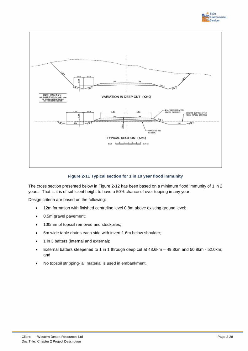
The cross section presented below in Figure 2-11 has been based on a minimum flood immunity of 1 in 10 years. That is it is of sufficient height to have a 10% chance of over topping in any year.
Design criteria are based on the following:
• 12m formation with finished centreline level 0.9m above existing ground level;
• 0.5m gravel pavement;
• 6m wide table drains each side with invert 1.6m below shoulder;
• 100mm of topsoil removed and stockpiles;
• 1 in 3 batters (internal and external);
• External batters steepened to 1 in 1 through deep cut at 48.6km – 49.8km and 50.8km - 52.0km; and
• No topsoil stripping- all material is used in embankment.
Client: Western Desert Resources Ltd Page 2-28 Doc Title: Chapter 2 Project Description
Figure 2-11 Typical section for 1 in 10 year flood immunity
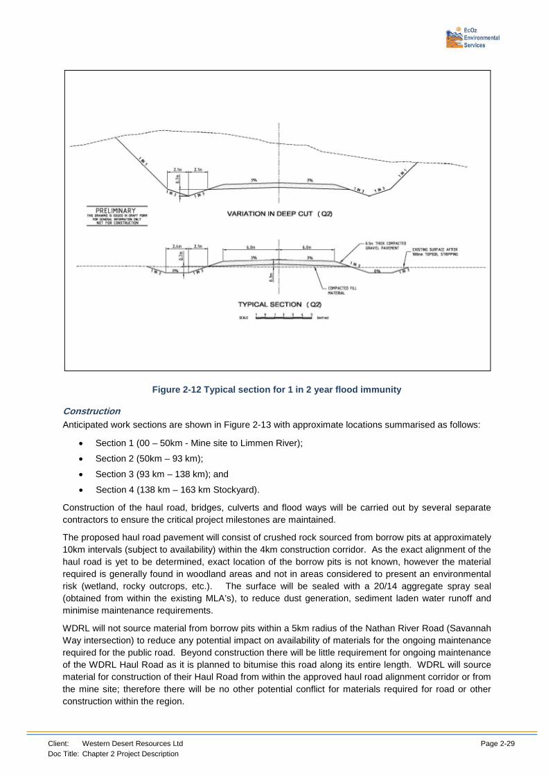
The cross section presented below in Figure 2-12 has been based on a minimum flood immunity of 1 in 2 years. That is it is of sufficient height to have a 50% chance of over topping in any year.
Design criteria are based on the following:
• 12m formation with finished centreline level 0.8m above existing ground level;
• 0.5m gravel pavement;
• 100mm of topsoil removed and stockpiles;
• 6m wide table drains each side with invert 1.6m below shoulder;
• 1 in 3 batters (internal and external);
• External batters steepened to 1 in 1 through deep cut at 48.6km – 49.8km and 50.8km - 52.0km; and
• No topsoil stripping- all material is used in embankment.
Client: Western Desert Resources Ltd Page 2-29 Doc Title: Chapter 2 Project Description
Figure 2-12 Typical section for 1 in 2 year flood immunity
Construction Anticipated work sections are shown in Figure 2-13 with approximate locations summarised as follows:
• Section 1 (00 – 50km - Mine site to Limmen River);
• Section 2 (50km – 93 km);
• Section 3 (93 km – 138 km); and
• Section 4 (138 km – 163 km Stockyard).
Construction of the haul road, bridges, culverts and flood ways will be carried out by several separate contractors to ensure the critical project milestones are maintained.
The proposed haul road pavement will consist of crushed rock sourced from borrow pits at approximately 10km intervals (subject to availability) within the 4km construction corridor. As the exact alignment of the haul road is yet to be determined, exact location of the borrow pits is not known, however the material required is generally found in woodland areas and not in areas considered to present an environmental risk (wetland, rocky outcrops, etc.). The surface will be sealed with a 20/14 aggregate spray seal (obtained from within the existing MLA’s), to reduce dust generation, sediment laden water runoff and minimise maintenance requirements.
WDRL will not source material from borrow pits within a 5km radius of the Nathan River Road (Savannah Way intersection) to reduce any potential impact on availability of materials for the ongoing maintenance required for the public road. Beyond construction there will be little requirement for ongoing maintenance of the WDRL Haul Road as it is planned to bitumise this road along its entire length. WDRL will source material for construction of their Haul Road from within the approved haul road alignment corridor or from the mine site; therefore there will be no other potential conflict for materials required for road or other construction within the region.

Client: Western Desert Resources Ltd Page 2-30 Doc Title: Chapter 2 Project Description
Construction of the haul road will involve the following activities:
• Vegetation clearing - this will involve pushing vegetation to the side of the alignment where it will be retained for rehabilitation purposes as required. All clearing activities will be completed in accordance with the appropriate guidelines and associated legislation. All workers will be appropriately trained in the identification of heritage and sensitive sites and also matters of environmental significance;
• Topsoil stripping and stockpiling - topsoil will be removed and stored for future rehabilitation purposes as required;
• Compacting and watering the cleared road area;
• Placing and compacting subgrade material sourced from cut to fill operation of existing material and new table drains along both sides of the proposed haul road; and
• Placing and compacting road pavement (base course) material sourced from borrow pits.
Major equipment required for construction of the haul road is likely to include excavators, graders, rollers, tip trucks, front end loaders, dozers and water carts. Bridge and culvert construction will also require cranes and piling rigs.
Construction works will be conducted 12 hours per day, seven days per week and require a total workforce of approximately 120 workers. Where possible, construction workers and contractors will be sourced locally, generally from the Northern Territory, however additional recruitment from the rest of Australia may be necessary.
The Haul Road will not be fenced except in isolated areas where it is deemed necessary for safety or other reasons, for example at the Savannah Way intersection and local path crossovers.
Erosion and Sediment Control The following erosion and sediment control devices and stormwater management controls will be implemented on the site:
• Tree Clearing – Clearing of vegetation will be undertaken where necessary and is to be restricted to identified areas only;
• Diversion Channels– Used to divert clean water from upstream catchments around the site, and convey flow within disturbed areas to sediment basins;
• Catch Drains – Used on the downstream side of the construction to capture contaminated runoff;
• Silt Fences – Used to intercept runoff from disturbed areas and aims to temporarily pond up-slope water allowing settlement.
• Check Dams – Used to reduce velocities within open drains. This will protect the open drain itself from erosion
• Level Spreaders – Used to reduce velocities and return channelised flow to sheet flow;
• Sediment Basins – Used to trap and retain sediment via settlement of suspended particles;
• Floating Booms – Used to sediment export from constructions within waterways.
These controls have been developed in accordance with IECA Best Practice Erosion and Sediment Control guidelines and the location of these devices is presented in Appendix A of the ESCP – Haul Road.
The following erosion and sediment controls have been developed and adopted for the proposed development. Details of these devices are contained within the drawings in Appendix A of the Haul Road Erosion and Sediment Control Plan.

Client: Western Desert Resources Ltd Page 2-31 Doc Title: Chapter 2 Project Description
Diversion Channels
Diversion channels are to be constructed on the upstream side of the haul road to direct clean runoff around the construction works area. This will minimise the volume of water which will require treatment. The capacity of the diversion channels has been calculated using Manning’s equation for a minimum bed slope of 1 in 1,000 and a roughness of 0.035. The catchment runoff draining into the diversion channels has been based on a typical two (2) hour duration storm with a 1 in 10 year rainfall intensity of 47 mm/hr and a runoff coefficient of 0.30 (in accordance with the WDRL hydrology report). The maximum catchment area draining into each diversion channel along the length of the haul road is 256 ha. This equates to a 1 in 10 year peak flow of 10.0 m3/s. The proposed diversion channels will therefore have a maximum flow depth of 1.41 m, resulting in a 2 m wide inundation of the road shoulder.
Catch Drains
Catch Drains will be utilised on the downstream side of the road construction to capture contaminated water running off the construction area. These drains will direct runoff into the sediment basins where it will be treated prior to release. Check dams will be installed within the catch drains to create sediment basins. Catch drains have been sized to capture the 1 in 10 year storm event.
Check Dams
Check Dams will be utilised within the proposed diversion channels on the upstream side of the proposed works and within the proposed catch drains on the downstream site of the haul road.
These devices will be used to reduce the velocities within the Diversion channels and prevent scouring. On the downstream side of the haul road within the Catch Drains the proposed Check Dams will create opportunities for runoff to pond, promoting settlement of sediments. In effect the Check Dams will be used to created small sediment basins.
Check Dams are to be composed of 200 mm rock spalls with a height of 400 mm. Longitudinal spacing of the check dams within the drains will be as per Table 2.6 below.
Table 2-6 Check Dam Spacing
Longitudinal Slope Check Dam Spacing Length of Road
0 - 1% Not Required 116.0km
1 - 2% 200m 31.5km
2 - 3% 100m 10.0km
>3% 50m 8.5km
Sediment Fences
Given the maintenance involved with Sediment Fences and the isolated nature of the site the use of Sediment Fences has been minimised. These control measures will be used at the base of exposed batters where obvious risk of sediment export is evident.
Level Spreaders
Level spreaders are constructed along the contour line and consist of a level entry that allows concentrated flow to spread over a nominated flow width before discharging as sheet flow down a stable slope.
Sediment Basins
Sediment basins are generally required where:
• Areas with exposed highly erodible soils;

Client: Western Desert Resources Ltd Page 2-32 Doc Title: Chapter 2 Project Description
• Areas with exposed slopes greater than 2%; and
• Areas with exposed soils after 30 September or before May 1.
As construction may continue outside these dates, sediment basins will be required.
Sediment basins are to be installed on the downstream side of the road at maximum 500 m spacings. The catchment for each basin will therefore be the width of half of the road plus the width of the catch drain multiplied by 500 m (7,500 m2 total for each basin). Sediment basins have been sized to capture the Q10 runoff volume of the contributing catchments and allow for 3 months of sediment storage based on the Universal Soil Loss Equation.
Table 2-7 and Table 2-8 provide a summary of the annual sediment loss prediction and the sediment basin sizing configuration respectively.
Table 2-7 Annual Sediment Loss Prediction
Basin ID
Ac (ha)
Slope Grade
Intensity 6I2 (mm/hr)
R K LS C P A (t/ha/yr)
Yield (m3/yr
Typical 0.75 1 16.1 13739 0.05 0.24 1 1.3 201.5 116
Table 2-8 Sediment Basin Configuration
Catchment
Area (ha)
Settling Zone Volume (m3)
Storage Zone Volume (m3)
Surface Area (m2)
Length (m)
Width (m)
Total Depth
(m)
Total Volume
(m3)
500m lenth
0.75 168 51 450 45 10 0.75 219
The configuration of the sediment basin will have a minimum length to width ratio of 4:1. The minimum depth of the “settling zone” is 0.6 m. The side batters of the basins will be at a slope of 1:6.
Artificial flocculation will be applied on retained runoff to assist in the settling process. This will be completed via the application of Gypsum within 24 hours of the conclusion of each storm event and before any pumping out of the basin. Application of the Gypsum will occur by broadcasting it over the surface by hand, ensuring an even spread over the basin surface at a rate of 32 kg per 100 m³ of water.
Floating Booms
Floating Booms are used to contain sediment and construction debris when work is being carried out within a natural watercourse. The booms are to be placed within the watercourse on the downstream side of the construction works prior to commencement of any construction.
Restricted Areas
All areas identified as being non-clearable areas should be flagged and/or marked on the ground so as to restrict movement of vehicles or persons to this area. All areas to be cleared should be provided to clearing contractors, downloaded onto GPS units prior to the commencement of any clearing activities.
2.6.5 River Crossing Designs
The haul road alignment has been optimised to ensure that the river crossings are kept to a minimum and crossings are located at the most favourable locations. Hydrological investigations indicate that the planned alignment will include 10 major river crossings requiring bridges, 11 minor waterway crossings
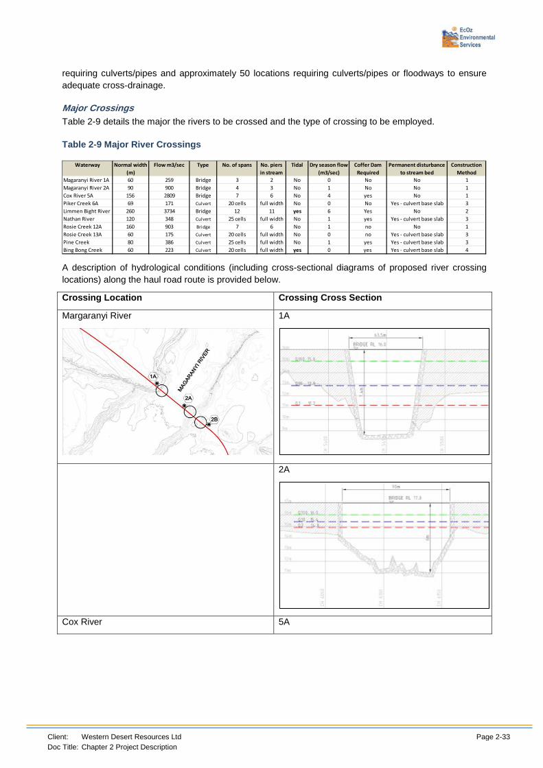
Client: Western Desert Resources Ltd Page 2-33 Doc Title: Chapter 2 Project Description
requiring culverts/pipes and approximately 50 locations requiring culverts/pipes or floodways to ensure adequate cross-drainage.
Major Crossings Table 2-9 details the major the rivers to be crossed and the type of crossing to be employed.
Table 2-9 Major River Crossings
A description of hydrological conditions (including cross-sectional diagrams of proposed river crossing locations) along the haul road route is provided below.
Crossing Location Crossing Cross Section
Margaranyi River
1A
2A
Cox River 5A
Waterway Normal width (m)
Flow m3/sec Type No. of spans No. piers in stream
Tidal Dry season flow (m3/sec)
Coffer Dam Required
Permanent disturbance to stream bed
Construction Method
Magaranyi River 1A 60 259 Bridge 3 2 No 0 No No 1Magaranyi River 2A 90 900 Bridge 4 3 No 1 No No 1Cox River 5A 156 2809 Bridge 7 6 No 4 yes No 1Piker Creek 6A 69 171 Culvert 20 cells full width No 0 No Yes - culvert base slab 3Limmen Bight River 260 3734 Bridge 12 11 yes 6 Yes No 2Nathan River 120 348 Culvert 25 cells full width No 1 yes Yes - culvert base slab 3Rosie Creek 12A 160 903 Bridge 7 6 No 1 no No 1Rosie Creek 13A 60 175 Culvert 20 cells full width No 0 no Yes - culvert base slab 3Pine Creek 80 386 Culvert 25 cells full width No 1 yes Yes - culvert base slab 3Bing Bong Creek 60 223 Culvert 20 cells full width yes 0 yes Yes - culvert base slab 4

Client: Western Desert Resources Ltd Page 2-34 Doc Title: Chapter 2 Project Description
Crossing Location Crossing Cross Section
Piker Creek
6A
Limmen Bight River
7A
Nathan River
7A

Client: Western Desert Resources Ltd Page 2-35 Doc Title: Chapter 2 Project Description
Crossing Location Crossing Cross Section
The core range of construction methods to be utilised are described below. The design of river crossings will take into account the potential to impede hydrological flows and hence fish passage. Section 2.6.6 outlines some of the general practices which will be put in place to ensure minimal disturbance to the stream bed and instating flow rates as near as possible to the natural prior to construction.
Bridge Construction Method 1: The bridge construction at the sites nominated will involve the construction 2, 3 or 6 isolated piers and foundations within the channel. These are spaced at 25m

Client: Western Desert Resources Ltd Page 2-36 Doc Title: Chapter 2 Project Description
centres and hence can be constructed within a finite area whilst maintaining normal river flow in dry season. Construction traffic will need to traverse the stream bed for works on each side resulting in local disturbance. No coffer dam or diversion will be required. Any low flow can be maintained by culverts under the construction access road. The stream bed will not be adversely impacted after construction with normal hydrologic processes continuing un-impacted.
Bridge Construction Method 2: The bridge construction at Limmen Bight River will involve the construction of 11 isolated piers and foundations within the channel. These are spaced at 25m centres and will be located in standing water affected by tidal prism. Construction traffic access will be by pushing out soil from each side of the river, leaving a central river conveyance section of at least 10m. This will result in substantial temporary disturbance but will allow fish passage. The stream bed will not be adversely impacted after construction with normal hydrologic processes continuing un impacted.
Bridge Construction Method 3: The box culvert construction at the sites nominated will involve the construction of a stream base concrete slab across the channel. Work will progress from both sides of the stream leaving a section for conveyance in the centre. Construction traffic will need to traverse the stream bed for works on each side resulting in local disturbance. Any low flow can be maintained by pumping or by pipe diversion around the works. The stream bed will be adversely impacted after construction due to concreting of the base. Normal flow should be returned after construction
Bridge Construction Method 4: The box culvert construction at Bing Bong Creek will involve the construction of a stream base concrete slab across the channel. The stream is affected by tidal inflows dailly with a minimum depth of 1.5m of standing water. Culvert construction will need to progress in the dry to a coffer dam will be required. Work will progress from both sides of the stream leaving a section for conveyance in the centre. Construction traffic will need to traverse the stream bed for works on each side resulting in local disturbance. Any low flow can be maintained by pumping or by pipe diversion around the works. The stream bed will be adversely impacted after construction due to concreting of the base. Normal flow should be returned after construction
Locations of major river crossings are shown in Figure 2-14.
Minor Crossings Minor waterways have been classified for the purpose of this assessment as follows:
• Catchment area less than 80 km2;
• Require structures such as box culverts and stormwater pipes which can be constructed as part of a standard road contract; and
• Structures where overtopping by flood waters will not cause catastrophic road failures
Minor crossings are detailed in Table 2-10.
Table 2-10 Minor Crossings
CHAINAGE (m) CROSSING TYPE
CATCHMENT AREA (ha)
Catchment Culvert type
800 tabledrain 26.2 1000 culvert crossing 32.2 A 2000 tabledrain 11.4 2300 culvert crossing 45.4 A 2500 tabledrain 15.3 4000 tabledrain 35.3 4100 culvert crossing 58.6 A 5300 tabledrain 23.0 5400 major 1a Magaranyi
6100 major 2a Magaranyi 6400 minor 2b

Client: Western Desert Resources Ltd Page 2-37 Doc Title: Chapter 2 Project Description
CHAINAGE (m) CROSSING TYPE
CATCHMENT AREA (ha)
Catchment Culvert type
7200 culvert crossing 35.7 A 7500 tabledrain 23.5 8100 minor 3a 1633.9 9300 culvert crossing 56.1 A 9500 tabledrain 37.8
13500 tabledrain 95.6 13600 minor 4a 283.4 14400 minor 4b 730.1 15000 tabledrain 175.2 17500 tabledrain 9.0 18300 culvert crossing 104.8 A 18900 culvert crossing 42.4 A 19000 tabledrain 6.3 20500 tabledrain 42.5 22000 tabledrain 164.4 22300 culvert crossing 1047.0 D 22500 tabledrain 56.3 24000 culvert crossing 54.6 A 27000 tabledrain 90.9 27300 culvert crossing 121.0 A 27500 tabledrain 11.9 28300 culvert crossing 9.1 A 29100 major 5a Cox River 31000 tabledrain 5.4 32600 minor 5b 33200 culvert crossing 134.0 B 33500 tabledrain 101.9 34900 culvert crossing 70.0 A 35000 tabledrain 53.2 38500 tabledrain 237.6 38700 culvert crossing 397.7 C 39000 tabledrain 7.2 45000 tabledrain 30.8 41900 culvert crossing 414.6 C 42000 tabledrain 95.0 44000 tabledrain 3.6 44200 culvert crossing 26.4 A 46000 tabledrain 15.2 46100 major 6a Piker Creek 47000 tabledrain 10.3 48000 tabledrain 3.9 48800 major 7a Limmen
49800 culvert crossing 67.0 A 50100 culvert crossing 133.3 B 50900 culvert crossing 115.5 B 51000 tabledrain 39.4 52000 culvert crossing 39.7 A 53300 tabledrain 102.3 53500 culvert crossing 274.3 B 54500 tabledrain 10.4 54800 minor 18a 1183.4 56500 tabledrain 36.9 59000 tabledrain 37.5 59300 minor 8a 1776.9 59500 tabledrain 61.7 61500 tabledrain 29.4 61700 culvert crossing 388.1 C 64500 tabledrain 46.8
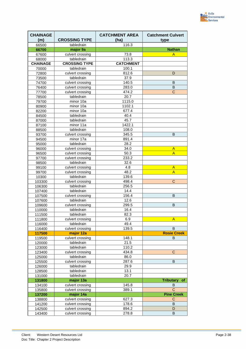
Client: Western Desert Resources Ltd Page 2-38 Doc Title: Chapter 2 Project Description
CHAINAGE (m) CROSSING TYPE
CATCHMENT AREA (ha)
Catchment Culvert type
66500 tabledrain 116.3 66700 major 9a Nathan
67600 culvert crossing 73.8 A 68000 tabledrain 113.3
CHAINAGE
CROSSING TYPE CATCHMENT
70000 tabledrain 100.1 72800 culvert crossing 812.6 D 73500 tabledrain 37.9 74700 culvert crossing 140.5 B 76400 culvert crossing 283.0 B 77700 culvert crossing 474.2 C 78500 tabledrain 20.7 79700 minor 10a 1115.0 80900 minor 10a 1102.1 82200 minor 10a 677.4 84500 tabledrain 40.4 87000 tabledrain 45.7 87100 minor 11a 1422.1 88500 tabledrain 108.0 93700 culvert crossing 345.5 B 94500 minor 17a 891.4 95000 tabledrain 28.2 96000 culvert crossing 34.0 A 96500 culvert crossing 50.3 A 97700 culvert crossing 233.2 98500 tabledrain 32.6 99100 culvert crossing 4.8 A 99700 culvert crossing 48.2 A 10300 tabledrain 139.6
103300 culvert crossing 498.4 C 106300 tabledrain 256.5 107400 tabledrain 14.4 107500 culvert crossing 156.4 B 107600 tabledrain 12.6 109600 culvert crossing 299.5 B 110000 tabledrain 16.4 111500 tabledrain 82.3 111800 culvert crossing 6.9 A 116000 tabledrain 49.4 116400 culvert crossing 139.5 B 117500 major 12a Rosie Creek 119500 culvert crossing 148.1 B 120000 tabledrain 21.5 123000 tabledrain 110.2 123400 culvert crossing 434.8 C 125000 tabledrain 86.0 125500 culvert crossing 287.6 B 126000 tabledrain 29.9 128500 tabledrain 13.1 131000 tabledrain 20.7 131800 major 13a Tributary of
134100 culvert crossing 145.8 B 135800 culvert crossing 389.1 C 137200 major 14a Pine Creek 138800 culvert crossing 627.3 C 141200 culvert crossing 178.6 B 142500 culvert crossing 894.2 D 143400 culvert crossing 278.8 B

Client: Western Desert Resources Ltd Page 2-39 Doc Title: Chapter 2 Project Description
CHAINAGE (m) CROSSING TYPE
CATCHMENT AREA (ha)
Catchment Culvert type
144000 tabledrain 161.2 146500 tabledrain 125.1 147400 culvert crossing 435.0 C 149000 tabledrain 30.1 149500 minor 15a 151800 culvert crossing 742.6 D 153500 tabledrain 12.5 154000 culvert crossing 165.8 B 155000 major 16a Bing Bong
158000 tabledrain 114.9 158300 culvert crossing 160.6 B 158500 tabledrain 8.3 162000 tabledrain 84.1 163100 culvert crossing 512.1 C
Since there are numerous local drainage catchments for preliminary assessment types of catchments have grouped into Type A, B, C and D depending upon catchment area reporting to the drainage crossing. The results of this are shown in Table 2-11 below. To produce this table catchments have been grouped into four (4) different size ranges based on catchment area, and a culvert configuration suitable to convey the 10 year ARI flow for each catchment type has been determined. These culvert sizes may be fine-tuned in the detailed design stage.
Table 2-11 Culvert Configurations
2.6.6 Fish Passage
Impact on Water quality at culvert crossings will be minimised by ensuring exit velocities at all culvert structures are low enough to ensure erosion does not occur at the culvert site, or where exit velocities are high culvert outlets will be incorporated with energy dissipation structures (e.g. Reno mattress) to ensure erosion does not occur. Designed principles to promote fish passage will be installed, such as application of scree to culvert bases and ensuring minimum culvert sizes are acceptable for fish passage to occur. Nominal design for culverts that allow fish passage is provided below:
Planning for the Haul Road has focused on minimising the total number of crossings as far as practicable. Designs of river crossings have taken the following factors into account (taken from Witheridge 2002):
1. Locating crossings away from sharp bends, sections of unstable channel, or major riffle systems;
2. Avoidance of meandering waterways where erosion or change in alignment may occur in the future;
3. Ensure that works do not change the frequency or spacing of an existing pool – riffle system;

Client: Western Desert Resources Ltd Page 2-40 Doc Title: Chapter 2 Project Description
4. Avoidance of significant habitat and/or features in the riparian zone; and
5. Avoidance of essential shade trees particularly in areas where vegetation cover is limited.
In all cases the precautionary principle will be applied by assuming that fish and aquatic habitat exists and the appropriate river crossing will be used to ensure that fish passage will not be impeded. Major crossings that flow for the majority of the year, and/or are likely to support threatened species (e.g. sawfish) will be crossed using bridge construction. Minor crossings in areas of more intermittent flow, but which are likely to support breeding or feeding areas for some aquatic fauna will use culvert crossings, and other crossings which are less likely to support fish habitat through little or no flow except during heavy rain events, will have causeway crossings.
Design Principles Bridges (from Witheridge 2002):
• The main waterway should be free from bridge piers or foundations.
• Design and orientate bridge piers, including those located within overbank areas, to avoid the formation of large-scale turbulence or the erosion of the bed and banks of the waterway.
• When sizing the waterway area of the bridge, give appropriate consideration to fish passage requirements along the floodplains, including locating bridge abutments well away from the channel banks and the possible installation of floodplain culverts adjacent to the main crossing.
• Maximise light penetration under the bridge or arch to encourage fish passage, possibly by increasing the spacing between divided bridge decks or with the use of skylights or grates in the median strip.
• Minimise the use and extent of those bed and bank erosion control measures that may reduce aquatic habitat values or inhibit the regrowth of natural in-stream and bank vegetation.
Culverts (from Witheridge 2002)
• Select the appropriate culvert type to allow fish passage (box or pipe, concrete or corrugated metal, single cell or multi-cell);
• The culvert should be aligned with the downstream channel, where practicable, to minimise bank erosion;
• Minimise changes to the channel's natural flow, width, roughness and base-flow water depth through the culvert's wet cells. Wet cells should have a minimum water depth of 0.2-0.3 metres to encourage fish passage;
• The effective flow area under the waterway crossing should be at least equal to the natural or existing flow area of the channel below the deck/crest level of the crossing. The culvert should be designed to maximise the geometric similarities of the natural channel profile from the bed of the culvert up to a flow depth of 0.5 metres;
• For smooth bed culverts flow velocities for water depth up to 0.5 metres should be no more than 0.3m/s;
• Natural bed material should be placed along the bed of the wet cells, or allowed to deposit in the cells. The hydraulic design of these culverts should allow for added bed roughness which will facilitate upstream fish movement;
• Artificial roughness, such as rounded stone, may need to be grouted across the bed of the wet cells to provide the desirable bed roughness and fish resting areas, if this is unlikely to occur naturally;
• Where feasible, pools at both the inlet and outlet of the culvert should be constructed to assist in the dissipation of flow energy and to act as resting areas for migrating fish;

Client: Western Desert Resources Ltd Page 2-41 Doc Title: Chapter 2 Project Description
• Debris deflector walls should be used to reduce the incidence of debris blocking the passage of fish; and
• To avoid the formation of a perched culvert and damage to the stream's bed and banks, erosion at the outlet should be controlled with the use of rock protection and/or the formation of a stabilised energy dissipation pool.
Causeways
The use of causeways will be minimised where fish passage is required. The following general principles will be observed:
• Where practical, construct the deck to follow the stream's natural cross section to achieve variable flow depths over the causeway.
• Install low-flow pipes/boxes to carry the normal dryweather flow satisfying those conditions specified above for a "low-flow” culvert design.
2.6.7 Savannah Way Intersection
Construction activities associated with the intersection at Savannah Way will be finalised once the detail, design and documentation has been completed. It is anticipated that the intersection will be at grade with the appropriate traffic management plans and controls put in place in accordance with the relevant Australian Standards and Guidelines. Construction and design of the haul road will be performed in coordination with recommendations from the NT roads authority. The intersection will be upgraded to accommodate the additional traffic loads and volumes from the haul road. Mine related traffic will be required to stop and give way to all traffic travelling along the Savannah Way.
Traffic control measures to be incorporated into the Savannah Way intersection include, but are not limited to;
• Appropriate length of visibility, as recommended;
• Appropriate road alignment approach angle, as recommended;
• Appropriate access and haul road signage, as recommended; and
• Speed limitations and speed control devices, as recommended.
Refer to Appendix T Haul Road Traffic Management Plan for more specific information regarding the treatment and design of the Savannah Way intersection.
2.6.8 Vegetation Clearing Methods
All clearing activities for the construction of the Haul Road will be completed in accordance with the Mining Management Plan (MMP), DoR Guidelines and associated legislation. Full research into the possibility of existing sensitive or heritage sites will ensue prior to commencement of any activities, and ongoing assessment of potential sites will also be made. Environmental and heritage studies have been performed along the route and Native Title holders have been officially engaged to inspect and approve a route that does not impact on cultural values.
All clearing will be carried out by bulldozers and then front end loaders using a blade-up method where possible, to retain the top soil and vegetation, which is then to be stockpiled for stabilisation and any future rehabilitation.
Larger debris, such as tree stumps, will be removed from site and disposed of in accordance with any relevant legislation and industry best practice.

Client: Western Desert Resources Ltd Page 2-42 Doc Title: Chapter 2 Project Description
Figure 2-13 Proposed Haul Road – Construction and campsite locations

Client: Western Desert Resources Ltd Page 2-43 Doc Title: Chapter 2 Project Description
2.6.9 Construction Phase Monitoring
Prior to construction onsite, it is recommended the contractor shall undertake a series of data collection exercises to define the existing stormwater quality. This will comprise the collection of water samples after the following rainfall events:
• Three storm events of greater than 25 mm; and
• Three smaller rainfall events.
Samples will be analysed for total suspended solids (TSS), pH, dissolved oxygen (DO) and hydrocarbons with the results being used as water quality indicators for construction phase monitoring. Monitoring during the construction phase will be conducted to determine the impact of activities on the subject site only. Sampling by the proponent will be undertaken in accordance with procedures set out in the Environmental Protection Authority’s Water Quality Sampling Manual. A NATA registered laboratory will be used to perform the analysis of collected samples. Monitoring reports will be compiled upon request.
2.6.10 Provision of Utilities – Haul Road
The anticipated temporary access during construction works shall be as shown in Figure 2-13, summarised as follows:
• Section 1 – Main access to be from mine site along proposed alignment. Additional temporary access road from approximately 28km to Savannah Way. Camp will be at Mine site;
• Section 2 – Main access to be along proposed alignment. Additional temporary access road from approx. 63km to Savannah Way. Camp site at approximately 63km adjacent to proposed road alignment;
• Section 3 – Main access to be from Bing Bong Port end along proposed alignment through section 4, and along section 3 alignment. Camp site at approximately 123km adjacent to proposed road alignment; and
• Section 4 – Main access to be from Bing Bong Port end along proposed alignment. Camp site at approximately 150km adjacent to proposed road alignment.
Portable generators will provide power along the haul road. This will provide power for construction camps and construction water bores. There is no operational requirement for power post construction.
Telecommunications along the Haul Road will be initially via a 2-way radio system back to the Mine Control Centre. Satellite phones will also be accessible for emergencies and outside communications.
WDRL will place bores at approximately 10km intervals along the haul road to supply the necessary water for dust suppression and camps during the construction phase. Bores will remain available for use throughout the life of the project.

Client: Western Desert Resources Ltd Page 2-44
Doc Title: Chapter 2 Project Description
Figure 2-14 Proposed Haul Road and Major River Crossings

Client: Western Desert Resources Ltd Page 2-45 Doc Title: Chapter 2 Project Description
2.6.11 Construction campsites
It is expected that approximately 120 workers will be required on site at various stages during the construction phase of the haul road. Each construction camp within the nominated construction section will consist of approximately 30 workers.
The construction workforce will be accommodated in purpose-built construction camps to be located as shown in Figure 2-13. The buildings and infrastructure at the construction camps will be constructed using conventional demountable components (Figure 2-15). All necessary infrastructure will be installed including water, sewerage, drainage and electricity. The construction workers will require facilities as follows:
• Sleeping accommodation units;
• Mess with associated kitchen;
• Ablution block (shower/toilet);
• Laundry facilities;
• Medical/first aid;
• Site office; and
• Workshop/Containers. Camps will be located at least 100m away from any creek or waterbody. Camps will be located away from stock pads and at least 500m away from wells, bores, dams and drinking troughs used by stock.
Camps will not be set up in areas of environmental or cultural sensitivity.
Diesel generator units will be independent, portable and contained on spill trays. Dedicated self bunded tanks will supply the generators with diesel fuel as required. Generators will be silenced and contained in sealed containers to minimise noise generation, and will be strategically placed to ensure minimal noise output, especially around camp areas.
Figure 2-15 Typical construction camp layout
Client: Western Desert Resources Ltd Page 2-46 Doc Title: Chapter 2 Project Description
Camp site clearing Clearing of the camp sites will involve removal of ground shrubs, grass and small trees, care will be taken not to break the ground surface wherever possible. Large canopy trees will be retained for shade except in the case of overhanging dead trees and branches which will be removed. Any topsoil or vegetation cleared from the site will be stockpiled for re-use during rehabilitation.
A fire break will be cleared around the camp site and this will be scraped clean for up to two blade widths wide. Periodic maintenance of the fire break will be carried out during the field season. Any open camp fires will be located on ground cleared to bare earth with a firebreak wide enough to prevent spread to the surrounding bush.
An area will be set aside for vehicle maintenance, hazardous material and waste storage and for cleaning vehicles.
A weed survey of the camp site will be performed prior to clearing and appropriate management measures installed (refer to the Weed and Pest Management Plan, Appendix F).
Camp Waste Management A waste pit may be required for larger or longer term camps. This would be located away from the camp site and any nearby watercourses. The pit would be deep enough to hold all of the planned waste and allow for burial to a minimum depth of 1m.
Ablution facilities will depend on the size of the camp and its duration. Septic tanks will be used. After extended use, septic tanks will need to be pumped out and then removed, this will require the services of a waste disposal contractor, who will remove the effluent from site. More information is in the Water section below.
Camp water supply Water for camp use will be obtained from groundwater bores. Studies performed during bore installation will ensure that the aquifer is suitable for the planned activity. Water treatment will be installed if required.
Waste water from kitchens, washing machines and ablutions facilities will be retained for appropriate disposal.
2.6.12 Construction Plant and Machinery Required
Standard Civil Equipment will be required for the Haul Road:
• Bulldozers; • Graders; • Earthmovers; • Water Carts; • Sealing Trucks; • Light Vehicles; • Cranes; • Concrete Agitator Trucks; • Concrete Pumps; • Concrete Batch Plants; • Compaction Rollers; • Prime movers; • Side tippers; • End tippers;

Client: Western Desert Resources Ltd Page 2-47 Doc Title: Chapter 2 Project Description
• Front end Loaders; • Excavators; • Bitumen plant; and • Portable crushing and screening equipment.
2.6.13 Ongoing Haul Road Maintenance
WDRL have investigated and decided on the option of sealing the road in an effort to minimise ongoing road maintenance and intend to pursue this option.
There will be an ongoing requirement for weed management, for more details refer to Appendix F Weed and Pest Management Plan.
2.6.14 Haul Road Decommissioning Plan
Post mining haul Road Requirements The Haul Road will provide access and transport pathways for the 8 -10 year mine life, during which time WDRL would be looking to increase the longevity of the operations by finding additional resources. At the cessation of the project WDRL would then look to the NT Government for advice as to their preferences regarding decommissioning. The standard road rehabilitation techniques outlined below will be applied if the relevant stakeholders do not wish to take ownership of the road.
Rehabilitation of the haul road Should the haul road no longer be required, WDRL will rehabilitate the haul road area according to the following general principles (also refer to Appendix P – Rehabilitation and Closure Plan):
• Removal of all infrastructure including culverts, bridges, signage and any other civil construction, ensuring that the remaining land surface is safe and stable;
• To aid in success of rehabilitation, access to the road will be blocked to ensure no unofficial ongoing use of the road by the general public;
• Establishment of a land surface which is able to support vegetation growth and not prone to erosion or sedimentation issues in perpetuity, particularly near waterways and in areas subject to flood risk;
• Ensure re-instatement of vegetation native to the area and consistent with the surrounding environment, through deep ripping to the contour and natural seeding;
• Identification of areas with potential for weed introduction or spread and appropriate mitigation strategies undertaken, e.g. ongoing monitoring and control programs; and
• Ensure that drainage is not interrupted to minimise downstream impacts on vegetation, this may include leaving some culverts in place beyond the life of the haul road, to ensure that flow is not impeded.

Client: Western Desert Resources Ltd Page 2-48 Doc Title: Chapter 2 Project Description
2.7 Bing Bong Load Out Facility
WDRL will utilise the existing load out facility at Bing Bong for the direct shipping of ore to overseas markets. The WDRL proposal will result in an increase in footprint and activities in the area but as these areas are within the existing facility and off limits to public access, they will not impact on public access and activities currently undertaken in the Bing Bong area. The stockyard facility will be located on Bing Bong Station land with none of the infrastructure crossing public roads. The private haul road from the mine and the conceptual design of all facilities near Bing Bong avoids crossing the Robinson Road.
The access road to the Bing Bong Station homestead would be re-routed under the overland conveyor and would provide access for light vehicles. The existing intersection into the Xstrata Bing Bong Facility would need to be modified to allow access to the new WDRL barge loader with the addition of a new road but the remainder of the intersection would remain unchanged.
The facility design is based upon equipment that is reliable and easy to maintain, arranged in a layout that allows the stockpiling and barge loading capacity to be progressively developed, and allows for future expansion.
Initially the project will establish a Stockyard and Barge Loading facility with sufficient capacity to export 1.5Mtpa of product through the Bing Bong Port that can be expanded to 3.0Mtpa whilst operational. Early operations will utilise a manual stockpiling operation with later plans to move to an automated stockpiling operation.
During the first two years the administration offices, workshop, fuel storage, power station, stockyard area, reclaim hoppers, reclaim conveyors and barge loading system would be installed.
Ore would be delivered to the stockyard and dumped on the ground with the stockpiles created with FEL. Stockpiles would be created to deliver shipments to suit shipment requirements.
Later, a two individual truck receival and stacking systems would be constructed at the stockyard to accept road trains from the mine with ore stacked into shipment sized stockpiles of up to 100,000 tonnes with a fixed radial and luffing stacker at a rate of 900tph.
The reclaim and barge loading system would be constructed early in the project with the stockpiled ore reclaimed by FEL into three fixed location hoppers on to a reclaim conveyor at a rate up to 1500tph. Belt weighers set up after each reclaim hopper would monitor the tonnages on the belt and the control system would adjust the downstream hopper outputs to maximize the conveyor capacity.
Ore would be sampled with a cross stream sample cutter at the transfer station from the reclaim conveyor to the overland conveyor.
Two self-propelled 6300DWT barges would transport the ore from the port to the transhipping point initially for the 1.5 Mtpa operation increasing to three self-propelled barges for the 3 Mtpa operation. Operations up to 1.5Mtpa would see the transhipping anchorage point closer to the port due to the shallower draft of the Supramax vessels. Once operations have ramped up to 3 Mtpa the transhipping point would be lengthened to approximately 21 NM from the Port to accommodate larger Panamax sized vessels and a 32T floating crane would be used to transfer the material from the barges to Panamax-sized Ocean Going Vessels (OGV).
Additional dredging of the channel is not required to support the WDRL proposal as the draft of the barges is planned to be the same as that of the existing barge. Some minor disturbances associated with the construction of the berthing and loading point will be required and is detailed below. More information is available in Chapter 5 Marine Environment.
Current operations at the port are such that there should be adequate local supplies of all required materials, gravels, water, etc.

Client: Western Desert Resources Ltd Page 2-49 Doc Title: Chapter 2 Project Description
2.7.1 WDRL Berth
The proposed WDRL berth would be positioned to allow the uninterrupted operation of the existing Xstrata berth. A swing basin for the facility with a diameter of 1.75 times the length of the proposed barge and current MV Aburri has been allowed for.
In order to define the toe of the dredged basin it is assumed that seabed comprises of marine sediments and that the dredged basin batter slopes along edges not supported or stabilised using stone revetments. At this stage slopes have been assumed to be 1:5 however they may be as flat as 1:10.
To maximise the available berthing area and swing basin within the port confines it is proposed to construct a combi-pile wall along the line of the top of dredge batter on the western side of the basin. The dredge batter in front of the wall would be excavated to provide a berth pocket to accommodate the loaded barge at all states of the tide.
A combi-pile wall has been chosen over a conventional sheet piled wall to avoid excavations associated with installing tie backs and the potential exposure of acid sulphate soils.
The berth deck will incorporate a curved runway for the barge loader to travel on with end stops and the travel limits and a cyclone tie down/maintenance position over the reclaimed land.
Fenders will be placed along the berth face to dissipate any impacts from berthing vessels. This is anticipated to include rubber cone fenders and Ultra High Density Polyethylene chafer panels. Bollards would be provided along the berth to facilitate mooring of the barge.
It is assumed, during loading, the barges would be moved using their own winches and/or propulsion. Mooring points would be provided at either end of the berth to which winch lines can be connected.
All steelwork surface preparation and protection will comply with the current Australian Standards for marine environments.
Dredge Spoil Currently Xstrata dispose of their dredge spoil within a designated area adjacent to the port and existing camp facilities. It is proposed that a new facility be built due to the current facility not operating to the appropriate level, with this new facility being used by both Xstrata and WDRL, however at this stage negotiations are still taking place and it is not known whether the new facility will be owned and operated by Xstrata or WDRL.
Approval for the new facility will be obtained under the Mineral Titles Act 2012 and the design and operation will be approved under the Mining Management Act 2011. The new facility will be subjected to close scrutiny from the Department of Resources due to historical problems with the existing dredge spoil facility and will be designed and built to the highest standard and as per best practice.
The quantity of dredge material in front of the proposed sheet pile wharf structure requiring to be cleared for the WDRL operations is approximately 9000m3. This will be a once off dredging exercise during construction. Total dredging required for the Xstrata operations is approximately 600,000m3 at a frequency of once every four years. This is not proposed to change with the currently proposed upgrading of McArthur River Mine Phase 3 Development Project.

Client: Western Desert Resources Ltd Page 2-50 Doc Title: Chapter 2 Project Description
2.7.2 Port Infrastructure and Services
Bing Bong Stockyard and Reclaim System See Figure 2-16 for general layout of stockyard and loading facility.
Ore Delivery up to 1.5Mtpa
The haul trucks would enter the southern end of the stockyard area and deposit ore on the ground at an allocated area and then proceed north and out of the stockyard area onto the loop road and back to the haul road. The deposited ore would be picked up by front end loaders (FEL) and stockpiled in the designated shipment size stockpile. Dust suppression within the stockyard would be provided by mobile water carts and fixed location water cannons.
Ore Delivery up to 3Mtpa
The trucks would enter the facility from the haul road and drive onto an elevated roadway beside the stockyard. The elevated roadway is to enable the trucks to side tip into a ground mounted truck unloading hopper and feeder system. A truck queuing area would be located prior to the stockyard on the approaching haul road, that would allow queuing of trucks should the unloading systems be in use or unavailable. A traffic light system would signal the next truck to the receival hopper location to provide seamless unloading between trucks. At the completion of dumping the truck would exit the elevated roadway and proceed to the truck inspection area prior to leaving site and/or the truck refuelling station.
Receival and Stacking System (RSS)
The proposed stockyard would have two RSS that are designed to operate independently. Each RSS has a truck unloading hopper with low level feeder, transfer conveyor and radial stacker. Each RSS has a nominal design capacity of 900tph.

Client: Western Desert Resources Ltd Page 2-51 Doc Title: Chapter 2 Project Description
Figure 2-16 Stockyard and Barge Loading Facility Overall Layout

Client: Western Desert Resources Ltd Page 2-52 Doc Title: Chapter 2 Project Description
The truck unloading hoppers would be located on the right hand side of the roadway with each hopper of sufficient length to accept two trailers from a road train without the need to reposition. Each RSS hopper would have a capacity of 120 tonnes and be fitted with a dust hood and dust suppression water sprays.
The low level feeder would discharge material from the hopper at a controlled rate via an enclosed transfer chute onto the transfer conveyor. The transfer conveyor would travel under the elevated roadway and discharge onto the radial stacker located on the opposite side to the unloading hopper. See Figure 2-17.
Figure 2-17 Truck Unloader and Stacker
Each RSS system would have a fixed length radial stacker capable of luffing and slewing. The stackers would be located on the opposite side of the road to the receival hoppers each with the capacity to create a stockpile of up to 100,000 tonnes at a maximum height above the stockyard floor of 17m. The stacker would be fully automated to construct radial chevron or cone ply stockpiles. The stackers are automatic and without an operator’s cabin.
The stackers would be slew ring mounted and provide radial movement via pneumatic tyred, hydraulically driven bogies. The stacker drive wheels would be able to operate on a compacted earth runway.
The stacker would luff via two hydraulic cylinders, one mounted on each side on the boom.
Each cylinder will have the capacity to hold the boom at maximum luff while under full operating capacity to provide redundancy to the system.
Concrete retaining walls are to be installed between the stockpile and the stacker runway to prevent material and vehicle movements on to the runway surface.

Client: Western Desert Resources Ltd Page 2-53 Doc Title: Chapter 2 Project Description
Dust suppression water sprays would be provided at each of the conveyor transfer points and the discharge of the stacker onto the stockpile. The discharge height of material from the stackers to the stockpile would be measured by radar level detectors and a fixed discharge height maintained by the control system.
A radial and luff encoder system would provide feedback on each machine’s operational location. A bobcat sump and pump would be positioned near the unloading hopper and transfer conveyor. The operation of the RSS would be controlled by the main control room with a traffic light system to indicate to the truck driver when the system is ready to accept material.
A cyclone tie-down and maintenance area would be provided at one end of the stacker travel to lock the stacker in position during a cyclone and allow access for maintenance.
The stackers would comply with Australian Standards for Mobile Bulk Materials Handling Machines AS4321.1.
Reclaim Hoppers and Reclaim Conveyor
Reclaim of the ore would be by FEL into three fixed position hoppers along the reclaim conveyor CV-10. The hoppers would be suitable for CAT 988/990 machines or similar. The three hoppers would be suitably spaced along the stockpile area.
Each reclaim hopper would have a variable speed drive controlled by the barge loading SCADA system with feedback from belt weighers located after the reclaim hopper. See Figure 2-18.
During the reclaiming/barge loading sequence only two of the three hoppers would typically be in use, depending on which stockpile the conveyor is being loaded from. Dust suppression water sprays and canopies would be installed to each hopper.
The reclaim conveyor would also contain a self-cleaning magnet and metal detector positioned after the last belt weigher. The magnet would discharge any ferrous metal items into an enclosed chute positioned to the side of the conveyor which would drop into a removable scrap bin or concrete bunker.
The metal detector would identify ferrous and non-ferrous metals that have made it past the magnet. If metal is detected, the reclaim conveyor and feed hoppers would stop. An operator would be required to remove the foreign objects before resetting the metal detector and continuing the loading sequence. An interlocked guard will be installed in the metal retrieval zone to prevent the conveyor re-starting while anyone is on the belt.
A cross stream sampler cutter would be installed to the head end of CV-10 within the transfer chute. Typically 80 samples would be taken at equal intervals over the total shipment capacity at an average of every 1200 t during the barge loading sequence. The samples would travel down a separate chute to a rotary sample collector. The samples would be transported to the mine for analysis.

Client: Western Desert Resources Ltd Page 2-54 Doc Title: Chapter 2 Project Description
Figure 2-18 Stockyard Facility

Client: Western Desert Resources Ltd Page 2-55 Doc Title: Chapter 2 Project Description
Overland Conveyor
The proposed overland conveyor has an operational design capacity of 1500tph with an annualised rate of 3 Mtpa. It has a length of approximately 2500m to the proposed Bing Bong Barge Loading Facility.
The overland conveyor would be a single flight with a length of approximately 2500 m, and would rise up 8m to discharge onto the barge loading conveyor CV-12 (Figure 2-19). The overland conveyor would be covered for the entire ground mounted length of approximately 2200 m and then fully enclosed with a sealed floor for the remaining 300 m elevated section to the CV-12 transfer station.
A causeway would be constructed for the conveyor and maintenance access road from the stockyard to near the barge loading facility. CV-11 would discharge onto the barge loader conveyor CV-12 via a large capacity transfer chute to hold the material during emergency stop situations due to the differential stopping time between the longer overland conveyor and shorter barge loading conveyor.
The overland conveyor at the port end would be elevated allowing light vehicle access to the existing Bing Bong station homestead.
Figure 2-19 Overland conveyor
Barge Loading Conveyor
The proposed barge loader conveyor CV-12 will be a fixed height and slewing loader with a telescopic or cascade chute at the head end and a design capacity of 1500tph. The head chute will be fitted with a cascading or telescopic chute to ensure the material fall height from the chute to the stockpile on the barge is maintained at less than 2m (See Figure 2-20). This will reduce the dust generated during loading and allow for the tidal changes and varying material stockpile heights.
The barge loader’s structure will provide 14m of clearance from the deck of the barge to the underside of the barge loader at the high tide level.
The loader would be fully enclosed with sealed floors to contain dust lift off, spillage and carry back.
The barge loader would be required to slew clockwise from the operating position to the maintenance/tie down position whilst non-operational and barge berthing movements are taking place. Maintenance and cleaning activities on the barge loader will carried out over land.
CV-12 will have the capacity to “pull out” material from a full CV-11 to CV-12 transfer chute.

Client: Western Desert Resources Ltd Page 2-56 Doc Title: Chapter 2 Project Description
Figure 2-20 Barge Loading Facility
Bing Bong Port Control and Administration Building
A small administration and control room building has been proposed to be located on the stockyard plant site and accessed via the main entrance off Robinson road through the security gate.
The administration building would have offices, an operators’ room, a meeting/crib room, men’s and women’s ablutions and a kitchen. The building would be located on the access road into the dump facility with a veranda on the north and south sides. It would be fitted with wall mounted split-system refrigerated air conditioners throughout. The Process Control Room will be incorporated into the administration buildings.
Security
Security at the stockyard facility would be managed through the administration building and shift operators. Security to the Barge Loader will be managed by WDRL at the access road via a gate.
Cyclone Bunker
A cyclone bunker will be provided either at the accommodation or stockyard site for use by all WDRL personnel and the barge crews. The bunker will be design and constructed to all relevant Australian Standards for cyclone prone areas and have a sufficient capacity for WDRL personnel and contractors.
First Aid, Emergency Response and Training
WDRL is strongly committed to ensuring a healthy and safe workplace environment for all of its employees, contractors and visitors. To eliminate or minimise the risk to personnel as far as reasonably practicable, the following control measures will be implemented:
• Evacuation and emergency response procedures;
Client: Western Desert Resources Ltd Page 2-57 Doc Title: Chapter 2 Project Description
• Emergency contact list and communication systems;
• Appropriate first aid equipment and signage;
• Appropriate fire fighting equipment and signage;
• Site emergency assembly locations and emergency escape routes;
• Induction and awareness training in all emergency response procedures; and
• Training in first aid, fire fighting and other relevant emergency response functions and routine checking of first aid and fire fighting facilities.
WDRL will utilise some existing infrastructure for first aid and training rooms, specifically a room at the stockyard will be allocated for the purpose of first aid/medical treatment. There is also the opportunity to share emergency response facilities with Xstrata. WDRL have in place an Emergency Procedures Plan (EPP), and will be upgrading this as the project progresses.
Laboratory and Sampling
A sample station and storage area will be provided at the stockyard with samples returned to the mine for preparation.
Loadout Control Centre Buildings
LCC buildings would be provided at each of the main equipment and infrastructure locations nominally:
• Stockyard Stacking and Reclaim Systems; and
• Overland Conveyor and Barge Loading System.
Plant Workshop and Store
A small fixed and mobile plant workshop will be provided at the stockyard adjacent to the office and control room building. The area will include a wash down area with drainage to a collection sump and a maintenance bay capable of housing a FEL. The building will be constructed from steel structural members with steel cladding to the relevant Australian Standards for cyclone prone areas and would also include a store plus an electrical and mechanical workshop.
Barges Proposed barging and shipping operations, including ship loading and barge loading concepts have been designed by independent authorised consultants.
Barge Details
It is proposed to use self-propelled barges (SPB) with the following basic parameters:
• Overall Length: 79.8m;
• Cargo Area Length: 65m (approx.);
• Breath: 28.0m;
• Summer Draft: 4.0m; and
• Deadweight: 6,300 DWT.
Transhipping Requirements During year 1 and year 2, the independent authorised consultant’s proposed set-up is designed to supply an average 9000tpd (tonnes per day) loading performance using geared OGV Supramax type (55,000 DWT). The proposed set-up for transhipment includes: Geared OGV Supramax type with cranes and 2 units 6300 DWT Self-Propelled Barges (SPB) with electrical propulsion.

Client: Western Desert Resources Ltd Page 2-58 Doc Title: Chapter 2 Project Description
To achieve the 1.5Mtpa with a 55,000 DWT Supramax, 27 ships are to be loaded with an average loading time of 7 days.
From year 3 to year 8, with production ramp-up to 3 Mtpa, the independent authorised consultants have proposed a floating crane to transfer the ore from the barges to a larger Panamax type vessel (90,000 DWT). WDRL’s proposed set-up for transhipment includes: 1 unit of 32T Floating Crane (FC), Class BV / ALM (marine standard), NT/Aus. Standards, 3 units 6300 DWT Self-Propelled Barges (SPB) with electrical propulsion, Class BV/ABS or LR, NT/Aus. Standards. This offers multi-level redundancy (internal and external), which ensures certainty of supply to the OGV. It is flexible and easily scalable, should WDRL’s requirements increase over time.
The crane has an operating capacity of 17,500tpd using a grab specifically designed for handling dusty materials. To achieve the proposed annual export target of 3.0Mtpa, 33 Panamax sized ships are required to be loaded per year, averaging 6 days of loading per vessel.
Equipment on the floating crane is electrically controlled with no hydraulics on board. This reduces the possibility of pollution from oil leakage and split hoses. The floating crane can operate in winds up to Beaufort 4 (max 16 knots) and seas up to Douglas 3 (max 1.25m high waves).
The barges would transport all fuel, food, water and operating supplies to the floating crane when transporting the ore for shipment.
The barges would utilise the existing port access channel that is currently maintained at 3.5 m water depth Low Water Spring Level (LWL) and 65m wide.
The cycle time for the barge to the Panamax transhipping anchorage point, which has been roughly estimated at 21 nautical miles from the port, would be approximately 26 hours for a 6300 DWT barge.
A barge traffic management plan will be developed by WDRL in conjunction with Xstrata and agreed upon by Xstrata to establish operating rules for the safety of all port users.
Cyclone Mooring Cyclone moorings will be provided for the barges and floating crane at West and Centre Island.
The remaining barge crews would be transferred to shore and to a cyclone shelter or evacuated from site in the event of a cyclone.
Fuel A fuel farm comprising self bunded tanks providing a total of approximately 500,000L of diesel fuel will be provided at the stockyard facility. It will be located near the power station and the loop road for road trains delivering ore.
A refuelling station for light vehicles, trucks, road trains and front end loaders will be located near the office and workshop buildings when exiting the loop road.
Refuelling of the barges will be by a service truck that will refuel from the fuel farm.
The self-propelled barges would be refuelled at the barge loading facility. The barge would also carry fuel and refuel the floating crane at the transhipment location.
An emergency response plan will be developed and equipment supplied to deal with any spill that occurs.

Client: Western Desert Resources Ltd Page 2-59 Doc Title: Chapter 2 Project Description
Electrical Power Generation
Containerised diesel generators at the stockyard facility will provide power for both the stockyard and barge loading facility. Fuel for power generation will be provided from the self bunded tanks in the fuel farm.
A step up transformer will be located at the power station with a HV power cable run beside the overland conveyor to the barge loading facility where a step down transformer will be installed along with an MCC, control panel and switch room.
Lighting
Sufficient lighting will be provided all around the stockyard area and truck receival stations and at the port on the barge loading system and barge. Lighting will be provided to conveyors and transfer stations where required and portable lighting plant may be used occasionally.
Lightning Protection
Sufficient lightning protection will be provided on all elevated structures with earthing to ground included.
Plant Services Process and Potable Water
Stockyard water will be sourced from bores that will need to be identified in further planning phases of the project. A reverse osmosis plant may be installed to treat bore water and provide potable water.
Storm water will be collected in settlement ponds and recycled for dust suppression water.
2.7.3 Proposed Shared Infrastructure and Services
The opportunity for WDRL to export iron ore out of the Bing Bong Port facility creates an opportunity for Xstrata and WDRL to share current and future infrastructure and services for the improvement and benefit of both operations.
Accommodation WDRL proposes that the existing Xstrata accommodation village be expanded to accommodate the WDRL personnel. It is estimated that an additional 30 rooms will be required, along with commensurate increases in laundry, dining, communications, power and sewage.
WDRL will fund the expansion of the camp and facilities and pay Xstrata a man-day rate to manage and operate the accommodation village.
First Aid WDRL and Xstrata have the ability to share experienced first aid/medical treatment personnel at Bing Bong and provide 24 hour coverage for its workers. It is expected that minor first aid incidents will be handled by each individual company, with resources shared for major incidents. A shift roster may be developed between WDRL and Xstrata to cover incidents that occur outside normal business hours.
Emergency Response WDRL proposes that a combined emergency response team and equipment be provided for incidents that occur within the barge loading facility. The companies will provide equipment, personnel and training required to ensure 24 hour coverage during operations.
Client: Western Desert Resources Ltd Page 2-60 Doc Title: Chapter 2 Project Description
Dredging and Port Maintenance Maintaining a safe and operational port is a key priority for both companies to enable export of materials through Bing Bong Port. Maintenance dredging costs of the canal and turning basin, maintenance of the navigation markers and port upgrades is likely to be shared between both companies.
Environmental Monitoring WDRL will implement an environmental monitoring program for their operation at Bing Bong, in particular dust monitoring for the stockpile and barge loading facility.
WDRL propose to participate in and contribute towards the existing Xstrata environmental monitoring program within the port and transhipment areas.
Shared Freight Deliveries Opportunities may exist to share freight deliveries to Bing Bong between WDRL and Xstrata.
Shared Specialist Equipment and Personnel Cross hiring or sharing of specialist equipment and personnel such as cranes or inspection/environmental personnel that require mobilisation would reduce costs.
The travel and accommodation costs associated with attracting particular skill sets to the site would be reduced.
Co-ordination of Shipping Movements With the increase in shipping planned within the Bing Bong port a Shipping Officer maybe be required to monitor and co-ordinate the movement of barges within the port and those passing through the access canal. The operational analysis prepared by WDRL below shows a preliminary analysis of entrance channel usage by both Xstrata and WDRL

Client: Western Desert Resources Ltd Page 2-61 Doc Title: Chapter 2 Project Description
Figure 2-21 Entrance Channel Utilisation Operational Analysis

Client: Western Desert Resources Ltd Page 2-62 Doc Title: Chapter 2 Project Description
2.8 Transport
2.8.1 Public Road Network
WDRL’s Roper Bar Iron Ore Project will utilise existing road infrastructure for access to the mine site and camp as well as the Bing Bong Barge Loadout Facility. During the construction phase of the project, goods will be transported utilising public access roads. During operation of the mine however, utilisation of public roads will decrease as personnel will be flown to site, and all ore will be transported via a purpose built private haul road. Some supplies will be required to be transported to site via the public road network.
Stuart Highway The Stuart Highway is a two lane single carriageway highway connecting Darwin in the Northern Territory to Port Augusta in South Australia – via Katherine, Tennant Creek and Alice Springs. It is a Northern Territory Government controlled sealed road of approximately 7m width.
Roper Highway The Roper Highway is a single land highway connecting the Stuart Highway (10km south of Mataranka) to near Urapunga. The road is approximately 3m wide, single lane bitumen for the initial 130km from the Stuart Highway, it then changes to gravel and widens to approximately 7m.
Nathan River Road (Savannah Way) The Nathan River Road (part of the Savannah Way) connects the Roper Highway to the Carpentaria Highway. This road is utilised to access the WDRL mine site. The road is Northern Territory Government controlled and of gravel construction with some key areas sealed to mitigate flooding issues.
Carpentaria Highway The Carpentaria Highway is a 381km highway that connects Daly Waters (on the Stuart Highway) to Borroloola. It is a sealed road generally single lane (with dual lane single carriageway sections) up to the McArthur River Mine where the road becomes dual lane single carriageway to Borroloola.
Old Bing Bong Road Old Bing Bong Road connects the township of Borroloola to the Bing Bong Port Facility. It is a Northern Territory Government controlled sealed road approximately 6m wide, two lane single carriageway. The maximum permitted speed is 110km/h.
Roper Bar Iron Ore Mine Access Route The Roper Bar Iron Ore Project will be accessed via a WDRL managed access road that connects to Nathan River Road/Savannah Way which can be accessed via either the Carpentaria Highway to the South or the Roper Highway to the North. The majority of site related traffic will be travelling from Darwin to site accessing the Stuart Highway, Roper Highway and Nathan River Road/Savannah Way.
Bing Bong Access Route The stockpile and barge loading facility at Bing Bong will be accessed via the Stuart Highway, Carpentaria Highway and Old Bing Bong Road. Traffic will be mainly during the construction phase of the project with additional traffic stemming from ongoing maintenance work. All haul vehicles will access the stockpile and barge loading facility through the purpose built haul road.

Client: Western Desert Resources Ltd Page 2-63 Doc Title: Chapter 2 Project Description
2.8.2 Construction Phase Transport
WDRL predict a Construction period for the development of the Roper Bar Iron Ore Project to be 40 weeks in total. During the construction period, goods and materials will be regularly transported from Darwin to the mine, camp, haul road and port facility. Details of the transportation of materials during the construction phase are provided below.
Table 2-12 Construction Vehicles
Vehicle Type Approx. Tonnage
Number Purpose Area
Light Vehicles < 2.5 tonne 10 per week Staff, contractor, authority Darwin to Mine site and Bing Bong
Drilling Rig 40 tonne 1 (on site 4 weeks then
return)
Construct water bores Darwin to Mine site and Haul Road route to Bing
Bong
Fuel Trucks 100-200 tonne 2 per week Supply fuel for all project requirements
Darwin to Mine site and Bing Bong
Mobilisation Trucks
40 tonne 6 (on site 6 weeks then
return)
Move all portable crushing gear to site
Darwin to Mine Site
Supplies Truck 40 tonne 1 per week Consumables Darwin to Mine Site
Mobilisation Trucks
100-200 tonne 45 Camp and Mine Construction Infrastructure
Darwin to Camp
Haul Trucks 150 tonne 10 Haul truck fleet (on site 8 years)
Darwin to Mine Site
Mobilisation Trucks
>100 tonne 4 Transport 2 x 100 tonne excavators, 2 x 100 tonne
dump trucks
Darwin to Mine
Mobilisation Trucks
<100 tonne 14 Transport 4 x water carts, 3 x graders, 4 x rollers, 3
x loaders
Darwin to Mine
Trucks >100 tonne 4 Side Tipper Trucks Darwin to Mine
Mobilisation Trucks
120 tonne 130 Haul Road and Haul Road Camp Construction
Darwin to mine and Bing Bong
Table 2-13 Average weekly vehicle movements during Construction Period
Vehicle size Avg. No. per week Total Number
< 2.5 tonne 10 400
< 100 tonne 1.75 70
> 100 tonne 6.575 263
Total 18.325 733

Client: Western Desert Resources Ltd Page 2-64 Doc Title: Chapter 2 Project Description
2.8.3 Operations Transport
During the operations phase of the mine, transportation using public roads will mainly comprise fuel and supply trucks and any additional light vehicle movements. Mine staff will access the site via aeroplane in a rostered Fly-In, Fly-Out (FIFO) arrangement. Coaster buses will be utilised to ferry staff between the airstrip and camp.
Table 2-14 Operations transport vehicle numbers
Vehicle Type Approx. Tonnage Number Purpose Area
Light Vehicles < 2.5 tonne 10 per week Staff, contractor, authority
Darwin to Mine site and Bing Bong
Fuel Trucks 100-200 tonne 2 per week Supply fuel for all project
requirements Darwin to Mine site and Bing
Bong
Supply Truck 40 tonne 1 per week Consumables Darwin to Mine Site
Table 2-15 Operations vehicle size breakdown
Vehicle size Avg. No. per week Total Number per Year < 2.5 Tonne 10 530
< 100 tonne 1 53
> 100 tonne 2 106
Total 13 689
Operations Travel Times Traffic will be limited to operating only during daylight hours for activities not concerned with mine operation and loading of haulage vehicles. This will mean that vehicles will only operate outside of daylight hours on WDRL privately managed roads. Only essential travel will occur on public roads.
Haulage Vehicles Ore will be transported via the haul road to the Bing Bong storage area 24 hours per day for an estimated 325 days per year. It is estimated that the haul road will not be usable for 40 days per year due to heavy rainfall and/or flooding. Haul trucks will perform 4 return trips each day from the mine site to the Bing Bong loading facility. During years one and two 10 trucks will perform this operation daily; this will increase to 20 trucks daily for years 3 to 8.

Client: Western Desert Resources Ltd Page 2-65 Doc Title: Chapter 2 Project Description
Table 2-16 Size and frequency of haul trucks
Period Number of trucks
Payload (tonnes)
Return Trips per
day
Frequency (minutes)
Daily Total Tonnage
Total Annual Tonnage
Years 1 and 2 10 120 4 18 4800 1.5M
Years 3 to 8 20 120 4 9 9600 2.1M
2.8.4 Safeguards, Management and Monitoring
Transport Management is discussed within the WDRL Draft Environmental Management Plan (Appendix C). This includes details on how WDRL plan to mitigate risks concerning vehicle movements throughout the life of the project. The management plan includes:
• Methods for complying with any relevant road vehicle axle limits;
• Methods for securing loads;
• Measures to reduce any road traffic noise impacts;
• Consultation with local communities affected by transport impacts;
• Traffic management; and
• Management of driver fatigue.
Transportation of dangerous goods to and from the mine site will be performed by a licensed contractor and will be conducted under the Dangerous Goods (Road and Rail Transport) Act 2001 and the Dangerous Goods (Road and Rail Transport) Regulations 2004. Both the storage and transportation of Dangerous goods will be conducted under the Dangerous Goods Act 2008 and the Dangerous Goods Regulations 2009.

Client: Western Desert Resources Ltd Page 2-66 Doc Title: Chapter 2 Project Description
2.9 Water
This Chapter describes the water requirements, sources and balances for the Roper Bar Project Area, the proposed haul road and Bing Bong loading facility. Existing surface water hydrology and quality is discussed in Chapter 6 and Appendix N1. Existing groundwater resources and quality are discussed in Chapter 6 and Appendix E. A Draft Water Management Plan for the project has also been developed, which is provided as Appendix R.
2.9.1 Water Requirements
Water requirements for various aspects of the construction and operation of the project have been estimated and are detailed below. These have been calculated using average, low (1952) and high (2011) rainfall figures from Ngukurr.
Potable Water Potable water is required for human consumption, kitchens and ablutions such as toilets, showers and bathrooms at the camps (permanent mine camp and temporary haul road construction camps), mine and administrative buildings, airport, and Port of Bing Bong offices. Total potable water requirements have been estimated assuming a consumption of 300L per person per day. These are:
Permanent:
• 18,250 kL/annum at the camp site.
• 3,650 kL/annum at the mine site.
• 3,285 kL/annum at the Bing Bong Stockyard.
Temporary (16 weeks construction period):
• 4,032 kL for construction camps along the Bing Bong haul road.
Potable water will need to have a total dissolved solids (TDS) concentration of less than 500mg/L to negate the need for a water treatment plant. Sterilisation by in-line chlorine dosing will be undertaken prior to transferring water from groundwater bores into a potable water tank.
Mining Operations Water will be required at the mine site for the crushing/screening plant (331,128 kL/annum) and dust suppression of haul roads (113,029 kL/annum) and stockpiles (21,462 kL/annum). The total volume required for mining operations is estimated at 465,619 kL/annum.
Bing Bong Stockyard A total estimated volume of 175,696 kL/annum will be required for dust suppression at the Bing Bong Stockyard.
Fire Fire water will be sourced from stand-alone systems in accordance with Australian Standards. In addition to dedicated equipment, dust suppression trucks will also be available for fire fighting.
Haul Road Construction Construction, compaction and dust suppression of the proposed 165km haul road will require a total volume of water of 33,600 kL.

Client: Western Desert Resources Ltd Page 2-67 Doc Title: Chapter 2 Project Description
2.9.2 Water Sources
Potable Water The existing exploration camp obtains its water from a nearby bore which produces water of a high quality, albeit containing elevated carbonates. It is envisaged that additional potable water requirements for the mine camp will be sourced from the existing camp bore and if required, additional bores will be constructed in this area.
Potable water for the mine site and Bing Bong Stockyard will be obtained from bores to be constructed; one north of the camp/mine site and one at the Bing Bong Stockyard.
Potable water for the four temporary construction camps along the haul road will be obtained from bores to be constructed at the camp sites and treated prior to use, if required. Alternatively, water will be imported by road tanker from the mine site and stored on site in temporary storage tanks. Where construction camp water bores are to be established, consideration will be given to local existing users (i.e. human and environmental), such that they will not be impacted.
Mining Operations Surface waters from the Towns River will not be used for mining. Groundwater influx to the open pits has been estimated at 2,365,200 kL/a and will provide most of the water required at the plant. Evaporative losses from the open pits and plant ultimately results in a water deficit; therefore make-up water will be sourced from storage, groundwater from bores and recycling from processing.
Bores will be established using appropriate drilling, sampling and testing methods to ascertain long term sustainable yields, so that abstraction for mining will not impact on existing users/stakeholders.
Haul Road Construction Water for haul road construction will be obtained from surface waters during periods of stream flow and/or bores along the route of the haul road.
Bing Bong Stockyard Stockyard water will be sourced from a bore at the facility. Since the site is within the seawater intrusion zone, a small reverse osmosis (RO) plant will be installed to treat bore water for potable supplies. Stormwater will be collected in settlement ponds and recycled for dust suppression.
2.9.3 Water Management and Infrastructure
Potable Water The current water treatment plant at the exploration camp consists of a softening filter (to remove carbonates), a 5 micron and 1 micron particle filter, a charcoal filter for taste and a UV light to kill bacteria. Treatment for potable water supplies by RO plants (or similar) will be provided, where and if required.
Mining Operations A raw water dam (RWD) will be constructed at the plant. This dam will receive water from sediment basins and the main storage at F West Pit 4 (Figure 2-22, shown in blue), a small pit that will be mined first to provide storage capacity for rain and groundwater influxes into the open pits (hereafter referred to as ‘Pit Water Store - PWS’). The maximum storage volume of the PWS is 956,300m3 (Table 2-17).

Client: Western Desert Resources Ltd Page 2-68 Doc Title: Chapter 2 Project Description
Figure 2-22 Location of Area F Water Storage Pit 4 (PWS).
Table 2-17. Depth-Capacity of Area F Water Storage Pit 4 (PWS).
Maximum Volume (m3) Depth (m) Maximum Width (m) Maximum Length (m)
956,300 up to 45 87 645
901,700 40 86 645
781,500 35 83 642
597,500 30 77 638
410,200 25 77 612
250,200 20 63 594
158,600 15 46 387
87,800 10 39 334
35,600 5 32 280
Water from PWS will be used for the processing of ore through the gravity separation and crushing circuits. Water will be recovered from the processing circuits and returned to the RWD for recycling.
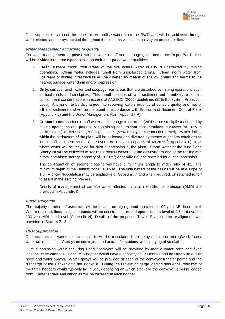
Client: Western Desert Resources Ltd Page 2-69 Doc Title: Chapter 2 Project Description
Dust suppression around the mine site will utilise water from the RWD and will be achieved through water misters and sprays located throughout the plant, as well as on conveyors and stockpiles.
Water Management According to Quality For water management purposes, surface water runoff and seepage generated at the Roper Bar Project will be divided into three types, based on their anticipated water qualities:
1. Clean: surface runoff from areas of the site where water quality is unaffected by mining operations. Clean water includes runoff from undisturbed areas. Clean storm water from upstream of mining infrastructure will be diverted by means of shallow drains and berms to the nearest surface water drain and/or depression.
2. Dirty: surface runoff water and seepage from areas that are disturbed by mining operations such as haul roads and stockpiles. This runoff contains silt and sediment and is unlikely to contain contaminant concentrations in excess of ANZECC (2000) guidelines (95% Ecosystem Protection Level). Any runoff to be discharged into receiving waters must be of suitable quality and free of silt and sediment and will be managed in accordance with Erosion and Sediment Control Plans (Appendix L) and the Water Management Plan (Appendix R).
3. Contaminated: surface runoff water and seepage from areas (WRDs, ore stockpiles) affected by mining operations and potentially containing contaminant concentrations in excess (or likely to be in excess) of ANZECC (2000) guidelines (95% Ecosystem Protection Level). Water falling within the perimeters of the plant will be collected and diverted by means of shallow catch drains into runoff sediment basins (i.e. several with a total capacity of 48,262m3; Appendix L), from where water will be recycled for dust suppression at the plant. Storm water at the Bing Bong Stockyard will be collected in sediment basins (several at the downstream end of the facility with a total combined storage capacity of 1,821m3; Appendix L2) and recycled for dust suppression.
The configuration of sediment basins will have a minimum length to width ratio of 4:1. The minimum depth of the “settling zone” is 0.6 m. The side batters of the basins will be at a slope of 1:6. Artificial flocculation may be applied (e.g. Gypsum), if and when required, on retained runoff to assist in the settling process.
Details of management of surface water affected by acid metalliferous drainage (AMD) are provided in Appendix K.
Flood Mitigation The majority of mine infrastructure will be located on high ground, above the 100-year ARI flood level. Where required, flood mitigation bunds will be constructed around open pits to a level of 0.5m above the 100 year ARI flood level (Appendix N). Details of the proposed Towns River stream re-alignment are provided in Section 2.13.
Dust Suppression Dust suppression water for the mine site will be reticulated from sprays near the mining/work faces, water tankers, misters/sprays on conveyors and at transfer stations, and spraying of stockpiles.
Dust suppression within the Bing Bong Stockyard will be provided by mobile water carts and fixed location water cannons. Each RSS hopper would have a capacity of 120 tonnes and be fitted with a dust hood and water sprays. Water sprays will be provided at each of the conveyor transfer points and the discharge of the stacker onto the stockpile. During the reclaiming/barge loading sequence, only two of the three hoppers would typically be in use, depending on which stockpile the conveyor is being loaded from. Water sprays and canopies will be installed at each hopper.

Client: Western Desert Resources Ltd Page 2-70 Doc Title: Chapter 2 Project Description
2.9.4 Waste Water Management
The project requires construction of sewage treatment plants (STP) to treat the domestic stream generated from the mining camp and mine site. These systems will have the capacity to treat the entire domestic stream of both “black” and “grey” waste waters. The facilities will be Biological Nutrient Reduction (BNR) configurations, capable of treating daily volumes of waste water far in excess of those predicted. Two ‘TransPAC Mega ISO Type 4’ treatment systems will be utilised, each suitable to treat up to 50,000L per day. These systems provide secondary treatment to achieve final effluent quality with reduced nutrients, suitable for reuse via sub soil irrigation or evaporation irrigation.
The STPs will be installed and operated to treat water from the mine site and main camp to a high quality and will be recycled according to the Northern Territory Department of Health Guidelines for Management of Recycled Water Systems (2011). The end product from these STPs will also be validated and monitored to conform to the water quality set out in these guidelines before being recycled. Recycled water from the camp STP will be used for irrigation and dust suppression around the mining camp, whilst recycled water from the mine site STP will be directed into the RWD.
The existing septic system at the exploration camp will be utilised during construction of the new mine camp, and during the period of STP validation and monitoring. Subsequently, the existing septic system will be decommissioned but retained in the event of a failure of the STP.
Septic tanks will also be installed at construction camps along the haul road and will receive all (“grey” and “black”) wastewaters. These septic tanks will be pumped out and removed when construction camps are dismantled.
2.9.5 Discharge
As outlined above, surface water run-off will be managed according to quality. Contaminated water will be retained on site, therefore a Waste Discharge Licence will not be required. The mine has a large storage capacity with a water deficit water balance (see below). Dirty water will be collected and recycled on site for dust suppression.
2.9.6 Water Balance
Water balances have been calculated for the construction and operational phases of the project. These estimations assume:
• 200 personnel accommodated at the mining camp.
• 30 personnel accommodated at Bing Bong.
• 120 people accommodated in haul road construction camps for a period of 16 weeks.
• Consumption of potable water is 300 L/person/day.
• Human consumptive losses are estimated at 40%.
• Water requirements for dust suppression are based on 3L/m2/d.
• Runoff coefficients are based on 80% for the Plant area and 30% for the ore and waste rock stockpiles.
• Model prediction for influx into pits is a steady-state flux with no increase due to annual recharge.
Rainfall and evaporation rates are based on data from the Bureau of Meteorology weather station at Ngukurr. The low and high rainfall scenarios are based on the lowest and highest recorded annual rainfalls at Ngukurr (1952 and 2011, respectively).

Client: Western Desert Resources Ltd Page 2-71 Doc Title: Chapter 2 Project Description
Construction Phase Details of the water balance for the haul road and mine construction are provided in Table 2-18 below.
Table 2-18: Potable and Construction Water Requirements.
Water Sources
Volume (kL)
Early Wet Average Wet Late Wet
Surface Flows 33,600 22,400 11,200
Rainfall 22,400 11,200 0
Potable Bore Water 11,330 11,330 11,330
Total 67,330 44,930 22,530
Water Demands
Potable Water: Main Camp 7,300 7,300 7,300
Potable Water: Haul Road 4,030 4,030 4,030
Haul Road Construction 33,600 33,600 33,600
Equipment Wash Down 100 100 100
Total 45,030 45,030 45,030
Surplus/(Deficit) 22,300 (100) (22,500)
Deficits in the water balance will be sourced from bores along the haul road route.
Mining Operations and Bing Bong Groundwater studies of the mine project area indicate that local aquifers have very low yields and modelling of potential groundwater inflows to the pits indicates that given the size of the pit voids and evaporation rates in the area, much of the water is expected to evaporate from the pit surface (see Chapter 6). Pit dewatering rates are therefore expected to be relatively low (around 15L/s) and initially (i.e. above the ground water level and prior to requirement for dewatering), existing bores will be used to supply the mine site and associated infrastructure with water. The purpose of this water will be primarily for dust suppression during construction activities, at the gravity separation plant and the haul roads. A proposed, schematic mine water management system for the mine site is presented in Figure 2-23 and for Bing Bong in Figure 2-24.
A preliminary water balance for the mining operations and Bing Bong Stockyard is provided in Table 2-19. In summary, it is evident that:
• Pit seepage or influx (i.e. pit dewatering) is the primary source of water.
• Processing is the primary user of water.
• Inputs from rainfall are relatively low and are exceeded by losses to evaporation, which renders a water deficit balance and hence there is a requirement for large storage capacities.
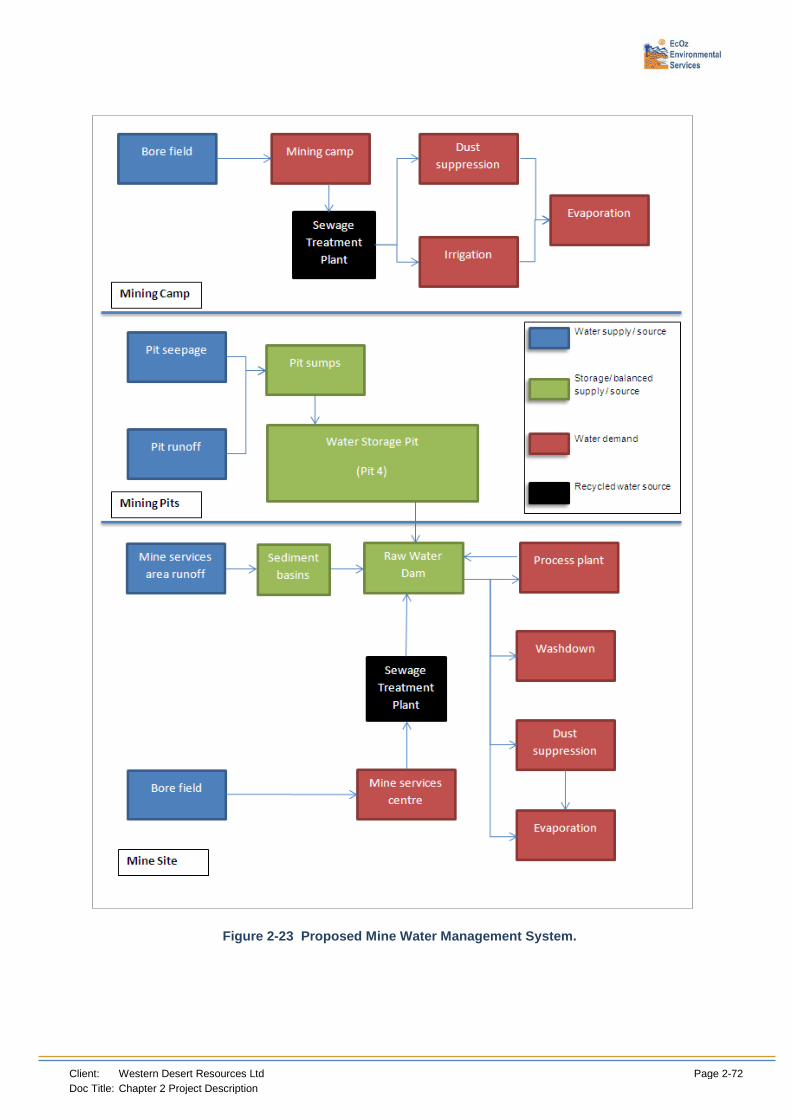
Client: Western Desert Resources Ltd Page 2-72 Doc Title: Chapter 2 Project Description
Figure 2-23 Proposed Mine Water Management System.

Client: Western Desert Resources Ltd Page 2-73 Doc Title: Chapter 2 Project Description
Figure 2-24 Proposed Bing Bong Water Management System.
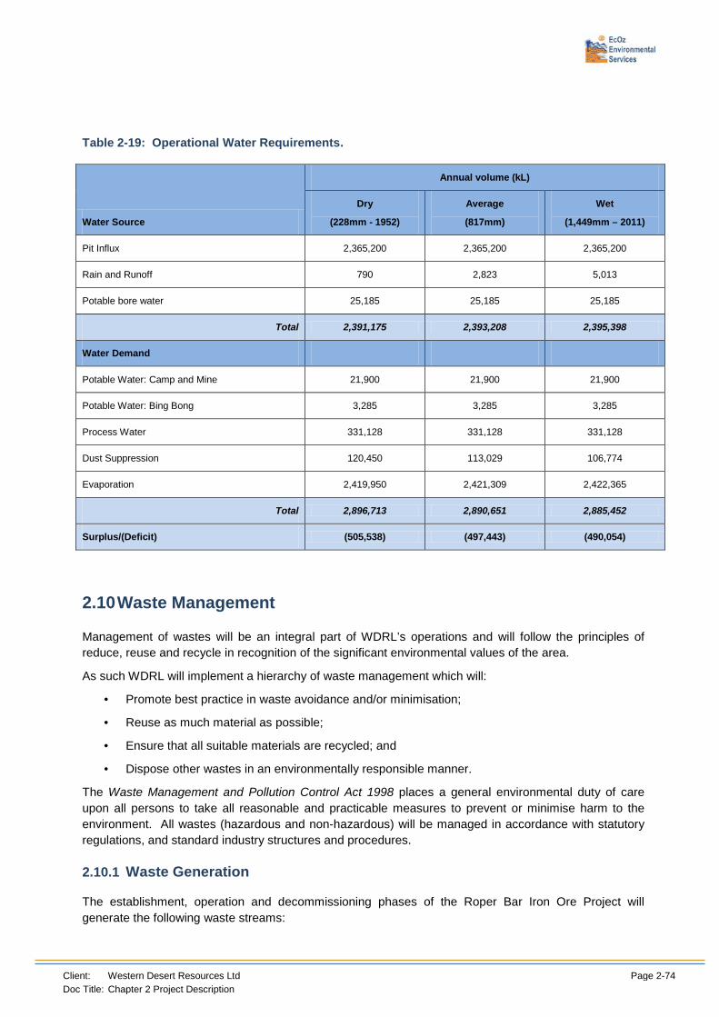
Client: Western Desert Resources Ltd Page 2-74 Doc Title: Chapter 2 Project Description
Table 2-19: Operational Water Requirements.
Water Source
Annual volume (kL)
Dry
(228mm - 1952)
Average
(817mm)
Wet
(1,449mm – 2011)
Pit Influx 2,365,200 2,365,200 2,365,200
Rain and Runoff 790 2,823 5,013
Potable bore water 25,185 25,185 25,185
Total 2,391,175 2,393,208 2,395,398
Water Demand
Potable Water: Camp and Mine 21,900 21,900 21,900
Potable Water: Bing Bong 3,285 3,285 3,285
Process Water 331,128 331,128 331,128
Dust Suppression 120,450 113,029 106,774
Evaporation 2,419,950 2,421,309 2,422,365
Total 2,896,713 2,890,651 2,885,452
Surplus/(Deficit) (505,538) (497,443) (490,054)
2.10 Waste Management
Management of wastes will be an integral part of WDRL’s operations and will follow the principles of reduce, reuse and recycle in recognition of the significant environmental values of the area.
As such WDRL will implement a hierarchy of waste management which will:
• Promote best practice in waste avoidance and/or minimisation;
• Reuse as much material as possible;
• Ensure that all suitable materials are recycled; and
• Dispose other wastes in an environmentally responsible manner.
The Waste Management and Pollution Control Act 1998 places a general environmental duty of care upon all persons to take all reasonable and practicable measures to prevent or minimise harm to the environment. All wastes (hazardous and non-hazardous) will be managed in accordance with statutory regulations, and standard industry structures and procedures.
2.10.1 Waste Generation
The establishment, operation and decommissioning phases of the Roper Bar Iron Ore Project will generate the following waste streams:

Client: Western Desert Resources Ltd Page 2-75 Doc Title: Chapter 2 Project Description
• Construction waste;
• General operations waste (including waste of a domestic nature);
• Mining wastes (waste rock); and
• Decommissioning waste.
Waste streams and products for construction and operation phases, and rehabilitation/decommissioning stages, and indicative quantities are given below.
Mining waste (waste rock) are mentioned but not detailed in this section. They are detailed in section 2.3.
Construction The construction phase of the project will generate a variety of wastes. The type and estimated quantity of waste generated during the establishment (construction) stage of the project is presented in Table 2-20. Plant matter cleared for construction and mining will be stockpiled to assist with future rehabilitation.
Table 2-20 Construction Waste
Waste Type Source(s)
Solid waste
Green waste/cleared vegetation Clearing of vegetation for construction of mine access road, and mine infrastructure area.
General solid wastes including putrescible and inert waste Construction facilities.
Broken concrete and concrete materials Left over concrete from the construction activities.
Scrap metal Barge facilities, mine infrastructure and site construction offices.
Timber pallets and off-cuts Barge facilities and mine infrastructure.
Tyres* Workshops
Empty contaminated containers and drums* Workshops
Hydrocarbon wastes (e.g. grease-trap waste, grease, oil filters and oily rags)* Workshops
Batteries* Workshop
Liquid waste
Sewage* From construction camp septic tanks.
Liquid hazardous wastes (e.g. solvents, lubricants, coolant, paints, resins, etc.)*
Maintenance workshops, vehicle wash down, site infrastructure, barge facilities and chemical, storage areas
* Listed waste
Operation Operation of the mine will result in the generation of a variety of liquid and solid wastes. Some of this waste may be hazardous (to human health and the environment). Key solid wastes generated during operation may include empty containers, recyclable material and used batteries. Key liquid wastes generated during operation will be the same as those generated during construction.
The type and quantity of waste generated during the operation stage of the project is presented in Table 2-21.

Client: Western Desert Resources Ltd Page 2-76 Doc Title: Chapter 2 Project Description
Table 2-21 Operational Waste
Waste Type Source(s)
Solid waste
Green waste/cleared vegetation Clearing of vegetation for mining areas, garden waste.
Waste Rock Material excavated so as to access ore
Waste Fines Mostly silica resulting from the gravity separation circuit
General mine site wastes including putrescibles and organic (food waste/scraps), paper and cardboard, plastic and wood products (e.g. damaged timber pallets, treated timber), clean rubber hose, computer and electrical equipment, gloves
Workshop, offices
Reusable intact wooden pallets Workshop, office
Scrap metal recyclables (e.g. beneficiation screens, scrap steel, clean drums) Mine plant, including administration, workshops
Other solid recyclables including printer toner cartridges, aluminium cans Workshop, office
Clinical wastes (e.g. bandages)* Nursing station
Vehicle tyres* Vehicle workshops
Batteries (recyclable)* Trucks and light vehicles
Liquid waste
Hydrocarbon wastes (e.g. grease-trap waste, grease, oil filters and oily rags)* Vehicle workshops, marine vessels
Cooking oils Kitchens
Empty contaminated containers and drums*
Sewage Treatment Plant solid waste and residues (sludge)* Offices, vehicle workshop, facilities
Liquid hazardous wastes (e.g. solvents, lubricants, coolant, paints, resins, etc.)*
Maintenance workshops, vehicle wash down, site infrastructure, marine vessels and chemical, storage areas
Treated Sewage – Treatment plant effluent Camp and workshop ablution facilities, marine vessels. * Listed waste
Decommissioning The type and quantity of waste generated during the gradual rehabilitation and final decommissioning of the mine is presented in Table 2-22.
Table 2-22 Decommissioning Waste
Waste Type Source(s)
Solid waste
General mine site wastes including putrescibles and organic (food waste/scraps), paper and cardboard, plastic and wood products (e.g. damaged timber pallets, treated timber), clean rubber hose,
Workshop, offices

Client: Western Desert Resources Ltd Page 2-77 Doc Title: Chapter 2 Project Description
computer and electrical equipment, gloves
Concrete Mine plant, including administration, workshops, camp etc
Reusable intact wooden pallets Workshop, office
Scrap metal recyclables (e.g. beneficiation screens, scrap steel, clean drums) Mine plant, including administration, workshops
Other solid recyclables including printer toner cartridges, aluminium cans Workshop, office, mining camp
Tyres* Vehicle workshops
Batteries (recyclable)* Trucks and light vehicles
Liquid waste
Sewage Treatment Plant solid waste and residues (sludge)* Offices, vehicle workshop, facilities
Waste oil (recyclable)* Vehicle workshop, power station
Hydrocarbon wastes (e.g. grease-trap waste, grease, oil filters and oily rags)* Vehicle workshops, marine vessels
Liquid hazardous wastes (e.g. solvents, lubricants, coolant, paints, resins, etc.)*
Maintenance workshops, vehicle wash down, marine vessels, site infrastructure and chemical storage areas
Treated Sewage – Treatment plant effluent* Camp and workshop ablution facilities, marine vessels * Listed waste
2.10.2 Treatment of Waste
Waste Minimisation, Re-use and Recycling There will be a putrescibles tip constructed onsite where most general wastes will be sent and burnt as required. A license for the tip will not be required as personnel utilising this facility will not exceed 1000 people (NRETAS, 2008), a maximum of 80 people will be onsite at any one time. The tip will be constructed in accordance with the Guidelines for the Siting, Design and Management of Solid Waste Disposal Sites in the Northern Territory (EPA 2003). WDRL will promote the reuse and recycling of waste packaging and construction materials, and used equipment/parts, tyres and metal to maximise resource conservation and value recovery, and minimise disposal in the on-site landfill. Wastes will be separated into different streams and materials. Separation of wastes will enable opportunities for re-use and recycling to be identified.
Recyclables include materials such as glass, aluminium, car batteries, paper, plastics and waste oil. These materials will be separated out and stored for transport to a designated recycling facility. This is likely to be the registered recycling facility in Mataranka.
Truck tyre recycling will be promoted through repair and re-treading. This will extend the useful service life of the tyre casing as far as practicable. All wastewater generated from the mine site and main camp will be treated to a high quality and recycled according to the Northern Territory Department of Health Guidelines for Management of Recycled Water Systems (2011).
Effluent from the newly installed sewage treatment plant will need to be validated for a period of twelve weeks before being recycled. During this period, as the water produced cannot be recycled, the four 3000L temporary sewage pits, currently in place for Exploration camp, will be utilised. It has been determined that they are of adequate size to deal with the short term additional material.
Once validated, the recycled water will be used for irrigation and dust suppression around the mining site. Irrigation of recycled water will be in accordance with the Guidelines for Management of Recycled Water Systems (Department of Health 2011) and Environmental Health Factsheet No. 513 Recycled Water Irrigation: Information Guide for Applicants (Department of Health 2011).

Client: Western Desert Resources Ltd Page 2-78 Doc Title: Chapter 2 Project Description
Disposal, non-mining waste Remaining non-hazardous (inert and putrescible) solid wastes will be disposed of in an on-site, trench type landfill. This landfill will service the main camp and mine site. The exact location of the landfill will be at an approved location, but will be located near the waste rock stockpile. It will be located at a distance of greater than 150 metres from any watercourse, and approximately 400 metres from the site office and workshops. Surface runoff will be diverted around the landfill trench which will also be fenced to exclude scavenging animals. Putrescible waste will be incinerated whenever they are disposed of into the trench. The landfill will be constructed and operated in accordance with the ‘Waste Management Guidelines for Small Communities in the Northern Territory’ (LGANT 2009). Wastes will be periodically covered with 150 millimetres of waste rock at least once per month and revegetated once the trench is filled.
One or more waste pits will probably be required for larger camps established during the construction of the haul road. These will be located away from the camp site and any nearby water courses. The pit will used to dispose of biodegradable wastes and be deep enough to hold all of the planned waste and allow for burial to a minimum depth of 1m. These waste pits will be fenced and burnt off regularly to discourage feral animals from scavenging the pit contents and contain rubbish. Non-biodegradable waste (e.g. cans, glass, hazardous or hydrocarbon waste, etc.) will be separated and disposed of at the nearest approved waste disposal facility.
Septic tanks will be installed at each of the camps established for the construction of the haul road and will receive all waste water from the camps. After extended use, septic tanks will need to be pumped out. This will require the services of a waste disposal contractor, who will remove the effluent from site.
Periodically the sludge from the Sewage Treatment Plant will need to be removed. These solids will be removed from site by a waste disposal contractor.
Septic tanks will be designed and installed in accordance with the Northern Territory Code of Practice for Small Onsite Sewage and Sullage Treatment Systems and the Disposal or Reuse of Sewage Effluent.
2.10.3 Listed waste
‘Listed waste’ is a term used in the Waste Management and Pollution Control Administration Regulations to describe materials that are considered to be harmful to people and/or the environment if disposed of incorrectly.
No chemicals are required for the processing of ore. Hydrocarbons are the primary type of hazardous material anticipated to be required on site. Hydrocarbons will be stored in appropriately bunded areas according to Australian standards AS/NZS 1940:1993 The storage and handling of flammable and combustible liquids and AS/NZS 4452:1997 The storage and handling of toxic substances. Bunding will be inspected for damage regularly and repaired as soon as is practicable if any damage is detected. Appropriate licences for storage will be obtained.
Some solvents and other potentially hazardous domestic materials will be generated from the main camp, mine site, and Bing Bong stockyard and barge loading facility. Correct management of these substances will ensure that adverse impacts are prevented or minimised.
Hazardous substances will be stored on site in accordance with the National Standards for the Storage and Handling of Dangerous Goods [NOHSC:1015(2001)] and the National Code of Practice for the Storage and Handling of Workplace Dangerous Goods [NOHSC:2017(2001)].
Volatile and incompatible substances will be stored separately to avoid potential reactions. Chemicals and dangerous goods will be stored in tanks and storage containers appropriate to the specific requirements of the substance (as classified in the UN Recommendations for the Transport of Dangerous Goods – Model Regulations).

Client: Western Desert Resources Ltd Page 2-79 Doc Title: Chapter 2 Project Description
Empty fuel drums shall be stored in plastic lined, earth walled and bunded areas. Drums will be returned to the supplier where possible. Otherwise they shall be disposed of at the nearest approved waste disposal facility for re-use or recycling.
Similarly, tyres which are beyond repair or cannot be re-treaded will be disposed of at the nearest approved waste disposal facility.
A register of all listed (hazardous) materials will be maintained. This will include materials brought onto, and materials generated as a result of activities, on-site. The register will document the hazardous material name, location, quantity, storage method and, where applicable, disposal method for the substance and containers. The register will be accompanied by a catalogue of MSDSs for all chemicals on site. These MSDSs will be referred to for recommendations for disposal. Chapter 2.5 Chemical, Fuel and Explosive Storage also discusses the storage of listed (hazardous) substances.
All listed wastes generated by the operation will be transported off-site to licensed waste disposal facilities by a suitably licensed contractor. This is likely to include waste oil, grease, batteries and heavy equipment fuel filters. Facilities for the collection of waste oils are located at Mataranka.
Clinical wastes will be managed in accordance with Section 27 Infection Control of the Remote Health Atlas (Department of Health and Families, 2006). The nursing station should generate very little clinical waste. By definition, clinical waste is that which has the potential to cause sharps injury, infection or public offence. It includes sharps, human tissue waste (includes identifiable human tissue, materials or solutions that contain free-flowing or expressible blood) that result from medical treatment and has the potential to cause disease. Sharps will be disposed of in the rigid yellow plastic sharps containers. Clinical Waste, other than sharps, will be double bagged in plastic, and the outer bag should be a yellow bag marked with the international bio-hazard symbol in black with wording that states ‘Medical Waste’. Clinical waste will be stored in a lockable yellow wheelie bin cleared marked as ‘Medical Waste’ and periodically transported to a waste management facility in Katherine.
It should be noted that clinical waste is also classified as hazardous waste under the NT Dangerous Goods Act.
Effluent pumped out from septic tanks used prior to commissioning of Sewage Treatment Plant, and the water produced by the STP during the first twelve weeks of validation will be sent to four 3000L temporary sewage pits, currently in place for Exploration camp, as discussed above.
Spill clean-up kits and Material Safety Data Sheets will be available and easily accessible. With respect to blasting, only qualified Shotfirers will be used and all of their activities will comply with the Dangerous Goods Act, Dangerous Goods Regulations and Australian Standard AS2187.2 - 2006 - Explosives Storage, Transport and Use, Part 2, Use of Explosives. Specific procedures will be developed for hazardous substances and dangerous goods. Hazardous material awareness training will be provided to all personnel and contractors where necessary.
Emergency Response In the event of a spill of chemicals or fuels the following precautions will be taken:
• Isolate the spill;
• Contain where possible;
• Evacuate from the area;
• Administer first aid, seek medical advice; and
• Notify identified personnel and authorities. Emergency procedures and reporting of incidents is detailed further in Chapter 10.

Client: Western Desert Resources Ltd Page 2-80 Doc Title: Chapter 2 Project Description
2.11 Workforce and Accommodation
2.11.1 Personnel Requirements
Staff requirements during the various stages of construction and operations are identified in Table 2-23.
Table 2-23 Expected Workforce (number of staff) required for Construction and Operations.
Stage Numbers Required
Construction Up to 200
Operations 150, potentially expanding up to 250 as the project expands
A vast range of skills will be required for both construction and operations. Examples of the expected workforce are included in Table 2-24.
Table 2-24 Expected Workforce (skills and expertise) required for Construction and Operations.
Construction Operations
Project Manager Mine Manager
Construction Manager Production Superintendent
Construction and Project Engineers Production Supervisor
Construction Superintendent Mobile Plant Operators
Site Supervisors Mining Technicians
Leading Hands Mine Production Engineers
Vehicle & Plant Operators Senior Mine Surveyors
Environmental staff Survey Technicians
Senior Geologists – Mining
Production Geologists
Senior Geology Technicians
Metallurgists
Leading Hand Operators
Operators (including Stockpile, Crushing, Milling, Gravity, Flotation)
Maintenance Superintendent
Mechanical/Project Engineer
Maintainers
Electrician
Chemists
Analysts
Environmental staff

Client: Western Desert Resources Ltd Page 2-81 Doc Title: Chapter 2 Project Description
2.11.2 Sourcing of staff
Due to the large amount of staff and skills that will be required during construction and operations, it is intended to employ staff in the local and regional area. Staff will also need to be engaged nationally and potentially internationally.
2.11.3 Skills and Training
All employees will be adequately experienced and/or trained, licenced and certified to carry out their respective roles. Background checks will form part of the Induction process and all relevant certification will be sighted and copied for personnel records.
On-site training will be implemented for any tasks which pose a safety risk to employees and a training schedule will be maintained for all training and licence records.
Any works requiring specific permitting or other certification, such as confined space works, will only be carried out by appropriately authorised personnel.
General site training will include:
• general duties of care and housekeeping;
• information on any hazardous products and substances and safe handling methods for any employees requiring exposure to these to fulfil their duties;
• work procedures and safe practices specific to employees tasks;
• the role of employees in risk assessment of situations and risk and hazard monitoring and control measures;
• personal protective equipment and its care and maintenance;
• emergency procedures protocols for site & associated areas;
• Sacred and heritage site identification awareness training;
• Traffic management safety & procedures; and
• OH&S procedures and protocols.
2.11.4 Transport of Workers
Fly In/Fly Out All staff and contractors will be employed on a fly in, fly out basis. It is expected fly in/fly out will be from locations including Darwin, Ngukurr, Borroloola and other areas as required using local commercial operators for charter services. It is anticipated that crews will be working a rotating 2 week on/1 week off roster. This may be altered for local communities and Indigenous workers.
Future expansion of the airstrip is planned, extending the airstrip up to 2000 meters long and 30 meters wide. Parking areas for vehicle and aircraft will be expanded. This will allow for Metroliner 23 and Brasilia 120 aircraft to be able to land on the airstrip. This aircraft can carry up to 30 passengers.
A rest and shelter facility will be constructed and will service as a gate-house for the entrance and exit of personnel and vehicles onto the airstrip grounds. A re-fuelling station will be constructed at the airstrip. This will ensure maximum payloads are available ex Darwin or other regional areas.
A one-way flight between Darwin and Roper Bar would take approximately 1.5 hours.

Client: Western Desert Resources Ltd Page 2-82 Doc Title: Chapter 2 Project Description
Travel Arrangements around site A new camp will be constructed approximately 2 – 3kms east of the airstrip. Mini busses will pick up and drop off the various shifts from the airstrip upon arrival and departure and also be used to drive staff to their work locations around site for various shift changeovers or if personnel need to relocate for their work.
2.11.5 Health and Safety
Medical Facilities on site WDRL will have medical facilities on site with a nurse on site at all times to cover the various shifts. Facilities will be located at the proposed WDRL camp site. It is also proposed that additional medical facilities will be located at the Bing Bong facility due to the distance between the two main areas.
Health and Safety Training Staff, including contract staff, will be provided with appropriate training in occupational health and safety and emergency procedures and will attend an induction, which will contain a component on health and safety, before access to site.
All staff holding senior positions are to be trained in Workplace/Remote First Aid as a minimum. All other staff, depending on their location and position held, are also to be trained with Senior First Aid as a minimum.
Safety Officers One Safety Officer is to be appointed to each division of the construction areas of each separate project. Safety Officers will be trained in ‘OHS for Team Leaders/Supervisors’ course or similar, to ensure all OHS standards and requirements are being met.
WHS Officer WDRL currently has employed a full time Workplace Health and Safety (WHS) Officer. The WHS Officer will coordinate all daily activities and reporting as required for statutory authorities and internal departments.
Dust and Noise The camp will be located approximately 2 – 3kms from the airstrip and approximately 8kms from the proposed Process Plant. The camp will also be set back some 200 metres off the main track. This will assist with reducing the noise impacts from vehicle movements. Roads around the camp will be sealed to control dust.
All haul vehicles transporting ore to Bing Bong will be covered so as to reduce dust emissions. On site, dust will be supressed with water trucks. All Loaders and other machinery will have pressurised cabins so as to reduce the impact of noise and dust on the operator.
Exposure to Hazardous Substances All hazardous chemicals on site are to be stored in approved HazChem containers and clearly labelled. Material Safety Data Sheets (MSDS) will be available for all chemicals on site and a training brief on chemicals will be provided as part of personnel induction.
The Company shall ensure that all persons engaged in the handling of hazardous substances are instructed in the hazards involved and the procedures and precautions to be observed at all times.
Initial and ongoing training is essential to maintain a high standard of personal safety and hygiene. As new chemical products and substances are introduced, the necessary relevant safety information shall

Client: Western Desert Resources Ltd Page 2-83 Doc Title: Chapter 2 Project Description
be provided immediately to the Supervisors and employees who will be using or handling the products and substances.
2.11.6 Staff Utilities
Accommodation The accommodation camp will be located approximately 2.5kms west of an existing exploration camp. The camp will have 150 beds during the initial construction and mine establishment period. Refer to chapter 2.5 for more information. Accommodation facilities for the Port will be supplied by the current suppliers at Bing Bong and construction camps are detailed in the Haul Road section above.
Food Storage Refrigerated & frozen foods will be stored on site in a number of 40ft containers. Dry Foods will be located in the kitchen area in an air conditioned room to ensure food remains at a consistent temperature to ensure freshness is maintained. All food will be stored in line with the National Food Safety Standards of Australia.
Food Preparation All food will be prepared on site in the main kitchen. The kitchen will operate 24 hours a day, catering for all shifts on site, including breakfast, lunch and tea. WDRL will employ professional chefs and kitchen hands to prepare all meals. All meals will be prepared under the National Food Safety Standards of Australia.
Drinking Water Sources and Treatment WDRL currently has identified bores for potential water sources. This water will be treated through a RO plant on site to ensure the water is of an acceptable and potable standard.
The water treatment facility takes out small particles through sediment filters. This reduces the particles in the water to less than 1 micron. The water quality direct from the bore is high. This water is then put through a water softener and is then UV treated to further remove any other bugs in the water.
At present, WDRL has an RO plant which can be expanded in the future as water consumption increases.
Licensed facilities WDRL will have a licensed premise on site for all staff. This will be located near the kitchen/mess area. Alcohol will be stored on site, in or near the bar facilities and will be locked at all times. A full stock take of items will be frequently conducted.
Ablution facilities All staff rooms will have an en-suite with shower and toilet facilities. Further information on treatment of such wastes is identified in the Waste Management section above.
2.12 Decommissioning and Closure
A Draft Rehabilitation and Closure Plan (RCP) is a requirement of the project EIS, to inform stakeholders and the regulatory bodies that rehabilitation and closure are being considered and accounted for during the project development stage.
The Mining Management Act 2001, administered by the NT Department of Resources (DoR), is the main statute under which mining operations are regulated in the Northern Territory. Under the Mining Management Act, a Mining Management Plan (MMP) is to be submitted with an application for an

Client: Western Desert Resources Ltd Page 2-84 Doc Title: Chapter 2 Project Description
authorisation and must include details on all aspects of the project operations, including a plan of closure activities.
The Mining Management Act also requires that operators of Mining interests submit 100% of the security calculated for rehabilitation and closure. This prerequisite is the highest level of security required by any jurisdiction in Australia and provides the regulators and stakeholders with confidence that the site can be successfully closed, irrespective of the financial or other condition of the operator.
The project draft RCP is presented as Appendix P and has been developed in accordance with the document Leading Practice Sustainable Development in Mining – Mine Rehabilitation (DITR 2006), the key message and goals associated with this Rehabilitation and Closure Planning document include:
• The development of a rehabilitation plan during the planning phase which will evolve as results from research and on-site trials become available;
• Ensuring early characterisation of the materials to be rehabilitated to identify potential issues in time for them to be resolved;
• The understanding of the environmental externalities which have the potential to constrain rehabilitation success; and
• The setting of realistic rehabilitation objectives.
This EIS or associated documents do not detail the aspects of closure that involve the removal of plant, equipment, structures, hardstand and concrete footings, buildings or water storages. These are mechanical processes that are simply achieved and expected, it is the stabilisation and rehabilitation of the site that requires the most detail at this stage of the process so that investigations into the rehabilitation methods can begin immediately the project commences.
As no mining has yet occurred, no rehabilitation trials have commenced, it is premature to begin to develop contingency management measures against rehabilitation failure. As the site will be managed so that it can be progressively rehabilitated, there will be sites undergoing several different stages of rehabilitation during the projects operational stage. This will allow for research and trials of the techniques used and these should inform the need for contingency measures. As a worst case scenario contingency, the NT Government holds an independently agreed rehabilitation security bond to the value of 100% of the potential cost of closing and rehabilitating the site as a precaution against WDRL being unable to fund the activities.
2.12.1 Progressive Rehabilitation It is expected that mining and rehabilitation should aim to create a landform with land use capability and/or suitability similar to that prior to disturbance unless other beneficial land uses are pre-determined and agreed. No other uses have been suggested for this project, however stakeholders do understand that although mining has a major impact on the environment, with appropriate design, operations and management, with time can be returned to an area with similar land use capabilities.
WDRL intend to demonstrate this early in their project via initiating rehabilitation actions and trials as soon as areas become available for rehabilitation.
Rehabilitation Objectives The main objectives of the WDRL rehabilitation program are to:
• Plan the placement of soil and waste materials in a strategic manner to facilitate progressive rehabilitation and to minimise material handling costs.
• Conduct studies that will enable effective techniques to be implemented when carrying out rehabilitation.

Client: Western Desert Resources Ltd Page 2-85 Doc Title: Chapter 2 Project Description
• Develop a clear set of indicators that will demonstrate successful rehabilitation.
• Carry out rehabilitation works that will, at the completion of the mining project, result in a stable, self-sustaining vegetated landscape having minimal impact on the surrounding environment. The analogue area will provide key natural parameters to achieve these objectives.
• Create a landform with a land use capability as similar to that prior to disturbance, unless other appropriate land uses are pre-determined and agreed; and
• Carry out construction and rehabilitation works that will, at the completion of the mining project, result in stable landforms with drainage systems having minimal impact on the surrounding environment.
The overall objective of WDRL, in line with views expressed during stakeholder consultation, is to create a stable final landform, returning as much of the Project area as practicable to a similar landscape and ecosystem to what was the pre-mining land use. The rehabilitation strategy will remain flexible and will be amended as new rehabilitation techniques and environmental investigations progress.
2.12.2 Rehabilitation Methods
Site-specific issues are here identified to enable adoption of the most appropriate rehabilitation methods to ensure they are both achievable and current best-practice (DITR 2006):
Flooding of Pit F West
• Banding and fencing of Pit perimeter to restrict inadvertent access to the pit void and promote public safety;
• Geotechnical measures to prevent erosion within and at both inflow and outflow pit areas;
• Monitoring of water quality at pit outflow and pit downstream areas;
• Continuous water balance to monitor pit water quantity exceedances;
• Hydrogeochemical modelling to monitor and, where needed, remediate any water quality deterioration; and
• Revegetation of pit and diversion channel surrounds will be promoted, particularly in areas with greater erosion possibility.
Backfilled Pits
• Assure that pits are properly contoured and blended with the surrounding environment;
• Assure that any reactive materials returned to the pits are properly encapsulated by methodologies as proposed for the PAF materials;
• Assure that pits are implemented with soil covers that promote self-seeded revegetation; and
• Assure that surface outlines are implemented with proper drainage systems so as to prevent erosion of cover soils.
Waste Rock Dumps
Where appropriate, waste rock dump rehabilitation designs will include:
• Approximate average heights of the waste rock dumps are designed to be 30m and outer slopes will be relatively flatter with a 2:1 ratio;

Client: Western Desert Resources Ltd Page 2-86 Doc Title: Chapter 2 Project Description
• Bunding to retain run-off on the top of the dumps;
• Cross-bunding and ripping on the top of the dump to minimise the potential for significant concentration of run-off at any point;
• Concave outer batter slopes with no berms to concentrate flow or trigger gullies;
• Placement of soil covers to promote self-seeded revegetation growth;
• Strategic placement of native plants, tree and rock debris to provide additional erosion protection at points of highest erosion potential; and
• Ongoing material characterisation of soil covers to achieve optimum fertiliser requirements for self-seeded vegetation growth and amendment recommendations.
Other considerations include:
• Although the waste materials are not expected to be susceptible to tunnel erosion, there is always potential for tunnels or sink-holes to develop in waste dumps. By minimising concentration of run-off on the top of the dumps and by keeping any potential ponding well away from the crests of the batters, potential for a sink-hole to pipe through to the outer batter slopes is minimal.
• Concave slope profiles more closely resemble natural landforms and tend to reduce erosion by a factor of two to three, relative to linear slopes of the same average gradient. They will be designed on the basis of site climate and rainfall characteristics and the properties of the materials present on site (DITR 2006).
• In addition to the detailed vegetation mapping that has taken place on the mine site, areas of vegetation surrounding the mining areas will be used as control sites for comparison with rehabilitation areas. Information obtained from this monitoring will be used to guide and continuously improve rehabilitation efforts. Further to this, as stated above, WDRL intends to investigate implementing an analogue area at which necessary research will be undertaken to better understand the soils present on site and the appropriate species selection for rehabilitation.
• Where PAF material is of concern, remediation and rehabilitation measures will include those stated in Appendix K. Where adequate, these measures will be implemented together with rehabilitation steps as listed above.
Further rehabilitation approaches
General rehabilitation of mine disturbed sites will be based on the following general principles:
• All areas significantly disturbed by mining activities will be rehabilitated to a stable landform with a self-sustaining vegetation cover, using local species;
• Constructed landforms will be sited so they do not interfere with any potential future pit areas or access to new ore bodies;
• The constructed landform will not divert or obstruct any major streams;
• Vegetation established on rehabilitated land will be similar to the vegetation type and community present before mining;
• Local seeds and propagules contained within topsoil will be retained for later revegetation programs;

Client: Western Desert Resources Ltd Page 2-87 Doc Title: Chapter 2 Project Description
• Rehabilitation works will commence within one year and/or when developed areas become available for rehabilitation purposes;
• Land will generally be regarded as successfully rehabilitated when nominated targets (to be established within two years of commencement of mining) for land suitability, land use (including vegetation cover and composition), landform stability, and land contamination have been met.
• All topsoil and soil forming materials will be stockpiled in a manner that enables retention of soil chemical and physical properties; and
• Rehabilitation trials will be performed during the early operational period to refine the rehabilitation design.
Haul Road Rehabilitation
The Haul Road will provide access and transport pathways for the 8 -10 year mine life, during which time WDRL would be looking to increase the longevity of the operations by finding additional resources. At the cessation of the project WDRL will consult with the NT Government on their preferences for decommissioning. The standard road rehabilitation techniques outlined below will be applied if the relevant stakeholders do not wish to take ownership of the road.
Should the haul road no longer be required, WDRL will rehabilitate the haul road area as follows;
• Removal of all infrastructure including culverts, bridges, signage and any other civil construction, ensuring that the remaining land surface is safe and stable;
• To aid in success of rehabilitation, access to the road will be blocked to ensure no unofficial ongoing use of the road by the general public;
• Establishment of a land surface which is able to support vegetation growth and not prone to erosion or sedimentation issues in perpetuity, particularly near waterways and in areas subject to flood risk;
• Ensure re-instatement of vegetation native to the area and consistent with the surrounding environment, through deep ripping to the contour and natural seeding;
• Identification of areas with potential for weed introduction or spread and appropriate mitigation strategies undertaken, e.g. ongoing monitoring and control programs; and
• Ensure that drainage is not interrupted to minimise downstream impacts on vegetation, this may include leaving some culverts in place beyond the life of the haul road, to ensure that flow is not impeded.
Environmental issues During operations, the progressively rehabilitated areas will be subject to management so that they are excluded from any bushfires or intentional burning activities.
Operations are expected to be a sufficient enough deterrent to feral animals. The feral animal density in the region is currently low and mining operations are not expected to result in this increasing, so if required feral animal impacts to rehabilitation will be investigated during operations.
The mine site is currently weed free and quarantine measures are in place in an attempt to maintain the site as weed free. This will impact rehabilitation activities in that no soils will be able to be imported to site, including soil for seedlings propagated for revegetation purposes.
Weed monitoring will be performed on a very regular basis and is identified in the Weed and Pest Management Plan.

Client: Western Desert Resources Ltd Page 2-88 Doc Title: Chapter 2 Project Description
The surface waters in the region are naturally turbid and sediment laden. WDRL do not intend increasing the sediment load of the surface waters and will be installing erosion and sediment control measures to manage this issue during vegetation establishment. The design and study and refinement of that design during progressive rehabilitation will allow for a greater understanding of long term erosion and sedimentation potential.
The prevention of impacts to surface and groundwater resources from potentially acid forming (PAF) materials is identified as a risk to rehabilitation success and study into these issues will continue as the project progresses. It is normal for PAF material to be significantly deep so as to allow for the further and longer term study of the materials, the study and design of placement areas and materials, the establishment of monitoring bores and other devices, and the development of contingency plans. This is all part of the ongoing acid rock drainage (ARD) studies that are documented in Appendix K.
There is the potential for temporary and partial interruptions to stream flows during Haul Rd construction. No diversions or re-alignments are planned as it is expected that all crossings can be constructed without major interruptions to the stream flow. Construction activities are planned for late in the dry season when flows are at their lowest or have ceased. The Environmental Management Plan includes details of management measures, however the selected contractor will also be required to finalise such measures prior to construction.
One re-alignment within the mine site is required, as the stream traverses pit F. This re-alignment will be planned and designed to be a permanent feature in the landscape. The conceptual design is in the surface water section of the EIS and at Appendix N. A permanent stream re-alignment will be designed and constructed to a greater level of detail than would be required for a temporary re-alignment. It will be established very early in the project development and be operational for the life of the project. This will allow for at least 8 years of monitoring and management, to ensure its stability and functionality.
Any attempts to revert the stream to its former channel location would require crossing the former pit, which will be filled with material that is less well consolidated than the undisturbed or unmined areas. This will result in greater management risks in regard to stability and the potential for water loss into the unconsolidated sediments. The timing of this would most likely occur during closure, rather than during the operational phase, meaning that there would be fewer resources available to monitor and manage the channel post operations.
Post Closure Land Tenure and Use The post rehabilitation landforms of the in-filled pits, ROM pads and infrastructure areas will generally be broad, vegetated mounds with an earthen cover and a revegetated surface. Some reinstatement of rocky ridges will also be likely in certain locations.
As far as possible, the landforms will be designed to be compliant with the post-mining land use agreed to by the relevant stakeholders. As the post-mining land use is likely to include conservation, it is important that the reinstated landforms are capable of supporting a sustainable ecosystem that is as similar as possible to the original ecosystems.
There will be ongoing opportunity through the life of project via the social impact assessment and consultation process, to establish more specific details about rehabilitation and site-specific requirements.
The Northern Territory Government has commenced the process of declaring the Limmen National Park based on the excision of the highly prospective iron ore deposits within the St Vidgeon portion. Parts of this area will be repatriated into the park if subsequently shown to be unlikely to provide for future mining potential and, in mined areas, when the resource is no longer economically viable for mining and the areas have been appropriately rehabilitated.

Client: Western Desert Resources Ltd Page 2-89 Doc Title: Chapter 2 Project Description
2.13 Towns River Realignment
Appendix N2 outlines in detail, amongst other things, the considerations and final design of the mine pit layout and realignment of the Towns River, (see Option C in Appendix N2). This section gives a succinct summary of that detail.
2.13.1 Design and Impact of the Realignment
The mining area and realignment is shown in Figure 2-25. The construction approach is:
• Mining Area F Pit 3 during a single dry season.
• Construct an inlet at the western end of Pit 3 and provide an inlet and outlet at the eastern end.
• Allow the pit to permanently flood during the following wet season.
• Construct channels between oxbows on the northern side of Pit 2 where pit infrastructure are to be constructed across existing flow channels.
• Construct the final outlet into the existing stream channel between the Exclusion Zone and Pit 2.
Figure 2-25 Minesite and River Realignment.
This has been designed to contain the 20-year ARI within the realignment channel since the existing streams only convey incidental flows within the banks. This rationale facilitates maintaining sinuosity, imitation of existing channel morphology and meander pattern as far as practicable within engineering risk constraints. In contrast to other design options this one (Appendix N2 option C) requires the least disturbance and alteration of catchments, stream channels and other flood protection infrastructure.

Client: Western Desert Resources Ltd Page 2-90 Doc Title: Chapter 2 Project Description
Reference should be made to Appendix N2 Sections 4.2.4, 5 and 6 for detailed modelling and design pertaining to the above elements of the design. Detailed plans, longitudinal profiles and cross-sections appear in Appendix D of Appendix N2.
In addition to the above, the Towns River at the western end of Pit 3 will be allowed to flow into the pit by means of an additional excavation of a top flitch in the southern wall. This flitch will vary in depth below natural surface between 1.2m at the channel end to a maximum of 3.2m at the pit wall as depicted below and will be protected by rock armouring where required. The open pit will be constructed with the two upper benches at 40o, some 10m high separated by a berm 5m wide and subsidence is considered unlikely.
Following flooding of Pit 3, it is anticipated that the realignment will not impact on the downstream freshwater, estuarine and marine environments, with regard to water quality as peak flows and velocities will not change (Appendix N2).
Detailed modelling indicated that likely changes to catchments, surface water elevations at key locations when comparing the realignment (post-development scenario) with the existing stream (pre-development scenario) will be minimal (Appendix N2):
The surface water hydrology report (Appendix N) also studied the potential for flooding of the site. The open pits not intended for flooding would be protected by bunds set at minimum required heights (Table 2-25) assuming a minimum freeboard requirement of between 30% and 50%. At locations where water is expected to reach the face of either bund, Table 2-25 provides an overview of the estimated 20-year flood level and corresponding proposed bund elevation.
Table 2-25 Flood Protection Bunds (see Appendix N2).
Location Name HEC-RAS Cross-Section
Estimated Water Surface Elevation (m)
Notes
Operating pit - south wall - east end
2699 19.6 Unlikely to be affected by 20 year ARI flooding
Operating pit - south wall - nr Wades Crossing
324 23 Freeboard - +50% of the height from ground level to 20 year ARI flood level
Operating pit - north wall - nr Wades Crossing
8282 22.9 Freeboard - +50% of the height from ground level to 20 year ARI flood level
Operating pit - north wall - east end
3994 20.6 Freeboard - +50% of the height from ground level to 20 year ARI flood level
Eastern Waste Dump 2699 19.6 Toe of dump unlikely to be affected by 20 year ARI flooding
Western Waste Dump 324 23 Toe of dump unlikely to be affected by 20 year ARI flooding
Erosion protection by means of rock armouring is to be provided where the flow velocity exceeds 2m/s. HECRAS modelling (Appendix N2) indicated that the velocities adjacent to the pit bund and waste dumps will be well below this level and erosion protection measures are not required for the pit bund and waste dump facilities therefore.