Embed Size (px)
Citation preview

Chapter 21: Three Dimensional Kinetics
of a Rigid Body

©2007 Pearson Education South Asia Pte Ltd
Chapter Objectives
• To introduce the methods for finding the moments of
inertia and products of inertia of a body about various
axes.
• To show how to apply the principles of work and
energy and linear and angular momentum to a rigid
body having three-dimensional motion.
• To develop and apply the equations of motion in three
dimensions.
• To study the motion of a gyroscope and torque-free
motion.

©2007 Pearson Education South Asia Pte Ltd
• Moments and Products of Inertia
• Angular Momentum
• Kinetic Energy
• Equations of Motion
• Gyroscopic Motion
• Torque-Free Motion
Chapter Outline

©2007 Pearson Education South Asia Pte Ltd
21.1 Moments and Products of Inertia
Moment of Inertia
• Consider the rigid body
• The moment of inertia for a differential element dm of the body about any one of the three coordinate axes is defined as the product of the mass of the element and the square of the
shortest distance from the axis
to the element
• From the figure,
)( 22 zyrx

©2007 Pearson Education South Asia Pte Ltd
21.1 Moments and Products of
Inertia
Moment of Inertia
• For mass moment of inertia of dm about the
x axis,
• For each of the axes,
mmzzz
mmyyy
mmxxx
xxx
dmyxdmrI
dmzxdmrI
dmzydmrI
dmzydmrdI
)(
)(
)(
)(
222
222
222
222

©2007 Pearson Education South Asia Pte Ltd
21.1 Moments and Products of
Inertia
Moment of Inertia
• Moment of inertia is always a positive
quantity
• Hence, summation of the product of mass
dm is always positive

©2007 Pearson Education South Asia Pte Ltd
21.1 Moments and Products of
Inertia
Product of Inertia
• Defined with respect to a set of orthogonal
planes as the product of the mass of the
element and the perpendicular (or shortest)
distances from the plane to the element
• For product of inertia dIxy for element dm,
dIxy = xy dm
• Note dIyx = dIxy

©2007 Pearson Education South Asia Pte Ltd
21.1 Moments and Products of
Inertia
Product of Inertia
• For each combination of planes,
mdxzII
mdyzII
mdxyII
mzxxz
mzyyz
myxxy

©2007 Pearson Education South Asia Pte Ltd
21.1 Moments and Products of
Inertia
Product of Inertia
• Unlike the moment of inertia, which is always positive, the product of inertia may be positive, negative or zero
• Result depends on the sign of the two defining coordinates, which vary independently from one another
• If either one or both of the orthogonal planes are planes of symmetry for the mass, the product of inertia with respect to these planes will be zero

©2007 Pearson Education South Asia Pte Ltd
21.1 Moments and Products of
Inertia
Product of Inertia
• In such cases, the elements of mass will occur in pairs on each side of the plane of symmetry
• On one side of the plane, the product of inertia will be positive while on the other side, the product of inertia will be negative, the sum therefore yielding zero
• Consider the y-z plane of
symmetry, Ixy = Ixz = 0

©2007 Pearson Education South Asia Pte Ltd
21.1 Moments and Products of
Inertia
Product of Inertia
• Calculation of Iyz will yield a positive result
since all elements of mass are located using
only positive y and z coordinates
• Consider the x-z and y-z being planes of
symmetry, Ixy = Iyz = Ixz = 0

©2007 Pearson Education South Asia Pte Ltd
21.1 Moments and Products of
Inertia
Parallel Axis and Parallel Plane Theorems
• If G has coordinates xG, yG, zG defined from the z, y, z axes, the parallel axis equations used to calculate the moments of inertia about the x, y, z axes are
• Products of inertia of a composite body are computed in the same manners as the body’s moments of inertia
)()(
)()(
)()(
22
''
22
''
22
''
GGGzzzz
GGGyyyy
GGGxxxx
yxmII
zxmII
zymII
©2007 Pearson Education South Asia Pte Ltd
21.1 Moments and Products of
Inertia
Parallel Axis and Parallel Plane Theorems
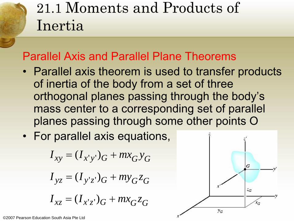
• Parallel axis theorem is used to transfer products of inertia of the body from a set of three orthogonal planes passing through the body’s mass center to a corresponding set of parallel planes passing through some other points O
• For parallel axis equations,
GGGzxxz
GGGzyyz
GGGyxxy
zmxII
zmyII
ymxII
)(
)(
)(
''
''
''

©2007 Pearson Education South Asia Pte Ltd
21.1 Moments and Products of
Inertia
Inertia Tensor
• Inertial properties of a body are completely characterized
by nine terms, six of which are independent of one
another
• For an inertia tensor,
• An inertia tensor has a unique set of values for a body
when it is computed for each location of the origin O and
orientation of the coordinates origin
zzzyzx
xzyyyx
xzxyxx
III
III
III

©2007 Pearson Education South Asia Pte Ltd
21.1 Moments and Products of
Inertia
Inertia Tensor
• For point O, specify a unique axes inclination for which the products of inertia for the body are zero when computed with respect to these axes
• For a diagonalized inertia tensor,
• For principal moments of inertia for the body
zzzyyyxxx
z
y
x
IIIIII
I
I
I
,,
00
00
00

©2007 Pearson Education South Asia Pte Ltd
21.1 Moments and Products of
Inertia
Inertia Tensor
• Of these three principal moments of inertia,
one will be a maximum and one will be a
minimum
• If the coordinates axes are orientated such
that two of the three orthogonal planes
containing the axes are planes of symmetry
for the body, then all the products of inertia
for the body are zero with respect to the
coordinate planes, hence the coordinate
axes are principle axes of inertia

©2007 Pearson Education South Asia Pte Ltd
21.1 Moments and Products of
Inertia
Moment of Inertia About an Arbitrary Axis
• Consider the body where nine elements of the inertia tensor have been computed for the x, y, z axes having an origin at O
• Determine the moment of inertia of the body
about the Oa axis, for which the
direction is defined by vector ua
• IOa = ∫b2 dm where b is the
perpendicular distance from
dm to Oa

©2007 Pearson Education South Asia Pte Ltd
21.1 Moments and Products of
Inertia
Moment of Inertia About an Arbitrary Axis
• Position of dm is located using r, b = rsinθ, which
represents the magnitude of the cross-product ua
x r
• For moment of inertia,
• Provided
kzjyixr
kujuiuu
dmrxurxudmrxuI
zyxa
am
am
aOa
2

©2007 Pearson Education South Asia Pte Ltd
21.1 Moments and Products of
Inertia
Moment of Inertia About an Arbitrary Axis
• Hence,
• For moment of inertia,
zxxzzyyzyyxxyzzzyyyxxx
mzx
mzy
myx
mz
my
mx
yxxzm
zyOa
yxxzzya
uuIuuIuuIuIuIuI
dmxzuudmyzuudmxyuu
dmyxudmzxudmzyu
dmxuyuzuxuyuzuI
kxuyujzuxuiyuzurxu
222
222
])()()[(
)()()(
222
222222222
222

©2007 Pearson Education South Asia Pte Ltd
21.1 Moments and Products of
Inertia
Moment of Inertia About an Arbitrary Axis
• If the inertia tensor is specified for the x, y, z axes, the moment of inertia of the body about the inclined Oa axis can be found
• Direction cosines ux, uy and uz can be determined
• Direction angles α, β and γ made between the positive Oa axis and the positive x, y, z axes can be determined from the direction cosines ux, uy and uz, respectively

©2007 Pearson Education South Asia Pte Ltd
21.1 Moments and Products of
Inertia
Example 21.1
Determine the moment of inertia of the bent rod
about the Aa axis. The mass of each of the three
segments are shown in the figure.

©2007 Pearson Education South Asia Pte Ltd
21.1 Moments and Products of
Inertia
Solution
• For moment of inertia of a slender rod, I = 1/12
ml2
• For each segment of the rod,
2
2
2
2
2
2
.200.0
.160.0
.160.0
.400.0
.453.0
.480.0
mkgI
mkgI
mkgI
mkgI
mkgI
mkgI
xz
yz
xy
zz
yy
xx
View Free Body Diagram
©2007 Pearson Education South Asia Pte Ltd
21.1 Moments and Products of
Inertia
Solution
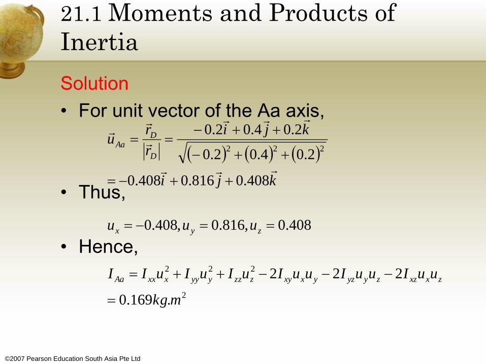
• For unit vector of the Aa axis,
• Thus,
• Hence,
2
222
222
.169.0
222
408.0,816.0,408.0
408.0816.0408.0
2.04.02.0
2.04.02.0
mkg
uuIuuIuuIuIuIuII
uuu
kji
kji
r
ru
zxxzzyyzyxxyzzzyyyxxxAa
zyx
D
DAa

©2007 Pearson Education South Asia Pte Ltd
21.2 Angular Momentum
• Consider the rigid body having a mass m and center of mass at G
• X, Y, Z coordinate system represent an inertial frame of reference and its axes are fixed or translating with a constant velocity
• Angular momentum as
measured from this
reference will be
computed relative to
the arbitrary point A

©2007 Pearson Education South Asia Pte Ltd
21.2 Angular Momentum
• Position vectors rA and ρA are drawn from the
coordinates to point A and from A to the ith particle
of the body
• If the particle’s mass is mi, for angular momentum
about point A,
(HA)i = ρA x mivi
where vi represent the particle’s velocity measured
from the X, Y, Z coordinate system
• If the body has an angular velocity ω,
vi = vA + ω x ρA

©2007 Pearson Education South Asia Pte Ltd
21.2 Angular Momentum
• Hence,
(HA)i = ρA x mi(vA + ω x ρA )
= (ρAmi) x vA + ρA x (ω x ρA)mi
• Summing all the particles of the body,
HA = (∫m ρA dm) x vA + ∫m ρA x (ω x ρA) dm

©2007 Pearson Education South Asia Pte Ltd
21.2 Angular Momentum
Fixed Point O
• If A becomes fixed point O in the body,
vA = 0
HO = ∫m ρO x (ω x ρO) dm

©2007 Pearson Education South Asia Pte Ltd
21.2 Angular Momentum
Center of Mass G
• If A is located at the center of mass G,
∫m ρA dm = 0
HG = ∫m ρG x (ω x ρG) dm

©2007 Pearson Education South Asia Pte Ltd
Arbitrary Point A
• In general, A may be some point other than O or G
HA = ρG/A x mvG + HG
• Angular momentum consists of two parts – the moment of the linear momentum
mvG of the body about point A
added (vectorially) the angular
momentum HG
21.2 Angular Momentum
©2007 Pearson Education South Asia Pte Ltd
21.2 Angular Momentum
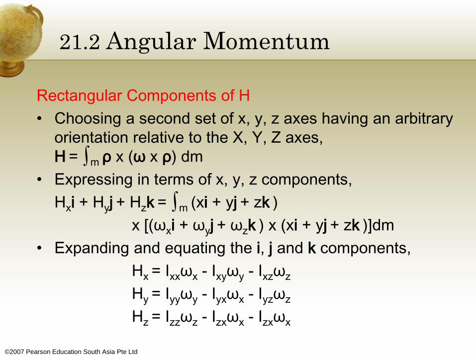
Rectangular Components of H
• Choosing a second set of x, y, z axes having an arbitrary
orientation relative to the X, Y, Z axes,
H = ∫m ρ x (ω x ρ) dm
• Expressing in terms of x, y, z components,
Hxi + Hyj + Hzk = ∫m (xi + yj + zk )
x [(ωxi + ωyj + ωzk ) x (xi + yj + zk )]dm
• Expanding and equating the i, j and k components,
Hx = Ixxωx - Ixyωy - Ixzωz
Hy = Iyyωy - Iyxωx - Iyzωz
Hz = Izzωz - Izxωx - Izxωx

©2007 Pearson Education South Asia Pte Ltd
21.2 Angular Momentum
Rectangular Components of H
• If the x, y, z coordinate axes are oriented such as they become the principal axes of inertia for the body at that point
• If these axes are used, for products of inertia,
Ixy = Iyz = Izx = 0
• If the principal moments of inertia about the x, y, z axes are represented as Ix = Ixx, Iy = Iyy, Iz = Izz, for components of angular momentum,
Hx = Ixωx, Hy = Iyωy, Hz = Izωz

©2007 Pearson Education South Asia Pte Ltd
21.2 Angular Momentum
Principle of Impulse and Momentum
• For principle of impulse and momentum,
• In 3D, each vector term can be represented by 3
scalar components and 6 scalar equations
• 3 equations relate the linear impulse and
momentum in the x, y, z directions and the other
3 equations relate the body’s angular impulse
and momentum about the x, y, z axes
21
21
)()(
)()(
2
1
2
1
O
t
tOO
G
t
tG
HdtMH
vmdtFvm

©2007 Pearson Education South Asia Pte Ltd
21.3 Kinetic Energy
• Consider the rigid body which has a mass m and center of mass at G
• For kinetic energy of the ith particle of the body having a mass mi and velocity vi measured relative to the inertial X, Y, Z frame of reference,
• Provided the velocity of an
arbitrary point A of the body
is known,
AAi
iiiiii
xvv
vvmvmT
)(2
1
2
1 2

©2007 Pearson Education South Asia Pte Ltd
21.3 Kinetic Energy
• For kinetic energy of the particle,
• The kinetic energy for the entire body is obtained by
summing the kinetic energies of the body
• The last term on the right can be re-written as
cxbacbxa
dmxxdmxvmvvT
mxxmxvmvv
xvxvmT
mAA
mAAiAA
iAAiAAiAA
AAAAii
)()(2
1)()(
2
1
)()(2
1)()(
2
1
)()(2
1

©2007 Pearson Education South Asia Pte Ltd
21.3 Kinetic Energy
• Hence,
mAA
mAAiAA
dmx
dmxvmvvT
)(2
1
)()(2
1

©2007 Pearson Education South Asia Pte Ltd
21.3 Kinetic Energy
Fixed Point O
• If A is a fixed point O in the body,
222
2
1
2
1
2
1
2
1
0
zzyyxx
O
A
IIIT
HT
v

©2007 Pearson Education South Asia Pte Ltd
21.3 Kinetic Energy
Center of Mass G
• If A is located at the center of mass G of the
body,
• Kinetic energy consists of the translational kinetic
energy of the mass center and the body’s
rotational kinetic energy
2222
2
2
1
2
1
2
1
2
1
2
1
2
1
0
zzyyxxG
GG
A
IIImvT
HmvT
dm

©2007 Pearson Education South Asia Pte Ltd
21.3 Kinetic Energy
Principle of Work and Energy
• Used to solve problems involving force,
velocity and displacement
• Only one scalar equation can be written for
each body
T1 + ∑U1-2 = T2

©2007 Pearson Education South Asia Pte Ltd
21.4 Equations of Motion
Equations of Translation Motion
• Defined in terms of acceleration of the body’s mass center, which is measured from an inertial X, Y, Z reference
• For equations of translation motion in vector form,
• For scalar equations of translation motion,
• For sum of all external forces acting on the body,
kFjFiFF
amFamFamF
amF
zyx
zGzyGyxGx
G
)(,)(,)(

©2007 Pearson Education South Asia Pte Ltd
21.4 Equations of Motion
Equations of Rotational Motion
which states that sum of moments about a fixed point O of all the external forces acting on a system of particles (contained in a rigid body) is equal to the time rate of change of the total angular momentum of the body about point O
• When moments of external forces acting on the particles are summed about the system’s mass center G, one again obtain summation ∑MG to the angular momentum HG
OO HM

©2007 Pearson Education South Asia Pte Ltd
Equations of Rotational Motion
• Consider a system of particles where X, Y, Z
represents an inertial frame of reference and
the x, y, z axes with origin at G, translate with
respect to this frame
• In general, G is accelerating,
so by definition, the translating
frame is not an inertial reference
21.4 Equations of Motion

©2007 Pearson Education South Asia Pte Ltd
21.4 Equations of Motion
Equations of Rotational Motion
• For the angular momentum of the ith particle with respect to this frame,
• Taking the time derivatives,
• By definition,
• Thus, the first term on the right side is zero since the cross-product of equal vectors equals zero.
GiGi
GiiGiGiiGiGi
GiiGiGi
rv
vmxrvmxrH
vmxrH
//
////
//
)(
)(

©2007 Pearson Education South Asia Pte Ltd
21.4 Equations of Motion
Equations of Rotational Motion
• Since
• Hence,
• When the results are summed, for the time
change of the total angular momentum of the
body computed relative to point G,
)(
)()(
//
//
//
GiiGiG
GiiGiGi
GiGi
amxrH
amxrH
va

©2007 Pearson Education South Asia Pte Ltd
21.4 Equations of Motion
Equations of Rotational Motion
• For relative acceleration for the ith particle,
where ai and aG represent accelerations of the ith particle and point G measured with respect to the inertial frame of reference
• By vector cross-product,
• By definition of the mass center, since position vector r relative to G is zero,
rmrm
axrmamxrH
aaa
iGii
GiGiiGiiGiG
GiGi
)()(
)()(
/
////
/

©2007 Pearson Education South Asia Pte Ltd
21.4 Equations of Motion
Equations of Rotational Motion
• Using the equation of motion,
• For the rotational equation of motion for the body,
• If the scalar components of the angular momentum HO or HG are computed about x, y, z axes that are rotating with an angular velocity Ω, which may be different from the body’s angular velocity ω, then the time derivative
GG
iGiG
HM
FxrM
)( /

©2007 Pearson Education South Asia Pte Ltd
21.4 Equations of Motion
Equations of Rotational Motion
must be used to account for the rotation of the x, y, z axes as measured from the inertial X, Y, Z axes
• For the time derivative of H,
• There are 3 ways to define the motion of the x, y, z axes
GxyzGG
OxyzOO
HxHM
HxHM
dtHdH
)(
)(
/

©2007 Pearson Education South Asia Pte Ltd
21.4 Equations of Motion
x, y, z Axes having motion Ω = 0
• If the body has general motion, the x, y, z axes may be chosen with origin at G, such that the axes only translate to the inertial X, Y, Z frame of reference
• However, the body may have a rotation ω about these axes, and therefore the moments and products of inertia of the body would have to be expressed as functions of time

©2007 Pearson Education South Asia Pte Ltd
21.4 Equations of Motion
x, y, z Axes having motion Ω = ω
• The x, y, z axes may be chosen with origin at G,
such that they are fixed in and move with the
body
• The moments and the products of inertia of the
body relative to these axes will be constant
during the motion
GxyzGG
OxyzOO
HxHM
HxHM
)(
)(

©2007 Pearson Education South Asia Pte Ltd
21.4 Equations of Motion
x, y, z Axes having motion Ω = ω
• For a rigid body symmetric with respect to the x-y
reference plane, and undergoing general plane
motion,
0//,0
)()()(
)(
)()()(
)(
)()(
)()(
22
22
22
dtddtdII
III
IIIM
III
IIIM
II
IIIIM
yxyxyzxz
xzyyzyxxyzyxzx
yxyyxxzzzz
zyxxyxzzxyxzyz
xzxxzzyyyy
yxyzxzyyz
xzyxyzyzzyyxxxx

©2007 Pearson Education South Asia Pte Ltd
21.4 Equations of Motion
x, y, z Axes having motion Ω = ω
• Hence,
• If the x, y and z axes are chosen as principal
axes of inertia, the products of inertia are zero,
Ixx = Iz
• For the Euler equations of motion,
yxyxzzz
xzxzyyy
zyzyxxx
zzzzyx
IIIM
IIIM
IIIM
IMMM
)(
)(
)(
,0

©2007 Pearson Education South Asia Pte Ltd
21.4 Equations of Motion
x, y, z Axes having motion Ω = ω
• Since the x, y, z components are rotating at
Ω = ω,
• Since
• Hence,
xyz
xyz
x
x
)(
0
)(

©2007 Pearson Education South Asia Pte Ltd
21.4 Equations of Motion
x, y, z Axes having motion Ω ≠ ω
• Choose the x, y, z axes having an angular velocity Ω which is different from the angular velocity ω of the body
• This is particular suitable for the analysis of spinning tops and gyroscopes, which are symmetrical about their spinning axes
• When this is the case, the moments and products of inertia remain constant during the motion

©2007 Pearson Education South Asia Pte Ltd
21.4 Equations of Motion
x, y, z Axes having motion Ω ≠ ω
• Any one of these sets of moment equations represents a series of three first order nonlinear differential equations
• These equations are coupled since the angular velocity components are present in all the terms
yxyxyxzzz
xzxzxzyyy
zyzyzyxxx
IIIM
IIIM
IIIM

©2007 Pearson Education South Asia Pte Ltd
21.4 Equations of Motion
Procedure for Analysis
FBD
• Draw a FBD of the body at the instant considered and specify the x, y, z coordinate system
• Origin of this reference must be located either at the body’s mass center G or at point O, considered fixed in an inertial reference frame and located either in the body or a massless extension of the body
• Unknown reactive forces can be shown having a positive sense of direction

©2007 Pearson Education South Asia Pte Ltd
21.4 Equations of Motion
Procedure for Analysis
FBD
• Depending on the nature of the problem, decide which type of rotational motion Ω = 0, Ω = ω, or Ω ≠ ω
• When choosing, one should keep in mind that the moment equations are simplified in such a manner that they represent principal axes of inertia for the body at all times
• Compute the necessary moments and products of inertia for the body relative to the x, y, z axes

©2007 Pearson Education South Asia Pte Ltd
21.4 Equations of Motion
Procedure for Analysis
Kinematics
• Determine the x, y, z components of the body’s angular velocity and compute the time derivatives of ω
• If Ω = ω then, ώ = (ώ)xyz and we can either find the components of ω along the x, y, z axes when the axes are oriented in a general position and take the time derivatives of these components (ώ)xyz or we can find the time derivatives of ω with respect to the X, Y, Z axes, ώ, and then determine the components of ώx, ώy, ώz

©2007 Pearson Education South Asia Pte Ltd
21.4 Equations of Motion
Procedure for Analysis
Equations of Motion
• Apply either the two vector equations or the
six scalar component equation appropriate
for the x, y, z coordinate axes chosen for the
problem

©2007 Pearson Education South Asia Pte Ltd
21.5 Gyroscopic Motion
• Starting the X, Y, Z and the x, y, z axes in
coincidence, the final position of the top id
determined by
1. Rotate the top about the Z (or z) axis through
an angle Φ (0 ≤ Φ ≤ 2π)
2. Rotate the top about the x axis through an
angle θ (0 ≤ θ ≤ π)
3. Rotate the top about the z axis through an
angle ψ (0 ≤ ψ ≤ 2π) to obtain the final position
• Sequence must be maintained

©2007 Pearson Education South Asia Pte Ltd
21.5 Gyroscopic Motion
• Since these finite rotation are not vectors and in
this case, the differential rotation are vectors and
thus, the angular velocity ω of the top can be
expressed in terms of the time derivatives of the
Euler angles
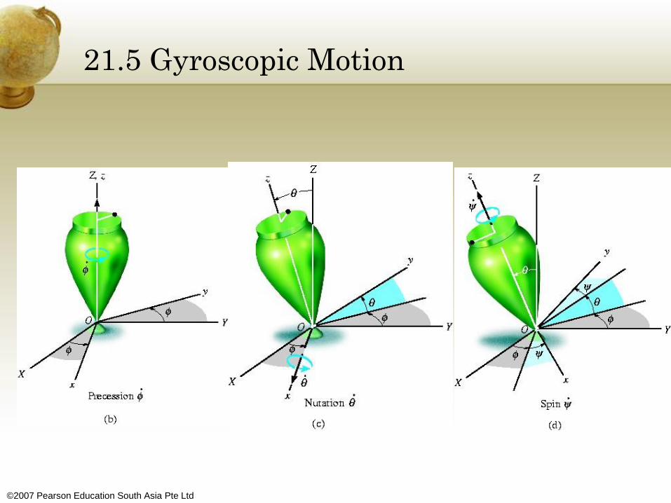
• The angular components are
known as precession,
nutation and spin
©2007 Pearson Education South Asia Pte Ltd
21.5 Gyroscopic Motion

©2007 Pearson Education South Asia Pte Ltd
21.5 Gyroscopic Motion
• It can be seen that these vectors are not all perpendicular to one another
• However, ω of the top can still be expressed in terms of these three components
• The body (top) is symmetric with respect to the z or spin axis
• If the top is orientated so that at the instant, the spin angle equals 0 and the x, y, z axes follow the motion of the body only in nutation and precession, i.e. Ω = ωp + ωn, the nutation and spin are always directed along the x and z axes respectively

©2007 Pearson Education South Asia Pte Ltd
21.5 Gyroscopic Motion
• Hence, for the angular velocity of the body specified only in terms of the Euler’s angle θ,
• Since the motion of the axes is not affected by the spin component,
• The x, y, z axes represent the principal axes of inertia of the body for any spin of the body about these axes
kji
kji
kji
kji
zyx
zyx
)cos()sin(
)cos()sin(

©2007 Pearson Education South Asia Pte Ltd
21.5 Gyroscopic Motion
• Hence, the moments of inertia are constant and will be represented by Ixx = Iyy = I and Izz = Iz
• Since Ω ≠ ω,
• Each moment summation applies only at the fixed point O or at the center of mass G of the body
)sincos(
)cos()cos2sin(
)cos(sin)cossin( 2
zx
zy
zx
IM
IIM
IIM

©2007 Pearson Education South Asia Pte Ltd
21.5 Gyroscopic Motion
• Since the equations represent a coupled set of nonlinear second order differential equations, in general, a closed-form solution may not be obtained
• Instead, the Euler’s angles may be obtained graphically as functions of time using numerical analysis and computer techniques
• As special case, steady precession, occurs when the nutation angle, precession and spin all remains constant

©2007 Pearson Education South Asia Pte Ltd
21.5 Gyroscopic Motion
• The equations reduce to
• Furthering simplifying,
or
• Note that the effects the spin has on the moment about the x axis
)cos(sin
sincossin
0,0
)cos(sincossin
2
2
IIM
IIM
MM
IIM
zzx
zzx
zy
zx

©2007 Pearson Education South Asia Pte Ltd
• When θ = 90°, consider the spinning rotor,
equations reduce to
or
• It can be seen that the vectors ∑Mx, Ωy and ωz
all act along their respective positive axes and
therefore are mutually perpendicular
21.5 Gyroscopic Motion
zyzx
zx
IM
IM
©2007 Pearson Education South Asia Pte Ltd
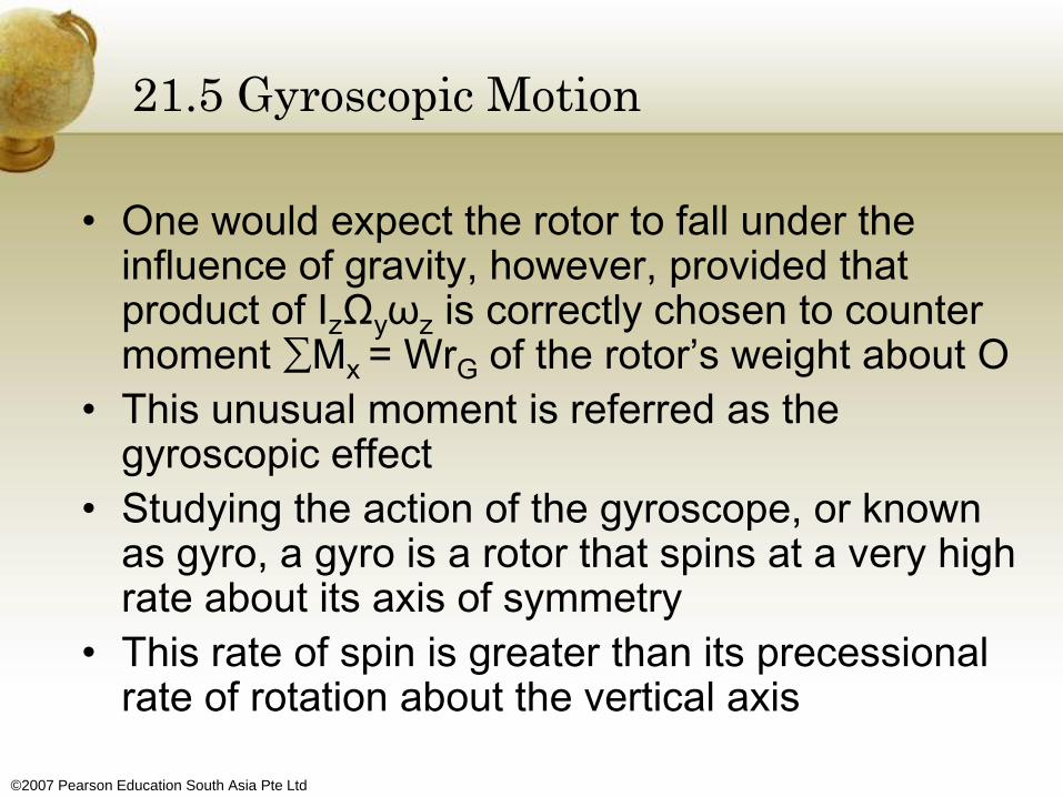
• One would expect the rotor to fall under the influence of gravity, however, provided that product of IzΩyωz is correctly chosen to counter moment ∑Mx = WrG of the rotor’s weight about O
• This unusual moment is referred as the gyroscopic effect
• Studying the action of the gyroscope, or known as gyro, a gyro is a rotor that spins at a very high rate about its axis of symmetry
• This rate of spin is greater than its precessional rate of rotation about the vertical axis
21.5 Gyroscopic Motion

©2007 Pearson Education South Asia Pte Ltd
21.5 Gyroscopic Motion
• Hence, the angular momentum of the gyro can
be assumed directed among its axis of spin
• Thus, for the gyro rotor, ωz >> Ωy, and the
magnitude of the angular momentum about point
O reduces to the form HO = Izωz
• Since both the magnitude and directions of HO
are constant as observed from the x, y, z, direct
application yields
∑Mx = Ωy x HO
©2007 Pearson Education South Asia Pte Ltd
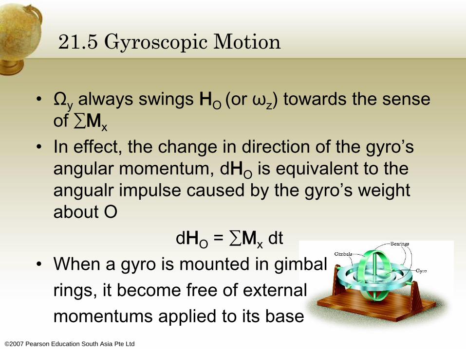
• Ωy always swings HO (or ωz) towards the sense
of ∑Mx
• In effect, the change in direction of the gyro’s
angular momentum, dHO is equivalent to the
angualr impulse caused by the gyro’s weight
about O
dHO = ∑Mx dt
• When a gyro is mounted in gimbal
rings, it become free of external
momentums applied to its base
21.5 Gyroscopic Motion

©2007 Pearson Education South Asia Pte Ltd
21.5 Gyroscopic Motion
• In theory, its angular momentum H will never precess but, instead maintain its same fixed orientation along the axis of spin when the base is rotated
• This type of gyroscope is called a free gyro and is useful as a gyrocompass when the spin axis of the gyro is directed north
• In reality, the gimbal mechanism is never completely free of friction, so such a device is useful only for the local navigation of ships and aircraft

©2007 Pearson Education South Asia Pte Ltd
21.6 Torque-Free Motion
• When the only external force
acting on a body is caused by
gravitation, the general motion of
the body is referred to as torque-free motion
• In order to describe the
characteristics of this motion, the
distribution of the body’s mass will
be assumed axisymmetric, as
shown in figure, where the z axis
represents an axis of symmetry

©2007 Pearson Education South Asia Pte Ltd
21.6 Torque-Free Motion
• The origin of the x, y, z coordinates is located
at the mass center G, such that Izz = Iz and Ixx = Iyy = I for the body
• Since gravitation is the only external force
present, the summation of moments about
the mass center is zero
• This required the angular momentum of the
body to be constant,
constantGH

©2007 Pearson Education South Asia Pte Ltd
21.6 Torque-Free Motion
• At the instant considered, it will assumed that
the inertial frame of reference is oriented so
that the positive Z axis is directed along HG
and the y axis lies in the plane formed by the
z and Z axes.
• The Euler angle formed between Z and z is
θ, and therefore, with this choice of axes the
angular momentum may be expressed as
kjH cossin GGG HH

©2007 Pearson Education South Asia Pte Ltd
21.6 Torque-Free Motion
• Since
• Equating the respective i, j, k components of
the above two equations yields
• or
kjiH zyxG III
kjz
GG
z
Gz
Gyx
I
H
I
H
I
H
I
H
cossin
cossin0

©2007 Pearson Education South Asia Pte Ltd
21.6 Torque-Free Motion
• Equating the respective i, j, k components of
into
• We obtain
kji
kji
)cos()sin(
zyx
z
Gz
Gyx
I
H
I
H
cossin0
z
GG
I
H
I
H
sincos
sinsin0

©2007 Pearson Education South Asia Pte Ltd
21.6 Torque-Free Motion
• Solving, we get
cos
const
G
z
z
G
HII
II
I
H

©2007 Pearson Education South Asia Pte Ltd
21.6 Torque-Free Motion
• Thus for torque-free motion of an
axisymmetrical body, the angle θ formed
between the angular-momentum vector and
the spin of the body remains constant
• Furthermore, the angular momentum HG,
precession Φ, and spin Ψ for the body
remain constant at all times during the
motion
cosz
z
I
II
. .

©2007 Pearson Education South Asia Pte Ltd
21.6 Torque-Free Motion
• As shown, the body precesses about the Z axis, which is fixed in direction, spinning about z axis.
• These two components of angular motion may be studied by using a simple cone model
• The space cone defining the precession
is fixed from rotating, since the
precession has a fixed direction,
while the body cone rotates around
the space cone’s outer surface
without slipping

©2007 Pearson Education South Asia Pte Ltd
21.6 Torque-Free Motion
• On the basis, an attempt should be made to
imagine the motion
• The interior angle of each cone is chosen such
that the resultant angular velocity of the body is
directed along the line of contact of the two
cones
• This line of contact represents the instantaneous
axis of rotation for the body cone and hence the
angular velocity of both the body cone and the
body must be directed along this line

©2007 Pearson Education South Asia Pte Ltd
21.6 Torque-Free Motion
• Since the spin is a function of the moments
of inertia I and Iz of the body, the cone model
is satisfactory for describing the motion,
provided I > Iz
• Torque-free motion which meets these
requirements is called regular precession
• If I > Iz, the spin is negative and precession is
positive

©2007 Pearson Education South Asia Pte Ltd
21.6 Torque-Free Motion
• This motion is represented by the satellite motion shown below (I < Iz)
• The cone model may again be used to represent; however, to preserve the correct vector addition of spin and precession to obtain the angular velocity ω, the inside surface of the body cone must roll on the outside surface of the (fixed) space cone
• This motion is called
retrograde precession

©2007 Pearson Education South Asia Pte Ltd
Chapter Review
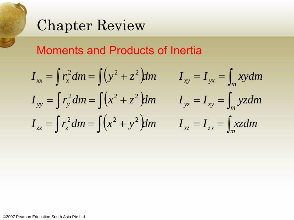
Moments and Products of Inertia
• A body has 6 components of inertia for any specified x, y, z axes
• 3 are moments of inertia about each of the axes, Ix, Iy, Iz, and 3 are products of inertia , each defined from two orthogonal planes Ixy, Iyz and Ixz
• If either one or both of the planes are planes of symmetry, then the product of inertia with respect to these planes will be zero
• Moments and products of integrations can be determined by direct integration
©2007 Pearson Education South Asia Pte Ltd
Chapter Review
Moments and Products of Inertia
dmxzIIdmyxdmrI
dmyzIIdmzxdmrI
dmxyIIdmzydmrI
mzxxzzzz
mzyyzyyy
myxxyxxx
222
222
222

©2007 Pearson Education South Asia Pte Ltd
Chapter Review
Moments and Products of Inertia
• If these quantities are to be determined with
respect to axes or planes that do not pass
through the mass center, parallel axes
theorems must be used
• Provided the 6 components of inertia are
known, the moment of inertia about any axis
may be determined using the transformation
equation
zxxzzyyzyyxxyzzzyyyxxxOa uuIuuIuuIuIuIuII 222222

©2007 Pearson Education South Asia Pte Ltd
Chapter Review
Principle Moments of Inertia
• At any point on or off the body, the x, y, z axes can be oriented so that the products of inertia will be zero.
• The resulting moments of inertia are called the principal moments of inertia, one of which will be a maximum and the other a minimum moment of inertia for the body.
z
y
x
I
I
I
00
00
00

©2007 Pearson Education South Asia Pte Ltd
Chapter Review
Principle of Impulse and Momentum
• The angular momentum for a body can be
determined about any arbitrary point A.
• Once the linear and angular momentum for
the body have been formulated, then the
principle of impulse and momentum can be
used to solve problems that involve force,
velocity, and time.

©2007 Pearson Education South Asia Pte Ltd
Chapter Review
Principle of Impulse and Momentum
Mass) of(Center
Point) (Fixed
Point)(Arbitary
/
21
21
2
1
2
1
dmH
dmH
HmvH
HdtMH
vmFdtvm
GGG
OOO
GGAGA
O
t
t
OO
G
t
t
G

©2007 Pearson Education South Asia Pte Ltd
Chapter Review
Principle of Impulse and Momentum
zzzyzyxzxz
zyzyyyxyxy
zxzyxyxxxx
IIIH
IIIH
IIIH
where

©2007 Pearson Education South Asia Pte Ltd
Chapter Review
Principle of Work and Energy
• Kinetic energy of a body is usually
determined relative to a fixed point or the
body’s mass center
• Provided the axes are principal axes of
inertia, for a fixed point,
• And relative to the mass center,
222
2
1
2
1
2
1zzyyxx IIIT
2211
2222
2
1
2
1
2
1
2
1
TUT
IIImvT zzyyxxG

©2007 Pearson Education South Asia Pte Ltd
Chapter Review
Equations of Motion
• There are 3 scalar equations of translational motion for a rigid body moving in 3D
• There are 3 scalar equations of rotational motion depending upon the location of the x, y, z reference
• Most often, these axes are oriented so that the axes are principal axes of inertia
zGzyGyxGx amFamFamF )(,)(,)(

©2007 Pearson Education South Asia Pte Ltd
Chapter Review
Equations of Motion
• If the axes are fixed in and move with the rotation
ω of the body, the equations are referred to as
the Euler’s equations of motion (Ω = ω),
• If the axes have a rotation (Ω ≠ ω), yxyxzzz
xzxzyyy
zyzyxxx
IIIM
IIIM
IIIM
)(
)(
)(
yxyxyxzzz
xzxzxzyyy
zyzyzyxxx
IIIM
IIIM
IIIM

©2007 Pearson Education South Asia Pte Ltd
Chapter Review
Gyroscopic Motion
• The angular motion is best described using the
changes in motion of the three Euler angles
• These angular velocity components are the
precession, nutation and the spin
• If spin equals zero and the precession and
nutation are constant, the motion is referred as
steady precession
• For rotational equations of motion,
0,0
)cos(sincossin2
zy
zx
MM
IIM

©2007 Pearson Education South Asia Pte Ltd
Chapter Review
Gyroscopic Motion
• It is the spin of the gyro motor that is responsible
for holding the rotor from falling downward, and
instead causing it to precess about a vertical axis
• This phenomenon is called the gyroscopic effect

©2007 Pearson Education South Asia Pte Ltd
Chapter Review
Torque-Free Motion
• A body that is subjected to a gravitational force
that will have no moments on it about its mass
center, and so the motion is described as torque-
free motion
• The angular momentum for the body will remain
constant and this causes the body to have both a
spin and a precession

©2007 Pearson Education South Asia Pte Ltd
Chapter Review
Torque-Free Motion
• The behavior depends on the size of the moment
of inertia of a symmetric body about the spin axis
Iz versus that about a perpendicular axis I
• If I > Iz, regular precession occur
• If I < Iz, retrograde precession occur
cos
constant
G
Z
Z
G
HH
II
I
H