Embed Size (px)
Citation preview

7/26/2019 Chapter 25 Book Biomedical Technology and Devices Handbook
http://slidepdf.com/reader/full/chapter-25-book-biomedical-technology-and-devices-handbook 1/15
25Minimally InvasiveCardiovascular
Technologies
CONTENTS
25.1 Introduction
25.2 Angioplasty
25.3 Stents
25.4 Aneurysm Treatment
25.5 Embolic Filters
25.6 Cardiac Ablation Catheters
References
25.1 Introduction
Cardiovascular disease remains the most common cause of death in western countries despite consider-
able advances in treatment strategies. In the 20th century, technologies such as the heart/lung bypass
machine were developed to enable surgeons to operate on virtually any part of the system, including the
heart itself. While these procedures have saved countless lives, they suffer from relatively high mortality
and morbidity rates due to their invasiveness. The procedures often take several hours in the surgical
suite, followed by several days to weeks of recovery in intensive care wards. The cost to the patient and/or
their insurance carrier for these procedures exceeds $30,000. Many of the most severely diseased patients
were excluded from surgery because of the danger associated with the procedure itself.
An effort began in the 1960s to move toward less invasive procedures to treat cardiovascular disease
states. Advances in materials science, imaging, and pharmaceuticals have led to a wide variety of devicesto treat such pathologies such as occlusive atherosclerotic plaques, heart valve deficiencies, aneurysms,
and deep venous thrombosis. These procedures are less traumatic to the patient, require fewer hospital
resources, and shorten recovery times. In most cases, a small entry point is established in the femoral
artery, located near the groin. Catheters are inserted and led up to the disease location. The patient can
be under general or local anesthesia. This is advantageous in neural procedures, in which the patient can
be asked certain questions or to perform certain tasks to monitor neural function. Once the procedure
is completed, the entry point is closed, and the patient is sent to recovery. In many cases, the patient
goes home within days to resume normal activities. The cost of such procedures is approximately one
third less than the equivalent surgical procedure, although this savings varies considerably (Hltaky et al.,
1997). As the long-term performance of these devices is improved, the savings over surgical procedureswill continue to increase.
The move toward less invasive procedures has occurred in parallel with an overall trend of increasing
numbers of total cardiovascular procedures. From 1979 to 1999, the total number of cardiovascular
James E. Moore, Jr.Florida International University
Marc JalisiFlorida International University
Michael R. MorenoFlorida International University
Eric CrumplerFlorida International University
© 2004 by CRC Press LLC

7/26/2019 Chapter 25 Book Biomedical Technology and Devices Handbook
http://slidepdf.com/reader/full/chapter-25-book-biomedical-technology-and-devices-handbook 2/15
7/26/2019 Chapter 25 Book Biomedical Technology and Devices Handbook
http://slidepdf.com/reader/full/chapter-25-book-biomedical-technology-and-devices-handbook 3/15
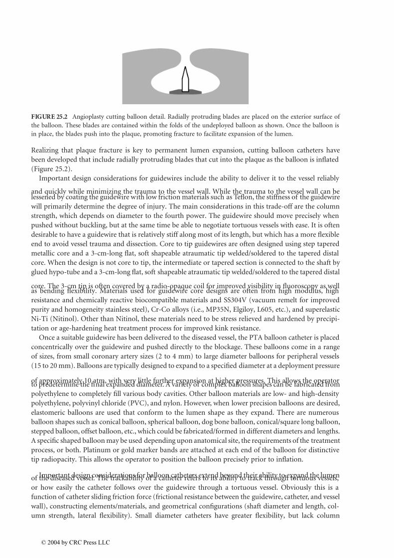
Realizing that plaque fracture is key to permanent lumen expansion, cutting balloon catheters have
been developed that include radially protruding blades that cut into the plaque as the balloon is inflated
(Figure 25.2).
Important design considerations for guidewires include the ability to deliver it to the vessel reliably
and quickly while minimizing the trauma to the vessel wall. While the trauma to the vessel wall can belessened by coating the guidewire with low friction materials such as Teflon, the stiffness of the guidewire
will primarily determine the degree of injury. The main considerations in this trade-off are the column
strength, which depends on diameter to the fourth power. The guidewire should move precisely when
pushed without buckling, but at the same time be able to negotiate tortuous vessels with ease. It is often
desirable to have a guidewire that is relatively stiff along most of its length, but which has a more flexible
end to avoid vessel trauma and dissection. Core to tip guidewires are often designed using step tapered
metallic core and a 3-cm-long flat, soft shapeable atraumatic tip welded/soldered to the tapered distal
core. When the design is not core to tip, the intermediate or tapered section is connected to the shaft by
glued hypo-tube and a 3-cm-long flat, soft shapeable atraumatic tip welded/soldered to the tapered distal
core. The 3-cm tip is often covered by a radio-opaque coil for improved visibility in fluoroscopy as wellas bending flexibility. Materials used for guidewire core designs are often from high modulus, high
resistance and chemically reactive biocompatible materials and SS304V (vacuum remelt for improved
purity and homogeneity stainless steel), Cr-Co alloys (i.e., MP35N, Elgiloy, L605, etc.), and superelastic
Ni-Ti (Nitinol). Other than Nitinol, these materials need to be stress relieved and hardened by precipi-
tation or age-hardening heat treatment process for improved kink resistance.
Once a suitable guidewire has been delivered to the diseased vessel, the PTA balloon catheter is placed
concentrically over the guidewire and pushed directly to the blockage. These balloons come in a range
of sizes, from small coronary artery sizes (2 to 4 mm) to large diameter balloons for peripheral vessels
(15 to 20 mm). Balloons are typically designed to expand to a specified diameter at a deployment pressure
of approximately 10 atm, with very little further expansion at higher pressures. This allows the operatorto predetermine the final expanded diameter. A variety of complex balloon shapes can be fabricated from
polyethylene to completely fill various body cavities. Other balloon materials are low- and high-density
polyethylene, polyvinyl chloride (PVC), and nylon. However, when lower precision balloons are desired,
elastomeric balloons are used that conform to the lumen shape as they expand. There are numerous
balloon shapes such as conical balloon, spherical balloon, dog bone balloon, conical/square long balloon,
stepped balloon, offset balloon, etc., which could be fabricated/formed in different diameters and lengths.
A specific shaped balloon may be used depending upon anatomical site, the requirements of the treatment
process, or both. Platinum or gold marker bands are attached at each end of the balloon for distinctive
tip radiopacity. This allows the operator to position the balloon precisely prior to inflation.
Important design considerations for balloon catheters extend beyond their ability to expand the lumenof the diseased vessel. The trackability of a catheter refers to its ability to track through tortuous vessels,
or how easily the catheter follows over the guidewire through a tortuous vessel. Obviously this is a
function of catheter sliding friction force (frictional resistance between the guidewire, catheter, and vessel
wall), constructing elements/materials, and geometrical configurations (shaft diameter and length, col-
umn strength, lateral flexibility). Small diameter catheters have greater flexibility, but lack column
FIGURE 25.2 Angioplasty cutting balloon detail. Radially protruding blades are placed on the exterior surface of
the balloon. These blades are contained within the folds of the undeployed balloon as shown. Once the balloon is
in place, the blades push into the plaque, promoting fracture to facilitate expansion of the lumen.
© 2004 by CRC Press LLC
7/26/2019 Chapter 25 Book Biomedical Technology and Devices Handbook
http://slidepdf.com/reader/full/chapter-25-book-biomedical-technology-and-devices-handbook 4/15
strength. This makes it necessary to use stronger shaft materials, distal tapering and/or reinforcing with
braids, coils, or stiffening wires. The crossability of a catheter refers to the ability of its distal end to
traverse the lesion to be treated. Thus, the goals are to design low-profile catheters with small diameter
distal tips, and balloons with high inflation ratios (inflated to deflated diameters). These strategies are
augmented with polymeric coatings to reduce friction, and minimizing the amount of adhesive used for
balloon-catheter attachment. The adhesion spots create relatively stiff sections that impede crossability.
Finally, gradual transitions in catheter stiffness and matching properties of catheters to guidewires help
to optimize crossability.
In many cases, clinicians determine that some of the atherosclerotic plaque must be removed to
increase the long-term chances for an open lumen. This process is referred to as “debulking.” There
are a variety of technologies developed for this purpose, but the degree of success has been limited.
Despite considerable development work in the 1980s and 1990s, laser angioplasty has never enjoyed
widespread clinical use. This procedure uses high laser energy to vaporize plaque by breaking molecular
bonds. The guidewire is positioned across target coronary lesion, and the laser catheter is activated
and advanced slowly through the lesion. In a laser balloon angioplasty device used in coronary
angioplasty, the laser is mounted inside the balloon and transmits light through the balloon walls.Mechanical atherectomy catheters aim to physically destroy and remove, rather than displace, the
plaque material. The design of this type of device requires pulverization and vacuum aspiration of
material to prevent thromboembolic events. In a subset of these devices, directional coronary atherec-
tomy, a catheter/cutter is pushed against arterial plaque. A related application of such technologies is
the removal of thrombus from bypass and AV fistula grafts (thrombectomy).
25.3 Stents
First described in the modern era by Dotter (1969), stents were designed to improve upon the limited
success of balloon angioplasty for the treatment of occlusive vascular disease. A stent is a tubular scaffold
that is expanded inside the artery in order to prop open the lumen. Dotter attempted placement of plastic
stents in canine politeal arteries that thrombosed after 24 h. Later animal studies using both stainless
steel coil stents and nitinol coils were tried successfully (Dotter et al., 1983). The first human use of stents
occurred in 1986 (Sigwart et al., 1987).
The variety of stent designs conceived or developed is staggering. A search of the U.S. Patent and
Trademark Office database in late 2002 revealed more than 4500 patents including the term “stent.” While
not all of these patents were for medical devices, it is interesting to note that approximately half of these
patents were applied for in the year 2000 or later. Most stents can be classified as either balloon-expandable
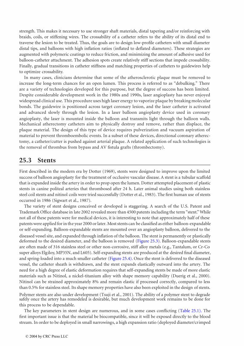
or self-expanding. Balloon-expandable stents are mounted over an angioplasty balloon, delivered to the
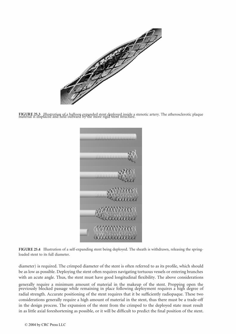
diseased vessel site, and expanded through inflation of the balloon. The stent is permanently or plastically deformed to the desired diameter, and the balloon is removed (Figure 25.3). Balloon-expandable stents
are often made of 316 stainless steel or other non-corrosive, stiff alloy metals (e.g., Tantalum, or Cr-Co
super alloys Elgiloy, MP35N, and L605). Self-expanding stents are produced at the desired final diameter,
and spring-loaded into a much smaller catheter (Figure 25.4). Once the stent is delivered to the diseased
vessel, the catheter sheath is withdrawn, and the stent expands elastically outward into the artery. The
need for a high degree of elastic deformation requires that self-expanding stents be made of more elastic
materials such as Nitinol, a nickel-titanium alloy with shape memory capability (Duerig et al., 2000).
Nitinol can be strained approximately 8% and remain elastic if processed correctly, compared to less
than 0.5% for stainless steel. Its shape memory properties have also been exploited in the design of stents.
Polymer stents are also under development (Tsuji et al., 2001). The ability of a polymer stent to degradesafely once the artery has remodeled is desirable, but much development work remains to be done for
this process to be dependable.
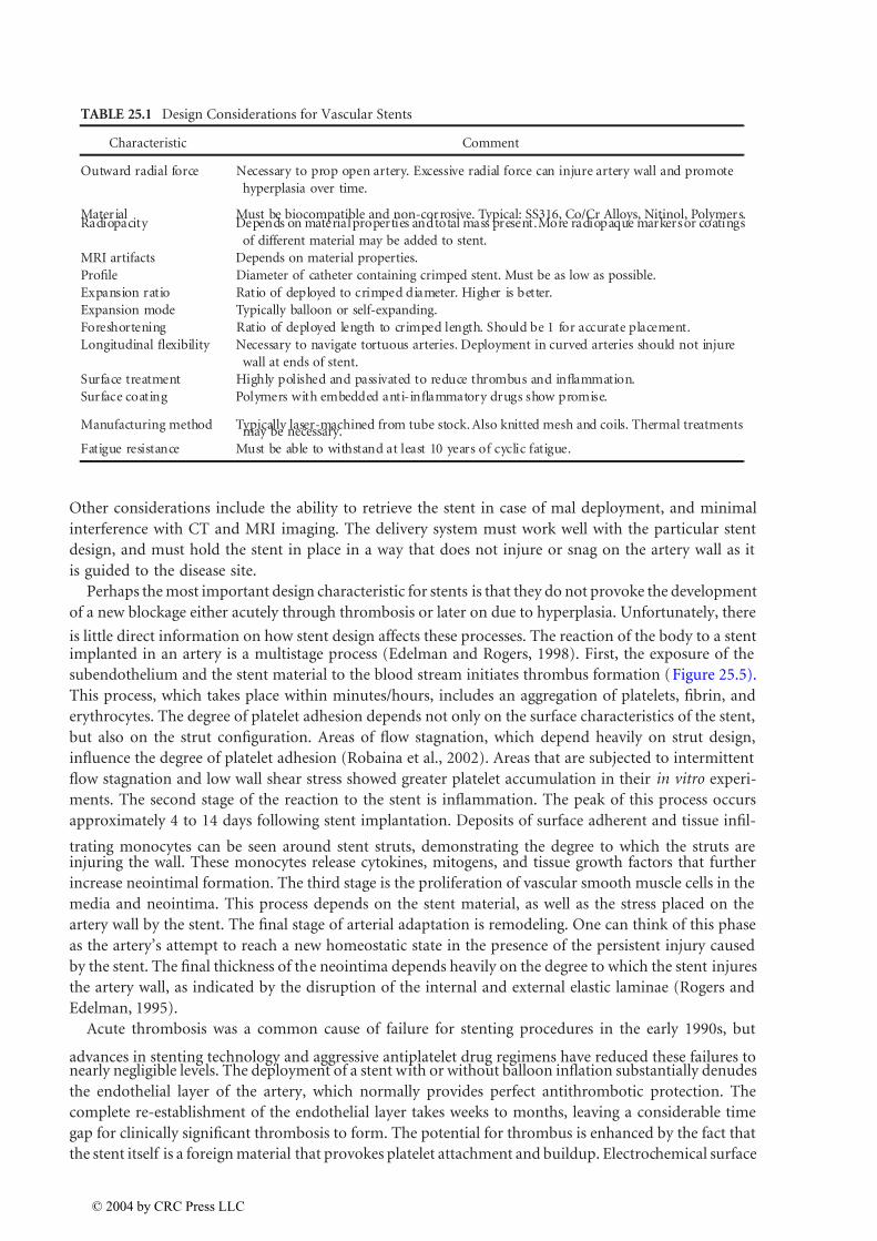
The key parameters in stent design are numerous, and in some cases conflicting (Table 25.1). The
first important issue is that the material be biocompatible, since it will be exposed directly to the blood
stream. In order to be deployed in small narrowings, a high expansion ratio (deployed diameter/crimped
© 2004 by CRC Press LLC
7/26/2019 Chapter 25 Book Biomedical Technology and Devices Handbook
http://slidepdf.com/reader/full/chapter-25-book-biomedical-technology-and-devices-handbook 5/15
diameter) is required. The crimped diameter of the stent is often referred to as its profile, which should
be as low as possible. Deploying the stent often requires navigating tortuous vessels or entering branches
with an acute angle. Thus, the stent must have good longitudinal flexibility. The above considerations
generally require a minimum amount of material in the makeup of the stent. Propping open thepreviously blocked passage while remaining in place following deployment requires a high degree of
radial strength. Accurate positioning of the stent requires that it be sufficiently radiopaque. These two
considerations generally require a high amount of material in the stent, thus there must be a trade-off
in the design process. The expansion of the stent from the crimped to the deployed state must result
in as little axial foreshortening as possible, or it will be difficult to predict the final position of the stent.
FIGURE 25.3 Illustration of a balloon expanded stent deployed inside a stenotic artery. The atherosclerotic plaquematerial is displaced and held outward by the more rigid stent structure.
FIGURE 25.4 Illustration of a self-expanding stent being deployed. The sheath is withdrawn, releasing the spring-
loaded stent to its full diameter.
© 2004 by CRC Press LLC
7/26/2019 Chapter 25 Book Biomedical Technology and Devices Handbook
http://slidepdf.com/reader/full/chapter-25-book-biomedical-technology-and-devices-handbook 6/15
Other considerations include the ability to retrieve the stent in case of mal deployment, and minimal
interference with CT and MRI imaging. The delivery system must work well with the particular stent
design, and must hold the stent in place in a way that does not injure or snag on the artery wall as it
is guided to the disease site.
Perhaps the most important design characteristic for stents is that they do not provoke the development
of a new blockage either acutely through thrombosis or later on due to hyperplasia. Unfortunately, there
is little direct information on how stent design affects these processes. The reaction of the body to a stentimplanted in an artery is a multistage process (Edelman and Rogers, 1998). First, the exposure of the
subendothelium and the stent material to the blood stream initiates thrombus formation (Figure 25.5).
This process, which takes place within minutes/hours, includes an aggregation of platelets, fibrin, and
erythrocytes. The degree of platelet adhesion depends not only on the surface characteristics of the stent,
but also on the strut configuration. Areas of flow stagnation, which depend heavily on strut design,
influence the degree of platelet adhesion (Robaina et al., 2002). Areas that are subjected to intermittent
flow stagnation and low wall shear stress showed greater platelet accumulation in their in vitro experi-
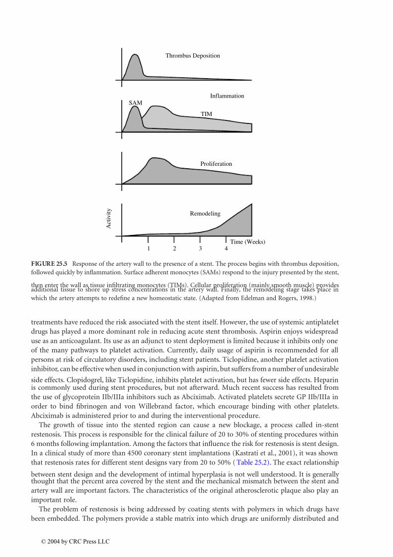
ments. The second stage of the reaction to the stent is inflammation. The peak of this process occurs
approximately 4 to 14 days following stent implantation. Deposits of surface adherent and tissue infil-
trating monocytes can be seen around stent struts, demonstrating the degree to which the struts areinjuring the wall. These monocytes release cytokines, mitogens, and tissue growth factors that further
increase neointimal formation. The third stage is the proliferation of vascular smooth muscle cells in the
media and neointima. This process depends on the stent material, as well as the stress placed on the
artery wall by the stent. The final stage of arterial adaptation is remodeling. One can think of this phase
as the artery’s attempt to reach a new homeostatic state in the presence of the persistent injury caused
by the stent. The final thickness of the neointima depends heavily on the degree to which the stent injures
the artery wall, as indicated by the disruption of the internal and external elastic laminae (Rogers and
Edelman, 1995).
Acute thrombosis was a common cause of failure for stenting procedures in the early 1990s, but
advances in stenting technology and aggressive antiplatelet drug regimens have reduced these failures tonearly negligible levels. The deployment of a stent with or without balloon inflation substantially denudes
the endothelial layer of the artery, which normally provides perfect antithrombotic protection. The
complete re-establishment of the endothelial layer takes weeks to months, leaving a considerable time
gap for clinically significant thrombosis to form. The potential for thrombus is enhanced by the fact that
the stent itself is a foreign material that provokes platelet attachment and buildup. Electrochemical surface
TABLE 25.1 Design Considerations for Vascular Stents
Characteristic Comment
Outward radial force Necessary to prop open artery. Excessive radial force can injure artery wall and promote
hyperplasia over time.
Material Must be biocompatible and non-corrosive. Typical: SS316, Co/Cr Alloys, Nitinol, Polymers.Radiopacity Depends on material properties and total mass present. More radiopaque markers or coatings
of different material may be added to stent.
MRI artifacts Depends on material properties.
Profile Diameter of catheter containing crimped stent. Must be as low as possible.
Expansion ratio Ratio of deployed to crimped diameter. Higher is better.
Expansion mode Typically balloon or self-expanding.
Foreshortening Ratio of deployed length to crimped length. Should be 1 for accurate placement.
Longitudinal flexibility Necessary to navigate tortuous arteries. Deployment in curved arteries should not injure
wall at ends of stent.
Surface treatment Highly polished and passivated to reduce thrombus and inflammation.
Surface coating Polymers with embedded anti-inflammatory drugs show promise.
Manufacturing method Typically laser-machined from tube stock. Also knitted mesh and coils. Thermal treatmentsmay be necessary.
Fatigue resistance Must be able to withstand at least 10 years of cyclic fatigue.
© 2004 by CRC Press LLC
7/26/2019 Chapter 25 Book Biomedical Technology and Devices Handbook
http://slidepdf.com/reader/full/chapter-25-book-biomedical-technology-and-devices-handbook 7/15
treatments have reduced the risk associated with the stent itself. However, the use of systemic antiplatelet
drugs has played a more dominant role in reducing acute stent thrombosis. Aspirin enjoys widespread
use as an anticoagulant. Its use as an adjunct to stent deployment is limited because it inhibits only one
of the many pathways to platelet activation. Currently, daily usage of aspirin is recommended for all
persons at risk of circulatory disorders, including stent patients. Ticlopidine, another platelet activation
inhibitor, can be effective when used in conjunction with aspirin, but suffers from a number of undesirable
side effects. Clopidogrel, like Ticlopidine, inhibits platelet activation, but has fewer side effects. Heparinis commonly used during stent procedures, but not afterward. Much recent success has resulted from
the use of glycoprotein IIb/IIIa inhibitors such as Abciximab. Activated platelets secrete GP IIb/IIIa in
order to bind fibrinogen and von Willebrand factor, which encourage binding with other platelets.
Abciximab is administered prior to and during the interventional procedure.
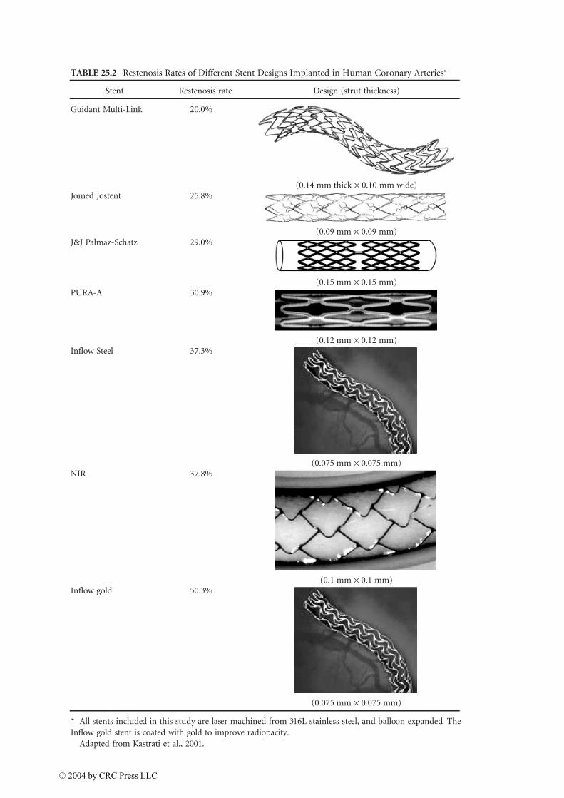
The growth of tissue into the stented region can cause a new blockage, a process called in-stent
restenosis. This process is responsible for the clinical failure of 20 to 30% of stenting procedures within
6 months following implantation. Among the factors that influence the risk for restenosis is stent design.
In a clinical study of more than 4500 coronary stent implantations (Kastrati et al., 2001), it was shown
that restenosis rates for different stent designs vary from 20 to 50% ( Table 25.2). The exact relationship
between stent design and the development of intimal hyperplasia is not well understood. It is generally thought that the percent area covered by the stent and the mechanical mismatch between the stent and
artery wall are important factors. The characteristics of the original atherosclerotic plaque also play an
important role.
The problem of restenosis is being addressed by coating stents with polymers in which drugs have
been embedded. The polymers provide a stable matrix into which drugs are uniformly distributed and
FIGURE 25.5 Response of the artery wall to the presence of a stent. The process begins with thrombus deposition,
followed quickly by inflammation. Surface adherent monocytes (SAMs) respond to the injury presented by the stent,
then enter the wall as tissue infiltrating monocytes (TIMs). Cellular proliferation (mainly smooth muscle) providesadditional tissue to shore up stress concentrations in the artery wall. Finally, the remodeling stage takes place in
which the artery attempts to redefine a new homeostatic state. (Adapted from Edelman and Rogers, 1998.)
TIM
Thrombus Deposition
InflammationSAM
Proliferation
Remodeling
Time (Weeks)
A c t i v i t y
1 2 3 4
© 2004 by CRC Press LLC
7/26/2019 Chapter 25 Book Biomedical Technology and Devices Handbook
http://slidepdf.com/reader/full/chapter-25-book-biomedical-technology-and-devices-handbook 8/15
TABLE 25.2 Restenosis Rates of Different Stent Designs Implanted in Human Coronary Arteries*
Stent Restenosis rate Design (strut thickness)
Guidant Multi-Link 20.0%
(0.14 mm thick ¥ 0.10 mm wide)Jomed Jostent 25.8%
(0.09 mm ¥ 0.09 mm)J&J Palmaz-Schatz 29.0%
(0.15 mm ¥ 0.15 mm)PURA-A 30.9%
(0.12 mm ¥ 0.12 mm)Inflow Steel 37.3%
(0.075 mm ¥ 0.075 mm)NIR 37.8%
(0.1 mm ¥ 0.1 mm)Inflow gold 50.3%
(0.075 mm ¥ 0.075 mm)
* All stents included in this study are laser machined from 316L stainless steel, and balloon expanded. The
Inflow gold stent is coated with gold to improve radiopacity.
Adapted from Kastrati et al., 2001.
© 2004 by CRC Press LLC

7/26/2019 Chapter 25 Book Biomedical Technology and Devices Handbook
http://slidepdf.com/reader/full/chapter-25-book-biomedical-technology-and-devices-handbook 9/15
released over a specific period of time, typically days to weeks (Uhrich et al., 1999). Although most
stent-coating technology is closely guarded, several coating techniques have been described. The most
common polymer coating that is often applied to the surface of the stent struts uses nonerodable and
nonbiodegradable methacrylate and/or ethylene base copolymers. The other biodegradable and non-
biodegradable polymers often employed include nylon, polyurethane, silicone, polyethylene terphtha-
late, polyglycolic acid/polylactic acid (PLGA), polycaprolactone, polyhydroxybutyrate valerate, poly(n-
butyl methacrylate), polyorthoester, poly(ethylene-co-vinyl acetate), and polyethyleneoxide/polybuty-
lene terephthalate (Uhrich et al., 1999). One important factor in the choice of polymers is the adherence
of the polymer to the stent. With deployment, mechanical stress/strain may have a tendency to delam-
inate the coating or cause uneven drug distribution (Hwang et al., 2001). Other factors involve uniform
distribution of the drug for expected efficacy. One of the first examples of coated stents involved heparin
(Hirsh, 1991), which reduces platelet adhesion. Heparin coating of stents is an attractive method because
of its anticoagulant properties and inhibitory effects on mesenchynmal cell growth and differentiation
(Hirsh, 1991; Clowes and Karnovsky, 1977). A number of materials have been evaluated (in vitro and
in vivo) as potential thrombo-resistant stent coatings such as hydrogels and polyurethanes. However,
the endpoint-attached heparin surface proved to be significantly superior to other models (Serruys etal., 1994; Ragosta et al., 1999; Clowes and Karnovsky, 1977). While antithrombogenic compounds
(heparin) and minimally thrombogenic compounds (phosphorycholine) have been integrated into
polymers, novel approaches based on anti-inflammatory or antiproliferation agents are being evaluated.
Two of the more promising pharmaceutical drugs suitable for coating include Paclitaxel (Taxol), includ-
ing taxane analogues and Rapamycin (Sirolimus). Paclitaxel, previously used as an anticancer agent that
reduces cellular proliferation, migration and signal transduction, has demonstrated in vitro and in vivo
success, and is currently being evaluated in human clinical trials. Early clinical trial data show that stents
coated with this drug have demonstrated reduced restenosis rates (Grube and Büllesfeld, 2002). Early
clinical studies of stents coated with Sirolimus showed near zero restenosis rates (Degertekin et al.,
2002). This drug has been systemically applied to patients for the prophylactic prevention of renaltransplant rejection (Poon et al., 2002). Sirolimus is a natural microlide immunosuppressant that
inhibits vascular smooth muscle cell proliferation through blocking the cellular transition from the G1
to the S phase (Gallo et al., 1999). This proliferation is prevented when Sirolimus (or Rapamycin) binds
to its cytosolic receptor, FKBP12, and blocks the activation of T cells, the lymphocytes responsible for
cell-mediated immunity. Through this mechanism, Sirolimus also prevents smooth muscle cell migra-
tion, thus interrupting the cascade of cellular activity leading to neointimal hyperplasia causing rest-
enosis (Sousa et al., 2001). Widespread clinical use of these devices over time will reveal if these exciting
new devices really solve the problem of restenosis.
25.4 Aneurysm Treatment
The development of PTA and stenting led clinicians to explore other conditions that might be treated
with adaptations of these technologies. In 1991, Juan Parodi treated a patient with an abdominal aortic
aneurysm (AAA) with a balloon expandable stent to which a vascular graft had been attached (Parodi
et al., 1991). This stent graft, or endograft, was deployed via a percutaneous catheter approach. The idea
was to seal the aneurysm from arterial pressure and reduce the risk of its rupture (Figure 25.6). AAAs,
the 13th leading cause of death in the U.S., manifest as a local ballooning of the aortic wall that forms
1 to 2 cm distal to the renal arteries. The aneurysm often extends into the iliac arteries. The large radius
and reduced wall thickness in the aneurysm make it prone to rupture, often a fatal event.
Since Parodi’s initial clinical experience, there have been numerous endografts developed for AAAtreatment. There are at least 15 designs currently in development or already in clinical use. The important
design considerations include the ability to remain sealed against healthy portions of the artery wall
proximal and distal to the aneurysm, ability to clot off the porous graft material, and minimal delivery
profile. It is also important to recognize that aneurysm geometry is highly individual. The device must
be prepared to treat a wide variety of vessel diameters, lengths, and degrees of tortuosity. Although
© 2004 by CRC Press LLC
7/26/2019 Chapter 25 Book Biomedical Technology and Devices Handbook
http://slidepdf.com/reader/full/chapter-25-book-biomedical-technology-and-devices-handbook 10/15
Parodi’s initial design was a single tube, the extension of many aneurysms into the iliac arteries requiredadaptation to bifurcated designs. A typical approach is to deploy the main body and one leg of the
endograft via one femoral artery, then deploy the other leg of the endograft via the contralateral femoral
artery. It is also possible to extend a single tapered graft into one iliac artery, then implant a femoral
cross-over graft surgically to supply the contralateral side. The contralateral side must then be sealed
using an iliac occluder plug. Regardless of the particular design, the ability to make a reliable seal between
the endograft components is crucial. Both balloon expanded and self-expanding stents have been used
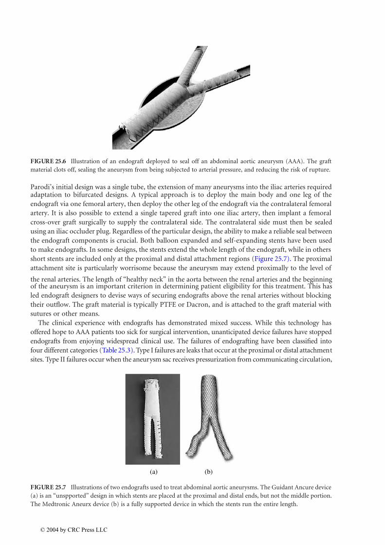
to make endografts. In some designs, the stents extend the whole length of the endograft, while in others
short stents are included only at the proximal and distal attachment regions (Figure 25.7). The proximal
attachment site is particularly worrisome because the aneurysm may extend proximally to the level of
the renal arteries. The length of “healthy neck” in the aorta between the renal arteries and the beginningof the aneurysm is an important criterion in determining patient eligibility for this treatment. This has
led endograft designers to devise ways of securing endografts above the renal arteries without blocking
their outflow. The graft material is typically PTFE or Dacron, and is attached to the graft material with
sutures or other means.
The clinical experience with endografts has demonstrated mixed success. While this technology has
offered hope to AAA patients too sick for surgical intervention, unanticipated device failures have stopped
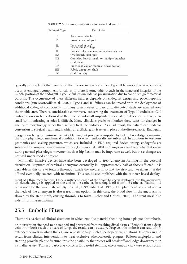
endografts from enjoying widespread clinical use. The failures of endografting have been classified into
four different categories (Table 25.3). Type I failures are leaks that occur at the proximal or distal attachment
sites. Type II failures occur when the aneurysm sac receives pressurization from communicating circulation,
FIGURE 25.6 Illustration of an endograft deployed to seal off an abdominal aortic aneurysm (AAA). The graft
material clots off, sealing the aneurysm from being subjected to arterial pressure, and reducing the risk of rupture.
FIGURE 25.7 Illustrations of two endografts used to treat abdominal aortic aneurysms. The Guidant Ancure device
(a) is an “unspported” design in which stents are placed at the proximal and distal ends, but not the middle portion.
The Medtronic Aneurx device (b) is a fully supported device in which the stents run the entire length.
(a) (b)
© 2004 by CRC Press LLC
7/26/2019 Chapter 25 Book Biomedical Technology and Devices Handbook
http://slidepdf.com/reader/full/chapter-25-book-biomedical-technology-and-devices-handbook 11/15
typically from arteries that connect to the inferior mesenteric artery. Type III failures are seen when leaks
occur at endograft component junctions, or there is some other breach in the structural integrity of themiddle portion of the endograft. Type IV failures include sac pressurization due to continued graft material
porosity. The occurrence of these different failures depends on endograft design and patient-specific
conditions (van Marrewijk et al., 2002). Type I and III failures can be treated with the deployment of
additional endograft components. In many cases, sleeves of bare or graft-coated stents are inserted over
the trouble area. There is considerable controversy concerning the treatment of Type II endoleaks. Coil
embolization can be performed at the time of endograft implantation or later, but access to these often
small communicating arteries is difficult. Many clinicians prefer to monitor these cases for changes in
aneurysm morphology rather than actively treat the endoleaks. As a last resort, the patient can undergo
conversion to surgical treatment, in which an artificial graft is sewn in place of the diseased aorta. Endograft
design is evolving to minimize the risk of failure, but progress is impeded by lack of knowledge concerningthe truly physiologic mechanical conditions to which endografts are subjected. In addition to tortuous
geometries and cycling pressures, which are included in FDA required device testing, endografts are
subjected to complex hemodynamic forces (Liffman et al., 2001). Changes in vessel geometry that occur
during normal physiologic movement such as hip flexion may be important as well, but these changes are
not well understood at present.
Minimally invasive devices have also been developed to treat aneurysm forming in the cerebral
circulation. Ruptures of cerebral aneurysms eventually kill approximately half of those afflicted. It is
desirable in this case to form a thrombus inside the aneurysm so that the structural weakness is sealed
off and eventually covered with neointima. This can be accomplished with the catheter-based deploy-
ment of a thin, metallic wire. Once a sufficient length of the “coil” has been deployed into the aneurysm,an electric charge is applied to the end of the catheter, breaking it off from the catheter. Platinum is
often used for the wire material (Byrne et al., 1999; Uda et al., 1998). The placement of a stent across
the neck of the aneurysm is also a treatment option. In this case, the blood flow in the aneurysm is
slowed by the stent mesh, causing thrombus to form (Lieber and Gounis, 2002). The stent mesh also
aids in forming neointima.
25.5 Embolic Filters
There are a variety of clinical situations in which embolic material shedding from a plaque, thrombosis,
or intervention site need to be trapped and prevented from reaching distal tissues. If emboli from a deepvein thrombosis reach the heart or lungs, the results can be deadly. Deep vein thrombosis can result from
extended periods in which the legs are kept stationary, such as postoperative situations. Emboli can also
result from clinical interventions to treat occlusive atherosclerotic plaques. Balloon angioplasty and
stenting provoke plaque fracture, thus the possibility that pieces will break off and lodge downstream in
a smaller artery. This is a particular concern for carotid stenting, where emboli can cause serious brain
TABLE 25.3 Failure Classifications for AAA Endografts
Endoleak Type Description
I Attachment site leak
IA Proximal end of graft
IB Distal end of graftIC Iliac occluder (plug)
II Branch leaks from communicating arteries
IIA One branch inlet only
IIB Complex, flow-through, or multiple branches
III Graft defect
IIIA Junctional leak or modular disconnection
IIIB Fabric disruption (hole)
IV Graft porosity
© 2004 by CRC Press LLC
7/26/2019 Chapter 25 Book Biomedical Technology and Devices Handbook
http://slidepdf.com/reader/full/chapter-25-book-biomedical-technology-and-devices-handbook 12/15
ischemia (Sievert and Rabe, 2002). Emboli may also result during the treatment of stenoses in saphenous
vein coronary bypass grafts (Morales and Heuser, 2002).
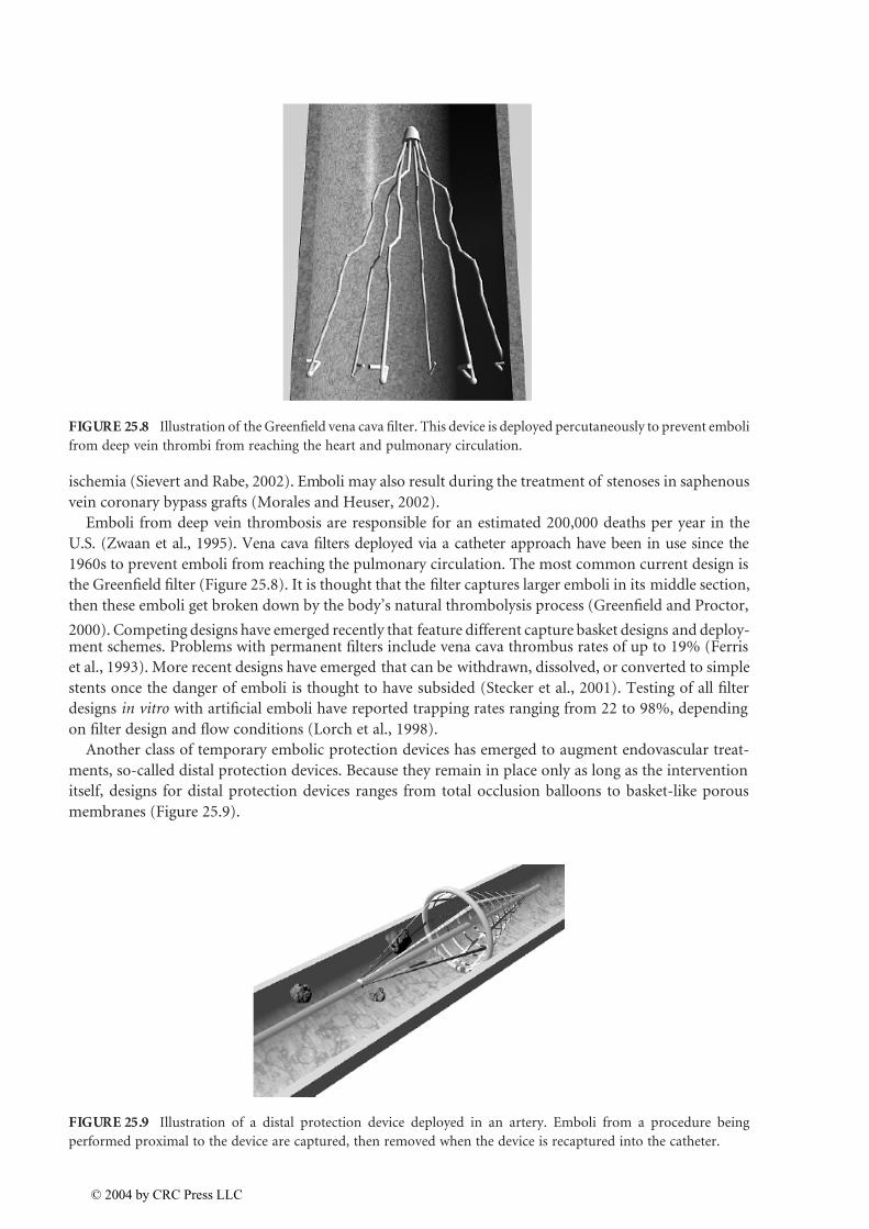
Emboli from deep vein thrombosis are responsible for an estimated 200,000 deaths per year in the
U.S. (Zwaan et al., 1995). Vena cava filters deployed via a catheter approach have been in use since the
1960s to prevent emboli from reaching the pulmonary circulation. The most common current design is
the Greenfield filter (Figure 25.8). It is thought that the filter captures larger emboli in its middle section,
then these emboli get broken down by the body’s natural thrombolysis process (Greenfield and Proctor,
2000). Competing designs have emerged recently that feature different capture basket designs and deploy-ment schemes. Problems with permanent filters include vena cava thrombus rates of up to 19% (Ferris
et al., 1993). More recent designs have emerged that can be withdrawn, dissolved, or converted to simple
stents once the danger of emboli is thought to have subsided (Stecker et al., 2001). Testing of all filter
designs in vitro with artificial emboli have reported trapping rates ranging from 22 to 98%, depending
on filter design and flow conditions (Lorch et al., 1998).
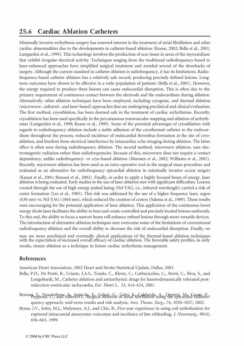
Another class of temporary embolic protection devices has emerged to augment endovascular treat-
ments, so-called distal protection devices. Because they remain in place only as long as the intervention
itself, designs for distal protection devices ranges from total occlusion balloons to basket-like porous
membranes (Figure 25.9).
FIGURE 25.8 Illustration of the Greenfield vena cava filter. This device is deployed percutaneously to prevent emboli
from deep vein thrombi from reaching the heart and pulmonary circulation.
FIGURE 25.9 Illustration of a distal protection device deployed in an artery. Emboli from a procedure being
performed proximal to the device are captured, then removed when the device is recaptured into the catheter.
© 2004 by CRC Press LLC
7/26/2019 Chapter 25 Book Biomedical Technology and Devices Handbook
http://slidepdf.com/reader/full/chapter-25-book-biomedical-technology-and-devices-handbook 13/15
25.6 Cardiac Ablation Catheters
Minimally invasive arrhythmia surgery has renewed interest in the treatment of atrial fibrillation and other
cardiac abnormalities due to the developments in catheter-based ablation (Keane, 2002; Bella et al., 2001;
Lustgarden et al., 1999). This technology involves the production of scar tissue in areas of the myocardium
that exhibit irregular electrical activity. Techniques ranging from the traditional radiofrequency-based to
laser-enhanced approaches have simplified surgical treatment and avoided several of the drawbacks of
surgery. Although the current standard in catheter ablation is radiofrequency, it has its limitations. Radio-
frequency-based catheter ablation has a relatively safe record, producing precisely defined lesions. Long-
term outcomes have shown to be effective in a wide population of patients (Bella et al., 2001). However,
the energy required to produce these lesions can cause endocardial disruption. This is often due to the
primary requirement of continuous contact between the electrode and the endocardium during ablation.
Alternatively, other ablation techniques have been employed, including cryogenic, and thermal ablation
(microwave-, infrared-, and laser-based) approaches that are undergoing preclinical and clinical evaluation.
The first method, cryoablation, has been deemed safe in the treatment of cardiac arrhythmias. Recently,
cryoablation has been used specifically in the percutaneous transvascular mapping and ablation of arrhyth-mias (Lustgarden et al., 1999; Keane et al., 1999). Some of the potential advantages of cryoablation with
regards to radiofrequency ablation include a stable adhesion of the cryothermal catheter to the endocar-
dium throughout the process, reduced incidence of endocardial thrombus formation at the site of cryo-
ablation, and freedom from electrical interference by intracardiac echo imaging during ablation. The latter
effect is often seen during radiofrequency ablation. The second method, microwave ablation, uses elec-
tromagnetic radiation rather than radiofrequencies. Because of this, microwave does not require a contact
dependency, unlike radiofrequency- or cryo-based ablation (Maessen et al., 2002; Williams et al., 2002).
Recently, microwave ablation has been used as an intra-operative tool in the surgical maze procedure and
evaluated as an alternative for radiofrequency epicardial ablation in minimally invasive access surgery
(Knaut et al., 2001; Benussi et al., 2002). Finally, in order to apply a highly focused beam of energy, laserablation is being evaluated. Early studies in the use of laser ablation met with significant difficulties. Lesions
created through the use of high-energy pulsed lasing (Nd-YAG, i.e., infrared wavelength) carried a risk of
crater formation (Lee et al., 1985). This risk was addressed by the use of a higher frequency laser, argon
(630 nm) vs. Nd-YAG (1064 nm), which reduced the creation of craters (Sakena et al., 1989). These results
were encouraging for the potential application of laser ablation. This application of the continuous lower
energy diode laser facilitates the ability to heat and create controlled and precisely located lesions uniformly.
To this end, the ability to focus a narrow beam will enhance refined lesions through more versatile devices.
The introduction of alternative ablation techniques may overcome some of the limitations of conventional
radiofrequency ablation and the overall ability to decrease the risk of endocardial disruption. Finally, we
may see more preclinical and eventually clinical applications of the thermal-based ablation techniqueswith the expectation of increased overall efficacy of cardiac ablation. The favorable safety profiles, in early
results, ensure ablation as a technique in future cardiac arrhythmia management.
References
American Heart Association, 2002 Heart and Stroke Statistical Update, Dallas, 2001.
Bella, P.D., De Ponti, R., Uriarte, J.A.S., Tondo, C., Klersy, C., Carbucicchio, C., Storti, C., Riva, S., and
Longobardi, M., Catheter ablation and antiarrhymic drugs for haemodynamically tolerated post-
infarction ventricular tachycardia, Eur. Heart J ., 23, 414–424, 2001.
Benussi, S., Nascimbene, S., Agricola, E., Calori, G., Calvi, S., Caldarola, A., Oppizzi, M., Casati, V.,Pappone, C., and Alfieri, O., Surgical ablation of atrial fibrillation using the epicardial radiofre-
quency approach: mid-term results and risk analysis, Ann. Thorac. Surg ., 74, 1050–1057, 2002.
Byrne, J.V., Sohn, M.J., Molyneux, A.J., and Chir, B., Five-year experience in using coil embolization for
ruptured intracranial aneurysms: outcomes and incidence of late rebleeding, J. Neurosurg ., 90(4),
656–663, 1999.
© 2004 by CRC Press LLC

7/26/2019 Chapter 25 Book Biomedical Technology and Devices Handbook
http://slidepdf.com/reader/full/chapter-25-book-biomedical-technology-and-devices-handbook 14/15
Clowes, A.W. and Karnovsky, M.J., Suppression by heparin of smooth muscle cell proliferation in injured
arteries, Nature, 265, 625–626, 1977.
Degertekin, M., Regar, E., Tanabe, K., Lee, C.H., and Serruys, P.W., Sirolimus eluting stent in the treatment
of atherosclerosis coronary artery disease, Minerva Cardioangiol ., 50(5), 405–418, 2002.
Dotter, C.T., Transluminally-placed coilspring endarterial tube grafts: long term patency in canine
popliteal artery, Invest. Radiol ., 4, 329–332, 1969.
Dotter, C.T., Buschman, R.W., McKinney, M.K., and Rösch, J., Transluminal expandable nitinol coil stent
grafting: preliminary report, Radiology , 147, 259–260, 1983.
Duerig, T.W., Tolomeo, D.E., and Wholey, M., An overview of superelastic stent design, Min. Invas. Ther.
Allied Technol ., 9(3/4), 235–246, 2000.
Edelman, E.R. and Rogers, C., Pathobiologic responses to stenting, Am. J. Cardiol ., 81, 4E–6E, 1998.
Ferris, E.J., McCowan, T.C., Carver, D.K., and MacFarland, D.J., Percutaneous inferior vena cava filters:
follow-up of seven designs in 320 patients, Radiology , 188, 851–856, 1993.
Fleisch, M. and Meier, B., Management and outcome of stents in 1998: long-term outcome, Cardiol. Rev .,
7, 215–218, 1999.
Gallo, R., Padurean, A., and Jayaramon, T., Inhibition of intimal thickening after balloon angioplasty inporcine coronary arteries by targeting regulators of the cell cycle, Circulation, 99, 2164–2170, 1999.
Greenfield, L.J. and Proctor, M.C., The percutaneous greenfield filter: outcomes and practice patterns, J.
Vasc. Surg ., 32(5), 888–893, 2000.
Grube, E. and Büllesfeld, L., Initial experience with Paclitaxel-coated stents, J. Interven. Cardiol., 15,
471–476, 2002.
Hirsh, J., Heparin, N. Engl. J. Med ., 324, 1565–1574, 1991.
Hlatky, M.A. et al., Medical care costs and quality of life after randomization to coronary angioplasty or
coronary by-pass surgery, N. Engl. J. Med ., 336(2), 92–99, 1997.
Hwang, C., Wu, D., and Edelman, E., Physiological transport forces govern drug distribution for stent-
based delivery, Circulation, 104, 600–605, 2001.Kastrati, A., Mehilli, J., Dirsschinger, J., et al., Restenosis after coronary placement of various stent types,
Am. J. Cardiol ., 877, 34–39, 2001.
Keane, D., New catheter ablation techniques for the treatment of cardiac arrhythmias, Cardiac ElectroPhy.
Rev ., 6, 341–348, 2002.
Keane, D., Zhou, L., Houghtaling, C., Aretez, T., McGovern, B., Garan, H., and Ruskin, J., Percutaneous
cryothermal catheter ablation for the creation of linear atrial lesions, Pace, 22(II), 587, 1999.
Knaut, M., Tugtekin, M., Spitzer, S.G., Karolyi, L., Boehme, H., and Schueler, S., Curative treatment of
chronic atrial fibrillation in patients with simultaneous cardiosurgical diseases with intraoperative
microwave ablation, JACC , 109A(abstr), 2001.
Lee, B.I., Gottdiener, J.S., Fletcher, R.D., Rodriguez, E.R., and Ferrans, V.J., Transcatheter ablation: com-parison between laser photoablation and electrode shock ablation in the dog, Circulation, 71,
579–586, 1985.
Lieber, B.B. and Gounis, M.J., The physics of endoluminal stenting in the treatment of cerebrovascular
aneurysms, Neurol. Res., 24(Suppl. 1), S33–42, 2002.
Liffman, K., Lawrence-Brown, M., Semmens, J.B., Bui, A., Rudman, M., and Hartley, D., Analytical
modeling and numerical simulation of forces in an endoluminal graft, J. Endovasc. Ther ., 8,
358–371, 2001.
Lorch, H., Zwaan, M., Kulke, C., and Weiss, H.D., In vitro studies of temporary vena cava filters,
Cardiovasc. Interv. Radiol ., 21, 146–150, 1998.
Lustgarden, D., Keane, D., and Ruskin, J., Cryothermal catheter ablation: mechanism of tissue injury andclinical results, Prog. Cardiovasc. Dis., 41, 481–498, 1999.
Maessen, J.G., Nijis, J.F.M.A., Smeets, J.L.R.M., Vainer, J., and Mochtar, B., Beating-heart treatment of
atrial fibrillation with microwave ablation, Ann. Thorac. Surg ., 74, S1307–1311, 2002.
Morales, P.A. and Heuser, R.R., Embolic protection devices, J. Interven. Cardiol ., 15, 485–490, 2002.
© 2004 by CRC Press LLC

7/26/2019 Chapter 25 Book Biomedical Technology and Devices Handbook
http://slidepdf.com/reader/full/chapter-25-book-biomedical-technology-and-devices-handbook 15/15