Embed Size (px)
Citation preview
Chapter 4: Methods of Analysis
4.1 Motivation4.2 Nodal Voltage Analysis4.3 Simultaneous Eqs. & Matrix Inversion 4.4 Nodal Voltage Analysis with Voltage Sources4.5 Mesh Current Analysis4.6 Mesh Current Analysis with Current Sources4.7 Nodal and Mesh Analysis by Inspection4.8 Nodal versus Mesh Analysis4.9 Summary
1
2
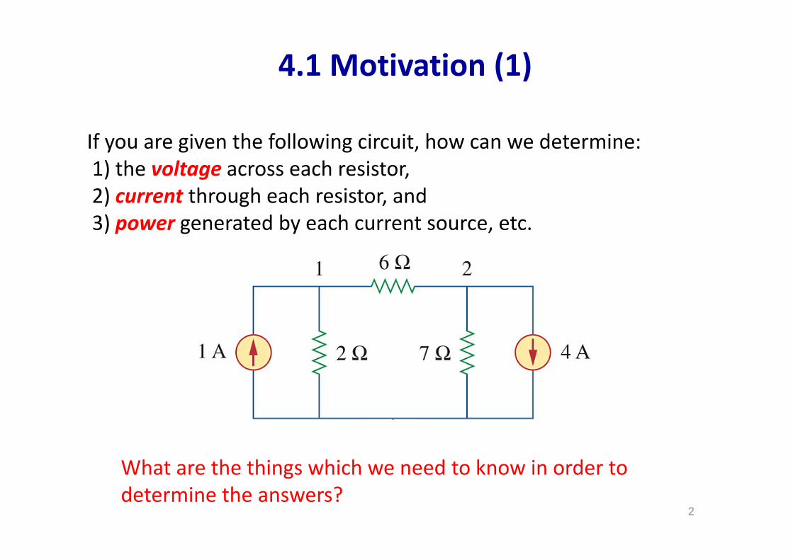
What are the things which we need to know in order to determine the answers?
4.1 Motivation (1)
If you are given the following circuit, how can we determine:1) the voltage across each resistor,2) current through each resistor, and3) power generated by each current source, etc.
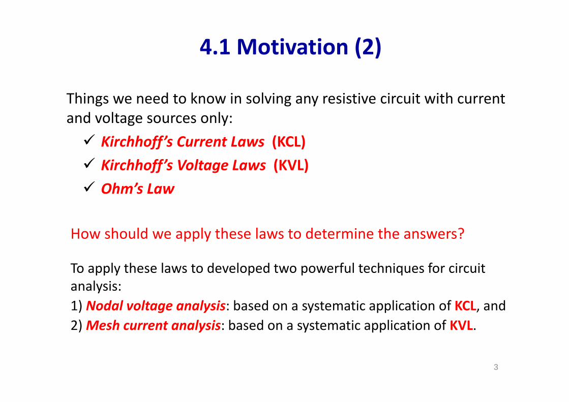
Things we need to know in solving any resistive circuit with current and voltage sources only:
3
How should we apply these laws to determine the answers?
Kirchhoff’s Current Laws (KCL) Kirchhoff’s Voltage Laws (KVL) Ohm’s Law
4.1 Motivation (2)
To apply these laws to developed two powerful techniques for circuit analysis:1) Nodal voltage analysis: based on a systematic application of KCL, and2) Mesh current analysis: based on a systematic application of KVL.
4.2 Nodal Voltage Analysis (1)
4
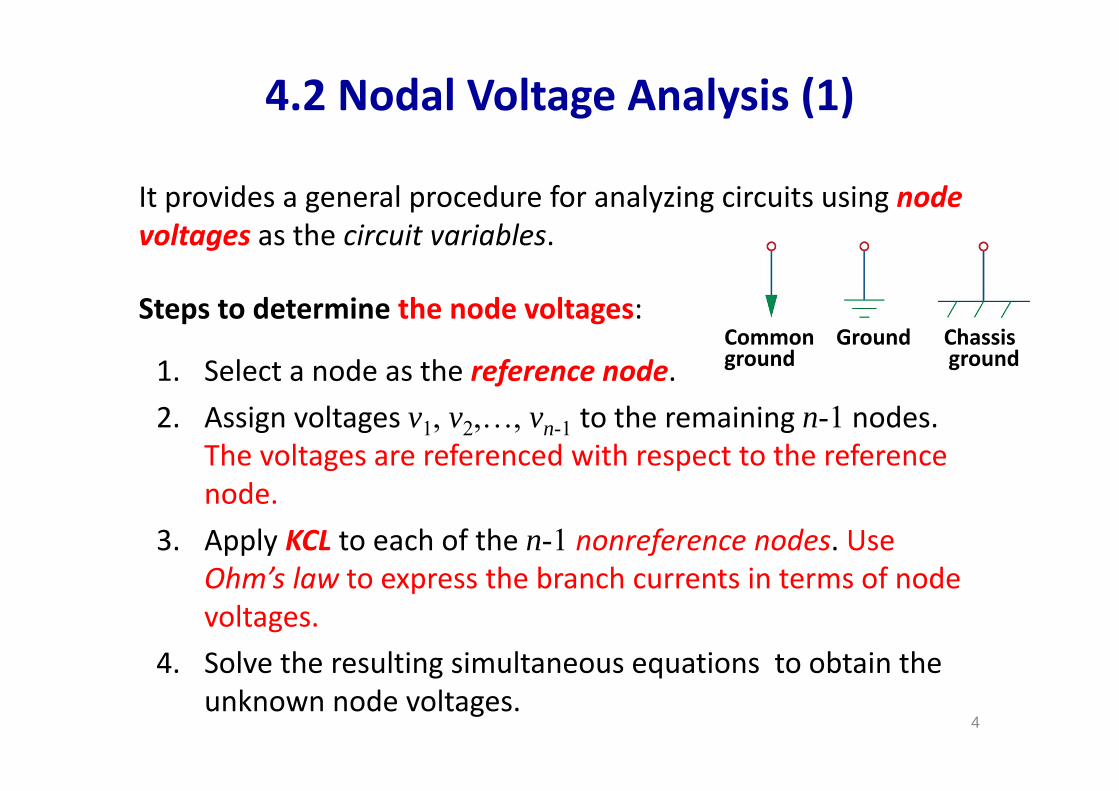
It provides a general procedure for analyzing circuits using node voltages as the circuit variables.
Steps to determine the node voltages:
1. Select a node as the reference node.2. Assign voltages v1, v2,…, vn-1 to the remaining n-1 nodes.
The voltages are referenced with respect to the reference node.
3. Apply KCL to each of the n-1 nonreference nodes. Use Ohm’s law to express the branch currents in terms of node voltages.
4. Solve the resulting simultaneous equations to obtain the unknown node voltages.
Common Ground Chassisground ground
5
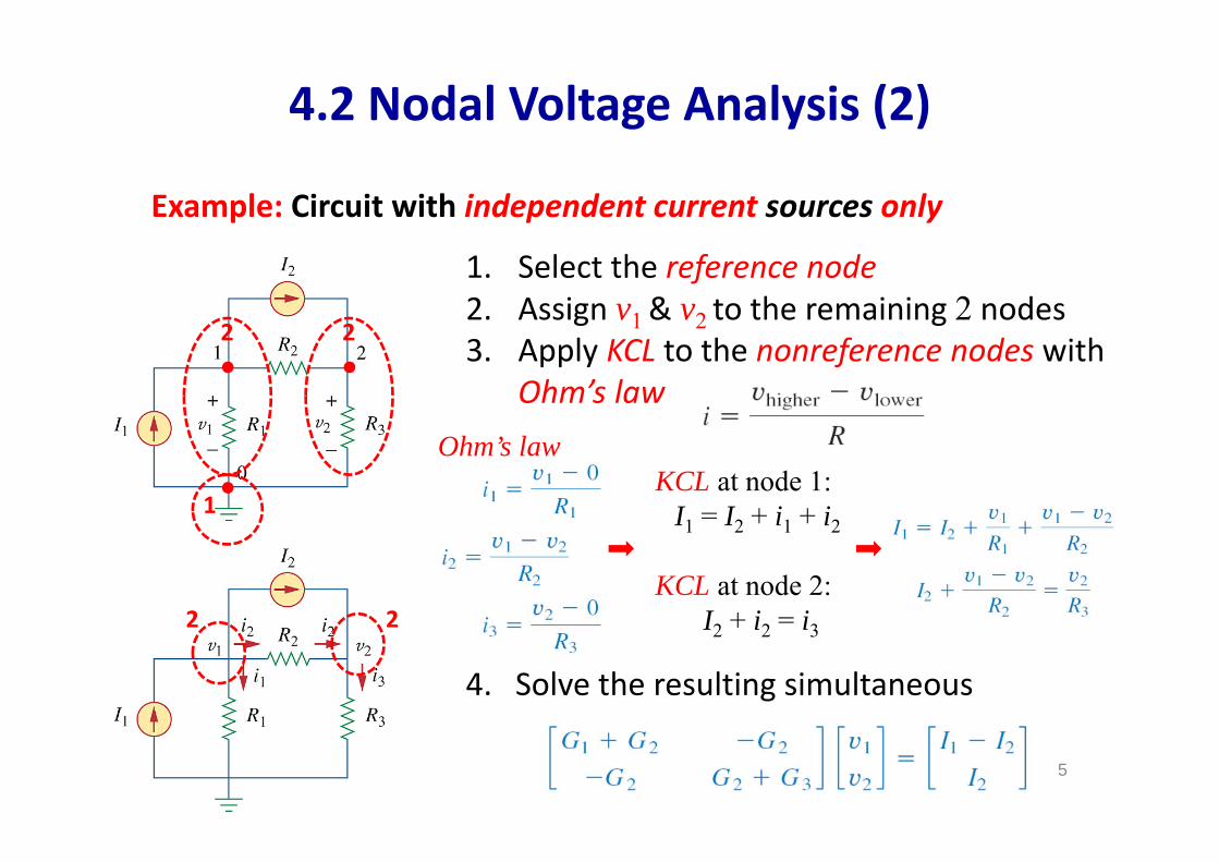
Example: Circuit with independent current sources only
1. Select the reference node2. Assign v1& v2 to the remaining 2 nodes 3. Apply KCL to the nonreference nodes with
Ohm’s law
4. Solve the resulting simultaneous
1
2 2
KCL at node 1: I1 = I2 + i1 + i2
KCL at node 2:I2 + i2 = i3
Ohm’s law
2 2
4.2 Nodal Voltage Analysis (2)
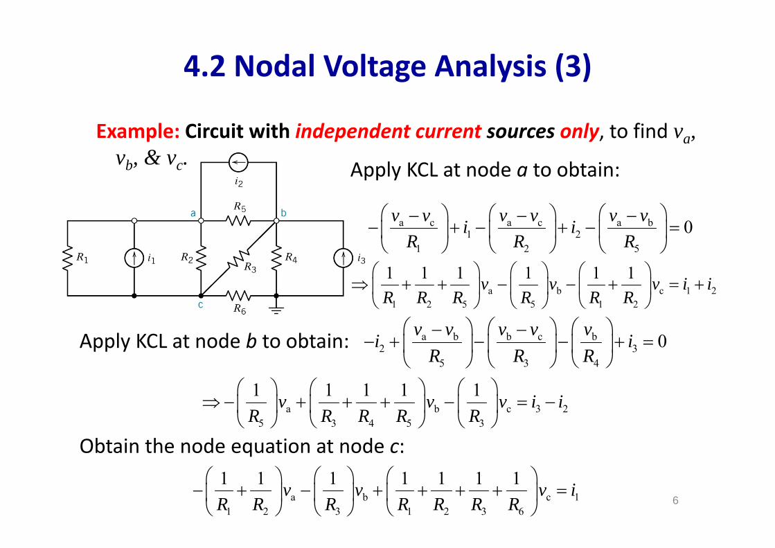
4.2 Nodal Voltage Analysis (3)
Example: Circuit with independent current sources only, to find va, vb, & vc.
a c a c a b1 2
1 2 5
0v v v v v vi iR R R
Apply KCL at node a to obtain:
a b c 1 21 2 5 5 1 2
1 1 1 1 1 1v v v i iR R R R R R
Apply KCL at node b to obtain: a b b c b2 3
5 3 4
0v v v v vi iR R R
a b c 3 25 3 4 5 3
1 1 1 1 1v v v i iR R R R R
Obtain the node equation at node c:
a b c 11 2 3 1 2 3 6
1 1 1 1 1 1 1v v v iR R R R R R R
6
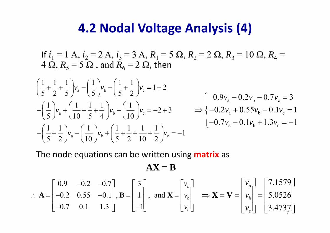
If i1 = 1 A, i2 = 2 A, i3 = 3 A, R1 = 5 Ω, R2 = 2 Ω, R3 = 10 Ω, R4 = 4 Ω, R5 = 5 Ω , and R6 = 2 Ω, then
a b c
a b c
a b c
1 1 1 1 1 1 1 25 2 5 5 5 2
1 1 1 1 1 2 35 10 5 4 101 1 1 1 1 1 1 15 2 10 5 2 10 2
v v v
v v v
v v v
4.2 Nodal Voltage Analysis (4)
a b c
a b c
a b c
0.9 0.2 0.7 30.2 0.55 0.1 10.7 0.1 1.3 1
v v vv v vv v v
The node equations can be written using matrix asAX = B
0.9 0.2 0.7 30.2 0.55 0.1 , 1 , and0.7 0.1 1.3 1
a
b
c
vvv
A B X7.15795.05263.4737
a
b
c
vvv
X V
7
8
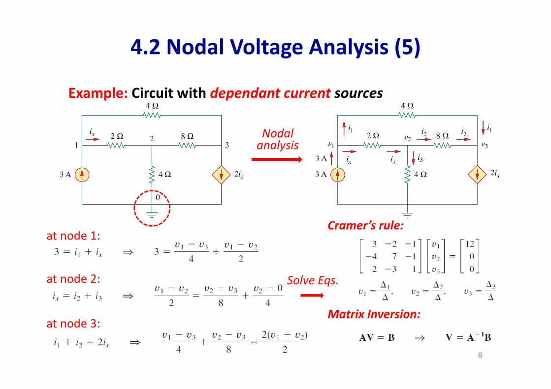
Example: Circuit with dependant current sources
Nodal analysis
Solve Eqs.
Cramer’s rule:
Matrix Inversion:
at node 1:
at node 2:
at node 3:
4.2 Nodal Voltage Analysis (5)
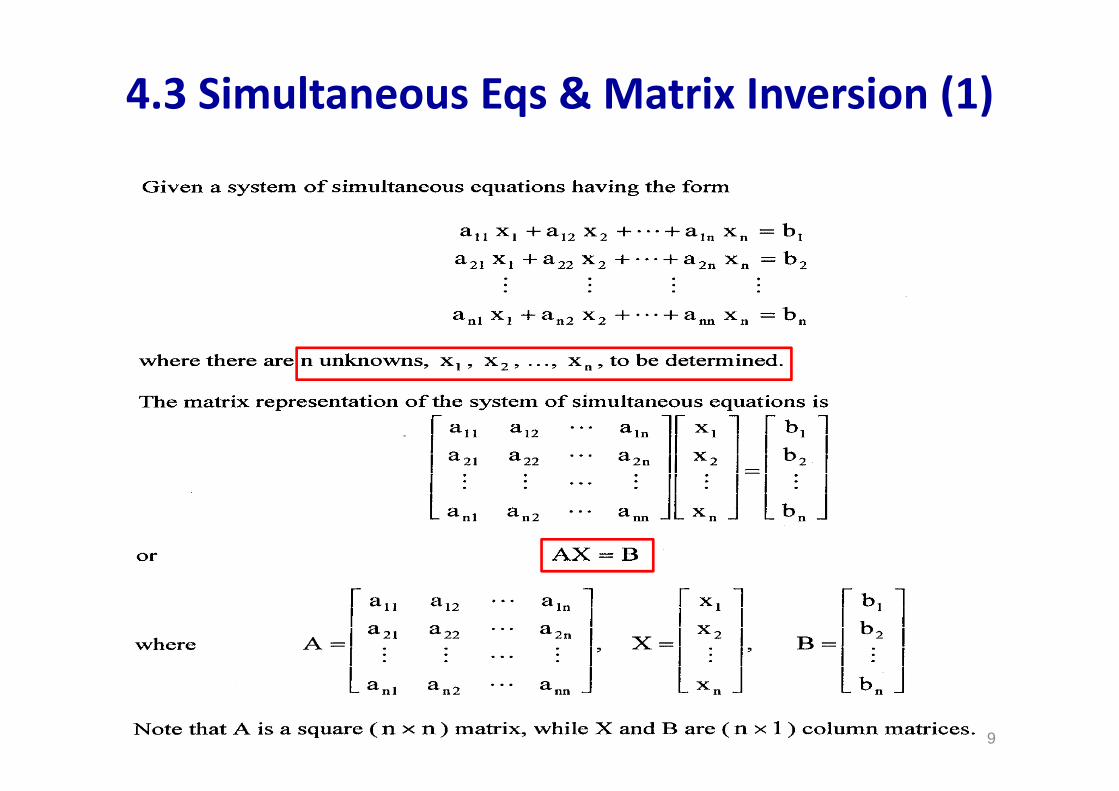
4.3 Simultaneous Eqs & Matrix Inversion (1)
99
10
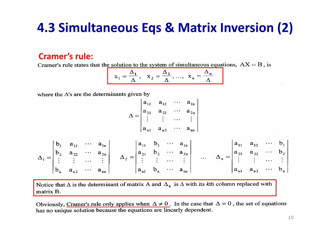
Cramer’s rule:
4.3 Simultaneous Eqs & Matrix Inversion (2)
10
11
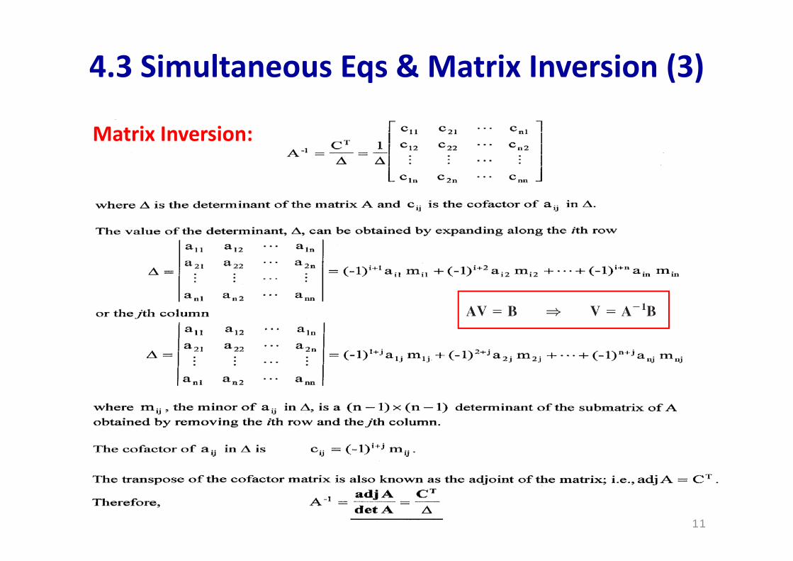
Matrix Inversion:
4.3 Simultaneous Eqs & Matrix Inversion (3)
11
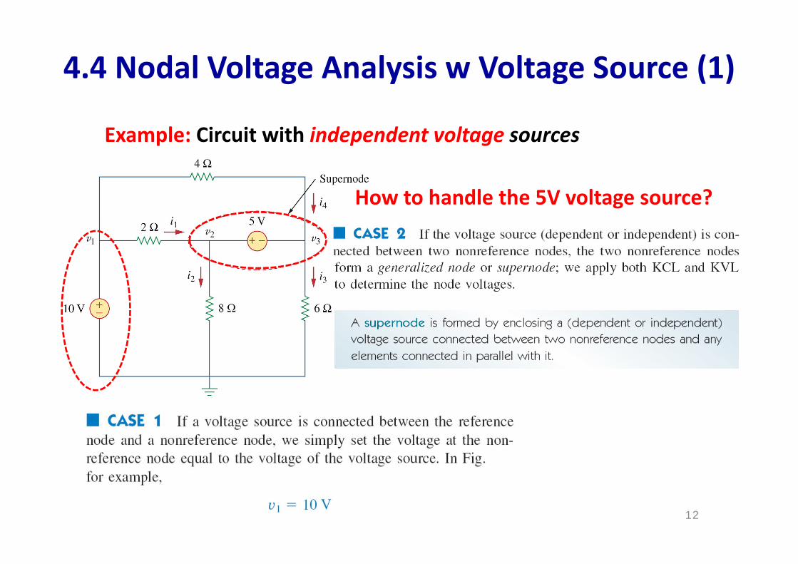
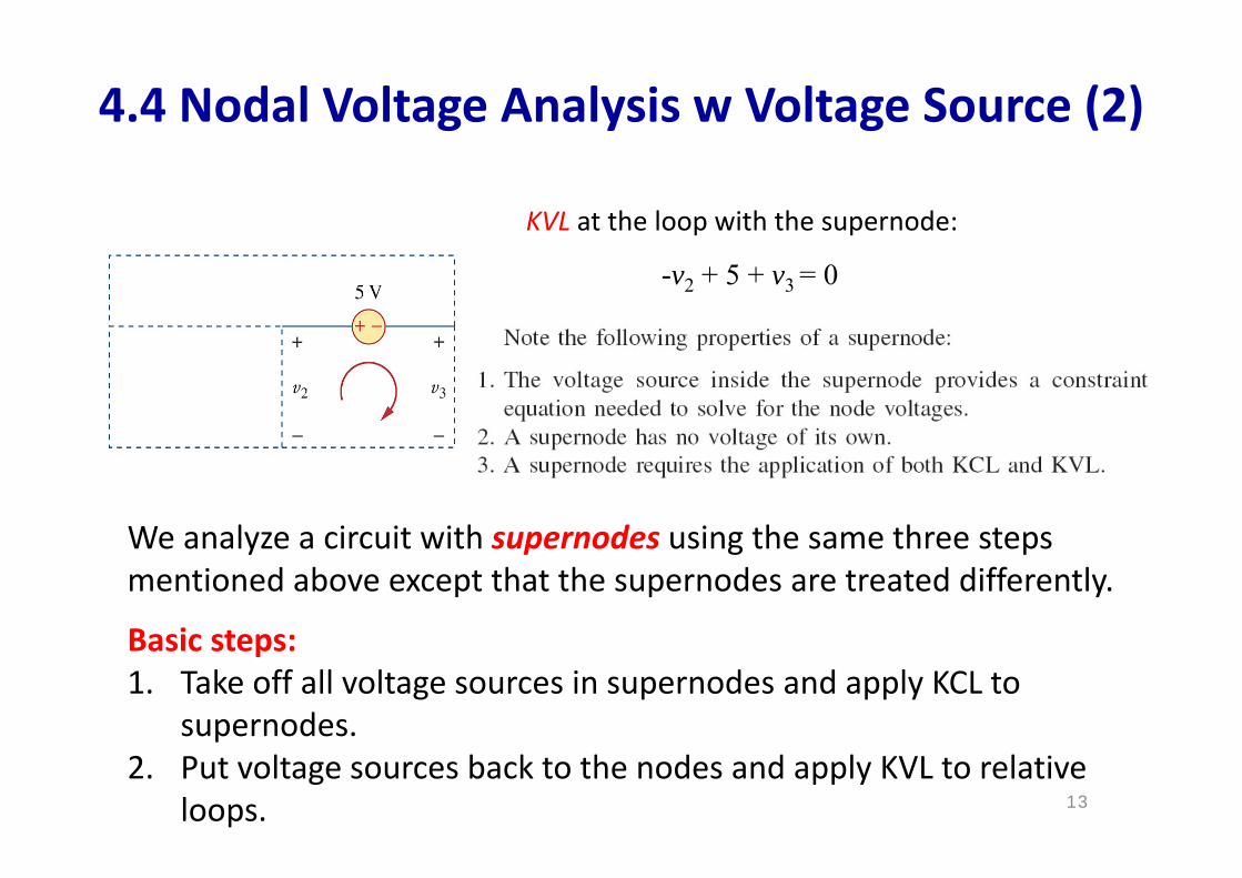
4.4 Nodal Voltage Analysis w Voltage Source (1)
12
Example: Circuit with independent voltage sources
How to handle the 5V voltage source?
13
We analyze a circuit with supernodes using the same three steps mentioned above except that the supernodes are treated differently.
Basic steps:1. Take off all voltage sources in supernodes and apply KCL to
supernodes.2. Put voltage sources back to the nodes and apply KVL to relative
loops.
KVL at the loop with the supernode:
-v2 + 5 + v3 = 0
4.4 Nodal Voltage Analysis w Voltage Source (2)
14
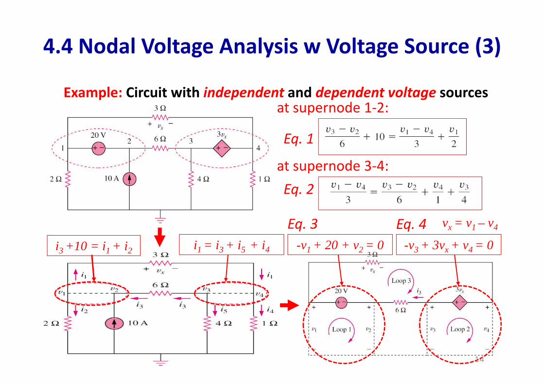
Example: Circuit with independent and dependent voltage sources
i3 +10 = i1 + i2 i1 = i3 + i5 + i4 -v1 + 20 + v2 = 0 -v3 + 3vx + v4 = 0
at supernode 1‐2:
at supernode 3‐4:
vx = v1 – v4
Eq. 1
Eq. 2
Eq. 3 Eq. 4
4.4 Nodal Voltage Analysis w Voltage Source (3)
14
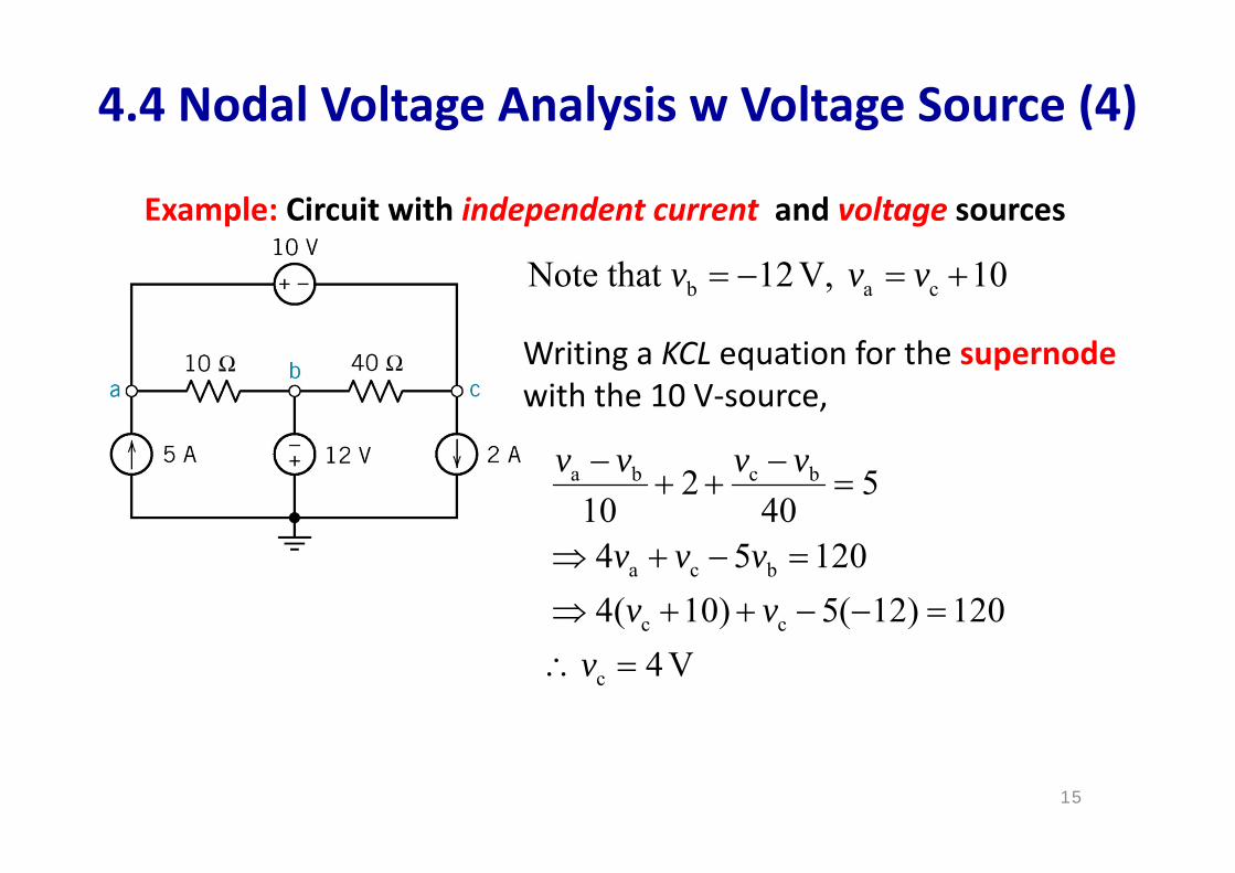
Example: Circuit with independent current and voltage sources
4.4 Nodal Voltage Analysis w Voltage Source (4)
b a cNote that 12V, 10v v v
Writing a KCL equation for the supernodewith the 10 V‐source,
a b c b
a c b
c c
c
2 510 404 5 1204( 10) 5( 12) 120
4 V
v v v v
v v vv v
v
15
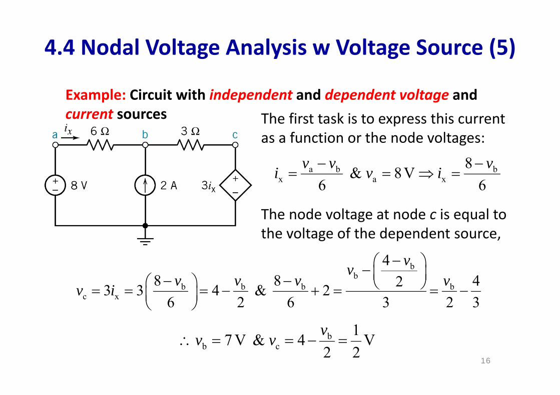
Example: Circuit with independent and dependent voltage and current sources
4.4 Nodal Voltage Analysis w Voltage Source (5)
The first task is to express this current as a function or the node voltages:
a b bx a x
8 & 8V6 6
v v vi v i
The node voltage at node c is equal to the voltage of the dependent source,
bb
b b b bc x
48 8 423 3 4 & 2
6 2 6 3 2 3
vvv v v vv i
bb c
17 V & 4 V2 2vv v
16
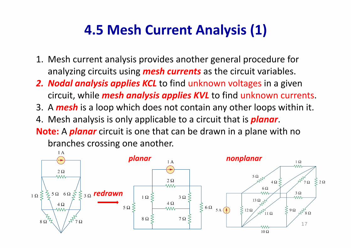
4.5 Mesh Current Analysis (1)
17
1. Mesh current analysis provides another general procedure for analyzing circuits using mesh currents as the circuit variables.
2. Nodal analysis applies KCL to find unknown voltages in a given circuit, while mesh analysis applies KVL to find unknown currents.
3. A mesh is a loop which does not contain any other loops within it.4. Mesh analysis is only applicable to a circuit that is planar. Note: A planar circuit is one that can be drawn in a plane with no
branches crossing one another.
redrawn
planar nonplanar
18
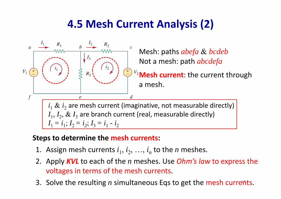
Steps to determine the mesh currents:1. Assign mesh currents i1, i2, …, in to the n meshes. 2. Apply KVL to each of the n meshes. Use Ohm’s law to express the
voltages in terms of the mesh currents. 3. Solve the resulting n simultaneous Eqs to get the mesh currents.
Mesh: paths abefa & bcdebNot a mesh: path abcdefa
Mesh current: the current through a mesh.
i1 & i2 are mesh current (imaginative, not measurable directly)I1, I2, & I3 are branch current (real, measurable directly)I1 = i1; I2 = i2; I3 = i1 - i2
4.5 Mesh Current Analysis (2)

19
Example: Circuit with dependent voltage source, to find I0
1. Assign mesh currents i1, i2, & i3
2. Apply KVL to each of the 3 meshes with Ohm’s law to express thevoltages in terms of i1, i2, & i3
3. Solve the 3 Eqs to get the mesh currents
at mesh 1:
at mesh 2:
at mesh 3:
4.5 Mesh Current Analysis (3)
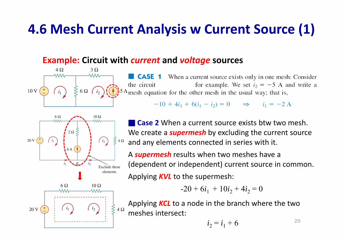
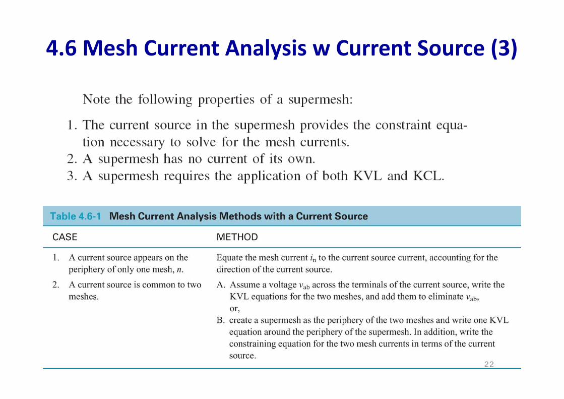
4.6 Mesh Current Analysis w Current Source (1)
20
Case 2 When a current source exists btw two mesh. We create a supermesh by excluding the current source and any elements connected in series with it. A supermesh results when two meshes have a (dependent or independent) current source in common.
Example: Circuit with current and voltage sources
Applying KVL to the supermesh: -20 + 6i1 + 10i2 + 4i2 = 0
Applying KCL to a node in the branch where the two meshes intersect:
i2 = i1 + 6
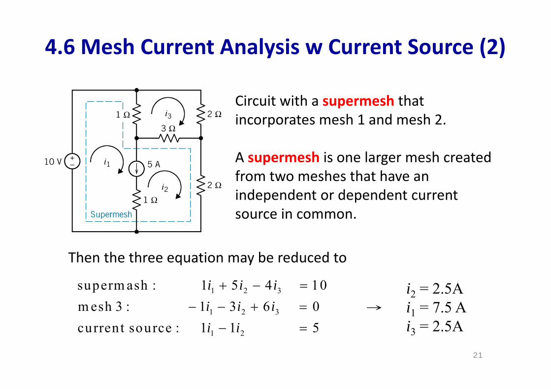
4.6 Mesh Current Analysis w Current Source (2)
Circuit with a supermesh that incorporates mesh 1 and mesh 2.
A supermesh is one larger mesh created from two meshes that have an independent or dependent current source in common.
1 2 3
1 2 3
1 2
superm ash : 1 5 4 10m esh 3 : 1 3 6 0current source : 1 1 5
i i ii i ii i
i2 = 2.5A → i1 = 7.5 A
i3 = 2.5A
Then the three equation may be reduced to
21
22
4.6 Mesh Current Analysis w Current Source (3)
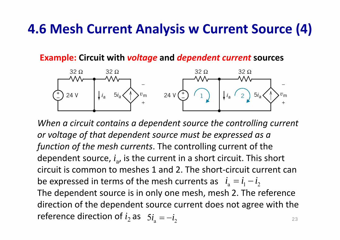
4.6 Mesh Current Analysis w Current Source (4)
Example: Circuit with voltage and dependent current sources
When a circuit contains a dependent source the controlling current or voltage of that dependent source must be expressed as a function of the mesh currents. The controlling current of the dependent source, ia, is the current in a short circuit. This short circuit is common to meshes 1 and 2. The short‐circuit current can be expressed in terms of the mesh currents asThe dependent source is in only one mesh, mesh 2. The reference direction of the dependent source current does not agree with the reference direction of i2 as
a 1 2i i i
a 25i i 23
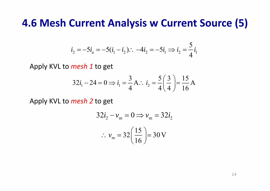
2 a 1 2 2 1 2 155 5( ) 4 54
i i i i i i i i
Apply KVL to mesh 1 to get
1 1 23 5 3 1532 24 0 A A4 4 4 16
i i i
4.6 Mesh Current Analysis w Current Source (5)
Apply KVL to mesh 2 to get
2 m m 232 0 32i v v i
m1532 30 V16
v
24
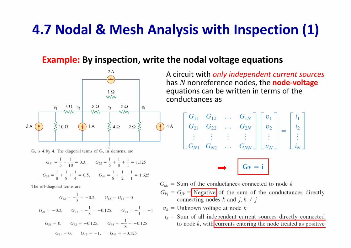
4.7 Nodal & Mesh Analysis with Inspection (1)
25
Example: By inspection, write the nodal voltage equationsA circuit with only independent current sources has N nonreference nodes, the node‐voltageequations can be written in terms of the conductances as
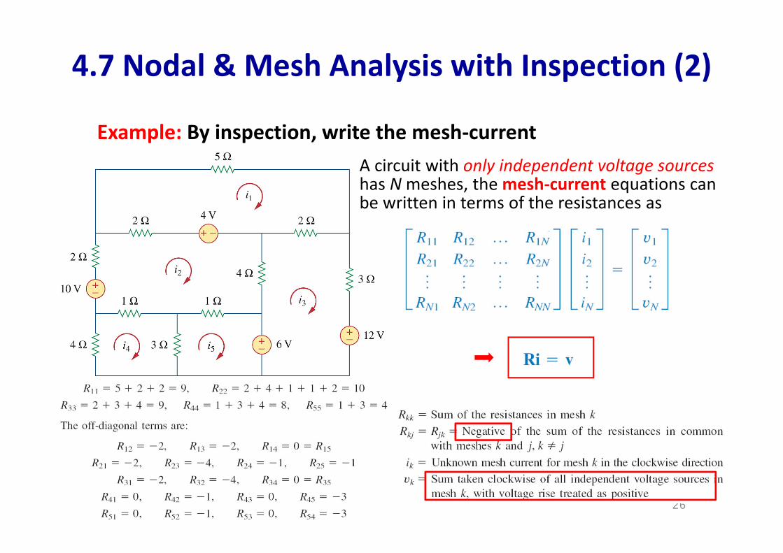
4.7 Nodal & Mesh Analysis with Inspection (2)
26
Example: By inspection, write the mesh‐currentA circuit with only independent voltage sources has Nmeshes, the mesh‐current equations can be written in terms of the resistances as
4.8 Nodal versus Mesh Analysis
27
To select the method that results in the smaller number of equations. For example:
1. Choose nodal analysis for circuit with fewer nodes than meshes.
*Choose mesh analysis for circuit with fewer meshes than nodes.
*Networks that contain many series connected elements, voltage sources, or supermeshes are more suitable for mesh analysis.
*Networks with parallel‐connected elements, current sources, or supernodes are more suitable for nodal analysis.
2. If node voltages are required, it may be expedient to apply nodal analysis. If branch or mesh currents are required, it may be better to use mesh analysis.
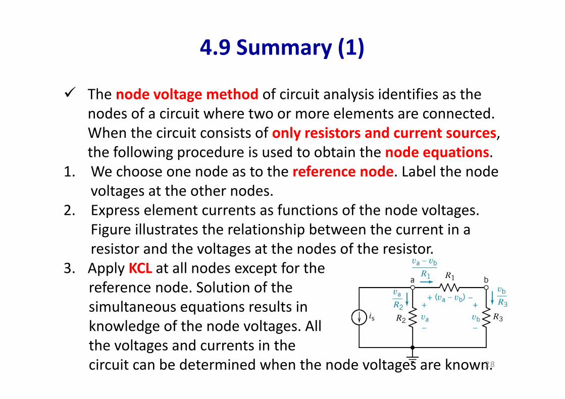
The node voltage method of circuit analysis identifies as the nodes of a circuit where two or more elements are connected. When the circuit consists of only resistors and current sources, the following procedure is used to obtain the node equations.
1. We choose one node as to the reference node. Label the node voltages at the other nodes.
2. Express element currents as functions of the node voltages. Figure illustrates the relationship between the current in a resistor and the voltages at the nodes of the resistor.
3. Apply KCL at all nodes except for the reference node. Solution of the simultaneous equations results in knowledge of the node voltages. Allthe voltages and currents in the circuit can be determined when the node voltages are known.
4.9 Summary (1)
28
When a circuit has voltage sources as well as current sources, we can still use the node voltage method by using the concept of a supernode. A supernode is a large node that includes two nodes connected by a known voltage source. If the voltage source is directly connected between a node q and the reference node, we may set vq = vs, and write the KCL equations at the remaining nodes.
If the circuit contains a dependent source, we first express the controlling voltage or current of the dependent source as a function of the node voltages. Next, we express the controlled voltage or current as a function of the node voltages. Finally, we apply KCL to nodes and supernodes.
4.9 Summary (2)
29
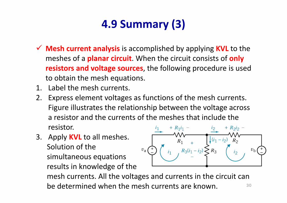
Mesh current analysis is accomplished by applying KVL to the meshes of a planar circuit. When the circuit consists of only resistors and voltage sources, the following procedure is used to obtain the mesh equations.
1. Label the mesh currents.2. Express element voltages as functions of the mesh currents.
Figure illustrates the relationship between the voltage across a resistor and the currents of the meshes that include the resistor.
3. Apply KVL to all meshes. Solution of the simultaneous equations results in knowledge of the mesh currents. All the voltages and currents in the circuit canbe determined when the mesh currents are known.
4.9 Summary (3)
30
If a current source is common to two adjoining meshes, we define the interior of the two meshes as a supermesh. We then write the mesh current equation around the periphery of the supermesh. If a current source appears at the periphery of only one mesh, mesh current as equal to the current of the source, accounting for the direction of the current source.
If the circuit contains a dependent source, we first express the controlling voltage or current of the dependent source as a function of the mesh currents. Next, we express the controlled voltage or current as a function of the mesh currents. Finally, we apply KVL to meshes and supermeshes.
Either node voltage or mesh current analysis can be used to obtain the currents or voltages in a circuit. However, a circuit with fewer node equation than mesh current equations may require that we select the node voltage method.
4.9 Summary (4)
31