Embed Size (px)
Citation preview

109
CHAPTER 4
POWER SUPPLY DISTRIBUTION AND GROUNDING
SCHEMES FOR TRACKED VEHICLES
4.1 INTRODUCTION
An electrical ground is a low impedance plane of reference
potential to which all the systems & circuits can be related. Grounding
is a technique which provides a low resistance path between electrical,
electronic equipments and earth the common reference low impedance
plane to shunt the fault currents (US Army 1979). Thus the grounding
(Denny 1993) is an absolute essential element to ensure protection of the
equipment and personnel from electric shock. This also helps to prevent
insulation puncture or flashover in the event of lightning, short-circuit
and also reduces electromagnetic interference. A resistance below 1
milliohm at operational frequency represents good grounding for the
equipment ( Hasse 1992).
4.2 GROUNDING PRINCIPLES AND EARTHING
STANDARDS
The electronic and electrical equipment have to generally
confirm to the MIL STD 454 C for the AC and DC Systems. Physical
effects of the same are given below as indicated in Table 4.1.

110
Table 4.1 Electric shock hazardous current levels
Alternating (60 Hz) Current mA Direct Current (mA) Effects
0.5-1.5 0-4 Perception 1-3 4-15 Surprise 3-22 15-88 Relax Action
21-40 80-160 Muscular inhibition
40-100 160-300 Respiratory block Over 100 Over 300 Fatal
The resistance of the human skin is usually somewhere
between 500 and 7500 ohms. Battery driven system usually does not
require any grounding except for lightning arc prevention.
At frequencies above 300 Hz, the current levels required to
produce the above effects begin to increase due to skin effect. Above
100-200 kHz, the sensation of shock changes from tingling to heat or
burns. They are seen in the event of electrical phenomena such as EMP
(Janes Defence 1999).
4.3 EARTH CONDUCTOR AND ELEMENTS IN MOBILE
VEHICLE
A good conductor such as copper or silver distribute the flow
of current over an area large enough to reduce the voltage gradients to
safe levels. In a tracked automobile, the chassis is used as return
conductor provides good ground conductor (Hughes 1983). The

111
operating voltage is either 28 V DC, 42 V DC, 115 V 400 Hz AC, 380 V
AC etc, depending upon the type of application for land vehicle. In the
present case 28 V DC system, the current is being controlled by a main
relay rated at 1000 A. This relay is mounted on silver plated bus bar so
that the ground resistance is reduced to a low value.
4.4 POWER SUPPLY DISTRIBUTION
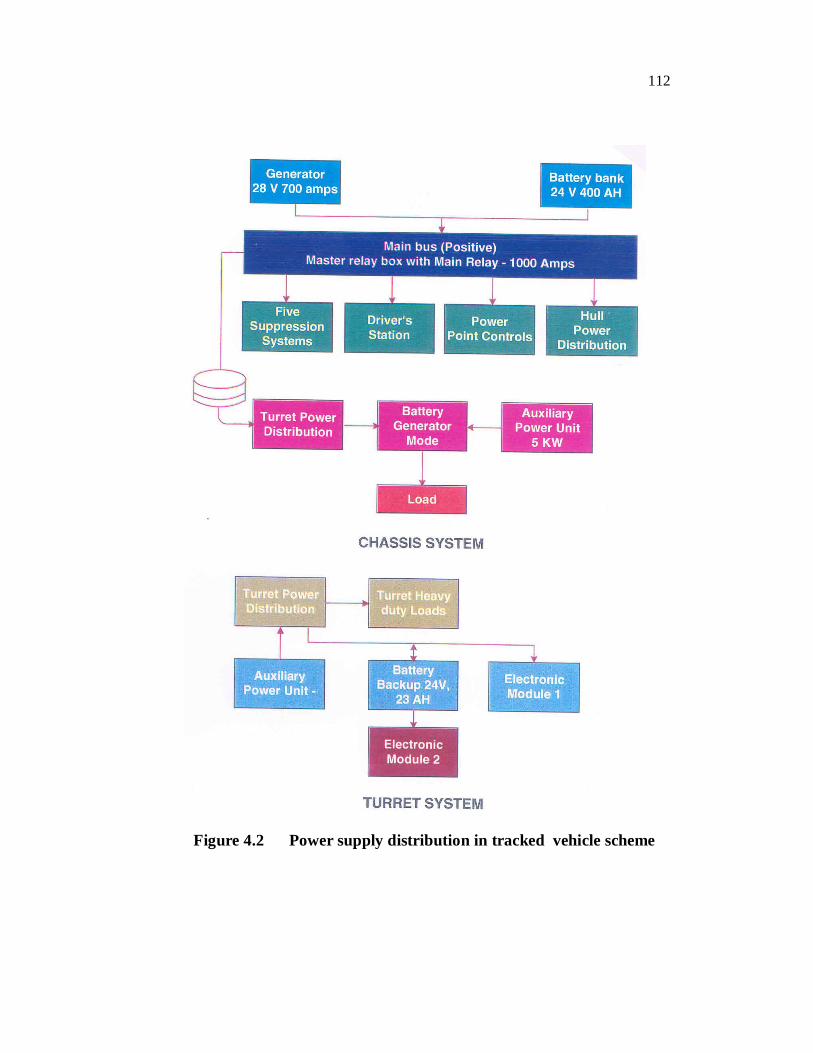
Figures 4.1 shows power sources and current flow diagram
.The Figure 4.2 depicts the power distribution scheme for the tracked
fighting vehicle. The generator is rated 700 A that charges battery bank.
The battery bank acts as a reservoir of energy. It gets charged during
running of the main engine. It supplements the generator and gives back
the energy to the system in the event of peak loads on demand.
Fig 4.1 Power sources & current flow diagram for vehicle
TDJB700 A
HULL LOADS
APU
5KW
GROUND
HULL200 A CONFIG -2 @
TURRET200 A CONFIG-1 **
APUPANEL
OTHER SYSTEMS
Battery Bank
RBJ
MRB
700 A TDJB700 A
HULL LOADS
APU
5KW
GROUND
HULL200 A CONFIG -2 @
TURRET200 A CONFIG-1 **
APUPANEL
OTHER SYSTEMS
RBJ
MRB
700 A
112
Figure 4.2 Power supply distribution in tracked vehicle scheme

113
4.5 CATHODE PROTECTION
All ground electrode metals are subject to corrosion i.e. to
react either chemically or electrochemically with its environment to
form a compound which is static in the environment. The two process
for corrosion are
a) Galvanic Corrosion: Develops from the formation of a
voltaic cell between the two different metals with moisture
acting as an electrotype.
b) Electrolytic corrosion: Develops when two metals are in
contacts through an electrolyte.
The best methodology is to use metals with low
electrochemical activity such as tin lead or copper. The method
suggested by Denny (et al 1993) was utilised in improving the
grounding within the vehicle. All the joints were electronically welded
and fused together to reduce corrosion.
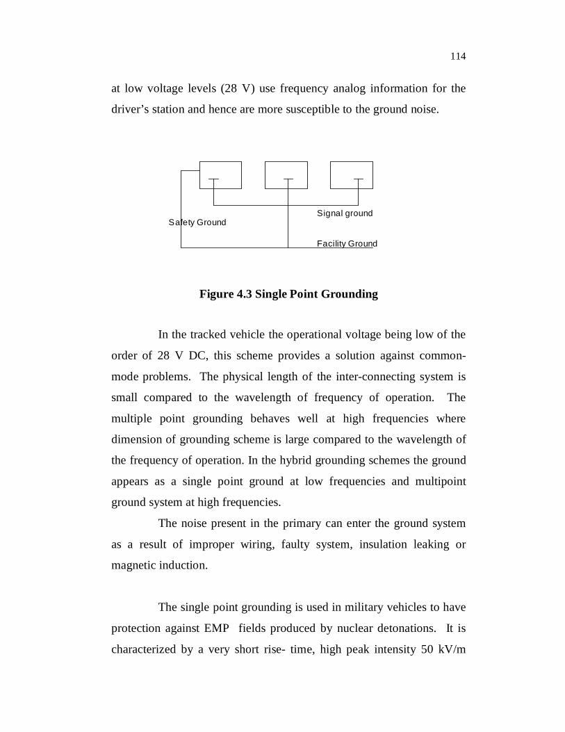
4.6 SINGLE POINT GROUNDING
In single point grounding scheme (4.3) by Denny each sub-
system is grounded to separate ground planes (structural grounds, signal
ground, shielded grounds, AC primary and secondary power grounds).
These individual ground planes from each sub-system are finally
connected by the shortest path to the system ground point of reference
potential.
The ground plane noise voltage poses a threat to circuits and
equipment referenced to the ground plane. In mobile vehicles operating
114
at low voltage levels (28 V) use frequency analog information for the
driver’s station and hence are more susceptible to the ground noise.
Safety Ground
Facility Ground
Signal ground
Figure 4.3 Single Point Grounding
In the tracked vehicle the operational voltage being low of the
order of 28 V DC, this scheme provides a solution against common-
mode problems. The physical length of the inter-connecting system is
small compared to the wavelength of frequency of operation. The
multiple point grounding behaves well at high frequencies where
dimension of grounding scheme is large compared to the wavelength of
the frequency of operation. In the hybrid grounding schemes the ground
appears as a single point ground at low frequencies and multipoint
ground system at high frequencies.
The noise present in the primary can enter the ground system
as a result of improper wiring, faulty system, insulation leaking or
magnetic induction.
The single point grounding is used in military vehicles to have
protection against EMP fields produced by nuclear detonations. It is
characterized by a very short rise- time, high peak intensity 50 kV/m
115
and short duration (250 ns), are repetitive in nature as indicated by
Hughes (et al 1983) . Most of the energy is concentrated at frequencies
below 10MHz where magnetic effects predominate. Electromagnetic
pulse protection methodology calls for single point grounding as
applicable to land vehicles.
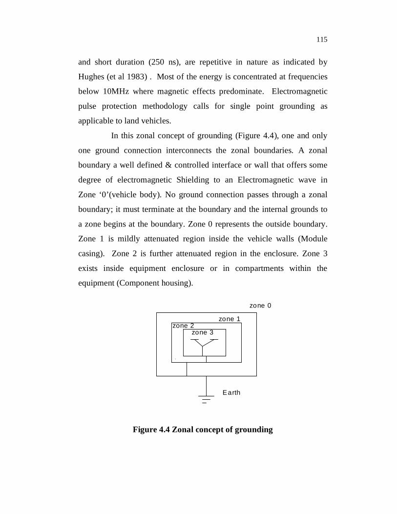
In this zonal concept of grounding (Figure 4.4), one and only
one ground connection interconnects the zonal boundaries. A zonal
boundary a well defined & controlled interface or wall that offers some
degree of electromagnetic Shielding to an Electromagnetic wave in
Zone ‘0’(vehicle body). No ground connection passes through a zonal
boundary; it must terminate at the boundary and the internal grounds to
a zone begins at the boundary. Zone 0 represents the outside boundary.
Zone 1 is mildly attenuated region inside the vehicle walls (Module
casing). Zone 2 is further attenuated region in the enclosure. Zone 3
exists inside equipment enclosure or in compartments within the
equipment (Component housing).
zone 0
zone 1 zone 2
zone 3
Earth
Fig: Zonal concept of grounding
Figure 4.4 Zonal concept of grounding

116
4.7 CABLE SHIELD GROUNDING
The shielded cable is used during interconnection of
subsystems with each other and shield must be grounded at both ends.
Edward (et al 1978) indicated that the grounding can be at one end
(asymmetric) or both end symmetric or grounded at intervals of the
cable. The effectiveness of grounding of the above methods depends on
electromagnetic coupling mode and the electrical length of cable (l/ λ)
used for the interconnection (Mauro et al 1996),(Fowler 1992).
The modes of electromagnetic coupling in the cable:
a) Electric field coupling – incident wave is polarised parallel
to the conductor length.
b) Magnetic field coupling – incident wave is polarised normal
to the loop formed by the cable and the ground plane.
A cable with both ends grounded is more efficient for E-field
excitations at low frequencies where as for H-field excitation; one end
grounded is more efficient as it avoids current formed by cable and
ground plane.
4.8 SHIELDED CABLE EXPOSURE TO EMP
The tracked vehicle has some mission critical equipment fitted
outside that gets exposed to electromagnetic interference. The size of the
vehicle determines the resonant frequencies normally lie in MHz range.
117
An EMP will induce current transients on the wiring two cases are
visualized as
1) Transmission line attached to deliberate antenna and
2) The normal wiring within the vehicle.
The second case the current transients that are induced due to
EMP on the cables are either one or more damped sine waves. In case
the cables are directly exposed to the electromagnetic wave, the cable
harnesses can get excited at its resonant frequencies. The vehicle cable
harness length lies in the range of 1m to 10 m, their resonant frequencies
lie in the range of 10 to 100MHz (Goedbloed 1987).The average cable
current transients is about less than 1A .The cables connected to
antenna, the peak amplitude of the cable bundle current does not exceed
10 A .Thus a 10 A damped sine wave (Q=6) can be used to represent a
worst case cable current (Dinallo et al 1982).The NEMP wave
constitutes both horizontal as well as vertical polarization.
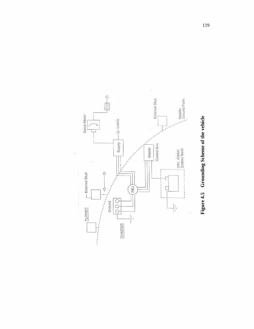
4.9 GROUNDING MEASUREMENTS ON BOARD THE VEHICLE
The EMI measurements( et al Miltary standards) were carried out
on the vehicle at several locations after optimising the various modules
with reduced voltage drops. These measurements were carried out using
micro ohmmeter in hot condition in majority of cases. The grounding
points within the vehicle are shown in the schematic diagram in Figure
4.5. The measured values in the vehicle are indicated in the Table 4.2
below. Multiple point grounding is being adopted to ensure better
performance at both high frequency and low frequency also.
118
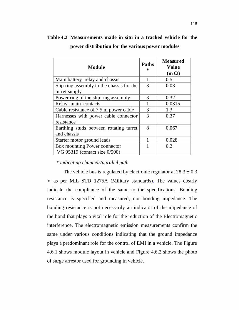
Table 4.2 Measurements made in situ in a tracked vehicle for the
power distribution for the various power modules
Module Paths*
Measured Value (m )
Main battery relay and chassis 1 0.5 Slip ring assembly to the chassis for the turret supply
3 0.03
Power ring of the slip ring assembly 3 0.32 Relay- main contacts 1 0.0315 Cable resistance of 7.5 m power cable 3 1.3 Harnesses with power cable connector resistance
3 0.37
Earthing studs between rotating turret and chassis
8 0.067
Starter motor ground leads 1 0.028 Box mounting Power connector VG 95319 (contact size 0/500)
1 0.2
* indicating channels/parallel path
The vehicle bus is regulated by electronic regulator at 28.3 0.3
V as per MIL STD 1275A (Military standards). The values clearly
indicate the compliance of the same to the specifications. Bonding
resistance is specified and measured, not bonding impedance. The
bonding resistance is not necessarily an indicator of the impedance of
the bond that plays a vital role for the reduction of the Electromagnetic
interference. The electromagnetic emission measurements confirm the
same under various conditions indicating that the ground impedance
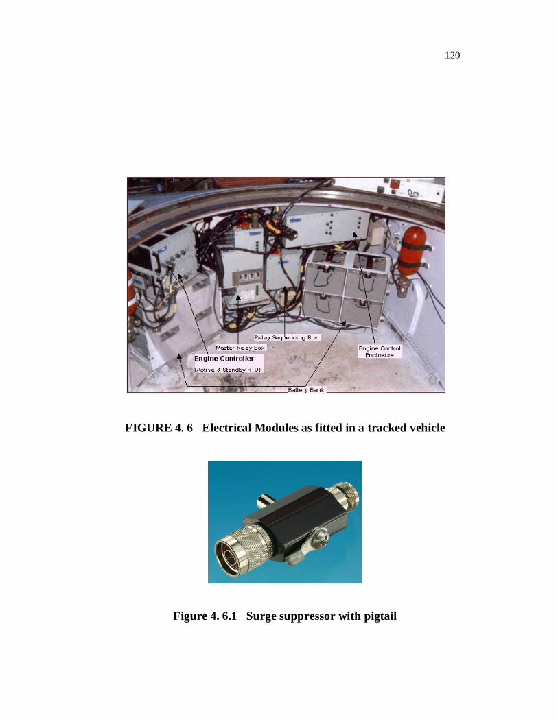
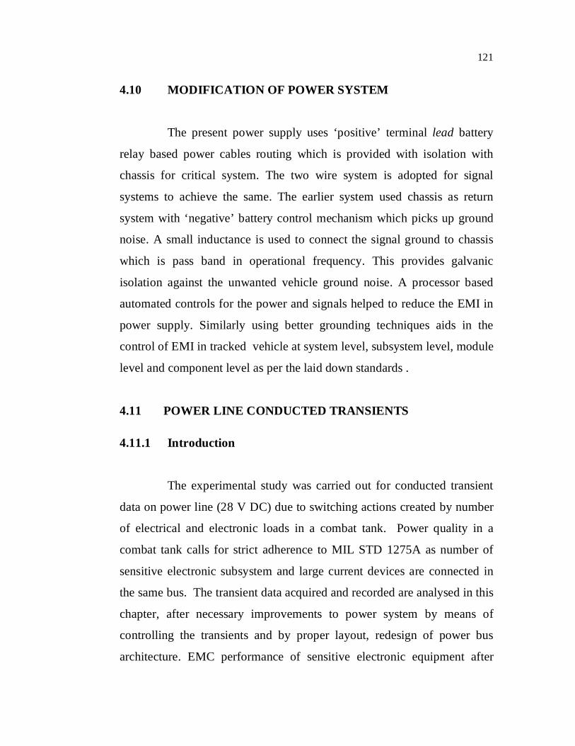
plays a predominant role for the control of EMI in a vehicle. The Figure
4.6.1 shows module layout in vehicle and Figure 4.6.2 shows the photo
of surge arrestor used for grounding in vehicle.
119
Figu
re 4
.5
Gro
undi
ng S
chem
e of
the
vehi
cle
120
FIGURE 4. 6 Electrical Modules as fitted in a tracked vehicle
Figure 4. 6.1 Surge suppressor with pigtail
121
4.10 MODIFICATION OF POWER SYSTEM
The present power supply uses ‘positive’ terminal lead battery
relay based power cables routing which is provided with isolation with
chassis for critical system. The two wire system is adopted for signal
systems to achieve the same. The earlier system used chassis as return
system with ‘negative’ battery control mechanism which picks up ground
noise. A small inductance is used to connect the signal ground to chassis
which is pass band in operational frequency. This provides galvanic
isolation against the unwanted vehicle ground noise. A processor based
automated controls for the power and signals helped to reduce the EMI in
power supply. Similarly using better grounding techniques aids in the
control of EMI in tracked vehicle at system level, subsystem level, module
level and component level as per the laid down standards .
4.11 POWER LINE CONDUCTED TRANSIENTS
4.11.1 Introduction
The experimental study was carried out for conducted transient
data on power line (28 V DC) due to switching actions created by number
of electrical and electronic loads in a combat tank. Power quality in a
combat tank calls for strict adherence to MIL STD 1275A as number of
sensitive electronic subsystem and large current devices are connected in
the same bus. The transient data acquired and recorded are analysed in this
chapter, after necessary improvements to power system by means of
controlling the transients and by proper layout, redesign of power bus
architecture. EMC performance of sensitive electronic equipment after
122
EMI hardening and a study of transients were carried out on distributed
power architecture to ensure power quality.
Goedbloed et al (1987) stated that regulation of power supply is a
important factor and transients are one of the EMI causes in low voltage
supply networks for a vehicle. The tracked vehicle uses chassis as return
conductors for all its major loads due to space constraints and tactical
requirements of vehicle. Due to common power supply bus for various
electrical and electronic loads in a combat tank, generally a poor voltage
regulation exists in the 28 VDC battery based power distribution system.
The power resources in the vehicle are used in conservative manner for
tracked vehicle as given below broadly to cater for various loads.
(a) Battery mode without engine on (called as Standby mode)
(b) Battery in parallel (Normal mode) with engine driven
generator and along with vehicle load sharing
(c) Battery in parallel with auxiliary power plant (called as
Silent watch mode) on with the main generator)
Common mode source impedance is the primary cause for
conducted EMI (Kimball 1986). The instantaneous bus voltage of electric
power supply varies with loads and other factors. The power supply
internal impedance (about 1-10 mΩ) plays a vital role in the above. The
ON / OFF transient of loads cause EMI that is very sensitive to electronic
equipments can cause malfunction ( Shin et al 1983).
In the present case a tracked vehicle hydraulic pump motor draws
a load current of over 2700 A for a short duration (300 ms). In case the
123
battery is floating across generator source has high internal impedance,
then this manifests into poor terminal voltage regulation. The power to
critical electronics is also drawn from the same bus obviously ends in
severe EMI problems .The supply distribution schematic is shown in the
Figure 4.6.
The vehicle is powered by battery 24 V, 400 AH that floats
across generator rated 28.3±0.3 V. The power is distributed to vehicle
mobile hull by high performance junction boxes, Raychem cables etc. The
rotating turret(upper) has the power fed via an assembly called as slip ring
assembly to various loads in a open architecture. Thus, in case there is fault
in one subsystem it gets isolated and becomes isolated from main vehicle
supply.
4.11.2 Power Supply as Per MIL STD 1275A
According to MILSTD 1275A, following technical parameters
are to be met in any land based military vehicle containing electrical and
electronic loads.
(a) Ripple at no load 8% (< 2 V )
(b) Ripple at full load 8% (< 2 V )
(c) Ripple frequency 200 kHz
(d) Spikes with no load < 2.5 time supply voltage, 250 V DC
(e) Spikes with full load < 2.5 time supply voltage, 250 V DC
(f) Minimum voltage dip permitted for electric loads at power
supply input end, 9 V
(g) Minimum voltage dip permitted at critical module viz
computer input 16 V

124
(h) Voltage O/P at rotating Platform (turret) when engine is
cranked 6 V
(i) Engine cranking cycle as per Figure 4.7
4.11.3 Automobile switching over voltages
The conducted over voltage in the fighting vehicle can be due to
various reasons as indicated below which require adequate suppression
(Melville 1984) .
1. Switching ‘ON’ of the main engine blower motor rated
11kW on the positive bus.
2. Switching ‘ON’/‘OFF’ of the two dust ejector, provided to
ensure clean air supply to the main engine, rated at 1.1
kW, 10500 rpm for engine.
Figure 4.7 Engine cranking and voltage dip for 28 Volts vehicle

125
3. Switching ‘ON’/‘OFF’ of the rotating loads (turret) rated at
550 A , 3 s Duty Cycle, Ipeak = 2400 A, 200 ms.
4. Switching ON/OFF of the main engine of the power pack.
5. Noise produced in the slip ring assembly, slip ring
assemblies that provide continuous rotating, 360o
power/signal paths between the two disjoints masses namely
mobile hull and rotating turret weapon platform. Noise
produced by the ignition system of the vehicle for the
Auxiliary power pack.
6. Over voltages caused by short circuits, earth faults etc.
Fowler (et al 1992) has indicated that the interconnecting cables
and connectors are one of main reasons for the EMI. Hence proper choice
has to made on the type of interconnecting connectors and cable, along
with the method of diagnosis and reduction of conducted noise emission.
The tracked vehicle uses shielded Raychem make cables along with
conventional ones for distribution onboard the vehicles. The Raychem
cables have given excellent performance along with ITT cannon make
connectors for the conducted and radiated emission performance. The
added advantage is that NEMP protection during induced currents can be
inbuilt feature of connector itself.
Dinallo (et al 1982) has indicated the methodology in his studies
cables to conform to the stipulated limits for the tracked vehicles. The
transients on board the vehicle were studied under various conditions for
the EMI levels.
In case of successful starting of vehicle the voltage builds up
gradually after charging the battery to the normal level as shown in the
126
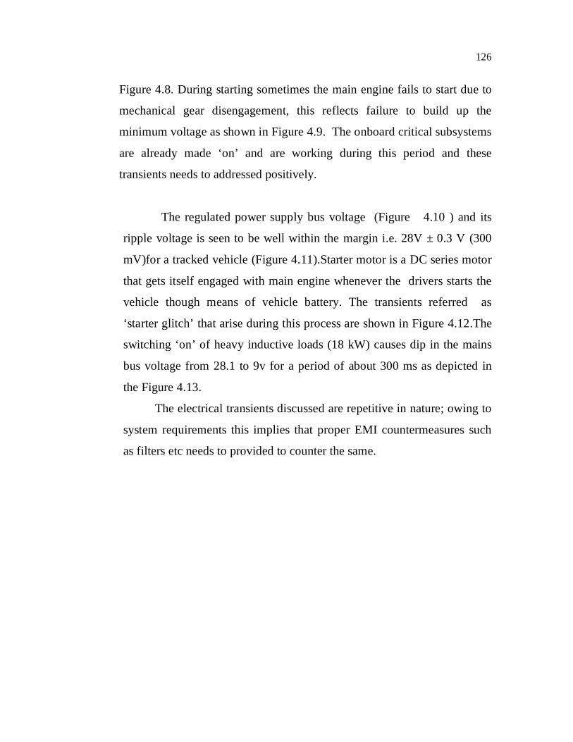
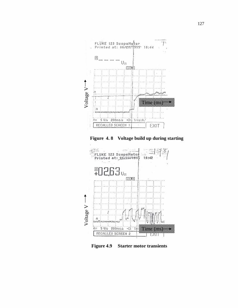
Figure 4.8. During starting sometimes the main engine fails to start due to
mechanical gear disengagement, this reflects failure to build up the
minimum voltage as shown in Figure 4.9. The onboard critical subsystems
are already made ‘on’ and are working during this period and these
transients needs to addressed positively.
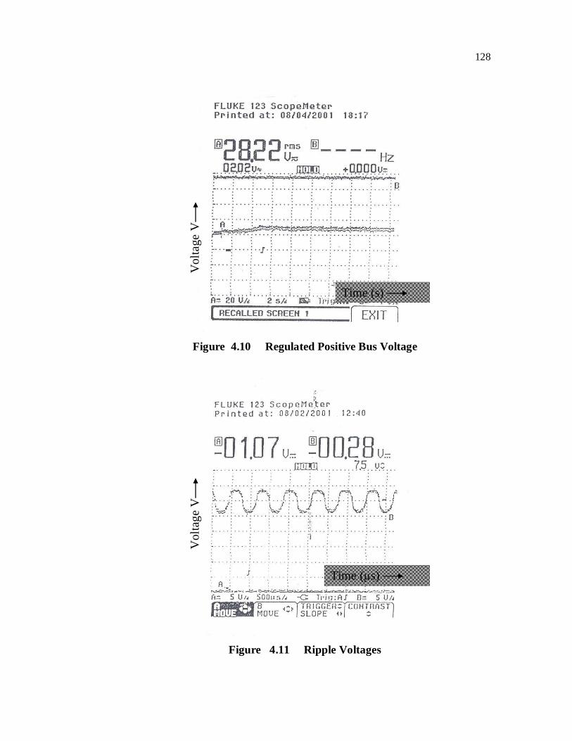
The regulated power supply bus voltage (Figure 4.10 ) and its
ripple voltage is seen to be well within the margin i.e. 28V ± 0.3 V (300
mV)for a tracked vehicle (Figure 4.11).Starter motor is a DC series motor
that gets itself engaged with main engine whenever the drivers starts the
vehicle though means of vehicle battery. The transients referred as
‘starter glitch’ that arise during this process are shown in Figure 4.12.The
switching ‘on’ of heavy inductive loads (18 kW) causes dip in the mains
bus voltage from 28.1 to 9v for a period of about 300 ms as depicted in
the Figure 4.13.
The electrical transients discussed are repetitive in nature; owing to
system requirements this implies that proper EMI countermeasures such
as filters etc needs to provided to counter the same.
127
Figure 4. 8 Voltage build up during starting
Figure 4.9 Starter motor transients
Time (ms)
Time (ms)
Vol
tage
V
Vol
tage
V
128
Figure 4.10 Regulated Positive Bus Voltage
Figure 4.11 Ripple Voltages
Time (s)
Time (µs)
Vol
tage
V
V
olta
ge V

129
Figure 4.12
Starter Motor Voltage Dip in Power Supply
Figure 4.13 Power Supply Dip during Loading
Vol
tage
V
V
olta
ge V
Time (s)
Time (s)

130
4.11.4 Compatibility of power supply and utilisation equipment
There shall be no influence by utilization equipment, which
would cause the electrical system to depart from the limits specified in the
detailed requirements. In the event of generator failure, battery is still in
the circuit to cater for the emergency loads.
4.12 CRITICAL SUBSYSTEM MODULE ANALYSIS
The following critical subsystems were experimented for record
of transients at power points in the vehicle.
(a) Stator motor (Engine ON / OFF)
(b) Hydraulic pump motor
(c) Dust ejector motor
(d) Fuel pumps
(e) Starter motor etc.
4.13 POWER SYSTEM MODIFICATION FOR EMC
The module schematics layout was evolved and modifications
were carried out in the DC bus to maintain power quality as enumerated
below.
(a) The control logic stipulates that either an auxiliary power
unit or the main generator comes in parallel with vehicle
battery at any point of time.

131
(b) All voltage sensitive electronic devices are supported by a
back up battery of 24 V, 23 AH capacity to cater for the dip
in power supply during operation of heavy loads.
(c) All less sensitive devices are fed from the output of main
generator or auxiliary generator.
(d) Directional protection is provided to back up battery to
avoid unnecessary drain to heavier loads at input end. In
addition individual loads are hardened for conducted EMI
with transient protection.
4.14 DISTRIBUTED POWER ARCHITECTURE
(a) Distributed power architecture (DPA) replaces multiple
central power sources.
(b) DPA provides small size, lighter weight, and better
operation with battery power and more efficient subsystem
isolation and redundancy.
(c) DPA allows a single 28 V bus and battery bank rather than
running redundant wiring for each voltage level.
(d) DPA allows upgradation of separate subsystem in without
making major changes onboard the vehicle.
(e) DC-DC converter provides very close regulation of output
voltages in spite of fluctuations in input voltage and heavy
load.
132
(f) Transformers in DC-DC converters provide electrical
isolation making it easy to build in redundancy and to
protect the whole system from effects of isolated failures.
4.15 TRANSIENT DATA ANALYSIS
The 28 V DC powers several critical electronic onboard modules.
The generator floats across the battery bank. Figure 4.14 shows the
variation of the current and voltage of electronic module 1 when the engine
was started in standby battery mode along with the transients. Figure 4.15
shows recording when the engine and nearby electronic module 1 (close to
the power source) were already switched on, the transients arising due to
switching on of heavy duty motors were monitored and recorded for
analysis.
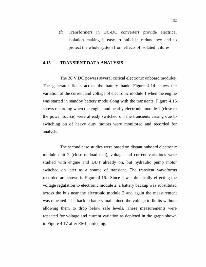
The second case studies were based on distant onboard electronic
module unit 2 (close to load end), voltage and current variations were
studied with engine and DUT already on, but hydraulic pump motor
switched on later as a source of transient. The transient waveforms
recorded are shown in Figure 4.16. Since it was drastically effecting the
voltage regulation to electronic module 2, a battery backup was substituted
across the bus near the electronic module 2 and again the measurement
was repeated. The backup battery maintained the voltage to limits without
allowing them to drop below safe levels. These measurements were
repeated for voltage and current variation as depicted in the graph shown
in Figure 4.17 after EMI hardening.

133
4.16 TEST DATA INFERENCE
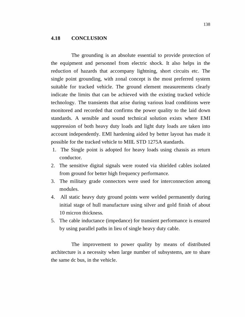
Figure 4.14 the electronic module 1 draws an additional current of 420 mA from its normal current of 24 A for the duration of 80 ms during the starting of main engine. The observed positive bus voltage dips from 24 V to 17.6 V. The transients were recorded with the hydraulic pumps switched ‘on’ as shown in Figure 4.15.The electronic module 1 draws 410 mA for 22 s with engine already kept on. This is well within the MIL STD specified limits and will not cause any malfunction. However the voltage glitch is severe in the case of electronic module 2, at the time of switching ‘on’ of the motor with main engine on. The current in the electronics module 2 varied from 0.1 A to 24.3 A in different amplitudes for duration of almost one second as in Figure 4.16, the voltage varies from 15.1 V to 18 V during the same period. The vehicle encountered malfunction during this period at the electronic module 2 which tripped several times. The onboard system does not permit occurrences of such events as the module gets reset or switched off. A modification was carried out on the vehicle, with the battery backup, which was separately installed to cater to the dip in power supply. The backup battery of 24 V, 23AH (Ni-cd) was connected across the electronic module 2 (Figure 4.19) .The transient voltage at input end of module 2 was observed as 0.4 V (from 27.1 to 26.7 V) while the unregulated output at source end remained 16.5 V. The current drawn by the module 2 remained consistent at 7.06 A (Normal current) and there was no impact on the electronic module 2 .The module level system performance was monitored during the transient period, due to switching on the hydraulic pump motor ref. Figure 4.17. EMI techniques such grounding, welding of ground points etc done on vehicle enhanced the performance. The bus voltage is maintained at stipulated levels as per standards.

134
Figure 4.14 Starter motor transients at Electronic
module 1
Figure 4.15 Transients recorded at Electronic module 1 due to
switching on of the hydraulic motor drives
Voltage (V)
Current (mA)
Voltage (V)
Current (mA)
Time ms
Time ms
135
Figure
4.16
Transients at Electronic module 2 due to switching
of heavy duty motors
Figure 4.17 Transients at Electronic module 2 after installation of
auxiliary battery enhanced layout and adoption of EMI
hardening
Voltage (V)
Current (mA)
Current (mA)
Voltage (V)
Time ms
Time ms
136
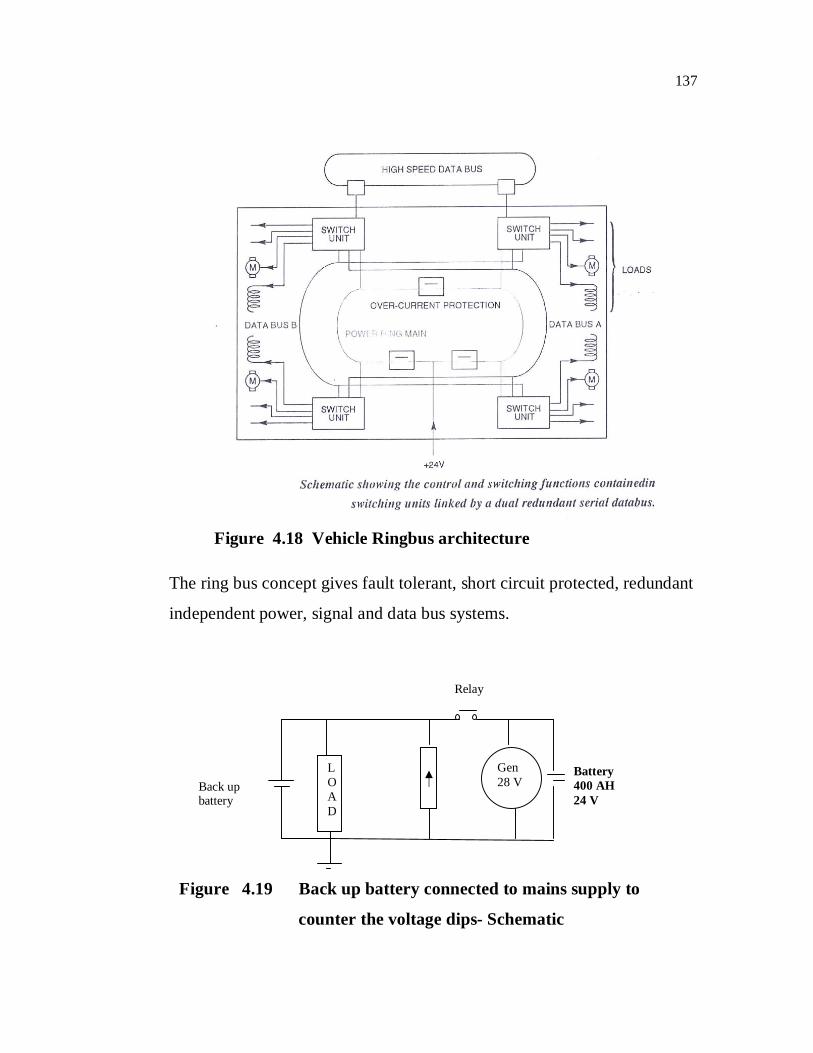
4.17 VEHICLE RING BUS TOPOLOGY
An improved distributed architecture (Figure 4.18) supply ring
system wherein the idle voltage of the power and communications bus is
regulated by a fault tolerant power supply circuit, and portions of the bus
coupled to devices located in a crush zone of the vehicle may be de-
coupled from other portions of the bus in the event of a short circuit across
the wires of that portion of the bus. The power and communications bus
comprises two wires (signal and ground) and the bus ground wire is
weakly biased to a reference voltage. A boost power supply referenced to
the bus ground establishes the nominal voltage of the signal wire, and
supplies charging current over the signal wire to the energy reserve circuits
of various devices coupled to the bus.
The power supply is transformer-isolated from the bus, and the
feedback circuitry for controlling the operation of the power supply senses
the bus voltage as coupled through the transformer. Consequently, the
power supply retains the ability to regulate the bus voltage in fault
conditions where the ground or signal wires of the bus are shorted to
vehicle ground or battery voltage. In such conditions, the bus ground shifts
from its normal value, and is detected to provide a warning indication to
the operator of the vehicle.
Open circuit failures of the bus wires are addressed by configuring
the bus in a closed ring topology, and short circuits across the bus wires are
addressed by configuring the bus so that portions of the bus disposed in
one or more crush zones of the vehicle can be de-coupled from the rest of
the bus.
137
Figure 4.18 Vehicle Ringbus architecture
The ring bus concept gives fault tolerant, short circuit protected, redundant
independent power, signal and data bus systems.
Figure 4.19 Back up battery connected to mains supply to
counter the voltage dips- Schematic
LOAD
Gen 28 V
Battery 400 AH 24 V
Back up battery
Relay
138
4.18 CONCLUSION
The grounding is an absolute essential to provide protection of the equipment and personnel from electric shock. It also helps in the reduction of hazards that accompany lightning, short circuits etc. The single point grounding, with zonal concept is the most preferred system suitable for tracked vehicle. The ground element measurements clearly indicate the limits that can be achieved with the existing tracked vehicle technology. The transients that arise during various load conditions were monitored and recorded that confirms the power quality to the laid down standards. A sensible and sound technical solution exists where EMI suppression of both heavy duty loads and light duty loads are taken into account independently. EMI hardening aided by better layout has made it possible for the tracked vehicle to MIIL STD 1275A standards. 1. The Single point is adopted for heavy loads using chassis as return
conductor. 2. The sensitive digital signals were routed via shielded cables isolated
from ground for better high frequency performance. 3. The military grade connectors were used for interconnection among
modules. 4. All static heavy duty ground points were welded permanently during
initial stage of hull manufacture using silver and gold finish of about 10 micron thickness.
5. The cable inductance (impedance) for transient performance is ensured by using parallel paths in lieu of single heavy duty cable.
The improvement to power quality by means of distributed architecture is a necessity when large number of subsystems, are to share the same dc bus, in the vehicle.