Embed Size (px)
Citation preview
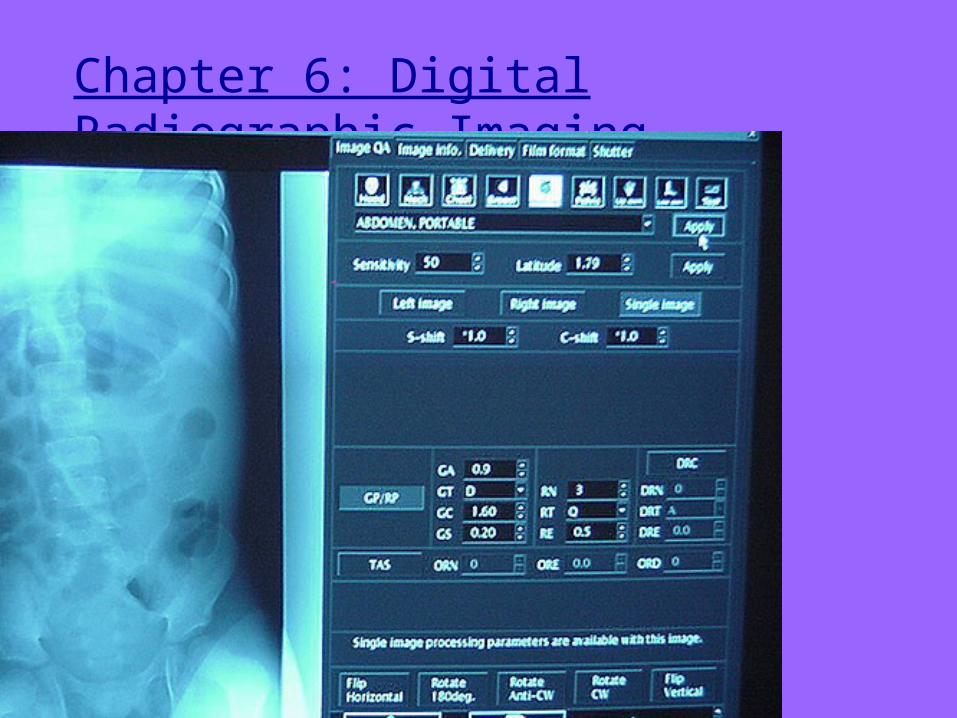
Chapter 6: Digital Radiographic Imaging
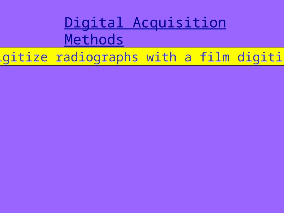
Digital Acquisition Methods
1. Digitize radiographs with a film digitizer
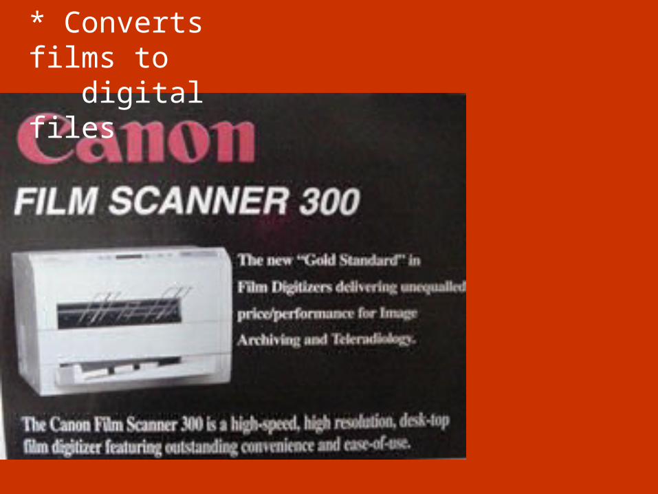
* Converts films to digital files
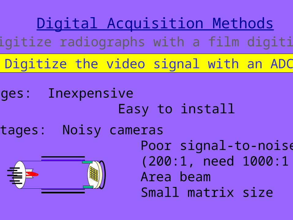
2. Digitize the video signal with an ADC
Advantages: Inexpensive Easy to install
Disadvantages: Noisy cameras Poor signal-to-noise ratio (200:1, need 1000:1 for digital) Area beam Small matrix size
Digital Acquisition Methods1. Digitize radiographs with a film digitizer
Digital Acquisition Methods
2. Digitize the video signal
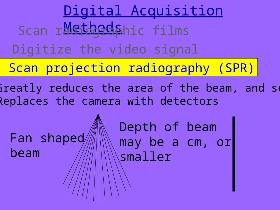
* Greatly reduces the area of the beam, and scatter* Replaces the camera with detectors
3. Scan projection radiography (SPR)
Fan shapedbeam
Depth of beammay be a cm, orsmaller
1. Scan radiographic films
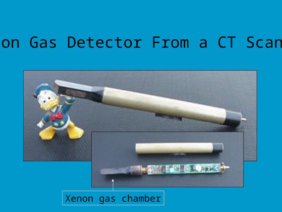
Xenon Gas Detector From a CT Scanner
Xenon gas chamber
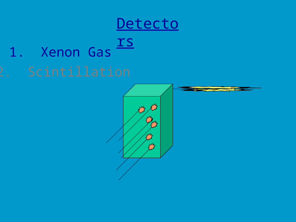
Detectors
1. Xenon Gas
2. Scintillation
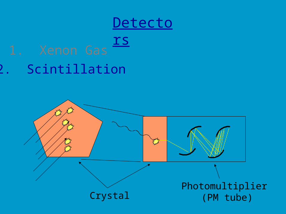
Detectors
1. Xenon Gas
2. Scintillation
CrystalPhotomultiplier
(PM tube)
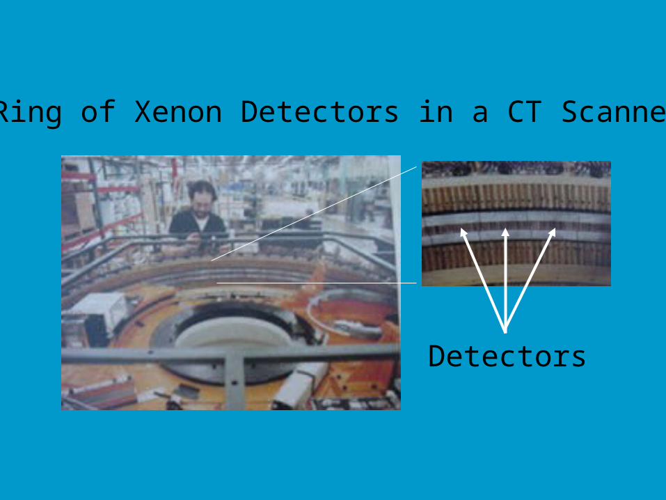
Ring of Xenon Detectors in a CT Scanner
Detectors
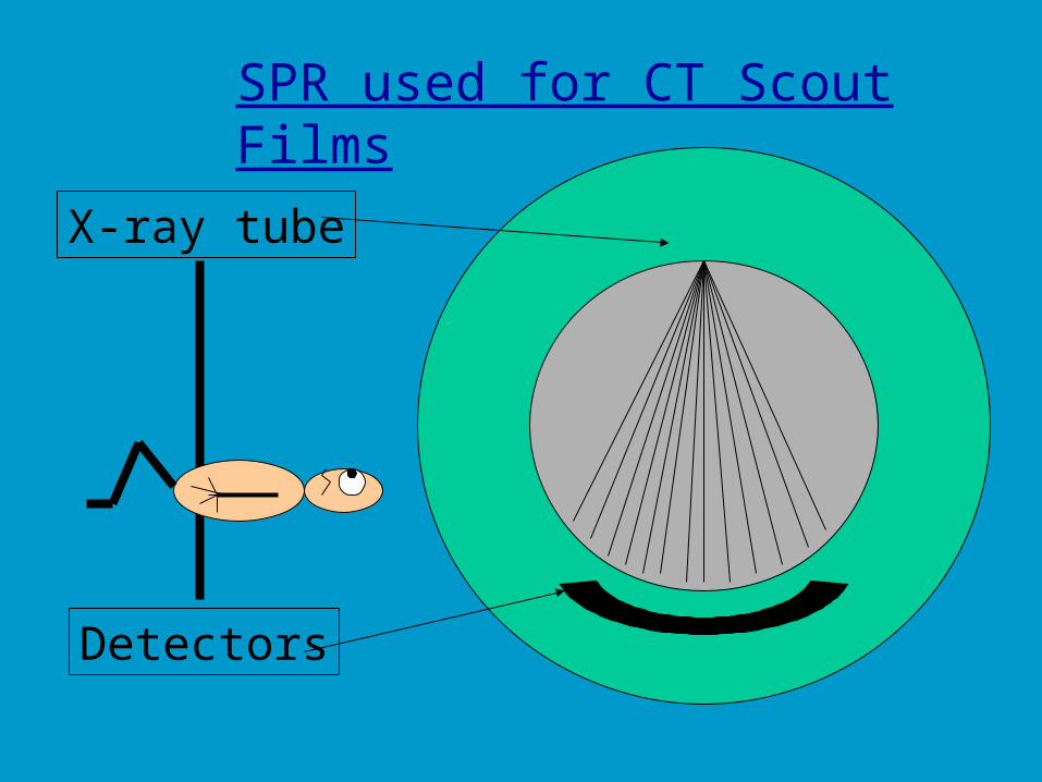
SPR used for CT Scout Films
X-ray tube
Detectors
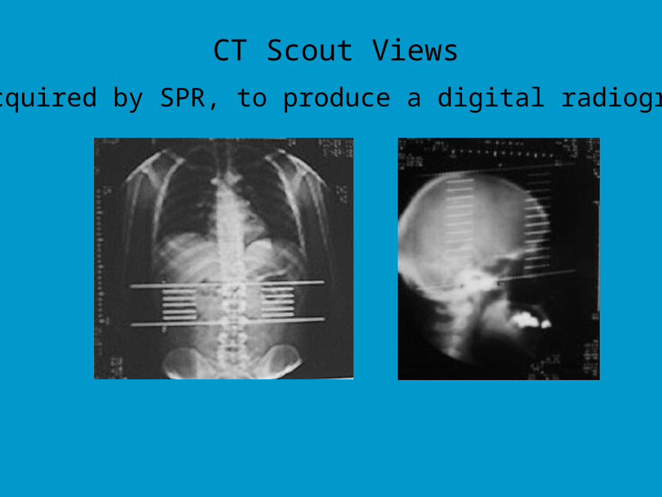
CT Scout Views
Acquired by SPR, to produce a digital radiograph
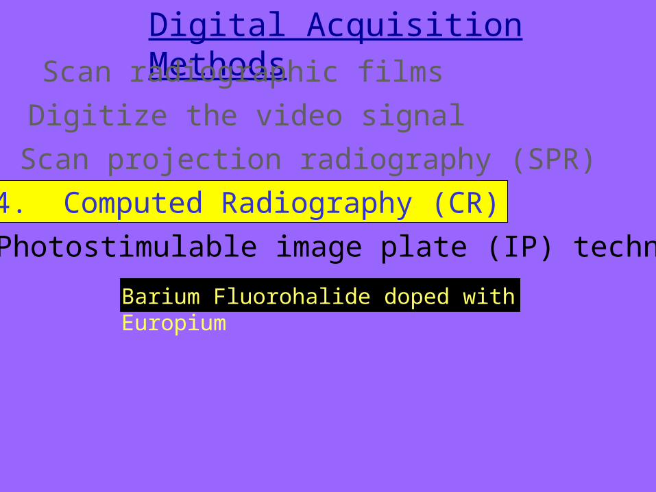
Digital Acquisition Methods
2. Digitize the video signal
3. Scan projection radiography (SPR)
4. Computed Radiography (CR)
Barium Fluorohalide doped with Europium
Photostimulable image plate (IP) technology
1. Scan radiographic films
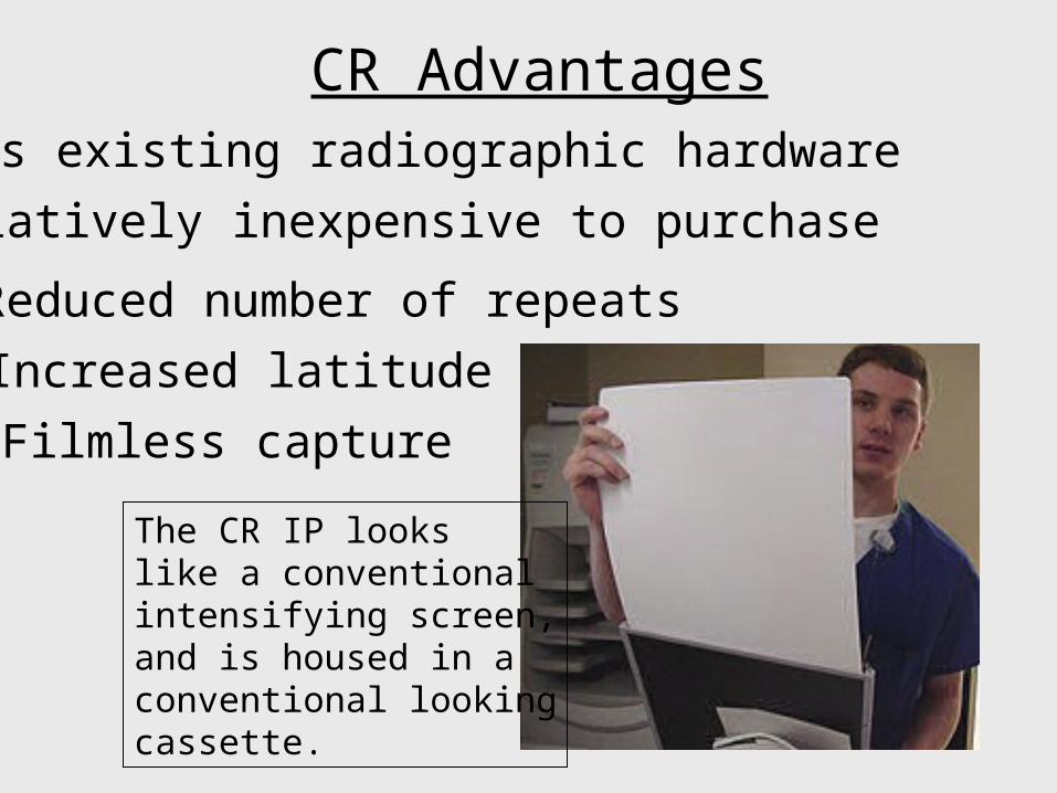
CR AdvantagesUses existing radiographic hardware
Relatively inexpensive to purchase
Filmless capture
Reduced number of repeats
Increased latitude
The CR IP lookslike a conventionalintensifying screen,and is housed in aconventional lookingcassette.
300 RSVOnly one speed (no detail or high speed)
Laser Film – wet or dry processing
CR Facts
Standard film sizes
Computed Radiography
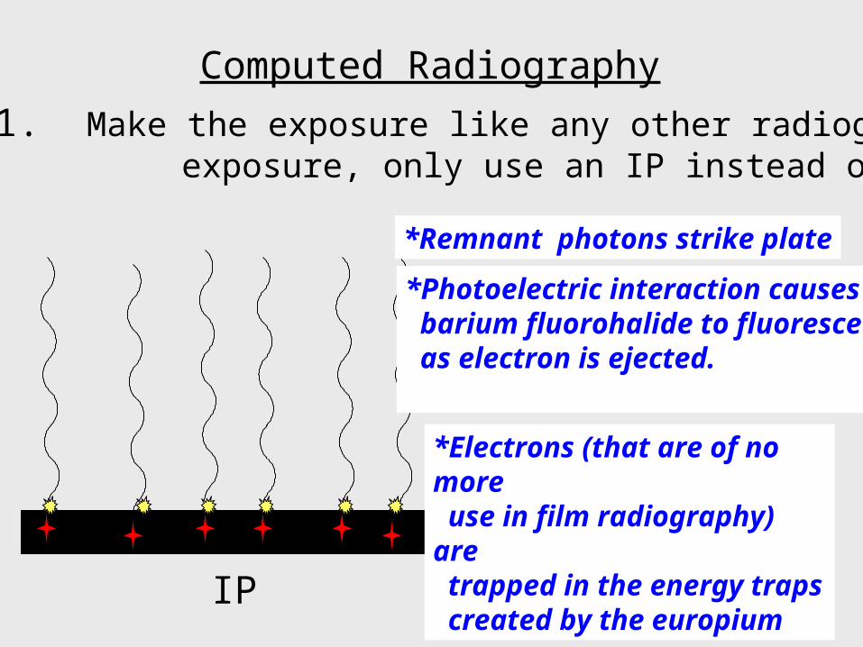
Step 1. Make the exposure like any other radiographic exposure, only use an IP instead of film.
IP
*Remnant photons strike plate
*Photoelectric interaction causes barium fluorohalide to fluoresce as electron is ejected.
*Electrons (that are of no more use in film radiography) are trapped in the energy traps created by the europium
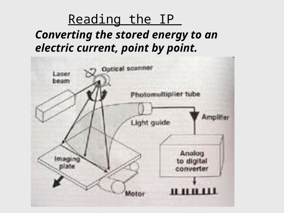
Reading the IP Converting the stored energy to an electric current, point by point.
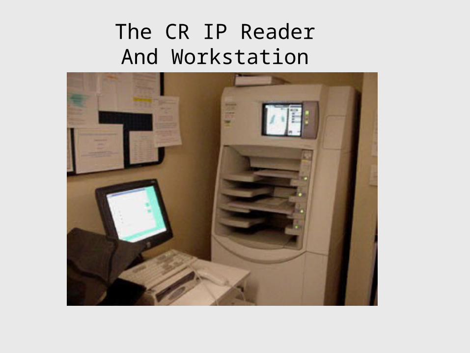
The CR IP ReaderAnd Workstation
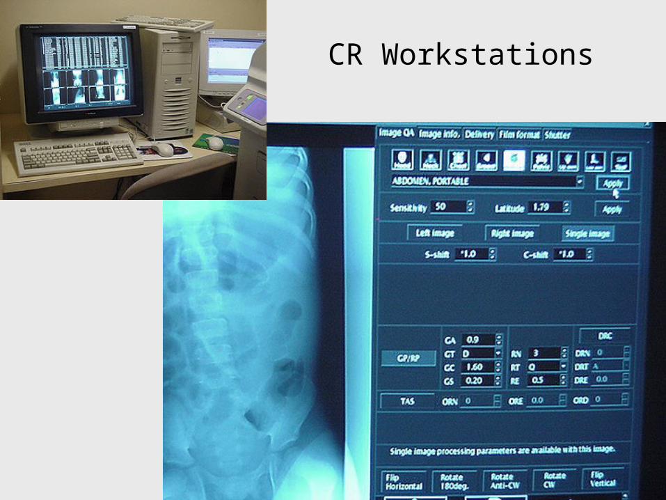
CR Workstations
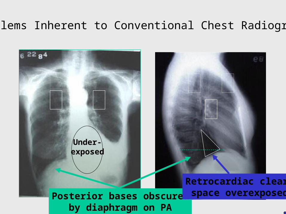
Problems Inherent to Conventional Chest Radiography
Under-exposed
Posterior bases obscuredby diaphragm on PA
Retrocardiac clear-space overexposed
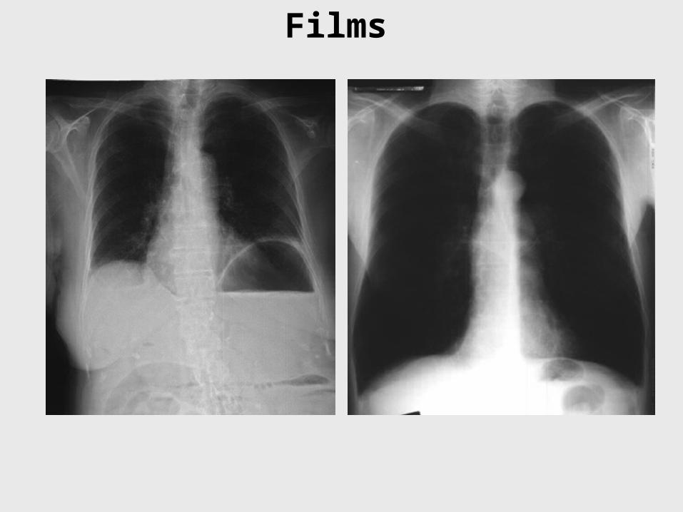
Films
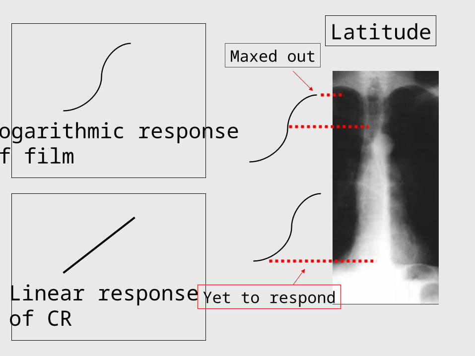
Latitude
Logarithmic responseof film
Linear response of CR
Yet to respond
Maxed out
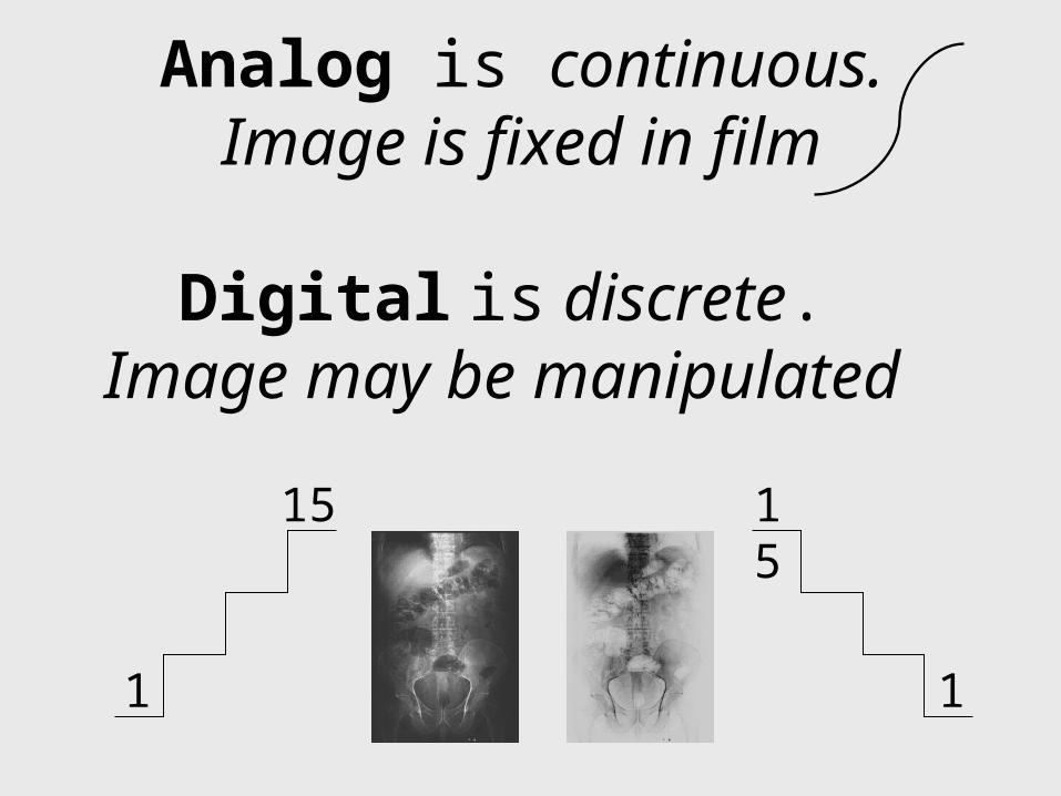
Analog is continuous.Image is fixed in film
Digital is discrete.
Image may be manipulated
1
15 15
1

CR Postprocessing & Characteristic Curves
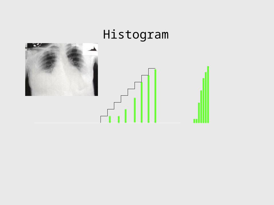
Histogram
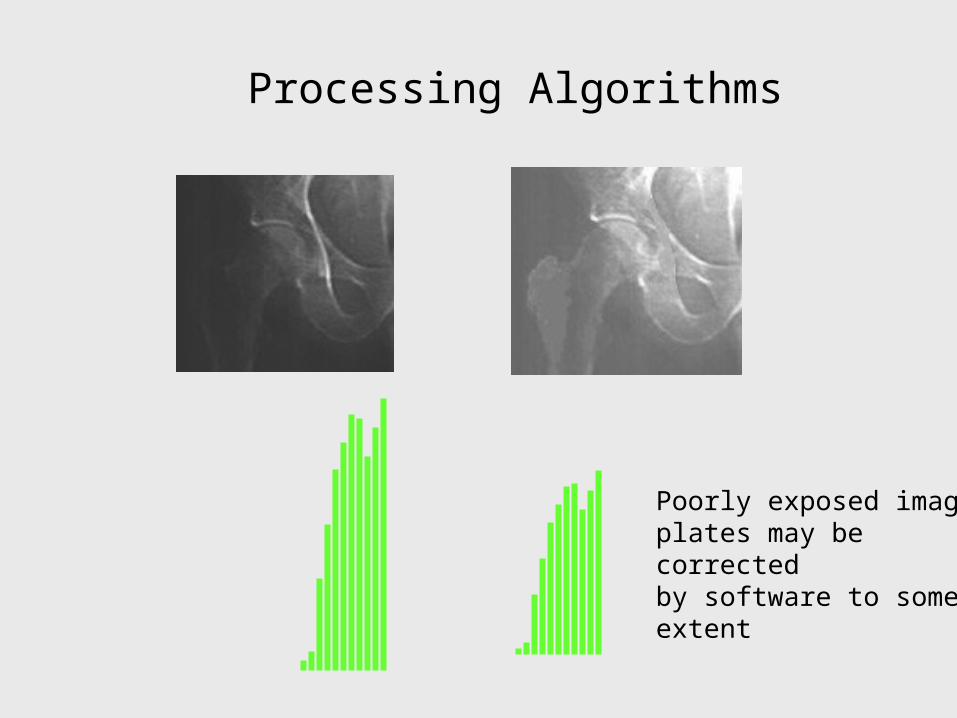
Processing Algorithms
Poorly exposed image plates may be corrected by software to some extent
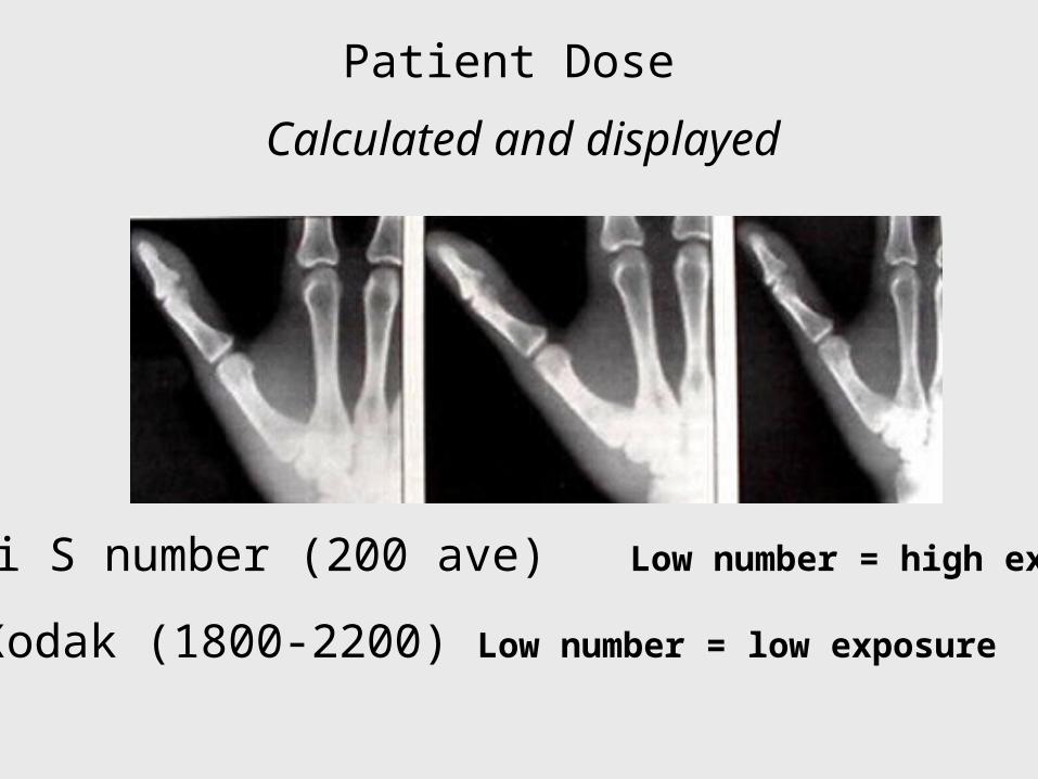
Patient Dose
Calculated and displayed
Fuji S number (200 ave) Low number = high exposure
Kodak (1800-2200) Low number = low exposure
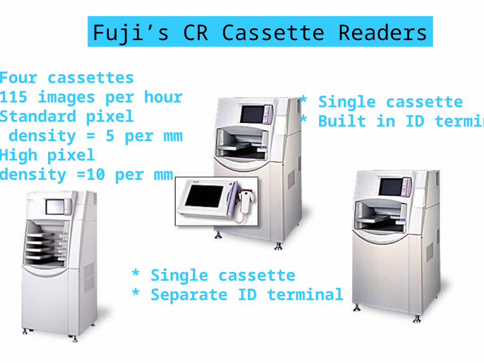
Fuji’s CR Cassette Readers
* Four cassettes* 115 images per hour* Standard pixel density = 5 per mm* High pixel density =10 per mm
* Single cassette* Separate ID terminal
* Single cassette* Built in ID terminal
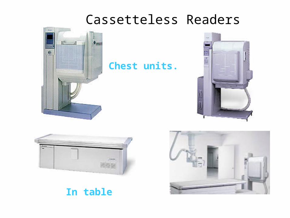
Cassetteless Readers
Chest units.
In table
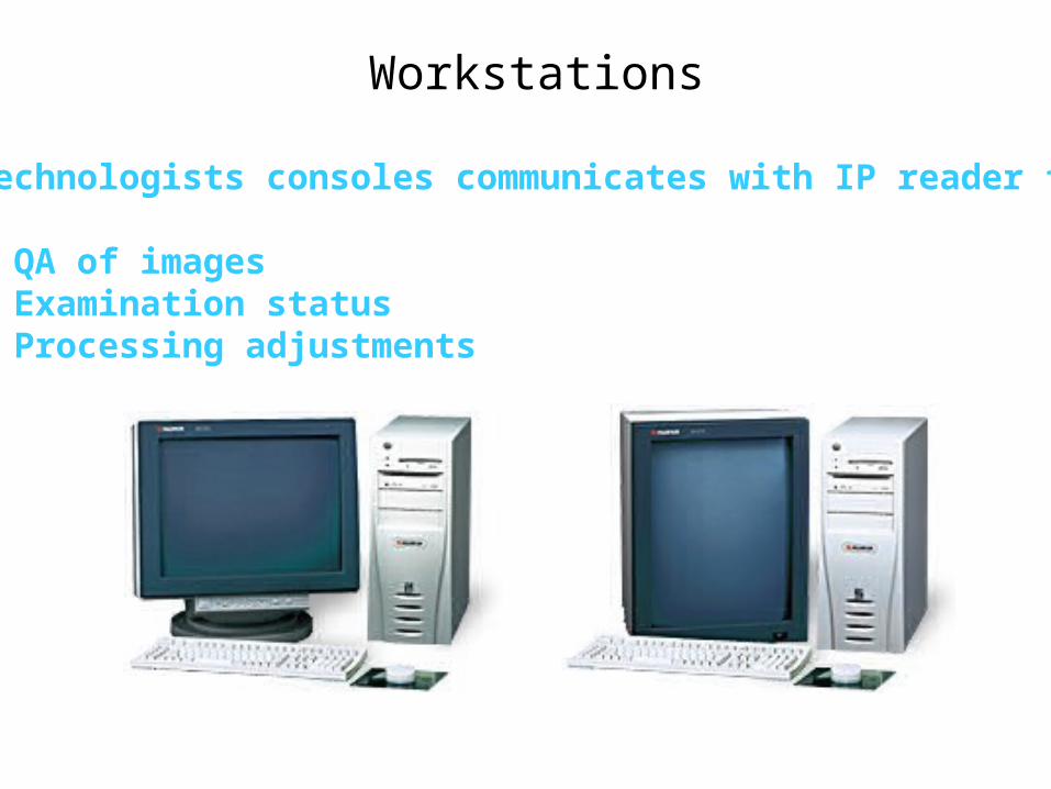
Workstations
Technologists consoles communicates with IP reader for:
* QA of images* Examination status* Processing adjustments
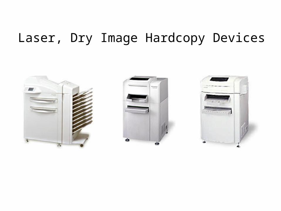
Laser, Dry Image Hardcopy Devices
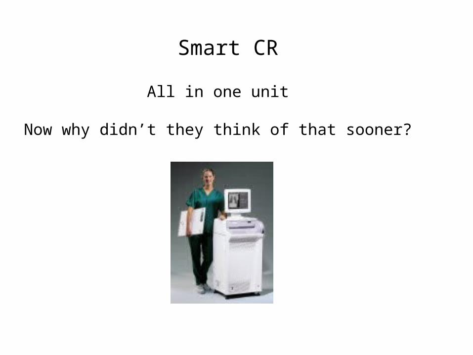
Smart CR
All in one unit
Now why didn’t they think of that sooner?
Digital Acquisition Methods
2. Digitize the video signal
3. Scan projection radiography (SPR)
4. Computed Radiography (CR)
6. Flat Panels Amorphous Silicon & Amorphous Selenium
5. Charged Couple Devices
1. Scan radiographic films
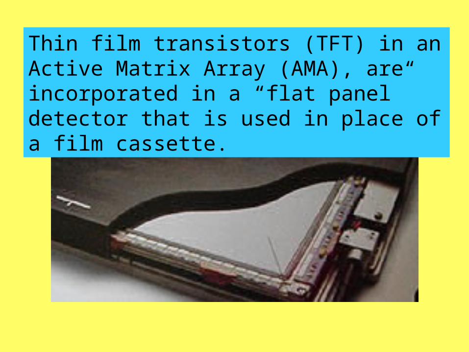
Thin film transistors (TFT) in an Active Matrix Array (AMA), are incorporated in a “flat panel” detector that is used in place of a film cassette.
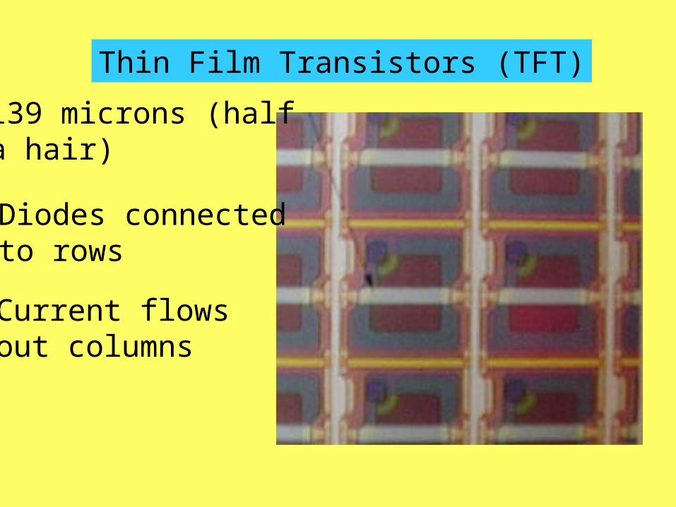
Thin Film Transistors (TFT)
139 microns (halfa hair)
Diodes connectedto rows
Current flows out columns
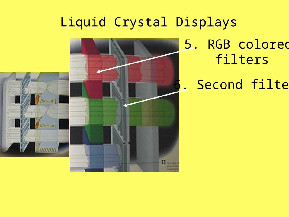
Liquid Crystal Displays
5. RGB colored filters
6. Second filter
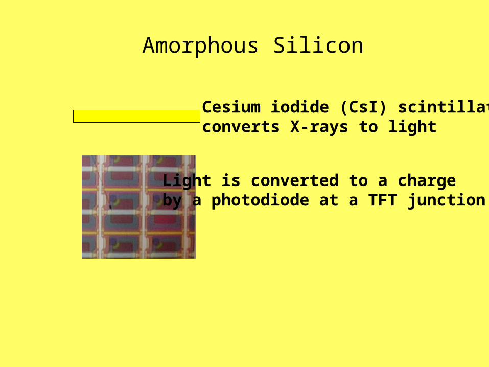
Amorphous Silicon
Cesium iodide (CsI) scintillatorconverts X-rays to light
Light is converted to a charge by a photodiode at a TFT junction.

Amorphous Selenium(called Direct Radiography)
Electrode with a bias voltage+ + + + + + + +
- - - - - - - - - - -
Photoconductor material
TFT
Photon in
Interaction createselectron-hole pairs
Positive charge
Negative charge
Signal out
Receptor Reader* Energy Comment Transformations
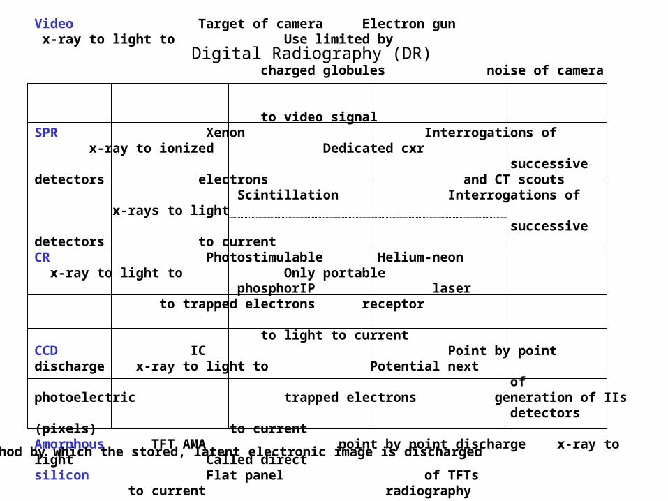
Video Target of camera Electron gun x-ray to light to Use limited by charged globules noise of camera to video signalSPR Xenon Interrogations of x-ray to ionized Dedicated cxr successive detectors electrons and CT scouts Scintillation Interrogations of x-rays to light successive detectors to currentCR Photostimulable Helium-neon x-ray to light to Only portable phosphorIP laser to trapped electrons receptor to light to currentCCD IC Point by point discharge x-ray to light to Potential next of photoelectric trapped electrons generation of IIs detectors (pixels) to currentAmorphous TFT AMA point by point discharge x-ray to light Called direct silicon Flat panel of TFTs to current radiography
Amorphous TFT AMA point by point discharge x-ray to current Called direct selenium Flat panel of TFTs radiography
* Method by which the stored, latent electronic image is discharged
Digital Radiography (DR)