Embed Size (px)
Citation preview
*,
'*
i
UNCLASSIFIED MARTIN MARIETTA ENERGY SYSTEMS LIBRARIES
3 445b Q3bQ517 A
ORNL 707Instrumentation
CHARACTERISTICS AND BEHAVIOR OF
BONDED WIRE RESISTANCE STRAIN
GAGES IN THERMAL COEFFICIENT OF
EXPANSION MEASUREMENTS
PART II SR~4 BAKELITE BONDED
DUAL LEAD GAGES
OAK RIDGE NATIONAL LABORATORYCENTRAL RESEARCH LIBRARY
CIRCULATION SECTION4500N ROOM 175
LIBRARY LOAN COPYdo nottransferto another person
the library will arrange a loan.UCN-7969 (3 977)
OAK RIDGE NATIONAL LABORATORYOPERATED BY
CARBIDE AND CARBON CHEMICALS DIVISIONUNION CARBIDE AND CARBON CORPORATION
irnn
POST OFFICE BOX P
OAK RIDQE, TENNESSEE
UNCLASSIFIED
-1-
UNCLASSIFIED
Report Number ORNL-707
This document consisit of 17pages. Copy 5 of 17^. A
Contract No„ Yl-7hP5, eng. 26
Physios Division
CHARACTERISTICS AND BEHAVIOR OF BONDED WIRE RESISTANCE STRAIN GAGES
IN THERMAL COEFFICIENT OF EXPANSION MEASTJREMENTS
PARI II SR-ii. BAKELITE BONDED DUAL LEAD GAGES
Martin R« GoodmanDate Issued: J[J^ J3^Q
OAK RXDSE HATIOHAL LABORATORYoperated by
CARBIDE ATO CABBQN CHEMICALS DWISIONUnion Carbide and Carbon Corporation
Post Office Box P
Oak Ridge, Tennessee
Krilffirnliiififfi SVSTEMS lib«»ies
3 445b 03bOS17 fl
UNCLASSIFIEDORNL 707Instrumentation
INTERNAL DISTRIBUTION;
1. G. T, Felbeek (C&CCC)2„ 706-A Library3. 706-A Libraryk, 706-B Library5. Biology Library6. Health Physics Library7. v--:TaJ.:liorgy Library8. Iraining School Libra9„ Training School Library10. Central Files11. Central Files12., Central Files13« Central Files14. C. E, Larson
15. A. M. Weinberg2.6 . L J. Murphy17„ C. 1. Center1.8. J. A. Swartout
19.20.
21.
22.
23.24.
25.26.
27.28o
29 =30.
31.32.
33.
3*.35.
A. H. Snell 36.A. Hollaender 37-J. H. Gillette 38.J. A. Lane 39-42.B. N. Lyon 43.M. M. Mann 44-73-W. C. Koehler 74.W. K. Ergen 75-E. P. Blizard 76.M. J. Skinner 77-D. W. Cardwell 78.D. S. Billington 79.E„ J. Boyle 80.L. K. Jetter 81.A. G. H. Anderson 82.G. M. Adamson 83.H. G. Savage 84.
85-86.
ESTEBITAL DISTBIBUTION;
87-94. Argonne National Laboratory95„ Armed Forces Special Weapons Project
96-97. Atomic Energy Commission, Washington98. Battelle Memorial Institute99. Brush Beryllium Company
100-107. Brookhaven National Laboratory108. Bureau of Ships
109-112. Carbide & Carbon Chemicals Division (K-25)113-ll6o Carbide & Carbon Chemicals Division (Y-12)
117. Chicago Operations Office118. Columbia University (J. R. Dunning)
119-121. General Electric, Richland122. Idaho Operations Office
123-124. Iowa State College125-128. Knolls Atomic Power Laboratory129-131. Los Alamos Scientific Laboratory
132. Massachusetts Institute of Technology (A. Eaufmann)133-135. Mcwad Laboratory136-137. Natioaal Advisory Committee for Aeronautics138-139. National Bureau of Standards140-144. New York Operations Office
145. North American Aviation, Inc.146. Patent Branch (WashingtonIkf. Sandia Laboratory148. Santa Fe Operations Office
li»-9-l63. Technical Information Division (Oak Ridge)164-165. USAF, NEPA166-170. University of California Radiation Laboratory171-174. Westinghouse Electric Company
UNCLASSIFIED
J. C. Wilson
W. D. ManlyR. P. Metcalf
M. A. BredigS. E. Dismuke
M. R. Goodman
F. A. SherrillL. C. Templeton
J. C. PiggJ. W. Cleland
W. Primak
R. G. Berggren
B. W. CoyleR. H. KernohanC. E. Stilson
S. A. Hluchan
W. J. Ladniak
Central Files (OP)
-3-
TA3LE OF CONTENTS
PAGE
Abstract h
Body of Report 5
Conclusions 11
References 13
Figures Ik
-lr
CHARACTERISTICS AND BEHAVIOR OF BONDED WIRE RESISTANCE STRAIH GAGES
IN THERMAL COEFFICIENT OF EXPANSION MEASUREMENTS
PART II SR-li BAKELITE BONDED DUAL LEAD GAGES
Martin R. Goodman
Oak Ridge National Laboratory*
ABSTRACT
Dual lead type bonded wire strain gages appear to have no significant
advantage over other types of bonded wire strain gages except less inherentgage creep. The literature indicates that ceramic bonded wire stram gages
have been used at temperatures as high as 800°C. These gages exhibit properties
similar to paper and bakelite bonded strain gages. Bonded wire resistance strau*
gages of any type are appropriate for application to very many problems. Whereextreme accuracy is desirable it is important to be thoroughly familiar with
the characteristics and behavior of these gages.
Work performed under Contract Number W-7^5, eng. 26, for the AtomicEnergy Project.
-5-
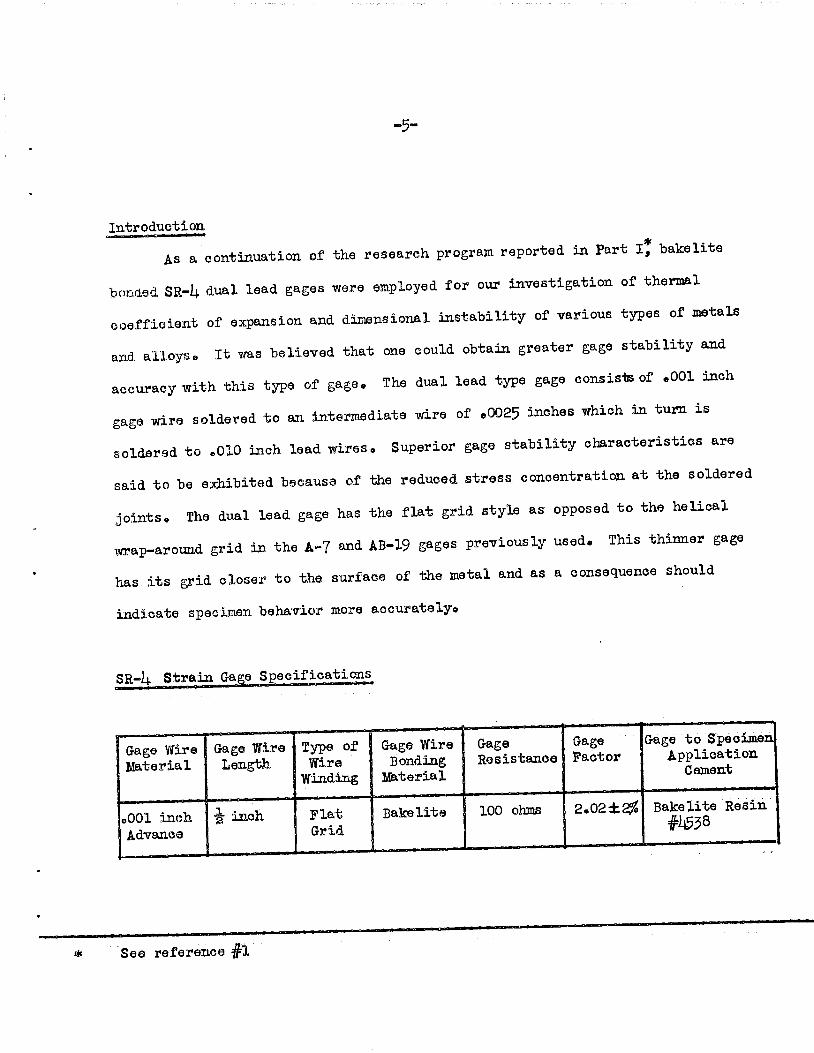
Intreduction
As acontinuation of the research program reported in Part I, bakelite
bonded SR-Ij. dual lead gages were employed for our investigation of thermalcoefficient of expansion and dimensional instability of various types of metals
and alloys. It was believed that one could obtain greater gage stability andaccuracy with this type of gage. The dual lead type gage consists of .001 5*chgage wire soldered to an intermediate wire of .0025 inches which to turn issoldered to .010 inch lead wires. Superior gage stability characteristics are
said to be exhibited because of the reduced stress concentration at the soldered
joints. The dual lead gage has the flat grid style as opposed to the helicalwrap-around grid in the A-7 and AB-19 gages previously used. This thinner gagehas its grid closer to the surface of the metal and as aconsequence should
indicate specimen behavior more accurately.
SR-ii Strain Gage Specifioations
rGage WireMaterial
Finch
anea
Gage WireLength
^ inch
See reference #1
Type ofWire
Winding
Flat
Grid
Gage WireBonding
Material
Gage j GageResistance! Factor
Bakelite 100 ohms 2.02±2%
Gage to SpecimenApplication
Cement
Bakelite Resin
#1^38
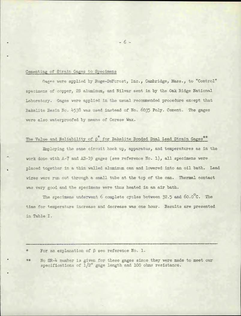
Cementing of Strain Gages to Specimens
Rag**«3 were applied by Ruge-PeFcrest, Inc., Cambridge, Mass., to "Control"
specimens of copper, 2S aluminum, and Nilvar sent in by the Oak Eidge National
Laboratory. Gages were applied in the usual recommended procedure except that
Eakelite Basin No. 4538 was used instead of No. 6035 Poly. Cement. The gages
were also waterproofed by means of Cerese Wax.
The Value and Reliability of ft for Bakelite Bonded Dual Lead Strain Gages
Employing the same circuit hook up, apparatus, and temperatures as in the
work done with A-7 and AB-19 gages (see reference No. 1), all specimens were
placed together iD a thin walled, aluminum can and lowered into an oil bath. Lead
wires were run out through a small, tube at the top of the can. Thermal contact
was very good and the specimens were thus heated in an air bath.
The specimens underwent 6 complete cycles between 32.5 and 60.0 C. The
time for temperature increase and decrease was one hour. Results are presented
in Table I.
* For an explanation of p see reference No. 1.
** No SR-4 number is given for these gages since they were made to meet ourspecifications of 1/2" gage length and 100 ohms resistance.
rGage #
1
2
3
h
5
6
-7-
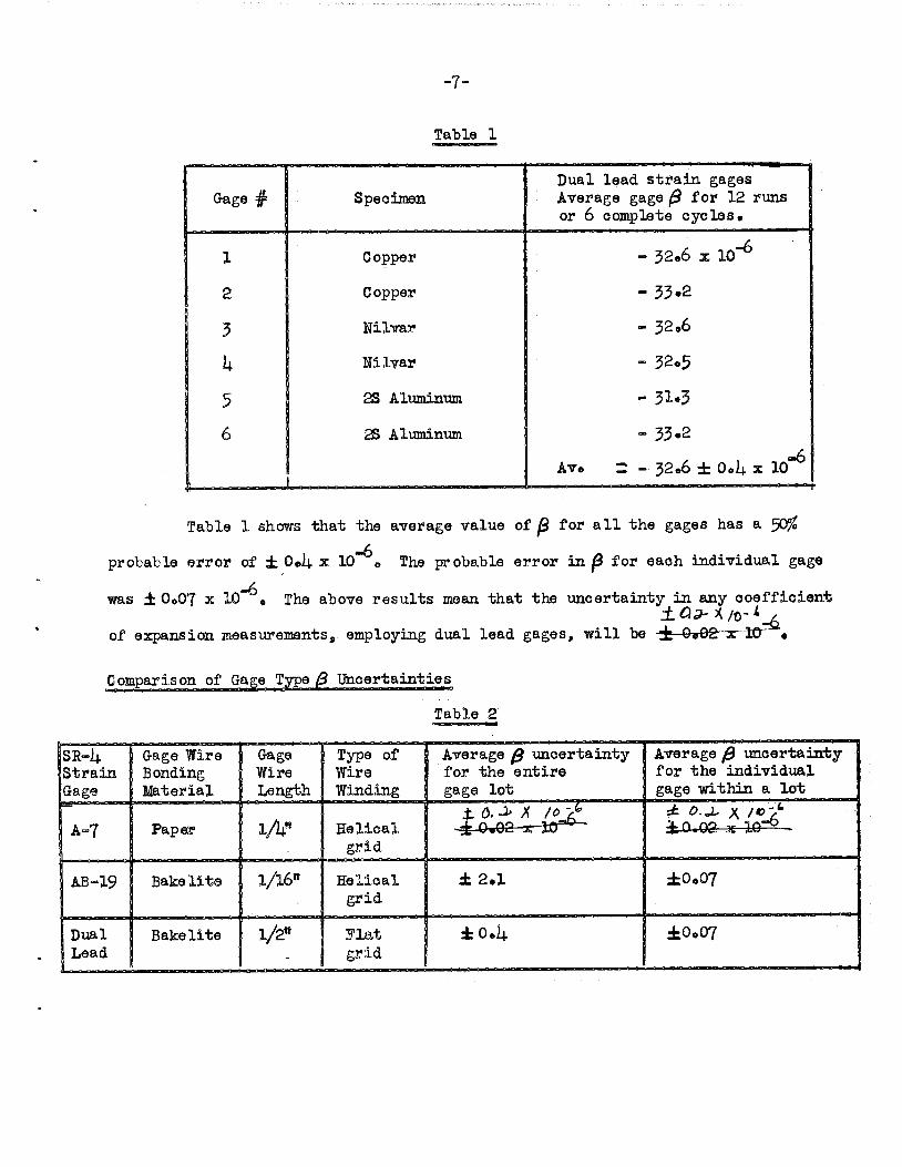
Table 1
Specimen
Copper
Copper
Nilvar
Nilvar
2S Aluminum
2S Aluminum
L
Dual lead strain gagesAverage gage /9 for 12 runsor 6 complete cycles.
- 32.6 x 10"°
-33.2
- 32.6
- 32.5
- 31.3
-33.2
Av. r - 32«6 ± Ock x lo"
Table 1 shows that the average value of j9 for all the gages has a-6probable error of ± 0»ii x 10
was ± 0o07 x 10"6
The probable error in f$ for each individual gage
SR-4|StrainJGage
A-7
AB-19
The above results mean that the uncertainty in any coefficient
of expansion measurements, employing dual lead gages, will be -±-0*02"X"~Kr •
Comparison of Gage Type /g uncertainties
Table 2
TGage Wire GageBondingMaterial
Type ofWire J WireLength 1 Winding
Average (} uncertaintyfor the entire
gage lot
Average 0 uncertaintyfor the individual
gage within a lot
Paper iAB
Bakelite l/l6w
Bakelite 1/2"
Helical
grid
Helical
grid
Flat
grid
* 0J- * '5.6
± 2.1 ±o»07
±0.4 ±o007

Table 2 appears to indicate that, taken as a lot, dual lead gages will
not give more precise coefficient of expansion measurements than non dual lead
gageso The type of grid appears to make no difference in precision. The l/2tt
ZTf -oe" a0* seem to be any better than the 1/V1 gage« Considered as an
individual gage, bakelite bonded gages appear to have better reproducibility
than paper bonded gageso
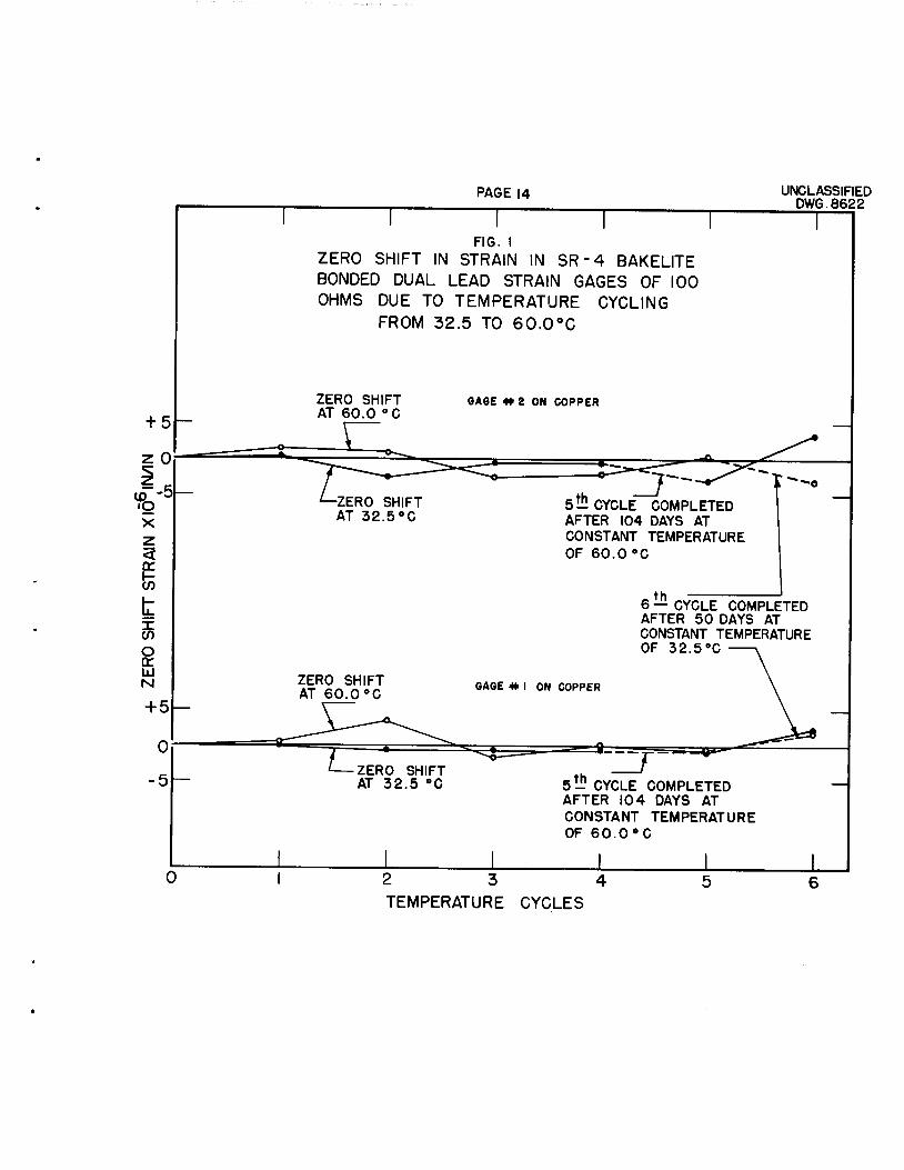
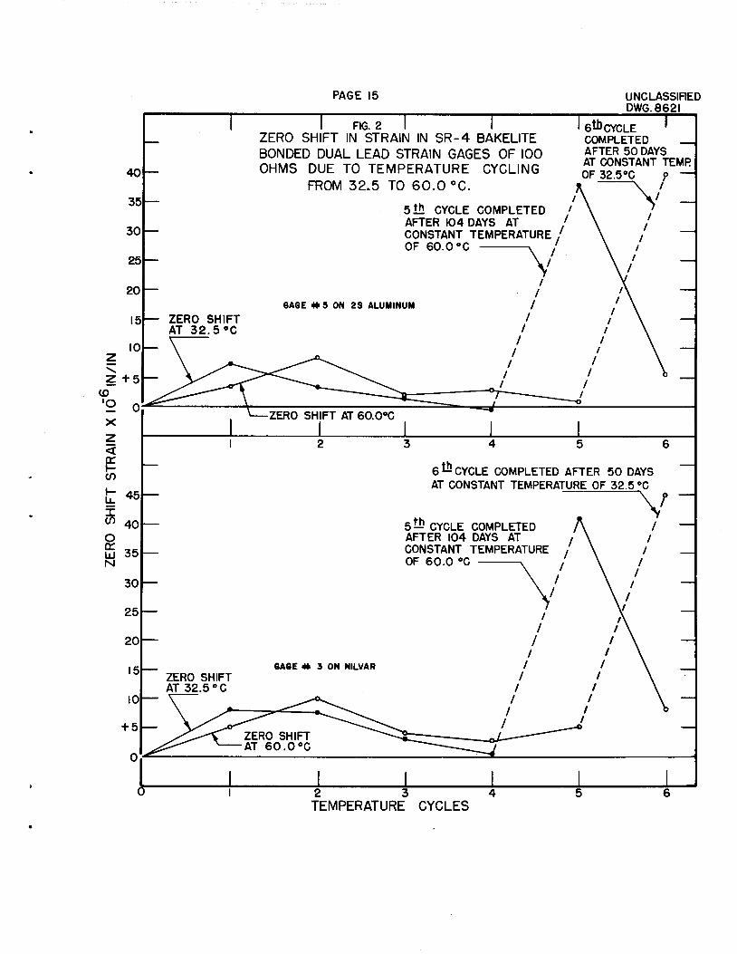
Strain Gage Zero Shift Due to Temperature Cycling
As shown in reference #1, a strain gage zero shift will occur after being
relieved of strain due to load or temperature cycling. Figures 1 and 2 show
typical zero shift for the dual lead gages employed in our present experimentso
Zero shift with temperature cycling appears to be more or less random with, respect
to direction and magnitude except that whenever a long time elapses between cycles
a very large zero shift occurs. It is not known why the gages on copper appear
to be more stable than the gages on Nilvar and 23 aluminum. At any rate, a zero
shift range is indicated within a gage lot. The exact nature of zero shift is
not yet understood.
Strain Gage Creep at Constant Temperature
To reduce gage creep and obtain better gage stability for static tests at
constant temperature, experience with the A-7 and AB-19 gages indicated a need
for a number of temperature curing cycles0 Accordingly the dual lead strain
gages underwent 5 complete temperature cycles from 32.5 "to 60*0 C. As temperature
equilibruim was reached readings were taken for thermal coefficient of expansion
measurements and the temperature was held constant from 1 to 102J. days so that
gage creep could be followed.
-9-
Careful observation during the first half of the first cycle at 60.0 C
temperature equilibruim failed to show an immediate and appreciable gage creep
with time. Since after 1 day at 60B0 c constant temperature the average gage
c^flAp totaled only 2.5 x 10"6 in/in the temperature was changed to 32o5°C and
coefficient of expansion measurements and gage creep observations were made*
After 6 days at 32«5°C the average total gage creep was 1x 10"^ in/in.
The first cycle was completed by raising the temperature back to 60.0°C. After
5 such eycles the temperature was held constant at 60.0°C for I0I4. days (21+96 hours)
during which time gage creep was followedo
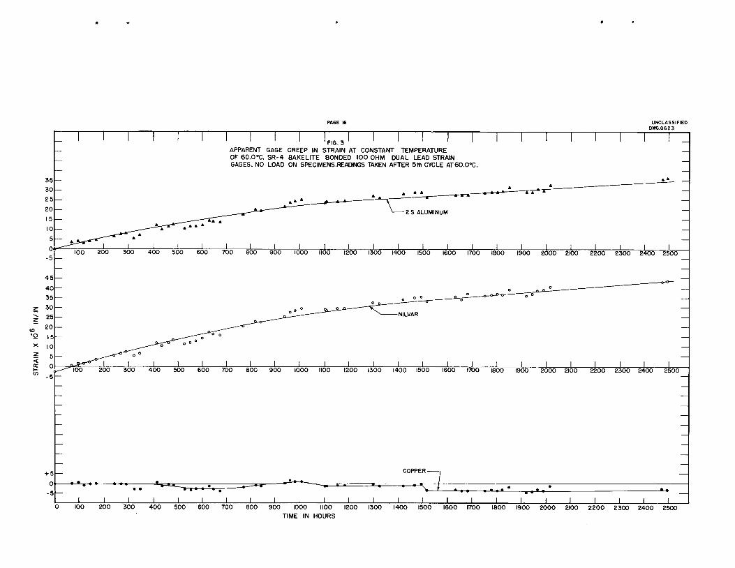
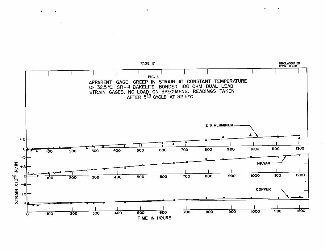
Figures 3 and 1+ show gage creep curves during the 5th cycle at 60.0° and
32.5 C respectively. Temperature difference is probably the main cause for the
difference in total gage creepo The particular gages on copper appear "to be
quite stable whereas the gages on Nilvar and 2S aluminum exhibit a gage creep
that increases with time. The reasons for such different creep behavior among
gages from the same lot is not known. For long range static tests such gage
creep anomalies would tend to nullify the dummy gage compensating principle,
if used.
A comparison of the total magnitude of gage creep after 5 temperature
cycles and during the same gage creep time interval indicates that the dual lead
gages creep very much less than than the A-7 or AB-19 gages. Presumably this
means that the dual lead type gage has better stability characteristics. However,
it should be remembered that Bakelite Resin # J+538 rather than the usual Bakelite
# 6035 Poly. Cement was used. It is not known whether this change of cement
contributes to the attainment of better gage stability.
-10-
Direction of Gage Creep Curves
Unlike the results obtained with the A-7 and AB-19 gages, for which the
direction of gage creep reversed itself with change of temperature, gage creep
for the dual lead gages (except for the gages on copper at 6O0O C) is always
in the same direction, as typically shown by Figures 3 and l\» The bakelite
body of the AB-19 and the dual lead gage is the same. But different cements
were used. Also the dual lead gages were waterproofed with Cerese waxo It
is obvious that the explanation of the directional gage creep for the A-7 and
AB-19 gages will not hold for the dual lead gages, otherwise similar matching
gage creep curves should have been obtained and also the magnitude of gage creep>
should have been the largest for strain gages on Nilvar, followed by copper, and
the smallest for strain gages on 2S aluminum. An explanation to account for the
direction of gage creep with dual lead gages will have to await further researches
on this subject©
Strain Gages for High Temperatures
The usual type of bonded wire resistance strain gage will either not stand
up for long or else not function satisfactorily at temperatures above 150°C. The
gage body material may char or creep and/or the cement may soften or creep.
Greatly diminishing gage accuracy would certainly result. '»*-';»*. 1 j0 circumvent
such adverse effects various types of ceramic bonded strain gages have been used
by Schabtach and Fehij by Manson, Kemp, and Morgan, and by others, with
fairly good results at temperatures as high as 800°C« Such gages have recently
become available commercially e
Known under the name "Surface Transferable Resistor." manufactured byTrans-Sonics, Inc., Airborne Instrumentation, Bedford Airport, Bedford, .ulasso
-11"
The literature indicates that ceramic bonded strain gages exhibit gage
zero shift and gage creep. Only strains much less than 1% can be measured,
othereise the ceramic will crack. Gage strain sensitivity candecrease significantly
at hip-h temperatures. It has been fcund that the gage wire resistance can also
ihaage significantly at high temperatures. Application of ceramic bonded gages
has been ataost entirely for dymanic work, with relatively large errors being
tolerable. For static tests at high temperatures ceramic gage characteristics
and behavior would have to be thoroughtly investigated.
Conclusions
If thermal coefficient of expansion measurements are to be made by means
of bonded wire resistance strain gages the limit of accuracy attainable will
probably be no better than±08l x 10 regardless of the type or size of gage
us edo
Any individual bakelite bonded strain gage will have better reproducibility
than a paper bonded strain gage. However, there appears to be practically no
difference in the precision of accuracy between paper and bakelite bonded strain
gages if test results are taken from many gages of the same lot or if an experiment
can only be performed onceo
There is no great amount of difference in gage zero shift between the
various types of gages©
Dual lead type strain gages appear to have less inherent gage creep than
other types of bonded 'wire strain gages.
a
•12-
The literature indicates; that ceramic bonded wire strain gages' have been
used at temperatures as high as 800°C. However, they exhibit inherent gage creep,
ze?~ -hift, and other adverse properties similar to paper and bakelite bonded
strain gages.
Paper, bakelite, and ceramic bonded wire resistance strain gages are
appropriate for most applications. However, for static work, or for work at high
temperatures, in which reasonably high precision is required, it is advisable to
be thoroughly familiar with the gage characteristics and behavior under such
conditions so that one may properly evaluate the data obtained by employment
of such gages for these special problems.
-13-
REFERENCBS
1- Mo R* Goodman* "Characteristics and Behavior of Bonded Wire Resistance
Strain Gages in Thermal Coefficient of Expansion Measurements- Part I- SR-4 Paper
Bonded A-7 and Bakelite Bonded AB-19 Gages", ORNL- 706 , May, 1950.
2°° B. Jones, "Some Physical Characteristics of the Wire Resistance Strain
Gage," appearing in, The Measurement of Stress and Strain in Solids, London
Institute of Physics, 19i|8.
3- P. Savic, Research, Vol.1, No.3, p.98, Dec. 1947.
4- W. R. Campbell, "Tests of Six Types of Bakelite Bonded Wire Strain
Gages," N.A.C.A. Technical Note # I656, July 194S»
5- C. Schabtach and R. 0. Fehr, Journal of Applied Mechanics, Vol. II,
No. 2, June I94I4, p. A-86.
6- S* S. Manson, R. H. Kemp, W. C. Morgan, Experimental Stress Analysis
Vol. V, Noo I, p. 90, 1947.
<
0
PAGE 14
FIG. I
ZERO SHIFT IN STRAIN IN SR-4 BAKELITEBONDED DUAL LEAD STRAIN GAGES OF 100OHMS DUE TO TEMPERATURE CYCLING
FROM 32.5 TO 60.0°C
ZERO SHIFTAT 60.0 °C
-ZERO SHIFTAT 32.5°C
GAGE * 2 ON COPPER
5HI CYCLE COMPLETEDAFTER 104 DAYS AT
CONSTANT TEMPERATURE
OF 60.0°C
UNCLASSIFIEDDWG.8622
6 — CYCLE COMPLETEDAFTER 50 DAYS ATCONSTANT TEMPERATUREOF 32.5°C
-ZERO SHIFTAT 32.5 °C
1
5tH CYCLE COMPLETEDAFTER 104 DAYS AT
CONSTANT TEMPERATUREOF 60.0 °C
2 3 4
TEMPERATURE CYCLES
J I
40
35
30
25
20
15
10
en
t 45en 40
o
UJ 35N
30
25
20
15
10
+ 5
0
ZERO SHIFTAT 32.5 °C
ZERO SHIFTAT 32.5 °C
PAGE 15
I FIG. 2 I IZERO SHIFT IN STRAIN IN SR-4 BAKELITE
UNCLASSIFIEDDWG. 8621
6thCYCLE 'COMPLETED I
BONDED DUAL LEAD STRAIN GAGES OF 100 £t]&mctamttpudOHMS DUE TO TEMPERATURE CYCLING 0}S -
FROM 32.5 TO 60.0 °C. ~:
5 th CYCLE COMPLETED 'AFTER 104 DAYS AT /CONSTANT TEMPERATUREOF 60.0 °C
VGAGE #5 ON 2S ALUMINUM
GAGE # 3 ON NILVAR
6 - CYCLE COMPLETED AFTER 50 DAYS
AT CONSTANT TEMPERATURE OF 32.5 °C
V;fh5^-' CYCLE COMPLETEDAFTER 104 DAYS AT
CONSTANT TEMPERATURE
OF 60.0 °C
2 3 4
TEMPERATURE CYCLES
+ 5-
0 •
-5-
100 200 300 400 500 600
'FIG. 3 ' ' ''ii
APPARENT GAGE CREEP IN STRAIN AT CONSTANT TEMPERATUREOF 60.0-C. SR-4 BAKELITE BONDED 100 OHM DUAL LEAD STRAINGAGES. NO LOAD ON SPECIMENS.READINGS TAKEN AFTER 5th CYCLE ATeO-CC.
COPPER
UNCLASSIFIED
DWG.8623
2000 2100 2200 2300 2400 2500
I700 800 900 1000 1100
TIME IN HOURS
_L _L _L _L _L _L1200 1300 1400 1500 1600 1700 1800 1900 2000 2100 2200 2300 2400 2500
100 200
PAGE 17
FIG. 4
APPARENT GAGE CREEP IN STRAIN AT CONSTANT TEMPERATUREOF 32.5°C. SR-4 BAKELITE BONDED 100 OHM DUAL LEADSTRAIN GAGES. NO LOAD ON SPECIMENS. READINGS TAKEN
AFTER 5^ CYCLE AT 32.5°C
300 400 500 600
TIME IN HOURS
700 800 900 1000
UNCLASSIFIEDDWG. 8910
1100