Embed Size (px)
DESCRIPTION
operation of molten battery
Citation preview
Liquid Metal Batteries: Past, Present, and FutureHojong Kim, Dane A. Boysen, Jocelyn M. Newhouse, Brian L. Spatocco, Brice Chung, Paul J. Burke,David J. Bradwell, Kai Jiang, Alina A. Tomaszowska, Kangli Wang, Weifeng Wei, Luis A. Ortiz,Salvador A. Barriga, Sophie M. Poizeau, and Donald R. Sadoway*
Department of Materials Science and Engineering, Massachusetts Institute of Technology, 77 Massachusetts Avenue, Cambridge,Massachusetts 02139-4307, United States
CONTENTS
1. Introduction A1.1. Description B1.2. Advantages and Disadvantages B1.3. Applications C
2. Past Work C2.1. Hoopes Cells D2.2. Thermally Regenerative Batteries D2.3. Bimetallic Cells E
2.3.1. General Motors Corporation E2.3.2. Atomics International E3.3.3. Argonne National Laboratory E
3. Present Work G3.1. Electrodes G
3.1.1. Thermodynamics H3.1.2. Economics I3.1.3. Alloying J
3.2. Electrolyte K3.3. Cell Performance M
3.3.1. Na−Bi Cells M3.3.2. Mg−Sb Cells N3.3.3. Li−Pb−Sb Cells N
4. Future Work O4.1. New Chemistries O
4.1.1. Lithium O4.1.2. Sodium O4.1.3. Calcium P4.1.4. Barium P4.1.5. Strontium P
4.2. Corrosion P4.2.1. Negative Current Collector P4.2.2. Positive Current Collector Q4.2.3. Electrical Insulator Q
4.3. Seals Q
4.3.1. Compressive Seals Q4.3.2. Adhesive Seals Q
4.4. Thermal Management Q5. Conclusions RAuthor Information R
Corresponding Author RNotes RBiographies R
Acknowledgments VGlossary V
Symbols VAcronyms V
References V
1. INTRODUCTION
The evolution of the liquid metal battery is a story of a noveltechnology originally conceived in a different economic andpolitical climate to provide flexibility in addressing theconstraints of a society just entering the nuclear age and withaspirations to electrify the everyday experience. Ironically, it isthese same massive research projects that receded intoobscurity that can now be resurrected and reinvented as anexciting opportunity for addressing society’s ambitions for bothsustainable and environmentally benign energy. In contrast tothe public’s demand for the constant improvement of high-performance lithium-ion batteries for portable electronics,1
liquid metal batteries are instead the story of a society catchingup with a technology far ahead of its time.The story of the all-liquid electrochemical cell begins nearly a
century ago with advances in the electrolytic production ofultrahigh-purity aluminum. Building upon those early advancesin classical electrometallurgy, four decades later the U.S.government began to fund pioneering work at a few of thenation’s top industrial and national laboratories to develop all-liquid cells for energy storage applications. Motivated by theCold War battle for technological supremacy, intensive researchon these thermally and electrically rechargeable all-liquidenergy storage cells continued in the U.S. throughout thenext decade, only to be abandoned as efforts shifted towardhigher-energy-density rechargeable cells with immobilizedcomponents better suited for automotive applications. After anearly 40-year hiatus, the rapid deployment of renewableenergy technologies, such as wind and solar power, hashastened the demand for low-cost, long-life, large-scale energy
Received: May 22, 2012
Review
pubs.acs.org/CR
© XXXX American Chemical Society A dx.doi.org/10.1021/cr300205k | Chem. Rev. XXXX, XXX, XXX−XXX
storage and renewed interest in the rechargeable three-liquid-layer galvanic cellthe liquid metal battery.1.1. Description
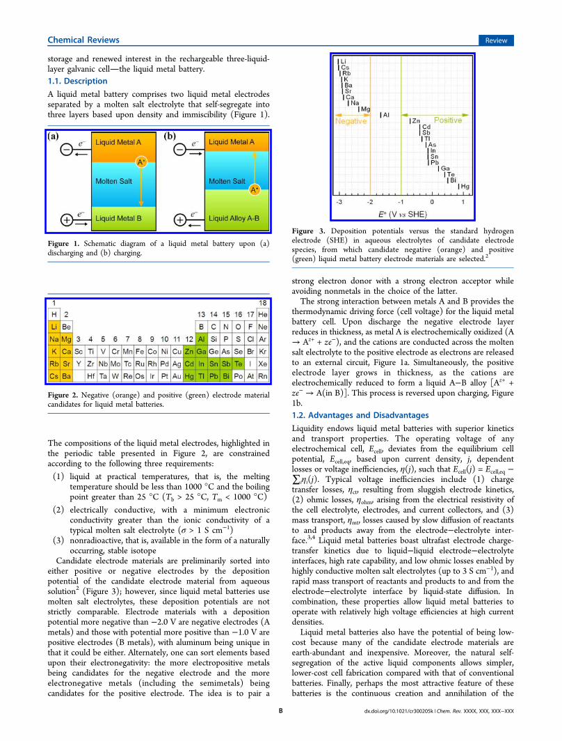
A liquid metal battery comprises two liquid metal electrodesseparated by a molten salt electrolyte that self-segregate intothree layers based upon density and immiscibility (Figure 1).
The compositions of the liquid metal electrodes, highlighted inthe periodic table presented in Figure 2, are constrainedaccording to the following three requirements:
(1) liquid at practical temperatures, that is, the meltingtemperature should be less than 1000 °C and the boilingpoint greater than 25 °C (Tb > 25 °C, Tm < 1000 °C)
(2) electrically conductive, with a minimum electronicconductivity greater than the ionic conductivity of atypical molten salt electrolyte (σ > 1 S cm−1)
(3) nonradioactive, that is, available in the form of a naturallyoccurring, stable isotope
Candidate electrode materials are preliminarily sorted intoeither positive or negative electrodes by the depositionpotential of the candidate electrode material from aqueoussolution2 (Figure 3); however, since liquid metal batteries usemolten salt electrolytes, these deposition potentials are notstrictly comparable. Electrode materials with a depositionpotential more negative than −2.0 V are negative electrodes (Ametals) and those with potential more positive than −1.0 V arepositive electrodes (B metals), with aluminum being unique inthat it could be either. Alternately, one can sort elements basedupon their electronegativity: the more electropositive metalsbeing candidates for the negative electrode and the moreelectronegative metals (including the semimetals) beingcandidates for the positive electrode. The idea is to pair a
strong electron donor with a strong electron acceptor whileavoiding nonmetals in the choice of the latter.The strong interaction between metals A and B provides the
thermodynamic driving force (cell voltage) for the liquid metalbattery cell. Upon discharge the negative electrode layerreduces in thickness, as metal A is electrochemically oxidized (A→ Az+ + ze−), and the cations are conducted across the moltensalt electrolyte to the positive electrode as electrons are releasedto an external circuit, Figure 1a. Simultaneously, the positiveelectrode layer grows in thickness, as the cations areelectrochemically reduced to form a liquid A−B alloy [Az+ +ze− → A(in B)]. This process is reversed upon charging, Figure1b.1.2. Advantages and Disadvantages
Liquidity endows liquid metal batteries with superior kineticsand transport properties. The operating voltage of anyelectrochemical cell, Ecell, deviates from the equilibrium cellpotential, Ecell,eq, based upon current density, j, dependentlosses or voltage inefficiencies, η(j), such that Ecell(j) = Ecell,eq −∑iηi(j). Typical voltage inefficiencies include (1) chargetransfer losses, ηct, resulting from sluggish electrode kinetics,(2) ohmic losses, ηohm, arising from the electrical resistivity ofthe cell electrolyte, electrodes, and current collectors, and (3)mass transport, ηmt, losses caused by slow diffusion of reactantsto and products away from the electrode−electrolyte inter-face.3,4 Liquid metal batteries boast ultrafast electrode charge-transfer kinetics due to liquid−liquid electrode−electrolyteinterfaces, high rate capability, and low ohmic losses enabled byhighly conductive molten salt electrolytes (up to 3 S cm−1), andrapid mass transport of reactants and products to and from theelectrode−electrolyte interface by liquid-state diffusion. Incombination, these properties allow liquid metal batteries tooperate with relatively high voltage efficiencies at high currentdensities.Liquid metal batteries also have the potential of being low-
cost because many of the candidate electrode materials areearth-abundant and inexpensive. Moreover, the natural self-segregation of the active liquid components allows simpler,lower-cost cell fabrication compared with that of conventionalbatteries. Finally, perhaps the most attractive feature of thesebatteries is the continuous creation and annihilation of the
Figure 1. Schematic diagram of a liquid metal battery upon (a)discharging and (b) charging.
Figure 2. Negative (orange) and positive (green) electrode materialcandidates for liquid metal batteries.
Figure 3. Deposition potentials versus the standard hydrogenelectrode (SHE) in aqueous electrolytes of candidate electrodespecies, from which candidate negative (orange) and positive(green) liquid metal battery electrode materials are selected.2
Chemical Reviews Review
dx.doi.org/10.1021/cr300205k | Chem. Rev. XXXX, XXX, XXX−XXXB

liquid metal electrodes upon charge−discharge cycling. Thisfeature grants liquid metal batteries the potential forunprecedented cycle life by rendering them immune tomicrostructural electrode degradation mechanisms that limitthe cycle life of a conventional battery.5,6 When taken together,low cost of materials, simple assembly, and the potential forlong lifetimes position liquid metal batteries particularly well forcompetition in the grid-storage market.Despite these advantages, liquid metal batteries possess some
disadvantages, which make them unsuitable for use in portableapplications. These include elevated operating temperatures(generally >200 °C), low theoretical specific energy density(typically <200 Wh kg−1), comparatively low equilibrium cellvoltages (typically <1.0 V), highly corrosive active cellcomponents, and high self-discharge rates for some chemistriesdue to metallic solubility of the electrode species in the moltensalt electrolyte. Moreover, three liquid layers make batteryoperation sensitive to motion and potentially hazardous shouldthe liquid electrodes touch, leading to a short-circuited cell andrapid heat generation.
1.3. Applications
High-temperature operation and all-liquid components restrictliquid metal batteries to stationary applications; however, thepromise of low-cost, scalable, and high rate capable energystorage makes liquid metal batteries prime candidates for grid-scale energy storage (0.1−1.0 GWh). Today, grid-scale energystorage capacity represents less than 6% (130 GW) of globalelectricity generation, and demand is likely to increase as theneed for off-grid storage grows due to market penetration ofintermittent renewable power sources, increased electrification,advancements in smart grid technology, and deployment ofelectric vehicles.7 However, in the absence of grid-scaleelectrical energy storage, power providers must continuouslyadjust output levels to meet fluctuating demand, causing awide-range of operational and infrastructural inefficiencies.Grid-scale energy storage requirements can be broadly
classified into either energy or power applications. Energyapplications, such as storing excess wind energy during periodsof low power demand and providing power during periods ofhigh demand, require long discharge times, typically severalhours. By contrast, power applications, such as capturing theenergy produced by a gust of wind, frequency regulation, andspinning reserves, require the ability to store large inputs ofenergy for short periods of time (seconds to minutes). As canbe seen from Figure 4a, most technologies are more economicalfor either energy ($ kWh−1) or power ($ kW−1) applica-tions;8−10 however, the high rate capability of liquid metalbatteries could allow them to serve both purposes, enablingdual-use applications and more attractive economics.For grid-scale energy storage, liquid metal batteries must be
cost-competitive with incumbent technologies.7 Detailed cost−benefit analyses of existing technologies can be foundelsewhere;7−9,11 however, a first-order approximation is madehere in an attempt to capture the essential metrics and enablethe comparison of this nascent technology to more establishedenergy storage technologies. In Figure 4b, the levelized cost orcapital cost normalized by the cycle life and energy efficiency(cost × cycles−1 × efficiency−1) of grid-scale energy storagetechnologies is plotted against the globally installed capacity.9
The trend is clear: low-cost technologies are preferred, even ifthey have very low energy and power densities and aregeographically constrained (e.g., pumped hydroelectric and
compressed air energy storage). Competing with existingenergy storage technologies such as these is a major challengefor electrochemical systems, even though batteries offer thebenefit of geographic flexibility and unfettered deployability. Toa first approximation, a levelized cost of 5¢ kWh−1 cyc−1 wouldallow liquid metal batteries to be competitive with incumbentenergy storage technologies. For example, a battery with a costof $400 kWh−1, lifetime of 10 000 cycles, and energy efficiencyof 80% would meet the 5¢ kWh−1 cyc−1 price point. Thislevelized cost estimate is useful in identifying economicallyviable chemistries for liquid metal batteries and gauging theirpotential as a competitive grid-scale energy storage technology.For a target levelized energy cost of 5¢ kWh−1 cyc−1, in thisreview, we assume a battery life of 10 000 cycles, an energyefficiency of 80%, and a materials cost of one-fourth of a totalbattery system to arrive at a target battery materials cost ofunder $100 kWh−1. This metric will serve as a guide later inselecting promising low-cost electrode materials.
2. PAST WORKThe history of all-liquid electrochemical cells dates back to theturn of the last century with roots in the development ofclassical electrometallurgy and begins with advances resulting inthe development of the three-liquid-layer Hoopes cell at theAluminum Company of America (Alcoa) in the 1920s for theelectrolytic production of high-purity aluminum.12 Forty yearslater, the three-liquid-layer cell re-emerged as one variant of the
Figure 4. (a) Cost of power versus energy for various energy storagetechnologies, where CAES stands for compressed air energy storage(data from refs 8−10) and (b) globally installed energy storagecapacity versus cycle normalized cost of energy (data from ref 9).
Chemical Reviews Review
dx.doi.org/10.1021/cr300205k | Chem. Rev. XXXX, XXX, XXX−XXXC
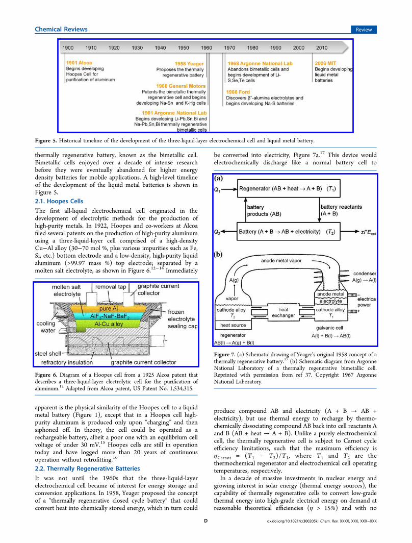
thermally regenerative battery, known as the bimetallic cell.Bimetallic cells enjoyed over a decade of intense researchbefore they were eventually abandoned for higher energydensity batteries for mobile applications. A high-level timelineof the development of the liquid metal batteries is shown inFigure 5.2.1. Hoopes Cells
The first all-liquid electrochemical cell originated in thedevelopment of electrolytic methods for the production ofhigh-purity metals. In 1922, Hoopes and co-workers at Alcoafiled several patents on the production of high-purity aluminumusing a three-liquid-layer cell comprised of a high-densityCu−Al alloy (30−70 mol %, plus various impurities such as Fe,Si, etc.) bottom electrode and a low-density, high-purity liquidaluminum (>99.97 mass %) top electrode; separated by amolten salt electrolyte, as shown in Figure 6.12−14 Immediately
apparent is the physical similarity of the Hoopes cell to a liquidmetal battery (Figure 1), except that in a Hoopes cell high-purity aluminum is produced only upon “charging” and thensiphoned off. In theory, the cell could be operated as arechargeable battery, albeit a poor one with an equilibrium cellvoltage of under 30 mV.15 Hoopes cells are still in operationtoday and have logged more than 20 years of continuousoperation without retrofitting.16
2.2. Thermally Regenerative Batteries
It was not until the 1960s that the three-liquid-layerelectrochemical cell became of interest for energy storage andconversion applications. In 1958, Yeager proposed the conceptof a “thermally regenerative closed cycle battery” that couldconvert heat into chemically stored energy, which in turn could
be converted into electricity, Figure 7a.17 This device wouldelectrochemically discharge like a normal battery cell to
produce compound AB and electricity (A + B → AB +electricity), but use thermal energy to recharge by thermo-chemically dissociating compound AB back into cell reactants Aand B (AB + heat → A + B). Unlike a purely electrochemicalcell, the thermally regenerative cell is subject to Carnot cycleefficiency limitations, such that the maximum efficiency isηCarnot = (T1 − T2)/T1, where T1 and T2 are thethermochemical regenerator and electrochemical cell operatingtemperatures, respectively.In a decade of massive investments in nuclear energy and
growing interest in solar energy (thermal energy sources), thecapability of thermally regenerative cells to convert low-gradethermal energy into high-grade electrical energy on demand atreasonable theoretical efficiencies (η > 15%) and with no
Figure 5. Historical timeline of the development of the three-liquid-layer electrochemical cell and liquid metal battery.
Figure 6. Diagram of a Hoopes cell from a 1925 Alcoa patent thatdescribes a three-liquid-layer electrolytic cell for the purification ofaluminum.12 Adapted from Alcoa patent, US Patent No. 1,534,315.
Figure 7. (a) Schematic drawing of Yeager’s original 1958 concept of athermally regenerative battery.17 (b) Schematic diagram from ArgonneNational Laboratory of a thermally regenerative bimetallic cell.Reprinted with permission from ref 37. Copyright 1967 ArgonneNational Laboratory.
Chemical Reviews Review
dx.doi.org/10.1021/cr300205k | Chem. Rev. XXXX, XXX, XXX−XXXD
moving parts quickly gained widespread appeal and spawnedresearch and development programs across the United States.Over the next decade, two general types of thermally
regenerative batteries emerged: (1) metal hydride or metalhalide cells and (2) bimetallic cells. For metal hydride or halidecells, hydrogen or halogen gases (X2 = H2, F2, Cl2, Br2, I2) areelectrochemically reacted with a liquid metal A to form a metalhydride or halide discharge product (AX) that is solvated in amolten salt electrolyte and subsequently thermochemicallyregenerated (dissociated) back into a hydrogen or halide gasand liquid metal. By contrast, in bimetallic cells an electro-positive liquid metal A is reacted with an electronegative liquidmetal B to form a molten metal alloy AB that is then thermallyregenerated (distilled) through the preferential evaporation ofreactant gas A from AB liquid product, as depicted in Figure 7b.Of this body of work, only bimetallic cells exhibit the three-
liquid-layer self-segregating structure relevant to this review.For a more comprehensive review of thermally regenerativecells that includes both cell types see Crouthamel and Recht(1967).18 In the United States, large-scale research anddevelopment efforts were undertaken in the 1960s to developbimetallic thermally regenerative cells at the General MotorsCorporation, Argonne National Laboratory, and AtomicsInternational (a division of North American Aviation).
2.3. Bimetallic Cells
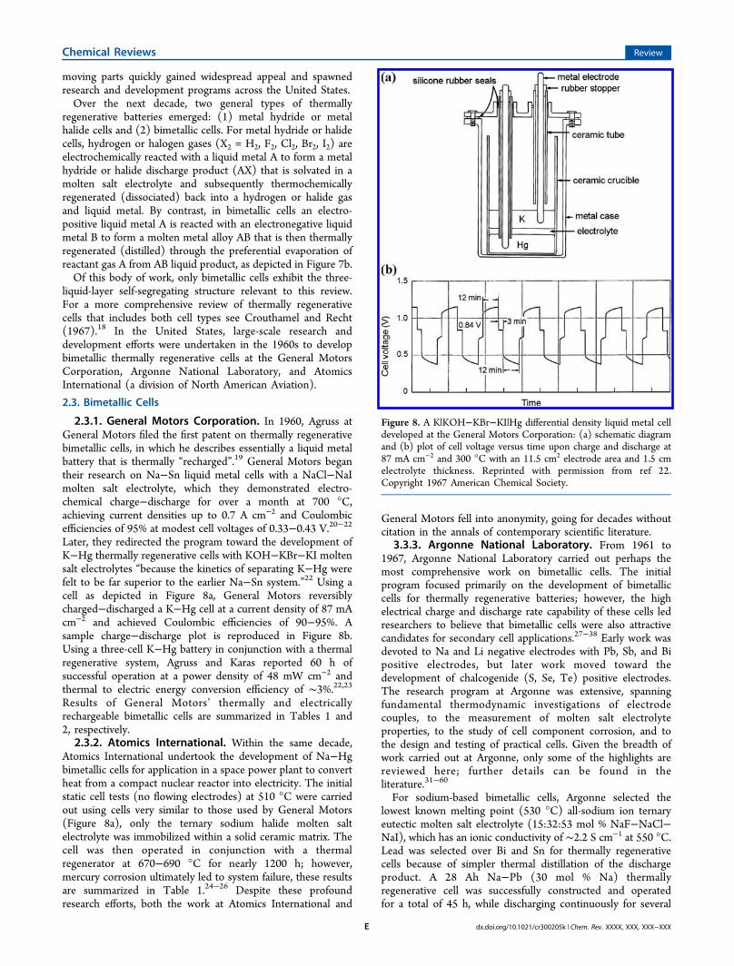
2.3.1. General Motors Corporation. In 1960, Agruss atGeneral Motors filed the first patent on thermally regenerativebimetallic cells, in which he describes essentially a liquid metalbattery that is thermally “recharged”.19 General Motors begantheir research on Na−Sn liquid metal cells with a NaCl−NaImolten salt electrolyte, which they demonstrated electro-chemical charge−discharge for over a month at 700 °C,achieving current densities up to 0.7 A cm−2 and Coulombicefficiencies of 95% at modest cell voltages of 0.33−0.43 V.20−22Later, they redirected the program toward the development ofK−Hg thermally regenerative cells with KOH−KBr−KI moltensalt electrolytes “because the kinetics of separating K−Hg werefelt to be far superior to the earlier Na−Sn system.”22 Using acell as depicted in Figure 8a, General Motors reversiblycharged−discharged a K−Hg cell at a current density of 87 mAcm−2 and achieved Coulombic efficiencies of 90−95%. Asample charge−discharge plot is reproduced in Figure 8b.Using a three-cell K−Hg battery in conjunction with a thermalregenerative system, Agruss and Karas reported 60 h ofsuccessful operation at a power density of 48 mW cm−2 andthermal to electric energy conversion efficiency of ∼3%.22,23Results of General Motors’ thermally and electricallyrechargeable bimetallic cells are summarized in Tables 1 and2, respectively.2.3.2. Atomics International. Within the same decade,
Atomics International undertook the development of Na−Hgbimetallic cells for application in a space power plant to convertheat from a compact nuclear reactor into electricity. The initialstatic cell tests (no flowing electrodes) at 510 °C were carriedout using cells very similar to those used by General Motors(Figure 8a), only the ternary sodium halide molten saltelectrolyte was immobilized within a solid ceramic matrix. Thecell was then operated in conjunction with a thermalregenerator at 670−690 °C for nearly 1200 h; however,mercury corrosion ultimately led to system failure, these resultsare summarized in Table 1.24−26 Despite these profoundresearch efforts, both the work at Atomics International and
General Motors fell into anonymity, going for decades withoutcitation in the annals of contemporary scientific literature.
3.3.3. Argonne National Laboratory. From 1961 to1967, Argonne National Laboratory carried out perhaps themost comprehensive work on bimetallic cells. The initialprogram focused primarily on the development of bimetalliccells for thermally regenerative batteries; however, the highelectrical charge and discharge rate capability of these cells ledresearchers to believe that bimetallic cells were also attractivecandidates for secondary cell applications.27−38 Early work wasdevoted to Na and Li negative electrodes with Pb, Sb, and Bipositive electrodes, but later work moved toward thedevelopment of chalcogenide (S, Se, Te) positive electrodes.The research program at Argonne was extensive, spanningfundamental thermodynamic investigations of electrodecouples, to the measurement of molten salt electrolyteproperties, to the study of cell component corrosion, and tothe design and testing of practical cells. Given the breadth ofwork carried out at Argonne, only some of the highlights arereviewed here; further details can be found in theliterature.31−60
For sodium-based bimetallic cells, Argonne selected thelowest known melting point (530 °C) all-sodium ion ternaryeutectic molten salt electrolyte (15:32:53 mol % NaF−NaCl−NaI), which has an ionic conductivity of ∼2.2 S cm−1 at 550 °C.Lead was selected over Bi and Sn for thermally regenerativecells because of simpler thermal distillation of the dischargeproduct. A 28 Ah Na−Pb (30 mol % Na) thermallyregenerative cell was successfully constructed and operatedfor a total of 45 h, while discharging continuously for several
Figure 8. A K|KOH−KBr−KI|Hg differential density liquid metal celldeveloped at the General Motors Corporation: (a) schematic diagramand (b) plot of cell voltage versus time upon charge and discharge at87 mA cm−2 and 300 °C with an 11.5 cm2 electrode area and 1.5 cmelectrolyte thickness. Reprinted with permission from ref 22.Copyright 1967 American Chemical Society.
Chemical Reviews Review
dx.doi.org/10.1021/cr300205k | Chem. Rev. XXXX, XXX, XXX−XXXE
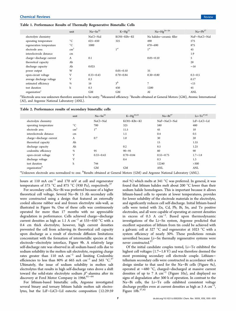
hours at 110 mA cm−2 and 170 mV at cell and regeneratortemperatures of 575 °C and 875 °C (930 Pa), respectively.37
For secondary cells, Na−Bi was preferred because of a highertheoretical cell voltage. Several Na−Bi 15 Ah secondary cellswere constructed using a design that featured an externallycooled silicone rubber seal and frozen electrolyte side-wall, asillustrated in Figure 9a. One of these cells was continuouslyoperated for more than 17 months with no appreciabledegradation in performance. Cells achieved charge−dischargecurrent densities as high as 1.1 A cm−2 at 535−650 °C with a0.4 cm thick electrolyte; however, high current densitiesprevented the cell from achieving its theoretical cell capacityupon discharge as a result of electrode diffusion limitationsconcomitant with the formation of intermetallic species at theelectrode−electrolyte interface, Figure 9b. A relatively largeself-discharge rate was observed in all sodium-based cells due tosodium solubility in the molten salt electrolyte, requiring chargerates greater than 110 mA cm−2 and limiting Coulombicefficiencies to less than 80% at 665 mA cm−2 and 565 °C.37
Ultimately, the issue of sodium solubility in molten saltelectrolytes that results in high self-discharge rates drove a shifttoward the solid-state electrolyte sodium β″-alumina after itsdiscovery at Ford Motor Company in 1966.61−64
For lithium-based bimetallic cells, Argonne investigatedseveral binary and ternary lithium halide molten salt electro-lytes, but the LiF−LiCl−LiI eutectic composition (12:29:59
mol %) which melts at 341 °C was preferred. In general, it wasfound that lithium halides melt about 200 °C lower than theirsodium halide homologues. This is important because it allowslithium-based cells to operate at lower temperatures, providesfor lower solubility of the electrode materials in the electrolyte,and significantly reduces cell self-discharge. Initial lithium-basedcells were tested with Zn, Cd, Pb, Bi, Sn, and Te positiveelectrodes, and all were capable of operating at current densitiesin excess of 0.3 A cm−2. Based upon thermodynamicinvestigations of the Li−Sn system, Argonne predicted thatexcellent separation of lithium from tin could be achieved witha galvanic cell at 327 °C and regenerator at 1023 °C with asystem efficiency of nearly 30%. These predictions remainunverified because Li−Sn thermally regenerative systems werenever constructed.37
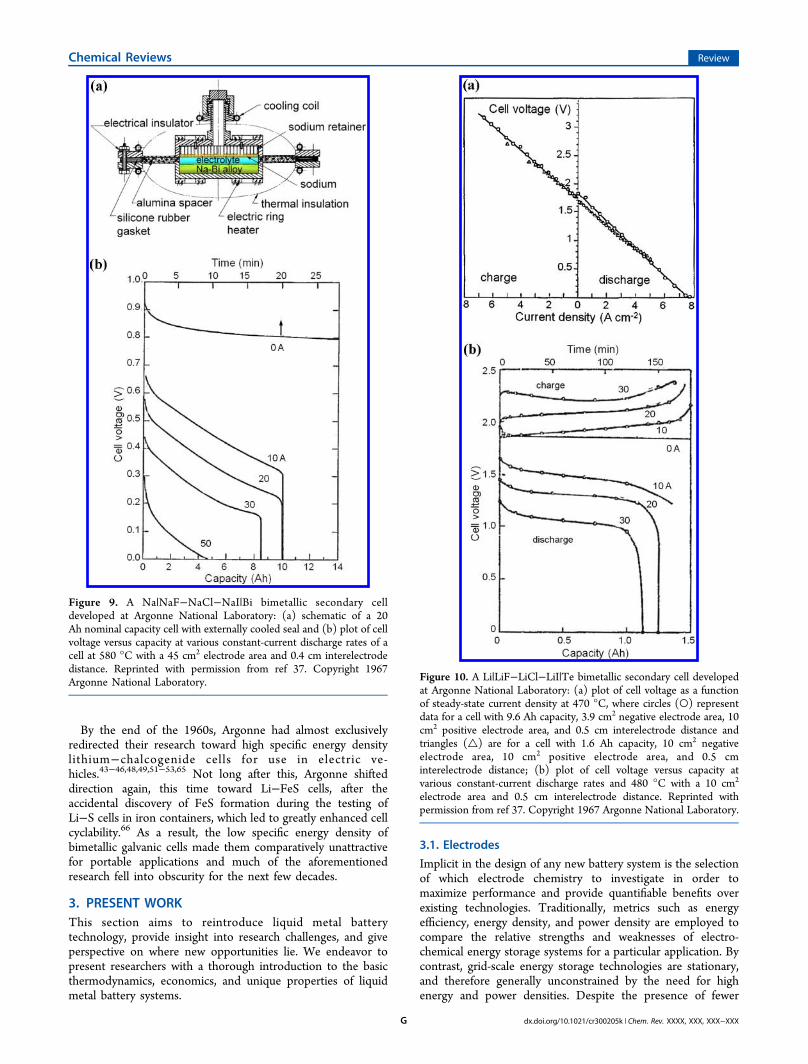
Of the initial candidate couples tested, Li−Te exhibited thehighest cell voltages (1.7−1.8 V) and was therefore deemed themost promising secondary cell electrode couple. Lithium−tellurium secondary cells were constructed in accordance with adesign similar to that used for the Na−Bi cells (Figure 9a),operated at ∼480 °C, charged−discharged at massive currentdensities of up to 7 A cm−2 (Figure 10a), and displayed nosigns of degradation after 300 h of operation. In contrast to theNa−Bi cells, the Li−Te cells exhibited consistent voltagedischarge profiles even at current densities as high as 3 A cm−2,Figure 10b.37,42
Table 1. Performance Results of Thermally Regenerative Bimetallic Cells
unit Na−Sn22 K−Hg22 Na−Hg24−26 Na−Pb37
electrolyte chemistry NaCl−NaI KOH−KBr−KI Na halides−ceramic filler NaF−NaCl−NaIoperating temperature °C 625−650 325 490 575regeneration temperature °C 1000 670−690 875electrode area cm2 1a 1a 45interelectrode distance cm 1.9charge−discharge current A 0.1 0.05−0.10 5theoretical capacity Ah 28discharge capacity Ah 0.025 ∼16power output W 0.05−0.10 35open-circuit voltage V 0.33−0.43 0.70−0.84 0.30−0.80 0.3−0.5average discharge voltage V 0.3 0.17estimated efficiency % 16 3b 7 <15test duration h 0.3 430 1200 45organizationc GM GM AI ANL
aElectrode area was unknown therefore assumed to be unity. bMeasured efficiency. cResults obtained at General Motors (GM), Atomic International(AI), and Argonne National Laboratory (ANL).
Table 2. Performance results of secondary bimetallic cells
unit Na−Sn22 K−Hg22,23 Na−Bi37 Li−Te37,42
electrolyte chemistry NaCl−NaI KOH−KBr−KI NaF−NaCl−NaI LiF−LiCl−LiIoperating temperature °C 700 325 580 480electrode area cm2 1a 11.5 45 10interelectrode distance cm 1.5 0.4 0.5charge−discharge current A 0.7 1.0 30 20theoretical capacity Ah 15 1.55discharge capacity Ah 0.2 8.5 1.25coulombic efficiency % 95 90−95 80 90open-circuit voltage V 0.33−0.43 0.70−0.84 0.55−0.75 1.7−1.8discharge voltage V 0.4 0.3 1.3test duration h 744 12240 >300organizationb GM GM ANL ANL
aUnknown electrode area normalized to one. bResults obtained at General Motors (GM) and Argonne National Laboratory (ANL).
Chemical Reviews Review
dx.doi.org/10.1021/cr300205k | Chem. Rev. XXXX, XXX, XXX−XXXF
By the end of the 1960s, Argonne had almost exclusivelyredirected their research toward high specific energy densitylithium−chalcogenide cells for use in electric ve-hicles.43−46,48,49,51−53,65 Not long after this, Argonne shifteddirection again, this time toward Li−FeS cells, after theaccidental discovery of FeS formation during the testing ofLi−S cells in iron containers, which led to greatly enhanced cellcyclability.66 As a result, the low specific energy density ofbimetallic galvanic cells made them comparatively unattractivefor portable applications and much of the aforementionedresearch fell into obscurity for the next few decades.
3. PRESENT WORKThis section aims to reintroduce liquid metal batterytechnology, provide insight into research challenges, and giveperspective on where new opportunities lie. We endeavor topresent researchers with a thorough introduction to the basicthermodynamics, economics, and unique properties of liquidmetal battery systems.
3.1. Electrodes
Implicit in the design of any new battery system is the selectionof which electrode chemistry to investigate in order tomaximize performance and provide quantifiable benefits overexisting technologies. Traditionally, metrics such as energyefficiency, energy density, and power density are employed tocompare the relative strengths and weaknesses of electro-chemical energy storage systems for a particular application. Bycontrast, grid-scale energy storage technologies are stationary,and therefore generally unconstrained by the need for highenergy and power densities. Despite the presence of fewer
Figure 9. A Na|NaF−NaCl−NaI|Bi bimetallic secondary celldeveloped at Argonne National Laboratory: (a) schematic of a 20Ah nominal capacity cell with externally cooled seal and (b) plot of cellvoltage versus capacity at various constant-current discharge rates of acell at 580 °C with a 45 cm2 electrode area and 0.4 cm interelectrodedistance. Reprinted with permission from ref 37. Copyright 1967Argonne National Laboratory. Figure 10. A Li|LiF−LiCl−LiI|Te bimetallic secondary cell developed
at Argonne National Laboratory: (a) plot of cell voltage as a functionof steady-state current density at 470 °C, where circles (○) representdata for a cell with 9.6 Ah capacity, 3.9 cm2 negative electrode area, 10cm2 positive electrode area, and 0.5 cm interelectrode distance andtriangles (△) are for a cell with 1.6 Ah capacity, 10 cm2 negativeelectrode area, 10 cm2 positive electrode area, and 0.5 cminterelectrode distance; (b) plot of cell voltage versus capacity atvarious constant-current discharge rates and 480 °C with a 10 cm2
electrode area and 0.5 cm interelectrode distance. Reprinted withpermission from ref 37. Copyright 1967 Argonne National Laboratory.
Chemical Reviews Review
dx.doi.org/10.1021/cr300205k | Chem. Rev. XXXX, XXX, XXX−XXXG
constraints, stationary energy storage solutions must providesignificant levels of energy or power, depending on theapplication, at particularly stringent price points. Thus, inidentifying candidate systems, the complementary metrics ofvoltage (impacting rate capability and energy efficiency) andelectrode material cost per unit of energy storage capacity($ kWh−1) are used to evaluate candidate electrode chemistries.In addition to metrics that directly quantify the cost andperformance of the cell, electrode alloying is identified as apromising path forward to lower system-level costs bydepressing the melting point and thus operating temperatureof the battery.3.1.1. Thermodynamics. The theoretical voltage of any
electrochemical cell is determined by the fundamentalthermodynamics of the negative and positive electrodematerials. For liquid metal battery systems, there are over100 possible binary alloy electrode combinations, each carryingwith it a unique voltage discharge profile. The evaluation of thethermodynamic properties of binary alloy systems enables theidentification of chemistries with higher cell voltages, whichfacilitate greater cell efficiencies at faster charge−dischargerates.The generic liquid metal battery electrochemical cell can be
written as
| |A(l) AX (l) A(in B)z (1)
where A is the negative electrode metal, B is the positiveelectrode metal, and AXz is an alkali or alkaline-earth moltensalt electrolyte. For this cell, the generic negative and positivehalf-cell reactions are
= +
+ =
+ −
+ −
ze
ze
negative A(l) A
positive A A(in B)
z
z(2)
and the overall cell reaction is
=cell A(l) A(in B) (3)
The thermodynamic driving force is the change in partial molarGibbs free energy,
Δ = − G G Gcell A(in B) A(l) (4)
where the partial molar Gibbs energy Gi for each component iis given by
= ° +
= ° + =
G G RT a
G G RT a a
ln
ln ( 1)
A(in B) A(l) A(in B)
A(l) A(l) A(l) A(l) (5)
where ai is the activity, GA(l)° the standard chemical potential, Rthe gas constant, and T temperature. From the Nernst equation
Δ = −G zFEcell cell,eq (6)
and eqs 4 and 5, the cell equilibrium voltage is related to thechange in partial molar Gibbs free energy
= −Δ = −E G zF RT zF a/( ) ( /( ))lncell,eq cell A(in B) (7)
where F is the Faraday constant and z the number of electrons.Conceptually, the thermodynamic driving force for celldischarge can be interpreted as emanating from a stronginteraction of metal A with metal B, in which the activity of Acan be extremely low (aA(in B) can be as low as 10−10). This ismanifest in the form of a high equilibrium cell voltage.Experimental measurements of enthalpies of reaction,
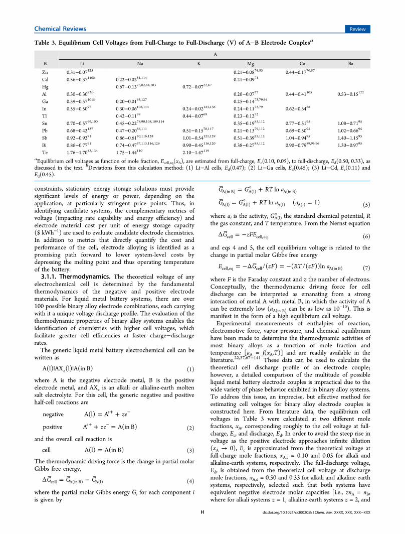
electromotive force, vapor pressure, and chemical equilibriumhave been made to determine the thermodynamic activities ofmost binary alloys as a function of mole fraction andtemperature [aA = f(xA,T)] and are readily available in theliterature.22,37,67−141 These data can be used to calculate thetheoretical cell discharge profile of an electrode couple;however, a detailed comparison of the multitude of possibleliquid metal battery electrode couples is impractical due to thewide variety of phase behavior exhibited in binary alloy systems.To address this issue, an imprecise, but effective method forestimating cell voltages for binary alloy electrode couples isconstructed here. From literature data, the equilibrium cellvoltages in Table 3 were calculated at two different molefractions, xA, corresponding roughly to the cell voltage at full-charge, Ec, and discharge, Ed. In order to avoid the steep rise involtage as the positive electrode approaches infinite dilution(xA → 0), Ec is approximated from the theoretical voltage atfull-charge mole fractions, xA,c = 0.10 and 0.05 for alkali andalkaline-earth systems, respectively. The full-discharge voltage,Ed, is obtained from the theoretical cell voltage at dischargemole fractions, xA,d = 0.50 and 0.33 for alkali and alkaline-earthsystems, respectively, selected such that both systems haveequivalent negative electrode molar capacities [i.e., znA = nB,where for alkali systems z = 1, alkaline-earth systems z = 2, and
Table 3. Equilibrium Cell Voltages from Full-Charge to Full-Discharge (V) of A−B Electrode Couplesa
A
B Li Na K Mg Ca Ba
Zn 0.31−0.07125 0.21−0.0874,83 0.44−0.1776,87
Cd 0.56−0.37140b 0.22−0.0281,114 0.21−0.0971
Hg 0.67−0.1375,82,84,103 0.72−0.0722,67
Al 0.30−0.3092b 0.20−0.0777 0.44−0.41105 0.53−0.15122
Ga 0.59−0.57101b 0.20−0.0193,127 0.25−0.1473,79,94
In 0.55−0.5097 0.30−0.06108,114 0.24−0.02123,136 0.24−0.1173,79 0.62−0.3488
Tl 0.42−0.1198 0.44−0.0769 0.23−0.1272
Sn 0.70−0.5799,100 0.45−0.2278,90,108,109,114 0.35−0.1985,112 0.77−0.5195 1.08−0.7195
Pb 0.68−0.42137 0.47−0.2086,111 0.51−0.1570,117 0.21−0.1379,112 0.69−0.5095 1.02−0.6695
Sb 0.92−0.9291 0.86−0.6180,116,128 1.01−0.54121,129 0.51−0.3985,112 1.04−0.9495 1.40−1.1595
Bi 0.86−0.7791 0.74−0.4737,113,116,126 0.90−0.45116,120 0.38−0.2785,112 0.90−0.7989,95,96 1.30−0.9795
Te 1.76−1.7042,134 1.75−1.44110 2.10−1.47119aEquilibrium cell voltages as function of mole fraction, Ecell,eq(xA), are estimated from full-charge, Ec(0.10, 0.05), to full-discharge, Ed(0.50, 0.33), asdiscussed in the text. bDeviations from this calculation method: (1) Li−Al cells, Ed(0.47); (2) Li−Ga cells, Ed(0.45); (3) Li−Cd, Ec(0.11) andEd(0.45).
Chemical Reviews Review
dx.doi.org/10.1021/cr300205k | Chem. Rev. XXXX, XXX, XXX−XXXH
xA,d = nA/(nA + nB)]. In most cases, the equilibrium cell voltageswere estimated at temperatures slightly above the melting pointof the higher melting electrode; however, it should be notedthat the temperature dependence of the cell potential tends tobe small (typically less than ±0.02 V/100 °C) over a widerange of concentrations.The complexity of estimating a full theoretical discharge
profile is illustrated by the Ca−Bi system presented inFigure 11.141 Three distinct features can be observed in this
discharge profile: (1) a sharp increase in cell voltage as thecalcium approaches infinite dilution (xCa → 0); (2) a cellvoltage plateau corresponding to a two-phase liquid−solidregion (0.25 < xCa < 0.52); and (3) a steep decrease in cellvoltage to zero as the solid intermetallic species Ca5Bi3 isformed (xCa > 0.63). In Figure 11, the fully charged, Ec, anddischarged, Ed, states are indicated, and from these values, theaverage equilibrium cell voltage, Ecell,eq = (Ec + Ed)/2, is closelyapproximated. Despite the limitations of this approximation,this example demonstrates the utility of the approach. Forcomparison, the estimated fully charged and dischargedequilibrium cell voltages of all known binary electrode couplesare given in Table 3.3.1.2. Economics. Based upon the equilibrium cell voltages
reported in Table 3, candidate electrode systems are comparedon a cost per energy basis ($ kWh−1), which uses 2010−2011average monthly bulk metal market prices, Pi, for each electrodematerial i, according to
∑ = −P m Pij
m
i j1
,(8)
where Pi,j is the average price of month j and m is the numberof months.142 Due to the large volumes of metals that would berequired for grid-scale energy storage applications, all pricesused are from bulk quotations on the scale of metric tons atpurities greater than 99%. In addition, because the prices ofcommodities change frequently and unpredictably, there are nofundamental limitations to cost metrics (i.e., they are derivedfrom market prices) as there are with thermodynamic orperformance metrics. Thus, when possible a ratio of thestandard deviation in 2010−2011 monthly prices, Pi,j,normalized by the monthly average price, Pi, over that period
is reported in order to quantify the recent volatility of the metalaccording to
∑σ = − − ×− −P m P P( 1) ( ) 100%i ij
m
i j i1 1
,2
(9)
The estimated cost of energy for electrode couples, CEest, on a
per unit energy basis (in $ kWh−1) is calculated from
∑= −C x zFE x P( )i
i iEest
A,d cell,eq1
(10)
where the average monthly bulk metal market prices, Pi, arefrom Table 4, the average equilibrium cell voltages, Ecell,eq, for
each electrode couple are calculated from Table 3, xA,drepresents the estimated negative electrode full-dischargecomposition, and xi is the mole fraction of electrodecomponent i in a cell. Implicit to this calculation are severalsimplifying assumptions: (1) cell charge−discharge energyefficiency is 100%; (2) cell discharge compositions xA,d areestimated to be 0.50 or 0.33 depending on the charge valence zof the active species; (3) electrode utilization is 100% such thatthe complete discharge of all active material is achieved; (4) thecosts of the electrolyte and cell container are neglected; (5) themetal market prices are a fair approximation of costs for therequired metal purity.From these data, a few important trends emerge. First, the
range in material prices spans 5 orders of magnitude, while cellvoltage values vary by less than 1 order of magnitude, thusillustrating the importance of using a cost metric when selectingcandidate electrode couples for grid-scale energy storageapplications. Second, price fluctuations are much morepronounced for positive than for negative electrode materials,a behavior that suggests that future cost modeling of scale-upshould factor in the variability of positive electrode prices, whilenegative electrode costs can be assumed to be constant. Lastly,from Table 5, it is evident that the high prices of some metalspreclude their application in grid-scale energy storage. Whetherdue to low equilibrium cell voltages or high cost of electrode
Figure 11. Plot of the measured equilibrium cell voltage as a functionof calcium mole fraction of Ca(s)|CaF2(s)|Ca(in Bi) cell at 600 °C.Reprinted with permission from ref 141. Copyright 2012 Elsevier.
Table 4. Average Monthly Metal Prices Pi and Volatilitiesσi.
142
metal, i Pi ($ mol−1) σi (%)
Li 0.43 2Naa 0.057Ka 5.1Mga 0.069Caa 0.14Baa 0.82Zn 0.15 5Cd 0.39 15Hg 0.27 11Al 0.066 6Ga 51 19In 74 19Tla 1200Sn 3.2 11Pb 0.52 6Sb 1.8 14Bi 4.9 14Te 44 22
aPrices are obtained from bulk quotations from the suppliers.
Chemical Reviews Review
dx.doi.org/10.1021/cr300205k | Chem. Rev. XXXX, XXX, XXX−XXXI
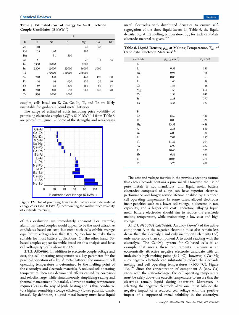
couples, cells based on K, Ga, Ge, In, Tl, and Te are likelyunsuitable for grid-scale liquid metal batteries.The range of estimated costs including price volatility of
promising electrode couples (CEest < $100 kWh−1) from Table 5
are plotted in Figure 12. Some of the strengths and weaknesses
of this evaluation are immediately apparent. For example,aluminum-based couples would appear to be the most attractivecandidates based on cost, but most such cells exhibit averageequilibrium voltages less than 0.50 V, too low to make themsuitable for most battery applications. On the other hand, Sb-based couples appear favorable based on this analysis and havecell voltages typically above 0.70 V.3.1.3. Alloying. In addition to electrode couple voltage and
cost, the cell operating temperature is a key parameter for thepractical operation of a liquid metal battery. The minimum celloperating temperature is determined by the melting point ofthe electrolyte and electrode materials. A reduced cell operatingtemperature decreases detrimental effects caused by corrosionand self-discharge, while simultaneously simplifying sealing andthermal management. In parallel, a lower operating temperaturerequires less in the way of Joule heating and is thus conduciveto a higher round-trip storage efficiency (lower parasitic ohmiclosses). By definition, a liquid metal battery must have liquid
metal electrodes with distributed densities to ensure self-segregation of the three liquid layers. In Table 6, the liquiddensity, ρm, at the melting temperature, Tm, for each candidateelectrode material is given.143
The cost and voltage metrics in the previous sections assumethat each electrode contains a pure metal. However, the use ofpure metals is not mandatory, and liquid metal batteryelectrodes composed of alloys can have superior electricalperformance and longer service lifetime enabled by a reducedcell operating temperature. In some cases, alloyed electrodesincur penalties such as a lower cell voltage, a decrease in ratecapability, and a higher cell cost. Therefore, alloying liquidmetal battery electrodes should aim to reduce the electrodemelting temperature, while maintaining a low cost and highvoltage.
3.1.3.1. Negative Electrodes. An alloy (A−A′) of the activecomponent A in the negative electrode must also remain lessdense than the electrolyte and only incorporate elements (A′)only more noble than component A to avoid reacting with theelectrolyte. The Ca−Mg system for Ca-based cells is anexample that meets these requirements. Calcium is aneconomically attractive negative electrode candidate with anundesirably high melting point (842 °C); however, a Ca−Mgalloy negative electrode can substantially reduce the electrodemelting and cell operating temperatures (<600 °C), Figure13a.144 Since the concentration of component A (e.g., Ca)varies with the state-of-charge, the cell operating temperaturemust be safely above the eutectic temperature to ensure that theelectrode remain liquid during operation. Moreover, inselecting the negative electrode alloy one must balance thenegative impact of a reduced cell voltage with the positiveimpact of a suppressed metal solubility in the electrolyte
Table 5. Estimated Cost of Energy for A−B ElectrodeCouple Candidates ($ kWh−1)
A
B Li Na K Mg Ca Ba
Zn 110 26 26Cd 65 140 100Hg 31 510Al 61 27 12 52Ga 3300 18000 9600In 5300 15000 23000 16000 5600Tl 170000 180000 250000Sn 210 370 440 190 150Pb 64 64 630 120 36 40Sb 89 93 330 150 69 64Bi 240 300 550 560 220 170Te 950 1000 1000
Figure 12. Plot of promising liquid metal battery electrode materialenergy costs (<$100 kWh−1) incorporating the market price volatilityof electrode materials.
Table 6. Liquid Density, ρm, at Melting Temperature, Tm, ofCandidate Electrode Materials143
electrode ρm (g cm−3) Tm (°C)
ALi 0.51 181Na 0.93 98K 0.83 63Rb 1.46 39Cs 1.84 28Mg 1.58 650Ca 1.38 842Sr 2.38 777Ba 3.34 727
BZn 6.57 420Cd 8.00 321Hg 13.53 −39Al 2.38 660Ga 6.08 30In 7.02 157Tl 11.22 304Sn 6.99 232Pb 10.66 327Sb 6.53 631Bi 10.05 271Te 5.70 450
Chemical Reviews Review
dx.doi.org/10.1021/cr300205k | Chem. Rev. XXXX, XXX, XXX−XXXJ
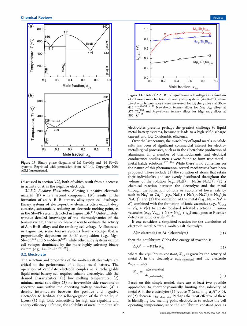
(discussed in section 3.2), both of which result from a decreasein activity of A in the negative electrode.3.1.3.2. Positive Electrodes. Alloying a positive electrode
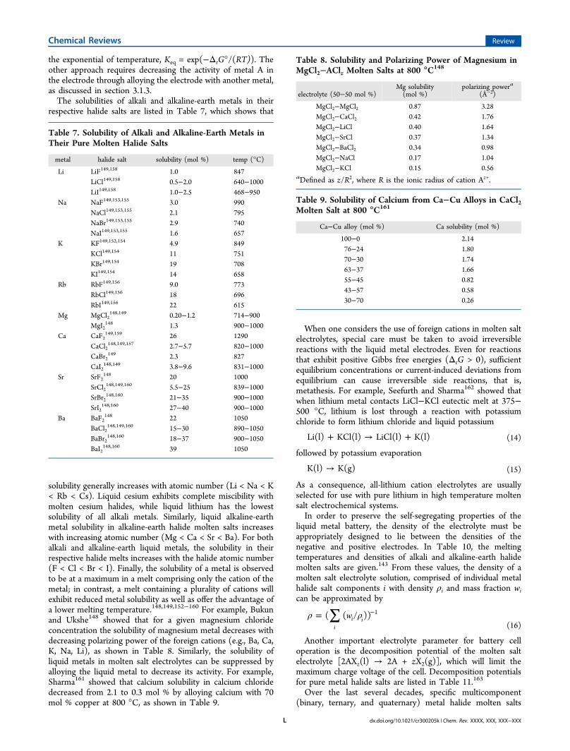
material (B) with a second component (B′) results in theformation of an A−B−B′ ternary alloy upon cell discharge.Binary systems of electropositive elements often exhibit deepeutectics, substantially reducing an electrode melting point, asin the Sb−Pb system depicted in Figure 13b.144 Unfortunately,without detailed knowledge of the thermodynamics of theternary system, there is no clear-cut way to evaluate the activityof A in B−B′ alloys and the resulting cell voltage. As illustratedin Figure 14, some ternary systems have a voltage that isproportionally dependent on B−B′ composition (e.g., Mg−Sb−Sn112 and Na−Sb−Bi128), while other alloy systems exhibitcell voltages dominated by the more highly solvating binarysystem (e.g., Li−Sb−In145,146).3.2. Electrolyte
The selection and properties of the molten salt electrolyte arecritical to the performance of a liquid metal battery. Theoperation of candidate electrode couples in a rechargeableliquid metal battery cell requires suitable electrolytes with thedesired characteristics: (1) low melting temperature; (2)minimal metal solubility; (3) no irreversible side reactions ofspectator ions within the operating voltage window; (4) adensity intermediate between the positive and negativeelectrodes to facilitate the self-segregation of the three liquidlayers; (5) high ionic conductivity for high rate capability andenergy efficiency. Of these, the solubility of metal in molten salt
electrolytes presents perhaps the greatest challenge to liquidmetal battery systems, because it leads to a high self-dischargecurrent and low Coulombic efficiency.Over the last century, the miscibility of liquid metals in halide
salts has been of significant commercial interest for electro-metallurgical processes, such as in the electrolytic production ofaluminum. In a number of thermodynamic and electricalconductance studies, metals were found to form true metal−metal halide solutions.147−150 While there is no consensus onthe nature of this phenomenon, several mechanisms have beenproposed. These include (1) the solvation of atoms that retaintheir individuality and are evenly distributed throughout thevolume of the solution [e.g., Na(l) = Na(in NaCl)], (2) achemical reaction between the electrolyte and the metalthrough the formation of ions or subions of lower valencysuch as Na2
+ or Ca22+ [e.g., Na(l) + Na+(in NaCl) = Na2
+(inNaCl)], and (3) the ionization of the metal (e.g., Na = Na• +e′) combined with the formation of ionic vacancies (e.g., VNaCl= VNa′ + VCl
• ) to create localized solvated electrons in anionvacancies (e.g., VNaCl + Na = NaNa
× + eCl× ) analogous to F-center
defects in ionic crystals.148,151
If one considers a simplified reaction for the dissolution ofelectrode metal A into a molten salt electrolyte,
=A(in electrode) A(in electrolyte) (11)
then the equilibrium Gibbs free energy of reaction is
Δ ° = −G RT Klnr eq (12)
where the equilibrium constant, Keq, is given by the activity ofmetal A in the electrolyte aA(in electrolyte) and the electrodeaA(in electrode),
=Ka
aeqA(in electrolyte)
A(in electrode) (13)
Based on this simple model, there are at least two possibleapproaches to thermodynamically limiting the solubility ofmetal A in the electrolyte: (1) reduce T (assuming ΔrH° > 0),or (2) decrease aA(in electrode). Perhaps the most effective of theseis identifying low melting point electrolytes to reduce the celloperating temperature, since the equilibrium constant goes as
Figure 13. Binary phase diagrams of (a) Ca−Mg and (b) Pb−Sbsystems. Reprinted with permission from ref 144. Copyright 2006ASM International.
Figure 14. Plots of A|A−B−B′ equilibrium cell voltages as a functionof antimony mole fraction for ternary alloy systems (A−B−B′), whereLi−Sb−In ternary alloys were measured for Li0.1In0.9 alloys at 360−415 °C,91,99,145,146 Na−Sb−Bi ternary alloys for Na0.1Bi0.9 alloys at577 °C,128 and Mg−Sb−Sn ternary alloys for Mg0.1Sn0.9 alloys at800 °C.112
Chemical Reviews Review
dx.doi.org/10.1021/cr300205k | Chem. Rev. XXXX, XXX, XXX−XXXK
the exponential of temperature, Keq = exp(−ΔrG°/(RT)). Theother approach requires decreasing the activity of metal A inthe electrode through alloying the electrode with another metal,as discussed in section 3.1.3.The solubilities of alkali and alkaline-earth metals in their
respective halide salts are listed in Table 7, which shows that
solubility generally increases with atomic number (Li < Na < K< Rb < Cs). Liquid cesium exhibits complete miscibility withmolten cesium halides, while liquid lithium has the lowestsolubility of all alkali metals. Similarly, liquid alkaline-earthmetal solubility in alkaline-earth halide molten salts increaseswith increasing atomic number (Mg < Ca < Sr < Ba). For bothalkali and alkaline-earth liquid metals, the solubility in theirrespective halide melts increases with the halide atomic number(F < Cl < Br < I). Finally, the solubility of a metal is observedto be at a maximum in a melt comprising only the cation of themetal; in contrast, a melt containing a plurality of cations willexhibit reduced metal solubility as well as offer the advantage ofa lower melting temperature.148,149,152−160 For example, Bukunand Ukshe148 showed that for a given magnesium chlorideconcentration the solubility of magnesium metal decreases withdecreasing polarizing power of the foreign cations (e.g., Ba, Ca,K, Na, Li), as shown in Table 8. Similarly, the solubility ofliquid metals in molten salt electrolytes can be suppressed byalloying the liquid metal to decrease its activity. For example,Sharma161 showed that calcium solubility in calcium chloridedecreased from 2.1 to 0.3 mol % by alloying calcium with 70mol % copper at 800 °C, as shown in Table 9.
When one considers the use of foreign cations in molten saltelectrolytes, special care must be taken to avoid irreversiblereactions with the liquid metal electrodes. Even for reactionsthat exhibit positive Gibbs free energies (ΔrG > 0), sufficientequilibrium concentrations or current-induced deviations fromequilibrium can cause irreversible side reactions, that is,metathesis. For example, Seefurth and Sharma162 showed thatwhen lithium metal contacts LiCl−KCl eutectic melt at 375−500 °C, lithium is lost through a reaction with potassiumchloride to form lithium chloride and liquid potassium
+ → +Li(l) KCl(l) LiCl(l) K(l) (14)
followed by potassium evaporation
→K(l) K(g) (15)
As a consequence, all-lithium cation electrolytes are usuallyselected for use with pure lithium in high temperature moltensalt electrochemical systems.In order to preserve the self-segregating properties of the
liquid metal battery, the density of the electrolyte must beappropriately designed to lie between the densities of thenegative and positive electrodes. In Table 10, the meltingtemperatures and densities of alkali and alkaline-earth halidemolten salts are given.143 From these values, the density of amolten salt electrolyte solution, comprised of individual metalhalide salt components i with density ρi and mass fraction wican be approximated by
∑ρ ρ= −w( ( / ))i
i i1
(16)
Another important electrolyte parameter for battery celloperation is the decomposition potential of the molten saltelectrolyte [2AXz(l) → 2A + zX2(g)], which will limit themaximum charge voltage of the cell. Decomposition potentialsfor pure metal halide salts are listed in Table 11.163
Over the last several decades, specific multicomponent(binary, ternary, and quaternary) metal halide molten salts
Table 7. Solubility of Alkali and Alkaline-Earth Metals inTheir Pure Molten Halide Salts
metal halide salt solubility (mol %) temp (°C)
Li LiF149,158 1.0 847LiCl149,158 0.5−2.0 640−1000LiI149,158 1.0−2.5 468−950
Na NaF149,153,155 3.0 990NaCl149,153,155 2.1 795NaBr149,153,155 2.9 740NaI149,153,155 1.6 657
K KF149,152,154 4.9 849KCl149,154 11 751KBr149,154 19 708KI149,154 14 658
Rb RbF149,156 9.0 773RbCl149,156 18 696RbI149,156 22 615
Mg MgCl2148,149 0.20−1.2 714−900
MgI2148 1.3 900−1000
Ca CaF2149,159 26 1290
CaCl2148,149,157 2.7−5.7 820−1000
CaBr2149 2.3 827
CaI2148,149 3.8−9.6 831−1000
Sr SrF2148 20 1000
SrCl2148,149,160 5.5−25 839−1000
SrBr2148,160 21−35 900−1000
SrI2148,160 27−40 900−1000
Ba BaF2148 22 1050
BaCl2148,149,160 15−30 890−1050
BaBr2148,160 18−37 900−1050
BaI2148,160 39 1050
Table 8. Solubility and Polarizing Power of Magnesium inMgCl2−AClz Molten Salts at 800 °C148
electrolyte (50−50 mol %)Mg solubility(mol %)
polarizing powera
(Å−2)
MgCl2−MgCl2 0.87 3.28MgCl2−CaCl2 0.42 1.76MgCl2−LiCl 0.40 1.64MgCl2−SrCl 0.37 1.34MgCl2−BaCl2 0.34 0.98MgCl2−NaCl 0.17 1.04MgCl2−KCl 0.15 0.56
aDefined as z/R2, where R is the ionic radius of cation Az+.
Table 9. Solubility of Calcium from Ca−Cu Alloys in CaCl2Molten Salt at 800 °C161
Ca−Cu alloy (mol %) Ca solubility (mol %)
100−0 2.1476−24 1.8070−30 1.7463−37 1.6655−45 0.8243−57 0.5830−70 0.26
Chemical Reviews Review
dx.doi.org/10.1021/cr300205k | Chem. Rev. XXXX, XXX, XXX−XXXL
have gained preference for a given active electrode speciesbased upon melting temperature, conductivity, and minimalside-reactions. The most common multicomponent molten saltelectrolytes used for Li-,164−166 Na-,37 Mg-,57 and Ca-based57−59 systems and their properties are given in Table 12.3.3. Cell Performance
Since 2006, the development of liquid metal battery technologyhas been reinitiated by the authors at the MassachusettsInstitute of Technology (MIT). Following the work carried outat Argonne National Laboratory in the 1960s, the more recentMIT investigations began with Na−Bi, but quickly migratedtoward Mg−Sb and Li−Pb−Sb chemistries, which exhibitsuperior Coulombic efficiencies and are lower cost.The construction and testing of liquid metal batteries
requires special treatment of a couple of key components.First, it is often necessary to pretreat negative current collectorsby immersing in a bath of the negative electrode liquid metal toensure proper wetting and contact. Bader and Bussea167
demonstrated that excellent wetting of sodium can be achievedwith most metals after pretreating the metal in liquid sodium at500−700 °C for several hours. Second, great care must betaken to minimize the exposure of active cell components to
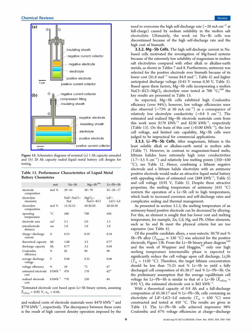
the ambient atmosphere due to the hygroscopic nature of mostmetal halide salts which leads to oxy-chloride formation andpoor cell performance. To accomplish this, ultradry salts shouldbe used, cells assembled in an ultradry, low oxygenconcentration (<0.3 ppm) argon atmosphere glovebox, andtests carried out in hermetically sealed cells or in a gloveboxfitted with furnace wells.At MIT, a 1 Ah nominal capacity cell, depicted in Figure 15a,
served as the test vehicle for exploring various chemistries, thatis, electrodes and electrolyte. This design features a cellcontainer that dually serves as the positive current collector, anegative current collector immersed in the negative liquid metalelectrode, and an insulating sheath usually composed of high-purity hot-pressed boron nitride due to its chemical inertnessand machinability. Because the 1 Ah cells are tested in an inertatmosphere glovebox, they are not sealed. While this is usefulfor rapid screening of new chemistries, it precludes theevaluation of metrics such as cell cycle life due to the gradualevaporation of active cell components. To address issues ofsealing, thermal management, and battery cycle life, a 20 Ahsealed cell was also designed, constructed, and tested. This celldesign features insulated electrical feedthroughs from the hotcell to an external cold zone, where an elastomer O-ringprovides an airtight seal, as depicted in Figure 15b.
3.3.1. Na−Bi Cells. Sodium−bismuth liquid metal batterycells were tested using a NaF−NaCl−NaI eutectic salt at560 °C, and key results are given in Table 13. Consistent withresults obtained by Argonne National Laboratory, these cellsachieved Coulombic and voltage efficiencies of 80% and 60%,respectively.The realized electrode materials cost per unit energy, CE
real,for Na−Bi cells was calculated from
∑= −C Q E x P( )i
i iEreal
d cell1
(17)
where Qd is the measured discharge capacity and Ecell is theaverage discharge cell voltage. For Na−Bi cells, the estimated
Table 10. Melting Temperature (Tm) and Liquid Density (ρ) at Melting Point of Pure AXz Halide Salts143
X−
F− Cl− Br− I−
Az+ Tm (°C) ρ (g cm−3) Tm (°C) ρ (g cm−3) Tm (°C) ρ (g cm−3) Tm (°C) ρ (g cm−3)
Li+ 848 1.81 610 1.50 552 2.53 469 3.11Na+ 996 1.95 801 1.56 747 2.34 660 2.74K+ 858 1.91 771 1.54 734 2.13 681 2.45Rb+ 833 2.87 715 2.25 682 2.72 642 2.90Cs+ 703 3.65 645 2.79 636 3.13 621 3.20Mg2+ 1263 714 1.68 711 2.62 634 3.05Ca2+ 1418 2.52 775 2.09 742 3.11 783 3.44Sr2+ 1477 3.47 874 2.73 657 3.70 538 4.09Ba2+ 1368 4.14 962 3.17 857 3.99 711 4.26
Table 11. Decomposition Potentials (V) of Pure AXz HalideSalt at 700 °C163
X−
Az+ Cl− Br− I−
Li+ 3.41 3.03 2.56Na+ 3.39 2.98 2.42K+ 3.53 3.16 2.59Rb+ 3.62 2.73 2.25Cs+ 3.68 2.40Mg2+ 2.61 2.21 1.62Ca2+ 3.38 2.88 2.24Sr2+ 3.54 3.04 2.55Ba2+ 3.62 3.25
Table 12. Properties of Common Low Melting Molten Halide Salt Electrolyte Systems
cation electrolyte composition, mol % Tm, °C ρ(T0), g cm−3 σ(T0), S cm−1 T0, °C
Li+ LiCl−KCl164 41:59 353 1.63 1.7 476LiF−LiCl−LiI165 20:50:30 430LiCl−LiI166 35:65 368 2.57 3.5 450
Na+ NaF−NaCl−NaI37 15:16:53 530 2.54 1.7−2.0 560Mg2+ NaCl−KCl−MgCl2
57 30:20:50 396Ca2+ LiCl−NaCl−CaCl2−BaCl257−59 29:20:35:16 390 2.28 1.9 527
Chemical Reviews Review
dx.doi.org/10.1021/cr300205k | Chem. Rev. XXXX, XXX, XXX−XXXM
and realized costs of electrode materials were $470 kWh−1 and$770 kWh−1, respectively. The discrepancy between these costsis the result of high current density operation imposed by the
need to overcome the high self-discharge rate (∼20 mA cm−2 atfull-charge) caused by sodium solubility in the molten saltelectrolyte. Ultimately, the work on Na−Bi cells wasdiscontinued because of the high self-discharge rate and thehigh cost of bismuth.
3.3.2. Mg−Sb Cells. The high self-discharge current in Na-based cells motivated the investigation of Mg-based systemsbecause of the extremely low solubility of magnesium in moltensalt electrolytes compared with other alkali or alkaline-earthmetals, as shown in Tables 7 and 8. Furthermore, antimony wasselected for the positive electrode over bismuth because of itslower cost ($1.8 mol−1 versus $4.9 mol−1, Table 4) and higheranticipated discharge voltage (0.45 V versus 0.30 V, Table 3).Based upon these factors, Mg−Sb cells incorporating a moltenNaCl−KCl−MgCl2 electrolyte were tested at 700 °C;168 thekey results are presented in Table 13.As expected, Mg−Sb cells exhibited high Coulombic
efficiency (over 94%); however, low voltage efficiencies werealso observed (∼73% at 50 mA cm−2) as a consequence ofrelatively low electrolyte conductivity (∼0.8 S cm−1). Theestimated and realized Mg−Sb electrode materials costs fromthis work were $170 kWh−1 and $230 kWh−1, respectively(Table 13). On the basis of this cost (>$100 kWh−1), the lowcell voltage, and limited rate capability, Mg−Sb cells werejudged to be impractical for commercial applications.
3.3.3. Li−Pb−Sb Cells. After magnesium, lithium is theleast soluble alkali or alkaline-earth metal in molten salts(Table 7). However, in contrast to magnesium-based melts,lithium halides have extremely high ionic conductivities(1.7−3.5 S cm−1) and relatively low melting points (350−430°C), see Table 12. Hence, combining a lithium negativeelectrode and a lithium halide electrolyte with an antimonypositive electrode would make an attractive liquid metal batterywith appealing values of estimated cost ($89 kWh−1, Table 5)and cell voltage (0.92 V, Table 3). Despite these attractiveproperties, the melting temperature of antimony (631 °C)restricts the operation of a Li−Sb cell to high temperatures,which leads to increased corrosion and self-discharge rates andcomplicates sealing and thermal management.As presented in section 3.1.3, the melting temperature of an
antimony-based positive electrode can be decreased by alloying.For this, an element is sought that has lower cost and meltingtemperature, for example, Zn, Cd, Hg, and Pb. Other elements,such as Sn and Bi meet the physical criteria but are tooexpensive (see Table 4).Of the possible candidate alloys, a near-eutectic 30:70 mol %
Sb−Pb alloy (Tliquidus ≈ 330 °C) was selected for the positiveelectrode, Figure 13b. From the Li−Sb binary phase diagram144
and the work of Weppner and Huggins,91 only one highmelting temperature intermetallic phase is expected tosignificantly reduce the cell voltage upon cell discharge, Li3Sb(Tm = 1150 °C). Therefore, the target lithium concentrationshould be less than 75:25 mol % Li−Sb to yield a fullydischarged cell composition of 45:38:17 mol % Li−Pb−Sb. Onthe preliminary assumption that the average equilibrium cellvoltage for Li−Pb−Sb is similar to that of a Li−Sb (Ecell,eq =0.92 V), the estimated electrode cost is $62 kWh−1.With a theoretical capacity of 0.8 Ah and a full-discharge
composition of 45:38:17 mol % Li−Pb−Sb, cells containing anelectrolyte of LiF−LiCl−LiI eutectic (Tm = 430 °C) wereconstructed and tested at 450 °C. The results are given inTable 13. The Li−Pb−Sb cells achieved impressive 98%Coulombic and 67% voltage efficiencies at charge−discharge
Figure 15. Schematics diagrams of nominal (a) 1 Ah capacity unsealedand (b) 20 Ah capacity sealed liquid metal battery cell designs fortesting.
Table 13. Performance Characteristics of Liquid MetalBattery Chemistries
unit Na−Bi Mg−Sb168 Li−Pb−Sb
electrodecomposition
mol % 39−61 30−70 45−38−17
electrolytechemistry
NaF−NaCl−NaI
MgCl2−NaCl−KCl
LiF−LiCl−LiI
electrolytecomposition
mol % 15:32:53 50:30:20 20:50:30
operatingtemperature
°C 560 700 450
electrode area cm2 2.1 2.0 1.3interelectrodedistance
cm 1.0 1.0 1.0
charge−dischargecurrent
A 0.53 0.10 0.34
theoretical capacity Ah 1.00 3.2 0.77discharge capacity Ah 0.77 3.2 0.58Coulombicefficiency
% 82 94 98
average dischargevoltage
V 0.48 0.35 0.66
voltage efficiency % 59 73 67estimated electrodecost
$ kWh−1 470 170 62a
realized electrodecost
$ kWh−1 770 230 84
aEstimated electrode cost based upon Li−Sb binary system, assumingEcell,eq = 0.92 V, xLi = 0.45.
Chemical Reviews Review
dx.doi.org/10.1021/cr300205k | Chem. Rev. XXXX, XXX, XXX−XXXN
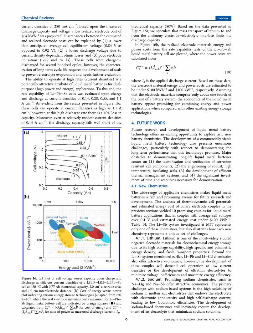
current densities of 280 mA cm−2. Based upon the measureddischarge capacity and voltage, a low realized electrode cost of$84 kWh−1 was projected. Discrepancies between the estimatedand realized electrode costs can be explained by (1) a lowerthan anticipated average cell equilibrium voltage (0.84 V asopposed to 0.92 V), (2) a lower discharge voltage due tocurrent density dependent ohmic losses, and (3) poor electrodeutilization (∼75 mol % Li). These cells were charged−discharged for several hundred cycles; however, the character-ization of long-term cycle life requires the development of sealsto prevent electrolyte evaporation and needs further evaluation.The ability to operate at high rates (current densities) is a
potentially attractive attribute of liquid metal batteries for dual-purpose (high power and energy) applications. To this end, therate capability of Li−Pb−Sb cells was evaluated upon chargeand discharge at current densities of 0.14, 0.28, 0.55, and 1.1A cm−2. As evident from the results presented in Figure 16a,these cells can operate at current densities as high as 1.1 Acm−2; however, at this high discharge rate there is a 40% loss incapacity. Moreover, even at relatively modest current densitiesof 0.14 A cm−2, the discharge capacity falls well short of the
theoretical capacity (80%). Based on the data presented inFigure 16a, we speculate that mass transport of lithium to andfrom the antimony electrode−electrolyte interface limits thedischarge capacity.In Figure 16b, the realized electrode materials energy and
power costs from the rate capability tests of the Li−Pb−Sbliquid metal battery cell are plotted, where the power costs arecalculated from
∑= −C I E x P( )i
i iPreal
d cell1
(18)
where Id is the applied discharge current. Based on these data,the electrode material energy and power costs are estimated tobe under $100 kWh−1 and $100 kW−1, respectively. Assumingthat the electrode materials comprise only about one-fourth ofthe cost of a battery system, the economics of the liquid metalbattery appear promising for combining energy and powerapplications when compared with other existing energy storagetechnologies.
4. FUTURE WORK
Future research and development of liquid metal batterytechnology offers an exciting opportunity to explore rich, newbattery chemistries. The development of a commercially viableliquid metal battery technology also presents enormouschallenges, particularly with respect to demonstrating thelong-term performance that this technology promises. Majorobstacles to demonstrating long-life liquid metal batteriescenter on (1) the identification and verification of corrosionresistant cell components, (2) the engineering of robust, hightemperature, insulating seals, (3) the development of efficientthermal management systems, and (4) the significant invest-ment of time and resources necessary for demonstration.
4.1. New Chemistries
The wide-range of applicable chemistries makes liquid metalbatteries a rich and promising avenue for future research anddevelopment. The analysis of thermodynamic cell potentialsand estimated energy cost of binary electrode couples in theprevious sections yielded 10 promising couples for liquid metalbattery applications, that is, couples with average cell voltagesover 0.4 V and estimated energy cost under $100 kWh−1,Table 14. The Li−Sb system investigated at MIT representsonly one of these chemistries, but also illustrates how each newchemistry represents a unique set of challenges.
4.1.1. Lithium. Lithium is one of the most-widely studiednegative electrode materials for electrochemical energy storagedue to its high voltage capability, high specific and volumetricenergy density, and facile transport properties. Beyond theLi−Sb system mentioned earlier, Li−Pb and Li−Cd chemistriesalso offer attractive economics; however, the development ofthese couples will demand cell operation at low currentdensities or the development of ultrathin electrolytes tominimize voltage inefficiencies and maximize energy efficiency.
4.1.2. Sodium. Promising sodium chemistries, such asNa−Hg and Na−Sb offer attractive economics. The primarychallenge with sodium-based systems is the high solubility ofsodium in molten salt electrolytes that endows the electrolytewith electronic conductivity and high self-discharge current,leading to low Coulombic efficiencies. The development ofsodium-based chemistries will inevitably require the develop-ment of an electrolyte that minimizes sodium solubility.
Figure 16. (a) Plot of cell voltage versus capacity upon charge anddischarge at different current densities of a Li|LiF−LiCl−LiI|Pb−Sbcell at 450 °C with 0.77 Ah theoretical capacity, 2.0 cm2 electrode area,and 1.0 cm interelectrode distance. (b) Cost of energy versus powerplot indicating various energy storage technologies (adapted from refs8−10), where the real electrode materials costs measured for Li−Pb−Sb liquid metal battery cell are indicated by orange squares (■) andcalculated from CE
real = (QdEcell)−1∑ixiPi for cost of energy and CP
real =(IdEcell)
−1∑ixiPi for cost of power at measured discharge current, Id.
Chemical Reviews Review
dx.doi.org/10.1021/cr300205k | Chem. Rev. XXXX, XXX, XXX−XXXO
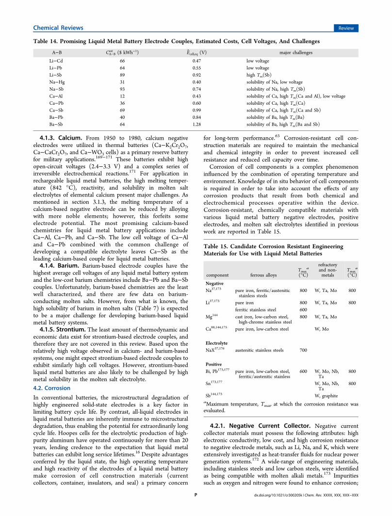
4.1.3. Calcium. From 1950 to 1980, calcium negativeelectrodes were utilized in thermal batteries (Ca−K2Cr2O7,Ca−CaCr2O7, and Ca−WO3 cells) as a primary reserve batteryfor military applications.169−171 These batteries exhibit highopen-circuit voltages (2.4−3.3 V) and a complex series ofirreversible electrochemical reactions.171 For application inrechargeable liquid metal batteries, the high melting temper-ature (842 °C), reactivity, and solubility in molten saltelectrolytes of elemental calcium present major challenges. Asmentioned in section 3.1.3, the melting temperature of acalcium-based negative electrode can be reduced by alloyingwith more noble elements; however, this forfeits someelectrode potential. The most promising calcium-basedchemistries for liquid metal battery applications includeCa−Al, Ca−Pb, and Ca−Sb. The low cell voltage of Ca−Aland Ca−Pb combined with the common challenge ofdeveloping a compatible electrolyte leaves Ca−Sb as theleading calcium-based couple for liquid metal batteries.4.1.4. Barium. Barium-based electrode couples have the
highest average cell voltages of any liquid metal battery systemand the low-cost barium chemistries include Ba−Pb and Ba−Sbcouples. Unfortunately, barium-based chemistries are the leastwell characterized, and there are few data on barium-conducting molten salts. However, from what is known, thehigh solubility of barium in molten salts (Table 7) is expectedto be a major challenge for developing barium-based liquidmetal battery systems.4.1.5. Strontium. The least amount of thermodynamic and
economic data exist for strontium-based electrode couples, andtherefore they are not covered in this review. Based upon therelatively high voltage observed in calcium- and barium-basedsystems, one might expect strontium-based electrode couples toexhibit similarly high cell voltages. However, strontium-basedliquid metal batteries are also likely to be challenged by highmetal solubility in the molten salt electrolyte.
4.2. Corrosion
In conventional batteries, the microstructural degradation ofhighly engineered solid-state electrodes is a key factor inlimiting battery cycle life. By contrast, all-liquid electrodes inliquid metal batteries are inherently immune to microstructuraldegradation, thus enabling the potential for extraordinarily longcycle life. Hoopes cells for the electrolytic production of high-purity aluminum have operated continuously for more than 20years, lending credence to the expectation that liquid metalbatteries can exhibit long service lifetimes.16 Despite advantagesconferred by the liquid state, the high operating temperatureand high reactivity of the electrodes of a liquid metal batterymake corrosion of cell construction materials (currentcollectors, container, insulators, and seal) a primary concern
for long-term performance.63 Corrosion-resistant cell con-struction materials are required to maintain the mechanicaland chemical integrity in order to prevent increased cellresistance and reduced cell capacity over time.Corrosion of cell components is a complex phenomenon
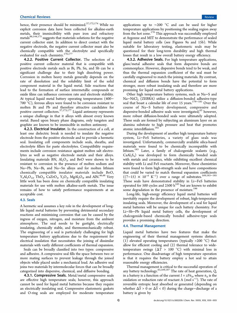
influenced by the combination of operating temperature andenvironment. Knowledge of in situ behavior of cell componentsis required in order to take into account the effects of anycorrosion products that result from both chemical andelectrochemical processes operative within the device.Corrosion-resistant, chemically compatible materials withvarious liquid metal battery negative electrodes, positiveelectrodes, and molten salt electrolytes identified in previouswork are reported in Table 15.
4.2.1. Negative Current Collector. Negative currentcollector materials must possess the following attributes: highelectronic conductivity, low cost, and high corrosion resistanceto negative electrode metals, such as Li, Na, and K, which wereextensively investigated as heat-transfer fluids for nuclear powergeneration systems.172 A wide-range of engineering materials,including stainless steels and low carbon steels, were identifiedas being compatible with molten alkali metals.173 Impuritiessuch as oxygen and nitrogen were found to enhance corrosion;
Table 14. Promising Liquid Metal Battery Electrode Couples, Estimated Costs, Cell Voltages, And Challenges
A−B CA−Best ($ kWh−1) Ecell,eq (V) major challenges
Li−Cd 66 0.47 low voltageLi−Pb 64 0.55 low voltageLi−Sb 89 0.92 high Tm(Sb)Na−Hg 31 0.40 solubility of Na, low voltageNa−Sb 93 0.74 solubility of Na, high Tm(Sb)Ca−Al 12 0.43 solubility of Ca, high Tm(Ca and Al), low voltageCa−Pb 36 0.60 solubility of Ca, high Tm(Ca)Ca−Sb 69 0.99 solubility of Ca, high Tm(Ca and Sb)Ba−Pb 40 0.84 solubility of Ba, high Tm(Ba)Ba−Sb 64 1.28 solubility of Ba, high Tm(Ba and Sb)
Table 15. Candidate Corrosion Resistant EngineeringMaterials for Use with Liquid Metal Batteries
component ferrous alloysTmax
a
(°C)
refractoryand non-metals
Tmaxa
(°C)
NegativeNa37,173 pure iron, ferritic/austenitic
stainless steels800 W, Ta, Mo 800
Li37,173 pure iron 800 W, Ta, Mo 800ferritic stainless steel 600
Mg144 cast iron, low-carbon steel,high-chrome stainless steel
800 W, Ta, Mo
Ca88,144,175 pure iron, low-carbon steel W, Mo
ElectrolyteNaX37,176 austenitic stainless steels 700
PositiveBi, Pb173,177 pure iron, low-carbon steel,
ferritic/austenitic stainless600 W, Mo, Nb,
Ta800
Sn173,177 W, Mo, Nb,Ta
800
Sb144,173 W, graphiteaMaximum temperature, Tmax, at which the corrosion resistance wasevaluated.
Chemical Reviews Review
dx.doi.org/10.1021/cr300205k | Chem. Rev. XXXX, XXX, XXX−XXXP
hence, their presence should be minimized.37,172,174 While noexplicit corrosion data have been collected for alkaline-earthmetals, their immiscibility with pure iron and refractorymetals88,144,175 suggests that materials solutions for the negativecurrent collector exist. In addition to direct contact with thenegative electrode, the negative current collector must also bechemically compatible with the electrolyte and specificallyevaluated for each chemistry.176,177
4.2.2. Positive Current Collector. The selection of apositive current collector material that is compatible withpositive electrode metals such as Bi, Pb, Sn, and Sb can be asignificant challenge due to their high dissolving power.Corrosion in molten heavy metals generally depends on therate of dissolution and the solubility limit of the solidcomponent material in the liquid metal. Side reactions thatlead to the formation of surface intermetallic compounds oroxide films can influence corrosion rate and electrode stability.At typical liquid metal battery operating temperatures (400−700 °C), ferrous alloys were found to be corrosion resistant tomolten Bi and Pb and therefore attractive candidates forpositive current collectors.37,173,177 Liquid antimony representsa unique challenge in that it alloys with almost every knownmetal. Based upon binary phase diagrams, only tungsten andgraphite are known to be immiscible in molten antimony.4.2.3. Electrical Insulator. In the construction of a cell, at
least one dielectric break is needed to insulate the negativeelectrode from the positive electrode and to provide a hermeticseal. Insulating cell components include seals, sheaths, andelectrolyte fillers for paste electrolytes. Compatibility require-ments include corrosion resistance against molten salt electro-lytes as well as negative electrode metals and their alloys.Insulating materials BN, Al2O3, and BeO were shown to beresistant to corrosion in the presence of molten sodium andNa−Pb, Na−Bi, and Na−Sn alloys and for molten lithiumchemically compatible insulator materials include BeO,Y3Al5O12, ThO2, CaZrO3, Y2O3, MgAl2O4, and AlN.46,48 Verylittle work has been done on chemically compatible insulatingmaterials for use with molten alkaline-earth metals. The issueremains of how to satisfy performance requirements at anacceptable cost.
4.3. Seals
A hermetic seal assumes a key role in the development of long-life liquid metal batteries by preventing detrimental secondaryreactions and minimizing corrosion that can be caused by theingress of oxygen, nitrogen, and moisture from the ambientatmosphere. The seal needs to be gastight, electricallyinsulating, chemically stable, and thermomechanically robust.The engineering of a seal is particularly challenging for hightemperature battery applications due to the requirement forelectrical insulation that necessitates the joining of dissimilarmaterials with vastly different coefficients of thermal expansion.Seals can be broadly classified into two types: compressive
and adhesive. A compressive seal fills the space between two ormore mating surfaces to prevent leakage through the joinedobjects while placed under a mechanical load. An adhesive sealjoins two materials by intermolecular forces that can be broadlycategorized into dispersive, chemical, and diffusive bonding.4.3.1. Compressive Seals. Metal/metal compressive seals
are effective high temperature seals; however, this approachcannot be used for liquid metal batteries because they requirean electrically insulating seal. Compressive elastomeric gasketsand O-ring seals are employed for moderate temperature
applications up to ∼200 °C and can be used for highertemperature applications by positioning the sealing region awayfrom the hot zone.178 This approach was successfully employedat Argonne and MIT to demonstrate the performance of sealedliquid metal battery cells (see Figures 9a and 15b). Whilesuitable for laboratory testing, elastomeric seals may bequestioned for their long-term durability and high thermallosses that result in a low overall battery energy efficiency.
4.3.2. Adhesive Seals. For high temperature applications,glass/metal adhesive seals that form dispersive bonds arecommonplace. However, dispersive bonds tend to be weak, andthus the thermal expansion coefficient of the seal must becarefully engineered to match the joining materials. By contrast,chemical and diffusion bonds have the potential to formstronger, more robust insulating seals and therefore are morepromising for liquid metal battery applications.Other high temperature battery systems, such as Na−S and
Na−NiCl2 (ZEBRA) utilize a diffusion-bonded adhesive-typeseal that boast a calendar life of over 15 years.179−181 Over thecourse of Na−S battery development, compressive anddispersive-bonded adhesive seals were investigated;63 however,more robust diffusion-bonded seals were ultimately adopted.These seals are formed by subjecting an aluminum layer on analumina substrate to high pressure and heat that promotesatomic interdiffusion.182
During the development of another high temperature batterysystem, Li−FeS batteries, a variety of glass seals wasinvestigated. Unfortunately, commercially available silica-basedmaterials were found to be chemically incompatible withlithium.183 Later, a family of chalcogenide sealants (e.g.,CaAl2S4) was developed to form chemically bonded sealswith metals and ceramics, while exhibiting excellent chemicalstability with Li and FeS reactants. Moreover, these chemistrieswere found to form high-strength seals and have compositionsthat could be varied to match thermal expansion coefficients((7−15) × 10−6 K−1) over a range of substrates.169,183−185
These seals have demonstrated stability in Li−FeS batteriesoperated for 500 cycles and 2500 h183 but are known to exhibitsome degradation in the presence of moisture.186
Long-life, high-energy efficiency liquid metal batteries willinevitably require the development of robust, high-temperatureinsulating seals. Moreover, the development of a seal for liquidmetal batteries will be unique for each battery chemistry. ForLi−Sb−Pb liquid metal battery cells, the development ofchalcogenide-based chemically bonded adhesive-type sealsprovides a promising direction.
4.4. Thermal Management
Liquid metal batteries have two features that make theengineering of their thermal management systems distinct:(1) elevated operating temperatures (typically >200 °C) thatallow for efficient cooling and (2) thermal tolerance to wide-temperature swings (ΔT > 100 °C) with minimal loss inperformance. One disadvantage of high temperature operationis that it requires the battery employ a hot seal to attainreasonable energy efficiencies.Thermal management is critical to the successful operation of
any battery technology.63,169,187 The rate of heat generation, Q,in a battery is a function of the current I = zFnA, where n A is theoxidation or reduction rate of reactant A (mol s−1). The rate ofreversible entropic heat absorbed or generated (depending onwhether ΔS > 0 or ΔS < 0) during the charge−discharge of abattery is given by
Chemical Reviews Review
dx.doi.org/10.1021/cr300205k | Chem. Rev. XXXX, XXX, XXX−XXXQ
= − Δ Q n T S( )rev A cell (19)
where from the thermodynamic relation ΔG = ΔH − TΔS , theNernst equation, and the definition of thermoneutral potentialEth ≡ ΔHcell/(zF), the reversible entropic heat generation orabsorption rate is given by
= − −Q I E E( )rev cell,eq th (20)
Assuming no Coulombic losses, the irreversible heat (Jouleheating) generated during charge−discharge is a function of thecurrent density dependent cell voltage inefficiencies describedin section 1.2,
∑ η = | |Q Ii
iirr(21)
and finally the total rate of heat generation upon charge anddischarge is
= + Q Q Qgen rev irr (22)
For optimal battery operation and high energy efficiency, theheat generated by cell charging and discharging should becarefully balanced with heat loss to the environment (Qloss ≈Qgen), where heat loss can take the form of conductive,convective, or radiative heat transfer. Ultimately, the degree ofinsulation or design of a cooling system will depend upon howthe battery is operated.
5. CONCLUSIONSBecause liquid metals and molten salts present no majorchallenges in terms of materials expenses or fabrication costs,the development and design of liquid metal batteries can beconstantly guided by a market price point instead of relyingupon economies of scale to reduce costs. Such clarity inmaterials input costs allows technologists to employ theevaluative metric of cost per unit energy ($ kWh−1) at eachdecision point along the path toward commercialization.Moreover, by circumventing the electrode solid-state decayand dendritic growth mechanisms that limit the life oftraditional batteries, liquid metal batteries have the potentialfor unprecedented operational life, which makes themeconomically attractive for grid-level energy storage whenamortized over their cycle life (¢ kWh−1 cyc−1). Thedemonstration of long-life liquid metal batteries still remains;however, based upon similar three-liquid-layer industrialelectrochemical systems, such as the Hoopes cell, one mightexpect continuous operational lifetimes in excess of 20 years tobe possible.It should be emphasized that grid storage is a multidimen-
sional cost-based challenge. In fact, there is a spectrum ofrequirements that demand differing types of energy service,from high-power storage required by frequency responseapplications to bulk-energy storage that enables base-loadrenewable energy. We believe that liquid metal batteries arewell positioned to simultaneously address multiple end-uses ata commercially competitive price. Specifically, liquid metalbatteries currently produced at the laboratory-scale generallyhave cell electrode materials energy costs of $50−100 kWh−1
and power costs of $50−400 kW−1 when operated at currentdensities between 70 and 1100 mA cm−2. Approximating forbattery balance of system costs (typically on the order of fourtimes the material costs), liquid metal batteries have thepotential to outperform Pb-acid, Na−S, Ni−Cd, Li-ion, and
various flow cell devices on both a cost per energy and cost perpower basis, all before accounting for unknown economies ofscale. This is only possible due to the unique design of thethree-liquid-layer system, which enables rapid charge−dischargekinetics due to facile charge transfer, molten salt electrolyteenabled high rate capability, long-life imparted by robust liquidelectrodes, and manufacturing scalability arising from thenatural self-segregation of all-liquid components. All of theseadvantages are unique to the liquid metal battery and make itan attractive candidate for addressing a wide array of energymarket opportunities.When viewed holistically, the ability of energy storage to
improve so many market segments lends credence to the beliefthat the greatest energy bottleneck of the modern day lies inthe ability to store energy, not to generate it. Several authorshave begun to highlight the inability of renewables to beconsidered as reliable base-load contributors, as well as theeconomic supply−demand vulnerabilities resulting from thesaturation of renewables, without a suitable means ofdomestically providing base power during cloudy or windlessperiods.188−190 Thus, grid-level energy storage opportunitieslike the liquid metal battery are truly a bridging technologybetween sustainable energy production and consumption.The future of liquid metal batteries is particularly exciting,
and the space for research is rich with opportunity. Thecombination of cost-driven development with a deep knowl-edge of the work that has proceeded is the formula to turn theconcept of the liquid metal battery into a viable energy storagesolution.
AUTHOR INFORMATIONCorresponding Author
*E-mail: [email protected]. Telephone: 617 253 3487. Fax:617 253 5418.Notes
The authors declare no competing financial interest.
Biographies
Dr. Hojong Kim is a research scientist at MIT, where he is leadingefforts to develop electrode materials for use in liquid metal batterytechnology. His research interests include electrochemical energyconversion and storage, environment-friendly electrometallurgicalprocesses, high-temperature corrosion, and materials for energystorage and conversion. Previously, he worked as a senior researchscientist and project lead at Samsung Corning Precision Glass Co. Ltdto improve the process yield for thin film transistor liquid crystaldisplay (TFT-LCD) glass manufacturing. Kim received his Ph.D. inthe Uhligh Corrosion Laboratory at MIT under Professor Latanision
Chemical Reviews Review
dx.doi.org/10.1021/cr300205k | Chem. Rev. XXXX, XXX, XXX−XXXR
(2004) and B.S. in Materials Science and Engineering from Seoul
National University in South Korea (2000).
Dr. Dane Boysen currently serves as a program director at the
Advanced Research Projects Agency-Energy (ARPA-E). Prior to
joining ARPA-E, Boysen led the development of the grid-scale energy
storage liquid metal battery at MIT under Professor Donald Sadoway.
In 2004, he cofounded Superprotonic Inc., a venture capital-backed
start-up company dedicated to the commercialization of solid acid
electrolyte-based fuel cells. This work has led to numerous patents and
publications in eminent periodicals, such as Science (January 2004) and
Nature (April 2001). His main focuses include electrochemical energy
conversion and storage, natural gas conversion and storage technology,
and materials for energy storage and conversion. Boysen received his
M.S. (2001) and Ph.D. (2004) in Materials Science at the California
Institute of Technology under Professor Sossina Haile.
Jocelyn Newhouse is a doctoral candidate in the Sadoway group where
she studies the kinetic limitations of high temperature electrochemical
alloying as it applies to the development of liquid metal batteries. Her
research interests include large-scale energy storage, efficiency of the
electricity grid, and integration of intermittent renewable energy
sources. Prior to MIT, Jocelyn obtained a B.A. in Chemistry from
Grinnell College, where she earned various awards and also studied
Spanish and economics.
Brian Spatocco is currently a doctoral candidate in the Sadoway
research group where he focuses on low-temperature, low-cost liquid
metal battery solutions for grid-scaled storage. Prior to MIT, Spatocco
obtained his B.S. in Materials Science and Engineering from Rutgers
University and M.Phil. in Technology Enterprise from the University
of Cambridge while on a Gates Cambridge Fellowship. His master’s
thesis studied the cost competitiveness and market compatibility of
ionic liquid-based electrolytes for lithium ion batteries. Outside of
energy research, Spatocco serves as a national and global student voice
for graduate research support and was recently named a 2012 Kremlin
Fellow for his targeted connection between the United States and
Russia in the area of emerging energy market cooperation.
Dr. Brice Chung is currently the lead scientist on the liquid metal
battery project for Total, a major partner of the research. Prior to
beginning work on the liquid metal battery project in 2010, Chung
earned his Ph.D. in theoretical physics from Universite Paris Sud
(2009) and a Masters in renewable energy from Mines Paris Tech
(2010). After studying strongly correlated quantum states for his thesis
work, Chung now focuses on innovation for clean energy, specifically
in the field of materials and devices for energy conversion and storage.
His current research efforts include the development of novel
chemistries for liquid metal batteries and technology scale-up.
Chemical Reviews Review
dx.doi.org/10.1021/cr300205k | Chem. Rev. XXXX, XXX, XXX−XXXS
Dr. Paul Burke currently leads the liquid metal battery energy storage
project at MIT under Professor Donald Sadoway. Personal research
efforts include cell scale-up and investigation of emerging chemistries.
Before joining Group Sadoway at MIT, Burke focused on the
development of magnesium powder metallurgy technology and
continues to collaborate in the field. Other research interests include
hydrometallurgical processing of electronic waste. Burke is a graduate
of Dalhousie University in Halifax, NS, with a M.A.Sc. (2007) and
Ph.D. (2011) under Professor Georges Kipouros.
Dr. David Bradwell currently serves as the CTO and senior vice
president of commercialization for Ambri Inc., (formerly known as
Liquid Metal Battery Corporation), a start-up company he cofounded
to develop and commercialize liquid metal battery technology. Prior to
joining Ambri, Bradwell was a Ph.D. student under Professor Sadoway
in the Department of Materials Science and Engineering at MIT,
where he launched the research on liquid metal batteries. After
graduating, Bradwell worked as a postdoctoral research associate on
the liquid metal battery project and ultimately took over as the project
lead before transitioning to the company in late 2011. Bradwell won a
TR35 award in 2010 for being one of the world’s top 35 innovators
under the age of 35.
Dr. Kai Jiang is currently a professor at Huazhong University of
Science and Technology (HUST) in China. Prior to joining HUST,
Jiang worked on the development of liquid metal batteries for grid-
scale energy storage as a postdoctoral associate in the Department of
Materials Science and Engineering at MIT. He also conducted
research on organic photovoltaics as a visiting scholar at Auburn
University between 2007 and 2009. Jiang received his B.S. (1999) in
physical chemistry and Ph.D. (2006) in electrochemistry at Wuhan
University, China. His current research interests focus on electro-
chemical energy storage and advanced materials for sustainable energy.
Dr. Alina A. Tomaszowska currently serves as a project manager at
Procter & Gamble. She joined MIT as a postdoctoral research
associate in 2010 under Professor Donald Sadoway, where her
research focused on the development of electrolytes for grid-scale
energy storage liquid metal battery. Prior to joining MIT,
Tomaszowska completed her Ph.D. in Chemistry at the Queens
University of Belfast under Professor Kenneth R. Seddon. Her studies
focused on the synthesis, characterization and application of novel
ionic liquids. Apart from her academic activities, Tomaszowska
conducted technology due diligence and provided expertise in the
synthesis and application of ionic liquids to industrial clients and
investors. In 2006, Tomaszowska received her M.Eng. in Chemical
Technology at The Silesian University of Technology, Poland.
Chemical Reviews Review
dx.doi.org/10.1021/cr300205k | Chem. Rev. XXXX, XXX, XXX−XXXT

Dr. Kangli Wang is currently working on the development of electrode
materials for liquid metal batteries as a postdoctoral associate in
Professor Donald Sadoway’s group at MIT. From 2007 to 2010, she
was a postdoctoral fellow in the group of Professor Jeffrey Fergus in
Material Engineering at Auburn University. She received her B.S. in
chemistry from Hubei University, China, in 2001 and her Ph.D. in
electrochemistry from Wuhan University, China, in 2006. Her research
interests include electrochemical energy storage, electrocatalysis, and
electrochemical sensors.
Dr. Weifeng Wei is currently a professor of Materials Engineering in
the State Key Laboratory for Powder Metallurgy at the Central South
University (China). After receiving his Ph.D. in Materials Engineering
from the University of Alberta (2009), Wei joined the Sadoway Group
as a postdoctoral research associate. His research concerns materials
development in the fields of energy conversion and storage, including
materials and device development for electrochemical energy storage
devices, such as electrochemical supercapacitors and Li-ion recharge-
able batteries, and electrochemical recycling of spent materials in
molten salt electrolytes. He has published more than 30 refereed
journal papers and presented at many conferences.
Luis Ortiz, Sc.D., is cofounder of Liquid Metal Battery Corporation
(LMBC). Prior to founding LMBC, Luis served as research director
for the Sadoway research group from 2008 to 2011. An accomplished
technologist, Luis has 6 years of industrial experience in the battery
industry serving as both an independent consultant and program
manager for technology transfer while with Valence Technology. Prior
to entering the energy sector, Luis was a Six Sigma Black Belt in
Honeywell’s Electronic Materials Division. Luis received an S.B. and
Sc.D. from MIT’s Department of Materials Science and Engineering.
Salvador Barriga is currently a doctoral candidate in the department of
Materials Science and Engineering at MIT working under Donald
Sadoway. His research focuses on electrochemical measurement of
diffusivity in liquid alloys and development of multiphysics computa-
tional models for liquid metal battery systems. Barriga previously
researched chemical adsorption of molybdenum selenide nanowires,
SQUID-detected magnetic resonance imaging, microfabrication of
bolomoters, and characterization of single photon detectors called
avalanche photodiodes. He also holds numerous leadership awards,
including the John Wulff Award for Excellence in Teaching from his
department. Barriga received his B.A. (2006) in physics at the
University of California, Berkeley, and his A.S. (2004) in physical
science at Modesto Junior College.
Chemical Reviews Review
dx.doi.org/10.1021/cr300205k | Chem. Rev. XXXX, XXX, XXX−XXXU
Dr. Sophie Poizeau is currently a postdoctoral associate in MaterialsScience and Engineering at MIT, working under the mentorship ofProf. Sadoway. Her research focuses on the thermodynamic propertiesof liquid alloys, involving both experimental work and thermodynamicmodeling, for the development of liquid metal batteries. Sheconducted her doctoral studies at MIT in the Sadoway group andholds an engineering degree (M. Eng. equivalent) from the EcoleCentrale Paris in France, from which she graduated in 2008.
Dr. Donald Sadoway is the John F. Elliott Professor of MaterialsChemistry in the Department of Materials Science and Engineering atMIT. The author of over 140 scientific papers and holder of 18 U.S.patents, his research into the electrochemistry of molten salts hasresulted in the invention of a rechargeable battery for grid-level storageapplications and the development of environmentally sound electro-chemical technology for the extraction, refining, and recycling ofmetals. Sadoway obtained the B.A.Sc. in Engineering Science, theM.A.Sc. in Chemical Metallurgy, and the Ph.D. in ChemicalMetallurgy, all from the University of Toronto. From 1995 to 2005,he held a MacVicar Faculty Fellowship, MIT’s highest award forexcellence in undergraduate education. In 2001, he was electedMember of the Norwegian Academy of Technological Sciences. In2012, he was named by Time magazine as one of the “100 MostInfluential People in the World”.
ACKNOWLEDGMENTS
The authors thank Professor Elton J. Cairns for sharing hisvaluable insight, experience, and knowledge with the MITresearch team. The financial support of the US Department ofEnergy, Advanced Research Projects Agency-Energy (AwardNo. DE-AR0000047) and TOTAL, S.A., is gratefully acknowl-edged.
GLOSSARY
Symbols
ηcarnot Carnot cycle efficiencyηct charge transfer lossesηohm ohmic lossesηmt mass transport lossesρi density of component iρm liquid density at melting temperatureσ electrical conductivityσi volatility of the metal priceai activity of species iCEest estimated cost of energy
CEreal realized cost of energy
CPreal realized cost of power
Ecell operating cell voltageEcell average cell discharge voltageEcell,eq equilibrium cell potentialEcell,eq average equilibrium cell voltageEc full-charge cell voltageEd full-discharge cell voltageEth thermoneutral potentialF Faraday constantΔrG° standard change in Gibbs free energy of reactionΔGcell partial molar Gibbs free energy of the cellGi partial molar Gibbs free energy of species iΔrH° standard change in enthalpy of reactionΔHcell partial molar enthalpy of the cellI currentj area specific current densityKeq equilibrium constantm number of monthsni moles of species inA molar oxidation/reduction rate of reactant APi,j average price of month j for electrode material iPi average monthly bulk metal market priceQd measured cell discharge capacityQgen total rate of heat generationQirr rate of irreversible heat generationQloss rate of heat lossQrev rate of reversible entropic heat absorbed or generatedR gas constantΔS cell partial molar entropy of the cellT temperatureTb boiling temperatureTm melting temperatureTliquidus liquidus temperaturexi mole fraction of species iwi mass fraction of component iz number of electrons in an electrochemical reaction or
charge number of an ion
Acronyms
SHE standard hydrogen electrodeCAES compressed air energy storageGM General Motors CorporationANL Argonne National LaboratoryAI Atomics InternationalMIT Massachusetts Institute of TechnologyZEBRA Zeolite Battery Research Africa
REFERENCES(1) Chalamala, B. R. Proc. IEEE 2007, 95, 2106.
Chemical Reviews Review
dx.doi.org/10.1021/cr300205k | Chem. Rev. XXXX, XXX, XXX−XXXV
(2) Bard, A. J.; Parsons, R.; Jordan, J. Standard Potentials in AqueousSolution; Marcel Dekker: New York, 1985.(3) Stender, W. W.; Zivotinsky, P. B.; Stroganoff, M. M. Trans.Electrochem. Soc. 1934, 65, 189.(4) Bard, A. J.; Faulkner, L. R. Electrochemical Methods: Fundamentalsand Applications; John Wiley: New York, 2001.(5) Christensen, J.; Newman, J. J. Solid State Electrochem. 2006, 10,293.(6) Deshpande, R. D.; Li, J. C.; Cheng, Y. T.; Verbrugge, M. W. J.Electrochem. Soc. 2011, 158, A845.(7) Eyer, J.; Corey, G. Energy Storage for the Electricity Grid:Benefits and Market Potential Assessment Guide - A Study for theDOE Energy Storage Systems Program, SAND2010-0815; SandiaNational Laboratories: Livermore, CA, 2010.(8) Rastler, D. Electricity Energy Storage Technology Options: AWhite Paper Primer on Applications, Costs, and Benefits, reportnumber 1020676; Electric Power Research Institute: Palo Alto, 2010.(9) Schoenung, S. Energy Storage Systems Cost Update: A Study forthe DOE Energy Storage Systems Program, SAND2011-2730; SandiaNational Laboratories: Livermore, CA, 2011.(10) Electricity Storage Association. http://www.electricitystorage.org/ (accessed Dec. 2011).(11) Yang, Z. G.; Zhang, J. L.; Kintner-Meyer, M. C. W.; Lu, X. C.;Choi, D. W.; Lemmon, J. P.; Liu, J. Chem. Rev. 2011, 111, 3577.(12) Hoopes, W. Electrolytically-refined Aluminum and ArticlesMade Therefrom. U.S. Patent 1,534,315, 1925.(13) Kondo, M.; Maeda, H.; Mizuguchi, M. JOM 1990, 42, 36.(14) Sanders, R. E. Kirk-Othmer Encyclopedia of Chemical Technology;John Wiley & Sons, Inc.: New York, 2000; Vol. 2.(15) Van, T. D.; Segers, L.; Winand, R. J. Electrochem. Soc. 1994, 141,927.(16) Kondo, M.; Imamaki, T. The Production Method and theProperties of High Purity Aluminum Refined by Three LayerElectrolytic Refining Process, Presented at the Light metal symposium(Keikinzoku Gakkai Symposium), Japan, 1998.(17) Yeager, E. Fuel Cells: Basic Considerations, in Power SourcesDivision, Proceedings of 12th Annual Battery Research and Development;Army Signal Research & Development Laboratory: Fort Monmouth,NJ, 21−22 MAY, 1958; p 2.(18) Regenerative EMF Cells; Crouthamel, C. E., Recht, H. L., Eds.;Advances in Chemistry, Vol. 64; American Chemical Society:Washington, DC, 1967.(19) Agruss, B. Regenerative Battery. U.S. Patent 3,245,836, 1966.(20) Weaver, R. D.; Smith, S. W.; Willmann, N. L. J. Electrochem. Soc.1962, 109, 653.(21) Agruss, B. J. Electrochem. Soc. 1963, 110, 1097.(22) Agruss, B.; Karas, H, R. In Regenerative EMF Cells; Crouthamel,C. E., Recht, H. L., Eds.; Advances in Chemistry, Vol. 64; AmericanChemical Society: Washington, DC, 1967; pp 62−81.(23) Agruss, B.; Karas, H. R. First Quarterly Technical ProgressReport on Design and Develpment of a Liquid Metal Cell, 274197;General Motors Corporation: Indianapolis, Inidana, 1962.(24) Groce, I. J.; Oldenkamp, R. D. In Regenerative EMF Cells;Crouthamel, C. E., Recht, H. L., Eds.; Advances in Chemistry, Vol. 64;American Chemical Society: Washington, DC, 1967; pp 43−52.(25) Heredy, L. A.; Iverson, M. L.; Ulrich, G. D.; Recht, H. L. InRegenerative EMF Cells; Crouthamel, C. E., Recht, H. L., Eds.;Advances in Chemistry, Vol. 64; American Chemical Society:Washington, DC, 1967; pp 30−42.(26) Oldenkamp, R. D.; Recht, H. L. In Regenerative EMF Cells;Crouthamel, C. E., Recht, H. L., Eds.; Advances in Chemistry, Vol. 64;American Chemical Society: Washington, DC, 1967; pp 53−61.(27) Fischer, A. K. In Regenerative EMF Cells; Crouthamel, C. E.,Recht, H. L., Eds.; Advances in Chemistry, Vol. 64; AmericanChemical Society: Washington, DC, 1967; pp 121−135.(28) Foster, M. S. In Regenerative EMF Cells; Crouthamel, C. E.,Recht, H. L., Eds.; Advances in Chemistry, Vol. 64; AmericanChemical Society: Washington, DC, 1967; pp 136−148.
(29) Hesson, J. C.; Shimotake, H. In Regenerative EMF Cells;American Chemical Society, 1967; Vol. 64, pp 82−104.(30) Johnson, C. E.; Heinrich, R. R. In Regenerative EMF Cells;Crouthamel, C. E., Recht, H. L., Eds.; Advances in Chemistry, Vol. 64;American Chemical Society: Washington, DC, 1967; pp 105−120.(31) Lawroski, S.; Vogel, R.; Levenson, M.; Munnecke, V. ChemicalEngineering Division Summary Report, ANL-6543; Argonne NationalLaboratory: Chicago, 1962.(32) Lawroski, S.; Vogel, R.; Levenson, M.; Munnecke, V. ChemicalEngineering Division Summary Report, ANL-6687; Argonne NationalLaboratory: Chicago, 1963.(33) Lawroski, S.; Vogel, R.; Levenson, M.; Munnecke, V. ChemicalEngineering Division Semiannual Report, ANL-6800; ArgonneNational Laboratory: Chicago, 1963.(34) Lawroski, S.; Vogel, R.; Levenson, M.; Masten, F. ChemicalEngineering Division Semiannual Report, ANL-6925; ArgonneNational Laboratory: Chicago, 1964.(35) Vogel, R.; Levenson, M.; Masten, F. Chemical EngineeringDivision Semiannual Report, ANL-7055, Argonne National Labo-ratory: Chicago, 19641965.(36) Vogel, R.; Levenson, M.; Schraidt, J.; Royal, J. ChemicalEngineering Division Semiannual Report; ANL-7125; ArgonneNational Laboratory: Chicago, 1966.(37) Cairns, E. J.; Crouthamel, C. E.; Fischer, A. K.; Foster, M. S.;Hesson, J. C. Galvanic cells with fused salts, ANL-7316; ArgonneNational Laboratory: Chicago, 1967.(38) Vogel, R.; Levenson, M.; Proud, E.; Royal, J. ChemicalEngineering Division Semiannual Report, ANL-7325; ArgonneNational Laboratory: Chicago, 1967.(39) Vogel, R. C.; Levenson, M.; Schraidt, J. H.; Royal, J. ChemicalEngineering Division Semiannual Report; ANL-7125; Argonne NationalLaboratory: Chicago, 1966.(40) Shimotake, H.; Cairns, E. J. Bimetallic Galvanic Cells with FusedSalt Electrolyte. Intersociety Energy Conversion Engineering ConferenceProceedings; American Society of Mechanical Engineers: New York,1967.(41) Shimotak., H; Cairns, E. J. IEEE Trans. Electron Devices 1968,ED15, 803.(42) Cairns, E. J.; Shimotake, H. Science 1969, 164, 1347.(43) Cairns, E. J.; Kyle, M. L.; Maroni, V. A.; Shimotake, H.;Steunenberg, R. K.; Tevebaugh, A. D. Development of High EnergyBatteries for Electric Vehicles, ANL-7756; Argonne NationalLaboratory: Chicago, 1970.(44) Cairns, E. J.; Gay, E. C.; Kolba, V. M.; Kyle, M. L.; Tevebaugh,A. D.; Trevorrow, L. E. Lithium Selenium Secondary Cells forComponents in Electric Vehiculary Propulsion Generating Systems,ANL-7745; Argonne National Laboratory: Chicago, 1970.(45) Cairns, E. J.; Cafasso, F. A.; Cunningham, P. T.; Eberhart, J. G.;Feder, H. M.; Maroni, V. A.; Schnyders, H. C.; Veleckis, E.;Tevebaugh, A. D.; Vogel, R. C. Physical Chemistry of Liquid Metalsand Molten Salts-Semiannual Report, ANL-7823; Argonne NationalLaboratory: Chicago, 1971.(46) Cairns, E. J.; Steunenberg, R. K.; Ackerman, J. P.; Feay, B. A.;Gruen, D. M.; Kyle, M. L.; Latimer, T. W.; Mundy, J. N.; Rubischko,R.; Shimotake, H.; Walker, D. E.; Zielen, A. J.; Tevebaugh, A. D.Development of High Energy Batteries for Electric Vehicles, ANL-7888; Argonne National Laboratory: Chicago, 1971.(47) Cunningham, P. T.; Johnson, S. A.; Cairns, E. J. J. Electrochem.Soc. 1971, 118, 1941.(48) Cairns, E. J.; Gay, E. C.; Steunenberg, R. K.; Shimotake, H.;Selman, J. R.; Wilson, T. L.; Webster, D. S. Development of HighSpecific Energy Batteries for Electric Vehicles, ANL-7953; ArgonneNational Laboratory: Chicago, 1972.(49) Gay, E. C.; Arntzen, J. D.; Cairns, E. J.; Kincinas, J. E.; Riha, J.G.; Trevorrow, L. E.; Walsh, W. J.; Webster, D. S. Lithium ChalcogenSecondary Cells for Components in Electric Vehicular PropulsionGenerating Systems, ANL-7863; Argonne National Laboratory:Chicago, 1972.
Chemical Reviews Review
dx.doi.org/10.1021/cr300205k | Chem. Rev. XXXX, XXX, XXX−XXXW
(50) Cunningham, P. T.; Cairns, E. J.; Johnson, S. A. J. Electrochem.Soc. 1972, 119, 1448.(51) Kyle, M. L.; Webster, D. S.; Cairns, E. J. Lithium Sulfur Batteriesfor Off-peak Energy Storage and Peak Power Generation Systems,ANL-7958; Argonne National Laboratory: Chicago, 1973.(52) Cairns, E. J.; Nelson, P. A.; Gay, E. C.; Steunenberg, R. K.;Walsh, W. J.; Battles, J. E.; Shimotake, H.; Ackerman, J. P.; Kyle, M. L.;Webster, D. S. Development of High Specific Energy Batteries forElectric Vehicles, ANL-7998; Argonne National Laboratory: Chicago,1973.(53) Walsh, W. J.; Gay, E. C.; Arntzen, J. D.; Kincinas, J. E.; Cairns, E.J.; Webster, D. S. Lithium Chalcogen Secondary Cells for Componentsin Electric Vehicular Propulsion Generation Systems, ANL-7999;Argonne National Laboratory: Chicago, 1973.(54) Cunningham, P. T.; Cairns, E. J.; Hathaway, E. J.; Johnson, S.A.; Maroni, V. A. J. Electrochem. Soc. 1973, 120, 591.(55) Cunningham, P. T.; Johnson, S. A.; Cairns, E. J. J. Electrochem.Soc. 1973, 120, 328.(56) Cairns, E. J.; Kucera, G. H.; Cunningh., Pt J. Electrochem. Soc.1973, 120, 595.(57) Nelson, P. A.; Barney, D. L.; Steunenberg, R. K.; Chilenskas, A.A.; Gay, E. C.; Battles, J. E.; Hornstra, F.; Miller, W. E.; Roche, M. F.;Shimotake, H.; Hudson, R.; Rubischko, R. J.; Sudar, S. High-Performance Batteries for Electric-Vehicle Propulsion and StationaryEnergy Storage, ANL-78-94; Argonne National Laboratory: Chicago,1978.(58) Nelson, P. A.; Barney, D. L.; Steunenberg, R. K.; Chilenskas, A.A.; Gay, E. C.; Battles, J. E.; Hornstra, F.; Miller, W. E.; Vissers, D. R.;Roche, M. F.; Shimotake, H.; Hudson, R.; Rubischko, R. J.; Sudar, S.High-Performance Batteries for Electric-Vehicle Propulsion andStationary Energy Storage, ANL-79-39; Argonne National Laboratory:Chicago, 1979.(59) Barney, D. L.; Roche, M. F.; Preto, S. K.; Ross, L. E.; Otto, N.C.; Martino, F. J. Calcium/Metal Sulfide Battery DevelopmentProgram, ANL-81-14; Argonne National Laboratory: Chicago, 1981.(60) Sudworth, J. L. Philos. Trans. R. Soc. London, Ser. A 1996, 354,1595.(61) Kummer, J. T.; Weber, N. Proc. SAE Congr. 1967, 670179.(62) Kummer, J. T.; Weber, N. Battery Having a Molten Alkali MetalAnode and a Molten Sulfur Cathode. U.S. Patent 3,413,150, 1968.(63) Sudworth, J. L.; Tilley, A. R. The Sodium Sulfur Battery;Chapman & Hall: London, New York, 1985.(64) Sudworth, J. L.; Barrow, P.; Dong, W.; Dunn, B.; Farrington, G.C.; Thomas, J. O. MRS Bull. 2000, 25, 22.(65) Kyle, M. L.; Webster, D. S.; Cairns, E. J. J. Electrochem. Soc.1972, 119, C214.(66) Cairns, E. J., Lawrence Berkeley National Laboratory, Berkeley,CA, Personal communication, 2011.(67) Armbruster, M. H.; Crenshaw, J. L. J. Am. Chem. Soc. 1934, 56,2525.(68) Lantratov, M. F.; Alabyshev, A. F. Zh. Fiz. Khim. 1959, 33, 2429.(69) Lantratov, M. F.; Tsarenko, E. V. Zh. Fiz. Khim. 1959, 33, 1792.(70) Lantratov, M. F. Zh. Fiz. Khim. 1960, 34, 782.(71) Terpilow, J.; Barycka, I. Bull. Acad. Pol. Sci., Ser. Sci. Chim. 1961,9, 175.(72) Terpilowski, J.; Slaby, H. Bull. Acad. Pol. Sci., Ser. Sci. Chim.1963, 11, 317.(73) Slaby, H.; Terpilow., J Bull. Acad. Pol. Sci., Ser. Sci. Chim. 1964,12, 581.(74) Chiotti, P.; Stevens, E. R. Trans. Metall. Soc. AIME 1965, 233,198.(75) Iverson, M. L.; Recht, H. L. J. Chem. Eng. Data 1967, 12, 262.(76) Chiotti, P.; Hecht, R. J. Trans. Metall. Soc. AIME 1967, 239, 536.(77) Belton, G. R.; Rao, Y. K. Trans. Metall. Soc. AIME 1969, 245,2189.(78) Yuan, D.; Kroger, F. A. J. Phys. Chem. 1969, 73, 2390.(79) Nebell, H. Rev. Roum. Chim. 1970, 15, 59.(80) Morachevskii, A. G.; Bykova, M. A.; Rozova, T. T. Zh. Prikl.Khim. 1970, 43, 1611.
(81) Lantratov, M. F.; Mikhailova, A. G. Zh. Prikl. Khim. 1971, 44,1778.(82) Hsueh, L.; Bennion, D. N. J. Electrochem. Soc. 1971, 118, 1128.(83) Pogodaev, A. M.; Lukashenko, E. E. Russ. J. Phys. Chem. 1972,46, 197.(84) Bykova, M. A.; Morachev, A. G. Zh. Prikl. Khim. 1973, 46, 312.(85) Egan, J. J. J. Nucl. Mater. 1974, 51, 30.(86) Fray, D. J.; Savory, B. J. Chem. Thermodyn. 1975, 7, 485.(87) Delcet, J.; Egan, J. J. Metall. Trans. B 1978, 9, 728.(88) Delcet, J.; Egan, J. J. J. Less-Common Met. 1978, 59, 229.(89) Delcet, J.; Heus, R. J.; Egan, J. J. J. Electrochem. Soc. 1978, 125,755.(90) Rivier, M.; Pelton, A. D. J. Electrochem. Soc. 1978, 125, 1377.(91) Weppner, W.; Huggins, R. A. J. Electrochem. Soc. 1978, 125, 7.(92) Wen, C. J.; Boukamp, B. A.; Huggins, R. A.; Weppner, W. J.Electrochem. Soc. 1979, 126, 2258.(93) Tamaki, S.; Cusack, N. E. J. Phys. F: Met. Phys. 1979, 9, 403.(94) Predel, B.; Hulse, K. J. Less-Common Met. 1979, 63, 159.(95) Delcet, J.; Delgado-Brune, A.; Egan, J. J. Coulometric TitrationsUsing CaF2 and BaF2 Solid Electrolytes to Study Alloy Phases,Proceedings of the Symposium on Calculation of Phase Diagrams andThermochemistry of Alloy Phases, Milwaukee, WI; Metallurgical Societyof AIME: Englewood, CO, 1979; p 275.(96) Delcet, J.; Brune, A.; Egan, J. J. J. Met. 1979, 31, F37.(97) Wen, C. J.; Huggins, R. A. Mater. Res. Bull. 1980, 15, 1225.(98) Gray, P.; Cusack, N. E.; Tamaki, S.; Tsuchiya, Y. Phys. Chem.Liq. 1980, 9, 307.(99) Wen, C. J.; Huggins, R. A. J. Solid State Chem. 1980, 35, 376.(100) Wen, C. J.; Huggins, R. A. J. Electrochem. Soc. 1981, 128, 1181.(101) Wen, C. J.; Huggins, R. A. J. Electrochem. Soc. 1981, 128, 1636.(102) Wen, C. J.; Huggins, R. A. J. Solid State Chem. 1981, 37, 271.(103) Ishiguro, T.; Takeda, S.; Tamaki, S. J. Phys. F: Met. Phys. 1982,12, 845.(104) Notin, M.; Djamshidi, B.; Gachon, J. C.; Hertz, J. Thermochim.Acta 1982, 57, 57.(105) Notin, M.; Gachon, J. C.; Hertz, J. J. Less-Common Met. 1982,85, 205.(106) Notin, M.; Gachon, J. C.; Hertz, J. J. Chem. Thermodyn. 1982,14, 425.(107) Notin, M.; Hertz, J. CALPHAD: Comput. Coupling PhaseDiagrams Thermochem. 1982, 6, 49.(108) Rais, A.; Cusack, N. E.; Neale, F. E. J. Phys. F: Met. Phys. 1982,12, 1091.(109) Tamaki, S.; Ishiguro, T.; Takeda, S. J. Phys. F: Met. Phys. 1982,12, 1613.(110) Morachesvkii, A. G.; Maiorova, E. A.; Romanchenko, N. M.;Kozlova, M. V. Russ. J. Appl. Chem. 1982, 55, 481.(111) Matsunaga, S.; Ishiguro, T.; Tamaki, S. J. Phys. F: Met. Phys.1983, 13, 587.(112) Eckert, C. A.; Irwin, R. B.; Smith, J. S. Metall. Trans. B 1983,14, 451.(113) Iwase, M.; Sugino, S.; Ichise, E. High Temp. Mater. Processes(London) 1984, 6, 143.(114) Iwase, M.; Sugino, S.; Ichise, E.; Waseda, Y. J. Chem.Thermodyn. 1985, 17, 601.(115) Egan, J. J.; Freyland, W. Ber. Bunsen-Ges. 1985, 89, 381.(116) Egan, J. J. High Temp. Sci. 1985, 19, 111.(117) Saboungi, M. L.; Leonard, S. R.; Ellefson, J. J. Chem. Phys.1986, 85, 6072.(118) Petric, A.; Pelton, A. D.; Saboungi, M. L. J. Electrochem. Soc.1988, 135, 2754.(119) Petric, A.; Pelton, A. D.; Saboungi, M. L. J. Chem. Phys. 1988,89, 5070.(120) Petric, A.; Pelton, A. D.; Saboungi, M. L. J. Phys. F: Met. Phys.1988, 18, 1473.(121) Saboungi, M. L.; Ellefson, J.; Johnson, G. K. J. Chem. Phys.1988, 88, 5812.(122) Srikanth, S.; Jacob, K. T. Metall. Trans. B 1991, 22, 607.
Chemical Reviews Review
dx.doi.org/10.1021/cr300205k | Chem. Rev. XXXX, XXX, XXX−XXXX
(123) Takenaka, T.; Petric, A.; Saboungi, M. L. J. Phys.: Condens.Matter 1991, 3, 1603.(124) Srikanth, S.; Jacob, K. T. Z. Metallkd. 1991, 82, 675.(125) Gasior, W.; Moser, Z. J. Chim. Phys. Phys.-Chim. Biol. 1993, 90,387.(126) Morachevskii, A. C.; Bochagina, E. V. Russ. J. Appl. Chem.2000, 73, 952.(127) Morachevskii, A. G. Russ. J. Appl. Chem. 2000, 73, 2017.(128) Morachevskii, A. G.; Bochagina, E. B.; Bykova, M. A. Russ. J.Appl. Chem. 2000, 73, 1699.(129) Morachevskii, A. G.; Bochagina, E. V. Russ. J. Appl. Chem.2000, 73, 1875.(130) Morachevskii, A. G.; Bochagina, E. V. Russ. J. Appl. Chem.2000, 73, 1146.(131) Morachevskii, A. G.; Bochagina, E. V. Russ. J. Appl. Chem.2000, 73, 760.(132) Morachevskii, A. G.; Vaisgant, Z. I.; Bochagina, E. V. Russ. J.Appl. Chem. 2000, 73, 391.(133) Morachevskii, A. G. Russ. J. Appl. Chem. 2001, 74, 1994.(134) Morachevskii, A. G. Russ. J. Appl. Chem. 2001, 74, 564.(135) Morachevskii, A. G. Russ. J. Appl. Chem. 2001, 74, 569.(136) Morachevskii, A. G.; Bykova, M. A. Russ. J. Appl. Chem. 2001,74, 1793.(137) Gasior, W.; Moser, Z. J. Nucl. Mater. 2001, 294, 77.(138) Morachevskii, A. G. Russ. J. Appl. Chem. 2002, 75, 367.(139) Morachevskii, A. G.; Bochagina, E. V. Russ. J. Appl. Chem.2002, 75, 362.(140) Huggins, R. A. Energy Storage; Springer: New York, London,2010.(141) Kim, H.; Boysen, D. A.; Bradwell, D. J.; Chung, B.; Jiang, K.;Tomaszowska, A. A.; Wang, K.; Wei, W.; Sadoway, D. R. Electrochim.Acta 2012, 60, 154.(142) MetalPrices Online Database. http://www.metalprices.com(accessed Dec. 2011).(143) CRC Handbook of Chemistry and Physics; CRC Press:Cleveland, OH, 1977.(144) Massalski, T. B. Binary Alloy Phase Diagrams; ASMInternational: Materials Park, OH, 1990.(145) Sitte, W.; Weppner, W. Appl. Phys. A: Solids Surf. 1985, 38, 31.(146) Sitte, W.; Weppner, W. Z. Naturforsch., A: Phys. Sci. 1987, 42,1.(147) Bronstein, H. R.; Bredig, M. A. J. Am. Chem. Soc. 1958, 80,2077.(148) Ukshe, E. A.; Bukun, N. G. Russ. Chem. Rev. 1961, 30, 90.(149) Bredig, M. A. Mixtures of Metals with Molten Salts, ORNL-3391; Oak Ridge National Laboratory: Oak Ridge, TN, 1963.(150) Haarberg, G. M.; Thonstad, J. J. Appl. Electrochem. 1989, 19,789.(151) Haarberg, G. M.; Osen, K. S.; Heus, R. J.; Egan, J. J. J.Electrochem. Soc. 1990, 137, 2777.(152) Bredig, M. A.; Bronstein, H. R.; Smith, W. T. J. Am. Chem. Soc.1955, 77, 1454.(153) Bredig, M. A.; Johnson, J. W.; Smith, W. T. J. Am. Chem. Soc.1955, 77, 307.(154) Johnson, J. W.; Bredig, M. A. J. Phys. Chem. 1958, 62, 604.(155) Bredig, M. A.; Bronstein, H. R. J. Phys. Chem. 1960, 64, 64.(156) Bredig, M. A.; Johnson, J. W. J. Phys. Chem. 1960, 64, 1899.(157) Dworkin, A. S.; Bredig, M. A.; Bronstein, H. R. Discuss. FaradaySoc. 1961, 188.(158) Dworkin, A. S.; Bredig, M. A.; Bronstein, H. R. J. Phys. Chem.1962, 66, 572.(159) Lichter, B. D.; Bredig, M. A. J. Electrochem. Soc. 1965, 112, 506.(160) Dworkin, A. S.; Bronstei, H. R.; Bredig, M. A. J. Phys. Chem.1968, 72, 1892.(161) Sharma, R. A. J. Phys. Chem. 1970, 74, 3896.(162) Seefurth, R. N.; Sharma, R. A. J. Electrochem. Soc. 1975, 122,1049.
(163) Delimarskii, I. K.; Markov, B. F. Electrochemistry of Fused Salts;Translated from the Russian by Adam Peiperl. Translation edited byReuben E. Wood; Sigma Press: Washington DC, 1961.(164) Vanartsdalen, E. R.; Yaffe, I. S. J. Phys. Chem. 1955, 59, 118.(165) Johnson, C. E.; Hathaway, E. J. J. Electrochem. Soc. 1971, 118,631.(166) Janz, G. J.; Tomkins, R. P. T.; Allen, C. B. J. Phys. Chem. Ref.Data 1979, 8, 125.(167) Bader, M.; Busse, C. A. J. Nucl. Mater. 1977, 67, 295.(168) Bradwell, D. J.; Kim, H.; Sirk, A. H. C.; Sadoway, D. R. J. Am.Chem. Soc. 2012, 134, 1895.(169) Linden, D.; Reddy, T. B. Handbook of Batteries; McGraw-Hill:New York, 2002.(170) Guidotti, R. A.; Masset, P. J. Power Sources 2006, 161, 1443.(171) Guidotti, R. A.; Masset, P. J. J. Power Sources 2008, 183, 388.(172) DiStefano, J. R.; Hoffman, E. E. Corrosion Mechanisms inRefractory Metal-Alkali Metal Systems, ORNL-3424; Oak RidgeNational Laboratory, 1963.(173) Liquid Metals Handbook; US Government Printing Office:Washington DC, 1955.(174) Manly, W. D. Fundamentals of Liquid Metal Corrosion,ORNL-2055; Oak Ridge National Laboratory, 1956.(175) Vrana, L. M. Kirk-Othmer Encyclopedia of Chemical Technology;John Wiley & Sons, Inc.: New York, 2000.(176) Janz, G. J.; Tomkins, R. P. T. Corrosion 1979, 35, 485.(177) Shimotake, H.; Hesson, J. C. In Regenerative EMF Cells;Crouthamel, C. E., Recht, H. L., Eds.; Advances in Chemistry, Vol. 64;American Chemical Society: Washington, DC, 1967; pp 149−185.(178) Hesson, J. C. Seal. U.S. Patent 3,419,432, 1968.(179) Oshima, T.; Kajita, M.; Okuno, A. Int. J. Appl. Ceram. Technol.2004, 1, 269.(180) Sudworth, J. L. J. Power Sources 2001, 100, 149.(181) Bito, A. Overview of the Sodium-Sulfur Battery for the IEEEStationary Battery Committee, Power Engineering Society GeneralMeeting, 12−16 June, 2005; p 1232.(182) Baker, D. J.; Budgen, W. G.; Smith, P. R. Joining of CeramicComponents to Metal Components. U.S. Patent 5,009,357, 1991.(183) Kaun, T. D.; Hash, M. C.; Simon, D. R. Sulfide Ceramics inMolten Salt Electrolyte Batteries, ANL-84744; Argonne NationalLaboratory: Chicago, 1995.(184) Kaun, T. D.; Nelson, P. A.; Redey, L.; Vissers, D. R.;Henriksen, G. L. Electrochim. Acta 1993, 38, 1269.(185) Henriksen, G. L.; Vissers, D. R. J. Power Sources 1994, 51, 115.(186) Jansen, A.; Henriksen, G. L.; Nelson, P. A., Argonne NationalLaboratory, Lemont, IL, Private communication, 2011.(187) Okuyama, R.; Nomura, E. J. Power Sources 1999, 77, 164.(188) Rosenbloom, E. A Problem With Wind Power; http://www.aweo.org/problemwithwind.html, 2006.(189) DeMeo, E. A.; Jordan, G. A.; Kalich, C.; King, J.; Milligan, M.R.; Murley, C.; Oakleaf, B.; Schuerger, M. J. IEEE Power Energy Mag.2007, 5, 59.(190) Denholm, P.; Ela, E.; Kirby, B.; Milligan, M. The Role ofEnergy Storage with Renewable Electricity Generation, NREL/TP-6A2-47187; National Renewable Energy Laboratory: Golden, CO,2010.
Chemical Reviews Review
dx.doi.org/10.1021/cr300205k | Chem. Rev. XXXX, XXX, XXX−XXXY


![Chemical Society Reviews Volume 42 Issue 7 [Doi 10.1039%2FC2CS35289C]](https://img.pdfslide.net/doc/110x75/577c85f11a28abe054bf2825/chemical-society-reviews-volume-42-issue-7-doi-1010392fc2cs35289c.jpg)