Embed Size (px)
Citation preview

2012-03-4000 Ver. 2 ENG
LISH
Head Office & Factory391-8 Gaumjung-Dong, Seongsan-Gu, Changwon, Gyeongnam, KoreaTEL : +82 55 280 9114, FAX : +82 55 282 9680 http : //www.hyundai-wia.com, E-mail : [email protected]
Seoul Office9th Floor Landmark Tower 837-36, Yeoksam Dong, Gangnam-Gu, Seoul, KoreaTEL : +82 2 2112 8452~63, FAX : +82 2 2112 8400
Hyundai-Wia MacHine aMerica cOrp. 450 Commerce Blvd. Carlstadt, New Jersey, U.S.A., 07072TEL : +1 201 636 5600 FAX : +1 201 636 5678http ://www.hyundai-kiamachine.com
cHicagO OFFice751 Landmeier Rd. Elk Grove Village, IL 60007 U.S.A.TEL : +1 847 640 8870(#201) FAX : +1 847 640 8701 http ://www.hyundai-kiamachine.com
L.a OFFice11155 Knott Ave, Suit F, Cypress, CA 90630 U.S.A TEL : +1 714 373 5480 FAX : +1 714 373 5485 http ://www.hyundai-kiamachine.com
argentina OFFiceAV, Alicia Moreau de Justo 1848 of 4-6 Puerto Madero(C1107AFL). Buenos Aires, Argentina TEL : +54 11 4313 1917 FAX : +54 11 4313 1929 http ://www.hyundai-kiamachine.com
Hyundai-Kia eurOpe gMbH Kaiserleipromenade 5, D-63067 Offenbach,Germany TEL : +49 69 271 472700 FAX : +49 69 271 472719 http ://www.hyundai-kia.de
raunHeiM Service centerKelsterbacher Str. 38-46 D-65479 Raunheim, Germany TEL : +49 6142 834 0 FAX : +49 6142 834 100 http ://www.hyundai-kia.de
cHina beiging OFFiceRoom 908 No. 38 Xiaoyun Road, Chaoyang District, Beijing China 100027 TEL : +86 10 8453 9850~2 FAX : +86 10 8453 9853
SangHai OFFiceRoom 501 Ocular B/D, No.1366 Wu Zhong Road, 201103 Shanghai, Chian TEL : +86 21 3431 0370~2 FAX : +86 21 3431 0376
guangzHOu OFFiceRoom 906, International Finance Place, No.8 Huaxia Road, Pearl River New Town, Tianhe District, Guangzhou, China, 510623 TEL : +86 20 8550 6595~6 FAX : +86 20 8550 6597
cHengdu OFFiceRoom 2103, Block A, Times Plaza, Zongfu Road, Chengdu, China 610016 TEL : +86 28 8665 5550 FAX : +86 28 8665 2985
WuHan OFFice Room 43-05, New World International Trade Building(Wuhan) No.568 Jianshe Avenue, Jianghan District, Hankou, Wuhan, Hubei 430022 TEL : +86 - 27 - 5952- 3256~7 FAX : +86 - 27 - 5952 - 3258
QingdaO OFFiceRoom 1207, Zhaoyin Building, 36 Hongkong Middle Road, Qungdao, shandong 266071, China TEL : +86 - 532 - 8667-9333~5 FAX : +86 - 532 - 8667-9338
SHenyang OFFiceRoom 1304, Fortune Center No. 53 Bezhan Road Shenhs, D StrictShenyang, China 110013 TEL : +86 - 24 - 3228 - 6640 FAX : +86 - 24 - 3228 - 6642
india cHennai OFFiceNo.6, Papparambakkam Village, Thiruvallur Taluk & District - 602025 Tamilnadu, India TEL : +91- 44 - 3717 - 6333 FAX : +91 - 44 - 3717 - 6363
※ Specifications are subject to change for improvement without notice.
Heavy Duty Vertical Machining Center
F750/960 Series
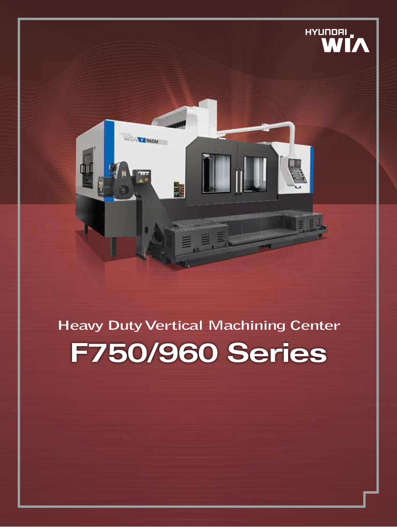
Heavy Duty Vertical Machining Center
F750/960 Series

The New Face of Mold Machining
High precision Vertical Machining Center ideal for Heavy duty cutting, as well as machining molds.
The powerful and strong geared spindle head provides both high spindle speed and high low end
torque with minimal vibration.
F750/960 Series
HYUNDAI WIA MACHINE TOOL 2 3
High-Rigidity & Heavy duty cuttingVertical Machining Center
Spindle
Peripheral Device
Easy to Operate
Peripheral Equipment
● Built-In Spindle● Spindle Taper● Spindle Coolant
● ATC & Magazine● Machining Ability● HW-MP II
● FANUC 31i-A● SIEMENS 828D● Software
● Chip Conveyor● Option
Basic Structure● Bed● Slide Way● Lubricating Device System

BASIC STRUCTURE
The Finite Element Analysis Method (FEA) is used during machine development in order to increase rigidity and decrease both heat growth and vibration in the casting.
This ensures the machine remains stable even under the heaviest cutting conditions.
FEA Method
Lubricating device
Slide Way
AIR Lift Slide Method
High Quality Capability & Productivity
Slide Way
An automatic, centralized lubrication system supplies the optimal amount of lubricating oil to each axis.
Automatic Centralized Lubrication System
All axis are driven by high precision double-nut ballscrews.
The double pretension design provides outstanding positioning and repeatability with virtually no thermal growth.
All ballscrews are connected directly to the servo drive motors without gears or belts, to eliminate backlash.
The table is supported at all times by the use of 4 box ways and 2 supplementary ways.
This allows for a maximum table load of 4,500 kg without any distortion in the table.
By adapting the “semi-rising sliding ways” the load on the X&Y axis slide way is decreased. By dramatically decreasing the slide way load the X&Y axis is able to hold tolerance and repeatability over longer cycle times.
AIR Semi-Rising Slide Way
10 Faces Restriction Y Axis Slide Way (F960)
All Guideways are hardened & ground, wide box type for unsurpassed long-term rigidity and accuracy.
Each Guideway is induction hardened and precision ground providing outstanding performance, even during heavy duty machining operations.
Box Guide Way
Pre-tensioned & Double Anchored Ball Screw
AIR Semi-Rising Slide Way
HYUNDAI WIA MACHINE TOOL 4 5
Ball-screw Deviation (Diameter) Deviation (μm)
Number of Positioning Repeated (Time)

Main Spindle
Built-In Spindle
Spindle Coolant
Spindle Torque & Power
Big Plus Spindle
The Big Plus spindle system (BBT #50) provides dual contact between the spindle face and the flange face of the tool holder. This greatly increase tool rigidity, reduces run out and adds significant productivity to your machining applications.
Through the spindle coolant is available.
This is particularly useful for deep hole drilling and helps increase tool life and decrease cycle time.
Through the spindle coolant is available.
This is particularly useful for deep hole drilling and helps increase tool life and decrease cycle time.
• Rigidity improved due to increases of reference diam.• Improvement of ATC repeat precision • Prevention of Z axis displacement when rotating in high speed• Increased life cycle of tools
Both the F750M and 960M feature a standard built-in cartridge type spindle ideal for mold manufactures.
The high torque is also suitable for a wide variety of heavy machining applications.
Application of 2 Faces Spindle (F750B/F750M/F960M)
Cooling System of Cutting Oil
Spindle Thru Coolant
Before Clamping After Clamping
Clamping
Non Contact Contact
Axial Movement is Important for Face Contact
F750B & F960B are designed with a 2-step gear drive, providing both high spindle speed and high low end torque.
Gear Type Spindle
SPINDLEHigh-Power & Heavy Duty Cutting
Spindle Construction
HYUNDAI WIA MACHINE TOOL 6 7
By using ultra precision class angular ball bearings, fast acceleration and deceleration of the main spindle is achieved.
The spindle head is designed to minimize the heat displacement of main spindle, and with the use of a hydraulic tool lock system the machining stability has been increased.
4,500 r/min 8,000 r/min 12,000 r/min Opt.

20ea
30ea
Ø125mm (4.9″)
Ø240mm (9.4″)
300mm (11.8″)
20kg (44.1 lb)
Memory Random
3.5sec
F750B(M)/960B(M)ITEM
No. of Tool Std.
No. of Tool Opt.
Max. Tool Dia. (W/T Adjacent Tool)
Max. Tool Dia. (W/O Adjacent Tool)
Max. Tool Length
Max. Tool Weight
Tool Selection Method
Tool Change Time (T-T/C-C)
The tool magazine holds twenty (20) tools as standard with forty (40) tools as an option for the F750 and thirty (30) for the F960. Random access allows for pre-staging of tools for faster tool changes and increased productivity
Magazine
Main Specification of Cam Box & Twin Arm
The Double Arm ATC provides fast and reliable tool changes to help reduce machining cycle times.
ATC
PERIPHERAL DEVICEHeavy Duty Cutting by High-Rigid & Accurate Mechanism
Machining
Machining ability
FACE MILL 〈Material〈JIS〉:S45C(Carbon steel〉
Tool diameter
Spindl rpm
Feed rate
Cutting width
Cutting depth
Chip quantity
Ø125 mm x 8F
600 r/min
700 mm/min
100 mm
6 mm
420 cc/min
DRILL 〈Material〈JIS〉:S45C(Carbon steel〉
Tool diameter
Spindl rpm
Feed rate
Cutting depth
Chip quantity
Ø60 mm x MT5
143 r/min
28 mm/min
65 mm
79 cc/min
Tapping 〈Material〈JIS〉:S45C(Carbon steel〉
Tool diameter
Spindl rpm
Feed rate
Tap depth
M45 mm x P4.5
49 r/min
220 mm/min
45 mm
Sample Workpieces
To aid in the machining of molds, the Hyundai WIA Mold package is applied as a standard feature for F750M/960M Series machines.
This ensures accurate and high quality surface finishes and contouring.
1. Featuring a FANUC 31i-A control2. 10.4″ LCD Display3. AICC II package4. Thermal Displacement Compensation feature5. Automatic Power off feature
- Machining condition selection function- AI contour control II- Smooth backlash compensation
Main points of Mold package
What is the AICC II package?
HW-MP II (HYUNDAI WIA-MOLD PACKAGE II)
HYUNDAI WIA MACHINE TOOL 8 9
HYUNDAI WIA MACHINE TOOL 10 11
Easy to Operate
Programming system for creating CNC programs easily.
HYUNDAI WIA's smart system is customized to provide user friendly functions to aid in the setup and operation of the machine.
M-Code List Opt. Calculator Opt. Product Guide Opt.
SIEMENS
SINUMERIK 828D Milling is an advanced CNC that was designed for vertical/horizontal machining centers and has the capability to handle six (6) axis. It is ideal for the shop floor thanks to its unique graphical user interface.
Users can quickly commission, operate, program, service and maintain machines tasks without the need for extensive training.
You can use a USB memory card, a CF memory card and LAN commonly with the Siemens Control
• Program Storage CNC memory : 3~5MB• Auto Change of Tool Life Control and Spare Tool• Acceleration and reduction and feed forward control through JERK control• High speed Mold Process (Advanced Surface)• Straight block spline control (COMPRESSOR) function• Connectivity and Remote Diagnositc Function of Network Drive
Programming & Operating Technology
CNC Technology
Shopfloor Communications
• Provide cycle programming (Program Guide) standard.• Support ISO ISO Code type(G291) standard• Interative programming system (SHOPMILL) • 2D / 3D Simulation + realtime Simulation• Connectivity and Remote Diagnositc Function of Network Drive• Support the setup graphic for workpiece coordinate(automatic / manual)• Support the graphic for tool length measuring function (automatic / manual)• Control of NC rotary and support of single section/cylinder interpolation
HW-PGi F Opt.
Programming Guide i for Fanuc System
FANUC
• Real-time cut monitoring• 2 Channel screen display • Self learning for machining amount • 3 stage of status monitoring (wear/break/no-load)
Example of easy programming
Programing is simulated
Realistic 3D solid animation
Readily programing with interactive type, without code
Engraving Cycle
Engraving Programs are instantly created by entering the required text.
❖ If you order these options, Please contact sales person
HW-TM Opt.
Tool Monitoring System

Peripheral Equipment
HYUNDAI WIA MACHINE TOOL 12 13
Coolant Chiller
Screw Type Chip AugurChip evacuation is achieved by the use of 2 screw type chip augur system.
Coolant temperature can be controlled by the use of a coolant chiller.
This ensures constant coolant temperature and minimizes growth in the machine due to heat distortion.
Hinge Belt Type
Scraper Type
Drum Filter Type
Material SS41, 45C, Steel casting Chip Roughly cut chips Synthetic chips
Material SS41, 45C, Steel casting Chip Chips shortly cut and out
Material AL, casting, non-metal Chip Chips in low density and fine powder
Show highly efficiency when treating lots of chips synthetic chip treatment, collective chips
Facilitate to treat chip shortly cut and out, facilitate to forward chips with 90 degree
Have advantage in precision when processing aluminum because chips are not introduced
to coolant nozzle
Standard & Optional
Call Light
Call Light
Call Light & Buzzer
Work Light
Electric Cabinet Light
Door Inter-Lock
Remote MPG
MPG
Spindle Load Meter
Spindle RPM Meter
Work Counter
Total Counter
Tool Counter
Multi Tool Counter
Electric Circuit Breaker
AVR (Auto Voltage Regulator)
Transformer & Cable
Flash Memory Card
Auto Power Off
Back up Module for Black out
Measuring Device
Air Zero
Work Measuring Device
TLM
(Marposs/Renishaw/Bloom)
Tool Broken Detective Device
Linear Scale
Coolant Level Sensor (Only for Chip Conveyor)
Enviornment
Air Conditioner
Dehumidifier
Oil Mist Collector
Oil Skimmer (Only for Chip Conveyor)
MQL (Minimal Quantity Lubrication)
Fixture & Automation
Auto Door
Auto Shutter (Only for Automatic System)
Sub O/P
NC Rotary TableI/F
Control of Additional Axis
External M Code 4ea
Automation Interface
I/O Extension (In & Out)
Hyd. Device
Std. Hyd. Unit
Hyd. Unit for Fixture
❖ The specifications as above will only serve as a reference.
F750B F960B F750M F960M
● ● ● ●
○ ○ ○ ○
○ ○ ○ ○
● ● ● ●
○ ○ ○ ○
● ● ● ●
● ● ● ●
○ ○ ○ ○
X X X X
○ ○ ○ ○
X X X X
○ ○ ○ ○
X X X X
○ ○ ○ ○
○ ○ ○ ○
○ ○ ○ ○
○ ○ ○ ○
○ ○ ○ ○
○ ○ ○ ○
☆ ☆ ☆ ☆
○ – ○ –
– ○ – ○
– ○ – ○
○ ○ ○ ○
○ ○ F31i ● F31i ●
☆ ☆ ☆ ☆
○ ○ ○ ○
○ ○ ○ ○
○ ○ ○ ○
○ ○ ○ ○
○ ○ ○ ○
☆ ☆ ☆ ☆
○ ○ ○ ○
☆ ☆ ☆ ☆
○ ○ ○ ○
○ ○ ○ ○
○ ○ ○ ○
○ ○ ○ ○
☆ ☆ ☆ ☆
○ ○ ○ ○
○ ○ ○ ○
X X X X
☆ ☆ ☆ ☆
○ ○ ○ ○
☆ ☆ ☆ ☆
○ ○ ○ ○
☆ ☆ ☆ ☆
○ ○ ○ ○
☆ ☆ ☆ ☆
○ ○ ○ ○
○ ○ ○ ○
12R ○ 12R ○ 12R ○ 12R ○
○ ○ ○ ○
○ ○ ○ ○
○ ○ ○ ○
☆ ☆ ☆ ☆
Electric Device
4,500rpm (18.5/15kW)
4,500rpm (12kW) SIEMENS
8,000rpm (18.5/15kW)
8,000rpm (12kW) SIEMENS
8,000rpm (22/18.5kW)
8,000rpm (18.5kW) SIEMENS
12,000rpm(30/25kW)
Spindle Cooling System
ATC
ATC Extension
Tool Shank Type
U-Center
Stud Bolt Collet Change
Table & Column
APC
Tap Type Pallet
T-Slot Pallet
NC Rotary Table
High Column
Coolant System
Std. Coolant (Nozzle)
Bed Flushing Coolant
Spindle Thru Coolant
TOP COVER (Only for Spindle Thru Coolant)
Jet Coolant
Gun Coolant
Side Oil Hole Coolant
Air Gun
Spindle Air Blow
Tool Measuring Air Blow (Only for TLM)
Air Blow for Automation
Thru MQL Device (Without MQL)
Coolant Chiller
Power Coolant System (For Automation)
Chip Disposal
Coolant Tank
Cabin Screw Chip Conveyor
Chip Conveyor
Chip Conveyor (Hinge/Scraper)
Special Chip Conveyor (Drum Filter)
Chip box
Safety Device
Total Splash Guard
Half Splash Guard
S/W
Machine Guidance
HWTM (Tool Monitoring System)
DNC Software
Dialogue Program
Tool ID Manager
Spindle Heat Distortion Compensation
Spindle Warm up Function
ETC
Tool Box
Customized Color
CAD&CAM Software
Built-in
20EA
30EA
40EA
BT50
BBT50
D'andrea
45°
60°
90°
Rotary Turn
250mm
20bar
30bar
70bar, 15ℓ
70bar, 30ℓ
470ℓ
690ℓ
Front (Left)
Left (Rear)
Standard (180ℓ)
Swing (200ℓ)
Large Size (330ℓ)
Customized
Need for Munsel NO.
1 Color : ■
3 Color : ■■■
3 Color : ■■■B
FANUC
SIEMENS
FANUC
SIEMENS
FANUC
SIEMENS
Digital
Digital
Digital
6ea
9ea
40kVA
45kVA
50kVA
TACO
SMC
Touch
Laser
X/Y/Z Axis
Std.
High Speed
Single
Channel
1Axis
2Axis
16Contact
32Contact
70bar/13ℓ
45bar
70bar
100bar
Customized
F750B F960B F750M F960M
● X X X
○ X X X
○ X X X
○ X X X
X ● X X
X ○ X X
X X ● ●
● ● ● ●
● ● ● ●
○ ○ ○ ○
○ X ○ X
○ ● ○ ○
● ○ ● ●
○ ○ ○ ○
● ● ● ●
○ ○ ○ ○
○ ○ ○ ○
X X X X
X X X X
● ● ● ●
☆ ☆ ☆ ☆
○ X ○ X
● ● ● ●
● ● ● ●
○ ○ ○ ○
○ ○ ○ ○
○ ○ ○ ○
☆ ☆ ☆ ☆
○ ○ ○ ○
○ ○ ○ ○
○ ○ ○ ○
○ ○ ○ ○
○ ○ ○ ○
○ ○ ○ ○
○ ○ ○ ○
☆ ☆ ☆ ☆
☆ ☆ ☆ ☆
☆ ☆ ☆ ☆
☆ ☆ ☆ ☆
● – ● –
– ● – ●
● ● ● ●
● X ● X
○ ○ ○ ○
X X X X
☆ ☆ ☆ ☆
● ● ● ●
☆ ☆ ☆ ☆
☆ ☆ ☆ ☆
☆ ☆ ☆ ☆
○ ○ ○ ○
● ● ● ●
☆ ☆ ☆ ☆
○ ○ ○ ○
○ ○ ○ ○
○ ○ ○ ○
○ ○ ○ ○
○ ○ F31i ● F31i ●
☆ ☆ ☆ ☆
● ● ● ●
☆ ☆ ☆ ☆
☆ ☆ ☆ ☆
Spindle
● : Standard ○ : Option ☆ : Prior Consultation X : Non Application - : Impossible
Spindle Probe
Work piece coordinate values can be set automatically using the optional spindle probe.
Linear Scale
Linear scales are available when highly accurate positioning is required, by mini-mizing thermal deformation
TLM
Tool lengths and diameters can be set automatically using the optional tool setter. This can also be used to monitor tool wear and detect broken tools
Chip Conveyor Opt.
Opt.
Opt.
Opt.
Opt.

unit : mm(in)
Specifications
External Dimensions
F750M
F960M

HYUNDAI WIA MACHINE TOOL 14 15
unit : mm(in)
unit : mm(in)
Tooling System
Interference
F960MF750M
BT50
BBT50
PULL STUD
PULL STUD

HYUNDAI WIA MACHINE TOOL 16 17
Controller
FANUC 32i-A
3 (X, Y, Z) axes
3 axes (G00 & G01 : 3 axes)
(G02 & G03 : 2 axes)
X axis : 0.001 mm (0.0001”)
Y axis : 0.001 mm (0.0001”)
Z axis : 0.001 mm (0.0001”)
X axis : 0.001 mm (0.0001”)
Y axis : 0.001 mm (0.0001”)
Z axis : 0.001 mm (0.0001”)
G20 / G21
Each axis / All axes
All axis
Over-travel
+/- 0~9999 Pulse
(Rapid traverse & Cutting feed)
10.4” color LCD
Sequence, program
Rapid, Jog, handle
x1, x10, x100
F code feedrate direct command
0~200% (10% Unit)
0~5,000 mm/min (197 ipm)
F0, F25%, F50%, F100%
Positioning/Linear/Circular
(G00/G01/G02/G03)
Controlled axes
Simultaneous
controllable axes
Least input increment
Least command increment
Inch / Metric conversion
Interlock
Machine lock
Emergency stop
Stored stroke check 1
Mirror image
Follow-up
Servo off
Backlash compensation
Position switch
Stored pitch error
compensation
Bi-direction Stored pitch
error compensation
LCD/MDI
Automatic operation (memory)
MDI operation
Search function
Program restart
Dry run
Single block
Buffer register
DNC operation
Manual jog feed
Manual handle feed-rate
Feed command
Feedrate override
Jog feed
Rapid traverse override
Override cancel
Rapid traverse bell-shaped
acceleration/deceleration
Auto corner deceleration
Label skip
Control in/out
Nano Interpolation
Axis control / Display unit
Feed functions
Program input & Interpolation functions
Operation
•Figures in inch are converted from metric values. •Design and specifications subject to change without notice.
RS232C
100 Mbps
320 m (128 Kbyte)
125 ea
Alarm & operator message
Selection of 5 optional language
Screen saver
48 Pair
#100~#199, #500~ #999
G60
100 Mbps
1GB
9 ea (Application can be limited)
3 unit
640m (256Kbyte) /
1280m (512Kbyte) / 2560m (1Mbyte)
HWTM (Built-in Fanuc type)
Reader / Puncher interface
Memory card input/output
Embedded ethernet
Part program storage length
Registered programs
Memory lock
Back ground editing
Extended part program editing
External message
Self-diagnosis function
History display
Help function
Run hour / Parts count display
Actual cutting feedrate display
Graphic display
Sp. / Servo setting screen
Multi-language display
Erase CRT screen display
Auto data back-up
Additional Axis
Additional work
coordinate system
Add custom macro
common variable
Polar coordinate interpolation
Polar coordinate command
Cylindrical interpolation
Single direction positioning
Fast ethernet
Data server
Manual Guide i
Optional block skip add
Manual handle interrupt
3 M.P.G
Part program storage length
Dynamic graphic display
Protection of data at 8 levels
Tool monitoring function
Data Input / Output & Editing functions
Setting, Display, Diagnosis
Option
G61 / G09
G04, 0 ~ 9999.9999sec
G28
G27
G30
M00, M01 / M02, M30
EIA RS-244 / ISO 840
(Automatic recognition)
1 ea
+ / - 9999.9999″
(+ / - 8digits)
O4 digit
G90 / G91
G17,G18,G19
G52~G59
“On” fixed
G10
10 levels of nesting
G73, G74, G76, G80 ~ G89
G31
M3 digits
S5 digits, binary output
50% ~ 120% (10% unit)
Max. T8 digits
G40~G42
G43, G44, G49
99 Pairs
Exact stop mode
/ Exact stop
Dwell
Helical interpolation
Threading / Synchronous feed
Manual reference point return
1st Reference point return
Reference point return check
2nd Reference point return
Program stop/end
Tape code
Optional block skip
Maximum programmable
dimensions
Program number
Absolute and incremental
command
Decimal point input
Plane selection
Work coordinate
system setting
Manual absolute
Programmable data input
Sub program call
Custom macro
AICC (AI contour control 2 )
Circular interpolation by
radius R
Canned cycle
Optional chamfering
/ corner R
Skip function
Automatic coordinate
system setting
Coordinate system rotation
Programmable mirror image
Miscellaneous function
Miscellaneous function lock
Spindle speed command
Spindle speed override
Spindle orientation
Rigid tapping
Tool function
Cutter compensation C
Tool length compensation
Tool offset pairs
Tool life management
Program input & Interpolation functions
Auxiliary / Spindle functions
Tool functions / Tool compensation
Specifications
Specifications
F960B F960MF750B F750M 1,800 X 700 (70.9″×27.6″) 2,700 X 950 (106.3″×37.4″)
2,000 (4,409) 4,500 (9,921)
-
-
-
Big Plus #50 NT #50 Big Plus #50
4,500 [8,000] 12,000 8,000 12,000
18.5/15 (25/20) [18.5/15 (25/20)] 30/25 (40/33.5)
22/18.5 (30/25) 30/25(40/33.5)
12 (16) [12 (16)] 18.5 (25)
893/732 [657/532] 420/238
776/657 420/238
881 [642] 658
GEAR BUILT-IN GEAR BUILT-IN
1,550 / 750 / 720 2,450 / 960 / 850
200 ~920 [450~1,170] 200 ~ 1,050
790 1,000
16/16/12 (630/630/472) 16/16/20 (630/630/787)
5 (197) 10 (394)
BOX GUIDE
20 [30,40] 20 [30]
BBT50 BT50 BBT50
Ø125 (4.9″)
Ø240 (9.5″)
300 (11.8″)
20 (44.1)
RANDOM
3.5
10
470 (124.2) 81 0 (224.5)
3 (0.8) 4.4 (1.16)
13
250
35 [40:BUILT-IN] 40 [45:BUILT-IN]
Over 25 Over 50
220 / 60 (200 / 50)
4,040 X 3,770 (240.2″×148.4″) 6,100 X 4,425 (159.1″×150.8″)
3,475 (136.8″) 3,425 (134.8″) 3,645 (143.5″) 3,627 (142.8″)
13,000 (28,660) 23,500 (51,808.6)
FANUC 31i-A [SIEMENS 828D]
TABlE
Table Size
Maximum Load Capacity
Table Change Time
Change Method
Table Driving Method
Spindle Taper
Spindle RPM
Spindle Power Output (Max./Cont.)
Spindle Torque (Max./Cont.)
Spindle Driving Method
Travel (X/Y/Z)
Distance from Table Surface to Sp
Distance from Column to SP. center
Rapid Feed Rate (X/Y/Z)
Cutting Feed Rate (X/Y/Z)
Slide Type
Number of Tools
Tool Shank
Max. Tool Dia. (W/T Adjacent Tool)
Max. Tool Dia. (W/O Adjacent Tool)
Max. Tool Length
Max. Tool Weight
Tool Selection Method
Tool Change Time T-T
C-C
Coolant Tank
Lubricating Tank
Hydraulic Tank
Air Consumption (0.5MPa)
Electric Power Supply
Thickness of Power Cable
Voltage
Floor Space (L×W)
Height
Weight
Controller
FEED
TANkCAPACITy
SPINDlE
ATC
MACHINE
NC
POWERSuPPly
❖ Specifications are subject to change for improvement without notice.
mm(in)
kg(lb)
sec
-
-
-
r/min
kW(HP)
N.m
-
mm(in)
mm(in)
mm(in)
m/min(ipm)
m/min(ipm)
-
EA
-
mm(in)
mm(in)
mm(in)
kg(lb)
-
sec
sec
ℓ(gel)
ℓ(gel)
ℓ(gel)
ℓ/min
KVA
Sq
V/Hz
mm(in)
mm(in)
kg(lb)
-
ITEM
[ ] : Option : SIEMENS Type

HYUNDAI WIA MACHINE TOOL 18 19
Controller
SINUMERIK 828D
5MB
23 digits
Standard (7Level)
G90 - G91
M - Code
M00, M01, M02, M30
AICC
128/256
Soft Limit
Time, Parts
Internal
Chinese Traditional, Czech, Danish, Dutch, Finnish, Hungarian,
Japanese, Korean, Polish, Russian, Swedish, Portuguese, Turkish
Max 4
5 axes
6 axes (axes + spindle)
0.0001mm / 0.00001inch
0 - 120%
F1, 5, 25/50, 100%
50% - 120%
Max 4 axes
TFT 10.4˝ Color
Ref 1, 2 Approach
Start, Stop, Rev, Jog, Ort.
2D
Max. configuration of axes
Max. configuration of axes and sp.
Least Command/input
Feedrate Override
Rapid Traverse Override
Acceleration with jerk limitation
Programmable acceleration
Follow-up mode
Measuring system 1 and 2,
selectable
Separate path feed for corners and
chamfers
Travel to fixed stop
Spindle Override
Spindle Orientation
Spindle Speed Limitation
Rigid Tapping
Linear interpolation axes
Circle via center point and end point
Circle via interpolation point
Helical interpolation
Universal interpolator NURBS
(non-uniform rational B splines)
Advanced Surface
Compressor for 3-axis machining
Tool Nose R Comp./Tool Radius Comp.
Zero Offset
(G54, G55, G56, G57 ,G58, G59)
Programmable Zero Offset
3D Tool Radius Compensation
Tool management
CRT / MDI
Screen saver
Manual Handle/Jog Feed
Reposition
Reference Approach
Spindle Control
Single Block
Feed Hold
Optional Block Skip
Machine Lock
Dry Run
Simulation
Control
Feed Function
Spindle Functions
Interpolations
Tool Function
Diagnosis Function
Programming Function
Alarm Display
Spindle Load/rpm Meter
PLC status/LAD display
Part Program Storage Length
Program Name
Subroutine Call
Absolute/incremental Command
Scaling, ROT
Inch / Metric Conversion
Conversational Cycle Program
Block Search with/without
Calculation
Variable Program (Macro)
Read / Write System Variable
BackGround Editing
Miscellaneous Functions
Lable Skip
Program Stop/End
Lookahead , Jerk LimitationFeed &
forward control
ISO Dialect Interpreter(G291)
Maximum number of tools/cuttings
Number of levels for skip blocks 1
Emergency Stop
Over Travel
Contour Monitoring
Program Protection
Actual Speed Display(Monitor)
Tool Life Management
Work Count Function
Two Language switchable
RS 232C I/F
Ethernet
USB Memory Stick & CF Card
DRF offset
Load and save of MDI
Teach-in
Number of levels for skip blocks 8
Simulation in 3-D display
ShopMill
TRACYL
TRANSMIT
Display
Manual Operation
Auto Operation
Protection Function
Automation Support Fun.
language Function
Data Transfer
Option
•Figures in inch are converted from metric values. •Design and specifications subject to change without notice.
ENERGY SAVING & ECO FRIENDLY
HYUNDAI WIA leads the way in Energy saving and Eco Friendly Machine Tools.
All machines are designed and built with power saving methods and
environmental consideration in mind.
MQL : Minimal Quantity Lubrication Energy Saving
Efficient Lubrication SystemOil Skimmer
Mist Collector
Minimum quantity lubrication or near-dry machining has revolutionized how machining operations are cutting costs, improving tool life and being environmentally responsible.
The goal of this system is to spray only the amount of lubricant required to prevent heat and chip build up at the cutting tool or work piece face
By applying lubricant only when the machines axis are moving lubrication consumption is reduced by 30% compared to standard systems.
Power Consumption Monitor
Real time power consumption can be monitored through the OP screen
ECO System
Coolant
(Wet Cutting)
MQl Cutting
(Semi-Dry)
lubricating Minimal
Mist Oil
Compressed Air
Cooling
Chip Disposal
An Oil Skimmer can be used to reduce coolant contamination.
Mist Collectors reduce the amount of smoke and mist in the air creating a more comfortable and safer work environment
❖ This Catalogue made by recycle paper
Opt.
Opt.
Opt.