Embed Size (px)
Citation preview
Mcilvaine Company
Northfield, IL
Choke Valve Decision Guide
Scope and action plan
May, 2016
Choke Valve Decision Guide and Webinar
Mcilvaine is compiling a continually updated decision guide for operators of choke valves used in oiland gas and other industries for fluid control.
Contaminants such as sand integrated into varying mixtures of water, oil, methane and other gasesprovide both operational and maintenance challenges.
The guide will:
• identify the major applications and then the performance of various designs and variousmaterials for specific conditions
• be the basis of a recorded Webinar discussion to be conducted in early Fall 2016
• be offered free of cost to any end user
• be published in Industrial Valves: World Markets and Strategies
The wisdom of the industry is sought in order to make this guide the best it can be. Input iswelcomed from any and all sources.
For more information contact Bob Mcilvaine at [email protected] 847-784-0012ext. 112
2
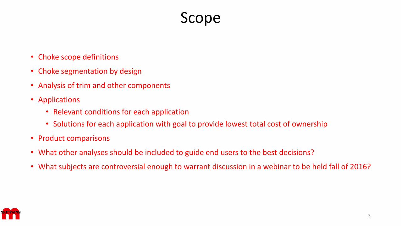
Scope
• Choke scope definitions
• Choke segmentation by design
• Analysis of trim and other components
• Applications
• Relevant conditions for each application
• Solutions for each application with goal to provide lowest total cost of ownership
• Product comparisons
• What other analyses should be included to guide end users to the best decisions?
• What subjects are controversial enough to warrant discussion in a webinar to be held fall of 2016?
3
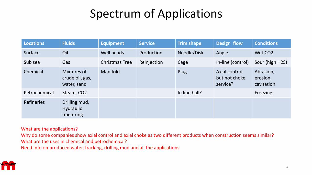
Spectrum of Applications
Locations Fluids Equipment Service Trim shape Design flow Conditions
Surface Oil Well heads Production Needle/Disk Angle Wet CO2
Sub sea Gas Christmas Tree Reinjection Cage In-line (control) Sour (high H2S)
Chemical Mixtures of crude oil, gas, water, sand
Manifold Plug Axial control but not choke service?
Abrasion,erosion, cavitation
Petrochemical Steam, CO2 In line ball? Freezing
Refineries Drilling mud,Hydraulicfracturing
4
What are the applications? Why do some companies show axial control and axial choke as two different products when construction seems similar? What are the uses in chemical and petrochemical? Need info on produced water, fracking, drilling mud and all the applications
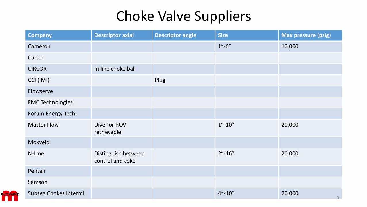
Choke Valve SuppliersCompany Descriptor axial Descriptor angle Size Max pressure (psig)
Cameron 1”-6” 10,000
Carter
CIRCOR In line choke ball
CCI (IMI) Plug
Flowserve
FMC Technologies
Forum Energy Tech.
Master Flow Diver or ROV retrievable
1”-10” 20,000
Mokveld
N-Line Distinguish between control and coke
2”-16” 20,000
Pentair
Samson
Subsea Chokes Intern’l. 4”-10” 20,0005
Choke Definition
A choke valve is a particular design of valve that raises and lowers a solid cylinder (called a "plug" or "stem") which is placedaround or inside another cylinder that has holes or slots. The design of a choke valve means fluids flowing through the cageare coming from all sides and that the streams of flow (through the holes or slots) collide with each other at the center of thecage cylinder, thereby dissipating the energy of the fluid through "flow impingement". The main advantage of choke valves isthat they can be designed to be totally linear in their flow rate.
Choke valves are severe service valves which are designed specifically for oil and gas wellhead applications, both in a surfaceand subsurface context. They are used for controlling the flow on production, reinjection and subsurface wellheads. Chokevalves are subjected to typical wellhead extreme conditions which can cause erosion, corrosion and other damage. Typicallythis can include high fluid velocity, slugging, sand production and multiphase of oil, gases and water. Also a choke valve has tohave a very high turndown capability as it has to cover a wide range of flowrates. Thus the design of choke valves is requiredto be very robust with careful selection of valve configuration, flow path profiles, materials and ease of maintenance.
In subsea applications the choke valve has to cope with severe marine environmental conditions and be designed for subsearobot maintenance. If choke valves are selected poorly maintenance becomes a real issue with valves having to be removedregularly which is a real cost impost. Chokes can be operated manually or automatically. Sometimes a "choke bean" size isdetailed, this is a device placed in a choke line that regulates the flow through the choke. Flow depends on the size of theopening in the bean; the larger the opening, the greater the flow.
Actuator selection is also important, actuators may be a "stepping type" or linear depending on the valve design. Controlsystems can be complex on large facilities where multiple wells are controlled to production and reinjection manifolds.
6
Choke Design
Chokes hold a backpressure on a flowing well to make better use of the gas for natural gas lift and to control the bottom holepressure for recovery reasons. In vertical pipe flow, the gas expands rapidly with decreasing hydrostatic head and the liquid moves inslugs through the tubing. The potential gas lift energy is rapidly lost and liquids fall back and begin to accumulate over theperforations. Accumulating liquids hold a back pressure on the formation. If enough liquids accumulate, the well may "die" and quitflowing.
A choke holds back pressure by restricting the flow opening at the well head. Back pressure restricts the uncontrolled expansion andrise of the gas and thus helps keep the gas dispersed in the liquids on the way up the tubing. Chokes may be variable or have a setopening. The set openings, often called "beans," are short flow tubes. They are graduated in 64ths of an inch. Common flow sizes areabout 8 through more than 20 (in 64ths) for small to moderate rate gas wells. Liquid producers and high rate gas wells us 20+ chokesettings. The size of the choke needed depends on reservoir pressure, tubing size, amount of gas, and amount and density of liquids.Variable chokes may use a increasing width slot design that allows quick resetting. They are useful on well cleanups followingstimulation where choke size can vary over the course of a single day from 4/64ths to over 40. They are also used where periodicliquid unloading necessitates frequent choke size changes.
7
Choke function and problems
Solids in the produced fluids are the major source of failures for chokes. Abrasion from sand, scale, ice,corrosion particles and other solids can cut out the choke restriction and cause the well to load up with fluidsand die.
Choke abrasion from solids and cavitation is increased when large pressure drops are taken. In these situations,choke life is often measured in minutes. For better performance at high pressure drops, take the drop in stagesacross three or more choke sets in series. The problem is with gas expansion; as gas goes from 5000 psi toatmospheric pressure, the gas expands 340 fold, with a similar increase in velocity. The same pressure drop,taken in series from 5000 to 3000, from 3000 to 500 and 800 to atmospheric results in gas volume (andvelocity) increases of 136 fold (5000 psi to 3000 psi), 150 fold (3000 psi to 800 psi) and 54 fold (500 psi toatmospheric). The 340 fold total drop is the same, but the velocity increase across any one choke is significantlyreduced.
8
Choke Valve in Christmas Tree
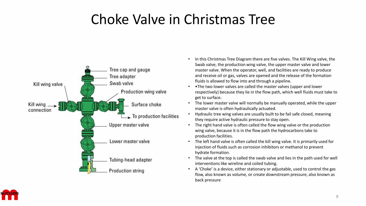
• In this Christmas Tree Diagram there are five valves. The Kill Wing valve, the Swab valve, the production wing valve, the upper master valve and lower master valve. When the operator, well, and facilities are ready to produce and receive oil or gas, valves are opened and the release of the formation fluids is allowed to flow into and through a pipeline.
• •The two lower valves are called the master valves (upper and lower respectively) because they lie in the flow path, which well fluids must take to get to surface.
• The lower master valve will normally be manually operated, while the upper master valve is often hydraulically actuated.
• Hydraulic tree wing valves are usually built to be fail safe closed, meaning they require active hydraulic pressure to stay open.
• The right hand valve is often called the flow wing valve or the production wing valve, because it is in the flow path the hydrocarbons take to production facilities.
• The left hand valve is often called the kill wing valve. It is primarily used for injection of fluids such as corrosion inhibitors or methanol to prevent hydrate formation.
• The valve at the top is called the swab valve and lies in the path used for well interventions like wireline and coiled tubing.
• A ‘Choke’ is a device, either stationary or adjustable, used to control the gas flow, also known as volume, or create downstream pressure, also known as back pressure
9
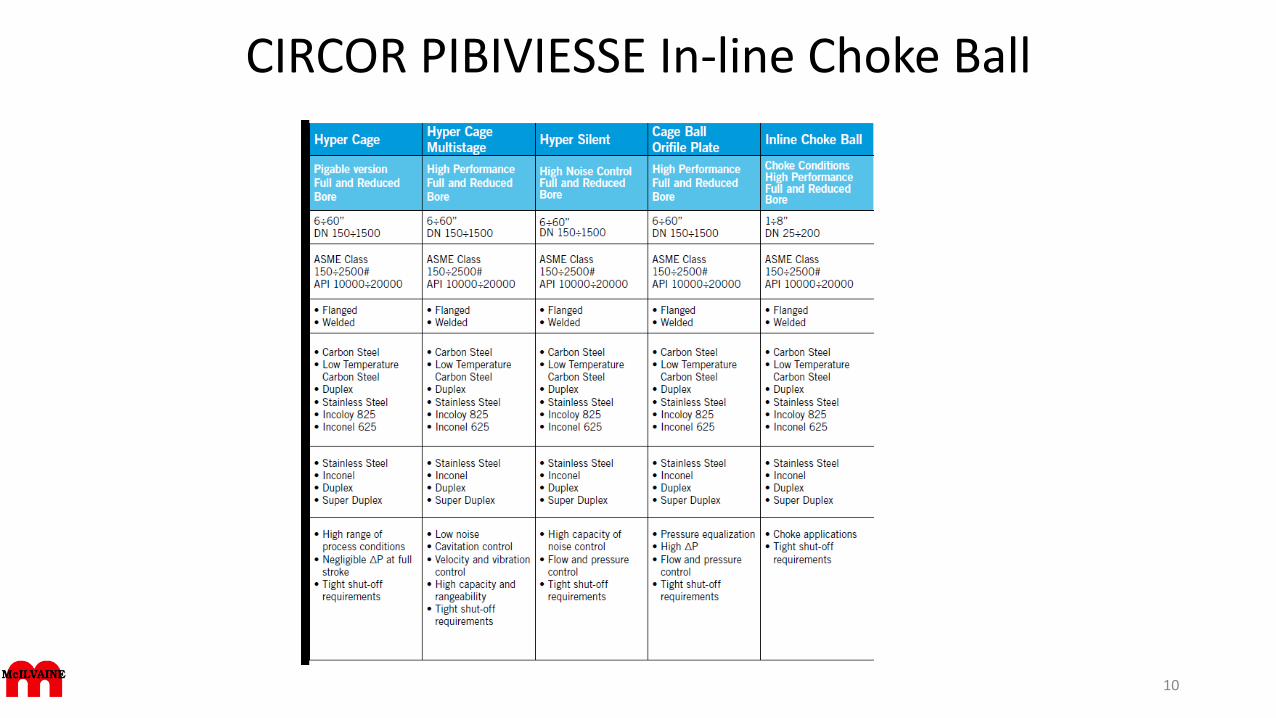
CIRCOR PIBIVIESSE In-line Choke Ball
10
Cameron Multiple Orifice choke valves
• Cameron’s Multiple Orifice Valves (MOVs) together with four special trim designs incorporate materials to meet the tough conditions including cavitation, erosion, and freezing, three of the greatest threats to efficient flow control operations.
• Cameron has an extensive database and can select the proper materials and alloys for specific choke applications. Continuing investigations to determine the relative erosion, abrasion, and cavitation resistance characteristic of materials allows Cameron to develop improved choke technologies for enhanced durability and wear resistance.
• The effects of abrasion, erosion, and cavitation can be reduced by applying hard facing to the interior surfaces of the choke outlet or by using an extended wear sleeve in the outlet.
• Specific grades of tungsten carbide are effective at reducing erosion wear, while StelliteTM is most resistant to the destructive consequences of cavitation.
11
Cameron MOV special designs for each application
The purpose of the MOV is to provide accurate, calibrated flow control and increased choke service life in all applications,including erosive conditions. Toward that goal, new disc designs have been required to meet new and greater demands ofbetter rangeability, higher capacity, and increasingly severe conditions. These new disc designs involve altering the normallyround orifice shapes on the discs to adapt them for special conditions. With practically every drilling job, large cuttings come upthe casing with the mud. The cuttings can block the throttling restriction in many chokes. However, Cameron’s drilling choketrim is specially designed for mud service. Utilizing a half-moon shaped hole, the drilling choke trim rotates through a controlrange from fully open to fully closed in 180 degrees. This design delivers control so reliable that the drilling choke outperformsother designs for well killing and pressure control, especially in severe service involving H2 S, abrasive fluids, and highpressures.
1. Style 0 – Standard Service Standard service valves are the lowest cost choke styles. They generally are intended for sweetcrude oil, deaerated water, sweet natural gas, and other non-corrosive fluids.
2. Style 8 – Sour Service In addition to the requirements of the standard valve type, the materials of the pressure containingparts of this style meet the requirements of NACE MR-01-75. Sour service chokes are intended for applications with H2 Spresent as defined by NACE MR-01-75 requirements
3. Style 4 – Wet CO2 Service This type of choke is intended for applications and service with wet CO2 (sweet or sour) and otherapplications where 410 or 316 SS is accepted. All wetted pressure-containing parts are made of stainless steel.
4. Style C – Low Temperature/Sour Service In addition to the requirements of standard and sour gas service chokes, therequirements of API 6A specifications are met. This adds Charpy impact testing of materials for pressure containing parts. Thesevalves are intended for cold -50° F (-46° C) flow and/or ambient conditions, with or without sour service.
12
Cameron MOV applications
• Cameron’s extensive MOV line covers 1” to 6” (25 mm to 152 mm) sizes that can handle pressures up to 10,000 psi while operating at temperatures ranging from -50° F to 650° F (-46° C to 343° C). They are manufactured to meet API, ANSI, and NACE standards. MOVs are available in both adjustable and positive configurations with a variety of end connections to meet most requirements, as well as angled and in-line body configurations.
• The near-linear flow characteristics of the MOV make it well suited for production choke applications including:
• Wellhead – Attached to the wing valve on the Christmas tree, and provides great control for oil and gas production.
• Manifold – Used to maintain pressures and control flow rates in oil or gas production systems, and for pressure control in chokeand kill manifolds.
• Separator Letdown – Used as a quick open/quick close quarter-turn valve to maintain levels in separators.
• Heater Bypass – Used on a secondary bypass loop to reduce and control gas pressure.
• Water Flood – Used to control injection rates for pressure maintenance and enhanced oil recovery (EOR). CO2 – Provides accurate injection control for EOR with great resistance to freeze up.
• Gas Lift – Used to maintain pressures and control gas injection rates in a well to aid in oil production.
13
Carter Process Control GmbH (CPC), Austria, offers trim
• Carter Process Control GmbH has designed and engineered (Patent Pending) a Solid Tungsten Carbide multi Stage Severe Service Trim for Control Choke Valves with “NO” brazing, EDM or Erosion.
• JACK Trim—Solid Tungsten Carbide 6% cobalt (1-3 micron WC) Plug—Solid Tungsten Carbide 6% cobalt (1-3 micron WC) Seat Ring—Solid Tungsten Carbide 6% cobalt (1-3 micron WC) or insert Stem—Duplex (F51), Inconel or other as required
• As a non valve manufacturer but with extensive control valve trim manufacturing experience CPC is uniquely positioned to supply its trim to any valve manufacturer or end user that requires a severe service multistage pressure reduction trim. Available in an almost limitless range of sizes and pressure reduction stages to fit the most arduous of operating conditions.
14
CCI Severe Service Technology
CCI DRAG® Technology for Severe Service Choke Valves - Today’s gas field environment means higher wellheadpressures with aggressive fluids with entrained sand and other solid particles. A conventional single stagechoke valve is not suitable for this kind of severe service. The need to maintain production rates means thatfrequent choke repair or replacement is no longer acceptable. CCI has the world’s first true severe servicechoke valve that uses a combination of proven DRAG® velocity control technology and the best grades oftungsten carbide material used in the industry to provide long trim life and precise process control.
15
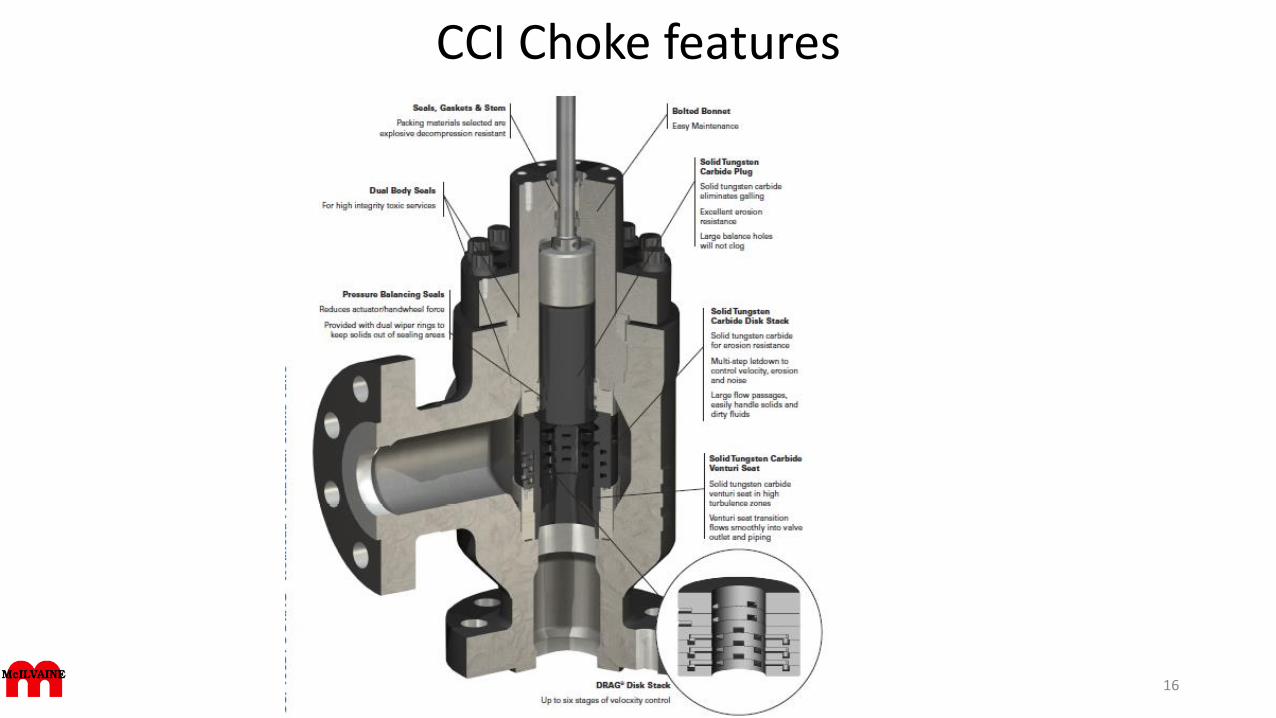
CCI Choke features
16
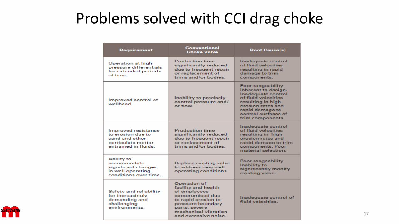
Problems solved with CCI drag choke
17
Design Comparison
See the following CCI chart and provide feedback relative to:
• Tungsten carbide for plug, disk stack, etc.
• Passage size
• Multi step let down
• Stroke length
• Number of scrapers
• Transition shape
• Interchangeable trim
• Number of stages
18
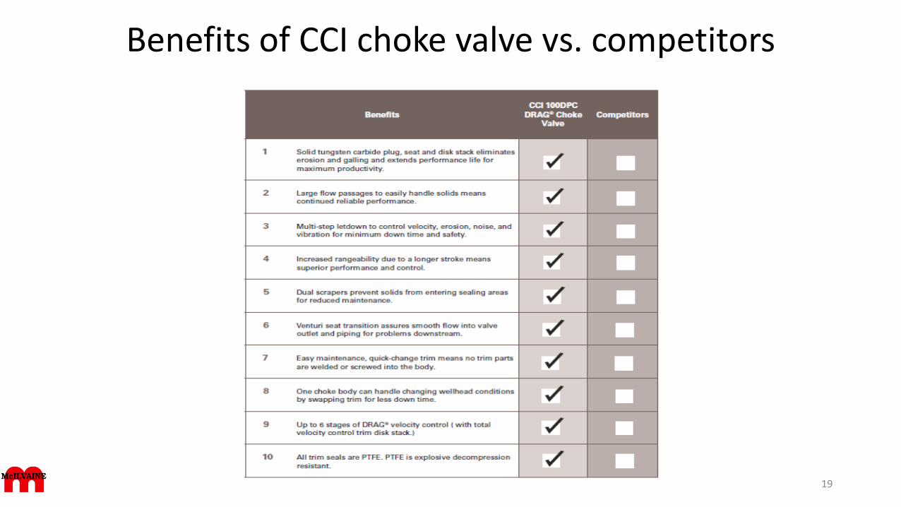
Benefits of CCI choke valve vs. competitors
19
Choke valve short life can be extended with CCIWellhead choke valves, usually in sizes of up to 6in and in the API pressure range 5000 to 15,000, have long been considered an almost expendable item of
equipment. Typically the life of choke valves can be very short. A matter of hours is not unheard of, although months is more common, but this is still unsatisfactory.
The reason is complex, and only recently has it become comprehensively understood. Essentially, it is a system problem — the interaction of many factors which
constantly change and produce a number of levels of overall instability and rapid wear out.
One of these factors is the composition of the fluid handled, which can change frequently and unpredictably. Another reason is design operating conditions that are
appropriate today can change over time and may in a few years extend beyond the capabilities of the original valve design. These controlling factors largely exclude
operating pressure and differential pressure as problem areas in choke valve design. Today, even at the high end of choke valve operating pressures, the industry has
a vast store of high pressure applications experience that is equally applicable to choke valve service.
Fluid composition: The fluid handled is a mixture of crude oil, gas, water, sand, and often other solid components. Since the proportion of each component in the
fluid mixture can change constantly, it is difficult if not impossible to accurately determine the actual effective fluid velocity because each of the components travels
at a different velocity in the build stream. Therefore, velocity in the pure sense cannot be a useful as reliable choke valve design criterion. However, it is obvious that
the sand, and perhaps other solids, is the bottom-line culprit in short choke valve life. But this is far from the whole story.
Changing operating conditions: While in time, choke valve flows are relatively constant, well head pressures change as the wells age. Usually, high operating
pressures are associated with relatively stable down-well geological formations where less sand in released But as wellhead pressures start to fall, and these
geological formations start to collapse, the percentage of the sand in the fluid flow can increase. In some cases, this decreasing pressure/ increased sand
relationship can be inverted, further complicating the choke valve design process. In addition, decreasing operating pressures with relatively constant flow can
increase the required valve coefficient Cv) by as much as a factor of 10, usually well beyond the original value’s design capability. While common single-stage choke
valves have attempted to achieve acceptable performance life through improved material, this has not been enough. As more and more large older wells are
changing from oil to gas production, choke valve internal velocities ae increasing, exacerbating the erosive damage effect of the entrained sand. And as valve trim
erodes as a result, control is compromised and the flow needed requires closer plug/seat operation. This, in turn, accelerates plug/seat erosion, regardless of
materials. Another contributing factor is increased vibration (and related high noise levels) which the eroded valve trim and other operating circumstances can
create. So, it is this vicious circle that plagues operations with extremely high maintenance costs and grossly unacceptable short choke valve life.
20
CCI multi stage valve design advantages
To limit fluid velocity throughout the valve trim and to drastically reduce the erosive effects of the sand, amultistage valve design uses a stack of disks, each of which incorporates a tortuous path flow pattern by meansof a series of right-angle turns in each disk. The velocity of all fluid components is thereby cut by at least 75 percent compared to single-stage plug / seat and drilled hole-cage designs.
By using tungsten carbine trim throughout, the erosive effects of the sand are minimized. In addition, longvalve stem stroke increases range ability and enhances controllability, so that flow set points can bemaintained and changes in operating conditions can be accommodated over time. These valves are alsocharacterized, which means that the tortuous paths in discrete groups on individual disks in the disk stack aredifferently designed; that is, flow per disk in one group is higher or lower that in a disk in another group. Thebenefit in choke valve characterization lies in the ability to maintain a larger distance between the plug and theseat at low flows; pressure reduction is there for the same as that achieved within the tortuous path,multistage disks rather than by a throttling process through a small plug/disk annular clearance.
The use of this multistage valve technology and modern materials of construction have borne fruit. Valve lifehas been demonstrated to be up to 10 times greater than was expected previously, especially where sandcontent was high. This gain in choke valve life has been shown to be true for new, replacement and old valvesthat have been retrofitted with multistage characterized , longstroke all tungsten-carbine trim.
21
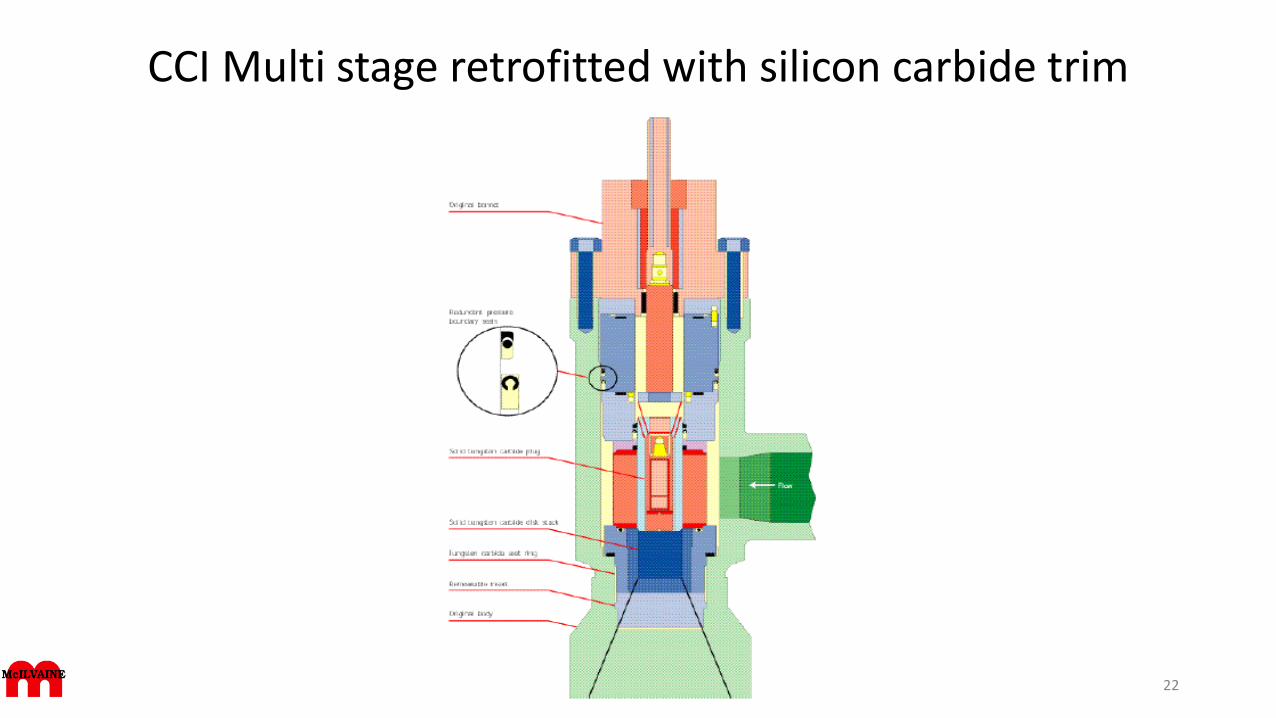
CCI Multi stage retrofitted with silicon carbide trim
22
Integrated gas lift system from Flowserve
Integrated Control Valve Systems Boost ROI With “easy oil” diminished and the price of oil trendingupward, it makes good engineering and business sense to optimize the gas-lift process by installingan integrated flow control gas injection system over manual choke or conventional automatedcontrol valve systems.
This is because an integrated solution decreases the consumption of gas and energy whileincreasing the recovery rates of the oil and gas. Under the right circumstances, a return oninvestment can be realized in a matter of days, paving the way for a boost in revenue and reductionof costs.
We want to pursue details on the integrated system from Flowserve and the input from others onthe importance of the solutions approach.
23
FMC Technologies Subsea Chokes and Flow Modules
FMC’s “F” Series Subsea Chokes and Flow Modules are for production,injection, gas lift and waterflood applications. Best practice featuresleverage FMC’s field proven subsea experience and technology, includingmetal and elastomeric seals, mechanical clamp technology, fluiddynamics, flow assurance and system design.
FMC’s subsea choke family includes:
• Non-Retrievable Choke
• Insert Retrievable Choke
• Insert Running Tool
• Hydraulic Stepping Actuator and Electric Actuators
Additionally, FMC has introduced Retrievable Flow Modules, allowingmodular packaging of chokes, flow meters, pressure/temperaturesensors and erosion detectors in an easily retrievable/re-deployableand/or upgradeable package.
24
Rigorous Qualification Testing• API 6A/17D (ISO 10423 / ISO 13628-4) PR2, Annex F tested• Extended FMC endurance tested at 300˚F• Independent Cv tested to ISA 75.02• Independent erosion test• Independent API 6A Annex I slurry test• Hyperbaric tested to 10,000 feet (3,048 m) water depth• Endurance tested at 1 million pulses/steps• Subsea field-tested under severe operating conditions
FMC Technologies Subsea Chokes
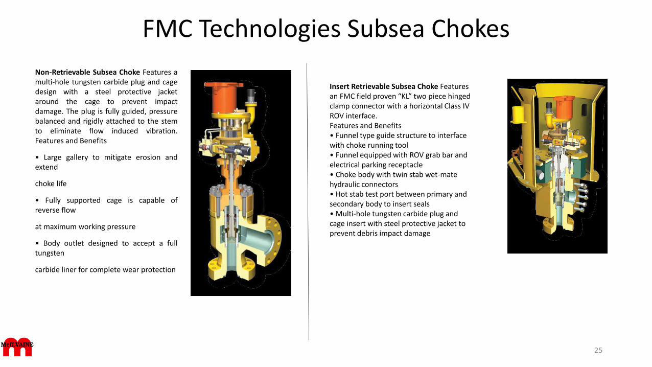
Non-Retrievable Subsea Choke Features amulti-hole tungsten carbide plug and cagedesign with a steel protective jacketaround the cage to prevent impactdamage. The plug is fully guided, pressurebalanced and rigidly attached to the stemto eliminate flow induced vibration.Features and Benefits
• Large gallery to mitigate erosion andextend
choke life
• Fully supported cage is capable ofreverse flow
at maximum working pressure
• Body outlet designed to accept a fulltungsten
carbide liner for complete wear protection
25
Insert Retrievable Subsea Choke Features an FMC field proven “KL” two piece hingedclamp connector with a horizontal Class IV ROV interface.Features and Benefits• Funnel type guide structure to interface with choke running tool• Funnel equipped with ROV grab bar and electrical parking receptacle• Choke body with twin stab wet-mate hydraulic connectors• Hot stab test port between primary and secondary body to insert seals• Multi-hole tungsten carbide plug and cage insert with steel protective jacket to prevent debris impact damage
FMC Technologies Choke throttle valve
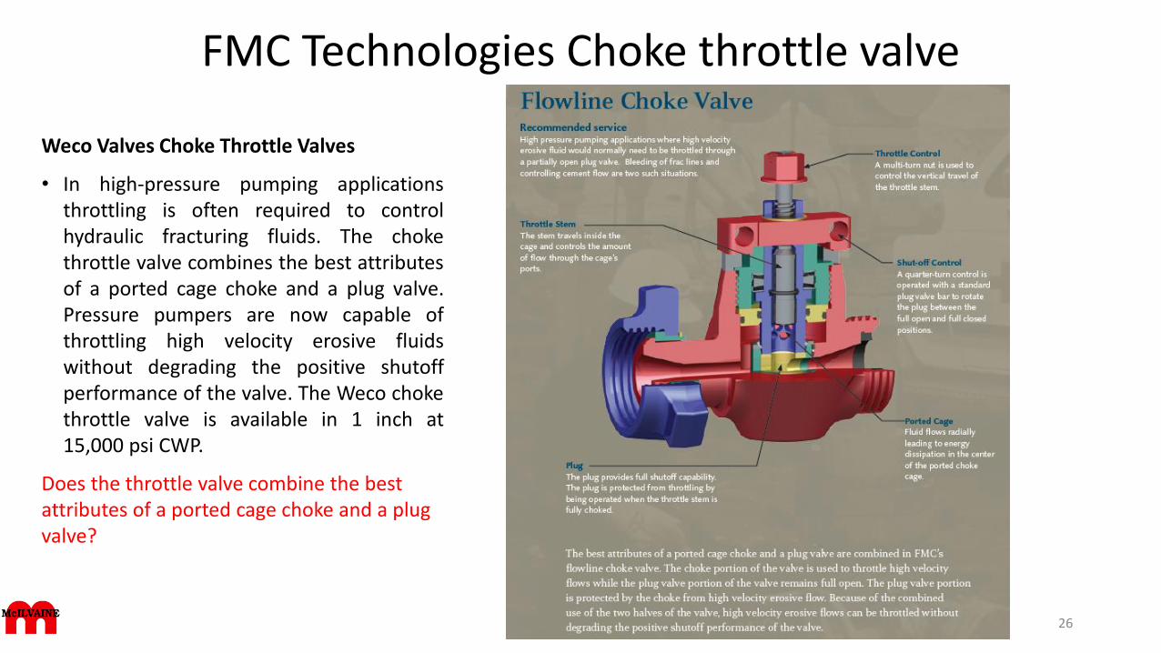
Weco Valves Choke Throttle Valves
• In high-pressure pumping applicationsthrottling is often required to controlhydraulic fracturing fluids. The chokethrottle valve combines the best attributesof a ported cage choke and a plug valve.Pressure pumpers are now capable ofthrottling high velocity erosive fluidswithout degrading the positive shutoffperformance of the valve. The Weco chokethrottle valve is available in 1 inch at15,000 psi CWP.
Does the throttle valve combine the best attributes of a ported cage choke and a plug valve?
26
FMC Technologies Actuator
Electric Choke Actuator
• In the years since FMC began development of electric solutions, options for several subseaapplications have been released. The first application, installed in 2001 and 2002, was anelectric choke actuator for Statoil’s Statford Satellite project.
• This consists of electric choke controls and a sand detection system connected to a centralelectric control module. The field originally featured only ROV-operated chokes, andproduction adjustment of individual wells could not be done as frequently as the operatorwanted. Installing electrical actuators and sand detectors proved efficient. The system wasinstalled without production shutdown and works with the existing electro-hydrauliccontrols. It has had nearly 100% up-time to date. Electric choke actuation is efficient andsimple. Traditional electro-hydraulic choke controls may use stepping actuators. Eachstepping actuator requires two hydraulic control valves in the electro-hydraulic controlmodule, and some 200 steps (hydraulic pulses) to travel from fully closed to fully open.
• In StatoilHydro’s Norne Retrofit project in the North Sea, FMC’s actuator system operatesmanifold and pigging valves as well as the chokes. The electric manifold valves were a cost-efficient retrofit for Norne. The electrical equipment that replaced manually andhydraulically operated valves and chokes gives better response time for the chokes andenables free routing of existing and new infield wells. It also liberated hydraulic lines in anexisting umbilical for use as injection chemical lines. Capital expenditures for the fieldextension were reduced significantly. Electric manifold valve control is attractive in systemswhere control modules can be eliminated from the manifold to completely eliminate thehydraulic distribution for the manifold which improves delivery time, simplifies testing, andreduces cost.
27
What about Electric actuators vs. alternatives?
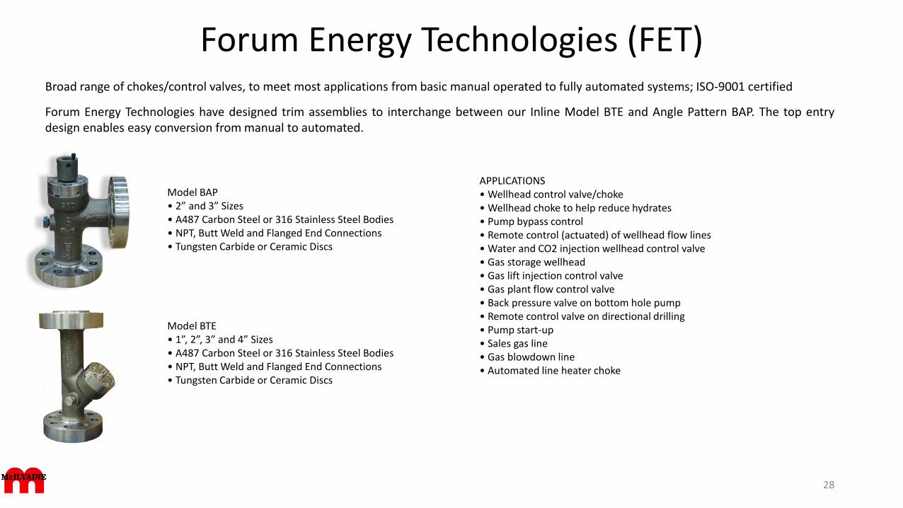
Forum Energy Technologies (FET)Broad range of chokes/control valves, to meet most applications from basic manual operated to fully automated systems; ISO-9001 certified
Forum Energy Technologies have designed trim assemblies to interchange between our Inline Model BTE and Angle Pattern BAP. The top entrydesign enables easy conversion from manual to automated.
28
Model BAP • 2” and 3” Sizes• A487 Carbon Steel or 316 Stainless Steel Bodies• NPT, Butt Weld and Flanged End Connections• Tungsten Carbide or Ceramic Discs
Model BTE• 1”, 2”, 3” and 4” Sizes• A487 Carbon Steel or 316 Stainless Steel Bodies• NPT, Butt Weld and Flanged End Connections• Tungsten Carbide or Ceramic Discs
APPLICATIONS• Wellhead control valve/choke• Wellhead choke to help reduce hydrates• Pump bypass control• Remote control (actuated) of wellhead flow lines• Water and CO2 injection wellhead control valve• Gas storage wellhead• Gas lift injection control valve• Gas plant flow control valve• Back pressure valve on bottom hole pump• Remote control valve on directional drilling• Pump start-up• Sales gas line• Gas blowdown line• Automated line heater choke
Forum Energy Technologies (FET)
29
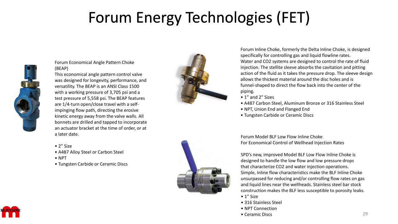
Forum Inline Choke, formerly the Delta Inline Choke, is designed specifically for controlling gas and liquid flowline rates.Water and CO2 systems are designed to control the rate of fluid injection. The stellite sleeve absorbs the cavitation and pittingaction of the fluid as it takes the pressure drop. The sleeve design allows the thickest material around the disc holes and isfunnel-shaped to direct the flow back into the center of the piping.• 1” and 2” Sizes • A487 Carbon Steel, Aluminum Bronze or 316 Stainless Steel • NPT, Union End and Flanged End • Tungsten Carbide or Ceramic Discs
Forum Economical Angle Pattern Choke (BEAP)This economical angle pattern control valve was designed for longevity, performance, and versatility. The BEAP is an ANSI Class 1500 with a working pressure of 3,705 psi and a test pressure of 5,558 psi. The BEAP features are 1/4-turn open/close travel with a self-impinging flow path, directing the erosive kinetic energy away from the valve walls. All bonnets are drilled and tapped to incorporate an actuator bracket at the time of order, or at a later date.
• 2” Size• A487 Alloy Steel or Carbon Steel• NPT• Tungsten Carbide or Ceramic Discs
Forum Energy Technologies (FET)
Forum Model BLF Low Flow Inline ChokeFor Economical Control of Wellhead Injection Rates
SPD’s new, improved Model BLF Low Flow Inline Choke isdesigned to handle the low flow and low pressure dropsthat characterize CO2 and water injection operations.Simple, Inline flow characteristics make the BLF Inline Chokeunsurpassed for reducing and/or controlling flow rates on gasand liquid lines near the wellheads. Stainless steel bar stockconstruction makes the BLF less susceptible to porosity leaks.• 1” Size • 316 Stainless Steel • NPT Connection • Ceramic Discs
Master Flo Valve
Products are engineered for surface and subsea environments and areinstalled on some of the most demanding production sites around theworld. Range of applications, including high erosion, high pressure, hightemperature, SAGD
Choke valves range in price from $1,000 to $400,000. The costliest arelarge subsea units that have been used at water depths of up to 3,000metres. Many of those are designed so they can be retrieved for servicewith remote-operated tools.
Master Flo Choke valve applications• Blow Down - Separator blow downs / Level controllers, separator
discharges• Vent Valves - Vent valves to flare• Level Controllers - High pressure drop level controllers, (or high
abrasive applications• Gas Lift and Injection - Chokes used to control injection volumes• Water Injection - Injection Chokes with multistage trims available for
large pressure drops• Water Injection Recycle Lines - High pressure drop liquid recycle
lines with Master Flo's multistage trim• Overboard Dumps - High pressure drops with multistage trim• Dump Valves - Glycol Knock out drums / Separator dump valves• Production - Wellhead and Manifold choke• Glycol Injection• Well Cleanup
What is the range of pricing and what affects the price?
We need details on the applications mentioned such as overboard dumps, well cleanup, vent valve to flare.
30
Master Flo Sub Sea Choke Valves
Equipment operates at depths of over 10,000 feet below sea level as well as high pressure, high temperature conditions, whilemaintaining high controllability and reliability.Products range from:• bolted bonnet• diver insert retrievable• ROV insert retrievable• manual actuated• stepping actuated• linear actuated• electric actuated• all available in 1"-10" configurations with a wide range of feedback and monitoring options
Additionally:• Single or multi-phase production• Water/chemical/gas injection• Artificial gas lift• Anti-surge• Closed loop flow control• All choke and control valves can be provided as non-retrievable, diver retrievable or insert retrievable designs.• This product range is also complemented by a full suite of onshore and offshore handling, test and intervention equipment which
can be packaged to meet project requirements and be provided on a rental or purchase basis.
31
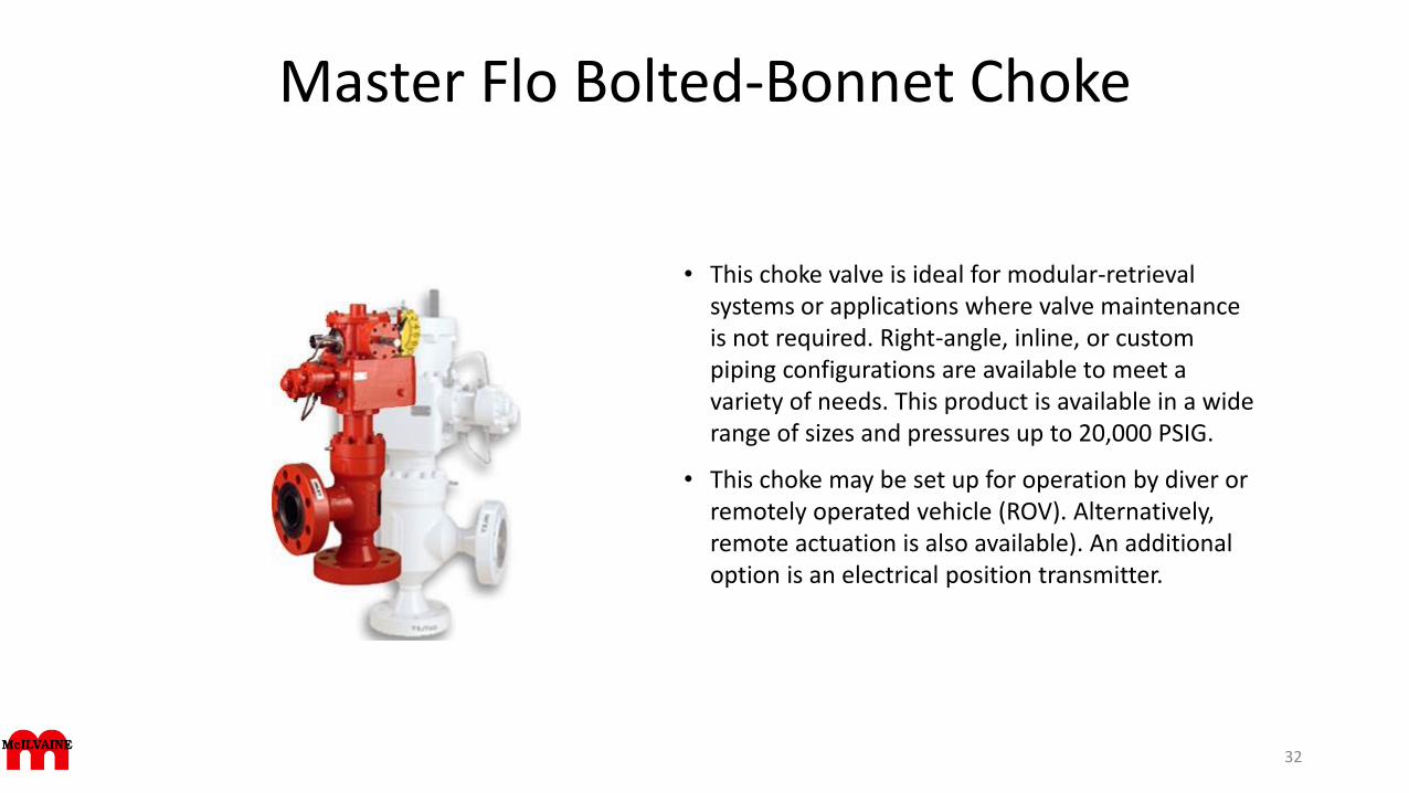
Master Flo Bolted-Bonnet Choke
• This choke valve is ideal for modular-retrieval systems or applications where valve maintenance is not required. Right-angle, inline, or custom piping configurations are available to meet a variety of needs. This product is available in a wide range of sizes and pressures up to 20,000 PSIG.
• This choke may be set up for operation by diver or remotely operated vehicle (ROV). Alternatively, remote actuation is also available). An additional option is an electrical position transmitter.
32
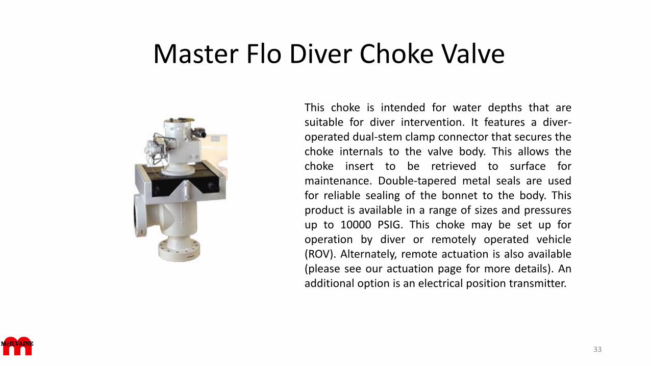
Master Flo Diver Choke Valve
This choke is intended for water depths that aresuitable for diver intervention. It features a diver-operated dual-stem clamp connector that secures thechoke internals to the valve body. This allows thechoke insert to be retrieved to surface formaintenance. Double-tapered metal seals are usedfor reliable sealing of the bonnet to the body. Thisproduct is available in a range of sizes and pressuresup to 10000 PSIG. This choke may be set up foroperation by diver or remotely operated vehicle(ROV). Alternately, remote actuation is also available(please see our actuation page for more details). Anadditional option is an electrical position transmitter.
33
Master Flo Insert-Retrievable Chokes
• HRV chokes are qualified for water depths up to 11,000 feet (3,350 m) and are available for pressures up to 20,000 psig (138,000 kPa). It consists of a right-angle body with an insert module that can be installed or retrieved by a cable-deployed running tool with the assistance of a remotely operated vehicle (ROV). The choke insert module (CIM) includes all of the valve internals, the actuator, and an ROV-operated clamp connector, which secures the insert to the valve body. Metal-to-metal seals are used at all critical sealing areas including a double-tapered metal bonnet seal. This product is available in a number of sizes and pressure/temperature ranges.
• The insert clamp connector (ICC) is available with either horizontal or vertical ROV access in several positions relative to the valve piping. This clamp system is designed so that, should it fail, the connector stem can be cut by an ROV-mounted tool thereby allowing emergency release of the insert module. Because this clamp connector is part of the insert module, it can then be repaired once retrieved to the surface.
34
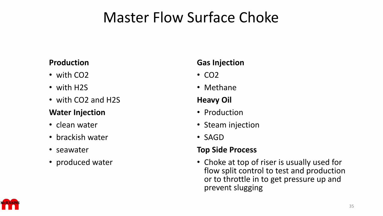
Master Flow Surface Choke
Production
• with CO2
• with H2S
• with CO2 and H2S
Water Injection
• clean water
• brackish water
• seawater
• produced water
Gas Injection
• CO2
• Methane
Heavy Oil
• Production
• Steam injection
• SAGD
Top Side Process
• Choke at top of riser is usually used for flow split control to test and production or to throttle in to get pressure up and prevent slugging
35
Master Flo Valve DesignComments on agreement with these specs?
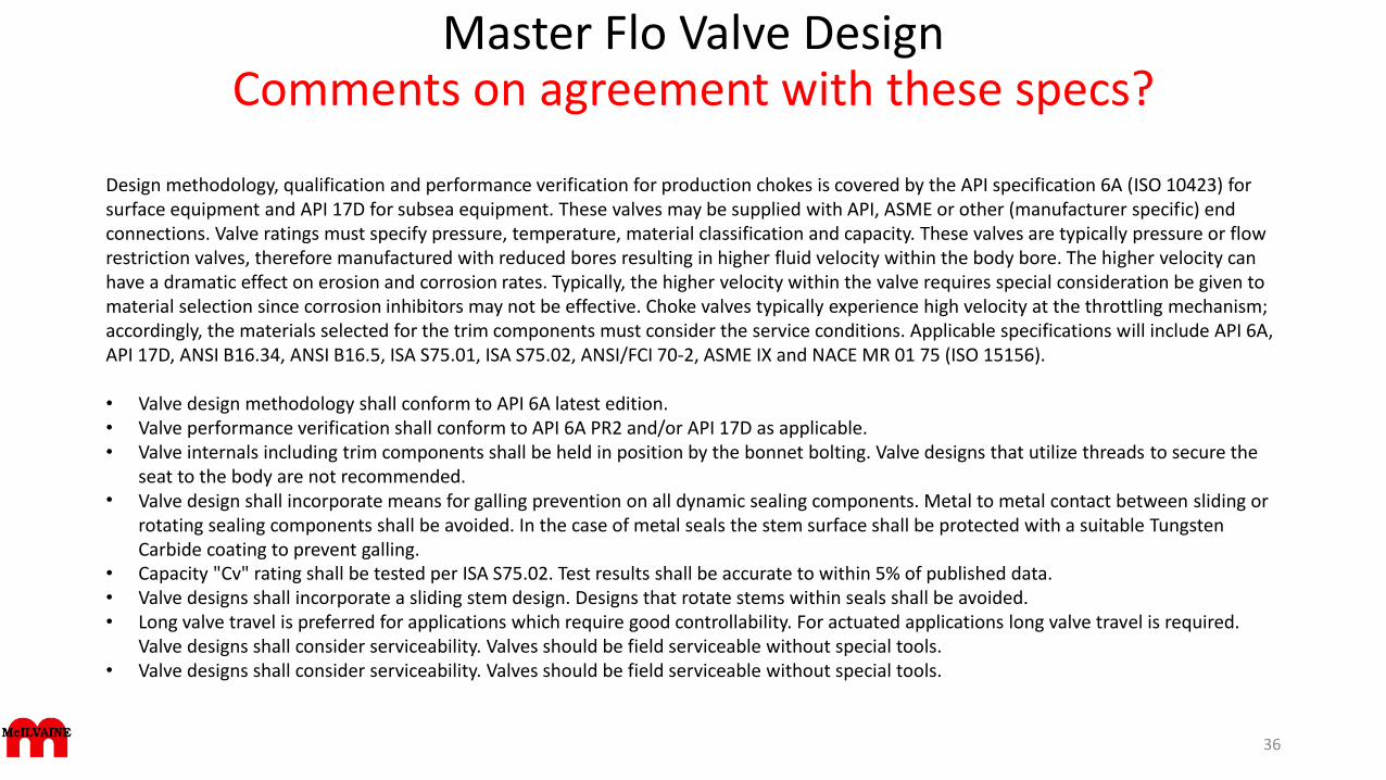
Design methodology, qualification and performance verification for production chokes is covered by the API specification 6A (ISO 10423) for surface equipment and API 17D for subsea equipment. These valves may be supplied with API, ASME or other (manufacturer specific) end connections. Valve ratings must specify pressure, temperature, material classification and capacity. These valves are typically pressure or flow restriction valves, therefore manufactured with reduced bores resulting in higher fluid velocity within the body bore. The higher velocity can have a dramatic effect on erosion and corrosion rates. Typically, the higher velocity within the valve requires special consideration be given to material selection since corrosion inhibitors may not be effective. Choke valves typically experience high velocity at the throttling mechanism; accordingly, the materials selected for the trim components must consider the service conditions. Applicable specifications will include API 6A, API 17D, ANSI B16.34, ANSI B16.5, ISA S75.01, ISA S75.02, ANSI/FCI 70-2, ASME IX and NACE MR 01 75 (ISO 15156).
• Valve design methodology shall conform to API 6A latest edition.• Valve performance verification shall conform to API 6A PR2 and/or API 17D as applicable.• Valve internals including trim components shall be held in position by the bonnet bolting. Valve designs that utilize threads to secure the
seat to the body are not recommended.• Valve design shall incorporate means for galling prevention on all dynamic sealing components. Metal to metal contact between sliding or
rotating sealing components shall be avoided. In the case of metal seals the stem surface shall be protected with a suitable Tungsten Carbide coating to prevent galling.
• Capacity "Cv" rating shall be tested per ISA S75.02. Test results shall be accurate to within 5% of published data.• Valve designs shall incorporate a sliding stem design. Designs that rotate stems within seals shall be avoided.• Long valve travel is preferred for applications which require good controllability. For actuated applications long valve travel is required.
Valve designs shall consider serviceability. Valves should be field serviceable without special tools.• Valve designs shall consider serviceability. Valves should be field serviceable without special tools.
36
Master Flo Body DesignComments on agreement with these specs?
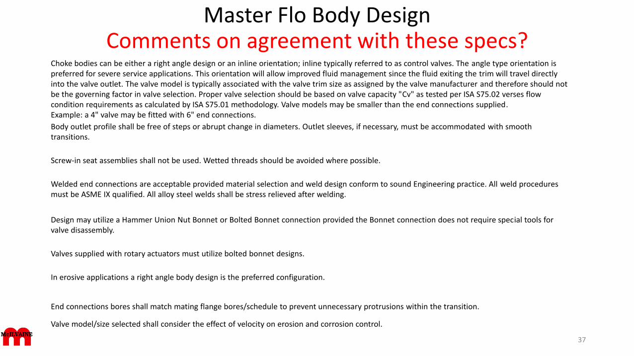
Choke bodies can be either a right angle design or an inline orientation; inline typically referred to as control valves. The angle type orientation is preferred for severe service applications. This orientation will allow improved fluid management since the fluid exiting the trim will travel directly into the valve outlet. The valve model is typically associated with the valve trim size as assigned by the valve manufacturer and therefore should not be the governing factor in valve selection. Proper valve selection should be based on valve capacity "Cv" as tested per ISA S75.02 verses flow condition requirements as calculated by ISA S75.01 methodology. Valve models may be smaller than the end connections supplied.Example: a 4" valve may be fitted with 6" end connections.
Body outlet profile shall be free of steps or abrupt change in diameters. Outlet sleeves, if necessary, must be accommodated with smooth transitions.
Screw-in seat assemblies shall not be used. Wetted threads should be avoided where possible.
Welded end connections are acceptable provided material selection and weld design conform to sound Engineering practice. All weld procedures must be ASME IX qualified. All alloy steel welds shall be stress relieved after welding.
Design may utilize a Hammer Union Nut Bonnet or Bolted Bonnet connection provided the Bonnet connection does not require special tools for valve disassembly.
Valves supplied with rotary actuators must utilize bolted bonnet designs.
In erosive applications a right angle body design is the preferred configuration.
End connections bores shall match mating flange bores/schedule to prevent unnecessary protrusions within the transition.
Valve model/size selected shall consider the effect of velocity on erosion and corrosion control.
37
Master Flo Trim DesignsComments on agreement with these specs?
Trim designs may be classified as needle and seat, disk, or cage designs. Important factors to consider in trim selection are controllability defined as the "turn down ratio"; pressure recovery factor defined as the "FL factor"; valve capacity defined as the "Cv."
Design shall incorporate cage type trim. Trim design can be cage with external sleeve or internal plug design. Erosive or high pressure applications shall utilize an external throttling sleeve. Internal plug designs are not recommended for erosive or high pressure drop applications.
Valve trim should be designed with equal percentage opening characteristics for improved controllability. Quick opening characteristics shall not be supplied for modulating service.
For erosive service the ports should be positioned on the valve axis to reduce turbulence around the cage. For non-erosive service multi-ported cages are acceptable.
The shut-off mechanism is to be segregated and upstream of throttling ports. The seating face shall be metal to metal.
Materials used for erosion protection shall be solid tungsten carbide for erosive conditions and hardened stainless steel for non-erosion applications. Stainless steel carriers are acceptable for the flow sleeve; however the entire turbulent area and high velocity zone shall be protected with hardened trim material. The Cage shall be of solid hardened trim material. Hard facing or overlay shall not be used.
Tungsten Carbide trim materials shall utilize composite binders considering both erosion and corrosion properties. Minimum hardness for the tungsten carbide shall be Ra 93. Binder constitutes shall be Nickel, Chromium and Cobalt at a minimum.
Multi-Stage trim designs shall utilize a throttling mechanism on each stage. Designs which throttle on the initial or final stage only are not acceptable.
Trim design shall consider the potential for plugging and the design shall incorporate suitable means for passing normal sand and proppant that may be present within the fluid media
Designs should consider life cycle costs. Designs which incorporate the trim components into the valve stem should be avoided.
Trim design shall be capable of Class V shutoff as defined by ANSI/FCI 70-238
Master Flo ActuatorsComments on agreement with these specs?
Valve actuation may incorporate a manual operator (hand wheel) or pneumatic, hydraulic or electric actuators. For remote modulating operation the actuator is typically fitted with a positioner that will accept an input signal (either 3-15 psi, 6-30 psi or 4-20mA) to position the valve respective to the input signal. Linear actuators can incorporate fail positions defined as "fail open", "fail closed" or "fail last". This action is typically achieved through a mechanical spring, however in the case of linear hydraulic actuators; this can be accomplished through incorporation of an accumulator.
Typical positional accuracy for linear actuated valves shall be 2% of valve travel for pneumatic applications and 1% for hydraulic applications.
Typical positional accuracy for rotary actuated valves shall be 1% of valve travel.
The number of moving parts external to the valve and actuator shall be minimized. Exposed linkages shall be avoided where possible.
Actuation mounting shall consider service. Adequate provision shall be made for operator safety and environmental protection.
Where linear actuation is utilized the actuator design should be double acting.
Where modulating service is specified, actuators are to be fitted with positioners.
Actuators shall be sized to ensure proper valve operation at shut-off and flowing conditions. In the case of "fail open/close" operation the actuator shall operate the valve to the desired position against worst case conditions.
Electric and rotary actuators shall provide suitable means to "torque seat" to maintain Class V shut-off capabilities.
39
Mokveld Choke valve analysis of problemsDesign considerations to avoid these problems
Corrosion: Corrosion is generally associated with the choice of wrong materials. A common mistake is to use a choke valve specification based on history. It must be remembered that an oil/gas well has a process component make up that is associated with a particular well. One well may produce Carbon Dioxide, while the other doesn't. A standard specification may cause the wrong material to be selected for an application. Corrosion is relatively easily solved, as a choice of suitable materials is widely available. However a comprehensive knowledge of materials is required as combinations of certain materials may lead to galling.Erosion: It is important to understand the difference between single and two phase scenarios.Velocity can cause body erosion, trim erosion and piping erosion. There are different philosophies with respect to what velocities are and not acceptable, however generally selected velocities are too high. For liquid application, a rule of thumb is that the velocity has to be controlled below 5-7 m/s measured in the outlet of the flange, for two phase this is 10-15 m/s and for gas 25 - 40 m/s. It should be noted that these figures do not include for sand production and also do not take the gas/liquid ratio into account for two phase situations. It should also be noted that often choke valves are reduced in size, for example a 4 inch nominal body with 6 inch inlet and/or outlet flanges. If the velocity at the outlet flange is still within the above mentioned rule of thumb it does not automatically indicate that everything will be expected to work out, as the velocity in the so called nominal body goes up and may well exceed what is considered to be acceptable. The choke velocity should be calculated first of all with the same body and flange size before reducing the nom body size. If the velocity is lower than mentioned in the above rule of thumb, one can calculate a smaller nominal body with smaller flange. If still within the given limits a smaller body with larger flanges can be used with reduced risk of erosion.Thus velocity is the most important design criteria, correct design limitation of this in combination with a well-designed trim will limit any erosion.Calculating velocities has to be based on general calculations for gas, liquids and a combination of the two (two phase). A calculation is required to determine the required Cv and this can be achieved by fitting different trims in nominal body sizes. However different pipe diameter selection produces different velocities. Relatively low velocities are not advised, as the result is likely to result in the selection of a too large size choke. High velocities are likely to result in erosion of the body with an associated high maintenance cost.Trim selection is also very important. As an example Mokveld chokes are equipped with a cage provided with holes uniformly distributed over the full circumference. This design ensures that the fluid is symmetrically distributed. The many flow jets are diametrically opposed. Consequently, the energy is dissipated in the centre of the valve. This occurs in the fluid itself and not near the surface of any choke component. Also, preferential flow, the major cause of body erosion, is fully avoided.Cavitation: Cavitation should not be taken lightly as it can not only lead to erosion but it can also cause vibration. The vibration may shatter brittle materials as Tungsten Carbide often used for the trim.Leaking: Leaks on Choke Valves are sometimes caused by the selection of incorrect materials, but may be also attributed to general design of the Choke Valve. Some chokes have a split body design, these vary from a forged block (main body) with weld on or fitted flange connections (adapters) to main body bolted bonnet type. A one piece body casting is one answer to these problems. Also the Choke Valve seals have to fail before leaks occur. Seals utilised on almost all designs are of the ‘O'Ring’ type. As a choke is used under high pressure and pressure drop these O'Rings may be subjected to explosive decompression. This can cause them to split or deform. Should this happen the sealing property is lost. Explosive decompression often occurs when Viton is used. This happens to be one of the most suitable resilient materials for hydrocarbon service. Hence careful consideration of seal materials is required if Viton is selected as it is subject to explosive decompression. Furthermore the service of the O'Rings has to be considered as this can differ from static to dynamic applications. Most problems with O'Rings occur in dynamic applications.
40
N- Line Chokes
• N-Line Valves provides engineered flow control solutions for upstream oil and gas production.
• Control Chokes and Valves are available in a full range of materials and configurations size 2" to 16" and pressure classes ASME 600 to 2500, API 2,000 to 20,000.
41
N-Line Plug and Cage Trim
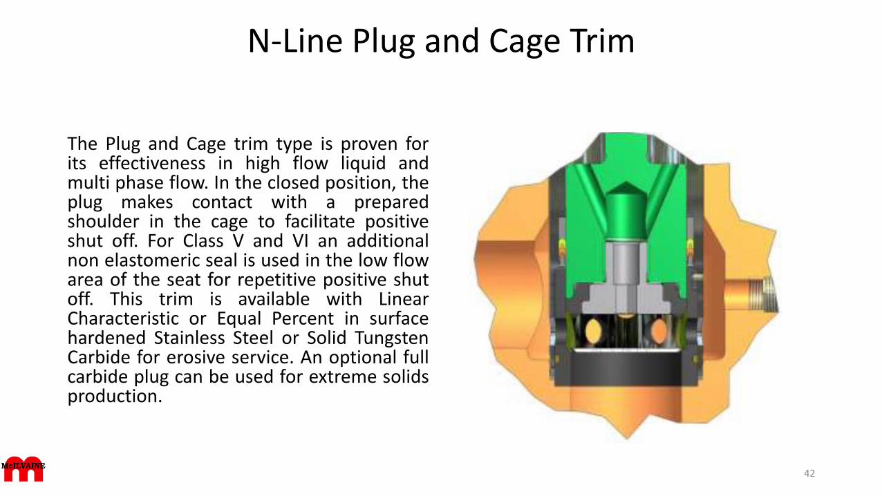
The Plug and Cage trim type is proven forits effectiveness in high flow liquid andmulti phase flow. In the closed position, theplug makes contact with a preparedshoulder in the cage to facilitate positiveshut off. For Class V and VI an additionalnon elastomeric seal is used in the low flowarea of the seat for repetitive positive shutoff. This trim is available with LinearCharacteristic or Equal Percent in surfacehardened Stainless Steel or Solid TungstenCarbide for erosive service. An optional fullcarbide plug can be used for extreme solidsproduction.
42
N-Line High Flow Plug and Cage Trim
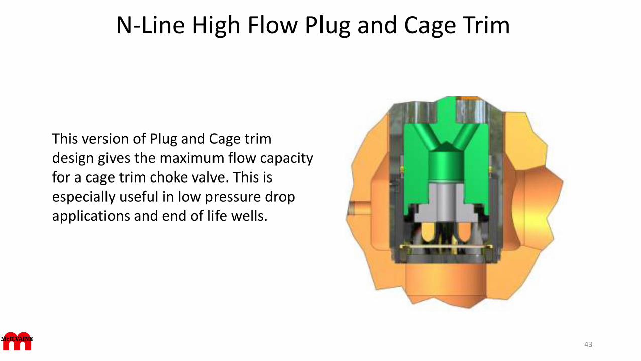
This version of Plug and Cage trim design gives the maximum flow capacity for a cage trim choke valve. This is especially useful in low pressure drop applications and end of life wells.
43
N-Line External Sleeve Trim
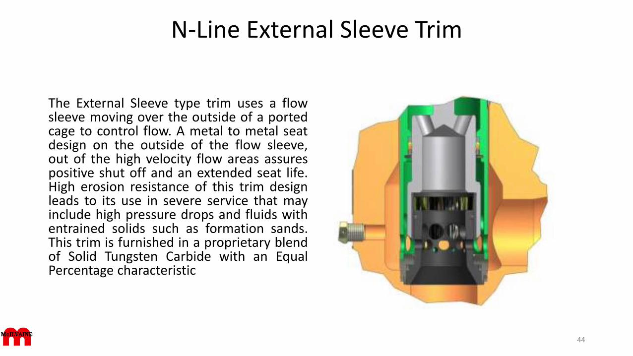
The External Sleeve type trim uses a flowsleeve moving over the outside of a portedcage to control flow. A metal to metal seatdesign on the outside of the flow sleeve,out of the high velocity flow areas assurespositive shut off and an extended seat life.High erosion resistance of this trim designleads to its use in severe service that mayinclude high pressure drops and fluids withentrained solids such as formation sands.This trim is furnished in a proprietary blendof Solid Tungsten Carbide with an EqualPercentage characteristic
44
N–Trim Single Path-Multi Stage Trim
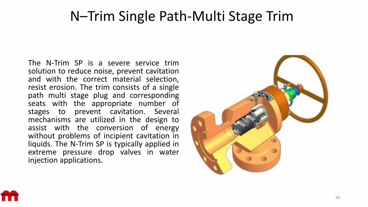
The N-Trim SP is a severe service trimsolution to reduce noise, prevent cavitationand with the correct material selection,resist erosion. The trim consists of a singlepath multi stage plug and correspondingseats with the appropriate number ofstages to prevent cavitation. Severalmechanisms are utilized in the design toassist with the conversion of energywithout problems of incipient cavitation inliquids. The N-Trim SP is typically applied inextreme pressure drop valves in waterinjection applications.
45
N–Trim Multi Path-Multi Stage Trim
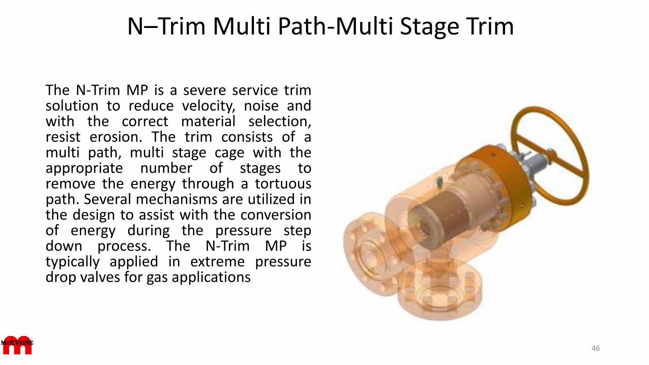
The N-Trim MP is a severe service trimsolution to reduce velocity, noise andwith the correct material selection,resist erosion. The trim consists of amulti path, multi stage cage with theappropriate number of stages toremove the energy through a tortuouspath. Several mechanisms are utilized inthe design to assist with the conversionof energy during the pressure stepdown process. The N-Trim MP istypically applied in extreme pressuredrop valves for gas applications
46
Type HTS Sleeve and Cage
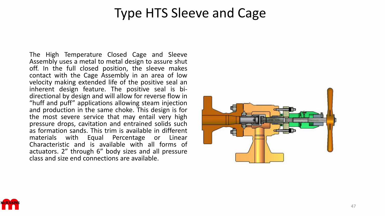
The High Temperature Closed Cage and SleeveAssembly uses a metal to metal design to assure shutoff. In the full closed position, the sleeve makescontact with the Cage Assembly in an area of lowvelocity making extended life of the positive seal aninherent design feature. The positive seal is bi-directional by design and will allow for reverse flow in“huff and puff” applications allowing steam injectionand production in the same choke. This design is forthe most severe service that may entail very highpressure drops, cavitation and entrained solids suchas formation sands. This trim is available in differentmaterials with Equal Percentage or LinearCharacteristic and is available with all forms ofactuators. 2” through 6” body sizes and all pressureclass and size end connections are available.
47
N–Line actuator
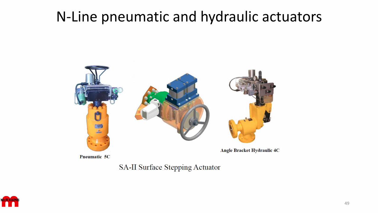
The N-Line Valves SA-II Stepping Actuator is a pneumatically or hydraulically powered rotary indexing outputactuator.
The actuator consists of two power cylinder and pawl assemblies, from which the drive wheel and output shaftare driven. One operating cycle consists first of pressurizing one cylinder thereby extending the pawl to engagethe drive wheel and thus incrementally rotate the output shaft in the appropriate direction, the cylinder is thendepressurized retracting the pawl to its rest position. This single operating cycle rotates the output shaft of theactuator and correspondingly the valve stem by 30°. This operating cycle is repeated until the valve reaches thedesired position.
To drive the actuator and the valve in the opposite direction, an operating cycle is repeated using the othercylinder. When the cylinders are depressurized, the pawls are disengaged from the drive wheel, allowing thedrive wheel to be rotated manually through the manual override on the outside of the actuator to position thevalve. A spring detent prevents position drift from vibration. Local visual position indication is via a stainlesssteel micrometer for unequaled accuracy and reliability.
A housing containing limit switches, a position transmitter and terminal strip is mounted externally on the yokefor direct valve stem position feedback via 4-20mA signal including HART or digital protocols. All recognizedstandards for electrical apparatus are available.
48
N-Line pneumatic and hydraulic actuators
49
Pentair choke valve Model CHV-Angle (Vonk)
• Providing superior performance in abrasive environments, precise flow control and ease of maintenance, delivering operational reliability in the most challenging applications.
• Extended service life, delivered by a robust but simple rotating disc and bean design.
• Low life cycle costs resulting from improved resistance to erosive production fluids.
• Ease of maintenance and inspection, facilitated by removal of limited internals while valve remains in service.
• Operational confidence and safety, guaranteed by 100% shut-off to Class V ANSI FCI-70.
• Operational reliability with the capability of handling high pressure drops and delivering fixed Cv values.
• Controlled environmental impact governed by reduced effects of noise and vibration.
• Improved pressure recovery performance factor delivered by the unique bean and disk design.
• Vonk chokes comply with the most stringent requirements of the European Directives and harmonized standards including Pressure Equipment Directive (97/23/EC PED) and ATEX 94/9/EC for potentially explosive atmosphere
50
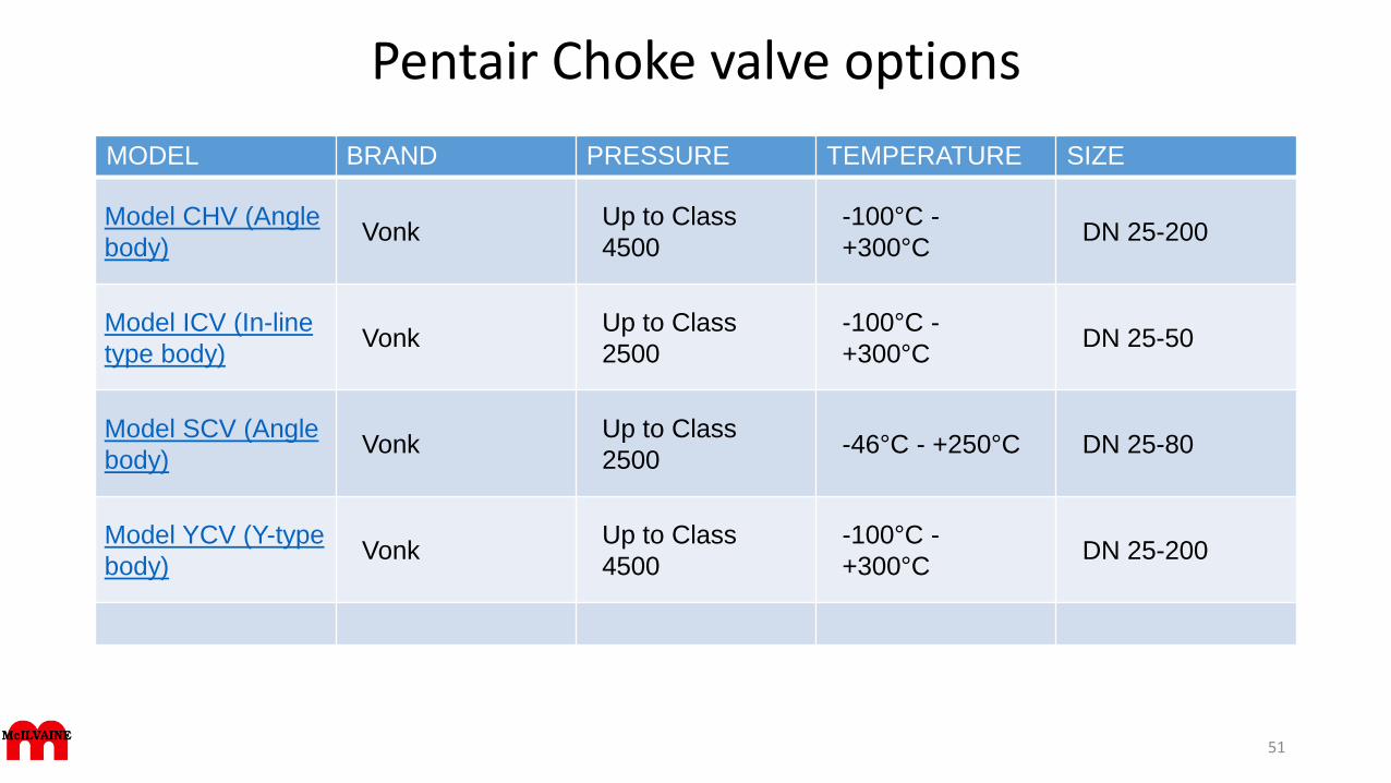
Pentair Choke valve options
MODEL BRAND PRESSURE TEMPERATURE SIZE
Model CHV (Angle
body)Vonk
Up to Class
4500
-100°C -
+300°CDN 25-200
Model ICV (In-line
type body)Vonk
Up to Class
2500
-100°C -
+300°CDN 25-50
Model SCV (Angle
body)Vonk
Up to Class
2500-46°C - +250°C DN 25-80
Model YCV (Y-type
body)Vonk
Up to Class
4500
-100°C -
+300°CDN 25-200
51
Analysis by Pentair India
• Oil & Gas Choke valves or Control valves are extensively used in the petrochemical and process industries for the regulation of fluid flow. They experience a wide range of operating environments. Some of these operating conditions are extremely aggressive being not only corrosive but also erosive due to entrainment of sand in to the production flow. These are referred to as severe service conditions in oil & gas industries.
• Sand production is a known problem in the oil & gas industry. This produced sand carries through chokes (Control Valves) present in wellheads. Chokes are typically suffering for this in form of erosive damage. The erosive damage is decided by many differentfactors where the flow rate velocity of the fluid, sand rate, thermodynamic properties of the service conditions, fluid flow pattern, flow directions & materials are important ones.
• Dedicated effort is required to counter the control valve erosion to be able to maintain oil & gas production at an optimal level with attention to avoid unscheduled maintenance, safety and availability of other equipments also. Use of Computational Fluid Dynamics (CFD) has been essential in this work by simulating fluid flow through the control valves for optimizing the design,choosing the optimal erosion resistant material, coming up with improved erosion-related models and better mechanisedoperational procedures of the control valves.
• From the present simulation analysis of erosion wear the importance of pressure drop, flow velocity and flow pattern is analysed. Erosion rate is analysed for a 51mm bore (2, 1/16” – 5000 psi) choke valve as up to 0.24 mm per year for a 50% valve opening.
52
Pentair Choke presentation
The production part of oil & gas extraction platform involves topside & subsea manifolds arrangement. These manifolds is an assembly of equipment including tubing head adapters, valves, tees, crosses, top connectors and chokes attached to the uppermost connection of the tubing head used to control well production in oil & gas industries. They are rated for working pressures of 14 Mpa (2000 psi) to 103 Mpa (15,000 psi). Choke is the only device used to limit the production of flowing fluids. Chokes hold a back pressure on a flowing well to make better use of compressible fluid such as natural gas lift and control the bottomhole pressure for recovery reasons. In vertical pipe flow, gas expands rapidly with decreasing hydrostatic head and the fluid moves in slugs through the tubing. Solids in the produced fluids (Natural gas) are the major source of failures of chokes. Abrasion from sand, scale, ice, corrosion particles and other solids can cut through choke restriction and cause the well to load up with fluids and solids.
Pentair conclusions
Erosion in choke valves operating either in top side or subsea field subjected to sandy severe service conditions are considered as problems in oil & gas industries.
1. Critical location of the choke valve is trim components subjected to higher pressure drop also experiences higher flow velocity causes erosion in choke valves.
2. Particulate erosion in mainly due to jet impingement of sand particles inside the trim components of choke. Higher velocity causes the jet impingement.
3. Sand erosion rate is higher with increased pressure drop in low percentage valve openings.
4. Fluid flow pattern and sand particle sizes, hardness also influences in erosion rate for choke valves.
53
Samson / Ringo Valvulas SL
• Choke valves have been developed to cope with high pressure drop applications on liquid, gas or multiphase fluids for oil and gas wells; used in production, gaslift-topside and water injection applications. Special designs include low noise or anti-cavitation features. Materials are selected to withstand erosion. Interchangeable beans allow the use of the same valve at different conditions.
• Applications include refineries, chemical and petrochemical industry, oil and gas upstream, midstream and downstream, offshore, water treatment and energy generation plants (nuclear, fossil, combined cycle and thermosolar).
• ISO 9001-2008 by Lloyds register, CE stamp also by Lloyd´s Register, TÜV, API 6D, API 6A, API 6DSS and ASME III N and NPT stamps environmental protection and health and safety responsibilities being certified according to ISO 14001 and OHSAS 18001.
54
Subsea Chokes International (SCI)
• Retrievable Subsea Chokes• Fully Operational in the Most Challenging of Deepwater, High Pressure Offshore
Environments• Significantly greater resistance to erosion than current choke solutions.• Operational with pressures at the wellhead of up to 20,000 PSI• Flexibility regarding sizing – Cvs from 100 to over 1000• A new simplified actuation technology.• Real-time information during production
• Product Specs General specifications:• Pressure rating: 20,000 PSI / 1,380 Bar• Temperature rating: -60F – 350F / -50C – 180C• CV range: 40 – 1000• Line size: 4" – 10"• Complies to all relevant ISO and IPO standards• Standard ROV interfaces• Fully redundant instrumentation• Pressure / temperature• Erosion measurements of critical areas• General condition monitoring• Positional indication with high accuracy
55