Embed Size (px)
Citation preview
CHOOSING TWO TECHNOLOGIES THAT BEST SUITE FOR MAKING VOTER
ID CARD
A Thesis
Submitted to the Department of Computer Science and Engineering
Of
BRAC University
By
AFZAL AFTAB
Student ID: 05310045
MD. TAREQ ABDULLAH
Student ID: 05310046
In Partial Fulfillment of the
Requirements for the Degree
Of
Bachelor of Science in Electronics and Communication Engineering
May 2008

1
DECLARATION
We hereby declare that this thesis is based on the results found by our self. Materials of work found by other researcher are mentioned by reference. This thesis, neither in whole nor in part, has been previously submitted for any degree. Signature of Signature of Supervisor Author
2
ACKNOWLEDGMENTS
The successful completion of this report has seen many helping hands, without
which this would have not been possible. However, the space involved does not
allow us to mention everybody individually. We would like to express our special
thanks and sincere gratitude to Dr. Tarik A Chowdhury. We deeply appreciate his
enthusiasm and guidance in preparing this report. While doing this report we
really enjoyed the work and also identified a lot about the technologies that we
are going to apply. We would like to thank him on behalf of the excellent
guidance through valuable advice and support as well. We would like to thank
BRAC authority for their library and Internet facilities from where we got
enormous information.
3
ABSTRACT Voting is an important national issue for every country and the whole voting
process should be flawless and secured. To ensure free and fair election,
Bangladesh needs a voting system where people can vote without any influence
and faultlessness. Existing manual voting system has limitation and gives room
for the politicians to influence voters and the people to vote in their favor and
thereby it makes the voting system unfair. Such a situation can be overcome
through some automated system like electronic Voter ID card making. In this
thesis we have chosen two technologies that best suit for making a secured
Voter ID card which ultimately contributes to a proper voting system. The first
technology is RFID and the second one is BIOMETRICS. This thesis provides a
brief idea of how these technologies work, what are the core features of them
and how they are going to be applied for making Voter ID card. We have done
simulations for both RFID and Biometrics. It seems simulation results are
influential in applying these sophisticated technologies in practical field.
4
TABLE OF CONTENTS Page TITLE……………...........................................................................................… DECLARATION….........................................................................................…1 ACKNOWLEDGEMENTS................................................................................2 ABSTRACT………...........................................................................................3 TABLE OF CONTENTS...........................................................................…....4 LIST OF TABLES...........................................................................................6 LIST OF FIGURES........................................................................................7 CHAPTER I. INTRODUCTION……………………………………………..……8 CHAPTER II. RFID TECHNOLOGY 2.1 Background....................................................................................9 2.2 RFID System Overview..................................................................9 2.3 RFID Tags. ................................................................................... 10 2.4 Types of RFID Cards and Standards………………………………...13 2.5 RF Communication…………………………………………………..…14 2.6 RFID Application………………………………………………………..15 2.7 Negative Aspects of RFID…………………………………………….17 CHAPTER III. BIOMETRICS TECHNOLOGY 3.1 Introduction.................................................................................18 3.2 Types of Biometrics....................................................................18 3.3 How Biometrics Recognition System Works..................................19 3.4 The Characteristics that we have Chosen...................................20 3.5 Privacy and Security....................................................................20
5
CHAPTER IV. SIMULATION 4.1 RFID Simulation Modeling……………………………...................21 4.2 Biometrics Simulation (Face Detection)......................................24 CHAPTER V. CONCLUSION…………………………………………………..29 References...............................................................................................30
6
LIST OF TABLES Table Page 1. RFID Standards....................................................................................6 2. Types of RFID Cards............................................................................7 . 3. Different Types of Attacks andCountermeasures.........................…….10
7
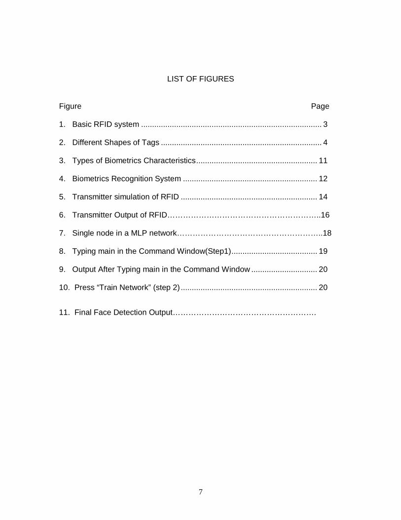
LIST OF FIGURES Figure Page 1. Basic RFID system .................................................................................. 3 2. Different Shapes of Tags ......................................................................... 4 3. Types of Biometrics Characteristics....................................................... 11 4. Biometrics Recognition System ............................................................. 12 5. Transmitter simulation of RFID .............................................................. 14 6. Transmitter Output of RFID…………………………………………………..16 7. Single node in a MLP network………………………………………………..18 8. Typing main in the Command Window(Step1)....................................... 19 9. Output After Typing main in the Command Window .............................. 20 10. Press “Train Network” (step 2) .............................................................. 20
11. Final Face Detection Output……………………………………………….
8
CHAPTER I
INTRODUCTION
Radio Frequency Identification is a means of capturing data about an
object without using a human to read the data. [1] RFID uses short range radio
technologies to communicate mainly digital information associated with items
through the use of tags attached to the item. [2] In information technology,
biometrics refers to technologies that measure and analyze human body
characteristics, such as fingerprints, eye retinas and irises, voice patterns, facial
patterns and hand measurements, for authentication purposes.[14] In this thesis
our objective is to make Voter ID card with the help of RFID and Biometrics.
Voter ID card involves the issue of security and reliability. Both of these
technologies ensure this kind of security and reliability up to an acceptable level.
This is why we are using RFID and Biometrics technology in making Voter ID
card.
Chapters Two and Three will discuss RFID and BIOMETRICS
respectively. These chapters will discuss the history of the technologies, the
different versions of each technology and common uses of each one in today’s
society. We will explain security and privacy issues surrounding present day
usage of these technologies and the measures that have been taken to
safeguard civil liberties and constitutional freedoms.
Chapter four will discuss about simulation of both RFID and
BIOMETRICS. It will have a brief description of all the individual parts of the
simulation.
Chapter Five, the final chapter, will draw conclusions on the possible
implications these technologies will have upon people. It will also include future
implementation part that has to be made for better service and security.
9
CHAPTER II
RFID TECHNOLOGY 2.1 Background
“RFID (Radio Frequency Identification) was used first in 1940s. This
technology suffered a very slow start and it is only since 1997 that we have seen
the massive growth in the industry as technology caught up with the desires and
the possibility of low cost tags was realized. Now we have the capability to make
tags at a reasonable cost and the opportunities are beginning to really show
themselves. According to a statistics, there are 338 companies that have
identified themselves as being involved in RFID around the world. But a few
years ago, we could count the suppliers on our fingers, this is a massive
increase.”[1]
“Although RFID technologies have been in existence since the
1940’s for weapon identification and are already widely used in several areas
such as automated toll payments, proximity cards, or theft detection tags. The
improving cost structure and decreased chip size have only recently made it
accessible and practical for wide-ranging tracking applications widely across the
economy, especially in the industrial, transport, security and consumer goods
and service sectors.” [2]
2.2 RFID System Overview RFID stands for Radio Frequency IDentification, a technology that uses tiny computer chips smaller than a grain of sand to track items at a distance.[15] There are many different types of RFID systems that vary in their
10
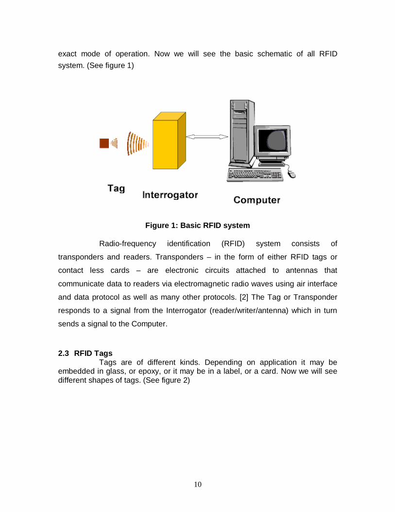
exact mode of operation. Now we will see the basic schematic of all RFID system. (See figure 1)
Figure 1: Basic RFID system
Radio-frequency identification (RFID) system consists of
transponders and readers. Transponders – in the form of either RFID tags or
contact less cards – are electronic circuits attached to antennas that
communicate data to readers via electromagnetic radio waves using air interface
and data protocol as well as many other protocols. [2] The Tag or Transponder
responds to a signal from the Interrogator (reader/writer/antenna) which in turn
sends a signal to the Computer.
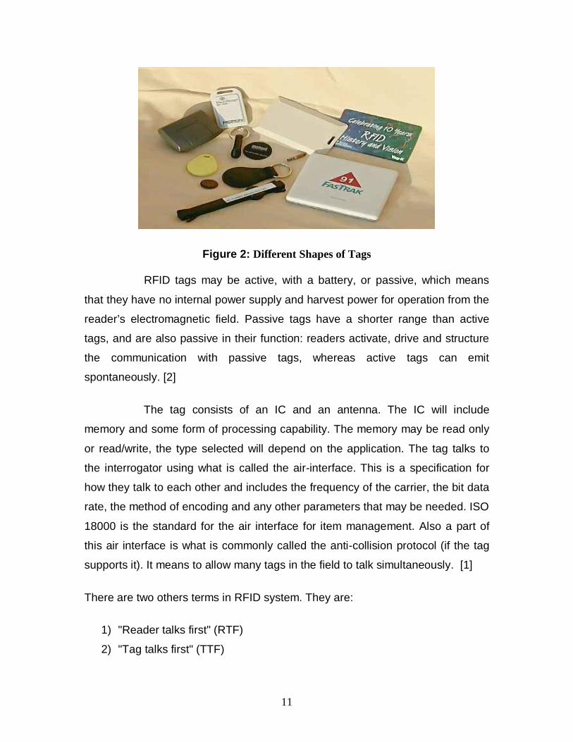
2.3 RFID Tags Tags are of different kinds. Depending on application it may be embedded in glass, or epoxy, or it may be in a label, or a card. Now we will see different shapes of tags. (See figure 2)
11
Figure 2: Different Shapes of Tags
RFID tags may be active, with a battery, or passive, which means
that they have no internal power supply and harvest power for operation from the
reader’s electromagnetic field. Passive tags have a shorter range than active
tags, and are also passive in their function: readers activate, drive and structure
the communication with passive tags, whereas active tags can emit
spontaneously. [2]
The tag consists of an IC and an antenna. The IC will include
memory and some form of processing capability. The memory may be read only
or read/write, the type selected will depend on the application. The tag talks to
the interrogator using what is called the air-interface. This is a specification for
how they talk to each other and includes the frequency of the carrier, the bit data
rate, the method of encoding and any other parameters that may be needed. ISO
18000 is the standard for the air interface for item management. Also a part of
this air interface is what is commonly called the anti-collision protocol (if the tag
supports it). It means to allow many tags in the field to talk simultaneously. [1]
There are two others terms in RFID system. They are:
1) "Reader talks first" (RTF)
2) "Tag talks first" (TTF)
12
In RTF system, the tag just sits there, until it hears a request from the
interrogator. This means that even though a tag may be illuminated (receiving
power) from the interrogator, it does not talk until it is asked a question. [1]
On the other hand, in TTF the tag talks as soon as it gets power, or
in the case of a battery assisted tag or active tag, it talks for short periods of time,
all the time. This gives us a much faster indication of a tag within sight of the
interrogator, but it also means that the airwaves have constant traffic.
The antenna in a tag is the physical interface for the RF to be
received and transmitted. Its construction varies depending on the tag itself and
the frequency it operates on. Low frequency tags often use coils of wire, whereas
high frequency tags are usually printed with conducting inks. [1]
RFID operates in several frequency bands. The exact frequency is
controlled by the Radio Regulatory body in each country. The generic
frequencies for RFID are: 125 - 134 kHz, 13.56 MHz, UHF (400 – 930 MHz), 2.45
GHz and 5.8 GHz. Although there are other frequencies used, these are the main
ones. [1]
Each of the frequency bands has advantages and disadvantages for
operation. The lower frequencies 125-134 kHz and 13.56 MHz work much better
near water or humans than do the higher frequency tags. Comparing passive
tags, the lower frequencies usually have less range, and they have a slower data
transfer rate. The higher frequency ranges have more regulatory controls and
differences from country to country. [1]
13
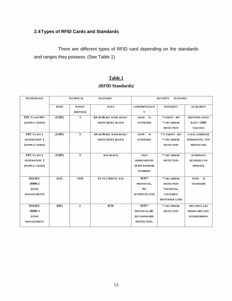
2.4 Types of RFID Cards and Standards
There are different types of RFID card depending on the standards
and ranges they possess. (See Table 1)
Table 1
(RFID Standards)
TECHNICAL FEATURES SECURITY FEATURES TECHNOLOGY
BAND RANGE
(METERS)
DATA CONFIDENTIALIT
Y
INTEGRITY AVAILIBITY
EPC CLASS 0/0+
(SUPPLY CHAIN)
(UHF) 3 64 OR 96 BIT WITH READ /
WRITE (R/W) BLOCK
NONE IS
STANDARD
* PARITY BIT
* CRC ERROR
DETECTION
IDENTIFICATION
RATE >1000
TAGS/SEC
EPC CLASS 1
GENERATION 1
(SUPPLY CHAIN)
(UHF) 3 64 OR 96 BIT WITH READ /
WRITE (R/W) BLOCK
NONE IS
STANDARD
* 5 PARITY BIT
* CRC ERROR
DETECTION
LOCK COMMAND
PERMANENT, NOT
PROTECTED
EPC CLASS 1
GENERATION 2
(SUPPLY CHAIN)
(UHF) 3 R/W BLOCK TAGS
ADDRESSED BY
16 BIT RANDOM
NUMBERS
* CRC ERROR
DETECTION
NUMEROUS
READERS CAN
OPERATE
ISO/IEC
18000-2
(ITEM
MANAGEMENT)
(LF) <0.01 UP TO 1 KBYTE R/W “RTF”
PROTOCOL,
NO
AUTHENTICATIO
* CRC ERROR
DETECTION
*OPTIONAL,
LOCKABLE
IDENTIFIER CODE
NONE IS
STANDARD
ISO/IEC
18000-3
(ITEM
MANAGEMENT
(HF) 2 R/W “RTF”
PROTOCOL,48-
BIT PASSWORD
PROTECTION,
* CRC ERROR
DETECTION
MULTIPLE TAG
MODES ARE NON-
INTERFERRING
14
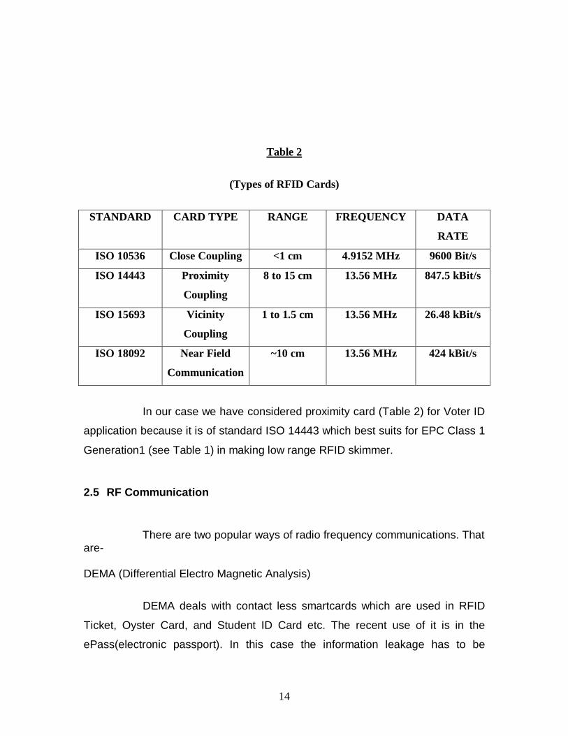
Table 2
(Types of RFID Cards)
STANDARD CARD TYPE RANGE FREQUENCY DATA
RATE
ISO 10536 Close Coupling <1 cm 4.9152 MHz 9600 Bit/s
ISO 14443 Proximity
Coupling
8 to 15 cm 13.56 MHz 847.5 kBit/s
ISO 15693 Vicinity
Coupling
1 to 1.5 cm 13.56 MHz 26.48 kBit/s
ISO 18092 Near Field
Communication
~10 cm 13.56 MHz 424 kBit/s
In our case we have considered proximity card (Table 2) for Voter ID
application because it is of standard ISO 14443 which best suits for EPC Class 1
Generation1 (see Table 1) in making low range RFID skimmer.
2.5 RF Communication
There are two popular ways of radio frequency communications. That are-
DEMA (Differential Electro Magnetic Analysis)
DEMA deals with contact less smartcards which are used in RFID
Ticket, Oyster Card, and Student ID Card etc. The recent use of it is in the
ePass(electronic passport). In this case the information leakage has to be
15
monitored by means of near-field probes that detect the electromagnetic
emanation of the chip.
Remote Power Analysis
This is useful in inventory control system or secures documents.
Here the technique is to use two capacitors embedded in the RFID tags in such a
way that at any given time one of them is storing energy that is being generated
by the charge pump of the tag that sucks energy from the electromagnetic or
magnetic field of a tag reader, and the other one is discharging and powering the
computational element of the tag chip. The roles of the two capacitors alternate
rapidly, and thus, the power consumption of the computational element is
detached from the energy generation element of the tag, in the sense that
external power measurements do not reveal information about the tags internal
operations.
2.6 RFID Application Access Control
Texas Instruments RFID line of 13.56 MHz readers provides a new
level of performance, speed and accuracy for the RFID access control market.
[13]
Document Verification
The invention comprises a method for personal document verification
to confirm whether a document is genuine and/or the holder is the person to
whom the document was issued. [9]
Asset Management System
The system can track items such as confidential documents, laptops,
containers of hazardous material, and valuables which are tagged with a TI-RFid
13.56 MHz smart label. This application also includes public organizations,
16
government departments, and universities that must comply with audit
requirements. Private companies and military users can use the system to track
high-value electronic equipment. [10]
Supply Chain
Different manufacturing companies use RFID technology in supply
chain management.
The EPC Global Network
The Electronic Product code (EPC) has been called the "next
generation barcode" but it is much more than that. It is an unique number that
identifies a specific item in the supply chain. The EPC is stored on a radio
frequency identification (RFID) tag, which combines a silicon chip and an
antenna. The EPC global Network is a set of technologies that enable immediate,
automatic identification and sharing of information on items in the supply chain.
In that way, the EPC global Network will make organizations more effective by
enabling true visibility of information about items in the supply chain. [11]
Near Field Communication (NFC)
NFC is for very short range two-way wireless connectivity, and is a
short-range radio frequency (RF) technology that allows a reader to read small
amounts of data from other devices or tags when brought next to each other. It is
based on contactless and Radio Frequency Identification (RFID) solutions, which
consist of a tag and a reader. The reader, when activated, emits a short-range
radio signal that powers up a microchip on the tag, and allows for reading a small
amount of data that can be stored on the tag.[12]
17
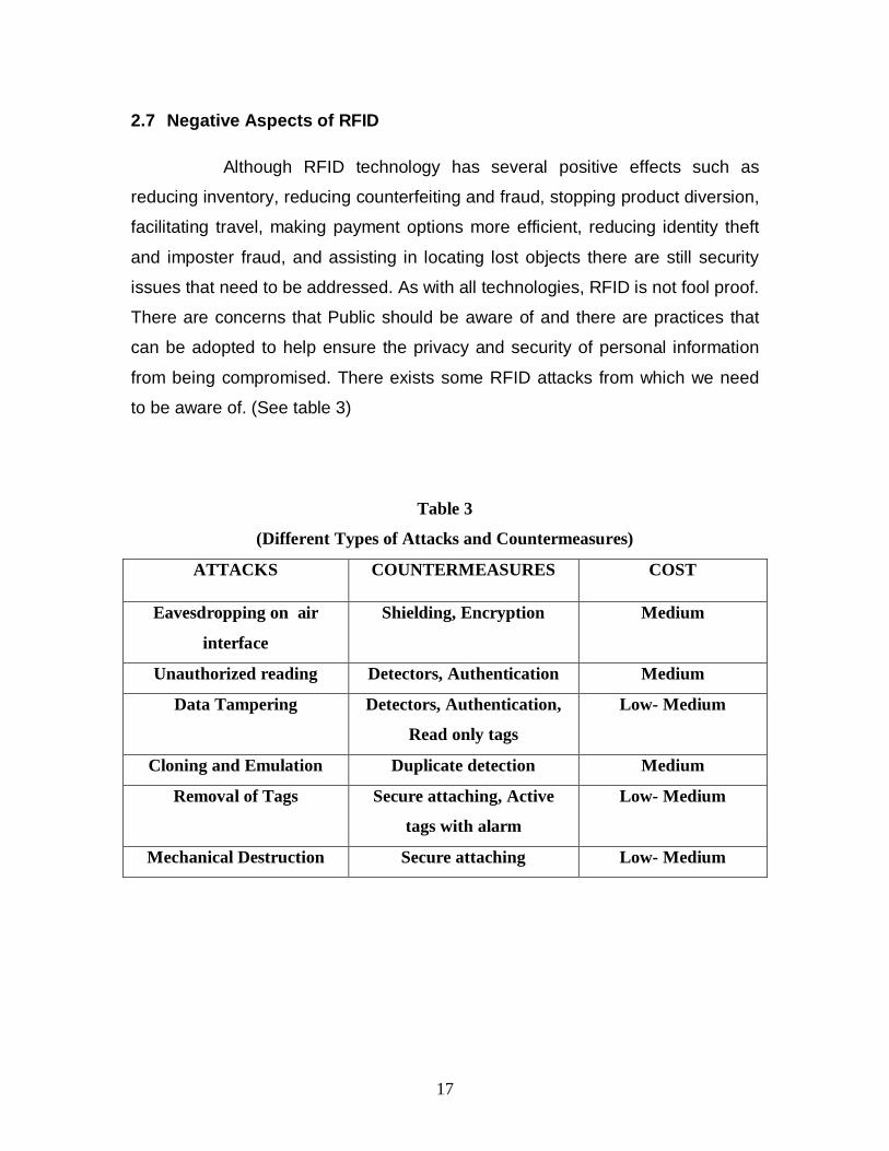
2.7 Negative Aspects of RFID Although RFID technology has several positive effects such as
reducing inventory, reducing counterfeiting and fraud, stopping product diversion,
facilitating travel, making payment options more efficient, reducing identity theft
and imposter fraud, and assisting in locating lost objects there are still security
issues that need to be addressed. As with all technologies, RFID is not fool proof.
There are concerns that Public should be aware of and there are practices that
can be adopted to help ensure the privacy and security of personal information
from being compromised. There exists some RFID attacks from which we need
to be aware of. (See table 3)
Table 3
(Different Types of Attacks and Countermeasures)
ATTACKS COUNTERMEASURES COST
Eavesdropping on air
interface
Shielding, Encryption Medium
Unauthorized reading Detectors, Authentication Medium
Data Tampering Detectors, Authentication,
Read only tags
Low- Medium
Cloning and Emulation Duplicate detection Medium
Removal of Tags Secure attaching, Active
tags with alarm
Low- Medium
Mechanical Destruction Secure attaching Low- Medium
18
CHAPTER III
BIOMETRICS TECHNOLOGY 3.1 Introduction Biometric technologies have existed for centuries. They consist of
both identifying an individual and verifying that person’s identity. Biometrics is the
study of methods for uniquely recognizing human, based upon one or more
intrinsic physical or behavioral traits.
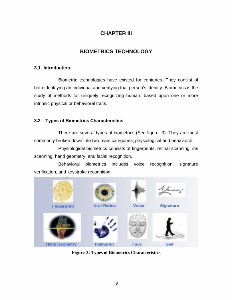
3.2 Types of Biometrics Characteristics There are several types of biometrics (See figure- 3). They are most
commonly broken down into two main categories; physiological and behavioral.
Physiological biometrics consists of fingerprints, retinal scanning, iris
scanning, hand geometry, and facial recognition.
Behavioral biometrics includes voice recognition, signature
verification, and keystroke recognition.
Figure-3: Types of Biometrics Characteristics
19
Each individual characteristic is significantly different from the other
in the effectiveness of determining a person’s identity on a one to many or a one
to one scale. Governments rely heavily on physiological biometrics to verify an
individual on a one to many scale. This is important to keep in mind when
determining the best biometric to use in conjunction with a national id card;
however, it is also important to note the security and privacy issues surrounding
the use of this technology.
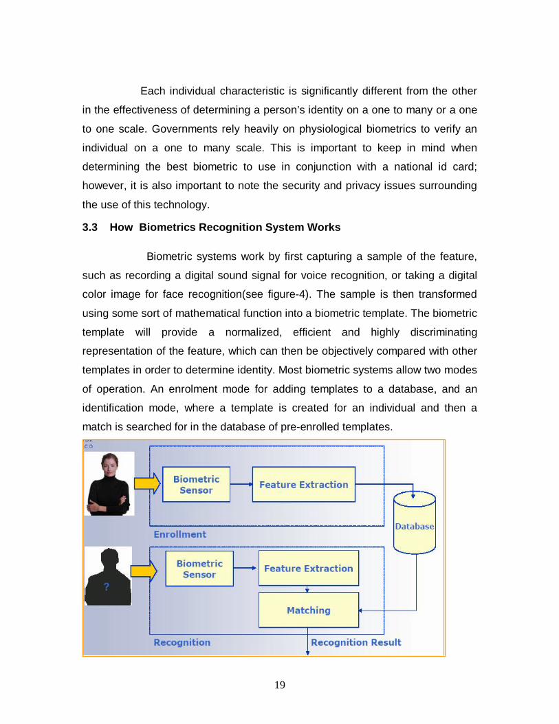
3.3 How Biometrics Recognition System Works Biometric systems work by first capturing a sample of the feature,
such as recording a digital sound signal for voice recognition, or taking a digital
color image for face recognition(see figure-4). The sample is then transformed
using some sort of mathematical function into a biometric template. The biometric
template will provide a normalized, efficient and highly discriminating
representation of the feature, which can then be objectively compared with other
templates in order to determine identity. Most biometric systems allow two modes
of operation. An enrolment mode for adding templates to a database, and an
identification mode, where a template is created for an individual and then a
match is searched for in the database of pre-enrolled templates.
20
Figure-4: Biometrics Recognition System
A good biometric is characterized by use of a feature that is; highly
unique – so that the chance of any two people having the same characteristic will
be minimal, stable – so that the feature does not change over time, and be easily
captured – in order to provide convenience to the user, and prevent
misrepresentation of the feature.
3.4 The Characteristics That We have Chosen We have chosen facial recognition as our biometrics characteristics.
Facial recognition is the most favored of all biometric identifiers because it is the
least intrusive, the easiest to capture, and is still considered a reliable biometric.
Individuals rely on face recognition everyday; a person buying alcohol shows
picture identification such as a driver’s license to prove that s/he is in fact the
person on the id that is over twenty-one. A traveler will provide a passport or visa
with a photo to prove his/her nationality and ability to cross borders. Surveillance
cameras capture a person’s photo in stores, airports, gas stations, and various
other public places.
3.5 Privacy and Security Biometrics works to accomplish two main goals: (1) to identify a
person by matching one of his/her biometric identifiers to biometrics housed on a
large and centralized database and (2) to verify a person’s identity by matching a
biometric to the biometric template on the person’s id card. Civil libertarians
argue that combining biometric identifiers within a national identification card
threatens personal privacy. It must also be noted that a biometric identifier, once
compromised is compromised forever and cannot be rewritten or expunged from
the centralized databases that house it. The government controls what biometric
is sacrificed, what database it is housed on, and who can access that
information. As biometric technology is being rapidly accepted and implemented
into government systems an individual’s privacy is threatened. Reasonable
21
safeguards must be implemented alongside the deployment of biometric
technologies to maximize public safety benefits while minimizing the intrusion on
individual privacy.
CHAPTER IV
SIMULATION
4.1 RFID Simulation Modeling
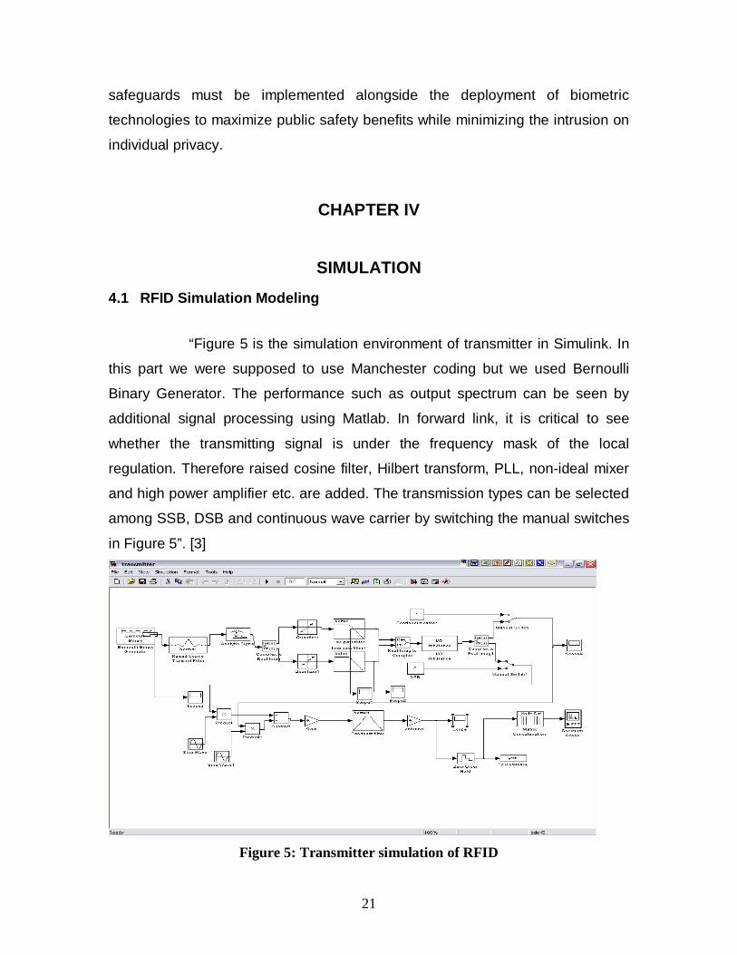
“Figure 5 is the simulation environment of transmitter in Simulink. In
this part we were supposed to use Manchester coding but we used Bernoulli
Binary Generator. The performance such as output spectrum can be seen by
additional signal processing using Matlab. In forward link, it is critical to see
whether the transmitting signal is under the frequency mask of the local
regulation. Therefore raised cosine filter, Hilbert transform, PLL, non-ideal mixer
and high power amplifier etc. are added. The transmission types can be selected
among SSB, DSB and continuous wave carrier by switching the manual switches
in Figure 5”. [3]
Figure 5: Transmitter simulation of RFID
22
A brief description of some important portion of the transmitter part is given below. Coding The protocol this paper based on using Bernouli Binary Generator.
BER is introduced to evaluate the performance of a digital communication
system. In forward link, the CNR is large enough for a tag to demodulate data by
envelope detector. The tag reflects the incident power, and the reflect power is
very weak for a passive tag since it can only send the return data through
changing RCS (radar cross section) which is very small. If most of the power
were reflected, the tag would not work. If less power were reflected, reader would
not reach a high sensitivity physically. [3]
Raised Cosine Filer A band-limited signal, which has no ISI (inter symbol interference),
should satisfy Nyquist criterion [5]. Usually, it is realized by a raised cosine filter.
[3]
Quantization
The signal is over sampled by FIR filter such as raised filter and
Hilbert transform. After digital signal processing, the digitized signal is send into
analog part. In practical, a DAC will convert digital signals into analog, which
yields quantization error. [3]
Power Amplifier The power amplifier is modeled with nonlinearities, IIP2 and IIP3 for
different types of power amplifiers. The AM/PM effect of amplifier is not included
since tags are not sensitive to the phase of the carrier. [3]
Band Pass Filer The output band pass filter is to remove the out of band spurious spectrum. A fourth order Bessel filter is selected with the bandwidth range from
23
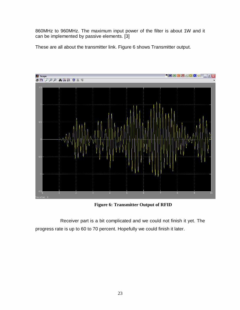
860MHz to 960MHz. The maximum input power of the filter is about 1W and it can be implemented by passive elements. [3] These are all about the transmitter link. Figure 6 shows Transmitter output.
Figure 6: Transmitter Output of RFID
Receiver part is a bit complicated and we could not finish it yet. The
progress rate is up to 60 to 70 percent. Hopefully we could finish it later.
24
4.2 Biometrics Simulation (Face Detection)
In this simulation we have used Gabor Filter equation for feature
extraction. We also used Matlab Neural Network Toolbox. The matlab codes and
process of running the simulation is described below.
Gabor filters are found to have Gaussian transfer functions in the
frequency domain. Thus, taking the Inverse Fourier Transform of this transfer
function we get a filter characteristics closely resembling to the Gabor filters. The
Gabor filter is basically a Gaussian (with variances sx and sy along x and y-axes
respectively) modulated by a complex sinusoid (with centre frequencies U and V
along x and y-axes respectively).
Gabor filters are used mostly in shape detectin and feature extractin
in image processing.
function [G,gabout] = gaborfilter1(I,Sx,Sy,f,theta);
from 'gaborfilter1' with different f(Frequency) and theta(Angle).
for example
f:0,2,4,8,16,32
theta = 0,pi/3,pi/6,pi/2,3pi/4
then for any input image like(eg. stereo.jpg)
you have 6x5 = 30 filtered images.
You can choose your desired angles or frequencies.
You can put nominaly Sx & Sy = 2,4 or some one else.
For instance I tested above example on ('cameraman.tif')(in MATLAB pictures)
I = imread('cameraman.tif');
[G,gabout] = gaborfilter1(I,2,4,16,pi/3);
figure,imshow(uint8(gabout));
Neural networks consist of a large class of different architectures. In
many cases, the issue is approximating a static nonlinear, mapping f( x) with a
neural network f NN (x) , where x∈ RK
25
The most useful neural networks in function approximation are
Multilayer Layer Perceptron (MLP) and Radial Basis Function (RBF) networks.
Here we concentrate on MLP networks.
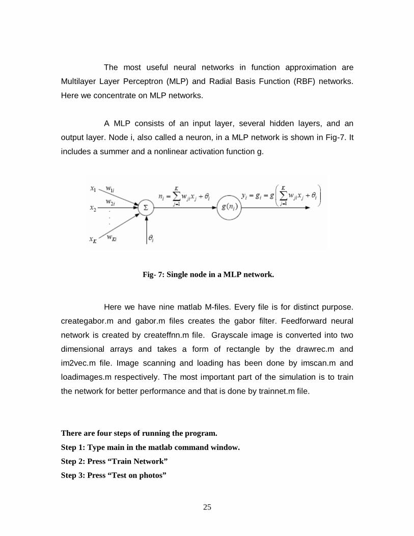
A MLP consists of an input layer, several hidden layers, and an
output layer. Node i, also called a neuron, in a MLP network is shown in Fig-7. It
includes a summer and a nonlinear activation function g.
Fig- 7: Single node in a MLP network.
Here we have nine matlab M-files. Every file is for distinct purpose.
creategabor.m and gabor.m files creates the gabor filter. Feedforward neural
network is created by createffnn.m file. Grayscale image is converted into two
dimensional arrays and takes a form of rectangle by the drawrec.m and
im2vec.m file. Image scanning and loading has been done by imscan.m and
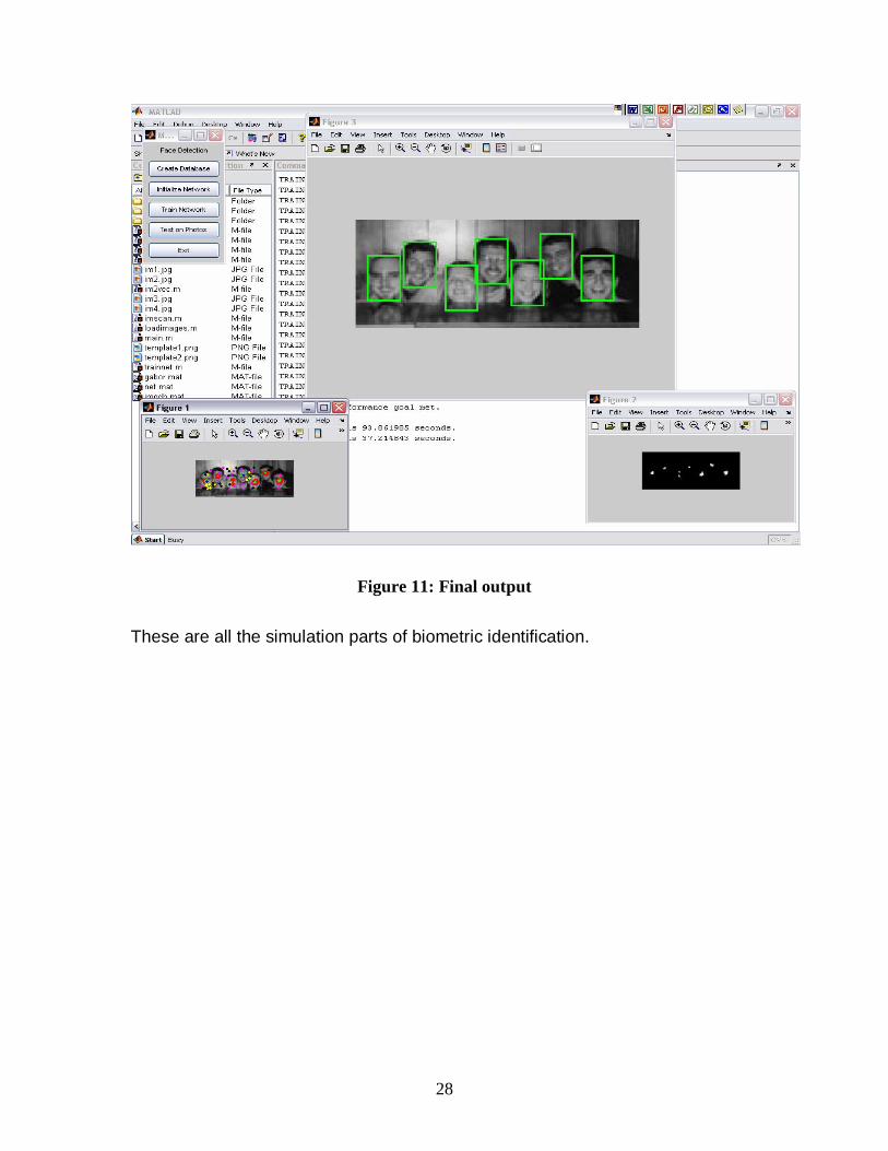
loadimages.m respectively. The most important part of the simulation is to train
the network for better performance and that is done by trainnet.m file.
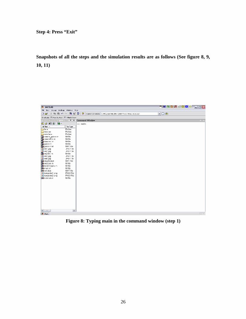
There are four steps of running the program.
Step 1: Type main in the matlab command window.
Step 2: Press “Train Network”
Step 3: Press “Test on photos”
26
Step 4: Press “Exit”
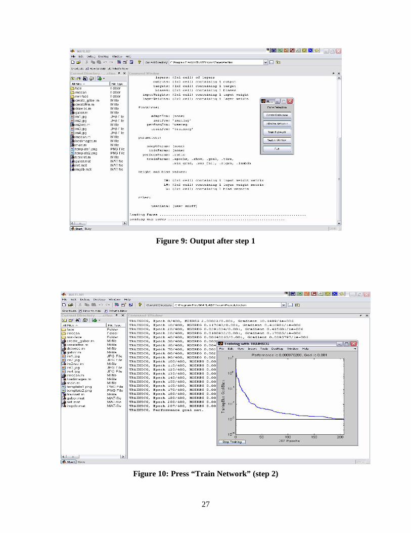
Snapshots of all the steps and the simulation results are as follows (See figure 8, 9,
10, 11)
Figure 8: Typing main in the command window (step 1)
27
Figure 9: Output after step 1
Figure 10: Press “Train Network” (step 2)
28
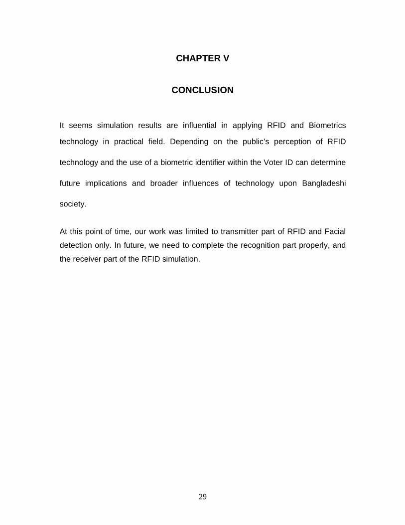
Figure 11: Final output
These are all the simulation parts of biometric identification.
29
CHAPTER V
CONCLUSION
It seems simulation results are influential in applying RFID and Biometrics
technology in practical field. Depending on the public’s perception of RFID
technology and the use of a biometric identifier within the Voter ID can determine
future implications and broader influences of technology upon Bangladeshi
society.
At this point of time, our work was limited to transmitter part of RFID and Facial
detection only. In future, we need to complete the recognition part properly, and
the receiver part of the RFID simulation.
30
A LIST OF REFERENCES
1. http://www.hightechaid.com/tech/rfid/what_is_rfid.htm
2. http://www.oecd.org/dataoecd/57/43/36323191.pdf
3. http://www.m-lab.ch/auto-
id/SwissReWorkshop/papers/SystemModelingAndSimulationOfRFID.pdf
4. EPC Radio-Frequency Identity Protocols Generation 2 Identity Tag (Class 1): Protocol
for Communications at 860MHz-960MHz. EPC Global Hardware Action Group (HAG),
EPC Identity Tag (Class 1) Generation 2, Last-Call Working Draft Version 1.0.2, 2003-
11-24
5. John G. Proakis, “Digital Communications (Fourth Edition)”, McGraw-Hill
Companies, Inc, 2001
6. Behzad Razavi, “RF Microelectronics”, Prentice Hall, Inc. 1998
7. The Palomar system Deliverable D7, Version V2.1,2002
8. http://www.eng.tau.ac.il/~yash/kw-usenix06/index.html
9. http://www.wipo.int/pctdb/en/wo.jsp?IA=WO2007072031&wo=2007072031&DISPLAY=DESC
10. http://www.ferret.com.au/c/Electro-Com-Australia/RFid-asset-management-system-n701083
11. http://www.sanc.org.sg/frame_epcglobal.htm
12. http://europe.nokia.com/A4153291
13. http://www.telepen-access-control.co.uk/rfid-6.htm
14. http://searchsecurity.techtarget.com/sDefinition/0,,sid14_gci211666,00.html
15. http://www.spychips.com/what-is-rfid.html