Embed Size (px)
Citation preview
Ciontea, Catalin Iosif and Bak, Claus Leth and Blaabjerg, Frede and
Hong, Qiteng and Booth, Campbell and Madsen, Kjeld Kilsgaard (2018)
Utilisation of symmetrical components in a communication-based
protection for loop MV feeders with variable short-circuit power. The
Journal of Engineering, 2018 (15). pp. 1245-1251. ,
http://dx.doi.org/10.1049/joe.2018.0174
This version is available at https://strathprints.strath.ac.uk/66382/
Strathprints is designed to allow users to access the research output of the University of
Strathclyde. Unless otherwise explicitly stated on the manuscript, Copyright © and Moral Rights
for the papers on this site are retained by the individual authors and/or other copyright owners.
Please check the manuscript for details of any other licences that may have been applied. You
may not engage in further distribution of the material for any profitmaking activities or any
commercial gain. You may freely distribute both the url (https://strathprints.strath.ac.uk/) and the
content of this paper for research or private study, educational, or not-for-profit purposes without
prior permission or charge.
Any correspondence concerning this service should be sent to the Strathprints administrator:
The Strathprints institutional repository (https://strathprints.strath.ac.uk) is a digital archive of University of Strathclyde research
outputs. It has been developed to disseminate open access research outputs, expose data about those outputs, and enable the
management and persistent access to Strathclyde's intellectual output.
The Journal of Engineering
The 14th International Conference on Developments in Power SystemProtection (DPSP 2018)
Utilisation of symmetrical components in acommunication-based protection for loop MVfeeders with variable short-circuit power
eISSN 2051-3305Received on 3rd May 2018Accepted on 23rd May 2018E-First on 20th August 2018doi: 10.1049/joe.2018.0174www.ietdl.org
Catalin Iosif Ciontea1,2 , Claus Leth Bak1, Frede Blaabjerg1, Qiteng Hong3, Campbell Booth3, KjeldKilsgaard Madsen2
1Department of Energy Technology, Aalborg University, 9220 Aalborg East, Denmark2Department of Research and Development, DEIF A/S, 7800 Skive, Denmark3Department of Electronic and Electrical Engineering, University of Strathclyde, Glasgow G1 1XW, Scotland, UK
E-mail: [email protected]
Abstract: Variability of the available short-circuit power also implies variation of the fault level, which can potentially causeseveral protection problems in the electric networks. In this study, a novel protection method that is insensitive to the fault levelchanges caused by variable short-circuit power is presented. It relies on utilisation of symmetrical components of the short-circuit currents and on communication between the protection relays. The proposed method addresses the single phase toground (SPG) faults occurring in directly grounded distribution networks, with focus on closed-loop medium voltage (MV)feeders. Case studies are presented, which demonstrate that the proposed protection scheme is capable of effectively detectingthe SPG faults in closed-loop feeders with variable short-circuit power.
1諜IntroductionIn general, the distribution networks comprise radial feederssupplied from a single utility source [1]. In this arrangement, thecurrent flow is unidirectional and protection against the short-circuit faults is realised typically by overcurrent (OC) relays [1],but an electric fault could cause a power outage for all loads placeddownstream the fault location [2]. In order to address thisdrawback, some distribution networks comprise loop feeders, sothat no consumer will be out of service in the event of a single faultwithin the feeder [3]. However, in a closed-loop feeder the currentflow is bidirectional and the conventional OC protection needs tobe upgraded in order to provide proper protection against theelectric faults [2, 3].
Regardless of the type of feeder involved in a distributionnetwork, its protection system is challenged by variability of theavailable short-circuit power, as the short-circuit currents are alsovariable in this situation [4]. With the advance of distributedgeneration, variability of the short-circuit power is not uncommonnowadays [5] and the protection system needs to operate correctlyeven in such conditions. It is well known that the traditional OCrelays are not suitable in these conditions, as they could experiencelonger tripping times, loss of coordination and other protectionissues [4, 5]. In order to mitigate some of the protection problemsmentioned above, a new protection scheme is proposed in [5] forradial MV feeders with variable short-circuit currents. Theproposed protection scheme is effective against SPG faultsoccurring in directly grounded distribution feeders and relies on theevaluation of the ratio between the zero sequence and positivesequence of the fault current. More precisely, the SPG fault in aradial feeder is indicated by a non-zero magnitude of this ratio forall relays located upstream of the fault location and precisely thisinformation is used in [5] to clear the faulted section of the feeder.As a continuation of the work presented in [5], the proposedprotection scheme is improved so that it can also be applied inclosed-loop feeders. Therefore, this paper presents a newcommunication-based protection scheme for loop MV feeders withvariable short-circuit power.
The protection scheme proposed in this paper has severalbenefits over conventional OC protection. It is insensitive to faultlevel changes, so it only needs a single set of settings for its relaysfor a wide range of network conditions and it does not require a
prior knowledge of the rated or fault currents in the circuit thatneeds to be protected. Moreover, the proposed protection schemeallows for normally-open-loop feeders to be closed without theneed of voltage transformers, as in the case of directional OCrelays [6] or additional current transformers (CTs). The newlydeveloped protection scheme has been tested in a closed-loop MVfeeder with variable short-circuit power using PSCAD and thesimulation results demonstrate its effectiveness in these conditions.
The remaining of this paper is structured as follows. Sections 2and 3 present the theoretical background of the proposed method ofprotection. In Section 2, the SPG fault is analysed using the methodof symmetrical components in a distribution feeder and based onthis analysis the new method of protection is described in Section3. In Section 4, some case studies are presented and PSCAD isused for simulating various fault conditions to validate theperformance of the proposed protection scheme. Section 5concludes this paper with some final remarks.
2諜Fault analysisAnalysis of the SPG fault seeks to determine the symmetricalcomponents of the fault currents, as measured by the CTs in a loopfeeder. It should be noted that only these currents are available forthe protection system, so only their equivalent sequencecomponents present interest in this paper. Once these quantities aredetermined, the ratio between the current zero sequence andcurrent positive sequence is calculated in the eventuality of aclosed-loop, respectively, open-loop (radial) feeder. The objectiveis to determine the difference between these two scenarios, asnoticed by the aforementioned ratio and based on them to adapt themethod of protection proposed in [5] for the case of closed-loopfeeders.
2.1 Loop feeder
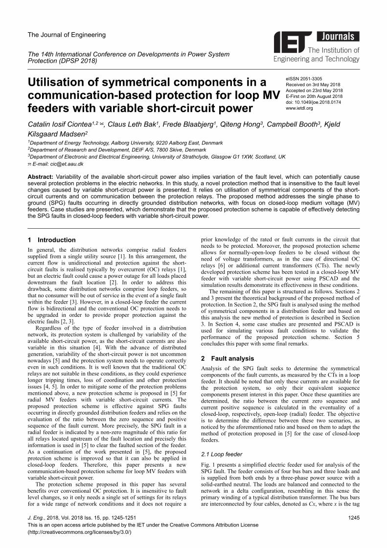
Fig. 1 presents a simplified electric feeder used for analysis of theSPG fault. The feeder consists of four bus bars and three loads andis supplied from both ends by a three-phase power source with asolid-earthed neutral. The loads are balanced and connected to thenetwork in a delta configuration, resembling in this sense theprimary winding of a typical distribution transformer. The bus barsare interconnected by four cables, denoted as Cx, where x is the tag
J. Eng., 2018, Vol. 2018 Iss. 15, pp. 1245-1251This is an open access article published by the IET under the Creative Commons Attribution License(http://creativecommons.org/licenses/by/3.0/)
1245
of the cable. Monitoring of the feeder is realised for protectionpurposes by four sets of CTs, labelled as CTx, where x is the tag ofthe CT. The loop feeder can become radial by opening of eithercircuit breaker (CB) CB1 or CB2. The electric loads are labelled asL1, L2 and L3, respectively, while the internal e.m.f. of the powersource is denoted as E. A SPG fault with the fault resistance RF isapplied on cable C1 and the fault current is fed from both sides ofthe loop feeder.
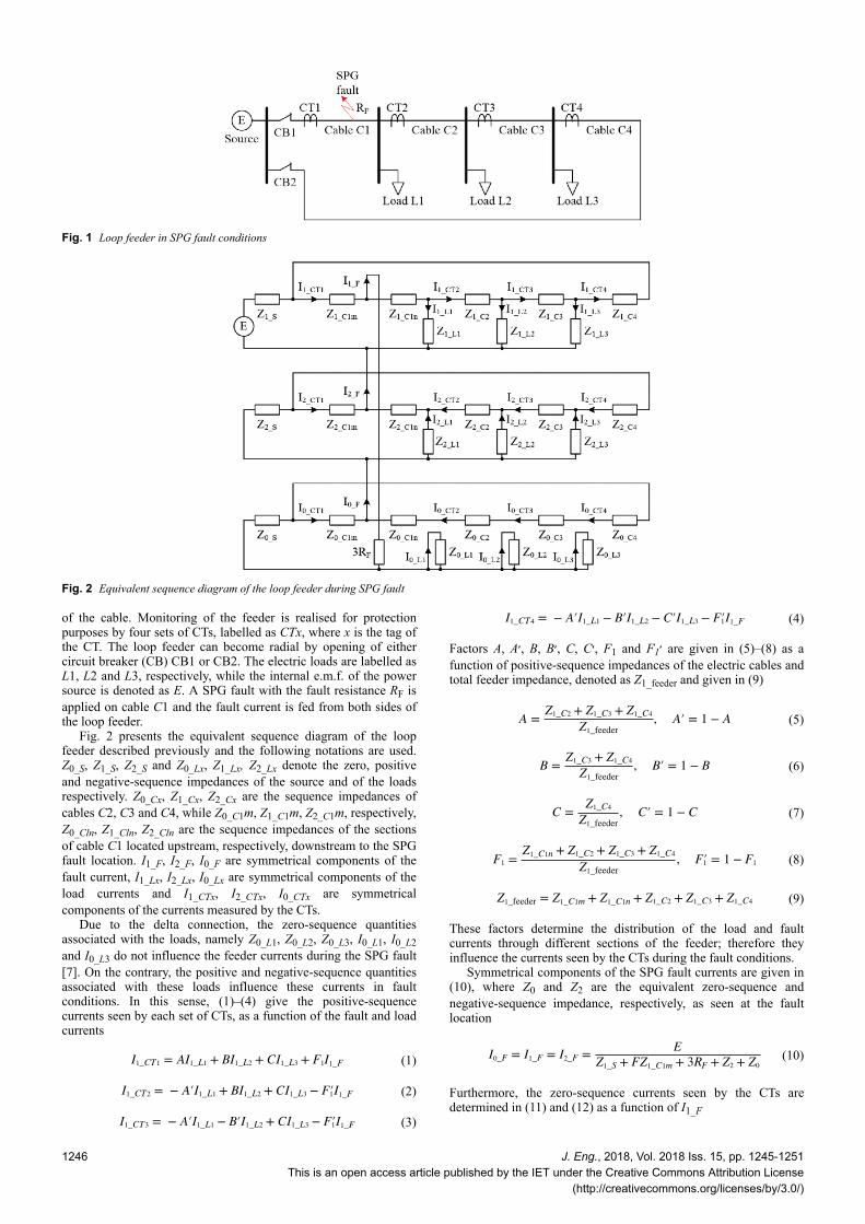
Fig. 2 presents the equivalent sequence diagram of the loopfeeder described previously and the following notations are used.Z0_S, Z1_S, Z2_S and Z0_Lx, Z1_Lx, Z2_Lx denote the zero, positiveand negative-sequence impedances of the source and of the loadsrespectively. Z0_Cx, Z1_Cx, Z2_Cx are the sequence impedances ofcables C2, C3 and C4, while Z0_C1m, Z1_C1m, Z2_C1m, respectively,Z0_Cln, Z1_Cln, Z2_Cln are the sequence impedances of the sectionsof cable C1 located upstream, respectively, downstream to the SPGfault location. I1_F, I2_F, I0_F are symmetrical components of thefault current, I1_Lx, I2_Lx, I0_Lx are symmetrical components of theload currents and I1_CTx, I2_CTx, I0_CTx are symmetricalcomponents of the currents measured by the CTs.
Due to the delta connection, the zero-sequence quantitiesassociated with the loads, namely Z0_L1, Z0_L2, Z0_L3, I0_L1, I0_L2and I0_L3 do not influence the feeder currents during the SPG fault[7]. On the contrary, the positive and negative-sequence quantitiesassociated with these loads influence these currents in faultconditions. In this sense, (1)–(4) give the positive-sequencecurrents seen by each set of CTs, as a function of the fault and loadcurrents
I1_CT1 = AI1_L1 + BI1_L2 + CI1_L3 + F1I1_F (1)
I1_CT2 = − A′I1_L1 + BI1_L2 + CI1_L3 − F1′I1_F (2)
I1_CT3 = − A′I1_L1 − B′I1_L2 + CI1_L3 − F1′I1_F (3)
I1_CT4 = − A′I1_L1 − B′I1_L2 − C′I1_L3 − F1′I1_F (4)
Factors A, A≧, B, B≧, C, C≧, F1 and F ≧1 are given in (5)–(8) as afunction of positive-sequence impedances of the electric cables andtotal feeder impedance, denoted as Z1_feeder and given in (9)
A =Z1_C2 + Z1_C3 + Z1_C4
Z1_feeder
, A′ = 1 − A (5)
B =Z1_C3 + Z1_C4
Z1_feeder
, B′ = 1 − B (6)
C =Z1_C4
Z1_feeder
, C′ = 1 − C (7)
F1 =Z1_C1n + Z1_C2 + Z1_C3 + Z1_C4
Z1_feeder
, F1′ = 1 − F1 (8)
Z1_feeder = Z1_C1m + Z1_C1n + Z1_C2 + Z1_C3 + Z1_C4 (9)
These factors determine the distribution of the load and faultcurrents through different sections of the feeder; therefore theyinfluence the currents seen by the CTs during the fault conditions.
Symmetrical components of the SPG fault currents are given in(10), where Z0 and Z2 are the equivalent zero-sequence andnegative-sequence impedance, respectively, as seen at the faultlocation
I0_F = I1_F = I2_F =E
Z1_S + FZ1_C1m + 3RF + Z2 + Z0
(10)
Furthermore, the zero-sequence currents seen by the CTs aredetermined in (11) and (12) as a function of I1_F
Fig. 1超 Loop feeder in SPG fault conditions
Fig. 2超 Equivalent sequence diagram of the loop feeder during SPG fault
1246 J. Eng., 2018, Vol. 2018 Iss. 15, pp. 1245-1251This is an open access article published by the IET under the Creative Commons Attribution License
(http://creativecommons.org/licenses/by/3.0/)
I0_CT1 = F0I1_F (11)
I0_CT2 = I0_CT3 = I0_CT4 = − F0′I1_F (12)
Factors F0 and F ≧0 are given in (13) as a function of the equivalentzero-sequence impedances of the cables and total feederimpedance, denoted as Z0_feeder and given in (14)
F0 =Z0_C1n + Z0_C2 + Z0_C3 + Z0_C4
Z0_feeder
, F0′ = 1 − F0 (13)
Z0_feeder = Z0_C1m + Z0_C1n + Z0_C2 + Z0_C3 + Z0_C4 (14)
Finally, the ratios between the zero-sequence components andpositive-sequence components of the currents seen by each set ofCTs are given in the following equations:
I0_CT1
I1_CT1
=F0I1_F
AI1_L1 + BI1_L2 + CI1_L3 + F1I1_F
(15)
I0_CT2
I1_CT2
=−F′0I1_F
−A′I1_L1 + BI1_L2 + CI1_L3 − F′1I1_F
(16)
I0_CT3
I1_CT3
=−F′0I1_F
−A′I1_L1 − B′I1_L2 + CI1_L3 − F′1I1_F
(17)
I0_CT4
I1_CT4
=−F′0I1_F
−A′I1_L1 − B′I1_L2 − C′II_L3 − F′1I1_F
(18)
These ratios are complex numbers and their evaluation couldprovide valuable information for the protection system. In healthyconditions, the magnitude of these ratios is zero, but during theSPG fault their magnitudes increase significantly. Furthermore,assuming that F1鳥=鳥F0, which is typically true [8], is clear that themagnitudes of I0_CT1/I1_CT1 and I0_CT4/I1_CT4 cannot exceed 1 evenin fault conditions. However, the same cannot be said aboutI0_CT2/I1_CT2 and I0_CT3/I1_CT3, as their magnitudes could exceed 1,depending on the value of the factors A, B, C and F. Moreimportantly, there is no relation between the location of the SPGfault in the closed-loop feeder (e.g. in between CT1 and CT2 in thisanalysis) and the magnitudes of the examined ratios. Therefore, byobserving these ratios in a loop feeder, only the presence of theSPG fault can be indicated, but not its exact location.
2.2 Radial feeder
If CB2 is opened, the considered loop feeder becomes radial andthe load and fault currents will be supplied from a single directionthrough CT1. In this situation, the mathematical expression of theratio between the zero-sequence and positive-sequence of thecurrent seen by CT1 is given in (19). Again, the magnitude ofI0_CT1/I1_CT1 is zero only in healthy conditions and it increasessignificantly during the SPG fault, but it will not exceed 1
I0_CT1
I1_CT1
=I1_F
I1_L1 + I1_L2 + I1_L3 + I1_F
(19)
I0_CT2/I1_CT2 and I0_CT3/I1_CT3 are zero in both healthy and faultconditions for the considered SPG fault with CB2 open, as the faultcurrent does not pass through CT2 and CT3. Also, no currentpasses through CT4 because CB2 is open; therefore I0_CT4/I1_CT4 iszero in this situation.
If CB1 is opened, while CB2 is kept closed, the feeder issupplied from the opposite direction through CT4. In this situation,no current will pass through CT1, while the fault current producedby the considered SPG fault is noticed by all of the other CTs. Theratio between the current zero-sequence and current positive-sequence, as seen by those CTs is given in the following equations:
I0_CT2
I1_CT2
=−I1_F
−I1_L1 − I1_F
(20)
I0_CT3
I1_CT3
=−I1_F
−I1_L1 − I1_L2 − I1_F
(21)
I0_CT4
I1_CT4
=−I1_F
−I1_L1 − I1_L2 − I1_L3 − I1_F
(22)
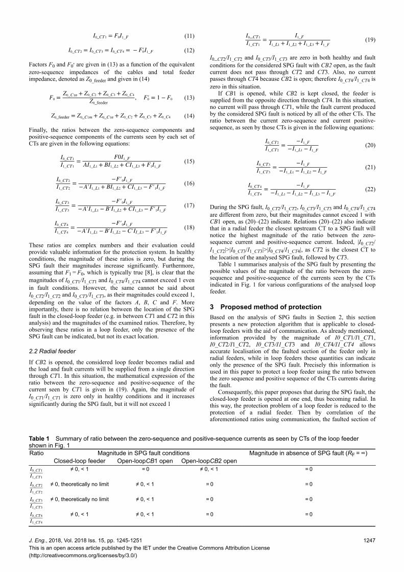
During the SPG fault, I0_CT2/I1_CT2, I0_CT3/I1_CT3 and I0_CT4/I1_CT4are different from zero, but their magnitudes cannot exceed 1 withCB1 open, as (20)–(22) indicate. Relations (20)–(22) also indicatethat in a radial feeder the closest upstream CT to a SPG fault willnotice the highest magnitude of the ratio between the zero-sequence current and positive-sequence current. Indeed, |I0_CT2/I1_CT2|>|I0_CT3/I1_CT3|>|I0_CT4/I1_CT4|, as CT2 is the closest CT tothe location of the analysed SPG fault, followed by CT3.
Table 1 summarises analysis of the SPG fault by presenting thepossible values of the magnitude of the ratio between the zero-sequence and positive-sequence of the currents seen by the CTsindicated in Fig. 1 for various configurations of the analysed loopfeeder.
3諜Proposed method of protectionBased on the analysis of SPG faults in Section 2, this sectionpresents a new protection algorithm that is applicable to closed-loop feeders with the aid of communication. As already mentioned,information provided by the magnitude of I0_CT1/I1_CT1,I0_CT2/I1_CT2, I0_CT3/I1_CT3 and I0_CT4/I1_CT4 allowsaccurate localisation of the faulted section of the feeder only inradial feeders, while in loop feeders these quantities can indicateonly the presence of the SPG fault. Precisely this information isused in this paper to protect a loop feeder using the ratio betweenthe zero sequence and positive sequence of the CTs currents duringthe fault.
Consequently, this paper proposes that during the SPG fault, theclosed-loop feeder is opened at one end, thus becoming radial. Inthis way, the protection problem of a loop feeder is reduced to theprotection of a radial feeder. Then by correlation of theaforementioned ratios using communication, the faulted section of
Table 1諜Summary of ratio between the zero-sequence and positive-sequence currents as seen by CTs of the loop feedershown in Fig. 1Ratio Magnitude in SPG fault conditions Magnitude in absence of SPG fault (RF鳥=鳥∞)
Closed-loop feeder Open-loopCB1 open Open-loopCB2 openI0_CT1
I1_CT1
≠ 0, < 1 鳥=鳥0 ≠ 0, < 1 鳥=鳥0
I0_CT2
I1_CT2
≠ 0, theoretically no limit ≠ 0, < 1 鳥=鳥0 鳥=鳥0
I0_CT3
I1_CT3
≠ 0, theoretically no limit ≠ 0, < 1 鳥=鳥0 鳥=鳥0
I0_CT4
I1_CT4
≠ 0, < 1 ≠ 0, < 1 鳥=鳥0 鳥=鳥0
J. Eng., 2018, Vol. 2018 Iss. 15, pp. 1245-1251This is an open access article published by the IET under the Creative Commons Attribution License(http://creativecommons.org/licenses/by/3.0/)
1247
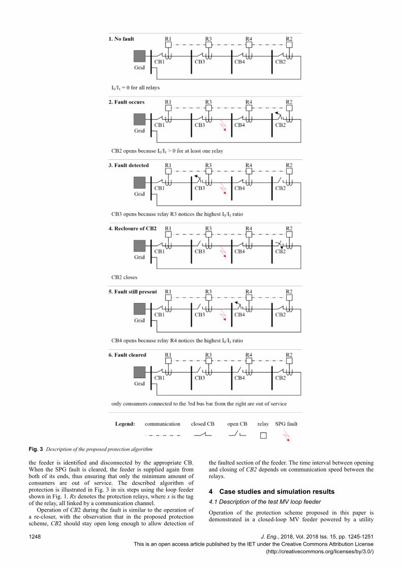
the feeder is identified and disconnected by the appropriate CB.When the SPG fault is cleared, the feeder is supplied again fromboth of its ends, thus ensuring that only the minimum amount ofconsumers are out of service. The described algorithm ofprotection is illustrated in Fig. 3 in six steps using the loop feedershown in Fig. 1. Rx denotes the protection relays, where x is the tagof the relay, all linked by a communication channel.
Operation of CB2 during the fault is similar to the operation ofa re-closer, with the observation that in the proposed protectionscheme, CB2 should stay open long enough to allow detection of
the faulted section of the feeder. The time interval between openingand closing of CB2 depends on communication speed between therelays.
4諜Case studies and simulation results4.1 Description of the test MV loop feeder
Operation of the protection scheme proposed in this paper isdemonstrated in a closed-loop MV feeder powered by a utility
Fig. 3超 Description of the proposed protection algorithm
1248 J. Eng., 2018, Vol. 2018 Iss. 15, pp. 1245-1251This is an open access article published by the IET under the Creative Commons Attribution License
(http://creativecommons.org/licenses/by/3.0/)
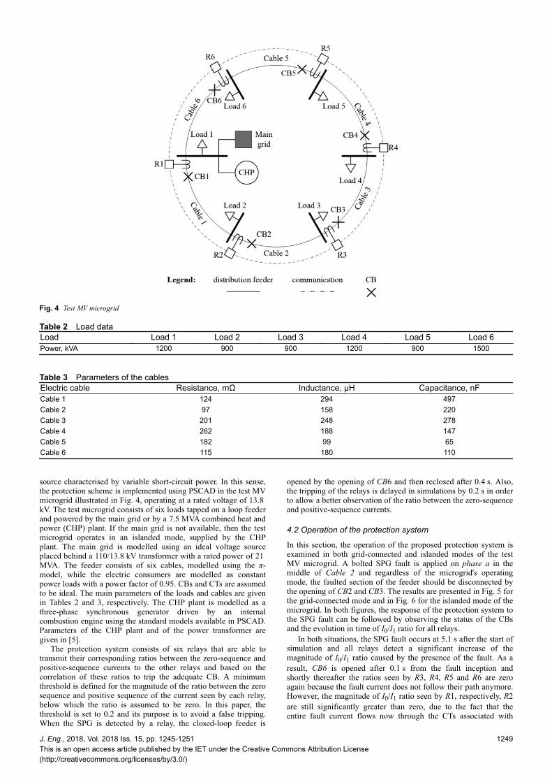
source characterised by variable short-circuit power. In this sense,the protection scheme is implemented using PSCAD in the test MVmicrogrid illustrated in Fig. 4, operating at a rated voltage of 13.8跳kV. The test microgrid consists of six loads tapped on a loop feederand powered by the main grid or by a 7.5跳MVA combined heat andpower (CHP) plant. If the main grid is not available, then the testmicrogrid operates in an islanded mode, supplied by the CHPplant. The main grid is modelled using an ideal voltage sourceplaced behind a 110/13.8跳kV transformer with a rated power of 21跳MVA. The feeder consists of six cables, modelled using the ヾ-model, while the electric consumers are modelled as constantpower loads with a power factor of 0.95. CBs and CTs are assumedto be ideal. The main parameters of the loads and cables are givenin Tables 2 and 3, respectively. The CHP plant is modelled as athree-phase synchronous generator driven by an internalcombustion engine using the standard models available in PSCAD.Parameters of the CHP plant and of the power transformer aregiven in [5].
The protection system consists of six relays that are able totransmit their corresponding ratios between the zero-sequence andpositive-sequence currents to the other relays and based on thecorrelation of these ratios to trip the adequate CB. A minimumthreshold is defined for the magnitude of the ratio between the zerosequence and positive sequence of the current seen by each relay,below which the ratio is assumed to be zero. In this paper, thethreshold is set to 0.2 and its purpose is to avoid a false tripping.When the SPG is detected by a relay, the closed-loop feeder is
opened by the opening of CB6 and then reclosed after 0.4跳s. Also,the tripping of the relays is delayed in simulations by 0.2跳s in orderto allow a better observation of the ratio between the zero-sequenceand positive-sequence currents.
4.2 Operation of the protection system
In this section, the operation of the proposed protection system isexamined in both grid-connected and islanded modes of the testMV microgrid. A bolted SPG fault is applied on phase a in themiddle of Cable 2 and regardless of the microgrid's operatingmode, the faulted section of the feeder should be disconnected bythe opening of CB2 and CB3. The results are presented in Fig. 5 forthe grid-connected mode and in Fig. 6 for the islanded mode of themicrogrid. In both figures, the response of the protection system tothe SPG fault can be followed by observing the status of the CBsand the evolution in time of I0/I1 ratio for all relays.
In both situations, the SPG fault occurs at 5.1跳s after the start ofsimulation and all relays detect a significant increase of themagnitude of I0/I1 ratio caused by the presence of the fault. As aresult, CB6 is opened after 0.1跳s from the fault inception andshortly thereafter the ratios seen by R3, R4, R5 and R6 are zeroagain because the fault current does not follow their path anymore.However, the magnitude of I0/I1 ratio seen by R1, respectively, R2are still significantly greater than zero, due to the fact that theentire fault current flows now through the CTs associated with
Fig. 4超 Test MV microgrid
Table 2諜Load dataLoad Load 1 Load 2 Load 3 Load 4 Load 5 Load 6Power, kVA 1200 900 900 1200 900 1500
Table 3諜Parameters of the cablesElectric cable Resistance, mっ Inductance, たH Capacitance, nFCable 1 124 294 497Cable 2 97 158 220Cable 3 201 248 278Cable 4 262 188 147Cable 5 182 99 65Cable 6 115 180 110
J. Eng., 2018, Vol. 2018 Iss. 15, pp. 1245-1251This is an open access article published by the IET under the Creative Commons Attribution License(http://creativecommons.org/licenses/by/3.0/)
1249
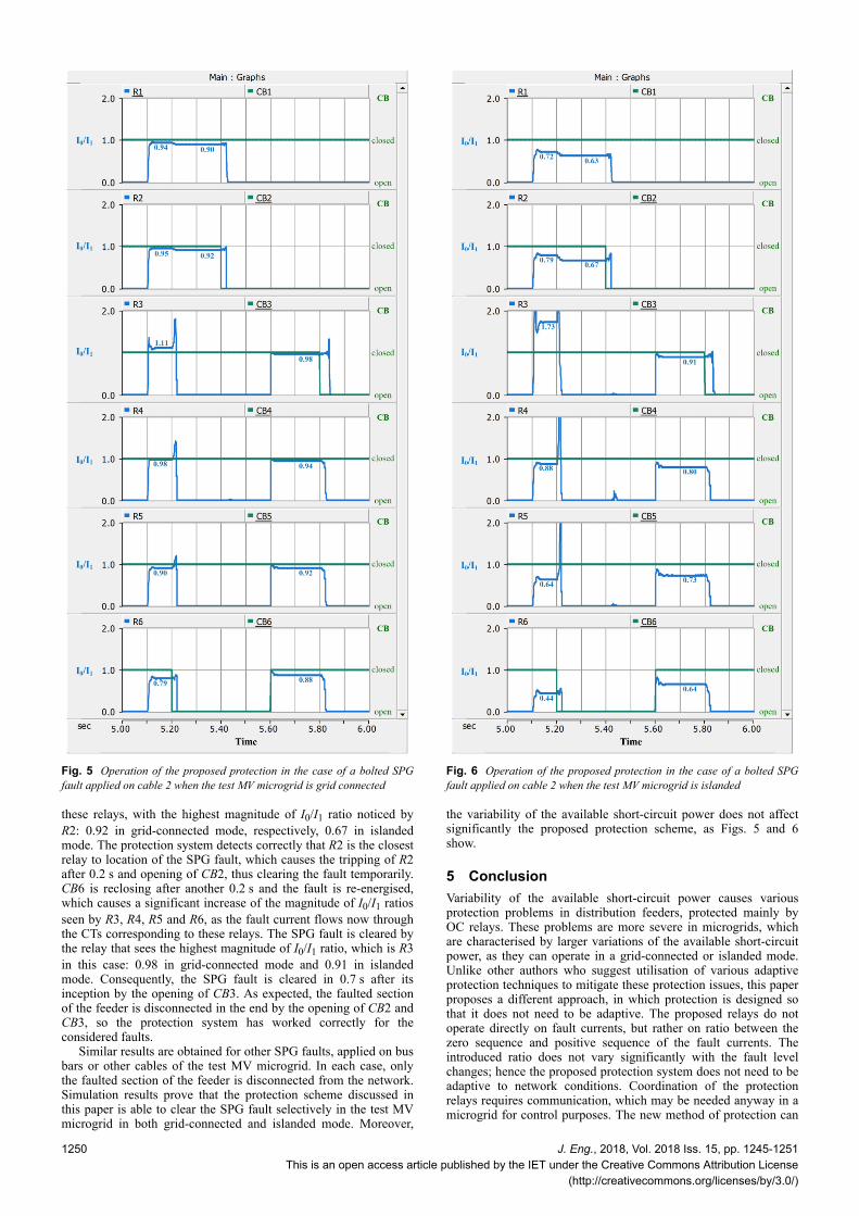
these relays, with the highest magnitude of I0/I1 ratio noticed byR2: 0.92 in grid-connected mode, respectively, 0.67 in islandedmode. The protection system detects correctly that R2 is the closestrelay to location of the SPG fault, which causes the tripping of R2after 0.2跳s and opening of CB2, thus clearing the fault temporarily.CB6 is reclosing after another 0.2跳s and the fault is re-energised,which causes a significant increase of the magnitude of I0/I1 ratiosseen by R3, R4, R5 and R6, as the fault current flows now throughthe CTs corresponding to these relays. The SPG fault is cleared bythe relay that sees the highest magnitude of I0/I1 ratio, which is R3in this case: 0.98 in grid-connected mode and 0.91 in islandedmode. Consequently, the SPG fault is cleared in 0.7跳s after itsinception by the opening of CB3. As expected, the faulted sectionof the feeder is disconnected in the end by the opening of CB2 andCB3, so the protection system has worked correctly for theconsidered faults.
Similar results are obtained for other SPG faults, applied on busbars or other cables of the test MV microgrid. In each case, onlythe faulted section of the feeder is disconnected from the network.Simulation results prove that the protection scheme discussed inthis paper is able to clear the SPG fault selectively in the test MVmicrogrid in both grid-connected and islanded mode. Moreover,
the variability of the available short-circuit power does not affectsignificantly the proposed protection scheme, as Figs. 5 and 6show.
5諜ConclusionVariability of the available short-circuit power causes variousprotection problems in distribution feeders, protected mainly byOC relays. These problems are more severe in microgrids, whichare characterised by larger variations of the available short-circuitpower, as they can operate in a grid-connected or islanded mode.Unlike other authors who suggest utilisation of various adaptiveprotection techniques to mitigate these protection issues, this paperproposes a different approach, in which protection is designed sothat it does not need to be adaptive. The proposed relays do notoperate directly on fault currents, but rather on ratio between thezero sequence and positive sequence of the fault currents. Theintroduced ratio does not vary significantly with the fault levelchanges; hence the proposed protection system does not need to beadaptive to network conditions. Coordination of the protectionrelays requires communication, which may be needed anyway in amicrogrid for control purposes. The new method of protection can
Fig. 5超 Operation of the proposed protection in the case of a bolted SPGfault applied on cable 2 when the test MV microgrid is grid connected
Fig. 6超 Operation of the proposed protection in the case of a bolted SPGfault applied on cable 2 when the test MV microgrid is islanded
1250 J. Eng., 2018, Vol. 2018 Iss. 15, pp. 1245-1251This is an open access article published by the IET under the Creative Commons Attribution License
(http://creativecommons.org/licenses/by/3.0/)
be applied in loop feeders, as shown in this paper. Also, thesimulations realised in PSCAD prove the effectiveness of theproposed protection scheme in the detection of the SPG faults inclosed-loop feeders with variable short-circuit power.
6諜References[1] Mashau, T., Kibaara, S., Chowdhury, S., et al.: ‘Impact of distributed
generation on protection coordination in a radial distribution feeder’. 46th Int.Universities Power Engineering Conf., Soest, Germany, September 2011
[2] Davies, T.: ‘Protection of industrial power systems, 2nd edition’ (NewnesButterworth-Heinemann, UK, 1996)
[3] The Electricity Council: ‘Power system protection: systems and methods,volume 2’ (Peter Peregrinus Ltd., Stevenage, UK, 1990)
[4] Ciontea, C.I., Leth Bak, C., Blaabjerg, F., et al.: ‘Decentralized adaptiveovercurrent protection for medium voltage maritime power systems’. IEEEPES Asia-Pacific Power and Energy Engineering Conf., Xi'an, China,October 2016
[5] Ciontea, C.I., Leth Bak, C., Blaabjerg, F., et al.: ‘Utilization of symmetricalcomponents in a communication-assisted protection scheme for radial MVfeeders with variable or reduced short-circuit currents’. CIGRE Symp.,Dublin, Ireland, May-June 2017
[6] Voima, S., Laaksonen, H., Kauhaniemi, K.: ‘Adaptive protection scheme forsmart grids’. 12th IET Int. Conf. on Developments in Power SystemProtection, Copenhagen, Denmark, March-April 2014
[7] Blackburn, J.L.: ‘Symmetrical components for power systems engineering’(Marcel Dekker Inc., New York, USA, 1993)
[8] Anthony, M.A.: ‘Electric power system protection and coordination’(McGraw-Hill Inc, New York, USA, 1994)
J. Eng., 2018, Vol. 2018 Iss. 15, pp. 1245-1251This is an open access article published by the IET under the Creative Commons Attribution License(http://creativecommons.org/licenses/by/3.0/)
1251