Embed Size (px)
Citation preview
Cisco Systems, Inc.All contents are Copyright © 1992–2002 Cisco Systems, Inc. All rights reserved. Important Notices and Privacy Statement.
Page 1 of 17
Data Sheet
Cisco Catalyst 2950 Series Intelligent Ethernet Switchesfor Metro Access (Enhanced Image)
Product Overview
The Cisco Catalyst® 2950 Series Intelligent
Ethernet switches is an affordable line of
fixed-configuration Fast Ethernet and
Gigabit Ethernet switches that extend
intelligence to the metro access edge,
enabling service breadth, availability,
security, and manageability. Key
components of the Cisco Metro Ethernet
Switching portfolio, these switches are ideal
for service providers looking to deliver
profitable Ethernet services to the
residential and small-office, home-office
(SOHO) market. Featuring advanced rate
limiting, voice virtual LAN (VLAN)
support, and multicast management, these
switches enable a variety of residential
metro services such as Internet access, voice
over IP (VoIP), and broadcast video.
The Cisco Catalyst 2950 Series Intelligent
Ethernet switches consists of the following
devices—which are only available with the
Enhanced Image (EI) software for the Cisco
Catalyst 2950 Series:
• Cisco Catalyst 2950G-48 Switch—
48 10/100 ports and 2 gigabit interface
converter (GBIC)-based Gigabit
Ethernet ports
• Cisco Catalyst 2950G-24 Switch—
24 10/100 ports and 2 GBIC ports
• Cisco Catalyst 2950G-24-DC
Switch—24 10/100 ports, 2 GBIC ports,
and DC power
• Cisco Catalyst 2950G-12 Switch—
12 10/100 ports and 2 GBIC ports
• Cisco Catalyst 2950T-24 Switch—
24 10/100 ports and 2 fixed 10/100/
1000BaseT uplink ports
• Cisco Catalyst 2950C-24 Switch—
24 10/100 ports and 2 fixed 100BaseFX
uplink ports
• Catalyst 2950ST-24-LRE—24 LRE and
2 Gigabit Ethernet ports (user can select
either 10BaseT/100BaseTX/1000BaseT
Ethernet Ports or Small Form Factor
Pluggable (SFP) Transceivers)
• Catalyst 2950ST-8-LRE—8 LRE and 2
Gigabit Ethernet ports (user can select
either 10BaseT/100BaseTX/1000BaseT
Ethernet Ports or Small Form Factor
Pluggable (SFP) Transceivers)
The two built-in Gigabit Ethernet ports on
the Cisco Catalyst 2950G-12, 2950G-24,
and 2950G-48 accommodate a range of
GBIC transceivers, including the Cisco
Course Wave Division Multiplexing
(CWDM) GBIC Solution, Cisco
GigaStack® GBIC, 1000BaseSX,
1000BaseLX/LH, 1000BaseZX and
1000BaseT GBICs. The dual GBIC-based
Gigabit Ethernet implementation provides
customers with tremendous deployment
flexibility— allowing them increased
availability with the redundant uplinks.
High levels of resiliency can also be
implemented by deploying dual redundant
Gigabit Ethernet uplinks, UplinkFast and
Cisco Systems, Inc.All contents are Copyright © 1992–2002 Cisco Systems, Inc. All rights reserved. Important Notices and Privacy Statement.
Page 2 of 17
Per-VLAN Spanning Tree Plus (PVST+) for uplink load balancing. This Gigabit Ethernet flexibility makes the Cisco
Catalyst 2950 Series switches an ideal metro access edge complement to the Cisco 7600 Series Internet Router and
Cisco Catalyst 6500 Series of metro Ethernet switches.
Intelligence at the Metro Access Edge: Enabling Profitable Ethernet Services
Service providers that address the residential and SOHO market face the continual challenge of offering compelling
value-added services.
Although alternative broadband technologies such as DSL can offer bandwidth at speeds ranging up to 1.5 Mbps,
the monthly subscriber fees for such speeds can be out of reach for most users. As a result, compelling high-quality
services such as high-speed Internet access, VoIP, or broadcast video are often not viable propositions over these
technologies. However, in the metro, service providers are discovering that high-performance, Ethernet access over
fiber-optic networks can easily provide cost-effective bandwidth of 10 to 100 Mbps. By taking advantage of the
simplicity and cost benefits of Ethernet, revenue growth via voice, video, and data services becomes a reality. When
considering the deployment of Ethernet services, service providers must consider the following issues:
• Building cost-effective, highly available, scalable metro Ethernet networks
• Providing profitable new services while reducing operational and capital costs
• Having the network flexibility to move up market to enterprise and small and medium- sized business services
These issues are especially relevant at the metro access edge. As service providers look to provide profitable Ethernet
services such as high-speed Internet access, voice, and video, Cisco intelligent functionality such as advanced quality
of service (QoS), granular rate limiting, and multicast management are essential in the provider’s customer-located
equipment. In addition, availability and security concerns at the access edge are addressed with intelligent features
such as subsecond Spanning Tree Protocol (STP) convergence and 802.1x support. With Cisco Catalyst 2950 Series
Intelligent Ethernet switches, Cisco delivers the ideal balance of affordability and intelligence, enabling profitable
Ethernet service breadth, availability, security and manageability.
Most important, the Cisco Catalyst 2950 Series is a key component of the Cisco Metro Ethernet Switching portfolio.
As such, service providers are assured that they can offer a range of residential and commercial services over the same
network. For regional metro, metro aggregation, and metro access, Cisco Metro Ethernet Switching enables service
providers to deliver profitable, comprehensive Ethernet services. With the effective integration of existing WAN
services such as Frame Relay and ATM, Cisco Metro Ethernet Switching offers an unmatched breadth of service
delivery mechanisms. Cisco also helps service providers minimize total cost of ownership for new services with its
extensive automated operations support. Through technology leadership, financial stability, and a commitment to
customer support, Cisco ensures service success from “start to scale.”
Service Breadth Through Advanced Quality of Service, Rate Limiting, and Voice/
Multicast Features
To achieve profitability, service providers that serve the residential and SOHO markets must offer value-added
services such as voice and video in addition to basic high-speed Internet connectivity to increase revenue per
subscriber. But these services are compelling only when service quality matches that of competing voice and
video offerings.
Cisco Systems, Inc.All contents are Copyright © 1992–2002 Cisco Systems, Inc. All rights reserved. Important Notices and Privacy Statement.
Page 3 of 17
The Cisco Catalyst 2950 Series offers superior and highly granular QoS to ensure that network traffic is classified
and prioritized, and that congestion is avoided in the best possible manner. The Cisco Catalyst 2950 Series can
classify, reclassify, police (determine if the packet is in or out of predetermined profiles and affect actions on the
packet), and mark or drop the incoming packets before the packet is placed in the shared buffer. Packet classification
allows the network elements to discriminate between various traffic flows and enforce policies based on Layer 2 and
Layer 3 QoS fields.
To implement QoS, first, the Cisco Catalyst 2950 Series switches identify traffic flows, or packet groups, and classify
or reclassify these groups using either the Differentiated Services Code Point (DSCP) field or the 802.1p
class-of-service (CoS) field, or both. Classification and reclassification can be based on criteria as specific as the
source/destination IP address, source/destination Media Access Control (MAC) address, or the Layer 4 Transmission
Control Protocol/User Datagram Protocol (TCP/UDP) port. At the ingress, the Cisco Catalyst 2950 Series can also
perform policing and marking of the packet.
After the packet goes through classification, policing, and marking, it is then assigned to the appropriate queue before
exiting the switch. The Cisco Catalyst 2950 Series supports four egress (outgoing port) queues per port, which allows
the service provider to be more discriminating and specific in assigning priorities for the various applications. At the
egress, the switch performs Weighted Round Robin (WRR) or strict priority scheduling to determine the order in
which the queues are processed. The WRR queuing algorithm ensures that the lower-priority packets are not entirely
starved for bandwidth and are serviced without compromising the priority settings administered by the network
manager. Strict priority scheduling ensures that the highest-priority packets are always serviced first, ahead of all
other traffic.
In terms of rate limiting, the Cisco Catalyst 2950 Series is capable of allocating bandwidth based on several criteria,
including MAC source address, MAC destination address, IP source address, IP destination address, and TCP/UDP
port number. Bandwidth allocation is essential in network environments requiring service-level agreements (SLAs),
or when it is necessary for the network manager to control the bandwidth given to certain subscribers. The Cisco
Catalyst 2950 Series supports up to 6 policers per Fast Ethernet port and up to 60 policers on a Gigabit Ethernet
port. Traffic policing can be done in 1-Mbps increments on Fast Ethernet ports and 8-Mbps increments on Gigabit
Ethernet ports, giving the network manager very granular control of network bandwidth.
In addition, the Cisco Catalyst 2950 Series provides key voice and video service features with voice VLAN (auxiliary
VLAN) for VoIP services and hardware-based Internet Group Management Protocol (IGMP) snooping, allowing the
switch to “listen in” on the IGMP conversation between hosts and routers. When a switch hears an IGMP join
request from a host for a given multicast group, the switch adds the host port number to the Group Destination
Address (GDA) list for that group. And, when the switch hears an IGMP leave request, it removes the host port from
the list. Together with the superior QoS and rate-limiting features mentioned previously, service providers can build
a flexible network with the Cisco Catalyst 2950 Series to provide voice, video, and data services all in one network
architecture.
Service Availability through Resiliency Enhancements and Network Redundancy
The Cisco Catalyst 2950 Series provides a rich set of resiliency enhancement features to ensure quick failover
recovery and create a high-availability network. The IEEE 802.1w Rapid Spanning Tree standard allows the service
provider to achieve subsecond spanning tree convergence times to maximize network stability and reliability. The
Cisco Systems, Inc.All contents are Copyright © 1992–2002 Cisco Systems, Inc. All rights reserved. Important Notices and Privacy Statement.
Page 4 of 17
IEEE 802.1s Multiple Spanning Tree standard can be deployed in conjunction with 802.1w to improve the scalability
of the STP by grouping VLANs into spanning tree instances, as well as to provide backward compatibility to devices
running the 802.1D STP.
In addition, service providers can enable Bridge Protocol Data Unit (BPDU) guard and Spanning Tree Root Guard
(STRG) to enhance the reliability of their networks. BPDU guard allows the service provider to shut down STP
PortFast-enabled interfaces to avoid receiving BPDUs from their customers’ networks. STRG prevents customer
devices outside of the service provider’s network from becoming STP root nodes.
The Cisco Catalyst 2950 Series enables the service provider to construct a highly redundant network. PVST+ allows
the service provider to implement Layer 2 load-sharing on redundant links, efficiently utilizing the extra capacity
inherent in a redundant design. Service providers can also utilize Cisco EtherChannel® technology to aggregate up
to 4 Gbps through Gigabit EtherChannel technology and up to 1.6 Gbps through Fast EtherChannel technology. The
Cisco EtherChannel technology enhances fault tolerance and offers higher-speed aggregated bandwidth between
switches and to routers.
In addition to resiliency and network redundancy advantages, the Cisco Catalyst 2950 Series enables metro network
scalability at the access edge through its support of Cisco CWDM GBIC Solution. This solution allows service
providers to scale their bandwidth without deploying additional fiber. The service provider can scale up to eight
gigabits of bandwidth on a pair of single-mode fibers at distances up to 120 km. With the support for Cisco CWDM
GBICs on the Cisco Catalyst 2950 Series, service providers can aggregate multiple Cisco Catalyst 2950 Series
switches to easily upgrade network bandwidth with existing fiber infrastructure.
Metro network scalability is also enhanced by the Cisco Catalyst 2950 Series support of 4096 VLAN IDs and 256
active VLANs per switch.
Service Security Through Cisco Access Control Parameters and Enhanced Security
Features
The Cisco Catalyst 2950 Series offers enhanced data security through the use of access control parameters (ACPs).
By denying packets based on source and destination MAC addresses, IP addresses, or TCP/UDP ports, users can be
restricted from sensitive portions of the network. Also, because all ACP lookups are done in hardware, forwarding
performance is not compromised when implementing ACP-based security in the network.
Service providers can also implement higher levels of data security by supporting private VLAN edge. This feature
provides security and isolation between ports on a switch, ensuring that traffic travels directly from its entry point
to the aggregation device through a virtual path and cannot be directed to a different port. Local Proxy Address
Resolution Protocol (ARP) works in conjunction with private VLAN edge to minimize broadcasts and maximize
available bandwidth.
With the Cisco Catalyst 2950 Series, service providers can implement high levels of console security. Multilevel access
security on the switch console and the Web-based management interface prevents unauthorized users from accessing
or altering switch configuration. Terminal Access Controller Access Control System (TACACS+) authentication
enables centralized access control of the switch and restricts unauthorized users from altering the configuration.
Service providers are also able to enhance their network security by adding 802.1x port-based authentication for
authenticating individual customers, and port security with MAC address aging for limiting the concurrent MAC
addresses allowed per port.
Cisco Systems, Inc.All contents are Copyright © 1992–2002 Cisco Systems, Inc. All rights reserved. Important Notices and Privacy Statement.
Page 5 of 17
Service Management Through Cisco IE 2100 Series and SNMP
The Cisco Catalyst 2950 Series provides outstanding service management capabilities via Cisco IE 2100 Series
Intelligence Engine support and Simple Network Management Protocol (SNMP). Service providers will be able to
integrate the Cisco Catalyst 2950 Series seamlessly into their operations support systems (OSSs) and enable improved
flow-through provisioning.
The Cisco IE 2100 Series network device allows service providers to effectively manage a network of Cisco IOS®
devices, including the Cisco Catalyst 2950 Series. It is a completely self-contained unit that includes a task-oriented
Web graphical user interface (GUI), a programmable extensible markup language (XML) interface, configuration
template management, and an embedded repository. Network operators can use the Web GUI to quickly turn existing
Cisco IOS command-line interface (CLI) configuration files into reusable templates. The Cisco IE 2100 Series
supports easy integration into existing customer OSS/business support system (BSS) and provisioning systems via its
external repository support and the event-based Cisco IOS XML interface that effectively “workflow-enables” Cisco
device deployment.
Service providers also can manage the Cisco Catalyst 2950 Series using SNMP version 2 and version 3, and the Telnet
interface for comprehensive in-band management. A CLI-based management console provides detailed out-of-band
management.
A comprehensive set of Management Information Bases (MIBs) is provided for the service provider to collect traffic
information on the Cisco Catalyst 2950 Series for various billing methods.
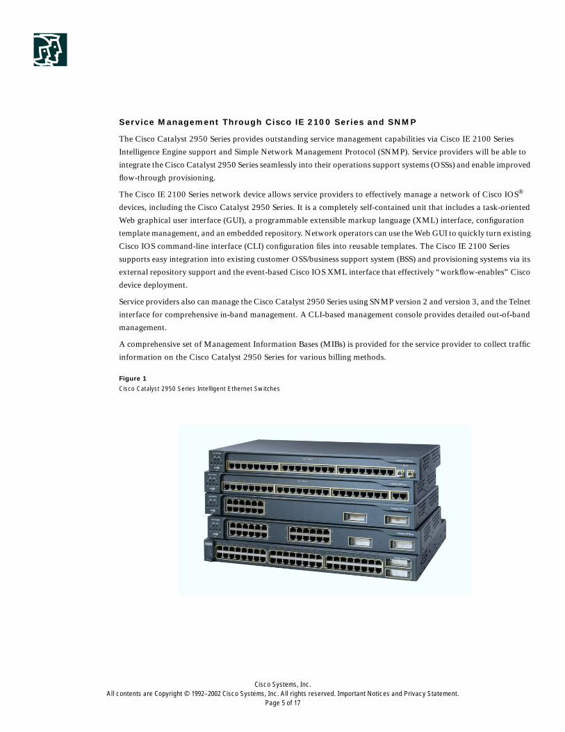
Figure 1
Cisco Catalyst 2950 Series Intelligent Ethernet Switches
Cisco Systems, Inc.All contents are Copyright © 1992–2002 Cisco Systems, Inc. All rights reserved. Important Notices and Privacy Statement.
Page 6 of 17
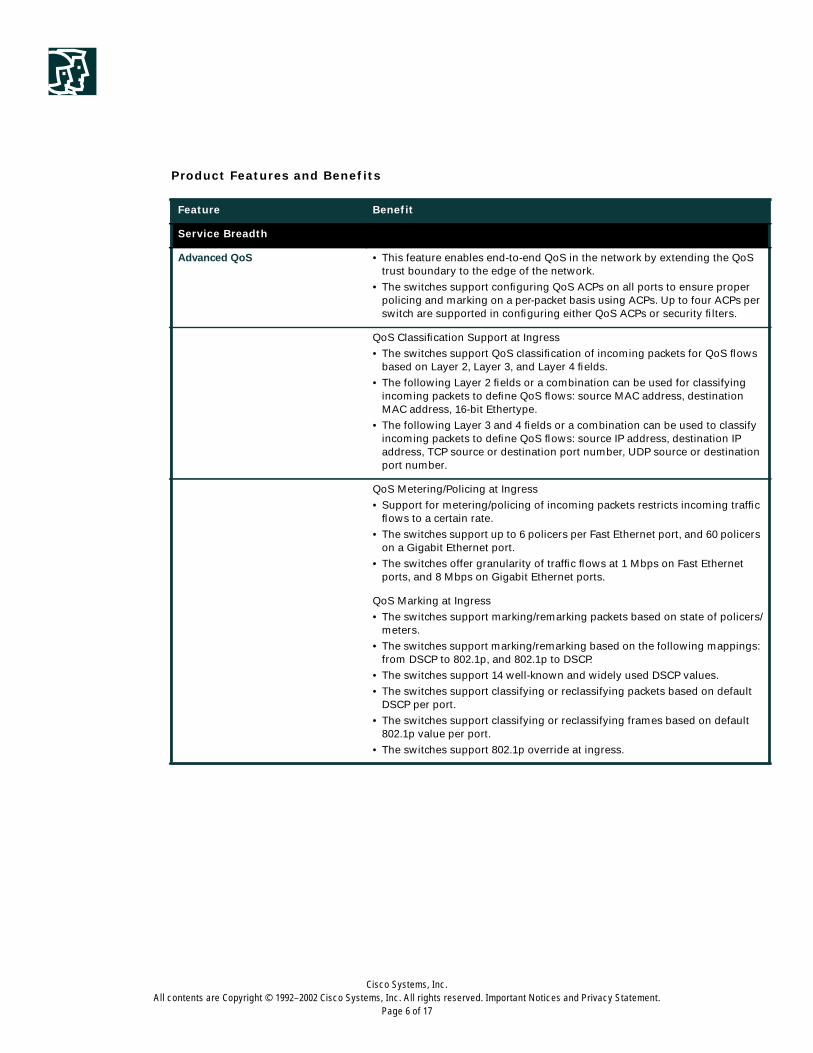
Product Features and Benefits
Feature Benefit
Service Breadth
Advanced QoS • This feature enables end-to-end QoS in the network by extending the QoStrust boundary to the edge of the network.
• The switches support configuring QoS ACPs on all ports to ensure properpolicing and marking on a per-packet basis using ACPs. Up to four ACPs perswitch are supported in configuring either QoS ACPs or security filters.
QoS Classification Support at Ingress
• The switches support QoS classification of incoming packets for QoS flowsbased on Layer 2, Layer 3, and Layer 4 fields.
• The following Layer 2 fields or a combination can be used for classifyingincoming packets to define QoS flows: source MAC address, destinationMAC address, 16-bit Ethertype.
• The following Layer 3 and 4 fields or a combination can be used to classifyincoming packets to define QoS flows: source IP address, destination IPaddress, TCP source or destination port number, UDP source or destinationport number.
QoS Metering/Policing at Ingress
• Support for metering/policing of incoming packets restricts incoming trafficflows to a certain rate.
• The switches support up to 6 policers per Fast Ethernet port, and 60 policerson a Gigabit Ethernet port.
• The switches offer granularity of traffic flows at 1 Mbps on Fast Ethernetports, and 8 Mbps on Gigabit Ethernet ports.
QoS Marking at Ingress
• The switches support marking/remarking packets based on state of policers/meters.
• The switches support marking/remarking based on the following mappings:from DSCP to 802.1p, and 802.1p to DSCP.
• The switches support 14 well-known and widely used DSCP values.
• The switches support classifying or reclassifying packets based on defaultDSCP per port.
• The switches support classifying or reclassifying frames based on default802.1p value per port.
• The switches support 802.1p override at ingress.
Cisco Systems, Inc.All contents are Copyright © 1992–2002 Cisco Systems, Inc. All rights reserved. Important Notices and Privacy Statement.
Page 7 of 17
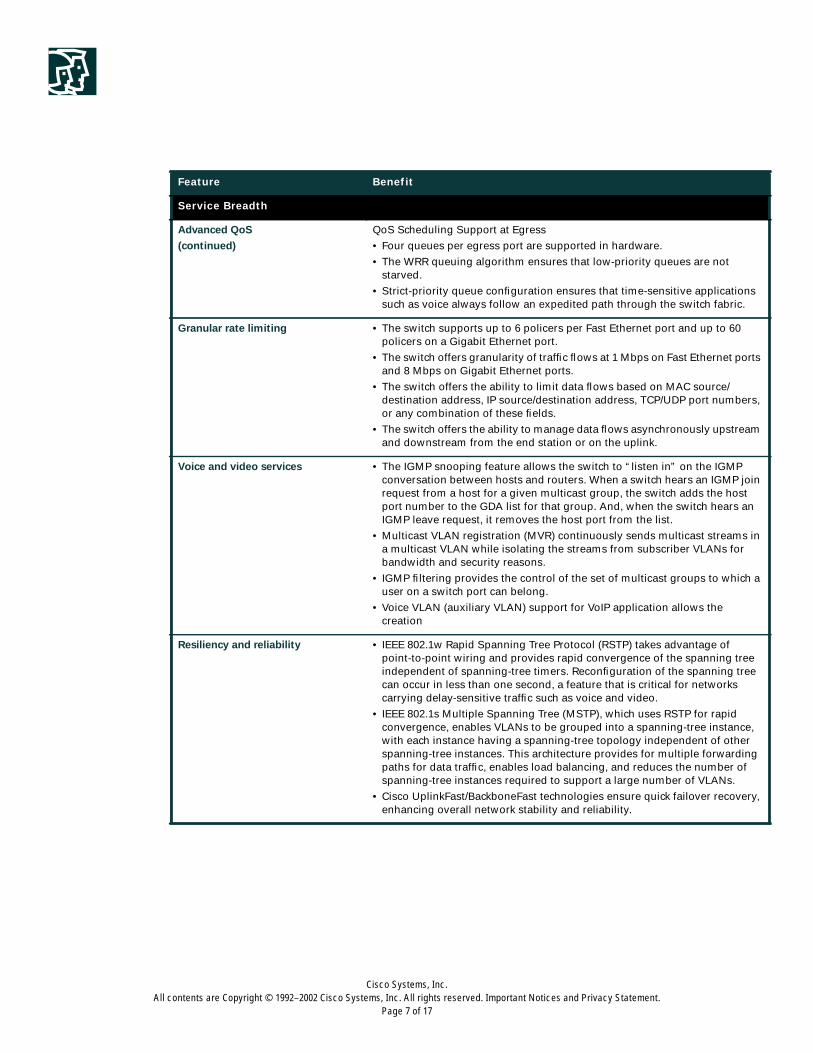
Service Breadth
Advanced QoS
(continued)
QoS Scheduling Support at Egress
• Four queues per egress port are supported in hardware.
• The WRR queuing algorithm ensures that low-priority queues are notstarved.
• Strict-priority queue configuration ensures that time-sensitive applicationssuch as voice always follow an expedited path through the switch fabric.
Granular rate limiting • The switch supports up to 6 policers per Fast Ethernet port and up to 60policers on a Gigabit Ethernet port.
• The switch offers granularity of traffic flows at 1 Mbps on Fast Ethernet portsand 8 Mbps on Gigabit Ethernet ports.
• The switch offers the ability to limit data flows based on MAC source/destination address, IP source/destination address, TCP/UDP port numbers,or any combination of these fields.
• The switch offers the ability to manage data flows asynchronously upstreamand downstream from the end station or on the uplink.
Voice and video services • The IGMP snooping feature allows the switch to “listen in” on the IGMPconversation between hosts and routers. When a switch hears an IGMP joinrequest from a host for a given multicast group, the switch adds the hostport number to the GDA list for that group. And, when the switch hears anIGMP leave request, it removes the host port from the list.
• Multicast VLAN registration (MVR) continuously sends multicast streams ina multicast VLAN while isolating the streams from subscriber VLANs forbandwidth and security reasons.
• IGMP filtering provides the control of the set of multicast groups to which auser on a switch port can belong.
• Voice VLAN (auxiliary VLAN) support for VoIP application allows thecreation
Resiliency and reliability • IEEE 802.1w Rapid Spanning Tree Protocol (RSTP) takes advantage ofpoint-to-point wiring and provides rapid convergence of the spanning treeindependent of spanning-tree timers. Reconfiguration of the spanning treecan occur in less than one second, a feature that is critical for networkscarrying delay-sensitive traffic such as voice and video.
• IEEE 802.1s Multiple Spanning Tree (MSTP), which uses RSTP for rapidconvergence, enables VLANs to be grouped into a spanning-tree instance,with each instance having a spanning-tree topology independent of otherspanning-tree instances. This architecture provides for multiple forwardingpaths for data traffic, enables load balancing, and reduces the number ofspanning-tree instances required to support a large number of VLANs.
• Cisco UplinkFast/BackboneFast technologies ensure quick failover recovery,enhancing overall network stability and reliability.
Feature Benefit
Cisco Systems, Inc.All contents are Copyright © 1992–2002 Cisco Systems, Inc. All rights reserved. Important Notices and Privacy Statement.
Page 8 of 17
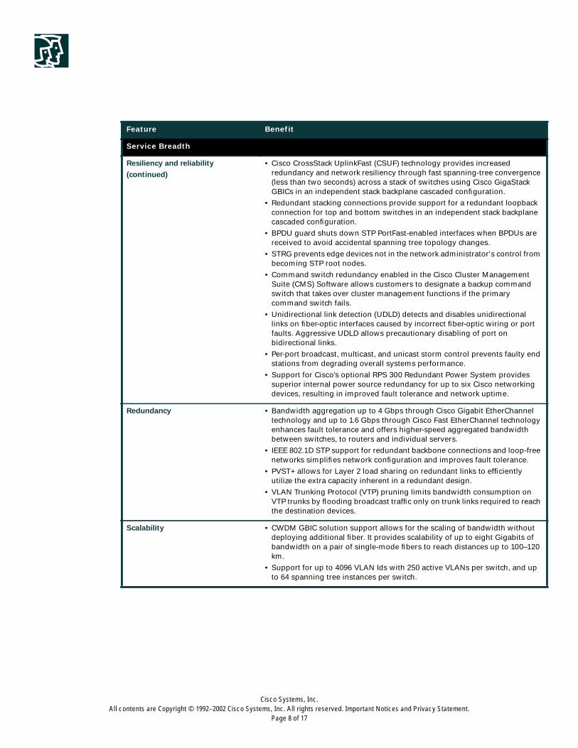
Service Breadth
Resiliency and reliability
(continued)
• Cisco CrossStack UplinkFast (CSUF) technology provides increasedredundancy and network resiliency through fast spanning-tree convergence(less than two seconds) across a stack of switches using Cisco GigaStackGBICs in an independent stack backplane cascaded configuration.
• Redundant stacking connections provide support for a redundant loopbackconnection for top and bottom switches in an independent stack backplanecascaded configuration.
• BPDU guard shuts down STP PortFast-enabled interfaces when BPDUs arereceived to avoid accidental spanning tree topology changes.
• STRG prevents edge devices not in the network administrator's control frombecoming STP root nodes.
• Command switch redundancy enabled in the Cisco Cluster ManagementSuite (CMS) Software allows customers to designate a backup commandswitch that takes over cluster management functions if the primarycommand switch fails.
• Unidirectional link detection (UDLD) detects and disables unidirectionallinks on fiber-optic interfaces caused by incorrect fiber-optic wiring or portfaults. Aggressive UDLD allows precautionary disabling of port onbidirectional links.
• Per-port broadcast, multicast, and unicast storm control prevents faulty endstations from degrading overall systems performance.
• Support for Cisco’s optional RPS 300 Redundant Power System providessuperior internal power source redundancy for up to six Cisco networkingdevices, resulting in improved fault tolerance and network uptime.
Redundancy • Bandwidth aggregation up to 4 Gbps through Cisco Gigabit EtherChanneltechnology and up to 1.6 Gbps through Cisco Fast EtherChannel technologyenhances fault tolerance and offers higher-speed aggregated bandwidthbetween switches, to routers and individual servers.
• IEEE 802.1D STP support for redundant backbone connections and loop-freenetworks simplifies network configuration and improves fault tolerance.
• PVST+ allows for Layer 2 load sharing on redundant links to efficientlyutilize the extra capacity inherent in a redundant design.
• VLAN Trunking Protocol (VTP) pruning limits bandwidth consumption onVTP trunks by flooding broadcast traffic only on trunk links required to reachthe destination devices.
Scalability • CWDM GBIC solution support allows for the scaling of bandwidth withoutdeploying additional fiber. It provides scalability of up to eight Gigabits ofbandwidth on a pair of single-mode fibers to reach distances up to 100–120km.
• Support for up to 4096 VLAN Ids with 250 active VLANs per switch, and upto 64 spanning tree instances per switch.
Feature Benefit
Cisco Systems, Inc.All contents are Copyright © 1992–2002 Cisco Systems, Inc. All rights reserved. Important Notices and Privacy Statement.
Page 9 of 17
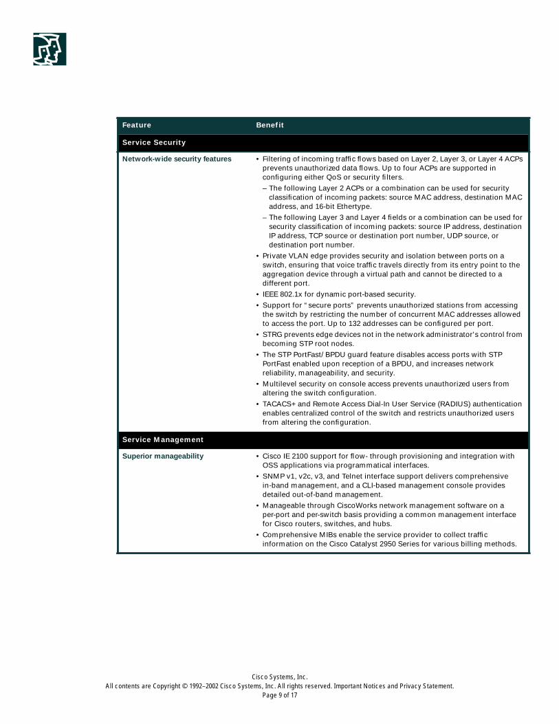
Service Security
Network-wide security features • Filtering of incoming traffic flows based on Layer 2, Layer 3, or Layer 4 ACPsprevents unauthorized data flows. Up to four ACPs are supported inconfiguring either QoS or security filters.
– The following Layer 2 ACPs or a combination can be used for securityclassification of incoming packets: source MAC address, destination MACaddress, and 16-bit Ethertype.
– The following Layer 3 and Layer 4 fields or a combination can be used forsecurity classification of incoming packets: source IP address, destinationIP address, TCP source or destination port number, UDP source, ordestination port number.
• Private VLAN edge provides security and isolation between ports on aswitch, ensuring that voice traffic travels directly from its entry point to theaggregation device through a virtual path and cannot be directed to adifferent port.
• IEEE 802.1x for dynamic port-based security.
• Support for “secure ports” prevents unauthorized stations from accessingthe switch by restricting the number of concurrent MAC addresses allowedto access the port. Up to 132 addresses can be configured per port.
• STRG prevents edge devices not in the network administrator's control frombecoming STP root nodes.
• The STP PortFast/ BPDU guard feature disables access ports with STPPortFast enabled upon reception of a BPDU, and increases networkreliability, manageability, and security.
• Multilevel security on console access prevents unauthorized users fromaltering the switch configuration.
• TACACS+ and Remote Access Dial-In User Service (RADIUS) authenticationenables centralized control of the switch and restricts unauthorized usersfrom altering the configuration.
Service Management
Superior manageability • Cisco IE 2100 support for flow- through provisioning and integration withOSS applications via programmatical interfaces.
• SNMP v1, v2c, v3, and Telnet interface support delivers comprehensivein-band management, and a CLI-based management console providesdetailed out-of-band management.
• Manageable through CiscoWorks network management software on aper-port and per-switch basis providing a common management interfacefor Cisco routers, switches, and hubs.
• Comprehensive MIBs enable the service provider to collect trafficinformation on the Cisco Catalyst 2950 Series for various billing methods.
Feature Benefit
Cisco Systems, Inc.All contents are Copyright © 1992–2002 Cisco Systems, Inc. All rights reserved. Important Notices and Privacy Statement.
Page 10 of 17
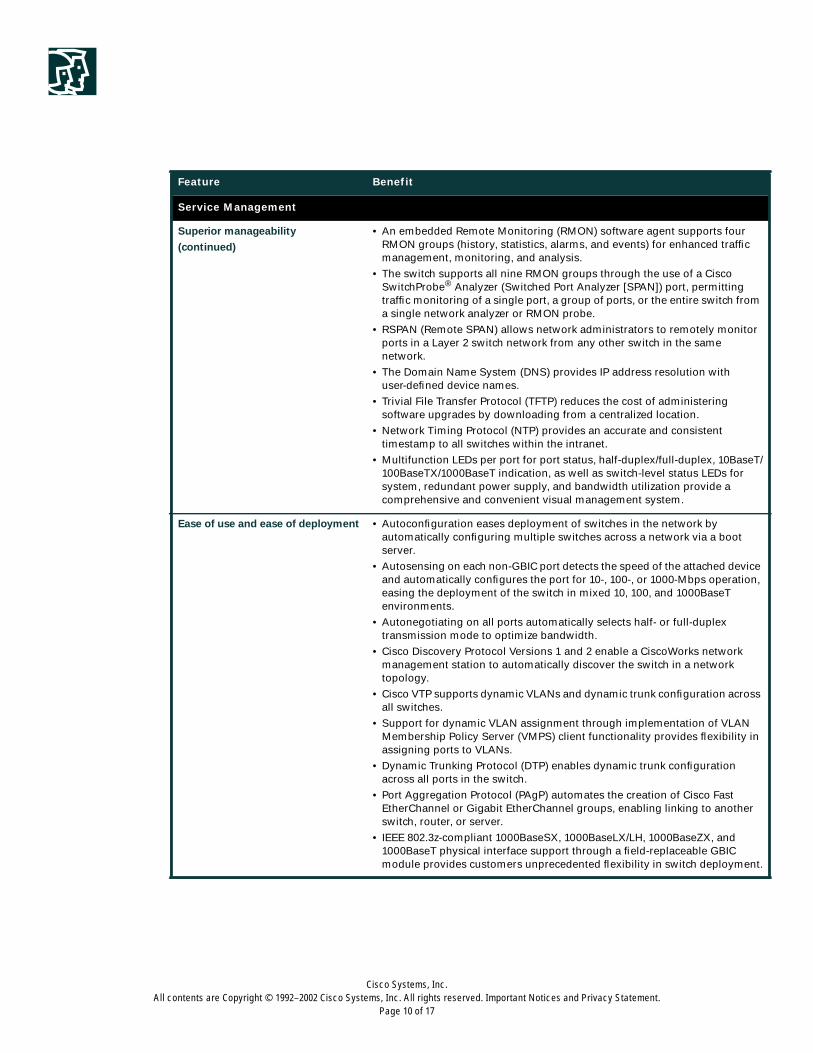
Service Management
Superior manageability
(continued)
• An embedded Remote Monitoring (RMON) software agent supports fourRMON groups (history, statistics, alarms, and events) for enhanced trafficmanagement, monitoring, and analysis.
• The switch supports all nine RMON groups through the use of a CiscoSwitchProbe® Analyzer (Switched Port Analyzer [SPAN]) port, permittingtraffic monitoring of a single port, a group of ports, or the entire switch froma single network analyzer or RMON probe.
• RSPAN (Remote SPAN) allows network administrators to remotely monitorports in a Layer 2 switch network from any other switch in the samenetwork.
• The Domain Name System (DNS) provides IP address resolution withuser-defined device names.
• Trivial File Transfer Protocol (TFTP) reduces the cost of administeringsoftware upgrades by downloading from a centralized location.
• Network Timing Protocol (NTP) provides an accurate and consistenttimestamp to all switches within the intranet.
• Multifunction LEDs per port for port status, half-duplex/full-duplex, 10BaseT/100BaseTX/1000BaseT indication, as well as switch-level status LEDs forsystem, redundant power supply, and bandwidth utilization provide acomprehensive and convenient visual management system.
Ease of use and ease of deployment • Autoconfiguration eases deployment of switches in the network byautomatically configuring multiple switches across a network via a bootserver.
• Autosensing on each non-GBIC port detects the speed of the attached deviceand automatically configures the port for 10-, 100-, or 1000-Mbps operation,easing the deployment of the switch in mixed 10, 100, and 1000BaseTenvironments.
• Autonegotiating on all ports automatically selects half- or full-duplextransmission mode to optimize bandwidth.
• Cisco Discovery Protocol Versions 1 and 2 enable a CiscoWorks networkmanagement station to automatically discover the switch in a networktopology.
• Cisco VTP supports dynamic VLANs and dynamic trunk configuration acrossall switches.
• Support for dynamic VLAN assignment through implementation of VLANMembership Policy Server (VMPS) client functionality provides flexibility inassigning ports to VLANs.
• Dynamic Trunking Protocol (DTP) enables dynamic trunk configurationacross all ports in the switch.
• Port Aggregation Protocol (PAgP) automates the creation of Cisco FastEtherChannel or Gigabit EtherChannel groups, enabling linking to anotherswitch, router, or server.
• IEEE 802.3z-compliant 1000BaseSX, 1000BaseLX/LH, 1000BaseZX, and1000BaseT physical interface support through a field-replaceable GBICmodule provides customers unprecedented flexibility in switch deployment.
Feature Benefit
Cisco Systems, Inc.All contents are Copyright © 1992–2002 Cisco Systems, Inc. All rights reserved. Important Notices and Privacy Statement.
Page 11 of 17
Product Specifications
(See separate Cisco Catalyst 2950 LRE data sheet for Catalyst 2950ST-24-LRE and Catalyst 2950ST-8-LRE product
specifications)
Service Management
Ease of use and ease of deployment
(continued)
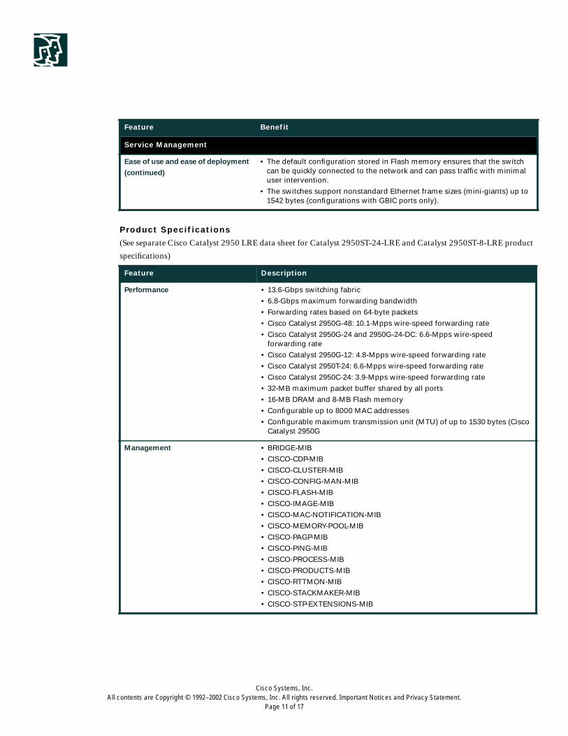
• The default configuration stored in Flash memory ensures that the switchcan be quickly connected to the network and can pass traffic with minimaluser intervention.
• The switches support nonstandard Ethernet frame sizes (mini-giants) up to1542 bytes (configurations with GBIC ports only).
Feature Description
Performance • 13.6-Gbps switching fabric
• 6.8-Gbps maximum forwarding bandwidth
• Forwarding rates based on 64-byte packets
• Cisco Catalyst 2950G-48: 10.1-Mpps wire-speed forwarding rate
• Cisco Catalyst 2950G-24 and 2950G-24-DC: 6.6-Mpps wire-speedforwarding rate
• Cisco Catalyst 2950G-12: 4.8-Mpps wire-speed forwarding rate
• Cisco Catalyst 2950T-24: 6.6-Mpps wire-speed forwarding rate
• Cisco Catalyst 2950C-24: 3.9-Mpps wire-speed forwarding rate
• 32-MB maximum packet buffer shared by all ports
• 16-MB DRAM and 8-MB Flash memory
• Configurable up to 8000 MAC addresses
• Configurable maximum transmission unit (MTU) of up to 1530 bytes (CiscoCatalyst 2950G
Management • BRIDGE-MIB
• CISCO-CDP-MIB
• CISCO-CLUSTER-MIB
• CISCO-CONFIG-MAN-MIB
• CISCO-FLASH-MIB
• CISCO-IMAGE-MIB
• CISCO-MAC-NOTIFICATION-MIB
• CISCO-MEMORY-POOL-MIB
• CISCO-PAGP-MIB
• CISCO-PING-MIB
• CISCO-PROCESS-MIB
• CISCO-PRODUCTS-MIB
• CISCO-RTTMON-MIB
• CISCO-STACKMAKER-MIB
• CISCO-STP-EXTENSIONS-MIB
Feature Benefit
Cisco Systems, Inc.All contents are Copyright © 1992–2002 Cisco Systems, Inc. All rights reserved. Important Notices and Privacy Statement.
Page 12 of 17
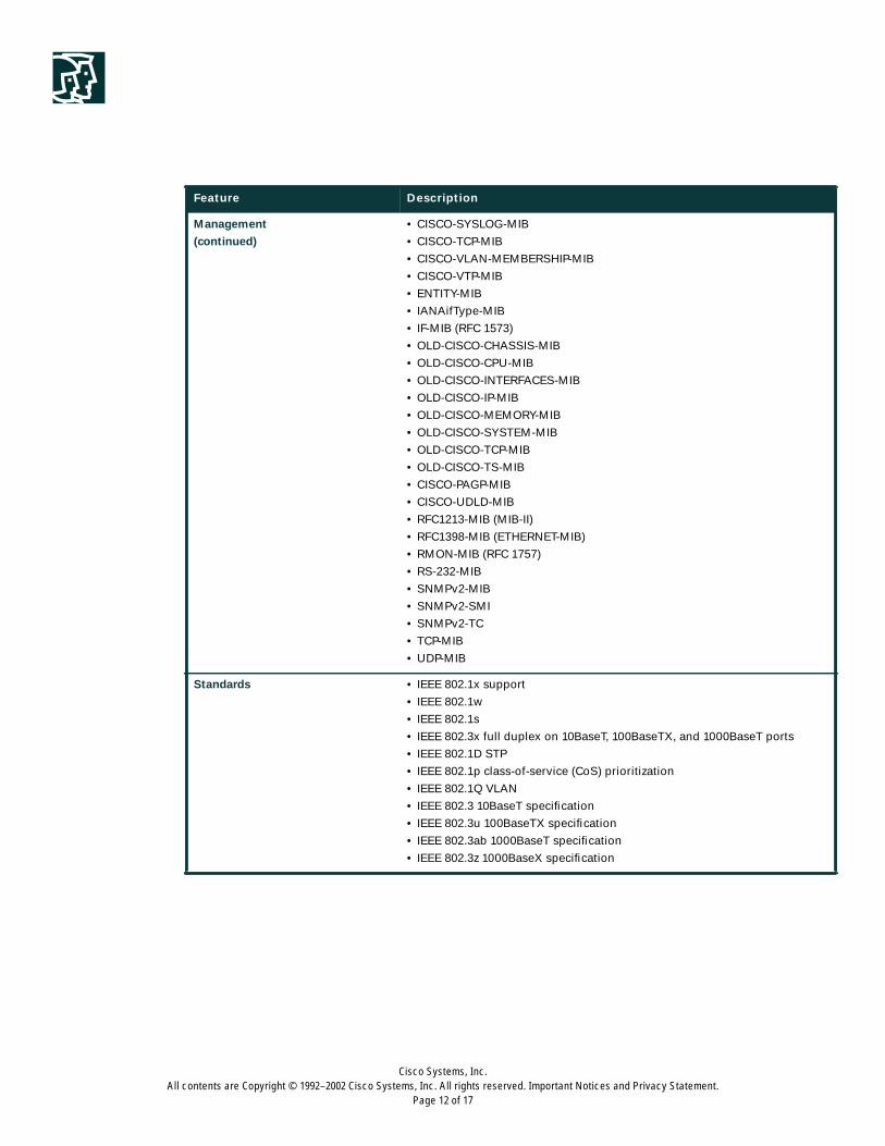
Management
(continued)
• CISCO-SYSLOG-MIB
• CISCO-TCP-MIB
• CISCO-VLAN-MEMBERSHIP-MIB
• CISCO-VTP-MIB
• ENTITY-MIB
• IANAifType-MIB
• IF-MIB (RFC 1573)
• OLD-CISCO-CHASSIS-MIB
• OLD-CISCO-CPU-MIB
• OLD-CISCO-INTERFACES-MIB
• OLD-CISCO-IP-MIB
• OLD-CISCO-MEMORY-MIB
• OLD-CISCO-SYSTEM-MIB
• OLD-CISCO-TCP-MIB
• OLD-CISCO-TS-MIB
• CISCO-PAGP-MIB
• CISCO-UDLD-MIB
• RFC1213-MIB (MIB-II)
• RFC1398-MIB (ETHERNET-MIB)
• RMON-MIB (RFC 1757)
• RS-232-MIB
• SNMPv2-MIB
• SNMPv2-SMI
• SNMPv2-TC
• TCP-MIB
• UDP-MIB
Standards • IEEE 802.1x support
• IEEE 802.1w
• IEEE 802.1s
• IEEE 802.3x full duplex on 10BaseT, 100BaseTX, and 1000BaseT ports
• IEEE 802.1D STP
• IEEE 802.1p class-of-service (CoS) prioritization
• IEEE 802.1Q VLAN
• IEEE 802.3 10BaseT specification
• IEEE 802.3u 100BaseTX specification
• IEEE 802.3ab 1000BaseT specification
• IEEE 802.3z 1000BaseX specification
Feature Description
Cisco Systems, Inc.All contents are Copyright © 1992–2002 Cisco Systems, Inc. All rights reserved. Important Notices and Privacy Statement.
Page 13 of 17
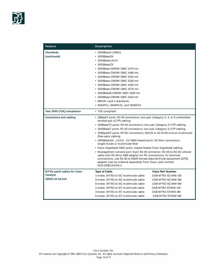
Standards
(continued)
• 1000BaseX (GBIC)
• 1000BaseSX
• 1000BaseLX/LH
• 1000BaseZX
• 1000Base-CWDM GBIC 1470 nm
• 1000Base-CWDM GBIC 1490 nm
• 1000Base-CWDM GBIC 1510 nm
• 1000Base-CWDM GBIC 1530 nm
• 1000Base-CWDM GBIC 1550 nm
• 1000Base-CWDM GBIC 1570 nm
• 1000BaseE-CWDM GBIC 1590 nm
• 1000Base-CWDM GBIC 1610 nm
• RMON I and II standards
• SNMPv1, SNMPv2c, and SNMPv3
Year 2000 (Y2K) compliance • Y2K compliant
Connectors and cabling • 10BaseT ports: RJ-45 connectors; two-pair Category 3, 4, or 5 unshieldedtwisted-pair (UTP) cabling
• 100BaseTX ports: RJ-45 connectors; two-pair Category 5 UTP cabling
• 1000BaseT ports: RJ-45 connectors; two-pair Category 5 UTP cabling
• 100BaseFX ports: MT-RJ connectors, 50/125 or 62.5/125 micron multimodefiber-optic cabling
• 1000BaseSX, -LX/LH, -ZX GBIC-based ports: SC fiber connectors,single-mode or multimode fiber
• Cisco GigaStack GBIC ports: copper-based Cisco GigaStack cabling
• Management console port: 8-pin RJ-45 connector, RJ-45-to-RJ-45 rollovercable with RJ-45-to-DB9 adapter for PC connections; for terminalconnections, use RJ-45-to-DB25 female data-terminal-equipment (DTE)adapter (can be ordered separately from Cisco, part numberACS-DSBUASYN=)
MT-RJ patch cables for CiscoCatalyst
2950C-24 Switch
Type of Cable Cisco Part Number
1-meter, MT-RJ-to-SC multimode cable CAB-MTRJ-SC-MM-1M
3-meter, MT-RJ-to-SC multimode cable CAB-MTRJ-SC-MM-3M
5-meter, MT-RJ-to-SC multimode cable CAB-MTRJ-SC-MM-5M
1-meter, MT-RJ-to-ST multimode cable CAB-MTRJ-ST-MM-1M
3-meter, MT-RJ-to-ST multimode cable CAB-MTRJ-ST-MM-3M
5-meter, MT-RJ-to-ST multimode cable CAB-MTRJ-ST-MM-5M
Feature Description
Cisco Systems, Inc.All contents are Copyright © 1992–2002 Cisco Systems, Inc. All rights reserved. Important Notices and Privacy Statement.
Page 14 of 17
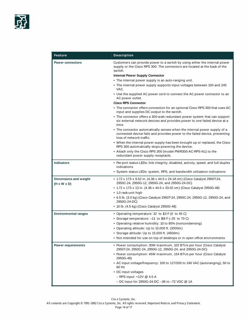
Power connectors Customers can provide power to a switch by using either the internal powersupply or the Cisco RPS 300. The connectors are located at the back of theswitch.
Internal Power Supply Connector
• The internal power supply is an auto-ranging unit.
• The internal power supply supports input voltages between 100 and 240VAC.
• Use the supplied AC power cord to connect the AC power connector to anAC power outlet.
Cisco RPS Connector
• The connector offers connection for an optional Cisco RPS 300 that uses ACinput and supplies DC output to the switch.
• The connector offers a 300-watt redundant power system that can supportsix external network devices and provides power to one failed device at atime.
• The connector automatically senses when the internal power supply of aconnected device fails and provides power to the failed device, preventingloss of network traffic.
• When the internal power supply has been brought up or replaced, the CiscoRPS 300 automatically stops powering the device.
• Attach only the Cisco RPS 300 (model PWR300-AC-RPS-N1) to theredundant power supply receptacle.
Indicators • Per-port status LEDs: link integrity, disabled, activity, speed, and full-duplexindications
• System status LEDs: system, RPS, and bandwidth utilization indications
Dimensions and weight
(H x W x D)
• 1.72 x 17.5 x 9.52 in. (4.36 x 44.5 x 24.18 cm) (Cisco Catalyst 2950T-24,2950C-24, 2950G-12, 2950G-24, and 2950G-24-DC)
• 1.72 x 17.5 x 13 in. (4.36 x 44.5 x 33.02 cm) (Cisco Catalyst 2950G-48)
• 1.0 rack-unit high
• 6.5 lb. (3.0 kg) (Cisco Catalyst 2950T-24, 2950C-24, 2950G-12, 2950G-24, and2950G-24-DC)
• 10 lb. (4.5 kg) (Cisco Catalyst 2950G-48)
Environmental ranges • Operating temperature: 32 to 113 F (0 to 45 C)
• Storage temperature: –13 to 158 F (–25 to 70 C)
• Operating relative humidity: 10 to 85% (noncondensing)
• Operating altitude: Up to 10,000 ft. (3000m)
• Storage altitude: Up to 15,000 ft. (4500m)
• Not intended for use on top of desktops or in open office environments
Power requirements • Power consumption: 30W maximum, 102 BTUs per hour (Cisco Catalyst2950T-24, 2950C-24, 2950G-12, 2950G-24, and 2950G-24-DC)
• Power consumption: 45W maximum, 154 BTUs per hour (Cisco Catalyst2950G-48)
• AC input voltage/frequency: 100 to 127/200 to 240 VAC (autoranging), 50 to60 Hz
• DC input voltages
– RPS input: +12V @ 4.5 A
– DC input for 2950G-24-DC: –36 to –72 VDC @ 1A
Feature Description
Cisco Systems, Inc.All contents are Copyright © 1992–2002 Cisco Systems, Inc. All rights reserved. Important Notices and Privacy Statement.
Page 15 of 17
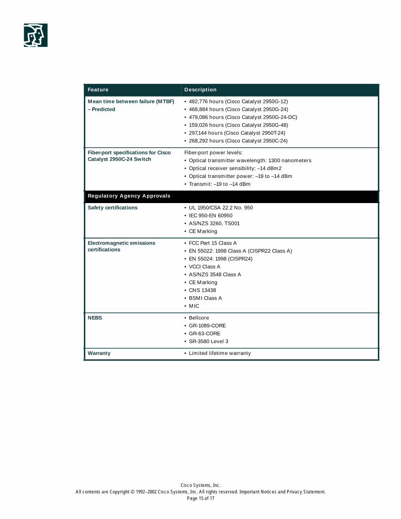
Mean time between failure (MTBF)
– Predicted
• 482,776 hours (Cisco Catalyst 2950G-12)
• 468,884 hours (Cisco Catalyst 2950G-24)
• 479,086 hours (Cisco Catalyst 2950G-24-DC)
• 159,026 hours (Cisco Catalyst 2950G-48)
• 297,144 hours (Cisco Catalyst 2950T-24)
• 268,292 hours (Cisco Catalyst 2950C-24)
Fiber-port specifications for CiscoCatalyst 2950C-24 Switch
Fiber-port power levels:
• Optical transmitter wavelength: 1300 nanometers
• Optical receiver sensibility: –14 dBm2
• Optical transmitter power: –19 to –14 dBm
• Transmit: –19 to –14 dBm
Regulatory Agency Approvals
Safety certifications • UL 1950/CSA 22.2 No. 950
• IEC 950-EN 60950
• AS/NZS 3260, TS001
• CE Marking
Electromagnetic emissionscertifications
• FCC Part 15 Class A
• EN 55022: 1998 Class A (CISPR22 Class A)
• EN 55024: 1998 (CISPR24)
• VCCI Class A
• AS/NZS 3548 Class A
• CE Marking
• CNS 13438
• BSMI Class A
• MIC
NEBS • Bellcore
• GR-1089-CORE
• GR-63-CORE
• SR-3580 Level 3
Warranty • Limited lifetime warranty
Feature Description
Cisco Systems, Inc.All contents are Copyright © 1992–2002 Cisco Systems, Inc. All rights reserved. Important Notices and Privacy Statement.
Page 16 of 17
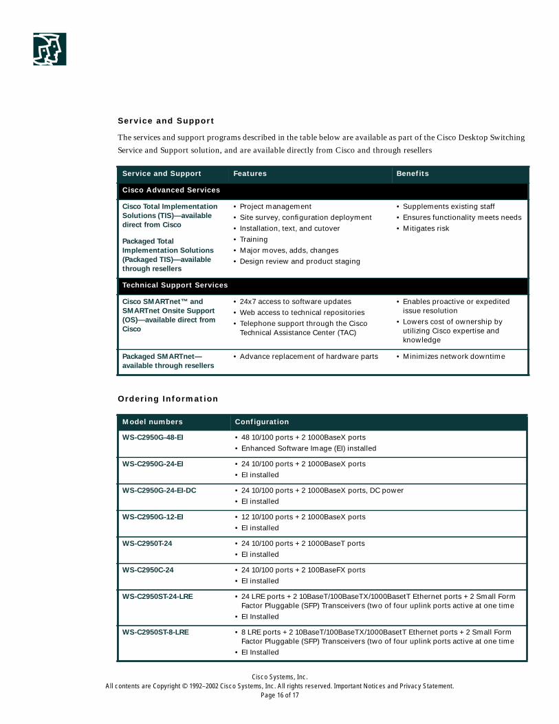
Service and Support
The services and support programs described in the table below are available as part of the Cisco Desktop Switching
Service and Support solution, and are available directly from Cisco and through resellers
Ordering Information
Service and Support Features Benefits
Cisco Advanced Services
Cisco Total ImplementationSolutions (TIS)—availabledirect from Cisco
• Project management
• Site survey, configuration deployment
• Installation, text, and cutover
• Training
• Major moves, adds, changes
• Design review and product staging
• Supplements existing staff
• Ensures functionality meets needs
• Mitigates risk
Packaged TotalImplementation Solutions(Packaged TIS)—availablethrough resellers
Technical Support Services
Cisco SMARTnet™ andSMARTnet Onsite Support(OS)—available direct fromCisco
• 24x7 access to software updates
• Web access to technical repositories
• Telephone support through the CiscoTechnical Assistance Center (TAC)
• Enables proactive or expeditedissue resolution
• Lowers cost of ownership byutilizing Cisco expertise andknowledge
Packaged SMARTnet—available through resellers
• Advance replacement of hardware parts • Minimizes network downtime
Model numbers Configuration
WS-C2950G-48-EI • 48 10/100 ports + 2 1000BaseX ports
• Enhanced Software Image (EI) installed
WS-C2950G-24-EI • 24 10/100 ports + 2 1000BaseX ports
• EI installed
WS-C2950G-24-EI-DC • 24 10/100 ports + 2 1000BaseX ports, DC power
• EI installed
WS-C2950G-12-EI • 12 10/100 ports + 2 1000BaseX ports
• EI installed
WS-C2950T-24 • 24 10/100 ports + 2 1000BaseT ports
• EI installed
WS-C2950C-24 • 24 10/100 ports + 2 100BaseFX ports
• EI installed
WS-C2950ST-24-LRE • 24 LRE ports + 2 10BaseT/100BaseTX/1000BasetT Ethernet ports + 2 Small FormFactor Pluggable (SFP) Transceivers (two of four uplink ports active at one time
• EI Installed
WS-C2950ST-8-LRE • 8 LRE ports + 2 10BaseT/100BaseTX/1000BasetT Ethernet ports + 2 Small FormFactor Pluggable (SFP) Transceivers (two of four uplink ports active at one time
• EI Installed

Corporate HeadquartersCisco Systems, Inc.170 West Tasman DriveSan Jose, CA 95134-1706USAwww.cisco.comTel: 408 526-4000
800 553-NETS (6387)Fax: 408 526-4100
European HeadquartersCisco Systems International BVHaarlerbergparkHaarlerbergweg 13-191101 CH AmsterdamThe Netherlandswww-europe.cisco.comTel: 31 0 20 357 1000Fax: 31 0 20 357 1100
Americas HeadquartersCisco Systems, Inc.170 West Tasman DriveSan Jose, CA 95134-1706USAwww.cisco.comTel: 408 526-7660Fax: 408 527-0883
Asia Pacific HeadquartersCisco Systems, Inc.Capital Tower168 Robinson Road#22-01 to #29-01Singapore 068912www.cisco.comTel: +65 317 7777Fax: +65 317 7799
Cisco Systems has more than 200 offices in the following countries and regions. Addresses, phone numbers, and fax numbers are listed on the
C i s c o W e b s i t e a t w w w . c i s c o . c o m / g o / o f f i c e s
Argentina • Australia • Austria • Belgium • Brazil • Bulgaria • Canada • Chile • China PRC • Colombia • Costa Rica • Croatia
Czech Republic • Denmark • Dubai, UAE • Finland • France • Germany • Greece • Hong Kong SAR • Hungary • India • Indonesia • Ireland
Israel • Italy • Japan • Korea • Luxembourg • Malaysia • Mexico • The Netherlands • New Zealand • Norway • Peru • Philippines • Poland
Portugal • Puerto Rico • Romania • Russia • Saudi Arabia • Scotland • Singapore • Slovakia • Slovenia • South Africa • Spain • Sweden
Switzer land • Taiwan • Thai land • Turkey • Ukraine • United Kingdom • United States • Venezuela • Vietnam • Zimbabwe
All contents are Copyright © 1992–2002, Cisco Systems, Inc. All rights reserved. Catalyst, Cisco, Cisco IOS, Cisco Systems, and the Cisco Systems logo are registered trademarks of Cisco Systems, Inc. and/or its affiliates in
the U.S. and certain other countries.
All other trademarks mentioned in this document or Web site are the property of their respective owners. The use of the word partner does not imply a partnership relationship between Cisco and any other company.
(0208R) LW3663 0902
For More Information on Cisco Products, Contact:
• United States and Canada: 800 553-NETS (6387)
• Europe: 32 2 778 4242
• Australia: 612 9935 4107
• Other: 408 526-7209
• World Wide Web URL: http://www.cisco.com