Embed Size (px)
Citation preview
7/25/2019 City Standard Construction Specifications
http://slidepdf.com/reader/full/city-standard-construction-specifications 1/511
7/25/2019 City Standard Construction Specifications
http://slidepdf.com/reader/full/city-standard-construction-specifications 2/511
CITY STANDARD CONSTRUCTION SPECIFICATIONS AND DETAILS 1/2015 UPDATES
GENERAL SUMMARY
A short term project was performed during the month of October 2014 with the assistance of Freese and
Nichols, Inc. (FNI) to review and address some known conflicts and omissions along with known dated
regulatory requirements in the current City Standard Construction Specifications. The focus targeted the
Standard Construction Specifications most commonly required for use on City Street Bond projects. The
recommended updates and edits are generally described below.
ADDED:
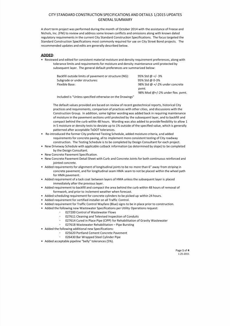
• Reviewed and edited for consistent material moisture and density requirement preferences, along with
tolerance limits and requirements for moisture and density maintenance until protected by
subsequent layer. The general default preferences are summarized below:
Backfill outside limits of pavement or structure (NG): 95% Std @ +/- 3%
Subgrade or under structures: 95% Std @ 0-3%
Flexible Base: 98% Std @ +/-2% under concrete
pvmt.
98% Mod @+/-2% under flex. pvmt.
Included is “Unless specified otherwise on the Drawings”
The default values provided are based on review of recent geotechnical reports, historical City
practices and requirements, comparison of practices with other cities, and discussions with the
Construction Group. In addition, some tighter wording was added back in requiring maintenance
of moisture in the pavement sections until protected by the subsequent layer, and to backfill and
compact behind the curb within 48 hours. Wording was also added to provide flexibility to allow 1
in 5 moisture or density tests to deviate up to 1% outside of the specified value, which is generally
patterned after acceptable TxDOT tolerances.
• Re-introduced the former City preferred Testing Schedule, added moisture criteria, and added
requirements for concrete paving, all to implement more consistent testing of City roadway
construction. The Testing Schedule is to be completed by Design Consultant for each project.
• New Driveway Schedule with applicable cutback information (as determined by slope) to be completed
by the Design Consultant.
•
New Concrete Pavement Specification.•
New Concrete Pavement Detail Sheet with Curb and Concrete Joints for both continuous reinforced and
jointed concrete.
• Added requirements for alignment of longitudinal joints to be no more than 6” away from striping in
concrete pavement, and for longitudinal seam HMA seam to not be placed within the wheel path
for HMA pavement.
•
Added requirement of a tack coat between layers of HMA unless the subsequent layer is placed
immediately after the previous layer.
• Added requirement to backfill and compact the area behind the curb within 48 hours of removal of
formwork, and prior to inclement weather when forecast.
•
Added scheduling requirement for concrete cylinders to be picked up within 24 hours.
• Added requirement for certified installer on all Traffic Control.
• Added requirement for Traffic Control Wayfare (Blue) signs to be in place prior to construction.
•
Added the following new Wastewater Specifications per Utility Operations request:
◦ 027200 Control of Wastewater Flows
◦ 027611 Cleaning and Televised Inspection of Conduits
◦ 027614 Cured in Place Pipe (CIPP) for Rehabilitation of Gravity Wastewater
◦ 027618 Wastewater Rehabilitation – Pipe Bursting
•
Added the following additional new Specifications:
◦ 025620 Portland Cement Concrete Pavement
◦ 026430 Bar Wrapped Steel Cylinder Pipe
• Added acceptable pipeline “belly” tolerances (5%).
Page 1 of 4 1-25-2015
7/25/2019 City Standard Construction Specifications
http://slidepdf.com/reader/full/city-standard-construction-specifications 3/511
CITY STANDARD CONSTRUCTION SPECIFICATIONS AND DETAILS 1/2015 UPDATES
GENERAL SUMMARY
• Added requirements for buried utilities beneath the roadway to be inspected, tested, and televised (as
applicable) prior to placement of the pavement section.
• Added requirement for pipe markings to be installed face up in the trench to allow for inspection.
•
Added new Storm Water Detail Sheets (3) with essential and common BMP Details (including a TCEQ
compliant inlet protection detail), and essential elements if the disturbed area is less than 1acre,
between 1-5 acres, or greater than 5 acres.
•
Updated references such as “Storm Sewer” and “Sanitary Sewer to “Storm Water” and “Wastewater”,
and “Proposal” to “Bid Form”.
• Reviewed Measurement and Payment sections and edited for typical City preferences, including units of
measure, with addition of “unless otherwise indicted on the Bid Form.”
• Added Storm Inlet Extensions (TxDOT based).
•
Added concrete apron to Post Inlet.
•
Added new Storm Water Manhole Details
• Added Storm MH riser Detail.
• Added Storm Detail for new pipe to existing RCB connection.
• Added Storm Concrete Collar Detail (only allowed for connection of like sized pipe).
•
Added Storm RCP Plug Detail.
• Added Storm Trench Backfill Details for Reinforced Concrete Pipe and for Reinforced Concrete Box.
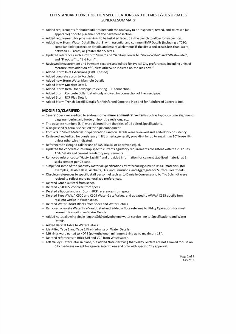
MODIFIED/CLARIFIED:
• Several Specs were edited to address some minor administrative items such as typos, column alignment,
page numbering and footer, minor title revisions, etc.
•
The obsolete numbers (S-#) were deleted from the titles of all edited Specifications.
• A single sand criteria is specified for pipe embedment.
• Conflicts in Select Material in Specifications and on Details were reviewed and edited for consistency.
• Reviewed and edited for consistency in lift criteria, generally providing for up to maximum 10” loose lifts
unless otherwise indicated.
• References to Geogrid call for use of TX5 Triaxial or approved equal.
• Updated the concrete curb ramp spec to current regulatory requirements consistent with the 2012 City
ADA Details and current regulatory requirements.
•
Removed references to “Hasty Backfill” and provided information for cement stabilized material at 2sacks cement per CY sand.
• Simplified some of the roadway material Specifications by referencing current TxDOT materials. (for
examples, Flexible Base, Asphalts, Oils, and Emulsions, and Aggregate for Surface Treatments).
•
Obsolete references to specific staff personnel such as to Danielle Converse and to Tilo Schmidt were
revised to reflect more generalized preferences.
• Deleted Grade 40 steel from specs.
• Deleted 2,500 PSI concrete from specs.
• Deleted elliptical and arch Storm RCP references from specs.
•
Deleted Type AWWA C500 and C509 Water Gate Valves, and updated to AWWA C515 ductile iron
resilient wedge in Water specs.
• Deleted Water Thrust Blocks from specs and Water Details.
• Removed obsolete Water Fire Vault Detail and added a Note referring to Utility Operations for most
current information on Water Details.• Added notes allowing single length SDR9 polyethylene water service line to Specifications and Water
Details.
• Added Backfill Table to Water Details.
•
Identified Type 1 and Type 2 Fire Hydrants on Water Details
• MH rings were edited to HDPE (polyethylene), minimum 1 ring up to maximum 18”.
• Deleted references to Brick MH and VCP from Wastewater.
• Left Valley Gutter Detail in place, but added Note clarifying that Valley Gutters are not allowed for use on
City roadways except for general interim use and only with specific City approval.
Page 2 of 4 1-25-2015
7/25/2019 City Standard Construction Specifications
http://slidepdf.com/reader/full/city-standard-construction-specifications 4/511
CITY STANDARD CONSTRUCTION SPECIFICATIONS AND DETAILS 1/2015 UPDATES
GENERAL SUMMARY
• Allow for option in Backfill Tables to use tested compacted effort on last 3’ of trench backfill instead of
cement stabilized material for concrete roadways.
• Revised the surface slope between the back of curb and the edge of sidewalk to maximum 2”/foot
instead of 1”/foot to reduce the amount of sidewalk curb required.
• Revised the Sidewalk Drain Detail to a secured trench plate, and removed the previous Sidewalk Drain
detail with a 3” PVC pipe drain through the curb.
•
Provided tapers on the driveway/curb to eliminate sharp corners, which tend to break.
•
Updated Sheet Title Blocks on edited Drawings to Capital Programs in place of Engineering Services.
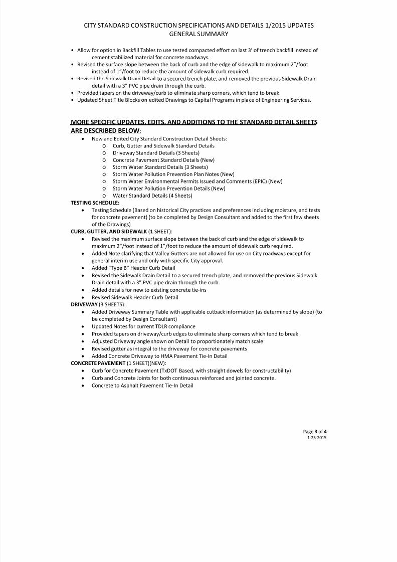
MORE SPECIFIC UPDATES, EDITS, AND ADDITIONS TO THE STANDARD DETAIL SHEETS
ARE DESCRIBED BELOW:
• New and Edited City Standard Construction Detail Sheets:
o
Curb, Gutter and Sidewalk Standard Details
o Driveway Standard Details (3 Sheets)
o Concrete Pavement Standard Details (New)
o Storm Water Standard Details (3 Sheets)
o
Storm Water Pollution Prevention Plan Notes (New)
o
Storm Water Environmental Permits Issued and Comments (EPIC) (New)
o Storm Water Pollution Prevention Details (New)
o Water Standard Details (4 Sheets)
TESTING SCHEDULE:
• Testing Schedule (Based on historical City practices and preferences including moisture, and tests
for concrete pavement) (to be completed by Design Consultant and added to the first few sheets
of the Drawings)
CURB, GUTTER, AND SIDEWALK (1 SHEET):
• Revised the maximum surface slope between the back of curb and the edge of sidewalk to
maximum 2”/foot instead of 1”/foot to reduce the amount of sidewalk curb required.
• Added Note clarifying that Valley Gutters are not allowed for use on City roadways except for
general interim use and only with specific City approval.
•
Added “Type B” Header Curb Detail• Revised the Sidewalk Drain Detail to a secured trench plate, and removed the previous Sidewalk
Drain detail with a 3” PVC pipe drain through the curb.
• Added details for new to existing concrete tie-ins
• Revised Sidewalk Header Curb Detail
DRIVEWAY (3 SHEETS):
• Added Driveway Summary Table with applicable cutback information (as determined by slope) (to
be completed by Design Consultant)
• Updated Notes for current TDLR compliance
• Provided tapers on driveway/curb edges to eliminate sharp corners which tend to break
• Adjusted Driveway angle shown on Detail to proportionately match scale
• Revised gutter as integral to the driveway for concrete pavements
•
Added Concrete Driveway to HMA Pavement Tie-In DetailCONCRETE PAVEMENT (1 SHEET)(NEW):
• Curb for Concrete Pavement (TxDOT Based, with straight dowels for constructability)
• Curb and Concrete Joints for both continuous reinforced and jointed concrete.
• Concrete to Asphalt Pavement Tie-In Detail
Page 3 of 4 1-25-2015
7/25/2019 City Standard Construction Specifications
http://slidepdf.com/reader/full/city-standard-construction-specifications 5/511
CITY STANDARD CONSTRUCTION SPECIFICATIONS AND DETAILS 1/2015 UPDATES
GENERAL SUMMARY
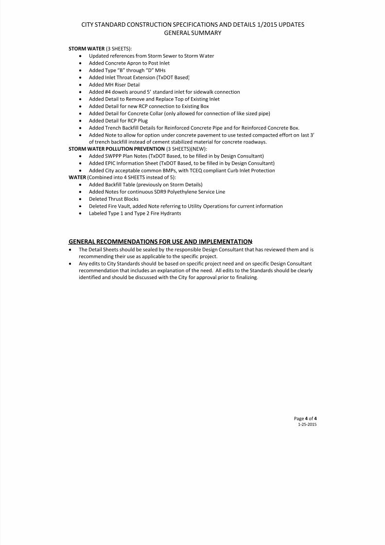
STORM WATER (3 SHEETS):
• Updated references from Storm Sewer to Storm Water
• Added Concrete Apron to Post Inlet
• Added Type “B” through “D” MHs
• Added Inlet Throat Extension (TxDOT Based)
•
Added MH Riser Detail• Added #4 dowels around 5’ standard inlet for sidewalk connection
• Added Detail to Remove and Replace Top of Existing Inlet
• Added Detail for new RCP connection to Existing Box
• Added Detail for Concrete Collar (only allowed for connection of like sized pipe)
• Added Detail for RCP Plug
• Added Trench Backfill Details for Reinforced Concrete Pipe and for Reinforced Concrete Box.
• Added Note to allow for option under concrete pavement to use tested compacted effort on last 3’
of trench backfill instead of cement stabilized material for concrete roadways.
STORM WATER POLLUTION PREVENTION (3 SHEETS)(NEW):
• Added SWPPP Plan Notes (TxDOT Based, to be filled in by Design Consultant)
• Added EPIC Information Sheet (TxDOT Based, to be filled in by Design Consultant)
•
Added City acceptable common BMPs, with TCEQ compliant Curb Inlet ProtectionWATER (Combined into 4 SHEETS instead of 5):
• Added Backfill Table (previously on Storm Details)
• Added Notes for continuous SDR9 Polyethylene Service Line
• Deleted Thrust Blocks
• Deleted Fire Vault, added Note referring to Utility Operations for current information
• Labeled Type 1 and Type 2 Fire Hydrants
GENERAL RECOMMENDATIONS FOR USE AND IMPLEMENTATION:
• The Detail Sheets should be sealed by the responsible Design Consultant that has reviewed them and is
recommending their use as applicable to the specific project.• Any edits to City Standards should be based on specific project need and on specific Design Consultant
recommendation that includes an explanation of the need. All edits to the Standards should be clearly
identified and should be discussed with the City for approval prior to finalizing.
Page 4 of 4 1-25-2015
7/25/2019 City Standard Construction Specifications
http://slidepdf.com/reader/full/city-standard-construction-specifications 6/511
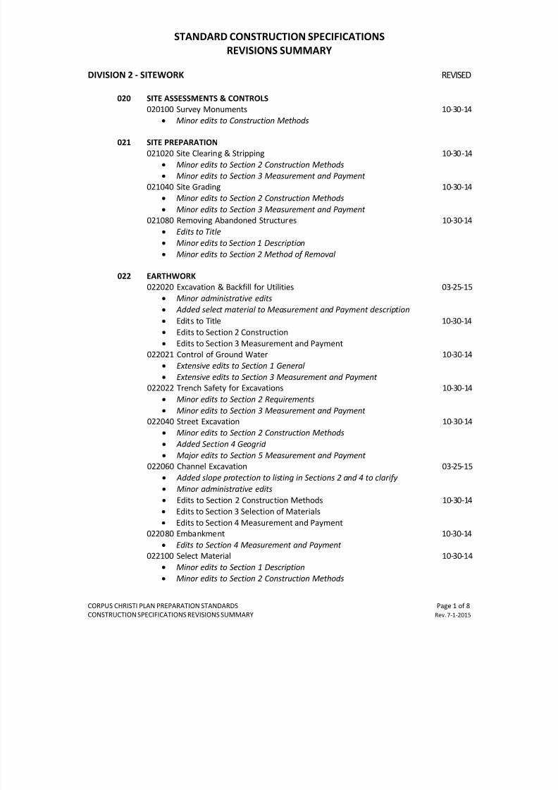
STANDARD CONSTRUCTION SPECIFICATIONS
REVISIONS SUMMARY
CORPUS CHRISTI PLAN PREPARATION STANDARDS Page 1 of 8
CONSTRUCTION SPECIFICATIONS REVISIONS SUMMARY Rev. 7-1-2015
DIVISION 2 - SITEWORK REVISED
020 SITE ASSESSMENTS & CONTROLS
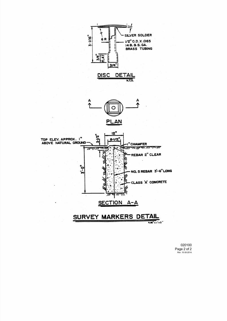
020100 Survey Monuments 10-30-14
•
Minor edits to Construction Methods
021 SITE PREPARATION
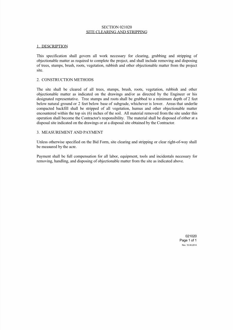
021020 Site Clearing & Stripping 10-30 -14
• Minor edits to Section 2 Construction Methods
•
Minor edits to Section 3 Measurement and Payment
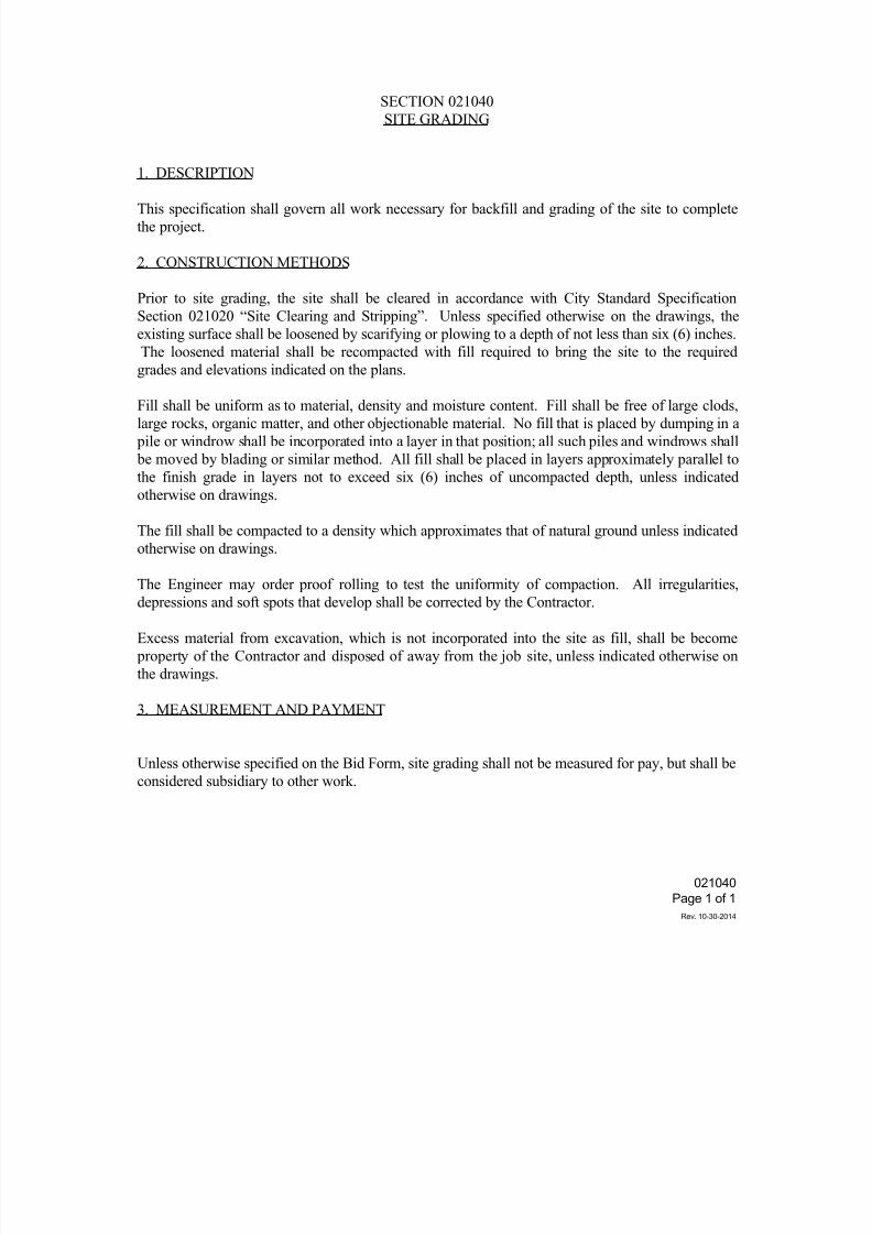
021040 Site Grading 10-30-14
•
Minor edits to Section 2 Construction Methods
• Minor edits to Section 3 Measurement and Payment
021080 Removing Abandoned Structures 10-30-14
• Edits to Title
• Minor edits to Section 1 Description
•
Minor edits to Section 2 Method of Removal
022 EARTHWORK
022020 Excavation & Backfill for Utilities 03-25-15
• Minor administrative edits
•
Added select material to Measurement and Payment description
• Edits to Title 10-30-14
• Edits to Section 2 Construction
•
Edits to Section 3 Measurement and Payment
022021 Control of Ground Water 10-30-14
•
Extensive edits to Section 1 General
•
Extensive edits to Section 3 Measurement and Payment 022022 Trench Safety for Excavations 10-30-14
• Minor edits to Section 2 Requirements
• Minor edits to Section 3 Measurement and Payment
022040 Street Excavation 10-30-14
•
Minor edits to Section 2 Construction Methods
•
Added Section 4 Geogrid
• Major edits to Section 5 Measurement and Payment
022060 Channel Excavation 03-25-15
• Added slope protection to listing in Sections 2 and 4 to clarify
• Minor administrative edits
•
Edits to Section 2 Construction Methods 10-30-14•
Edits to Section 3 Selection of Materials
• Edits to Section 4 Measurement and Payment
022080 Embankment 10-30-14
• Edits to Section 4 Measurement and Payment
022100 Select Material 10-30-14
• Minor edits to Section 1 Description
•
Minor edits to Section 2 Construction Methods
7/25/2019 City Standard Construction Specifications
http://slidepdf.com/reader/full/city-standard-construction-specifications 7/511
STANDARD CONSTRUCTION SPECIFICATIONS
REVISIONS SUMMARY
CORPUS CHRISTI PLAN PREPARATION STANDARDS Page 2 of 8
CONSTRUCTION SPECIFICATIONS REVISIONS SUMMARY Rev. 7-1-2015
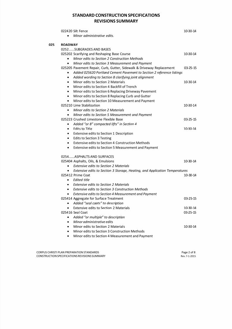
022420 Silt Fence 10-30-14
•
Minor administrative edits.
025 ROADWAY
0252......SUBGRADES AND BASES
025202 Scarifying and Reshaping Base Course 10-30-14
• Minor edits to Section 2 Construction Methods
• Minor edits to Section 3 Measurement and Payment
025205 Pavement Repair, Curb, Gutter, Sidewalk & Driveway Replacement 03-25-15
•
Added 025620 Portland Cement Pavement to Section 2 reference listings
• Added wording to Section 8 clarifying joint alignment
• Minor edits to Section 2 Materials 10-30-14
• Minor edits to Section 4 Backfill of Trench
•
Minor edits to Section 6 Replacing Driveway Pavement
• Minor edits to Section 8 Replacing Curb and Gutter
• Minor edits to Section 10 Measurement and Payment
025210 Lime Stabilization 10-30-14
• Minor edits to Section 2 Materials
•
Minor edits to Section 5 Measurement and Payment
025223 Crushed Limestone Flexible Base 03-25-15
•
Added “or 8” compacted lifts” in Section 4
• Edits to Title 10-30-14
• Extensive edits to Section 1 Description
•
Edits to Section 3 Testing
• Extensive edits to Section 4 Construction Methods
• Extensive edits to Section 5 Measurement and Payment
0254......ASPHALTS AND SURFACES025404 Asphalts, Oils, & Emulsions 10-30-14
• Extensive edits to Section 2 Materials
• Extensive edits to Section 3 Storage, Heating, and Application Temperatures
025412 Prime Coat 10-30-14
• Edited title
• Extensive edits to Section 2 Materials
•
Extensive edits to Section 3 Construction Methods
• Extensive edits to Section 4 Measurement and Payment
025414 Aggregate for Surface Treatment 03-25-15
• Added “seal coats” to description
•
Extensive edits to Section 2 Materials 10-30-14025416 Seal Coat 03-25-15
• Added “or multiple” to description
•
Minor administrative edits
• Minor edits to Section 2 Materials 10-30-14
• Minor edits to Section 3 Construction Methods
• Minor edits to Section 4 Measurement and Payment
7/25/2019 City Standard Construction Specifications
http://slidepdf.com/reader/full/city-standard-construction-specifications 8/511
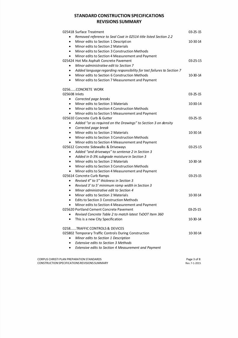
STANDARD CONSTRUCTION SPECIFICATIONS
REVISIONS SUMMARY
CORPUS CHRISTI PLAN PREPARATION STANDARDS Page 3 of 8
CONSTRUCTION SPECIFICATIONS REVISIONS SUMMARY Rev. 7-1-2015
025418 Surface Treatment 03-25-15
•
Removed reference to Seal Coat in 02514 title listed Section 2.2
• Minor edits to Section 1 Description 10-30-14
• Minor edits to Section 2 Materials
• Minor edits to Section 3 Construction Methods
•
Minor edits to Section 4 Measurement and Payment
025424 Hot Mix Asphalt Concrete Pavement 03-25-15
• Minor administrative edit to Section 7
• Added language regarding responsibility for test failures to Section 7
• Minor edits to Section 6 Construction Methods 10-30-14
•
Minor edits to Section 7 Measurement and Payment
0256......CONCRETE WORK
025608 Inlets 03-25-15
• Corrected page breaks
•
Minor edits to Section 3 Materials 10-30-14
•
Minor edits to Section 4 Construction Methods
• Minor edits to Section 5 Measurement and Payment
025610 Concrete Curb & Gutter 03-25-15
• Added “or as required on the Drawings” to Section 3 on density
•
Corrected page break
• Minor edits to Section 2 Materials 10-30-14
• Minor edits to Section 3 Construction Methods
•
Minor edits to Section 4 Measurement and Payment
025612 Concrete Sidewalks & Driveways 03-25-15
•
Added “and driveways” to sentence 2 in Section 3
• Added in 0-3% subgrade moisture in Section 3
•
Minor edits to Section 2 Materials 10-30-14• Minor edits to Section 3 Construction Methods
•
Minor edits to Section 4 Measurement and Payment
025614 Concrete Curb Ramps 03-25-15
• Revised 4” to 5” thickness in Section 3
•
Revised 3’ to 5’ minimum ramp width in Section 3
• Minor administrative edit to Section 4
• Minor edits to Section 2 Materials 10-30-14
•
Edits to Section 3 Construction Methods
• Minor edits to Section 4 Measurement and Payment
025620 Portland Cement Concrete Pavement 03-25-15
•
Revised Concrete Table 2 to match latest TxDOT Item 360• This is a new City Specification 10-30-14
0258......TRAFFIC CONTROLS & DEVICES
025802 Temporary Traffic Controls During Construction 10-30-14
• Minor edits to Section 1 Description
• Extensive edits to Section 3 Methods
•
Extensive edits to Section 4 Measurement and Payment
7/25/2019 City Standard Construction Specifications
http://slidepdf.com/reader/full/city-standard-construction-specifications 9/511
STANDARD CONSTRUCTION SPECIFICATIONS
REVISIONS SUMMARY
CORPUS CHRISTI PLAN PREPARATION STANDARDS Page 4 of 8
CONSTRUCTION SPECIFICATIONS REVISIONS SUMMARY Rev. 7-1-2015
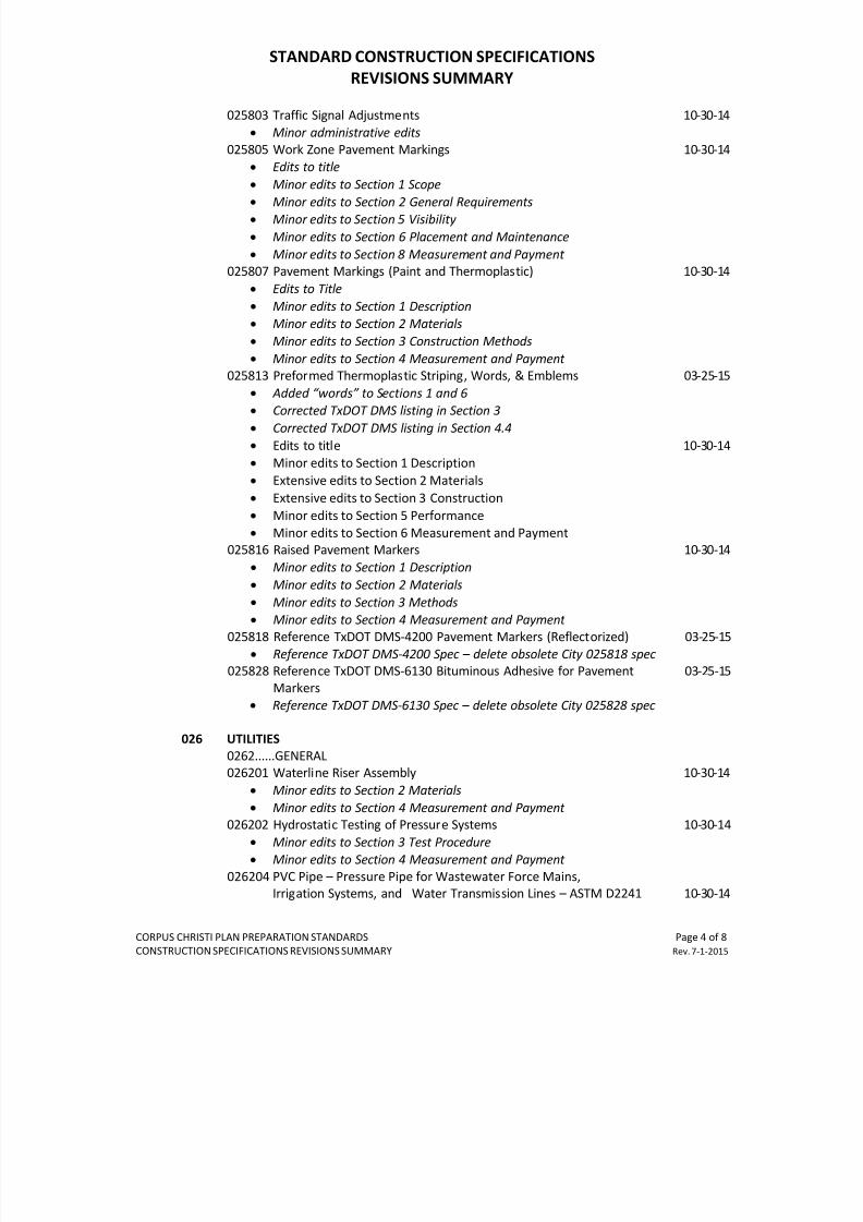
025803 Traffic Signal Adjustments 10-30-14
•
Minor administrative edits
025805 Work Zone Pavement Markings 10-30-14
•
Edits to title
• Minor edits to Section 1 Scope
•
Minor edits to Section 2 General Requirements
•
Minor edits to Section 5 Visibility
• Minor edits to Section 6 Placement and Maintenance
• Minor edits to Section 8 Measurement and Payment
025807 Pavement Markings (Paint and Thermoplastic) 10-30-14
• Edits to Title
• Minor edits to Section 1 Description
•
Minor edits to Section 2 Materials
• Minor edits to Section 3 Construction Methods
• Minor edits to Section 4 Measurement and Payment
025813 Preformed Thermoplastic Striping, Words, & Emblems 03-25-15
•
Added “words” to Sections 1 and 6
•
Corrected TxDOT DMS listing in Section 3
• Corrected TxDOT DMS listing in Section 4.4
• Edits to title 10-30-14
•
Minor edits to Section 1 Description
• Extensive edits to Section 2 Materials
• Extensive edits to Section 3 Construction
• Minor edits to Section 5 Performance
•
Minor edits to Section 6 Measurement and Payment
025816 Raised Pavement Markers 10-30-14
• Minor edits to Section 1 Description
•
Minor edits to Section 2 Materials
• Minor edits to Section 3 Methods
•
Minor edits to Section 4 Measurement and Payment
025818 Reference TxDOT DMS-4200 Pavement Markers (Reflectorized) 03-25-15
•
Reference TxDOT DMS-4200 Spec – delete obsolete City 025818 spec
025828 Reference TxDOT DMS-6130 Bituminous Adhesive for Pavement 03-25-15
Markers
• Reference TxDOT DMS-6130 Spec – delete obsolete City 025828 spec
026 UTILITIES
0262......GENERAL
026201 Waterline Riser Assembly 10-30-14• Minor edits to Section 2 Materials
• Minor edits to Section 4 Measurement and Payment
026202 Hydrostatic Testing of Pressure Systems 10-30-14
• Minor edits to Section 3 Test Procedure
•
Minor edits to Section 4 Measurement and Payment
026204 PVC Pipe – Pressure Pipe for Wastewater Force Mains,
Irrigation Systems, and Water Transmission Lines – ASTM D2241 10-30-14
7/25/2019 City Standard Construction Specifications
http://slidepdf.com/reader/full/city-standard-construction-specifications 10/511
STANDARD CONSTRUCTION SPECIFICATIONS
REVISIONS SUMMARY
CORPUS CHRISTI PLAN PREPARATION STANDARDS Page 5 of 8
CONSTRUCTION SPECIFICATIONS REVISIONS SUMMARY Rev. 7-1-2015
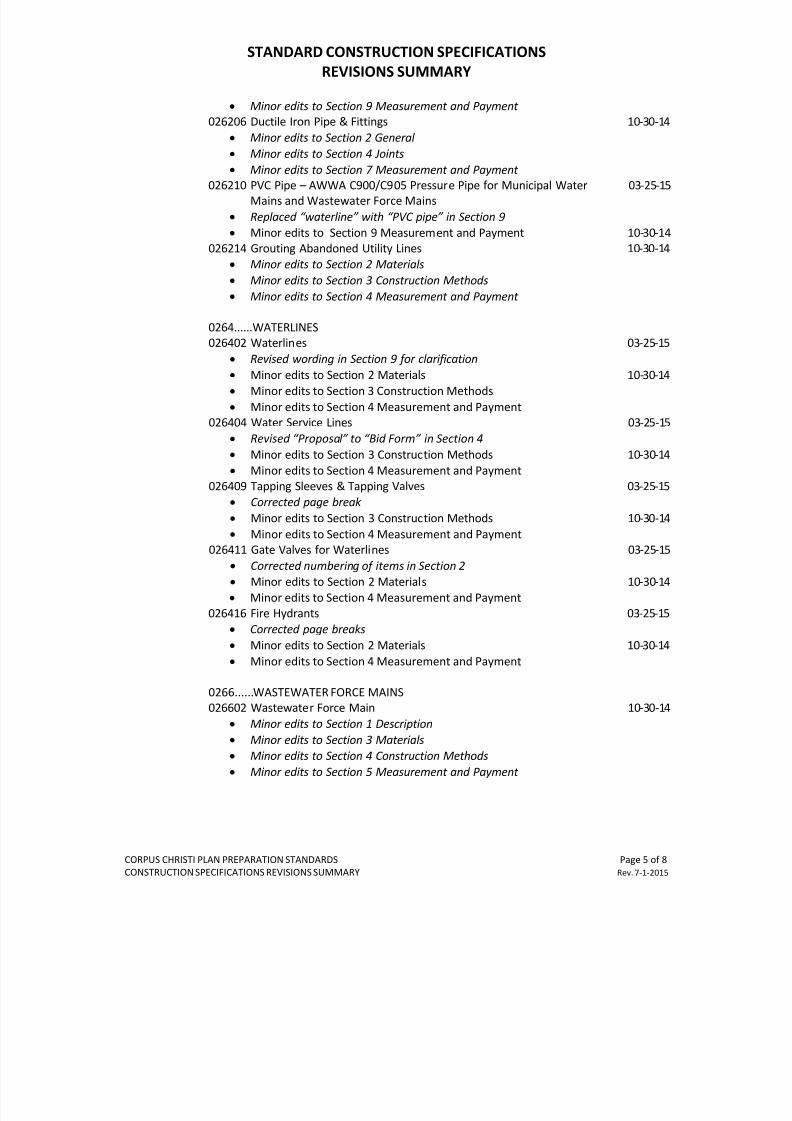
•
Minor edits to Section 9 Measurement and Payment
026206 Ductile Iron Pipe & Fittings 10-30-14
• Minor edits to Section 2 General
• Minor edits to Section 4 Joints
• Minor edits to Section 7 Measurement and Payment
026210 PVC Pipe – AWWA C900/C905 Pressure Pipe for Municipal Water 03-25-15
Mains and Wastewater Force Mains
• Replaced “waterline” with “PVC pipe” in Section 9
•
Minor edits to Section 9 Measurement and Payment 10-30-14
026214 Grouting Abandoned Utility Lines 10-30-14
•
Minor edits to Section 2 Materials
• Minor edits to Section 3 Construction Methods
• Minor edits to Section 4 Measurement and Payment
0264......WATERLINES
026402 Waterlines 03-25-15
•
Revised wording in Section 9 for clarification
• Minor edits to Section 2 Materials 10-30-14
•
Minor edits to Section 3 Construction Methods
• Minor edits to Section 4 Measurement and Payment
026404 Water Service Lines 03-25-15
• Revised “Proposal” to “Bid Form” in Section 4
• Minor edits to Section 3 Construction Methods 10-30-14
•
Minor edits to Section 4 Measurement and Payment
026409 Tapping Sleeves & Tapping Valves 03-25-15
•
Corrected page break
• Minor edits to Section 3 Construction Methods 10-30-14
•
Minor edits to Section 4 Measurement and Payment026411 Gate Valves for Waterlines 03-25-15
• Corrected numbering of items in Section 2
•
Minor edits to Section 2 Materials 10-30-14
•
Minor edits to Section 4 Measurement and Payment
026416 Fire Hydrants 03-25-15
•
Corrected page breaks
• Minor edits to Section 2 Materials 10-30-14
• Minor edits to Section 4 Measurement and Payment
0266......WASTEWATER FORCE MAINS
026602 Wastewater Force Main 10-30-14• Minor edits to Section 1 Description
• Minor edits to Section 3 Materials
•
Minor edits to Section 4 Construction Methods
• Minor edits to Section 5 Measurement and Payment
7/25/2019 City Standard Construction Specifications
http://slidepdf.com/reader/full/city-standard-construction-specifications 11/511
STANDARD CONSTRUCTION SPECIFICATIONS
REVISIONS SUMMARY
CORPUS CHRISTI PLAN PREPARATION STANDARDS Page 6 of 8
CONSTRUCTION SPECIFICATIONS REVISIONS SUMMARY Rev. 7-1-2015
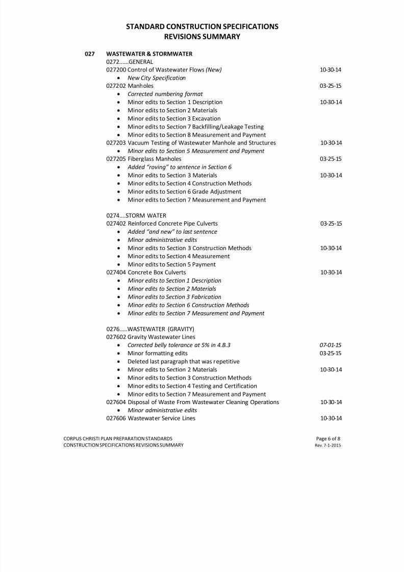
027 WASTEWATER & STORMWATER
0272......GENERAL
027200 Control of Wastewater Flows (New) 10-30-14
• New City Specification
027202 Manholes 03-25-15
•
Corrected numbering format
•
Minor edits to Section 1 Description 10-30-14
• Minor edits to Section 2 Materials
• Minor edits to Section 3 Excavation
• Minor edits to Section 7 Backfilling/Leakage Testing
•
Minor edits to Section 8 Measurement and Payment
027203 Vacuum Testing of Wastewater Manhole and Structures 10-30-14
• Minor edits to Section 5 Measurement and Payment
027205 Fiberglass Manholes 03-25-15
• Added “roving” to sentence in Section 6
• Minor edits to Section 3 Materials 10-30-14
•
Minor edits to Section 4 Construction Methods
• Minor edits to Section 6 Grade Adjustment
• Minor edits to Section 7 Measurement and Payment
0274....STORM WATER
027402 Reinforced Concrete Pipe Culverts 03-25-15
• Added “and new” to last sentence
• Minor administrative edits
• Minor edits to Section 3 Construction Methods 10-30-14
•
Minor edits to Section 4 Measurement
• Minor edits to Section 5 Payment
027404 Concrete Box Culverts 10-30-14• Minor edits to Section 1 Description
• Minor edits to Section 2 Materials
•
Minor edits to Section 3 Fabrication
• Minor edits to Section 6 Construction Methods
• Minor edits to Section 7 Measurement and Payment
0276.....WASTEWATER (GRAVITY)
027602 Gravity Wastewater Lines
•
Corrected belly tolerance at 5% in 4.B.3 07-01-15
• Minor formatting edits 03-25-15
•
Deleted last paragraph that was repetitive•
Minor edits to Section 2 Materials 10-30-14
• Minor edits to Section 3 Construction Methods
• Minor edits to Section 4 Testing and Certification
• Minor edits to Section 7 Measurement and Payment
027604 Disposal of Waste From Wastewater Cleaning Operations 10-30-14
• Minor administrative edits
027606 Wastewater Service Lines 10-30-14
7/25/2019 City Standard Construction Specifications
http://slidepdf.com/reader/full/city-standard-construction-specifications 12/511
STANDARD CONSTRUCTION SPECIFICATIONS
REVISIONS SUMMARY
CORPUS CHRISTI PLAN PREPARATION STANDARDS Page 7 of 8
CONSTRUCTION SPECIFICATIONS REVISIONS SUMMARY Rev. 7-1-2015
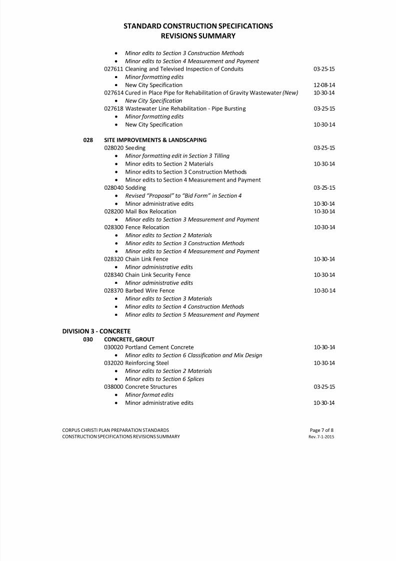
•
Minor edits to Section 3 Construction Methods
• Minor edits to Section 4 Measurement and Payment
027611 Cleaning and Televised Inspection of Conduits 03-25-15
• Minor formatting edits
• New City Specification 12-08-14
027614 Cured in Place Pipe for Rehabilitation of Gravity Wastewater (New) 10-30-14
•
New City Specification
027618 Wastewater Line Rehabilitation - Pipe Bursting 03-25-15
•
Minor formatting edits
• New City Specification 10-30-14
028 SITE IMPROVEMENTS & LANDSCAPING
028020 Seeding 03-25-15
•
Minor formatting edit in Section 3 Tilling
• Minor edits to Section 2 Materials 10-30-14
• Minor edits to Section 3 Construction Methods
•
Minor edits to Section 4 Measurement and Payment
028040 Sodding 03-25-15
•
Revised “Proposal” to “Bid Form” in Section 4
• Minor administrative edits 10-30-14
028200 Mail Box Relocation 10-30-14
• Minor edits to Section 3 Measurement and Payment
028300 Fence Relocation 10-30-14
• Minor edits to Section 2 Materials
• Minor edits to Section 3 Construction Methods
•
Minor edits to Section 4 Measurement and Payment
028320 Chain Link Fence 10-30-14
•
Minor administrative edits 028340 Chain Link Security Fence 10-30-14
• Minor administrative edits
028370 Barbed Wire Fence 10-30-14
•
Minor edits to Section 3 Materials
• Minor edits to Section 4 Construction Methods
• Minor edits to Section 5 Measurement and Payment
DIVISION 3 - CONCRETE
030 CONCRETE, GROUT
030020 Portland Cement Concrete 10-30-14
•
Minor edits to Section 6 Classification and Mix Design032020 Reinforcing Steel 10-30-14
•
Minor edits to Section 2 Materials
• Minor edits to Section 6 Splices
038000 Concrete Structures 03-25-15
• Minor format edits
• Minor administrative edits 10-30-14
7/25/2019 City Standard Construction Specifications
http://slidepdf.com/reader/full/city-standard-construction-specifications 13/511
STANDARD CONSTRUCTION SPECIFICATIONS
REVISIONS SUMMARY
CORPUS CHRISTI PLAN PREPARATION STANDARDS Page 8 of 8
CONSTRUCTION SPECIFICATIONS REVISIONS SUMMARY Rev. 7-1-2015
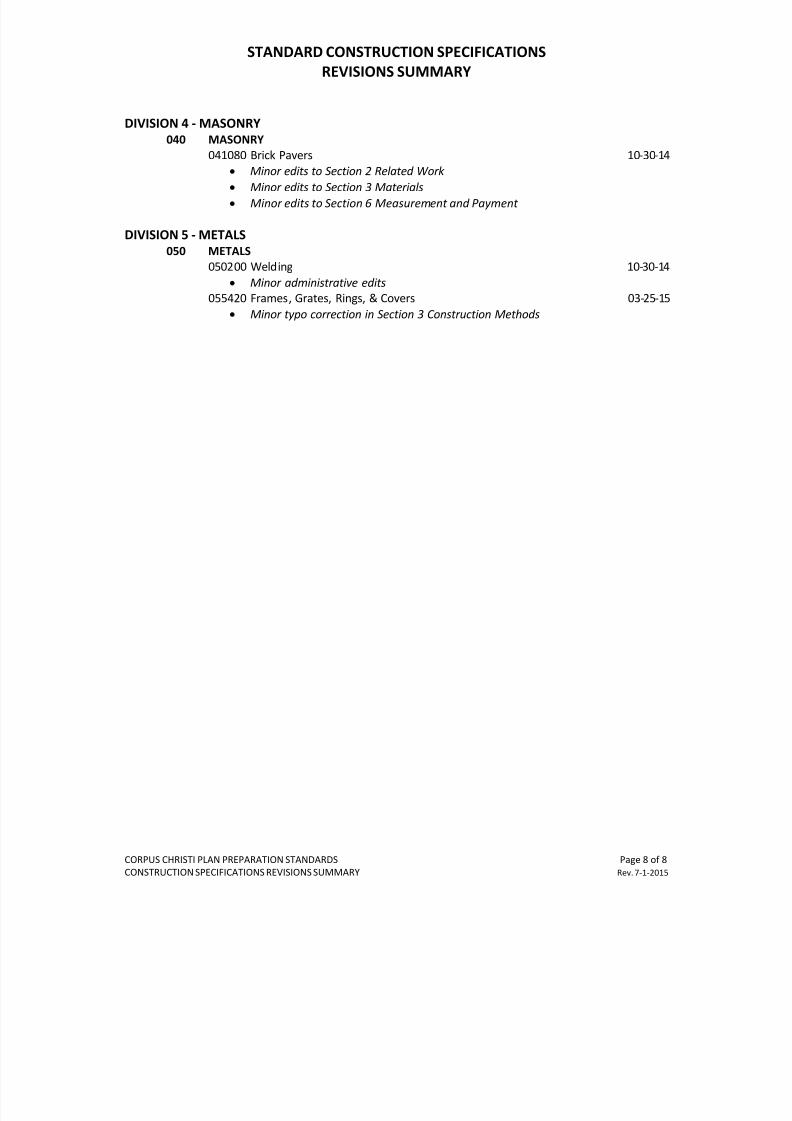
DIVISION 4 - MASONRY
040 MASONRY
041080 Brick Pavers 10-30-14
•
Minor edits to Section 2 Related Work
• Minor edits to Section 3 Materials
• Minor edits to Section 6 Measurement and Payment
DIVISION 5 - METALS
050 METALS
050200 Welding 10-30-14
• Minor administrative edits
055420 Frames, Grates, Rings, & Covers 03-25-15
• Minor typo correction in Section 3 Construction Methods
7/25/2019 City Standard Construction Specifications
http://slidepdf.com/reader/full/city-standard-construction-specifications 14/511
CITY STANDARD CONSTRUCTION SPECIFICATIONS INDEX
ALL STANDARD SPECIFICATIONS SHOULD BE REVIEWED BY THE RESPONSIBLE DESIGN CONSULTANT FOR USE AS APPLICABLE TO
THEIR PROJECT. THE ASTERISKED* SPECIFICATIONS HAVE NOT BEEN RECENTLY REVIEWED FOR USE AND MAY CONTAIN
OBSOLETE REFERENCES OR MATERIALS. RECOMMENDED REVISIONS AND UPDATES SHOULD BE SUBMITTED TO THE CITY FOR
REVIEW PRIOR TO USE.
CORPUS CHRISTI PLAN PREPARATION STANDARDS Page 1 of 6
CONSTRUCTION SPECIFICATIONS INDEX Rev. 7-01-2015
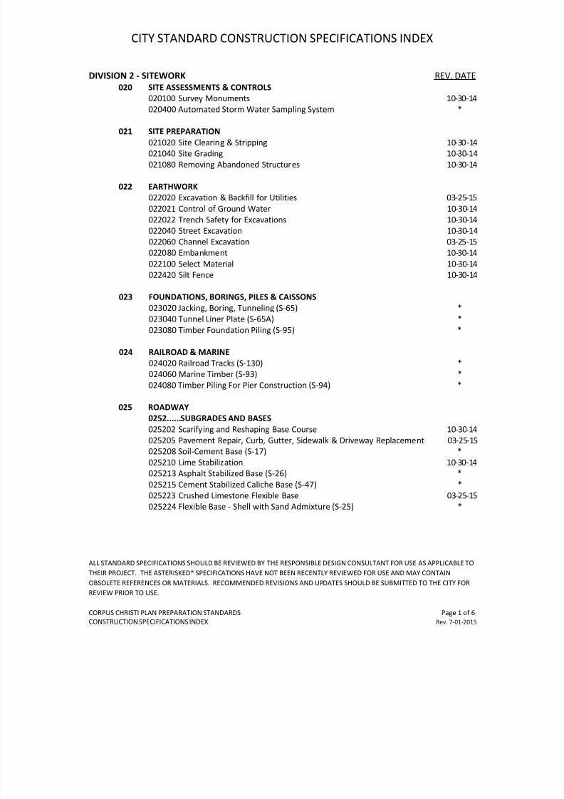
DIVISION 2 - SITEWORK REV. DATE
020 SITE ASSESSMENTS & CONTROLS
020100 Survey Monuments 10-30-14
020400 Automated Storm Water Sampling System *
021 SITE PREPARATION
021020 Site Clearing & Stripping 10-30 -14
021040 Site Grading 10-30-14
021080 Removing Abandoned Structures 10-30-14
022 EARTHWORK
022020 Excavation & Backfill for Utilities 03-25-15
022021 Control of Ground Water 10-30-14
022022 Trench Safety for Excavations 10-30-14
022040 Street Excavation 10-30-14
022060 Channel Excavation 03-25-15
022080 Embankment 10-30-14022100 Select Material 10-30-14
022420 Silt Fence 10-30-14
023 FOUNDATIONS, BORINGS, PILES & CAISSONS
023020 Jacking, Boring, Tunneling (S-65) *
023040 Tunnel Liner Plate (S-65A) *
023080 Timber Foundation Piling (S-95) *
024 RAILROAD & MARINE
024020 Railroad Tracks (S-130) *
024060 Marine Timber (S-93) *
024080 Timber Piling For Pier Construction (S-94) *
025 ROADWAY
0252......SUBGRADES AND BASES
025202 Scarifying and Reshaping Base Course 10-30-14
025205 Pavement Repair, Curb, Gutter, Sidewalk & Driveway Replacement 03-25-15
025208 Soil-Cement Base (S-17) *
025210 Lime Stabilization 10-30-14
025213 Asphalt Stabilized Base (S-26) *
025215 Cement Stabilized Caliche Base (S-47) *
025223 Crushed Limestone Flexible Base 03-25-15
025224 Flexible Base - Shell with Sand Admixture (S-25) *
7/25/2019 City Standard Construction Specifications
http://slidepdf.com/reader/full/city-standard-construction-specifications 15/511
CITY STANDARD CONSTRUCTION SPECIFICATIONS INDEX
ALL STANDARD SPECIFICATIONS SHOULD BE REVIEWED BY THE RESPONSIBLE DESIGN CONSULTANT FOR USE AS APPLICABLE TO
THEIR PROJECT. THE ASTERISKED* SPECIFICATIONS HAVE NOT BEEN RECENTLY REVIEWED FOR USE AND MAY CONTAIN
OBSOLETE REFERENCES OR MATERIALS. RECOMMENDED REVISIONS AND UPDATES SHOULD BE SUBMITTED TO THE CITY FOR
REVIEW PRIOR TO USE.
CORPUS CHRISTI PLAN PREPARATION STANDARDS Page 2 of 6
CONSTRUCTION SPECIFICATIONS INDEX Rev. 7-01-2015
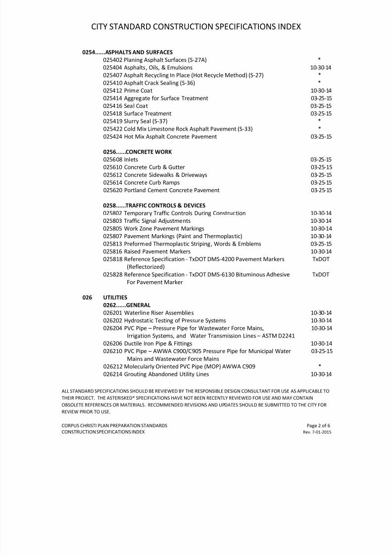
0254......ASPHALTS AND SURFACES
025402 Planing Asphalt Surfaces (S-27A) *
025404 Asphalts, Oils, & Emulsions 10-30-14
025407 Asphalt Recycling In Place (Hot Recycle Method) (S-27) *
025410 Asphalt Crack Sealing (S-36) *
025412 Prime Coat 10-30-14
025414 Aggregate for Surface Treatment 03-25-15
025416 Seal Coat 03-25-15
025418 Surface Treatment 03-25-15
025419 Slurry Seal (S-37) *
025422 Cold Mix Limestone Rock Asphalt Pavement (S-33) *
025424 Hot Mix Asphalt Concrete Pavement 03-25-15
0256......CONCRETE WORK
025608 Inlets 03-25-15
025610 Concrete Curb & Gutter 03-25-15
025612 Concrete Sidewalks & Driveways 03-25-15025614 Concrete Curb Ramps 03-25-15
025620 Portland Cement Concrete Pavement 03-25-15
0258......TRAFFIC CONTROLS & DEVICES
025802 Temporary Traffic Controls During Construction 10-30-14
025803 Traffic Signal Adjustments 10-30-14
025805 Work Zone Pavement Markings 10-30-14
025807 Pavement Markings (Paint and Thermoplastic) 10-30-14
025813 Preformed Thermoplastic Striping, Words & Emblems 03-25-15
025816 Raised Pavement Markers 10-30-14
025818 Reference Specification - TxDOT DMS-4200 Pavement Markers TxDOT
(Reflectorized)
025828 Reference Specification - TxDOT DMS-6130 Bituminous Adhesive TxDOT
For Pavement Marker
026 UTILITIES
0262......GENERAL
026201 Waterline Riser Assemblies 10-30-14
026202 Hydrostatic Testing of Pressure Systems 10-30-14
026204 PVC Pipe – Pressure Pipe for Wastewater Force Mains, 10-30-14
Irrigation Systems, and Water Transmission Lines – ASTM D2241
026206 Ductile Iron Pipe & Fittings 10-30-14
026210 PVC Pipe – AWWA C900/C905 Pressure Pipe for Municipal Water 03-25-15Mains and Wastewater Force Mains
026212 Molecularly Oriented PVC Pipe (MOP) AWWA C909 *
026214 Grouting Abandoned Utility Lines 10-30-14
7/25/2019 City Standard Construction Specifications
http://slidepdf.com/reader/full/city-standard-construction-specifications 16/511
CITY STANDARD CONSTRUCTION SPECIFICATIONS INDEX
ALL STANDARD SPECIFICATIONS SHOULD BE REVIEWED BY THE RESPONSIBLE DESIGN CONSULTANT FOR USE AS APPLICABLE TO
THEIR PROJECT. THE ASTERISKED* SPECIFICATIONS HAVE NOT BEEN RECENTLY REVIEWED FOR USE AND MAY CONTAIN
OBSOLETE REFERENCES OR MATERIALS. RECOMMENDED REVISIONS AND UPDATES SHOULD BE SUBMITTED TO THE CITY FOR
REVIEW PRIOR TO USE.
CORPUS CHRISTI PLAN PREPARATION STANDARDS Page 3 of 6
CONSTRUCTION SPECIFICATIONS INDEX Rev. 7-01-2015
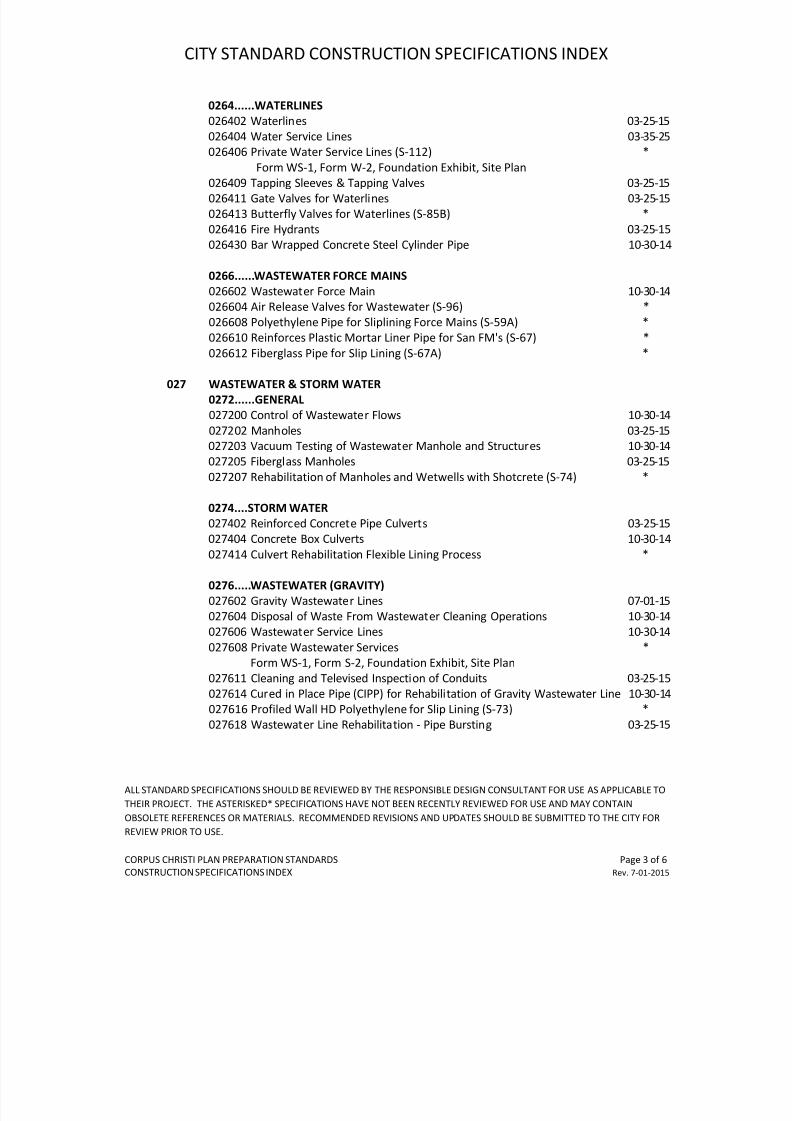
0264......WATERLINES
026402 Waterlines 03-25-15
026404 Water Service Lines 03-35-25
026406 Private Water Service Lines (S-112) *
Form WS-1, Form W-2, Foundation Exhibit, Site Plan
026409 Tapping Sleeves & Tapping Valves 03-25-15
026411 Gate Valves for Waterlines 03-25-15
026413 Butterfly Valves for Waterlines (S-85B) *
026416 Fire Hydrants 03-25-15
026430 Bar Wrapped Concrete Steel Cylinder Pipe 10-30-14
0266......WASTEWATER FORCE MAINS
026602 Wastewater Force Main 10-30-14
026604 Air Release Valves for Wastewater (S-96) *
026608 Polyethylene Pipe for Sliplining Force Mains (S-59A) *
026610 Reinforces Plastic Mortar Liner Pipe for San FM's (S-67) *
026612 Fiberglass Pipe for Slip Lining (S-67A) *
027 WASTEWATER & STORM WATER
0272......GENERAL
027200 Control of Wastewater Flows 10-30-14
027202 Manholes 03-25-15
027203 Vacuum Testing of Wastewater Manhole and Structures 10-30-14
027205 Fiberglass Manholes 03-25-15
027207 Rehabilitation of Manholes and Wetwells with Shotcrete (S-74) *
0274....STORM WATER
027402 Reinforced Concrete Pipe Culverts 03-25-15
027404 Concrete Box Culverts 10-30-14
027414 Culvert Rehabilitation Flexible Lining Process *
0276.....WASTEWATER (GRAVITY)
027602 Gravity Wastewater Lines 07-01-15
027604 Disposal of Waste From Wastewater Cleaning Operations 10-30-14
027606 Wastewater Service Lines 10-30-14
027608 Private Wastewater Services *
Form WS-1, Form S-2, Foundation Exhibit, Site Plan
027611 Cleaning and Televised Inspection of Conduits 03-25-15
027614 Cured in Place Pipe (CIPP) for Rehabilitation of Gravity Wastewater Line 10-30-14
027616 Profiled Wall HD Polyethylene for Slip Lining (S-73) *027618 Wastewater Line Rehabilitation - Pipe Bursting 03-25-15
7/25/2019 City Standard Construction Specifications
http://slidepdf.com/reader/full/city-standard-construction-specifications 17/511
CITY STANDARD CONSTRUCTION SPECIFICATIONS INDEX
ALL STANDARD SPECIFICATIONS SHOULD BE REVIEWED BY THE RESPONSIBLE DESIGN CONSULTANT FOR USE AS APPLICABLE TO
THEIR PROJECT. THE ASTERISKED* SPECIFICATIONS HAVE NOT BEEN RECENTLY REVIEWED FOR USE AND MAY CONTAIN
OBSOLETE REFERENCES OR MATERIALS. RECOMMENDED REVISIONS AND UPDATES SHOULD BE SUBMITTED TO THE CITY FOR
REVIEW PRIOR TO USE.
CORPUS CHRISTI PLAN PREPARATION STANDARDS Page 4 of 6
CONSTRUCTION SPECIFICATIONS INDEX Rev. 7-01-2015
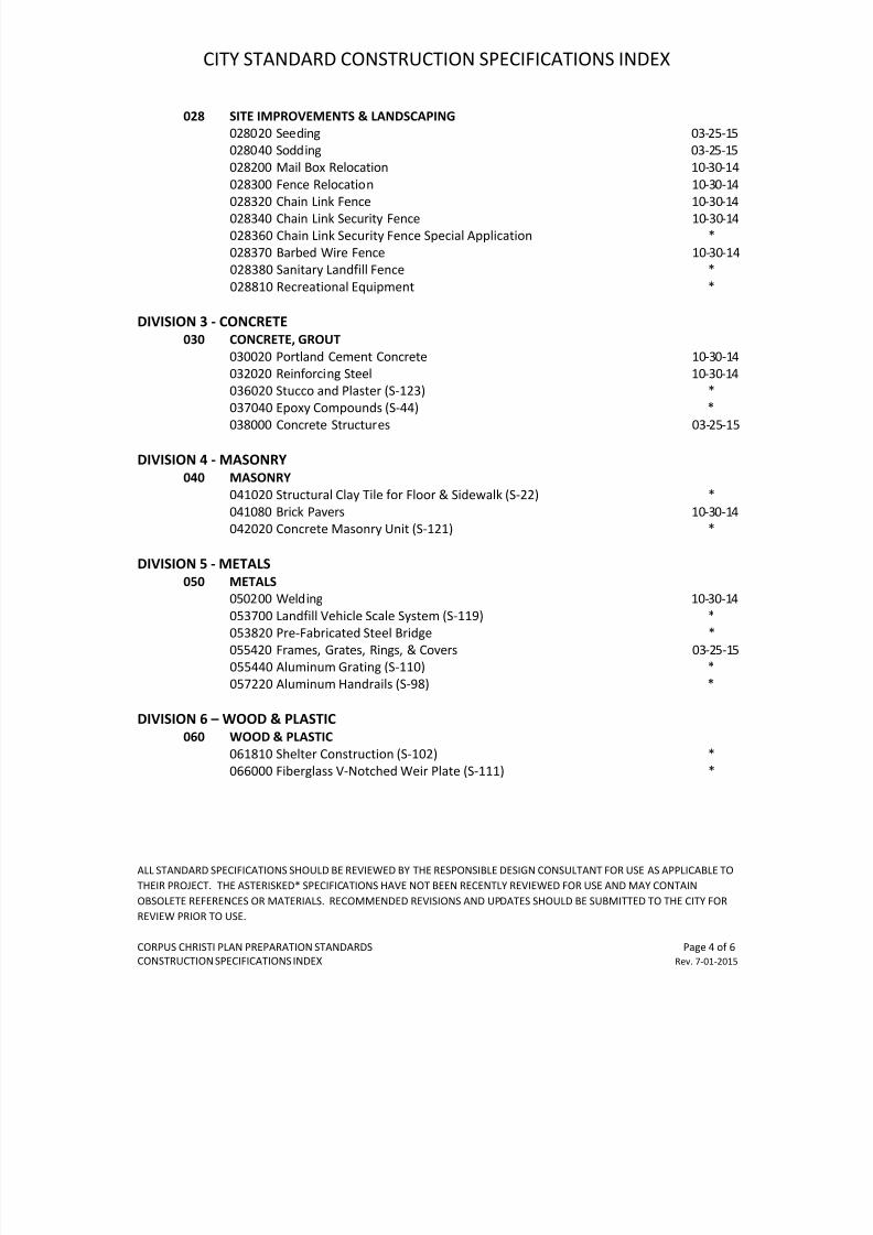
028 SITE IMPROVEMENTS & LANDSCAPING
028020 Seeding 03-25-15
028040 Sodding 03-25-15
028200 Mail Box Relocation 10-30-14
028300 Fence Relocation 10-30-14
028320 Chain Link Fence 10-30-14
028340 Chain Link Security Fence 10-30-14
028360 Chain Link Security Fence Special Application *
028370 Barbed Wire Fence 10-30-14
028380 Sanitary Landfill Fence *
028810 Recreational Equipment *
DIVISION 3 - CONCRETE
030 CONCRETE, GROUT
030020 Portland Cement Concrete 10-30-14
032020 Reinforcing Steel 10-30-14
036020 Stucco and Plaster (S-123) *037040 Epoxy Compounds (S-44) *
038000 Concrete Structures 03-25-15
DIVISION 4 - MASONRY
040 MASONRY
041020 Structural Clay Tile for Floor & Sidewalk (S-22) *
041080 Brick Pavers 10-30-14
042020 Concrete Masonry Unit (S-121) *
DIVISION 5 - METALS
050 METALS050200 Welding 10-30-14
053700 Landfill Vehicle Scale System (S-119) *
053820 Pre-Fabricated Steel Bridge *
055420 Frames, Grates, Rings, & Covers 03-25-15
055440 Aluminum Grating (S-110) *
057220 Aluminum Handrails (S-98) *
DIVISION 6 – WOOD & PLASTIC
060 WOOD & PLASTIC
061810 Shelter Construction (S-102) *
066000 Fiberglass V-Notched Weir Plate (S-111) *
7/25/2019 City Standard Construction Specifications
http://slidepdf.com/reader/full/city-standard-construction-specifications 18/511
7/25/2019 City Standard Construction Specifications
http://slidepdf.com/reader/full/city-standard-construction-specifications 19/511
CITY STANDARD CONSTRUCTION SPECIFICATIONS INDEX
ALL STANDARD SPECIFICATIONS SHOULD BE REVIEWED BY THE RESPONSIBLE DESIGN CONSULTANT FOR USE AS APPLICABLE TO
THEIR PROJECT. THE ASTERISKED* SPECIFICATIONS HAVE NOT BEEN RECENTLY REVIEWED FOR USE AND MAY CONTAIN
OBSOLETE REFERENCES OR MATERIALS. RECOMMENDED REVISIONS AND UPDATES SHOULD BE SUBMITTED TO THE CITY FOR
REVIEW PRIOR TO USE.
CORPUS CHRISTI PLAN PREPARATION STANDARDS Page 6 of 6
CONSTRUCTION SPECIFICATIONS INDEX Rev. 7-01-2015
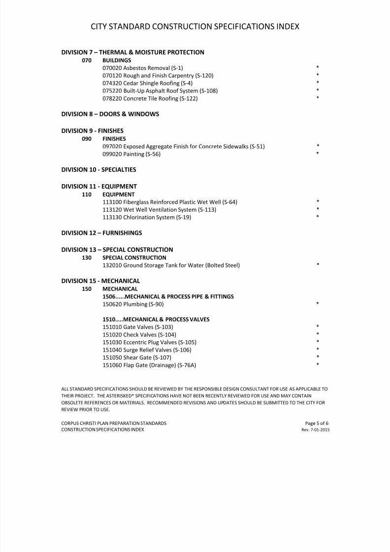
1515......FLOW METERS
151502 Ultrasonic Doppler Flow Meter and Recorder (S-118) *
1516......PUMPS & COMPRESSORS
151620 Submersible Pumps for Wastewater (S-114) *
151630 Propeller Pumps (S-38) *
151640 Submersible Grinder Pumps for Wastewater *
DIVISION 16 - ELECTRICAL
160 ELECTRICAL
161001 Lift Station Electrical Materials (S-18) *
7/25/2019 City Standard Construction Specifications
http://slidepdf.com/reader/full/city-standard-construction-specifications 20/511
7/25/2019 City Standard Construction Specifications
http://slidepdf.com/reader/full/city-standard-construction-specifications 21/511
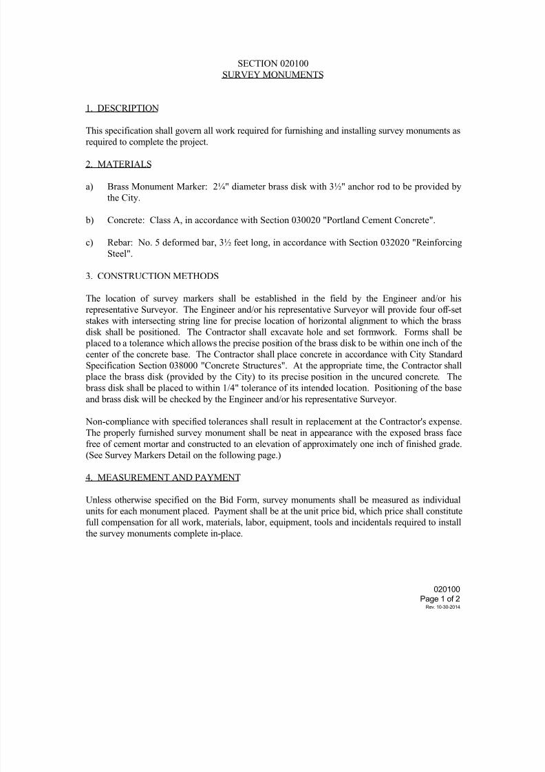
020100
Page 2 of 2Rev. 10-30-2014
7/25/2019 City Standard Construction Specifications
http://slidepdf.com/reader/full/city-standard-construction-specifications 22/511
02040012/3/8
Page 1 of 6
SECTI ON 020400AUTOMATED STORMWATER SAMPLI NG SYSTEM
1. DESCRI PTI ON
Thi s speci f i cat i on shal l govern al l equi pment and sof t ware r equi r ed f or t hei nst al l at i on of aut omat ed storm wat er sampl i ng syst ems f or col l ect i ng storm wat ersampl es i n r emote l ocat i ons t o meet EPA NPDES r equi r ement s f or st orm water di schar gest o r ecei vi ng wat er s of t he Uni t ed St at es.
2. EQUI PMENT CERTI FI CATI ON
The cont r act or shal l submi t t he manuf act urer ' s cer t i f i cat i on and t echni calspeci f i cat i on f or each pi ece of equi pment used i n t he st orm wat er sampl i ng syst emst at i ng t hat t he equi pment f ur ni shed meet s or exceeds t he speci f i cat i ons herei n. Thr eecopi es of al l submi t t al s shal l be made suf f i ci ent l y i n advance of si t e mobi l i zat i on t oal l ow i nspect i on and conf i r mat i on. I mpr oper l y packaged or l abel ed mat er i al s shal l ber ej ect ed and r emoved f r omt he j ob si t e.
3. SAMPLI NG STATI ON
The st or m wat er sampl i ng st at i on shal l consi st of equi pment f or measur i ng f l ow andcol l ect i ng st or m wat er sampl es f r om condui t s or open channel s. The basi c stat i on shal l
consi st of a pr ogr ammabl e measur ement and cont r ol modul e wi t h t el ecommuni cat i onscapabi l i t y, a per i st al t i c pump, and one or mor e bot t l es t o col l ect t he sampl e, at emper ature measur i ng devi ce and a r ai n gauge. Fl ow measurement shal l be per f ormed byan ul t r asoni c- Doppl er f l ow met er i n conj unct i on wi t h a pr i mar y devi ce or t he Manni ngequat i on. Land- l i ne network communi cat i ons shal l be used at t he si t e. The component sof t he syst emshal l be r ated t o NEMA- 4X st andards or i nst al l ed i n NEMA- 4X encl osur es.
The syst em shal l be encl osed i n a vandal r esi st ant l ockabl e wel ded housi ng st r uct ure.
4. CONTROL STATI ON
Mul t i pl e stat i ons shal l be moni t ored and cont r ol l ed r emotel y f r om an I BM- compat i bl e PCwi t h St orm Cont r ol sof t war e. Sof t war e shal l be compat i bl e wi t h exi st i ng sof t war e onCi t y equi pment . The communi cat i on pr otocol used on t hi s syst em shal l be compat i bl ewi t h Campbel l Sci ent i f i c, I nc. ’ s pr opr i et ar y PC 208 Sof t war e. St or m Cont r ol sof t war e
shal l pr ovi de t he capabi l i t y t o i ni t i al i ze t he r emot el y si t uat ed st at i ons, moni t or andcont rol t hei r oper at i on and downl oad r ecor ded data. Campbel l Sci ent i f i c, I nc. sof t ware( PC208) i s r equi r ed as a mi ni mum t o addr ess i ssues of compat i bi l i t y.
5. MEASUREMENT AND CONTROL MODULE WI TH WI RI NG PANEL
The measur ement and cont r ol modul e shal l be programmabl e contr ol l er wi t h bui l t - i n dat al oggi ng capabi l i t y and f aci l i t i es f or exci t i ng and measur i ng anal og and di gi t al sensor sand devi ces. I t shal l have a 9- pi n communi cat i on port whi ch wi l l be used t o connect ahand- hel d consol e, or t o connect r emote communi cat i on f aci l i t i es. The modul e shal l bea pr eci si on i nst r ument wi t h an i nst r uct i on set speci f i cal l y sel ect ed f or measur i ngenvi r onment al par amet er s. I t shal l have a set of ei ght di gi t al port s whi ch may bepr ogrammed as i nput or out put channel s t o cont r ol t he sensors or sense thei r condi t i on.
The el ect r oni c components shal l be housed i n an envi r onmental l y seal ed cani st er . Thecani ster shal l f i t i nt o a wi ri ng panel t o f aci l i t at e f i el d connect i ons. Several l evel sof el ect r i cal t r ansi ent pr ot ect i on shal l be pr ovi ded i n t he wi r i ng panel and t heel ectr oni cs cani ster.
Speci f i cat i ons: Campbel l CR10X or appr oved equal .A. I nput / out put
Anal og I nput s: 12 si ngl e- ended or 6 di f f er ent i alDi gi t al Cont r ol / St at us Por t s: 8 pr ogr ammabl e
7/25/2019 City Standard Construction Specifications
http://slidepdf.com/reader/full/city-standard-construction-specifications 23/511
02040012/3/8
Page 2 of 6
Pul se I nput s: 2Exci t at i on Out put s: 3Swi t ched 12 Vol t Por t : 19- Pi n Seri al I / O Por t : 1
B. Anal og I nput s:Range: +/ - 2. 5, 7. 5, 25, 250, 2500 mi l l i vol t s, sof t war e sel ect abl eResol ut i on: 0. 33, 1. 00, 3. 33, 33. 3, 333 respect i vel yAccuracy: 0. 2% of FSR over - 25 t o +50 degrees C
0. 1% of FSR over 0 to +40 degrees CNormal Mode Rej ect i on: 70 dBDC Common Mode Rej ect i on: >140 dBI nput Resi st ance: 200 gi gohms
C. Exci t at i on Out put sRange: +/ - 2500 mi l l i vol t sResol ut i on: 0. 67 mi l l i vol t sAccuracy: Same as vol t age i nput
D. Di gi t al Cont r ol / St at us Por t sOut put Vol t ages: Hi gh 5. 0 +/ - 0. 1 V; Low, 0. 1 VI nput St at e: Hi gh 3. 0 t o 5. 5 V; Low - 0. 5 t o +0. 8 V
E. Cl ock Accuracy: +/ - 1 mi nut e per mont hF. Memor y: 32K ROM; 128K RAMG. Syst em Power Requi r ement s: 9. 6 t o 16 vol t s.
6. WATER SAMPLI NG EQUI PMENT
The wat er sampl i ng equi pment shal l be I SCO 6700 sampl er or appr oved equal and shal lconsi st of a Cont r ol l er/ Pump assembl y, a sampl e cont ai ner, a base assembl y whi ch hol dst he sampl e cont ai ner and a suppl y of i ce, and a suct i on l i ne. The Cont r ol l er/ Pumpassembl y shal l consi st of a per i st al t i c pump, a dr i ve mot or, a l i qui d det ect or, andcont r ol el ect r oni cs housed i n a NEMA- 4X encl osure. Sampl e vol umes shal l be progr ammedby means of an i nt egr al cont r ol panel on t he sampl er . Sampl i ng wi l l be cont r ol l ed i nr eal - t i me by el ect r i cal si gnal s t o a cont r ol por t . The sampl er base shal l be capabl eof hol di ng a 19- l i t er gl ass sampl e cont ai ner and a suppl y of i ce.
The sampl e cont ai ner shal l be hi gh qual i t y borosi l i cat e gl ass. The sampl e cont ai nercl osur e shal l be Tef l on. Wi t h t he except i on of a shor t sect i on of si l i con hose i n t heper i st al t i c pump, t he sampl e suct i on l i ne shal l be Tef l on. Suct i on l i ne shal l be
pr ovi ded i n cont i nuous r uns f r om each st at i on encl osur e t o t he i nt ake st ruct ur e i n t hewat er st r eam. Al l mater i al s t hat come i n cont act wi t h t he wat er sampl e shal l beconstr ucted of Tef l on, borosi l i cat e gl ass, or st ai nl ess steel . Pr i or t o i nstal l at i oni n t he wat er st r eam, al l component s shal l undergo a r i gorous cl eani ng pr otocol t or emove t he pot ent i al f or cont ami nat i on of t r ace metal s and or gani c compounds.
A. Speci f i cat i ons:Cont r ol l er / PumpSampl e Vol ume Accur acy: +/ - 10 ml or +/ - 10% of programmed vol ume,whi chever i s gr eat erSampl e Vol ume Repeat abi l i t y: +/ - 5 mi l l i l i t er s or +/ - 5% of
t he average sampl e vol ume i n aset , whi chever i s gr eat er
Sucti on Li f t : 28 FeetLi ne Tr anspor t Vel oci t y: 3. 0 f eet / second at 3 f oot suct i on
head2. 2 f eet / second at 25 f oot suct i on
head
7/25/2019 City Standard Construction Specifications
http://slidepdf.com/reader/full/city-standard-construction-specifications 24/511
02040012/3/8
Page 3 of 6
Encl osure: NEMA 4- X, 6
Sampl er Housi ng, Bot t l e Cont ai nerHei ght : 35 i nches maxi mumDi ameter: 19. 96 i nchesCapaci t y: 1- 19 l i t er bot t l er wi t h st opper
Sampl e Bot t l eCapaci t y: 19 l i t er sMat er i al : Borosi l i cat eSt opper : Sol i d PFTE wi t h cl amp mechani sm f or t r anspor t at i on
Sol i d PFTE wi t h 7/ 16 cent er ed hol e f or sampl i ng
Suct i on Li ne:3/ 8 i nch I . D. sol i d- wal l FEP Tef l on, wi t h wal l t hi ckness
of 0. 063 +/ - 0. 006 i nches.
B. Cl eani ng Pr ot ocol :Pr i or t o i nst al l at i on at a si t e t o be sampl ed, al l component s t hat wi l l come i ncont act wi t h the sampl e shal l be cl eaned usi ng appropr i ate methods t o remove l ow-l evel or gani c and t r ace met al cont ami nant s. Thi s wi l l i ncl ude al l bot t l es,bot t l e st opper s, Tef l on and si l i cone t ubi ng, and i nt ake st r ai ner s. Cl eani ngshal l be t o l evel s equal t o or bel ow pr oj ect det ect i on l i mi t s.
Af t er cl eani ng, but pr i or t o i nst al l at i on, t en percent of al l bot t l es and Tef l ont ubi ng shal l have equi pment bl ank anal yses perf ormed. The bl anks shal l beanal yzed f or t he cont ami nant s of concer n t o t he Progr am. I f t he l i mi t s shownbel ow ar e exceeded, t he ent i r e l ot of bot t l es or t ubi ng shal l be r e- cl eaned andbl anks wi l l be r eanal yzed. Thi s pr ocess i s r equi r ed unt i l document at i on can bepr ovi ded t o the Ci t y that equi pment bl anks ar e f r ee of al l cont ami nant s ofconcer n at no addi t i onal pay.
Det ect i on l i mi t s used f or anal ysi s:One (1) part per mi l l i on f or Tot al Or gani c Compounds
( TOC)One ( 1) par t per bi l l i on f or zi nc, copper , and l ead
Two ( 2) part s per bi l l i on f or ni ckel
7. Thermi st or
A t emper ature sensor usi ng a t her mi st or Campbel l 107B or approved equal shal l be housedi n a wat er pr oof encl osur e wi t h a cabl e at t ached. The uni t shal l be sui t abl e f or bur i alor i mmersi on i n water.
Speci f i cat i ons:Accuracy: +/ - 1. 0 degrees C over - 40 t o +55 degrees C
+/ - 0. 1 degr ees C over - 35 t o +48 degrees C
8. SI TE ENCLOSURE:
The si t e encl osur e shal l be a t op- openi ng, l ockabl e st eel box of wel ded const r uct i onwi t h l ouver s l ocat ed on t he f r ont and si des f or vent i l at i on. I t shal l be desi gned t obe vandal r esi st ant wi t h carr i age bol t s used t o at t ach hi nges and other component s t hatar e not wel ded. Two hasps shal l be pr ovi ded f or padl ocks. Prot ect i ve cover s shal l bewel ded over t he hasps t o di scour age cut t i ng of t he padl ocks.

7/25/2019 City Standard Construction Specifications
http://slidepdf.com/reader/full/city-standard-construction-specifications 25/511
02040012/3/8
Page 4 of 6
Speci f i cat i onsDi mensi ons: 36 i nches hi gh x 42 i nches wi de x 30 i nches deepwi t h open bot t omMateri al : 12 Gauge St eelCol or: Whi t e pai nt appl i ed over pr i mer on both i nsi de and
out si deMount i ng: 2 i nch wi de i nt er nal base f l ange wi t h 1/ 2 i nchdi ameter hol esCool i ng: Vent i l at i on i s pr ovi ded by hooded l ouver s l ocat ed
near t he bot t omof t he encl osur e on t he f r ont andback and near t he t op of t he encl osur e on each si de.
9. FLOW MEASUREMENT:
An ul t r asoni c Doppl er f l ow- measurement devi ce I SCO 4150 or approved equal shal l be usedt o measure t he aver age part i cl e vel oci t y acr oss t he l i qui d st r eam. A pr essuresensi t i ve l i qui d l evel sensi ng devi ce shal l be i ncor por at ed i nt o the t r ansducerhousi ng. The f l ow measur i ng devi ce shal l be capabl e of provi di ng r eal - t i me vel oci t y,dept h, and bat t ery vol t age measurement s upon command f r om t he Measurement and Contr olModul e wi t h a RS 232 i nterf ace. The f l ow shal l be cal cul ated i n t he Measurement andCont r ol Modul e f r omt he aver age vel oci t y and dept h pr ovi ded by t he f l ow meter and thechannel geomet r y.
Speci f i cat i ons:Vel oci t y Range: - 5 t o 20 f eet / secondDept h Range: 0. 1 t o 10 f eet
Temperat ure Range:Logger/ Cont r ol l er : - 18 t o 60 degr ees C Oper at i ngProbe: 0 t o 71 degrees C Oper at i ng
0 t o 50 degr ees C Compensat ed
10. COMMUNI CATI ONS:
Land- l i ne communi cat i ons shal l be pr ovi ded wi t h a modem t hat i nt er f aces wi t h t heMeasur ement and Cont r ol Modul e 9- pi n ser i al port and a publ i c l and- l i ne swi t chedt el ephone net work. The modemshal l be capabl e of communi cat i on wi t h a Hayes- compati bl emodem and an I BM- compat i bl e PC.
Speci f i cat i ons:A. St andards: Bel l 212a, CCI TT V. 22B. Baud Rat es: 300, 1200C. Oper at i on: Ful l - dupl ex over st andar d phone l i nesD. Oper at i ng t emper ature: - 25 t o +50 degrees C
11. REMOTE STORM CONTROL:
The St or m Cont r ol sof t war e shal l be compat i bl e wi t h exi st i ng hardware and sof t war ewhi ch i s owned by t he Ci t y. The net work of Sampl i ng Stat i ons wi l l be moni t ored andcont r ol l ed f r oman I BM- compat i bl e PC equi pped wi t h a VGA moni t or , appr opr i ate modems,and St or m Cont r ol sof t war e. The St or m Cont r ol sof t war e shal l pr ovi de menu sel ect abl epr ogr ams t o al l ow an operat or t o r emotel y i ni t i al i ze operat i on, moni t or and modi f y t heoper at i on of any of t he Sampl i ng St at i ons, and t er mi nat e t he oper at i on, al l i n r ealt i me. The sof t war e shal l have t he capabi l i t y of r et r i evi ng l ogged dat a r emot el y f r omt he st at i on at a l at er t i me af t er t he event i s compl et ed. Dat a ret r i eved f r om each oft he st at i on si t es shal l be st or ed sequent i al l y i n a dat a base f or t hat si t e. The St ormCont r ol sof t war e shal l use t he f aci l i t i es of Campbel l Sci ent i f i c, I nc. PC208 Dat aLogger Suppor t Sof t ware.
The PC208 Dat a Logger Suppor t Sof t war e i s a sui t e of programs t hat r un on an I BM-
7/25/2019 City Standard Construction Specifications
http://slidepdf.com/reader/full/city-standard-construction-specifications 26/511
02040012/3/8
Page 5 of 6
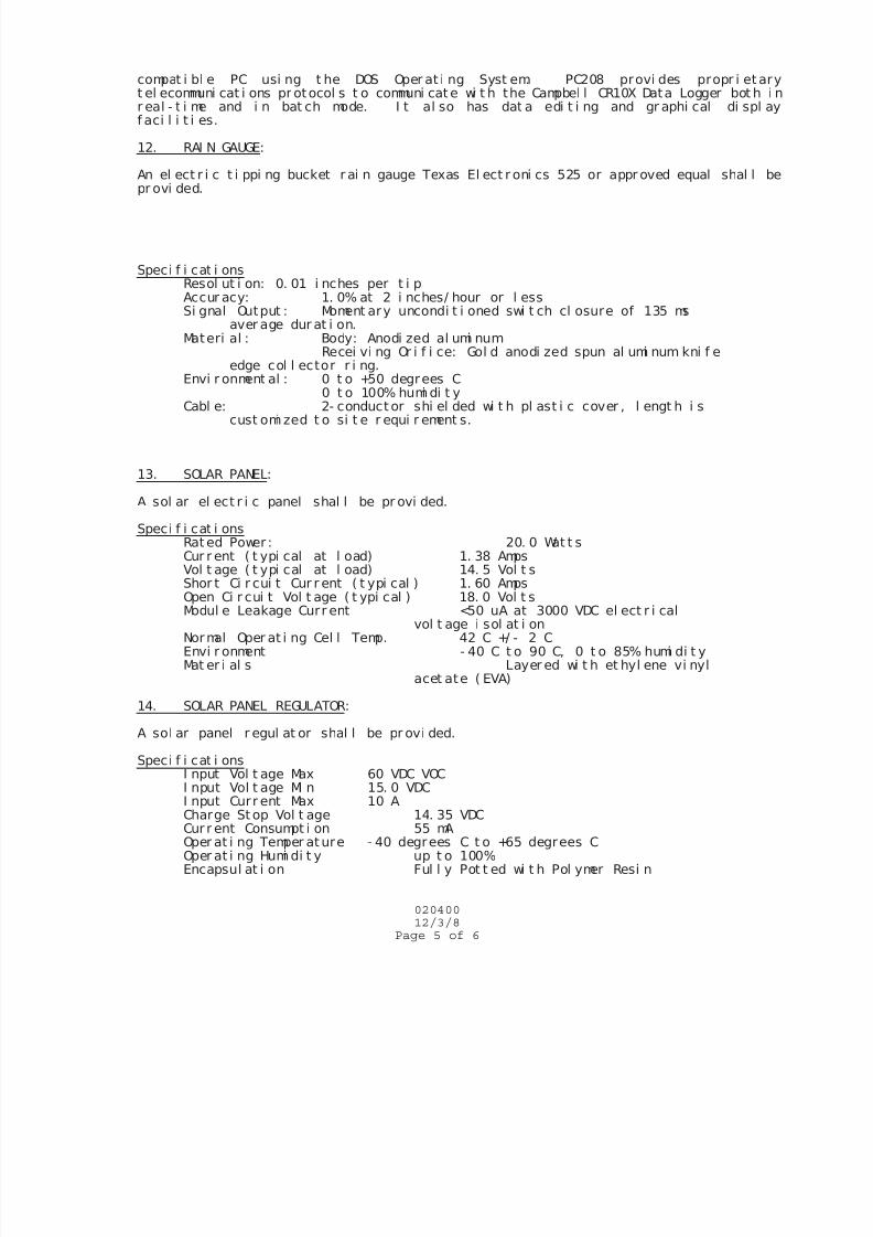
compat i bl e PC usi ng t he DOS Oper at i ng Syst em. PC208 provi des propr i et aryt el ecommuni cat i ons pr otocol s t o communi cat e wi t h the Campbel l CR10X Data Logger bot h i nr eal - t i me and i n bat ch mode. I t al so has dat a edi t i ng and gr aphi cal di spl ayf aci l i t i es.
12. RAI N GAUGE:
An el ect r i c t i ppi ng bucket r ai n gauge Texas El ect r oni cs 525 or appr oved equal shal l bepr ovi ded.
Speci f i cat i onsResol ut i on: 0. 01 i nches per t i pAccur acy: 1. 0% at 2 i nches/ hour or l essSi gnal Output : Moment ary uncondi t i oned swi t ch cl osure of 135 ms
aver age dur at i on.Materi al : Body: Anodi zed al umi num
Recei vi ng Or i f i ce: Gol d anodi zed spun al umi num kni f e edge col l ector r i ng.
Envi r onment al : 0 t o +50 degrees C
0 t o 100% humi di t yCabl e: 2- conduct or shi el ded wi t h pl ast i c cover , l engt h i s
cust omi zed t o si t e r equi r ement s.
13. SOLAR PANEL:
A sol ar el ect r i c panel shal l be pr ovi ded.
Speci f i cat i onsRat ed Power : 20. 0 Wat t sCur r ent ( t ypi cal at l oad) 1. 38 AmpsVol t age ( t ypi cal at l oad) 14. 5 Vol t s
Shor t Ci r cui t Cur r ent ( t ypi cal ) 1. 60 AmpsOpen Ci r cui t Vol t age ( t ypi cal ) 18. 0 Vol t sModul e Leakage Curr ent <50 uA at 3000 VDC el ect r i cal
vol t age i sol at i onNormal Oper at i ng Cel l Temp. 42 C +/ - 2 CEnvi r onment - 40 C t o 90 C, 0 t o 85% humi di t yMat er i al s Layer ed wi t h et hyl ene vi nyl
acet ate ( EVA)
14. SOLAR PANEL REGULATOR:
A sol ar panel r egul at or shal l be pr ovi ded.
Speci f i cat i onsI nput Vol t age Max 60 VDC VOCI nput Vol t age Mi n 15. 0 VDCI nput Curr ent Max 10 ACharge St op Vol t age 14. 35 VDCCur r ent Consumpt i on 55 mAOper at i ng Temper at ure - 40 degrees C t o +65 degrees COper at i ng Humi di t y up t o 100%Encapsul at i on Ful l y Pot t ed wi t h Pol ymer Resi n
7/25/2019 City Standard Construction Specifications
http://slidepdf.com/reader/full/city-standard-construction-specifications 27/511
02040012/3/8
Page 6 of 6
Packagi ng I nj ect i on mol ded, i mpact and UV r esi st ant ,ABS pl ast i c encl osur e
7/25/2019 City Standard Construction Specifications
http://slidepdf.com/reader/full/city-standard-construction-specifications 28/511
7/25/2019 City Standard Construction Specifications
http://slidepdf.com/reader/full/city-standard-construction-specifications 29/511
7/25/2019 City Standard Construction Specifications
http://slidepdf.com/reader/full/city-standard-construction-specifications 30/511
SECTION 021080
REMOVING ABANDONED STRUCTURES
1. DESCRIPTION
This specification shall provide for the demolition, removal and disposal of abandoned structures or
portions of abandoned structures, as noted on the drawings, and shall include all excavation and
backfilling necessary to complete the removal. The work shall be done in accordance with the
provisions of these specifications.
2. METHOD OF REMOVAL
Culverts or Sewers. Pipe shall be removed by careful excavation of all dirt on top and the sides in
such manner that the pipe will not be damaged. Removal of sewer appurtenances shall be included
for removal with the pipe. Those pipes which are deemed unsatisfactory for reuse by the Engineer
may be removed in any manner the Contractor may select.
Concrete Structures. Unwanted concrete structures or concrete portions of structures shall be
removed to the lines and dimensions shown on the drawings, and these materials shall be disposed
of as shown on the drawings or as directed by the Engineer. Any portion of the existing structure
outside of the limits designated for removal which is damaged by the Contractor's operations shall
be restored to its original condition at the Contractor's entire expense. Explosives shall not be used
in the removal of portions of the existing structure unless approved by the Engineer, in writing.
Portions of the abandoned structure shall be removed to the lines and dimensions shown on the
plans, and these materials shall be disposed of as shown on the drawings or as directed by the
Engineer. Any portion of the existing structure, outside of the limits designated for removal,damaged during the operations of the Contractor, shall be restored to its original condition entirely
at the Contractor’s expense. Explosives shall not be used in the removal of portions of the existing
structure unless approved by the Engineer, in writing.
Concrete portions of structures below the permanent ground line, which will not interfere in any
manner with the proposed construction, may be left in place, but removal shall be carried at least
five (5) feet below the permanent ground line and neatly squared off. Reinforcement shall be cut
off close to the concrete.
Steel Structures. Steel structures or steel portions of structures shall be dismantled in sections as
determined by the Engineer. The sections shall be stored if the members are to be salvaged andreused. Rivets and bolts connecting steel railing members, steel beams of beam spans and steel
stringers of truss spans, shall be removed by butting the heads with a "cold cut" and punching or
drilling from the hole, or by such other method that will not injure the members for re-use and will
meet the approval of the Engineer. The removal of rivets and bolts from connections of truss
021080
Page 1 of 3
Rev. 10-30-2014
7/25/2019 City Standard Construction Specifications
http://slidepdf.com/reader/full/city-standard-construction-specifications 31/511
members, bracing members, and other similar members in the structure will not be required unless
specifically called for on the plans or special provisions, and the Contractor shall have the option of
dismantling these members by flame-cutting the members immediately adjacent to the connections.
Flame-cutting will not be permitted, however, when the plans or special provisions call for the
structure unit to be salvaged in such manner as to permit re-erection. In such case, all members
shall be carefully matchmarked with paint in accordance with diagrams furnished by the Engineer prior to dismantling, and all rivets and bolts shall be removed from the connections in the manner
specified in the first portion of this paragraph.
Timber Structures. Timber structures or timber portions of structures to be reused shall be removed
in such manner as to damage the timber for further use as little as possible. All bolts and nails shall
be removed from such lumber as deemed salvable by the Engineer.
Unless otherwise specified on the drawings, timber piles shall be either pulled or cut off at the point
not less than five (5) feet below ground line, with the choice between these two methods resting
with the Contractor, unless otherwise specified.
Brick or Stone Structures. Unwanted brick or stone structures or stone portions of structures shall
be removed. Portions of such structures below the permanent ground line, which will not in any
manner interfere with the proposed construction, may be left in place, but removal shall be carried
at least five (5) feet below the permanent ground line and neatly squared off.
Salvage. All material such as pipe, timbers, railings, etc., which the Engineer deems as salvable for
reuse, and all salvaged structural steel, shall be delivered to a designated storage area.
Materials, other than structural steel, which are not deemed salvable by the Engineer, shall become
the property of the Contractor and shall be removed to suitable disposal sites off of the right-of-way
arranged for by the Contractor, or otherwise disposed of in a manner satisfactory to the Engineer.
Where temporary structures are necessary for a detour adjacent to the present structure, the
Contractor will be permitted to use the material in the old structure for the detour structure, but he
shall dismantle and stack or dispose of the material as required above as soon as the new structure
is opened for traffic.
Backfill. All excavations made in connection with this specification and all openings below the
natural ground line caused by the removal of abandoned structures or portions thereof shall be
backfilled to the level of the original ground line, unless otherwise provided on the drawings.
Backfill in accordance with applicable requirements of Sections 022020 “Excavation and Backfill
for Utilities” and 022080 “Embankment”. All open ends of abandoned pipe or other structuresshall be filled or plugged as specified.
That portion of the backfill which will support any portion of the roadbed, embankment, levee, or
other structural feature shall be placed in layers of the same depth as those required for placing
021080
Page 2 of 3
Rev. 10-30-2014
7/25/2019 City Standard Construction Specifications
http://slidepdf.com/reader/full/city-standard-construction-specifications 32/511
embankment, maximum 10” loose lifts unless otherwise specified. Material in each layer shall be
wetted uniformly, if required, and shall be compacted to a minimum of 95% Standard Proctor
density, unless otherwise specified. In places inaccessible to blading and rolling equipment,
mechanical or hand tamps or rammers shall be used to obtain the required compaction.
That portion of the backfill which will not support any portion of the roadbed, embankment, orother structural feature shall be placed as directed by the Engineer in such manner and to such state
of compaction as will preclude objectionable amount of settlement, maximum 10” loose lifts to
minimum 95% Standard Proctor density unless otherwise specified.
3. MEASUREMENT AND PAYMENT
Unless otherwise specified on the Bid Form, the work governed by this specification shall not be
measured for pay, but shall be subsidiary to the project.
021080
Page 3 of 3
Rev. 10-30-2014
7/25/2019 City Standard Construction Specifications
http://slidepdf.com/reader/full/city-standard-construction-specifications 33/511
SECTION 022020
EXCAVATION AND BACKFILL FOR UTILITIES
1. DESCRIPTION
This specification shall govern all work for excavation and backfill for utilities required to complete
the project.
2. CONSTRUCTION
(1) Unless otherwise specified on the drawings or permitted by the Engineer, all pipe and
conduit shall be constructed in open cut trenches with vertical sides. Trenches shall be
sheathed and braced as necessary throughout the construction period. Sheathing and bracing
shall be the responsibility of the Contractor (refer to Section 022022 “Trench Safety for
Excavations” of the City Standard Specifications).
Trenches shall have a maximum width of one foot beyond the horizontal projection of the
outside surfaces of the pipe and parallel thereto on each side unless otherwise specified.
The Contractor shall not have more than 200 feet of open trench left behind the trenching
operation and no more than 500 feet of ditch behind the ditching machine that is not
compacted as required by the plans and specifications. No trench or excavation shall remain
open after working hours.
For all utility conduit and sewer pipe to be constructed in fill above natural ground, the
embankment shall first be constructed to an elevation not less than one foot above the top of
the pipe or conduit, after which excavation for the pipe or conduit shall be made.
If quicksand, muck, or similar unstable material is encountered during the excavation, thefollowing procedure shall be used unless other methods are called for on the drawings. If the
unstable condition is a result of ground water, the Contractor, prior to additional excavation,
shall control it. After stable conditions have been achieved, unstable soil shall be removed or
stabilized to a depth of 2 feet below the bottom of pipe for pipes 2 feet or more in height; and
to a depth equal to the height of pipe, 6 inches minimum, for pipes less then 2 feet in height.
Such excavation shall be carried at least one foot beyond the horizontal limits of the structure
on all sides. All unstable soil so removed shall be replaced with suitable stable material,
placed in uniform layers of suitable depth as directed by the Engineer, and each layer shall be
wetted, if necessary, and compacted by mechanical tamping as required to provide a stable
condition. For unstable trench conditions requiring outside forms, seals, sheathing and
bracing, any additional excavation and backfill required shall be done at the Contractor'sexpense.
(2) Shaping of Trench Bottom. The trench bottom shall be undercut a minimum depth sufficient
to accommodate the class of bedding indicated on the plans and specifications.
022020Page 1 of 4
Rev. 3-25-2015
7/25/2019 City Standard Construction Specifications
http://slidepdf.com/reader/full/city-standard-construction-specifications 34/511
(3) Dewatering Trench. Pipe or conduit shall not be constructed or laid in a trench in the
presence of water. All water shall be removed from the trench sufficiently prior to the pipe
or conduit planing operation to insure a relatively dry (no standing water), firm bed. The
trench shall be maintained in such dewatered condition until the trench has been backfilled to
a height at lease one foot above the top of pipe. Removal of water may be accomplished by
bailing, pumping, or by installation of well-points, as conditions warrant. Removal of well-
points shall be at rate of 1/3 per 24 hours (every third well-point). The Contractor shall
prevent groundwater from trench or excavation dewatering operations from discharging
directly into the storm water system. Groundwater from dewatering operations shall besampled and tested, if applicable, and disposed of, in accordance with City Standard
Specification Section 022021 "Control of Ground Water".
(4) Excavation in Streets. Excavation in streets, together with the maintenance of traffic where
specified, and the restoration of the pavement riding surface, shall be in accordance with
drawing detail or as required by other applicable specifications.
(5) Removing Abandoned Structures. When abandoned masonry structures or foundations are
encountered in the excavation, such obstructions shall be removed for the full width of the
trench and to a depth one foot below the bottom of the trench. When abandoned inlets or
manholes are encountered and no plan provision is made for adjustment or connection to the
new utility, such manholes and inlets shall be removed completely to a depth one foot below
the bottom of the trench. In each instance, the bottom to the trench shall be restored to grade
by backfilling and compacting by the methods provided hereinafter for backfill. Where the
trench cuts through utility lines which are known to be abandoned, these lines shall be cut
flush with the sides of the trench and blocked with a concrete plug in a manner satisfactory to
the Engineer.
(6) Protection of Utilities. The Contractor shall conduct his work such that a reasonable
minimum of disturbance to existing utilities will result. Particular care shall be exercised to
avoid the cutting or breakage of water and gas lines. Such lines, if broken, shall be restored promptly by the Contractor. When active wastewater lines are cut in the trenching
operations, temporary flumes shall be provided across the trench while open, and the lines
shall be restored when the backfilling has progressed to the original bedding line of the sewer
so cut.
The Contractor shall inform utility owners sufficiently in advance of the Contractor's
operations to enable such utility owners to reroute, provide temporary detours, or to make
other adjustments to utility lines in order that the Contractor may proceed with his work with
a minimum of delay. The Contractor shall not hold the City liable for any expense due to
delay or additional work because of utility adjustments or conflicts.
(7) Excess Excavated Material. All materials from excavation not required for backfilling the
trench shall be removed by the Contractor from the job site promptly following the
completion of work involved.
022020Page 2 of 4
Rev. 3-25-2015
7/25/2019 City Standard Construction Specifications
http://slidepdf.com/reader/full/city-standard-construction-specifications 35/511
(8) Backfill
A. Backfill Procedure Around Pipe (Initial Backfill)
All trenches and excavation shall be backfilled as soon as is practical after the pipes or
conduits are properly laid. In addition to the specified pipe bedding material, the backfill
around the pipe as applicable shall be granular material as shown on the standard details or as
described in the applicable specification section, and shall be free of large hard lumps or
other debris. If indicated on the plans, pipe shall be encased with cement-stabilized sand backfill as described below. The backfill shall be deposited in the trench simultaneously on
both sides of the pipe for the full width of the trench, in layers not to exceed ten (10) inches
(loose measurement), wetted if required to obtain proper compaction, and thoroughly
compacted by use of mechanical tampers to a density comparable to the adjacent undisturbed
soil or as otherwise specified on the plans, but not less than 95% Standard Proctor density. A
thoroughly compacted material shall be in place between the external wall of the pipe and the
undisturbed sides of the trench and to a level twelve (12) inches above the top of the pipe.
B. Backfill Over One Foot Above Pipe (Final Backfill)
UNPAVED AREAS: The backfill for that portion of trench over one (1) foot above the pipe
or conduit not located under pavements (including waterlines, gravity wastewater lines,
wastewater force mains and reinforced concrete storm water pipe) shall be imported select
material or clean, excess material from the excavation meeting the following requirements:
Free of hard lumps, rock fragments, or other debris,
No clay lumps greater than 2" diameter
Moisture Content: +/-3%
Backfill material shall be placed in layers not more than ten (10) inches in depth (loose
measurement), wetted if required to obtain proper compaction, and thoroughly compacted by
use of mechanical tampers to the natural bank density but not less than 95% Standard Proctor
density, unless otherwise indicated. Flooding of backfill is not allowed. Jetting of backfillmay only be allowed in sandy soils and in soils otherwise approved by the Engineer.
Regardless of backfill method, no lift shall exceed 10 inches and density shall not be less
than 95% Standard Proctor density. A period of not less than twenty-four (24) hours shall
elapse between the time of jetting and the placing of the top four (4) feet of backfill. If
jetting is used, the top four (4) feet of backfill shall be placed in layers not more than 10
inches in depth (loose measurement), wetted if required to obtain proper compaction, and
thoroughly compacted by use of mechanical tampers to the natural bank density but not less
than 95% Standard Proctor density (ASTM D698).
PAVED AREAS: At utility line crossings under pavements (including waterlines, gravity
wastewater lines, wastewater force mains, and reinforced concrete storm water pipe), and
where otherwise indicated on the drawings, trenches shall be backfilled as shown below:
From top of initial backfill (typically twelve (12) inches above top of the pipe) to three
(3) feet below bottom of road base course, backfill shall be select material meeting the
requirements of 022100 “Select Material”.
022020Page 3 of 4
Rev. 3-25-2015
7/25/2019 City Standard Construction Specifications
http://slidepdf.com/reader/full/city-standard-construction-specifications 36/511
Asphalt Roadways
The upper three (3) feet of trench below the road base course shall be backfilled to the
bottom of the road base course with cement-stabilized sand containing a minimum of 2
sacks of Standard Type I Portland cement per cubic yard of sand and compacted to not
less than 95% Standard Proctor density.
Concrete Roadways
The Contractor may elect to backfill the upper three (3) feet of trench below the road
base course
with cement stabilized sand as noted above, or in the case of storm water pipe or box installation the Contractor may backfill and compact select material to 98%
Standard Proctor density (ASTM D698) following City Standard Specification Section
022100.
3. MEASUREMENT AND PAYMENT
Unless otherwise specified on the Bid Form, excavation and backfill for utilities, including select
material or cement-stabilized sand backfill, shall not be measured and paid for separately. It shall be
considered subsidiary to the items for which the excavation and backfill is required.
022020Page 4 of 4
Rev. 3-25-2015
7/25/2019 City Standard Construction Specifications
http://slidepdf.com/reader/full/city-standard-construction-specifications 37/511
SECTION 022021
CONTROL OF GROUND WATER
1. GENERAL
1.1 SECTION INCLUDES
A. Dewatering, depressurizing, draining, and maintaining trenches, shaft excavations, structuralexcavations, and foundation beds in a stable condition, and controlling ground water conditions
for tunnel excavations.
B. Protection of excavations and trenches from surface runoff.
C. Disposing of removed ground water by approved methods.
1.2 REFERENCES
A. ASTM D 698 - Test Methods for Moisture-Density Relations of Soils and Soil-Aggregate
Mixtures, Using 5.5-lb (2.49 kg) Rammer and 12-inch (304.8 mm) Drop.
B. Federal Regulations, 29 CFR Part 1926, Standards-Excavation, Occupational Safety and Health
Administration (OSHA).
C. Federal Register 40 CFR (Vol. 55, No. 222) Part 122, EPA Administered Permit Programs
(NPDES), Para.122.26(b)(14) Storm Water Discharge.
1.3 DEFINITIONS
A. Ground water control includes both dewatering and depressurization of water-bearing soillayers.
1. Dewatering includes lowering the water table and intercepting seepage which would
otherwise emerge from slopes or bottoms of excavations, or into tunnels and shafts, and
disposing of removed ground water by approved methods. The intent of dewatering is to
increase the stability of tunnel excavations and excavated slopes; prevent dislocation of
material from slopes or bottoms of excavations; reduce lateral loads on sheeting and
bracing; improve excavating and hauling characteristics of excavated material; prevent
failure or heaving of the bottom of excavations; and to provide suitable conditions for
placement of backfill materials and construction of structures, piping and other
installations.
2. Depressurization includes reduction in piezometric pressure within strata not controlled by
dewatering alone, as required to prevent failure or heaving of excavation bottom or
instability of tunnel excavations.
B. Excavation drainage includes keeping excavations free of surface and seepage water.
022021
Page 1 of 10
Rev. 10-30-2014
7/25/2019 City Standard Construction Specifications
http://slidepdf.com/reader/full/city-standard-construction-specifications 38/511
C. Surface drainage includes the use of temporary drainage ditches and dikes and installation of
temporary culverts and sump pumps with discharge lines as required to protect the Work from
any source of surface water.
D. Equipment and instrumentation for monitoring and control of the ground water control system
includes piezometers and monitoring wells, and devices, such as flow meters, for observing and
recording flow rates.
1.4 PERFORMANCE REQUIREMENTS
A. Conduct subsurface investigations as needed to identify ground water conditions and to provide
parameters for design, installation, and operation of ground water control systems.
B. Design a ground water control system, compatible with requirements of Federal Regulations 29
CFR Part 1926 and City Standard Specification Section 022022 - Trench Safety for
Excavations, to produce the following results:
1. Effectively reduce the hydrostatic pressure affecting:
a) Excavations (including utility trenches);
b) Tunnel excavation, face stability or seepage into tunnels.
2. Develop a substantially dry and stable subgrade for subsequent construction operations.
3. Preclude damage to adjacent properties, buildings, structures, utilities, installed facilities,
and other work.
4. Prevent the loss of fines, seepage, boils, quick condition, or softening of the foundation
strata.
5. Maintain stability of sides and bottom of excavations.
C. Provide ground water control systems which may include single-stage or multiple-stage well
point systems, eductor and ejector-type systems, deep wells, or combinations of these equipment
types.
D. Provide drainage of seepage water and surface water, as well as water from any other source
entering the excavation. Excavation drainage may include placement of drainage materials,
such as crushed stone and filter fabric, together with sump pumping.
E. Provide ditches, berms, pumps and other methods necessary to divert and drain surface water
away from excavations.
F. Locate ground water control and drainage systems so as not to interfere with utilities,
construction operations, adjacent properties, or adjacent water wells.
022021
Page 2 of 10
Rev. 10-30-2014
7/25/2019 City Standard Construction Specifications
http://slidepdf.com/reader/full/city-standard-construction-specifications 39/511
G. Assume sole responsibility for ground water control systems and for any loss or damage
resulting from partial or complete failure of protective measures, and any settlement or resultant
damage caused by the ground water control operations. Modify ground water control systems or
operations if they cause or threaten to cause damage to new construction, existing site
improvements, adjacent property, or adjacent water wells, or affect potentially contaminated
areas. Repair damage caused by ground water control systems or resulting from failure of the
system to protect property as required.
H. Provide an adequate number of piezometers installed at the proper locations and depths asrequired to provide meaningful observations of the conditions affecting the excavation, adjacent
structures, and water wells.
I. Provide environmental monitoring wells installed at the proper locations and depths as required
to provide adequate observations of hydrostatic conditions and possible contaminant transport
from contamination sources into the work area or into the ground water control system.
J. Decommission piezometers and monitoring wells installed during design phase studies and left
for Contractors monitoring and use, if applicable.
1.5 ENVIRONMENTAL REQUIREMENTS
A. Comply with requirements of agencies having jurisdiction.
B. Comply with Texas Commission on Environmental Quality (TCEQ) regulations and Texas
Water Well Drillers Association for development, drilling, and abandonment of wells used in
dewatering system.
C. Prior to beginning construction activities, file Notice of Intent (NOI) for Storm Water
Discharges Associated with Construction Activity under the Texas Pollutant Elimination
System (TPDES) General Permit No. TXR150000, administered by the Texas Commission onEnvironmental Quality (TCEQ). The general permit falls under the provisions of Section 402 of
the Clean Water Act and Chapter 26 of the Texas Water Code.
D. Prepare submittal form and submit to TCEQ along with application fee.
E. Upon completion of construction, file Notice of Termination (NOT) for Storm Water
Discharges Associated with Construction Activity under the TPDES General Permit with the
TCEQ.
F. Obtain all necessary permits from agencies with control over the use of ground water and
matters affecting well installation, water discharge, and use of existing storm drains and naturalwater sources. Because the review and permitting process may be lengthy, take early action to
pursue and submit for the required approvals.
G. Monitor ground water discharge for contamination while performing pumping in the vicinity of
potentially contaminated sites.
022021
Page 3 of 10
Rev. 10-30-2014
7/25/2019 City Standard Construction Specifications
http://slidepdf.com/reader/full/city-standard-construction-specifications 40/511
H. Conduct sampling and testing of ground water and receiving waters as outlined in Article 3
below.
2. PRODUCTS
2.1 EQUIPMENT AND MATERIALS
A. Equipment and materials are at the option of Contractor as necessary to achieve desired results
for dewatering.
B. Eductors, well points, or deep wells, where used, shall be furnished, installed and operated by an
experienced contractor regularly engaged in ground water control system design, installation,
and operation.
C. All equipment must be in good repair and operating order.
D. Sufficient standby equipment and materials shall be kept available to ensure continuous
operation, where required.
3. EXECUTION
3.1 GROUND WATER CONTROL
A. Perform a subsurface investigation by borings as necessary to identify water bearing layers,
piezometric pressures, and soil parameters for design and installation of ground water control
systems. Perform pump tests, if necessary to determine the drawdown characteristics of the
water bearing layers.
B. Provide labor, material, equipment, techniques and methods to lower, control and handle ground
water in a manner compatible with construction methods and site conditions. Monitoreffectiveness of the installed system and its effect on adjacent property.
C. Install, operate, and maintain ground water control systems in accordance with the ground water
control system design. Notify the City’s Construction Inspector in writing of any changes made
to accommodate field conditions and changes to the Work. Revise the ground water control
system design to reflect field changes.
D. Provide for continuous system operation, including nights, weekends, and holidays. Arrange for
appropriate backup if electrical power is primary energy source for dewatering system.
E. Monitor operations to verify that the system lowers ground water piezometric levels at a raterequired to maintain a dry excavation resulting in a stable subgrade for prosecution of
subsequent operations.
F. Where hydrostatic pressures in confined water bearing layers exist below excavation,
depressurize those zones to eliminate risk of uplift or other instability of excavation or installed
022021
Page 4 of 10
Rev. 10-30-2014

7/25/2019 City Standard Construction Specifications
http://slidepdf.com/reader/full/city-standard-construction-specifications 41/511
works. Allowable piezometric elevations shall be defined in the ground water control system
design.
G. Remove ground water control installations.
1. Remove pumping system components and piping when ground water control is no longer
required.
2. Remove piezometers and monitoring wells when directed by the City Engineer.
3. Grout abandoned well and piezometer holes. Fill piping that is not removed with cement-
bentonite grout or cement-sand grout.
H. During backfilling, dewatering may be reduced to maintain water level a minimum of 5 feet
below prevailing level of backfill. However, do not allow that water level to result in uplift
pressures in excess of 80 percent of downward pressure produced by weight of structure or
backfill in place. Do not allow water levels to rise into cement stabilized sand until at least 48
hour after placement.
I. Provide a uniform diameter for each pipe drain run constructed for dewatering. Remove pipe
drain when it has served its purpose. If removal of pipe is impractical, provide grout
connections at 50-foot intervals and fill pipe with cement-bentonite grout or cement-sand grout
when pipe is removed from service.
J. Extent of construction ground water control for structures with a permanent perforated
underground drainage system may be reduced, such as for units designed to withstand
hydrostatic uplift pressure. Provide a means for draining the affected portion of underground
system, including standby equipment. Maintain drainage system during operations and remove
it when no longer required.
K. Remove system upon completion of construction or when dewatering and control of surface or
ground water is no longer required.
L. In unpaved areas, compact backfill to not less than 95 percent of Standard Proctor maximum dry
density in accordance with ASTM D 698. In paved areas (or areas to receive paving), compact
backfill to not less than 98 percent of Standard Proctor maximum dry density in accordance with
ASTM D 698.
3.2 REQUIREMENTS FOR EDUCTOR, WELL POINTS, OR DEEP WELLS
A. For above ground piping in ground water control system, include a 12-inch minimum length ofclear, transparent piping between every eductor well or well point and discharge header so that
discharge from each installation can be visually monitored.
B. Install sufficient piezometers or monitoring wells to show that all trench or shaft excavations in
water bearing materials are pre-drained prior to excavation. Provide separate piezometers for
022021
Page 5 of 10
Rev. 10-30-2014
7/25/2019 City Standard Construction Specifications
http://slidepdf.com/reader/full/city-standard-construction-specifications 42/511
7/25/2019 City Standard Construction Specifications
http://slidepdf.com/reader/full/city-standard-construction-specifications 43/511
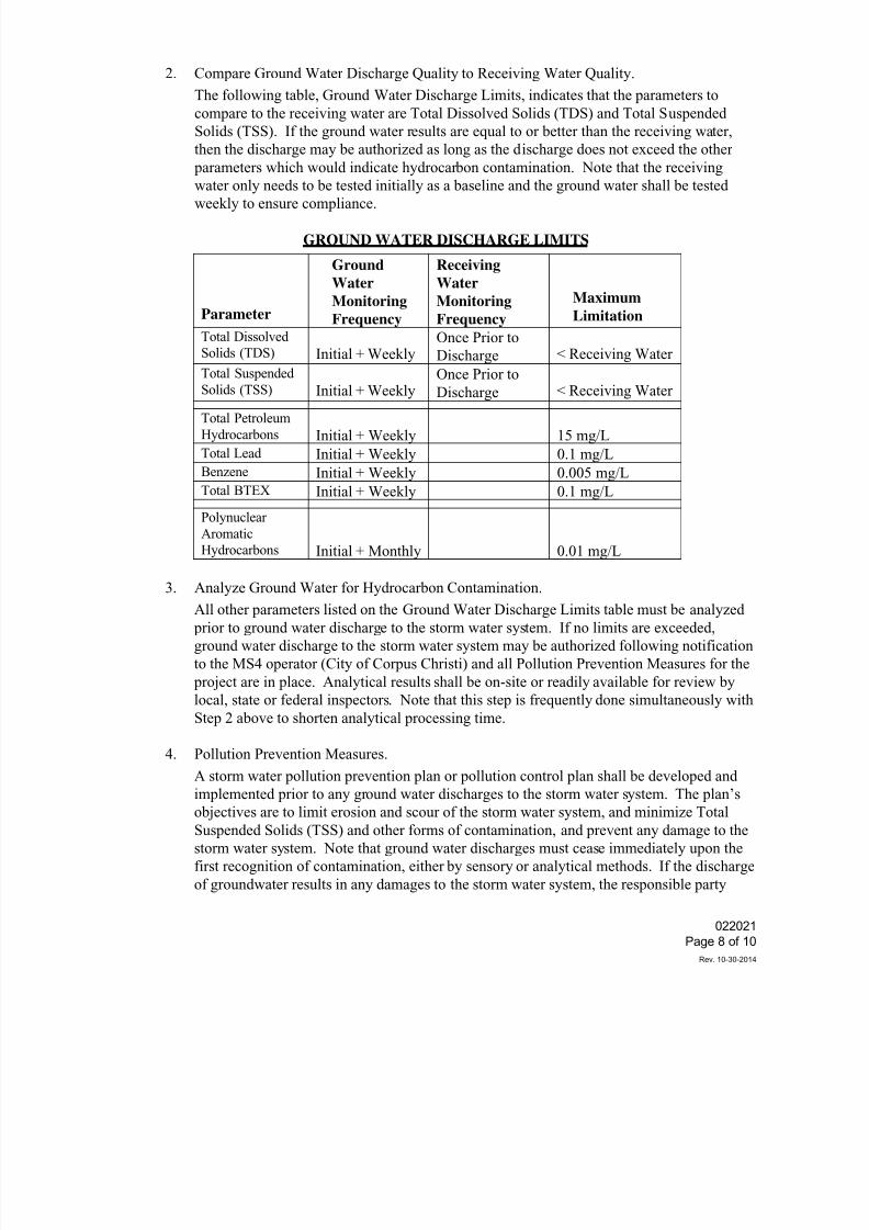
7/25/2019 City Standard Construction Specifications
http://slidepdf.com/reader/full/city-standard-construction-specifications 44/511
2. Compare Ground Water Discharge Quality to Receiving Water Quality.
The following table, Ground Water Discharge Limits, indicates that the parameters to
compare to the receiving water are Total Dissolved Solids (TDS) and Total Suspended
Solids (TSS). If the ground water results are equal to or better than the receiving water,
then the discharge may be authorized as long as the discharge does not exceed the other
parameters which would indicate hydrocarbon contamination. Note that the receiving
water only needs to be tested initially as a baseline and the ground water shall be tested
weekly to ensure compliance.
GROUND WATER DISCHARGE LIMITS
Parameter
Ground
Water
Monitoring
Frequency
Receiving
Water
Monitoring
Frequency
Maximum
Limitation
Total Dissolved
Solids (TDS) Initial + WeeklyOnce Prior to
Discharge < Receiving Water
Total Suspended
Solids (TSS) Initial + Weekly
Once Prior to
Discharge < Receiving Water
Total Petroleum
Hydrocarbons Initial + Weekly 15 mg/LTotal Lead Initial + Weekly 0.1 mg/LBenzene Initial + Weekly 0.005 mg/LTotal BTEX Initial + Weekly 0.1 mg/L
Polynuclear
Aromatic
Hydrocarbons Initial + Monthly 0.01 mg/L
3. Analyze Ground Water for Hydrocarbon Contamination.
All other parameters listed on the Ground Water Discharge Limits table must be analyzed
prior to ground water discharge to the storm water system. If no limits are exceeded,
ground water discharge to the storm water system may be authorized following notification
to the MS4 operator (City of Corpus Christi) and all Pollution Prevention Measures for the
project are in place. Analytical results shall be on-site or readily available for review by
local, state or federal inspectors. Note that this step is frequently done simultaneously with
Step 2 above to shorten analytical processing time.
4. Pollution Prevention Measures.
A storm water pollution prevention plan or pollution control plan shall be developed andimplemented prior to any ground water discharges to the storm water system. The plan’s
objectives are to limit erosion and scour of the storm water system, and minimize Total
Suspended Solids (TSS) and other forms of contamination, and prevent any damage to the
storm water system. Note that ground water discharges must cease immediately upon the
first recognition of contamination, either by sensory or analytical methods. If the discharge
of groundwater results in any damages to the storm water system, the responsible party
022021
Page 8 of 10
Rev. 10-30-2014
7/25/2019 City Standard Construction Specifications
http://slidepdf.com/reader/full/city-standard-construction-specifications 45/511
shall remediate any damage to the storm water system and the environment to the
satisfaction of the Storm Water Department and/or any State or Federal Regulatory Agency.
5. MS4 Operator Notification.
The MS4 operator shall be notified prior to ground water discharge to the storm water
system. Contractor shall contact the designated City MS4 representative to request
authorization to discharge ground water to the storm water system.
Notification shall include:
Project Name:
Responsible Party:
Discharge Location:
Receiving Water:
Estimated Time of Discharge:
Linear Project: Yes / No
Pollution Prevention Measures Implemented:
Statement indicating all sampling and testing has been conducted and meets the
requirements of a legitimate discharge.
G. Discharges to Wastewater System
In the event that the groundwater does not equal or exceed the receiving water quality, an
alternative disposal option would include pumping to the nearest sanitary sewer system.
Discharge to the sanitary sewer system requires a permit from the Wastewater Department. If
discharging to temporary holding tanks and trucking to a sanitary sewer or wastewater treatment
plant, the costs for these operations shall be negotiated.
Contractor shall contact the Pretreatment Group for City Utility Operations to obtain a
Wastewater Discharge Permit Application for authorization to discharge to the wastewater
system. Authorization approval will include review of laboratory analysis of the ground water
and estimated flow data. Note that groundwater discharges must cease immediately upon the
first recognition of contamination, either by sensory or analytical methods. If the discharge of
groundwater results in any damages to the wastewater collection system or wastewater
overflows, the responsible party shall remediate any damage to the wastewater collection system
and the environment to the satisfaction of the Wastewater Department and/or any State or
Federal Regulatory Agency.
H. Other groundwater disposal alternatives or solutions may be approved by the Engineer on a case
by case basis.
3.7 SURFACE WATER CONTROL
A. Intercept surface water and divert it away from excavations through the use of dikes, ditches,
curb walls, pipes, sumps or other approved means.
B. Divert surface water into sumps and pump into drainage channels or storm drains, when
022021
Page 9 of 10
Rev. 10-30-2014
7/25/2019 City Standard Construction Specifications
http://slidepdf.com/reader/full/city-standard-construction-specifications 46/511
approved by the City Engineer. Provide settling basins when required by the City Engineer.
C. Storm water that enters the excavation can be pumped out as long as care is taken to minimize
solids and mud entering the pump suction and flow is pumped to a location that allows for sheet
flow prior to entering a storm water drainage ditch or storm water inlet. An alternative to sheet
flow is to pump storm water to an area where ponding occurs naturally without leaving the
designated work area or by manmade berm(s) prior to entering the storm water system. Sheet
flow and ponding is required to allow solids screening and/or settling prior to entering the storm
water system. Storm water or groundwater shall not be discharged to private property.
4. MEASUREMENT AND PAYMENT
Unless otherwise specified on the Bid Form, control of ground water will not be measured and paid for
separately, but shall be considered subsidiary to other bid items.
022021
Page 10 of 10
Rev. 10-30-2014
7/25/2019 City Standard Construction Specifications
http://slidepdf.com/reader/full/city-standard-construction-specifications 47/511
022022
Page 1 of 1
Rev. 10-30-2014
SECTION 022022
TRENCH SAFETY FOR EXCAVATIONS
1. DESCRIPTION
This specification shall govern all work for providing for worker safety in excavations and trenching
operations required to complete the project.
2. REQUIREMENTS
Worker Safety in excavations and trenches shall be provided by the Contractor in accordance with
Occupational Safety and Health Administration (OSHA) Standards, 29 CFR Part 1926 Subpart P -
Excavations.
It is the sole responsibility of the Contractor, and not the City or Engineer or Consultant, to
determine and monitor the specific applicability of a safety system to the field conditions to be
encountered on the job site during the project.
The Contractor shall indemnify and hold harmless the City and Engineer
and Consultant from alldamages and costs that may result from failure of methods or equipment used by the Contractor to
provide for worker safety.
Trenches, as used herein, shall apply to any excavation into which structures, utilities, or sewers are
placed regardless of depth.
Trench Safety Plan, as used herein, shall apply to all methods and materials used to provide for
worker safety in excavation and trenching operations required during the project.
3. MEASUREMENT AND PAYMENT
Measurement of Trench Safety shall be by the linear foot of trench, regardless of depth.
Measurement shall be taken along the centerline of the trench.
Measurement for Excavation Safety for Utility Structures shall be per each excavation. Excavations
include, but are not limited to, those for manholes, vaults, pits and other such structures that are
incidental to utility work.
Measurement for Excavation Safety for Special Structures shall be per each excavation or by the
lump sum for each special structure identified in the Proposal.
Payment shall be at the unit price bid and shall fully compensate the Contractor for all work,
equipment, materials, personnel, and incidentals as required to provide for worker safety in trenches
and excavations for the project.
Revision current for Texas Code Chapter 756 Subchapter C. Trench Safety.
7/25/2019 City Standard Construction Specifications
http://slidepdf.com/reader/full/city-standard-construction-specifications 48/511
7/25/2019 City Standard Construction Specifications
http://slidepdf.com/reader/full/city-standard-construction-specifications 49/511
022040
Page 2 of 3
Rev. 10-30-2014
(C) Curb Backfill and Topsoil (Sidewalks, Parkways, Islands, etc.)
Fill and compact areas behind curbs and adjacent to sidewalks and driveways within 48 hours after
completion of concrete work. The top 6 inches (where disturbed by construction or where
unsatisfactory material is exposed by excavation) of finish earth grade shall be clean excavated
material or topsoil capable of supporting a good growth of grass when fertilized and seeded orsodded. It shall be free of concrete, asphalt, shell, caliche, debris and any other material that
detracts from its appearance or hampers the growth of grass. Topsoil shall meet the requirements
specified in City Standard Specification Section 028020 "Seeding".
(D) Matching Grades at Right-of-Way Line
Finish grade at the property line shall be as shown on the drawings. The Engineer may require a
reasonable amount of filling on private property where the sidewalk grade is above the property
elevation. Use suitable material from the excavation. Unless otherwise directed, cuts at right-of -
way lines shall be made at a slope of three horizontal to one vertical (3:1) or flatter.
(E) Drainage
During construction, the roadbed and ditches shall be maintained in such condition as to insure
proper drainage at all times, and ditches and channels shall be so constructed and maintained as to
avoid damage to the roadway section.
All slopes which, in the judgment of the Engineer, require variation, shall be accurately shaped,
and care shall be taken that no material is loosened below the required slopes. All breakage and
slides shall be removed and disposed of as directed.
3. SELECTION OF ROADBED MATERIALS
Where shown on the plans, Select Material shall be utilized to improve the roadbed, in which case
the work shall be performed in such manner and sequence that suitable materials may be selected,
removed separately, and deposited in the roadway within limits and at elevations required. Material
used for roadway embankment shall meet the requirements of City Standard Specification Section
022100 Select Material.
4. GEOGRID
If indicated on the drawings, geogrid shall be placed in the base layer according to the pavement
details to provide a mechanically-stabilized aggregate base layer within the pavement structure.Geogrid shall be "Tensar TX5 Triaxial Geogrid", or pre-approved equivalent. Use (and approval)
of a different product must be supported by documentation showing that the alternate pavement
section will meet or exceed the required number of 18-kip equivalent single axle loads (ESAL) and
structural number (SN) over the stated pavement design life, and the pavement design must be
sealed and signed by a Texas professional engineer. Documentation must also include the
structural design value used for the geogrid structural contribution, based on and supported by
7/25/2019 City Standard Construction Specifications
http://slidepdf.com/reader/full/city-standard-construction-specifications 50/511
7/25/2019 City Standard Construction Specifications
http://slidepdf.com/reader/full/city-standard-construction-specifications 51/511
SECTION 022060
CHANNEL EXCAVATION
1. DESCRIPTION
This specification shall govern all work for Channel Excavation required to complete the project.
2. CONSTRUCTION METHODS
Trees, stumps, brush and other vegetation shall be removed and hauled away. Excavated slopes
shall be finished in conformance with the lines and grades established by the Engineer. When
completed, the average plane of slopes shall conform to the slopes indicated on the drawings, and
no point on completed slopes shall vary from the designated slopes by more than 0.5 foot measured
at right angles to the slope. In no case shall any portion of the slope encroach on the roadbed. The
tops of excavated slopes and the end of excavation shall be rounded. The bottom and sides of the
ditch or channel shall be undercut a minimum depth sufficient to accommodate topsoil for seeding,
sodding, or slope protection, as indicated on the drawings.
All suitable materials removed from the excavation shall be used, insofar as practicable, in the
formation of embankments in accordance with City Standard Specification Section 022080"Embankment", or shall be otherwise utilized or satisfactorily disposed of as indicated on drawings,
or as directed, and the completed work shall conform to the established alignment, grades and cross
sections. During construction, the channel shall be kept drained, insofar as practicable, and the
work shall be prosecuted in a neat workmanlike manner.
Unsuitable channel excavation in excess of that needed for construction shall become the property
of the Contractor and removed from the site and properly disposed of.
3. SELECTION OF MATERIALS
Where shown on the drawings, selected materials shall be utilized in the formation of embankmentor to improve the roadbed, provided that the material meets the requirements specified in City
Standard Specification Sections 022040 "Street Excavation" and 022100 “Select Material”, in
which case the work shall be performed in such manner and sequence that suitable materials may
be selected, removed separately and deposited in the roadway within the limits and at elevations
required. Concrete for lining channels, where specified on the drawings, shall be Class "A" in
accordance with City Standard Specification Section 030020 "Portland Cement Concrete".
4. MEASUREMENT AND PAYMENT
Unless otherwise specified on the Bid Form, channel excavation shall be measured in its original
position and the volume computed in cubic yards by the method of average end areas, or by linearfoot of channel or drainage ditch, as specified. Channel excavation shall include, but not be limited
to, clearing and removal of vegetation, excavation, de-watering, embankment, compaction, hauling,
and disposal. Channel excavation shall not include undercutting to accommodate topsoil, sod, or
slope protection. Payment shall be at the bid price for the unit of measurement specified and shall
be full compensation for furnishing all labor, materials, tools, equipment and incidentals necessary
to complete the work.
022060
Page 1 of 1
Rev. 3-25-2015
7/25/2019 City Standard Construction Specifications
http://slidepdf.com/reader/full/city-standard-construction-specifications 52/511
022080
Page 1 of 2
Rev. 10-30-2014
SECTION 022080
EMBANKMENT
1. DESCRIPTION
This specification shall govern all work for Embankment required to complete the project.
2. CONSTRUCTION METHODS
Prior to placing embankment, the area to be covered shall be stripped of all vegetation and the
material so removed shall be disposed of off the job site. Washes, gulleys, wet areas, and yielding
areas shall be corrected as directed by the Engineer.
Unless otherwise indicated on the drawings, the surface of the ground which is to receive
embankment shall be loosened by scarifying or plowing to a depth of not less than 6 inches. The
loosened material shall be recompacted with the new embankment as hereinafter specified.
Embankment shall be placed in layers not to exceed ten (10) inches uncompacted (loose) depth for
the full width of the embankment, unless otherwise noted.
Where embankment is adjacent to a hillside or old roadbed, the existing slope shall be cut in steps
to not less than the vertical depth of an uncompacted layer. The fill material shall be placed from
the low side and compacted. Each layer shall overlap the existing embankment by at least the
width indicated by the embankment slope.
Trees, stumps, roots, vegetation, debris or other unsuitable materials shall not be placed in
embankment.
Each layer of embankment shall be uniform as to material, density and moisture content before
beginning compaction. Where layers of unlike materials abut each other, each layer shall be
feather-edged for at least 100 feet or the material shall be so mixed as to prevent abrupt changes in
the soil. No material placed in the embankment by dumping in a pile or windrow shall be
incorporated in a layer in that position, but all such piles or windrows shall be moved by blading or
similar methods. Clods or lumps of material shall be broken and the embankment material mixed
by blading, harrowing, disking or similar methods to the end that a uniform material of uniform
density is secured in each layer. Except as otherwise required by the drawings, all embankments
shall be constructed in layers approximately parallel to the finished grade and each layer shall be so
constructed as to provide a uniform slope of 1/4 inch per foot from the centerline of the
embankment to the outside.
Each layer shall be compacted to the required density and moisture by any method, type and size of
equipment that will give the required compaction. Prior to and in conjunction with the rolling
operation, each layer shall be brought to the moisture content necessary to obtain the required
density and shall be kept leveled with suitable equipment to insure uniform compaction over the
entire layer.
For each layer of earth embankment and select material, it is the intent of this specification to
provide the density as required herein, unless otherwise shown on the drawings. Soils for
7/25/2019 City Standard Construction Specifications
http://slidepdf.com/reader/full/city-standard-construction-specifications 53/511
022080
Page 2 of 2
Rev. 10-30-2014
embankment shall be sprinkled with water as required to provide not less than optimum moisture
and compacted to the extent necessary to provide not less than 95% Standard Proctor density
(ASTM D698). Field density determinations will be made in accordance with approved methods.
After each layer of earth embankment or select material is complete, tests, as necessary, will be
made by the Engineer. If the material fails to meet the density specified, the course shall be
reworked as necessary to obtain the specified compaction, and the compaction method shall be
altered on subsequent work to obtain specified density. Such procedure shall be determined by,and subject to, the approval of the Engineer.
The Engineer may order proof rolling to test the uniformity of compaction of the embankment
layers. All irregularities, depressions, weak or soft spots which develop shall be corrected
immediately by the Contractor.
Should the embankment, due to any reason or cause, lose the required stability, density or moisture
before the pavement structure is placed, it shall be recompacted and refinished at the sole expense
of the Contractor. Excessive loss of moisture in the subgrade shall be prevented by sprinkling,
sealing or covering with a subsequent layer of granular material.
3. SELECTION OF MATERIAL
In addition to the requirement in the excavation items of the specifications covering the general
selection and utilization of materials to improve the roadbed, embankments shall be constructed in
proper sequence to receive the select material layers shown on drawings, with such modifications
as may be directed by the Engineer. The layer of embankment immediately preceding the upper
layer of select material shall be constructed to the proper section and grade within a tolerance of not
more than 0.10 foot from the established section and grade when properly compacted and finished
to receive the select material layer. Select material, when specified, shall meet the requirements in
City Standard Specification Section 022100 "Select Material".
4. MEASUREMENT AND PAYMENT
Unless otherwise specified on the Bid Form, embankment shall not be measured and paid for
separately, but shall be subsidiary to other items of work.
7/25/2019 City Standard Construction Specifications
http://slidepdf.com/reader/full/city-standard-construction-specifications 54/511
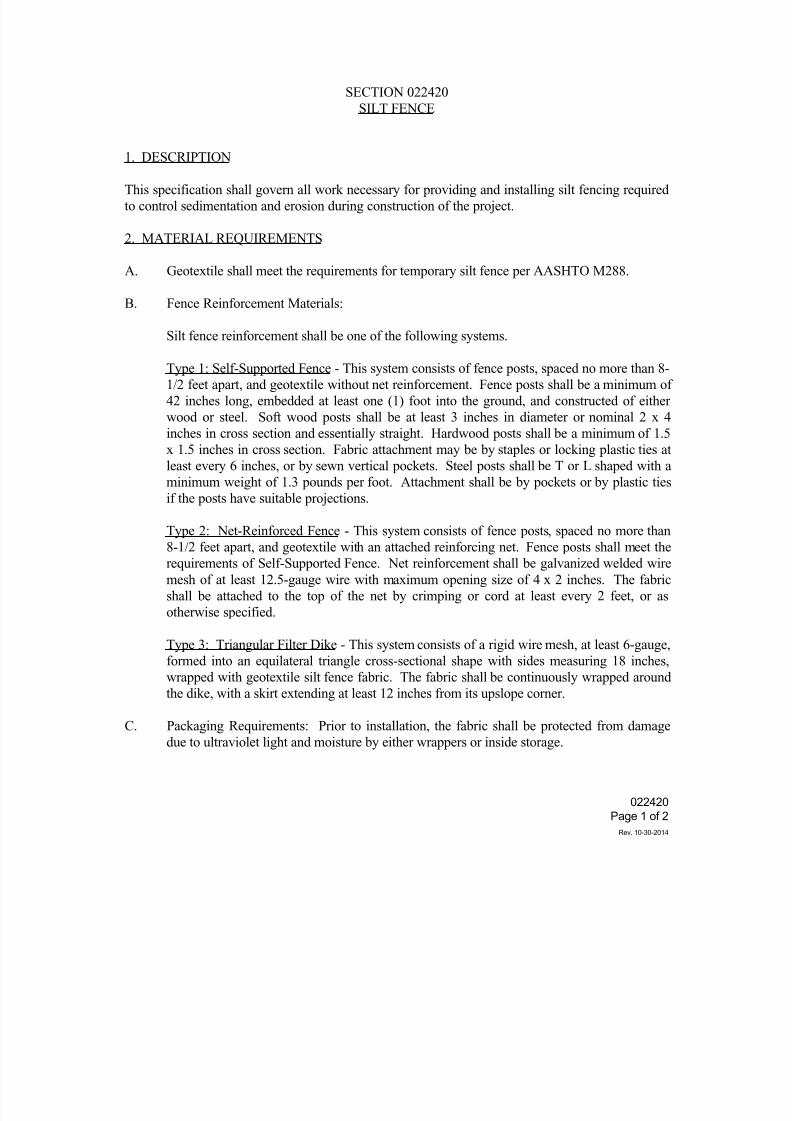
7/25/2019 City Standard Construction Specifications
http://slidepdf.com/reader/full/city-standard-construction-specifications 55/511
022420
Page 1 of 2
Rev. 10-30-2014
SECTION 022420
SILT FENCE
1. DESCRIPTION
This specification shall govern all work necessary for providing and installing silt fencing required
to control sedimentation and erosion during construction of the project.
2. MATERIAL REQUIREMENTS
A. Geotextile shall meet the requirements for temporary silt fence per AASHTO M288.
B. Fence Reinforcement Materials:
Silt fence reinforcement shall be one of the following systems.
Type 1: Self-Supported Fence - This system consists of fence posts, spaced no more than 8-
1/2 feet apart, and geotextile without net reinforcement. Fence posts shall be a minimum of
42 inches long, embedded at least one (1) foot into the ground, and constructed of either
wood or steel. Soft wood posts shall be at least 3 inches in diameter or nominal 2 x 4
inches in cross section and essentially straight. Hardwood posts shall be a minimum of 1.5
x 1.5 inches in cross section. Fabric attachment may be by staples or locking plastic ties at
least every 6 inches, or by sewn vertical pockets. Steel posts shall be T or L shaped with a
minimum weight of 1.3 pounds per foot. Attachment shall be by pockets or by plastic ties
if the posts have suitable projections.
Type 2: Net-Reinforced Fence - This system consists of fence posts, spaced no more than8-1/2 feet apart, and geotextile with an attached reinforcing net. Fence posts shall meet the
requirements of Self-Supported Fence. Net reinforcement shall be galvanized welded wire
mesh of at least 12.5-gauge wire with maximum opening size of 4 x 2 inches. The fabric
shall be attached to the top of the net by crimping or cord at least every 2 feet, or as
otherwise specified.
Type 3: Triangular Filter Dike - This system consists of a rigid wire mesh, at least 6-gauge,
formed into an equilateral triangle cross-sectional shape with sides measuring 18 inches,
wrapped with geotextile silt fence fabric. The fabric shall be continuously wrapped around
the dike, with a skirt extending at least 12 inches from its upslope corner.
C. Packaging Requirements: Prior to installation, the fabric shall be protected from damage
due to ultraviolet light and moisture by either wrappers or inside storage.
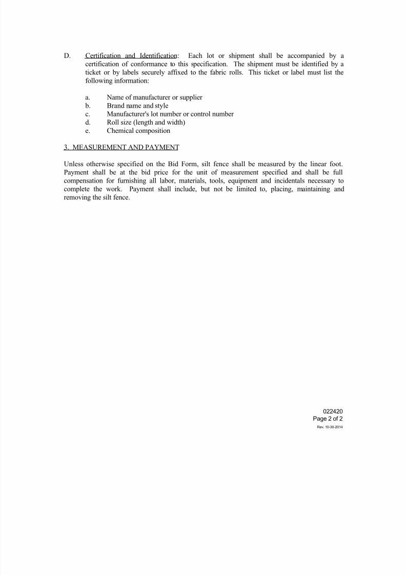
7/25/2019 City Standard Construction Specifications
http://slidepdf.com/reader/full/city-standard-construction-specifications 56/511
022420
Page 2 of 2
Rev. 10-30-2014
D. Certification and Identification: Each lot or shipment shall be accompanied by a
certification of conformance to this specification. The shipment must be identified by a
ticket or by labels securely affixed to the fabric rolls. This ticket or label must list the
following information:
a. Name of manufacturer or supplier
b. Brand name and style
c. Manufacturer's lot number or control number
d. Roll size (length and width)
e. Chemical composition
3. MEASUREMENT AND PAYMENT
Unless otherwise specified on the Bid Form, silt fence shall be measured by the linear foot.
Payment shall be at the bid price for the unit of measurement specified and shall be full
compensation for furnishing all labor, materials, tools, equipment and incidentals necessary tocomplete the work. Payment shall include, but not be limited to, placing, maintaining and
removing the silt fence.
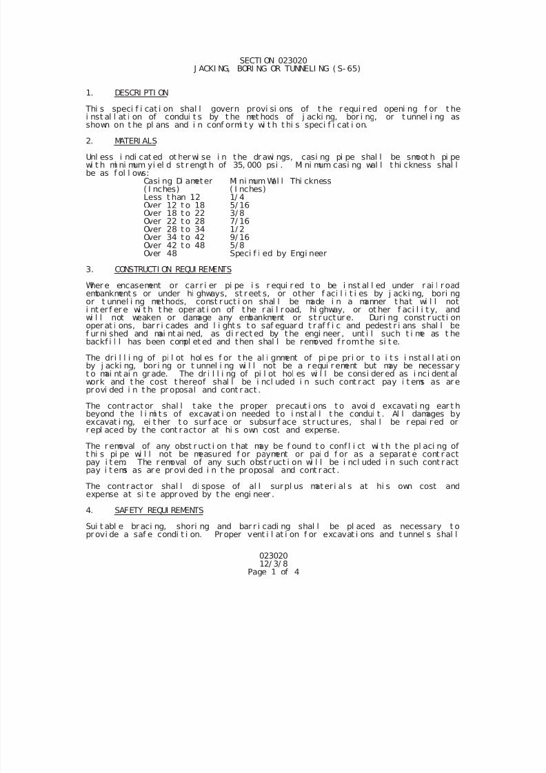
7/25/2019 City Standard Construction Specifications
http://slidepdf.com/reader/full/city-standard-construction-specifications 57/511
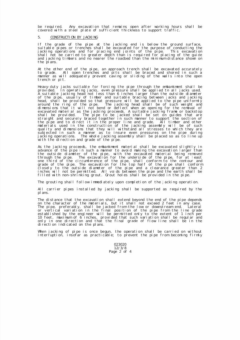
7/25/2019 City Standard Construction Specifications
http://slidepdf.com/reader/full/city-standard-construction-specifications 58/511
02302012/ 3/ 8
Page 2 of 4
be r equi red. Any excavat i on t hat r emai ns open af t er worki ng hour s shal l becovered wi t h a st eel pl at e of suf f i ci ent t hi ckness t o support t r af f i c.
5. CONSTRUCTI ON BY J ACKI NG
I f t he gr ade of t he pi pe at t he j acki ng end i s bel ow t he gr ound sur f ace,sui t abl e pi pes or t r enches shal l be excavat ed f or t he pur pose of conduct i ng the
j acki ng operat i ons and f or pl aci ng end j oi nts of t he pi pe. Thi s excavat i onshal l not be car r i ed t o gr eat er dept h t han i s r equi r ed f or pl aci ng of t he gui deand j acki ng t i mber s and no nearer t he r oadbed t han t he mi ni mumdi st ance shown ont he pl ans.
At t he ot her end of t he pi pe, an appr oach t r ench shal l be excavat ed accur atel yt o gr ade. Al l open t r enches and pi t s shal l be br aced and shor ed i n such amanner as wi l l adequat el y pr event cavi ng or sl i di ng of t he wal l s i nt o the opent r ench or pi t .
Heavy- dut y j acks sui t abl e f or f orci ng t he pi pe thr ough t he embankment shal l bepr ovi ded. I n oper at i ng j acks, even pr essur e shal l be appl i ed t o al l j acks used.A sui t abl e j acki ng head not l ess t han 6 i nches l ar ger t han t he out si de di amet erof t he pi pe, usual l y of t i mber and sui t abl e br aci ng bet ween j acks and j acki nghead, shal l be pr ovi ded so t hat pressure wi l l be appl i ed t o t he pi pe uni f orml yaround t he r i ng of t he pi pe. The j acki ng head shal l be of such wei ght and
di mensi ons t hat i t wi l l not bend or def l ect when an openi ng f or t he removal ofexcavated materi al as the j acki ng pr oceeds. A sui t abl e j acki ng f r ame or backst opshal l be pr ovi ded. The pi pe t o be j acked shal l be set on gui des t hat ar est r ai ght and securel y br aced t ogether i n such manner t o support t he sect i on oft he pi pe and t o di r ect i t i n t he pr oper l i ne and gr ade. Al l t i mber and ot hermat er i al s used i n t he const ruct i on of t he j acki ng assembl y wi l l be of suchqual i t y and di mensi ons t hat t hey wi l l wi t hst and al l st r esses t o whi ch t hey ar esubj ected i n such a manner as t o i nsur e even pressures on t he pi pe duri ng
j acki ng operat i ons. The whol e j acki ng assembl y shal l be pl aced so as t o l i ne upwi t h t he di r ect i on and gr ade of t he pi pe.
As t he j acki ng pr oceeds, t he embankment materi al shal l be excavated sl i ght l y i nadvance of t he pi pe i n such a manner t o avoi d maki ng t he excavat i on l arger t hant he out si de di ameter of t he pi pe, wi t h the excavat ed mater i al bei ng removedt hr ough t he pi pe. The excavat i on f or t he under si de of t he pi pe, f or at l east
one t hi r d of t he ci r cumf er ence of t he pi pe, shal l conf or m t o the cont our andgr ade of t he pi pe. The excavat i on f or t he t op hal f of t he pi pe shal l conf or mcl osel y t o t he out si de di amet er of t he pi pe and a cl ear ance gr eat er t han 2i nches wi l l not be per mi t t ed. Al l voi ds bet ween t he pi pe and t he ear t h shal l bef i l l ed wi t h non- shr i nki ng grout . Gr out hol es shal l be pr ovi ded i n t he pi pe.
The grout i ng shal l f ol l ow i mmedi atel y upon compl et i on of t he j acki ng operat i on.
Al l car r i er pi pes i nst al l ed by j acki ng shal l be suppor t ed as requi r ed by t hepl ans.
The di st ance t hat t he excavat i on shal l extend beyond t he end of t he pi pe dependson t he char acter of t he mat er i al s, but i t shal l not exceed 2 f eet i n any case.
The pi pe, pref erabl y, shal l be j acked f r om t he l ow or downst r eam end. Lat eralor vert i cal vari at i on i n t he f i nal posi t i on of t he pi pe f r om t he l i ne gr ade
est abl i shed by the engi neer wi l l be per mi t t ed onl y to the extent of 1 i nch per10 f eet , maxi mum of 6 i nches, pr ovi ded t hat such var i at i on shal l be regul ar andonl y i n one di r ect i on and t hat t he f i nal grade of f l ow l i ne shal l be i n t hedi r ecti on i ndi cat ed on the pl ans.
When j acki ng of pi pe i s once begun, t he operat i on shal l be carr i ed on wi t houti nt er r upt i on, i nsof ar as pract i cabl e; t o pr event t he pi pe f r om becomi ng f i r ml y
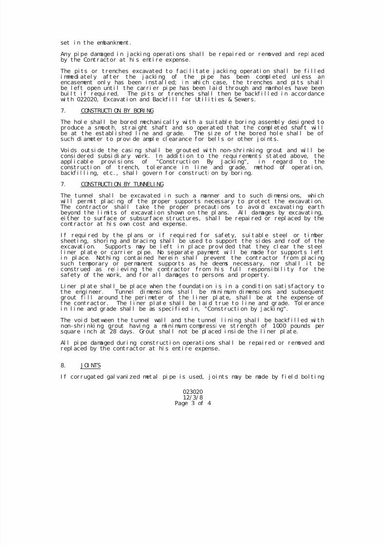
7/25/2019 City Standard Construction Specifications
http://slidepdf.com/reader/full/city-standard-construction-specifications 59/511
02302012/ 3/ 8
Page 3 of 4
set i n t he embankment .
Any pi pe damaged i n j acki ng operat i ons shal l be r epai r ed or r emoved and repl acedby the Cont r act or at hi s ent i r e expense.
The pi t s or t r enches excavated t o f aci l i t ate j acki ng operat i on shal l be f i l l edi mmedi atel y af t er t he j acki ng of t he pi pe has been compl eted unl ess anencasement onl y has been i nst al l ed; i n whi ch case, t he t r enches and pi t s shal lbe l ef t open unt i l t he car r i er pi pe has been l ai d thr ough and manhol es have beenbui l t i f r equi r ed. The pi t s or t r enches shal l t hen be backf i l l ed i n accor dancewi t h 022020, Excavat i on and Backf i l l f or Ut i l i t i es & Sewer s.
7. CONSTRUCTI ON BY BORI NG
The hol e shal l be bored mechani cal l y wi t h a sui t abl e bor i ng assembl y desi gned t opr oduce a smoot h, st r ai ght shaf t and so oper at ed that t he compl et ed shaf t wi l lbe at t he est abl i shed l i ne and gr ade. The si ze of t he bored hol e shal l be ofsuch di amet er t o pr ovi de ampl e cl earance f or bel l s or ot her j oi nt s.
Voi ds out si de t he casi ng shal l be gr out ed wi t h non- shr i nki ng gr out and wi l l beconsi der ed subsi di ar y work. I n addi t i on t o the requi r ement s st at ed above, t heappl i cabl e pr ovi si ons of "Const r uct i on By J acki ng", i n r egar d t o t heconst r uct i on of t r ench, t ol er ance i n l i ne and gr ade, met hod of operat i on,
backf i l l i ng, et c. , shal l gover n f or const r ucti on by bor i ng.
7. CONSTRUCTI ON BY TUNNELI NG
The t unnel shal l be excavated i n such a manner and t o such di mensi ons, whi chwi l l per mi t pl aci ng of t he pr oper suppor t s necessar y t o pr ot ect t he excavat i on.
The contr act or shal l t ake t he proper precaut i ons t o avoi d excavat i ng ear t hbeyond t he l i mi t s of excavat i on shown on t he pl ans. Al l damages by excavat i ng,ei t her t o sur f ace or subsur f ace st r uct ur es, shal l be r epai r ed or r epl aced by thecont ractor at hi s own cost and expense.
I f r equi r ed by t he pl ans or i f r equi red f or saf et y, sui t abl e st eel or t i mbersheet i ng, shori ng and br aci ng shal l be used t o support t he si des and r oof of t heexcavat i on. Support s may be l ef t i n pl ace provi ded t hat t hey cl ear t he st eell i ner pl at e or carr i er pi pe. No separ at e payment wi l l be made f or support s l ef t
i n pl ace. Not hi ng cont ai ned her ei n shal l pr event t he cont r actor f r om pl aci ngsuch temporary or per manent suppor t s as he deems necessary, nor shal l i t beconstr ued as rel i evi ng t he cont r actor f r om hi s f ul l r esponsi bi l i t y f or t hesaf ety of t he work, and f or al l damages to persons and pr oper t y.
Li ner pl at e shal l be pl ace when t he f oundat i on i s i n a condi t i on sat i sf act or y t ot he engi neer. Tunnel di mensi ons shal l be mi ni mum di mensi ons and subsequentgr out f i l l around t he per i met er of t he l i ner pl at e, shal l be at t he expense oft he cont r act or . The l i ner pl at e shal l be l ai d t r ue t o l i ne and grade. Tol er ancei n l i ne and gr ade shal l be as speci f i ed i n, "Const r uct i on by J acki ng".
The voi d bet ween t he t unnel wal l and t he t unnel l i ni ng shal l be backf i l l ed wi t hnon-shr i nki ng grout havi ng a mi ni mum compressi ve st rength of 1000 pounds persquare i nch at 28 days. Gr out shal l not be pl aced i nsi de the l i ner pl at e.
Al l pi pe damaged dur i ng const r uct i on operat i ons shal l be repai r ed or r emoved andr epl aced by the cont ract or at hi s ent i r e expense.
8. J OI NTS
I f cor r ugat ed gal vani zed met al pi pe i s used, j oi nt s may be made by f i el d bol t i ng
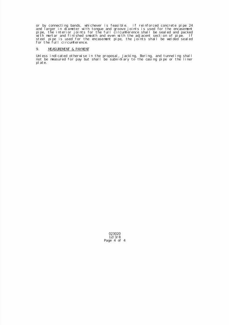
7/25/2019 City Standard Construction Specifications
http://slidepdf.com/reader/full/city-standard-construction-specifications 60/511
02302012/ 3/ 8
Page 4 of 4
or by connect i ng bands, whi chever i s f easi bl e. I f r ei nf or ced concret e pi pe 24and l arger i n di ameter wi t h tongue and gr oove j oi nt s i s used f or t he encasementpi pe, t he i nt er i or j oi nt s f or t he f ul l ci r cumf er ence shal l be seal ed and packedwi t h mort ar and f i ni shed smoot h and even wi t h t he adj acent sect i on of pi pe. I fst eel pi pe i s used f or t he encasement pi pe, t he j oi nt s shal l be wel ded seal edf or t he f ul l ci r cumf er ence.
9. MEASUREMENT & PAYMENT
Unl ess i ndi cat ed ot her wi se i n t he pr oposal , J acki ng, Bor i ng, and t unnel i ng shal lnot be measur ed f or pay but shal l be subsi di ar y to the casi ng pi pe or t he l i nerpl at e.
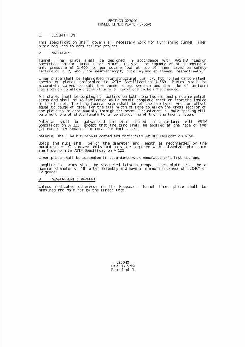
7/25/2019 City Standard Construction Specifications
http://slidepdf.com/reader/full/city-standard-construction-specifications 61/511
023040Rev 11/ 2/ 99Page 1 of 1
SECTI ON 023040 TUNNEL LI NER PLATE ( S- 65A)
1. DESCRI PTI ON
Thi s speci f i cat i on shal l govern al l necessary work f or f urni shi ng t unnel l i nerpl at e requi r ed to compl et e the pr oj ect .
2. MATERI ALS Tunnel l i ner pl ate shal l be desi gned i n accordance wi t h AASHTO "Desi gnSpeci f i cat i on f or Tunnel Li ner Pl at e". I t shal l be capabl e of wi t hst andi ng auni t pr essure of 1, 400 l b. per squar e f oot at t op of l i ner based on saf et yf actor s of 3, 2, and 3 f or seam st r engt h, buckl i ng and st i f f ness, r espect i vel y.
Li ner pl at e shal l be f abr i cat ed f r om str uctur al qual i t y, hot - r ol l ed car bon- st eelsheet s or pl at es conf or mi ng t o ASTM Speci f i cat i on A- 569. Pl at es shal l beaccurat el y cur ved t o sui t t he t unnel cross sect i on and shal l be of uni f or mf abr i cat i on t o al l ow pl at es of si mi l ar cur vat ur e t o be i nt er changed.
Al l pl at es shal l be punched f or bol t i ng on bot h l ongi t udi nal and ci r cumf er ent i alseams and shal l be so f abr i cat ed as t o per mi t compl et e er ect i on f r om t he i nsi deof t he t unnel . The l ongi t udi nal seam shal l be of t he l ap t ype, wi t h an of f setequal t o gauge of met al f or t he f ul l wi dt h of l at e t o al l ow t he cross sect i on oft he pl at e t o be cont i nuousl y thr ough t he seam. Ci r cumf er ent i al hol e spaci ng wi l lbe a mul t i pl e of pl at e l engt h t o al l ow st agger i ng of t he l ongi t udi nal seam.
Materi al shal l be gal vani zed and zi nc coated i n accor dance wi t h ASTMSpeci f i cat i on A 123, except t hat t he zi nc shal l be appl i ed at t he r at e of t wo( 2) ounces per squar e f oot t ot al f or bot h si des.
Materi al shal l be bi t umi nous coated and conf orm t o AASHTO Desi gnat i on M190.
Bol t s and nut s shal l be of t he di ameter and l ength as recommended by t hemanuf actur er. Gal vani zed bol t s and nut s ar e r equi red wi t h gal vani zed pl ate andshal l conf or m t o ASTM Speci f i cat i on A 153.
Li ner pl at e shal l be assembl ed i n accor dance wi t h manuf act urer ' s i nst r uct i ons.
Longi t udi nal seams shal l be stagger ed bet ween ri ngs. Li ner pl at e shal l be anomi nal di ameter of 48" af t er assembl y and have a mi ni mumt hi ckness of . 1046" or12 gauge.
3. MEASUREMENT & PAYMENT
Unl ess i ndi cat ed other wi se i n t he Pr oposal , Tunnel l i ner pl at e shal l bemeasur ed and pai d f or by t he l i near f oot .
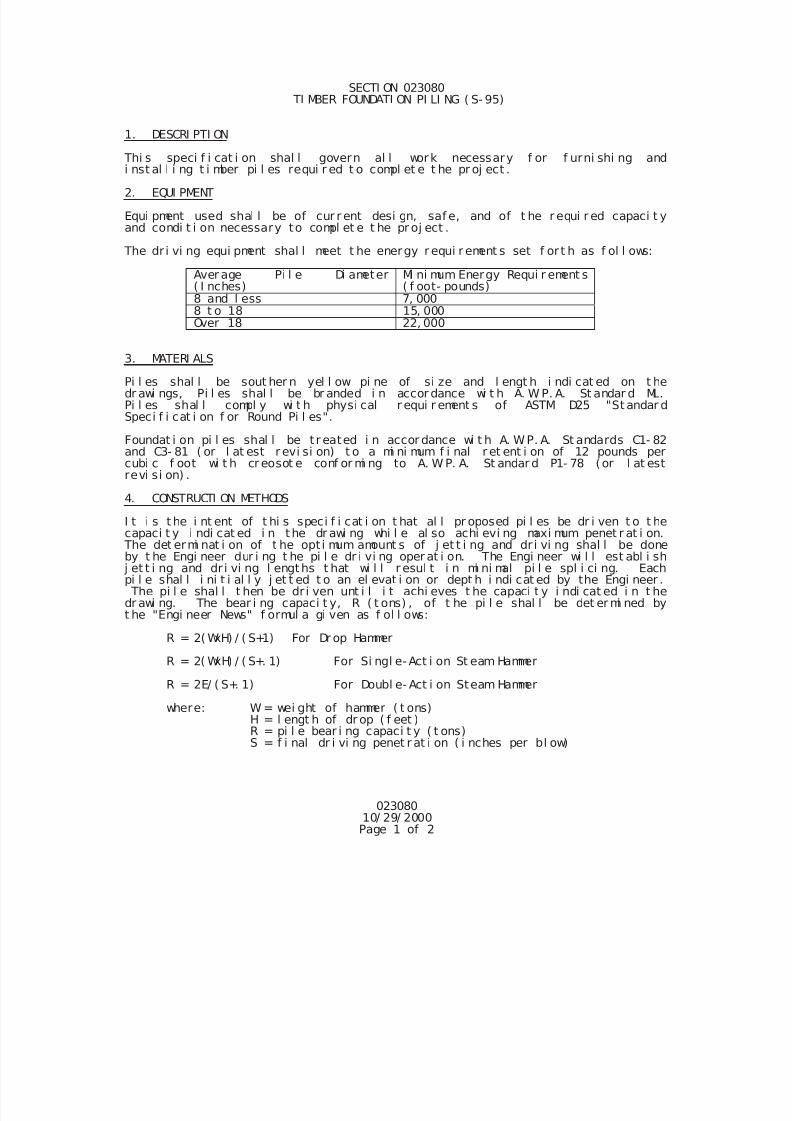
7/25/2019 City Standard Construction Specifications
http://slidepdf.com/reader/full/city-standard-construction-specifications 62/511
02308010/ 29/ 2000Page 1 of 2
SECTI ON 023080 TI MBER FOUNDATI ON PI LI NG ( S- 95)
1. DESCRI PTI ON
Thi s speci f i cat i on shal l govern al l work necessary f or f urni shi ng andi nst al l i ng t i mber pi l es requi r ed t o compl et e t he pr oj ect .
2. EQUI PMENT
Equi pment used shal l be of cur r ent desi gn, saf e, and of t he r equi r ed capaci t yand condi t i on necessary to compl et e t he pr oj ect .
The dr i vi ng equi pment shal l meet t he energy r equi r ement s set f or t h as f ol l ows:
Aver age Pi l e Di ameter( I nches)
Mi ni mum Energy Requi r ement s( f oot- pounds)
8 and l ess 7, 0008 t o 18 15, 000Over 18 22, 000
3. MATERI ALS
Pi l es shal l be sout her n yel l ow pi ne of si ze and l engt h i ndi cat ed on t hedr awi ngs, Pi l es shal l be br anded i n accor dance wi t h A. W. P. A. St andar d ML.Pi l es shal l compl y wi t h physi cal r equi r ement s of ASTM D25 "St andar dSpeci f i cat i on f or Round Pi l es".
Foundat i on pi l es shal l be t r eated i n accor dance wi t h A. W. P. A. St andards C1- 82and C3- 81 ( or l at est r evi si on) t o a mi ni mum f i nal r et ent i on of 12 pounds percubi c f oot wi t h cr eosot e conf or mi ng to A. W. P. A. St andar d P1- 78 (or l at estrevi si on) .
4. CONSTRUCTI ON METHODS
I t i s t he i nt ent of t hi s speci f i cat i on t hat al l pr oposed pi l es be dr i ven t o t he
capaci t y i ndi cat ed i n the dr awi ng whi l e al so achi evi ng maxi mum penet r at i on. The det ermi nat i on of t he opt i mum amount s of j et t i ng and dr i vi ng shal l be doneby t he Engi neer dur i ng t he pi l e dr i vi ng oper at i on. The Engi neer wi l l est abl i sh
j et t i ng and dr i vi ng l engths t hat wi l l r esul t i n mi ni mal pi l e spl i ci ng. Eachpi l e shal l i ni t i al l y j et t ed t o an el evat i on or dept h i ndi cat ed by the Engi neer . The pi l e shal l t hen be dr i ven unt i l i t achi eves t he capaci t y i ndi cat ed i n t hedr awi ng. The bear i ng capaci t y, R ( t ons) , of t he pi l e shal l be det er mi ned byt he "Engi neer News" f ormul a gi ven as f ol l ows:
R = 2( WxH) / ( S+1) For Dr op Hammer
R = 2( WxH) / ( S+. 1) For Si ngl e- Act i on St eam Hammer
R = 2E/ ( S+. 1) For Doubl e- Act i on Steam Hammer
where: W = wei ght of hammer ( t ons)H = l engt h of dr op ( f eet )R = pi l e bear i ng capaci t y ( t ons)S = f i nal dr i vi ng penet r at i on ( i nches per bl ow)
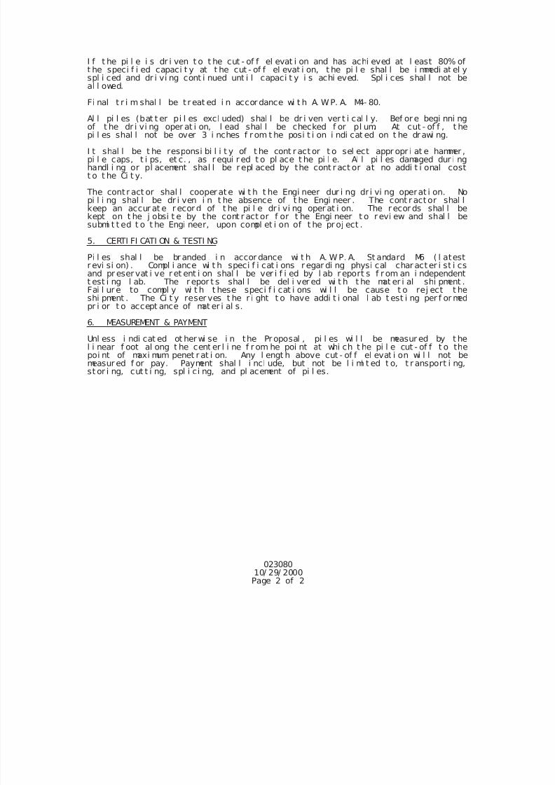
7/25/2019 City Standard Construction Specifications
http://slidepdf.com/reader/full/city-standard-construction-specifications 63/511
02308010/ 29/ 2000Page 2 of 2
I f t he pi l e i s dr i ven t o t he cut - of f el evat i on and has achi eved at l east 80% oft he speci f i ed capaci t y at t he cut - of f el evat i on, t he pi l e shal l be i mmedi at el yspl i ced and dr i vi ng cont i nued unt i l capaci t y i s achi eved. Spl i ces shal l not beal l owed.
Fi nal t r i m shal l be t r eat ed i n accor dance wi t h A. W. P. A. M4- 80.
Al l pi l es (bat t er pi l es excl uded) shal l be dr i ven ver t i cal l y. Bef or e begi nni ngof t he dr i vi ng oper at i on, l ead shal l be checked f or pl um. At cut - of f , t hepi l es shal l not be over 3 i nches f r om t he posi t i on i ndi cat ed on t he dr awi ng.
I t shal l be t he responsi bi l i t y of t he cont r act or t o sel ect appr opr i at e hammer ,pi l e caps, t i ps, et c. , as r equi r ed t o pl ace t he pi l e. Al l pi l es damaged dur i nghandl i ng or pl acement shal l be r epl aced by the cont r act or at no addi t i onal costt o t he Ci t y.
The cont r act or shal l cooper at e wi t h t he Engi neer dur i ng dr i vi ng operat i on. Nopi l i ng shal l be dr i ven i n t he absence of t he Engi neer . The cont r act or shal lkeep an accur at e r ecor d of t he pi l e dr i vi ng oper at i on. The r ecor ds shal l bekept on t he j obsi t e by the cont r act or f or t he Engi neer t o r evi ew and shal l besubmi t t ed t o t he Engi neer, upon compl et i on of t he pr oj ect .
5. CERTI FI CATI ON & TESTI NG
Pi l es shal l be br anded i n accor dance wi t h A. W. P. A. St andard M6 ( l atestr evi si on) . Compl i ance wi t h speci f i cat i ons r egar di ng physi cal char act er i st i csand pr eser vat i ve r et ent i on shal l be ver i f i ed by l ab r eport s f r om an i ndependentt est i ng l ab. The r epor t s shal l be del i ver ed wi t h t he mat er i al shi pment .Fai l ur e to compl y wi t h t hese speci f i cat i ons wi l l be cause t o rej ect t heshi pment . The Ci t y reser ves t he r i ght t o have addi t i onal l ab t est i ng per f or medpr i or t o accept ance of mat er i al s.
6. MEASUREMENT & PAYMENT
Unl ess i ndi cat ed ot her wi se i n the Pr oposal , pi l es wi l l be measur ed by t hel i near f oot al ong t he cent er l i ne f r om he poi nt at whi ch t he pi l e cut - of f t o thepoi nt of maxi mum penet r at i on. Any l engt h above cut - of f el evat i on wi l l not bemeasur ed f or pay. Payment shal l i ncl ude, but not be l i mi t ed t o, t r ansport i ng,
st or i ng, cut t i ng, spl i ci ng, and pl acement of pi l es.
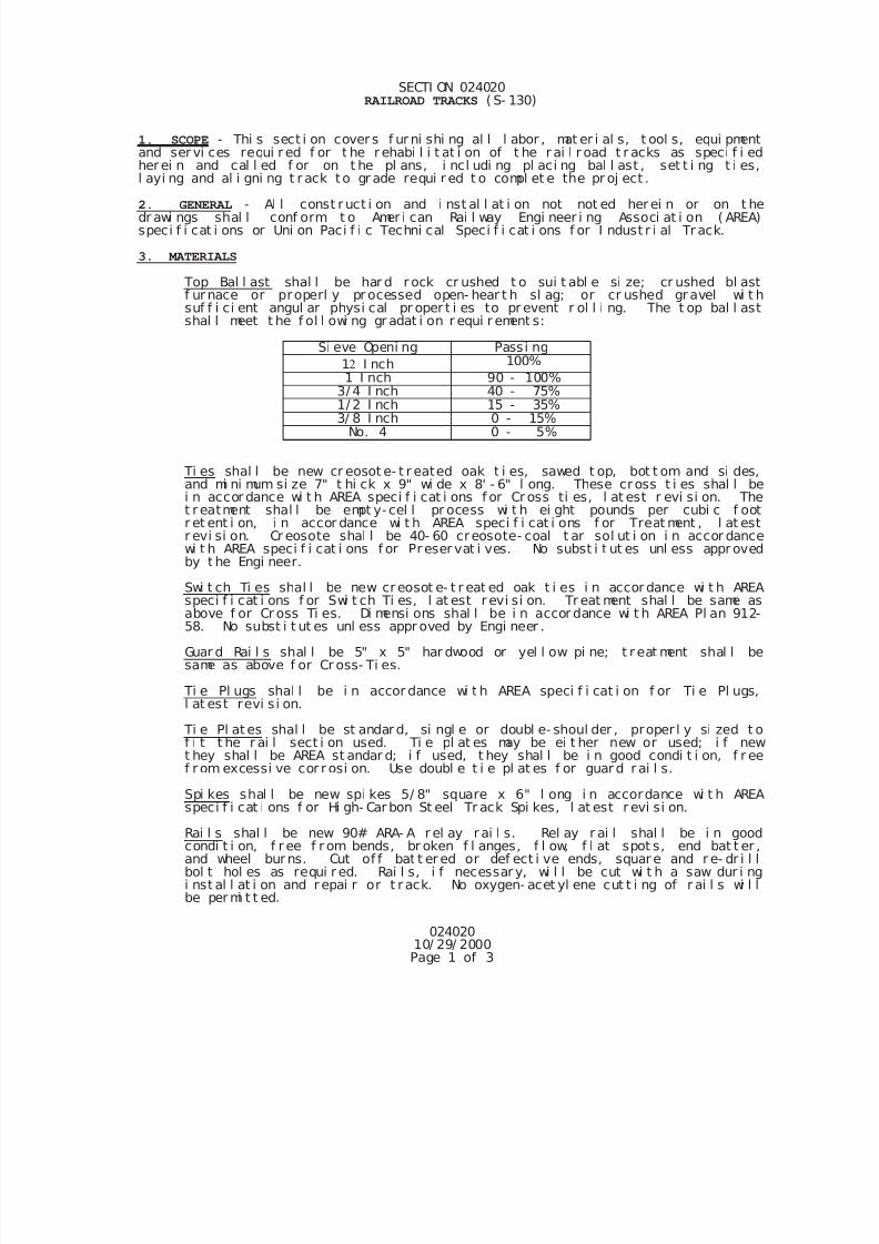
7/25/2019 City Standard Construction Specifications
http://slidepdf.com/reader/full/city-standard-construction-specifications 64/511
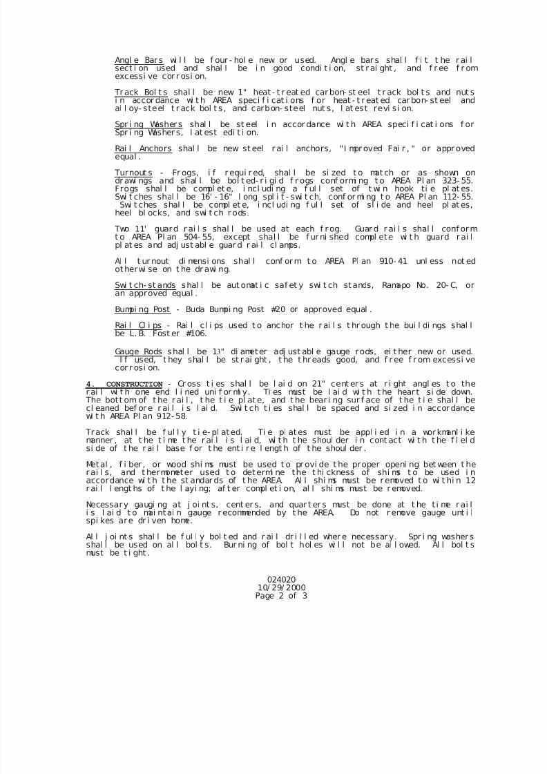
7/25/2019 City Standard Construction Specifications
http://slidepdf.com/reader/full/city-standard-construction-specifications 65/511
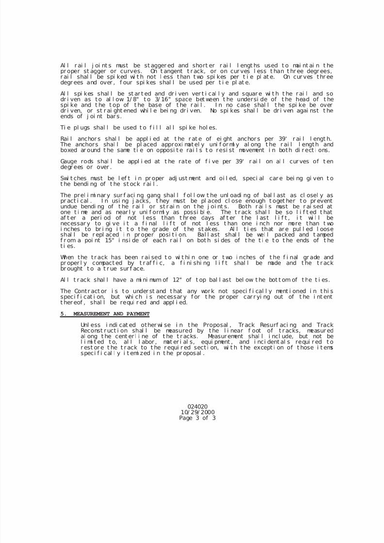
7/25/2019 City Standard Construction Specifications
http://slidepdf.com/reader/full/city-standard-construction-specifications 66/511
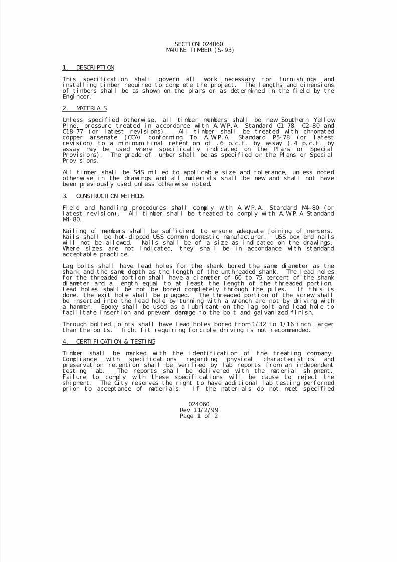
7/25/2019 City Standard Construction Specifications
http://slidepdf.com/reader/full/city-standard-construction-specifications 67/511
024060Rev 11/ 2/ 99Page 1 of 2
SECTI ON 024060 MARI NE TI MBER ( S- 93)
1. DESCRI PTI ON
Thi s speci f i cat i on shal l govern al l work necessary f or f urni shi ngs andi nst al l i ng t i mber r equi r ed t o compl et e t he pr oj ect . The l engt hs and di mensi onsof t i mber s shal l be as shown on the pl ans or as det er mi ned i n the f i el d by t heEngi neer.
2. MATERI ALS
Unl ess speci f i ed otherwi se, al l t i mber members shal l be new Sout her n Yel l owPi ne, pr essur e t r eat ed i n accor dance wi t h A. W. P. A. Standard C1- 78, C2- 80 andC18- 77 ( or l at est r evi si ons) . Al l t i mber shal l be t r eat ed wi t h chr omat edcopper ar senate ( CCA) conf ormi ng To A. W. P. A. St andar d P5- 78 ( or l atestrevi si on) t o a mi ni mum f i nal retent i on of . 6 p. c. f . by assay (. 4 p. c. f . byassay may be used where speci f i cal l y i ndi cat ed on the Pl ans or Speci alPr ovi si ons) . The gr ade of l umber shal l be as speci f i ed on t he Pl ans or Speci alPr ovi si ons.
Al l t i mber shal l be S4S mi l l ed t o appl i cabl e si ze and t ol er ance, unl ess noted
other wi se i n the dr awi ngs and al l mat er i al s shal l be new and shal l not havebeen pr evi ousl y used unl ess ot herwi se noted.
3. CONSTRUCTI ON METHODS
Fi el d and handl i ng pr ocedur es shal l compl y wi t h A. W. P. A. Standar d M4-80 ( orl at est r evi si on) . Al l t i mber shal l be t r eat ed t o compl y wi t h A. W. P. A St andar dM4- 80.
Nai l i ng of member s shal l be suf f i ci ent t o ensur e adequat e j oi ni ng of members.Nai l s shal l be hot - di pped USS common domest i c manuf act urer . USS box end nai l swi l l not be al l owed. Nai l s shal l be of a si ze as i ndi cat ed on t he dr awi ngs.Wher e si zes ar e not i ndi cat ed, t hey shal l be i n accor dance wi t h st andar daccept abl e pr act i ce.
Lag bol t s shal l have l ead hol es f or t he shank bored t he same di ameter as t heshank and t he same depth as t he l ength of t he unt hreaded shank. The l ead hol esf or t he thr eaded port i on shal l have a di amet er of 60 to 75 percent of t he shankdi ameter and a l engt h equal t o at l east t he l engt h of t he t hr eaded port i on.Lead hol es shal l be not be bored compl et el y t hr ough t he pi l es. I f t hi s i sdone, t he exi t hol e shal l be pl ugged. The t hr eaded port i on of t he screw shal lbe i nsert ed i nt o the l ead hol e by t ur ni ng wi t h a wr ench and not by dr i vi ng wi t ha hammer. Epoxy shal l be used as a l ubri cant on t he l ag bol t and l ead hol e t of aci l i t at e i nser t i on and pr event damage t o t he bol t and gal vani zed f i ni sh.
Through bol t ed j oi nt s shal l have l ead hol es bored f r om 1/ 32 t o 1/ 16 i nch l argert han t he bol t s. Ti ght f i t r equi r i ng f or ci bl e dr i vi ng i s not r ecommended.
4. CERTI FI CATI ON & TESTI NG
Ti mber shal l be marked wi t h t he i dent i f i cat i on of t he t r eat i ng company.Compl i ance wi t h speci f i cat i ons regar di ng physi cal char act er i st i cs andpr eser vat i on r et ent i on shal l be ver i f i ed by l ab r epor t s f r om an i ndependentt est i ng l ab. The r epor t s shal l be del i ver ed wi t h t he mat er i al shi pment .Fai l ur e to compl y wi t h t hese speci f i cat i ons wi l l be cause t o rej ect t heshi pment . The Ci t y reser ves t he r i ght t o have addi t i onal l ab t est i ng per f or medpr i or t o accept ance of mat er i al s. I f t he mat er i al s do not meet speci f i ed
7/25/2019 City Standard Construction Specifications
http://slidepdf.com/reader/full/city-standard-construction-specifications 68/511
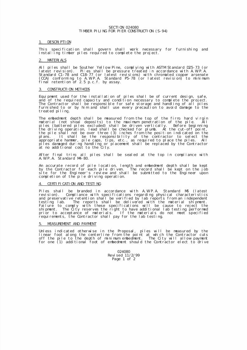
7/25/2019 City Standard Construction Specifications
http://slidepdf.com/reader/full/city-standard-construction-specifications 69/511
7/25/2019 City Standard Construction Specifications
http://slidepdf.com/reader/full/city-standard-construction-specifications 70/511
024080Revi sed 11/ 2/ 99
Page 2 of 2
t he pi l e deeper t han t he mi ni mum embedment depth. Any l ength above t he t opcut - of f wi l l not be measur ed f or pay. Payment shal l i ncl ude, but not bel i mi t ed t o t r anspor t i ng, st or i ng, cut t i ng, dr i l l i ng and pl acement of t he pi l es.
7/25/2019 City Standard Construction Specifications
http://slidepdf.com/reader/full/city-standard-construction-specifications 71/511
025202
Page 1 of 1
Rev. 10-30-2014
SECTION 025202
SCARIFYING AND RESHAPING BASE COURSE
1. DESCRIPTION
"Scarifying and Reshaping Base Course" shall consist of scarifying and reshaping the existing base
course (with or without asphalt surface) to the line, grade and section as indicated on the drawings.
2. CONSTRUCTION METHODS
The existing base and surface shall be scarified to the width and depth indicated on the drawings.
Subgrade shall remain undisturbed, unless indicated otherwise on the drawings. Any asphalt
surfacing shall be broken into particles no larger than 2 ½ inches. The asphalt surfacing shall then
be uniformly mixed with the existing base. Additional base material, where required to achieve the
lines and grades shown on the drawings, shall also be added to and uniformly mixed with the
existing scarified base material. If indicated on the drawings, geogrid shall be installed in the
pavement section.
The base material shall be shaped and rolled after mixing and allowed to set at least 48 hours
before final compaction. Moisture content shall be maintained in the material during the 48-hour
period. Material shall be sprinkled with water or aerated to optimum moisture content, and
compacted in layers (10-inch maximum loose depth) to a minimum density of 98% Modified
Proctor density (AASHTO T180), at a moisture content on the wet side of optimum (+3%
maximum). Use mechanical tamps in areas inaccessible to rollers.
Upon completion of compaction, the surface shall be smooth and shall conform to line, grade and
section as shown on the drawings. Areas with any deviation in excess of 1/4 inch in cross-section,
and in lengths of 16 feet measured longitudinally, shall be corrected by loosening, adding or
removing material, reshaping, and re-compacting by sprinkling and rolling. Moisture content shall be maintained on the wet side of optimum (+3% maximum) until paving is complete.
If required, lime shall be applied in the amount indicated on the drawings. Lime shall be applied
and the treated base mixed, cured, compacted and finished in accordance with City Standard
Specification Section 025210 "Lime Stabilization."
3. MEASUREMENT AND PAYMENT
Unless otherwise specified on the Bid Form, scarifying and reshaping base course shall not be
measured and paid for separately, but shall be subsidiary to other work.
7/25/2019 City Standard Construction Specifications
http://slidepdf.com/reader/full/city-standard-construction-specifications 72/511
SECTION 025205
PAVEMENT REPAIR, CURB, GUTTER, SIDEWALK AND DRIVEWAY REPLACEMENT
1. DESCRIPTION
This specification shall govern the removal and replacing of all types of pavements and surfacing
required to complete the project.
2. MATERIALS
Unless otherwise specified on the drawings, materials and proportions used along with this
specification shall conform to the respective following specifications:
City Standard Specifications
Section 022020 “Excavation and Backfill for Utilities”Section 022100 “Select Material”
Section 025223 "Crushed Limestone Flexible Base”
Section 025424 "Hot Mix Asphaltic Concrete Pavement"
Section 025610 "Concrete Curb and Gutter"
Section 025612 "Concrete Sidewalks and Driveways"
Section 025620 “Portland Cement Concrete Pavement”
Section 030020 "Portland Cement Concrete", Class "A" Concrete
Section 032020 "Reinforcing Steel"
Section 038000 "Concrete Structures".
3. METHOD OF CUTTING
The outline of the trench shall be marked upon the surface of the pavement to be cut, and all cuts into
the pavement shall be saw-cut as nearly vertical as it is possible to make them. All unwanted
materials removed shall be disposed of by the Contractor and shall not be used as backfill material.
4. BACKFILL OF TRENCH
Excavation and backfilling of trench shall be in accordance with City Standard Specification Section
022020 “Excavation and Backfill for Utilities.”
5. REPLACING STREET AND OTHER PAVEMENT
All pavements, driveways, sidewalks, and curbs and gutters which are cut shall be replaced in a
workmanlike manner, with like or better materials or per pavement repair details on the drawings.
025205Page 1 of 2
Rev. 3-25-2015
7/25/2019 City Standard Construction Specifications
http://slidepdf.com/reader/full/city-standard-construction-specifications 73/511
6. REPLACING DRIVEWAY PAVEMENT
On all concrete driveway pavements, the replacement shall consist of a reinforced Class "A" concrete
slab with a minimum thickness of six (6) inches. The type of finish for the replaced section shall be
the same as that appearing on the old pavement. Reinforcement shall be #4 bars at 12 inches eachway with additional diagonal bars as indicated on the drawings. Any other type shall be replaced
with like or better replacement. Replacement shall, in general, be to original joint or score mark.
7. REPLACING SIDEWALKS
On all sidewalk pavements, the replacement shall consist of a reinforced Class "A" concrete slab four
(4) inches thick. The type of finish for the replaced section shall be the same as that appearing on the
old sidewalk. Replacement shall, in general, be to original joint or score marks. Reinforcement shall
be 4" x 4" - W2.9 x W2.9 welded wire fabric located at mid-depth in the slab.
8. REPLACING CURB AND GUTTER
On all curb and gutter, the replacement shall consist of a section conforming in all details to the
original section or to City of Corpus Christi Standard curb and gutter section, if required by the
Engineer. Cuts through the curb shall be replaced with Class "A" concrete. Preserve the original
steel reinforcing and reinforce all new curbs with three #4 bars. Adjust grades for positive drainage.
Replacement shall, in general, be to original joint or score mark. For jointed concrete roadways, the
joints in curb or in curb and gutter should match the concrete roadway joints.
9. REPAIRING STREET SHOULDERS AND UNIMPROVED STREETS
On streets or roads without curb and gutter where a shoulder is disturbed, it shall be restored to likeor better condition. The shoulder surface shall be rolled to an acceptably stable condition.
10. MEASUREMENT AND PAYMENT
Unless otherwise specified on the Bid Form, pavement repair shall be measured by the square yard of
the type of repair specified; curb and gutter replacement shall be measured by the linear foot; and
sidewalk and driveway replacement shall each be measured by the square foot. Payment will be
made at the unit price bid for the completed work and shall be full compensation for all labor,
materials, equipment, tools, and incidentals required to complete the work. No separate measurement
or payment will be made for subgrade compaction, sand leveling course, geogrid, ordinary backfill,
cement-stabilized sand backfill, flexible base, prime coat, hot-mix asphaltic concrete, etc.
025205Page 2 of 2
Rev. 3-25-2015
7/25/2019 City Standard Construction Specifications
http://slidepdf.com/reader/full/city-standard-construction-specifications 74/511
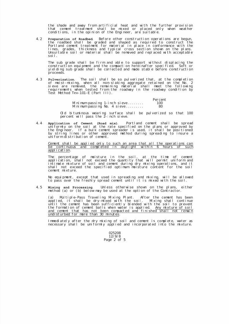
7/25/2019 City Standard Construction Specifications
http://slidepdf.com/reader/full/city-standard-construction-specifications 75/511
02520812/ 9/ 8
Page 2 of 5
t he shade and away f r om ar t i f i ci al heat and wi t h t he f ur t her pr ovi si ont hat cement t r eat ment shal l be mi xed or pl aced onl y when weat hercondi t i ons, i n t he opi ni on of t he Engi neer , ar e sui t abl e.
4. 2 Preparation of Roadbed . Bef or e other const r uct i on oper at i ons ar e begun,t he roadbed shal l be gr aded and shaped as requi r ed t o const r uct t hePor t l and cement t r eatment f or mater i al i n pl ace i n conf ormance wi t h thel i nes, gr ades, t hi ckness and t ypi cal cross sect i on shown on t he pl ans.Unsui t abl e soi l or mater i al shal l be removed and r epl aced wi t h accept abl esoi l .
The sub gr ade shal l be f i r m and abl e t o support wi t hout di spl aci ng t heconst r uct i on equi pment and t he compact i on herei naf t er speci f i ed. Sof t oryi el di ng sub gr ade shal l be cor r ect ed and made stabl e bef ore const r uct i onproceeds.
4. 3 Pulverization. The soi l shal l be so pul ver i zed t hat , at t he compl et i onof moi st - mi xi ng, when al l non- sl aki ng aggr egat e ret ai ned on t he No. 2si eve ar e removed, t he remai ni ng mat er i al shal l meet t he f ol l owi ngr equi r ement s when test ed f r om t he roadway i n the roadway condi t i on by
Test Met hod Tex-101- E ( Part I I I ) .
Per cent
Mi ni mum passi ng 1- i nch si eve . . . . . . . . 100Mi ni mum passi ng No. 4 si eve . . . . . . . . . 80
Ol d bi t umi nous weari ng sur f ace shal l be pul ver i zed so t hat 100per cent wi l l pass t he 2- i nch si eve.
4. 4 Application of Cement (Road mix). Por t l and cement shal l be spr eaduni f or ml y on the soi l at t he rat e speci f i ed on t he pl ans or appr oved byt he Engi neer . I f a bul k cement spr eader i s used, i t shal l be posi t i onedby st r i ng l i nes or other appr oved met hod dur i ng spr eadi ng to i nsur e auni f or m di st r i but i on of cement .
Cement shal l be appl i ed onl y t o such an area t hat al l t he oper at i ons canbe cont i nuous and compl eted i n dayl i ght wi t hi n 6 hour s of suchappl i cat i on.
The percent age of moi st ur e i n t he soi l , at the t i me of cementappl i cat i on, shal l not exceed t he quant i t y t hat wi l l per mi t uni f or m andi nt i mat e mi xtur e of soi l and cement dur i ng dr y mi xi ng operat i ons, and i tshal l not exceed t he speci f i ed opt i mum moi st ur e cont ent f or t he soi lcement mi xt ure.
No equi pment , except t hat used i n spreadi ng and mi xi ng, wi l l be al l owedt o pass over t he f r eshl y spr ead cement unt i l i t i s mi xed wi t h t he soi l .
4. 5 Mixing and Processing. Unl ess other wi se shown on t he pl ans, ei t hermethod (a) or ( b) bel ow may be used at t he opt i on of t he Cont r actor.
( a) Mul t i pl e- Pass Travel i ng Mi xi ng Pl ant . Af t er t he cement has beenappl i ed, i t shal l be dr y-mi xed wi t h t he soi l . Mi xi ng shal l cont i nue
unt i l t he cement has been suf f i ci ent l y bl ended wi t h t he soi l t o pr eventt he f ormat i on of cement bal l s when water i s appl i ed. Any mi xtur e of soi land cement t hat has not been compact ed and f i ni shed shal l not r emai nundi st urbed f or more than 30 mi nut es.
I mmedi atel y af t er the dr y mi xi ng of soi l and cement i s compl et e, water asnecessar y shal l be uni f orml y appl i ed and i ncor por at ed i nt o t he mi xture.
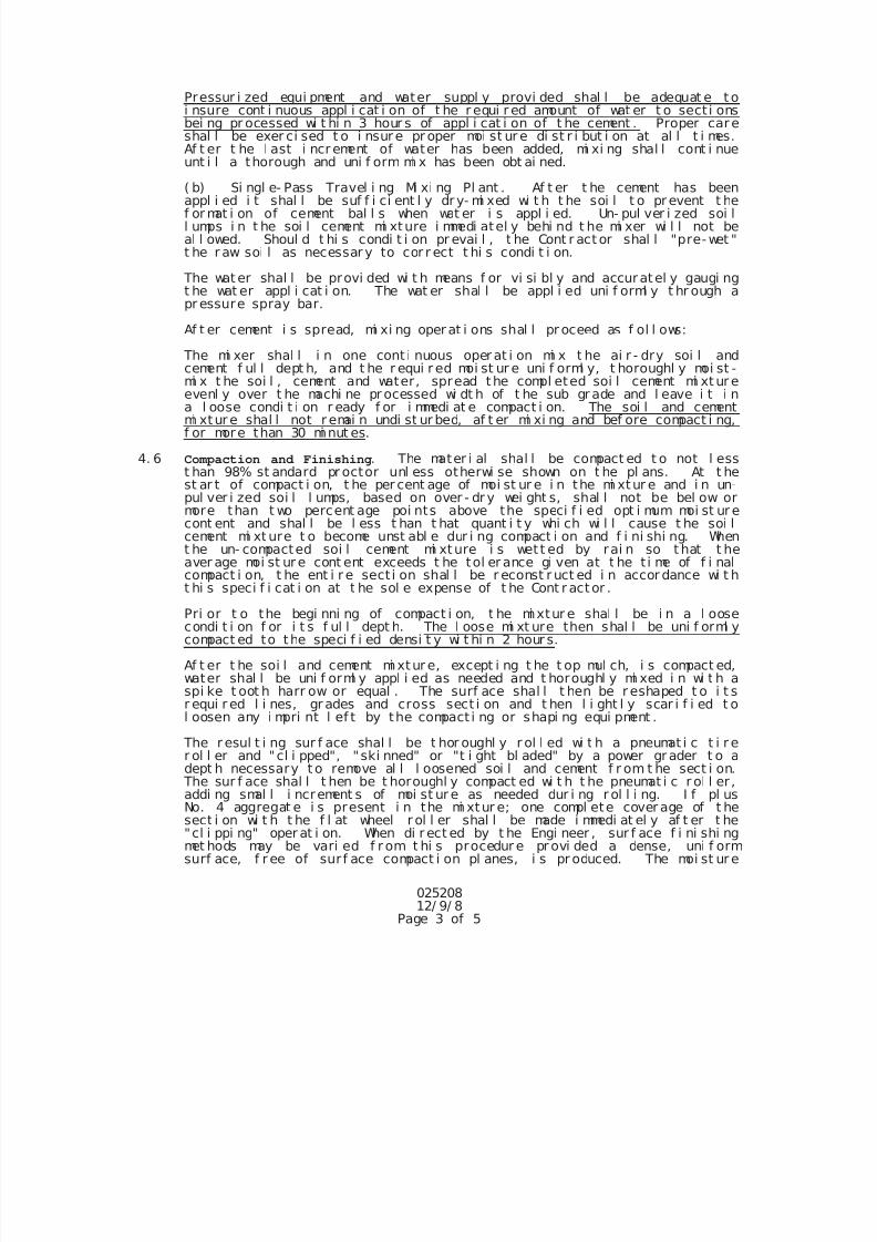
7/25/2019 City Standard Construction Specifications
http://slidepdf.com/reader/full/city-standard-construction-specifications 76/511
02520812/ 9/ 8
Page 3 of 5
Pressur i zed equi pment and water suppl y provi ded shal l be adequat e t oi nsure cont i nuous appl i cat i on of t he r equi r ed amount of wat er t o sect i onsbei ng pr ocessed wi t hi n 3 hour s of appl i cat i on of t he cement . Proper careshal l be exer ci sed t o i nsur e pr oper moi st ur e di st r i but i on at al l t i mes.Af t er t he l ast i ncr ement of water has been added, mi xi ng shal l cont i nueunt i l a thorough and uni f orm mi x has been obt ai ned.
( b) Si ngl e- Pass Travel i ng Mi xi ng Pl ant . Af t er t he cement has beenappl i ed i t shal l be suf f i ci ent l y dr y- mi xed wi t h t he soi l t o pr event t hef or mat i on of cement bal l s when wat er i s appl i ed. Un- pul ver i zed soi ll umps i n t he soi l cement mi xture i mmedi atel y behi nd t he mi xer wi l l not beal l owed. Shoul d t hi s condi t i on pr evai l , t he Cont r act or shal l "pre- wet "t he r aw soi l as necessar y to cor r ect t hi s condi t i on.
The wat er shal l be provi ded wi t h means f or vi si bl y and accuratel y gaugi ngt he wat er appl i cat i on. The wat er shal l be appl i ed uni f orml y t hr ough apr essure spray bar.
Af t er cement i s spread, mi xi ng oper at i ons shal l pr oceed as f ol l ows:
The mi xer shal l i n one cont i nuous oper at i on mi x t he ai r - dry soi l andcement f ul l dept h, and t he r equi r ed moi st ur e uni f orml y, t horoughl y moi st -mi x t he soi l , cement and water, spread the compl eted soi l cement mi xt ur e
evenl y over t he machi ne pr ocessed wi dt h of t he sub gr ade and l eave i t i na l oose condi t i on r eady f or i mmedi at e compact i on. The soi l and cementmi xtur e shal l not r emai n undi st ur bed, af t er mi xi ng and bef ore compact i ng,f or more than 30 mi nut es.
4. 6 Compaction and Finishing. The mater i al shal l be compact ed t o not l esst han 98% st andard pr octor unl ess otherwi se shown on t he pl ans. At t hest ar t of compact i on, t he per cent age of moi st ur e i n the mi xtur e and i n un-pul ver i zed soi l l umps, based on over - dr y wei ght s, shal l not be bel ow ormore than t wo percent age poi nts above the speci f i ed opt i mum moi st ur econt ent and shal l be l ess t han t hat quant i t y whi ch wi l l cause t he soi lcement mi xt ure t o become unst abl e dur i ng compact i on and f i ni shi ng. Whent he un- compacted soi l cement mi xture i s wett ed by rai n so t hat t heaver age moi st ur e cont ent exceeds t he tol er ance gi ven at t he t i me of f i nalcompact i on, t he ent i r e sect i on shal l be r econst r uct ed i n accor dance wi t h
t hi s speci f i cat i on at t he sol e expense of t he Cont r actor .
Pri or t o the begi nni ng of compact i on, t he mi xtur e shal l be i n a l oosecondi t i on f or i t s f ul l dept h. The l oose mi xt ure then shal l be uni f orml ycompact ed to the speci f i ed densi t y wi t hi n 2 hour s.
Af t er t he soi l and cement mi xtur e, except i ng t he t op mul ch, i s compact ed,water shal l be uni f orml y appl i ed as needed and t horoughl y mi xed i n wi t h aspi ke t oot h harr ow or equal . The surf ace shal l t hen be r eshaped t o i t sr equi r ed l i nes, gr ades and cross sect i on and t hen l i ght l y scar i f i ed t ol oosen any i mpri nt l ef t by the compact i ng or shapi ng equi pment .
The r esul t i ng sur f ace shal l be t hor oughl y r ol l ed wi t h a pneumat i c t i r er ol l er and "cl i pped", "ski nned" or "t i ght bl aded" by a power gr ader t o adept h necessary t o remove al l l oosened soi l and cement f r om t he sect i on.
The sur f ace shal l t hen be t horoughl y compact ed wi t h t he pneumat i c r ol l er ,addi ng smal l i ncrement s of moi st ur e as needed dur i ng r ol l i ng. I f pl usNo. 4 aggregat e i s present i n the mi xtur e; one compl ete cover age of t hesect i on wi t h t he f l at wheel r ol l er shal l be made i mmedi at el y af t er t he"cl i ppi ng" oper at i on. When di r ect ed by t he Engi neer , sur f ace f i ni shi ngmet hods may be vari ed f r om t hi s procedur e pr ovi ded a dense, uni f ormsurf ace, f r ee of sur f ace compact i on pl anes, i s pr oduced. The moi st ur e
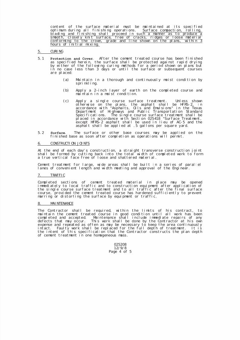
7/25/2019 City Standard Construction Specifications
http://slidepdf.com/reader/full/city-standard-construction-specifications 77/511
02520812/ 9/ 8
Page 4 of 5
cont ent of t he sur f ace mat er i al must be mai nt ai ned at i t s speci f i edopt i mum dur i ng al l f i ni shi ng oper at i ons. Sur f ace compacti on, r ol l i ng,bl adi ng and f i ni shi ng shal l pr oceed i n such a manner as t o pr oduce asmoot h, cl osel y kni t sur f ace, f r ee of cracks, r i dges or l oose mat er i alconf ormi ng to the crown, gr ade and l i ne shown on t he pl ans, wi t hi n 3hour s of i ni t i al mi xi ng.
5. CURI NG
5. 1 Protection and Cover. Af t er t he cement t r eat ed cour se has been f i ni shedas speci f i ed her ei n, t he sur f ace shal l be pr otected agai nst r api d dr yi ngby ei t her of t he f ol l owi ng cur i ng met hods f or a per i od shown on pl ans buti n no case l ess t han 3 days or unt i l t he sur f ace or subsequent cour sesar e pl aced:
( a) Mai nt ai n i n a t horough and cont i nuousl y moi st condi t i on byspri nkl i ng.
( b) Appl y a 2- i nch l ayer of ear t h on t he compl eted cour se andmai nt ai n i n a moi st condi t i on.
( c) Appl y a si ngl e cour se surf ace t r eat ment . Unl ess shownot her wi se on the pl ans, t he asphal t shal l be HFRS- 2, i n
accor dance wi t h "Asphal t s, Oi l s and Emul si ons" i n the TexasDepart ment of Hi ghways and Publ i c Tr anspor t at i on St andardSpeci f i cat i ons. The si ngl e cour se sur f ace t r eat ment shal l bepl aced i n accordance wi t h Sect i on 025418 "Sur f ace Treat ment ,except HFRS- 2 asphal t shal l be used i n l i eu of AC- 5 and theasphal t shal l be appl i ed at . 5 gal l ons per squar e yar d.
5. 2 Surface. The sur f ace or ot her base cour ses may be appl i ed on t hef i ni shed base as soon af t er compl et i on as oper at i ons wi l l per mi t .
6. CONSTRUCTI ON J OI NTS
At t he end of each day' s const r uct i on, a st r ai ght t r ansver se const r uct i on j oi ntshal l be f ormed by cut t i ng back i nt o the t otal wi dt h of compl et ed work t o f orma t r ue ver t i cal f ace f r ee of l oose and shat t er ed mat er i al .
Cement t r eat ment f or l ar ge, wi de ar eas shal l be bui l t i n a ser i es of par al l ell anes of conveni ent l ength and wi dth meet i ng and appr oval of t he Engi neer .
7. TRAFFI C
Compl eted sect i ons of cement t r eat ed materi al i n pl ace may be openedi mmedi at el y t o l ocal t r af f i c and to const r uct i on equi pment af t er appl i cat i on oft he si ngl e cour se sur f ace t r eat ment and t o al l t r af f i c af t er t he f i nal sur f acecour se, pr ovi ded the cement t r eated cour se has har dened suf f i ci ent l y t o pr eventmar r i ng or di st or t i ng the sur f ace by equi pment or t r af f i c.
8. MAI NTENANCE
The Cont r act or shal l be r equi r ed, wi t hi n t he l i mi t s of hi s cont r act , t o
mai nt ai n the cement t r eat ed cour se i n good condi t i on unt i l al l work has beencompl eted and accept ed. Mai ntenance shal l i ncl ude i mmedi ate r epai r s of anydef ects t hat may occur . Thi s work shal l be done by t he Cont r actor at hi s ownexpense and repeat ed as of t en as may be necessary t o keep t he area cont i nuousl yi nt act. Faul t y wor k shal l be r epl aced f or t he f ul l dept h of t r eat ment . I t i st he i nt ent of t hi s speci f i cat i on t hat t he Cont r act or const r uct s t he pl an dept hof cement t r eatment i n one homogeneous mass.
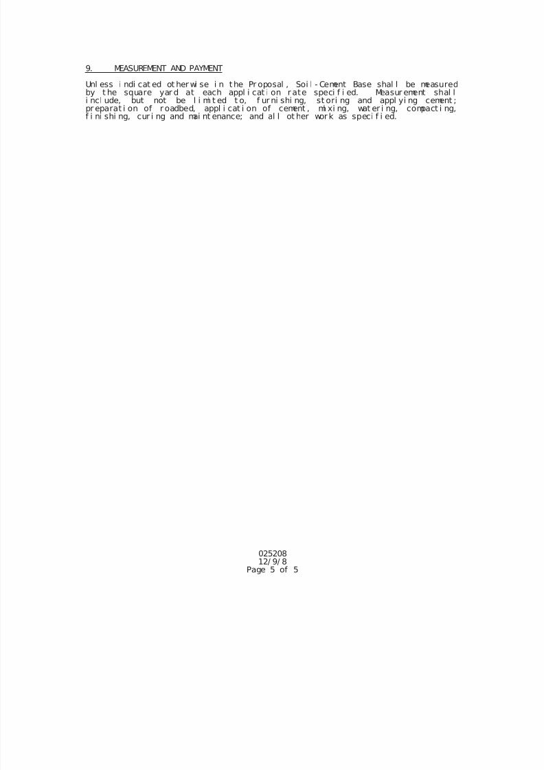
7/25/2019 City Standard Construction Specifications
http://slidepdf.com/reader/full/city-standard-construction-specifications 78/511
7/25/2019 City Standard Construction Specifications
http://slidepdf.com/reader/full/city-standard-construction-specifications 79/511
025210
Page 1 of 4
Rev. 10-30-2014
SECTION 025210
LIME STABILIZATION
1. DESCRIPTION
This specification shall consist of treating the subgrade, subbase or base by the pulverizing,
addition of lime, mixing and compacting the mixed material to the required density. Thisspecification applies to natural ground, embankment, existing pavement structure or proposed base,
and shall be constructed as specified herein and in conformity with the typical sections, lines and
grades as shown on the plans or as established by the Engineer.
2. MATERIALS
(1) The lime shall be a commercially produced "Hydrated Lime" in accordance with
AASHTO M216, or in accordance with TxDOT Specification Item 260. The
specifications apply specifically to the normal hydrate of lime made from "high-
calcium" type limestone. Hydrated lime for stabilization purposes shall be applied
as a slurry.
(2) Lime to be used for the treated subgrade, existing subbase, existing base or
proposed base is determined by preliminary tests and shall be applied at a rate
indicated on the drawings, but no less than 6%.
3. EQUIPMENT
The machinery, tools and equipment necessary for proper prosecution of the work shall be on the
project and approved by the Engineer prior to the beginning of construction operations.
All machinery, tools and equipment used shall be maintained in a satisfactory and workmanlikemanner.
Hydrated lime shall be stored and handled in closed weatherproof containers until immediately
before distribution on the roadbed. If storage bins are used, they shall be completely enclosed.
Hydrated lime in bags shall be stored in weatherproof buildings with adequate protection from
ground dampness. If lime is furnished in trucks, each truck shall have the weight of lime certified
on public scales.
If lime is furnished in bags, each bag shall bear the manufacturer's certified weight. Bags varying
more than 5 percent from that weight may be rejected and the average weight of bags in any
shipment, as shown by weighing 50 bags taken at random, shall not be less than the manufacturer'scertified weight.
7/25/2019 City Standard Construction Specifications
http://slidepdf.com/reader/full/city-standard-construction-specifications 80/511
025210
Page 2 of 4
Rev. 10-30-2014
4. CONSTRUCTION METHODS
General - It is the primary requirement of this specification to secure a completed course of treated
material containing a uniform lime mixture, free from loose or segregated areas, of uniform density
and moisture content, well bound for its full depth and with a smooth surface suitable for placing
subsequent courses. It shall be the responsibility of the Contractor to regulate the sequence of his
work, to use the proper amount of lime, maintain the work and rework the courses as necessary to
meet the above requirements.
Application - Lime shall be spread only on that area where the first mixing operations can be
completed during the same working day.
Unless otherwise shown on drawings, lime shall be applied at a rate in pounds of dry-hydrated lime
per square yard, in the form of a slurry. Application rate may be varied by the Engineer, if
conditions warrant, but no less than 6% must be applied.
Certification of lime quantity and quality shall be provided as required to monitor the application.
Certification should be in the form of weight tickets which indicate the actual weight of dry
hydrated lime, CA(OH)2.
The application and mixing of lime with the material shall be accomplished by the method
hereinafter described.
The lime shall be mixed with water in trucks with approved distributors and applied as a thin water
suspension or slurry.
Mixing - The mixing procedure shall be as hereinafter described.
(a) First Mixing: The material and lime shall be thoroughly mixed by approved road mixers
or other approved equipment, and the mixing continued until, in the opinion of theEngineer, a homogeneous, friable mixture of material and lime is obtained, free from all
clods or lumps. Materials containing plastic clays or other material which will not readily
mix with lime shall be mixed as thoroughly as possible at the time of the lime application,
brought to the proper moisture content and left to cure 1 to 4 days as directed by the
Engineer. During the curing period, the material shall be kept moist as directed.
(b) Final Mixing: After the required curing time, the material shall be uniformly mixed by
approved methods. If the soil binder-lime mixture contains clods, they shall be reduced in
size by raking, blading, discing, harrowing, scarifying or the use of other approved
pulverization methods so that, when all nonslaking aggregates retained on the No. 4 sieve
are removed, the remainder of the material shall meet the following requirements whentested dry by laboratory sieves:
7/25/2019 City Standard Construction Specifications
http://slidepdf.com/reader/full/city-standard-construction-specifications 81/511
025210
Page 3 of 4
Rev. 10-30-2014
Percent
Minimum Passing 1" Sieve .................................................. 100
Minimum Passing No. 4 Sieve ............................................. 85
Old bituminous wearing surface shall be pulverized so that 100% will pass a 2 ½" sieve.
During the interval of time between applications and mixing, hydrated lime that has been
exposed to the open air for a period of 6 hours or more, or to excessive loss due to washingor blowing, will not be accepted for payment.
Compaction - Compaction of the mixture shall begin immediately after final mixing and in no case
later than 3 calendar days after final mixing, unless approval is obtained from the Engineer. The
material shall be aerated or sprinkled as necessary to provide the optimum moisture. Compaction
shall begin at the bottom and shall continue until the entire depth of mixture is uniformly
compacted as hereinafter specified.
If the total thickness of the material to be treated cannot be mixed in one operation, the previously
mixed material shall be bladed to a windrow just beyond the area to be treated and the next layer
mixed with lime as previously specified. The first layer of the material shall be compacted in sucha manner that the treated material will not be mixed with the underlying material.
The course shall be sprinkled as required to maintain moisture content on the wet side of optimum
and compacted to the extent necessary to provide the specified density. Unless shown otherwise on
the drawings, all lime treated subgrades, sub-bases, and bases that are not in direct contact with
surface or binder course shall be compacted to a minimum of 95% Standard Proctor density
(AASHTO T99), unless otherwise specified.
In addition to the requirements specified for density, the full depth of the material shown on the
plans shall be compacted to the extent necessary to remain firm and stable under construction
equipment. After each section is completed, tests, as necessary, will be made by the Engineer. Ifthe material fails to meet the density requirements, it shall be reworked as necessary to meet these
requirements.
Rework, when required to meet pulverization requirements or density requirements, shall include
the addition of lime, about 10% to 15% of the initial application rate, or as deemed necessary by
the Engineer. A new optimum density will be obtained.
Throughout this entire operation, the shape of the course shall be maintained by blading, and the
surface, upon completion, shall be smooth and in conformity with the typical section shown on the
drawings and to the established lines and grades.
7/25/2019 City Standard Construction Specifications
http://slidepdf.com/reader/full/city-standard-construction-specifications 82/511
025210
Page 4 of 4
Rev. 10-30-2014
5. MEASUREMENT AND PAYMENT
Unless otherwise specified on the Bid Form, lime stabilization for bases, sub-bases and subgrade
shall be measured by the square yard of lime-stabilized material in place.
Pulverizing, mixing, watering grading, compacting, working material etc., shall not be measured
for pay but shall be subsidiary to other work.
Payment shall be full compensation for all materials, labor, equipment, tools, and incidentals
necessary for the completion of work.
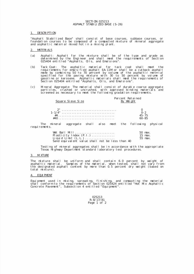
7/25/2019 City Standard Construction Specifications
http://slidepdf.com/reader/full/city-standard-construction-specifications 83/511
025213R- 8/ 17/ 81
Page 1 of 2
SECTI ON 025213 ASPHALT STABI LI ZED BASE ( S- 26)
1. DESCRI PTI ON
"Asphal t St abi l i zed Base" shal l consi st of base cour ses, subbase cour ses, orf oundat i on cour ses t o be composed of a compact ed mi xt ure of mi ner al aggregateand asphal t i c mat eri al mi xed hot i n a mi xi ng pl ant .
2. MATERI ALS
( a) Asphal t : Asphal t f or t he mi xture shal l be of t he t ype and gr ade asdet ermi ned by t he Engi neer and shal l meet t he requi r ement s of Sect i on025404 ent i t l ed "Asphal t s, Oi l s, and Emul si ons".
( b) Tack Coat : The asphal t i c mat er i al f or t ack coat shal l meet t her equi r ement s f or emul si f i ed asphal t EA- 11M or shal l be a cut back asphal tmade by combi ni ng 50 t o 70 percent by vol ume of t he asphal t i c mater i alspeci f i ed f or t he pavi ng mi xtur e wi t h 30 to 50 percent by vol ume ofgasol i ne or ker osene. Asphal t i c mat er i al s shal l meet t he r equi r ement s ofSect i on 025404 ent i t l ed "Asphal t s, Oi l s, and Emul si ons" .
( c) Mi ner al Aggr egat e: The mat er i al shal l consi st of dur abl e coar se aggr egat epar t i cl es, cr ushed or uncrushed, wi t h appr oved bi ndi ng mater i al s andscr eened as necessar y t o meet t he f ol l owi ng gradat i on r equi r ement s.
Per cent Ret ai nedSquar e Si eve Si ze By Wei ght
2" . . . . . . . . . . . . . . . . . . . . . . . . . . . . . . . . . 01- 1/ 4" . . . . . . . . . . . . . . . . . . . . . . . . . . . . . . . . 0- 2
#4 . . . . . . . . . . . . . . . . . . . . . . . . . . . . . . . . . . 45- 75#40 . . . . . . . . . . . . . . . . . . . . . . . . . . . . . . . . . . 60- 85
The mi ner al aggregat e shal l al so meet t he f ol l owi ng physi calr equi r ement s.
Wet Bal l Mi l l . . . . . . . . . . . . . . . . . . . . . . . . 50 max.Pl ast i ci t y I ndex ( P. I . ) . . . . . . . . . . . . . . 15 max.Li qui d Li mi t ( L. L. ) . . . . . . . . . . . . . . . . . . 55 max.Sand equi val ent val ue shal l not be l ess t han 40
Test i ng of mi ner al aggregat es shal l be i n accor dance wi t h t he appropr i ate Texas Hi ghway Depart ment st andar d l aboratory t est procedures.
3. MI XTURE
The mi xt ure shal l be uni f orm and shal l contai n 6. 0 per cent by wei ght ofasphal t i c mat er i al . Sampl es of t he mat er i al , when t est ed, shal l not var y f r omt he desi gnat ed asphal t cont ent by more t han 0. 5 percent dr y wei ght ( based ont ot al mi xt ure).
4. EQUI PMENT
Equi pment used i n mi xi ng, spr eadi ng, f i ni shi ng, and compact i ng the mater i alshal l conf or m t o the requi r ement s of Sect i on 025424 ent i t l ed "Hot Mi x Asphal t i cConcr ete Pavement " , Subsect i on 4 ent i t l ed "Equi pment " .
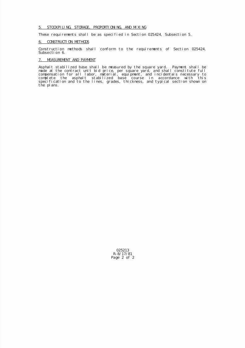
7/25/2019 City Standard Construction Specifications
http://slidepdf.com/reader/full/city-standard-construction-specifications 84/511
025213R- 8/ 17/ 81
Page 2 of 2
5. STOCKPI LI NG, STORAGE, PROPORTI ONI NG, AND MI XI NG
These r equi r ement s shal l be as speci f i ed i n Sect i on 025424, Subsect i on 5.
6. CONSTRUCTI ON METHODS
Const r uct i on methods shal l conf orm t o t he r equi r ement s of Sect i on 025424,Subsect i on 6.
7. MEASUREMENT AND PAYMENT
Asphal t st abi l i zed base shal l be measured by t he square yar d. Payment shal l bemade at t he cont r act uni t bi d pr i ce, per squar e yar d, and shal l const i t ut e f ul lcompensat i on f or al l l abor , mat er i al , equi pment , and i nci dent al s necessar y tocompl et e t he asphal t st abi l i zed base cour se i n accordance wi t h t hi sspeci f i cat i on and t o t he l i nes, gr ades, t hi ckness, and t ypi cal sect i on shown ont he pl ans.
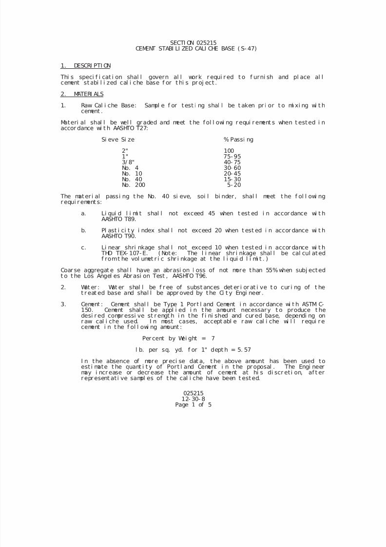
7/25/2019 City Standard Construction Specifications
http://slidepdf.com/reader/full/city-standard-construction-specifications 85/511
025215 12- 30- 8
Page 1 of 5
SECTI ON 025215 CEMENT STABI LI ZED CALI CHE BASE ( S- 47)
1. DESCRI PTI ON
Thi s speci f i cat i on shal l govern al l work r equi r ed t o f urni sh and pl ace al lcement st abi l i zed cal i che base f or t hi s pr oj ect .
2. MATERI ALS
1. Raw Cal i che Base: Sampl e f or test i ng shal l be t aken pr i or t o mi xi ng wi t hcement .
Materi al shal l be wel l gr aded and meet t he f ol l owi ng r equi r ement s when t ested i naccor dance wi t h AASHTO T27:
Si eve Si ze % Passi ng
2" 1001" 75-953/ 8" 40- 75No. 4 30- 60
No. 10 20- 45No. 40 15- 30No. 200 5- 20
The mater i al passi ng t he No. 40 si eve, soi l bi nder , shal l meet t he f ol l owi ngr equi r ement s:
a. Li qui d l i mi t shal l not exceed 45 when t est ed i n accor dance wi t hAASHTO T89.
b. Pl ast i ci t y i ndex shal l not exceed 20 when t est ed i n accor dance wi t hAASHTO T90.
c. Li near shri nkage shal l not exceed 10 when t ested i n accor dance wi t h THD TEX- 107- E. ( Not e: The l i near shr i nkage shal l be cal cul ated
f romt he vol umet r i c shr i nkage at t he l i qui d l i mi t . )
Coar se aggregat e shal l have an abrasi on l oss of not more than 55%when subj ectedt o t he Los Angel es Abr asi on Test , AASHTO T96.
2. Wat er : Wat er shal l be f r ee of subst ances det er i or at i ve t o cur i ng of t het r eat ed base and shal l be appr oved by the Ci t y Engi neer .
3. Cement : Cement shal l be Type 1 Port l and Cement i n accordance wi t h ASTM C-150. Cement shal l be appl i ed i n t he amount necessary t o produce t hedesi r ed compr essi ve st r engt h i n the f i ni shed and cur ed base, dependi ng onr aw cal i che used. I n most cases, accept abl e r aw cal i che wi l l r equi r ecement i n t he f ol l owi ng amount :
Per cent by Wei ght = 7
l b. per sq. yd. f or 1" dept h = 5. 57
I n the absence of more pr eci se dat a, t he above amount has been used toest i mate t he quant i t y of Port l and Cement i n t he pr oposal . The Engi neermay i ncr ease or decr ease the amount of cement at hi s di scr et i on, af t err epr esent at i ve sampl es of t he cal i che have been t ested.
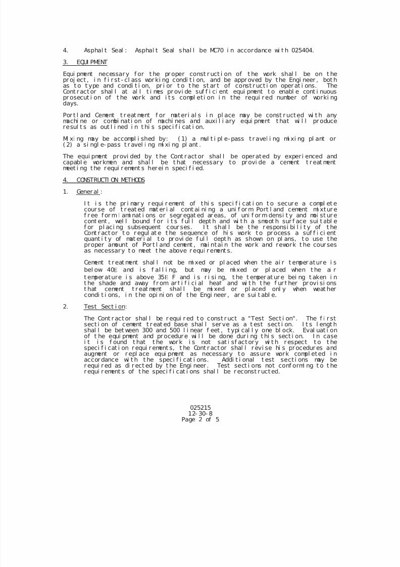
7/25/2019 City Standard Construction Specifications
http://slidepdf.com/reader/full/city-standard-construction-specifications 86/511
025215 12- 30- 8
Page 2 of 5
4. Asphal t Seal : Asphal t Seal shal l be MC70 i n accordance wi t h 025404.
3. EQUI PMENT
Equi pment necessary f or t he pr oper const r uct i on of t he work shal l be on t hepr oj ect , i n f i r st - cl ass wor ki ng condi t i on, and be appr oved by the Engi neer , bot has t o t ype and condi t i on, pr i or t o t he st ar t of const r uct i on oper at i ons. TheCont ract or shal l at al l t i mes pr ovi de suf f i ci ent equi pment t o enabl e cont i nuouspr osecut i on of t he work and i t s compl et i on i n the requi r ed number of worki ngdays.
Por t l and Cement t r eat ment f or materi al s i n pl ace may be const r ucted wi t h anymachi ne or combi nat i on of machi nes and auxi l i ary equi pment t hat wi l l pr oduceresul t s as out l i ned i n t hi s speci f i cat i on.
Mi xi ng may be accompl i shed by: ( 1) a mul t i pl e-pass t r avel i ng mi xi ng pl ant or( 2) a si ngl e- pass t r avel i ng mi xi ng pl ant .
The equi pment provi ded by t he Cont ract or shal l be operated by exper i enced andcapabl e workmen and shal l be t hat necessary to pr ovi de a cement t r eat mentmeet i ng the requi r ement s herei n speci f i ed.
4. CONSTRUCTI ON METHODS
1. Gener al :
I t i s t he pr i mar y r equi r ement of thi s speci f i cat i on t o secure a compl et ecour se of t r eat ed mat er i al cont ai ni ng a uni f or m Port l and cement mi xtur ef r ee f or m l ami nat i ons or segr egat ed ar eas, of uni f or m densi t y and moi st ur econt ent , wel l bound f or i t s f ul l dept h and wi t h a smoot h sur f ace sui t abl ef or pl aci ng subsequent cour ses. I t shal l be t he r esponsi bi l i t y of t heCont r act or t o r egul at e t he sequence of hi s work t o pr ocess a suf f i ci entquant i t y of mat er i al t o pr ovi de f ul l dept h as shown on pl ans, t o use theproper amount of Por t l and cement , mai ntai n the work and rework t he cour sesas necessary t o meet t he above r equi r ement s.
Cement t r eat ment shal l not be mi xed or pl aced when the ai r t emper ature i s
bel ow 40 and i s f al l i ng, but may be mi xed or pl aced when t he ai rt emper ature i s above 35 F and i s r i si ng, t he t emper at ur e bei ng t aken i nt he shade and away f r om ar t i f i ci al heat and wi t h t he f ur t her pr ovi si onst hat cement t r eat ment shal l be mi xed or pl aced onl y when weat hercondi t i ons, i n t he opi ni on of t he Engi neer , ar e sui t abl e.
2. Test Sect i on:
The Cont r act or shal l be r equi r ed t o const r uct a "Test Sect i on". The f i r stsect i on of cement t r eat ed base shal l ser ve as a t est sect i on. I t s l engt hshal l be bet ween 300 and 500 l i near f eet , t ypi cal l y one bl ock. Eval uat i onof t he equi pment and pr ocedure wi l l be done dur i ng t hi s sect i on. I n casei t i s f ound t hat t he wor k i s not sat i sf actor y wi t h r espect t o t hespeci f i cat i on r equi r ement s, t he Cont r actor shal l r evi se hi s pr ocedur es andaugment or r epl ace equi pment as necessary t o assure work compl eted i n
accor dance wi t h t he speci f i cat i ons. Addi t i onal t est sect i ons may ber equi r ed as di r ect ed by t he Engi neer . Test sect i ons not conf ormi ng t o t her equi r ement s of t he speci f i cat i ons shal l be r econst r ucted.
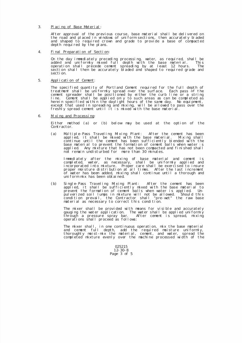
7/25/2019 City Standard Construction Specifications
http://slidepdf.com/reader/full/city-standard-construction-specifications 87/511
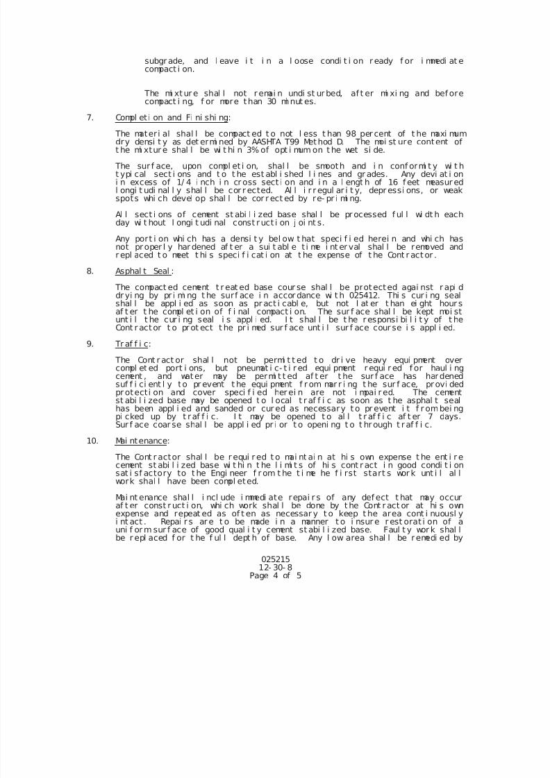
7/25/2019 City Standard Construction Specifications
http://slidepdf.com/reader/full/city-standard-construction-specifications 88/511
025215 12- 30- 8
Page 4 of 5
subgr ade, and l eave i t i n a l oose condi t i on r eady f or i mmedi at ecompact i on.
The mi xtur e shal l not r emai n undi st ur bed, af t er mi xi ng and bef orecompact i ng, f or more than 30 mi nut es.
7. Compl et i on and Fi ni shi ng:
The materi al shal l be compact ed t o not l ess t han 98 per cent of t he maxi mumdry densi t y as det ermi ned by AASHTA T99 Method D. The moi st ure content oft he mi xtur e shal l be wi t hi n 3% of opt i mum on t he wet si de.
The sur f ace, upon compl et i on, shal l be smooth and i n conf ormi t y wi t ht ypi cal sect i ons and t o t he est abl i shed l i nes and gr ades. Any devi at i oni n excess of 1/ 4 i nch i n cr oss sect i on and i n a l engt h of 16 f eet measur edl ongi t udi nal l y shal l be cor r ected. Al l i r r egul ar i t y, depr essi ons, or weakspots whi ch devel op shal l be cor r ect ed by re- pr i mi ng.
Al l sect i ons of cement st abi l i zed base shal l be pr ocessed f ul l wi dt h eachday wi t hout l ongi t udi nal const ruct i on j oi nt s.
Any port i on whi ch has a densi t y bel ow t hat speci f i ed herei n and whi ch has
not proper l y har dened af t er a sui t abl e t i me i nt er val shal l be removed andr epl aced t o meet t hi s speci f i cat i on at t he expense of t he Cont r act or .
8. Asphal t Seal :
The compact ed cement t r eat ed base cour se shal l be protected agai nst r api ddr yi ng by pr i mi ng t he surf ace i n accor dance wi t h 025412. Thi s cur i ng sealshal l be appl i ed as soon as pr act i cabl e, but not l at er t han ei ght hour saf t er t he compl et i on of f i nal compact i on. The sur f ace shal l be kept moi stunt i l t he cur i ng seal i s appl i ed. I t shal l be t he r esponsi bi l i t y of t heCont r actor t o pr ot ect t he pr i med sur f ace unt i l sur f ace cour se i s appl i ed.
9. Tr af f i c:
The Cont r act or shal l not be permi t t ed t o dr i ve heavy equi pment over
compl et ed port i ons, but pneumat i c- t i r ed equi pment r equi r ed f or haul i ngcement , and water may be permi t t ed af t er t he sur f ace has hardenedsuf f i ci ent l y to pr event t he equi pment f r om mar r i ng t he sur f ace, provi dedpr otecti on and cover speci f i ed her ei n are not i mpai r ed. The cementst abi l i zed base may be opened t o l ocal t r af f i c as soon as t he asphal t sealhas been appl i ed and sanded or cur ed as necessary t o pr event i t f r ombei ngpi cked up by t raf f i c. I t may be opened t o al l t r af f i c af t er 7 days.Sur f ace coar se shal l be appl i ed pr i or t o openi ng t o t hr ough t raf f i c.
10. Mai ntenance:
The Cont r actor shal l be r equi r ed t o mai nt ai n at hi s own expense t he ent i r ecement st abi l i zed base wi t hi n t he l i mi t s of hi s cont r act i n good condi t i onsat i sf actory to t he Engi neer f r om t he t i me he f i rst start s wor k unt i l al lwork shal l have been compl eted.
Mai nt enance shal l i ncl ude i mmedi ate repai r s of any def ect t hat may occuraf t er const r uct i on, whi ch work shal l be done by t he Cont r act or at hi s ownexpense and repeat ed as of t en as necessar y t o keep t he area cont i nuousl yi nt act . Repai r s ar e t o be made i n a manner t o i nsur e r est orat i on of auni f or m sur f ace of good qual i t y cement st abi l i zed base. Faul t y wor k shal lbe r epl aced f or t he f ul l dept h of base. Any l ow area shal l be remedi ed by
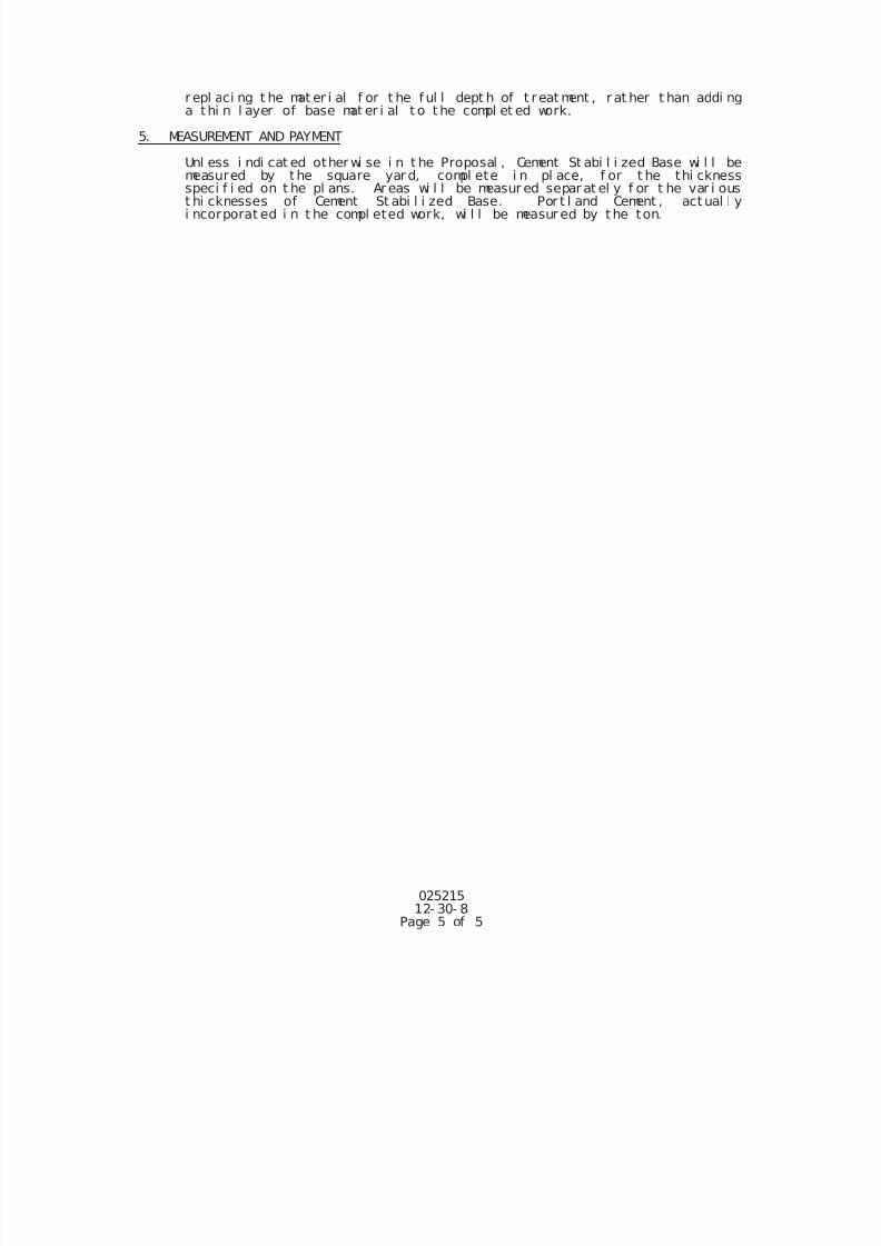
7/25/2019 City Standard Construction Specifications
http://slidepdf.com/reader/full/city-standard-construction-specifications 89/511
025215 12- 30- 8
Page 5 of 5
r epl aci ng t he mat er i al f or t he f ul l dept h of t r eat ment , r at her t han addi nga thi n l ayer of base mat er i al t o t he compl et ed work.
5. MEASUREMENT AND PAYMENT
Unl ess i ndi cat ed other wi se i n t he Proposal , Cement St abi l i zed Base wi l l bemeasured by the square yar d, compl ete i n pl ace, f or t he thi cknessspeci f i ed on t he pl ans. Ar eas wi l l be measur ed separ at el y f or t he var i oust hi cknesses of Cement St abi l i zed Base. Por t l and Cement , act ual l yi ncorporat ed i n t he compl eted work, wi l l be measur ed by t he ton.
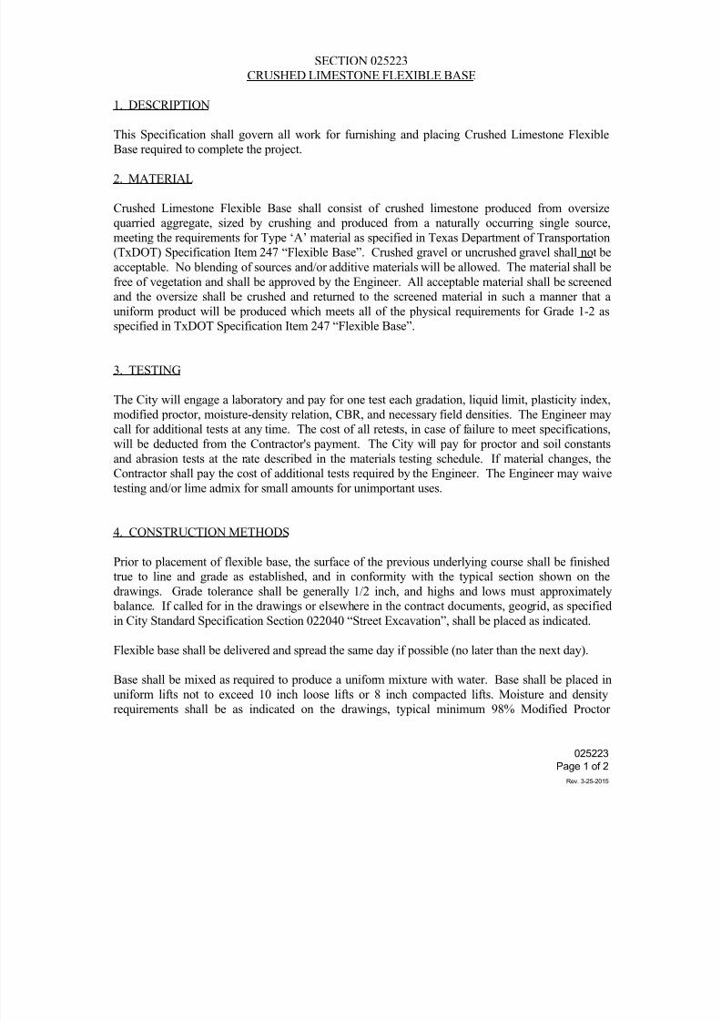
7/25/2019 City Standard Construction Specifications
http://slidepdf.com/reader/full/city-standard-construction-specifications 90/511
SECTION 025223
CRUSHED LIMESTONE FLEXIBLE BASE
1. DESCRIPTION
This Specification shall govern all work for furnishing and placing Crushed Limestone Flexible
Base required to complete the project.
2. MATERIAL
Crushed Limestone Flexible Base shall consist of crushed limestone produced from oversize
quarried aggregate, sized by crushing and produced from a naturally occurring single source,
meeting the requirements for Type ‘A’ material as specified in Texas Department of Transportation
(TxDOT) Specification Item 247 “Flexible Base”. Crushed gravel or uncrushed gravel shall not be
acceptable. No blending of sources and/or additive materials will be allowed. The material shall be
free of vegetation and shall be approved by the Engineer. All acceptable material shall be screened
and the oversize shall be crushed and returned to the screened material in such a manner that a
uniform product will be produced which meets all of the physical requirements for Grade 1-2 as
specified in TxDOT Specification Item 247 “Flexible Base”.
3. TESTING
The City will engage a laboratory and pay for one test each gradation, liquid limit, plasticity index,
modified proctor, moisture-density relation, CBR, and necessary field densities. The Engineer may
call for additional tests at any time. The cost of all retests, in case of failure to meet specifications,
will be deducted from the Contractor's payment. The City will pay for proctor and soil constants
and abrasion tests at the rate described in the materials testing schedule. If material changes, the
Contractor shall pay the cost of additional tests required by the Engineer. The Engineer may waive
testing and/or lime admix for small amounts for unimportant uses.
4. CONSTRUCTION METHODS
Prior to placement of flexible base, the surface of the previous underlying course shall be finished
true to line and grade as established, and in conformity with the typical section shown on the
drawings. Grade tolerance shall be generally 1/2 inch, and highs and lows must approximately
balance. If called for in the drawings or elsewhere in the contract documents, geogrid, as specified
in City Standard Specification Section 022040 “Street Excavation”, shall be placed as indicated.
Flexible base shall be delivered and spread the same day if possible (no later than the next day).
Base shall be mixed as required to produce a uniform mixture with water. Base shall be placed in
uniform lifts not to exceed 10 inch loose lifts or 8 inch compacted lifts. Moisture and density
requirements shall be as indicated on the drawings, typical minimum 98% Modified Proctor
025223
Page 1 of 2
Rev. 3-25-2015
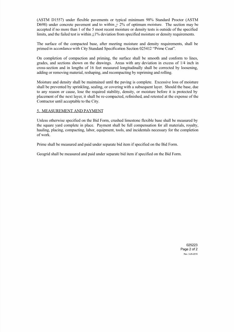
7/25/2019 City Standard Construction Specifications
http://slidepdf.com/reader/full/city-standard-construction-specifications 91/511
(ASTM D1557) under flexible pavements or typical minimum 98% Standard Proctor (ASTM
D698) under concrete pavement and to within + 2% of optimum moisture. The section may be
accepted if no more than 1 of the 5 most recent moisture or density tests is outside of the specified
limits, and the failed test is within +1% deviation from specified moisture or density requirements.
The surface of the compacted base, after meeting moisture and density requirements, shall be
primed in accordance with City Standard Specification Section 025412 “Prime Coat”.
On completion of compaction and priming, the surface shall be smooth and conform to lines,
grades, and sections shown on the drawings. Areas with any deviation in excess of 1/4 inch in
cross-section and in lengths of 16 feet measured longitudinally shall be corrected by loosening,
adding or removing material, reshaping, and recompacting by repriming and rolling.
Moisture and density shall be maintained until the paving is complete. Excessive loss of moisture
shall be prevented by sprinkling, sealing, or covering with a subsequent layer. Should the base, due
to any reason or cause, lose the required stability, density, or moisture before it is protected by
placement of the next layer, it shall be re-compacted, refinished, and retested at the expense of the
Contractor until acceptable to the City.
5. MEASUREMENT AND PAYMENT
Unless otherwise specified on the Bid Form, crushed limestone flexible base shall be measured by
the square yard complete in place. Payment shall be full compensation for all materials, royalty,
hauling, placing, compacting, labor, equipment, tools, and incidentals necessary for the completion
of work.
Prime shall be measured and paid under separate bid item if specified on the Bid Form.
Geogrid shall be measured and paid under separate bid item if specified on the Bid Form.
025223
Page 2 of 2
Rev. 3-25-2015
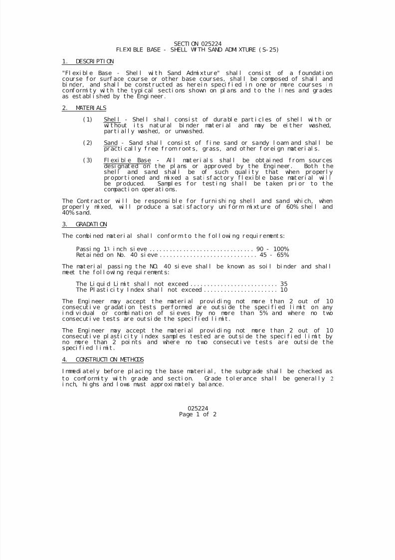
7/25/2019 City Standard Construction Specifications
http://slidepdf.com/reader/full/city-standard-construction-specifications 92/511
025224Page 1 of 2
SECTI ON 025224FLEXI BLE BASE - SHELL WI TH SAND ADMI XTURE ( S- 25)
1. DESCRI PTI ON
"Fl exi bl e Base - Shel l wi t h Sand Admi xtur e" shal l consi st of a f oundat i oncour se f or surf ace cour se or other base cour ses, shal l be composed of shal l andbi nder, and shal l be const r uct ed as her ei n speci f i ed i n one or more cour ses i nconf ormi t y wi t h the typi cal sect i ons shown on pl ans and t o the l i nes and gr adesas est abl i shed by the Engi neer .
2. MATERI ALS
( 1) Shel l - Shel l shal l consi st of durabl e part i cl es of shel l wi t h orwi t hout i t s nat ur al bi nder mat er i al and may be ei t her washed,par t i al l y washed, or unwashed.
( 2) Sand - Sand shal l consi st of f i ne sand or sandy l oam and shal l bepr acti cal l y f r ee f r om r oot s, gr ass, and ot her f or ei gn mat er i al s.
( 3) Fl exi bl e Base - Al l mat er i al s shal l be obt ai ned f r om sour cesdesi gnat ed on t he pl ans or appr oved by t he Engi neer . Both t heshel l and sand shal l be of such qual i t y that when pr oper l y
pr opor t i oned and mi xed a sat i sf act or y f l exi bl e base mat er i al wi l lbe pr oduced. Sampl es f or test i ng shal l be t aken pr i or to t hecompact i on oper at i ons.
The Cont r act or wi l l be r esponsi bl e f or f urni shi ng shel l and sand whi ch, whenpr oper l y mi xed, wi l l pr oduce a sat i sf actor y uni f or m mi xt ur e of 60% shel l and40% sand.
3. GRADATI ON
The combi ned mat er i al shal l conf orm t o t he f ol l owi ng r equi r ement s:
Passi ng 1 i nch si eve . . . . . . . . . . . . . . . . . . . . . . . . . . . . . . . 90 - 100% Ret ai ned on No. 40 si eve . . . . . . . . . . . . . . . . . . . . . . . . . . . . . 45 - 65%
The mat er i al passi ng t he NO. 40 si eve shal l be known as soi l bi nder and shal lmeet t he f ol l owi ng requi r ement s:
The Li qui d Li mi t shal l not exceed . . . . . . . . . . . . . . . . . . . . . . . . . . 35 The Pl ast i ci t y I ndex shal l not exceed . . . . . . . . . . . . . . . . . . . . . . 10
The Engi neer may accept t he mater i al provi di ng not more t han 2 out of 10consecut i ve gr adat i on test s per f ormed ar e out si de the speci f i ed l i mi t on anyi ndi vi dual or combi nat i on of si eves by no more than 5% and where no twoconsecut i ve t est s ar e out si de t he speci f i ed l i mi t .
The Engi neer may accept t he mater i al provi di ng not more t han 2 out of 10consecut i ve pl ast i ci t y i ndex sampl es t est ed ar e out si de t he speci f i ed l i mi t byno more than 2 poi nts and wher e no two consecut i ve t est s are outsi de t hespeci f i ed l i mi t .
4. CONSTRUCTI ON METHODS
I mmedi atel y bef ore pl aci ng t he base materi al , t he subgr ade shal l be checked as
t o conf ormi t y wi t h gr ade and sect i on. Gr ade t ol er ance shal l be general l y
i nch, hi ghs and l ows must appr oxi matel y bal ance.
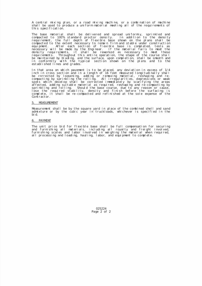
7/25/2019 City Standard Construction Specifications
http://slidepdf.com/reader/full/city-standard-construction-specifications 93/511
025224Page 2 of 2
A cent r al mi xi ng pl an, or a road mi xi ng machi ne, or a combi nat i on of machi neshal l be used to pr oduce a uni f or m mat er i al meet i ng al l of t he requi r ement s oft hi s speci f i cat i on.
The base mater i al shal l be del i vered and spr ead uni f orml y, spr i nkl ed andcompact ed t o 100% st andar d pr oct or densi t y. I n addi t i on t o t he densi t yr equi r ement , t he f ul l dept h of f l exi bl e base shown on the pl ans shal l becompact ed t o t he extent necessary t o remai n f i r m and st abl e under const r uct i onequi pment . Af t er each sect i on of f l exi bl e base i s compl et ed, t est s asnecessary wi l l be made by t he Engi neer . I f t he mat er i al f ai l s to meet t hedensi t y r equi r ement s, i t shal l be reworked as necessary t o meet t heser equi r ement s. Thr oughout t hi s ent i r e oper at i on, t he shape of t he cour se shal lbe mai ntai ned by bl adi ng, and the sur f ace, upon compl et i on, shal l be smoot h andi n conf ormi t y wi t h t he t ypi cal sect i on shown on t he pl ans and t o theest abl i shed l i nes and gr ades.
I n that area on whi ch pavement i s t o be pl aced, any devi at i on i n excess of 1/ 4i nch i n cross sect i on and i n a l engt h of 16 f eet measur ed l ongi t udi nal l y shal lbe corr ected by l ooseni ng, addi ng or r emovi ng materi al , r eshapi ng and r e-compact i ng by spr i nkl i ng t he r ol l i ng. Al l i r r egul ar i t i es, depr essi ons or weakspot s whi ch devel op shal l be corr ect ed i mmedi atel y by scar i f yi ng t he ar easaf f ect ed, addi ng sui t abl e mater i al as r equi r ed, r eshapi ng and r e- compact i ng byspri nkl i ng and r ol l i ng. Shoul d t he base cour se, due t o any r eason or cause,
l ose t he r equi r ed st abi l i t y, densi t y and f i ni sh bef or e t he sur f aci ng i scompl et e, i t shal l be re- compact ed and r ef i ni shed at t he sol e expense of t heCont r act or .
5. MEASUREMENT
Measurement shal l be by t he square yard i n pl ace of t he combi ned shel l and sandadmi xtur e or by the cubi c year i n t r uckl oads, whi chever i s speci f i ed i n t hebi d.
6. PAYMENT
The uni t pr i ce bi d f or f l exi bl e base shal l be f ul l compensat i on f or secur i ngand f ur ni shi ng al l mat er i al s, i ncl udi ng al l r oyal t y and f r ei ght i nvol ved,f ur ni shi ng scal es and l abor i nvol ved i n wei ghi ng t he mat eri al when r equi r ed,
al l pr ocessi ng and l oadi ng, haul i ng, l abor, and equi pment t o compl et e.

7/25/2019 City Standard Construction Specifications
http://slidepdf.com/reader/full/city-standard-construction-specifications 94/511
025402Rev 12-30- 8Page 1 of 2
SECTI ON 025402 PLANI NG ASPHALTI C SURFACES ( S- 27A)
1. DESCRI PTI ON
Thi s speci f i cat i on shal l govern al l work r equi r ed f or pl ani ng an exi st i ngasphal t i c concr et e pavement r equi r ed to compl ete the pr oj ect .
2. EQUI PMENT
Pl aner shal l be a sel f pr opel l ed pl ani ng machi ne capabl e of r emovi ng, i n onepass, a. c. sur f ace to any requi r ed thi ckness l ess t han 9 i nches, i n a mi ni mumof 6- f oot wi dt h. The pl aner shal l be capabl e of accur at el y and aut omat i cal l yest abl i shi ng pr of i l e gr ades al ong each edge of t he machi ne by ref erenci ng f r omt he exi st i ng pavement or curb and shal l have an aut omat i c system f orcont r ol l i ng cross sl ope.
The machi ne shal l be equi pped wi t h an i ntegr al l oader t o r emove mater i al bei ngcut f r om t he sur f ace of t he r oadway and di schar ge t he cut t i ngs i nt o a t r uck,al l i n one operat i on. Adequat e back- up equi pment ( st r eet sweeper s, l oaders,water t r ucks, et c. ) and per sonnel wi l l al so be pr ovi ded t o mi ni mi ze dust andr emove al l cut t i ngs. The pl aner shal l be equi pped wi t h means t o cont r ol dust
cr eat ed by t he cut t i ng act i on and shal l have a manual syst em pr ovi di ng f oruni f orml y varyi ng the dept h of cut whi l e the machi ne i s i n mot i on t her ebymaki ng i t possi bl e t o cut f l ush t o al l i nl et s, manhol es, or ot her obst r uct i onswi t hi n the paved ar ea.
Any machi ne that i s i ncapabl e, i n t he opi ni on of t he Engi neer , of meet i ng t heser equi r ement s wi l l not be per mi t t ed t o be used. Var i ous machi nes may beper mi t t ed t o make t r i al r uns t o demonst r at e to the Engi neer t he capabi l i t i es oft hat machi ne.
3. CONSTRUCTI ON METHODS
The pavement sur f ace shal l be r emoved t o t he depth, wi dth, grade and cr osssect i on as shown on t he pl ans, or as di r ect ed by t he Engi neer .
The Engi neer may r equi r e t hat t he pavement pl ani ng oper at i on be r ef erenced f r oman i ndependent grade cont r ol i n those areas wher e he deems t hi s t ype of cont r olt o be appr opr i at e. For t hi s type of oper at i on, t he i ndependent gr ade cont r olshal l be est abl i shed and mai nt ai ned by t he Cont r actor i n a manner accept abl e t ot he Engi neer , and t he f i nal posi t i on of i t shal l be accept abl e t o the Engi neer .
I n t he event t he ent i r e pavement wi dt h al ong a sect i on of st r eet has not beenpl aned t o a f l ush sur f ace by the end of a wor k per i od r esul t i ng i n a ver t i calor near ver t i cal l ongi t udi nal f ace extendi ng mor e t hat 1. 25 i nches i n hei ght ,t hi s l ongi t udi nal f ace shal l be sl oped i n a manner accept abl e to the Engi neerso as not t o creat e a hazar d t o t r af f i c. Tr aver se f aces that ar e pr esent att he end of a work per i od shal l be t apered i n a manner approved by t he Engi neert o avoi d creat i ng a hazar d f or t r af f i c.
Unwant ed l oose mat er i al r esul t i ng f r om t he operat i on shal l become pr opert y of
t he Cont r actor and di sposed of by the Cont r actor i n an accept abl e manner.When l ocat ed adj acent t o st eep cur bs, pavement t hat cannot be r emoved by t hepl ani ng machi ne shal l be r emoved by other methods acceptabl e to t he Engi neerand t he pavement and cur b sur f ace shal l be cl eaned of al l debr i s and l ef t i n aneat and pr esent abl e condi t i on.
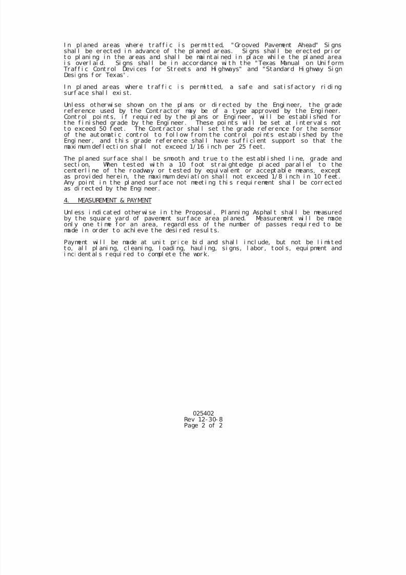
7/25/2019 City Standard Construction Specifications
http://slidepdf.com/reader/full/city-standard-construction-specifications 95/511
025402Rev 12-30- 8Page 2 of 2
I n pl aned areas wher e t r af f i c i s per mi t t ed, "Gr ooved Pavement Ahead" Si gnsshal l be er ect ed i n advance of t he pl aned ar eas. Si gns shal l be er ect ed pr i ort o pl ani ng i n the ar eas and shal l be mai nt ai ned i n pl ace whi l e the pl aned areai s over l ai d. Si gns shal l be i n accor dance wi t h t he "Texas Manual on Uni f orm
Traf f i c Cont r ol Devi ces f or St r eet s and Hi ghways" and "Standar d Hi ghway Si gnDesi gns f or Texas" .
I n pl aned ar eas wher e t r af f i c i s per mi t t ed, a saf e and sat i sf act or y ri di ngsurf ace shal l exi st.
Unl ess other wi se shown on t he pl ans or di r ected by the Engi neer, t he gr ader ef erence used by t he Cont r act or may be of a type appr oved by t he Engi neer.Cont r ol poi nt s, i f r equi r ed by t he pl ans or Engi neer , wi l l be est abl i shed f ort he f i ni shed gr ade by t he Engi neer . These poi nt s wi l l be set at i nt er val s nott o exceed 50 f eet . The Cont r act or shal l set t he gr ade r ef er ence f or t he sensorof t he aut omat i c cont r ol t o f ol l ow f r om t he cont r ol poi nt s est abl i shed by theEngi neer , and t hi s gr ade r ef er ence shal l have suf f i ci ent support so that t hemaxi mum def l ect i on shal l not exceed 1/ 16 i nch per 25 f eet .
The pl aned sur f ace shal l be smooth and t r ue t o t he est abl i shed l i ne, grade andsect i on, When t est ed wi t h a 10 f oot st r ai ght edge pl aced par al l el t o t hecent erl i ne of t he r oadway or t est ed by equi val ent or accept abl e means, exceptas provi ded her ei n, t he maxi mum devi at i on shal l not exceed 1/ 8 i nch i n 10 f eet .
Any poi nt i n t he pl aned sur f ace not meet i ng t hi s r equi r ement shal l be corr ect edas di r ect ed by the Engi neer .
4. MEASUREMENT & PAYMENT
Unl ess i ndi cat ed other wi se i n t he Proposal , Pl anni ng Asphal t shal l be measuredby t he squar e yard of pavement sur f ace area pl aned. Measurement wi l l be madeonl y one t i me f or an area, r egardl ess of t he number of passes requi r ed t o bemade i n or der t o achi eve t he desi r ed resul t s.
Payment wi l l be made at uni t pr i ce bi d and shal l i ncl ude, but not be l i mi t edt o, al l pl ani ng, cl eani ng, l oadi ng, haul i ng, si gns, l abor , t ool s, equi pment andi nci dent al s r equi r ed to compl et e the wor k.
7/25/2019 City Standard Construction Specifications
http://slidepdf.com/reader/full/city-standard-construction-specifications 96/511
025404Page 1 of 1
Rev. 10-30-2014
SECTION 025404
ASPHALTS, OILS AND EMULSIONS
1. DESCRIPTION
This specification shall govern all work for asphalt cement, cut-back and emulsified asphalts,
performance-graded asphalt binders, and other miscellaneous asphaltic materials required to
complete the project.
2. MATERIALS
When tested according to Texas Department of Transportation Test Methods, the various materials
shall meet the applicable requirements of TxDOT Specification Item 300, “Asphalts, Oils, and
Emulsions” (Latest Edition).
3. STORAGE, HEATING AND APPLICATION TEMPERATURES
Store and apply asphaltic materials in accordance with TxDOT Item 300 (Latest Edition) at the
lowest temperature yielding satisfactory results. Follow the manufacturer’s instructions for any
agitation requirements in storage and in application and storage temperatures.
4. MEASUREMENT AND PAYMENT
Unless otherwise specified on the Bid Form, asphalts, oils and emulsions shall not be measured and
paid for separately, but shall be considered subsidiary to the appropriate bid item.
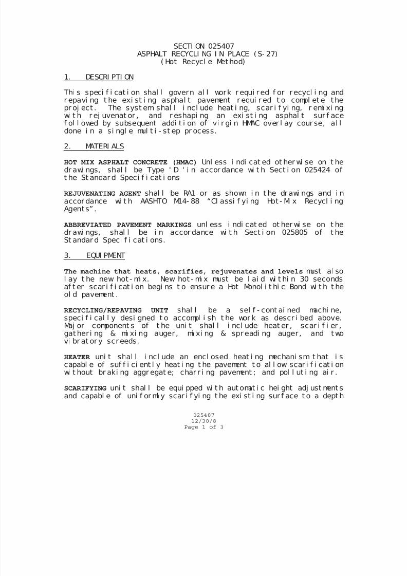
7/25/2019 City Standard Construction Specifications
http://slidepdf.com/reader/full/city-standard-construction-specifications 97/511
02540712/30/8
Page 1 of 3
SECTI ON 025407ASPHALT RECYCLI NG I N PLACE (S- 27)
( Hot Recycl e Met hod)
1. DESCRI PTI ON
Thi s speci f i cat i on shal l govern al l work r equi r ed f or r ecycl i ng andr epavi ng t he exi st i ng asphal t pavement r equi r ed t o compl et e thepr oj ect . The syst em shal l i ncl ude heat i ng, scar i f yi ng, r emi xi ngwi t h r ej uvenat or , and r eshapi ng an exi st i ng asphal t sur f acef ol l owed by subsequent addi t i on of vi r gi n HMAC over l ay cour se, al ldone i n a si ngl e mul t i - st ep pr ocess.
2. MATERI ALS
HOT MIX ASPHALT CONCRETE (HMAC) Unl ess i ndi cat ed ot her wi se on t hedr awi ngs, shal l be Type ' D ' i n accor dance wi t h Sect i on 025424 oft he St andar d Speci f i cat i ons
REJUVENATING AGENT shal l be RA1 or as shown i n t he dr awi ngs and i naccor dance wi t h AASHTO M14- 88 “Cl assi f yi ng Hot - Mi x Recycl i ngAgents” .
ABBREVIATED PAVEMENT MARKINGS unl ess i ndi cat ed ot her wi se on t hedr awi ngs, shal l be i n accor dance wi t h Sect i on 025805 of t heSt andar d Speci f i cat i ons.
3. EQUI PMENT
The machine that heats, scarifies, rejuvenates and levels must al sol ay t he new hot - mi x. New hot - mi x must be l ai d wi t hi n 30 secondsaf t er scar i f i cat i on begi ns t o ensur e a Hot Monol i t hi c Bond wi t h t heol d pavement .
RECYCLING/REPAVING UNIT shal l be a sel f - cont ai ned machi ne,speci f i cal l y desi gned t o accompl i sh t he wor k as descr i bed above.Maj or component s of t he uni t shal l i ncl ude heat er , scar i f i er ,gat her i ng & mi xi ng auger , mi xi ng & spr eadi ng auger , and t wovi br at or y screeds.
HEATER uni t shal l i ncl ude an encl osed heat i ng mechani sm t hat i s
capabl e of suf f i ci ent l y heat i ng t he pavement t o al l ow scar i f i cat i onwi t hout br aki ng aggr egat e; char r i ng pavement ; and pol l ut i ng ai r .
SCARIFYING uni t shal l be equi pped wi t h aut omat i c hei ght adj ust ment sand capabl e of uni f or ml y scar i f yi ng t he exi st i ng sur f ace t o a dept h
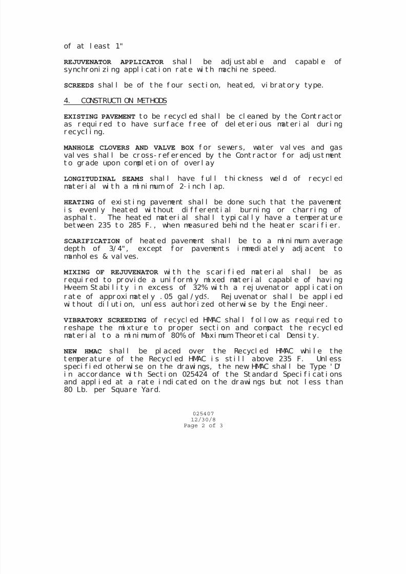
7/25/2019 City Standard Construction Specifications
http://slidepdf.com/reader/full/city-standard-construction-specifications 98/511
02540712/30/8
Page 2 of 3
of at l east 1"
REJUVENATOR APPLICATOR shal l be adj ust abl e and capabl e ofsynchr oni zi ng appl i cat i on r at e wi t h machi ne speed.
SCREEDS shal l be of t he f our sect i on, heat ed, vi br at or y type.
4. CONSTRUCTI ON METHODS
EXISTING PAVEMENT t o be r ecycl ed shal l be cl eaned by the Cont r act oras r equi r ed t o have sur f ace f r ee of del et er i ous mat er i al dur i ngr ecycl i ng.
MANHOLE CLOVERS AND VALVE BOX f or sewer s, water val ves and gasval ves shal l be cr oss- r ef er enced by t he Cont r act or f or adj ust mentt o gr ade upon compl et i on of over l ay
LONGITUDINAL SEAMS shal l have f ul l t hi ckness wel d of r ecycl edmat er i al wi t h a mi ni mum of 2- i nch l ap.
HEATING of exi st i ng pavement shal l be done such t hat t he pavementi s evenl y heat ed wi t hout di f f er ent i al bur ni ng or char r i ng ofasphal t . The heat ed mat er i al shal l t ypi cal l y have a t emper at ur ebetween 235 t o 285 F. , when measur ed behi nd t he heat er scar i f i er .
SCARIFICATION of heat ed pavement shal l be t o a mi ni mum averagedept h of 3/ 4" , except f or pavement s i mmedi atel y adj acent t omanhol es & val ves.
MIXING OF REJUVENATOR wi t h t he scar i f i ed mat er i al shal l be asr equi r ed to pr ovi de a uni f or ml y mi xed mat er i al capabl e of havi ngHveem St abi l i t y i n excess of 32% wi t h a r ej uvenat or appl i cat i on
r at e of appr oxi mat el y . 05 gal / yd. Rej uvenat or shal l be appl i edwi t hout di l ut i on, unl ess aut hor i zed ot her wi se by t he Engi neer .
VIBRATORY SCREEDING of r ecycl ed HMAC shal l f ol l ow as r equi r ed t or eshape t he mi xt ur e t o pr oper sect i on and compact t he r ecycl edmat er i al t o a mi ni mum of 80% of Maxi mum Theor et i cal Densi t y.
NEW HMAC shal l be pl aced over t he Recycl ed HMAC whi l e t het emper atur e of t he Recycl ed HMAC i s st i l l above 235 F. Unl essspeci f i ed otherwi se on t he dr awi ngs, t he new HMAC shal l be Type ' D'i n accor dance wi t h Sect i on 025424 of t he St andar d Speci f i cat i onsand appl i ed at a rat e i ndi cat ed on t he dr awi ngs but not l ess t han80 Lb. per Square Yard.
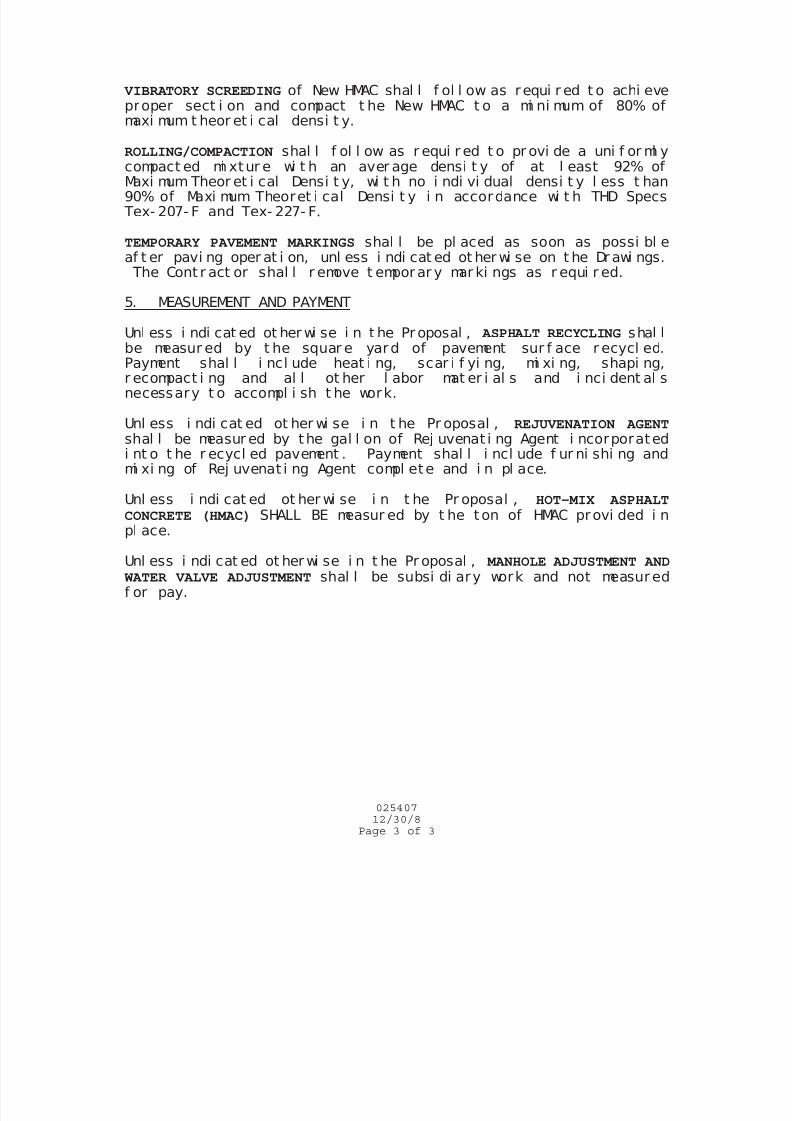
7/25/2019 City Standard Construction Specifications
http://slidepdf.com/reader/full/city-standard-construction-specifications 99/511
02540712/30/8
Page 3 of 3
VIBRATORY SCREEDING of New HMAC shal l f ol l ow as requi r ed t o achi eveproper sect i on and compact t he New HMAC t o a mi ni mum of 80% ofmaxi mum t heor et i cal densi t y.
ROLLING/COMPACTION shal l f ol l ow as r equi r ed t o pr ovi de a uni f or ml ycompact ed mi xtur e wi t h an aver age densi t y of at l east 92% ofMaxi mum Theor et i cal Densi t y, wi t h no i ndi vi dual densi t y l ess t han90% of Maxi mum Theoret i cal Densi t y i n accordance wi t h THD Specs Tex- 207- F and Tex- 227- F.
TEMPORARY PAVEMENT MARKINGS shal l be pl aced as soon as possi bl eaf t er pavi ng oper at i on, unl ess i ndi cat ed ot her wi se on t he Dr awi ngs. The Cont r act or shal l r emove t emporar y mar ki ngs as r equi r ed.
5. MEASUREMENT AND PAYMENT
Unl ess i ndi cat ed ot her wi se i n t he Pr oposal , ASPHALT RECYCLING shal l
be measur ed by t he squar e yard of pavement sur f ace r ecycl ed.Payment shal l i ncl ude heat i ng, scar i f yi ng, mi xi ng, shapi ng,r ecompact i ng and al l ot her l abor mat er i al s and i nci dent al snecessary t o accompl i sh t he work.
Unl ess i ndi cat ed ot her wi se i n t he Pr oposal , REJUVENATION AGENTshal l be measur ed by the gal l on of Rej uvenat i ng Agent i ncorporatedi nt o t he r ecycl ed pavement . Payment shal l i ncl ude f ur ni shi ng andmi xi ng of Rej uvenat i ng Agent compl ete and i n pl ace.
Unl ess i ndi cat ed ot her wi se i n t he Pr oposal , HOT-MIX ASPHALT
CONCRETE (HMAC) SHALL BE measur ed by t he t on of HMAC provi ded i n
pl ace.
Unl ess i ndi cat ed ot her wi se i n t he Pr oposal , MANHOLE ADJUSTMENT AND WATER VALVE ADJUSTMENT shal l be subsi di ary work and not measur edf or pay.
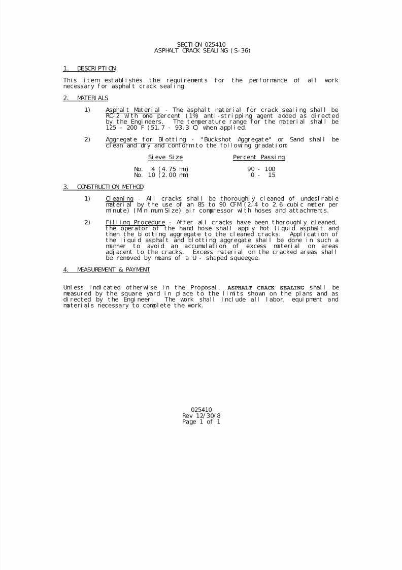
7/25/2019 City Standard Construction Specifications
http://slidepdf.com/reader/full/city-standard-construction-specifications 100/511
025410Rev 12/ 30/ 8Page 1 of 1
SECTI ON 025410 ASPHALT CRACK SEALI NG ( S- 36)
1. DESCRI PTI ON
Thi s i t em est abl i shes t he r equi r ement s f or t he per f ormance of al l worknecessar y f or asphal t crack seal i ng.
2. MATERI ALS
1) Asphal t Mat er i al - The asphal t mat er i al f or crack seal i ng shal l beRC- 2 wi t h one per cent ( 1%) ant i - st r i ppi ng agent added as di r ect edby t he Engi neers. The t emper atur e r ange f or t he mater i al shal l be125 - 200 F ( 51. 7 - 93. 3 C) when appl i ed.
2) Aggr egat e f or Bl ott i ng - " Buckshot Aggr egat e" or Sand shal l becl ean and dr y and conf or m t o the f ol l owi ng gr adat i on:
Si eve Si ze Per cent Passi ng
No. 4 ( 4. 75 mm) 90 - 100No. 10 ( 2. 00 mm) 0 - 15
3. CONSTRUCTI ON METHOD
1) Cl eani ng - Al l cracks shal l be t horoughl y cl eaned of undesi r abl emat er i al by t he use of an 85 to 90 CFM ( 2. 4 to 2. 6 cubi c met er permi nut e) ( Mi ni mum Si ze) ai r compr essor wi t h hoses and at t achment s.
2) Fi l l i ng Pr ocedur e - Af t er al l cr acks have been t hor oughl y cl eaned,t he oper ator of t he hand hose shal l appl y hot l i qui d asphal t andt hen t he bl ot t i ng aggr egat e t o t he cl eaned cracks. Appl i cat i on oft he l i qui d asphal t and bl ott i ng aggr egat e shal l be done i n such amanner t o avoi d an accumul at i on of excess mater i al on areasadj acent t o t he cr acks. Excess mater i al on t he cr acked ar eas shal lbe removed by means of a U - shaped squeegee.
4. MEASUREMENT & PAYMENT
Unl ess i ndi cat ed ot her wi se i n t he Proposal , ASPHALT CRACK SEALING shal l bemeasured by t he square yard i n pl ace t o the l i mi t s shown on t he pl ans and asdi r ect ed by t he Engi neer . The work shal l i ncl ude al l l abor, equi pment andmateri al s necessary t o compl ete the work.
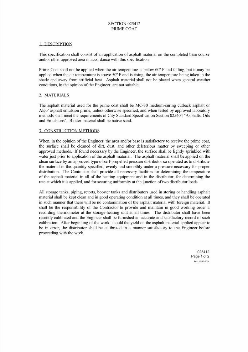
7/25/2019 City Standard Construction Specifications
http://slidepdf.com/reader/full/city-standard-construction-specifications 101/511
025412
Page 1 of 2
Rev. 10-30-2014
SECTION 025412
PRIME COAT
1. DESCRIPTION
This specification shall consist of an application of asphalt material on the completed base courseand/or other approved area in accordance with this specification.
Prime Coat shall not be applied when the air temperature is below 60º F and falling, but it may be
applied when the air temperature is above 50º F and is rising; the air temperature being taken in the
shade and away from artificial heat. Asphalt material shall not be placed when general weather
conditions, in the opinion of the Engineer, are not suitable.
2. MATERIALS
The asphalt material used for the prime coat shall be MC-30 medium-curing cutback asphalt or
AE-P asphalt emulsion prime, unless otherwise specified, and when tested by approved laboratorymethods shall meet the requirements of City Standard Specification Section 025404 "Asphalts, Oils
and Emulsions". Blotter material shall be native sand.
3. CONSTRUCTION METHODS
When, in the opinion of the Engineer, the area and/or base is satisfactory to receive the prime coat,
the surface shall be cleaned of dirt, dust, and other deleterious matter by sweeping or other
approved methods. If found necessary by the Engineer, the surface shall be lightly sprinkled with
water just prior to application of the asphalt material. The asphalt material shall be applied on the
clean surface by an approved type of self-propelled pressure distributor so operated as to distribute
the material in the quantity specified, evenly and smoothly under a pressure necessary for properdistribution. The Contractor shall provide all necessary facilities for determining the temperature
of the asphalt material in all of the heating equipment and in the distributor, for determining the
rate at which it is applied, and for securing uniformity at the junction of two distributor loads.
All storage tanks, piping, retorts, booster tanks and distributors used in storing or handling asphalt
material shall be kept clean and in good operating condition at all times, and they shall be operated
in such manner that there will be no contamination of the asphalt material with foreign material. It
shall be the responsibility of the Contractor to provide and maintain in good working order a
recording thermometer at the storage-heating unit at all times. The distributor shall have been
recently calibrated and the Engineer shall be furnished an accurate and satisfactory record of such
calibration. After beginning of the work, should the yield on the asphalt material applied appear to be in error, the distributor shall be calibrated in a manner satisfactory to the Engineer before
proceeding with the work.
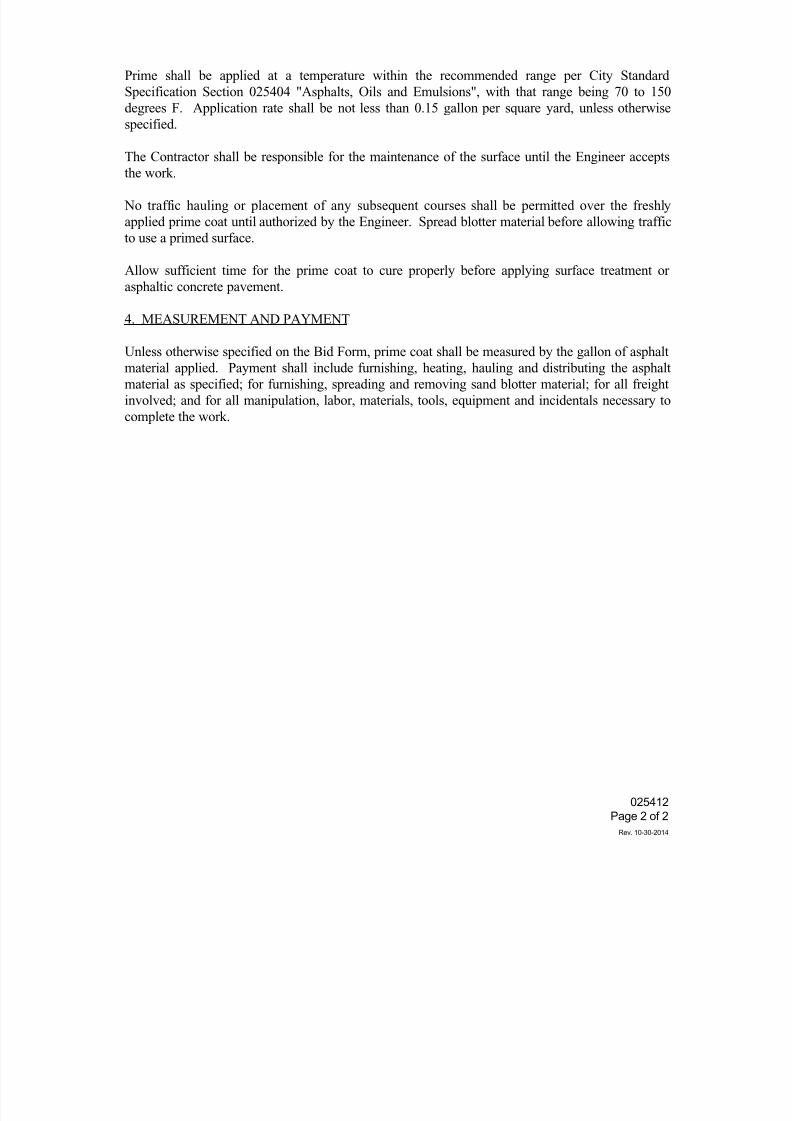
7/25/2019 City Standard Construction Specifications
http://slidepdf.com/reader/full/city-standard-construction-specifications 102/511
025412
Page 2 of 2
Rev. 10-30-2014
Prime shall be applied at a temperature within the recommended range per City Standard
Specification Section 025404 "Asphalts, Oils and Emulsions", with that range being 70 to 150
degrees F. Application rate shall be not less than 0.15 gallon per square yard, unless otherwise
specified.
The Contractor shall be responsible for the maintenance of the surface until the Engineer accepts
the work.
No traffic hauling or placement of any subsequent courses shall be permitted over the freshly
applied prime coat until authorized by the Engineer. Spread blotter material before allowing traffic
to use a primed surface.
Allow sufficient time for the prime coat to cure properly before applying surface treatment or
asphaltic concrete pavement.
4. MEASUREMENT AND PAYMENT
Unless otherwise specified on the Bid Form, prime coat shall be measured by the gallon of asphaltmaterial applied. Payment shall include furnishing, heating, hauling and distributing the asphalt
material as specified; for furnishing, spreading and removing sand blotter material; for all freight
involved; and for all manipulation, labor, materials, tools, equipment and incidentals necessary to
complete the work.
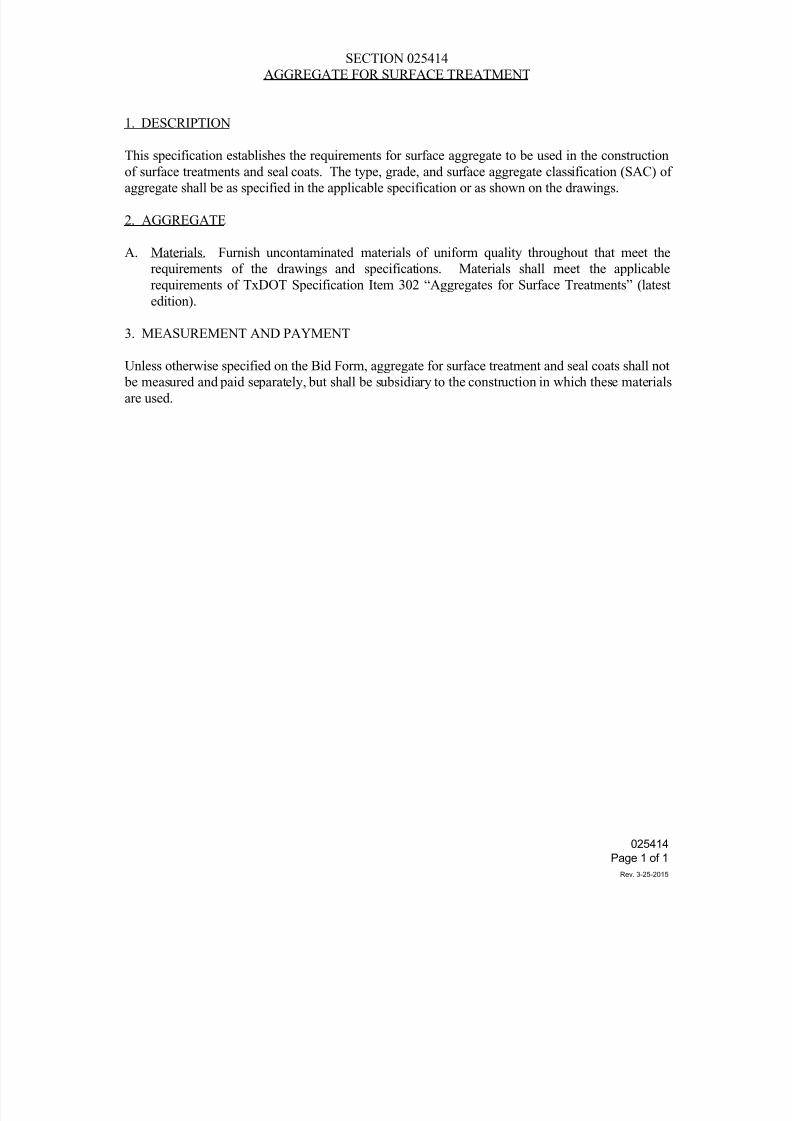
7/25/2019 City Standard Construction Specifications
http://slidepdf.com/reader/full/city-standard-construction-specifications 103/511
SECTION 025414
AGGREGATE FOR SURFACE TREATMENT
1. DESCRIPTION
This specification establishes the requirements for surface aggregate to be used in the construction
of surface treatments and seal coats. The type, grade, and surface aggregate classification (SAC) ofaggregate shall be as specified in the applicable specification or as shown on the drawings.
2. AGGREGATE
A. Materials. Furnish uncontaminated materials of uniform quality throughout that meet the
requirements of the drawings and specifications. Materials shall meet the applicable
requirements of TxDOT Specification Item 302 “Aggregates for Surface Treatments” (latest
edition).
3. MEASUREMENT AND PAYMENT
Unless otherwise specified on the Bid Form, aggregate for surface treatment and seal coats shall not
be measured and paid separately, but shall be subsidiary to the construction in which these materials
are used.
025414
Page 1 of 1
Rev. 3-25-2015
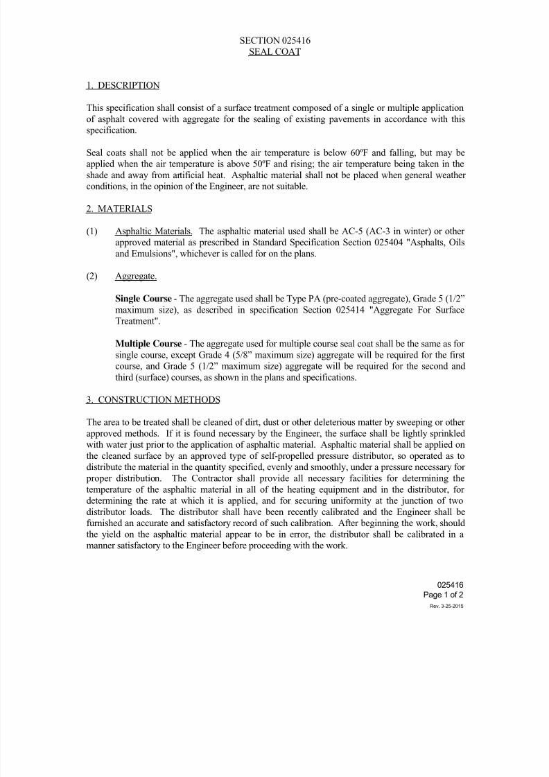
7/25/2019 City Standard Construction Specifications
http://slidepdf.com/reader/full/city-standard-construction-specifications 104/511
SECTION 025416
SEAL COAT
1. DESCRIPTION
This specification shall consist of a surface treatment composed of a single or multiple application
of asphalt covered with aggregate for the sealing of existing pavements in accordance with thisspecification.
Seal coats shall not be applied when the air temperature is below 60ºF and falling, but may be
applied when the air temperature is above 50ºF and rising; the air temperature being taken in the
shade and away from artificial heat. Asphaltic material shall not be placed when general weather
conditions, in the opinion of the Engineer, are not suitable.
2. MATERIALS
(1) Asphaltic Materials. The asphaltic material used shall be AC-5 (AC-3 in winter) or other
approved material as prescribed in Standard Specification Section 025404 "Asphalts, Oilsand Emulsions", whichever is called for on the plans.
(2) Aggregate.
Single Course - The aggregate used shall be Type PA (pre-coated aggregate), Grade 5 (1/2”
maximum size), as described in specification Section 025414 "Aggregate For Surface
Treatment".
Multiple Course - The aggregate used for multiple course seal coat shall be the same as for
single course, except Grade 4 (5/8” maximum size) aggregate will be required for the first
course, and Grade 5 (1/2” maximum size) aggregate will be required for the second andthird (surface) courses, as shown in the plans and specifications.
3. CONSTRUCTION METHODS
The area to be treated shall be cleaned of dirt, dust or other deleterious matter by sweeping or other
approved methods. If it is found necessary by the Engineer, the surface shall be lightly sprinkled
with water just prior to the application of asphaltic material. Asphaltic material shall be applied on
the cleaned surface by an approved type of self-propelled pressure distributor, so operated as to
distribute the material in the quantity specified, evenly and smoothly, under a pressure necessary for
proper distribution. The Contractor shall provide all necessary facilities for determining the
temperature of the asphaltic material in all of the heating equipment and in the distributor, fordetermining the rate at which it is applied, and for securing uniformity at the junction of two
distributor loads. The distributor shall have been recently calibrated and the Engineer shall be
furnished an accurate and satisfactory record of such calibration. After beginning the work, should
the yield on the asphaltic material appear to be in error, the distributor shall be calibrated in a
manner satisfactory to the Engineer before proceeding with the work.
025416
Page 1 of 2
Rev. 3-25-2015
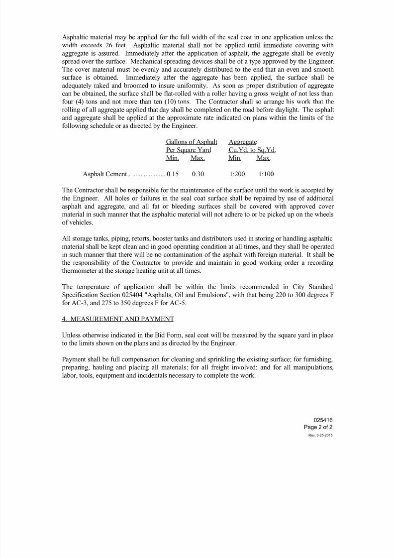
7/25/2019 City Standard Construction Specifications
http://slidepdf.com/reader/full/city-standard-construction-specifications 105/511
Asphaltic material may be applied for the full width of the seal coat in one application unless the
width exceeds 26 feet. Asphaltic material shall not be applied until immediate covering with
aggregate is assured. Immediately after the application of asphalt, the aggregate shall be evenly
spread over the surface. Mechanical spreading devices shall be of a type approved by the Engineer.
The cover material must be evenly and accurately distributed to the end that an even and smooth
surface is obtained. Immediately after the aggregate has been applied, the surface shall be
adequately raked and broomed to insure uniformity. As soon as proper distribution of aggregatecan be obtained, the surface shall be flat-rolled with a roller having a gross weight of not less than
four (4) tons and not more than ten (10) tons. The Contractor shall so arrange his work that the
rolling of all aggregate applied that day shall be completed on the road before daylight. The asphalt
and aggregate shall be applied at the approximate rate indicated on plans within the limits of the
following schedule or as directed by the Engineer.
Gallons of Asphalt Aggregate
Per Square Yard Cu.Yd. to Sq.Yd.
Min. Max. Min. Max.
Asphalt Cement .. .................... 0.15 0.30 1:200 1:100
The Contractor shall be responsible for the maintenance of the surface until the work is accepted by
the Engineer. All holes or failures in the seal coat surface shall be repaired by use of additional
asphalt and aggregate, and all fat or bleeding surfaces shall be covered with approved cover
material in such manner that the asphaltic material will not adhere to or be picked up on the wheels
of vehicles.
All storage tanks, piping, retorts, booster tanks and distributors used in storing or handling asphaltic
material shall be kept clean and in good operating condition at all times, and they shall be operated
in such manner that there will be no contamination of the asphalt with foreign material. It shall be
the responsibility of the Contractor to provide and maintain in good working order a recordingthermometer at the storage heating unit at all times.
The temperature of application shall be within the limits recommended in City Standard
Specification Section 025404 "Asphalts, Oil and Emulsions", with that being 220 to 300 degrees F
for AC-3, and 275 to 350 degrees F for AC-5.
4. MEASUREMENT AND PAYMENT
Unless otherwise indicated in the Bid Form, seal coat will be measured by the square yard in place
to the limits shown on the plans and as directed by the Engineer.
Payment shall be full compensation for cleaning and sprinkling the existing surface; for furnishing,
preparing, hauling and placing all materials; for all freight involved; and for all manipulations,
labor, tools, equipment and incidentals necessary to complete the work.
025416
Page 2 of 2
Rev. 3-25-2015
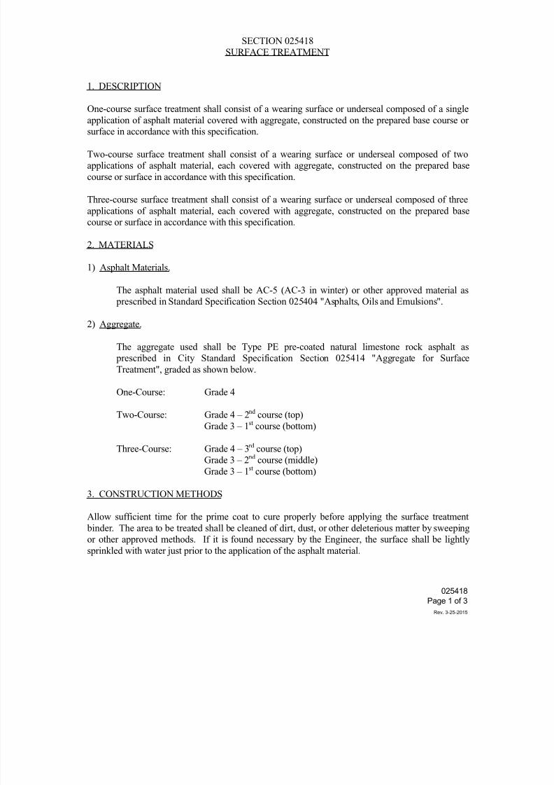
7/25/2019 City Standard Construction Specifications
http://slidepdf.com/reader/full/city-standard-construction-specifications 106/511
SECTION 025418
SURFACE TREATMENT
1. DESCRIPTION
One-course surface treatment shall consist of a wearing surface or underseal composed of a single
application of asphalt material covered with aggregate, constructed on the prepared base course orsurface in accordance with this specification.
Two-course surface treatment shall consist of a wearing surface or underseal composed of two
applications of asphalt material, each covered with aggregate, constructed on the prepared base
course or surface in accordance with this specification.
Three-course surface treatment shall consist of a wearing surface or underseal composed of three
applications of asphalt material, each covered with aggregate, constructed on the prepared base
course or surface in accordance with this specification.
2. MATERIALS
1) Asphalt Materials.
The asphalt material used shall be AC-5 (AC-3 in winter) or other approved material as
prescribed in Standard Specification Section 025404 "Asphalts, Oils and Emulsions".
2) Aggregate.
The aggregate used shall be Type PE pre-coated natural limestone rock asphalt as
prescribed in City Standard Specification Section 025414 "Aggregate for Surface
Treatment", graded as shown below.
One-Course: Grade 4
Two-Course: Grade 4 – 2nd course (top)
Grade 3 – 1st course (bottom)
Three-Course: Grade 4 – 3rd course (top)
Grade 3 – 2nd course (middle)
Grade 3 – 1st course (bottom)
3. CONSTRUCTION METHODS
Allow sufficient time for the prime coat to cure properly before applying the surface treatment
binder. The area to be treated shall be cleaned of dirt, dust, or other deleterious matter by sweeping
or other approved methods. If it is found necessary by the Engineer, the surface shall be lightly
sprinkled with water just prior to the application of the asphalt material.
025418
Page 1 of 3
Rev. 3-25-2015
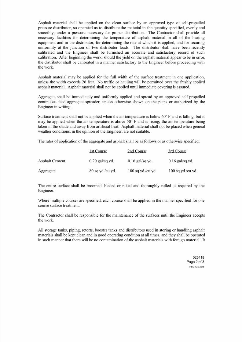
7/25/2019 City Standard Construction Specifications
http://slidepdf.com/reader/full/city-standard-construction-specifications 107/511
Asphalt material shall be applied on the clean surface by an approved type of self-propelled
pressure distributor, so operated as to distribute the material in the quantity specified, evenly and
smoothly, under a pressure necessary for proper distribution. The Contractor shall provide all
necessary facilities for determining the temperature of asphalt material in all of the heating
equipment and in the distributor, for determining the rate at which it is applied, and for securing
uniformity at the junction of two distributor loads. The distributor shall have been recently
calibrated and the Engineer shall be furnished an accurate and satisfactory record of suchcalibration. After beginning the work, should the yield on the asphalt material appear to be in error,
the distributor shall be calibrated in a manner satisfactory to the Engineer before proceeding with
the work.
Asphalt material may be applied for the full width of the surface treatment in one application,
unless the width exceeds 26 feet. No traffic or hauling will be permitted over the freshly applied
asphalt material. Asphalt material shall not be applied until immediate covering is assured.
Aggregate shall be immediately and uniformly applied and spread by an approved self-propelled
continuous feed aggregate spreader, unless otherwise shown on the plans or authorized by the
Engineer in writing.
Surface treatment shall not be applied when the air temperature is below 60º F and is falling, but it
may be applied when the air temperature is above 50º F and is rising; the air temperature being
taken in the shade and away from artificial heat. Asphalt material shall not be placed when general
weather conditions, in the opinion of the Engineer, are not suitable.
The rates of application of the aggregate and asphalt shall be as follows or as otherwise specified:
1st Course 2nd Course 3rd Course
Asphalt Cement 0.20 gal/sq.yd. 0.16 gal/sq.yd. 0.16 gal/sq.yd.
Aggregate 80 sq.yd./cu.yd. 100 sq.yd./cu.yd. 100 sq.yd./cu.yd.
The entire surface shall be broomed, bladed or raked and thoroughly rolled as required by the
Engineer.
Where multiple courses are specified, each course shall be applied in the manner specified for one
course surface treatment.
The Contractor shall be responsible for the maintenance of the surfaces until the Engineer acceptsthe work.
All storage tanks, piping, retorts, booster tanks and distributors used in storing or handling asphalt
materials shall be kept clean and in good operating condition at all times, and they shall be operated
in such manner that there will be no contamination of the asphalt materials with foreign material. It
025418
Page 2 of 3
Rev. 3-25-2015
7/25/2019 City Standard Construction Specifications
http://slidepdf.com/reader/full/city-standard-construction-specifications 108/511
shall be the responsibility of the Contractor to provide and maintain in good working order a
recording thermometer at the storage heating unit at all times. The Engineer will select the
temperature of application based on the temperature-viscosity relationship that will permit
application of the asphalt within the limits recommended in Standard Specification Section 025404
"Asphalts, Oils and Emulsions", with that being 220 to 300 degrees F for AC-3, and 275 to 350
degrees F for AC-5.
4. MEASUREMENT AND PAYMENT
Unless otherwise specified on the Bid Form, surface treatment as an integral part of the final
structural pavement section shall be measured in place by the square yard of surface area to the
limits shown on the plans and as directed by the Engineer.
Payment shall be full compensation for all labor, materials, tools, equipment and incidentals
necessary to furnish and place the type of surface treatment called for.
Surface treatment for temporary pavements shall not be measured and paid separately, but shall be
subsidiary to the construction in which the surface treatment is used.
025418
Page 3 of 3
Rev. 3-25-2015
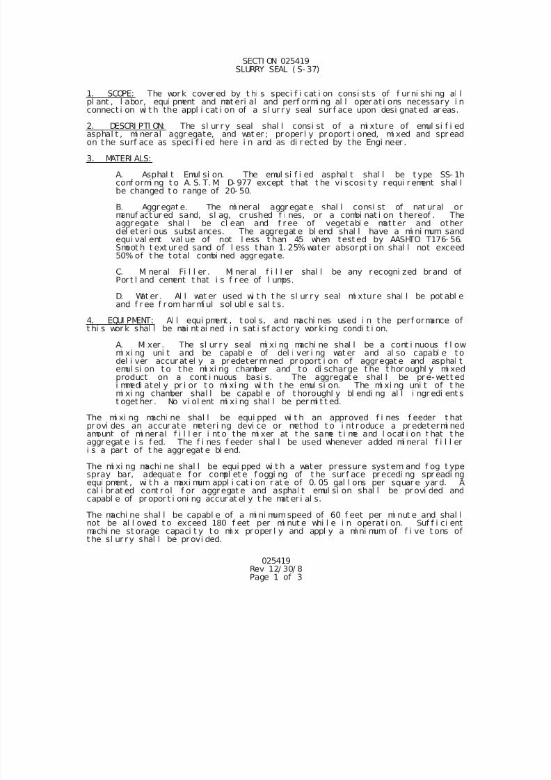
7/25/2019 City Standard Construction Specifications
http://slidepdf.com/reader/full/city-standard-construction-specifications 109/511
025419Rev 12/ 30/ 8Page 1 of 3
SECTI ON 025419 SLURRY SEAL ( S- 37)
1. SCOPE: The wor k cover ed by t hi s speci f i cat i on consi st s of f ur ni shi ng al lpl ant , l abor, equi pment and mat eri al and perf ormi ng al l oper at i ons necessary i nconnect i on wi t h the appl i cat i on of a sl ur r y seal sur f ace upon desi gnat ed ar eas.
2. DESCRI PTI ON: The sl ur r y seal shal l consi st of a mi xture of emul si f i edasphal t , mi ner al aggr egate, and wat er ; pr oper l y pr oport i oned, mi xed and spr eadon t he surf ace as speci f i ed here i n and as di r ect ed by the Engi neer .
3. MATERI ALS:
A. Asphal t Emul si on. The emul si f i ed asphal t shal l be t ype SS- 1hconf ormi ng t o A. S. T. M. D- 977 except t hat t he vi scosi t y r equi r ement shal lbe changed t o range of 20- 50.
B. Aggr egat e. The mi ner al aggr egat e shal l consi st of nat ur al ormanuf act ur ed sand, sl ag, cr ushed f i nes, or a combi nat i on t hereof . Theaggr egate shal l be cl ean and f r ee of vegetabl e matt er and otherdel eter i ous subst ances. The aggregat e bl end shal l have a mi ni mum sandequi val ent val ue of not l ess t han 45 when test ed by AASHTO T176- 56.
Smoot h t ext ur ed sand of l ess t han 1. 25% water absorpt i on shal l not exceed50% of t he total combi ned aggr egate.
C. Mi ner al Fi l l er . Mi ner al f i l l er shal l be any r ecogni zed br and ofPor t l and cement t hat i s f r ee of l umps.
D. Wat er . Al l wat er used wi t h t he sl ur r y seal mi xture shal l be pot abl eand f r ee f r om har mf ul sol ubl e sal t s.
4. EQUI PMENT: Al l equi pment , t ool s, and machi nes used i n t he perf ormance oft hi s wor k shal l be mai nt ai ned i n sat i sf actor y wor ki ng condi t i on.
A. Mi xer . The sl ur r y seal mi xi ng machi ne shal l be a cont i nuous f l owmi xi ng uni t and be capabl e of del i ver i ng wat er and al so capabl e todel i ver accur at el y a pr edeter mi ned pr oport i on of aggr egat e and asphal t
emul si on t o t he mi xi ng chamber and to di scharge t he t hor oughl y mi xedproduct on a cont i nuous basi s. The aggregat e shal l be pr e- wett edi mmedi atel y pr i or t o mi xi ng wi t h t he emul si on. The mi xi ng uni t of t hemi xi ng chamber shal l be capabl e of t horoughl y bl endi ng al l i ngr edi ent st oget her . No vi ol ent mi xi ng shal l be per mi t t ed.
The mi xi ng machi ne shal l be equi pped wi t h an approved f i nes f eeder t hatpr ovi des an accur ate meteri ng devi ce or method t o i ntr oduce a pr edetermi nedamount of mi ner al f i l l er i nt o the mi xer at t he same t i me and l ocat i on t hat t heaggr egat e i s f ed. The f i nes f eeder shal l be used whenever added mi neral f i l l eri s a par t of t he aggr egat e bl end.
The mi xi ng machi ne shal l be equi pped wi t h a water pressure syst em and f og t ypespray bar, adequat e f or compl et e f oggi ng of t he sur f ace pr ecedi ng spr eadi ngequi pment , wi t h a maxi mum appl i cat i on r at e of 0. 05 gal l ons per squar e yar d. A
cal i br at ed cont r ol f or aggr egat e and asphal t emul si on shal l be pr ovi ded andcapabl e of pr opor t i oni ng accur at el y t he mat er i al s.
The machi ne shal l be capabl e of a mi ni mumspeed of 60 f eet per mi nut e and shal lnot be al l owed t o exceed 180 f eet per mi nut e whi l e i n operat i on. Suf f i ci entmachi ne st orage capaci t y t o mi x pr oper l y and appl y a mi ni mum of f i ve t ons oft he sl ur r y shal l be pr ovi ded.
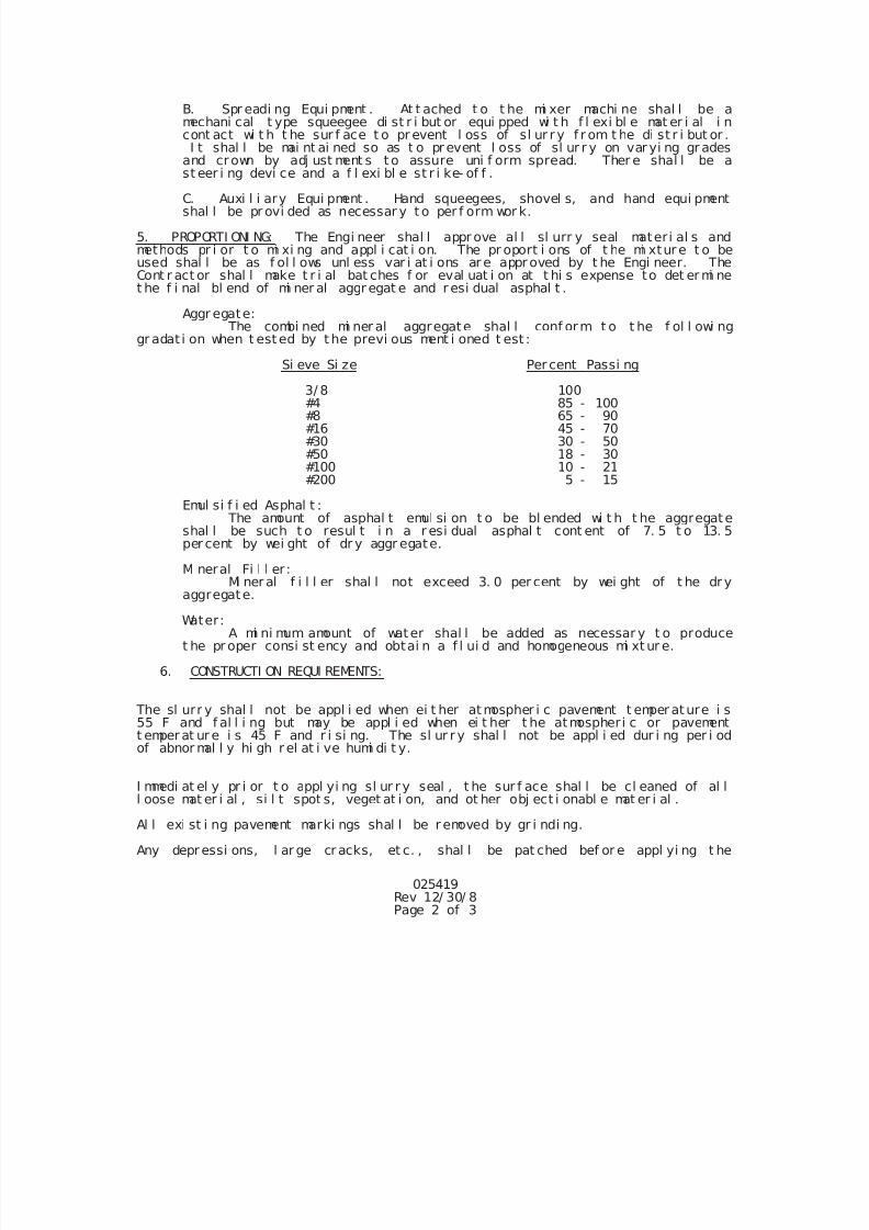
7/25/2019 City Standard Construction Specifications
http://slidepdf.com/reader/full/city-standard-construction-specifications 110/511
025419Rev 12/ 30/ 8Page 2 of 3
B. Spr eadi ng Equi pment . At t ached t o t he mi xer machi ne shal l be amechani cal t ype squeegee di st r i but or equi pped wi t h f l exi bl e mat er i al i ncont act wi t h t he sur f ace t o pr event l oss of sl ur r y f r om t he di st r i but or .I t shal l be mai nt ai ned so as t o pr event l oss of sl ur r y on var yi ng gr ades
and crown by adj ust ment s t o assure uni f orm spread. Ther e shal l be ast eer i ng devi ce and a f l exi bl e st r i ke- of f .
C. Auxi l i ary Equi pment . Hand squeegees, shovel s, and hand equi pmentshal l be pr ovi ded as necessar y t o per f orm wor k.
5. PROPORTI ONI NG: The Engi neer shal l appr ove al l sl urr y seal materi al s andmethods pr i or t o mi xi ng and appl i cat i on. The pr oport i ons of t he mi xtur e t o beused shal l be as f ol l ows unl ess var i at i ons ar e appr oved by t he Engi neer. TheCont r act or shal l make t r i al bat ches f or eval uat i on at t hi s expense to det er mi net he f i nal bl end of mi ner al aggr egat e and r esi dual asphal t .
Aggr egate: The combi ned mi ner al aggregate shal l conf orm t o t he f ol l owi ng
gr adat i on when t est ed by t he previ ous ment i oned t est :
Si eve Si ze Per cent Passi ng
3/ 8 100#4 85 - 100#8 65 - 90#16 45 - 70#30 30 - 50#50 18 - 30#100 10 - 21#200 5 - 15
Emul si f i ed Asphal t : The amount of asphal t emul si on t o be bl ended wi t h t he aggregate
shal l be such t o resul t i n a r esi dual asphal t cont ent of 7. 5 t o 13. 5per cent by wei ght of dr y aggr egate.
Mi neral Fi l l er :
Mi ner al f i l l er shal l not exceed 3. 0 per cent by wei ght of t he dr yaggregate.
Water:A mi ni mum amount of water shal l be added as necessar y t o produce
t he pr oper consi st ency and obtai n a f l ui d and homogeneous mi xt ur e.
6. CONSTRUCTI ON REQUI REMENTS:
The sl urr y shal l not be appl i ed when ei t her at mospher i c pavement t emper at ure i s55 F and f al l i ng but may be appl i ed when ei t her t he atmospheri c or pavementt emper at ur e i s 45 F and r i si ng. The sl ur r y shal l not be appl i ed dur i ng per i odof abnor mal l y hi gh r el at i ve humi di t y.
I mmedi at el y pr i or t o appl yi ng sl ur r y seal , t he sur f ace shal l be cl eaned of al ll oose mat er i al , si l t spot s, veget at i on, and ot her obj ect i onabl e mat er i al .
Al l exi st i ng pavement marki ngs shal l be r emoved by gr i ndi ng.
Any depr essi ons, l ar ge cr acks, et c. , shal l be pat ched bef or e appl yi ng t he
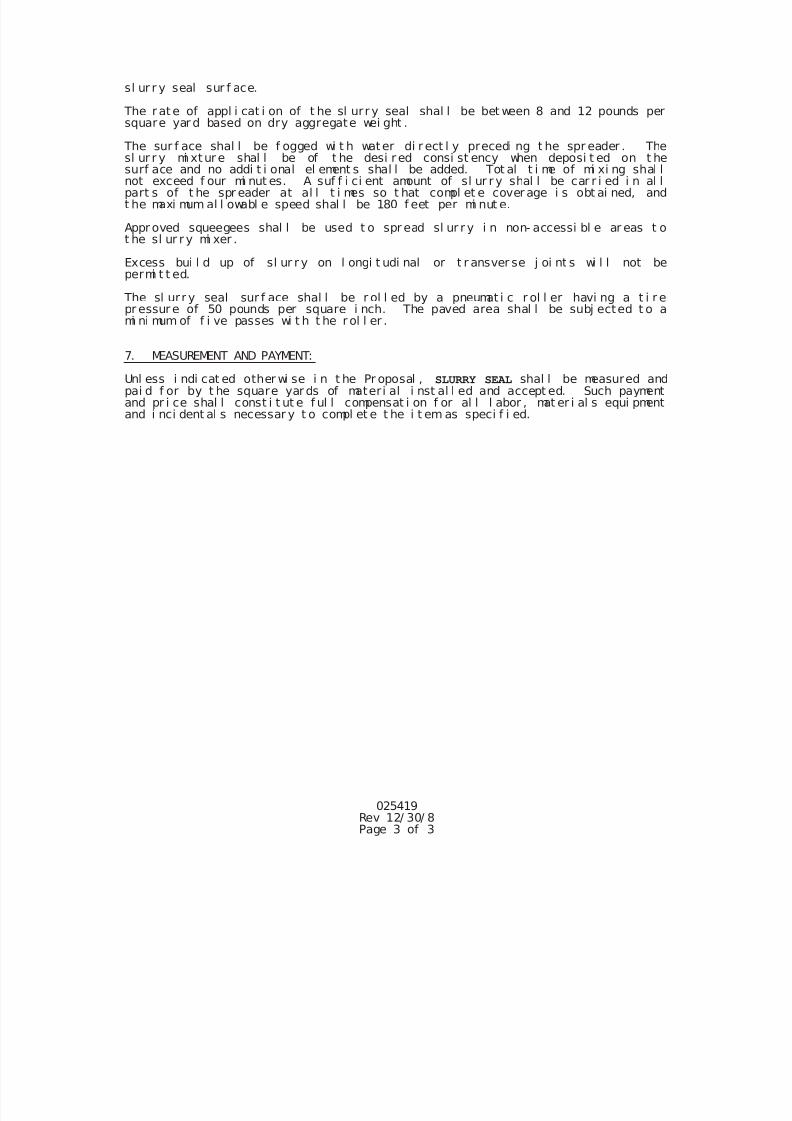
7/25/2019 City Standard Construction Specifications
http://slidepdf.com/reader/full/city-standard-construction-specifications 111/511
025419Rev 12/ 30/ 8Page 3 of 3
sl ur r y seal sur f ace.
The r at e of appl i cat i on of t he sl urr y seal shal l be bet ween 8 and 12 pounds persquare yar d based on dry aggregate wei ght .
The sur f ace shal l be f ogged wi t h water di r ect l y precedi ng t he spr eader . Thesl ur r y mi xtur e shal l be of t he desi r ed consi st ency when deposi t ed on t hesurf ace and no addi t i onal el ement s shal l be added. Tot al t i me of mi xi ng shal lnot exceed f our mi nut es. A suf f i ci ent amount of sl ur r y shal l be car r i ed i n al lpart s of t he spr eader at al l t i mes so t hat compl et e cover age i s obt ai ned, andt he maxi mum al l owabl e speed shal l be 180 f eet per mi nut e.
Appr oved squeegees shal l be used t o spr ead sl ur r y i n non- accessi bl e ar eas t ot he sl ur r y mi xer .
Excess bui l d up of sl ur r y on l ongi t udi nal or t r ansver se j oi nt s wi l l not bepermi t t ed.
The sl urr y seal sur f ace shal l be r ol l ed by a pneumat i c r ol l er havi ng a t i r epr essur e of 50 pounds per square i nch. The paved area shal l be subj ected t o ami ni mum of f i ve passes wi t h t he r ol l er .
7. MEASUREMENT AND PAYMENT:
Unl ess i ndi cat ed other wi se i n t he Pr oposal , SLURRY SEAL shal l be measured andpai d f or by t he square yar ds of materi al i nst al l ed and accept ed. Such paymentand pr i ce shal l const i t ut e f ul l compensat i on f or al l l abor , mat er i al s equi pmentand i nci dent al s necessar y t o compl et e t he i t em as speci f i ed.
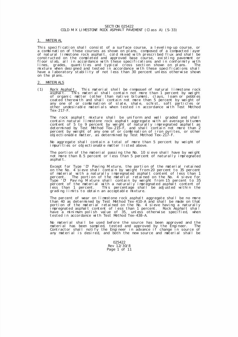
7/25/2019 City Standard Construction Specifications
http://slidepdf.com/reader/full/city-standard-construction-specifications 112/511
025422Rev 12/ 30/ 8Page 1 of 11
SECTI ON 025422COLD MI X LI MESTONE ROCK ASPHALT PAVEMENT ( Cl ass A) ( S- 33)
1. MATERI AL
Thi s speci f i cat i on shal l consi st of a sur f ace course, a l evel i ng- up course, ora combi nat i on of t hese courses as shown on pl ans, composed of a compact ed l ayerof nat ur al l i mest one rock asphal t , col d mi xed wi t h pr escr i bed f l ux and shal l beconst r ucted on t he compl eted and appr oved base course, exi st i ng pavement orf l oor sl ab, al l i n accor dance wi t h t hese speci f i cat i ons and i n conf or mi t y wi t hl i nes, gr ades, quant i t i es and t ypi cal cross sect i on shown on pl ans. Themi xtur e when desi gned and test ed i n accor dance wi t h t hese speci f i cat i ons shal lhave a l aborat ory st abi l i t y of not l ess t han 30 percent unl ess ot her wi se shownon the pl ans.
2. MATERI ALS
( 1) Rock Asphal t . Thi s mat er i al shal l be composed of nat ur al l i mest one r ockasphal t . Thi s mat eri al shal l cont ai n not more t han 1 per cent by wei ghtof or gani c mat t er ( ot her t han nat i ve bi t umen) , cl ays, l oam or pebbl escoat ed t herewi t h and shal l cont ai n not more then 5 percent by wei ght ofany one of or combi nat i on of sl at e, shal e, schi st , sof t par t i cl es or
other undesi r abl e materi al s when t est ed i n accordance wi t h Test Method Tex- 217- F.
The r ock asphal t mi xtur e shal l be uni f orm and wel l gr aded and shal lcont ai n natur al l i mestone rock asphal t aggr egate wi t h an average bi t umencont ent of 5 to 9 percent by wei ght of natur al l y i mpr egnated asphal t asdet ermi ned by Test Method Tex- 215- F, and shal l cont ai n not more than 2per cent by wei ght of any one of or combi nat i on of i r on pyr i t es, or ot herobj ect i onabl e matt er, as determi ned by Test Method Tex- 217-F.
No aggr egate shal l cont ai n a t otal of more t han 5 percent by wei ght ofi mpur i t i es or obj ect i onabl e mat t er l i st ed above.
The port i on of t he mater i al passi ng t he No. 10 si eve shal l have by wei ghtnot more t han 8. 5 percent or l ess t han 5 per cent of natur al l y i mpr egnated
asphal t .
Except f or Type ' D' Pavi ng Mi xture, t he por t i on of the mat er i al r et ai nedon t he No. 4 si eve shal l cont ai n by wei ght f r om 20 per cent t o 35 per centof mat er i al wi t h a nat ur al l y i mpr egnat ed asphal t cont ent of l ess t han 1per cent . The port i on of t he mat er i al r et ai ned on t he No. 4 si eve f or
Type ' D' Pavi ng Mi xt ure shal l contai n by wei ght f r om 15 per cent t o 35per cent of t he mat er i al wi t h a nat ur al l y i mpr egnat ed asphal t cont ent ofl ess than 1 per cent . Thi s per cent age shal l be adj ust ed wi t hi n t hegr adi ng l i mi t s t o obt ai n an accept abl e mi xtur e.
The per cent of wear on l i mest one r ock asphal t aggregat e shal l be no moret han 40 as det ermi ned by Test Method Tex- 410- A and shal l be made on t hatpor t i on of t he mat er i al r et ai ned on t he No. 4 si eve havi ng a nat ur al l yi mpr egnat ed asphal t cont ent of l ess t han 1 percent . Rock Asphal t shal l
have a mi ni mum pol i sh val ue of 35, unl ess ot herwi se speci f i ed, whent est ed i n accordance wi t h Test Method Tex- 438-A.
No materi al shal l be used bef ore the source has been appr oved and t hemater i al has been sampl ed, t est ed and approved by t he Engi neer. TheCont r act or shal l noti f y the Engi neer i n advance i f change i n sour ce ofany mat eri al i s desi r ed, and both the new sour ce and mat er i al shal l be
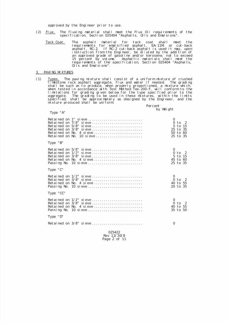
7/25/2019 City Standard Construction Specifications
http://slidepdf.com/reader/full/city-standard-construction-specifications 113/511
025422Rev 12/ 30/ 8Page 2 of 11
appr oved by t he Engi neer pr i or t o use.
( 2) Fl ux. The f l uxi ng mat er i al shal l meet t he Fl ux Oi l r equi r ement s of t hespeci f i cat i on, Sect i on 025404 "Asphal t s, Oi l s and Emul si ons" .
Tack Coat . The asphal t mater i al f or t ack coat shal l meet t her equi r ement s f or emul si f i ed asphal t , EA- 11M, or cut - backasphal t , RC- 2. I f RC- 2 cut - back asphal t i s used i t may, uponi nst r uct i on f r om t he Engi neer , be di l ut ed by t he addi t i on ofan appr oved gr ade of gasol i ne and/ or ker osene, not t o exceed15 per cent by vol ume. Asphal t i c mat eri al s shal l meet t her equi r ement s of t he speci f i cat i on, Sect i on 025404 "Asphal t s,Oi l s and Emul si ons" .
3. PAVI NG MI XTURES
( 1) Types. The pavi ng mi xt ur e shal l consi st of a uni f or m mi xt ur e of crushedl i mestone r ock asphal t aggr egate, f l ux and wat er i f needed. The gr adi ngshal l be such as t o pr oduce, when pr oper l y pr oport i oned, a mi xtur e whi ch,when tested i n accordance wi t h Test Met hod Tex- 200- F, wi l l conf orm t o thel i mi t at i ons f or gr adi ng gi ven bel ow f or t he t ype speci f i ed pr i or t o t heaggr egate. The gr adi ng t o be used i n t hese mi xtur es, wi t hi n t he l i mi t sspeci f i ed, shal l be appr oxi matel y as desi gned by the Engi neer, and t he
mi xtur e pr oduced shal l be uni f orm.Per cent
by Wei ght Type "A"
Ret ai ned on 1" si eve . . . . . . . . . . . . . . . . . . . . . . . . . . . . 0 Ret ai ned on 7/ 8" si eve . . . . . . . . . . . . . . . . . . . . . . . . . . 0 t o 2
Ret ai ned on 5/ 8" si eve . . . . . . . . . . . . . . . . . . . . . . . . . . 5 t o 15Ret ai ned on 3/ 8" si eve . . . . . . . . . . . . . . . . . . . . . . . . . . 25 t o 35Retai ned on No. 4 si eve . . . . . . . . . . . . . . . . . . . . . . . . . 50 to 60Retai ned on No. 10 si eve . . . . . . . . . . . . . . . . . . . . . . . . 25 to 35
Type "B"
Ret ai ned on 5/ 8" si eve . . . . . . . . . . . . . . . . . . . . . . . . . . 0
Ret ai ned on 1/ 2" si eve . . . . . . . . . . . . . . . . . . . . . . . . . . 0 t o 2Ret ai ned on 3/ 8" si eve . . . . . . . . . . . . . . . . . . . . . . . . . . 5 t o 15Retai ned on No. 4 si eve . . . . . . . . . . . . . . . . . . . . . . . . . 45 to 60Passi ng No. 10 si eve . . . . . . . . . . . . . . . . . . . . . . . . . . . . 25 t o 35
Type "C"
Ret ai ned on 1/ 2" si eve . . . . . . . . . . . . . . . . . . . . . . . . . . 0 Ret ai ned on 3/ 8" si eve . . . . . . . . . . . . . . . . . . . . . . . . . . 0 t o 2
Retai ned on No. 4 si eve . . . . . . . . . . . . . . . . . . . . . . . . . 40 to 55Passi ng No. 10 si eve . . . . . . . . . . . . . . . . . . . . . . . . . . . . 20 t o 35
Type "CC"
Ret ai ned on 1/ 2" si eve . . . . . . . . . . . . . . . . . . . . . . . . . . 0
Ret ai ned on 3/ 8" si eve . . . . . . . . . . . . . . . . . . . . . . . . . . 0 t o 2Retai ned on No. 4 si eve . . . . . . . . . . . . . . . . . . . . . . . . . 40 to 55Passi ng No. 10 si eve . . . . . . . . . . . . . . . . . . . . . . . . . . . . 35 t o 50
Type "D"
Ret ai ned on 3/ 8" si eve . . . . . . . . . . . . . . . . . . . . . . . . . . 0
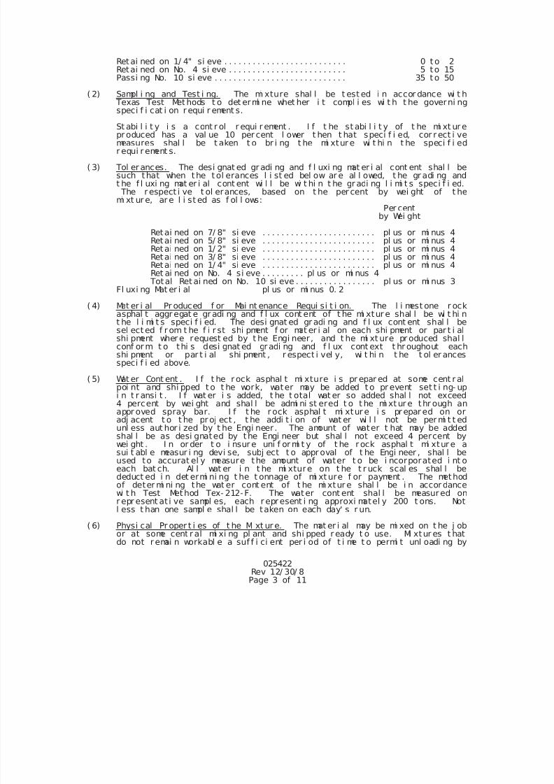
7/25/2019 City Standard Construction Specifications
http://slidepdf.com/reader/full/city-standard-construction-specifications 114/511
025422Rev 12/ 30/ 8Page 3 of 11
Ret ai ned on 1/ 4" si eve . . . . . . . . . . . . . . . . . . . . . . . . . . 0 t o 2Retai ned on No. 4 si eve . . . . . . . . . . . . . . . . . . . . . . . . . 5 to 15Passi ng No. 10 si eve . . . . . . . . . . . . . . . . . . . . . . . . . . . . 35 t o 50
( 2) Sampl i ng and Test i ng. The mi xture shal l be t est ed i n accor dance wi t h Texas Test Met hods t o det ermi ne whet her i t compl i es wi t h t he governi ngspeci f i cat i on r equi r ement s.
St abi l i t y i s a cont r ol r equi r ement . I f t he st abi l i t y of t he mi xt ur epr oduced has a val ue 10 per cent l ower t hen t hat speci f i ed, cor r ect i vemeasures shal l be t aken t o br i ng t he mi xtur e wi t hi n t he speci f i edr equi r ement s.
( 3) Tol er ances. The desi gnat ed gr adi ng and f l uxi ng mat er i al cont ent shal l besuch that when the t ol erances l i st ed bel ow ar e al l owed, t he gr adi ng andt he f l uxi ng mat er i al cont ent wi l l be wi t hi n t he gr adi ng l i mi t s speci f i ed. The r espect i ve t ol erances, based on t he per cent by wei ght of t hemi xt ur e, ar e l i st ed as f ol l ows:
Per centby Wei ght
Retai ned on 7/ 8" si eve . . . . . . . . . . . . . . . . . . . . . . . . pl us or mi nus 4Retai ned on 5/ 8" si eve . . . . . . . . . . . . . . . . . . . . . . . . pl us or mi nus 4
Retai ned on 1/ 2" si eve . . . . . . . . . . . . . . . . . . . . . . . . pl us or mi nus 4Retai ned on 3/ 8" si eve . . . . . . . . . . . . . . . . . . . . . . . . pl us or mi nus 4Retai ned on 1/ 4" si eve . . . . . . . . . . . . . . . . . . . . . . . . pl us or mi nus 4Ret ai ned on No. 4 si eve . . . . . . . . . pl us or mi nus 4
Total Ret ai ned on No. 10 si eve . . . . . . . . . . . . . . . . . pl us or mi nus 3Fl uxi ng Mat er i al pl us or mi nus 0. 2
( 4) Mat er i al Pr oduced f or Mai nt enance Requi si t i on. The l i mest one r ockasphal t aggr egat e gr adi ng and f l ux cont ent of t he mi xtur e shal l be wi t hi nt he l i mi t s speci f i ed. The desi gnat ed gr adi ng and f l ux cont ent shal l besel ect ed f r om t he f i r st shi pment f or mat er i al on each shi pment or par t i alshi pment wher e request ed by t he Engi neer , and t he mi xt ure pr oduced shal lconf or m t o thi s desi gnat ed gr adi ng and f l ux cont ext t hr oughout eachshi pment or par t i al shi pment , r espect i vel y, wi t hi n t he t ol er ancesspeci f i ed above.
( 5) Wat er Cont ent . I f t he r ock asphal t mi xture i s pr epar ed at some cent r alpoi nt and shi pped t o t he work, water may be added t o pr event set t i ng- upi n t r ansi t . I f wat er i s added, t he t otal wat er so added shal l not exceed4 percent by wei ght and shal l be admi ni st ered t o t he mi xt ur e thr ough anappr oved spray bar. I f t he r ock asphal t mi xtur e i s pr epar ed on oradj acent t o t he pr oj ect , t he addi t i on of wat er wi l l not be per mi t t edunl ess aut hor i zed by t he Engi neer . The amount of water t hat may be addedshal l be as desi gnated by the Engi neer but shal l not exceed 4 percent bywei ght . I n or der t o i nsur e uni f or mi t y of t he r ock asphal t mi xtur e asui t abl e measur i ng devi se, subj ect t o appr oval of t he Engi neer , shal l beused to accurat el y measure the amount of water t o be i ncorporated i nt oeach bat ch. Al l wat er i n t he mi xture on t he t r uck scal es shal l bededuct ed i n det ermi ni ng t he t onnage of mi xt ure f or payment . The methodof deter mi ni ng the wat er cont ent of t he mi xtur e shal l be i n accor dance
wi t h Test Method Tex- 212-F. The water cont ent shal l be measured onr epr esent at i ve sampl es, each r epr esent i ng approxi matel y 200 t ons. Notl ess t han one sampl e shal l be taken on each day' s r un.
( 6) Physi cal Pr oper t i es of t he Mi xt ur e. The mat er i al may be mi xed on t he j obor at some cent r al mi xi ng pl ant and shi pped r eady t o use. Mi xtur es t hatdo not r emai n workabl e a suf f i ci ent per i od of t i me t o permi t unl oadi ng by
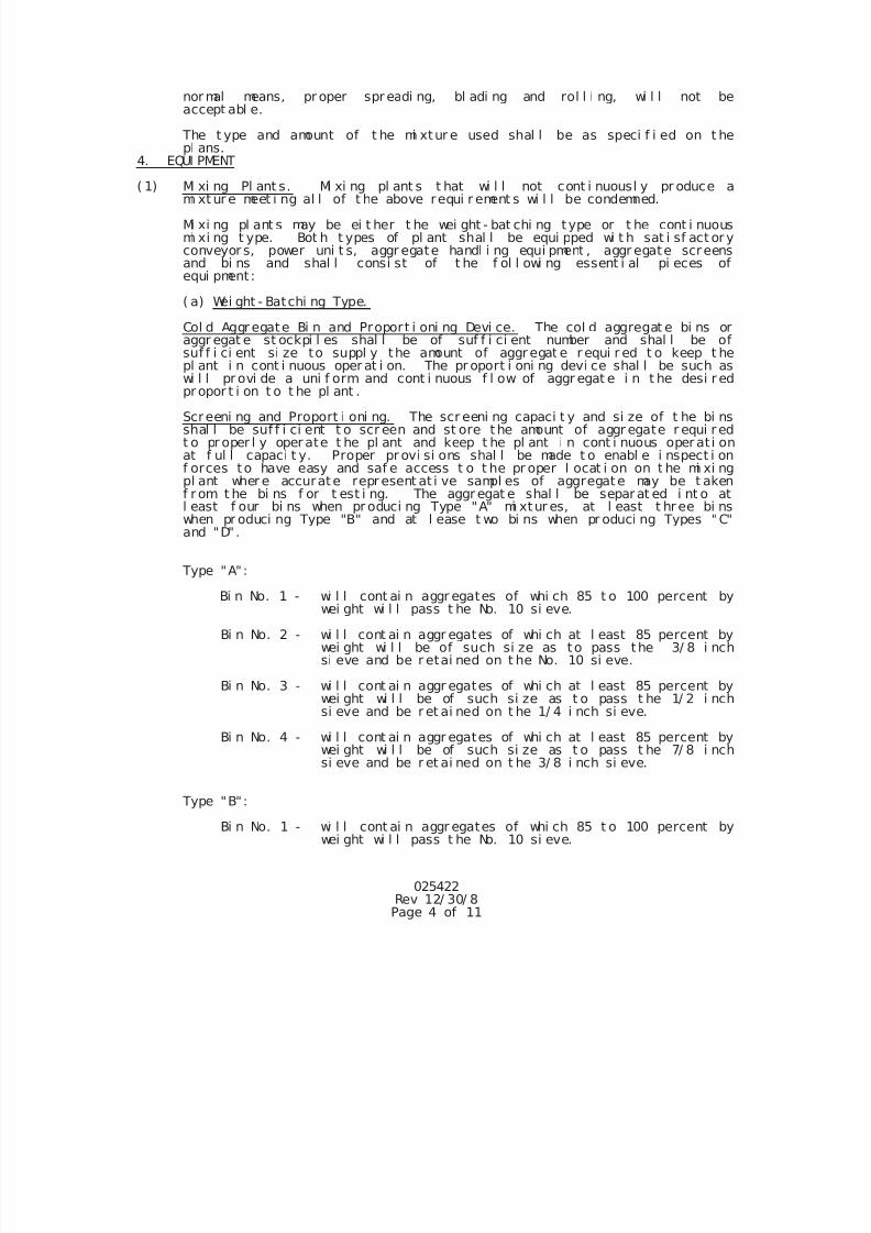
7/25/2019 City Standard Construction Specifications
http://slidepdf.com/reader/full/city-standard-construction-specifications 115/511
025422Rev 12/ 30/ 8Page 4 of 11
nor mal means, pr oper spr eadi ng, bl adi ng and rol l i ng, wi l l not beaccept abl e.
The t ype and amount of t he mi xtur e used shal l be as speci f i ed on t hepl ans.
4. EQUI PMENT
( 1) Mi xi ng Pl ant s. Mi xi ng pl ant s t hat wi l l not cont i nuousl y pr oduce ami xt ur e meet i ng al l of t he above requi r ement s wi l l be condemned.
Mi xi ng pl ant s may be ei t her t he wei ght - bat chi ng type or t he cont i nuousmi xi ng t ype. Bot h t ypes of pl ant shal l be equi pped wi t h sat i sf act or yconveyor s, power uni t s, aggr egate handl i ng equi pment , aggr egate screensand bi ns and shal l consi st of t he f ol l owi ng essent i al pi eces ofequi pment :
( a) Wei ght - Batchi ng Type.
Col d Aggr egate Bi n and Proport i oni ng Devi ce. The col d aggregat e bi ns oraggr egat e st ockpi l es shal l be of suf f i ci ent number and shal l be ofsuf f i ci ent si ze to suppl y the amount of aggr egat e r equi r ed t o keep t hepl ant i n cont i nuous oper at i on. The pr oport i oni ng devi ce shal l be such aswi l l pr ovi de a uni f orm and cont i nuous f l ow of aggr egat e i n t he desi r ed
pr opor t i on t o t he pl ant .
Screeni ng and Proport i oni ng. The scr eeni ng capaci t y and si ze of t he bi nsshal l be suf f i ci ent t o scr een and st ore t he amount of aggr egate r equi r edt o pr oper l y oper ate t he pl ant and keep t he pl ant i n cont i nuous oper at i onat f ul l capaci t y. Proper pr ovi si ons shal l be made t o enabl e i nspect i onf orces to have easy and saf e access t o t he pr oper l ocat i on on t he mi xi ngpl ant wher e accurate repr esent at i ve sampl es of aggregate may be t akenf r om t he bi ns f or t est i ng. The aggr egat e shal l be separ at ed i nt o atl east f our bi ns when pr oduci ng Type "A" mi xtur es, at l east t hr ee bi nswhen pr oduci ng Type "B" and at l ease t wo bi ns when pr oduci ng Types "C"and "D" .
Type "A":
Bi n No. 1 - wi l l cont ai n aggr egates of whi ch 85 t o 100 percent bywei ght wi l l pass t he No. 10 si eve.
Bi n No. 2 - wi l l cont ai n aggr egates of whi ch at l east 85 percent bywei ght wi l l be of such si ze as to pass the 3/ 8 i nchsi eve and be r etai ned on t he No. 10 si eve.
Bi n No. 3 - wi l l cont ai n aggr egates of whi ch at l east 85 percent bywei ght wi l l be of such si ze as t o pass t he 1/ 2 i nchsi eve and be r et ai ned on t he 1/ 4 i nch si eve.
Bi n No. 4 - wi l l cont ai n aggr egates of whi ch at l east 85 percent bywei ght wi l l be of such si ze as t o pass t he 7/ 8 i nchsi eve and be r et ai ned on t he 3/ 8 i nch si eve.
Type "B":
Bi n No. 1 - wi l l cont ai n aggr egates of whi ch 85 t o 100 percent bywei ght wi l l pass t he No. 10 si eve.
7/25/2019 City Standard Construction Specifications
http://slidepdf.com/reader/full/city-standard-construction-specifications 116/511
025422Rev 12/ 30/ 8Page 5 of 11
Bi n No. 2 - wi l l cont ai n aggr egates of whi ch at l east 85 percent bywei ght wi l l be of such si ze as t o pass t he 3/ 8 i nchsi eve and be r etai ned on t he No. 10 si eve.
Bi n No. 3 - wi l l cont ai n aggr egates of whi ch at l east 85 percent bywei ght wi l l be of such si ze as t o pass t he 1/ 2 i nchsi eve and be r et ai ned on t he 1/ 4 i nch si eve.
Type "C", Type "CC" and Type "D":
Bi n No. 1 - wi l l cont ai n aggr egates of whi ch 85 t o 100 percent bywei ght wi l l pass t he No. 10 si eve.
Bi n No. 2 - wi l l cont ai n aggr egates of whi ch at l east 85 percent bywei ght wi l l be of such si ze as t o pass t he 3/ 8 i nchsi eve and be r etai ned on t he No. 10 si eve.
Aggr egat e Wei gh Box and Bat chi ng Scal es. The aggregat e wei gh box andbat chi ng scal es shal l be of suf f i ci ent capaci t y to hol d and wei gh acompl ete batch of aggr egate.
Fl ux Oi l Bucket and Scal es. The f l ux oi l bucket and scal es shal l be ofsuf f i ci ent capaci t y t o hol d and wei gh the necessar y mat er i al f or one
bat ch.
Mi xer . The mi xer shal l be of t he pug mi l l t ype and shal l have a capaci t yof not l ess than 3, 000 pounds i n a si ngl e batch. The number of bl adesand the posi t i on of same shal l be such as t o gi ve a uni f orm and compl et eci r cul at i on of t he bat ch i n t he mi xer . The mi xer shal l be equi pped wi t han appr oved spr ay bar t hat wi l l di st r i but e the f l uxi ng mat er i al qui ckl yand uni f orml y t hr oughout t he mi xer . I f , i n t he opi ni on of t he Engi neer ,any mi xer has a t endency to segr egate t he mi neral aggregat e or f ai l s t osecur e a t hor ough and uni f or m mi xi ng wi t h t he f l uxi ng mat er i al , i t shal lnot be used. Al l mi xer s shal l be pr ovi ded wi t h an aut omati c t i me l ockt hat wi l l l ock the di schar ge door s and t he shaf t seal s of t he mi xer shal lbe t i ght enough t o pr event t he spi l l i ng of aggr egat e or mi xture f r om t hepug mi l l .
( b) Cont i nuous Mi xi ng Type
Col d Aggr egate Bi n and Proport i oni ng Devi ce. Same as f or wei ght - batchi ngt ype of pl ant .
Screeni ng and Proport i oni ng. Same r equi r ement s as speci f i ed underwei ght - bat chi ng pl ant s. These r equi r ement s shal l al so appl y t o mat er i al st hat are st ockpi l ed and t hat ar e pr oposed f or di r ect use by a cont i nuousmi xi ng pl ant wi t hout t he use of pl ant bi ns.
Fl uxi ng Mat er i al Spr ay Bar . The f l uxi ng mat er i al spr ay bar shal l be so
Mi xer . The mi xer shal l be of t he pug mi l l cont i nuous type and shal l t horough and uni f orm mi xi ng of t he aggr egat e wi t h t he f l uxi ngmat er i al , i t shal l not be used.
( 2) Spr eadi ng and Fi ni shi ng Machi ne. The spr eadi ng and f i ni shi ngmachi ne, when permi t t ed, shal l be a type appr oved by t he Engi neerand shal l be capabl e of pr oduci ng a sur f ace t hat wi l l meet t her equi r ement of t he t ypi cal cross sect i on and t he sur f ace t est .
( 3) Motor Gr ader . The motor gr ader shal l be a sel f - pr opel l ed power -
7/25/2019 City Standard Construction Specifications
http://slidepdf.com/reader/full/city-standard-construction-specifications 117/511
025422Rev 12/ 30/ 8Page 6 of 11
gr ader ; i t shal l be equi pped wi t h smoot h tr ead pneumat i c t i r edwheel s; shal l have a bl ade l engt h of not l ess t han 12 f eet ; shal lhave a wheel base of not l ess t han 16 f eet; and shal l be t i ght andi n good operat i ng condi t i on and appr oved by the Engi neer.
( 4) Pneumat i c Ti r e Rol l er s. The r ol l er s shal l consi st of not l esst han seven pneumat i c t i r ed wheel s, r unni ng on axl es i n such mannert hat t he rear gr oup of t i r es wi l l cover t he ent i r e gap bet weenadj acent t i r es of t he f orward gr oup, and mount ed i n a r i gi d f r ameand pr ovi ded wi t h a l oadi ng pl at f or m or body sui t abl e f or bal l astl oadi ng. The f r ont axl e shal l be at t ached t o t he f r ame i n suchmanner t hat t he r ol l er may be t ur ned wi t hi n a mi ni mum ci r cl e. Thepneumat i c t i r e rol l er under wor ki ng condi t i ons shal l have anef f ect i ve r ol l i ng wi dt h of appr oxi mat el y 84 i nches and shal l be sodesi gned t hat be bal l ast l oadi ng t he t otal l oad may be var i eduni f orml y f r om 23, 500 pounds or l ess t o 50, 000 pounds or more.
The r ol l er shal l be equi pped wi t h t i r es t hat wi l l af f ord groundcont act pressures t o 90 pounds per square i nch or more. Theoper at i ng l oad and t i r e ai r pr essur e shal l be wi t hi n t he r ange oft he manuf act ur er ' s char t as di r ect ed by t he Engi neer . TheCont r act or shal l f ur ni sh t he Engi neer wi t h char t s and t abul at i onsshowi ng t he cont act ar eas and cont act pr essur es f or t he f ul l r angeof t i r e i nf l at i on pr essur es and f or t he f ul l r ange of l oadi ngs f or
t he par t i cul ar t i r es f ur ni shed.
The pneumat i c t i r e r ol l er shal l be dr awn by a sui t abl e crawl ert ype t r act or , a pneumat i c t i r ed t r act or, or a tr uck of adequat et r act i ve ef f or t , or may be of t he sel f - pr opel l ed t ype, and t her ol l er , when dr awn or pr opel l ed by ei t her t ype of equi pment , shal lbe consi der ed a medi um pneumat i c t i r e r ol l er uni t . The power uni tshal l have adequate t r act i ve ef f ort t o pr oper l y move t he oper at i ngr ol l er at var i abl e uni f orm speeds up t o appr oxi mat el y 5 mi l es perhour.
The t i r e pr essur e of each t i r e shal l be adj ust ed as di r ect ed byt he Engi neer and thi s pressure shal l not var y by more than 5pounds per square i nch.
( 5) Two Axl e Tandem Rol l er . Thi s r ol l er shal l be an accept abl e powerdr i ve tandem r ol l er wei ghi ng not l ess t han 8 tons.
( 6) Thr ee Wheel Rol l er . Thi s r ol l er shal l be an accept abl e powerdr i ven t hr ee wheel r ol l er , wei ghi ng not l ess t han 10 t ons.
( 7) Thr ee Axl e Tandem Rol l er . Thi s r ol l er shal l be an accept abl edr i ven t hr ee axl e r ol l er wei ghi ng not l ess t han 10 t ons.
( 8) St r ai ght edges and Templ at es. The Cont r act or shal l pr ovi deaccept abl e 10- f oot st r ai ght edges f or sur f ace t est i ng.
Sat i sf act or y t empl at es shal l be pr ovi ded as r equi r ed by t heEngi neer .
( 9) Tr unk Scal es. A set of st andar d pl at f or m t r uck scal es, shal l bepl aced at a l ocat i on appr oved by t he Engi neer.
7/25/2019 City Standard Construction Specifications
http://slidepdf.com/reader/full/city-standard-construction-specifications 118/511
025422Rev 12/ 30/ 8Page 7 of 11
( 10) Al l Equi pment . Shal l be mai nt ai ned i n good r epai r and oper at i ngcondi t i on and shal l be appr oved by t he Engi neer .
( 11) Al t er nat e Equi pment . When per mi t t ed by t he Engi neer i n wr i t i ng,equi pment ot her t han t hat speci f i ed whi ch wi l l consi st ent l ypr oduce sat i sf act ory r esul t s may be used.
5. STORAGE, PROPORTI ONS AND MI XI NG
( 1) St orage of Rock Asphal t
Cent r al Mi xi ng Pl ant s. Suf f i ci ent mat er i al shal l be st or ed,st ockpi l ed or pr oduced to per mi t cont i nuous oper at i on t hr oughoutany worki ng peri od wi t hout shut downs due to materi al shor t ages.I f t he nat ur al l i mest one rock asphal t aggr egat es are st or ed orst ockpi l ed, t hey shal l be handl ed i n such a manner as t o pr eventsegr egat i on, t he mi xi ng of var i ous mat er i al s or si zes and t hecont ami nat i on wi t h f orei gn mat er i al s.
St orage of t he cr ushed l i mest one rock asphal t mi xture upon t hegr ound wi l l not be per mi t t ed at t he pl ant si t e. Mat er i al t hatcomes i n cont act wi t h ear t h or ot her obj ect i onabl e f orei gn matt er
shal l be r ej ect ed. Mi xtur es t hat do not remai n workabl e asuf f i ci ent per i od of t i me t o per mi t pr oper spr eadi ng, bl adi ng andr ol l i ng wi l l not be accept abl e. St or age, handl i ng or l oadi ng oft he rock asphal t mi xture shal l be i n such manner as t o pr eventundue segregat i on.
( 2) St orage and Heat i ng of Fl ux. The f l ux st orage shal l be ampl e t omeet t he r equi r ement s of t he pl ant . The f l ux may be heated by
st eam coi l or di r ect f i r e t o a t emper at ur e not t o exceed 250F.Agi t at i on by steam or ai r wi l l not be permi t t ed. I f di rect f i r eheat i ng i s used, t he heat i ng equi pment shal l be such t hat i t wi l li nsur e posi t i ve ci r cul at i on of t he f l ux whi l e bei ng heat ed andshal l be appr oved by t he Engi neer . Car e shal l be t aken not t oi nj ur e t he f l ux by subj ect i ng i t t o undue cont i nuous heat . The
heat i ng apparatus shal l be equi pped wi t h a recordi ng t hermometerwi t h a 24 hour char t t hat wi l l r ecord the t emper at ur e of t hef l uxi ng mat er i al wher e i t i s at t he hi ghest t emper at ur e.
( 3) Pr opor t i oni ng. The pr opor t i oni ng of t he var i ous mat er i al sent er i ng i nt o the mi xture shal l be i n accor dance wi t h t hi sspeci f i cat i on. Aggr egat e shal l be pr opor t i oned by wei ght usi ngt he wei gh box and bat chi ng scal es when t he wei ght - bat ch type ofpl ant us used and by vol ume usi ng t he aggr egate pr oport i oni ngdevi ce when t he cont i nuous mi xer t ype of pl ant i s used. Thef l uxi ng mater i al shal l be pr oport i oned by wei ght or by vol umebased on wei ght usi ng t he speci f i ed equi pment . The pr oport i ons ofeach const i t uent by wei ght of t he pavi ng mi xtur e shal l be wi t hi nt he f ol l owi ng l i mi t s.
Cr ushed Li mest one Rock Asphal t s, 96 t o 97. 5 percent by wei ght.
Fl ux Mat er i al , 2. 5 t o 4 per cent by wei ght .
( 4) Mi xi ng. I n i nt r oduci ng t he bat ch i nt o t he mi xer , t he sequence of
7/25/2019 City Standard Construction Specifications
http://slidepdf.com/reader/full/city-standard-construction-specifications 119/511
025422Rev 12/ 30/ 8Page 8 of 11
addi t i on of aggr egat e and f l ux oi l and t he amount of mi xi ng shal lbe done i n a manner t o mi ni mi ze f ormat i on of " f l ux bal l s" andpr oduce opt i mum condi t i ons f or a homogeneous mi x. The mi xer shal lbe equi pped wi t h an appr oved spray bar t hat wi l l di st r i but e t hef l ux oi l qui ckl y and uni f orml y t hr oughout t he mi xer . Any mi xert hat has a t endency t o segregat e the rock asphal t aggr egate orf ai l s t o secur e a t hor ough and uni f or m mi xi ng wi t h t he f l ux oi lshal l not be used.
Mi xt ures pr oduced when t he l i mest one r ock asphal t aggregatescont ai n moi st ur e i n excess of sat ur at ed sur f ace dr y condi t i on wi l lnot be accept ed. Excess moi st ur e wi l l be evi denced by vi sualsur f ace moi st ur e on the aggr egat es or any unusual quant i t i es off i nes cl i ngi ng t o t he coar se aggr egat e.
I n order t o observe pl ant oper at i ons and t he r ock asphal tmi xtur es, adequat e l i ght i ng shal l be pr ovi ded or mi xi ng shal l beconf i ned t o t he dayl i ght hour s.
Al l l i mest one r ock asphal t mi xtur es shi pped on any one par t i cul arr equi si t i on or proj ect shal l be pr oduced out of t he same mi xi ngpl an, unl ess i f i n t he opi ni on of t he Engi neer t her e i s nodi f f er ence i n the qual i t y of t he rock asphal t mi xtur e when
pr oduced by t wo di f f erence mi xi ng pl ant s. Materi al s pr oduced by awei ght - batchi ng pl ant shal l not be mi xed mat er i al pr oduced f r om acont i nuous mi xi ng pl ant .
6. CONSTRUCTI ON METHODS
The r ock asphal t mi xt ure, t ack coat or pr i me coat shal l not be pl aced when t he
ai r t emperat ur e i s bel ow 60F and i s f al l i ng, but i t may be pl aced when t he ai r
t emper ature i s above 50F and i s r i si ng, t he temper at ur e bei ng taken i n theshade away f r om ar t i f i ci al heat , wi t h t he f ur t her pr ovi si on t hat asphal t i cmi xture or t ack coat shal l onl y be pl aced when t he humi di t y and general weat hercondi t i ons, i n t he opi ni on of t he Engi neer , ar e sui t abl e.
( 1) Pr i me Coat . I f a pr i me coat i s r equi r ed, i t wi l l be appl i ed andpai d f or as a separat e i t em. The t ack coat or r ock asphal tmi xtur e shal l not be appl i ed on a pr evi ousl y pr i med f l exi bl e baseunt i l t he pr i med base has compl et el y cur ed to t he sat i sf act i on oft he Engi neer .
( 2) Tack Coat . Bef or e t he r ock asphal t mi xtur e i s l ai d, t he sur f aceupon whi ch t he tack coat i s t o pl aced shal l be cl eaned thoroughl yt o t he sat i sf act i on of t he Engi neer . The sur f ace shal l be gi ven auni f or m appl i cat i on of t ack coat meet i ng t he r equi r ement s f or t ackcoat under asphal t i c mat er i al s of t hi s speci f i cat i on. Thi s tackcoat shal l be appl i ed, as di r ect ed by t he Engi neer , wi t h anappr oved sprayer at a rate not t o exceed 0. 05 gal l on per squareyar d of surf ace. Wher e t he mi xtur e wi l l adher e t o t he surf ace onwhi ch i t i s t o be pl aced wi t hout t he use of a tack coat , t he tackcoat may be el i mi nated by t he Engi neer . The t ack coat shal l ber ol l ed wi t h a pneumat i c t i r e rol l er as di r ect ed by t he Engi neer .
( 3) Pl aci ng. I f the mi xt ur es ar e shi pped t o t he j ob, t he r ai l r oadcar s shal l f i r st be cl eaned of al l f or ei gn mat t er , and t hemateri al shal l be l oaded i n such a manner as t o pr eventsegr egat i on. The r ock asphal t mi xtur e, pr epar ed as speci f i ed,shal l be haul ed t o the work i n t i ght vehi cl es pr evi ousl y cl eaned
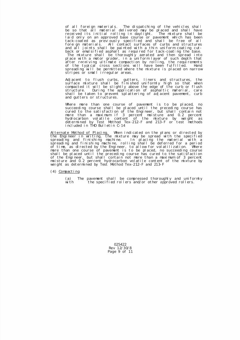
7/25/2019 City Standard Construction Specifications
http://slidepdf.com/reader/full/city-standard-construction-specifications 120/511
025422Rev 12/ 30/ 8Page 9 of 11
of al l f or ei gn mat er i al s. The di spat chi ng of t he vehi cl es shal lbe so that al l mat er i al del i ver ed may be pl aced and shal l haverecei ved i t s i ni t i al r ol l i ng i n dayl i ght . The mi xt ure shal l bel ai d onl y on an approved base course or pavement whi ch has beent ack- coat ed as pr evi ousl y speci f i ed and shal l be f r ee of al lf or ei gn mat er i al s. Al l cont act sur f aces of cur bs and st r uct ur esand al l j oi nt s shal l be pai nt ed wi t h a t hi n uni f or m coat i ng cut -back or emul si f i ed asphal t as r equi r ed f or t ack-coat i ng t he base. The mi xt ure shal l be t hor oughl y aer at ed and t hen spr ead i ntopl ace wi t h a mot or gr ader , i n a uni f or m l ayer of such dept h t hataf t er r ecei vi ng ul t i mat e compact i on by rol l i ng, t he r equi r ement sof t he t ypi cal cross sect i ons wi l l have been f ul f i l l ed. Handspreadi ng wi l l be permi t t ed where t he mi xt ur e i s pl aced on narr owst r i pes or smal l i r r egul ar ar eas.
Adj acent t o f l ush cur bs, gut t er s, l i ner s and st r uct ur es, t hesur f ace mi xtur e shal l be f i ni shed uni f orml y hi gh so that whencompact ed i t wi l l be sl i ght l y above the edge of t he cur b or f l ushst r uct ur e. Dur i ng t he appl i cat i on of asphal t i c mat er i al , car eshal l be t aken t o pr event spl at t er i ng of adj acent pavement , cur band gut t er s or st r uctur es.
Wher e more t han one course of pavement i s t o be pl aced, no
succeedi ng cour se shal l be pl aced unt i l t he pr ecedi ng cour se hascur ed t o the sat i sf act i on of t he Engi neer , but shal l cont ai n notmore than a maxi mum i f 3 percent moi st ure and 0. 2 percenthydr ocar bon vol at i l e cont ent of t he mi xtur e by wei ght asdet ermi ned by Test Met hod Tex- 212- F and 213- F or t est met hodsi ncl uded i n THD Bul l et i n C- 14
Al t ernat e Met hod of Pl aci ng. When i ndi cat ed on t he pl ans or di r ect ed byt he Engi neer i n wr i t i ng, t he mi xtur e may be spr ead wi t h t he speci f i edspr eadi ng and f i ni shi ng machi ne. I n pl aci ng t he mat er i al wi t h aspr eadi ng and f i ni shi ng machi ne, r ol l i ng shal l be def er r ed f or a per i odof t i me, as di r ected by t he Engi neer , t o al l ow f or vol at i l i zat i on. Wher emore t han one cour se of pavement i s t o be pl aced, no succeedi ng cour seshal l be pl aced unt i l t he pr ecedi ng cour se has cur ed t o t he sat i sf act i onof t he Engi neer , but shal l cont ai n not more t han a maxi mum of 3 percent
moi st ur e and 0. 2 per cent hydr ocarbon vol at i l e cont ent of t he mi xtur e bywei ght as det ermi ned by Test Method Tex-212- F and 213- F
( 4) Compact i ng
( a) The pavement shal l be compressed t hor oughl y and uni f orml ywi t h t he speci f i ed r ol l er s and/ or ot her appr oved r ol l er s.
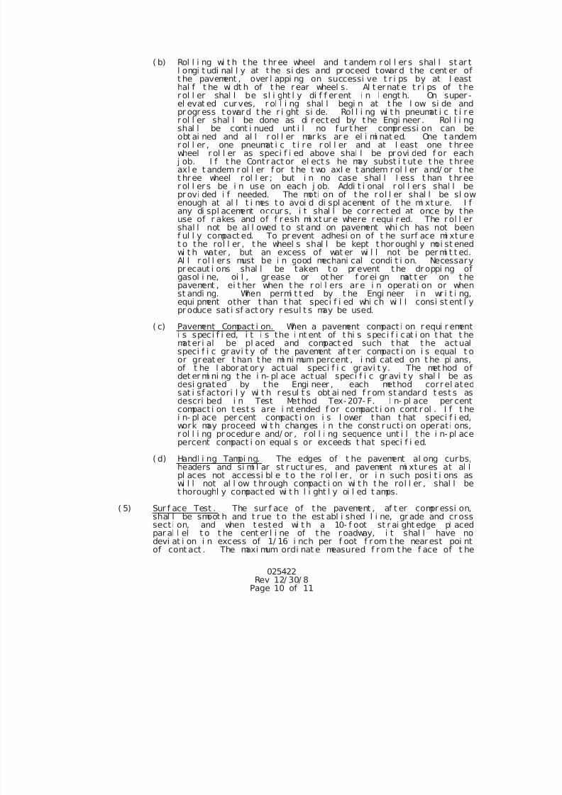
7/25/2019 City Standard Construction Specifications
http://slidepdf.com/reader/full/city-standard-construction-specifications 121/511
025422Rev 12/ 30/ 8
Page 10 of 11
( b) Rol l i ng wi t h t he t hr ee wheel and t andem r ol l er s shal l st ar tl ongi t udi nal l y at t he si des and pr oceed towar d the cent er oft he pavement , over l appi ng on successi ve t r i ps by at l easthal f t he wi dt h of t he r ear wheel s. Al t er nat e t r i ps of t her ol l er shal l be sl i ght l y di f f er ent i n l engt h. On super -el evat ed cur ves, r ol l i ng shal l begi n at t he l ow si de andpr ogr ess t owar d t he r i ght si de. Rol l i ng wi t h pneumat i c t i r er ol l er shal l be done as di r ect ed by t he Engi neer . Rol l i ngshal l be cont i nued unt i l no f ur t her compr essi on can beobt ai ned and al l r ol l er mar ks ar e el i mi nat ed. One t andemr ol l er , one pneumat i c t i r e r ol l er and at l east one t hr eewheel r ol l er as speci f i ed above shal l be pr ovi ded f or each
j ob. I f t he Contr act or el ect s he may subst i t ute t he t hreeaxl e t andem r ol l er f or t he t wo axl e t andem r ol l er and/ or t het hr ee wheel r ol l er ; but i n no case shal l l ess t han t hr eer ol l er s be i n use on each j ob. Addi t i onal r ol l er s shal l bepr ovi ded i f needed. The moti on of t he r ol l er shal l be sl owenough at al l t i mes t o avoi d di spl acement of t he mi xtur e. I fany di spl acement occur s, i t shal l be cor r ect ed at once by theuse of r akes and of f r esh mi xtur e where r equi r ed. The r ol l ershal l not be al l owed t o st and on pavement whi ch has not beenf ul l y compact ed. To pr event adhesi on of t he surf ace mi xtur et o the rol l er , t he wheel s shal l be kept t hor oughl y moi st ened
wi t h water , but an excess of wat er wi l l not be per mi t t ed.Al l r ol l er s must be i n good mechani cal condi t i on. Necessarypr ecaut i ons shal l be taken t o pr event t he dr oppi ng ofgasol i ne, oi l , gr ease or ot her f or ei gn mat t er on t hepavement , ei t her when t he r ol l ers ar e i n operat i on or whenst andi ng. When permi t t ed by t he Engi neer i n wr i t i ng,equi pment other t han t hat speci f i ed whi ch wi l l consi st ent l ypr oduce sat i sf act ory r esul t s may be used.
( c) Pavement Compact i on. When a pavement compact i on r equi r ementi s speci f i ed, i t i s the i nt ent of t hi s speci f i cat i on t hat t hemater i al be pl aced and compact ed such t hat t he act ualspeci f i c gr avi t y of t he pavement af t er compact i on i s equal t oor great er t han t he mi ni mum percent , i ndi cat ed on t he pl ans,of t he l abor at or y act ual speci f i c gr avi t y. The met hod of
det er mi ni ng t he i n- pl ace act ual speci f i c gr avi t y shal l be asdesi gnated by t he Engi neer , each method corr el atedsat i sf actori l y wi t h r esul t s obt ai ned f r om st andar d t est s asdescri bed i n Test Method Tex- 207- F. I n- pl ace per centcompact i on t est s are i nt ended f or compact i on cont r ol . I f t hei n- pl ace per cent compact i on i s l ower t han t hat speci f i ed,work may proceed wi t h changes i n the const r uct i on operat i ons,r ol l i ng pr ocedur e and/ or , r ol l i ng sequence unt i l t he i n- pl acepercent compact i on equal s or exceeds t hat speci f i ed.
( d) Handl i ng Tampi ng. The edges of t he pavement al ong curbs,headers and si mi l ar st r uct ur es, and pavement mi xtur es at al lpl aces not accessi bl e t o t he r ol l er , or i n such posi t i ons aswi l l not al l ow t hr ough compact i on wi t h t he rol l er , shal l bet horoughl y compact ed wi t h l i ght l y oi l ed t amps.
( 5) Sur f ace Test . The sur f ace of t he pavement , af t er compr essi on,shal l be smoot h and t r ue t o the est abl i shed l i ne, gr ade and cr osssect i on, and when t ested wi t h a 10- f oot st r ai ght edge pl acedpar al l el t o t he cent er l i ne of t he r oadway, i t shal l have nodevi at i on i n excess of 1/ 16 i nch per f oot f r om t he near est poi ntof cont act . The maxi mum ordi nat e measured f r om t he f ace of t he
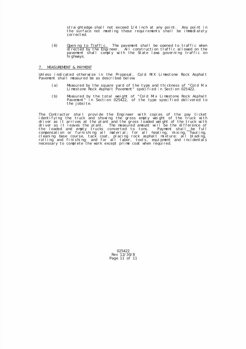
7/25/2019 City Standard Construction Specifications
http://slidepdf.com/reader/full/city-standard-construction-specifications 122/511
025422Rev 12/ 30/ 8
Page 11 of 11
st r ai ght edge shal l not exceed 1/ 4 i nch at any poi nt . Any poi nt i nt he sur f ace not meet i ng these requi r ement s shal l be i mmedi atel ycor r ect ed.
( 6) Openi ng t o Traf f i c. The pavement shal l be opened t o t r af f i c whendi r ect ed by t he Engi neer . Al l const r uct i on t r af f i c al l owed on t hepavement shal l compl y wi t h the St at e l aws gover ni ng tr af f i c onhi ghways.
7. MEASUREMENT & PAYMENT
Unl ess i ndi cat ed other wi se i n the Pr oposal , Col d MI X Li mest one Rock Asphal tPavement shal l measured be as descr i bed bel ow.
( a) Measured by t he square yar d of t he t ype and t hi ckness of "Col d Mi xLi mest one Rock Asphal t Pavement " speci f i ed i n Sect i on 025422.
( b) Measured by t he t otal wei ght of "Col d Mi x Li mest one Rock Asphal tPavement ” i n Sect i on 025422, of t he type speci f i ed del i ver ed t ot he j obsi t e.
The Cont r act or shal l provi de t he Engi neer wi t h copi es of t he pay t i cketi dent i f yi ng the t r uck and showi ng the gr oss empt y wei ght of t he t r uck wi t hdr i ver as i t ar r i ves at t he pl ant and t he gr oss l oaded wei ght of t he t r uck wi t hdr i ver as i t l eaves the pl ant . The measured amount wi l l be t he di f f er ence oft he l oaded and empt y t r ucks conver t ed t o t ons. Payment shal l be f ul lcompensat i on or f ur ni shi ng al l mat er i al ; f or al l heat i ng, mi xi ng, haul i ng,cl eani ng base cour se, t ack coat , pl aci ng r ock asphal t mi xt ur e; al l bl adi ng,r ol l i ng and f i ni shi ng; and f or al l l abor , t ool s, equi pment and i nci dent al snecessar y t o compl ete the work except pr i me coat when requi r ed.
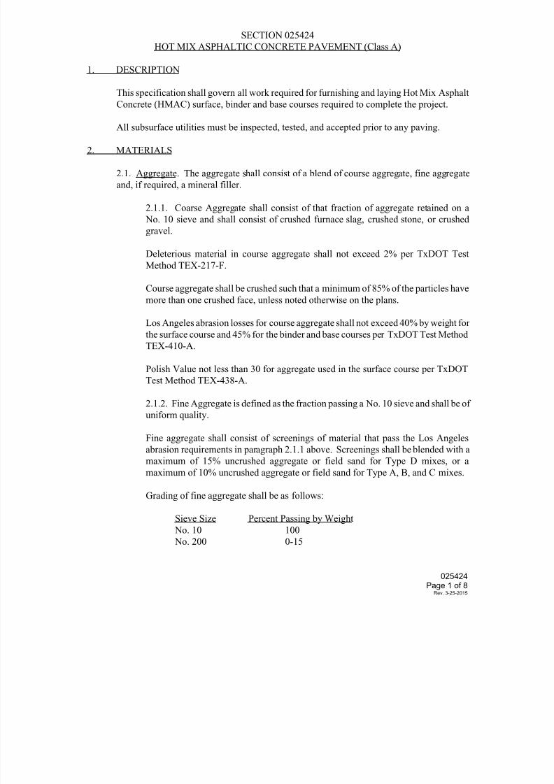
7/25/2019 City Standard Construction Specifications
http://slidepdf.com/reader/full/city-standard-construction-specifications 123/511
SECTION 025424
HOT MIX ASPHALTIC CONCRETE PAVEMENT (Class A)
1. DESCRIPTION
This specification shall govern all work required for furnishing and laying Hot Mix Asphalt
Concrete (HMAC) surface, binder and base courses required to complete the project.
All subsurface utilities must be inspected, tested, and accepted prior to any paving.
2. MATERIALS
2.1. Aggregate. The aggregate shall consist of a blend of course aggregate, fine aggregate
and, if required, a mineral filler.
2.1.1. Coarse Aggregate shall consist of that fraction of aggregate retained on a
No. 10 sieve and shall consist of crushed furnace slag, crushed stone, or crushed
gravel.
Deleterious material in course aggregate shall not exceed 2% per TxDOT Test
Method TEX-217-F.
Course aggregate shall be crushed such that a minimum of 85% of the particles have
more than one crushed face, unless noted otherwise on the plans.
Los Angeles abrasion losses for course aggregate shall not exceed 40% by weight for
the surface course and 45% for the binder and base courses per TxDOT Test Method
TEX-410-A.
Polish Value not less than 30 for aggregate used in the surface course per TxDOTTest Method TEX-438-A.
2.1.2. Fine Aggregate is defined as the fraction passing a No. 10 sieve and shall be of
uniform quality.
Fine aggregate shall consist of screenings of material that pass the Los Angeles
abrasion requirements in paragraph 2.1.1 above. Screenings shall be blended with a
maximum of 15% uncrushed aggregate or field sand for Type D mixes, or a
maximum of 10% uncrushed aggregate or field sand for Type A, B, and C mixes.
Grading of fine aggregate shall be as follows:
Sieve Size Percent Passing by Weight
No. 10 100
No. 200 0-15
025424Page 1 of 8
Rev. 3-25-2015
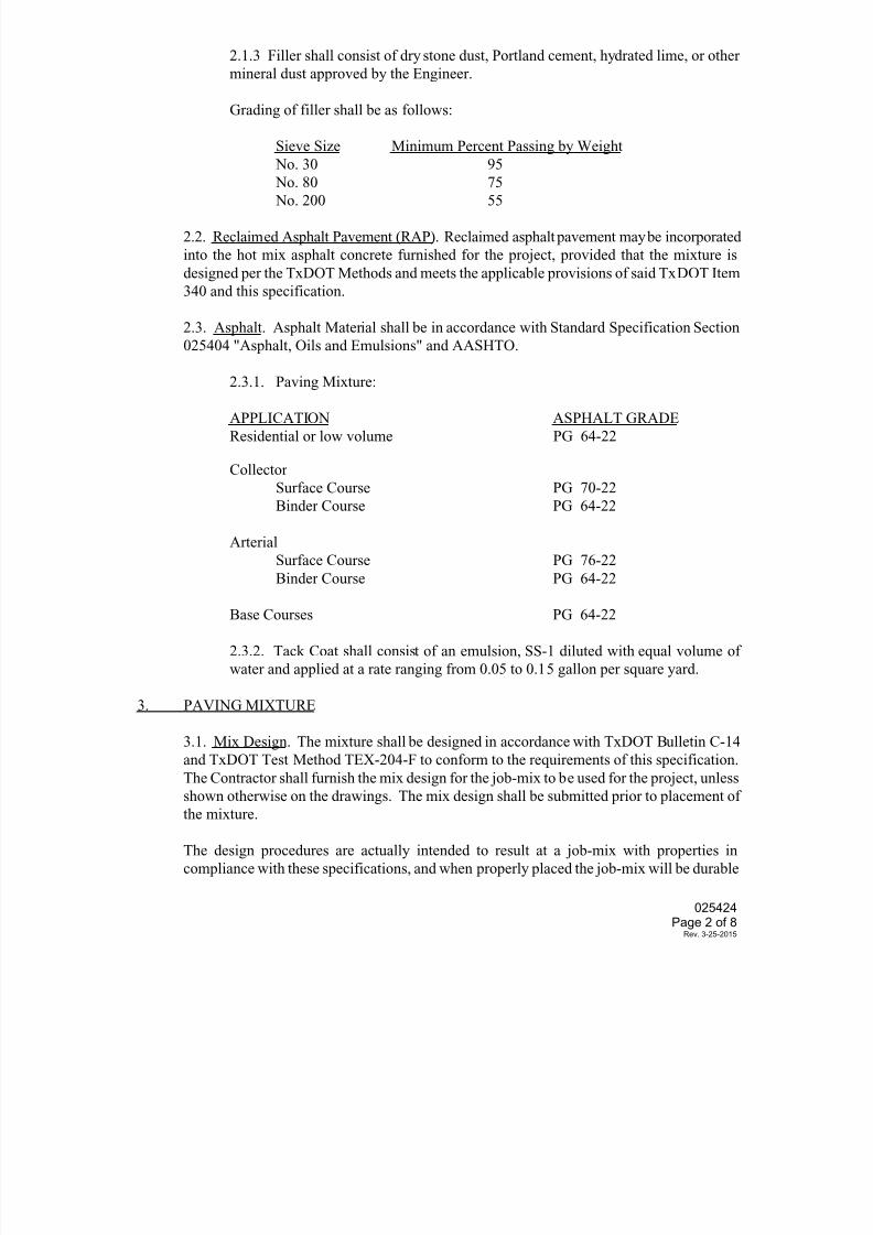
7/25/2019 City Standard Construction Specifications
http://slidepdf.com/reader/full/city-standard-construction-specifications 124/511
2.1.3 Filler shall consist of dry stone dust, Portland cement, hydrated lime, or other
mineral dust approved by the Engineer.
Grading of filler shall be as follows:
Sieve Size Minimum Percent Passing by Weight
No. 30 95
No. 80 75
No. 200 55
2.2. Reclaimed Asphalt Pavement (RAP). Reclaimed asphalt pavement may be incorporated
into the hot mix asphalt concrete furnished for the project, provided that the mixture is
designed per the TxDOT Methods and meets the applicable provisions of said TxDOT Item
340 and this specification.
2.3. Asphalt. Asphalt Material shall be in accordance with Standard Specification Section
025404 "Asphalt, Oils and Emulsions" and AASHTO.
2.3.1. Paving Mixture:
APPLICATION ASPHALT GRADE
Residential or low volume PG 64-22
Collector
Surface Course PG 70-22
Binder Course PG 64-22
Arterial
Surface Course PG 76-22
Binder Course PG 64-22
Base Courses PG 64-22
2.3.2. Tack Coat shall consist of an emulsion, SS-1 diluted with equal volume of
water and applied at a rate ranging from 0.05 to 0.15 gallon per square yard.
3. PAVING MIXTURE
3.1. Mix Design. The mixture shall be designed in accordance with TxDOT Bulletin C-14
and TxDOT Test Method TEX-204-F to conform to the requirements of this specification.
The Contractor shall furnish the mix design for the job-mix to be used for the project, unlessshown otherwise on the drawings. The mix design shall be submitted prior to placement of
the mixture.
The design procedures are actually intended to result at a job-mix with properties in
compliance with these specifications, and when properly placed the job-mix will be durable
025424Page 2 of 8
Rev. 3-25-2015
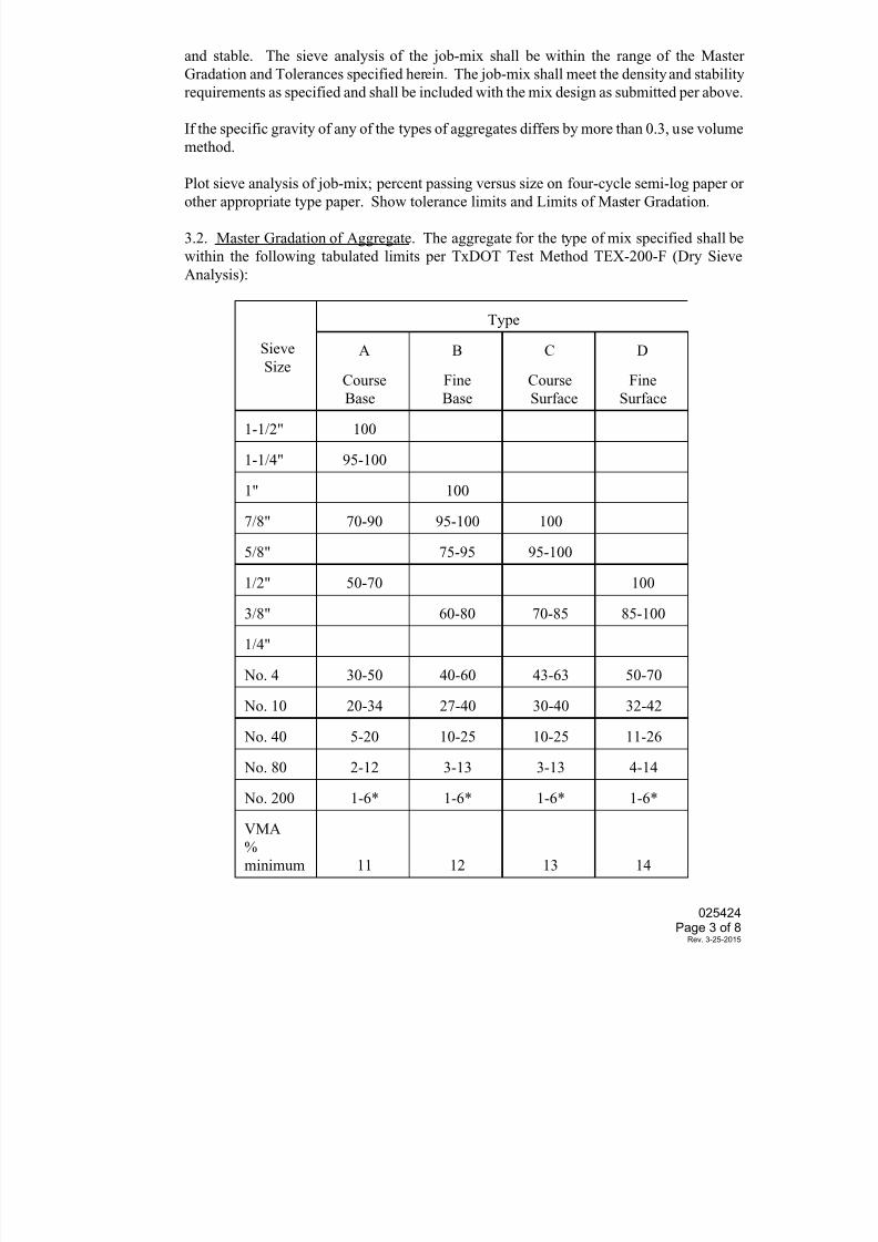
7/25/2019 City Standard Construction Specifications
http://slidepdf.com/reader/full/city-standard-construction-specifications 125/511
and stable. The sieve analysis of the job-mix shall be within the range of the Master
Gradation and Tolerances specified herein. The job-mix shall meet the density and stability
requirements as specified and shall be included with the mix design as submitted per above.
If the specific gravity of any of the types of aggregates differs by more than 0.3, use volume
method.
Plot sieve analysis of job-mix; percent passing versus size on four-cycle semi-log paper or
other appropriate type paper. Show tolerance limits and Limits of Master Gradation.
3.2. Master Gradation of Aggregate. The aggregate for the type of mix specified shall be
within the following tabulated limits per TxDOT Test Method TEX-200-F (Dry Sieve
Analysis):
Sieve
Size
Type
A B C D
Course
Base
Fine
Base
Course
Surface
Fine
Surface
1-1/2" 100
1-1/4" 95-100
1" 100
7/8" 70-90 95-100 100
5/8" 75-95 95-100
1/2" 50-70 100
3/8" 60-80 70-85 85-100
1/4"
No. 4 30-50 40-60 43-63 50-70
No. 10 20-34 27-40 30-40 32-42
No. 40 5-20 10-25 10-25 11-26
No. 80 2-12 3-13 3-13 4-14
No. 200 1-6* 1-6* 1-6* 1-6*
VMA
%
minimum 11 12 13 14
025424Page 3 of 8
Rev. 3-25-2015
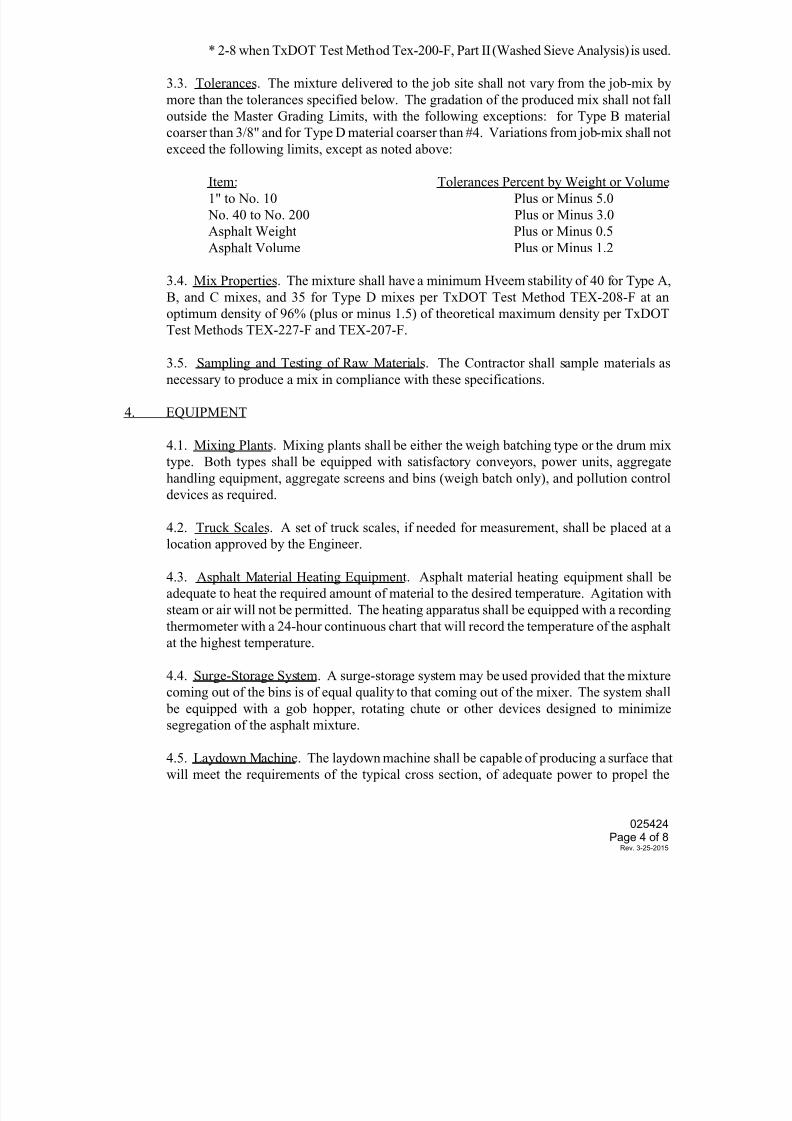
7/25/2019 City Standard Construction Specifications
http://slidepdf.com/reader/full/city-standard-construction-specifications 126/511
* 2-8 when TxDOT Test Method Tex-200-F, Part II (Washed Sieve Analysis) is used.
3.3. Tolerances. The mixture delivered to the job site shall not vary from the job-mix by
more than the tolerances specified below. The gradation of the produced mix shall not fall
outside the Master Grading Limits, with the following exceptions: for Type B material
coarser than 3/8" and for Type D material coarser than #4. Variations from job-mix shall not
exceed the following limits, except as noted above:
Item: Tolerances Percent by Weight or Volume1" to No. 10 Plus or Minus 5.0
No. 40 to No. 200 Plus or Minus 3.0
Asphalt Weight Plus or Minus 0.5
Asphalt Volume Plus or Minus 1.2
3.4. Mix Properties. The mixture shall have a minimum Hveem stability of 40 for Type A,
B, and C mixes, and 35 for Type D mixes per TxDOT Test Method TEX-208-F at an
optimum density of 96% (plus or minus 1.5) of theoretical maximum density per TxDOT
Test Methods TEX-227-F and TEX-207-F.
3.5. Sampling and Testing of Raw Materials. The Contractor shall sample materials as
necessary to produce a mix in compliance with these specifications.
4. EQUIPMENT
4.1. Mixing Plants. Mixing plants shall be either the weigh batching type or the drum mix
type. Both types shall be equipped with satisfactory conveyors, power units, aggregate
handling equipment, aggregate screens and bins (weigh batch only), and pollution control
devices as required.
4.2. Truck Scales. A set of truck scales, if needed for measurement, shall be placed at alocation approved by the Engineer.
4.3. Asphalt Material Heating Equipment. Asphalt material heating equipment shall be
adequate to heat the required amount of material to the desired temperature. Agitation with
steam or air will not be permitted. The heating apparatus shall be equipped with a recording
thermometer with a 24-hour continuous chart that will record the temperature of the asphalt
at the highest temperature.
4.4. Surge-Storage System. A surge-storage system may be used provided that the mixture
coming out of the bins is of equal quality to that coming out of the mixer. The system shall
be equipped with a gob hopper, rotating chute or other devices designed to minimizesegregation of the asphalt mixture.
4.5. Laydown Machine. The laydown machine shall be capable of producing a surface that
will meet the requirements of the typical cross section, of adequate power to propel the
025424Page 4 of 8
Rev. 3-25-2015
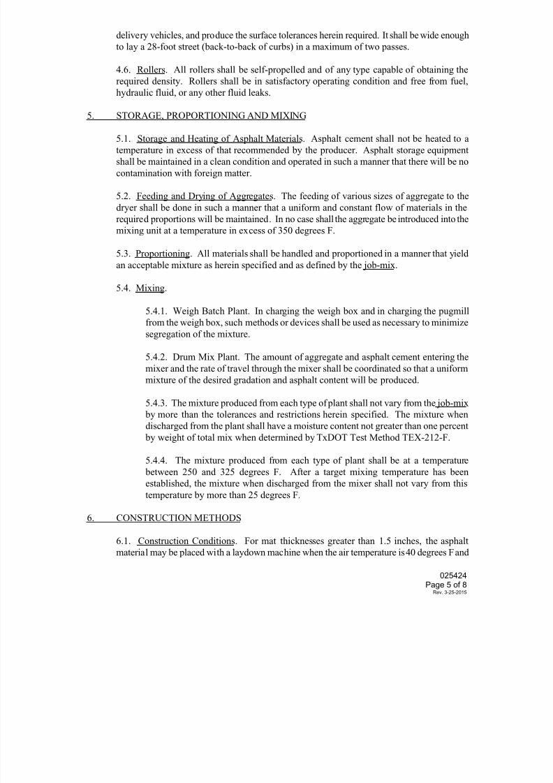
7/25/2019 City Standard Construction Specifications
http://slidepdf.com/reader/full/city-standard-construction-specifications 127/511
delivery vehicles, and produce the surface tolerances herein required. It shall be wide enough
to lay a 28-foot street (back-to-back of curbs) in a maximum of two passes.
4.6. Rollers. All rollers shall be self-propelled and of any type capable of obtaining the
required density. Rollers shall be in satisfactory operating condition and free from fuel,
hydraulic fluid, or any other fluid leaks.
5. STORAGE, PROPORTIONING AND MIXING
5.1. Storage and Heating of Asphalt Materials. Asphalt cement shall not be heated to a
temperature in excess of that recommended by the producer. Asphalt storage equipment
shall be maintained in a clean condition and operated in such a manner that there will be no
contamination with foreign matter.
5.2. Feeding and Drying of Aggregates. The feeding of various sizes of aggregate to the
dryer shall be done in such a manner that a uniform and constant flow of materials in the
required proportions will be maintained. In no case shall the aggregate be introduced into the
mixing unit at a temperature in excess of 350 degrees F.
5.3. Proportioning. All materials shall be handled and proportioned in a manner that yield
an acceptable mixture as herein specified and as defined by the job-mix.
5.4. Mixing.
5.4.1. Weigh Batch Plant. In charging the weigh box and in charging the pugmill
from the weigh box, such methods or devices shall be used as necessary to minimize
segregation of the mixture.
5.4.2. Drum Mix Plant. The amount of aggregate and asphalt cement entering the
mixer and the rate of travel through the mixer shall be coordinated so that a uniformmixture of the desired gradation and asphalt content will be produced.
5.4.3. The mixture produced from each type of plant shall not vary from the job-mix
by more than the tolerances and restrictions herein specified. The mixture when
discharged from the plant shall have a moisture content not greater than one percent
by weight of total mix when determined by TxDOT Test Method TEX-212-F.
5.4.4. The mixture produced from each type of plant shall be at a temperature
between 250 and 325 degrees F. After a target mixing temperature has been
established, the mixture when discharged from the mixer shall not vary from this
temperature by more than 25 degrees F.
6. CONSTRUCTION METHODS
6.1. Construction Conditions. For mat thicknesses greater than 1.5 inches, the asphalt
material may be placed with a laydown machine when the air temperature is 40 degrees F and
025424Page 5 of 8
Rev. 3-25-2015
7/25/2019 City Standard Construction Specifications
http://slidepdf.com/reader/full/city-standard-construction-specifications 128/511
rising but not when the air temperature is 50 degrees F and falling. In addition, mat thickness
less than and including 1.5 inches shall not be placed when the temperature of the surface on
which the mat is placed is below 50 degrees F.
All subsurface utilities shall be inspected, tested, and accepted prior to paving.
6.2. Prime Coat. If a prime coat is required, it shall be applied and paid for as a separate
item conforming to the requirements of City Standard Specification Section 025412 "Prime
Coat", except the application temperature shall be as provided above. The tack coat orasphaltic concrete shall not be applied on a previously primed flexible base until the primed
base has completely cured to the satisfaction of the Engineer.
6.3. Tack Coat. Before the asphalt mixture is laid, the surface upon which the tack coat is to
be placed shall be thoroughly cleaned to the satisfaction of the Engineer. The surface shall
be given a uniform application of tack coat using materials and rates herein specified and/or
as shown on the plans. The tack coat shall be rolled with a pneumatic tire roller as necessary.
Tack coat is required before any pavement course not placed immediately following the
previous course placement.
6.4. Transporting Asphalt Concrete. The asphalt mixture shall be hauled to the job site in
tight vehicles previously cleaned of all foreign matter. In cool weather or for long hauls,
canvas covers and insulated truck beds may be necessary. The inside of the bed may be
given a light coating of lime water or other suitable release agent necessary to prevent from
adhering. Diesel oil is not allowed.
6.5. Placing. The asphalt mixture shall be spread on the approved prepared surface with a
laydown machine or other approved equipment in such a manner that when properly
compacted, the finished surface will be smooth and of uniform density, and meet the
requirements of the typical cross section as shown on the plans.
6.5.1. Flush Structures. Adjacent to flush curbs, gutters, liners and structures, the
surface shall be finished uniformly high so that when compacted, it will be slightly
above the edge of the curb and flush structure.
6.5.2. Construction joints of successive courses of asphaltic material shall be offset
at least six inches. Construction joints on surface courses shall coincide with lane
lines, or as directed by the Engineer, but shall not be in the anticipated wheel path of
the roadway.
6.6. Compacting. The asphalt mixture shall be compacted thoroughly and uniformly with
the necessary rollers to obtain the required density and surface tolerances herein describedand any requirements as shown on the plans. Regardless of the method of compaction
control followed, all rolling shall be completed before the mixture temperature drops below
175 degrees F.
025424Page 6 of 8
Rev. 3-25-2015
7/25/2019 City Standard Construction Specifications
http://slidepdf.com/reader/full/city-standard-construction-specifications 129/511
6.7. In-Place Density. In-place density control is required for all mixtures except for thin,
irregular level-up courses. Material should be compacted to between 96% and 92% of
maximum theoretical density or between 4% and 8% air voids. Average density shall be
greater than 92% and no individual determination shall be lower than 90%. Testing shall be
in accordance with TxDOT Test Methods TEX-207-F and TEX-227-F.
Pavement specimens, which shall be either cores or sections of the compacted mixture, will
be tested as required to determine the percent air voids. Other methods, such as nuclear
determination of in-place density, which correlate satisfactorily with actual project specimensmay be used when approved by the Engineer.
6.8. Thickness. The total compacted average thickness of the combined HMAC courses
shall not be less than the amount specified on the drawings. No more than 10% of the
measured thickness(es) shall be more than 1/4 inch less than the plan thickness(es). If so, the
quantity for pay shall be decreased as deemed appropriate by the Engineer.
6.9. Surface Smoothness Criteria and Tests. The pavement surface after compaction, shall
be smooth and true to the established lines, grade and cross-section. The surface shall be
tested by the City with the Mays Roughness Meter. The Mays Roughness Value for each
600-foot section shall not exceed ninety inches per mile per traffic lane.
For each 600-foot section not meeting this criteria, the Engineer shall have the option of
requiring that section to be reworked to meet the criteria, or paying an adjusted unit price for
the surface course. The unit price adjustment shall be made on the following basis:
Adjusted Unit Price = (Adjustment Factor) X Surface Course Unit Bid Price
The adjustment factor shall be:
For Residential Streets:
Adjustment Factor = 1.999 - 0.0111 M
For All Other Class Streets (Non Residential)
Adjustment Factor = 1.287 - 0.0143 M
Where M = Mays Roughness Value
In no case shall the Contractor be paid more than the unit bid price. If the surface course is
an inverted penetration (surface treatment) the Mays Roughness Value observed will bereduced by ten inches per mile, prior to applying the above criteria.
Localized defects (obvious settlements, humps, ridges, etc.) shall be tested with a ten-foot
straightedge placed parallel to the roadway centerline. The maximum deviation shall not
025424Page 7 of 8
Rev. 3-25-2015
7/25/2019 City Standard Construction Specifications
http://slidepdf.com/reader/full/city-standard-construction-specifications 130/511
exceed 1/8 inch in ten feet. Areas not meeting this criteria shall be corrected to the
satisfaction of the Engineer.
Pavement areas having surface irregularities, segregation, raveling or otherwise deemed
unacceptable by the Engineer shall be removed and replaced by the Contractor in a manner
approved by the Engineer, at no additional cost to the City.
6.10. Opening to Traffic. The pavement shall be opened to traffic when directed by the
Engineer. The Contractor's attention is directed to the fact that all construction trafficallowed on pavement open to the public will be subject to the State laws governing traffic on
highways.
If the surface ravels, it will be the Contractor's responsibility to correct this condition at his
expense.
7. MEASUREMENT AND PAYMENT
Unless otherwise specified on the Bid Form, hot mix asphaltic concrete pavement shall be
measured by the square yard of the type and thickness of "Hot Mix Asphaltic Concrete" as
shown on the drawings.
The Contractor shall provide the Engineer with copies of the "pay ticket" identifying the
truck and showing the gross empty weight of the truck with driver as it arrives at the plant
and the gross loaded weight of the truck with driver as it leaves the plant. The measured
amount will be the difference of the loaded and empty trucks converted to tons.
Payment shall be full compensation for quarrying, furnishing all materials, freight involved;
for all heating, mixing, hauling, cleaning the existing base course or pavement, tack coat,
placing asphaltic concrete mixture, rolling and finishing; and for all manipulations, labor,
tools, equipment, and incidentals necessary to complete the work except prime coat whenrequired.
Prime coat, performed where required, will be measured and paid for in accordance with the
provisions governing City Standard Specification Section 025412 "Prime Coat".
All templates, straightedges, scales, and other weight and measuring devices necessary for
the proper construction, measuring and checking of the work shall be furnished, operated
and maintained by the Contractor at his expense.
Any paving placed prior to inspection, testing, and acceptance of underground utilities may
be rejected by the City and will be replaced at the Contractor’s expense after correcting anysubsurface utility defects. Pavement that fails to meet the in place density criteria may be
rejected by the City and will be replaced at the Contractor’s expense, or such pavement may,
at the City’s discretion, be accepted by the City and the unit price for payment shall be
reduced as deemed appropriate by the Engineer.
025424Page 8 of 8
Rev. 3-25-2015
7/25/2019 City Standard Construction Specifications
http://slidepdf.com/reader/full/city-standard-construction-specifications 131/511
SECTION 025608
INLETS
1. DESCRIPTION
This specification shall govern for the construction of inlets complete in place and the materialsused therein, including the installation, and the furnishing of frames, grates, rings and covers.
2. TYPES
The various types of inlets are designated on the drawings by letters or by numbers indicating the
particular design of each. Each type shall be constructed in accordance with the details shown on
the drawings and to the depth required by the profiles and schedules given.
3. MATERIALS
(1) Concrete. Concrete for curb inlets shall be Class "A" concrete conforming to therequirements of City Standard Specification Section 038000 "Concrete Structures", and City
Standard Specification Section 030020 "Portland Cement Concrete", except as otherwise
provided on the drawings. Concrete for grate inlets, drop inlets and post inlets shall be
Class "C" concrete in accordance with City Standard Specification Section 030020
"Portland Cement Concrete".
(2) Mortar. Mortar shall be composed of one part Portland cement and two parts clean, sharp
mortar sand suitably graded for the purpose by conforming in other respects to the
provisions of City Standard Specification Section 030020 "Portland Cement Concrete" for
fine aggregate. Hydrated lime or lime putty may be added to the mix but in no case shall it
exceed 10 percent by weight of the total dry mix.
(3) Reinforcing Steel. Reinforcing Steel shall conform to the requirements of City Standard
Specification Section 032020 "Reinforcing Steel".
(4) Concrete Blocks. Concrete blocks, when shown on the drawings, shall conform to the
requirements of ASTM C 139.
(5) Frames, Grates, Rings and Covers. Frames, grates, rings and covers shall conform to the
requirements of City Standard Specification Section 055420 "Frames, Grates, Rings and
Covers".
(6) Cast Iron. Cast iron for supports and inlet units shall conform to the shape and dimensions
shown on the plans. The castings shall be clean and perfect, free from sand or blow holes or
other defects. Cast iron castings shall conform to the requirements of "Gray Iron Castings"
ASTM A 48, Class 30.
025608
Page 1 of 2
Rev. 3-25-2015
7/25/2019 City Standard Construction Specifications
http://slidepdf.com/reader/full/city-standard-construction-specifications 132/511
4. CONSTRUCTION METHODS
(1) General. All concrete work shall be performed in accordance with the requirements of City
Standard Specification Section 038000 "Concrete Structures", unless otherwise specified.
Forms will be required for all concrete walls, except where the nature of the surrounding
material is such that it can be trimmed to a smooth vertical face.
(2) Inlets for Precast Concrete Pipe Sewers. The construction of inlets for precast concrete pipe
sewers shall be done as soon as is practicable after sewer lines into or through inlet
locations are completed. All sewers shall be cut neatly at the inside face of the walls of inlet
and pointed up with mortar. Subgrade under cast-in-place and precast inlets shall be
compacted to not less than 95% Standard Proctor density.
(3) Inverts. The inverts passing out or through the inlet shall be shaped and routed across the
floor of inlet as shown on the plans. This shaping may be accomplished by adding and
shaping mortar or concrete after the base is cast or by placing the required additional
material with the base.
(4) Finishing Complete Inlets. Inlets shall be completed in accordance with the drawings.
Backfilling to finish grade elevation with native material, free of debris and compacted to
over 95% Standard Proctor density. Backfilling shall be in accordance with the provisions
of City Standard Specification Section 022020 "Excavation and Backfill for Utilities".
5. MEASUREMENT AND PAYMENT
Unless otherwise specified on the Bid Form, inlets shall be measured as individual units by each
inlet, complete in place.
Extension to inlets will be measured by each extension separately from the inlet.
Excavation, backfill, frames, grates, rings and covers will be considered subsidiary to the
construction of the inlets.
Payments shall be full compensation for furnishing all concrete, reinforcing steel, mortar, castings,
frames, grates, rings and covers, and for all other materials, labor , tools, equipment and incidentals
required to perform the work prescribed above.
025608
Page 2 of 2
Rev. 3-25-2015
7/25/2019 City Standard Construction Specifications
http://slidepdf.com/reader/full/city-standard-construction-specifications 133/511
SECTION 025610
CONCRETE CURB AND GUTTER
1. DESCRIPTION
This specification shall consist of Portland cement concrete combined concrete curb and gutter or
separate concrete curb with or without reinforcing steel as required, constructed on an approved
subgrade or foundation material in accordance with these specifications, in conformity with the
lines and grades established by the Engineer and details shown on the drawings.
2. MATERIALS
Unless otherwise specified on the drawings, materials and proportions for concrete used in
construction under this specification shall conform to the requirements as specified for Class "A"
Concrete under City Standard Specification Section 030020 "Portland Cement Concrete".
Reinforcing steel shall conform to the requirements as specified in City Standard SpecificationSection 032020 "Reinforcing Steel". Expansion joint filler shall be redwood material meeting the
requirements specified in City Standard Specification Section 038000 "Concrete Structures".
3. CONSTRUCTION METHODS
The foundation shall be excavated and shaped to line, grade and cross-section, and hand tamped
and sprinkled. If dry, the subgrade or foundation material shall be sprinkled lightly with water and
compacted to not less than 98% Standard Proctor density, or as required on the drawings. Flexible
base shall be compacted to specified density and moisture immediately before concrete is deposited
thereon.
Outside forms shall be of wood or metal, of a section satisfactory to the Engineer, straight, free of
warp, and of a depth equal to the depth of the curb and gutter. They shall be securely staked to line
and grade, and maintained in a true position during the depositing of concrete. Inside forms for the
curb shall be approved material, shall be of such design as to provide the curb required, and shall be
rigidly attached to the outside forms. For reinforced concrete roadways, all jointing must be
reflected through the curb, including redwood expansion joints and construction joints. Driveway
gutter shall be placed integrally with the driveway as shown on the City Standard Details.
The reinforcing steel shall be placed in position as shown on the typical details. Care shall be
exercised to keep all reinforcing steel in its proper location.
Concrete for curb and gutter shall be mixed in a manner satisfactory to the Engineer. The curb and
gutter shall be placed in sections of the length indicated on the plans, and each section shall be
separated by a premolded insert or board joint of cross-section specified for the curb and gutter, and
of the thickness indicated on the drawings.
025610
Page 1 of 2
Rev. 3-25-2015
7/25/2019 City Standard Construction Specifications
http://slidepdf.com/reader/full/city-standard-construction-specifications 134/511
After the concrete has been struck off and after it has become sufficiently set, the exposed surfaces
shall be thoroughly worked with a wooden float. The exposed edges shall be rounded by the use of
an edging tool to the radius indicated on the drawings. All exposed surfaces of curb and gutter, or
curb, shall be brushed to a smooth and uniform surface.
The completed curb and gutter shall be cured with Type 2, white pigmented curing compoundunless shown otherwise on the drawings. Other methods of curing as outlined in City Standard
Specification Section 038000 "Concrete Structures" will be acceptable with a required curing
period of 72 hours.
The area behind the curb shall be backfilled, tamped, and sloped as directed as soon as possible and
no later than 48 hours after the removal of forms. Backfill shall be placed to the full height of the
curb, or as otherwise specified.
4. MEASUREMENT AND PAYMENT
Unless otherwise specified on the Bid Form, concrete curb and gutter or concrete curb will bemeasured by the linear foot for each type of curb, complete in place. Payment shall be full
compensation for preparing the subgrade; for furnishing and placing all materials including
reinforcing steel and expansion joint material; for furnishing, placing, shaping and tamping backfill;
and for all manipulation, labor, tools, equipment and incidentals necessary to complete the work.
025610
Page 2 of 2
Rev. 3-25-2015
7/25/2019 City Standard Construction Specifications
http://slidepdf.com/reader/full/city-standard-construction-specifications 135/511
SECTION 025612
CONCRETE SIDEWALKS AND DRIVEWAYS
1. DESCRIPTION
This specification shall consist of sidewalks and driveways, with or without reinforcing steel,
composed of Portland cement concrete, constructed as herein specified on an approved subgrade, in
conformity with the lines and grades established by the Engineer and the details shown on the
drawings.
2. MATERIALS
Materials and proportions used in construction under this item shall conform to the requirements as
specified for Class "A" concrete under City Standard Specification Section 030020 "Portland Cement
Concrete". Reinforcing steel shall conform to the requirements as specified in City Standard
Specification Section 032020 "Reinforcing Steel". Expansion joint filler shall be redwood meetingthe requirements specified in City Standard Specification Section 038000 "Concrete Structures". Cap
seal shall be “Greenstreak” or approved equal.
3. CONSTRUCTION METHODS
The subgrade shall be excavated, compacted and shaped to line, grade and cross-section and hand
tamped and sprinkled with water. Subgrade under concrete sidewalks and driveways shall be
compacted to not less than 95% Standard Proctor density. The subgrade shall be within 0-3% of
optimum moisture content at the time the concrete is placed.
Forms shall be of wood or metal, of a section satisfactory to the Engineer, straight, free from warp,
and of a depth equal to the thickness of the finished work. They shall be securely staked to line and
grade and maintained in a true position during the depositing of concrete.
The reinforcing steel shall be placed in position as shown on the drawings. Care shall be exercised
to keep all reinforcing steel in its proper location.
Driveways shall incorporate the gutter in a unified concrete placement as shown in the City Standard
Detail for driveways.
Sidewalks shall be constructed in sections of the lengths shown on drawings. Unless otherwise
provided by the drawings, no section shall be of a length less than 8 feet, and any section less than 8
feet shall be removed by the Contractor at his own expense.
025612Page 1 of 2
Rev. 3-25-2015
7/25/2019 City Standard Construction Specifications
http://slidepdf.com/reader/full/city-standard-construction-specifications 136/511
The different sections shall be separated by a premolded insert or board joint of the thickness shown
on the drawings, placed vertically and at right angles to the longitudinal axis of the sidewalks.
Where the sidewalk or driveways abut a curb or retaining wall, approved expansion joint material
shall be placed along their entire length. Similar expansion joint material shall be placed around all
obstructions protruding through sidewalks or driveways.
Concrete shall be mixed in a manner satisfactory to the Engineer, placed in the forms to the depth
specified and spaded and tamped until thoroughly compacted and mortar entirely covers the surface.
The top surface shall be floated with a wooden float to a gritty texture. The outer edges and joints
shall then be rounded with approved tools to the radii shown on drawings.
5-foot wide sidewalks shall be marked into separate sections, each 5 feet in length, by the use of
approved jointing tools. For other widths of sidewalk, joints to be spaced longitudinally to match the
transverse width.
When completed, the sidewalks and driveways shall be cured with Type 2, white pigmented curing
compound. Other methods of curing as outlined in City Standard Specification Section 038000"Concrete Structures" will be acceptable with a required curing period of 72 hours.
4. MEASUREMENT AND PAYMENT
Unless otherwise specified on the Bid Form, concrete sidewalks and driveways shall be measured by
the square foot of surface area of completed sidewalks, driveways, or sidewalks and driveways, as
indicated on the drawings.
Payment shall be full compensation for preparing and compacting the subgrade; for furnishing and
placing all materials including concrete, reinforcing steel and expansion joint material; and for all
manipulation, labor, tools, equipment and incidentals necessary to complete the work.
025612Page 2 of 2
Rev. 3-25-2015
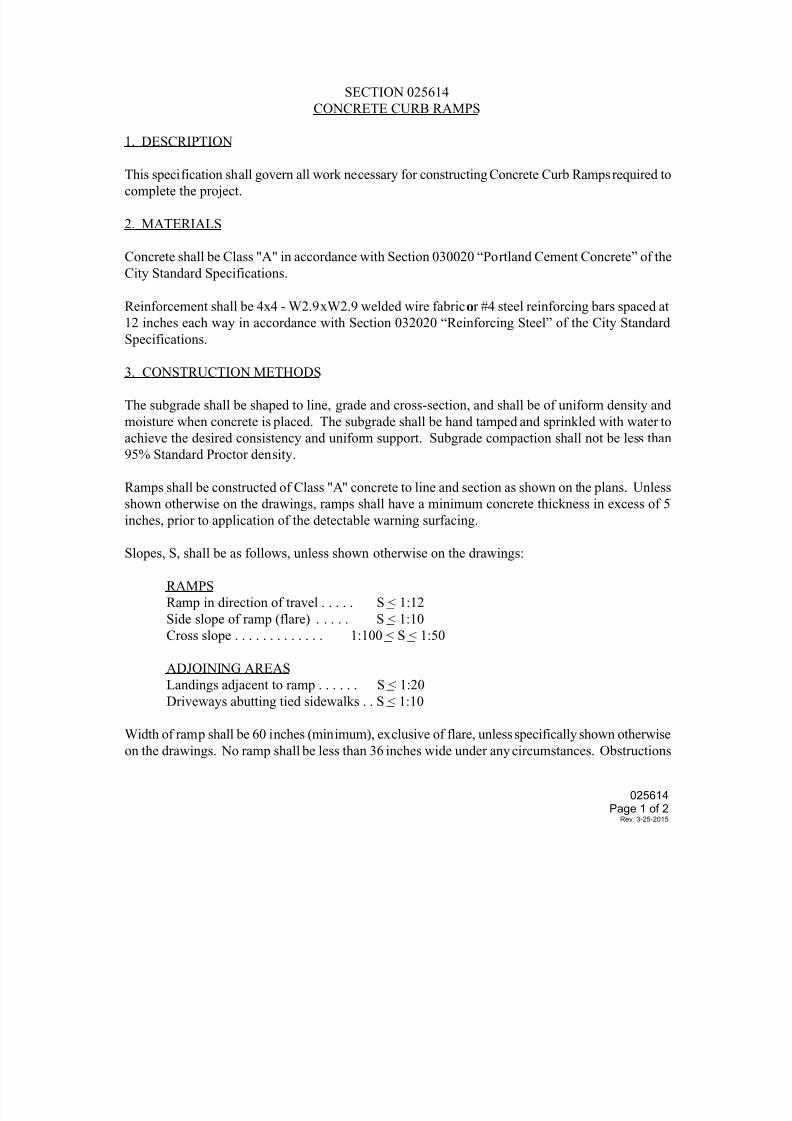
7/25/2019 City Standard Construction Specifications
http://slidepdf.com/reader/full/city-standard-construction-specifications 137/511
SECTION 025614
CONCRETE CURB RAMPS
1. DESCRIPTION
This specification shall govern all work necessary for constructing Concrete Curb Ramps required tocomplete the project.
2. MATERIALS
Concrete shall be Class "A" in accordance with Section 030020 “Portland Cement Concrete” of the
City Standard Specifications.
Reinforcement shall be 4x4 - W2.9xW2.9 welded wire fabric or #4 steel reinforcing bars spaced at
12 inches each way in accordance with Section 032020 “Reinforcing Steel” of the City Standard
Specifications.
3. CONSTRUCTION METHODS
The subgrade shall be shaped to line, grade and cross-section, and shall be of uniform density and
moisture when concrete is placed. The subgrade shall be hand tamped and sprinkled with water to
achieve the desired consistency and uniform support. Subgrade compaction shall not be less than
95% Standard Proctor density.
Ramps shall be constructed of Class "A" concrete to line and section as shown on the plans. Unless
shown otherwise on the drawings, ramps shall have a minimum concrete thickness in excess of 5
inches, prior to application of the detectable warning surfacing.
Slopes, S, shall be as follows, unless shown otherwise on the drawings:
RAMPS
Ramp in direction of travel . . . . . S < 1:12
Side slope of ramp (flare) . . . . . S < 1:10
Cross slope . . . . . . . . . . . . . 1:100 < S < 1:50
ADJOINING AREAS
Landings adjacent to ramp . . . . . . S < 1:20
Driveways abutting tied sidewalks . . S < 1:10
Width of ramp shall be 60 inches (minimum), exclusive of flare, unless specifically shown otherwise
on the drawings. No ramp shall be less than 36 inches wide under any circumstances. Obstructions
025614Page 1 of 2
Rev. 3-25-2015
7/25/2019 City Standard Construction Specifications
http://slidepdf.com/reader/full/city-standard-construction-specifications 138/511
shall be removed or relocated, as appropriate, or the location of the ramp may be shifted, if
authorized.
Detectable warning surface shall be polymer composite material detectable warning panels as shown
on the drawings. Surfacing shall be flush with abutting areas and placed using a template as required
to achieve an esthetic well-defined edge. Surfacing shall be subsidiary work and will not bemeasured for separate pay.
Pavement markings for street crossings shall be placed such that the crosswalk is properly aligned
with respect to the curb ramp. See striping details for proper alignment of pavement markings with
respect to intersection and curb ramp.
Properly constructed curb ramp shall be true to line, section and grade, and shall be free of loose
material and irregularities.
4. MEASUREMENT AND PAYMENT
Unless otherwise specified on the Bid Form, concrete curb ramps shall be measured by the horizontal
square foot of ramp surface area, including side flares when used. Adjoining curbs, gutters,
sidewalks, and driveways will be excluded from said measurement.
Payment shall include, but not be limited to, subgrade preparation, formwork, concrete, rebar,
detectable warning surfaces, borders, molding and curing required to complete the curb ramp, and
shall be full compensation for all labor, materials, equipment and incidentals required to complete
the work.
025614Page 2 of 2
Rev. 3-25-2015
7/25/2019 City Standard Construction Specifications
http://slidepdf.com/reader/full/city-standard-construction-specifications 139/511
SECTION 025620
PORTLAND CEMENT CONCRETE PAVEMENT
1. DESCRIPTION
This specification shall govern for the construction of Portland cement concrete pavement on a prepared subgrade or base course, in accordance with the typical sections shown on the drawings.
The concrete shall be composed of Portland cement, aggregates (fine and coarse), admixtures if
desired or required, and water, proportioned and mixed as hereinafter provided.
All subsurface utilities must be inspected, tested, and accepted prior to any paving.
2. MATERIALS
(1) Cement
The cement shall be either Type I, Type II or Type III Portland cement conforming to ASTMDesignation: C150, modified as follows:
Unless otherwise specified by the Engineer, the specific surface area of Type I and II
cements shall not exceed 2000 square centimeters per gram (Wagner Turbidimeter –
TxDOT Test Method Tex-310-D). The Contractor shall furnish the Engineer with a
statement as to the specific surface area of the cement, expressed in square
centimeters per gram, for each shipment.
For concrete pavements, strength requirements shall be demonstrated using flexural (beam) or
compressive (cylinder) tests as required in the drawings.
Either Type I or II cement shall be used unless Type II is specified on the plans. Except when Type
II is specified on the plans, Type III cement may be used when the anticipated air temperature for
the succeeding 12 hours will not exceed 60°F. Type III cement shall be used when high early
strength concrete pavement is specified on the drawings.
Different types of cement may be used in the same project, but all cement used in any one
monolithic placement of concrete pavement shall be of the same type and brand. Only one brand of
each type of cement will be permitted in any one project unless otherwise authorized by the
Engineer.
Cement may be delivered in bulk where adequate bin storage is provided. All other cement shall bedelivered in bags marked plainly with the name of the manufacturer and the type of cement.
Similar information shall be provided in the bills of lading accompanying each shipment of
packaged or bulk cement. Bags shall contain 94 pounds net. All bags shall be in good condition at
time of delivery.
All cement shall be properly protected against dampness. No caked cement will be accepted.
025620
Page 1 of 5
Rev. 3-25-2015
7/25/2019 City Standard Construction Specifications
http://slidepdf.com/reader/full/city-standard-construction-specifications 140/511
Cement remaining in storage for a prolonged period of time may be retested and rejected if it fails
to conform to any of the requirements of these specifications.
(2) Mixing Water
Water for use in concrete and for curing shall be in accordance with City Standard Specification
Section 030020 “Portland Cement Concrete”.
(3) Coarse Aggregate
Coarse aggregate for use in concrete mixture shall be in accordance with City Standard
Specification Section 030020 “Portland Cement Concrete”, Grade No. 2.
(4) Fine Aggregate
Fine aggregate for use in concrete mixture shall be in accordance with City Standard Specification
Section 030020 “Portland Cement Concrete”, Grade No. 1.
(5) Mineral Filler
Mineral filler shall consist of stone dust, clean crushed sand, or other approved inert material.
(6) Mortar (Grout)
Mortar for repair of concrete pavements shall consist of 1 part cement, 2 parts finely graded sand,
and enough water to make the mixture plastic. When required to prevent color difference, white
cement shall be added to produce the color required. When required by the Engineer, latex
adhesive shall be added to the mortar.
(7) Admixtures
Calcium chloride will not be permitted. Unless otherwise noted, air-entraining, retarding and
water-reducing admixtures may be used in all concrete and shall conform to the requirements of
City Standard Specification Section 030020 “Portland Cement Concrete”.
(8) Reinforcing Steel
Unless otherwise designated on the plans, all steel reinforcement shall be deformed bars, and shall
conform to ASTM Designation: A615, Grade 60, and shall be open hearth, basic oxygen or electric
furnace new billet steel in accordance with City Standard Specification Section 032020
“Reinforcing Steel”.
Dowels shall be plain billet steel smooth bars conforming to ASTM Designation: A615, Grade 60,
and shall have hot-dip galvanized finish.
3. STORAGE OF MATERIALS
All cement and aggregate shall be stored and handled in accordance with City Standard
Specification Section 030020 “Portland Cement Concrete”.
025620
Page 2 of 5
Rev. 3-25-2015
7/25/2019 City Standard Construction Specifications
http://slidepdf.com/reader/full/city-standard-construction-specifications 141/511
4. MEASUREMENT OF MATERIALS
Measurement of the materials, except water, used in batches of concrete, shall be in accordance
with City Standard Specification Section 030020 “Portland Cement Concrete”.
5. CLASSIFICATION AND MIX DESIGN
It shall be the responsibility of the Contractor to furnish the mix design to comply with the
requirements herein and in accordance with THD Bulletin C-11. The Contractor shall perform, at
his own expense, the work required to substantiate the design, except the testing of strength
specimens, which will be done by the Engineer. Complete concrete design data shall be submitted
to the Engineer for approval.
It shall also be the responsibility of the Contractor to determine and measure the batch quantity of
each ingredient, including all water, so that the mix conforms to these specifications and any other
requirements shown on the plans.
In lieu of the above mix design responsibility, the Contractor may accept a design furnished by theEngineer; however, this will not relieve the Contractor of providing concrete meeting the
requirements of these specifications.
Trial batches will be made and tested using all of the proposed ingredients prior to placing the
concrete, and when the aggregate and/or brand of cement or admixture is changed. Trial batches
shall be made in the mixer to be used on the job. When transit mix concrete is to be used, the trial
designs will be made in a transit mixer representative of the mixers to be used. Batch size shall not
be less than 50 percent of the rated mixing capacity of the truck.
Mix designs from previous or concurrent jobs may be used without trial batches if it is shown that
no substantial change in any of the proposed ingredients has been made.
This specification section incorporates the requirements of City Standard Specification Section
030020 “Portland Cement Concrete”.
6. CONSISTENCY
In cases where the consistency requirements cannot be satisfied without exceeding the maximum
allowable amount of water, the Contractor may use, or the Engineer may require, an approved
water-reducing or retarding agent, or the Contractor shall furnish additional aggregates or
aggregates with different characteristics, which will produce the required results. Additional
cement may be required or permitted as a temporary measure until aggregates are changed anddesigns checked with the different aggregates or admixture.
The consistency of the concrete as placed should allow the completion of all finishing operations
without the addition of water to the surface. When field conditions are such that additional
moisture is needed for the final concrete surface finishing operation, the required water shall be
applied to the surface by fog spray only, and shall be held to a minimum. The concrete shall be
025620
Page 3 of 5
Rev. 3-25-2015
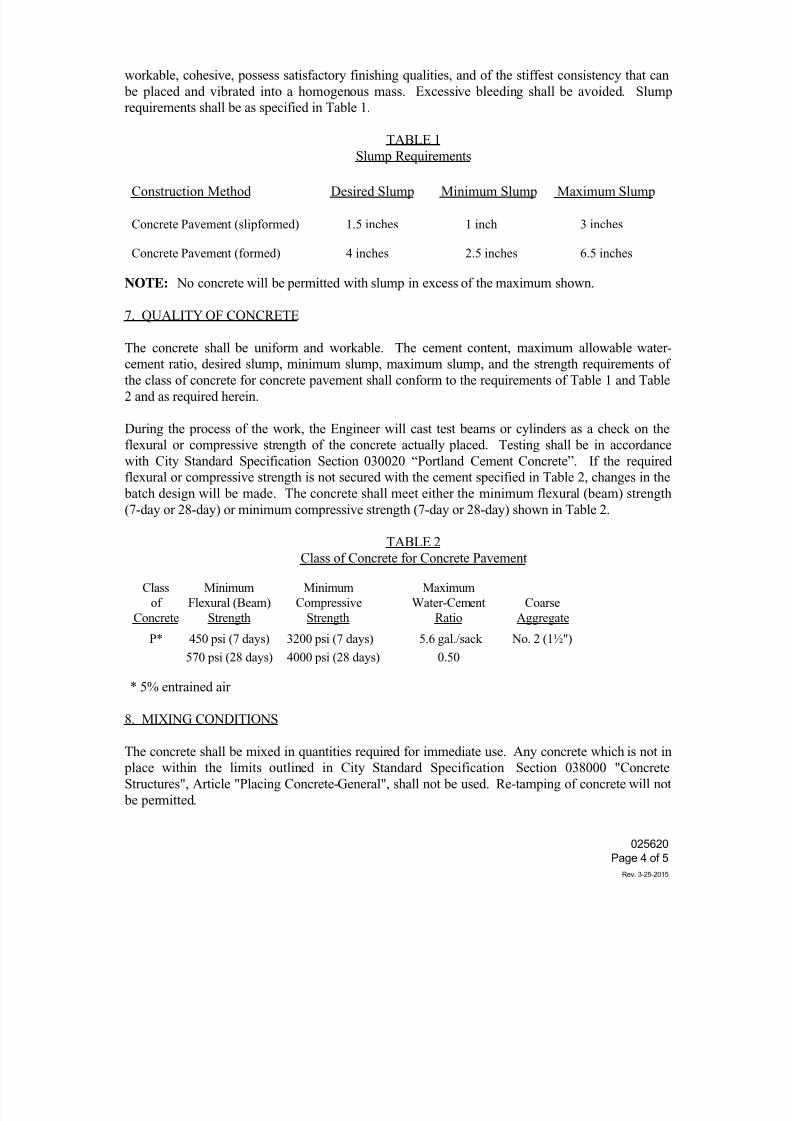
7/25/2019 City Standard Construction Specifications
http://slidepdf.com/reader/full/city-standard-construction-specifications 142/511
workable, cohesive, possess satisfactory finishing qualities, and of the stiffest consistency that can
be placed and vibrated into a homogenous mass. Excessive bleeding shall be avoided. Slump
requirements shall be as specified in Table 1.
TABLE 1
Slump Requirements
Construction Method Desired Slump Minimum Slump Maximum Slump
Concrete Pavement (slipformed) 1.5 inches 1 inch 3 inches
Concrete Pavement (formed) 4 inches 2.5 inches 6.5 inches
NOTE: No concrete will be permitted with slump in excess of the maximum shown.
7. QUALITY OF CONCRETE
The concrete shall be uniform and workable. The cement content, maximum allowable water-cement ratio, desired slump, minimum slump, maximum slump, and the strength requirements of
the class of concrete for concrete pavement shall conform to the requirements of Table 1 and Table
2 and as required herein.
During the process of the work, the Engineer will cast test beams or cylinders as a check on the
flexural or compressive strength of the concrete actually placed. Testing shall be in accordance
with City Standard Specification Section 030020 “Portland Cement Concrete”. If the required
flexural or compressive strength is not secured with the cement specified in Table 2, changes in the
batch design will be made. The concrete shall meet either the minimum flexural (beam) strength
(7-day or 28-day) or minimum compressive strength (7-day or 28-day) shown in Table 2.
TABLE 2
Class of Concrete for Concrete Pavement
Class Minimum Minimum Maximum
of Flexural (Beam) Compressive Water-Cement Coarse
Concrete Strength Strength Ratio Aggregate
P* 450 psi (7 days) 3200 psi (7 days) 5.6 gal./sack No. 2 (1½")
570 psi (28 days) 4000 psi (28 days) 0.50
* 5% entrained air
8. MIXING CONDITIONS
The concrete shall be mixed in quantities required for immediate use. Any concrete which is not in
place within the limits outlined in City Standard Specification Section 038000 "Concrete
Structures", Article "Placing Concrete-General", shall not be used. Re-tamping of concrete will not
be permitted.
025620
Page 4 of 5
Rev. 3-25-2015
7/25/2019 City Standard Construction Specifications
http://slidepdf.com/reader/full/city-standard-construction-specifications 143/511
Mixing conditions shall conform to the requirements of City Standard Specification Section 030020
“Portland Cement Concrete”.
9. MIXING AND MIXING EQUIPMENT
Mixing and mixing equipment shall conform to the requirements of City Standard SpecificationSection 030020 “Portland Cement Concrete”.
10. READY-MIX PLANTS
The requirements for ready-mix plants shall be as specified in City Standard Specification Section
030020 “Portland Cement Concrete”.
11. PLACING, CURING AND FINISHING
All subsurface utilities must be inspected, tested, and accepted prior to any paving.
Subgrade preparation shall be as specified on the plans. The placing of concrete, including
construction of forms and falsework, curing and finishing shall be in accordance with City Standard
Specification Section 038000 "Concrete Structures". For membrane curing, curing material shall
conform to Type 2, Class A curing compound, or as otherwise shown on the drawings.
12. JOINTS IN CONCRETE PAVEMENT
The placing of joints in concrete pavement shall be in accordance with City Standard Specification
Section 038000 "Concrete Structures" and as detailed on the drawings.
13. MEASUREMENT AND PAYMENT
Unless otherwise specified on the Bid Form, the quantities of concrete for concrete pavement(s),
which will constitute the completed and accepted pavement(s) in-place, will be measured by the
square yard or square foot for the indicated thickness and type of cement.
Payment shall be full compensation for furnishing, hauling, mixing, placing, curing and finishing
all concrete; all grouting and pointing; furnishing and placing reinforcing steel and steel dowels as
shown on the plans; furnishing and placing drains; furnishing and placing metal flashing strips;
furnishing and placing expansion joint material, joint filler and sealants, and contraction (control)
joints required by this specification or shown on the plans; and for all forms and falsework, labor,
tools, equipment and incidentals necessary to complete the work.
Any paving placed prior to inspection, testing, and acceptance of underground utilities may be
rejected by the City and will be replaced at the Contractor’s expense after correcting any
subsurface utility defects.
025620
Page 5 of 5
Rev. 3-25-2015
7/25/2019 City Standard Construction Specifications
http://slidepdf.com/reader/full/city-standard-construction-specifications 144/511
025802
Page 1 of 3
Rev. 10-30-2014
SECTION 025802
TEMPORARY TRAFFIC CONTROLS DURING CONSTRUCTION
1. DESCRIPTION
This specification shall govern all work required for Temporary Traffic Controls during
construction. The work shall include furnishing, installing, moving, replacing, and maintaining alltemporary traffic controls including, but not limited to, barricades, signs, barriers, cones, lights,
signals, temporary detours, temporary striping and markers, flagger, temporary drainage pipes and
structures, blue business signs, and such temporary devices as necessary to safely complete the
project.
2. MATERIALS
Traffic control devices shall conform to the latest edition of the "Texas Manual on Uniform Traffic
Control Devices", unless indicated otherwise on the Traffic Control Plan.
3. METHODS
Sufficient traffic control measures shall be used to assure a safe condition and to provide a minimum
of inconvenience to motorists and pedestrians.
If the Traffic Control Plan (TCP) is included in the drawings, any changes to the TCP by the
Contractor shall be prepared by a Texas licensed professional engineer and submitted to the City
Traffic Engineer for approval, prior to construction. If the TCP is not included in the drawings, the
Contractor shall provide the TCP prepared by a Texas licensed professional engineer and submit the
TCP to the City Traffic Engineer for approval, prior to construction.
The Contractor is responsible for implementing and maintaining the traffic control plan and will
be responsible for furnishing all traffic control devices, temporary signage and ATSSA certified
flaggers. The construction methods shall be conducted to provide the least possible interference
to traffic so as to permit the continuous movement of traffic in all allowable directions at all
times. The Contractor shall cleanup and remove from the work area all loose material resulting
from construction operations at the end of each workday.
All signs, barricades, and pavement markings shall conform to the BC standard sheets, TCP
sheets and the latest version of the "Texas Manual on Uniform Traffic Control Devices".
The Contractor may be required to furnish additional barricades, signs, and warning lights to
maintain traffic and promote motorists safety. Any such additional signs and barricades will be
considered subsidiary to the pay item for traffic control. All signs, barricades, and posts will be
either new or freshly painted.
The contractor and any traffic control subcontractor must be ATSSA certified for Traffic
Control.
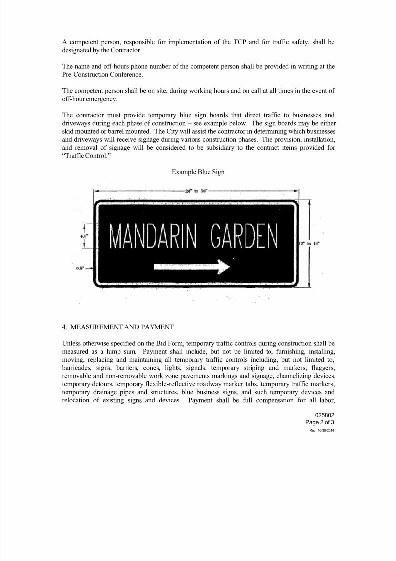
7/25/2019 City Standard Construction Specifications
http://slidepdf.com/reader/full/city-standard-construction-specifications 145/511
025802
Page 2 of 3
Rev. 10-30-2014
A competent person, responsible for implementation of the TCP and for traffic safety, shall be
designated by the Contractor.
The name and off-hours phone number of the competent person shall be provided in writing at the
Pre-Construction Conference.
The competent person shall be on site, during working hours and on call at all times in the event ofoff-hour emergency.
The contractor must provide temporary blue sign boards that direct traffic to businesses and
driveways during each phase of construction – see example below. The sign boards may be either
skid mounted or barrel mounted. The City will assist the contractor in determining which businesses
and driveways will receive signage during various construction phases. The provision, installation,
and removal of signage will be considered to be subsidiary to the contract items provided for
“Traffic Control.”
Example Blue Sign
4. MEASUREMENT AND PAYMENT
Unless otherwise specified on the Bid Form, temporary traffic controls during construction shall be
measured as a lump sum. Payment shall include, but not be limited to, furnishing, installing,
moving, replacing and maintaining all temporary traffic controls including, but not limited to,
barricades, signs, barriers, cones, lights, signals, temporary striping and markers, flaggers,
removable and non-removable work zone pavements markings and signage, channelizing devices,
temporary detours, temporary flexible-reflective roadway marker tabs, temporary traffic markers,
temporary drainage pipes and structures, blue business signs, and such temporary devices and
relocation of existing signs and devices. Payment shall be full compensation for all labor,
7/25/2019 City Standard Construction Specifications
http://slidepdf.com/reader/full/city-standard-construction-specifications 146/511
025802
Page 3 of 3
Rev. 10-30-2014
equipment, materials, personnel, and incidentals necessary to provide a safe condition during
construction of all phases and elements of the project and to complete the work.
Payment will be made on the following basis: The initial monthly estimate will include 50% of the
lump sum bid amount minus retention (typically 5%). The balance will be paid with the final
estimate, upon completion of the project.
7/25/2019 City Standard Construction Specifications
http://slidepdf.com/reader/full/city-standard-construction-specifications 147/511
025803
Page 1 of 1
Rev. 10-30-2014
SECTION 025803
TRAFFIC SIGNAL ADJUSTMENTS
1. DESCRIPTION
This specification shall govern all work for Traffic Signal Adjustments required to complete the
project.
2. MATERIALS
All equipment and materials for adjustments shall be provided by the Contractor, unless indicated
otherwise on the drawings.
3. METHODS
The existing signal controls shall be maintained by the Contractor.
Transferring control of the adjusted signal control shall be done by the Contractor.
A minimum of 72 hours advance notice shall be provided to the City Traffic Engineer by the
Contractor, prior to transferring control of the adjusted signal control or any other interim signal
adjustments necessary to control traffic, unless otherwise noted on the drawings.
Manual traffic direction by the City Police Department shall be arranged and provided for by the
Contractor at any signalized intersection at any time that signal control must be interrupted. The
Contractor shall arrange for a representative from the City's Traffic Signals Division to be on site toinspect the process of signal control transfer, during the work.
4. MEASUREMENT AND PAYMENT
Unless otherwise specified on the Bid Form, traffic signal adjustments will not be measured for pay,
but shall be considered subsidiary to other work.
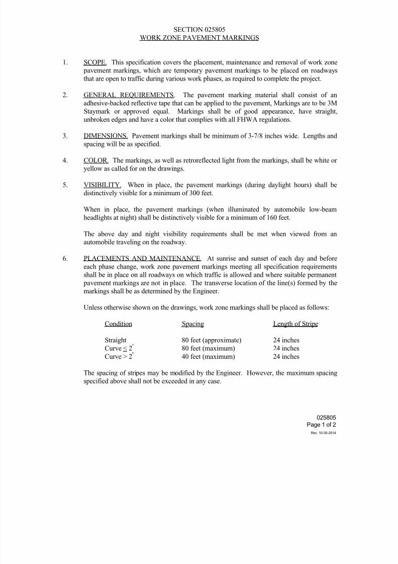
7/25/2019 City Standard Construction Specifications
http://slidepdf.com/reader/full/city-standard-construction-specifications 148/511
025805
Page 1 of 2
Rev. 10-30-2014
SECTION 025805
WORK ZONE PAVEMENT MARKINGS
1. SCOPE. This specification covers the placement, maintenance and removal of work zone
pavement markings, which are temporary pavement markings to be placed on roadways
that are open to traffic during various work phases, as required to complete the project.
2. GENERAL REQUIREMENTS. The pavement marking material shall consist of an
adhesive-backed reflective tape that can be applied to the pavement, Markings are to be 3M
Staymark or approved equal. Markings shall be of good appearance, have straight,
unbroken edges and have a color that complies with all FHWA regulations.
3. DIMENSIONS. Pavement markings shall be minimum of 3-7/8 inches wide. Lengths and
spacing will be as specified.
4. COLOR. The markings, as well as retroreflected light from the markings, shall be white or
yellow as called for on the drawings.
5. VISIBILITY. When in place, the pavement markings (during daylight hours) shall be
distinctively visible for a minimum of 300 feet.
When in place, the pavement markings (when illuminated by automobile low-beam
headlights at night) shall be distinctively visible for a minimum of 160 feet.
The above day and night visibility requirements shall be met when viewed from an
automobile traveling on the roadway.
6. PLACEMENTS AND MAINTENANCE. At sunrise and sunset of each day and before
each phase change, work zone pavement markings meeting all specification requirementsshall be in place on all roadways on which traffic is allowed and where suitable permanent
pavement markings are not in place. The transverse location of the line(s) formed by the
markings shall be as determined by the Engineer.
Unless otherwise shown on the drawings, work zone markings shall be placed as follows:
Condition Spacing Length of Stripe
Straight 80 feet (approximate) 24 inches
Curve < 2º 80 feet (maximum) 24 inches
Curve > 2º
40 feet (maximum) 24 inches
The spacing of stripes may be modified by the Engineer. However, the maximum spacing
specified above shall not be exceeded in any case.
7/25/2019 City Standard Construction Specifications
http://slidepdf.com/reader/full/city-standard-construction-specifications 149/511
025805
Page 2 of 2
Rev. 10-30-2014
The Contractor will be responsible for maintaining the work zone pavement markings for a
maximum period of two weeks. If, however, the Contractor is also responsible for placing
the standard pavement markings, the Contractor will be responsible for maintaining the
work zone pavement markings until permanent pavement markings are in place.
7. REMOVAL. Where removal is required, it will be accomplished in accordance with
instructions of the Engineer or as called for on the drawings.
8. MEASUREMENT AND PAYMENT. Unless otherwise specified on the Bid Form, work
zone pavement markings shall not be measured and paid for separately, but shall be
considered subsidiary to the appropriate bid item.
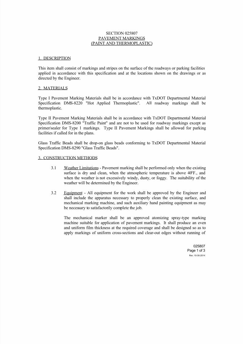
7/25/2019 City Standard Construction Specifications
http://slidepdf.com/reader/full/city-standard-construction-specifications 150/511
025807
Page 1 of 3
Rev. 10-30-2014
SECTION 025807
PAVEMENT MARKINGS
(PAINT AND THERMOPLASTIC)
1. DESCRIPTION
This item shall consist of markings and stripes on the surface of the roadways or parking facilities
applied in accordance with this specification and at the locations shown on the drawings or as
directed by the Engineer.
2. MATERIALS
Type I Pavement Marking Materials shall be in accordance with TxDOT Departmental Material
Specification DMS-8220 "Hot Applied Thermoplastic". All roadway markings shall be
thermoplastic.
Type II Pavement Marking Materials shall be in accordance with TxDOT Departmental Material
Specification DMS-8200 "Traffic Paint" and are not to be used for roadway markings except as
primer/sealer for Type 1 markings. Type II Pavement Markings shall be allowed for parking
facilities if called for in the plans.
Glass Traffic Beads shall be drop-on glass beads conforming to TxDOT Departmental Material
Specification DMS-8290 "Glass Traffic Beads".
3. CONSTRUCTION METHODS
3.1 Weather Limitations - Pavement marking shall be performed only when the existing
surface is dry and clean, when the atmospheric temperature is above 40°F., and
when the weather is not excessively windy, dusty, or foggy. The suitability of the
weather will be determined by the Engineer.
3.2 Equipment - All equipment for the work shall be approved by the Engineer and
shall include the apparatus necessary to properly clean the existing surface, and
mechanical marking machine, and such auxiliary hand painting equipment as may
be necessary to satisfactorily complete the job.
The mechanical marker shall be an approved atomizing spray-type markingmachine suitable for application of pavement markings. It shall produce an even
and uniform film thickness at the required coverage and shall be designed so as to
apply markings of uniform cross-sections and clear-out edges without running of
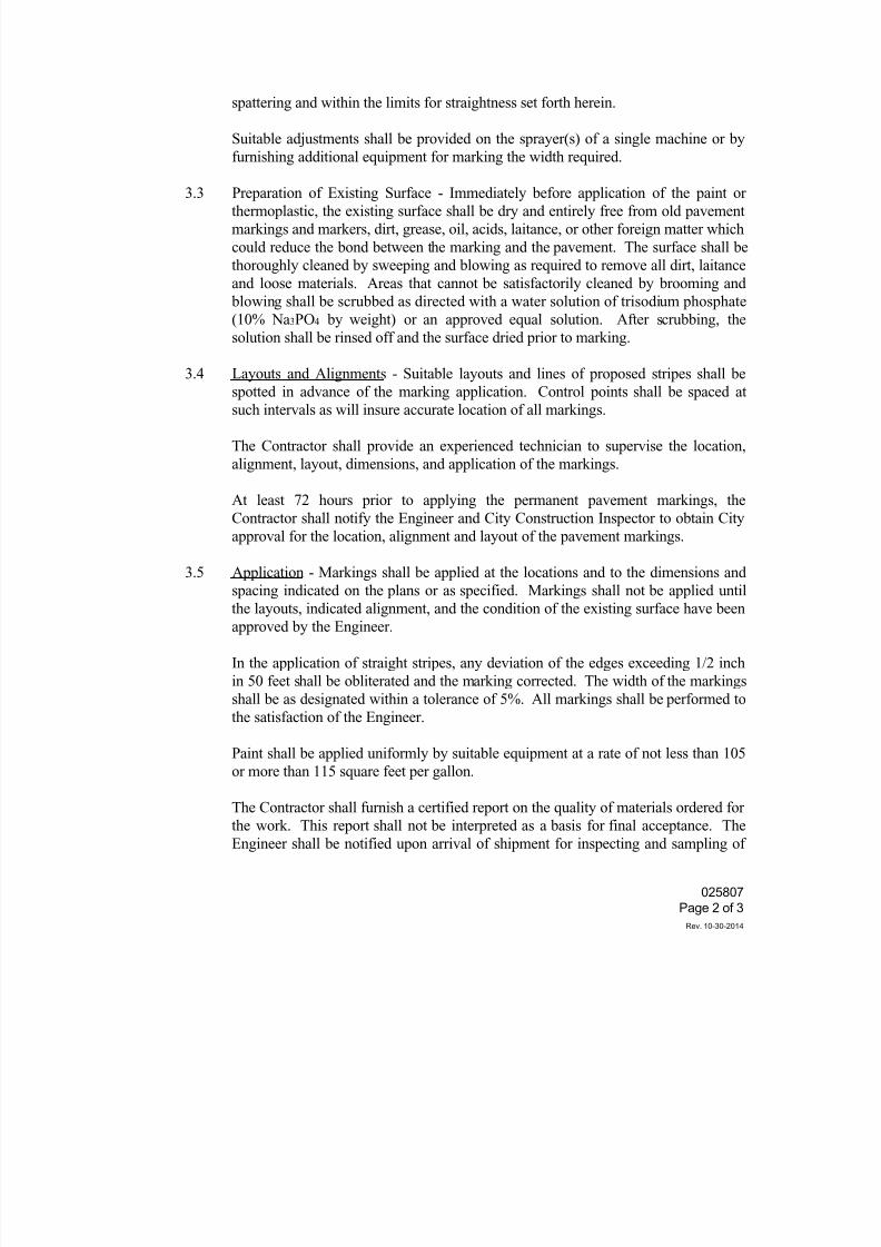
7/25/2019 City Standard Construction Specifications
http://slidepdf.com/reader/full/city-standard-construction-specifications 151/511
025807
Page 2 of 3
Rev. 10-30-2014
spattering and within the limits for straightness set forth herein.
Suitable adjustments shall be provided on the sprayer(s) of a single machine or by
furnishing additional equipment for marking the width required.
3.3 Preparation of Existing Surface - Immediately before application of the paint orthermoplastic, the existing surface shall be dry and entirely free from old pavement
markings and markers, dirt, grease, oil, acids, laitance, or other foreign matter which
could reduce the bond between the marking and the pavement. The surface shall be
thoroughly cleaned by sweeping and blowing as required to remove all dirt, laitance
and loose materials. Areas that cannot be satisfactorily cleaned by brooming and
blowing shall be scrubbed as directed with a water solution of trisodium phosphate
(10% Na3PO4 by weight) or an approved equal solution. After scrubbing, the
solution shall be rinsed off and the surface dried prior to marking.
3.4 Layouts and Alignments - Suitable layouts and lines of proposed stripes shall be
spotted in advance of the marking application. Control points shall be spaced atsuch intervals as will insure accurate location of all markings.
The Contractor shall provide an experienced technician to supervise the location,
alignment, layout, dimensions, and application of the markings.
At least 72 hours prior to applying the permanent pavement markings, the
Contractor shall notify the Engineer and City Construction Inspector to obtain City
approval for the location, alignment and layout of the pavement markings.
3.5 Application - Markings shall be applied at the locations and to the dimensions and
spacing indicated on the plans or as specified. Markings shall not be applied untilthe layouts, indicated alignment, and the condition of the existing surface have been
approved by the Engineer.
In the application of straight stripes, any deviation of the edges exceeding 1/2 inch
in 50 feet shall be obliterated and the marking corrected. The width of the markings
shall be as designated within a tolerance of 5%. All markings shall be performed to
the satisfaction of the Engineer.
Paint shall be applied uniformly by suitable equipment at a rate of not less than 105
or more than 115 square feet per gallon.
The Contractor shall furnish a certified report on the quality of materials ordered for
the work. This report shall not be interpreted as a basis for final acceptance. The
Engineer shall be notified upon arrival of shipment for inspecting and sampling of
7/25/2019 City Standard Construction Specifications
http://slidepdf.com/reader/full/city-standard-construction-specifications 152/511
025807
Page 3 of 3
Rev. 10-30-2014
the materials. When required, all emptied containers shall be returned to the paint
material storage or made available for tallying by the Engineer. The containers
shall not be removed from the job site or destroyed without permission. The
Contractor shall make an accurate accounting of the paint materials used in the
accepted work.
3.6 Protection - After application, all markings shall be protected while drying. Thefresh markings shall be protected from damage of any kind. The Contractor shall be
directly responsible for protecting the markings and shall erect or place suitable
warning signs, flags or barricades, protective screens or coverings as required. All
surfaces shall be protected from disfiguration by spatter, splashes, spillage,
drippings of paint or other materials.
3.7 Defective Workmanship or Material - When any material not conforming to the
requirements of the specifications or drawings has been delivered to the project or
incorporated in the work, or any work performed is of inferior quality, such material
or work shall be corrected as directed by the Engineer, at the expense of the
Contractor.
4. MEASUREMENT AND PAYMENT
Unless otherwise specified on the Bid Form, pavement markings shall be measured by the square
foot or linear foot of each type of marking. Eliminating existing pavement markings and markers
will not be measured and paid for separately, but shall be subsidiary to the pavement marking
items.
Payment shall be full compensation for furnishing all materials and for eliminating existing
pavement markings and markers, for all preparation, layout and application of the materials, and for
all labor, equipment, tools and incidentals necessary to complete the work.
7/25/2019 City Standard Construction Specifications
http://slidepdf.com/reader/full/city-standard-construction-specifications 153/511
SECTION 025813
PREFORMED THERMOPLASTIC STRIPING, WORDS AND EMBLEMS
1. DESCRIPTION
This specification shall govern all work for furnishing and installing preformed thermoplastic
striping, words and emblems required to complete the project.
2. PRE-CONSTRUCTION CONFERENCE
When required by the Engineer, prior to beginning work on the markings but after receipt by the
Engineer of the required information, a conference will be held between the representatives of the
Contractor and the Engineer to set up more completely the sequence of work to be followed and the
estimated progress schedule.
3. MATERIALS
The preformed pavement marking material shall be thermoplastic material meeting the specifications
of TxDOT Departmental Material Specification DMS-8220 “Hot Applied Thermoplastic,” and shall
be approved by the Engineer for use on this project.
4. CONSTRUCTION
(1) General. The Contractor shall furnish all materials and equipment and perform work or
services necessary for complete and proper construction of the completed system of
pavement markings.
(2) Traffic Conditions. Roadways on which markings are to be placed may be either free of
traffic or open to traffic. On roadways already open to traffic, markings shall be placed underexisting traffic conditions.
(3) Dimensions. Markings will be in accordance with the color, length, width, shape,
configuration and location requirements of the plans and as directed by the Engineer.
(4) Methods. All material placement shall be in accordance with TxDOT Standard Specification
Item 668 “Prefabricated Pavement Markings” and City Section 025807 “Pavement Markings
(Paint and Thermoplastic).”
(5) Surface Preparation. The pavement upon which the markings are to be placed shall be
cleaned and prepared, to the satisfaction of the Engineer, prior to placement of the markings.Cleaning shall be by any effective method, approved by the Engineer that completely and
effectively removes contaminants, loose materials, and conditions deleterious to proper
adhesion. Surfaces shall be further prepared after cleaning by sealing or priming, as
recommended by the manufacturer of the pavement marking material.
025813Page 1 of 3
Rev. 3-25-2015
7/25/2019 City Standard Construction Specifications
http://slidepdf.com/reader/full/city-standard-construction-specifications 154/511
(6) Moisture. Pavement to which the material is to be applied shall be completely dry. When
questionable, pavements will be considered dry if, on a sunny day after observation for 15
minutes, no condensation occurs on the underside of a one (1) square foot piece of clear
plastic that has been placed on the pavement and weighted down on the edges.
(7) Temperature. Pavement and ambient air temperature requirements recommended by the
material manufacturer shall be observed. If no temperature requirements are established by
the materials manufacturer, material will not be placed if the pavement temperature is below
60 degrees F or if it is above 120 degrees F.
(8) Clean-Up. At all times, the project site shall be kept free of all unnecessary traffic hazards.
Upon completion of the work, the Contractor shall remove all rubbish from the work site,
and shall clean and restore the area to a manner acceptable to the Engineer. Also, all damage
done by the Contractor during the prosecution of the work must be repaired. Before
acceptance, the work site must be neat and in a presentable condition throughout. No extra
compensation will be allowed for fulfilling these clean-up requirements.
5. PERFORMANCE
(1) Adhesion. Installed pavement markings shall adhere to the pavement sufficiently to prevent
lifting, shifting, smearing, spreading, flowing or tearing by traffic.
(2) Appearance. In addition to complying with all requirements listed herein, pavement
markings shall present a neat, uniform appearance, and shall be free of unsightly conditions.
Markings shall be free of ragged edges, misshapen lines or contours, and splices in transverse
markings.
(3) Visibility. The pavement marking material, in place on the roadway, shall have uniform and
distinctive retro-reflectance when observed in accordance with TxDOT Test Method Tex-
828-B.
(4) Observation Period. All material, workmanship and labor furnished shall be covered by
manufacturer’s guarantee and/or warranty for a period of 12 months commencing on the final
delivery date of the materials.
Pavement markings that fail to meet all requirements of this specification shall be removed
and replaced at the expense of the Contractor within 30 working days following notification
by the Engineer of such failure. All replacement pavement markings shall also meet all
requirements of this specification for the same warranty period after installation.
025813Page 2 of 3
Rev. 3-25-2015
7/25/2019 City Standard Construction Specifications
http://slidepdf.com/reader/full/city-standard-construction-specifications 155/511
6. MEASUREMENT AND PAYMENT
Unless otherwise specified on the Bid Form, preformed striping, words and emblems shall be
measured by each type and color indicated on the Bid Form including preformed arrows and words
or other symbols as indicated in the Bid Form.
Payment shall be full compensation for cleaning the pavement by any suitable means other than blast
cleaning, for furnishing and placing all materials, and for all labor, tools, equipment and incidentals
necessary to complete the work.
025813Page 3 of 3
Rev. 3-25-2015
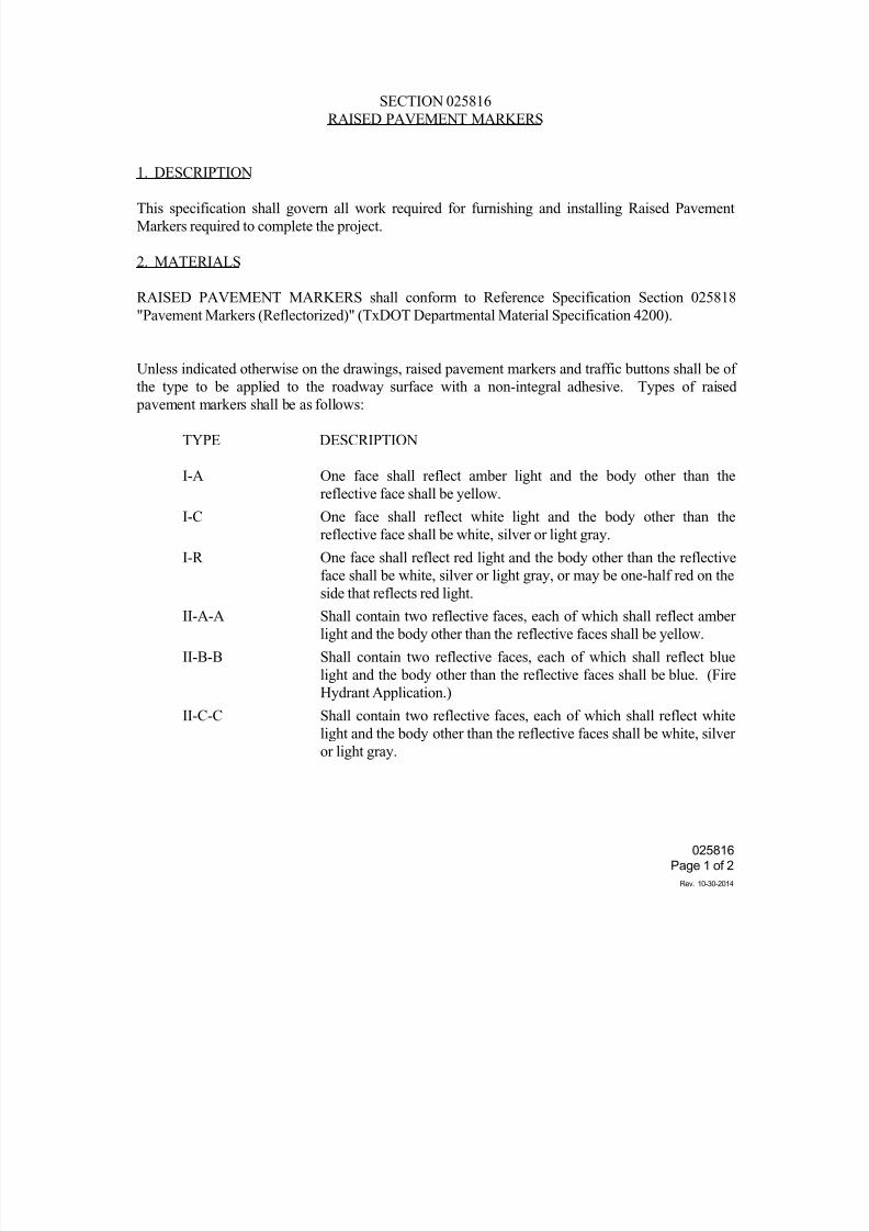
7/25/2019 City Standard Construction Specifications
http://slidepdf.com/reader/full/city-standard-construction-specifications 156/511
025816
Page 1 of 2
Rev. 10-30-2014
SECTION 025816
RAISED PAVEMENT MARKERS
1. DESCRIPTION
This specification shall govern all work required for furnishing and installing Raised Pavement
Markers required to complete the project.
2. MATERIALS
RAISED PAVEMENT MARKERS shall conform to Reference Specification Section 025818
"Pavement Markers (Reflectorized)" (TxDOT Departmental Material Specification 4200).
Unless indicated otherwise on the drawings, raised pavement markers and traffic buttons shall be of
the type to be applied to the roadway surface with a non-integral adhesive. Types of raised pavement markers shall be as follows:
TYPE DESCRIPTION
I-A One face shall reflect amber light and the body other than the
reflective face shall be yellow.
I-C One face shall reflect white light and the body other than the
reflective face shall be white, silver or light gray.
I-R One face shall reflect red light and the body other than the reflective
face shall be white, silver or light gray, or may be one-half red on the
side that reflects red light.
II-A-A Shall contain two reflective faces, each of which shall reflect amber
light and the body other than the reflective faces shall be yellow.
II-B-B Shall contain two reflective faces, each of which shall reflect blue
light and the body other than the reflective faces shall be blue. (Fire
Hydrant Application.)
II-C-C Shall contain two reflective faces, each of which shall reflect white
light and the body other than the reflective faces shall be white, silver
or light gray.
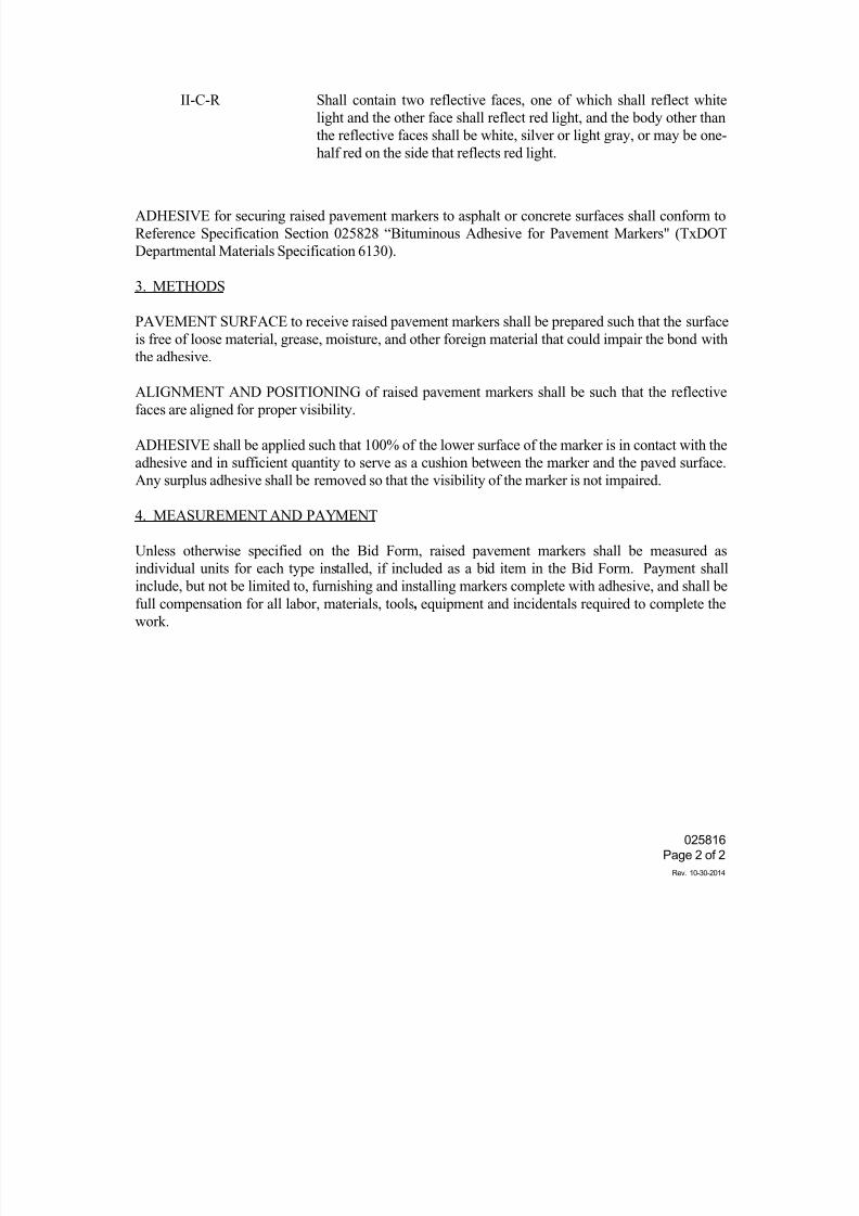
7/25/2019 City Standard Construction Specifications
http://slidepdf.com/reader/full/city-standard-construction-specifications 157/511
025816
Page 2 of 2
Rev. 10-30-2014
II-C-R Shall contain two reflective faces, one of which shall reflect white
light and the other face shall reflect red light, and the body other than
the reflective faces shall be white, silver or light gray, or may be one-
half red on the side that reflects red light.
ADHESIVE for securing raised pavement markers to asphalt or concrete surfaces shall conform to
Reference Specification Section 025828 “Bituminous Adhesive for Pavement Markers" (TxDOT
Departmental Materials Specification 6130).
3. METHODS
PAVEMENT SURFACE to receive raised pavement markers shall be prepared such that the surface
is free of loose material, grease, moisture, and other foreign material that could impair the bond with
the adhesive.
ALIGNMENT AND POSITIONING of raised pavement markers shall be such that the reflective
faces are aligned for proper visibility.
ADHESIVE shall be applied such that 100% of the lower surface of the marker is in contact with the
adhesive and in sufficient quantity to serve as a cushion between the marker and the paved surface.
Any surplus adhesive shall be removed so that the visibility of the marker is not impaired.
4. MEASUREMENT AND PAYMENT
Unless otherwise specified on the Bid Form, raised pavement markers shall be measured as
individual units for each type installed, if included as a bid item in the Bid Form. Payment shall
include, but not be limited to, furnishing and installing markers complete with adhesive, and shall be
full compensation for all labor, materials, tools, equipment and incidentals required to complete the
work.
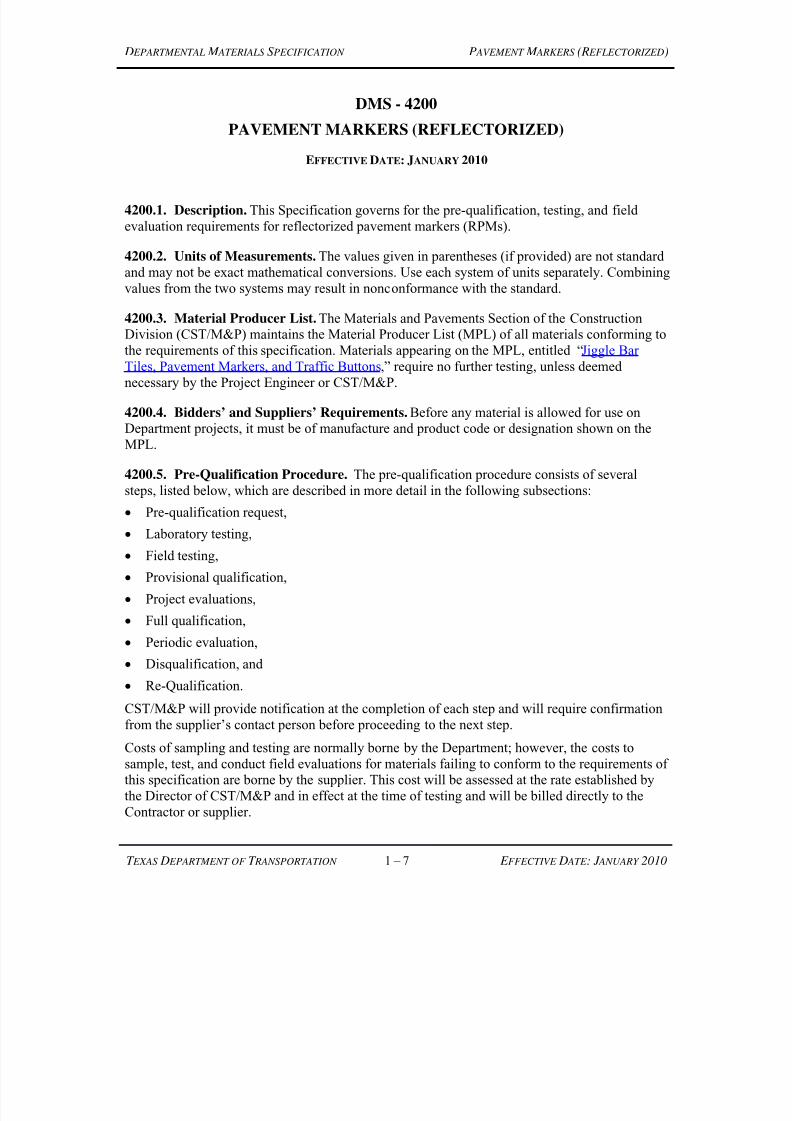
7/25/2019 City Standard Construction Specifications
http://slidepdf.com/reader/full/city-standard-construction-specifications 158/511
D EPARTMENTAL M ATERIALS S PECIFICATION P AVEMENT M ARKERS (R EFLECTORIZED)
T EXAS D EPARTMENT OF T RANSPORTATION 1 – 7 E FFECTIVE D ATE : J ANUARY 2010
DMS - 4200
PAVEMENT MARKERS (REFLECTORIZED)
EFFECTIVE DATE: JANUARY 2010
4200.1. Description. This Specification governs for the pre-qualification, testing, and field
evaluation requirements for reflectorized pavement markers (RPMs).
4200.2. Units of Measurements. The values given in parentheses (if provided) are not standard
and may not be exact mathematical conversions. Use each system of units separately. Combining
values from the two systems may result in nonconformance with the standard.
4200.3. Material Producer List. The Materials and Pavements Section of the ConstructionDivision (CST/M&P) maintains the Material Producer List (MPL) of all materials conforming to
the requirements of this specification. Materials appearing on the MPL, entitled “Jiggle Bar Tiles, Pavement Markers, and Traffic Buttons,” require no further testing, unless deemed
necessary by the Project Engineer or CST/M&P.
4200.4. Bidders’ and Suppliers’ Requirements. Before any material is allowed for use onDepartment projects, it must be of manufacture and product code or designation shown on the
MPL.
4200.5. Pre-Qualification Procedure. The pre-qualification procedure consists of several
steps, listed below, which are described in more detail in the following subsections:
Pre-qualification request,
Laboratory testing,
Field testing,
Provisional qualification,
Project evaluations,
Full qualification,
Periodic evaluation,
Disqualification, and
Re-Qualification.
CST/M&P will provide notification at the completion of each step and will require confirmationfrom the supplier’s contact person before proceeding to the next step.
Costs of sampling and testing are normally borne by the Department; however, the costs to
sample, test, and conduct field evaluations for materials failing to conform to the requirements ofthis specification are borne by the supplier. This cost will be assessed at the rate established by
the Director of CST/M&P and in effect at the time of testing and will be billed directly to the
Contractor or supplier.
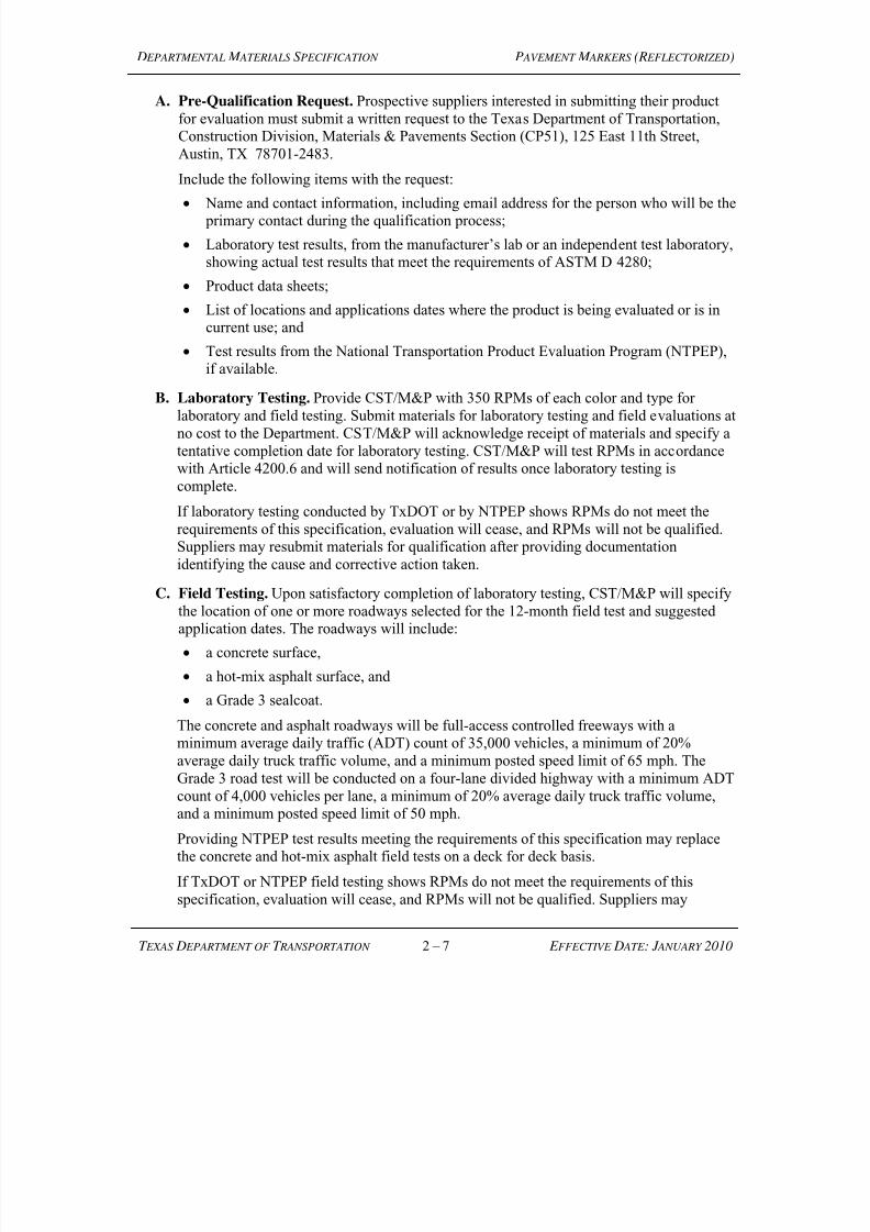
7/25/2019 City Standard Construction Specifications
http://slidepdf.com/reader/full/city-standard-construction-specifications 159/511
D EPARTMENTAL M ATERIALS S PECIFICATION P AVEMENT M ARKERS (R EFLECTORIZED)
T EXAS D EPARTMENT OF T RANSPORTATION 2 – 7 E FFECTIVE D ATE : J ANUARY 2010
A. Pre-Qualification Request. Prospective suppliers interested in submitting their product
for evaluation must submit a written request to the Texas Department of Transportation,Construction Division, Materials & Pavements Section (CP51), 125 East 11th Street,
Austin, TX 78701-2483.
Include the following items with the request:
Name and contact information, including email address for the person who will be the primary contact during the qualification process;
Laboratory test results, from the manufacturer’s lab or an independent test laboratory,showing actual test results that meet the requirements of ASTM D 4280;
Product data sheets;
List of locations and applications dates where the product is being evaluated or is incurrent use; and
Test results from the National Transportation Product Evaluation Program (NTPEP),if available.
B. Laboratory Testing. Provide CST/M&P with 350 RPMs of each color and type for
laboratory and field testing. Submit materials for laboratory testing and field evaluations at
no cost to the Department. CST/M&P will acknowledge receipt of materials and specify a
tentative completion date for laboratory testing. CST/M&P will test RPMs in accordancewith Article 4200.6 and will send notification of results once laboratory testing is
complete.
If laboratory testing conducted by TxDOT or by NTPEP shows RPMs do not meet the
requirements of this specification, evaluation will cease, and RPMs will not be qualified.Suppliers may resubmit materials for qualification after providing documentation
identifying the cause and corrective action taken.
C. Field Testing. Upon satisfactory completion of laboratory testing, CST/M&P will specify
the location of one or more roadways selected for the 12-month field test and suggestedapplication dates. The roadways will include:
a concrete surface,
a hot-mix asphalt surface, and
a Grade 3 sealcoat.
The concrete and asphalt roadways will be full-access controlled freeways with aminimum average daily traffic (ADT) count of 35,000 vehicles, a minimum of 20%
average daily truck traffic volume, and a minimum posted speed limit of 65 mph. The
Grade 3 road test will be conducted on a four-lane divided highway with a minimum ADTcount of 4,000 vehicles per lane, a minimum of 20% average daily truck traffic volume,and a minimum posted speed limit of 50 mph.
Providing NTPEP test results meeting the requirements of this specification may replacethe concrete and hot-mix asphalt field tests on a deck for deck basis.
If TxDOT or NTPEP field testing shows RPMs do not meet the requirements of this
specification, evaluation will cease, and RPMs will not be qualified. Suppliers may
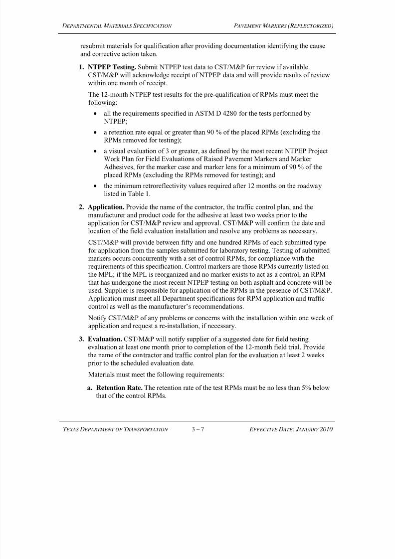
7/25/2019 City Standard Construction Specifications
http://slidepdf.com/reader/full/city-standard-construction-specifications 160/511
D EPARTMENTAL M ATERIALS S PECIFICATION P AVEMENT M ARKERS (R EFLECTORIZED)
T EXAS D EPARTMENT OF T RANSPORTATION 3 – 7 E FFECTIVE D ATE : J ANUARY 2010
resubmit materials for qualification after providing documentation identifying the cause
and corrective action taken.
1. NTPEP Testing. Submit NTPEP test data to CST/M&P for review if available.CST/M&P will acknowledge receipt of NTPEP data and will provide results of review
within one month of receipt.
The 12-month NTPEP test results for the pre-qualification of RPMs must meet the
following:
all the requirements specified in ASTM D 4280 for the tests performed by
NTPEP;
a retention rate equal or greater than 90 % of the placed RPMs (excluding theRPMs removed for testing);
a visual evaluation of 3 or greater, as defined by the most recent NTPEP ProjectWork Plan for Field Evaluations of Raised Pavement Markers and Marker
Adhesives, for the marker case and marker lens for a minimum of 90 % of the
placed RPMs (excluding the RPMs removed for testing); and the minimum retroreflectivity values required after 12 months on the roadway
listed in Table 1.
2. Application. Provide the name of the contractor, the traffic control plan, and the
manufacturer and product code for the adhesive at least two weeks prior to theapplication for CST/M&P review and approval. CST/M&P will confirm the date and
location of the field evaluation installation and resolve any problems as necessary.
CST/M&P will provide between fifty and one hundred RPMs of each submitted type
for application from the samples submitted for laboratory testing. Testing of submittedmarkers occurs concurrently with a set of control RPMs, for compliance with the
requirements of this specification. Control markers are those RPMs currently listed onthe MPL; if the MPL is reorganized and no marker exists to act as a control, an RPM
that has undergone the most recent NTPEP testing on both asphalt and concrete will beused. Supplier is responsible for application of the RPMs in the presence of CST/M&P.
Application must meet all Department specifications for RPM application and traffic
control as well as the manufacturer’s recommendations.
Notify CST/M&P of any problems or concerns with the installation within one week ofapplication and request a re-installation, if necessary.
3. Evaluation. CST/M&P will notify supplier of a suggested date for field testingevaluation at least one month prior to completion of the 12-month field trial. Provide
the name of the contractor and traffic control plan for the evaluation at least 2 weeks prior to the scheduled evaluation date.
Materials must meet the following requirements:
a. Retention Rate. The retention rate of the test RPMs must be no less than 5% belowthat of the control RPMs.
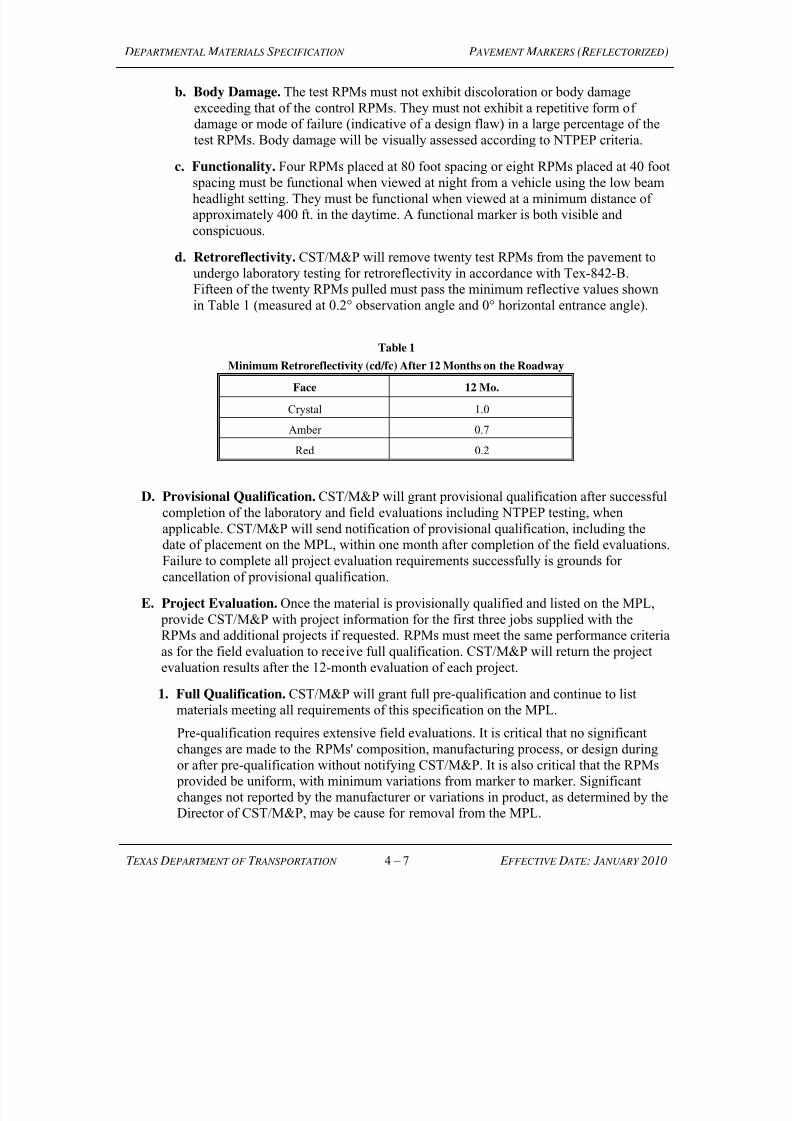
7/25/2019 City Standard Construction Specifications
http://slidepdf.com/reader/full/city-standard-construction-specifications 161/511
D EPARTMENTAL M ATERIALS S PECIFICATION P AVEMENT M ARKERS (R EFLECTORIZED)
T EXAS D EPARTMENT OF T RANSPORTATION 4 – 7 E FFECTIVE D ATE : J ANUARY 2010
b. Body Damage. The test RPMs must not exhibit discoloration or body damage
exceeding that of the control RPMs. They must not exhibit a repetitive form ofdamage or mode of failure (indicative of a design flaw) in a large percentage of the
test RPMs. Body damage will be visually assessed according to NTPEP criteria.
c. Functionality. Four RPMs placed at 80 foot spacing or eight RPMs placed at 40 foot
spacing must be functional when viewed at night from a vehicle using the low beamheadlight setting. They must be functional when viewed at a minimum distance ofapproximately 400 ft. in the daytime. A functional marker is both visible and
conspicuous.
d. Retroreflectivity. CST/M&P will remove twenty test RPMs from the pavement to
undergo laboratory testing for retroreflectivity in accordance with Tex-842-B.Fifteen of the twenty RPMs pulled must pass the minimum reflective values shown
in Table 1 (measured at 0.2° observation angle and 0° horizontal entrance angle).
Table 1
Minimum Retroreflectivity (cd/fc) After 12 Months on the Roadway
Face 12 Mo.
Crystal 1.0
Amber 0.7
Red 0.2
D. Provisional Qualification. CST/M&P will grant provisional qualification after successful
completion of the laboratory and field evaluations including NTPEP testing, when
applicable. CST/M&P will send notification of provisional qualification, including thedate of placement on the MPL, within one month after completion of the field evaluations.
Failure to complete all project evaluation requirements successfully is grounds for
cancellation of provisional qualification.
E. Project Evaluation. Once the material is provisionally qualified and listed on the MPL,
provide CST/M&P with project information for the first three jobs supplied with theRPMs and additional projects if requested. RPMs must meet the same performance criteria
as for the field evaluation to receive full qualification. CST/M&P will return the project
evaluation results after the 12-month evaluation of each project.
1. Full Qualification. CST/M&P will grant full pre-qualification and continue to list
materials meeting all requirements of this specification on the MPL.
Pre-qualification requires extensive field evaluations. It is critical that no significant
changes are made to the RPMs' composition, manufacturing process, or design during
or after pre-qualification without notifying CST/M&P. It is also critical that the RPMs provided be uniform, with minimum variations from marker to marker. Significant
changes not reported by the manufacturer or variations in product, as determined by theDirector of CST/M&P, may be cause for removal from the MPL.
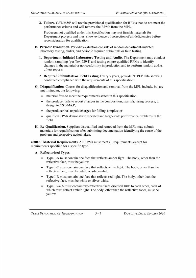
7/25/2019 City Standard Construction Specifications
http://slidepdf.com/reader/full/city-standard-construction-specifications 162/511
D EPARTMENTAL M ATERIALS S PECIFICATION P AVEMENT M ARKERS (R EFLECTORIZED)
T EXAS D EPARTMENT OF T RANSPORTATION 5 – 7 E FFECTIVE D ATE : J ANUARY 2010
2. Failure. CST/M&P will revoke provisional qualification for RPMs that do not meet the
performance criteria and will remove the RPMs from the MPL.
Producers not qualified under this Specification may not furnish materials forDepartment projects and must show evidence of correction of all deficiencies before
reconsideration for qualification.
F. Periodic Evaluation. Periodic evaluation consists of random department-initiated
laboratory testing, audits, and periodic required submittals or field testing.
1. Department-Initiated Laboratory Testing and Audits. The Department may conduct
random sampling (per Tex-729-I) and testing on pre-qualified RPMs to identifychanges in the material or nonconformity in production and to perform random audits
of test reports.
2. Required Submittals or Field Testing. Every 5 years, provide NTPEP data showing
continued compliance with the requirements of this specification.
G. Disqualification. Causes for disqualification and removal from the MPL include, but arenot limited to, the following:
material fails to meet the requirements stated in this specification;
the producer fails to report changes in the composition, manufacturing process, or
design to CST/M&P;
the producer has unpaid charges for failing samples; or
qualified RPMs demonstrate repeated and large-scale performance problems in thefield.
H. Re-Qualification. Suppliers disqualified and removed from the MPL may submit
materials for requalification after submitting documentation identifying the cause of the problem and corrective action taken.
4200.6. Material Requirements. All RPMs must meet all requirements, except for
requirements specified for a specific type.
A. Reflectorized Types.
Type I-A must contain one face that reflects amber light. The body, other than thereflective face, must be yellow.
Type I-C must contain one face that reflects white light. The body, other than thereflective face, must be white or silver-white.
Type I-R must contain one face that reflects red light. The body, other than thereflective face, must be white or silver-white.
Type II-A-A must contain two reflective faces oriented 180° to each other, each of
which must reflect amber light. The body, other than the reflective faces, must beyellow.
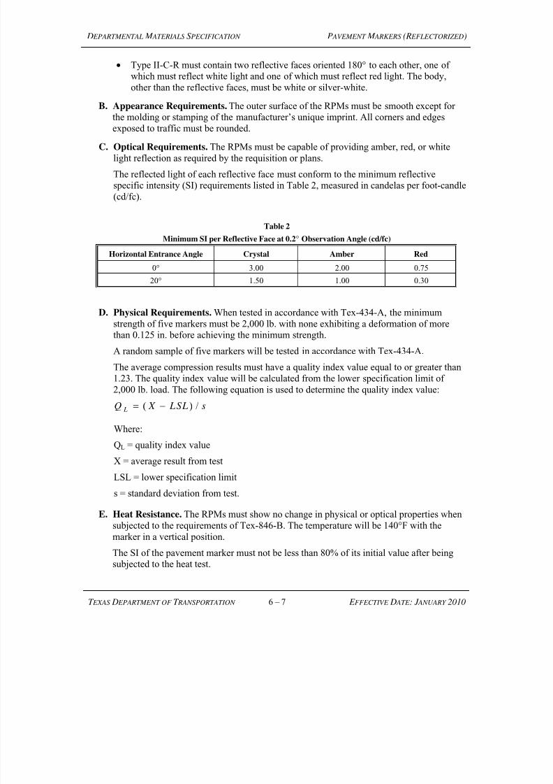
7/25/2019 City Standard Construction Specifications
http://slidepdf.com/reader/full/city-standard-construction-specifications 163/511
D EPARTMENTAL M ATERIALS S PECIFICATION P AVEMENT M ARKERS (R EFLECTORIZED)
T EXAS D EPARTMENT OF T RANSPORTATION 6 – 7 E FFECTIVE D ATE : J ANUARY 2010
Type II-C-R must contain two reflective faces oriented 180° to each other, one of
which must reflect white light and one of which must reflect red light. The body,
other than the reflective faces, must be white or silver-white.
B. Appearance Requirements. The outer surface of the RPMs must be smooth except forthe molding or stamping of the manufacturer’s unique imprint. All corners and edges
exposed to traffic must be rounded.
C. Optical Requirements. The RPMs must be capable of providing amber, red, or white
light reflection as required by the requisition or plans.
The reflected light of each reflective face must conform to the minimum reflectivespecific intensity (SI) requirements listed in Table 2, measured in candelas per foot-candle
(cd/fc).
Table 2
Minimum SI per Reflective Face at 0.2° Observation Angle (cd/fc)
Horizontal Entrance Angle Crystal Amber Red
0° 3.00 2.00 0.75
20° 1.50 1.00 0.30
D. Physical Requirements. When tested in accordance with Tex-434-A, the minimum
strength of five markers must be 2,000 lb. with none exhibiting a deformation of morethan 0.125 in. before achieving the minimum strength.
A random sample of five markers will be tested in accordance with Tex-434-A.
The average compression results must have a quality index value equal to or greater than
1.23. The quality index value will be calculated from the lower specification limit of
2,000 lb. load. The following equation is used to determine the quality index value:
Q X LSL s L ( ) /
Where:
QL = quality index value
X = average result from test
LSL = lower specification limit
s = standard deviation from test.
E. Heat Resistance. The RPMs must show no change in physical or optical properties when
subjected to the requirements of Tex-846-B. The temperature will be 140°F with the
marker in a vertical position.
The SI of the pavement marker must not be less than 80% of its initial value after beingsubjected to the heat test.
7/25/2019 City Standard Construction Specifications
http://slidepdf.com/reader/full/city-standard-construction-specifications 164/511
D EPARTMENTAL M ATERIALS S PECIFICATION P AVEMENT M ARKERS (R EFLECTORIZED)
T EXAS D EPARTMENT OF T RANSPORTATION 7 – 7 E FFECTIVE D ATE : J ANUARY 2010
F. Impact Test. The RPMs will be impact tested during the pre-qualification process. They
will be impacted with a 20-lb. weight in the form of a 2-in. solid right-circular cylinderwith a flat impact face having rounded edges falling freely through a vertical guide. The
RPMs will be impacted while resting on a solid, flat, steel plate that is at least 1/2 in. thick.
The RPMs will be tested at increasing heights until failure occurs. Failure will occur when
the lens or body cracks. The height at which failure occurs -6 in. will be the acceptancethreshold for RPMs supplied after pre-qualification.
4200.7. Archived Versions. Archived versions are available.
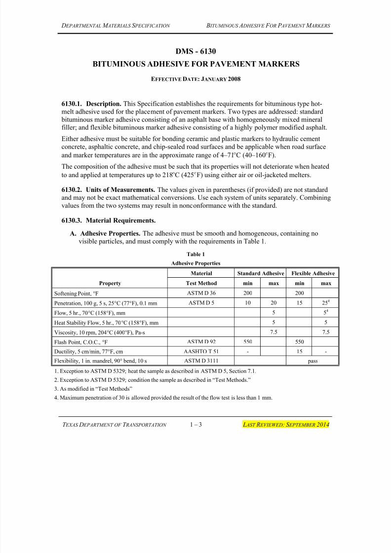
7/25/2019 City Standard Construction Specifications
http://slidepdf.com/reader/full/city-standard-construction-specifications 165/511
D EPARTMENTAL M ATERIALS S PECIFICATION B ITUMINOUS A DHESIVE F OR P AVEMENT M ARKERS
T EXAS D EPARTMENT OF T RANSPORTATION 1 – 3 L AST R EVIEWED: S EPTEMBER 2014
DMS - 6130
BITUMINOUS ADHESIVE FOR PAVEMENT MARKERS
EFFECTIVE DATE: JANUARY 2008
6130.1. Description. This Specification establishes the requirements for bituminous type hot-
melt adhesive used for the placement of pavement markers. Two types are addressed: standard
bituminous marker adhesive consisting of an asphalt base with homogeneously mixed mineralfiller; and flexible bituminous marker adhesive consisting of a highly polymer modified asphalt.
Either adhesive must be suitable for bonding ceramic and plastic markers to hydraulic cement
concrete, asphaltic concrete, and chip-sealed road surfaces and be applicable when road surface
and marker temperatures are in the approximate range of 4–71°C (40–160°F).
The composition of the adhesive must be such that its properties will not deteriorate when heated
to and applied at temperatures up to 218°C (425°F) using either air or oil-jacketed melters.
6130.2. Units of Measurements. The values given in parentheses (if provided) are not standardand may not be exact mathematical conversions. Use each system of units separately. Combining
values from the two systems may result in nonconformance with the standard.
6130.3. Material Requirements.
A. Adhesive Properties. The adhesive must be smooth and homogeneous, containing no
visible particles, and must comply with the requirements in Table 1.
Table 1
Adhesive Properties
Property
Material Standard Adhesive Flexible Adhesive
Test Method min max min max
Softening Point, °F ASTM D 36 200 200
Penetration, 100 g, 5 s, 25°C (77°F), 0.1 mm ASTM D 5 10 20 15 254
Flow, 5 hr., 70°C (158°F), mm 5 54
Heat Stability Flow, 5 hr., 70°C (158°F), mm 5 5
Viscosity, 10 rpm, 204°C (400°F), Pa-s 7.5 7.5
Flash Point, C.O.C., °F ASTM D 92 550 550
Ductility, 5 cm/min, 77°F, cm AASHTO T 51 - 15 -
Flexibility, 1 in. mandrel, 90° bend, 10 s ASTM D 3111 pass
1. Exception to ASTM D 5329; heat the sample as described in ASTM D 5, Section 7.1.
2. Exception to ASTM D 5329; condition the sample as described in “Test Methods.”
3. As modified in “Test Methods”
4. Maximum penetration of 30 is allowed provided the result of the flow test is less than 1 mm.
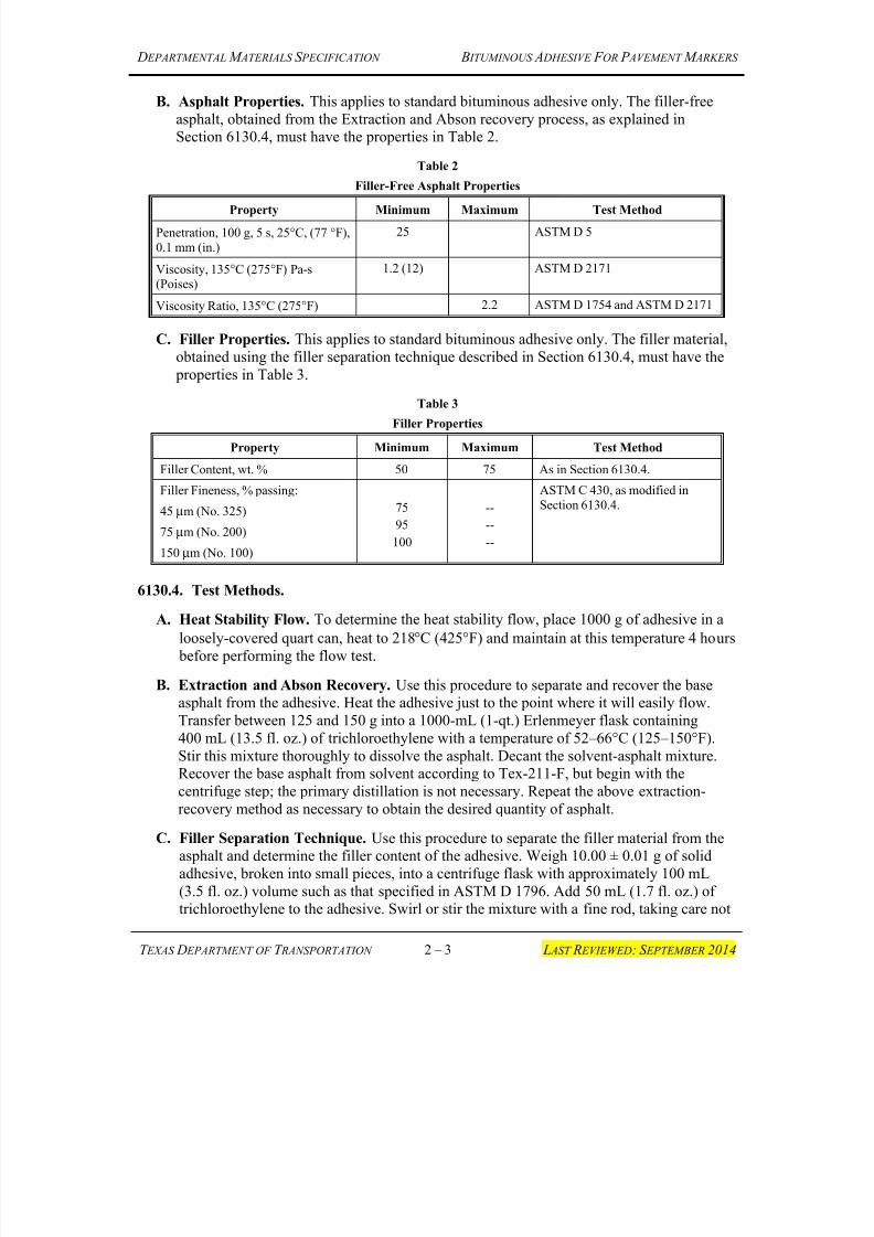
7/25/2019 City Standard Construction Specifications
http://slidepdf.com/reader/full/city-standard-construction-specifications 166/511
D EPARTMENTAL M ATERIALS S PECIFICATION B ITUMINOUS A DHESIVE F OR P AVEMENT M ARKERS
T EXAS D EPARTMENT OF T RANSPORTATION 2 – 3 L AST R EVIEWED: S EPTEMBER 2014
B. Asphalt Properties. This applies to standard bituminous adhesive only. The filler-free
asphalt, obtained from the Extraction and Abson recovery process, as explained inSection 6130.4, must have the properties in Table 2.
Table 2
Filler-Free Asphalt Properties
Property Minimum Maximum Test Method
Penetration, 100 g, 5 s, 25°C, (77 °F),
0.1 mm (in.)
25 ASTM D 5
Viscosity, 135°C (275°F) Pa-s(Poises)
1.2 (12) ASTM D 2171
Viscosity Ratio, 135°C (275°F) 2.2 ASTM D 1754 and ASTM D 2171
C. Filler Properties. This applies to standard bituminous adhesive only. The filler material,
obtained using the filler separation technique described in Section 6130.4, must have the
properties in Table 3.
Table 3
Filler Properties
Property Minimum Maximum Test Method
Filler Content, wt. % 50 75 As in Section 6130.4.
Filler Fineness, % passing:
45 µm (No. 325)
75 µm (No. 200)
150 µm (No. 100)
75
95
100
--
--
--
ASTM C 430, as modified in
Section 6130.4.
6130.4. Test Methods.
A. Heat Stability Flow. To determine the heat stability flow, place 1000 g of adhesive in a
loosely-covered quart can, heat to 218°C (425°F) and maintain at this temperature 4 hours
before performing the flow test.
B. Extraction and Abson Recovery. Use this procedure to separate and recover the baseasphalt from the adhesive. Heat the adhesive just to the point where it will easily flow.
Transfer between 125 and 150 g into a 1000-mL (1-qt.) Erlenmeyer flask containing
400 mL (13.5 fl. oz.) of trichloroethylene with a temperature of 52–66°C (125–150°F).
Stir this mixture thoroughly to dissolve the asphalt. Decant the solvent-asphalt mixture.Recover the base asphalt from solvent according to Tex-211-F, but begin with the
centrifuge step; the primary distillation is not necessary. Repeat the above extraction-
recovery method as necessary to obtain the desired quantity of asphalt.
C. Filler Separation Technique. Use this procedure to separate the filler material from theasphalt and determine the filler content of the adhesive. Weigh 10.00 ± 0.01 g of solid
adhesive, broken into small pieces, into a centrifuge flask with approximately 100 mL
(3.5 fl. oz.) volume such as that specified in ASTM D 1796. Add 50 mL (1.7 fl. oz.) oftrichloroethylene to the adhesive. Swirl or stir the mixture with a fine rod, taking care not
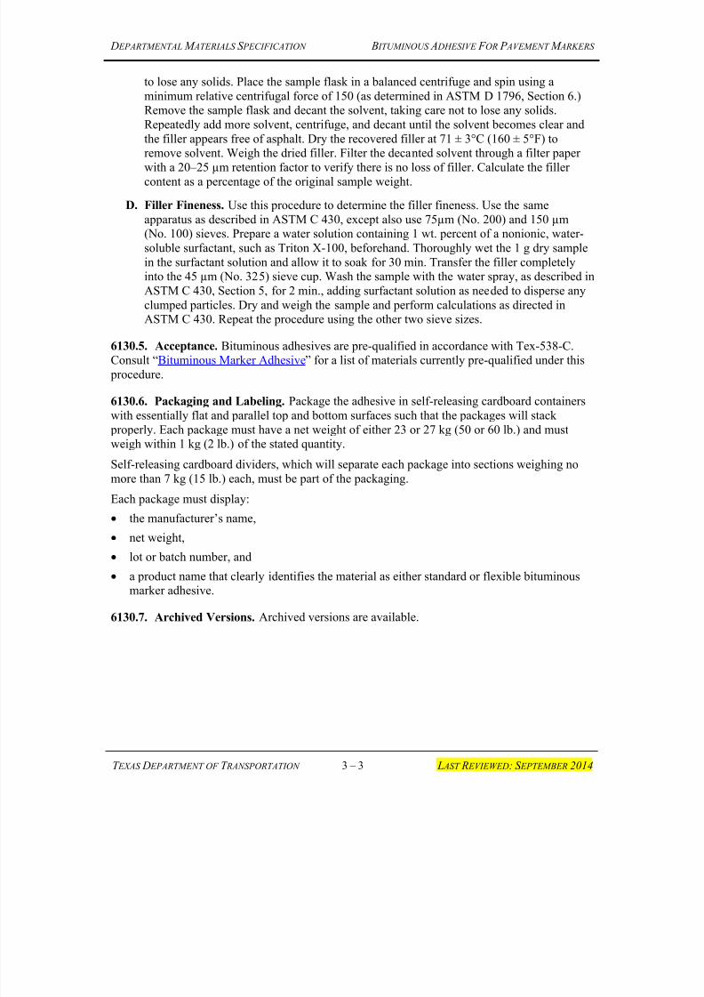
7/25/2019 City Standard Construction Specifications
http://slidepdf.com/reader/full/city-standard-construction-specifications 167/511
D EPARTMENTAL M ATERIALS S PECIFICATION B ITUMINOUS A DHESIVE F OR P AVEMENT M ARKERS
T EXAS D EPARTMENT OF T RANSPORTATION 3 – 3 L AST R EVIEWED: S EPTEMBER 2014
to lose any solids. Place the sample flask in a balanced centrifuge and spin using a
minimum relative centrifugal force of 150 (as determined in ASTM D 1796, Section 6.)Remove the sample flask and decant the solvent, taking care not to lose any solids.
Repeatedly add more solvent, centrifuge, and decant until the solvent becomes clear and
the filler appears free of asphalt. Dry the recovered filler at 71 ± 3°C (160 ± 5°F) to
remove solvent. Weigh the dried filler. Filter the decanted solvent through a filter paperwith a 20–25 µm retention factor to verify there is no loss of filler. Calculate the filler
content as a percentage of the original sample weight.
D. Filler Fineness. Use this procedure to determine the filler fineness. Use the same
apparatus as described in ASTM C 430, except also use 75µm (No. 200) and 150 µm(No. 100) sieves. Prepare a water solution containing 1 wt. percent of a nonionic, water-
soluble surfactant, such as Triton X-100, beforehand. Thoroughly wet the 1 g dry sample
in the surfactant solution and allow it to soak for 30 min. Transfer the filler completelyinto the 45 µm (No. 325) sieve cup. Wash the sample with the water spray, as described in
ASTM C 430, Section 5, for 2 min., adding surfactant solution as needed to disperse any
clumped particles. Dry and weigh the sample and perform calculations as directed in
ASTM C 430. Repeat the procedure using the other two sieve sizes.
6130.5. Acceptance. Bituminous adhesives are pre-qualified in accordance with Tex-538-C.Consult “Bituminous Marker Adhesive” for a list of materials currently pre-qualified under this
procedure.
6130.6. Packaging and Labeling. Package the adhesive in self-releasing cardboard containers
with essentially flat and parallel top and bottom surfaces such that the packages will stack
properly. Each package must have a net weight of either 23 or 27 kg (50 or 60 lb.) and mustweigh within 1 kg (2 lb.) of the stated quantity.
Self-releasing cardboard dividers, which will separate each package into sections weighing no
more than 7 kg (15 lb.) each, must be part of the packaging.
Each package must display:
• the manufacturer’s name,
• net weight,
• lot or batch number, and
• a product name that clearly identifies the material as either standard or flexible bituminousmarker adhesive.
6130.7. Archived Versions. Archived versions are available.
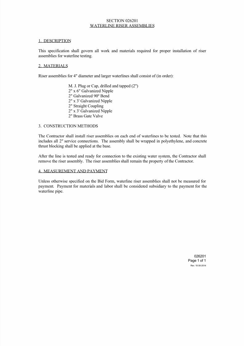
7/25/2019 City Standard Construction Specifications
http://slidepdf.com/reader/full/city-standard-construction-specifications 168/511
026201
Page 1 of 1
Rev. 10-30-2014
SECTION 026201
WATERLINE RISER ASSEMBLIES
1. DESCRIPTION
This specification shall govern all work and materials required for proper installation of riser
assemblies for waterline testing.
2. MATERIALS
Riser assemblies for 4" diameter and larger waterlines shall consist of (in order):
M. J. Plug or Cap, drilled and tapped (2")
2" x 6" Galvanized Nipple
2" Galvanized 90º Bend
2" x 3' Galvanized Nipple
2" Straight Coupling
2" x 3' Galvanized Nipple2" Brass Gate Valve
3. CONSTRUCTION METHODS
The Contractor shall install riser assemblies on each end of waterlines to be tested. Note that this
includes all 2" service connections. The assembly shall be wrapped in polyethylene, and concrete
thrust blocking shall be applied at the base.
After the line is tested and ready for connection to the existing water system, the Contractor shall
remove the riser assembly. The riser assemblies shall remain the property of the Contractor.
4. MEASUREMENT AND PAYMENT
Unless otherwise specified on the Bid Form, waterline riser assemblies shall not be measured for
payment. Payment for materials and labor shall be considered subsidiary to the payment for the
waterline pipe.
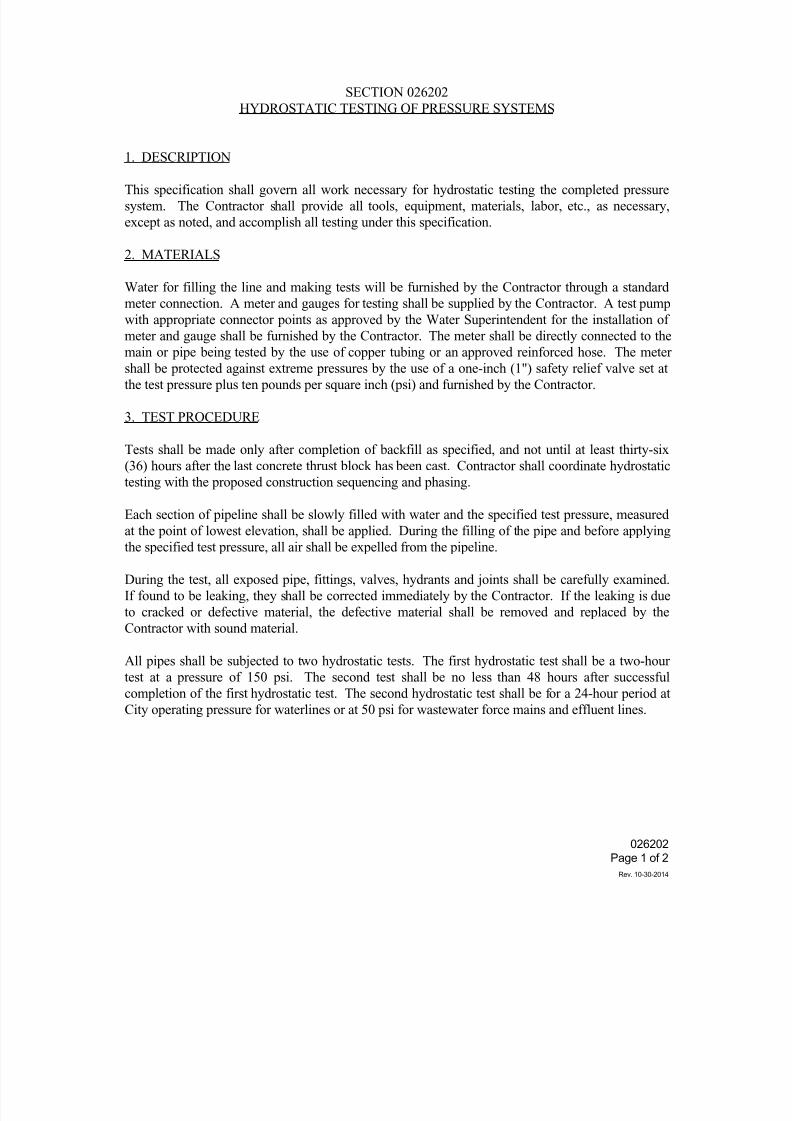
7/25/2019 City Standard Construction Specifications
http://slidepdf.com/reader/full/city-standard-construction-specifications 169/511
026202
Page 1 of 2
Rev. 10-30-2014
SECTION 026202HYDROSTATIC TESTING OF PRESSURE SYSTEMS
1. DESCRIPTION
This specification shall govern all work necessary for hydrostatic testing the completed pressuresystem. The Contractor shall provide all tools, equipment, materials, labor, etc., as necessary,except as noted, and accomplish all testing under this specification.
2. MATERIALS
Water for filling the line and making tests will be furnished by the Contractor through a standardmeter connection. A meter and gauges for testing shall be supplied by the Contractor. A test pumpwith appropriate connector points as approved by the Water Superintendent for the installation ofmeter and gauge shall be furnished by the Contractor. The meter shall be directly connected to the
main or pipe being tested by the use of copper tubing or an approved reinforced hose. The metershall be protected against extreme pressures by the use of a one-inch (1") safety relief valve set atthe test pressure plus ten pounds per square inch (psi) and furnished by the Contractor.
3. TEST PROCEDURE
Tests shall be made only after completion of backfill as specified, and not until at least thirty-six(36) hours after the last concrete thrust block has been cast. Contractor shall coordinate hydrostatictesting with the proposed construction sequencing and phasing.
Each section of pipeline shall be slowly filled with water and the specified test pressure, measured
at the point of lowest elevation, shall be applied. During the filling of the pipe and before applyingthe specified test pressure, all air shall be expelled from the pipeline.
During the test, all exposed pipe, fittings, valves, hydrants and joints shall be carefully examined.If found to be leaking, they shall be corrected immediately by the Contractor. If the leaking is dueto cracked or defective material, the defective material shall be removed and replaced by theContractor with sound material.
All pipes shall be subjected to two hydrostatic tests. The first hydrostatic test shall be a two-hourtest at a pressure of 150 psi. The second test shall be no less than 48 hours after successfulcompletion of the first hydrostatic test. The second hydrostatic test shall be for a 24-hour period at
City operating pressure for waterlines or at 50 psi for wastewater force mains and effluent lines.
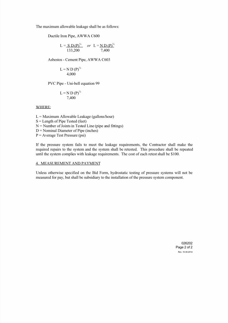
7/25/2019 City Standard Construction Specifications
http://slidepdf.com/reader/full/city-standard-construction-specifications 170/511
026202
Page 2 of 2
Rev. 10-30-2014
The maximum allowable leakage shall be as follows:
Ductile Iron Pipe, AWWA C600
L = S D (P)½
or L = N D (P)½
133,200 7,400
Asbestos - Cement Pipe, AWWA C603
L = N D (P)½
4,000
PVC Pipe - Uni-bell equation 99
L = N D (P)½
7,400
WHERE:
L = Maximum Allowable Leakage (gallons/hour)S = Length of Pipe Tested (feet) N = Number of Joints in Tested Line (pipe and fittings)D = Nominal Diameter of Pipe (inches)P = Average Test Pressure (psi)
If the pressure system fails to meet the leakage requirements, the Contractor shall make therequired repairs to the system and the system shall be retested. This procedure shall be repeated
until the system complies with leakage requirements. The cost of each retest shall be $100.
4. MEASUREMENT AND PAYMENT
Unless otherwise specified on the Bid Form, hydrostatic testing of pressure systems will not bemeasured for pay, but shall be subsidiary to the installation of the pressure system component.
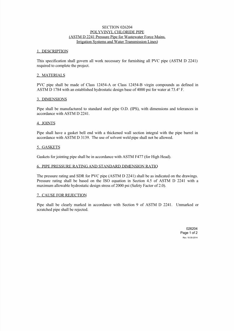
7/25/2019 City Standard Construction Specifications
http://slidepdf.com/reader/full/city-standard-construction-specifications 171/511
026204
Page 1 of 2
Rev. 10-30-2014
SECTION 026204
POLYVINYL CHLORIDE PIPE
(ASTM D 2241 Pressure Pipe for Wastewater Force Mains,
Irrigation Systems and Water Transmission Lines)
1. DESCRIPTION
This specification shall govern all work necessary for furnishing all PVC pipe (ASTM D 2241)
required to complete the project.
2. MATERIALS
PVC pipe shall be made of Class 12454-A or Class 12454-B virgin compounds as defined in
ASTM D 1784 with an established hydrostatic design base of 4000 psi for water at 73.4° F.
3. DIMENSIONS
Pipe shall be manufactured to standard steel pipe O.D. (IPS), with dimensions and tolerances in
accordance with ASTM D 2241.
4. JOINTS
Pipe shall have a gasket bell end with a thickened wall section integral with the pipe barrel in
accordance with ASTM D 3139. The use of solvent weld pipe shall not be allowed.
5. GASKETS
Gaskets for jointing pipe shall be in accordance with ASTM F477 (for High Head).
6. PIPE PRESSURE RATING AND STANDARD DIMENSION RATIO
The pressure rating and SDR for PVC pipe (ASTM D 2241) shall be as indicated on the drawings.
Pressure rating shall be based on the ISO equation in Section 4.5 of ASTM D 2241 with a
maximum allowable hydrostatic design stress of 2000 psi (Safety Factor of 2.0).
7. CAUSE FOR REJECTION
Pipe shall be clearly marked in accordance with Section 9 of ASTM D 2241. Unmarked or
scratched pipe shall be rejected.
7/25/2019 City Standard Construction Specifications
http://slidepdf.com/reader/full/city-standard-construction-specifications 172/511
026204
Page 2 of 2
Rev. 10-30-2014
8. CERTIFICATION
The Contractor shall furnish, in duplicate to the Engineer, a copy of the manufacturer's affidavit of
compliance with this specification. Certification shall accompany each delivery of materials, to
include gaskets.
9. MEASUREMENT AND PAYMENT
Unless otherwise specified on the Bid Form, PVC pipe (ASTM D 2241) will be measured by the
linear foot along the centerline for each size installed. Measurement of pipe shall be up to, but not
include, the fittings.
Payment shall include all labor, pipe, and equipment for hauling, bracing, trench excavation,
testing, backfilling, and for all cleaning up and other incidentals necessary to install the pipe
complete in place, per linear foot.
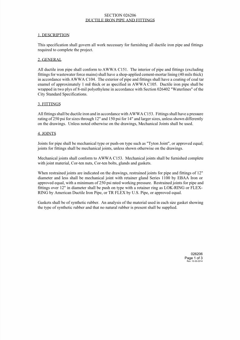
7/25/2019 City Standard Construction Specifications
http://slidepdf.com/reader/full/city-standard-construction-specifications 173/511
026206Page 1 of 3
Rev. 10-30-2014
SECTION 026206
DUCTILE IRON PIPE AND FITTINGS
1. DESCRIPTION
This specification shall govern all work necessary for furnishing all ductile iron pipe and fittings
required to complete the project.
2. GENERAL
All ductile iron pipe shall conform to AWWA C151. The interior of pipe and fittings (excluding
fittings for wastewater force mains) shall have a shop-applied cement-mortar lining (40 mils thick)
in accordance with AWWA C104. The exterior of pipe and fittings shall have a coating of coal tar
enamel of approximately 1 mil thick or as specified in AWWA C105. Ductile iron pipe shall be
wrapped in two plys of 8-mil polyethylene in accordance with Section 026402 "Waterlines" of the
City Standard Specifications.
3. FITTINGS
All fittings shall be ductile iron and in accordance with AWWA C153. Fittings shall have a pressure
rating of 250 psi for sizes through 12" and 150 psi for 14" and larger sizes, unless shown differently
on the drawings. Unless noted otherwise on the drawings, Mechanical Joints shall be used.
4. JOINTS
Joints for pipe shall be mechanical type or push-on type such as "Tyton Joint", or approved equal;
joints for fittings shall be mechanical joints, unless shown otherwise on the drawings.
Mechanical joints shall conform to AWWA C153. Mechanical joints shall be furnished complete
with joint material, Cor-ten nuts, Cor-ten bolts, glands and gaskets.
When restrained joints are indicated on the drawings, restrained joints for pipe and fittings of 12"
diameter and less shall be mechanical joint with retainer gland Series 1100 by EBAA Iron or
approved equal, with a minimum of 250 psi rated working pressure. Restrained joints for pipe and
fittings over 12" in diameter shall be push on type with a retainer ring as LOK-RING or FLEX-
RING by American Ductile Iron Pipe, or TR FLEX by U.S. Pipe, or approved equal.
Gaskets shall be of synthetic rubber. An analysis of the material used in each size gasket showing
the type of synthetic rubber and that no natural rubber is present shall be supplied.
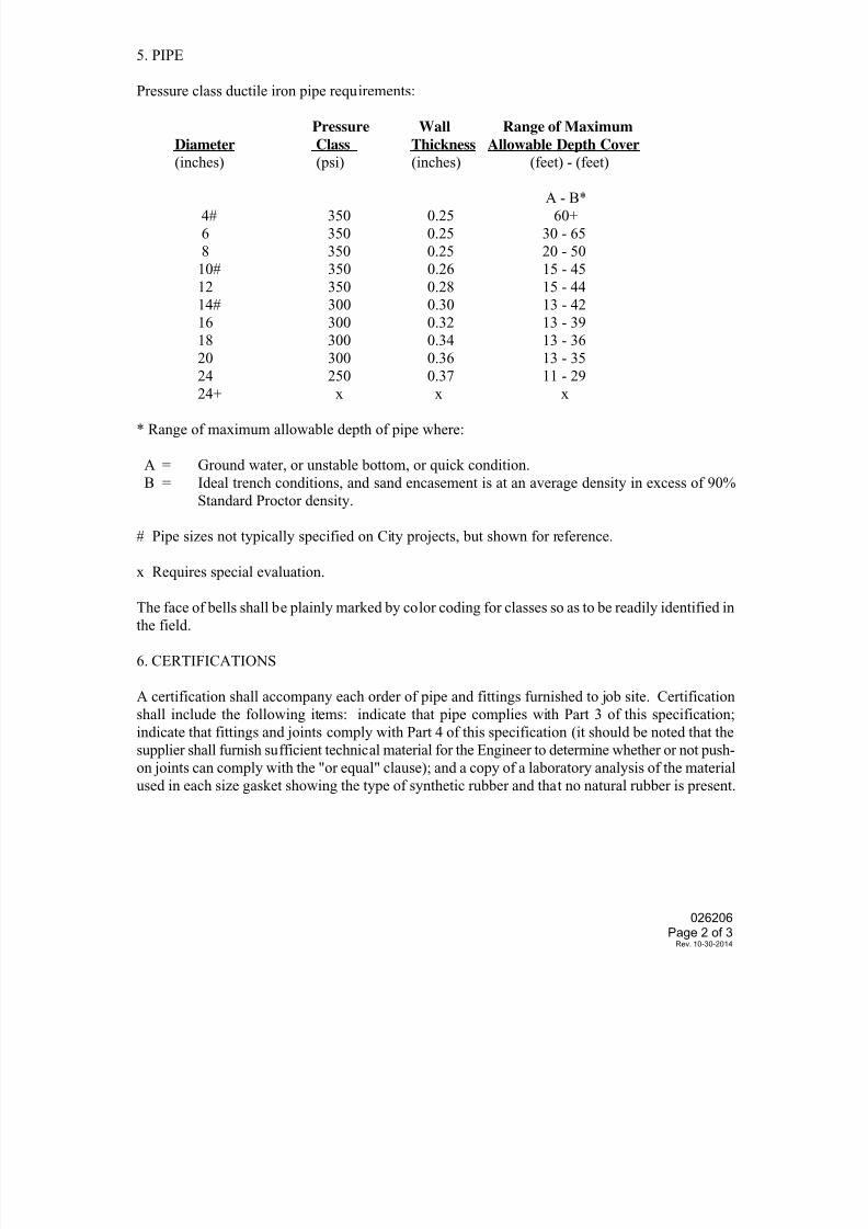
7/25/2019 City Standard Construction Specifications
http://slidepdf.com/reader/full/city-standard-construction-specifications 174/511
026206Page 2 of 3
Rev. 10-30-2014
5. PIPE
Pressure class ductile iron pipe requirements:
Pressure Wall Range of Maximum
Diameter Class Thickness Allowable Depth Cover
(inches) (psi) (inches) (feet) - (feet)
A - B*4# 350 0.25 60+
6 350 0.25 30 - 65
8 350 0.25 20 - 50
10# 350 0.26 15 - 45
12 350 0.28 15 - 44
14# 300 0.30 13 - 42
16 300 0.32 13 - 39
18 300 0.34 13 - 36
20 300 0.36 13 - 35
24 250 0.37 11 - 29
24+ x x x
* Range of maximum allowable depth of pipe where:
A = Ground water, or unstable bottom, or quick condition.
B = Ideal trench conditions, and sand encasement is at an average density in excess of 90%
Standard Proctor density.
# Pipe sizes not typically specified on City projects, but shown for reference.
x Requires special evaluation.
The face of bells shall be plainly marked by color coding for classes so as to be readily identified in
the field.
6. CERTIFICATIONS
A certification shall accompany each order of pipe and fittings furnished to job site. Certification
shall include the following items: indicate that pipe complies with Part 3 of this specification;
indicate that fittings and joints comply with Part 4 of this specification (it should be noted that the
supplier shall furnish sufficient technical material for the Engineer to determine whether or not push-
on joints can comply with the "or equal" clause); and a copy of a laboratory analysis of the material
used in each size gasket showing the type of synthetic rubber and that no natural rubber is present.
7/25/2019 City Standard Construction Specifications
http://slidepdf.com/reader/full/city-standard-construction-specifications 175/511
026206Page 3 of 3
Rev. 10-30-2014
7. MEASUREMENT AND PAYMENT
Unless otherwise specified on the Bid Form, ductile iron pipe shall be measured by the linear foot
along the centerline for each size of pipe installed. Measurement of pipe shall be up to, but not
include, the fittings.
Ductile iron fittings shall be measured per each by the type and size, as indicated in the Bid Form.
Payment shall include all labor, materials, tools and equipment for the completed installation and
testing of the waterline, together with all incidentals necessary to install the pipe and fittings complete
in place.
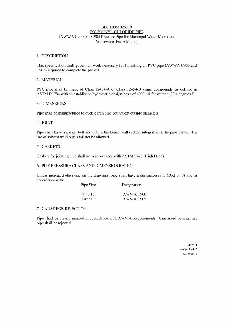
7/25/2019 City Standard Construction Specifications
http://slidepdf.com/reader/full/city-standard-construction-specifications 176/511
SECTION 026210
POLYVINYL CHLORIDE PIPE
(AWWA C900 and C905 Pressure Pipe for Municipal Water Mains and
Wastewater Force Mains)
1. DESCRIPTION
This specification shall govern all work necessary for furnishing all PVC pipe (AWWA C900 and
C905) required to complete the project.
2. MATERIAL
PVC pipe shall be made of Class 12454-A or Class 12454-B virgin compounds, as defined in
ASTM D1784 with an established hydrostatic-design-basis of 4000 psi for water at 73.4 degrees F.
3. DIMENSIONS
Pipe shall be manufactured to ductile iron pipe equivalent outside diameters.
4. JOINT
Pipe shall have a gasket bell end with a thickened wall section integral with the pipe barrel. The
use of solvent weld pipe shall not be allowed.
5. GASKETS
Gaskets for jointing pipe shall be in accordance with ASTM F477 (High Head).
6. PIPE PRESSURE CLASS AND DIMENSION RATIO
Unless indicated otherwise on the drawings, pipe shall have a dimension ratio (DR) of 18 and in
accordance with:
Pipe Size Designation
4" to 12" AWWA C900
Over 12" AWWA C905
7. CAUSE FOR REJECTION
Pipe shall be clearly marked in accordance with AWWA Requirements. Unmarked or scratched
pipe shall be rejected.
026210
Page 1 of 2
Rev. 3-25-2015
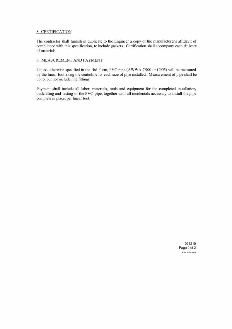
7/25/2019 City Standard Construction Specifications
http://slidepdf.com/reader/full/city-standard-construction-specifications 177/511
8. CERTIFICATION
The contractor shall furnish in duplicate to the Engineer a copy of the manufacturer's affidavit of
compliance with this specification, to include gaskets. Certification shall accompany each delivery
of materials.
9. MEASUREMENT AND PAYMENT
Unless otherwise specified in the Bid Form, PVC pipe (AWWA C900 or C905) will be measured
by the linear foot along the centerline for each size of pipe installed. Measurement of pipe shall be
up to, but not include, the fittings.
Payment shall include all labor, materials, tools and equipment for the completed installation,
backfilling and testing of the PVC pipe, together with all incidentals necessary to install the pipe
complete in place, per linear foot.
026210
Page 2 of 2
Rev. 3-25-2015
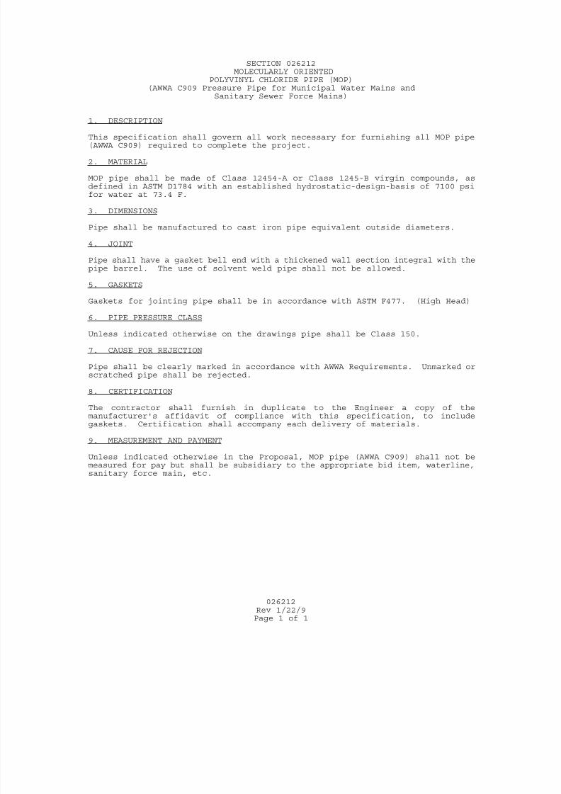
7/25/2019 City Standard Construction Specifications
http://slidepdf.com/reader/full/city-standard-construction-specifications 178/511
026212
Rev 1/22/9Page 1 of 1
SECTION 026212MOLECULARLY ORIENTED
POLYVINYL CHLORIDE PIPE (MOP)(AWWA C909 Pressure Pipe for Municipal Water Mains and
Sanitary Sewer Force Mains)
1. DESCRIPTION This specification shall govern all work necessary for furnishing all MOP pipe(AWWA C909) required to complete the project.
2. MATERIAL MOP pipe shall be made of Class 12454-A or Class 1245-B virgin compounds, asdefined in ASTM D1784 with an established hydrostatic-design-basis of 7100 psifor water at 73.4 F.
3. DIMENSIONS Pipe shall be manufactured to cast iron pipe equivalent outside diameters.
4. JOINT
Pipe shall have a gasket bell end with a thickened wall section integral with thepipe barrel. The use of solvent weld pipe shall not be allowed.
5. GASKETS Gaskets for jointing pipe shall be in accordance with ASTM F477. (High Head)
6. PIPE PRESSURE CLASS Unless indicated otherwise on the drawings pipe shall be Class 150.
7. CAUSE FOR REJECTION Pipe shall be clearly marked in accordance with AWWA Requirements. Unmarked or
scratched pipe shall be rejected.
8. CERTIFICATION The contractor shall furnish in duplicate to the Engineer a copy of themanufacturer's affidavit of compliance with this specification, to includegaskets. Certification shall accompany each delivery of materials.
9. MEASUREMENT AND PAYMENT Unless indicated otherwise in the Proposal, MOP pipe (AWWA C909) shall not bemeasured for pay but shall be subsidiary to the appropriate bid item, waterline,sanitary force main, etc.
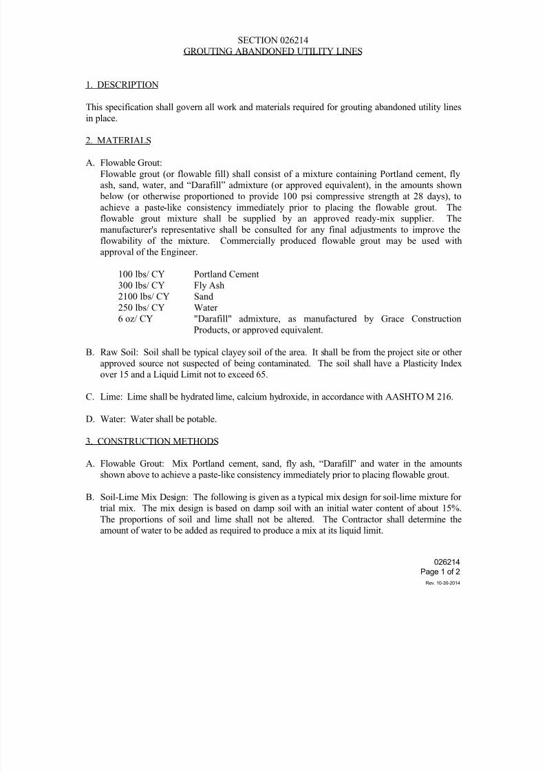
7/25/2019 City Standard Construction Specifications
http://slidepdf.com/reader/full/city-standard-construction-specifications 179/511
SECTION 026214
GROUTING ABANDONED UTILITY LINES
1. DESCRIPTION
This specification shall govern all work and materials required for grouting abandoned utility lines
in place.
2. MATERIALS
A. Flowable Grout:
Flowable grout (or flowable fill) shall consist of a mixture containing Portland cement, fly
ash, sand, water, and “Darafill” admixture (or approved equivalent), in the amounts shown
below (or otherwise proportioned to provide 100 psi compressive strength at 28 days), to
achieve a paste-like consistency immediately prior to placing the flowable grout. The
flowable grout mixture shall be supplied by an approved ready-mix supplier. The
manufacturer's representative shall be consulted for any final adjustments to improve the
flowability of the mixture. Commercially produced flowable grout may be used withapproval of the Engineer.
100 lbs/ CY Portland Cement
300 lbs/ CY Fly Ash
2100 lbs/ CY Sand
250 lbs/ CY Water
6 oz/ CY "Darafill" admixture, as manufactured by Grace Construction
Products, or approved equivalent.
B. Raw Soil: Soil shall be typical clayey soil of the area. It shall be from the project site or other
approved source not suspected of being contaminated. The soil shall have a Plasticity Indexover 15 and a Liquid Limit not to exceed 65.
C. Lime: Lime shall be hydrated lime, calcium hydroxide, in accordance with AASHTO M 216.
D. Water: Water shall be potable.
3. CONSTRUCTION METHODS
A. Flowable Grout: Mix Portland cement, sand, fly ash, “Darafill” and water in the amounts
shown above to achieve a paste-like consistency immediately prior to placing flowable grout.
B. Soil-Lime Mix Design: The following is given as a typical mix design for soil-lime mixture for
trial mix. The mix design is based on damp soil with an initial water content of about 15%.
The proportions of soil and lime shall not be altered. The Contractor shall determine the
amount of water to be added as required to produce a mix at its liquid limit.
026214
Page 1 of 2
Rev. 10-30-2014
7/25/2019 City Standard Construction Specifications
http://slidepdf.com/reader/full/city-standard-construction-specifications 180/511
Trial Mix Design:
Damp Soil 1000 lb.
Lime 50 lb.
Water (approximate) 48 gal.
Consistency shall be checked with liquid limit apparatus.
C. Placement: The Contractor shall grout abandoned lines as indicated on the drawings.
Temporary pumping and venting ports shall be placed as required to provide complete filling of
the abandoned line and proper placement of the grout. If segregation or "sand packing" is
experienced during pumping, the Contractor shall reduce the water content of the mix or obtain
other soil source (for soil-lime mixture), as required. Any damage resulting from pumping
operation shall be repaired at the Contractor's expense.
4. MEASUREMENT AND PAYMENT
Unless otherwise specified on the Bid Form, grouting abandoned utility lines shall be measured bythe linear foot of abandoned-in-place pipe. Payment shall be full compensation for all labor,
equipment, materials and incidentals required to mix, transport, and place the grout and restore
surface at pump ports.
026214
Page 2 of 2
Rev. 10-30-2014
7/25/2019 City Standard Construction Specifications
http://slidepdf.com/reader/full/city-standard-construction-specifications 181/511
SECTION 026402WATERLINES
1. DESCRIPTION
This specification, in conjunction with the City of Corpus Christi's Water Distribution SystemStandards, shall govern all work necessary for the installation of all waterline facilities required to
complete the project.
2. MATERIALS
Concrete: Concrete shall have a minimum compressive strength of 3000 psi at 28 days.
Bedding Sand for Encasement: Bedding sand and initial backfill around the pipe shall begranular material of low plasticity as indicated on the drawings.
Ductile Iron Pipe and Fittings: See City Standard Specification Section 026206.
Polyvinyl Chloride Pipe: See City Standard Specification Section 026210.
Tapping Sleeves and Valves: See City Standard Specification Section 026409.
Gate Valves for Waterlines: See City Standard Specification Section 026411.
Fire Hydrants: See City Standard Specification Section 026416.
3. CONSTRUCTION METHODS
(1) HANDLING MATERIALS
a) General: The Contractor shall be responsible for the safe storage of all materialsfurnished to, or by him, and accepted by him, until it has been incorporated into thecompleted project.
All material found during the progress of the work to have cracks, flaws or otherdefects will be rejected, and the Contractor shall remove such defective material fromthe site of the work.
b) Unloading and Distribution of Materials at Work Site: Pipe and other materials shall be unloaded at point of delivery, hauled to and distributed at the job site by the
Contractor. Materials shall at all times be handled with care and in accordance withmanufacturer's recommendations. Care shall be taken not to scratch PVC pipe.Excessive scratching shall be considered cause for rejection of PVC pipe. Materialsmay be unloaded opposite or near the place where it is to be installed provided that it isto be incorporated into the work within 10 days. The Contractor shall not distributematerial in such a manner as to cause undue inconvenience to the public.
026402
Page 1 of 5Rev. 3-25-2015
7/25/2019 City Standard Construction Specifications
http://slidepdf.com/reader/full/city-standard-construction-specifications 182/511
c) Storing Materials: Materials that are not to be incorporated into the work within 10
days shall be stored on platforms. The interior of pipes and accessories shall be keptfree from dirt and foreign matter.
(2) ALIGNMENT AND GRADE
a) General: All pipes shall be laid and maintained to the required lines and grades.
Fittings, valves and hydrants shall be at the required locations with joints centered,spigots home and all valve and hydrant stems plumb.
Temporary support and adequate protection of all underground and surface utilitystructures encountered in the progress of the work shall be furnished by the Contractor.
Where the grade or alignment of the pipe is obstructed by existing utility structuressuch as conduits, ducts, pipes, connections to sewers or drains, the obstruction shall be permanently supported, relocated, removed, or reconstructed by the Contractor at theContractor's expense, in cooperation with the owners of such utility structures.
One (1) 20-ft. section of waterline pipe shall be centered over/under gravitywastewater line at all gravity wastewater line crossings. Waterline shall be ductile iron pipe with mechanical joint fittings, in accordance with City Standard SpecificationSection 026206, wherever new waterline crosses under new gravity wastewater line.
Maintain a minimum of six inches (2 feet usual) vertical clearance between outsides of pipes where a new waterline crosses over a new wastewater line. Maintain a minimumof twelve inches vertical clearance between outsides of pipes where a new waterlinecrosses under a new wastewater line.
Alternatively, at gravity wastewater line crossings, the proposed PVC waterline may be
encased in a 20-ft. joint of ductile iron pipe with a minimum pressure rating of 150 psithat is at least two nominal sizes larger than the carrier pipe. The carrier pipe shall besupported in the casing at five foot (5') intervals with spacers, or shall be filled to thespring line with clean washed sand, graded as shown in the City Standard WaterDetails. The casing pipe shall be centered under the gravity wastewater line asindicated on the drawings, and both ends of the casing shall be sealed with cementgrout or manufactured seal.
b) Deviation from Drawings: No deviation from the line and grade shown on the plansmay be made without the written consent of the Engineer.
c) Depth of Cover: Depth of cover will be measured from the established street grade orthe surface of the permanent improvement, or from finished grade to the top of the pipe barrel. Unless otherwise shown on drawings, the minimum depth of cover shall be 36 inches. Waterlines 12" and larger located under streets shall have 48 inches ofcover at all points.
026402
Page 2 of 5Rev. 3-25-2015
7/25/2019 City Standard Construction Specifications
http://slidepdf.com/reader/full/city-standard-construction-specifications 183/511
(3) TRENCH EXCAVATION AND BACKFILL
See City Standard Specification Section 022020, “Excavation and Backfill for Utilities” andapplicable City Standard Details for Water.
(4) POLYETHYLENE WRAPPING
All ductile iron pipe, valves and fittings, except pipe or valves which are laid in encasement
pipe or in concrete valve boxes, shall be wrapped in polyethylene. The polyethylenematerial shall have a thickness of 8 mils and may be either clear or black. The wrappingshall be lapped in such manner that all surfaces of pipe, valves and fittings, including joints,shall have a double thickness of polyethylene. If a single longitudinal lap is made using adouble thickness of polyethylene, it shall be lapped a minimum of 18 inches and the lapshall be placed in the lower quadrant of the pipe and in such a manner that backfill materialcannot fall into the lap. The polyethylene shall be secured in place with binder twine at notmore than 6-foot intervals. If wrapping is applied before the pipe is placed in the trench,then special care shall be taken in handling the pipe so that the wrapping will not bedamaged. Care shall also be exercised in backfilling around the pipe and fittings and in blocking fittings so as not to damage the wrapping. Any wrapping that may be damaged
shall be repaired in a manner satisfactory to the Engineer and so as to form the best protection to the pipes.
(5) SAND ENCASEMENT
All pipe and fittings that are not enclosed in concrete valve boxes or laid in encasement pipe, shall be completely encased with a minimum of eight inches (8") of sand on the bottom and sides of waterlines smaller than 16 inches in diameter, and twelve inches(12") over the top of the waterline, unless otherwise indicated on the drawings. Thisencasement includes the bottom, sides and top of pipe and fittings including bells, so that all portions will be encased with sand to insulate the pipe from the natural ground and from the
backfill. The sand shall be compacted to a minimum of 90% Standard Proctor density.Provide twelve inches (12") of sand encasement all around the pipe for 16-inch diameterand larger waterlines.
Sand shall be placed in a manner that will not injure the polyethylene wrapping and shall becompacted under, around the side, and over the pipe in a manner that will reduce settlementto a minimum and as approved by the Engineer.
In order to reduce the amount of sand required, the trench bottom may be excavated in arounded manner so as to maintain at least a minimum of eight inches of sand between theexcavation and the pipe (twelve inches for 16-inch diameter and larger waterlines), unless
otherwise indicated on the drawings.
(6) LOWERING PIPE AND ACCESSORIES IN THE TRENCH
a) General: The trench shall be excavated true and parallel to the pipe center line with aminimum clearance of eight inches below the pipe bottom and with a like clearance
026402
Page 3 of 5Rev. 3-25-2015
7/25/2019 City Standard Construction Specifications
http://slidepdf.com/reader/full/city-standard-construction-specifications 184/511
from the bottom of the bell to the bottom of the bell hole. The trench shall then berefilled to the proper grade with sand as specified. The placing of the encasingmaterial shall be done in such a manner so as to be free of all natural soil rock or otherforeign matter.
After final grading in the trench of the encasing material, bell holes shall be excavatedat each joint.
Proper implements, tools and facilities satisfactory to the Engineer shall be providedand used by the Contractor for the safe and efficient execution of the work. All pipe,fittings, valves, hydrants and accessories shall be carefully lowered into the trench bymeans of a derrick, ropes or other suitable equipment, in such a manner as to preventdamage to pipe and fittings. Under no circumstances shall pipe or accessories bedropped or dumped into the trench.
b) Inspection of Pipe and Accessories: The pipe and accessories shall be inspected fordefects prior to lowering in the trench. Any defective, damaged or unsound pipe shall be replaced.
c) Clean Pipe: All foreign matter or dirt shall be removed from the interior of the pipe prior to lowering into the trench. Pipe shall be kept clean both in and out of the trenchat all times during the laying.
(7) JOINTING PIPES
All pipes shall be made up in accordance with manufacturer's recommendation. Pipedeflection shall not exceed 75% of the maximum amount recommended by themanufacturer.
(8) CONCRETE THRUST BLOCKS
Temporary thrust blocks or other means of carrying thrust loads generated by hydrostatictesting shall be provided at all ends of lines to be tested. Details of the end connections andmethod of temporary blocking shall be submitted to the Engineer for approval. Aftersatisfactory completion of the hydrostatic testing, this temporary blocking shall be removedso that connections may be made with existing lines. This work is subsidiary to waterlineinstallation and no separate payment will be made for it.
Temporary thrust blocks are not allowed for long term use.
(9) METAL HARNESS
Metal harness, tie rods and clamps, or swivel fittings shall be used to prevent pipemovement. Steel rods and clamps shall be galvanized or otherwise rust proofed, or coatedwith hot coal tar enamel, then wrapped with two layers of polyethylene wrapping.
026402
Page 4 of 5Rev. 3-25-2015
7/25/2019 City Standard Construction Specifications
http://slidepdf.com/reader/full/city-standard-construction-specifications 185/511
(10) STERILIZATION
a) Fittings: Valves, hydrants and fittings shall be stored on timbers and kept clean.Where soil or other substance has come in contact with the water surfaces of thefittings, the interior shall be washed and sterilized with 2% solution of calciumhypochlorite.
b) Pipe: As each joint of pipe is laid, the Contractor, unless otherwise directed by the
Engineer, shall throw powdered calcium hypochlorite (70%) through the length of the joint (one pound for each 1,680 gallons of water to give 50 ppm). When the waterlineis complete, and before testing, the waterline shall be slowly filled with water betweenvalves and allowed to stand for 48 hours. After the sterilization period is completed,lines shall be flushed by the Contractor under the direct supervision of a representativeof the City Water Department. The Engineer will take sample for testing two hoursafter refilling. If the sample does not pass State Health Department purificationstandards, the procedure shall be repeated. The entire procedure shall be coordinatedunder the supervision of the Water Division Superintendent/Engineer.
During the sterilization process, valves shall be operated only under the supervision of
the Water Division Superintendent/Engineer. There shall be a base fee of $100 paid by the Contractor to the City for each retest that is required.
(11) HYDROSTATIC TESTING WATER SYSTEM
See City Standard Specification Section 026202, “Hydrostatic Testing of PressureSystems”.
(12) WATER SERVICE CONNECTIONS
See Standard Specification Section 026404, “Water Service Lines”.
4. MEASUREMENT AND PAYMENT
Unless otherwise specified on the Bid Form, waterlines will be measured by the linear foot for eachsize installed. Payment for waterlines will be made under the appropriate pipe material item andshall include, but not be limited to, trenching, dewatering, bedding, pipe (except for fittings),
restraints, temporary thrust blocking, backfill, sterilization, and hydrostatic testing. Payment shall be full compensation for all labor, materials, tools, equipment and incidentals required to completethe work.
026402
Page 5 of 5Rev. 3-25-2015
7/25/2019 City Standard Construction Specifications
http://slidepdf.com/reader/full/city-standard-construction-specifications 186/511
SECTION 026404
WATER SERVICE LINES
1. DESCRIPTION
This specification shall govern all work necessary for furnishing and installing water service lines
required to complete the project. Water service lines are those lines from the City main to the meter
at the property line.
2. MATERIALS
GENERAL
Service fittings shall have a minimum of 150 psi working pressure rating, unless indicated otherwise.
Fittings and materials shall be in accordance with the applicable provisions of AWWA C800.
All service connections shall require service clamps.
SERVICE CLAMP
Service clamps shall be brass saddle with two silicone bronze straps with I.P. thread and have a
minimum working pressure rating of 200 psi. The saddle and nuts shall be of 85-5-5-5 brass alloy
per ASTM B-62 and AWWA C800. The nuts shall have unitized washers. Straps shall be 5/8 inch
high-quality silicone bronze, flattened and contoured to provide a wider bearing surface against the
pipe. Clamps shall be comparable to:
Ford 202B, Smith Blair 323, Rockwell 323
CORPORATION STOP
Corporation stop shall be of brass with I.P. thread inlet and Mueller 110 compression connection
outlet designed for Type K copper pipe and be comparable in design to the following:
Mueller H-15028 for 1" size
Mueller H-15023 for 1-½" & 2" sizes
026404Page 1 of 2
Rev. 3-25-2015
7/25/2019 City Standard Construction Specifications
http://slidepdf.com/reader/full/city-standard-construction-specifications 187/511
ANGLE METER STOP
Angle meter stop shall have a Teflon coated bronze ball which rotates within two Buna-N rubber
seats. Inlet shall be packed joint for Type K copper and be comparable in design to the following:
Ford BA43-342 for 1" service line with 5/8" x 3/4" or 3/4" meter sizeBrass gate valve required for 1-½" and 2" sizes
SERVICE LINE
Service line shall be of Type K copper tube or approved one piece SDR9 polyethylene with
restrained compression brass fittings and stainless steel inserts.
Other products of comparable features and equal quality may be substituted for the above items with
approval of the Engineer.
3. CONSTRUCTION METHODS
See City Standard Specification Section 022020, "Excavation and Backfill for Utilities ".
Service lines shall be placed by the Contractor as indicated on the drawings and as directed by the
Engineer.
Relocation of existing meters and changeovers to the new system shall be done only under the direct
supervision of the City Water Department.
4. MEASUREMENT AND PAYMENT
Unless otherwise specified on the Bid Form, water service lines shall be measured with the units
indicated in the Bid Form for each size of service line. Payment for service lines shall include, but
not be limited to, the following: copper tubing, corporation stop, service clamp, angle meter stop,
trenching, trench safety, backfilling including pavement repair, testing, flushing, clean-up and site
restoration; and shall be full compensation for all labor, equipment, tools and incidentals required for
proper installation of the water service lines.
026404Page 2 of 2
Rev. 3-25-2015
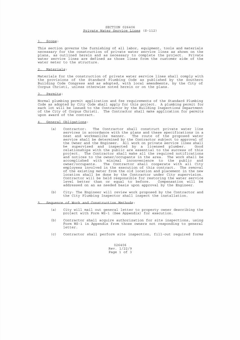
7/25/2019 City Standard Construction Specifications
http://slidepdf.com/reader/full/city-standard-construction-specifications 188/511
026406
Rev. 1/22/9Page 1 of 3
SECTION 026406Private Water Service Lines (S-112)
1. Scope:
This section governs the furnishing of all labor, equipment, tools and materialsnecessary for the construction of private water service lines as shown on theplans, as outlined herein and as necessary to complete the project. Privatewater service lines are defined as those lines from the customer side of thewater meter to the structure.
2. Materials:
Materials for the construction of private water service lines shall comply withthe provisions of the Standard Plumbing Code as published by the SouthernBuilding Code Congress and as adopted, with local amendments, by the City ofCorpus Christi, unless otherwise noted herein or on the plans.
3. Permits:
Normal plumbing permit application and fee requirements of the Standard PlumbingCode as adopted by City Code shall apply for this project. A plumbing permit for
each lot will be issued to the Contractor by the Building Inspections Departmentof the City of Corpus Christi. The Contractor shall make application for permitsupon award of the contract.
4. General Obligations:
(a) Contractor: The Contractor shall construct private water lineservices in accordance with the plans and these specifications in aneat and workmanlike manner. The route of the proposed waterservice shall be determined by the Contractor subject to approval ofthe Owner and the Engineer. All work on private service lines shallbe supervised and inspected by a licensed plumber. Goodrelationships with the public are essential to the success of thisproject. The Contractor shall make all the required notificationsand notices to the owner/occupants in the area. The work shall be
accomplished with minimal inconvenience to the public andowner/occupants. The Contractor shall cooperate with all Cityemployees involved in the execution of this contract. The removalof the existing meter from the old location and placement in the newlocation shall be done by the Contractor under City supervision.Contractor will be held responsible for restoring the water servicelevel better than or equal to before. Compensation will beaddressed on an as needed basis upon approval by the Engineer.
(b) City: The Engineer will review work proposed by the Contractor andthe City Plumbing Inspector shall inspect the installation.
5. Sequence of Work and Construction Methods:
(a) City will mail out general letter to property owner describing theproject with Form WS-1 (See Appendix) for execution.
(b) Contractor shall acquire authorization for site inspections, usingForm WS-1 in Appendix from those owners not responding to generalletter.
(c) Contractor shall perform site inspection, fill-out required forms
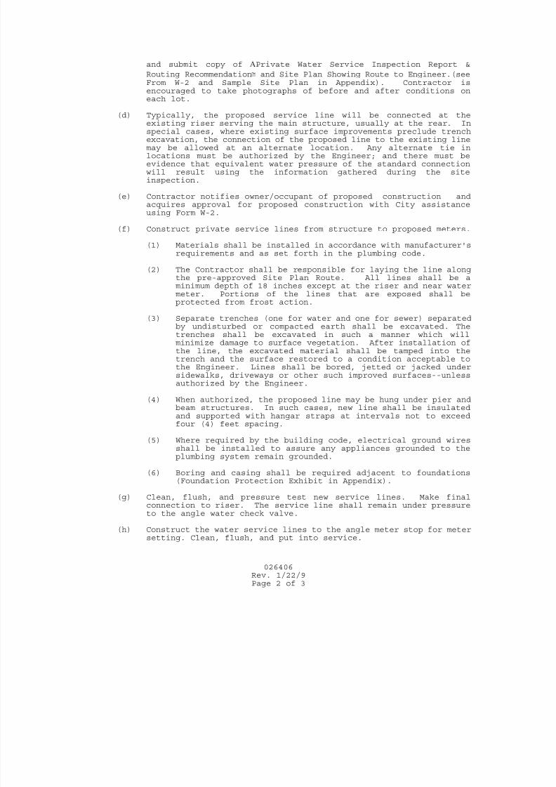
7/25/2019 City Standard Construction Specifications
http://slidepdf.com/reader/full/city-standard-construction-specifications 189/511
026406
Rev. 1/22/9Page 2 of 3
and submit copy of Private Water Service Inspection Report &
Routing Recommendation and Site Plan Showing Route to Engineer.(seeFrom W-2 and Sample Site Plan in Appendix). Contractor isencouraged to take photographs of before and after conditions oneach lot.
(d) Typically, the proposed service line will be connected at the
existing riser serving the main structure, usually at the rear. Inspecial cases, where existing surface improvements preclude trenchexcavation, the connection of the proposed line to the existing linemay be allowed at an alternate location. Any alternate tie inlocations must be authorized by the Engineer; and there must beevidence that equivalent water pressure of the standard connectionwill result using the information gathered during the siteinspection.
(e) Contractor notifies owner/occupant of proposed construction andacquires approval for proposed construction with City assistanceusing Form W-2.
(f) Construct private service lines from structure to proposed meters.
(1) Materials shall be installed in accordance with manufacturer'srequirements and as set forth in the plumbing code.
(2) The Contractor shall be responsible for laying the line alongthe pre-approved Site Plan Route. All lines shall be aminimum depth of 18 inches except at the riser and near watermeter. Portions of the lines that are exposed shall beprotected from frost action.
(3) Separate trenches (one for water and one for sewer) separatedby undisturbed or compacted earth shall be excavated. Thetrenches shall be excavated in such a manner which willminimize damage to surface vegetation. After installation ofthe line, the excavated material shall be tamped into thetrench and the surface restored to a condition acceptable tothe Engineer. Lines shall be bored, jetted or jacked under
sidewalks, driveways or other such improved surfaces--unlessauthorized by the Engineer.
(4) When authorized, the proposed line may be hung under pier andbeam structures. In such cases, new line shall be insulatedand supported with hangar straps at intervals not to exceedfour (4) feet spacing.
(5) Where required by the building code, electrical ground wiresshall be installed to assure any appliances grounded to theplumbing system remain grounded.
(6) Boring and casing shall be required adjacent to foundations(Foundation Protection Exhibit in Appendix).
(g) Clean, flush, and pressure test new service lines. Make finalconnection to riser. The service line shall remain under pressureto the angle water check valve.
(h) Construct the water service lines to the angle meter stop for metersetting. Clean, flush, and put into service.
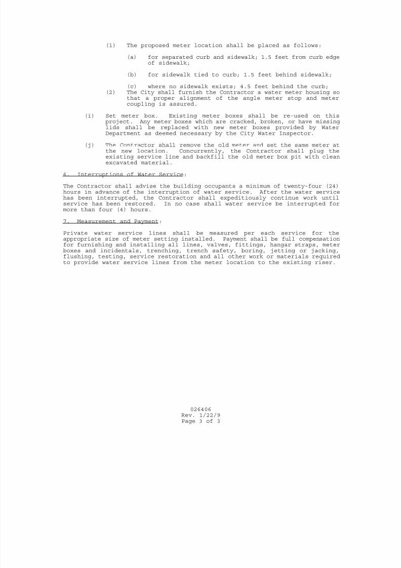
7/25/2019 City Standard Construction Specifications
http://slidepdf.com/reader/full/city-standard-construction-specifications 190/511
026406
Rev. 1/22/9Page 3 of 3
(1) The proposed meter location shall be placed as follows:
(a) for separated curb and sidewalk; 1.5 feet from curb edgeof sidewalk;
(b) for sidewalk tied to curb; 1.5 feet behind sidewalk;
(c) where no sidewalk exists; 4.5 feet behind the curb;(2) The City shall furnish the Contractor a water meter housing so
that a proper alignment of the angle meter stop and metercoupling is assured.
(i) Set meter box. Existing meter boxes shall be re-used on thisproject. Any meter boxes which are cracked, broken, or have missinglids shall be replaced with new meter boxes provided by WaterDepartment as deemed necessary by the City Water Inspector.
(j) The Contractor shall remove the old meter and set the same meter atthe new location. Concurrently, the Contractor shall plug theexisting service line and backfill the old meter box pit with cleanexcavated material.
6. Interruptions of Water Service:
The Contractor shall advise the building occupants a minimum of twenty-four (24)hours in advance of the interruption of water service. After the water servicehas been interrupted, the Contractor shall expeditiously continue work untilservice has been restored. In no case shall water service be interrupted formore than four (4) hours.
7. Measurement and Payment:
Private water service lines shall be measured per each service for theappropriate size of meter setting installed. Payment shall be full compensationfor furnishing and installing all lines, valves, fittings, hangar straps, meterboxes and incidentals, trenching, trench safety, boring, jetting or jacking,flushing, testing, service restoration and all other work or materials requiredto provide water service lines from the meter location to the existing riser.
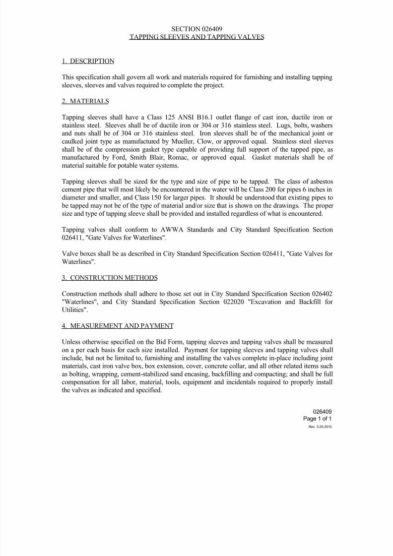
7/25/2019 City Standard Construction Specifications
http://slidepdf.com/reader/full/city-standard-construction-specifications 191/511
SECTION 026409
TAPPING SLEEVES AND TAPPING VALVES
1. DESCRIPTION
This specification shall govern all work and materials required for furnishing and installing tapping
sleeves, sleeves and valves required to complete the project.
2. MATERIALS
Tapping sleeves shall have a Class 125 ANSI B16.1 outlet flange of cast iron, ductile iron or
stainless steel. Sleeves shall be of ductile iron or 304 or 316 stainless steel. Lugs, bolts, washers
and nuts shall be of 304 or 316 stainless steel. Iron sleeves shall be of the mechanical joint or
caulked joint type as manufactured by Mueller, Clow, or approved equal. Stainless steel sleeves
shall be of the compression gasket type capable of providing full support of the tapped pipe, as
manufactured by Ford, Smith Blair, Romac, or approved equal. Gasket materials shall be of
material suitable for potable water systems.
Tapping sleeves shall be sized for the type and size of pipe to be tapped. The class of asbestos
cement pipe that will most likely be encountered in the water will be Class 200 for pipes 6 inches in
diameter and smaller, and Class 150 for larger pipes. It should be understood that existing pipes to
be tapped may not be of the type of material and/or size that is shown on the drawings. The proper
size and type of tapping sleeve shall be provided and installed regardless of what is encountered.
Tapping valves shall conform to AWWA Standards and City Standard Specification Section
026411, "Gate Valves for Waterlines".
Valve boxes shall be as described in City Standard Specification Section 026411, "Gate Valves for
Waterlines".
3. CONSTRUCTION METHODS
Construction methods shall adhere to those set out in City Standard Specification Section 026402
"Waterlines", and City Standard Specification Section 022020 "Excavation and Backfill for
Utilities".
4. MEASUREMENT AND PAYMENT
Unless otherwise specified on the Bid Form, tapping sleeves and tapping valves shall be measured
on a per each basis for each size installed. Payment for tapping sleeves and tapping valves shallinclude, but not be limited to, furnishing and installing the valves complete in-place including joint
materials, cast iron valve box, box extension, cover, concrete collar, and all other related items such
as bolting, wrapping, cement-stabilized sand encasing, backfilling and compacting; and shall be full
compensation for all labor, material, tools, equipment and incidentals required to properly install
the valves as indicated and specified.
026409
Page 1 of 1
Rev. 3-25-2015
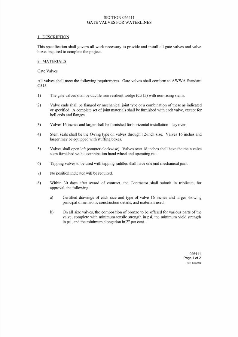
7/25/2019 City Standard Construction Specifications
http://slidepdf.com/reader/full/city-standard-construction-specifications 192/511
SECTION 026411
GATE VALVES FOR WATERLINES
1. DESCRIPTION
This specification shall govern all work necessary to provide and install all gate valves and valve
boxes required to complete the project.
2. MATERIALS
Gate Valves
All valves shall meet the following requirements. Gate valves shall conform to AWWA Standard
C515.
1) The gate valves shall be ductile iron resilient wedge (C515) with non-rising stems.
2) Valve ends shall be flanged or mechanical joint type or a combination of these as indicatedor specified. A complete set of joint materials shall be furnished with each valve, except for
bell ends and flanges.
3) Valves 16 inches and larger shall be furnished for horizontal installation – lay over.
4) Stem seals shall be the O-ring type on valves through 12-inch size. Valves 16 inches and
larger may be equipped with stuffing boxes.
5) Valves shall open left (counter clockwise). Valves over 18 inches shall have the main valve
stem furnished with a combination hand wheel and operating nut.
6) Tapping valves to be used with tapping saddles shall have one end mechanical joint.
7) No position indicator will be required.
8) Within 30 days after award of contract, the Contractor shall submit in triplicate, for
approval, the following:
a) Certified drawings of each size and type of valve 16 inches and larger showing
principal dimensions, construction details, and materials used.
b) On all size valves, the composition of bronze to be offered for various parts of thevalve, complete with minimum tensile strength in psi, the minimum yield strength
in psi, and the minimum elongation in 2" per cent.
026411
Page 1 of 2
Rev. 3-25-2015
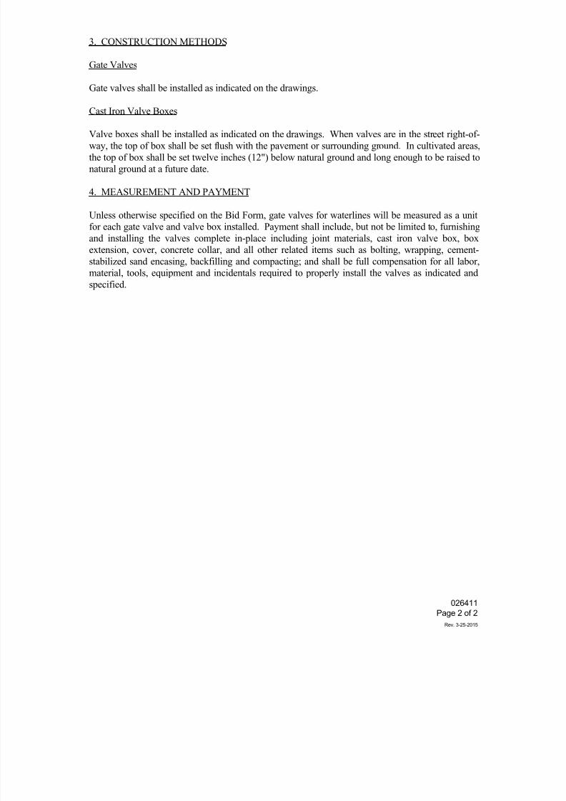
7/25/2019 City Standard Construction Specifications
http://slidepdf.com/reader/full/city-standard-construction-specifications 193/511
3. CONSTRUCTION METHODS
Gate Valves
Gate valves shall be installed as indicated on the drawings.
Cast Iron Valve Boxes
Valve boxes shall be installed as indicated on the drawings. When valves are in the street right-of-
way, the top of box shall be set flush with the pavement or surrounding ground. In cultivated areas,
the top of box shall be set twelve inches (12") below natural ground and long enough to be raised to
natural ground at a future date.
4. MEASUREMENT AND PAYMENT
Unless otherwise specified on the Bid Form, gate valves for waterlines will be measured as a unit
for each gate valve and valve box installed. Payment shall include, but not be limited to, furnishing
and installing the valves complete in-place including joint materials, cast iron valve box, box
extension, cover, concrete collar, and all other related items such as bolting, wrapping, cement-stabilized sand encasing, backfilling and compacting; and shall be full compensation for all labor,
material, tools, equipment and incidentals required to properly install the valves as indicated and
specified.
026411
Page 2 of 2
Rev. 3-25-2015
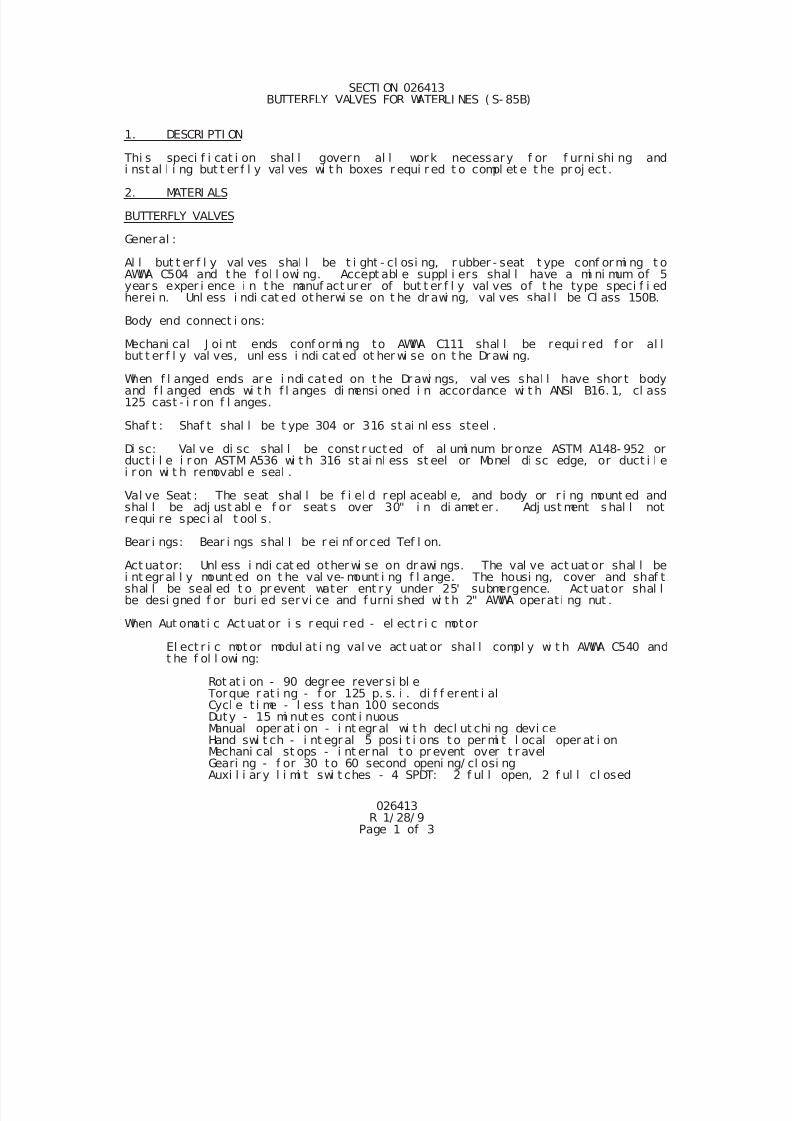
7/25/2019 City Standard Construction Specifications
http://slidepdf.com/reader/full/city-standard-construction-specifications 194/511
026413R 1/ 28/ 9
Page 1 of 3
SECTI ON 026413 BUTTERFLY VALVES FOR WATERLI NES ( S- 85B)
1. DESCRI PTI ON
Thi s speci f i cat i on shal l govern al l work necessary f or f urni shi ng andi nst al l i ng but t er f l y val ves wi t h boxes r equi r ed t o compl et e t he pr oj ect .
2. MATERI ALS
BUTTERFLY VALVES
General :
Al l but t er f l y val ves shal l be t i ght - cl osi ng, r ubber - seat t ype conf or mi ng t oAWWA C504 and t he f ol l owi ng. Accept abl e suppl i ers shal l have a mi ni mum of 5year s exper i ence i n t he manuf act ur er of but t er f l y val ves of t he type speci f i edherei n. Unl ess i ndi cat ed otherwi se on t he dr awi ng, val ves shal l be Cl ass 150B.
Body end connect i ons:
Mechani cal J oi nt ends conf ormi ng to AWWA C111 shal l be requi r ed f or al l
but t er f l y val ves, unl ess i ndi cat ed ot her wi se on t he Dr awi ng.
When f l anged ends ar e i ndi cated on t he Dr awi ngs, val ves shal l have shor t bodyand f l anged ends wi t h f l anges di mensi oned i n accordance wi t h ANSI B16. 1, cl ass125 cast - i r on f l anges.
Shaf t : Shaf t shal l be t ype 304 or 316 st ai nl ess steel .
Di sc: Val ve di sc shal l be const r uct ed of al umi num br onze ASTM A148- 952 orduct i l e i r on ASTM A536 wi t h 316 st ai nl ess st eel or Monel di sc edge, or duct i l ei r on wi t h removabl e seal .
Val ve Seat : The seat shal l be f i el d r epl aceabl e, and body or r i ng mount ed andshal l be adj ust abl e f or seat s over 30" i n di amet er . Adj ust ment shal l notrequi re speci al t ool s.
Bear i ngs: Bear i ngs shal l be r ei nf or ced Tef l on.
Act uator: Unl ess i ndi cat ed other wi se on dr awi ngs. The val ve act uat or shal l bei nt egr al l y mount ed on t he val ve- mount i ng f l ange. The housi ng, cover and shaf tshal l be seal ed t o pr event water ent r y under 25' submergence. Act uator shal lbe desi gned f or buri ed servi ce and f urni shed wi t h 2" AWWA operat i ng nut .
When Aut omati c Act uat or i s r equi r ed - el ect r i c motor
El ect r i c mot or modul at i ng val ve act uat or shal l compl y wi t h AWWA C540 andt he f ol l owi ng:
Rot at i on - 90 degr ee rever si bl e Torque r at i ng - f or 125 p. s. i . di f f erent i al
Cycl e t i me - l ess t han 100 secondsDuty - 15 mi nut es cont i nuousManual oper at i on - i nt egr al wi t h decl ut chi ng devi ceHand swi t ch - i nt egr al 5 posi t i ons t o per mi t l ocal oper at i onMechani cal st ops - i nt er nal t o pr event over t r avelGeari ng - f or 30 to 60 second openi ng/ cl osi ngAuxi l i ar y l i mi t swi t ches - 4 SPDT: 2 f ul l open, 2 f ul l cl osed
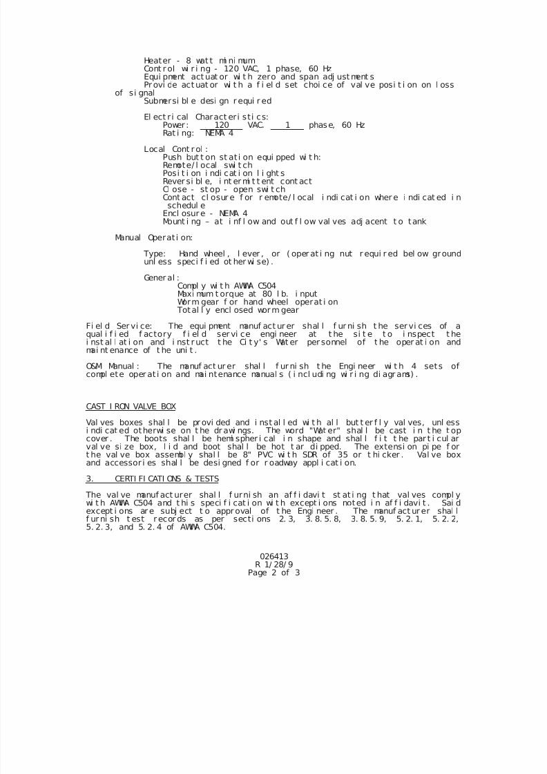
7/25/2019 City Standard Construction Specifications
http://slidepdf.com/reader/full/city-standard-construction-specifications 195/511
026413R 1/ 28/ 9
Page 2 of 3
Heater - 8 wat t mi ni mum Cont r ol wi r i ng - 120 VAC, 1 phase, 60 Hz
Equi pment act uat or wi t h zero and span adj ust ment sPr ovi de act uat or wi t h a f i el d set choi ce of val ve posi t i on on l oss
of si gnalSubmersi bl e desi gn r equi r ed
El ect r i cal Charact eri st i cs:Power : 120 VAC. 1 phase, 60 HzRat i ng: NEMA 4
Local Cont r ol :Push but t on st at i on equi pped wi t h:Remote/ l ocal swi t chPosi t i on i ndi cat i on l i ght sRever si bl e, i nt er mi t t ent cont actCl ose - st op - open swi t chCont act cl osur e f or r emote/ l ocal i ndi cat i on wher e i ndi cat ed i nschedul e
Encl osure - NEMA 4Mount i ng – at i nf l ow and out f l ow val ves adj acent t o tank
Manual Operat i on:
Type: Hand wheel , l ever , or ( oper at i ng nut r equi r ed bel ow groundunl ess speci f i ed ot her wi se) .
Gener al :Compl y wi t h AWWA C504Maxi mum t orque at 80 l b. i nputWorm gear f or hand wheel operat i on
Total l y encl osed worm gear
Fi el d Ser vi ce: The equi pment manuf act ur er shal l f ur ni sh t he ser vi ces of aqual i f i ed f actory f i el d ser vi ce engi neer at t he si t e t o i nspect t hei nst al l at i on and i nst r uct t he Ci t y' s Wat er per sonnel of t he oper at i on andmai nt enance of t he uni t .
O&M Manual : The manuf act ur er shal l f ur ni sh t he Engi neer wi t h 4 sets ofcompl ete oper at i on and mai ntenance manual s ( i ncl udi ng wi r i ng di agr ams) .
CAST I RON VALVE BOX
Val ves boxes shal l be pr ovi ded and i nst al l ed wi t h al l but t er f l y val ves, unl essi ndi cat ed otherwi se on t he dr awi ngs. The word "Wat er" shal l be cast i n t he t opcover . The boots shal l be hemi spher i cal i n shape and shal l f i t t he par t i cul arval ve si ze box, l i d and boot shal l be hot t ar di pped. The extensi on pi pe f ort he val ve box assembl y shal l be 8" PVC wi t h SDR of 35 or t hi cker . Val ve boxand accessor i es shal l be desi gned f or r oadway appl i cat i on.
3. CERTI FI CATI ONS & TESTS
The val ve manuf act urer shal l f urni sh an af f i davi t st at i ng t hat val ves compl ywi t h AWWA C504 and t hi s speci f i cat i on wi t h except i ons noted i n af f i davi t . Sai dexcept i ons ar e subj ect t o appr oval of t he Engi neer . The manuf act ur er shal lf ur ni sh t est r ecor ds as per secti ons 2. 3, 3. 8. 5. 8, 3. 8. 5. 9, 5. 2. 1, 5. 2. 2,5. 2. 3, and 5. 2. 4 of AWWA C504.
7/25/2019 City Standard Construction Specifications
http://slidepdf.com/reader/full/city-standard-construction-specifications 196/511
026413R 1/ 28/ 9
Page 3 of 3
4. SHOP DRAWI NGS
The manuf act urer shal l submi t cer t i f i ed shop drawi ngs as per sect i ons 1. 4 and1. 5 of AWWA C504.
5. CONSTRUCTI ON METHODS
Val ves shal l be i nst al l ed i n a workman l i ke manor and wr apped wi t h t wo pl i es of8- mi l pol yet hyl ene.
Val ve boxes i n st r eet ROW shal l be set f l ush wi t h pavement or sur r oundi nggr ound. I n cul t i vat ed ar eas t he t op of box shal l be set 12" bel ow nat ur algr ound and l ong enough t o be r ai sed t o natural gr ound at a f ut ur e date.
6. MEASUREMENT AND PAYMENT
Unl ess i ndi cat ed ot her wi se i n t he Pr oposal , But t er f l y Val ves wi t h box shal l bemeasured as a uni t f or each si ze of val ve and box assembl y. Payment shal li ncl ude but not be l i mi t ed t o f ur ni shi ng and i nst al l i ng t he val ve and boxcompl et e wi t h pol yet hyl ene wr ap, concrete col l ar , box assembl y, and al l l abor,mat er i al s, i nci dent al s, et c. , requi red f or t he pr oper 1i nstal l at i on.
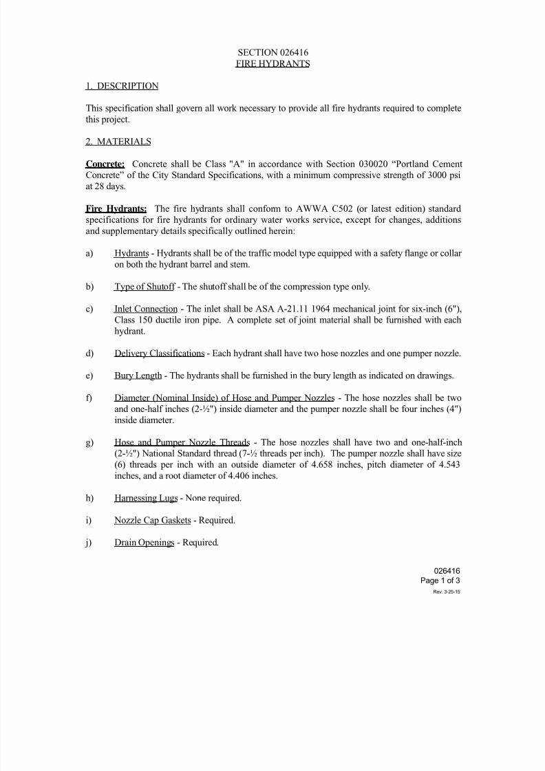
7/25/2019 City Standard Construction Specifications
http://slidepdf.com/reader/full/city-standard-construction-specifications 197/511
SECTION 026416
FIRE HYDRANTS
1. DESCRIPTION
This specification shall govern all work necessary to provide all fire hydrants required to complete
this project.
2. MATERIALS
Concrete: Concrete shall be Class "A" in accordance with Section 030020 “Portland Cement
Concrete” of the City Standard Specifications, with a minimum compressive strength of 3000 psi
at 28 days.
Fire Hydrants: The fire hydrants shall conform to AWWA C502 (or latest edition) standard
specifications for fire hydrants for ordinary water works service, except for changes, additions
and supplementary details specifically outlined herein:
a) Hydrants - Hydrants shall be of the traffic model type equipped with a safety flange or collar
on both the hydrant barrel and stem.
b) Type of Shutoff - The shutoff shall be of the compression type only.
c) Inlet Connection - The inlet shall be ASA A-21.11 1964 mechanical joint for six-inch (6"),
Class 150 ductile iron pipe. A complete set of joint material shall be furnished with each
hydrant.
d) Delivery Classifications - Each hydrant shall have two hose nozzles and one pumper nozzle.
e) Bury Length - The hydrants shall be furnished in the bury length as indicated on drawings.
f) Diameter (Nominal Inside) of Hose and Pumper Nozzles - The hose nozzles shall be two
and one-half inches (2-½") inside diameter and the pumper nozzle shall be four inches (4")
inside diameter.
g) Hose and Pumper Nozzle Threads - The hose nozzles shall have two and one-half-inch
(2-½") National Standard thread (7-½ threads per inch). The pumper nozzle shall have size
(6) threads per inch with an outside diameter of 4.658 inches, pitch diameter of 4.543
inches, and a root diameter of 4.406 inches.
h) Harnessing Lugs - None required.
i) Nozzle Cap Gaskets - Required.
j) Drain Openings - Required.
026416
Page 1 of 3
Rev. 3-25-15
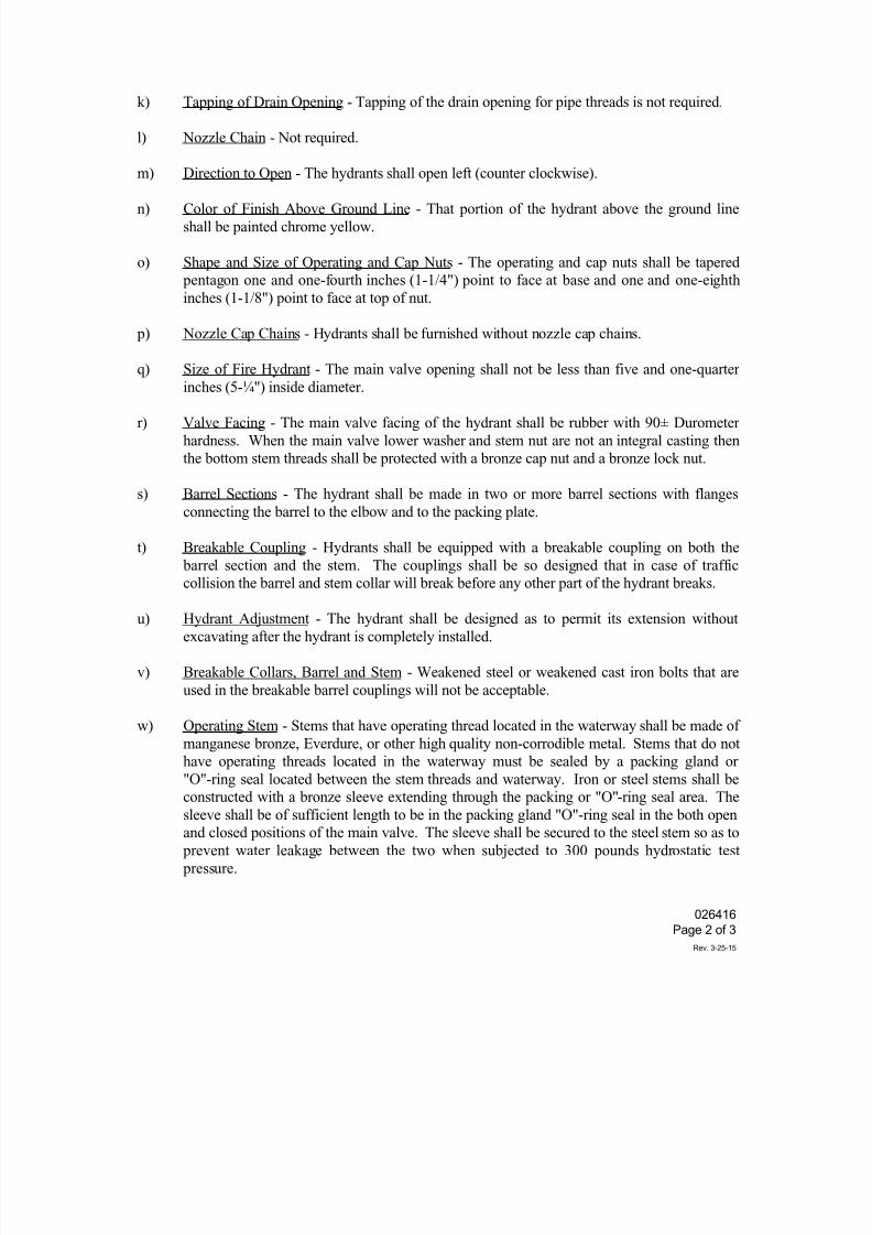
7/25/2019 City Standard Construction Specifications
http://slidepdf.com/reader/full/city-standard-construction-specifications 198/511
k) Tapping of Drain Opening - Tapping of the drain opening for pipe threads is not required.
l) Nozzle Chain - Not required.
m) Direction to Open - The hydrants shall open left (counter clockwise).
n) Color of Finish Above Ground Line - That portion of the hydrant above the ground line
shall be painted chrome yellow.
o) Shape and Size of Operating and Cap Nuts - The operating and cap nuts shall be tapered
pentagon one and one-fourth inches (1-1/4") point to face at base and one and one-eighth
inches (1-1/8") point to face at top of nut.
p) Nozzle Cap Chains - Hydrants shall be furnished without nozzle cap chains.
q) Size of Fire Hydrant - The main valve opening shall not be less than five and one-quarter
inches (5-¼") inside diameter.
r) Valve Facing - The main valve facing of the hydrant shall be rubber with 90± Durometer
hardness. When the main valve lower washer and stem nut are not an integral casting then
the bottom stem threads shall be protected with a bronze cap nut and a bronze lock nut.
s) Barrel Sections - The hydrant shall be made in two or more barrel sections with flanges
connecting the barrel to the elbow and to the packing plate.
t) Breakable Coupling - Hydrants shall be equipped with a breakable coupling on both the
barrel section and the stem. The couplings shall be so designed that in case of traffic
collision the barrel and stem collar will break before any other part of the hydrant breaks.
u) Hydrant Adjustment - The hydrant shall be designed as to permit its extension without
excavating after the hydrant is completely installed.
v) Breakable Collars, Barrel and Stem - Weakened steel or weakened cast iron bolts that are
used in the breakable barrel couplings will not be acceptable.
w) Operating Stem - Stems that have operating thread located in the waterway shall be made of
manganese bronze, Everdure, or other high quality non-corrodible metal. Stems that do not
have operating threads located in the waterway must be sealed by a packing gland or
"O"-ring seal located between the stem threads and waterway. Iron or steel stems shall beconstructed with a bronze sleeve extending through the packing or "O"-ring seal area. The
sleeve shall be of sufficient length to be in the packing gland "O"-ring seal in the both open
and closed positions of the main valve. The sleeve shall be secured to the steel stem so as to
prevent water leakage between the two when subjected to 300 pounds hydrostatic test
pressure.
026416
Page 2 of 3
Rev. 3-25-15
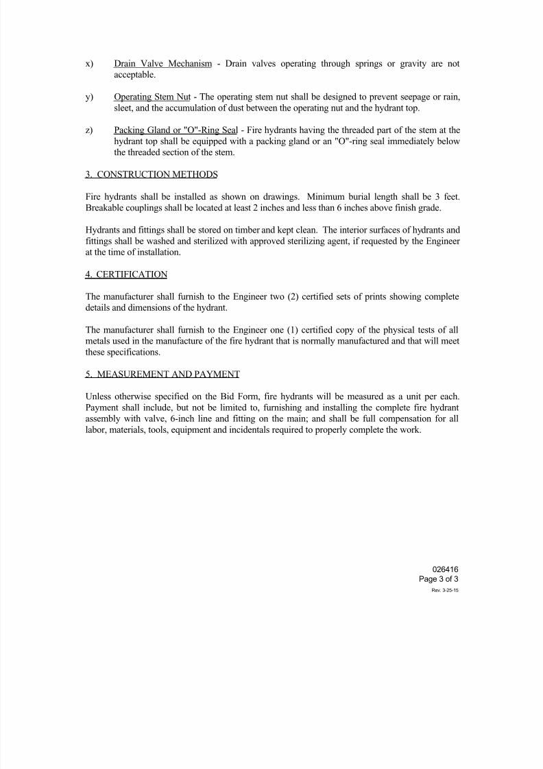
7/25/2019 City Standard Construction Specifications
http://slidepdf.com/reader/full/city-standard-construction-specifications 199/511
x) Drain Valve Mechanism - Drain valves operating through springs or gravity are not
acceptable.
y) Operating Stem Nut - The operating stem nut shall be designed to prevent seepage or rain,
sleet, and the accumulation of dust between the operating nut and the hydrant top.
z) Packing Gland or "O"-Ring Seal - Fire hydrants having the threaded part of the stem at the
hydrant top shall be equipped with a packing gland or an "O"-ring seal immediately below
the threaded section of the stem.
3. CONSTRUCTION METHODS
Fire hydrants shall be installed as shown on drawings. Minimum burial length shall be 3 feet.
Breakable couplings shall be located at least 2 inches and less than 6 inches above finish grade.
Hydrants and fittings shall be stored on timber and kept clean. The interior surfaces of hydrants and
fittings shall be washed and sterilized with approved sterilizing agent, if requested by the Engineerat the time of installation.
4. CERTIFICATION
The manufacturer shall furnish to the Engineer two (2) certified sets of prints showing complete
details and dimensions of the hydrant.
The manufacturer shall furnish to the Engineer one (1) certified copy of the physical tests of all
metals used in the manufacture of the fire hydrant that is normally manufactured and that will meet
these specifications.
5. MEASUREMENT AND PAYMENT
Unless otherwise specified on the Bid Form, fire hydrants will be measured as a unit per each.
Payment shall include, but not be limited to, furnishing and installing the complete fire hydrant
assembly with valve, 6-inch line and fitting on the main; and shall be full compensation for all
labor, materials, tools, equipment and incidentals required to properly complete the work.
026416
Page 3 of 3
Rev. 3-25-15
7/25/2019 City Standard Construction Specifications
http://slidepdf.com/reader/full/city-standard-construction-specifications 200/511
026430
Page 1 of 18
Rev. 10-30-2014
SECTION 026430
BAR WRAPPED CONCRETE STEEL CYLINDER PIPE
PART 1 GENERAL
1.01 SECTION INCLUDES
A. Furnishing and installing new bar wrapped concrete steel cylinder pipe and fittings for buried
water lines for sizes 20 inches to 60 inches.
1.02 MEASUREMENT AND PAYMENT
A. Unit Prices.
1. No separate payment will be made for bar wrapped concrete steel cylinder pipe
under this Section. Include cost in price for water lines.
2. Maintain, on site, minimum of two 3-degree and two 5-degree grade angle
adapters. When used during construction, adapter will be paid at unit price.
3. Refer to Special Provision A-4 - Method of Award - Explanation of Measurement and
Payment for unit price procedures.
B. Stipulated Price (Lump Sum). Not used.
1.03 REFERENCES
A. AASHTO - Standard Specifications for Highway Bridges.
B. AREMA - Manual of Railway’ Engineering, Volume II, Chapter 15.
C. ASTM A 615- Standard Specification for Deformed and Plain Billet-Steel Bars for Concrete
Reinforcement.
D. ASTM C 33 - Standard Specification for Concrete Aggregates.
E. ASTM C 35 - Standard Specification for Inorganic Aggregates for Use in Gypsum PIaster
F. ASTM C 150-
Standard Specification for Portland Cement.
G. ASTM C 497 - Standard Test Method for Concrete Pipe, Manhole Sections, or Tile, Testing.
H. ASTM D 512 - Standard Test Methods for Chloride Ion in Water.
7/25/2019 City Standard Construction Specifications
http://slidepdf.com/reader/full/city-standard-construction-specifications 201/511
026430
Page 2 of 18
Rev. 10-30-2014
I. ASTM C 1107 (CRD C-621) -Standard Specification for Packaged Dry, Hydraulic-
Cement Grout (Nonshrink).
J. ASTM D 1293 -Standard Test Methods for pH of Water.
K. ASTM E 165 -Standard Test Methods for Dye Protection
L. ASTM E 340 -Standard Test Method for Macroetching Metals and Alloys.
M. ASTM E 709 -Standard Test methods for Magnetic Particle Testing.
N. ASTM E 1032 -Standard Test Methods for Radiographic Examination of Weidments.
0. ANSI/AWS A3.0 -Standard Welding Terms and Definitions.
P. AWWA C 206 -Standard for Field Welding of Steel Water Pipe.
Q. AWWA C 207 -Standard for Steel Pipe Flanges for Waterworks Service -Sizes 4 in.
through 144 in.
R. AWWA C 301 -Standard for Pre-stressed Concrete Pressure Pipe, Steel-CylinderType, for Water and Other Liquids.
S. AWWA C 303 -Standard for Concrete Pressure Pipe, Bar-Wrapped, Steel-Cylinder
Type.
T. AWWA C 304 -Standard for Design of Pre-stressed Concrete Cylinder Pipe.
U. AWWA M 9- Concrete Pressure Pipe.
V. NSF 61 -Drinking Water System Components -Health Effects.
W. SSPC SP 7- Surface Preparation Specifications No.7 Brush Off Blast Cleaning.
1.04. SUBMITTALS
A. Conform to requirements of CC 01 33 02 Shop Drawings.
B. Submit shop drawings and certification signed and sealed by Professional Engineer
registered in State of Texas showing following:
1. Manufacturer’s pipe design calculations.
2. Provide lay schedule of pictorial nature indicating alignment and grade, layingdimensions, welding procedures, fabrication, fitting, flange, and special details, with
plan view of each pipe segment sketched, detailing pipe invert elevations, horizontal
7/25/2019 City Standard Construction Specifications
http://slidepdf.com/reader/full/city-standard-construction-specifications 202/511
026430
Page 3 of 18
Rev. 10-30-2014
bends, welded joints, and other critical features. Indicate station numbers for pipe and
fittings corresponding to Drawings. Do not start production of pipe and fittings prior to
review and approval by the Engineer. Provide final approved lay schedule on CD-Rom in
Adobe portable document format (*PDF).
3. Include hot tapping procedure.
4. Submit certification from manufacturer that design was performed for project inaccordance with requirements of this section
C. Submit inspection procedures to be used by manufacturer and for quality control and
assurance for materials and welding. Submit standard repair procedures that describe in detail
shop and field work to be performed. Repair defects such as substandard welds, excessiveradial offsets (misalignment), pitting, gouges, cracks, etc.
D. Submit following within 45 days after manufacturing of pipe and fittings.
1. Steel:
a. Steel reports as required in AWWA C 303, Section 5.2.5.
b. Results of other tests of steel reinforcement required in AWWA C 303, Section
5.2.
2. Test Results.
a. Hydrostatic testing, acid etching, magnetic particle and x-ray weld test reports as
required.
b. Compressive strength (7 and 28 day) test results for each type of coating and
lining mix design.
3. Submit pipe manufacturer’s certification that Bar Wrapped Steel Cylinder Pipe:
a. Cylinder assembly has been hydrostatically tested at factory.
b. Mortar coatings and linings were applied or allowed to cure at temperature above
32 degrees Fahrenheit.
E. Submit following nonshrink grout for special applications:
I. Manufacturer’s technical literature including specifications for mixing, placing, and
curing grout.
2. Results of tests performed by certified independent testing laboratory showing
conformance to ASTM C 1107, Nonshrink Grout and requirements of this
specification.
3. Certification product is suitable for use in contact with potable water.
7/25/2019 City Standard Construction Specifications
http://slidepdf.com/reader/full/city-standard-construction-specifications 203/511
026430
Page 4 of 18
Rev. 10-30-2014
F. Submit certification for welder and welding operator demonstrating their certificationwithin past 6 months in accordance with AWWA C 206. Indicate certified procedures and
position each welder is qualified to perform.
G. Calibrate within last 12 months for equipment such as scales, measuring devices, and
calibration tools used in manufacture of pipe. Each device used in manufacture of pipe is 11
required to have tag recording date of last calibration. Devices are subject to inspection bythe Engineer.
1.05 QUALITY CONTROL
A. Manufacturer to have permanent quality control department and laboratory facility capableof performing inspection and testing required. Inspection procedures and manufacturing
process are subject to inspection by the Engineer. Perform manufacturer tests and
inspections required by AWWA C 303 as modified by these Specifications. Correctnonconforming conditions.
1. Cylinder and Joint Ring Assembly:
a. Review mill certifications for conformance requirements of Specifications.
b. Perform physical testing of each heat of steel for conformance to applicableASTM standards.
c. Inspect physical dimensions and overall condition of joint rings andcylinder/joint ring assembly to verify compliance with requirements of AWWA
C 303. Maximum allowable thickness variation of cylinder shall not be less
than determined thickness.
d. Test cylinder/joint ring weld for tensile strength. Test one specimen for each500 cylinder/joint ring assemblies in addition to those tests required by
AWWAC3OI.
e. Reject pipe with dented steel cylinders.
2. Bar Rod
a. Review mill certifications for conformance to requirements of Specifications.
b. Inspect rod spacing during placement on cylinder.
c. Test rod splices for each production run or minimum of once a week,whichever is less, for conformance with minimum strength criteria.
3. Pipe Lining Coating:
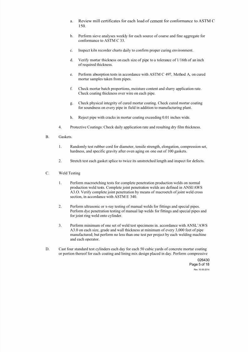
7/25/2019 City Standard Construction Specifications
http://slidepdf.com/reader/full/city-standard-construction-specifications 204/511
026430
Page 5 of 18
Rev. 10-30-2014
a. Review mill certificates for each load of cement for conformance to ASTM C
150.
b. Perform sieve analyses weekly for each source of coarse and fine aggregate for
conformance to ASTM C 33.
c. Inspect kiln recorder charts daily to confirm proper curing environment.
d. Verify mortar thickness on each size of pipe to a tolerance of 1/16th of an inch
of required thickness.
e. Perform absorption tests in accordance with ASTM C 497, Method A, on cured
mortar samples taken from pipes.
f. Check mortar batch proportions, moisture content and slurry application rate.
Check coating thickness over wire on each pipe.
g. Check physical integrity of cured mortar coating. Check cured mortar coating
for soundness on every pipe in field in addition to manufacturing plant.
h. Reject pipe with cracks in mortar coating exceeding 0.01 inches wide.
4. Protective Coatings: Check daily application rate and resulting dry film thickness.
B. Gaskets.
1. Randomly test rubber cord for diameter, tensile strength, elongation, compression set,
hardness, and specific gravity after oven aging on one out of 100 gaskets.
2. Stretch test each gasket splice to twice its unstretched length and inspect for defects.
C. Weld Testing
1. Perform macroetching tests for complete penetration production welds on normal
production weld tests. Complete joint penetration welds are defined in ANSI/AWS
A3.O. Verify complete joint penetration by means of macroetch of joint weld cross
section, in accordance with ASTM E 340.
2. Perform ultrasonic or x-ray testing of manual welds for fittings and special pipes.
Perform dye penetration testing of manual lap welds for fittings and special pipes and
for joint ring weld onto cylinder.
3. Perform minimum of one set of weld test specimens in. accordance with ANSL’AWS
A3.0 on each size, grade and wall thickness at minimum of every 3,000 feet of pipe
manufactured; but perform no less than one test per project by each welding machine
and each operator.
D. Cast four standard test cylinders each day for each 50 cubic yards of concrete mortar coating
or portion thereof for each coating and lining mix design placed in day. Perform compressive
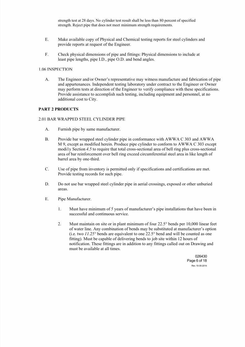
7/25/2019 City Standard Construction Specifications
http://slidepdf.com/reader/full/city-standard-construction-specifications 205/511
026430
Page 6 of 18
Rev. 10-30-2014
strength test at 28 days. No cylinder test result shall be less than 80 percent of specified
strength. Reject pipe that does not meet minimum strength requirements.
E. Make available copy of Physical and Chemical testing reports for steel cylinders and
provide reports at request of the Engineer.
F. Check physical dimensions of pipe and fittings: Physical dimensions to include atleast pipe lengths, pipe I.D., pipe O.D. and bend angles.
1.06 INSPECTION
A. The Engineer and/or Owner’s representative may witness manufacture and fabrication of pipeand appurtenances. Independent testing laboratory under contract to the Engineer or Owner
may perform tests at direction of the Engineer to verify compliance with these specifications.
Provide assistance to accomplish such testing, including equipment and personnel, at no
additional cost to City.
PART 2 PRODUCTS
2.01 BAR WRAPPED STEEL CYLINDER PIPE
A. Furnish pipe by same manufacturer.
B. Provide bar wrapped steel cylinder pipe in conformance with AWWA C 303 and AWWA
M 9, except as modified herein. Produce pipe cylinder to conform to AWWA C 303 exceptmodi1y Section 4.5 to require that total cross-sectional area of bell ring plus cross-sectional
area of bar reinforcement over bell ring exceed circumferential steel area in like length of
barrel area by one-third.
C. Use of pipe from inventory is permitted only if specifications and certifications are met.Provide testing records for such pipe.
D. Do not use bar wrapped steel cylinder pipe in aerial crossings, exposed or other unburied
areas.
E. Pipe Manufacturer.
1. Must have minimum of 5 years of manufacturer’s pipe installations that have been insuccessful and continuous service.
2. Must maintain on site or in plant minimum of four 22.5° bends per 10,000 linear feet
of water line. Any combination of bends may be substituted at manufacturer’s option(i.e. two 11.25° bends are equivalent to one 22.5° bend and will be counted as one
fitting). Must be capable of delivering bends to job site within 12 hours of
notification. These fittings are in addition to any fittings called out on Drawing andmust be available at all times.
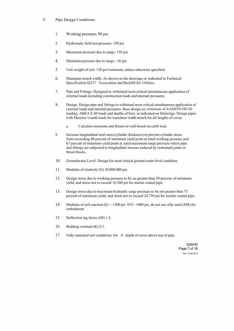
7/25/2019 City Standard Construction Specifications
http://slidepdf.com/reader/full/city-standard-construction-specifications 206/511
026430
Page 7 of 18
Rev. 10-30-2014
F. Pipe Design Conditions:
1. Working pressure: 90 psi.
2. Hydrostatic field test pressure: 150 psi
3. Maximum pressure due to surge: 150 psi.
4. Minimum pressure due to surge: -10 psi.
5. Unit weight of soil: 120 pcf minimum, unless otherwise specified.
6. Minimum trench width: As shown on the drawings or indicated in Technical
Specification 02317 — Excavation and Backfill for Utilities.
7. Pipe and Fittings: Designed to withstand most critical simultaneous application of
external loads including construction loads and internal pressures.
8. Design: Design pipe and fittings to withstand most critical simultaneous application ofexternal loads and internal pressures. Base design on minimum of AASHTO HS-20
loading, AREA E-80 loads and depths of bury as indicated on Drawings. Design pipes
with Marston’s earth loads for transition width trench for all heights of cover.
a. Calculate moments and thrusts in wall based on earth load.
9. Increase longitudinal steel area (cylinder thickness) to prevent cylinder stressfrom exceeding 40 percent of minimum yield point at rated working pressure and
67 percent of minimum yield point at rated maximum surge pressure where pipe
and fittings are subjected to longitudinal stresses induced by restrained joints or
thrust blocks.
10. Groundwater Level: Design for most critical ground water level condition.
11. Modulus of elasticity (E) 30,000,000 psi.
12. Design stress due to working pressure to be no greater than 50 percent of minimum
yield, and stress not to exceed 16,500 psi for mortar coated pipe.
13. Design stress due to maximum hydraulic surge pressure to be not greater than 75
percent of minimum yield, and stress not to exceed 24,750 psi for mortar coated pipe.
14. Modulus of soil reaction (E) < 1500 psi. If E> 1000 psi, do not use silty sand (SM) for
embedment.
15. Deflection lag factor (DI) 1.2.
16. Bedding constant (K) 0.1.
17. Fully saturated soil conditions: hw = h = depth of cover above top of pipe.
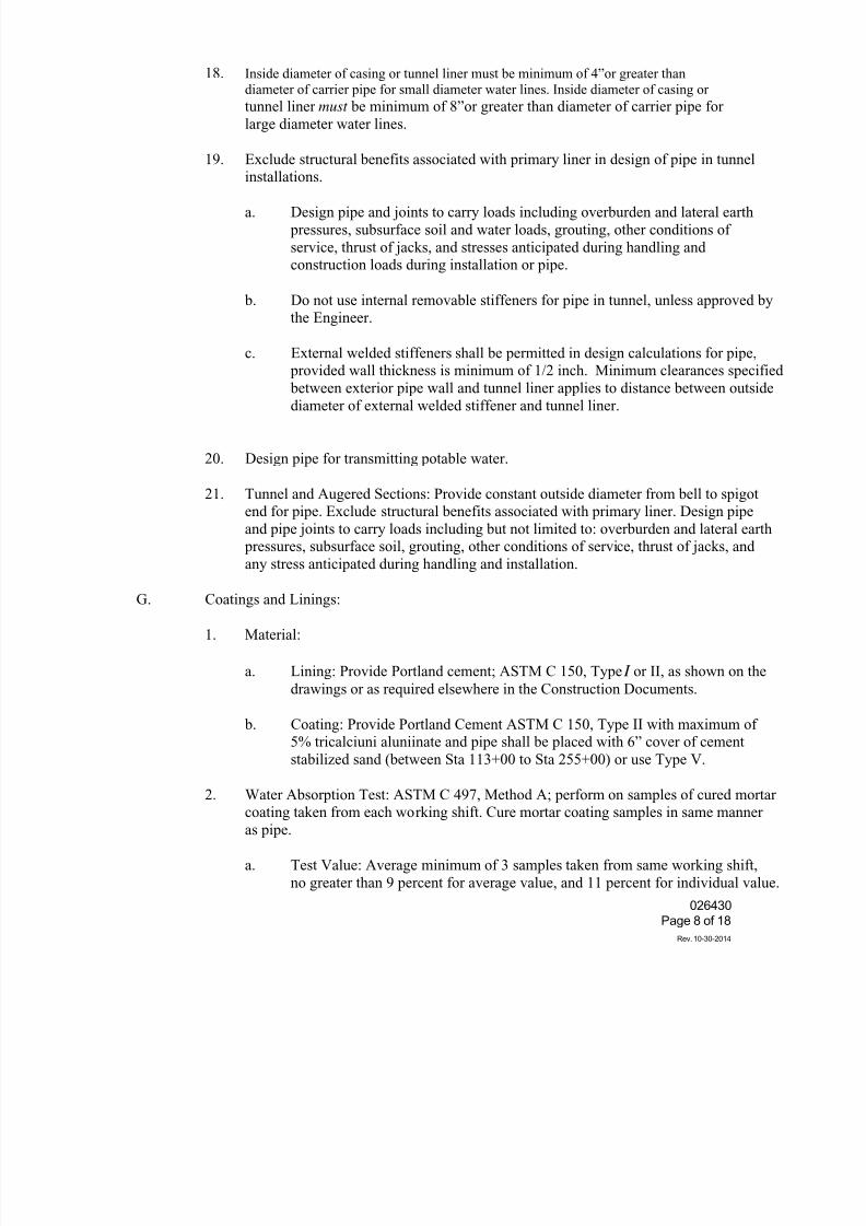
7/25/2019 City Standard Construction Specifications
http://slidepdf.com/reader/full/city-standard-construction-specifications 207/511
026430
Page 8 of 18
Rev. 10-30-2014
18. Inside diameter of casing or tunnel liner must be minimum of 4”or greater thandiameter of carrier pipe for small diameter water lines. Inside diameter of casing or
tunnel liner must be minimum of 8”or greater than diameter of carrier pipe for
large diameter water lines.
19. Exclude structural benefits associated with primary liner in design of pipe in tunnelinstallations.
a. Design pipe and joints to carry loads including overburden and lateral earth
pressures, subsurface soil and water loads, grouting, other conditions of
service, thrust of jacks, and stresses anticipated during handling andconstruction loads during installation or pipe.
b. Do not use internal removable stiffeners for pipe in tunnel, unless approved bythe Engineer.
c. External welded stiffeners shall be permitted in design calculations for pipe, provided wall thickness is minimum of 1/2 inch. Minimum clearances specifie
between exterior pipe wall and tunnel liner applies to distance between outsidediameter of external welded stiffener and tunnel liner.
20. Design pipe for transmitting potable water.
21. Tunnel and Augered Sections: Provide constant outside diameter from bell to spigotend for pipe. Exclude structural benefits associated with primary liner. Design pipe
and pipe joints to carry loads including but not limited to: overburden and lateral earth pressures, subsurface soil, grouting, other conditions of service, thrust of jacks, and
any stress anticipated during handling and installation.
G. Coatings and Linings:
1. Material:
a. Lining: Provide Portland cement; ASTM C 150, Type I or II, as shown on the
drawings or as required elsewhere in the Construction Documents.
b. Coating: Provide Portland Cement ASTM C 150, Type II with maximum of5% tricalciuni aluniinate and pipe shall be placed with 6” cover of cement
stabilized sand (between Sta 113+00 to Sta 255+00) or use Type V.
2. Water Absorption Test: ASTM C 497, Method A; perform on samples of cured mortarcoating taken from each working shift. Cure mortar coating samples in same manner
as pipe.
a. Test Value: Average minimum of 3 samples taken from same working shift,
no greater than 9 percent for average value, and 11 percent for individual value
7/25/2019 City Standard Construction Specifications
http://slidepdf.com/reader/full/city-standard-construction-specifications 208/511
026430
Page 9 of 18
Rev. 10-30-2014
b. Test Frequency: Perform tests each working shift until conformance toabsorption requirements has been established by 10 consecutive passing test
results, at which time testing may be performed weekly. Resume testing for each
working shift if absorption test results fail until conformance to absorption
requirements is reestablished by 10 consecutive passing test results.
3. Apply one coat of primer to exposed steel parts of steel bell and spigot rings. Prior to
coating, blast clean in accordance with SSPC-SP7 (Brush Off Blast Cleaning). Apply
primer in accordance with manufacturer’s recommendations.
4. Coat and line access inlets, service outlets, test inlets and air release/vacuum reliefriser pipe with same coating and lining of main pipe in accordance with AWWA
C 303, Section 4, unless otherwise indicated on Drawings.
5. Do not defer placing of coating of any portion of pipe length. Verify cement mortarcoating thickness on each size of pipe by nondestructive method before removing pipe
from coating machine.
6. Remove and replace disbonded lining or coating. Reject pipe requiring patches larger
than 100 square inches or 12 inches in greatest dimension. Allow no more than one
patch on either lining or coating of pipe. Provide WELD-CRETE Probond Epoxy
Bonding Agent ET-150, parts A and B; Sikadur 32 Hi-Mod, or approved equal
bonding agent for pipe patching.
H. Fittings and Specials:
1. Design fittings to same internal and external loads as straight pipe.
2. Manufacture in accordance with Technical Specification Section 02518 - Steel Pipeand Fittings for Large Diameter Water Lines.
3. Provide fabricated bends or fittings with minimum radius of 2-1/2 times pipe diameter.
4. Design test plugs to withstand forces generated by hydrostatic test and test pressure from
either side. Do not exceed 50% of minimum yield for design stresses due to hydrostatic
pressure. Assume opposite side of plug may not contain water.
5. Provide no specials less than 4 feet in length unless indicated on Drawings or
approved by the Engineer.
6. Butt Straps for Closure Piece: Provide at locations indicated on Drawings or
authorized by the Engineer. Minimum 12-inch-wide split butt strap; minimum plate
thickness equal to thinnest member being joined; fabricated from material equal in
chemical and physical properties to thinnest member being joined. Permit no angular
deflection at butt-strap joints.
7/25/2019 City Standard Construction Specifications
http://slidepdf.com/reader/full/city-standard-construction-specifications 209/511
026430
Page 10 of 18
Rev. 10-30-2014
7. Provide minimum 6 inch welded outlet for inspecting each closure section, unless
access manway is within 40 feet of closure section.
8. Provide Densco petroleum based tape or approved equal for exposed portions of nuts
and bolts.
I. Joints:
1. AWWA C 303 rubber-gasketed or welded bell-and-spigot type except where flanged
joints are required for valves and fittings as shown on Drawings. Refer to Technical
Specification Section 02511 - Water Lines for details on joints and jointing.
2. Rubber-Gasketed Joints: Double weld bell and spigot ring onto steel cylinder. In
thrust areas, double weld bell and spigot onto steel cylinder.
3. Restrained Joints: Restrain joints by welding or harnessing joints.
a. Design Pressure: 1.5 times working pressure.
b. Harnessed Joints: AWWA M 9, clamp or snap ring type, except where prohibited.
c. Groundwater Level: Assumed to be .equal to natural ground surface.
d. Provide restrained joint pipe with adequate cylinder thickness to transmit full
thrust generated by internal pressure across joints.
1) Calculate distance of restrained joints based on resistance along each
leg of bend with thrust based on bend angle. Provide restrained joints
between stations identified in Article 3.06 RESTRAINED PIPE
REQUIREMENTS.
2) Cylinder thickness not to be less than that defined in AWWA C 303,Table 2, and minimum nominal cylinder thickness.
3) Allow cylinder thickness to reduce linearly from maximum calculated
thickness to minimum thickness required by design over required length
(as determined in Paragraph 2.01 J.3.d.1) of restrained joints.
4) Provide full circumferential welds at joints required to be welded.
J. Use only fully circumferentially welded joints in areas considered potentially petroleum
contaminated, within tunnels and under foreign pipelines. Perform welding in accordance
with Technical Specification Section 02518 - Steel Pipe and Fittings for Large Diameter
Water Lines.
K. Pipe Flanges: AWWA C 207 for standard steel flanges of pressure class corresponding to
pipe class.
L. Pipe Lengths: Provide pipe sections in standard lengths with minimum length of 16 feet and
maximum length as indicated on shop Drawings and approved by the Engineer.Gasketed joints are allowed on standard lengths of pipe. Non-standard pipe lengths
7/25/2019 City Standard Construction Specifications
http://slidepdf.com/reader/full/city-standard-construction-specifications 210/511
026430
Page 11 of 18
Rev. 10-30-2014
must be approved by the Engineer and joints must be welded as specified herein to
achieve equal to or greater than standard pipe length before gasketed joints can beused. Internally and externally mark each pipe section with durable marking to show
location and pipe pressure.
M. Hydrostatic Test of Cylinder: In accordance with AWWA C 303, at point of manufacture.Hold test for minimum 2 minutes for thorough inspection of cylinder. Repair or reject
cylinders revealing leaks or cracks.
N. Transport fittings with end caps. Remove end caps just prior to installation.
O. Transport fittings 36 inches in diameter and larger with stalls. Remove stalls after completio
of backfill.
P. Provide radius of curve as indicated on Drawings unless approved by the Engineer. Makecurves and bends by deflecting joints, by use of beveled joints, or by combination of two
methods, unless otherwise indicated on Drawings. Do not exceed deflection anglerecommended by pipe manufacturer. Provide beveled pipe sections of standard length used i
curved alignment, except when shorter sections are required to limit radius of curvature. Insuch case, provide sections throughout curve of substantially equal length.
Q. When manufacturing straight pipe sections, manual welding is allowed for following:
1. Tack welding of coils and plates during continuous pipe making process.
2. Rewelding and repairing structural defects in plate and automatic machine welds.
3. Attaching new coil of steel to previous coil.
2.02 BAR ROD
A. Conform to requirements of ASTM A 615, AWWA C 303 and this specification.
B. Test foreign manufactured rod by local independent laboratory.
C. Rod manufacturer is responsible for performing mechanical tests required in ASTM A 615.
D. Pipe manufacturer is responsible for requiring rod manufacturer to submit certified results ofchemical and mechanical tests, performed by rod manufacturer. Pipe manufacturer is
responsible for performing mechanical tests, and is required to attest to such in affidavit of
compliance.
E. Do not use rod with visible pitting.
2.03 GROUT FOR JOINTS AND SPECIAL APPLICATION
A. Joint Grout:
7/25/2019 City Standard Construction Specifications
http://slidepdf.com/reader/full/city-standard-construction-specifications 211/511
026430
Page 12 of 18
Rev. 10-30-2014
1. Cement Grout Mixture: One part cement to two parts of fine, sharp clean sand. Mix
interior joint mortar with as little water as possible until very stiff but workable. Mixexterior joint mortar with water until it has consistency of thick cream.
2. Water: Potable water with total dissolved solids less than 1000 mg/l; ASTM D 512
chloride ions less than 100 mg/I for slurry and mortar cure; ASTM D 1293 pHgreater than 6.5. Use potable water with 2SGppm limit on chlorides and sulfates.
3. Portland Cement: ASTM C 150, Type II with a maximum of 5% tricalcium aluminate
and pipe shall be placed with 6” cover of cement stabilized sand (between Sta. 113+00to Sta. 255+00) or use Type V as shown on the drawings or as required elsewhere in
the Construction Documents. Provide one type of cement for entire project.
4. Sand:
a. Interior joints: ASTM C 35 fine graded plaster sand.
b. Exterior joints: ASTM C 33 natural sand with 100 percent passing No. 16
sieve.
5. Mix cement grout to specific gravity of 19 lb/gallon or greater as measured bygrout/slurry balance. Use balance manufactured grout/slurry by Baroid or approved
equal. Perform test in presence of and as requested by the Engineer. Add additional
cement grout or water to mixed cement grout to bring mix to proper moisture contentor specific gravity. Discard cement grout mixed more than 20 minutes that is not at
proper moisture content or specific gravity.
B. Nonshrink Grout for Special Applications, Patches and Repairs.
1. Conform to requirements of ASTM C 1107, Nonshrink Grout.
2. Pre-blended factory-packaged material manufactured under rigid quality control.
3. Contain non-metallic natural aggregate, be non-staining and non-corrosive.
4. Meeting NSF 61 Standard suitable for use in contact with potable water supply.
5. Exterior: Highly flowable to fill joint wrapper without leaving voids or trapped air.Interior capable of being placed with plastic consistency.
6. Non-bleeding and non-segregating at fluid consistency.
7. Contain no chlorides or additives which may contribute to corrosion of bar wrapped
steel cylinder pipe.
8. Free of gas-producing, gas-releasing agents.
7/25/2019 City Standard Construction Specifications
http://slidepdf.com/reader/full/city-standard-construction-specifications 212/511
7/25/2019 City Standard Construction Specifications
http://slidepdf.com/reader/full/city-standard-construction-specifications 213/511
026430
Page 14 of 18
Rev. 10-30-2014
B. Manufacturer’s Notifications to Customer: Should the Engineer wish to see specific pipes during
manufacturing process, manufacturer shall provide the Engineer with minimum of three (3)
weeks advance notice of when and where production of those pipes will take place.
C. Repair damage to pipe or protective lining per manufacture specifications before final
acceptance.
D. Shipping: Where required, provide pipe and fittings with sufficient interior strutting or cross bracing to prevent deflection under their own weight.
PART 3 EXECUTION.
3.01 INSTALLATION
A. In the event of conflict between City Standard Specification Section 050200 — Welding, and the
requirements of this specification, Specification Section 050200 will govern.
B. Conform to requirements of City Standard Specification Section 026402 - Waterlines. Do notinstall pipe without approved lay schedule.
C. Install stulls prior to placement of pipe, bends, and fittings to prevent deflection during
installation. Provide stulls consisting of timber struts with end blocks shaped to fit curvature
of interior surface of pipe or other appropriate configuration and material. Firmly edge and
secure stulls to blocks so that they will remain intact position during handling and
installation. Provide stulls adequate to resist loads encountered without structural failure to
stull members or damage to pipe. Where applicable, place stalls at such lengths so as to
elongate vertical diameter of pipe as required to suit trench conditions encountered.
D. Install pipe within six months of pipe being manufactured.
E. Manufacturer shall make available services of representative, throughout project duration
when deemed necessary by the Engineer, to advise aspects of installation including but not
limited to handling, storing, cleaning and inspecting, coatings and linings repairs, and general
construction methods affecting pipe.
F. Bedding and Backfilling
1. Conform to requirements of City Standard Specification Section 022020- Excavation
and Backfill for Utilities.
2. Take necessary precautions during bedding and backfilling operations to prevent
deformation or deflection of cylindrical shape of pipe by more than allowable pipe
deflection.
3. Do not move trench support system (trench safety system) once bedding material is
compacted.
7/25/2019 City Standard Construction Specifications
http://slidepdf.com/reader/full/city-standard-construction-specifications 214/511
026430
Page 15 of 18
Rev. 10-30-2014
4. Align pipe at proper grade prior to joint connection and do not shift after
jointing operation has been completed.
5. Excavate outside specified trench section for bell holes, and for spacessufficient to permit removal of slings. Provide bell holes at proper locations
for unrestricted access to joint. Form bell holes large enough to facilitate joint wrapping and to permit visual examination of process. Enlargement of
bell holes as required or directed by the Engineer or Engineer’s designatedrepresentative. Subsequent backfilling thereof shall not be considered asauthorized additional excavation and backfill. Backfill bell holes and spaces
to satisfaction of the Engineer.
6. Remove blocking after placing sufficient backfill to hold pipe in position.
G. Follow non-shrink grout manufacturer’s specifications for nonshrink grouting.
H. Store pipe at job-site with securely-fastened plastic end caps to maintain moist pipeinterior. Promptly replace damaged end caps to avoid shrinkage or cracking of
cement-mortar lining. Immediately replace damaged plastic end caps. Do not leaveuncapped for more than 4 hours.
I. Deviation of installed pipe in any one pipe section from line and grade shown on approvedshop drawing layout shall not exceed 2 inches from grade and 3 inches from line. No
deviation from line and grade at contact interfaces are allowed.
J. Use adequate surveying methods, procedures and employ competent surveying personnel to
ensure pipe sections are laid to line and grade and within stipulated tolerances. Measure and
record, in form approved by the Engineer, in-place survey data for pipe laid each day andsubmit copy of data to the Engineer at end of that day. Survey data to include unique pipe
number, deflection angle at pipe joint and whether beveled ends were used, invert elevation pipe joint, deviation of joint from project line, deviation of joint from project grade, inside pipe joint lap measured at top, bottom, and at springline (each side).
K. Static Electricity:
1. Properly ground steel pipeline during construction as necessary to prevent build-up
static electricity.
2. Electrically test where required after installation of pipeline is complete.
3.02 DEFLECTION
A. Allowable deflection from specified diameter determined as follows:
Allowable Deflection (D)2/4000, (D= Nominal inside pipe diameter in inches.)
B. Deflection may be measured by the Engineer at any location along pipe. Arithmetical
averages of deflection are not acceptable.
7/25/2019 City Standard Construction Specifications
http://slidepdf.com/reader/full/city-standard-construction-specifications 215/511
026430
Page 16 of 18
Rev. 10-30-2014
C. If deflection exceeds that specified, remove entire portion of deflected pipe section andinstall new pipe as directed by the Engineer at no cost to City.
3.03 CLOSURES AND APPROVED PIPE MODIFICATIONS.
A. No modifications of standard pipe for closures shall be permitted in the field. No field cuttingof pipe or exposure of bar wire is permitted without written approval from the Engineer.
B. Pipe manufacturer’s representative and the Engineer to entirely witness closures and approved pipe
modification efforts.
C. Provide minimum lap of 4 inches between member being joined and edge of butt strap. Weld on
both interior and exterior, unless otherwise approved by the Engineer.
D. Provide full circumferential welds on joints required to be welded. Employ independent.
certified testing laboratory, approved by the Engineer, to perform weld tests on field welds.
Include cost of such testing in contract unit price for water lien. Use magnetic particle test
method for lap welds or X-ray methods for butt welds, for 100 percent of joint welds.Maintain records of tests. If defective weld is revealed, repair defective weld, and retest. Use
wire and flux from same manufacturer throughout an entire project.
E. Fill wrapper in field and allowing excess grout water to seep out. Refill wrapper as necessary.
When joint mortar level has stabilized and begun to mechanically stiffen, lap Ethafoam
wrapper over top of joint, and secure in place.
F. Stretch test each gasket splice to twice its unstretched length and inspect for defects.
3.04 VISIBLE CRACKS
A. No visible cracks longer than 6 inches, measured to be within 15 degrees of line parallel to
pipe longitudinal axis, are permitted except:
1. In surface laitance of centrifugally cast concrete,
2. In sections of pipe with steel reinforcing collars or wrappers, or
3. Within 12 inches of pipe ends.
B. Repair interior lining cracks that exceed 1/16-inch (0.0625 inches) wide.
C. Reject pipe with exterior coating cracks that exceed 0.01 inches wide.
D. Immediately remove pipe from site if pipe has cracks exceeding limitations and cracks are not
repairable.
3.05 FIELD REPAIR PROCEDURES FOR COATING/LINING
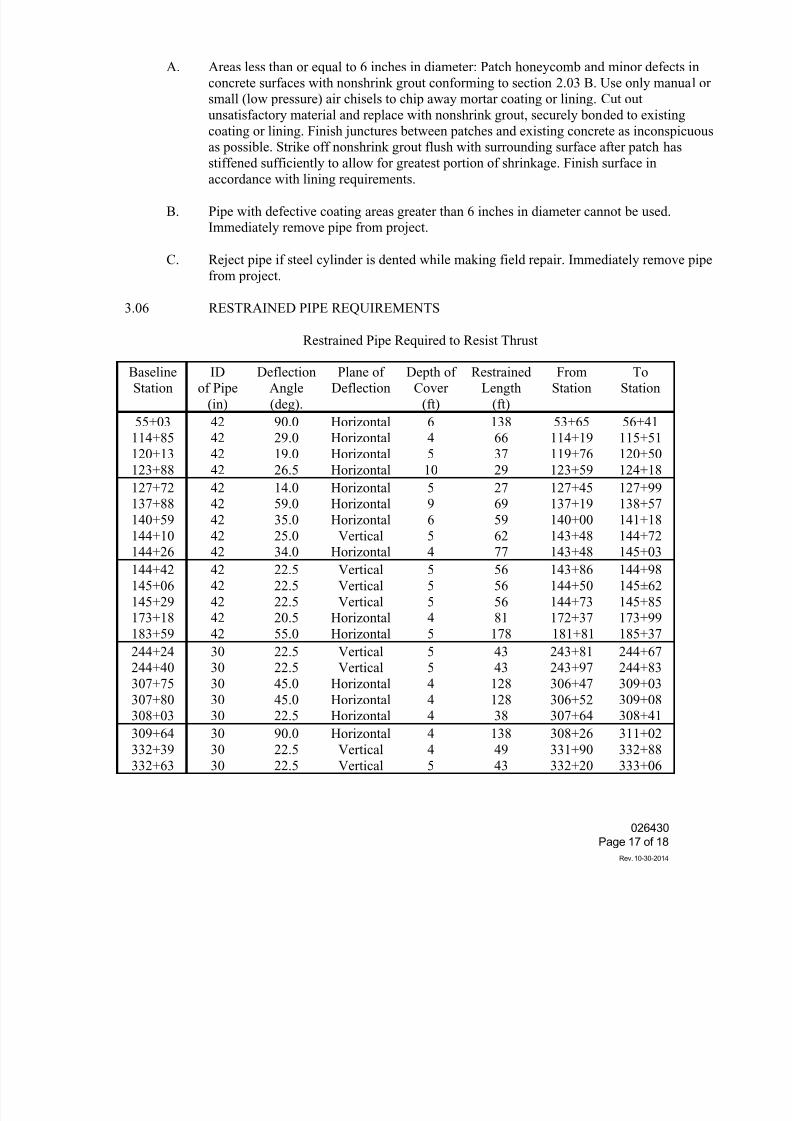
7/25/2019 City Standard Construction Specifications
http://slidepdf.com/reader/full/city-standard-construction-specifications 216/511
026430
Page 17 of 18
Rev. 10-30-2014
A. Areas less than or equal to 6 inches in diameter: Patch honeycomb and minor defects in
concrete surfaces with nonshrink grout conforming to section 2.03 B. Use only manual orsmall (low pressure) air chisels to chip away mortar coating or lining. Cut out
unsatisfactory material and replace with nonshrink grout, securely bonded to existing
coating or lining. Finish junctures between patches and existing concrete as inconspicuousas possible. Strike off nonshrink grout flush with surrounding surface after patch has
stiffened sufficiently to allow for greatest portion of shrinkage. Finish surface in
accordance with lining requirements.
B. Pipe with defective coating areas greater than 6 inches in diameter cannot be used.Immediately remove pipe from project.
C. Reject pipe if steel cylinder is dented while making field repair. Immediately remove pipe
from project.
3.06 RESTRAINED PIPE REQUIREMENTS
Restrained Pipe Required to Resist Thrust
BaselineStation
IDof Pipe
(in)
DeflectionAngle
(deg).
Plane ofDeflection
Depth ofCover
(ft)
RestrainedLength
(ft)
FromStation
ToStation
55+03114+85
120+13
123+88
4242
42
42
90.029.0
19.0
26.5
HorizontalHorizontal
Horizontal
Horizontal
64
5
10
13866
37
29
53+65114+19
119+76
123+59
56+41115+51
120+50
124+18
127+72137+88
140+59
144+10144+26
4242
42
4242
14.059.0
35.0
25.034.0
HorizontalHorizontal
Horizontal
VerticalHorizontal
59
6
54
2769
59
6277
127+45137+19
140+00
143+48143+48
127+99138+57
141+18
144+72145+03
144+42
145+06
145+29173+18
183+59
42
42
4242
42
22.5
22.5
22.520.5
55.0
Vertical
Vertical
VerticalHorizontal
Horizontal
5
5
54
5
56
56
5681
178
143+86
144+50
144+73172+37
181+81
144+98
145±62
145+85173+99
185+37
244+24244+40
307+75
307+80308+03
3030
30
3030
22.522.5
45.0
45.022.5
VerticalVertical
Horizontal
HorizontalHorizontal
55
4
44
4343
128
12838
243+81243+97
306+47
306+52307+64
244+67244+83
309+03
309+08308+41
309+64
332+39
332+63
30
30
30
90.0
22.5
22.5
Horizontal
Vertical
Vertical
4
4
5
138
49
43
308+26
331+90
332+20
311+02
332+88
333+06
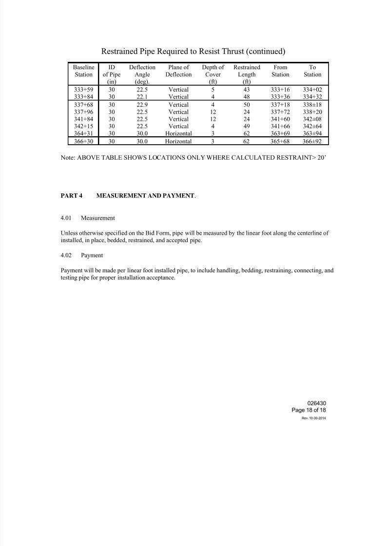
7/25/2019 City Standard Construction Specifications
http://slidepdf.com/reader/full/city-standard-construction-specifications 217/511
026430
Page 18 of 18
Rev. 10-30-2014
Restrained Pipe Required to Resist Thrust (continued)
Baseline
Station
ID
of Pipe
(in)
Deflection
Angle
(deg).
Plane of
Deflection
Depth of
Cover
(ft)
Restrained
Length
(ft)
From
Station
To
Station
333+59
333+84
30
30
22.5
22.1
Vertical
Vertical
5
4
43
48
333+16
333+36
334+02
334+32
337+68
337+96
341+84
342+15
364+31
30
30
30
30
30
22.9
22.5
22.5
22.5
30.0
Vertical
Vertical
Vertical
Vertical
Horizontal
4
12
12
4
3
50
24
24
49
62
337+18
337+72
341+60
341+66
363+69
338±18
338+20
342±08
342±64
363±94
366+30 30 30.0 Horizontal 3 62 365+68 366±92
Note: ABOVE TABLE SHOWS LOCATIONS ONLY WHERE CALCULATED RESTRAINT> 20’
PART 4 MEASUREMENT AND PAYMENT.
4.01 Measurement
Unless otherwise specified on the Bid Form, pipe will be measured by the linear foot along the centerline of
installed, in place, bedded, restrained, and accepted pipe.
4.02 Payment
Payment will be made per linear foot installed pipe, to include handling, bedding, restraining, connecting, and
testing pipe for proper installation acceptance.
7/25/2019 City Standard Construction Specifications
http://slidepdf.com/reader/full/city-standard-construction-specifications 218/511
SECTION 026602
WASTEWATER FORCE MAIN
1. DESCRIPTION
This specification shall govern all work required for the installation of all wastewater force mains
required to complete the project.
2. GENERAL REQUIREMENTS
1. All work shall be done in a workmanlike manner, in accordance with the drawings and
specifications.
2. Prior to construction, the Contractor shall submit, for approval, certificates of inspection in
duplicate to the Engineer from the pipe and fittings manufacturer(s) that said materials
supplied have been inspected at the plant and meet the requirements of this specification.
3. It shall be the responsibility of the Contractor to keep on hand extra fittings and pipe, as he
may deem necessary to make adjustments due to unknown obstructions, or to replace
defective materials without delay to the project. When defective materials are discovered,
they shall be immediately marked and removed from job site.
4. All pipe and fittings shall be clearly marked with trademark of manufacturer, batch number,
location of plant, ASTM/ANSI/AWWA designation, size, pressure rating, class/SDR, and
pressure rating.
5. Wastewater marking tape shall be continuously applied along the top of the force main,except at joints. The tape shall be green and 2 inches wide and state "Sewer".
3. MATERIALS
A. Ductile Iron Pipe Fittings: See City Standard Specification Section 026206.
B. PVC Pipe (AWWA C900 or C905): See City Standard Specification Section 026210.
C. Concrete: Concrete shall have a minimum compressive strength of 3000 PSI at
28 days.
026602
Page 1 of 7
Rev. 10-30-2014
7/25/2019 City Standard Construction Specifications
http://slidepdf.com/reader/full/city-standard-construction-specifications 219/511
D. Bedding Sand for Encasement: Sand shall be as indicated on the drawings.
E. Non-Standard Fittings: Fittings having non-standard dimensions or fabricated especially
for this project shall have a minimum pressure rating of 250 psi and durability comparable
to that of the system. Drawings and specifications for non-standard fittings shall be
submitted for approval of the Engineer prior to construction. Couplings and adapters forDIP and PVC connections shall be considered non-standard fittings.
F. Ceramic Epoxy Lining for Ductile Iron Pipe Fittings: When indicated in the drawings
or Special Provisions, the interior of DI pipe and fittings shall be furnished with a factory
applied ceramic epoxy lining. Lining material shall be Protecto 401 Ceramic Epoxy Lining,
of 40 mils nominal dry thickness. The epoxy shall be fused to the interior of the pipe by
heat, forming a securely bonded lining.
1. Operating Limits: The lining shall have the capability of withstanding operating
temperatures from 0º F to 170º F and withstanding sewage with a minimum pH of4.0.
2. Application: The interior surface of each pipe shall be blast-cleaned to remove
high temperature oxide film and to form an anchor pattern over the entire surface
prior to heating and lining. Epoxy lining is to cover the inner surface of the pipe,
extending from the plain or beveled end to the rear of the gasket socket.
3. Adhesion: Pipe shall be checked at the point of manufacture to assure bond of the
lining to the pipe. Any indication of separation of lining from pipe is cause for
rejection. .
4. Entrapped Material: Any sizeable protrusion in the lining, obviously caused by
lining over foreign materials, shall be cause for rejection.
5. Separations: Linings which have separations caused during the lining operation
shall be rejected.
6. Damages to Lining: Injurious mechanical damage, such as chuck marks and
gouges, extending to bare metal are not acceptable. The pipe having such a defect
shall be rejected.
7. Lining Thickness: Linings of nominal 40 mil thickness shall generally equal orexceed 40 mil throughout the pipe. At pipe ends, lining thickness may taper for a
distance of 4 inches from the ends, to a minimum of 20 mil thickness. However, the
lining shall not deviate by more than 5 mil from the 40 mil nominal thickness as
required through the pipe. The lining thickness of each pipe and fitting shall be
taken at the point of manufacture using a general electric magnetic dry film
thickness device, digital coating thickness gauge, Positector 2000, or approved
026602
Page 2 of 7
Rev. 10-30-2014
7/25/2019 City Standard Construction Specifications
http://slidepdf.com/reader/full/city-standard-construction-specifications 220/511
equal. Pipe and/or fittings with a lining thickness less than the minimum specified
shall be rejected.
8. Bell and Plain End Overcoat: The bell socket and the last 2 inches of the plain
end of each pipe shall be coated on the inside and outside with a factory applied
mastic or epoxy coating. This coating shall be a minimum of 10 mil thickness andshall be Koppers 300M, Industrial Ruff Stuff, Roskote Mastic A-938, or equal.
9. Pinholes and/or Holidays: The inside surface of each pipe or fitting shall be free
of pinholes, holiday discontinuities and any blister type surface imperfections. The
manufacturer shall check each pipe and fitting for holidays at the point of
manufacture with a high voltage holiday detection device. Tinker & Rasor Model
AP-W, or approved equal. Testing shall be conducted at the voltage as calculated in
Section 3: Testing and Voltages of the "Recommended Practice for High Voltage
Electrical Inspection of Pipeline Coatings Prior to Installation" as published by the
National Association of Corrosion Engineers (NACE) Technical Practices
Committee. All actual holiday testing procedures shall conform to NACE standardRP-02-74 and American Society for Testing Materials (ASTM) Designation: G62-
(latest) "Standard Test Methods for Holiday Detection in Pipeline Coatings." No
holidays, misses or skips larger than a pinhole will be accepted for repair. A
maximum of 6 holidays, as defined in ASTM Standard G62 and as determined by
the detection test described above, on any one standard pipe length, fitting or special
may be repaired with epoxy.
10. Independent Testing Laboratory Representation: All testing as specified herein
including the lining thickness test and the holiday test shall be witnessed by a
representative from an approved independent testing laboratory. The independent
laboratory shall be a member of the American Council of Independent Laboratories.Manufacturer must submit for approval by the City the name of the testing
laboratory and actual qualifications of actual representative that will witness the
testing. The manufacturer shall furnish three (3) copies of report by independent
testing laboratory depicting results of all testing witnessed by the independent
laboratory.
11. Field Testing: Each pipe and fitting is subject to inspection in the field by the City
for conformance to these specifications prior to installation. Any defects as
specified herein with any pipe or fittings shall be grounds for rejection.
12. Sealing Cut Ends and Repairing Field Damaged Areas: Remove burrs fromfield cut ends and smooth out edge of epoxy lining. Remove all traces of oil or
lubricant used during field cutting operation. All areas of loose lining associated
with the cutting operation shall be removed and the exposed metal cleaned by
sanding or scraping. For larger areas, roughen the bare pipe surface with a small
chisel to provide an anchor pattern for the epoxy. The epoxy lining shall be
"stripped" back by chiseling, cutting or scraping about 1" to 2" into well adhered
026602
Page 3 of 7
Rev. 10-30-2014
7/25/2019 City Standard Construction Specifications
http://slidepdf.com/reader/full/city-standard-construction-specifications 221/511
lined area before patching. After removal of loose lining and dirt, the area to be
patched shall be "scratched" or "gouged" to offer an anchor pattern for the epoxy.
Include an overlap of 1" to 2" of roughened epoxy lining in the area to be epoxy
coated. The roughening shall be done with a rough grade emery paper (40 grit),
rasp, or small chisel. Avoid honing, buffing, or wire brushing since these tend to
make surface to be repaired too smooth. With the area to be sealed or repairedabsolutely clean and suitably "roughened," apply a thick coat of two-part coal tar
epoxy. The detailed mixing and application procedure for the epoxy shall follow
the epoxy manufacturer's instructions. This heavy coat of epoxy shall be "worked"
into the scratched surface by brushing. The Contractor shall maintain a supply of
epoxy on the job site as required to seal cut ends and repair damaged pipe when
encountered. Epoxy shall be of the type recommended or supplied by the pipe
manufacturer.
13. Warranty: A five year warranty shall be furnished by the manufacturer on the
serviceability of the lining. This warranty shall include, but not be limited to the
statement, at any time up to the end of the fifth year from the date of pipe shipment:
a. The lining shall not have disbound.
b. The lining shall not have suffered any appreciable underfilm migration.
c. The interior pipe metal, at points of pinholes or holidays, shall not have
suffered detrimental deterioration.
d. The lining shall have maintained its smooth surface characteristics.
Contractor and/or manufacturer shall not make any exemption or exception to the
above stated conditions or warranty within the limits as stated in this specification
section.
14. Certification: The manufacturer shall furnish notarized certificates of compliance
stating that the lining conforms to all requirements of these specifications.
4. CONSTRUCTION METHODS
4.1 HANDLING AND STORAGE OF MATERIALS
A. General: The Contractor shall be responsible for the safe storage of all materials
furnished to or by him and accepted by him until the materials have been
incorporated in the completed project.
All material found during the progress of the work to have cracks, flaws or other
defects will be rejected, and the Contractor shall remove such defective material
from the site of the work.
026602
Page 4 of 7
Rev. 10-30-2014
7/25/2019 City Standard Construction Specifications
http://slidepdf.com/reader/full/city-standard-construction-specifications 222/511
B. Unloading and Distribution of Materials at Work Site: Pipe and other materials
shall be unloaded at point of delivery, hauled to, and distributed at the job site by the
Contractor. Materials shall at all times be handled with care and in accordance with
manufacturer's recommendations. Care shall be taken not to scratch PVC pipe.
Excessive scratching shall be considered cause for rejection of PVC pipe. Materials
may be unloaded opposite or near the place where it is to be installed provided thatit is to be incorporated into the work within ten days. The Contractor shall not
distribute material in such a manner as to cause undue inconvenience to the public.
C. Storing Materials: Materials that are not to be incorporated into the work within
10 days shall be stored on platforms. The interior of pipes and accessories shall be
kept free from dirt and foreign matter.
4.2 INSTALLATION
A. Alignment and Grade: All pipes shall be laid and maintained to the required line
and grade.
Temporary support and adequate protection of all underground and surface utility
structures encountered in the progress of the work shall be furnished by the
Contractor.
Where the grade or alignment of the pipe is obstructed by existing utility structures
such as conduits, ducts, pipes, connections to sewers or drains, the obstruction shall
be permanently supported, relocated, removed, or reconstructed by the Contractor at
the Contractor's expense, in cooperation with the owners of such utility structures.
Force Mains shall be laid with no less than 36 inches of cover, unless indicatedotherwise in the drawings. Greater depths will be permitted when required to avoid
conflicts with existing structures.
Lines shall be laid to grade which permit entrapped air to flow to a high point for
release through an air release valve as shown on the drawings. The Contractor shall
investigate well in advance of pipe laying for conflicts which may necessitate the
readjustment of planned line and grade.
B. Trench Excavation and Backfill: See City Standard Specification Section 022020
"Excavation and Backfill for Utilities and Sewers", and drawings.
C. Force Main Connection to Existing Manhole: Where new force main is
connected to existing manhole, the manhole shall be prepared to receive the
proposed force main and restored after connection. Manhole inverts shall be
repaved as necessary to provide a smooth flowing system.
D. Polyethylene Encasement: All metallic pipe, valves and fittings, except those
026602
Page 5 of 7
Rev. 10-30-2014
7/25/2019 City Standard Construction Specifications
http://slidepdf.com/reader/full/city-standard-construction-specifications 223/511
which occur in encasement pipe or in concrete valve boxes, shall be wrapped in
polyethylene. The polyethylene material shall have a thickness of 8 mils and may be
either clear or black. The wrapping shall be lapped in such a manner that all
surfaces of pipe valves and fittings, including joints, shall have a double thickness of
polyethylene. If a single longitudinal lap is made using a double thickness of
polyethylene, it shall be lapped a minimum of 18 inches and the lap shall be placedin the lower quadrant of the pipe and in such a manner that backfill material cannot
fall into the lap. The polyethylene shall be secured in place with binder twine at not
more than 6-foot intervals. If wrapping is applied before the pipe is placed in the
trench, then special care shall be taken in handling the pipe so that the wrapping will
not be damaged. Care shall also be exercised in backfilling around the pipe and
fittings and in blocking fittings so as not to damage the wrapping. Any wrapping
that may be damaged shall be repaired in a manner satisfactory to the Engineer and
so as to form the best protection to the pipes.
E. Sand Encasement: Sand shall be granular soil of low plasticity such that 30%
minimum passes a #4 sieve and no more than 20 % passes a #200 sieve, and the plasticity index (PI) shall not exceed 10. Soils with a Unified Classification of SW
and SP, or AASHTO Classification of A3 and some A2 soil shall be required.
F. Pre-Placement Inspection: Prior to lowering into trench, all pipe and accessories
shall be inspected for defects. All foreign matter or dirt shall be removed from the
interior of the pipe prior to lowering into trench. Pipe shall be kept clean at all times
during the laying.
G. Jointing Pipe and Fittings: All pipes and fittings shall be made up in accordance
with manufacturer's recommendation. Pipe deflection shall not exceed 75% of the
maximum amount recommended by the manufacturer.
H. Concrete Thrust Blocks:
Temporary thrust blocks or other means of carrying thrust loads generated by
hydrostatic testing shall be provided at all ends of lines to be tested. Details of the
end connections and method of temporary blocking shall be submitted to the
Engineer for approval. After satisfactory completion of the hydrostatic test, this
temporary blocking shall be removed so that connections may be made with existing
lines. This work is subsidiary and no separate payment will be made for it.
I. Restrained Joints and Fittings: Metal harness, tie rods and clamps or restrainedfittings shall be used to prevent movement when soil conditions will not withstand
thrust blocking. Steel rods and clamps shall be galvanized or otherwise rust-proofed
or coated with hot coal tar enamel then wrapped with two layers of polyethylene
wrapping.
4.3 HYDROSTATIC TESTING WASTEWATER FORCE MAIN
026602
Page 6 of 7
Rev. 10-30-2014
7/25/2019 City Standard Construction Specifications
http://slidepdf.com/reader/full/city-standard-construction-specifications 224/511
See City Standard Specification Section 026202, Hydrostatic Testing of Pressure Systems.
5. MEASUREMENT AND PAYMENT
Unless otherwise specified in the Bid Form, wastewater force mains will be measured by the linearfoot along the centerline of pipe. Payment shall include, but not be limited to, trenching,
dewatering, pipe, bedding, thrust blocks, fittings, restraints and backfill, and shall be full
compensation for all labor, materials, equipment, tools and incidentals required to complete the
work at the unit price bid.
026602
Page 7 of 7
Rev. 10-30-2014
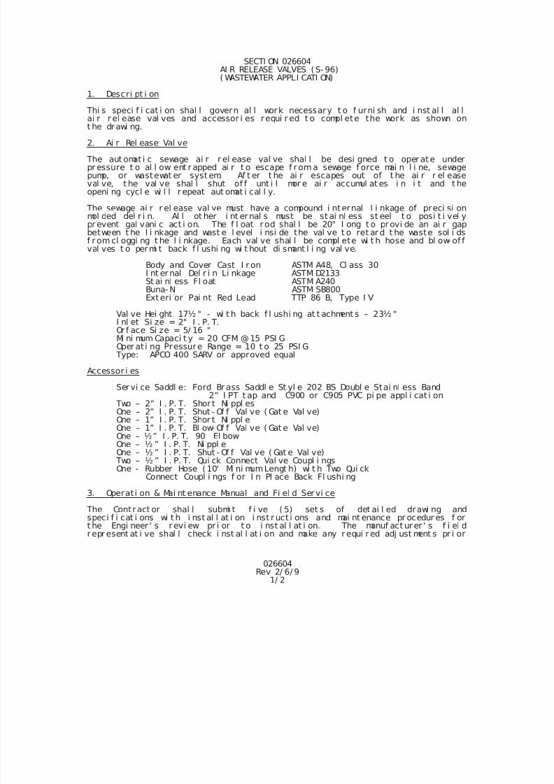
7/25/2019 City Standard Construction Specifications
http://slidepdf.com/reader/full/city-standard-construction-specifications 225/511
7/25/2019 City Standard Construction Specifications
http://slidepdf.com/reader/full/city-standard-construction-specifications 226/511
026604Rev 2/ 6/ 9
2/ 2
t o oper at i on of system.
4. Measurement and Payment
Unl ess i ndi cat ed other wi se i n t he Proposal , Ai r Rel ease Val ves and accessor i esshal l be measur ed as uni t s and shal l i ncl ude but not be l i mi t ed t o val ve,accessori es and vaul t . Payment shal l i ncl ude al l mat er i al , l abor , andi nci dent al s r equi r ed to compl et e the wor k.
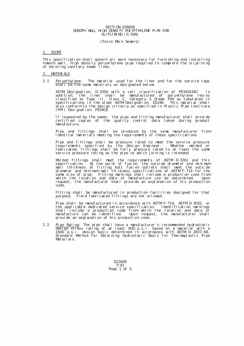
7/25/2019 City Standard Construction Specifications
http://slidepdf.com/reader/full/city-standard-construction-specifications 227/511
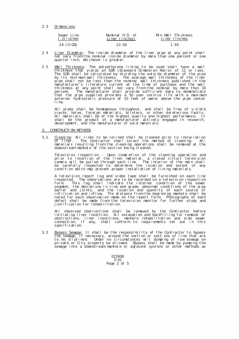
7/25/2019 City Standard Construction Specifications
http://slidepdf.com/reader/full/city-standard-construction-specifications 228/511
0226087/ 91
Page 2 of 5
2. 3 Di mensi ons:
Sewer Li neI . D. I nches
Nomi nal O. D. ofLi ner ( I nches)
Mi n. Wal l Thi cknessLi ner ( I nches
24 ( CI OD) 22. 00 1. 95
2. 4 Li ner Di amet er : The i nsi de di amet er of t he l i ner pi pe at any poi nt shal lnot var y f r om t he nomi nal i nsi de di ameter by more t han one per cent or onequar t er i nch, whi chever i s great er .
2. 5 Wal l Thi ckness: The pol yet hyl ene l i ni ng t o be used shal l have a wal lt hi ckness t hat yi el ds an SDR ( St andar d Di mensi on Rat i o) of 11 or l ess.
The SDR shal l be cal cul ated by di vi di ng t he out si de di ameter of t he pi peby i t s mi ni mum wal l t hi ckness. The aver age wal l t hi ckness of t he l i nerpi pe shal l not be l ess t han t he nomi nal wal l t hi ckness publ i shed i n t hemanuf act ur er ' s l i t er at ur e cur r ent at t he t i me of pur chase and t he wal lt hi ckness at any poi nt shal l not vary f r om t he nomi nal by mor e than 10per cent . The manuf act urer shal l pr ovi de suf f i ci ent dat a t o demonst r at et hat t he pi pe suppl i ed pr ovi des a 50 year ser vi ce l i f e wi t h a maxi mumexter nal hydr ostat i c pr essur e of 10 f eet of wat er above the pi pe cent erl i ne.
Al l pi pes shal l be homogenous t hr oughout , and shal l be f r ee of vi si bl ecracks, hol es, f or ei gn mat eri al s, bl i st er s, or other del et er i ous f aul t s.Al l mat er i al s shal l be of t he hi ghest qual i t y and hi ghest per f or mance. I tshal l be the pr oduct of a manuf act urer act i vel y engaged i n resear ch,devel opment , and t he manuf actur er of sai d materi al s.
3. CONSTRUCTI ON METHODS
3. 1 Cl eani ng: Al l l i nes to be rel i ned shal l be cl eaned pri or t o i nstal l at i onof l i ner . The Cont r actor shal l sel ect t he met hod of cl eani ng. Al lmat er i al s r esul t i ng f r om t he cl eani ng operat i ons shal l be removed at t hedownst r eam manhol e of t he sect i on bei ng cl eaned.
Tel evi si on I nspect i on - Upon compl et i on of t he cl eani ng oper at i on andpri or t o i nsert i on of t he l i ner mat eri al , a cl osed ci rcui t t el evi si oncamer a wi l l be pul l ed t hr ough each l i ne. The i nt er i or of t he mai n shal lbe car ef ul l y i nspect ed t o det er mi ne the l ocat i on and extent of anycondi t i on whi ch may pr event pr oper i nst al l at i on of l i ni ng mat er i al s.
A t el evi si on r eport l og and vi deo t ape shal l be f ur ni shed on each l i nei nspect ed. The obser vat i ons ar e t o be r ecor ded on a t el evi si on i nspect i onf or m. Thi s l og shal l i ndi cat e t he i nt er nal condi t i on of t he sewersegment , t he devi at i ons i n l i ne and gr ade, abnormal condi t i ons of t he pi pebar r el and j oi nt s, and t he l ocat i on and quant i t y of each source ofi nf i l t r at i on and i nf l ow. The di st ance f r om t he begi nni ng manhol e shal l benot ed f or each observat i on made on t he r eport f orm. Photogr aphs of eachdef ect shal l be made f r om t he t el evi si on moni t or f or f ur t her st udy and
j ust i f i cat i on f or r ehabi l i t at i on.
Al l observed obst r uct i ons shal l be r emoved by the Cont r actor bef ore
i ni t i at i ng l i ner i nser t i on. Al l excavat i on and backf i l l i ng f or r emoval ofobst r uct i ons, l i ner i nser t i ons, manhol e rehabi l i t at i on and si de sewerconnecti on, i f any, shal l conf or m t o requi r ement s set out i n t hi sspeci f i cat i on.
3. 2 Bypass Sewage: I t shal l be t he responsi bi l i t y of t he Cont r actor t o bypasst he sewage, i f necessary, ar ound t he sect i on or sect i ons of l i ne that ar et o be sl i pl i ned. Under no ci r cumst ances wi l l dumpi ng of r aw sewage onpri vat e or Ci t y propert y be al l owed. Bypass shal l be made by pumpi ng t hesewage i nto a downst r eam manhol e or adj acent syst em, or other methods as
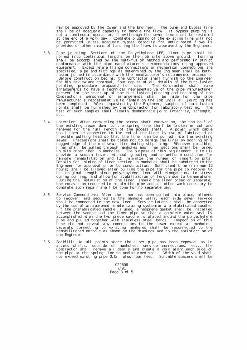
7/25/2019 City Standard Construction Specifications
http://slidepdf.com/reader/full/city-standard-construction-specifications 229/511
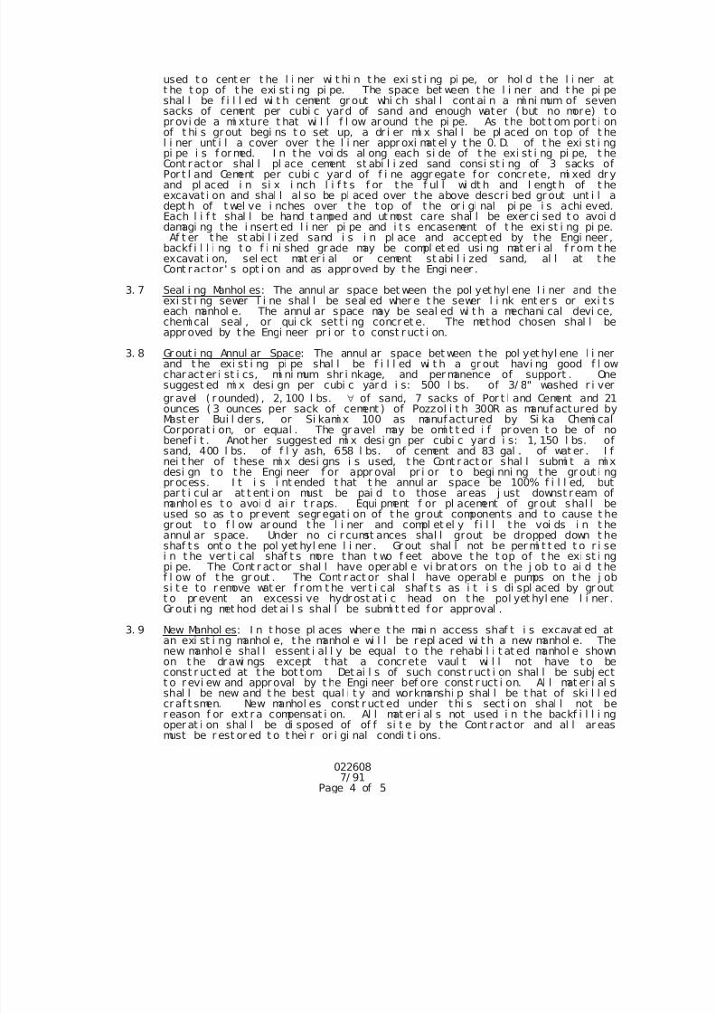
7/25/2019 City Standard Construction Specifications
http://slidepdf.com/reader/full/city-standard-construction-specifications 230/511
0226087/ 91
Page 4 of 5
used t o cent er t he l i ner wi t hi n t he exi st i ng pi pe, or hol d t he l i ner att he t op of t he exi st i ng pi pe. The space bet ween t he l i ner and t he pi peshal l be f i l l ed wi t h cement gr out whi ch shal l cont ai n a mi ni mum of sevensacks of cement per cubi c yard of sand and enough water ( but no more) t opr ovi de a mi xture t hat wi l l f l ow ar ound t he pi pe. As the bot t om por t i onof t hi s gr out begi ns t o set up, a dr i er mi x shal l be pl aced on t op of t hel i ner unt i l a cover over t he l i ner appr oxi mat el y t he 0. D. of t he exi st i ngpi pe i s f or med. I n t he voi ds al ong each si de of t he exi st i ng pi pe, t heCont ract or shal l pl ace cement st abi l i zed sand consi st i ng of 3 sacks ofPor t l and Cement per cubi c yar d of f i ne aggr egate f or concrete, mi xed dr yand pl aced i n si x i nch l i f t s f or t he f ul l wi dt h and l engt h of t heexcavat i on and shal l al so be pl aced over t he above descr i bed gr out unt i l adept h of t wel ve i nches over t he top of t he or i gi nal pi pe i s achi eved.Each l i f t shal l be hand t amped and ut most care shal l be exer ci sed t o avoi ddamagi ng the i nsert ed l i ner pi pe and i t s encasement of t he exi st i ng pi pe.Af t er t he st abi l i zed sand i s i n pl ace and accept ed by the Engi neer ,
backf i l l i ng t o f i ni shed gr ade may be compl et ed usi ng mat er i al f r om t heexcavat i on, sel ect mat er i al or cement st abi l i zed sand, al l at t heCont ractor ' s opt i on and as appr oved by t he Engi neer .
3. 7 Seal i ng Manhol es: The annul ar space bet ween the pol yet hyl ene l i ner and theexi st i ng sewer l i ne shal l be seal ed wher e t he sewer l i nk ent er s or exi t seach manhol e. The annul ar space may be seal ed wi t h a mechani cal devi ce,
chemi cal seal , or qui ck set t i ng concr et e. The method chosen shal l beappr oved by t he Engi neer pr i or t o const r uct i on.
3. 8 Gr out i ng Annul ar Space: The annul ar space bet ween t he pol yet hyl ene l i nerand t he exi st i ng pi pe shal l be f i l l ed wi t h a gr out havi ng good f l owchar act er i st i cs, mi ni mum shr i nkage, and per manence of support . Onesuggest ed mi x desi gn per cubi c yar d i s: 500 l bs. of 3/ 8" washed r i ver
gr avel ( r ounded) , 2, 100 l bs. of sand, 7 sacks of Por t l and Cement and 21ounces ( 3 ounces per sack of cement ) of Pozzol i t h 300R as manuf actured byMast er Bui l der s, or Si kami x 100 as manuf actured by Si ka Chemi calCorporat i on, or equal . The gr avel may be omi t t ed i f pr oven t o be of nobenef i t . Anot her suggest ed mi x desi gn per cubi c yar d i s: 1, 150 l bs. ofsand, 400 l bs. of f l y ash, 658 l bs. of cement and 83 gal . of wat er . I fnei t her of t hese mi x desi gns i s used, t he Cont r act or shal l submi t a mi xdesi gn t o t he Engi neer f or appr oval pr i or t o begi nni ng t he gr out i ng
pr ocess. I t i s i nt ended t hat t he annul ar space be 100% f i l l ed, butpar t i cul ar at t ent i on must be pai d t o those areas j ust downst r eam ofmanhol es t o avoi d ai r t r aps. Equi pment f or pl acement of gr out shal l beused so as t o pr event segr egat i on of t he grout components and to cause t hegr out t o f l ow ar ound t he l i ner and compl et el y f i l l t he voi ds i n t heannul ar space. Under no ci r cumst ances shal l grout be dropped down t heshaf t s ont o t he pol yet hyl ene l i ner . Gr out shal l not be per mi t t ed t o r i sei n t he ver t i cal shaf t s more than t wo f eet above t he t op of t he exi st i ngpi pe. The Cont r act or shal l have oper abl e vi br at ors on t he j ob t o ai d t hef l ow of t he gr out . The Cont r act or shal l have operabl e pumps on t he j obsi t e to r emove wat er f r om t he ver t i cal shaf t s as i t i s di spl aced by gr outt o pr event an excessi ve hydr ost at i c head on t he pol yet hyl ene l i ner .Gr out i ng met hod det ai l s shal l be submi t t ed f or appr oval .
3. 9 New Manhol es: I n t hose pl aces wher e t he mai n access shaf t i s excavat ed at
an exi st i ng manhol e, t he manhol e wi l l be r epl aced wi t h a new manhol e. Thenew manhol e shal l essent i al l y be equal t o t he rehabi l i t at ed manhol e shownon t he drawi ngs except t hat a concr ete vaul t wi l l not have t o beconst r uct ed at t he bot t om. Det ai l s of such const r uct i on shal l be subj ectt o r evi ew and approval by t he Engi neer bef ore const r uct i on. Al l mat er i al sshal l be new and t he best qual i t y and workmanshi p shal l be t hat of ski l l edcr af t smen. New manhol es const r uct ed under t hi s sect i on shal l not ber eason f or ext r a compensat i on. Al l mat er i al s not used i n t he backf i l l i ngoper at i on shal l be di sposed of of f si t e by the Cont ract or and al l ar easmust be r est or ed t o t hei r or i gi nal condi t i ons.
7/25/2019 City Standard Construction Specifications
http://slidepdf.com/reader/full/city-standard-construction-specifications 231/511
0226087/ 91
Page 5 of 5
4. CLEANUP
Af t er al l i nst al l at i on wor k has been compl et ed, t he Cont r act or shal l cl ean upt he ar ea ar ound the work area and ret urn the gr ound cover t o a l i ke or bett ercondi t i on as exi st ed pr i or t o const ruct i on. Al l pavement shal l be r epai r ed asspeci f i ed. Al l br oken pi pe, and other mat er i al not a par t of t he gr ound covershal l be haul ed of f and pr oper l y di sposed of by the Cont r act or.
5. MEASUREMENT AND PAYMENT
5. 1 Measur ement : Unl ess speci f i ed ot her wi se i n t he Speci al Pr ovi si ons,Sani t ar y Sewer Sl i pl i ni ng wi l l be measur ed by t he l i near f oot f or eachsi ze i nstal l ed.
5. 2 Payment : Unl ess speci f i ed ot herwi se i n t he Speci al Pr ovi si ons, Sani t ar ySewer Sl i pl i ni ng shal l be pai d by t he l i near f oot f or each si ze i nst al l ed,compl ete i n pl ace.
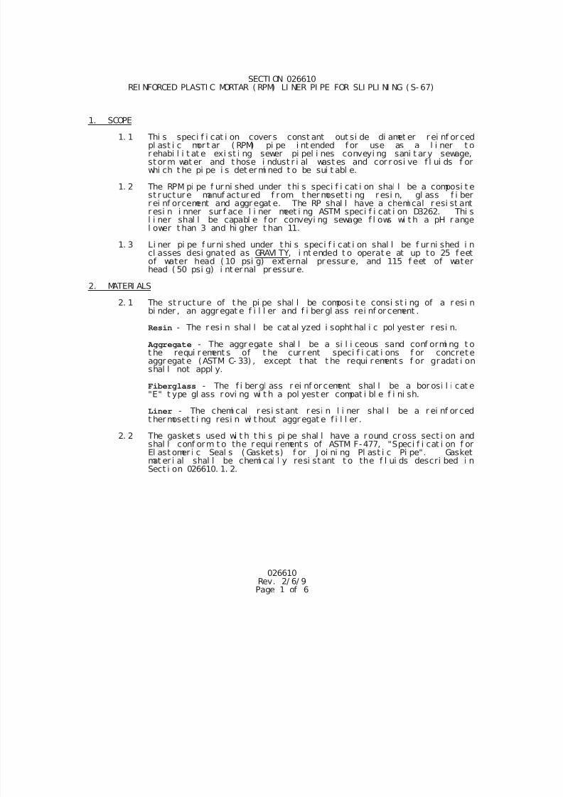
7/25/2019 City Standard Construction Specifications
http://slidepdf.com/reader/full/city-standard-construction-specifications 232/511
026610Rev. 2/ 6/ 9Page 1 of 6
SECTI ON 026610 REI NFORCED PLASTI C MORTAR ( RPM) LI NER PI PE FOR SLI PLI NI NG ( S- 67)
1. SCOPE
1. 1 Thi s speci f i cat i on cover s const ant out si de di amet er r ei nf or cedpl ast i c mor t ar ( RPM) pi pe i nt ended f or use as a l i ner t or ehabi l i t at e exi st i ng sewer pi pel i nes conveyi ng sani t ar y sewage,st or m wat er and t hose i ndust r i al wast es and cor r osi ve f l ui ds f orwhi ch t he pi pe i s det er mi ned t o be sui t abl e.
1. 2 The RPM pi pe f ur ni shed under thi s speci f i cat i on shal l be a composi t est r uctur e manuf actur ed f r om t her moset t i ng r esi n, gl ass f i berr ei nf orcement and aggr egat e. The RP shal l have a chemi cal r esi st antr esi n i nner sur f ace l i ner meet i ng ASTM speci f i cat i on D3262. Thi sl i ner shal l be capabl e f or conveyi ng sewage f l ows wi t h a pH r angel ower t han 3 and hi gher t han 11.
1. 3 Li ner pi pe f urni shed under t hi s speci f i cat i on shal l be f ur ni shed i n
cl asses desi gnated as GRAVI TY, i nt ended t o operat e at up to 25 f eetof water head ( 10 psi g) ext ernal pr essur e, and 115 f eet of waterhead ( 50 psi g) i nt er nal pr essur e.
2. MATERI ALS
2. 1 The st r uctur e of t he pi pe shal l be composi t e consi st i ng of a r esi nbi nder , an aggr egat e f i l l er and f i ber gl ass rei nf or cement .
Resin - The r esi n shal l be cat al yzed i sopht hal i c pol yest er r esi n.
Aggregate - The aggr egate shal l be a si l i ceous sand conf ormi ng t ot he requi r ement s of t he cur r ent speci f i cat i ons f or concret eaggr egat e (ASTM C- 33) , except t hat t he requi r ement s f or gradat i onshal l not appl y.
Fiberglass - The f i ber gl ass r ei nf or cement shal l be a bor osi l i cat e"E" t ype gl ass r ovi ng wi t h a pol yest er compat i bl e f i ni sh.
Liner - The chemi cal r esi st ant r esi n l i ner shal l be a r ei nf or cedt her moset t i ng resi n wi t hout aggr egat e f i l l er .
2. 2 The gasket s used wi t h t hi s pi pe shal l have a round cr oss sect i on andshal l conf orm t o the r equi r ement s of ASTM F-477, "Speci f i cat i on f orEl ast omer i c Seal s ( Gasket s) f or J oi ni ng Pl ast i c Pi pe". Gasketmat er i al shal l be chemi cal l y resi st ant t o the f l ui ds descri bed i nSect i on 026610. 1. 2.
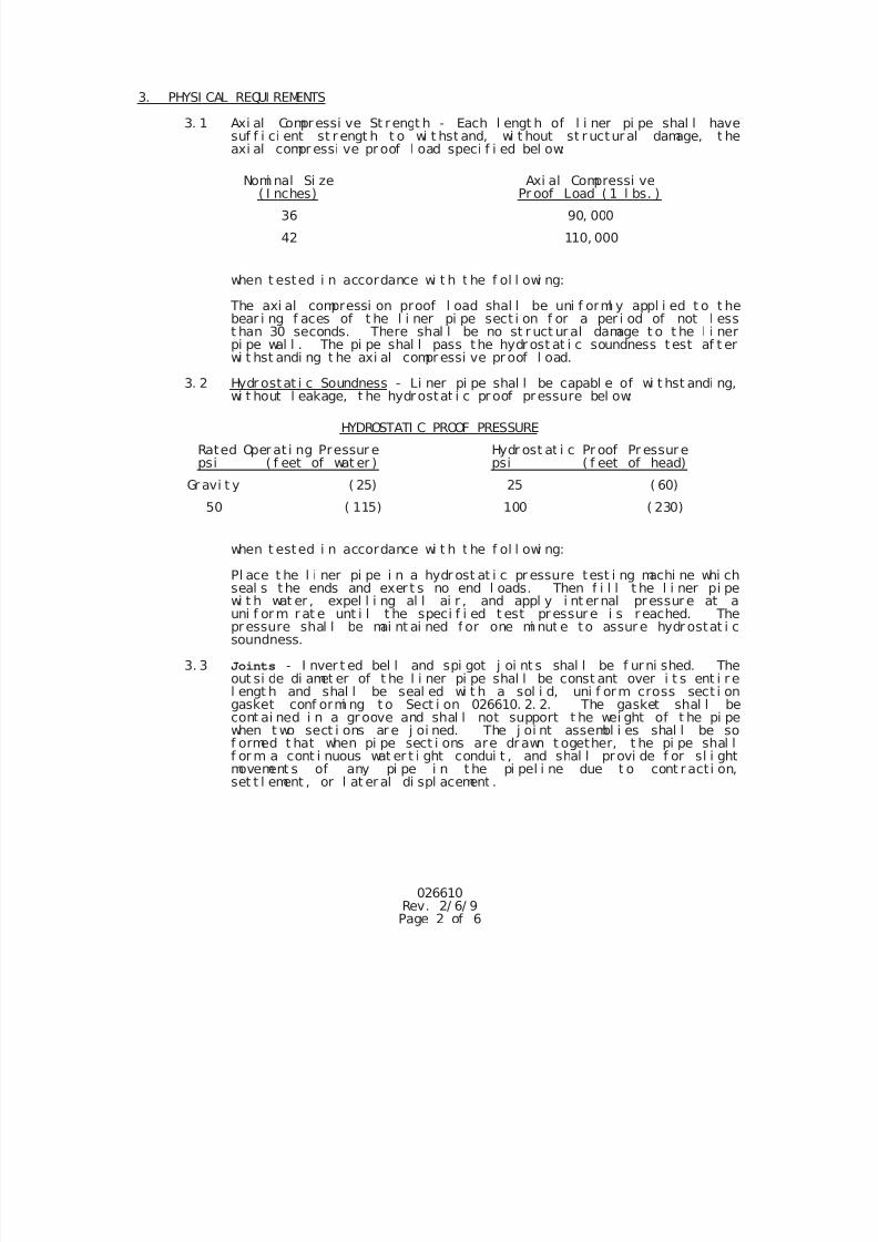
7/25/2019 City Standard Construction Specifications
http://slidepdf.com/reader/full/city-standard-construction-specifications 233/511
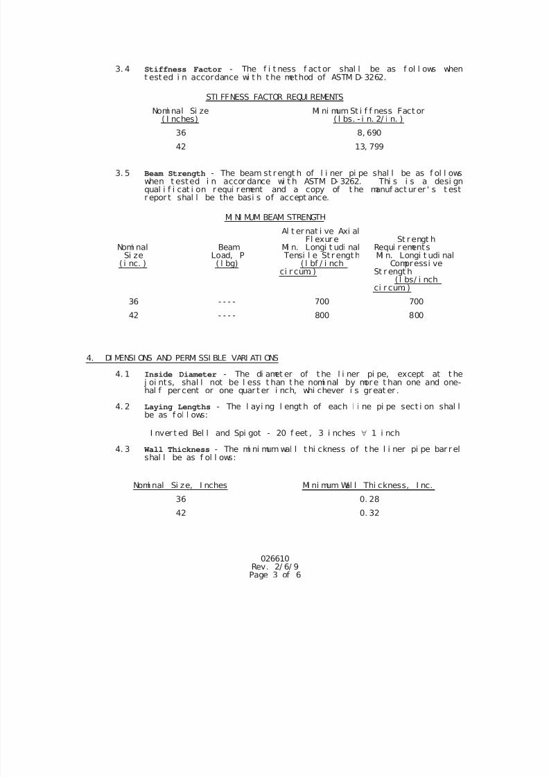
7/25/2019 City Standard Construction Specifications
http://slidepdf.com/reader/full/city-standard-construction-specifications 234/511
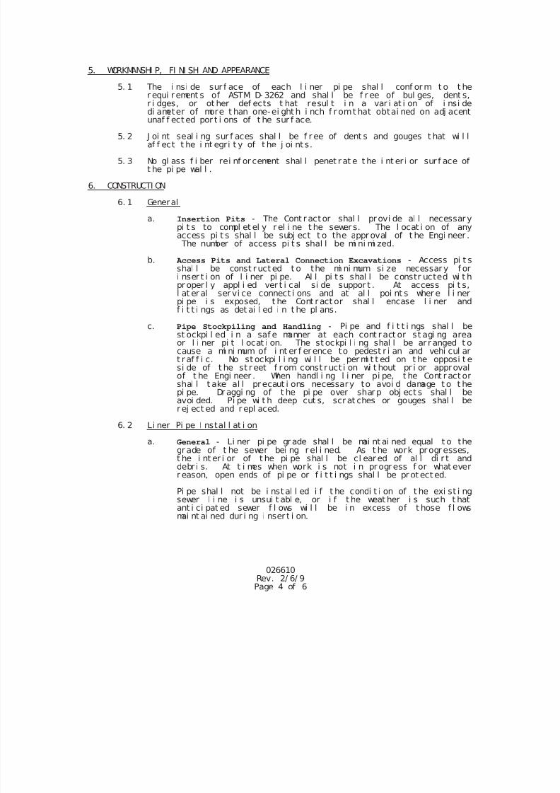
7/25/2019 City Standard Construction Specifications
http://slidepdf.com/reader/full/city-standard-construction-specifications 235/511
026610Rev. 2/ 6/ 9Page 4 of 6
5. WORKMANSHI P, FI NI SH AND APPEARANCE
5. 1 The i nsi de sur f ace of each l i ner pi pe shal l conf or m t o t her equi r ement s of ASTM D- 3262 and shal l be f r ee of bul ges, dent s,r i dges, or ot her def ects t hat resul t i n a var i at i on of i nsi dedi ameter of more t han one-ei ght h i nch f r omt hat obtai ned on adj acentunaf f ect ed por t i ons of t he sur f ace.
5. 2 J oi nt seal i ng sur f aces shal l be f r ee of dent s and gouges t hat wi l laf f ect t he i nt egri t y of t he j oi nt s.
5. 3 No gl ass f i ber rei nf or cement shal l penet r at e t he i nt er i or sur f ace oft he pi pe wal l .
6. CONSTRUCTI ON
6. 1 General
a. Insertion Pits - The Cont r actor shal l provi de al l necessar ypi t s to compl et el y r el i ne t he sewer s. The l ocat i on of anyaccess pi t s shal l be subj ect t o the appr oval of t he Engi neer . The number of access pi t s shal l be mi ni mi zed.
b. Access Pits and Lateral Connection Excavations - Access pi t sshal l be const r uct ed t o the mi ni mum si ze necessar y f ori nser t i on of l i ner pi pe. Al l pi t s shal l be constr ucted wi t hpr oper l y appl i ed ver t i cal si de suppor t . At access pi t s,l at er al ser vi ce connect i ons and at al l poi nt s wher e l i nerpi pe i s exposed, t he Cont r act or shal l encase l i ner andf i t t i ngs as det ai l ed i n t he pl ans.
c. Pipe Stockpiling and Handling - Pi pe and f i t t i ngs shal l best ockpi l ed i n a saf e manner at each cont r act or st agi ng areaor l i ner pi t l ocat i on. The st ockpi l i ng shal l be ar r anged t ocause a mi ni mum of i nt er f erence to pedest r i an and vehi cul art r af f i c. No st ockpi l i ng wi l l be per mi t t ed on t he opposi t esi de of t he st reet f r om const ruct i on wi t hout pr i or approval
of t he Engi neer . When handl i ng l i ner pi pe, t he Cont r act orshal l t ake al l pr ecaut i ons necessary to avoi d damage t o t hepi pe. Dr aggi ng of t he pi pe over shar p obj ect s shal l beavoi ded. Pi pe wi t h deep cut s, scr at ches or gouges shal l ber ej ect ed and r epl aced.
6. 2 Li ner Pi pe I nstal l at i on
a. General - Li ner pi pe gr ade shal l be mai nt ai ned equal t o thegr ade of t he sewer bei ng r el i ned. As t he work pr ogr esses,t he i nt er i or of t he pi pe shal l be cl ear ed of al l di r t anddebr i s. At t i mes when work i s not i n pr ogr ess f or what everr eason, open ends of pi pe or f i t t i ngs shal l be pr ot ect ed.
Pi pe shal l not be i nst al l ed i f t he condi t i on of t he exi st i ng
sewer l i ne i s unsui t abl e, or i f t he weat her i s such t hatant i ci pat ed sewer f l ows wi l l be i n excess of t hose f l owsmai nt ai ned dur i ng i nser t i on.
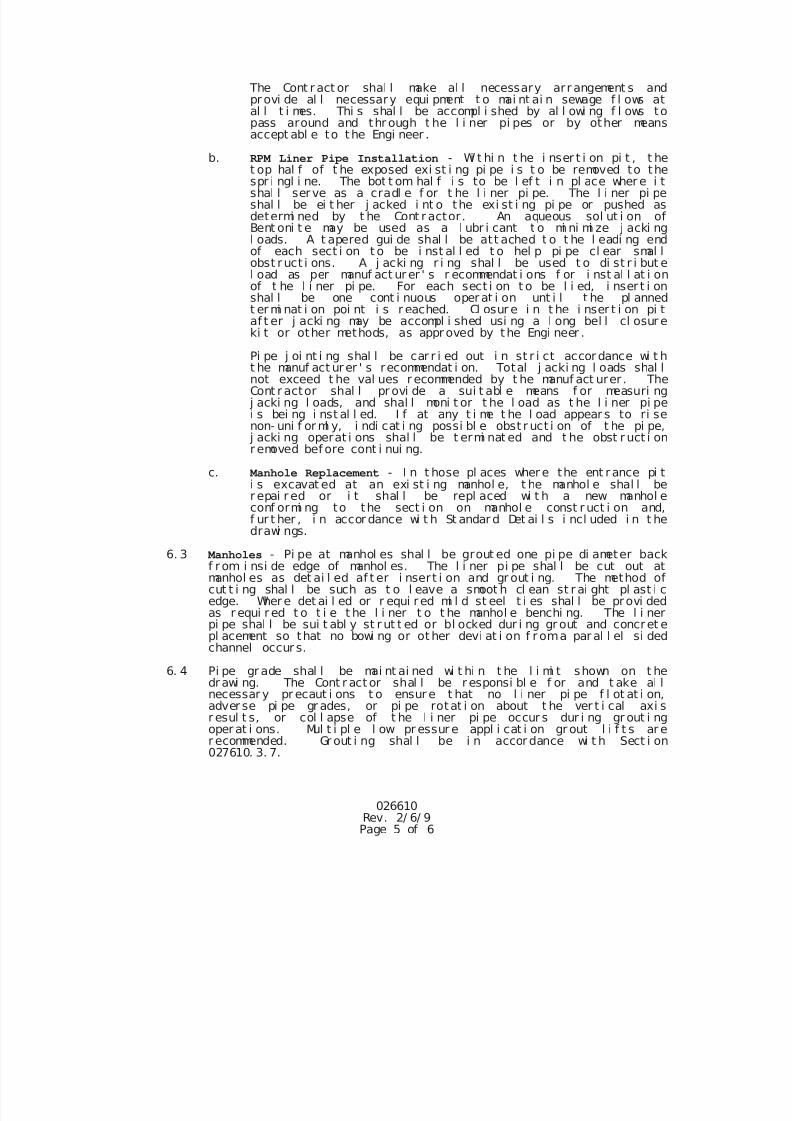
7/25/2019 City Standard Construction Specifications
http://slidepdf.com/reader/full/city-standard-construction-specifications 236/511
7/25/2019 City Standard Construction Specifications
http://slidepdf.com/reader/full/city-standard-construction-specifications 237/511
026610Rev. 2/ 6/ 9Page 6 of 6
6. 5 Measurement and Payment - Unl ess i ndi cat ed ot her wi se i n t heProposal , Rei nf or ced Pl ast i c Mor t ar Pi pe f or Sl i pl i ni ng shal l bemeasur ed and pai d f or by the l i near f oot , compl et e i n pl ace.
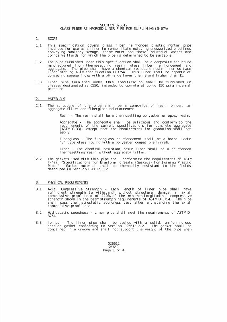
7/25/2019 City Standard Construction Specifications
http://slidepdf.com/reader/full/city-standard-construction-specifications 238/511
0266122/ 6/ 9
Page 1 of 4
SECTI ON 026612 GLASS FI BER REI NFORCED LI NER PI PE FOR SLI PLI NI NG ( S- 67A)
1. SCOPE
1. 1 Thi s speci f i cat i on covers gl ass f i ber r ei nf or ced pl ast i c mor t ar pi pei nt ended f or use as a l i ner t o rehabi l i t at e exi st i ng pr essur i zed pi pel i nesconveyi ng sani t ar y sewage, st orm wat er and those i ndust r i al wast es andcor r osi ve f l ui ds f or whi ch t he pi pe i s det er mi ned t o be sui t abl e.
1. 2 The pi pe f urni shed under t hi s speci f i cat i on shal l be a composi t e st r uct ur emanuf actur ed f r om t her moset t i ng resi n, gl ass f i ber r ei nf or cement andaggr egat e. The pi pe shal l have a chemi cal r esi st ant r esi n i nner sur f acel i ner meet i ng ASTM speci f i cat i on D- 3754. Thi s l i ner shal l be capabl e ofconveyi ng sewage f l ows wi t h a pH r ange l ower t han 3 and hi gher t han 11.
1. 3 Li ner pi pe f urni shed under t hi s speci f i cat i on shal l be f ur ni shed i ncl asses desi gnated as C150, i nt ended t o operat e at up t o 150 psi g i nt ernalpr essure.
2. MATERI ALS
2. 1 The st r uct ure of t he pi pe shal l be a composi t e of r esi n bi nder , anaggr egat e f i l l er and f i ber gl ass r ei nf or cement .
Resi n - The r esi n shal l be a t hermoset t i ng pol yest er or epoxy resi n.
Aggr egat e - The aggr egat e shal l be si l i ceous and conf orm t o t her equi r ement s of t he cur r ent speci f i cat i ons f or concret e aggregat e( ASTM C- 33) , except t hat t he requi r ement s f or gr adat i on shal l notappl y.
Fi ber gl ass - The f i ber gl ass r ei nf or cement shal l be a bor osi l i cat e"E" t ype gl ass r ovi ng wi t h a pol yest er compat i bl e f i ni sh.
Li ner - The chemi cal r esi st ant r esi n l i ner shal l be a r ei nf or ced
t her moset t i ng resi n wi t hout aggr egat e f i l l er .
2. 2 The gasket s used wi t h t hi s pi pe shal l conf orm t o t he r equi r ement s of ASTMF-477, "Speci f i cat i ons f or El ast omer i c Seal s (Gasket s) f or J oi ni ng Pl ast i cPi pe. " Gasket mat er i al shal l be chemi cal l y r esi st ant t o t he f l ui dsdescr i bed i n Sect i on 026612. 1. 2.
3. PHYSI CAL REQUI REMENTS
3. 1 Axi al Compr essi ve St r engt h - Each l engt h of l i ner pi pe shal l havesuf f i ci ent st r engt h t o wi t hst and, wi t hout st r uct ur al damage, an axi alcompr essi ve pr oof l oad of 110% of t he mi ni mum l ongi t udi nal compressi vest r engt h shown i n t he beam st r engt h r equi r ement s of ASTM D- 3754. The pi pe
shal l pass t he hydr ost at i c soundness t est af t er wi t hst andi ng t he axi alcompr essi ve pr oof l oad.
3. 2 Hydr ostat i c soundness - Li ner pi pe shal l meet t he r equi r ement s of ASTM D-3754.
3. 3 J oi nt s - The l i ner pi pe shal l be seal ed wi t h a sol i d, uni f or m crosssect i on gasket conf ormi ng t o Sect i on 026612. 2. 2. The gasket shal l becont ai ned i n a groove and shal l not support t he wei ght of t he pi pe when
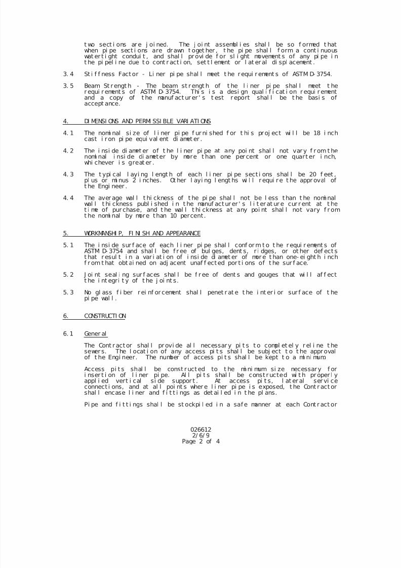
7/25/2019 City Standard Construction Specifications
http://slidepdf.com/reader/full/city-standard-construction-specifications 239/511
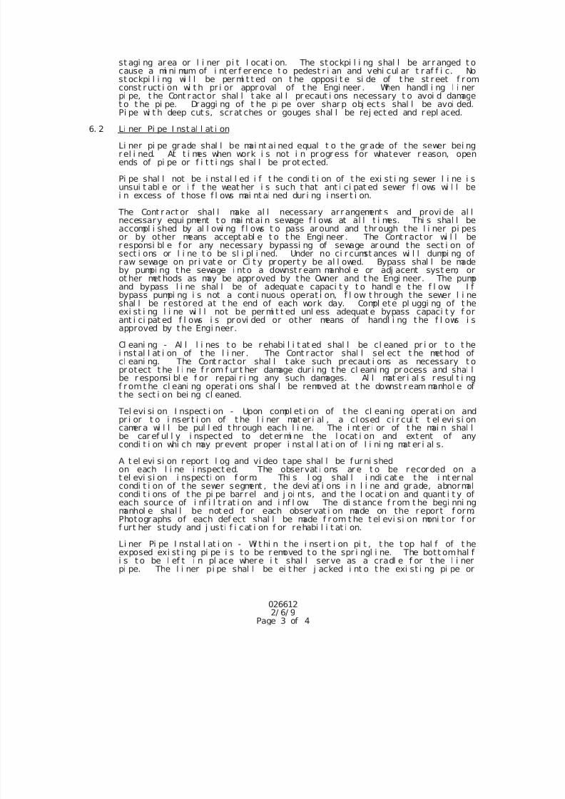
7/25/2019 City Standard Construction Specifications
http://slidepdf.com/reader/full/city-standard-construction-specifications 240/511
0266122/ 6/ 9
Page 3 of 4
st agi ng ar ea or l i ner pi t l ocat i on. The st ockpi l i ng shal l be ar r anged t ocause a mi ni mum of i nt er f er ence t o pedest r i an and vehi cul ar t r af f i c. Nost ockpi l i ng wi l l be per mi t t ed on t he opposi t e si de of t he st reet f r omconst r uct i on wi t h pr i or appr oval of t he Engi neer . When handl i ng l i nerpi pe, t he Cont r act or shal l t ake al l pr ecaut i ons necessary t o avoi d damaget o t he pi pe. Dr aggi ng of t he pi pe over shar p obj ect s shal l be avoi ded.Pi pe wi t h deep cut s, scrat ches or gouges shal l be rej ect ed and r epl aced.
6. 2 Li ner Pi pe I nst al l at i on
Li ner pi pe grade shal l be mai nt ai ned equal t o t he gr ade of the sewer bei ngr el i ned. At t i mes when work i s not i n pr ogress f or whatever r eason, openends of pi pe or f i t t i ngs shal l be pr ot ected.
Pi pe shal l not be i nst al l ed i f t he condi t i on of t he exi st i ng sewer l i ne i sunsui t abl e or i f t he weat her i s such t hat ant i ci pat ed sewer f l ows wi l l bei n excess of t hose f l ows mai nt ai ned dur i ng i nser t i on.
The Cont r act or shal l make al l necessary arr angement s and provi de al lnecessary equi pment t o mai nt ai n sewage f l ows at al l t i mes. Thi s shal l beaccompl i shed by al l owi ng f l ows t o pass ar ound and thr ough the l i ner pi pesor by other means accept abl e t o t he Engi neer . The Cont r actor wi l l ber esponsi bl e f or any necessary bypassi ng of sewage ar ound the sect i on of
sect i ons or l i ne t o be sl i pl i ned. Under no ci r cumst ances wi l l dumpi ng ofr aw sewage on pri vat e or Ci t y propert y be al l owed. Bypass shal l be madeby pumpi ng t he sewage i nto a downst r eam manhol e or adj acent syst em, orot her met hods as may be approved by the Owner and t he Engi neer. The pumpand bypass l i ne shal l be of adequat e capaci t y t o handl e t he f l ow. I fbypass pumpi ng i s not a cont i nuous operat i on, f l ow t hrough the sewer l i neshal l be r estored at t he end of each work day. Compl ete pl uggi ng of t heexi st i ng l i ne wi l l not be per mi t t ed unl ess adequat e bypass capaci t y f orant i ci pat ed f l ows i s pr ovi ded or other means of handl i ng t he f l ows i sapproved by t he Engi neer.
Cl eani ng - Al l l i nes t o be r ehabi l i t at ed shal l be cl eaned pr i or t o t hei nst al l at i on of t he l i ner . The Cont r actor shal l sel ect t he met hod ofcl eani ng. The Cont ract or shal l t ake such pr ecaut i ons as necessary t opr otect t he l i ne f r om f ur t her damage dur i ng t he cl eani ng pr ocess and shal l
be r esponsi bl e f or repai r i ng any such damages. Al l mat er i al s r esul t i ngf r omt he cl eani ng operat i ons shal l be removed at t he downst r eam manhol e oft he sect i on bei ng cl eaned.
Tel evi si on I nspect i on - Upon compl et i on of t he cl eani ng operat i on andpr i or t o i nser t i on of t he l i ner mat er i al , a cl osed ci r cui t t el evi si oncamer a wi l l be pul l ed t hr ough each l i ne. The i nt er i or of t he mai n shal lbe car ef ul l y i nspect ed to det er mi ne the l ocat i on and extent of anycondi t i on whi ch may pr event pr oper i nst al l at i on of l i ni ng mat er i al s.
A t el evi si on r epor t l og and vi deo tape shal l be f ur ni shedon each l i ne i nspect ed. The observat i ons ar e t o be r ecor ded on at el evi si on i nspecti on f or m. Thi s l og shal l i ndi cat e t he i nt er nalcondi t i on of t he sewer segment , t he devi at i ons i n l i ne and grade, abnormalcondi t i ons of t he pi pe bar rel and j oi nt s, and t he l ocat i on and quant i t y of
each sour ce of i nf i l t r at i on and i nf l ow. The di st ance f r om t he begi nni ngmanhol e shal l be not ed f or each obser vat i on made on the r eport f orm.Photographs of each def ect shal l be made f r om t he t el evi si on moni t or f orf urt her study and j usti f i cat i on f or rehabi l i t at i on.
Li ner Pi pe I nst al l at i on - Wi t hi n t he i nsert i on pi t , t he t op hal f of t heexposed exi st i ng pi pe i s to be r emoved t o t he spr i ngl i ne. The bott omhal fi s t o be l ef t i n pl ace wher e i t shal l serve as a cradl e f or t he l i nerpi pe. The l i ner pi pe shal l be ei t her j acked i nt o t he exi st i ng pi pe or
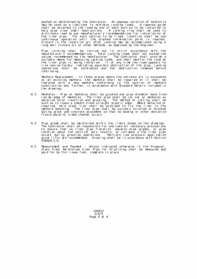
7/25/2019 City Standard Construction Specifications
http://slidepdf.com/reader/full/city-standard-construction-specifications 241/511
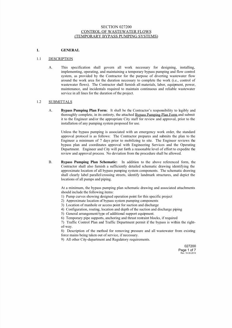
7/25/2019 City Standard Construction Specifications
http://slidepdf.com/reader/full/city-standard-construction-specifications 242/511
027200Page 1 of 7
Rev. 10-30-2014
SECTION 027200
CONTROL OF WASTEWATER FLOWS(TEMPORARY BYPASS PUMPING SYSTEMS)
1. GENERAL
1.1 DESCRIPTION
A. This specification shall govern all work necessary for designing, installing,
implementing, operating, and maintaining a temporary bypass pumping and flow control
system, as provided by the Contractor for the purpose of diverting wastewater flow
around the work area for the duration necessary to complete the work (i.e., control of
wastewater flows). The Contractor shall furnish all materials, labor, equipment, power,
maintenance, and incidentals required to maintain continuous and reliable wastewater
service in all lines for the duration of the project.
1.2 SUBMITTALS
A. Bypass Pumping Plan Form: It shall be the Contractor’s responsibility to legibly and
thoroughly complete, in its entirety, the attached Bypass Pumping Plan Form and submit
it to the Engineer and/or the appropriate City staff for review and approval, prior to the
installation of any pumping system proposed for use.
Unless the bypass pumping is associated with an emergency work order, the standard
approval protocol is as follows: The Contractor prepares and submits the plan to the
Engineer a minimum of 7 days prior to mobilizing to site. The Engineer reviews the
bypass plan and coordinates approval with Engineering Services and the Operating
Department. Engineer and City will put forth a reasonable level of effort to expedite the
review and approval process. No deviation from the procedure shall be allowed.
B. Bypass Pumping Plan Schematic: In addition to the above referenced form, the
Contractor shall also furnish a sufficiently detailed schematic drawing identifying the
approximate location of all bypass pumping system components. The schematic drawing
shall clearly label parallel/crossing streets, identify landmark structures, and depict the
locations of all pumps and piping.
At a minimum, the bypass pumping plan schematic drawing and associated attachments
should include the following items:
1) Pump curves showing designed operation point for this specific project2) Approximate location of bypass system pumping components
3) Location of manhole or access point for suction and discharge
4) Configuration, routing, location and depth of the suction and discharge piping
5) General arrangement/type of additional support equipment.
6) Temporary pipe supports, anchoring and thrust restraint blocks, if required
7) Traffic Control Plan and Traffic Department permit if the bypass is within the right-
of-way.
8) Description of the method for removing pressure and all wastewater from existing
force mains being taken out of service, if necessary.
9) All other City-department and Regulatory requirements.
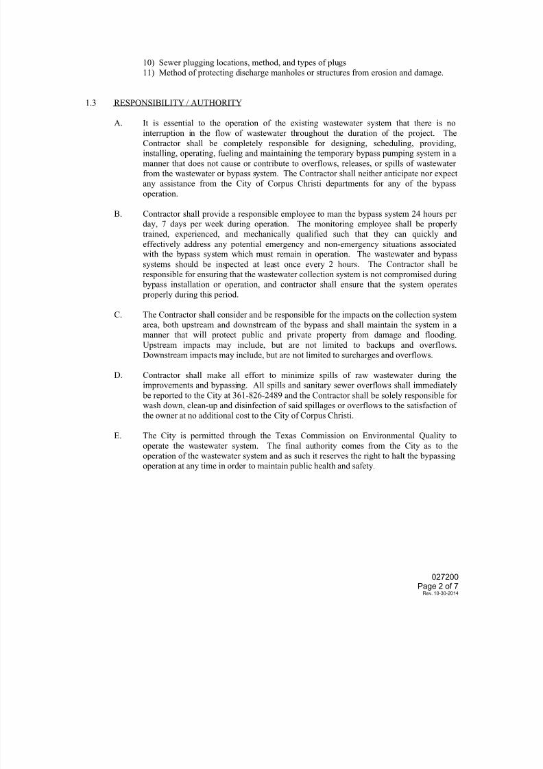
7/25/2019 City Standard Construction Specifications
http://slidepdf.com/reader/full/city-standard-construction-specifications 243/511
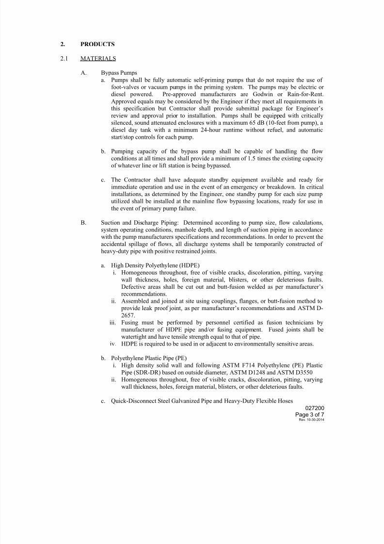
7/25/2019 City Standard Construction Specifications
http://slidepdf.com/reader/full/city-standard-construction-specifications 244/511
027200Page 3 of 7
Rev. 10-30-2014
2. PRODUCTS
2.1 MATERIALS
A. Bypass Pumps
a. Pumps shall be fully automatic self-priming pumps that do not require the use of
foot-valves or vacuum pumps in the priming system. The pumps may be electric ordiesel powered. Pre-approved manufacturers are Godwin or Rain-for-Rent.
Approved equals may be considered by the Engineer if they meet all requirements inthis specification but Contractor shall provide submittal package for Engineer’s
review and approval prior to installation. Pumps shall be equipped with critically
silenced, sound attenuated enclosures with a maximum 65 dB (10-feet from pump), a
diesel day tank with a minimum 24-hour runtime without refuel, and automatic
start/stop controls for each pump.
b. Pumping capacity of the bypass pump shall be capable of handling the flow
conditions at all times and shall provide a minimum of 1.5 times the existing capacity
of whatever line or lift station is being bypassed.
c. The Contractor shall have adequate standby equipment available and ready for
immediate operation and use in the event of an emergency or breakdown. In critical
installations, as determined by the Engineer, one standby pump for each size pump
utilized shall be installed at the mainline flow bypassing locations, ready for use in
the event of primary pump failure.
B. Suction and Discharge Piping: Determined according to pump size, flow calculations,
system operating conditions, manhole depth, and length of suction piping in accordance
with the pump manufacturers specifications and recommendations. In order to prevent the
accidental spillage of flows, all discharge systems shall be temporarily constructed of
heavy-duty pipe with positive restrained joints.
a. High Density Polyethylene (HDPE)
i. Homogeneous throughout, free of visible cracks, discoloration, pitting, varying
wall thickness, holes, foreign material, blisters, or other deleterious faults.
Defective areas shall be cut out and butt-fusion welded as per manufacturer’s
recommendations.
ii. Assembled and joined at site using couplings, flanges, or butt-fusion method to
provide leak proof joint, as per manufacturer’s recommendations and ASTM D-
2657.
iii. Fusing must be performed by personnel certified as fusion technicians by
manufacturer of HDPE pipe and/or fusing equipment. Fused joints shall be
watertight and have tensile strength equal to that of pipe.
iv. HDPE is required to be used in or adjacent to environmentally sensitive areas.
b. Polyethylene Plastic Pipe (PE)
i. High density solid wall and following ASTM F714 Polyethylene (PE) Plastic
Pipe (SDR-DR) based on outside diameter, ASTM D1248 and ASTM D3550
ii. Homogeneous throughout, free of visible cracks, discoloration, pitting, varying
wall thickness, holes, foreign material, blisters, or other deleterious faults.
c. Quick-Disconnect Steel Galvanized Pipe and Heavy-Duty Flexible Hoses
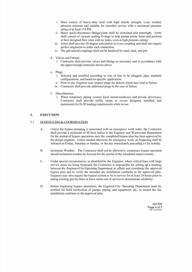
7/25/2019 City Standard Construction Specifications
http://slidepdf.com/reader/full/city-standard-construction-specifications 245/511
027200Page 4 of 7
Rev. 10-30-2014
i. Must consist of heavy-duty steel with high tensile strength, x-ray welded,
abrasion resistant and suitable for intended service with a maximum pressure
rating of at least 174 PSI
ii. Bauer quick-disconnect fittings/joints shall be restrained and watertight. Joints
shall consist of vacuum sealing O-rings to help pumps prime faster and perform
at their designed flow rates with no leaks, even at high pressure ratings
iii. Joints shall provide 30-degree articulation at every coupling and shall not require perfect alignment to make each connection.
iv. The galvanized couplings shall not be hindered by sand, mud, and grit.
d. Valves and Fittings
i. Contractor shall provide valves and fittings as necessary and in accordance with
the approved pipe materials shown above.
e. Plugs
i. Selected and installed according to size of line to be plugged, pipe, manhole
configurations, and based on specific application.
ii. Prior to use, Engineer may inspect plugs for defects which may lead to failure.
iii. Contractor shall provide additional plugs in the case of failure
f. Miscellaneous
i. When temporary piping crosses local streets/roadways and private driveways,
Contractor shall provide traffic ramps or covers designed, installed, and
maintained for H-20 loading requirements while in use.
3. EXECUTION
3.1 SCHEDULING & COORDINATION
A. Unless the bypass pumping is associated with an emergency work order, the Contractorshall provide a minimum of 48 hour notice to the Engineer and Wastewater Department
for the startup of bypass operations once the completed bypass plan has been approved by
the design engineer. Unless needed otherwise for emergency work, no bypassing shall be
initiated on Friday, Saturday or Sunday, or the day immediately preceding a City holiday.
B. Inclement Weather: The Contractor shall not be allowed to commence bypass operation
should inclement weather be forecast for the period of the scheduled improvements.
C. Under special circumstances, as identified by the Engineer, where critical lines with large
service areas are being bypassed, the Contractor is responsible for setting up a meeting
between the Engineer/City/Operating Department to affirm and coordinate the approved
bypass plan and to verify the intended site installation conforms to the approved plan.Engineer may also require the bypass system to be in service for at least 24-hours prior to
taking existing gravity lines or force mains out of service to demonstrate reliability.
D. Before beginning bypass operations, the Engineer/City Operating Department must be
notified for field verification of pumps, piping, and equipment, etc., to ensure the site
installation conforms to the approved plan.
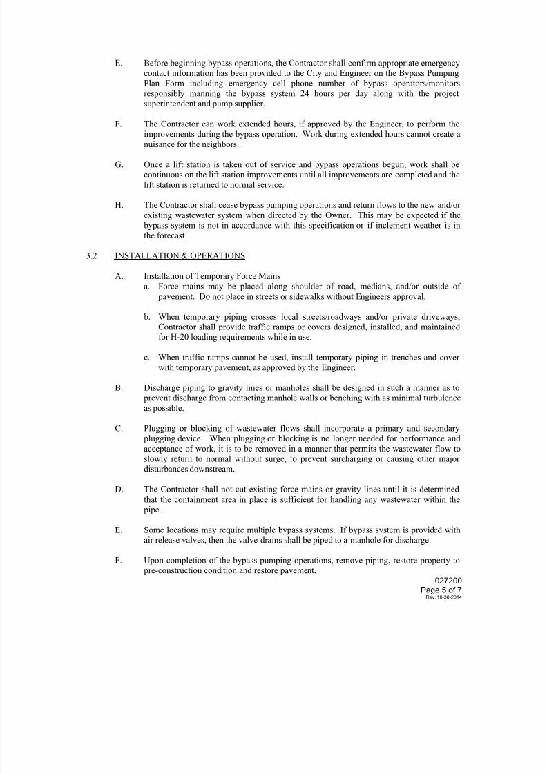
7/25/2019 City Standard Construction Specifications
http://slidepdf.com/reader/full/city-standard-construction-specifications 246/511
7/25/2019 City Standard Construction Specifications
http://slidepdf.com/reader/full/city-standard-construction-specifications 247/511
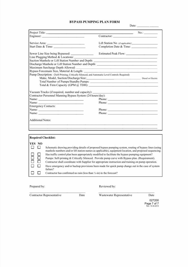
7/25/2019 City Standard Construction Specifications
http://slidepdf.com/reader/full/city-standard-construction-specifications 248/511
027200Page 7 of 7
Rev. 10-30-2014
BYPASS PUMPING PLAN FORMDate: ________ ______
Project Title: ________________________________________________________ No.: _________
Engineer: ____________________________ Contractor: _____________________________
Service Area: _________________________ Lift Station No. (if applicable):_________________Start Date & Time: _____________________ Completion Date & Time: _________________
Sewer Line Size being Bypassed: _______________ Estimated Peak Flow: _____________________
Line Plugging Method & Locations: _______________________________________________________
Suction Manhole or Lift Station Number and Depth: __________________________________________
Discharge Manhole or Lift Station Number and Depth: ________________________________________
Maximum Surcharge Depth Allowed: ______________________________________________________
Bypass Forcemain Size, Material & Length: _________________________________________________
Pump Description: (Self-Priming, Critically Silenced, and Automatic Level Controls Required)
Make, Model, Suction/Discharge Size:____________________________________ Diesel or Electric
Total Number of Pumps/Standby Pumps: _____________________________________________
Total & Firm Capacity (GPM @ TDH): ______________________________________________
Vacuum Trucks (if required, number and capacity): ___________________________________________
Contractor Personnel Manning Bypass System (24 hours/day):
Name: ______________________________ Phone: _________________________________
Name: ______________________________ Phone: _________________________________
Emergency Contacts:
Name: ______________________________ Phone: _________________________________
Name: ______________________________ Phone: _________________________________
Additional Notes:
_____________________________________________________________________________________
_____________________________________________________________________________________
Required Checklist:
YES NO
Schematic drawing providing details of proposed bypass pumping system, routing of bypass lines (using
manhole numbers and/or lift station names as applicable), equipment location, and proposed sequencing.
Has traffic control plan been appropriately modified to facilitate the bypass pumping equipment?
Pumps: Self-priming & Critically Silenced. Provide pump curve with Bypass plan. (Requirement).
Contractor shall coordinate with Supplier for appropriate instruction and training on pump operation.
Have emergency and/or backup provisions been made for quick pump change out in the case of system
failure?Contractor has confirmed no rain (less than ½-in) in the forecast?
Prepared by: Reviewed by:
_____________________________________ _____________________________________
Contractor Representative Date Wastewater Representative Date
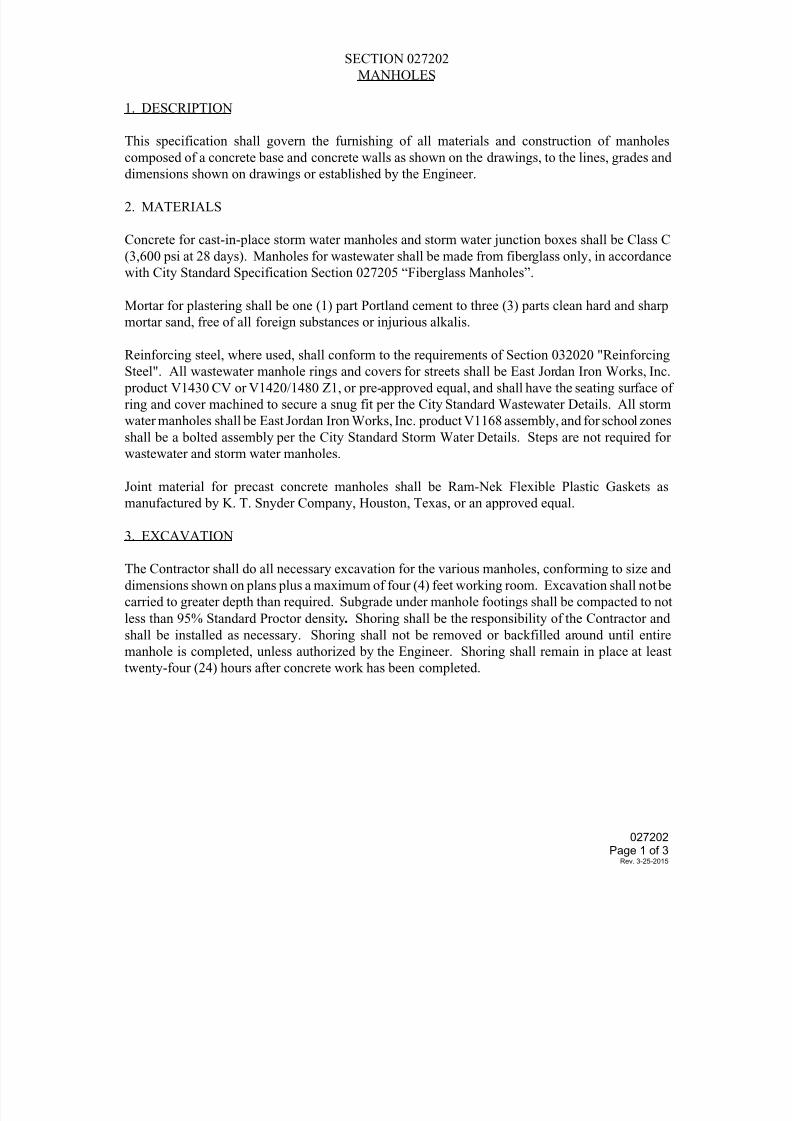
7/25/2019 City Standard Construction Specifications
http://slidepdf.com/reader/full/city-standard-construction-specifications 249/511
SECTION 027202
MANHOLES
1. DESCRIPTION
This specification shall govern the furnishing of all materials and construction of manholes
composed of a concrete base and concrete walls as shown on the drawings, to the lines, grades and
dimensions shown on drawings or established by the Engineer.
2. MATERIALS
Concrete for cast-in-place storm water manholes and storm water junction boxes shall be Class C
(3,600 psi at 28 days). Manholes for wastewater shall be made from fiberglass only, in accordance
with City Standard Specification Section 027205 “Fiberglass Manholes”.
Mortar for plastering shall be one (1) part Portland cement to three (3) parts clean hard and sharp
mortar sand, free of all foreign substances or injurious alkalis.
Reinforcing steel, where used, shall conform to the requirements of Section 032020 "ReinforcingSteel". All wastewater manhole rings and covers for streets shall be East Jordan Iron Works, Inc.
product V1430 CV or V1420/1480 Z1, or pre-approved equal, and shall have the seating surface of
ring and cover machined to secure a snug fit per the City Standard Wastewater Details. All storm
water manholes shall be East Jordan Iron Works, Inc. product V1168 assembly, and for school zones
shall be a bolted assembly per the City Standard Storm Water Details. Steps are not required for
wastewater and storm water manholes.
Joint material for precast concrete manholes shall be Ram-Nek Flexible Plastic Gaskets as
manufactured by K. T. Snyder Company, Houston, Texas, or an approved equal.
3. EXCAVATION
The Contractor shall do all necessary excavation for the various manholes, conforming to size and
dimensions shown on plans plus a maximum of four (4) feet working room. Excavation shall not be
carried to greater depth than required. Subgrade under manhole footings shall be compacted to not
less than 95% Standard Proctor density. Shoring shall be the responsibility of the Contractor and
shall be installed as necessary. Shoring shall not be removed or backfilled around until entire
manhole is completed, unless authorized by the Engineer. Shoring shall remain in place at least
twenty-four (24) hours after concrete work has been completed.
027202Page 1 of 3
Rev. 3-25-2015
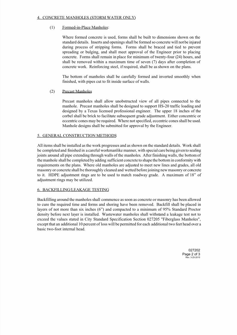
7/25/2019 City Standard Construction Specifications
http://slidepdf.com/reader/full/city-standard-construction-specifications 250/511
4. CONCRETE MANHOLES (STORM WATER ONLY)
(1) Formed-in-Place Manholes:
Where formed concrete is used, forms shall be built to dimensions shown on the
standard details. Inserts and openings shall be formed so concrete will not be injured
during process of stripping forms. Forms shall be braced and tied to prevent
spreading or bulging, and shall meet approval of the Engineer prior to placingconcrete. Forms shall remain in place for minimum of twenty-four (24) hours, and
shall be removed within a maximum time of seven (7) days after completion of
concrete work. Reinforcing steel, if required, shall be as shown on the plans.
The bottom of manholes shall be carefully formed and inverted smoothly when
finished, with pipes cut to fit inside surface of walls.
(2) Precast Manholes
Precast manholes shall allow unobstructed view of all pipes connected to the
manhole. Precast manholes shall be designed to support HS-20 traffic loading anddesigned by a Texas licensed professional engineer. The upper 18 inches of the
corbel shall be brick to facilitate subsequent grade adjustment. Either concentric or
eccentric cones may be required. Where not specified, eccentric cones shall be used.
Manhole designs shall be submitted for approval by the Engineer.
5. GENERAL CONSTRUCTION METHODS
All items shall be installed as the work progresses and as shown on the standard details. Work shall
be completed and finished in a careful workmanlike manner, with special care being given to sealing
joints around all pipe extending through walls of the manholes. After finishing walls, the bottom of
the manhole shall be completed by adding sufficient concrete to shape the bottom in conformity withrequirements on the plans. Where old manholes are adjusted to meet new lines and grades, all old
masonry or concrete shall be thoroughly cleaned and wetted before joining new masonry or concrete
to it. HDPE adjustment rings are to be used to match roadway grade. A maximum of 18” of
adjustment rings may be utilized.
6. BACKFILLING/LEAKAGE TESTING
Backfilling around the manholes shall commence as soon as concrete or masonry has been allowed
to cure the required time and forms and shoring have been removed. Backfill shall be placed in
layers of not more than six inches (6”) and compacted to a minimum of 95% Standard Proctor
density before next layer is installed. Wastewater manholes shall withstand a leakage test not to
exceed the values stated in City Standard Specification Section 027205 "Fiberglass Manholes",
except that an additional 10 percent of loss will be permitted for each additional two feet head over a
basic two-foot internal head.
027202Page 2 of 3
Rev. 3-25-2015
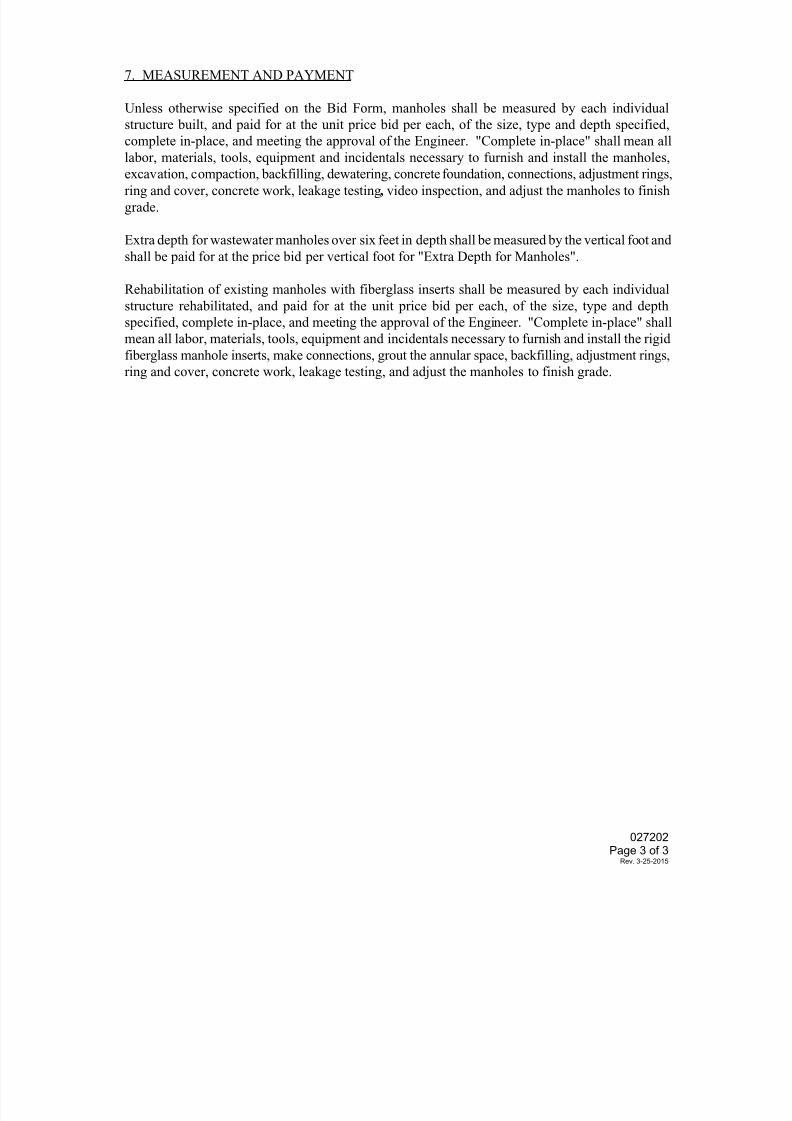
7/25/2019 City Standard Construction Specifications
http://slidepdf.com/reader/full/city-standard-construction-specifications 251/511
7. MEASUREMENT AND PAYMENT
Unless otherwise specified on the Bid Form, manholes shall be measured by each individual
structure built, and paid for at the unit price bid per each, of the size, type and depth specified,
complete in-place, and meeting the approval of the Engineer. "Complete in-place" shall mean all
labor, materials, tools, equipment and incidentals necessary to furnish and install the manholes,
excavation, compaction, backfilling, dewatering, concrete foundation, connections, adjustment rings,ring and cover, concrete work, leakage testing, video inspection, and adjust the manholes to finish
grade.
Extra depth for wastewater manholes over six feet in depth shall be measured by the vertical foot and
shall be paid for at the price bid per vertical foot for "Extra Depth for Manholes".
Rehabilitation of existing manholes with fiberglass inserts shall be measured by each individual
structure rehabilitated, and paid for at the unit price bid per each, of the size, type and depth
specified, complete in-place, and meeting the approval of the Engineer. "Complete in-place" shall
mean all labor, materials, tools, equipment and incidentals necessary to furnish and install the rigid
fiberglass manhole inserts, make connections, grout the annular space, backfilling, adjustment rings,ring and cover, concrete work, leakage testing, and adjust the manholes to finish grade.
027202Page 3 of 3
Rev. 3-25-2015
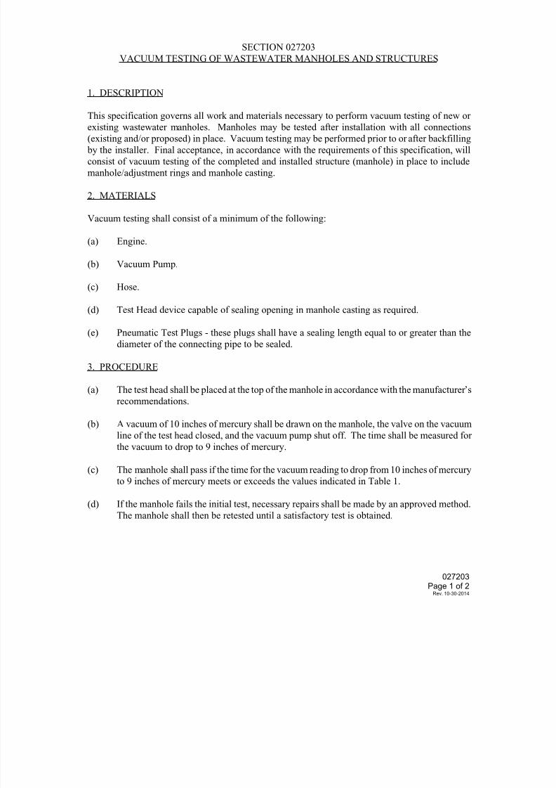
7/25/2019 City Standard Construction Specifications
http://slidepdf.com/reader/full/city-standard-construction-specifications 252/511
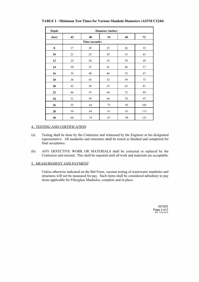
7/25/2019 City Standard Construction Specifications
http://slidepdf.com/reader/full/city-standard-construction-specifications 253/511
027203Page 2 of 2
Rev. 10-30-2014
TABLE 1 - Minimum Test Times for Various Manhole Diameters (ASTM C1244)
Depth Diameter (inches)
(feet) 42 48 54 60 72
Time (seconds)
8 17 20 23 26 33
10 21 25 29 33 41
12 25 30 35 39 49
14 30 35 41 46 57
16 34 40 46 52 67
18 38 45 52 59 73
20 42 50 53 65 81
22 46 55 64 72 89
24 51 59 64 78 97
26 55 64 75 85 105
28 59 69 81 91 113
30 68 74 87 98 121
4. TESTING AND CERTIFICATION
(a) Testing shall be done by the Contractor and witnessed by the Engineer or his designatedrepresentative. All manholes and structures shall be tested as finished and completed for
final acceptance.
(b) ANY DEFECTIVE WORK OR MATERIALS shall be corrected or replaced by the
Contractor and retested. This shall be repeated until all work and materials are acceptable.
5. MEASUREMENT AND PAYMENT
Unless otherwise indicated on the Bid Form, vacuum testing of wastewater manholes and
structures will not be measured for pay. Such items shall be considered subsidiary to pay
items applicable for Fiberglass Manholes, complete and in-place.
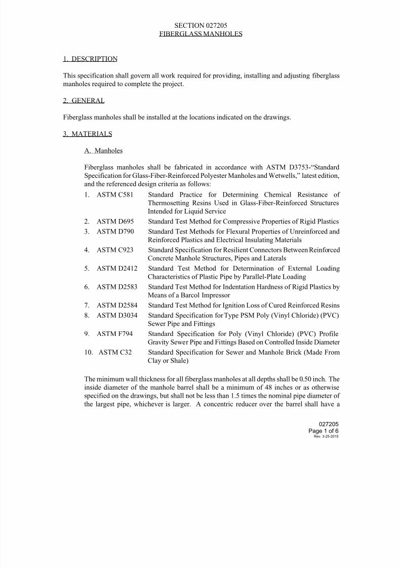
7/25/2019 City Standard Construction Specifications
http://slidepdf.com/reader/full/city-standard-construction-specifications 254/511
SECTION 027205
FIBERGLASS MANHOLES
1. DESCRIPTION
This specification shall govern all work required for providing, installing and adjusting fiberglass
manholes required to complete the project.
2. GENERAL
Fiberglass manholes shall be installed at the locations indicated on the drawings.
3. MATERIALS
A. Manholes
Fiberglass manholes shall be fabricated in accordance with ASTM D3753-“Standard
Specification for Glass-Fiber-Reinforced Polyester Manholes and Wetwells,” latest edition,
and the referenced design criteria as follows:
1. ASTM C581 Standard Practice for Determining Chemical Resistance of
Thermosetting Resins Used in Glass-Fiber-Reinforced Structures
Intended for Liquid Service
2. ASTM D695 Standard Test Method for Compressive Properties of Rigid Plastics
3. ASTM D790 Standard Test Methods for Flexural Properties of Unreinforced and
Reinforced Plastics and Electrical Insulating Materials
4. ASTM C923 Standard Specification for Resilient Connectors Between Reinforced
Concrete Manhole Structures, Pipes and Laterals
5. ASTM D2412 Standard Test Method for Determination of External LoadingCharacteristics of Plastic Pipe by Parallel-Plate Loading
6. ASTM D2583 Standard Test Method for Indentation Hardness of Rigid Plastics by
Means of a Barcol Impressor
7. ASTM D2584 Standard Test Method for Ignition Loss of Cured Reinforced Resins
8. ASTM D3034 Standard Specification for Type PSM Poly (Vinyl Chloride) (PVC)
Sewer Pipe and Fittings
9. ASTM F794 Standard Specification for Poly (Vinyl Chloride) (PVC) Profile
Gravity Sewer Pipe and Fittings Based on Controlled Inside Diameter
10. ASTM C32 Standard Specification for Sewer and Manhole Brick (Made From
Clay or Shale)
The minimum wall thickness for all fiberglass manholes at all depths shall be 0.50 inch. The
inside diameter of the manhole barrel shall be a minimum of 48 inches or as otherwise
specified on the drawings, but shall not be less than 1.5 times the nominal pipe diameter of
the largest pipe, whichever is larger. A concentric reducer over the barrel shall have a
027205Page 1 of 6
Rev. 3-25-2015
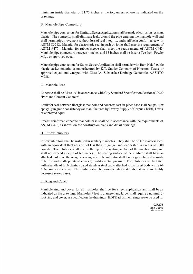
7/25/2019 City Standard Construction Specifications
http://slidepdf.com/reader/full/city-standard-construction-specifications 255/511
7/25/2019 City Standard Construction Specifications
http://slidepdf.com/reader/full/city-standard-construction-specifications 256/511
7/25/2019 City Standard Construction Specifications
http://slidepdf.com/reader/full/city-standard-construction-specifications 257/511
insure the safety of the structure, but in no case shall de-watering be terminated sooner than
seven (7) days after placing concrete. All de-watering methods and procedures are subject to
the approval of the Engineer. The excavation shall be inspected and approved by the
Engineer before work on the structure is started. The Contractor shall provide a relatively
smooth, firm foundation bed for footings and slabs that bear directly on the undisturbed earth
without additional cost to the City, regardless of the soil conditions encountered. The
Engineer will be the sole judge as to whether these conditions have been met. The
Contractor shall pile excavated material in a manner that will not create an unsafe condition.
Unauthorized Over-Excavation: Excavation for slabs, footings, etc., that rest on earth,
shall not be carried below the elevation shown on the drawings. In the event the excavation
is carried below the indicated elevation, the Contractor shall bring the slab, footing, etc., to
the required grade by filling with concrete.
Wall Preparation for Pipe Penetrations: For sanitary sewer application, pipe penetrations
for pipe sizes 4-inch through 15-inch shall be made with appropriately sized core drill bits
recommended by the manufacturer. Pipe penetrations other than described above and as
authorized by the Engineer shall be made as follows: cut shall be equal to the outside
diameter of pipe to pass through it, plus 1/2 inch. Cuts are to be made using electric or
gasoline powered circular saw with masonry blade. Impact type tools shall not be used.
Handling: Manholes shall be handled and stored in a safe manner as necessary to prevent
damaging either the manhole or the surroundings. If manhole must be moved by rolling, the
ground which it traverses shall be smooth and free of rocks, debris, etc. Manholes shall be
lifted as specified by the manufacturer.
Height Adjustment: If necessary, utilize HDPE adjustment rings to adjust the manhole to
the correct grade elevation. A maximum of 18” of adjustment rings may be utilized.
Installation: Lower manhole into wet concrete until it rests at the proper elevation, and aminimum of six (6) inches into concrete, then plumb.
Backfill Material: Unless shown otherwise on the drawings, initial backfill around
manholes (from subgrade to five feet (5') above the top of the concrete footing) shall be
flowable grout. The remaining final backfill around manholes shall be cement-stabilized
sand, or approved equal, containing a minimum of 2 sacks of standard Type I or Type II
Portland cement per cubic yard of sand, free of large hard lumps, rock fragments or other
debris. The material shall be free of large lumps or clods which will not readily break down
under compaction. This material shall be subject to approval by the Engineer. Backfill
material shall be free of vegetation or other extraneous material. Topsoil should be
stockpiled separately and used for finish grading around the structure, if necessary.
027205Page 4 of 6
Rev. 3-25-2015
7/25/2019 City Standard Construction Specifications
http://slidepdf.com/reader/full/city-standard-construction-specifications 258/511
Schedule of Backfilling: The Contractor may begin backfilling around manhole as soon as
the concrete has been allowed to cure and the forms removed.
Compaction: Backfill shall be placed in layers not to exceed 6 inches compacted thickness
and mechanically tamped to at least 95% Standard Proctor density (ASTM D698). Backfill
shall be placed in such a manner as to prevent any wedging action against the structure.
Contractor shall follow operational requirements for bypass pumping as set forth in City
Standard Specification Section 027200 "Control of Wastewater Flows".
5. TESTING
Manholes shall be tested for leakage by either of two tests as specified by the Engineer.
Water Leakage Test:
The Contractor shall provide water, labor, and materials for testing.
Testing shall be as follows:
1. With sewers plugged, the manhole shall be filled with water.
2. The manhole shall be checked after 24 hours have elapsed.
3. Water loss shall not exceed 2.4 gallons per foot of depth for the 24-hour period for
4-foot diameter manholes, or 3.0 gallons per foot of depth for the 24-hour period for
5-foot diameter manholes. Water loss shall not exceed 0.6 gallon per foot of
diameter per foot of depth for the 24-hour period for all sizes of sanitary manholes.
4. If the manhole is within 9 feet of a waterline that is not or cannot be encased, the
manhole shall be tested for no leaks and no noticeable loss of water shall be
experienced for the 24-hour period.
If water loss is excessive, the Contractor shall correct the problem and the manhole shall be retested.
Vacuum Test:
Vacuum testing shall be in accordance with City Standard Specification Section 027203
“Vacuum Testing of Wastewater Manholes and Structures”.
6. GRADE ADJUSTMENT OF EXISTING FIBERGLASS MANHOLES
The adjustment of the ring and cover is to be achieved by removal or addition of HDPE grade
adjustment rings that rest above the fiberglass corbel. If the ring and cover must be lowered to the
extent that the new elevation cannot be achieved by removal of adjustment rings and it is necessaryto remove a section of the fiberglass manhole, this work shall be done as described below.
Note that manhole repair kits are available for this work.
Remove the appropriately sized section of the existing manhole from the vertical manhole wall at
least 6 inches below the seam where the corbel meets the vertical wall.
027205Page 5 of 6
Rev. 3-25-2015
7/25/2019 City Standard Construction Specifications
http://slidepdf.com/reader/full/city-standard-construction-specifications 259/511
Excavate evenly around the manhole as required.
Mark, cut and remove the required section of the manhole. Make a square cut as necessary for a
good butt splice.
Grind and clean ends of fiberglass that are to be re-united.
Replace and align the top. Fiberglass a 6-inch strip along the outside seam all around with two layersof mat with one layer of woven roving sandwiched between.
After the outside has set, go on the inside and fill any voids in the seam with epoxy or material
provided by the manhole manufacturer for use in such application.
After the putty has set, fiberglass a 6-inch strip on the inside as previously done on the outside.
After curing, backfill with cement-stabilized sand, as described above, compacted to a minimum of
95% Standard Proctor density (ASTM D698) or as directed by the Engineer or his designated
representative.
7. MEASUREMENT AND PAYMENT
Unless otherwise specified on the Bid Form, fiberglass manholes shall be measured per each for each
size (diameter) of manhole indicated.
Payment shall be made at the unit price bid and shall fully compensate the Contractor for all
materials, labor, tools, equipment, and incidentals required to complete the work. Payment shall
include, but not be limited to; excavation, dewatering, compaction, concrete foundation, manhole
assembly, connections, cast iron frame and cover, adjustment to finish grade, concrete work, backfill,
leakage testing, bypass pumping, and other work as required to complete the fiberglass manhole.
Extra depth for a sanitary manhole over 6 feet in depth will be measured by the vertical foot of depth
in excess of 6 feet and bid as “Extra Depth for Manhole (Wastewater)”.
Rehabilitation of existing manholes with fiberglass inserts shall be measured by each individual
structure rehabilitated, and paid for at the unit price bid per each, of the size, type and depth
specified, complete in-place, and meeting the approval of the Engineer. "Complete in-place" shall
mean all labor, materials, tools, equipment and incidentals necessary to furnish and install the rigid
fiberglass manhole inserts, make connections, grout the annular space with flowable grout,
backfilling, leakage testing, and adjust the manholes to finish grade.
027205Page 6 of 6
Rev. 3-25-2015
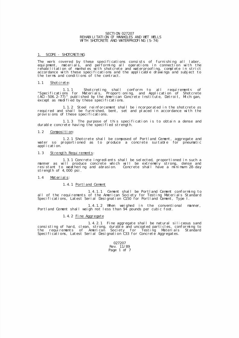
7/25/2019 City Standard Construction Specifications
http://slidepdf.com/reader/full/city-standard-construction-specifications 260/511
027207Rev. 11/ 89Page 1 of 7
SECTI ON 027207 REHABI LI TATI ON OF MANHOLES AND WET WELLSWI TH SHOTCRETE AND WATERPROOFI NG ( S- 74)
1. SCOPE - SHOTCRETI NG
The work covered by t hese speci f i cat i ons consi st s of f urni shi ng al l l abor ,equi pment , mat er i al s, and per f ormi ng al l oper at i ons i n connect i on wi t h t her ehabi l i t at i on of manhol es wi t h shot cret e and wat er pr oof i ng, compl et e i n st r i ctaccordance wi t h these speci f i cat i ons and the appl i cabl e dr awi ngs and subj ect t ot he ter ms and condi t i ons of t he cont r act .
1. 1 Shot cr et e:
1. 1. 1 Shot cret i ng shal l conf or m t o al l r equi r ement s of"Speci f i cat i ons f or Mat er i al s, Pr opor t i oni ng, and Appl i cat i on of Shot crete( ACI - 506. 2- 77) " publ i shed by t he Amer i can Concret e I nst i t ut e, Det r oi t , Mi chi gan,except as modi f i ed by t hese speci f i cat i ons.
1. 1. 2 St eel r ei nf or cement shal l be i ncor por at ed i n t he shot cret e asr equi r ed and shal l be f ur ni shed, bent , set and pl aced i n accordance wi t h t hepr ovi si ons of t hese speci f i cat i ons.
1. 1. 3 The pur pose of t hi s speci f i cat i on i s t o obt ai n a dense anddur abl e concret e havi ng t he speci f i ed st r engt h.
1. 2 Composi t i on:
1. 2. 1 Shotcr ete shal l be composed of Por t l and Cement , aggregate andwater so pr oport i oned as t o pr oduce a concr ete sui t abl e f or pneumati cappl i cat i on.
1. 3 St rengt h Requi rement s:
1. 3. 1 Concret e i ngr edi ent s shal l be sel ect ed, pr opor t i oned i n such amanner as wi l l produce concrete whi ch wi l l be ext remel y st r ong, dense andr esi st ant t o weat heri ng and abr asi on. Concr ete shal l have a mi ni mum 28- dayst r engt h of 4, 000 psi .
1. 4 Mat er i al s:
1. 4. 1 Port l and Cement
1. 4. 1. 1 Cement shal l be Por t l and Cement conf ormi ng t oal l of t he r equi r ement s of t he Amer i can Soci et y for Test i ng Mat er i al s St andar dSpeci f i cat i ons, Lat est Ser i al Desi gnat i on C150 f or Por t l and Cement , Type I .
1. 4. 1. 2 When wei ghed i n t he convent i onal manner ,Por t l and Cement shal l wei gh not l ess t han 94 pounds per cubi c f oot .
1. 4. 2 Fi ne Aggr egate
1. 4. 2. 1 Fi ne aggr egat e shal l be nat ur al si l i ceous sandconsi st i ng of hard, cl ean, st r ong, dur abl e and uncoat ed par t i cl es, conf or mi ng tot he r equi r ement s of Ameri can Soci ety f or Test i ng Materi al s St andardSpeci f i cat i ons, Lat est Ser i al Desi gnat i on C33 f or Concret e Aggr egat es.
7/25/2019 City Standard Construction Specifications
http://slidepdf.com/reader/full/city-standard-construction-specifications 261/511
027207Rev. 11/ 89Page 2 of 7
1. 4. 2. 2 Fi ne aggr egat e shal l not cont ai n l ess t han 3%nor more than 6%of moi st ure.
1. 4. 2. 3 Fi ne aggr egat e shal l be evenl y gr aded f r omf i ne t o coar se and shal l be wi t hi n t he f ol l owi ng l i mi t s:
Passi ng No. 3/ 8 si eve - 100% Passi ng No. 4 si eve - 95% t o 100%
Passi ng Go. 8 si eve - 80% t o 100%Passi ng No. 16 si eve - 50% t o 85%Passi ng No. 30 si eve - 25% t o 60%Passi ng No. 50 si eve - 10% t o 30%Passi ng No. 100 si eve - 2% t o 10%
1. 4. 3 Water
1. 4. 3. 1 Wat er used i n mi xi ng at t he nozzl e shal l bef r esh, cl ean, and f r ee f r om i nj ur i ous amount s of oi l , aci d, al kal i , veget abl e,sewage and/ or or gani c matt er. Water shal l be consi der ed as wei ghi ng 8. 33 poundsper gal l on.
1. 4. 4 Rei nf orcement
1. 4. 4. 1 Rei nf or cement bar s shal l conf or m t o t he l at estr equi r ement s of ASTM St andard Speci f i cat i ons, Ser i al Desi gnat i on A 615 f orDef ormed Bi l l et St eel Bar s f or Concret e
Rei nf orcement . Unl ess shown otherwi se on t he pl ans, al l bars shal l be Gr ade 40.
1. 4. 4. 2 St eel mesh r ei nf or cement shal l be el ect r i cal l ywel ded, col d dr awn, mi l d st eel f abr i c conf ormi ng t o t he l at est r equi rement s ofASTM St andar d Speci f i cat i ons, Ser i al Desi gnat i on A 185 f or Wel ded St eel Wi r eFabr i c f or Concret e Rei nf orcement . Mesh can be f abr i cat ed f r omcol d- dr awn st eelwi r e conf ormi ng t o t he r equi r ement s of t he l at est ASTM St andar d Speci f i cat i ons,Seri al Desi gnati on A 82. Unl ess ot herwi se shown on t he pl ans, mesh shal l be 2 x2 - WO. 9 x WO. 9 gal vani zed wel ded wi r e f abr i c.
1. 4. 5 St orage of Mat er i al s
1. 4. 5. 1 Cement shal l be st ored wi t h adequat epr ovi si ons f or t he pr event i on of absor pt i on of moi st ur e. I t shal l be st or ed i na manner t hat wi l l per mi t easy access f or i nspect i on and i dent i f i cat i on of eachshi pment.
1. 4. 5. 2 Aggr egat e shal l be st ockpi l ed at poi nt ssel ect ed t o pr ovi de maxi mum dr ai nage and t o pr event t he i ncl usi on of any f orei gnmat er i al dur i ng r ehandl i ng.
1. 4. 5. 3 On del i ver y t o t he si t e of t he wor k, t hest eel r ei nf orcement shal l be car ef ul l y bundl ed, t agged and st ored so the bar sf or any posi t i on i n t he work may be r eadi l y i dent i f i ed. Al l r ei nf or ci ng st eelshal l be st ored on approved materi al above t he ground.
1. 5 Sampl i ng and Test i ng Cement and Aggregat e
1. 5. 1 The Cont r act or shal l det er mi ne t he sour ce, ki nd andqual i t y of t he cement and aggregates t o be used i n t he work wel l i n advance oft he t i me schedul ed f or st ar t i ng the work and, when so di r ect ed, shal l submi tsuch i nf or mat i on f or appr oval bef or e star t i ng shot cret e operat i ons.
7/25/2019 City Standard Construction Specifications
http://slidepdf.com/reader/full/city-standard-construction-specifications 262/511
027207Rev. 11/ 89Page 3 of 7
1. 5. 2 The cost of t est i ng cement and aggr egates shal l be borneby t he Ci t y. Cer t i f i ed t est r epor t s and cer t i f i cat es, when so di r ected, shal lbe submi t t ed i n dupl i cate to the Engi neer and t o such other agenci es or personsas he may desi gnat e.
1. 5. 3 Wher e cement and aggr egate suppl i ers mai ntai n r egul arr ecogni zed t est i ng ser vi ces, cer t i f i ed copi es of such t est s shal l be submi t t edt o t he Engi neer. However, i n any case of doubt as t o t he accuracy and/ oradequacy of such t est s, t he Owner may requi r e that cement and aggr egates bet ested by a recogni zed commerci al t est i ng l aboratory whi ch has been sel ected byt he Cont r actor and appr oved by t he Owner. The t est i ng l aboratory shal l t hent est t he cement and aggregates and prepare wr i t t en r eport s showi ng the resul t sof such t est s on each shi pment . The l aborat or y shal l al so cer t i f y t hat t hemat er i al s covered by the report compl y i n al l r espect s wi t h t hesespeci f i cat i ons.
1. 5. 4 No cement or aggregat e whi ch f ai l s t o meet t her equi r ement s of t hese speci f i cat i ons shal l be i ncor por at ed i nt o t he wor k.
1. 6 Sur f ace Pr epar at i on
1. 6. 1 Unsound mat er i al s of const r uct i on and al l coat ed, scal y,
or unsound materi al shal l be removed by chi ppi ng wi t h pneumat i c hammers andchi sel s t o sound sur f ace; al l cracks and cavi t i es shal l be chi pped t o suchf ormat i on t hat t hei r si des f orm appr oxi mat el y a 45- degree angl e to the exposedsur f ace f or at l east one ( 1) i nch i n dept h. Al l ar eas to r ecei ve pneumat i cconcrete shal l be cl eaned by f l ushi ng or scour i ng wi t h water and compr essed ai r
j et s t o assur e r emoval of al l l oose par t i cl es. Al l areas of exi st i ng sur f acesshal l be gi ven a wet sandbl ast i ng wi t h t he shotcr ete equi pment and t he ai rpr essur e at t he cement gun shal l not be l ess than 50 psi or hydr obl ast @ mi n.6000 psi .
A caust i c wash compr i sed of sodi um hydr oxi de sol ut i on at a r at i o of onequar t of 50% Sodi um Hydroxi de Sol ut i on t o 100 gal l ons of wat er shal l be appl i edt o al l sur f aces. The mi xi ng, appl i cat i on, and removal of t he sol ut i on shal l bedone wi t h caut i on t o avoi d cont act wi t h body and i n a workmanl i ke manner. Thesol ut i on shal l r emai n on t he sur f ace f or at l east 15 mi nut es. Once t he sol ut i on
has been washed compl etel y of f , t he surf ace shal l be al l owed t o dr y bef oreappl i cat i on of r epl acement mat er i al s.
1. 6. 2 To i nsur e per f ect bond, t he newl y chi pped, sandbl ast ed,and washed surf ace shal l be t horoughl y moi st ened wi t h water pr i or t o appl i cat i onof shot cret e. I n no i nst ance shal l shotcret e be appl i ed i n an ar ea wher e f r eer unni ng wat er exi st s.
1. 7 Pr opor t i oni ng
1. 7. 1 Pr i or t o st ar t of shot cret i ng, t he Cont ract or shal lsubmi t t o the Engi neer t he r ecommended mi x as a rat i o of cement t o aggr egate.Recommended mi x shal l be on the basi s of t est data f r om pr i or experi ence andcapabl e of produci ng t he r equi r ed 4, 000 psi compr essi ve st r engt h. Provi ded data
submi t t ed i s adequate, no f ur t her t est i ng of r ecommended mi x wi l l be requi red. 1. 7. 2 The Cont r act or shal l pr ovi de al l equi pment necessary t ocont rol t he act ual amount s of al l mat er i al s ent er i ng i nt o t he concret e. Thet ypes of equi pment and methods used f or measur i ng materi al s shal l be subj ect t oappr oval .
7/25/2019 City Standard Construction Specifications
http://slidepdf.com/reader/full/city-standard-construction-specifications 263/511
027207Rev. 11/ 89Page 4 of 7
1. 8 Mi xi ng
1. 8. 1 Shotcr ete shal l be t horoughl y mi xed by machi ne and t henpassed t hr ough a si eve t o remove al l l ar ge par t i cl es bef ore pl aci ng i n hopper oft he cement gun. The mi xt ure shal l not be per mi t t ed t o become damp. Each bat chshoul d be ent i r el y di schar ged bef ore rechargi ng i s begun. The mi xer shal l becl eaned t horoughl y enough to remove al l adherent materi al s f r omt he mi xi ng vanesand f r om t he dr um at r egul ar i nt er val s.
1. 8. 2 Wat er shal l not be added t o t he mi x bef ore i t ent er s t hecement gun. Quant i t i es of wat er shal l be cont r ol l ed by a val ve at t he nozzl e oft he gun. Water cont ent shal l be adj ust ed as r equi red f or pr oper pl acement , butshal l i n no case exceed f our gal l ons of wat er per sack of cement , i ncl udi ng t hewater cont ai ned i n t he aggr egate.
1. 8. 3 Remi xi ng or t emper i ng shal l not be permi t t ed. Mi xedmateri al t hat has st ood 45 mi nut es wi t hout bei ng used shal l be di scarded.Rebound materi al s shal l not be r eused.
1. 9 Appl i cat i on
1. 9. 1 Shotcret e shal l not be pl aced on a f r ozen sur f ace nordur i ng f r eezi ng weat her . Shotcret e shal l not be pl aced when i t i s ant i ci pat ed
t hat t he temperat ure dur i ng t he f ol l owi ng 24 hours wi l l dr op bel ow 32 degr eesFahr enhei t .
1. 9. 2 Sequence of appl i cat i on may be f r ombott omt o t op or vi cever sa i f r ebound i s proper l y removed.
1. 9. 3 Cor ner s shal l be f i l l ed f i rst . "Shoot i ng" shal l be f r oman angl e as near per pendi cul ar t o the sur f ace as pr act i cabl e, wi t h t he nozzl ehel d approxi mat el y 3 f eet f r om t he wor k ( except i n conf i ned cont r ol ) . I f t hef l ow of mat er i al at t he nozzl e i s not uni f orm and sl ugs, sand spot s, or wetsl oughs r esul t , t he nozzl eman shal l di r ect t he nozzl e away f r om t he wor k unt i lt he f aul t y condi t i ons are cor r ect ed. Such def ect s shal l be r epl aced as the workpr ogresses.
1. 9. 4 Shot cret i ng shal l be suspended i f :
( 1) Ai r vel oci t y separ at es t he cement f r om t he sand at t he nozzl e.( 2) Temper ature approaches f r eezi ng and t he newl y pl aced shot cr ete
cannot be pr otected.
1. 9. 5 Shotcr et e shal l be appl i ed i n one or more l ayer s t o sucht ot al t hi ckness as requi r ed t o r est or e t he ar ea as det ai l ed over t he or i gi nall i nes of t he adj oi ni ng sur f ace, unl ess ot her wi se speci f i ed. Al l cavi t i es,depr essi ons, washout s, and si mi l ar f ai l ur es shal l be r ebui l t t o or i gi nal l i nesby use of shot crete rei nf orced wi t h wi re mesh; where t he cavi t y exceeds 4 i nchesi n dept h, a l ayer of mesh shal l be used f or each 3 i nches of dept h of shot cret e.However , i n no case shal l wi r e mesh be pl aced behi nd exi st i ng rei nf orcement .
1. 9. 6 The t i me i nt er val bet ween successi ve l ayer s i n sl opi ng,ver t i cal or over hangi ng wor k must be suf f i ci ent t o al l ow i ni t i al but not f i nal
set t o devel op. At t he t i me t he i ni t i al set i s devel opi ng, t he sur f ace shal l becl eaned t o remove t he t hi n f i l m of l ai t ance i n order t o pr ovi de a per f ect bondwi t h succeedi ng appl i cat i ons.
1. 10 Const r uct i on J oi nt s
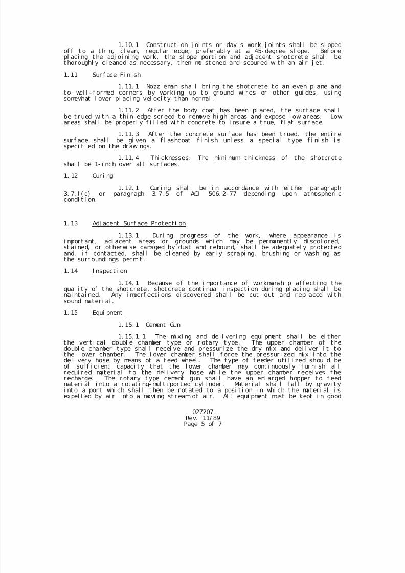
7/25/2019 City Standard Construction Specifications
http://slidepdf.com/reader/full/city-standard-construction-specifications 264/511
027207Rev. 11/ 89Page 5 of 7
1. 10. 1 Const r uct i on j oi nt s or day' s wor k j oi nt s shal l be sl opedof f t o a t hi n, cl ean, r egul ar edge, pr ef er abl y at a 45- degree sl ope. Bef or epl aci ng t he adj oi ni ng work, t he sl ope port i on and adj acent shotcret e shal l bet horoughl y cl eaned as necessary, t hen moi st ened and scour ed wi t h an ai r j et.
1. 11 Sur f ace Fi ni sh
1. 11. 1 Nozzl eman shal l br i ng t he shot cr ete t o an even pl ane andt o wel l - f ormed corner s by worki ng up t o gr ound wi r es or other gui des, usi ngsomewhat l ower pl aci ng vel oci t y than nor mal .
1. 11. 2 Af t er t he body coat has been pl aced, t he sur f ace shal lbe t r ued wi t h a thi n-edge scr eed t o remove hi gh areas and expose l ow areas. Lowar eas shal l be pr oper l y f i l l ed wi t h concrete to i nsur e a t r ue, f l at sur f ace.
1. 11. 3 Af t er t he concret e sur f ace has been t r ued, t he ent i r esur f ace shal l be gi ven a f l ashcoat f i ni sh unl ess a speci al t ype f i ni sh i sspeci f i ed on the dr awi ngs.
1. 11. 4 Thi cknesses: The mi ni mum t hi ckness of t he shotcret eshal l be 1- i nch over al l sur f aces.
1. 12 Cur i ng
1. 12. 1 Cur i ng shal l be i n accor dance wi t h ei t her par agr aph3. 7. l ( d) or paragr aph 3. 7. 5 of ACI 506. 2- 77 dependi ng upon atmospheri ccondi t i on.
1. 13 Adj acent Sur f ace Protect i on
1. 13. 1 Dur i ng pr ogr ess of t he work, where appear ance i si mpor t ant , adj acent areas or grounds whi ch may be per manent l y di scol ored,st ai ned, or otherwi se damaged by dust and r ebound, shal l be adequat el y protectedand, i f cont act ed, shal l be cl eaned by ear l y scrapi ng, br ushi ng or washi ng ast he surr oundi ngs per mi t .
1. 14 I nspect i on
1. 14. 1 Because of t he i mport ance of workmanshi p af f ect i ng t hequal i t y of t he shot crete, shot crete cont i nual i nspect i on dur i ng pl aci ng shal l bemai nt ai ned. Any i mperf ecti ons di scovered shal l be cut out and r epl aced wi t hsound materi al .
1. 15 Equi pment
1. 15. 1 Cement Gun
1. 15. 1. 1 The mi xi ng and del i ver i ng equi pment shal l be ei t hert he ver t i cal doubl e chamber t ype or r otary t ype. The upper chamber of t hedoubl e chamber t ype shal l r ecei ve and pr essur i ze the dr y mi x and del i ver i t t ot he l ower chamber. The l ower chamber shal l f orce t he pressur i zed mi x i nt o t he
del i ver y hose by means of a f eed wheel . The t ype of f eeder ut i l i zed shoul d beof suf f i ci ent capaci t y t hat t he l ower chamber may cont i nuousl y f ur ni sh al lr equi r ed materi al t o the del i ver y hose whi l e t he upper chamber r ecei ves t her echarge. The rotary t ype cement gun shal l have an enl arged hopper t o f eedmat eri al i nt o a r ot at i ng- mul t i por t ed cyl i nder . Mat er i al shal l f al l by gr avi t yi nt o a por t whi ch shal l t hen be r ot at ed t o a posi t i on i n whi ch t he mat er i al i sexpel l ed by ai r i nt o a movi ng st r eam of ai r . Al l equi pment must be kept i n good
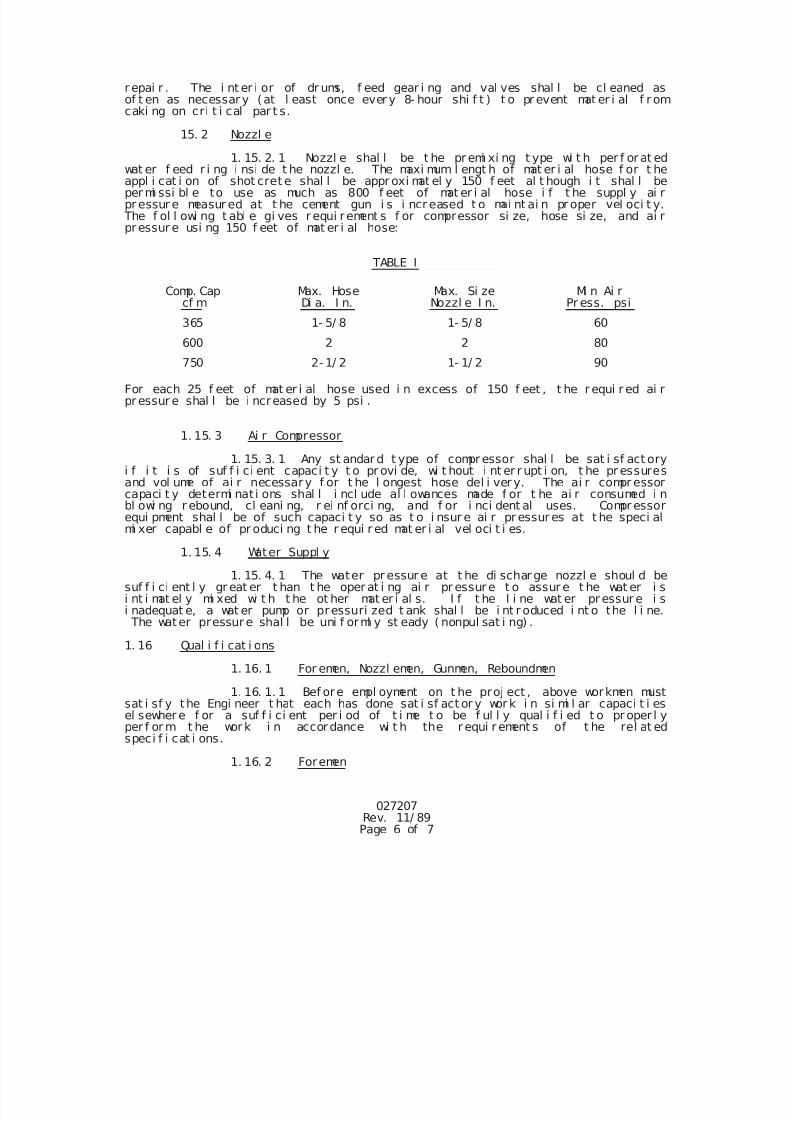
7/25/2019 City Standard Construction Specifications
http://slidepdf.com/reader/full/city-standard-construction-specifications 265/511
027207Rev. 11/ 89Page 6 of 7
r epai r . The i nt er i or of dr ums, f eed gear i ng and val ves shal l be cl eaned asof t en as necessar y (at l east once ever y 8- hour shi f t ) t o pr event mat er i al f r omcaki ng on cri t i cal par t s.
15. 2 Nozzl e
1. 15. 2. 1 Nozzl e shal l be t he pr emi xi ng t ype wi t h per f or at edwat er f eed r i ng i nsi de t he nozzl e. The maxi mum l engt h of mat er i al hose f or t heappl i cat i on of shot cret e shal l be appr oxi mat el y 150 f eet al t hough i t shal l beper mi ssi bl e to use as much as 800 f eet of mat er i al hose i f t he suppl y ai rpr essur e measur ed at t he cement gun i s i ncr eased t o mai nt ai n pr oper vel oci t y.
The f ol l owi ng t abl e gi ves r equi rement s f or compressor si ze, hose si ze, and ai rpr essur e usi ng 150 f eet of mat er i al hose:
TABLE I
Comp. Capcf m
Max. HoseDi a. I n.
Max. Si zeNozzl e I n.
Mi n Ai rPr ess. psi
365 1- 5/ 8 1- 5/ 8 60
600 2 2 80
750 2- 1/ 2 1- 1/ 2 90
For each 25 f eet of mat er i al hose used i n excess of 150 f eet , t he r equi r ed ai rpr essur e shal l be i ncreased by 5 psi .
1. 15. 3 Ai r Compressor
1. 15. 3. 1 Any st andar d t ype of compr essor shal l be sat i sf act oryi f i t i s of suf f i ci ent capaci t y t o pr ovi de, wi t hout i nt er r upt i on, t he pr essuresand vol ume of ai r necessary f or t he l ongest hose del i ver y. The ai r compr essorcapaci t y determi nat i ons shal l i ncl ude al l owances made f or t he ai r consumed i nbl owi ng r ebound, cl eani ng, r ei nf orci ng, and f or i nci dent al uses. Compr essorequi pment shal l be of such capaci t y so as t o i nsur e ai r pr essur es at t he speci al
mi xer capabl e of pr oduci ng t he r equi r ed mat er i al vel oci t i es.
1. 15. 4 Water Suppl y
1. 15. 4. 1 The water pr essur e at t he di schar ge nozzl e shoul d besuf f i ci ent l y gr eat er t han t he oper at i ng ai r pr essur e t o assur e t he wat er i si nt i mat el y mi xed wi t h t he ot her mat er i al s. I f t he l i ne wat er pr essur e i si nadequat e, a wat er pump or pressuri zed t ank shal l be i nt r oduced i nt o the l i ne. The water pressur e shal l be uni f orml y st eady ( nonpul sat i ng) .
1. 16 Qual i f i cat i ons
1. 16. 1 For emen, Nozzl emen, Gunmen, Reboundmen
1. 16. 1. 1 Bef ore empl oyment on t he proj ect , above workmen mustsat i sf y the Engi neer t hat each has done sat i sf act or y wor k i n si mi l ar capaci t i esel sewher e f or a suf f i ci ent per i od of t i me t o be f ul l y qual i f i ed t o pr oper l yper f or m t he wor k i n accordance wi t h the r equi r ement s of t he rel at edspeci f i cat i ons.
1. 16. 2 Foremen
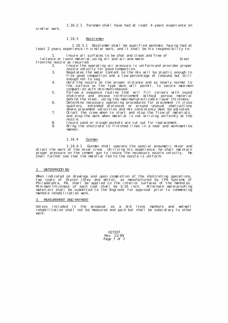
7/25/2019 City Standard Construction Specifications
http://slidepdf.com/reader/full/city-standard-construction-specifications 266/511
027207Rev. 11/ 89Page 7 of 7
1. 16. 2. 1 For eman shal l have had at l east 4 years experi ence onsi mi l ar wor k.
1. 16. 3 Nozzl emen
1. 16. 3. 1 Nozzl emen shal l be qual i f i ed workmen, havi ng had atl east 2 year s exper i ence i n si mi l ar wor k, and i t shal l be hi s r esponsi bi l i t y t o:
1. I nsur e al l surf aces t o be shot and cl ean and f ree ofl ai t ance or l oose mat er i al , usi ng ai r and ai r - and- wat er bl ast
f r om t he nozzl e as r equi r ed.2. I nsur e t he oper at i ng ai r pr essure i s uni f or m and pr ovi des pr oper
nozzl e vel oci t y f or good compact i on.3. Regul at es t he wat er cont ent so t he mi x wi l l be pl ast i c enough t o
f i ve good compact i on and a l ow percent age of r ebound but st i l lenough not t o sag.
4. Hol d t he nozzl e at t he pr oper di st ance and as near l y normal t ot he sur f ace as t he type work wi l l permi t , t o secur e maxi mumcompact i on wi t h mi ni mumr ebound.
5. Fol l ow a sequence r out i ne t hat wi l l f i l l cor ner s wi t h soundshot cr ete and encase r ei nf orcement wi t hout porous mater i albehi nd t he st eel , usi ng t he maxi mum pr act i cabl e l ayer t hi ckness.
6. Determi ne necessar y operat i ng pr ocedur es f or pl acement i n cl osequart ers, ext ended di st ances or ar ound unusual obst r uct i onswher e pl acement vel oci t i es and mi x consi st ency must be adj ust ed.
7. Di r ect the crew when t o st ar t and st op t he f l ow of mat er i al s,and stop t he work when mat er i al i s not ar r i vi ng uni f orml y at t henozzl e.
8. I nsur e sand or sl ough pocket s ar e cut out f or r epl acement .9. Br i ng t he shotcret e t o f i ni shed l i nes i n a neat and workmanl i ke
manner .
1. 16. 4 Gunman
1. 16. 4. 1 Gunman shal l operate t he speci al pneumat i c mi xer anddi r ect t he wor k of t he mi xer cr ew. Ut i l i zi ng hi s exper i ence, he shal l mai nt ai n
pr oper pr essur e on t he cement gun t o i nsure the necessary nozzl e vel oci t y. Heshal l f ur t her see t hat t he mat er i al f ed t o t he nozzl e i s uni f or m.
2. WATERPROOFI NG
When i ndi cated on dr awi ngs and upon compl et i on of t he shotcr et i ng operat i ons,t wo coat s of Drycon ( Gr ey and whi t e) , as manufactured by I PA Syst ems ofPhi l adel phi a, PA, shal l be appl i ed t o t he i nt er i or sur f aces of t he manhol es.Mi ni mum t hi ckness of each coat shal l be 1/ 16 i nch. Al t er nat e wat er proof i ngmateri al s shal l be submi t t ed t o the Engi neer f or appr oval pr i or t o commenci ngmanhol e rehabi l i t at i on work.
3. MEASUREMENT AND PAYMENT
Unl ess i ncl uded i n the pr oposal as a bi d i t em, manhol e and wet wel lr ehabi l i t at i on shal l not be measur ed and pai d but shal l be subsi di ar y t o otherwor k.
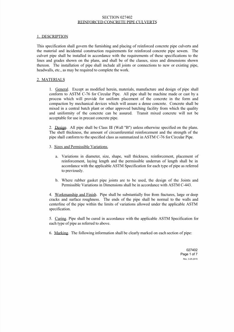
7/25/2019 City Standard Construction Specifications
http://slidepdf.com/reader/full/city-standard-construction-specifications 267/511
SECTION 027402
REINFORCED CONCRETE PIPE CULVERTS
1. DESCRIPTION
This specification shall govern the furnishing and placing of reinforced concrete pipe culverts and
the material and incidental construction requirements for reinforced concrete pipe sewers. Theculvert pipe shall be installed in accordance with the requirements of these specifications to the
lines and grades shown on the plans, and shall be of the classes, sizes and dimensions shown
thereon. The installation of pipe shall include all joints or connections to new or existing pipe,
headwalls, etc., as may be required to complete the work.
2. MATERIALS
1. General. Except as modified herein, materials, manufacture and design of pipe shall
conform to ASTM C-76 for Circular Pipe. All pipe shall be machine made or cast by a
process which will provide for uniform placement of the concrete in the form and
compaction by mechanical devices which will assure a dense concrete. Concrete shall bemixed in a central batch plant or other approved batching facility from which the quality
and uniformity of the concrete can be assured. Transit mixed concrete will not be
acceptable for use in precast concrete pipe.
2. Design. All pipe shall be Class III (Wall "B") unless otherwise specified on the plans.
The shell thickness, the amount of circumferential reinforcement and the strength of the
pipe shall conform to the specified class as summarized in ASTM C-76 for Circular Pipe.
3. Sizes and Permissible Variations.
a. Variations in diameter, size, shape, wall thickness, reinforcement, placement ofreinforcement, laying length and the permissible underrun of length shall be in
accordance with the applicable ASTM Specification for each type of pipe as referred
to previously.
b. Where rubber gasket pipe joints are to be used, the design of the Joints and
Permissible Variations in Dimensions shall be in accordance with ASTM C-443.
4. Workmanship and Finish. Pipe shall be substantially free from fractures, large or deep
cracks and surface roughness. The ends of the pipe shall be normal to the walls and
centerline of the pipe within the limits of variations allowed under the applicable ASTM
specification.
5. Curing. Pipe shall be cured in accordance with the applicable ASTM Specification for
each type of pipe as referred to above.
6. Marking. The following information shall be clearly marked on each section of pipe:
027402
Page 1 of 7
Rev. 3-25-2015
7/25/2019 City Standard Construction Specifications
http://slidepdf.com/reader/full/city-standard-construction-specifications 268/511
a. The class of pipe.
b. The date of manufacture.
c. The name or trademark of the manufacturer.
d. Marking shall be indented on the pipe section or painted thereon with waterproof paint.
7. Minimum Age for Shipment. Pipe shall be considered ready for shipment when it
conforms to the requirements of the tests specified herein.
8. Inspection. The quality of materials, the process of manufacture, and the finished pipe
shall be subject to inspection and approval by the Engineer at the pipe manufacturing plant.
In addition, the finished pipe shall be subject to further inspection by the Engineer at the
project site prior to and during installation.
9. Causes for Rejection. Pipe shall be subject to rejection on account of failure to conformto any of the specification requirements. Individual sections of pipe may be rejected
because of any of the following:
a. Fractures or cracks passing through the shell, except for a single end crack that does
not exceed the depth of the joint.
b. Defects that indicate imperfect proportioning, mixing and molding.
c. Surface defects indicating honeycombed or open texture.
d. Damaged ends, where such damage would prevent making a satisfactory joint.
10. Repairs. Pipe may be repaired if necessary, because of occasional imperfections in
manufacture or accidental injury during the handling, and will be acceptable if, in the
opinion of the Engineer, the repairs are sound and properly finished and cured and the
repaired pipe conforms to the requirements of the specifications.
11. Rejections. All rejected pipe shall be plainly marked by the Engineer and shall be
replaced by the Contractor with pipe that meets the requirements of these specifications.
Such rejected pipe shall be removed immediately from the worksite.
12. Jointing Materials. Unless otherwise specified on the plans, the Contractor shall havethe option of making the joints by any of the following methods:
a. Ram-Nek, a pre-formed plastic base joint material manufactured by K. T. Knyder
Company, Houston, Texas, or an approved equal. Use of Talcote as joint material
will not be not permitted. Ram-Nek joint material and primer shall be supplied for
027402
Page 2 of 7
Rev. 3-25-2015
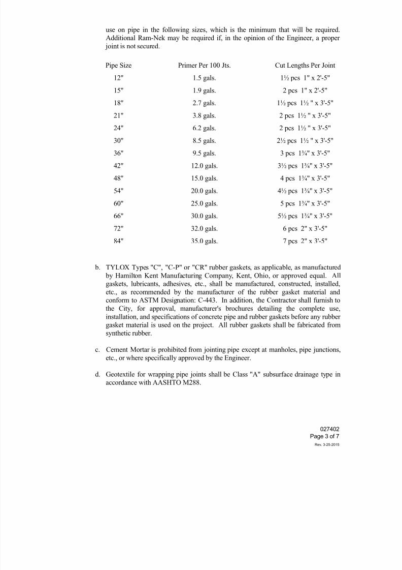
7/25/2019 City Standard Construction Specifications
http://slidepdf.com/reader/full/city-standard-construction-specifications 269/511
use on pipe in the following sizes, which is the minimum that will be required.
Additional Ram-Nek may be required if, in the opinion of the Engineer, a proper
joint is not secured.
Pipe Size Primer Per 100 Jts. Cut Lengths Per Joint
12" 1.5 gals. 1½ pcs 1" x 2'-5"
15" 1.9 gals. 2 pcs 1" x 2'-5"
18" 2.7 gals. 1½ pcs 1½ " x 3'-5"
21" 3.8 gals. 2 pcs 1½ " x 3'-5"
24" 6.2 gals. 2 pcs 1½ " x 3'-5"
30" 8.5 gals. 2½ pcs 1½ " x 3'-5"
36" 9.5 gals. 3 pcs 1¾" x 3'-5"
42" 12.0 gals. 3½ pcs 1¾" x 3'-5"
48" 15.0 gals. 4 pcs 1¾" x 3'-5"54" 20.0 gals. 4½ pcs 1¾" x 3'-5"
60" 25.0 gals. 5 pcs 1¾" x 3'-5"
66" 30.0 gals. 5½ pcs 1¾" x 3'-5"
72" 32.0 gals. 6 pcs 2" x 3'-5"
84" 35.0 gals. 7 pcs 2" x 3'-5"
b. TYLOX Types "C", "C-P" or "CR" rubber gaskets, as applicable, as manufactured by Hamilton Kent Manufacturing Company, Kent, Ohio, or approved equal. All
gaskets, lubricants, adhesives, etc., shall be manufactured, constructed, installed,
etc., as recommended by the manufacturer of the rubber gasket material and
conform to ASTM Designation: C-443. In addition, the Contractor shall furnish to
the City, for approval, manufacturer's brochures detailing the complete use,
installation, and specifications of concrete pipe and rubber gaskets before any rubber
gasket material is used on the project. All rubber gaskets shall be fabricated from
synthetic rubber.
c. Cement Mortar is prohibited from jointing pipe except at manholes, pipe junctions,
etc., or where specifically approved by the Engineer.
d. Geotextile for wrapping pipe joints shall be Class "A" subsurface drainage type in
accordance with AASHTO M288.
027402
Page 3 of 7
Rev. 3-25-2015
7/25/2019 City Standard Construction Specifications
http://slidepdf.com/reader/full/city-standard-construction-specifications 270/511
3. CONSTRUCTION METHODS
Reinforced concrete pipe culverts shall be constructed from the specified materials in accordance
with the following methods and procedures:
1. Excavation. All excavation shall be in accordance with the requirements of City
Standard Specification Section 022020 "Excavation and Backfill for Utilities," except
where tunneling or jacking methods are shown on the plans or permitted by the Engineer.When pipe is laid in a trench, the trench, when completed and shaped to receive the pipe,
shall be of sufficient width to provide free working space for satisfactory bedding and
jointing and thorough tamping of the backfill and bedding material under and around the
pipe. The Contractor shall make such temporary provisions as may be necessary to insure
adequate drainage of the trench and bedding during the construction operation. Pipe shall
be placed such that the identification markings are visible at the top prior to backfill.
2. Bedding. The pipe shall be bedded in accordance with the bedding details shown on the
drawings. Bedding shall not be measured for pay, but shall be subsidiary to other work.
If the subgrade of the trench is unstable, even if this condition occurs at relatively shallowdepths, full encasement of the pipe with crushed stone shall be required.
3. Laying Pipe. Unless otherwise authorized by the Engineer, the laying of pipe on the
prepared foundation shall be started at the outlet (downstream) end with the spigot or
tongue end pointing downstream, and shall proceed toward the inlet (upstream) end with the
abutting sections properly matched, true to the established lines and grades. Where bell and
spigot pipe are used, cross trenches shall be cut in the foundation to allow the barrel of the
pipe to rest firmly upon the prepared bed. These cross trenches shall be not more than two
inches larger than the bell ends of the pipe. Proper facilities shall be provided for hoisting
and lowering the sections of pipe into the trench without disturbing the prepared foundation
and the sides of the trench. The ends of the pipe shall be carefully cleaned before the pipe is placed. As each length of pipe is laid, the mouth of the pipe shall be protected to prevent
the entrance of earth or bedding material. The pipe shall be fitted and matched so that when
laid in the bed, it shall form a smooth, uniform conduit. When elliptical pipe with circular
reinforcing or circular pipe with elliptical reinforcing is used, the pipe shall be laid in the
trench in such position that the markings "TOP" or "BOTTOM" shall not be more than 5
degrees from the vertical plane through the longitudinal axis of the pipe.
For pipe over 42 inches in diameter, the Contractor may drill two holes not larger than 2
inches in diameter, in the top of each section of the pipe, to aid in lifting and placing.
The holes shall be neatly drilled, without spalling of the concrete, and shall be done withoutthe cutting of any reinforcement. After the pipe is laid, the holes shall be filled with mortar
and properly cured, and placed such that they are visible from the top for inspection prior to
backfill.
Multiple installations of reinforced concrete pipe shall be laid with the center lines of
027402
Page 4 of 7
Rev. 3-25-2015
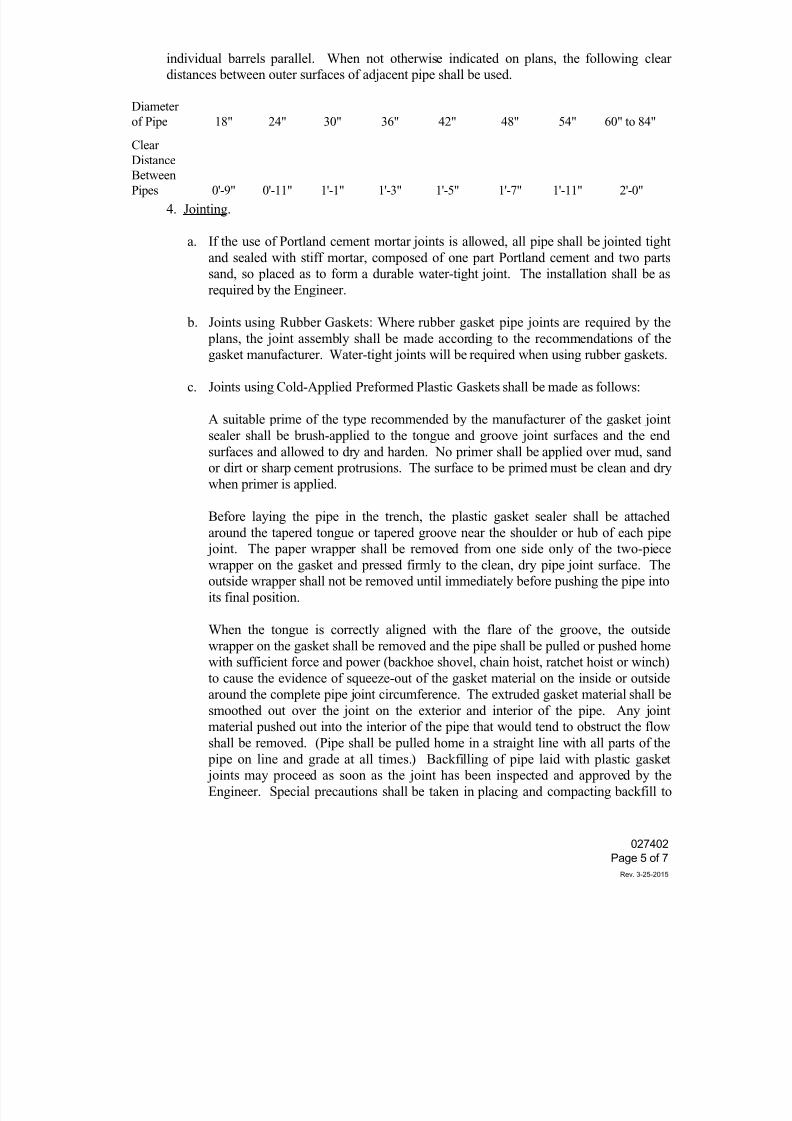
7/25/2019 City Standard Construction Specifications
http://slidepdf.com/reader/full/city-standard-construction-specifications 271/511
individual barrels parallel. When not otherwise indicated on plans, the following clear
distances between outer surfaces of adjacent pipe shall be used.
Diameter
of Pipe 18" 24" 30" 36" 42" 48" 54" 60" to 84"
Clear
Distance
BetweenPipes 0'-9" 0'-11" 1'-1" 1'-3" 1'-5" 1'-7" 1'-11" 2'-0"
4. Jointing.
a. If the use of Portland cement mortar joints is allowed, all pipe shall be jointed tight
and sealed with stiff mortar, composed of one part Portland cement and two parts
sand, so placed as to form a durable water-tight joint. The installation shall be as
required by the Engineer.
b. Joints using Rubber Gaskets: Where rubber gasket pipe joints are required by the
plans, the joint assembly shall be made according to the recommendations of the
gasket manufacturer. Water-tight joints will be required when using rubber gaskets.
c. Joints using Cold-Applied Preformed Plastic Gaskets shall be made as follows:
A suitable prime of the type recommended by the manufacturer of the gasket joint
sealer shall be brush-applied to the tongue and groove joint surfaces and the end
surfaces and allowed to dry and harden. No primer shall be applied over mud, sand
or dirt or sharp cement protrusions. The surface to be primed must be clean and dry
when primer is applied.
Before laying the pipe in the trench, the plastic gasket sealer shall be attached
around the tapered tongue or tapered groove near the shoulder or hub of each pipe joint. The paper wrapper shall be removed from one side only of the two-piece
wrapper on the gasket and pressed firmly to the clean, dry pipe joint surface. The
outside wrapper shall not be removed until immediately before pushing the pipe into
its final position.
When the tongue is correctly aligned with the flare of the groove, the outside
wrapper on the gasket shall be removed and the pipe shall be pulled or pushed home
with sufficient force and power (backhoe shovel, chain hoist, ratchet hoist or winch)
to cause the evidence of squeeze-out of the gasket material on the inside or outside
around the complete pipe joint circumference. The extruded gasket material shall be
smoothed out over the joint on the exterior and interior of the pipe. Any jointmaterial pushed out into the interior of the pipe that would tend to obstruct the flow
shall be removed. (Pipe shall be pulled home in a straight line with all parts of the
pipe on line and grade at all times.) Backfilling of pipe laid with plastic gasket
joints may proceed as soon as the joint has been inspected and approved by the
Engineer. Special precautions shall be taken in placing and compacting backfill to
027402
Page 5 of 7
Rev. 3-25-2015
7/25/2019 City Standard Construction Specifications
http://slidepdf.com/reader/full/city-standard-construction-specifications 272/511
avoid damage to the joints.
When the atmospheric temperature is below 60 degrees F, plastic joint seal gaskets
shall either be stored in an area warmed to above 70 degrees F, or artificially
warmed to this temperature in a manner satisfactory to the Engineer. Gaskets shall
then be applied to pipe joints immediately prior to placing pipe in the trench,
followed by connection to previously laid pipe.
d. Pipe Joints for storm sewers shall be wrapped with geotextile material. The
geotextile wrap shall be at least 2 feet wide and shall be centered on each joint.
5. After the pipe has been placed, bedded and jointed as specified, filling and/or backfilling
shall be done in accordance with the applicable requirements of City Standard Specification
Section 022020 "Excavation and Backfill for Utilities." If unstable conditions are
encountered, fully encase the pipe with crushed stone as described above. When mortar
joints are allowed, no fill or backfill shall be placed until the jointing material has been
cured for at least six (6) hours.
Special precautions shall be taken in placing and compacting the backfill to avoid anymovement of the pipe or damage to the joints. For side drain culverts and all other culverts
where joints consist of materials other than mortar, immediate backfilling will be permitted.
6. Unless otherwise shown on the plans or permitted in writing by the Engineer, no heavy
earth moving equipment will be permitted to haul over the structure until a minimum of 4
feet of permanent or temporary compacted fill has been placed thereon. Pipe damaged by
the Contractor's equipment shall be removed and replaced by the Contractor at no additional
cost.
7. Cleaning and Television Inspection. All enclosed reinforced concrete pipe and manholes
installed on this project shall be cleaned and televised in accordance with City StandardSpecification Section 027611 "Cleaning and Televised Inspection of Conduits."
4. MEASUREMENT
Unless otherwise specified on the Bid Form, reinforced concrete pipe will be measured by the
linear foot. Such measurement will be made between the ends of the pipe barrel along its central
axis. Where spurs or branches, or connections to existing pipe lines are involved, measurement
of the spur or new connecting pipe will be made from the intersection of its center axis with the
outside surfaces of the pipe into which it connects. Where inlets, headwalls, catch basins,
manholes, junction chambers, or other structures are included in lines of pipe, that length of pipe
tying into the structure wall will be included for measurement but no other portion of thestructure length or width will be so included.
For multiple pipes, the measured length will be the sum of the lengths of the barrels measured as
prescribed above.
027402
Page 6 of 7
Rev. 3-25-2015
7/25/2019 City Standard Construction Specifications
http://slidepdf.com/reader/full/city-standard-construction-specifications 273/511
5. PAYMENT
Payment for reinforced concrete pipe measured as prescribed above will be made at the contract
unit price bid per linear foot for the various sizes of "Reinforced Concrete Pipe" of the class
specified.
Payment shall be full compensation for furnishing and transporting the pipe; hauling and placing of
earth cushion material where required for bedding pipe; for the preparation and shaping of beds; forhauling, placing and jointing of pipes; for furnishing and installing geotextile pipe joint wrapping;
for end finish; for all connections to existing and new structures; for cleaning and television
inspection; and for all other items of materials, labor, equipment, tools, excavation, backfill and
incidentals necessary to complete the culvert or storm sewer in accordance with the plans and these
specifications.
027402
Page 7 of 7
Rev. 3-25-2015
7/25/2019 City Standard Construction Specifications
http://slidepdf.com/reader/full/city-standard-construction-specifications 274/511
027404Page 1 of 3
Rev. 10-30-2014
SECTION 027404
CONCRETE BOX CULVERTS
1. DESCRIPTION
This specification shall govern all work required for constructing, furnishing, and installing
reinforced concrete box culverts required to complete the project.
All reinforced concrete boxes for this project shall be precast concrete in accordance with TxDOT
Standards for precast box culverts and the details shown on the drawings for the appropriate height
of fill, and design shall conform to ASTM C1577.
Alternate designs of precast boxes will be considered for approval upon submission of shop
drawings detailing the box and certifications that the box, as designed, is structurally comparable to
or better than the box shown in the contract drawings and is designed to support HS20 loading per
ASSHTO M273. The shop drawings and certifications shall be signed and sealed by a Texas
registered professional engineer.
2. MATERIALS
1. Concrete. Unless otherwise shown on the plans, Class "C" concrete shall be used for cast-in-
place boxes, conforming to the requirements of City Standard Specification Section 030020
"Portland Cement Concrete" and City Standard Specification Section 038000 "Concrete
Structures", except that Class "S" concrete will be required for top slabs of direct traffic cast-
in-place boxes.
Concrete for precast (machine-made) boxes shall meet the requirements of ASTM C76
Sections: "Cement", "Aggregates" and "Mixture", and shall have a minimum 28-day
compressive strength of 5,000 psi.
2. Reinforcement. Reinforcing steel shall conform to the requirements of City Standard
Specification Section 032020 "Reinforcing Steel" and the details shown on the plans.
3. Jointing. Materials for jointing shall conform to the requirements of City Standard
Specification Section 027402 "Reinforced Concrete Pipe Culverts".
4. Membrane Curing. Materials for membrane curing shall conform to City Standard
Specification Section 038000 "Concrete Structures".
5. Geotextile. Geotextile fabric for wrapping joints shall be Class 1 geotextile for subsurface
drainage with an average opening size (AOS) of 0.22mm and in accordance with AASHTOM288.
3. FABRICATION
The requirement of City Standard Specification Section 030020 "Portland Cement Concrete" and
City Standard Specification Section 038000 "Concrete for Structures" shall govern for cast-in-place
concrete box culverts and for precast (formed) boxes except where otherwise specified herein.
7/25/2019 City Standard Construction Specifications
http://slidepdf.com/reader/full/city-standard-construction-specifications 275/511
027404Page 2 of 3
Rev. 10-30-2014
Forms for precast (machine-made) boxes shall be made of steel. Forms for cast-in-place boxes and
precast (formed) boxes may be either wood or steel.
Forms shall be mortar-tight and of sufficient strength to prevent excessive bulging or misalignment
of adjacent boxes. They shall be constructed to permit their removal without damage to the
concrete. Offsets at form joints shall not exceed one-eighth inch (1/8"). Forms shall be clean and
free of extraneous matter when concrete is placed.
Positive means of supporting steel cages in place throughout forming and concrete placement shall
be required and subject to the approval of the Engineer. Welding of reinforcing steel will be
permitted only where shown on the plans. Welding shall be done by a qualified welder and shall
conform to industry standards.
Precast (machine-made) boxes shall be cast by a process which will provide for uniform placement
of the concrete in the forms and compaction by mechanical devices which will assure dense
concrete. Concrete shall be mixed in a central batch plant or other approved batching facility from
which the quality and uniformity of the concrete can be assured. Transit mixed concrete shall not be
acceptable for use in precast (machine-made) boxes.
4. TESTING AND CERTIFICATION
1. Physical Requirements. Precast boxes shall meet the requirement of ASTM C1577. Testing
shall be done by a materials engineering testing laboratory which meets the requirements for
membership in the American Council of Independent Laboratories.
2. Fabrication Tolerances. Precast boxes shall conform to the following tolerances:
When two box sections are fitted together on a flat surface, in proper alignment and in the
position they will be installed, the longitudinal opening at any point shall not exceed
one inch (1”).
Not more than four lifting holes may be provided in each box to facilitate handling. They may be
cast-in, cut into the fresh concrete after form removal or drilled, and shall not be more than 2 inches
in diameter or 2 inches square. Cutting or displacement of the reinforcement will not be permitted.
Spalled areas around the holes shall be repaired. Concrete boxes shall be given an "Ordinary
Surface Finish" in accordance with Section 038000 "Concrete Structures".
3. Certification. Certification of quality shall be provided with each delivery of materials to the
job site by the manufacturer. Certification shall be a written report by the materials
engineering testing laboratory.
5. DEFECTS AND REPAIRS
Fine cracks or checks on the surface of the member which do not extend to the plane of the nearest
reinforcement will not be cause for rejection unless they are numerous and extensive. Cracks which
extend into the plane of the reinforcing steel but are acceptable otherwise, shall be repaired in an
approved manner.
7/25/2019 City Standard Construction Specifications
http://slidepdf.com/reader/full/city-standard-construction-specifications 276/511
027404Page 3 of 3
Rev. 10-30-2014
Small damaged or honeycombed areas which are purely surficial in nature may be repaired.
Excessive damage, honeycombing or cracking will be subject to structural review. Repairs shall be
sound, properly finished, and cured in conformance with the pertinent specifications. When fine
cracks or hairline cracks on the surface indicate poor curing practices, further production of precast
boxes shall be discontinued until corrections are made and proper curing provided.
6. CONSTRUCTION METHODS
Excavation and backfill shall be in accordance with City Standard Specification Section 022020
"Excavation and Backfill for Utilities" and City Standard Details for Stormwater. Bedding for
precast concrete box culverts located under pavements shall consist of 6 inches of cement-stabilized
sand containing a minimum of 1½ sacks of Standard Type I or Type II Portland cement per cubic
yard of sand and compacted to not less than 95% Standard Proctor density.
Unless otherwise shown on the plans, the Contractor may use any of the jointing materials, except
rubber gaskets, and shall comply with the jointing requirements specified in the City Standard
Specification Section 027402 "Reinforced Concrete Pipe Culverts".
All box joints shall be wrapped with geotextile fabric. The wrap shall be at least two (2) feet wide
and centered on the joints.
Lifting holes shall be filled with mortar or concrete and cured to the satisfaction of the Engineer.
7. MEASUREMENT AND PAYMENT
Unless otherwise specified on the Bid Form, concrete box culverts shall be measured by the linear
foot for each size of box installed. The measurement will be made between the ends of the box
along the centerline. For boxes used in the multiple barrel structures, the measured length will bethe sum of the lengths of all barrels.
Payment shall be made at the contract bid price and shall fully compensate the Contractor for
furnishing, transporting and installing the box culverts; for bedding materials and bed preparation
including compaction; for excavation and backfill of trenches; for all connections to existing and
new structures; and for all labor, materials, tools, equipment and incidentals required to complete the
work as shown on the contract drawings and as specified herein.
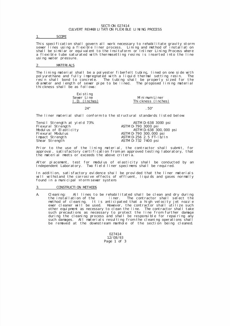
7/25/2019 City Standard Construction Specifications
http://slidepdf.com/reader/full/city-standard-construction-specifications 277/511
02741412/ 08/ 93
Page 1 of 3
SECTI ON 027414CULVERT REHABI LI TATI ON FLEXI BLE LI NI NG PROCESS
1. SCOPE
Thi s speci f i cat i on shal l govern al l work necessary t o rehabi l i t ate gravi t y st ormsewer l i nes usi ng a f l exi bl e l i ner process. Li ni ng and met hod of i nst al l at i on
shal l be si mi l ar or equi val ent t o t he I nsi t uf orm or I nl i ner Li ni ng Process wher ea f l exi bl e t ube sat ur at ed wi t h t her moset t i ng r esi ns i s i nser t ed i nt o t he l i neusi ng water pr essure.
2. MATERI ALS
The l i ni ng mater i al shal l be a pol yest er f i ber f el t t ubi ng, l i ned on one si de wi t hpol yur et hane and f ul l y i mpr egnat ed wi t h a l i qui d t her mal set t i ng r esi n. Ther esi n shal l bond t o concret e. The t ubi ng shal l be pr oper l y si zed f or t hedi amet er and l engt h of sewer pi pe t o be l i ned. The pr oposed l i ni ng mater i alt hi ckness shal l be as f ol l ows:
Exi st i ngSewer Li ne Mi ni mum Li nerI . D. ( I nches) Thi ckness ( I nches)
24" . 50"
The l i ner mat er i al shal l conf or m t o t he st r uct ural st andar ds l i st ed bel ow:
Tensi l St r engt h at yi el d 73% ASTM D- 638 3000 psiFl exur al St r engt h ASTM D- 790 3000 psiModul us of El ast i ci t y ASTM D- 638 300, 000 psiFl exur al Modul us ASTM D- 790 300, 000 psiI mpact St r engt h ASTM D- 256 2. 5 FT- l b/ I nShear St r ength ASTM D- 732 7400 psi
Pr i or t o the use of t he l i ni ng mat er i al , t he cont r actor shal l submi t , f orappr oval , sat i sf actory cer t i f i cat i on f r om an appr oved t est i ng l abor at or y, t hat
t he mat eri al meet s or exceeds t he above cr i t er i a.
Af t er pl acement , t est f or modul us of el ast i ci t y shal l be conduct ed by anI ndependent Labor at or y. Two f i el d l i ner speci mens shal l be r equi r ed.
I n addi t i on, sat i sf act or y evi dence shal l be pr ovi ded t hat t he l i ner mat er i al swi l l wi t hst and t he cor r osi ve ef f ect s of ef f l uent , l i qui ds and gases nor mal l yf ound i n a muni ci pal st orm sewer syst em.
3. CONSTRUCTI ON METHODS
A. Cl eani ng: Al l l i nes t o be r ehabi l i t at ed shal l be cl ean and dr y dur i ngt he i nst al l at i on of t he l i ner . The cont r actor shal l sel ect t hemet hod of cl eani ng. I t i s ant i ci pat ed t hat a hi gh vel oci t y j et nozzl e
ewer cl eaner wi l l be used. However , t he cont r act or shal l ut i l i ze suchother equi pment as necessary to cl ean t he l i ne. The cont r act or shal l t akesuch pr ecaut i ons as necessary t o pr otect t he l i ne f r om f ur t her damagedur i ng the cl eani ng pr ocess and shal l be responsi bl e f or r epai r i ng anysuch damages. Al l mat er i al s resul t i ng f r om t he cl eani ng oper at i ons shal lbe r emoved at t he downst r eam manhol e of t he sect i on bei ng cl eaned.
7/25/2019 City Standard Construction Specifications
http://slidepdf.com/reader/full/city-standard-construction-specifications 278/511
02741412/ 08/ 93
Page 2 of 3
Di sposal of t hi s mat er i al shal l be as pr ovi ded i n t he Speci al Pr ovi si ons.
B. I nspect i on: Upon compl et i on of t he cl eani ng oper at i on and pr i or t oi nser t i on of t he l i ner mat er i al , an i nspect i on shal l be per f or med. Thei nt er i or of t he mai n shal l be car ef ul l y i nspect ed t o det er mi ne t hel ocat i on and extent of any condi t i on whi ch may pr event pr oper i nst al l at i onof l i ni ng mat er i al s or bondi ng of mat er i al s t o t he pi pel i ne shal l be not ed
so that t hese condi t i ons can be cor r ect ed.
C. Repai r s: Any obst acl es or condi t i ons det r i ment al t o l i ner i nst al l at i onshal l be corr ect ed by maki ng an excavat i on at t hat poi nt and ef f ect i ngt he necessary r epai r s. The met hod and extent of t he r epai r s shal l beapproved by t he Engi neer .
D. Mai nt ai n Fl ows: St or m wat er f l ows, t hat may i nt er mi t t ent l y occur , shal lnot be r est r i ct ed dur i ng pr oj ect .
E. Li ner I nst al l at i on: Rehabi l i t at i on of t he sewer pi pe shal l beaccompl i shed by t he i nst al l at i on of f l exi bl e l i ner by an i nver si on pr ocesswher ei n t he f l exi bl e t ube i s sat ur at ed wi t h r esi n t ur ned i nsi de out andf or ced i n t he exi st i ng l i ne usi ng wat er pr essur e. The cont r act or shal lbegi n t hi s phase of t he work unt i l t her e ar e suf f i ci ent mat er i al s on handt o compl et e t he j ob.
The f i berf el t t ube shal l be vacuumi mpregnat ed wi t h suf f i ci ent r esi n andcat al yst syst em t o achi eve t he l i ner t hi ckness speci f i ed. Oncei mpr egnated, t he t ube shal l be i nser t ed t hr ough an exi st i ng manhol e bymeans of an i nver si on pr ocess and t he appl i cat i on of a hydr ost at i c headsuf f i ci ent t o f ul l y ext end i t t o t he next desi gnat ed access poi nt . Thehydr ost at i c head shal l be suf f i ci ent t o hol d t he l i ner t i ght t o t heexi st i ng pi pe wal l , pr oduce di mpl es at s i de connect i ons and f l ar ed endsat t he ent r ance and exi t access poi nt s.
Af t er i nver si on i s compl et ed t he cont r act or shal l suppl y a sui t abl e heatsour ce and wat er r eci r cul at i on equi pment . The equi pment shal l be capabl eof del i ver i ng hot wat er t o the f ar end of t he pi pe sect i on t hr ough a hose,
whi ch has been per f orated per manuf acturer s r ecommendat i ons, t o uni f orml yr ai se t he wat er t emperat ur e i n the l i ne sect i on above the temper at ur e t oef f ect a cur e of t he r esi n.
The heat sour ce shal l be f i t t ed wi t h sui t abl e moni t or t o gauge t het emperature of t he i ncomi ng and out goi ng heat exchange ci r cul at i ng water.
Thermocoupl e shal l be pl aced between t he i mpregnat ed t ube and t he i nvertat t he f ar access poi nt t o determi ne the temperat ur e and t i me of exotherm.Wat er t emper at ur e i n t he pi pel i ne dur i ng t he cure per i od shal l not be l esst han 150 F as measured at t he heat exchanger r eturn l i ne.
I ni t i al cur e shal l be deemed t o be compl et ed when i nspect i on of t heexposed por t i ons of t he l i ner appear t o be hard and sound and t het her mocoupl e i ndi cat e t hat an exotherm has occur r ed. The cur e per i od
shal l be of a dur at i on r ecommend by t he resi n manuf acturer modi f i ed f ort he l i ni ng pr ocess dur i ng whi ch t i me the r eci r cul at i on of t he wat er andcycl i ng of t he heat exchanger t o mai nt ai n the t emperat ur e cont i nuousl y.
The cont r act or shal l cool t he f i ni shed l i ner t o a t emper ature bel ow 100 Fbef or e r el i evi ng t he st at i c head i n t he i nver si on st and pi pe. Cool -
7/25/2019 City Standard Construction Specifications
http://slidepdf.com/reader/full/city-standard-construction-specifications 279/511
02741412/ 08/ 93
Page 3 of 3
down may be accompl i shed by t he i nt r oduct i on of cool water i nt o t hei nver si on st and pi pe t o repl ace wat er bei ng dr ai ned f r om t he downst r eamend. Car e shal l be t aken i n t he r el ease of t he st at i c head such t hat avacuum wi l l not be devel oped that coul d damage the newl y i nst al l ed l i ner .
F. Br anch of Ser vi ce Connect i ons: Af t er l i ner has been cur ed, t hecont r act or shal l r econnect t he exi st i ng act i ve br anch l i nes as desi gned by
t he Engi neer . Thi s shal l general l y be done wi t hout excavat i on and i n t hecase of non- man ent r y pi pes f r omt he i nt er i or of t he pi pel i ne by means ofa tel evi si on camer a and a cut t i ng devi ce t hat r e- est abl i shes t hem t o notl ess t han 90 per cent capaci t y.
G. I nspect i on of Compl et ed Work: A f i nal i nspect i on wi l l be r equi r ed uponcompl et i on of r ehabi l i t at i on oper at i ons. I t i s the i nt ent of t he pl ansand speci f i cat i ons t hat t he ent i r e l engt h of t he compl et ed r ehabi l i t at i onbe i nspect ed.
H. Cl ean Up: Af t er al l i nst al l at i on work has been compl et ed t he cont r act orshal l cl ean t he ar ea around t he work si t e and r etur n t he gr ound cover t o al i ke or bet t er condi t i on as exi st ed pr i or t o const r uct i on. Al l pavementdi st ur bed shal l be repai r ed as speci f i ed el sewher e i n t hesespeci f i cat i ons.
4. MEASUREMENT AND PAYMENT
Unl ess speci f i ed ot her wi se i n t he Pr oposal , Sani t ar y Sewer Rehabi l i t at i on -Fl exi bl e Li ni ng Process shal l be measured and pai d by the l i near f oot f or eachsi ze i nst al l ed, compl et e i n pl ace.
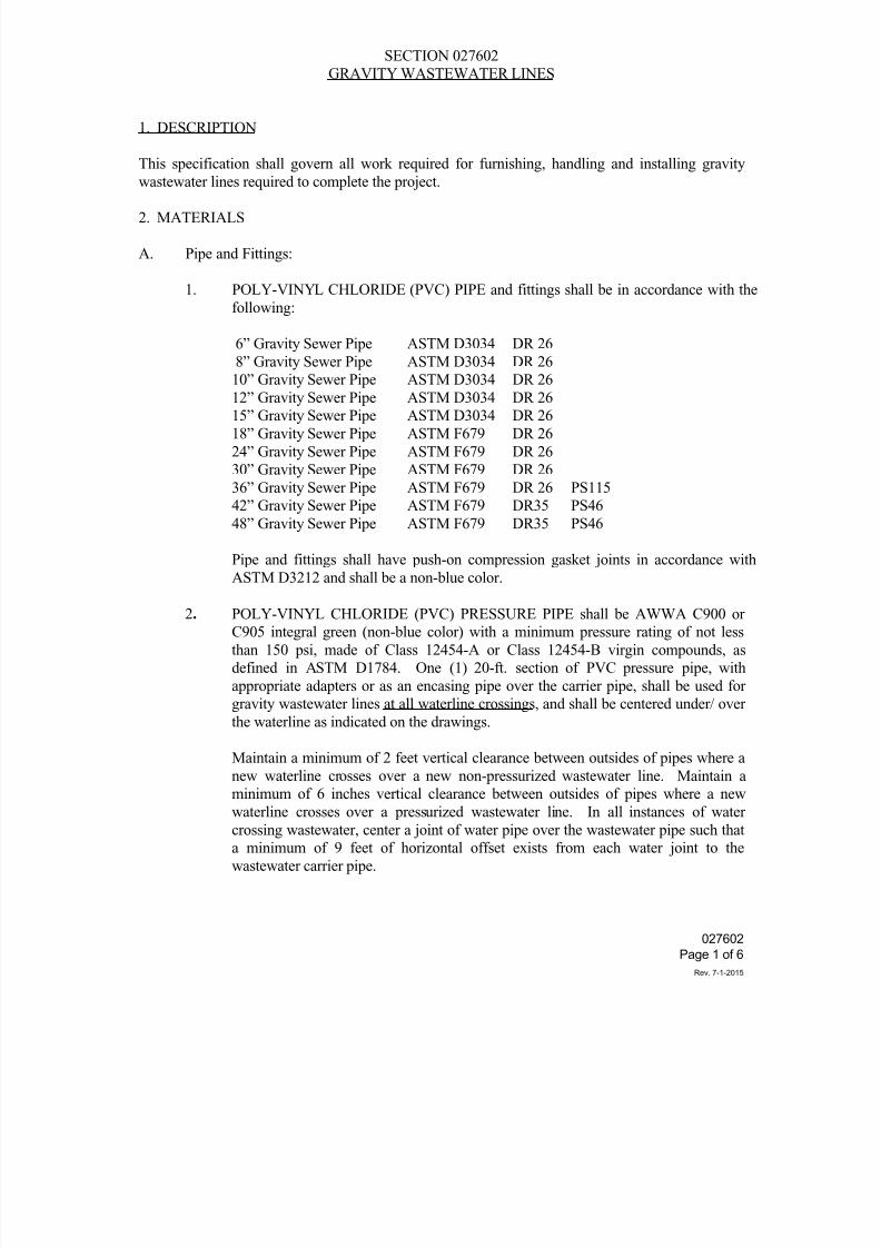
7/25/2019 City Standard Construction Specifications
http://slidepdf.com/reader/full/city-standard-construction-specifications 280/511
027602
Page 1 of 6
Rev. 7-1-2015
SECTION 027602
GRAVITY WASTEWATER LINES
1. DESCRIPTION
This specification shall govern all work required for furnishing, handling and installing gravity
wastewater lines required to complete the project.
2. MATERIALS
A. Pipe and Fittings:
1. POLY-VINYL CHLORIDE (PVC) PIPE and fittings shall be in accordance with the
following:
6” Gravity Sewer Pipe ASTM D3034 DR 26
8” Gravity Sewer Pipe ASTM D3034 DR 26
10” Gravity Sewer Pipe ASTM D3034 DR 26
12” Gravity Sewer Pipe ASTM D3034 DR 2615” Gravity Sewer Pipe ASTM D3034 DR 26
18” Gravity Sewer Pipe ASTM F679 DR 26
24” Gravity Sewer Pipe ASTM F679 DR 26
30” Gravity Sewer Pipe ASTM F679 DR 26
36” Gravity Sewer Pipe ASTM F679 DR 26 PS115
42” Gravity Sewer Pipe ASTM F679 DR35 PS46
48” Gravity Sewer Pipe ASTM F679 DR35 PS46
Pipe and fittings shall have push-on compression gasket joints in accordance with
ASTM D3212 and shall be a non-blue color.
2. POLY-VINYL CHLORIDE (PVC) PRESSURE PIPE shall be AWWA C900 or
C905 integral green (non-blue color) with a minimum pressure rating of not less
than 150 psi, made of Class 12454-A or Class 12454-B virgin compounds, as
defined in ASTM D1784. One (1) 20-ft. section of PVC pressure pipe, with
appropriate adapters or as an encasing pipe over the carrier pipe, shall be used for
gravity wastewater lines at all waterline crossings, and shall be centered under/ over
the waterline as indicated on the drawings.
Maintain a minimum of 2 feet vertical clearance between outsides of pipes where a
new waterline crosses over a new non-pressurized wastewater line. Maintain a
minimum of 6 inches vertical clearance between outsides of pipes where a newwaterline crosses over a pressurized wastewater line. In all instances of water
crossing wastewater, center a joint of water pipe over the wastewater pipe such that
a minimum of 9 feet of horizontal offset exists from each water joint to the
wastewater carrier pipe.
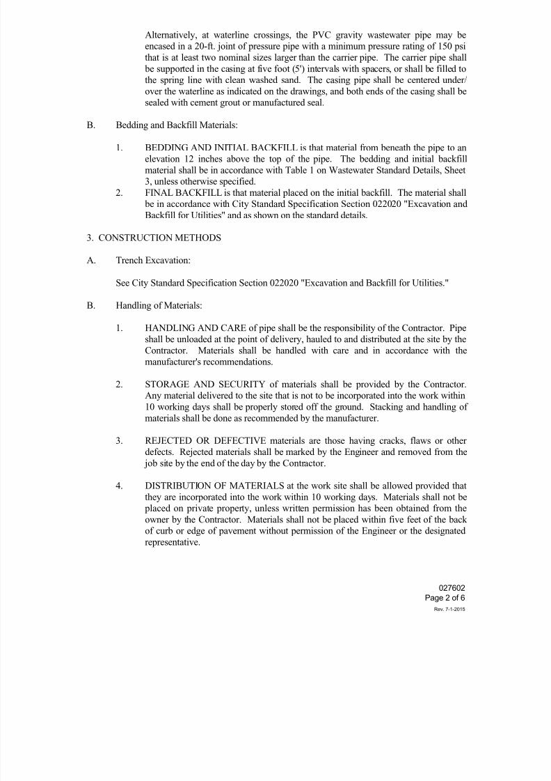
7/25/2019 City Standard Construction Specifications
http://slidepdf.com/reader/full/city-standard-construction-specifications 281/511
027602
Page 2 of 6
Rev. 7-1-2015
Alternatively, at waterline crossings, the PVC gravity wastewater pipe may be
encased in a 20-ft. joint of pressure pipe with a minimum pressure rating of 150 psi
that is at least two nominal sizes larger than the carrier pipe. The carrier pipe shall
be supported in the casing at five foot (5') intervals with spacers, or shall be filled to
the spring line with clean washed sand. The casing pipe shall be centered under/
over the waterline as indicated on the drawings, and both ends of the casing shall be
sealed with cement grout or manufactured seal.
B. Bedding and Backfill Materials:
1. BEDDING AND INITIAL BACKFILL is that material from beneath the pipe to an
elevation 12 inches above the top of the pipe. The bedding and initial backfill
material shall be in accordance with Table 1 on Wastewater Standard Details, Sheet
3, unless otherwise specified.
2. FINAL BACKFILL is that material placed on the initial backfill. The material shall
be in accordance with City Standard Specification Section 022020 "Excavation and
Backfill for Utilities" and as shown on the standard details.
3. CONSTRUCTION METHODS
A. Trench Excavation:
See City Standard Specification Section 022020 "Excavation and Backfill for Utilities."
B. Handling of Materials:
1. HANDLING AND CARE of pipe shall be the responsibility of the Contractor. Pipe
shall be unloaded at the point of delivery, hauled to and distributed at the site by the
Contractor. Materials shall be handled with care and in accordance with the
manufacturer's recommendations.
2. STORAGE AND SECURITY of materials shall be provided by the Contractor.
Any material delivered to the site that is not to be incorporated into the work within
10 working days shall be properly stored off the ground. Stacking and handling of
materials shall be done as recommended by the manufacturer.
3. REJECTED OR DEFECTIVE materials are those having cracks, flaws or other
defects. Rejected materials shall be marked by the Engineer and removed from the
job site by the end of the day by the Contractor.
4. DISTRIBUTION OF MATERIALS at the work site shall be allowed provided that
they are incorporated into the work within 10 working days. Materials shall not be placed on private property, unless written permission has been obtained from the
owner by the Contractor. Materials shall not be placed within five feet of the back
of curb or edge of pavement without permission of the Engineer or the designated
representative.
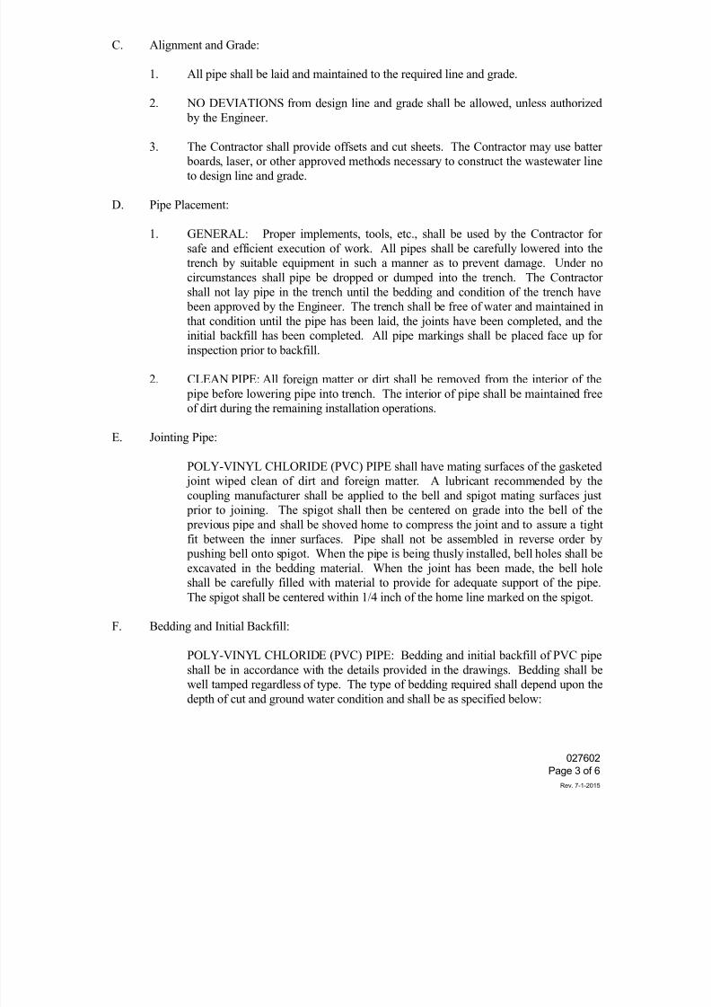
7/25/2019 City Standard Construction Specifications
http://slidepdf.com/reader/full/city-standard-construction-specifications 282/511
027602
Page 3 of 6
Rev. 7-1-2015
C. Alignment and Grade:
1. All pipe shall be laid and maintained to the required line and grade.
2. NO DEVIATIONS from design line and grade shall be allowed, unless authorized
by the Engineer.
3. The Contractor shall provide offsets and cut sheets. The Contractor may use batter
boards, laser, or other approved methods necessary to construct the wastewater lineto design line and grade.
D. Pipe Placement:
1. GENERAL: Proper implements, tools, etc., shall be used by the Contractor for
safe and efficient execution of work. All pipes shall be carefully lowered into the
trench by suitable equipment in such a manner as to prevent damage. Under no
circumstances shall pipe be dropped or dumped into the trench. The Contractor
shall not lay pipe in the trench until the bedding and condition of the trench have
been approved by the Engineer. The trench shall be free of water and maintained in
that condition until the pipe has been laid, the joints have been completed, and theinitial backfill has been completed. All pipe markings shall be placed face up for
inspection prior to backfill.
2. CLEAN PIPE: All foreign matter or dirt shall be removed from the interior of the
pipe before lowering pipe into trench. The interior of pipe shall be maintained free
of dirt during the remaining installation operations.
E. Jointing Pipe:
POLY-VINYL CHLORIDE (PVC) PIPE shall have mating surfaces of the gasketed
joint wiped clean of dirt and foreign matter. A lubricant recommended by thecoupling manufacturer shall be applied to the bell and spigot mating surfaces just
prior to joining. The spigot shall then be centered on grade into the bell of the
previous pipe and shall be shoved home to compress the joint and to assure a tight
fit between the inner surfaces. Pipe shall not be assembled in reverse order by
pushing bell onto spigot. When the pipe is being thusly installed, bell holes shall be
excavated in the bedding material. When the joint has been made, the bell hole
shall be carefully filled with material to provide for adequate support of the pipe.
The spigot shall be centered within 1/4 inch of the home line marked on the spigot.
F. Bedding and Initial Backfill:
POLY-VINYL CHLORIDE (PVC) PIPE: Bedding and initial backfill of PVC pipe
shall be in accordance with the details provided in the drawings. Bedding shall be
well tamped regardless of type. The type of bedding required shall depend upon the
depth of cut and ground water condition and shall be as specified below:
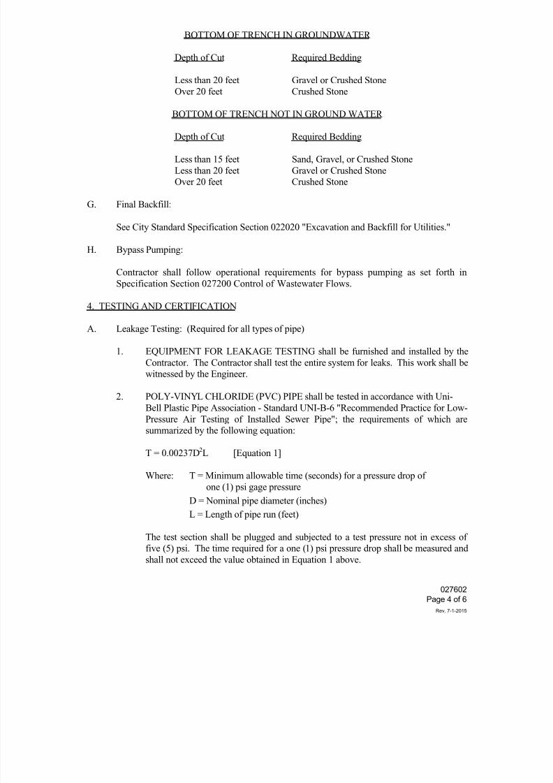
7/25/2019 City Standard Construction Specifications
http://slidepdf.com/reader/full/city-standard-construction-specifications 283/511
027602
Page 4 of 6
Rev. 7-1-2015
BOTTOM OF TRENCH IN GROUNDWATER
Depth of Cut Required Bedding
Less than 20 feet Gravel or Crushed Stone
Over 20 feet Crushed Stone
BOTTOM OF TRENCH NOT IN GROUND WATER
Depth of Cut Required Bedding
Less than 15 feet Sand, Gravel, or Crushed Stone
Less than 20 feet Gravel or Crushed Stone
Over 20 feet Crushed Stone
G. Final Backfill:
See City Standard Specification Section 022020 "Excavation and Backfill for Utilities."
H. Bypass Pumping:
Contractor shall follow operational requirements for bypass pumping as set forth in
Specification Section 027200 Control of Wastewater Flows.
4. TESTING AND CERTIFICATION
A. Leakage Testing: (Required for all types of pipe)
1. EQUIPMENT FOR LEAKAGE TESTING shall be furnished and installed by the
Contractor. The Contractor shall test the entire system for leaks. This work shall be
witnessed by the Engineer.
2. POLY-VINYL CHLORIDE (PVC) PIPE shall be tested in accordance with Uni-
Bell Plastic Pipe Association - Standard UNI-B-6 "Recommended Practice for Low-
Pressure Air Testing of Installed Sewer Pipe"; the requirements of which are
summarized by the following equation:
T = 0.00237D2L [Equation 1]
Where: T = Minimum allowable time (seconds) for a pressure drop of
one (1) psi gage pressure
D = Nominal pipe diameter (inches)
L = Length of pipe run (feet)
The test section shall be plugged and subjected to a test pressure not in excess of
five (5) psi. The time required for a one (1) psi pressure drop shall be measured and
shall not exceed the value obtained in Equation 1 above.
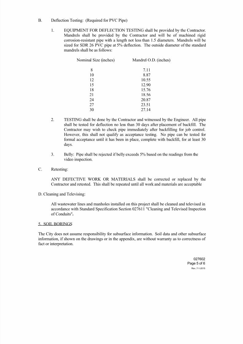
7/25/2019 City Standard Construction Specifications
http://slidepdf.com/reader/full/city-standard-construction-specifications 284/511
027602
Page 5 of 6
Rev. 7-1-2015
B. Deflection Testing: (Required for PVC Pipe)
1. EQUIPMENT FOR DEFLECTION TESTING shall be provided by the Contractor.
Mandrels shall be provided by the Contractor and will be of machined rigid
corrosion-resistant pipe with a length not less than 1.5 diameters. Mandrels will be
sized for SDR 26 PVC pipe at 5% deflection. The outside diameter of the standard
mandrels shall be as follows:
Nominal Size (inches) Mandrel O.D. (inches)
8 7.11
10 8.87
12 10.55
15 12.90
18 15.76
21 18.56
24 20.87
27 23.51
30 27.14
2. TESTING shall be done by the Contractor and witnessed by the Engineer. All pipe
shall be tested for deflection no less than 30 days after placement of backfill. The
Contractor may wish to check pipe immediately after backfilling for job control.
However, this shall not qualify as acceptance testing. No pipe can be tested for
formal acceptance until it has been in place, complete with backfill, for at least 30
days.
3. Belly: Pipe shall be rejected if belly exceeds 5% based on the readings from the
video inspection.
C. Retesting:
ANY DEFECTIVE WORK OR MATERIALS shall be corrected or replaced by the
Contractor and retested. This shall be repeated until all work and materials are acceptable
D. Cleaning and Televising:
All wastewater lines and manholes installed on this project shall be cleaned and televised in
accordance with Standard Specification Section 027611 "Cleaning and Televised Inspection
of Conduits".
5. SOIL BORINGS
The City does not assume responsibility for subsurface information. Soil data and other subsurface
information, if shown on the drawings or in the appendix, are without warranty as to correctness of
fact or interpretation.
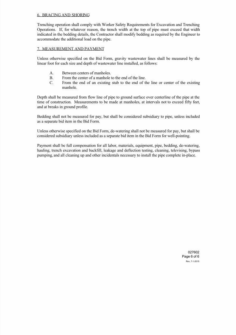
7/25/2019 City Standard Construction Specifications
http://slidepdf.com/reader/full/city-standard-construction-specifications 285/511
027602
Page 6 of 6
Rev. 7-1-2015
6. BRACING AND SHORING
Trenching operation shall comply with Worker Safety Requirements for Excavation and Trenching
Operations. If, for whatever reason, the trench width at the top of pipe must exceed that width
indicated in the bedding details, the Contractor shall modify bedding as required by the Engineer to
accommodate the additional load on the pipe.
7. MEASUREMENT AND PAYMENT
Unless otherwise specified on the Bid Form, gravity wastewater lines shall be measured by the
linear foot for each size and depth of wastewater line installed, as follows:
A. Between centers of manholes.
B. From the center of a manhole to the end of the line.
C. From the end of an existing stub to the end of the line or center of the existing
manhole.
Depth shall be measured from flow line of pipe to ground surface over centerline of the pipe at the
time of construction. Measurements to be made at manholes, at intervals not to exceed fifty feet,
and at breaks in ground profile.
Bedding shall not be measured for pay, but shall be considered subsidiary to pipe, unless included
as a separate bid item in the Bid Form.
Unless otherwise specified on the Bid Form, de-watering shall not be measured for pay, but shall be
considered subsidiary unless included as a separate bid item in the Bid Form for well-pointing.
Payment shall be full compensation for all labor, materials, equipment, pipe, bedding, de-watering,
hauling, trench excavation and backfill, leakage and deflection testing, cleaning, televising, bypass
pumping, and all cleaning up and other incidentals necessary to install the pipe complete in-place.
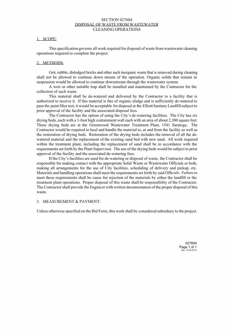
7/25/2019 City Standard Construction Specifications
http://slidepdf.com/reader/full/city-standard-construction-specifications 286/511
027604Page 1 of 1
Rev. 10-30-2014
SECTION 027604
DISPOSAL OF WASTE FROM WASTEWATER
CLEANING OPERATIONS
1. SCOPE:
This specification governs all work required for disposal of waste from wastewater cleaning
operations required to complete the project.
2. METHODS:
Grit, rubble, dislodged bricks and other such inorganic waste that is removed during cleaning
shall not be allowed to continue down stream of the operation. Organic solids that remain in
suspension would be allowed to continue downstream through the wastewater system.
A weir or other suitable trap shall be installed and maintained by the Contractor for the
collection of such waste.
This material shall be de-watered and delivered by the Contractor to a facility that is
authorized to receive it. If this material is free of organic sludge and is sufficiently de-watered to
pass the paint filter test, it would be acceptable for disposal at the Elliott Sanitary Landfill subject to prior approval of the facility and the associated disposal fees.
The Contractor has the option of using the City’s de-watering facilities. The City has six
drying beds, each with a 1-foot high containment wall each with an area of about 2,300 square feet.
These drying beds are at the Greenwood Wastewater Treatment Plant, 1541 Saratoga. The
Contractor would be required to haul and handle the material to, at and from the facility as well as
the restoration of drying beds. Restoration of the drying beds includes the removal of all the de-
watered material and the replacement of the existing sand bed with new sand. All work required
within the treatment plant, including the replacement of sand shall be in accordance with the
requirements set forth by the Plant Supervisor. The use of the drying beds would be subject to prior
approval of the facility and the associated de-watering fees.
If the City’s facilities are used for de-watering or disposal of waste, the Contractor shall be
responsible for making contact with the appropriate Solid Waste or Wastewater Officials or both,
making all arrangements for the use of City facilities, scheduling of delivery and pickup, etc.
Materials and handling operations shall meet the requirements set forth by said Officials. Failure to
meet these requirements shall be cause for rejection of the materials by either the landfill or the
treatment plant operations. Proper disposal of this waste shall be responsibility of the Contractor.
The Contractor shall provide the Engineer with written documentation of the proper disposal of this
waste.
3. MEASUREMENT & PAYMENT:
Unless otherwise specified on the Bid Form, this work shall be considered subsidiary to the project.
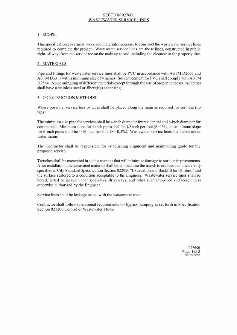
7/25/2019 City Standard Construction Specifications
http://slidepdf.com/reader/full/city-standard-construction-specifications 287/511
027606
Page 1 of 2Rev. 10-30-2014
SECTION 027606
WASTEWATER SERVICE LINES
1. SCOPE:
This specification governs all work and materials necessary to construct the wastewater service lines
required to complete the project. Wastewater service lines are those lines, constructed in public
right-of-way, from the service tee on the main up to and including the cleanout at the property line.
2. MATERIALS:
Pipe and fittings for wastewater service lines shall be PVC in accordance with ASTM D2665 and
ASTM D3311 with a minimum size of 4 inches. Solvent cement for PVC shall comply with ASTM
D2564. No co-mingling of different materials except through the use of proper adaptors. Adaptors
shall have a stainless steel or fiberglass shear ring.
3. CONSTRUCTION METHODS:
Where possible, service tees or wyes shall be placed along the main as required for services (notaps).
The minimum size pipe for services shall be 4-inch diameter for residential and 6-inch diameter for
commercial. Minimum slope for 4-inch pipes shall be 1/8 inch per foot (S=1%), and minimum slope
for 6-inch pipes shall be 1/16 inch per foot (S= 0.5%). Wastewater service lines shall cross under
water mains.
The Contractor shall be responsible for establishing alignment and maintaining grade for the
proposed service.
Trenches shall be excavated in such a manner that will minimize damage to surface improvements.
After installation, the excavated material shall be tamped into the trench to not less than the density
specified in City Standard Specification Section 022020 "Excavation and Backfill for Utilities," and
the surface restored to a condition acceptable to the Engineer. Wastewater service lines shall be
bored, jetted or jacked under sidewalks, driveways, and other such improved surfaces, unless
otherwise authorized by the Engineer.
Service lines shall be leakage tested with the wastewater main.
Contractor shall follow operational requirements for bypass pumping as set forth in Specification
Section 027200 Control of Wastewater Flows
7/25/2019 City Standard Construction Specifications
http://slidepdf.com/reader/full/city-standard-construction-specifications 288/511
027606
Page 2 of 2Rev. 10-30-2014
4. MEASUREMENT AND PAYMENT:
Unless otherwise specified on the Bid Form, wastewater service lines shall be measured as
individual units for each connection made to the main. Payment shall include, but not be limited to,
the line from the tee on the main to, and including, the cleanout at the property line. Payment shall
be full compensation for all labor, materials, equipment, trench safety, bypass pumping and
incidentals necessary for wastewater service lines required to complete the project.
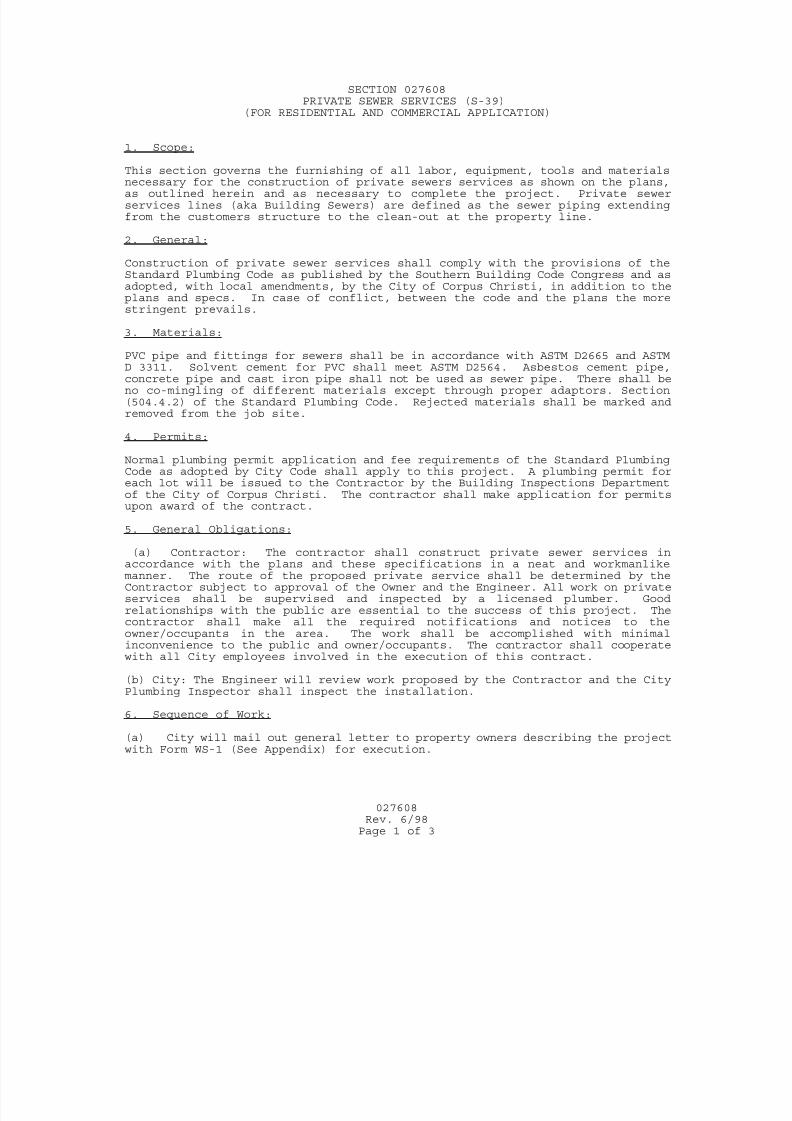
7/25/2019 City Standard Construction Specifications
http://slidepdf.com/reader/full/city-standard-construction-specifications 289/511
027608
Rev. 6/98Page 1 of 3
SECTION 027608PRIVATE SEWER SERVICES (S-39)
(FOR RESIDENTIAL AND COMMERCIAL APPLICATION)
1. Scope: This section governs the furnishing of all labor, equipment, tools and materialsnecessary for the construction of private sewers services as shown on the plans,as outlined herein and as necessary to complete the project. Private sewerservices lines (aka Building Sewers) are defined as the sewer piping extendingfrom the customers structure to the clean-out at the property line.
2. General: Construction of private sewer services shall comply with the provisions of theStandard Plumbing Code as published by the Southern Building Code Congress and asadopted, with local amendments, by the City of Corpus Christi, in addition to theplans and specs. In case of conflict, between the code and the plans the morestringent prevails.
3. Materials:
PVC pipe and fittings for sewers shall be in accordance with ASTM D2665 and ASTMD 3311. Solvent cement for PVC shall meet ASTM D2564. Asbestos cement pipe,concrete pipe and cast iron pipe shall not be used as sewer pipe. There shall beno co-mingling of different materials except through proper adaptors. Section(504.4.2) of the Standard Plumbing Code. Rejected materials shall be marked andremoved from the job site.
4. Permits: Normal plumbing permit application and fee requirements of the Standard PlumbingCode as adopted by City Code shall apply to this project. A plumbing permit foreach lot will be issued to the Contractor by the Building Inspections Departmentof the City of Corpus Christi. The contractor shall make application for permitsupon award of the contract.
5. General Obligations: (a) Contractor: The contractor shall construct private sewer services inaccordance with the plans and these specifications in a neat and workmanlikemanner. The route of the proposed private service shall be determined by theContractor subject to approval of the Owner and the Engineer. All work on privateservices shall be supervised and inspected by a licensed plumber. Goodrelationships with the public are essential to the success of this project. Thecontractor shall make all the required notifications and notices to theowner/occupants in the area. The work shall be accomplished with minimalinconvenience to the public and owner/occupants. The contractor shall cooperatewith all City employees involved in the execution of this contract.
(b) City: The Engineer will review work proposed by the Contractor and the CityPlumbing Inspector shall inspect the installation.
6. Sequence of Work: (a) City will mail out general letter to property owners describing the projectwith Form WS-1 (See Appendix) for execution.
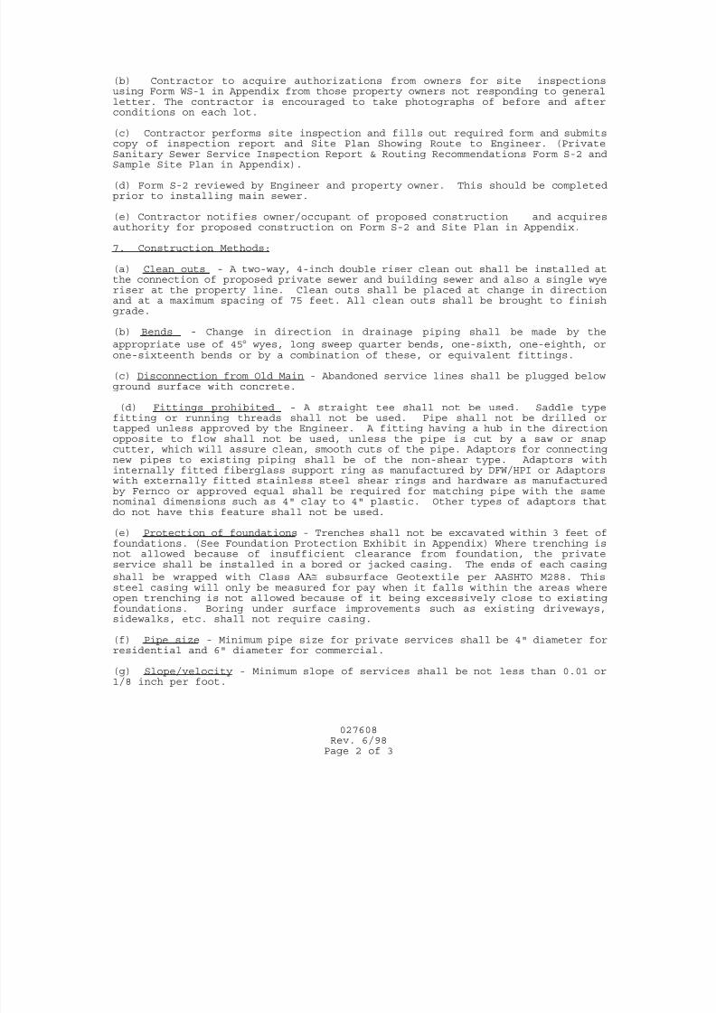
7/25/2019 City Standard Construction Specifications
http://slidepdf.com/reader/full/city-standard-construction-specifications 290/511
027608
Rev. 6/98Page 2 of 3
(b) Contractor to acquire authorizations from owners for site inspectionsusing Form WS-1 in Appendix from those property owners not responding to generalletter. The contractor is encouraged to take photographs of before and afterconditions on each lot.
(c) Contractor performs site inspection and fills out required form and submitscopy of inspection report and Site Plan Showing Route to Engineer. (PrivateSanitary Sewer Service Inspection Report & Routing Recommendations Form S-2 andSample Site Plan in Appendix).
(d) Form S-2 reviewed by Engineer and property owner. This should be completedprior to installing main sewer.
(e) Contractor notifies owner/occupant of proposed construction and acquiresauthority for proposed construction on Form S-2 and Site Plan in Appendix.
7. Construction Methods: (a) Clean outs - A two-way, 4-inch double riser clean out shall be installed atthe connection of proposed private sewer and building sewer and also a single wyeriser at the property line. Clean outs shall be placed at change in directionand at a maximum spacing of 75 feet. All clean outs shall be brought to finishgrade.
(b) Bends - Change in direction in drainage piping shall be made by the
appropriate use of 45 wyes, long sweep quarter bends, one-sixth, one-eighth, orone-sixteenth bends or by a combination of these, or equivalent fittings.
(c) Disconnection from Old Main - Abandoned service lines shall be plugged belowground surface with concrete.
(d) Fittings prohibited - A straight tee shall not be used. Saddle typefitting or running threads shall not be used. Pipe shall not be drilled ortapped unless approved by the Engineer. A fitting having a hub in the directionopposite to flow shall not be used, unless the pipe is cut by a saw or snapcutter, which will assure clean, smooth cuts of the pipe. Adaptors for connectingnew pipes to existing piping shall be of the non-shear type. Adaptors withinternally fitted fiberglass support ring as manufactured by DFW/HPI or Adaptors
with externally fitted stainless steel shear rings and hardware as manufacturedby Fernco or approved equal shall be required for matching pipe with the samenominal dimensions such as 4" clay to 4" plastic. Other types of adaptors thatdo not have this feature shall not be used.
(e) Protection of foundations - Trenches shall not be excavated within 3 feet offoundations. (See Foundation Protection Exhibit in Appendix) Where trenching isnot allowed because of insufficient clearance from foundation, the privateservice shall be installed in a bored or jacked casing. The ends of each casing
shall be wrapped with Class A subsurface Geotextile per AASHTO M288. Thissteel casing will only be measured for pay when it falls within the areas whereopen trenching is not allowed because of it being excessively close to existingfoundations. Boring under surface improvements such as existing driveways,sidewalks, etc. shall not require casing.
(f) Pipe size - Minimum pipe size for private services shall be 4" diameter forresidential and 6" diameter for commercial.
(g) Slope/velocity - Minimum slope of services shall be not less than 0.01 or1/8 inch per foot.
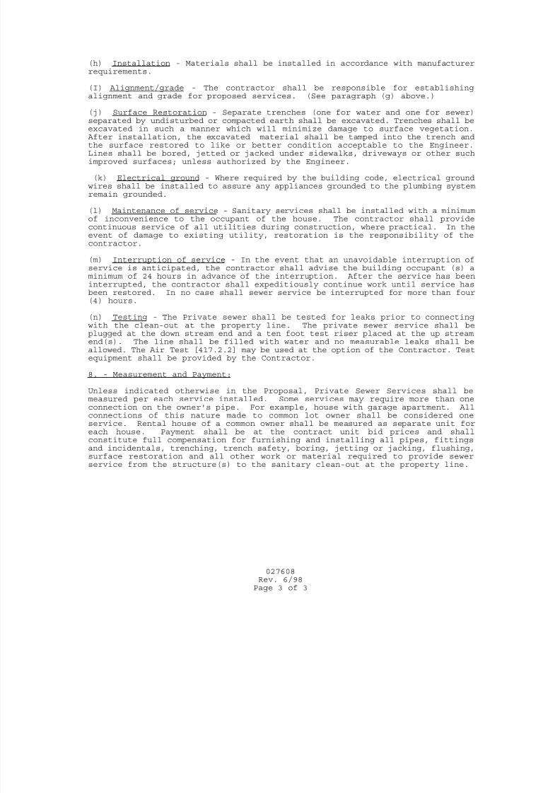
7/25/2019 City Standard Construction Specifications
http://slidepdf.com/reader/full/city-standard-construction-specifications 291/511
027608
Rev. 6/98Page 3 of 3
(h) Installation - Materials shall be installed in accordance with manufacturerrequirements.
(I) Alignment/grade - The contractor shall be responsible for establishingalignment and grade for proposed services. (See paragraph (g) above.)
(j) Surface Restoration - Separate trenches (one for water and one for sewer)separated by undisturbed or compacted earth shall be excavated. Trenches shall beexcavated in such a manner which will minimize damage to surface vegetation. After installation, the excavated material shall be tamped into the trench andthe surface restored to like or better condition acceptable to the Engineer.Lines shall be bored, jetted or jacked under sidewalks, driveways or other suchimproved surfaces; unless authorized by the Engineer.
(k) Electrical ground - Where required by the building code, electrical groundwires shall be installed to assure any appliances grounded to the plumbing systemremain grounded.
(l) Maintenance of service - Sanitary services shall be installed with a minimumof inconvenience to the occupant of the house. The contractor shall providecontinuous service of all utilities during construction, where practical. In theevent of damage to existing utility, restoration is the responsibility of thecontractor.
(m) Interruption of service - In the event that an unavoidable interruption ofservice is anticipated, the contractor shall advise the building occupant (s) aminimum of 24 hours in advance of the interruption. After the service has beeninterrupted, the contractor shall expeditiously continue work until service hasbeen restored. In no case shall sewer service be interrupted for more than four(4) hours.
(n) Testing - The Private sewer shall be tested for leaks prior to connectingwith the clean-out at the property line. The private sewer service shall beplugged at the down stream end and a ten foot test riser placed at the up streamend(s). The line shall be filled with water and no measurable leaks shall beallowed. The Air Test [417.2.2] may be used at the option of the Contractor. Testequipment shall be provided by the Contractor.
8. - Measurement and Payment: Unless indicated otherwise in the Proposal, Private Sewer Services shall bemeasured per each service installed. Some services may require more than oneconnection on the owner's pipe. For example, house with garage apartment. Allconnections of this nature made to common lot owner shall be considered oneservice. Rental house of a common owner shall be measured as separate unit foreach house. Payment shall be at the contract unit bid prices and shallconstitute full compensation for furnishing and installing all pipes, fittingsand incidentals, trenching, trench safety, boring, jetting or jacking, flushing,surface restoration and all other work or material required to provide sewerservice from the structure(s) to the sanitary clean-out at the property line.
7/25/2019 City Standard Construction Specifications
http://slidepdf.com/reader/full/city-standard-construction-specifications 292/511
SECTION 027611
CLEANING AND TELEVISED INSPECTION OF CONDUITS
1. SCOPE
This specification shall govern for all work, equipment, supervision and materialsrequired to provide for cleaning and remote CCTV inspection and documentation of
wastewater or other lines and manholes as required.
2. TECHNICAL REQUIREMENTS
2.1 General
Closed circuit television inspection will typically be done under one or more of
the conditions listed below. Requirements for on-screen labeling during each linesegment set up, televising, video file labeling and hard copy inspection reports
will be specifically addressed. The Contractor shall neither request nor receive
assistance from the City, in the performance of work described in thisspecification. Unless otherwise specified and at Contractors expense, theContractor shall provide for the control of wastewater flows and monitoring of the
collection system for back-ups and surcharges, while flow control devices are in
place.
It shall be the responsibility of the Contractor(s) to adhere to all applicable OSHA
rules and regulations while performing any and all City-related projects or jobs (toinclude, but not necessarily limited to “Confined Space Entry”.
2.2 Inspection Equipment and Methods
Electronic media shall be used to record the condition of all the segments of the
mains and the manholes, tap locations and unusual situations during inspection.The inspection imaging shall be made on color professional grade DVD format
for each line segment. All observations will require both audio and on-screen
display. The camera shall transit through the wastewater line in either direction ata speed not greater than 30 feet per minute, stopping as necessary to permit proper
documentation of the wastewater line’s condition. Lighting for the camera shall
be suitable to allow a clear picture of the entire periphery of the pipe. A
television camera with pan and tilt capability will be required. The camera,television monitor, and other components of the video systems shall be capable of
producing picture quality to the satisfaction of the City.
The capture system shall have the capability of recording, digitizing and storing
single frames of video images and “real time” live video, as well as collecting,
storing and printing wastewater line inspection data for graphic display and reportgeneration. The imaging capture system shall store digitized picture images, have
the ability to export picture files to industry standard formats (jpg, bmp, and tif),
be transferable to DVD and be printed at no cost to the City. Use of proprietarysoftware is discouraged; however, if the Contractor provides the software and
027611Page 1 of 8
Rev. 3-25-2015
7/25/2019 City Standard Construction Specifications
http://slidepdf.com/reader/full/city-standard-construction-specifications 293/511
three licenses to the City, proprietary software COMPATIBLE with the City’s
GIS and existing database systems in use may be approved. However, in every
case all observations will be recorded using the City approved PACP codes.
2.3 Flow Control / By-Passing
This procedure will be used on all previously accepted (City owned) linesegments. Except for new wastewater line acceptance inspections, the line shall
be dewatered during inspection. A water jet cleaning unit will normally be
running in the line in advance of the television camera to allow the highest quality
picture available. Dewatering shall remove standing water and fog from the linesegment to provide 360 degree view of the pipe being televised. Too high water
level or the camera being submerged will be grounds for rejection of the
inspection.
All wastewater flows from intersecting lines shall typically be controlled through
the use of in-line plugs for vacuum trucks and are considered subsidiary to the
inspection for all line sizes. Plugs in intersecting lines shall be installed by theContractor with no assistance from the City. The Contractor shall also monitor
the upstream system for back-ups and surcharges, which may lead to Sanitary
Sewer Overflows (SSOs). The Contractor shall immediately report to the CityCall Center (361) 826-2489 all sanitary sewer overflows. Flow Control devices
shall be installed in accordance with all applicable OSHA requirements,
including, but not necessarily limited to confined space protocol.
2.4 Evaluation of Existing Lines for Potential Repairs/Rehabilitation – Pre CCTV:
Cleaning and televising using a CCTV camera may be needed to traverse each
line segment from manhole to manhole as specified in the work order. When an
obstruction prevents the camera from proceeding, the obstruction will be recordedon the initial setup and a reverse setup will be attempted to view the pipe and
obstruction from the other side. If the camera fails to pass through the entire
section, the inspection shall be considered complete and no additional inspectionwill be required. However, the line segment evaluation form, as well as the
graphic report, shall note full line length and the length traveled from each
manhole set-up. All inspection efforts on the line segment will be recorded on thesame tape / disk. The Contractor must exert all reasonable effort to televise the
entire length of a segment of wastewater line, or to assist the repair crews with
usable information for point repair. Prior to transiting the line the video displayinitially is to include upstream and downstream manhole numbers, pipe size /
material, adjacent street names and the date. During the transit the display mustshow the continuous distance from the insertion manhole with an accuracy of
+1% of the actual length to help mark observations on the report form. The videomust have narrative documentation of notable observations. The Inspection
Report shall consist of condition observations recorded using City-approved
computer software generated formats, generally conforming to NASSCO andPACP codes. Specifically, items considered notable include: deviations in
alignment and grade; abnormal conditions of the pipe barrel and joints; locations
027611Page 2 of 8
Rev. 3-25-2015
7/25/2019 City Standard Construction Specifications
http://slidepdf.com/reader/full/city-standard-construction-specifications 294/511
and quantities of any sources of infiltration or inflow; dropped, broken, properly /
improperly installed service taps; debris, roots or other impediments to flow and
any other condition that may prevent either the proper completion of theinspection, or affect any proposed rehabilitation process. Evaluation of existing
lines includes associated manhole inspection.
2.5 Evaluation After Repairs / Rehabilitation Post CCTV:
Following repairs or rehabilitation to existing lines (by Contractor), a CCTV
camera shall travel through required line segment to televise. The intent of this process is to inspect the interior of the line to determine the location of repairs,
and extent of any unacceptable work . Prior to transiting the line the video display
initially is to include upstream and downstream manhole numbers, pipe size /material, adjacent street names and the date. During the transit the display must
show the continuous distance from the insertion manhole with an accuracy of +/-
1% of the actual length to help mark observations on the report form.
Specifically, items such as detailed inspection of the repaired area using pan-and-tilt equipment will be shown in the Inspection Report, including digital
photographs of acceptable or inadequate and/or questionable work. The video
must include narrative documentation of notable observations, and be crossreferenced to the Inspection Report. The Inspection Report shall consist of
condition observations recorded using City-approved computer-software
generated formats conforming to NASSCO and PACP codes.
2.6 New Pipeline Inspection:
Upon completion of the installation of new lines, including any appurtenances
such as manholes, service connections, etc., a CCTV camera shall traverse
through each completed line segment. The intent of this process is to inspect theinterior of the completed line to determine the location of service taps and extent
of omissions and/or any unacceptable work on the pipeline or manholes, such as
sags, infiltration, gapped joints, protruding gaskets, etc. Prior to transiting the
line, the initial video shall initially include the upstream and downstream manholedesignations, pipe size, project name and other pertinent information. When
inspecting / documenting new wastewater line conditions, the Contractor must
conduct a specific inspection for the presence of sags in the newly installed line.The approved method involves the use of an inclinometer on the camera. The
belly tolerance is 5% or less for acceptable pipe installation. Any deviation from
the 5% belly tolerance limit must be approved by the applicable Utility OperatingDepartment.
The graphic report will note the start and stop of sags and approximate maximum
depth. During the transit the display must show the continuous distance from theinsertion manhole with an accuracy of +1% of the actual length to help mark
observations on the Inspection Report form. The video must include narrative
documentation of notable observations, and be cross referenced to the Inspection
027611Page 3 of 8
Rev. 3-25-2015
7/25/2019 City Standard Construction Specifications
http://slidepdf.com/reader/full/city-standard-construction-specifications 295/511
Report. The Inspection Report shall consist of condition observations recorded
using approved computer-software generated formats. Specifically, items such as
deviations in alignment and grade causing bellies / sags; abnormal conditions ofthe pipe barrel and joints; locations and quantities of any sources of infiltration or
inflow; dropped, broken, properly / improperly installed service taps or any other
condition that may assist the Utilities Department in determining the quality of the pipeline installation.
2.7 Manhole Inspection:
A CCTV camera shall traverse the manhole from top to bottom to record the
condition of the manhole and invert for structural condition and sources of
infiltration on the manhole and invert. The initial video display must show theentry manhole number, location / street address, date and depth.
a. The requirement is to commence capturing video at ground level. The video
must be steady while panning and lowering to clearly record condition of the
ring, corbel, the walls, and pipeline penetrations. The camera is to rotateduring descent to inspect typical conditions and all penetrations. At the
bottom of the manhole the complete invert will be inspected / viewed for
infiltration and general condition. A washed out picture due to sunlight orshaking will be rejected for payment
b. This manhole information may be retained on the same DVD if the line
segment is also being investigated, or, if inspection is issued as a separatework order, a separate DVD and report will be required. As with pipeline
inspection, digital photographs of key points of note must accompany the
report and DVD. These would include seals on pipeline penetration,
infiltration locations and other anomalies.
c. The format of the Manhole Inspection Report will be as proposed by theContractor and, following discussion, mutually approved by the Utilities
Department and the Contractor. A sample form is included at the end of this
specification. It will contain as a minimum:
location & I.D.number manhole diameter
manhole material depth of manhole
condition of ring / cover evidence of infiltrationcondition of walls presence of inflow inhibitor
condition of pipe mouths presence of coatingscondition of invert location: street / easementabove invert penetrations
2.8 CCTV Set-up:
a. A CCTV set-up includes all of the work, equipment, supervision, personnel,
and materials needed to traverse a line segment.
027611Page 4 of 8
Rev. 3-25-2015
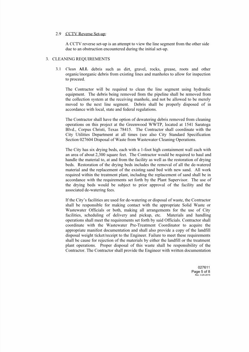
7/25/2019 City Standard Construction Specifications
http://slidepdf.com/reader/full/city-standard-construction-specifications 296/511
2.9 CCTV Reverse Set-up:
A CCTV reverse set-up is an attempt to view the line segment from the other side
due to an obstruction encountered during the initial set-up.
3. CLEANING REQUIREMENTS
3.1 Clean ALL debris such as dirt, gravel, rocks, grease, roots and other
organic/inorganic debris from existing lines and manholes to allow for inspectionto proceed.
The Contractor will be required to clean the line segment using hydraulicequipment. The debris being removed from the pipeline shall be removed from
the collection system at the receiving manhole, and not be allowed to be merely
moved to the next line segment. Debris shall be properly disposed of in
accordance with local, state and federal regulations.
The Contractor shall have the option of dewatering debris removed from cleaning
operations on this project at the Greenwood WWTP, located at 1541 SaratogaBlvd., Corpus Christi, Texas 78415. The Contractor shall coordinate with the
City Utilities Department at all times (see also City Standard Specification
Section 027604 Disposal of Waste from Wastewater Cleaning Operations.
The City has six drying beds, each with a 1-foot high containment wall each with
an area of about 2,300 square feet. The Contractor would be required to haul andhandle the material to, at and from the facility as well as the restoration of drying
beds. Restoration of the drying beds includes the removal of all the de-watered
material and the replacement of the existing sand bed with new sand. All workrequired within the treatment plant, including the replacement of sand shall be in
accordance with the requirements set forth by the Plant Supervisor. The use of
the drying beds would be subject to prior approval of the facility and the
associated de-watering fees.
If the City’s facilities are used for de-watering or disposal of waste, the Contractor
shall be responsible for making contact with the appropriate Solid Waste orWastewater Officials or both, making all arrangements for the use of City
facilities, scheduling of delivery and pickup, etc. Materials and handling
operations shall meet the requirements set forth by said Officials. Contractor shallcoordinate with the Wastewater Pre-Treatment Coordinator to acquire the
appropriate manifest documentation and shall also provide a copy of the landfill
disposal weight ticket/receipt to the Engineer. Failure to meet these requirements
shall be cause for rejection of the materials by either the landfill or the treatment plant operations. Proper disposal of this waste shall be responsibility of the
Contractor. The Contractor shall provide the Engineer with written documentation
027611Page 5 of 8
Rev. 3-25-2015
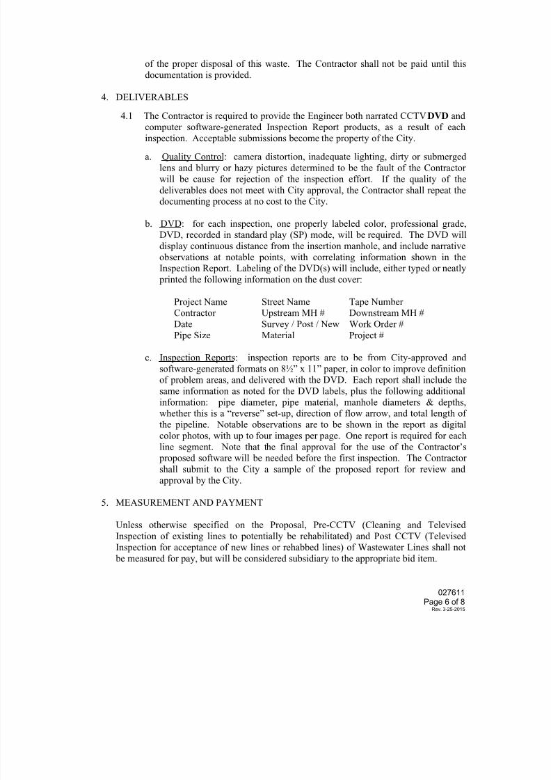
7/25/2019 City Standard Construction Specifications
http://slidepdf.com/reader/full/city-standard-construction-specifications 297/511
of the proper disposal of this waste. The Contractor shall not be paid until this
documentation is provided.
4. DELIVERABLES
4.1 The Contractor is required to provide the Engineer both narrated CCTV DVD and
computer software-generated Inspection Report products, as a result of eachinspection. Acceptable submissions become the property of the City.
a. Quality Control: camera distortion, inadequate lighting, dirty or submerged
lens and blurry or hazy pictures determined to be the fault of the Contractor
will be cause for rejection of the inspection effort. If the quality of the
deliverables does not meet with City approval, the Contractor shall repeat thedocumenting process at no cost to the City.
b. DVD: for each inspection, one properly labeled color, professional grade,DVD, recorded in standard play (SP) mode, will be required. The DVD will
display continuous distance from the insertion manhole, and include narrativeobservations at notable points, with correlating information shown in theInspection Report. Labeling of the DVD(s) will include, either typed or neatly
printed the following information on the dust cover:
Project Name Street Name Tape NumberContractor Upstream MH # Downstream MH #
Date Survey / Post / New Work Order #
Pipe Size Material Project #
c. Inspection Reports: inspection reports are to be from City-approved and
software-generated formats on 8½” x 11” paper, in color to improve definitionof problem areas, and delivered with the DVD. Each report shall include the
same information as noted for the DVD labels, plus the following additional
information: pipe diameter, pipe material, manhole diameters & depths,whether this is a “reverse” set-up, direction of flow arrow, and total length of
the pipeline. Notable observations are to be shown in the report as digital
color photos, with up to four images per page. One report is required for each
line segment. Note that the final approval for the use of the Contractor’s proposed software will be needed before the first inspection. The Contractor
shall submit to the City a sample of the proposed report for review and
approval by the City.
5. MEASUREMENT AND PAYMENT
Unless otherwise specified on the Proposal, Pre-CCTV (Cleaning and Televised
Inspection of existing lines to potentially be rehabilitated) and Post CCTV (Televised
Inspection for acceptance of new lines or rehabbed lines) of Wastewater Lines shall not
be measured for pay, but will be considered subsidiary to the appropriate bid item.
027611Page 6 of 8
Rev. 3-25-2015
7/25/2019 City Standard Construction Specifications
http://slidepdf.com/reader/full/city-standard-construction-specifications 298/511
Cleaning and Televised Inspection of Wastewater Lines includes an inspection of all
manholes entered, crossed, or associated with the line being inspected.
Reverse CCTV Set-Up shall not be allowed for acceptance televising as obstructions
should not be encountered in new pipe that would require the Contractor to relocate to
another manhole (upstream or downstream) of the original manhole.
027611Page 7 of 8
Rev. 3-25-2015
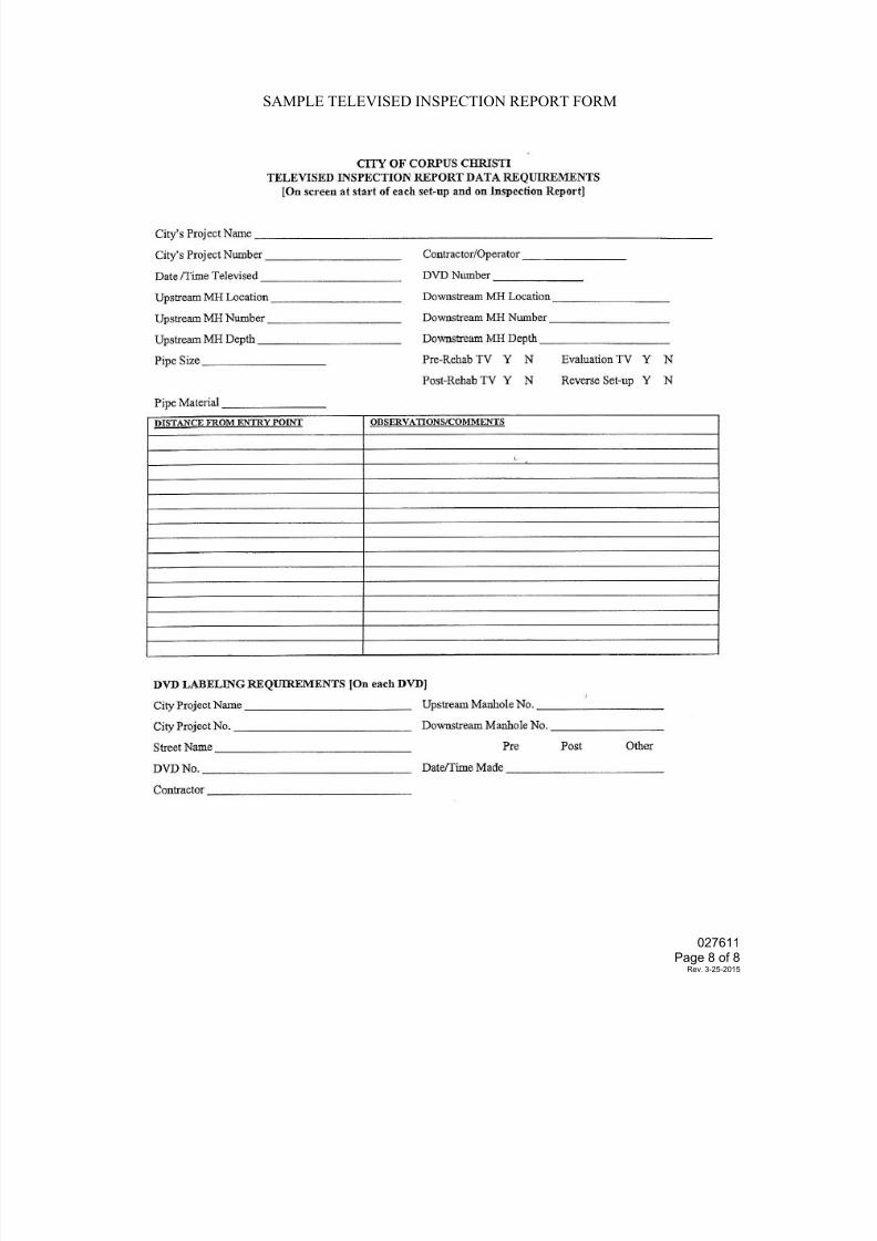
7/25/2019 City Standard Construction Specifications
http://slidepdf.com/reader/full/city-standard-construction-specifications 299/511
SAMPLE TELEVISED INSPECTION REPORT FORM
027611Page 8 of 8
Rev. 3-25-2015
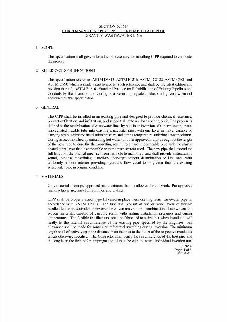
7/25/2019 City Standard Construction Specifications
http://slidepdf.com/reader/full/city-standard-construction-specifications 300/511
027614 Page 1 of 8
Rev. 10-30-2014
SECTION 027614 CURED-IN-PLACE-PIPE (CIPP) FOR REHABILITATION OF
GRAVITY WASTEWATER LINE
1. SCOPE
This specification shall govern for all work necessary for installing CIPP required to complete
the project.
2. REFERENCE SPECIFICATIONS
This specification references ASTM D5813, ASTM F1216, ASTM D 2122, ASTM C581, and
ASTM D790 which is made a part hereof by such reference and shall be the latest edition and
revision thereof. ASTM F1216 - Standard Practice for Rehabilitation of Existing Pipelines andConduits by the Inversion and Curing of a Resin-Impregnated Tube, shall govern when not
addressed by this specification.
3. GENERAL
The CIPP shall be installed in an existing pipe and designed to provide chemical resistance,
prevent exfiltration and infiltration, and support all external loads acting on it. The process isdefined as the rehabilitation of wastewater lines by pull-in or inversion of a thermosetting resin
impregnated flexible tube into existing wastewater pipe, with one layer or more, capable of
carrying resin, withstand installation pressure and curing temperature, utilizing a water column.Curing is accomplished by circulating hot water (or other approved fluid) throughout the length
of the new tube to cure the thermosetting resin into a hard impermeable pipe with the plastic
coated outer layer that is compatible with the resin system used. The new pipe shall extend the
full length of the original pipe (i.e. from manhole to manhole), and shall provide a structurallysound, jointless, closefitting, Cured-In-Place-Pipe without delamination or lifts, and with
uniformly smooth interior providing hydraulic flow equal to or greater than the existing
wastewater pipe in original condition.
4. MATERIALS
Only materials from pre-approved manufacturers shall be allowed for this work. Pre-approved
manufacturers are, Insituform, Inliner, and U-liner.
CIPP shall be properly sized Type III cured-in-place thermosetting resin wastewater pipe in
accordance with ASTM D5813. The tube shall consist of one or more layers of flexibleneedled felt or an equivalent nonwoven or woven material or a combination of nonwoven and
woven materials, capable of carrying resin, withstanding installation pressures and curingtemperatures. The flexible felt fiber tube shall be fabricated to a size that when installed it will
neatly fit the internal circumference of the existing pipe specified by the Engineer. Anallowance shall be made for some circumferential stretching during inversion. The minimum
length shall effectively span the distance from the inlet to the outlet of the respective manholes
unless otherwise specified. The Contractor shall verify the circumference of the host pipe andthe lengths in the field before impregnation of the tube with the resin. Individual insertion runs
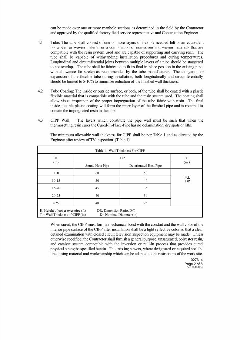
7/25/2019 City Standard Construction Specifications
http://slidepdf.com/reader/full/city-standard-construction-specifications 301/511
027614 Page 2 of 8
Rev. 10-30-2014
can be made over one or more manhole sections as determined in the field by the Contractor
and approved by the qualified factory field service representative and Construction Engineer.
4.1 Tube: The tube shall consist of one or more layers of flexible needled felt or an equivalent
nonwoven or woven material or a combination of nonwoven and woven materials that are
compatible with the resin system used and are capable of supporting and carrying resin. Thetube shall be capable of withstanding installation procedures and curing temperatures.
Longitudinal and circumferential joints between multiple layers of a tube should be staggered
to not overlap. The tube shall be fabricated to fit its final in-place position in the existing pipe,with allowance for stretch as recommended by the tube manufacturer. The elongation or
expansion of the flexible tube during installation, both longitudinally and circumferentially
should be limited to 5-10% to minimize reduction of the finished wall thickness.
4.2 Tube Coating: The inside or outside surface, or both, of the tube shall be coated with a plastic
flexible material that is compatible with the tube and the resin system used. The coating shall
allow visual inspection of the proper impregnation of the tube fabric with resin. The final
inside flexible plastic coating will form the inner layer of the finished pipe and is required tocontain the impregnated resin in the tube.
4.3 CIPP Wall: The layers which constitute the pipe wall must be such that when the
thermosetting resin cures the Cured-In-Place-Pipe has no delamination, dry spots or lifts.
The minimum allowable wall thickness for CIPP shall be per Table 1 and as directed by the
Engineer after review of TV inspection. (Table 1)
Table 1 - Wall Thickness For CIPP
H
(Ft)
DR T
(in.)Sound Host Pipe Deteriorated Host Pipe
<10 60 50
T= DDR10-15 50 40
15-20 45 35
20-25 40 30
>25 40 25
H, Height of cover over pipe (ft) DR, Dimension Ratio, D/T
T = Wall Thickness of CIPP (in) D= Nominal Diameter (in)
When cured, the CIPP must form a mechanical bond with the conduit and the wall color of the
interior pipe surface of the CIPP after installation shall be a light reflective color so that a clear
detailed examination with closed circuit television inspection equipment may be made. Unlessotherwise specified, the Contractor shall furnish a general purpose, unsaturated, polyester resin,
and catalyst system compatible with the inversion or pull-in process that provides cured
physical strengths specified herein. The existing sewers, where designated or required shall be
lined using material and workmanship which can be adapted to the restrictions of the work site.
7/25/2019 City Standard Construction Specifications
http://slidepdf.com/reader/full/city-standard-construction-specifications 302/511
027614 Page 3 of 8
Rev. 10-30-2014
The Contractor shall not begin this phase of the work until there is sufficient material on hand
to complete the job and required submittals as per 4.4 are submitted to the qualified factoryfield service representative and Construction Engineer, prior to use of the lining material.
4.4 Submittal: The following items shall have submittals and shall be in conformance with the
requirements of Special Provisions.
4.4.1 RESIN:
a. Submit technical data sheet showing physical and chemical properties for the proposed resin to be used in the project.
b. Submit test results to show compliance with ASTM C581 - Standard Practice
for Determining Chemical Resistance of Thermosetting Resins Used in GlassFiber Reinforced Structures Intended for Liquid Services.
4.4.2 TUBE:
a. Submit technical data sheet showing physical properties.
4.4.3 CIPP:
a. Prepare and submit curing schedule. b. Submit copies of curing log sheets with temperature reading prior to curing,
during curing and during cool down for each installation section. Must be
submitted at least weekly.c. Submit, copies of all test results performed by the Contractor’s Independent
Testing Laboratory for test listed in Section 9, testing.
d. Submit Contractor’s Quality Control Plan and/or Procedures showing controlconditions used during impregnation of the resin to ensure proper materials and
proper dispersion is achieved in the wet out process.e. Submit pre-installation TV inspection video after cleaning, and Acceptance TV
inspection video after rehabilitation as per City Standard Specification Section
027611.
5. CONSTRUCTION METHODS
5.1 Pre-Installation Procedures: The following installation procedures shall be adhered to unless
otherwise approved by the City’s Engineer.
5.1.1 Safety: The Contractor shall carry out his operations in strict accordance with all applicable
OSHA standards. Particular attention is drawn to those safety requirements involving work on
an elevated platform and entry into a confined space or the use of steam.
5.1.2 Access: It shall be the responsibility of the Contractor to locate and designate all manhole
access points open and accessible for the work, and provide rights of access to these points.
Traffic routing shall be per traffic control plan approved by the City Traffic Engineer. If a streetmust be closed to traffic because of the orientation of the sewer, the Contractor shall submit a
proposed traffic control and detour plan for approval to the City Traffic Engineer.
7/25/2019 City Standard Construction Specifications
http://slidepdf.com/reader/full/city-standard-construction-specifications 303/511
027614 Page 4 of 8
Rev. 10-30-2014
5.1.3 Pre-Installation Cleaning: It shall be the responsibility of the Contractor to remove all debris
that is located within the wastewater pipe. The Contractor is responsible for the disposal of alldebris removed from the sewers during the cleaning operation per City Standard Specification
Section 027604.
5.1.4 Pre-Installation Inspection: Inspection of wastewater pipe shall be performed by experienced personnel trained in locating breaks, obstacles and service connections by closed circuit
television inspection. The interior of the pipe shall be carefully inspected to determine that the
line is free any conditions which may prevent proper installation of the CIPP. A videotape andlog per Section City Standard Specification Section 027611 shall be submitted to the Engineer
prior to installation.
5.1.5 Bypassing Wastewater: The Contractor shall provide for continuous sewage flow as necessary.
Bypass pumping shall be made by plugging the line upstream and pumping the flow into a
downstream manhole or adjacent system. The pump and bypass lines shall be of adequate
capacity and size to handle the flow. Discharge into storm sewer shall not be allowed. All
bypass pumping must be per City Standard Specification Section 027200 Control ofWastewater Flows.
5.1.6 Point Repairs & Line Obstructions: It shall be the responsibility of the Contractor to clear the
line of obstructions such as solids, roots protruding service or other obstruction that would
impede flow thru the CIPP. Displaced joints, missing portions of pipe or other occurrences thatmay not be rectified by thru-the-pipe methods shall be repaired as a point repair, when directed
by the Engineer. The Contractor shall make a point repair excavation to uncover and remove
or repair the obstruction. PVC pipe, in accordance with City Standard Specification Section027602 Gravity Wastewater Lines, shall be used as a host replacement pipe for the CIPP.
5.1.7 Service: The Contractor shall maintain continuous wastewater service without disruptions.
5.1.8 Public Notification: A public notification program shall be implemented and shall, as a
minimum, require the Contractor to be responsible for contacting each home or businessconnected to the wastewater line and informing them of the work to be conducted, and when
their wastewater service will be affected. The Contractor shall provide the following:
5.1.8.1 Written notice to be delivered to each home or business describing the work, schedules,
how it affects them, and a local telephone of the Contractor they can call to discuss the
project or any problems which could arise.
5.1.8.2 Personal contact and attempted written notice the day prior to the beginning of work being conducted on the section relative to the residents affected.
5.1.8.3 Personal contact with any home or business which cannot be reconnected within the
time stated in the written notice.
6. INSTALLATION PROCEDURES
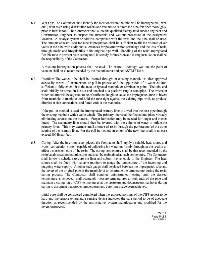
7/25/2019 City Standard Construction Specifications
http://slidepdf.com/reader/full/city-standard-construction-specifications 304/511
027614 Page 5 of 8
Rev. 10-30-2014
6.1 Wet-Out: The Contractor shall identify the location where the tube will be impregnated (“wet-
out”) with resin using distribution rollers and vacuum to saturate the tube felt fiber thoroughly prior to installation. The Contractor shall allow the qualified factory field service engineer and
Construction Engineer to inspect the materials and wet-out procedure at the designated
location. A catalyst system or additive compatible with the resin and the tube shall be used.
The amount of resin used for tube impregnation shall be sufficient to fill the volume of airvoids in the tube with additional allowances for polymerization shrinkage and the loss of resin
through cracks and irregularities in the original pipe wall. Handling of the resin-impregnated
flexible tube to prevent resin setting until it is ready for insertion and during installation shall bethe responsibility of the Contractor.
A vacuum impregnation process shall be used. To insure a thorough wet-out, the point ofvacuum shall be as recommended by the manufacturer and per ASTM F1216.
6.2 Insertion: The wetted tube shall be inserted through an existing manhole or other approved
access by means of an inversion or pull-in process and the application of a water column
sufficient to fully extend it to the next designated manhole or termination point. The tube endshall initially be turned inside out and attached to a platform ring or standpipe. The inversion
water column will be adjusted to be of sufficient height to cause the impregnated tube to invertfrom manhole-to-manhole and hold the tube tight against the existing pipe wall, to produce
dimples at side connections, and flared ends at the manholes.
If the pull-in method is used, the impregnated primary liner is towed into the host pipe through
the existing manhole with a cable winch. The primary liner shall be floated into place virtually
eliminating stresses on the material. Proper lubrication may be needed for longer and thickerliners. The secondary liner should then be inverted with the column of water to inflate the
primary liner. This may extrude small amount of resin through the perforations of the outercoating of the primary liner. For the pull-in method, insertion of the new liner shall in no case
exceed 800 linear feet.
6.3 Curing: After the insertion is completed, the Contractor shall supply a suitable heat source andwater recirculation system capable of delivering hot water uniformly throughout the section to
effect a consistent cure of the resin. The curing temperature shall be that recommended by the
resin/catalyst system manufacturer and shall be maintained at such temperature. The Contractorshall follow a schedule to cure the liner and submit the schedule to the Engineer. The heat
source shall be fitted with suitable monitors to gauge the temperature of the incoming and
outgoing water supply. Another such gauge shall be placed between the impregnated tube andthe invert of the original pipe at the manhole(s) to determine the temperature during the resin
curing process. The Contractor shall continue uninterrupted heating until the desired
temperature is achieved, shall accurately measure temperatures at both ends of the pipe andmaintain a curing log of CIPP temperatures at the upstream and downstream manholes during
curing to document that proper temperatures and cure times have been achieved.
Initial cure shall be considered completed when the exposed portions of the CIPP appear to behard and the remote temperature sensing device indicates the cure period to be of adequate
duration as recommended by the resin/catalyst system manufacturer and modified for the
inversion process.

7/25/2019 City Standard Construction Specifications
http://slidepdf.com/reader/full/city-standard-construction-specifications 305/511
027614 Page 6 of 8
Rev. 10-30-2014
6.4 Cool-Down: The Contractor shall cool the hardened CIPP to a temperature below 100 degreesFahrenheit before relieving the water column. Cool water may be added to the water column
while draining hot water from a small hole at the opposite end of the CIPP so that a constant
water column height is maintained until cool-down is completed. Care shall be taken in the
release of the water column so that a vacuum will not be developed that could damage thenewly installed CIPP. Do not discharge water in excess of 100 degree Fahrenheit into the
wastewater system.
6.5 Warranty: The finished CIPP shall be continuous over the entire length of an inversion run and
be free from visual defects such as foreign inclusions, dry spots, pinholes, lifts and
delamination. It shall also meet the leakage requirements or pressure test specified below. Thefinished CIPP shall be warranted for one year after the acceptance of the Project. During the
warranty period any defects which will affect the integrity or strength of the CIPP shall be
repaired at the Contractor’s expense in a manner mutually agreed to by the City and the
Contractor.
7. SEALING OF MANHOLES
If the CIPP fails to make a tight seal at a manhole, the Contractor shall apply a seal at that point.
The seal shall be of a material compatible with the CIPP material. Do not leave any annular
gaps. Seal the annular space with a 1/2 inch diameter activated oakum band soaked inchemical sealant. Seal any annular spaces greater than 1/2 inch with manhole wall repair
material. Finish off the seal with a non-shrink all solids epoxy placed around the pipe opening
from inside the manhole in a band at least 4 inches wide. Complete the sealing procedure foreach liner segment immediately after the liner is cured.
8. SERVICE CONNECTIONS
After the CIPP has been cured in place, the Contractor shall reopen the existing active service
connections as designated by the Engineer. This shall generally be done without excavation,and in the case of non-man entry pipe, from the interior of the pipeline by means of a television
camera and a robotic cutting device that reestablishes the service connection to not less than
100% capacity. Cutting devices that use high pressure water shall not be used since they maycause damage to the service. When fiberglass or other reinforcing fibers are used, that may
cause wicking at service openings, the service opening edges must be sealed with a resin
mixture compatible with the tube resin. The Contractor shall certify he has a minimum of twocomplete working cutter units plus spare key components on the site before each insertion.
9. TESTING
9.1 Chemical Resistance: The CIPP shall meet the chemical resistance requirements of ASTM F
1216, Appendix X2. The test specimens shall be capable of exposure for a minimum of one
month at a temperature of 73.4ºF. During this period the CIPP test specimens should lose no
more than 20% of their initial flexural strength and flexural modulus when tested in accordancewith Section 8 of ASTM F1216. In Appendix X2, Table X2.1 presents a list of chemical
solutions that serve as a recommended minimum requirement for the chemical-resistant
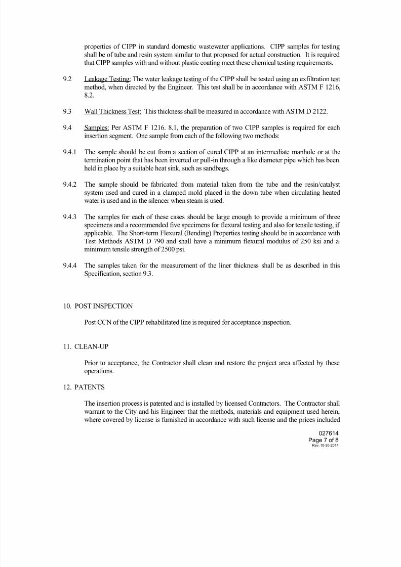
7/25/2019 City Standard Construction Specifications
http://slidepdf.com/reader/full/city-standard-construction-specifications 306/511
027614 Page 7 of 8
Rev. 10-30-2014
properties of CIPP in standard domestic wastewater applications. CIPP samples for testing
shall be of tube and resin system similar to that proposed for actual construction. It is requiredthat CIPP samples with and without plastic coating meet these chemical testing requirements.
9.2 Leakage Testing: The water leakage testing of the CIPP shall be tested using an exfiltration test
method, when directed by the Engineer. This test shall be in accordance with ASTM F 1216,8.2.
9.3 Wall Thickness Test: This thickness shall be measured in accordance with ASTM D 2122.
9.4 Samples: Per ASTM F 1216. 8.1, the preparation of two CIPP samples is required for each
insertion segment. One sample from each of the following two methods:
9.4.1 The sample should be cut from a section of cured CIPP at an intermediate manhole or at the
termination point that has been inverted or pull-in through a like diameter pipe which has been
held in place by a suitable heat sink, such as sandbags.
9.4.2 The sample should be fabricated from material taken from the tube and the resin/catalyst
system used and cured in a clamped mold placed in the down tube when circulating heatedwater is used and in the silencer when steam is used.
9.4.3 The samples for each of these cases should be large enough to provide a minimum of threespecimens and a recommended five specimens for flexural testing and also for tensile testing, if
applicable. The Short-term Flexural (Bending) Properties testing should be in accordance with
Test Methods ASTM D 790 and shall have a minimum flexural modulus of 250 ksi and aminimum tensile strength of 2500 psi.
9.4.4 The samples taken for the measurement of the liner thickness shall be as described in this
Specification, section 9.3.
10. POST INSPECTION
Post CCN of the CIPP rehabilitated line is required for acceptance inspection.
11. CLEAN-UP
Prior to acceptance, the Contractor shall clean and restore the project area affected by theseoperations.
12. PATENTS
The insertion process is patented and is installed by licensed Contractors. The Contractor shall
warrant to the City and his Engineer that the methods, materials and equipment used herein,
where covered by license is furnished in accordance with such license and the prices included
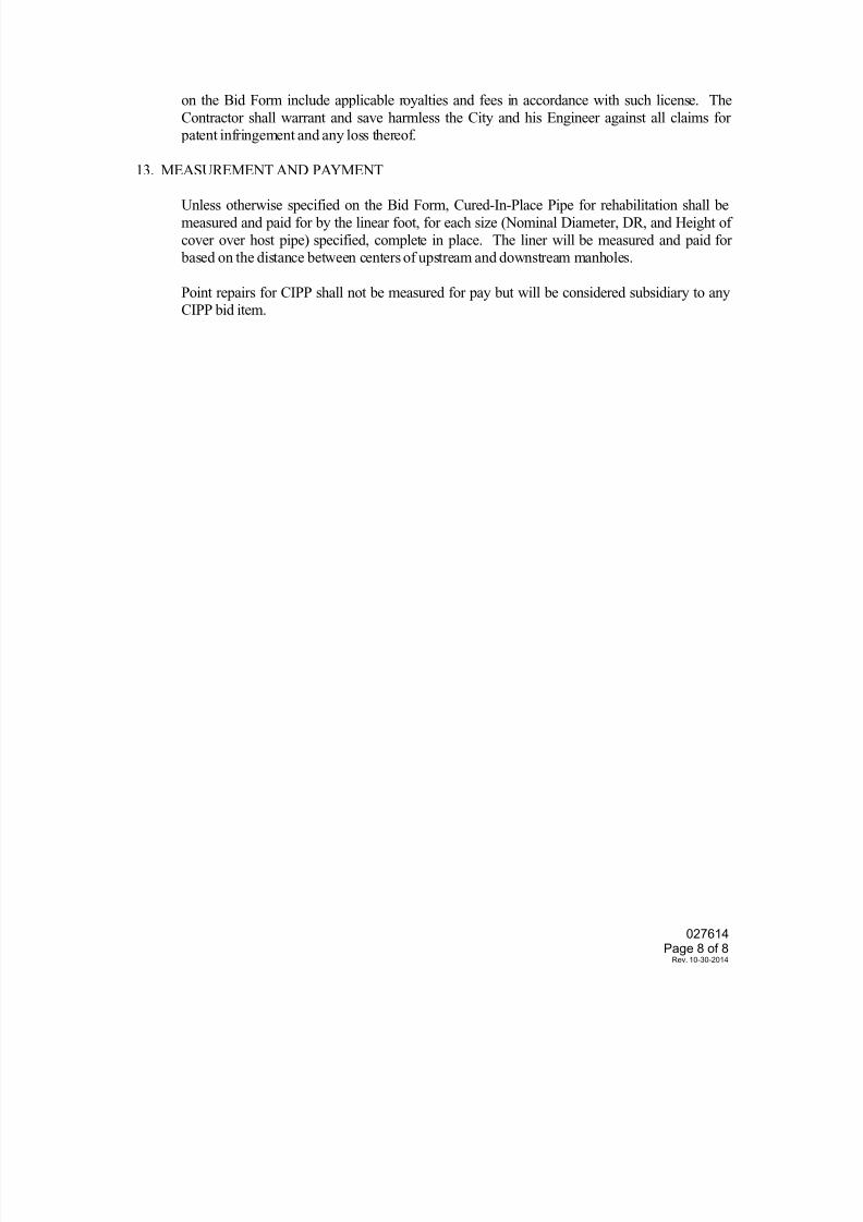
7/25/2019 City Standard Construction Specifications
http://slidepdf.com/reader/full/city-standard-construction-specifications 307/511
027614 Page 8 of 8
Rev. 10-30-2014
on the Bid Form include applicable royalties and fees in accordance with such license. The
Contractor shall warrant and save harmless the City and his Engineer against all claims for patent infringement and any loss thereof.
13. MEASUREMENT AND PAYMENT
Unless otherwise specified on the Bid Form, Cured-In-Place Pipe for rehabilitation shall be
measured and paid for by the linear foot, for each size (Nominal Diameter, DR, and Height of
cover over host pipe) specified, complete in place. The liner will be measured and paid for based on the distance between centers of upstream and downstream manholes.
Point repairs for CIPP shall not be measured for pay but will be considered subsidiary to anyCIPP bid item.
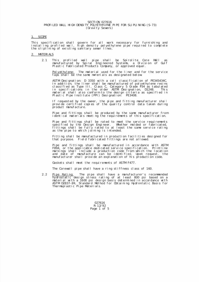
7/25/2019 City Standard Construction Specifications
http://slidepdf.com/reader/full/city-standard-construction-specifications 308/511
027616R- 12/ 92
Page 1 of 5
SECTI ON 027616 PROFI LED WALL HI GH DENSI TY POLYETHYLENE PI PE FOR SLI PLI NI NG ( S- 73)
( Gr avi t y Sewers )
1. SCOPE
Thi s speci f i cat i on shal l govern f or al l work necessary f or f urni shi ng andi nst al l i ng pr of i l ed wal l , hi gh densi t y pol yet hyl ene pi pe r equi r ed t o compl et et he sl i pl i ni ng of exi sti ng sani t ar y sewer l i nes.
2. MATERI ALS
2. 1 Thi s pr of i l ed wal l pi pe shal l be Spi r ol i t e Cor e Wal l asmanuf act ur ed by Spi r al Engi neered Syst ems, a Di vi si on of Gul fPl ast i c Fabr i cated Product s Company, or appr oved equal .
Pol yet hyl ene: The mat er i al used f or t he l i ner and f or t he ser vi cet aps shal l be the same materi al s as desi gnated bel ow.
ASTM Desi gnat i on: D 3350 wi t h a cel l cl assi f i cat i on of PE345434C.I n addi t i on, t he l i ner shal l be manuf act ur ed of pol yet hyl ene r esi nscl assi f i ed as Type I I I , Cl ass C, Cat egor y 5 Gr ade P34 as t abul at ed
i n speci f i cat i ons i n t he ol der ASTM Desi gnat i on, D1248. Thi smat er i al shal l al so conf or m t o t he desi gn cri t er i a as speci f i ed i nPl ast i c Pi pe I nst i t ut e ( PPI ) Desi gnat i on: PE3408.
I f r equest ed by t he owner , t he pi pe and f i t t i ng manuf act ur er shal lpr ovi de cer t i f i ed copi es of t he qual i t y cont r ol dat a t aken dur i ngpr oduct manuf actur e.
Pi pe and f i t t i ngs shal l be pr oduced by t he same manuf act ur er f r omi dent i cal mat er i al s meet i ng t he r equi r ement s of t hi s speci f i cat i on.
Pi pe and f i t t i ngs shal l be rat ed to meet t he ser vi ce r equi r ement sspeci f i ed by t he Desi gn Engi neer . Whet her mol ded or f abr i cat ed,f i t t i ngs shal l be f ul l y r at ed t o at l east t he same ser vi ce r at i ngas t he pi pe t o whi ch j oi ni ng i s i nt ended.
Fi t t i ng shal l be manuf act ur ed i n pr oduct i on f aci l i t i es desi gned f ort hat pur pose. Fi el d f abr i cat ed f i t t i ngs ar e not al l owed.
Pi pe and f i t t i ngs shal l be manuf act ur ed i n accor dance wi t h ASTMF894, or t he appl i cabl e dedi cat ed ser vi ce speci f i cat i on. Pr i nt l i nemar ki ngs shal l i ncl ude a pr oduct i on code f r om whi ch t he l ocat i onand dat e of manuf actur e can be i dent i f i ed. Upon r equest , t hemanuf act ur er shal l pr ovi de an expl anat i on of hi s pr oduct i on code.
Gasket s shal l meet t he requi r ement s of ASTM F477.
The Corewal l pi pe shal l have a r i ng st i f f ness cl ass of 160.
2. 2 Pi pe Rat i ng: The pi pe shal l have a manuf act urer ' s r ecommended
hydr ost at i c desi gn st r ess r at i ng of at l east 800 psi based on amateri al wi t h a 1600 psi desi gn basi s det ermi ned i n accor dance wi t hASTM D2837- 69, St andar d Met hod f or Obt ai ni ng Hydr ostat i c Basi s f or
Thermopl ast i c Pi pe Mat er i al s.
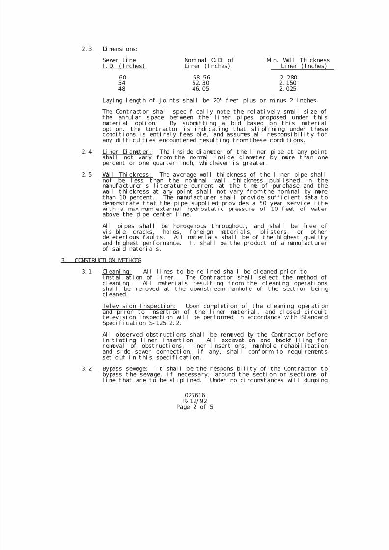
7/25/2019 City Standard Construction Specifications
http://slidepdf.com/reader/full/city-standard-construction-specifications 309/511
027616R- 12/ 92
Page 2 of 5
2. 3 Di mensi ons:
Sewer Li ne Nomi nal O. D. of Mi n. Wal l Thi cknessI . D. ( I nches) Li ner ( I nches) Li ner ( I nches)
60 58. 56 2. 28054 52. 30 2. 15048 46. 05 2. 025
Layi ng l engt h of j oi nt s shal l be 20' f eet pl us or mi nus 2 i nches.
The Contr act or shal l speci f i cal l y note t he r el at i vel y smal l si ze oft he annul ar space bet ween t he l i ner pi pes pr oposed under t hi smat er i al opt i on. By submi t t i ng a bi d based on t hi s mat er i alopt i on, t he Cont r actor i s i ndi cat i ng t hat sl i pl i ni ng under t hesecondi t i ons i s ent i r el y f easi bl e, and assumes al l r esponsi bi l i t y f orany di f f i cul t i es encount er ed r esul t i ng f r om t hese condi t i ons.
2. 4 Li ner Di amet er : The i nsi de di amet er of t he l i ner pi pe at any poi ntshal l not var y f r om t he normal i nsi de di amet er by more t han oneper cent or one quar t er i nch, whi chever i s great er .
2. 5 Wal l Thi ckness: The aver age wal l t hi ckness of t he l i ner pi pe shal lnot be l ess t han t he nomi nal wal l t hi ckness publ i shed i n t hemanuf act ur er ' s l i t er atur e cur r ent at t he t i me of pur chase and t hewal l t hi ckness at any poi nt shal l not vary f r omt he nomi nal by moret han 10 per cent . The manuf act ur er shal l pr ovi de suf f i ci ent dat a t odemonst r ate t hat t he pi pe suppl i ed pr ovi des a 50 year servi ce l i f ewi t h a maxi mum ext er nal hydr ostat i c pr essure of 10 f eet of wat erabove the pi pe cent er l i ne.
Al l pi pes shal l be homogenous t hr oughout , and shal l be f r ee ofvi si bl e cracks, hol es, f or ei gn mat eri al s, bl i sters, or ot herdel et er i ous f aul t s. Al l mat er i al s shal l be of t he hi ghest qual i t yand hi ghest per f ormance. I t shal l be t he pr oduct of a manuf act ur erof sai d mat er i al s.
3. CONSTRUCTI ON METHODS
3. 1 Cl eani ng: Al l l i nes t o be r el i ned shal l be cl eaned pr i or t oi nst al l at i on of l i ner . The Cont r act or shal l sel ect t he met hod ofcl eani ng. Al l mat er i al s r esul t i ng f r om t he cl eani ng oper at i onsshal l be removed at t he downst r eam manhol e of t he sect i on bei ngcl eaned.
Tel evi si on I nspect i on: Upon compl et i on of t he cl eani ng oper at i onand pr i or t o i nser t i on of t he l i ner mat er i al , and cl osed ci r cui tt el evi si on i nspect i on wi l l be per f ormed i n accor dance wi t h St andar dSpeci f i cat i on S- 125. 2. 2.
Al l observed obst r uct i ons shal l be removed by t he Cont r act or bef orei ni t i at i ng l i ner i nsert i on. Al l excavat i on and backf i l l i ng f or
r emoval of obst r uct i ons, l i ner i nser t i ons, manhol e r ehabi l i t at i onand si de sewer connect i on, i f any, shal l conf or m t o r equi r ement sset out i n t hi s speci f i cat i on.
3. 2 Bypass sewage: I t shal l be t he r esponsi bi l i t y of t he Cont r act or t obypass t he sewage, i f necessary, ar ound t he sect i on or sect i ons ofl i ne t hat ar e t o be sl i pl i ned. Under no ci r cumst ances wi l l dumpi ng
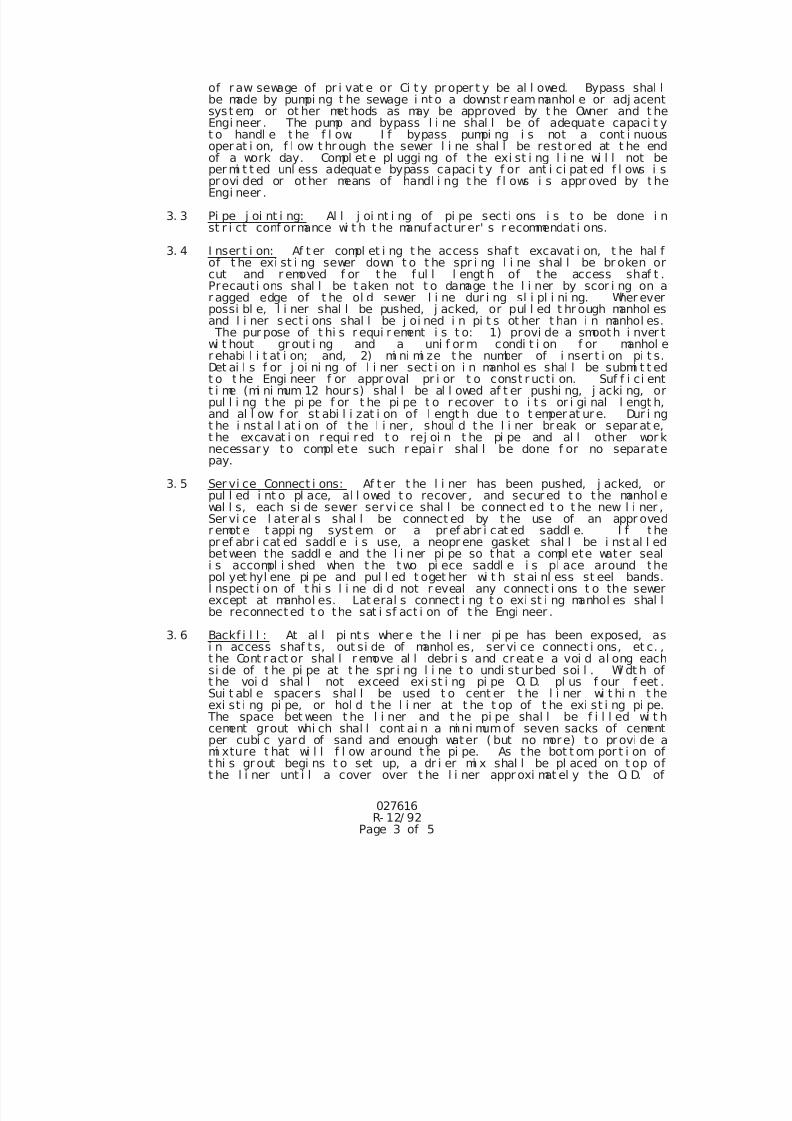
7/25/2019 City Standard Construction Specifications
http://slidepdf.com/reader/full/city-standard-construction-specifications 310/511
027616R- 12/ 92
Page 3 of 5
of r aw sewage of pr i vat e or Ci t y pr oper t y be al l owed. Bypass shal lbe made by pumpi ng t he sewage i nto a downst r eammanhol e or adj acentsyst em, or ot her met hods as may be approved by t he Owner and t heEngi neer . The pump and bypass l i ne shal l be of adequate capaci t yt o handl e t he f l ow. I f bypass pumpi ng i s not a cont i nuousoper at i on, f l ow t hr ough the sewer l i ne shal l be rest or ed at t he endof a work day. Compl et e pl uggi ng of t he exi st i ng l i ne wi l l not beper mi t t ed unl ess adequat e bypass capaci t y f or ant i ci pat ed f l ows i spr ovi ded or other means of handl i ng t he f l ows i s appr oved by t heEngi neer .
3. 3 Pi pe j oi nt i ng: Al l j oi nt i ng of pi pe secti ons i s t o be done i nst r i ct conf ormance wi t h t he manuf actur er' s r ecommendat i ons.
3. 4 I nser t i on: Af t er compl et i ng t he access shaf t excavat i on, t he hal fof t he exi st i ng sewer down t o t he spr i ng l i ne shal l be br oken orcut and r emoved f or t he f ul l l engt h of t he access shaf t .Precaut i ons shal l be t aken not t o damage t he l i ner by scor i ng on ar agged edge of t he ol d sewer l i ne dur i ng sl i pl i ni ng. Wher everpossi bl e, l i ner shal l be pushed, j acked, or pul l ed t hr ough manhol esand l i ner sect i ons shal l be j oi ned i n pi t s ot her t han i n manhol es. The pur pose of t hi s r equi r ement i s t o: 1) provi de a smooth i nver twi t hout gr out i ng and a uni f or m condi t i on f or manhol e
r ehabi l i t at i on; and, 2) mi ni mi ze t he number of i nser t i on pi t s.Det ai l s f or j oi ni ng of l i ner sect i on i n manhol es shal l be submi t t edt o t he Engi neer f or appr oval pr i or t o const r ucti on. Suf f i ci entt i me (mi ni mum 12 hour s) shal l be al l owed af t er pushi ng, j acki ng, orpul l i ng t he pi pe f or t he pi pe t o r ecover t o i t s or i gi nal l engt h,and al l ow f or st abi l i zat i on of l engt h due t o t emper at ur e. Dur i ngt he i nst al l at i on of t he l i ner , shoul d t he l i ner br eak or separ at e,t he excavat i on r equi r ed t o rej oi n t he pi pe and al l other wor knecessar y to compl ete such r epai r shal l be done f or no separatepay.
3. 5 Ser vi ce Connect i ons: Af t er t he l i ner has been pushed, j acked, orpul l ed i nt o pl ace, al l owed t o recover , and secur ed t o the manhol ewal l s, each si de sewer servi ce shal l be connect ed t o t he new l i ner ,Ser vi ce l ater al s shal l be connect ed by t he use of an appr oved
r emot e t appi ng syst em or a pr ef abr i cat ed saddl e. I f thepr ef abr i cat ed saddl e i s use, a neopr ene gasket shal l be i nst al l edbetween the saddl e and the l i ner pi pe so that a compl ete water seali s accompl i shed when t he two pi ece saddl e i s pl ace around thepol yet hyl ene pi pe and pul l ed t oget her wi t h st ai nl ess st eel bands.I nspect i on of t hi s l i ne di d not r eveal any connect i ons t o the sewerexcept at manhol es. Lat eral s connect i ng t o exi st i ng manhol es shal lbe reconnect ed t o the sat i sf act i on of t he Engi neer .
3. 6 Backf i l l : At al l pi nt s wher e t he l i ner pi pe has been exposed, asi n access shaf t s, out si de of manhol es, ser vi ce connect i ons, et c. ,t he Cont r act or shal l r emove al l debr i s and cr eat e a voi d al ong eachsi de of t he pi pe at t he spr i ng l i ne t o undi st ur bed soi l . Wi dt h oft he voi d shal l not exceed exi st i ng pi pe O. D. pl us f our f eet .Sui t abl e spacer s shal l be used t o cent er t he l i ner wi t hi n t he
exi st i ng pi pe, or hol d t he l i ner at t he t op of t he exi st i ng pi pe. The space bet ween t he l i ner and t he pi pe shal l be f i l l ed wi t hcement grout whi ch shal l cont ai n a mi ni mumof seven sacks of cementper cubi c yard of sand and enough water ( but no more) t o pr ovi de ami xture t hat wi l l f l ow ar ound t he pi pe. As the bot t om por t i on oft hi s gr out begi ns t o set up, a dr i er mi x shal l be pl aced on t op oft he l i ner unt i l a cover over t he l i ner appr oxi mat el y the O. D. of
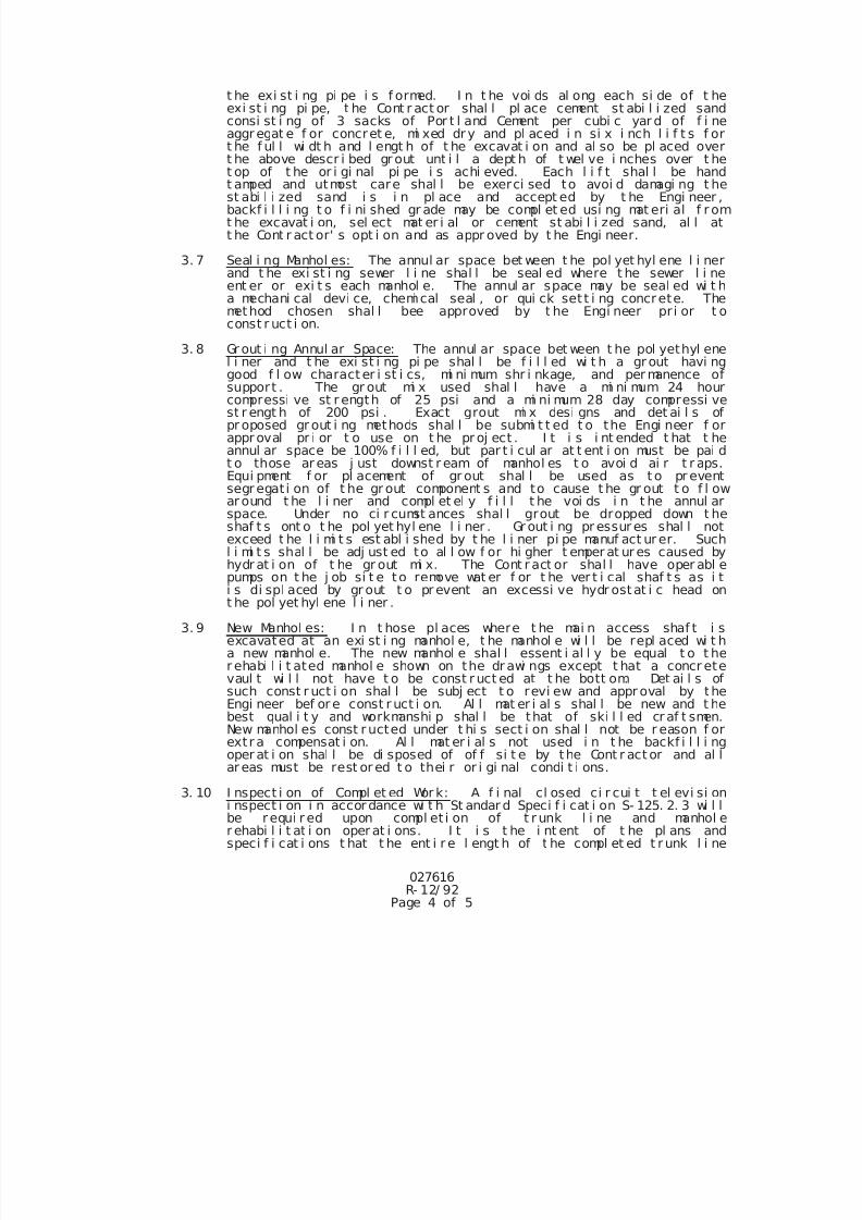
7/25/2019 City Standard Construction Specifications
http://slidepdf.com/reader/full/city-standard-construction-specifications 311/511
027616R- 12/ 92
Page 4 of 5
t he exi st i ng pi pe i s f ormed. I n t he voi ds al ong each si de of t heexi st i ng pi pe, t he Cont r act or shal l pl ace cement st abi l i zed sandconsi st i ng of 3 sacks of Por t l and Cement per cubi c yar d of f i neaggr egat e f or concret e, mi xed dr y and pl aced i n si x i nch l i f t s f ort he f ul l wi dt h and l engt h of t he excavat i on and al so be pl aced overt he above descr i bed gr out unt i l a dept h of t wel ve i nches over t het op of t he or i gi nal pi pe i s achi eved. Each l i f t shal l be handt amped and utmost care shal l be exerci sed to avoi d damagi ng t hest abi l i zed sand i s i n pl ace and accept ed by t he Engi neer ,backf i l l i ng t o f i ni shed gr ade may be compl et ed usi ng mat eri al f r omt he excavat i on, sel ect mat er i al or cement st abi l i zed sand, al l att he Cont r act or' s opt i on and as appr oved by t he Engi neer.
3. 7 Seal i ng Manhol es: The annul ar space bet ween t he pol yet hyl ene l i nerand t he exi st i ng sewer l i ne shal l be seal ed where t he sewer l i neent er or exi t s each manhol e. The annul ar space may be seal ed wi t ha mechani cal devi ce, chemi cal seal , or qui ck set t i ng concrete. Themethod chosen shal l bee approved by t he Engi neer pr i or t oconst r uct i on.
3. 8 Gr out i ng Annul ar Space: The annul ar space bet ween t he pol yethyl enel i ner and t he exi st i ng pi pe shal l be f i l l ed wi t h a gr out havi nggood f l ow charact er i st i cs, mi ni mum shr i nkage, and per manence of
support . The gr out mi x used shal l have a mi ni mum 24 hourcompressi ve st r ength of 25 psi and a mi ni mum 28 day compressi vest r engt h of 200 psi . Exact grout mi x desi gns and det ai l s ofpr oposed gr out i ng methods shal l be submi t t ed t o the Engi neer f orappr oval pr i or t o use on t he pr oj ect . I t i s i nt ended t hat t heannul ar space be 100% f i l l ed, but par t i cul ar at t ent i on must be pai dt o those ar eas j ust downst r eam of manhol es t o avoi d ai r t r aps.Equi pment f or pl acement of gr out shal l be used as t o pr eventsegr egat i on of t he gr out component s and to cause t he gr out t o f l owar ound t he l i ner and compl et el y f i l l t he voi ds i n t he annul arspace. Under no ci r cumst ances shal l grout be dropped down t heshaf t s ont o t he pol yet hyl ene l i ner . Gr out i ng pr essur es shal l notexceed t he l i mi t s est abl i shed by t he l i ner pi pe manuf act ur er. Suchl i mi t s shal l be adj ust ed to al l ow f or hi gher t emper at ur es caused byhydr at i on of t he gr out mi x. The Cont r act or shal l have oper abl e
pumps on t he j ob si t e to remove wat er f or t he ver t i cal shaf t s as i ti s di spl aced by gr out t o pr event an excessi ve hydr ostat i c head ont he pol yet hyl ene l i ner .
3. 9 New Manhol es: I n t hose pl aces where t he mai n access shaf t i sexcavated at an exi st i ng manhol e, t he manhol e wi l l be repl aced wi t ha new manhol e. The new manhol e shal l essent i al l y be equal t o t her ehabi l i t ated manhol e shown on the dr awi ngs except t hat a concr etevaul t wi l l not have t o be const r uct ed at t he bott om. Det ai l s ofsuch const r uct i on shal l be subj ect t o revi ew and appr oval by theEngi neer bef or e const r uct i on. Al l mat er i al s shal l be new and t hebest qual i t y and workmanshi p shal l be that of ski l l ed cr af t smen.New manhol es const r ucted under t hi s sect i on shal l not be r eason f orextr a compensat i on. Al l mat er i al s not used i n t he backf i l l i ngoper at i on shal l be di sposed of of f si t e by the Cont r act or and al l
ar eas must be rest or ed t o thei r or i gi nal condi t i ons.3. 10 I nspect i on of Compl et ed Wor k: A f i nal cl osed ci r cui t t el evi si on
i nspect i on i n accor dance wi t h St andar d Speci f i cat i on S- 125. 2. 3 wi l lbe requi r ed upon compl et i on of t r unk l i ne and manhol er ehabi l i t at i on oper at i ons. I t i s t he i nt ent of t he pl ans andspeci f i cat i ons t hat t he ent i r e l engt h of t he compl et ed t r unk l i ne
7/25/2019 City Standard Construction Specifications
http://slidepdf.com/reader/full/city-standard-construction-specifications 312/511
027616R- 12/ 92
Page 5 of 5
r ehabi l i t at i on be i nspect ed, however , t he Cont r act or shal l have t heopt i on of per f or mi ng f i nal i nspect i on of sect i ons of t he t r unk l i neas compl et ed. The t i me, l ocat i on, and l engt h of f i nal i nspect i onsshal l be as appr oved by t he Engi neer .
4. CLEANUP
Af t er al l i nst al l at i on wor k has been compl et ed, t he Cont r act orshal l cl eanup t he ar ea around t he work area and return t he gr oundcover t o a l i ke or bet t er condi t i on as exi st ed pr i or t oconst r uct i on. Al l pavement s shal l be r epai r ed as speci f i ed. Al lbr oken pi pe, and ot her mat er i al not a par t of t he gr ound covershal l be haul ed of f and pr oper l y di sposed of t he Cont r act or .
5. MEASUREMENT AND PAYMENT
Unl ess i ndi cat ed other wi se i n t he Pr oposal , Sani t ar y Sewer Sl i pl i ni ngwi l l be measur ed by the l i near f oot f or each si ze i nst al l ed.
7/25/2019 City Standard Construction Specifications
http://slidepdf.com/reader/full/city-standard-construction-specifications 313/511
SECTION 027618
WASTEWATER LINE REHABILITATION / PIPEBURSTING
1. SCOPE
This specification shall govern all work necessary to rehabilitate gravity wastewater lines by
pipebursting, wherein a horizontal boring technique utilizing a cutting/expansive tool head fragments
the existing pipe, and a fusion welded, high density polyethylene pipe is drawn into the resulting
tunnel.
2. MATERIALS
2.1 Polyethylene:
ASTM Designation: D-3350 with a cell classification of 335434B D or E (with inner
wall of light color). In addition, the liner shall be manufactured of polyethylene resinsclassified as Type III, Class C, Category 5, Grade P34, as tabulated in specifications
in the older ASTM Designation, D-1248. This material shall also conform to the
design criteria as specified in Plastic Pipe Institute (PPI) Designation: PE3408.
2.2 Dimensions: The pipe shall be (SDR 17, IPS) per ASTM F714 of the nominal
diameter as shown on the plans and specified in the Bid Form, unless TCEQ
requirements for water and wastewater line separation require pressure rated pipe of
at least 150 psi, in which case DR 11, IPS pipe shall be utilized. At this pressure
rating, a larger pipe may be required to maintain equivalent flow characteristics and
hydraulic radius to the existing wastewater line.
2.3 Quality: All pipe shall be homogenous throughout, and shall be free of visible
cracks, holes, foreign materials, blisters, or other deleterious faults. All materials
shall be of the highest quality and highest performance. It shall be the product of a
manufacturer actively engaged in research, development, and the manufacturer of
said materials.
3. CONSTRUCTION METHODS
3.1 Pipe Jointing: Sections of the polyethylene (PE) liner pipe shall be joined by the
butt-fusion method and performed in strict conformance with the pipe manufacturer's
recommendations using approved equipment. The Contractor shall makearrangements to have a technical representative of the pipe manufacturer present for
the start-up of the butt-fusion jointing and training of the contractor's personnel, or
arrangements shall be made for the pipe manufacturer's representative to remain on
the job until all jointing has been completed. When requested by the Engineer,
samples of butt-fusion joints shall be furnished by the contractor for laboratory
027618 Page 1 of 4
Rev. 3-25-2015
7/25/2019 City Standard Construction Specifications
http://slidepdf.com/reader/full/city-standard-construction-specifications 314/511
testing. The test of such samples shall clearly demonstrate joint integrity, strength,
etc.
3.2 Insertion Pits: The location and number of insertion pits shall be determined by the
Contractor to maximize insertion lengths and keep the number of excavations to a
minimum. The insertion pit size shall be the minimum necessary to perform insertionoperations. Locations of insertion pits shall be acceptable to the Engineer.
Removal of obstructions and point repairs shall be done as necessary. This work
shall be done in accordance with Section 022020 of the City Standard Specifications,
“Excavation and Backfill for Utilities.”
3.3 Pulling Pipe: New polyethylene pipe shall be pulled immediately behind the pipe
bursting equipment in accordance with the manufacturer's procedures. The machine
shall be specifically designed and manufactured for the pipe insertion process.
The Contractor shall install all pulleys, rollers, bumpers, alignment control devices,and other equipment, required to protect existing manholes, and to protect the pipe
from damage during installation. Lubrication may be used as recommended by the
pipe manufacturer. Under no circumstances shall the pipe be stressed beyond 50% of
its tensile strength at yield, that being 22,600 lb. for an 8" SDR 17 pipe. Provide a
suitable pull measuring device connected to the winch or pulling system.
Upon commencement, insertion shall be continuous without interruption, if possible.
Terminal sections of pipe that are joined within the insertion pit shall be connected
with a 1/4" thick neoprene gasket and a stainless steel band clamp having a minimum
of 4 bolt/nut drawn down fixtures. The butt gap between pipe ends shall not exceed1/2".
The installed pipe shall be allowed the manufacturer's recommended amount of time,
but not less than 24 hours, for relaxation prior to any reconnection of service lines,
sealing of the annulus, or backfilling the insertion pit. Sufficient excess length shall
be allowed to provide for this occurrence.
3.4 Service Connections: All service connections shall be identified, excavated, and
disconnected prior to pipe bursting. After the new main has been pulled into place,
allowed to recover, and secured to the manhole walls, each service shall be
reconnected to the new main. Services shall be connected by the use of an approved
pre-fabricated saddle. The pre-fabricated saddle shall be equipped with a neoprene
gasket installed between the saddle and the liner pipe so that a complete water seal is
accomplished when the two-piece saddle is placed around the polyethylene pipe and
pulled together with stainless steel bands. Drill hole in main shall be flush with the
inside diameter of the saddle. Continuous service shall be maintained.
027618 Page 2 of 4
Rev. 3-25-2015
7/25/2019 City Standard Construction Specifications
http://slidepdf.com/reader/full/city-standard-construction-specifications 315/511
3.5 Annulus Sealing: The relaxed pipe shall be cut 4" inside of manholes and any annular
space sealed. The annular space may be sealed with a mechanical device, chemical
seal, or quick-setting concrete. The method chosen shall be approved by the Engineer
prior to construction. The sealant shall extend at least 8-inches past the outside of the
manhole wall. The sealant shall form a smooth transition above the liner projection
into the manhole. The sealant shall be applied 3" beyond the annulus on the insidewall of the manhole. The complete joint shall be uniform and water-tight.
3.6 Backfill: The insertion pit(s) shall be backfilled with an approved granular material
from the invert to a minimum of 12" above the pipe. The balance of the insertion pit
may be backfilled using approved material taken from the excavation. All backfilling
shall be accomplished in such a manner as to achieve a 95% Standard Proctor
density.
3.7 By-Pass Wastewater Flows: It shall be the responsibility of the Contractor to maintain
continuous flow of wastewater, during execution of work. This includes flow of all
mains, laterals, and services. Pumps and by-pass lines shall be of adequate capacityto handle all flows. Dumping of raw sewage on private or city property shall not be
allowed. By-pass shall be made by pumping the sewage into the downstream manhole
or adjacent system, or other methods as may be approved by the Owner and the
Engineer. All bypass pumping must be per City Standard Specification Section
027200 “Control of Wastewater Flows.”
4. DELIVERY, STORAGE AND HANDLING OF MATERIALS:
The Contractor shall be responsible for all handing and security of the materials.
5. CLEANUP:
The Contractor shall clean up the area around the work area and restore surface improvements to a
like or better condition as existed prior to construction. All pavement shall be repaired as specified.
All broken pipe and other unwanted material shall become property of the Contractor and hauled off
and disposed by the Contractor.
6. TELEVISION INSPECTION:
Television inspection of pipeline shall be performed by experienced personnel, in accordance with
City Standard Specification 027611. Television inspection shall be per the following:
Post Construction video DVD of each wastewater line shall include voice description and stationing
of each service indicated. Data and stationing shall be visually displayed on video.
By-pass or diversion of flow shall be done by the Contractor as necessary to obtain acceptable video.
027618 Page 3 of 4
Rev. 3-25-2015
7/25/2019 City Standard Construction Specifications
http://slidepdf.com/reader/full/city-standard-construction-specifications 316/511
If any portion of the inspection DVD be deemed inadequate by the City, the Contractor shall re-video
that portion to the satisfaction of the City at no additional expense to the City. DVDs of all work
shall be furnished to the City prior to acceptance of work. One copy shall become property of The
City and retained by the City.
7. TESTING:
After the proposed line has been completed, internally inspected with video camera and record as
required. DVD shall be furnished to the City prior to acceptance of work.
Manholes and services are to be tested as described elsewhere.
8. MEASUREMENT AND PAYMENT:
Unless indicated otherwise in the Bid Form, Wastewater Rehabilitation / Pipebursting will be
measured by the linear foot for each size and depth range installed. Payment shall include, but not be
limited to, all materials, labor, equipment and incidentals required for (other than pavement repair)trenching, installing the new line, surface restoration, clean-up, televised inspection, and other work
as may be required.
027618 Page 4 of 4
Rev. 3-25-2015
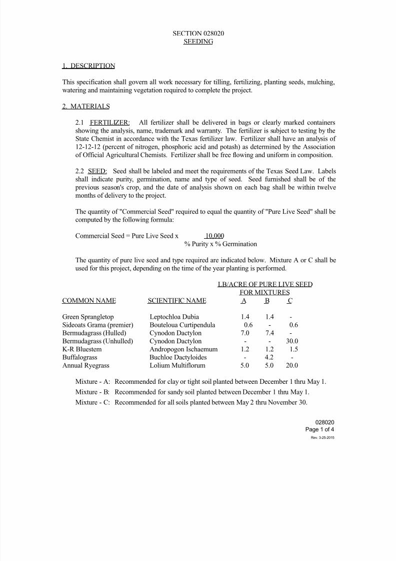
7/25/2019 City Standard Construction Specifications
http://slidepdf.com/reader/full/city-standard-construction-specifications 317/511
SECTION 028020
SEEDING
1. DESCRIPTION
This specification shall govern all work necessary for tilling, fertilizing, planting seeds, mulching,
watering and maintaining vegetation required to complete the project.
2. MATERIALS
2.1 FERTILIZER: All fertilizer shall be delivered in bags or clearly marked containers
showing the analysis, name, trademark and warranty. The fertilizer is subject to testing by the
State Chemist in accordance with the Texas fertilizer law. Fertilizer shall have an analysis of
12-12-12 (percent of nitrogen, phosphoric acid and potash) as determined by the Association
of Official Agricultural Chemists. Fertilizer shall be free flowing and uniform in composition.
2.2 SEED: Seed shall be labeled and meet the requirements of the Texas Seed Law. Labels
shall indicate purity, germination, name and type of seed. Seed furnished shall be of the previous season's crop, and the date of analysis shown on each bag shall be within twelve
months of delivery to the project.
The quantity of "Commercial Seed" required to equal the quantity of "Pure Live Seed" shall be
computed by the following formula:
Commercial Seed = Pure Live Seed x 10,000
% Purity x % Germination
The quantity of pure live seed and type required are indicated below. Mixture A or C shall be
used for this project, depending on the time of the year planting is performed.
LB/ACRE OF PURE LIVE SEED
FOR MIXTURES
COMMON NAME SCIENTIFIC NAME A B C
Green Sprangletop Leptochloa Dubia 1.4 1.4 -
Sideoats Grama (premier) Bouteloua Curtipendula 0.6 - 0.6
Bermudagrass (Hulled) Cynodon Dactylon 7.0 7.4 -
Bermudagrass (Unhulled) Cynodon Dactylon - - 30.0
K-R Bluestem Andropogon Ischaemum 1.2 1.2 1.5
Buffalograss Buchloe Dactyloides - 4.2 -Annual Ryegrass Lolium Multiflorum 5.0 5.0 20.0
Mixture - A: Recommended for clay or tight soil planted between December 1 thru May 1.
Mixture - B: Recommended for sandy soil planted between December 1 thru May 1.
Mixture - C: Recommended for all soils planted between May 2 thru November 30.
028020
Page 1 of 4
Rev. 3-25-2015
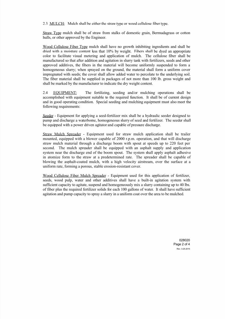
7/25/2019 City Standard Construction Specifications
http://slidepdf.com/reader/full/city-standard-construction-specifications 318/511
2.3 MULCH: Mulch shall be either the straw type or wood cellulose fiber type.
Straw Type mulch shall be of straw from stalks of domestic grain, Bermudagrass or cotton
hulls, or other approved by the Engineer.
Wood Cellulose Fiber Type mulch shall have no growth inhibiting ingredients and shall be
dried with a moisture content less that 10% by weight. Fibers shall be dyed an appropriatecolor to facilitate visual metering and application of mulch. The cellulose fiber shall be
manufactured so that after addition and agitation in slurry tank with fertilizers, seeds and other
approved additives, the fibers in the material will become uniformly suspended to form a
homogeneous slurry; when sprayed on the ground, the material shall form a uniform cover
impregnated with seeds; the cover shall allow added water to percolate to the underlying soil.
The fiber material shall be supplied in packages of not more than 100 lb. gross weight and
shall be marked by the manufacturer to indicate the dry weight content.
2.4 EQUIPMENT: The fertilizing, seeding and/or mulching operations shall be
accomplished with equipment suitable to the required function. It shall be of current design
and in good operating condition. Special seeding and mulching equipment must also meet thefollowing requirements:
Seeder - Equipment for applying a seed-fertilizer mix shall be a hydraulic seeder designed to
pump and discharge a waterborne, homogeneous slurry of seed and fertilizer. The seeder shall
be equipped with a power driven agitator and capable of pressure discharge.
Straw Mulch Spreader - Equipment used for straw mulch application shall be trailer
mounted, equipped with a blower capable of 2000 r.p.m. operation, and that will discharge
straw mulch material through a discharge boom with spout at speeds up to 220 feet per
second. The mulch spreader shall be equipped with an asphalt supply and application
system near the discharge end of the boom spout. The system shall apply asphalt adhesivein atomize form to the straw at a predetermined rate. The spreader shall be capable of
blowing the asphalt-coated mulch, with a high velocity airstream, over the surface at a
uniform rate, forming a porous, stable erosion-resistant cover.
Wood Cellulose Fiber Mulch Spreader - Equipment used for this application of fertilizer,
seeds, wood pulp, water and other additives shall have a built-in agitation system with
sufficient capacity to agitate, suspend and homogeneously mix a slurry containing up to 40 lbs.
of fiber plus the required fertilizer solids for each 100 gallons of water. It shall have sufficient
agitation and pump capacity to spray a slurry in a uniform coat over the area to be mulched.
028020
Page 2 of 4
Rev. 3-25-2015
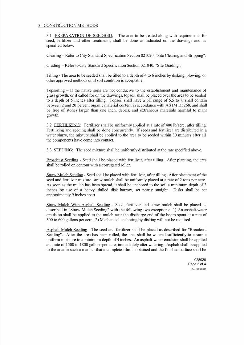
7/25/2019 City Standard Construction Specifications
http://slidepdf.com/reader/full/city-standard-construction-specifications 319/511
3. CONSTRUCTION METHODS
3.1 PREPARATION OF SEEDBED: The area to be treated along with requirements for
seed, fertilizer and other treatments, shall be done as indicated on the drawings and as
specified below.
Clearing – Refer to City Standard Specification Section 021020, "Site Clearing and Stripping".
Grading - Refer to City Standard Specification Section 021040, "Site Grading".
Tilling - The area to be seeded shall be tilled to a depth of 4 to 6 inches by disking, plowing, or
other approved methods until soil condition is acceptable.
Topsoiling – If the native soils are not conducive to the establishment and maintenance of
grass growth, or if called for on the drawings, topsoil shall be placed over the area to be seeded
to a depth of 5 inches after tilling. Topsoil shall have a pH range of 5.5 to 7; shall contain
between 2 and 20 percent organic material content in accordance with ASTM D5268; and shall
be free of stones larger than one inch, debris, and extraneous materials harmful to plantgrowth.
3.2 FERTILIZING: Fertilizer shall be uniformly applied at a rate of 400 lb/acre, after tilling.
Fertilizing and seeding shall be done concurrently. If seeds and fertilizer are distributed in a
water slurry, the mixture shall be applied to the area to be seeded within 30 minutes after all
the components have come into contact.
3.3 SEEDING: The seed mixture shall be uniformly distributed at the rate specified above.
Broadcast Seeding - Seed shall be placed with fertilizer, after tilling. After planting, the area
shall be rolled on contour with a corrugated roller.
Straw Mulch Seeding - Seed shall be placed with fertilizer, after tilling. After placement of the
seed and fertilizer mixture, straw mulch shall be uniformly placed at a rate of 2 tons per acre.
As soon as the mulch has been spread, it shall be anchored to the soil a minimum depth of 3
inches by use of a heavy, dulled disk harrow, set nearly straight. Disks shall be set
approximately 9 inches apart.
Straw Mulch With Asphalt Seeding - Seed, fertilizer and straw mulch shall be placed as
described in "Straw Mulch Seeding" with the following two exceptions: 1) An asphalt-water
emulsion shall be applied to the mulch near the discharge end of the boom spout at a rate of
300 to 600 gallons per acre. 2) Mechanical anchoring by disking will not be required.
Asphalt Mulch Seeding - The seed and fertilizer shall be placed as described for "Broadcast
Seeding". After the area has been rolled, the area shall be watered sufficiently to assure a
uniform moisture to a minimum depth of 4 inches. An asphalt-water emulsion shall be applied
at a rate of 1500 to 1800 gallons per acre, immediately after watering. Asphalt shall be applied
to the area in such a manner that a complete film is obtained and the finished surface shall be
028020
Page 3 of 4
Rev. 3-25-2015
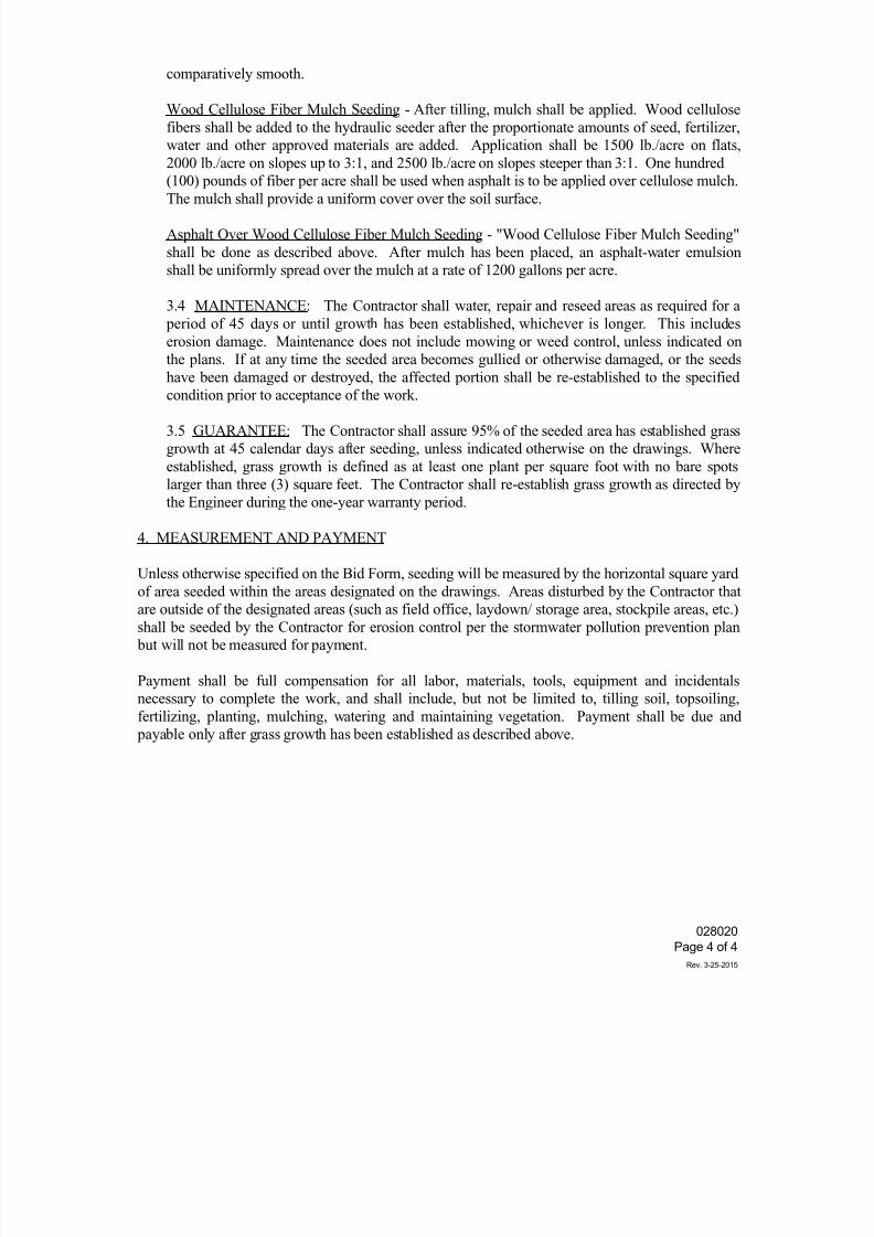
7/25/2019 City Standard Construction Specifications
http://slidepdf.com/reader/full/city-standard-construction-specifications 320/511
comparatively smooth.
Wood Cellulose Fiber Mulch Seeding - After tilling, mulch shall be applied. Wood cellulose
fibers shall be added to the hydraulic seeder after the proportionate amounts of seed, fertilizer,
water and other approved materials are added. Application shall be 1500 lb./acre on flats,
2000 lb./acre on slopes up to 3:1, and 2500 lb./acre on slopes steeper than 3:1. One hundred
(100) pounds of fiber per acre shall be used when asphalt is to be applied over cellulose mulch.
The mulch shall provide a uniform cover over the soil surface.
Asphalt Over Wood Cellulose Fiber Mulch Seeding - "Wood Cellulose Fiber Mulch Seeding"
shall be done as described above. After mulch has been placed, an asphalt-water emulsion
shall be uniformly spread over the mulch at a rate of 1200 gallons per acre.
3.4 MAINTENANCE: The Contractor shall water, repair and reseed areas as required for a
period of 45 days or until growth has been established, whichever is longer. This includes
erosion damage. Maintenance does not include mowing or weed control, unless indicated on
the plans. If at any time the seeded area becomes gullied or otherwise damaged, or the seeds
have been damaged or destroyed, the affected portion shall be re-established to the specified
condition prior to acceptance of the work.
3.5 GUARANTEE: The Contractor shall assure 95% of the seeded area has established grass
growth at 45 calendar days after seeding, unless indicated otherwise on the drawings. Where
established, grass growth is defined as at least one plant per square foot with no bare spots
larger than three (3) square feet. The Contractor shall re-establish grass growth as directed by
the Engineer during the one-year warranty period.
4. MEASUREMENT AND PAYMENT
Unless otherwise specified on the Bid Form, seeding will be measured by the horizontal square yard
of area seeded within the areas designated on the drawings. Areas disturbed by the Contractor thatare outside of the designated areas (such as field office, laydown/ storage area, stockpile areas, etc.)
shall be seeded by the Contractor for erosion control per the stormwater pollution prevention plan
but will not be measured for payment.
Payment shall be full compensation for all labor, materials, tools, equipment and incidentals
necessary to complete the work, and shall include, but not be limited to, tilling soil, topsoiling,
fertilizing, planting, mulching, watering and maintaining vegetation. Payment shall be due and
payable only after grass growth has been established as described above.
028020
Page 4 of 4
Rev. 3-25-2015
7/25/2019 City Standard Construction Specifications
http://slidepdf.com/reader/full/city-standard-construction-specifications 321/511
SECTION 028040
SODDING
1. DESCRIPTION
This specification shall govern all work necessary for furnishing and placing sod as required to
complete the project.
2. MATERIALS
Fertilizer: All fertilizer used shall be delivered in bags or containers with clearly marked
analysis. A granulated fertilizer shall be used with an analysis of 10-20-10.
These figures represent the percent of nitrogen, phosphoric acid and potash
nutrients, respectively, as determined by the methods of the Association of
Official Agricultural Chemists. The rate of application shall be not less than 350
pounds per acre (7.23 lb. per 100 SY). In the event that it is necessary to
substitute a fertilizer with a different analysis, it shall be granulated fertilizer with
a lower concentration. The total nutrients applied per unit area shall not be lessthat the specified amount of each nutrient.
Sod: Sod shall consist of live Bermuda grass with thickly matted roots throughout the
soil and with a minimum thickness of 3 inches or 0.25 foot, or live St. Augustine
with thickly matted roots throughout the soil with a minimum thickness of 1 inch
or 0.08 foot. The Contractor shall not use sod where grass is thinned out. Grass
shall be mowed and raked to remove all weeds and long stems prior to extraction
at the source. Sod and soil shall be kept moist at all times during the sodding
process. Care must be taken at all times to retain native soil on the root system.
Water: Water shall be free from oils, acids, alkalis, and salts that may inhibit grassgrowth. Unless indicated otherwise on the drawings, water shall be provided by
the City and shall be transported and applied by the Contractor.
3. CONSTRUCTION METHODS
Spot Sodding: Prior to planting, the area to be sodded shall be graded and shaped. Squares of
sod with a minimum width of 3 inches shall be planted in rows on 15-inch
centers in both directions. Sod shall be placed so that it is firmly against the
bottom of the hole, and the top of the sod shall not be more than 1/2 inch below
finished grade. Soil shall be firmly packed against all sides of the sod. Soil shall
not be allowed to cover the sod except for soil incidental to raking, provided thatthe quantity of soil is not enough to hinder the growth. Areas to be spot sodded
shall be indicated on the drawing or as directed by the Engineer in field. After
sod has been planted, the area shall be fertilized and watered.
028040
Page 1 of 2
Rev. 3-25-2015
7/25/2019 City Standard Construction Specifications
http://slidepdf.com/reader/full/city-standard-construction-specifications 322/511
Block Sodding: Prior to planting, the area to be sodded shall be graded and shaped. Sod blocks
shall be uniformly placed over the prepared area. The sodded area shall then be
fertilized and watered. After the area is sufficiently dry, the area shall be rolled
or tamped to form a thoroughly compacted mat. Any voids in the mats shall be
filled with additional sod and tamped. If, in the opinion of the Engineer, slopes
may cause displacement, areas to be block sodded shall be indicated on the
drawings or as directed by the Engineer in the field.
Mulch Sodding: The sod source shall be disked in two directions cutting the sod thoroughly to a
depth of not less than 4 inches or more than 10 inches, being careful to avoid
having soil containing no grass roots. The disked sod may be windrowed or
otherwise handled in a manner satisfactory to the Engineer. The material shall be
rejected if not kept in a moist condition.
Prior to placing mulch sod, the cut slopes shall be scarified by plowing furrows 4 inches to 6 inches
deep along horizontal slope lines at 2-foot vertical intervals. Excavated material from the furrows
shall not protrude more than 3 inches above the original surface of the cut. Fertilizer shall be
distributed uniformly over the area. The sod shall then be dumped upon the prepared area and
spread uniformly to the required approximate thickness shown on the plans.
Any section not true to lines and cross section shall be remedied by the addition of sod material.
After the sod material has been spread and shaped, it shall be compacted with a corrugated roller of
the "Cultipacker" type. All rolling of slope areas shall be on the contour. The area to be mulch
sodded shall be indicated on the drawings or as directed by the Engineer in the field.
4. MEASUREMENT AND PAYMENT
Unless otherwise specified on the Bid Form, spot sodding and block sodding shall be measured by
the square yard taken in a horizontal plane.
Payment shall include, but not be limited to, excavation, transporting, storing and placing of sod,
and application of fertilizer and water.
028040
Page 2 of 2
Rev. 3-25-2015
7/25/2019 City Standard Construction Specifications
http://slidepdf.com/reader/full/city-standard-construction-specifications 323/511
028200
Page 1 of 1
Rev. 10-30-2014
SECTION 028200
MAIL BOX RELOCATION
1. DESCRIPTION
This specification shall govern all work for relocation of mail boxes required to complete the project.
2. REQUIREMENTS
Where mail is delivered to residents by means of roadside mail boxes, the Contractor shall maintain
access to these mail boxes throughout the course of construction. Due to the existing location of
mailboxes, the Contractor shall, in some cases, be required to move the boxes to temporary
locations. Upon completion of construction, the Contractor shall be required to erect the moved
mailboxes to a permanent location. Any materials or labor required for either the temporary or
permanent move shall be considered subsidiary, and no direct payment shall be made.
It is the intent of this item to provide the residents with mailbox facilities at least equal to or better
than those existing prior to construction.
In all cases, the temporary and permanent locations of all moved mail boxes shall be in accordance
with U. S. Postal Service requirements with regard to height, distance from roadway, accessibility,
etc. It shall be the Contractor's responsibility to contact the U. S. Postal Service and gather
information as to their requirements.
3. MEASUREMENT AND PAYMENT
Unless otherwise specified on the Bid Form, mail box relocation shall not be measured for pay butwill be considered subsidiary to the appropriate item.
7/25/2019 City Standard Construction Specifications
http://slidepdf.com/reader/full/city-standard-construction-specifications 324/511
028300
Page 1 of 1
Rev. 10-30-2014
SECTION 028300
FENCE RELOCATION
1. DESCRIPTION
This specification shall govern all work necessary to accomplish the relocation of any fence that
needs to be moved to complete this project. The necessity and the time schedule for relocation of
any given fence shall be determined by the Engineer.
2. MATERIALS
Whenever possible, all or part of the existing fence materials shall be used in constructing the
relocated fence. Any materials damaged or destroyed as a result of removal of the fence from its
existing location shall be replaced with materials of equal or better quality at the expense of the
contractor.
3. CONSTRUCTION METHODS
It is the intent of this specification that fences be reconstructed to original condition (condition at
time just prior to commencement of construction on this project). Unless otherwise specified, no
fence shall be replaced until the area surrounding its new location has been worked to its finished
grade. Any fence that is damaged while being removed shall be repaired prior to being reset or
replaced with like kind.
4. MEASUREMENT AND PAYMENT
Unless otherwise specified on the Bid Form, fence relocation shall be measured by the linear footof relocated fence (not fence removed from original location).
Payment shall constitute full compensation for removal, replacement, necessary repairs, and all
other work related to the relocation of fences.
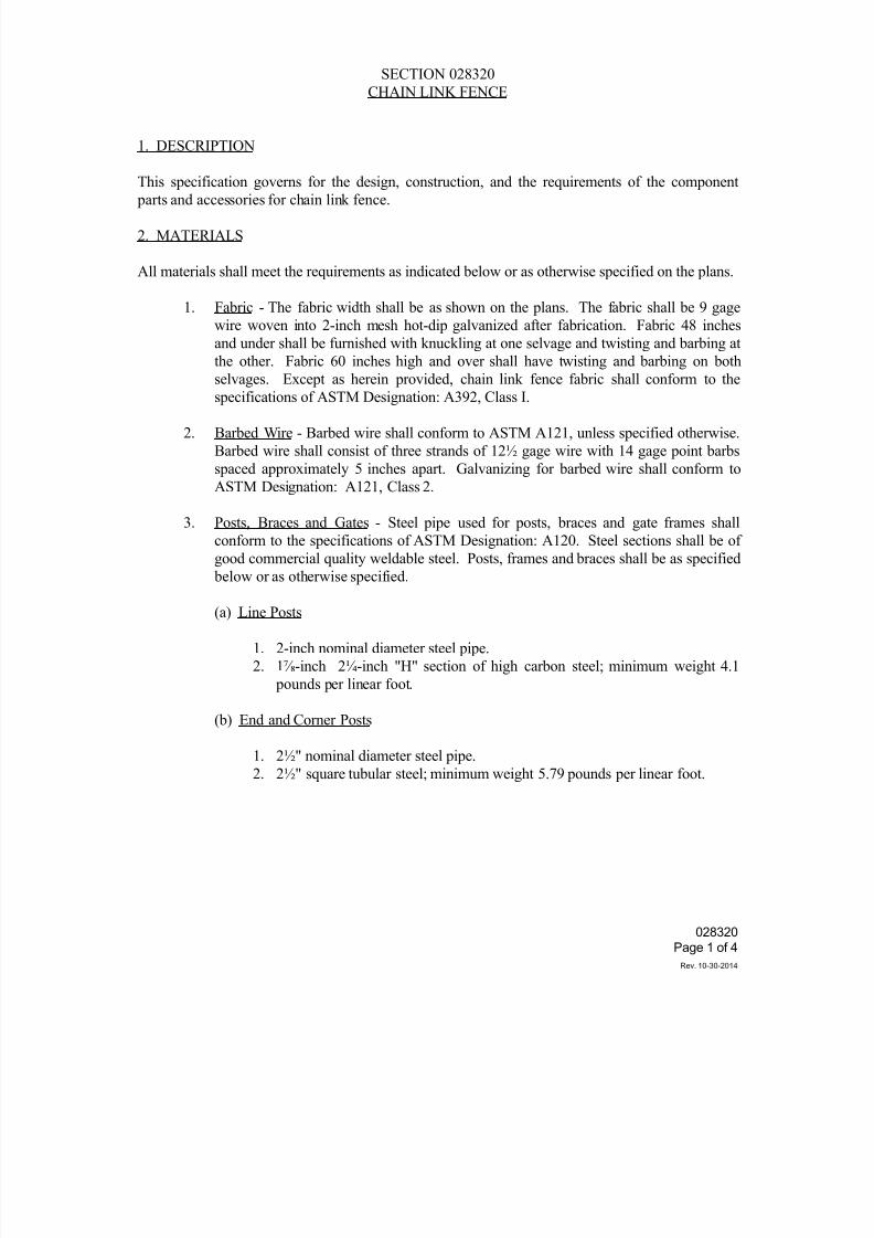
7/25/2019 City Standard Construction Specifications
http://slidepdf.com/reader/full/city-standard-construction-specifications 325/511
028320
Page 1 of 4
Rev. 10-30-2014
SECTION 028320
CHAIN LINK FENCE
1. DESCRIPTION
This specification governs for the design, construction, and the requirements of the component
parts and accessories for chain link fence.
2. MATERIALS
All materials shall meet the requirements as indicated below or as otherwise specified on the plans.
1. Fabric - The fabric width shall be as shown on the plans. The fabric shall be 9 gage
wire woven into 2-inch mesh hot-dip galvanized after fabrication. Fabric 48 inches
and under shall be furnished with knuckling at one selvage and twisting and barbing at
the other. Fabric 60 inches high and over shall have twisting and barbing on both
selvages. Except as herein provided, chain link fence fabric shall conform to the
specifications of ASTM Designation: A392, Class I.
2. Barbed Wire - Barbed wire shall conform to ASTM A121, unless specified otherwise.
Barbed wire shall consist of three strands of 12½ gage wire with 14 gage point barbs
spaced approximately 5 inches apart. Galvanizing for barbed wire shall conform to
ASTM Designation: A121, Class 2.
3. Posts, Braces and Gates - Steel pipe used for posts, braces and gate frames shall
conform to the specifications of ASTM Designation: A120. Steel sections shall be of
good commercial quality weldable steel. Posts, frames and braces shall be as specified
below or as otherwise specified.
(a) Line Posts
1. 2-inch nominal diameter steel pipe.
2. 1⅞-inch 2¼-inch "H" section of high carbon steel; minimum weight 4.1
pounds per linear foot.
(b) End and Corner Posts
1. 2½" nominal diameter steel pipe.
2. 2½" square tubular steel; minimum weight 5.79 pounds per linear foot.
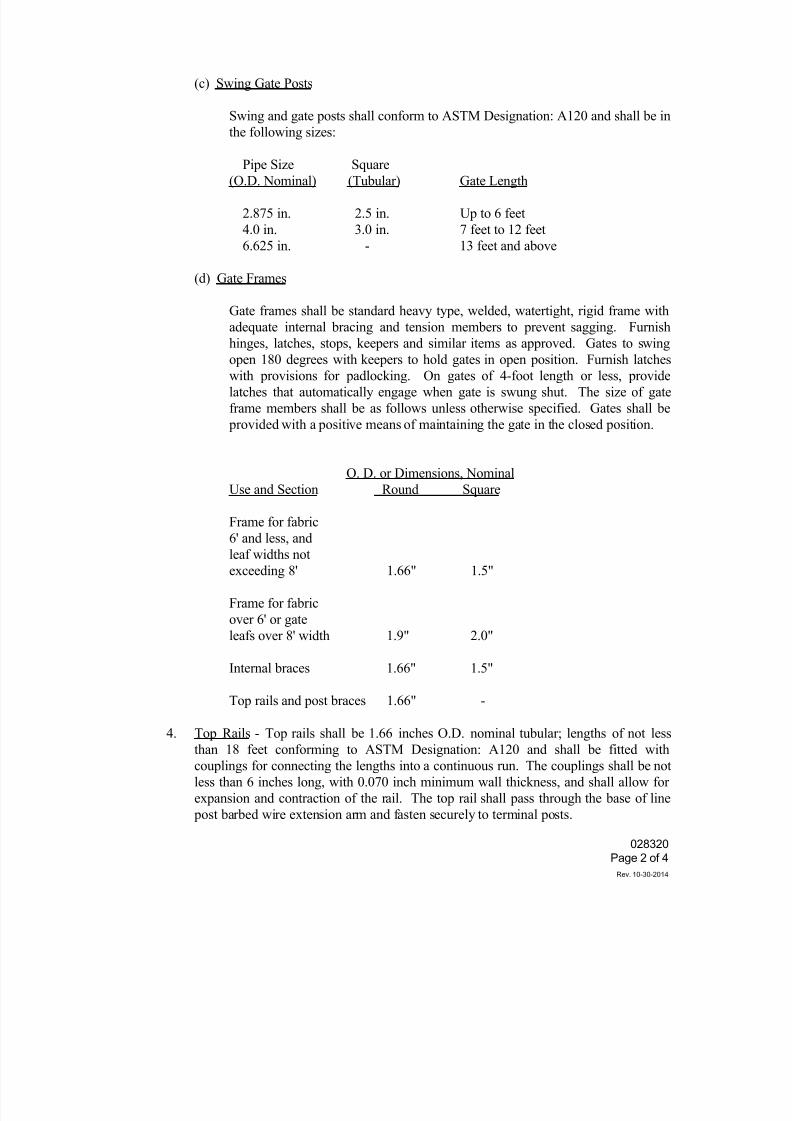
7/25/2019 City Standard Construction Specifications
http://slidepdf.com/reader/full/city-standard-construction-specifications 326/511
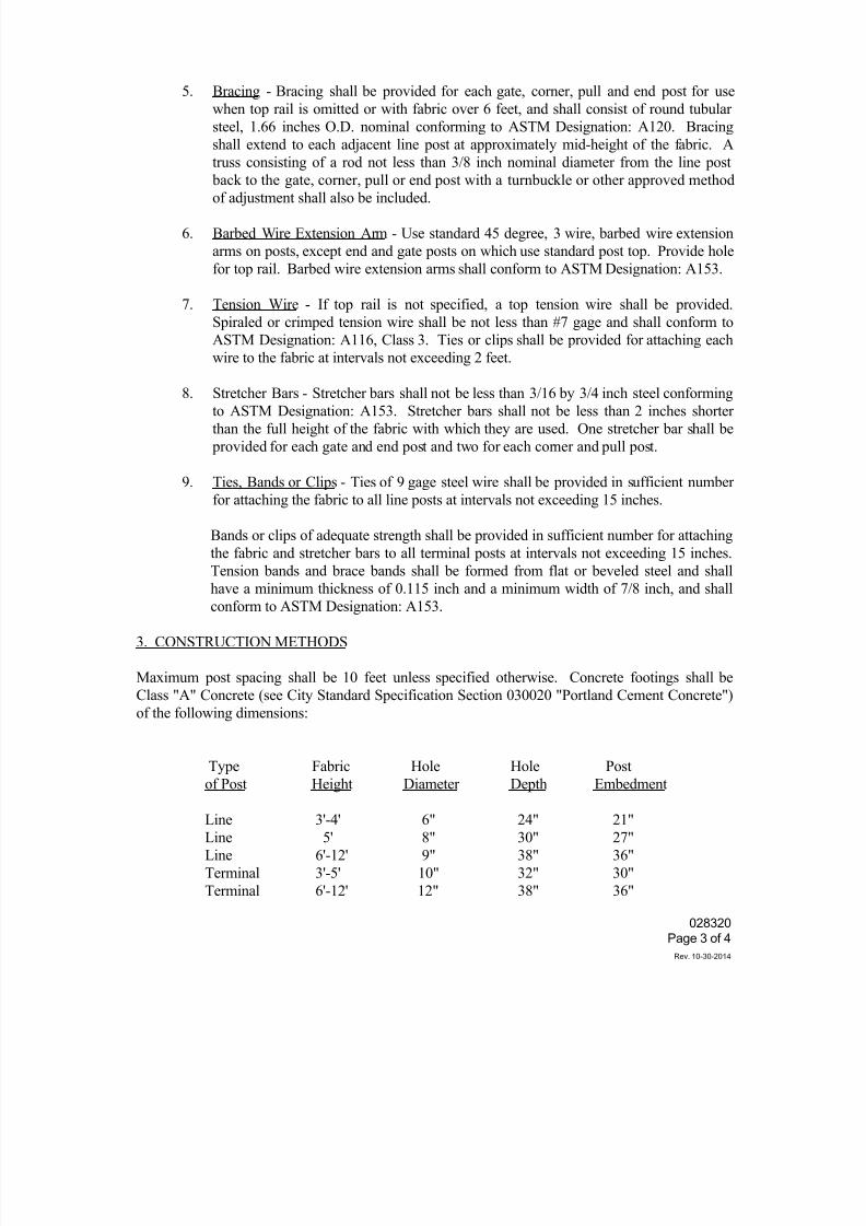
7/25/2019 City Standard Construction Specifications
http://slidepdf.com/reader/full/city-standard-construction-specifications 327/511
028320
Page 3 of 4
Rev. 10-30-2014
5. Bracing - Bracing shall be provided for each gate, corner, pull and end post for use
when top rail is omitted or with fabric over 6 feet, and shall consist of round tubular
steel, 1.66 inches O.D. nominal conforming to ASTM Designation: A120. Bracing
shall extend to each adjacent line post at approximately mid-height of the fabric. A
truss consisting of a rod not less than 3/8 inch nominal diameter from the line post
back to the gate, corner, pull or end post with a turnbuckle or other approved method
of adjustment shall also be included.
6. Barbed Wire Extension Arm - Use standard 45 degree, 3 wire, barbed wire extension
arms on posts, except end and gate posts on which use standard post top. Provide hole
for top rail. Barbed wire extension arms shall conform to ASTM Designation: A153.
7. Tension Wire - If top rail is not specified, a top tension wire shall be provided.
Spiraled or crimped tension wire shall be not less than #7 gage and shall conform to
ASTM Designation: A116, Class 3. Ties or clips shall be provided for attaching each
wire to the fabric at intervals not exceeding 2 feet.
8. Stretcher Bars - Stretcher bars shall not be less than 3/16 by 3/4 inch steel conformingto ASTM Designation: A153. Stretcher bars shall not be less than 2 inches shorter
than the full height of the fabric with which they are used. One stretcher bar shall be
provided for each gate and end post and two for each corner and pull post.
9. Ties, Bands or Clips - Ties of 9 gage steel wire shall be provided in sufficient number
for attaching the fabric to all line posts at intervals not exceeding 15 inches.
Bands or clips of adequate strength shall be provided in sufficient number for attaching
the fabric and stretcher bars to all terminal posts at intervals not exceeding 15 inches.
Tension bands and brace bands shall be formed from flat or beveled steel and shall
have a minimum thickness of 0.115 inch and a minimum width of 7/8 inch, and shall
conform to ASTM Designation: A153.
3. CONSTRUCTION METHODS
Maximum post spacing shall be 10 feet unless specified otherwise. Concrete footings shall be
Class "A" Concrete (see City Standard Specification Section 030020 "Portland Cement Concrete")
of the following dimensions:
Type Fabric Hole Hole Post
of Post Height Diameter Depth Embedment
Line 3'-4' 6" 24" 21"
Line 5' 8" 30" 27"
Line 6'-12' 9" 38" 36"
Terminal 3'-5' 10" 32" 30"
Terminal 6'-12' 12" 38" 36"
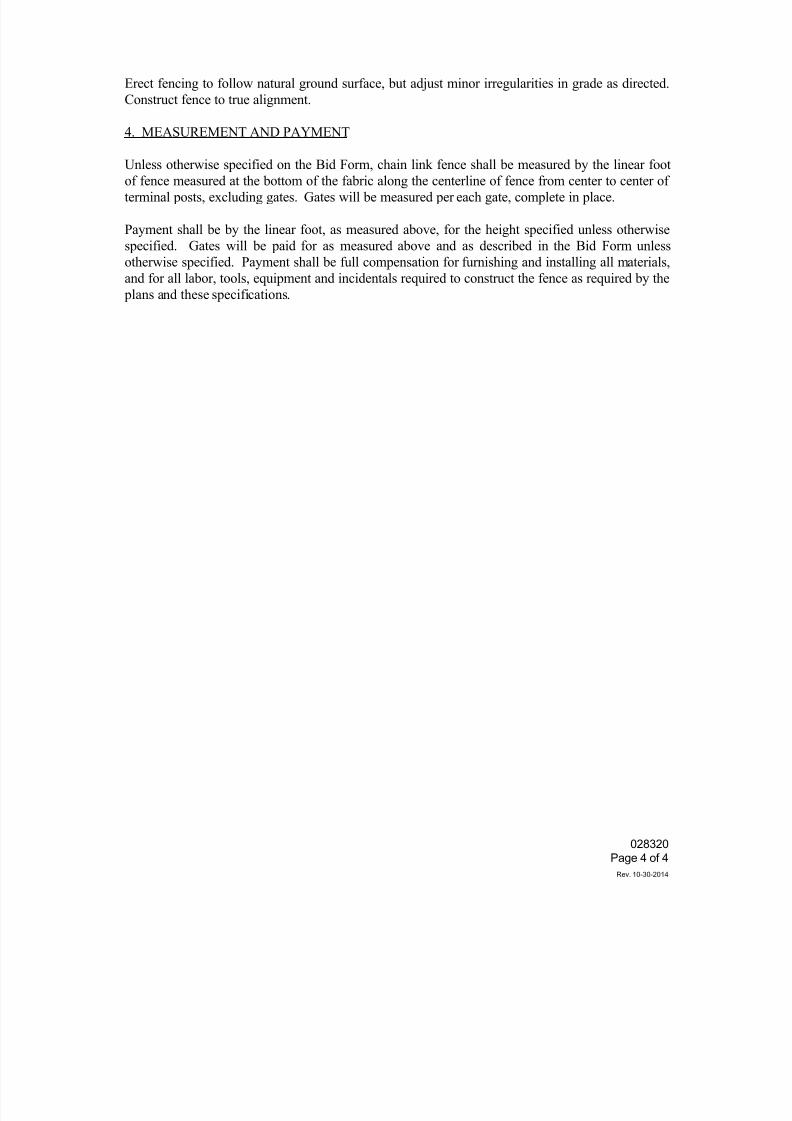
7/25/2019 City Standard Construction Specifications
http://slidepdf.com/reader/full/city-standard-construction-specifications 328/511
028320
Page 4 of 4
Rev. 10-30-2014
Erect fencing to follow natural ground surface, but adjust minor irregularities in grade as directed.
Construct fence to true alignment.
4. MEASUREMENT AND PAYMENT
Unless otherwise specified on the Bid Form, chain link fence shall be measured by the linear foot
of fence measured at the bottom of the fabric along the centerline of fence from center to center ofterminal posts, excluding gates. Gates will be measured per each gate, complete in place.
Payment shall be by the linear foot, as measured above, for the height specified unless otherwise
specified. Gates will be paid for as measured above and as described in the Bid Form unless
otherwise specified. Payment shall be full compensation for furnishing and installing all materials,
and for all labor, tools, equipment and incidentals required to construct the fence as required by the
plans and these specifications.
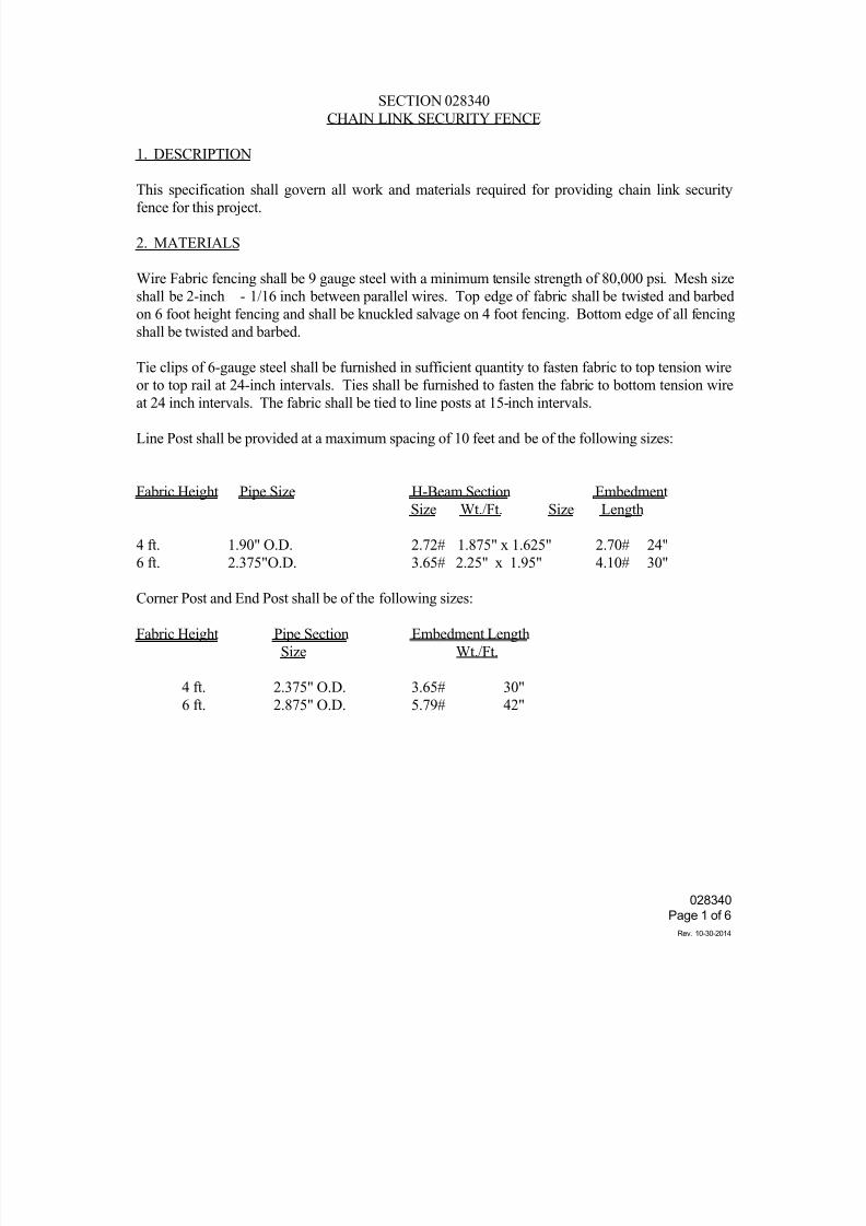
7/25/2019 City Standard Construction Specifications
http://slidepdf.com/reader/full/city-standard-construction-specifications 329/511
028340
Page 1 of 6
Rev. 10-30-2014
SECTION 028340
CHAIN LINK SECURITY FENCE
1. DESCRIPTION
This specification shall govern all work and materials required for providing chain link securityfence for this project.
2. MATERIALS
Wire Fabric fencing shall be 9 gauge steel with a minimum tensile strength of 80,000 psi. Mesh size
shall be 2-inch - 1/16 inch between parallel wires. Top edge of fabric shall be twisted and barbed
on 6 foot height fencing and shall be knuckled salvage on 4 foot fencing. Bottom edge of all fencing
shall be twisted and barbed.
Tie clips of 6-gauge steel shall be furnished in sufficient quantity to fasten fabric to top tension wire
or to top rail at 24-inch intervals. Ties shall be furnished to fasten the fabric to bottom tension wireat 24 inch intervals. The fabric shall be tied to line posts at 15-inch intervals.
Line Post shall be provided at a maximum spacing of 10 feet and be of the following sizes:
Fabric Height Pipe Size H-Beam Section Embedment
Size Wt./Ft. Size Length
4 ft. 1.90" O.D. 2.72# 1.875" x 1.625" 2.70# 24"
6 ft. 2.375"O.D. 3.65# 2.25" x 1.95" 4.10# 30"
Corner Post and End Post shall be of the following sizes:
Fabric Height Pipe Section Embedment Length
Size Wt./Ft.
4 ft. 2.375" O.D. 3.65# 30"
6 ft. 2.875" O.D. 5.79# 42"
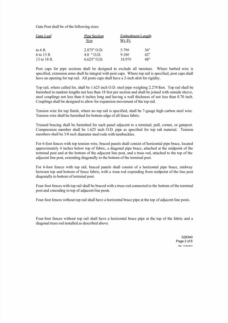
7/25/2019 City Standard Construction Specifications
http://slidepdf.com/reader/full/city-standard-construction-specifications 330/511
028340
Page 2 of 6
Rev. 10-30-2014
Gate Post shall be of the following sizes:
Gate Leaf Pipe Section Embedment Length
Size Wt./Ft.
to 6 ft. 2.875" O.D. 5.79# 36"6 to 13 ft. 4.0 " O.D. 9.10# 42"
13 to 18 ft. 6.625" O.D. 18.97# 48"
Post caps for pipe sections shall be designed to exclude all moisture. Where barbed wire is
specified, extension arms shall be integral with post caps. Where top rail is specified, post caps shall
have an opening for top rail. All posts caps shall have a 2-inch skirt for rigidity.
Top rail, where called for, shall be 1.625 inch O.D. steel pipe weighing 2.27#/foot. Top rail shall be
furnished in random lengths not less than 18 feet per section and shall be joined with outside sleeve,
steel couplings not less than 6 inches long and having a wall thickness of not less than 0.70 inch.
Couplings shall be designed to allow for expansion movement of the top rail.
Tension wire for top finish, where no top rail is specified, shall be 7-gauge high carbon steel wire.
Tension wire shall be furnished for bottom edge of all fence fabric.
Trussed bracing shall be furnished for each panel adjacent to a terminal, pull, corner, or gatepost.
Compression member shall be 1.625 inch O.D. pipe as specified for top rail material. Tension
members shall be 3/8 inch diameter steel rods with turnbuckles.
For 6-foot fences with top tension wire, braced panels shall consist of horizontal pipe brace, located
approximately 4 inches below top of fabric, a diagonal pipe brace, attached at the midpoint of the
terminal post and at the bottom of the adjacent line post, and a truss rod, attached to the top of theadjacent line post, extending diagonally to the bottom of the terminal post.
For 6-foot fences with top rail, braced panels shall consist of a horizontal pipe brace, midway
between top and bottom of fence fabric, with a truss rod expending from midpoint of the line post
diagonally to bottom of terminal post.
Four-foot fences with top rail shall be braced with a truss rod connected to the bottom of the terminal
post and extending to top of adjacent line posts.
Four-foot fences without top rail shall have a horizontal brace pipe at the top of adjacent line posts.
Four-foot fences without top rail shall have a horizontal brace pipe at the top of the fabric and a
diagonal truss rod installed as described above.
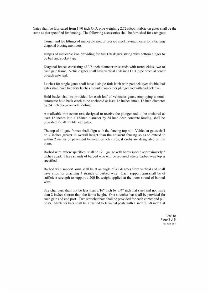
7/25/2019 City Standard Construction Specifications
http://slidepdf.com/reader/full/city-standard-construction-specifications 331/511
028340
Page 3 of 6
Rev. 10-30-2014
Gates shall be fabricated from 1.90 inch O.D. pipe weighing 2.72#/foot. Fabric on gates shall be the
same as that specified for fencing. The following accessories shall be furnished for each gate:
Corner and tee fittings of malleable iron or pressed steel having means for attaching
diagonal bracing members.
Hinges of malleable iron providing for full 180 degree swing with bottom hinges to
be ball and socket type.
Diagonal braces consisting of 3/8 inch diameter truss rods with turnbuckles, two to
each gate frame. Vehicle gates shall have vertical 1.90 inch O.D. pipe brace at center
of each gate leaf.
Latches for single gates shall have a single fork latch with padlock eye; double leaf
gates shall have two fork latches mounted on center plunger rod with padlock eye.
Hold backs shall be provided for each leaf of vehicular gates, employing a semi-
automatic hold back catch to be anchored at least 12 inches into a 12 inch diameter
by 24 inch deep concrete footing.
A malleable iron center rest, designed to receive the plunger rod, to be anchored at
least 12 inches into a 12-inch diameter by 24 inch deep concrete footing, shall be
provided for all double leaf gates.
The top of all gate frames shall align with the fencing top rail. Vehicular gates shall
be 4 inches greater in overall height than the adjacent fencing so as to extend to
within 2 inches of pavement between 6-inch curbs, if curbs are designated on the plans.
Barbed wire, where specified, shall be 12 gauge with barbs spaced approximately 5
inches apart. Three strands of barbed wire will be required where barbed wire top is
specified.
Barbed wire support arms shall be at an angle of 45 degrees from vertical and shall
have clips for attaching 3 strands of barbed wire. Each support arm shall be of
sufficient strength to support a 200 lb. weight applied at the outer strand of barbed
wire.
Stretcher bars shall not be less than 3/16" inch by 3/4" inch flat steel and not more
than 2 inches shorter than the fabric height. One stretcher bar shall be provided for
each gate and end post. Two stretcher bars shall be provided for each corner and pull
posts. Stretcher bars shall be attached to terminal posts with 1 inch x 1/8 inch flat
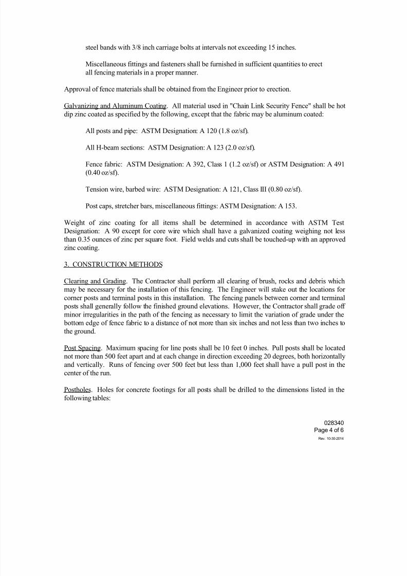
7/25/2019 City Standard Construction Specifications
http://slidepdf.com/reader/full/city-standard-construction-specifications 332/511
028340
Page 4 of 6
Rev. 10-30-2014
steel bands with 3/8 inch carriage bolts at intervals not exceeding 15 inches.
Miscellaneous fittings and fasteners shall be furnished in sufficient quantities to erect
all fencing materials in a proper manner.
Approval of fence materials shall be obtained from the Engineer prior to erection.
Galvanizing and Aluminum Coating. All material used in "Chain Link Security Fence" shall be hot
dip zinc coated as specified by the following, except that the fabric may be aluminum coated:
All posts and pipe: ASTM Designation: A 120 (1.8 oz/sf).
All H-beam sections: ASTM Designation: A 123 (2.0 oz/sf).
Fence fabric: ASTM Designation: A 392, Class 1 (1.2 oz/sf) or ASTM Designation: A 491
(0.40 oz/sf).
Tension wire, barbed wire: ASTM Designation: A 121, Class III (0.80 oz/sf).
Post caps, stretcher bars, miscellaneous fittings: ASTM Designation: A 153.
Weight of zinc coating for all items shall be determined in accordance with ASTM Test
Designation: A 90 except for core wire which shall have a galvanized coating weighing not less
than 0.35 ounces of zinc per square foot. Field welds and cuts shall be touched-up with an approved
zinc coating.
3. CONSTRUCTION METHODS
Clearing and Grading. The Contractor shall perform all clearing of brush, rocks and debris which
may be necessary for the installation of this fencing. The Engineer will stake out the locations for
corner posts and terminal posts in this installation. The fencing panels between corner and terminal
posts shall generally follow the finished ground elevations. However, the Contractor shall grade off
minor irregularities in the path of the fencing as necessary to limit the variation of grade under the
bottom edge of fence fabric to a distance of not more than six inches and not less than two inches to
the ground.
Post Spacing. Maximum spacing for line posts shall be 10 feet 0 inches. Pull posts shall be located
not more than 500 feet apart and at each change in direction exceeding 20 degrees, both horizontally
and vertically. Runs of fencing over 500 feet but less than 1,000 feet shall have a pull post in thecenter of the run.
Postholes. Holes for concrete footings for all posts shall be drilled to the dimensions listed in the
following tables:
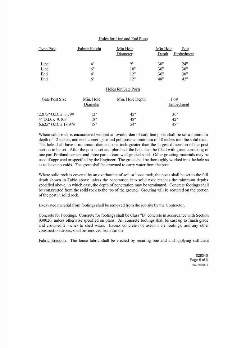
7/25/2019 City Standard Construction Specifications
http://slidepdf.com/reader/full/city-standard-construction-specifications 333/511
028340
Page 5 of 6
Rev. 10-30-2014
Holes for Line and End Posts
Type Post Fabric Height Min.Hole Min.Hole Post
Diameter Depth Embedment
Line 4' 9" 30" 24"
Line 6" 10" 36" 30"
End 4' 12" 36" 30"
End 6' 12" 48" 42"
Holes for Gate Posts
Gate Post Size Min. Hole Min. Hole Depth Post
Diameter Embedment
2.875" O.D. x 5.79# 12" 42" 36"
4" O.D. x 9.10# 18" 48" 42"
6.625" O.D. x 18.97# 18" 54" 48"
Where solid rock is encountered without an overburden of soil, line posts shall be set a minimum
depth of 12 inches, and end, corner, gate and pull posts a minimum of 18 inches into the solid rock.
The hole shall have a minimum diameter one inch greater than the largest dimension of the post
section to be set. After the post is set and plumbed, the hole shall be filled with grout consisting of
one part Portland cement and three parts clean, well-graded sand. Other grouting materials may be
used if approved or specified by the Engineer. The grout shall be thoroughly worked into the hole so
as to leave no voids. The grout shall be crowned to carry water from the post.
Where solid rock is covered by an overburden of soil or loose rock, the posts shall be set to the full
depth shown in Table above unless the penetration into solid rock reaches the minimum depths
specified above, in which case, the depth of penetration may be terminated. Concrete footings shall
be constructed from the solid rock to the top of the ground. Grouting will be required on the portion
of the post in solid rock.
Excavated material from footings shall be removed from the job site by the Contractor.
Concrete for Footings. Concrete for footings shall be Class "B" concrete in accordance with Section
030020, unless otherwise specified on plans. All concrete footings shall be cast up to finish gradeand crowned 2 inches to shed water. Excess concrete not used in the footings, and any other
construction debris, shall be removed from the site.
Fabric Erection. The fence fabric shall be erected by securing one end and applying sufficient
7/25/2019 City Standard Construction Specifications
http://slidepdf.com/reader/full/city-standard-construction-specifications 334/511
028340
Page 6 of 6
Rev. 10-30-2014
tension to the other end to remove all slack before making attachments. The fabric shall be cut and
each span shall be attached independently at all corner posts and pull posts. Fastening to end, pull,
corner and gateposts shall be with stretcher bars which shall be secured to the posts with stretcher
bar bands at intervals not exceeding 15 inches. Fence fabric shall generally follow the finished
contour of the site with the bottom edge of fabric located 2 inches above the grade. In uneven areas,
the ground shall be graded so that the maximum distance between bottom of fabric and ground inlimited to 6 inches.
Electric grounds. Grounding rods shall be at least 5/8 inch diameter by 8 feet long "copperweld"
rods driven or drilled into the soil so that the top of the rod is approximately 6 inches below grade.
A No. 6 solid copper conductor shall be clamped to the ground rod and the bottom tension wire of
the fence with cast bronze clamps with bronze or stainless steel bolts and washers. Each 1,000-foot
of fence shall be provided with a ground located near the center of the run. At least one electrical
ground shall be installed for each fenced closure. A ground shall be provided directly under the
point where a power line passes over the fence.
4. MEASUREMENT AND PAYMENT
Unless otherwise specified on the Bid Form, chain link security fence shall be measured by the
linear foot. Measurement shall include but not be limited to furnishing and erecting all fence
materials, gates, caps, concrete, ground wires, and cleanup. Payment shall be made at the unit price
bid and shall fully compensate the Contractor for all materials required, all labor, all tools, all
equipment and all other incidentals required to complete the work as shown on the contract drawings
and as specified herein.
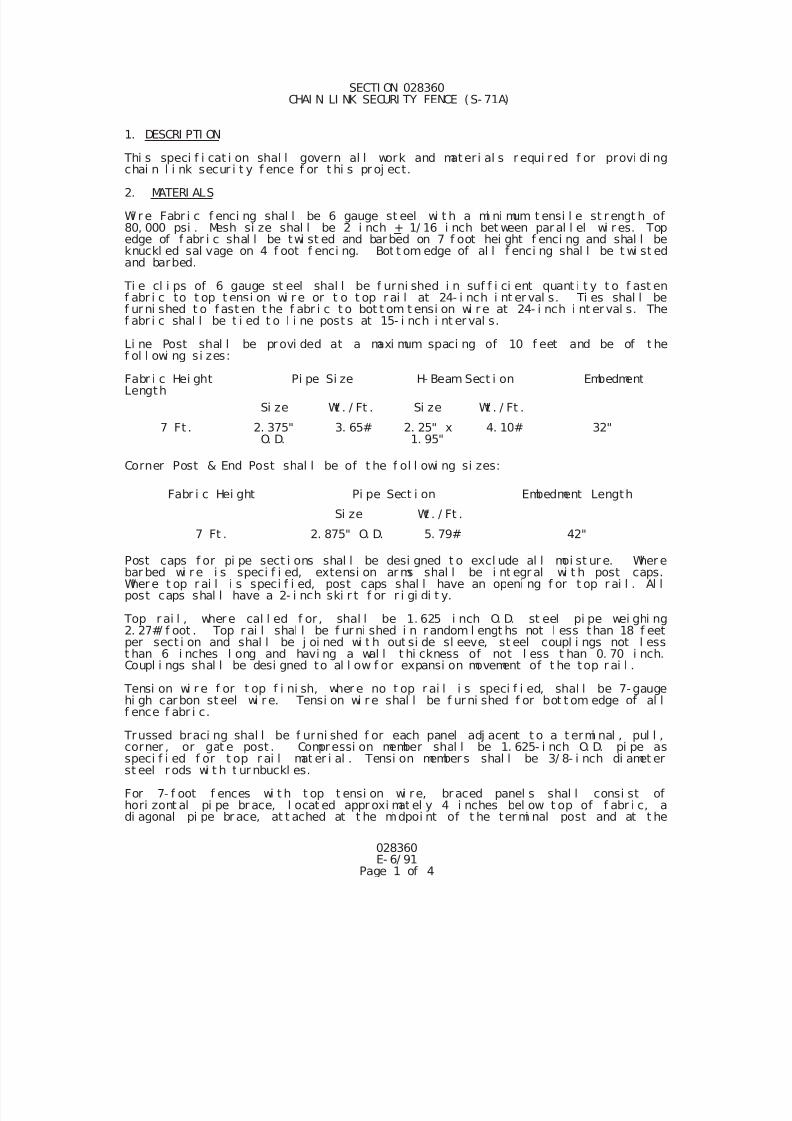
7/25/2019 City Standard Construction Specifications
http://slidepdf.com/reader/full/city-standard-construction-specifications 335/511
028360E- 6/ 91
Page 1 of 4
SECTI ON 028360 CHAI N LI NK SECURI TY FENCE (S- 71A)
1. DESCRI PTI ON
Thi s speci f i cat i on shal l govern al l work and materi al s r equi red f or provi di ngchai n l i nk secur i t y f ence f or t hi s pr oj ect.
2. MATERI ALS
Wi r e Fabr i c f enci ng shal l be 6 gauge st eel wi t h a mi ni mum t ensi l e st r engt h of80, 000 psi . Mesh si ze shal l be 2 i nch + 1/ 16 i nch bet ween par al l el wi r es. Topedge of f abr i c shal l be twi st ed and barbed on 7 f oot hei ght f enci ng and shal l beknuckl ed sal vage on 4 f oot f enci ng. Bot t om edge of al l f enci ng shal l be t wi st edand barbed.
Ti e cl i ps of 6 gauge st eel shal l be f urni shed i n suf f i ci ent quant i t y t o f ast enf abr i c to t op t ensi on wi r e or t o t op r ai l at 24- i nch i nt er val s. Ti es shal l bef ur ni shed t o f ast en t he f abr i c t o bot t om t ensi on wi r e at 24- i nch i nt er val s. Thef abr i c shal l be t i ed t o l i ne post s at 15- i nch i nt er val s.
Li ne Post shal l be pr ovi ded at a maxi mum spaci ng of 10 f eet and be of t he
f ol l owi ng si zes:
Fabr i c Hei ght Pi pe Si ze H- Beam Sect i on EmbedmentLength
Si ze Wt . / Ft . Si ze Wt . / Ft .
7 Ft . 2. 375"O. D.
3. 65# 2. 25" x1. 95"
4. 10# 32"
Corner Post & End Post shal l be of t he f ol l owi ng si zes:
Fabr i c Hei ght Pi pe Sect i on Embedment Length
Si ze Wt . / Ft .
7 Ft . 2. 875" O. D. 5. 79# 42"
Post caps f or pi pe sect i ons shal l be desi gned t o excl ude al l moi st ur e. Wher ebar bed wi r e i s speci f i ed, extensi on ar ms shal l be i nt egr al wi t h post caps.Wher e t op r ai l i s speci f i ed, post caps shal l have an openi ng f or t op r ai l . Al lpost caps shal l have a 2- i nch ski r t f or r i gi di t y.
Top r ai l , where cal l ed f or , shal l be 1. 625 i nch O. D. st eel pi pe wei ghi ng2. 27#/ f oot . Top r ai l shal l be f ur ni shed i n r andom l engt hs not l ess than 18 f eetper sect i on and shal l be j oi ned wi t h out si de sl eeve, st eel coupl i ngs not l esst han 6 i nches l ong and havi ng a wal l t hi ckness of not l ess t han 0. 70 i nch.Coupl i ngs shal l be desi gned to al l ow f or expansi on movement of t he top r ai l .
Tensi on wi r e f or t op f i ni sh, wher e no t op r ai l i s speci f i ed, shal l be 7- gaugehi gh carbon st eel wi r e. Tensi on wi r e shal l be f urni shed f or bot t om edge of al l
f ence f abr i c.
Trussed braci ng shal l be f urni shed f or each panel adj acent t o a t ermi nal , pul l ,corner , or gat e post . Compressi on member shal l be 1. 625- i nch O. D. pi pe asspeci f i ed f or t op r ai l mat er i al . Tensi on member s shal l be 3/ 8- i nch di amet erst eel r ods wi t h t ur nbuckl es.
For 7- f oot f ences wi t h t op t ensi on wi re, braced panel s shal l consi st ofhori zont al pi pe br ace, l ocat ed appr oxi mat el y 4 i nches bel ow t op of f abr i c, adi agonal pi pe br ace, at t ached at t he mi dpoi nt of t he ter mi nal post and at t he
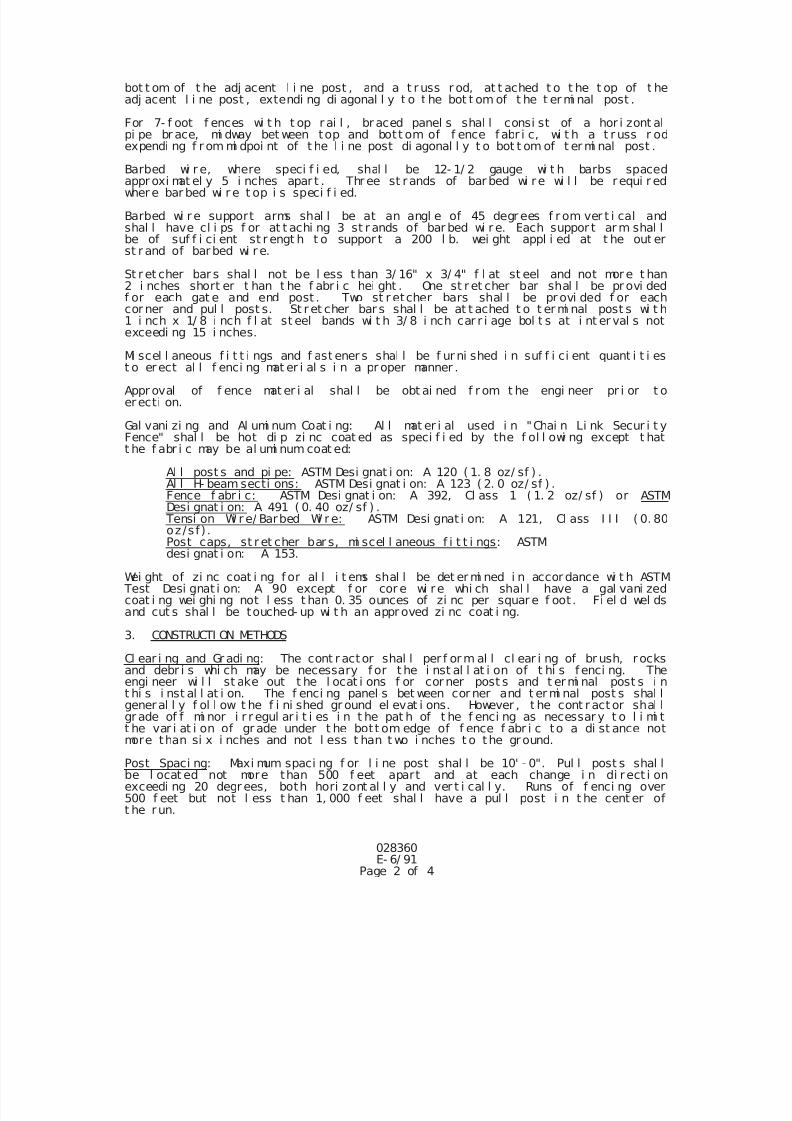
7/25/2019 City Standard Construction Specifications
http://slidepdf.com/reader/full/city-standard-construction-specifications 336/511
028360E- 6/ 91
Page 2 of 4
bot t om of t he adj acent l i ne post , and a t r uss r od, at t ached t o t he t op of t headj acent l i ne post , extendi ng di agonal l y t o t he bot t om of t he t er mi nal post .
For 7- f oot f ences wi t h t op r ai l , br aced panel s shal l consi st of a hor i zont alpi pe br ace, mi dway bet ween top and bott om of f ence f abr i c, wi t h a t r uss r odexpendi ng f r om mi dpoi nt of t he l i ne post di agonal l y t o bot t om of t er mi nal post .
Barbed wi r e, where speci f i ed, shal l be 12- 1/ 2 gauge wi t h barbs spacedappr oxi mat el y 5 i nches apar t . Thr ee st rands of bar bed wi re wi l l be requi r edwher e bar bed wi r e t op i s speci f i ed.
Barbed wi re support arms shal l be at an angl e of 45 degr ees f r om ver t i cal andshal l have cl i ps f or at t achi ng 3 st r ands of bar bed wi r e. Each suppor t ar m shal lbe of suf f i ci ent st r engt h t o suppor t a 200 l b. wei ght appl i ed at t he out erst r and of barbed wi r e.
St r et cher bar s shal l not be l ess t han 3/ 16" x 3/ 4" f l at st eel and not mor e t han2 i nches short er t han t he f abr i c hei ght . One st r et cher bar shal l be pr ovi dedf or each gat e and end post . Two st r etcher bars shal l be pr ovi ded f or eachcor ner and pul l post s. St r et cher bar s shal l be at t ached t o t er mi nal post s wi t h1 i nch x 1/ 8 i nch f l at st eel bands wi t h 3/ 8 i nch car r i age bol t s at i nt er val s notexceedi ng 15 i nches.
Mi scel l aneous f i t t i ngs and f ast ener s shal l be f ur ni shed i n suf f i ci ent quant i t i est o erect al l f enci ng mat er i al s i n a pr oper manner .
Appr oval of f ence mat er i al shal l be obt ai ned f r om t he engi neer pr i or t oer ecti on.
Gal vani zi ng and Al umi num Coat i ng: Al l mat er i al used i n "Chai n Li nk Secur i t yFence" shal l be hot di p zi nc coat ed as speci f i ed by the f ol l owi ng except t hatt he f abr i c may be al umi num coat ed:
Al l post s and pi pe: ASTM Desi gnat i on: A 120 ( 1. 8 oz/ sf ) .Al l H- beam secti ons: ASTM Desi gnat i on: A 123 ( 2. 0 oz/ sf ) .Fence f abr i c: ASTM Desi gnat i on: A 392, Cl ass 1 ( 1. 2 oz/ sf ) or ASTMDesi gnat i on: A 491 ( 0. 40 oz/ sf ) .
Tensi on Wi r e/ Barbed Wi r e: ASTM Desi gnat i on: A 121, Cl ass I I I ( 0. 80
oz/sf) .Post caps, st r et cher bar s, mi scel l aneous f i t t i ngs: ASTM desi gnat i on: A 153.
Wei ght of zi nc coat i ng f or al l i t ems shal l be det er mi ned i n accor dance wi t h ASTM Test Desi gnat i on: A 90 except f or cor e wi re whi ch shal l have a gal vani zedcoat i ng wei ghi ng not l ess t han 0. 35 ounces of zi nc per squar e f oot . Fi el d wel dsand cut s shal l be touched- up wi t h an appr oved zi nc coat i ng.
3. CONSTRUCTI ON METHODS
Cl ear i ng and Gr adi ng: The cont r actor shal l per f or m al l cl ear i ng of br ush, r ocksand debr i s whi ch may be necessary f or t he i nst al l at i on of t hi s f enci ng. Theengi neer wi l l st ake out t he l ocat i ons f or cor ner post s and t ermi nal post s i nt hi s i nst al l at i on. The f enci ng panel s bet ween cor ner and t er mi nal post s shal l
general l y f ol l ow t he f i ni shed gr ound el evat i ons. However , t he cont r act or shal lgr ade of f mi nor i r r egul ar i t i es i n t he pat h of t he f enci ng as necessar y t o l i mi tt he var i at i on of gr ade under t he bott om edge of f ence f abr i c to a di st ance notmore than si x i nches and not l ess t han t wo i nches t o the ground.
Post Spaci ng: Maxi mum spaci ng f or l i ne post shal l be 10' - 0". Pul l post s shal lbe l ocat ed not more than 500 f eet apart and at each change i n di r ect i onexceedi ng 20 degr ees, both hori zont al l y and ver t i cal l y. Runs of f enci ng over500 f eet but not l ess t han 1, 000 f eet shal l have a pul l post i n t he cent er oft he run.
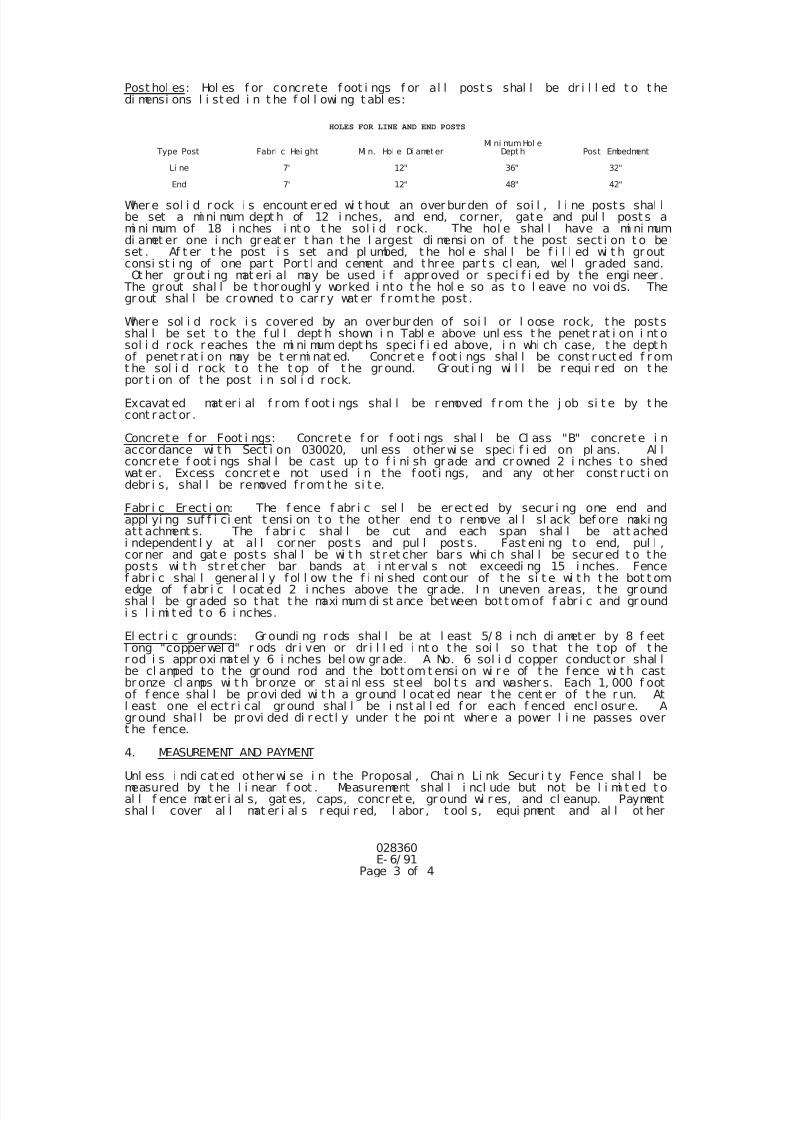
7/25/2019 City Standard Construction Specifications
http://slidepdf.com/reader/full/city-standard-construction-specifications 337/511
028360E- 6/ 91
Page 3 of 4
Post hol es: Hol es f or concrete f oot i ngs f or al l post s shal l be dr i l l ed t o t hedi mensi ons l i st ed i n t he f ol l owi ng t abl es:
HOLES FOR LINE AND END POSTS
Type Post Fabri c Hei ght Mi n. Hol e Di amet erMi ni mumHol e
Dept h Post Embedment
Li ne 7' 12" 36" 32"
End 7' 12" 48" 42"
Wher e sol i d r ock i s encount er ed wi t hout an over bur den of soi l , l i ne posts shal lbe set a mi ni mum dept h of 12 i nches, and end, corner, gate and pul l post s ami ni mum of 18 i nches i nt o t he sol i d r ock. The hol e shal l have a mi ni mumdi amet er one i nch great er t han t he l argest di mensi on of t he post sect i on t o beset . Af t er t he post i s set and pl umbed, t he hol e shal l be f i l l ed wi t h gr outconsi st i ng of one par t Por t l and cement and three par t s cl ean, wel l gr aded sand.Ot her gr out i ng mat eri al may be used i f appr oved or speci f i ed by the engi neer .
The grout shal l be t horoughl y worked i nto t he hol e so as t o l eave no voi ds. Thegr out shal l be crowned t o car r y wat er f r omt he post .
Wher e sol i d rock i s cover ed by an over bur den of soi l or l oose rock, t he postsshal l be set t o the f ul l dept h shown i n Tabl e above unl ess t he penet r at i on i nt osol i d r ock r eaches the mi ni mum dept hs speci f i ed above, i n whi ch case, t he dept h
of penet r at i on may be t er mi nat ed. Concret e f oot i ngs shal l be const r uct ed f r omt he sol i d r ock t o t he t op of t he gr ound. Gr out i ng wi l l be r equi r ed on t hepor t i on of t he post i n sol i d r ock.
Excavat ed mat er i al f r om f oot i ngs shal l be r emoved f r om t he j ob si t e by t hecont ract or .
Concret e f or Foot i ngs: Concret e f or f oot i ngs shal l be Cl ass "B" concret e i naccordance wi t h Sect i on 030020, unl ess other wi se speci f i ed on pl ans. Al lconcrete f oot i ngs shal l be cast up t o f i ni sh grade and cr owned 2 i nches t o shedwat er . Excess concret e not used i n the f oot i ngs, and any ot her const ruct i ondebr i s, shal l be removed f r om t he si t e.
Fabr i c Er ect i on: The f ence f abr i c sel l be erect ed by secur i ng one end andappl yi ng suf f i ci ent t ensi on t o t he other end t o r emove al l sl ack bef ore maki ng
att achment s. The f abr i c shal l be cut and each span shal l be att achedi ndependent l y at al l cor ner post s and pul l post s. Fast eni ng t o end, pul l ,cor ner and gat e posts shal l be wi t h st ret cher bar s whi ch shal l be secur ed t o theposts wi t h st r et cher bar bands at i nt er val s not exceedi ng 15 i nches. Fencef abr i c shal l general l y f ol l ow t he f i ni shed cont our of t he si t e wi t h t he bot t omedge of f abr i c l ocat ed 2 i nches above the gr ade. I n uneven areas, t he gr oundshal l be gr aded so t hat t he maxi mum di st ance between bott omof f abr i c and gr oundi s l i mi t ed t o 6 i nches.
El ect r i c gr ounds: Gr oundi ng r ods shal l be at l east 5/ 8 i nch di amet er by 8 f eetl ong "copper wel d" r ods dr i ven or dr i l l ed i nt o t he soi l so t hat t he t op of t her od i s appr oxi matel y 6 i nches bel ow gr ade. A No. 6 sol i d copper conduct or shal lbe cl amped to the gr ound rod and the bot t om t ensi on wi r e of t he f ence wi t h castbr onze cl amps wi t h br onze or st ai nl ess st eel bol t s and washer s. Each 1, 000 f ootof f ence shal l be pr ovi ded wi t h a gr ound l ocat ed near t he cent er of t he r un. At
l east one el ect r i cal gr ound shal l be i nst al l ed f or each f enced encl osur e. Agr ound shal l be pr ovi ded di r ect l y under t he poi nt wher e a power l i ne passes overt he fence.
4. MEASUREMENT AND PAYMENT
Unl ess i ndi cat ed other wi se i n t he Proposal , Chai n Li nk Secur i t y Fence shal l bemeasured by t he l i near f oot . Measurement shal l i ncl ude but not be l i mi t ed t oal l f ence mat er i al s, gat es, caps, concret e, gr ound wi r es, and cl eanup. Paymentshal l cover al l mat er i al s r equi r ed, l abor , t ool s, equi pment and al l ot her
7/25/2019 City Standard Construction Specifications
http://slidepdf.com/reader/full/city-standard-construction-specifications 338/511
028360E- 6/ 91
Page 4 of 4
i nci dent al s r equi r ed t o compl et e the work.
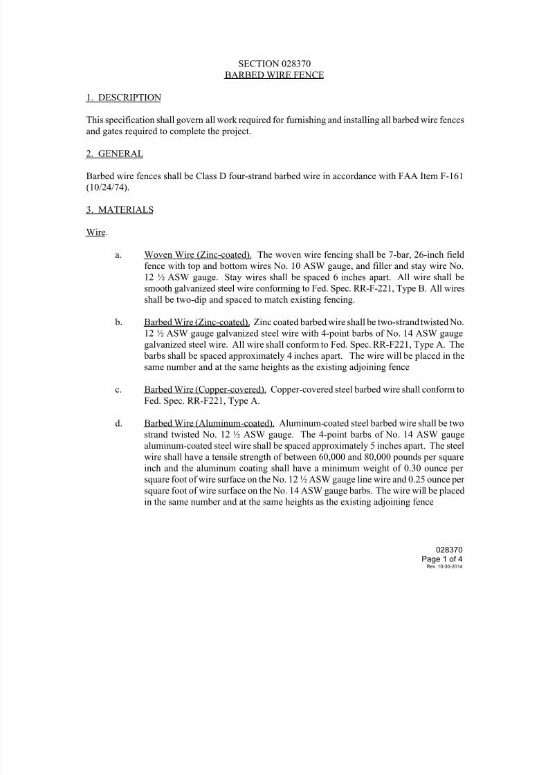
7/25/2019 City Standard Construction Specifications
http://slidepdf.com/reader/full/city-standard-construction-specifications 339/511
028370
Page 1 of 4Rev. 10-30-2014
SECTION 028370
BARBED WIRE FENCE
1. DESCRIPTION
This specification shall govern all work required for furnishing and installing all barbed wire fencesand gates required to complete the project.
2. GENERAL
Barbed wire fences shall be Class D four-strand barbed wire in accordance with FAA Item F-161
(10/24/74).
3. MATERIALS
Wire.
a. Woven Wire (Zinc-coated). The woven wire fencing shall be 7-bar, 26-inch field
fence with top and bottom wires No. 10 ASW gauge, and filler and stay wire No.
12 ½ ASW gauge. Stay wires shall be spaced 6 inches apart. All wire shall be
smooth galvanized steel wire conforming to Fed. Spec. RR-F-221, Type B. All wires
shall be two-dip and spaced to match existing fencing.
b. Barbed Wire (Zinc-coated). Zinc coated barbed wire shall be two-strand twisted No.
12 ½ ASW gauge galvanized steel wire with 4-point barbs of No. 14 ASW gauge
galvanized steel wire. All wire shall conform to Fed. Spec. RR-F221, Type A. The
barbs shall be spaced approximately 4 inches apart. The wire will be placed in the
same number and at the same heights as the existing adjoining fence
c. Barbed Wire (Copper-covered). Copper-covered steel barbed wire shall conform to
Fed. Spec. RR-F221, Type A.
d. Barbed Wire (Aluminum-coated). Aluminum-coated steel barbed wire shall be two
strand twisted No. 12 ½ ASW gauge. The 4-point barbs of No. 14 ASW gauge
aluminum-coated steel wire shall be spaced approximately 5 inches apart. The steel
wire shall have a tensile strength of between 60,000 and 80,000 pounds per square
inch and the aluminum coating shall have a minimum weight of 0.30 ounce per
square foot of wire surface on the No. 12 ½ ASW gauge line wire and 0.25 ounce per
square foot of wire surface on the No. 14 ASW gauge barbs. The wire will be placedin the same number and at the same heights as the existing adjoining fence
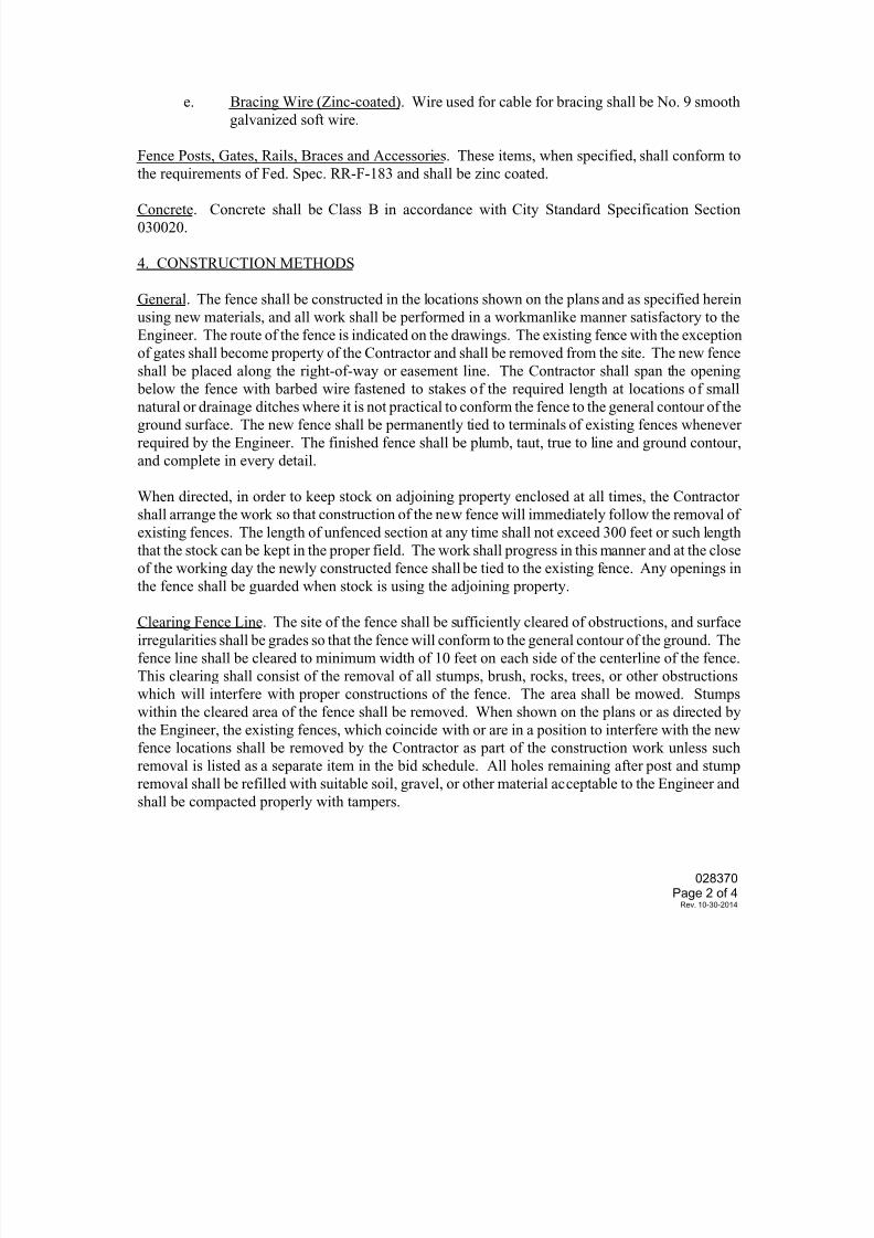
7/25/2019 City Standard Construction Specifications
http://slidepdf.com/reader/full/city-standard-construction-specifications 340/511
028370
Page 2 of 4Rev. 10-30-2014
e. Bracing Wire (Zinc-coated). Wire used for cable for bracing shall be No. 9 smooth
galvanized soft wire.
Fence Posts, Gates, Rails, Braces and Accessories. These items, when specified, shall conform to
the requirements of Fed. Spec. RR-F-183 and shall be zinc coated.
Concrete. Concrete shall be Class B in accordance with City Standard Specification Section
030020.
4. CONSTRUCTION METHODS
General. The fence shall be constructed in the locations shown on the plans and as specified herein
using new materials, and all work shall be performed in a workmanlike manner satisfactory to the
Engineer. The route of the fence is indicated on the drawings. The existing fence with the exception
of gates shall become property of the Contractor and shall be removed from the site. The new fence
shall be placed along the right-of-way or easement line. The Contractor shall span the opening
below the fence with barbed wire fastened to stakes of the required length at locations of smallnatural or drainage ditches where it is not practical to conform the fence to the general contour of the
ground surface. The new fence shall be permanently tied to terminals of existing fences whenever
required by the Engineer. The finished fence shall be plumb, taut, true to line and ground contour,
and complete in every detail.
When directed, in order to keep stock on adjoining property enclosed at all times, the Contractor
shall arrange the work so that construction of the new fence will immediately follow the removal of
existing fences. The length of unfenced section at any time shall not exceed 300 feet or such length
that the stock can be kept in the proper field. The work shall progress in this manner and at the close
of the working day the newly constructed fence shall be tied to the existing fence. Any openings in
the fence shall be guarded when stock is using the adjoining property.
Clearing Fence Line. The site of the fence shall be sufficiently cleared of obstructions, and surface
irregularities shall be grades so that the fence will conform to the general contour of the ground. The
fence line shall be cleared to minimum width of 10 feet on each side of the centerline of the fence.
This clearing shall consist of the removal of all stumps, brush, rocks, trees, or other obstructions
which will interfere with proper constructions of the fence. The area shall be mowed. Stumps
within the cleared area of the fence shall be removed. When shown on the plans or as directed by
the Engineer, the existing fences, which coincide with or are in a position to interfere with the new
fence locations shall be removed by the Contractor as part of the construction work unless such
removal is listed as a separate item in the bid schedule. All holes remaining after post and stump
removal shall be refilled with suitable soil, gravel, or other material acceptable to the Engineer andshall be compacted properly with tampers.
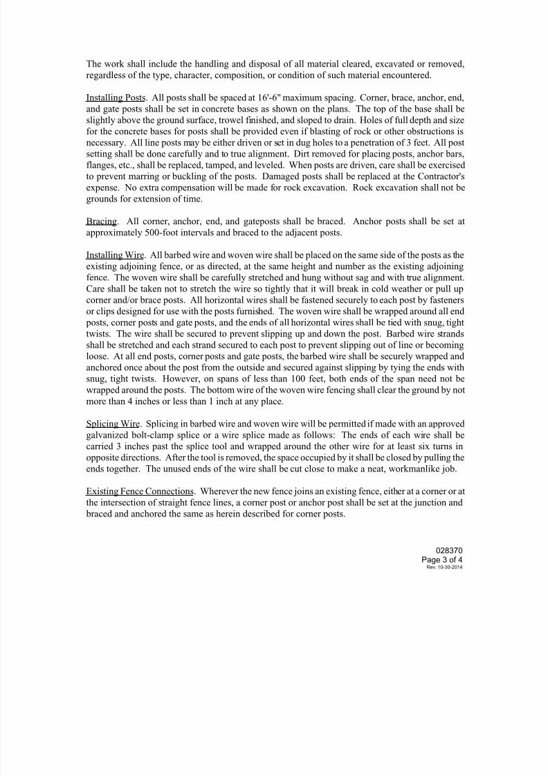
7/25/2019 City Standard Construction Specifications
http://slidepdf.com/reader/full/city-standard-construction-specifications 341/511
028370
Page 3 of 4Rev. 10-30-2014
The work shall include the handling and disposal of all material cleared, excavated or removed,
regardless of the type, character, composition, or condition of such material encountered.
Installing Posts. All posts shall be spaced at 16'-6" maximum spacing. Corner, brace, anchor, end,
and gate posts shall be set in concrete bases as shown on the plans. The top of the base shall be
slightly above the ground surface, trowel finished, and sloped to drain. Holes of full depth and sizefor the concrete bases for posts shall be provided even if blasting of rock or other obstructions is
necessary. All line posts may be either driven or set in dug holes to a penetration of 3 feet. All post
setting shall be done carefully and to true alignment. Dirt removed for placing posts, anchor bars,
flanges, etc., shall be replaced, tamped, and leveled. When posts are driven, care shall be exercised
to prevent marring or buckling of the posts. Damaged posts shall be replaced at the Contractor's
expense. No extra compensation will be made for rock excavation. Rock excavation shall not be
grounds for extension of time.
Bracing. All corner, anchor, end, and gateposts shall be braced. Anchor posts shall be set at
approximately 500-foot intervals and braced to the adjacent posts.
Installing Wire. All barbed wire and woven wire shall be placed on the same side of the posts as the
existing adjoining fence, or as directed, at the same height and number as the existing adjoining
fence. The woven wire shall be carefully stretched and hung without sag and with true alignment.
Care shall be taken not to stretch the wire so tightly that it will break in cold weather or pull up
corner and/or brace posts. All horizontal wires shall be fastened securely to each post by fasteners
or clips designed for use with the posts furnished. The woven wire shall be wrapped around all end
posts, corner posts and gate posts, and the ends of all horizontal wires shall be tied with snug, tight
twists. The wire shall be secured to prevent slipping up and down the post. Barbed wire strands
shall be stretched and each strand secured to each post to prevent slipping out of line or becoming
loose. At all end posts, corner posts and gate posts, the barbed wire shall be securely wrapped and
anchored once about the post from the outside and secured against slipping by tying the ends withsnug, tight twists. However, on spans of less than 100 feet, both ends of the span need not be
wrapped around the posts. The bottom wire of the woven wire fencing shall clear the ground by not
more than 4 inches or less than 1 inch at any place.
Splicing Wire. Splicing in barbed wire and woven wire will be permitted if made with an approved
galvanized bolt-clamp splice or a wire splice made as follows: The ends of each wire shall be
carried 3 inches past the splice tool and wrapped around the other wire for at least six turns in
opposite directions. After the tool is removed, the space occupied by it shall be closed by pulling the
ends together. The unused ends of the wire shall be cut close to make a neat, workmanlike job.
Existing Fence Connections. Wherever the new fence joins an existing fence, either at a corner or atthe intersection of straight fence lines, a corner post or anchor post shall be set at the junction and
braced and anchored the same as herein described for corner posts.
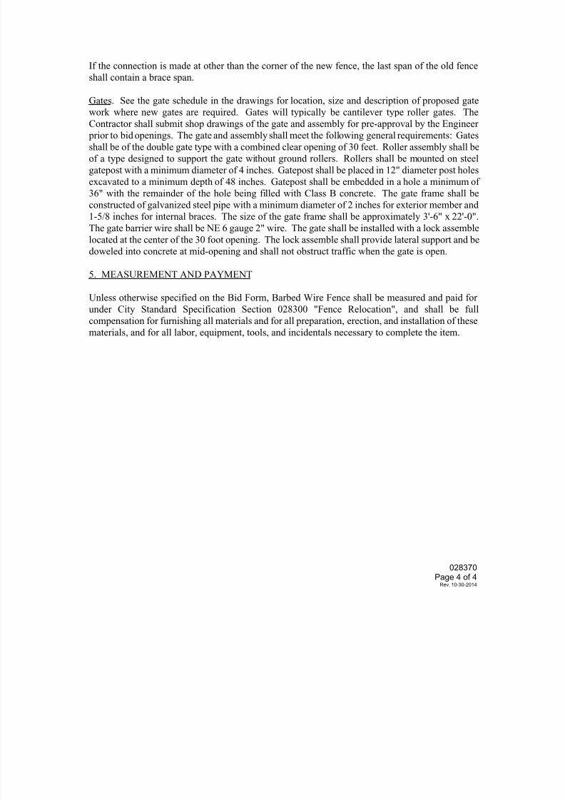
7/25/2019 City Standard Construction Specifications
http://slidepdf.com/reader/full/city-standard-construction-specifications 342/511
028370
Page 4 of 4Rev. 10-30-2014
If the connection is made at other than the corner of the new fence, the last span of the old fence
shall contain a brace span.
Gates. See the gate schedule in the drawings for location, size and description of proposed gate
work where new gates are required. Gates will typically be cantilever type roller gates. The
Contractor shall submit shop drawings of the gate and assembly for pre-approval by the Engineer prior to bid openings. The gate and assembly shall meet the following general requirements: Gates
shall be of the double gate type with a combined clear opening of 30 feet. Roller assembly shall be
of a type designed to support the gate without ground rollers. Rollers shall be mounted on steel
gatepost with a minimum diameter of 4 inches. Gatepost shall be placed in 12" diameter post holes
excavated to a minimum depth of 48 inches. Gatepost shall be embedded in a hole a minimum of
36" with the remainder of the hole being filled with Class B concrete. The gate frame shall be
constructed of galvanized steel pipe with a minimum diameter of 2 inches for exterior member and
1-5/8 inches for internal braces. The size of the gate frame shall be approximately 3'-6" x 22'-0".
The gate barrier wire shall be NE 6 gauge 2" wire. The gate shall be installed with a lock assemble
located at the center of the 30 foot opening. The lock assemble shall provide lateral support and be
doweled into concrete at mid-opening and shall not obstruct traffic when the gate is open.
5. MEASUREMENT AND PAYMENT
Unless otherwise specified on the Bid Form, Barbed Wire Fence shall be measured and paid for
under City Standard Specification Section 028300 "Fence Relocation", and shall be full
compensation for furnishing all materials and for all preparation, erection, and installation of these
materials, and for all labor, equipment, tools, and incidentals necessary to complete the item.
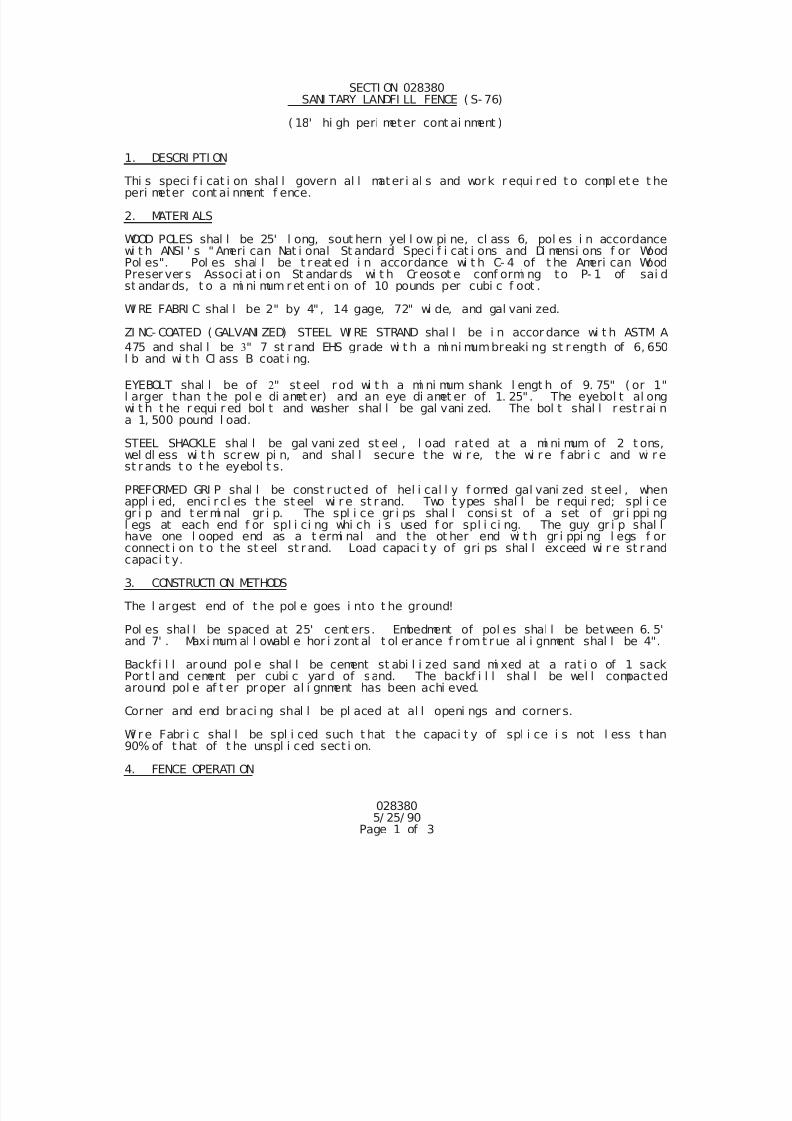
7/25/2019 City Standard Construction Specifications
http://slidepdf.com/reader/full/city-standard-construction-specifications 343/511
0283805/ 25/ 90
Page 1 of 3
SECTI ON 028380 SANI TARY LANDFI LL FENCE ( S- 76)
( 18' hi gh peri meter cont ai nment )
1. DESCRI PTI ON
Thi s speci f i cat i on shal l govern al l mater i al s and work r equi r ed t o compl ete t heperi meter cont ai nment f ence.
2. MATERI ALS
WOOD POLES shal l be 25' l ong, sout hern yel l ow pi ne, cl ass 6, pol es i n accordancewi t h ANSI ' s " Ameri can Nat i onal St andard Speci f i cat i ons and Di mensi ons f or WoodPol es". Pol es shal l be t reat ed i n accordance wi t h C- 4 of t he Ameri can WoodPreser ver s Associ at i on St andar ds wi t h Cr eosot e conf ormi ng to P- 1 of sai dst andar ds, t o a mi ni mum r et ent i on of 10 pounds per cubi c f oot .
WI RE FABRI C shal l be 2" by 4", 14 gage, 72" wi de, and gal vani zed.
ZI NC- COATED ( GALVANI ZED) STEEL WI RE STRAND shal l be i n accor dance wi t h ASTM A
475 and shal l be " 7 st r and EHS grade wi t h a mi ni mumbreaki ng st r ength of 6, 650l b and wi t h Cl ass B coat i ng.
EYEBOLT shal l be of " st eel r od wi t h a mi ni mum shank l engt h of 9. 75" ( or 1"l arger t han t he pol e di amet er) and an eye di amet er of 1. 25". The eyebol t al ongwi t h t he r equi r ed bol t and washer shal l be gal vani zed. The bol t shal l r est r ai na 1, 500 pound l oad.
STEEL SHACKLE shal l be gal vani zed st eel , l oad r ated at a mi ni mum of 2 t ons,wel dl ess wi t h scr ew pi n, and shal l secure t he wi r e, t he wi re f abr i c and wi r est r ands t o t he eyebol t s.
PREFORMED GRI P shal l be const r uct ed of hel i cal l y f ormed gal vani zed st eel , whenappl i ed, enci r cl es t he st eel wi r e st r and. Two t ypes shal l be r equi red; spl i cegr i p and t er mi nal gr i p. The spl i ce gr i ps shal l consi st of a set of gr i ppi ngl egs at each end f or spl i ci ng whi ch i s used f or spl i ci ng. The guy gr i p shal lhave one l ooped end as a t ermi nal and the ot her end wi t h gr i ppi ng l egs f orconnect i on t o t he st eel st r and. Load capaci t y of gri ps shal l exceed wi r e st r andcapaci t y.
3. CONSTRUCTI ON METHODS
The l argest end of t he pol e goes i nto t he ground!
Pol es shal l be spaced at 25' cent ers . Embedment of pol es shal l be between 6. 5'and 7' . Maxi mum al l owabl e hor i zont al t ol er ance f r om t r ue al i gnment shal l be 4".
Backf i l l ar ound pol e shal l be cement st abi l i zed sand mi xed at a rat i o of 1 sackPor t l and cement per cubi c yar d of sand. The backf i l l shal l be wel l compactedaround pol e af t er pr oper al i gnment has been achi eved.
Corner and end br aci ng shal l be pl aced at al l openi ngs and corner s.
Wi r e Fabr i c shal l be spl i ced such t hat t he capaci t y of spl i ce i s not l ess t han90% of t hat of t he unspl i ced sect i on.
4. FENCE OPERATI ON
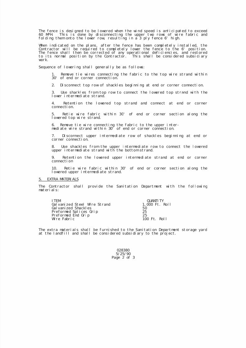
7/25/2019 City Standard Construction Specifications
http://slidepdf.com/reader/full/city-standard-construction-specifications 344/511
0283805/ 25/ 90
Page 2 of 3
The f ence i s desi gned t o be l owered when t he wi nd speed i s ant i ci pat ed t o exceed60 MPH. Thi s i s done by di sconnecti ng t he upper t wo r ows of wi re f abr i c andf ol di ng t hem ont o t he l ower r ow, r esul t i ng i n a 3 pl y f ence 6' hi gh.
When i ndi cat ed on the pl ans, af t er t he f ence has been compl et el y i nst al l ed, t heCont ract or wi l l be r equi r ed t o compl et el y l ower t he f ence t o t he 6' posi t i on.
The f ence shal l t hen be cor r ect ed of any operat i onal def i ci enci es, and rest oredt o i t s normal posi t i on by t he Cont r actor . Thi s shal l be consi der ed subsi di ar ywor k.
Sequence of l ower i ng shal l gener al l y be as f ol l ows:
1. Remove t i e wi r es connect i ng t he f abr i c to t he t op wi re st r and wi t hi n30' of end or corner connect i on.
2. Di sconnect t op r ow of shackl es begi nni ng at end or corner connect i on.
3. Use shackl es f r om t op row t o connect t he l ower ed t op st r and wi t h t hel ower i nt er medi at e st r and.
4. Retent i on t he l owered t op st r and and connect at end or cornerconnecti on.
5. Ret i e wi r e f abr i c wi t hi n 30' of end or cor ner sect i on al ong t hel ower ed t op wi re st r and.
6. Remove t i e wi r e connect i ng t he f abr i c to t he upper i nt er -medi at e wi r e st r and wi t hi n 30' of end or cor ner connect i on.
7. Di sconnect upper i nt ermedi ate r ow of shackl es begi nni ng at end orcor ner connect i on.
8. Use shackl es f r om t he upper i nt ermedi ate r ow t o connect t he l oweredupper i nt er medi at e st r and wi t h t he bott omst r and.
9. Retent i on t he l owered upper i nt ermedi ate st rand at end or cor nerconnect i on
10. Ret i e wi r e f abr i c wi t hi n 30' of end or cor ner sect i on al ong t hel owered upper i nt ermedi ate st r and.
5. EXTRA MATERI ALS
The Cont r act or shal l provi de t he Sani t at i on Depart ment wi t h t he f ol l owi ngmat er i al s:
I TEM QUANTI TYGal vani zed St eel Wi r e St r and 1, 000 Ft . Rol lGal vani zed Shackl es 50Pref ormed Spl i ces Gr i p 25Pref ormed End Gr i p 25
Wi r e Fabr i c 100 Ft. Rol l
The extr a mater i al s shal l be f urni shed t o t he Sani t at i on Depart ment st orage yardat t he l andf i l l and shal l be consi der ed subsi di ar y to the proj ect .
7/25/2019 City Standard Construction Specifications
http://slidepdf.com/reader/full/city-standard-construction-specifications 345/511
0283805/ 25/ 90
Page 3 of 3
6. MEASUREMENT & PAYMENT
Unl ess i ndi cat ed ot her wi se i n t he Pr oposal , Sani t ar y Landf i l l Fence shal l be byt he l i near f oot al ong t he cent er l i ne of t he f ence and shal l i ncl ude but not bel i mi t ed t o post , wi r e, connect i ons, spl i ces, sand backf i l l , cor ner and endsecti ons, et c.
Payment shal l f ul l y compensat e t he Cont r act or f or al l mat er i al s, l abor ,equi pment , and ot her i nci dent al s r equi r ed t o i nst al l t he f ence.
7/25/2019 City Standard Construction Specifications
http://slidepdf.com/reader/full/city-standard-construction-specifications 346/511
028810Page 1 of 1
SECTI ON 028810RECREATI ONAL EQUI PMENT (S- 99)
1. DESCRI PTI ON
Thi s speci f i cat i on governs al l l abor , mat er i al s, equi pment r equi r ed f or properi nst al l at i on of r ecreat i onal equi pment , and r el at ed i t ems.
2. MATERI ALS
Al l mater i al s shal l be as manuf act ured by Gamet i me Equi pment or an approvedequal . Al l equi pment and r el at ed i t ems are l i st ed i n t he Appendi x of t heSpeci al Pr ovi si ons and Speci f i cat i ons.
3. I NSTALLATI ON
Al l equi pment and r el at ed i t ems shal l be i nst al l ed as per manuf act ur er sr ecommendat i ons unl ess otherwi se i ndi cated on t he pl ans.
4. MEASUREMENT AND PAYMENT
Recreat i onal equi pment shal l be measured and pai d f or by l ump sum. Such
payment shal l const i t ut e f ul l compensat i on f or al l l abor , mat er i al s, equi pmentand i nci dent al s necessar y t o compl et e the i nst al l at i on as speci f i ed.
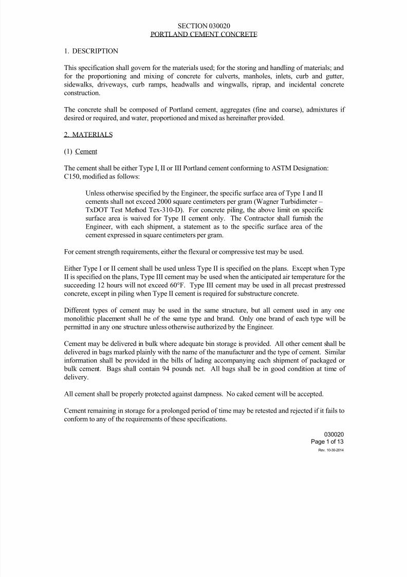
7/25/2019 City Standard Construction Specifications
http://slidepdf.com/reader/full/city-standard-construction-specifications 347/511
030020
Page 1 of 13
Rev. 10-30-2014
SECTION 030020
PORTLAND CEMENT CONCRETE
1. DESCRIPTION
This specification shall govern for the materials used; for the storing and handling of materials; and
for the proportioning and mixing of concrete for culverts, manholes, inlets, curb and gutter,
sidewalks, driveways, curb ramps, headwalls and wingwalls, riprap, and incidental concrete
construction.
The concrete shall be composed of Portland cement, aggregates (fine and coarse), admixtures if
desired or required, and water, proportioned and mixed as hereinafter provided.
2. MATERIALS
(1) Cement
The cement shall be either Type I, II or III Portland cement conforming to ASTM Designation:
C150, modified as follows:
Unless otherwise specified by the Engineer, the specific surface area of Type I and II
cements shall not exceed 2000 square centimeters per gram (Wagner Turbidimeter –
TxDOT Test Method Tex-310-D). For concrete piling, the above limit on specific
surface area is waived for Type II cement only. The Contractor shall furnish the
Engineer, with each shipment, a statement as to the specific surface area of the
cement expressed in square centimeters per gram.
For cement strength requirements, either the flexural or compressive test may be used.
Either Type I or II cement shall be used unless Type II is specified on the plans. Except when Type
II is specified on the plans, Type III cement may be used when the anticipated air temperature for the
succeeding 12 hours will not exceed 60°F. Type III cement may be used in all precast prestressed
concrete, except in piling when Type II cement is required for substructure concrete.
Different types of cement may be used in the same structure, but all cement used in any one
monolithic placement shall be of the same type and brand. Only one brand of each type will be
permitted in any one structure unless otherwise authorized by the Engineer.
Cement may be delivered in bulk where adequate bin storage is provided. All other cement shall be
delivered in bags marked plainly with the name of the manufacturer and the type of cement. Similar
information shall be provided in the bills of lading accompanying each shipment of packaged or
bulk cement. Bags shall contain 94 pounds net. All bags shall be in good condition at time of
delivery.
All cement shall be properly protected against dampness. No caked cement will be accepted.
Cement remaining in storage for a prolonged period of time may be retested and rejected if it fails to
conform to any of the requirements of these specifications.
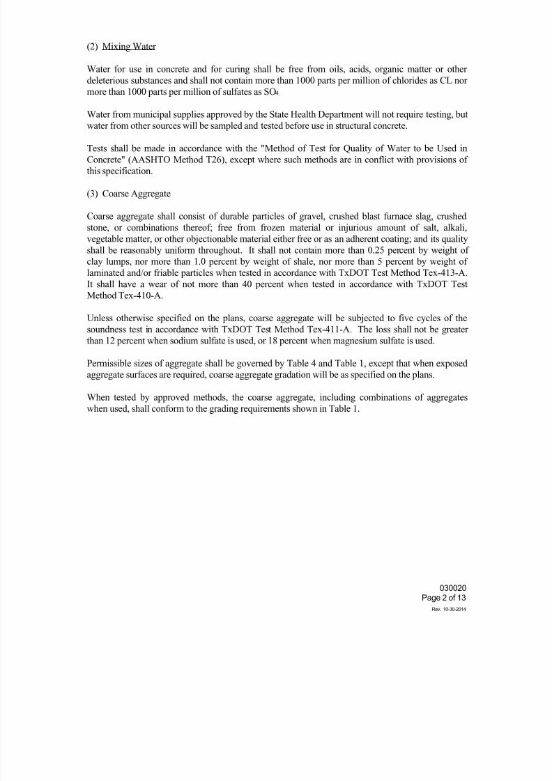
7/25/2019 City Standard Construction Specifications
http://slidepdf.com/reader/full/city-standard-construction-specifications 348/511
030020
Page 2 of 13
Rev. 10-30-2014
(2) Mixing Water
Water for use in concrete and for curing shall be free from oils, acids, organic matter or other
deleterious substances and shall not contain more than 1000 parts per million of chlorides as CL nor
more than 1000 parts per million of sulfates as SO4.
Water from municipal supplies approved by the State Health Department will not require testing, but
water from other sources will be sampled and tested before use in structural concrete.
Tests shall be made in accordance with the "Method of Test for Quality of Water to be Used in
Concrete" (AASHTO Method T26), except where such methods are in conflict with provisions of
this specification.
(3) Coarse Aggregate
Coarse aggregate shall consist of durable particles of gravel, crushed blast furnace slag, crushed
stone, or combinations thereof; free from frozen material or injurious amount of salt, alkali,
vegetable matter, or other objectionable material either free or as an adherent coating; and its quality
shall be reasonably uniform throughout. It shall not contain more than 0.25 percent by weight ofclay lumps, nor more than 1.0 percent by weight of shale, nor more than 5 percent by weight of
laminated and/or friable particles when tested in accordance with TxDOT Test Method Tex-413-A.
It shall have a wear of not more than 40 percent when tested in accordance with TxDOT Test
Method Tex-410-A.
Unless otherwise specified on the plans, coarse aggregate will be subjected to five cycles of the
soundness test in accordance with TxDOT Test Method Tex-411-A. The loss shall not be greater
than 12 percent when sodium sulfate is used, or 18 percent when magnesium sulfate is used.
Permissible sizes of aggregate shall be governed by Table 4 and Table 1, except that when exposed
aggregate surfaces are required, coarse aggregate gradation will be as specified on the plans.
When tested by approved methods, the coarse aggregate, including combinations of aggregates
when used, shall conform to the grading requirements shown in Table 1.
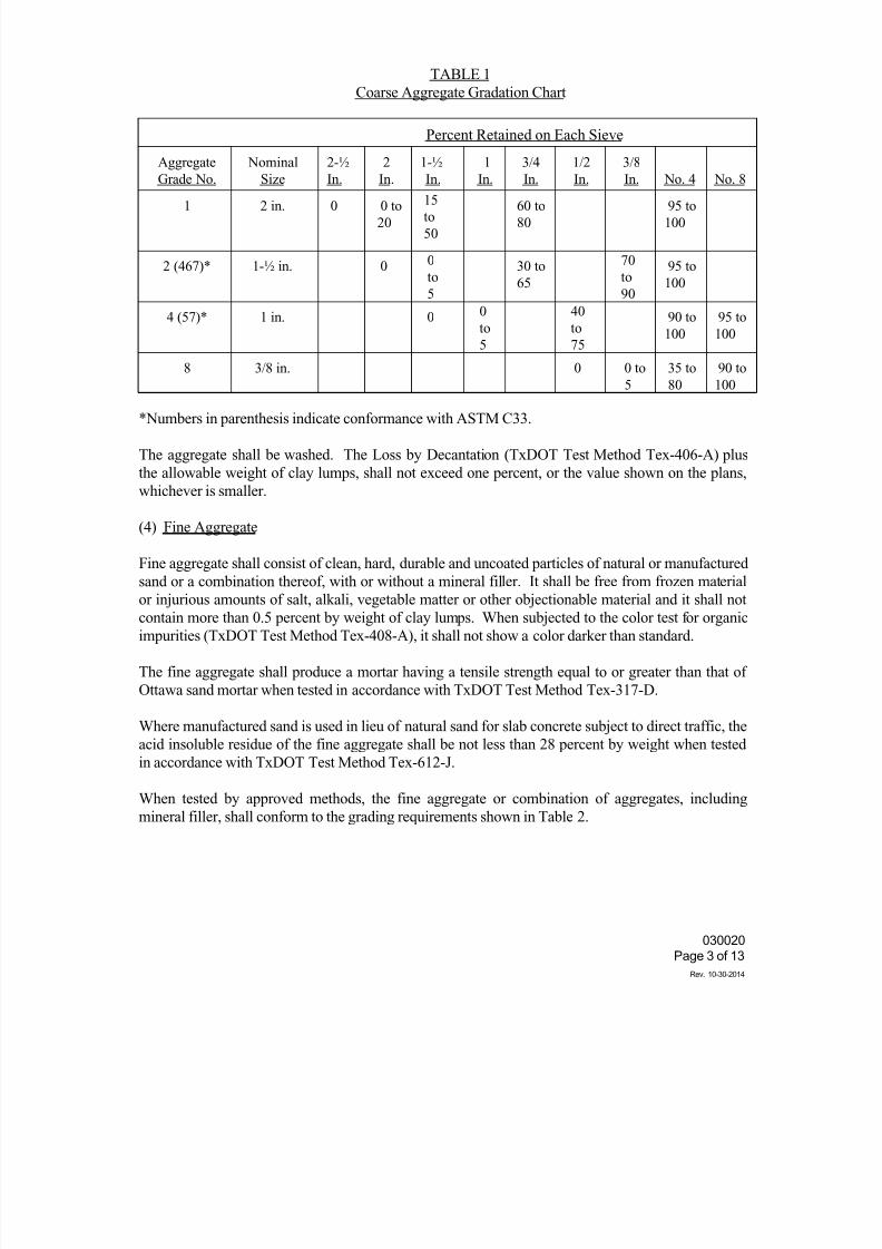
7/25/2019 City Standard Construction Specifications
http://slidepdf.com/reader/full/city-standard-construction-specifications 349/511
030020
Page 3 of 13
Rev. 10-30-2014
TABLE 1
Coarse Aggregate Gradation Chart
Percent Retained on Each Sieve
Aggregate
Grade No.
Nominal
Size
2-½
In.
2
In.
1-½
In.
1
In.
3/4
In.
1/2
In.
3/8
In. No. 4 No. 8
1 2 in. 0 0 to
20
15to
50
60 to
80
95 to
100
2 (467)* 1-½ in. 0 0
to
5
30 to
65
70
to
90
95 to
100
4 (57)* 1 in. 0 0
to
5
40
to
75
90 to
100
95 to
100
8 3/8 in. 0 0 to
5
35 to
80
90 to
100
*Numbers in parenthesis indicate conformance with ASTM C33.
The aggregate shall be washed. The Loss by Decantation (TxDOT Test Method Tex-406-A) plus
the allowable weight of clay lumps, shall not exceed one percent, or the value shown on the plans,
whichever is smaller.
(4) Fine Aggregate
Fine aggregate shall consist of clean, hard, durable and uncoated particles of natural or manufactured
sand or a combination thereof, with or without a mineral filler. It shall be free from frozen material
or injurious amounts of salt, alkali, vegetable matter or other objectionable material and it shall not
contain more than 0.5 percent by weight of clay lumps. When subjected to the color test for organic
impurities (TxDOT Test Method Tex-408-A), it shall not show a color darker than standard.
The fine aggregate shall produce a mortar having a tensile strength equal to or greater than that of
Ottawa sand mortar when tested in accordance with TxDOT Test Method Tex-317-D.
Where manufactured sand is used in lieu of natural sand for slab concrete subject to direct traffic, the
acid insoluble residue of the fine aggregate shall be not less than 28 percent by weight when tested
in accordance with TxDOT Test Method Tex-612-J.
When tested by approved methods, the fine aggregate or combination of aggregates, including
mineral filler, shall conform to the grading requirements shown in Table 2.
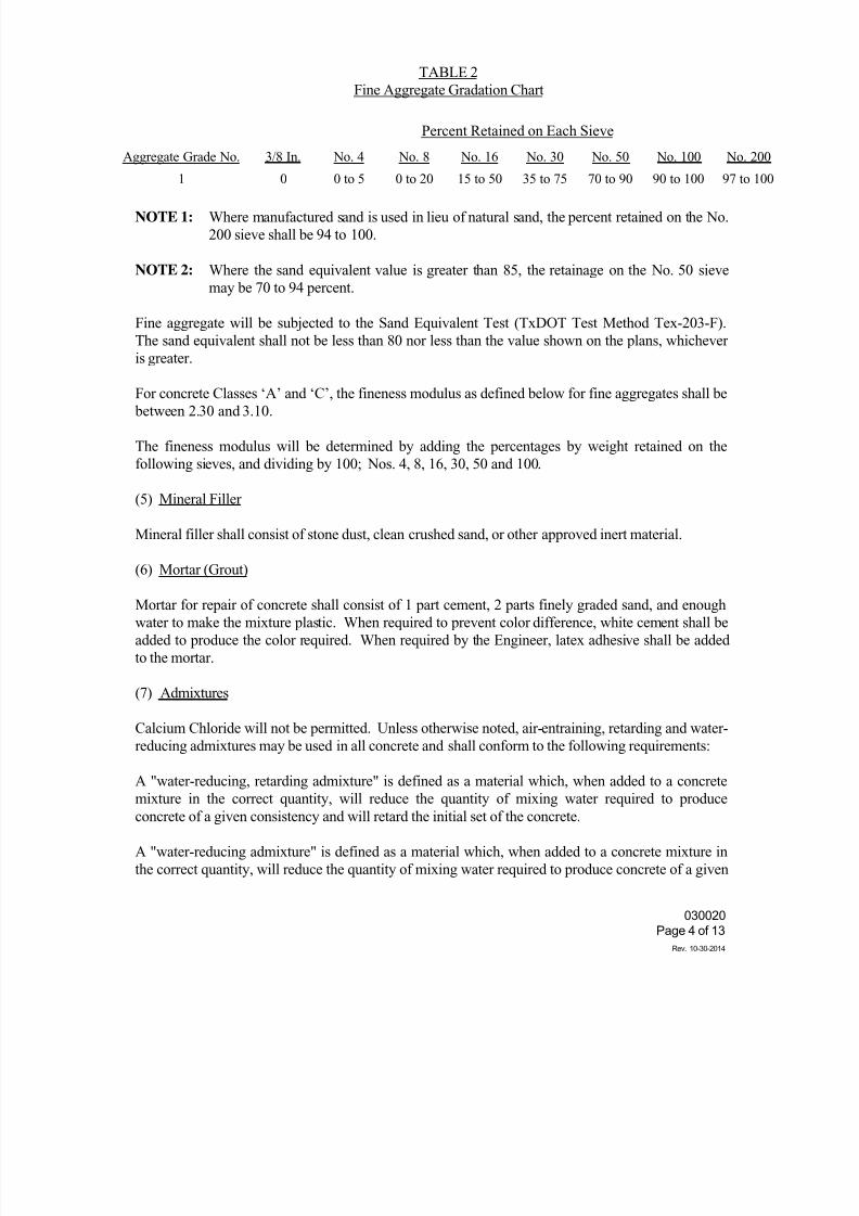
7/25/2019 City Standard Construction Specifications
http://slidepdf.com/reader/full/city-standard-construction-specifications 350/511
030020
Page 4 of 13
Rev. 10-30-2014
TABLE 2
Fine Aggregate Gradation Chart
Percent Retained on Each Sieve
Aggregate Grade No. 3/8 In. No. 4 No. 8 No. 16 No. 30 No. 50 No. 100 No. 200
1 0 0 to 5 0 to 20 15 to 50 35 to 75 70 to 90 90 to 100 97 to 10
NOTE 1: Where manufactured sand is used in lieu of natural sand, the percent retained on the No.
200 sieve shall be 94 to 100.
NOTE 2: Where the sand equivalent value is greater than 85, the retainage on the No. 50 sieve
may be 70 to 94 percent.
Fine aggregate will be subjected to the Sand Equivalent Test (TxDOT Test Method Tex-203-F).
The sand equivalent shall not be less than 80 nor less than the value shown on the plans, whichever
is greater.
For concrete Classes ‘A’ and ‘C’, the fineness modulus as defined below for fine aggregates shall be
between 2.30 and 3.10.
The fineness modulus will be determined by adding the percentages by weight retained on the
following sieves, and dividing by 100; Nos. 4, 8, 16, 30, 50 and 100.
(5) Mineral Filler
Mineral filler shall consist of stone dust, clean crushed sand, or other approved inert material.
(6) Mortar (Grout)
Mortar for repair of concrete shall consist of 1 part cement, 2 parts finely graded sand, and enough
water to make the mixture plastic. When required to prevent color difference, white cement shall be
added to produce the color required. When required by the Engineer, latex adhesive shall be added
to the mortar.
(7) Admixtures
Calcium Chloride will not be permitted. Unless otherwise noted, air-entraining, retarding and water-
reducing admixtures may be used in all concrete and shall conform to the following requirements:
A "water-reducing, retarding admixture" is defined as a material which, when added to a concrete
mixture in the correct quantity, will reduce the quantity of mixing water required to produce
concrete of a given consistency and will retard the initial set of the concrete.
A "water-reducing admixture" is defined as a material which, when added to a concrete mixture in
the correct quantity, will reduce the quantity of mixing water required to produce concrete of a given
7/25/2019 City Standard Construction Specifications
http://slidepdf.com/reader/full/city-standard-construction-specifications 351/511
030020
Page 5 of 13
Rev. 10-30-2014
consistency.
(a) Retarding and Water-Reducing Admixtures. The admixture shall meet the
requirements for Type A and Type D admixture as specified in ASTM
Designation: C494, modified as follows:
(1) The water-reducing retarder shall retard the initial set of the concrete
a minimum of 2 hours and a maximum of 4 hours, at a specified
dosage rate, at a temperature of 90°F.
(2) The cement used in any series of tests shall be either the cement
proposed for specific work or a "reference" Type I cement from one
mill.
(3) Unless otherwise noted on the plans, the minimum relative durability
factor shall be 80.
The air-entraining admixture used in the referenced and test concrete shall be neutralized Vinsol
resin.
(b) Air-Entraining Admixture. The admixture shall meet the requirements of
ASTM Designation: C260, modified as follows:
(1) The cement used in any series of tests shall be either the cement
proposed for specific work or a "reference" Type I cement from one
mill.
(2) Unless otherwise noted on the plans, the minimum relative durability
factor shall be 80.
The air-entraining admixture used in the referenced concrete shall be neutralized Vinsol resin.
3. STORAGE OF CEMENT
All cement shall be stored in well-ventilated weatherproof buildings or approved bins, which will
protect it from dampness or absorption of moisture. Storage facilities shall be ample, and each
shipment of packaged cement shall be kept separated to provide easy access for identification and
inspection.
The Engineer may permit small quantities of sacked cement to be stored in the open for a maximum
of 48 hours on a raised platform and under waterproof covering.
4. STORAGE OF AGGREGATE
The method of handling and storing concrete aggregate shall prevent contamination with foreign
materials. If the aggregates are stored on the ground, the sites for the stockpiles shall be clear of all
vegetation and level. The bottom layer of aggregate shall not be disturbed or used without
recleaning.
7/25/2019 City Standard Construction Specifications
http://slidepdf.com/reader/full/city-standard-construction-specifications 352/511
030020
Page 6 of 13
Rev. 10-30-2014
When conditions require the use of two or more sizes of aggregates, they shall be separated to
prevent intermixing. Where space is limited, stockpiles shall be separated by physical barriers.
Methods of handling aggregates during stockpiling and subsequent use shall be such that segregation
will be minimized.
Unless otherwise authorized by the Engineer, all aggregate shall be stockpiled at least 24 hours to
reduce the free moisture content.
5. MEASUREMENT OF MATERIALS
The measurement of the materials, except water, used in batches of concrete, shall be by weight.
The fine aggregate, coarse aggregate and mineral filler shall be weighed separately. Where bulk
cement is used, it shall be weighed separately, but batch weighing of sacked cement will not be
required. Where sacked cement is used, the quantities of material per batch shall be based upon
using full bags of cement. Batches involving the use of fractional bags will not be permitted.
Allowance shall be made for the water content in the aggregates.
Bags of cement varying more than 3 percent from the specified weight of 94 pounds may be
rejected, and when the average weight per bag in any shipment, as determined by weighing 50 bags
taken at random, is less than the net weight specified, the entire shipment may be rejected. If the
shipment is accepted, the Engineer will adjust the concrete mix to a net weight per bag fixed by an
average of all individual weights which are less than the average weight determined from the total
number weighed.
6. CLASSIFICATION AND MIX DESIGN
It shall be the responsibility of the Contractor to furnish the mix design, using a coarse aggregate
factor acceptable to the Engineer, for the class(es) of concrete specified. The mix shall be designed
by a qualified concrete technician to conform with the requirements contained herein and in
accordance with the THD Bulletin C-11. The Contractor shall perform, at his own expense, the
work required to substantiate the design, except the testing of strength specimens, which will be
done by the Engineer. Complete concrete design data shall be submitted to the Engineer for
approval.
It shall also be the responsibility of the Contractor to determine and measure the batch quantity of
each ingredient, including all water, so that the mix conforms to these specifications and any other
requirements shown on the plans.
Trial batches will be made and tested using all of the proposed ingredients prior to placing the
concrete, and when the aggregate and/or brand of cement or admixture is changed. Trial batches
shall be made in the mixer to be used on the job. When transit mix concrete is to be used, the trial
designs will be made in a transit mixer representative of the mixers to be used. Batch size shall not
be less than 50 percent of the rated mixing capacity of the truck.
Mix designs from previous or concurrent jobs may be used without trial batches if it is shown that no
7/25/2019 City Standard Construction Specifications
http://slidepdf.com/reader/full/city-standard-construction-specifications 353/511
030020
Page 7 of 13
Rev. 10-30-2014
substantial change in any of the proposed ingredients has been made.
The coarse aggregate factor shall not be more than 0.82, except that when the voids in the coarse
aggregate exceed 48 percent of the total dry loose volume, the coarse aggregate factor shall not
exceed 0.85. The coarse aggregate factor shall not be less than 0.70 for Grades 1, 2 and 3
aggregates.
If the strength required for the class of concrete being produced is not secured with the cement
specified in Table 4, the Contractor may use an approved water-reducing or retarding admixture, orhe shall furnish aggregates with different characteristics which will produce the required results.
Additional cement may be required or permitted as a temporary measure until the redesign is
checked.
Water-reducing or retarding agents may be used with all classes of concrete at the option of the
Contractor.
When water-reducing or retarding agents are used at the option of the Contractor, reduced dosage of
the admixture will be permitted.
Entrained air will be required in accordance with Table 4. The concrete shall be designed to entrain5 percent air when Grade 2 coarse aggregate is used and 6 percent when Grade 3 coarse aggregate is
used. Concrete as placed in the structure shall contain the proper amount as required above with a
tolerance of plus or minus 1.5 percentage points. Occasional variations beyond this tolerance will
not be cause for rejection. When the quantity of entrained air is found to be above 7 percent with
Grade 2 coarse aggregate or above 8 percent for Grade 3 coarse aggregate, additional test beams or
cylinders will be made. If these beams or cylinders pass the minimum flexural or compressive
requirements, the concrete will not be rejected because of the variation in air content.
7. CONSISTENCY
In cases where the consistency requirements cannot be satisfied without exceeding the maximum
allowable amount of water, the Contractor may use, or the Engineer may require, an approved water-
reducing or retarding agent, or the Contractor shall furnish additional aggregates or aggregates with
different characteristics, which will produce the required results. Additional cement may be required
or permitted as a temporary measure until aggregates are changed and designs checked with the
different aggregates or admixture.
The consistency of the concrete as placed should allow the completion of all finishing operations
without the addition of water to the surface. When field conditions are such that additional moisture
is needed for the final concrete surface finishing operation, the required water shall be applied to the
surface by fog spray only, and shall be held to a minimum. The concrete shall be workable,
cohesive, possess satisfactory finishing qualities, and of the stiffest consistency that can be placed
and vibrated into a homogenous mass. Excessive bleeding shall be avoided. Slump requirements
will be as specified in Table 3.
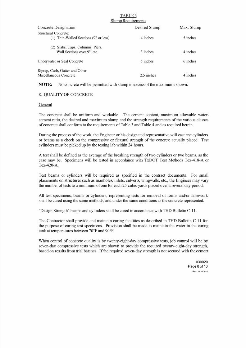
7/25/2019 City Standard Construction Specifications
http://slidepdf.com/reader/full/city-standard-construction-specifications 354/511
030020
Page 8 of 13
Rev. 10-30-2014
TABLE 3
Slump Requirements
Concrete Designation Desired Slump Max. Slump
Structural Concrete:
(1) Thin-Walled Sections (9" or less)
(2) Slabs, Caps, Columns, Piers,
Wall Sections over 9", etc.
Underwater or Seal Concrete
Riprap, Curb, Gutter and Other
Miscellaneous Concrete
4 inches
3 inches
5 inches
2.5 inches
5 inches
4 inches
6 inches
4 inches
NOTE: No concrete will be permitted with slump in excess of the maximums shown.
8. QUALITY OF CONCRETE
General
The concrete shall be uniform and workable. The cement content, maximum allowable water-
cement ratio, the desired and maximum slump and the strength requirements of the various classes
of concrete shall conform to the requirements of Table 3 and Table 4 and as required herein.
During the process of the work, the Engineer or his designated representative will cast test cylinders
or beams as a check on the compressive or flexural strength of the concrete actually placed. Test
cylinders must be picked up by the testing lab within 24 hours.
A test shall be defined as the average of the breaking strength of two cylinders or two beams, as the
case may be. Specimens will be tested in accordance with TxDOT Test Methods Tex-418-A or
Tex-420-A.
Test beams or cylinders will be required as specified in the contract documents. For small
placements on structures such as manholes, inlets, culverts, wingwalls, etc., the Engineer may vary
the number of tests to a minimum of one for each 25 cubic yards placed over a several day period.
All test specimens, beams or cylinders, representing tests for removal of forms and/or falsework
shall be cured using the same methods, and under the same conditions as the concrete represented.
"Design Strength" beams and cylinders shall be cured in accordance with THD Bulletin C-11.
The Contractor shall provide and maintain curing facilities as described in THD Bulletin C-11 forthe purpose of curing test specimens. Provision shall be made to maintain the water in the curing
tank at temperatures between 70°F and 90°F.
When control of concrete quality is by twenty-eight-day compressive tests, job control will be by
seven-day compressive tests which are shown to provide the required twenty-eight-day strength,
based on results from trial batches. If the required seven-day strength is not secured with the cement
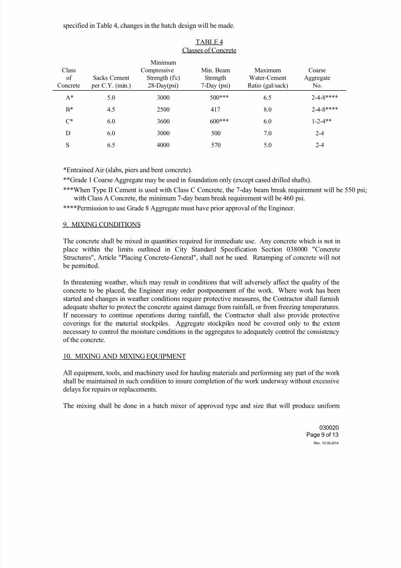
7/25/2019 City Standard Construction Specifications
http://slidepdf.com/reader/full/city-standard-construction-specifications 355/511
030020
Page 9 of 13
Rev. 10-30-2014
specified in Table 4, changes in the batch design will be made.
TABLE 4
Classes of Concrete
Class
of
Concrete
Sacks Cement
per C.Y. (min.)
Minimum
Compressive
Strength (f'c)
28-Day(psi)
Min. Beam
Strength
7-Day (psi)
Maximum
Water-Cement
Ratio (gal/sack)
Coarse
Aggregate
No.
A* 5.0 3000 500*** 6.5 2-4-8****
B* 4.5 2500 417 8.0 2-4-8****
C* 6.0 3600 600*** 6.0 1-2-4**
D 6.0 3000 500 7.0 2-4
S 6.5 4000 570 5.0 2-4
*Entrained Air (slabs, piers and bent concrete).
**Grade 1 Coarse Aggregate may be used in foundation only (except cased drilled shafts).***When Type II Cement is used with Class C Concrete, the 7-day beam break requirement will be 550 p
with Class A Concrete, the minimum 7-day beam break requirement will be 460 psi.
****Permission to use Grade 8 Aggregate must have prior approval of the Engineer.
9. MIXING CONDITIONS
The concrete shall be mixed in quantities required for immediate use. Any concrete which is not in
place within the limits outlined in City Standard Specification Section 038000 "Concrete
Structures", Article "Placing Concrete-General", shall not be used. Retamping of concrete will not
be permitted.
In threatening weather, which may result in conditions that will adversely affect the quality of the
concrete to be placed, the Engineer may order postponement of the work. Where work has been
started and changes in weather conditions require protective measures, the Contractor shall furnish
adequate shelter to protect the concrete against damage from rainfall, or from freezing temperatures.
If necessary to continue operations during rainfall, the Contractor shall also provide protective
coverings for the material stockpiles. Aggregate stockpiles need be covered only to the extent
necessary to control the moisture conditions in the aggregates to adequately control the consistency
of the concrete.
10. MIXING AND MIXING EQUIPMENT
All equipment, tools, and machinery used for hauling materials and performing any part of the work
shall be maintained in such condition to insure completion of the work underway without excessive
delays for repairs or replacements.
The mixing shall be done in a batch mixer of approved type and size that will produce uniform
7/25/2019 City Standard Construction Specifications
http://slidepdf.com/reader/full/city-standard-construction-specifications 356/511
030020
Page 10 of 13
Rev. 10-30-2014
distribution of the material throughout the mass. Mixers may be either the revolving drum type or
the revolving blade type, and shall be capable of producing concrete meeting the requirements of
these specifications.
After all the ingredients are assembled in the drum, the mixing shall continue not less than 1 minute
for mixers of one cubic yard or less capacity plus 15 seconds for each additional cubic yard or
portion thereof.
The mixer shall operate at the speed and capacity designated by the Mixer Manufacturers Bureau ofthe Associated General Contractors of America. The mixer shall have a plate affixed showing the
manufacturer's recommended operating data.
The absolute volume of the concrete batch shall not exceed the rated capacity of the mixer.
The entire contents of the drum shall be discharged before any materials are placed therein for the
succeeding batch.
The first batch of concrete materials placed in the mixer for each placement shall contain an extra
quantity of sand, cement and water sufficient to coat the inside surface of the drum.
Upon the cessation of mixing for any considerable length of time, the mixer shall be thoroughly
cleaned.
The concrete mixer shall be equipped with an automatic timing device which is put into operation
when the skip is raised to its full height and dumping. This device shall lock the discharging
mechanism and prevent emptying of the mixer until all the materials have been mixed together for
the minimum time required, and it shall ring a bell after the specified time of mixing has elapsed.
The water tank shall be arranged so that the amount of water can be measured accurately, and when
the tank starts to discharge, the inlet supply shall cut off automatically.
Whenever a concrete mixer is not adequate or suitable for the work, it shall be removed from the site
upon a written order from the Engineer and a suitable mixer provided by the Contractor.
Pick-up and thro-over blades in the drum of the mixer which are worn down more than 10 percent in
depth shall be repaired or replaced with new blades.
Improperly mixed concrete shall not be placed in the structure.
Job mix concrete shall be concrete mixed in an approved batch mixer in accordance with the
requirements stated above, adjacent to the structure for which the concrete is being mixed, and
moved to the placement site in non-agitating equipment.
11. READY-MIX PLANTS
A. General. It shall be the Contractor's responsibility to furnish concrete meeting all
requirement of the governing specification sections, and concrete not meeting the slump,
workability and consistency requirements of the governing specification sections shall not be
7/25/2019 City Standard Construction Specifications
http://slidepdf.com/reader/full/city-standard-construction-specifications 357/511
030020
Page 11 of 13
Rev. 10-30-2014
placed in the structure or pavement.
Ready-Mixed Concrete shall be mixed and delivered by means of one of the following
approved methods.
(1) Mixed completely in a stationary mixer and transported to the point of
delivery in a truck agitator or a truck mixer operating at truck agitator or
truck mixer agitation speed. (Central-Mix Concrete)
(2) Mixed complete in a truck mixer and transported to the placement site at
mixing and/or agitating speed (Transit-Mix Concrete), subject to the
following provisions:
(a) Truck mixers will be permitted to transport concrete to the job site at
mixing speed if equipped with double actuated counters which will
separate revolutions at mixing speed from total revolutions.
(b) Truck mixers equipped with a single actuated counter counting total
revolutions of the drum shall mix the concrete at the plant not less
than 50 nor more than 70 revolutions at mixing speed, transport it tothe job site at agitating speed and complete the required mixing
before placing the concrete.
(3) Mixed completely in a stationery mixer and transported to the job site in
approved non-agitating trucks with special bodies. This method of
transporting will be permitted for concrete pavement only.
B. Equipment.
(1) Batching Plant. The batching plant shall be provided with adequate bins for batching
all aggregates and materials required by the specifications.
Bulk cement shall be weighed on a scale separate from those used for other materials
and in a hopper entirely free and independent of that used for weighing the
aggregates.
(2) Mixers and Agitators.
(a) General: Mixers shall be of an approved stationary or truck-type capable of
combining the ingredients into a thoroughly mixed and uniform mass.
Facilities shall be provided to permit ready access to the inside of the drum
for inspection, cleaning and repair of blades.
Mixers and agitators shall be subject to daily examination for changes in
condition due to accumulation of hardened concrete and/or wear of blades,
and any hardened concrete shall be removed before the mixer will be
permitted to be used. Worn blades shall be repaired or replaced with new in
7/25/2019 City Standard Construction Specifications
http://slidepdf.com/reader/full/city-standard-construction-specifications 358/511
030020
Page 12 of 13
Rev. 10-30-2014
accordance with the manufacturer's design and arrangement for that
particular unit when any part or section is worn as much as 10 percent below
the original height of the manufacturer's design.
(b) Stationary Mixers: These shall conform to the requirements of Article
"Mixing and Mixing Equipment". Truck mixers mounted on a stationary
base will not be considered as a stationary mixer.
(c) Truck Mixers: In addition, truck mixers shall comply with the followingrequirements:
An engine in satisfactory working condition and capable of accurately
gauging the desired speed of rotation shall be mounted as an integral part of
the mixing unit for the purpose of rotating the drum. Truck mixers equipped
with a transmission that will govern the speed of the drum within the
specified revolutions per minute (rpm) will not require a separate engine.
All truck mixers shall be equipped with actuated counters by which the
proper number of revolutions of the drum, as specified in Article 11. A.
above, may be readily verified. The counters shall be read and recorded atthe start of mixing at mixing speeds.
Each until shall have adequate water supply and accurate metering or
gauging devices for measuring the amount used.
(d) Agitators: Concrete agitators shall be of the truck type, capable of
maintaining a thoroughly mixed and uniform concrete mass and discharging
it within the same degree of uniformity specified for mixers. Agitators shall
comply with all of the requirements for truck mixers, except for the actual
mixing requirements.
C. Operation of Plant and Equipment.
Delivery of ready-mixed concrete shall equal or exceed the rate approved by the Engineer for
continuous placement. In all cases, the delivery of concrete to the placement site shall assure
compliance with the time limits in the applicable specification for depositing successive batches in
any monolithic unit. The Contractor shall satisfy the Engineer that adequate standby trucks are
available.
A standard ticket system will be used for recording concrete batching, mixing and delivery date.
Tickets will be delivered to the job inspector.
Loads arriving without ticket and/or in unsatisfactory condition shall not be used.
When a stationary mixer is used for the entire mixing operation, the mixing time for one cubic yard
of concrete shall be one minute plus 15 seconds for each additional cubic yard or portion thereof.
This mixing time shall start when all cement, aggregates and initial water have entered the drum.
7/25/2019 City Standard Construction Specifications
http://slidepdf.com/reader/full/city-standard-construction-specifications 359/511
030020
Page 13 of 13
Rev. 10-30-2014
The mixer shall be charged so that some of the mixing water will enter the drum in advance of the
cement and aggregate. All of the mixing water shall be in the drum by the end of the first one-fourth
of the specified mixing time. Water used to flush down the blades after charging shall be accurately
measured and included in the quantity of mixing water. The introduction of the initial mixing water,
except blade wash down water and that permitted in this Article, shall be prior to or simultaneous
with the charging of the aggregates and cement.
The loading of truck mixers shall not exceed 63 percent of the total volume of the drum. When used
as an agitator only, the loading shall not exceed 80 percent of the drum volume.
When Ready-Mix Concrete is used, additional mortar (one sack cement, three parts sand and
sufficient water) shall be added to the batch to coat the drum of the mixer or agitator truck, and this
shall be required for every load of Class C concrete only and for the first batch from central mix
plants.
A portion of the mixing water, required by the batch design to produce the desired slump, may be
withheld and added at the job site, but only with permission of the Engineer and under his
supervision. When water is added under the above conditions, it shall be thoroughly mixed as
specified below for water added at the job site.
Mixing speed shall be attained as soon as all ingredients are in the mixer, and each complete batch
(containing all the required ingredients) shall be mixed not less than 70 nor more than 100
revolutions of the drum at mixing speed except that when water is added at the job site, 25
revolutions (minimum) at mixing speed will be required to uniformly disperse the additional water
throughout the mix. Mixing speed shall be as designated by the manufacturer.
All revolutions after the prescribed mixing time shall be at agitating speed. The agitating speed shall
be not less than one (1) nor more than five (5) rpm. The drum shall be kept in continuous motion
from the time mixing is started until the discharge is completed.
12. PLACING, CURING AND FINISHING
The placing of concrete, including construction of forms and falsework, curing and finishing, shall
be in accordance with City Standard Specification Section 038000 "Concrete Structures".
13. MEASUREMENT AND PAYMENT
Unless otherwise specified on the Bid Form, the quantities of concrete of the various classifications
which will constitute the completed and accepted structure(s) in-place will be measured by the cubic
yard, per each, square foot, square yard or linear foot, as the case may be. Measurement will be as
shown on the drawings and/or in the Bid Form.
Payment shall be full compensation for furnishing, hauling, mixing, placing, curing and finishing all
concrete; all grouting and pointing; furnishing and placing drains; furnishing and placing metal
flashing strips; furnishing and placing expansion joint material required by this specification or
shown on the plans; and for all forms and falsework, labor, tools, equipment and incidentals
necessary to complete the work.
7/25/2019 City Standard Construction Specifications
http://slidepdf.com/reader/full/city-standard-construction-specifications 360/511
032020
Page 1 of 6
Rev. 10-30-2014
SECTION 032020
REINFORCING STEEL
1. DESCRIPTION
This specification shall govern the furnishing and placing of reinforcing steel, deformed and smooth,
of the size and quantity designated on the plans and in accordance with these specifications.
2. MATERIALS
Unless otherwise designated on the plans, all bar reinforcement shall be deformed, and shall
conform to ASTM Designation: A 615, Grades 60 or 75, and shall be open hearth, basic oxygen, or
electric furnace new billet steel.
Large diameter new billet steel (Nos. 14 and 18), Grade 75, will be permitted for straight bars only.
Where bending of bar sizes No. 14 or No. 18 of Grade 60 is required, bend testing shall be
performed on representative specimens as described for smaller bars in the applicable ASTM
Specification. The required bend shall be 90 degrees around a pin having a diameter of 10 times thenominal diameter of the bar.
Spiral reinforcement shall be smooth (not deformed) bars or wire of the minimum diameter shown
on the plans, and shall be made by one or more of the following processes: open hearth, basic
oxygen, or electric furnace. Bars shall be rolled from billets reduced from ingots and shall comply
with ASTM Designation: A 306, Grade 65 minimum (references to ASTM Designation: A 29 is
voided). Dimensional tolerances shall be in accordance with ASTM Designation: A 615, or ASTM
Designation: A 615, Grade 60, except for deformations. Wire shall be cold-drawn from rods that
have been hot-rolled from billets and shall comply with ASTM Designation: A 185.
In cases where the provisions of this specification are in conflict with the provisions of the ASTM
Designation to which reference is made, the provisions of this specification shall govern.
Report of chemical analysis showing the percentages of carbon, manganese, phosphorus and sulphur
will be required for all reinforcing steel when it is to be welded.
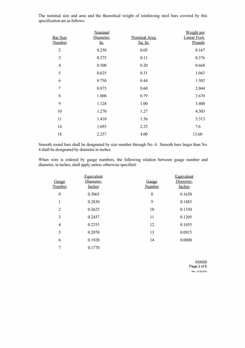
7/25/2019 City Standard Construction Specifications
http://slidepdf.com/reader/full/city-standard-construction-specifications 361/511
032020
Page 2 of 6
Rev. 10-30-2014
The nominal size and area and the theoretical weight of reinforcing steel bars covered by this
specification are as follows:
Bar Size
Number
Nominal
Diameter,
In.
Nominal Area,
Sq. In.
Weight per
Linear Foot,
Pounds
2 0.250 0.05 0.167
3 0.375 0.11 0.376
4 0.500 0.20 0.668
5 0.625 0.31 1.043
6 0.750 0.44 1.502
7 0.875 0.60 2.044
8 1.000 0.79 2.670
9 1.128 1.00 3.400
10 1.270 1.27 4.303
11 1.410 1.56 5.313
14 1.693 2.25 7.6
18 2.257 4.00 13.60
Smooth round bars shall be designated by size number through No. 4. Smooth bars larger than No.
4 shall be designated by diameter in inches.
When wire is ordered by gauge numbers, the following relation between gauge number and
diameter, in inches, shall apply unless otherwise specified:
Gauge
Number
Equivalent
Diameter,
Inches
Gauge
Number
Equivalent
Diameter,
Inches
0 0.3065 8 0.1620
1 0.2830 9 0.1483
2 0.2625 10 0.1350
3 0.2437 11 0.1205
4 0.2253 12 0.1055
5 0.2070 13 0.0915
6 0.1920 14 0.0800
7 0.1770
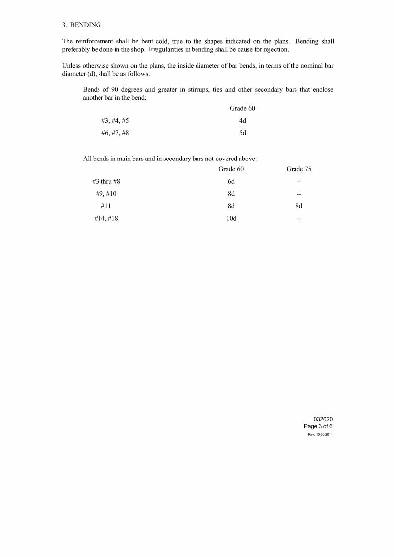
7/25/2019 City Standard Construction Specifications
http://slidepdf.com/reader/full/city-standard-construction-specifications 362/511
032020
Page 3 of 6
Rev. 10-30-2014
3. BENDING
The reinforcement shall be bent cold, true to the shapes indicated on the plans. Bending shall
preferably be done in the shop. Irregularities in bending shall be cause for rejection.
Unless otherwise shown on the plans, the inside diameter of bar bends, in terms of the nominal bar
diameter (d), shall be as follows:
Bends of 90 degrees and greater in stirrups, ties and other secondary bars that encloseanother bar in the bend:
Grade 60
#3, #4, #5 4d
#6, #7, #8 5d
All bends in main bars and in secondary bars not covered above:
Grade 60 Grade 75
#3 thru #8 6d --
#9, #10 8d --
#11 8d 8d
#14, #18 10d --
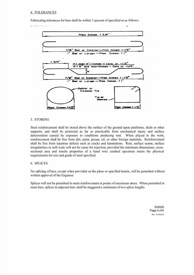
7/25/2019 City Standard Construction Specifications
http://slidepdf.com/reader/full/city-standard-construction-specifications 363/511
032020
Page 4 of 6
Rev. 10-30-2014
4. TOLERANCES
Fabricating tolerances for bars shall be within 3 percent of specified or as follows:
5. STORING
Steel reinforcement shall be stored above the surface of the ground upon platforms, skids or other
supports, and shall be protected as far as practicable from mechanical injury and surfacedeterioration caused by exposure to conditions producing rust. When placed in the work,
reinforcement shall be free from dirt, paint, grease, oil, or other foreign materials. Reinforcement
shall be free from injurious defects such as cracks and laminations. Rust, surface seams, surface
irregularities or mill scale will not be cause for rejection, provided the minimum dimensions, cross-
sectional area and tensile properties of a hand wire crushed specimen meets the physical
requirements for size and grade of steel specified.
6. SPLICES
No splicing of bars, except when provided on the plans or specified herein, will be permitted without
written approval of the Engineer.
Splices will not be permitted in main reinforcement at points of maximum stress. When permitted in
main bars, splices in adjacent bars shall be staggered a minimum of two splice lengths.
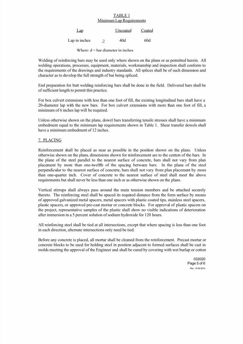
7/25/2019 City Standard Construction Specifications
http://slidepdf.com/reader/full/city-standard-construction-specifications 364/511
032020
Page 5 of 6
Rev. 10-30-2014
TABLE 1
Minimum Lap Requirements
Lap Uncoated Coated
Lap in inches > 40d 60d
Where: d = bar diameter in inches
Welding of reinforcing bars may be used only where shown on the plans or as permitted herein. All
welding operations, processes, equipment, materials, workmanship and inspection shall conform to
the requirements of the drawings and industry standards. All splices shall be of such dimension and
character as to develop the full strength of bar being spliced.
End preparation for butt welding reinforcing bars shall be done in the field. Delivered bars shall be
of sufficient length to permit this practice.
For box culvert extensions with less than one foot of fill, the existing longitudinal bars shall have a
20-diameter lap with the new bars. For box culvert extensions with more than one foot of fill, a
minimum of 6 inches lap will be required.
Unless otherwise shown on the plans, dowel bars transferring tensile stresses shall have a minimum
embedment equal to the minimum lap requirements shown in Table 1. Shear transfer dowels shall
have a minimum embedment of 12 inches.
7. PLACING
Reinforcement shall be placed as near as possible in the position shown on the plans. Unless
otherwise shown on the plans, dimensions shown for reinforcement are to the centers of the bars. In
the plane of the steel parallel to the nearest surface of concrete, bars shall not vary from plan
placement by more than one-twelfth of the spacing between bars. In the plane of the steel
perpendicular to the nearest surface of concrete, bars shall not vary from plan placement by more
than one-quarter inch. Cover of concrete to the nearest surface of steel shall meet the above
requirements but shall never be less than one inch or as otherwise shown on the plans.
Vertical stirrups shall always pass around the main tension members and be attached securely
thereto. The reinforcing steel shall be spaced its required distance from the form surface by means
of approved galvanized metal spacers, metal spacers with plastic coated tips, stainless steel spacers,
plastic spacers, or approved pre-cast mortar or concrete blocks. For approval of plastic spacers on
the project, representative samples of the plastic shall show no visible indications of deterioration
after immersion in a 5 percent solution of sodium hydroxide for 120 hours.
All reinforcing steel shall be tied at all intersections, except that where spacing is less than one foot
in each direction, alternate intersections only need be tied.
Before any concrete is placed, all mortar shall be cleaned from the reinforcement. Precast mortar or
concrete blocks to be used for holding steel in position adjacent to formed surfaces shall be cast in
molds meeting the approval of the Engineer and shall be cured by covering with wet burlap or cotton
7/25/2019 City Standard Construction Specifications
http://slidepdf.com/reader/full/city-standard-construction-specifications 365/511
032020
Page 6 of 6
Rev. 10-30-2014
mats for a period of 72 hours.
The blocks shall be cast in the form of a frustum of a cone or pyramid with the smaller face placed
against the forms.
A suitable tie wire shall be provided in each block, to be used for anchoring to the steel. Except in
unusual cases, and when specifically otherwise authorized by the Engineer, the size of the surface to
be placed adjacent to the forms shall not exceed two and one-half inches square or the equivalent
thereof in cases where circular or rectangular areas are provided. Blocks shall be cast accurately tothe thickness required, and the surface to be placed adjacent to the forms shall be a true plane free of
surface imperfections.
Reinforcement shall be supported and tied in such manner that a sufficiently rigid case of steel is
provided. If the cage is not adequately supported to resist settlement or floating upward of the steel,
overturning of truss bars or movement in any direction during concrete placement, permission to
continue concrete placement will be withheld until corrective measures are taken. Sufficient
measurements shall be made during concrete placement to insure compliance with the first
paragraph of Article 7 of this specification.
Mats of wire fabric shall overlap each other sufficiently to maintain a uniform strength and shall befastened securely at the ends and edges.
No concrete shall be deposited until the Engineer has inspected the placement of the reinforcing steel
and given permission to proceed.
8. MEASUREMENT AND PAYMENT
Unless otherwise specified on the Bid Form, reinforcing steel is considered subsidiary to the various
items shown in the Bid Form and shall not be measured and paid for as a separate item.
7/25/2019 City Standard Construction Specifications
http://slidepdf.com/reader/full/city-standard-construction-specifications 366/511
036020Page 1 of 2
SECTI ON 036020 STUCCO AND PLASTER ( S- 123)
1. GENERAL
Thi s work i ncl udes l at h, f urr i ng and st ucco i ncl udi ng al l accessor i esconf or mi ng t o det ai l s.
Thi s Appl i cat or shal l show evi dence of exper i ence and compet ency i naccompl i shi ng pl ast er work of t he hi ghest workmanshi p, whi ch i s t he r equi r ementherei n. Al l i mpr oper workmanshi p shal l be r emoved and be r epl aced wi t h pr operworkmanshi p at any st age of t he work.
Al l manuf act ur ed mat er i al s shal l be del i ver ed i n t he or i gi nal packages,cont ai ner s, or bundl es bear i ng t he name of t he manuf act urer and t he brand name.
Al l cement i t i ous mat eri al must be kept dr y unt i l r eady f or use, and must bekept of f t he gr ound, under cover , and away f r om any sweat i ng wal l s or otherdamp surf aces.
2. LATHI NG MATERI ALS
Al l l at h f or ext er i or st ucco shal l be gal vani zed, sel f - f ur r i ng di amond l at h
wei ghi ng not l ess than 2. 5 l bs. per square yar d.
Ti e wi r es shal l be No. 16 gauge gal vani zed wi r e.
Appl y l at h over cont i nuous 6 mi l . pol yet hyl ene vapor bar r i er f i l m.
3. ACCESSORI ES
Accessor i es shal l be zi nc, and equal , i n t ot al val ue, t o U. S. G. No. 1- Aexpanded corner bead; No. 60 or 66 expanded square casi ng bead; No. 10- Aexpanded bul l nose cor ner bead; No. 15 and ot her expansi on j oi nt s and ot heraccessor i es as necessary f or st oppi ng pl ast er at al l changes of pl ane or backupmateri al . Use 1/ 2" beads on masonr y; 3/ 4" beads on metal l ath.
4. STUCCO MATERI ALS
St ucco shal l be appl i ed i n 3 coat s, 3/ 4" t hi ck on met al l at h.
5. PORTLAND CEMENT EXTERI OR PLASTER
Port l and cement exter i or pl ast er ( wher e st ucco i s cal l ed f or ) shal l be a 3 coatsyst em, buf f col ored. Submi t sampl es t o Engi neer ' s sat i sf act i on. Appr oxi mat ecol or sampl e may be seen at Engi neer ' s of f i ce by i nt er ested part i es. Submi tsampl e to match.
6. SCRATCH COAT
Scrat ch Coat - one sack Por t l and cement , t wo sacks equal t o U. S. G.
Bondcrete l i me, 7 cubi c f eet sand and 2 l bs. f i ber . Scrat ch sur f ace anddamp cur e f or 48 hours mi ni mum.
7. BROWN COAT
Br own Coat - same propor t i ons and materi al s as scr atch coat except use 9cu. f t . sand f i ni sh. Damp cur e 48 hour s mi ni mum.
7/25/2019 City Standard Construction Specifications
http://slidepdf.com/reader/full/city-standard-construction-specifications 367/511
036020Page 2 of 2
8. FI NI SH COAT
Fi ni sh Coat - 1/ 8" t hi ck, equal , i n t ot al val ue, to U. S. G. Ext er i orSt ucco, wi t h col or added, r ecei vi ng sand f i ni sh.
9. PATCHI NG AND POI NTI NG
Upon compl et i on of t he bui l di ng and when di r ect ed, al l l oose, cr acked, damaged,or def ect i ve pl ast er i ng shal l be cut out and r epl ast er ed i n a sat i sf act or y andappr oved manner. Al l poi nt i ng and patchi ng of pl ast ered sur f aces, and wher epl ast er i ng abut s or adj oi ns any ot her f i ni shed work, shal l be done i n a neatand workmanl i ke manner . Pl ast er dr oppi ngs or spat t er i ngs shal l be r emoved f r omal l sur f aces. Exposed pl ast er ed sur f aces shal l be l ef t i n cl ean, unbl emi shedcondi t i on r eady t o r ecei ve pai nt or ot her f i ni sh. Pr ot ect i ve cover i ng shal l ber emoved f r om f l oor s and ot her sur f aces, and al l r ubbi sh and debr i s shal l ber emoved f r omt he bui l di ng.
Fi ni sh coat of al l pl ast er work shal l be pr oper l y damp cur ed accor di ng t odi r ect i ons of t he manuf act ur er of t he mat er i al s used.
The r epai r i ng of damage t o pl ast er work caused by ot her t r ades shal l be done byt hi s Appl i cat or and shal l be pai d f or by t he t r ade responsi bl e f or t he damage.
Do not appl y pl ast er bel ow 55 F. t emperat ur e.
10. CLEANI NG AND PATCHI NG
Cl ean f l oor s of dr oppi ngs i mmedi at el y af t er each coat i s appl i ed. At anyexter i or l ocat i ons, r emove dr oppi ngs or spl ashes f r om al l concret e, masonr y orot her f i ni sh sur f aces.
Pat ch af t er al l other work except pai nt i ng has been compl eted. Cut out damagedor broken pl ast er t o st r ai ght l i nes wi t h cl ean, shar p edges. Cut out cr acks t owi dt h of at l east 1- i nch. Fi l l ar eas to be pat ched wi t h vase mat er i al s, t hengi ve a f i ni sh coat of same mat er i al as adj oi ni ng pl ast er . Pat ched ar eas shal lmat ch adj oi ni ng wor k i n f i ni sh and t extur e. J oi ni ngs shal l be f l ush and smoot hso j oi nt s bet ween pat ch and exi st i ng pl ast er ar e i mper cept i bl e.
7/25/2019 City Standard Construction Specifications
http://slidepdf.com/reader/full/city-standard-construction-specifications 368/511
0370402/ 20/ 9
Page 1 of 2
SECTI ON 37040EPOXY COMPOUNDS ( S- 44)
1. DESCRI PTI ON
Thi s speci f i cat i on shal l govern al l work necessary t o provi de and appl y Epoxycompounds.
2. MATERI ALS ( USE - TYPE)
( 1) Epoxy Bondi ng Compound f or bondi ng new concr ete t o hardened concr ete orother st r uct ur al materi al : Epoxy Bondi ng Compound shal l be a t wocomponent , 100% sol i ds, moi st ur e i nsensi t i ve syst em. Epoxy shal l be "FX-752 Bondi ng Agent " as manuf actured by Fox I ndust r i es I nc. of Bal t i more,Maryl and or "Si kast i x 370, Si kadur Hi - Mod" as manuf actured by Si kaChemi cal Corpor at i on of Lyndhur st , New J ersey or approved equal .
( 2) Epoxy Gr out f or Epoxy pat ch on non- hor i zont al sur f aces t o concrete: EpoxyCompound shal l be a l ow- modul us, hi gh vi scosi t y, moi st ur e i nsensi t i vesyst em. Epoxy shal l be "Si kast i x 360, Skadur Lo- Mod Gel " as manuf actur edby Si ka Chemi cal Corporat i on, or approved equal .
3. CONSTRUCTI ON METHODS
( 1) Bond new concr et e t o exi st i ng concrete:
a. Sur f ace Pr epar at i on: The exi st i ng concrete or st r uct ur al sur f acet o whi ch t he new concr ete i s t o be bonded shal l be cl eaned. Theexi st i ng sur f ace shal l be made f r ee f r om dust , l ai t ance, gr ease,cur i ng compounds, waxes and al l f orei gn mat er i al . Cl eani ng shal lbe done by sandbl ast i ng, mechani cal abr asi on, or ( by washi ng onl yi f aut hor i zed by t he Engi neer ) . Dur i ng appl i cat i on of bondi ngcompound, sur f ace may be dr y, moi st , or wet, but sur f ace shal l bef r ee of st andi ng wat er .
b. Proport i oni ng and Mi xi ng: The epoxy shal l be pr oport i oned andmi xed i n st r i ct accor dance wi t h t he manuf act ur er s i nst r uct i ons.
The epoxy shal l be used i n a neat condi t i on ( wi t hout aggregat e
f i l l er ) .
c. Appl i cat i on of Epoxy: The epoxy bondi ng compound shal l be appl i edt o t he pr epar ed surf ace wi t h the mi ni mum al l owabl e cover ages asf ol l ows:
Concret e ( f l oat f i ni shed, cl eaned by washi ng) 75 SF/ gal
Concrete (r ough f i ni sh, cl eaned by sandbl ast or mechani calabr asi on) 50 SF/ gal
Ot her sur f aces as speci f i ed on the dr awi ngs
d. Concrete Over l ay: The concr et e over l ay shal l be i n accor dance wi t ht he dr awi ngs or 030020 of st andar d speci f i cat i ons. The concr et e
overl ay shal l be appl i ed over t he epoxy wi t hi n a peri od of t i mewhi ch SHALL NOT EXCEED 60% of t he t ack f r ee t i me of t he epoxy. I ti s i mpor t ant f or t he Cont r act or t o not e that t hese t i mes var y wi t ht he t emperat ur e and pot t i me. The f ol l owi ng al l owabl e t i mes ( 60%of t ack f r ee ti me, wher e t he tack f r ee ti me i s t he per i od of t i mef rom i ni t i al mi xi ng of t he t wo component s unt i l t he t hi n f i l m ofepoxy har dens) ar e provi ded bel ow. The al l owabl e t i mes must be
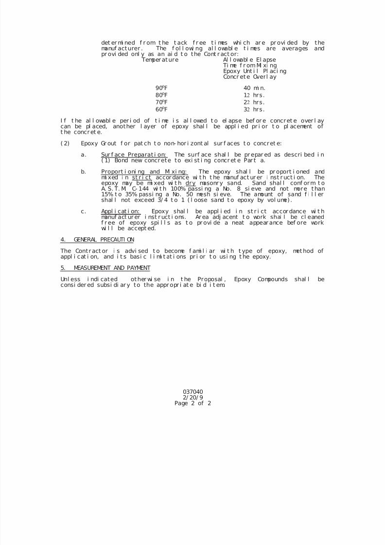
7/25/2019 City Standard Construction Specifications
http://slidepdf.com/reader/full/city-standard-construction-specifications 369/511
0370402/ 20/ 9
Page 2 of 2
det er mi ned f r om t he t ack f r ee t i mes whi ch ar e pr ovi ded by themanuf acturer . The f ol l owi ng al l owabl e t i mes are averages andpr ovi ded onl y as an ai d t o the Cont r act or:
Temper ature Al l owabl e El apse Ti me f r omMi xi ngEpoxy Unt i l Pl aci ngConcr ete Overl ay
90oF 40 mi n. 80oF 1 hrs.
70oF 2 hrs.
60oF 3 hrs.
I f t he al l owabl e per i od of t i me i s al l owed t o el apse bef or e concret e over l aycan be pl aced, another l ayer of epoxy shal l be appl i ed pr i or t o pl acement oft he concret e.
( 2) Epoxy Gr out f or pat ch t o non- hor i zont al sur f aces t o concret e:
a. Sur f ace Preparat i on: The surf ace shal l be pr epar ed as descri bed i n( 1) Bond new concrete to exi st i ng concr et e Par t a.
b. Proport i oni ng and Mi xi ng: The epoxy shal l be pr oport i oned andmi xed i n st r i ct accor dance wi t h t he manuf act ur er i nst r uct i on. Theepoxy may be mi xed wi t h dry masonr y sand. Sand shal l conf orm t oA. S. T. M. C- 144 wi t h 100% passi ng a No. 8 si eve and not more than15% t o 35% passi ng a No. 50 mesh si eve. The amount of sand f i l l ershal l not exceed 3/ 4 t o 1 ( l oose sand t o epoxy by vol ume) .
c. Appl i cat i on: Epoxy shal l be appl i ed i n st r i ct accor dance wi t hmanuf act ur er i nst r uct i ons. Ar ea adj acent t o work shal l be cl eanedf r ee of epoxy spi l l s as t o pr ovi de a neat appear ance bef ore workwi l l be accept ed.
4. GENERAL PRECAUTI ON
The Contr act or i s advi sed t o become f ami l i ar wi t h t ype of epoxy, met hod of
appl i cat i on, and i t s basi c l i mi t at i ons pr i or t o usi ng t he epoxy.5. MEASUREMENT AND PAYMENT
Unl ess i ndi cated other wi se i n t he Proposal , Epoxy Compounds shal l beconsi der ed subsi di ar y to the appr opr i at e bi d i t em.
7/25/2019 City Standard Construction Specifications
http://slidepdf.com/reader/full/city-standard-construction-specifications 370/511
SECTION 038000
CONCRETE STRUCTURES
1. DESCRIPTION
This specification shall govern for construction of all types of structures involving the use of
structural concrete, except where the requirements are waived or revised by other governing
specifications.
All concrete structures shall be constructed in accordance with the design requirements and details
shown on the plans; in conformity with the pertinent provisions of the items contracted for; the
incidental specifications referred to; and in conformity with the requirements herein.
2. MATERIALS
(1) Concrete. All concrete shall conform to the provisions of City Standard Specification Section
030020 "Portland Cement Concrete".
The class of concrete for each type of structure or unit shall be as specified on the plans or by
pertinent governing specifications.
(2) Expansion Joint Material.
(a) Preformed Fiber Material. Preformed fiber expansion joint material shall be of the
dimensions shown on the plans. The material shall be one of the following types, unless
otherwise noted on the plans:
1. Preformed Bituminous Fiber Materials shall meet the requirements of ASTM
Designation: D1751 "Standard Specification for Preformed Expansion JointFiller for Concrete Paving and Structural Construction (Non-extruding and
Resilient Bituminous Types)".
2. Preformed Non-Bituminous Fiber Material shall meet the requirements of ASTM
Designation: D1751 "Standard Specification for Preformed Expansion Joint
Filler for Concrete Paving and Structural Construction (Non-extruding and
Resilient Bituminous Types)", except that the requirements pertaining to bitumen
content, density and water absorption shall be voided.
3. Redwood.
(b) Joint Sealing Materials. Unless otherwise shown on the drawings, joint sealing
material shall conform to the following requirements. The material shall adhere to the
sides of the concrete joint or crack and shall form an effective seal against infiltration of
water and incompressibles. The material shall not crack or break when exposed to low
temperatures.
038000Page 1 of 19
Rev. 3-25-2015
7/25/2019 City Standard Construction Specifications
http://slidepdf.com/reader/full/city-standard-construction-specifications 371/511
1. Class 1-a. (Two-Component, Synthetic Polymer, Cold-Extruded Type). Curing
is to be by polymerization and not by evaporation of solvent or fluxing of harder
particles. This type is specifically designed for vertical or sloping joints and
hence not self-leveling. It shall cure sufficiently at an average temperature of 77
degrees F ± 3 degrees F in a maximum of 24 hours. For performance
requirements see under 2.(2)(b)2. below.
2. Class 1-b. (Two-Component, Synthetic Polymer, Cold-Pourable, Self-Leveling
Type). Curing is to be by polymerization and not by evaporation of solvent orfluxing of harder particles. It shall cure sufficiently at an average temperature of
77 degrees F ± 3 degrees F in a maximum of 3 hours.
Performance Requirements: Class 1-a and Class 1-b joint materials, when tested in
accordance with TxDOT Test Method Tex-525-C, shall meet the above curing times
and the following requirements:
It shall be of such consistency that it can be mixed and poured, or mixed and
extruded into joints at temperatures above 60 degrees F.
Penetration, 77º F.:
150 gm. cone, 5 sec., max., cm.................. 0.90
Bond and Extension 75%, Oº F, 5 cycles:
Dry Concrete Blocks............................ Pass
Wet Concrete Blocks............................ Pass
Steel Blocks...(Primed if specified by manuf.). Pass
Flow at 200º F................................. None
Water Content % by weight, max................. 5.0
Resilience:
Original sample min. % (cured)................. 50
Oven aged at 158º F min. % .................... 50For Class 1-a Material Only:
Cold Flow (10 min.)............................ None
(c) Asphalt Board. Asphalt Board shall consist of two liners of 0.016-inch asphalt
impregnated paper, filled with a mastic mixture of asphalt and vegetable fiber and/or mineral
filler. Boards shall be smooth, flat and sufficiently rigid to permit installation. When tested
in accordance with TxDOT Test Method Tex-524-C, the asphalt board shall not deflect from
the horizontal more than one inch in three and one-half inches (1" in 3½").
(d) Rebonded Neoprene Filler. Rebonded neoprene filler shall consist of ground closed-
cell neoprene particles, rebonded and molded into sheets of uniform thickness, of the
dimensions shown on plans.
Filler material shall have the following physical properties and shall meet the requirements of
ASTM Designation: D1752 “Standard Specification for Preformed Sponge Rubber and Cork
Expansion Joint Fillers for Concrete Paving and Structural Construction”, Type 1, where
applicable:
038000Page 2 of 19
Rev. 3-25-2015
7/25/2019 City Standard Construction Specifications
http://slidepdf.com/reader/full/city-standard-construction-specifications 372/511
PROPERTY METHOD REQUIREMENT
Color ASTM D1752, Type 1 Black
Density ASTM D1752, Type 1 40 lb./ft3 Min.
Recovery ASTM D1752, Type 1 90% Min.
Compression ASTM D1752, Type 1 50 to 500 psi
Extrusion ASTM D1752, Type 1 0.25 inch Max.
Tensile Strength ASTM D1752, Type 1 20 psi Min.
Elongation 75% Min.
The manufacturers shall furnish the Engineer with certified test results as to compliance with
the above requirements and a 12 inch x 12 inch x 1 inch sample from the shipment for
approval.
(3) Curing Materials.
(a) Membrane curing materials shall comply with ASTM Designation: C 309 "Standard
Specification for Liquid Membrane-Forming Compounds for Curing Concrete", Type 1 clear
or translucent, or Type 2 white-pigmented. The material shall have a minimum flash-point
of 80 degrees F when tested by the "Pensky-Martin Closed Cup Method".
It shall be of such consistency that it can be satisfactorily applied as a fine mist through an atomizing
nozzle by means of approved pressure spraying equipment at atmospheric temperatures above 40
degrees F.
It shall be of such nature that it will not produce permanent discoloration of concrete surfaces nor
react deleteriously with the concrete or its components. Type 1 compound shall contain a fugitivedye that will be distinctly visible not less than 4 hours nor more than 7 days after application. The
compound shall produce a firm, continuous, uniform moisture impermeable film free from pinholes
and shall adhere satisfactorily to the surfaces of damp concrete. It shall, when applied to the damp
concrete surface at the rate of coverage specified herein, be dry to the touch in not more than 4 hours,
and shall adhere in a tenacious film without running off or appreciable sagging. It shall not
disintegrate, check, peel or crack during the required curing period.
The compound shall not peel or pick up under traffic and shall disappear from the surface of the
concrete by gradual disintegration.
The compound shall be delivered to the job only in the manufacturer's original containers, which
shall be clearly labeled with the manufacturer's name, the trade name of the material, and a batch
number or symbol with which test samples may be correlated.
The water retention test shall be in accordance with TxDOT Test Method Tex-219-F. Percentage
loss shall be defined as the water lost after the application of the curing material was applied. The
permissible percentage moisture loss (at the rate of coverage specified herein) shall not exceed the
038000Page 3 of 19
Rev. 3-25-2015
7/25/2019 City Standard Construction Specifications
http://slidepdf.com/reader/full/city-standard-construction-specifications 373/511
following:
24 hours after application............2 percent
72 hours after application............4 percent
Type 1 (Resin Base Only) curing compound will be permitted for slab concrete in bridge decks and
top slabs of direct traffic culverts.
(b) Mat curing of concrete is allowed where permitted by Table 1 in this specification orwhere otherwise approved by the Engineer.
3. EXPANSION JOINTS
Joints and devices to provide for expansion and contraction shall be constructed where and as
indicated herein or on the plans.
All open joints and joints to be filled with expansion joint material, shall be constructed using forms
adaptable to loosening or early removal. To avoid expansion or contraction damage to the adjacent
concrete, these forms shall be loosened as soon as possible after final concrete set to permit free
movement without requiring full form removal.
Prior to placing the sealing material, the vertical facing the joint shall be cleaned of all laitance by
sandblasting or by mechanical routing. Cracked or spalled edges shall be repaired. The joint shall be
blown clean of all foreign material and sealed. Where preformed fiber joint material is used, it shall
be anchored to the concrete on one side of the joint by light wire or nails, to prevent the material
from falling out. The top one inch (1”) of the joint shall be filled with joint sealing material.
Finished joints shall conform to the indicated outline with the concrete sections completely separated
by the specified opening or joint material.
Soon after form removal and again where necessary after surface finishing, all projecting concrete
shall be removed along exposed edges to secure full effectiveness of the expansion joints.
4. CONSTRUCTION JOINTS
The joint formed by placing plastic concrete in direct contact with concrete that has attained its initial
set shall be deemed a construction joint. The term “monolithic placement” shall be interpreted to
mean at the manner and sequence of concrete placing shall not create construction joints.
Construction joints shall be of the type and at the locations shown on the plans. Additional joints
will not be permitted without written authorization from the Engineer, and when authorized, shallhave details equivalent to those shown on the plans for joints in similar locations.
Unless otherwise provided, construction joints shall be square and normal to the forms. Bulkheads
shall be provided in the forms for all joints, except when horizontal.
Construction joints requiring the use of joint sealing material shall be as detailed on the plans. The
038000Page 4 of 19
Rev. 3-25-2015
7/25/2019 City Standard Construction Specifications
http://slidepdf.com/reader/full/city-standard-construction-specifications 374/511
material will be specified on the plans without referenced to joint type.
A concrete placement terminating at a horizontal construction joint shall have the top surface
roughened thoroughly as soon as practicable after initial set is attained. The surfaces at bulkheads
shall be roughened as soon as the forms are removed.
The hardened concrete surface shall be thoroughly cleaned of all loose material, laitance, dirt or
foreign material, and saturated with water so it is moist when placing fresh concrete against it.
Forms shall be drawn tight against the placing of the fresh concrete.
5. FORMS
(1) General. Except where otherwise specified, forms may be of either timber or metal.
Forms for round columns exposed to view shall be of steel, except that other materials will be
allowed with written permission of the Engineer.
Forming plans shall be submitted to the Engineer for approval as specified. Forms shall be designed
for the pressure exerted by a liquid weighing 150 pounds per cubic foot. The rate of placing the
concrete shall be taken into consideration in determining the depth of the equivalent liquid. For job
fabricated forms, an additional live load of 50 pounds per square foot shall be allowed on horizontal
surfaces. The maximum unit stresses shall not exceed 125 percent of the allowable stresses used by
the Texas Department of Transportation for the design of structures.
Commercially produced structural units used in formwork shall not exceed the manufacturer's
maximum allowable working load for moment, shear or end reaction. The maximum working load
shall include a live load of 35 pounds per square foot of horizontal form surface, and sufficient
details and data shall be submitted for use in checking formwork details for approval.
Forms shall be practically mortar-tight, rigidly braced and strong enough to prevent bulging betweensupports, and maintained to the proper line and grade during concrete placement. Forms shall be
maintained in a manner that will prevent warping and shrinkage.
Offset at form joints shall not exceed one-sixteenth of an inch (1/16”).
Deflections due to cast-in-place slab concrete and railing shown in the dead load deflection diagram
shall be taken into account in the setting of slab forms.
All forms and footing areas shall be cleaned of any extraneous matter before placing concrete.
Permission to place concrete will not be given until all such work is completed to the satisfaction ofthe Engineer.
If, at any stage of the work, the forms show signs of bulging or sagging, the portion of the concrete
causing such condition shall be removed immediately, if necessary, and the forms shall be reset and
securely braced against further movement.
038000Page 5 of 19
Rev. 3-25-2015
7/25/2019 City Standard Construction Specifications
http://slidepdf.com/reader/full/city-standard-construction-specifications 375/511
(2) Timber Forms. Lumber for forms shall be properly seasoned, of good quality, and free from
imperfections which would affect its strength or impair the finished surface of the concrete. The
lumber used for facing or sheathing shall be finished on at least one side and two edges and shall be
sized to uniform thickness.
Form lining will be required for all formed surfaces, except for the inside of culvert barrels, inlets
and manholes; surfaces that are subsequently covered by backfill material or are completely
enclosed; and, any surface formed by a single finished board. Lining will not be required when
plywood forms are used.
Form lining shall be of an approved type such as Masonite or plywood. Thin membrane sheeting,
such as polyethylene sheets, shall not be used for form lining.
Forms may be constructed of plywood not less than one-half inch in thickness, with no form lining
required. The grain of the face plies on plywood forms shall be placed parallel to the span between
the supporting studs or joists.
Plywood used for forming surfaces that remain exposed shall be equal to that specified as B-B
Plyform Class I or Class II Exterior, of the U. S. Department of Commerce, National Bureau of
Standards and Technology, latest edition.
Forms or form lumber to be reused shall be maintained clean and in good condition. Any lumber
which is split, warped, bulged, marred, or has defects that will produce inferior work, shall not be
used and, if condemned, shall be promptly removed from the work.
Studs and joists shall be spaced so that the facing form material remains in true alignment under the
imposed loads.
Wales shall be spaced close enough to hold forms securely to the designated lines and scabbed at
least 4 feet on each side of joints to provide continuity. A row of wales shall be placed near the bottom of each placement.
Facing material shall be placed with parallel and square joints and securely fastened to supporting
studs.
Forms for surfaces receiving only an ordinary finish and exposed to view shall be placed with the
form panels symmetrical, i.e., long dimensions set in the same direction. Horizontal joints shall be
continuous.
Molding specified for chamfer strips or other uses shall be made of materials of a grade that will not
split when nailed and which can be maintained to a true line without warping. Wood molding shall be mill cut and dressed on all faces. Unless otherwise provided, forms shall be filleted at all sharp
corners and edges with triangular chamfer strips measuring three-quarter inch (3/4”) on the sides.
Forms for railing and ornamental work shall be constructed to standards equivalent to first-class
millwork. All moldings, panel work and bevel strips shall be straight and true with nearly mitered
joints designed so the finished work is true, sharp and clean cut.
038000Page 6 of 19
Rev. 3-25-2015
7/25/2019 City Standard Construction Specifications
http://slidepdf.com/reader/full/city-standard-construction-specifications 376/511
All forms shall be constructed to permit their removal without marring or damaging the concrete.
The forms may be given a slight draft to permit ease of removal.
Metal form ties of an approved type or a satisfactory substitute shall be used to hold forms in place
and shall be of a type that permits ease of removal of the metal as hereinafter specified.
All metal appliances used inside of forms for alignment purposes shall be removed to a depth of at
least one-half inch (1/2”) from the concrete surface. They shall be made so the metal may beremoved without undue chipping or spalling, and when removed, shall leave a smooth opening in the
concrete surface. Burning off of rods, bolts or ties will not be permitted.
Any wire ties used shall be cut back at least one-half inch (1/2”) from the face of the concrete.
Devices holding metal ties in place shall be capable of developing the strength of the tie and
adjustable to allow for proper alignment.
Metal and wooden spreaders which are separate from the forms shall be removed entirely as the
concrete is being placed.
Adequate clean-out openings shall be proved for narrow walls and other locations where access to
the bottom of the forms is not readily attainable.
Prior to placing concrete, the facing of all forms shall be treated with oil or other bond breaking
coating of such composition that it will not discolor or otherwise injuriously affect the concrete
surface. Care shall be exercised to prevent coating of the reinforcing steel.
(3) Metal Forms. The foregoing requirements for timber forms regarding design, mortar-tightness,
filleted corners, beveled projections, bracing, alignment, removal, reuse and wetting shall also apply
to metal forms, except that these will not require lining, unless specifically noted on the plans.
The thickness of form metal shall be as required to maintain the true shape without warping or
bulging. All bolt and rivet heads on the facing sides shall be countersunk. Clamps, pins or other
connecting devices shall be designed to hold the forms rigidly together and to allow removal without
injury to the concrete. Metal forms which do not present a smooth surface or line up properly shall
not be used. Metal shall be kept free from rust, grease or other foreign materials.
6. PLACING REINFORCEMENT
Reinforcement in concrete structures shall be placed carefully and accurately and rigidly supported as
provided in the City Standard Specification Section 032020 "Reinforcing Steel". Reinforcing steelsupports shall not be welded to I-beams or girders.
7. PLACING CONCRETE-GENERAL
The minimum temperature of all concrete at the time of placement shall be not less than 50 degrees F.
038000Page 7 of 19
Rev. 3-25-2015
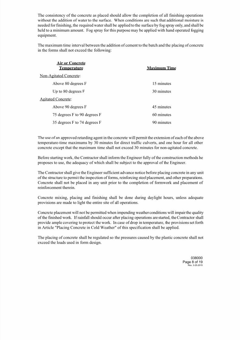
7/25/2019 City Standard Construction Specifications
http://slidepdf.com/reader/full/city-standard-construction-specifications 377/511
The consistency of the concrete as placed should allow the completion of all finishing operations
without the addition of water to the surface. When conditions are such that additional moisture is
needed for finishing, the required water shall be applied to the surface by fog spray only, and shall be
held to a minimum amount. Fog spray for this purpose may be applied with hand operated fogging
equipment.
The maximum time interval between the addition of cement to the batch and the placing of concrete
in the forms shall not exceed the following:
Air or Concrete
Temperature Maximum Time
Non-Agitated Concrete:
Above 80 degrees F 15 minutes
Up to 80 degrees F 30 minutes
Agitated Concrete:
Above 90 degrees F 45 minutes
75 degrees F to 90 degrees F 60 minutes
35 degrees F to 74 degrees F 90 minutes
The use of an approved retarding agent in the concrete will permit the extension of each of the above
temperature-time maximums by 30 minutes for direct traffic culverts, and one hour for all other
concrete except that the maximum time shall not exceed 30 minutes for non-agitated concrete.
Before starting work, the Contractor shall inform the Engineer fully of the construction methods he
proposes to use, the adequacy of which shall be subject to the approval of the Engineer.
The Contractor shall give the Engineer sufficient advance notice before placing concrete in any unit
of the structure to permit the inspection of forms, reinforcing steel placement, and other preparations.
Concrete shall not be placed in any unit prior to the completion of formwork and placement of
reinforcement therein.
Concrete mixing, placing and finishing shall be done during daylight hours, unless adequate
provisions are made to light the entire site of all operations.
Concrete placement will not be permitted when impending weather conditions will impair the quality
of the finished work. If rainfall should occur after placing operations are started, the Contractor shall
provide ample covering to protect the work. In case of drop in temperature, the provisions set forth
in Article "Placing Concrete in Cold Weather" of this specification shall be applied.
The placing of concrete shall be regulated so the pressures caused by the plastic concrete shall not
exceed the loads used in form design.
038000Page 8 of 19
Rev. 3-25-2015
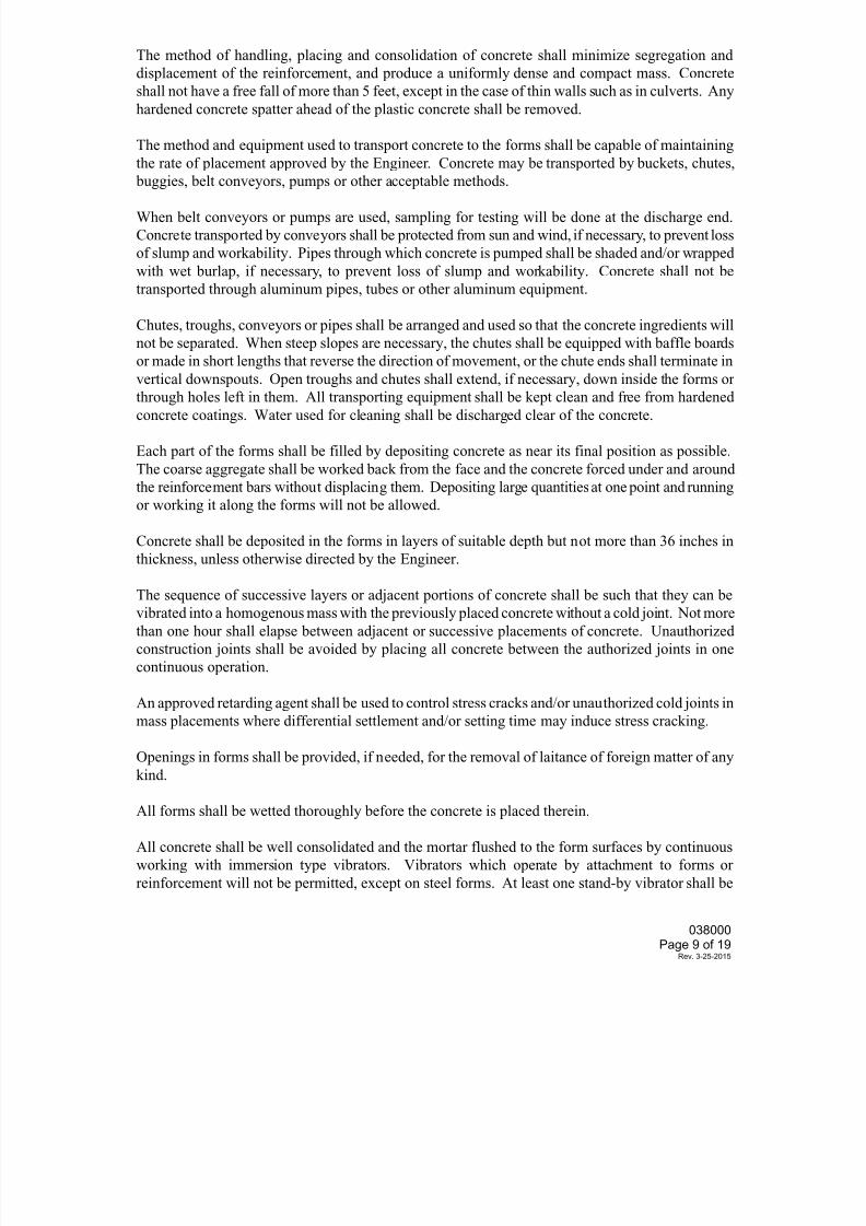
7/25/2019 City Standard Construction Specifications
http://slidepdf.com/reader/full/city-standard-construction-specifications 378/511
The method of handling, placing and consolidation of concrete shall minimize segregation and
displacement of the reinforcement, and produce a uniformly dense and compact mass. Concrete
shall not have a free fall of more than 5 feet, except in the case of thin walls such as in culverts. Any
hardened concrete spatter ahead of the plastic concrete shall be removed.
The method and equipment used to transport concrete to the forms shall be capable of maintaining
the rate of placement approved by the Engineer. Concrete may be transported by buckets, chutes,
buggies, belt conveyors, pumps or other acceptable methods.
When belt conveyors or pumps are used, sampling for testing will be done at the discharge end.
Concrete transported by conveyors shall be protected from sun and wind, if necessary, to prevent loss
of slump and workability. Pipes through which concrete is pumped shall be shaded and/or wrapped
with wet burlap, if necessary, to prevent loss of slump and workability. Concrete shall not be
transported through aluminum pipes, tubes or other aluminum equipment.
Chutes, troughs, conveyors or pipes shall be arranged and used so that the concrete ingredients will
not be separated. When steep slopes are necessary, the chutes shall be equipped with baffle boards
or made in short lengths that reverse the direction of movement, or the chute ends shall terminate in
vertical downspouts. Open troughs and chutes shall extend, if necessary, down inside the forms or
through holes left in them. All transporting equipment shall be kept clean and free from hardened
concrete coatings. Water used for cleaning shall be discharged clear of the concrete.
Each part of the forms shall be filled by depositing concrete as near its final position as possible.
The coarse aggregate shall be worked back from the face and the concrete forced under and around
the reinforcement bars without displacing them. Depositing large quantities at one point and running
or working it along the forms will not be allowed.
Concrete shall be deposited in the forms in layers of suitable depth but not more than 36 inches in
thickness, unless otherwise directed by the Engineer.
The sequence of successive layers or adjacent portions of concrete shall be such that they can be
vibrated into a homogenous mass with the previously placed concrete without a cold joint. Not more
than one hour shall elapse between adjacent or successive placements of concrete. Unauthorized
construction joints shall be avoided by placing all concrete between the authorized joints in one
continuous operation.
An approved retarding agent shall be used to control stress cracks and/or unauthorized cold joints in
mass placements where differential settlement and/or setting time may induce stress cracking.
Openings in forms shall be provided, if needed, for the removal of laitance of foreign matter of any
kind.
All forms shall be wetted thoroughly before the concrete is placed therein.
All concrete shall be well consolidated and the mortar flushed to the form surfaces by continuous
working with immersion type vibrators. Vibrators which operate by attachment to forms or
reinforcement will not be permitted, except on steel forms. At least one stand-by vibrator shall be
038000Page 9 of 19
Rev. 3-25-2015
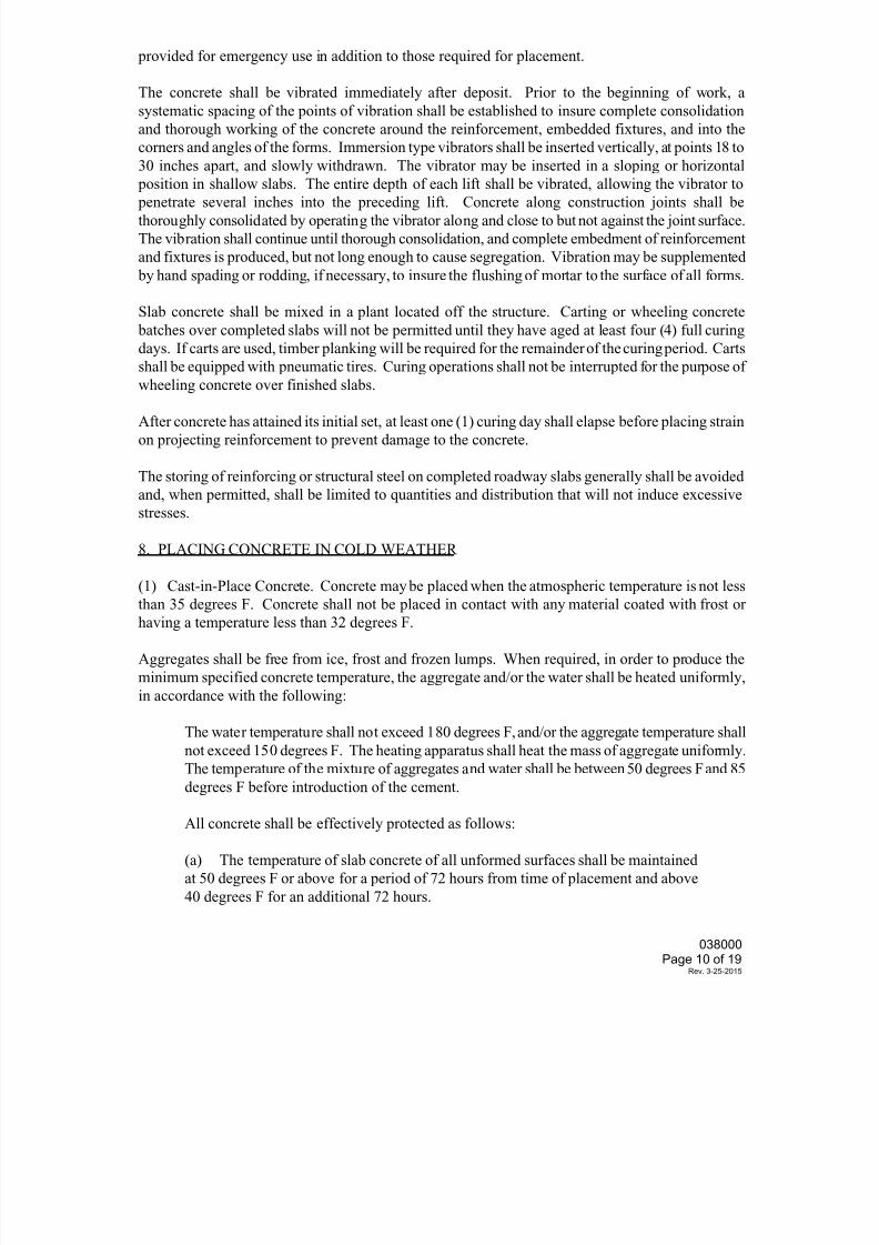
7/25/2019 City Standard Construction Specifications
http://slidepdf.com/reader/full/city-standard-construction-specifications 379/511
provided for emergency use in addition to those required for placement.
The concrete shall be vibrated immediately after deposit. Prior to the beginning of work, a
systematic spacing of the points of vibration shall be established to insure complete consolidation
and thorough working of the concrete around the reinforcement, embedded fixtures, and into the
corners and angles of the forms. Immersion type vibrators shall be inserted vertically, at points 18 to
30 inches apart, and slowly withdrawn. The vibrator may be inserted in a sloping or horizontal
position in shallow slabs. The entire depth of each lift shall be vibrated, allowing the vibrator to
penetrate several inches into the preceding lift. Concrete along construction joints shall bethoroughly consolidated by operating the vibrator along and close to but not against the joint surface.
The vibration shall continue until thorough consolidation, and complete embedment of reinforcement
and fixtures is produced, but not long enough to cause segregation. Vibration may be supplemented
by hand spading or rodding, if necessary, to insure the flushing of mortar to the surface of all forms.
Slab concrete shall be mixed in a plant located off the structure. Carting or wheeling concrete
batches over completed slabs will not be permitted until they have aged at least four (4) full curing
days. If carts are used, timber planking will be required for the remainder of the curing period. Carts
shall be equipped with pneumatic tires. Curing operations shall not be interrupted for the purpose of
wheeling concrete over finished slabs.
After concrete has attained its initial set, at least one (1) curing day shall elapse before placing strain
on projecting reinforcement to prevent damage to the concrete.
The storing of reinforcing or structural steel on completed roadway slabs generally shall be avoided
and, when permitted, shall be limited to quantities and distribution that will not induce excessive
stresses.
8. PLACING CONCRETE IN COLD WEATHER
(1) Cast-in-Place Concrete. Concrete may be placed when the atmospheric temperature is not lessthan 35 degrees F. Concrete shall not be placed in contact with any material coated with frost or
having a temperature less than 32 degrees F.
Aggregates shall be free from ice, frost and frozen lumps. When required, in order to produce the
minimum specified concrete temperature, the aggregate and/or the water shall be heated uniformly,
in accordance with the following:
The water temperature shall not exceed 180 degrees F, and/or the aggregate temperature shall
not exceed 150 degrees F. The heating apparatus shall heat the mass of aggregate uniformly.
The temperature of the mixture of aggregates and water shall be between 50 degrees F and 85
degrees F before introduction of the cement.
All concrete shall be effectively protected as follows:
(a) The temperature of slab concrete of all unformed surfaces shall be maintained
at 50 degrees F or above for a period of 72 hours from time of placement and above
40 degrees F for an additional 72 hours.
038000Page 10 of 19
Rev. 3-25-2015
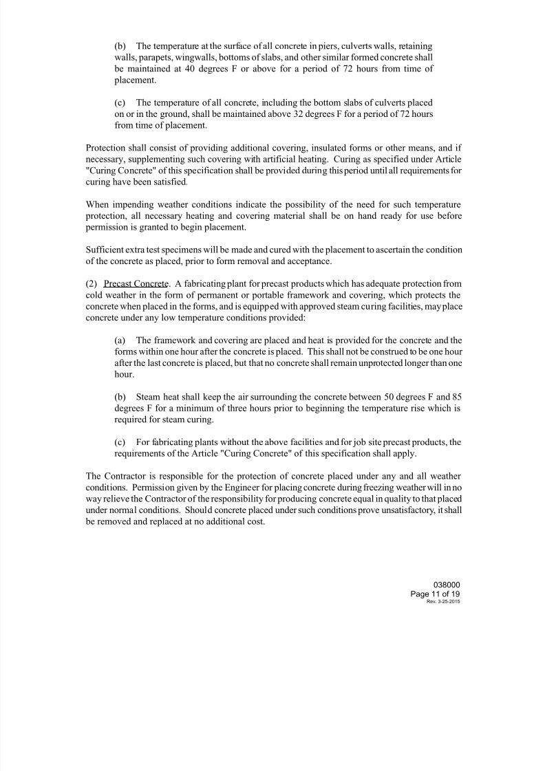
7/25/2019 City Standard Construction Specifications
http://slidepdf.com/reader/full/city-standard-construction-specifications 380/511
7/25/2019 City Standard Construction Specifications
http://slidepdf.com/reader/full/city-standard-construction-specifications 381/511
9. PLACING CONCRETE IN WATER
Concrete shall be deposited in water only when specified on the plans or with written permission by
the Engineer. The forms or cofferdams shall be sufficiently tight to prevent any water current
passing through the space in which the concrete is being deposited. Pumping will not be permitted
during the concrete placing, nor until it has set for at least 36 hours.
The concrete shall be placed with a tremie, closed bottom-dump bucket, or other approved method,
and shall not be permitted to fall freely through the water nor shall it be disturbed after it has been placed. The concrete surface shall be kept approximately level during placement.
The tremie shall consist of a water-tight tube 14 inches or less in diameter. It shall be constructed so
that the bottom can be sealed and opened after it is in place and fully charged with concrete. It shall
be supported so that it can be easily moved horizontally to cover all the work area and vertically to
control the concrete flow.
Bottom-dump buckets used for underwater placing shall have a capacity of not less than one-half
cubic yard. It shall be lowered gradually and carefully until it rests upon the concrete already placed
and raised very slowly during the upward travel; the intent being to maintain still water at the point
of discharge and to avoid agitating the mixture.
The placing operations shall be continuous until the work is complete.
10. PLACING CONCRETE IN BOX CULVERTS
In general, construction joints will be permitted only where shown on the plans.
Where the top slab and walls are placed monolithically in culverts more than 4 feet in clear height,
an interval of not less than one (1) nor more than two (2) hours shall elapse before placing the top
slab to allow for shrinkage in the wall concrete.
The base slab shall be finished accurately at the proper time to provide a smooth uniform surface.
Top slabs which carry direct traffic shall be finished as specified for roadway slabs in Article "Finish
of Roadway Slabs". Top slabs of fill type culverts shall be given a reasonably smooth float finish.
11. PLACING CONCRETE IN FOUNDATIONS AND SUBSTRUCTURE
Concrete shall not be placed in footings until the depth and character of the foundation has been
inspected by the Engineer and permission has been given to proceed.
Placing of concrete footings upon seal concrete courses will be permitted after the caissons orcofferdams are free from water and the seal concrete course cleaned. Any necessary pumping or
bailing during the concreting operation shall be done from a suitable sump located outside the forms.
All temporary wales or braces inside cofferdams or caissons shall be constructed or adjusted as the
work proceeds to prevent unauthorized construction joints in footings or shafts.
038000Page 12 of 19
Rev. 3-25-2015
7/25/2019 City Standard Construction Specifications
http://slidepdf.com/reader/full/city-standard-construction-specifications 382/511
When footings can be placed in a dry excavation without the use of cofferdams or caissons, forms
may be omitted, if desired by the Contractor and approved by the Engineer, and the entire excavation
filled with concrete to the elevation of the top of footing; in which case, measurement for payment
will be based on the footing dimensions shown on the plans.
12. TREATMENT AND FINISHING OF HORIZONTAL SURFACES EXCEPT ROADWAY
SLABS
All unformed upper surfaces shall be struck off to grade and finished. The use of mortar topping forsurfaces under this classification will not be permitted.
After the concrete has been struck off, the surface shall be floated with a suitable float. Sidewalks
shall be given a wood float or broom finish, or may be striped with a brush, as specified by the
Engineer. Other surfaces shall be wood float finished and striped with a fine brush leaving a fine-
grained texture.
13. FINISH OF ROADWAY SLABS
As soon as the concrete has been placed and vibrated in a section of sufficient width to permit
working, the surface shall be approximately leveled, struck off and screeded, carrying a slight excess
of concrete ahead of the screed to insure filling of all low spots. The screed shall be designed rigid
enough to hold true to shape and shall have sufficient adjustments to provide for the required
camber. A vibrating screed may be used if heavy enough to prevent undue distortion. The screeds
shall be provided with a metal edge.
Longitudinal screeds shall be moved across the concrete with a saw-like motion while their ends rest
on headers or templates set true to the roadway grade or on the adjacent finished slab.
The surface of the concrete shall be screeded a sufficient number of times and at such intervals to
produce a uniform surface, true to grade and free of voids.
If necessary, the screeded surface shall be worked to smooth finish with a long handled wood or
metal float of the proper size, or hand floated from bridges over the slab.
When required by the Engineer, the Contractor shall perform sufficient checks with a long handled
10-foot straightedge on the plastic concrete to insure that the final surface will be within the
tolerances specified below. The check shall be made with the straightedge parallel to the centerline.
Each pass thereof shall lap half of the preceding pass. All high spots shall be removed and all
depressions over one-sixteenth inch (1/16”) in depth shall be filled with fresh concrete and floated.
The checking and floating shall be continued until the surface is true to grade and free of
depressions, high spots, voids or rough spots.
Rail support holes shall be filled with concrete and finished to match the top of the slab.
Surface Texturing.
Perform surface texturing using a either carpet drag or metal tining as indicated on the drawings.
Complete final texturing before the concrete has attained its initial set. Draw the carpet drag
038000Page 13 of 19
Rev. 3-25-2015
7/25/2019 City Standard Construction Specifications
http://slidepdf.com/reader/full/city-standard-construction-specifications 383/511
longitudinally along the pavement surface with the carpet contact surface area adjusted to provide a
satisfactory coarsely textured surface. A metal-tine texture finish is required using a tining machine
unless otherwise shown on the plans. Provide the metal-tine finish immediately after the concrete
surface has set enough for consistent tining. Operate the metal-tine device to obtain grooves spaced
at 1 in., approximately 3/16 in. deep, with a minimum depth of 1/8 in., and approximately 1/12 in.
wide. Do not overlap a previously tined area. Use manual methods for achieving similar results on
ramps and other irregular sections of pavements. Repair damage to the edge of the slab and joints
immediately after texturing. Do not tine pavement that will be overlaid.
Upon completion of the floating and/or straight edging and before the disappearance of the moisture
sheen, the surface shall be given a broom or burlap drag finish. The grooves of these finishes shall
be parallel to the structure centerline. It is the intent that the average texture depth resulting from the
number of tests directed by the Engineer be not less than 0.035 inch with a minimum texture depth of
0.030 inch for any one test when tested in accordance with TxDOT Test Method Tex-436-A. Should
the texture depth fall below that intended, the finishing procedures shall be revised to produce the
desired texture.
After the concrete has attained its final set, the roadway surface shall be tested with a standard 10-
foot straightedge. The straightedge shall be placed parallel to the centerline of roadway to bridge any
depressions and touch high spots. Ordinates of irregularities measured from the face of the
straightedge to the surface of the slab shall not exceed one-eighth of an inch (1/8”), making proper
allowances for camber, vertical curvature and surface texture. Occasional variations, not exceeding
three-sixteenth of an inch (3/16”) will be acceptable, if in the opinion of the Engineer it will not
affect the riding qualities.
When directed by the Engineer, irregularities exceeding the above requirements shall be corrected.
In all roadway slab finishing operations, camber for specified vertical curvature and transverse slopes
shall be provided.
14. CURING CONCRETE
The Contractor shall inform the Engineer fully of the methods and procedures proposed for curing;
shall provide the proper equipment and material in adequate amounts; and shall have the proposed
methods, equipment and material approved prior to placing concrete.
Inadequate curing and/or facilities, therefore, shall be cause for the Engineer to stop all construction
on the job until remedial action is taken. All concrete shall be cured for a period of four (4) curing
days except as noted herein.
038000Page 14 of 19
Rev. 3-25-2015
7/25/2019 City Standard Construction Specifications
http://slidepdf.com/reader/full/city-standard-construction-specifications 384/511
EXCEPTIONS TO 4-DAY CURING
Description Required Curing
Upper Surfaces of Bridge Slabs and 8 curing days (Type I or III) cement
Top Slabs of Direct Traffic Culverts 10 curing days (Type II cement)
Concrete Piling (non-prestressed) 6 curing days
When the air temperature is expected to drop below 35 degrees F, the water curing mats shall be covered with polyethylene sheeting, burlap-polyethylene blankets or other material to
provide the protection required by Article "Placing Concrete in Cold Weather" of these
specifications.
A curing day is defined as a calendar day when the temperature, taken in the shade away from
artificial heat, is above 50 degrees F for at least 19 hours (colder days if satisfactory provisions are
made to maintain the temperature of all surfaces of the concrete above 40 degrees F for the entire 24
hours). The required curing period shall begin when all concrete therein has attained its initial set.
The following methods are permitted for curing concrete subject to the restrictions of Table 1 and the
following requirements for each method of curing.
(1) Form Curing. When forms are left in contact with the concrete, other curing methods will not
be required except for cold weather protection.
(2) Water Curing. All exposed surfaces of the concrete shall be kept wet continuously for the
required curing time. The water used for curing shall meet the requirements for concrete mixing
water as specified in the specification Section 030020 "Portland Cement Concrete". Seawater will
not be permitted. Water which stains or leaves an unsightly residue shall not be used.
(a) Wet Mat. Cotton mats shall be used for this curing method. They shall be placed as
soon as possible after the surface has sufficiently hardened to prevent damage to the concrete.
(See Article, "Placing Concrete" of this specification.) Damp burlap blankets made from
nine-ounce stock may be placed on the damp concrete surface for temporary protection prior
to the application of the cotton mats which may be placed dry and wetted down after
placement.
The mats shall be weighted down adequately to provide continuous contact with all concrete
surfaces where possible. The surfaces of the concrete shall be kept wet for the required
curing time. Surfaces which cannot be cured by contact shall be enclosed with mats and
anchored positively to the forms or to the ground so that outside air cannot enter the
enclosure. Sufficient moisture shall be provided inside the enclosure to keep all surfaces ofthe concrete wet.
(b) Water Spray. This curing method shall consist of overlapping sprays or sprinklers that
keep all unformed surfaces continuously wet.
(c) Ponding. This curing method requires the covering of the surfaces with a minimum of
two inches (2”) of clean granular material, kept wet at all times, or a minimum of one-inch
038000Page 15 of 19
Rev. 3-25-2015
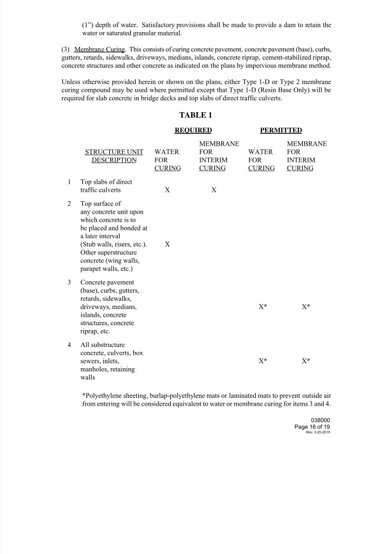
7/25/2019 City Standard Construction Specifications
http://slidepdf.com/reader/full/city-standard-construction-specifications 385/511
(1”) depth of water. Satisfactory provisions shall be made to provide a dam to retain the
water or saturated granular material.
(3) Membrane Curing. This consists of curing concrete pavement, concrete pavement (base), curbs,
gutters, retards, sidewalks, driveways, medians, islands, concrete riprap, cement-stabilized riprap,
concrete structures and other concrete as indicated on the plans by impervious membrane method.
Unless otherwise provided herein or shown on the plans, either Type 1-D or Type 2 membrane
curing compound may be used where permitted except that Type 1-D (Resin Base Only) will berequired for slab concrete in bridge decks and top slabs of direct traffic culverts.
TABLE 1
REQUIRED PERMITTED
STRUCTURE UNIT
DESCRIPTION
WATER
FOR
CURING
MEMBRANE
FOR
INTERIM
CURING
WATER
FOR
CURING
MEMBRANE
FOR
INTERIM
CURING
1 Top slabs of direct
traffic culverts X X
2 Top surface of
any concrete unit upon
which concrete is to
be placed and bonded at
a later interval
(Stub walls, risers, etc.).
Other superstructure
concrete (wing walls, parapet walls, etc.)
X
3 Concrete pavement
(base), curbs, gutters,
retards, sidewalks,
driveways, medians,
islands, concrete
structures, concrete
riprap, etc.
X* X*
4 All substructure
concrete, culverts, boxsewers, inlets,
manholes, retaining
walls
X* X*
*Polyethylene sheeting, burlap-polyethylene mats or laminated mats to prevent outside air
from entering will be considered equivalent to water or membrane curing for items 3 and 4.
038000Page 16 of 19
Rev. 3-25-2015
7/25/2019 City Standard Construction Specifications
http://slidepdf.com/reader/full/city-standard-construction-specifications 386/511
Membrane curing shall not be applied to dry surfaces, but shall be applied just after free moisture has
disappeared. Formed surfaces and surfaces which have been given a first rub shall be dampened and
shall be moist at the time of application of the membrane.
When membrane is used for complete curing, the film shall remain unbroken for the minimum
curing period specified. Membrane which is damaged shall be corrected immediately by
reapplication of membrane. Unless otherwise noted herein or on the plans, the choice of membrane
type shall be at the option of the Contractor. Only one type of curing compound will be permitted onany one structure.
The membrane curing compound shall be applied after the surface finishing has been completed, and
immediately after the free surface moisture has disappeared. The surface shall be sealed with a
single uniform coating of curing compound applied at the rate of coverage recommended by the
manufacturer and directed by the Engineer, but not less than 1 gallon per 180 square feet of area.
The Contractor shall provide satisfactory means and facilities to properly control and check the rate
of application of the compound.
The compound shall be thoroughly agitated during its use and shall be applied by means of approved
mechanical power pressure sprayers. The sprayers used to apply the membrane to concrete pavement
or concrete pavement (base) shall travel at uniform speed along the forms and be mechanically
driven. The equipment shall be of such design that it will insure uniform and even application of the
membrane material. The sprayers shall be equipped with satisfactory atomizing nozzles. Only on
small miscellaneous items will the Contractor be permitted to use hand-powered spray equipment.
For all spraying equipment, the Contractor shall provide facilities to prevent the loss of the
compound between the nozzle and the concrete surface during the spraying operations.
The compounds shall not be applied to a dry surface. If the surface of the concrete has become dry,
it shall be moistened prior to application of membrane by fogging or mist application. Sprinkling or
coarse spraying will not be allowed.
At locations where the coating shows discontinuities, pinholes or other defects, or if rain falls on the
newly-coated surface before the film has dried sufficiently to resist damage, an additional coat of the
compound shall be applied immediately at the same rate of coverage specified herein.
To insure proper coverage, the Engineer shall inspect all treated areas after application of the
compound for the period of time designated in the governing specification for curing, either for
membrane curing or for other methods. Should the foregoing indicate that any area during the curing
period is not protected, an additional coat or coats of the compound shall be applied immediately,
and the rate of application of the membrane compound shall be increased until all areas are
uniformly covered.
When temperatures are such as to warrant protection against freezing, curing by this method shall be
supplemented with an approved insulating material capable of protecting the concrete for the
specified curing period.
If at any time there is reason to believe that this method of curing is unsatisfactory or is detrimental
038000Page 17 of 19
Rev. 3-25-2015
7/25/2019 City Standard Construction Specifications
http://slidepdf.com/reader/full/city-standard-construction-specifications 387/511
to the work, the Contractor, when notified, shall immediately cease the use of this method and shall
change to curing by one of the other methods specified under this contract.
15. REMOVAL OF FORMS
Except as herein provided, forms for vertical surfaces may be removed when the concrete has aged
not less than one day (24 hours) when Type I and Type II cement is used, and not less than one-half
day (12 hours) when Type III cement is used, provided it can be done without damage to the
concrete.
Forms for inside curb faces may be removed in approximately three hours provided it can be done
without damage to the curb.
16. FINISHING EXPOSED SURFACES
Concrete shall be finished as required in the specification Section for the respective item or as
otherwise specified on the plans.
An ordinary surface finish shall be applied to all concrete surfaces either as a final finish or
preparatory to a higher finish.
Ordinary Surface Finish shall be as follows:
After form removal, all porous or honey-combed areas and spalled areas shall be corrected by
chipping away all loose or broken material to sound concrete.
Feather edges shall be eliminated by cutting a face perpendicular to the surface. Shallow
cavities shall be repaired using adhesive grout or epoxy grout. If judged repairable by the
Engineer, large defective areas shall be corrected using concrete or other material approved
by the Engineer.
Holes and spalls caused by removal of metal ties, etc., shall be cleaned and filled with
adhesive grout or epoxy grout. Exposed parts of metal chairs on surfaces to be finished by
rubbing, shall be chipped out to a depth of one-half inch (1/2") and the surface repaired.
All fins, runs, drips or mortar shall be removed from surfaces which remain exposed. Form
marks and chamfer edges shall be smoothed by grinding and/or dry rubbing.
Grease, oil, dirt, curing compound, etc., shall be removed from surfaces requiring a higher
grade of finish. Discolorations resulting from spillage or splashing of asphalt, paint or other
similar material shall be removed.
Repairs shall be dense, well bonded and properly cured, and when made on surfaces which
remain exposed and do not require a higher finish, shall be finished to blend with the
surrounding concrete.
038000Page 18 of 19
Rev. 3-25-2015
7/25/2019 City Standard Construction Specifications
http://slidepdf.com/reader/full/city-standard-construction-specifications 388/511
17. MEASUREMENT AND PAYMENT
Unless otherwise specified on the Bid Form, no direct measurement or payment will be made for the
work to be done or the equipment to be furnished under this specification, but it shall be considered
subsidiary to the particular items required by the plans and the contract documents.
038000Page 19 of 19
Rev. 3-25-2015
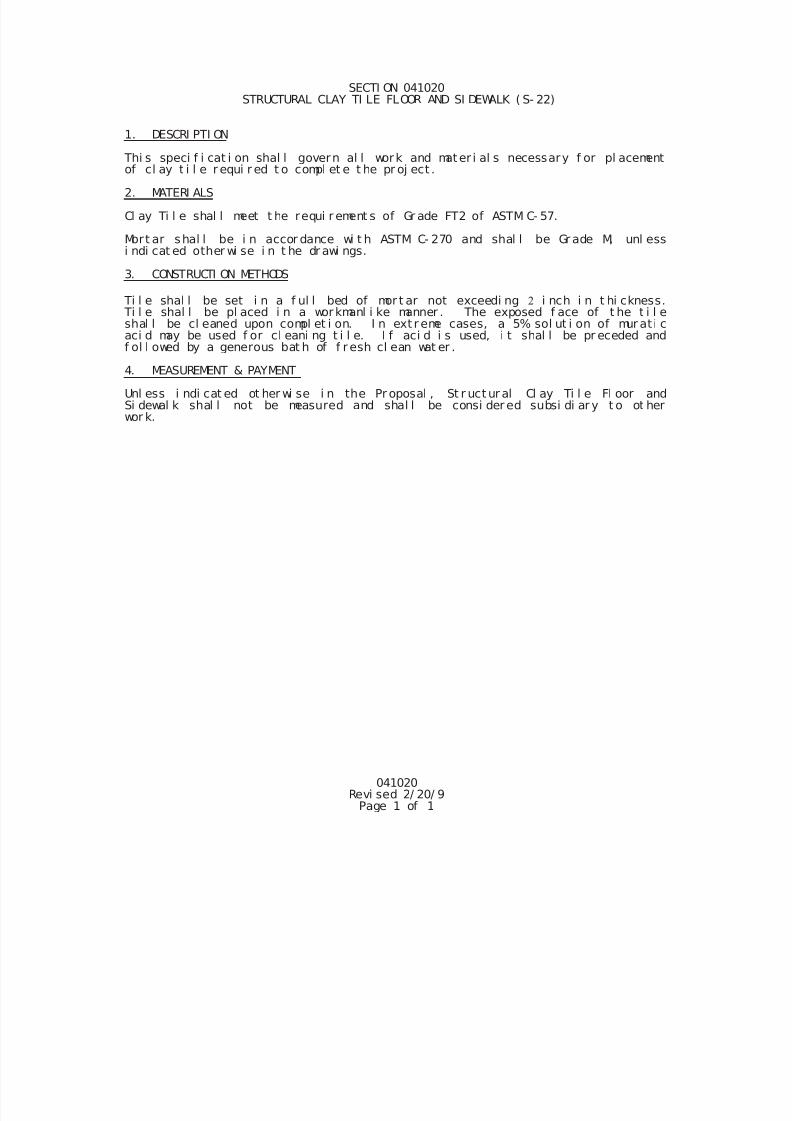
7/25/2019 City Standard Construction Specifications
http://slidepdf.com/reader/full/city-standard-construction-specifications 389/511
041020Revi sed 2/ 20/ 9
Page 1 of 1
SECTI ON 041020 STRUCTURAL CLAY TI LE FLOOR AND SI DEWALK ( S- 22)
1. DESCRI PTI ON
Thi s speci f i cat i on shal l govern al l work and mater i al s necessary f or pl acementof cl ay t i l e r equi r ed t o compl et e t he pr oj ect .
2. MATERI ALS
Cl ay Ti l e shal l meet t he requi r ement s of Gr ade FT2 of ASTM C- 57.
Mort ar shal l be i n accor dance wi t h ASTM C- 270 and shal l be Gr ade M, unl essi ndi cat ed other wi se i n t he dr awi ngs.
3. CONSTRUCTI ON METHODS
Ti l e shal l be set i n a f ul l bed of mor t ar not exceedi ng i nch i n t hi ckness. Ti l e shal l be pl aced i n a workmanl i ke manner . The exposed f ace of t he t i l eshal l be cl eaned upon compl et i on. I n ext r eme cases, a 5% sol ut i on of mur at i caci d may be used f or cl eani ng t i l e. I f aci d i s used, i t shal l be pr eceded andf ol l owed by a generous bat h of f r esh cl ean wat er .
4. MEASUREMENT & PAYMENT
Unl ess i ndi cat ed ot her wi se i n the Pr oposal , St r uct ur al Cl ay Ti l e Fl oor andSi dewal k shal l not be measured and shal l be consi der ed subsi di ar y t o ot herwor k.
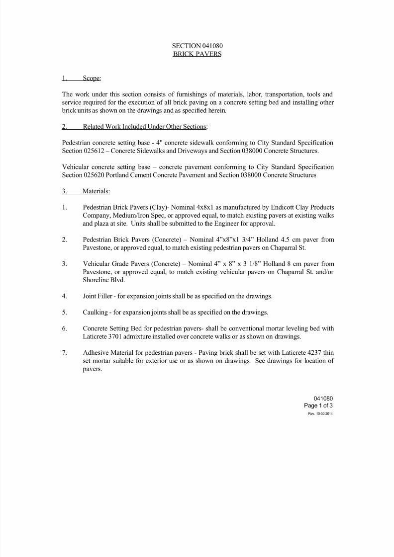
7/25/2019 City Standard Construction Specifications
http://slidepdf.com/reader/full/city-standard-construction-specifications 390/511
041080
Page 1 of 3
Rev. 10-30-2014
SECTION 041080
BRICK PAVERS
1. Scope:
The work under this section consists of furnishings of materials, labor, transportation, tools and
service required for the execution of all brick paving on a concrete setting bed and installing other
brick units as shown on the drawings and as specified herein.
2. Related Work Included Under Other Sections:
Pedestrian concrete setting base - 4" concrete sidewalk conforming to City Standard Specification
Section 025612 – Concrete Sidewalks and Driveways and Section 038000 Concrete Structures.
Vehicular concrete setting base – concrete pavement conforming to City Standard Specification
Section 025620 Portland Cement Concrete Pavement and Section 038000 Concrete Structures
3. Materials:
1. Pedestrian Brick Pavers (Clay)- Nominal 4x8x1 as manufactured by Endicott Clay Products
Company, Medium/Iron Spec, or approved equal, to match existing pavers at existing walks
and plaza at site. Units shall be submitted to the Engineer for approval.
2. Pedestrian Brick Pavers (Concrete) – Nominal 4”x8”x1 3/4” Holland 4.5 cm paver from
Pavestone, or approved equal, to match existing pedestrian pavers on Chaparral St.
3. Vehicular Grade Pavers (Concrete) – Nominal 4” x 8” x 3 1/8” Holland 8 cm paver fromPavestone, or approved equal, to match existing vehicular pavers on Chaparral St. and/or
Shoreline Blvd.
4. Joint Filler - for expansion joints shall be as specified on the drawings.
5. Caulking - for expansion joints shall be as specified on the drawings.
6. Concrete Setting Bed for pedestrian pavers- shall be conventional mortar leveling bed with
Laticrete 3701 admixture installed over concrete walks or as shown on drawings.
7. Adhesive Material for pedestrian pavers - Paving brick shall be set with Laticrete 4237 thinset mortar suitable for exterior use or as shown on drawings. See drawings for location of
pavers.
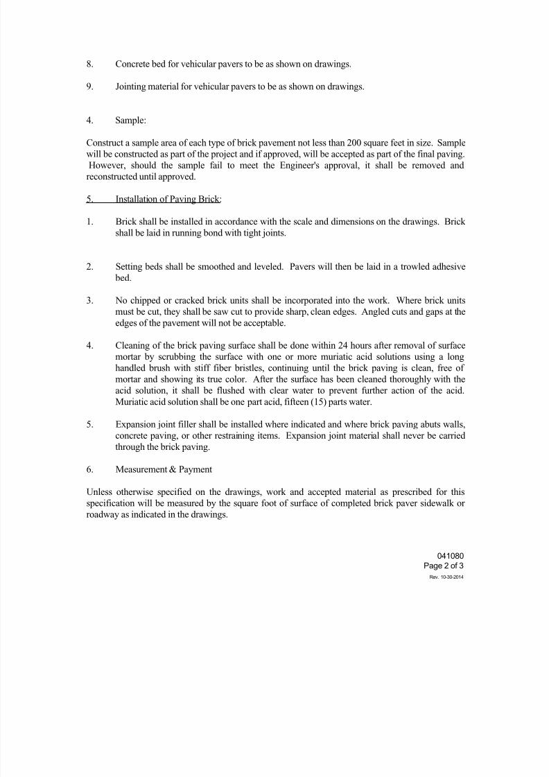
7/25/2019 City Standard Construction Specifications
http://slidepdf.com/reader/full/city-standard-construction-specifications 391/511
041080
Page 2 of 3
Rev. 10-30-2014
8. Concrete bed for vehicular pavers to be as shown on drawings.
9. Jointing material for vehicular pavers to be as shown on drawings.
4. Sample:
Construct a sample area of each type of brick pavement not less than 200 square feet in size. Sample
will be constructed as part of the project and if approved, will be accepted as part of the final paving.
However, should the sample fail to meet the Engineer's approval, it shall be removed and
reconstructed until approved.
5. Installation of Paving Brick:
1. Brick shall be installed in accordance with the scale and dimensions on the drawings. Brick
shall be laid in running bond with tight joints.
2. Setting beds shall be smoothed and leveled. Pavers will then be laid in a trowled adhesive
bed.
3. No chipped or cracked brick units shall be incorporated into the work. Where brick units
must be cut, they shall be saw cut to provide sharp, clean edges. Angled cuts and gaps at the
edges of the pavement will not be acceptable.
4. Cleaning of the brick paving surface shall be done within 24 hours after removal of surface
mortar by scrubbing the surface with one or more muriatic acid solutions using a long
handled brush with stiff fiber bristles, continuing until the brick paving is clean, free ofmortar and showing its true color. After the surface has been cleaned thoroughly with the
acid solution, it shall be flushed with clear water to prevent further action of the acid.
Muriatic acid solution shall be one part acid, fifteen (15) parts water.
5. Expansion joint filler shall be installed where indicated and where brick paving abuts walls,
concrete paving, or other restraining items. Expansion joint material shall never be carried
through the brick paving.
6. Measurement & Payment
Unless otherwise specified on the drawings, work and accepted material as prescribed for thisspecification will be measured by the square foot of surface of completed brick paver sidewalk or
roadway as indicated in the drawings.
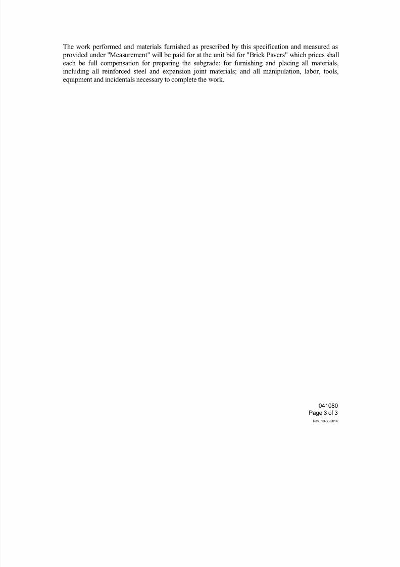
7/25/2019 City Standard Construction Specifications
http://slidepdf.com/reader/full/city-standard-construction-specifications 392/511
041080
Page 3 of 3
Rev. 10-30-2014
The work performed and materials furnished as prescribed by this specification and measured as
provided under "Measurement" will be paid for at the unit bid for "Brick Pavers" which prices shall
each be full compensation for preparing the subgrade; for furnishing and placing all materials,
including all reinforced steel and expansion joint materials; and all manipulation, labor, tools,
equipment and incidentals necessary to complete the work.
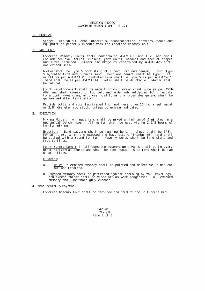
7/25/2019 City Standard Construction Specifications
http://slidepdf.com/reader/full/city-standard-construction-specifications 393/511
042020R 2/ 20/ 9
Page 1 of 1
SECTI ON 042020 CONCRETE MASONRY UNI T ( S- 121)
1. GENERAL
Scope: Fur ni sh al l l abor , mat er i al s, t r anspor t at i on, ser vi ces, t ool s andequi pment t o pr operl y execute work f or Concr ete Masonr y Uni t .
2. MATERI ALS
Concr et e masonr y uni t s shal l conf orm t o ASTM C90 and C129 and shal li ncl ude hol l ows, sol i ds, cl oser s, j amb uni t s, header s and speci al shapesand si zes r equi r ed. Li near shr i nkage as det ermi ned by ASTM C426 shal lnot exceed . 03%.
Mort ar shal l be Type S consi st i ng of 1 part Por t l and cement , 1 part TypeS hydr ated l i me and 6 par t s sand. Por t l and cement shal l be Type I , I I ,or I I I as per ASTM C150. Hydr at ed l i me shal l be Type S as per ASTM C207.Sand shal l be as per ASTM C144. Wat er shal l be dr i nkabl e. Mort ar shal l
be nat ur al .
J oi nt r ei nf or cement shal l be made f r om col d drawn st eel wi r e as per ASTM
A82, and shal l consi st of t wo def ormed si de rods wel ded at 16" i nt er val st o a cont i nuous di agonal cr oss r oad f ormi ng a t r uss desi gn and shal l begal vani zed af t er f abr i cat i on.
Provi de bol t s and r ods f abr i cat ed f r om not l ess t han 16 ga. sheet met alor 3/ 8" di amet er r od st ock, unl ess other wi se i ndi cat ed.
3. EXECUTI ON
Mi xi ng Mort ar : Al l mat eri al s shal l be mi xed a mi ni mum of 5 mi nut es i n amechani cal bat ch mi xer . Al l mort ar shal l be used wi t hi n 2 1/ 2 hour s ofi ni t i al mi xi ng.
Er ect i on: Bond pat t er n shal l be r unni ng bond. J oi nt s shal l be 3/ 8".Mort ar j oi nts whi ch are exposed and have become " t humbpr i nt" hard shal l
be t ool ed wi t h a r ound j oi nt er . Masonr y uni t s shal l be l ai d pl umb andt rue t o l i nes.
J oi nt r ei nf or cement i n al l concret e masonry uni t wal l s shal l be i n ever yother hor i zont al cour se and shal l be cont i nuous. Si de r ods shal l be l ap6" at spl i ces.
Cl eani ng:
a. Hol es i n exposed masonr y shal l be poi nt ed and def ect i ve j oi nt s cutout and r epai r ed.
b. Exposed masonr y shal l be pr ot ect ed agai nst st ai ni ng by wal l cover i ngs,and excess mort ar shal l be wi ped of f as work pr ogr esses. Al l exposedmasonry shal l be t horoughl y cl eaned.
4. Measur ement & Payment
Concr ete Masonry Uni t shal l be measured and pai d at t he uni t pr i ce bi d.
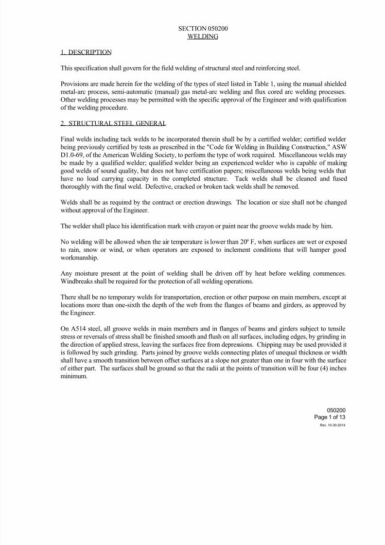
7/25/2019 City Standard Construction Specifications
http://slidepdf.com/reader/full/city-standard-construction-specifications 394/511
050200
Page 1 of 13
Rev. 10-30-2014
SECTION 050200
WELDING
1. DESCRIPTION
This specification shall govern for the field welding of structural steel and reinforcing steel.
Provisions are made herein for the welding of the types of steel listed in Table 1, using the manual shieldedmetal-arc process, semi-automatic (manual) gas metal-arc welding and flux cored arc welding processes
Other welding processes may be permitted with the specific approval of the Engineer and with qualification
of the welding procedure.
2. STRUCTURAL STEEL GENERAL
Final welds including tack welds to be incorporated therein shall be by a certified welder; certified welder
being previously certified by tests as prescribed in the "Code for Welding in Building Construction," ASW
D1.0-69, of the American Welding Society, to perform the type of work required. Miscellaneous welds may
be made by a qualified welder; qualified welder being an experienced welder who is capable of making
good welds of sound quality, but does not have certification papers; miscellaneous welds being welds thathave no load carrying capacity in the completed structure. Tack welds shall be cleaned and fused
thoroughly with the final weld. Defective, cracked or broken tack welds shall be removed.
Welds shall be as required by the contract or erection drawings. The location or size shall not be changed
without approval of the Engineer.
The welder shall place his identification mark with crayon or paint near the groove welds made by him.
No welding will be allowed when the air temperature is lower than 20º F, when surfaces are wet or exposed
to rain, snow or wind, or when operators are exposed to inclement conditions that will hamper good
workmanship.
Any moisture present at the point of welding shall be driven off by heat before welding commences
Windbreaks shall be required for the protection of all welding operations.
There shall be no temporary welds for transportation, erection or other purpose on main members, except at
locations more than one-sixth the depth of the web from the flanges of beams and girders, as approved by
the Engineer.
On A514 steel, all groove welds in main members and in flanges of beams and girders subject to tensile
stress or reversals of stress shall be finished smooth and flush on all surfaces, including edges, by grinding in
the direction of applied stress, leaving the surfaces free from depressions. Chipping may be used provided iis followed by such grinding. Parts joined by groove welds connecting plates of unequal thickness or width
shall have a smooth transition between offset surfaces at a slope not greater than one in four with the surface
of either part. The surfaces shall be ground so that the radii at the points of transition will be four (4) inches
minimum.
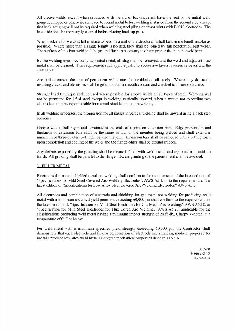
7/25/2019 City Standard Construction Specifications
http://slidepdf.com/reader/full/city-standard-construction-specifications 395/511
050200
Page 2 of 13
Rev. 10-30-2014
All groove welds, except when produced with the aid of backing, shall have the root of the initial weld
gouged, chipped or otherwise removed to sound metal before welding is started from the second side, except
that back gouging will not be required when welding steel piling or armor joints with E6010 electrodes. The
back side shall be thoroughly cleaned before placing back-up pass.
When backing for welds is left in place to become a part of the structure, it shall be a single length insofar as
possible. Where more than a single length is needed, they shall be joined by full penetration butt welds
The surfaces of this butt weld shall be ground flush as necessary to obtain proper fit-up in the weld joint.
Before welding over previously deposited metal, all slag shall be removed, and the weld and adjacent base
metal shall be cleaned. This requirement shall apply equally to successive layers, successive beads and the
crater area.
Arc strikes outside the area of permanent welds must be avoided on all steels. Where they do occur
resulting cracks and blemishes shall be ground out to a smooth contour and checked to insure soundness.
Stringer bead technique shall be used where possible for groove welds on all types of steel. Weaving wil
not be permitted for A514 steel except in welding vertically upward, when a weave not exceeding two
electrode diameters is permissible for manual shielded metal-arc welding.
In all welding processes, the progression for all passes in vertical welding shall be upward using a back step
sequence.
Groove welds shall begin and terminate at the ends of a joint on extension bars. Edge preparation and
thickness of extension bars shall be the same as that of the member being welded and shall extend a
minimum of three-quarter (3/4) inch beyond the joint. Extension bars shall be removed with a cutting torch
upon completion and cooling of the weld, and the flange edges shall be ground smooth.
Any defects exposed by the grinding shall be cleaned, filled with weld metal, and reground to a uniform
finish. All grinding shall be parallel to the flange. Excess grinding of the parent metal shall be avoided.
3. FILLER METAL
Electrodes for manual shielded metal-arc welding shall conform to the requirements of the latest edition of
"Specifications for Mild Steel Covered Arc-Welding Electrodes", AWS A5.1, or to the requirements of the
latest edition of "Specifications for Low Alloy Steel Covered Arc-Welding Electrodes," AWS A5.5.
All electrodes and combination of electrode and shielding for gas metal-arc welding for producing weld
metal with a minimum specified yield point not exceeding 60,000 psi shall conform to the requirements in
the latest edition of, "Specification for Mild Steel Electrodes for Gas Metal-Arc Welding," AWS A5.18, or
"Specification for Mild Steel Electrodes for Flux Cored Arc Welding," AWS A5.20, applicable for theclassifications producing weld metal having a minimum impact strength of 20 ft.-lb., Charpy V-notch, at a
temperature of 0º F or below.
For weld metal with a minimum specified yield strength exceeding 60,000 psi, the Contractor shall
demonstrate that each electrode and flux or combination of electrode and shielding medium proposed for
use will produce low alloy weld metal having the mechanical properties listed in Table A.
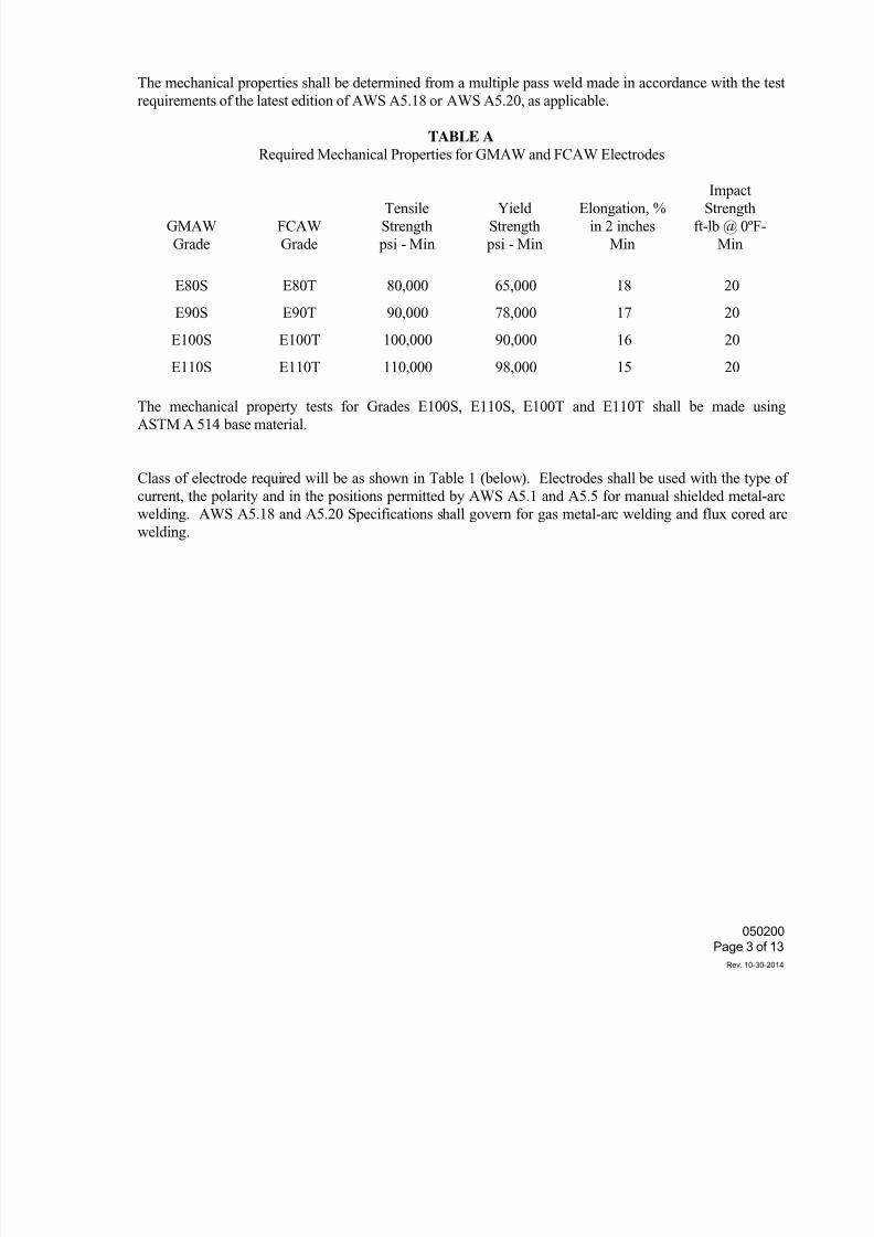
7/25/2019 City Standard Construction Specifications
http://slidepdf.com/reader/full/city-standard-construction-specifications 396/511
050200
Page 3 of 13
Rev. 10-30-2014
The mechanical properties shall be determined from a multiple pass weld made in accordance with the test
requirements of the latest edition of AWS A5.18 or AWS A5.20, as applicable.
TABLE A
Required Mechanical Properties for GMAW and FCAW Electrodes
GMAW
Grade
FCAW
Grade
Tensile
Strength
psi - Min
Yield
Strength
psi - Min
Elongation, %
in 2 inches
Min
ImpactStrength
ft-lb @ 0ºF-
Min
E80S E80T 80,000 65,000 18 20
E90S E90T 90,000 78,000 17 20
E100S E100T 100,000 90,000 16 20
E110S E110T 110,000 98,000 15 20
The mechanical property tests for Grades E100S, E110S, E100T and E110T shall be made using
ASTM A 514 base material.
Class of electrode required will be as shown in Table 1 (below). Electrodes shall be used with the type o
current, the polarity and in the positions permitted by AWS A5.1 and A5.5 for manual shielded metal-arc
welding. AWS A5.18 and A5.20 Specifications shall govern for gas metal-arc welding and flux cored arc
welding.
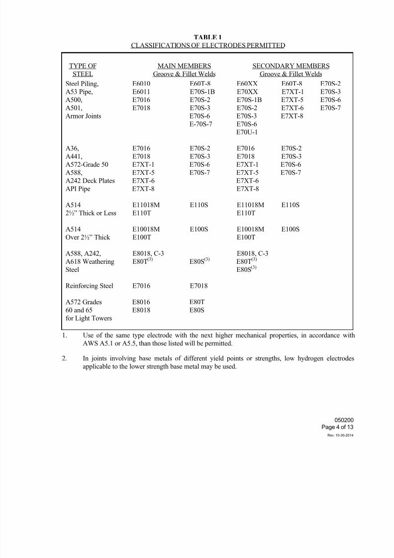
7/25/2019 City Standard Construction Specifications
http://slidepdf.com/reader/full/city-standard-construction-specifications 397/511
050200
Page 4 of 13
Rev. 10-30-2014
TABLE 1
CLASSIFICATIONS OF ELECTRODES PERMITTED
TYPE OF
STEEL
MAIN MEMBERS
Groove & Fillet Welds
SECONDARY MEMBERS
Groove & Fillet Welds
Steel Piling, E6010 E60T-8 E60XX E60T-8 E70S-2
A53 Pipe, E6011 E70S-1B E70XX E7XT-1 E70S-3
A500, E7016 E70S-2 E70S-1B E7XT-5 E70S-6
A501, E7018 E70S-3 E70S-2 E7XT-6 E70S-7
Armor Joints E70S-6 E70S-3 E7XT-8
E-70S-7 E70S-6
E70U-1
A36, E7016 E70S-2 E7016 E70S-2
A441, E7018 E70S-3 E7018 E70S-3
A572-Grade 50
A588,
A242 Deck Plates
E7XT-1
E7XT-5
E7XT-6
E70S-6
E70S-7
E7XT-1
E7XT-5
E7XT-6
E70S-6
E70S-7
API Pipe E7XT-8 E7XT-8
A514 E11018M E110S E11018M E110S
2½” Thick or Less E110T E110T
A514 E10018M E100S E10018M E100S
Over 2½” Thick E100T E100T
A588, A242, E8018, C-3 E8018, C-3
A618 Weathering E80T
(3)
E80S
(3)
E80T
(3)
Steel E80S(3)
Reinforcing Steel E7016 E7018
A572 Grades
60 and 65
for Light Towers
E8016
E8018
E80T
E80S
1. Use of the same type electrode with the next higher mechanical properties, in accordance with
AWS A5.1 or A5.5, than those listed will be permitted.
2. In joints involving base metals of different yield points or strengths, low hydrogen electrodes
applicable to the lower strength base metal may be used.
7/25/2019 City Standard Construction Specifications
http://slidepdf.com/reader/full/city-standard-construction-specifications 398/511
050200
Page 5 of 13
Rev. 10-30-2014
Before use, all electrodes with low hydrogen coverings conforming to AWS A5.1 shall be dried for not less
than two hours between 450 and 500 degrees F and electrodes with low hydrogen coverings conforming to
AWS A5.5 for not less than one hour at a temperature between 700 and 800 degrees F. Immediately after
drying, electrodes shall be stored in ovens held at a temperature of at least 250 degrees F. E70 electrodes
not used within four hours, E80 within two hours, and E110 within one-half hour after removal from the
storage oven shall be redried before use. Electrodes with flux which has been wet, cracked or otherwise
damaged, shall not be used. When used for welding A514 steel, electrodes shall be dried at least one hour a
temperatures between 700 and 800 degrees F before being used. Electrodes may be redried only once.
Suitable facilities for drying and storage of electrodes shall be furnished at the job site, along with
thermometers for checking and controlling the oven temperature.
In humid atmospheres, the times allowed for use without redrying may be reduced.
When gas or gas mixture is used for gas metal-arc welding, it shall be of a welding grade having a dew poin
of -40º F or lower. The gas manufacturer shall furnish certification to the Engineer that the gas or gas
mixture is suitable for the intended application and will meet the dew point requirements.
Welding wire coils removed from the original package shall be protected or stored to keep theircharacteristics or welding properties intact. Rusty coils, or portions of coils, that are rusty shall not be used.
Preheat
Preheat ahead of welding both groove and fillet welds (including tack welding) will be required as shown in
Table 2. Any moisture present at the point of welding shall be driven off by preheating before welding
begins. When the base metal is below the required temperature, it shall be preheated so the parts being
welded are not less than the specified temperature within three inches (3") of the point of welding.
Preheat and interpass temperatures must be sufficient to prevent crack formation. The preheat temperatures
shown in Table 2 are minimum and higher preheats may be necessary in highly restrained welds.
Preheating equipment shall be adequate to maintain the entire joint at or above the specified temperature.
When possible, a joint shall be completely welded before it is allowed to cool below the specified
temperature, but shall always be welded sufficiently to prevent cracking before cooling is permitted.
Usually preheat and interpass temperatures shall not exceed 400º F for thickness up to 1½ inches and
450º F for greater thickness. These temperatures shall never be exceeded on A514 steel.
The welder shall have and use approved equipment for checking preheat and interpass temperatures at all
times while welding is in progress.
For all groove welds, preheat temperature shall be measured on the side opposite to which the heat is applied
at points about three inches (3") away from the joint.
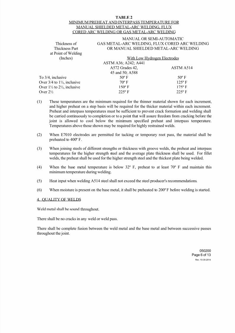
7/25/2019 City Standard Construction Specifications
http://slidepdf.com/reader/full/city-standard-construction-specifications 399/511
050200
Page 6 of 13
Rev. 10-30-2014
TABLE 2
MINIMUM PREHEAT AND INTERPASS TEMPERATURE FOR
MANUAL SHIELDED METAL-ARC WELDING, FLUX
CORED ARC WELDING OR GAS METAL-ARC WELDING
Thickness of
Thickness Part
at Point of Welding(Inches)
MANUAL OR SEMI-AUTOMATIC
GAS METAL-ARC WELDING, FLUX CORED ARC WELDING
OR MANUAL SHIELDED METAL-ARC WELDING
With Low Hydrogen Electrodes
ASTM A36; A242; A441
A572 Grades 42,
45 and 50; A588
ASTM A514
To 3/4, inclusive
Over 3/4 to 1½, inclusive
Over 1½ to 2½, inclusive
Over 2½
50º F
70º F
150º F
225º F
50º F
125º F
175º F
225º F
(1) These temperatures are the minimum required for the thinner material shown for each increment
and higher preheat on a step basis will be required for the thicker material within each increment.Preheat and interpass temperatures must be sufficient to prevent crack formation and welding shall
be carried continuously to completion or to a point that will assure freedom from cracking before the
joint is allowed to cool below the minimum specified preheat and interpass temperature
Temperatures above those shown may be required for highly restrained welds.
(2) When E7010 electrodes are permitted for tacking or temporary root pass, the material shall be
preheated to 400º F.
(3) When joining steels of different strengths or thickness with groove welds, the preheat and interpass
temperatures for the higher strength steel and the average plate thickness shall be used. For fille
welds, the preheat shall be used for the higher strength steel and the thickest plate being welded.
(4) When the base metal temperature is below 32º F, preheat to at least 70º F and maintain this
minimum temperature during welding.
(5) Heat input when welding A514 steel shall not exceed the steel producer's recommendations.
(6) When moisture is present on the base metal, it shall be preheated to 200º F before welding is started.
4. QUALITY OF WELDS
Weld metal shall be sound throughout.
There shall be no cracks in any weld or weld pass.
There shall be complete fusion between the weld metal and the base metal and between successive passes
throughout the joint.
7/25/2019 City Standard Construction Specifications
http://slidepdf.com/reader/full/city-standard-construction-specifications 400/511
050200
Page 7 of 13
Rev. 10-30-2014
Welds shall be free from overlap and the base metal free from undercut more than one one-hundredth inch
(1/100") deep when its direction is transverse to the primary stress in the part that is undercut. Undercu
shall not be more than one thirty-second inch (1/32") deep when its direction is parallel to the primary stress
in the part that is undercut.
All craters shall be filled to the full cross section of the welds.
All welds on A514 steel shall be visually examined for longitudinal or transverse cracks not less than 48hours after completion of the welding.
5. CORRECTIONS
When welding is unsatisfactory or indicates inferior workmanship, the following corrective measures will be
required by the Engineer whose specific approval shall be obtained for making each correction.
When requirements prescribe the removal of part of the weld or a portion of the base metal, removal shall be
by oxygen gouging or arc-air gouging.
Oxygen gouging shall not be used on A514 steel or A588 weathering steel. All surfaces shall be groundafter arc-air gouging.
Backgouging of splices in beams and girders or cutouts of defective welds shall be done by a welder
qualified to make beam and girder splices.
Where corrections require the deposition of additional weld metal, the sides of the area to be welded shall
have sufficient slope to permit depositing new metal.
Defective or unsound welds shall be corrected either by removing and replacing the entire weld, or as
follows:
Excessive convexity. Reduce to size by grinding off the excess weld metal.
Shrinkage cracks. Cracks in base metal, craters and excessive porosity. Remove defective
portions of base and weld metal down to sound metal and replace with additional sound weld metal.
Undercutting, undersize and excessive concavity. Clean and deposit additional weld metal.
Overlapping and incomplete fusion. Remove and replace the defective portion of weld.
Slag inclusions. Remove the parts of the weld containing slag and replace with sound weld metal.
Removal of adjacent base metal during welding. Clean and form full size by depositing
additional weld metal.
Where corrections require the deposition of additional weld metal, the electrode used shall be
smaller than that used for making the original weld. Surfaces shall be cleaned thoroughly before
re-welding.
7/25/2019 City Standard Construction Specifications
http://slidepdf.com/reader/full/city-standard-construction-specifications 401/511
050200
Page 8 of 13
Rev. 10-30-2014
A cracked weld shall be removed throughout its length, unless the extent of the crack can be
ascertained to be limited, in which case the weld metal shall be removed 2 inches (2") beyond each
end of the crack and repairs made.
Where work performed after the making of a deficient weld has made the weld inaccessible or has
caused new conditions making the correction of the deficiency dangerous or ineffectual, the original
conditions shall be restored by removal of welds or members, or both, before making the necessary
corrections, or else the deficiency shall be compensated by additional work according to a reviseddesign approved by the Engineer.
Improperly fitted and misaligned parts shall be cut apart and re-welded.
Members distorted by the heat of welding shall be straightened by mechanical means or by the
carefully supervised application of a limited amount of localized heat. Heated areas shall not exceed
1200º F as measured by Tempil-sticks or other approved methods for steel up to 65,000 psi yield
strength. Parts to be heat straightened shall be substantially free of stress from external forces
except when mechanical means are used in conjunction with the application of heat.
Heat straightening of A514 steel shall be done only under rigidly controlled procedures, subject tothe approval of the Engineer. In no case shall the maximum temperature of the steel exceed
1100º F. Sharp kinks and bends shall be cause for rejection of the material.
6. RADIOGRAPHIC INSPECTION
All groove welds designed to carry primary stresses shall be subject to radiographic inspection. When
subjected to such inspections, the presence of any of the following defects in excess of the limits indicated
will result in rejection of the defective weld until corrected.
1. Sections of welds shown to have any cracking, regardless of length or location, incomplete fusion
overlapping, or inadequate penetration shall be judged unacceptable.
2. Inclusions less than one-sixteenth inch (1/16") in greatest dimension including slag, porosity and
other deleterious material, shall be permitted if well dispersed so that the sum of the greatest
dimensions of the inclusions in any linear inch of welded joint shall not exceed three-eighth inch
(3/8").
3. Inclusions one-sixteenth inch (1/16") or larger in greatest dimension shall be permitted provided
such defects do not exceed the limits shown on Figure 1 or in subparagraph (2) above.
4. There shall be no inclusion greater than one-sixteenth inch (1/16") within one inch of the edge o
part or member at the joint or point of restraint.
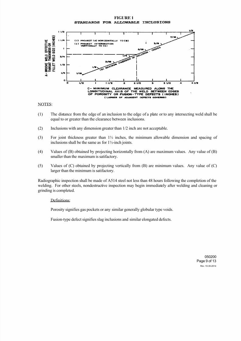
7/25/2019 City Standard Construction Specifications
http://slidepdf.com/reader/full/city-standard-construction-specifications 402/511
050200
Page 9 of 13
Rev. 10-30-2014
FIGURE 1
NOTES:
(1) The distance from the edge of an inclusion to the edge of a plate or to any intersecting weld shall be
equal to or greater than the clearance between inclusions.
(2) Inclusions with any dimension greater than 1/2 inch are not acceptable.
(3) For joint thickness greater than 1½ inches, the minimum allowable dimension and spacing of
inclusions shall be the same as for 1½-inch joints.
(4) Values of (B) obtained by projecting horizontally from (A) are maximum values. Any value of (B)
smaller than the maximum is satifactory.
(5) Values of (C) obtained by projecting vertically from (B) are minimum values. Any value of (C)
larger than the minimum is satifactory.
Radiographic inspection shall be made of A514 steel not less than 48 hours following the completion of the
welding. For other steels, nondestructive inspection may begin immediately after welding and cleaning or
grinding is completed.
Definitions:
Porosity signifies gas pockets or any similar generally globular type voids.
Fusion-type defect signifies slag inclusions and similar elongated defects.
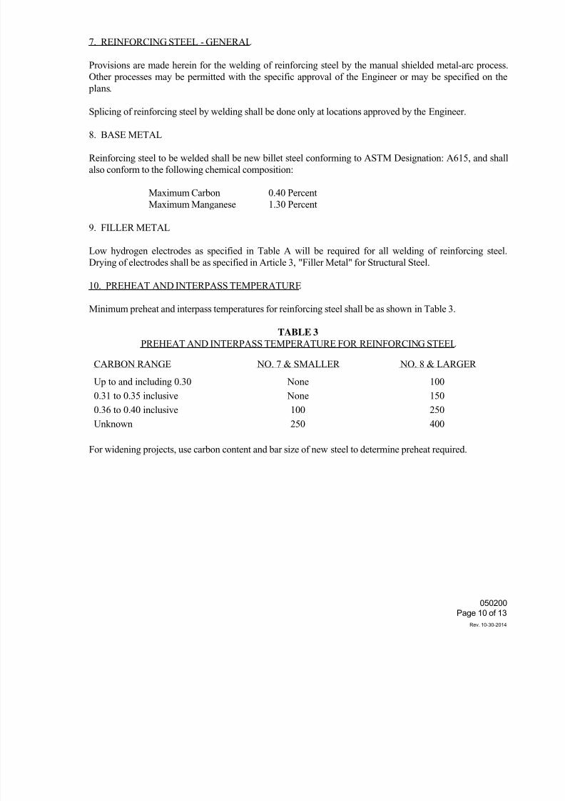
7/25/2019 City Standard Construction Specifications
http://slidepdf.com/reader/full/city-standard-construction-specifications 403/511
050200
Page 10 of 13
Rev. 10-30-2014
7. REINFORCING STEEL - GENERAL
Provisions are made herein for the welding of reinforcing steel by the manual shielded metal-arc process
Other processes may be permitted with the specific approval of the Engineer or may be specified on the
plans.
Splicing of reinforcing steel by welding shall be done only at locations approved by the Engineer.
8. BASE METAL
Reinforcing steel to be welded shall be new billet steel conforming to ASTM Designation: A615, and shall
also conform to the following chemical composition:
Maximum Carbon 0.40 Percent
Maximum Manganese 1.30 Percent
9. FILLER METAL
Low hydrogen electrodes as specified in Table A will be required for all welding of reinforcing steel.Drying of electrodes shall be as specified in Article 3, "Filler Metal" for Structural Steel.
10. PREHEAT AND INTERPASS TEMPERATURE
Minimum preheat and interpass temperatures for reinforcing steel shall be as shown in Table 3.
TABLE 3
PREHEAT AND INTERPASS TEMPERATURE FOR REINFORCING STEEL
CARBON RANGE NO. 7 & SMALLER NO. 8 & LARGER
Up to and including 0.30
0.31 to 0.35 inclusive
0.36 to 0.40 inclusive
Unknown
None
None
100
250
100
150
250
400
For widening projects, use carbon content and bar size of new steel to determine preheat required.
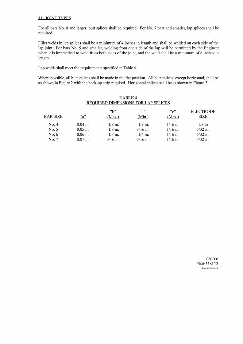
7/25/2019 City Standard Construction Specifications
http://slidepdf.com/reader/full/city-standard-construction-specifications 404/511
050200
Page 11 of 13
Rev. 10-30-2014
11. JOINT TYPES
For all bars No. 8 and larger, butt splices shall be required. For No. 7 bars and smaller, lap splices shall be
required.
Fillet welds in lap splices shall be a minimum of 4 inches in length and shall be welded on each side of the
lap joint. For bars No. 5 and smaller, welding from one side of the lap will be permitted by the Enginee
when it is impractical to weld from both sides of the joint, and the weld shall be a minimum of 6 inches inlength.
Lap welds shall meet the requirements specified in Table 4.
Where possible, all butt splices shall be made in the flat position. All butt splices, except horizontal, shall be
as shown in Figure 2 with the back-up strip required. Horizontal splices shall be as shown in Figure 3.
TABLE 4
REQUIRED DIMENSIONS FOR LAP SPLICES
BAR SIZE "a""b"
(Max.)
"t"(Min.)
"c"(Max.)
ELECTRODE
SIZE
No. 4
No. 5
No. 6
No. 7
0.04 in.
0.05 in.
0.06 in.
0.07 in.
1/8 in.
1/8 in.
1/8 in.
3/16 in.
1/8 in.
3/16 in.
1/4 in.
5/16 in.
1/16 in.
1/16 in.
1/16 in.
1/16 in.
1/8 in
5/32 in.
5/32 in.
5/32 in.
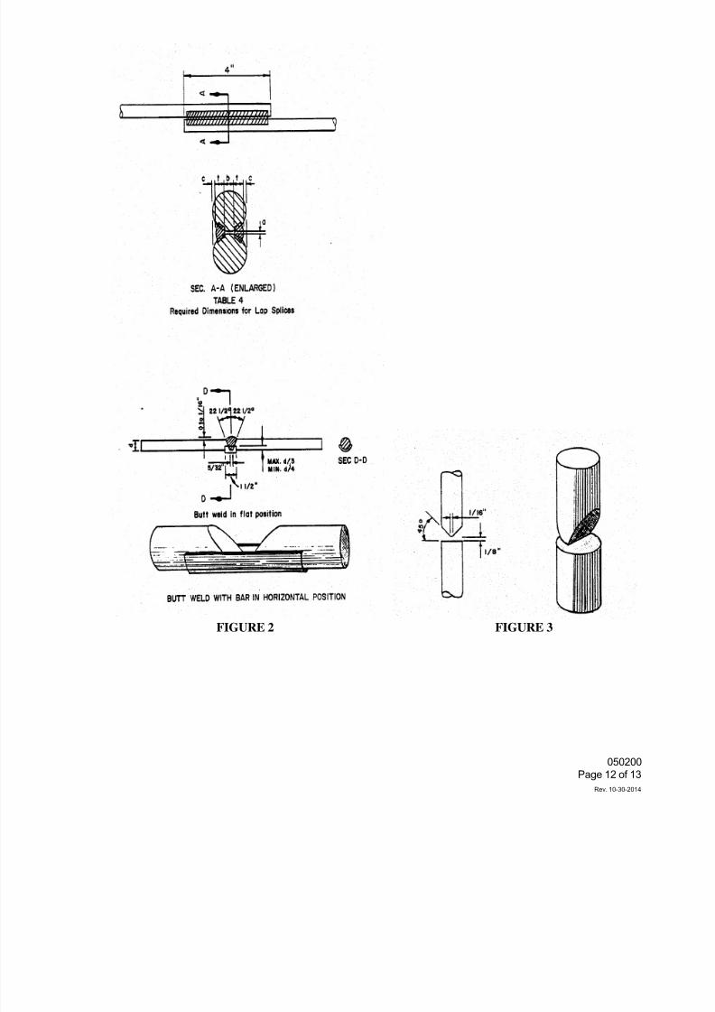
7/25/2019 City Standard Construction Specifications
http://slidepdf.com/reader/full/city-standard-construction-specifications 405/511
050200
Page 12 of 13
Rev. 10-30-2014
FIGURE 2 FIGURE 3
7/25/2019 City Standard Construction Specifications
http://slidepdf.com/reader/full/city-standard-construction-specifications 406/511
050200
Page 13 of 13
Rev. 10-30-2014
12. WIDENING PROJECTS
In general, the new reinforcing steel shall be either lap or butt spliced directly to the bar to be extended
When the reinforcement in the old portion of a structure is found to be of the wrong spacing, dowel bars
long enough to develop the welded lap or butt splice and also develop the bar in bond, as required in City
Standard Specification Section 032020 "Reinforcing Steel", shall be welded to the old steel, and the new
reinforcement placed at the correct spacing without welding to the old steel. No measurement or paymen
will be made for the dowels but will be subsidiary to the other items in the contract.
Both old and new reinforcement shall be cleaned thoroughly prior to the preparation of the joint.
13. RADIOGRAPHIC INSPECTION
When so designated on the plans, welded butt splices shall be radiographed. Weld quality shall be as
follows: There shall be no cracks and the sum of the greatest dimensions of porosity and fusion-type defects
shall not exceed one-tenth of the nominal bar diameter in inches.
14. MEASUREMENT AND PAYMENT
Unless otherwise specified on the Bid Form, welding will not be measured for pay, but will be considered
subsidiary to the various other bid items in the Bid Form.
7/25/2019 City Standard Construction Specifications
http://slidepdf.com/reader/full/city-standard-construction-specifications 407/511
053700 J une 23, 1989
Page 1 of 8
SECTI ON 053700LANDFI LL VEHI CLE WEI GHT SCALE SYSTEM ( S- 119)
1. DESCRI PTI ON
Thi s speci f i cat i on shal l govern al l work and mater i al s necessary t o f urni sh,const r uct , i nst al l , and cal i br at e, and pl ace scal es i nt o operat i on scal es, dat abase syst emand r emote termi nal r equi r ed t o compl ete t he pr oj ect .
2. GENERAL
2. 1 Requi r ement :
The Cont r act or shal l f ur ni sh and i nst al l two vehi cl e wei ght scal e systemscompl ete wi t h comput er t ermi nal s and a r emote of f i ce t er mi nal . The wei ghtscal es wi l l be used f or wei ghi ng vehi cl es, consi st i ng most l y of gar bagepacker t r ucks, ent er i ng i n t he Ci t y' s l andf i l l s. The Ci t y has t wol andf i l l s, t he El l i ot t Landf i l l at 7002 Gr eenwood and t he West si deLandf i l l l ocat ed at 3702 Car bon Pl ant Road. The compl ete wei ght scal e anddat a base syst em shal l f ul l y document vehi cl e wei ghi ng oper at i ons; al soupon r equest pr ovi de var i ous det ai l ed report s, mont hl y cust omer i nvoi ces,and pr ovi de a compl ete account i ng syst em of account s r ecei vabl e and
r evenues as descri bed i n t he f ol l owi ng speci f i cat i ons.
Comput er t er mi nal s shal l be i nst al l ed at each l andf i l l l ocat i on al ong wi t hscal es and r emote t er mi nal shal l be i nst al l ed at t he Sol i d Wast e Ser vi cesOf f i ce. Comput er t er mi nal f or t he West si de Landf i l l shal l be por t abl e.
2. 2 Warr ant y:
The Cont r act or shal l pr ovi de t he Ci t y wi t h a manuf act ur er ' s war r ant ycover i ng al l mat er i al s, l abor , and f r ei ght . The war r ant y per i od shal lbegi n upon acceptance of t he compl eted proj ect by t he Ci t y. The warr ant yper i od shal l be as f ol l ows:
Scal e 3 YearsAl l Ot her 2 Year s
The Cont r act or shal l be r esponsi bl e f or al l syst em mai ntenance f or t hef i r st year of t he war r ant y per i od.
3. MATERI ALS
3. 1 Scal e:
Two ( 2) r equi r ed, one f or t he El l i ot t Landf i l l and one f or t he West si deLandf i l l .
Mi ni mum Di mensi ons: 10 f eet wi dt h x 60 f eet l ong
Wei ght Capaci t y: 60 t on ( mi ni mum)
Sect i on Capaci t y: 40 t onsScal e Type: Pi t l ess l ow prof i l e - f ul l y el ectr oni c or el ectr oni c
mechani cal .
Wei ght br i dge Desi gn: Shal l meet Ameri can Rai l r oad Engi neeri ng Associ at i on( AREA) speci f i cat i ons f or br i dge def l ect i on wi t h40, 000 l b. t andem axl e l oad pl aced i n t he cent erof any modul e.
Deck Type: Steel
7/25/2019 City Standard Construction Specifications
http://slidepdf.com/reader/full/city-standard-construction-specifications 408/511
053700 J une 23, 1989
Page 2 of 8
Pl at f or m Checki ng: Checki ng of pl at f or m shal l be by bumper bol t s.
Scal e Si de Rai l s: Si de r ai l s shal l be a mi ni mum of 6" hi gh, ei t heri nt egr al or bol t - on str uctur al steel , r adi used t oprevent damage t o hubs and t i r es.
Pai nt Speci f i cat i ons: Al l met al sur f aces shal l be sandbl ast ed t o whi t e met al( SP- 5; bef ore coat i ng wi t h 2 par t cat al yzedEpoxy) . Any por t i on of t he f i ni sh whi ch i sdamaged by f i el d i nst al l at i on shal l be r ebl ast edand recoat ed.
3. 2 Dat a Base Syst em:
Thr ee ( 3) r equi r ed. Syst ems shal l be i nst al l ed at t he scal e l ocat i ons, one atEl l i ot t , one at West si de Landf i l l s and one system at t he Sol i d Wast e Ser vi cesOf f i ce. The syst em f or t he El l i ot t Landf i l l and t he Sol i d Wast e Ser vi ces Of f i ceshal l be l i nked by tel ephone dat a ci r cui t l i ne f or dai l y down l oadi ng of dai l yt r ansacti ons f r om El l i ot t Landf i l l t o t he of f i ce. The syst em f or t he West si deLandf i l l shal l be por t abl e type and down l oad dai l y t r ansact i ons ont o a di sket t ef or up l oadi ng t r ansact i ons ont o of f i ce comput er .
HARDWARE:
Comput er : El l i ot t Landf i l l and Sol i d Wast e Ser vi ces Of f i ce
Processor - Shal l have a 80286 CPUShal l have a mi ni mumcl ock speed at 10 mhz
Shal l have a f unct i onal 80287 math co- pr ocessor
Memory - Shal l be 640K RAM capaci t yShal l have 1 mb on the syst emboard expandabl e t o 2mb
Shal l be abl e to expand t o l 6mb usi ng cards
Secur i t y - Shal l i ncl ude a secur i t y key l ockShal l i ncl ude a secur i t y l ock down devi ce
Cl ock/Cal endar - Shal l i ncl ude an i nt er nal bat t er y powered systemcl ock/ cal endar
St orage - Shal l have one i nt er nal 5 1/ 4" di sk dr i ve capabl e ofr eadi ng/ wr i t i ng . 36 or 1. 2mb 5 1/ 4" di sket t es
Shal l have one ( 1) 2Omb f i xed di sk or l arger wi t h ( 40 ms) accesst i me or f ast er at each l andf i l l 6Omb f i xed di sk at Sol i dWast e Ser vi ces Of f i ce
Por t s - Must i ncl ude t he ser i al por t , one par al l el por t , and onemouse port
Mode - Shal l be i nternal wi t h a 2400 baud
Westside Landfill
Same as above except secur i t y, modem and mouse por t wi l l not ber equi r ed.
Keyboar d - El l i ot t and Sol i d Wast e Ser vi ces Of f i ce
Keyboar d must i ncl ude an I BM enhanced 101 keyboar d orequi val ent
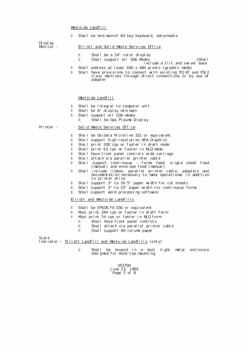
7/25/2019 City Standard Construction Specifications
http://slidepdf.com/reader/full/city-standard-construction-specifications 409/511
053700 J une 23, 1989
Page 3 of 8
West si de Landf i l l
Shal l be mi ni mumof 84 key keyboar d, det achabl e
Di spl ayMoni t or - El l i ot t and Sol i d Wast e Servi ces Of f i ce
Shal l be a 14" col or di spl ay Shal l suppor t al l VGA Modes Shal l
i ncl ude a t i l t and swi vel base
Shal l addr ess at l east 640 x 480 pi xel s (graphi c mode)
Shal l have pr ovi si ons to connect wi t h exi st i ng PC/ AT and PS/ 2cl ass machi nes thr ough di rect connect i ons or by use ofadapt er
West si de Landf i l l
Shal l be i nt egr al t o comput er uni t
Shal l be 6" di spl ay mi ni mum Shal l suppor t al l CGA modes
Shal l be Gas Pl asma Di spl ay
Pr i nt er - Sol i d Wast e Ser vi ces Of f i ce
Shal l be Oki dat a Mi crol i ne 321 or equi val ent
Shal l support hi gh resol ut i on APA Gr aphi cs
Shal l pr i nt 300 cps or f ast er i n draf t mode
Shal l pr i nt 63 cps or f aster i n NLQ mode
Shal l have f r ont panel cont rol s wi de car r i age
Shal l at t ach vi a paral l el pri nt er cabl e
Shal l support cont i nuous - f orms f eed, si ngl e sheet f eed
( manual ) and envel ope f eed ( manual ) Shal l i ncl ude r i bbon, paral l el pr i nt er cabl e, adapt er s and
document at i on necessary t o make operat i onal i n addi t i ont o pr i nt er dr i ve
Shal l support 3" t o 16. 5" paper wi dt h f or cut sheet s
Shal l support 3" t o 15" paper wi dt h f or cont i nuous f orms
Shal l support word pr ocessi ng sof t ware
El l i ot t and West si de Landf i l l s
Shal l be EPSON FX S50 or equi val ent
Must pr i nt 264 cps or f ast er i n dr af t f or m
Must pri nt 54 cps or f ast er i n NLQ f orm
Shal l have f r ont panel cont r ol s Shal l at t ach vi a par al l el pr i nt er cabl e
Shal l suppor t 80 col umn paper
Scal eI ndi cat or - El l i ot t Landf i l l and Westsi de Landf i l l s (onl y)
Shal l be housed i n a dust t i ght met al encl osur edesi gned f or desk- t op mount i ng
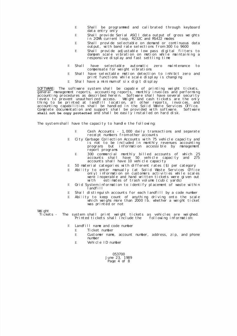
7/25/2019 City Standard Construction Specifications
http://slidepdf.com/reader/full/city-standard-construction-specifications 410/511
053700 J une 23, 1989
Page 4 of 8
Shal l be progr ammed and cal i brated t hrough keyboarddat a ent r y onl y
Shal l pr ovi de Ser i al ASCl l dat a out put of gr oss wei ght si n 2OMA cur r ent l oop, R232C and RS422 modes
Shal l provi de sel ectabl e on demand or cont i nuous dataout put , wi t h band r at e sel ect i ons f r om 300 t o 9600
Shal l pr ovi de adj ust abl e l ow pass di gi t al f i l t er s t odampen scal e vi brat i on on mot i on whi l e mai ntai ni ng ar esponsi ve di spl ay and f ast set t l i ng t i me
Shal l have sel ectabl e aut omati c zero mai nt enance t ocompensate f or wei ght vi br at i ons
Shal l have sel ectabl e mot i on det ect i on t o i nhi bi t zer o andpr i nt f unct i ons whi l e scal e di spl ay i s changi ng
Shal l have a mi ni mum of si x di gi t di spl ay
SOFTWARE: The sof t war e syst em shal l be capabl e of pr i nt i ng wei ght t i cket s,general management r eport s, account i ng report s, mont hl y i nvoi ces and per f ormi ngaccount i ng pr ocedures as descr i bed her ei n. Sof t war e shal l have sever al secur i t yl evel s t o pr event unaut hori zed access. Wei ght and cash t i cket s ar e t he onl yt hi ng t o be pr i nt ed at l andf i l l l ocat i on, al l ot her r epor t s, i nvoi ces, and
account i ng capabi l i t i es shal l be handl ed i n t he Sol i d Wast e Ser vi ces Of f i ce.Compl ete document at i on and suppor t shal l be provi ded wi t h sof t ware. Sof t wareshall not be copy protected and shal l be easi l y i nst al l ed on har d di sk.
The syst emshal l have t he capaci t y t o handl e t he f ol l owi ng:
Cash Account s - 1, 000 dai l y t r ansact i ons and separat er ecei pt numbers f r omother account s
Ci t y Garbage Col l ect i on Account s wi t h 75 vehi cl e capaci t y andi s not t o be i ncl uded i n mont hl y revenues account i ngprogr am, but i nf ormat i on accessi bl e by managementr eport progr ams
300 commerci al mont hl y bi l l ed accounts of whi ch 25account s shal l have 50 vehi cl e capaci t y and 275account s shal l have 10 vehi cl e capaci t y
50 mat er i al cat egor i es wi t h di f f er ent r at es ( $) per cat egory
Abi l i t y t o ent er manual l y ( at Sol i d Wast e Ser vi ces Of f i ceonl y) i nf or mat i on on cust omers act i vi t i es whi l e scal eswere i noperabl e and hand wr i t t en t i cket s wer e gi ven outwi t h est i mat es of t r ash vol ume ( cubi c yar ds)
Gr i d System i nf or mat i on t o i dent i f y pl acement of wast e wi t hi nl andf i l l
Shal l di st i ngui sh account s f or each l andf i l l by a code number
Abi l i t y t o keep count of anythi ng dr i vi ng ont o t he scal ewhi ch wei ghs more than 2000 l b. whether a wei ght t i cketwas pr i nt ed or not
Wei ght Ti cket s - The syst em shal l pr i nt wei ght t i cket s as vehi cl es are wei ghed.Pr i nt ed t i cket s shal l i ncl ude t he f ol l owi ng i nf or mat i on:
Landf i l l name and code number
Ti cket number
Cust omer name, account number , address, zi p, and phonenumber
Vehi cl e I D number
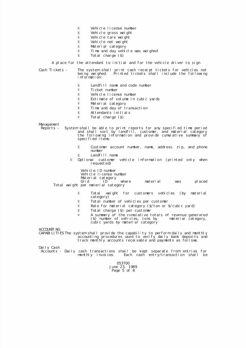
7/25/2019 City Standard Construction Specifications
http://slidepdf.com/reader/full/city-standard-construction-specifications 411/511
053700 J une 23, 1989
Page 5 of 8
Vehi cl e l i cense number
Vehi cl e gr oss wei ght
Vehi cl e t ar e wei ght
Vehi cl e net wei ght
Mat er i al cat egory
Ti me and day vehi cl e was wei ghed
Tot al char ge ( $)
A pl ace f or t he at t endant t o i ni t i al and f or t he vehi cl e dr i ver t o si gn
Cash Ti cket s - The syst em shal l pr i nt cash r ecei pt t i cket s f or vehi cl es notbei ng wei ghed. Pr i nt ed t i cket s shal l i ncl ude t he f ol l owi ngi nf or mat i on:
Landf i l l name and code number
Ti cket number
Vehi cl e l i cense number
Est i mate of vol ume i n cubi c yar ds
Mat er i al cat egory
Ti me and day of t r ansact i on
At t endant s i ni t i al s
Tot al char ge ( $)
Management Repor t s - System shal l be abl e t o pr i nt r epor t s f or any speci f i ed t i me per i od
and shal l sor t by l andf i l l , cust omer , and mat er i al cat egor yt he f ol l owi ng i nf ormati on and provi de cumul at i ve summary ofspeci f i ed i t ems:
Cust omer account number , name, addr ess. zi p, and phonenumber
Landf i l l name
Opt i onal cust omer vehi cl e i nf ormat i on ( pr i nt ed onl y whenr equest ed)
Vehi cl e I D numberVehi cl e l i cense numberMat er i al cat egor yGr i d I D wher e materi al was pl aced
Total wei ght per mater i al cat egory
Tot al wei ght f or cust omers vehi cl es ( by mat er i alcategory)
Tot al number of vehi cl es per cust omer
Rat e f or mat er i al cat egor y ( $/ t on or $/ cubi c yar d)
Tot al charge ( $) per cust omer
A summary of the cumul at i ve t otal s of revenue generated
( $) number of vehi cl es, t ons by mat er i al cat egory,cubi c yards by materi al category
ACCOUNTI NGCAPABI LI TI ES The syst em shal l pr ovi de the capabi l i t y to per f or m dai l y and mont hl y
account i ng pr ocedur es used t o veri f y dai l y bank deposi t s andt r ack mont hl y account s r ecei vabl e and payment s as f ol l ows.
Dai l y CashAccount s - Dai l y cash t ransact i ons shal l be kept separ at e f r om ent r i es f or
mont hl y i nvoi ces. Each cash ent r y/ t r ansact i on shal l be
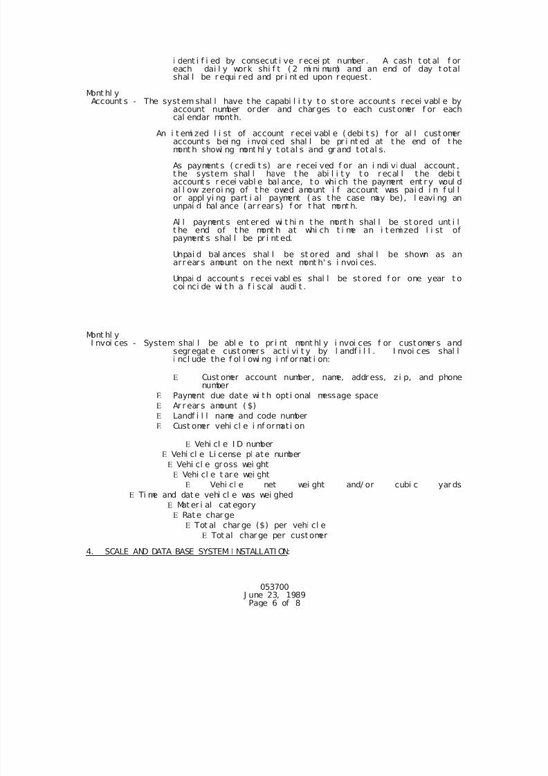
7/25/2019 City Standard Construction Specifications
http://slidepdf.com/reader/full/city-standard-construction-specifications 412/511
053700 J une 23, 1989
Page 6 of 8
i dent i f i ed by consecut i ve r ecei pt number . A cash t ot al f oreach dai l y work shi f t ( 2 mi ni mum) and an end of day t otalshal l be r equi r ed and pr i nt ed upon r equest .
Mont hl y Account s - The syst em shal l have t he capabi l i t y t o st ore account s recei vabl e by
account number order and charges t o each cust omer f or eachcal endar month.
An i t emi zed l i st of account r ecei vabl e ( debi t s) f or al l cust omeraccount s bei ng i nvoi ced shal l be pr i nt ed at t he end of t hemont h showi ng mont hl y t otal s and grand total s.
As payment s ( credi t s) are recei ved f or an i ndi vi dual account ,t he system shal l have t he abi l i t y t o r ecal l t he debi taccount s r ecei vabl e bal ance, t o whi ch the payment ent r y woul dal l ow zeroi ng of t he owed amount i f account was pai d i n f ul lor appl yi ng part i al payment ( as t he case may be), l eavi ng anunpai d bal ance (ar rear s) f or t hat mont h.
Al l payment s ent er ed wi t hi n t he mont h shal l be st ored unt i lt he end of t he mont h at whi ch t i me an i t emi zed l i st ofpayment s shal l be pr i nt ed.
Unpai d bal ances shal l be st ored and shal l be shown as anarr ear s amount on t he next mont h' s i nvoi ces.
Unpai d account s r ecei vabl es shal l be st ored f or one year t ocoi nci de wi t h a f i scal audi t .
Mont hl y I nvoi ces - System shal l be abl e to pr i nt mont hl y i nvoi ces f or cust omer s and
segregat e cust omer s act i vi t y by l andf i l l . I nvoi ces shal li ncl ude the f ol l owi ng i nf ormat i on:
Cust omer account number , name, addr ess, zi p, and phonenumber
Payment due date wi t h opt i onal message space
Ar r ear s amount ( $)
Landf i l l name and code number
Cust omer vehi cl e i nf ormati on
Vehi cl e I D number
Vehi cl e Li cense pl ate number
Vehi cl e gross wei ght
Vehi cl e t ar e wei ght
Vehi cl e net wei ght and/ or cubi c yards
Ti me and dat e vehi cl e was wei ghed
Mat er i al cat egory
Rate charge
Tot al char ge ($) per vehi cl e
Tot al char ge per cust omer
4. SCALE AND DATA BASE SYSTEM I NSTALLATI ON:
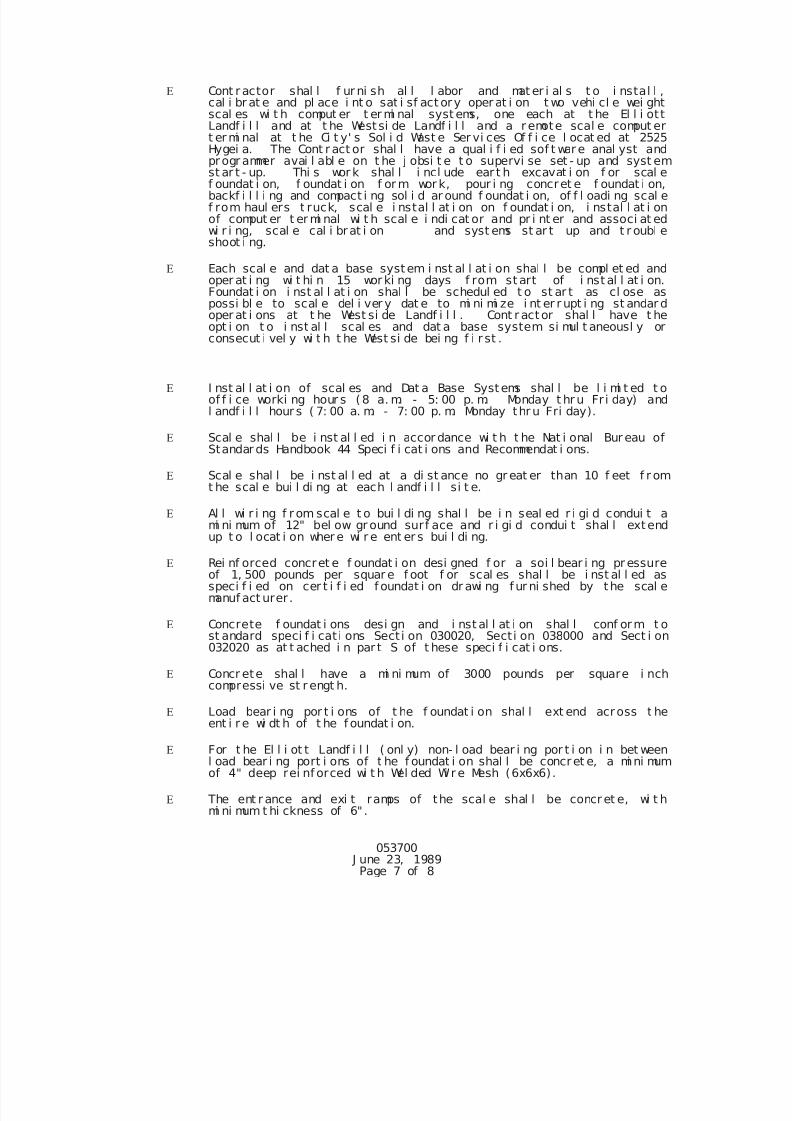
7/25/2019 City Standard Construction Specifications
http://slidepdf.com/reader/full/city-standard-construction-specifications 413/511
053700 J une 23, 1989
Page 7 of 8
Cont r actor shal l f ur ni sh al l l abor and mat er i al s t o i nstal l ,cal i br at e and pl ace i nt o sat i sf act ory oper at i on t wo vehi cl e wei ghtscal es wi t h comput er t er mi nal syst ems, one each at t he El l i ottLandf i l l and at t he Westsi de Landf i l l and a r emote scal e comput ert er mi nal at t he Ci t y' s Sol i d Wast e Ser vi ces Of f i ce l ocat ed at 2525Hygei a. The Cont r act or shal l have a qual i f i ed sof t war e anal yst andprogr ammer avai l abl e on t he j obsi t e t o supervi se set - up and syst em
st ar t - up. Thi s wor k shal l i ncl ude ear t h excavat i on f or scal ef oundat i on, f oundat i on f or m wor k, pour i ng concret e f oundat i on,backf i l l i ng and compact i ng sol i d ar ound f oundat i on, of f l oadi ng scal ef rom haul ers t ruck, scal e i nstal l at i on on f oundat i on, i nstal l at i onof comput er t er mi nal wi t h scal e i ndi cat or and pr i nt er and associ at edwi r i ng, scal e cal i brat i on and syst ems st ar t up and t r oubl eshoot i ng.
Each scal e and dat a base system i nst al l at i on shal l be compl et ed andoper at i ng wi t hi n 15 wor ki ng days f rom st art of i nst al l at i on.Foundat i on i nst al l at i on shal l be schedul ed t o st ar t as cl ose aspossi bl e to scal e del i ver y dat e to mi ni mi ze i nt er r upt i ng st andar doper at i ons at t he West si de Landf i l l . Cont r actor shal l have t heopt i on t o i nst al l scal es and dat a base system si mul t aneousl y orconsecut i vel y wi t h t he West si de bei ng f i r st .
I nst al l at i on of scal es and Dat a Base Systems shal l be l i mi t ed t oof f i ce worki ng hour s (8 a. m. - 5: 00 p. m. Monday t hr u Fr i day) andl andf i l l hour s ( 7: 00 a. m. - 7: 00 p. m. Monday thr u Fri day).
Scal e shal l be i nst al l ed i n accor dance wi t h t he Nat i onal Bur eau ofStandar ds Handbook 44 Speci f i cat i ons and Recommendat i ons.
Scal e shal l be i nst al l ed at a di st ance no gr eat er than 10 f eet f r omt he scal e bui l di ng at each l andf i l l si t e.
Al l wi r i ng f r om scal e t o bui l di ng shal l be i n seal ed r i gi d condui t ami ni mum of 12" bel ow gr ound surf ace and r i gi d condui t shal l extendup t o l ocat i on wher e wi r e ent er s bui l di ng.
Rei nf orced concret e f oundat i on desi gned f or a soi l bear i ng pr essureof 1, 500 pounds per squar e f oot f or scal es shal l be i nst al l ed asspeci f i ed on cer t i f i ed f oundat i on dr awi ng f ur ni shed by the scal emanuf act urer .
Concrete f oundat i ons desi gn and i nst al l at i on shal l conf orm t ost andard speci f i cat i ons Sect i on 030020, Secti on 038000 and Sect i on032020 as at t ached i n par t S of t hese speci f i cat i ons.
Concr ete shal l have a mi ni mum of 3000 pounds per square i nchcompressi ve st r engt h.
Load bear i ng por t i ons of t he f oundat i on shal l ext end across t heent i r e wi dt h of t he f oundat i on.
For t he El l i ot t Landf i l l ( onl y) non- l oad bear i ng por t i on i n bet weenl oad bear i ng port i ons of t he f oundat i on shal l be concret e, a mi ni mumof 4" deep rei nf orced wi t h Wel ded Wi r e Mesh (6x6x6).
The ent r ance and exi t ramps of the scal e shal l be concr et e, wi t hmi ni mum t hi ckness of 6".
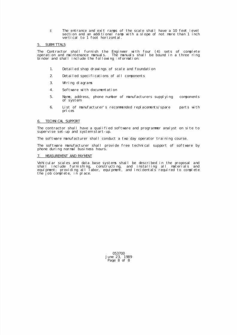
7/25/2019 City Standard Construction Specifications
http://slidepdf.com/reader/full/city-standard-construction-specifications 414/511
053700 J une 23, 1989
Page 8 of 8
The ent r ance and exi t r amps of t he scal e shal l have a 10 f eet l evelsect i on and an addi t i onal r amp wi t h a sl ope of not more than 1 i nchver t i cal t o 1 f oot hor i zont al .
5. SUBMI TTALS
The Cont r act or shal l f urni sh t he Engi neer wi t h f our ( 4) set s of compl eteoperat i on and mai ntenance manual s. The manual s shal l be bound i n a t hree ri ngbi nder and shal l i ncl ude t he f ol l owi ng i nf ormat i on:
1. Detai l ed shop dr awi ngs of scal e and f oundat i on
2. Det ai l ed speci f i cat i ons of al l component s
3. Wi r i ng di agr ams
4. Sof t ware wi t h document at i on
5. Name, address, phone number of manuf act urers suppl yi ng componentsof syst em
6. Li st of manuf act ur er' s r ecommended r epl acement s/ spar e part s wi t hpri ces
6. TECHNI CAL SUPPORT
The contr act or shal l have a qual i f i ed sof t ware and progr ammer anal yst on si t e t osupervi se set - up and syst em st ar t - up.
The sof t ware manuf act urer shal l conduct a t wo day operator t r ai ni ng course.
The sof t ware manuf act urer shal l provi de f r ee t echni cal suppor t of sof t ware byphone duri ng nor mal busi ness hours.
7. MEASUREMENT AND PAYMENT
Vehi cul ar scal es and data base syst ems shal l be descr i bed i n the pr oposal andshal l i ncl ude f ur ni shi ng, constr ucti ng, and i nstal l i ng al l mat er i al s andequi pment ; pr ovi di ng al l l abor, equi pment , and i nci dent al s r equi r ed t o compl et et he j ob compl et e, i n pl ace.
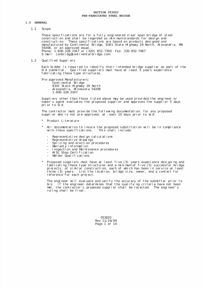
7/25/2019 City Standard Construction Specifications
http://slidepdf.com/reader/full/city-standard-construction-specifications 415/511
053820Rev 11/ 24/ 99Page 1 of 14
SECTION 053820
PRE-FABRICATED STEEL BRIDGE
1.0 GENERAL
1. 1 Scope
These speci f i cat i ons are f or a f ul l y engi neer ed cl ear span br i dge of st eelconst r uct i on and shal l be r egarded as mi ni mumst andards f or desi gn andconst r uct i on. These speci f i cat i ons ar e based on pr oduct s desi gned and
manuf act ured by Cont i nental Br i dge, 8301 Stat e Hi ghway 29 Nor t h, Al exandr i a, M56308, or an approved equal .Phone: 1- 800- 328- 2047 or ( 320) 852- 7500 Fax: 320- 852- 7067E- mai l : conbr i dg@cont i nent al br i dge. com
1. 2 Qual i f i ed Suppl i er s
Each bi dder i s r equi r ed t o i dent i f y thei r i nt ended br i dge suppl i er as par t of tbi d submi t t al . Qual i f i ed suppl i er s must have at l east 5 year s exper i encef abr i cat i ng t hese t ype st r uct ur es.
Pre- appr oved Manuf actur ers:Cont i nent al Br i dge8301 St at e Hi ghway 29 Nor t hAl exandr i a, Mi nnesot a 563081- 800- 328- 2047
Suppl i ers other t han t hose l i st ed above may be used pr ovi ded t he engi neer orowner ' s agent eval uat es t he pr oposed suppl i er and appr oves t he suppl i er 5 dayspr i or t o bi d.
The cont r act or must provi de t he f ol l owi ng documentat i on, f or any proposedsuppl i er who i s not pr e- appr oved, at l east 10 days pr i or t o bi d:
* Pr oduct Li t er at ur e
* Al l document at i on t o i nsur e t he pr oposed subst i t ut i on wi l l be i n compl i ancewi t h t hese speci f i cat i ons. Thi s shal l i ncl ude:
- Repr esent at i ve desi gn cal cul at i ons- Repr esent at i ve dr awi ngs- Spl i ci ng and er ect i on pr ocedur es- Warr ant y i nf ormat i on- I nspect i on and Mai nt enance pr ocedur es- AI SC Shop Cer t i f i cat i on- Wel der Qual i f i cat i ons
* Proposed suppl i ers must have at l east f i ve ( 5) year s exper i ence desi gni ng af abr i cat i ng t hese t ype st r uct ur es and a mi ni mum of f i ve ( 5) successf ul br i dpr oj ect s, of si mi l ar const r uct i on, each of whi ch has been i n ser vi ce at l eat hr ee ( 3) year s. Li st t he l ocat i on, br i dge si ze, owner , and a cont act f orr ef er ence f or each pr oj ect .
The engi neer wi l l eval uate and ver i f y t he accur acy of t he submi t t al pr i or tbi d. I f t he engi neer det er mi nes that t he qual i f yi ng cr i t er i a have not beenmet , t he cont r act or ' s pr oposed suppl i er shal l be r ej ect ed. The engi neer ' srul i ng shal l be f i nal .
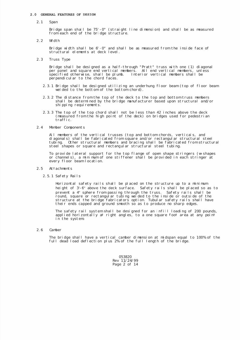
7/25/2019 City Standard Construction Specifications
http://slidepdf.com/reader/full/city-standard-construction-specifications 416/511
053820Rev 11/ 24/ 99Page 2 of 14
2.0 GENERAL FEATURES OF DESIGN
2. 1 Span
Br i dge span shal l be 75' - 0" ( st r ai ght l i ne di mensi on) and shal l be as measuredf r om each end of t he br i dge st r uct ur e.
2. 2 Wi dth
Br i dge wi dt h shal l be 6' - 0" and shal l be as measur ed f r om t he i nsi de f ace of
st r uct ur al el ement s at deck l evel .2. 3 Truss Type
Br i dge shal l be desi gned as a hal f - t hr ough "Pr at t " t r uss wi t h one ( 1) di agonalper panel and square end ver t i cal members. Al l end ver t i cal members , unl essspeci f i ed ot her wi se, shal l be pl umb. I nt er i or ver t i cal member s shal l beper pendi cul ar t o t he chord f aces.
2. 3. 1 Br i dge shal l be desi gned ut i l i zi ng an under hung f l oor beam ( t op of f l oor bewel ded t o t he bott om of t he bot t om chor d) .
2. 3. 2 The di st ance f r omt he t op of t he deck t o t he t op and bot t omt r uss membersshal l be determi ned by t he br i dge manuf actur er based upon st r uct ural and/ orshi ppi ng r equi r ement s.
2. 3. 3 The t op of t he t op chor d shal l not be l ess t han 42 i nches above t he deck( measured f r omt he hi gh poi nt of t he deck) on br i dges used f or pedest r i ant r af f i c.
2. 4 Member Component s
Al l member s of t he ver t i cal t r usses ( t op and bot t om chor ds, ver t i cal s, anddi agonal s) shal l be f abr i cat ed f r om squar e and/ or r ect angul ar st r uct ur al st eelt ubi ng. Ot her st r uct ur al member s and br aci ng shal l be f abr i cat ed f r omst r uct ust eel shapes or squar e and r ect angul ar st r uct ur al st eel t ubi ng.
To provi de l at eral support f or t he t op f l ange of open shape st r i nger s ( w- shapeor channel s) , a mi ni mum of one st i f f ener shal l be pr ovi ded i n each st r i nger at
ever y f l oor beam l ocat i on.
2. 5 At t achment s
2. 5. 1 Saf et y Rai l s
Hor i zont al saf et y rai l s shal l be pl aced on t he str uct ur e up to a mi ni mum
hei ght of 3- 6 above t he deck sur f ace. Saf et y r ai l s shal l be pl aced so as
prevent a 4 spher e f r om passi ng t hr ough t he t r uss. Saf et y r ai l s shal l ber ound, square or r ect angul ar t ubi ng wel ded t o t he i nsi de or out si de of t hest r uct ur e at t he br i dge f abr i cat or s opt i on. Tubul ar saf et y r ai l s shal l havet hei r ends capped and ground smooth so as t o produce no sharp edges.
The saf et y r ai l sys t em shal l be desi gned f or an i nf i l l l oadi ng of 200 pound
appl i ed hori zont al l y at r i ght angl es, t o a one squar e f oot ar ea at any poi ni n t he syst em.
2. 6 Camber
The br i dge shal l have a ver t i cal camber di mensi on at mi dspan equal t o 100% of f ul l dead l oad def l ecti on pl us 2% of t he f ul l l engt h of t he br i dge.
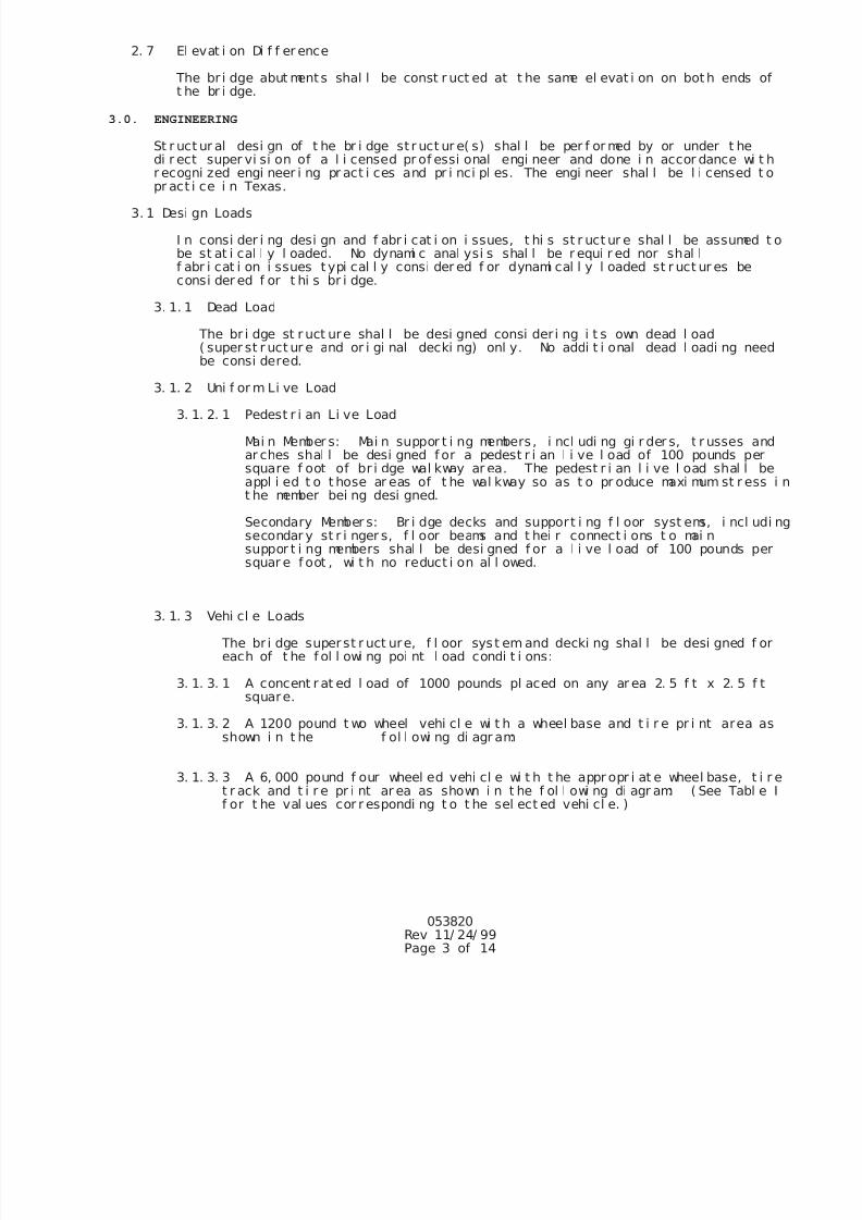
7/25/2019 City Standard Construction Specifications
http://slidepdf.com/reader/full/city-standard-construction-specifications 417/511
053820Rev 11/ 24/ 99Page 3 of 14
2. 7 El evat i on Di f f er ence
The br i dge abut ments shal l be const r uct ed at t he same el evat i on on bot h ends ot he br i dge.
3.0. ENGINEERING
St r uct ur al desi gn of t he br i dge st r uct ur e( s) shal l be per f or med by or under t hedi r ect super vi si on of a l i censed pr of essi onal engi neer and done i n accor dance wi tr ecogni zed engi neer i ng pr act i ces and pr i nci pl es. The engi neer shal l be l i censed t
pr act i ce i n Texas.3. 1 Desi gn Loads
I n consi der i ng desi gn and f abr i cat i on i ssues, t hi s st r uct ur e shal l be assumed tbe st at i cal l y l oaded. No dynami c anal ysi s shal l be r equi r ed nor shal lf abr i cat i on i ssues t ypi cal l y consi der ed f or dynami cal l y l oaded st r uct ur es beconsi der ed f or t hi s br i dge.
3. 1. 1 Dead Load
The br i dge st r uct ure shal l be desi gned consi der i ng i t s own dead l oad( super st r uct ur e and or i gi nal decki ng) onl y. No addi t i onal dead l oadi ng neebe consi dered.
3. 1. 2 Uni f or m Li ve Load
3. 1. 2. 1 Pedest r i an Li ve Load
Mai n Member s: Mai n suppor t i ng members , i ncl udi ng gi r der s, t r usses anar ches shal l be desi gned f or a pedest r i an l i ve l oad of 100 pounds persquare f oot of br i dge wal kway ar ea. The pedest r i an l i ve l oad shal l bappl i ed t o t hose ar eas of t he wal kway so as t o pr oduce maxi mum st r esst he member bei ng desi gned.
Secondary Member s: Br i dge decks and support i ng f l oor syst ems, i ncl udsecondar y st r i nger s, f l oor beams and t hei r connect i ons t o mai nsuppor t i ng members shal l be desi gned f or a l i ve l oad of 100 pounds pesquar e f oot , wi t h no reduct i on al l owed.
3. 1. 3 Vehi cl e Loads
The br i dge superst r uct ure, f l oor sys t em and decki ng shal l be desi gned f oeach of t he f ol l owi ng poi nt l oad condi t i ons:
3. 1. 3. 1 A concent r at ed l oad of 1000 pounds pl aced on any ar ea 2. 5 f t x 2. 5 f tsquare.
3. 1. 3. 2 A 1200 pound t wo wheel vehi cl e wi t h a wheel base and t i r e pr i nt area ashown i n t he f ol l owi ng di agr am:
3. 1. 3. 3 A 6, 000 pound f our wheel ed vehi cl e wi t h t he appr opr i at e wheel base, t it r ack and t i r e pr i nt ar ea as shown i n t he f ol l owi ng di agr am: ( See Tabl ef or t he val ues cor r espondi ng t o t he sel ect ed vehi cl e. )
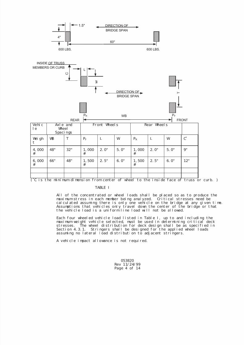
7/25/2019 City Standard Construction Specifications
http://slidepdf.com/reader/full/city-standard-construction-specifications 418/511
1.5"
600 LBS. 600 LBS.
60"
4"
DIRECTION OF
BRIDGE SPAN
INSIDE OF TRUSS
EMBERS OR CURB
PR PF
REAR FRONT
L
053820Rev 11/ 24/ 99Page 4 of 14
Vehi cl e
Axl e andWheel
Spaci ngs
Fr ont Wheel s Rear Wheel s
Wei ght
WB T PF L W PR L W C*
4, 000#
48" 32" 1, 000#
2. 0" 5. 0" 1, 000#
2. 0" 5. 0" 9"
6, 000
#
66" 48" 1, 500
#
2. 5" 6. 0" 1, 500
#
2. 5" 6. 0" 12"
( *C i s t he mi ni mum di mensi on f r om cent er of wheel t o the i nsi de f ace of t r uss or cur b. )
TABLE I
Al l of t he concent r ated or wheel l oads shal l be pl aced so as t o pr oduce themaxi mumst r ess i n each member bei ng anal yzed. Cr i t i cal st r esses need becal cul at ed assumi ng ther e i s onl y one vehi cl e on t he br i dge at any gi ven t iAssumpt i ons t hat vehi cl es onl y t r avel down t he cent er of t he br i dge or t hatt he vehi cl e l oad i s a uni f or m l i ne l oad wi l l not be al l owed.
Each f our wheel ed vehi cl e l oad l i st ed i n Tabl e I , up t o and i ncl udi ng t hemaxi mum wei ght vehi cl e sel ect ed, must be used i n det er mi ni ng cri t i cal deckst r esses. The wheel di st r i but i on f or deck desi gn shal l be as speci f i ed i nSect i on 4. 3. 1. St r i nger s shal l be desi gned f or t he appl i ed wheel l oadsassumi ng no l at er al l oad di st r i but i on t o adj acent st r i nger s.
A vehi cl e i mpact al l owance i s not r equi r ed.
M
WB
DIRECTION OF
BRIDGE SPAN
7/25/2019 City Standard Construction Specifications
http://slidepdf.com/reader/full/city-standard-construction-specifications 419/511
053820Rev 11/ 24/ 99Page 5 of 14
3. 1. 4 Wi nd Load
3. 1. 4. 1 Hor i zont al For ces
The br i dge( s) shal l be desi gned f or a wi nd l oad of 35 pounds per squaf oot on t he f ul l ver t i cal pr oj ect ed ar ea of t he br i dge as i f encl osed
The wi nd l oad shal l be appl i ed hor i zont al l y at r i ght angl es t o t hel ongi t udi nal axi s of t he st r uctur e.
The wi nd l oadi ng shal l be consi dered bot h i n t he desi gn of t he l at eral oad br aci ng syst em and i n t he desi gn of t he t r uss ver t i cal member s,f l oor beams and t hei r connect i ons.
3. 1. 4. 2 Over t ur ni ng For ces
The ef f ect of f or ces t endi ng t o over t urn st r uct ures shal l be cal cul atassumi ng t hat t he wi nd di r ect i on i s at r i ght angl es t o t he l ongi t udi naxi s of t he st r uct ur e. I n addi t i on, an upwar d f or ce shal l be appl i edt he wi ndwar d quar t er poi nt of t he t r ansver se superst r uct ur e wi dt h. Tf orce shal l be 20 pounds per square f oot of deck.
3. 1. 7 Top Chord Rai l i ng Loads
The t op chor d, t r uss ver t i cal s, and f l oor beams shal l be desi gned f or l at er
wi nd l oads ( per sect i on 3. 1. 4. 1) and f or any l oads r equi r ed to pr ovi de topchor d st abi l i t y as out l i ned i n Sect i on 3. 3. 6; however , i n no case shal l t hel oad be l ess t han 50 pounds per l i neal f oot or a 200 pound poi nt l oad,whi chever pr oduces gr eat er st r esses, appl i ed i n any di r ect i on at any poi ntal ong the t op chor d.
3. 1. 9 Load Combi nat i ons
The l oads l i st ed herei n shal l be consi dered t o act i n t he f ol l owi ngcombi nat i ons, whi chever pr oduce the most unf avorabl e ef f ects on t he br i dgesupers t r uct ur e or st r uct ural member concerned.[ DL=Dead Load; LL = Li ve Load; WL = Wi nd Load; VEH = Vehi cl e Load]
DL + LLDL + VEHDL+WLDL+LL+WLDL+VEH+. 3WL
NOTE: Al l owabl e st r esses may be i ncreased 1/ 3 above t he val ues ot her wpr ovi ded when pr oduced by wi nd l oadi ng, act i ng al one or i n combi nat i owi t h t he desi gn dead and l i ve l oads.
I t shal l be t he r esponsi bi l i t y of t he f oundat i on engi neer t o det er mi ne anyaddi t i onal l oads ( i . e. ear t h pr essur e, st r eam f or ce on abut ment s, wi nd l oadother t han t hose appl i ed per pendi cul ar t o t he l ong axi s of t he br i dge, et c.and l oad combi nat i ons r equi r ed f or desi gn of t he abut ment s.
3. 2 Desi gn Li mi t at i ons
3. 2. 1 Def l ect i on
3. 2. 1. 1 Ver t i cal Def l ecti on
The ver t i cal def l ect i on of t he mai n t r usses due t o ser vi ce pedest r i anl i ve l oad shal l not exceed 1/ 400 of t he span.
7/25/2019 City Standard Construction Specifications
http://slidepdf.com/reader/full/city-standard-construction-specifications 420/511
053820Rev 11/ 24/ 99Page 6 of 14
The ver t i cal def l ect i on of cant i l ever spans of t he st r uct ure due t oser vi ce pedest r i an l i ve l oad shal l not exceed 1/ 300 of t he cant i l everarm l engt h.
The def l ect i on of t he f l oor syst em members ( f l oor beams and st r i nger sdue t o ser vi ce pedest r i an l i ve l oad shal l not exceed 1/ 360 of t hei rr espect i ve spans.
The ser vi ce pedest r i an l i ve l oad shal l be 100 PSF f or def l ect i on chec
Def l ecti on l i mi t s due t o occasi onal vehi cul ar t r af f i c shal l not beconsi dered.
3. 2. 1. 2 Hor i zont al Def l ect i on
The hor i zontal def l ect i on of t he st r uct ure due t o l at er al wi nd l oadsshal l not exceed 1/ 500 of t he span under 35 PSF wi nd l oad.
3. 2. 2 Mi ni mum Thi ckness of Met al
The mi ni mum t hi ckness of al l st r uct ural st eel members shal l be 3/ 16" nomi naand be i n accor dance wi t h t he AI SC Manual of St eel Const r uct i ons' "St andardMi l l Pr act i ce Gui del i nes" . For ASTM A500 and ASTM A847 t ubi ng, t he sect i onpr oper t i es used f or desi gn shal l be per t he St eel Tube I nst i t ut e of Nort hAmer i ca' s Hol l ow St r uct ur al Sect i ons "Di mensi ons and Sect i on Proper t i es".
3. 3 Gover ni ng Desi gn Codes / Ref erences
St r uctur al members shal l be desi gned i n accordance wi t h r ecogni zed engi neer i ngpr act i ces and pr i nci pl es as f ol l ows:
3. 3. 1 St r uct ur al St eel Al l owabl e St r esses
Amer i can I nst i t ut e of St eel Const r uct i on ( AI SC) .
St r uct ur al st eel desi gn shal l be i n accor dance wi t h t hose sect i ons of t he"Manual of St eel Const r uct i on: Al l owabl e St r ess Desi gn" r el at ed to desi gn requi r ement sand al l owabl e st r esses.
3. 3. 2 Wel ded Tubul ar Connect i ons
Ameri can Nat i onal St andards I nst i t ut e / Ameri can Wel di ng Soci ety (ANSI / AWS)and t heCanadi an I nst i t ut e of St eel Const r uct i on ( CI SC) .
Al l wel ded t ubul ar connect i ons shal l be checked, when wi t hi n appl i cabl el i mi t s, f or t he l i mi t i ng f ai l ur e modes out l i ned i n t he ANSI / AWS D1. 1Str uct ur al Wel di ng Code or i n accor dance wi t h t he "Desi gn Gui de f or Hol l owSt r uct ur al Sect i on Connect i ons" as publ i shed by t he Canadi an I nst i t ut e ofSt eel Const r uct i on ( CI SC) .When out si de t he “val i di t y range” def i ned i n t hese desi gn gui del i nes, t he
f ol l owi ng l i mi t statesor f ai l ure modes must be checked:
* Chor d f ace pl ast i f i cat i on* Punchi ng shear ( t hrough mai n member f ace)* Mat eri al f ai l ure
- Tensi on f ai l ure of t he web member- Local buckl i ng of a compressi on web member
* Wel d f ai l ur e- Al l owabl e st r ess based on “ef f ect i ve l engt hs”- “Ul t i mat e” capaci t y
* Local buckl i ng of a mai n member f ace
7/25/2019 City Standard Construction Specifications
http://slidepdf.com/reader/full/city-standard-construction-specifications 421/511
053820Rev 11/ 24/ 99Page 7 of 14
* Mai n member f ai l ur e:- Web or si dewal l yi el di ng- Web or si dewal l cr i ppl i ng- Web or si dewal l buckl i ng- Overal l shear f ai l ur e
Al l t ubul ar j oi nt s shal l be pl ai n unst i f f ened j oi nt s ( made wi t hout t he use r ei nf or ci ng pl at es) except as f ol l ows:
* Fl oor beams hung beneat h t he l ower chor d of t he st r uct ure may beconst r uct ed wi t h or wi t hout st i f f ener ( or gusset ) pl at es, as r equi r ed bydesi gn.
* Fl oor beams whi ch f r ame di r ect l y i nt o t he t r uss ver t i cal s (H- Sect i onbr i dges) may be desi gned wi t h or wi t hout end st i f f eni ng pl at es as requi rby desi gn.
* Where chor ds, end f l oor beams and i n hi gh pr of i l es t he t op end st r uts wet o the end ver t i cal s, t he end ver t i cal s ( or connect i ons) may requi r est i f f eni ng t o tr ansf er t he f or ces f r om t hese member s i nt o the end ver t i c
* Tr uss ver t i cal t o chor d connect i ons.
NOTE: The ef f ect s of f abr i cat i on t ol er ances shal l be account ed f or i n t hedesi gn of t he st r uct ur e. Speci al at t ent i on shal l be gi ven t o t he act ual f i
up gap at wel ded t r uss j oi nt s.
NOTE: Open ends of t ubes on pai nted st r uctures shal l be capped and sealwel ded.
3. 3. 3 Bol t ed Spl i ces
Amer i can I nst i t ut e of St eel Const r uct i on ( AI SC) and t he Resear ch Counci l onSt r uct ur alConnect i ons of t he Engi neer i ng Foundat i on ( RCSC) .
Bol t ed spl i ce desi gn shal l be i n accor dance wi t h Sect i on J 3 of t he “Manual St eel Const r uct i on: Al l owabl e St r ess Desi gn”. Spl i ces shal l be desi gned ft he actual l oad i n t he member but i n no case f or l ess t han 50% of t he
ef f ect i ve st r engt h of t he member .
Bol t ed f i el d spl i ces shal l be l ocat ed on t he br i dge so as t o pr oduce ast r uct ur e whi ch can be economi cal l y shi pped and erected. Spl i ces al ong t hel engt h of t he br i dge ( i n chor ds and di agonal s) shal l be pl aced at t heappr oxi mate mi d poi nt of a bay ( between t wo panel poi nt s) . Spl i ces across wi dth of t he br i dge ( i n f l oor beams and wi nd braces) may be used, whennecessar y, t o keep t he over al l st r uct ur e wi dt h wi t hi n r easonabl e l i mi t s f orshi ppi ng.
3. 3. 6 Top Chor d St abi l i t y
St r uct ur al St abi l i t y Resear ch Counci l ( SSRC) , f ormer l y Col umn Resear chCounci l .
The t op chor d of a hal f - t hrough t r uss shal l be consi dered as a col umn wi t hel ast i c l at er al suppor t s at t he panel poi nt s. The cri t i cal buckl i ng f or ce t he col umn, so det ermi ned, shal l exceed t he maxi mumf orce f r omdead l oad anl i ve l oad ( uni f or m or vehi cul ar ) i n any panel of t he top chord by not l ess t han 50 per cent f or par al l el chor d tr uss bri dges 100 per cent f or t i edarch bri dges. The desi gn appr oach t o pr event t op chord buckl i ng shal l be aout l i ned by E. C.Hol t ' s r esearch work i n conj unct i on wi t h t he Col umn Research Counci l on t he
7/25/2019 City Standard Construction Specifications
http://slidepdf.com/reader/full/city-standard-construction-specifications 422/511
st abi l i t y of t he t op chor d of a hal f - t hr ough t r uss. See Appendi x A f or t hecal cul at i on of t he spri ng const ant C and t he det er mi nat i on of an appr opr i atf actor f or out - of - pl ane buckl i ng.
I n addi t i on, f or t he dead l oad pl us vehi cl e l oad combi nat i on, t he spr i ngconst ant “C” f ur ni shed by t he t r ansver se “U- Frames” shal l not be l ess t han r equi r ed as def i ned by:
L
Prequired C c46.1
wher e Pc i s t he maxi mumt op chor d compressi on due to dead l oad pl us t hevehi cl e l oad t i mes t he appr opr i at e saf et y f act or ( 1. 5 f or par al l el chor d t rbr i dges or 2. 0 f or t i ed ar ch t r uss br i dges) and L i s t he l engt h i n i nches oone t r uss panel or bay.
For uni f orml y l oaded br i dges, t he ver t i cal t r uss member s, t he f l oor beams at hei r connect i ons ( t r ansver se f r ames) i n hal f - t hr ough t r uss spans shal l bepr oport i oned t o r esi st a l at er al f orce of not l ess t han 1/ 100k ti mes t he t ochord compr essi ve l oad, but not l ess t han . 004 t i mes t hat t op chord l oad,appl i ed at t he t op chord panel poi nt s of each t r uss. The t op chord l oad idetermi ned by usi ng t he l arger t op chord axi al f orce i n t he members on ei t hsi de of t he "U- f r ame" bei ng anal yzed. For end f r ames, t he same conceptappl i es except t he t r ansver se f or ce i s 1% of t he axi al l oad i n t he end post
member .
For br i dges wi t h vehi cl e l oads, t he l at er al f or ce appl i ed at t he top chor del evat i on f or desi gn of t he t r ansver se f r ames shal l not be l ess t han 1% of t op chor d compr essi on due to dead l oad pl us any vehi cl e l oadi ng.
The bendi ng f or ces i n t he t r ansver se f r ames, as determi ned above, act i nconj unct i on wi t h al l f orces pr oduced by t he act ual br i dge l oads as det er mi nby an appr opr i ate anal ysi s whi ch assumes t hat t he f l oor beams are “f i xed” tt he t r usses at each end.
NOTE: The ef f ect s of t hr ee di mensi onal l oadi ng ( i ncl udi ng “U- f r ame”r equi r ement s) shal l be consi dered i n t he desi gn of t he st r uct ur e. The “U-f r ame” f orces i n hal f - t hr ough spans shal l be added t o t he f orces der i ved f r
a t hr ee di mensi onal anal ysi s of t he br i dge.
4.0 MATERIALS
4. 1 St eel
4. 1. 1 Pai nt ed St eel
Br i dges whi ch are t o be pai nt ed shal l be f abr i cated usi ng ASTM A500 gr ade Ccol d- f ormed wel ded square and rect angul ar t ubi ng ( Fy = 50, 000 psi ) and/ or hst r engt h, l ow al l ow, at mospher i c corr osi on r esi st ant ASTM A847 col d- f ormedwel ded square and r ect angul ar t ubi ng ( Fy = 50, 000 psi ) and/ or ASTM A588, ASA242, ASTM A572, ASTM A 606 ( Fy = 50, 000 psi ) and/ or ASTM A36( Fy = 36, 000 psi ) pl at e and st r uct ur al st eel shapes. Spl i ce pl at es, i fr equi r ed, shal l be ASTM A588.
4. 2 Bol t s
Fi el d spl i ces shal l be f ul l y bol t ed wi t h ASTM A325 type 3 hi gh st r engt h boli n accor dance wi t h t he “Speci f i cat i ons f or St r uct ur al J oi nt s Usi ng ASTM A32or A490 Bol t s”.
4. 3 Decki ng
4. 3. 1 Gr at e decki ng
053820Rev 11/ 24/ 99Page 8 of 14
7/25/2019 City Standard Construction Specifications
http://slidepdf.com/reader/full/city-standard-construction-specifications 423/511
053820Rev 11/ 24/ 99Page 9 of 14
Thi s br i dge shal l be provi ded wi t h a st eel grat e deck.
The grat e decki ng shal l ut i l i ze bear i ng bars spaced 1- 3/ 16 on cent er wi t h
wel ded cr ossbar s at 4 cent er s. The gr at i ng shal l be desi gned t o car r y t hei mposed deck l oads at t he st r i nger or f l oor beam spaci ngs used i n t he br i dgas determi ned by the br i dge desi gner .
Gr at e decki ng shal l be desi gned f or concent r ated l oads as speci f i ed i n Sect3. 1. 3. Gr ate decki ng shal l be desi gned usi ng onl y t he bars engaged by t he
“t i r e pr i nt ar ea” unl ess cr oss bar s sui t abl e f or t r ansver se l oad di st r i but iar e ut i l i zed. Gr at i ng shal l be gal vani zed i n accor dance wi t h ASTM A123 wi t hsmoot h bear i ng bar s.
5.0 WELDING
5. 1 Wel di ng
Wel di ng and wel d pr ocedur e qual i f i cat i on t est s shal l conf or m t o t he pr ovi si onsANSI / AWS D1. 1 “St r uct ur al Wel di ng Code”, 1996 Edi t i on. Fi l l er met al shal l be accor dance wi t h t he appl i cabl e AWS Fi l l er Metal Speci f i cat i on ( i . e. AWS A 5. 28f or t he GMAW Process) . For exposed, bare, unpai nt ed appl i cat i ons of corr osi onr esi st ant st eel s ( i . e. ASTM A588 and A847) , t he f i l l er met al shal l be i naccordance wi t h AWS D1. 1, Sect i on 3. 7. 3.
5. 2 Wel der s
Wel der s shal l be pr oper l y accr edi t ed oper at ors , each of whomshal l submi tcer t i f i cat i on of sat i sf actori l y passi ng AWS st andar d qual i f i cat i on t est s f or aposi t i ons wi t h unl i mi t ed t hi ckness of base metal , have a mi ni mum of 6 mont hsexperi ence i n wel di ng t ubul ar st r uct ur es and have demonst r ated t he abi l i t y t omake uni f orm sound wel ds of t he type requi r ed.
6.0 SUBMITTALS
6. 1 Submi t t al Dr awi ngs
Schemat i c drawi ngs and di agr ams shal l be submi t t ed t o t he cust omer f or t hei rr evi ew af t er r ecei pt of or der . Submi t t al dr awi ngs shal l be uni que dr awi ngs,pr epar ed t o i l l ust r at e t he speci f i c por t i on of t he wor k t o be done. Al l r el atdesi gn i nf ormat i on such as member s i zes, br i dge r eact i ons, and general not esshal l be cl ear l y speci f i ed on t he dr awi ngs. Dr awi ngs shal l have cross r ef er endetai l s and sheet numbers. Al l dr awi ngs shal l be si gned and seal ed by aProf essi onal Engi neer who i s l i censed i n accor dance wi t h Sect i on 3. 0.
6. 2 St r uct ur al Cal cul at i ons
St r uct ur al cal cul at i ons f or t he br i dge super st r uct ur e shal l be submi t t ed by t hbr i dge manuf act ur er and revi ewed by t he appr ovi ng engi neer . Al l cal cul at i onsshal l be si gned and seal ed by a Prof essi onal Engi neer who i s l i censed i n
accor dance wi t h Sect i on 3. 0. The cal cul at i ons shal l i ncl ude al l desi gni nf ormat i on necessary t o det ermi ne t he st r uct ur al adequacy of t he br i dge. Thecal cul at i ons shal l i ncl ude t he f ol l owi ng:
* Al l AI SC al l owabl e st r ess checks f or axi al , bendi ng and shear f or ces i n t hecr i t i cal member of each t r uss member t ype (i . e. t op chord, bot t om chor d, f lbeam, vert i cal , et c. ) .
* Checks f or t he cr i t i cal connect i on f ai l ur e modes f or each t r uss member t ype( i . e. ver t i cal , di agonal , f l oor beam, et c. ) . Speci al at t ent i on shal l be git o al l wel ded t ube on t ube connect i ons ( see sect i on 3. 3. 2 f or desi gn check
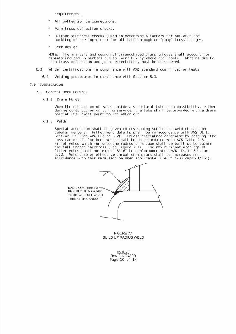
7/25/2019 City Standard Construction Specifications
http://slidepdf.com/reader/full/city-standard-construction-specifications 424/511
r equi r ement s) .
* Al l bol t ed spl i ce connecti ons.
* Mai n t r uss def l ect i on checks.
* U- Frame st i f f ness checks ( used t o det er mi ne K f act ors f or out - of - pl anebuckl i ng of t he t op chor d) f or al l hal f t hr ough or "pony" t r uss br i dges.
* Deck desi gn.
NOTE: The anal ysi s and desi gn of t r i angul at ed t r uss br i dges shal l account f ormoment s i nduced i n member s due t o j oi nt f i xi t y wher e appl i cabl e. Moment s due bot h t r uss def l ect i on and j oi nt eccent r i ci t y must be consi der ed.
6. 3 Wel der cer t i f i cat i ons i n compl i ance wi t h AWS st andar d qual i f i cat i on t est s.
6. 4 Wel di ng pr ocedur es i n compl i ance wi t h Sect i on 5. 1.
7.0 FABRICATION
7. 1 General Requi r ement s
7. 1. 1 Dr ai n Hol es
When t he col l ect i on of wat er i nsi de a st r uct ur al t ube i s a possi bi l i t y, ei tdur i ng const r uct i on or dur i ng ser vi ce, t he t ube shal l be pr ovi ded wi t h a drhol e at i t s l owest poi nt t o l et wat er out .
7. 1. 2 Wel ds
Speci al at t ent i on shal l be gi ven t o devel opi ng suf f i ci ent wel d t hr oat s ont ubul ar member s. Fi l l et wel d det ai l s shal l be i n accor dance wi t h AWS D1. 1,Sect i on 3. 9 ( See AWS Fi gur e 3. 2) . Unl ess det er mi ned other wi se by test i ng, l oss f act or “Z” f or heel wel ds shal l be i n accor dance wi t h AWS Tabl e 2. 8.Fi l l et wel ds whi ch r un ont o t he r adi us of a t ube shal l be bui l t up t o obt ait he f ul l t hr oat t hi ckness ( See Fi gur e 7. 1) . The maxi mum r oot openi ngs off i l l et wel ds shal l not exceed 3/ 16” i n conf ormance wi t h AWS D1. 1, Sect i on5. 22. Wel d si ze or ef f ect i ve t hr oat di mensi ons shal l be i ncr eased i n
accor dance wi t h thi s same sect i on when appl i cabl e ( i . e. f i t - up gaps> 1/ 16”)
RADIUS OF TUBE TO
BE BUILT UP IN ORDER
TO OBTAIN FULL WELD
THROAT THICKNESS
FIGURE 7.1
BUILD UP RADIUS WELD
053820Rev 11/ 24/ 99Page 10 of 14
7/25/2019 City Standard Construction Specifications
http://slidepdf.com/reader/full/city-standard-construction-specifications 425/511
053820Rev 11/ 24/ 99Page 11 of 14
The f abri cat or shal l have ver i f i ed t hat t he t hroat t hi ckness of part i al j oipenet r at i on gr oove wel ds ( pr i mar i l y mat ched edge wel ds or t he f l are- bevel -gr oove wel ds on underhung f l oor beams) shal l be obt ai nabl e wi t h t hei r f i t - uand wel d procedur es. Mat ched edge wel ds shal l be “f l ushed” out when r equit o obt ai n t he f ul l t hr oat or branch member wal l t hi ckness.
For f ul l penet r at i on but t wel ds of t ubul ar member s, t he backi ng mat er i al shbe f abr i cat ed pr i or t o i nst al l at i on i n t he t ube so as t o be cont i nuous ar out he f ul l t ube per i met er , i ncl udi ng cor ner s. Backi ng may be of f our t ypes:
* A “box” wel ded up f r om f our ( 4) pl at es.
* Two “channel ” sect i ons, bent to f i t t he i nsi de r adi us of t he t ube,wel ded t oget her wi t h f ul l penet r at i on wel ds.
* A smal l er t ube sect i on whi ch sl i des i nsi de t he spl i ced t ube.
* A sol i d pl at e cut t o f i t the i nsi de r adi us of the t ube.
Corner s of t he “box” backi ng, made f r omf our pl at es, shal l be wel ded andgr ound t o mat ch t he i nsi de cor ner r adi i of t he chords. The sol i d pl at e optshal l r equi r e a weep hol e ei t her i n t he chord wal l above t he “hi gh si de” oft he pl at e or i n t he pl at e i t sel f . I n al l t ypes of backi ng, t he mi ni mum f i tt ol er ances f or backi ng must be mai nt ai ned at t he cor ner s of t he t ubes as we
as across t he “f l at s”.
7. 1. 3 Seal i ng and Caul ki ng
To prevent r ust r uns on pai nt ed st r uct ures, open ends of al l t ubes shal l becapped and seal wel ded. Wher ever pract i cal , member end connect i ons and st eon st eel cont act sur f aces, such as st r i nger t o f l oor beam connect i ons, shalbe wel ded al l ar ound. Long seams between members or any seam whi ch cannot pr act i cal l y wel ded shal l be caul ked.
7. 1. 4 Pai nt Cl ear ance
To provi de adequat e cl earance f or i ni t i al pai nt i ng and f ut ure r ecoat i ng, a
mi ni mum of a 1- 1/ 2 gap shal l be provi ded bet ween any two opposi ng pai ntedsur f aces. I f t hi s gap cannot be mai nt ai ned, member si zes shal l be i ncr easeor f i l l er pl at es added t o br i ng t he opposi ng sur f aces i n cont act f or sealwel di ng.
7. 2 Qual i t y Cert i f i cat i on
Br i dge( s) shal l be f abr i cat ed by a f abr i cat or who i s cur r ent l y cer t i f i ed by t hAmer i can I nst i t ut e of St eel Const r uct i on t o have t he per sonnel , or gani zat i on,exper i ence, capabi l i t y, and commi t ment t o pr oduce f abr i cat ed st r uct ur al st eel ft he cat egor y “Si mpl e St eel Br i dges” as set f or t h i n t he AI SC Cer t i f i cat i onPr ogr am. Qual i t y cont r ol shal l be i n accor dance wi t h pr ocedur es out l i ned f orAI SC cert i f i cat i on.
8.0 FINISHING
8. 1 Bl ast Cl eani ng
8. 1. 1 Pai nt ed St eel
Al l exposed sur f aces of st eel t o be pai nt ed shal l be bl ast cl eaned i naccor dance wi t h the appr opr i at e sect i on of t he St eel St r uct ur es Pai nt i ngCounci l Surf ace Preparat i on Speci f i cat i ons as recommended by the pai ntmanuf act urer .
7/25/2019 City Standard Construction Specifications
http://slidepdf.com/reader/full/city-standard-construction-specifications 426/511
053820Rev 11/ 24/ 99Page 12 of 14
8. 2 Pai nt i ng
Al l exposed st eel sur f aces shal l r ecei ve shop appl i ed pr i mer and f i ni sh coat s. The pai nt sys t em shal l consi st of one of t he f ol l owi ng:
* Pr i mer: Carbol i ne 893 Epoxy Pr i mer Top Coat : Carbot hane 133 HB Pol yuret haneAs manuf act ured by The Carbol i ne Company, 350 Hanl ey I ndust r i al Cour t ,St . Loui s, MO 63144- 1599 314- 644- 1000.
* Pr i mer: Pi t t Guar d Al l Weat her DTR Expoxy Pr i mer Top Coat : Pi t t hane Acr yl i c- Al i phat i c Ur et hane EnamalAs manuf act ur ed by PPG Ar chi t ect ur al Fi ni shes, I nc. , One PPG Pl ace,Pi t t sbur gh, PA 15272 800- 441- 9695.
* Pr i mer : Epoxi de 52 Epoxy Pr i mer Top Coat : Acr ol on 218 HS Acr yl i c Pol yuret haneAs manuf act ured by Sherwi n Wi l l i ams, PO Box 7570,Hi ghl ands Ranch, CO 80126- 9170 800- 336- 1110.
Each syst em shal l consi st of a mi ni mum of one pr i mer and one top coat appl i ed accor dance wi t h and t o t he mi ni mum dr y f i l m t hi ckness l i st ed i n t he pai ntmanuf acturer ’ s r ecommendat i ons. The t op coat pai nt col or shal l be (specifier t
input color choice here).
NOTE: Unl ess speci f i ed ot her wi se, connect i on f ayi ng sur f aces and t he i nt er i orsur f aces of al l st r uct ur al t ubi ng shal l not be coat ed.
8. 2. 3 Touch- up Pai nt
A nomi nal quant i t y of t ouch- up pai nt wi l l be pr ovi ded t o repai r mar r edsur f aces. Touch- up pai nt i ng i ncl udes any and al l pai nt i ng r equi r ed af t er tst r ucture r eaches the si t e, and i s the r esponsi bi l i t y of ot her s. Thi spai nt i ng shal l i ncl ude, but not be l i mi t ed t o, t he f ol l owi ng ar eas:
1. Any areas damaged due t o shi ppi ng, handl i ng, and erect i on of t he br i dand components.
2. Bol t heads and exposed area of bol t s and nut s as appl i cabl e.
3. Non- gal vani zed at t achment s or anchor bol t s i f not made of cor r osi onres i stant steel .
4. I f appl i cabl e, smal l ar eas ( 0 t o 2 each si de) ar ound bol t ed f i el dspl i ces, desi gned as “sl i p cri t i cal ”, wher e one or al l pai nt coat s mabe r equi r ed t o be l ef t of f t he f ayi ng sur f aces.
8. 2. 4 Pai nt er Qual i f i cat i ons
Al l pai nt er s shal l be cer t i f i ed by t he appr opr i at e pai nt manuf act ur er f orpr oper handl i ng, mi xi ng, t hi nni ng ( i f r equi r ed) and appl i cat i on of t he pai nsystem i n accor dance wi t h t he manuf act ur er ’ s i nst r uct i ons. The pai nt er s shal so be cer t i f i ed by t he Depar t ment of Transpor t at i on i n the st at e i n whi cht he br i dge i s manuf actur ed.
9.0 DELIVERY AND ERECTION
Del i ver y i s made to a l ocat i on near est t he si t e whi ch i s easi l y accessi bl e t o norover - t he- r oad t r act or / t r ai l er equi pment . Al l t r ucks del i ver i ng br i dge mat er i al swi l l need t o be unl oaded at t he t i me of ar r i val .
7/25/2019 City Standard Construction Specifications
http://slidepdf.com/reader/full/city-standard-construction-specifications 427/511
053820Rev 11/ 24/ 99Page 13 of 14
The manuf act urer wi l l provi de detai l ed, wr i t t en i nst r uct i on i n t he proper l i f t i ngpr ocedures and spl i ci ng pr ocedur es ( i f r equi r ed) . The method and sequence ofer ecti on shal l be t he r esponsi bi l i t y of Cont r actor.
The br i dge manuf act urer shal l provi de wr i t t en i nspect i on and mai nt enance procedurt o be f ol l owed by t he br i dge owner .
10.0 BEARINGS
10. 1 Bear i ng Devi ces
Br i dge bear i ngs shal l consi st of a st eel set t i ng or sl i de pl at e pl aced on t heabut ment or gr out pad. The br i dge bear i ng pl ate whi ch i s wel ded t o the br i dgest r uct ur e shal l bear on t hi s set t i ng pl at e. One end of t he br i dge wi l l be f i xby f ul l y t i ght eni ng t he nut s on t he anchor bol t s at t hat end. The opposi t e enwi l l have f i nger t i ght onl y nut s t o al l ow movement under t her mal expansi on orcont r act i on.
The br i dge bear i ngs shal l si t i n a r ecessed pocket on t he concr et e abut ment .Mi ni mum 28- day st r engt h f or t he abut ment concr ete shal l be 3000 PSI . The bearseat shal l be a mi ni mum of 16" wi de. The st ep hei ght ( f r om bot t om of bear i ng t op- of - deck) shal l be deter mi ned by t he br i dge manuf act ur er .
Br i dges i n excess of 100 f eet i n l engt h or br i dges wi t h dead l oad react i ons of15, 000 pounds or more ( at each beari ng l ocat i on) shal l have t ef l on on t ef l on ost ai nl ess st eel on t ef l on sl i de bear i ngs pl aced bet ween t he br i dge bear i ng pl atand t he set t i ng pl at e. The t op sl i de pl at e shal l be l ar ge enough t o cover t hel ower t ef l on sl i de sur f ace at both t emper at ur e ext r emes.
11.0 FOUNDATIONS
Unl ess speci f i ed ot her wi se, t he br i dge manuf act ur er shal l det ermi ne t he number,di amet er , mi ni mum gr ade and f i ni sh of al l anchor bol t s. The anchor bol t s shal l bdesi gned t o r esi st al l hor i zont al and upl i f t f or ces t o be t r ansf er r ed by thesuper st r uct ur e t o t he support i ng f oundat i ons. Engi neer i ng desi gn of t he br i dgesuppor t i ng f oundat i ons ( abut ment , pi er , br acket and/ or f oot i ngs) , i ncl udi ng desi gof anchor bol t embedment s, shal l be t he r esponsi bi l i t y of t he f oundat i on engi neer
The cont r act or shal l provi de al l mat er i al s f or ( i ncl udi ng anchor bol t s) andconst r uct i on of t he br i dge suppor t i ng f oundat i ons. The cont r act or shal l i nst al l anchor bol t s i n accor dance wi t h t he manuf actur er ' s anchor bol t spaci ng di mensi ons
I nf or mat i on as t o br i dge suppor t r eact i ons and anchor bol t l ocat i ons wi l l bef ur ni shed by the br i dge manuf act ur er af t er r ecei pt of order and af t er t he br i dgedesi gn i s compl et e.
12.0 PAYMENT
A par t i al payment or "deposi t " f or t he pr ef abr i cat ed br i dge shal l be made upon orand st orage as r equi r ed by t he terms of t he manuf actur er.
13.0 WARRANTY
The br i dge manuf act urer shal l war r ant t hei r st eel t r uss st r uct ure( s) t o be f r ee ofdesi gn, mat eri al and workmanshi p def ect s f or a per i od of f i f t een year s f r omt he dof del i ver y. Thi s war r ant y does not i ncl ude decki ng, r ai l i ng at t achment s, on anyot her i t ems not par t of t he st eel t r uss st r uct ur e.
Thi s warr ant y shal l not cover def ect s i n t he br i dge caused by abuse, mi suse,over l oadi ng, acci dent , i mpr oper mai nt enance, al t er at i on or any ot her cause not t hr esul t of def ect i ve mat er i al s or wor kmanshi p. Thi s war r ant y shal l be voi d unl esowner ’ s r ecords, whi ch wi l l i ndi cat e compl i ance wi t h t he mi ni mum gui del i nes
7/25/2019 City Standard Construction Specifications
http://slidepdf.com/reader/full/city-standard-construction-specifications 428/511
053820Rev 11/ 24/ 99Page 14 of 14
speci f i ed i n the I nspect i on and Mai nt enance Pr ocedur es, can be suppl i ed.
Repai r or r epl acement s shal l be the excl usi ve r emedy f or def ect s under t hi swarr ant y. The br i dge manuf act ur er shal l not be l i abl e f or any consequent i al ori nci dent al damages f or br each of any expr ess or i mpl i ed war r ant y on t hei rst r uct ur es.
14.0 APPROVAL CHECKLIST
The f ol l owi ng checkl i st wi l l be used i n t he eval uat i on of al l submi t t al s t o assure compl i ance wi t h t he
Speci al Speci f i cat i ons f or Pref abr i cat ed Br i dge. Thi s checkl i st i s consi der ed t he mi ni mum accept abl er equi r ement s for compl i ance wi t h t hese speci f i cat i ons. Any devi ati ons fr om t hi s checkl i st shal l beconsi dered grounds f or r ej ect i on of t he submi t t al . Any costs associ ated wi t h del ays caused by t her ej ect i on of t he submi t t al , due to non- compl i ance wi t h t hi s checkl i st , shal l be ful l y bor ne by thecont r act or and br i dge suppl i er.
SUBMITTAL DRAWINGS
Data Required to be Shown:
Wel d Fai l ur e Checks ( Ul t i mate)
Br i dge El evat i on Local Buckl i ng of t he Mai n Member Face Checks
Br i dge Cr oss Secti on Mai n Member Yi el di ng Fai l ure Checks
Al l Member Si zes Mai n Member Cr i ppl i ng Fai l ure Checks
Al l Vert i cal Truss Member s are Squar e Mai n Member Buckl i ng Fai l ure Checks
or Rect angul ar Tubi ng Mai n Member Shear Fai l ure Checks
Br i dge React i ons Al l Bol t ed Spl i ce Checks ( i f appl i cabl e)
General Notes I ndi cat i ng Mai n Truss Def l ect i on Checks
AI SC St r ess Conf ormance Decki ng Materi al Checks Mat eri al Speci f i cat i ons t o be Fol l owed “U- Frame” St i f f ness Checks ( i f “Pony” Truss)
Desi gn Li ve Load nter i or and End Por t al Desi gn Checks( i f “Box” Tru
Desi gn Vehi cl e Load ( I f Appl i cabl e) et ermi nat i oN of Top Chor d K Fact or Based on“U- Fr a
Desi gn Wi nd Load St i f f ness ( i f “Pony” Truss)
Ot her Speci f i ed Desi gn Loads Consi der at i on of I ndi vi dual Member Moment s Due t o
Wel di ng Pr ocess t r uss Def l ecti on, J oi nt Fi xi t y and J oi nt Eccent ri ci
Bl ast Cl eani ng
Pai nt Syst em t o be Used ( I f Appl i cabl e) FABRICATION SUBMITTALS
Pai nt Col or Chart ( I f Appl i cabl e) Data Required to be Shown:
Det ai l ed Bol t ed Spl i ces ( I f Appl i cabl e)
Bol t ed Spl i ce Locat i on ( I f appl i cabl e) ** Wri tt en I nstal l at i on I nstr uct i ons
Si gnat ure and Seal of Prof essi onal Engi neer, ** Wri t t en Spl i ci ng I nstr ucti ons
l i censed i n Accor dance wi t h Sect i on 3. 0 ** Wr i t t en Mai ntenance & I nspect i on I nst r uct i
** Wel der Cert i f i cat i ons
DESIGN CALCULATIONS ** Wel di ng ProceduresData Required to be Shown: Mat er i al Cert i f i cat i ons ( i f appl i cabl e)
Str uctural Steel ( i f appl i cabl e)
Data I nput f or 3- D Anal ysi s of Br i dge Decki ng ( i f appl i cabl e)
J oi nt Coor di nat es & Member I nci dences Str uctural Bol ts ( i f appl i cabl e)
J oi nt and Member Loads ** Qual i t y Cont r ol Sect i on of AI SC
Member Pr opert i es Cer t i f i cat i on Manual ( i f appl i cabl e)
Load Combi nat i ons ** Pai nter Cert i f i cat i ons ( i f appl i cabl e)
AI SC Member St r ess Checks f or Each Member Type Wel d Test i ng Report s ( i f appl i cabl e)
Cr i t i cal Connect i on Fai l ure Mode Checks For EachMember Type
Chor d Face Pl ast i f i cat i on Checks ** NOTE: These i t ems are r equi r ed t o be submi t t ed
Punchi ng Shear Checks al ong wi t h Submi t t al Dr awi ngs and Desi gn Cal cul ati ons.
Mater i al Fai l ure Checks ( Truss Webs) Those Fabri cat i on Submi t t al I t ems not marked are
Wel d Fai l ure Checks ( Ef f ecti ve Length) t o be submi t t ed pri or t o shi pment of t he bri dge.
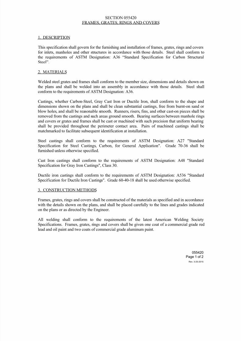
7/25/2019 City Standard Construction Specifications
http://slidepdf.com/reader/full/city-standard-construction-specifications 429/511
SECTION 055420
FRAMES, GRATES, RINGS AND COVERS
1. DESCRIPTION
This specification shall govern for the furnishing and installation of frames, grates, rings and covers
for inlets, manholes and other structures in accordance with those details. Steel shall conform tothe requirements of ASTM Designation: A36 “Standard Specification for Carbon Structural
Steel”.
2. MATERIALS
Welded steel grates and frames shall conform to the member size, dimensions and details shown on
the plans and shall be welded into an assembly in accordance with those details. Steel shall
conform to the requirements of ASTM Designation: A36.
Castings, whether Carbon-Steel, Gray Cast Iron or Ductile Iron, shall conform to the shape and
dimensions shown on the plans and shall be clean substantial castings, free from burnt-on sand or blow holes, and shall be reasonable smooth. Runners, risers, fins, and other cast-on pieces shall be
removed from the castings and such areas ground smooth. Bearing surfaces between manhole rings
and covers or grates and frames shall be cast or machined with such precision that uniform bearing
shall be provided throughout the perimeter contact area. Pairs of machined castings shall be
matchmarked to facilitate subsequent identification at installation.
Steel castings shall conform to the requirements of ASTM Designation: A27 "Standard
Specification for Steel Castings, Carbon, for General Application". Grade 70-36 shall be
furnished unless otherwise specified.
Cast Iron castings shall conform to the requirements of ASTM Designation: A48 "StandardSpecification for Gray Iron Castings", Class 30.
Ductile iron castings shall conform to the requirements of ASTM Designation: A536 "Standard
Specification for Ductile Iron Castings". Grade 60-40-18 shall be used otherwise specified.
3. CONSTRUCTION METHODS
Frames, grates, rings and covers shall be constructed of the materials as specified and in accordance
with the details shown on the plans, and shall be placed carefully to the lines and grades indicated
on the plans or as directed by the Engineer.
All welding shall conform to the requirements of the latest American Welding Society
Specifications. Frames, grates, rings and covers shall be given one coat of a commercial grade red
lead and oil paint and two coats of commercial grade aluminum paint.
055420
Page 1 of 2
Rev. 3-25-2015
7/25/2019 City Standard Construction Specifications
http://slidepdf.com/reader/full/city-standard-construction-specifications 430/511
Painting on gray iron castings will not be required, except when used in conjunction with structural
steel shapes.
Commercial grade galvanized bolts and nuts shall be used. The zinc coating shall be uniform in
thickness, smooth and continuous.
4. MEASUREMENT AND PAYMENT
Unless otherwise specified on the Bid Form, frames, grates, rings and covers will not be measured
for payment, but shall be considered subsidiary to other bid items.
055420
Page 2 of 2
Rev. 3-25-2015
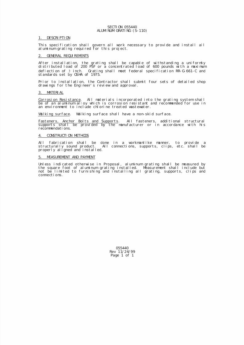
7/25/2019 City Standard Construction Specifications
http://slidepdf.com/reader/full/city-standard-construction-specifications 431/511
055440Rev 11/ 24/ 99Page 1 of 1
SECTI ON 055440ALUMI NUM GRATI NG ( S- 110)
1. DESCRI PTI ON
Thi s speci f i cat i on shal l govern al l work necessary t o provi de and i nst al l al lal umi num gr at i ng r equi r ed f or t hi s pr oj ect.
2. GENERAL REQUI REMENTS
Af t er i nst al l at i on, t he gr at i ng shal l be capabl e of wi t hst andi ng a uni f or ml ydi st r i buted l oad of 200 PSF or a concent r ated l oad of 600 pounds wi t h a maxi mum
def l ecti on of i nch. Gr at i ng shal l meet f eder al speci f i cat i on RR- G- 661- C andst andar ds set by OSHA of 1975.
Pr i or t o i nst al l at i on, t he Cont r actor shal l submi t f our set s of det ai l ed shopdr awi ngs f or t he Engi neer' s r evi ew and appr oval .
3. MATERI AL
Cor r osi on Resi st ance. Al l mat er i al s i ncor por at ed i nt o t he gr at i ng syst em shal lbe of an al umi num al l oy whi ch i s cor r osi on r esi st ant and recommended f or use i nan envi r onment t o i ncl ude chl ori ne tr eat ed wast ewat er .
Wal ki ng sur f ace. Wal ki ng sur f ace shal l have a non- ski d surf ace.
Fast ener s, Anchor Bol t s and Suppor t s. Al l f ast ener s, addi t i onal st r uct ur alsupport s shal l be pr ovi ded by t he manuf act ur er or i n accor dance wi t h hi sr ecommendat i ons.
4. CONSTRUCTI ON METHODS
Al l f abr i cat i on shal l be done i n a workmanl i ke manner, t o pr ovi de ast r uctural l y sound pr oduct. Al l connecti ons, suppor t s, cl i ps, et c. shal l bepr oper l y al i gned and i nst al l ed.
5. MEASUREMENT AND PAYMENT
Unl ess i ndi cat ed otherwi se i n Proposal , al umi num gr at i ng shal l be measured byt he squar e f oot of al umi num gr at i ng i nst al l ed. Measur ement shal l i ncl ude butnot be l i mi t ed t o f ur ni shi ng and i nst al l i ng al l gr at i ng, suppor t s, cl i ps andconnect i ons.
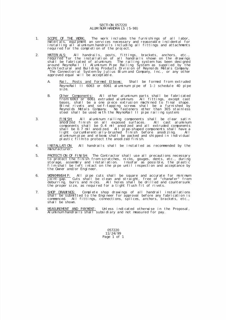
7/25/2019 City Standard Construction Specifications
http://slidepdf.com/reader/full/city-standard-construction-specifications 432/511
05722011/ 24/ 99
Page 1 of 1
SECTI ON 057220 ALUMI NUM HANDRAI LS ( S- 98)
1. SCOPE OF THE WORK: The wor k i ncl udes t he f ur ni shi ngs of al l l abor ,mat eri al s, equi pment an servi ces necessary and r easonabl e i nci dent al f ori nst al l i ng al l al umi num handr ai l s i ncl udi ng al l f i t t i ngs and at t achment sr equi r ed f or t he compl et i on of t he pr oj ect .
2. MATERI ALS: Al l handrai l s , posts , f i t t i ngs, brackets , anchors, etc . ,r equi r ed f or t he i nst al l at i on of al l handr ai l s shown on t he dr awi ngsshal l be f abr i cat ed of al umi num. The r ai l i ng syst em has been desi gnedar ound ReynoRai l I I Al umi num Pi pe Rai l i ng System as suppl i ed by t heAr chi t ect ur al and Bui l di ng Product s Di vi si on of Reynol ds Metal s Company. The Connect or i al Syst em by J ul i us Bl um and Company, I nc. , or any ot herappr oved equal wi l l be accept abl e.
A. Rai l , Posts and For med El bows: Shal l be f ormed f r om ext r uded
ReynoRai l I I 6063 or 6061 al umi num pi pe of 1- schedul e 40 pi pesi ze.
B. Ot her Component s: Al l ot her al umi num par t s shal l be f abr i cat edf r om 6063 or 6061 extr uded al umi num. Al l f i t t i ngs, except castbases, shal l be a one pi ece ext r usi on machi ned t o f i nal shape.Bl i nd r i vet s and sel f - t appi ng screws shal l be a f ur ni shed byReynol ds Metal s Company. No f ast eners ot her t han 305 st ai nl essst eel shal l be used wi t h t he ReynoRai l I I pi pe r ai l i ng syst em.
3. FI NI SH: Al l al umi num r ai l i ng component s shal l be cl ear sat i nanodi zed f i ni sh on al l exposed sur f aces. Al l cast al umi numcomponents shal l be 0. 4 mi l anodi zed and al l extr uded componentsshal l be 0. 7 mi l anodi zed. Al l pi pe- shaped component s shal l have al i ght cur cumf er ent i al l y- br ushed f i ni sh bef or e anodi zi ng. Al lal umi num pi pe and el bows shal l be packed and shi pped i n i ndi vi dualpl asti c f i l m t o protect t he anodi zed f i ni sh.
4. I NSTALLATI ON: Al l handr ai l s shal l be i nst al l ed as r ecommended by t hemanuf act urer.
5. PROTECTI ON OF FI NI SH: The Cont r act or shal l use al l pr ecaut i ons necessar yt o pr ot ect t he f i ni sh f r om scr at ches, ni cks, gouges, dent s, et c. , dur i ngst or age, assembl y and i nst al l at i on. I nsof ar as possi bl e, t he pl ast i cf i l m shal l be l ef t i nt act on t he pi pe unt i l i nspect i on and accept ance byt he Owner and/ or Engi neer.
6. WORKMANSHI P: Al l pi pe cut s shal l be squar e and accur at e f or mi ni mum j oi nt - gap. Cuts shal l be cl ean and st r ai ght , f r ee of "chanaf er" f r omdebur r i ng, bur r s and ni cks. Al l hol es shal l be dr i l l ed and count er sunkt he proper si ze, as requi r ed f or a t i ght f l ush f i t of r i vet s.
7. SHOP DRAWI NGS: Compl et e shop dr awi ngs of al l handr ai l i nst al l at i onsshal l be submi t t ed t o t he Engi neer f or appr oval bef ore any f abr i cat i on i scommenced. Al l f i t t i ngs, connect i ons, spl i ces, anchor s, bracket s, et c. ,
shal l be shown.
8. MEASUREMENT AND PAYMENT: Unl ess i ndi cat ed otherwi se i n t he Proposal ,Al umi num handr ai l s shal l subsi di ary and not measured f or pay.
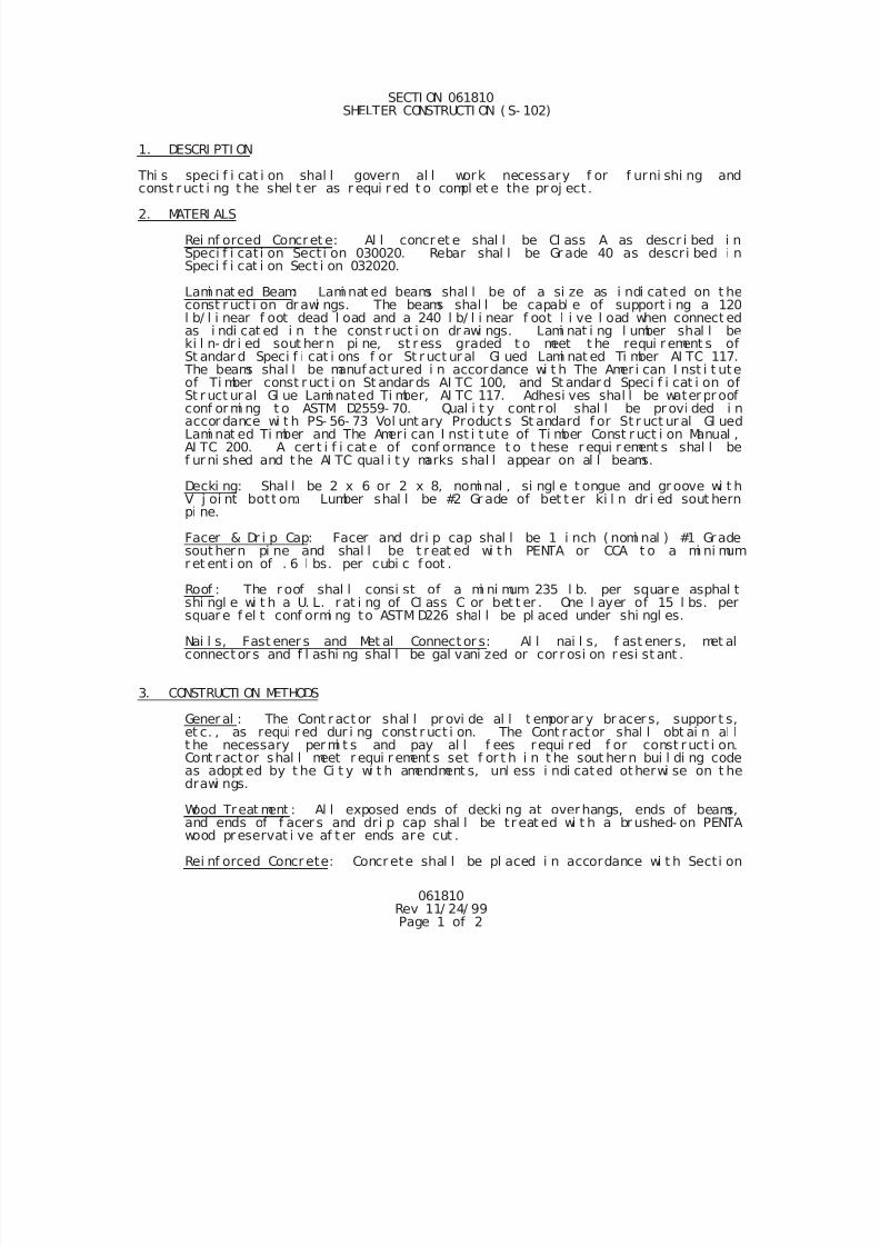
7/25/2019 City Standard Construction Specifications
http://slidepdf.com/reader/full/city-standard-construction-specifications 433/511
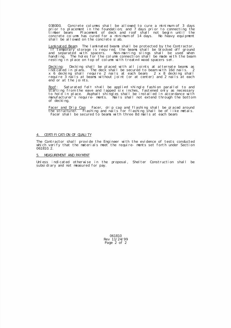
7/25/2019 City Standard Construction Specifications
http://slidepdf.com/reader/full/city-standard-construction-specifications 434/511
061810Rev 11/ 24/ 99Page 2 of 2
038000. Concr ete col umns shal l be al l owed t o cure a mi ni mum of 3 dayspr i or t o pl acement i n t he f oundat i on; and 7 days pr i or t o connect i ng thet i mber beam. Pl acement of deck and r oof shal l not begi n unt i l t heconcrete col umn has cured f or a mi ni mum of 14 days. No heavy equi pmentshal l be al l owed on t he concret e sl ab.
Lami nat ed Beam: The l ami nat ed beams shal l be protected by t he Cont r actor .I f t emporary st orage i s r equi r ed, t he beams shal l be bl ocked of f gr ound
and separated wi t h spacers. Non- marr i ng sl i ngs shal l be used whenhandl i ng. The hol es f or t he col umn connect i on shal l be made wi t h t he beamr est i ng i n pl ace on t op of col umn wi t h t r eat ed wood spacers set .
Decki ng: Decki ng shal l be pl aced wi t h al l j oi nt s at al t ernat e beams asi ndi cat ed i n pl ans. The deck shal l be secur ed t o beam wi t h 16d nai l s. 2x 6 decki ng shal l r equi r e 2 nai l s at each beam. 2 x 8 decki ng shal lr equi r e 3 nai l s at beams wi t hout j oi nt ( or at cent er ) and 2 nai l s at eachend or at t he j oi nt s.
Roof : Sat ur at ed f el t shal l be appl i ed shi ngl e f ashi on par al l el t o andst ar t i ng f r om t he eave and l apped si x i nches, f ast ened onl y as necessaryt o hol d i n pl ace. Asphal t shi ngl es shal l be i nst al l ed i n accor dance wi t hmanuf act ur er ' s requi r e- ment s. Nai l s shal l not extend t hrough t he bott omof decki ng.
Facer and Dr i p Cap: Facer, dr i p cap and f l ashi ng shal l be pl aced aroundt he st r ucturer. Fl ashi ng and nai l s f or f l ashi ng shal l be of l i ke met al s.Facer shal l be secured t o beams wi t h three 8d mai l s at each beam.
4. CERTI FI CATI ON OF QUALI TY
The Cont r act or shal l provi de t he Engi neer wi t h t he evi dence of t est s conduct edwhi ch ver i f y that t he mat er i al s meet t he requi r e- ment s set f ort h under Sect i on061810. 2.
5. MEASUREMENT AND PAYMENT
Unl ess i ndi cat ed ot her wi se i n t he pr oposal , Shel t er Const r uct i on shal l besubsi di ary and not measured f or pay.
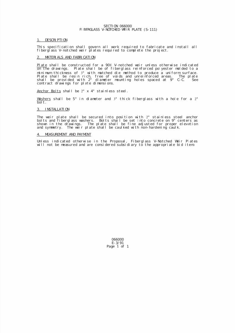
7/25/2019 City Standard Construction Specifications
http://slidepdf.com/reader/full/city-standard-construction-specifications 435/511
066000E- 3/ 91
Page 1 of 1
SECTI ON 066000 FI BERGLASS V- NOTCHED WEI R PLATE (S- 111)
1. DESCRI PTI ON
Thi s speci f i cat i on shal l govern al l work r equi r ed t o f abr i cat e and i nst al l al lf i bergl ass V- not ched wei r pl at es r equi r ed to compl et e the proj ect .
2. MATERI ALS AND FABRI CATI ON
Pl at e shal l be const r ucted f or a 90 V- notched wei r unl ess ot her wi se i ndi cat edon t he dr awi ngs. Pl at e shal l be of f i ber gl ass rei nf or ced pol yest er mol ded t o a
mi ni mum t hi ckness of " wi t h matched di e method t o pr oduce a uni f orm surf ace.Pl at e shal l be resi n r i ch, f r ee of voi ds and unrei nf or ced ar eas. The pl at eshal l be provi ded wi t h 2" di amet er mount i ng hol es spaced at 9" C- C. Seecont ract dr awi ngs f or pl at e di mensi ons.
Anchor Bol t s shal l be " x 4" st ai nl ess st eel .
Washers shal l be 5" i n di ameter and " t hi ck f i ber gl ass wi t h a hol e f or a "bol t .
3. I NSTALLATI ON
The wei r pl ate shal l be secured i nto posi t i on wi t h " st ai nl ess steel anchorbol t s and f i ber gl ass washer s. Bol t s shal l be set i nt o concret e on 9" cent er s asshown i n t he dr awi ngs. The pl at e shal l be f i ne adj ust ed f or pr oper el evat i onand symmetr y. The wei r pl ate shal l be caul ked wi t h non- hardeni ng caul k.
4. MEASUREMENT AND PAYMENT
Unl ess i ndi cat ed other wi se i n t he Proposal , Fi ber gl ass V- Notched Wei r Pl at eswi l l not be measured and are consi der ed subsi di ary t o t he appr opr i at e bi d i t em.
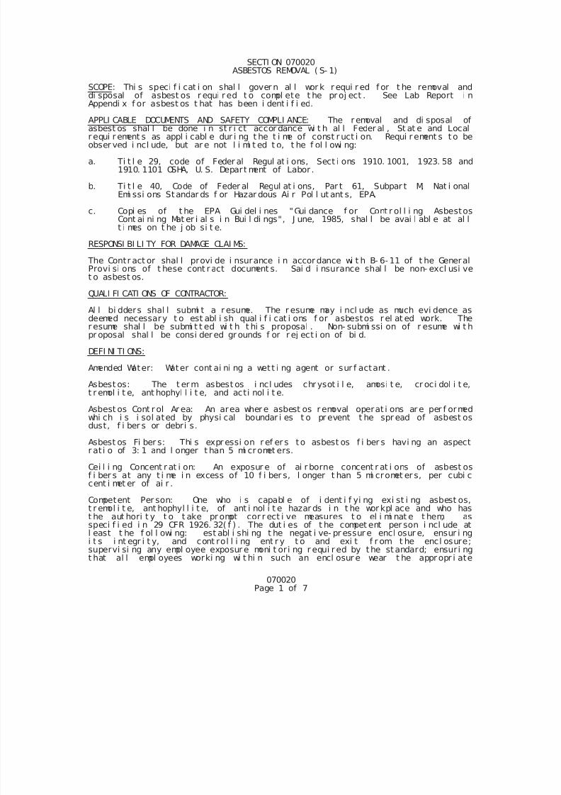
7/25/2019 City Standard Construction Specifications
http://slidepdf.com/reader/full/city-standard-construction-specifications 436/511
070020Page 1 of 7
SECTI ON 070020 ASBESTOS REMOVAL ( S- 1)
SCOPE: Thi s speci f i cat i on shal l gover n al l wor k r equi r ed f or t he removal anddi sposal of asbest os r equi r ed t o compl ete t he pr oj ect . See Lab Report i nAppendi x f or asbest os t hat has been i dent i f i ed.
APPLI CABLE DOCUMENTS AND SAFETY COMPLI ANCE: The r emoval and di sposal ofasbest os shal l be done i n st r i ct accor dance wi t h al l Feder al , St at e and Localr equi r ement s as appl i cabl e dur i ng t he t i me of const r uct i on. Requi r ement s t o beobser ved i ncl ude, but ar e not l i mi t ed t o, t he f ol l owi ng:
a. Ti t l e 29, code of Feder al Regul at i ons, Sect i ons 1910. 1001, 1923. 58 and1910. 1101 OSHA, U. S. Depart ment of Labor .
b. Ti t l e 40, Code of Feder al Regul at i ons, Par t 61, Subpar t M, Nat i onalEmi ssi ons Standar ds f or Hazar dous Ai r Pol l ut ant s, EPA.
c. Copi es of t he EPA Gui del i nes "Gui dance f or Cont r ol l i ng AsbestosCont ai ni ng Mat er i al s i n Bui l di ngs", J une, 1985, shal l be avai l abl e at al lt i mes on t he j ob si t e.
RESPONSI BI LI TY FOR DAMAGE CLAI MS:
The Contr act or shal l provi de i nsurance i n accor dance wi t h B- 6- 11 of t he GeneralProvi si ons of t hese cont r act document s. Sai d i nsurance shal l be non- excl usi vet o asbest os.
QUALI FI CATI ONS OF CONTRACTOR:
Al l bi dders shal l submi t a r esume. The r esume may i ncl ude as much evi dence asdeemed necessary t o est abl i sh qual i f i cat i ons f or asbestos r el at ed work. Ther esume shal l be submi t t ed wi t h t hi s proposal . Non- submi ssi on of r esume wi t hpr oposal shal l be consi der ed gr ounds f or r ej ect i on of bi d.
DEFI NI TI ONS:
Amended Water: Water cont ai ni ng a wett i ng agent or sur f actant .
Asbest os: The t er m asbest os i ncl udes chr ysot i l e, amosi t e, cr oci dol i t e,t r emol i t e, ant hophyl l i t e, and acti nol i t e.
Asbest os Cont r ol Ar ea: An area wher e asbest os r emoval operat i ons ar e per f ormedwhi ch i s i sol ated by physi cal boundar i es t o pr event t he spr ead of asbest osdust, f i ber s or debri s.
Asbest os Fi ber s: Thi s expr essi on r ef er s to asbest os f i ber s havi ng an aspectr at i o of 3: 1 and l onger t han 5 mi cr omet ers.
Cei l i ng Concent r at i on: An exposur e of ai r borne concent r at i ons of asbest osf i ber s at any t i me i n excess of 10 f i ber s, l onger t han 5 mi cromet er s, per cubi ccent i met er of ai r .
Competent Per son: One who i s capabl e of i dent i f yi ng exi st i ng asbest os,t r emol i t e, ant hophyl l i t e, of ant i nol i t e hazar ds i n t he wor kpl ace and who hast he aut hori t y t o t ake pr ompt cor r ect i ve measures t o el i mi nat e t hem, asspeci f i ed i n 29 CFR 1926. 32( f ) . The dut i es of t he compet ent per son i ncl ude atl east t he f ol l owi ng: est abl i shi ng t he negat i ve- pr essur e encl osur e, ensur i ngi t s i nt egr i t y, and cont rol l i ng ent r y t o and exi t f r om t he encl osure;supervi si ng any empl oyee exposur e moni t or i ng r equi r ed by t he st andard; ensur i ngt hat al l empl oyees worki ng wi t hi n such an encl osur e wear t he appr opr i ate
7/25/2019 City Standard Construction Specifications
http://slidepdf.com/reader/full/city-standard-construction-specifications 437/511
070020Page 2 of 7
personal pr otect i ve equi pment , ar e t r ai ned i n the use of appr opr i at e met hodsexposur e cont r ol , and use the hygi ene f aci l i t i es and decont ami nat i on pr ocedur esspeci f i ed i n t he st andar d; and ensur i ng t hat engi neer i ng cont r ol s i n use ar e i npr oper oper at i ng condi t i on and ar e f unct i oni ng pr oper l y.
Ar ea Moni t ori ng: Sampl i ng of asbest os f i ber concent r at i ons wi t hi n t he asbest oscont r ol ar ea and out si de the asbest os cont r ol ar ea whi ch i s r epr esent at i ve oft he ai r borne concent r at i ons of asbest os f i ber s whi ch may r each the br eat hi ngzone.
Fr i abl e Asbest os Mat er i al : Mat eri al t hat cont ai ns more t han one per centasbest os by wei ght and t hat can be cr umbl ed, pul ver i zed or r educed t o power byhand pressure when dr y.
HEPA Fi l t er Equi pment : Hi gh ef f i ci ency par t i cul at e absol ut e f i l t er ed vacuumi ngequi pment wi t h a f i l t er syst em capabl e of col l ect i ng and r et ai ni ng asbest osf i ber s. Fi l t ers shal l be of 99. 97 percent eff i ci ency f or r et ai ni ng f i bers of0. 3 mi crons or l ar ger .
Nonf r i abl e Asbest os Mat er i al : Mat er i al t hat cont ai ns asbest os i n whi ch t hef i ber s have been l ocked i n by a bondi ng agent , coat i ng, bi nder , or ot hermat er i al so t hat t he asbest os i s wel l bound and wi l l not r el ease f i ber s i nexcess of t he asbest os cont r ol l i mi t dur i ng any appr opr i at e use, handl i ng,
demol i t i on, st or age, t r anspor t at i on, pr ocessi ng or di sposal .
Per sonal Moni t ori ng: Sampl i ng of asbest os f i ber concent r at i ons wi t hi n t hebreat hi ng zone of an empl oyee.
Ti me Wei ght ed Average ( TWA) : Three sampl es are r equi r ed t o est abl i sh t he 8-hour t i me wei ght ed aver age. The TWA i s an 8- hour t i me wei ght ed aver ageai r borne concent r at i on of f i ber s, l onger t han 5 mi cromet er s, per cubi ccent i met er of ai r .
Asbest os Per mi ssi bl e Exposur e Li mi t : 0. 2 f i ber s ( l onger than 5 mi cromet ers)per cubi c cent i meter as an 8- hour t i me wei ght ed average.
TI TLE TO MATERI ALS: Al l mat er i al s r esul t i ng f r om demol i t i on work, except asspeci f i ed other wi se, shal l become t he pr oper t y of t he Cont r act or and shal l be
di sposed of as speci f i ed her ei n.
MEDI CAL REQUI REMENTS: 29 CFR 1910. 1001.
Medi cal Exami nat i ons: Bef ore exposur e t o ai r borne asbest os f i ber s, pr ovi deworkers wi t h a comprehensi ve medi cal exami nat i on as r equi r ed by 29 CFR1910. 1001. Thi s exami nat i on i s not r equi r ed i f adequate r ecor ds show t heempl oyee has been exami ned as r equi r ed by 29 CFR 1910. 1001 r equi r ement s wi t h i nt he past year. The same medi cal exami nat i on shal l be gi ven on an annual basi st o empl oyees engaged i n an occupat i on i nvol vi ng asbest os f i ber s and wi t hi n 30cal endar days bef ore of af t er t he ter mi nat i on of empl oyment i n such occupat i on.Speci f i cal l y i dent i f y x- r ay f i l ms of asbest os wor ker s to t he consul t i ng
r adi ol ogi st and mark medi cal r ecor d j ackets wi t h the word "ASBESTOS".
Medi cal Recor ds: Mai nt ai n compl ete and accur ate r ecor ds of empl oyees' medi cal
exami nat i ons f or a peri od of 40 years af t er t ermi nat i on of empl oyment and maker ecor ds of t he requi r ed medi cal exami nat i ons avai l abl e f or i nspect i on andcopyi ng t o: The Assi st ant Secretar y of Labor f or Occupat i onal Saf et y andHeal t h, t he Di r ect or of The Nat i onal I nst i t ut e f or Occupat i onal Saf et y andHeal t h ( NI OSH) , aut hori zed r epr esent at i ves of t hem, and an empl oyee' s physi ci anupon t he r equest of t he empl oyee or f ormer empl oyee.
RESPI RATOR PROGRAM: Est abl i sh a r espi r ator progr am as r equi r ed by ANSI Z88. 2
7/25/2019 City Standard Construction Specifications
http://slidepdf.com/reader/full/city-standard-construction-specifications 438/511
070020Page 3 of 7
AND 29 CFR 1910. 134.
I NDUSTRI AL HYGI ENI ST: Conduct moni t or i ng and t r ai ni ng under t he di r ect i on ofan i ndust r i al hygi eni st cer t i f i ed by t he Amer i can Boar d of I ndust r i al Hygi ene.
POST BI D SUBMI TTALS: Pri or t o i ssuance of work or der, t he cont r act or shal lpr ovi de t he f ol l owi ng submi t t al s. These submi t t al s shal l be r evi ewed at t hepr e- const r uct i on conf er ence and shal l i ncl ude the f ol l owi ng:
Not i f i cat i on t o Publ i c Agenci es: The cont r act or shal l send wr i t t ennot i ce of t he pr oposed asbest os rel at ed wor k to al l appl i cabl e publ i cagenci es wi t h a copy t o t he Engi neer . The not i ce shal l advi se sai dagenci es of t he dat e of t he pr e- const r uct i on conf er ence i n addi t i on t oother rel evant i nf ormat i on. The pr e- const r uct i on conf er ence wi l l beschedul ed by t he Const r uct i on Engi neer ( 880- 3058) of t he Ci t y. Agenci est o be not i f i ed i ncl ude t he f ol l owi ng:
Envi r onment al Protect i on Agency1201 El m St r eetDal l as, TX 75270
Texas Ai r Pol l ut i on Contr ol5602 Ol d Br ownsvi l l e Road
Corpus Chr i st i , TX 78415
Ci t y- County Heal t h Depart ment1702 Hor ne RoadCorpus Chr i st i , TX 78416
Bui l di ng Of f i c i alCi t y of Cor pus Chr i st iP. O. Box 9277Corpus Chr i st i , TX 78469
Per mi t s and Ar r angement s: The Cont r act or shal l submi t proof t hat al lr equi r ed per mi t s, di sposal si t es, t r anspor t and ot her necessar yarr angement s f or t he hazar dous wast e have been procur ed.
Educat i on of Worker s: The Cont r actor shal l submi t document at i on( cer t i f i cat es si gned by each empl oyee) i ndi cat i ng t hat each empl oyee t obe associ ated wi t h t he asbestos rel ated work has had cur r ent i nst r uct i onson t he hazards of asbestos and t hat each demonst r ated pr of i ci ency i n al laspects of work pr ocedures and pr otect i ve measures.
Medi cal Recor ds: The Cont r actor shal l submi t document at i on t hat eachempl oyee has had a cur r ent physi cal exami nat i on i ncl udi ng name, addr ess,and phone number of t he physi ci an conduct i ng sai d exami nat i on.
Cer t i f i cat i on of Equi pment : The Cont r act or shal l submi t manuf act ur er ' scer t i f i cat i on t hat vacuums, vent i l at i on equi pment and other equi pmentr equi r ed t o cont ai n ai r bor ne asbest os f i ber s conf or m t o ANSI Z9. 2
Envi r i nment al Pr otect i on Pl an: The Cont r act or shal l submi t a det ai l ed
pl an of work pr ocedur es t o be used i n the removal and demol i t i on ofmat eri al s cont ai ni ng asbest os. The pl an shal l be pr epar ed, si gned andseal ed, i ncl udi ng cer t i f i cat i on number and dat e, by the cer t i f i edi ndust r i al hygi eni st or consul t i ng pr of essi onal engi neer . Such a pl anshal l i ncl ude l ocat i on of asbest os cont r ol ar eas, change r ooms, l ayout ofchange r oom, i nt er f ace of t r ades, i nvol ved i n t he demol i t i on, sequenci ngof asbest os rel at ed work, di sposal pl an, t ype of wett i ng agent andasbest os seal er t o be used, ai r moni t or i ng and a det ai l ed descr i pt i on of
7/25/2019 City Standard Construction Specifications
http://slidepdf.com/reader/full/city-standard-construction-specifications 439/511
070020Page 4 of 7
t he method t o be empl oyed i n order t o cont r ol pol l ut i on and pr ovi de asaf e wor k ar ea. Thi s pl an shal l be r evi ewed pr i or t he st ar t of anyasbest os work.
Test i ng Labor atory: The Contr act or shal l submi t t he name, address andt el ephone number of t he t est i ng l aborat ory sel ect ed f or t he moni t ori ng,t est i ng, and repor t i ng of ai r bor ne concent r at i ons of asbest os f i ber sal ong wi t h cer t i f i cat i on t hat persons count i ng t he sampl es have been
j udged prof i ci ent by successf ul par t i ci pat i on wi t hi n t he l ast year i n t heNat i onal I nst i t ut e f or Occupat i onal Saf et y and Heal t h ( NI OSH) Prof i ci encyAnal yti cal Test i ng ( PAT) Pr ogr am.
I ndust r i al Hygi eni st or Consul t i ng Engi neer : Submi t t he name, addr essand t el ephone number of t he i ndust r i al hygi eni st sel ect ed t o pr epar easbest os pl an, di r ect moni t or i ng and t r ai ni ng, and a cer t i f i cat i on t hatt he I ndust r i al Hygi eni st i s cer t i f i ed by t he Amer i can Boar d of I ndust r i alHygi ene, or St at e Boar d of Regi st r at i on f or Pr of essi onal Engi neer s,i ncl udi ng cer t i f i cat i on number and dat e.
SUBMI TTALS FOR ENVI RONMENTAL MONI TORI NG:
Moni t ori ng Resul t s: Fi ber count i ng shal l be compl et ed and r esul t s revi ewed byt he i ndust r i al hygi eni st wi t hi n 16 hour s. The i ndust r i al hygi eni st shal l
not i f y the Cont r actor and t he Engi neer i mmedi atel y of any exposur es to asbest osf i ber s i n excess of t he accept abl e l i mi t s. Submi t moni t or i ng r esul t s to theEngi neer wi t hi n thr ee worki ng days, si gned by t he test i ng l aborat ory empl oyeeper f ormi ng ai r moni t ori ng, and empl oyee that t est ed, and the cer t i f i edi ndustr i al hygi eni st.
Moni t or i ng of Nonf r i abl e Mat er i al s: A copy of al l moni t or i ng r epor t s ofnonf r i abl e asbest os, i ncl udi ng a descr i pt i on of t he wor k pr ocedur e at t he t i meof ai r moni t ori ng, shal l be submi t t ed t o t he Engi neer pr i or t o compl et i on oft he pr oj ect.
Not i f i cat i on: Not i f y t he Engi neer t hr ee wor ki ng days pr i or t o t he st ar t ofasbest os work.
Di sposal Mani f est : The Cont r act or shal l submi t wr i t t en evi dence t hat t he
l andf i l l f or di sposal i s appr oved f or asbest os di sposal by the ESEPA and st at eor l ocal r egul at or y agency( s) . Submi t det ai l ed del i ver y t i cket s, pr epar ed,si gned and dated by an agent of t he l andf i l l , cer t i f yi ng t he amount of asbest osmat er i al s del i ver ed t o the l andf i l l , wi t hi n t hr ee wor ki ng days af t er del i ver y.
Local Exhaust Syst em: The l ocal exhaust syst em shal l be operat ed cont i nuousl y24 hour s a day unt i l t he encl osur e of t he asbest os cont r ol ar ea i s r emoved.Pressure di f f erent i al r ecor di ng f or each work day shal l be r evi ewed by t hei ndust r i al hygi eni st and submi t t ed to t he Engi neer wi t hi n 24 hour s f r om t he endof each work day. The i ndust r i al hygi eni st shal l not i f y t he Cont r act or and t heEngi neer i mmedi at el y of any pr essur e di f f er ent i al whi ch i s l ess t han . 02 i nchesof water .
EXECUTI ON
Equi pment : Make avai l abl e t o t he Engi neer t wo compl ete set s of per sonalpr ot ect i ve equi pment and i nst r uct i ons f or t hei r use as r equi r ed her ei n f orent r y t o t he asbest os cont r ol ar ea at al l t i mes f or i nspect i on of t he asbest oscont r ol ar ea.
Compet ent Per son: The Cont r act or shal l have a "Compet ent Per son" on t he j obsi t e dur i ng wor k.
7/25/2019 City Standard Construction Specifications
http://slidepdf.com/reader/full/city-standard-construction-specifications 440/511
070020Page 5 of 7
Pr ot ect i ve Cl ot hi ng: Pr ovi de per sonnel exposed t o ai r bor ne concent r at i ons ofasbest os f i ber s wi t h f i r e retardant di sposabl e pr ot ect i ve whol e body cl ot hi ng,headcover i ng, gl oves, and f oot cover i ngs. Pr ovi de di sposabl e pl ast i c or r ubbergl oves t o pr otect hands. Cl oth gl oves may be worn i nsi de t he pl ast i c or r ubbergl oves f or comf ort but shal l not be used al one. Make sl eeves secur e at t hewr i st s and make cover i ngs secur e at t he ankl es by t he use of t ape.
Caut i on Si gns and Label s: Pr ovi de bi l i ngual caut i on si gns at al l appr oaches toasbest os cont r ol ar eas cont ai ni ng concent r at i ons of ai r bor ne asbest os f i ber s.Locat e si gns at such a di st ance that per sonnel may r ead t he si gn and t ake thenecessar y pr otect i ve st eps requi r ed bef ore ent er i ng t he ar ea. Pr ovi de l abel sand af f i x t o al l asbest os mat er i al s, scrap, wast e, debr i s and ot her pr oduct scont ami nat ed wi t h asbest os.
Tool s and Local Exhaust Syst em: Provi de a l ocal exhaust syst em i n t he asbest oscont r ol ar ea. The l ocal exhaust system shal l be i n accor dance wi t h ANSI Z9. 2Equi p exhaust wi t h absol ut e ( HEPA) f i l t er s. Local exhaust equi pment must besuf f i ci ent t o mai nt ai n a mi ni mum pr essur e di f f er ent i al of mi nus 0. 02 i nch ofwater col umn r el at i ve t o adj acent , unseal ed areas. Provi de cont i nuous 24- hourper day moni t or i ng of t he pr essur e di f f er ent i al wi t h an aut omat i c r ecor di ngi nst r ument . I n no case shal l t he bui l di ng vent i l at i on system be used as t hel ocal exhaust system f or t he asbest os cont r ol ar ea. Fi l t er s on vacuum andexhaust equi pment shal l conf orm t o ANSI Z9. 2.
Work Procedur es: Per f orm asbest os r el ated work i n accor dance wi t h 29 CFR1910. 1001 and as speci f i ed herei n. Use wet removal procedures. Per sonnelshal l wear and ut i l i ze pr ot ect i ve cl othi ng and equi pment as speci f i ed her ei n.Eat i ng, smoki ng and dr i nki ng shal l not be per mi t t ed i n t he asbest os cont r olarea. Per sonnel of other t r ades not engaged i n t he r emoval and demol i t i on ofasbest os shal l not be exposed at any t i me to ai r borne concent r at i ons ofasbest os unl ess al l t he per sonnel pr ot ect i on pr ovi si ons of t hi s speci f i cat i onar e compl i ed wi t h by t he t r ade per sonnel . Shut down t he bui l di ng, heat i ng,vent i l at i on and ai r condi t i oni ng systems. Di sconnect el ect r i cal ser vi ce whenwet r emoval i s per f ormed and pr ovi de temporary el ect r i cal servi ce.
Fur ni shi ngs: Uncont ami nat ed f ur ni shi ngs shal l be r emoved pr i or to asbest osr emoval as appl i cabl e.
Asbest os Cont r ol Ar ea Requi r ement s: Seal openi ngs i n areas wher e t he r el easeof ai r borne asbest os f i ber s i s expect ed. Est abl i sh an asbest os cont r ol ar eawi t h t he use of cur t ai ns, por t abl e par t i t i ons, or ot her encl osur es i n or der t opr event t he escape of asbest os f i ber s f r om t he cont ami nat ed asbest os cont r olarea.
Asbest os Handl i ng Pr ocedur es: Suf f i ci ent l y wet asbest os mat er i al wi t h a f i nespray of amended water dur i ng removal , cut t i ng or other handl i ng so as t or educe t he emi ssi on of ai r borne f i bers. Remove materi al and i mmedi atel y pl acei n pl ast i c di sposal bags. Wher e unusual ci r cumst ances pr ohi bi t t he use ofpl ast i c bags, submi t an al t er nat e pr oposal f or cont ai nment of asbest os f i ber st o t he Engi neer f or appr oval . For exampl e, i n t he case wher e both pi pi ng andi nsul at i on ar e t o be r emoved, t he Cont r act or may el ect t o wet t he i nsul at i onand wr ap the pi pes and i nsul at i on i n pl ast i c and remove the pi pe by sect i ons.
Seal i ng and Removal of Asbest os- Contami nat ed I t ems: Remove contami nat edar chi t ect ur al mechani cal and el ect r i cal appur t enances such as venet i an bl i nds,f ul l - hei ght part i t i ons, carpet i ng, duct work, pi pes and f i t t i ngs, radi at ors,l i ght f i xtur es, condui t , panel s, and other cont ami nat ed f or r emoval bycompl et el y coat i ng t he i t ems wi t h an asbestos seal er at t he demol i t i on si t ebef ore removi ng t he i t ems f r om t he asbest os cont r ol area. Remai ni ng asbest osr esi due shal l not be of such si ze so as t o al l ow di sl odgi ng by means ot her t hanvacuumi ng. These i t ems need not be vacuumed. The asbest os seal er shal l be
7/25/2019 City Standard Construction Specifications
http://slidepdf.com/reader/full/city-standard-construction-specifications 441/511
070020Page 6 of 7
t i nt ed a cont r ast i ng col or . I t shal l be spr ay- appl i ed by ai r l ess met hod. Thor oughness of seal i ng oper at i on shal l be vi sual l y gauged by t he extent ofcol or ed coat i ng on exposed sur f aces. Seal er s shal l be equal t o t he f ol l owi ngpr oduct s:
"Asbest i t e 2000" manuf act ur ed by Ar pi n Product s, I nc. , P. O. Box 262, OakHurst , NJ 07755, Phone ( 201)531-0674. ( Appl i cat i on r ate as r ecommendedby manuf act ur er. )
"Wedbest os Seal er" di st r i but ed by Webco Product s, St i nnes West ernChemi cal , 3270 East Washi ngt on Bl vd. , Los Angel es, CA 90023, Phone (213)269- 0191. ( Appl i cat i on r ate as r ecommended by manuf actur er. )
"Dust - Set " Manuf actur ed by Mateson Chemi cal Corpor at i on, 1025 E.Mont gomery Avenue, Phi l a. , PA 19125, Phone ( 215)423- 3200. ( Appl i cat i onr ate as r ecommended by manuf act urer . )
Moni t or i ng: Moni t or i ng of ai r bor ne concent r at i ons of asbest os f i ber s shal l bei n accordance wi t h 29 CFR 1910. 1001 and as speci f i ed herei n.
Moni t ori ng Pri or t o Asbestos Work: Provi de ar ea moni t ori ng and establ i sh t her ef erence TWA one day pri or t o t he maski ng and seal i ng oper at i ons f or each
demol i t i on si t e.
Moni t or i ng Duri ng Asbest os Work: Provi de per sonal and area moni t or i ng andest abl i sh the TWA dur i ng t he f i r st exposur e to ai r bor ne concent r at i ons ofasbest os. Thereaf t er, pr ovi ded t he same t ype of work i s bei ng per f ormed,pr ovi de area moni t ori ng once ever y f our hour s dur i ng t he work shi f t i nsi de t heasbest os cont r ol area, out si de t he ent r ance t o t he asbest os cont r ol ar ea, andat t he exhaust openi ng of t he l ocal exhaust syst em. I f moni t ori ng out si de t heasbest os cont r ol area shows ai r borne concent r at i ons have r eached the speci f i ed
TWA, st op al l work, cor r ect t he condi t i on( s) causi ng t he i ncrease, and not i f yt he Engi neer i mmedi atel y.
Si t e I nspect i on: Whi l e per f ormi ng asbest os r emoval wor k, t he Cont r act or shal lbe subj ect t o onsi t e i nspect i on by t he Engi neer who may be assi st ed by saf etyor heal t h per sonnel . I f t he wor k i s f ound t o be i n vi ol at i on of t hi s
speci f i cat i on, t he Engi neer wi l l i ssue a st op wor k or der t o be i n ef f ecti mmedi at el y and unt i l t he vi ol at i on i s resol ved. St andby t i me r equi r ed t or esol ve the vi ol at i on shal l be at t he Cont r act or ' s expense.
Cl ean- up and Di sposal : Essent i al par t s of asbest os dust cont r ol ar ehousekeepi ng and cl ean- up procedures. Mai nt ai n sur f aces of t he asbest oscont r ol ar ea f r ee of accumul at i ons of asbest os f i ber s. Gi ve met i cul ousat t ent i on t o r est r i ct i ng t he spr ead of dust and debr i s; keep wast e f r om bei ngdi st r i but ed over t he gener al area. Do not bl ow down t he space wi t h compressedai r . When asbestos r emoval i s compl et e, al l asbest os debr i s i s removed f r omt he wor ksi t e, t he f i nal cl ean- up i s compl et ed, cer t i f y t he ar ea as saf e bef or et he si gns ar e r emoved. Af t er f i nal cl ean- up, r emove al l f i l t er s on t hebui l di ng HVAC system and pr ovi de new f i l t er s. Di spose of f i l t er s as asbest os-cont ami nat ed mat eri al s. Reest abl i sh HVAC, mechani cal , and el ect r i cal syst emsi n pr oper wor ki ng or der . The Engi neer wi l l vi sual l y i nspect t he af f ect ed
surf aces f or r esi dual asbest os mat eri al and accumul at ed dust and the Cont r act orshal l r e- cl ean al l ar eas showi ng dust or r esi dual asbest os mat er i al s. I f r e-cl eani ng i s r equi r ed, moni t or t he asbest os ai r bor ne concent r at i on af t er r e-cl eani ng. Not i f y t he Engi neer bef ore unr est r i ct ed ent r y i s per mi t t ed. TheCi t y shal l have t he opt i on t o per f or m moni t or i ng t o cer t i f y the ar eas ar e saf ebef or e ent r y i s per mi t t ed.
Pr ocedur e f or Di sposal : Col l ect asbest os wast e, scr ap, debr i s, bags,
7/25/2019 City Standard Construction Specifications
http://slidepdf.com/reader/full/city-standard-construction-specifications 442/511
070020Page 7 of 7
cont ai ners, equi pment , and asbest os- cont ami nat ed cl othi ng whi ch may pr oduceai r borne concent r at i ons of asbestos f i bers and pl ace i n seal ed i mper meabl ebags. Af f i x a caut i on l abel t o each bag. Di spose of wast e asbestos mater i alat an Envi r onment al Prot ect i on Agency ( EPA) or st ate- appr oved sani t ar yl andf i l l . For t emporary st orage, st ore seal ed i mper meabl e bags i n asbest oswast e drums. Procedur e f or haul i ng and di sposal shal l compl y wi t h 40 CFR 61( Subpar t B) , st at e, r egi onal and l ocal st andar ds. Seal ed pl ast i c bags may bedumped f r om dr ums i nt o the bur i al si t e unl ess t he bags have been broken ordamaged. Damaged bags shal l r emai n i n t he drum and t he ent i r e cont ami nat eddrumshal l be bur i ed. Uncontami nat ed drums may be r ecycl ed. Workers unl oadi ngt he seal ed dr ums shal l wear appr opr i at e r espi r ators and per sonal pr otect i veequi pment when handl i ng asbest os mat eri al s at t he di sposal si t e.
MEASUREMENT AND PAYMENT
Unl ess i ndi cat ed other wi se i n t he Proposal , Asbestos Removal shal l not bemeasured f or di r ect payment and wi l l be subsi di ar y t o t he pr oj ect .
7/25/2019 City Standard Construction Specifications
http://slidepdf.com/reader/full/city-standard-construction-specifications 443/511
070120R2/ 20/ 9
Page 1 of 2
SECTI ON 070120 ROUGH AND FI NI SH CARPENTRY ( S- 120)
1. GENERAL
Scope: Fur ni sh al l l abor, equi pment , and mat er i al s t o pr oper l yexecut e al l r ough and f i ni sh car pent r y.
Del i ver y and St orage: Lumber del i ver ed t o t he si t e shal l becar ef ul l y pi l ed of f t he gr ound i n such a manner as t o i nsur e pr operdrai nage, vent i l at i on and pr ot ect i on f r om t he weat her .
2. MATERI ALS
Grade marki ng: Each pi ece of f r ami ng and board l umber shal l beart he of f i ci al t r ademark and gr ademark of t he manuf acturer' sassoci at i on or t he aut hori zed i nspect i on bur eau under rul es of whi cht he l umber i s manuf actured, graded and pur chased.
Si zes, pat t erns and moi st ur e cont ent : Lumber shal l be sur f aced f oursi des. Lumber t o be i ncor por at ed i n t he st r uctur e shal l conf or m t o
t he moi st ur e- cont ent r equi r ement of t he l at est of f i ci al gradi ngr ul es of nat i onal l y recogni zed associ at i ons r epr esent i ng the l umberi ndust r y. Lumber t r eat ed wi t h wat er - bor ne pr eservat i ves shal l bedr i ed t o a moi st ur e cont ent not exceedi ng 19 percent af t ert reat ment .
Pl ywood shal l bear t he mar k of a r ecogni zed associ at i on ofi ndependent i nspect i on agency t hat mai nt ai ns cont i nui ng cont r ol overt he qual i t y of t he pl ywood. The mar k shal l i dent i f y t he pl ywood ast o speci es, gl ue type and gr ade.
Speci es and gr ades of l umber f or t he var i ous uses shal l , at t heopt i on of t he cont r actor , be any one of t he speci es l i st ed f or t hepur pose of and of t he gr ade speci f i ed f or t he speci es used.
Frami ng, bucks, sl eeper s, nai l i ng st r i ps and nai l er s: Cypr ess; east ern heml ock; sout hern pi ne - No. 2Bal samf i r ; east er n whi t e pi ne, Norway pi ne; east er n spruce - No. 1Cedar ; coast r egi on Dougl as f i r , i nl and Dougl as f i r , whi t e f i r , westcoast heml ock; west er n l ar ch; I daho whi t e pi ne, l odgepol e pi ne,ponderosa pi ne - St andard.Redwood - sap common.
Nai l s and Bol t s shal l be gal vani zed.
3. EXECUTI ON
Frami ng shal l be cl osel y f i t t ed, accur at el y set t o requi r ed l i nesand l evel s and r i gi dl y secur ed i n pl ace.
Nai l i ng st r i ps, unl ess ot her wi se shown, shal l be cont i nuous, cutwi t h squar e ends i n as l ong l engt hs as pr act i cabl e, and r i gi dl ysecur ed i n pl ace.
I nt er i or f i ni sh shal l be machi ne sanded at t he mi l l and sand- paper edsmoot h at t he bui l di ng when i nst al l ed. I nt er i or t r i m shal l best andar d st ock mol di ngs and member s conf ormi ng t o t he f ol l owi ngr equi r ement s, and of appr oved desi gn and t ype. I nt er i or t r i m shal lbe r un wi t h hol l ow backs. J oi nts shal l be made i n approved manner t o
7/25/2019 City Standard Construction Specifications
http://slidepdf.com/reader/full/city-standard-construction-specifications 444/511
070120R2/ 20/ 9
Page 2 of 2
conceal shr i nkage and shal l be t i ght . Tr i m shal l be secur ed wi t hf i ne f i ni shi ng nai l s and wi t h screws and gl ued as requi r ed. Nai l sshal l be set f or put t y st oppi ng. Wood f i ni sh shal l be set st rai ght ,pl umb or l evel , i n per f ect al i gnment , and shal l be cl osel y f i t t ed.Mol di ngs shal l be mi t ered at exter i or corner s and coped at i nt er i orangl es. Tr i m shal l be drawn t i ght agai nst f i ni shed sur f aces.
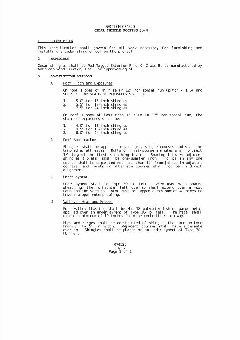
7/25/2019 City Standard Construction Specifications
http://slidepdf.com/reader/full/city-standard-construction-specifications 445/511
07432011/ 92
Page 1 of 2
SECTI ON 074320 CEDAR SHINGLE ROOFING (S-4)
1. DESCRIPTION
Thi s speci f i cat i on shal l govern f or al l work necessary f or f urni shi ng andi nst al l i ng a cedar shi ngl e r oof on t he pr oj ect.
2. MATERIALS
Cedar shi ngl es shal l be Red Tagged Exteri or Fi r e-X, Cl ass B, as manuf act ur ed byAmeri can Wood Treat er, I nc. , or appr oved equal .
3. CONSTRUCTION METHODS
A. Roof Pi t ch and Exposur es
On r oof sl opes of 4" r i se i n 12" hor i zont al r un ( pi t ch - 1/ 6) andst eeper, t he st andard exposur es shal l be:
1. 5. 0" f or 16- i nch shi ngl es2. 5. 5" f or 18- i nch shi ngl es
3. 7. 5" f or 24- i nch shi ngl es
On r oof sl opes of l ess t han 4" r i se i n 12" hor i zont al r un, t hest andard exposur es shal l be:
1. 4. 0" f or 16- i nch shi ngl es2. 4. 5" f or 18- i nch shi ngl es3. 6. 0" f or 24- i nch shi ngl es
B. Roof Appl i cat i on
Shi ngl es shal l be appl i ed i n st r ai ght , si ngl e cour ses and shal l bet ri pl ed at al l eaves. But t s of f i r st- course shi ngl es shal l proj ect
1" beyond t he f i r st sheat hi ng board. Spaci ng bet ween adj acentshi ngl es (j oi nt s) shal l be one- quar t er i nch. J oi nt s i n any one
cour se shal l be separat ed not l ess t han 1" f r om j oi nt s i n adj acentcour ses, and j oi nt s i n al t er nat e cour ses shal l not be i n di r ectal i gnment .
C. Under l ayment
Under l ayment shal l be Type 30- l b. f el t . When used wi t h spacedsheat hi ng, t he hori zont al f el t over l ap shal l extend over a woodl at h and t he ver t i cal j oi nt must be l apped a mi ni mum of 4 i nches toi nsur e pr oper wat er pr oof i ng.
D. Val l eys, Hi ps and Ri dges
Roof val l ey f l ashi ng shal l be No. 18 gal vani zed sheet gauge met alappl i ed over an under l ayment of Type 30- l b. f el t . The metal shal l
ext end a mi ni mum of 10 i nches f r omt he cent erl i ne each way.
Hi ps and r i dges shal l be const r uct ed of shi ngl es t hat ar e uni f or mf r om 3" t o 5" i n wi dt h. Adj acent cour ses shal l have al t er nat eoverl ap. Shi ngl es shal l be pl aced on an underl ayment of Type 30-l b. f el t .
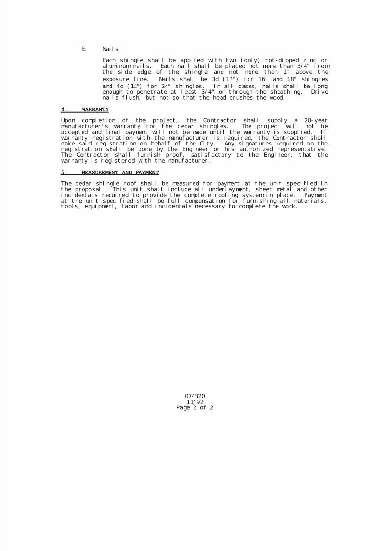
7/25/2019 City Standard Construction Specifications
http://slidepdf.com/reader/full/city-standard-construction-specifications 446/511
07432011/ 92
Page 2 of 2
E. Nai l s
Each shi ngl e shal l be appl i ed wi t h t wo ( onl y) hot - di pped zi nc oral umi num nai l s. Each nai l shal l be pl aced not mor e t han 3/ 4" f r omt he si de edge of t he shi ngl e and not more than 1" above t he
exposur e l i ne. Nai l s shal l be 3d ( 1") f or 16" and 18" shi ngl es
and 4d ( 1") f or 24" shi ngl es. I n al l cases, nai l s shal l be l ongenough t o penetr ate at l east 3/ 4" or t hr ough t he sheat hi ng. Dr i venai l s f l ush, but not so that t he head crushes the wood.
4. WARRANTY
Upon compl et i on of t he pr oj ect , t he Cont r act or shal l suppl y a 20- yearmanuf act ur er ' s war r ant y f or t he cedar shi ngl es. The pr oj ect wi l l not beaccept ed and f i nal payment wi l l not be made unt i l t he war r ant y i s suppl i ed. I fwar r ant y r egi st r at i on wi t h t he manuf act ur er i s requi r ed, t he Cont r act or shal lmake sai d r egi st r at i on on behal f of t he Ci t y. Any si gnat ur es requi r ed on t her egi st r at i on shal l be done by t he Engi neer or hi s aut hori zed r epr esent at i ve.
The Contr act or shal l f urni sh proof , sat i sf act ory t o t he Engi neer , t hat t hewar r ant y i s r egi st er ed wi t h the manuf act ur er .
5. MEASUREMENT AND PAYMENT
The cedar shi ngl e r oof shal l be measur ed f or payment at t he uni t speci f i ed i nt he pr oposal . Thi s uni t shal l i ncl ude al l under l ayment , sheet met al and ot heri nci dent al s requi r ed t o pr ovi de t he compl et e r oof i ng system i n pl ace. Paymentat t he uni t speci f i ed shal l be f ul l compensat i on f or f ur ni shi ng al l mat er i al s,t ool s, equi pment , l abor and i nci dent al s necessary to compl ete t he work.
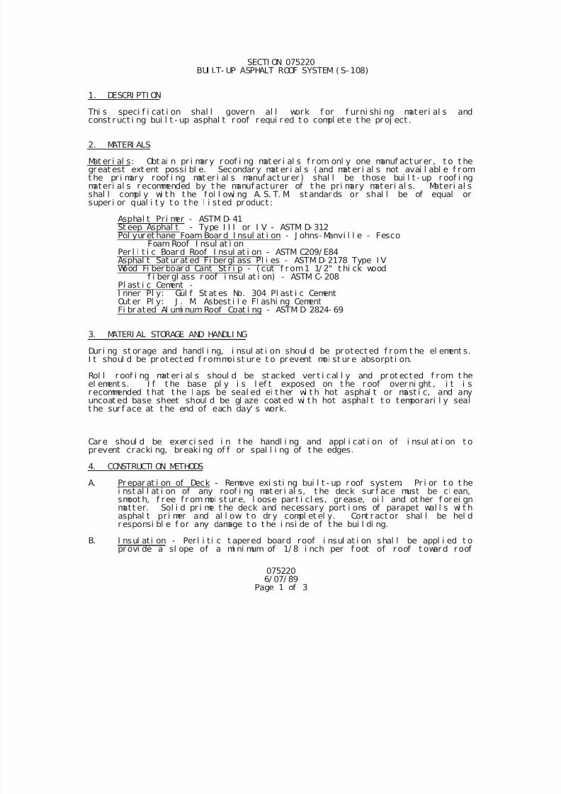
7/25/2019 City Standard Construction Specifications
http://slidepdf.com/reader/full/city-standard-construction-specifications 447/511
0752206/ 07/ 89
Page 1 of 3
SECTI ON 075220 BUI LT- UP ASPHALT ROOF SYSTEM ( S- 108)
1. DESCRI PTI ON
Thi s speci f i cat i on shal l govern al l work f or f urni shi ng materi al s andconst r uct i ng bui l t - up asphal t r oof r equi r ed t o compl et e t he pr oj ect .
2. MATERI ALS
Mat er i al s: Obt ai n pr i mar y r oof i ng mat er i al s f r om onl y one manuf act urer , t o t hegr eat est ext ent possi bl e. Secondar y mat er i al s ( and mat er i al s not avai l abl e f r omt he pr i mar y roof i ng mat er i al s manuf act ur er ) shal l be those bui l t - up r oof i ngmateri al s r ecommended by t he manuf acturer of t he pri mary materi al s. Materi al sshal l compl y wi t h t he f ol l owi ng A. S. T. M. st andar ds or shal l be of equal orsuper i or qual i t y t o t he l i st ed pr oduct :
Asphal t Pr i mer - ASTM D- 41St eep Asphal t - Type I I I or I V - ASTM D- 312Pol yur et hane Foam Boar d I nsul at i on - J ohns- Manvi l l e - Fesco
Foam Roof I nsul at i on
Per l i t i c Boar d Roof I nsul at i on - ASTM C209/ E84Asphal t Sat ur at ed Fi bergl ass Pl i es - ASTM D- 2178 Type I VWood Fi ber boar d Cant St r i p - ( cut f r om1 1/ 2" t hi ck wood
f i ber gl ass r oof i nsul at i on) - ASTM C- 208Pl ast i c Cement -I nner Pl y: Gul f St at es No. 304 Pl ast i c CementOut er Pl y: J . M. Asbest i l e Fl ashi ng CementFi br ated Al umi num Roof Coat i ng - ASTM D- 2824- 69
3. MATERI AL STORAGE AND HANDLI NG
Dur i ng st or age and handl i ng, i nsul at i on shoul d be protect ed f r om t he el ement s.I t shoul d be pr otect ed f r ommoi st ur e t o pr event moi st ur e absorpt i on.
Rol l r oof i ng mat er i al s shoul d be st acked ver t i cal l y and pr ot ected f r om t heel ement s. I f t he base pl y i s l ef t exposed on t he r oof over ni ght , i t i sr ecommended t hat t he l aps be seal ed ei t her wi t h hot asphal t or mast i c, and anyuncoat ed base sheet shoul d be gl aze coat ed wi t h hot asphal t t o temporari l y sealt he sur f ace at t he end of each day' s work.
Car e shoul d be exer ci sed i n t he handl i ng and appl i cat i on of i nsul at i on t opr event cracki ng, br eaki ng of f or spal l i ng of t he edges.
4. CONSTRUCTI ON METHODS
A. Pr epar at i on of Deck - Remove exi sti ng bui l t - up r oof syst em. Pr i or t o t hei nst al l at i on of any roof i ng mat er i al s, t he deck sur f ace must be cl ean,
smoot h, f r ee f r om moi st ur e, l oose par t i cl es, gr ease, oi l and ot her f or ei gnmatt er. Sol i d pr i me t he deck and necessary port i ons of parapet wal l s wi t hasphal t pr i mer and al l ow t o dr y compl et el y. Cont r act or shal l be hel dr esponsi bl e f or any damage t o t he i nsi de of t he bui l di ng.
B. I nsul ati on - Perl i t i c t apered board roof i nsul at i on shal l be appl i ed t opr ovi de a sl ope of a mi ni mum of 1/ 8 i nch per f oot of r oof t owar d r oof
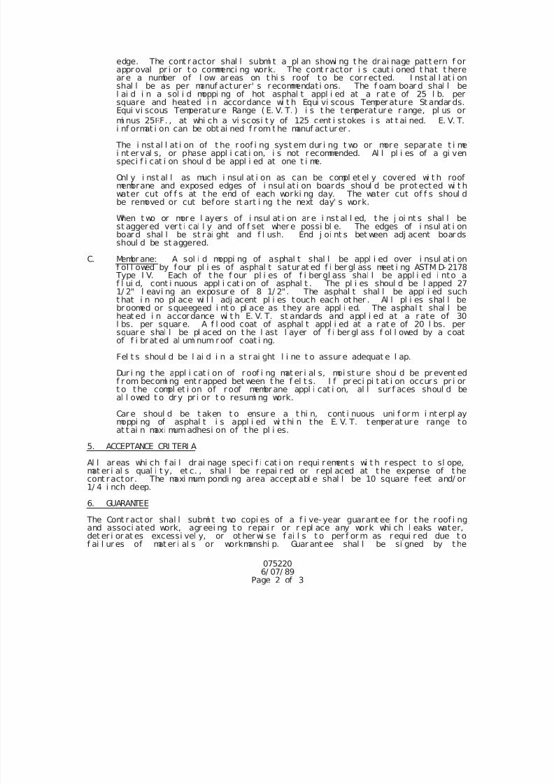
7/25/2019 City Standard Construction Specifications
http://slidepdf.com/reader/full/city-standard-construction-specifications 448/511
0752206/ 07/ 89
Page 2 of 3
edge. The cont r actor shal l submi t a pl an showi ng t he dr ai nage patt ern f orappr oval pr i or t o commenci ng work. The cont r actor i s caut i oned t hat t herear e a number of l ow ar eas on t hi s roof t o be cor r ected. I nst al l at i onshal l be as per manuf acturer' s recommendat i ons. The f oam boar d shal l bel ai d i n a sol i d moppi ng of hot asphal t appl i ed at a r at e of 25 l b. persquare and heated i n accordance wi t h Equi vi scous Temper ature St andar ds.Equi vi scous Temperat ur e Range ( E. V. T. ) i s t he t emperat ur e r ange, pl us or
mi nus 25
F. , at whi ch a vi scosi t y of 125 cent i st okes i s at t ai ned. E. V. T.i nf ormat i on can be obt ai ned f r om t he manuf act urer .
The i nst al l at i on of t he roof i ng syst em dur i ng t wo or more separ ate t i mei nt er val s, or phase appl i cat i on, i s not r ecommended. Al l pl i es of a gi venspeci f i cat i on shoul d be appl i ed at one t i me.
Onl y i nst al l as much i nsul at i on as can be compl et el y covered wi t h roofmembrane and exposed edges of i nsul at i on boards shoul d be prot ect ed wi t hwater cut of f s at t he end of each worki ng day. The water cut of f s shoul dbe removed or cut bef ore st art i ng t he next day' s work.
When t wo or mor e l ayer s of i nsul at i on ar e i nst al l ed, t he j oi nt s shal l best aggered ver t i cal l y and of f set wher e possi bl e. The edges of i nsul at i onboar d shal l be st r ai ght and f l ush. End j oi nt s bet ween adj acent boar dsshoul d be st aggered.
C. Membr ane: A sol i d moppi ng of asphal t shal l be appl i ed over i nsul at i onf ol l owed by f our pl i es of asphal t satur at ed f i ber gl ass meet i ng ASTM D- 2178
Type I V. Each of t he f our pl i es of f i ber gl ass shal l be appl i ed i nto af l ui d, cont i nuous appl i cat i on of asphal t . The pl i es shoul d be l apped 271/ 2" l eavi ng an exposur e of 8 1/ 2". The asphal t shal l be appl i ed sucht hat i n no pl ace wi l l adj acent pl i es touch each ot her . Al l pl i es shal l bebr oomed or squeegeed i nt o pl ace as they are appl i ed. The asphal t shal l beheat ed i n accordance wi t h E. V. T. st andar ds and appl i ed at a r ate of 30l bs. per squar e. A f l ood coat of asphal t appl i ed at a r at e of 20 l bs. persquar e shal l be pl aced on t he l ast l ayer of f i ber gl ass f ol l owed by a coatof f i brat ed al umi num r oof coat i ng.
Fel t s shoul d be l ai d i n a st r ai ght l i ne t o assur e adequat e l ap.
Dur i ng t he appl i cat i on of r oof i ng mat er i al s, moi st ur e shoul d be pr event edf r om becomi ng ent r apped bet ween t he f el t s. I f pr eci pi t at i on occur s pr i ort o the compl et i on of r oof membr ane appl i cat i on, al l sur f aces shoul d beal l owed t o dr y pr i or t o resumi ng work.
Car e shoul d be t aken t o ensur e a t hi n, cont i nuous uni f or m i nt er pl aymoppi ng of asphal t i s appl i ed wi t hi n the E. V. T. t emperat ur e range toat t ai n maxi mum adhesi on of t he pl i es.
5. ACCEPTANCE CRI TERI A
Al l ar eas whi ch f ai l dr ai nage speci f i cat i on requi r ement s wi t h r espect t o sl ope,mat er i al s qual i t y, et c. , shal l be r epai r ed or r epl aced at t he expense of t hecont ractor. The maxi mum pondi ng area accept abl e shal l be 10 square f eet and/ or1/ 4 i nch deep.
6. GUARANTEE
The Cont r act or shal l submi t t wo copi es of a f i ve- year guarant ee f or t he r oof i ngand associ ated work, agr eei ng t o repai r or r epl ace any work whi ch l eaks water,det er i or at es excessi vel y, or ot her wi se f ai l s t o per f or m as requi r ed due t of ai l ur es of mat er i al s or workmanshi p. Guar ant ee shal l be si gned by t he
7/25/2019 City Standard Construction Specifications
http://slidepdf.com/reader/full/city-standard-construction-specifications 449/511
0752206/ 07/ 89
Page 3 of 3
Cont ract or.
At t he end of t he f i ve- year per i od ( t wo year s f r om subst ant i al compl et i on) ,r epr esent at i ves of t he Cont r actor and t he Ci t y shal l i nspect t he r oof f or anydef i ci enci es due t o wear and t ear or f aul t y const r uct i on. Al l def i ci enci esshal l be Cont r act or ' s at no expense t o the Ci t y.
7. MEASUREMENT AND PAYMENT
Unl ess i ndi cat ed ot her wi se i n t he pr oposal , bui l t - up asphal t r oof shal l not bemeasur ed f or pay but shal l be consi der ed subsi di ar y to the pr oj ect .
7/25/2019 City Standard Construction Specifications
http://slidepdf.com/reader/full/city-standard-construction-specifications 450/511
078220R 2/ 20/ 9
Page 1 of 2
SECTI ON 078220 CONCRETE TI LE ROOFI NG ( S- 122)
1. PRODUCTS DELI VERY, STORAGE, AND HANDLI NG
Del i ver y:
a. Cl ear l y i dent i f y manuf act urer , t r adename, st yl e and col or ofpal l et i zed mat er i al .
b. Del i ver mat er i al s i n or i gi nal cont ai ner s wi t h manuf act ur er ' sl abel s i nt act and l egi bl e.
Storage:
a. St ore cement i t i ous mat er i al s i n weat her - t i ght spaces; keepf r ee f r om moi st ur e.
b. Aggr egate - Store i n wel l dr ai ned area t o mi ni mi ze change i nmoi st ur e cont ent ; pr event cont ami nat i on by ot her mat er i al s.
c. Pr ot ect i on - Cover st or ed mat er i al s wi t h t ar paul i n or ot her
sui t abl e cover i ng t o pr event soi l i ng or exposur e t o weat her .Fast en coveri ngs t o pr event r emoval by wi nd.
Handl i ng: Do not st ack t i l es on r oof i n quant i t i es exceedi ng si xt i l es hi gh on 12 i n. ( 300 mm) cent ers at ever y thi r d cour se onsl ope.
2. SUBMI TTALS
Sampl es: Submi t 2 sampl es of f ul l si ze st andar d t i l e.
Shop Dr awi ngs: Submi t shop dr awi ngs det ai l i ng shop f abr i cat edcust omshapes.
3. J OB CONDI TI ONS
1. Do not set t i l es i n mort ar when t he ambi ent t emperat ur e i s
l ess t han 40 F. (4. 4 C) or when such temper ature i sexpect ed wi t hi n 24 hour s.
2. Do not star t set t i ng t i l es unt i l ot her t r ades have compl et edwor k requi r i ng t r af f i c on or across roof sur f aces.
4. GUARANTEE
Guarant ee mat eri al s and workmanshi p t o be f r ee f r om def ects andl eaks f or a per i od of 2 year s f r om dat e of accept ance.
5. CONCRETE ROOFI NG TI LES
1. Monray, Vi l l a Fi el d Type manuf act ur ed by Moni er Roof t i l e( t r ade name).
2. Espana Mi ssi on Ti l e manuf actur ed by Li f et i l e.
3. Col or shal l be sel ect ed f r om t he manuf act ur er ' s st andar dcol or sampl es.
4. Fi t t i ngs: Fur ni sh al l f i t t i ngs as needed f or compl et ei nst al l at i on i n accordance wi t h manuf actur er' s r ecommended
7/25/2019 City Standard Construction Specifications
http://slidepdf.com/reader/full/city-standard-construction-specifications 451/511
078220R 2/ 20/ 9
Page 2 of 2
and appr oved sampl es.
6. FELT UNDERLAYMENT
Coal - t ar sat ur at ed r oof i ng f el t , ASTM D227, 30 l bs. x 36 wi dt h.
7. FASTENERS
Under l ayment - Fast ener s shal l be speci f i ed f or bui l t - up roof .
Ti l e - Fast eners shal l be as r ecommended by t he t i l e manuf act urer.
8. ROOF CEMENT AND SEALANT
Roof cement and seal ant shal l be as r ecommended by t he t i l emanuf act urer .
9. MORTAR
1. ASTM C270 - Type O.
2. Col or t o be sel ected t o mat ch t i l e col or al kal i and sun
r esi st ant mi ner al oxi de.
10. METAL TRI M AND FLASHI NG
Metal t r i m and f l ashi ng t o be as r ecommended by manuf acturer.
11. WOOD NAI LER STRI PS
Pi ne or Fi r , Gr ade 2, Wol mani zed. ( Speci es)
12. LAYI NG ROOFI NG TI LES
Layout and i nst al l t i l es i n accor dance wi t h manuf act urer ' sspeci f i cat i ons usi ng cl osur es t r i m at r i dge, hi p and copi ngmanuf actured f or t he pur pose.
13. Cl eani ng
1. Remove any mort ar or asphal t spl at t er f r omadj acent sur f aces.
2. Upon compl et i on of work, r emove excess materi al s and br okent i l es f r om t he pr emi ses.
7/25/2019 City Standard Construction Specifications
http://slidepdf.com/reader/full/city-standard-construction-specifications 452/511
097020Rev- 9/ 95
Page 1 of 1
SECTI ON 097020 EXPOSED AGGREGATE FI NI SH FOR CONCRETE SI DEWALKS ( S- 51)
1. DESCRI PTI ON
Thi s speci f i cat i on shal l consi st of exposed aggregat e f i ni sh, al so cal l ed "PeaGr avel " or "Pebbl e Concr ete, " f or si dewal ks composed of Por t l and cementconcrete, const r uct ed as her ei n speci f i ed, i n conf or mi t y wi t h pl ans.
2. MATERI ALS
Mater i al s used shal l be the same as speci f i ed i n Sect i on 025612, Concr et eSi dewal ks and Dr i veways". Exposed aggr egat e shal l be f r om 1/ 2" mi ni mum t o3/ 4" maxi mum i n si ze f r ee f r om f l at pi eces, cl eaned pr i or t o use.
3. CONSTRUCTI ON METHODS
Wet over whi ch toppi ng i s t o be pour ed, pour concr ete, scr eed and darby.Aggr egate to be exposed shal l be evenl y di st r i but ed by hand ( approxi matel y 4. 25l bs. per sq. f t . ) so t he ent i r e sur f ace i s compl et el y cover ed wi t h a si ngl el ayer ( speci al car e shal l be t aken i n cover i ng edges uni f or ml y). Wor kaggr egat e i nt o concr et e wi t h dar by and as soon as sur f ace wi l l support t he
wei ght of t he mechani c on knee- boar ds, hand f l oat t horoughl y so that al laggr egate i s compl etel y embedded j ust bel ow t he sur f ace wi t h no hol es oropeni ngs l ef t i n t he sur f ace, af t er whi ch an appr oved r et ar der may be appl i edat t he Cont r act or' s opt i on. At t he pr oper t i me, aggr egat e shal l be exposed bysprayi ng the sur f ace wi t h a garden hose equi pped wi t h spr i nkl er at t achment andbr ushi ng and f l ushi ng t he wat er f r om t he sur f ace wi t hout over exposi ng ordi sl odgi ng t he aggr egat e. Care shal l be exer ci sed i n movi ng over sur f aceduri ng spray and br ushi ng t o avoi d br eaki ng the aggr egate bond.
When compl et ed, t he Cont r act or shal l cur e t he sl abs wi t h a cl ear, non- st ai ni ngcuri ng compound. See Sect i on 038000, "Concr ete Str uctures" Sect i on 14 f orcuri ng speci f i cat i ons.
J ust pr i or t o compl et i on of t he proj ect , t he sl abs shal l be t hor oughl y cl eanedwi t h wat er and l i ght mur at i c aci d sol ut i on, t hor oughl y r i nsed and compl et el y
and evenl y cover ed wi t h "Sono Gl aze" as manuf actured by Sonneborn Bui l di ngPr oduct s, I nc. , or an appr oved equal gl aze.
4. MEASUREMENT & PAYMENT
Unl ess i ndi cat ed other wi se i n the Pr oposal , Work and accept ed mater i al aspr escr i bed f or t hi s speci f i cat i on wi l l be measur ed by t he squar e f oot ofsur f ace ar ea of compl et ed. The work wi l l be pai d f or at t he uni t bi d pr i ce
under t he bi d i t em "Exposed Aggr egat e" or Cur b Ramp, whi ch pr i ce shal l bef ul l compensat i on f or pr epar i ng t he subgr ade; f or f ur ni shi ng and pl aci ng al lmat er i al s, i ncl udi ng al l r ei nf or ci ng st eel , and expansi on j oi nt mat er i al s; andal l mani pul at i on, l abor , t ool s, equi pment , and i nci dent al s necessar y t ocompl ete the work.
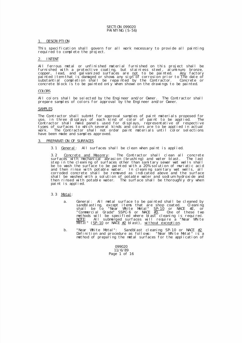
7/25/2019 City Standard Construction Specifications
http://slidepdf.com/reader/full/city-standard-construction-specifications 453/511
099020 11/ 6/ 89
Page 1 of 16
SECTI ON 099020 PAI NTI NG ( S-56)
1. DESCRI PTI ON
Thi s speci f i cat i on shal l govern f or al l work necessary t o provi de al l pai nt i ngr equi r ed t o compl et e t he pr oj ect .
2. I NTENT
Al l f er r ous met al or unf i ni shed mat er i al f ur ni shed on t hi s pr oj ect shal l bef ur ni shed wi t h a pr ot ect i ve coat i ng, but st ai nl ess st eel , al umi num, br onze,copper , l ead, and gal vani zed sur f aces ar e not t o be pai nt ed. Any f actor ypai nt ed i t em t hat i s damaged or shows any si gn of cor rosi on pr i or t o t he dat e ofsubst ant i al compl et i on shal l be r epai nt ed by t he Cont r act or . Concret e orconcr ete bl ock i s t o be pai nt ed onl y when shown on t he drawi ngs t o be pai nted.
COLORS
Al l col ors shal l be sel ect ed by t he Engi neer and/ or Owner . The Cont r act or shal lpr epar e sampl es of col ors f or appr oval by t he Engi neer and/ or Owner.
SAMPLES
The Cont r act or shal l submi t f or approval sampl es of pai nt mater i al s proposed f oruse, i n t hr ee di spl ays of each ki nd of col or of pai nt t o be appl i ed. TheCont ract or shal l make panel s used f or di spl ays, r epr esent at i ve of r espect i vet ypes of sur f aces t o whi ch sever al ki nds and col ors are t o be appl i ed i n act ualwor k. The Cont r actor shal l not order pai nt mat er i al s unt i l col or sel ect i onshave been made and sampl es appr oved.
3. PREPARATI ON OF SURFACES
3. 1 Gener al : Al l sur f aces shal l be cl ean when pai nt i s appl i ed.
3. 2 Concret e and Masonr y: The Cont r act or shal l cl ean al l concret esur f aces wi t h mechani cal abr asi on ( br ushi ng) and wat er bl ast . The l ast
st ep i n t he cl eani ng of sur f aces ot her t han sani t ar y sewer wet wel l s shal lbe to wash the sur f ace t o be pai nt ed wi t h a 20% sol ut i on of mur i at i c aci dand t hen r i nse wi t h pot abl e wat er . I n cl eani ng sani t ar y wet wel l s, al lcor r oded concr ete shal l be r emoved as i ndi cated above and t he sur f aceshal l be washed wi t h a sol ut i on of potabl e water and sodi um hydr oxi de andt hen r i nsed wi t h potabl e water. The surf ace shal l be t horoughl y dry whenpai nt i s appl i ed.
3. 3 Metal :
a. Gener al : Al l met al sur f ace t o be pai nt ed shal l be cl eaned bysandbl ast i ng, except i t ems that ar e shop coat ed. Cl eani ngshal l be t o "Near Whi t e Metal " SP- 10 or NACE #2, or"Commerci al Gr ade" SSPC- 6 or NACE #3. One of t hese t wo
met hods wi l l be speci f i ed wher e bl ast cl eani ng i s r equi r ed.NOTE: Al l submerged surf aces wi l l r equi re a "Near Whi t eMetal " ( SP- 10 or NACE #2 bl ast ) , wi t hout except i on.
b. "Near Whi t e Metal " : Sandbl ast cl eani ng SP- 10 or NACE #2.Def i ni t i on and pr ocedur e as f ol l ows: "Near Whi t e Met al " i s amet hod of pr epar i ng t he met al sur f aces f or t he appl i cat i on of
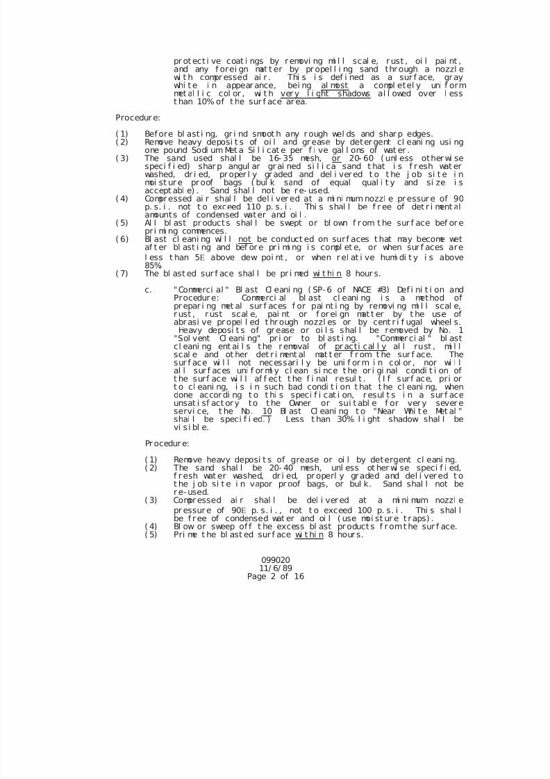
7/25/2019 City Standard Construction Specifications
http://slidepdf.com/reader/full/city-standard-construction-specifications 454/511
099020 11/ 6/ 89
Page 2 of 16
pr ot ect i ve coat i ngs by removi ng mi l l scal e, r ust , oi l pai nt ,and any f orei gn mat t er by pr opel l i ng sand thr ough a nozzl ewi t h compr essed ai r . Thi s i s def i ned as a sur f ace, gr aywhi t e i n appear ance, bei ng al most a compl etel y uni f ormmet al l i c col or , wi t h ver y l i ght shadows al l owed over l esst han 10% of t he sur f ace ar ea.
Procedur e:
( 1) Bef ore bl ast i ng, gr i nd smoot h any r ough wel ds and shar p edges.( 2) Remove heavy deposi t s of oi l and gr ease by deter gent cl eani ng usi ng
one pound Sodi um Met a Si l i cat e per f i ve gal l ons of wat er .( 3) The sand used shal l be 16- 35 mesh, or 20- 60 ( unl ess other wi se
speci f i ed) shar p angul ar gr ai ned si l i ca sand t hat i s f r esh wat erwashed, dr i ed, pr oper l y graded and del i ver ed t o t he j ob si t e i nmoi st ur e pr oof bags ( bul k sand of equal qual i t y and si ze i saccept abl e) . Sand shal l not be re- used.
( 4) Compr essed ai r shal l be del i ver ed at a mi ni mum nozzl e pr essur e of 90p. s. i . not t o exceed 110 p. s. i . Thi s shal l be f r ee of det r i ment alamounts of condensed water and oi l .
( 5) Al l bl ast pr oducts shal l be swept or bl own f r om t he sur f ace bef or epr i mi ng commences.
( 6) Bl ast cl eani ng wi l l not be conduct ed on sur f aces t hat may become wet
af t er bl ast i ng and bef or e pr i mi ng i s compl et e, or when sur f aces arel ess t han 5 above dew poi nt , or when r el at i ve humi di t y i s above85%.
( 7) The bl ast ed sur f ace shal l be pr i med wi t hi n 8 hour s.
c. "Commerci al " Bl ast Cl eani ng ( SP-6 of NACE #3) Def i ni t i on andProcedur e: Commerci al bl ast cl eani ng i s a method ofpr epar i ng met al sur f aces f or pai nt i ng by removi ng mi l l scal e,r ust , r ust scal e, pai nt or f or ei gn mat t er by t he use ofabr asi ve pr opel l ed t hr ough nozzl es or by cent r i f ugal wheel s.Heavy deposi t s of gr ease or oi l s shal l be removed by No. 1
"Sol vent Cl eani ng" pr i or to bl ast i ng. "Commer ci al " bl astcl eani ng ent ai l s t he r emoval of pr acti cal l y al l rust , mi l lscal e and ot her det r i ment al mat t er f r om t he sur f ace. Thesur f ace wi l l not necessari l y be uni f or m i n col or , nor wi l l
al l sur f aces uni f or ml y cl ean si nce t he or i gi nal condi t i on oft he surf ace wi l l af f ect t he f i nal resul t . ( I f surf ace, pri ort o cl eani ng, i s i n such bad condi t i on t hat t he cl eani ng, whendone accordi ng t o t hi s speci f i cat i on, r esul t s i n a sur f aceunsat i sf act or y to t he Owner or sui t abl e f or ver y sever eservi ce, t he No. 10 Bl ast Cl eani ng t o "Near Whi t e Met al "shal l be speci f i ed. ) Less t han 30% l i ght shadow shal l bevi s i bl e.
Procedur e:
( 1) Remove heavy deposi t s of grease or oi l by detergent cl eani ng.( 2) The sand shal l be 20- 40 mesh, unl ess ot her wi se speci f i ed,
f r esh wat er washed, dr i ed, pr operl y graded and del i vered t ot he j ob si t e i n vapor pr oof bags, or bul k. Sand shal l not be
r e-used. ( 3) Compr essed ai r shal l be del i vered at a mi ni mum nozzl e
pr essur e of 90 p. s. i . , not t o exceed 100 p. s. i . Thi s shal lbe f r ee of condensed wat er and oi l ( use moi st ur e t raps) .
( 4) Bl ow or sweep of f t he excess bl ast pr oduct s f r omt he sur f ace.( 5) Pri me t he bl ast ed sur f ace wi t hi n 8 hour s.
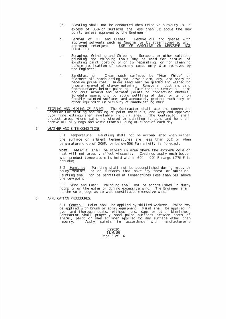
7/25/2019 City Standard Construction Specifications
http://slidepdf.com/reader/full/city-standard-construction-specifications 455/511
099020 11/ 6/ 89
Page 3 of 16
( 6) Bl ast i ng shal l not be conduct ed when r el at i ve humi di t y i s i n
excess of 85% or sur f aces ar e l ess t han 5 above t he dewpoi nt , unl ess appr oved by t he Engi neer .
d. Removal of Oi l and Grease: Remove oi l and grease wi t happroved sol vents such as Napt ha, or by st eam combi ned wi t happroved detergent. USE OF GASOLI NE OR KEROSENE NOT
PERMI TTED. e. Scrapi ng, Gr i ndi ng and Chi ppi ng: Scraper s or other sui t abl e
gr i ndi ng and chi ppi ng tool s may be used f or r emoval ofexi st i ng pai nt coat i ng pr i or t o r epai nt i ng, or f or cl eani ngbef ore appl i cat i on of secondar y coats onl y when approved byt he Engi neer .
f . Sandbl ast i ng: Cl ean such sur f aces by "Near Whi t e" or"Commerci al " sandbl ast i ng and l eave cl ean, dr y, and ready t or ecei ve pr i me coat . Ri ver sand must be graded and washed t oi nsure removal of cl ayey materi al . Remove al l dust and sandf r om sur f aces bef ore pai nt i ng. Take car e t o r emove al l sandand gr i t around and between j oi nts of connect i ng members.Schedul e oper at i ons t o avoi d set t l i ng of dust or gr i t onf r eshl y pai nt ed surf aces and adequat el y pr otect machi ner y orot her equi pment i n vi ci ni t y of sandbl ast i ng wor k.
4. STORI NG AND MI XI NG OF PAI NT: The Cont r act or shal l use one conveni entl ocat i on f or st ori ng and mi xi ng of pai nt mat er i al s, and keep and appr ovedt ype f i r e ext i ngui sher avai l abl e i n t hi s ar ea. The Cont r actor shal lpr otect ar eas wher e pai nt i s st ored or pai nt i ng i s done and he shal lr emove al l oi l y r ags and wast e f r ombui l di ng at cl ose of each day.
5. WEATHER AND SI TE CONDI TI ONS:
5. 1 Temperat ur e: Pai nt i ng shal l not be accompl i shed when ei t her
t he sur f ace or ambi ent t emperat ur es are l ess t han 50 or when
t emper ature drop of 20F, or bel ow 50 Fahr enhei t , i s f or ecast .
NOTE:
Mater i al shal l be st ored i n area where t he ext r eme col d orheat wi l l not great l y af f ect vi scosi t y. Coat i ngs appl y much bet t er
when pr oduct t emper ature i s hel d wi t hi n 60 - 90 F r ange ( 77 F i sopt i mum) .
5. 2 Humi di t y: Pai nt i ng shal l not be accompl i shed dur i ng mi st y orr ai ny weat her , or on sur f aces t hat have any f r ost or moi st ur e.
Pai nt i ng shal l not be per mi t t ed at t emper at ures l ess t han 5F abovet he dew poi nt .
5. 3 Wi nd and Dust : Pai nt i ng shal l not be accompl i shed i n dust yr ooms or on t he ext eri or dur i ng excessi ve wi nd. The Engi neer shal lbe the sol e j udge as t o what const i t ut es excessi ve wi nd.
6. APPLI CATI ON PROCEDURES:
6. 1 Gener al : Pai nt shal l be appl i ed by ski l l ed workmen. Pai nt maybe appl i ed wi t h br ush or spray equi pment . Pai nt shal l be appl i ed i neven and t horough coat s, wi t hout r uns, sags or other bl emi shes.Cont r act or shal l pr oper l y sand pai nt sur f aces bet ween coat s ofenamel , pai nt or shel l ac when appl i ed t o any sur f ace other t hanmasonr y. Appl y pai nt s i n accordance wi t h manuf acturer' s
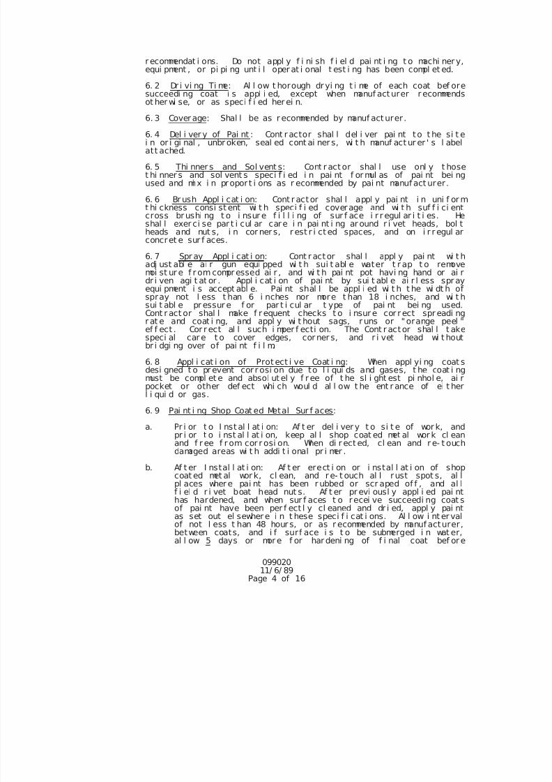
7/25/2019 City Standard Construction Specifications
http://slidepdf.com/reader/full/city-standard-construction-specifications 456/511
099020 11/ 6/ 89
Page 4 of 16
r ecommendat i ons. Do not appl y f i ni sh f i el d pai nt i ng t o machi ner y,equi pment , or pi pi ng unt i l oper at i onal t est i ng has been compl et ed.
6. 2 Dr i vi ng Ti me: Al l ow t horough dryi ng t i me of each coat bef oresucceedi ng coat i s appl i ed, except when manuf act urer r ecommendsot her wi se, or as speci f i ed her ei n.
6. 3 Coverage: Shal l be as r ecommended by manuf act urer .
6. 4 Del i ver y of Pai nt : Cont r actor shal l del i ver pai nt to t he si t ei n or i gi nal , unbr oken, seal ed cont ai ner s, wi t h manuf act ur er ' s l abelatt ached.
6. 5 Thi nner s and Sol vent s: Cont r act or shal l use onl y t hoset hi nner s and sol vent s speci f i ed i n pai nt f or mul as of pai nt bei ngused and mi x i n propor t i ons as r ecommended by pai nt manuf act urer.
6. 6 Br ush Appl i cat i on: Cont r actor shal l appl y pai nt i n uni f or mt hi ckness consi st ent wi t h speci f i ed coverage and wi t h suf f i ci entcross br ushi ng t o i nsur e f i l l i ng of sur f ace i r r egul ar i t i es. Heshal l exer ci se par t i cul ar care i n pai nt i ng ar ound r i vet heads, bol theads and nut s, i n cor ner s, r est r i ct ed spaces, and on i r r egul arconcret e sur f aces.
6. 7 Spr ay Appl i cat i on: Cont r actor shal l appl y pai nt wi t hadj ust abl e ai r gun equi pped wi t h sui t abl e water t r ap t o removemoi st ur e f r om compr essed ai r , and wi t h pai nt pot havi ng hand or ai rdr i ven agi t at or . Appl i cat i on of pai nt by sui t abl e ai r l ess spr ayequi pment i s accept abl e. Pai nt shal l be appl i ed wi t h t he wi dt h ofspray not l ess t han 6 i nches nor more t han 18 i nches, and wi t hsui t abl e pr essur e f or par t i cul ar t ype of pai nt bei ng used.Cont r act or shal l make f r equent checks t o i nsur e cor r ect spr eadi ngr at e and coat i ng, and appl y wi t hout sags, r uns or "orange peel "ef f ect . Cor r ect al l such i mper f ecti on. The Cont r actor shal l t akespeci al car e t o cover edges, cor ner s, and r i vet head wi t houtbr i dgi ng over of pai nt f i l m.
6. 8 Appl i cat i on of Prot ect i ve Coat i ng: When appl yi ng coat s
desi gned t o pr event cor r osi on due to l i qui ds and gases, t he coat i ngmust be compl et e and absol ut el y f r ee of t he sl i ght est pi nhol e, ai rpocket or other def ect whi ch woul d al l ow t he ent r ance of ei t herl i qui d or gas.
6. 9 Pai nt i ng Shop Coat ed Metal Sur f aces:
a. Pr i or t o I nst al l at i on: Af t er del i ver y t o si t e of wor k, andpr i or t o i nst al l at i on, keep al l shop coat ed met al wor k cl eanand f r ee f r om cor r osi on. When di r ect ed, cl ean and r e- t ouchdamaged areas wi t h addi t i onal pr i mer .
b. Af t er I nstal l at i on: Af t er erect i on or i nstal l at i on of shopcoat ed met al wor k, cl ean, and r e- t ouch al l r ust spot s, al lpl aces wher e pai nt has been r ubbed or scr aped of f , and al l
f i el d r i vet boat head nut s. Af t er pr evi ousl y appl i ed pai nthas hardened, and when sur f aces t o recei ve succeedi ng coat sof pai nt have been per f ect l y cl eaned and dr i ed, appl y pai ntas set out el sewher e i n t hese speci f i cat i ons. Al l ow i nt er valof not l ess t han 48 hour s, or as r ecommended by manuf acturer,between coats, and i f surf ace i s t o be submerged i n wat er,al l ow 5 days or mor e f or har deni ng of f i nal coat bef or e
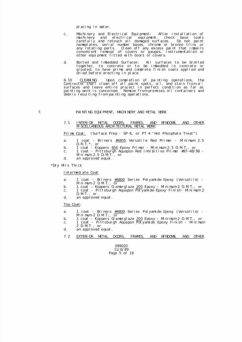
7/25/2019 City Standard Construction Specifications
http://slidepdf.com/reader/full/city-standard-construction-specifications 457/511
099020 11/ 6/ 89
Page 5 of 16
pl aci ng i n wat er .
c. Machi ner y and El ectr i cal Equi pment : Af t er i nst al l at i on ofmachi nery and el ectr i cal equi pment , check base coat scaref ul l y and r etouch al l damaged surf aces. Do not pai ntnamepl ates, ser i al number bases, chrome or br onze t r i m, orany r ot at i ng par t s. Cl ean of f any excess pai nt t hat i mpai r sconveni ent r emoval of covers or gauges, i nst r ument at i on orother equi pment f i t t ed wi t h door s or cover s.
d. Bol t ed and I mbedded Sur f aces: Al l sur f aces t o be bl ot t edt oget her, t o concr ete or t o be i mbedded i n concr et e orgr out ed, t o have pr i me and compl ete f i ni sh coats appl i ed anddr i ed bef or e er ect i ng i n pl ace.
6. 10 CLEANI NG: Upon compl et i on of pai nt i ng operat i ons, theCont ract or shal l cl ean of f al l pai nt spot s, oi l , and stai n f rom al lsur f aces and l eave ent i r e pr oj ect i n per f ect condi t i on as f ar aspai nt i ng work i s concerned. Remove f r ompr emi ses al l cont ai ner s anddebr i s r esul t i ng f r om pai nt i ng oper at i ons.
7. PAI NTI NG EQUI PMENT, MACHI NERY AND METAL WORK
7. 1 I NTERI OR METAL DOORS, FRAMES, AND WI NDOWS, AND OTHERMI SCELLANEOUS ARCHI TECTURAL METAL WORK:
Pri me Coat : ( Sur f ace Prep - SP-6, or PT- 4 "Hot Phosphat e Treat ")
a. 1 coat - Br i ner s #4805 Versat i l e Red Pr i mer - Mi ni mum 2. 5D. M. T. *, or
b. 1 coat - Koppers 654 Epoxy Pr i mer - Mi ni mum 2. 5 D. M. T. , orc. 1 coat - Pi t t sburgh Aquapon Red I nhi bi t i ve Pri mer #97- 48/ 98 -
Mi ni mum 2. 5 D. M. T. , ord. an approved equal .
*Dr y Mi l s Thi ck
I nt ermedi ate Coat
a. 1 coat - Br i ner s #4800 Ser i es Pol yami de- Epoxy ( Ver sat i l e) -Mi ni mum 2 D. M. T. , or
b. 1 coat - Koppers Gl amorgl aze 200 Epoxy - Mi ni mum2 D. M. T. , or c. 1 coat - Pi t t sbur gh Aquapon Pol yami de-Epoxy Fi ni sh- Mi ni mum 2
D. M. T. , ord. an approved equal .
Top Coat:
a. 1 coat - Br i ner s #4800 Ser i es Pol yami de- Epoxy ( Ver sat i l e) -
Mi ni mum 2 D. M. T. , orb. 1 coat - Koppers Gl amorgl aze 200 Epoxy - Mi ni mum2 D. M. T. , or c. 1 coat - Pi t t sbur gh Aquapon Pol yami de Epoxy Fi ni sh - Mi ni mum
2 D. M. T. , ord. an approved equal .
7. 2 EXTERI OR METAL DOORS, FRAMES, AND WI NDOWS, AND OTHER
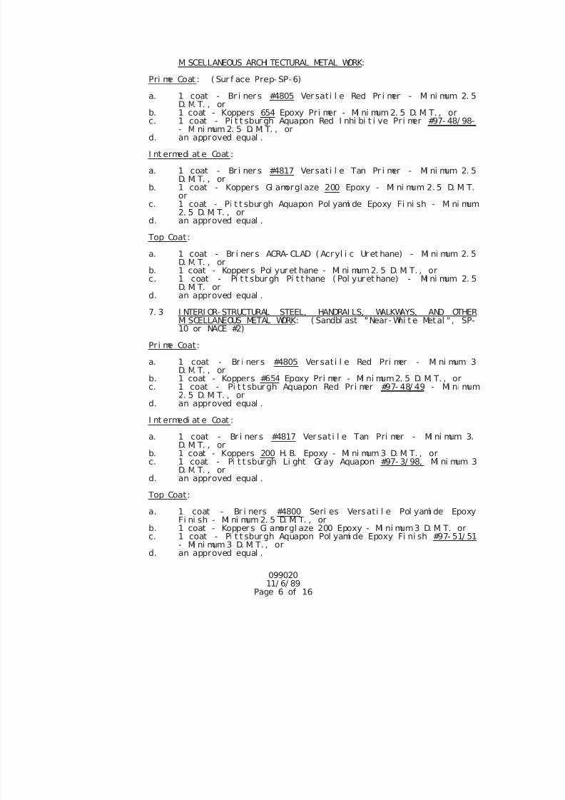
7/25/2019 City Standard Construction Specifications
http://slidepdf.com/reader/full/city-standard-construction-specifications 458/511
099020 11/ 6/ 89
Page 6 of 16
MI SCELLANEOUS ARCHI TECTURAL METAL WORK:
Pri me Coat : ( Sur f ace Prep- SP-6)
a. 1 coat - Br i ner s #4805 Versat i l e Red Pr i mer - Mi ni mum 2. 5D. M. T. , or
b. 1 coat - Koppers 654 Epoxy Pr i mer - Mi ni mum 2. 5 D. M. T. , orc. 1 coat - Pi t t sbur gh Aquapon Red I nhi bi t i ve Pr i mer #97- 48/ 98-
- Mi ni mum 2. 5 D. M. T. , ord. an approved equal .
I nt ermedi at e Coat :
a. 1 coat - Br i ner s #4817 Versat i l e Tan Pr i mer - Mi ni mum 2. 5D. M. T. , or
b. 1 coat - Koppers Gl amorgl aze 200 Epoxy - Mi ni mum 2. 5 D. M. T.or
c. 1 coat - Pi t t sbur gh Aquapon Pol yami de Epoxy Fi ni sh - Mi ni mum2. 5 D. M. T. , or
d. an approved equal .
Top Coat:
a. 1 coat - Br i ner s ACRA- CLAD ( Acryl i c Ur et hane) - Mi ni mum 2. 5D. M. T. , or
b. 1 coat - Kopper s Pol yur et hane - Mi ni mum 2. 5 D. M. T. , orc. 1 coat - Pi t t sbur gh Pi t t hane ( Pol yur et hane) - Mi ni mum 2. 5
D. M. T. ord. an approved equal .
7. 3 I NTERI OR-STRUCTURAL STEEL, HANDRAI LS, WALKWAYS, AND OTHERMI SCELLANEOUS METAL WORK: ( Sandbl ast "Near- Whi t e Metal " , SP-10 or NACE #2)
Pr i me Coat:
a. 1 coat - Br i ner s #4805 Ver sat i l e Red Pri mer - Mi ni mum 3D. M. T. , or
b. 1 coat - Koppers #654 Epoxy Pr i mer - Mi ni mum2. 5 D. M. T. , orc. 1 coat - Pi t t sbur gh Aquapon Red Pr i mer #97- 48/ 49 - Mi ni mum2. 5 D. M. T. , or
d. an approved equal .
I nt ermedi at e Coat :
a. 1 coat - Br i ner s #4817 Ver sat i l e Tan Pri mer - Mi ni mum 3.D. M. T. , or
b. 1 coat - Koppers 200 H. B. Epoxy - Mi ni mum 3 D. M. T. , orc. 1 coat - Pi t t sburgh Li ght Gr ay Aquapon #97- 3/ 98, Mi ni mum 3
D. M. T. , ord. an approved equal .
Top Coat:
a. 1 coat - Br i ners #4800 Seri es Versati l e Pol yami de EpoxyFi ni sh - Mi ni mum 2. 5 D. M. T. , or
b. 1 coat - Kopper s Gl amorgl aze 200 Epoxy - Mi ni mum3 D. M. T. orc. 1 coat - Pi t t sbur gh Aquapon Pol yami de Epoxy Fi ni sh #97- 51/ 51
- Mi ni mum 3 D. M. T. , ord. an approved equal .
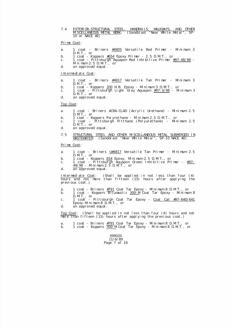
7/25/2019 City Standard Construction Specifications
http://slidepdf.com/reader/full/city-standard-construction-specifications 459/511
099020 11/ 6/ 89
Page 7 of 16
7. 4 EXTERI OR-STRUCTURAL STEEL, HANDRAI LS, WALKWAYS, AND OTHERMI SCELLANEOUS METAL WORK: ( Sandbl ast "Near Whi t e Met al ", SP-10 or NACE #2)
Pr i me Coat:
a. 1 coat - Br i ner s #4805 Ver sat i l e Red Pri mer - Mi ni mum 3D. M. T. , or
b. 1 coat - Koppers #654 Epoxy Pri mer - 2. 5 D. M. T. , orc. 1 coat - Pi t t sburgh Aquapon Red I nhi bi t i ve Pri mer #97- 48/ 98 -
Mi ni mum 2. 5 D. M. T. , ord. an approved equal .
I nt ermedi at e Coat :
a. 1 coat - Br i ner s #4817 Ver sat i l e Tan Pri mer - Mi ni mum 3D. M. T. , or
b. 1 coat - Koppers 200 H. B. Epoxy - Mi ni mum 3 D. M. T. , orc. 1 coat - Pi t t sbur gh Li ght Gr ay Aquapon #97- 3/ 98 - Mi ni mum 3
D. M. T. , ord. an approved equal .
Top Coat:
a. 1 coat - Br i ner s ACRA- CLAD ( Acryl i c Ur et hane) - Mi ni mum 2. 5D. M. T. , or
b. 1 coat - Kopper s Pol yret hane - Mi ni mum 2. 5 D. M. T. , orc. 1 coat - Pi t t sbur gh Pi t t hane ( Pol yur et hane) - Mi ni mum 2. 5
D. M. T. , ord. an approved equal .
7. 5 STRUCTURAL STEEL AND OTHER MI SCELLANEOUS METAL SUBMERGED I NWASTEWATER: ( Sandbl ast "Near Whi t e Met al " , SP-10 NACE #2)
Pr i me Coat:
a. 1 coat - Br i ner s U#4817 Versat i l e Tan Pri mer - Mi ni mum 2. 5
D. M. T. , orb. 1 coat - Koppers 654 Epoxy, Mi ni mum 2. 5 D. M. T. , orc. 1 coat - Pi t t sburgh Aquapon Gr een I nhi bi t i ve Pri mer - #97-
49/ 98 - Mi ni mum 2. 5 D. M. T. , ord. an approved equal .
I nt er medi at e Coat : ( Shal l be appl i ed i n not l ess t han f our ( 4)hour s and not more t han f i f t een (15) hour s af t er appl yi ng theprevi ous coat . )
a. 1 coat - Br i ners #791 Coal Tar Epoxy - Mi ni mum 8 D. M. T. , orb. 1 coat - Koppers Bi t umast i c 300- M Coal Tar Epoxy - Mi ni mum 8
D. M. T. , orc. 1 coat - Pi t t sburgh Coal Tar Epoxy - Coal Cat #97- 640/ 641
Epoxy- Mi ni mum 8 D. M. T. , or
d. an approved equal . Top Coat: ( Shal l be appl i ed i n not l ess t han f our ( 4) hours and notmor e than f i f t een ( 15) hour s af t er appl yi ng the pr evi ous coat . )
a. 1 coat - Br i ners #791 Coal Tar Epoxy - Mi ni mum 8 D. M. T. , orb. 1 coat - Koppers 300- M Coal Tar Epoxy - Mi ni mum 8 D. M. T. , or
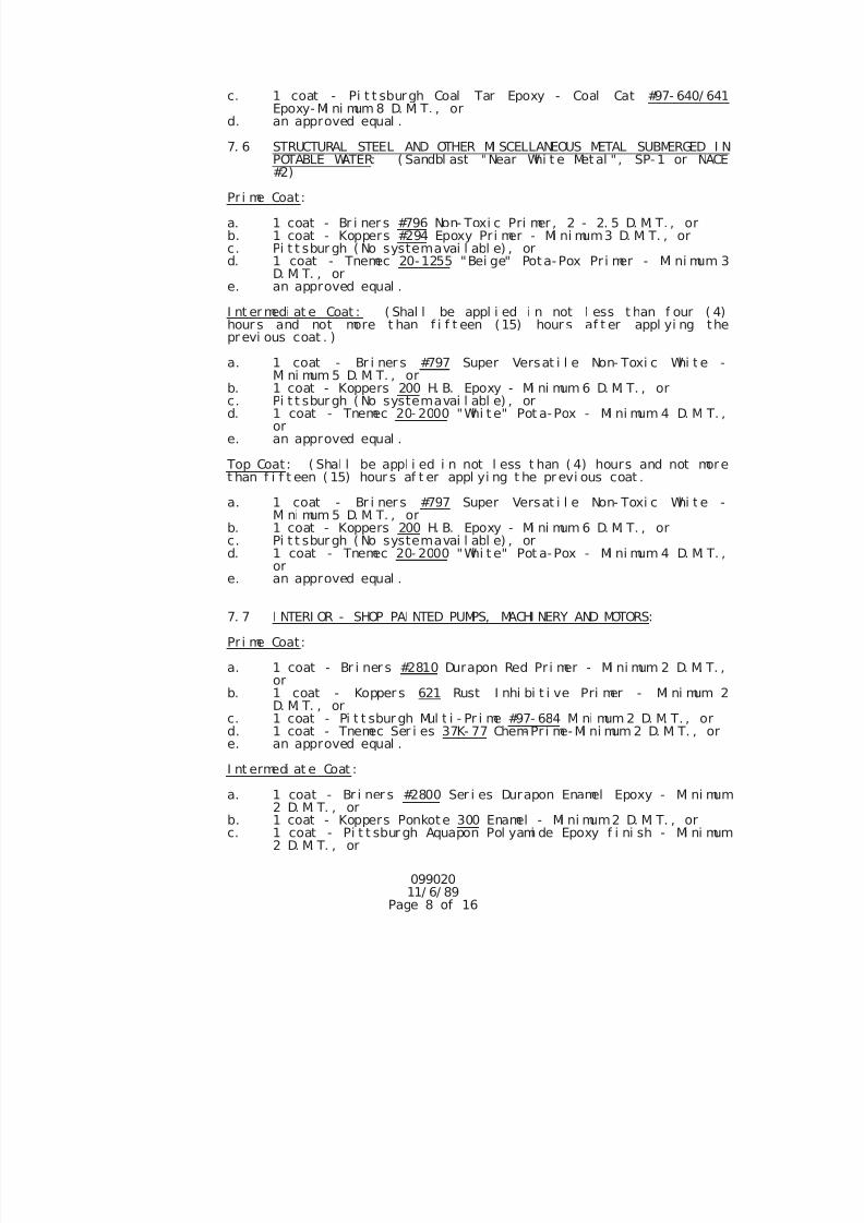
7/25/2019 City Standard Construction Specifications
http://slidepdf.com/reader/full/city-standard-construction-specifications 460/511
099020 11/ 6/ 89
Page 8 of 16
c. 1 coat - Pi t t sburgh Coal Tar Epoxy - Coal Cat #97- 640/ 641Epoxy- Mi ni mum 8 D. M. T. , or
d. an approved equal .
7. 6 STRUCTURAL STEEL AND OTHER MI SCELLANEOUS METAL SUBMERGED I NPOTABLE WATER: ( Sandbl ast "Near Whi t e Met al " , SP- 1 or NACE#2)
Pr i me Coat:
a. 1 coat - Br i ner s #796 Non- Toxi c Pri mer , 2 - 2. 5 D. M. T. , orb. 1 coat - Koppers #294 Epoxy Pr i mer - Mi ni mum3 D. M. T. , orc. Pi t t sbur gh ( No systemavai l abl e) , ord. 1 coat - Tnemec 20-1255 "Bei ge" Pota- Pox Pr i mer - Mi ni mum 3
D. M. T. , ore. an approved equal .
I nt er medi at e Coat : ( Shal l be appl i ed i n not l ess t han f our ( 4)hour s and not more t han f i f t een (15) hour s af t er appl yi ng theprevi ous coat . )
a. 1 coat - Br i ner s #797 Super Versat i l e Non- Toxi c Whi t e -Mi ni mum 5 D. M. T. , or
b. 1 coat - Koppers 200 H. B. Epoxy - Mi ni mum 6 D. M. T. , orc. Pi t t sbur gh ( No systemavai l abl e) , ord. 1 coat - Tnemec 20- 2000 "Whi t e" Pot a-Pox - Mi ni mum 4 D. M. T. ,
or e. an approved equal .
Top Coat: ( Shal l be appl i ed i n not l ess t han ( 4) hours and not moret han f i f t een ( 15) hour s af t er appl yi ng t he pr evi ous coat .
a. 1 coat - Br i ner s #797 Super Versat i l e Non- Toxi c Whi t e -Mi ni mum 5 D. M. T. , or
b. 1 coat - Koppers 200 H. B. Epoxy - Mi ni mum 6 D. M. T. , orc. Pi t t sbur gh ( No systemavai l abl e) , ord. 1 coat - Tnemec 20- 2000 "Whi t e" Pot a-Pox - Mi ni mum 4 D. M. T. ,
or
e. an approved equal .
7. 7 I NTERI OR - SHOP PAI NTED PUMPS, MACHI NERY AND MOTORS:
Pr i me Coat:
a. 1 coat - Br i ner s #2810 Durapon Red Pr i mer - Mi ni mum 2 D. M. T. ,or
b. 1 coat - Kopper s 621 Rust I nhi bi t i ve Pri mer - Mi ni mum 2D. M. T. , or
c. 1 coat - Pi t t sbur gh Mul t i - Pr i me #97- 684 Mi ni mum 2 D. M. T. , ord. 1 coat - Tnemec Ser i es 37K- 77 Chem- Pr i me- Mi ni mum 2 D. M. T. , ore. an approved equal .
I nt ermedi at e Coat : a. 1 coat - Br i ner s #2800 Ser i es Durapon Enamel Epoxy - Mi ni mum
2 D. M. T. , orb. 1 coat - Koppers Ponkote 300 Enamel - Mi ni mum2 D. M. T. , orc. 1 coat - Pi t t sbur gh Aquapon Pol yami de Epoxy f i ni sh - Mi ni mum
2 D. M. T. , or
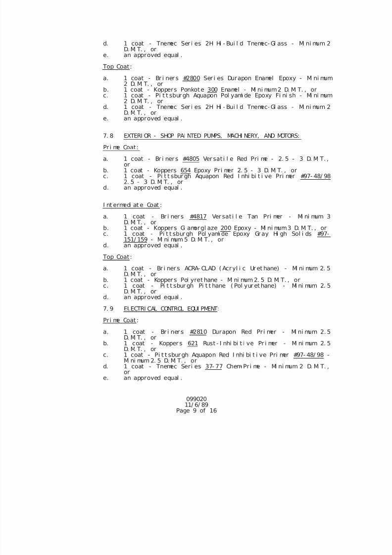
7/25/2019 City Standard Construction Specifications
http://slidepdf.com/reader/full/city-standard-construction-specifications 461/511
099020 11/ 6/ 89
Page 9 of 16
d. 1 coat - Tnemec Ser i es 2H Hi - Bui l d Tnemec- Gl ass - Mi ni mum 2D. M. T. , or
e. an approved equal .
Top Coat:
a. 1 coat - Br i ner s #2800 Ser i es Durapon Enamel Epoxy - Mi ni mum2 D. M. T. , or
b. 1 coat - Koppers Ponkote 300 Enamel - Mi ni mum2 D. M. T. , orc. 1 coat - Pi t t sbur gh Aquapon Pol yami de Epoxy Fi ni sh - Mi ni mum
2 D. M. T. , ord. 1 coat - Tnemec Ser i es 2H Hi - Bui l d Tnemec- Gl ass - Mi ni mum 2
D. M. T. , ore. an approved equal .
7. 8 EXTERI OR - SHOP PAI NTED PUMPS, MACHI NERY, AND MOTORS:
Pr i me Coat:
a. 1 coat - Br i ner s #4805 Ver sat i l e Red Pri me - 2. 5 - 3 D. M. T. ,or
b. 1 coat - Koppers 654 Epoxy Pr i mer 2. 5 - 3 D. M. T. , or
c. 1 coat - Pi t t sbur gh Aquapon Red I nhi bi t i ve Pri mer #97- 48/ 982. 5 - 3 D. M. T. , or
d. an approved equal .
I nt ermedi at e Coat :
a. 1 coat - Br i ner s #4817 Ver sat i l e Tan Pri mer - Mi ni mum 3D. M. T. , or
b. 1 coat - Koppers Gl amorgl aze 200 Epoxy - Mi ni mum3 D. M. T. , orc. 1 coat - Pi t t sbur gh Pol yami de Epoxy Gr ay Hi gh Sol i ds #97-
151/ 159 - Mi ni mum 5 D. M. T. , ord. an approved equal .
Top Coat:
a. 1 coat - Br i ner s ACRA- CLAD ( Acryl i c Ur et hane) - Mi ni mum 2. 5D. M. T. , or
b. 1 coat - Kopper s Pol yret hane - Mi ni mum 2. 5 D. M. T. , orc. 1 coat - Pi t t sbur gh Pi t t hane ( Pol yur et hane) - Mi ni mum 2. 5
D. M. T. , ord. an approved equal .
7. 9 ELECTRI CAL CONTROL EQUI PMENT:
Pr i me Coat:
a. 1 coat - Br i ner s #2810 Durapon Red Pr i mer - Mi ni mum 2. 5D. M. T. , or
b. 1 coat - Kopper s 621 Rust - I nhi bi t i ve Pr i mer - Mi ni mum 2. 5
D. M. T. , orc. 1 coat - Pi t t sburgh Aquapon Red I nhi bi t i ve Pri mer #97- 48/ 98 -Mi ni mum 2. 5 D. M. T. , or
d. 1 coat - Tnemec Seri es 37- 77 Chem- Pr i me - Mi ni mum 2 D. M. T. ,or
e. an approved equal .
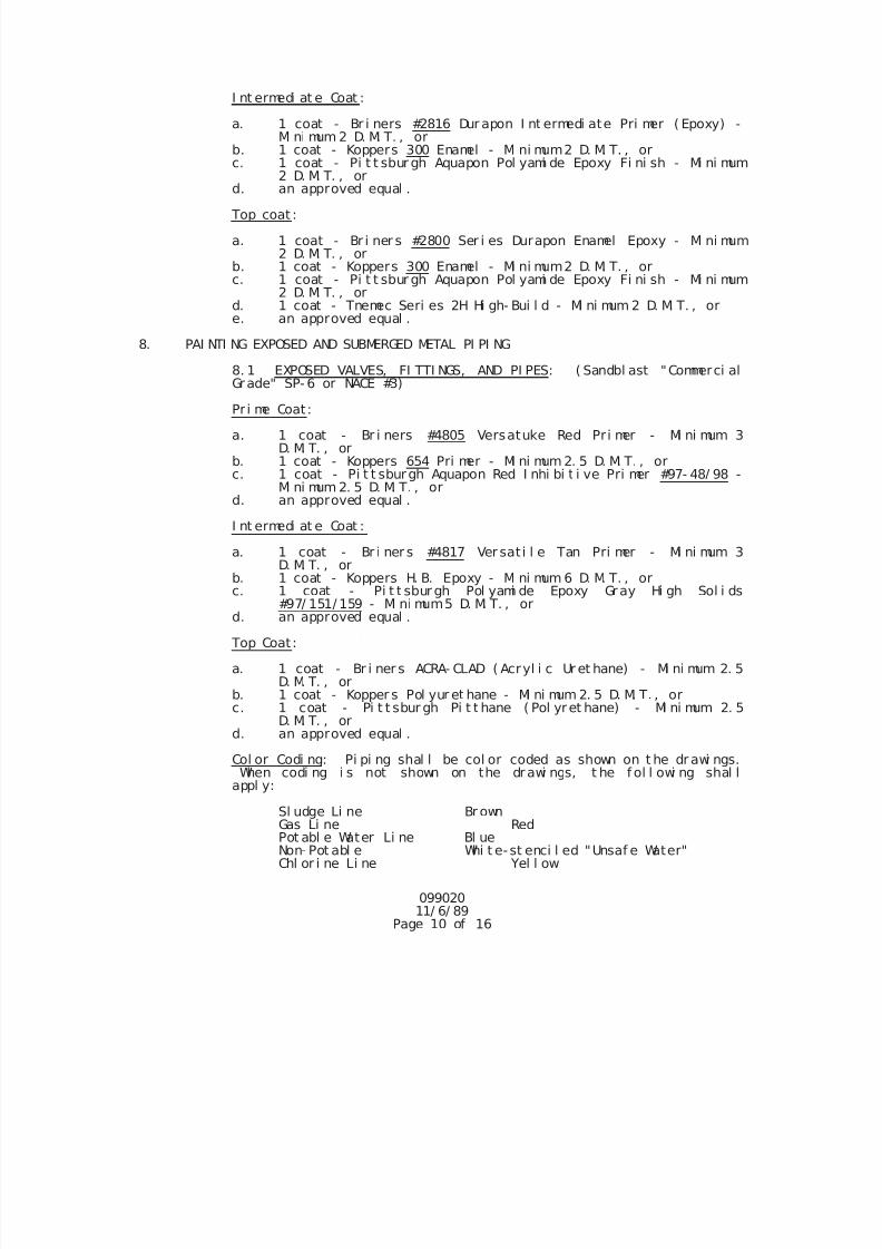
7/25/2019 City Standard Construction Specifications
http://slidepdf.com/reader/full/city-standard-construction-specifications 462/511
099020 11/ 6/ 89
Page 10 of 16
I nt ermedi at e Coat :
a. 1 coat - Br i ners #2816 Dur apon I nt ermedi ate Pri mer ( Epoxy) -Mi ni mum 2 D. M. T. , or
b. 1 coat - Koppers 300 Enamel - Mi ni mum2 D. M. T. , orc. 1 coat - Pi t t sbur gh Aquapon Pol yami de Epoxy Fi ni sh - Mi ni mum
2 D. M. T. , ord. an approved equal .
Top coat :
a. 1 coat - Br i ner s #2800 Ser i es Durapon Enamel Epoxy - Mi ni mum2 D. M. T. , or
b. 1 coat - Koppers 300 Enamel - Mi ni mum2 D. M. T. , orc. 1 coat - Pi t t sbur gh Aquapon Pol yami de Epoxy Fi ni sh - Mi ni mum
2 D. M. T. , ord. 1 coat - Tnemec Seri es 2H Hi gh- Bui l d - Mi ni mum 2 D. M. T. , ore. an approved equal .
8. PAI NTI NG EXPOSED AND SUBMERGED METAL PI PI NG
8. 1 EXPOSED VALVES, FI TTI NGS, AND PI PES: ( Sandbl ast "Commerci alGrade" SP- 6 or NACE #3)
Pr i me Coat:
a. 1 coat - Br i ners #4805 Versatuke Red Pr i mer - Mi ni mum 3D. M. T. , or
b. 1 coat - Koppers 654 Pri mer - Mi ni mum 2. 5 D. M. T. , orc. 1 coat - Pi t t sburgh Aquapon Red I nhi bi t i ve Pri mer #97- 48/ 98 -
Mi ni mum 2. 5 D. M. T. , ord. an approved equal .
I nt ermedi at e Coat :
a. 1 coat - Br i ner s #4817 Ver sat i l e Tan Pri mer - Mi ni mum 3D. M. T. , or
b. 1 coat - Koppers H. B. Epoxy - Mi ni mum 6 D. M. T. , or
c. 1 coat - Pi t t sbur gh Pol yami de Epoxy Gray Hi gh Sol i ds#97/ 151/ 159 - Mi ni mum5 D. M. T. , ord. an approved equal .
Top Coat:
a. 1 coat - Br i ner s ACRA- CLAD ( Acryl i c Ur et hane) - Mi ni mum 2. 5D. M. T. , or
b. 1 coat - Kopper s Pol yur et hane - Mi ni mum 2. 5 D. M. T. , orc. 1 coat - Pi t t sbur gh Pi t t hane ( Pol yret hane) - Mi ni mum 2. 5
D. M. T. , ord. an approved equal .
Col or Codi ng: Pi pi ng shal l be col or coded as shown on t he dr awi ngs.When codi ng i s not shown on the drawi ngs, t he f ol l owi ng shal l
appl y: Sl udge Li ne Br own
Gas Li ne RedPot abl e Water Li ne Bl ueNon- Pot abl e Whi t e- st enci l ed "Unsaf e Water"Chl or i ne Li ne Yel l ow
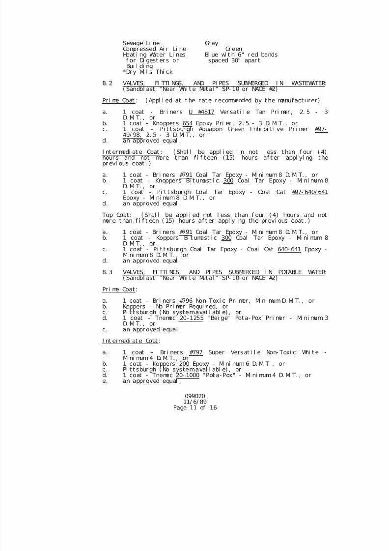
7/25/2019 City Standard Construction Specifications
http://slidepdf.com/reader/full/city-standard-construction-specifications 463/511
099020 11/ 6/ 89
Page 11 of 16
Sewage Li ne Gr ayCompressed Ai r Li ne Gr eenHeat i ng Water Li nes Bl ue wi t h 6" r ed bandsf or Di gest er s or spaced 30" apar tBui l di ng
*Dr y Mi l s Thi ck
8. 2 VALVES, FI TTI NGS, AND PI PES SUBMERGED I N WASTEWATER:( Sandbl ast "Near Whi t e Metal " SP- 10 or NACE #2)
Pri me Coat : ( Appl i ed at t he r ate r ecommended by t he manufacturer)
a. 1 coat - Br i ner s U #4817 Ver sat i l e Tan Pri mer , 2. 5 - 3D. M. T. , or
b. 1 coat - Knopper s 654 Epoxy Pri er , 2. 5 - 3 D. M. T. , orc. 1 coat - Pi t t sbur gh Aquapon Gr een I nhi bi t i ve Pr i mer #97-
49/ 98, 2. 5 - 3 D. M. T. , ord. an approved equal .
I nt er medi at e Coat : ( Shal l be appl i ed i n not l ess t han f our ( 4)hour s and not more t han f i f t een (15) hour s af t er appl yi ng theprevi ous coat . )
a. 1 coat - Br i ners #791 Coal Tar Epoxy - Mi ni mum 8 D. M. T. , or b. 1 coat - Knoppers Bi t umast i c 300 Coal Tar Epoxy - Mi ni mum 8
D. M. T. , orc. 1 coat - Pi t t sburgh Coal Tar Epoxy - Coal Cat #97- 640/ 641
Epoxy - Mi ni mum 8 D. M. T. , ord. an approved equal .
Top Coat: ( Shal l be appl i ed not l ess t han f our ( 4) hours and notmor e than f i f t een ( 15) hour s af t er appl yi ng the pr evi ous coat . )
a. 1 coat - Br i ners #791 Coal Tar Epoxy - Mi ni mum 8 D. M. T. , orb. 1 coat - Koppers Bi t umast i c 300 Coal Tar Epoxy - Mi ni mum 8
D. M. T. , orc. 1 coat - Pi t t sbur gh Coal Tar Epoxy - Coal Cat 640- 641 Epoxy -
Mi ni mum 8 D. M. T. , or
d. an approved equal .
8. 3 VALVES, FI TTI NGS, AND PI PES SUBMERGED I N POTABLE WATER:( Sandbl ast "Near Whi t e Metal " SP- 10 or NACE #2)
Pr i me Coat:
a. 1 coat - Br i ner s #796 Non- Toxi c Pri mer , Mi ni mum D. M. T. , orb. Koppers - No Pr i mer Requi r ed, orc. Pi t t sbur gh ( No systemavai l abl e) , ord. 1 coat - Tnemec 20-1255 "Bei ge" Pota- Pox Pr i mer - Mi ni mum 3
D. M. T. , orc. an appr oved equal .
I nt ermedi at e Coat :
a. 1 coat - Br i ner s #797 Super Versat i l e Non- Toxi c Whi t e -Mi ni mum 4 D. M. T. , or
b. 1 coat - Koppers 200 Epoxy - Mi ni mum 6 D. M. T. , orc. Pi t t sbur gh ( No systemavai l abl e) , ord. 1 coat - Tnemec 20- 1000 "Pot a-Pox" - Mi ni mum 4 D. M. T. , ore. an approved equal .
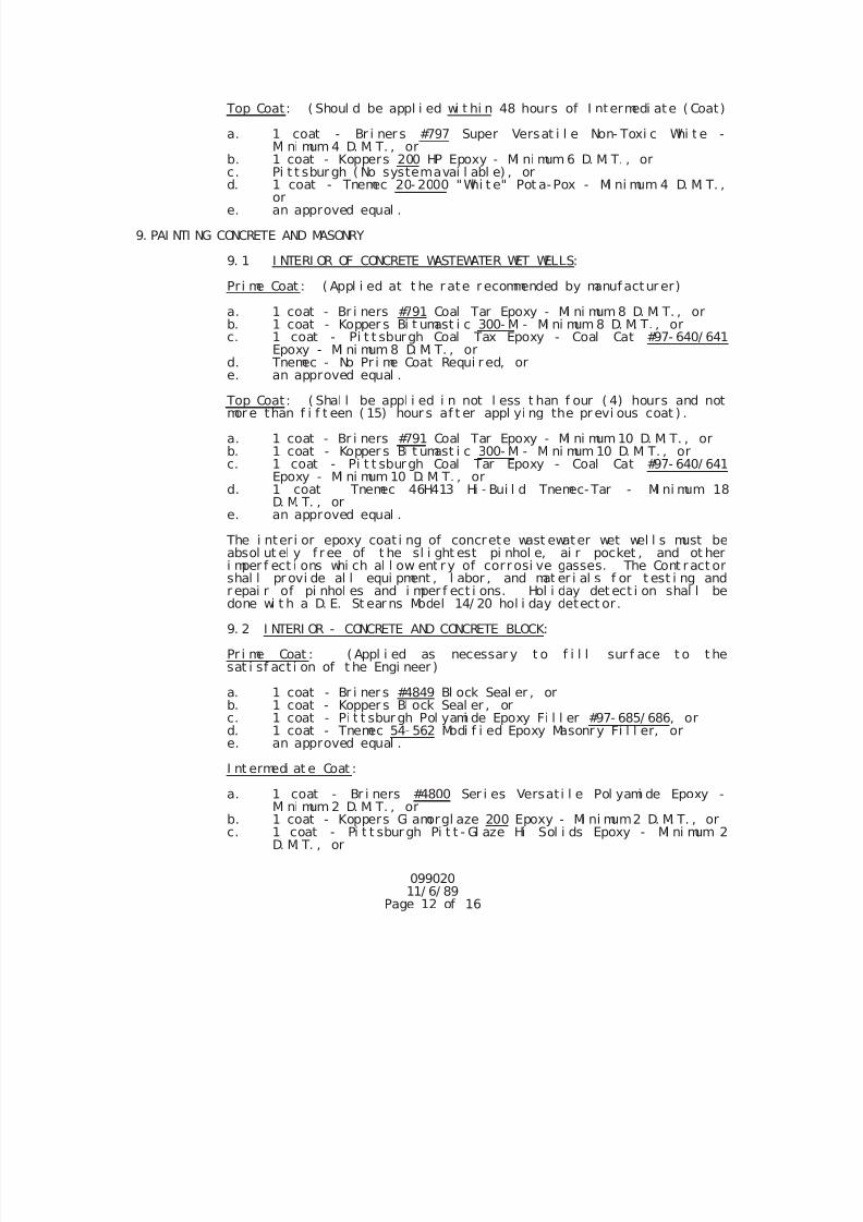
7/25/2019 City Standard Construction Specifications
http://slidepdf.com/reader/full/city-standard-construction-specifications 464/511
099020 11/ 6/ 89
Page 12 of 16
Top Coat: ( Shoul d be appl i ed wi t hi n 48 hours of I ntermedi ate ( Coat)
a. 1 coat - Br i ner s #797 Super Versat i l e Non- Toxi c Whi t e -Mi ni mum 4 D. M. T. , or
b. 1 coat - Koppers 200 HP Epoxy - Mi ni mum 6 D. M. T. , orc. Pi t t sbur gh ( No systemavai l abl e) , ord. 1 coat - Tnemec 20- 2000 "Whi t e" Pot a-Pox - Mi ni mum 4 D. M. T. ,
or e. an approved equal .
9. PAI NTI NG CONCRETE AND MASONRY
9. 1 I NTERI OR OF CONCRETE WASTEWATER WET WELLS:
Pr i me Coat : ( Appl i ed at t he r ate r ecommended by manuf actur er)
a. 1 coat - Br i ners #791 Coal Tar Epoxy - Mi ni mum 8 D. M. T. , orb. 1 coat - Kopper s Bi t umast i c 300- M - Mi ni mum 8 D. M. T. , orc. 1 coat - Pi t t sburgh Coal Tax Epoxy - Coal Cat #97- 640/ 641
Epoxy - Mi ni mum 8 D. M. T. , ord. Tnemec - No Pr i me Coat Requi r ed, ore. an approved equal .
Top Coat: ( Shal l be appl i ed i n not l ess t han f our ( 4) hours and notmor e than f i f t een ( 15) hour s af t er appl yi ng the pr evi ous coat ) .
a. 1 coat - Br i ners #791 Coal Tar Epoxy - Mi ni mum 10 D. M. T. , orb. 1 coat - Kopper s Bi t umast i c 300- M - Mi ni mum 10 D. M. T. , orc. 1 coat - Pi t t sburgh Coal Tar Epoxy - Coal Cat #97- 640/ 641
Epoxy - Mi ni mum 10 D. M. T. , ord. 1 coat Tnemec 46H413 Hi - Bui l d Tnemec- Tar - Mi ni mum 18
D. M. T. , ore. an approved equal .
The i nter i or epoxy coat i ng of concrete wast ewater wet wel l s must beabsol ut el y f r ee of t he sl i ght est pi nhol e, ai r pocket , and ot heri mper f ect i ons whi ch al l ow ent r y of corrosi ve gasses. The Cont ract or
shal l pr ovi de al l equi pment , l abor , and mat er i al s f or t est i ng andr epai r of pi nhol es and i mper f ect i ons. Hol i day det ect i on shal l bedone wi t h a D. E. St ear ns Model 14/ 20 hol i day detect or.
9. 2 I NTERI OR - CONCRETE AND CONCRETE BLOCK:
Pr i me Coat : ( Appl i ed as necessar y t o f i l l sur f ace t o t hesat i sf act i on of t he Engi neer )
a. 1 coat - Br i ner s #4849 Bl ock Seal er , orb. 1 coat - Kopper s Bl ock Seal er , orc. 1 coat - Pi t t sbur gh Pol yami de Epoxy Fi l l er #97- 685/ 686, ord. 1 coat - Tnemec 54- 562 Modi f i ed Epoxy Masonr y Fi l l er, ore. an approved equal .
I nt ermedi at e Coat : a. 1 coat - Br i ners #4800 Ser i es Versat i l e Pol yami de Epoxy -
Mi ni mum 2 D. M. T. , orb. 1 coat - Koppers Gl amorgl aze 200 Epoxy - Mi ni mum2 D. M. T. , orc. 1 coat - Pi t t sbur gh Pi t t - Gl aze Hi Sol i ds Epoxy - Mi ni mum 2
D. M. T. , or
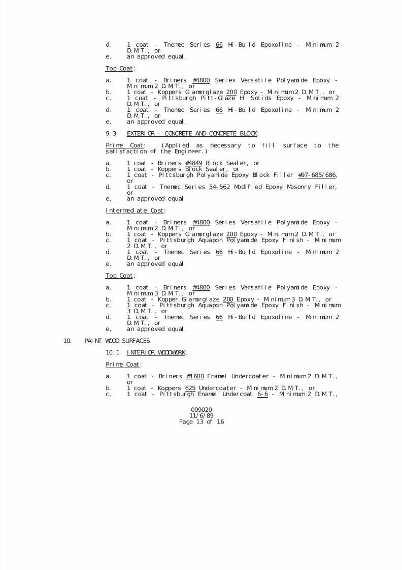
7/25/2019 City Standard Construction Specifications
http://slidepdf.com/reader/full/city-standard-construction-specifications 465/511
099020 11/ 6/ 89
Page 13 of 16
d. 1 coat - Tnemec Ser i es 66 Hi - Bui l d Epoxol i ne - Mi ni mum 2D. M. T. , or
e. an approved equal .
Top Coat:
a. 1 coat - Br i ners #4800 Ser i es Versat i l e Pol yami de Epoxy -Mi ni mum 2 D. M. T. , or
b. 1 coat - Koppers Gl amorgl aze 200 Epoxy - Mi ni mum2 D. M. T. , orc. 1 coat - Pi t t sbur gh Pi t t - Gl aze Hi Sol i ds Epoxy - Mi ni mum 2
D. M. T. , ord. 1 coat - Tnemec Ser i es 66 Hi - Bui l d Epoxol i ne - Mi ni mum 2
D. M. T. , ore. an approved equal .
9. 3 EXTERI OR - CONCRETE AND CONCRETE BLOCK:
Pr i me Coat : ( Appl i ed as necessar y t o f i l l sur f ace t o t hesat i sf acti on of t he Engi neer . )
a. 1 coat - Br i ner s #4849 Bl ock Seal er , orb. 1 coat - Kopper s Bl ock Seal er , orc. 1 coat - Pi t t sbur gh Pol yami de Epoxy Bl ock Fi l l er #97- 685/ 686,
or d. 1 coat - Tnemec Seri es 54- 562 Modi f i ed Epoxy Masonr y Fi l l er,
or e. an approved equal .
I nt ermedi at e Coat :
a. 1 coat - Br i ners #4800 Ser i es Versat i l e Pol yami de Epoxy -Mi ni mum 2 D. M. T. , or
b. 1 coat - Koppers Gl amorgl aze 200 Epoxy - Mi ni mum2 D. M. T. , orc. 1 coat - Pi t t sbur gh Aquapon Pol yami de Epoxy Fi ni sh - Mi ni mum
2 D. M. T. , ord. 1 coat - Tnemec Ser i es 66 Hi - Bui l d Epoxol i ne - Mi ni mum 2
D. M. T. , ore. an approved equal .
Top Coat:
a. 1 coat - Br i ners #4800 Ser i es Versat i l e Pol yami de Epoxy -Mi ni mum 3 D. M. T. , or
b. 1 coat - Kopper Gl amorgl aze 200 Epoxy - Mi ni mum3 D. M. T. , orc. 1 coat - Pi t t sbur gh Aquapon Pol yami de Epoxy Fi ni sh - Mi ni mum
3 D. M. T. , ord. 1 coat - Tnemec Ser i es 66 Hi - Bui l d Epoxol i ne - Mi ni mum 2
D. M. T. , ore. an approved equal .
10. PAI NT WOOD SURFACES
10. 1 I NTERI OR WOODWORK:
Pr i me Coat :
a. 1 coat - Br i ner s #1600 Enamel Undercoat er - Mi ni mum2 D. M. T. ,or
b. 1 coat - Koppers 625 Undercoater - Mi ni mum 2 D. M. T. , orc. 1 coat - Pi t t sbur gh Enamel Under coat 6- 6 - Mi ni mum 2 D. M. T. ,
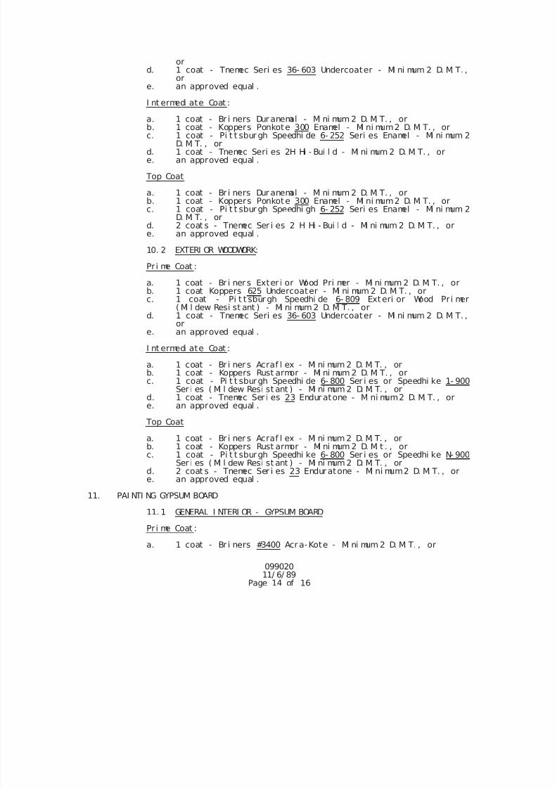
7/25/2019 City Standard Construction Specifications
http://slidepdf.com/reader/full/city-standard-construction-specifications 466/511
099020 11/ 6/ 89
Page 14 of 16
or d. 1 coat - Tnemec Seri es 36- 603 Undercoater - Mi ni mum 2 D. M. T. ,
or e. an approved equal .
I nt ermedi ate Coat :
a. 1 coat - Br i ners Dur anemal - Mi ni mum 2 D. M. T. , orb. 1 coat - Koppers Ponkote 300 Enamel - Mi ni mum2 D. M. T. , orc. 1 coat - Pi t t sbur gh Speedhi de 6- 252 Seri es Enamel - Mi ni mum 2
D. M. T. , ord. 1 coat - Tnemec Seri es 2H Hi - Bui l d - Mi ni mum 2 D. M. T. , ore. an approved equal .
Top Coat
a. 1 coat - Br i ners Dur anemal - Mi ni mum 2 D. M. T. , orb. 1 coat - Koppers Ponkote 300 Enamel - Mi ni mum2 D. M. T. , orc. 1 coat - Pi t t sbur gh Speedhi gh 6- 252 Seri es Enamel - Mi ni mum 2
D. M. T. , ord. 2 coat s - Tnemec Ser i es 2 H Hi - Bui l d - Mi ni mum 2 D. M. T. , ore. an approved equal .
10. 2 EXTERI OR WOODWORK:
Pr i me Coat :
a. 1 coat - Br i ner s Exter i or Wood Pri mer - Mi ni mum 2 D. M. T. , orb. 1 coat Koppers 625 Undercoater - Mi ni mum 2 D. M. T. , orc. 1 coat - Pi t t sbur gh Speedhi de 6- 809 Exteri or Wood Pr i mer
( Mi l dew Resi st ant ) - Mi ni mum 2 D. M. T. , ord. 1 coat - Tnemec Seri es 36- 603 Undercoater - Mi ni mum 2 D. M. T. ,
or e. an approved equal .
I nt ermedi ate Coat :
a. 1 coat - Br i ner s Acraf l ex - Mi ni mum 2 D. M. T. , or
b. 1 coat - Koppers Rust armor - Mi ni mum 2 D. M. T. , orc. 1 coat - Pi t t sburgh Speedhi de 6- 800 Ser i es or Speedhi ke 1- 900Ser i es ( Mi l dew Resi st ant ) - Mi ni mum 2 D. M. T. , or
d. 1 coat - Tnemec Ser i es 23 Enduratone - Mi ni mum2 D. M. T. , ore. an approved equal .
Top Coat
a. 1 coat - Br i ner s Acraf l ex - Mi ni mum 2 D. M. T. , orb. 1 coat - Koppers Rust armor - Mi ni mum 2 D. M. t . , orc. 1 coat - Pi t t sburgh Speedhi ke 6- 800 Ser i es or Speedhi ke N- 900
Ser i es ( Mi l dew Resi st ant ) - Mi ni mum 2 D. M. T. , ord. 2 coat s - Tnemec Ser i es 23 Endur atone - Mi ni mum2 D. M. T. , ore. an approved equal .
11. PAI NTI NG GYPSUM BOARD11. 1 GENERAL I NTERI OR - GYPSUM BOARD
Pr i me Coat :
a. 1 coat - Br i ners #3400 Acr a-Kote - Mi ni mum 2 D. M. T. , or
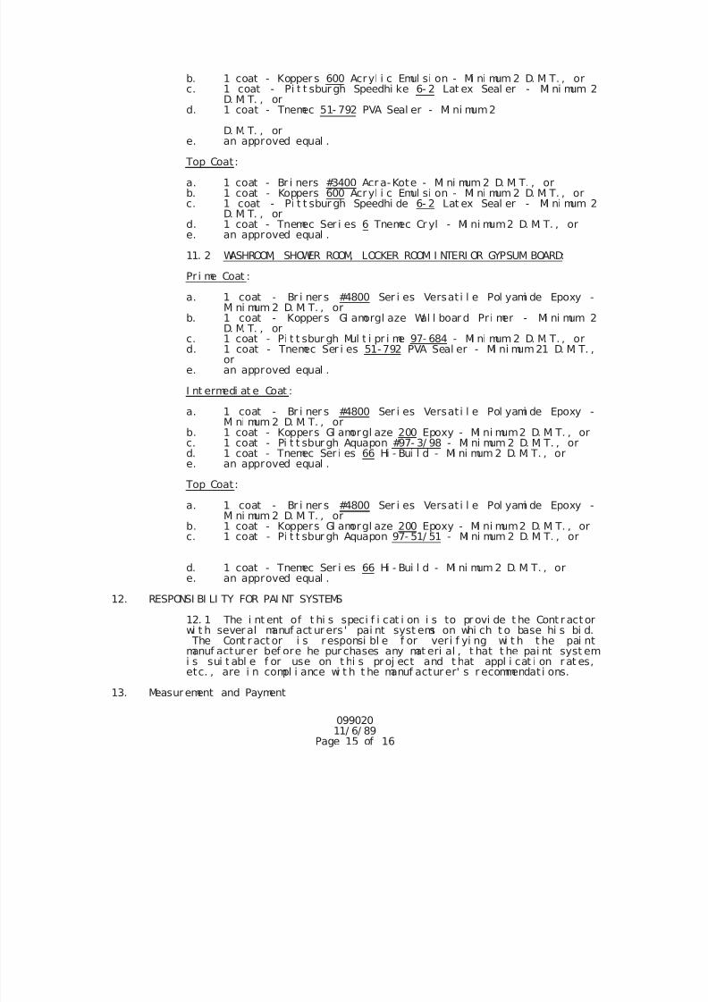
7/25/2019 City Standard Construction Specifications
http://slidepdf.com/reader/full/city-standard-construction-specifications 467/511
099020 11/ 6/ 89
Page 15 of 16
b. 1 coat - Kopper s 600 Acryl i c Emul si on - Mi ni mum 2 D. M. T. , orc. 1 coat - Pi t t sbur gh Speedhi ke 6- 2 Lat ex Seal er - Mi ni mum 2
D. M. T. , ord. 1 coat - Tnemec 51- 792 PVA Seal er - Mi ni mum2
D. M. T. , ore. an approved equal .
Top Coat:
a. 1 coat - Br i ners #3400 Acr a-Kote - Mi ni mum 2 D. M. T. , orb. 1 coat - Koppers 600 Acryl i c Emul si on - Mi ni mum 2 D. M. T. , or
c. 1 coat - Pi t t sbur gh Speedhi de 6- 2 Lat ex Seal er - Mi ni mum 2D. M. T. , or
d. 1 coat - Tnemec Ser i es 6 Tnemec Cr yl - Mi ni mum2 D. M. T. , ore. an approved equal .
11. 2 WASHROOM, SHOWER ROOM, LOCKER ROOM I NTERI OR GYPSUM BOARD:
Pr i me Coat :
a. 1 coat - Br i ner s #4800 Ser i es Versat i l e Pol yami de Epoxy -Mi ni mum 2 D. M. T. , or
b. 1 coat - Kopper s Gl amorgl aze Wal l boar d Pr i mer - Mi ni mum 2D. M. T. , or
c. 1 coat - Pi t t sbur gh Mul t i pr i me 97- 684 - Mi ni mum 2 D. M. T. , ord. 1 coat - Tnemec Ser i es 51-792 PVA Seal er - Mi ni mum21 D. M. T. ,
or e. an approved equal .
I nt ermedi at e Coat :
a. 1 coat - Br i ner s #4800 Ser i es Versat i l e Pol yami de Epoxy -Mi ni mum 2 D. M. T. , or
b. 1 coat - Koppers Gl amorgl aze 200 Epoxy - Mi ni mum2 D. M. T. , orc. 1 coat - Pi t t sbur gh Aquapon #97- 3/ 98 - Mi ni mum 2 D. M. T. , ord. 1 coat - Tnemec Ser i es 66 Hi - Bui l d - Mi ni mum 2 D. M. T. , ore. an approved equal .
Top Coat:
a. 1 coat - Br i ner s #4800 Ser i es Versat i l e Pol yami de Epoxy -Mi ni mum 2 D. M. T. , or
b. 1 coat - Koppers Gl amorgl aze 200 Epoxy - Mi ni mum2 D. M. T. , orc. 1 coat - Pi t t sbur gh Aquapon 97- 51/ 51 - Mi ni mum 2 D. M. T. , or
d. 1 coat - Tnemec Ser i es 66 Hi - Bui l d - Mi ni mum 2 D. M. T. , ore. an approved equal .
12. RESPONSI BI LI TY FOR PAI NT SYSTEMS
12. 1 The i nt ent of t hi s speci f i cat i on i s to pr ovi de t he Cont r actor
wi t h sever al manuf act ur ers ' pai nt syst ems on whi ch t o base hi s bi d. The Cont r act or i s r esponsi bl e f or veri f yi ng wi t h t he pai ntmanuf acturer bef ore he pur chases any mat eri al , t hat t he pai nt syst emi s sui t abl e f or use on t hi s pr oj ect and t hat appl i cat i on r at es,etc. , are i n compl i ance wi t h t he manuf actur er' s r ecommendat i ons.
13. Measurement and Payment
7/25/2019 City Standard Construction Specifications
http://slidepdf.com/reader/full/city-standard-construction-specifications 468/511
099020 11/ 6/ 89
Page 16 of 16
Pai nt i ng shal l not be measur ed f or pay and shal l be subsi di ar y toother work.
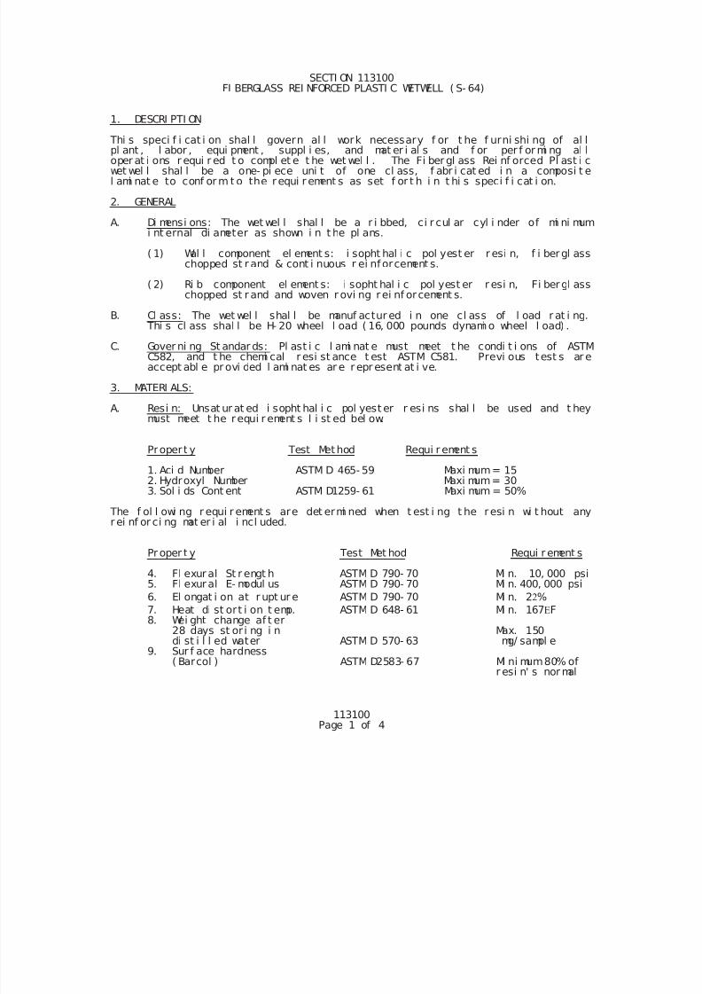
7/25/2019 City Standard Construction Specifications
http://slidepdf.com/reader/full/city-standard-construction-specifications 469/511
113100Page 1 of 4
SECTI ON 113100 FI BERGLASS REI NFORCED PLASTI C WETWELL ( S- 64)
1. DESCRI PTI ON
Thi s speci f i cat i on shal l govern al l work necessary f or t he f urni shi ng of al lpl ant , l abor , equi pment , suppl i es, and mat er i al s and f or per f or mi ng al loper at i ons r equi r ed t o compl et e t he wet wel l . The Fi ber gl ass Rei nf orced Pl ast i cwet wel l shal l be a one- pi ece uni t of one cl ass, f abr i cat ed i n a composi t el ami nat e to conf or m t o the requi r ement s as set f or t h i n t hi s speci f i cat i on.
2. GENERAL
A. Di mensi ons: The wet wel l shal l be a r i bbed, ci r cul ar cyl i nder of mi ni mumi nt ernal di ameter as shown i n t he pl ans.
( 1) Wal l component el ement s: i sopht hal i c pol yest er r esi n, f i bergl asschopped st r and & cont i nuous r ei nforcement s.
( 2) Ri b component el ement s: i sopht hal i c pol yest er r esi n, Fi bergl asschopped st r and and woven r ovi ng rei nf orcement s.
B. Cl ass: The wet wel l shal l be manuf actur ed i n one cl ass of l oad r at i ng. Thi s cl ass shal l be H- 20 wheel l oad ( 16, 000 pounds dynami o wheel l oad) .
C. Gover ni ng St andar ds: Pl ast i c l ami nat e must meet t he condi t i ons of ASTMC582, and t he chemi cal r esi st ance t est ASTM C581. Previ ous test s ar eaccept abl e pr ovi ded l ami nat es ar e r epr esent at i ve.
3. MATERI ALS:
A. Resi n: Unsat ur at ed i sopht hal i c pol yest er r esi ns shal l be used and t heymust meet t he requi r ement s l i st ed bel ow.
Propert y Test Method Requi r ement s
1. Aci d Number ASTM D 465- 59 Maxi mum= 15 2. Hydroxyl Number Maxi mum= 303. Sol i ds Cont ent ASTM D1259- 61 Maxi mum = 50%
The f ol l owi ng r equi r ement s are det ermi ned when t est i ng t he resi n wi t hout anyr ei nf or ci ng mat er i al i ncl uded.
Pr oper t y Test Met hod Requi r ement s
4. Fl exural St r engt h ASTM D 790- 70 Mi n. 10, 000 psi5. Fl exural E- modul us ASTM D 790- 70 Mi n. 400, 000 psi
6. El ongat i on at r upt ur e ASTM D 790- 70 Mi n. 2%
7. Heat di st ort i on t emp. ASTM D 648- 61 Mi n. 167F 8. Wei ght change af t er
28 days st or i ng i n Max. 150di st i l l ed water ASTM D 570- 63 mg/ sampl e
9. Sur f ace hardness( Barcol ) ASTM D2583- 67 Mi ni mum80% of
r esi n' s nor mal
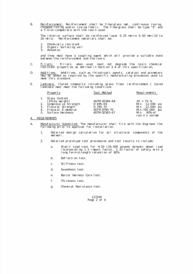
7/25/2019 City Standard Construction Specifications
http://slidepdf.com/reader/full/city-standard-construction-specifications 470/511
113100Page 2 of 4
B. Rei nf orcement : Rei nf or cement shal l be f i ber gl ass mat , cont i nuous r ovi ng,chopped r ovi ng and/ or rovi ng f abr i c. The f i ber gl ass shal l be t ype "E" anda f i ni sh compat i bl e wi t h t he r esi n used.
The i nt er i or sur f ace shal l be r ei nf or ced l ayer 0. 25 mm t o 0. 50 mm ( 10 t o20 mi l s) . Rei nf or cement mat er i al s shal l be:
1. Chemi cal l y r esi st ant2. Or gani c Sur f aci ng vei l3. Asbest os
and t hey must have a coupl i ng agent whi ch wi l l provi de a sui t abl e bondbet ween t he r ei nf orcement and t he r esi n.
C. Fi l l ers: Fi l l ers, when used, must not degrade t he resi n chemi calr esi st ant pr oper t i es as def i ned i n Secti on 3. A of t hi s speci f i cat i on.
D. Addi t i ves: Addi t i ves, such as t hi xot ropi c agent s, cat al yst and promot ersmay be added as r equi r ed by t he speci f i c manuf acturi ng processes used t omeet t hi s st andard.
E. Lami nat e: ( Cur ed composi t e i ncl udi ng gl ass f i ber r ei nf or cement . ) Cur ed
l ami nat e must meet t he f ol l owi ng condi t i ons:
Pr oper t y Test Met hod Requi rement s
1. Gl ass Cont ent( 9%by wei ght) ASTM D2584-68 20 + 70 %
2. Compressi ve Str ength D 695-69 Mi n. 12, 000 psi3. Fl exur al St r engt h D 790- 70 Mi n. 12, 000 psi4. Fl exur al E- modul us ASTM D790- 70 Mi n. 700, 000 psi5. Sur f ace Hardness ASTM D2583- 67 Mi n. 90% of
r esi n' s nor mal4. REQUI REMENTS
A. Manuf acturer Submi t t ed: The manuf acturer shal l f i l e wi t h t he Engi neer t hef ol l owi ng pr i or t o approval f or i nst al l at i on.
1. Det ai l ed desi gn cal cul at i on f or al l st r uct ur al component s of t hewet wel l .
2. Det ai l ed pr ot ot ype t est pr ocedures and t est r esul t s t o i ncl ude:
a. St at i c Load t est f or H- 20 ( 16, 000 pounds dynami c wheel l oadi ncor por at i ng 1. 5 i mpact f act or , 1. 33 f actor of saf et y wi t h al ong t er m st r engt h ret ent i on of 80%.
b. Def l ecti on t est.
c. St i f f ness test.
d. Soundness t est .
e. Barcol Har ness Cur e t est .
f . Thi ckness t est .
g. Chemi cal Resi st ance t est .
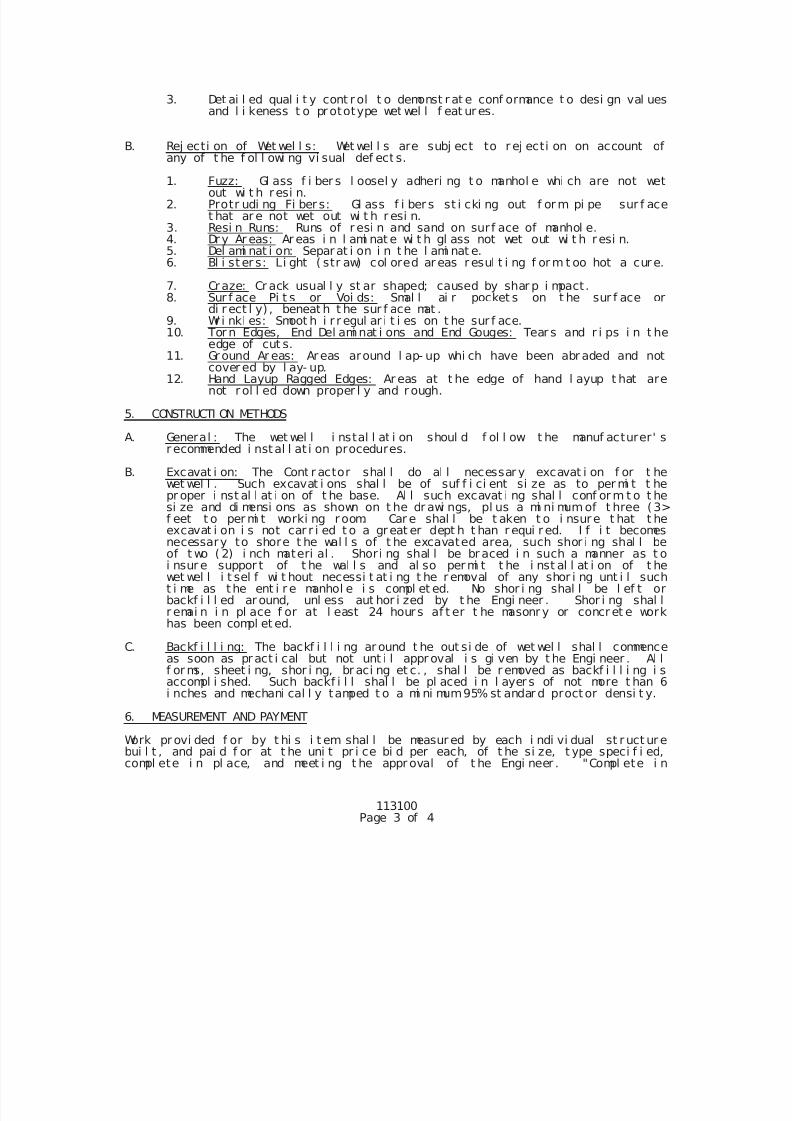
7/25/2019 City Standard Construction Specifications
http://slidepdf.com/reader/full/city-standard-construction-specifications 471/511
113100Page 3 of 4
3. Det ai l ed qual i t y cont r ol t o demonst r at e conf ormance t o desi gn val uesand l i keness t o prototype wet wel l f eat ur es.
B. Rej ecti on of Wet wel l s: Wet wel l s are subj ect to r ej ecti on on account ofany of t he f ol l owi ng vi sual def ect s.
1. Fuzz: Gl ass f i ber s l oosel y adheri ng t o manhol e whi ch are not wetout wi t h resi n.
2. Protr udi ng Fi ber s: Gl ass f i ber s st i cki ng out f or m pi pe sur f acet hat ar e not wet out wi t h r esi n.
3. Resi n Runs: Runs of r esi n and sand on sur f ace of manhol e. 4. Dry Ar eas: Ar eas i n l ami nat e wi t h gl ass not wet out wi t h resi n. 5. Del ami nat i on: Separat i on i n t he l ami nat e. 6. Bl i st er s: Li ght ( str aw) col ored ar eas r esul t i ng f or m t oo hot a cur e.
7. Craze: Cr ack usual l y st ar shaped; caused by shar p i mpact. 8. Sur f ace Pi t s or Voi ds: Smal l ai r pocket s on t he sur f ace or
di r ect l y) , beneat h t he sur f ace mat . 9. Wr i nkl es: Smoot h i r r egul ar i t i es on t he sur f ace. 10. Tor n Edges, End Del ami nat i ons and End Gouges: Tear s and r i ps i n t he
edge of cut s.
11. Ground Ar eas: Areas around l ap- up whi ch have been abr aded and notcover ed by l ay- up.
12. Hand Layup Ragged Edges: Ar eas at t he edge of hand l ayup t hat arenot r ol l ed down proper l y and r ough.
5. CONSTRUCTI ON METHODS
A. General : The wet wel l i nstal l at i on shoul d f ol l ow t he manuf acturer' sr ecommended i nstal l at i on procedures.
B. Excavat i on: The Cont r actor shal l do al l necessar y excavat i on f or t hewet wel l . Such excavat i ons shal l be of suf f i ci ent si ze as to per mi t t hepr oper i nst al l at i on of t he base. Al l such excavat i ng shal l conf or m t o t hesi ze and di mensi ons as shown on t he dr awi ngs, pl us a mi ni mumof t hree (3>f eet t o per mi t worki ng room. Car e shal l be t aken t o i nsure t hat t he
excavat i on i s not car r i ed t o a great er dept h t han r equi r ed. I f i t becomesnecessary to shore t he wal l s of t he excavated area, such shor i ng shal l beof t wo ( 2) i nch materi al . Shori ng shal l be br aced i n such a manner as t oi nsur e suppor t of t he wal l s and al so permi t t he i nst al l at i on of t hewet wel l i t sel f wi t hout necessi t at i ng t he r emoval of any shor i ng unt i l sucht i me as the ent i r e manhol e i s compl et ed. No shor i ng shal l be l ef t orbackf i l l ed ar ound, unl ess aut hor i zed by t he Engi neer . Shor i ng shal lr emai n i n pl ace f or at l east 24 hours af t er t he masonr y or concr et e workhas been compl et ed.
C. Backf i l l i ng: The backf i l l i ng ar ound t he out si de of wet wel l shal l commenceas soon as pract i cal but not unt i l appr oval i s gi ven by t he Engi neer . Al lf or ms, sheet i ng, shor i ng, br aci ng et c. , shal l be r emoved as backf i l l i ng i saccompl i shed. Such backf i l l shal l be pl aced i n l ayer s of not more t han 6i nches and mechani cal l y tamped t o a mi ni mum95% st andar d proctor densi t y.
6. MEASUREMENT AND PAYMENT
Work pr ovi ded f or by t hi s i t em shal l be measur ed by each i ndi vi dual st r uct ur ebui l t , and pai d f or at t he uni t pr i ce bi d per each, of t he si ze, t ype speci f i ed,compl ete i n pl ace, and meet i ng t he appr oval of t he Engi neer . "Compl ete i n
7/25/2019 City Standard Construction Specifications
http://slidepdf.com/reader/full/city-standard-construction-specifications 472/511
113100Page 4 of 4
pl ace" shal l mean al l l abor, mat er i al s, equi pment necessary t o f ur ni sh andi nst al l t he wet wel l .
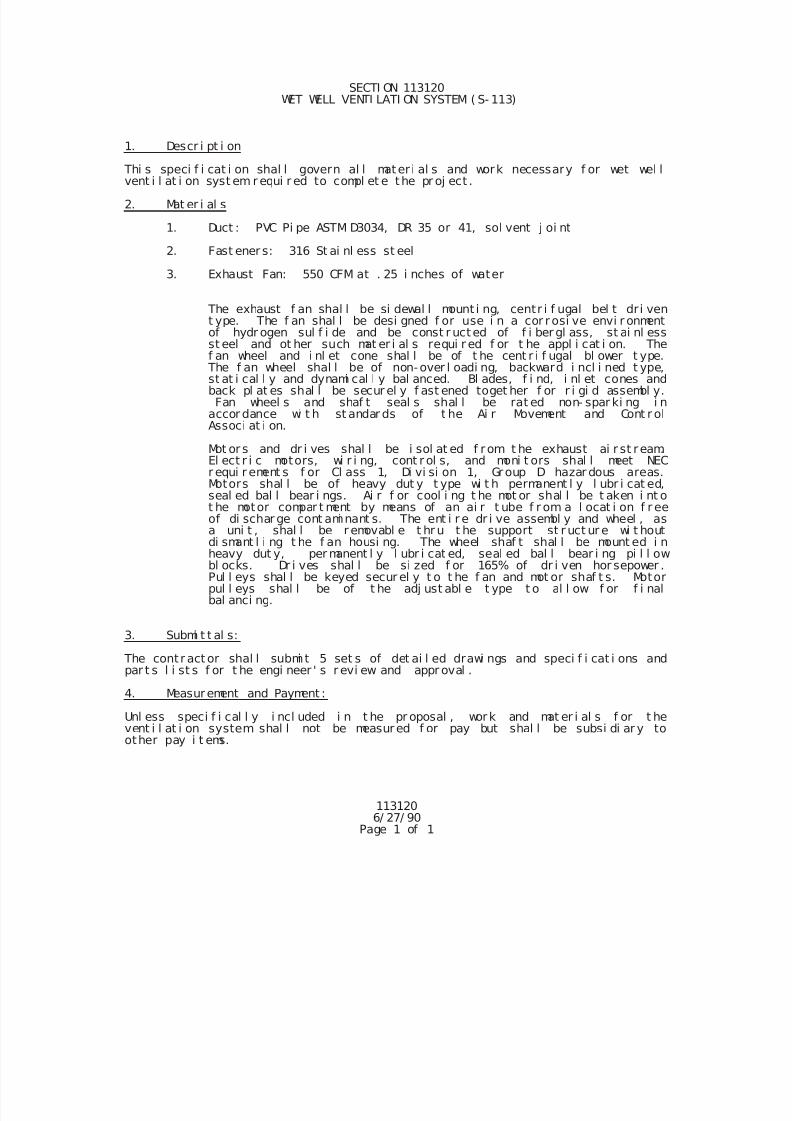
7/25/2019 City Standard Construction Specifications
http://slidepdf.com/reader/full/city-standard-construction-specifications 473/511
1131206/ 27/ 90
Page 1 of 1
SECTI ON 113120 WET WELL VENTI LATI ON SYSTEM ( S- 113)
1. Descr i pt i on
Thi s speci f i cat i on shal l govern al l mater i al s and work necessary f or wet wel lvent i l at i on syst em r equi r ed to compl et e the pr oj ect .
2. Mat er i al s
1. Duct : PVC Pi pe ASTM D3034, DR 35 or 41, sol vent j oi nt
2. Fast ener s: 316 St ai nl ess st eel
3. Exhaust Fan: 550 CFM at . 25 i nches of water
The exhaust f an shal l be si dewal l mount i ng, centr i f ugal bel t dr i vent ype. The f an shal l be desi gned f or use i n a cor rosi ve envi r onmentof hydr ogen sul f i de and be const r ucted of f i ber gl ass, st ai nl essst eel and ot her such mat er i al s requi r ed f or t he appl i cat i on. The
f an wheel and i nl et cone shal l be of t he cent r i f ugal bl ower t ype. The f an wheel shal l be of non-over l oadi ng, backward i ncl i ned t ype,st at i cal l y and dynami cal l y bal anced. Bl ades, f i nd, i nl et cones andback pl at es shal l be secur el y f ast ened toget her f or r i gi d assembl y.Fan wheel s and shaf t seal s shal l be rat ed non- spar ki ng i n
accor dance wi t h st andar ds of t he Ai r Movement and Cont r olAssoci at i on.
Mot or s and dr i ves shal l be i sol at ed f r om t he exhaust ai r st ream.El ect r i c motors, wi r i ng, cont r ol s, and moni t ors shal l meet NECr equi r ement s f or Cl ass 1, Di vi si on 1, Group D hazar dous areas.Motors shal l be of heavy dut y t ype wi t h permanent l y l ubr i cat ed,seal ed bal l bear i ngs. Ai r f or cool i ng t he mot or shal l be t aken i nt ot he motor compar t ment by means of an ai r t ube f r om a l ocat i on f r eeof di schar ge cont ami nant s. The ent i r e dr i ve assembl y and wheel , as
a uni t , shal l be r emovabl e t hr u t he support st r uct ur e wi t houtdi smant l i ng t he f an housi ng. The wheel shaf t shal l be mount ed i nheavy dut y, per manent l y l ubr i cat ed, seal ed bal l bear i ng pi l l owbl ocks. Dr i ves shal l be si zed f or 165% of dr i ven hor sepower .Pul l eys shal l be keyed secur el y t o t he f an and mot or shaf t s. Motorpul l eys shal l be of t he adj ust abl e t ype t o al l ow f or f i nalbal anci ng.
3. Submi t t al s:
The contr act or shal l submi t 5 set s of det ai l ed drawi ngs and speci f i cat i ons andpar t s l i st s f or t he engi neer ' s r evi ew and appr oval .
4. Measurement and Payment :
Unl ess speci f i cal l y i ncl uded i n t he pr oposal , work and mat er i al s f or t hevent i l at i on system shal l not be measured f or pay but shal l be subsi di ar y toother pay i t ems.
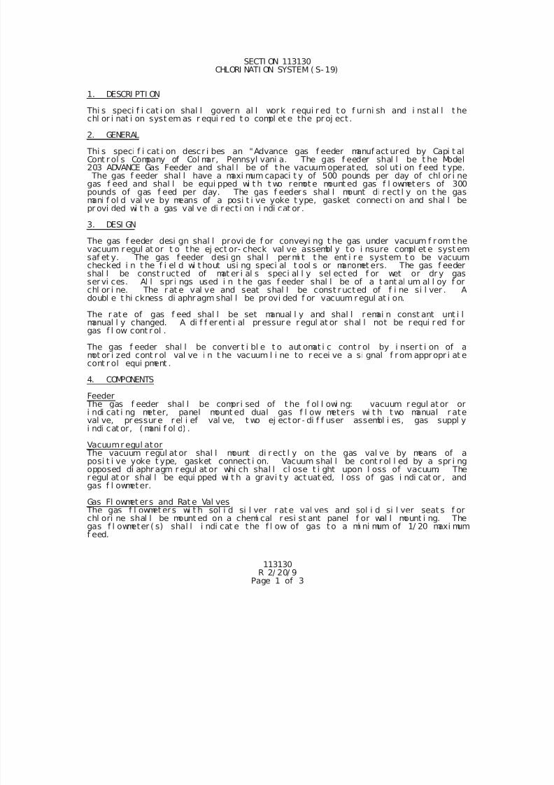
7/25/2019 City Standard Construction Specifications
http://slidepdf.com/reader/full/city-standard-construction-specifications 474/511
113130R 2/ 20/ 9
Page 1 of 3
SECTI ON 113130CHLORI NATI ON SYSTEM ( S- 19)
1. DESCRI PTI ON
Thi s speci f i cat i on shal l govern al l work r equi r ed t o f urni sh and i nst al l t hechl or i nat i on syst em as r equi r ed t o compl et e the pr oj ect .
2. GENERAL
Thi s speci f i cat i on descr i bes an "Advance gas f eeder manuf act ured by Capi t alCont r ol s Company of Col mar, Pennsyl vani a. The gas f eeder shal l be t he Model203 ADVANCE Gas Feeder and shal l be of t he vacuumoperated, sol ut i on f eed t ype. The gas f eeder shal l have a maxi mum capaci t y of 500 pounds per day of chl or i negas f eed and shal l be equi pped wi t h t wo remot e mount ed gas f l owmet ers of 300pounds of gas f eed per day. The gas f eeder s shal l mount di r ect l y on t he gasmani f ol d val ve by means of a posi t i ve yoke t ype, gasket connect i on and shal l bepr ovi ded wi t h a gas val ve di r ect i on i ndi cat or .
3. DESI GN
The gas f eeder desi gn shal l provi de f or conveyi ng t he gas under vacuum f r om t he
vacuum r egul at or t o the ej ect or- check val ve assembl y to i nsure compl et e syst emsaf et y. The gas f eeder desi gn shal l per mi t t he ent i r e system t o be vacuumchecked i n t he f i el d wi t hout usi ng speci al t ool s or manomet ers. The gas f eedershal l be const r uct ed of mat er i al s speci al l y sel ect ed f or wet or dr y gasser vi ces. Al l spr i ngs used i n t he gas f eeder shal l be of a t ant al um al l oy f orchl or i ne. The r at e val ve and seat shal l be const r uct ed of f i ne si l ver . Adoubl e t hi ckness di aphr agm shal l be pr ovi ded f or vacuum r egul at i on.
The r ate of gas f eed shal l be set manual l y and shal l r emai n const ant unt i lmanual l y changed. A di f f er ent i al pr essur e r egul at or shal l not be r equi r ed f orgas f l ow cont r ol .
The gas f eeder shal l be conver t i bl e t o aut omat i c cont r ol by i nser t i on of amot or i zed cont r ol val ve i n t he vacuum l i ne to r ecei ve a si gnal f r om appr opr i at econt r ol equi pment .
4. COMPONENTS
Feeder The gas f eeder shal l be compri sed of t he f ol l owi ng: vacuum r egul at or ori ndi cat i ng meter, panel mount ed dual gas f l ow meters wi t h t wo manual r ateval ve, pr essur e r el i ef val ve, t wo ej ector - di f f user assembl i es, gas suppl yi ndi cat or, ( mani f ol d) .
Vacuumr egul ator The vacuum r egul at or shal l mount di r ect l y on t he gas val ve by means of aposi t i ve yoke t ype, gasket connect i on. Vacuum shal l be cont r ol l ed by a spr i ngopposed di aphr agm r egul at or whi ch shal l cl ose t i ght upon l oss of vacuum. Ther egul at or shal l be equi pped wi t h a gr avi t y act uat ed, l oss of gas i ndi cat or , andgas f l owmeter.
Gas Fl owmet ers and Rat e Val ves The gas f l owmeters wi t h sol i d si l ver r at e val ves and sol i d si l ver seat s f orchl ori ne shal l be mount ed on a chemi cal r esi st ant panel f or wal l mount i ng. Thegas f l owmeter ( s) shal l i ndi cat e the f l ow of gas to a mi ni mum of 1/ 20 maxi mumf eed.
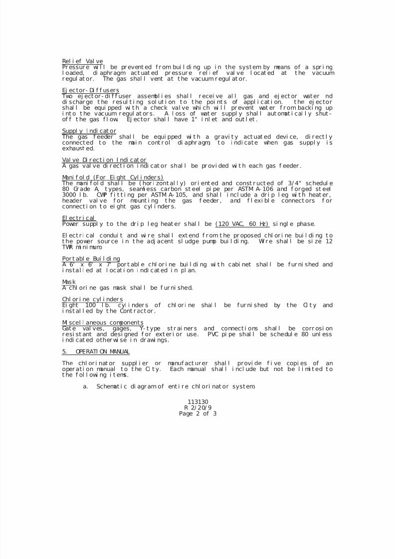
7/25/2019 City Standard Construction Specifications
http://slidepdf.com/reader/full/city-standard-construction-specifications 475/511
113130R 2/ 20/ 9
Page 2 of 3
Rel i ef Val vePr essur e wi l l be pr event ed f r om bui l di ng up i n the system by means of a spr i ngl oaded, di aphr agm act uat ed pr essur e r el i ef val ve l ocat ed at t he vacuumr egul at or. The gas shal l vent at t he vacuum r egul at or.
Ej ector- Di f f users Two ej ect or - di f f user assembl i es shal l r ecei ve al l gas and ej ect or water nddi schar ge t he r esul t i ng sol ut i on t o t he poi nt s of appl i cat i on. t he ej ectorshal l be equi pped wi t h a check val ve whi ch wi l l pr event wat er f r om backi ng upi nt o t he vacuum r egul at or s. A l oss of wat er suppl y shal l aut omat i cal l y shut -of f t he gas f l ow. Ej ector shal l have 1" i nl et and out l et .
Suppl y I ndi cat or The gas f eeder shal l be equi pped wi t h a gravi t y act uat ed devi ce, di r ect l yconnected t o the mai n cont r ol di aphr agm, t o i ndi cate when gas suppl y i sexhaust ed.
Val ve Di r ect i on I ndi cat orA gas val ve di r ect i on i ndi cat or shal l be pr ovi ded wi t h each gas f eeder .
Mani f ol d (For Ei ght Cyl i nder s) The mani f ol d shal l be ( hor i zont al l y) or i ent ed and const r uct ed of 3/ 4" schedul e80 Gr ade A, t ypes, seaml ess carbon st eel pi pe per ASTM A- 106 and f orged st eel3000 l b. CWP f i t t i ng per ASTM A- 105, and shal l i ncl ude a dr i p l eg wi t h heat er ,header val ve f or mount i ng t he gas f eeder , and f l exi bl e connect ors f orconnect i on t o ei ght gas cyl i nder s.
El ectr i calPower suppl y to the dr i p l eg heat er shal l be (120 VAC, 60 Hz) si ngl e phase.
El ect r i cal condui t and wi r e shal l ext end f r om t he pr oposed chl or i ne bui l di ng t ot he power sour ce i n t he adj acent sl udge pump bui l di ng. Wi r e shal l be si ze 12
TWR mi ni mum.
Por t abl e Bui l di ng
A 6' x 6' x 7' por t abl e chl or i ne bui l di ng wi t h cabi net shal l be f ur ni shed andi nstal l ed at l ocat i on i ndi cat ed i n pl an.
MaskA chl ori ne gas mask shal l be f ur ni shed.
Chl or i ne cyl i nder sEi ght 100 l b. cyl i nder s of chl or i ne shal l be f ur ni shed by the Ci t y andi nst al l ed by t he Cont r act or .
Mi scel l aneous componentsGat e val ves, gages, Y- t ype st r ai ner s and connect i ons shal l be corr osi onr esi st ant and desi gned f or exter i or use. PVC pi pe shal l be schedul e 80 unl essi ndi cat ed other wi se i n dr awi ngs.
5. OPERATI ON MANUAL The chl or i nat or suppl i er or manuf act urer shal l provi de f i ve copi es of anoper at i on manual t o t he Ci t y. Each manual shal l i ncl ude but not be l i mi t ed t ot he f ol l owi ng i t ems.
a. Schemat i c di agr am of ent i r e chl ori nat or system.
7/25/2019 City Standard Construction Specifications
http://slidepdf.com/reader/full/city-standard-construction-specifications 476/511
113130R 2/ 20/ 9
Page 3 of 3
b. Par t s and assembl e di agr am wi t h par t s number s f or orderi ng.c. Oper at i ons and mai ntenance procedures and schedul e.
6. WARRANTY
The Ci t y shal l be suppl i ed wi t h a wr i t t en one year war r ant y agai nst def ect i vechl or i nat i on equi pment f r om t he manuf act ur er and suppl i er .
7. MEASUREMENT AND PAYMENT
Measurement of t he chl or i nat i on syst em shal l be made as a l ump sum.Measur ement shal l i ncl ude but not be l i mi t ed t o, al l chl or i nat i on equi pment ,f i l t er wat er suppl y l i nes, di f f user l i nes, f i t t i ng, chl ori ne bui l di ng, mask,f our chl or i ne cyl i nder s, mount i ng br acket s, val ves, gages, and st r ai ner s.
Payment shal l be made at t he uni t pr i ce bi d and shal l f ul l y compensat e t hecont r act or f or al l equi pment , l abor , mat er i al s and ot her i nci dent al r equi r edf or f ur ni shi ng and i nst al l i ng t he chl or i nat i on syst em.
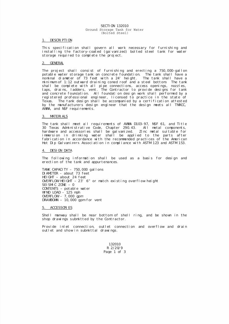
7/25/2019 City Standard Construction Specifications
http://slidepdf.com/reader/full/city-standard-construction-specifications 477/511
SECTI ON 132010Ground Storage Tank for Water
(Bolted Steel)
1. DESCRI PTI ON
Thi s speci f i cat i on shal l govern al l work necessary f or f urni shi ng and
i nst al l i ng t he f act or y- coat ed ( gal vani zed) bol t ed st eel t ank f or wat erst orage requi r ed t o compl et e t he pr oj ect .
2. GENERAL
The proj ect shal l consi st of f urni shi ng and erect i ng a 750, 000- gal l onpotabl e water st orage t ank on concr et e f oundat i on. The t ank shal l have anomi nal di amet er of 73 f eet wi t h a 24’ hei ght . The t ank shal l have ami ni mum of 1: 12 out ward drai ni ng coned r oof and a st eel bot t om. The t ankshal l be compl et e wi t h al l pi pe connect i ons, access openi ngs, nozzl es,t aps, dr ai ns, l adder s, vent . The Cont r act or t o pr ovi de desi gns f or t ankand concrete f oundat i on. Al l f oundat i on desi gn work shal l per f ormed by ar egi st er ed pr of essi onal engi neer , l i censed t o pr act i ce i n t he st at e of
Texas. The t ank desi gn shal l be accompani ed by a cer t i f i cat i on at t est edby t he manuf acturer s desi gn engi neer t hat t he desi gn meet s al l TNRCC,AWWA, and NSF requi r ement s.
3. MATERI ALS
The t ank shal l meet al l r equi r ement s of AWWA D103- 97, NSF 61, and Ti t l e30 Texas Admi ni st r at i ve Code, Chapter 290. 43. Al l metal component s,har dwar e and accessori es shal l be gal vani zed. Zi nc met al sui t abl e f ori mmer si on i n dr i nki ng wat er shal l be appl i ed t o t he par t s af t erf abr i cat i on i n accordance wi t h the recommended pr act i ces of t he Ameri canHot Di p Gal vani zer s Associ at i on i n compl i ance wi t h ASTM 123 and ASTM 153.
4. DESI GN DATA
The f ol l owi ng i nf ormat i on shal l be used as a basi s f or desi gn ander ect i on of t he tank and appur t enances.
TANK CAPACI TY – 750, 000 gal l onsDI AMETER – about 73 f eetHEI GHT – about 24 f eetOVERFLOW HEI GHT – 23’ 6” or match exi st i ng over f l ow hei ghtSEI SMI C ZONE – 0CONTENTS – pot abl e wat erWI ND LOAD – 125 mphOVERFLOW – 7, 000 gpmDRAWDOWN – 10, 000 gpm f or vent
5. ACCESSORI ES
Shel l manway shal l be near bot t om of shel l r i ng, and be shown i n theshop dr awi ngs submi t t ed by t he Cont r actor .
Pr ovi de i nl et connect i on, out l et connect i on and over f l ow and dr ai nout l et and show i n submi t t al dr awi ngs.
132010R 2/ 20/ 9
Page 1 of 3
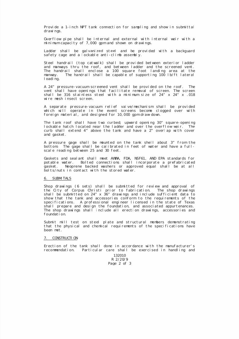
7/25/2019 City Standard Construction Specifications
http://slidepdf.com/reader/full/city-standard-construction-specifications 478/511
Provi de a 1- i nch NPT t ank connect i on f or sampl i ng and show i n submi t t aldrawi ngs.
Over f l ow pi pe shal l be i nt er nal and exter nal wi t h i nt er nal wei r wi t h ami ni mumcapaci t y of 7, 000 gpmand shown on dr awi ngs.
Ladder shal l be gal vani zed st eel and be pr ovi ded wi t h a backguardsaf ety cage and a l ockabl e ant i - cl i mb assembl y.
St eel handr ai l ( t op cat wal k) shal l be pr ovi ded bet ween exter i or l adderand manways t hru t he r oof , and bet ween l adder and t he scr eened vent .
The handrai l shal l encl ose a 100 square f oot l andi ng ar ea at t hemanway. The handr ai l shal l be capabl e of support i ng 100 l b/ f t l ater all oadi ng.
A 24” pr essure- vacuum scr eened vent shal l be provi ded on t he r oof . Thevent shal l have openi ngs t hat f aci l i t at e removal of scr een. The scr eenshal l be 316 st ai nl ess st eel wi t h a mi ni mum si ze of 24” x 24” x . 018wi r e mesh i nsect scr een.
A separ at e pr essur e- vacuum r el i ef val ve/ mechani sm shal l be pr ovi dedwhi ch wi l l operat e i n the event scr eens become cl ogged over wi t hf orei gn materi al , and desi gned f or 10, 000 gpmdr aw- down.
The t ank r oof shal l have t wo cur bed; upward openi ng 30” square- openi ngl ockabl e hat ch l ocated near t he l adder and over t he over f l ow wei r . Thecurb shal l ext end 4” above t he t ank and have a 2” over l ap wi t h coverand gasket .
A pr essur e gage shal l be mount ed on t he tank shel l about 3” f r om t hebott om. The gage shal l be cal i br at ed i n f eet of wat er and have a f ul l -scal e readi ng bet ween 25 and 30 f eet .
Gasket s and seal ant shal l meet AWWA, FDA, NSF61, AND EPA st andar ds f orpot abl e wat er . Bol t ed connect i ons shal l i ncor por at e a pr ef abr i cat edgasket . Neoprene backed washers or approved equal shal l be at al lbol t s/ nut s i n cont act wi t h t he st or ed wat er .
6. SUBMI TALS
Shop dr awi ngs ( 6 set s) shal l be submi t t ed f or r evi ew and appr oval oft he Ci t y of Corpus Chr i st i pr i or t o f abr i cat i on. The shop dr awi ngsshal l be submi t t ed on 24” x 36” drawi ngs and i ncl ude suf f i ci ent dat a toshow t hat t he t ank and accessor i es conf orm t o t he requi r ement s of t hespeci f i cat i ons. A pr of essi onal engi neer l i censed i n t he st at e of Texasshal l pr epar e and desi gn t he f oundat i on, and associ ated appur t enances.
The shop drawi ngs shal l i ncl ude al l er ect i on drawi ngs, accessor i es and
f oundat i on.
Submi t mi l l t est on st eel pl ate and st r uct ur al members demonst r at i ngt hat t he physi cal and chemi cal r equi r ement s of t he speci f i cat i ons havebeen met .
7. CONSTRUCTI ON
132010R 2/ 20/ 9
Page 2 of 3
Er ect i on of t he tank shal l done i n accor dance wi t h t he manuf act ur er’ sr ecommendat i on. Par t i cul ar care shal l be exer ci sed i n handl i ng and
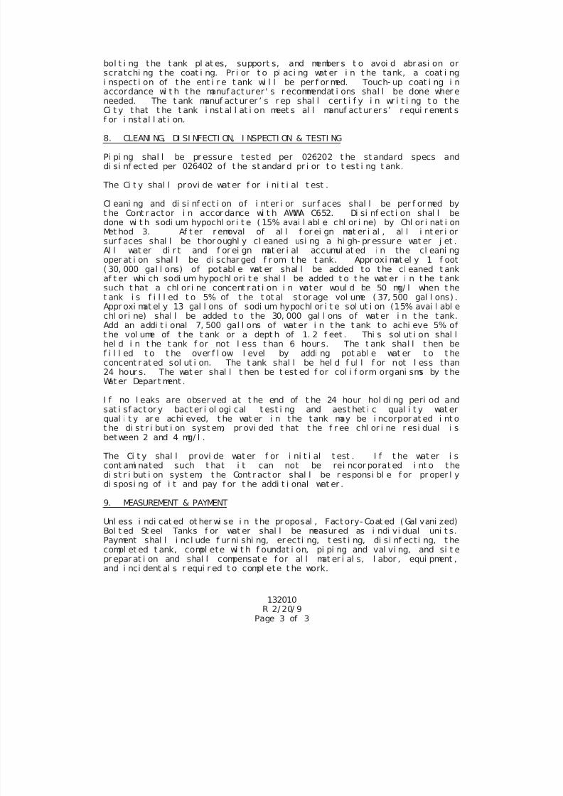
7/25/2019 City Standard Construction Specifications
http://slidepdf.com/reader/full/city-standard-construction-specifications 479/511
bol t i ng the t ank pl at es, support s, and member s t o avoi d abr asi on orscratchi ng t he coat i ng. Pr i or t o pl aci ng wat er i n t he tank, a coat i ngi nspect i on of t he ent i r e t ank wi l l be per f or med. Touch- up coat i ng i naccordance wi t h t he manuf act urer ' s r ecommendat i ons shal l be done wher eneeded. The t ank manuf act ur er ’ s r ep shal l cer t i f y i n wr i t i ng t o t heCi t y that t he t ank i nst al l at i on meet s al l manuf act ur er s’ r equi r ement sf or i nstal l at i on.
8. CLEANI NG, DI SI NFECTI ON, I NSPECTI ON & TESTI NG
Pi pi ng shal l be pr essur e t est ed per 026202 t he st andard specs anddi si nf ect ed per 026402 of t he st andar d pr i or t o t est i ng t ank.
The Ci t y shal l provi de wat er f or i ni t i al t est .
Cl eani ng and di si nf ect i on of i nt er i or sur f aces shal l be per f or med byt he Cont r actor i n accor dance wi t h AWWA C652. Di si nf ect i on shal l bedone wi t h sodi um hypochl or i t e ( 15% avai l abl e chl or i ne) by Chl or i nat i onMet hod 3. Af t er r emoval of al l f or ei gn mat er i al , al l i nt er i orsur f aces shal l be t hor oughl y cl eaned usi ng a hi gh- pr essur e wat er j et .
Al l wat er di r t and f or ei gn mat er i al accumul at ed i n the cl eani ngoper at i on shal l be di schar ged f r om t he t ank. Appr oxi mat el y 1 f oot( 30, 000 gal l ons) of potabl e wat er shal l be added to t he cl eaned t ankaf t er whi ch sodi um hypochl ori t e shal l be added t o t he wat er i n t he t anksuch t hat a chl or i ne concent r at i on i n water woul d be 50 mg/ l when t het ank i s f i l l ed t o 5% of t he t ot al st or age vol ume ( 37, 500 gal l ons) .Appr oxi mat el y 13 gal l ons of sodi um hypochl or i t e sol ut i on (15% avai l abl echl ori ne) shal l be added t o the 30, 000 gal l ons of wat er i n t he tank.Add an addi t i onal 7, 500 gal l ons of wat er i n t he t ank to achi eve 5% oft he vol ume of t he t ank or a dept h of 1. 2 f eet . Thi s sol ut i on shal lhel d i n t he t ank f or not l ess t han 6 hour s. The t ank shal l t hen bef i l l ed t o t he over f l ow l evel by addi ng pot abl e wat er t o t heconcent r at ed sol ut i on. The t ank shal l be hel d f ul l f or not l ess than24 hour s. The wat er shal l t hen be t est ed f or col i f orm organi sms by t heWat er Depar t ment .
I f no l eaks are observed at t he end of t he 24 hour hol di ng peri od andsat i sf act or y bact er i ol ogi cal t est i ng and aest het i c qual i t y wat erqual i t y ar e achi eved, t he wat er i n the tank may be i ncorpor at ed i nt ot he di st r i but i on syst em, pr ovi ded t hat t he f r ee chl or i ne r esi dual i sbetween 2 and 4 mg/ l .
The Ci t y shal l provi de wat er f or i ni t i al t est . I f t he wat er i scont ami nated such t hat i t can not be rei ncor porat ed i nt o thedi st r i but i on syst em, t he Cont r act or shal l be r esponsi bl e f or pr oper l ydi sposi ng of i t and pay f or t he addi t i onal wat er .
9. MEASUREMENT & PAYMENT
Unl ess i ndi cat ed ot her wi se i n t he pr oposal , Fact ory- Coat ed ( Gal vani zed)Bol t ed St eel Tanks f or wat er shal l be measur ed as i ndi vi dual uni t s.Payment shal l i ncl ude f ur ni shi ng, er ecti ng, t est i ng, di si nf ecti ng, t hecompl et ed t ank, compl ete wi t h f oundat i on, pi pi ng and val vi ng, and si t epr epar at i on and shal l compensat e f or al l mat er i al s, l abor , equi pment ,and i nci dent al s r equi r ed t o compl ete t he work.
132010R 2/ 20/ 9
Page 3 of 3
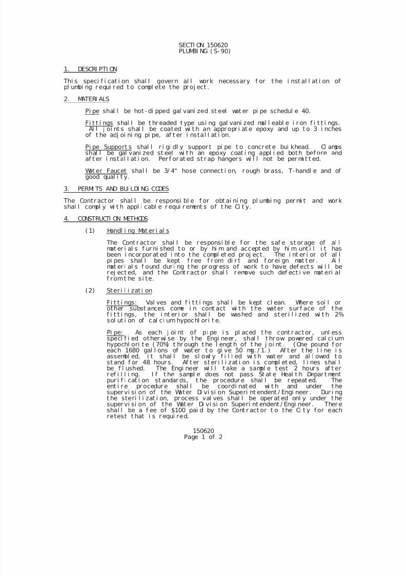
7/25/2019 City Standard Construction Specifications
http://slidepdf.com/reader/full/city-standard-construction-specifications 480/511
150620Page 1 of 2
SECTI ON 150620 PLUMBI NG ( S- 90)
1. DESCRI PTI ON
Thi s speci f i cat i on shal l govern al l work necessary f or t he i nst al l at i on ofpl umbi ng r equi r ed t o compl ete the pr oj ect .
2. MATERI ALS
Pi pe shal l be hot - di pped gal vani zed st eel wat er pi pe schedul e 40.
Fi t t i ngs shal l be t hr eaded t ype usi ng gal vani zed mal l eabl e i r on f i t t i ngs.Al l j oi nt s shal l be coated wi t h an appr opr i at e epoxy and up t o 3 i nches
of t he adj oi ni ng pi pe, af t er i nstal l at i on.
Pi pe Support s shal l r i gi dl y suppor t pi pe t o concret e bul khead. Cl ampsshal l be gal vani zed st eel wi t h an epoxy coat i ng appl i ed both bef ore andaf t er i nst al l at i on. Per f or at ed st r ap hanger s wi l l not be per mi t t ed.
Wat er Faucet shal l be 3/ 4" hose connect i on, r ough br ass, T-handl e and ofgood qual i t y.
3. PERMI TS AND BUI LDI NG CODES
The Contr act or shal l be r esponsi bl e f or obt ai ni ng pl umbi ng per mi t and workshal l compl y wi t h appl i cabl e r equi r ement s of t he Ci t y.
4. CONSTRUCTI ON METHODS
( 1) Handl i ng Mat er i al s
The Cont r actor shal l be r esponsi bl e f or t he saf e st or age of al lmat er i al s f ur ni shed t o or by hi m and accept ed by hi m unt i l i t hasbeen i ncor por at ed i nt o t he compl et ed pr oj ect . The i nt er i or of al lpi pes shal l be kept f r ee f r om di r t and f or ei gn mat t er . Al lmat er i al s f ound dur i ng t he pr ogr ess of work t o have def ect s wi l l be
r ej ect ed, and t he Cont r act or shal l r emove such def ect i ve mat eri alf romt he s i te.
(2) Ster i l i zat i on
Fi t t i ngs: Val ves and f i t t i ngs shal l be kept cl ean. Wher e soi l orother subst ances come i n cont act wi t h t he water sur f ace of t hef i t t i ngs, t he i nt er i or shal l be washed and st er i l i zed wi t h 2%sol ut i on of cal ci um hypochl ori t e.
Pi pe: As each j oi nt of pi pe i s pl aced t he cont r act or , unl essspeci f i ed other wi se by t he Engi neer , shal l t hr ow power ed cal ci umhypochl ori t e ( 70%) t hr ough t he l engt h of t he j oi nt . ( One pound f oreach 1680 gal l ons of wat er t o gi ve 50 mg. / 1. ) Af t er t he l i ne i sassembl ed, i t shal l be sl owl y f i l l ed wi t h wat er and al l owed t o
st and f or 48 hour s. Af t er st er i l i zat i on i s compl et ed, l i nes shal lbe f l ushed. The Engi neer wi l l t ake a sampl e t est 2 hour s af t err ef i l l i ng. I f t he sampl e does not pass St at e Heal t h Depar t mentpur i f i cat i on st andar ds, t he pr ocedur e shal l be r epeat ed. Theent i r e pr ocedur e shal l be coordi nat ed wi t h and under t hesuper vi si on of the Water Di vi si on Superi nt endent / Engi neer . Dur i ngt he steri l i zat i on, pr ocess val ves shal l be oper at ed onl y under t hesuper vi si on of the Wat er Di vi si on Superi nt endent / Engi neer . Ther eshal l be a f ee of $100 pai d by the Cont r act or t o the Ci t y f or eachretest t hat i s r equi red.
7/25/2019 City Standard Construction Specifications
http://slidepdf.com/reader/full/city-standard-construction-specifications 481/511
150620Page 2 of 2
( 3) Hydr ostat i c Test i ng Wat er Syst em
See Sect i on 026202 Hydr ost at i c Test i ng of Pressur e Syst em.
5. MEASUREMENT
Unl ess speci f i ed ot her wi se i n the speci al pr ovi si ons, measur ement shal l be madeas f ol l ows:
Pi pe wi l l be measur ed by t he l i near f oot al ong the cent er l i ne f or eachsi ze of pi pe i nst al l ed. Measur ement shal l be up t o but not i ncl ude t hef i t t i ngs.
Fi t t i ngs wi l l be measur ed as i ndi vi dual uni t s f or each t ype and si zei nstal l ed.
6. PAYMENT
Payment shal l i ncl ude but not l i mi t ed t o al l mat er i al s, l abor , equi pment ,suppor t cl amps, t est i ng, st er i l i zat i on, and al l ot her i nci dent al s necessar y tocompl et e the j ob.
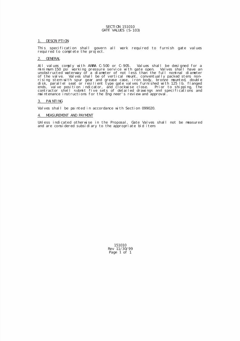
7/25/2019 City Standard Construction Specifications
http://slidepdf.com/reader/full/city-standard-construction-specifications 482/511
151010Rev 11/ 30/ 99Page 1 of 1
SECTI ON 151010 GATE VALUES (S- 103)
1. DESCRI PTI ON
Thi s speci f i cat i on shal l govern al l work r equi r ed t o f urni sh gat e val uesr equi r ed t o compl et e t he pr oj ect .
2. GENERAL
Al l val ues compl y wi t h AWWA C- 500 or C- 905. Val ues shal l be desi gned f or ami ni mum 150 psi worki ng pr essure servi ce wi t h gate open. Val ves shal l have anunobst r uct ed waterway of a di ameter of not l ess t han the f ul l nomi nal di ameterof t he val ve. Val ves shal l be of ver t i cal mount , convent ual l y packed st em, non-r i si ng st em wi t h spur gear and gr ease case, i r on body, br onze mount ed, doubl edi sk, par al l el seat or r esi l i ent t ype gat e val ves f ur ni shed wi t h 125 l b. f l angedends, val ve posi t i on i ndi cat or , and cl ockwi se cl ose. Pr i or t o shi ppi ng, t hecont ract or shal l submi t f i ve set s of det ai l ed dr awi ngs and speci f i cat i ons andmai nt enance i nst r uct i ons f or t he Engi neer ' s r evi ew and appr oval .
3. PAI NTI NG
Val ves shal l be pai nt ed i n accordance wi t h Sect i on 099020.
4. MEASUREMENT AND PAYMENT
Unl ess i ndi cated other wi se i n t he Proposal , Gate Val ves shal l not be measur edand ar e consi der ed subsi di ary to the appr opr i at e bi d i t em.
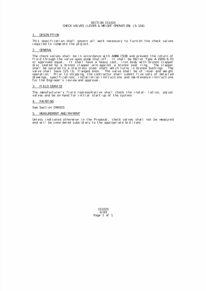
7/25/2019 City Standard Construction Specifications
http://slidepdf.com/reader/full/city-standard-construction-specifications 483/511
1510206/ 89
Page 1 of 1
SECTI ON 151020 CHECK VALVES ( LEVER & WEI GHT OPERATI ON) ( S- 104)
1. DESCRI PTI ON
Thi s speci f i cat i on shal l govern al l work necessary t o f urni sh t he check val vesr equi r ed t o compl et e t he pr oj ect .
2. GENERAL
The check val ves shal l be i n accordance wi t h AWWA C508 and prevent t he r eturn off l ui d t hr ough t he val ve upon pump shut - of f . I t shal l be Mul l er Type A- 2600- 6- 01or appr oved equal . I t shal l have a heavy cast , i r on body wi t h br onze cl apperdi sc seat ed by a bronze cl apper ar m agai nst a br onze seat r i ng. The cl appershal l be secur ed t o a st ai nl ess st eel shaf t whi ch t ur ns i n br onze bushi ngs. Theval ve shal l have 125 l b. f l anged ends. The val ve shal l be of l ever and wei ghtoper at i on. Pr i or t o shi ppi ng, t he cont r actor shal l submi t f i ve set s of det ai l eddr awi ngs, speci f i cat i ons, i nst al l at i on i nst r ucti ons and mai nt enance i nst ruct i onsf or t he Engi neer ' s r evi ew and appr oval .
3. FI ELD SERVI CE
The manuf act urer ' s f i el d r epr esent at i ve shal l check t he i nst al - l at i on, adj ustval ves and be on- hand f or i ni t i al st ar t - up of t he syst em.
4. PAI NTI NG
See Sect i on 099020.
5. MEASUREMENT AND PAYMENT
Unl ess i ndi cated otherwi se i n t he Proposal , check val ves shal l not be measuredand wi l l be consi der ed subsi di ar y t o t he appr opr i at e bi d i t em.
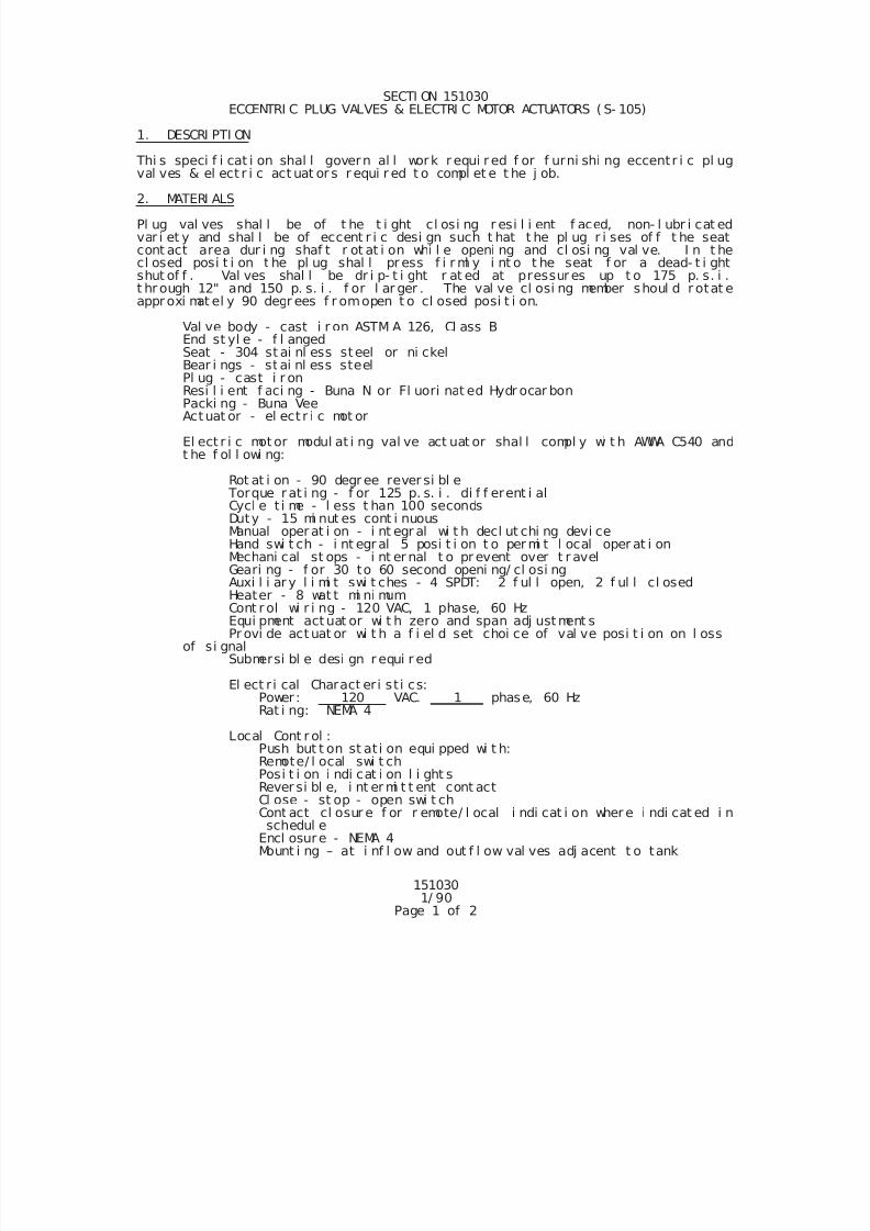
7/25/2019 City Standard Construction Specifications
http://slidepdf.com/reader/full/city-standard-construction-specifications 484/511
1510301/ 90
Page 1 of 2
SECTI ON 151030 ECCENTRI C PLUG VALVES & ELECTRI C MOTOR ACTUATORS ( S- 105)
1. DESCRI PTI ON
Thi s speci f i cat i on shal l govern al l work r equi r ed f or f urni shi ng eccentr i c pl ugval ves & el ect r i c act uat or s r equi r ed t o compl et e t he j ob.
2. MATERI ALS
Pl ug val ves shal l be of t he t i ght cl osi ng r esi l i ent f aced, non- l ubr i cat edvar i et y and shal l be of eccent r i c desi gn such t hat t he pl ug r i ses of f t he seatcont act area dur i ng shaf t r ot at i on whi l e openi ng and cl osi ng val ve. I n t hecl osed posi t i on t he pl ug shal l pr ess f i r ml y i nt o t he seat f or a dead- t i ghtshut of f . Val ves shal l be dr i p- t i ght r at ed at pressur es up t o 175 p. s. i .t hr ough 12" and 150 p. s. i . f or l ar ger . The val ve cl osi ng member shoul d r otat eappr oxi mat el y 90 degr ees f r omopen t o cl osed posi t i on.
Val ve body - cast i r on ASTM A 126, Cl ass BEnd st yl e - f l angedSeat - 304 st ai nl ess steel or ni ckelBear i ngs - st ai nl ess steelPl ug - cast i r on
Resi l i ent f aci ng - Buna N or Fl uori nat ed Hydr ocar bonPacki ng - Buna VeeActuat or - el ect r i c mot or
El ect r i c mot or modul at i ng val ve act uat or shal l compl y wi t h AWWA C540 andt he f ol l owi ng:
Rot at i on - 90 degr ee rever si bl e Torque r at i ng - f or 125 p. s. i . di f f erent i alCycl e t i me - l ess t han 100 secondsDuty - 15 mi nut es cont i nuousManual oper at i on - i nt egr al wi t h decl ut chi ng devi ceHand swi t ch - i nt egr al 5 posi t i on t o per mi t l ocal oper at i onMechani cal st ops - i nt er nal t o pr event over t r avelGeari ng - f or 30 to 60 second openi ng/ cl osi ng
Auxi l i ar y l i mi t swi t ches - 4 SPDT: 2 f ul l open, 2 f ul l cl osedHeater - 8 wat t mi ni mum Cont r ol wi r i ng - 120 VAC, 1 phase, 60 Hz
Equi pment act uat or wi t h zero and span adj ust ment sPr ovi de act uat or wi t h a f i el d set choi ce of val ve posi t i on on l oss
of si gnalSubmersi bl e desi gn r equi r ed
El ect r i cal Charact eri st i cs:Power : 120 VAC. 1 phase, 60 HzRat i ng: NEMA 4
Local Cont r ol :Push but t on st at i on equi pped wi t h:Remote/ l ocal swi t ch
Posi t i on i ndi cat i on l i ght sRever si bl e, i nt er mi t t ent cont actCl ose - st op - open swi t chCont act cl osur e f or r emote/ l ocal i ndi cat i on wher e i ndi cat ed i nschedul e
Encl osure - NEMA 4Mount i ng – at i nf l ow and out f l ow val ves adj acent t o tank
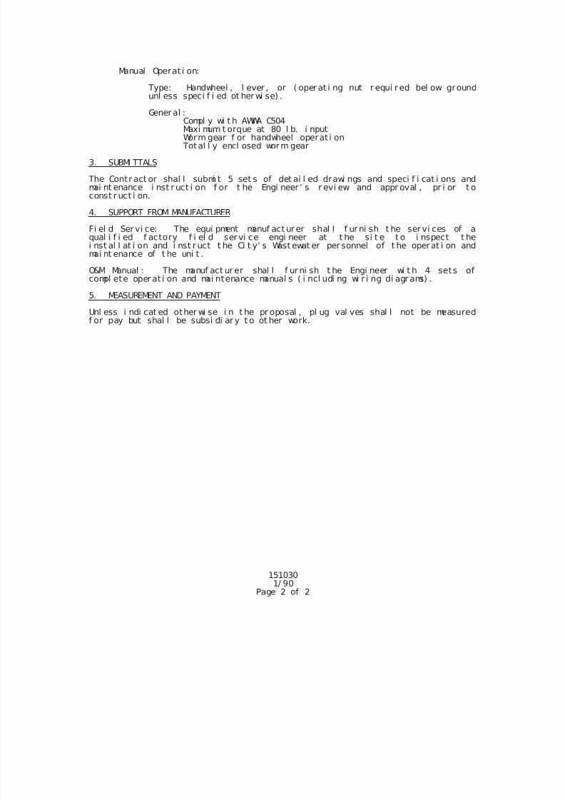
7/25/2019 City Standard Construction Specifications
http://slidepdf.com/reader/full/city-standard-construction-specifications 485/511
1510301/ 90
Page 2 of 2
Manual Operat i on:
Type: Handwheel , l ever , or ( oper at i ng nut r equi r ed bel ow groundunl ess speci f i ed ot her wi se) .
Gener al :Compl y wi t h AWWA C504Maxi mum t orque at 80 l b. i nputWorm gear f or handwheel operat i on
Total l y encl osed worm gear
3. SUBMI TTALS
The Contr act or shal l submi t 5 set s of det ai l ed drawi ngs and speci f i cat i ons andmai nt enance i nst r uct i on f or t he Engi neer ' s r evi ew and appr oval , pr i or t oconst r uct i on.
4. SUPPORT FROM MANUFACTURER
Fi el d Ser vi ce: The equi pment manuf act ur er shal l f ur ni sh t he ser vi ces of aqual i f i ed f actory f i el d ser vi ce engi neer at t he si t e t o i nspect t hei nst al l at i on and i nst r uct t he Ci t y' s Wast ewat er per sonnel of t he oper at i on and
mai nt enance of t he uni t .
O&M Manual : The manuf act ur er shal l f ur ni sh t he Engi neer wi t h 4 sets ofcompl ete oper at i on and mai ntenance manual s ( i ncl udi ng wi r i ng di agr ams) .
5. MEASUREMENT AND PAYMENT
Unl ess i ndi cat ed other wi se i n t he pr oposal , pl ug val ves shal l not be measuredf or pay but shal l be subsi di ar y t o ot her work.
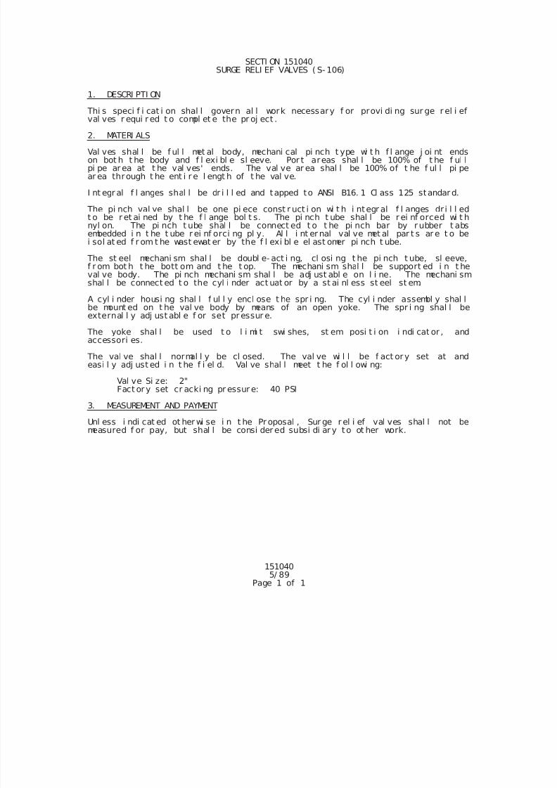
7/25/2019 City Standard Construction Specifications
http://slidepdf.com/reader/full/city-standard-construction-specifications 486/511
1510405/ 89
Page 1 of 1
SECTI ON 151040 SURGE RELI EF VALVES ( S- 106)
1. DESCRI PTI ON
Thi s speci f i cat i on shal l govern al l work necessary f or provi di ng sur ge r el i efval ves r equi r ed t o compl et e the pr oj ect .
2. MATERI ALS
Val ves shal l be f ul l met al body, mechani cal pi nch t ype wi t h f l ange j oi nt endson bot h t he body and f l exi bl e sl eeve. Por t areas shal l be 100% of t he f ul lpi pe ar ea at t he val ves' ends. The val ve ar ea shal l be 100% of t he f ul l pi pear ea through t he ent i r e l engt h of t he val ve.
I nt egr al f l anges shal l be dr i l l ed and tapped to ANSI B16. 1 Cl ass 125 standar d.
The pi nch val ve shal l be one pi ece const r uct i on wi t h i ntegr al f l anges dr i l l edt o be r et ai ned by t he f l ange bol t s. The pi nch t ube shal l be r ei nf orced wi t hnyl on. The pi nch t ube shal l be connect ed t o t he pi nch bar by r ubber t absembedded i n t he t ube r ei nf orci ng pl y. Al l i nt er nal val ve met al par t s ar e t o bei sol at ed f r om t he wast ewat er by the f l exi bl e el ast omer pi nch t ube.
The st eel mechani sm shal l be doubl e- act i ng, cl osi ng t he pi nch t ube, sl eeve,f r om bot h t he bott om and t he t op. The mechani sm shal l be support ed i n t heval ve body. The pi nch mechani sm shal l be adj ust abl e on l i ne. The mechani smshal l be connect ed t o the cyl i nder act uat or by a st ai nl ess st eel st em.
A cyl i nder housi ng shal l f ul l y encl ose t he spr i ng. The cyl i nder assembl y shal lbe mount ed on t he val ve body by means of an open yoke. The spr i ng shal l beexternal l y adj ust abl e f or set pr essur e.
The yoke shal l be used t o l i mi t swi shes, st em posi t i on i ndi cat or , andaccessori es.
The val ve shal l normal l y be cl osed. The val ve wi l l be f act ory set at andeasi l y adj ust ed i n t he f i el d. Val ve shal l meet t he f ol l owi ng:
Val ve Si ze: 2"Fact or y set cr acki ng pr essur e: 40 PSI
3. MEASUREMENT AND PAYMENT
Unl ess i ndi cat ed ot her wi se i n t he Pr oposal , Sur ge r el i ef val ves shal l not bemeasured f or pay, but shal l be consi der ed subsi di ar y to ot her work.
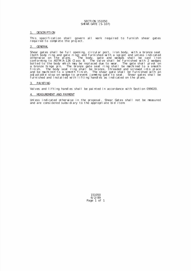
7/25/2019 City Standard Construction Specifications
http://slidepdf.com/reader/full/city-standard-construction-specifications 487/511
1510506/ 2/ 89
Page 1 of 1
SECTI ON 151050SHEAR GATE ( S- 107)
1. DESCRI PTI ON
Thi s speci f i cat i on shal l govern al l work r equi r ed t o f urni sh shear gat esr equi r ed t o compl et e the pr oj ect .
2. GENERAL
Shear gat es shal l be f ul l openi ng, ci r cul ar por t , i r on body, wi t h a br onze seat( both body r i ng and gat e ri ng) and f ur ni shed wi t h a spi got end unl ess i ndi cat edotherwi se on t he pl ans. The body, gate and wedges shal l be cast i r onconf ormi ng t o ASTM A- 126 Cl ass B. The val ve shal l be f ur ni shed wi t h 2 wedgesbol t ed t o the body whi ch may be repl aced due to wear . The gate shal l pi vot ona bronze hi nge pi n. The br onze gate seat r i ng shal l be machi ned t o a smoot hf i ni sh. The body seat r i ng shal l be br onze, t hr eaded and scr ewed i nt o pl aceand be machi ned t o a smoot h f i ni sh. The shear gat e shal l be f ur ni shed wi t h anadj ust abl e st op on wedge t o pr event j ammi ng gat e t o seat . Shear gat es shal l bef ur ni shed and i nst al l ed wi t h l i f t i ng handl es as i ndi cat ed on t he pl ans.
3. PAI NTI NG
Val ves and l i f t i ng handl es shal l be pai nt ed i n accor dance wi t h Sect i on 099020.
4. MEASUREMENT AND PAYMENT
Unl ess i ndi cat ed ot her wi se i n the pr oposal , Shear Gat es shal l not be measuredand are consi dered subsi di ary t o t he appr opr i ate bi d i t em.
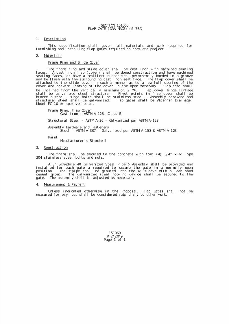
7/25/2019 City Standard Construction Specifications
http://slidepdf.com/reader/full/city-standard-construction-specifications 488/511
151060R 2/ 20/ 9
Page 1 of 1
SECTI ON 151060 FLAP GATE ( DRAI NAGE) ( S- 76A)
1. Descr i pt i on
Thi s speci f i cat i on shal l gover n al l mat er i al s and wor k r equi r ed f orf ur ni shi ng and i nst al l i ng f l ap gat es r equi r ed t o compl et e pr oj ect .
2. Mat er i al s
Fr ame Ri ng and Sl i de Cover
The f r ame r i ng and sl i de cover shal l be cast i r on wi t h machi ned seat i ngf aces. A cast i r on f l ap ( cover ) shal l be domed const r uct i on and have machi nedseat i ng f aces, or have a resi l i ent r ubber seal per manent l y bonded i n a gr ooveand be f l ush wi t h t he sur r oundi ng cast i r on seat f ace. The f l ap cover shal l beat t ached t o the sl i de cover i n such a manner as t o al l ow f ul l openi ng of t hecover and pr event j ammi ng of t he cover i n t he open waterway. Fl ap seat shal l
be i ncl i ned f r om t he ver t i cal a mi ni mum of 2 . Fl ap cover hi nge l i nkageshal l be gal vani zed st eel st r uctural . Pi vot poi nt s i n f l ap cover shal l bebr onze bushed. Hi nge bol t s shal l be st ai nl ess st eel . Assembl y hardwar e andst r uct ur al st eel shal l be gal vani zed. Fl ap gat es shal l be Wat er man Dr ai nage,Model FC- 10 or approved equal .
Fr ame Ri ng, Fl ap CoverCast I r on - ASTM A- 126, Cl ass B
St r uct ur al St eel - ASTM A- 36 - Gal vani zed per ASTM A- 123
Assembl y Hardware and Fast ener sSt eel - ASTM A- 307 - Gal vani zed per ASTM A- 153 & ASTM A- 123
Pai ntManuf actur er' s Standard
3. Const r uct i on
The f r ame shal l be secur ed t o t he concr et e wi t h f our (4) 3/ 4" x 6" Type304 st ai nl ess st eel bol t s and nut s.
A 3" Schedul e 40 Gal vani zed Steel Pi pe & Assembl y shal l be provi ded andi nst al l ed f or each gate a r equi r ed t o secur e t he gat e i n a normal l y openposi t i on. The 3"pi pe shal l be gr out ed i nt o t he 4" sl eeve wi t h a l ean sandcement gr out . The gal vani zed st eel hooki ng devi ce shal l be secur ed t o t hegate. The assembl y shal l be adj ust ed as necessar y.
4. Measurement & Payment
Unl ess i ndi cat ed other wi se i n t he Pr oposal , Fl ap Gat es shal l not bemeasured f or pay, but shal l be consi der ed subsi di ar y t o ot her work.
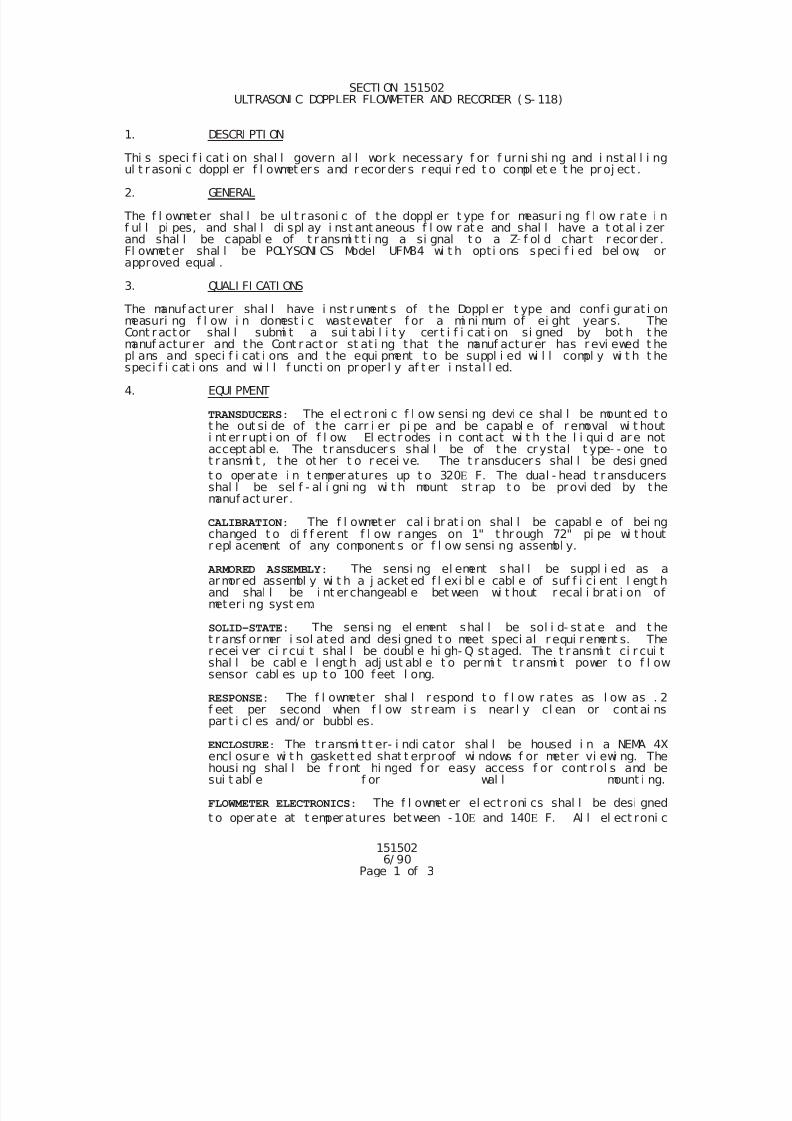
7/25/2019 City Standard Construction Specifications
http://slidepdf.com/reader/full/city-standard-construction-specifications 489/511
151502 6/ 90
Page 1 of 3
SECTI ON 151502 ULTRASONI C DOPPLER FLOWMETER AND RECORDER ( S- 118)
1. DESCRI PTI ON
Thi s speci f i cat i on shal l govern al l work necessary f or f urni shi ng and i nst al l i ngul t r asoni c doppl er f l owmet er s and r ecor der s r equi r ed t o compl et e t he pr oj ect .
2. GENERAL
The f l owmeter shal l be ul t r asoni c of t he doppl er t ype f or measur i ng f l ow r ate i nf ul l pi pes, and shal l di spl ay i nst ant aneous f l ow r at e and shal l have a t ot al i zerand shal l be capabl e of t r ansmi t t i ng a si gnal t o a Z- f ol d char t r ecor der .Fl owmeter shal l be POLYSONI CS Model UFM84 wi t h opti ons speci f i ed bel ow, orapproved equal .
3. QUALI FI CATI ONS
The manuf act urer shal l have i nst r ument s of t he Doppl er t ype and conf i gur at i onmeasuri ng f l ow i n domest i c wastewater f or a mi ni mum of ei ght year s. TheCont ractor shal l submi t a sui t abi l i t y cer t i f i cat i on si gned by bot h t hemanuf actur er and the Cont r act or st at i ng that t he manuf actur er has r evi ewed t he
pl ans and speci f i cat i ons and t he equi pment t o be suppl i ed wi l l compl y wi t h t hespeci f i cat i ons and wi l l f uncti on pr oper l y af t er i nstal l ed.
4. EQUI PMENT
TRANSDUCERS: The el ect r oni c f l ow sensi ng devi ce shal l be mount ed t ot he out si de of t he carr i er pi pe and be capabl e of r emoval wi t houti nt er r upt i on of f l ow. El ect r odes i n cont act wi t h t he l i qui d are notaccept abl e. The t r ansducer s shal l be of t he cr ystal t ype- - one tot ransmi t , t he ot her t o r ecei ve. The t r ansducer s shal l be desi gned
t o oper ate i n t emper atures up t o 320 F. The dual - head t r ansducersshal l be sel f - al i gni ng wi t h mount st r ap t o be provi ded by themanuf act urer .
CALIBRATION: The f l owmet er cal i br at i on shal l be capabl e of bei ng
changed t o di f f erent f l ow r anges on 1" t hr ough 72" pi pe wi t houtr epl acement of any component s or f l ow sensi ng assembl y.
ARMORED ASSEMBLY: The sensi ng el ement shal l be suppl i ed as aarmor ed assembl y wi t h a j acket ed f l exi bl e cabl e of suf f i ci ent l engt hand shal l be i nt er changeabl e bet ween wi t hout r ecal i br at i on ofmeteri ng syst em.
SOLID-STATE: The sensi ng el ement shal l be sol i d- st at e and t het ransf ormer i sol ated and desi gned t o meet speci al r equi r ement s. Ther ecei ver ci r cui t shal l be doubl e hi gh- Q st aged. The t r ansmi t ci r cui tshal l be cabl e l engt h adj ust abl e t o per mi t t r ansmi t power t o f l owsensor cabl es up t o 100 feet l ong.
RESPONSE: The f l owmeter shal l r espond t o f l ow r ates as l ow as . 2
f eet per second when f l ow st ream i s near l y cl ean or cont ai nspar t i cl es and/ or bubbl es.
ENCLOSURE: The tr ansmi t t er- i ndi cator shal l be housed i n a NEMA 4Xencl osur e wi t h gaskett ed shat t erproof wi ndows f or meter vi ewi ng. Thehousi ng shal l be f r ont hi nged f or easy access f or cont r ol s and besui t abl e f or wal l mount i ng.
FLOWMETER ELECTRONICS: The f l owmet er el ect r oni cs shal l be desi gned
t o oper ate at t emper atures between - 10 and 140 F. Al l el ect roni c
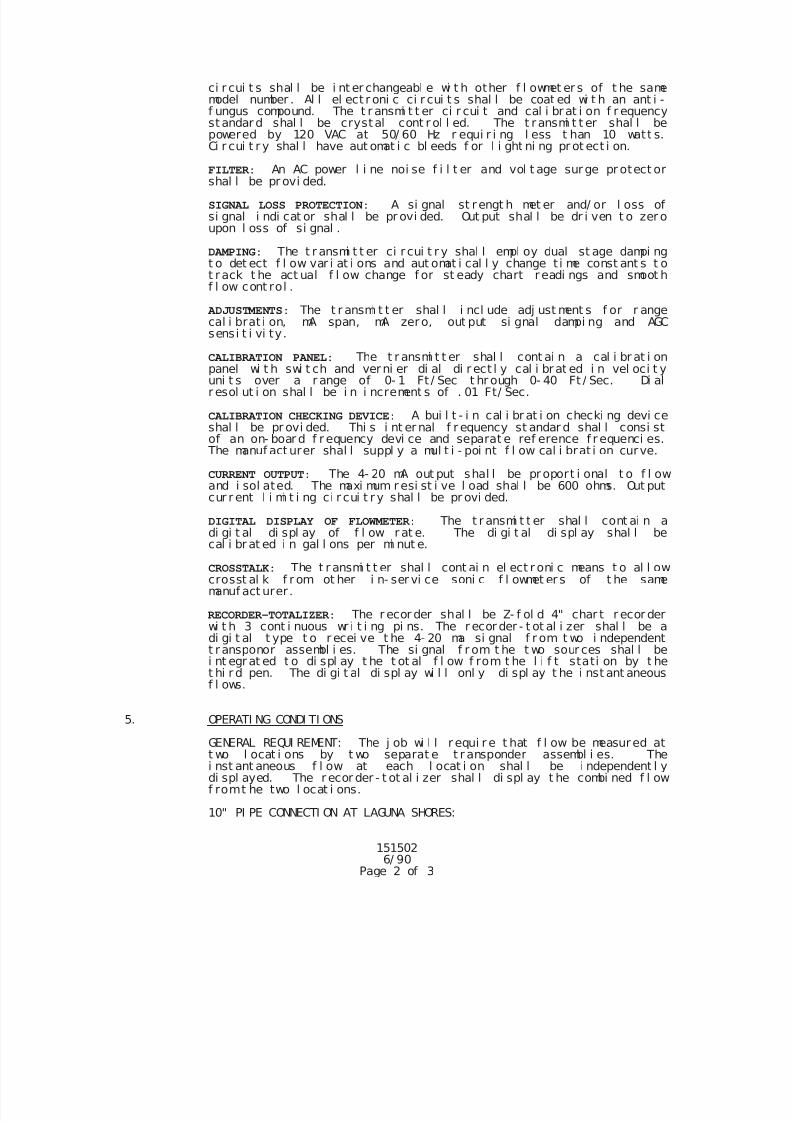
7/25/2019 City Standard Construction Specifications
http://slidepdf.com/reader/full/city-standard-construction-specifications 490/511
151502 6/ 90
Page 2 of 3
ci r cui t s shal l be i nt er changeabl e wi t h other f l owmet er s of t he samemodel number . Al l el ect r oni c ci r cui t s shal l be coat ed wi t h an ant i -f ungus compound. The t r ansmi t t er ci r cui t and cal i brat i on f r equencyst andar d shal l be crystal cont r ol l ed. The t ransmi t t er shal l bepowered by 120 VAC at 50/ 60 Hz r equi r i ng l ess t han 10 watt s.Ci r cui t r y shal l have aut omat i c bl eeds f or l i ght ni ng pr ot ect i on.
FILTER: An AC power l i ne noi se f i l t er and vol t age surge pr otect orshal l be pr ovi ded.
SIGNAL LOSS PROTECTION: A si gnal st rengt h met er and/ or l oss ofsi gnal i ndi cat or shal l be pr ovi ded. Out put shal l be dr i ven t o zer oupon l oss of si gnal .
DAMPING: The t r ansmi t t er ci r cui t r y shal l empl oy dual st age dampi ngt o det ect f l ow var i at i ons and aut omat i cal l y change t i me const ant s t ot rack t he act ual f l ow change f or st eady chart r eadi ngs and smoot hf l ow cont rol .
ADJUSTMENTS: The t r ansmi t t er shal l i ncl ude adj ust ment s f or r angecal i brat i on, mA span, mA zero, out put si gnal dampi ng and AGCsensi t i vi ty.
CALIBRATION PANEL: The t r ansmi t t er shal l cont ai n a cal i br at i onpanel wi t h swi t ch and verni er di al di r ect l y cal i brat ed i n vel oci t yuni t s over a r ange of 0- 1 Ft / Sec t hr ough 0- 40 Ft / Sec. Di alr esol ut i on shal l be i n i ncrement s of . 01 Ft/ Sec.
CALIBRATION CHECKING DEVICE: A bui l t - i n cal i br at i on checki ng devi ceshal l be pr ovi ded. Thi s i nt er nal f r equency st andar d shal l consi stof an on- boar d f r equency devi ce and separat e ref erence f r equenci es.
The manuf act urer shal l suppl y a mul t i - poi nt f l ow cal i brat i on curve.
CURRENT OUTPUT: The 4- 20 mA out put shal l be proport i onal t o f l owand i sol ated. The maxi mum r esi st i ve l oad shal l be 600 ohms. Out putcur r ent l i mi t i ng ci r cui t r y shal l be pr ovi ded.
DIGITAL DISPLAY OF FLOWMETER: The t r ansmi t t er shal l cont ai n a
di gi t al di spl ay of f l ow r at e. The di gi t al di spl ay shal l becal i br at ed i n gal l ons per mi nut e.
CROSSTALK: The t r ansmi t t er shal l cont ai n el ect r oni c means t o al l owcrosst al k f r om ot her i n- ser vi ce soni c f l owmet er s of t he samemanuf act urer .
RECORDER-TOTALIZER: The r ecor der shal l be Z- f ol d 4" char t r ecor derwi t h 3 cont i nuous wr i t i ng pi ns. The r ecor der - t ot al i zer shal l be adi gi t al t ype t o r ecei ve t he 4- 20 ma si gnal f r om t wo i ndependentt ransponor assembl i es. The si gnal f r om t he t wo sour ces shal l bei nt egr at ed t o di spl ay t he t ot al f l ow f rom t he l i f t stati on by t het hi r d pen. The di gi t al di spl ay wi l l onl y di spl ay t he i nst ant aneousf l ows.
5. OPERATI NG CONDI TI ONS
GENERAL REQUI REMENT: The j ob wi l l r equi r e t hat f l ow be measured att wo l ocat i ons by t wo separat e t r ansponder assembl i es. Thei nst ant aneous f l ow at each l ocat i on shal l be i ndependent l ydi spl ayed. The r ecor der - t ot al i zer shal l di spl ay t he combi ned f l owf romt he two l ocat i ons.
10" PI PE CONNECTI ON AT LAGUNA SHORES:
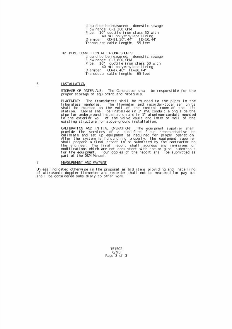
7/25/2019 City Standard Construction Specifications
http://slidepdf.com/reader/full/city-standard-construction-specifications 491/511
151502 6/ 90
Page 3 of 3
Li qui d t o be measur ed: domest i c sewageFl ow range: 0-1, 200 GPMPi pe: 10" ducti l e i r on cl ass 50 wi t h
40 mi l pol yet hyl ene l i ni ngDi ameter : OD=11. 10". 44" I D=10. 44"
Transducer cabl e l ength: 55 f eet
16" PI PE CONNECTI ON AT LAGUNA SHORES:Li qui d t o be measur ed: domest i c sewageFl ow range: 0-3, 800 GPMPi pe: 16" duct i l e i r on cl ass 50 wi t h
40 mi l pol yet hyl ene l i ni ngDi ameter : OD=17. 40" I D=16. 64"
Transducer cabl e l ength: 65 f eet
6. I NSTALLATI ON
STORAGE OF MATERI ALS: The Cont r actor shal l be r esponsi bl e f or t heproper st orage of equi pment and materi al s.
PLACEMENT: The t r ansducers shal l be mounted t o t he pi pes i n t he
f i ber gl ass manhol es. The f l owmet er and r ecor der - t ot al i zer uni t sshal l be mount ed on t he wal l of t he cont rol r oom of t he l i f tst at i on. Cabl es shal l be i nst al l ed i n 1" PVC condui t al ong si de t hepi pe f or underground i nst al l at i on and i n 1" al umi num condui t mount edt o t he ext er i or wal l of t he val ve vaul t and i nt er i or wal l of t heexi st i ng st r uctur e f or above- gr ound i nst al l at i on.
CALI BRATI ON AND I NI TI AL OPERATI ON: The equi pment suppl i er shal lprovi de t he ser vi ces of a qual i f i ed f i el d r epresent at i ve t ocal i br at e and set up equi pment as r equi r ed for pr oper oper at i on.Af t er t he syst em i s f unct i oni ng pr oper l y, t he equi pment suppl i ershal l pr epar e a f i nal r epor t t o be submi t t ed by t he cont r act or t ot he engi neer . The f i nal r epor t shal l addr ess any revi si ons ormodi f i cat i ons whi ch are not consi st ent wi t h t he or i gi nal submi t t al sf or t he equi pment . Four copi es of t he r eport shal l be submi t t ed as
par t of t he 0&M Manual .
7. MEASUREMENT AND PAYMENT
Unl ess i ndi cat ed ot her wi se i n t he pr oposal as bi d i t em, pr ovi di ng and i nst al l i ngof ul t r asoni c doppl er f l owmeter and r ecorder shal l not be measured f or pay butshal l be consi der ed subsi di ar y t o other work.
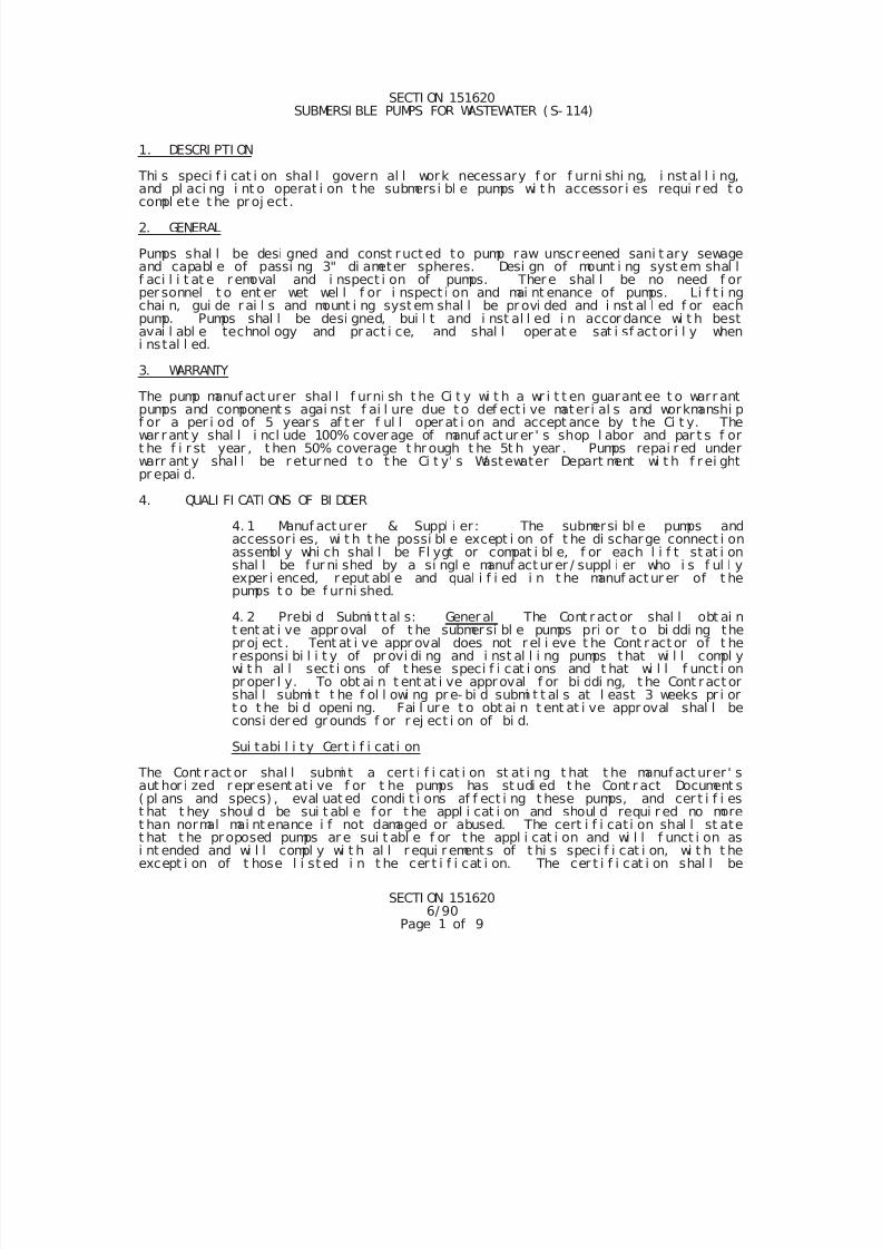
7/25/2019 City Standard Construction Specifications
http://slidepdf.com/reader/full/city-standard-construction-specifications 492/511
SECTI ON 1516206/ 90
Page 1 of 9
SECTI ON 151620 SUBMERSI BLE PUMPS FOR WASTEWATER ( S- 114)
1. DESCRI PTI ON
Thi s speci f i cat i on shal l govern al l work necessary f or f urni shi ng, i nst al l i ng,and pl aci ng i nt o operat i on t he submers i bl e pumps wi t h accessor i es requi r ed t ocompl ete t he pr oj ect .
2. GENERAL
Pumps shal l be desi gned and const ruct ed to pump raw unscr eened sani t ary sewageand capabl e of passi ng 3" di ameter spheres. Desi gn of mount i ng syst em shal lf aci l i t at e r emoval and i nspect i on of pumps. There shal l be no need f orper sonnel t o ent er wet wel l f or i nspect i on and mai nt enance of pumps. Li f t i ngchai n, gui de r ai l s and mount i ng system shal l be pr ovi ded and i nst al l ed f or eachpump. Pumps shal l be desi gned, bui l t and i nst al l ed i n accor dance wi t h bestavai l abl e technol ogy and pr act i ce, and shal l operat e sat i sf act or i l y wheni nstal l ed.
3. WARRANTY
The pump manuf act urer shal l f urni sh t he Ci t y wi t h a wr i t t en guarant ee t o warr antpumps and component s agai nst f ai l ure due t o def ect i ve materi al s and workmanshi pf or a per i od of 5 year s af t er f ul l operat i on and accept ance by t he Ci t y. Thewar r ant y shal l i ncl ude 100% cover age of manuf act ur er ' s shop l abor and par t s f ort he f i r st year , t hen 50% coverage t hr ough t he 5t h year . Pumps repai r ed underwarr ant y shal l be r eturned t o t he Ci t y' s Wastewater Depart ment wi t h f r ei ghtpr epai d.
4. QUALI FI CATI ONS OF BI DDER
4. 1 Manuf act urer & Suppl i er: The submersi bl e pumps andaccessor i es, wi t h t he possi bl e except i on of t he di scharge connect i onassembl y whi ch shal l be Fl ygt or compat i bl e, f or each l i f t st at i onshal l be f ur ni shed by a si ngl e manuf act ur er / suppl i er who i s f ul l yexper i enced, r eput abl e and qual i f i ed i n t he manuf act ur er of t he
pumps t o be f urni shed.
4. 2 Prebi d Submi t t al s: Gener al The Cont r act or shal l obt ai nt ent at i ve appr oval of t he submersi bl e pumps pri or t o bi ddi ng theproj ect . Tent at i ve appr oval does not r el i eve t he Cont ract or of t her esponsi bi l i t y of pr ovi di ng and i nst al l i ng pumps t hat wi l l compl ywi t h al l sect i ons of t hese speci f i cat i ons and t hat wi l l f unct i onproper l y. To obt ai n t ent at i ve approval f or bi ddi ng, t he Cont ract orshal l submi t t he f ol l owi ng pr e- bi d submi t t al s at l east 3 weeks pr i ort o t he bi d openi ng. Fai l ur e t o obt ai n t ent at i ve appr oval shal l beconsi der ed gr ounds f or r ej ect i on of bi d.
Sui tabi l i ty Cert i f i cat i on
The Cont r act or shal l submi t a cer t i f i cat i on st at i ng t hat t he manuf act urer ' s
aut hor i zed r epr esent at i ve f or t he pumps has st udi ed t he Cont r act Document s( pl ans and specs) , eval uat ed condi t i ons af f ect i ng t hese pumps, and cer t i f i est hat t hey shoul d be sui t abl e f or t he appl i cat i on and shoul d requi r ed no moret han normal mai nt enance i f not damaged or abused. The cert i f i cat i on shal l st atet hat t he proposed pumps ar e sui t abl e f or t he appl i cat i on and wi l l f unct i on asi nt ended and wi l l compl y wi t h al l r equi r ement s of t hi s speci f i cat i on, wi t h t heexcept i on of t hose l i st ed i n t he cer t i f i cat i on. The cer t i f i cat i on shal l be
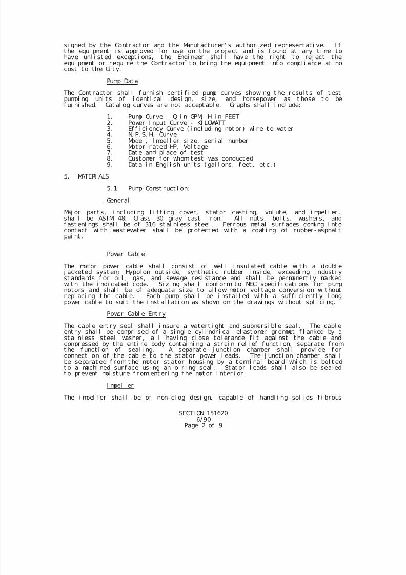
7/25/2019 City Standard Construction Specifications
http://slidepdf.com/reader/full/city-standard-construction-specifications 493/511
SECTI ON 1516206/ 90
Page 2 of 9
si gned by t he Cont r act or and t he Manuf act urer ' s aut hori zed r epr esent at i ve. I ft he equi pment i s appr oved f or use on t he pr oj ect and i s f ound at any t i me tohave unl i st ed except i ons, t he Engi neer shal l have t he ri ght t o rej ect t heequi pment or r equi r e the Cont r actor t o br i ng the equi pment i nt o compl i ance at nocost t o the Ci t y.
Pump Dat a
The Cont r act or shal l f urni sh cer t i f i ed pump curves showi ng t he r esul t s of t estpumpi ng uni t s of i dent i cal desi gn, si ze, and horsepower as t hose t o bef ur ni shed. Cat al og cur ves ar e not accept abl e. Gr aphs shal l i ncl ude:
1. Pump Curve - Q i n GPM, H i n FEET2. Power I nput Curve - KI LOWATT3. Ef f i ci ency Cur ve ( i ncl udi ng mot or ) wi r e t o wat er4. N. P. S. H. Cur ve5. Model , I mpel l er si ze, ser i al number6. Motor r ated HP, Vol t age7. Dat e and pl ace of t est8. Customer f or whom t est was conduct ed9. Dat a i n Engl i sh uni t s ( gal l ons, f eet , et c. )
5. MATERI ALS
5. 1 Pump Const ruct i on:
General
Maj or par t s, i ncl udi ng l i f t i ng cover, st at or cast i ng, vol ut e, and i mpel l er ,shal l be ASTM 48, Cl ass 30 gr ay cast i r on. Al l nut s, bol t s, washer s, andf ast eni ngs shal l be of 316 st ai nl ess steel . Fer r ous met al sur f aces comi ng i nt ocont act wi t h wast ewat er shal l be pr otect ed wi t h a coat i ng of r ubber - asphal tpai nt .
Power Cabl e
The mot or power cabl e shal l consi st of wel l i nsul ated cabl e wi t h a doubl e
j acketed syst em, Hypol on out si de, synt het i c r ubber i nsi de, exceedi ng i ndust r yst andards f or oi l , gas, and sewage resi st ance and shal l be per manent l y markedwi t h t he i ndi cat ed code. Si zi ng shal l conf or m t o NEC speci f i cat i ons f or pumpmotors and shal l be of adequate si ze to al l ow motor vol t age conver si on wi t houtr epl aci ng t he cabl e. Each pump shal l be i nst al l ed wi t h a suf f i ci ent l y l ongpower cabl e t o sui t t he i nst al l at i on as shown on t he dr awi ngs wi t hout spl i ci ng.
Power Cabl e Ent r y
The cabl e ent r y seal shal l i nsure a watert i ght and submersi bl e seal . The cabl eent r y shal l be compr i sed of a si ngl e cyl i ndr i cal el ast omer gr ommet f l anked by ast ai nl ess st eel washer , al l havi ng cl ose t ol er ance f i t agai nst t he cabl e andcompressed by t he ent i r e body cont ai ni ng a st r ai n r el i ef f unct i on, separ at e f r omt he f unct i on of seal i ng. A separ at e j unct i on chamber shal l pr ovi de f orconnect i on of t he cabl e t o t he st at or power l eads. The j unct i on chamber shal l
be separat ed f r om t he motor st ator housi ng by a t ermi nal boar d whi ch i s bol t edt o a machi ned sur f ace usi ng an o- r i ng seal . St at or l eads shal l al so be seal edt o prevent moi st ur e f r om ent er i ng t he mot or i nt er i or .
I mpel l er
The i mpel l er shal l be of non- cl og desi gn, capabl e of handl i ng sol i ds f i brous
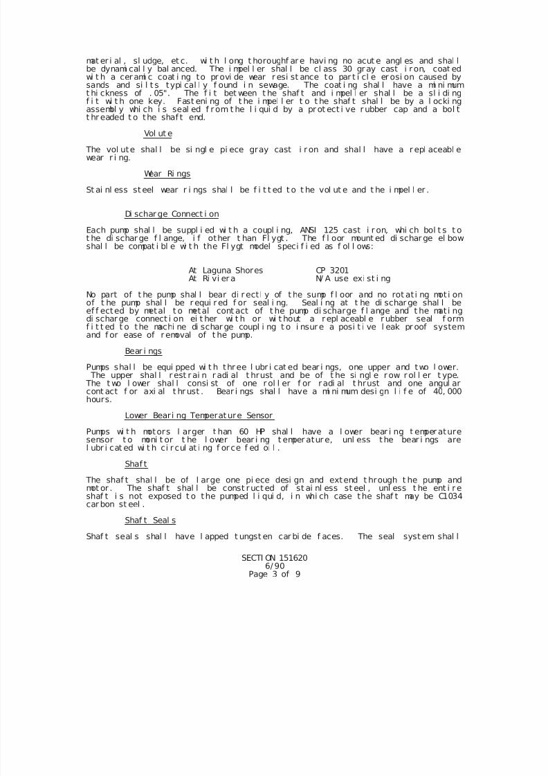
7/25/2019 City Standard Construction Specifications
http://slidepdf.com/reader/full/city-standard-construction-specifications 494/511
SECTI ON 1516206/ 90
Page 3 of 9
mat er i al , sl udge, et c. wi t h l ong t horoughf ar e havi ng no acut e angl es and shal lbe dynami cal l y bal anced. The i mpel l er shal l be cl ass 30 gr ay cast i r on, coat edwi t h a cerami c coat i ng to pr ovi de wear r esi st ance to par t i cl e er osi on caused bysands and si l t s typi cal l y f ound i n sewage. The coat i ng shal l have a mi ni mumt hi ckness of . 05". The f i t bet ween t he shaf t and i mpel l er shal l be a sl i di ngf i t wi t h one key. Fast eni ng of t he i mpel l er t o t he shaf t shal l be by a l ocki ngassembl y whi ch i s seal ed f r om t he l i qui d by a pr ot ect i ve r ubber cap and a bol tt hr eaded t o the shaf t end.
Vol ut e
The vol ute shal l be si ngl e pi ece gray cast i r on and shal l have a r epl aceabl ewear r i ng.
Wear Ri ngs
St ai nl ess st eel wear r i ngs shal l be f i t t ed t o t he vol ut e and t he i mpel l er .
Di schar ge Connect i on
Each pump shal l be suppl i ed wi t h a coupl i ng, ANSI 125 cast i r on, whi ch bol t s t ot he di schar ge f l ange, i f other t han Fl ygt . The f l oor mount ed di schar ge el bow
shal l be compat i bl e wi t h the Fl ygt model speci f i ed as f ol l ows:
At Laguna Shores CP 3201At Ri vi er a N/ A use exi st i ng
No part of t he pump shal l bear di r ect l y of t he sump f l oor and no rot at i ng mot i onof t he pump shal l be r equi r ed f or seal i ng. Seal i ng at t he di schar ge shal l beef f ected by metal t o metal cont act of t he pump di scharge f l ange and t he mat i ngdi schar ge connect i on ei t her wi t h or wi t hout a r epl aceabl e r ubber seal f ormf i t t ed t o the machi ne di schar ge coupl i ng t o i nsur e a posi t i ve l eak pr oof systemand f or ease of r emoval of t he pump.
Bear i ngs
Pumps shal l be equi pped wi t h three l ubr i cat ed bear i ngs, one upper and two l ower. The upper shal l r est r ai n r adi al t hrust and be of t he si ngl e r ow r ol l er t ype. The t wo l ower shal l consi st of one r ol l er f or r adi al t hrust and one angul arcont act f or axi al t hr ust . Bear i ngs shal l have a mi ni mum desi gn l i f e of 40, 000hours.
Lower Beari ng Temperature Sensor
Pumps wi t h motors l arger t han 60 HP shal l have a l ower bear i ng t emper aturesensor t o moni t or t he l ower bear i ng t emper atur e, unl ess the bear i ngs arel ubr i cat ed wi t h ci r cul at i ng f or ce f ed oi l .
Shaf t
The shaf t shal l be of l arge one pi ece desi gn and extend t hrough t he pump and
mot or . The shaf t shal l be const ruct ed of st ai nl ess st eel , unl ess t he ent i r eshaf t i s not exposed t o the pumped l i qui d, i n whi ch case t he shaf t may be C1034car bon st eel .
Shaf t Seal s
Shaf t seal s shal l have l apped t ungst en car bi de f aces. The seal syst em shal l
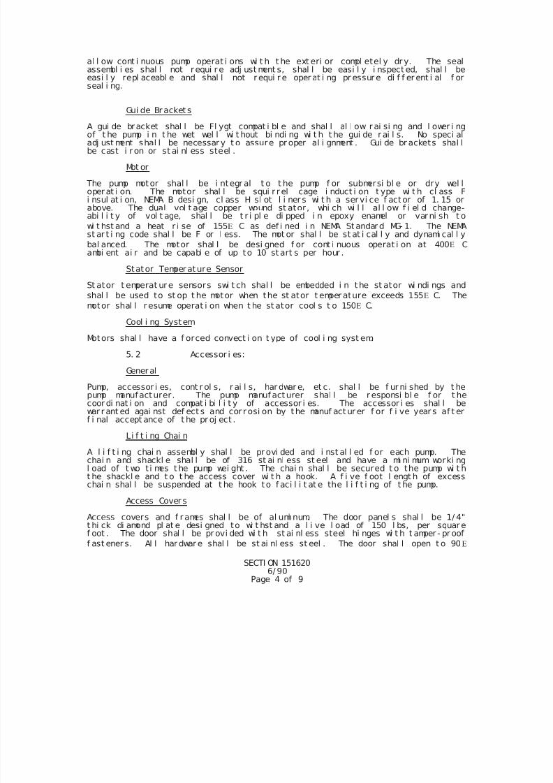
7/25/2019 City Standard Construction Specifications
http://slidepdf.com/reader/full/city-standard-construction-specifications 495/511
SECTI ON 1516206/ 90
Page 4 of 9
al l ow cont i nuous pump operat i ons wi t h t he ext eri or compl etel y dr y. The sealassembl i es shal l not r equi r e adj ust ment s, shal l be easi l y i nspect ed, shal l beeasi l y repl aceabl e and shal l not r equi r e oper at i ng pr essur e di f f er ent i al f orseal i ng.
Gui de Br acket s
A gui de bracket shal l be Fl ygt compat i bl e and shal l al l ow r ai si ng and l ower i ngof t he pump i n t he wet wel l wi t hout bi ndi ng wi t h t he gui de r ai l s. No speci aladj ust ment shal l be necessar y t o assure pr oper al i gnment . Gui de br ackets shal lbe cast i r on or st ai nl ess steel .
Mot or
The pump motor shal l be i ntegr al t o t he pump f or submersi bl e or dry wel loper at i on. The motor shal l be squi r r el cage i nduct i on t ype wi t h cl ass Fi nsul at i on, NEMA B desi gn, cl ass H sl ot l i ner s wi t h a ser vi ce f actor of 1. 15 orabove. The dual vol t age copper wound st ator, whi ch wi l l al l ow f i el d change-abi l i t y of vol t age, shal l be t r i pl e di pped i n epoxy enamel or varni sh t o
wi t hst and a heat r i se of 155 C as def i ned i n NEMA St andar d MG- 1. The NEMAst ar t i ng code shal l be F or l ess. The mot or shal l be st at i cal l y and dynami cal l y
bal anced. The motor shal l be desi gned f or cont i nuous operat i on at 400
Cambi ent ai r and be capabl e of up to 10 st art s per hour .
Stator Temperature Sensor
St ator t emperat ur e sensors swi t ch shal l be embedded i n the st ator wi ndi ngs and
shal l be used to st op t he motor when the st ator t emper ature exceeds 155 C. The
motor shal l r esume operat i on when t he st ator cool s t o 150 C.
Cool i ng System
Motors shal l have a f orced convect i on t ype of cool i ng syst em.
5. 2 Accessor i es:
General
Pump, accessor i es, cont r ol s, r ai l s, har dwar e, et c. shal l be f ur ni shed by t hepump manufacturer. The pump manuf acturer shal l be r esponsi bl e f or t hecoor di nat i on and compat i bi l i t y of accessor i es. The accessor i es shal l bewar r ant ed agai nst def ect s and cor r osi on by the manuf act ur er f or f i ve year s af t erf i nal accept ance of t he pr oj ect .
Li f t i ng Chai n
A l i f t i ng chai n assembl y shal l be pr ovi ded and i nst al l ed f or each pump. Thechai n and shackl e shal l be of 316 st ai nl ess st eel and have a mi ni mum worki ngl oad of t wo t i mes t he pump wei ght . The chai n shal l be secured t o the pump wi t ht he shackl e and t o t he access cover wi t h a hook. A f i ve f oot l engt h of excesschai n shal l be suspended at t he hook to f aci l i t at e the l i f t i ng of t he pump.
Access Cover s
Access covers and f r ames shal l be of al umi num. The door panel s shal l be 1/ 4"t hi ck di amond pl at e desi gned to wi t hst and a l i ve l oad of 150 l bs, per squar ef oot . The door shal l be pr ovi ded wi t h st ai nl ess steel hi nges wi t h t amper - pr oof
f ast ener s. Al l har dwar e shal l be st ai nl ess st eel . The door shal l open t o 90
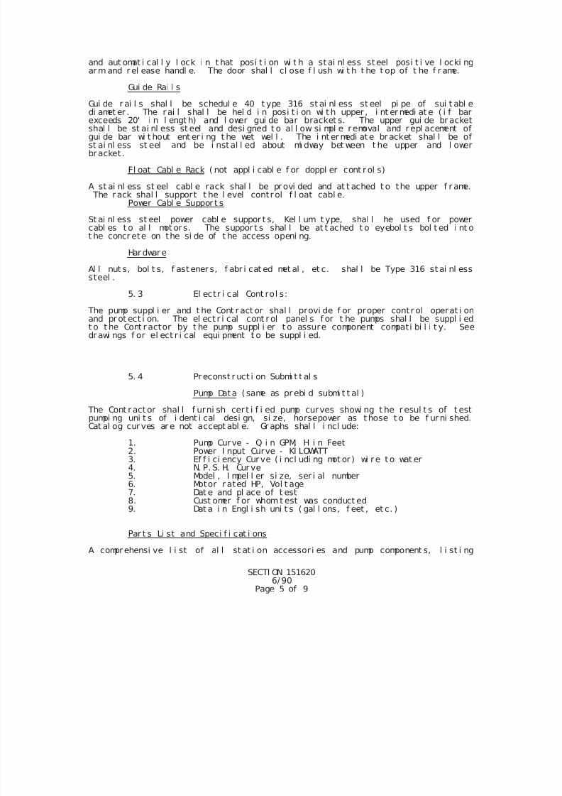
7/25/2019 City Standard Construction Specifications
http://slidepdf.com/reader/full/city-standard-construction-specifications 496/511
SECTI ON 1516206/ 90
Page 5 of 9
and aut omat i cal l y l ock i n t hat posi t i on wi t h a st ai nl ess steel posi t i ve l ocki ngar m and r el ease handl e. The door shal l cl ose f l ush wi t h t he t op of t he f r ame.
Gui de Rai l s
Gui de r ai l s shal l be schedul e 40 t ype 316 st ai nl ess st eel pi pe of sui t abl edi amet er . The r ai l shal l be hel d i n posi t i on wi t h upper , i nt er medi at e ( i f barexceeds 20' i n l engt h) and l ower gui de bar bracket s. The upper gui de br acketshal l be st ai nl ess st eel and desi gned t o al l ow si mpl e r emoval and r epl acement ofgui de bar wi t hout ent er i ng t he wet wel l . The i nt er medi at e br acket shal l be ofst ai nl ess st eel and be i nstal l ed about mi dway bet ween t he upper and l owerbr acket.
Fl oat Cabl e Rack ( not appl i cabl e f or doppl er cont r ol s)
A st ai nl ess st eel cabl e rack shal l be pr ovi ded and at t ached t o the upper f r ame. The r ack shal l support t he l evel contr ol f l oat cabl e.
Power Cabl e Suppor t s
St ai nl ess st eel power cabl e suppor t s, Kel l um t ype, shal l he used f or powercabl es t o al l mot or s. The suppor t s shal l be at t ached t o eyebol t s bol t ed i nt ot he concr ete on the si de of t he access openi ng.
Har dware
Al l nut s, bol t s, f ast ener s, f abr i cat ed met al , et c. shal l be Type 316 st ai nl esssteel .
5. 3 El ectr i cal Cont rol s:
The pump suppl i er and t he Cont r act or shal l provi de f or proper contr ol operat i onand pr ot ect i on. The el ect r i cal cont r ol panel s f or t he pumps shal l be suppl i edt o t he Cont r actor by t he pump suppl i er t o assure component compati bi l i t y. Seedr awi ngs f or el ect r i cal equi pment t o be suppl i ed.
5. 4 Preconst r uct i on Submi t t al s
Pump Data ( same as prebi d submi t t al )
The Cont r act or shal l f urni sh cer t i f i ed pump curves showi ng t he r esul t s of t estpumpi ng uni t s of i dent i cal desi gn, si ze, horsepower as t hose t o be f ur ni shed.Cat al og cur ves ar e not accept abl e. Gr aphs shal l i ncl ude:
1. Pump Curve - Q i n GPM, H i n Feet2. Power I nput Curve - KI LOWATT3. Ef f i ci ency Cur ve ( i ncl udi ng mot or ) wi r e t o wat er4. N. P. S. H. Cur ve5. Model , I mpel l er si ze, ser i al number6. Motor r ated HP, Vol t age7. Dat e and pl ace of t est
8. Cust omer f or whom t est was conduct ed9. Dat a i n Engl i sh uni t s ( gal l ons, f eet , et c. )
Par t s Li st and Speci f i cat i ons
A compr ehensi ve l i st of al l st at i on accessor i es and pump component s, l i st i ng
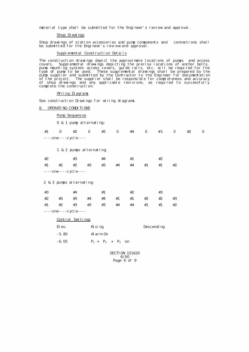
7/25/2019 City Standard Construction Specifications
http://slidepdf.com/reader/full/city-standard-construction-specifications 497/511
SECTI ON 1516206/ 90
Page 6 of 9
mat er i al t ype shal l be submi t t ed f or t he Engi neer ' s r evi ew and approval .
Shop Dr awi ngs
Shop drawi ngs of st at i on accessor i es and pump component s and connect i ons shal lbe submi t t ed f or t he Engi neer ' s r evi ew and appr oval .
Suppl ement al Const r uct i on Det ai l s
The const r uct i on drawi ngs depi ct t he approxi mate l ocat i ons of pumps and accesscovers. Suppl ement al dr awi ngs depi ct i ng t he pr eci se l ocat i ons of anchor bol t s,pump mount i ng system, access cover s, gui de r ai l s, et c. wi l l be r equi r ed f or t het ype of pump t o be used. These suppl ement al drawi ngs shal l be prepared by t hepump suppl i er and submi t t ed by the Cont r actor t o the Engi neer f or document at i onof t he proj ect . The suppl i er shal l be r esponsi bl e f or compl et eness and accur acyof shop dr awi ngs and any appl i cabl e r evi si ons, as requi r ed t o successf ul l ycompl ete t he const r uct i on.
Wi r i ng Di agr ams
See const r uct i on Dr awi ngs f or wi r i ng di agr ams.
6. OPERATI NG CONDI TI ONS
Pump Sequences
0 & 1 pump al t ernat i ng:
#1 0 #2 0 #3 0 #4 0 #1 0 #2 0
- - - - one- - - - cycl e- - - -
1 & 2 pumps al t ernat i ng:
#2 #3 #4 #1 #2
#1 #2 #2 #3 #3 #4 #4 #1 #1 #2
- - - - one- - - - cycl e- - - -
2 & 3 pumps al t ernat i ng:
#3 #4 #1 #2 #3
#2 #3 #3 #4 #4 #1 #1 #2 #2 #3
#1 #2 #3 #3 #3 #4 #4 #1 #1 #2
- - - - one- - - - cycl e- - - -
Cont r ol Set t i ngs
El ev. Ri si ng Descendi ng
- 5. 80 Al ar m On
- 6. 05 P1 + P2 + P3 on
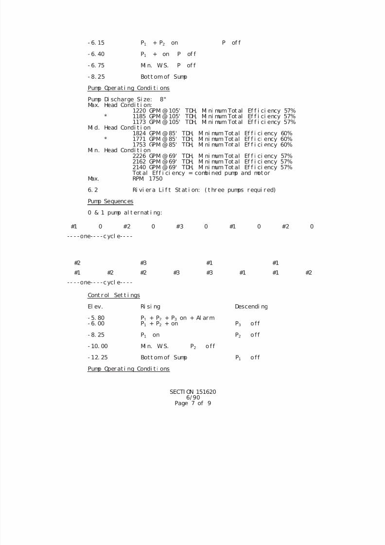
7/25/2019 City Standard Construction Specifications
http://slidepdf.com/reader/full/city-standard-construction-specifications 498/511
SECTI ON 1516206/ 90
Page 7 of 9
- 6. 15 P1 + P2 on P of f
- 6. 40 P1 + on P of f
- 6. 75 Mi n. W. S. P of f
- 8. 25 Bot t omof Sump
Pump Oper at i ng Condi t i ons
Pump Di scharge Si ze: 8"Max. Head Condi t i on:
1220 GPM @105' TDH, Mi ni mum Tot al Ef f i ci ency 57% * 1185 GPM @105' TDH, Mi ni mum Tot al Ef f i ci ency 57% 1173 GPM @105' TDH, Mi ni mum Tot al Ef f i ci ency 57% Mi d. Head Condi t i on
1824 GPM @85' TDH, Mi ni mum Tot al Ef f i ci ency 60% * 1771 GPM @85' TDH, Mi ni mum Tot al Ef f i ci ency 60% 1753 GPM @85' TDH, Mi ni mum Tot al Ef f i ci ency 60% Mi n. Head Condi t i on
2226 GPM @69' TDH, Mi ni mum Tot al Ef f i ci ency 57% 2162 GPM @69' TDH, Mi ni mum Tot al Ef f i ci ency 57% 2140 GPM @69' TDH, Mi ni mum Tot al Ef f i ci ency 57%
Tot al Ef f i ci ency = combi ned pump and motorMax. RPM: 1750
6. 2 Ri vi er a Li f t St at i on: ( t hr ee pumps r equi red)
Pump Sequences
0 & 1 pump al t ernat i ng:
#1 0 #2 0 #3 0 #1 0 #2 0
- - - - one- - - - cycl e- - - -
#2 #3 #1 #1
#1 #2 #2 #3 #3 #1 #1 #2
- - - - one- - - - cycl e- - - -
Cont r ol Set t i ngs
El ev. Ri si ng Descendi ng
- 5. 80 P1 + P2 + P on + Al arm3
- 6. 00 P1 + P2 + on P3 o f f
- 8. 25 P1 on P2 o f f
- 10. 00 Mi n. W. S. P2 o f f
- 12. 25 Bot t omof Sump P1 o f f
Pump Oper at i ng Condi t i ons
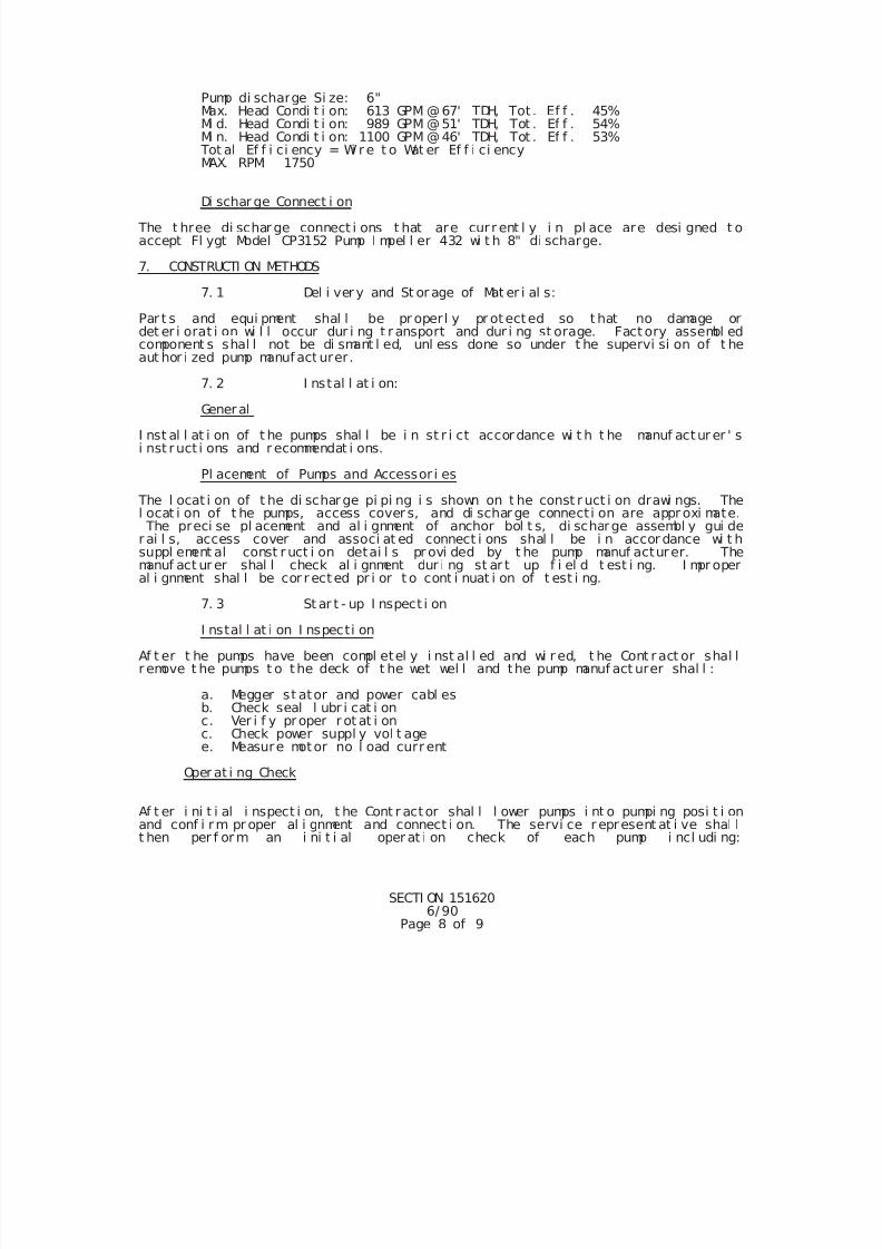
7/25/2019 City Standard Construction Specifications
http://slidepdf.com/reader/full/city-standard-construction-specifications 499/511
SECTI ON 1516206/ 90
Page 8 of 9
Pump di scharge Si ze: 6"Max. Head Condi t i on: 613 GPM @67' TDH, Tot . Ef f . 45%
Mi d. Head Condi t i on: 989 GPM @51' TDH, Tot . Ef f . 54% Mi n. Head Condi t i on: 1100 GPM @46' TDH, Tot . Ef f . 53% Tot al Ef f i ci ency = Wi r e t o Wat er Ef f i ci ency
MAX. RPM: 1750
Di schar ge Connect i on
The t hree di schar ge connect i ons t hat are cur r ent l y i n pl ace are desi gned t oaccept Fl ygt Model CP3152 Pump I mpel l er 432 wi t h 8" di scharge.
7. CONSTRUCTI ON METHODS
7. 1 Del i ver y and St or age of Mat er i al s:
Par t s and equi pment shal l be pr operl y pr otected so t hat no damage ordet er i orat i on wi l l occur dur i ng t r ansport and dur i ng st orage. Fact ory assembl edcomponent s shal l not be di smant l ed, unl ess done so under t he supervi si on of t heaut hor i zed pump manuf act urer.
7. 2 I nstal l at i on:
General
I nst al l at i on of t he pumps shal l be i n st r i ct accor dance wi t h t he manuf actur er ' si nst ruct i ons and r ecommendat i ons.
Pl acement of Pumps and Accessor i es
The l ocat i on of t he di scharge pi pi ng i s shown on t he const r uct i on drawi ngs. Thel ocat i on of t he pumps, access cover s, and di schar ge connect i on are appr oxi mate. The preci se pl acement and al i gnment of anchor bol t s, di scharge assembl y gui der ai l s, access cover and associ at ed connect i ons shal l be i n accor dance wi t hsuppl ement al const r uct i on detai l s pr ovi ded by t he pump manuf acturer. Themanuf act ur er shal l check al i gnment dur i ng st ar t up f i el d t est i ng. I mpr operal i gnment shal l be cor r ect ed pr i or t o cont i nuat i on of t est i ng.
7. 3 St ar t - up I nspect i on
I nstal l at i on I nspecti on
Af t er t he pumps have been compl etel y i nst al l ed and wi r ed, t he Cont r act or shal lr emove t he pumps t o the deck of t he wet wel l and the pump manuf act urer shal l :
a. Megger st ator and power cabl esb. Check seal l ubr i cat i onc. Ver i f y proper r ot at i onc. Check power suppl y vol t agee. Measure motor no l oad curr ent
Oper at i ng Check
Af t er i ni t i al i nspect i on, t he Cont r actor shal l l ower pumps i nt o pumpi ng posi t i onand conf i rm pr oper al i gnment and connect i on. The servi ce r epresent at i ve shal lt hen per f or m an i ni t i al oper at i on check of each pump i ncl udi ng:
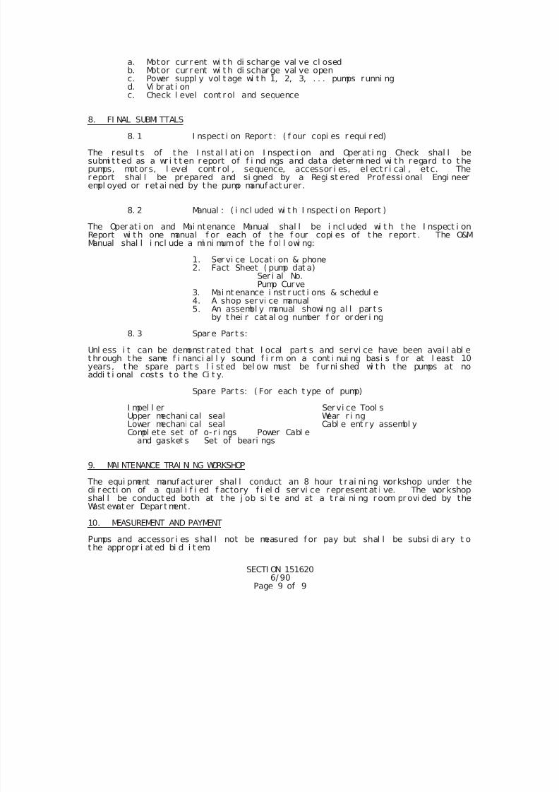
7/25/2019 City Standard Construction Specifications
http://slidepdf.com/reader/full/city-standard-construction-specifications 500/511
SECTI ON 1516206/ 90
Page 9 of 9
a. Motor cur r ent wi t h di schar ge val ve cl osedb. Motor cur r ent wi t h di schar ge val ve openc. Power suppl y vol t age wi t h 1, 2, 3, . . . pumps runni ngd. Vi br at i onc. Check l evel cont rol and sequence
8. FI NAL SUBMI TTALS
8. 1 I nspect i on Repor t : ( f our copi es requi r ed)
The r esul t s of t he I nst al l at i on I nspect i on and Oper at i ng Check shal l besubmi t t ed as a wr i t t en r eport of f i ndi ngs and data deter mi ned wi t h regard to t hepumps, mot or s, l evel cont r ol , sequence, accessor i es, el ect r i cal , etc. Ther eport shal l be pr epared and si gned by a Regi st ered Prof essi onal Engi neerempl oyed or r etai ned by t he pump manuf act urer.
8. 2 Manual : ( i ncl uded wi t h I nspect i on Report )
The Oper at i on and Mai ntenance Manual shal l be i ncl uded wi t h t he I nspect i onReport wi t h one manual f or each of t he f our copi es of t he r eport . The O&MManual shal l i ncl ude a mi ni mum of t he f ol l owi ng:
1. Ser vi ce Locat i on & phone2. Fact Sheet ( pump dat a)
Ser i al No. Pump Curve
3. Mai nt enance i nst r uct i ons & schedul e 4. A shop servi ce manual
5. An assembl y manual showi ng al l par t sby t hei r cat al og number f or or der i ng
8. 3 Spar e Par t s:
Unl ess i t can be demonst r ated t hat l ocal part s and servi ce have been avai l abl et hr ough t he same f i nanci al l y sound f i r m on a cont i nui ng basi s f or at l east 10years, t he spare part s l i st ed bel ow must be f ur ni shed wi t h the pumps at no
addi t i onal cost s t o t he Ci t y.
Spare Par t s: ( For each t ype of pump)
I mpel l er Servi ce Tool sUpper mechani cal seal Wear r i ngLower mechani cal seal Cabl e ent ry assembl yCompl ete set of o- r i ngs Power Cabl e
and gasket s Set of beari ngs
9. MAI NTENANCE TRAI NI NG WORKSHOP
The equi pment manuf act urer shal l conduct an 8 hour t r ai ni ng workshop under t hedi r ecti on of a qual i f i ed f actory f i el d ser vi ce r epr esent at i ve. The wor kshop
shal l be conduct ed both at t he j ob si t e and at a t r ai ni ng r oom pr ovi ded by theWast ewat er Depar t ment.
10. MEASUREMENT AND PAYMENT
Pumps and accessor i es shal l not be measured f or pay but shal l be subsi di ary t ot he appr opr i at ed bi d i t em.
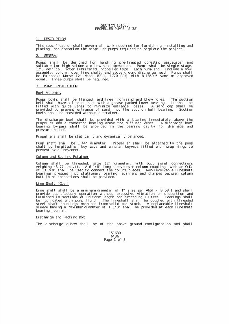
7/25/2019 City Standard Construction Specifications
http://slidepdf.com/reader/full/city-standard-construction-specifications 501/511
151630 6/ 86
Page 1 of 5
SECTI ON 151630 PROPELLER PUMPS ( S- 38)
1. DESCRI PTI ON
Thi s speci f i cat i on shal l govern al l work r equi r ed f or f urni shi ng, i nst al l i ng andpl aci ng i nt o oper at i on t he pr opel l er pumps r equi r ed t o compl et e t he pr oj ect .
2. GENERAL
Pumps shal l be desi gned f or handl i ng pre- t r eat ed domest i c wast ewater andsui t abl e f or hi gh vol ume and l ow head operat i on. Pumps shal l be si ngl e st age,12", ver t i cal , wat er l ubr i cat ed, pr opel l er t ype. Each pump shal l i ncl ude a bowlassembl y, col umn, open l i ne shaf t , and above ground di schar ge head. Pumps shal lbe Fai r banks Morse 12" Model 8211, 1770 RPM, wi t h B- 1369. 5 vane or approvedequal . Thr ee pumps shal l be r equi r ed.
3. PUMP CONSTRUCTI ON
Bowl Assembl y
Pumps bowl s shal l be f l anged, and f r ee f r om sand and bl ow hol es. The suct i on
bel l shal l have a f l ar ed i nl et wi t h a gr ease packed l ower bear i ng. I t shal l bef i t t ed wi t h gui de vanes to mi ni mi ze ent r ance l osses. A sand cap shal l bepr ovi ded t o pr event ent r ance of sand i nt o t he suct i on bel l bear i ng. Suct i onbowl s shal l be pr ovi ded wi t hout a str ai ner .
The di scharge bowl shal l be provi ded wi t h a bear i ng i mmedi atel y above t hepr opel l er and a connect or bear i ng above t he di f f user vanes. A di schar ge bowlbear i ng by- pass shal l be provi ded i n the bear i ng cavi t y f or dr ai nage andpressure rel i ef .
Pr opel l er s shal l be st at i cal l y and dynami cal l y bal anced.
Pump shaf t shal l be 1. 44" di ameter. Propel l er shal l be att ached t o t he pumpshaf t by l ongi t udi nal key ways and annul ar keyways f i t t ed wi t h snap ri ngs t oprevent axi al movement .
Col umn and Beari ng Retai ner
Col umn shal l be t hreaded, si ze 12" di amet er , wi t h but t j oi nt connect i onswei ghi ng 43. 77 l bs. / f t . A 6 1/ 8" l ong sl eeve t ype col umn coupl i ng, wi t h an O. D.of 13 7/ 8" shal l be used t o connect t he col umn pi eces. Non- r evol vabl e l i neshaf tbeari ngs pressed i nt o st at i onary bear i ng r etai ner s and cl amped bet ween col umnbut t j oi nt connect i ons shal l be pr ovi ded.
Li ne Shaf t ( Open)
Li ne shaf t shal l be a mi ni mum di amet er of 1" si ze per ANSI - B 58. 1 and shal lpr ovi de sat i sf act or y oper at i on wi t hout excessi ve vi br at i on or di st or t i on andf ur ni shed i n sect i ons of uni f orm l engt h not exceedi ng 10 f eet . Bear i ngs shal lbe l ubr i cat ed wi t h pump f l ui d. The l i neshaf t shal l be coupl ed wi t h t hr eaded
st eel shaf t coupl i ngs machi ned f r om sol i d bar st ock. A r epl aceabl e l i neshaf tsl eeve havi ng a maxi mum di ameter of 1 1/ 8" shal l be pr ovi ded at each l i neshaf tbear i ng j our nal .
Di schar ge and Packi ng Box
The di schar ge el bow shal l be of t he above ground conf i gur at i on and shal l
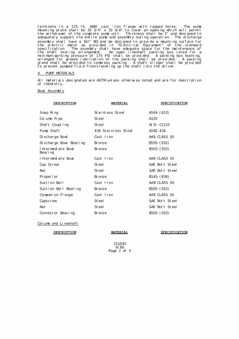
7/25/2019 City Standard Construction Specifications
http://slidepdf.com/reader/full/city-standard-construction-specifications 502/511
151630 6/ 86
Page 2 of 5
t ermi nate i n a 125 l b. ANSI cast i r on f l ange wi t h t apped hol es. The pumpmount i ng pl ate shal l be 33 3/ 4" x 33 3/ 4" t o cover an openi ng whi ch wi l l permi tt he wi t hdr awal of t he compl ete pump uni t . Thi ckness shal l be 1" and desi gned t oadequatel y suppor t t he ent i r e pump and assembl y dur i ng operat i on. The di scharge
assembl y shal l have a 16" BD and be desi gned t o pr ovi de a mount i ng sur f ace f ort he el ect r i c mot or as provi ded i n "El ect r i cal Equi pment " of t he standar dspeci f i cat i on. The assembl y shal l have adequate space f or t he mai nt enance of
t he shaf t seal i ng arr angement . An open l i neshaf t packi ng box r ated f or ami ni mum worki ng pr essur e of 175 PSI shal l be pr ovi ded. A packi ng box bushi ng,ar r anged f or gr ease l ubr i cat i on of t he packi ng shal l be provi ded. A packi nggl and shal l be pr ovi ded t o compr ess packi ng. A shaf t sl i nger shal l be pr ovi dedt o prevent pumped f l ui d f r om t r avel i ng up t he shaf t i nt o t he dr i ver .
4. PUMP MATERI ALS
Al l mat er i al s desi gnat ed ar e ASTM unl ess other wi se noted and ar e f or descr i pt i onof chemi st r y.
Bowl Assembl y
DESCRIPTION MATERIAL SPECIFICATION
Snap Ri ng St ai nl ess St eel A564- ( 632)
Col umn Pi pe St eel A120
Shaf t Coupl i ng St eel AI SI - C1215
Pump Shaf t 416 Stai nl ess Steel A582- 416
Di scharge Bowl Cast I r on A48- CLASS 30
Di schar ge Bowl Bear i ng Br onze B505- ( 932)
I nt ermedi ate BowlBear i ng
Br onze B505- ( 932)
I ntermedi ate Bowl Cast I r on A48- CLASS 30
Cap Scr ew St eel SAE Bol t St eel
Nut St eel SAE Bol t St eel
Pr opel l er Br onze B145- ( 836)
Suct i on Bel l Cast I r on A48- CLASS 30
Suct i on Bel l Bear i ng Br onze B505- ( 932)
Compani on Fl ange Cast I r on A48- CLASS 30
Capscr ew St eel SAE Bol t St eel
Nut St eel SAE Bol t St eel
Connect or Bear i ng Br onze B505- ( 932)
Col umn and Li neshaf t
DESCRIPTION MATERIAL SPECIFICATION
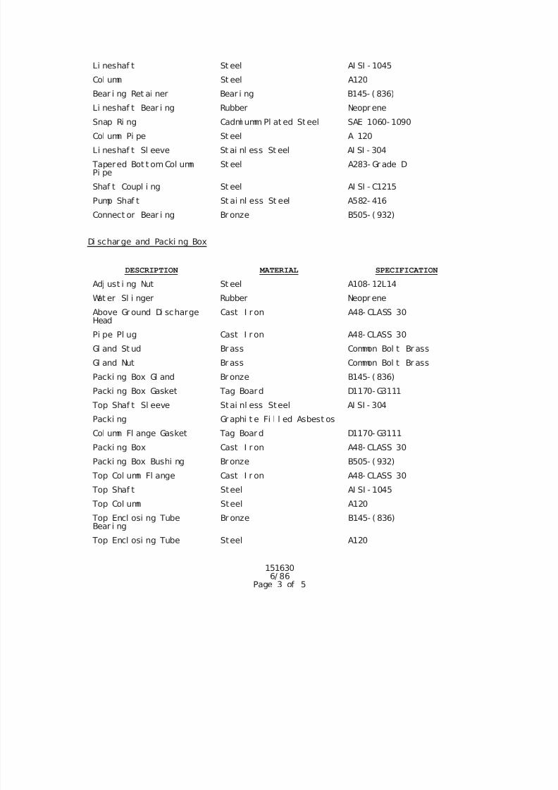
7/25/2019 City Standard Construction Specifications
http://slidepdf.com/reader/full/city-standard-construction-specifications 503/511
151630 6/ 86
Page 3 of 5
Li neshaf t St eel AI SI - 1045
Col umn St eel A120
Bear i ng Ret ai ner Bear i ng B145- ( 836)
Li neshaf t Bear i ng Rubber Neopr ene
Snap Ri ng Cadmi umm Pl at ed Steel SAE 1060- 1090Col umn Pi pe St eel A 120
Li neshaf t Sl eeve St ai nl ess St eel AI SI - 304
Tapered Bot t om Col umnPi pe
St eel A283- Gr ade D
Shaf t Coupl i ng St eel AI SI - C1215
Pump Shaf t St ai nl ess St eel A582- 416
Connect or Bear i ng Br onze B505- ( 932)
Di schar ge and Packi ng Box
DESCRIPTION MATERIAL SPECIFICATION
Adj ust i ng Nut St eel A108- 12L14
Wat er Sl i nger Rubber Neopr ene
Above Gr ound Di schargeHead
Cast I r on A48- CLASS 30
Pi pe Pl ug Cast I r on A48- CLASS 30
Gl and St ud Br ass Common Bol t Br ass
Gl and Nut Br ass Common Bol t Br ass
Packi ng Box Gl and Br onze B145- ( 836)
Packi ng Box Gasket Tag Board D1170- G3111
Top Shaf t Sl eeve Stai nl ess Steel AI SI - 304
Packi ng Gr aphi t e Fi l l ed Asbest os
Col umn Fl ange Gasket Tag Boar d D1170- G3111
Packi ng Box Cast I r on A48- CLASS 30
Packi ng Box Bushi ng Br onze B505- ( 932)
Top Col umn Fl ange Cast I r on A48- CLASS 30
Top Shaf t Steel AI SI - 1045
Top Col umn Steel A120
Top Encl osi ng TubeBear i ng
Br onze B145- ( 836)
Top Encl osi ng Tube Steel A120
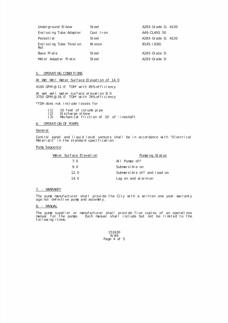
7/25/2019 City Standard Construction Specifications
http://slidepdf.com/reader/full/city-standard-construction-specifications 504/511
151630 6/ 86
Page 4 of 5
Under gr ound El bow St eel A283- Gr ade D, A120
Encl osi ng Tube Adapter Cast I r on A48- CLASS 30
Pedest r al St eel A283- Gr ade D, A120
Encl osi ng Tube Tensi onNut
Br onze B145- ( 836)
Base Pl at e St eel A283- Gr ade D
Mot or Adapt er Pl at e St eel A283- Gr ade D
5. OPERATI NG CONDI TI ONS
At Wet Wel l Water Sur f ace El evat i on of 14. 0
4100 GPM @11. 0' TDH* wi t h 65% ef f i ci ency
At wet wel l wat er sur f ace el evat i on 8. 03750 GPM @16. 0' TDH* wi t h 74% ef f i ci ency
*TDH does not i ncl ude l osses f or
( 1) 10 f eet of col umn pi pe( 2) Di schar ge el bow( 3) Mechani cal f r i cti on of 10' of l i neshaf t
6. OPERATI ON OF PUMPS
General
Cont rol panel and l i qui d l evel sensor s shal l be i n accor dance wi t h "El ect r i calMat er i al s" i n t he st andar d speci f i cat i on.
Pump Sequence
Wat er Sur f ace El evat i on Pumpi ng St at us
7. 0 Al l Pumps of f
9. 0 Submer si bl e on
12. 0 Submer si bl e of f and l ead on
14. 0 Lag on and al ar m on
7. - WARRANTY
The pump manuf act urer shal l provi de t he Ci t y wi t h a wr i t t en one year warr ant yagai nst def ect i ve pump and assembl y.
8. - MANUAL
The pump suppl i er or manuf act urer shal l provi de f i ve copi es of an operat i onsmanual f or t he pumps. Each manual shal l i ncl ude but not be l i mi t ed t o t hef ol l owi ng i t ems:
7/25/2019 City Standard Construction Specifications
http://slidepdf.com/reader/full/city-standard-construction-specifications 505/511
151630 6/ 86
Page 5 of 5
a. Cert i f i ed pump curve f or each pumpb. Par t s and assembl y di agr am wi t h part numbers f or orderi ngc. Mai ntenance schedul e and procedur esd. Gener al oper at i ons
9. - MEASUREMENT AND PAYMENT
Measurement f or propel l er pumps shal l be made as a l ump sum and shal l i ncl udebut not be l i mi t ed t o al l t hr ee pr opel l er pumps and assembl y compl et e i n pl ace.
Payment shal l be made at t he uni t pr i ce bi d and shal l f ul l y compensate theCont ractor f or al l equi pment , l abor , mat er i al s, and i nci dent al s r equi r ed f orf ur ni shi ng and i nst al l i ng pumps and assembl y.
7/25/2019 City Standard Construction Specifications
http://slidepdf.com/reader/full/city-standard-construction-specifications 506/511
151640Rev-5/96
Page 1 of 6
SECTION 151640 SUBMERSIBLE GRINDER PUMPS FOR WASTEWATER
(LESS THAN 10 HORSEPOWER)
1. DESCRIPTION This specification shall govern all work necessary for furnishing, installing,and placing into operation, heavy duty submersible grinder pumps capable ofgrinding sewage into a finely ground slurry for ease in pumping.
2. GENERAL Pumps shall be designed and constructed to grind and pump raw unscreened sanitarysewage without clogging. Design of wetwell systems shall facilitate removal andinspection of pumps. Lifting cables shall be provided and installed for eachpump. Pumps shall be designed, built and installed in accordance with bestavailable technology and practice, and shall operate satisfactorily wheninstalled. Each pump unit, with its appurtenances, shall be capable ofcontinuous duty underwater without loss of watertight integrity to a depth of 65feet.
3. WARRANTY
The pump manufacturer shall furnish the City with a written guarantee to warrantpumps and components against failure due to defective materials and workmanshipfor a period of 5 years after full operation and acceptance by the City. Thewarranty shall include 100% coverage of manufacturers shop labor and parts forthe first year then 50% coverage through the 5th year. Pumps repaired underwarranty shall be returned to the City's Wastewater Department with freightprepaid.
4. QUALIFICATIONS OF BIDDERS The submersible pumps and accessories, shall be furnished by a singlemanufacturer/supplier who is fully experienced, reputable and qualified in themanufacture of the pumps to be furnished. The manufacturer/supplier shall alsomaintain provisions for providing parts and/or service within 48 hours of
notification by the owner.
5. MATERIALS A. General:
Major parts including lifting cover, stator casting, volute, and impellershall be ASTM 48, Class 30 gray cast iron. All nuts, bolts, washers, andfastenings shall be of 316 stainless steel. All metal surfaces other thanstainless steel or brass coming into contact with wastewater shall beprotected with a coating of rubber-asphalt paint, or other water proofcoating approved by the Engineer.
B. Power Cable:The motor power cable shall consist of well insulated cable with a doublejacketed system, Hypolon outside, synthetic rubber inside, exceedingindustry standards for oil, gas, and sewage resistance, and shall bepermanently marked with the indicated code. Sizing shall conform to NECand ICEA specifications for pump motors. Each pump shall be installedwith a sufficiently long power cable to suit the installation as shown onthe drawings without splicing.
C. Power Cable Entry:
7/25/2019 City Standard Construction Specifications
http://slidepdf.com/reader/full/city-standard-construction-specifications 507/511
151640Rev-5/96
Page 2 of 6
The cable entry seal shall insure a watertight and submersible seal. Thecable entry shall be comprised of a single cylindrical elastomer grommetflanked by a stainless steel washer, all having close tolerance fitagainst the cable and compressed by the entire body, containing a strainrelief function, separate from the function of sealing. A separatejunction chamber shall provide for connection of the cable to the statorpower leads. The junction chamber shall be separated from the motorstator housing by a terminal board which is bolted to a machined surfaceusing an O-ring seal. Stator leads shall also be sealed to preventmoisture from entering the motor interior. Epoxies, silicones, or othersecondary sealing systems shall not be considered acceptable.
D. Impeller and Grinding System:The grinding system shall consist of a rotating cutter of chrome alloyedcast iron and a stationary cutter of 316 "L" hardened stainless steel.Cutting systems with plastic components or coatings shall be unacceptable.The impeller shall be of the multi-vane, semi-open type of cast iron ASTM
A 48-76 Class 30B, and shall be fastened to the pump-motor shaft by atapered collet and locking screw. All mating surfaces of the pump andmotor housings shall be machined and fitted with nitrile o-rings wherewatertight sealing is required. Machining and fitting shall be such thatsealing is accomplished by controlled compression of the o-rings withoutthe requirement of specific torque limits to achieve compression.
Rectangular cross sectioned gaskets requiring specific torque limits toachieve compression shall not be considered adequate nor equal.
E. Bearings:Pumps shall be equipped with two permanently lubricated bearings, oneupper and one lower. The upper shall restrain radial thrust and be ofthe single row ball type. The lower shall consist of a two row angularcontact ball bearing. Bearings shall have a minimum design life of 40,000hours.
F. Shaft:The shaft shall be of one piece design and extend through the pump andmotor. The shaft shall be constructed of stainless steel.
G. Shaft Seals:
Each pump shall be provided with a tandem mechanical shaft seal system.The upper of the tandem set of seals shall operate in an oil chamber. Theupper seal shall contain one stationary carbon ring and one positivelyrotating ceramic ring. The lower of the tandem set of seals shall consistof a stationary ring and a positively driven rotating ring. Both ringsshall be constructed of ceramic on pumps smaller than 3.0 horsepower. Onpumps of 3.0 horsepower and larger, the stationary ring shall beconstructed of ceramic and the rotating ring constructed of tungstencarbide.
H. Motor:The pump motor shall be integral to the pump for submersible or dry welloperation. The motor shall be a squirrel cage induction type with class Finsulation, NEMA B design, with Class H slot liners and a service factorof 1.15 or above. The stator shall be triple dipped in epoxy enamel orvarnish to withstand a heat rise of 155
o C as defined in NEMA standard MG-
1. The NEMA starting code shall be F or less. The motor shall bestatically and dynamically balanced. The motor shall be designed forcontinuous operation at 40
o C ambient air temperature and be capable of up
to 10 starts per hour. The pump motor(s) shall be furnished for operationwith 230 volts, 1 phase, 60 hertz power supply.
7/25/2019 City Standard Construction Specifications
http://slidepdf.com/reader/full/city-standard-construction-specifications 508/511
151640Rev-5/96
Page 3 of 6
I. Motor Overload Protection:Motors shall have a forced convection type of cooling system. Inaddition, thermal radiators (cooling fins), integral to the statorhousing, shall be adequate to provide the cooling required by the motor atthe maximum rated power of this unit. A minimum of two thermal sensorsshall be imbedded in the stator winding and coils. The thermal sensorsshall be wired to the control panel and wired in series so that theopening of either sensor will cause the motor to shut down. Thermalsensors and controls which average the temperature across the phases ofthe winding and coils will not be acceptable. Stator temperature sensorswitches shall stop the motor when the stator temperature exceeds 155
o C.
The motor shall resume operation when the stator cools down to 150o C.
J. General Accessories:Pump accessories, controls, hardware, etc. shall be furnished by the pumpmanufacturer. The pump manufacturer shall be responsible for thecoordination and compatibility of all accessories. The accessories shallbe warranted against defects and corrosion by the manufacturer for fiveyears after final acceptance of the project.
K. Lifting Cable: A lifting cable assembly shall be provided and installed for each pump.The cable and shackle shall be of 304 stainless steel and have a minimum
working load of twice the pump weight. The cable shall be secured to thepump with the shackle and to the access cover with a hook. A four footlength of excess cable shall be suspended at the hook to facilitate thelifting of the pump.
L. Access Covers: Access covers and frames shall be of aluminum. The door panels shall bediamond plate finish and designed to withstand a live load of 300 lbs persquare foot. The door shall be provided with stainless steel hinges withtamperproof fasteners. All hardware shall be stainless steel. The doorshall close flush with the top of the frame and shall have lockablehardware installed.
M. Float Cable Rack: A cable rack fabricated of type 304 stainless steel shall be provided and
attached to the access cover frame. The rack shall have provisions forholding in place and supporting the level control float cables.
N. Power Cable Supports:Stainless steel power cable supports (Kellums Grip) shall be used for allpower cables. The supports shall be attached to eye bolts bolted into theside of the access opening, or other support approved by the Engineer.Supporting the power cables on the cable rack will not be acceptable.
O. Hardware: All nuts, bolts, anchor bolts, wedge anchors, and other hardware(including nuts and bolts for pipe fittings) shall be minimum grade type304 stainless steel.
P. Electrical Pump Controls:The electrical control panels for the pump(s) shall be supplied to theContractor by the pump supplier to assure component compatibility. Thepump supplier and Contractor shall provide for proper control operationand protection. The control panel shall be factory wired and tested priorto shipment. The control panel shall include but is not limited to thefollowing:
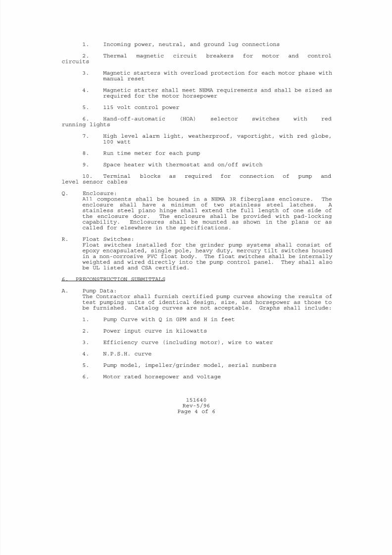
7/25/2019 City Standard Construction Specifications
http://slidepdf.com/reader/full/city-standard-construction-specifications 509/511
151640Rev-5/96
Page 4 of 6
1. Incoming power, neutral, and ground lug connections
2. Thermal magnetic circuit breakers for motor and controlcircuits
3. Magnetic starters with overload protection for each motor phase withmanual reset
4. Magnetic starter shall meet NEMA requirements and shall be sized asrequired for the motor horsepower
5. 115 volt control power
6. Hand-off-automatic (HOA) selector switches with redrunning lights
7. High level alarm light, weatherproof, vaportight, with red globe,100 watt
8. Run time meter for each pump
9. Space heater with thermostat and on/off switch
10. Terminal blocks as required for connection of pump andlevel sensor cables
Q. Enclosure: All components shall be housed in a NEMA 3R fiberglass enclosure. Theenclosure shall have a minimum of two stainless steel latches. Astainless steel piano hinge shall extend the full length of one side ofthe enclosure door. The enclosure shall be provided with pad-lockingcapability. Enclosures shall be mounted as shown in the plans or ascalled for elsewhere in the specifications.
R. Float Switches:Float switches installed for the grinder pump systems shall consist ofepoxy encapsulated, single pole, heavy duty, mercury tilt switches housedin a non-corrosive PVC float body. The float switches shall be internally
weighted and wired directly into the pump control panel. They shall alsobe UL listed and CSA certified.
6. PRECONSTRUCTION SUBMITTALS A. Pump Data:
The Contractor shall furnish certified pump curves showing the results oftest pumping units of identical design, size, and horsepower as those tobe furnished. Catalog curves are not acceptable. Graphs shall include:
1. Pump Curve with Q in GPM and H in feet
2. Power input curve in kilowatts
3. Efficiency curve (including motor), wire to water
4. N.P.S.H. curve
5. Pump model, impeller/grinder model, serial numbers
6. Motor rated horsepower and voltage
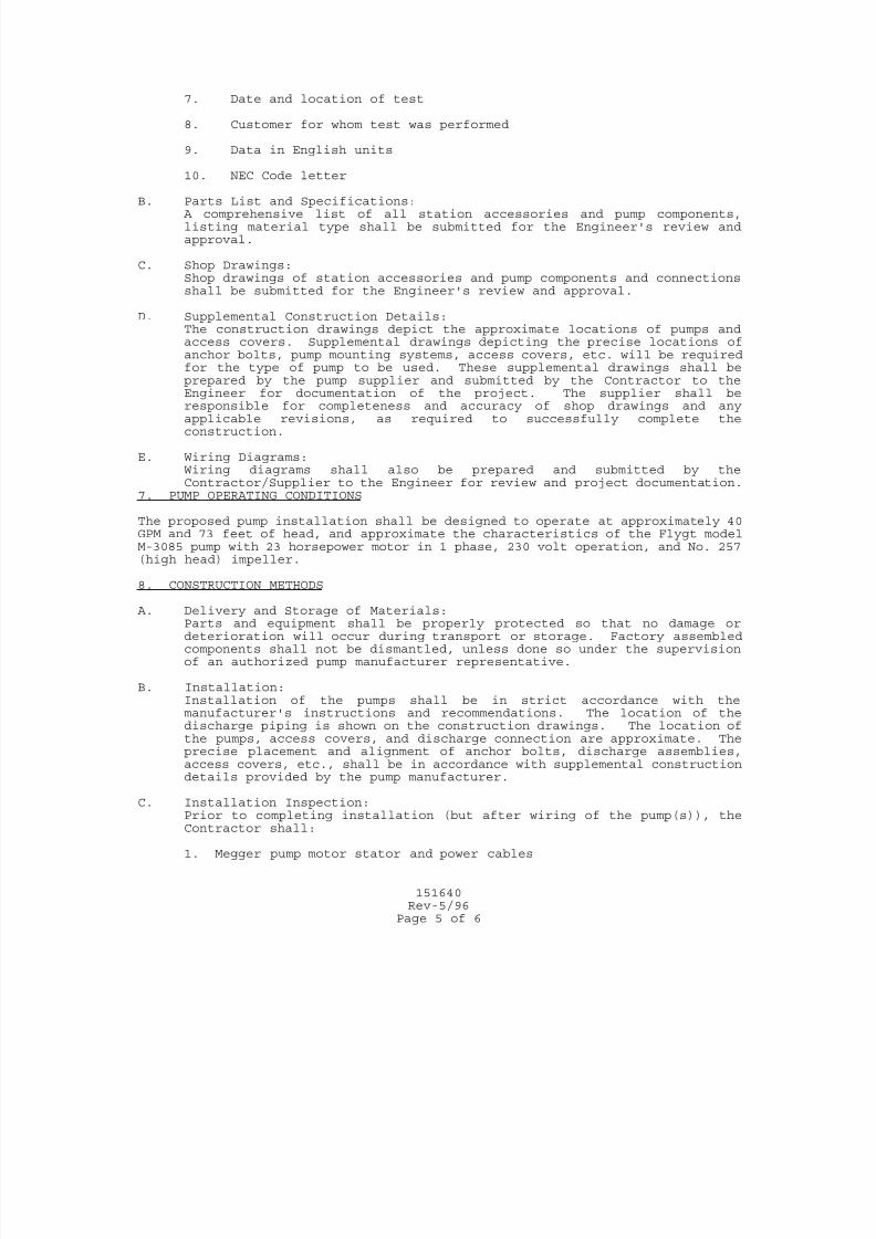
7/25/2019 City Standard Construction Specifications
http://slidepdf.com/reader/full/city-standard-construction-specifications 510/511
151640Rev-5/96
Page 5 of 6
7. Date and location of test
8. Customer for whom test was performed
9. Data in English units
10. NEC Code letter
B. Parts List and Specifications: A comprehensive list of all station accessories and pump components,listing material type shall be submitted for the Engineer's review andapproval.
C. Shop Drawings:Shop drawings of station accessories and pump components and connectionsshall be submitted for the Engineer's review and approval.
D. Supplemental Construction Details:The construction drawings depict the approximate locations of pumps andaccess covers. Supplemental drawings depicting the precise locations ofanchor bolts, pump mounting systems, access covers, etc. will be requiredfor the type of pump to be used. These supplemental drawings shall beprepared by the pump supplier and submitted by the Contractor to the
Engineer for documentation of the project. The supplier shall beresponsible for completeness and accuracy of shop drawings and anyapplicable revisions, as required to successfully complete theconstruction.
E. Wiring Diagrams:Wiring diagrams shall also be prepared and submitted by theContractor/Supplier to the Engineer for review and project documentation.
7. PUMP OPERATING CONDITIONS The proposed pump installation shall be designed to operate at approximately 40GPM and 73 feet of head, and approximate the characteristics of the Flygt modelM-3085 pump with 23 horsepower motor in 1 phase, 230 volt operation, and No. 257(high head) impeller.
8. CONSTRUCTION METHODS A. Delivery and Storage of Materials:
Parts and equipment shall be properly protected so that no damage ordeterioration will occur during transport or storage. Factory assembledcomponents shall not be dismantled, unless done so under the supervisionof an authorized pump manufacturer representative.
B. Installation:Installation of the pumps shall be in strict accordance with themanufacturer's instructions and recommendations. The location of thedischarge piping is shown on the construction drawings. The location ofthe pumps, access covers, and discharge connection are approximate. Theprecise placement and alignment of anchor bolts, discharge assemblies,access covers, etc., shall be in accordance with supplemental constructiondetails provided by the pump manufacturer.
C. Installation Inspection:Prior to completing installation (but after wiring of the pump(s)), theContractor shall:
1. Megger pump motor stator and power cables
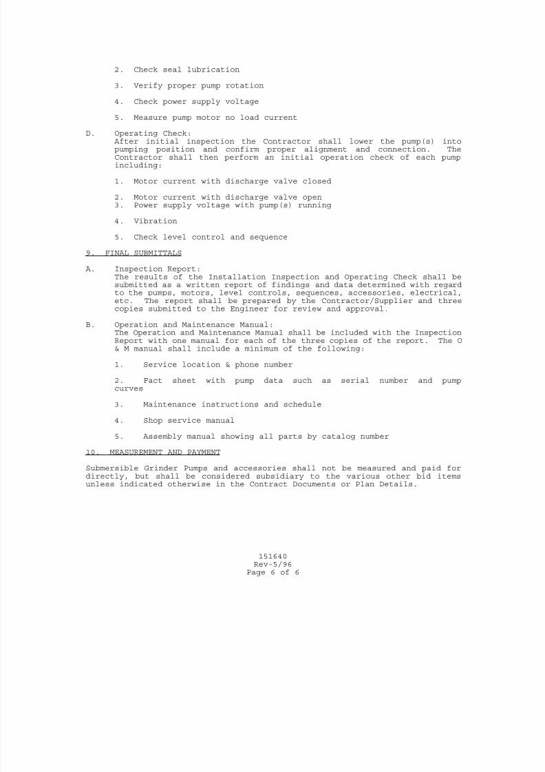
7/25/2019 City Standard Construction Specifications
http://slidepdf.com/reader/full/city-standard-construction-specifications 511/511
2. Check seal lubrication
3. Verify proper pump rotation
4. Check power supply voltage
5. Measure pump motor no load current
D. Operating Check: After initial inspection the Contractor shall lower the pump(s) intopumping position and confirm proper alignment and connection. TheContractor shall then perform an initial operation check of each pumpincluding:
1. Motor current with discharge valve closed
2. Motor current with discharge valve open3. Power supply voltage with pump(s) running
4. Vibration
5. Check level control and sequence
9. FINAL SUBMITTALS