Embed Size (px)
Citation preview

i
STANDARD CONSTRUCTION SPECIFICATIONS FOR WATER SYSTEMS
DIVISION 60 INDEX
SECTION 60.01 GENERAL....................................................................................... 1 Article 1.1 Scope of Work................................................................................. 1 Article 1.2 Applicable Standards ...................................................................... 1 Article 1.3 Survey............................................................................................. 3 Article 1.4 Pipe Insulation................................................................................. 3 Article 1.5 Payment - General .......................................................................... 3
SECTION 60.02 FURNISH AND INSTALL PIPE....................................................... 4 Article 2.1 General ........................................................................................... 4 Article 2.2 Material ........................................................................................... 4 Article 2.3 Construction.................................................................................... 7 Article 2.4 Flushing and Testing..................................................................... 10 Article 2.5 Measurement ................................................................................ 15 Article 2.6 Basis of Payment .......................................................................... 15
SECTION 60.03 FURNISH AND INSTALL VALVES ............................................... 17 Article 3.1 General ......................................................................................... 17 Article 3.2 Material ......................................................................................... 17 Article 3.3 Construction.................................................................................. 19 Article 3.4 Measurement ................................................................................ 20 Article 3.5 Basis of Payment .......................................................................... 20
SECTION 60.04 FURNISH AND INSTALL FIRE HYDRANTS ................................ 21 Article 4.1 General ......................................................................................... 21 Article 4.2 Materials ....................................................................................... 21 Article 4.3 Construction.................................................................................. 22 Article 4.4 Measurement ................................................................................ 23 Article 4.5 Basis of Payment .......................................................................... 24
SECTION 60.05 FIRE LINES .................................................................................. 25 Article 5.1 General ......................................................................................... 25 Article 5.2 Material ......................................................................................... 25 Article 5.3 Construction.................................................................................. 25 Article 5.4 Fire Hydrants, Valves and Valve Boxes ........................................ 26 Article 5.5 Flushing and Testing..................................................................... 26 Article 5.6 Measurement ................................................................................ 26 Article 5.7 Basis of Payment .......................................................................... 26
ii
SECTION 60.06 WATER SERVICE LINES ............................................................. 27 Article 6.1 General ......................................................................................... 27 Article 6.2 Material ......................................................................................... 27 Article 6.3 Construction.................................................................................. 28 Article 6.4 Measurement ................................................................................ 31 Article 6.5 Basis of Payment .......................................................................... 31
SECTION 60.07 POLYETHYLENE ENCASEMENT................................................ 32 Article 7.1 General ......................................................................................... 32 Article 7.2 Material ......................................................................................... 32 Article 7.3 Construction.................................................................................. 32 Article 7.4 Measurement ................................................................................ 33 Article 7.5 Basis of Payment .......................................................................... 33
SECTION 60.08 TEMPORARY WATER SYSTEMS ............................................... 34 Article 8.1 General ......................................................................................... 34 Article 8.2 Material ......................................................................................... 34 Article 8.3 Construction.................................................................................. 35 Article 8.4 Measurement ................................................................................ 36 Article 8.5 Basis of Payment .......................................................................... 36
SECTION 60.09 REPLACE VALVE BOX ................................................................ 37 Article 9.1 General ......................................................................................... 37 Article 9.2 Material ......................................................................................... 37 Article 9.3 Construction.................................................................................. 37 Article 9.4 Measurement ................................................................................ 37 Article 9.5 Basis of Payment .......................................................................... 37
SECTION 60.10 RESET VALVE BOX SECTIONS BELOW FINISHED GRADE..... 38 Article 10.1 General ......................................................................................... 38 Article 10.2 Material ......................................................................................... 38 Article 10.3 Construction.................................................................................. 38 Article 10.4 Measurement ................................................................................ 38 Article 10.5 Basis of Payment .......................................................................... 38
SECTION 60.11 REPLACE TOP SECTION OF VALVE BOX ................................. 39 Article 11.1 General ......................................................................................... 39 Article 11.2 Material ......................................................................................... 39 Article 11.3 Construction.................................................................................. 39 Article 11.4 Measurement ................................................................................ 40 Article 11.5 Basis of Payment .......................................................................... 40
SECTION 60.12 ABANDON PIPELINE IN PLACE.................................................. 41 Article 12.1 General ......................................................................................... 41 Article 12.2 Material ......................................................................................... 41 Article 12.3 Construction.................................................................................. 41 Article 12.4 Measurement ................................................................................ 41 Article 12.5 Basis of Payment .......................................................................... 42
iii
SECTION 60.13 CONNECT TO EXISTING WATER SYSTEM ............................... 43 Article 13.1 General ......................................................................................... 43 Article 13.2 Material ......................................................................................... 43 Article 13.3 Construction.................................................................................. 43 Article 13.4 Measurement ................................................................................ 44 Article 13.5 Basis of Payment .......................................................................... 44
SECTION 60.14 REMOVE AND SALVAGE EXISTING FIRE HYDRANT ............... 45 Article 14.1 General ......................................................................................... 45 Article 14.2 Material ......................................................................................... 45 Article 14.3 Construction.................................................................................. 45 Article 14.4 Measurement ................................................................................ 46 Article 14.5 Basis of Payment .......................................................................... 46
SECTION 60.15 RELOCATE WATER MAIN........................................................... 47 Article 15.1 General ......................................................................................... 47 Article 15.2 Construction.................................................................................. 47 Article 15.3 Measurement ................................................................................ 47 Article 15.4 Basis of Payment .......................................................................... 48
SECTION 60.16 RAISE OR LOWER WATER SERVICE ........................................ 49 Article 16.1 General ......................................................................................... 49 Article 16.2 Materials ....................................................................................... 49 Article 16.3 Construction.................................................................................. 49 Article 16.4 Measurement ................................................................................ 49 Article 16.5 Basis of Payment .......................................................................... 50
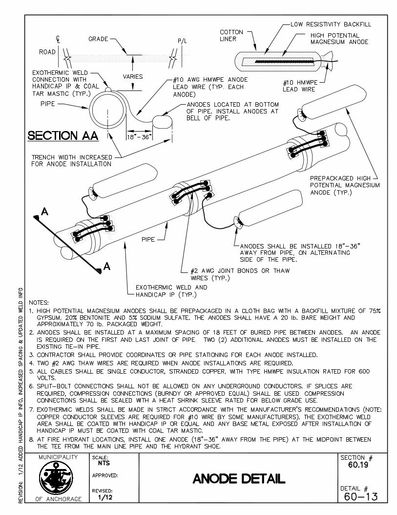
SECTION 60.17 FURNISH AND INSTALL GALVANIC ANODES........................... 51 Article 17.1 General ......................................................................................... 51 Article 17.2 Definitions ..................................................................................... 51 Article 17.3 Materials ....................................................................................... 51 Article 17.4 Installation..................................................................................... 52 Article 17.5 Measurement ................................................................................ 53 Article 17.6 Basis of Payment .......................................................................... 53
SECTION 60.18 ABANDON PRIVATE WATER WELL ........................................... 54 Article 18.1 Description .................................................................................... 54 Article 18.2 Materials and Construction ........................................................... 54 Article 18.3 Measurement ................................................................................ 55 Article 18.4 Basis of Payment .......................................................................... 56
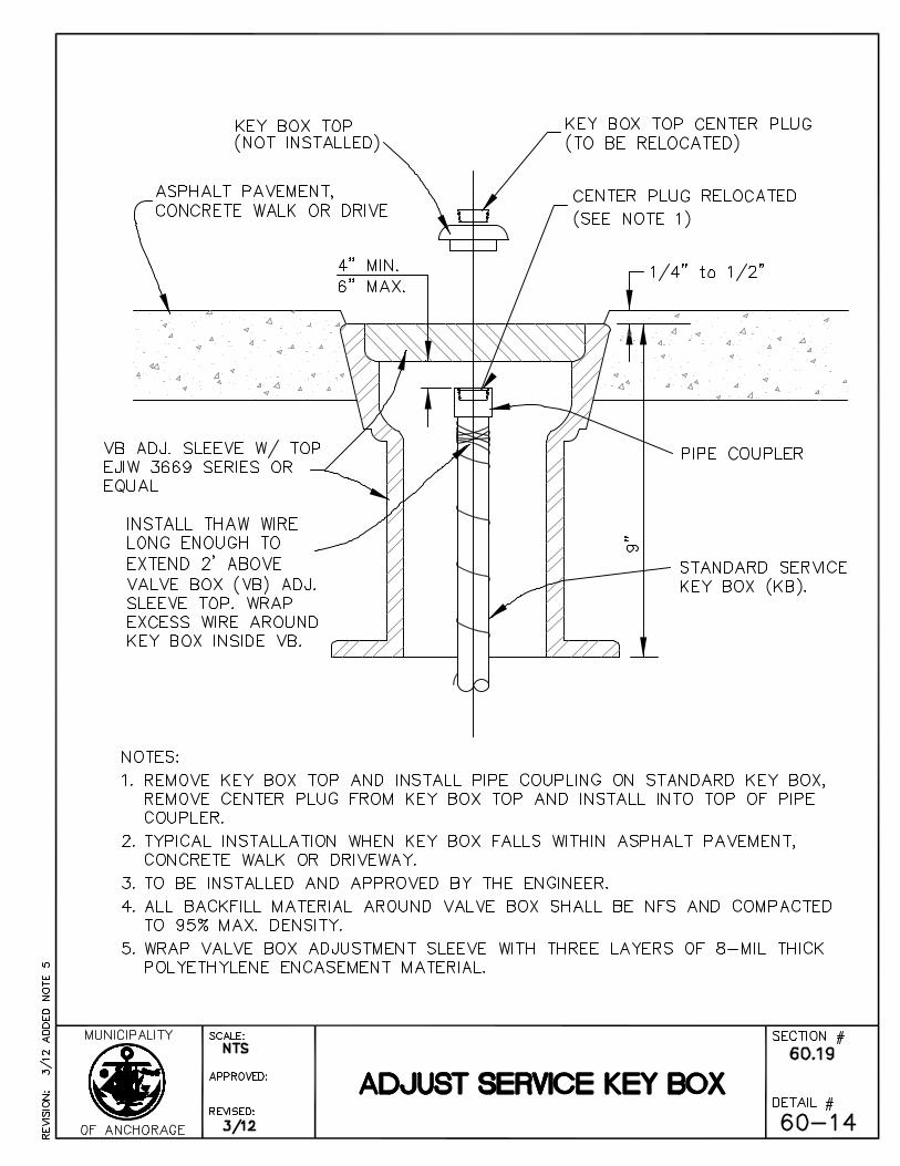
SECTION 60.19 ADJUST KEY BOX......................................................................... 57 Article 19.1 General ......................................................................................... 57 Article 19.2 Material ......................................................................................... 57 Article 19.3 Construction.................................................................................. 57 Article 19.4 Measurement ................................................................................ 57
iv
SECTION 60.20 ADJUST VALVE BOX TO FINISH GRADE................................... 59 Article 20.1 General ......................................................................................... 59 Article 20.2 Material ......................................................................................... 59 Article 20.3 Construction.................................................................................. 59 Article 20.4 Measurement ................................................................................ 59 Article 20.5 Basis of Payment .......................................................................... 59
Page 1 R3 Standard Construction Specifications Rev 3 2009 MASS Division 60 – Water Systems 3/13
STANDARD CONSTRUCTION SPECIFICATIONS FOR WATER SYSTEMS
DIVISION 60
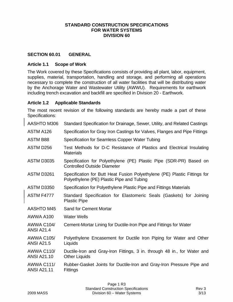
SECTION 60.01 GENERAL
Article 1.1 Scope of Work The Work covered by these Specifications consists of providing all plant, labor, equipment, supplies, material, transportation, handling and storage, and performing all operations necessary to complete the construction of all water facilities that will be distributing water by the Anchorage Water and Wastewater Utility (AWWU). Requirements for earthwork including trench excavation and backfill are specified in Division 20 - Earthwork.
Article 1.2 Applicable Standards The most recent revision of the following standards are hereby made a part of these Specifications:
AASHTO M306 Standard Specification for Drainage, Sewer, Utility, and Related Castings
ASTM A126 Specification for Gray Iron Castings for Valves, Flanges and Pipe Fittings
ASTM B88 Specification for Seamless Copper Water Tubing
ASTM D256 Test Methods for D-C Resistance of Plastics and Electrical Insulating Materials
ASTM D3035 Specification for Polyethylene (PE) Plastic Pipe (SDR-PR) Based on Controlled Outside Diameter
ASTM D3261 Specification for Butt Heat Fusion Polyethylene (PE) Plastic Fittings for Polyethylene (PE) Plastic Pipe and Tubing
ASTM D3350 Specification for Polyethylene Plastic Pipe and Fittings Materials
ASTM F4777 Standard Specification for Elastomeric Seals (Gaskets) for Joining Plastic Pipe
AASHTO M45 Sand for Cement Mortar
AWWA A100 Water Wells
AWWA C104/ ANSI A21.4
Cement-Mortar Lining for Ductile-Iron Pipe and Fittings for Water
AWWA C105/ ANSI A21.5
Polyethylene Encasement for Ductile Iron Piping for Water and Other Liquids
AWWA C110/ ANSI A21.10
Ductile-Iron and Gray-Iron Fittings, 3 in. through 48 in., for Water and Other Liquids
AWWA C111/ ANSI A21.11
Rubber-Gasket Joints for Ductile-Iron and Gray-Iron Pressure Pipe and Fittings
Page 2 R3 Standard Construction Specifications Rev 3 2009 MASS Division 60 – Water Systems 3/13
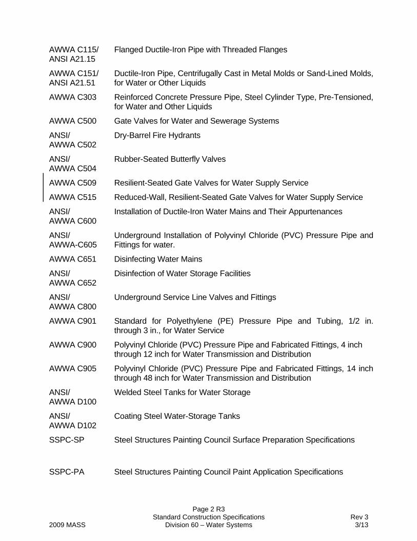
AWWA C115/ ANSI A21.15
Flanged Ductile-Iron Pipe with Threaded Flanges
AWWA C151/ ANSI A21.51
Ductile-Iron Pipe, Centrifugally Cast in Metal Molds or Sand-Lined Molds, for Water or Other Liquids
AWWA C303 Reinforced Concrete Pressure Pipe, Steel Cylinder Type, Pre-Tensioned, for Water and Other Liquids
AWWA C500 Gate Valves for Water and Sewerage Systems
ANSI/ AWWA C502
Dry-Barrel Fire Hydrants
ANSI/ AWWA C504
Rubber-Seated Butterfly Valves
AWWA C509 Resilient-Seated Gate Valves for Water Supply Service
AWWA C515 Reduced-Wall, Resilient-Seated Gate Valves for Water Supply Service
ANSI/ AWWA C600
Installation of Ductile-Iron Water Mains and Their Appurtenances
ANSI/ AWWA-C605
Underground Installation of Polyvinyl Chloride (PVC) Pressure Pipe and Fittings for water.
AWWA C651 Disinfecting Water Mains
ANSI/ AWWA C652
Disinfection of Water Storage Facilities
ANSI/ AWWA C800
Underground Service Line Valves and Fittings
AWWA C901 Standard for Polyethylene (PE) Pressure Pipe and Tubing, 1/2 in. through 3 in., for Water Service
AWWA C900 Polyvinyl Chloride (PVC) Pressure Pipe and Fabricated Fittings, 4 inch through 12 inch for Water Transmission and Distribution
AWWA C905 Polyvinyl Chloride (PVC) Pressure Pipe and Fabricated Fittings, 14 inch through 48 inch for Water Transmission and Distribution
ANSI/ AWWA D100
Welded Steel Tanks for Water Storage
ANSI/ AWWA D102
Coating Steel Water-Storage Tanks
SSPC-SP Steel Structures Painting Council Surface Preparation Specifications
SSPC-PA Steel Structures Painting Council Paint Application Specifications
Page 3 R3 Standard Construction Specifications Rev 3 2009 MASS Division 60 – Water Systems 3/13
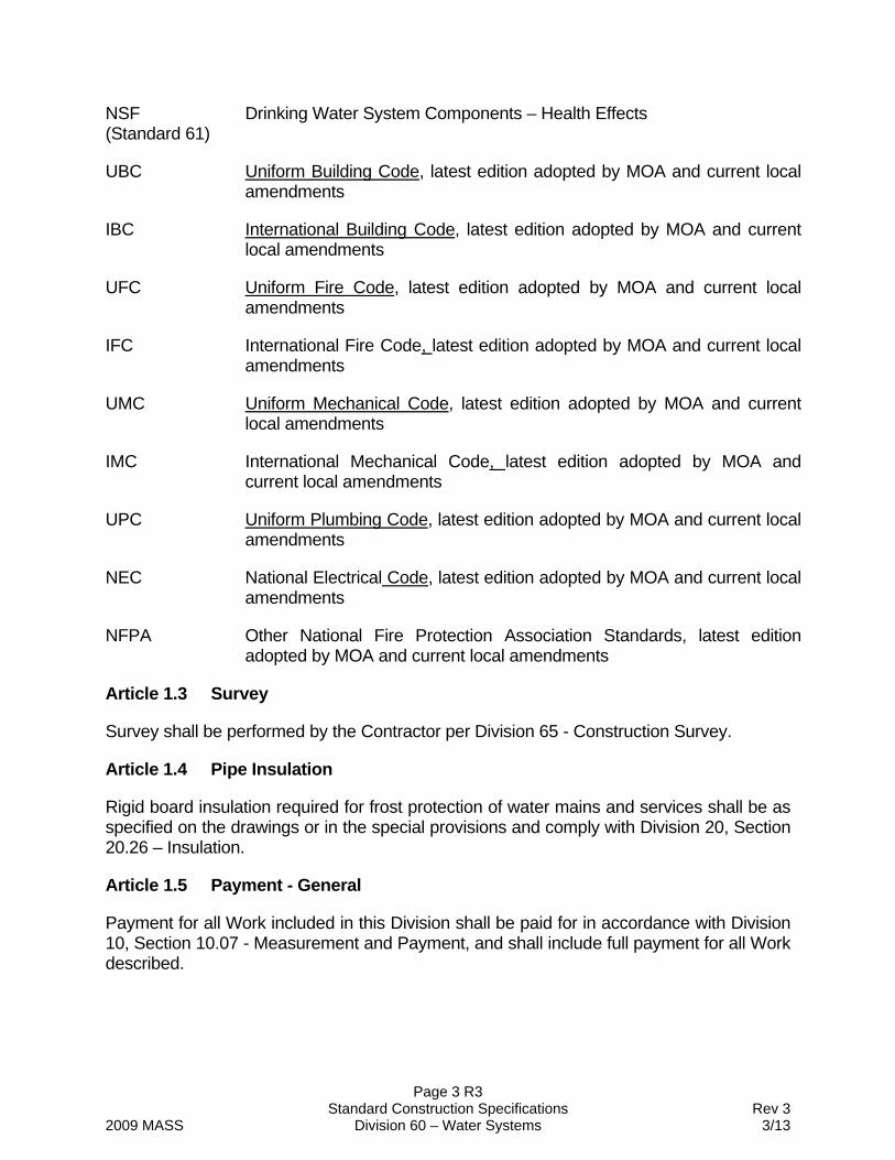
NSF (Standard 61)
Drinking Water System Components – Health Effects
UBC Uniform Building Code, latest edition adopted by MOA and current local amendments
IBC International Building Code, latest edition adopted by MOA and current local amendments
UFC Uniform Fire Code, latest edition adopted by MOA and current local amendments
IFC International Fire Code, latest edition adopted by MOA and current local amendments
UMC Uniform Mechanical Code, latest edition adopted by MOA and current local amendments
IMC International Mechanical Code, latest edition adopted by MOA and current local amendments
UPC Uniform Plumbing Code, latest edition adopted by MOA and current local amendments
NEC National Electrical Code, latest edition adopted by MOA and current local amendments
NFPA Other National Fire Protection Association Standards, latest edition adopted by MOA and current local amendments
Article 1.3 Survey
Survey shall be performed by the Contractor per Division 65 - Construction Survey.
Article 1.4 Pipe Insulation
Rigid board insulation required for frost protection of water mains and services shall be as specified on the drawings or in the special provisions and comply with Division 20, Section 20.26 – Insulation.
Article 1.5 Payment - General
Payment for all Work included in this Division shall be paid for in accordance with Division 10, Section 10.07 - Measurement and Payment, and shall include full payment for all Work described.
Page 4 R3 Standard Construction Specifications Rev 3 2009 MASS Division 60 – Water Systems 3/13
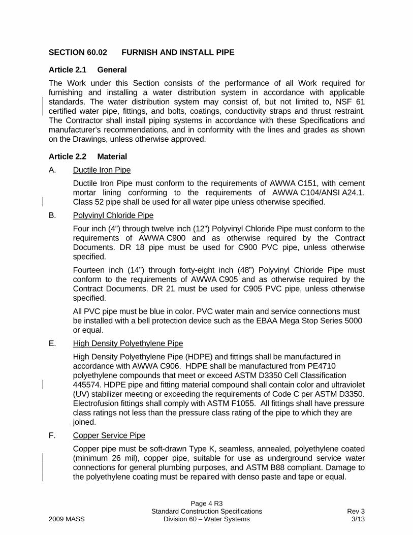
SECTION 60.02 FURNISH AND INSTALL PIPE
Article 2.1 General The Work under this Section consists of the performance of all Work required for furnishing and installing a water distribution system in accordance with applicable standards. The water distribution system may consist of, but not limited to, NSF 61 certified water pipe, fittings, and bolts, coatings, conductivity straps and thrust restraint. The Contractor shall install piping systems in accordance with these Specifications and manufacturer’s recommendations, and in conformity with the lines and grades as shown on the Drawings, unless otherwise approved.
Article 2.2 Material A. Ductile Iron Pipe
Ductile Iron Pipe must conform to the requirements of AWWA C151, with cement mortar lining conforming to the requirements of AWWA C104/ANSI A24.1. Class 52 pipe shall be used for all water pipe unless otherwise specified.
B. Polyvinyl Chloride Pipe Four inch (4”) through twelve inch (12”) Polyvinyl Chloride Pipe must conform to the requirements of AWWA C900 and as otherwise required by the Contract Documents. DR 18 pipe must be used for C900 PVC pipe, unless otherwise specified. Fourteen inch (14”) through forty-eight inch (48”) Polyvinyl Chloride Pipe must conform to the requirements of AWWA C905 and as otherwise required by the Contract Documents. DR 21 must be used for C905 PVC pipe, unless otherwise specified. All PVC pipe must be blue in color. PVC water main and service connections must be installed with a bell protection device such as the EBAA Mega Stop Series 5000 or equal.
E. High Density Polyethylene Pipe High Density Polyethylene Pipe (HDPE) and fittings shall be manufactured in accordance with AWWA C906. HDPE shall be manufactured from PE4710 polyethylene compounds that meet or exceed ASTM D3350 Cell Classification 445574. HDPE pipe and fitting material compound shall contain color and ultraviolet (UV) stabilizer meeting or exceeding the requirements of Code C per ASTM D3350. Electrofusion fittings shall comply with ASTM F1055. All fittings shall have pressure class ratings not less than the pressure class rating of the pipe to which they are joined.
F. Copper Service Pipe Copper pipe must be soft-drawn Type K, seamless, annealed, polyethylene coated (minimum 26 mil), copper pipe, suitable for use as underground service water connections for general plumbing purposes, and ASTM B88 compliant. Damage to the polyethylene coating must be repaired with denso paste and tape or equal.

Page 5 R3 Standard Construction Specifications Rev 3 2009 MASS Division 60 – Water Systems 3/13
G. Concrete Cylinder Pipe Concrete Cylinder Pipe shall conform to the requirements of AWWA C303 and as otherwise required by the Contract Documents.
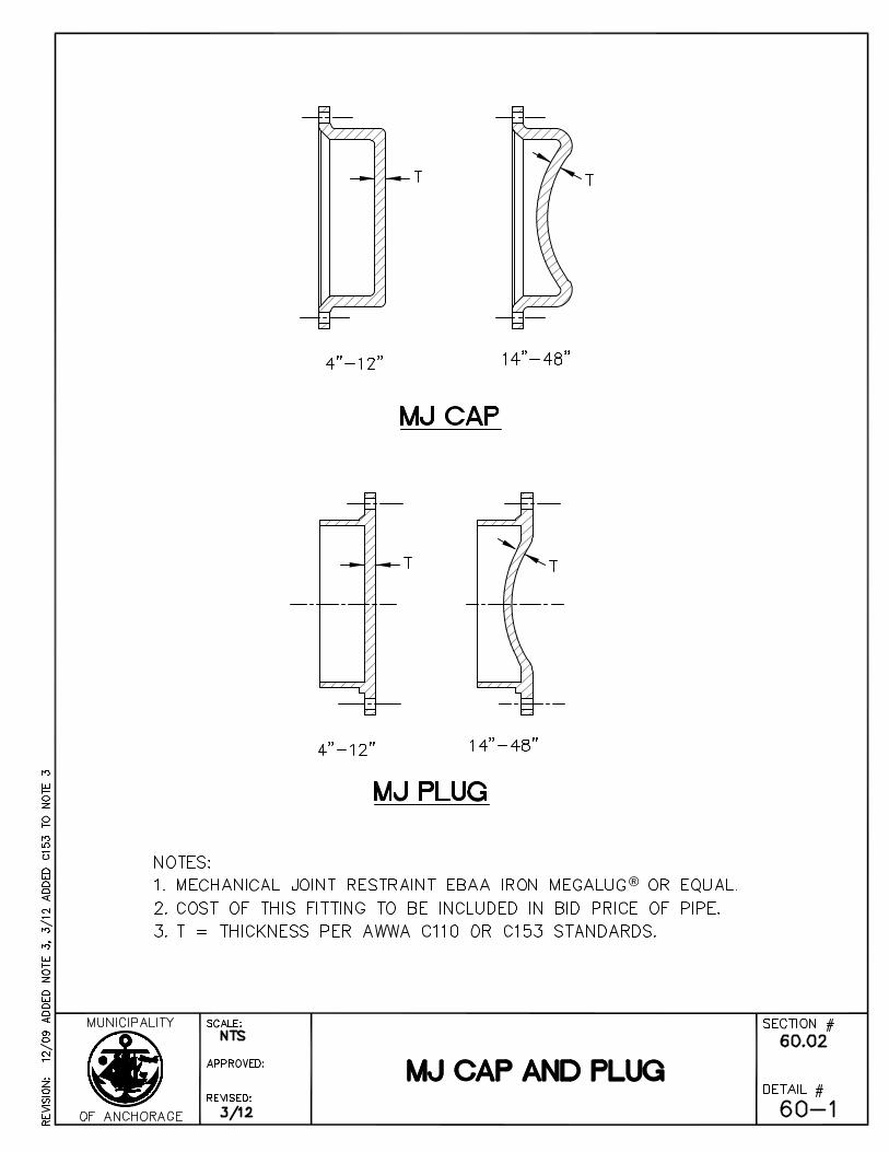
H. Fittings and Gaskets Fittings, except for the bell protection devices, are to have exterior and interior surfaces coated with fusion bonded epoxy in accordance with AWWA C116/A21.13-09. Unless otherwise indicated on the Drawings, rubber gaskets for ductile iron pipe joints shall conform to AWWA C111 and rubber gaskets for PVC pipe joints shall conform to ASTM F477. Fittings shall be a minimum of 250 pounds pressure rating, mechanical joint or bell, lined or unlined, either cast iron or ductile iron, unless otherwise required by the Contract Documents. All fittings must conform to the requirements of AWWA C110/ANSI A21.10 or C153 A21.53-06. Fittings must utilize carbon steel or stainless steel nuts and bolts. Fittings with carbon steel bolts and nuts must conform to the dimensional and material standards as outlined in AWWA C111 and C115 and be factory-coated with a blue fluoropolymer coating system. Fittings with stainless steel bolts and nuts must conform to the dimensional standards as outlined in AWWA C111 and C115 and the material standards in ASTM F593 and F594 with a minimum tensile strength of 75,000psi. Bolts and nuts must have imprinted markings indicating the material and grade of the metal used in fabrication. Where bolts and nuts for fittings cannot be covered by the above references then the contractor must submit to the engineer for approval corrosion resistant bolts and nuts and supported reasons for the request of an alternate to this standard.
I. Continuity Straps Continuity straps shall be stranded Number 2 AWG copper wire with HMWPE insulation suitable for direct burial.
J. Thrust Restraint System Where specified on the Drawings and/or required in these Specifications, water distribution piping must be installed with a thrust restraint systems. Joints, fittings, valves and piping deflection points must utilize a thrust restraint system. The Contractor shall provide pipe manufacturer submittals, which include thrust restraint calculations prior to construction. Contractor shall field demonstrate to the Engineer the installation and/or construction of each new restrained joint or restraining system. Contractor shall provide AWWU with a minimum of 48 hours notice, excluding non-working days, to coordinate the review of the field demonstration. The Contractor shall certify that the restrained joint system is installed in accordance with the manufacturer's instructions. If Contractor fails to install the restrained joint system in accordance with manufacturer's instructions, in the opinion of the Engineer, Contractor shall remove the disapproved system and replace with a new restrained joint system. Contractor shall be responsible for access to the field demonstration location and all trench excavation, dewatering, and backfill operations prior to, during, and after
Page 6 R3 Standard Construction Specifications Rev 3 2009 MASS Division 60 – Water Systems 3/13
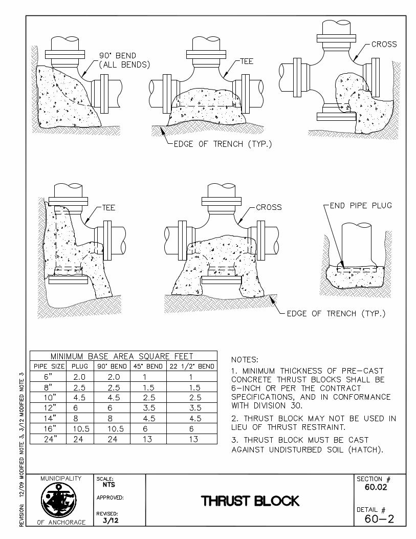
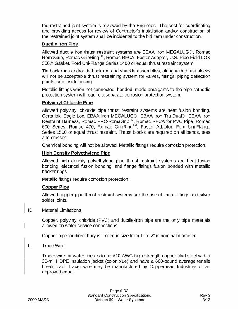
the restrained joint system is reviewed by the Engineer. The cost for coordinating and providing access for review of Contractor's installation and/or construction of the restrained joint system shall be incidental to the bid item under construction. Ductile Iron Pipe Allowed ductile iron thrust restraint systems are EBAA Iron MEGALUG, Romac RomaGrip, Romac GripRingTM, Romac RFCA, Foster Adaptor, U.S. Pipe Field LOK 350 Gasket, Ford Uni-Flange Series 1400 or equal thrust restraint system. Tie back rods and/or tie back rod and shackle assemblies, along with thrust blocks will not be acceptable thrust restraining system for valves, fittings, piping deflection points, and inside casing. Metallic fittings when not connected, bonded, made amalgams to the pipe cathodic protection system will require a separate corrosion protection system. Polyvinyl Chloride Pipe Allowed polyvinyl chloride pipe thrust restraint systems are heat fusion bonding, Certa-lok, Eagle-Loc, EBAA Iron MEGALUG, EBAA Iron Tru-Dual, EBAA Iron Restraint Harness, Romac PVC-RomaGripTM, Romac RFCA for PVC Pipe, Romac 600 Series, Romac 470, Romac GripRingTM, Foster Adaptor, Ford Uni-Flange Series 1500 or equal thrust restraint. Thrust blocks are required on all bends, tees and crosses. Chemical bonding will not be allowed. Metallic fittings require corrosion protection. High Density Polyethylene Pipe Allowed high density polyethylene pipe thrust restraint systems are heat fusion bonding, electrical fusion bonding, and flange fittings fusion bonded with metallic backer rings. Metallic fittings require corrosion protection. Copper Pipe Allowed copper pipe thrust restraint systems are the use of flared fittings and silver solder joints.
K. Material Limitations
Copper, polyvinyl chloride (PVC) and ductile-iron pipe are the only pipe materials allowed on water service connections.
Copper pipe for direct bury is limited in size from 1” to 2” in nominal diameter.
L. Trace Wire
Tracer wire for water lines is to be #10 AWG high-strength copper clad steel with a 30-mil HDPE insulation jacket (color blue) and have a 600-pound average tensile break load. Tracer wire may be manufactured by Copperhead Industries or an approved equal.
Page 7 R3 Standard Construction Specifications Rev 3 2009 MASS Division 60 – Water Systems 3/13
Article 2.3 Construction A Planned interruptions
Water service and mainline interruptions must be minimized. All planned interruptions require notifying AWWU, the Engineer, and affected property owners and residents a minimum of seventy-two (72) hours and a maximum of one-hundred forty-four (144) hours in advance of the interruption. Each interruption requires a separate notification. Interruptions not started within the planned interruption period require a new notice and waiting period. The AFD is to be notified for all water interruptions and the MOA health department is to be notified for water interruptions to food and health care establishments. Property managers/owners of buildings that potentially have fire sprinkler/alarm systems are to be notified of pending outages in addition to residence/occupants of such spaces. The property manager is to be given three working days to take necessary precautions to mitigate any potential effects to the sprinkler/alarm system from the interruption. It shall be the Contractor’s responsibility to coordinate “turn-off” and “turn-on” with the Engineer.
B. Excavation and Backfill The Contractor shall provide all excavation, backfill, and compaction necessary to install pipe in accordance with Division 20, Section 20.13 - Trench Excavation and Backfill.
C. Materials Delivery Pipe and appurtenances shall be handled in such a manner to ensure delivery to the trench in a sound, undamaged condition. Particular care shall be taken not to damage the pipe, pipe coating, or lining. Before installation the engine is to be provided an opportunity to examine the pipe and appurtenances for damage and defects. Damaged or defective pipe may be rejected. Rejected pipe must be removed from the project and replaced with acceptable material at no additional cost. The pipe shall not be strung out along the shoulders of the road for long distances if it causes inconvenience to the public. The amount of pipe strung at the job site shall be at the discretion of the Engineer. Rubber gaskets shall be protected from extended exposure to direct sunlight. Gaskets are to be installed when the ambient temperature is above freezing.
D. Installation Installation shall be in accordance with the requirements of ANSI/AWWA C600, C605, M23, M41 and M55 except for the following items Deflection at pipe to pipe joints is to be limited to 80% of the maximum deflection angle recommend by the pipe manufacturer for ductile iron pipe Deflection at pipe to pipe joints is to be limited to 0% of the maximum deflection angle recommend by the pipe manufacturer for polyvinyl chloride pipe
Page 8 R3 Standard Construction Specifications Rev 3 2009 MASS Division 60 – Water Systems 3/13
Testing allowance (leakage allowance) will not be allowed Flushing must meet the AWWA and AWWU requirements The interior of the pipe and accessories shall be thoroughly cleaned of foreign matter before being lowered into the trench. The pipe shall be kept clean during laying operation by plugging. Pipe and appurtenances shall be carefully lowered into the trench by means of derrick, ropes, belt slings, or other suitable equipment. Under no circumstances shall any of the pipe or appurtenances be dropped or dumped into the trench. Care shall be taken to avoid abrasion of the pipe coating. Poles used as levers or skids shall be of wood and shall have broad, flat faces to prevent damage to the pipe and coating. The trench bottom shall be graded to provide uniform support for the pipe barrel. Water shall be kept out of the trench by pumping, if necessary, until the jointing is completed. When Work is not in progress, open ends of the pipe, fittings, and valves shall be securely plugged so that no trench water, earth or other substances will enter the pipes or fittings. Where any part of the coating or lining is damaged, the repair shall be made by the Contractor at his expense and in a manner satisfactory to the Engineer. At a sufficient distance, prior to encountering a known obstacle or tie-in to an existing pipe, the Contractor shall expose and verify the exact location of the obstacle or pipe so that proper alignment and/or grade may be determined before the pipe sections are laid in the trench and backfilled. The connections shall be made by using fittings to suit actual conditions. All connections larger than two inch (2”) diameter made under pressure shall be made by AWWU forces. Pipe ends left for future connections shall be plugged or capped, and restrained, as shown on the Drawings or as directed by the Engineer. The Contractor shall install vertically an eight foot (8') wood post, directly over the end of pipe. Cutting of pipe shall be done in a neat and workmanlike manner without damage to the pipe. All non-tightly bonded coated ductile iron pipe and fittings are to be encased in one layer of polyethylene encasement. All Valve boxes and hydrant barrels, regardless of coatings, are to be encased in three layers of polyethylene encasement. Polyethylene Encasement is to be installed in accordance with Section 60.07 - Polyethylene Encasement. Water mains and services shall be constructed to meet all separation requirements of 18 AAC 80.020. Variance from the separation requirements requires a waiver from the Alaska Department of Environmental Conservation and prior approval from AWWU. The Contractor shall stagger the joints for the water pipe such that no joint is closer than nine feet (9’) from the centerline crossing of water to sanitary sewer and storm drain pipes. In addition, where water and sanitary sewer or storm sewer mains and services intersect, the vertical separation between the water and pipelines shall be eighteen inches (18”) minimum between exterior pipe surfaces.
Page 9 R3 Standard Construction Specifications Rev 3 2009 MASS Division 60 – Water Systems 3/13
E. Alignment and Grade Contractor shall lay the pipe in the trench so that after the line is completed, the bottom of the pipe conforms accurately to the grades and alignment given by the Engineer. A maximum two-tenths foot (2/10’ or 0.2’) deviation from design elevation and alignment will be allowed. The pipe shall be generally straight to visual observation as determined by the Engineer. The Contractor shall check both line and grade and record measurements in a field book for each piece of pipe and appurtenance laid. The Contractor shall have instruments such as a transit and level for transferring alignment and grades from offset hubs. He also shall have in his employ a person who is qualified to use such instruments and who shall have the responsibility of placing and maintaining such construction guides. The Contractor will furnish to the Engineer a copy of the surveyor's notes for the newly installed pipe and appurtenances. The practice of placing backfill over a section of pipe to provide a platform for instruments shall be subject to the approval of the Engineer and shall be accomplished in accordance with Division 20, Section 20.13, Article 13.3 - Construction. All adjustments to line and grade shall be done by scraping away or filling the earth under the body of the pipe and not by blocking or wedging up. Deflection of the pipe to achieve vertical curves, horizontal curves, or off-sets must not be greater than allowed. If the alignment requires deflection in excess of the above limitations, the Contractor shall furnish special bends to provide angular deflections within the limits allowable. Short radius curves and closures shall be formed by shorter lengths of pipe, bevels, or fabricated specials.
F. Jointing of Ferrious Metal Pipe The Contractor has the option of using either mechanical or push-on joints. All joints shall conform to the requirements of ANSI/AWWA C600. The Contractor is required to use mechanically restrained joints and fittings on all hydrant leads. The Engineer has the option of checking any or all mechanical joints to assure proper torque as specified by the manufacturer. Metallic pipe is to have two (2) electrical continuity straps installed on each side of every joint for all pipe diameters. Straps are to be welded to a clean, dry surface. Each exothermic wire weld connection is to be protected with one (1) field applied Royston Handy Cap IP or equal. Uncoated surfaces are to be coated with coal tar pitch to the satisfaction of the Engineer. Split bolts or mechanical bolt connection of the wires will not be allowed. Whenever flange connections are shown on the Drawings, called for in the Specifications, or required in the Work, the flange and fittings shall conform to the requirements of AWWA C110/ANSI A21.10 for two hundred fifty pound (250#) pressure ratings.
G. Jointing of High Density Polyethylene All HDPE water main piping and fittings is to be butt-fused in accordance with ASTM D2657. The individual who performs the butt-fusion shall have written
Page 10 R3 Standard Construction Specifications Rev 3 2009 MASS Division 60 – Water Systems 3/13
certification from an HDPE pipe manufacturer stating he/she has successfully completed an 8-hour (minimum) certification class on butt–fusion techniques and procedures. In addition, this individual shall have fused a combined total of more than 5,000 feet of hope piping in diameters 4-inches and larger. The contractor shall ensure that each joint is fused at the temperature and pressure recommended by the pipe manufacturer in order to achieve the maximum pressure rating for that joint. All butt-fused joints for HDPE piping and fabricated fittings shall be documented by a computer data logger that records pressure and temperature applied at each fused joint, along with the date and time the joint was fused. Computer printouts, electronic data, and the project station for each field fused joint shall be submitted to AWWU through the Engineer. The use of electro-fusion couplings to join HDPE piping may be allowed upon written approval of AWWU and the Engineer. Electro-fusion couplings shall comply with ASTM F1055. Contractor shall record the exact location of any installed electro-fusion coupling in the record drawing submittal.
H. Jointing of PVC pipe The Contractor has the option of using butt fusion, mechanical joints or push-on joints. Except for butt fusion, all joints shall conform to the requirements of AWWA C605. Fused joints must done by a qualified fusion technician, recorded by an electronic monitor and be completed per the pipe manufacturer’s recommendations The Contractor is required to use mechanically restrained joints and fittings on all hydrant leads. The Engineer has the option of checking any or all mechanical joints to assure proper torque as specified by the manufacturer.
I. Jointing of Copper pipe. Copper pipe may be joined with the use of soldered couplers, three part unions and by swedging with solder. Solder must be silver solder. All joints are to be outside of the rights-of-ways and/or easement, unless give prior approval by the AWWU Engineering Director.
J. Detectable Warning Tape Detectable underground warning tape is required for installation of all pipe types. Warning tape must not be less than five (5) mil, foil backed, six inches (6”) wide vinyl tape, colored green, with “Caution Buried Sewer Line Below” continuously printed in black along the tape length. The warning tape must be continuously laid with the pipe and be at least eighteen inches (18”) above and no more than thirty six inches (36”) the pipe.
K. Tracer Wire for PVC and HDPE Pipe Tracer wire shall be grounded at all dead ends, except fire hydrant legs, using a 24-inch long minimum copper clad grounding rod. A grounding clamp approved for direct burial use shall be used to connect the tracer wire to the grounding rod. Direct burial grounding clamps shall be EK17 as manufactured by Erico or approved equal.
Page 11 R3 Standard Construction Specifications Rev 3 2009 MASS Division 60 – Water Systems 3/13
Tracer wire shall be securely affixed to the top exterior surface of the pipe using PVC pipe tape at 5-foot intervals. Tracer wire shall be looped around valves, saddles, curb stops, and other appurtenances in such a manner that there is no interference with the operation of the appurtenances. Tracer wire shall be continuous and without splices, breaks, or cuts except for spliced-in connections as approved by the Engineer. Where any approved spliced-in connections occur, 3M DBR watertight connectors, or approved equal, shall be used to provide electrical continuity. All spliced connections must be inspected by the Engineer before being buried. Tracer wire shall be brought to the surface at all junctions and terminals, including at all valve boxes for water valves and fire hydrant legs. DryConn Waterproof Direct Bury Lugs as manufactured by King Innovation, or approved equal, shall be used to splice into the main line tracer wire. The main line tracer wire shall not be broken or cut. Tracer wire shall be spiral-wrapped around the exterior of the valve box riser pipe and brought into the valve box top section. Provide 5 feet minimum of additional wire neatly coiled within each valve box. Prior to final payment, a continuity test shall be performed on tracer wire with the Engineer present to verify that the trace wire is continuous and allows for the proper tracing of the piping. If the Engineer identifies locations where the trace wire is not continuous, to include all connection points between new and existing water mains, the Contractor, at no additional cost to the Owner, shall make necessary repairs/corrections. Continuity testing shall be conducted prior to repaving roadways.
Article 2.4 Flushing and Testing An AWWU representative must be present for all testing and flushing. Water, sewer and storm drain main and service trenches are to be substantially filled and compacted prior to flushing and testing. The Contractor shall perform the flushing, hydrostatic testing, disinfection, and continuity testing. The Contractor is made aware that in the event repairs are made on the system in order to pass the hydrostatic test, and these repairs are made subsequent to disinfection of the system, then the open-bore flush and the disinfection will be null and void and shall be repeated to the satisfaction of the Engineer after the repairs are made. Costs for repeat testing and flushing will be incidental to the bid item being tested. A request to supply water for flushing, testing, and disinfecting shall be scheduled in writing with the Engineer at least forty eight (48) hours prior to obtaining AWWU-supplied water. The request for flushing, testing, and disinfecting will be subject to water availability. In the event of high water demand or low water availability within the AWWU water system, meeting Contractor's schedule may not be possible. Contractor shall submit, in writing, for the Engineer to review and approve, a schedule and procedure for the testing and flushing of all newly installed pipe. When, in the opinion of the Engineer, the testing and flushing schedule and procedure is deficient, inadequate, improper, or conditions are such that the impact to existing water service areas are adversely affected by service interruptions, the Contractor will be notified in writing by the Engineer. Such notification shall be accompanied by a statement of the corrective action
Page 12 R3 Standard Construction Specifications Rev 3 2009 MASS Division 60 – Water Systems 3/13
to be taken. Contractor shall adhere to the testing and flushing schedule and comply with such instruction as directed by the Engineer. All water mains, service lines (including stub-outs), fire lines, and fire hydrant legs must be flushed, hydrostatically tested, and disinfected before the piping system can be put into service. All piping and components in the test section shall be restrained and the trench section shall be substantially backfilled before the piping system is flushed. The Contractor cannot hydrostatically test and disinfect the piping system at the same time. A. Flushing
All newly installed pipe systems are to be open-bore flushed, including fire lines. Flushing must be completed prior to hydrostatic testing and disinfection. Sufficient water velocity must be achieved and maintained to remove foreign matter from within the pipe. The Contractor is to configure the flushing operation, where possible, from higher to lower elevation, utilizing higher pressure mains first, allowing AWWU to manipulate the water distribution system to achieve higher than normal pressures and flows to the newly constructed main or other appropriate measures to increase flushing velocities. The Contractor shall furnish, install and remove all fittings and pipes necessary to perform the flushing, at no additional cost to the Owner. It will be the Contractor's responsibility to notify the Engineer and AWWU forty eight (48) hours in advance of any flushing operations. The Contractor shall provide a plan for approval by the Engineer for the disposal of the discharge waters from the open-bore flush. The flush water discharge location must receive approval from governing authority of that location. Depending upon the availability of water, flushing of newly constructed pipe systems may be required by AWWU to take place during non-working hours, holidays, Saturdays or Sundays. The Owner will not be responsible for any additional cost incurred by the Contractor for flushing outside of usual working hours. The Contractor must comply with the following restrictions:
Flushing must not be completed through hydrants or reduced outlets
Flush water must not be directly connected to the sanitary sewer system. When specifically permitted by AWWU, flush water discharged to the sanitary sewer system must be de-chlorinated, have flow regulation, and be limited to the sewer system capacity. The sewer system capacity may exclude discharging to sewer regardless of the flow conditions at the proposed discharge point.
The Contractor shall not operate the AWWU water distribution system. Only AWWU personnel are authorized to manipulate the existing pipe system to supply water for flushing and testing.
When, in the opinion of the Engineer, the Contractor’s proposed testing and flushing schedule and procedure is deficient, inadequate, improper, or conditions are such that the impact to existing water service areas are adversely affected by service interruptions, the Contractor will be notified in writing by the Engineer. Such
Page 13 R3 Standard Construction Specifications Rev 3 2009 MASS Division 60 – Water Systems 3/13
notification shall be accompanied by a statement of the corrective action to be taken. Contractor shall adhere to the testing and flushing schedule and comply with such instruction as directed by the Engineer.
B. Hydrostatic Testing A hydrostatic test (Pressure Test) must be conducted on all newly constructed water pipe, fire hydrant leads, services and stub-outs in accordance with the requirements of the referenced AWWA standards unless hereinafter modified. The Contractor shall furnish all necessary assistance, equipment, labor, materials, and supplies (except the test pressure gauge) necessary to complete the test to the satisfaction of the Engineer. The Contractor shall suitably valve-off or plug the outlet to the existing or previously-tested water main at his expense, prior to making the required hydrostatic test. Prior to testing, all air shall be expelled from the pipe. If permanent air vents are not located at all high points and dead ends, the Contractor shall, at his expense, install corporation cocks at such points so the air can be expelled as the line is slowly filled with water. All main valves, fire hydrant valves, and plugs shall be tested. All intermediate valves within the section being tested will be closed and reopened as directed by the Engineer during the actual test. Only static pressure will be allowed on the opposite side of the end valves of the section being tested. All hydrostatic testing will be performed through a test copper. The test pressure shall not exceed the design pressure of the pipe, fittings, valves, thrust restraints, or other appurtenances of the test section. Use of fire hydrants for testing will not be allowed. If the pressure decreases below the required test pressure during the test period, the preceding portion of that test will be declared void. Cracked or defective pipe, gaskets, mechanical joints, fittings, valves, or hydrants discovered as a consequence of the hydrostatic tests shall be removed and replaced with sound material at the Contractor's expense. The test shall then be repeated until the results are satisfactory. The Contractor shall notify the Engineer forty-eight (48) hours, (two (2) working days) prior to any test and shall notify the Engineer two (2) hours in advance of the scheduled time if the test is to be canceled. In the event the Engineer has not been notified of cancellation and the Contractor is not prepared for the test as scheduled, the Contractor shall reimburse the Engineer for all expenses incurred. These will include, but not be limited to, salaries, transportation and administrative costs. Hydrostatic testing of water pipe lines containing a chlorine mixture above 2 ppm will not be allowed. PVC, DIP, Copper - Testing The hydrostatic pressure shall be one hundred fifty (150) psi. The duration of each hydrostatic pressure test shall be thirty (30) minutes. After the required test pressure has been reached, pumping will be terminated. If the pressure remains constant for 30 minutes without the aid of a pump, the results of the test shall be considered satisfactory as approved by the Engineer. The leakage allowance described in ANSI/AWWA 600 shall not be allowed. Fire lines must pass a pressure
Page 14 R3 Standard Construction Specifications Rev 3 2009 MASS Division 60 – Water Systems 3/13
test at two hundred (200) psi for two hours in accordance with the Fire Underwriter's requirements as outlined in the National Fire Codes. HDPE - Testing The hydrostatic pressure test procedure for HDPE consists of filling the piping with water, an initial expansion phase, a test phase, and depressurizing. Before applying hydrostatic pressure test, all piping and all components in the test section shall be restrained and the trench section backfilled to original grade. The maximum test duration is eight (8) hours including time to pressurize, time for initial expansion, time at test pressure and time to depressurize the test section. If the test is not completed due to leakage, equipment failure, or for any other reason, depressurize the test section completely and allow it to relax for at least eight (8) hours before pressurizing the test section again. The newly installed HDPE water main shall be hydrostatically tested to the rated operating pressure of the pipe. The rated operating pressure of HDPE SDR11 piping is 160 psi. See PPI Handbook of Polyethylene Pipe Chapter 2 for test pressures for other SDR’s. Gradually pressurize the test section to test pressure and maintain test pressure for four (4) hours. During the initial expansion phase, polyethylene pipe will expand slightly. Additional test liquid will be required to maintain pressure. It is not necessary to monitor the amount of water added during the initial expansion phase. Immediately following the initial expansion phase, reduce test pressure by 10 psi and stop adding test liquid. If there are no visible leaks and the test pressure remains steady (within 5% of the target value) for one (1) hour, the water main shall be deemed as having passed the test.
C. Disinfection Disinfection of the newly installed water pipe is to take place after passing the hydrostatic test requirements. To disinfect the newly installed main, the Contractor may elect to apply the disinfectant by one of the following methods:
1. liquid chlorine gas-water mixture, or 2. calcium hypochlorite and water mixture. Calcium hypochlorite shall be
comparable to commercial products known as HTH, Perchloren or Machochlor.
The chlorinating agent shall be applied at a point of not more than ten feet (10’) from the beginning of the new water pipe. Under no conditions shall the chlorinating agent be introduced through a fire hydrant. Water is to be fed slowly into the new line with chlorine applied in amounts to produce a dosage of a minimum of twenty-five parts per million (25 ppm). Water is to be expelled from the new main through the end and all branches and services until the required dosage is evident at all extremities. Points at which the highly chlorinated solution is expelled is to be no more than 10’ from the end of main, service or branch line. The Contractor may submit alternate disinfection plan that is compliant with ANSI/AWWA C-651 to the Engineer for review and approval. Calcium hypochlorite shall be mixed into a solution of water and injected or pumped into the water main. During the chlorination process, all intermediate valves and accessories shall be operated. Valves shall be manipulated so that the strong
Page 15 R3 Standard Construction Specifications Rev 3 2009 MASS Division 60 – Water Systems 3/13
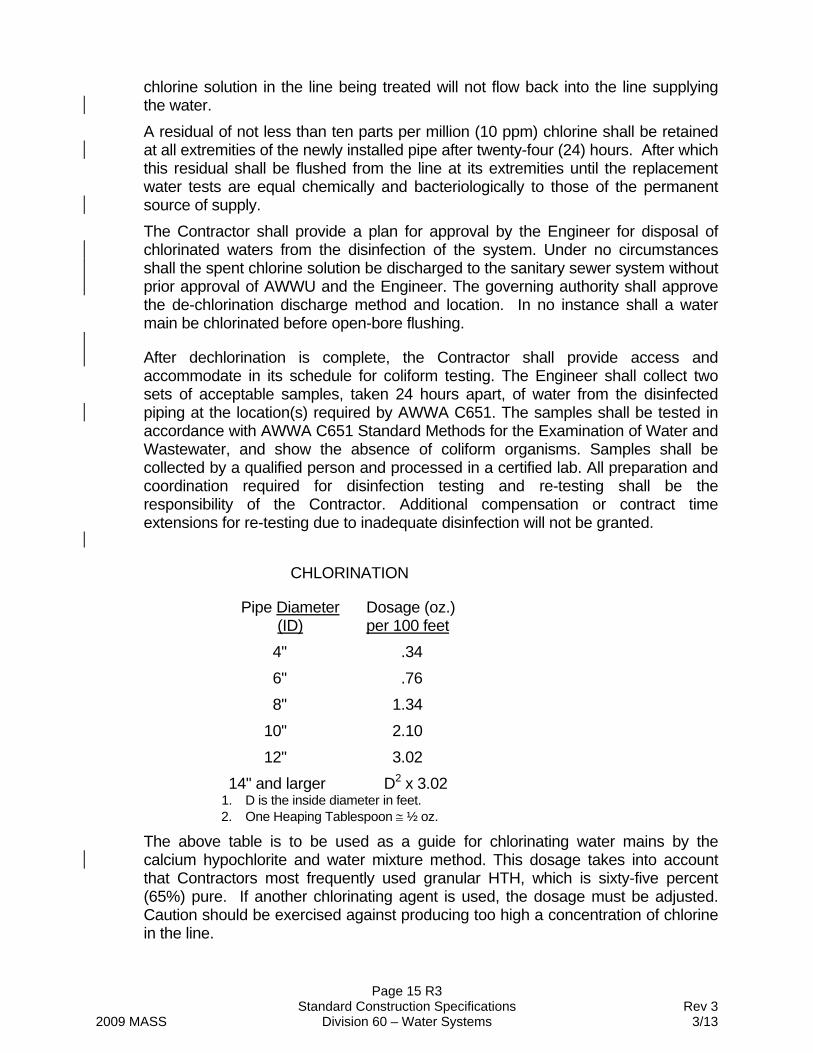
chlorine solution in the line being treated will not flow back into the line supplying the water. A residual of not less than ten parts per million (10 ppm) chlorine shall be retained at all extremities of the newly installed pipe after twenty-four (24) hours. After which this residual shall be flushed from the line at its extremities until the replacement water tests are equal chemically and bacteriologically to those of the permanent source of supply. The Contractor shall provide a plan for approval by the Engineer for disposal of chlorinated waters from the disinfection of the system. Under no circumstances shall the spent chlorine solution be discharged to the sanitary sewer system without prior approval of AWWU and the Engineer. The governing authority shall approve the de-chlorination discharge method and location. In no instance shall a water main be chlorinated before open-bore flushing.
After dechlorination is complete, the Contractor shall provide access and accommodate in its schedule for coliform testing. The Engineer shall collect two sets of acceptable samples, taken 24 hours apart, of water from the disinfected piping at the location(s) required by AWWA C651. The samples shall be tested in accordance with AWWA C651 Standard Methods for the Examination of Water and Wastewater, and show the absence of coliform organisms. Samples shall be collected by a qualified person and processed in a certified lab. All preparation and coordination required for disinfection testing and re-testing shall be the responsibility of the Contractor. Additional compensation or contract time extensions for re-testing due to inadequate disinfection will not be granted.
CHLORINATION
Pipe Diameter (ID)
Dosage (oz.) per 100 feet
4" .34 6" .76 8" 1.34
10" 2.10 12" 3.02
14" and larger D2 x 3.02 1. D is the inside diameter in feet. 2. One Heaping Tablespoon ½ oz.
The above table is to be used as a guide for chlorinating water mains by the calcium hypochlorite and water mixture method. This dosage takes into account that Contractors most frequently used granular HTH, which is sixty-five percent (65%) pure. If another chlorinating agent is used, the dosage must be adjusted. Caution should be exercised against producing too high a concentration of chlorine in the line.
Page 16 R3 Standard Construction Specifications Rev 3 2009 MASS Division 60 – Water Systems 3/13
Disinfection will not be allowed until all open-bore flush pipes are removed and the water system is sealed.
D. Continuity Tests The Contractor shall perform electrical conductivity tests on all ductile iron mains in the presence of a representative of the Engineer. Continuity testing shall also be performed on all water service connections and extensions greater than two inches (2”) in diameter. The Contractor shall maintain a circuit of six hundred (600) amperes DC current for a period of fifteen (15) minutes. Input current shall not exceed ten percent (10%) of the return circuit. All equipment necessary to maintain the circuit shall be supplied by the Contractor. All continuity tests will be through wires connected to the main and brought to the surface. The use of water service thaw wires, fire hydrants and valves as substitutes for wires will not be accepted. All wires brought to the surface to complete the continuity test shall be placed in a valve box adjustment sleeve. Continuity tests must not be performed until all excavations have been completed and backfilled.
E. Test and Air Vent Copper Pipe Removal The Contractor shall, upon acceptance of testing, remove all test and air vent copper pipe and close the corporation stop at the main with a copper disc and flare nut installed in the presence of the Engineer.
Article 2.5 Measurement Measurement for furnishing and installing water main shall be per linear foot of horizontal distance of the various sizes as set forth in the Bid Schedule. Measurement will be from station to station as staked in the field and as shown on the Drawings, except where the grade exceeds twenty-five percent (25%), in which case measurement will be by actual pipe length.
Article 2.6 Basis of Payment Payment for this Work shall be in accordance with Division 10, Section 10.07 - Measurement and Payment, and shall include full payment for all Work described in this Section. Unless specifically identified for payment under a separate pay item, the unit price bid to Furnish and Install (size) (type) Water Main shall include all labor, equipment and materials to furnish and install a functional potable water main including, but not limited to, the following incidental items: delivery of non-serviceable portions of removed pipe, valves, and fittings at a Contractor-furnished disposal site; delivery of serviceable portions of removed pipe, valves, and fittings to the Owner, when directed by the Engineer; installation of all pipe, tees, crosses, bends, caps, plugs, adapters, reducers, thrust restraint systems, and other fittings; installation of thrust blocks; adjustment to finish grade; cleaning and flushing; hydrostatic testing; provisions coordinating the supply of water as required for flushing and hydrostatic testing; disinfecting; continuity testing; protection and/or restoration of all existing utilities; maintenance of existing water distribution system
Page 17 R3 Standard Construction Specifications Rev 3 2009 MASS Division 60 – Water Systems 3/13
flows; shoring and/or protection of existing light poles; maintenance and restoration of existing drainage patterns; restoration of existing driveways; signage, mail boxes, newspaper boxes, trees and shrubs located on private property; landscaping, utility markers, survey monumentation; removal and replacement of miscellaneous public or private improvements; preparation of off-roadway areas for topsoil and re-seeding; cleanup, and miscellaneous items required to complete the Work as shown on the Drawings. Where the Work includes disconnecting existing water services from and existing water main and reconnecting them to a new water main, the disconnection and reconnection of those existing water services will be considered incidental to the price bid for installation of the new water main. Trench excavation and backfill shall be paid for under Division 20, Section 20.13 - Trench Excavation and Backfill. Payment shall be made on the following unit:
ITEM UNIT
Furnish and Install (Size) (Type) Water Main Linear Foot
Page 18 R3 Standard Construction Specifications Rev 3 2009 MASS Division 60 – Water Systems 3/13
SECTION 60.03 FURNISH AND INSTALL VALVES
Article 3.1 General The Work under this Section consists of the performance of all Work required for furnishing and installing valves, including valve boxes and marker posts.
Article 3.2 Material Tie back rods and/or tie back rod and shackle assemblies are not acceptable as restrained joints or restraining system for valves and valve/pipe joint interface. Unless otherwise detailed on the Drawings, valve and valve/pipe interface shall be push-on rubber gasket type conforming to AWWA C111 and be restrained per Section 60.02. A. Gate Valves
Gate valves shall be iron body, fully bronze mounted, double disc, parallel or resilient seat valves as manufactured in accordance with the requirements of AWWA C509 “Resilient-Seated Gate Valves for Water Supply Service” or AWWA C515 “Reduced-Wall, Resilient-Seated Gate Valves for Water Supply Service”. Gate valve bonnet bolts shall be Type 316 stainless steel with a minimum tensile strength of 75,000 PSI and shall conform to ASTM F593 and F594. All bolts shall be stamped with the grade marking on the head of the bolt, and shall be “T-316”, “316”, or “F593”.
B. Butterfly Valves Butterfly valves shall be of the rubber-seated tight-closing type. They shall meet or exceed the performance requirements of AWWA C504 for operational pressures of 150 psi working pressure and 300 psi hydrostatic pressure. Mechanical joint valve ends shall be per AWWA C110/ANSI 21.10 and AWWA C111/ANSI 21.11 of the latest revision, and "Short-Body" in accordance with the requirements of Table 2 of ANSI/AWWA C504. Accessories (bolts, glands, and gaskets) shall be supplied by the valve manufacturer. Butterfly valve actuator bolts that are exposed shall be Type 316 stainless steel with a minimum tensile strength of 75,000 PSI and shall conform to ASTM F593 and F594. All bolts shall be stamped with the grade marking on the head of the bolt, and shall be “T-316”, “316”, or “F593”. Valves must use full ANSI/AWWA C504 Class 150 B valve shaft diameter and full Class 150 B underground service operator torque rating throughout entire travel to provide capability for operation in emergency service. Valve body shall be high-strength cast iron ASTM A126 Class B. For valves with the rubber seat mounted on the disc, the mating surface in the body shall be 304 or 316 steel. For valves containing the rubber seat in the body, the method of seat retention shall be in accordance with the requirements of ANSI/AWWA C504, except that no retaining fasteners or other hardware shall be permitted in the flow stream.
Page 19 R3 Standard Construction Specifications Rev 3 2009 MASS Division 60 – Water Systems 3/13
Valve operators, unless otherwise required by the Contract Documents, shall be of the traveling nut type, sealed, gasketed, and lubricated for underground service and capable of withstanding on overload input torque of four hundred fifty (450) foot-pounds at full open or closed position without damage to the valve or valve operator. The number of turns to operate the valve shall be a minimum of two (2) turns per inch of valve diameter for ninety degrees (90) of closure travel at a maximum pull of eighty (80) pounds. All valves shall open counterclockwise and be equipped with two inch (2”) square AWWA operating nut. For butterfly valves twenty inches (20") and less, the valve shaft shall be one piece extending full size through valve bearings, disc and shaft seal. In the event that the shaft is turned down to fit connections to the operator, the limits of ANSI/AWWA C504, Section 3.3.2 shall be strictly observed. Carbon steel shafts, if used, shall have 304 or 316 stainless steel journals with static seals to isolate the interior of the disc and the shaft from the water. For butterfly valves over twenty inches (20"), the valve shaft shall be of two-piece stub shaft type, made of 18-8 Type 304 stainless steel. Valve bearings and shaft seals for valves of all sizes shall meet the requirements of ANSI/AWWA C504 Section 3.6 and 3.7 respectively, with the following additional requirements:
1. Sleeve bearings shall have a maximum coefficient of friction of 0.1. 2. For underground service, packing shall be pressure-energized chevron or
"O" ring type, not requiring adjustment and suitable for permanent duty. C. Pressure Reducing Valves
Pressure reducing valves shall be supplied as directed in the Contract Documents. D. Valve Boxes
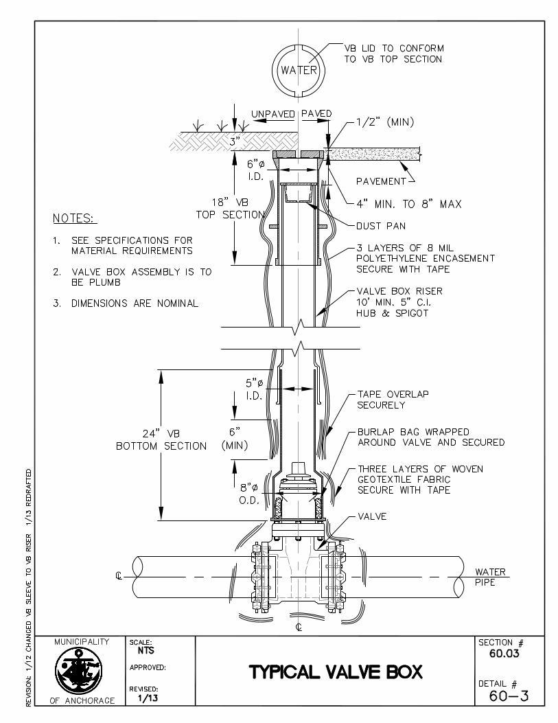
Valve boxes are to meet the requirements of and be constructed of the following individual parts: Lid – cast or ductile iron with lifting ears that conforms with and fits closely the top section and is rated heavy duty Top section- cast or ductile iron, rated heavy duty, 18” minimum height, minimum 6” inner diameter, recessed to receive the lid Dust pan – cast or ductile iron, 3” minimum height, ¼” minimum thick material, lift handle/bar and fits into and rests on the riser Riser – cast or ductile iron pipe that fits inside the top section and over the bottom section, minimum 10’ long Bottom section – cast or ductile iron, rated heavy duty, 24” minimum height, with round or oval bottom hood sections to fit over the top of the valve Geotextile – woven, class 2 in conformance with MASS Section 20.25 – Geotextile fabric Polyethylene film – 8 mil in conformance with MASS Section 60.07 – Polyethylene Encasement
Page 20 R3 Standard Construction Specifications Rev 3 2009 MASS Division 60 – Water Systems 3/13
Burlap bag – all natural, biodegradable fabric woven from jute fibers with openings of less than 1/8” Tape – minimum 2” wide, 20 mil thick, UPC approved PVC Tape Heavy duty rated items are to meet AASHTO M306 criteria. Internal diameter of the smallest section shall not be less than five inches (5”). Minimum thickness of the metal shall not be less than five-sixteenth inch (5/16”). Castings shall be smooth and the workmanship shall be acceptable to the Engineer.
E. Markers Valve boxes shall be marked with markers consisting of two and one-half inch (2.5”) O.D. galvanized steel pipe sections, seven feet (7’) in length, with three feet (3’) buried in the ground. Markers shall be shop painted "Caterpillar Yellow" and painted with stenciled two inch (2”) black numerals, showing the appropriate references. Markers shall be located on the nearest property line, due north, south, east or west of the valve at a maximum distance of fifty feet (50’), unless otherwise directed by the Engineer. Markers shall not be required where valve boxes are located in paved areas. Markers shall carry the following notation:
VB (feet) (direction) F. Live Tap Connections
Contractor shall provide all trench excavation, backfill, and compaction necessary to assist AWWU with the live tap connections. Excavation for live tap connections shall be unclassified and Contractor shall excavate substances encountered to the depth required for the live tap connections. Variations from the depth indicated in the Drawings will not be grounds for additional compensation. It shall be Contractor's responsibility to familiarize himself with the depth of water mains for the project. Contractor shall excavate for live tap connections in such a manner that the excavation is 90 to the main water line, whenever possible. The trench shall be long enough and of sufficient width at the bottom to allow installation of the valve for the live tap connection and provide safety for AWWU Operations personnel. Contractor shall be responsible for, and shall bear the expenses incurred, if a water main should be damaged during excavation or backfilling. AWWU, at it’s option, will allow the Contractor to make repairs, or AWWU will make repairs; however, Contractor shall bear the cost of all material, labor, and other expenses. Contractor shall provide assistance, equipment, labor, materials, and supplies (except the water main line valve) necessary to complete the live tap connection. Contractor shall notify the Engineer and AWWU 48 hours (two working days) prior to installation of the live tap connection. In addition, Contractor shall obtain all necessary permits for the live tap connection and pay all associated fees. Unless otherwise detailed on the Drawings, valve and valve/pipe interface shall be push-on rubber gasket type conforming to AWWA C111. Where specified on the Drawings, restrained joint pipe shall be EBAA Iron MEGALUG, Romac Industries RomaGrip, or approved equal.
Page 21 R3 Standard Construction Specifications Rev 3 2009 MASS Division 60 – Water Systems 3/13
Contractor shall provide pipe manufacturer submittals which include thrust restraint calculations prior to construction.
Article 3.3 Construction The Contractor shall provide all trench excavation, backfill, and compaction necessary to install valves in accordance with Division 20, Section 20.13 - Trench Excavation and Backfill. Valves or valve boxes shall be installed where shown on the Drawings. Valve box components shall be plumb and centered over the operating nut. Valve boxes shall be of sufficient length (ten foot [10’] sections) for the pipe cover depth on the profile drawings. The valve operator shall be placed on the side of the water main away from the centerline of the street or easement. On fire line installations, a valve shall be placed outside the building so that all fire hydrants will remain in service in the event water service to the building must be shut off for any reason. Valves shall have the interiors cleaned of all foreign matter before installation. If the valve is at the end of the line, it shall be plugged prior to backfilling. The valve shall be inspected by the Engineer in the open and closed positions to ensure that all parts are in working condition. Provisions shall be made to prevent soil infiltration into the valve box. Wrap burlap inside bottom section under the packing gland and wrap three (3) layers of woven geotextile fabric around the outside of the valve and base section of the valve box and secure the fabric at the top and bottom with tape. Encase the valve box with three layers of eight-mil polyethylene, encasement, taped securely in place. The Contractor shall expose all valve boxes for prefinal and final inspection. After final inspection of the valves located in unpaved areas, Class ‘E’ bedding is to be placed directly over the valve box lid to facilitate locating and uncovering in the future.
Article 3.4 Measurement The quantity to be paid shall be the actual number of valves of each class and size (including valve boxes and marker posts) furnished, installed and accepted.
Article 3.5 Basis of Payment
Payment for this Work shall be in accordance with Division 10, Section 10.07 - Measurement and Payment, and shall include full payment for all Work described in this Section.
Payment shall be made on the following unit:
ITEM UNIT
Furnish and Install (Size) Gate Valve Each
Furnish and Install (Size) Butterfly Valve Each
Page 22 R3 Standard Construction Specifications Rev 3 2009 MASS Division 60 – Water Systems 3/13
SECTION 60.04 FURNISH AND INSTALL FIRE HYDRANTS
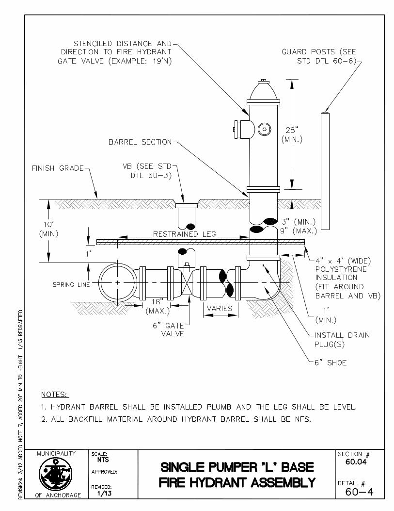
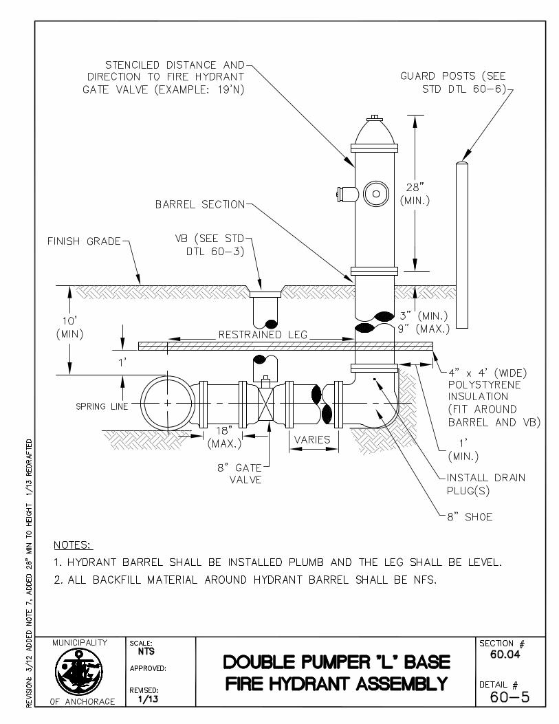
Article 4.1 General The Work under this Section consists of the performance of all Work required for the furnishing and installation of "L-Base" Fire Hydrant Assemblies, including the fire hydrant leg pipe, auxiliary gate valve, valve box, joint restraint, guard rails, and fire hydrants.
Article 4.2 Materials A. Fire Hydrants
Fire hydrants shall conform to the requirements of ANSI/AWWA C502 for Dry Barrel Fire Hydrants. Fire hydrants shall be Mueller Centurian or equal. 1. All fire hydrants shall be supplied with a five and one-fourth inch (5.25”) main
valve opening. 2. All single pumper hydrants shall be furnished with a six inch (6”) ANSI Class
125 standard mechanical-joint end. All double pumper hydrants shall be furnished with an eight inch (8") ANSI Class 125 standard mechanical-joint.
3. All connections shall be mechanical-joint unless otherwise indicated in the Contract Documents.
4. Single pumper hydrants shall be furnished with two (2) two and one-half inch (2.5”) hose connections and one (1) four and one-half inch (4.5”) pumper connection. Double pumper hydrants shall be furnished with one (1) two and one-half inch (2.5”) hose connection and two (2) four and one-half inch (4.5”) pumper connections.
5. Unless otherwise required by the Contract Documents, all hydrants shall be furnished with a barrel length that will allow a minimum of ten feet (10’) of bury. The lower barrel must be one piece to achieve a ten foot burial depth.
6. The main valves shall be of the compression type, where water pressure holds the main valve closed permitting easy maintenance or repair of the entire barrel assembly from above the ground without the need of a water shutoff.
7. All fire hydrants shall be furnished with a breakaway flange which allows both barrel and stem to break clean upon impact from any angle. Traffic flange design must be such that repair and replacement can be accomplished above ground.
8. Painting and coating shall be in accordance with cited AWWA Specifications. After installation, the hydrant section from the traffic flange to the top of the operating nut shall be painted "Caterpillar Yellow."
9. Operating and nozzle nuts shall be pentagon shaped with one and one-half inch (1.5”) point to flat measurements.
10. Hose nozzle threading shall be in conformance with NFPA #194 for National (America) Standard Fire Hose Coupling Screw Threads.
Page 23 R3 Standard Construction Specifications Rev 3 2009 MASS Division 60 – Water Systems 3/13
11. All working parts shall be bronze or noncorrosive metal in accordance with the requirements of ANSI/AWWA C502.
12. All hydrants shall be right hand opening (clockwise). 13. All hydrants shall be non-draining. Drain plugs shall not be removed. 14. The operating nut of the hydrants is to be a minimum of twenty eight (28”)
above the traffic breakaway flange. The traffic breakaway flange is to be between three inches (3”) to nine inches (9”) above adjacent grades.
B. Auxiliary Gate Valves All gate valves and valve boxes shall be furnished and installed in accordance with Section 60.03 - Furnish and Install Valves.
C. Thrust-Restraint System Unless otherwise detailed on the Drawings, Contractor shall provide push-on rubber gasket type conforming to AWWA C111. Where specified on the Drawings and/or Standard Details, Contractor shall install EBAA Iron MEGALUG, Romac Industries RomaGrip, U.S. Pipe Field LOK Gasket System, or approved equal, on restrained joint pipe. Contractor shall ensure all restrained-joint installation areas shall include joints, fittings, and piping deflection points.
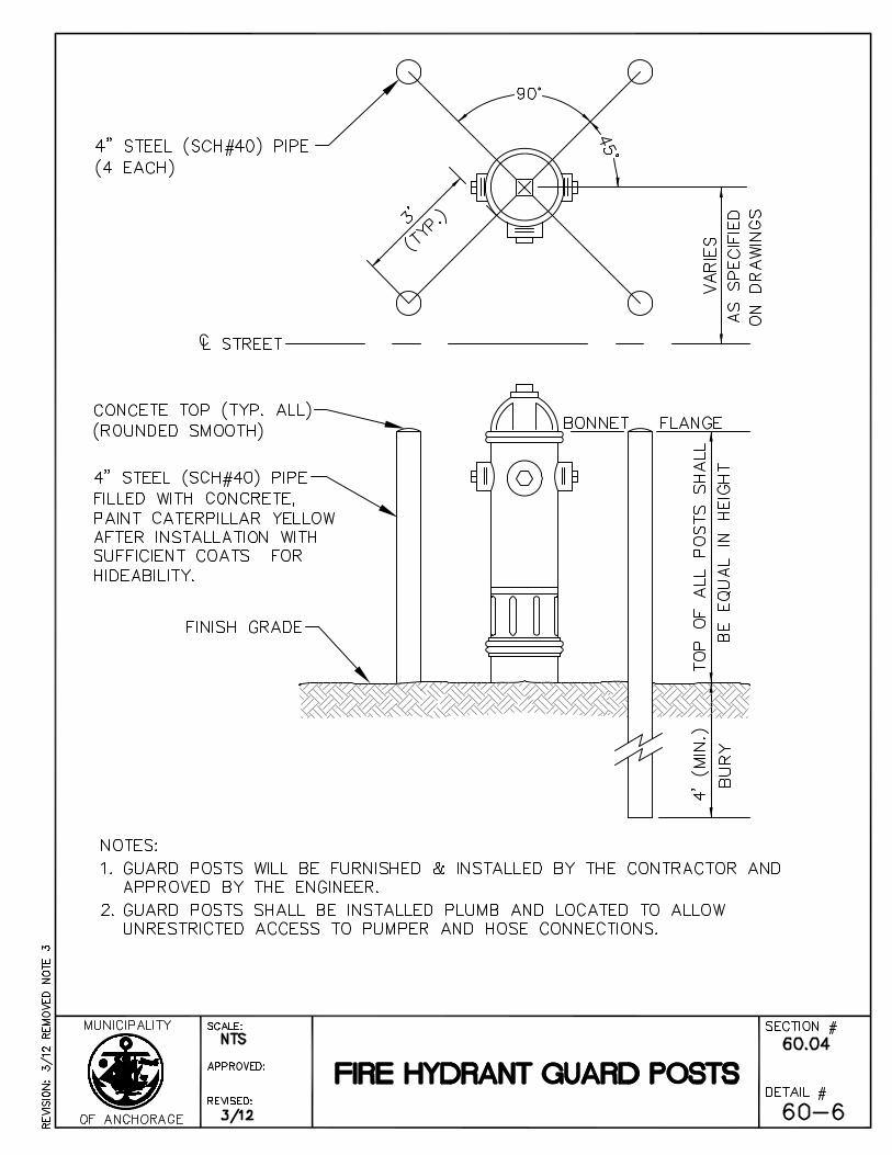
D. Guard Posts The Contractor shall install guard posts at each hydrant installation in accordance with the Standard Details. If, in the opinion of the Engineer, the guard posts are not to be installed, they shall be delivered to the Anchorage Water and Wastewater Utility storage yard. Measurement and payment for guard posts shall be incidental to the Bid item "Furnish and Install Fire Hydrant Assembly."
Article 4.3 Construction The Contractor shall provide all trench excavation, backfill and compaction necessary to install the fire hydrant assembly in accordance with Division 20, Section 20.13 - Trench Excavation and Backfill. The Contractor shall tape coat the barrel section, shoe, MJ restraint, and all buried bolted connections with Densyl Tape as manufactured by Denso or approved equal. All surfaces shall be primed with Densyl Paste as manufactured by Denso or approved equal. The Contractor shall wrap the hydrant barrel section with three layers of 8-mil thick polyethylene encasement, up to the finish ground surface. The fire hydrant auxiliary valve shall be closed during installation and remain closed during all main line open bore flushing operations. The auxiliary gate valve shall be opened for hydrostatic pressure testing and disinfection and while the hydrant is being raised by AWWU under pressure. All fire hydrant legs shall be installed level. The fire hydrant barrel shall be installed plumb. Fire hydrants will be adjusted to final grade by the AWWU Operations Division. The Contractor shall provide AWWU with a minimum of seventy-two (72) hours notice, excluding non-working days, to coordinate fire hydrant adjustment. The Contractor shall be responsible for access to the hydrant location and all trench excavation, dewatering and backfill operations prior to, during, and after the fire hydrants are adjusted by AWWU personnel. The cost for coordinating and providing trenching
Page 24 R3 Standard Construction Specifications Rev 3 2009 MASS Division 60 – Water Systems 3/13
operations are incidental to the fire hydrant installation. Any adjustments to the fire hydrant traffic flange on a Municipal Contract will be made by AWWU at no cost to the Contractor. Adjustment to other fire hydrants will be made by Anchorage Water and Wastewater Utility on a reimbursable basis. Hydrants installed but not available for use shall be covered with burlap and securely tied. In lieu of valve box markers for the auxiliary gate valves, the Contractor shall paint in two inch (2”) black lettered stencils, the direction and distances to the nearest one-tenth foot (1/10’ or 0.1’) the distance to the valve box on the face of the fire hydrant directly below the bonnet flange.
Article 4.4 Measurement The method of measurement to furnish and install fire hydrants shall be as follows:
A. Single Pumper Fire Hydrants Single Pumper Fire Hydrants shall be measured as complete assemblies furnished, constructed, installed, and accepted in place for each installation, including, but not limited to, fire hydrants six inch (6”) leg to main, six inch (6”) auxiliary gate valve and valve box, guard post installation, and thrust-restraint system. The price shall include full compensation for furnishing and installing single pumper hydrants as shown in the Standard Details.
B. Double Pumper Fire Hydrants Double Pumper Fire Hydrants shall be measured as complete assemblies furnished, constructed, installed, and accepted in place for each installation, including, but not limited to, fire hydrants eight inch (8”) leg to main, eight inch (8”) auxiliary gate valve and valve box, guard post installation, and thrust-restraint system. The price shall include full compensation for furnishing and installing double pumper hydrants as shown in the Standard Details.
Article 4.5 Basis of Payment
Payment for this Work shall be in accordance with Division 10, Section 10.07 - Measurement and Payment, and shall include full payment for all Work described in this Section.
Payment shall be made under the following units:
ITEM UNIT
Furnish and Install Fire Hydrant Assembly (Single Pumper) Each
Furnish and Install Fire Hydrant Assembly (Double Pumper) Each
Page 25 R2 Standard Construction Specifications Rev 2 2009 MASS Division 60 – Water Systems 3/12
SECTION 60.05 FIRE LINES
Article 5.1 General
The Work required under this Section consists of the performance of all Work required for the furnishing and installation of fire lines including thrust-restraint system, fittings, valves, and valve boxes.
Article 5.2 Material
Refer to Section 60.02, Article 2.2 – Materials. The fire line riser from the service piping is to be composed of metallic pipe extending vertically from a ninety degree (90ª) fitting through the plane of the building floor. The fire sprinkler riser must be constructed of material in compliance with the NFPA. All below grade metallic piping must be cathodically protected.
Article 5.3 Construction A. General
A fire line that originates at a water utility main or at the valve downstream of a fire hydrant tee has the primary purpose of providing fire protection inside a building. No connections, other than those for additional fire protection, will be allowed on the fire line outside the building. Domestic water obtained from a fire line will be connected and metered inside the building. Valves and valve boxes shall be installed where shown on the Drawings.
B. Excavation and Backfill The Contractor shall provide all excavation, backfill, and compaction necessary to install fire lines in accordance with Division 20, Section 20.13 - Trench Excavation and Backfill.
C. Materials Delivery Refer to Section 60.02, Article 2.3 – Construction.
D. Thrust Restraint Thrust-restraint systems are to comply with Section 60.02, Article 2.2, SubArticle J and are to be installed for minimum distance of forty feet (40’) in both directions from all fittings.
E. Alignment and Grade Refer to Section 60.02, Article 2.3 - Construction
F. Jointing of Pipe Refer to Section 60.02, Article 2.3.. - Construction
Page 26 R2 Standard Construction Specifications Rev 2 2009 MASS Division 60 – Water Systems 3/12
Article 5.4 Fire Hydrants, Valves and Valve Boxes
Refer to Sections 60.03 and 60.04.
Article 5.5 Flushing and Testing
Refer to Section 60.02 Article 2.4 – Flushing and Testing.
Hydrostatic testing may be performed through the line riser.
Article 5.6 Measurement
Measurement for furnishing and installing fire lines shall be per linear foot of horizontal distance of the various sizes as set forth in the Bid Schedule. Measurement will be from station to station as staked in the field and as shown on the Drawings, except where the grade exceeds twenty-five (25) percent, in which case measurement will be by actual pipe length.
Article 5.7 Basis of Payment
Payment for this Work shall be in accordance with Division 10, Section 10.07 - Measurement and Payment, and shall include full payment for all Work described in this Section.
Unless specifically identified for payment under a separate pay item, the unit price bid to Furnish and Install (size) (type) Fire Line shall include all labor, equipment and materials to furnish and install a functional fire line including, but not limited to, the following incidental items: delivery of non-serviceable portions of removed pipe, valves, and fittings at a Contractor-furnished disposal site; delivery of serviceable portions of removed pipe, valves, and fittings to the Owner, when directed by the Engineer; installation of all pipe, tees, crosses, bends, caps, plugs, adapters, reducers, thrust restraint systems, and other fittings; installation of thrust blocks; adjustment to finish grade; cleaning and flushing; hydrostatic testing; disinfecting; continuity testing; protection and/or restoration of all existing utilities; maintenance of existing water distribution system flows; shoring and/or protection of existing light poles; maintenance and restoration of existing drainage patterns; restoration of existing driveways; signage, mail boxes, newspaper boxes, trees and shrubs located on private property; landscaping, utility markers, survey monumentation; removal and replacement of miscellaneous public or private improvements; preparation of off-roadway areas for topsoil and re-seeding; cleanup, and miscellaneous items required to complete the Work as shown on the Drawings.
Excavation and backfill shall be paid for under Division 20, Section 20.13 - Trench Excavation and Backfill.
Payment shall be made on the following unit:
ITEM UNIT
Furnish and Install (Size) (Type) Fire Line Linear Foot
Page 27 R2 Standard Construction Specifications Rev 2 2009 MASS Division 60 – Water Systems 3/12
SECTION 60.06 WATER SERVICE LINES
Article 6.1 General
The Work under this Section consists of the performance of Work required for furnishing and installing water service lines including fittings, key boxes, and valve boxes.
A service line provides potable water to a building or lot for domestic or commercial use.
A permit shall be purchased from AWWU permit section prior to any and all construction (either on or off property in the AWWU service area).
Twenty-four (24) hours notification shall be given to AWWU Inspector prior to making the connection available for inspection.
Before an on-property service line permit for any new subdivision can be released for construction, all property corners shall be established and identified.
A water service connection is located in a right-of-way (ROW) or easement and is the pipe and appurtenances extending from a water main to a keybox. A keybox is normally located at the property or water easement line.
A service extension is the pipe and appurtenances within a parcel extending from the keybox to a structure or structures on a private system. The service extension connects the water service to a structure.
Article 6.2 Material
A. Pipe
Pipe material must comply with Section 60.02 – Furnish and Install Pipe
B. Key Box Valve and Valve Box
Keyboxes are to be telescoping, furnished with a lid, have an arch pattern base and is to be constructed of cast or ductile iron. The operating rod and connection pin are to be constructed of stainless steel alloy type 304 or 316. The connection pin is to be a minimum of 3/16” by two inches (2”) long.
Keyboxes located within pavement or concrete are to be adjusted to finish grade and installed in a valve box adjustment sleeve. Adjustment of keyboxes is to be accomplished by removing the keybox lid, installing a black iron pipe coupling, installing a section of black iron pipe, and replacing the keybox lid at the finish grade.
All valves and valve boxes must be furnished and installed in accordance with Section 60.03 - Furnish and Install Valves.
Page 28 R3 Standard Construction Specifications Rev 3 2009 MASS Division 60 – Water Systems 3/13
The key box or valve box shall provide a clear and unobstructed access to a curb stop or valve to enable the AWWU operation of the curb stop or valve. Key boxes and valve boxes shall be wrapped with eight mils (8-mils) thick polyethylene encasement. Key boxes or valve boxes shall not be in contact with a gas main. Key boxes or valve boxes shall be installed in the standard location as shown in the Standard Details.
Key boxes shall be of an acceptable construction as outlined in this Article for construction and as shown in the Standard Details for Typical Water Service Connects. Key boxes shall be installed with a standard location marker as defined in the Design Criteria of the Anchorage Water and Wastewater Utility.
Valves shall be of an acceptable construction as outlined in Section 60.03, Article 3.2 - Materials and the Standard Details for Typical Valve Box. Valves shall be installed with a standard marker as defined in Section 60.03, SubArticle 3.2.E - Markers.
C. Thaw Wire
The thaw wire for water service lines shall be insulated No. 2 AWG stranded copper conductor rated for 600V. Insulation shall be HMWPE, or approved for use in buried low temperature service.
D. Tapping Saddle
All service taps are to utilize tapping saddles. Taps two inches (2”) and smaller are to use Romac 306, Powerseal 3412AS or equal tapping saddles. Service taps larger than two inches (2”) are completed by AWWU.
Article 6.3 Construction
A. Excavation and Backfill
The Contractor shall provide all excavation, backfill, and compaction necessary to install water source lines in accordance with Division 20, Section 20.13 - Trench Excavation and Backfill.
B. Service Connections
A corporation stop or main valve shall be installed at a point in the service line as close to the main water supply as possible. There shall be line pressure in the main at all times connections are being made. Contractor shall construct all service lines two inches (2”) and smaller of seamless, soft drawn, polyethylene coated Type K copper. All service connections larger than two inches (2”) is to be accomplished by AWWU connection crews. The Contractor may make the connection by special agreement with the AWWU Permits Section. All ductile iron and PVC pipe installations shall be flushed, hydrostatic tested, and disinfected as outlined in Section 60.02 - Furnish and Install Pipe.
Page 29 R3 Standard Construction Specifications Rev 3 2009 MASS Division 60 – Water Systems 3/13
A water service line shall not cross property lines of adjoining lots. The key box shall be installed at the edge of the right-of-way or edge of permanent water easement of the lot being served, no closer than five feet (5') from adjoining property lines, and shall be marked by a marker extending three feet (3’) above grade, painted blue with 2” high stenciled letters spelling “WATER” near the top. An AWWU representative is to perform the field inspection at the initial connection or service line extension from the AWWU water main without exception. The connection and extension is to be exposed in its entirety for the inspection. The permit shall be posted and available at the time of inspection. No unions will be allowed in the right-of-way on newly constructed service lines. Where water service lines intersect with sanitary sewer or storm drain pipelines, the water service line shall be located to provide a minimum vertical separation of eighteen inches (18”) between the water pipe and sanitary sewer or storm drain pipeline, with the separation distance measured from outside of water pipeline to outside of sanitary sewer pipeline. As-built records shall include the pipe station of service connection at the main, service length and distance to the nearest property corner.
C. Excavation
The Contractor shall excavate whatever substances that are encountered to the depth required for the connections. Depth for water service connections will be a minimum of ten feet (10') below proposed finished grade. The ten foot (10') depth below finished grade shall be maintained five feet (5') past the footings, before the depth shall be less than ten feet (10'). Variations in depth from the depth stated above will not be grounds for additional payment. It shall be the Contractor's responsibility to familiarize himself with the depth of water mains for the project. The portion of the right-of-way that extends from the main to the key box (curb stop) will be excavated in such a manner that will allow the service connection to be installed horizontally (no slope). The Contractor shall excavate for water connections in such a manner that the excavation is ninety degrees (90) to the street line, whenever possible. Two services, two inches (2”) or less, shall not be installed in a single trench when separation between keyboxes is greater than twelve feet (12’) or two feet (2’) separation cannot be maintained. The ditch shall be long enough to allow the key box to be set at the property line. Trenches shall be of sufficient width at the bottom to allow for laying of the particular service (minimum two and one-half feet [2.5’] for single service). The Contractor shall expose the main to be tapped for distance of two feet (2’) or greater either side of the proposed tap location. Excavation on both sides of the pipe shall be carried to below the bottom of the pipe for clearance of the tapping saddle. No water service shall be within a horizontal distance of ten feet (10') from the sanitary sewer service, footing drain or storm service. The Contractor shall be responsible for, and shall bear the expenses incurred, in the event that a main should be damaged during excavation or backfilling. The
Page 30 R3 Standard Construction Specifications Rev 3 2009 MASS Division 60 – Water Systems 3/13
water Utility will repair all damaged mains; however, the Contractor shall bear the cost of all material, labor, and other expenses thereof. If approved by AWWU, the Contractor may repair the damaged main. All on-property installations shall be constructed to the same standard as off-property installations.
D. Backfill
At such time as the Engineer may direct, but only after the service lines and appurtenances have been properly completed and inspected, the trenches and appurtenant structures shall be backfilled. The backfilled material, free from large clods, frozen material or stones, shall be placed by the Contractor in conformance with the codes and regulations of the Municipality.
The Contractor shall exercise due care in backfilling to keep the service box and thaw wire vertical and in place. In the event the service box or thaw wire is displaced, the Contractor will be required to excavate and restore the service box and thaw wire to the proper position. Any work necessary to restore the service box and thaw wire to the proper position will be performed at the Contractor's expense.
A thaw wire constructed to a #2 copper plastic or rubber coated wire shall be attached to the corporation stop on one inch (1") connections by an approved method. On one and one-half (1 1/2") and two inch (2") connections, the thaw wire shall be attached to the saddle on the main. Three inch (3”) through ten inch (10") connections shall have continuity straps attached in the same manner as that of main line installation.
E. Disconnects
If an existing service line is replaced by a new service or becomes unusable due to a replat of the property, demolition, or improvements to an existing building, it shall be disconnected at the main, at no cost to the Municipality. The disconnect shall be witnessed by an AWWU inspector.
F. Hydrostatic Testing
Hydrostatic testing must comply with M.A.S.S Section 60.02. A bleeder will be installed at each service line key box and extended a minimum of one foot (1') above the existing ground. The bleeder will be capped after testing is complete. The bleeder may not be used for the on-property system and must be disconnected at the time of the on-property hook-up.
G. Disconnect/Reconnect Water Service
Disconnect and reconnect existing water service lines where shown on the Drawings or as directed by the Engineer.
Page 31 R3 Standard Construction Specifications Rev 3 2009 MASS Division 60 – Water Systems 3/13
Reconnect to existing water service line piping with Flare x Flare pipe union. Furnish and install reducer if existing water service extension piping is smaller than new piping. Furnish and install dielectric union if existing water service line piping is of dissimilar metal from new piping. Unions are not to be installed within the ROW.
Article 6.4 Measurement
Measurement for Furnishing and Installing Water Service Lines shall be per linear foot of horizontal distance of the various sizes set forth in the Bid Schedule. Measurement will be from station to station as staked in the filed and as shown on the Drawings, except where the grade exceeds twenty-five percent (25%), in which case measurement will be actual pipe length.
Article 6.5 Basis of Payment
Payment for this Work shall be in accordance with Division 10, Section 10.07 - Measurement and Payment, and shall include full payment for all Work described in this Section.
Unless specifically identified for payment under a separate pay item, the unit price bid to Furnish and Install (size) Water Service Lines shall include all labor, equipment and materials to furnish and install a functional potable water service including, but not limited to, the following incidental items: verify location of existing water services; disconnection and reconnection of customer’s existing services where the Work includes replacement of existing services; clearing and grubbing; trench excavation and backfill; excess excavation and backfill; excavation dewatering; trench support system; furnishing and installing Class E bedding; compaction of fill; installation of pipe, fittings, adapters, or other necessary appurtenances; polyethylene encasement; hydrostatic testing, flushing, disinfection, water service insulation; disposal of unusable or surplus material; seeding; protection of existing utilities; restoration of existing drainage patterns; removal and replacement of existing culverts, guardrail, fences, landscaping, and other public or private improvements; finish grading; and cleanup.
Where the Work includes disconnecting existing water services from an existing water main and reconnecting them to a new water main, the disconnection and reconnection of those existing water services will be considered incidental to the costs bid for installation of the new water main.
Fittings and appurtenances as shown on the Drawings or not specifically identified for payment under a separate pay item but required for normal completion of water service line installation, will be considered incidental and shall be included in the linear foot cost of the water service lines.
Payment shall be made under the following unit:
ITEM UNIT
Furnish and Install (Size) Water Service Line Linear Foot
Page 32 R2 Standard Construction Specifications Rev 2 2009 MASS Division 60 – Water Systems 3/12
SECTION 60.07 POLYETHYLENE ENCASEMENT
Article 7.1 General The Work under this Section consists of providing all operations pertaining to the furnishing and installation of one layer of polyethylene encasement on all ductile and cast iron mains and services, fittings, fire hydrants, valve boxes, etc. The polyethylene encasement shall be a linear low-density polyethylene film with a minimum thickness of 8 mil.
Article 7.2 Material The polyethylene encasement material for pipe shall be 8-mils thick and conform to AWWA C105/ANSI A21.5.
Article 7.3 Construction The Contractor shall use Method A of ANSI/AWWA A21.5/C105 to install polyethylene encasement. Method A:
1. Cut a section of polyethylene tube approximately two (2) feet longer than the pipe section. Remove all lumps of clay, mud, cinders, or other material that might have accumulated on the pipe surface during storage. Slip the polyethylene tube around the pipe, starting at the spigot end. Bunch the tube accordion fashion on the end of the pipe. Pull back the overhanging end of the tube until it clears the pipe end.
2. Dig shallow bell hole in the trench bottom at the joint location to facilitate installation of the polyethylene tube. Lower the pipe into the trench and make up the pipe joint with the preceding section of pipe.
3. Move the cable to the bell end of the pipe and lift the pipe slightly to provide clearance to easily slide the tube. Spread the tube over the entire barrel of the pipe. Note: Make sure that no dirt or other bedding material becomes trapped between the wrap and the pipe.
4. Make the overlap of the polyethylene tube by pulling back the bunched polyethylene from the proceeding length of pipe and securing it in place. Note: The polyethylene may be secured in place by using tape or plastic tie straps.
5. Overlap the secured tube end with the tube end of the new pipe section. Secure the new tube end in place.
6. Take up the slack in the tube along the barrel of the pipe to make a snug, but not tight, fit. Fold excess polyethylene back over the top of the pipe.
7. Secure the fold at several locations along the pipe barrel (approximately every three (3) feet).
8. Repair all small rips, tears, or other tube damage with adhesive tape. If the polyethylene is badly damaged, repair the damaged area with a sheet of polyethylene and seal the edges of the repair with adhesive tape.
Page 33 R3 Standard Construction Specifications Rev 3 2009 MASS Division 60 – Water Systems 3/13
9. Carefully backfill the trench in according to procedures in AWWA C600 Standard. To prevent damage during backfilling, allow adequate slack in the tube at the joint. Backfill should be free of cinders, rocks, boulders, nails, sticks, or other materials that might damage the polyethylene. Avoid damaging the polyethylene when using tamping devices.
Damaged polyethylene encasement is to be repaired or the pipeline removed and the polyethylene encasement replaced. Costs for repair and/or replacement of damaged polyethylene encasement shall be considered incidental to the installation of the polyethylene encasement and/or the installation of the pipeline protected by the encasement.
Article 7.4 Measurement
Polyethylene encasement shall not be measured for payment.
Article 7.5 Basis of Payment
No separate payment shall be made for polyethylene encasement. This Work is considered incidental to the bid item under construction.
Page 34 R2 Standard Construction Specifications Rev 2 2009 MASS Division 60 – Water Systems 3/12
SECTION 60.08 TEMPORARY WATER SYSTEMS
Article 8.1 General
The Work under this Section consists of the performance of all operations pertaining to the construction, installation, maintenance and removal of temporary water service during construction of this project to current AWWU customers in the area. It is the intent that the Contractor maintains water service during the entire period of construction activities to all current customers in the project area.
The Contractor shall submit a plan for any temporary water systems to the State of Alaska, Department of Environmental Conservation (ADEC) for review and approval prior to beginning Work on such system. The plan must identify the type of system, the method of construction and the maintenance and operation procedures to be used. The plan must identify service to each existing customer except those who agree in writing to have their service temporarily disconnected. The Contractor shall obtain such agreement. To be submitted with the plan are any agreements between the Contractor and property owner regarding access and use of private property. The methods to be employed in maintaining water service are left to the Contractor. Surface piping, trailer mounted supply systems, and so forth may all be considered as long as they comply with current health standards and requirements. A copy of the ADEC approved plan shall be provided to the Engineer, along with copies of any agreements with property owners referred to above.
The Contractor shall also submit the name and phone number of a contact person and at least one alternate who shall be available on a twenty-four (24) hour basis for repair and/or maintenance of the temporary water system. In the event that the Contractor fails to repair and/or maintain the temporary system and AWWU is required to perform repairs and/or maintenance, all costs associated with said repairs and/or maintenance shall be deducted from the Contract amount.
Article 8.2 Material
The Contractor shall use only those materials and equipment listed in this Section to supply temporary water service. Temporary water service shall be supplied under the service criteria outlined in this Section. All equipment used must be specifically designed and properly disinfected for he storage, handling, and delivery of potable water.
Service shall be supplied to each structure presently served by AWWU. The following minimum criteria shall be use for service to each structure:
A. Forty (40) psi minimum, one hundred (100) psi maximum delivery pressure measured at the connection to the structure.
B. Five (5) gallons per minute flow at the above delivery pressure measured at the connection to the structure. Commercial and other business structures may require higher water flows.
Page 35 R2 Standard Construction Specifications Rev 2 2009 MASS Division 60 – Water Systems 3/12
C. Potable water system and water quality shall conform to 18 AAC 80 Alaska Drinking Water Standards.
D. All services to structures shall be valved to allow individual control of service to each structure.
Materials used for temporary water service shall conform to the requirements of these Specifications. The temporary water service system shall be constructed from one or more of the following materials: polyvinyl chloride (PVC), high-density polyethylene (HDPE), copper, ductile iron, cast iron or galvanized steel.
The primary water feeder pipe shall be a minimum of three inches (3”) in diameter.
Article 8.3 Construction
All temporary water service equipment shall be disinfected per ANSI/AWWA C652, Disinfection of Water Storage Facilities and ANSI/AWWA C651, Disinfection of Water Mains. All bacteriological samples required under these Specifications shall be done by a testing laboratory certified by the State of Alaska.
All temporary service equipment shall be disinfected prior to connecting to a residence or business and shall be disinfected each and every time the equipment is moved or connected to another residence per above-referenced Specifications.
The Engineer shall be notified twenty-four (24) hours prior to the installation of any temporary water system. The Engineer shall be present to inspect the disinfection process of any temporary water service system.
No residence presently serviced by the AWWU system shall be without water for a period greater than six (6) hours in any twenty-four (24) hours period. Each residence or business owner shall be notified seventy-two (72) hours before they are transferred on or off the temporary water system and before any other service interruption. Prior to constructing temporary water services on private property, the Contractor shall secure a written “Permission to Enter” from the property owner. Such permission shall hold the Municipality of Anchorage, AWWU, and its agents harmless for any claims resulting from damage or harm sustained due to the Contractor’s operation. The Contractor shall also provide a copy of each “Permission to Enter” form to the Engineer.
Following the successful installation of the temporary water system, the existing water service shall be appropriately disconnected at a main shutoff valve inside the structure. Qualified personnel who are familiar with building plumbing systems shall accomplish the disconnection of the existing water service. This Work shall be performed to prevent backfeeding water through the service connection.
Fire hydrants may be used as a water source for a temporary water system. The Contractor will be required to obtain a hydrant permit from AWWU and will be required to meet all permit conditions (winter use of a hydrant shall required special permission from AWWU). In addition, the Contractor shall provide a gate valve assembly at the fire hydrant as a shutoff valve for the temporary water system. The Contractor shall furnish and install
Page 36 R2 Standard Construction Specifications Rev 2 2009 MASS Division 60 – Water Systems 3/12
a backflow prevention device at the meter. The Contractor shall be responsible for any damage to the hydrant and temporary service piping and shall repair such damage at no cost to the Owner.
Article 8.4 Measurement
Providing temporary water service as required throughout the project shall be measured as lump sum.
Article 8.5 Basis of Payment
Payment for this Work shall be in accordance with Division 10, Section 10.07 - Measurement and Payment, and shall include full payment for all Work described in this Section.
Payment shall be made under the following unit:
ITEM UNIT
Temporary Water System Lump Sum
Page 37 R2 Standard Construction Specifications Rev 2 2009 MASS Division 60 – Water Systems 3/12
SECTION 60.09 REPLACE VALVE BOX
Article 9.1 General
The Work under this Section consists of performing all operations pertaining to the removal, disposal, and replacement of mainline, service line, fire line, and/or fire hydrant valve boxes that have become separated and/or misaligned to such an extent as to require replacement, from the top of the valve to final finished grade, including the replacement of all valve box sections, lids, and dust pans.
Article 9.2 Material
All materials used in the replacing valve boxes shall conform to the requirements defined in Section 60.03 - Furnish and Install Valves and the Standard Details.
Backfill shall be Type II Classified material to the subgrade elevation.
Article 9.3 Construction
All construction shall be in accordance with the provision of Section 60.03 – Furnish and Install Valves.
All locations where replacing a valve box is required shall be excavated to the top of the valve and conform to the procedures outlined in Section 60.03 - Furnish and Install Valves, concerning installation of the valve box and the Standard Details.
Article 9.4 Measurement
Valve boxes replacement will be measured per unit, complete in place.
Article 9.5 Basis of Payment
Payment for this Work shall be in accordance with Division 10, Section 10.07 - Measurement and Payment, and shall include full payment for all Work described in this Section.
Payment shall be made under the following unit:
ITEM UNIT
Replace Valve Box Each
Page 38 R2 Standard Construction Specifications Rev 2 2009 MASS Division 60 – Water Systems 3/12
SECTION 60.10 RESET VALVE BOX SECTIONS BELOW FINISHED GRADE
Article 10.1 General The Work under this Section includes all operations pertaining to the reconnection of mainline, service line, fire line, and/or fire hydrant valve box sections that have separated below finish grade. Work under this Section also includes the requirements of the Drawings and applicable sections of this Division and Division 20 – Earthwork. All broken and/or missing valve box components are to be replaced with new materials furnished and installed by the Contractor in accordance with these specifications.
Article 10.2 Material All materials used in the reconnection of mainline and fire hydrant valve boxes shall conform to the requirements defined in Section 60.03 - Furnish and Install Valves and the Standard Details. Backfill shall be Type II Classified material to the subgrade elevation.
Article 10.3 Construction All construction shall be in accordance with the provision of Section 60.03 – Furnish and Install Valves. All locations where reconnections are required shall be excavated to the depth required to perform the reconnection. The Contractor shall be responsible for removing the liner inside the valve box casing and determining the location of the separation. Care shall be used to ensure that soil or other foreign matter does not enter the valve box standpipe.
Article 10.4 Measurement Resetting Valve Box Section Below Finish Grade will be measured per unit, complete in place. The same valve shall not be paid for under this pay item if it is paid for under Section 60.09 - Replace Valve Box. In particular, related work includes, but is not limited to, removal of debris from inside the valve box standpipe, trench excavation and backfill, disposal of unsuitable or surplus material, mechanical compaction, adjust mainline valve box to finish grade, replace broken valve box components, and classified materials. No separate measurement for payment will be made.
Article 10.5 Basis of Payment Payment for this Work shall be in accordance with Division 10, Section 10.07 - Measurement and Payment, and shall include full payment for all Work described in this Section. Payment shall be made under the following unit:
ITEM UNIT Reset Valve Box Sections Below Finished Grade Each
Page 39 R Standard Construction Specifications Rev 1 2009 MASS Division 60 – Water Systems 2/10
SECTION 60.11 REPLACE TOP SECTION OF VALVE BOX
Article 11.1 General
The Work under this Section consists of performing all operations for the removal, disposal, and replacement of mainline, service line, fire line, and fire hydrant valve box top section(s), lid(s), and dust pan(s) that are missing or damaged in the opinion of the Engineer. The Contractor is to provide all labor, materials and supervision required to furnish and install new valve box components needed to rehabilitate existing valve boxes.
Under this Section, rehabilitation of existing valve boxes can include the following items of Work:
Removal and replacement of valve box lids.
Removal and replacement of valve box dust pans.
Removal and replacement of valve box top sections.
The valve box components to be removed and replaced for a specific valve box are identified in the Drawings. The Contractor is to reuse those components that are not to be replaced in assembly of the rehabilitated valve box.
Article 11.2 Material
Materials used in this Work shall conform to the requirements of Section 60.03, Article 3.2 - Material.
Article 11.3 Construction
The Contractor shall excavate around the valve box as needed to access the Work. All excavation, shoring, dewatering, backfill and compaction efforts required to access the Work shall be per Division 20 – Earthwork. All importation of fill and/or disposal of unsuitable material, excavation, and backfill efforts shall be considered incidental to Work, and will not be paid separately.
Upon completion of the Work, the Contractor shall restore the existing grades and surrounding area to preconstruction conditions. Any pavement, sidewalk, curb and gutter, landscaping, and/or other improvements disturbed and/or damaged by the manhole rehabilitation effort shall be restored by the Contractor to preconstruction conditions. Restoration of these conditions shall be considered incidental to the Work, and will not be paid separately.
The Contractor shall remove and replace those valve box components identified in the Drawings. The rehabilitated valve box shall be configured according to the requirements of this Division and the Standard Details.
Page 40 Standard Construction Specifications
Division 60 – Water Systems 11/08
The Contractor shall use care in protecting those component parts of the existing valve box that are to be reused in the rehabilitated valve box.
Article 11.4 Measurement
Rehabilitated valve box assemblies shall be measured as units complete in place with the components identified in the Drawings replaced and accepted by the Engineer.
All effort required to complete the Work, including excavation, shoring, dewatering, backfilling, restoration of Work area to existing preconstruction conditions, and/or other items of Work needed to complete the Replace Top Section of Valve Box effort shall be considered incidental to the completion of the Work and shall not be paid for separately.
Article 11.5 Basis of Payment
Payment for this Work shall be in accordance with Division 10, Section 10.07 - Measurement and Payment, and shall include full payment for all Work described in this Section.
Payment shall be made under the following unit:
ITEM UNIT Remove and Replace Valve Box Lids Each Remove and Replace Valve Box Dust Pan Each Remove and Replace Valve Box Top Section Each
Page 41 Standard Construction Specifications
Division 60 – Water Systems 11/08
SECTION 60.12 ABANDON PIPELINE IN PLACE
Article 12.1 General
The Work under this Section includes all operations pertaining to the abandonment of pipeline in place. Where shown on the Drawings, or otherwise directed by the Engineer, the Contractor shall abandon an existing pipeline in place in accordance with the requirements of this Section.
Article 12.2 Material
Sand slurry shall consist of a mixture of water and sand with an approximate ratio of seven (7) gallons of water per cubic foot of sand. Sand may consist of native material with a particle size distribution such that one hundred percent (100%) of the material passes the No. 4 U.S. Standard Sieve and contains no lumps, frozen material, organic matter, or other deleterious material.
Article 12.3 Construction
Wherever existing pipe is to be abandoned in place, the Contractor shall empty the line of all water, fill the pipe full with sand slurry, and plug the ends. Placement of the sand slurry shall be by means of a tremie pipe or other method that shall enable uniform placement of the sand slurry throughout the length of the pipe being abandoned. The Contractor shall demonstrate the entire pipe to be abandoned has been filled prior to the installation of end caps. Validation shall include placement of a predetermined volume of sand slurry into the pipe to be abandoned.
In the event the pipeline to be abandoned is cracked or crushed, the Contractor shall excavate to the next joint of pipe and install the plug. Crushed pipe sections or portions thereof shall be removed and disposed of by the Contractor.
All excavation, shoring, dewatering, disposal of unsuitable material, backfilling, and compactive effort required for completion of this Work shall conform to the requirements of Division 20 – Earthwork.
During the execution of this effort, the Contractor shall maintain vehicular traffic and pedestrian access as required in Division 10 - Standard General Provisions.
The Contractor shall restore the Work area to preconstruction conditions.
The Contractor shall notify the Engineer twenty-four (24) hours in advance of abandoning each main and shall provide safe access for the inspection of the process.
Article 12.4 Measurement
Measurement of quantities of pipeline to be abandoned in place shall be per lineal foot of pipeline to be abandoned for each nominal pipeline size. Length shall include pipeline that is removed due to damaged ends.
Page 42 Standard Construction Specifications
Division 60 – Water Systems 11/08
Removal and disposal of pipeline sections that have damaged ends and cannot be plugged in place shall be considered incidental to the Abandon Pipeline in Place scope of Work identified in this Section.
Any excavation, shoring, dewatering, disposal of unsuitable material, backfilling, compactive effort, maintenance of vehicular traffic and/or pedestrian access, paving, landscaping, or restoration of existing preconstruction conditions necessary to complete the Abandon Pipeline in Place scope of Work identified in this Section that is not specifically address by a separate bid item shall be considered incidental to the Work completed under this Section. Costs incurred for completion of these incidental Work items are considered including in the unit cost bid for completion of the Work in this Section.
Article 12.5 Basis of Payment
Payment for this Work shall be in accordance with Division 10, Section 10.07 -Measurement and Payment, and shall include full payment for all Work described in this Section.
Payment shall be made under the following unit:
ITEM UNIT
Abandon Pipeline in Place (Pipeline Nominal Size) (Type of Pipe) Linear Foot
Page 43 R Standard Construction Specifications Rev 1 2009 MASS Division 60 – Water Systems 2/10
SECTION 60.13 CONNECT TO EXISTING WATER SYSTEM
Article 13.1 General
This Section consists of all Work necessary for furnishing all material, labor, and equipment necessary for locating, excavating, and assisting Municipal crews in making a live tap into an existing water main.
Article 13.2 Material The Contractor shall obtain the live tap permit to initiate the connection process. The live tap permit will be issued by AWWU at no cost to the Contractor for capital projects managed by the Municipality of Anchorage or AWWU.
AWWU will supply the gate valve and valve box for the live tap.
AWWU will furnish the tapping machine and personnel to operate the tapping machine.
All materials used in the construction of connections to the existing water main shall conform to the requirements of Section 60.02 - Furnish and Install Pipe.
Article 13.3 Construction
The Contractor shall be responsible for trench excavation and backfill in accordance with Division 20, Section 20.14 - Trench Excavation, Backfill and Compaction for Service Connections. Excavation shall meet all OSHA standards.
The Contractor shall provide all necessary equipment and manpower to assist AWWU personnel in moving piping, valves, tapping machines and miscellaneous items into and out of the trench during the entire time AWWU personnel are working to complete the installation of the water line tap.
Connections to existing water mains shall utilize existing stubs, tees, crosses and valves. New valves may not be installed downstream of existing valves unless an active service or branch exists downstream of the existing valve.
The Contractor may choose to perform a valve leakage test of the existing valve in the presence of an AWWU inspector prior to making a connection. The quantity of water lost per hour shall be recorded and added to the completed main during pressure testing. Contractor shall remove existing valves found to be unacceptable and replace with a new valve.
Where no existing point of connection exists a live tap will be performed by AWWU for new mains up to twelve inches (12”) in diameter. New mains larger than twelve inches (12”) require the installation of a tee or cross.
AWWU will provide the staff, tapping machine, connection valve and valve box.
AWWU staff will complete the installation of the water main tap and new connection.
Page 44 Standard Construction Specifications
Division 60 – Water Systems 11/08
Contractor shall backfill around the tapped water main and new valve, and install the AWWU-furnished valve box assembly.
Contractor shall be responsible for all shoring, dewatering, disposal of unsuitable material, backfilling, and compaction effort.
During the execution of this effort, the Contractor shall maintain vehicular traffic and pedestrian access, as required in Division 10 – Standard General Provisions.
The Contractor shall restore the Work area to preconstruction conditions, as required by Division 10 – Standard General Provisions. Landscaping, paving and concrete work shall conform to Division 75 – Landscaping Improvements, Division 40 – Asphalt Surfacing, and Division 30 – Portland Cement Concrete, respectively, and the Standard Details.
The Contractor shall provide seventy-two (72) hours notice to the Engineer prior to anticipated flow interruption and/or physical connection to existing water systems to coordinate “turn-offs” with municipal crews. The actual connections shall be made only during periods of low water demand, as determined by the Owner.
The Contractor shall notify any property owners or residents, seventy-two (72) hours prior to interruption of any utility services. Disruption of water service to any structure shall be limited to six (6) hours in any twenty-four (24) hour period when authorized by the Engineer. Where the existing main line service to structures will be disrupted in excess of six (6) hours, the Contractor shall furnish and install a temporary water system. If the water service is disrupted in excess of six (6) hours, with or without the temporary water system, a penalty of $150 will be assessed per structure per violation within the twenty-four (24) hour period.
Construction of connections to existing water mains shall be in accordance with this Division and Section 60.02 - Furnish and Install Pipe.
The valve box shall be installed and adjusted to final grade by the Contractor.
Article 13.4 Measurement Connect to existing water main shall be measured per each unit, complete in place.
Article 13.5 Basis of Payment Payment for this Work shall be in accordance with Division 10, Section 10.07 -Measurement and Payment, and shall include full payment for all Work described in this Section.
Payment shall be made under the following unit:
ITEM UNIT
Connect to Existing Water Main (Identify Location, Type of Pipe and Nominal Pipe Size) Each
Page 45 R Standard Construction Specifications Rev 1 2009 MASS Division 60 – Water Systems 2/10
SECTION 60.14 REMOVE AND SALVAGE EXISTING FIRE HYDRANT
Article 14.1 General
The Work under this Section consists of removing and salvaging serviceable portions of existing fire hydrant assemblies identified in the Drawings and delivering them to AWWU’s Operations Building at 325 East 94th Court, Anchorage, Alaska.
Article 14.2 Material
Materials used in this Work shall conform to the requirements of Section 60.02, Article 2.2 - Materials.
Article 14.3 Construction
The Contractor shall excavate, expose and remove the fire hydrant assemblies identified in the Drawings to be salvaged.
The hydrant assembly components to be removed and salvaged at each hydrant location where the hydrant is to be salvaged include:
Hydrant assembly (head, barrel, and shoe) Hydrant gate valve Hydrant gate valve box Hydrant leg
Upon inspection of the exposed hydrant assembly components, the Engineer may determine that one or more of the components are not salvageable. These items are to be transported by the Contractor to a disposal site approved for disposal of construction debris.
The Contractor shall install a plug in the branch connection on the tee in the water main where the hydrant assembly is removed. If the water main is to remain in active service, the plug shall be tested for leakage according to Section 60.02, Article 2.4 – Flushing and Testing, prior to the water main being covered with fill. Disinfect the existing water main at the locations where the hydrant assemblies are removed per AWWA C651.
Excavation, shoring, dewatering, disposal of unsuitable material, backfilling, and compaction, shall all conform to the requirements of Division 20 – Earthwork.
During the execution of this effort, the Contractor shall maintain vehicular traffic and pedestrian access as required in Division 10 – Standard General Provisions.
The Contractor shall restore the Work area to preconstruction conditions as required by Division 10 – Standard General Provisions. Landscaping, paving and concrete work shall conform to Division 75 – Landscaping Improvements, Division 40 – Asphalt Surfacing and Division 30 – Portland Cement Concrete, respectively, and the Standard Details.
Page 46 Standard Construction Specifications
Division 60 – Water Systems 11/08
Article 14.4 Measurement
Removing, disposing of or salvaging, and delivery of existing fire hydrant serviceable portions will be measured per each fire hydrant removed and salvaged in accordance with this Section.
Article 14.5 Basis of Payment
Payment for this Work shall be in accordance with Division 10, Section 10.07 -Measurement and Payment, and shall include full payment for all Work described in this Section.
Payment shall be made under the following unit:
ITEM UNIT
Remove and Salvage Existing Fire Hydrant Each
Page 47 R Standard Construction Specifications Rev 1 2009 MASS Division 60 – Water Systems 2/10
SECTION 60.15 RELOCATE WATER MAIN
Article 15.1 General
The Work under this Section consists of providing all operations pertaining to relocating water mains. In the preparation of the Drawings, efforts have been made to determine exact elevations of live utilities; however, elevations of utilities shown are not represented as exact and are shown to include approximate location only. The Engineer shall have the final say as to whether the main is raised or lowered.
Article 15.2 Construction
Where a water main crosses the location of a sewer, the water main shall be raised or lowered sufficiently to permit a minimum (outside diameter) vertical distance of eighteen inches (18”) from the sewer line. The Contractor may employ either of the following methods for raising or lowering a water main. He may raise or lower lengths of the water main as necessary on either side of the proposed sewer to allow the main to pass under or over the sewer, providing the deflection at any joint does not exceed the pipe manufacturer’s recommendations, or the water main may be raised or lowered using four (4) pipe bends no to exceed twenty-two and one-half degrees (22 ½º). In special cases only, and when approved by the Engineer in advance, forty-five degree (45º) bends may be used. The method of lowering and materials to be used shall be approved by the Engineer prior to commencing Work. The Contractor shall give seventy-two (72) hours notice to AWWU and the Engineer prior to any planned water shutoff.
Article 15.3 Measurement
Raising or lowering existing water mains will be measured as units complete in place without regard to the diameter of the water main or length required to be lowered.
Article 15.4 Basis of Payment
Payment for this Work shall be in accordance with Division 10, Section 10.07 - Measurement and Payment, and shall include full payment for all Work described in this Section.
Payment shall be made under the following unit:
ITEM UNIT
Relocate Water Main Each
Page 48 R Standard Construction Specifications Rev 1 2009 MASS Division 60 – Water Systems 2/10
THIS PAGE INTENTIONALLY LEFT BLANK
Page 49 R Standard Construction Specifications Rev 1 2009 MASS Division 60 – Water Systems 2/10
SECTION 60.16 RAISE OR LOWER WATER SERVICE
Article 16.1 General
The Work under this Section consists of providing all operations pertaining to raising or lowering existing water services when the grade(s) of such services interfere(s) with the construction of new sanitary or storm sewers. The Work includes, but is not limited to, trench excavation and backfill, compaction, furnishing trench backfill, disposal of unsuitable or surplus material, and water service line piping.
Article 16.2 Materials
Materials to be used in the Work shall conform to Section 60.06, Article 6.2 - Material.
Article 16.3 Construction
Where a conflict in grade occurs between new storm and/or sanitary sewers, and an existing water service connection, the Contractor shall excavate the water service connection from the point of interception to a sufficient distance to raise or lower the water service such that the grade conflict will be eliminated. In no case will the length of raising or lowering of the water service exceed fifty feet (50’).
If the clearance between the raised or lowered water service and the storm drain is less than three feet (3’), insulation board (R-20) shall be installed in accordance with Section 60.10, Article 1.4 - Insulation. However, in no case shall the vertical separation distance between the service connection and the storm drain and/or sanitary sewer be less than eighteen inches (18”) without an ADEC separation waiver.
All excavation, backfill, and pipe laying shall be performed in accordance with the applicable provisions of Division 20 - Earthwork and this Division. Any materials needed to complete the raising or lowering of a water service shall be provided by Contractor and considered incidental to the Contract.
The existing water service shall be disinfected according to AWWA C651 prior to being place back in service.
Article 16.4 Measurement
Measurement for raising or lowering water service lines will be measured as units complete in place.
Fittings and appurtenances not specifically identified for payment under a separate pay item, but required for normal completion of raising or lowering water service lines will be considered incidental and shall be included in the unit cost of the Work.
Disinfection of the raised or lowered water service line shall be considered incidental and shall be included in the unit cost of the Work.
Page 50 Standard Construction Specifications
Division 60 – Water Systems 11/08
Any excavation, shoring, dewatering, disposal of unsuitable material, backfilling, compactive effort, maintenance of vehicular traffic and/or pedestrian access, paving, landscaping, or restoration of existing preconstruction conditions necessary to complete the Raise or Lower Water Service scope of Work identified in this Section that is not specifically addressed by a separate bid item shall be considered incidental to the Work completed under this Section. Costs incurred for completion of these incidental Work items are considered included in the unit cost bid for completion of the Work in this Section.
Article 16.5 Basis of Payment
Payment for this Work shall be in accordance with Division 10, Section 10.07 - Measurement and Payment, and shall include full payment for all Work described in this Section.
Payment shall be made under the following unit:
ITEM UNIT
Raise or Lower Water Service Each
Page 51 R2 Standard Construction Specifications Rev 2 2009 MASS Division 60 – Water Systems 3/12
SECTION 60.17 FURNISH AND INSTALL GALVANIC ANODES
Article 17.1 General
The Work under this Section consists of the performance of all Work required for furnishing and installing galvanic anodes for added protection of water pipe from corrosion. The Contractor shall install galvanic anodes in accordance with these specifications and in conformity with the detail shown on the Drawings, unless otherwise approved.
Article 17.2 Definitions
In these Contract Documents, the following words or expressions shall have the meaning given below:
AWG American Wire Gauge
BDC Bottom Dead Center of the Pipe
HMWPE High Molecular Weight Polyethylene
NACE National Association of Corrosion Engineers
Article 17.3 Materials
A. Anodes
Anodes utilized for typical galvanic anode system installation shall be prepackaged magnesium style anodes weighing twenty (20) pounds. Anode composition shall be in accordance with ASTM B843-2003 Table 1, Grade HP, M1C.
Anodes shall be packaged in a low resistive backfill consisting of seventy-five percent (75%) gypsum, twenty percent (20%) bentonite, and five percent (5%) sodium sulfate.
Anodes shall be provided with #10 AWG stranded copper, single-conductor cable with HMWPE insulation. Lead wire cable shall be rated for six hundred (600) volts and designed for direct burial applications.
B. Pipe Connection Lead Wire
Lead wires shall be of sufficient length for splice-free routing between the anode and the pipe and shall be #10 AWG stranded copper, single-conductor cable with HMWPE insulation. Lead wire cable shall be rated for six hundred (600) volts and designed for direct burial applications.
Page 52 R2 Standard Construction Specifications Rev 2 2009 MASS Division 60 – Water Systems 3/12
C. Thermite Welding Equipment and Materials
Equipment and materials used to bond the #10 AWG HMWPE to the pipeline shall be “CADWELD” type as manufactured by ERICO Products, Inc. of Cleveland, Ohio, or approved equal. Thermite weld caps, designed to protect the CADWELD bonds from corrosion, shall be Royston “Handy Cap 2” or approved equal.
Article 17.4 Installation
A. General Requirements
Excavation, shoring, dewatering, disposal of unsuitable material, backfilling, and compaction, shall all conform to the requirements of Division 20 – Earthwork.
During the execution of this effort, the Contractor shall maintain vehicular traffic and pedestrian access as required in Division 10 – Standard General Provisions.
The Contractor shall restore the Work area to preconstruction conditions as required by Division 10 – Standard General Provisions. Landscaping, paving and concrete work shall conform to Divisions 75 – Landscaping Improvements, Division 40 – Asphalt Surfacing, and Division 30 – Portland Cement Concrete, respectively, and the Standard Details.
B. Anode Installation
The following is a list of general procedures utilized for typical installation of galvanic anodes:
1. Anode Placement
Anodes shall be installed twelve to thirty-six inches (12” to 36”) from the side wall of the pipe, to a centerline depth in-line with the approximate horizontal plane of the pipe’s BDC. Anodes may be placed on either side of the pipeline, one anode per every pipe section (joint).

Page 53 R Standard Construction Specifications Rev 1 2009 MASS Division 60 – Water Systems 2/10
2. Lead Wire Connection to Pipe
The #10 AWG HMWPE lead wires shall be attached to the top dead center of the pipe. Lead wire connection to the pipe shall utilize exothermic weld connection methodology as outlined above and on the drawings. Contractor shall follow CADWELD manufacturer’s instructions for use.
3. Backfilling
Extreme care shall be taken not to damage the anodes or direct buried lead wires during backfill procedures.
Article 17.5 Measurement
Measurement for furnishing and installing anodes shall be per each anode installed. The price shall include full compensation for furnishing and installing anodes as described herein and as shown on the Drawings.
Any excavation, shoring, dewatering, disposal of unsuitable material, backfilling, compactive effort, maintenance of vehicular traffic and/or pedestrian access, paving, landscaping, or restoration of existing preconstruction conditions necessary to complete the Furnish and Install of Galvanic Anodes scope of Work identified in this Section that is not specifically addressed by a separate bid item shall be considered incidental to the Work completed under this Section. Costs incurred for completion of these incidental Work items are considered included in the unit cost bid for completion of the Work in this Section.
Article 17.6 Basis of Payment
Payment for this Work shall be in accordance with Division 10, Section 10.07 - Measurement and Payment, and shall include full payment for all Work described in this Section.
Payment shall be made under the following unit:
ITEM UNIT
Furnish and Install Anode Each
Page 54 Standard Construction Specifications
Division 60 – Water Systems 11/08
SECTION 60.18 ABANDON PRIVATE WATER WELL
Article 18.1 Description
The Work under this Section consists of furnishing all material, labor, and equipment necessary to abandon existing private water wells as described in this Section.
The depths to the bottom of the boring, depth to static groundwater and locations of the wells to be abandoned are described in the Special Provisions.
Article 18.2 Materials and Construction
The Contractor shall use the following procedure when abandoning the wells:
1. Remove the existing well pump and appurtenances. The well pump and appurtenances shall be carefully removed to avoid damage and delivered to the property owner after removal.
2. Backfill the well casing to ten feet (10’) above the screen with disinfected sand or gravel. Sand shall be used as backfill adjacent to water bearing strata consisting of sand, and gravel shall be used as backfill adjacent to water bearing strata consisting of gravel. Disinfected sand or gravel is defined as sand or gravel washed in a one part per million chlorine/water solution prior to the backfilling operation. The Contractor shall provide proof to the Engineer that any imported sand or gravel has been disinfected prior to backfilling the casing.
3. If the aquifer is pressurized, place a seal over the top of the disinfected sand or gravel to seal the aquifer. The seal may consist of bentonite chips or other suitable means, as approved by the Engineer.
4. Backfill the next section of well casing for a minimum distance of ten feet (10’) with concrete or cement grout. If necessary, the depth of the concrete or cement grout may have to exceed ten feet (10’) to ensure the lower aquifer is thoroughly sealed. The concrete or cement grout shall be placed from the bottom upward through a pipe or tremie in such a way as to avoid segregation or dilution of the material. The concrete or cement grout shall be allowed thirty-six (36) hours to cure prior to proceeding with the next step.
5. Backfill the next section of well casing to fifteen feet (15’) below the ground surface with gravel. Disinfected gravel is not required in this zone.
6. Excavate the area adjacent to the top of the well to a depth of five feet (5’) and cut the casing at this level. Then backfill the remaining ten feet (10’) of well casing with bentonite, concrete, or cement grout. Weld a metal cap on top of the well casing to ensure the well is sealed.
Page 55 Standard Construction Specifications
Division 60 – Water Systems 11/08
7. Backfill the area within a two foot (2’) minimum radius from the center of the well casing to a level which is two inches (2”) above the top of the sealed well casing with concrete or cement grout to preclude the downward migration of water along the outside of the casing. Then backfill the remainder of the excavated hole with native soils.
8. As part of this bid item, the Contractor shall be responsible for topsoil and reseeding all lawn areas damaged by the Contractor during the well abandonment operation. In addition, the Contractor shall be responsible for the repair and/or replacement of all existing utilities, driveways, trees, utility markers, survey monuments, fences, retaining walls, buildings, sidewalks, gardens, landscaping, and other private improvements damaged by the Contractor as a result of the well abandonment operation.
9. The Contractor shall provide a log of the well abandonment to the Engineer prior to receiving final payment for this Work. The log shall describe the materials used in the abandonment and the depths below existing grade each type of material was used, in addition to any other pertinent information regarding the abandonment.
The Contractor may employ, at his/her option, an alternate method of abandoning the wells that conforms to the requirements of ANSI/AWWA Standard A 100. In the event the Contractor elects to obtain approval to employ an alternate method, he/she shall first secure the approval of the ADEC and then submit a Substitution Request form to the Engineer for approval. The substitution request shall clearly identify the method the Contractor wishes to employ; clearly reference applicable sections of ANSI/AWWA Standard A 100 which allow the Contractor’s proposed method of abandonment; and, include written approval from the ADEC specific for these particular walls.
Excavation, shoring, dewatering, disposal of unsuitable material, backfilling, and compaction, shall all conform to the requirements of Division 20 – Earthwork.
During the execution of this effort, the Contractor shall maintain vehicular traffic and pedestrian access as required in Division 10 – Standard General Provisions.
The Contractor shall restore the Work area to preconstruction conditions as required by Division 10 – Standard General Provisions. Landscaping, paving and concrete work shall conform to Division 75 – Landscaping Improvements, Division 40 – Asphalt Surfacing, and Division 30 – Portland Cement Concrete respectively, and the Standard Details.
Article 18.3 Measurement
Measurement for payment shall be per each well abandoned in accordance with the requirements of this Section or ADEC requirements if an alternate method of well abandonment is employed and approved by the Engineer.
Any excavation, shoring, dewatering, disposal of unsuitable material, backfilling, compactive effort, maintenance of vehicular traffic and/or pedestrian access, paving,
Page 56 Standard Construction Specifications
Division 60 – Water Systems 11/08
landscaping, or restoration of existing preconstruction conditions necessary to complete the Abandon Existing Private Water Well scope of Work identified in this Section that is not specifically addressed by a separate bid item shall be considered incidental to the Work completed under this Section. Costs incurred for completion of these incidental Work items are considered included in the unit cost bid for completion of the Work in this Section.
Article 18.4 Basis of Payment
Payment for this Work shall be in accordance with Division 10, Section 10.07 - Measurement and Payment, and shall include full payment for all Work described in this Section.
Payment shall be made under the following unit:
ITEM UNIT
Abandon Private Water Well Each
Page 57 R Standard Construction Specifications Rev 1 2009 MASS Division 60 – Water Systems 2/10
SECTION 60.19 ADJUST KEY BOX
Article 19.1 General
The Work under this Section consists of providing all materials, equipment and labor and performing all operations necessary for adjusting existing key boxes to finished height and/or finished grade. All broken and/or missing keybox components are to be replaced with new materials furnished and installed by the Contractor in accordance with these specifications.
Article 19.2 Material
All materials used in the key box adjustment shall conform to the requirements defined in Section 60.06 - Water Service Lines and the Standard Details.
Article 19.3 Construction
Key boxes to be adjusted will be identified by the Engineer. In all cases the maximum height of the adjusted key box will be flush with the final ground surface. If excavation is required to adjust the key box, the ground surface will be restored to its original condition unless otherwise indicated in the Drawings. The Contractor shall be responsible for ensuring that the valve box is vertical, clean, to proper grade, and readily accessible for operation of the valve.
Any damage to a key box resulting from construction under this Contract shall be repaired or the damaged portion replaced at the Contractor’s expense. Adjustments to key boxes to be lowered will include cutting excessive length of key box, threading, and installing threaded unions to complete adjustments. Only threaded joints will be allowed. “Quick-connect” style connections assembled with set screws will not be accepted.
Where key box is located in concrete slab, adjustment will include cutting concrete, installing pavement riser and lid, and restoring disturbed area to original condition.
Contractor shall adjust the valve box to finish grade prior to placement of asphalt pavement. After-the-fact cutting of new asphalt for adjustments is not accepted. Any adjustment(s) requiring cutting of new asphalt shall not be paid and shall be deducted from the quantity.
Article 19.4 Measurement
Adjusting key boxes will be measured per unit, complete in place.
Page 58 Standard Construction Specifications
Division 60 – Water Systems 11/08
Article 19.5 Basis of Payment
Payment for this Work shall be in accordance with Division 10, Section 10.07 – Measurement and Payment, and shall include full payment for all Work described in this Section.
Payment shall be made under the following unit:
ITEM UNIT
Adjust Key Box Each
Adjust Key Box (Concrete Slab or Asphalt Paving) Each
Page 59 R Standard Construction Specifications Rev 1 2009 MASS Division 60 – Water Systems 2/10
SECTION 60.20 ADJUST VALVE BOX TO FINISH GRADE
Article 20.1 General
The Work under this Section consists of providing all operations pertaining to adjustment of existing mainline or hydrant valve boxes to finish grade, including the replacement of any and all broken valve box sections, lids, and dust pans.
Article 20.2 Material
All materials used in the adjustment of mainline valve boxes shall conform to the requirements of the utility company having jurisdiction over the water system.
Article 20.3 Construction
All valve box adjustments will be accomplished as directed by the Engineer. During the adjustment of the valve boxes, the top section will be replaced with a new top section, dust pan, and lid market “water,” per the water utility specifications. Any salvaged top sections will be identified by the Engineer. All salvaged top sections will be delivered to the AWWU Warehouse by the Contractor. Any damage to a mainline valve box resulting from construction under this contract shall be repaired or the damaged portion replaced at the Contractor's expense. The Contractor shall be responsible for ensuring that the valve box is vertical, clean, to proper grade, and readily accessible for operation of the valve.
Contractor shall adjust the valve box to finish grade prior to placement of asphalt pavement. After-the-fact cutting of new asphalt for adjustments is not accepted. Any adjustment(s) requiring cutting of new asphalt shall not be paid and shall be deducted from the quantity.
Article 20.4 Measurement
Mainline valve box adjustments will be measured per unit, complete in place.
Article 20.5 Basis of Payment
Payment for this Work shall be in accordance with Division 10, Section 10.07 - Measurement and Payment, and shall include full payment for all Work described in this Section.
Payment shall be made under the following unit:
ITEM UNIT
Adjust Valve Box to Finish Grade EACH

MUNICIPALITY OF ANCHORAGE STANDARD SPECIFICATIONS
DIVISION 60 WATER SYSTEMS
STANDARD DETAILS
STANDARD CONSTRUCTION SPECIFICATIONS MISCELLANEOUS
DIVISION 60 INDEX OF STANDARD DETAILS
60-1 MJ Cap and Plug 60-2 Thrust Block 60-3 Typical Valve Box 60-4 Single Pumper “L” Base Fire Hydrant Assembly 60-5 Double Pumper “L” Base Fire Hydrant Assembly 60-6 Fire Hydrant Guard Posts 60-7 Water Service Connect - 1” 60-8 Water Service Connect - 1-1/2” and 2” 60-9 Irrigation System 60-10 Connecting Ductile Iron Pipe to Ductile Iron Pipe 60-11 Typical Pipe Angle Marker 60-12 Relocate Water Main (Storm Drain) 60-13 Anode Detail 60-14 Adjust Service Key Box