Embed Size (px)
Citation preview

Section 00001 - 1
City Utilities Technical Specifications
Natural Gas & Water Work
Revised July 18, 2016
Revision Date: July 18, 2016
SECTION 00007
SEALS PAGE
The following Technical Specifications are true, complete, and accurate. This is the official document to be used for City Utilities Natural Gas and Water work until such time City Utilities certifiys a revision.
END OF SECTION
Section 00007 - 1
Revision Date: July 18, 2016
Section 00010 – 1
SECTION 00010
INDEX TO CONTRACT DOCUMENTS
00001 PROJECT TITLE PAGE 00007 SEALS PAGE 00010 INDEX TO CONTRACT DOCUMENTS 00600 DOT DRUG TESTING REQUIREMENTS 00820 GENERAL PROJECT REQUIREMENTS 00890 PERMITS 01110 WORK BY OTHERS 01200 MEASUREMENT AND PAYMENT 01300 COORDINATION 01310 PROJECT PROGRESS MEETINGS 01330 SUBMITTALS 01350 ENVIRONMENTAL PROTECTION PROCEDURES 01410 REGULATORY REQUIREMENTS 01420 WATER AND NATURAL GAS CONSTRUCTION STANDARDS 01425 REFERENCES 01450 CONTRACTOR’S QUALITY CONTROL 01460 INSPECTIONS 01525 FIELD OFFICES AND SHEDS 01720 FIELD ENGINEERING 01770 CONTRACT CLOSE-OUT/CLEANUP 02220 DEMOLITION AND CLEARING 02315 EXCAVATION AND BACKFILLING 02320 UTILITY CASINGS 02410 TUNNELING 02510 WATER PIPING 02515 DISINFECTION AND TESTING 02550 MECHANICAL - NATURAL GAS PIPING 02700 PAVING AND SURFACING 02900 LANDSCAPING 03200 CONCRETE REINFORCEMENT 03300 CONCRETE Attachment A General Conditions Attachment B Special Conditions Attachment C Approved Natural Gas and Water Contractors
END OF SECTION
Revision Date: July 18, 2016
00600 – 1
SECTION 00600
DOT DRUG TESTING REQUIREMENTS 1.01 This Contract includes work covered by the drug testing requirement of the Department of
Transportation, 49 CFR. Part 199 and Part 40. Contractor shall comply with all aspects of those two parts of the Code of Federal Regulations. City Utilities will have the right to inspect for compliance.
1.02 Submit, after Notice of Award and prior to Notice to Proceed, an affidavit of compliance to DOT
Regulations 49 CFR Parts 199 and 40, properly filled out, signed, and notarized, to City Utilities Safety Supervisor. Affidavit is included at the end of this section.
1.03 Once every three months, deliver to City Utilities the testing records (non-name specific) as
requested for the purpose of monitoring the drug and alcohol training and testing program for compliance with DOT Regulations 49 CFR Parts 199 and 40. Said records shall be delivered within 30 days of the end of each three month period. Additionally, upon 48 hours' notice, deliver to City Utilities the Anti-Drug and Alcohol Misuse Plan for the purpose of monitoring compliance with DOT Regulations 49 CFR Parts 199 and 40.
END OF SECTION
Revision Date: July 18, 2016
00600 – 2
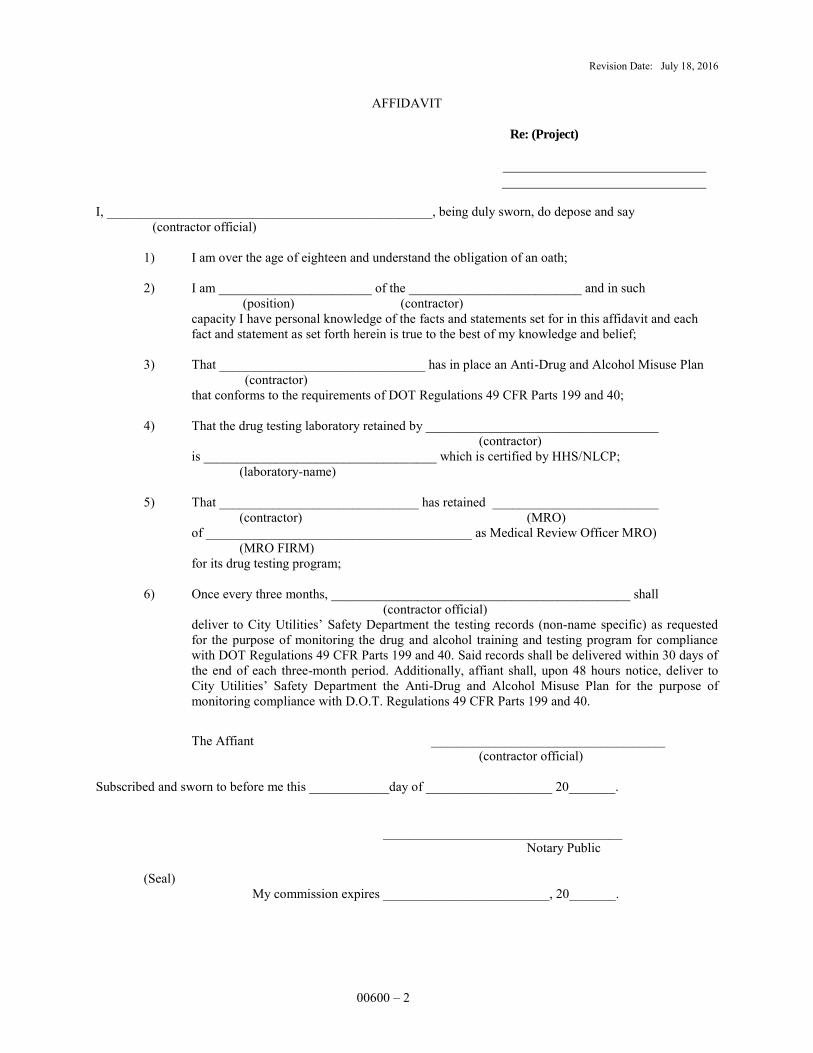
AFFIDAVIT
Re: (Project)
I, _________________________________________________, being duly sworn, do depose and say (contractor official)
1) I am over the age of eighteen and understand the obligation of an oath;
2) I am _______________________ of the __________________________ and in such (position) (contractor) capacity I have personal knowledge of the facts and statements set for in this affidavit and each
fact and statement as set forth herein is true to the best of my knowledge and belief;
3) That _______________________________ has in place an Anti-Drug and Alcohol Misuse Plan (contractor) that conforms to the requirements of DOT Regulations 49 CFR Parts 199 and 40;
4) That the drug testing laboratory retained by ___________________________________ (contractor)
is ___________________________________ which is certified by HHS/NLCP; (laboratory-name)
5) That ______________________________ has retained _________________________ (contractor) (MRO)
of ________________________________________ as Medical Review Officer MRO) (MRO FIRM) for its drug testing program;
6) Once every three months, _____________________________________________ shall (contractor official)
deliver to City Utilities’ Safety Department the testing records (non-name specific) as requested for the purpose of monitoring the drug and alcohol training and testing program for compliance with DOT Regulations 49 CFR Parts 199 and 40. Said records shall be delivered within 30 days of the end of each three-month period. Additionally, affiant shall, upon 48 hours notice, deliver to City Utilities’ Safety Department the Anti-Drug and Alcohol Misuse Plan for the purpose of monitoring compliance with D.O.T. Regulations 49 CFR Parts 199 and 40.
The Affiant ____________________________________________ (contractor official) Subscribed and sworn to before me this ____________day of ___________________ 20_______. ____________________________________ Notary Public (Seal)
My commission expires _________________________, 20_______.

Revision Date: July 18, 2016
00600 – 3
QUARTERLY REPORT OF DOT DRUG TESTING
Dates Covered Company Name By This Report
Number of Employees
tested
Date tested
Type of test
Results of test
Action taken if test was positive.
Average number of employees covered by Pipeline and Hazardous Materials Safety Administration (DOT pipeline safety standards) for this reporting period.
Number of blind samples submitted to testing laboratory for quality assurance if required.
SIGNATURE DATE
END OF SECTION
Revision Date: July 18, 2016
00820 – 1
SECTION 00820
GENERAL PROJECT REQUIREMENTS PART I GENERAL 1.01 Work includes, but is not limited to installation, relocation and/or retirement of gas and/or water
mains, services, and appurtenances. 1.02 It is the intent of this Contract for the Contractor to install the gas and/or water facilities to the full
extent as shown on the Drawings. It is the Contractor’s responsibility to build these same gas and/or water lines to meet or exceed the requirements of the U.S. Department of Transportation and/or Missouri Public Service Commission and/or Missouri Department of Natural Resources regulations and/or City Utilities’ Contract Documents, Technical Specifications, and Construction Standards, whichever is greater. Contractor shall make any minor changes in required fittings or in routing (horizontal or vertical) within the pipeline easements shown on the Drawings or within public rights-of-way as a result of field conditions at no additional cost to City Utilities. Some underground facilities are shown on the Drawings, but the Drawings may not accurately represent the locations of the underground facilities. There may be other underground facilities that are not shown on the Drawings. Contractor shall not use the Drawings to locate underground facilities. Contractor is responsible for locating all underground facilities in accordance with Section 01720.
1.03 NOTIFICATION AND CUSTOMER RELATIONS: Notify all residents affected by work done
under this Contract at least 48 hours, but no more than 7 days, prior to starting work in the affected area. Notification shall be of a form and format approved by the Inspector. Execute the work in a customer/neighborhood friendly manner. In addition, notify adjacent utility customers and property owners of proposed location of work equipment parked overnight and of proposed material storage areas and stockpiles of sand, gravel and dirt. Adjust parking and material storage to maximize customer satisfaction and to minimize traffic congestion.
1.04 PREQUALIFIED GAS AND WATER CONTRACTORS: All City Utilities gas and water utility installation shall be performed by a prequalified gas and/or water Contractor. Prequalified Contractor application forms can be obtained from City Utilities Purchasing Department at (417) 831-8679 or [email protected].
PART II MATERIALS AND EQUIPMENT 2.01 City Utilities shall provide the following water materials: HDPE pipe, ductile iron pipe, PVC pipe,
designed casing pipe, copper pipe, valves, valve boxes, pipe fittings, corporation stops, curb stops, brass adapters and connections, tracer wire, direct bury splice kits, solvent cement, solvent cleaner, joint lubricant, service saddles, meters, meter tiles and meter tile rings and lids unless otherwise specified in the Contract Documents.
2.02 City Utilities shall supply the following gas materials: steel pipe, polyethylene pipe, designed casing
pipe, valves, valve boxes, fittings, tracer wire, pressure control fittings, pipe coatings, cathodic protection materials, pipe dope and thread tape unless otherwise specified in the Contract Documents.
2.03 Contractor shall supply any other work materials and supplies as may be required. This would
include, but not be limited to: sand, chat or other granular fill material; paint; paint brushes; tools; concrete and forms; topsoil; fertilizer, mulch and grass seed; fencing materials; erosion control materials; skids; dunnage; and welding rod. When Contractor elects to install piping by means other than open trenching then Contractor shall supply casing pipe.
2.04 The Inspector will order materials from City Utilities’ Storeroom for Contractor as needed for the
project. Requests for materials should be submitted to the Inspector at least 24 hours in advance.
Revision Date: July 18, 2016
00820 – 2
2.05 Contractor shall pick up requisitioned materials at the City Utilities stores facility designated by the
Inspector. All materials for the project shall be picked up at one time. However, on larger projects Inspector may designate several pick-ups as the job progresses. Contractor shall provide adequate transportation and labor to load and receive materials, except that City Utilities will provide a forklift and operator as necessary to load heavier items. Contractor shall provide wood blocking, straps, tarps, etc. required for hauling the materials. Materials may be picked up from 9:00 a.m. to 3:00 p.m. Monday through Friday, except holidays.
2.06 Generally, most materials issued shall be new. However, City Utilities reserves the right to issue
used material which the Inspector has judged to be suitable for reuse. 2.07 All labor, tools, equipment and incidentals necessary to complete the work, as well as any materials
not specifically provided by City Utilities, shall be completely covered by the prices in the Bid. 2.08 Contractor shall be responsible for the material, and for the replacement of lost, broken or stolen
material. Contractor shall examine all material upon receipt, and by acceptance, certify suitability for use. Make objections to issued materials to the Inspector. Inspector will establish a reasonable allowance for pipe waste on each project.
2.09 Pick up items normally packaged in bulk quantities, such as coiled tracer wire, in such bulk
quantities. Unused quantities shall be returned to the stores facility by the Contractor or transferred to the next job as long as additional work continues. The Inspector will make appropriate requisitions, transfers and returns for each project.
2.10 Provide equipment and personnel to handle products by methods to prevent soiling or damage to
products or packaging. PART III EXECUTION 3.01 Store fabricated products above ground, on blocking or skids, to prevent soiling or staining. Store
loose granular materials in a well-drained area on solid surfaces. Arrange storage in a manner to provide easy access for inspection or inventory by either the Contractor or the Inspector.
3.02 Do not damage public or private property in handling or storage of materials. Do not hinder access
to fire hydrants, fire and police alarms, mailboxes, water valves, gas valves and manholes. Do not use private property for storage of materials without express written permission of property owner. Provide Inspector with documentation of permission to store materials.
3.03 Do not store any material, equipment, buildings, tools, vehicles or any other items owned by the Contractor on property owned by City Utilities except at the specific sites designated by the Inspector or as shown on the Drawings for storage and use by the Contractor. If no sites are designated, then the Contractor is responsible for locating and procuring any required site or sites.
3.04 Make periodic inspection of stored products to ensure that products are maintained under specific
conditions, and free from damage or deterioration. 3.05 Keep construction area as clean as possible. Control mud and dust to prevent customer
dissatisfaction and complaints. Do not allow mud and dirt to enter Storm Sewer system. Keep trash, containers, packaging materials, etc., picked up on a daily basis.
3.06 Coordinate driveway closures with property owners. Give all property owners 48 hours advance
notification prior to closing driveways.
Revision Date: July 18, 2016
00820 – 3
3.07 At the end of the project, return all excess and/or salvage materials (used or new) to the City Utilities stores facility designated by the Inspector in a form (broken down into stock item components) and conditions suitable to the Storekeeper.
3.08 Inclusive in the work is close coordination with all appropriate jurisdictional agencies. The
Contractor is responsible for determining paving requirements not specifically shown on the Drawings (temporary and permanent), construction standards, boring requirements, erosion and sediment control, traffic control and safety requirements of these agencies. No additional payment will be made for compliance to jurisdictional requirements. Contractor is responsible for coordinating the work as described herein.
END OF SECTION
Revision Date: July 18, 2016
00890 – 1
SECTION 00890
PERMITS PART I GENERAL 1.01 City Utilities will obtain railroad, Corps of Engineers, and MODOT permits. Contractor must obtain
all other necessary permits and comply with all codes of construction as required by Section 01410.
END OF SECTION
Revision Date: July 18, 2016
01110 – 1
SECTION 01110
WORK BY OTHERS
PART I GENERAL 1.01 City Utilities personnel shall operate all main line gas valves and perform all purging of gas mains. A
48-hour advance notification is required. 1.02 City Utilities personnel shall operate all main line water valves and provide labor and equipment
for disinfection, flushing and sampling of all water mains. Such work shall require a 48-hour advance notification.
1.03 City Utilities will provide equipment, materials and labor for completion of main size taps on
water mains unless otherwise specified in the Contract Documents (4” through 12” tap size). Such work shall require a 48-hour advance notification and will not be scheduled after 3:00 p.m. or outside normal working hours for City Utilities’ crews. Contractor shall dig and prepare excavation with appropriately safe shoring and traffic control as necessary. Contractor shall install tapping sleeve, valve and other fittings and provide hoisting equipment for installation and removal of tapping machine.
1.04 City Utilities will provide equipment, materials and labor for tapping gas mains unless otherwise
specified in the Contract Documents (sizes 2” through 12”, 150 psig maximum pressure). Such work shall require a 48-hour advance notification and will not be scheduled after 3:00 p.m. or outside normal working hours for City Utilities’ crews. Contractor shall dig and prepare excavation with appropriately safe shoring and traffic control as necessary. Contractor shall provide hoisting equipment for installation and removal of tapping machine.
1.05 City Utilities will provide equipment, materials and labor to perform all welding of steel gas pipes
unless otherwise specified in Attachment B, Special Conditions. Such work shall require a 48-hour advance notification and will not be scheduled after 3:00 p.m. or outside normal working hours for City Utilities’ crews. Contractor shall dig and prepare excavation with appropriate safe shoring and traffic control as necessary.
1.06 City Utilities will perform all work that involves modifying components in service regulators such
as orifice changes, etc. PART II MATERIALS NOT USED PART III EXECUTION NOT USED
END OF SECTION
Revision Date: July 18, 2016
01200 – 1
SECTION 01200
MEASUREMENT AND PAYMENT PART I GENERAL 1.01 Contractor shall furnish all labor, equipment, and necessary materials to accomplish the work as
designated in the Contract.
1.02 Contractor shall construct the work for the unit prices established in the Bid Form. Standard Bid Items include, but are not limited to, fittings, valves, excavation, backfill, lowering-in, tracer wire, warning tape, pressure testing, disinfection, connections to existing mains and services, fusion, minor piping adjustments, pavement restoration, landscaping, and retirement of old mains, services and hydrants. Non-standard Bid Items may be included on the bid form, in which case the work to be performed by the Contractor will be described in the Special Conditions. Any work not itemized on the Bid Form shall be considered part of and incidental to the gas and/or water Bid Items unless noted as an exception to the initial bid.
1.03 Any delay, additional work or extra cost to the Contractor caused by or resulting from damage to existing underground installations shall not constitute a claim by Contractor for additional payment or damages.
PART II STANDARD BID ITEMS 2.01 The following items represent the Standard Bid Items for City Utilities natural gas and water utility
construction projects. Bid items are to be installed as shown on the Drawings per the Technical Specifications and/or Construction Standards:
A. Install (Size & Material) Gas Main: This item covers the installation of gas main by an approved
method. Payment will be made for actual footage installed measured along the centerline of the pipe.
B. Install (Size & Material) Gas Main, Joint Trench: This item covers the installation of gas main
in a joint trench with another utility commodity. Payment will be made for actual footage installed measured along the centerline of the pipe.
C. Install (Size & Material) Gas Service: This item covers the complete installation of a gas service
by an approved method. Payment will be made for each service installed. Bid Item also includes installing a new riser and re-plumbing of customer’s exterior piping as needed. Any interior re-plumbing required will be paid separately or be handled by City Utilities.
D. Install (Size & Material) Gas Service Street Crossing: Item includes installation of and
connection to service tapping fitting on one end, and connection to gas service on the other. Payment will be made for each crossing installed. On long side services, Bid Items C and D are additive.
E. Tie-Over (Size & Material) Gas Service: This item covers the tie-over of an existing gas service to a new gas main. Payment will be made for each tie-over performed.
F. Install (Size & Material) Gas Main Spot Lowering: This item covers the lowering of an existing
gas main. Payment will be made for each lowering installed.
G. Install (Size & Material) Gas Service Spot Lowering: This item covers the lowering of an existing gas service. Payment will be made for each lowering installed.
H. Install (Size & Material) Water Main: This item covers the installation of water main by an
Revision Date: July 18, 2016
01200 – 2
approved method. Payment will be made for actual footage installed measured along the centerline of the pipe.
I. Install (Size & Material) Water Main, Joint Trench: This item covers the installation of water
main in a joint trench with another utility commodity. Payment will be made for actual footage installed measured along the centerline of the pipe.
J. Install (Size & Material) Water Service, Single Meterset: This item covers the installation of a
water service from the service tapping fitting or street crossing connection to the meterset. Payment will be made for each meterset installed.
K. Install (Size & Material) Water Service, Dual Meterset: This item covers the installation of
water services from the service tapping fitting or street crossing connection to the dual meterset. Payment will be made for each dual meterset installed.
L. Install (Size & Material) Water Service Street Crossing: Item includes installation of and
connection to service tapping fitting on one end, and connection to water service on the other. Payment will be made for each crossing installed. On long side services, Bid Items J or K and L are additive.
M. Install (Size & Material) Fire Service: This item covers the installation of a fire service to a new main. Payment will be made for each fire service installed.
N. Tie-Over (Size & Material) (Fire, Commercial, Domestic) Service: This item covers the tie-over
of an existing service to a new main. Payment will be made for each tie-over performed.
O. Install (Size & Material) Water Main Spot Lowering: This item covers the lowering of an existing water main. Payment will be made for each lowering installed.
P. Install (Size & Material) Water Service Spot Lowering: This item covers the lowering of an
existing water service. Payment will be made for each lowering installed. PART III EXECUTION 3.01 On a monthly schedule the Contractor is to submit requests for payment based on work completed.
The quantities shown on the Drawings and Bid Form are estimates only and no guarantees are given as to actual quantities.
3.02 Contractor shall deliver and unload all materials to job site without charge to City Utilities.
3.03 With final payment request, submit affidavit certifying compliance with wage rate determination. 3.04 Minor dimensional and routing changes are to be expected as part of the work. Changes in horizontal
and vertical dimensions as well as minor changes requiring additional fittings or additional depth shall not constitute sufficient grounds for extra payment other than for the additional footage or quantities as described in the Bid Items.
3.05 No payment will be made for mobilization and/or preparatory work unless specifically detailed in the Contract Documents.
END OF SECTION
Revision Date: July 18, 2016
01300 – 1
SECTION 01300 COORDINATION PART I GENERAL - This Section includes coordination of trades and coordination with Owner, other
contractors and jurisdictional agencies. PART II MATERIALS - NOT USED PART III EXECUTION 3.01 Coordinate the work of all trades under this contract. 3.02 Coordinate with existing operations on-site to access and use construction area during normal
working hours. 3.03 Coordinate all activities through the Inspector. 3.04 Coordination with Others: A. The Contractor, by agreeing to perform work under these Contract Specifications, hereby
certifies that he is able to furnish labor that can work in harmony with all other elements of labor employed or to be employed on the work.
B. Other Contracts may be awarded during this Contract Time. Some of these Contracts may
involve on-site activity which must be coordinated with this Contract. In addition, City Utilities crews may perform other work involving on-site construction which must be coordinated with this Contract.
3.05 Inclusive in the Work is close coordination with all appropriate jurisdictional agencies. No additional
payment will be made for compliance to jurisdictional requirements. Contractor is responsible for coordinating the Work as described herein.
3.06 Resolution of Disputes:
A. The Contractor and Inspector shall attempt to resolve all disputes. B. If resolution is not reached, the Contractor may request additional meetings with the
Resident Engineer. If a resolution is not reached, the Contractor may request to meet with City Utilities’ management. These meetings will be scheduled through the Resident Engineer.
C. In the event that the Contractor fails to satisfactorily resolve disputes or complete Work as
called for in the Contract, such unresolved disputes or unfinished work may be held as sufficient ground by City Utilities to refuse to enter into any future contracts with the Contractor.
END OF SECTION
Revision Date: July 18, 2016
01310 – 1
SECTION 01310
PROJECT PROGRESS MEETINGS PART I GENERAL 1.01 A pre-construction meeting shall be scheduled prior to start of construction on the project to discuss
any aspect of the prosecution of the work. 1.02 City Utilities or Contractor may at any time request a project meeting to discuss any aspect of work. 1.03 Contractor’s resident superintendent must be present at any and all meetings. PART II MATERIALS – NOT USED PART III EXECUTION – NOT USED
END OF SECTION
Revision Date: July 18, 2016
01330 – 1
SECTION 01330
SUBMITTALS
PART I GENERAL 1.01 As required by Resident Engineer, submit to City Utilities for approval a list of all materials
provided by Contractor to be installed on the Project. All natural gas piping and HDPE water piping will require a “Certificate of Quality” from the pipe manufacturer specific to that batch or ‘lot’ of pipe, if pipe is supplied by Contractor. All steel gas piping supplied by the Contractor shall require mill test reports to be supplied to City Utilities.
1.02 All material to be supplied by the Contractor that is not currently an approved brand shall require a submittal and prior approval by City Utilities. The current approved Material Specifications are located online at http://www.cityutilities.net/business/construction.htm. Materials supplied by
City Utilities will also conform to these Specifications. 1.03 Contact Resident Engineer about any questions regarding approved materials. PART II MATERIALS – NOT USED PART III EXECUTION – NOT USED
END OF SECTION
Revision Date: July 18, 2016
01350 – 1
SECTION 01350
ENVIRONMENTAL PROTECTION PROCEDURES
PART I GENERAL 1.01 Conduct all construction activities in conformance with all federal, state and local laws,
regulations and ordinances for the protection of the environment. 1.02 The work under this Contract may affect the City of Springfield’s drinking water supply. Under no
circumstances shall the Contractor or any of his subcontractors allow any debris, fuel, chemicals, liquids or other materials to enter this water supply through direct or indirect means. Contain and dispose of all materials by means acceptable to the appropriate jurisdictional agency. Have materials on-site for containment of spills such as hydraulic hose breaks, etc.
PART II MATERIALS 2.01 No hazardous or toxic materials will be allowed in any phase of the work. 2.02 Drilling mud used shall not be harmful to the environment and shall comply with all applicable
regulations. PART III EXECUTION 3.01 When required, the Contractor shall acquire a Land Disturbance Permit and provide a Storm
Water Pollution Prevention Plan (SWPPP) outlining the Best Management Practices (i.e. mulch logs, silt fences, etc.) that the Contractor is to carry out for the duration of the project.
3.02 Contractor shall comply with all requirements of the jurisdictional agency’s Land Disturbance
Permit and/or SWPPP, when applicable. 3.03 Contractor shall install and maintain Best Management Practices for stormwater sediment and
erosion control during construction in accordance with the appropriate jurisdictional agency’s construction standards. Best Management Practices shall also be utilized on projects when a SWPPP is not required.
3.04 All drilling mud shall be contained and reclaimed. Contractor is responsible for any spilled drilling
mud.
END OF SECTION
Revision Date: July 18, 2016
01410 – 1
SECTION 01410
REGULATORY REQUIREMENTS PART I GENERAL 1.01 Conduct all construction activities in conformance with all applicable Federal, State and local laws,
regulations and ordinances, including the Occupational Safety and Health Act of 1970 (OSHA) and applicable regulations of the Missouri Public Service Commission.
1.02 PERSONNEL QUALIFICATIONS
Any Contractor personnel performing a “Covered Task” as defined in the Missouri Public Service Commission Pipeline Safety Regulations, 4 CSR 240-40.030, Section 12(D) shall be appropriately Operator Qualified prior to performing such task. Contractors may be qualified through City Utilities Operator Qualification Plan or by submitting their own Operator Qualification Plan for approval. If the Contractor chooses to be qualified through City Utilities Operator Qualification Plan, City Utilities will perform the testing and evaluations. If the Contractor chooses to submit their own Plan, they must submit a written Operator Qualification Plan for evaluation that meets all Federal and Missouri Public Service Commission requirements. A. The Operator Qualification plan shall include at a minimum:
a. List and description of covered tasks covered by the Operator Qualification Plan. b. List and description of all training and evaluation modules that make up the full
qualification for each covered task. c. Listing of job classifications with accompanying covered tasks and qualification
modules. d. Description of the program under which employees are qualified and identification
of any third-party vendors utilized for training and testing.
B. Per the Plan, employee information is required to be submitted with the plan. At a minimum this shall include:
a. List of employees (including pictures) assigned to the project. b. Operator Qualification testing results for each employee assigned to the project. c. When and where each employee on the project was qualified and by whom. d. The expiration date of each current qualification for each employee assigned to the
project. e. List and description of covered tasks for which each individual is qualified.
This plan must be submitted to City Utilities and approved before any work may be performed. City Utilities reserves the right to deny any submitted plans and require an amended Plan to be resubmitted. Any Contractor personnel installing HDPE water main must have attended a fusion training course and be qualified by City Utilities prior to performing any fusion work on City Utilities water distribution system. City Utilities offers this training, or, Contractor may submit training and qualification records for their personnel to City Utilities for approval.
PART II MATERIALS – NOT USED PART III EXECUTION – NOT USED
END OF SECTION

Revision Date: July 18, 2016
01420 – 1
SECTION 01420
WATER AND NATURAL GAS CONSTRUCTION STANDARDS PART I GENERAL
Construction Standards may be found at http://www.cityutilities.net/business/construction.htm. Any other construction details otherwise encountered will be provided by the Project Manager. Copies of Construction Standards are available at City Utilities’ Gas and Water Operations Center, 1321 W. Calhoun. Construction Standards and other instructions specified in the Drawings shall be followed for all work on the project. City Utilities may make substitutions of equivalent materials or assemblies for those shown in the Construction Standards at no additional cost.
PART II MATERIALS - NOT USED PART III EXECUTION - NOT USED
END OF SECTION
Revision Date: July 18, 2016
01425 – 1
SECTION 01425
REFERENCES
PART I GENERAL 1.01 REFERENCES AND ABBREVIATIONS The latest edition of the following specifications covers certain materials and methods to be utilized
by the Contractor. Abbreviations as used in the Contract Documents mean the following: 1. AWWA: American Water Works Association 2. AGA: American Gas Association 3. AASHTO: American Association of State Highway & Transportation Officials 4. API: American Petroleum Institute 5. ASA: American Standards Association 6. DOT: United States Department of Transportation 7. AWS: American Welding Society 8. AREA: American Railway Engineering Association 9. ACI: American Concrete Institute 10. OSHA: Occupational Safety and Health Administration 11. ASTM: American Society for Testing and Materials 12. ANSI: American National Standards Institute 13. IEEE: The Institute for Electrical and Electronics Engineers 14. NACE: National Association Corrosion Engineers 15. MANGO: Missouri Association of Natural Gas Operators 16. NESC: National Electric Safety Code 17. PPI: Plastic Pipe Institute 18. DIPRA: Ductile Iron Pipe Research Association 19. UNIBELL: PVC Pipe Association 1.02 REFERENCES AND DATES All standard references apply to the most current versions of these standards except where noted.
END OF SECTION
Revision Date: July 18, 2016
01450 – 1
SECTION 01450
CONTRACTOR’S QUALITY CONTROL
PART I GENERAL 1.01 The Contractor's Resident Superintendent, to the extent qualified, may be used for quality control,
supplemented as necessary by additional personnel for surveillance, special technicians or testing facilities to provide capability for the controls required by the Specifications.
PART II MATERIALS - NOT USED PART III EXECUTION 3.01 Provide for inspection of all work to ensure that materials and supplies are placed and installed in
accordance with the Drawings and Specifications. Do not build upon or conceal any feature of work containing uncorrected defects.
END OF SECTION

Revision Date: July 18, 2016
01460 – 1
SECTION 01460
INSPECTIONS
PART I GENERAL 1.01 All work is subject to inspection, examination or test, at any time by the Resident Engineer. 1.02 The Inspector shall be the designated representative of the Resident Engineer. 1.03 The Resident Engineer and Inspector have the right and authority to determine whether the work is
being done in accordance with the requirements of the Contract Documents, Drawings and Specifications.
PART II MATERIALS - NOT USED PART III EXECUTION - NOT USED
END OF SECTION
Revision Date: July 18, 2016
01525 – 1
SECTION 01525
FIELD OFFICES AND SHEDS
PART I GENERAL 1.01 The Contractor is responsible for supplying all of the facilities needed for the successful completion
of the job. Maintain all working, storage and parking areas in a neat and orderly manner. 1.02 Obtain and maintain all utility services needed during construction. 1.03 FIELD OFFICES AND SUPERVISION No field offices will be required unless otherwise specified in the Contract Documents. Provide
Inspector with telephone numbers at which Contractor and his Resident Superintendent may be contacted at any time. Designate a minimum of two people as after hour contacts.
PART II MATERIALS AND EQUIPMENT 2.01 Furnish storage space, sanitary facilities, trash disposal and utilities. 2.02 The Contractor will be responsible for access to and from the site without causing damage to any
adjacent facilities or surrounding land. 2.03 Provide gate locks to interlock with City Utilities’ locks, if applicable. If locks are inappropriately
secured prohibiting City Utilities access, they will be forcibly removed. PART III EXECUTION 3.01 Workers’ vehicles are to be parked legally in an area designated by the Contractor. 3.02 Upon completion of the project, remove all traces of temporary facilities. Fill all disturbed grass
areas, grade and seed in conformance with Section 02900. 3.03 Maintain the continuity of security systems. 3.04 Upon completion of project, remove all traces of temporary utilities unless instructed otherwise by
the Inspector.
END OF SECTION
Revision Date: July 18, 2016
01720 – 1
SECTION 01720
FIELD ENGINEERING PART I GENERAL 1.01 This section includes requirements for surveying and job layout. PART II MATERIALS - NOT USED PART III EXECUTION 3.01 The Contractor is solely responsible for locating all existing underground installations including,
without limitation, service connections, in advance of excavating or trenching, by contacting the owners thereof, prospecting, and the use of the Missouri One-Call System and other appropriate locating services. The Contractor shall use its own information and shall not use the Drawings to locate underground facilities, since they may not accurately represent the locations of underground facilities or even the existence of all underground facilities. Contractor shall use all reasonable means necessary to avoid damage to underground facilities including, without limitation, hand-digging.
3.02 Damages to existing City Utilities gas or water mains should be reported to the Inspector, 911, and
City Utilities central dispatching (417) 863-9000. City Utilities will repair all gas and water lines broken by tear-out, poor construction, blasting or any other reason due to the construction of these facilities. City Utilities crews will not perform service or meter box relocation work for the Contractor.
3.03 Contractor may elect to temporarily disconnect gas or water service lines during the course of the
project to facilitate the installation of new mains. Notification shall be given to all customers affected as described in Sections 2515 and 2550. Customers shall be reinstated the same day to minimize disruptions. Some critical customers who may require water for life support, dialysis, etc. may not be able to be disconnected. If Contractor elects to temporarily disconnect the gas or water service lines, the fittings necessary to perform that work shall be supplied by the Contractor and approved by the Resident Engineer.
3.04 When blasting is to be performed, Contractor shall notify City Utilities 24 hours in advance so that the Inspector may be present to inspect gas and water facilities and arrange for a gas and water leak survey prior to blasting.
3.05 Instructions for Utility Staking
A. GENERAL
1. City Utilities will provide construction surveying and staking for contracted work directly issued by City Utilities. All surveying and staking shall be performed under the direct supervision of a Professional Land Surveyor. The Surveyor shall set all property corners and stake the limits of any easements where utilities are to be installed. The Surveyor shall layout the construction site prior to the start of work and provide staking for all utility installations. The work shall consist of physically marking and placing stakes necessary for the Contractor to properly install utilities in accordance with the Drawings. After initial construction staking has been completed by City Utilities or its agents, it shall be the responsibility of the Contractor to protect the integrity of the construction stakes. If the construction staking is disturbed or destroyed during construction, the Contractor shall be responsible for any fees incurred by City Utilities for re-staking the remaining work to be completed.
Revision Date: July 18, 2016
01720 – 2
2. For work not directly issued by City Utilities, construction surveying and staking shall be performed as described in the following paragraphs.
B. OFFSETS – DEPTH
1. Stake all utilities as shown on the project drawings with offset staking at 50’ intervals. Offset stakes shall be set at nearest R/W or easement line to main but no less than 6 feet off centerline and perpendicular to line at points where the line changes direction. Centerline shall be staked at 50’ intervals to correspond with offset stakes. Stakes shall also be placed and appropriately marked at all valves, fire hydrants, tees, taps, meter pit locations, property corners on main sides, lateral/street crossing locations, easement lines and as needed to insure inter-visibility along long runs of main or rough terrains.
2. All cuts shown on stakes are to be to bottom of trench from existing grade at base
of offset stake. Necessary cuts shall be calculated based on required cover over gas/water main when site is finished grade. Cover is 3’-0” for electric conduit. On joint trench installations, the required cover for water mains shall be used to determine the necessary cut.
C. CENTERLINE STAKING
1. Water main stakes shall be marked “Centerline Water” on one side and tie with
blue flagging. 2. Gas main stakes shall be marked “Centerline Gas” on one side and tie with yellow
flagging.
3. Electric conduit sakes shall be marked “Centerline Electric” on one side and tie with red flagging.
D. OFFSET STAKING
1. Offset stakes shall have the offset distance in a circle and the word Water, Gas, or
Electric marked on the front side with the cut. Backside of stake is to show the station (if applicable). All cuts will be figured from the ground elevation at the base of the offset stake unless otherwise directed by City Utilities. Tie the flagging colors as per Centerline Staking.
E. LATERALS
1. Laterals shall be staked at the tee and at the end point of the lateral. Offset stakes shall be set at both ends of the lateral. Gas lateral end points will be staked one foot (1’) behind the designed curb on the opposite side of the street from the main. Water lateral end points will be staked two feet (2’) behind the designed curb on the opposite side of the street from the main. The stakes will be marked “Gas Lateral” or “Water Lateral” and tied with respective flagging color. Taps for laterals will be staked on the centerline of the main and marked “Gas Tap” or “Water Tap” and tied with respective flagging color. Offsets will be required on the tap.
F. FIRE HYDRANTS
1. Fire hydrants are to be staked 6 inches off the right-of-way line unless otherwise dimensioned on drawing. The backside of the stake shall be marked “Fire Hydrant.” The front side of the stake will have a cut to the bottom of the trench,
Revision Date: July 18, 2016
01720 – 3
and a cut or a fill to the finish grade at that point. This cut or fill will coincide with the bury line on a fire hydrant. Two offset stakes will also be set on property line/right-of-way, 10 foot either side of fire hydrant stake.
G. ELECTRICAL JUNCTION ENCLOSURES, TRANSFORMERS AND SECONDARY
PEDESTALS
1. Unless otherwise noted, stake electrical junction enclosures, transformers, secondary pedestals and streetlights as shown on the applicable underground distribution standard drawing.
H. CUT SHEETS
1. Cut Sheets shall be kept on all construction staking and copies must be furnished to the City Utilities’ Inspector upon request.
I. CONSTRUCTION STANDARDS
1. See Construction Standards for additional utility staking information.
2. Where gas and water mains and electric conduit are placed such that finished grade elevation will be higher than the paralleling centerline of street elevation, the utilities shall be installed below the street centerline elevation at the depths specified in the Construction Standards unless otherwise noted.
END OF SECTION
Revision Date: July 18, 2016
01770 – 1
SECTION 01770
CONTRACT CLOSEOUT
PART I GENERAL 1.01 Prior to City Utilities making final payments a continuous signal must be verified on the tracer wire. 1.02 Within 14 days after Substantial Completion of construction, City Utilities shall notify the Contractor
in writing (i.e. punch list) of any defects or defaults in performance which may have been discovered upon final inspection. The Contractor shall remedy promptly all such defects or defaults before the Construction Project shall be accepted by City Utilities.
1.03 In the event the Contractor fails to remedy such defects or defaults within 30 days after notification,
City Utilities may elect to correct these defects or defaults and deduct the cost of such corrections from any reimbursements due the Contractor, or may bill the Contractor for such corrections. In addition, the Contractor shall be removed from the list of City Utilities approved Contractors for a period of not less than one year from date of completion of project on which deficiencies occurred.
PART II MATERIALS - NOT USED PART III EXECUTION 3.01 Completely remove all traces of equipment, excess materials and debris from the site after all
punchlist items have been completed, inspected and approved by Inspector. 3.02 Clean-up site to Inspector’s satisfaction and leave site as good as or better than original conditions.
END OF SECTION

Revision Date: July 18, 2016
02220 - 1
SECTION 02220
DEMOLITION AND CLEARING
PART I GENERAL 1.01 DESCRIPTION: Work includes, but is not limited to: A. Removal of designated items.
B. Protection of items not designated to be removed.
C. URBAN FOREST MANAGEMENT POLICY In an effort to responsibly manage the urban forest, guide all work performed under this Contract to reduce damage to any trees. Perform all work in accordance with the guidelines in the booklet "Trenching and Tunneling Near Trees - A Field Pocket Guide for Qualified Utility Workers." Copies of this booklet are available for inspection at City Utilities Forester located at 828 N. Prince Lane, Springfield, MO. Copies are also available from the National Arbor Day Foundation, 100 Arbor Avenue, Nebraska City, NE 68410.
PART II MATERIALS - NOT USED PART III EXECUTION 3.01 CONSTRUCTION LIMITS
Inspector will establish the construction limits and designate items to be removed, and may designate items to remain.
3.02 REMOVAL OF ITEMS
A. Completely clear, grub and remove tree stumps, brush, hedge and other items within the
construction limits not designated to remain.
B. Existing structures, including, but not limited to, pavement, curbs, sidewalks or other similar objects where portions of these objects are to be left in place, shall be removed to an existing joint or a new joint sawed to a minimum depth of one inch with a true line and vertical face.
C. Completely remove and dispose of all debris.
D. All concrete, masonry, drainage pipes, reinforcement steel, structural steel, castings,
timbers, or other materials not salvageable shall be disposed of by the Contractor at his own expense. Contractor shall provide disposal location for all materials and obtain written approval from property owners for material deposited on private property. Submit written approval of the property owners to the Inspector.
3.03 PROTECTION OF REMAINING ITEMS
A. The Inspector may designate existing above-ground structures, trees, shrubs and plants that are to remain. Contractor shall preserve without damage these items throughout the construction period.
B. Contractor shall make temporary fence closures during construction and restore fences to
original condition or better upon completion of the work.
Revision Date: July 18, 2016
02220 - 2
C. Contractor shall protect and restore ornamental trees and shrubs.
END OF SECTION
Revision Date: July 18, 2016
02315 – 1
SECTION 02315
EXCAVATION AND BACKFILLING FOR PIPING
PART I GENERAL 1.01 DESCRIPTION: Work includes, but is not limited to the following as they apply to all gas and
water mains, services, and casing piping: A. Trenching and trench backfilling. B. Blasting and rock excavation. C. Rough and finish grading. D. Furnishing and installing granular fill. 1.02 REGULATORY COMPLIANCE
All excavation and backfill is subject to regulations and permits of appropriate jurisdictional agencies.
PART II MATERIALS AND EQUIPMENT 2.01 FILL MATERIAL
All fill material shall conform to City Utilities’ Construction Standards and is subject to approval of the Inspector.
2.02 BACKFILL IN NON PAVED AREAS
A. Other than pipe bedding, backfill with suitable materials excavated from trench and processed as required, or borrowed from locations arranged and paid for by Contractor. Material shall be free from organic matter, refuse, ashes, cinders or other unsuitable materials, and shall not be frozen. Materials shall be free from gravel, stone or shale particles greater in any dimension than four inches for the first foot of backfill above the pipe embedment material to establish a clear zone. Backfill above the clear zone may have materials up to a maximum of twelve inches in any dimension. As an alternate to the clear zone requirement, Contractor may elect to provide an additional six inches of sand over and above the requirements called for in the Construction Standards. Backfill material shall contain sufficient fines to provide a dense mass capable of being compacted.
B. Casing piping installed by open trenching shall be bedded and backfilled with select
backfill.
2.03 BACKFILL IN PAVED AREAS
A. Other than pipe bedding as called out in the applicable Construction Standards, backfill trenches in designated area with granular material that meets the appropriate jurisdictional agency’s requirements.
B. Casing piping installed by open trenching of roadways shall be bedded and backfilled full
depth with granular material meeting the specifications of the appropriate jurisdictional agency.
Revision Date: July 18, 2016
02315 – 2
C. This material will be required under sidewalks, existing paved areas, proposed paved areas, unpaved “driven-over” areas utilized as drives or parking lots, and as necessary on excavations paralleling proposed or existing streets and drives to avoid settlement of curbs or paving.
D. When flowable fill is required, gas or water lines shall be covered with a protective rock
shield.
2.04 PIPE BEDDING MATERIALS
A. Bed all gas mains, water mains, gas services, and water services in accordance with the Construction Standards.
PART III EXECUTION 3.01 TRENCHING
A. Centerline: Maintain centerline of the trench in a straight line with minimum bends or changes in direction. When trenching in pavement, saw cut the pavement in a straight line on both sides of the future excavations.
B. Length: Minimize the amount of open trench length at any time on the same street. Fill
trenches as soon as practical after pipe is placed in the ditch and placement and bedding is approved by the Inspector. Coordinate closing of driveways with the individual property owners. Provide adequate access to all businesses during their operating hours.
C. Width: Maintain width of trench ample to permit pipe to be laid and jointed properly,
and backfill to be placed and compacted as specified in accordance with applicable construction standards.
D. Depth: Depth shall be as shown in Construction Standards, unless otherwise indicated on the Drawings. Measurements shall be made from the low side of the trench. Areas where design depth differs from standard depth will be noted on construction Drawings however minor deviations in grade are to be expected in order to avoid other infrastructure and shall not constitute as additional work or payment due the Contractor.
Gas Services on Private Property: Provide a minimum of 18 inches from the top of the pipe to existing grade unless service is inserted in existing steel service line. Maintain 12 inches minimum cover over inserted steel lines verified as described in gas piping section.
Extra depth ditch may be required to route under existing obstructions. No extra payment will be made for extra depth ditch due to these obstructions.
Where gas and water mains are placed such that finished grade elevation will be higher than the paralleling centerline of street elevation, the utilities shall be installed below the street centerline elevation at the depths indicated in the constructions standards unless otherwise noted on the construction Drawings.
Where crossing roadways, piping shall be installed as required by the jurisdictional agency’s permit.
E. Adjacent Structures, Water, Sewer, Gas Line and Telephone Cable Crossings:
1. Follow such method of course as may be approved by the Inspector in passing
all underground structures.
Revision Date: July 18, 2016
02315 – 3
2. Exercise extreme care in crossing or paralleling water, sewer, gas lines and
telephone cables. Cross or parallel all structures at Contractor’s sole risk and responsibility. Should any damage occur to such lines, Contractor is fully liable and will pay full cost of repairing same.
3. Make all arrangements and pay for relocation and bracing where poles or
anchors are affected by the trenching operation.
F. Foundation for Pipe:
1. Grade the trench bottom as required to achieve uniform and continuous bearing and support for the pipe on solid and undisturbed earth free from rocks and other obstructions that could cause point loads throughout the length of pipe. Finish subgrade to a straight line between pipe joints.
2. Place, grade and compact to a uniform depth a minimum of six inches of
specified bedding material in the ditch bottom prior to placing any pipe in the ditch.
3. Where trench excavation is inadvertently carried below specified grade, backfill
with approved trench excavated material in 6-inch lifts compacted to provide a firm and unyielding subgrade.
4. Where the bottom of trench at subgrade is found to be unstable or include ashes,
cinders, refuse or other organic material, excavate and remove such unsuitable material and fill according to Item 3, above.
G. Trench Bracing and Shoring: Support all trenches in accordance with all pertinent and
applicable codes, rules and regulations.
H. Protect the public from any excavations left open during times when Contractor is not working.
3.02 SPOIL AREAS
A. Store no spoil off the right-of-ways or easements unless prior written permission has been obtained from the property owner and a copy of said agreement provided to the Inspector.
B. Locate and maintain off-site spoil areas for excess excavated materials. Restore these
areas to satisfactory condition before final payment is approved. Provide a certificate of acceptance from the owner of the spoil area to the Inspector.
3.03 PIPE BEDDING Pipe bedding shall conform to all applicable Construction Standards. 3.04 BACKFILL AND COMPACTION
A. Do not backfill trench until work is inspected and approval to proceed with backfill has been given by the Inspector. Complete backfilling promptly after approval to proceed.
B. Place material in six inch lifts and compact as necessary to avoid settlement of ditch line.
Fill any settled areas for a period of one year after date of acceptance by City Utilities. Restore surface as needed.
Revision Date: July 18, 2016
02315 – 4
3.05 ROCK EXCAVATION
A. All blasting is performed at the Contractor’s sole risk. The Contractor is solely responsible for any and all damages caused by blasting to any adjacent structure or any other underground facilities. If damage does occur to any above or below ground facilities, including other City Utilities facilities, the Contractor is fully liable.
B. All excavation is considered unclassified. Presence of rock shall not relieve Contractor of
depth requirements given in paragraph 3.01. There shall be no change in the Contract Price due to rock, regardless of type or hardness unless provided for in the Bid Documents.
C. In high hazard areas, remove rock by jackhammering as necessary. Make determination
of whether or not rock can be blasted, but Contractor shall be fully liable for any damages.
D. Perform all blasting in accordance with the City of Springfield’s General Ordinance
#4714, even for areas outside the jurisdiction of the City of Springfield. Only persons holding blasting licenses as issued by the Springfield Fire Department may perform blasting. Contractor must present areas desired to be blasted to Resident Engineer for prior approval. Upon approval contractor must obtain any necessary blasting permits and submit a copy to the Resident Engineer.
3.06 OPEN CUTTING ROADWAYS
Open cut roadways only as approved by the governing authority. If approval to open cut is not received, crossing must be installed using approved trenchless methods.
3.07 TRAFFIC CONTROL
Control traffic in accordance with the latest edition of the Manual on Uniform Traffic Control Devices and with the approval of the jurisdictional agency.
END OF SECTION
Revision Date: July 18, 2016
02320 – 1
SECTION 02320
UTILITY CASINGS
PART I GENERAL 1.01 SUMMARY
A. This section applies to casing pipe installed by tunneling or trenching. B. Casings for Gas and Water lines shall be installed per applicable Construction Standards.
1.02 REFERENCES
A. Applicable Standards:
1. American Petroleum Institute (API)
a. API 1104 – Standard for Welding Pipelines and Related Facilities b. API RP 1102 – Standard for Steel Casings
2. American Society for Testing and Materials (ASTM)
a. A36 – Structural steel b. A570 – Hot-rolled carbon steel sheet and strip, structural quality
3. American Water Works Association (AWWA)
a. C206 – Field welding of steel water pipe
4. Steel Structures Painting Council (SSPC)
a. SP-3 – Power tool cleaning
1.03 SUBMITTALS
If Contractor is supplying materials, submit shop drawings for proposed casing spacers and other items specified by Resident Engineer for approval prior to shipment.
PART II PRODUCTS 2.01 MATERIALS
All materials shall conform to current City Utilities Specifications. HDPE 4710 DR 11-13.5 black with yellow stripes gas piping that meets ASTM D2513 is permissible for use as casing.
PART III. EXECUTION 3.01 INSTALLATION
A. All work shall, as a minimum, meet the requirements of API RP1102, the highway, railroad or utility having jurisdiction and shall be subject to their inspection and approval.
B. Casing pipes installed by tunneling shall conform to the following requirements and
Section 02410:
Revision Date: July 18, 2016
02320 – 2
1. Casings rejected due to misalignment or other failures to conform to
specifications shall be abandoned in place. The ends of the abandoned casing shall be capped or plugged to provide a tight seal. Casing pipe shall not be recovered for reuse.
2. Casing spacers are not required when installing polyethylene gas or water pipe
in a polyethylene casing unless called for on the Drawings.
C. Casing pipes installed by open cut shall conform to the following requirements and Section 02315:
1. Bottom of casing may be installed on graded, compacted earth or gravel
bedding.
D. Joints
1. All joints along pipe casings shall be joined to conform with the requirements of Sections 02510 and 02550. Contractor personnel will not be required to be qualified for joining casing piping.
3.02 GROUTING
A. Where voids are present the casing pipe shall be grouted per the appropriate jurisdictional requirements.
END OF SECTION
Revision Date: July 18, 2016
02410 –1
SECTION 02410
TUNNELING
PART I GENERAL 1.01 DESCRIPTION
Includes augering, boring, driving, drilling, pipe bursting, moleing or other methods approved by Resident Engineer.
1.02 INSTALLATION
A. Any gas pipe installed by tunneling shall either be encased in a steel casing or sleeved in polyethylene gas pipe according to Construction Standards, except as noted in Item B.
B. Only steel gas pipe with polymer concrete coating over fusion bonded epoxy coating with
‘Powercrete’ coated joints may be installed uncased as described in the Construction Standards. Manufacturer’s cure times on field applied coatings shall be strictly adhered to.
C. All water pipe intended to be cased shall be noted on the Drawings and shall be installed
according to the Construction Standards.
D. Optional Casing Installations: In locations where tunneling is not required by the Contract Documents, Contractor may elect to tunnel gas or water lines, to avoid surface restoration, but only with Resident Engineer’s approval. No extra payment will be made for such tunneling and Contractor shall supply or reimburse City Utilities for supplying additional casing materials.
PART II MATERIALS AND EQUIPMENT 2.01 Drilling Fluids: All drilling fluids must be environmentally acceptable and shall be completely
contained throughout the drilling process. PART III EXECUTION 3.01 DIAMETER OF TUNNEL EXCAVATIONS
A. Perform all directional drilling in accordance with ASTM F1962 and PPI standards.
B. Maintain diameter of tunnel excavations large enough to allow insertion of the pipe without causing damage to the pipe. Diameter of tunnel excavation shall minimize the amount of annular space between the excavation and the piping.
C. Maintain diameter of tunnel excavation no more than 2 inches greater than the size of the
pipe except 1 ¼” and smaller pipe may be inserted in a 4” tunnel excavation or otherwise approved by Resident Engineer.
3.02 GENERAL TUNNELING SPECIFICATIONS
A. Tunnel depth shall be at standard depth to the top of casing pipe unless more cover is required by governing jurisdictional agencies, unless otherwise noted on the Drawings.
B. Establish initial angle of tunnel excavation to maintain design depth throughout the
tunnel excavation.
Revision Date: July 18, 2016
02410 –1
C. In the event of unforeseen deflections encountered during the tunnel excavation, a
vertical upward deflection of up to six inches, vertical downward deflection of up to 24 inches, and lateral deflections up to 18 inches are allowed, provided there is no conflict with existing or proposed facilities. Deflections greater than this are unacceptable, and will require reboring or trenching to the appropriate depth.
D. During directional drilling, the boring head shall be located utilizing underground
locating equipment capable of pinpointing the drill head. This shall be done at least once for every ten feet of drilling length in both the horizontal and vertical directions and provided to Inspector in writing.
E. Contractor shall ensure sanitary sewer main and lateral crossings are not damaged by
exposing them during the tunneling process or by video camera inspection after tunneling is complete. Contractor shall also take precautionary measures to avoid damaging all other foreign line crossings (stormwater, telephone, fiber optic, etc.). Contractor shall be responsible for the repair of any damage made to existing facilities.
F. Piping installed in tunnel excavation shall be pulled back in one continuous section, as
one continuous operation unless otherwise directed by Resident Engineer. G. Contractor shall utilize a swivel or other means to minimize rotation of the pipe during
pullback. H. Contractor shall provide adequate support rollers for the pipe during pullback. Rollers
and cradles shall be of a type to prevent damage to the pipe and coating and of sufficient number to prevent overstressing of the pipe due to sag bends during pullback.
I. In the event the Contractor must abandon the tunnel excavation before completion of the
full excavation, the Contractor shall seal the hole per the appropriate jurisdictional agency’s guidelines. The Contractor shall then complete a new tunnel excavation at no extra cost to City Utilities.
J. Observe the bend radius of the piping being installed per the applicable Construction
Standards and manufacturers recommendations. K. Tracer wire shall be attached to the pull head of the drilling rig and be installed with all
gas and water piping. Wire used is to be in accordance with the applicable Construction Standards.
L. When pulling polyethylene gas or water piping the Contractor shall not exceed the
allowable tensile load values for safe pullback in accordance with ASTM F1804. Contractor shall use a weak link to prevent over-stressing the pipe during pullback. A mechanical break-away connector or a one foot section of smaller SDR or diameter plastic pipe placed between the pull head and leading edge of the pipe are acceptable weak links. Below are approximate values for safe pull forces for PE4710 and PE2708 1-12 Hour Pulls.

Revision Date: July 18, 2016
02410 –1
PE 4710 1-12 Hour Pulls at 73°F* Safe Pull Force (lbs)
Size (in) SDR 11 SDR 13.5 SDR 17 1 597 - - 2 1,947 - - 4 - 6,602 - 6 16,440 13,644 - 8 28,282 23,471 - 12 60,167 49,933 - 16 104,547 86,764 - 18 - - 87,961
*See Service Temperature Design Factors for temperatures over 80°F
Service Temperature Design Factors for PE 4710 Service Temperature Safe Pull Force Multiplier
≤ 80 F 1.00 ≤ 90 F 0.90
≤ 100 F 0.80 ≤ 110 F 0.71 ≤ 120 F 0.63 ≤ 130 F 0.57 ≤ 140 F 0.50
PE 2708 1-12 Hour Pulls Safe Pull Force (lbs)
Size (in) ≤ 73°F ≤ 100°F ≤ 120°F ≤ 140°F 0.75 282 257 208 178 1.25 769 700 568 485
2 1,446 1,316 1,068 912 4 5,194 4,725 3,836 3,276 6 11,258 10,241 8,314 7,101 8 19,082 17,357 14,091 12,036
M. When polyethylene pipe is being installed, an additional 5% pipe length shall be installed
at the entry and exit points to allow for relaxation due to temperature. MDPE and HDPE expansion/contraction according to PPI TR-21 handbook are expected to be 1.1 inch per 100 feet per 10 degrees temperature change. Allow piping to achieve the same temperature as the ground to counter act pipe creep prior to making tie-ins at the ends of the piping. The typical relaxation time should be twenty four hours.
END OF SECTION

Revision Date: July 18, 2016
02510 – 1
SECTION 02510
WATER PIPING
PART I GENERAL 1.01 DESCRIPTION Includes, but is not limited to, installation of water mains, including pipe, valves
and fittings. Also includes retirement of mains and service tie-overs as shown on the drawing. 1.02 RELATED WORK DESCRIBED ELSEWHERE:
A. Work by Others, Section 01110.
B. Field Engineering, Section 01720.
C. Demolition and Clearing, Section 02220.
D. Excavation and Backfilling, Section 02315.
E. Utility Casings, Section 02320.
F. Tunneling, Section 02410.
G. Disinfection and Testing, Section 02515.
H. Paving and Surfacing, Section 02700.
I. Concrete, Section 03300. 1.03 PRODUCT HANDLING
A. Use all means necessary to protect the material before, during and after installation.
1. Handle pipe with padded forklifts, wide non-abrasive slings, padded clamps or padded pipe hooks. Pipe must be secured so that it cannot fall while being handled. Conventional chains, chain hooks and non-padded forklifts are expressly forbidden.
2. All coated steel pipe and fittings shall be stored off the ground on wooden
pallets or skids.
3. Contractor is responsible for all dents, gouges, coating defects and/or dimensional variations.
B. In the event of damage, Contractor shall immediately make all repairs and replacements
to the approval of the Inspector. PART II MATERIALS AND EQUIPMENT 2.01 All materials will conform to City Utilities material Specifications unless otherwise indicated on
the Drawings or in these Specifications.
2.02 INSTALLATION IN CONTAMINATED AREAS A. When contaminated soils are encountered unexpectedly, Contractor shall immediately notify
Resident Engineer. Engineer may require additional precautions to protect water quality.
Revision Date: July 18, 2016
02510 – 2
2.03 All valves shall be of open right (clockwise) design. 2.04 Ductile iron valves and fittings have a protective coating that shall be protected to minimize
damage. Exterior coating defects shall be repaired with petrolatum wax tape.
PART III EXECUTION 3.01 INSTALLATION – GENERAL
Install pipe in strict accordance with the manufacturers’ installation instructions and laying schedules. Run true to grade and alignment as shown on the Drawings with fittings and valves at the required locations. Match and make connections to existing fittings at the points of termination of the piping system. Make tie-ins onto existing live water mains under the supervision of the Inspector using approved equipment and materials. Do not operate any valves, blowoffs or similar equipment on the existing water system of City Utilities without prior approval by the Inspector.
3.02 INSTALLATION METHODS
Install pipe by trenching as specified in Technical Specifications, Section 02315, by tunneling as specified in Section 02410, and/or by casing as specified in Section 02320.
3.03 PIPE CLEANING AND PREPARATION
A. Thoroughly clean and inspect all pipe and fittings for damage before placing in the trench. If damage to pipe is found during inspection, repair or replace the pipe as directed by the Inspector.
B. Prevent foreign material from entering the pipe while it is being installed. Allow no debris, tools, clothing or other materials in the pipe.
C. When pipe laying is not in progress for an extended period of time such as nights and weekends, close the open ends of pipe with a water tight plug. If water is in the trench, the seal shall remain in place until the trench is pumped completely dry. Chlorine tablets may be added to the ditch water per AWWA C651 to avoid additional contamination as further described in Section 02515. Do not use hypochlorite intended for use in swimming pools. Do not lay pipe in water or when trench conditions are unsuitable.
3.04 REPAIR OF COATING
In case of damage to the protective coating or lining of ductile iron pipe, repair the pipe in accordance with AWWA C104. Repair of coating damage to epoxy coated surfaces shall be made with petrolatum wax tape.
3.05 PIPE SUPPORT AND EMBEDMENT
Support the barrel of the pipe by the granular leveling course with bell holes excavated for the bell end. Having so supported the pipe, embed it with granular material after joining pipe.
Revision Date: July 18, 2016
02510 – 3
3.06 JOINING PIPE A. Push-on Joints – In accordance with manufacturers recommendations, lay pipe with bell
ends facing in the direction of laying unless directed otherwise by the Inspector. After placing a length of pipe in the trench, clean and lubricate the gasket and gasket groove. Center the spigot end in the bell. Force pipe home giving care to not over-bell the pipe, and bring to correct line and grade. Prevent dirt from entering the joint space.
B. Threaded Joints - Pipe dope or thread tape shall be applied to the threads prior to joining.
Threaded joints are only to be used on 2” and smaller water lines. C. Compression (Pack or Mechanical) Joints - Install and tighten compression fittings per
manufacturer’s instructions. D. Flange joints - Assemble joints above ground and lower into trench, unless otherwise
acceptable to the Inspector. Tighten bolts per manufacturer’s instructions. E. Solvent Cement Joints - Shall not be used unless indicated on the Drawings. F. Restrained Joints - Install per manufacturer’s instructions and as detailed on the
Drawings.
G. HDPE connections – Join HDPE pipe per ASTM F2620 and Plastic Pipe Institute (PPI) TR-33/2006 “Generic Butt Fusion Joining Procedures for Field Joining of Polyethylene Pipe” www.plasticpipe.org.
Butt fusions are the preferred method of joining with electro fusion and socket fusion also permissible when joining HDPE to HDPE. Data loggers shall be used when performing butt fusions with a hydraulic machine. City Utilities Inspector will provide the data logger. Hydraulic butt fusion equipment shall be McElroy or pre-approved equal. When equipment other than McElroy is proposed, the Contractor will be required to supply an equivalent data logger or other approved means of capturing fusion data and providing the fusion data to City Utilities Inspector. When joining HDPE to DI or PVC piping a MJ or threaded transition fitting shall be fused to the HDPE to make the change in materials.
Mechanical fittings are only permissible when called for on the Drawing or otherwise called for within the Specifications. A stainless steel stiffener sized to encompass the entire bearing length of the compression fitting to the HDPE pipe is required when using approved mechanical or compression fittings.
All fusion joints shall be made by competent joiners who shall have been tested and approved in advance by City Utilities, and who have properly maintained this qualification. The test shall include destructive test of joints of each type to be made on the project.
Contractor shall make all fusions in accordance with the current manufacturer’s recommended procedures.
Contractor shall provide an approved machine when butt fusions are to be made. Contractor shall provide all necessary tools, approved by the Inspector, to complete all required fusion. Only tools specifically designed for the joining of polyethylene water pipe shall be used. All tools shall be kept clean.
Contractor shall provide an approved electrofusion machine when electrofusion fittings are to be installed. Contractor shall provide all necessary tools to complete all required fusions to the satisfaction of the Inspector.
Revision Date: July 18, 2016
02510 – 4
The pipe shall be prepared using an approved scraper designed for use with polyethylene piping. Paint-type scrapers will not be allowed unless approved by Resident Engineer.
3.07 PERMISSIBLE DEFLECTION AT JOINTS
Wherever it is necessary to deflect pipe from a straight line, either in the vertical or horizontal plane, to avoid obstructions or plumb valve stems, or where long-radius curves are permitted, deflect in accordance with the manufacturer’s recommendations and Construction Standards for satisfactory joining.
3.08 TIE-IN POINTS AND CROSSINGS
Expose existing casings, mains, storm drains, other utilities, and other obstacles well in advance of trenching and pipe laying to avoid abrupt changes in vertical alignment and the use of unnecessary fittings at tie-in points and crossings.
3.09 CUTTING OF PIPE
Cut pipe for inserting valves, fittings or closure pieces without damage to the pipe or cement lining and leave a smooth end at right angles to the axis of the pipe. Make all cuts in accordance with the manufacturer’s instructions. Only cut 16” or larger ductile iron pipe after it has been gauged to determine if the diameter of the pipe is within tolerance at the proposed cut location. HDPE pipe shall be cut with a guillotine style cutter or a chain saw with no lubricant in the bar oiler. Other methods will require approval by Inspector.
3.10 BENDING OF HDPE PIPING:
A. Install fittings at all locations as specified in the Drawings.
B. At locations where fittings are not specifically called for, HDPE pipe may be bent to route the line as required; however, bends which would produce excessive stress on the pipe shall not be allowed. The minimum bending radius shall adhere to the appropriate water Standard. Bends of a lesser radius shall not be permitted, and an appropriate fitting (elbow) shall be installed as necessary.
3.11 SQUEEZE-OFF OF HDPE PIPING:
A. Where available, City Utilities personnel shall utilize valves to control the flow of water in HDPE pipes. However, squeeze-off may be utilized where necessary to control the flow of water.
B. Contractor shall squeeze-off pipe using a properly designed tool and shall not damage the
pipe. The tools shall be equipped with appropriate gap stops. The tools shall be squared and centered on the pipe and shall be located at least three pipe diameters away from the nearest fitting or fusion joint. All squeeze-off shall be performed with the Inspector present.
C. The same location of pipe shall not be squeezed-off more than once. All squeeze-off
locations shall be marked on the pipe with electrical tape.
D. After squeeze-off, pipe shall be re-rounded. All squeeze-off operations shall conform to manufacturer’s recommendations.
Revision Date: July 18, 2016
02510 – 5
3.12 VALVE AND FITTING INSTALLATION
A. Valves and Fittings
Set and join valves, fittings, plugs and caps to pipe in accordance with the manufacturer’s recommendation. Valves shall be installed so operating nut is plumb so valve key will easily operate the valve within the box. Valves shall be installed so that the operating nut is no more than eight feet below finished grade. If the valve is more than eight feet below finished grade the Contractor shall install a valve extension shaft.
B. Valve Boxes
Install the valve box so as not to transfer surface loads directly onto the valve. Center and plumb valve box over the operating nut of the valve, with the box cover flush with the surface of the finished pavement or such other level as may be directed by the Inspector.
C. Anchorage for Valves and Fittings
All fittings shall have suitable thrust protection as indicated on the Drawing or in the Construction Standards.
3.13 SERVICE LINES AND METER SETS
A. Water services: The minimum size of service lines shall be 1” piping from main to meter set unless otherwise called for on the Drawings. Meter sets shall be constructed per the Drawings and applicable standards. Services and meters shall be installed according to the applicable Construction Standards and Drawings. New piping shall be installed from the outlet of the meter setting to the customer’s property line and tied over to the existing customer piping if it exists. No heat bending of piping material shall be allowed.
B. Fire Services: The minimum size of fire service lines shall be 2” piping from the main to the customer’s property line or easement line. The customer’s piping shall be considered the property line or easement line unless a fire service valve is installed, in that case, the customer’s ownership will be the point immediately downstream of the valve.
3.14 LOCATOR WIRE & WARNING TAPE
A. Install tracer wire per Construction Standards.
B. Warning tape shall be installed with all water mains and services that are installed by trenching per applicable Construction Standards.
3.15 WORK EQUIPMENT AND TOOLS
Furnish work equipment and tools necessary for the installation and connection of mains. 3.16 MAIN TAPS
City Utilities will furnish equipment and labor for tapping of water mains (2”-12” tap sizes). Such work shall require a 48-hour advance notification and will not be scheduled outside normal working hours for City Utilities’ crews unless prior approval has been received. Contractor shall dig and prepare excavation with shoring and traffic control as necessary. Contractor shall install tapping fitting, valve and provide hoisting equipment for installation and removal of tapping machine. Contractor may tap newly installed HDPE mains that are not in service using an EF
Revision Date: July 18, 2016
02510 – 6
branch saddle and tapping with a hole saw when approved by Resident Engineer. All shavings and debris shall be removed from the main after tap is made.
3.17 RETIRED WATER LINES
A. Other than minimum lengths as shown on the drawing and where retired water main conflicts with the installation of this projects’ improvements, Contractor may leave retired water main in place. Contractor may elect to remove old main, in which case pipe shall become Contractor’s to salvage. However, backfill, compact and restore all excavations performed in removing old pipe according to the Contract requirements, which may include backfilling with granular material under proposed or existing roadway areas and cleanup of established areas. No payment will be made to the Contractor for this pipe removal and excavation and restoration.
B. Plug and seal ends of all retired water lines with caps or plugs.
C. When necessary to complete installation of this project’s improvements, remove retired
water mains, services and meter pits, backfill and restore area per Contract requirements at no additional charge.
D. Retire asbestos cement (AC) pipe per Missouri Department of Natural Resources
(MoDNR) requirements and as specified within this Section. 3.18 SERVICE RENEWALS AND TIE-OVERS
A. Install new meter set and new meter tile per standards, retire existing service and install new customer service piping from the outlet of the meter tile to behind the property line to reconnect the customer’s piping per applicable standards. Meters shall be installed as close as practical to the customer’s property line or easement line.
B. All plumbing work shall conform to all applicable code requirements. C. Coordinate with Inspector regarding the routing of the customer line and the scheduling
of the work.
D. Services shall be completely renewed main to meter and backside of service tied to customers piping as called for within this Specification unless specifically called out to remain and be tied over to the new main on the Drawings.
3.19 RETIREMENT OF EXISTING SERVICES AND METER SETTINGS
Where services are called to be retired, retire at the main by closing the curb stop valve and install locator marker ball. Where services are being retired as part of ongoing construction, install a section of one inch pipe vertically over the corporation stop one foot above the top of the corporation stop to serve as a marker. When the main is also being retired physical retirement of the services at the main is not required. Remove meters from the existing setting and return to City Utilities. Remove rings and lids for reuse in relocated service installations or for return to City Utilities material yard. When retiring a meter tile, the elevation shall be adjusted to a position below grade backfill according to Section 02315 and restore surface per Section 02700 or Section 02900. When service lines and meter sets not shown on the Drawings are encountered during the course of construction, notify the Inspector to determine whether service is to be replaced or abandoned.
Revision Date: July 18, 2016
02510 – 7
3.20 REMOVAL OF DAMAGED PIPE
HDPE pipe found to have surface damage at a depth equal to or greater than 10% of the wall thickness, as determined by the Inspector, shall not be acceptable. Contractor shall cut out and replace with undamaged section of HDPE pipe, at the expense of the Contractor Other piping materials found to have damage unacceptable to the Inspector, shall be cut out and replaced with undamaged pipe at the expense of the Contractor.
3.21 ASBESTOS CEMENT PIPE REPAIRS, DEMOLITION, AND DISPOSAL
Contractor is being made aware that work on asbestos cement (AC) pipe is governed by OSHA regulations and that compliance with OSHA regulations is the sole responsibility of the Contractor. Work on AC pipe shall only be performed by OSHA trained personnel overseen by a “competent person” as defined by OSHA. Contractor shall be or retain a Registered Asbestos Contractor with the Missouri Department of Natural Resources. Additionally, all work shall be in accordance with EPA’s National Emission Standards for Hazardous Air Pollutants (NESHAP), EPA’s Governmental Employee Worker Protection Rule, and Missouri DNR’s Air Asbestos Rule. A. Excavation: When excavating an AC water main, take precautions to prevent the backhoe
teeth from scraping or gouging the pipe. Use a spotter to warn when the pipe is first exposed. Use heavy equipment to excavate laterally down to and around the pipe, and then complete the job by hand. This is especially important if the pipe is to be retired and removed.
B. Pipe Preparation: AC pipe must be kept wet at all times while cutting, scraping, chipping,
or otherwise abrading the pipe. Water mixed with a surfactant (soap, detergent or other agent, designed to reduce surface tension of the water) must be used to wet the pipe. A Hudson type sprayer shall be used to apply the solution. The solution shall be applied frequently to areas of the pipe being abraded.
C. Cutting: Asbestos-containing pipe shall never be cut with a high-speed mechanical saw.
Pipe shall be severed with a hand-operated pipe cutter or uncoupled and removed in entire joint lengths.
D. Coring (tapping): When tapping into an AC pipe do not use high-speed mechanical
boring equipment. Minimize dust by using a hand-operated drill or auger. If the tapping hole is too large for a hand drill, use an electric drill specially equipped with a HEPA vacuum attachment. Treat all collected dust, crumbs, coupons, etc. as asbestos waste by collecting in and/or on plastic bags and sheeting.
E. Retirement/Removal: Unless otherwise indicated on the Drawings, all existing AC pipe
shall be abandoned in place. “Abandoned in place” pertains only to those sections of pipe that have not been moved from their location of original installation. Pipe sections that have been removed or disconnected from their installed position must be removed from the trench and properly disposed of. Pipe sections and fragments removed from the trench must be immediately packaged for disposal and moved to a secure location. This may entail placing directly into a lined roll-off container and/or double wrapping or bagging individual pieces of pipe and/or pipe fragments in 6-mil plastic bags or sheeting. A locator marker ball shall be placed at all locations where asbestos pipe has been exposed. All cost for the proper disposal of AC pipe shall be borne by the Contractor.
F. Decontamination: All tools and equipment used during the maintenance of the AC pipe
shall be thoroughly cleaned with soap, water, and disposable towels. All materials such as towels used for cleaning, gloves, or plastic sheeting that becomes contaminated with asbestos containing material shall be packaged and disposed of properly.
Revision Date: July 18, 2016
02510 – 8
G. Disposal: Contractor is responsible for ensuring all sections and pieces of AC pipe and
materials that cannot be abandoned in place are properly packaged and disposed of at a licensed solid waste landfill approved by City Utilities. If desired, City Utilities will provide guidance to the Contractor on the landfill’s waste approval process. However, costs for disposal are borne by the Contractor, unless otherwise indicated on the Drawings or in these Specifications. Contractor will document disposal by providing to City Utilities the waste manifest(s) signed and returned to the Contractor by the landfill representative.
H. Reporting: Contractor is responsible to report to City Utilities information necessary for
reporting compliance to Missouri Department of Natural Resources. Contractor shall supply the name of the competent person who is performing any work on the pipe or any pipe removal, transport and disposal. The contractor shall provide the name and location of the disposal facility. This information shall be submitted to City Utilities Environmental Affairs at least 20 days prior to work on the pipe.
END OF SECTION
Revision Date: July 18, 2016
02515 – 1
SECTION 02515
DISINFECTION AND TESTING PART I GENERAL 1.01 This covers disinfection and testing of the water distribution system.
PART II MATERIALS AND EQUIPMENT 2.01 Contractor shall supply all necessary materials and equipment for the work described in Part III.
PART III EXECUTION 3.01 TESTING
A. Preventative Measures During Construction During construction, the interior as well as all sealing surfaces of pipe, fittings, and other accessories should be kept as clean as possible. Inspect the interior of all pipes prior to installation. If dirt enters the pipe, it should be removed and the affected interior of the pipe swabbed with a 1%-5% chlorine solution. All openings in pipelines should be closed with watertight plugs whenever the trench is unattended. Plugs should be treated with a 1%-5% chlorine solution prior to being inserted into the mains to avoid contamination. Likewise, fittings such as tapping fittings, valves, leak clamps, etc. shall be swabbed or sprayed with a 1%-5% chlorine solution to prevent contamination. Sealing, lubricating, or gasket materials used in pipe installation should be stored and handled in a manner that avoids contamination and be suitable for use with potable water. During construction, standing water in the trench that has the potential to enter open pipe ends should be treated with calcium hypochlorite tablets not intended for use in swimming pools according to AWWA 651 to ensure contaminants are not introduced into the pipe.
B. Preliminary Flushing of Mains
Before pressure testing and disinfection, the main should be completely filled with water from the low point to the high point when possible, to eliminate air pockets and then flushed to purge the line of dirt and debris. The initial fill should be done slowly in order to eliminate all air pockets. The flow rate should not exceed 1 ft/s. All air relief valves, hydrants, and other access points should be opened during initial fill in order to ensure all air has been expelled. Ineffective removal of dirt and debris from lines prior to disinfection often leads to failed bacterial tests, requiring repeated disinfection. Preliminary flushing should follow the initial slow fill and should be done to achieve a flow rate of at least 2.5 ft/sec to scour the main and remove all foreign material. The initial fill shall be performed by the Contractor with the Inspector present. Preliminary flushing shall be performed by City Utilities Water Operations. Times shall be recorded for calculation of the amount of water used. The following table shows the required flow rate to obtain a velocity of 2.5 ft/sec in commonly used sizes of pipe.
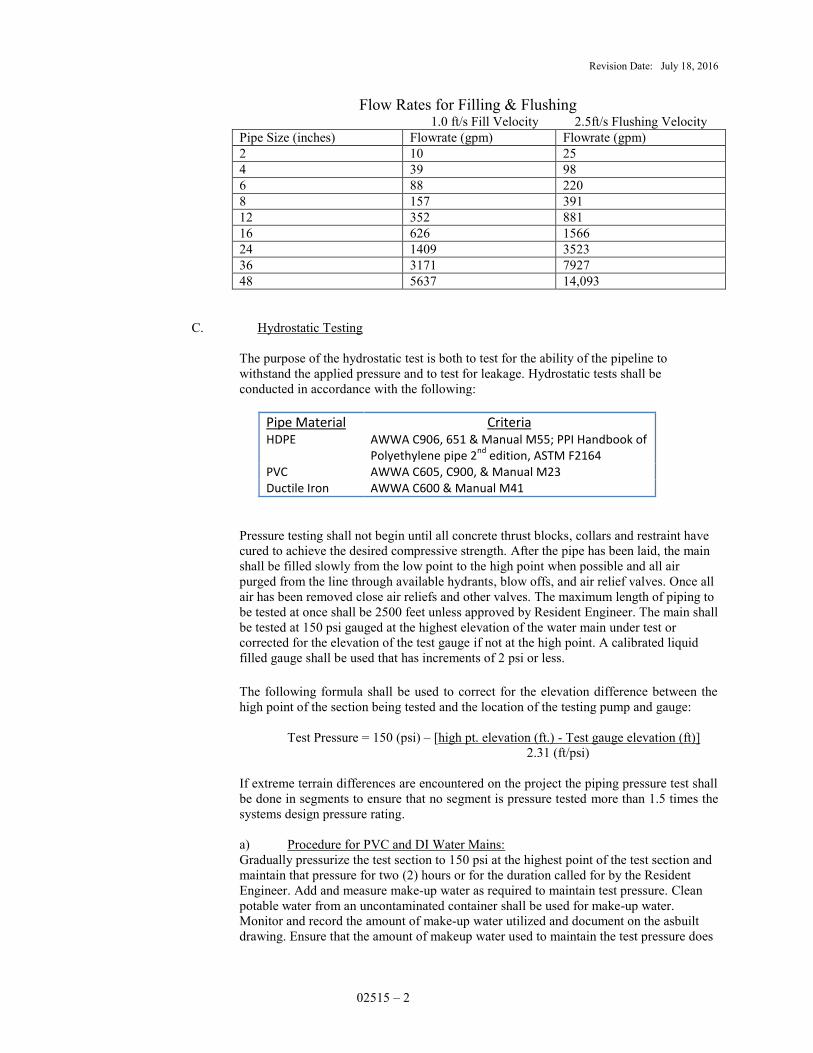
Revision Date: July 18, 2016
02515 – 2
Flow Rates for Filling & Flushing 1.0 ft/s Fill Velocity 2.5ft/s Flushing Velocity
Pipe Size (inches) Flowrate (gpm) Flowrate (gpm) 2 10 25 4 39 98 6 88 220 8 157 391 12 352 881 16 626 1566 24 1409 3523 36 3171 7927 48 5637 14,093
C. Hydrostatic Testing
The purpose of the hydrostatic test is both to test for the ability of the pipeline to withstand the applied pressure and to test for leakage. Hydrostatic tests shall be conducted in accordance with the following:
Pipe Material Criteria HDPE AWWA C906, 651 & Manual M55; PPI Handbook of
Polyethylene pipe 2nd
edition, ASTM F2164 PVC AWWA C605, C900, & Manual M23 Ductile Iron AWWA C600 & Manual M41
Pressure testing shall not begin until all concrete thrust blocks, collars and restraint have cured to achieve the desired compressive strength. After the pipe has been laid, the main shall be filled slowly from the low point to the high point when possible and all air purged from the line through available hydrants, blow offs, and air relief valves. Once all air has been removed close air reliefs and other valves. The maximum length of piping to be tested at once shall be 2500 feet unless approved by Resident Engineer. The main shall be tested at 150 psi gauged at the highest elevation of the water main under test or corrected for the elevation of the test gauge if not at the high point. A calibrated liquid filled gauge shall be used that has increments of 2 psi or less.
The following formula shall be used to correct for the elevation difference between the high point of the section being tested and the location of the testing pump and gauge:
Test Pressure = 150 (psi) – [high pt. elevation (ft.) - Test gauge elevation (ft)]
2.31 (ft/psi) If extreme terrain differences are encountered on the project the piping pressure test shall be done in segments to ensure that no segment is pressure tested more than 1.5 times the systems design pressure rating. a) Procedure for PVC and DI Water Mains: Gradually pressurize the test section to 150 psi at the highest point of the test section and maintain that pressure for two (2) hours or for the duration called for by the Resident Engineer. Add and measure make-up water as required to maintain test pressure. Clean potable water from an uncontaminated container shall be used for make-up water. Monitor and record the amount of make-up water utilized and document on the asbuilt drawing. Ensure that the amount of makeup water used to maintain the test pressure does
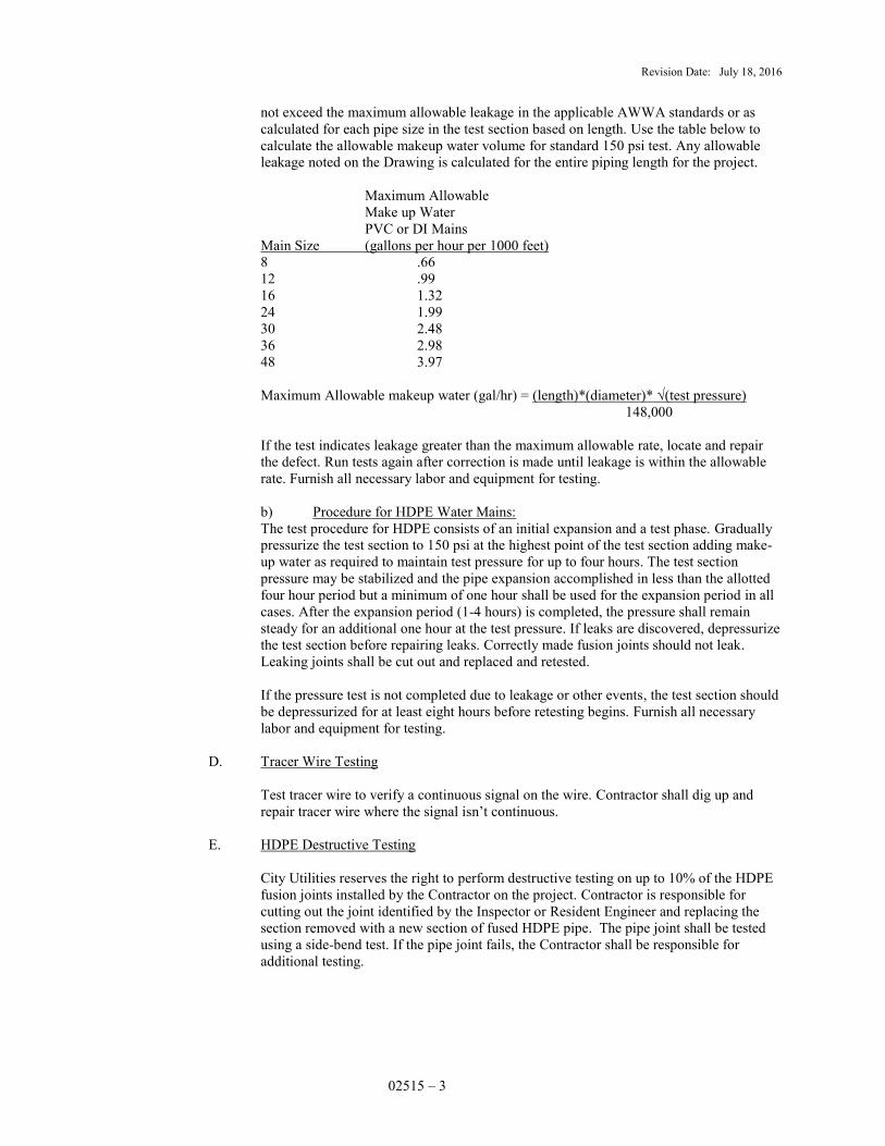
Revision Date: July 18, 2016
02515 – 3
not exceed the maximum allowable leakage in the applicable AWWA standards or as calculated for each pipe size in the test section based on length. Use the table below to calculate the allowable makeup water volume for standard 150 psi test. Any allowable leakage noted on the Drawing is calculated for the entire piping length for the project. Maximum Allowable Make up Water PVC or DI Mains Main Size (gallons per hour per 1000 feet) 8 .66 12 .99 16 1.32 24 1.99 30 2.48 36 2.98 48 3.97 Maximum Allowable makeup water (gal/hr) = (length)*(diameter)* √(test pressure) 148,000 If the test indicates leakage greater than the maximum allowable rate, locate and repair the defect. Run tests again after correction is made until leakage is within the allowable rate. Furnish all necessary labor and equipment for testing. b) Procedure for HDPE Water Mains: The test procedure for HDPE consists of an initial expansion and a test phase. Gradually pressurize the test section to 150 psi at the highest point of the test section adding make-up water as required to maintain test pressure for up to four hours. The test section pressure may be stabilized and the pipe expansion accomplished in less than the allotted four hour period but a minimum of one hour shall be used for the expansion period in all cases. After the expansion period (1-4 hours) is completed, the pressure shall remain steady for an additional one hour at the test pressure. If leaks are discovered, depressurize the test section before repairing leaks. Correctly made fusion joints should not leak. Leaking joints shall be cut out and replaced and retested. If the pressure test is not completed due to leakage or other events, the test section should be depressurized for at least eight hours before retesting begins. Furnish all necessary labor and equipment for testing.
D. Tracer Wire Testing Test tracer wire to verify a continuous signal on the wire. Contractor shall dig up and repair tracer wire where the signal isn’t continuous.
E. HDPE Destructive Testing
City Utilities reserves the right to perform destructive testing on up to 10% of the HDPE fusion joints installed by the Contractor on the project. Contractor is responsible for cutting out the joint identified by the Inspector or Resident Engineer and replacing the section removed with a new section of fused HDPE pipe. The pipe joint shall be tested using a side-bend test. If the pipe joint fails, the Contractor shall be responsible for additional testing.
Revision Date: July 18, 2016
02515 – 4
3.02 DISINFECTION
A. Disinfection of the water main and appurtenances shall be done in accordance with AWWA C-651 latest revision and this specification under the supervision of the City Utilities Inspector and Water Technician. After the pressure test, the Inspector will make arrangements with Water Operations to disinfect the installed lines. Contractor shall give City Utilities notice 48 hours in advance of the need for disinfection.
B. Perform disinfection operations after hydrostatic pressure tests have been completed. Do
not perform disinfection until all line segments are ready for disinfecting, unless otherwise directed. Use no water from a new main for any purpose until disinfection is completed and accepted. City Utilities shall place out of service rings on all valves and fire hydrants until the main has been disinfected and ready for service.
C. Install and remove sample assemblies per construction drawings and standards to allow
the main to be disinfected and sampled as directed by the Inspector. Points to sample the main will be required every 600 feet and at the end of all branch mains at a minimum. Service taps may be utilized as sample assembly points when appropriately located. Sample assembly to be shut off and the riser pipe cut and capped as close as possible to the main when retiring sample assembly. Provide a blow-off at the end of the main being disinfected to provide a means of flushing. Blow-off and sample assembly details are shown on the Standard Drawings.
D. Pretreatment of valves, sleeves, tees, and other fittings that present areas that can hold sediment or debris is encouraged. They should be treated with a 1%-5% chlorine solution prior to or during assembly. Tie in sections of piping or short segments of piping that do not lend themselves to standard disinfection shall be swabbed with a 1%-5% chlorine solution to provide disinfection.
E. All water mains shall be disinfected by City Utilities using the continuous feed method in
accordance with AWWA C651 except as noted otherwise. The slug method prescribed in AWWA C651 may also be used with prior approval from the Resident Engineer when placing a main back in service in a quicker time frame is necessary. The continuous feed method that should be followed is described as follows: Sodium Hypochlorite in a liquid form shall be injected to perform the disinfection of the line. A chlorine solution may also be mixed using granular calcium hypochlorite to be injected into the water lines. The chlorine injected shall be no lower than 1% available chlorine (10,000ppm) and no higher than 10% available chlorine (100,000ppm). Chlorine shall be injected at the beginning of the main being tested through a sample assembly located within four feet from the main feed valve supplying water. The feed valve supplying water shall be opened just enough to produce a very low flow (not a heavy stream) through the main exiting at the blow-off or hydrant at the end of the line. The chlorine solution shall then be constantly injected by pumping while the concentrations of chlorine are tested to ensure a consistent concentration throughout the main is achieved. Sampling of the chlorine concentration during injection should start at the sample assembly located closest to the injection point then moving away from the injection point toward other assemblies and to the end of the main. Injection is complete once testing at all sample assembly locations (at least every 600 ft. and at the end of all branch mains) have indicated that chlorine concentrations are at least 25 ppm. This shall be verified once injection has ceased. When stopping the injection process the feed valve supplying water shall be shut off first followed by the chlorine feed. The blow-off or hydrant at the end of the line should be closed as soon as the injection has stopped. The chlorine concentrations shall be no lower than 10 ppm 24 hours following the injection. The results of this testing shall be provided to the Resident Engineer. The highly chlorinated water used for disinfection shall not remain in the water main longer than ninety six hours.
Revision Date: July 18, 2016
02515 – 5
City Utilities may use high-test chlorine tablets to disinfect new water mains less than 50’ in length. The tablets can be secured to the top of each section of pipe with an approved food grade adhesive during main installation to supply the chlorine for disinfection. Use a minimum of one tablet per inch of pipe diameter per joint of pipe, up to 12” diameter pipe, based on the rate of ¼ once tablets with 65% available chlorine. Do not use the tablet method with polyethylene (HDPE) pipe or if trench water or foreign material enters the main. The use of 90% available chlorine tablets is not allowed. Store chlorine tablets in a sealed, opaque container until immediately before use.
F. Following disinfection, City Utilities Water Technician will flush and chemically de-chlorinate as needed the treated water from the line at all extremities until water in main has comparable chlorine residuals to surrounding system mains. The water in the main will then be sampled by the Water Technician 24 hours later at points at least every 600 feet and at the end of all branch mains, and examined for contamination per AWWA standards. Water will be sampled by the Water Technician a second time after another 24 hour retention period for contamination. During the sampling process water will not be flushed from the main except what is necessary to flush the sample assembly piping in order to retain the same water in the installed water pipe for the full sampling process. The feed valve may be opened slightly during the process if necessary to maintain pressure to obtain samples. After two consecutive sets of acceptable water quality samples, the main will then be approved and final tie-ins authorized to be made to the distribution system. Consideration shall be given by the Contractor for runoff water during the flushing process. Results of all water quality tests shall be provided to the Resident Engineer.
G. City Utilities will flush and sample a new main up to two times or four total quality sample tests. If water quality tests are still failing, the above disinfection process will be repeated. If the main still does not pass the water quality tests City Utilities may require the Contractor to pig the water main and continue to repeat the disinfection process until the main passes the quality tests. The Contractor will provide all labor, equipment, and all materials necessary to pig the main. This process shall continue until two consecutive water quality tests yield good results. Pigs used shall provide a general sweeping and swabbing of the line. They shall be foam (1-2lb/cubic foot density) with urethane coated nose cone wrapping and urethane rear sealing. Pigs should be able to pass through reduction of up to 60% to 65% of cross sectional area of nominal pipe. Pigs shall be able to traverse standard piping configurations such as 90° elbows, tees, crosses, wyes, gate valves, and ball valves. Contractor shall be responsible for all pigging activities including but not limited to breaking down of the line to insert and remove the pig, tracking of the pig, removal of stuck pig, disposal of the pig and material removed from the line.
3.03 CONTINUITY OF SERVICE
Prior to closing any valves, notify all affected customers 24 hours in advance and state how long the service will be curtailed. Cause no customer to be without service for more than eight hours. Schedule all tie-ins and other operations affecting customer service only as approved by the Inspector. Carefully plan such operations in advance, verify materials and conditions, and work continuously until all customers are in service. Some off-hour work and overtime labor may be required to avoid causing unnecessary hardship for business, schools, etc. Contractor shall bid accordingly.
END OF SECTION

Revision Date: July 18, 2016
02550 – 1
SECTION 02550
MECHANICAL – NATURAL GAS PIPING
PART I GENERAL 1.01 DESCRIPTION: Includes, but is not limited to, installation, retirement and/or relocation of gas
mains and services, including pipe, valves and fittings. 1.02 RELATED WORK DESCRIBED ELSEWHERE: Section 02220, Demolition and Clearing,
Section 02315 Excavation and Backfilling, Section 02410 Tunneling. 1.03 PRODUCT HANDLING:
A. Use all means necessary to protect the material before, during and after installation.
1. Handle pipe with padded forklifts, wide non-abrasive slings, padded clamps or padded pipe hooks. Pipe must be secured so that it cannot fall while being handled. Conventional chains, chain hooks and non-padded forklifts are expressly forbidden.
2. Use wooden skids or padding for material storage. All steel pipe and fitting shall be
stored off the ground on wooden pallets or skids.
3. Contractor is responsible for all dents, gouges, coating defects and/or dimensional variations.
B. In the event of damage, immediately make all repairs and replacements to the approval of
the Inspector. PART II PRODUCTS 2.01 Unless otherwise indicated on project Specifications, plastic gas pipe, along with plastic valves
and fittings, shall be (polyethylene) PE 2708 material, and steel gas pipe shall be API5L Grade B or X42 with fusion bonded epoxy coating.
PART III EXECUTION 3.01 INSTALLATION – GENERAL:
Contractor shall install gas mains and services to make all required interconnections and at required grades with all fittings and valves at the required locations.
3.02 INSTALLATION METHODS:
A. Install gas pipe by trenching as set forth in Section 02315, Excavation and Backfilling; by tunneling, as set forth in Section 02410, Tunneling; or by Insertion.
B. The minimum allowable depth for a service line to be inserted on private property shall be 18” for insertion through plastic service lines and 12” for insertion through steel service lines. The minimum depth on Right of Way shall be 18”.
3.03 PIPE CLEANING:
A. Prevent foreign material from entering the pipe while it is being installed. If the pipe laying crew cannot put the pipe into the trench without getting foreign material in the pipe, then a heavy, tightly woven canvas bag of suitable size shall be placed over each
Revision Date: July 18, 2016
02550 – 2
end and left there until the connection is to be made to the adjacent pipe. During laying operations, no debris, tools, clothing or other materials shall be placed in the pipe.
B. When pipe laying is not in progress, close the open ends of pipe with a watertight plug or
other approved means. This provision shall apply during meal breaks as well as overnight. If water is in the trench, the seal shall remain in place until the trench is pumped completely dry. Pipe shall not be laid in water or when trench conditions are unsuitable.
3.04 GAS MAIN DEHYDRATION:
Contractor shall be responsible for installing gas piping in a manner that does not allow water to enter the pipe. If the Inspector determines there is water in any gas piping two inches or larger in diameter, the Contractor shall be responsible for pigging that pipe in a manner approved by the Resident Engineer. The pipe shall be pigged repeatedly by the Contractor until the Resident Engineer has determined that the pipe is sufficiently dehydrated.
Pipeline pigs shall be Girard Poly Pig YBS-B, KRG or equal. Contractor shall supply all pigs. Inspector shall inspect pig after passage through pipe to determine if that pig may be reused.
Contractor shall be responsible for blocking passage of pig into pipes which do not need to be pigged. If pig passes into a pipe which does not need to be pigged, or if pig becomes stuck in the pipe, the Contractor shall retrieve the pig at his own expense, including but not limited to any excavation, pipe repair and landscape or pavement restoration. If there is water in any gas piping, the Contractor shall be responsible for dehydration of the line as directed by the Inspector and to the Inspector’s satisfaction.
3.05 STEEL PIPE JOINING METHODS:
A. City Utilities shall perform all joining of steel pipes and fittings, unless otherwise noted in the Bid Documents. When the Contractor is required to join steel pipe and fittings it shall be done by the shielded metal arc welding process and the following requirements shall apply:
B. Welding procedures:
1. All welding, including welder qualification testing, shall be done following City
Utilities written welding procedure specification (which complies with API 1104), or Contractor may submit for approval his own written welding procedure and procedure qualification records with his bid documents. Resident Engineer shall determine acceptability of submitted procedures based on API 1104 in advance of welder qualification testing. If Contractor has submitted his own procedure, he must have his procedure qualified per API 1104 as in Item B.2. below.
2. All welding shall be done by competent welders who shall have been tested by
an AWS certified welding inspector approved by City Utilities. The welding test shall comply with the requirements of the Missouri Public Service Commission Regulations and API 1104 and shall be administered by a welding inspector certified by the American Welding Society to have complied with the requirements of Section 6.1 of AWS QC1-88, “Standard for AWS Certification of Welding Inspectors.” A list of companies with certified welding inspectors approved by City Utilities will be made available to the Contractor upon request.
Revision Date: July 18, 2016
02550 – 3
The Contractor shall arrange and pay for all welder and procedure qualification testing. This expense is coincident with the installation of steel gas main and shall not be considered grounds for additional charge to City Utilities. Welders shall perform a 12 inch multiple qualification test in accordance with API 1104 and have the results documented on a City Utilities approved form.
Contractor may choose to use an AWS inspector or testing company other than those listed by City Utilities but must obtain approval in advance from Resident Engineer.
3. No gas materials will be issued to the Contractor until the welding procedure and the minimum number of welders required by that procedure have been tested and then approved by Resident Engineer. City Utilities will provide pipe for weld tests from the storeroom at 1402 N. Newton. Contractor shall be responsible for cutting pipe nipples to length and picking up the pipe for the tests.
4. Welders must have gas or petroleum pipeline welding experience or have been
previously qualified by City Utilities or MANGO.
5. Contractor shall furnish all oxygen, acetylene, fuel, welding rod, welding machines, beveling machines, weld clamps, all tools and other material required for welder qualification testing and welding work. Welders using defective or deficient equipment or lacking these necessary tools will not be tested.
6. If welding is interrupted during weather conditions which may cause uneven or
accelerated cooling of the weld, the joint shall be wrapped with insulating material and the weld joint shall be preheated when welding resumes. Weld must be preheated, if required by the Welding Procedure Specification.
7. Short “pup” joints must be a minimum of one pipe diameter, or 24” whichever is
longer.
C. Welding Codes:
All welding must comply with the requirements of the following codes and standards:
1. Missouri Public Service Commission Pipeline Safety Regulations, 4 CSR 240-40.030, Section (5) “Welding of Steel in Pipelines.”
2. Transportation of Natural and Other Gas by Pipeline: Minimum Federal Safety
Standards, Part 192, Subpart E and Appendix C.
3. API Standard 1104, Standard for Welding Pipelines and Related Facilities, latest edition.
4. ASME/ANSI B31.8. – Code for Pressure Piping.
5. Any other applicable local, state or federal regulations or codes.
D. Welding Equipment:
1. All machines and equipment used in connection with the welding work must be
kept in good mechanical condition.
2. Non-arcing clamps are required for all pipe welding.

Revision Date: July 18, 2016
02550 – 4
E. Preparation for Welding:
1. Field beveling of pipe ends: All steel pipe which is field cut must have the ends
properly beveled per API Standard 1104, latest edition, before welding. Bevel the pipe ends by machine tool or machine oxygen cutting. The beveled ends should be smooth and uniform and dimensions shall be in accordance with the approved welding procedure. Mitered joints are not acceptable.
2. 90 welding elbows cut to make elbows of lower angle must be rebeveled as
specified above. Elbows thus produced must have an inside arc length (crotch) of at least 1-inch.
3. Welders must shield from weld splatter the fusion-bond epoxy coating of pipe
beyond the 2-inch cutback and alignment clamp by wrapping coated area with a leather protector.
4. Contractor shall provide protection for welders while working during cold, rainy
or stormy weather, or other adverse weather conditions (blowing sand and dust, etc.) to assure good quality welds. Welding will not be done when the Inspector judges that weather conditions are severe enough to impair quality of the welds. Multiple welders may be required if the size of the pipe and the weather conditions dictate.
5. Prior to alignment, the beveled ends of each joint of pipe shall be thoroughly
cleaned of paint, rust, mill scale, dirt or other matter.
6. Longitudinal seams of successive lengths of pipe shall be offset by a minimum 25 percent of the pipe diameter.
F. Repair of Defective Welds:
1. If non-destructive or visual inspection indicates a weld is defective, the
Contractor shall cut a cylinder of pipe from the pipeline containing the defective weld and replace it with good pipe, welded properly, at no additional charge.
2. The Contractor may also elect to repair the weld in accordance with
requirements of Section 7.0 of API Standard 1104, except all cracked welds shall be cut out and replaced as in F.1. above.
G. Arc Burns:
1. Contractor shall take necessary measures to avoid arcing between ground leads
of the welding machines and the pipe or fittings. Striking the arc on the pipe or fittings at any point other than the welding groove shall not be permitted.
2. All arc burns on the pipe shall be removed by cutting out that portion of pipe as
a cylinder and replacing with good pipe at no additional charge to City Utilities.
3. Arc burns in fittings, valves and tie-in welds may be repaired by grinding with prior authorization by the Inspector. The area repaired by grinding shall be checked for complete removal of the arc burn and metallurgical notch. The remaining wall thickness must then be verified.
Revision Date: July 18, 2016
02550 – 5
3.06 FIELD BENDING OF STEEL PIPE:
A. The minimum radius of curvature for all diameters of steel pipe shall be 1553 times the outside diameter of the pipe.
B. Field bending of steel pipe below the minimum radius of curvature shall not be allowed
unless otherwise specified in the bid documents. 3.07 REMOVAL OF DAMAGED PIPE
Gas pipe found to have surface damage at a depth equal to or greater than 10% of the wall thickness, as determined by the Inspector, shall not be acceptable. Contractor shall cut out and replace with undamaged section of pipe, at the expense of the Contractor Other gas fittings or materials found to have damage unacceptable to the Inspector, shall be cut out and replaced at the expense of the Contractor.
3.08 PROCEDURES FOR COATING JOINTS AND FITTINGS AND REPAIRING ALL AREAS OF
COATING DAMAGE ON STEEL PIPE:
A. Pipe shall be jeeped and holidays repaired prior to lowering into trench. Clean the outside of the area to be protected of all foreign substances such as dirt, scale or rust. Remove oil or grease by a solvent. Coat the area per Construction Standards or as otherwise indicated on the plans. Allow coated areas to air dry completely before being backfilled.
B. All pipe coatings shall be applied in accordance with manufacturer’s recommended
procedure, specifically including the recommended use of primers.
C. Field applied polymer concrete shall be used to coat joints on polymer concrete coated steel pipe for uncased bores. Coating shall be allowed to cure completely prior to insertion through the bore hole. Coating may not be applied to welds that have been made within the previous fifteen hours.
3.09 LOWERING-IN:
A. Steel pipeline shall be lowered into the ditch following field coating of weld joints and after pipe and coating have been inspected and approved by Inspector for lowering in. Adequacy of equipment used for lowering-in shall be subject to the approval of the Inspector.
B. During lowering-in, pipe shall be handled by use of rubber tire rollers or lowering-in
belts of proper design to prevent damage to the coating.
C. Lowering-in must be done gradually and uniformly so as to allow even distribution of the total weight of the pipe to avoid undue stress on the pipe and to prevent damage to the pipe coating. Do not drop or subject the pipe to impact.
D. Remove all debris, skids, welding rods, etc. from the bottom of trench before lowering
the pipe.
E. After lowering-in, the pipe coating shall be inspected for possible damage. If the pipe coating has been damaged, the pipe shall be raised again, inspected by jeeping, and the coating repaired.
Revision Date: July 18, 2016
02550 – 6
3.10 PLASTIC PIPE JOINING METHODS:
A. Polyethylene pipe shall be joined by heat fusion or electrofusion. Joining of similar types of pipe shall typically be made by heat fusion. All joints consisting of dissimilar types of pipe shall be by electrofusion. Mechanical fittings are only permissible for temporary installations or when called for on the Drawings or otherwise called for within the Specifications.
B. All fusion joints shall be made by competent joiners who shall have been tested and
approved in advance by City Utilities, and who have properly maintained this qualification. The test shall comply with the requirements of the Missouri Public Service Commission Regulations. The test shall include destructive test of joints of each type to be made on the project.
C. Heat Fusion Procedures:
1. Contractor shall make all fusions in accordance with City Utilities current recommended procedures.
2. Contractor shall provide all tools and an acceptable butt fusion machine capable
of fusing all sizes of piping for the project. All tools shall be electrically heated only. Fuel-fired tools shall not be acceptable. Only tools specifically designed for the joining of polyethylene gas pipe shall be used. All tools shall be kept clean.
3. Data loggers shall be used when performing butt fusions with a hydraulic
machine. City Utilities Inspector will provide the data logger. Hydraulic butt fusion equipment shall be McElroy or pre-approved equal. When equipment other than McElroy is proposed, the Contractor will be required to supply an equivalent data logger or other approved means of capturing fusion data and providing the fusion data to City Utilities Inspector.
D. Electrofusion:
1. Contractor shall provide all tools and an acceptable electrofusion machine
capable of fusing all sizes of piping for the project.
2. The pipe shall be prepared using an approved scraper designed for use with medium density polyethylene piping. Paint-type scrapers will not be allowed.
3.11 VALVE AND FITTING INSTALLATION:
A. Contractor shall set valves and fittings and join to pipe as shown on the Drawings and Construction Standards.
B. Contractor shall install a valve box for every valve. The valve box shall not transmit
shock or stress to the valve and shall be centered and plumb over the operating nut of the valve. The box cover shall be flush with the surface of the finished grade or as directed by the Inspector.
3.12 BENDING OF POLYETHYLENE (PLASTIC) PIPE:
A. Install fittings at all locations as specified in the Drawings.
B. At locations where fittings are not specifically called for, plastic pipe may be bent to route the line as required; however, bends which would produce excessive stress on the
Revision Date: July 18, 2016
02550 – 7
pipe shall not be allowed. The bending radius shall adhere to the manufacturer’s recommendations and the gas Construction Standards. Where bend radius will not conform to the Construction Standards and manufacturer’s recommendations, an appropriate fitting (elbow) shall be installed as necessary.
3.13 CUTTING OF POLYETHYLENE (PLASTIC) PIPE:
A. Cut pipe square and remove all burrs and cuttings prior to joining.
B. Pipe may be cut with a hacksaw or carpenter’s saw, or a specifically designed plastic pipe cutter may be used.
C. Standard metal pipe wheel-cutters are not acceptable.
3.14 SQUEEZE-OFF OF POLYETHYLENE (PLASTIC) PIPE:
A. Where available, City Utilities personnel shall utilize valves to control the flow of gas in plastic pipes. However, squeeze-off may be utilized where necessary.
B. Contractor shall squeeze-off pipe using a properly designed tool and shall not damage the
pipe. The tools shall be equipped with appropriate gap stops. The tools shall be squared and centered on the pipe and shall be located at least three pipe diameters away from the nearest fitting or fusion joint. All squeeze-off shall be performed with the Inspector present.
C. The same location of pipe shall not be squeezed-off more than once. All squeeze-off
locations shall be marked by wrapping the pipe with electrical tape.
D. After squeeze-off, pipe shall be re-rounded. All squeeze-off operations shall conform to ASTM F1041, latest revision.
3.15 LOCATOR WIRE:
A. Contractor shall install locator wire with all plastic main and service piping, except with plastic pipe inserted in steel pipe. When inserting in steel pipe the tracer wire shall be thermite welded to the casing pipe per Construction Standards to provide continuity. Plastic service lines that do not have existing tracer wire shall be replaced with a new service line with tracer wire. Contractor may elect to pipe burst the existing service line if it is of sufficient depth, and install a casing with tracer wire attached to the outside along with a new service line.
B. Installation shall be as indicated in Construction Standards.
C. Contractor shall connect wire to existing locator wire where present. Do not connect wire
to any existing steel gas mains remaining in service. Connect wire utilizing a direct bury splice kit.
3.16 CATHODIC PROTECTION, ANODES AND TEST STATIONS:
A. Contractor shall replace damaged anodes and test stations and install new magnesium anodes and test stations at points designated on the Drawings per City Utilities Standards. The Inspector shall be present when test stations are installed.
B. Contractor shall connect test wires and anode wires to the gas line by thermite welding
(cadwelding) in accordance with City Utilities Construction Standards. Maximum charge to be utilized in the thermite welding procedure shall be 15 grams. Any procedure which

Revision Date: July 18, 2016
02550 – 8
is deemed harmful to the gas line will not be permitted. Fast quenching with water to achieve a quick cool down is not permitted.
C. Cutting of the steel portion of “Anodeless” risers is not allowed.
D. Contractor shall coat the thermite welded area per City Utilities Construction Standards.
3.17 PRESSURE TESTING:
A. New Installations:
1. Contractor shall subject all new piping installed to an air or nitrogen pressure test unless otherwise specified in the Contract Documents.
2. Contractor shall test all mains to be operated at 60 psig or less at 90 psig for a
minimum of one hour or as directed on the Drawings or standards.
3. Contractor shall test all services at 90 psig for a minimum of fifteen minutes. Long or larger services may require additional time, per Construction Standards.
4. Contractor shall provide all material and equipment required for the pressure
tests. Provide and install any required gauges and charts. Gauges shall be accurate to within one percent and shall register the applicable test pressure near the center of the scale.
5. Inspector shall determine acceptability of all pressure tests, including the
calibration history of all gauges used.
B. Final Tie-Ins: Soap test all final connections which cannot be air pressure tested after the tie-in section is pressurized with gas.
C. Inspector may also test any of the work after it is pressurized with gas leak detecting
equipment.
D. Leakage: If any of the above described tests on new installations result in leakage, the defective pipe, joint or fitting shall be located and repaired, and tests shall be made again after the correction is made.
3.18 PRESSURE CONTROL WORK:
A. Tapping and Stopping of Steel Mains:
1. All steel mains shall be tapped or stopped using the appropriate pressure control fitting.
2. Contractor shall furnish all equipment and labor required to place equipment and
materials in advance of and as-needed by City Utilities Pressure Control personnel, including digging, hoisting, bolting and welding. City Utilities shall be responsible for welding on all pressure control fittings unless indicated otherwise in the Bid Documents.
3. City Utilities Pressure Control personnel shall provide labor and equipment to
make the tap or stoppling on 12” diameter and smaller piping with pressure 150 psig or less. When tapping or stoppling work is to be performed on mains larger than 12” or on mains operating above 150 psig, Contractor shall secure the
Revision Date: July 18, 2016
02550 – 9
services of an approved company to perform the operations. A list of approved companies is available from Resident Engineer.
B. Squeeze-Off of Polyethylene (Plastic) Mains and Services:
Contractor shall provide all necessary tools and labor to squeeze-off new and existing plastic mains and service, utilizing procedures as prescribed in Section 3.13.
C. Operations of Main Line Gas Valves:
City Utilities shall operate all main line gas valves as required in coordination with Contractor’s work.
D. Purging:
1. All mains shall be purged of air after a satisfactory pressure test is completed.
2. Contractor shall install all necessary fittings for purging.
3. City Utilities shall provide all necessary labor for purging all mains.
E. Notice Required:
1. Contractor shall coordinate the sequencing of all required Pressure Control work
with the Inspector.
2. A 48-hour advance notice is required for any Pressure Control operation. 3. All tapping and stoppling operations shall be scheduled to commence in the
morning hours so that work can be completed during the normal City Utilities work day. Tapping and Stoppling operations will not begin after 12:00 noon.
3.19 CONTINUITY OF SERVICE:
A. Contractor shall follow direction of the Inspector to maintain a maximum degree of continuous service to City Utilities’ customers.
B. Service shall not be interrupted overnight unless special arrangements are made with the
involved customers by Contractor.
C. Once Contractor has begun a specific procedure which requires an interruption of service, Inspector shall have the authority to require the Contractor to work continuously until said service is restored at no additional charge.
D. Contractor shall notify customers 24 hours in advance of service interruptions.
3.20 RESTORATION OF SERVICE:
City Utilities will be responsible for relighting of all gas services. Contractor shall coordinate this work and give immediate notice to the Inspector whenever a service is ready to be relighted.
3.21 RETIRED GAS MAIN AND SERVICES:
A. Other than minimum lengths as shown on the drawing and where retired gas main conflicts with the installation of this projects’ improvements, Contractor may leave

Revision Date: July 18, 2016
02550 – 10
retired gas main in place. All retired gas mains shall have the ends plugged or sealed with caps or foam sealant, as approved by the Inspector.
B. When necessary to complete installation of this project’s improvements, or otherwise at
Contractor’s discretion, Contractor shall remove and dispose of retired gas mains and services. The affected area shall be backfilled and restored per Contract requirements and meet all jurisdictional agency requirements. No additional charge shall be made by Contractor for any work associated with removal of pipe.
3.22 PIPING WITH ASBESTOS COATING REPAIRS, DEMOLITION, AND DISPOSAL
Contractor is being made aware that work on piping with asbestos material within the coating of the pipe is governed by OSHA regulations and that compliance with OSHA regulations is the sole responsibility of the Contractor. Work on pipe with asbestos coating shall only be performed by OSHA trained personnel overseen by a “competent person” as defined by OSHA. Contractor shall be or retain a Registered Asbestos Contractor with the Missouri Department of Natural Resources. Additionally, all work shall be in accordance with EPA’s National Emission Standards for Hazardous Air Pollutants (NESHAP), EPA’s Governmental Employee Worker Protection Rule, and Missouri DNR’s Air Asbestos Rule. A. Excavation: When excavating a gas pipe with asbestos coating, take precautions to prevent
the backhoe teeth from scraping or gouging the pipe. Use a spotter to warn when the pipe is first exposed. Use heavy equipment to excavate laterally down to and around the pipe, then complete the job by hand. This is especially important if the pipe is to be retired and removed.
B. Pipe Preparation: Piping with asbestos coatings must be kept wet at all times while cutting,
scraping, chipping, or otherwise abrading the pipe coating. Water mixed with a surfactant (soap, detergent or other agent, designed to reduce surface tension of the water) must be used to wet the pipe. A Hudson type sprayer shall be used to apply the solution. The solution shall be applied frequently to areas of the pipe coating being removed.
C. Cutting Piping with asbestos coating shall never be cut using a high-speed mechanical saw
without first removing the coating.
D. Coring: When tapping or coring pipe with asbestos containing coating, remove all coating from the affected area prior to installing any tapping fittings on piping . A hammer or similar tool shall be used to break away large chunks of the coating from the pipe. A putty knife or similar tool shall be used to remove any remaining layers of the asphaltic coating. Plastic sheeting shall be placed beneath or beside the pipe to collect all coating as it is removed. Treat all collected coating, dust, crumbs as asbestos waste. Once coating removal is complete, ensure that all pieces of coating are retained on the plastic sheeting, placed in plastic bags and properly disposed.
E. Retirement/Removal: Unless otherwise indicated on the Drawings, all existing piping with asbestos containing coating shall be abandoned in place. . “Abandon in place” pertains only to those sections that have not been moved from their location of original installation. Pipe sections that have been removed or disconnected from their installed position must be removed from the trench and properly disposed of. Pipe sections and fragments of coating removed from the trench must be immediately packaged for disposal and moved to a secure location. This may entail placing directly into a lined roll-off containing and/or double wrapping or bagging individual pieces of pipe and/or pipe fragments and/or coating fragments in 6-mil plastic bags or sheeting. All cost for the proper disposal of pipe and/or coatings which is removed without direction and written authorization of the Resident Engineer, shall be borne by the Contractor.
Revision Date: July 18, 2016
02550 – 11
F. Decontamination: All tools and equipment used during the maintenance of piping with asbestos coating shall be thoroughly cleaned with soap, water, and disposable towels. All materials such as towels used for cleaning, gloves, or plastic sheeting that becomes contaminated with asbestos containing material shall be packaged and disposed of properly.
G. Disposal: Contractor is responsible for ensuring all sections and pieces of piping with asbestos
containing coating that cannot be abandoned in place are properly packaged and disposed of at a licensed solid waste landfill approved by City Utilities. This also includes any coating debris collected. Prevent damage to the coating when transporting pipe sections. Frayed coating edges must be wrapped in plastic or secured with duct tape. The pipe length should be limited to 20 feet, or as dictated by the disposal Contractor. Do not transport pipe with loose coating unless it is adequately wrapped in plastic. If desired, City Utilities will provide guidance to the Contractor on the landfill’s waste approval process. However, costs for disposal are borne by the Contractor, unless otherwise indicated on the Drawings or in these Specifications. Contractor will document disposal by providing to City Utilities the waste manifest(s) signed and returned to the Contractor by the landfill representative.
H. Reporting: Contractor is responsible to report to City Utilities information necessary for
reporting compliance to Missouri Department of Natural Resources. Contractor shall supply the name of the competent person who is performing any work on the pipe or any pipe removal, transport and disposal. The contractor shall provide the name and location of the disposal facility. This information shall be submitted to City Utilities Environmental Affairs at least 20 days prior to work on the pipe.
END OF SECTION
Revision Date: July 18, 2016
02700 – 1
SECTION 02700
PAVING AND SURFACING PART I GENERAL 1.01 DESCRIPTION: Includes, but is not limited to, pavement replacement in streets, driveways and
sidewalks. Pavement repairs required due to potholing for utilities are to be performed per this Specification and are considered inclusive in the per foot pipe prices established in the contract.
1.02 RELATED WORK SPECIFIED ELSEWHERE: Excavation and Backfilling; Section 02315. PART II MATERIALS AND EQUIPMENT 2.01 Meet appropriate jurisdictional agency paving standards.
PART III EXECUTION 3.01 GENERAL PAVING REPLACEMENT:
A. All paving replacements and associated costs are the sole responsibility of the Contractor. Paving must be restored according to the appropriate jurisdictional agency’s requirements and be performed to their satisfaction.
B. When trench excavations are made on private property, parking lots or driveways, backfill
immediately with compacted granular material according to excavation Specifications to restore access. Install a smooth final asphalt repair within 30 days of the trench backfill.
C. Install a smooth temporary patch across streets the same day as the trench is backfilled.
Final repair shall be completed within 30 days of the trench being backfilled. 3.02 DRIVEWAY REPLACEMENTS:
A. Cut paved driveways in a straight line along both sides of the area to be excavated. 3.03 REGULATORY COMPLIANCE:
A. Comply with all applicable jurisdictional requirements.
END OF SECTION
Revision Date: July 18, 2016
02900 – 1
SECTION 02900
LANDSCAPING PART 1 GENERAL 1.01 DESCRIPTION: Includes, but is not limited to, the items listed below.
A. Performing preliminary cleanup.
B. Planting bushes, trees or plants.
C. Applying topsoil to disturbed areas on right-of-way and easements.
D. Hydraulic seeding of disturbed areas.
E. Cultivation and drilling of disturbed pasture or cropland areas.
F. Re-seeding during specified seeding windows.
G. All disturbed areas to be restored to as good as or better than original condition.
H. The Inspector will determine pre-existing conditions and will designate areas that need to be seeded, sodded and/or landscaped.
1.02 RELATED WORK SPECIFIED ELSEWHERE: A. Excavation and Backfilling; Section 02315. B. Demolition and Clearing; Section 02220. PART II MATERIALS AND EQUIPMENT 2.01 TOPSOIL:
A. Fertile, friable soil of loamy character, free of sub-soil, stumps, refuse and other foreign material.
B. Normal amount of natural humus and reasonably free of roots, hard dirt, heavy or stiff clay,
coarse sand, noxious weeds, noxious weed seeds, sticks, brush and other litter.
C. Obtained from well-drained, arable land and be of an even texture.
D. Not infested with nematodes or with any other noxious animal life or toxic substances.
E. Sandy loam of low fertility, even though mixed with leaf mold, manure or other fertilizers is not acceptable.
2.02 GRASS SEED: A. Clean, dry new crop seed.
B. Provide grass seed for established areas in a blend as specified below, unless directed otherwise by the landowner or Inspector:
Revision Date: July 18, 2016
02900 – 2
1. 75% by weight of a three-way blend (equal parts) of turf fescues, consisting of any three of the following varieties: Olympic, Falcon, Bonanza, Rebel, Hound Dog, Astro 2000, Eldorado, Wrangler, FineLawn One, Anthem or Apache.
2. 15% by weight of Perennial Rye, consisting of one or more of the following
varieties: Affinity, Derby, Regal, Manhattan or Chateau.
3. 10% by weight of Bluegrass, consisting of either Kentucky Bluegrass, Park Bluegrass or both.
4. Purity 98%.
5. Germination 85%.
C. Complies with standards of the Official Seed Analysis of North America.
D. Recommended for full sun exposure in Springfield, Missouri.
E. Seed shall be free from Johnson Grass, Canadian Thistle or field bind weed seed.
2.03 FERTILIZER:
Provide a mixture containing 13 pounds each of soluble nitrogen, phosphate and potash per 100 pounds.
2.04 MULCH FOR HYDRAULICALLY SEEDED AREAS: Provide a mixture of 50% recycled slick paper mulch and 50% ground corrugated paper mulch by
weight. The recycled slick paper mulch shall be produced from printers slick paper containing wood cellulose and kaolin clay. Newsprint is not allowed. The slick paper mulch shall have a maximum moisture content of 8% by weight, and shall have a pH of 4.5 to 6.5. The corrugated paper mulch shall have a moisture capacity of 700 grams water per 100 grams dry mulch minimum, a dry moisture content of 12% maximum, and a pH of 5.0 to 8.0. All mulch materials must be free of any germination or growth-inhibiting substances, green in color, and have the property of being evenly dispersed and suspended when agitated in water.
Clean wheat straw shall be applied over the hydraulic mulch. 2.05 SOD: Sod shall be placed as shown on the plans. PART III EXECUTION 3.01 PRELIMINARY CLEANUP: Clear disturbed areas, including those disturbed by trenching, storing of dirt, pipe laying, pipe
storage, movement of equipment and other work of all rubbish, brush, rock, trash and excess dirt in a timely manner as soon as the ditch is backfilled, depending upon existing conditions and level of public concern. This may be required as often as daily. The Inspector will determine an appropriate schedule depending upon job conditions. Rake surface as necessary to remove all above items, including all rock measuring two-inches or more in its greatest dimension. In pasture and cropland areas, remove all above items in a timely fashion. Tractor-drawn equipment, including rock rakes and steel roller drum are allowed.
Revision Date: July 18, 2016
02900 – 3
3.02 PLANTING:
Contractor shall replace individual trees, plants and shrubs as necessary or as directed by the Inspector. Plant in accordance with "Planting Trees and Shrubs" by the University of Missouri - Columbia Extension Division (Publication No. 6850). Replacement trees, plants and shrubs shall be nursery grown and of the same type, strain, size and value as those removed. Plant replacement trees, plants and shrubs as soon as possible after installation of mains, with due consideration given to optimal times of the year to plant the given species.
3.03 APPLICATION OF TOPSOIL: Established lawn and parkway areas
After preliminary cleanup has been performed, apply topsoil meeting the requirements of PART II, MATERIALS AND EQUIPMENT to a minimum depth of four inches to disturbed areas. Pulverize topsoil and grade to match existing terrain. Rake surface smooth for sod or to provide a good seedbed for hydraulic seeding as specified below.
3.04 SEEDING:
Perform initial seeding as soon as practical after preliminary cleanup and application of topsoil. Restore all disturbed areas, except for pasture and cropland, by hydraulic seeding. Seeding windows are specified as follows: Perform autumn seeding between August 15 and October 15, and spring seeding between March 15 and May 15. If initial seeding is performed within either of the specified seeding windows, the only additional work required of the Contractor shall be warranty work. When seeding outside a normal seeding window quick germinating seed shall be used such as winter wheat or perennial rye to establish ground cover. Contractor may be required to provide and install erosion control blankets to protect these areas. Re-seeding during the next earliest seeding window shall be considered part of the work if initial seeding falls outside either of the specified seeding windows. The Inspector will determine if re-seeding is required.
A. HYDRAULIC SEEDING: Mix seed, fertilizer and mulch with water and constantly agitate
so that a uniform mixture can be applied hydraulically to the specified areas. Do not add the seed to the water more than four hours before application. Calculate ratios of seed, fertilizer, mulch and water so that seed will be applied at the rate of twelve pounds minimum per 1000 square feet of area, fertilizer will be applied at the rate of eight pounds minimum per 1000 square feet of area, and mulch will be applied at the rate of 1000 pounds minimum dry weight per acre. Wet application rate of the mixture shall be 2000 pounds per acre minimum. Blow wheat straw mulch onto the hydraulic mulch within one hour of application of the hydraulic mulch.
B. Restoration of disturbed pasture and cropland areas:
1. Seed bed preparation: Tillage - prepare a seed bed by use of tillage operations that leaves a seed bed free of weeds. Leave the vegetative material destroyed by such operations on the surface. Several diskings or harrowings over same area may be required to provide a satisfactory seedbed.
2. Seeding method: Drilling - Plant the recommended seed with a grass drill
equipped with double coulter furrow openers with depth bands and press wheels. Seed should be planted 1/4" to 1/2" deep. Cultipacking is required following seeding.
3. Fertilizer requirements: Apply fertilizer at the rate 8 pounds minimum per 1,000
square feet.
Revision Date: July 18, 2016
02900 – 4
4. Seeding rates and mixture: Apply seed grass(es) at the rate (pure live seed or bulk seed per acre) of 30 lb/acre, or as recommended by the seed supplier.
5. Where permanent seeding must be delayed due to seasonal seeding or climate
conditions, quick germinating seed such as winter wheat or perennial rye will be applied. Contractor may be required to provide erosion control blanket to provide protection to the disturbed areas until vegetation can be established. Subsequently drill temporary cover with no-till methods to establish permanent crop cover.
C. Restoration of slopes: When areas with slopes 3:1 or greater are restored a biodegradable
erosion control blanket shall be installed over the seedbed to protect the slope (Propex CS2 or approved equal). Contractor shall supply the fabric and staples and install per manufacturer’s recommendations.
END OF SECTION

Revision Date: July 18, 2016
03200 – 1
SECTION 03200
CONCRETE REINFORCEMENT PART I GENERAL 1.01 Furnish all labor, materials and equipment necessary to complete the work as specified in this
Section. 1.02 Comply with the provisions of the Concrete Reinforcing Steel Institutes "Manual of Standard
Practice" unless more stringent requirements are shown. PART II MATERIALS AND EQUIPMENT 2.01 Reinforcing bars will be sized according to the plans and will be ASTM A615, Grade 60, deformed
bars. 2.02 Steel wire will be plain, cold-drawn and will conform to ASTM A82. 2.03 Use bolsters, chairs, spacers or other devices for spacing, supporting and fastening the reinforcing
bars in place. PART III EXECUTION 3.01 The reinforcement will be fabricated to the shapes and dimensions shown and placed where
indicated. Lap splices will be made in conformance with ACI Standard 318. 3.02 The reinforcement will be free from all substances that would reduce or destroy the bond. After a
substantial delay, steel left exposed will be inspected and cleaned. 3.03 Reinforcement detailing and placement, including concrete protection for steel reinforcement, unless
otherwise indicated, will conform to ACI Standards 318 and 315 and will match reinforcement as shown on the Drawings.
3.04 Wire mesh reinforcement will be continuous between crack-control joints in slabs-on-grade. Laps
will be at least one full mesh, staggered in both directions, and secured with wire or standard clips. Wire mesh will extend to within 2 inches of joints but not through joints.
3.05 Supports will be installed and intersections of reinforcement securely tied with steel wire to limit
displacement to the tolerances permitted by ACI Standard 315. The number, type and spacing of supports will conform to ACI Standard 315, unless otherwise indicated.
3.06 Reinforcement for slabs-on-grade will be supported on precast concrete blocks. Size and spacing of
blocks will be as required to provide firm support and the clearance specified or indicated. Set wire ties so ends are directed into concrete, not toward exposed concrete surfaces.
3.07 Reinforcement and other fixed metal items shall not be continuous through expansion or control
joints.
END OF SECTION
Revision Date: July 18, 2016
03300 – 1
SECTION 03300
CONCRETE
PART I GENERAL 1.01 DESCRIPTION This Section covers all cast-in-place concrete, including reinforcing steel, forms, finishing and
other appurtenant work for thrust blocks, thrust collars and other items shown on the Drawings. Also see Section 03200, Concrete Reinforcement.
1.02 RELATED WORK DESCRIBED ELSEWHERE
Water Piping, Section 02510. PART II MATERIALS AND EQUIPMENT 2.01 MATERIALS: Cement ASTM C150, Type I or ASTM C715, Type IA. Fine Aggregate Clean natural sand, ASTM C33. Coarse Aggregate Crushed rock, washed gravel or other inert granular material conforming to ASTM C33. Water Potable Reinforcing Steel Bars ASTM A615, Grade 60 2.02 PRELIMINARY REVIEW
Submit the source and quality of concrete materials and the concrete mix along with test data proposed for the work to the Inspector for review, before any concrete is placed.
2.03 SLUMP
Keep concrete slump as low as possible consistent with proper handling and thorough compaction. Unless otherwise authorized by the Inspector, slump shall not exceed 4 inches except for flowable fill. Add no water to mix after the slump test without approval by Resident Engineer.
2.04 STRENGTH
The minimum acceptable compressive strengths as determined by ASTM C39 shall be as follows:
Age Minimum Strength 7 days 2500 psi 28 days 3750 psi
Very high early strength concrete shall achieve a 2500 psi compressive strength within 3 hours. Contractor shall submit mix design for high early strength concrete to Inspector for review prior to placement along with compressive strength documentation. Flowable fill compressive strength shall be demonstrated by failure to deform or crush under foot traffic.
Revision Date: July 18, 2016
03300 – 2
2.05 STORAGE OF MATERIALS
Store cement in suitable moisture proof enclosures. Do not use cement which has become caked or lumpy. Store aggregates so that segregation and the inclusion of foreign materials are prevented. Do not use the bottom 6 inches of aggregate piles in contact with the ground.
Reinforcing steel shall be carefully handled and shall be stored on supports which will keep the steel from contact with the ground.
2.06 REINFORCEMENTS
Reinforcements shall be accurately formed and shall be free from loose rust, scale and contaminants which reduce bond.
PART III EXECUTION 3.01 BATCHING AND MIXING
Furnish concrete from an acceptable ready-mix concrete supplier or mix at the site. Concrete shall at a minimum conform to ASTM C94.
3.02 PLACING CONCRETE
Thrust blocks and thrust collars shall be placed between solid, undisturbed earth and the fitting or piping to be anchored. Thrust blocks shall be so placed that the pipe and joints will be accessible for repair and installed per Construction Standards. The minimum compressive strength for the concrete shall be achieved prior to relying on the concrete for any thrust restraint. The use of very high early strength concrete is permissible for installations where time constraints exist. When the Drawings call for flowable fill or Contractor wishes to utilize flowable fill in lieu of compacted backfill, no additional payment will be made. Contractor shall make requests to utilize flowable fill to the Resident Engineer. Flowable fill mix and placement shall conform to Specifications of local jurisdictional agency or at a minimum the Missouri Standards Specifications for Highway Construction latest edition.
3.03 FINISHING
No surface treatment will be required for buried concrete not forming an integral part of a structure except that required to obtain the surface elevations or contours and surfaces free of laitance.
3.04 INSPECTION
No concrete shall be covered until installation has been approved by City Utilities. 3.05 REPAIR OF DEFECTIVE WORK
In the event that concrete installation is found to be sub-standard, the Contractor shall be required to remove and replace installation with proper materials and execution.
END OF SECTION
Revision Date: July 18, 2016
Attachment A
ATTACHMENT A
GENERAL CONDITIONS

Revision Date: July 18, 2016
Attachment B
ATTACHMENT B
SPECIAL CONDITIONS

Revision Date: July 18, 2016
Attachment B
Not used for this contract

Revision Date: July 18, 2016
Attachment C
ATTACHMENT C
APPROVED NATURAL GAS AND WATER CONTRACTORS
Revision Date: July 18, 2016
Attachment C
Not used for this contract