Embed Size (px)
Citation preview

Civil works construction technology
Civil engineering department
5th year
Sofie Johansson IST1 88853
Elin Fryklund IST1 88854
Bojan Fajdiga IST1 88915
Antonio Barhouche IST1 88870
Maxime De Almeida IST1 89099
05/12/2017
Bridge cantilever construction with in situ concreting
Civil Works Construction Technology
2
INTRODUCTION
Bridge cantilever construction method can be executed both with prefabricated an in-situ concreting.
The method does not require false work or centering which leaves traffic under the spans widely
unobstructed during construction of the bridge. The only access from the ground is when constructing
the piers and abutments and for the preparation for the start of cantilevering, that will start from
these locations. The method consist in building the bridge structure by part that are called segments.
When casting on the construction site the segments are concreted into a formwork that is connected
to a movable structure called form traveller. Form travelers are supported by steel cantilever trusses
attached to previously completed segment. When the previously cast segment has developed enough
strength can it be prestressed to previous segment and to support the subsequent one. After that the
form traveller can move on and start the next segment.
Figure 1: Cantilever cast-in-situ bridge construction1
1 https://theses.lib.vt.edu/theses/available/etd-120199-224950/unrestricted/11lucko_chapter4.pdf

Civil Works Construction Technology
3
TABLE OF CONTENTS
Introduction ............................................................................................................................................. 2
Equipment to be used ............................................................................................................................. 4
1 Segmental bridges ........................................................................................................................... 4
2 Construction of a bridge and equipment for construction ............................................................. 4
2.1 Cast in situ method and Equipment for this method .............................................................. 5
How to control movements during construction? .................................................................................. 7
1 Cantilever Tendons .......................................................................................................................... 7
1.1 Principle ................................................................................................................................... 7
1.2 Disposition ............................................................................................................................... 8
2 Continuity tendons ........................................................................................................................ 10
2.1 Principle ................................................................................................................................. 10
2.2 Disposition ............................................................................................................................. 10
3 Temporary pilings .......................................................................................................................... 11
4 Closure of the end span ................................................................................................................. 11
5 Embedding on a pier ..................................................................................................................... 12
How to correct final misalignments in closing segment? ...................................................................... 13
Useful references .................................................................................................................................. 15

Civil Works Construction Technology
4
Equipment to be used
1 SEGMENTAL BRIDGES
A Segmental Bridge is a bridge built in short sections (called segments), that is one piece at a time. And
then segments are erected to make the bridge. The bridge is either cast-in-place or precast. The first
cast-in-place segmental concrete bridge, built in 1950, across the Lahn River in Germany.
Segmental bridges are classified under the following categories:
- Balance Cantilever Bridges
- Progressive Placement Bridges
- Span-by-Span Constructed Bridges
- Incrementally Launched Bridges
Balance Cantilever Bridges
Balanced cantilever construction is an economical method when access from the below is expensive
or practically impossible. Segments may be cast in-situ or precast concrete normally with a box shape
cross-section. Construction starts from the top of a pier, with the segment normally fixed to the pier
either permanently or temporarily during the construction. For in-situ balanced cantilever
construction, the formwork is suspended from the end of the last segment. The new segment is cast,
and once the concrete has developed a predetermined strength, the section is post-tensioned to the
rest of the bridge. The figures show the construction sequence of this type of construction. Segments
are often cast and stressed in pairs, one each side of the pier.
Figure 2: Balance Cantilever Bridge
2 CONSTRUCTION OF A BRIDGE AND EQUIPMENT FOR CONSTRUCTION
There are many methods for construction one bridge. This time we will say something about the in-
situ balanced cantilever construction. In basic terms, cast-in-situ construction describes a process
whereby segments are progressively cast on site in their final positions within the structure.
Construction of a bridge is a very complex process and uses special equipment.
Equipment for construction of bridges is:
- Form Traveler machine
- Hydraulic jacks
- Mobile scaffolding
- Gantry crane or other crane
Civil Works Construction Technology
5
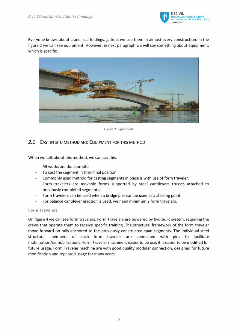
Everyone knows about crane, scaffoldings, jackets we use them in almost every construction. In the
figure 2 we can see equipment. However, in next paragraph we will say something about equipment,
which is specific.
Figure 3: Equipment
2.1 CAST IN SITU METHOD AND EQUIPMENT FOR THIS METHOD
When we talk about this method, we can say this:
- All works are done on site
- To cast the segment in their final position
- Commonly used method for casting segments in place is with use of form traveler.
- Form travelers are movable forms supported by steel cantilevers trusses attached to
previously completed segments.
- Form travelers can be used when a bridge pier can be used as a starting point
- For balance cantilever erection is used, we need minimum 2 form travelers.
Form Travelers
On figure 4 we can see form travelers. Form Travelers are powered by hydraulic system, requiring the
crews that operate them to receive specific training .The structural framework of the form traveler
move forward on rails anchored to the previously constructed span segments. The individual steel
structural members of each form traveler are connected with pins to facilitate
mobilization/demobilizations. Form Traveler machine is easier to be use, it is easier to be modified for
future usage. Form Traveler machine are with good quality modular connection, designed for future
modification and repeated usage for many years.

Civil Works Construction Technology
6
Figure 4: Form travelers
This is special workshop in the top of the pillars. They are supplied with the necessary molds,
substrates, screws, concreting devices. The concrete can be prepared on site or carried from the
concrete factory. For the production we need to have the necessary molds, formwork, vibratory for
concrete. On the pillar, we have scaffolds.
If we need lifting equipment we mounted on the upper part of the pillar.
On market today we can find various types of form machines. For same special bridges sometime
companies design special types of equipment.

Civil Works Construction Technology
7
How to control movements during construction? During the construction of segmental concrete bridges using the balanced cantilever method, it is
necessary to guarantee the stability of the cantilever arms on their pier before they are joined to the
neighbouring cantilever or to the cast-on-falsework section on the end span.
It is essential to prevent the cantilever from tipping on the pier crosshead. In fact, the movements have
to be controlled during construction when the cantilever is unbalanced due to the weight of a segment
that is built or installed before its symmetrical counterpart is in place.
Five main solutions can be used to stabilize cantilevers on their piers. The choice of the method
depends on the general design of the structure.
The cantilever method of construction requires, as a first method, the use of two sets of prestressing
tendons, the cantilever tendons and the continuity tendons. Using prestress tendons is the most widely
used method for stabilising cantilevers during the construction. In principle, this is the most economical
method for spans of less than 120 meters in length.
1 CANTILEVER TENDONS
1.1 PRINCIPLE2 The cantilever tendons are required primarily to resist the effects arising from the construction stages,
which constitute the greater part of the hogging bending moment at the piers. They are the principal
reinforcement of the structural system and are necessary to hold the segments added and to take up
the negative moment.
Figure 5: Longitudinal disposition of cantilever tendons
They are located in the deck slab and are anchored at the ends of the segments. In this way, an efficient
arrangement that closely balances the moment diagram can be achieved. Anchors are preferably
located at the intersection of deck slab and web.
2 https://www.google.pt/url?sa=t&rct=j&q=&esrc=s&source=web&cd=2&ved=0ahUKEwikvqaluuHXAhVEqxoKHV8wD-
QQFggsMAE&url=https%3A%2F%2Feducnet.enpc.fr%2Fpluginfile.php%2F11070%2Fmod_folder%2Fcontent%2F0%2F3-2-POA.pdf%3Fforcedownload%3D1&usg=AOvVaw3HO0H_T5FhdwGtX2O-srIJ

Civil Works Construction Technology
8
Figure 6: Construction load and longitudinal disposition of cantilever tendons
The cantilever tendons are within the concrete section, they are “internal tendons”.
At least one pair of tendons is anchored per segment. Sometimes, the decision will be made to include
the minimum number of tendons only within the concrete section, in order that the external tendons,
which can usually be stressed in a more controlled manner, may provide more resistance.
Figure 7: Lenght of cantilever tendons3
When designing the bridge, it may be desirable to make provision for additional (empty) pre-stressing
ducts to be installed. These would then be available to accommodate additional tendons in the event
that, during construction, the stressing records indicated that insufficient pre-stress had been applied
(e.g. due to exceptionally high friction in the ducts).
All the ducts are filled with grout at the end of the construction, to avoid corrosion.
1.2 DISPOSITION The cantilever tendons have a straight profile and are located in the top and bottom slabs. They apply
the uniform prestress, and are therefore called the launching tendons.
The design of cantilever tendons is made mainly by using the construction load, the dead load of the
element and the wind load. Here is the disposition of those tendons in a transversal section.
3 https://books.google.pt/books?id=4R-
_kt9PDcUC&pg=PA168&lpg=PA168&dq=cantilever+tendons+bridge&source=bl&ots=rvmGAw9Ch8&sig=oyAj9Ky05pt64q-S-RD9quSljbI&hl=fr&sa=X&ved=0ahUKEwjTxMzVl9zXAhXGmLQKHbXRB9wQ6AEIYjAK#v=onepage&q&f=false

Civil Works Construction Technology
9
Figure 8: Disposition of cantilever tendons in a transversal section
Two or four cables can be specified per segment. If, for the aforementioned reasons, we decide not to
anchor the tendons in the webs and want to avoid increasing the size of the gusset, the optimum
number of tendons specified for the end of each segment is two (one tendon per web). This
arrangement makes it possible to standardize the reinforcements for the segments.
Figure 9: Typical balanced cantilever segment4
4 http://www.utraconindia.com/bridges_tanks.html
Civil Works Construction Technology
10
2 CONTINUITY TENDONS
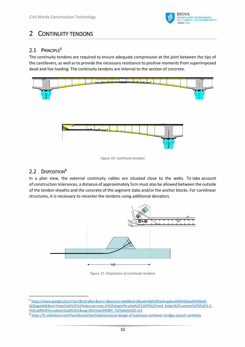
2.1 PRINCIPLE5 The continuity tendons are required to ensure adequate compression at the joint between the tips of
the cantilevers, as well as to provide the necessary resistance to positive moments from superimposed
dead and live loading. The continuity tendons are internal to the section of concrete.
Figure 10: Continuity tendons
2.2 DISPOSITION6 In a plan view, the external continuity cables are situated close to the webs. To take account
of construction tolerances, a distance of approximately 5cm must also be allowed between the outside
of the tendon sheaths and the concrete of the segment slabs and/or the anchor blocks. For curvilinear
structures, it is necessary to recenter the tendons using additional deviators.
Figure 11: Disposition of continuity tendons
5 https://www.google.pt/url?sa=t&rct=j&q=&esrc=s&source=web&cd=2&ved=0ahUKEwikvqaluuHXAhVEqxoKHV8wD-QQFggsMAE&url=https%3A%2F%2Feducnet.enpc.fr%2Fpluginfile.php%2F11070%2Fmod_folder%2Fcontent%2F0%2F3-2-POA.pdf%3Fforcedownload%3D1&usg=AOvVaw3HO0H_T5FhdwGtX2O-srIJ 6 https://fr.slideshare.net/PiyushKumarSanthalia/practical-design-of-balanced-cantilever-bridges-piyush-santhalia

Civil Works Construction Technology
11
3 TEMPORARY PILINGS7
This method consists of increasing the center distance between the temporary support blocks by
placing them on temporary metal or concrete pilings. This is only feasible when the bridge deck is
situated at a reasonable height above the ground (less than 15 meters or so).
Figure 12: Example of a temporary piling
This method is used on terrestrial sites in the following situations:
- For total lengths in excess of 100 meters
- When the pier head dimensions are reduced, often for architectural reasons
- When the pier shafts do not have enough resistance to flexion to stabilize the cantilever on
their own.
This is a viable solution for aquatic sites, provided that the pilings are supported on the foundation
bulkhead for the pier. The cantilever is usually stabilized by two pilings positioned symmetrically in
relation to the pier.
4 CLOSURE OF THE END SPAN
If the structure has spans of very unequal lengths or very short end spans, it is possible to use the
closure of the small spans to stabilize the adjacent half-cantilevers. At the start of the construction of
the half- cantilever, the structure must be stabilized using traditional methods. When the cantilever
reaches the middle of the shorter span, the central connection segment is assembled. The longer
span is then built by over- cantilevering, using the weight of the rear span to counteract the
imbalance.
7 http://www.infra-transports-materiaux.cerema.fr/IMG/pdf/US_F0308A_Prestressed_concrete_bridges.pdf

Civil Works Construction Technology
12
Figure 13: Weight of the rear span used to counteract the imbalance
5 EMBEDDING ON A PIER
When the cantilever is permanently embedded on its pier, the stability calculation is given by the
strength calculations for the pier shaft and foundations. For structures subjected to very strong
winds, additional stays are often necessary, requiring extra verifications under dynamic wind effects.
This solution is also required in the case of double pier shafts.
Figure 14: Embedding of the cantilever on the pier
Figure 15: Pier with double shafts

Civil Works Construction Technology
13
How to correct final misalignments in closing segment?8
When a bridge is nearly done and there is only the closing segment left, there is a risk that there will
be misalignments between the tips of the two cantilevers. This can be handled through using hydraulic
jacks or dead weights to correct the carefully smaller misalignments between the two cantilever tips.
For cast-in-place construction alignment variations and corrections are more easily accommodated but
more corrections will probably be necessary. When comparing cast-in-place construction and precast
construction the increase in alignment corrections will be much bigger for the cast-in-place
construction which relates directly to the age of the concrete when loaded. In cast-in-place
construction the concrete is generally much younger when it is loaded9.
The misalignment between the two cantilever tips can be corrected when molding the final closing
segment where the two girders meet at midspan of the bridge. This molding can be done by three
different methods.
These three methods are:
The first method that can be used is a hinged connection, where the structure is allowed a slight
horizontal movement. Even though the system is structurally relative simple hinges are complicated
details and because of the hinges, the structurally capacity of the system is reduced. Because the
structure can move in the hinge it can be a slight angle between the two superstructure halfs due to
deflection in the structure. This deflection is bad for the appearance of the bridge and the user’s
comfort.
Figure 16: Hinged connection
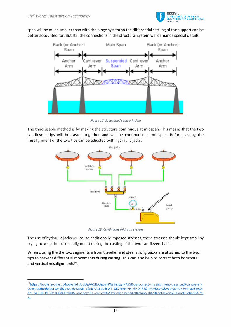
The second method that can be used is by a suspended span sitting on bearings between the
cantilevers. In this method the deflection angle between the shorter cantilevers and the suspended
8 https://theses.lib.vt.edu/theses/available/etd-120199-224950/unrestricted/11lucko_chapter4.pdf 9https://www.researchgate.net/publication/229038055_Constructability_Considerations_for_Balanced_Cantilever_Construction
Civil Works Construction Technology
14
span will be much smaller than with the hinge system so the differential settling of the support can be
better accounted for. But still the connections in the structural system will demands special details.
Figure 17: Suspended span principle
The third usable method is by making the structure continuous at midspan. This means that the two
cantilevers tips will be casted together and will be continuous at midspan. Before casting the
misalignment of the two tips can be adjusted with hydraulic jacks.
Figure 18: Continuous midspan system
The use of hydraulic jacks will cause additionally imposed stresses, these stresses shoule kept small by
trying to keep the correct alignment during the casting of the two cantilevers halfs.
When closing the the two segments a from traveller and steel strong backs are attached to the two
tips to prevent differential movements during casting. This can also help to correct both horizontal
and vertical misalignments10.
10https://books.google.pt/books?id=JpClAgAAQBAJ&pg=PA99&lpg=PA99&dq=correct+misalignment+balanced+Cantilever+Construction&source=bl&ots=JzU42osN_L&sig=AL6ou6cWT_8K7Pn6YrHy46HOhRE&hl=sv&sa=X&ved=0ahUKEwjhiab3k9LXAhUIWBQKHfo3DekQ6AEIPzAH#v=onepage&q=correct%20misalignment%20balanced%20Cantilever%20Construction&f=false

Civil Works Construction Technology
15
Useful references
https://www.researchgate.net/publication/299449141_Cast_in-
Situ_Balanced_Cantilever_for_Building_a_Bridge
http://www.bbrnetwork.com/technologies/construction-methods.html
https://www.youtube.com/watch?v=jdmuIjaROHA
https://theses.lib.vt.edu/theses/available/etd-120199-224950/unrestricted/11lucko_chapter4.pdf
http://eprints.utm.my/33326/1/MohdKhairulAzmanMFKA2012.pdf
http://citeseerx.ist.psu.edu/viewdoc/download?doi=10.1.1.502.2785&rep=rep1&type=pdf
http://www.waagner-biro.com/en/divisions/bridge-construction/about