Embed Size (px)
Citation preview

ALARM
WARNING
DIAG ERROR
COM 1
TX RXCOM 2
TX RX
CL-7 Regulator Control
ENTER
ESC EDIT
FUNC SYM
1 2ABC
3DEF
4GHI
5JKL
6MNO
7PQRS
8TUV
9WXYZ
0
VOLT LIMITER HIGH
OUT-OF-BAND HIGH
OUT-OF-BAND LOW
VOLT LIMITER LOW
AUTO TAP BLOCKED
REVERSE POWER
VOLT REDUCTION
1 2 3
DATA PORTS
USBDRIVE
PC
CONTROL FUNCTION
OFF
LOCAL MANUAL LOWER
NEUTRAL VOLTMETEREXTERNAL
SOURCE
INTERNAL
MOTOR6A
SUPER-VISORY
OFF
DRAGHANDRESET
OFF
EXTERNALPOWER
AUTO/REMOTE RAISE
OFF
LOCAL MANUAL LOWER
NEUTRAL VOLTMETER
INTERNAL
MOTOR6A
OFFVR2
EXTERNALPOWER
AUTO/REMOTE RAISE
VR3
OFF
LOCAL MANUAL LOWER
NEUTRAL VOLTMETER
INTERNAL
MOTOR6A
OFF
EXTERNALPOWER
AUTO/REMOTE RAISE
CL-7 voltage regulator control installation, operation, and maintenance instructions
COOPER POWERCOOPER POWERSERIESSERIESSERIESSERIESSERIESSERIESSERIES
Voltage Regulators MN225003EN
Effective June 2015Supersedes October 2014

ii CL-7 voltage regulator control installation, operation, and maintenance instructions MN225003EN June 2015
DISCLAIMER OF WARRANTIES AND LIMITATION OF LIABILITY
The information, recommendations, descriptions and safety notations in this document are based on Eaton Corporation’s (“Eaton”) experience and judgment and may not cover all contingencies. If further information is required, an Eaton sales office should be consulted. Sale of the product shown in this literature is subject to the terms and conditions outlined in appropriate Eaton selling policies or other contractual agreement between Eaton and the purchaser.
THERE ARE NO UNDERSTANDINGS, AGREEMENTS, WARRANTIES, EXPRESSED OR IMPLIED, INCLUDING WARRANTIES OF FITNESS FOR A PARTICULAR PURPOSE OR MERCHANTABILITY, OTHER THAN THOSE SPECIFICALLY SET OUT IN ANY EXISTING CONTRACT BETWEEN THE PARTIES. ANY SUCH CONTRACT STATES THE ENTIRE OBLIGATION OF EATON. THE CONTENTS OF THIS DOCUMENT SHALL NOT BECOME PART OF OR MODIFY ANY CONTRACT BETWEEN THE PARTIES.
In no event will Eaton be responsible to the purchaser or user in contract, in tort (including negligence), strict liability or other-wise for any special, indirect, incidental or consequential damage or loss whatsoever, including but not limited to damage or loss of use of equipment, plant or power system, cost of capital, loss of power, additional expenses in the use of existing power facilities, or claims against the purchaser or user by its customers resulting from the use of the information, recommendations and descriptions contained herein. The information contained in this manual is subject to change without notice.
iiiCL-7 voltage regulator control installation, operation, and maintenance instructions MN225003EN June 2015
Contents
SAFETY INFORMATIONSafety Information . . . . . . . . . . . . . . . . . . . . . . . . . . . . . . . . . . . . . . . . . . . . . . . . . . . . . . . . . . . . . . . . . . . . . . . . . . . . . iv
PRODUCT INFORMATIONIntroduction . . . . . . . . . . . . . . . . . . . . . . . . . . . . . . . . . . . . . . . . . . . . . . . . . . . . . . . . . . . . . . . . . . . . . . . . . . . . . . . . . . .1
Acceptance and Initial Inspection. . . . . . . . . . . . . . . . . . . . . . . . . . . . . . . . . . . . . . . . . . . . . . . . . . . . . . . . . . . . . . . . . . .1
Handling and Storage . . . . . . . . . . . . . . . . . . . . . . . . . . . . . . . . . . . . . . . . . . . . . . . . . . . . . . . . . . . . . . . . . . . . . . . . . . . .1
Standards . . . . . . . . . . . . . . . . . . . . . . . . . . . . . . . . . . . . . . . . . . . . . . . . . . . . . . . . . . . . . . . . . . . . . . . . . . . . . . . . . . . . .1
Description . . . . . . . . . . . . . . . . . . . . . . . . . . . . . . . . . . . . . . . . . . . . . . . . . . . . . . . . . . . . . . . . . . . . . . . . . . . . . . . . . . . .1
Control Panel Layout . . . . . . . . . . . . . . . . . . . . . . . . . . . . . . . . . . . . . . . . . . . . . . . . . . . . . . . . . . . . . . . . . . . . . . . . . . . .2
SECTION 1: CONTROL FRONT PANELLower Panel (Grey) . . . . . . . . . . . . . . . . . . . . . . . . . . . . . . . . . . . . . . . . . . . . . . . . . . . . . . . . . . . . . . . . . . . . . . . . . . . . . .3
Connecting Power to External Source Terminals . . . . . . . . . . . . . . . . . . . . . . . . . . . . . . . . . . . . . . . . . . . . . . . . . . . . . . . .4
120 Vac Applications to an Eaton's Cooper Power series 120 V Control . . . . . . . . . . . . . . . . . . . . . . . . . . . . . . . . . .4
240 Vac Applications to an Eaton's Cooper Power series 120 V Control . . . . . . . . . . . . . . . . . . . . . . . . . . . . . . . . . .6
240 Vac Applications to an Eaton's Cooper Power series 240 V Control . . . . . . . . . . . . . . . . . . . . . . . . . . . . . . . . . .8
Upper Panel (Black) . . . . . . . . . . . . . . . . . . . . . . . . . . . . . . . . . . . . . . . . . . . . . . . . . . . . . . . . . . . . . . . . . . . . . . . . . . . . .10
Indicator LEDS . . . . . . . . . . . . . . . . . . . . . . . . . . . . . . . . . . . . . . . . . . . . . . . . . . . . . . . . . . . . . . . . . . . . . . . . . . . . . . . . .13
Data Ports . . . . . . . . . . . . . . . . . . . . . . . . . . . . . . . . . . . . . . . . . . . . . . . . . . . . . . . . . . . . . . . . . . . . . . . . . . . . . . . . . . . .13
Hot-Key Mapping . . . . . . . . . . . . . . . . . . . . . . . . . . . . . . . . . . . . . . . . . . . . . . . . . . . . . . . . . . . . . . . . . . . . . . . . . . . . . . .13
SECTION 2: CONTROL INSTALLATIONMounting the Control . . . . . . . . . . . . . . . . . . . . . . . . . . . . . . . . . . . . . . . . . . . . . . . . . . . . . . . . . . . . . . . . . . . . . . . . . . .14
Placing the Control into Service . . . . . . . . . . . . . . . . . . . . . . . . . . . . . . . . . . . . . . . . . . . . . . . . . . . . . . . . . . . . . . . . . . .14
Operational Check . . . . . . . . . . . . . . . . . . . . . . . . . . . . . . . . . . . . . . . . . . . . . . . . . . . . . . . . . . . . . . . . . . . . . . . . . . . . . .15
Removal from Service . . . . . . . . . . . . . . . . . . . . . . . . . . . . . . . . . . . . . . . . . . . . . . . . . . . . . . . . . . . . . . . . . . . . . . . . . . .17
Removal of Control . . . . . . . . . . . . . . . . . . . . . . . . . . . . . . . . . . . . . . . . . . . . . . . . . . . . . . . . . . . . . . . . . . . . . . . . . . . . .18
Replacement of Control . . . . . . . . . . . . . . . . . . . . . . . . . . . . . . . . . . . . . . . . . . . . . . . . . . . . . . . . . . . . . . . . . . . . . . . . .18
SECTION 3: INITIAL CONTROL PROGRAMMINGBasic Programming . . . . . . . . . . . . . . . . . . . . . . . . . . . . . . . . . . . . . . . . . . . . . . . . . . . . . . . . . . . . . . . . . . . . . . . . . . . . .19
Multi-Phase Programming . . . . . . . . . . . . . . . . . . . . . . . . . . . . . . . . . . . . . . . . . . . . . . . . . . . . . . . . . . . . . . . . . . . . . . . .20
Programming and Reconfiguring for Different Voltage Systems . . . . . . . . . . . . . . . . . . . . . . . . . . . . . . . . . . . . . . . . . . .21
Determination of Leading or Lagging on Delta-Connected Regulators . . . . . . . . . . . . . . . . . . . . . . . . . . . . . . . . . . . . . .24
SECTION 4: CONTROL OPERATIONAutomatic Operation . . . . . . . . . . . . . . . . . . . . . . . . . . . . . . . . . . . . . . . . . . . . . . . . . . . . . . . . . . . . . . . . . . . . . . . . . . . .25
Manual Operation . . . . . . . . . . . . . . . . . . . . . . . . . . . . . . . . . . . . . . . . . . . . . . . . . . . . . . . . . . . . . . . . . . . . . . . . . . . . . .25
Self-Test . . . . . . . . . . . . . . . . . . . . . . . . . . . . . . . . . . . . . . . . . . . . . . . . . . . . . . . . . . . . . . . . . . . . . . . . . . . . . . . . . . . . . .25
Security System . . . . . . . . . . . . . . . . . . . . . . . . . . . . . . . . . . . . . . . . . . . . . . . . . . . . . . . . . . . . . . . . . . . . . . . . . . . . . . .26
Remote Security Override . . . . . . . . . . . . . . . . . . . . . . . . . . . . . . . . . . . . . . . . . . . . . . . . . . . . . . . . . . . . . . . . . . . . . . . .26
Basic Control Operations . . . . . . . . . . . . . . . . . . . . . . . . . . . . . . . . . . . . . . . . . . . . . . . . . . . . . . . . . . . . . . . . . . . . . . . . .27
SECTION 5: CONTROL PROGRAMMINGQuik-Start Setup . . . . . . . . . . . . . . . . . . . . . . . . . . . . . . . . . . . . . . . . . . . . . . . . . . . . . . . . . . . . . . . . . . . . . . . . . . . . . . .29
Function Menu . . . . . . . . . . . . . . . . . . . . . . . . . . . . . . . . . . . . . . . . . . . . . . . . . . . . . . . . . . . . . . . . . . . . . . . . . . . . . . . .32
The instructions in this manual are not intended as a substitute for proper training or adequate experience in the safe operation of the equipment described. Only competent technicians who are familiar with this equipment should install, operate, and service it.
A competent technician has these qualifications:
• Is thoroughly familiar with these instructions.
• Is trained in industry-accepted high and low-voltage safe operating practices and procedures.
• Is trained and authorized to energize, de-energize, clear, and ground power distribution equipment.
• Is trained in the care and use of protective equipment such as arc flash clothing, safety glasses, face shield, hard hat, rubber gloves, clampstick, hotstick, etc.
Following is important safety information. For safe installation and operation of this equipment, be sure to read and understand all cautions and warnings.
Safety instructionsFollowing are general caution and warning statements that apply to this equipment. Additional statements, related to specific tasks and procedures, are located throughout the manual.
Safety for life!
SAFETYFOR LIFE
!SAFETYFOR LIFE
Eaton meets or exceeds all applicable industry standards relating to product safety in its Cooper Power™ series products. We actively promote safe practices in the use and maintenance of our products through our service literature, instructional training programs, and the continuous efforts of all Eaton employees involved in product design, manufacture, marketing, and service.
We strongly urge that you always follow all locally approved safety procedures and safety instructions when working around high voltage lines and equipment, and support our “Safety For Life” mission.
Safety information
DANGERHazardous voltage. Contact with hazardous voltage will cause death or severe personal injury. Follow all locally approved safety procedures when working around high- and low-voltage lines and equipment. G103.3
WARNING Before installing, operating, maintaining, or testing this equipment, carefully read and understand the contents of this manual. Improper operation, handling or maintenance can result in death, severe personal injury, and equipment damage. G101.0
WARNING This equipment is not intended to protect human life. Follow all locally approved procedures and safety practices when installing or operating this equipment. Failure to comply can result in death, severe personal injury and equipment damage. G102.1
WARNING Power distribution and transmission equipment must be properly selected for the intended application. It must be installed and serviced by competent personnel who have been trained and understand proper safety procedures. These instructions are written for such personnel and are not a substitute for adequate training and experience in safety procedures. Failure to properly select, install or maintain power distribution and transmission equipment can result in death, severe personal injury, and equipment damage. G122.3
This manual may contain four types of hazard statements:
DANGER Indicates an imminently hazardous situation which, if not avoided, will result in death or serious injury.
WARNING Indicates a potentially hazardous situation which, if not avoided, could result in death or serious injury.
CAUTION Indicates a potentially hazardous situation which, if not avoided, may result in minor or moderate injury.
CAUTION: Indicates a potentially hazardous situation which, if not avoided, may result in equipment damage only.
Hazard Statement Definitions
iv CL-7 voltage regulator control installation, operation, and maintenance instructions MN225003EN June 2015
vCL-7 voltage regulator control installation, operation, and maintenance instructions MN225003EN June 2015
Function Codes . . . . . . . . . . . . . . . . . . . . . . . . . . . . . . . . . . . . . . . . . . . . . . . . . . . . . . . . . . . . . . . . . . . . . . . . . . . . . . . .46
Special Functions . . . . . . . . . . . . . . . . . . . . . . . . . . . . . . . . . . . . . . . . . . . . . . . . . . . . . . . . . . . . . . . . . . . . . . . . . . . . . . 110
Alarms . . . . . . . . . . . . . . . . . . . . . . . . . . . . . . . . . . . . . . . . . . . . . . . . . . . . . . . . . . . . . . . . . . . . . . . . . . . . . . . . . . . . . . 110
Sequence of Events (SOE) . . . . . . . . . . . . . . . . . . . . . . . . . . . . . . . . . . . . . . . . . . . . . . . . . . . . . . . . . . . . . . . . . . . . . . 111
Power-Up/Reset Conditions . . . . . . . . . . . . . . . . . . . . . . . . . . . . . . . . . . . . . . . . . . . . . . . . . . . . . . . . . . . . . . . . . . . . . .112
Indication Messages . . . . . . . . . . . . . . . . . . . . . . . . . . . . . . . . . . . . . . . . . . . . . . . . . . . . . . . . . . . . . . . . . . . . . . . . . . .112
Metering-PLUS Formats . . . . . . . . . . . . . . . . . . . . . . . . . . . . . . . . . . . . . . . . . . . . . . . . . . . . . . . . . . . . . . . . . . . . . . . .113
SECTION 6: CONTROL FEATURESCalendar/Clock . . . . . . . . . . . . . . . . . . . . . . . . . . . . . . . . . . . . . . . . . . . . . . . . . . . . . . . . . . . . . . . . . . . . . . . . . . . . . . . .115
Metering . . . . . . . . . . . . . . . . . . . . . . . . . . . . . . . . . . . . . . . . . . . . . . . . . . . . . . . . . . . . . . . . . . . . . . . . . . . . . . . . . . . .115
Tap Position Indication (TPI) . . . . . . . . . . . . . . . . . . . . . . . . . . . . . . . . . . . . . . . . . . . . . . . . . . . . . . . . . . . . . . . . . . . . . .116
Source-Side Voltage . . . . . . . . . . . . . . . . . . . . . . . . . . . . . . . . . . . . . . . . . . . . . . . . . . . . . . . . . . . . . . . . . . . . . . . . . . . .116
Reverse Power Operation . . . . . . . . . . . . . . . . . . . . . . . . . . . . . . . . . . . . . . . . . . . . . . . . . . . . . . . . . . . . . . . . . . . . . . .117
Bias Co-Generation Mode . . . . . . . . . . . . . . . . . . . . . . . . . . . . . . . . . . . . . . . . . . . . . . . . . . . . . . . . . . . . . . . . . . . . . . .123
Multi-Phase Voltage Regulation . . . . . . . . . . . . . . . . . . . . . . . . . . . . . . . . . . . . . . . . . . . . . . . . . . . . . . . . . . . . . . . . . . .126
Voltage Limiter . . . . . . . . . . . . . . . . . . . . . . . . . . . . . . . . . . . . . . . . . . . . . . . . . . . . . . . . . . . . . . . . . . . . . . . . . . . . . . .128
Voltage Reduction . . . . . . . . . . . . . . . . . . . . . . . . . . . . . . . . . . . . . . . . . . . . . . . . . . . . . . . . . . . . . . . . . . . . . . . . . . . . .128
Soft ADD-AMP Feature . . . . . . . . . . . . . . . . . . . . . . . . . . . . . . . . . . . . . . . . . . . . . . . . . . . . . . . . . . . . . . . . . . . . . . . . .129
Adaptive ADD-AMP . . . . . . . . . . . . . . . . . . . . . . . . . . . . . . . . . . . . . . . . . . . . . . . . . . . . . . . . . . . . . . . . . . . . . . . . . . . .129
Supervisory Control and Data Acquisition (SCADA) . . . . . . . . . . . . . . . . . . . . . . . . . . . . . . . . . . . . . . . . . . . . . . . . . . .129
SECTION 7: ADVANCED CONTROL FEATURESMetering-PLUS Feature . . . . . . . . . . . . . . . . . . . . . . . . . . . . . . . . . . . . . . . . . . . . . . . . . . . . . . . . . . . . . . . . . . . . . . . . .134
USB Memory Device. . . . . . . . . . . . . . . . . . . . . . . . . . . . . . . . . . . . . . . . . . . . . . . . . . . . . . . . . . . . . . . . . . . . . . . . . . .138
Communications . . . . . . . . . . . . . . . . . . . . . . . . . . . . . . . . . . . . . . . . . . . . . . . . . . . . . . . . . . . . . . . . . . . . . . . . . . . . . .139
Protocols . . . . . . . . . . . . . . . . . . . . . . . . . . . . . . . . . . . . . . . . . . . . . . . . . . . . . . . . . . . . . . . . . . . . . . . . . . . . . . . . . . . .139
Configurable Logic . . . . . . . . . . . . . . . . . . . . . . . . . . . . . . . . . . . . . . . . . . . . . . . . . . . . . . . . . . . . . . . . . . . . . . . . . . . . .139
Alarms . . . . . . . . . . . . . . . . . . . . . . . . . . . . . . . . . . . . . . . . . . . . . . . . . . . . . . . . . . . . . . . . . . . . . . . . . . . . . . . . . . . . . .143
Sequence of Events (SOE) . . . . . . . . . . . . . . . . . . . . . . . . . . . . . . . . . . . . . . . . . . . . . . . . . . . . . . . . . . . . . . . . . . . . . .143
Data Profiler . . . . . . . . . . . . . . . . . . . . . . . . . . . . . . . . . . . . . . . . . . . . . . . . . . . . . . . . . . . . . . . . . . . . . . . . . . . . . . . . . .143
TIME-ON-TAP Feature . . . . . . . . . . . . . . . . . . . . . . . . . . . . . . . . . . . . . . . . . . . . . . . . . . . . . . . . . . . . . . . . . . . . . . . . . .144
Preventive Maintenance Tapping . . . . . . . . . . . . . . . . . . . . . . . . . . . . . . . . . . . . . . . . . . . . . . . . . . . . . . . . . . . . . . . . . .145
Duty Cycle Monitor . . . . . . . . . . . . . . . . . . . . . . . . . . . . . . . . . . . . . . . . . . . . . . . . . . . . . . . . . . . . . . . . . . . . . . . . . . . .145
Leader/Follower Scheme . . . . . . . . . . . . . . . . . . . . . . . . . . . . . . . . . . . . . . . . . . . . . . . . . . . . . . . . . . . . . . . . . . . . . . . .145
Voltage Sag Monitoring . . . . . . . . . . . . . . . . . . . . . . . . . . . . . . . . . . . . . . . . . . . . . . . . . . . . . . . . . . . . . . . . . . . . . . . . .145
Battery Options . . . . . . . . . . . . . . . . . . . . . . . . . . . . . . . . . . . . . . . . . . . . . . . . . . . . . . . . . . . . . . . . . . . . . . . . . . . . . . .147
DC Power Supply (13.5 Vdc) . . . . . . . . . . . . . . . . . . . . . . . . . . . . . . . . . . . . . . . . . . . . . . . . . . . . . . . . . . . . . . . . . . . . .147
SECTION 8: TROUBLESHOOTINGExternal Check . . . . . . . . . . . . . . . . . . . . . . . . . . . . . . . . . . . . . . . . . . . . . . . . . . . . . . . . . . . . . . . . . . . . . . . . . . . . . . . .148
Control Panel Troubleshooting . . . . . . . . . . . . . . . . . . . . . . . . . . . . . . . . . . . . . . . . . . . . . . . . . . . . . . . . . . . . . . . . . . . .148
Tap-Changer Operation Troubleshooting . . . . . . . . . . . . . . . . . . . . . . . . . . . . . . . . . . . . . . . . . . . . . . . . . . . . . . . . . . . .150
Metering Troubleshooting . . . . . . . . . . . . . . . . . . . . . . . . . . . . . . . . . . . . . . . . . . . . . . . . . . . . . . . . . . . . . . . . . . . . . . .153
Control Calibration . . . . . . . . . . . . . . . . . . . . . . . . . . . . . . . . . . . . . . . . . . . . . . . . . . . . . . . . . . . . . . . . . . . . . . . . . . . . .153
SECTION 9: APPENDIXVR-32 Tap Connections and Voltage Levels . . . . . . . . . . . . . . . . . . . . . . . . . . . . . . . . . . . . . . . . . . . . . . . . . . . . . . . . . .155
Wiring Diagrams and Schematics . . . . . . . . . . . . . . . . . . . . . . . . . . . . . . . . . . . . . . . . . . . . . . . . . . . . . . . . . . . . . . . . .157

vi CL-7 voltage regulator control installation, operation, and maintenance instructions MN225003EN June 2015

Product information
IntroductionThis document describes the operation and maintenance instructions for the CL-7 Voltage Regulator Control for Eaton's Cooper Power™ series voltage regulators. Refer to Service Information MN225008EN (S225-10-30) VR-32 Voltage Regulator with Quik-Drive™ Tap-Changer Installation, Operation, and Maintenance Instructions for installation and operation information on Eaton's Cooper Power series Voltage Regulator.
Read this manual firstRead and understand the contents of this manual and follow all locally approved procedures and safety practices before installing or operating this equipment. Read and understand the manual detailing the installation and operation of the regulator used with this control.
Additional informationThese instructions cannot cover all details or vari ations in the equipment, procedures, or processes described nor provide directions for meeting every possible contin gency during installation, operation, or maintenance. For additional information, please contact your Eaton representative.
Acceptance and initial inspectionThis product is completely assembled, tested, and inspected at the factory. It is carefully calibrated, adjusted, and in good condition when accepted by the carrier for shipment.
Upon receipt, inspect the carton for signs of damage. Unpack the control and inspect it thoroughly for damage incurred during shipment. If damage is discovered, file a claim with the carrier immediately.
Handling and storageBe careful during handling and storage of equipment to minimize the possibility of damage.
StandardsEaton's regulators are designed and tested in accordance with the following standards:
IEEE Std C37.90.1™-2012 Standard
IEEE Std C37.90.2™-2004 Standard
IEEE Std C57.13™-2008 Standard
IEEE Std C57.15™-2009 Standard
IEEE Std C57.91™-2011 Standard
IEEE Std C57.131™-2012 Standard
EN 50081-2
EN 61000-4
IEC 60068-2
IEC 60214-1
IEC 60255-5
Quality standardsISO 9001 Certified Quality Management System.
DescriptionThe CL-7 voltage regulator control from Eaton's Cooper Power series incorporates the latest in digital technology to provide accurate, rapid, and dependable control of a step-voltage regulator. Utilizing surface-mount technology and low-power electronics, the CL-7 control is CE (Commonwealth Europe) compliant. The nameplate located on the control box defines the power circuit.
The CL-7 control provides the first of its kind single- or multi-phase voltage regulation utilizing a single control platform. During every step of develop, focus was placed on producing a control to meet the growing demand for smart grid ready features and for flexibility to meet the needs of the future. While great effort was put into enhancing its features, the CL-7 control remains true to its roots by maintaining the ease of use of its predecessor CL controls. The control features the same look and feel of the earlier controls and whenever possible, the same function codes were utilized. The CL-7 control allows keypad programming, Metering-PLUS™ status inquiries, USB memory device uploading and downloading, and multiple communication ports with user-selectable DNP3 or IEC 60870-5 protocol. Additional communications protocol options are also available upon request. LED indicators provide instant information on alarm, communications, and regulation condition status. A four-line display provides detailed information and further simplifies programming. In addition, the CL-7 control is highly configurable and ready for use in applications where either digital or analog SCADA is required.
CAUTION Lifting hazard. A complete control box assembly with control can weight in excess of 50 lbs. Proper lifting techniques and team lifts should be employed in order to avoid personal injury.
1CL-7 voltage regulator control installation, operation, and maintenance instructions MN225003EN June 2015
ALARM
WARNING
DIAG ERROR
COM 1
TX RXCOM 2
TX RX
CL-7 Regulator Control
ENTER
ESC EDIT
FUNC SYM
1 2ABC
3DEF
4GHI
5JKL
6MNO
7PQRS
8TUV
9WXYZ
0
VOLT LIMITER HIGH
OUT-OF-BAND HIGH
OUT-OF-BAND LOW
VOLT LIMITER LOW
AUTO TAP BLOCKED
REVERSE POWER
VOLT REDUCTION
1 2 3
DATA PORTS
USBDRIVE
PC
CONTROL FUNCTION
OFF
LOCAL MANUAL LOWER
NEUTRAL VOLTMETEREXTERNAL
SOURCE
INTERNAL
MOTOR6A
SUPER-VISORY
OFF
DRAGHANDRESET
OFF
EXTERNALPOWER
AUTO/REMOTE RAISE
OFF
LOCAL MANUAL LOWER
NEUTRAL VOLTMETER
INTERNAL
MOTOR6A
OFFVR2
EXTERNALPOWER
AUTO/REMOTE RAISE
VR3
OFF
LOCAL MANUAL LOWER
NEUTRAL VOLTMETER
INTERNAL
MOTOR6A
OFF
EXTERNALPOWER
AUTO/REMOTE RAISE
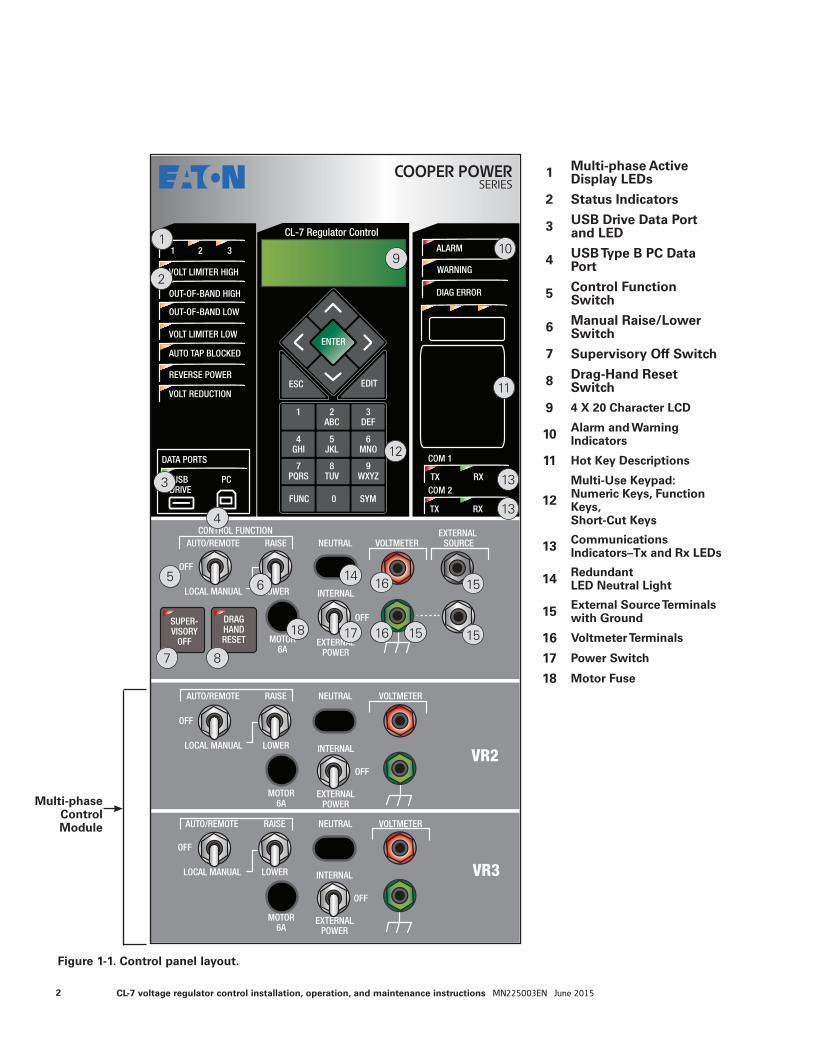
Figure 1-1. Control panel layout.
Multi-phase Control Module
10
12
1
2
3
4
56
7 8
9
11
13
13
1415
15
16
161718 15
1 Multi-phase Active Display LEDs
2 Status Indicators
3 USB Drive Data Port and LED
4 USB Type B PC Data Port
5 Control Function Switch
6 Manual Raise/Lower Switch
7 Supervisory Off Switch
8 Drag-Hand Reset Switch
9 4 X 20 Character LCD
10 Alarm and Warning Indicators
11 Hot Key Descriptions
12
Multi-Use Keypad:Numeric Keys, Function Keys, Short-Cut Keys
13 Communications Indicators–Tx and Rx LEDs
14 Redundant LED Neutral Light
15 External Source Terminals with Ground
16 Voltmeter Terminals
17 Power Switch
18 Motor Fuse
2 CL-7 voltage regulator control installation, operation, and maintenance instructions MN225003EN June 2015
Section 1: Control front panel
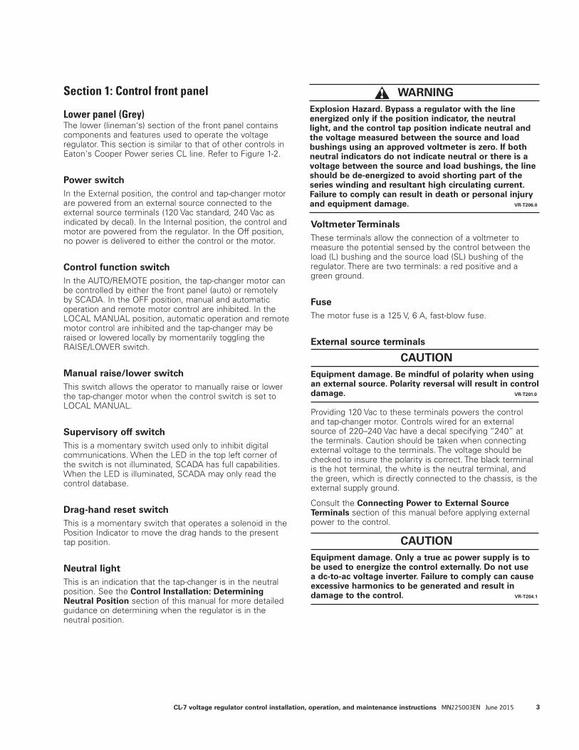
Lower panel (Grey)The lower (lineman's) section of the front panel contains components and features used to operate the voltage regulator. This section is similar to that of other controls in Eaton's Cooper Power series CL line. Refer to Figure 1-2.
Power switchIn the External position, the control and tap-changer motor are powered from an external source connected to the external source terminals (120 Vac standard, 240 Vac as indicated by decal). In the Internal position, the control and motor are powered from the regulator. In the Off position, no power is delivered to either the control or the motor.
Control function switchIn the AUTO/REMOTE position, the tap-changer motor can be controlled by either the front panel (auto) or remotely by SCADA. In the OFF position, manual and automatic operation and remote motor control are inhibited. In the LOCAL MANUAL position, automatic operation and remote motor control are inhibited and the tap-changer may be raised or lowered locally by momentarily toggling the RAISE/LOWER switch.
Manual raise/lower switchThis switch allows the operator to manually raise or lower the tap-changer motor when the control switch is set to LOCAL MANUAL.
Supervisory off switchThis is a momentary switch used only to inhibit digital communications. When the LED in the top left corner of the switch is not illuminated, SCADA has full capabilities. When the LED is illuminated, SCADA may only read the control database.
Drag-hand reset switchThis is a momentary switch that operates a solenoid in the Position Indicator to move the drag hands to the present tap position.
Neutral lightThis is an indication that the tap-changer is in the neutral position. See the Control Installation: Determining Neutral Position section of this manual for more detailed guidance on determining when the regulator is in the neutral position.
Voltmeter TerminalsThese terminals allow the connection of a voltmeter to measure the potential sensed by the control between the load (L) bushing and the source load (SL) bushing of the regulator. There are two terminals: a red positive and a green ground.
FuseThe motor fuse is a 125 V, 6 A, fast-blow fuse.
External source terminals
Providing 120 Vac to these terminals powers the control and tap-changer motor. Controls wired for an external source of 220–240 Vac have a decal specifying “240” at the terminals. Caution should be taken when connecting external voltage to the terminals. The voltage should be checked to insure the polarity is correct. The black terminal is the hot terminal, the white is the neutral terminal, and the green, which is directly connected to the chassis, is the external supply ground.
Consult the Connecting Power to External Source Terminals section of this manual before applying external power to the control.
CAUTION Equipment damage. Only a true ac power supply is to be used to energize the control externally. Do not use a dc-to-ac voltage inverter. Failure to comply can cause excessive harmonics to be generated and result in damage to the control. VR-T204.1
CAUTION Equipment damage. Be mindful of polarity when using an external source. Polarity reversal will result in control damage. VR-T201.0
WARNING Explosion Hazard. Bypass a regulator with the line energized only if the position indicator, the neutral light, and the control tap position indicate neutral and the voltage measured between the source and load bushings using an approved voltmeter is zero. If both neutral indicators do not indicate neutral or there is a voltage between the source and load bushings, the line should be de-energized to avoid shorting part of the series winding and resultant high circulating current. Failure to comply can result in death or personal injury and equipment damage. VR-T206.0
3CL-7 voltage regulator control installation, operation, and maintenance instructions MN225003EN June 2015

Connecting power to external source terminals
120 Vac applications to an Eaton's Cooper Power series 120 V control
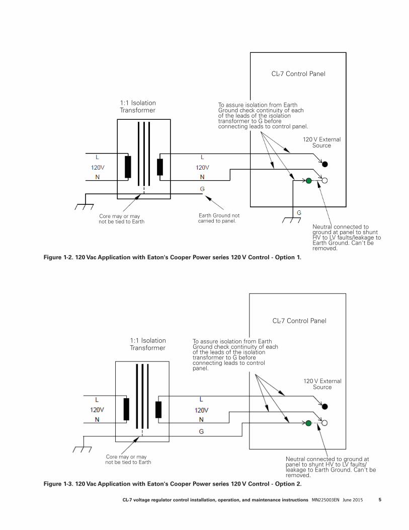
Option 1:The control box assembly is connected to earth ground to provide protection to operations personnel. This is a typical field application where the control is mounted on a grounded regulator tank or dropped down a pole with the control box grounded properly.
Since the control is configured for 120 Vac, a 1:1 isolation transformer must be used to isolate the supply voltage. This isolation transformer must isolate both the neutral and line on the secondary side. Also, the neutral and ground on the secondary side should not be bonded or connected. To check isolation from earth ground, check the continuity of each lead on the isolation transformer with respect to ground (G). Check this before connecting the leads to the control panel. See Figure 1-2.
The control panel assembly is grounded through the tank or a separate grounding strap. Earth ground of the isolation transformer is not connected to the control. The only source of earth ground reference on secondary of the isolation transformer is through the control box connection to ground.
Option 2:The control box assembly is floating. This is a typical shop or lab application where the control is mounted on an ungrounded regulator tank or sitting on a workbench.
The 120 Vac external source must be completely isolated. In most cases an isolation transformer is needed. This isolation transformer must isolate both the neutral and line on the secondary side. Also, the neutral and ground on the secondary side should not be bonded or connected. To check isolation from earth ground, check the continuity of each lead on the isolation transformer with respect to ground (G). Check this before connecting the leads to the control panel. See Figure 1-3.
In this case, the ground of the isolation transformer is connected to the green terminal post on the CL-7 control. In this configuration, the only source of earth ground reference on the secondary side of the isolation transformer is through the control box connection to the isolation transformer ground.
4 CL-7 voltage regulator control installation, operation, and maintenance instructions MN225003EN June 2015
1:1 Isolation Transformer
CL-7 Control Panel
120 V External Source
Neutral connected to ground at panel to shunt HV to LV faults/leakage to Earth Ground. Can't be removed.
Earth Ground not carried to panel.
To assure isolation from Earth Ground check continuity of each of the leads of the isolation transformer to G before connecting leads to control panel.
Core may or may not be tied to Earth
1:1 Isolation Transformer
Core may or may not be tied to Earth
To assure isolation from Earth Ground check continuity of each of the leads of the isolation transformer to G before connecting leads to control panel.
CL-7 Control Panel
Neutral connected to ground at panel to shunt HV to LV faults/leakage to Earth Ground. Can't be removed.
120 V External Source
Figure 1-2. 120 Vac Application with Eaton's Cooper Power series 120 V Control - Option 1.
Figure 1-3. 120 Vac Application with Eaton's Cooper Power series 120 V Control - Option 2.
5CL-7 voltage regulator control installation, operation, and maintenance instructions MN225003EN June 2015
240 Vac applications to an Eaton's Cooper Power series 120 V control
Option 1:The control box assembly/panel is connected to earth ground to provide protection to operations personnel. This is a typical field application where the control is mounted on a grounded regulator tank or dropped down a pole with the control box grounded properly.
Since the control is configured for 120 Vac, a 2:1 isolation transformer must be used to step and isolate the supply voltage. This isolation transformer must isolate both the neutral and line on the secondary side. Also, the neutral and ground on the secondary side should not be bonded or connected. To check isolation from earth ground, check the continuity of each lead on the isolation transformer with respect to ground (G). Check this before connecting the leads to the control panel. See Figure 1-4.
The control panel assembly is grounded through the tank or a separate grounding strap. Earth ground of the isolation transformer is not connected to the control. The only source of earth ground reference on secondary of the isolation transformer is through the control box connection to ground.
Option 2:The control box assembly is floating. This is a typical shop or lab application when the control is mounted on an ungrounded regulator tank or setting on a workbench.
Since the control is configured for 120 Vac, a 2:1 isolation transformer must be used to step and isolate the supply voltage. This isolation transformer must isolate both the neutral and line on the secondary side. Also, the neutral and ground on the secondary side should not be bonded or connected. To check isolation from earth ground, check the continuity of each lead on the isolation transformer with respect to ground (G). Check this before connecting the leads to the control panel. See Figure 1-5.
In this case the ground of the isolation transformer is connected to the green terminal post on the CL-7 control. In this configuration, the only source of earth ground reference on the secondary side of the isolation transformer is through the control box connection to the isolation transformer ground.
6 CL-7 voltage regulator control installation, operation, and maintenance instructions MN225003EN June 2015

2:1 Isolation Transformer
CL-7 Control Panel
120 V External Source
Neutral connected to ground at panel to shunt HV to LV faults/leakage to Earth Ground. Can't be removed.
To assure isolation from Earth Ground check continuity of each of the leads of the isolation transformer to G before connecting leads to control panel.
Core may or may not be tied to Earth
Figure 1-4. 240 Vac Application with Eaton's Cooper Power series 120 V Control - Option 1.
Figure 1-5. 240 Vac Application with Eaton's Cooper Power series 120 V Control - Option 2.
2:1 Isolation Transformer
CL-7 Control Panel
Neutral connected to ground at panel to shunt HV to LV faults/leakage to Earth Ground. Can't be removed.
To assure isolation from Earth Ground check continuity of each of the leads of the isolation transformer to G before connecting leads to control panel.
Core may or may not be tied to Earth
120V External Source
Earth Ground not carried to panel.
7CL-7 voltage regulator control installation, operation, and maintenance instructions MN225003EN June 2015
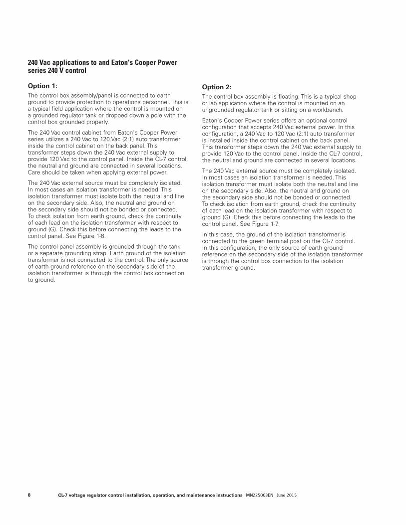
240 Vac applications to and Eaton's Cooper Power series 240 V control
Option 1:The control box assembly/panel is connected to earth ground to provide protection to operations personnel. This is a typical field application where the control is mounted on a grounded regulator tank or dropped down a pole with the control box grounded properly.
The 240 Vac control cabinet from Eaton's Cooper Power series utilizes a 240 Vac to 120 Vac (2:1) auto transformer inside the control cabinet on the back panel. This transformer steps down the 240 Vac external supply to provide 120 Vac to the control panel. Inside the CL-7 control, the neutral and ground are connected in several locations. Care should be taken when applying external power.
The 240 Vac external source must be completely isolated. In most cases an isolation transformer is needed. This isolation transformer must isolate both the neutral and line on the secondary side. Also, the neutral and ground on the secondary side should not be bonded or connected. To check isolation from earth ground, check the continuity of each lead on the isolation transformer with respect to ground (G). Check this before connecting the leads to the control panel. See Figure 1-6.
The control panel assembly is grounded through the tank or a separate grounding strap. Earth ground of the isolation transformer is not connected to the control. The only source of earth ground reference on the secondary side of the isolation transformer is through the control box connection to ground.
Option 2:The control box assembly is floating. This is a typical shop or lab application where the control is mounted on an ungrounded regulator tank or sitting on a workbench.
Eaton's Cooper Power series offers an optional control configuration that accepts 240 Vac external power. In this configuration, a 240 Vac to 120 Vac (2:1) auto transformer is installed inside the control cabinet on the back panel. This transformer steps down the 240 Vac external supply to provide 120 Vac to the control panel. Inside the CL-7 control, the neutral and ground are connected in several locations.
The 240 Vac external source must be completely isolated. In most cases an isolation transformer is needed. This isolation transformer must isolate both the neutral and line on the secondary side. Also, the neutral and ground on the secondary side should not be bonded or connected. To check isolation from earth ground, check the continuity of each lead on the isolation transformer with respect to ground (G). Check this before connecting the leads to the control panel. See Figure 1-7.
In this case, the ground of the isolation transformer is connected to the green terminal post on the CL-7 control. In this configuration, the only source of earth ground reference on the secondary side of the isolation transformer is through the control box connection to the isolation transformer ground.
8 CL-7 voltage regulator control installation, operation, and maintenance instructions MN225003EN June 2015
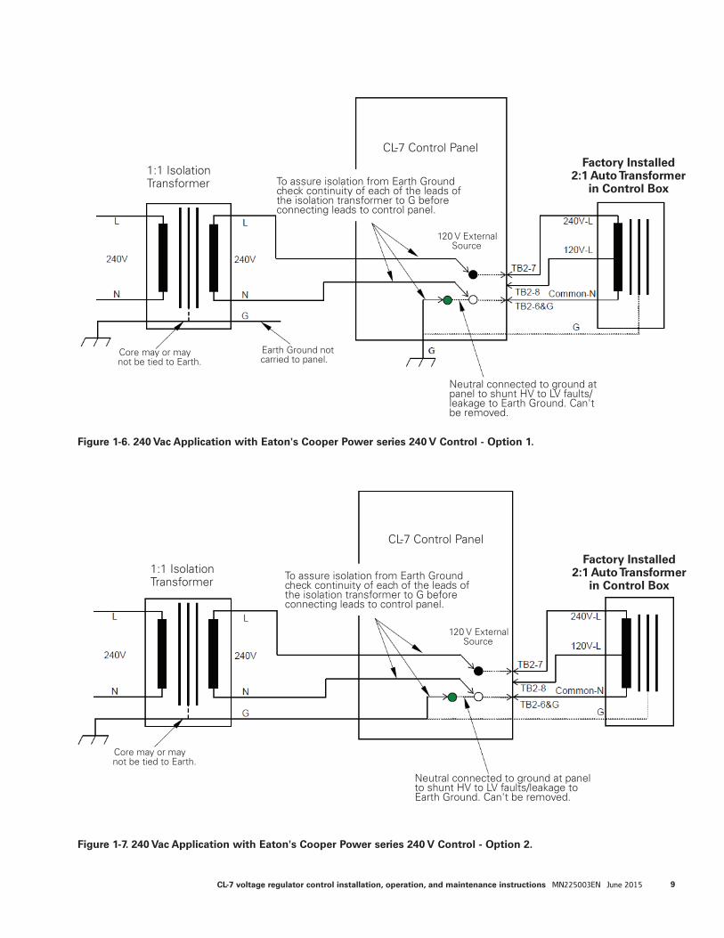
Figure 1-6. 240 Vac Application with Eaton's Cooper Power series 240 V Control - Option 1.
Figure 1-7. 240 Vac Application with Eaton's Cooper Power series 240 V Control - Option 2.
1:1 Isolation Transformer
CL-7 Control Panel
Neutral connected to ground at panel to shunt HV to LV faults/leakage to Earth Ground. Can't be removed.
To assure isolation from Earth Ground check continuity of each of the leads of the isolation transformer to G before connecting leads to control panel.
Core may or may not be tied to Earth.
Earth Ground not carried to panel.
1:1 Isolation Transformer
CL-7 Control Panel
Neutral connected to ground at panel to shunt HV to LV faults/leakage to Earth Ground. Can't be removed.
To assure isolation from Earth Ground check continuity of each of the leads of the isolation transformer to G before connecting leads to control panel.
Core may or may not be tied to Earth.
120 V External Source
120 V External Source
Factory Installed2:1 Auto Transformer
in Control Box
Factory Installed2:1 Auto Transformer
in Control Box
9CL-7 voltage regulator control installation, operation, and maintenance instructions MN225003EN June 2015
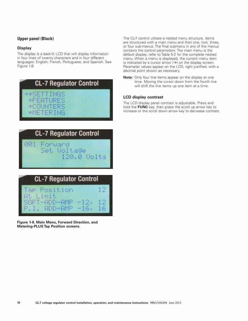
Upper panel (Black)
DisplayThe display is a back-lit LCD that will display information in four lines of twenty characters and in four different languages: English, French, Portuguese, and Spanish. See Figure 1-8.
The CL-7 control utilizes a nested menu structure, items are structured with a main menu and then one, two, three, or four sub-menus. The final submenu in any of the menus contains the control parameters. The main menu is the default display; refer to Table 5-2 for the complete nested menu. When a menu is displayed, the current menu item is indicated by a cursor arrow () on the display screen. Parameter values appear on the LCD, right justified, with a decimal point shown as necessary.
ote:N Only four line items appear on the display at one time. Moving the cursor down from the fourth line will shift the line items up one item at a time.
LCD display contrastThe LCD display panel contrast is adjustable. Press and hold the FUNC key, then press the scroll up arrow key to increase or the scroll down arrow key to decrease contrast.
Figure 1-8. Main Menu, Forward Direction, and Metering-PLUS Tap Position screens.
10 CL-7 voltage regulator control installation, operation, and maintenance instructions MN225003EN June 2015
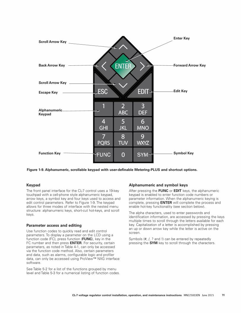
KeypadThe front panel interface for the CL-7 control uses a 19-key touchpad with a cell-phone style alphanumeric keypad, arrow keys, a symbol key and four keys used to access and edit control parameters. Refer to Figure 1-9. The keypad allows for three modes of interface with the nested menu structure: alphanumeric keys, short-cut hot-keys, and scroll keys.
Parameter access and editingUse function codes to quickly read and edit control parameters. To display a parameter on the LCD using a function code (FC), press function (FUNC), key in the FC number and then press ENTER. For security, certain parameters, as noted in Table 4-1, can only be accessed via the function code method. Also, certain parameters and data, such as alarms, configurable logic and profiler data, can only be accessed using ProView™ NXG interface software.
See Table 5-2 for a list of the functions grouped by menu level and Table 5-3 for a numerical listing of function codes.
Alphanumeric and symbol keysAfter pressing the FUNC or EDIT keys, the alphanumeric keypad is enabled to enter function code numbers or parameter information. When the alphanumeric keying is complete, pressing ENTER will complete the process and enable hot-key functionality (see section below).
The alpha characters, used to enter passwords and identification information, are accessed by pressing the keys multiple times to scroll through the letters available for each key. Capitalization of a letter is accomplished by pressing an up or down arrow key while the letter is active on the screen.
Symbols (#, /, ? and !) can be entered by repeatedly pressing the SYM key to scroll through the characters.
Figure 1-9. Alphanumeric, scrollable keypad with user-definable Metering-PLUS and shortcut options.
Scroll Arrow Key
Scroll Arrow Key
Function Key
Edit Key
Back Arrow Key
Enter Key
Forward Arrow Key
Symbol Key
Escape Key
Alphanumeric Keypad
11CL-7 voltage regulator control installation, operation, and maintenance instructions MN225003EN June 2015

Short-cut hot-keysThe keypad can be configured to create shortcut access to a variety of commonly used Metering-PLUS, menu and parameter displays. Keys mapped to support the Metering-PLUS feature provide, with one touch, commonly used diagnostic data. Refer to the Advanced Features: Metering-PLUS section of this manual for more information. Mapping can also provide one-button access to top-level nested items, some function codes, and enabling of configurable logic.
The default keypad map corresponds to that of the predecessor CL-6 control. A slide out panel (see Figure 1-10) provides a key-code for the key assignments. Two additional pre-programmed key maps can be selected or a custom keypad map can be created. Keypad mapping is available through the nested menu path MENU SYSTEM > Hot Keys or by using FC 944. A custom keypad map can only be created using ProView NXG software.
Options available in the User Defined mapping are CL Exclusive and CL Exclusive w/ Confirm. CL is configurable logic. These options allow for one-button activation of functionality created in configurable logic. Configurable logic inputs are available that correspond to the user-defined key assignments. After programming configurable logic and assigning a control key to activate the logic, a single key press (or key press and then a confirming key press) is all that is required to active the functionality of the logic. See Service Information MN225015EN, CL-7 Regulator Control ProView NXG Software Programming Guide for more information on this feature and creating configurable logic.
Slide-out panels are available for the alternate pre-programmed keypad assignments or a user-defined custom panel can be created.
The following options are available when creating a custom keypad map:
• Comp Voltage Metering-PLUS
• Load Voltage Metering-PLUS
• Load Current Metering-PLUS
• Tap Position Metering-PLUS
• USB Memory Drive
• SETTINGS Menu
• FEATURES Menu
• SEQUENCE OF EVENTS Log
• METERING Menu
• ALARMS Menu
• COUNTERS Menu
• COMMUNICATIONS Menu
• System Calendar and Clock FC 50
• DIAGNOSTICS Menu
• Security Access
• Total Operations FC 0
• Forward Set Voltage FC 1
• Forward Band Width FC 2
• Forward Time Delay FC 3
• Forward Line Drop Compensation Resistance FC 4
• Forward Line Drop Compensation Reactance FC 5
• Load Voltage FC 6
• Source Voltage FC 7
• Comp Voltage FC 8
• Load Current FC 9
• CL Exclusive
• CL Exclusive w/Confirm
Scroll arrow keysUse the arrow keys to move up or down between menu levels, scroll through parameter options when editing parameters, change the case of letters and change numerical values from positive to negative. When the multi-phase option is active on the control, the right arrow key can also be used to change the display between the connected regulators.
The ENTER and Escape (ESC) keys are used like the arrow keys to enter the menu structure or move between menu levels. ENTER is used to access submenus. ESC is used to step back or exit submenus. Repeated pressing of the ESC key will return the display screen to the top level main menu.
The LCD displays only four menu items at one time. For nested menu levels that contain more than 4 items, the arrow keys are used to move the cursor down from the fourth line and then shift the menu items up one item at a time. After reaching the last item, the menu will scroll to the top item.
Figure 1-10. Standard keypad hot-key assignments.
12 CL-7 voltage regulator control installation, operation, and maintenance instructions MN225003EN June 2015
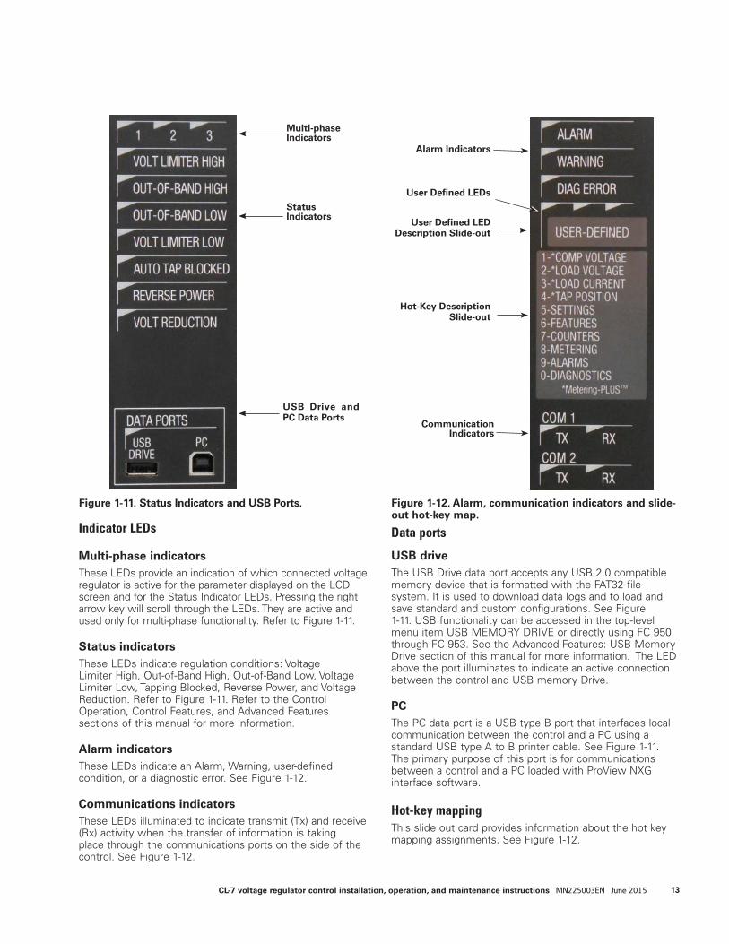
Indicator LEDs
Multi-phase indicatorsThese LEDs provide an indication of which connected voltage regulator is active for the parameter displayed on the LCD screen and for the Status Indicator LEDs. Pressing the right arrow key will scroll through the LEDs. They are active and used only for multi-phase functionality. Refer to Figure 1-11.
Status indicatorsThese LEDs indicate regulation conditions: Voltage Limiter High, Out-of-Band High, Out-of-Band Low, Voltage Limiter Low, Tapping Blocked, Reverse Power, and Voltage Reduction. Refer to Figure 1-11. Refer to the Control Operation, Control Features, and Advanced Features sections of this manual for more information.
Alarm indicatorsThese LEDs indicate an Alarm, Warning, user-defined condition, or a diagnostic error. See Figure 1-12.
Communications indicatorsThese LEDs illuminated to indicate transmit (Tx) and receive (Rx) activity when the transfer of information is taking place through the communications ports on the side of the control. See Figure 1-12.
Data ports
USB driveThe USB Drive data port accepts any USB 2.0 compatible memory device that is formatted with the FAT32 file system. It is used to download data logs and to load and save standard and custom configurations. See Figure 1-11. USB functionality can be accessed in the top-level menu item USB MEMORY DRIVE or directly using FC 950 through FC 953. See the Advanced Features: USB Memory Drive section of this manual for more information. The LED above the port illuminates to indicate an active connection between the control and USB memory Drive.
PCThe PC data port is a USB type B port that interfaces local communication between the control and a PC using a standard USB type A to B printer cable. See Figure 1-11. The primary purpose of this port is for communications between a control and a PC loaded with ProView NXG interface software.
Hot-key mappingThis slide out card provides information about the hot key mapping assignments. See Figure 1-12.
Figure 1-11. Status Indicators and USB Ports. Figure 1-12. Alarm, communication indicators and slide-out hot-key map.
Status Indicators
USB Drive and PC Data Ports
Multi-phase Indicators
Alarm Indicators
User Defined LEDs
User Defined LED Description Slide-out
Hot-Key Description Slide-out
Communication Indicators
13CL-7 voltage regulator control installation, operation, and maintenance instructions MN225003EN June 2015
Mounting the controlThe CL-7 regulator control in a control box can be mounted on the regulator tank or at a point remote from the unit. Rubber-covered cable of various lengths is available for interconnection between the control and the regulator.
Mounting a multi-phase controlAs with the single-phase control, the multi-phase control can be mounted on one of the regulator tanks or on a separate mounting point remote from the regulators. An individual control cable will be connected between the junction box of each regulator and the control box.
Placing the control into serviceRefer to the appropriate regulator manual, as indicated on the regulator nameplate for specific information on regulator installation (see Figure 3-4). Refer to Tables 2-1 and 2-2 for control specifications and metering accuracy.
When energizing the control from an external source, use only a 120 Vac source, unless the control was configured for 240 Vac, as indicated by a decal adjacent to the terminals.
Setting the control for serviceThe control must be properly programmed for service. Controls that come pre-installed at the factory on a voltage regulator will be set up for operation on that regulator. For controls that are retrofit onto a regulator, programming must be performed before the unit can be put into service. Refer to the Initial Control Programming section of this manual for more information.
The control must be energized to be programmed. Apply 120 Vac, or other voltage as indicated by the decal on the control, to the external source terminals; ensure the ground wire is connected to the ground terminal; and place
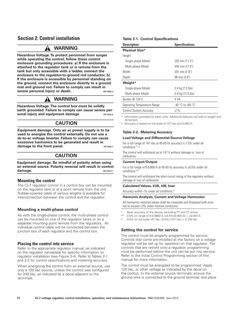
Section 2: Control installation Table 2-1. Control Specifications
Description Specifications
Physical Size*
Height
Single-phase Model
Multi-phase Model
Width
Depth
292 mm (11.5")
445 mm (17.5")
201 mm (7.9")
98 mm (3.9")
Weight*
Single-phase Model
Multi-phase Model
3.4 kg (7.5 lbs)
5.9 kg (12.9 lbs)
Burden @ 120 V 4 VA
Operating Temperature Range -40 °C to +85 °C
Control System Accuracy ±1%
* Information provided for base units. Additional features will add to weight and dimension.
† Accuracy is based on full scale of 127 Vac and 0.800 A.
Table 2-2. Metering Accuracy
Load Voltage and Differential/Source Voltage
For a full range of 147 Vac at 45-65 Hz accuracy is ± 5% under all conditions.* †
The control will withstand up to 147 V without damage or loss of calibration.
Current Input/Output
For a full range of 0-0.800 A at 45-65 Hz accuracy is ±0.5% under all conditions.**
The control will withstand the short-circuit rating of the regulator without damage or loss of calibration.
Calculated Values, kVA, kW, kvar
Accuracy within 1% under all conditions.*
Harmonic Analysis, Current and Voltage Harmonics
All harmonics metered values shall be computed and displayed with error not to exceed ±3% under nominal conditions.
* Basic accuracy of the device, excluding PT and CT errors.** 0.5% on range of 0-0.0800 A (±0.5%)(0.800 A) = ±0.004 A† 0.5% on full scale 147 Vac: (0.5%) (147 Vac) = 0.735 Vac
WARNING Hazardous Voltage. To protect personnel from surges while operating the control, follow these control enclosure grounding procedures: a) If the enclosure is attached to the regulator tank or is remote from the tank but only accessible with a ladder, connect the enclosure to the regulator-to-ground rod conductor; b) If the enclosure is accessible by personnel standing on the ground, connect the enclosure directly to a ground mat and ground rod. Failure to comply can result in severe personal injury or death. VR-T202.0
WARNING Hazardous Voltage. The control box must be solidly earth grounded. Failure to comply can cause severe per-sonal injury and equipment damage. VR-T203.0
CAUTION Equipment damage. Only an ac power supply is to be used to energize the control externally. Do not use a dc-to-ac voltage inverter. Failure to comply can cause excessive harmonics to be generated and result in damage to the front panel. VR-T204.1
CAUTION Equipment damage. Be mindful of polarity when using an external source. Polarity reversal will result in control damage. VR-T201.0
14 CL-7 voltage regulator control installation, operation, and maintenance instructions MN225003EN June 2015
the power switch in the external position. Alternately, the regulator may be energized at line potential and the power switch placed in the Internal position.
When power is applied to the control, the self-test routine will commence and the LCD display will activate, followed by a PASS message. Check the date and time displayed and reset if necessary. If a failure or diagnostic error message is displayed, refer to the Troubleshooting section of this manual.
Setting the control for multi-phase serviceWhen programming a control for multi-phase operation, there are a number of settings that configure the control for operation and a number that configure the control to function with the connected voltage regulators. It is important to identify the pertinent settings for the individual regulators and enter each setting into the control appropriately. Refer to the Multi-phase Voltage Regulation section of this manual and Bulletin B225-13018 CL-7 Multi-phase Control Reference for guidance on programming the control for multi-phase operation.
Operational check
Pre-installation checkThe CL-7 control has the facilities for either manual or automatic operation of the tap-changer, using either the internal source of power (the regulator) or an external source. To perform an operational check of the control before installing the regulator, follow these steps.
ote:N For use with a non-Eaton's Cooper Power series voltage regulator, refer to the manufacturer’s manual for equipment specific information.
1. Open V1 (and V6, if present) knife switch(es) located on back panel of control enclosure.
2. Place POWER switch in OFF position and CONTROL FUNCTION switch in OFF position.
3. Connect a variable 120 Vac 50/60 Hz source to EXTERNAL SOURCE terminals. Controls wired for an external source of 220 –240 Vac have a decal specifying “240” at the terminals. Verify proper polarity.
4. Place POWER switch in EXTERNAL position.
5. Move CONTROL FUNCTION switch to LOCAL MANUAL, press and hold RAISE/LOWER momentary toggle switch. Allow tap-changer to operate to 8 L, the 5% buck position. Verify tap position indication (TPI) is registering properly by pressing Metering-PLUS Tap Position key or viewing FC 12.
6. Raise and hold the RAISE/LOWER momentary toggle switch. Allow tap-changer to operate to 8 R, the 5% boost position.
7. Place CONTROL FUNCTION switch in the AUTO/REMOTE position.
8. Increase the variable voltage source until applied
voltage is out-of-band. Note that the OUT-OF-BAND HIGH LED on the front panel will come on. After the time delay period, the control will issue a lower-tap-change signal. Verify tap position indication (TPI) is registering properly by pressing the Metering-PLUS Tap Position key or viewing FC 12 and comparing the reading to the tap position indicator on the regulator junction box.
9. Decrease the variable voltage source until applied voltage is out of band. Note that the OUT-OF-BAND LOW LED on the front panel will come on. After the time delay period, the control will issue a raise-tap-change signal. Verify tap position indication (TPI) is registering properly by pressing the Metering-PLUS Tap Position key or viewing FC 12 and comparing the reading to the tap position indicator on the regulator junction box.
10. Place the CONTROL FUNCTION switch in the LOCAL MANUAL position and manually return the tap-changer to neutral. When on neutral, the NEUTRAL light will illuminate continuously and position indicator will point to zero.
11. Place CONTROL FUNCTION switch in OFF position.
12. Depress the DRAG HAND Reset momentary switch and release; the position indicator drag hands will reset to indicating hand.
13. Turn POWER switch to OFF and disconnect power supply from EXTERNAL SOURCE terminals.
In-service checkWith the control programmed for basic operation, perform an operational check of manual and automatic operation.
1. Press the Metering-PLUS Comp Voltage key to display compensated voltage and both band edges on the LCD panel.
2. Place the CONTROL FUNCTION switch in LOCAL MANUAL position.
3. Toggle the RAISE/LOWER switch up to activate a raise operation. Allow tap-changer to operate for enough steps to take voltage out of band. Note that the OUT-OF-BAND HIGH LED on the front panel will come on.
4. Place the CONTROL FUNCTION switch in the AUTO/REMOTE position. After the time delay period, the control should cause the regulator to step down to the top band edge. This will display on the LCD panel.
Example: 120 V and a 2 V bandwidth = 121 V top band edge.
5. After voltage is brought in-band and tap changing has stopped, move the CONTROL FUNCTION switch to the LOCAL MANUAL position.
6. Toggle the RAISE/LOWER switch down to activate a lower operation. Allow tap-changer to operate for enough steps to take voltage out of band. Note that the OUT-OF-BAND LOW LED on the front panel will come on.
15CL-7 voltage regulator control installation, operation, and maintenance instructions MN225003EN June 2015
7. Place the CONTROL FUNCTION switch in the AUTO/ REMOTE position. After the time delay period, the control should cause the regulator to step up to the lower band edge. This will display on the LCD panel.
Example: 120 V and a 2 V bandwidth = 119 V lower band edge.
Control bench testingWhen applying external voltage to a CL-7 control, disconnected from the control box back panel, follow these steps:
1. Place a jumper between positions 7 and 8 of the disconnect plug on the wiring harness of the control.
2. Place a second jumper between positions 6 and terminal G of the disconnected plug. There are two G terminals on the harness plug. The jumper would be placed into the G closest to terminal 6.
3. Connect the external source to the external source post on the front of the control. Connect the hot lead to the black terminal post, the neutral to the white post, and the ground to the green terminal post. See the detailed instructions for applying power to the external source terminals in Section 1 of this manual.
ote:N For a multi-phase control, this method will only enable powering of the main control. It is recommended to install the control into a control box to fully power a multi-phase control using the external source terminals.
Field calibration checkTo check the calibration of the control, compare the voltage that the control reports on the display to the voltage measured at the test terminals.
ote:N Field calibration checks are only an indication of calibration and are not as precise as the procedure described in the Troubleshooting section of this manual.
1. Connect an accurate true-RMS responding voltmeter to the voltmeter terminals.
2. Use the keypad to access FC 47 parameter. Key in:
FUNC, 47, ENTER.
Or access via the menu: FEATURES > Calibration > Voltage Calibration.
3. Under ideal conditions, the displayed voltage of the control will match the voltage of the voltmeter. Realistically, the voltages may be slightly different because:
A. The metering and operation is based upon the RMS value of the fundamental power line frequency. Thus, the metered values exclude the influences of harmonic voltages which are probably present on the line. A true RMS meter, however, will include these
harmonic voltages in its calculations of the RMS voltage. This does not present a problem with either metering device, since each device uses a different approach to metering.
B. The calibration of the voltmeter being used for measurement is probably not exact. Even a very good meter with a basic accuracy of 0.5% could be in error by as much as 0.6 V (out of 120 V) and still be considered to be “in calibration.” The control is calibrated using a conditioned power supply and reference voltmeters which are periodically calibration-checked, traceable to the National Bureau of Standards.
ote:N The control firmware is designed to perform ratio correction. Through the use of the ratio-correction transformer (RCT) located on the back panel, the volt-age brought to the control is usually corrected to the 120 V base voltage. However, there are some ratings in which this voltage is not fully corrected by the RCT. Refer to the regulator nameplate for specific information for that regulator. Table 3-3 gives a gen-eral indication of these voltages.
When mounting the CL-7 control into an existing enclosure, the existing enclosure may not have an RCT installed. In this case the voltage measured on the voltmeter terminals may not match the voltage read on the control.
Whatever voltage results from dividing the nominal system voltage, FC 43, by the overall PT ratio, FC 44, is considered by the control to be the nominal voltage. Therefore, when that voltage appears at the input of the control, 120 V will be reported as the output voltage, FC 6, whether the nominal is actually 120 V or not. Likewise, the compensated voltage, FC 8, and input voltage, FC 7, will be scaled accordingly. If the regulator is equipped and programmed for reverse power operation, the compensated voltage will be correct even during reverse power conditions.
Also note that the base voltage can be set to a 240 V base using FC 148. When this is done, all secondary voltage displays will also be scaled to correspond to the 240 V base. Despite the displays however, the control itself is still powered using an approximate 120 V input.
The load voltage, FC 10; source voltage, FC 11; and calculated parameters such as the kVA, kW, and kvar, are not scaled similarly to FC 6 and FC 8. Instead, they reflect the true value of line voltage.
ote:N The voltage measured at the test terminals during reverse power flow is the new source voltage at the load bushing of the regulator.
16 CL-7 voltage regulator control installation, operation, and maintenance instructions MN225003EN June 2015

Removal from serviceRefer to the appropriate regulator manual as indicated on the regulator nameplate for further information.
Determining neutral position
Return the regulator to neutral. Only a regulator in the neutral position can be safely removed from service without interrupting load continuity. It is recommended to use four (4) methods to determine the neutral condition.
Return the regulator to neutral1. Use the Raise/Lower switch to bring the regulator to
the neutral position.
2. When in neutral, the Neutral light will be continuously and brightly lit on the control front panel and the position indicator will point to zero.
3. Verify the neutral position of the regulator using four methods.
A. Verify that the neutral indicator light on the control is indicating the neutral position. Neutral is indicated only when the light is continuously and brightly illuminated.
B. Verify the tap position on the control indicates neutral by using the Metering-PLUS key or FC 12. When in neutral, the display will show "0" (zero).
C. Verify that the position indicator on the regulator is in the neutral position. The indicator should point straight up to either zero or N for Neutral.
D. Using an approved voltmeter, verify that there is no voltage difference between the source and load bushings.
4. When the regulator has been placed in the neutral position, but prior to bypassing, additional safety actions must be taken to disable the tap-changer motor and ensure that the tap-changer will not inadvertently switch to an off-neutral position. This can be accomplished by doing the following:
A. Place the CONTROL FUNCTION switch in the OFF position.
B. Remove the motor fuse.
C. Place the control POWER switch in the OFF position.
D. Open V1, knife switch (and V6 if present) located on the control back panel.
WARNING Explosion Hazard. To stop the regulator on the neutral position, the CONTROL FUNCTION switch should be returned to OFF during the switching operation from positions 1R or 1L to position neutral. Switching to OFF prior to reaching the neutral position prevents overshoot. Failure to comply can result in death or severe personal injury and equipment damage. VR-T208.0
WARNING Explosion Hazard. After placing the regulator in the neutral position for bypass switching, always disable the motor to prevent a tap change during bypassing which can result in the tap-changer stepping off of neutral. Failure to comply can cause death or severe personal injury and equipment damage. VR-T209.0
WARNING Explosion Hazard. Bypass a regulator with the line energized only if the position indicator, the neutral light, and the control tap position indicate neutral and the voltage measured between the source and load bushings using an approved voltmeter is zero. If both neutral indicators do not indicate neutral or there is a voltage between the source and load bushings, the line should be de-energized to avoid shorting part of the series winding and resultant high circulating current. Failure to comply can result in death or personal injury and equipment damage. VR-T206.0
WARNING Explosion Hazard. Always use the CONTROL FUNCTION switch (labeled AUTO/REMOTE, OFF, LOCAL MANUAL, and RAISE and LOWER) to operate the regulator, not the power switch. Failure to comply can result in the tap-changer stepping off of neutral immediately upon being energized, causing personal injury and equipment damage. VR-T207.0
DANGER Explosion Hazard. During bypass switching, the regulator must be in the neutral position. Prior to bypass switching: 1) The regulator must be placed in the neutral position; 2) Tap-changer operation must be disabled during the bypass switching. If the regulator is in any other position, part of the series winding will be shorted when the bypass switch is closed, resulting in high circulating current. Failure to comply will result in death or severe personal injury and equipment damage. VR-T205.0
17CL-7 voltage regulator control installation, operation, and maintenance instructions MN225003EN June 2015
Removal of controlThe control may be removed from the regulator with the regulator energized. Record settings, etc., to facilitate replacement of the control.
To open the control, unscrew the captive knob(s) on the left side of the panel. This allows the control to swing open on its hinges. With the control open, the back panel is readily accessible. The design of the control enclosure, back panel, and control enables easy replacement of the control, leaving the back panel, control enclosure, and cable intact. To remove the control, proceed as follows:
1. Push closed the current shorting switch C. This shorts out the secondary of the regulator CT.
ote:N Regulators shipped with a quick-disconnect cable contain a solid-state CT monitoring circuit in the junction box. This device automatically places a burden on the CT anytime the CT circuit is opened. For consistency and redundancy, it is recommended that the CT shorting switch be used whenever it is present on the back panel.
2. Pull open disconnect switch V1 (and V6 if present). This de-energizes terminal board TB3 (or TB2 if present).
3. Disconnect the control from the back panel at TB3 (or TB2 if present), located at the bottom of the back panel.
4. Disconnect the control ground lead from the back panel.
The control can now be lifted off its hinges. Care should be taken to prevent damage to a control while in transit and/or storage.
Replacement of control
To place a control into the control enclosure, follow the procedure outlined below:
1. Engage control on enclosure hinges.
2. Connect control ground lead to back panel.
3. Reconnect control to back panel at TB3 (or TB2 if present), located at the bottom of back panel.
4. Push closed the disconnect switch V1 (and V6 if present).
5. Pull open the current shorting switch C.
6. Close the control and tighten locking screw(s).
WARNING Flashover Hazard. Push the C shorting switch closed before attempting to remove the front panel. Failure to comply can open the regulator CT circuit, producing a flashover in the control, causing personal injury and equipment damage. VR-T210.0
WARNING Flashover Hazard. Do not pull open the current shorting switch C until the TB3 (or TB2 if present) connection is completed. Failure to comply can open the regulator CT secondary and cause a flashover in the control, causing personal injury and equipment damage. VR-T211.0
18 CL-7 voltage regulator control installation, operation, and maintenance instructions MN225003EN June 2015

Section 3: Initial control programming
This section explains each step for properly completing initial control programming settings on a CL-7 voltage regulator control and back panel. Check the System Line Voltage rating on the regulator nameplate. Refer to the regulator service manual as identified on the regulator nameplate for additional information on the regulator.
This section covers standard set-up procedures for controls, including control replacement. Refer to Programming and Reconfiguring for Different Voltage Systems, in this section of this manual, when installing/replacing the CL-7 control and reconfiguring the regulator for a different voltage system.
1. Start with all switches on the control front panel turned OFF.
2. There are two options for powering the control: internal power or external power. Select one method and follow the appropriate step.
A. Internal Power
Turn POWER switch to INTERNAL from the OFF position.
B. External Power
Apply external source to the EXTERNAL SOURCE binding posts: hot lead to black, top binding post; neutral lead to white, bottom binding post; ground to green ground binding post. See detailed instructions for applying power to the external source terminals in Section 1 of this manual.
Turn POWER switch to EXTERNAL from the OFF position.
Basic programmingComplete the steps in Table 3-1 to program the control for basic operation. Continue with the steps in Table 3-2 to then program the control for additional features or control replacement. For each item, check each value and verify or change as appropriate.
ote:N After turning on the control and the LCD displays PASS, press ESC for further keypad use.
Step-by-step instructions are included in Tables 3-1 and 3-2. The Instructions column lists keys to press (i.e.; ENTER, Edit, 7, etc.). Also, italicized instructions denote a choice or an entry; Value denotes a desired value entered via the numeric keypads; and following each “Scroll” is an italicized list of alternatives that appear in the display, within that function code. Scroll through the list until the desired alternative is selected, and then press Enter.
Perform a Demand Master Reset (FC 38) after completing the initial control programming to reset to present demand values.
ote:N Go to FC 941 to change the language setting.
Table 3-1. Programming for Basic OperationsFunction Code Description Instructions99 Security Function FUNC, 99, ENTER, Password Admin (default), ENTER1 Forward Set Voltage FUNC, 1, ENTER, EDIT, Value, ENTER2 Forward Bandwidth FUNC, 2, ENTER, EDIT, Value, ENTER3 Forward Time Delay FUNC, 3, ENTER, EDIT, Value, ENTER4 Forward Line Drop Comp. Resistance FUNC, 4, ENTER, EDIT, Value, ENTER5 Forward Line Drop Comp. Reactance FUNC, 5, ENTER, EDIT, Value, ENTER40 Control Identification FUNC, 40, ENTER, EDIT, I. D. number, ENTER41 Regulator Configuration FUNC, 41, ENTER, EDIT, Scroll - Wye; Delta Lagging; Delta Leading, ENTER42 Control Operating Mode FUNC, 42, ENTER, EDIT, Scroll - Sequential; Time Integrating; Voltage Averaging,
ENTER43 System Line Voltage FUNC, 43, ENTER, EDIT, Value, ENTER44 Overall PT Ratio FUNC, 44, ENTER, EDIT, Value, ENTER44 Internal PT Ratio FUNC 44, Down Arrow, EDIT, Value, ENTER45 C.T. Primary Rating FUNC, 45, ENTER, EDIT, Value, ENTER46 Demand Time Interval FUNC, 46, ENTER, EDIT, Value, ENTER49 Tap-Changer Type FUNC, 49, ENTER, EDIT, Scroll - Cooper QD8; Cooper QD5; Cooper QD3; Cooper
Spring Drive; Cooper Direct Drive; Siemens; General Electric; Howard; LTC-Reinhausen, ITB, Toshiba, User-Definded, ENTER
50 Calendar/Clock FUNC, 50, ENTER, EDIT, Month, Day, Year, Hour, Minute, ENTER140 Regulator Type FUNC, 140, ENTER, EDIT, Scroll - Type A; Type B; Type C; Type D, ENTER 144 P.I. ADD-AMP™ High Limit FUNC, 144, ENTER, EDIT, Value, ENTER 145 P.I. ADD-AMP Low Limit FUNC, 145, ENTER, EDIT, Value, ENTER 146 Vin PT Configuration FUNC, 146, ENTER, EDIT, Scroll - Vdiff without RCT1; Vin, Vdiff with RCT2, ENTER 69 Auto Operation Blocking Status FUNC, 69, ENTER, EDIT, Scroll - Normal; Blocked, ENTER148 Nominal Sec Load voltage FUNC, 141, ENTER, EDIT, Scroll - 120, 240, System Line Voltage ENTER141 Regulator Identification FUNC, 141, ENTER, EDIT, Value, ENTER
19CL-7 voltage regulator control installation, operation, and maintenance instructions MN225003EN June 2015
Multi-phase programmingWhen programming a control for multi-phase operation, there are a number of setting that configure the control for operation and a number that configure the control to function with the connected voltage regulators. It is important to identify the pertinent settings applying to the individual regulators and to the control and enter them correctly. Refer to the Multi-phase Voltage Regulation section of this manual and Bulletin B225-13018 CL-7 Multi-phase Control Reference for guidance on programming the control for multi-phase operation.
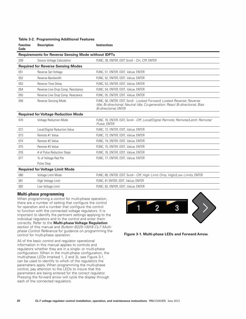
All of the basic control and regulator operational information in this manual applies to controls and regulators whether they are in a single- or multi-phase configuration. When in the multi-phase configuration, the multi-phase LEDs (marked 1, 2 and 3), see Figure 3-1, can be used to identify to which of the regulators the parameters apply. When programming the multi-phase control, pay attention to the LEDs to insure that the parameters are being entered for the correct regulator. Pressing the forward arrow will cycle the display through each of the connected regulators.
Table 3-2. Programming Additional Features
Function Code
Description Instructions
Requirements for Reverse Sensing Mode without IDPTs
039 Source Voltage Calculation FUNC, 39, ENTER, EDIT Scroll - On; Off, ENTER
Required for Reverse Sensing Modes
051 Reverse Set Voltage FUNC, 51, ENTER, EDIT, Value, ENTER
052 Reverse Bandwidth FUNC, 52, ENTER, EDIT, Value, ENTER
053 Reverse Time Delay FUNC, 53, ENTER, EDIT, Value, ENTER
054 Reverse Line Drop Comp. Resistance FUNC, 54, ENTER, EDIT, Value, ENTER
055 Reverse Line Drop Comp. Reactance FUNC, 55, ENTER, EDIT, Value, ENTER
056 Reverse Sensing Mode FUNC, 56, ENTER, EDIT, Scroll - Locked Forward; Locked Reverse; Reverse Idle; Bi-directional; Neutral Idle; Co-generation; React Bi-directional, Bias Bi-directional, ENTER
Required for Voltage Reduction Mode
070 Voltage Reduction Mode FUNC, 70, ENTER, EDIT, Scroll - Off; Local/Digital Remote; Remote/Latch; Remote/Pulse, ENTER
072 Local/Digital Reduction Value FUNC, 72, ENTER, EDIT, Value, ENTER
073 Remote #1 Value FUNC, 73, ENTER, EDIT, Value, ENTER
074 Remote #2 Value FUNC, 74, ENTER, EDIT, Value, ENTER
075 Remote #3 Value FUNC, 75, ENTER, EDIT, Value, ENTER
076 # of Pulse Reduction Steps FUNC, 76, ENTER, EDIT, Value, ENTER
077 % of Voltage Red Per
Pulse Step
FUNC, 77, ENTER, EDIT, Value, ENTER
Required for Voltage Limit Mode
080 Voltage Limit Mode FUNC, 80, ENTER, EDIT, Scroll - Off; High Limit Only; High/Low Limits, ENTER
081 High Voltage Limit FUNC, 81 ENTER, EDIT, Value, ENTER
082 Low Voltage Limit FUNC, 82, ENTER, EDIT, Value, ENTER
Figure 3-1. Multi-phase LEDs and Forward Arrow.
20 CL-7 voltage regulator control installation, operation, and maintenance instructions MN225003EN June 2015
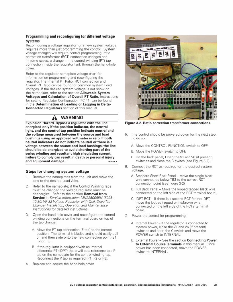
Programming and reconfiguring for different voltage systemsReconfiguring a voltage regulator for a new system voltage requires more than just programming the control. System voltage changes will require control programming, ratio correction transformer (RCT) connection changes and in some cases, a change in the control winding (PT) tap connection inside the regulator tank through the hand-hole cover.
Refer to the regulator nameplate voltage chart for information on programming and reconfiguring the regulator. The Internal PT Ratio, RCT connection and Overall PT Ratio can be found for common system Load Voltages. If the desired system voltage is not show on the nameplate, refer to the section Allowable System Voltages and Calculation of Overall PT Ratio. Instructions for setting Regulator Configuration (FC 41) can be found in the Determination of Leading or Lagging in Delta-Connected Regulators section of this manual.
Steps for changing system voltage1. Remove the nameplates from the unit and move the
pins to the desired Load Volts.
2. Refer to the nameplate; if the Control Winding Taps must be changed the voltage regulator must be deenergize. Refer to the section Removal from Service in Service Information MN225008EN (S225-10-30) VR-32 Voltage Regulator with Quik-Drive Tap-Changer Installation, Operation and Maintenance Instructions for detailed instructions.
3. Open the hand-hole cover and reconfigure the control winding connections on the terminal board on top of the tap changer.
A. Move the PT tap connection (E tap) to the correct position. The terminal is bladed and should easily pull off and then slide onto the new connection point (E1, E2 or E3).
B. If the regulator is equipped with an internal differential PT (IDPT) there will be a reference to a P tap on the nameplate for the control winding tap. Reconnect the P tap as required (P1, P2 or P3).
4. Replace and secure the hand-hole cover.
5. The control should be powered down for the next step. To do so:
A. Move the CONTROL FUNCTION switch to OFF
B. Move the POWER switch to OFF.
C. On the back panel, Open the V1 and V6 (if present) switches and close the C switch (see Figure 3-2).
6. Connect the RCT as required for the desired system voltage.
A. Standard Short Back Panel – Move the single black wire connected below TB3 to the correct RCT connection point (see figure 3-2)
B. Full Back Panel – Move the looped tagged black wire connected on the left side of the RCT terminal board.
C. IDPT RCT – If there is a second RCT for the IDPT, move the looped tagged white/brown wire connected on the left side of the RCT2 terminal board.
7. Power the control for programming:
A. Internal Power – If the regulator is connected to system power, close the V1 and V6 (if present) switches and open the C switch and move the POWER switch to INTERNAL.
B. External Power – See the section Connecting Power to External Source Terminals in this manual. Once power has been connected, move the POWER switch to INTERNAL.
Figure 3-2. Ratio correction transformer connections. WARNING
Explosion Hazard. Bypass a regulator with the line energized only if the position indicator, the neutral light, and the control tap position indicate neutral and the voltage measured between the source and load bushings using an approved voltmeter is zero. If both neutral indicators do not indicate neutral or there is a voltage between the source and load bushings, the line should be de-energized to avoid shorting part of the series winding and resultant high circulating current. Failure to comply can result in death or personal injury and equipment damage. VR-T206.1
21CL-7 voltage regulator control installation, operation, and maintenance instructions MN225003EN June 2015

8. Program the control as required for the new system voltage:
A. Set FC 41 to for the system configuration (Wye, Delta Leading, Delta Lagging).
B. Set FC 43 to the desired Load Volts.
C. Set FC 44 to the Overall Pot. Ratio as shown on the nameplate for the corresponding Load Volts or as determined for voltages other than shown on the nameplate.
D. Set FC 44 to the Internal PT Ratio as shown on the nameplate for the corresponding Load Volts or as determined for voltages other than shown on the nameplate.
9. Complete any other programming as required. Refer to Tables 3-1 and 3-2 for guidance on typical settings.
Allowable system voltages and calculation of overall PT ratioIf the system voltage is other than those listed on the nameplate, it can be determined if there is sufficient ratio correction available from the control winding (internal PT) taps and the Ratio Correction Transformer (RCT) taps to allow the CL-7 control and motor to function properly. The general guideline is that the overall PT ratio is sufficient if the voltage delivered to the control for the nominal voltage conditions is in the range of 115 –125 V.
To determine the voltage delivered to the control, use the following procedure:
1. Calculate the desired PT ratio.
Desired PT Ratio = Desired system voltage ÷ 120 V
2. Choose the internal PT ratio on the nameplate closest to the desired PT Ratio.
3. Calculate the actual voltage at the output of the internal PT.
Internal PT Output Voltage = Desired system voltage ÷ Selected Internal PT Ratio
4. Choose the RCT tap (133, 127, 120, 115, 110, 104) closest to the internal PT output voltage.
5. Given the RCT input tap, use Table 3-3 to determine the RCT ratio.
6. Calculate the control input voltage.
Control Input Voltage = Internal PT Output Voltage ÷ (RCT Ratio)
7. Calculate the overall PT ratio.
Overall PT Ratio = Internal PT Ratio x (RCT Ratio)
EXAMPLE: If a 60 Hz, 7620 V regulator is to be used on a system with a nominal voltage of 2500 V, the following is determined:1. 2500 V ÷ 120 V = 20.8
2. Choose 20:1 for the internal PT ratio.
3. Internal PT output voltage = 2500 V ÷ 20 = 125 V
4. Best RCT input tap is 127.
5. RCT ratio is 1.058.
6. Control input V = 125 ÷ 1.058 = 118 V
This is within allowable range.
7. Overall PT ratio = 20 x 1.058 = 21.2:1
Table 3-3. RCT Ratios
RCT Input Tap RCT Ratio
133
127
120
115
110
104
1.108
1.058
1.000
0.958
0.917
0.867
22 CL-7 voltage regulator control installation, operation, and maintenance instructions MN225003EN June 2015

Figure 3-4. Nameplates, 60 Hz regulator and 50 Hz regulator shown.
692 1384 490
2075 4485 210
692 1384 490
2075 4485 210
23CL-7 voltage regulator control installation, operation, and maintenance instructions MN225003EN June 2015
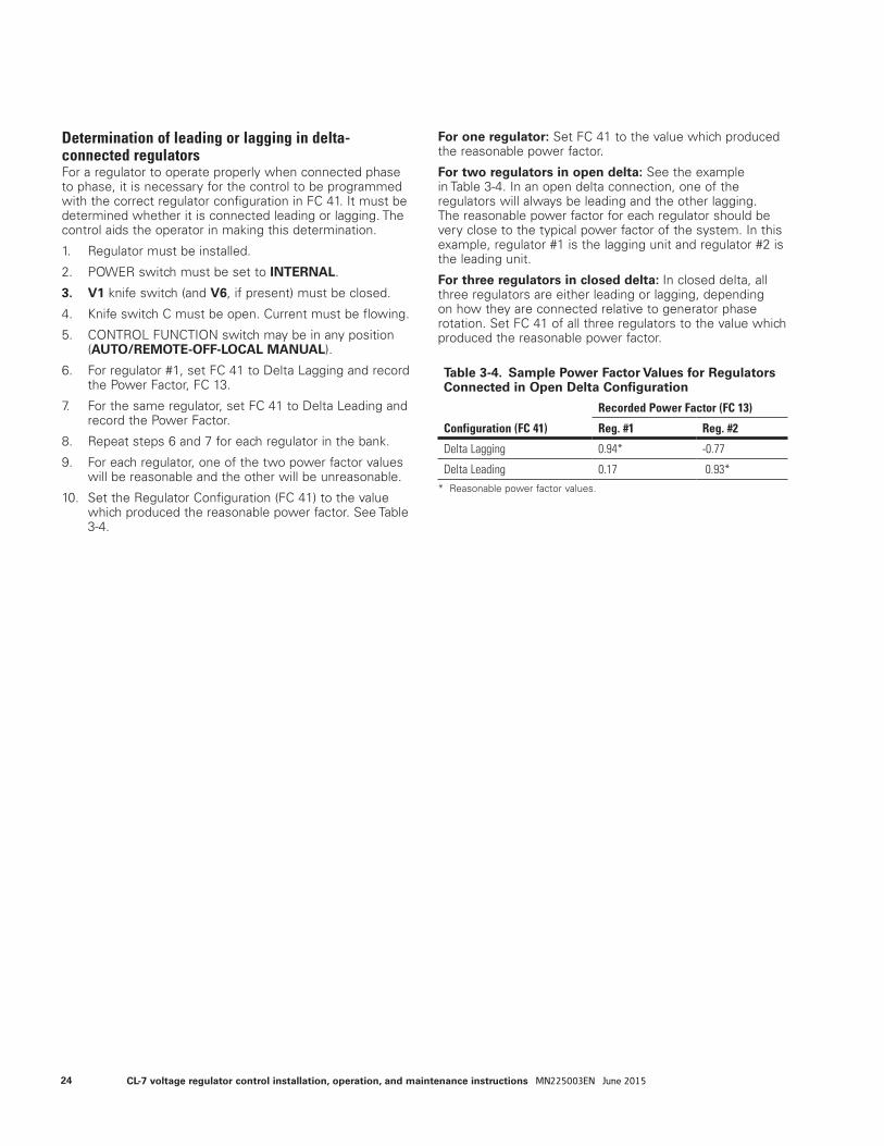
Determination of leading or lagging in delta-connected regulatorsFor a regulator to operate properly when connected phase to phase, it is necessary for the control to be programmed with the correct regulator configuration in FC 41. It must be determined whether it is connected leading or lagging. The control aids the operator in making this determination.
1. Regulator must be installed.
2. POWER switch must be set to INTERNAL.
3. V1 knife switch (and V6, if present) must be closed.
4. Knife switch C must be open. Current must be flowing.
5. CONTROL FUNCTION switch may be in any position (AUTO/REMOTE-OFF-LOCAL MANUAL).
6. For regulator #1, set FC 41 to Delta Lagging and record the Power Factor, FC 13.
7. For the same regulator, set FC 41 to Delta Leading and record the Power Factor.
8. Repeat steps 6 and 7 for each regulator in the bank.
9. For each regulator, one of the two power factor values will be reasonable and the other will be unreasonable.
10. Set the Regulator Configuration (FC 41) to the value which produced the reasonable power factor. See Table 3-4.
For one regulator: Set FC 41 to the value which produced the reasonable power factor.
For two regulators in open delta: See the example in Table 3-4. In an open delta connection, one of the regulators will always be leading and the other lagging. The reasonable power factor for each regulator should be very close to the typical power factor of the system. In this example, regulator #1 is the lagging unit and regulator #2 is the leading unit.
For three regulators in closed delta: In closed delta, all three regulators are either leading or lagging, depending on how they are connected relative to generator phase rotation. Set FC 41 of all three regulators to the value which produced the reasonable power factor.
Table 3-4. Sample Power Factor Values for Regulators Connected in Open Delta Configuration
Configuration (FC 41)
Recorded Power Factor (FC 13)
Reg. #1 Reg. #2
Delta Lagging 0.94* -0.77
Delta Leading 0.17 0.93** Reasonable power factor values.
24 CL-7 voltage regulator control installation, operation, and maintenance instructions MN225003EN June 2015
Section 4: Control operation
Automatic operationIn the automatic mode of operation, the POWER switch will be set on INTERNAL and the CONTROL FUNCTION switch will be placed on AUTO/REMOTE. The regulator is assumed energized from the primary circuit. If the sequential mode of operation (the standard mode set at FC 42) is selected, the control response on Eaton's Cooper Power series voltage regulator is as follows:
1. As the primary voltage moves to a level which represents an out-of-band condition, the sensing voltage will correspondingly reflect the same results on the 120 V (or 240 V) base. Assuming the voltage dropped low, a lower than normal signal will appear at the printed circuit board input terminals.
2. The signal is transformed and converted into a digital format for use by the microprocessor.
3. The microprocessor, recognizing the voltage condition as low and out-of-band, issues an output which activates the Out-of-Band Low indicator and starts an internal timer, which is equivalent to the time-delay setting.
4. During the time-out period, the voltage is continually sensed and sampled. Should the voltage momentarily move into band, the Out-of-Band Low indicator is deactivated and the timer is reset.
5. At the end of the time-delay period, the microprocessor issues an output which causes the raise triac to be activated.
6. The tap-changer motor begins to turn as a result of triac closure, and a cam on the tap-changer closes the raise holding switch. The holding switch now provides an alternate source for the motor current, which passes through the input terminals on the circuit board.
7. The microprocessor now recognizes that current is flowing in the holding switch circuit. The raise triac is deactivated.
8. As a result of the triac being deactivated, the motor current is now carried solely by the holding switch circuit. When the motor rotation is complete, the holding switch opens as a result of the cam action and the motor stops.
9. The microprocessor recognizes that the tap change is now complete by detecting that motor current is no longer flowing. The operations counter and tap position indication are incremented. A 2-second pause then occurs, allowing the sensing voltage to stabilize after motor operation.
10. At the end of this pause, if the voltage is still out-of-band, another output is issued to reactivate the raise triac, thus starting another tap change sequence. If the voltage is in-band, the OUT-OF-BAND LOW indicator is turned off and the time-delay timer is reset.
This sequence is altered slightly if the voltage-averaging or time-integrating mode of operation are selected. These characteristics are described in Control Operating Modes in this section of the manual.
Manual operationIn the manual mode of operation, the POWER switch can be set on either INTERNAL or EXTERNAL and the control switch will be placed on LOCAL MANUAL. If the external position is chosen, an external source must be applied to the terminals on the control. This should be a nominal 120 Vac source (or other ac voltage as indicated by a decal) and should not be a direct current to alternating current (dc-to-ac) inverter.
Operation of the momentary toggle RAISE/LOWER switch applies power through the position indicator limit switch contacts directly to the tap-changer motor. As the tap-changer motor cam rotates, the holding switch is closed, as described above in the Automatic Operation section. This holding-switch current is sensed by the circuit board, and the operations counter and tap position indicator are appropriately updated.
Tap change operation will continue as long as the RAISE/LOWER switch is held in either the raise or lower position and the ADD-AMP™ limit switch is not activated to open the circuit.
Self-testThere are three events which trigger the self-test routine: the initial control power-up, operator entry of self-test mode using FC 91, or detection of a firmware problem. Refer to the Troubleshooting section of this manual for more information on control self-test.
25CL-7 voltage regulator control installation, operation, and maintenance instructions MN225003EN June 2015
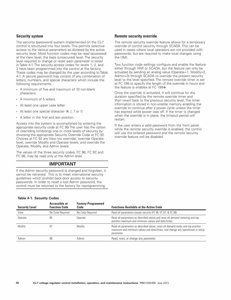
Security systemThe security (password) system implemented on the CL-7 control is structured into four levels. This permits selective access to the various parameters as dictated by the active security level. Most function codes may be read (accessed) at the View level, the base (unsecured) level. The security level required to change or reset each parameter is listed in Table 4-1. The security access codes for levels 1, 2, and 3 have been programmed into the control at the factory. These codes may be changed by the user according to Table 4-1. A secure password may consist of any combination of letters, numbers, and special characters which include the following requirements:
• A minimum of five and maximum of 10 non-blank characters.
• A minimum of 5 letters
• At least one upper case letter.
• At least one special character (#, /, ? or !)
• A letter in the first and last position.
Access into the system is accomplished by entering the appropriate security code at FC 99.The user has the option of overriding (inhibiting) one or more levels of security by choosing the appropriate Security Override Code at FC 92. Choices at FC 92 are View (no override), override Operate level, override Modify and Operate levels, and override the Operate, Modify, and Admin levels.
The values of the three security codes, FC 96, FC 97, and FC 98, may be read only at the Admin level.
Remote security overrideThe remote security override feature allows for a temporary override of control security through SCADA. This can be used in cases where local operators are not provided with passwords, but are required to make local changes using the HMI.
Two function code settings configure and enable the feature either through HMI or SCADA, but the feature can only be activated by sending an analog value (Operate=1, Modify=2, Admin=3) through SCADA to override the present security level to the level specified. The remote override timer is set at FC 199 to specify the length of the override in hours and the feature is enables at FC 199.
Once the override is activated, it will continue for the duration specified by the remote override timer and then revert back to the previous security level. The timer information is stored in non-volatile memory enabling the override to continue after a power cycle unless the timer has expired while power was off. If the timer is changed when the override is in place, the timeout period will restart.
If the user enters a valid password from the front panel while the remote security override is enabled, the control will use the entered password and the remote security override feature will be disabled.
Table 4-1. Security Codes
Security LevelAccessible atFunction Code
Factory-Programmed Code Functions Available at the Active Code
View No Code Required No Code Required Read all parameters except security (FC 96, FC 97, & FC 98)
Operate 96 Operate Read all parameters as described above,and reset all demand metering and tap position maximum and minimum values and date/times
Modify 97 Modify Read all parameters as described above, reset all demand meter and tap position maximum and minimum values and date/times, and change any operational or setup parameter
Admin 98 Admin Read, reset, or change any parameter
IMPORTANT If the Admin security password is changed and forgotten, it cannot be retrieved. This is to meet international security guidelines which prohibit back-door access to security passwords. In order to reset a lost Admin password, the control must be returned to the factory for reprogramming.
26 CL-7 voltage regulator control installation, operation, and maintenance instructions MN225003EN June 2015
Basic control operations
Set voltageThe set voltage is the voltage level to which the control will regulate on the 120 V or 240 V base. Since the control performs ratio correction in the firmware, this value will typically be set for 120.0 V/240.0, unless it is desired to operate at a voltage level higher or lower than nominal. For proper operation, the ratio-correcting transformer, located on the back panel of the control enclosure, must also be set for the correct tap as shown on the regulator nameplate.
BandwidthThe bandwidth is defined as that total voltage range, around the set voltage, which the control will consider as a satisfied condition. As an example, a 2 V bandwidth on a 120 V set voltage means the time delay timer will not activate until the voltage is below 119 V or above 121 V. When the voltage is in-band, the band edge indicators are off and the timer (time delay) is off. Selection of a small bandwidth will cause more tap changes to occur, but will provide a more tightly regulated line. Conversely, a larger bandwidth results in fewer tap changes, but at the expense of better regulation. Selection of the bandwidth and time-delay settings should be made recognizing the interdependence of these two parameters.
Time delay The time delay is the period of time (in seconds) that the control waits from when the voltage first goes out-of-band to the time when a tap change is issued. If a rapid response is required, a shorter setting should be used. If several devices on the same line are to be coordinated (cascaded), different time-delay settings will be required to allow the devices to operate in the desired sequence. Proceeding from the source, each device should have a longer time delay than the preceding device. A minimum 15-second difference between regulators located on the same phase on the same feeder is recommended. The delay allows the upstream device to perform its operations prior to the downstream device reacting. The time-delay setting of a voltage-minimizing, activated capacitor control should be set the same as a regulator control. Alternate time delays are available with the voltage limiter feature. Refer to the Voltage Limiter section of this manual.
Line drop compensation, resistance and reactance settingsQuite often regulators are installed some distance from the theoretical load center (the location at which the voltage is to be regulated). This means the load will not be served at the desired voltage level due to the losses (voltage drop) on the line between the regulator and the load. Furthermore, as the load increases, line losses also increase, causing the lowest voltage condition to occur during the time of heaviest loading.
To provide the regulator with the capability to regulate at a projected load center, the control has line-drop-compensation elements within it. This circuitry usually consists of a current transformer (CT), which produces a current proportional to the load current, and resistive (R) and reactive (X) elements through which this current flows. As the load increases, the resulting CT current flowing through these elements produces voltage drops, which simulate the voltage drops on the primary line.
Within the control, the input current is sampled and is used in a computer algorithm which calculates the respective resistive and reactive voltage drops based upon the line-drop-compensation values programmed into the control at FC 4 and FC 5 (or FC 54 and FC 55 for reverse power flow conditions). This is an accurate and economical means of developing the compensated voltage.
To select the proper R and X values, the user must know several factors about the line being regulated.
Regulator configurationThe control is designed to operate on wye (star)-connected and delta-connected regulators. Regulators connected line-to-ground (wye) develop potentials and currents suitable for direct implementation in the control. Regulators connected line-to-line (delta) develop a potential-to-current phase shift which is dependent upon whether the regulator is defined as leading or lagging. The phase shift must be known by the control to permit accurate calculations for correct operation. This is accomplished by entering the proper option at FC 41: Wye, Delta Lagging, or Delta Leading. See Determination of Leading or Lagging in Delta-Connected Regulators in Section 3 of this manual for more information on setting this parameter.
Control operating modesThe CL-7 control supports three modes in which the control responds to out-of-band conditions, permitting use of the mode that best fits the application. The three modes are Sequential, Time Integrating, and Voltage Averaging. The mode setting can be selected by scrolling within FC 42 or through Settings > Configuration in the menu structure.
Sequential mode This is the standard mode of response. When the load voltage goes out-of-band, the time-delay circuit is activated. At the end of the time delay, a tap change is initiated. After each tap change, a 2-second pause occurs to permit the control to sample the voltage again. This sequence continues until the voltage is brought into band, at which time the timing circuit is reset. Whenever the voltage goes in-band, the timer is reset.
27CL-7 voltage regulator control installation, operation, and maintenance instructions MN225003EN June 2015
Time-integrating modeWhen the load voltage goes out-of-band, the time-delay circuit is activated. At the end of the time-out, a tap change is initiated. After each tap change, a 2-second pause occurs to permit the control to sample the voltage again. If the voltage is still out-of-band, another tap change is performed. This sequence continues until the voltage is brought into band. When the voltage goes in-band, the timer is decremented at the rate of 1.1 seconds for every second elapsed, until it reaches zero.
Voltage-averaging modeWhen the load voltage goes out-of-band, the time-delay circuit is activated. During this time-delay period, the microprocessor monitors and averages the instantaneous load voltage. It then computes the number of tap changes required to bring the average voltage back to the set voltage level. When the time-delay period is complete, the computed number of tap changes are performed without any delay between them, up to a maximum of five consecutive tap changes, to avoid an accumulative error. The timer is not reset on voltage excursions in-band unless the voltage stays in-band for at least ten continuous seconds. An error-averaging characteristic is inherent with the voltage-averaging mode.
ote:N To permit sufficient time for the microprocessor to average the voltage, the time-delay period must be 30 seconds or longer. If the time delay is set for less than 30 seconds, the control ignores the setting and uses 30 seconds.
System line voltageThe control performs ratio correction in the firmware, and, consequently, the primary voltage must be entered for the control to perform this calculation. This value is simply the nominal single-phase voltage supplied across the L and SL terminals. Regulators shipped from the factory are set for the voltage indicated by the pin on the nameplate, and this value is programmed into the control. If the regulator is installed on any other system voltage, this system voltage must be entered for proper operation.
Overall PT ratioSince the control performs ratio correction in the firmware, the PT ratio for the voltage-sensing supply is required for the control to perform the calculation. The ratio to be programmed in the control is the Overall PT Ratio, which is a combination of the ratios of the PT in the tank and the RCT. For standard voltages shown on the regulator nameplate an Overall PT Ratio is listed. The Overall PT Ratio, which corresponds to the regulator’s rated voltage, is set by the factory. If the regulator is installed on any other system voltage, the corresponding Overall PT Ratio is also required and must be determined. See the section Allowable System Voltages and Calculation of Overall PT Ratio for more information.
The voltage from the RCT is normally corrected to 120 V. However, when this voltage is other than 120 V, the control
will calibrate the input voltage to a 120 V (or 240 V when FC 148 is set to 240 Volts) base and 120 V (or 240 V) will be displayed at FC 6. The voltage test terminals will continue to show the voltage as applied to the control from the RCT.
Internal PT ratioThe CL-7 control does not require a ratio correction transformer (RCT) for the internal differential PT (IDPT). If a regulator design includes an IDPT, but does not have a second RCT, the control is able to use the Internal PT ratio to determine the differential and source-side voltage. In order for this to work, the Internal PT ratio must be entered at FC 44 and the Vin PT Configuration (FC 146) must be set to Vdiff without RCT2.
Current transformer primary ratingThe control is designed for 200 mA as the rated CT current and will meter to 800 mA with no loss of accuracy. Ratio correction is performed by the firmware, and, consequently, the CT primary rating must be entered. The CT primary rating is available on the regulator nameplate.
EXAMPLE: If a CT ratio 400/0.2 is indicated on the nameplate, then 400 must be entered at FC 45.
Delta-connected (line-to-line connected) regulatorsWhen a regulator is connected line-to-line, the phase angle of the line current is 30 degrees displaced from the voltage impressed across the regulator. After setting the Regulator Configuration, FC 41, the correct relationship between the voltage and current is established. Setting the regulator Configuration to the incorrect delta value (lagging instead of leading, or vice versa), the phase angle will be in error 60 degrees.
See the section Determination of Leading or Lagging in Delta-Connected Regulators for information on selecting the correct setting. Below are considerations concerning delta-connected regulators:
• The basic decision-making of the control when line-drop compensation is not used is not affected by the phase angle; therefore, operation will be correct even if FC 41 is set to either of the two incorrect values. This is true for forward and reverse operation.
• If line-drop compensation is used, the scaling of the R and X values is controlled by FC 41; therefore, it is impor-tant to correctly set FC 41 for the compensated voltage to be correctly determined.
• The following metering parameters will be correct only if the Regulator Configuration is correctly set: power factor, kVA, kW, kvar, demand kVA, demand kW, and demand kvar.
ote:N The kVA, kW, kvar, demand kVA, demand kW, and demand kvar use the line-to-line voltage; therefore, they display the value at the regulator not on any one feeder. To determine the total three-phase value of any one of these parameters, each regulator value must be divided by √3 (1.732) before adding the three together.
28 CL-7 voltage regulator control installation, operation, and maintenance instructions MN225003EN June 2015
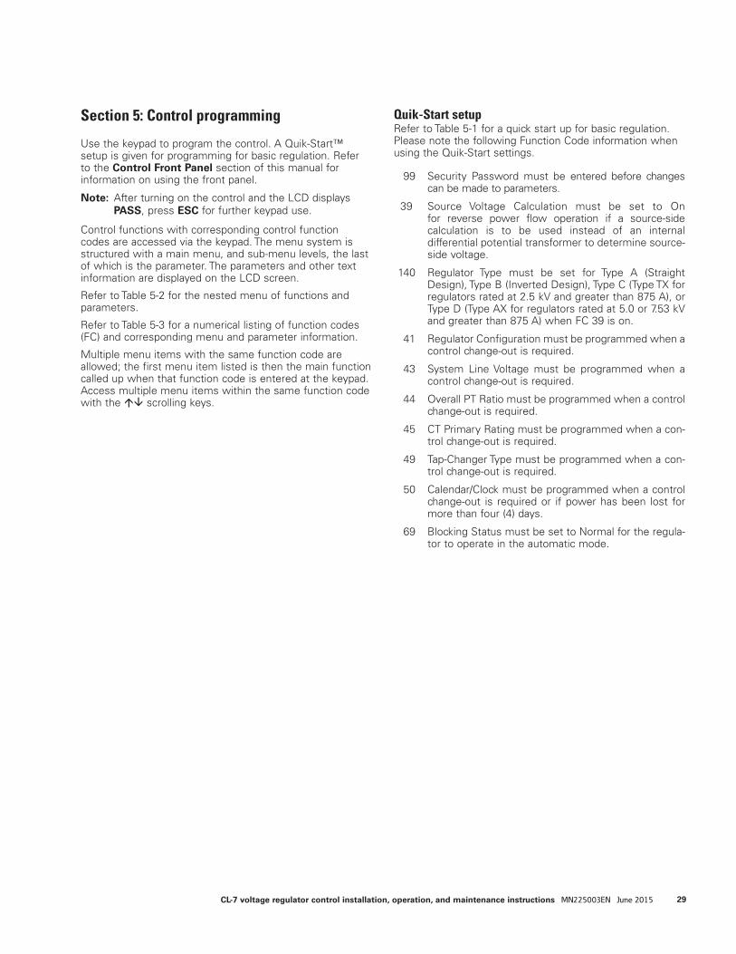
Section 5: Control programming
Use the keypad to program the control. A Quik-Start™ setup is given for programming for basic regulation. Refer to the Control Front Panel section of this manual for information on using the front panel.
ote:N After turning on the control and the LCD displays PASS, press ESC for further keypad use.
Control functions with corresponding control function codes are accessed via the keypad. The menu system is structured with a main menu, and sub-menu levels, the last of which is the parameter. The parameters and other text information are displayed on the LCD screen.
Refer to Table 5-2 for the nested menu of functions and parameters.
Refer to Table 5-3 for a numerical listing of function codes (FC) and corresponding menu and parameter information.
Multiple menu items with the same function code are allowed; the first menu item listed is then the main function called up when that function code is entered at the keypad. Access multiple menu items within the same function code with the scrolling keys.
Quik-Start setupRefer to Table 5-1 for a quick start up for basic regulation. Please note the following Function Code information when using the Quik-Start settings.
99 Security Password must be entered before changes can be made to parameters.
39 Source Voltage Calculation must be set to On for reverse power flow operation if a source-side calculation is to be used instead of an internal differential potential transformer to determine source-side voltage.
140 Regulator Type must be set for Type A (Straight Design), Type B (Inverted Design), Type C (Type TX for regulators rated at 2.5 kV and greater than 875 A), or Type D (Type AX for regulators rated at 5.0 or 7.53 kV and greater than 875 A) when FC 39 is on.
41 Regulator Configuration must be programmed when a control change-out is required.
43 System Line Voltage must be programmed when a control change-out is required.
44 Overall PT Ratio must be programmed when a control change-out is required.
45 CT Primary Rating must be programmed when a con-trol change-out is required.
49 Tap-Changer Type must be programmed when a con-trol change-out is required.
50 Calendar/Clock must be programmed when a control change-out is required or if power has been lost for more than four (4) days.
69 Blocking Status must be set to Normal for the regula-tor to operate in the automatic mode.
29CL-7 voltage regulator control installation, operation, and maintenance instructions MN225003EN June 2015

TABLE 5-1 Quik-Start Set-Up for Basic Regulation Function Code
Description Instructions
Security099 Security FUNC, 99, ENTER, Password (Admin), ENTER
Forward Settings001 Forward Set Voltage FUNC, 1, ENTER, EDIT, Value, ENTER002 Forward Bandwidth FUNC, 2, ENTER, EDIT, Value, ENTER003 Forward Time Delay FUNC, 3, ENTER, EDIT, Value, ENTER004 Forward Line Drip Comp. Resistance FUNC, 4, ENTER, EDIT, Value, ENTER005 Forward Line Drip Comp. Reactance FUNC, 5, ENTER, EDIT, Value, ENTERReverse Settings056 Reverse Sensing Mode FUNC, 56, ENTER, Scroll - Locked Forward; Locked Reverse; Reverse Idle;
Bi-Directional; Neutral Idle; Co-generation; React Bi-directional; Bias Bi-Directional, ENTER
039 Source Voltage Calculation FUNC, 39, ENTER, EDIT, Scroll - On or Off, ENTER 140 Regulator Type FUNC, 140, ENTER, EDIT, Scroll - Type A; Type B; Type C; Type D, ENTER044 Internal PT Ratio FUNC, 44, ENTER, Down Arrow, EDIT, Value, ENTER146 Vin PT Configuration FUNC, 146, ENTER, EDIT, Scroll - Vdiff without RCT2; Vin Mode; Vdiff with
RCT2, ENTER051 Reverse Set Voltage FUNC, 51, ENTER, EDIT, Value, ENTER052 Reverse Bandwidth FUNC, 52, ENTER, EDIT, Value, ENTER053 Reverse Time Delay FUNC, 53, ENTER, EDIT, Value, ENTER054 Reverse Line Drip Comp. Resistance FUNC, 54, ENTER, EDIT, Value, ENTER055 Reverse Line Drip Comp. Reactance FUNC, 55, ENTER, EDIT, Value, ENTERConfigurations041 Regulator Configuration FUNC, 41, ENTER, EDIT, Scroll - Wye; Delta Laging; Delta Leading,
ENTER042 Control Operation Mode FUNC, 42, ENTER, EDIT, Scroll - Sequential; Time-Integrating; Voltage-
Averaging, ENTER
043 System Line Voltage FUNC, 43, ENTER, EDIT, Value, ENTER044 Overall PT Ratio FUNC, 44, ENTER, EDIT, Value, ENTER045 C.T. Primary Rating FUNC, 45, ENTER, EDIT, Value, ENTER049 Tap-Changer Type FUNC, 49, ENTER, EDIT, Scroll - Cooper QD8; Cooper QD5; Cooper
QD3; Cooper Spring Drive; Cooper Direct Drive; Siemens; General Electric; Howard; LTC-Reinhausen, ITB; Toshiba; User-Defined, ENTER
050 System Calendar and Clock FUNC, 50, ENTER, EDIT, Month, Day, Year, Hour, Minute, ENTER
069 Auto Operation Blocking Status FUNC, 69, ENTER, EDIT, Scroll - Normal; Blocked, ENTER
30 CL-7 voltage regulator control installation, operation, and maintenance instructions MN225003EN June 2015
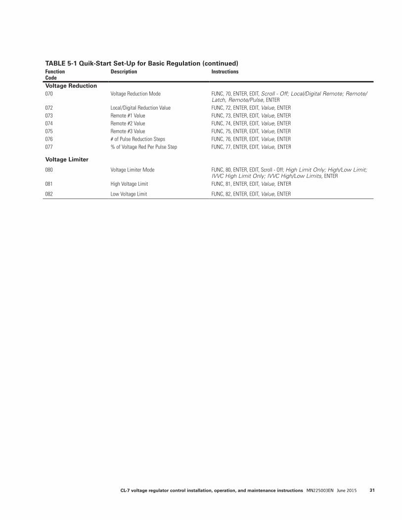
TABLE 5-1 Quik-Start Set-Up for Basic Regulation (continued)Function Code
Description Instructions
Voltage Reduction070 Voltage Reduction Mode FUNC, 70, ENTER, EDIT, Scroll - Off; Local/Digital Remote; Remote/
Latch, Remote/Pulse, ENTER072 Local/Digital Reduction Value FUNC, 72, ENTER, EDIT, Value, ENTER073 Remote #1 Value FUNC, 73, ENTER, EDIT, Value, ENTER074 Remote #2 Value FUNC, 74, ENTER, EDIT, Value, ENTER075 Remote #3 Value FUNC, 75, ENTER, EDIT, Value, ENTER076 # of Pulse Reduction Steps FUNC, 76, ENTER, EDIT, Value, ENTER077 % of Voltage Red Per Pulse Step FUNC, 77, ENTER, EDIT, Value, ENTER
Voltage Limiter
080 Voltage Limiter Mode FUNC, 80, ENTER, EDIT, Scroll - Off; High Limit Only; High/Low Limit; IVVC High Limit Only; IVVC High/Low Limits, ENTER
081 High Voltage Limit FUNC, 81, ENTER, EDIT, Value, ENTER
082 Low Voltage Limit FUNC, 82, ENTER, EDIT, Value, ENTER
31CL-7 voltage regulator control installation, operation, and maintenance instructions MN225003EN June 2015
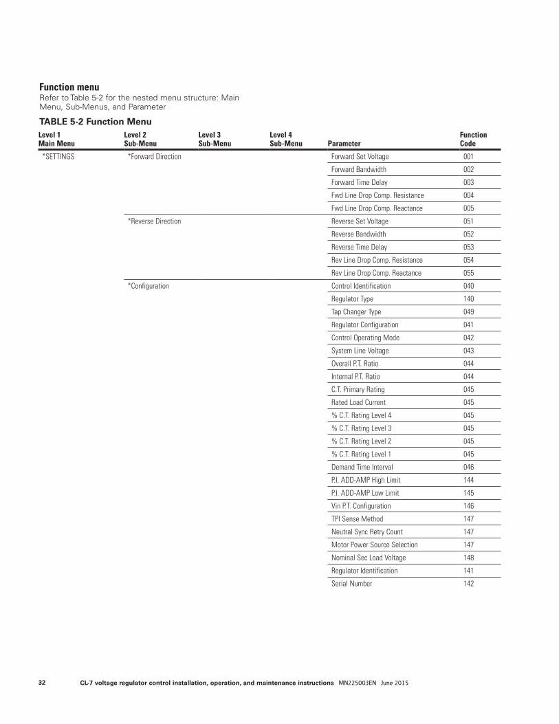
Function menuRefer to Table 5-2 for the nested menu structure: Main Menu, Sub-Menus, and Parameter
TABLE 5-2 Function MenuLevel 1Main Menu
Level 2Sub-Menu
Level 3Sub-Menu
Level 4Sub-Menu Parameter
Function Code
*SETTINGS *Forward Direction Forward Set Voltage 001
Forward Bandwidth 002
Forward Time Delay 003
Fwd Line Drop Comp. Resistance 004
Fwd Line Drop Comp. Reactance 005
*Reverse Direction Reverse Set Voltage 051
Reverse Bandwidth 052
Reverse Time Delay 053
Rev Line Drop Comp. Resistance 054
Rev Line Drop Comp. Reactance 055
*Configuration Control Identification 040
Regulator Type 140
Tap Changer Type 049
Regulator Configuration 041
Control Operating Mode 042
System Line Voltage 043
Overall P.T. Ratio 044
Internal P.T. Ratio 044
C.T. Primary Rating 045
Rated Load Current 045
% C.T. Rating Level 4 045
% C.T. Rating Level 3 045
% C.T. Rating Level 2 045
% C.T. Rating Level 1 045
Demand Time Interval 046
P.I. ADD-AMP High Limit 144
P.I. ADD-AMP Low Limit 145
Vin P.T. Configuration 146
TPI Sense Method 147
Neutral Sync Retry Count 147
Motor Power Source Selection 147
Nominal Sec Load Voltage 148
Regulator Identification 141
Serial Number 142
32 CL-7 voltage regulator control installation, operation, and maintenance instructions MN225003EN June 2015
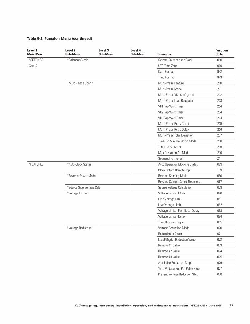
Table 5-2. Function Menu (continued)
Level 1Main Menu
Level 2Sub-Menu
Level 3Sub-Menu
Level 4Sub-Menu Parameter
Function Code
*SETTINGS
(Cont.)
*Calendar/Clock System Calendar and Clock 050
UTC Time Zone 050
Date Format 942
Time Format 943
_Multi-Phase Config Multi-Phase Feature 200
Multi-Phase Mode 201
Multi-Phase VRs Configured 202
Multi-Phase Lead Regulator 203
VR1 Tap Wait Timer 204
VR2 Tap Wait Timer 204
VR3 Tap Wait Timer 204
Multi-Phase Retry Count 205
Multi-Phase Retry Delay 206
Multi-Phase Total Deviation 207
Timer To Max Deviation Mode 208
Timer To Alt Mode 209
Max Deviation Alt Mode 210
Sequencing Interval 211
*FEATURES *Auto-Block Status Auto Operation Blocking Status 069
Block Before Remote Tap 169
*Reverse Power Mode Reverse Sensing Mode 056
Reverse Current Sense Threshold 057
*Source Side Voltage Calc Source Voltage Calculation 039
*Voltage Limiter Voltage Limiter Mode 080
High Voltage Limit 081
Low Voltage Limit 082
Voltage Limiter Fast Resp. Delay 083
Voltage Limiter Delay 084
Time Between Taps 085
*Voltage Reduction Voltage Reduction Mode 070
Reduction In Effect 071
Local/Digital Reduction Value 072
Remote #1 Value 073
Remote #2 Value 074
Remote #3 Value 075
# of Pulse Reduction Steps 076
% of Voltage Red Per Pulse Step 077
Present Voltage Reduction Step 078
33CL-7 voltage regulator control installation, operation, and maintenance instructions MN225003EN June 2015
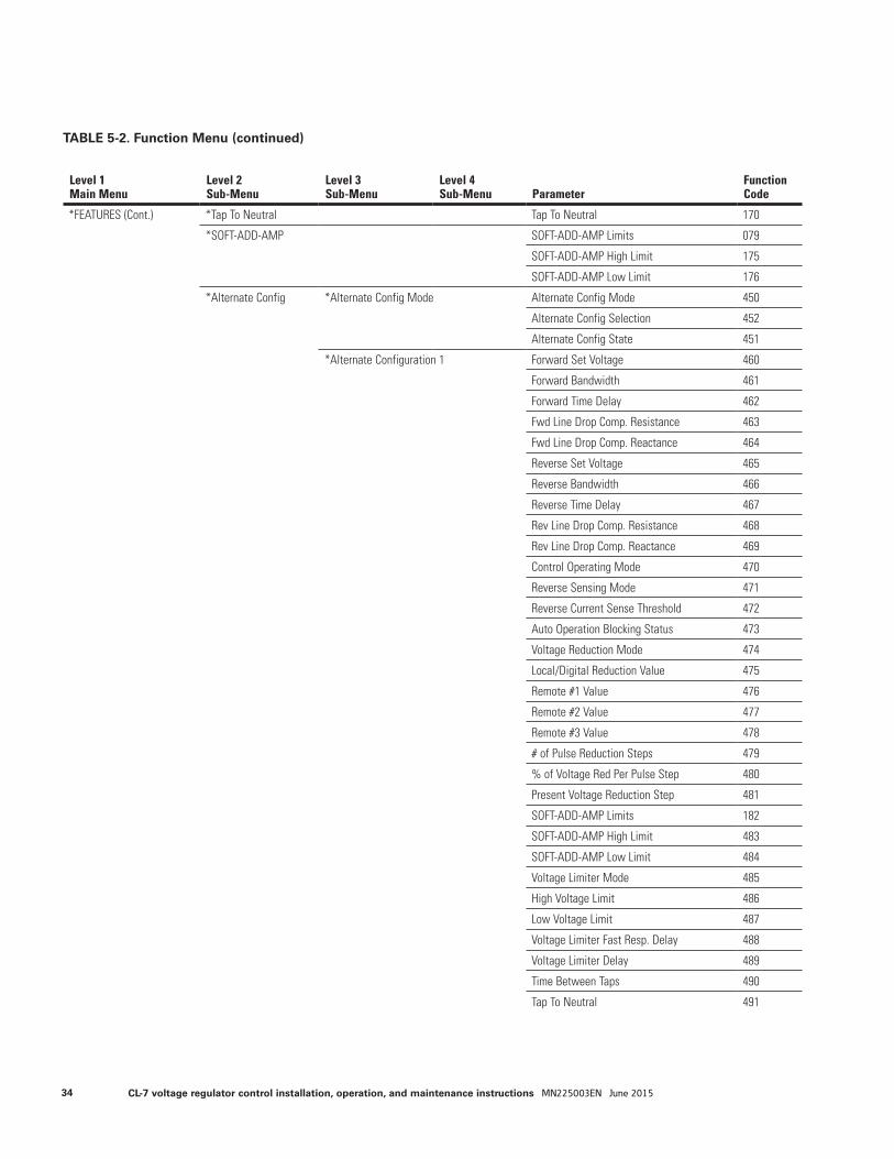
TABLE 5-2. Function Menu (continued)
Level 1Main Menu
Level 2Sub-Menu
Level 3Sub-Menu
Level 4Sub-Menu Parameter
Function Code
*FEATURES (Cont.) *Tap To Neutral Tap To Neutral 170
*SOFT-ADD-AMP SOFT-ADD-AMP Limits 079
SOFT-ADD-AMP High Limit 175
SOFT-ADD-AMP Low Limit 176
*Alternate Config *Alternate Config Mode Alternate Config Mode 450
Alternate Config Selection 452
Alternate Config State 451
*Alternate Configuration 1 Forward Set Voltage 460
Forward Bandwidth 461
Forward Time Delay 462
Fwd Line Drop Comp. Resistance 463
Fwd Line Drop Comp. Reactance 464
Reverse Set Voltage 465
Reverse Bandwidth 466
Reverse Time Delay 467
Rev Line Drop Comp. Resistance 468
Rev Line Drop Comp. Reactance 469
Control Operating Mode 470
Reverse Sensing Mode 471
Reverse Current Sense Threshold 472
Auto Operation Blocking Status 473
Voltage Reduction Mode 474
Local/Digital Reduction Value 475
Remote #1 Value 476
Remote #2 Value 477
Remote #3 Value 478
# of Pulse Reduction Steps 479
% of Voltage Red Per Pulse Step 480
Present Voltage Reduction Step 481
SOFT-ADD-AMP Limits 182
SOFT-ADD-AMP High Limit 483
SOFT-ADD-AMP Low Limit 484
Voltage Limiter Mode 485
High Voltage Limit 486
Low Voltage Limit 487
Voltage Limiter Fast Resp. Delay 488
Voltage Limiter Delay 489
Time Between Taps 490
Tap To Neutral 491
34 CL-7 voltage regulator control installation, operation, and maintenance instructions MN225003EN June 2015
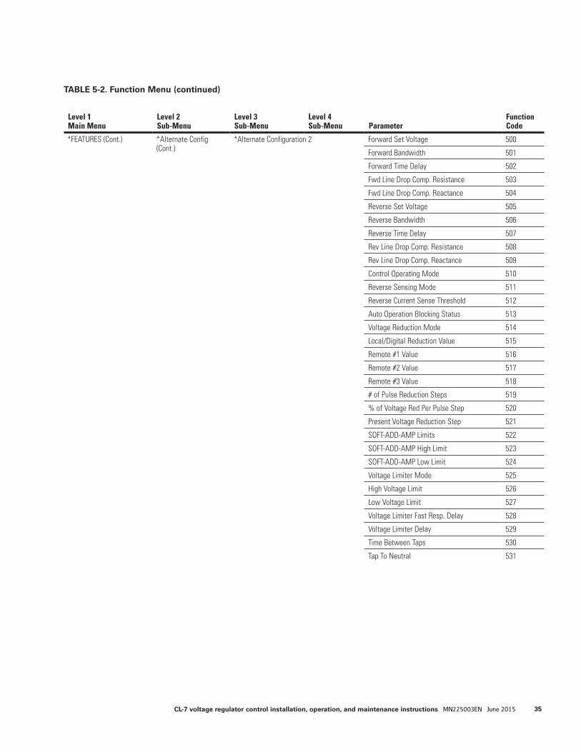
TABLE 5-2. Function Menu (continued)
Level 1Main Menu
Level 2Sub-Menu
Level 3Sub-Menu
Level 4Sub-Menu Parameter
Function Code
*FEATURES (Cont.)
*Alternate Config (Cont.)
*Alternate Configuration 2 Forward Set Voltage 500
Forward Bandwidth 501
Forward Time Delay 502
Fwd Line Drop Comp. Resistance 503
Fwd Line Drop Comp. Reactance 504
Reverse Set Voltage 505
Reverse Bandwidth 506
Reverse Time Delay 507
Rev Line Drop Comp. Resistance 508
Rev Line Drop Comp. Reactance 509
Control Operating Mode 510
Reverse Sensing Mode 511
Reverse Current Sense Threshold 512
Auto Operation Blocking Status 513
Voltage Reduction Mode 514
Local/Digital Reduction Value 515
Remote #1 Value 516
Remote #2 Value 517
Remote #3 Value 518
# of Pulse Reduction Steps 519
% of Voltage Red Per Pulse Step 520
Present Voltage Reduction Step 521
SOFT-ADD-AMP Limits 522
SOFT-ADD-AMP High Limit 523
SOFT-ADD-AMP Low Limit 524
Voltage Limiter Mode 525
High Voltage Limit 526
Low Voltage Limit 527
Voltage Limiter Fast Resp. Delay 528
Voltage Limiter Delay 529
Time Between Taps 530
Tap To Neutral 531
35CL-7 voltage regulator control installation, operation, and maintenance instructions MN225003EN June 2015
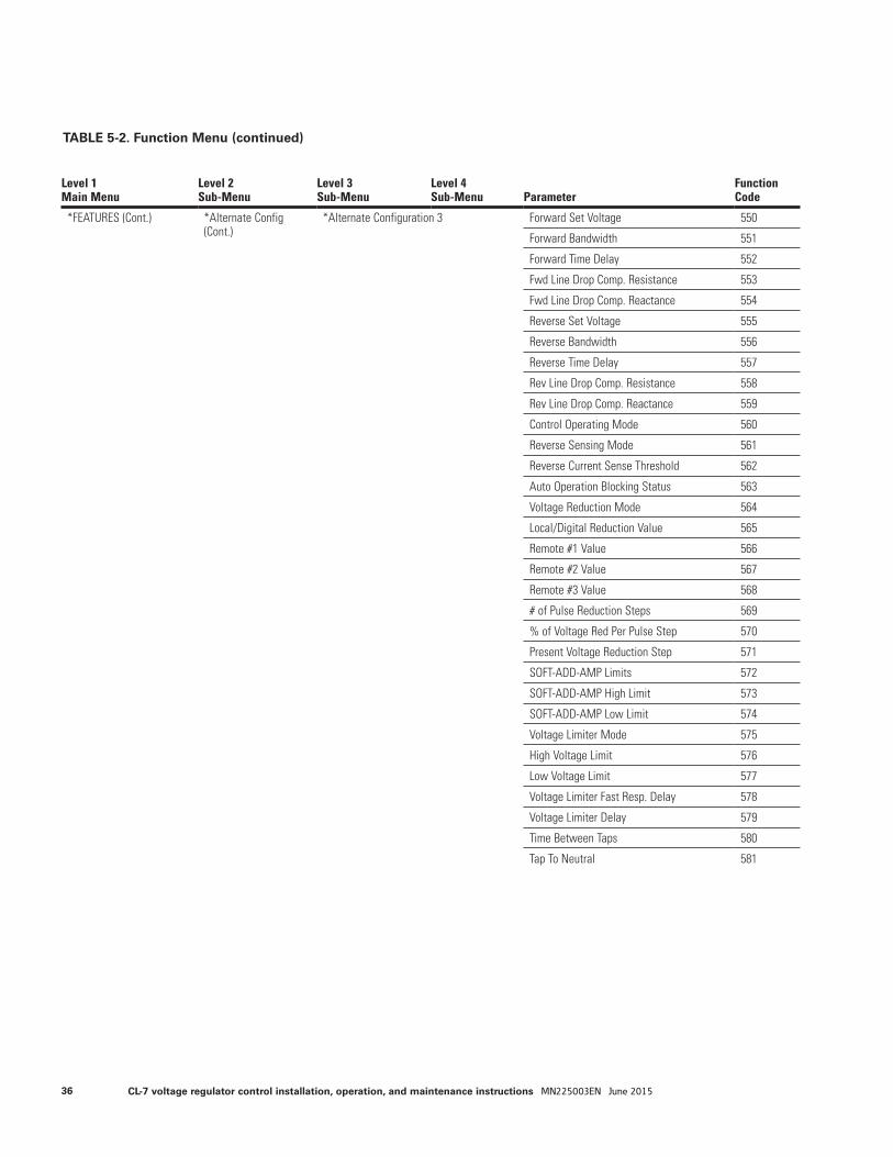
TABLE 5-2. Function Menu (continued)
Level 1Main Menu
Level 2Sub-Menu
Level 3Sub-Menu
Level 4Sub-Menu Parameter
Function Code
*FEATURES (Cont.) *Alternate Config (Cont.)
*Alternate Configuration 3 Forward Set Voltage 550
Forward Bandwidth 551
Forward Time Delay 552
Fwd Line Drop Comp. Resistance 553
Fwd Line Drop Comp. Reactance 554
Reverse Set Voltage 555
Reverse Bandwidth 556
Reverse Time Delay 557
Rev Line Drop Comp. Resistance 558
Rev Line Drop Comp. Reactance 559
Control Operating Mode 560
Reverse Sensing Mode 561
Reverse Current Sense Threshold 562
Auto Operation Blocking Status 563
Voltage Reduction Mode 564
Local/Digital Reduction Value 565
Remote #1 Value 566
Remote #2 Value 567
Remote #3 Value 568
# of Pulse Reduction Steps 569
% of Voltage Red Per Pulse Step 570
Present Voltage Reduction Step 571
SOFT-ADD-AMP Limits 572
SOFT-ADD-AMP High Limit 573
SOFT-ADD-AMP Low Limit 574
Voltage Limiter Mode 575
High Voltage Limit 576
Low Voltage Limit 577
Voltage Limiter Fast Resp. Delay 578
Voltage Limiter Delay 579
Time Between Taps 580
Tap To Neutral 581
36 CL-7 voltage regulator control installation, operation, and maintenance instructions MN225003EN June 2015
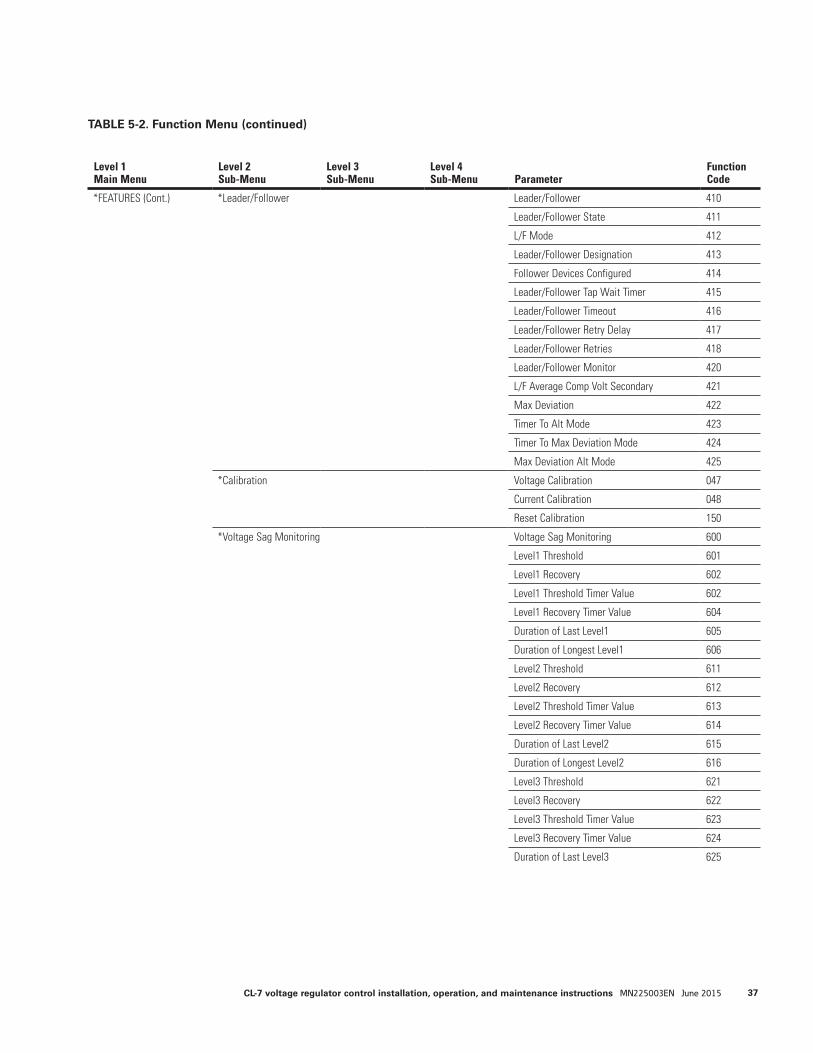
Level 1Main Menu
Level 2Sub-Menu
Level 3Sub-Menu
Level 4Sub-Menu Parameter
Function Code
*FEATURES (Cont.) *Leader/Follower Leader/Follower 410
Leader/Follower State 411
L/F Mode 412
Leader/Follower Designation 413
Follower Devices Configured 414
Leader/Follower Tap Wait Timer 415
Leader/Follower Timeout 416
Leader/Follower Retry Delay 417
Leader/Follower Retries 418
Leader/Follower Monitor 420
L/F Average Comp Volt Secondary 421
Max Deviation 422
Timer To Alt Mode 423
Timer To Max Deviation Mode 424
Max Deviation Alt Mode 425
*Calibration Voltage Calibration 047
Current Calibration 048
Reset Calibration 150
*Voltage Sag Monitoring Voltage Sag Monitoring 600
Level1 Threshold 601
Level1 Recovery 602
Level1 Threshold Timer Value 602
Level1 Recovery Timer Value 604
Duration of Last Level1 605
Duration of Longest Level1 606
Level2 Threshold 611
Level2 Recovery 612
Level2 Threshold Timer Value 613
Level2 Recovery Timer Value 614
Duration of Last Level2 615
Duration of Longest Level2 616
Level3 Threshold 621
Level3 Recovery 622
Level3 Threshold Timer Value 623
Level3 Recovery Timer Value 624
Duration of Last Level3 625
TABLE 5-2. Function Menu (continued)
37CL-7 voltage regulator control installation, operation, and maintenance instructions MN225003EN June 2015
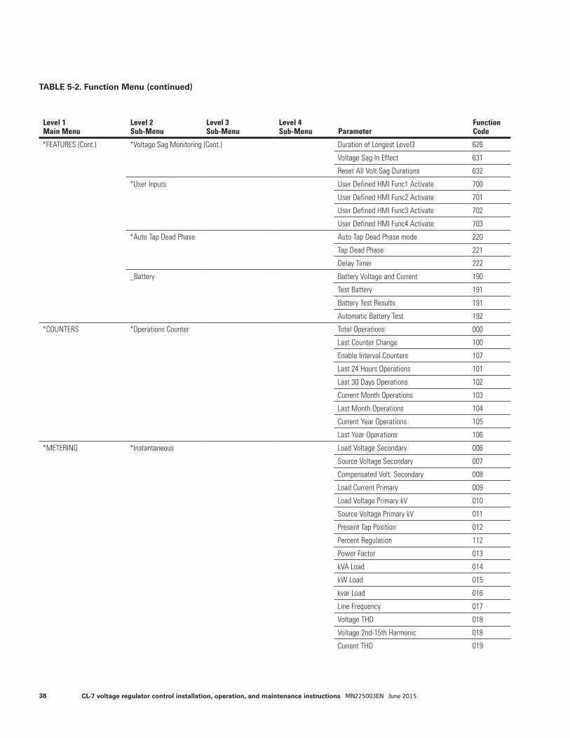
Level 1Main Menu
Level 2Sub-Menu
Level 3Sub-Menu
Level 4Sub-Menu Parameter
Function Code
*FEATURES (Cont.) *Voltage Sag Monitoring (Cont.) Duration of Longest Level3 626
Voltage Sag In Effect 631
Reset All Volt Sag Durations 632
*User Inputs User Defined HMI Func1 Activate 700
User Defined HMI Func2 Activate 701
User Defined HMI Func3 Activate 702
User Defined HMI Func4 Activate 703
*Auto Tap Dead Phase Auto Tap Dead Phase mode 220
Tap Dead Phase 221
Delay Timer 222
_Battery Battery Voltage and Current 190
Test Battery 191
Battery Test Results 191
Automatic Battery Test 192
*COUNTERS *Operations Counter Total Operations 000
Last Counter Change 100
Enable Interval Counters 107
Last 24 Hours Operations 101
Last 30 Days Operations 102
Current Month Operations 103
Last Month Operations 104
Current Year Operations 105
Last Year Operations 106
*METERING *Instantaneous Load Voltage Secondary 006
Source Voltage Secondary 007
Compensated Volt. Secondary 008
Load Current Primary 009
Load Voltage Primary kV 010
Source Voltage Primary kV 011
Present Tap Position 012
Percent Regulation 112
Power Factor 013
kVA Load 014
kW Load 015
kvar Load 016
Line Frequency 017
Voltage THD 018
Voltage 2nd-15th Harmonic 018
Current THD 019
TABLE 5-2. Function Menu (continued)
38 CL-7 voltage regulator control installation, operation, and maintenance instructions MN225003EN June 2015
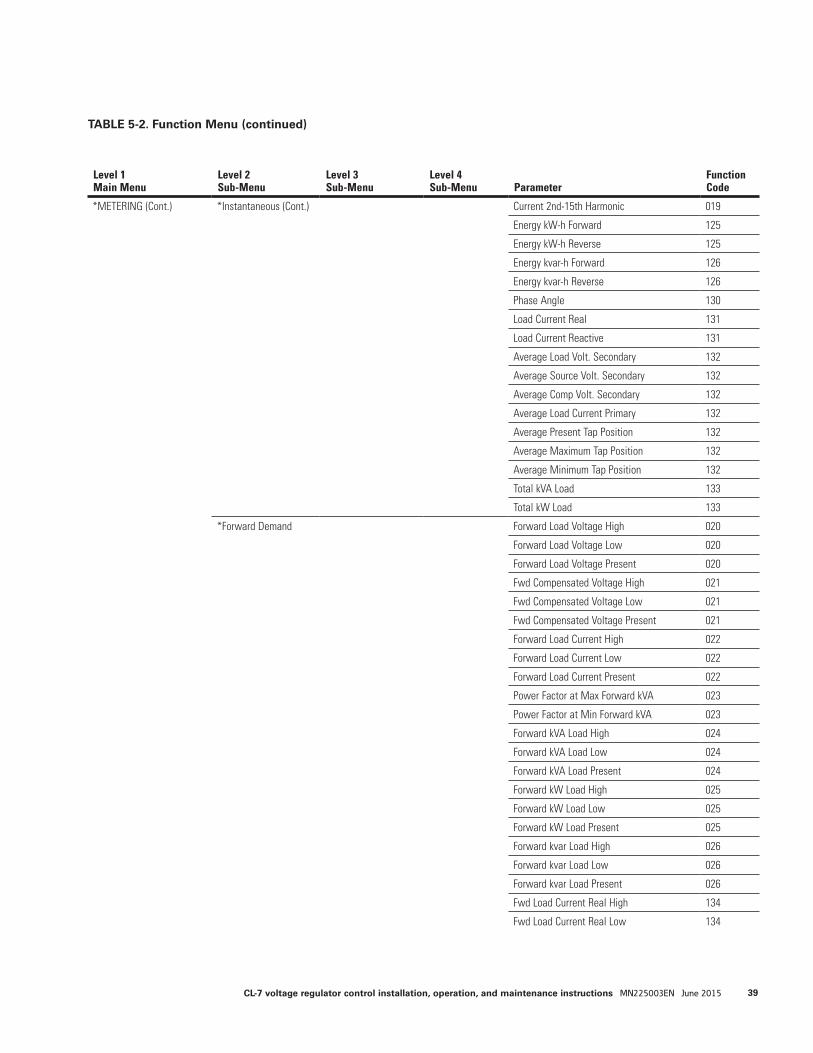
Level 1Main Menu
Level 2Sub-Menu
Level 3Sub-Menu
Level 4Sub-Menu Parameter
Function Code
*METERING (Cont.) *Instantaneous (Cont.) Current 2nd-15th Harmonic 019
Energy kW-h Forward 125
Energy kW-h Reverse 125
Energy kvar-h Forward 126
Energy kvar-h Reverse 126
Phase Angle 130
Load Current Real 131
Load Current Reactive 131
Average Load Volt. Secondary 132
Average Source Volt. Secondary 132
Average Comp Volt. Secondary 132
Average Load Current Primary 132
Average Present Tap Position 132
Average Maximum Tap Position 132
Average Minimum Tap Position 132
Total kVA Load 133
Total kW Load 133
*Forward Demand Forward Load Voltage High 020
Forward Load Voltage Low 020
Forward Load Voltage Present 020
Fwd Compensated Voltage High 021
Fwd Compensated Voltage Low 021
Fwd Compensated Voltage Present 021
Forward Load Current High 022
Forward Load Current Low 022
Forward Load Current Present 022
Power Factor at Max Forward kVA 023
Power Factor at Min Forward kVA 023
Forward kVA Load High 024
Forward kVA Load Low 024
Forward kVA Load Present 024
Forward kW Load High 025
Forward kW Load Low 025
Forward kW Load Present 025
Forward kvar Load High 026
Forward kvar Load Low 026
Forward kvar Load Present 026
Fwd Load Current Real High 134
Fwd Load Current Real Low 134
TABLE 5-2. Function Menu (continued)
39CL-7 voltage regulator control installation, operation, and maintenance instructions MN225003EN June 2015
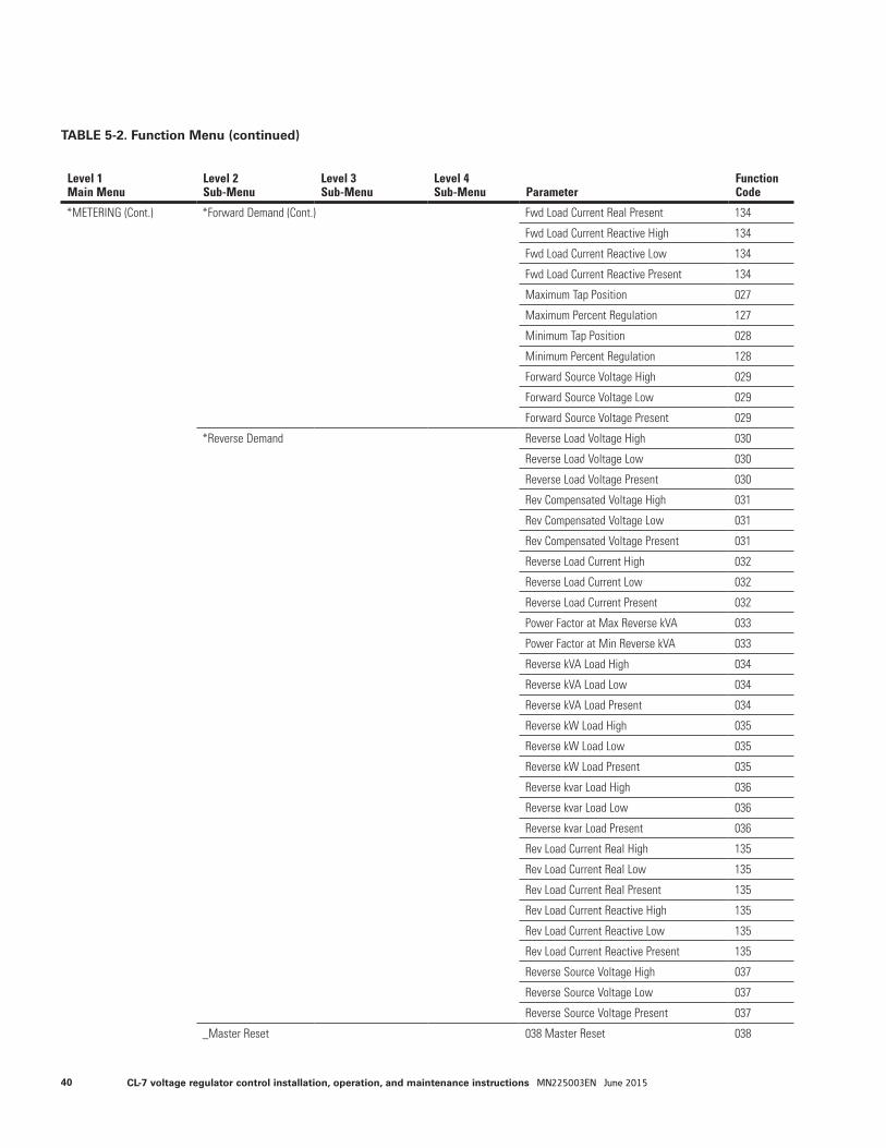
Level 1Main Menu
Level 2Sub-Menu
Level 3Sub-Menu
Level 4Sub-Menu Parameter
Function Code
*METERING (Cont.) *Forward Demand (Cont.) Fwd Load Current Real Present 134
Fwd Load Current Reactive High 134
Fwd Load Current Reactive Low 134
Fwd Load Current Reactive Present 134
Maximum Tap Position 027
Maximum Percent Regulation 127
Minimum Tap Position 028
Minimum Percent Regulation 128
Forward Source Voltage High 029
Forward Source Voltage Low 029
Forward Source Voltage Present 029
*Reverse Demand Reverse Load Voltage High 030
Reverse Load Voltage Low 030
Reverse Load Voltage Present 030
Rev Compensated Voltage High 031
Rev Compensated Voltage Low 031
Rev Compensated Voltage Present 031
Reverse Load Current High 032
Reverse Load Current Low 032
Reverse Load Current Present 032
Power Factor at Max Reverse kVA 033
Power Factor at Min Reverse kVA 033
Reverse kVA Load High 034
Reverse kVA Load Low 034
Reverse kVA Load Present 034
Reverse kW Load High 035
Reverse kW Load Low 035
Reverse kW Load Present 035
Reverse kvar Load High 036
Reverse kvar Load Low 036
Reverse kvar Load Present 036
Rev Load Current Real High 135
Rev Load Current Real Low 135
Rev Load Current Real Present 135
Rev Load Current Reactive High 135
Rev Load Current Reactive Low 135
Rev Load Current Reactive Present 135
Reverse Source Voltage High 037
Reverse Source Voltage Low 037
Reverse Source Voltage Present 037
_Master Reset 038 Master Reset 038
TABLE 5-2. Function Menu (continued)
40 CL-7 voltage regulator control installation, operation, and maintenance instructions MN225003EN June 2015

Level 1Main Menu
Level 2Sub-Menu
Level 3Sub-Menu
Level 4Sub-Menu Parameter
Function Code
*ALARMS *Alarms Active Unacknowledged (Unacknowledged Active Alarms) ---
_Alarms Active Acknowledged (Acknowledged Active Alarms) ---
*SEQUENCE OF EVENTS (Events Log) ---
*COMMUNICATIONS *Comm Port #1 *Comm Port #1 Configuration Protocol / Port Type 800
LoopShare Communications 800
ProView NXG Session 800
ProView NXG Address 800
Ethernet Switch On Comm Port #1 800
*Serial Configuration Serial Baud Rate 801
Serial Parity 801
Serial CTS Support 801
Serial Enable Delay 801
Serial Tx Disable Delay 801
Serial Echo Mode 801
*Network Configuration IP Address 802
Subnet Mask 802
Gateway 802
MAC Address 802
*DNP3 Basic DNP RBE Master 810
DNP IED Slave 810
DNP IED Slave 2 810
DNP User Map Selection 810
*DNP3 Network DNP Network Protocol Type 811
DNP Accept From Any IP 811
DNP Accept From IP Address 811
DNP Destination Port Number 811
DNP Listening Port Number 811
DNP Use Port From Request 811
DNP Keep Alive Timeout 811
DNP Keep Alive Retries 811
*IEC 60870-5-101 IEC101 Link Address 812
IEC101 Common Address 812
IEC101 Link Address Size 812
IEC101 Common Address Size 812
IEC101 Object Address Size 812
IEC101 Cause of Transmit Size 812
8IEC101 Single Command Op Mode 812
IEC101 Select Before Exec Time 812
IEC101 User Map Selection 812
TABLE 5-2. Function Menu (continued)
41CL-7 voltage regulator control installation, operation, and maintenance instructions MN225003EN June 2015
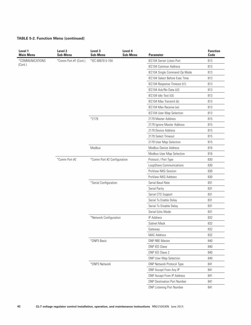
Level 1Main Menu
Level 2Sub-Menu
Level 3Sub-Menu
Level 4Sub-Menu Parameter
Function Code
*COMMUNICATIONS (Cont.)
*Comm Port #1 (Cont.) *IEC 60870-5-104 IEC104 Server Listen Port 813
IEC104 Common Address 813
IEC104 Single Command Op Mode 813
IEC104 Select Before Exec Time 813
IEC104 Response Timeout (t1) 813
IEC104 Ack/No Data (t2) 813
IEC104 Idle Test (t3) 813
IEC104 Max Transmit (k) 813
IEC104 Max Receive (w) 813
IEC104 User Map Selection 813
*2179 2179 Master Address 815
2179 Ignore Master Address 815
2179 Device Address 815
2179 Select Timeout 815
2179 User Map Selection 815
Modbus Modbus Device Address 816
Modbus User Map Selection 816
*Comm Port #2 *Comm Port #2 Configuration Protocol / Port Type 830
LoopShare Communications 830
ProView NXG Session 830
ProView NXG Address 830
*Serial Configuration Serial Baud Rate 831
Serial Parity 831
Serial CTS Support 831
Serial Tx Enable Delay 831
Serial Tx Disable Delay 831
Serial Echo Mode 831
*Network Configuration IP Address 832
Subnet Mask 832
Gateway 832
MAC Address 832
*DNP3 Basic DNP RBE Master 840
DNP IED Slave 840
DNP IED Slave 2 840
DNP User Map Selection 840
*DNP3 Network DNP Network Protocol Type 841
DNP Accept From Any IP 841
DNP Accept From IP Address 841
DNP Destination Port Number 841
DNP Listening Port Number 841
TABLE 5-2. Function Menu (continued)
42 CL-7 voltage regulator control installation, operation, and maintenance instructions MN225003EN June 2015
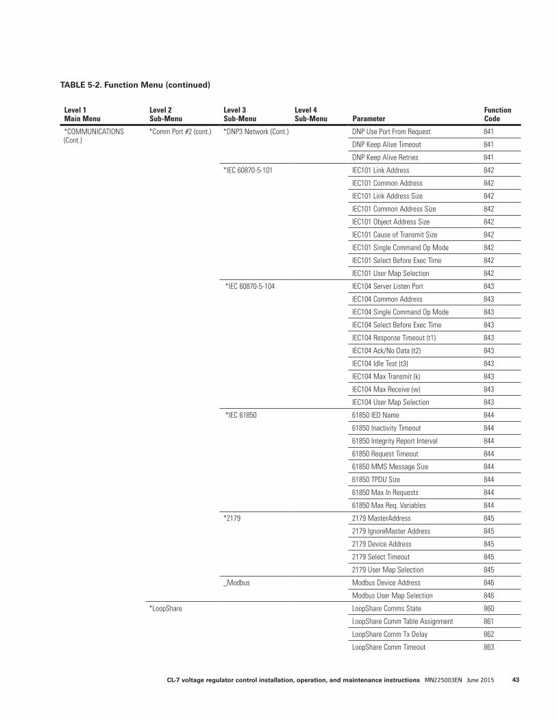
Level 1Main Menu
Level 2Sub-Menu
Level 3Sub-Menu
Level 4Sub-Menu Parameter
Function Code
*COMMUNICATIONS (Cont.)
*Comm Port #2 (cont.) *DNP3 Network (Cont.) DNP Use Port From Request 841
DNP Keep Alive Timeout 841
DNP Keep Alive Retries 841
*IEC 60870-5-101 IEC101 Link Address 842
IEC101 Common Address 842
IEC101 Link Address Size 842
IEC101 Common Address Size 842
IEC101 Object Address Size 842
IEC101 Cause of Transmit Size 842
IEC101 Single Command Op Mode 842
IEC101 Select Before Exec Time 842
IEC101 User Map Selection 842
*IEC 60870-5-104 IEC104 Server Listen Port 843
IEC104 Common Address 843
IEC104 Single Command Op Mode 843
IEC104 Select Before Exec Time 843
IEC104 Response Timeout (t1) 843
IEC104 Ack/No Data (t2) 843
IEC104 Idle Test (t3) 843
IEC104 Max Transmit (k) 843
IEC104 Max Receive (w) 843
IEC104 User Map Selection 843
*IEC 61850 61850 IED Name 844
61850 Inactivity Timeout 844
61850 Integrity Report Interval 844
61850 Request Timeout 844
61850 MMS Message Size 844
61850 TPDU Size 844
61850 Max In Requests 844
61850 Max Req. Variables 844
*2179 2179 MasterAddress 845
2179 IgnoreMaster Address 845
2179 Device Address 845
2179 Select Timeout 845
2179 User Map Selection 845
_Modbus Modbus Device Address 846
Modbus User Map Selection 846
*LoopShare LoopShare Comms State 860
LoopShare Comm Table Assignment 861
LoopShare Comm Tx Delay 862
LoopShare Comm Timeout 863
TABLE 5-2. Function Menu (continued)
43CL-7 voltage regulator control installation, operation, and maintenance instructions MN225003EN June 2015
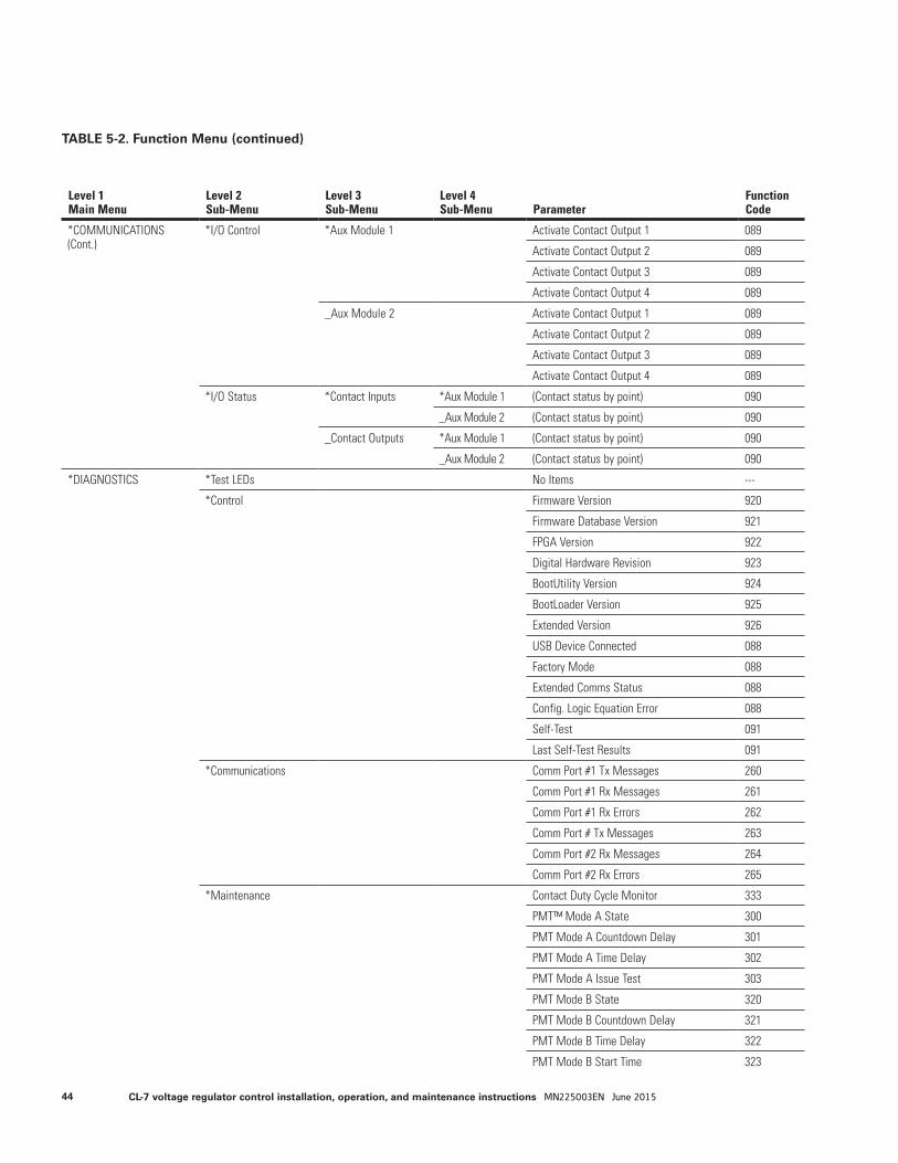
Level 1Main Menu
Level 2Sub-Menu
Level 3Sub-Menu
Level 4Sub-Menu Parameter
Function Code
*COMMUNICATIONS (Cont.)
*I/O Control *Aux Module 1 Activate Contact Output 1 089
Activate Contact Output 2 089
Activate Contact Output 3 089
Activate Contact Output 4 089
_Aux Module 2 Activate Contact Output 1 089
Activate Contact Output 2 089
Activate Contact Output 3 089
Activate Contact Output 4 089
*I/O Status *Contact Inputs *Aux Module 1 (Contact status by point) 090
_Aux Module 2 (Contact status by point) 090
_Contact Outputs *Aux Module 1 (Contact status by point) 090
_Aux Module 2 (Contact status by point) 090
*DIAGNOSTICS *Test LEDs No Items ---
*Control Firmware Version 920
Firmware Database Version 921
FPGA Version 922
Digital Hardware Revision 923
BootUtility Version 924
BootLoader Version 925
Extended Version 926
USB Device Connected 088
Factory Mode 088
Extended Comms Status 088
Config. Logic Equation Error 088
Self-Test 091
Last Self-Test Results 091
*Communications Comm Port #1 Tx Messages 260
Comm Port #1 Rx Messages 261
Comm Port #1 Rx Errors 262
Comm Port # Tx Messages 263
Comm Port #2 Rx Messages 264
Comm Port #2 Rx Errors 265
*Maintenance Contact Duty Cycle Monitor 333
PMT™ Mode A State 300
PMT Mode A Countdown Delay 301
PMT Mode A Time Delay 302
PMT Mode A Issue Test 303
PMT Mode B State 320
PMT Mode B Countdown Delay 321
PMT Mode B Time Delay 322
PMT Mode B Start Time 323
TABLE 5-2. Function Menu (continued)
44 CL-7 voltage regulator control installation, operation, and maintenance instructions MN225003EN June 2015
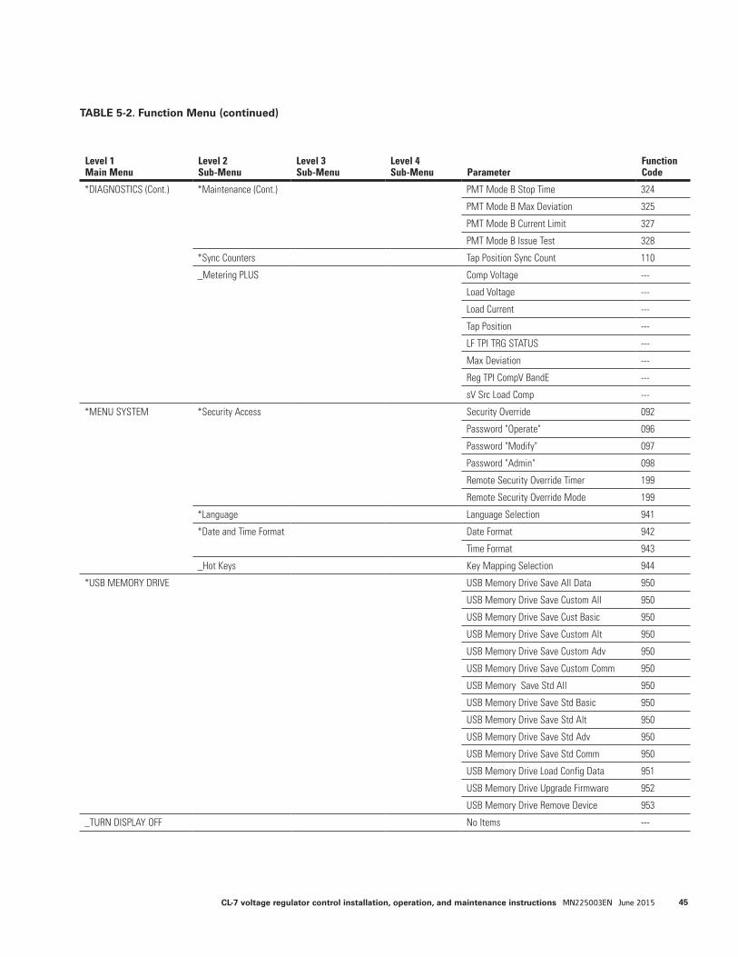
Level 1Main Menu
Level 2Sub-Menu
Level 3Sub-Menu
Level 4Sub-Menu Parameter
Function Code
*DIAGNOSTICS (Cont.) *Maintenance (Cont.) PMT Mode B Stop Time 324
PMT Mode B Max Deviation 325
PMT Mode B Current Limit 327
PMT Mode B Issue Test 328
*Sync Counters Tap Position Sync Count 110
_Metering PLUS Comp Voltage ---
Load Voltage ---
Load Current ---
Tap Position ---
LF TPI TRG STATUS ---
Max Deviation ---
Reg TPI CompV BandE ---
sV Src Load Comp ---
*MENU SYSTEM *Security Access Security Override 092
Password "Operate" 096
Password "Modify" 097
Password "Admin" 098
Remote Security Override Timer 199
Remote Security Override Mode 199
*Language Language Selection 941
*Date and Time Format Date Format 942
Time Format 943
_Hot Keys Key Mapping Selection 944
*USB MEMORY DRIVE USB Memory Drive Save All Data 950
USB Memory Drive Save Custom All 950
USB Memory Drive Save Cust Basic 950
USB Memory Drive Save Custom Alt 950
USB Memory Drive Save Custom Adv 950
USB Memory Drive Save Custom Comm 950
USB Memory Save Std All 950
USB Memory Drive Save Std Basic 950
USB Memory Drive Save Std Alt 950
USB Memory Drive Save Std Adv 950
USB Memory Drive Save Std Comm 950
USB Memory Drive Load Config Data 951
USB Memory Drive Upgrade Firmware 952
USB Memory Drive Remove Device 953
_TURN DISPLAY OFF No Items ---
TABLE 5-2. Function Menu (continued)
45CL-7 voltage regulator control installation, operation, and maintenance instructions MN225003EN June 2015
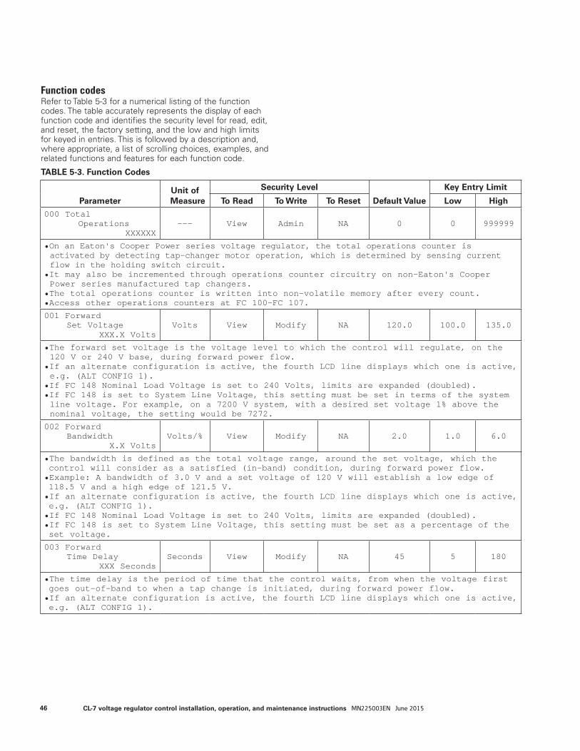
Function codesRefer to Table 5-3 for a numerical listing of the function codes. The table accurately represents the display of each function code and identifies the security level for read, edit, and reset, the factory setting, and the low and high limits for keyed in entries. This is followed by a description and, where appropriate, a list of scrolling choices, examples, and related functions and features for each function code.
TABLE 5-3. Function Codes
ParameterUnit of Measure
Security Level
Default Value
Key Entry Limit
To Read To Write To Reset Low High
000 Total Operations
XXXXXX--- View Admin NA 0 0 999999
• On an Eaton's Cooper Power series voltage regulator, the total operations counter is activated by detecting tap-changer motor operation, which is determined by sensing current flow in the holding switch circuit.
• It may also be incremented through operations counter circuitry on non-Eaton's Cooper Power series manufactured tap changers.
• The total operations counter is written into non-volatile memory after every count.• Access other operations counters at FC 100–FC 107.
001 Forward Set Voltage
XXX.X VoltsVolts View Modify NA 120.0 100.0 135.0
• The forward set voltage is the voltage level to which the control will regulate, on the 120 V or 240 V base, during forward power flow.
• If an alternate configuration is active, the fourth LCD line displays which one is active, e.g. (ALT CONFIG 1).
• If FC 148 Nominal Load Voltage is set to 240 Volts, limits are expanded (doubled). • If FC 148 is set to System Line Voltage, this setting must be set in terms of the system line voltage. For example, on a 7200 V system, with a desired set voltage 1% above the nominal voltage, the setting would be 7272.
002 Forward Bandwidth
X.X VoltsVolts/% View Modify NA 2.0 1.0 6.0
• The bandwidth is defined as the total voltage range, around the set voltage, which the control will consider as a satisfied (in-band) condition, during forward power flow.• Example: A bandwidth of 3.0 V and a set voltage of 120 V will establish a low edge of 118.5 V and a high edge of 121.5 V.• If an alternate configuration is active, the fourth LCD line displays which one is active, e.g. (ALT CONFIG 1).• If FC 148 Nominal Load Voltage is set to 240 Volts, limits are expanded (doubled).• If FC 148 is set to System Line Voltage, this setting must be set as a percentage of the set voltage.
003 Forward Time Delay
XXX SecondsSeconds View Modify NA 45 5 180
• The time delay is the period of time that the control waits, from when the voltage first goes out-of-band to when a tap change is initiated, during forward power flow.• If an alternate configuration is active, the fourth LCD line displays which one is active, e.g. (ALT CONFIG 1).
46 CL-7 voltage regulator control installation, operation, and maintenance instructions MN225003EN June 2015
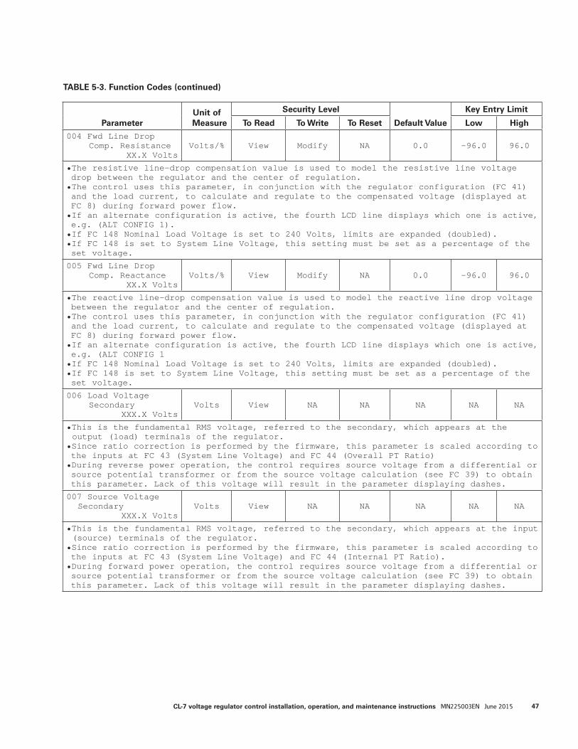
ParameterUnit of Measure
Security Level
Default Value
Key Entry Limit
To Read To Write To Reset Low High
000 Total Operations
XXXXXX--- View Admin NA 0 0 999999
• On an Eaton's Cooper Power series voltage regulator, the total operations counter is activated by detecting tap-changer motor operation, which is determined by sensing current flow in the holding switch circuit.
• It may also be incremented through operations counter circuitry on non-Eaton's Cooper Power series manufactured tap changers.
• The total operations counter is written into non-volatile memory after every count.• Access other operations counters at FC 100–FC 107.
001 Forward Set Voltage
XXX.X VoltsVolts View Modify NA 120.0 100.0 135.0
• The forward set voltage is the voltage level to which the control will regulate, on the 120 V or 240 V base, during forward power flow.
• If an alternate configuration is active, the fourth LCD line displays which one is active, e.g. (ALT CONFIG 1).
• If FC 148 Nominal Load Voltage is set to 240 Volts, limits are expanded (doubled). • If FC 148 is set to System Line Voltage, this setting must be set in terms of the system line voltage. For example, on a 7200 V system, with a desired set voltage 1% above the nominal voltage, the setting would be 7272.
002 Forward Bandwidth
X.X VoltsVolts/% View Modify NA 2.0 1.0 6.0
• The bandwidth is defined as the total voltage range, around the set voltage, which the control will consider as a satisfied (in-band) condition, during forward power flow.• Example: A bandwidth of 3.0 V and a set voltage of 120 V will establish a low edge of 118.5 V and a high edge of 121.5 V.• If an alternate configuration is active, the fourth LCD line displays which one is active, e.g. (ALT CONFIG 1).• If FC 148 Nominal Load Voltage is set to 240 Volts, limits are expanded (doubled).• If FC 148 is set to System Line Voltage, this setting must be set as a percentage of the set voltage.
003 Forward Time Delay
XXX SecondsSeconds View Modify NA 45 5 180
• The time delay is the period of time that the control waits, from when the voltage first goes out-of-band to when a tap change is initiated, during forward power flow.• If an alternate configuration is active, the fourth LCD line displays which one is active, e.g. (ALT CONFIG 1).
TABLE 5-3. Function Codes (continued)
ParameterUnit of Measure
Security Level
Default Value
Key Entry Limit
To Read To Write To Reset Low High
004 Fwd Line Drop Comp. Resistance
XX.X VoltsVolts/% View Modify NA 0.0 -96.0 96.0
• The resistive line-drop compensation value is used to model the resistive line voltage drop between the regulator and the center of regulation.• The control uses this parameter, in conjunction with the regulator configuration (FC 41) and the load current, to calculate and regulate to the compensated voltage (displayed at FC 8) during forward power flow. • If an alternate configuration is active, the fourth LCD line displays which one is active, e.g. (ALT CONFIG 1).• If FC 148 Nominal Load Voltage is set to 240 Volts, limits are expanded (doubled). • If FC 148 is set to System Line Voltage, this setting must be set as a percentage of the set voltage.
005 Fwd Line Drop Comp. Reactance
XX.X VoltsVolts/% View Modify NA 0.0 -96.0 96.0
• The reactive line-drop compensation value is used to model the reactive line drop voltage between the regulator and the center of regulation.• The control uses this parameter, in conjunction with the regulator configuration (FC 41) and the load current, to calculate and regulate to the compensated voltage (displayed at FC 8) during forward power flow.• If an alternate configuration is active, the fourth LCD line displays which one is active, e.g. (ALT CONFIG 1• If FC 148 Nominal Load Voltage is set to 240 Volts, limits are expanded (doubled).• If FC 148 is set to System Line Voltage, this setting must be set as a percentage of the set voltage.
006 Load Voltage Secondary
XXX.X VoltsVolts View NA NA NA NA NA
• This is the fundamental RMS voltage, referred to the secondary, which appears at the output (load) terminals of the regulator.
• Since ratio correction is performed by the firmware, this parameter is scaled according to the inputs at FC 43 (System Line Voltage) and FC 44 (Overall PT Ratio)• During reverse power operation, the control requires source voltage from a differential or source potential transformer or from the source voltage calculation (see FC 39) to obtain this parameter. Lack of this voltage will result in the parameter displaying dashes.
007 Source VoltageSecondary
XXX.X VoltsVolts View NA NA NA NA NA
• This is the fundamental RMS voltage, referred to the secondary, which appears at the input (source) terminals of the regulator.
• Since ratio correction is performed by the firmware, this parameter is scaled according to the inputs at FC 43 (System Line Voltage) and FC 44 (Internal PT Ratio).• During forward power operation, the control requires source voltage from a differential or source potential transformer or from the source voltage calculation (see FC 39) to obtain this parameter. Lack of this voltage will result in the parameter displaying dashes.
47CL-7 voltage regulator control installation, operation, and maintenance instructions MN225003EN June 2015
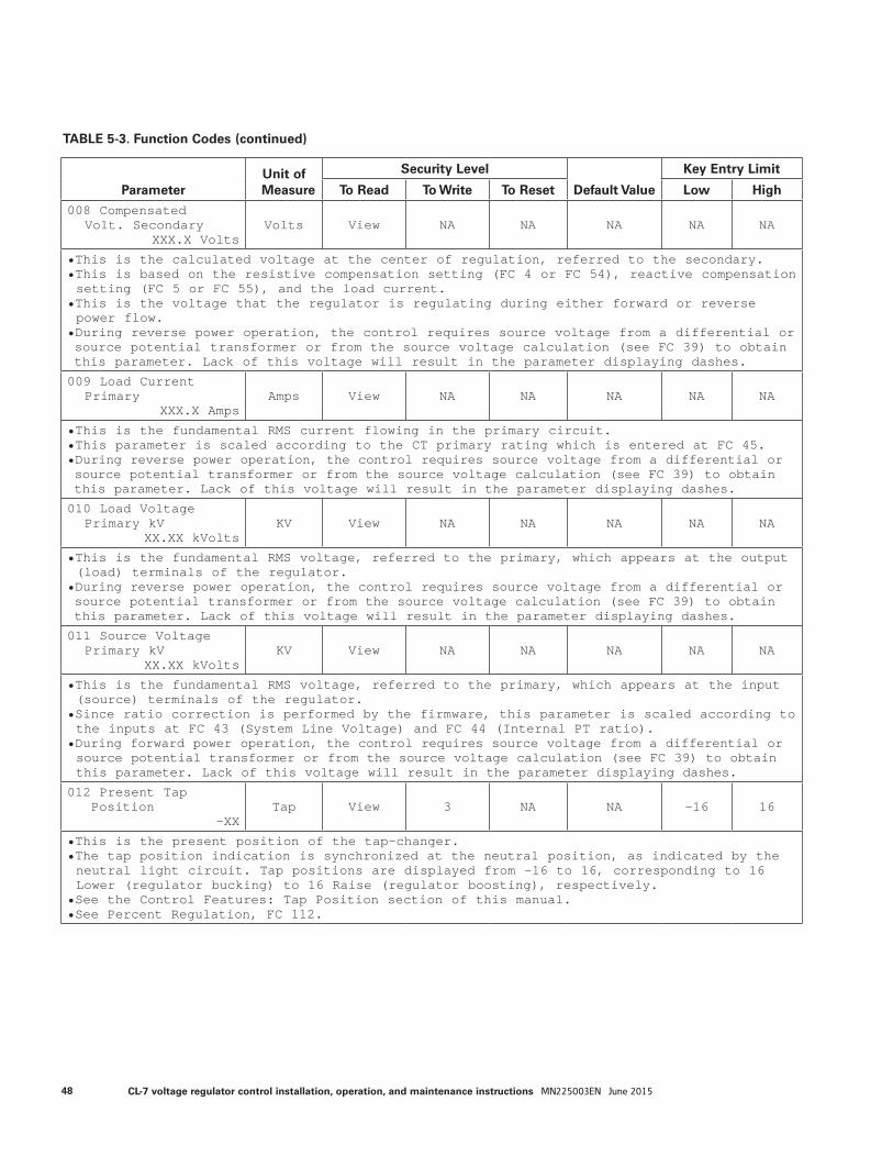
TABLE 5-3. Function Codes (continued)
ParameterUnit of Measure
Security Level
Default Value
Key Entry Limit
To Read To Write To Reset Low High
008 CompensatedVolt. Secondary
XXX.X VoltsVolts View NA NA NA NA NA
• This is the calculated voltage at the center of regulation, referred to the secondary.• This is based on the resistive compensation setting (FC 4 or FC 54), reactive compensation setting (FC 5 or FC 55), and the load current.
• This is the voltage that the regulator is regulating during either forward or reverse power flow.
• During reverse power operation, the control requires source voltage from a differential or source potential transformer or from the source voltage calculation (see FC 39) to obtain this parameter. Lack of this voltage will result in the parameter displaying dashes.
009 Load CurrentPrimary
XXX.X AmpsAmps View NA NA NA NA NA
• This is the fundamental RMS current flowing in the primary circuit.• This parameter is scaled according to the CT primary rating which is entered at FC 45.• During reverse power operation, the control requires source voltage from a differential or source potential transformer or from the source voltage calculation (see FC 39) to obtain this parameter. Lack of this voltage will result in the parameter displaying dashes.
010 Load VoltagePrimary kV
XX.XX kVoltsKV View NA NA NA NA NA
• This is the fundamental RMS voltage, referred to the primary, which appears at the output (load) terminals of the regulator.
• During reverse power operation, the control requires source voltage from a differential or source potential transformer or from the source voltage calculation (see FC 39) to obtain this parameter. Lack of this voltage will result in the parameter displaying dashes.
011 Source VoltagePrimary kV
XX.XX kVoltsKV View NA NA NA NA NA
• This is the fundamental RMS voltage, referred to the primary, which appears at the input (source) terminals of the regulator.
• Since ratio correction is performed by the firmware, this parameter is scaled according to the inputs at FC 43 (System Line Voltage) and FC 44 (Internal PT ratio).
• During forward power operation, the control requires source voltage from a differential or source potential transformer or from the source voltage calculation (see FC 39) to obtain this parameter. Lack of this voltage will result in the parameter displaying dashes.
012 Present TapPosition
-XXTap View 3 NA NA -16 16
• This is the present position of the tap-changer.• The tap position indication is synchronized at the neutral position, as indicated by the neutral light circuit. Tap positions are displayed from -16 to 16, corresponding to 16 Lower (regulator bucking) to 16 Raise (regulator boosting), respectively.
• See the Control Features: Tap Position section of this manual.• See Percent Regulation, FC 112.
48 CL-7 voltage regulator control installation, operation, and maintenance instructions MN225003EN June 2015
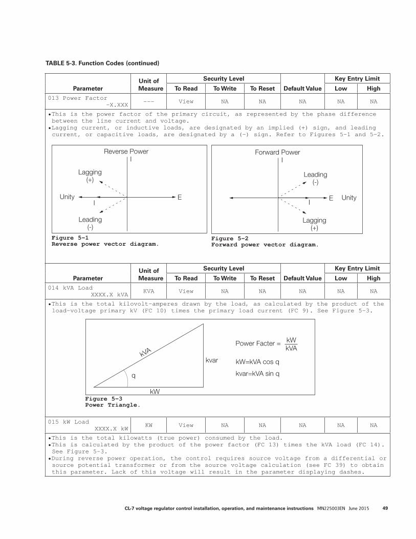
TABLE 5-3. Function Codes (continued)
ParameterUnit of Measure
Security Level
Default Value
Key Entry Limit
To Read To Write To Reset Low High
013 Power Factor-X.XXX --- View NA NA NA NA NA
• This is the power factor of the primary circuit, as represented by the phase difference between the line current and voltage.
• Lagging current, or inductive loads, are designated by an implied (+) sign, and leading current, or capacitive loads, are designated by a (-) sign. Refer to Figures 5-1 and 5-2.
ParameterUnit of Measure
Security Level
Default Value
Key Entry Limit
To Read To Write To Reset Low High
014 kVA LoadXXXX.X kVA KVA View NA NA NA NA NA
• This is the total kilovolt-amperes drawn by the load, as calculated by the product of the load-voltage primary kV (FC 10) times the primary load current (FC 9). See Figure 5-3.
015 kW LoadXXXX.X kW KW View NA NA NA NA NA
• This is the total kilowatts (true power) consumed by the load.• This is calculated by the product of the power factor (FC 13) times the kVA load (FC 14). See Figure 5-3.
• During reverse power operation, the control requires source voltage from a differential or source potential transformer or from the source voltage calculation (see FC 39) to obtain this parameter. Lack of this voltage will result in the parameter displaying dashes.
kW=kVA cos q
kW
kVAkvar
kvar=kVA sin qq
Power Facter = kWkVA
Figure 5-3Power Triangle.
Forward Power
Leading(-)
Lagging(+)
UnityE
I
I
Reverse Power
Leading(-)
Lagging(+)
Unity E
I
I
Figure 5-1Reverse power vector diagram.
Figure 5-2Forward power vector diagram.
49CL-7 voltage regulator control installation, operation, and maintenance instructions MN225003EN June 2015
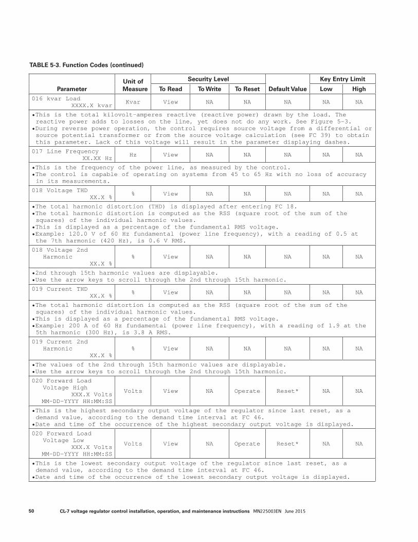
TABLE 5-3. Function Codes (continued)
ParameterUnit of Measure
Security Level
Default Value
Key Entry Limit
To Read To Write To Reset Low High
016 kvar LoadXXXX.X kvar Kvar View NA NA NA NA NA
• This is the total kilovolt-amperes reactive (reactive power) drawn by the load. The reactive power adds to losses on the line, yet does not do any work. See Figure 5-3.
• During reverse power operation, the control requires source voltage from a differential or source potential transformer or from the source voltage calculation (see FC 39) to obtain this parameter. Lack of this voltage will result in the parameter displaying dashes.
017 Line FrequencyXX.XX Hz Hz View NA NA NA NA NA
• This is the frequency of the power line, as measured by the control.• The control is capable of operating on systems from 45 to 65 Hz with no loss of accuracy in its measurements.
018 Voltage THDXX.X % % View NA NA NA NA NA
• The total harmonic distortion (THD) is displayed after entering FC 18.• The total harmonic distortion is computed as the RSS (square root of the sum of the squares) of the individual harmonic values.
• This is displayed as a percentage of the fundamental RMS voltage.• Example: 120.0 V of 60 Hz fundamental (power line frequency), with a reading of 0.5 at the 7th harmonic (420 Hz), is 0.6 V RMS.
018 Voltage 2ndHarmonic
XX.X %% View NA NA NA NA NA
• 2nd through 15th harmonic values are displayable.• Use the arrow keys to scroll through the 2nd through 15th harmonic.
019 Current THDXX.X % % View NA NA NA NA NA
• The total harmonic distortion is computed as the RSS (square root of the sum of the squares) of the individual harmonic values.
• This is displayed as a percentage of the fundamental RMS voltage.• Example: 200 A of 60 Hz fundamental (power line frequency), with a reading of 1.9 at the 5th harmonic (300 Hz), is 3.8 A RMS.
019 Current 2ndHarmonic
XX.X %% View NA NA NA NA NA
• The values of the 2nd through 15th harmonic values are displayable.• Use the arrow keys to scroll through the 2nd through 15th harmonic.
020 Forward LoadVoltage High
XXX.X VoltsMM-DD-YYYY HH:MM:SS
Volts View NA Operate Reset* NA NA
• This is the highest secondary output voltage of the regulator since last reset, as a demand value, according to the demand time interval at FC 46.
• Date and time of the occurrence of the highest secondary output voltage is displayed.
020 Forward LoadVoltage Low
XXX.X VoltsMM-DD-YYYY HH:MM:SS
Volts View NA Operate Reset* NA NA
• This is the lowest secondary output voltage of the regulator since last reset, as a demand value, according to the demand time interval at FC 46.
• Date and time of the occurrence of the lowest secondary output voltage is displayed.
50 CL-7 voltage regulator control installation, operation, and maintenance instructions MN225003EN June 2015
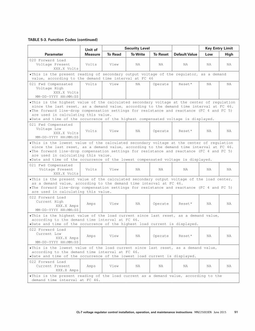
TABLE 5-3. Function Codes (continued)
ParameterUnit of Measure
Security Level
Default Value
Key Entry Limit
To Read To Write To Reset Low High
020 Forward LoadVoltage Present
XXX.X VoltsVolts View NA NA NA NA NA
• This is the present reading of secondary output voltage of the regulator, as a demand value, according to the demand time interval at FC 46
021 Fwd CompensatedVoltage High
XXX.X VoltsMM-DD-YYYY HH:MM:SS
Volts View NA Operate Reset* NA NA
• This is the highest value of the calculated secondary voltage at the center of regulation since the last reset, as a demand value, according to the demand time interval at FC 46.
• The forward line-drop compensation settings for resistance and reactance (FC 4 and FC 5) are used in calculating this value.
• Date and time of the occurrence of the highest compensated voltage is displayed.
021 Fwd CompensatedVoltage Low
XXX.X VoltsMM-DD-YYYY HH:MM:SS
Volts View NA Operate Reset* NA NA
• This is the lowest value of the calculated secondary voltage at the center of regulation since the last reset, as a demand value, according to the demand time interval at FC 46.
• The forward line-drop compensation settings for resistance and reactance (FC 4 and FC 5) are used in calculating this value.
• Date and time of the occurrence of the lowest compensated voltage is displayed.
021 Fwd Compensated Voltage Present
XXX.X VoltsVolts View NA NA NA NA NA
• This is the present value of the calculated secondary output voltage of the load center, as a demand value, according to the demand time interval at FC 46.
• The forward line-drop compensation settings for resistance and reactance (FC 4 and FC 5) are used in calculating this value.
022 Forward LoadCurrent High
XXX.X AmpsMM-DD-YYYY HH:MM:SS
Amps View NA Operate Reset* NA NA
• This is the highest value of the load current since last reset, as a demand value, according to the demand time interval at FC 46.
• Date and time of the occurrence of the highest load current is displayed.
022 Forward LoadCurrent Low
XXX.X AmpsMM-DD-YYYY HH:MM:SS
Amps View NA Operate Reset* NA NA
• This is the lowest value of the load current since last reset, as a demand value, according to the demand time interval at FC 46.
• Date and time of the occurrence of the lowest load current is displayed.
022 Forward LoadCurrent Present
XXX.X AmpsAmps View NA NA NA NA NA
• This is the present reading of the load current as a demand value, according to the demand time interval at FC 46.
51CL-7 voltage regulator control installation, operation, and maintenance instructions MN225003EN June 2015
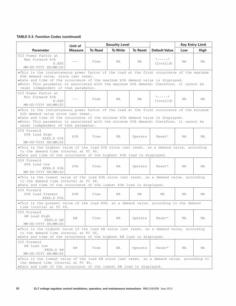
TABLE 5-3. Function Codes (continued)
ParameterUnit of Measure
Security Level
Default Value
Key Entry Limit
To Read To Write To Reset Low High
023 Power Factor atMax Forward kVA
X.XXXMM-DD-YYYY HH:MM:SS
--- View NA NA “-----” (Invalid) NA NA
• This is the instantaneous power factor of the load at the first occurrence of the maximum kVA demand value, since last reset.
• Date and time of the occurrence of the maximum kVA demand value is displayed.• Note: This parameter is associated with the maximum kVA demand; therefore, it cannot be reset independent of that parameter.
023 Power Factor atMin Forward kVA
X.XXXMM-DD-YYYY HH:MM:SS
--- View NA NA “-----” (Invalid) NA NA
• This is the instantaneous power factor of the load at the first occurrence of the minimum kVA demand value since last reset.
• Date and time of the occurrence of the minimum kVA demand value is displayed.• Note: This parameter is associated with the minimum kVA demand; therefore, it cannot be reset independent of that parameter.
024 ForwardkVA Load High
XXXX.X kVAMM-DD-YYYY HH:MM:SS
kVA View NA Operate Reset* NA NA
• This is the highest value of the load kVA since last reset, as a demand value, according to the demand time interval at FC 46.
• Date and time of the occurrence of the highest kVA load is displayed.
024 ForwardkVA Load Low
XXXX.X kVAMM-DD-YYYY HH:MM:SS
kVA View NA Operate Reset* NA NA
• This is the lowest value of the load kVA since last reset, as a demand value, according to the demand time interval at FC 46.
• Date and time of the occurrence of the lowest kVA load is displayed.
024 ForwardkVA Load Present
XXXX.X kVAkVA View NA NA NA NA NA
• This is the present value of the load kVA, as a demand value, according to the demand time interval at FC 46.
025 ForwardkW Load High
XXXX.X kWMM-DD-YYYY HH:MM:SS
kW View NA Operate Reset* NA NA
• This is the highest value of the load kW since last reset, as a demand value, according to the demand time interval at FC 46.
• Date and time of the occurrence of the highest kW load is displayed.
025 ForwardkW Load Low
XXXX.X kWMM-DD-YYYY HH:MM:SS
kW View NA Operate Reset* NA NA
• This is the lowest value of the load kW since last reset, as a demand value, according to the demand time interval at FC 46.
• Date and time of the occurrence of the lowest kW load is displayed.
52 CL-7 voltage regulator control installation, operation, and maintenance instructions MN225003EN June 2015
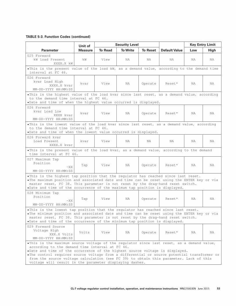
TABLE 5-3. Function Codes (continued)
ParameterUnit of Measure
Security Level
Default Value
Key Entry Limit
To Read To Write To Reset Low High
025 ForwardkW Load Present
XXXX.X kWkW View NA NA NA NA NA
• This is the present value of the load kW, as a demand value, according to the demand time interval at FC 46.
026 Forwardkvar Load High
XXXX.X kvarMM-DD-YYYY HH:MM:SS
kvar View NA Operate Reset* NA NA
• This is the highest value of the load kvar since last reset, as a demand value, according to the demand time interval at FC 46.
• Date and time of when the highest value occurred is displayed.
026 Forwardkvar Load Low
XXXX kvarMM-DD-YYYY HH:MM:SS
kvar View NA Operate Reset* NA NA
• This is the lowest value of the load kvar since last reset, as a demand value, according to the demand time interval at FC 46.
• Date and time of when the lowest value occurred is displayed.
026 Forward kvarLoad Present
XXXX.X kvarkvar View NA NA NA NA NA
• This is the present value of the load kvar, as a demand value, according to the demand time interval at FC 46.
027 Maximum TapPosition
-XXMM-DD-YYYY HH:MM:SS
Tap View NA Operate Reset* NA NA
• This is the highest tap position that the regulator has reached since last reset.• The maximum position and associated date and time can be reset using the ENTER key or via master reset, FC 38. This parameter is not reset by the drag-hand reset switch.
• Date and time of the occurrence of the maximum tap position is displayed.
028 Minimum TapPosition
-XXMM-DD-YYYY HH:MM:SS
Tap View NA Operate Reset* NA NA
• This is the lowest tap position that the regulator has reached since last reset.• The minimum position and associated date and time can be reset using the ENTER key or via master reset, FC 38. This parameter is not reset by the drag-hand reset switch.
• Date and time of the occurrence of the minimum tap position is displayed.
029 Forward SourceVoltage High
XXX.X VoltsMM-DD-YYYY HH:MM:SS
Volts View NA Operate Reset* NA NA
• This is the maximum source voltage of the regulator since last reset, as a demand value, according to the demand time interval at FC 46.
• Date and time of the occurrence of the highest source voltage is displayed.• The control requires source voltage from a differential or source potential transformer or from the source voltage calculation (see FC 39) to obtain this parameter. Lack of this voltage will result in the parameter displaying dashes.
53CL-7 voltage regulator control installation, operation, and maintenance instructions MN225003EN June 2015
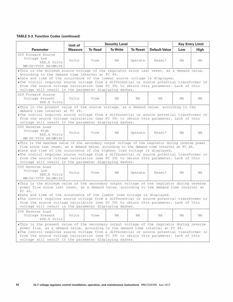
TABLE 5-3. Function Codes (continued)
ParameterUnit of Measure
Security Level
Default Value
Key Entry Limit
To Read To Write To Reset Low High029 Forward Source
Voltage LowXXX.X Volts
MM-DD-YYYY HH:MM:SS
Volts View NA Operate Reset* NA NA
• This is the minimum source voltage of the regulator since last reset, as a demand value, according to the demand time interval at FC 46.
• Date and time of the occurrence of the lowest source voltage is displayed.• The control requires source voltage from a differential or source potential transformer or from the source voltage calculation (see FC 39) to obtain this parameter. Lack of this voltage will result in the parameter displaying dashes.
029 Forward SourceVoltage Present
XXX.X VoltsVolts View NA NA NA NA NA
• This is the present value of the source voltage, as a demand value, according to the demand time interval at FC 46.
• The control requires source voltage from a differential or source potential transformer or from the source voltage calculation (see FC 39) to obtain this parameter. Lack of this voltage will result in the parameter displaying dashes.
030 Reverse LoadVoltage High
XXX.X VoltsMM-DD-YYYY HH:MM:SS
Volts View NA Operate Reset* NA NA
• This is the maximum value of the secondary output voltage of the regulator during reverse power flow since last reset, as a demand value, according to the demand time interval at FC 46.
• Date and time of the occurrence of the highest load voltage is displayed.• The control requires source voltage from a differential or source potential transformer or from the source voltage calculation (see FC 39) to obtain this parameter. Lack of this voltage will result in the parameter displaying dashes.
030 Reverse LoadVoltage Low
XXX.X VoltsMM-DD-YYYY HH:MM:SS
Volts View NA Operate Reset* NA NA
• This is the minimum value of the secondary output voltage of the regulator during reverse power flow since last reset, as a demand value, according to the demand time interval at FC 46.
• Date and time of the occurrence of the lowest load voltage is displayed.• The control requires source voltage from a differential or source potential transformer or from the source voltage calculation (see FC 39) to obtain this parameter. Lack of this voltage will result in the parameter displaying dashes.
030 Reverse LoadVoltage Present
XXX.X VoltsVolts View NA NA NA NA NA
• This is the present value of the secondary output voltage of the regulator during reverse power flow, as a demand value, according to the demand time interval at FC 46.
• The control requires source voltage from a differential or source potential transformer or from the source voltage calculation (see FC 39) to obtain this parameter. Lack of this voltage will result in the parameter displaying dashes.
54 CL-7 voltage regulator control installation, operation, and maintenance instructions MN225003EN June 2015

TABLE 5-3. Function Codes (continued)
ParameterUnit of Measure
Security Level
Default Value
Key Entry Limit
To Read To Write To Reset Low High
031 Rev CompensatedVoltage High
XXX.X VoltsMM-DD-YYYY HH:MM:SS
Volts View NA Operate Reset* NA NA
• This is the highest value of the calculated secondary voltage at the center of regulation during reverse power flow since last reset, as a demand value, according to the demand time interval at FC 46.
• The reverse line-drop compensation settings for resistance and reactance (FC 54 and FC 55) are used in calculating this value.
• Date and time of the occurrence of the highest compensated voltage is displayed.• The control requires source voltage from a differential or source potential transformer or from the source voltage calculation (see FC 39) to obtain this parameter. Lack of this voltage will result in the parameter displaying dashes.
031 Rev CompensatedVoltage Low
XXX.X VoltsMM-DD-YYYY HH:MM:SS
Volts View NA Operate Reset* NA NA
• This is the lowest value of the calculated secondary voltage at the load center during reverse power flow since last reset, as a demand value, according to the demand time interval at FC 46.
• The reverse line-drop compensation settings for resistance and reactance (FC 54 and FC 55) are used in calculating this value.
• Date and time of the occurrence of the lowest compensated voltage is displayed.• The control requires source voltage from a differential or source potential transformer or from the source voltage calculation (see FC 39) to obtain this parameter. Lack of this voltage will result in the parameter displaying dashes.
031 Rev CompensatedVoltage Present
XXX.X VoltsVolts View NA NA NA NA NA
• This is the present value of the calculated secondary voltage at the load center during reverse power flow, as a demand value, according to the demand time interval at FC 46.
• The reverse line-drop compensation settings for resistance and reactance (FC 54 and FC 55) are used in calculating this value.
• The control requires source voltage from a differential or source potential transformer or from the source voltage calculation (see FC 39) to obtain this parameter. Lack of this voltage will result in the parameter displaying dashes.
032 Reverse LoadCurrent High
XXX.X AmpsMM-DD-YYYY HH:MM:SS
Amps View NA Operate Reset* NA NA
• This is the highest value of the load current during reverse power flow since the last reset, as a demand value, according to the demand time interval at FC 46.
• Date and time of the occurrence of the highest load current is displayed.• The control requires source voltage from a differential or source potential transformer or from the source voltage calculation (see FC 39) to obtain this parameter. Lack of this voltage will result in the parameter displaying dashes.
55CL-7 voltage regulator control installation, operation, and maintenance instructions MN225003EN June 2015
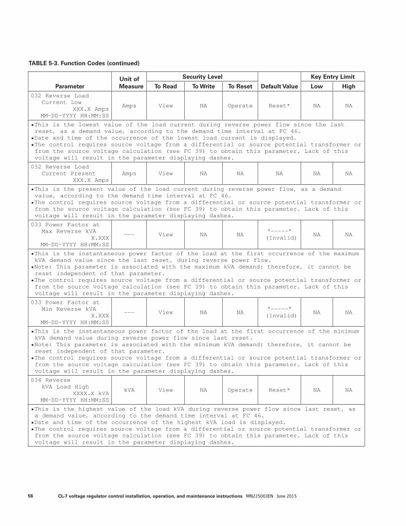
TABLE 5-3. Function Codes (continued)
ParameterUnit of Measure
Security Level
Default Value
Key Entry Limit
To Read To Write To Reset Low High
032 Reverse LoadCurrent Low
XXX.X AmpsMM-DD-YYYY HH:MM:SS
Amps View NA Operate Reset* NA NA
• This is the lowest value of the load current during reverse power flow since the last reset, as a demand value, according to the demand time interval at FC 46.
• Date and time of the occurrence of the lowest load current is displayed.• The control requires source voltage from a differential or source potential transformer or from the source voltage calculation (see FC 39) to obtain this parameter. Lack of this voltage will result in the parameter displaying dashes.
032 Reverse LoadCurrent Present
XXX.X AmpsAmps View NA NA NA NA NA
• This is the present value of the load current during reverse power flow, as a demand value, according to the demand time interval at FC 46.
• The control requires source voltage from a differential or source potential transformer or from the source voltage calculation (see FC 39) to obtain this parameter. Lack of this voltage will result in the parameter displaying dashes.
033 Power Factor atMax Reverse kVA
X.XXXMM-DD-YYYY HH:MM:SS
--- View NA NA “-----” (Invalid) NA NA
• This is the instantaneous power factor of the load at the first occurrence of the maximum kVA demand value since the last reset, during reverse power flow.
• Note: This parameter is associated with the maximum kVA demand; therefore, it cannot be reset independent of that parameter.
• The control requires source voltage from a differential or source potential transformer or from the source voltage calculation (see FC 39) to obtain this parameter. Lack of this voltage will result in the parameter displaying dashes.
033 Power Factor atMin Reverse kVA
X.XXXMM-DD-YYYY HH:MM:SS
--- View NA NA “-----” (Invalid) NA NA
• This is the instantaneous power factor of the load at the first occurrence of the minimum kVA demand value during reverse power flow since last reset.
• Note: This parameter is associated with the minimum kVA demand; therefore, it cannot be reset independent of that parameter.
• The control requires source voltage from a differential or source potential transformer or from the source voltage calculation (see FC 39) to obtain this parameter. Lack of this voltage will result in the parameter displaying dashes.
034 ReversekVA Load High
XXXX.X kVAMM-DD-YYYY HH:MM:SS
kVA View NA Operate Reset* NA NA
• This is the highest value of the load kVA during reverse power flow since last reset, as a demand value, according to the demand time interval at FC 46.
• Date and time of the occurrence of the highest kVA load is displayed.• The control requires source voltage from a differential or source potential transformer or from the source voltage calculation (see FC 39) to obtain this parameter. Lack of this voltage will result in the parameter displaying dashes.
56 CL-7 voltage regulator control installation, operation, and maintenance instructions MN225003EN June 2015
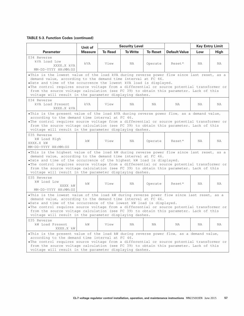
TABLE 5-3. Function Codes (continued)
ParameterUnit of Measure
Security Level
Default Value
Key Entry Limit
To Read To Write To Reset Low High
034 ReversekVA Load Low
XXXX.X kVAMM-DD-YYYY HH:MM:SS
kVA View NA Operate Reset* NA NA
• This is the lowest value of the load kVA during reverse power flow since last reset, as a demand value, according to the demand time interval at FC 46.
• Date and time of the occurrence the lowest kVA load is displayed.• The control requires source voltage from a differential or source potential transformer or from the source voltage calculation (see FC 39) to obtain this parameter. Lack of this voltage will result in the parameter displaying dashes.
034 ReversekVA Load Present
XXXX.X kVAkVA View NA NA NA NA NA
• This is the present value of the load kVA during reverse power flow, as a demand value, according to the demand time interval at FC 46.
• The control requires source voltage from a differential or source potential transformer or from the source voltage calculation (see FC 39) to obtain this parameter. Lack of this voltage will result in the parameter displaying dashes.
035 ReversekW Load High
XXXX.X kWMM-DD-YYYY HH:MM:SS
kW View NA Operate Reset* NA NA
• This is the highest value of the load kW during reverse power flow since last reset, as a demand value, according to the demand time interval at FC 46.
• Date and time of the occurrence of the highest kW load is displayed.• The control requires source voltage from a differential or source potential transformer or from the source voltage calculation (see FC 39) to obtain this parameter. Lack of this voltage will result in the parameter displaying dashes.
035 ReversekW Load Low
XXXX kWMM-DD-YYYY HH:MM:SS
kW View NA Operate Reset* NA NA
• This is the lowest value of the load kW during reverse power flow since last reset, as a demand value, according to the demand time interval at FC 46.
• Date and time of the occurrence of the lowest kW load is displayed.• The control requires source voltage from a differential or source potential transformer or from the source voltage calculation (see FC 39) to obtain this parameter. Lack of this voltage will result in the parameter displaying dashes.
035 ReversekW Load Present
XXXX.X kWkW View NA NA NA NA NA
• This is the present value of the load kW during reverse power flow, as a demand value, according to the demand time interval at FC 46.
• The control requires source voltage from a differential or source potential transformer or from the source voltage calculation (see FC 39) to obtain this parameter. Lack of this voltage will result in the parameter displaying dashes.
57CL-7 voltage regulator control installation, operation, and maintenance instructions MN225003EN June 2015
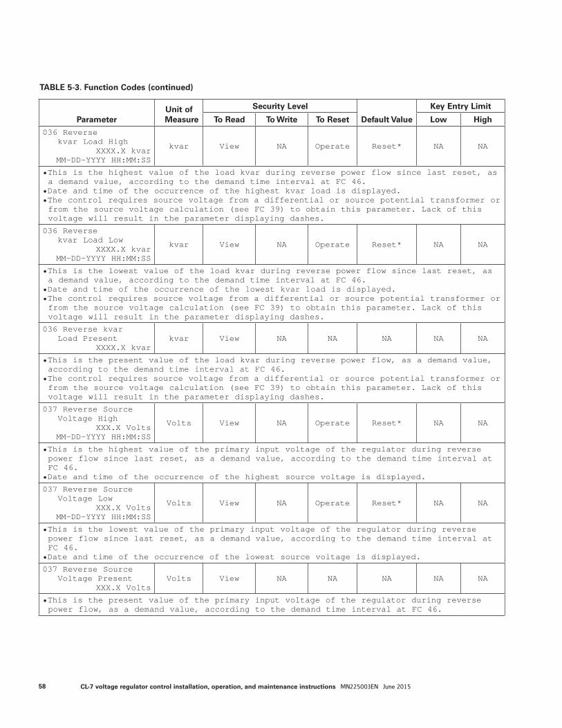
TABLE 5-3. Function Codes (continued)
ParameterUnit of Measure
Security Level
Default Value
Key Entry Limit
To Read To Write To Reset Low High
036 Reversekvar Load High
XXXX.X kvarMM-DD-YYYY HH:MM:SS
kvar View NA Operate Reset* NA NA
• This is the highest value of the load kvar during reverse power flow since last reset, as a demand value, according to the demand time interval at FC 46.
• Date and time of the occurrence of the highest kvar load is displayed.• The control requires source voltage from a differential or source potential transformer or from the source voltage calculation (see FC 39) to obtain this parameter. Lack of this voltage will result in the parameter displaying dashes.
036 Reversekvar Load Low
XXXX.X kvarMM-DD-YYYY HH:MM:SS
kvar View NA Operate Reset* NA NA
• This is the lowest value of the load kvar during reverse power flow since last reset, as a demand value, according to the demand time interval at FC 46.
• Date and time of the occurrence of the lowest kvar load is displayed.• The control requires source voltage from a differential or source potential transformer or from the source voltage calculation (see FC 39) to obtain this parameter. Lack of this voltage will result in the parameter displaying dashes.
036 Reverse kvarLoad Present
XXXX.X kvarkvar View NA NA NA NA NA
• This is the present value of the load kvar during reverse power flow, as a demand value, according to the demand time interval at FC 46.
• The control requires source voltage from a differential or source potential transformer or from the source voltage calculation (see FC 39) to obtain this parameter. Lack of this voltage will result in the parameter displaying dashes.
037 Reverse SourceVoltage High
XXX.X VoltsMM-DD-YYYY HH:MM:SS
Volts View NA Operate Reset* NA NA
• This is the highest value of the primary input voltage of the regulator during reverse power flow since last reset, as a demand value, according to the demand time interval at FC 46.
• Date and time of the occurrence of the highest source voltage is displayed.
037 Reverse SourceVoltage Low
XXX.X VoltsMM-DD-YYYY HH:MM:SS
Volts View NA Operate Reset* NA NA
• This is the lowest value of the primary input voltage of the regulator during reverse power flow since last reset, as a demand value, according to the demand time interval at FC 46.
• Date and time of the occurrence of the lowest source voltage is displayed.
037 Reverse SourceVoltage Present
XXX.X VoltsVolts View NA NA NA NA NA
• This is the present value of the primary input voltage of the regulator during reverse power flow, as a demand value, according to the demand time interval at FC 46.
58 CL-7 voltage regulator control installation, operation, and maintenance instructions MN225003EN June 2015
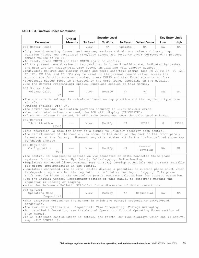
TABLE 5-3. Function Codes (continued)
ParameterUnit of Measure
Security Level
Default Value
Key Entry Limit
To Read To Write To Reset Low High
038 Master Reset --- View NA Operate NA NA NA
• Only demand metering forward and reverse; maximum and minimum raise and lower; tap position values and associated time/date stamps are reset to their corresponding present demand values at FC 38.
• To reset, press ENTER and then ENTER again to confirm.• If the present demand value or tap position is in an invalid state, indicated by dashes, the high and low values will also become invalid and will display dashes.
• Individual maximum and minimum values and their date/time stamps (see FC 20–FC 37, FC 127, FC 128, FC 134, and FC 135) may be reset to the present demand value: access the appropriate function code on display, press ENTER and then Enter again to confirm.
• Successful master reset is indicated by the word (Done) appearing on the display.• See the Control Programming: Special Functions section of this manual.
039 Source SideVoltage Calc.
On--- View Modify NA On NA NA
• The source side voltage is calculated based on tap position and the regulator type (see FC 140).
• Options include: Off; On.• The source voltage calculation provides accuracy to ±1.5% maximum error.• When calculated values are used, the LCD will display (CALCULATED).• If source voltage is sensed, it will take precedence over the calculated voltage.
040 ControlIdentification
12345--- View Modify NA 12345 0 99999
• This provision is made for entry of a number to uniquely identify each control.• The serial number of the control, as shown on the decal on the back of the front panel, is entered at the factory. However, any other number within the limits defined above may be chosen instead.
041 RegulatorConfiguration
Wye--- View Modify NA “-----”
(Invalid) NA NA
• The control is designed to operate on wye-connected or delta-connected three-phase systems. Options include: Wye (star); Delta-lagging; Delta-leading.
• Regulators connected line-to-ground (wye or star) develop potentials and currents suitable for direct implementation in the control.
• Regulators connected line-to-line (delta) develop a potential-to-current phase shift which is dependent upon whether the regulator is defined as leading or lagging. This phase shift must be known by the control to permit accurate calculations for correct operation.
• See the Initial Control Programming section of this manual to determine whether the regulator is leading or lagging.
• Note: See Reference Bulletin R225-10-1 for a discussion of delta connections.
042 ControlOperating Mode
Sequential--- View Modify NA Sequential NA NA
• This parameter determines the manner in which the control responds to out-of-band conditions.
• The available options are: Sequential; Time Integrating; Voltage Averaging.• For detailed information, see the Control Operation: Control Operating Modes section of this manual.
• If an alternate configuration is active, the fourth LCD line displays which one is active, e.g. (ALT CONFIG 1).
59CL-7 voltage regulator control installation, operation, and maintenance instructions MN225003EN June 2015
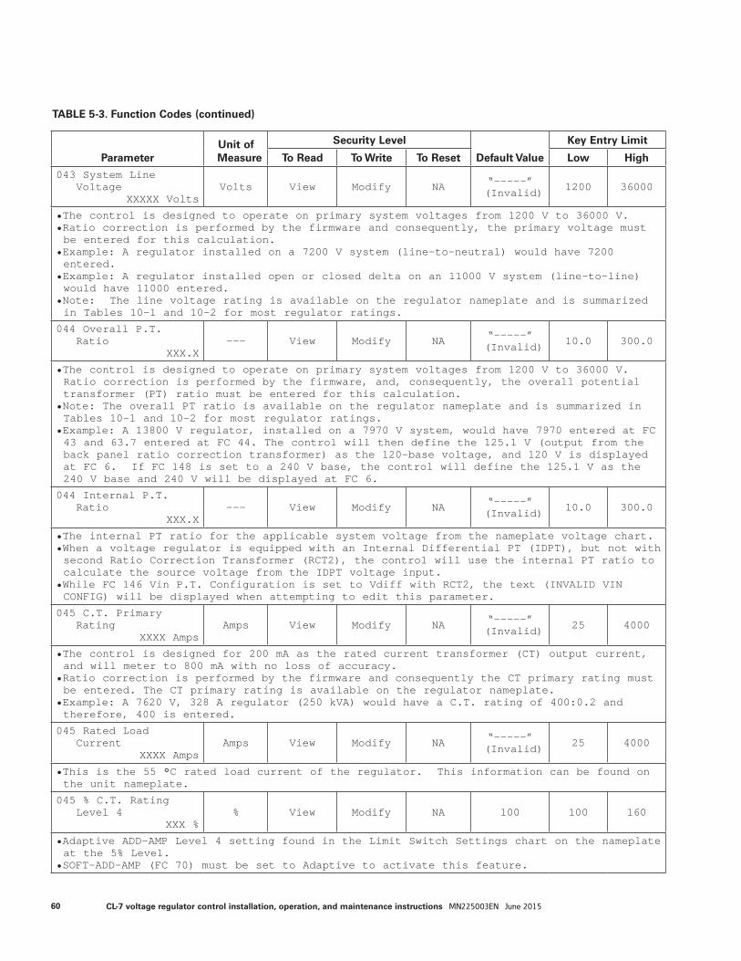
TABLE 5-3. Function Codes (continued)
ParameterUnit of Measure
Security Level
Default Value
Key Entry Limit
To Read To Write To Reset Low High
043 System LineVoltage
XXXXX VoltsVolts View Modify NA “-----”
(Invalid) 1200 36000
• The control is designed to operate on primary system voltages from 1200 V to 36000 V.• Ratio correction is performed by the firmware and consequently, the primary voltage must be entered for this calculation.
• Example: A regulator installed on a 7200 V system (line-to-neutral) would have 7200 entered.
• Example: A regulator installed open or closed delta on an 11000 V system (line-to-line) would have 11000 entered.
• Note: The line voltage rating is available on the regulator nameplate and is summarized in Tables 10-1 and 10-2 for most regulator ratings.
044 Overall P.T.Ratio
XXX.X--- View Modify NA “-----”
(Invalid) 10.0 300.0
• The control is designed to operate on primary system voltages from 1200 V to 36000 V. Ratio correction is performed by the firmware, and, consequently, the overall potential transformer (PT) ratio must be entered for this calculation.
• Note: The overall PT ratio is available on the regulator nameplate and is summarized in Tables 10-1 and 10-2 for most regulator ratings.
• Example: A 13800 V regulator, installed on a 7970 V system, would have 7970 entered at FC 43 and 63.7 entered at FC 44. The control will then define the 125.1 V (output from the back panel ratio correction transformer) as the 120-base voltage, and 120 V is displayed at FC 6. If FC 148 is set to a 240 V base, the control will define the 125.1 V as the 240 V base and 240 V will be displayed at FC 6.
044 Internal P.T.Ratio
XXX.X--- View Modify NA “-----”
(Invalid) 10.0 300.0
• The internal PT ratio for the applicable system voltage from the nameplate voltage chart.• When a voltage regulator is equipped with an Internal Differential PT (IDPT), but not with second Ratio Correction Transformer (RCT2), the control will use the internal PT ratio to calculate the source voltage from the IDPT voltage input.
• While FC 146 Vin P.T. Configuration is set to Vdiff with RCT2, the text (INVALID VIN CONFIG) will be displayed when attempting to edit this parameter.
045 C.T. PrimaryRating
XXXX AmpsAmps View Modify NA “-----”
(Invalid) 25 4000
• The control is designed for 200 mA as the rated current transformer (CT) output current, and will meter to 800 mA with no loss of accuracy.
• Ratio correction is performed by the firmware and consequently the CT primary rating must be entered. The CT primary rating is available on the regulator nameplate.
• Example: A 7620 V, 328 A regulator (250 kVA) would have a C.T. rating of 400:0.2 and therefore, 400 is entered.
045 Rated LoadCurrent
XXXX AmpsAmps View Modify NA “-----”
(Invalid) 25 4000
• This is the 55 °C rated load current of the regulator. This information can be found on the unit nameplate.
045 % C.T. RatingLevel 4
XXX %% View Modify NA 100 100 160
• Adaptive ADD-AMP Level 4 setting found in the Limit Switch Settings chart on the nameplate at the 5% Level.
• SOFT-ADD-AMP (FC 70) must be set to Adaptive to activate this feature.
60 CL-7 voltage regulator control installation, operation, and maintenance instructions MN225003EN June 2015
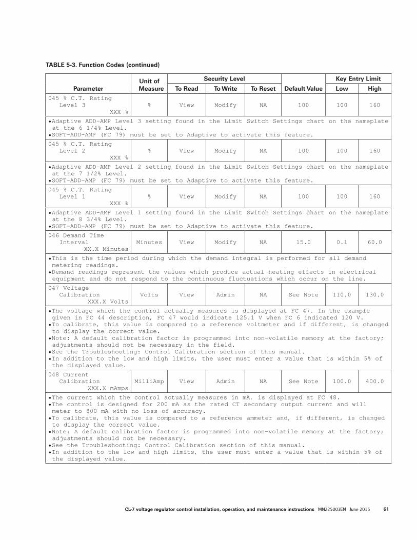
TABLE 5-3. Function Codes (continued)
ParameterUnit of Measure
Security Level
Default Value
Key Entry Limit
To Read To Write To Reset Low High
045 % C.T. RatingLevel 3
XXX %% View Modify NA 100 100 160
• Adaptive ADD-AMP Level 3 setting found in the Limit Switch Settings chart on the nameplate at the 6 1/4% Level.
• SOFT-ADD-AMP (FC 79) must be set to Adaptive to activate this feature.
045 % C.T. RatingLevel 2
XXX %% View Modify NA 100 100 160
• Adaptive ADD-AMP Level 2 setting found in the Limit Switch Settings chart on the nameplate at the 7 1/2% Level.
• SOFT-ADD-AMP (FC 79) must be set to Adaptive to activate this feature.
045 % C.T. RatingLevel 1
XXX %% View Modify NA 100 100 160
• Adaptive ADD-AMP Level 1 setting found in the Limit Switch Settings chart on the nameplate at the 8 3/4% Level.
• SOFT-ADD-AMP (FC 79) must be set to Adaptive to activate this feature.
046 Demand TimeInterval
XX.X MinutesMinutes View Modify NA 15.0 0.1 60.0
• This is the time period during which the demand integral is performed for all demand metering readings.
• Demand readings represent the values which produce actual heating effects in electrical equipment and do not respond to the continuous fluctuations which occur on the line.
047 VoltageCalibration
XXX.X VoltsVolts View Admin NA See Note 110.0 130.0
• The voltage which the control actually measures is displayed at FC 47. In the example given in FC 44 description, FC 47 would indicate 125.1 V when FC 6 indicated 120 V.
• To calibrate, this value is compared to a reference voltmeter and if different, is changed to display the correct value.
• Note: A default calibration factor is programmed into non-volatile memory at the factory; adjustments should not be necessary in the field.
• See the Troubleshooting: Control Calibration section of this manual.• In addition to the low and high limits, the user must enter a value that is within 5% of the displayed value.
048 CurrentCalibration
XXX.X mAmpsMilliAmp View Admin NA See Note 100.0 400.0
• The current which the control actually measures in mA, is displayed at FC 48.• The control is designed for 200 mA as the rated CT secondary output current and will meter to 800 mA with no loss of accuracy.
• To calibrate, this value is compared to a reference ammeter and, if different, is changed to display the correct value.
• Note: A default calibration factor is programmed into non-volatile memory at the factory; adjustments should not be necessary.
• See the Troubleshooting: Control Calibration section of this manual.• In addition to the low and high limits, the user must enter a value that is within 5% of the displayed value.
61CL-7 voltage regulator control installation, operation, and maintenance instructions MN225003EN June 2015
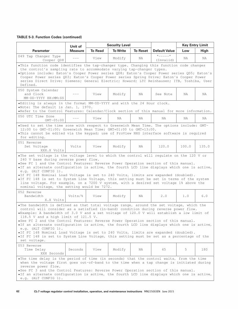
TABLE 5-3. Function Codes (continued)
ParameterUnit of Measure
Security Level
Default Value
Key Entry Limit
To Read To Write To Reset Low High
049 Tap Changer TypeCooper QD8 --- View Modify NA “-----”
(Invalid) NA NA
• This function code identifies the tap-changer type. Changing this function code changes the control’s sampling rate to accommodate varying tap-changer types.
• Options include: Eaton's Cooper Power series QD8; Eaton's Cooper Power series QD5; Eaton's Cooper Power series QD3; Eaton's Cooper Power series Spring Drive; Eaton's Cooper Power series Direct Drive; Siemens; General Electric; Howard; LTC Reinhausen; ITB, Toshiba, User Defined.
050 System Calendarand ClockMM-DD-YYYY HH:MM:SS
--- View Modify NA See Note NA NA
• Editing is always in the format MM-DD-YYYY and with the 24 Hour clock.• Note: The default is Jan. 1, 1970.• Refer to the Control Features: Calendar/Clock section of this manual for more information.
050 UTC Time ZoneGMT-05:00 --- View NA NA NA NA NA
• Used to set the time zone with respect to Greenwich Mean Time. The options include: GMT-12:00 to GMT-01:00; Greenwich Mean Time; GMT+01:00 to GMT+13:00.
• This cannot be edited via the keypad; use of ProView NXG interface software is required for editing.
051 ReverseSet Voltage
XXX.X VoltsVolts View Modify NA 120.0 100.0 135.0
• The set voltage is the voltage level to which the control will regulate on the 120 V or 240 V base during reverse power flow.
• See FC 1 and the Control Features: Reverse Power Operation section of this manual.• If an alternate configuration is active, the fourth LCD line displays which one is active, e.g. (ALT CONFIG 1).
• If FC 148 Nominal Load Voltage is set to 240 Volts, limits are expanded (doubled).• If FC 148 is set to System Line Voltage, this setting must be set in terms of the system line voltage. For example, on a 7200 V system, with a desired set voltage 1% above the nominal voltage, the setting would be 7272.
052 ReverseBandwidth
X.X VoltsVolts/% View Modify NA 2.0 1.0 6.0
• The bandwidth is defined as that total voltage range, around the set voltage, which the control will consider as a satisfied (in-band) condition during reverse power flow.
• Example: A bandwidth of 3.0 V and a set voltage of 120.0 V will establish a low limit of 118.5 V and a high limit of 121.5 V.
• See FC 2 and the Control Features: Reverse Power Operation section of this manual.• If an alternate configuration is active, the fourth LCD line displays which one is active, e.g. (ALT CONFIG 1).
• If FC 148 Nominal Load Voltage is set to 240 Volts, limits are expanded (doubled).• If FC 148 is set to System Line Voltage, this setting must be set as a percentage of the set voltage.
053 ReverseTime Delay
XXX SecondsSeconds View Modify NA 45 5 180
• The time delay is the period of time (in seconds) that the control waits, from the time when the voltage first goes out-of-band to the time when a tap change is initiated during reverse power flow.
• See FC 3 and the Control Features: Reverse Power Operation section of this manual.• If an alternate configuration is active, the fourth LCD line displays which one is active, e.g. (ALT CONFIG 1).
62 CL-7 voltage regulator control installation, operation, and maintenance instructions MN225003EN June 2015

TABLE 5-3. Function Codes (continued)
ParameterUnit of Measure
Security Level
Default Value
Key Entry Limit
To Read To Write To Reset Low High
054 Rev Line DropComp. Resistance
XX.X VoltsVolts/% View Modify NA 0.0 -96.0 96.0
• The resistive line-drop compensation value is used to model the resistive line voltage drop between the regulator and the center of regulation.
• The control uses this parameter, in conjunction with the regular configuration (FC 41) and the load current, to calculate and regulate to the compensated voltage (displayed at FC 8) during the reverse power flow.
• See FC 4 and the Control Features: Reverse Power Operation section of this manual.• If an alternate configuration is active, the fourth LCD line displays which one is active, e.g. (ALT CONFIG 1).
• If FC 148 Nominal Load Voltage is set to 240 Volts, limits are expanded (doubled).• If FC 148 is set to System Line Voltage, this setting must be set as a percentage of the set voltage.
055 Rev Line DropComp. Reactance
XX.X VoltsVolts/% View Modify NA 0.0 -96.0 96.0
• The reactive line-drop compensation value is used to model the reactive line drop voltage between the regulator and the center of regulation.
• The control uses this parameter, in conjunction with the regulator configuration (FC 41) and the load current, to calculate and regulate to the compensated voltage (displayed at FC 8) during the reverse power flow.
• See FC 5 and the Control Features: Reverse Power Operation section of this manual.• If an alternate configuration is active, the fourth LCD line displays which one is active, e.g. (ALT CONFIG 1).
• If FC 148 Nominal Load Voltage is set to 240 Volts, limits are expanded (doubled).• If FC 148 is set to System Line Voltage, this setting must be set as a percentage of the set voltage.
056 Reverse SensingMode
Locked Forward--- View Modify NA Locked
Forward NA NA
• The control offers seven different response characteristics for reverse power flow operation.
• Options include: Locked Forward; Locked Reverse; Reverse Idle; Bi-directional; Neutral Idle; Co-generation; Reactive Bi-directional; Bias Bi-directional.
• The current threshold set at FC 57 must be exceeded for some modes to function.• See the Control Features: Reverse Power Operation section of this manual.• If an alternate configuration is active, the fourth LCD line displays which one is active, e.g. (ALT CONFIG 1).
057 Reverse CurrentSense Threshold
X %% View Modify NA 1 1 5
• This is the current threshold at which the control recognizes current flow direction. Below the threshold, the current flow is considered to be indeterminate.
• This threshold is programmable as a percentage of the rated CT primary rating.• Example: A 328 A regulator utilizing a CT with a 400 A primary rating and with a 3% threshold value would have a threshold of 12 A.
• The metering of the control switches on a fixed 1% threshold, independent of FC 57.• See the Control Features: Reverse Power Operation section of this manual.• If an alternate configuration is active, the fourth LCD line displays which one is active, e.g. (ALT CONFIG 1).
63CL-7 voltage regulator control installation, operation, and maintenance instructions MN225003EN June 2015
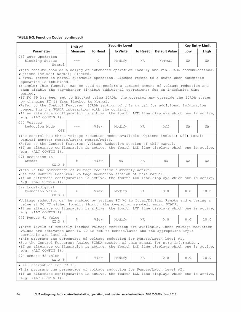
TABLE 5-3. Function Codes (continued)
ParameterUnit of Measure
Security Level
Default Value
Key Entry Limit
To Read To Write To Reset Low High
069 Auto OperationBlocking Status
Normal--- 0 Modify NA Normal NA NA
• This feature enables blocking of automatic operation locally and via SCADA communications.• Options include: Normal; Blocked.• Normal refers to normal automatic operation. Blocked refers to a state when automatic operation is inhibited.
• Example: This function can be used to perform a desired amount of voltage reduction and then disable the tap-changer (inhibit additional operations) for an indefinite time period.
• If FC 69 has been set to Blocked using SCADA, the operator may override the SCADA system by changing FC 69 from Blocked to Normal.
• Refer to the Control Features: SCADA section of this manual for additional information concerning the SCADA interaction with the control.
• If an alternate configuration is active, the fourth LCD line displays which one is active, e.g. (ALT CONFIG 1).
070 VoltageReduction Mode
Off--- View Modify NA Off NA NA
• The control has three voltage reduction modes available. Options include: Off; Local/Digital Remote; Remote/Latch; Remote/Pulse.
• Refer to the Control Features: Voltage Reduction section of this manual.• If an alternate configuration is active, the fourth LCD line displays which one is active, e.g. (ALT CONFIG 1).
071 Reduction InEffect
XX.X %% View NA NA NA NA NA
• This is the percentage of voltage reduction currently active.• See the Control Features: Voltage Reduction section of this manual.• If an alternate configuration is active, the fourth LCD line displays which one is active, e.g. (ALT CONFIG 1).
072 Local/DigitalReduction Value
XX.X %% View Modify NA 0.0 0.0 10.0
• Voltage reduction can be enabled by setting FC 70 to Local/Digital Remote and entering a value at FC 72 either locally through the keypad or remotely using SCADA.
• If an alternate configuration is active, the fourth LCD line displays which one is active, e.g. (ALT CONFIG 1).
073 Remote #1 ValueXX.X % % View Modify NA 0.0 0.0 10.0
• Three levels of remotely latched voltage reduction are available. These voltage reduction values are activated when FC 70 is set to Remote/Latch and the appropriate input terminals are latched.
• This programs the percentage of voltage reduction for Remote/Latch level #1.• See the Control Features: Analog SCADA section of this manual for more information.• If an alternate configuration is active, the fourth LCD line displays which one is active, e.g. (ALT CONFIG 1).
074 Remote #2 ValueXX.X % % View Modify NA 0.0 0.0 10.0
• See information for FC 73.• This programs the percentage of voltage reduction for Remote/Latch level #2.• If an alternate configuration is active, the fourth LCD line displays which one is active, e.g. (ALT CONFIG 1).
64 CL-7 voltage regulator control installation, operation, and maintenance instructions MN225003EN June 2015

TABLE 5-3. Function Codes (continued)
ParameterUnit of Measure
Security Level
Default Value
Key Entry Limit
To Read To Write To Reset Low High
075 Remote #3 ValueXX.X % % View Modify NA 0.0 0.0 10.0
• See information for FC 73.• This programs the percentage of voltage reduction for Remote/Latch level #3.• If an alternate configuration is active, the fourth LCD line displays which one is active, e.g. (ALT CONFIG 1).
076 # of PulseReduction Steps
XX--- View Modify NA 0 0 10
• Up to ten steps of remotely activated voltage reduction are available. The voltage reduction steps are activated when FC 70 is set to Remote/Pulse and a momentary pulse is applied to the appropriate input terminal.
• FC 76 defines the number of steps selected for pulsed voltage reduction. The percentage of voltage reduction of each step is defined at FC 77.
• See the Control Features: Analog SCADA section of this manual for more information.• If an alternate configuration is active, the fourth LCD line displays which one is active, e.g. (ALT CONFIG 1).
077 % of Voltage RedPer Pulse Step
XX.X %% View Modify NA 0.0 0.0 10.0
• This defines the percentage of voltage reduction which will be applied for each step of pulsed voltage reduction selected at FC 76.
• See the Control Features: Analog SCADA section of this manual for more information.• If an alternate configuration is active, the fourth LCD line displays which one is active, e.g. (ALT CONFIG 1).
078 Present VoltageReduction Step
XX--- View NA NA NA NA NA
• Displays the current step when Remote/Pulse voltage reduction is active.• If alternate configuration is active, the fourth LCD line displays which one is active, i.e. (ALT CONFIG 1).
079 SOFT-ADD-AMPLimits
Off--- View Modify NA Off NA NA
• This parameter enables the Soft ADD-AMP feature. Options include: Off; On; Remote Override; Cfg Logic Active; Adaptive.
• See the Control Features: Soft ADD-AMP section of this manual.• If an alternate configuration is active, the fourth LCD line displays which one is active, e.g. (ALT CONFIG 1).
080 Voltage LimiterMode
Off--- View Modify NA Off NA NA
• The control has voltage-limiting capabilities for both high-voltage and low-voltage conditions. Options include: Off; High limit only; High/low limits; IVVC High Limit Only; IVVC High/Low Limits.
• See the Control Features: Voltage Limiter section of this manual.• If an alternate configuration is active, the fourth LCD line displays which one is active, e.g. (ALT CONFIG 1)
65CL-7 voltage regulator control installation, operation, and maintenance instructions MN225003EN June 2015
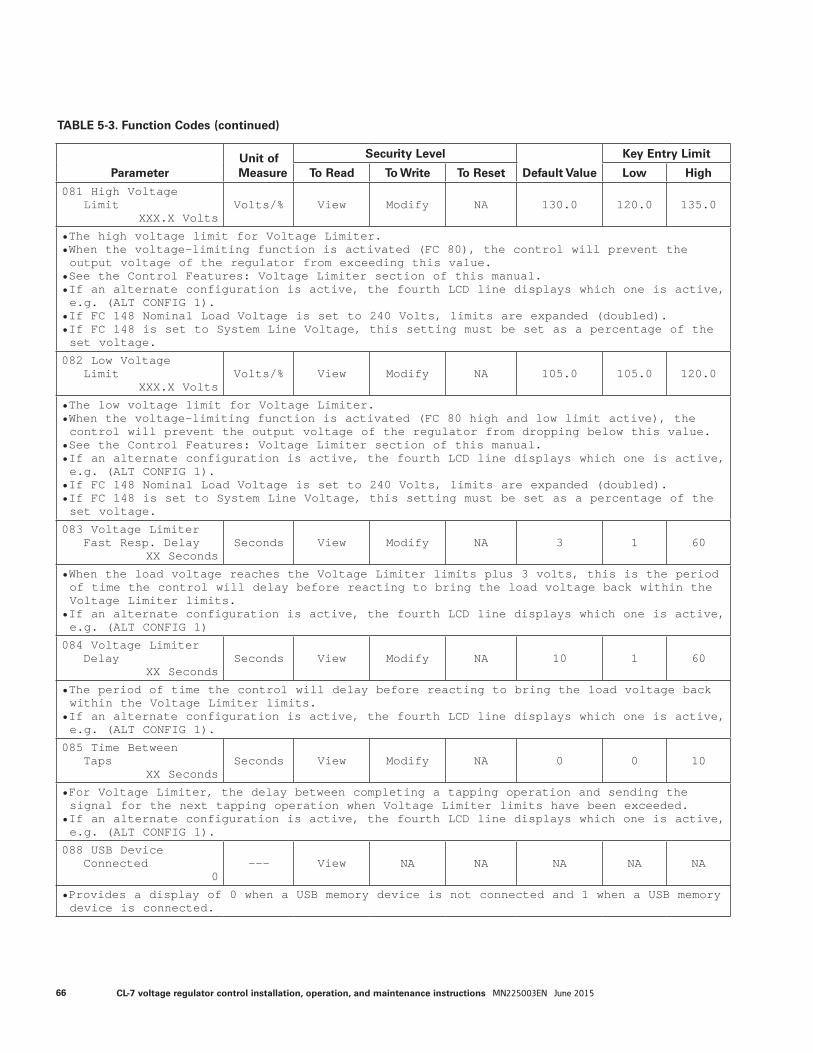
TABLE 5-3. Function Codes (continued)
ParameterUnit of Measure
Security Level
Default Value
Key Entry Limit
To Read To Write To Reset Low High
081 High VoltageLimit
XXX.X VoltsVolts/% View Modify NA 130.0 120.0 135.0
• The high voltage limit for Voltage Limiter.• When the voltage-limiting function is activated (FC 80), the control will prevent the output voltage of the regulator from exceeding this value.
• See the Control Features: Voltage Limiter section of this manual.• If an alternate configuration is active, the fourth LCD line displays which one is active, e.g. (ALT CONFIG 1).
• If FC 148 Nominal Load Voltage is set to 240 Volts, limits are expanded (doubled).• If FC 148 is set to System Line Voltage, this setting must be set as a percentage of the set voltage.
082 Low VoltageLimit
XXX.X VoltsVolts/% View Modify NA 105.0 105.0 120.0
• The low voltage limit for Voltage Limiter.• When the voltage-limiting function is activated (FC 80 high and low limit active), the control will prevent the output voltage of the regulator from dropping below this value.
• See the Control Features: Voltage Limiter section of this manual.• If an alternate configuration is active, the fourth LCD line displays which one is active, e.g. (ALT CONFIG 1).
• If FC 148 Nominal Load Voltage is set to 240 Volts, limits are expanded (doubled).• If FC 148 is set to System Line Voltage, this setting must be set as a percentage of the set voltage.
083 Voltage LimiterFast Resp. Delay
XX SecondsSeconds View Modify NA 3 1 60
• When the load voltage reaches the Voltage Limiter limits plus 3 volts, this is the period of time the control will delay before reacting to bring the load voltage back within the Voltage Limiter limits.
• If an alternate configuration is active, the fourth LCD line displays which one is active, e.g. (ALT CONFIG 1)
084 Voltage LimiterDelay
XX SecondsSeconds View Modify NA 10 1 60
• The period of time the control will delay before reacting to bring the load voltage back within the Voltage Limiter limits.
• If an alternate configuration is active, the fourth LCD line displays which one is active, e.g. (ALT CONFIG 1).
085 Time BetweenTaps
XX SecondsSeconds View Modify NA 0 0 10
• For Voltage Limiter, the delay between completing a tapping operation and sending the signal for the next tapping operation when Voltage Limiter limits have been exceeded.
• If an alternate configuration is active, the fourth LCD line displays which one is active, e.g. (ALT CONFIG 1).
088 USB DeviceConnected
0--- View NA NA NA NA NA
• Provides a display of 0 when a USB memory device is not connected and 1 when a USB memory device is connected.
66 CL-7 voltage regulator control installation, operation, and maintenance instructions MN225003EN June 2015

TABLE 5-3. Function Codes (continued)
ParameterUnit of Measure
Security Level
Default Value
Key Entry Limit
To Read To Write To Reset Low High
088 Factory AccessMode
Disabled--- View Modify NA Disabled NA NA
• This function is used to diagnose the control when an extended communications module is in use.
• Available options include: Disabled; Enabled.
088 Extended CommsStatus
0x0(RUNNING OK)
--- View NA NA NA NA NA
• Provides the status of an extended communications card.• (NOT AVAILABLE) indication is displayed if the extended communications card is not present.
• (RUNNING OK) indication is displayed if the extended communications card is present and operating properly.
• (FAILURE)-0x0 indication is displayed if the extended communications card is present and indicating a failure code.
088 Config. LogicEquation Error
X--- View NA NA NA NA NA
• Provide a display of 0 when there are no configurable logic errors and 1 when one or more configurable logic errors exist.
089 ActivateContact Output 1
X--- View Modify NA NA 0 1
• Enables activation of discrete output contact 1.• If value is 0, it can be changed to 1 and then back 0.• If value is 1 because its activation is being driven by a logic equation, attempting to change it to 0 will display (CANNOT OVERRIDE).
089 ActivateContact Output 2
X--- View Modify NA NA 0 1
• See description of Activate Contact Output 1.
089 ActivateContact Output 3
X--- View Modify NA NA 0 1
• See description of Activate Contact Output 1.
089 ActivateContact Output 4
X--- View Modify NA NA 0 1
• See description of Activate Contact Output 1.
090 CI1 = Inactive CI2 = Inactive CI3 = Inactive CI4 = Inactive
--- View NA NA NA NA NA
• Provides a status of the auxiliary input contacts and will display the status as Inactive or Active.
67CL-7 voltage regulator control installation, operation, and maintenance instructions MN225003EN June 2015

TABLE 5-3. Function Codes (continued)
ParameterUnit of Measure
Security Level
Default Value
Key Entry Limit
To Read To Write To Reset Low High
090 CO1 = Inactive CO2 = Inactive CO3 = Inactive CO4 = Inactive
--- View NA NA NA NA NA
• Provides a status of the auxiliary output contacts and will display the status as Inactive or Active.
091 Self-Test --- NA NA NA NA NA NA
• Access this parameter to initiate a self-test.• While on the Self-Test screen press ENTER and then ENTER again to confirm. Results are displayed when the self-test is complete. Press Escape for further keypad use.
• Refer to Power-Up/Reset Conditions in this section of the manual for more information.
091 Last Self-TestResults
0xXXXXXXXX--- View NA NA NA NA NA
• This display is entered at the FC 91 Self-Test screen by pressing the down arrow before activating the self-test. This information is primarily intended to be used as a means of transmitting diagnostic error codes through SCADA. This same information can be viewed at FC 95 in a readable format.
• The display for this parameter is a 32-bit value displayed in hexadecimal format. The value corresponds to the results of the FC 91 self-test.
• To decipher the hexadecimal value, convert the hex number to a binary number. Each digit of the binary number will correspond to a bit in the chart below. For example, a hex number of 208 would correspond to a binary number of 0000000001000001000. Reading the binary number from right to left provide a 1 at bit 3 (the forth digit) and bit 9 (the 10th digit). These bits correspond to diagnostic errors of "VR1 Input Voltage Missing" and "VR1 No Neutral Sync Signal".
• 0x00000001 – bit 0, Non-Volatile Setting (CRC error at system startup)• 0x00000002 – bit 1, Frequency Detection• 0x00000004 – bit 2, Data Acquisition• 0000000008 – bit 3, VR1 Input Voltage Missing• 0x00000010 – bit 4, VR2 Input Voltage Missing• 0x00000020 – bit 5, VR3 Input Voltage Missing • 0000000040 – bit 6, VR1 OUTPUT VOLTAGE MISSING• 0x00000080 – bit 7, VR2 Output Voltage Missing• 0x00000100 – bit 8, VR3 Output Voltage Missing • 0x00000200 – bit 9, VR1 No Neutral Sync Signal• 0x00000400 – bit 10, VR2 No Neutral Sync Signal • 0x00000800 – bit 11, VR3 No Neutral Sync Signal • 0x00001000 – bit 12, Clock Needs Setting • 0x00002000 – bit 13, Factory Calibration Required• 0x00004000 – bit 14, Configuration Values Required• 0x00008000 – bit 15, Battery Test• 0x00010000 – bit 16, VR1 Motor Trouble• 0x00020000 – bit 17, VR3 Motor Trouble• 0x00040000 – bit 18, VR3 Motor Trouble
092 SecurityOverride
View--- View Admin NA View NA NA
• This is the control security override parameter. Options for security override are: View; Operate; Modify; Admin.
• Entering the Admin level security code at FC 99 will permit the security parameters to be modified.
• See the Control Operation: Security System section of this manual.
68 CL-7 voltage regulator control installation, operation, and maintenance instructions MN225003EN June 2015

TABLE 5-3. Function Codes (continued)
ParameterUnit of Measure
Security Level
Default Value
Key Entry Limit
To Read To Write To Reset Low High
(095)Self-Test Completexx-xx-xxxx x:xx:xxa
(Pass)
--- View NA NA NA NA NA
• This function code will display the results of the last self-test.
096 Password"Operate"
XXXXXXXXXX--- Admin Admin NA Operate NA NA
• The alphanumeric security code for the Operate security level is displayed here.• Entry of the Admin level security code at FC 99 enables viewing and editing of this password.
• Entry of this alphanumeric code at FC 99 permits the user to change/reset parameters marked as Operate level security (i.e. demand and tap position readings).
• See the Control Operation: Security System section of this manual.
097 Password"Modify"
XXXXXXXXXX
--- Admin Admin NA Modify NA NA
• The alphanumeric security code for the Modify security level is displayed here.• Entry of the Admin level security code at FC 99 enables viewing and editing of this password.• Entry of this alphanumeric code at FC 99 permits the user to change/reset parameters marked as Modify level security (i.e. control settings, configuration, and clock) and Operate level security (i.e. demand and tap position readings).
• See the Control Operation: Security System section of this manual.
098 Password"Admin"
XXXXXXXXXX--- Admin Admin NA Admin NA NA
• The alphanumeric security code for the Admin security level is displayed here.• Entry of the Admin level security code at FC 99 enables viewing and editing of this password.
• Entry of this alphanumeric code at FC 99 permits the user to change/reset any parameter.• Note: If the level Admin code is changed by the user, the new value should be recorded and kept in a safe place. If lost, security codes can be retrieved with a USB memory device and ProView NXG software, with the ProView NXG software via a PC directly connected to the control, or with the remote communications system.
• See the Control Operation: Security System section of this manual.
099 Enter Password
------------- Admin Admin NA Admin NA NA
• This is the function code used to access the menu location where security codes are entered for access to the system.
• Scrolling to this level is not allowed.• See the Control Operation: Security System section of this manual.
100 Last CounterChange
XXXXXMM-DD-YYYY HH:MM:SS
--- View NA NA NA NA NA
• This displays the time and date since the Total Operations counter (FC 0) was last changed, as well as the quantity of operations entered at the last change.
101 Last 24 HoursOperations
XXXXXMM-DD-YYYY HH:MM:SS
--- View NA Admin Reset* to 0 NA NA
• Number of operations in last 24 hours (updated hourly and on every tap change).• This counter is reset by pressing ENTER and then ENTER again to confirm.
69CL-7 voltage regulator control installation, operation, and maintenance instructions MN225003EN June 2015
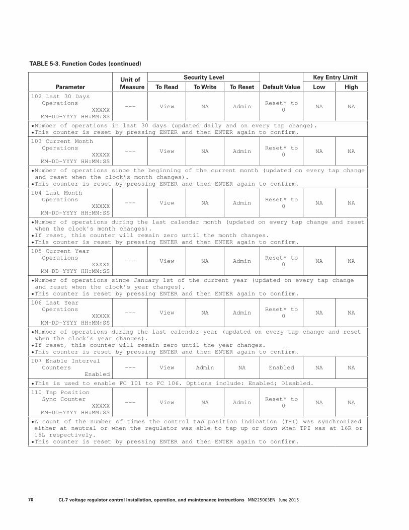
TABLE 5-3. Function Codes (continued)
ParameterUnit of Measure
Security Level
Default Value
Key Entry Limit
To Read To Write To Reset Low High
102 Last 30 DaysOperations
XXXXXMM-DD-YYYY HH:MM:SS
--- View NA Admin Reset* to 0 NA NA
• Number of operations in last 30 days (updated daily and on every tap change).• This counter is reset by pressing ENTER and then ENTER again to confirm.
103 Current MonthOperations
XXXXXMM-DD-YYYY HH:MM:SS
--- View NA Admin Reset* to 0 NA NA
• Number of operations since the beginning of the current month (updated on every tap change and reset when the clock’s month changes).
• This counter is reset by pressing ENTER and then ENTER again to confirm.
104 Last MonthOperations
XXXXXMM-DD-YYYY HH:MM:SS
--- View NA Admin Reset* to 0 NA NA
• Number of operations during the last calendar month (updated on every tap change and reset when the clock’s month changes).
• If reset, this counter will remain zero until the month changes.• This counter is reset by pressing ENTER and then ENTER again to confirm.
105 Current YearOperations
XXXXXMM-DD-YYYY HH:MM:SS
--- View NA Admin Reset* to 0 NA NA
• Number of operations since January 1st of the current year (updated on every tap change and reset when the clock’s year changes).
• This counter is reset by pressing ENTER and then ENTER again to confirm.
106 Last YearOperations
XXXXXMM-DD-YYYY HH:MM:SS
--- View NA Admin Reset* to 0 NA NA
• Number of operations during the last calendar year (updated on every tap change and reset when the clock’s year changes).
• If reset, this counter will remain zero until the year changes.• This counter is reset by pressing ENTER and then ENTER again to confirm.
107 Enable IntervalCounters
Enabled--- View Admin NA Enabled NA NA
• This is used to enable FC 101 to FC 106. Options include: Enabled; Disabled.
110 Tap PositionSync Counter
XXXXXMM-DD-YYYY HH:MM:SS
--- View NA Admin Reset* to 0 NA NA
• A count of the number of times the control tap position indication (TPI) was synchronized either at neutral or when the regulator was able to tap up or down when TPI was at 16R or 16L respectively.• This counter is reset by pressing ENTER and then ENTER again to confirm.
70 CL-7 voltage regulator control installation, operation, and maintenance instructions MN225003EN June 2015
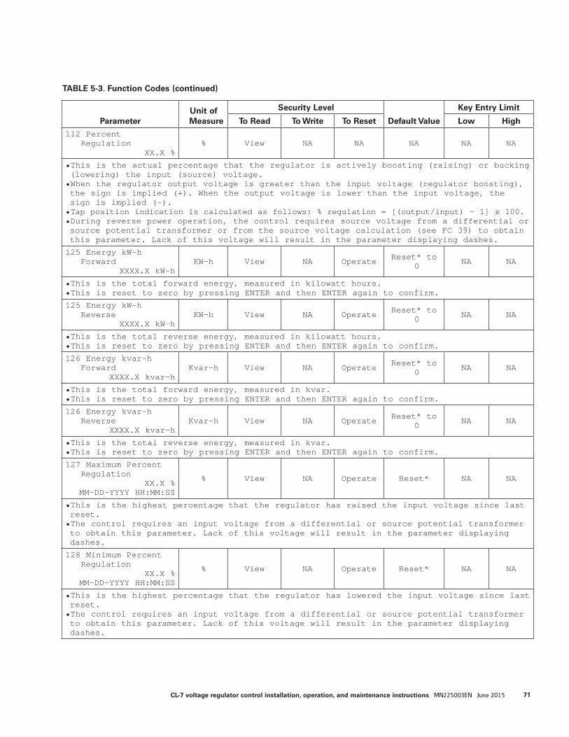
TABLE 5-3. Function Codes (continued)
ParameterUnit of Measure
Security Level
Default Value
Key Entry Limit
To Read To Write To Reset Low High
112 PercentRegulation
XX.X %% View NA NA NA NA NA
• This is the actual percentage that the regulator is actively boosting (raising) or bucking (lowering) the input (source) voltage.• When the regulator output voltage is greater than the input voltage (regulator boosting), the sign is implied (+). When the output voltage is lower than the input voltage, the sign is implied (-).• Tap position indication is calculated as follows: % regulation = [(output/input) - 1] x 100.• During reverse power operation, the control requires source voltage from a differential or source potential transformer or from the source voltage calculation (see FC 39) to obtain this parameter. Lack of this voltage will result in the parameter displaying dashes.
125 Energy kW-hForward
XXXX.X kW-hKW-h View NA Operate Reset* to
0 NA NA
• This is the total forward energy, measured in kilowatt hours.• This is reset to zero by pressing ENTER and then ENTER again to confirm.
125 Energy kW-hReverse
XXXX.X kW-hKW-h View NA Operate Reset* to
0 NA NA
• This is the total reverse energy, measured in kilowatt hours.• This is reset to zero by pressing ENTER and then ENTER again to confirm.
126 Energy kvar-hForward
XXXX.X kvar-hKvar-h View NA Operate Reset* to
0 NA NA
• This is the total forward energy, measured in kvar.• This is reset to zero by pressing ENTER and then ENTER again to confirm.
126 Energy kvar-hReverse
XXXX.X kvar-hKvar-h View NA Operate Reset* to
0 NA NA
• This is the total reverse energy, measured in kvar.• This is reset to zero by pressing ENTER and then ENTER again to confirm.
127 Maximum PercentRegulation
XX.X %MM-DD-YYYY HH:MM:SS
% View NA Operate Reset* NA NA
• This is the highest percentage that the regulator has raised the input voltage since last reset.• The control requires an input voltage from a differential or source potential transformer to obtain this parameter. Lack of this voltage will result in the parameter displaying dashes.
128 Minimum PercentRegulation
XX.X %MM-DD-YYYY HH:MM:SS
% View NA Operate Reset* NA NA
• This is the highest percentage that the regulator has lowered the input voltage since last reset.• The control requires an input voltage from a differential or source potential transformer to obtain this parameter. Lack of this voltage will result in the parameter displaying dashes.
71CL-7 voltage regulator control installation, operation, and maintenance instructions MN225003EN June 2015
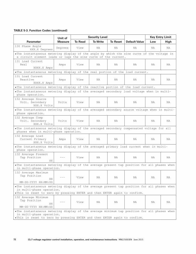
TABLE 5-3. Function Codes (continued)
ParameterUnit of Measure
Security Level
Default Value
Key Entry Limit
To Read To Write To Reset Low High
130 Phase AngleXXX.X Degrees Degrees View NA NA NA NA NA
• The instantaneous metering display of the angle by which the sine curve of the voltage in a circuit element leads or lags the sine curve of the current.
131 Load CurrentReal
XXXX.X AmpsAmps View NA NA NA NA NA
• The instantaneous metering display of the real portion of the load current.
131 Load CurrentReactive
XXXX.X AmpsAmps View NA NA NA NA NA
• The instantaneous metering display of the reactive portion of the load current.
• The instantaneous metering display of the averaged secondary load voltage when in multi-phase operation.
132 Average SourceVolt. Secondary
XXX.X VoltsVolts View NA NA NA NA NA
• The instantaneous metering display of the averaged secondary source voltage when in multi-phase operation.
132 Average CompVolt. Secondary
XXX.X VoltsVolts View NA NA NA NA NA
• The instantaneous metering display of the averaged secondary compensated voltage for all phases when in multi-phase operation.
132 Average LoadCurrent Primary
XXX.X VoltsAmps View NA NA NA NA NA
• The instantaneous metering display of the averaged primary load current when in multi-phase operation.
132 Average PresentTap Position
XX--- View NA NA NA NA NA
• The instantaneous metering display of the average present tap position for all phases when in multi-phase operation.
132 Average MaximumTap Position
XXMM-DD-YYYY HH:MM:SS
--- View NA NA NA NA NA
• The instantaneous metering display of the average present tap position for all phases when in multi-phase operation.
• This is reset to zero by pressing ENTER and then ENTER again to confirm.
132 Average MinimumTap Position
XXMM-DD-YYYY HH:MM:SS
--- View NA NA NA NA NA
• The instantaneous metering display of the average minimum tap position for all phases when in multi-phase operation.
• This is reset to zero by pressing ENTER and then ENTER again to confirm.
72 CL-7 voltage regulator control installation, operation, and maintenance instructions MN225003EN June 2015
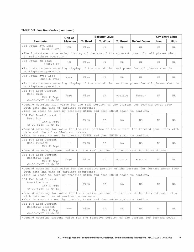
TABLE 5-3. Function Codes (continued)
ParameterUnit of Measure
Security Level
Default Value
Key Entry Limit
To Read To Write To Reset Low High
133 Total kVA LoadXXXX.X kVA kVA View NA NA NA NA NA
• The instantaneous metering display of the sum of the apparent power for all phases when in multi-phase operation.
133 Total kW LoadXXXX.X kW kW View NA NA NA NA NA
• An instantaneous metering display of the sum of the real power for all phases when in multi-phase operation.
133 Total kvar LoadXXXX.X kvar kvar View NA NA NA NA NA
• An instantaneous metering display of the sum of the reactive power for all phases when in multi-phase operation.
134 Fwd Load CurrentReal High
XXX.X AmpsMM-DD-YYYY HH:MM:SS
Amps View NA Operate Reset* NA NA
• Demand metering high value for the real portion of the current for forward power flow with date and time of earliest occurrence.
• This is reset to zero by pressing ENTER and then ENTER again to confirm.
134 Fwd Load CurrentReal Low
XXX.X AmpsMM-DD-YYYY HH:MM:SS
--- View NA NA NA NA NA
• Demand metering low value for the real portion of the current for forward power flow with date and time of earliest occurrence.
• This is reset to zero by pressing ENTER and then ENTER again to confirm.
134 Fwd Load CurrentReal Present
XXX.X Amps--- View NA NA NA NA NA
• Demand metering present value for the real portion of the current for forward power.
134 Fwd Load CurrentReactive High
XXX.X AmpsMM-DD-YYYY HH:MM:SS
Amps View NA Operate Reset* NA NA
• Demand metering high value for the reactive portion of the current for forward power flow with date and time of earliest occurrence.
• This is reset to zero by pressing ENTER and then ENTER again to confirm.
134 Fwd Load CurrentReactive Low
XXX.X AmpsMM-DD-YYYY HH:MM:SS
--- View NA NA NA NA NA
• Demand metering low value for the reactive portion of the current for forward power flow with date and time of earliest occurrence.
• This is reset to zero by pressing ENTER and then ENTER again to confirm.
134 Fwd Load CurrentReactive Present
XXX.X AmpsMM-DD-YYYY HH:MM:SS
--- View NA NA NA NA NA
• Demand metering present value for the reactive portion of the current for forward power.
73CL-7 voltage regulator control installation, operation, and maintenance instructions MN225003EN June 2015
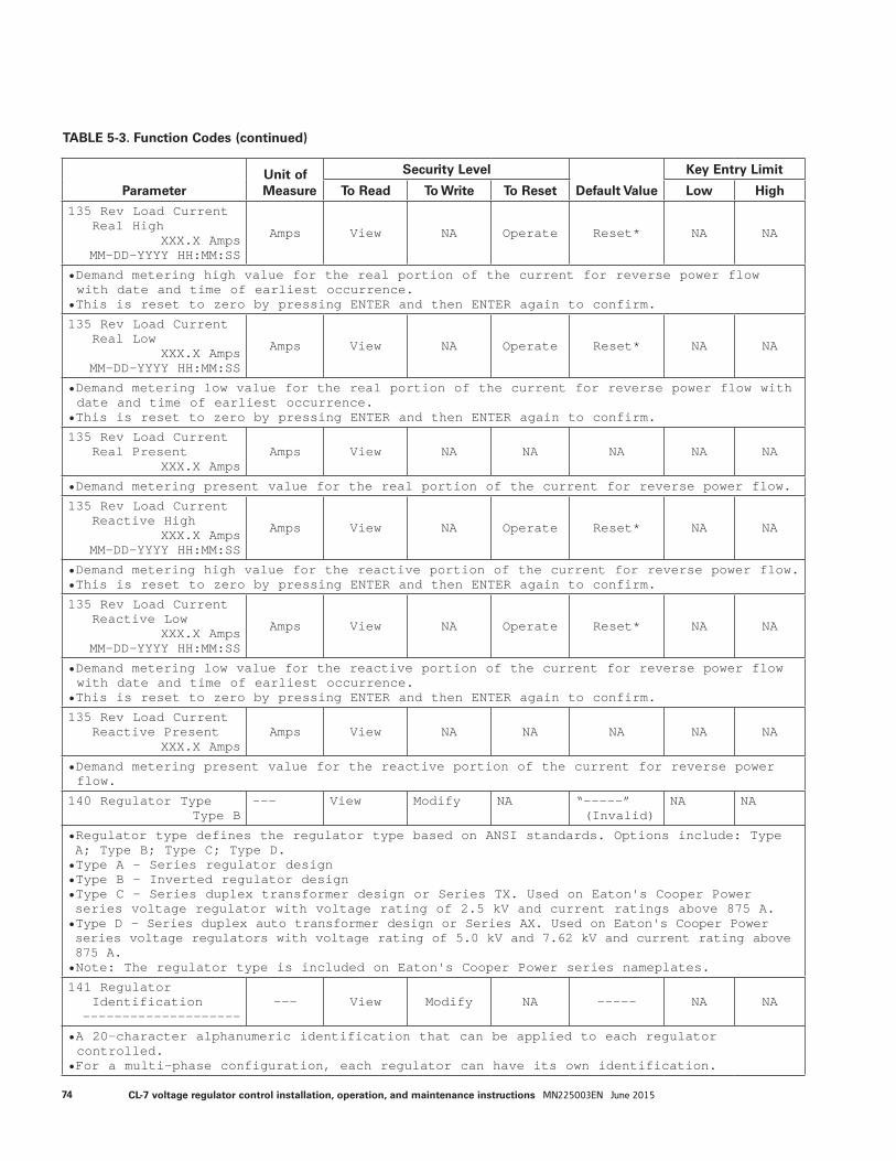
ParameterUnit of Measure
Security Level
Default Value
Key Entry Limit
To Read To Write To Reset Low High
135 Rev Load CurrentReal High
XXX.X AmpsMM-DD-YYYY HH:MM:SS
Amps View NA Operate Reset* NA NA
• Demand metering high value for the real portion of the current for reverse power flow with date and time of earliest occurrence.
• This is reset to zero by pressing ENTER and then ENTER again to confirm.
135 Rev Load CurrentReal Low
XXX.X AmpsMM-DD-YYYY HH:MM:SS
Amps View NA Operate Reset* NA NA
• Demand metering low value for the real portion of the current for reverse power flow with date and time of earliest occurrence.
• This is reset to zero by pressing ENTER and then ENTER again to confirm.
135 Rev Load CurrentReal Present
XXX.X AmpsAmps View NA NA NA NA NA
• Demand metering present value for the real portion of the current for reverse power flow.
135 Rev Load CurrentReactive High
XXX.X AmpsMM-DD-YYYY HH:MM:SS
Amps View NA Operate Reset* NA NA
• Demand metering high value for the reactive portion of the current for reverse power flow.• This is reset to zero by pressing ENTER and then ENTER again to confirm.
135 Rev Load CurrentReactive Low
XXX.X AmpsMM-DD-YYYY HH:MM:SS
Amps View NA Operate Reset* NA NA
• Demand metering low value for the reactive portion of the current for reverse power flow with date and time of earliest occurrence.
• This is reset to zero by pressing ENTER and then ENTER again to confirm.
135 Rev Load CurrentReactive Present
XXX.X AmpsAmps View NA NA NA NA NA
• Demand metering present value for the reactive portion of the current for reverse power flow.
140 Regulator TypeType B
--- View Modify NA “-----” (Invalid)
NA NA
• Regulator type defines the regulator type based on ANSI standards. Options include: Type A; Type B; Type C; Type D.• Type A – Series regulator design• Type B – Inverted regulator design• Type C – Series duplex transformer design or Series TX. Used on Eaton's Cooper Power series voltage regulator with voltage rating of 2.5 kV and current ratings above 875 A.• Type D – Series duplex auto transformer design or Series AX. Used on Eaton's Cooper Power series voltage regulators with voltage rating of 5.0 kV and 7.62 kV and current rating above 875 A.• Note: The regulator type is included on Eaton's Cooper Power series nameplates.
141 RegulatorIdentification
----------------------- View Modify NA ----- NA NA
• A 20-character alphanumeric identification that can be applied to each regulator controlled.
• For a multi-phase configuration, each regulator can have its own identification.
TABLE 5-3. Function Codes (continued)
74 CL-7 voltage regulator control installation, operation, and maintenance instructions MN225003EN June 2015
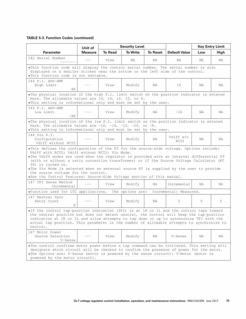
ParameterUnit of Measure
Security Level
Default Value
Key Entry Limit
To Read To Write To Reset Low High
142 Serial Number------- --- View NA NA NA NA NA
• This function code will display the control serial number. The serial number is also displayed on a smaller sticker near the bottom on the left side of the control.• This function code is not editable.
144 P.I. ADD-AMPHigh Limit
XX--- View Modify NA 16 NA NA
• The physical location of the high P.I. limit switch on the position indicator is entered here. The allowable values are 16, 14, 12, 10, or 8.• This setting is informational only and must be set by the user.
145 P.I. ADD-AMPLow Limit
-XX--- View Modify NA -16 NA NA
• The physical location of the low P.I. limit switch on the position indicator is entered here. The allowable values are -16, -14, -12, -10, or -8.• This setting is informational only and must be set by the user.
146 Vin P.T.ConfigurationVdiff without RCT2
--- View Modify NA Vdiff w/o RCT2 NA NA
• This defines the configuration of the PT for the source-side voltage. Options include: Vdiff with RCT2; Vdiff without RCT2; Vin Mode.• The Vdiff modes are used when the regulator is provided with an internal differential PT (with or without a ratio correction transformer) or if the Source Voltage Calculator (FC 39) is turned on. • The Vin Mode is selected when an external source PT is supplied by the user to provide the source voltage for the control.• See the Control Features: Source-Side Voltage section of this manual.
147 TPI Sense MethodIncremental --- View Modify NA Incremental NA NA
• Function used for LTC applications. The options are: Incremental; Measured.
147 Neutral SyncRetry Count
X--- View Modify NA 3 0 5
• If the control tap-position indication (TPI) is at 1R or 1L and the control taps toward the neutral position but does not detect neutral, the control will keep the tap-position indication at 1R or 1L and allow attempts to tap down or up to synchronize TPI with the actual tap position. This parameter is the number of allowable attempts to synchronize to neutral.
147 Motor PowerSource Selection
V-Sense--- View Modify NA V-Sense NA NA
• The control confirms motor power before a tap command can be initiated. This setting will designate which circuit will be checked to confirm the presence of power for the motor.
• The Options are: V-Sense (motor is powered by the sense circuit); V-Motor (motor is powered by the motor circuit).
TABLE 5-3. Function Codes (continued)
75CL-7 voltage regulator control installation, operation, and maintenance instructions MN225003EN June 2015
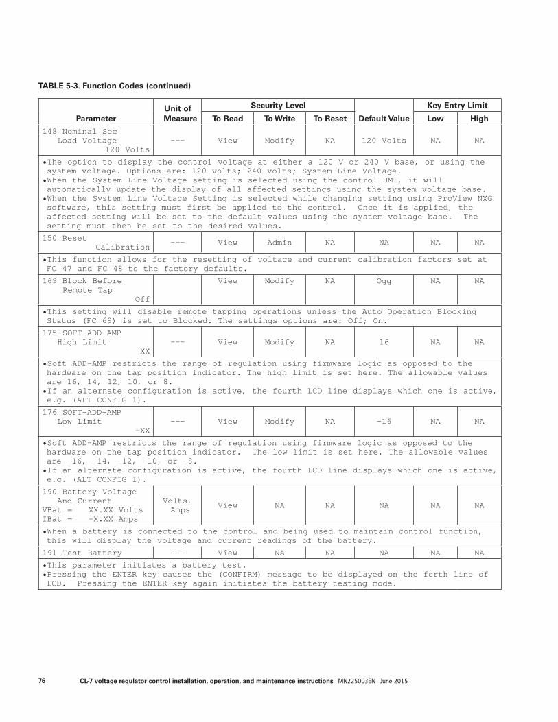
ParameterUnit of Measure
Security Level
Default Value
Key Entry Limit
To Read To Write To Reset Low High
148 Nominal SecLoad Voltage
120 Volts--- View Modify NA 120 Volts NA NA
• The option to display the control voltage at either a 120 V or 240 V base, or using the system voltage. Options are: 120 volts; 240 volts; System Line Voltage.• When the System Line Voltage setting is selected using the control HMI, it will automatically update the display of all affected settings using the system voltage base.• When the System Line Voltage Setting is selected while changing setting using ProView NXG software, this setting must first be applied to the control. Once it is applied, the affected setting will be set to the default values using the system voltage base. The setting must then be set to the desired values.
150 ResetCalibration --- View Admin NA NA NA NA
• This function allows for the resetting of voltage and current calibration factors set at FC 47 and FC 48 to the factory defaults.
169 Block Before Remote Tap
Off
View Modify NA Ogg NA NA
• This setting will disable remote tapping operations unless the Auto Operation Blocking Status (FC 69) is set to Blocked. The settings options are: Off; On.
175 SOFT-ADD-AMPHigh Limit
XX--- View Modify NA 16 NA NA
• Soft ADD-AMP restricts the range of regulation using firmware logic as opposed to the hardware on the tap position indicator. The high limit is set here. The allowable values are 16, 14, 12, 10, or 8.• If an alternate configuration is active, the fourth LCD line displays which one is active, e.g. (ALT CONFIG 1).
176 SOFT-ADD-AMPLow Limit
-XX--- View Modify NA -16 NA NA
• Soft ADD-AMP restricts the range of regulation using firmware logic as opposed to the hardware on the tap position indicator. The low limit is set here. The allowable values are -16, -14, -12, -10, or -8.• If an alternate configuration is active, the fourth LCD line displays which one is active, e.g. (ALT CONFIG 1).
190 Battery VoltageAnd Current
VBat = XX.XX VoltsIBat = -X.XX Amps
Volts, Amps View NA NA NA NA NA
• When a battery is connected to the control and being used to maintain control function, this will display the voltage and current readings of the battery.
191 Test Battery --- View NA NA NA NA NA
• This parameter initiates a battery test.• Pressing the ENTER key causes the (CONFIRM) message to be displayed on the forth line of LCD. Pressing the ENTER key again initiates the battery testing mode.
TABLE 5-3. Function Codes (continued)
76 CL-7 voltage regulator control installation, operation, and maintenance instructions MN225003EN June 2015
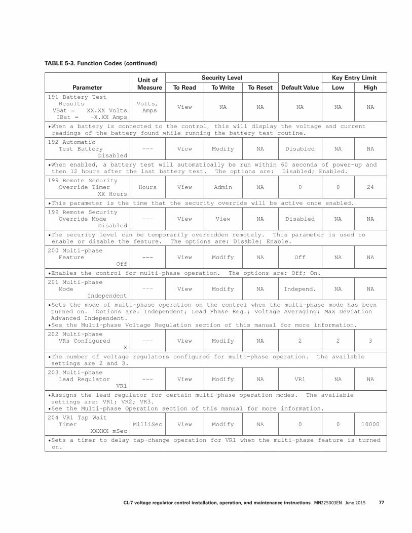
ParameterUnit of Measure
Security Level
Default Value
Key Entry Limit
To Read To Write To Reset Low High
191 Battery TestResults
VBat = XX.XX VoltsIBat = -X.XX Amps
Volts, Amps View NA NA NA NA NA
• When a battery is connected to the control, this will display the voltage and current readings of the battery found while running the battery test routine.
192 AutomaticTest Battery
Disabled--- View Modify NA Disabled NA NA
• When enabled, a battery test will automatically be run within 60 seconds of power-up and then 12 hours after the last battery test. The options are: Disabled; Enabled.
199 Remote SecurityOverride Timer
XX HoursHours View Admin NA 0 0 24
• This parameter is the time that the security override will be active once enabled.
199 Remote SecurityOverride Mode
Disabled--- View View NA Disabled NA NA
• The security level can be temporarily overridden remotely. This parameter is used to enable or disable the feature. The options are: Disable; Enable.
200 Multi-phaseFeature
Off--- View Modify NA Off NA NA
• Enables the control for multi-phase operation. The options are: Off; On.
201 Multi-phaseMode
Independent--- View Modify NA Independ. NA NA
• Sets the mode of multi-phase operation on the control when the multi-phase mode has been turned on. Options are: Independent; Lead Phase Reg.; Voltage Averaging; Max Deviation Advanced Independent.• See the Multi-phase Voltage Regulation section of this manual for more information.
202 Multi-phaseVRs Configured
X--- View Modify NA 2 2 3
• The number of voltage regulators configured for multi-phase operation. The available settings are 2 and 3.
203 Multi-phaseLead Regulator
VR1--- View Modify NA VR1 NA NA
• Assigns the lead regulator for certain multi-phase operation modes. The available settings are: VR1; VR2; VR3.• See the Multi-phase Operation section of this manual for more information.
204 VR1 Tap WaitTimer
XXXXX mSecMilliSec View Modify NA 0 0 10000
• Sets a timer to delay tap-change operation for VR1 when the multi-phase feature is turned on.
TABLE 5-3. Function Codes (continued)
77CL-7 voltage regulator control installation, operation, and maintenance instructions MN225003EN June 2015
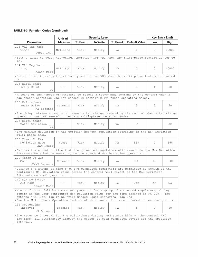
ParameterUnit of Measure
Security Level
Default Value
Key Entry Limit
To Read To Write To Reset Low High
204 VR2 Tap WaitTimer
XXXXX mSecMilliSec View Modify NA 0 0 10000
• Sets a timer to delay tap-change operation for VR2 when the multi-phase feature is turned on.
204 VR3 Tap WaitTimer
XXXXX mSecMilliSec View Modify NA 0 0 10000
• Sets a timer to delay tap-change operation for VR3 when the multi-phase feature is turned on.
205 Multi-phaseRetry Count
XX--- View Modify NA 3 1 10
• A count of the number of attempts to resend a tap-change command by the control when a tap-change operation was not sensed in certain multi-phase operating modes.
206 Multi-phaseRetry Delay
XX SecondsSeconds View Modify NA 5 5 60
• The delay between attempts to resend a tap-change command by the control when a tap-change operation was not sensed in certain multi-phase operating modes.
207 Multi-phaseTotal Deviation
XX--- View Modify NA 32 0 32
• The maximum deviation in tap position between regulators operating in the Max Deviation multi-phase mode.
208 Timer To MaxDeviation Mode
XXX HoursHours View Modify NA 168 0 168
• Defines the amount of time that the connected regulators will remain in the Max Deviation Alternate Mode before reverting to the standard Max Deviation operation.
209 Timer To AltMode
XXXX SecondsSeconds View Modify NA 60 10 3600
• Defines the amount of time that the connected regulators are permitted to remain at the configured Max Deviation value before the control will revert to the Max Deviation Alternate mode of operation.
210 Max DeviationAlt Mode
Ganged Mode--- View Modify NA Off NA NA
• The configured fall back mode of operation for a group of connected regulators if they remain at the user configured Max Deviation value for the time defined at FC 209. The options are: Off; Tap To Neutral; Ganged Mode; Historical Tap Pos.• See the Multi-phase Operation section of this manual for more information on the options.
211 SequencingInterval
XX SecondsSeconds View Modify NA 5 0 60
• The sequence interval for the multi-phase display and status LEDs on the control HMI. The LEDs will alternately display the status of each connected device for the specified interval.
TABLE 5-3. Function Codes (continued)
78 CL-7 voltage regulator control installation, operation, and maintenance instructions MN225003EN June 2015

ParameterUnit of Measure
Security Level
Default Value
Key Entry Limit
To Read To Write To Reset Low High
220 Auto Tap DeadPhase mode
Disabled
View Modify NA Disabled NA NA
• This setting will enable Tap-Dead-Phase functionality for a multi-phase control. Using this function, the control will use power from powered phases to operate the tap changer of dead phases.• The settings options include: Disabled, Tap To Neutral, Ganged Mode.
221 Tap Dead Phase
Inactive
View NA NA NA NA NA
• This will display the operational status of the Auto Tap Dead Phase mode function, either Inactive or Active.
222 Delay Timer
15 SecondsSeconds View Modify NA 15 1 180
• When a condition occurs that would enable the Auto Tap Dead Phase mode, the activation of the function will be delayed for this period of time.
260 Com 1Tx Messages
XXXXX--- View NA Operate Reset* to
0 NA NA
• Count of Transmitted Messages from Com 1.
261 Com 1Rx Messages
XXXXX--- View NA Operate Reset* to
0 NA NA
• Count of Received Messages from Com 1.
262 Com 1Rx Errors
XXXXX--- View NA Operate Reset* to 0 NA NA
• Count of Receive Errors from Com 1.
263 Com 2Tx Messages
XXXXX--- View NA Operate Reset* to 0 NA NA
• Count of Transmitted Messages from Com 2.
264 Com 2Rx Messages
XXXXX--- View NA Operate Reset* to 0 NA NA
• Count of Received Messages from Com 2.
265 Com 2Rx Errors
XXXXX--- View NA Operate Reset* to
0 NA NA
• Count of Receive Errors from Com 2.
300 PMT Mode AState
Off--- View Modify NA Off NA NA
• The Preventive Maintenance Tapping (PMT) feature Mode A will automatically raise and lower the tap-changer to wipe contact blades. The options include: Off; On.
301 PMT Mode ACountdown Delay
XX DaysDays View NA NA NA NA NA
• This is the time remaining until the next PMT Mode A operation.
TABLE 5-3. Function Codes (continued)
79CL-7 voltage regulator control installation, operation, and maintenance instructions MN225003EN June 2015
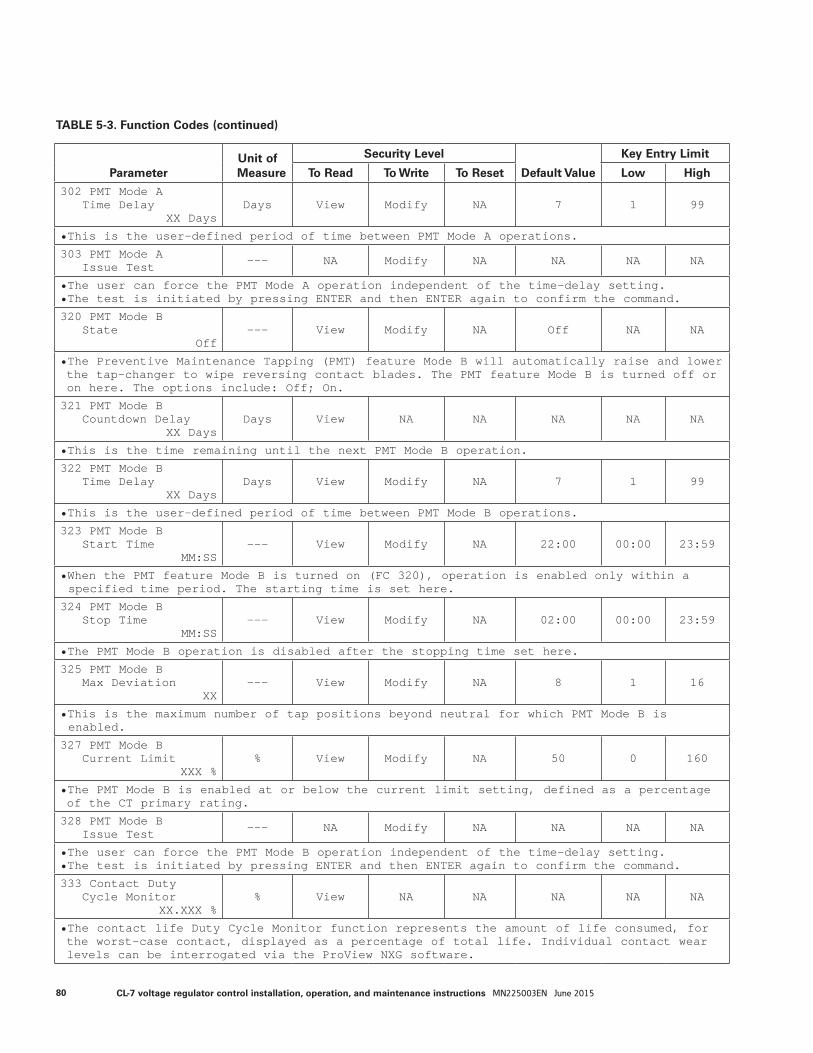
ParameterUnit of Measure
Security Level
Default Value
Key Entry Limit
To Read To Write To Reset Low High
302 PMT Mode ATime Delay
XX DaysDays View Modify NA 7 1 99
• This is the user-defined period of time between PMT Mode A operations.
303 PMT Mode AIssue Test --- NA Modify NA NA NA NA
• The user can force the PMT Mode A operation independent of the time-delay setting.• The test is initiated by pressing ENTER and then ENTER again to confirm the command.
320 PMT Mode BState
Off--- View Modify NA Off NA NA
• The Preventive Maintenance Tapping (PMT) feature Mode B will automatically raise and lower the tap-changer to wipe reversing contact blades. The PMT feature Mode B is turned off or on here. The options include: Off; On.
321 PMT Mode BCountdown Delay
XX DaysDays View NA NA NA NA NA
• This is the time remaining until the next PMT Mode B operation.
322 PMT Mode BTime Delay
XX DaysDays View Modify NA 7 1 99
• This is the user-defined period of time between PMT Mode B operations.
323 PMT Mode BStart Time
MM:SS--- View Modify NA 22:00 00:00 23:59
• When the PMT feature Mode B is turned on (FC 320), operation is enabled only within a specified time period. The starting time is set here.
324 PMT Mode BStop Time
MM:SS--- View Modify NA 02:00 00:00 23:59
• The PMT Mode B operation is disabled after the stopping time set here.
325 PMT Mode BMax Deviation
XX--- View Modify NA 8 1 16
• This is the maximum number of tap positions beyond neutral for which PMT Mode B is enabled.
327 PMT Mode BCurrent Limit
XXX %% View Modify NA 50 0 160
• The PMT Mode B is enabled at or below the current limit setting, defined as a percentage of the CT primary rating.
328 PMT Mode BIssue Test --- NA Modify NA NA NA NA
• The user can force the PMT Mode B operation independent of the time-delay setting.• The test is initiated by pressing ENTER and then ENTER again to confirm the command.
333 Contact DutyCycle Monitor
XX.XXX %% View NA NA NA NA NA
• The contact life Duty Cycle Monitor function represents the amount of life consumed, for the worst-case contact, displayed as a percentage of total life. Individual contact wear levels can be interrogated via the ProView NXG software.
TABLE 5-3. Function Codes (continued)
80 CL-7 voltage regulator control installation, operation, and maintenance instructions MN225003EN June 2015
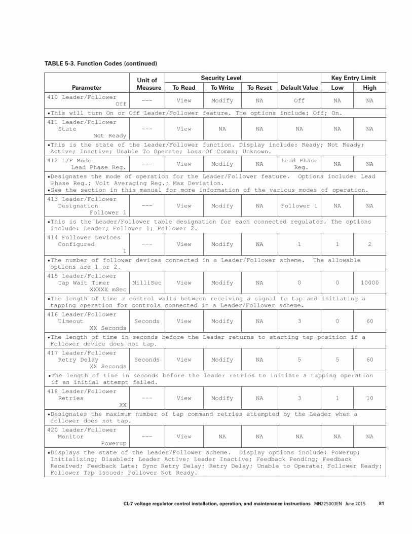
ParameterUnit of Measure
Security Level
Default Value
Key Entry Limit
To Read To Write To Reset Low High
410 Leader/FollowerOff --- View Modify NA Off NA NA
• This will turn On or Off Leader/Follower feature. The options include: Off; On.
411 Leader/FollowerState
Not Ready--- View NA NA NA NA NA
• This is the state of the Leader/Follower function. Display include: Ready; Not Ready; Active; Inactive; Unable To Operate; Loss Of Comms; Unknown.
412 L/F ModeLead Phase Reg. --- View Modify NA Lead Phase
Reg. NA NA
• Designates the mode of operation for the Leader/Follower feature. Options include: Lead Phase Reg.; Volt Averaging Reg.; Max Deviation.
• See the section in this manual for more information of the various modes of operation.
413 Leader/FollowerDesignation
Follower 1--- View Modify NA Follower 1 NA NA
• This is the Leader/Follower table designation for each connected regulator. The options include: Leader; Follower 1; Follower 2.
414 Follower DevicesConfigured
1--- View Modify NA 1 1 2
• The number of follower devices connected in a Leader/Follower scheme. The allowable options are 1 or 2.
415 Leader/FollowerTap Wait Timer
XXXXX mSecMilliSec View Modify NA 0 0 10000
• The length of time a control waits between receiving a signal to tap and initiating a tapping operation for controls connected in a Leader/Follower scheme.
416 Leader/FollowerTimeout
XX SecondsSeconds View Modify NA 3 0 60
• The length of time in seconds before the Leader returns to starting tap position if a Follower device does not tap.
417 Leader/FollowerRetry Delay
XX SecondsSeconds View Modify NA 5 5 60
• The length of time in seconds before the leader retries to initiate a tapping operation if an initial attempt failed.
418 Leader/FollowerRetries
XX--- View Modify NA 3 1 10
• Designates the maximum number of tap command retries attempted by the Leader when a follower does not tap.
420 Leader/FollowerMonitor
Powerup--- View NA NA NA NA NA
• Displays the state of the Leader/Follower scheme. Display options include: Powerup; Initializing; Disabled; Leader Active; Leader Inactive; Feedback Pending; Feedback Received; Feedback Late; Sync Retry Delay; Retry Delay; Unable to Operate; Follower Ready; Follower Tap Issued; Follower Not Ready.
TABLE 5-3. Function Codes (continued)
81CL-7 voltage regulator control installation, operation, and maintenance instructions MN225003EN June 2015

ParameterUnit of Measure
Security Level
Default Value
Key Entry Limit
To Read To Write To Reset Low High
421 L/F Average CompVolt Secondary
XXX.X VoltsVolts View NA NA NA NA NA
• Displays the average compensated voltage among regulators connected in a Leader/Follower scheme.
422 Max DeviationXX
--- View Modify NA 32 0 32
• The maximum deviation in tap position between regulators operating in the Max Deviation Leader/Follower mode.
423 Timer To AltMode
XXXX SecondsSeconds View Modify NA 60 10 3600
• Defines the amount of time that the connected regulators are permitted to remain at the configured Max Deviation value before the control will revert to the Max Deviation Alternate mode of operation.
424 Timer To MaxDeviation Mode
XXX HoursHours View Modify NA 168 0 168
• Defines the amount of time that the connected regulators will remain in the Max Deviation Alternate Mode before reverting to the standard Max Deviation operation.
425 Max DeviationAlt Mode
Ganged Mode--- View Modify NA Ganged
Mode NA NA
• The configured fall back mode of operation for a group of connected regulators if they remain at the user configured Max Deviation value for the time defined at FC 424. The options are: Off; Tap To Neutral; Ganged Mode; Historical Tap Pos.• See the Leader/Follower Operation section of this manual for more information on the options.
450 Alternate ConfigMode
Off--- View Modify NA Off NA NA
• This will turn on Alternate Configurations and designate a mode of operation. The options are: Off; On; ARLH; ARLC; Config Logic.• Selecting "On" will enable the basic Alternate Configuration settings.• Selecting ARLH will enable the Auto-Restore Local Heartbeat function. This function will revert control settings modified through SCADA communications back to original settings when a heartbeat signal is lost or discontinued.• Selecting ARLC will enable the Auto-Restore Local Comms function. This function will revert control settings modified through SCADA communications back to original settings when a communications signal is lost.• Selecting Config Logic will enable Alternate Configuration settings to be enabled or disabled using configurable logic equations.
451 Alternate ConfigState
Inactive--- View NA NA NA NA NA
• Displays the alternate configuration that is currently active. Display options include: Alt Config 1 Active; Alt Config 2 Active; Alt Config 3 Active; ARLC Active; ALRH Active.
452 Alternate ConfigSelection
Alt Config 1--- View Modify NA Off NA NA
• Allows for the selection of basic alternate configuration settings when FC 450 is set to “On”. Options include: Alt Config 1; Alt Config 2; Alt Config 3; Config Logic.
TABLE 5-3. Function Codes (continued)
82 CL-7 voltage regulator control installation, operation, and maintenance instructions MN225003EN June 2015
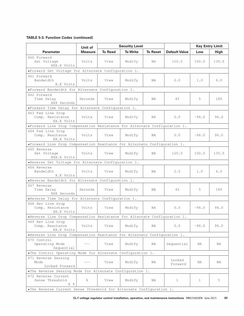
ParameterUnit of Measure
Security Level
Default Value
Key Entry Limit
To Read To Write To Reset Low High
460 ForwardSet Voltage
XXX.X VoltsVolts View Modify NA 120.0 100.0 135.0
• Forward Set Voltage for Alternate Configuration 1.
461 ForwardBandwidth
X.X VoltsVolts View Modify NA 2.0 1.0 6.0
• Forward Bandwidth for Alternate Configuration 1.
462 ForwardTime Delay
XXX SecondsSeconds View Modify NA 45 5 180
• Forward Time Delay for Alternate Configuration 1.463 Fwd Line Drop
Comp. ResistanceXX.X Volts
Volts View Modify NA 0.0 -96.0 96.0
• Forward Line Drop Compensation Resistance for Alternate Configuration 1.464 Fwd Line Drop
Comp. ReactanceXX.X Volts
Volts View Modify NA 0.0 -96.0 96.0
• Forward Line Drop Compensation Reactance for Alternate Configuration 1.465 Reverse
Set VoltageXXX.X Volts
Volts View Modify NA 120.0 100.0 135.0
• Reverse Set Voltage for Alternate Configuration 1.466 Reverse
BandwidthX.X Volts
Volts View Modify NA 2.0 1.0 6.0
• Reverse Bandwidth for Alternate Configuration 1.467 Reverse
Time DelayXXX Seconds
Seconds View Modify NA 45 5 180
• Reverse Time Delay for Alternate Configuration 1.468 Rev Line Drop
Comp. ResistanceXX.X Volts
Volts View Modify NA 0.0 -96.0 96.0
• Reverse Line Drop Compensation Resistance for Alternate Configuration 1.469 Rev Line Drop
Comp. ReactanceXX.X Volts
Volts View Modify NA 0.0 -96.0 96.0
• Reverse Line Drop Compensation Reactance for Alternate Configuration 1.470 Control
Operating ModeSequential
--- View Modify NA Sequential NA NA
• The Control Operating Mode for Alternate Configuration 1.471 Reverse Sensing
ModeLocked Forward
--- View Modify NA Locked Forward NA NA
• The Reverse Sensing Mode for Alternate Configuration 1.472 Reverse Current
Sense ThresholdX %
% View Modify NA 1 1 5
• The Reverse Current Sense Threshold for Alternate Configuration 1.
TABLE 5-3. Function Codes (continued)
83CL-7 voltage regulator control installation, operation, and maintenance instructions MN225003EN June 2015
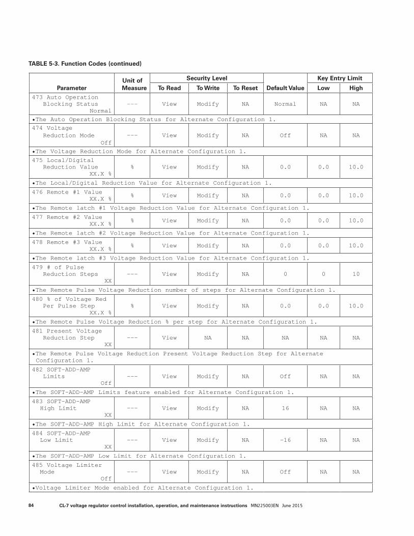
ParameterUnit of Measure
Security Level
Default Value
Key Entry Limit
To Read To Write To Reset Low High473 Auto Operation
Blocking StatusNormal
--- View Modify NA Normal NA NA
• The Auto Operation Blocking Status for Alternate Configuration 1.474 Voltage
Reduction ModeOff
--- View Modify NA Off NA NA
• The Voltage Reduction Mode for Alternate Configuration 1.
475 Local/DigitalReduction Value
XX.X %% View Modify NA 0.0 0.0 10.0
• The Local/Digital Reduction Value for Alternate Configuration 1.
476 Remote #1 ValueXX.X % % View Modify NA 0.0 0.0 10.0
• The Remote latch #1 Voltage Reduction Value for Alternate Configuration 1.
477 Remote #2 ValueXX.X % % View Modify NA 0.0 0.0 10.0
• The Remote latch #2 Voltage Reduction Value for Alternate Configuration 1.
478 Remote #3 ValueXX.X % % View Modify NA 0.0 0.0 10.0
• The Remote latch #3 Voltage Reduction Value for Alternate Configuration 1.
479 # of PulseReduction Steps
XX--- View Modify NA 0 0 10
• The Remote Pulse Voltage Reduction number of steps for Alternate Configuration 1.
480 % of Voltage RedPer Pulse Step
XX.X %% View Modify NA 0.0 0.0 10.0
• The Remote Pulse Voltage Reduction % per step for Alternate Configuration 1.
481 Present VoltageReduction Step
XX--- View NA NA NA NA NA
• The Remote Pulse Voltage Reduction Present Voltage Reduction Step for Alternate Configuration 1.
482 SOFT-ADD-AMPLimits
Off--- View Modify NA Off NA NA
• The SOFT-ADD-AMP Limits feature enabled for Alternate Configuration 1.
483 SOFT-ADD-AMPHigh Limit
XX--- View Modify NA 16 NA NA
• The SOFT-ADD-AMP High Limit for Alternate Configuration 1.
484 SOFT-ADD-AMPLow Limit
XX--- View Modify NA -16 NA NA
• The SOFT-ADD-AMP Low Limit for Alternate Configuration 1.
485 Voltage LimiterMode
Off--- View Modify NA Off NA NA
• Voltage Limiter Mode enabled for Alternate Configuration 1.
TABLE 5-3. Function Codes (continued)
84 CL-7 voltage regulator control installation, operation, and maintenance instructions MN225003EN June 2015

ParameterUnit of Measure
Security Level
Default Value
Key Entry Limit
To Read To Write To Reset Low High473 Auto Operation
Blocking StatusNormal
--- View Modify NA Normal NA NA
• The Auto Operation Blocking Status for Alternate Configuration 1.474 Voltage
Reduction ModeOff
--- View Modify NA Off NA NA
• The Voltage Reduction Mode for Alternate Configuration 1.
475 Local/DigitalReduction Value
XX.X %% View Modify NA 0.0 0.0 10.0
• The Local/Digital Reduction Value for Alternate Configuration 1.
476 Remote #1 ValueXX.X % % View Modify NA 0.0 0.0 10.0
• The Remote latch #1 Voltage Reduction Value for Alternate Configuration 1.
477 Remote #2 ValueXX.X % % View Modify NA 0.0 0.0 10.0
• The Remote latch #2 Voltage Reduction Value for Alternate Configuration 1.
478 Remote #3 ValueXX.X % % View Modify NA 0.0 0.0 10.0
• The Remote latch #3 Voltage Reduction Value for Alternate Configuration 1.
479 # of PulseReduction Steps
XX--- View Modify NA 0 0 10
• The Remote Pulse Voltage Reduction number of steps for Alternate Configuration 1.
480 % of Voltage RedPer Pulse Step
XX.X %% View Modify NA 0.0 0.0 10.0
• The Remote Pulse Voltage Reduction % per step for Alternate Configuration 1.
481 Present VoltageReduction Step
XX--- View NA NA NA NA NA
• The Remote Pulse Voltage Reduction Present Voltage Reduction Step for Alternate Configuration 1.
482 SOFT-ADD-AMPLimits
Off--- View Modify NA Off NA NA
• The SOFT-ADD-AMP Limits feature enabled for Alternate Configuration 1.
483 SOFT-ADD-AMPHigh Limit
XX--- View Modify NA 16 NA NA
• The SOFT-ADD-AMP High Limit for Alternate Configuration 1.
484 SOFT-ADD-AMPLow Limit
XX--- View Modify NA -16 NA NA
• The SOFT-ADD-AMP Low Limit for Alternate Configuration 1.
485 Voltage LimiterMode
Off--- View Modify NA Off NA NA
• Voltage Limiter Mode enabled for Alternate Configuration 1.
ParameterUnit of Measure
Security Level
Default Value
Key Entry Limit
To Read To Write To Reset Low High
486 High VoltageLimit
XXX.X VoltsVolts View Modify NA 130.0 120.0 135.0
• The Voltage Limiter High Limit for Alternate Configuration 1.
487 Low VoltageLimit
XXX.X VoltsVolts View Modify NA 105.0 105.0 120.0
• The Voltage Limiter Low Limit for Alternate Configuration 1.
488 Voltage LimiterFast Resp. Delay
XX SecondsSeconds View Modify NA 3 1 60
• The Voltage Limiter Fast Resp. Delay for Alternate Configuration 1.
489 Voltage LimiterDelay
XX SecondsSeconds View Modify NA 10 1 60
• The Voltage Limiter Delay for Alternate Configuration 1.
490 Time BetweenTaps
XX SecondsSeconds View Modify NA 0 0 10
• The Voltage Limiter Time Between Taps for Alternate Configuration 1.
491 Tap To NeutralOff --- View Modify NA Off NA NA
• The Tap to Neutral setting for Alternate Configuration 1.
500 ForwardSet Voltage
XXX.X VoltsVolts View Modify NA 120.0 100.0 135.0
• Forward Set Voltage for Alternate Configuration 2.
501 ForwardBandwidth
X.X VoltsVolts View Modify NA 2.0 1.0 6.0
• Forward Bandwidth for Alternate Configuration 2.
502 ForwardTime Delay
XXX SecondsSeconds View Modify NA 45 5 180
• Forward Time Delay for Alternate Configuration 2.
503 Fwd Line DropComp. Resistance
XX.X VoltsVolts View Modify NA 0.0 -96.0 96.0
• Forward Line Drop Compensation Resistance for Alternate Configuration 2.
504 Fwd Line DropComp. Reactance
XX.X VoltsVolts View Modify NA 0.0 -96.0 96.0
• Forward Line Drop Compensation Reactance for Alternate Configuration 2.
505 ReverseSet Voltage
XXX.X VoltsVolts View Modify NA 120.0 100.0 135.0
• Reverse Set Voltage for Alternate Configuration 2.
TABLE 5-3. Function Codes (continued)
85CL-7 voltage regulator control installation, operation, and maintenance instructions MN225003EN June 2015
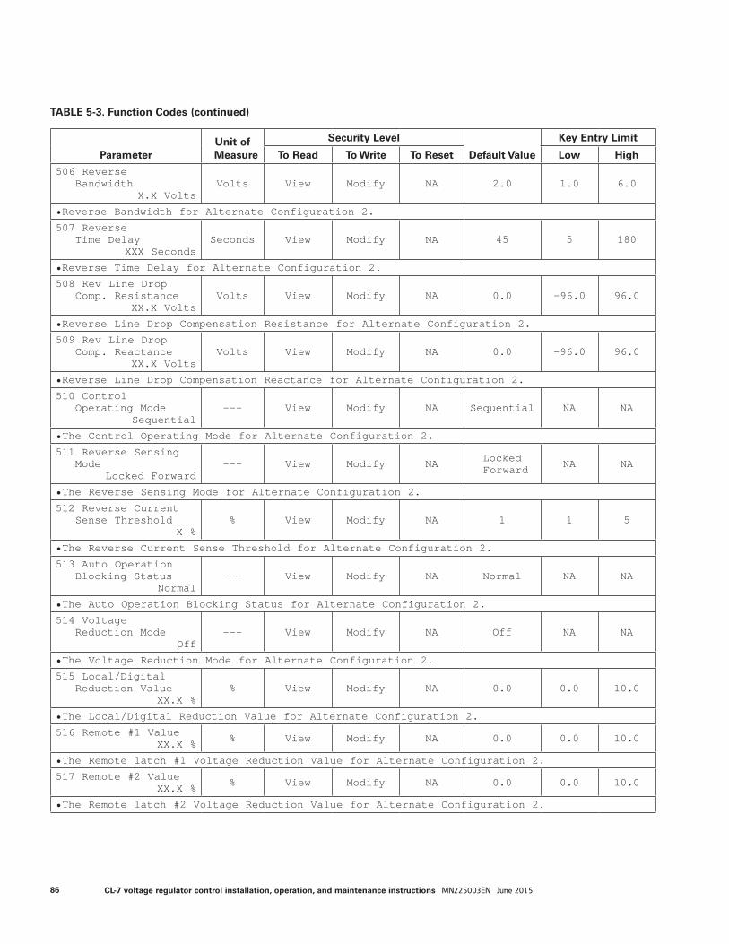
ParameterUnit of Measure
Security Level
Default Value
Key Entry Limit
To Read To Write To Reset Low High
506 ReverseBandwidth
X.X VoltsVolts View Modify NA 2.0 1.0 6.0
• Reverse Bandwidth for Alternate Configuration 2.
507 ReverseTime Delay
XXX SecondsSeconds View Modify NA 45 5 180
• Reverse Time Delay for Alternate Configuration 2.
508 Rev Line DropComp. Resistance
XX.X VoltsVolts View Modify NA 0.0 -96.0 96.0
• Reverse Line Drop Compensation Resistance for Alternate Configuration 2.
509 Rev Line DropComp. Reactance
XX.X VoltsVolts View Modify NA 0.0 -96.0 96.0
• Reverse Line Drop Compensation Reactance for Alternate Configuration 2.
510 ControlOperating Mode
Sequential--- View Modify NA Sequential NA NA
• The Control Operating Mode for Alternate Configuration 2.
511 Reverse SensingMode
Locked Forward--- View Modify NA Locked
Forward NA NA
• The Reverse Sensing Mode for Alternate Configuration 2.
512 Reverse CurrentSense Threshold
X %% View Modify NA 1 1 5
• The Reverse Current Sense Threshold for Alternate Configuration 2.
513 Auto OperationBlocking Status
Normal--- View Modify NA Normal NA NA
• The Auto Operation Blocking Status for Alternate Configuration 2.
514 VoltageReduction Mode
Off--- View Modify NA Off NA NA
• The Voltage Reduction Mode for Alternate Configuration 2.
515 Local/DigitalReduction Value
XX.X %% View Modify NA 0.0 0.0 10.0
• The Local/Digital Reduction Value for Alternate Configuration 2.
516 Remote #1 ValueXX.X % % View Modify NA 0.0 0.0 10.0
• The Remote latch #1 Voltage Reduction Value for Alternate Configuration 2.
517 Remote #2 ValueXX.X % % View Modify NA 0.0 0.0 10.0
• The Remote latch #2 Voltage Reduction Value for Alternate Configuration 2.
TABLE 5-3. Function Codes (continued)
86 CL-7 voltage regulator control installation, operation, and maintenance instructions MN225003EN June 2015
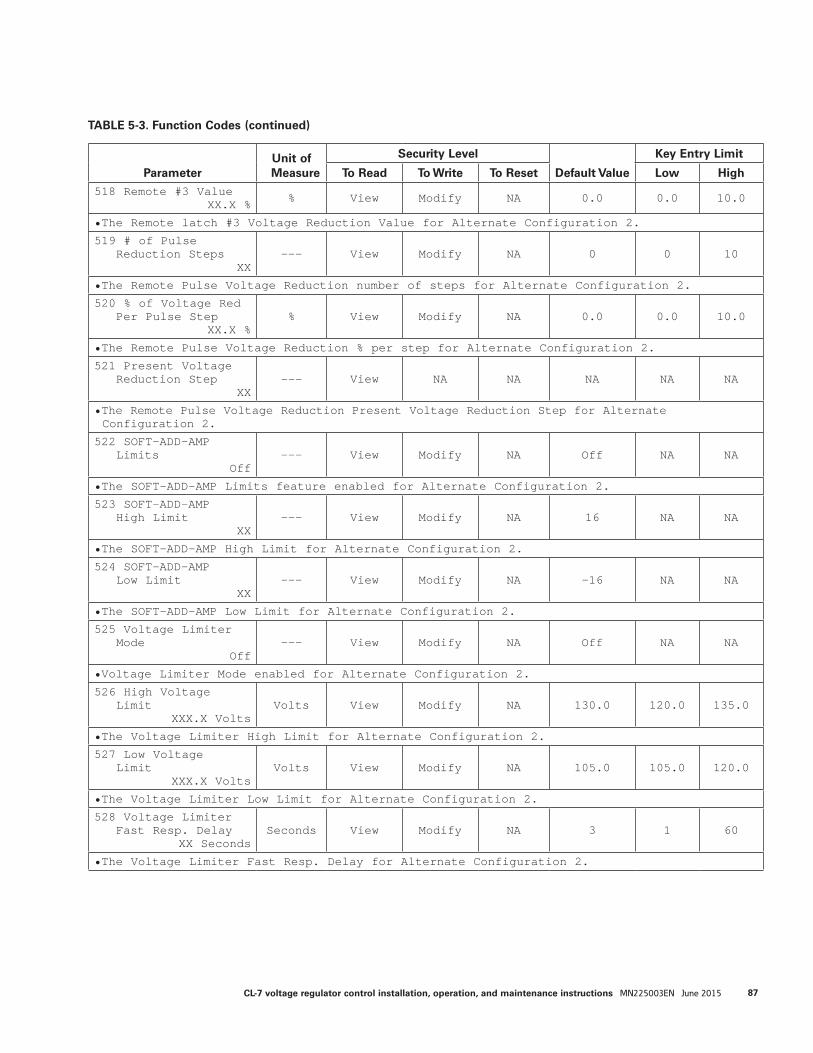
ParameterUnit of Measure
Security Level
Default Value
Key Entry Limit
To Read To Write To Reset Low High
506 ReverseBandwidth
X.X VoltsVolts View Modify NA 2.0 1.0 6.0
• Reverse Bandwidth for Alternate Configuration 2.
507 ReverseTime Delay
XXX SecondsSeconds View Modify NA 45 5 180
• Reverse Time Delay for Alternate Configuration 2.
508 Rev Line DropComp. Resistance
XX.X VoltsVolts View Modify NA 0.0 -96.0 96.0
• Reverse Line Drop Compensation Resistance for Alternate Configuration 2.
509 Rev Line DropComp. Reactance
XX.X VoltsVolts View Modify NA 0.0 -96.0 96.0
• Reverse Line Drop Compensation Reactance for Alternate Configuration 2.
510 ControlOperating Mode
Sequential--- View Modify NA Sequential NA NA
• The Control Operating Mode for Alternate Configuration 2.
511 Reverse SensingMode
Locked Forward--- View Modify NA Locked
Forward NA NA
• The Reverse Sensing Mode for Alternate Configuration 2.
512 Reverse CurrentSense Threshold
X %% View Modify NA 1 1 5
• The Reverse Current Sense Threshold for Alternate Configuration 2.
513 Auto OperationBlocking Status
Normal--- View Modify NA Normal NA NA
• The Auto Operation Blocking Status for Alternate Configuration 2.
514 VoltageReduction Mode
Off--- View Modify NA Off NA NA
• The Voltage Reduction Mode for Alternate Configuration 2.
515 Local/DigitalReduction Value
XX.X %% View Modify NA 0.0 0.0 10.0
• The Local/Digital Reduction Value for Alternate Configuration 2.
516 Remote #1 ValueXX.X % % View Modify NA 0.0 0.0 10.0
• The Remote latch #1 Voltage Reduction Value for Alternate Configuration 2.
517 Remote #2 ValueXX.X % % View Modify NA 0.0 0.0 10.0
• The Remote latch #2 Voltage Reduction Value for Alternate Configuration 2.
ParameterUnit of Measure
Security Level
Default Value
Key Entry Limit
To Read To Write To Reset Low High
518 Remote #3 ValueXX.X % % View Modify NA 0.0 0.0 10.0
• The Remote latch #3 Voltage Reduction Value for Alternate Configuration 2.
519 # of PulseReduction Steps
XX--- View Modify NA 0 0 10
• The Remote Pulse Voltage Reduction number of steps for Alternate Configuration 2.
520 % of Voltage RedPer Pulse Step
XX.X %% View Modify NA 0.0 0.0 10.0
• The Remote Pulse Voltage Reduction % per step for Alternate Configuration 2.
521 Present VoltageReduction Step
XX--- View NA NA NA NA NA
• The Remote Pulse Voltage Reduction Present Voltage Reduction Step for Alternate Configuration 2.
522 SOFT-ADD-AMPLimits
Off--- View Modify NA Off NA NA
• The SOFT-ADD-AMP Limits feature enabled for Alternate Configuration 2.
523 SOFT-ADD-AMPHigh Limit
XX--- View Modify NA 16 NA NA
• The SOFT-ADD-AMP High Limit for Alternate Configuration 2.
524 SOFT-ADD-AMPLow Limit
XX--- View Modify NA -16 NA NA
• The SOFT-ADD-AMP Low Limit for Alternate Configuration 2.
525 Voltage LimiterMode
Off--- View Modify NA Off NA NA
• Voltage Limiter Mode enabled for Alternate Configuration 2.
526 High VoltageLimit
XXX.X VoltsVolts View Modify NA 130.0 120.0 135.0
• The Voltage Limiter High Limit for Alternate Configuration 2.
527 Low VoltageLimit
XXX.X VoltsVolts View Modify NA 105.0 105.0 120.0
• The Voltage Limiter Low Limit for Alternate Configuration 2.
528 Voltage LimiterFast Resp. Delay
XX SecondsSeconds View Modify NA 3 1 60
• The Voltage Limiter Fast Resp. Delay for Alternate Configuration 2.
TABLE 5-3. Function Codes (continued)
87CL-7 voltage regulator control installation, operation, and maintenance instructions MN225003EN June 2015
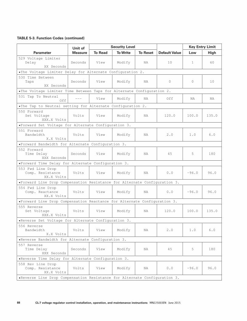
ParameterUnit of Measure
Security Level
Default Value
Key Entry Limit
To Read To Write To Reset Low High
529 Voltage LimiterDelay
XX SecondsSeconds View Modify NA 10 1 60
• The Voltage Limiter Delay for Alternate Configuration 2.
530 Time BetweenTaps
XX SecondsSeconds View Modify NA 0 0 10
• The Voltage Limiter Time Between Taps for Alternate Configuration 2.
531 Tap To NeutralOff --- View Modify NA Off NA NA
• The Tap to Neutral setting for Alternate Configuration 2.
550 ForwardSet Voltage
XXX.X VoltsVolts View Modify NA 120.0 100.0 135.0
• Forward Set Voltage for Alternate Configuration 3.
551 ForwardBandwidth
X.X VoltsVolts View Modify NA 2.0 1.0 6.0
• Forward Bandwidth for Alternate Configuration 3.
552 ForwardTime Delay
XXX SecondsSeconds View Modify NA 45 5 180
• Forward Time Delay for Alternate Configuration 3.
553 Fwd Line DropComp. Resistance
XX.X VoltsVolts View Modify NA 0.0 -96.0 96.0
• Forward Line Drop Compensation Resistance for Alternate Configuration 3.
554 Fwd Line DropComp. Reactance
XX.X VoltsVolts View Modify NA 0.0 -96.0 96.0
• Forward Line Drop Compensation Reactance for Alternate Configuration 3.
555 ReverseSet Voltage
XXX.X VoltsVolts View Modify NA 120.0 100.0 135.0
• Reverse Set Voltage for Alternate Configuration 3.
556 ReverseBandwidth
X.X VoltsVolts View Modify NA 2.0 1.0 6.0
• Reverse Bandwidth for Alternate Configuration 3.
557 ReverseTime Delay
XXX SecondsSeconds View Modify NA 45 5 180
• Reverse Time Delay for Alternate Configuration 3.
558 Rev Line DropComp. Resistance
XX.X VoltsVolts View Modify NA 0.0 -96.0 96.0
• Reverse Line Drop Compensation Resistance for Alternate Configuration 3.
TABLE 5-3. Function Codes (continued)
88 CL-7 voltage regulator control installation, operation, and maintenance instructions MN225003EN June 2015
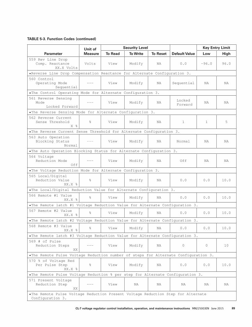
ParameterUnit of Measure
Security Level
Default Value
Key Entry Limit
To Read To Write To Reset Low High
559 Rev Line DropComp. Reactance
XX.X VoltsVolts View Modify NA 0.0 -96.0 96.0
• Reverse Line Drop Compensation Reactance for Alternate Configuration 3.
560 ControlOperating Mode
Sequential--- View Modify NA Sequential NA NA
• The Control Operating Mode for Alternate Configuration 3.
561 Reverse SensingMode
Locked Forward--- View Modify NA Locked
Forward NA NA
• The Reverse Sensing Mode for Alternate Configuration 3.
562 Reverse CurrentSense Threshold
X %% View Modify NA 1 1 5
• The Reverse Current Sense Threshold for Alternate Configuration 3.
563 Auto OperationBlocking Status
Normal--- View Modify NA Normal NA NA
• The Auto Operation Blocking Status for Alternate Configuration 3.
564 VoltageReduction Mode
Off--- View Modify NA Off NA NA
• The Voltage Reduction Mode for Alternate Configuration 3.
565 Local/DigitalReduction Value
XX.X %% View Modify NA 0.0 0.0 10.0
• The Local/Digital Reduction Value for Alternate Configuration 3.
566 Remote #1 ValueXX.X % % View Modify NA 0.0 0.0 10.0
• The Remote latch #1 Voltage Reduction Value for Alternate Configuration 3.
567 Remote #2 ValueXX.X % % View Modify NA 0.0 0.0 10.0
• The Remote latch #2 Voltage Reduction Value for Alternate Configuration 3.
568 Remote #3 ValueXX.X % % View Modify NA 0.0 0.0 10.0
• The Remote latch #3 Voltage Reduction Value for Alternate Configuration 3.
569 # of PulseReduction Steps
XX--- View Modify NA 0 0 10
• The Remote Pulse Voltage Reduction number of steps for Alternate Configuration 3.
570 % of Voltage RedPer Pulse Step
XX.X %% View Modify NA 0.0 0.0 10.0
• The Remote Pulse Voltage Reduction % per step for Alternate Configuration 3.
571 Present VoltageReduction Step
XX--- View NA NA NA NA NA
• The Remote Pulse Voltage Reduction Present Voltage Reduction Step for Alternate Configuration 3.
TABLE 5-3. Function Codes (continued)
89CL-7 voltage regulator control installation, operation, and maintenance instructions MN225003EN June 2015
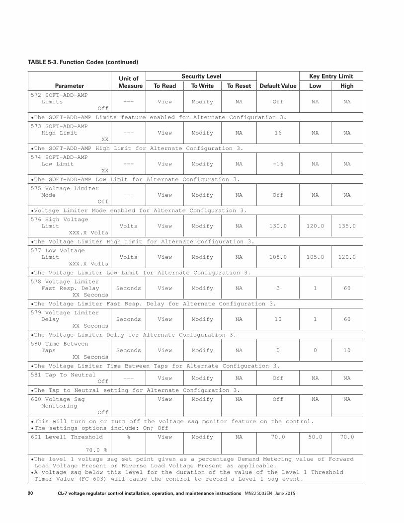
ParameterUnit of Measure
Security Level
Default Value
Key Entry Limit
To Read To Write To Reset Low High
572 SOFT-ADD-AMPLimits
Off--- View Modify NA Off NA NA
• The SOFT-ADD-AMP Limits feature enabled for Alternate Configuration 3.
573 SOFT-ADD-AMPHigh Limit
XX--- View Modify NA 16 NA NA
• The SOFT-ADD-AMP High Limit for Alternate Configuration 3.
574 SOFT-ADD-AMPLow Limit
XX--- View Modify NA -16 NA NA
• The SOFT-ADD-AMP Low Limit for Alternate Configuration 3.
575 Voltage LimiterMode
Off--- View Modify NA Off NA NA
• Voltage Limiter Mode enabled for Alternate Configuration 3.
576 High VoltageLimit
XXX.X VoltsVolts View Modify NA 130.0 120.0 135.0
• The Voltage Limiter High Limit for Alternate Configuration 3.
577 Low VoltageLimit
XXX.X VoltsVolts View Modify NA 105.0 105.0 120.0
• The Voltage Limiter Low Limit for Alternate Configuration 3.
578 Voltage LimiterFast Resp. Delay
XX SecondsSeconds View Modify NA 3 1 60
• The Voltage Limiter Fast Resp. Delay for Alternate Configuration 3.
579 Voltage LimiterDelay
XX SecondsSeconds View Modify NA 10 1 60
• The Voltage Limiter Delay for Alternate Configuration 3.
580 Time BetweenTaps
XX SecondsSeconds View Modify NA 0 0 10
• The Voltage Limiter Time Between Taps for Alternate Configuration 3.
581 Tap To NeutralOff --- View Modify NA Off NA NA
• The Tap to Neutral setting for Alternate Configuration 3.
600 Voltage SagMonitoring
Off
View Modify NA Off NA NA
• This will turn on or turn off the voltage sag monitor feature on the control.• The settings options include: On; Off
601 Level1 Threshold 70.0 %
% View Modify NA 70.0 50.0 70.0
• The level 1 voltage sag set point given as a percentage Demand Metering value of Forward Load Voltage Present or Reverse Load Voltage Present as applicable.
• A voltage sag below this level for the duration of the value of the Level 1 Threshold Timer Value (FC 603) will cause the control to record a Level 1 sag event.
TABLE 5-3. Function Codes (continued)
90 CL-7 voltage regulator control installation, operation, and maintenance instructions MN225003EN June 2015

ParameterUnit of Measure
Security Level
Default Value
Key Entry Limit
To Read To Write To Reset Low High
602 Level1 Recovery 75.0 %
% View Modify NA 75.0 71.0 100.0
• After a level 1 voltage sag has occurred, this is the level at which the voltage is said to have recovered from the sag. This value is given as a percentage Demand Metering value of Forward Load Voltage Present or Reverse Load Voltage Present as applicable.
• A voltage recovery above this level for the duration of the value of the Level 1 Recovery Timer Value (FC 604) will cause the control to record a Level 1 recovery event.
603 Level1 Threshold Timer Value 20 mSec
mSec View Modify NA 20 30000 20
• The minimum time duration that must be met in order to record a Level 1 sag event.
604 Level1 Recovery Timer Value 20 mSec
mSec View Modify NA 20 30000 20
• The minimum time duration that must be met by a sag recovery in order to record a level 1 sag recovery.
605 Duration of Last Level1 0 CyclesMM-DD-YYYY HH:MM:SSp
Cycles View NA Operate NA NA NA
• A date and time stamped record of the duration of the last level 1 voltage sag recorded in cycles.
• The duration is the time between the point at which a sag event reaches the threshold timer value and the recovery has reached the recovery timer value.
• This is reset to 0 and the current date and time by entering the appropriate security level and pressing ENTER.
606 Duration of Longest Level1 0 CyclesMM-DD-YYYY HH:MM:SSp
Cycles View NA Operate NA NA NA
• A date and time stamped record of the longest duration recorded for the Duration of Last Level1 (FC 605) voltage sag.
• This is reset to 0 and the current date and time by entering the appropriate security level and pressing ENTER.
611 Level2 Threshold 80.0 %
% View Modify NA 80.0 50.0 80.0
• The level 2 voltage sag set point given as a percentage Demand Metering value of Forward Load Voltage Present or Reverse Load Voltage Present as applicable.
• A voltage sag below this level for the duration of the value of the Level 2 Threshold Timer Value (FC 613) will cause the control to record a Level 2 sag event.
612 Level2 Recovery 85.0 %
% View Modify NA 85.0 81.0 100.0
• After a level 2 voltage sag has occurred, this is the level at which the voltage is said to have recovered from the sag. This value is given as a percentage Demand Metering value of Forward Load Voltage Present or Reverse Load Voltage Present as applicable.
• A voltage recovery above this level for the duration of the value of the Level 2 Recovery Timer Value (FC 614) will cause the control to record a Level 2 recovery event.
613 Level2 Threshold Timer Value 500 mSec
mSec View Modify NA 500 20 30000
• The minimum time duration that must be met in order to record a Level 2 sag event.
TABLE 5-3. Function Codes (continued)
91CL-7 voltage regulator control installation, operation, and maintenance instructions MN225003EN June 2015

ParameterUnit of Measure
Security Level
Default Value
Key Entry Limit
To Read To Write To Reset Low High
614 Level2 Recovery Timer Value 500 mSec
mSec View Modify NA 500 20 30000
• The minimum time duration that must be met by a sag recovery in order to record a level 2 sag recovery.
615 Duration of Last Level2 0 CyclesMM-DD-YYYY HH:MM:SSp
Cycles View NA Operate NA NA NA
• A date and time stamped record of the duration of the last level 2 voltage sag recorded in cycles.
• The duration is the time between the point at which a sag event reaches the threshold timer value and the recovery has reached the recovery timer value.
• This is reset to 0 and the current date and time by entering the appropriate security level and pressing ENTER.
616 Duration of Longest Level2 0 CyclesMM-DD-YYYY HH:MM:SSp
Cycles View NA Operate NA NA NA
• A date and time stamped record of the longest duration recorded for the Duration of Last Level 2 (FC 615) voltage sag.
• This is reset to 0 and the current date and time by entering the appropriate security level and pressing ENTER.
621 Level3 Threshold 90.0 %
% View Modify NA 90.0 50.0 90.0
• The level 3 voltage sag set point given as a percentage Demand Metering value of Forward Load Voltage Present or Reverse Load Voltage Present as applicable.
• A voltage sag below this level for the duration of the value of the Level 3 Threshold Timer Value (FC 623) will cause the control to record a Level 3 sag event.
623 Level3 Threshold Timer Value 10000 mSec
mSec View Modify NA 10000 20 30000
• The minimum time duration that must be met in order to record a Level 3 sag event.
624 Level3 Recovery Timer Value 10000 mSec
mSec View Modify NA 10000 20 30000
• The minimum time duration that must be met by a sag recovery in order to record a level 3 sag recovery.
625 Duration of Last Level3 0 CyclesMM-DD-YYYY HH:MM:SSp
Cycles View NA Operate NA NA NA
• A date and time stamped record of the duration of the last level 3 voltage sag recorded in cycles.
• The duration is the time between the point at which a sag event reaches the threshold timer value and the recovery has reached the recovery timer value.
• This is reset to 0 and the current date and time by entering the appropriate security level and pressing ENTER.
TABLE 5-3. Function Codes (continued)
92 CL-7 voltage regulator control installation, operation, and maintenance instructions MN225003EN June 2015
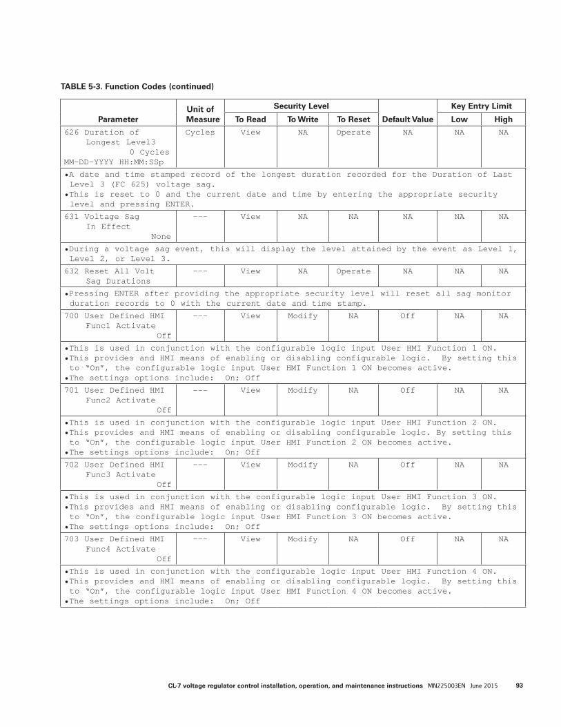
ParameterUnit of Measure
Security Level
Default Value
Key Entry Limit
To Read To Write To Reset Low High
626 Duration of Longest Level3 0 CyclesMM-DD-YYYY HH:MM:SSp
Cycles View NA Operate NA NA NA
• A date and time stamped record of the longest duration recorded for the Duration of Last Level 3 (FC 625) voltage sag.
• This is reset to 0 and the current date and time by entering the appropriate security level and pressing ENTER.
631 Voltage Sag In Effect None
--- View NA NA NA NA NA
• During a voltage sag event, this will display the level attained by the event as Level 1, Level 2, or Level 3.
632 Reset All Volt Sag Durations
--- View NA Operate NA NA NA
• Pressing ENTER after providing the appropriate security level will reset all sag monitor duration records to 0 with the current date and time stamp.
700 User Defined HMI Func1 Activate Off
--- View Modify NA Off NA NA
• This is used in conjunction with the configurable logic input User HMI Function 1 ON.• This provides and HMI means of enabling or disabling configurable logic. By setting this to “On”, the configurable logic input User HMI Function 1 ON becomes active.
• The settings options include: On; Off
701 User Defined HMI Func2 Activate Off
--- View Modify NA Off NA NA
• This is used in conjunction with the configurable logic input User HMI Function 2 ON.• This provides and HMI means of enabling or disabling configurable logic. By setting this to “On”, the configurable logic input User HMI Function 2 ON becomes active.
• The settings options include: On; Off
702 User Defined HMI Func3 Activate Off
--- View Modify NA Off NA NA
• This is used in conjunction with the configurable logic input User HMI Function 3 ON.• This provides and HMI means of enabling or disabling configurable logic. By setting this to “On”, the configurable logic input User HMI Function 3 ON becomes active.
• The settings options include: On; Off
703 User Defined HMI Func4 Activate Off
--- View Modify NA Off NA NA
• This is used in conjunction with the configurable logic input User HMI Function 4 ON.• This provides and HMI means of enabling or disabling configurable logic. By setting this to “On”, the configurable logic input User HMI Function 4 ON becomes active.
• The settings options include: On; Off
TABLE 5-3. Function Codes (continued)
93CL-7 voltage regulator control installation, operation, and maintenance instructions MN225003EN June 2015
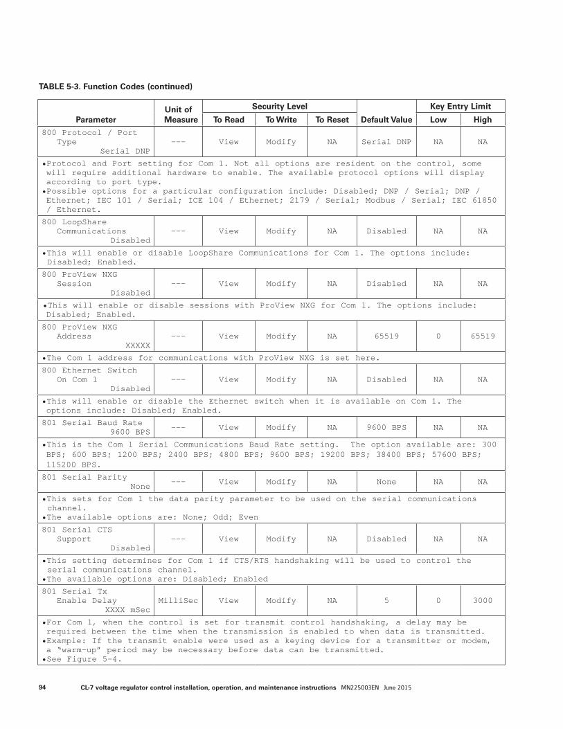
ParameterUnit of Measure
Security Level
Default Value
Key Entry Limit
To Read To Write To Reset Low High
800 Protocol / PortType
Serial DNP--- View Modify NA Serial DNP NA NA
• Protocol and Port setting for Com 1. Not all options are resident on the control, some will require additional hardware to enable. The available protocol options will display according to port type.• Possible options for a particular configuration include: Disabled; DNP / Serial; DNP / Ethernet; IEC 101 / Serial; ICE 104 / Ethernet; 2179 / Serial; Modbus / Serial; IEC 61850 / Ethernet.
800 LoopShareCommunications
Disabled--- View Modify NA Disabled NA NA
• This will enable or disable LoopShare Communications for Com 1. The options include: Disabled; Enabled.
800 ProView NXGSession
Disabled--- View Modify NA Disabled NA NA
• This will enable or disable sessions with ProView NXG for Com 1. The options include: Disabled; Enabled.
800 ProView NXGAddress
XXXXX--- View Modify NA 65519 0 65519
• The Com 1 address for communications with ProView NXG is set here.
800 Ethernet SwitchOn Com 1
Disabled--- View Modify NA Disabled NA NA
• This will enable or disable the Ethernet switch when it is available on Com 1. The options include: Disabled; Enabled.
801 Serial Baud Rate9600 BPS --- View Modify NA 9600 BPS NA NA
• This is the Com 1 Serial Communications Baud Rate setting. The option available are: 300 BPS; 600 BPS; 1200 BPS; 2400 BPS; 4800 BPS; 9600 BPS; 19200 BPS; 38400 BPS; 57600 BPS; 115200 BPS.
801 Serial ParityNone --- View Modify NA None NA NA
• This sets for Com 1 the data parity parameter to be used on the serial communications channel.
• The available options are: None; Odd; Even
801 Serial CTSSupport
Disabled--- View Modify NA Disabled NA NA
• This setting determines for Com 1 if CTS/RTS handshaking will be used to control the serial communications channel.
• The available options are: Disabled; Enabled
801 Serial TxEnable Delay
XXXX mSecMilliSec View Modify NA 5 0 3000
• For Com 1, when the control is set for transmit control handshaking, a delay may be required between the time when the transmission is enabled to when data is transmitted.• Example: If the transmit enable were used as a keying device for a transmitter or modem, a “warm-up” period may be necessary before data can be transmitted.• See Figure 5-4.
TABLE 5-3. Function Codes (continued)
94 CL-7 voltage regulator control installation, operation, and maintenance instructions MN225003EN June 2015
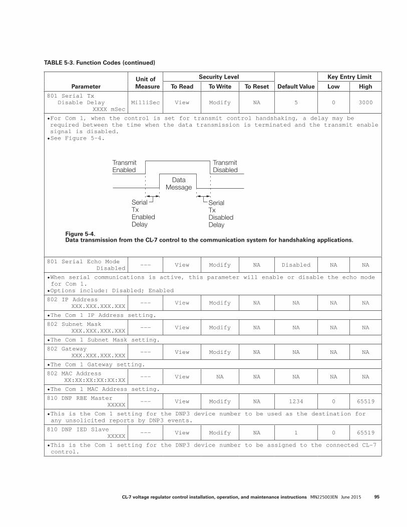
ParameterUnit of Measure
Security Level
Default Value
Key Entry Limit
To Read To Write To Reset Low High
801 Serial TxDisable Delay
XXXX mSecMilliSec View Modify NA 5 0 3000
• For Com 1, when the control is set for transmit control handshaking, a delay may be required between the time when the data transmission is terminated and the transmit enable signal is disabled.• See Figure 5-4.
801 Serial Echo ModeDisabled --- View Modify NA Disabled NA NA
• When serial communications is active, this parameter will enable or disable the echo mode for Com 1.
• Options include: Disabled; Enabled
802 IP AddressXXX.XXX.XXX.XXX --- View Modify NA NA NA NA
• The Com 1 IP Address setting.
802 Subnet MaskXXX.XXX.XXX.XXX --- View Modify NA NA NA NA
• The Com 1 Subnet Mask setting.
802 GatewayXXX.XXX.XXX.XXX --- View Modify NA NA NA NA
• The Com 1 Gateway setting.
802 MAC AddressXX:XX:XX:XX:XX:XX --- View NA NA NA NA NA
• The Com 1 MAC Address setting.
810 DNP RBE MasterXXXXX --- View Modify NA 1234 0 65519
• This is the Com 1 setting for the DNP3 device number to be used as the destination for any unsolicited reports by DNP3 events.
810 DNP IED SlaveXXXXX --- View Modify NA 1 0 65519
• This is the Com 1 setting for the DNP3 device number to be assigned to the connected CL-7 control.
TABLE 5-3. Function Codes (continued)
SerialTxEnabled Delay
TransmitDisabled
TransmitEnabled
DataMessage
SerialTxDisabled Delay
Figure 5-4.Data transmission from the CL-7 control to the communication system for handshaking applications.
95CL-7 voltage regulator control installation, operation, and maintenance instructions MN225003EN June 2015
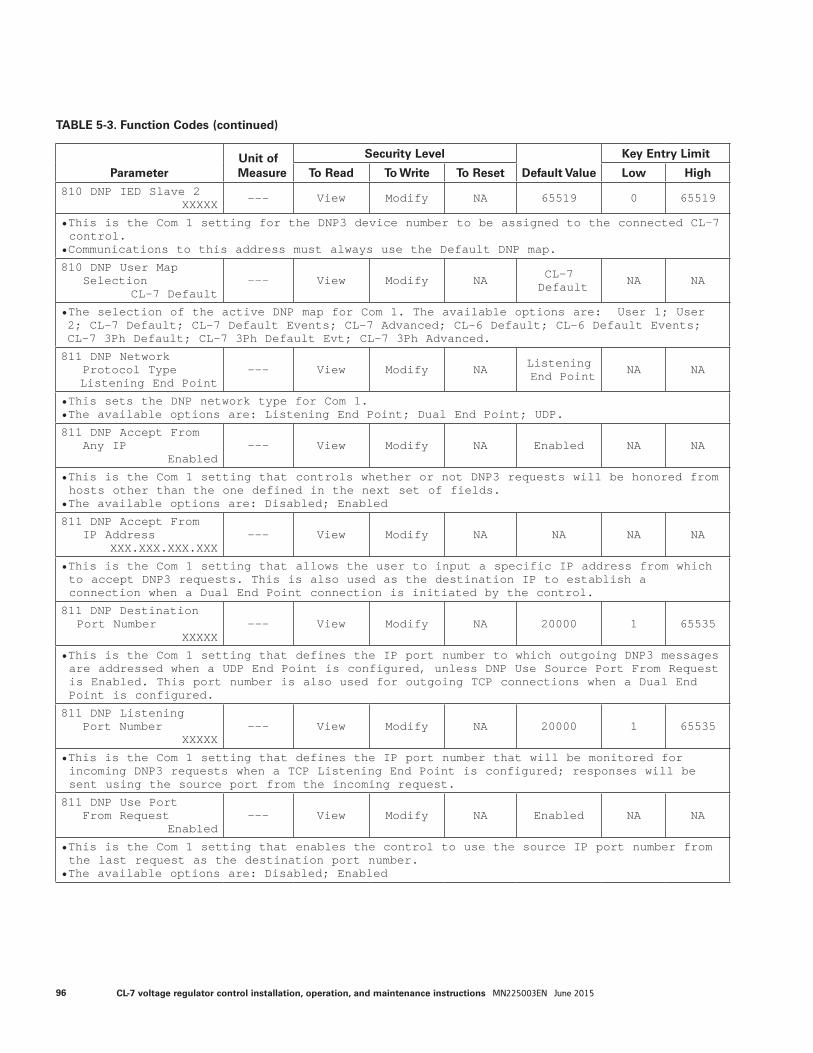
ParameterUnit of Measure
Security Level
Default Value
Key Entry Limit
To Read To Write To Reset Low High
810 DNP IED Slave 2XXXXX --- View Modify NA 65519 0 65519
• This is the Com 1 setting for the DNP3 device number to be assigned to the connected CL-7 control.
• Communications to this address must always use the Default DNP map.
810 DNP User MapSelection
CL-7 Default--- View Modify NA CL-7
Default NA NA
• The selection of the active DNP map for Com 1. The available options are: User 1; User 2; CL-7 Default; CL-7 Default Events; CL-7 Advanced; CL-6 Default; CL-6 Default Events; CL-7 3Ph Default; CL-7 3Ph Default Evt; CL-7 3Ph Advanced.
811 DNP NetworkProtocol TypeListening End Point
--- View Modify NA Listening End Point NA NA
• This sets the DNP network type for Com 1.• The available options are: Listening End Point; Dual End Point; UDP.
811 DNP Accept FromAny IP
Enabled--- View Modify NA Enabled NA NA
• This is the Com 1 setting that controls whether or not DNP3 requests will be honored from hosts other than the one defined in the next set of fields.
• The available options are: Disabled; Enabled
811 DNP Accept FromIP Address
XXX.XXX.XXX.XXX--- View Modify NA NA NA NA
• This is the Com 1 setting that allows the user to input a specific IP address from which to accept DNP3 requests. This is also used as the destination IP to establish a connection when a Dual End Point connection is initiated by the control.
811 DNP DestinationPort Number
XXXXX--- View Modify NA 20000 1 65535
• This is the Com 1 setting that defines the IP port number to which outgoing DNP3 messages are addressed when a UDP End Point is configured, unless DNP Use Source Port From Request is Enabled. This port number is also used for outgoing TCP connections when a Dual End Point is configured.
811 DNP ListeningPort Number
XXXXX--- View Modify NA 20000 1 65535
• This is the Com 1 setting that defines the IP port number that will be monitored for incoming DNP3 requests when a TCP Listening End Point is configured; responses will be sent using the source port from the incoming request.
811 DNP Use PortFrom Request
Enabled--- View Modify NA Enabled NA NA
• This is the Com 1 setting that enables the control to use the source IP port number from the last request as the destination port number.
• The available options are: Disabled; Enabled
TABLE 5-3. Function Codes (continued)
96 CL-7 voltage regulator control installation, operation, and maintenance instructions MN225003EN June 2015

ParameterUnit of Measure
Security Level
Default Value
Key Entry Limit
To Read To Write To Reset Low High
811 DNP Keep AliveTimeout
XXXXX Seconds--- View Modify NA 3600 1 65535
• This is the Com 1 setting for the time after which a DNP3 Data Link Layer status request will be sent if no message is received from the master (enter 0 to disable).
811 DNP Keep AliveRetries
XXX--- View Modify NA 3 1 255
• This is the Com 1 setting for the number of times the DNP3 Data Link Layer status request will be reattempted before the connection is closed.
812 IEC101 LinkAddress
XXXXX--- View Modify NA 2 0 See
note
• This is the Com 1 setting that assigns a unique identifier to the individual slave instance running on the device.
• If Link Address Size is 1, Link Address high value is 255• If Link Address Size is 2, Link Address high value is 65535
812 IEC101 CommonAddress
XXXXX--- View Modify NA 2 0 See
note
• This is the Com 1 setting that identifies the station address, where the station is comprised of all of a device's links.
• If Common Address Size is 1, Common Address high value is 255• If Common Address Size is 2, Common Address high value is 65535
812 IEC101 LinkAddress Size
X--- View Modify NA 1 1 2
• This is the Com 1 setting for the number of octets to be used for the value of the link address.
812 IEC101 CommonAddress Size
X--- View Modify NA 1 1 2
• This is the Com 1 setting for the number of octets to be used in the value of the common address.
812 IEC101 ObjectAddress Size
X--- View Modify NA 2 1 3
• This is the Com 1 setting for the number of octets to be used in the value of the object address.
812 IEC101 Cause ofTransmit Size
X--- View Modify NA 1 1 2
• This is the Com 1 setting for the number of octets to be used in the cause of transmission indication.
812 IEC101 SingleCommand Op Mode
SBE--- View Modify NA SBE NA NA
• This is the Com 1 setting that defines if the control will respond directly (Direct mode) to Single Command Operation commands or if a "select" is required before "execution" (SBE mode).
• The available options are: Direct; SBE.
TABLE 5-3. Function Codes (continued)
97CL-7 voltage regulator control installation, operation, and maintenance instructions MN225003EN June 2015
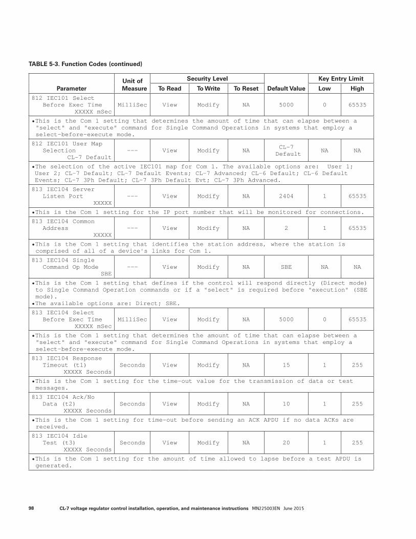
ParameterUnit of Measure
Security Level
Default Value
Key Entry Limit
To Read To Write To Reset Low High
812 IEC101 SelectBefore Exec Time
XXXXX mSecMilliSec View Modify NA 5000 0 65535
• This is the Com 1 setting that determines the amount of time that can elapse between a "select" and "execute" command for Single Command Operations in systems that employ a select-before-execute mode.
812 IEC101 User MapSelection
CL-7 Default--- View Modify NA CL-7
Default NA NA
• The selection of the active IEC101 map for Com 1. The available options are: User 1; User 2; CL-7 Default; CL-7 Default Events; CL-7 Advanced; CL-6 Default; CL-6 Default Events; CL-7 3Ph Default; CL-7 3Ph Default Evt; CL-7 3Ph Advanced.
813 IEC104 ServerListen Port
XXXXX--- View Modify NA 2404 1 65535
• This is the Com 1 setting for the IP port number that will be monitored for connections.
813 IEC104 CommonAddress
XXXXX--- View Modify NA 2 1 65535
• This is the Com 1 setting that identifies the station address, where the station is comprised of all of a device's links for Com 1.
813 IEC104 SingleCommand Op Mode
SBE--- View Modify NA SBE NA NA
• This is the Com 1 setting that defines if the control will respond directly (Direct mode) to Single Command Operation commands or if a "select" is required before "execution" (SBE mode).
• The available options are: Direct; SBE.
813 IEC104 SelectBefore Exec Time
XXXXX mSecMilliSec View Modify NA 5000 0 65535
• This is the Com 1 setting that determines the amount of time that can elapse between a "select" and "execute" command for Single Command Operations in systems that employ a select-before-execute mode.
813 IEC104 ResponseTimeout (t1)
XXXXX SecondsSeconds View Modify NA 15 1 255
• This is the Com 1 setting for the time-out value for the transmission of data or test messages.
813 IEC104 Ack/NoData (t2)
XXXXX SecondsSeconds View Modify NA 10 1 255
• This is the Com 1 setting for time-out before sending an ACK APDU if no data ACKs are received.
813 IEC104 IdleTest (t3)
XXXXX SecondsSeconds View Modify NA 20 1 255
• This is the Com 1 setting for the amount of time allowed to lapse before a test APDU is generated.
TABLE 5-3. Function Codes (continued)
98 CL-7 voltage regulator control installation, operation, and maintenance instructions MN225003EN June 2015

ParameterUnit of Measure
Security Level
Default Value
Key Entry Limit
To Read To Write To Reset Low High
813 IEC104 MaxTransmit (k)
XXXXX--- View Modify NA 12 1 32767
• This is the Com 1 setting for the maximum number of unacknowledged data frames that are allowed to be in transit.
813 IEC104 MaxReceive (w)
XXXXX--- View Modify NA 8 1 32767
• This is the Com 1 setting for the maximum number of data frames to wait before acknowledging if no data ACKs are received (w should normally not exceed 2k/3).
813 IEC104 User MapSelection
CL-7 Default--- View Modify NA CL-7
Default NA NA
• The selection of the active IEC104 map for Com 1. The available options are: User 1; User 2; CL-7 Default; CL-7 Default Events; CL-7 Advanced; CL-6 Default; CL-6 Default Events; CL-7 3Ph Default; CL-7 3Ph Default Evt; CL-7 3Ph Advanced.
815 2179 MasterAddress
XX--- View Modify NA 0 0 31
• This is the Com 1 setting for the address, from 0 to 31, of the master station controlling and polling the RTU.
• Configuration parameters for 2179 are displayed when the protocol is available.
815 2179 IgnoreMaster Address
Disabled--- View Modify NA Enabled NA NA
• This is the Com 1 setting that allows the device to accept commands and requests from masters other than that listed in the Master Device Address field.
• The available options are: Disabled; Enabled.
815 2179 DeviceAddress
XXXX--- View Modify NA 1 0 2047
• This is the Com 1 setting that specifies the address, from 0 to 2047, of the RTU instance on the control.
815 2179 SelectTimeout
XXXXXXX mSecMilliSec View Modify NA 5000 0 3600000
• This is the Com 1 setting that determines the amount of time that can elapse between a "select" and "operate" command for systems that employ select-before-operate commands.
815 2179 User MapSelectionCL-7 Default Event
--- View Modify NA CL-7 Default NA NA
• The selection of the active 2179 protocol map for Com 1. The available options are: User 1; User 2; CL-7 Default; CL-7 Default Events; CL-7 Advanced; CL-6 Default; CL-6 Default Events; CL-7 3Ph Default; CL-7 3Ph Default Evt; CL-7 3Ph Advanced.
816 Modbus DeviceAddress
XXX--- View Modify NA 1 1 247
• This is the Com 1 setting that specifies the address, from 1 to 247, of the RTU instance on the control.
• Configuration parameters for Modbus are displayed when protocol is available.
TABLE 5-3. Function Codes (continued)
99CL-7 voltage regulator control installation, operation, and maintenance instructions MN225003EN June 2015
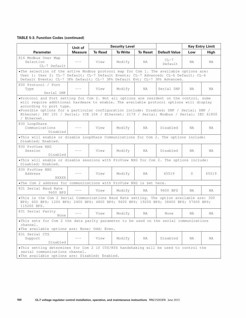
ParameterUnit of Measure
Security Level
Default Value
Key Entry Limit
To Read To Write To Reset Low High
816 Modbus User MapSelection
CL-7 Default--- View Modify NA CL-7
Default NA NA
• The selection of the active Modbus protocol map for Com 1. The available options are: User 1; User 2; CL-7 Default; CL-7 Default Events; CL-7 Advanced; CL-6 Default; CL-6 Default Events; CL-7 3Ph Default; CL-7 3Ph Default Evt; CL-7 3Ph Advanced.
830 Protocol / PortType
Serial DNP--- View Modify NA Serial DNP NA NA
• Protocol and Port setting for Com 2. Not all options are resident on the control, some will require additional hardware to enable. The available protocol options will display according to port type.• Possible options for a particular configuration include: Disabled; DNP / Serial; DNP / Ethernet; IEC 101 / Serial; ICE 104 / Ethernet; 2179 / Serial; Modbus / Serial; IEC 61850 / Ethernet.
830 LoopShareCommunications
Disabled--- View Modify NA Disabled NA NA
• This will enable or disable LoopShare Communications for Com 2. The options include: Disabled; Enabled.
830 ProView NXGSession
Disabled--- View Modify NA Disabled NA NA
• This will enable or disable sessions with ProView NXG for Com 2. The options include: Disabled; Enabled.
830 ProView NXGAddress
XXXXX--- View Modify NA 65519 0 65519
• The Com 2 address for communications with ProView NXG is set here.
831 Serial Baud Rate9600 BPS --- View Modify NA 9600 BPS NA NA
• This is the Com 2 Serial Communications Baud Rate setting. The option available are: 300 BPS; 600 BPS; 1200 BPS; 2400 BPS; 4800 BPS; 9600 BPS; 19200 BPS; 38400 BPS; 57600 BPS; 115200 BPS.
831 Serial ParityNone --- View Modify NA None NA NA
• This sets for Com 2 the data parity parameter to be used on the serial communications channel.
• The available options are: None; Odd; Even.
831 Serial CTSSupport
Disabled--- View Modify NA Disabled NA NA
• This setting determines for Com 2 if CTS/RTS handshaking will be used to control the serial communications channel.
• The available options are: Disabled; Enabled.
TABLE 5-3. Function Codes (continued)
100 CL-7 voltage regulator control installation, operation, and maintenance instructions MN225003EN June 2015
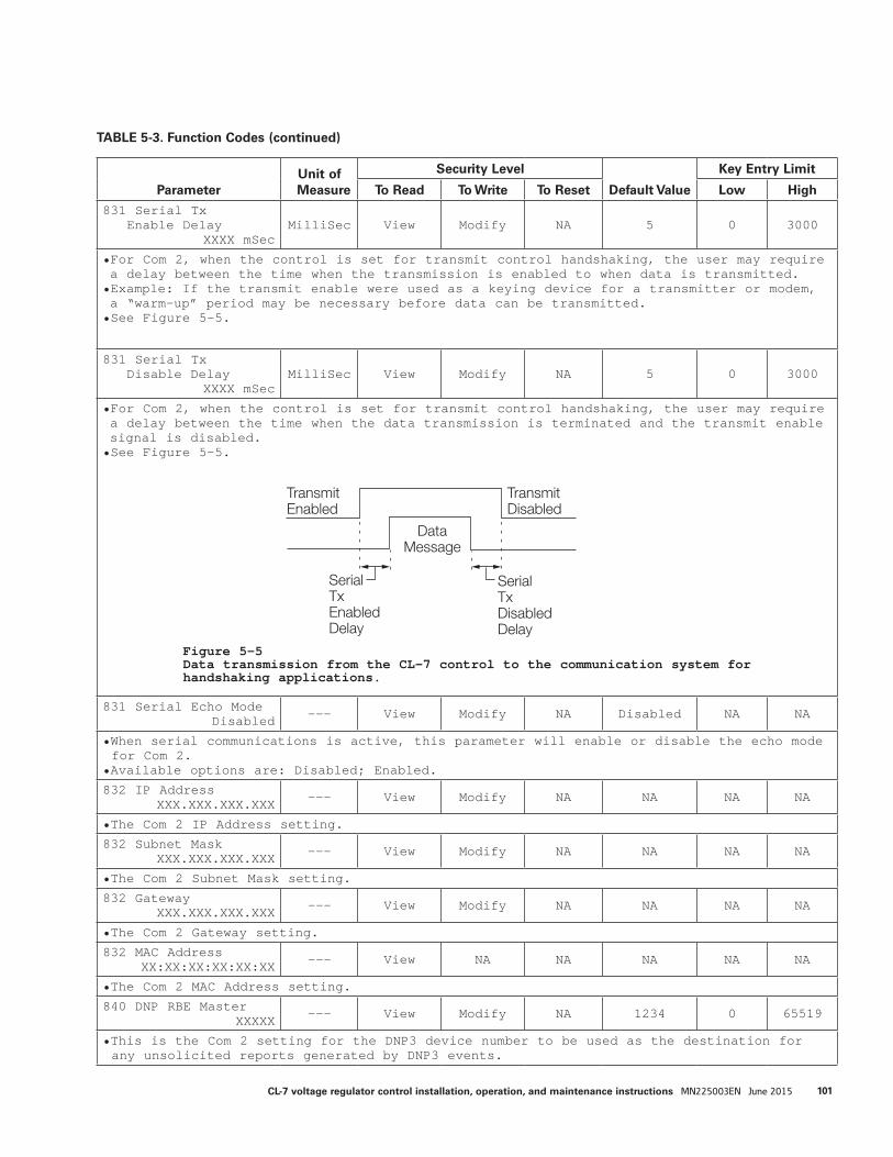
ParameterUnit of Measure
Security Level
Default Value
Key Entry Limit
To Read To Write To Reset Low High
831 Serial TxEnable Delay
XXXX mSecMilliSec View Modify NA 5 0 3000
• For Com 2, when the control is set for transmit control handshaking, the user may require a delay between the time when the transmission is enabled to when data is transmitted.• Example: If the transmit enable were used as a keying device for a transmitter or modem, a “warm-up” period may be necessary before data can be transmitted.• See Figure 5-5.
831 Serial TxDisable Delay
XXXX mSecMilliSec View Modify NA 5 0 3000
• For Com 2, when the control is set for transmit control handshaking, the user may require a delay between the time when the data transmission is terminated and the transmit enable signal is disabled.• See Figure 5-5.
831 Serial Echo ModeDisabled --- View Modify NA Disabled NA NA
• When serial communications is active, this parameter will enable or disable the echo mode for Com 2.
• Available options are: Disabled; Enabled.
832 IP AddressXXX.XXX.XXX.XXX --- View Modify NA NA NA NA
• The Com 2 IP Address setting.
832 Subnet MaskXXX.XXX.XXX.XXX --- View Modify NA NA NA NA
• The Com 2 Subnet Mask setting.
832 GatewayXXX.XXX.XXX.XXX --- View Modify NA NA NA NA
• The Com 2 Gateway setting.
832 MAC AddressXX:XX:XX:XX:XX:XX --- View NA NA NA NA NA
• The Com 2 MAC Address setting.
840 DNP RBE MasterXXXXX --- View Modify NA 1234 0 65519
• This is the Com 2 setting for the DNP3 device number to be used as the destination for any unsolicited reports generated by DNP3 events.
TABLE 5-3. Function Codes (continued)
Figure 5-5Data transmission from the CL-7 control to the communication system for handshaking applications.
SerialTxEnabled Delay
TransmitDisabled
TransmitEnabled
DataMessage
SerialTxDisabled Delay
101CL-7 voltage regulator control installation, operation, and maintenance instructions MN225003EN June 2015
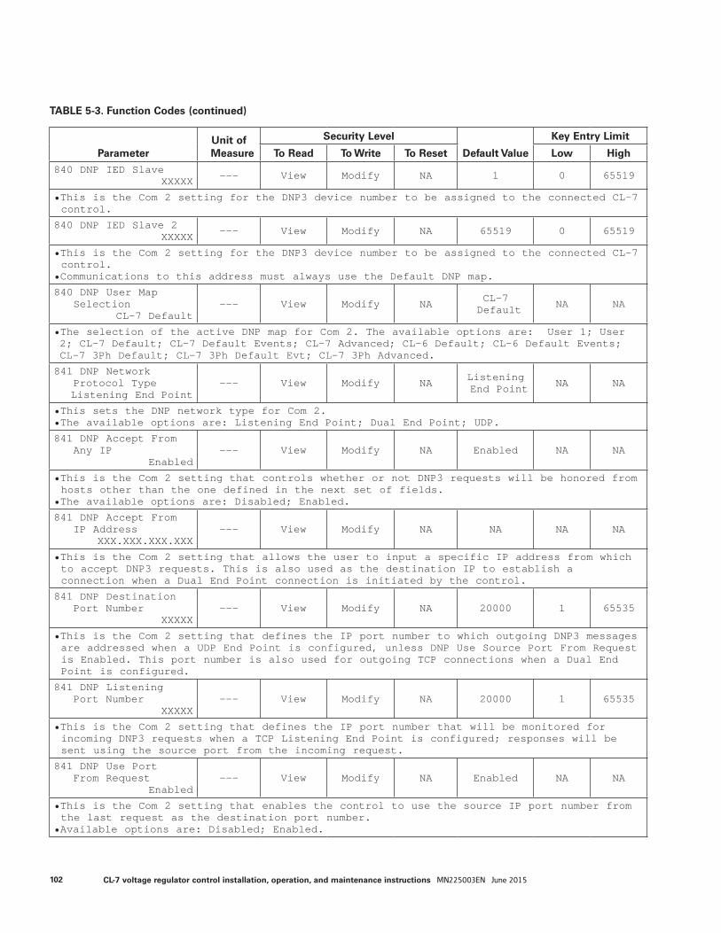
ParameterUnit of Measure
Security Level
Default Value
Key Entry Limit
To Read To Write To Reset Low High
840 DNP IED SlaveXXXXX --- View Modify NA 1 0 65519
• This is the Com 2 setting for the DNP3 device number to be assigned to the connected CL-7 control.
840 DNP IED Slave 2XXXXX --- View Modify NA 65519 0 65519
• This is the Com 2 setting for the DNP3 device number to be assigned to the connected CL-7 control.
• Communications to this address must always use the Default DNP map.
840 DNP User MapSelection
CL-7 Default--- View Modify NA CL-7
Default NA NA
• The selection of the active DNP map for Com 2. The available options are: User 1; User 2; CL-7 Default; CL-7 Default Events; CL-7 Advanced; CL-6 Default; CL-6 Default Events; CL-7 3Ph Default; CL-7 3Ph Default Evt; CL-7 3Ph Advanced.
841 DNP NetworkProtocol TypeListening End Point
--- View Modify NA Listening End Point NA NA
• This sets the DNP network type for Com 2.• The available options are: Listening End Point; Dual End Point; UDP.
841 DNP Accept FromAny IP
Enabled--- View Modify NA Enabled NA NA
• This is the Com 2 setting that controls whether or not DNP3 requests will be honored from hosts other than the one defined in the next set of fields.
• The available options are: Disabled; Enabled.
841 DNP Accept FromIP Address
XXX.XXX.XXX.XXX--- View Modify NA NA NA NA
• This is the Com 2 setting that allows the user to input a specific IP address from which to accept DNP3 requests. This is also used as the destination IP to establish a connection when a Dual End Point connection is initiated by the control.
841 DNP DestinationPort Number
XXXXX--- View Modify NA 20000 1 65535
• This is the Com 2 setting that defines the IP port number to which outgoing DNP3 messages are addressed when a UDP End Point is configured, unless DNP Use Source Port From Request is Enabled. This port number is also used for outgoing TCP connections when a Dual End Point is configured.
841 DNP ListeningPort Number
XXXXX--- View Modify NA 20000 1 65535
• This is the Com 2 setting that defines the IP port number that will be monitored for incoming DNP3 requests when a TCP Listening End Point is configured; responses will be sent using the source port from the incoming request.
841 DNP Use PortFrom Request
Enabled--- View Modify NA Enabled NA NA
• This is the Com 2 setting that enables the control to use the source IP port number from the last request as the destination port number.
• Available options are: Disabled; Enabled.
TABLE 5-3. Function Codes (continued)
102 CL-7 voltage regulator control installation, operation, and maintenance instructions MN225003EN June 2015
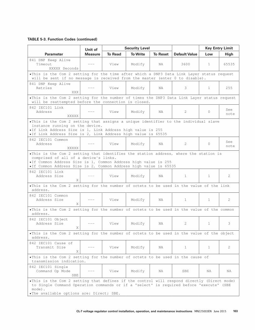
ParameterUnit of Measure
Security Level
Default Value
Key Entry Limit
To Read To Write To Reset Low High
841 DNP Keep AliveTimeout
XXXXX Seconds--- View Modify NA 3600 1 65535
• This is the Com 2 setting for the time after which a DNP3 Data Link Layer status request will be sent if no message is received from the master (enter 0 to disable).
841 DNP Keep AliveRetries
XXX--- View Modify NA 3 1 255
• This is the Com 2 setting for the number of times the DNP3 Data Link Layer status request will be reattempted before the connection is closed.
842 IEC101 LinkAddress
XXXXX--- View Modify NA 2 0 See
note
• This is the Com 2 setting that assigns a unique identifier to the individual slave instance running on the device.
• If Link Address Size is 1, Link Address high value is 255• If Link Address Size is 2, Link Address high value is 65535
842 IEC101 CommonAddress
XXXXX--- View Modify NA 2 0 See
note
• This is the Com 2 setting that identifies the station address, where the station is comprised of all of a device's links.
• If Common Address Size is 1, Common Address high value is 255• If Common Address Size is 2, Common Address high value is 65535
842 IEC101 LinkAddress Size
X--- View Modify NA 1 1 2
• This is the Com 2 setting for the number of octets to be used in the value of the link address.
842 IEC101 CommonAddress Size
X--- View Modify NA 1 1 2
• This is the Com 2 setting for the number of octets to be used in the value of the common address.
842 IEC101 ObjectAddress Size
X--- View Modify NA 2 1 3
• This is the Com 2 setting for the number of octets to be used in the value of the object address.
842 IEC101 Cause ofTransmit Size
X--- View Modify NA 1 1 2
• This is the Com 2 setting for the number of octets to be used in the cause of transmission indication.
842 IEC101 SingleCommand Op Mode
SBE--- View Modify NA SBE NA NA
• This is the Com 2 setting that defines if the control will respond directly (Direct mode) to Single Command Operation commands or if a "select" is required before "execute" (SBE mode).
• The available options are: Direct; SBE.
TABLE 5-3. Function Codes (continued)
103CL-7 voltage regulator control installation, operation, and maintenance instructions MN225003EN June 2015

ParameterUnit of Measure
Security Level
Default Value
Key Entry Limit
To Read To Write To Reset Low High
842 IEC101 SelectBefore Exec Time
XXXXX mSecMilliSec View Modify NA 5000 0 65535
• This is the Com 2 setting that determines the amount of time that can elapse between a "select" and "execute" command for Single Command Operations in systems that employ a select-before-execute mode.
842 IEC101 User MapSelection
CL-7 Default--- View Modify NA CL-7
Default NA NA
• The selection of the active IEC101 map for Com 2. The available options are: User 1; User 2; CL-7 Default; CL-7 Default Events; CL-7 Advanced; CL-6 Default; CL-6 Default Events; CL-7 3Ph Default; CL-7 3Ph Default Evt; CL-7 3Ph Advanced.
843 IEC104 ServerListen Port
XXXXX--- View Modify NA 2404 1 65535
• This is the Com 2 setting for the IP port number that will be monitored for connections.
843 IEC104 CommonAddress
XXXXX--- View Modify NA 2 1 65535
• This is the Com 2 setting that identifies the station address, where the station is comprised of all of a device's links.
843 IEC104 SingleCommand Op Mode
SBE--- View Modify NA SBE NA NA
• This is the Com 2 setting that defines if the control will respond directly (Direct mode) to Single Command Operation commands or if a "select" is required before "execution" (SBE mode).
• The available options are: Direct; SBE.
843 IEC104 SelectBefore Exec Time
XXXXX mSecMilliSec View Modify NA 5000 0 65535
• This is the Com 2 setting that determines the amount of time that can elapse between a "select" and "execute" command for Single Command Operations in systems that employe a select-before-execute mode.
843 IEC104 ResponseTimeout (t1)
XXXXX SecondsSeconds View Modify NA 15 1 255
• This is the Com 2 setting for the time-out value for the transmission of data or test messages.
843 IEC104 Ack/NoData (t2)
XXXXX SecondsSeconds View Modify NA 10 1 255
• This is the Com 2 setting for a time-out before sending an ACK APDU if no data ACKs are received.
843 IEC104 IdleTest (t3)
XXXXX SecondsSeconds View Modify NA 20 1 255
• This is the Com 2 setting for the amount of time allowed to lapse before a test APDU is generated.
TABLE 5-3. Function Codes (continued)
104 CL-7 voltage regulator control installation, operation, and maintenance instructions MN225003EN June 2015
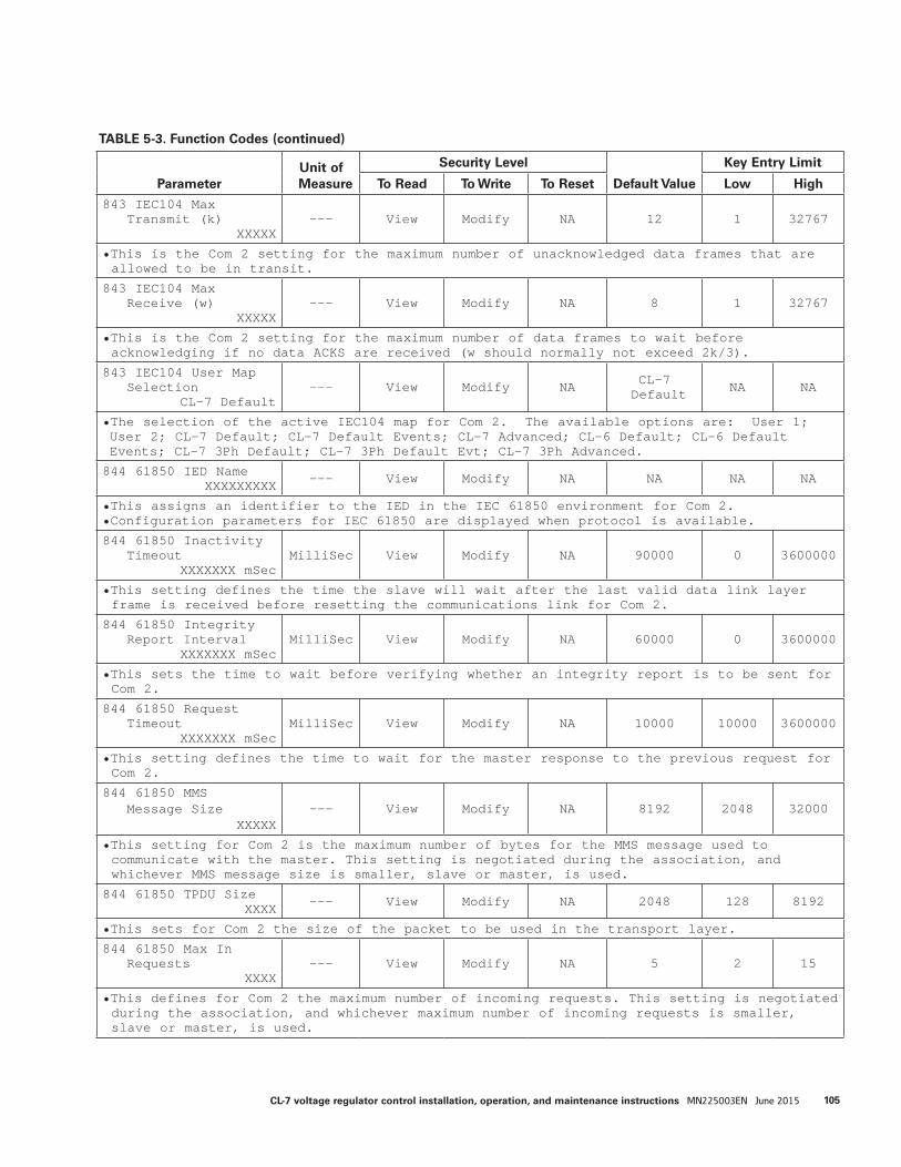
TABLE 5-3. Function Codes (continued)
ParameterUnit of Measure
Security Level
Default Value
Key Entry Limit
To Read To Write To Reset Low High
843 IEC104 MaxTransmit (k)
XXXXX--- View Modify NA 12 1 32767
• This is the Com 2 setting for the maximum number of unacknowledged data frames that are allowed to be in transit.
843 IEC104 MaxReceive (w)
XXXXX--- View Modify NA 8 1 32767
• This is the Com 2 setting for the maximum number of data frames to wait before acknowledging if no data ACKS are received (w should normally not exceed 2k/3).
843 IEC104 User MapSelection
CL-7 Default--- View Modify NA CL-7
Default NA NA
• The selection of the active IEC104 map for Com 2. The available options are: User 1; User 2; CL-7 Default; CL-7 Default Events; CL-7 Advanced; CL-6 Default; CL-6 Default Events; CL-7 3Ph Default; CL-7 3Ph Default Evt; CL-7 3Ph Advanced.
844 61850 IED NameXXXXXXXXX --- View Modify NA NA NA NA
• This assigns an identifier to the IED in the IEC 61850 environment for Com 2.• Configuration parameters for IEC 61850 are displayed when protocol is available.
844 61850 InactivityTimeout
XXXXXXX mSecMilliSec View Modify NA 90000 0 3600000
• This setting defines the time the slave will wait after the last valid data link layer frame is received before resetting the communications link for Com 2.
844 61850 IntegrityReport Interval
XXXXXXX mSecMilliSec View Modify NA 60000 0 3600000
• This sets the time to wait before verifying whether an integrity report is to be sent for Com 2.
844 61850 RequestTimeout
XXXXXXX mSecMilliSec View Modify NA 10000 10000 3600000
• This setting defines the time to wait for the master response to the previous request for Com 2.
844 61850 MMSMessage Size
XXXXX--- View Modify NA 8192 2048 32000
• This setting for Com 2 is the maximum number of bytes for the MMS message used to communicate with the master. This setting is negotiated during the association, and whichever MMS message size is smaller, slave or master, is used.
844 61850 TPDU SizeXXXX --- View Modify NA 2048 128 8192
• This sets for Com 2 the size of the packet to be used in the transport layer.
844 61850 Max InRequests
XXXX--- View Modify NA 5 2 15
• This defines for Com 2 the maximum number of incoming requests. This setting is negotiated during the association, and whichever maximum number of incoming requests is smaller, slave or master, is used.
105CL-7 voltage regulator control installation, operation, and maintenance instructions MN225003EN June 2015
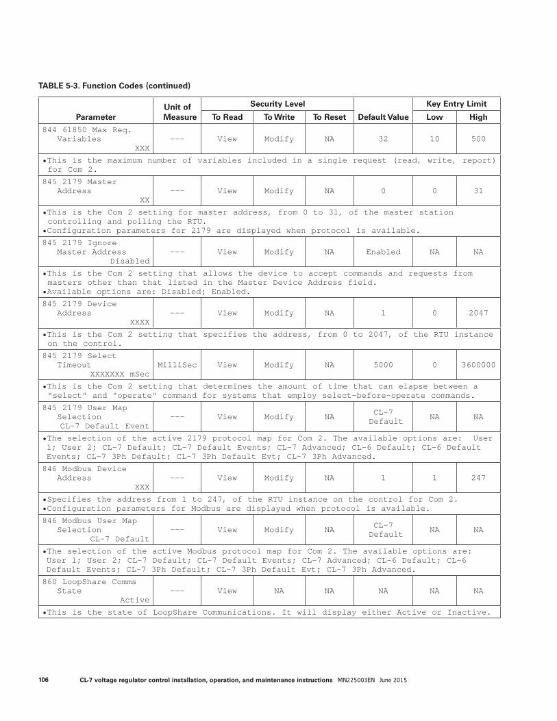
ParameterUnit of Measure
Security Level
Default Value
Key Entry Limit
To Read To Write To Reset Low High
844 61850 Max Req.Variables
XXX--- View Modify NA 32 10 500
• This is the maximum number of variables included in a single request (read, write, report) for Com 2.
845 2179 MasterAddress
XX--- View Modify NA 0 0 31
• This is the Com 2 setting for master address, from 0 to 31, of the master station controlling and polling the RTU.
• Configuration parameters for 2179 are displayed when protocol is available.
845 2179 IgnoreMaster Address
Disabled--- View Modify NA Enabled NA NA
• This is the Com 2 setting that allows the device to accept commands and requests from masters other than that listed in the Master Device Address field.
• Available options are: Disabled; Enabled.
845 2179 DeviceAddress
XXXX--- View Modify NA 1 0 2047
• This is the Com 2 setting that specifies the address, from 0 to 2047, of the RTU instance on the control.
845 2179 SelectTimeout
XXXXXXX mSecMilliSec View Modify NA 5000 0 3600000
• This is the Com 2 setting that determines the amount of time that can elapse between a "select" and "operate" command for systems that employ select-before-operate commands.
845 2179 User MapSelectionCL-7 Default Event
--- View Modify NA CL-7 Default NA NA
• The selection of the active 2179 protocol map for Com 2. The available options are: User 1; User 2; CL-7 Default; CL-7 Default Events; CL-7 Advanced; CL-6 Default; CL-6 Default Events; CL-7 3Ph Default; CL-7 3Ph Default Evt; CL-7 3Ph Advanced.
846 Modbus DeviceAddress
XXX--- View Modify NA 1 1 247
• Specifies the address from 1 to 247, of the RTU instance on the control for Com 2.• Configuration parameters for Modbus are displayed when protocol is available.
846 Modbus User MapSelection
CL-7 Default--- View Modify NA CL-7
Default NA NA
• The selection of the active Modbus protocol map for Com 2. The available options are: User 1; User 2; CL-7 Default; CL-7 Default Events; CL-7 Advanced; CL-6 Default; CL-6 Default Events; CL-7 3Ph Default; CL-7 3Ph Default Evt; CL-7 3Ph Advanced.
860 LoopShare CommsState
Active--- View NA NA NA NA NA
• This is the state of LoopShare Communications. It will display either Active or Inactive.
TABLE 5-3. Function Codes (continued)
106 CL-7 voltage regulator control installation, operation, and maintenance instructions MN225003EN June 2015
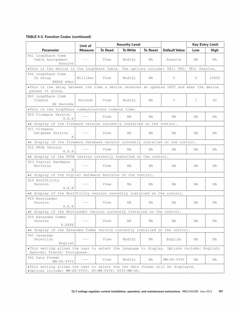
ParameterUnit of Measure
Security Level
Default Value
Key Entry Limit
To Read To Write To Reset Low High
861 LoopShare CommTable Assignment
Passive--- View Modify NA Passive NA NA
• This is the device in the LoopShare Table. The options include: VR1; VR2; VR3; Passive.
862 LoopShare CommTx Delay
XXXXX mSecMilliSec View Modify NA 0 0 10000
• This is the delay between the time a device receives an updated LFDT and when the device passes it along.
863 LoopShare CommTimeout
XX SecondsSeconds View Modify NA 3 1 60
• This is the LoopShare communications timeout time.
920 Firmware VersionX.X.X --- View NA NA NA NA NA
• A display of the firmware version currently installed on the control.
921 FirmwareDatabase Version
X--- View NA NA NA NA NA
• A display of the firmware Database version currently installed on the control.
922 FPGA VersionX.X.X --- View NA NA NA NA NA
• A display of the FPGA version currently installed on the control.
923 Digital HardwareRevision
X--- View NA NA NA NA NA
• A display of the Digital Hardware Revision of the control.
924 BootUtilityVersion
X.X.X--- View NA NA NA NA NA
• A display of the BootUtility version currently installed on the control.
925 BootLoaderVersion
X.X.X--- View NA NA NA NA NA
• A display of the BootLoader version currently installed on the control.
926 Extended CommsVersion
X.XXXX--- View NA NA NA NA NA
• A display of the Extended Comms version currently installed on the control.
941 LanguageSelection
English--- View Modify NA English NA NA
• This setting allows the user to select the language to display. Options include: English; Spanish; French; Portuguese.
942 Date FormatMM-DD-YYYY --- View Modify NA MM-DD-YYYY NA NA
• This setting allows the user to select how the date format will be displayed. • Options include: MM-DD-YYYY; DD-MM-YYYY; YYYY-MM-DD.
TABLE 5-3. Function Codes (continued)
107CL-7 voltage regulator control installation, operation, and maintenance instructions MN225003EN June 2015

ParameterUnit of Measure
Security Level
Default Value
Key Entry Limit
To Read To Write To Reset Low High
943 Time Format12 Hour AM/PM --- View Modify NA 12 Hour
AM/PM NA NA
• This setting allows the user to select whether time will be displayed on the 12-hour or the 24-hour scale. Options include: 12 Hour AM/PM; 24 Hour.
944 Key MappingSelection
Cl-7 Advanced--- View Modify NA CL-7
Advanced NA NA
• This setting allows for the selection of one of the preprogrammed keypad mapping configurations or to select the custom user option. The options are: CL-7 Advanced; CL-7 Basic; Standard Platform; Custom User.• To program the Custom User option, ProView NXG Software must be used.
950 USB Memory DriveSave All Data --- View View NA NA NA NA
• This is a command to write control data to a USB memory device. Refer to the Advanced Features: USB Memory Device section of this manual.
950 USB Memory DriveSave Custom All --- View View NA NA NA NA
• This command saves all settings from a control onto a USB memory device. Using the custom option will include the control ID in the file name as a default.
950 USB Memory DriveSave Cust Basic --- View View NA NA NA NA
• This command saves the group of settings defined as the Basic settings from a control onto a USB memory device. Using the custom option will include the control ID in the file name as a default.
950 USB Memory DriveSave Custom Alt --- View View NA NA NA NA
• This command saves the group of settings defined as the Alternate Configuration settings from a control onto a USB memory device. Using the custom option will include the control ID in the file name as a default.
950 USB Memory DriveSave Custom Adv --- View View NA NA NA NA
• This command saves the group of settings defined as the Advanced Features settings from a control onto a USB memory device. Using the custom option will include the control ID in the file name as a default.
950 USB Memory DriveSave Custom Comm --- View View NA NA NA NA
• This command saves the group of settings defined as Communications settings from a control onto a USB memory device. Using the custom option will include the control ID in the file name as a default.
950 USB Memory DriveSave Std All --- View View NA NA NA NA
• This command saves all settings from a control onto a USB memory device. Using the Standard option will include the word “Standard” in the file name as a default.
950 USB Memory DriveSave Std Basic --- View View NA NA NA NA
• This command saves the group of settings defined as the Basic settings from a control onto a USB memory device. Using the Standard option will include the word “Standard” in the file name as a default.
TABLE 5-3. Function Codes (continued)
108 CL-7 voltage regulator control installation, operation, and maintenance instructions MN225003EN June 2015
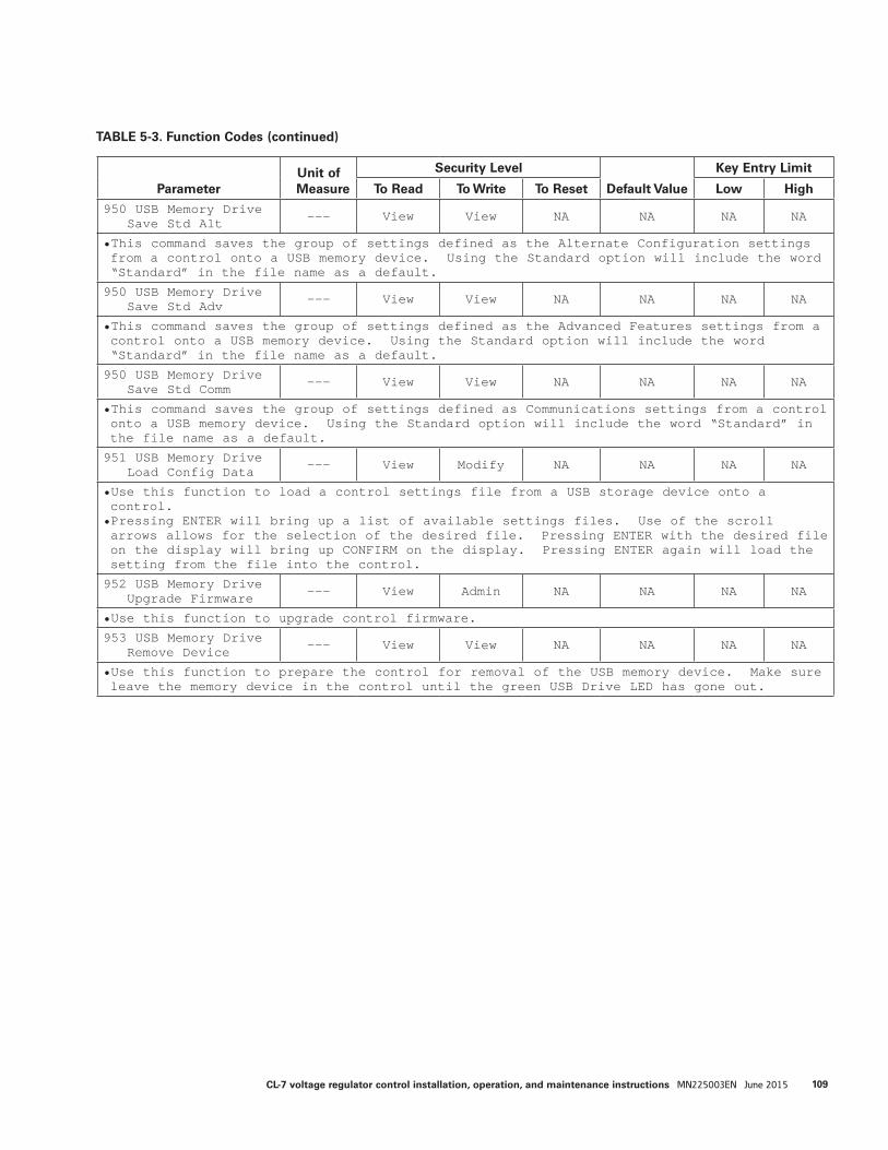
ParameterUnit of Measure
Security Level
Default Value
Key Entry Limit
To Read To Write To Reset Low High
950 USB Memory DriveSave Std Alt --- View View NA NA NA NA
• This command saves the group of settings defined as the Alternate Configuration settings from a control onto a USB memory device. Using the Standard option will include the word “Standard” in the file name as a default.
950 USB Memory DriveSave Std Adv --- View View NA NA NA NA
• This command saves the group of settings defined as the Advanced Features settings from a control onto a USB memory device. Using the Standard option will include the word “Standard” in the file name as a default.
950 USB Memory DriveSave Std Comm --- View View NA NA NA NA
• This command saves the group of settings defined as Communications settings from a control onto a USB memory device. Using the Standard option will include the word “Standard” in the file name as a default.
951 USB Memory DriveLoad Config Data --- View Modify NA NA NA NA
• Use this function to load a control settings file from a USB storage device onto a control.• Pressing ENTER will bring up a list of available settings files. Use of the scroll arrows allows for the selection of the desired file. Pressing ENTER with the desired file on the display will bring up CONFIRM on the display. Pressing ENTER again will load the setting from the file into the control.
952 USB Memory DriveUpgrade Firmware --- View Admin NA NA NA NA
• Use this function to upgrade control firmware.
953 USB Memory DriveRemove Device --- View View NA NA NA NA
• Use this function to prepare the control for removal of the USB memory device. Make sure leave the memory device in the control until the green USB Drive LED has gone out.
TABLE 5-3. Function Codes (continued)
109CL-7 voltage regulator control installation, operation, and maintenance instructions MN225003EN June 2015
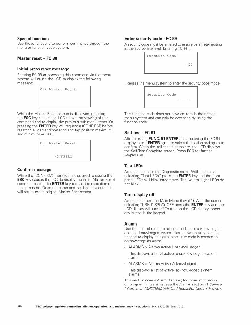
Special functionsUse these functions to perform commands through the menu or function code system.
Master reset – FC 38
Initial press reset messageEntering FC 38 or accessing this command via the menu system will cause the LCD to display the following message:
While the Master Reset screen is displayed, pressing the ESC key causes the LCD to exit the viewing of this command and to display the previous sub-menu items. Or, pressing the ENTER key will request a (CONFIRM) before resetting all demand metering and tap position maximum and minimum values.
Confirm messageWhile the (CONFIRM) message is displayed: pressing the ESC key causes the LCD to display the initial Master Reset screen; pressing the ENTER key causes the execution of the command. Once the command has been executed, it will return to the original Master Rest screen.
Enter security code - FC 99A security code must be entered to enable parameter editing at the appropriate level. Entering FC 99...
...causes the menu system to enter the security code mode:
This function code does not have an item in the nested-menu system and can only be accessed by using the function code.
Self-test - FC 91After pressing FUNC, 91 ENTER and accessing the FC 91 display, press ENTER again to select the option and again to confirm. When the self-test is complete, the LCD displays the Self-Test Complete screen. Press ESC for further keypad use.
Test LEDsAccess this under the Diagnostic menu. With the cursor selecting “Test LEDs” press the ENTER key and the front panel LEDs will blink three times. The Neutral Light LEDs do not blink.
Turn display offAccess this from the Main Menu (Level 1). With the cursor selecting TURN DISPLAY OFF press the ENTER key and the LCD display will turn off. To turn on the LCD display, press any button in the keypad.
AlarmsUse the nested menu to access the lists of acknowledged and unacknowledged system alarms. No security code is needed to display an alarm; a security code is needed to acknowledge an alarm.
• ALARMS > Alarms Active Unacknowledged
This displays a list of active, unacknowledged system alarms.
• ALARMS > Alarms Active Acknowledged
This displays a list of active, acknowledged system alarms.
This section covers Alarm displays; for more information on programming alarms, see the Alarms section of Service Information MN2258015EN CL-7 Regulator Control ProView
038 Master Reset
038 Master Reset
(CONFIRM)
Function Code
_99
Security Code -------
110 CL-7 voltage regulator control installation, operation, and maintenance instructions MN225003EN June 2015

NXG Software Programming Guide.
If there are no unacknowledged active alarms available, the
LCD displays the following message:
If there are no acknowledged active alarms available, the
LCD displays the following message:
An actual alarm display example:
Status and data alarmsFor a complete list and descriptions of the available Status and Data Alarms section of Service Information MN2258015EN CL-7 Regulator Control ProView NXG Software Programming Guide.
Instantaneous metering and counter quantitiesFor most Instantaneous Metering quantities, there are two data alarms available: One that can be triggered for a high threshold value and one that can be triggered for a low threshold value. For counter quantities, there will be only one data alarm that will be triggered for a high threshold.
Maintenance quantitiesSee the Advanced Features: Duty Cycle Monitor section of this manual for more information on these alarms.
• Contact Life Level 1 Exceeded
• Contact Life Level 2 Exceeded
Sequence of events (SOE)Use the Sequence of Events menu item to access a list of events. No security code is needed to display events; a security code is needed to acknowledge an event.
This section covers displaying the SOE; for more information on programming SOE and a complete list of available events, see the Sequence of Events section of Service Information MN2258015EN CL-7 Regulator Control ProView NXG Software Programming Guide.
The event labels can use 2 LCD lines for a total of up to 40 characters.
If there are no events available, the LCD displays the following message:
An SOE example:
When accessed through the keypad, only the last 50 events will be displayed. If there are many events (100+) that have not been read via the front panel, it may take a few seconds. While this is occurring the following message, indicating that events are being read, may appear before displaying the latest events:
No UnacknowledgedActive Alarms
No AcknowledgedActive Alarms
Supervisory State Active 01/25/2013 11:35:58a
(MORE...) VR1 Control SwitchAuto/Remote01/25/2013 11:35:58a
(MORE...)
There Are No Events.
Events...
111CL-7 voltage regulator control installation, operation, and maintenance instructions MN225003EN June 2015
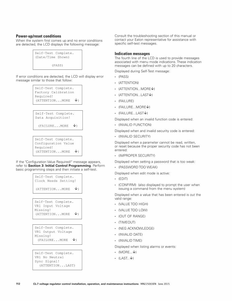
Power-up/reset conditionsWhen the system first comes up and no error conditions are detected, the LCD displays the following message:
If error conditions are detected, the LCD will display error message similar to those that follow:
If the "Configuration Value Required!" message appears, refer to Section 3: Initial Control Programming. Perform basic programming steps and then initiate a self-test.
Consult the troubleshooting section of this manual or contact your Eaton representative for assistance with specific self-test messages.
Indication messagesThe fourth line of the LCD is used to provide messages associated with menu mode indications. These indication messages can be defined with up to 20 characters.
Displayed during Self-Test message:
• (PASS)
• (ATTENTION)
• (ATTENTION...MORE)
• (ATTENTION...LAST)
• (FAILURE)
• (FAILURE...MORE)
• (FAILURE...LAST)
Displayed when an invalid function code is entered:
• (INVALID FUNCTION)
Displayed when and invalid security code is entered:
• (INVALID SECURITY)
Displayed when a parameter cannot be read, written, or reset because the proper security code has not been entered:
• (IMPROPER SECURITY)
Displayed when setting a password that is too weak:
• (PASSWORD TOO WEAK)
Displayed when edit mode is active:
• (EDIT)
• (CONFIRM) (also displayed to prompt the user when issuing a command from the menu system)
Displayed when a value that has been entered is out the valid range:
• (VALUE TOO HIGH)
• (VALUE TOO LOW)
• (OUT OF RANGE)
• (TIMEOUT)
• (NEG ACKNOWLEDGE)
• (INVALID DATE)
• (INVALID TIME)
Displayed when listing alarms or events:
• (MORE...)
• (LAST...)
Self-Test Complete. (Date/Time Shown)
(PASS)
Self-Test Complete. Configuration Value Required!(ATTENTION...MORE )
Self-Test Complete. Factory Calibration Required!(ATTENTION...MORE )
Self-Test Complete. Data Acquisition!
(FAILURE...MORE )
Self-Test Complete. Clock Needs Setting!
(ATTENTION...MORE )
Self-Test Complete.VR1 Input VoltageMissing!(ATTENTION...MORE )
Self-Test Complete.VR1 Output Voltage Missing!(FAILURE...MORE )
Self-Test Complete. VR1 No Neutral Sync Signal!
(ATTENTION...LAST)
112 CL-7 voltage regulator control installation, operation, and maintenance instructions MN225003EN June 2015
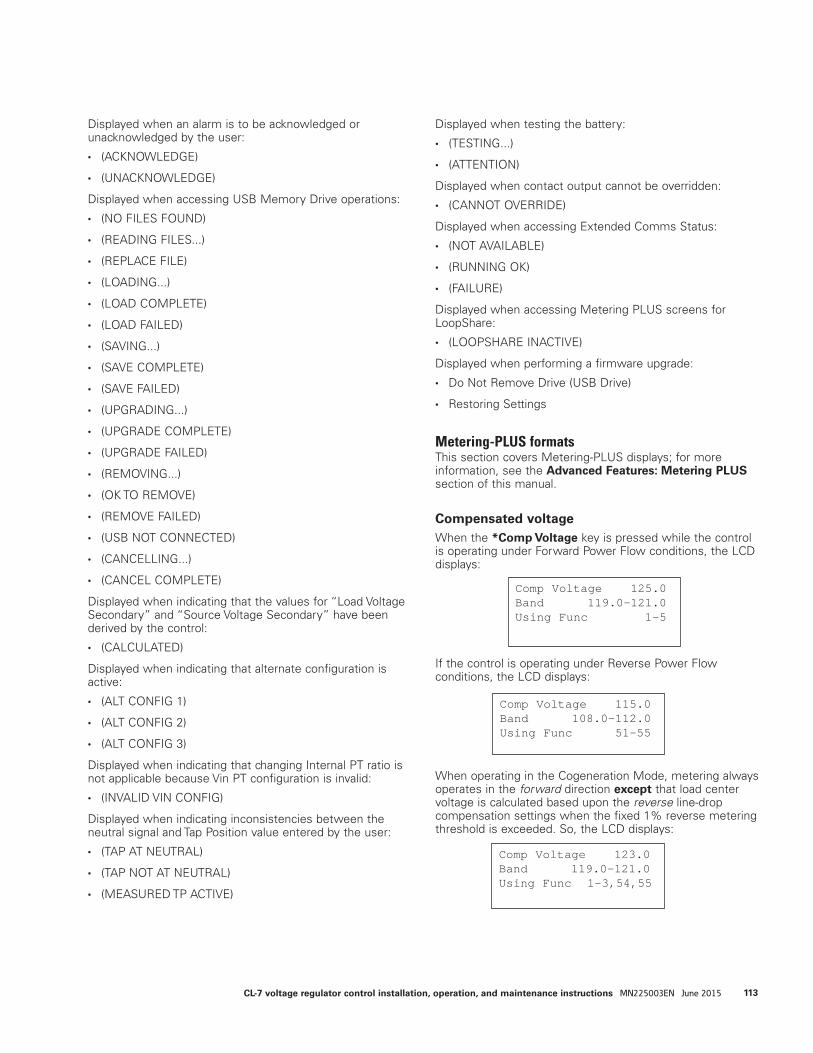
Displayed when an alarm is to be acknowledged or unacknowledged by the user:
• (ACKNOWLEDGE)
• (UNACKNOWLEDGE)
Displayed when accessing USB Memory Drive operations:
• (NO FILES FOUND)
• (READING FILES...)
• (REPLACE FILE)
• (LOADING...)
• (LOAD COMPLETE)
• (LOAD FAILED)
• (SAVING...)
• (SAVE COMPLETE)
• (SAVE FAILED)
• (UPGRADING...)
• (UPGRADE COMPLETE)
• (UPGRADE FAILED)
• (REMOVING...)
• (OK TO REMOVE)
• (REMOVE FAILED)
• (USB NOT CONNECTED)
• (CANCELLING...)
• (CANCEL COMPLETE)
Displayed when indicating that the values for “Load Voltage Secondary” and “Source Voltage Secondary” have been derived by the control:
• (CALCULATED)
Displayed when indicating that alternate configuration is active:
• (ALT CONFIG 1)
• (ALT CONFIG 2)
• (ALT CONFIG 3)
Displayed when indicating that changing Internal PT ratio is not applicable because Vin PT configuration is invalid:
• (INVALID VIN CONFIG)
Displayed when indicating inconsistencies between the neutral signal and Tap Position value entered by the user:
• (TAP AT NEUTRAL)
• (TAP NOT AT NEUTRAL)
• (MEASURED TP ACTIVE)
Displayed when testing the battery:
• (TESTING...)
• (ATTENTION)
Displayed when contact output cannot be overridden:
• (CANNOT OVERRIDE)
Displayed when accessing Extended Comms Status:
• (NOT AVAILABLE)
• (RUNNING OK)
• (FAILURE)
Displayed when accessing Metering PLUS screens for LoopShare:
• (LOOPSHARE INACTIVE)
Displayed when performing a firmware upgrade:
• Do Not Remove Drive (USB Drive)
• Restoring Settings
Metering-PLUS formatsThis section covers Metering-PLUS displays; for more information, see the Advanced Features: Metering PLUS section of this manual.
Compensated voltageWhen the *Comp Voltage key is pressed while the control is operating under Forward Power Flow conditions, the LCD displays:
If the control is operating under Reverse Power Flow conditions, the LCD displays:
When operating in the Cogeneration Mode, metering always operates in the forward direction except that load center voltage is calculated based upon the reverse line-drop compensation settings when the fixed 1% reverse metering threshold is exceeded. So, the LCD displays:
Comp Voltage 125.0 Band 119.0-121.0 Using Func 1-5
Comp Voltage 115.0 Band 108.0-112.0 Using Func 51-55
Comp Voltage 123.0 Band 119.0-121.0 Using Func 1-3,54,55
113CL-7 voltage regulator control installation, operation, and maintenance instructions MN225003EN June 2015
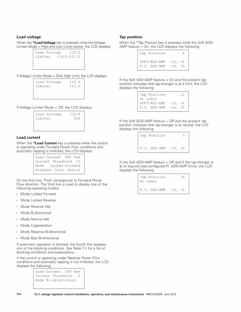
Load voltageWhen the *Load Voltage key is pressed while the Voltage Limiter Mode = High and Low Limits Active, the LCD displays:
If Voltage Limiter Mode = Only High Limit, the LCD displays:
If Voltage Limiter Mode = Off, the LCD displays:
Load currentWhen the *Load Current key is pressed while the control is operating under Forward Power Flow conditions and automatic tapping is inhibited, the LCD displays:
On the first line, "Fwd" corresponds to Forward Power Flow direction. The third line is used to display one of the following operating modes:
• Mode Locked Forward
• Mode Locked Reverse
• Mode Reverse Idle
• Mode Bi-directional
• Mode Neutral Idle
• Mode Cogeneration
• Mode Reactive Bi-directional
• Mode Bias Bi-directional
If automatic operation is blocked, the fourth line displays one of the blocking conditions. See Table 7-1 for a list of blocking conditions and explanations.
If the control is operating under Reverse Power Flow conditions and automatic tapping is not inhibited, the LCD displays the following:
Tap positionWhen the *Tap Position key is pressed while the Soft ADD-AMP feature = On, the LCD displays the following:
If the Soft ADD-AMP feature = On and the present tap position indicates that tap-changer is at a limit, the LCD displays the following:
If the Soft ADD-AMP feature = Off and the present tap position indicates that tap-changer is at neutral, the LCD displays the following:
If the Soft ADD-AMP feature = Off and if the tap-changer is at or beyond user-configured P.I. ADD-AMP limits, the LCD displays the following:
Tap Position 0
P.I. ADD-AMP -14, 16
Tap Position 16 At Limit
P.I. ADD-AMP -14, 16
Tap Position 8
SOFT-ADD-AMP -12, 14 P.I. ADD-AMP -14, 16
Tap Position - 12 At Limit SOFT-ADD-AMP -12, 14 P.I. ADD-AMP -14, 16
Load Current 200 Rev Current Threshold 2 Mode Bi-directional
Load Current 600 Fwd Current Threshold 12 Mode Locked Forward Blocked: Cntrl Switch
Load Voltage 115.0 Limiter Off
Load Voltage 115.0Limiter 119.0-121.0
Load Voltage 115.0 Limiter 121.0
114 CL-7 voltage regulator control installation, operation, and maintenance instructions MN225003EN June 2015
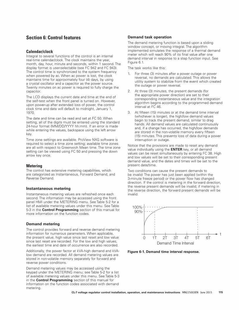
Section 6: Control features
Calendar/clockIntegral to several functions of the control is an internal real-time calendar/clock. The clock maintains the year, month, day, hour, minute and seconds, within 1 second. The display format is user-selectable (see FC 942 and FC 943). The control time is synchronized to the system frequency when powered by ac. When ac power is lost, the clock maintains time for approximately four (4) days, by using a crystal oscillator and a capacitor as the power source. Twenty minutes on ac power is required to fully charge the capacitor.
The LCD displays the current date and time at the end of the self-test when the front panel is turned on. However, upon power-up after extended loss of power, the control clock time and date will default to midnight, January 1, 1970.
The date and time can be read and set at FC 50. When setting, all of the digits must be entered using the standard 24-hour format (MM/DD/YYYY hh:mm). If an error is made while entering the values, backspace using the left arrow key.
Time zone settings are available. ProView NXG software is required to select a time zone setting; available time zones are all with respect to Greenwich Mean time. The time zone setting can be viewed using FC 50 and pressing the down arrow key once.
MeteringThe control has extensive metering capabilities, which are categorized as Instantaneous, Forward Demand, and Reverse Demand.
Instantaneous meteringInstantaneous metering values are refreshed once each second. The information may be accessed using the front panel HMI under the METERING menu. See Table 5-2 for a list of available metering values under this menu. See Table 5-3 in the Control Programming section of this manual for more information on the function codes.
Demand meteringThe control provides forward and reverse demand metering information for numerous parameters. When applicable, the present value, high value since last reset and low value since last reset are recorded. For the low and high values, the earliest time and date of occurrence are also recorded.
Additionally, the power factor at kVA-high demand and kVA-low demand are recorded. All demand metering values are stored in non-volatile memory separately for forward and reverse power conditions.
Demand metering values may be accessed using the keypad under the METERING menu; see Table 5-2 for a list of available metering values under this menu. See Table 5-3 in the Control Programming section of this manual for information on the function codes associated with demand metering.
Demand task operationThe demand metering function is based upon a sliding window concept, or moving integral. The algorithm implemented simulates the response of a thermal demand meter which will reach 90% of its final value after one demand interval in response to a step function input. See Figure 6.1.
The task works like this:
1. For three (3) minutes after a power outage or power reversal, no demands are calculated. This allows the utility system to stabilize from the event which created the outage or power reversal.
2. At three (3) minutes, the present demands (for the appropriate power direction) are set to their corresponding instantaneous value and the integration algorithm begins according to the programmed demand interval at FC 46.
3. At fifteen (15) minutes or at the demand time interval (whichever is longer), the high/low demand values begin to track the present demand, similar to drag hands. All demand values are calculated continuously and, if a change has occurred, the high/low demands are stored in the non-volatile memory every fifteen (15) minutes. This prevents loss of data during a power interruption or outage.
Notice that the provisions are made to reset any demand value individually using the ENTER key, or all demand values can be reset simultaneously by entering FC 38. High and low values will be set to their corresponding present demand value, and the dates and times will be set to the present date/time.
Two conditions can cause the present demands to be invalid: The power has just been applied (within the 3-minute freeze period) or the power flow has changed direction. If the control is metering in the forward direction, the reverse present demands will be invalid; if metering in the reverse direction, the forward present demands will be invalid.
100%90%
6T0 1T 2T 3T 4T 5TDemand Time Interval
t
Figure 6-1. Demand time interval response.
115CL-7 voltage regulator control installation, operation, and maintenance instructions MN225003EN June 2015
Tap position indication (TPI)The control has the ability to track the position of the tap-changer. The TPI function senses the status of the motor and neutral light circuits and does not require source (input) voltage. The present tap position is stored at FC 12.
EXAMPLES: “8” at FC 12 indicates 8 raise and “-7” indicates 7 lower.
The TPI function is synchronized to the position of the tap-changer by running the regulator to the neutral position. To manually set the present tap position: Access Admin security level; access FC 12; use the EDIT key to change to the desired value.
The maximum tap position since last reset (upper drag-hand value of the present tap position) and its date and time are stored at FC 27. The minimum tap position since last reset (lower drag hand value of the present tap position) and its date and time are stored at FC 28.
The TPI drag hand values and dates/times are reset to the present values by the master reset, FC 38, or by resetting each of the values individually. The drag hand reset switch resets the drag hands of the position indicator only, not TPI. All TPI values are stored in non-volatile memory.
The following conditions could occur if the present tap position was manually set incorrectly:
• The present tap position value will go to invalid “---” if the present tap position is 0 (zero, neutral) but no neutral signal is detected. For example, this condition will occur if a replacement control with present tap position set to “0” is installed on a regulator which is not in the neutral position.
• If the TPI function detects a successful upward tap and the prior value of FC 12 was “16”, or a successful down-ward tap is detected and the prior value of FC 12 was “–16,” the prior value will be maintained.
The display will show a diagnostic error message upon power-up when: (1) the present tap position value prior to power-up is “---” (invalid) and the regulator is not in neutral position; (2) The present tap position prior to power-up is “0” and the regulator is not in the neutral position. [This condition will cause the present tap position value to go to invalid (“----”)]; and (3) During automatic or manual operation the present tap position changes to “0”, but a neutral signal is not received. The No Neutral Sync signal is an attention signal, not a failure signal.
The TPI will satisfy the diagnostics routine upon power-up when: (1) The regulator is in neutral and the present tap position is “0”; (2) The present tap position is not “0” and the regulator is not in neutral, including when the tap position is not set correctly; and (3) When the regulator is in neutral and the present tap position is not “0” (TPI will self-correct and reset the tap position).
Source-side voltageWithout a source voltage input, some functions will indicate dashes when displayed. There are three methods for supplying a source-side voltage to the CL-7 control: an Internal Differential Potential Transformer (IDPT), an external source-side PT, or source-side voltage calculation.
Differential voltageThe voltage regulator may be designed and ordered with an Internal Differential PT (IDPT). The IDPT will be included in the schematic on the voltage regulator nameplate and labeled Series Winding Potential Transformer. An IDPT supplies the voltage difference between the source and load bushings of the voltage regulator. This differential voltage is then combined with the load voltage to provide the source-side voltage. When using an IDPT on an Eaton's Cooper Power series voltage regulator, the source voltage accuracy is within ± 1%.
As a standard, a second ratio correction transformer (RCT2) is not supplied on regulators equipped with an IDPT. The control will use the internal PT ratio entered at FC 44 and the input voltage from the IDPT to determine the differential voltage between the source and the load bushings. The setting at FC 146 must be set to Vdiff without RCT2 for this configuration.
If an RCT2 is supplied, the Overall PT Ratio entered at FC 44 and the input voltage from the IDPT are used to determine the differential voltage. The setting at FC 146 must be set to Vdiff with RCT2 for this configuration.
External source voltageAn external source-side PT may be connected to the voltage regulator to supply a directly measured source voltage. To use an external source-side PT, the user must change Vin PT Configuration, FC 146, from the default Vdiff without RCT2 to Vin Mode. Using an external source-side PT may be desirable if the voltage regulators are in a closed-delta configuration. In a closed delta, the source voltage and percent regulation will only reflect the true system source values if an external source voltage is used. Voltage regulator performance is not affected by the difference between metering parameters when using an external source PT: the accuracy of the source voltage is dependent upon the accuracy of the PT.
Source-side voltage calculationThe CL-7 control has the ability to calculate the source-side voltage without an IDPT or an external PT. When this feature is turned on at FC 39, the control will use the load voltage from the main PT, the regulator type (Type A, Type B, Type C or Type D), the tap position, and the internal impedance of the regulator to calculate the source-side voltage. This calculated source voltage is accurate to within ±1.5%. Only the regulator type needs to be programmed into the control; the other values are already available.
116 CL-7 voltage regulator control installation, operation, and maintenance instructions MN225003EN June 2015
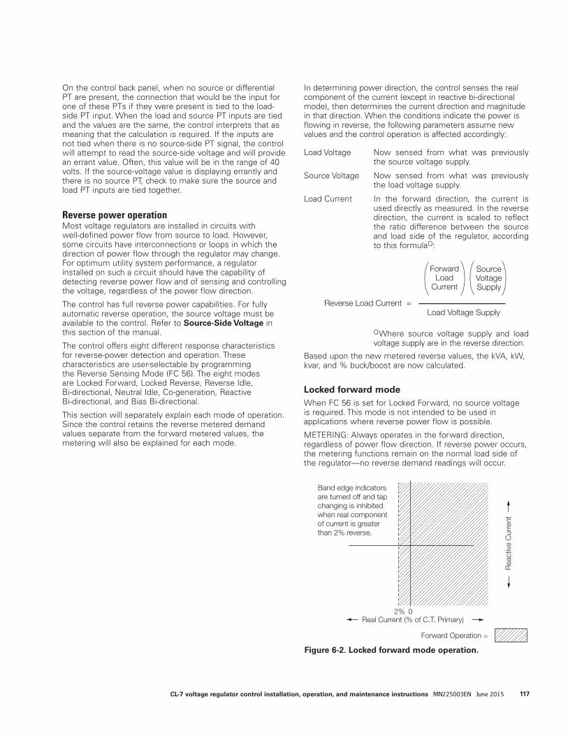
On the control back panel, when no source or differential PT are present, the connection that would be the input for one of these PTs if they were present is tied to the load-side PT input. When the load and source PT inputs are tied and the values are the same, the control interprets that as meaning that the calculation is required. If the inputs are not tied when there is no source-side PT signal, the control will attempt to read the source-side voltage and will provide an errant value. Often, this value will be in the range of 40 volts. If the source-voltage value is displaying errantly and there is no source PT, check to make sure the source and load PT inputs are tied together.
Reverse power operationMost voltage regulators are installed in circuits with well-defined power flow from source to load. However, some circuits have interconnections or loops in which the direction of power flow through the regulator may change. For optimum utility system performance, a regulator installed on such a circuit should have the capability of detecting reverse power flow and of sensing and controlling the voltage, regardless of the power flow direction.
The control has full reverse power capabilities. For fully automatic reverse operation, the source voltage must be available to the control. Refer to Source-Side Voltage in this section of the manual.
The control offers eight different response characteristics for reverse-power detection and operation. These characteristics are user-selectable by programming the Reverse Sensing Mode (FC 56). The eight modes are Locked Forward, Locked Reverse, Reverse Idle, Bi-directional, Neutral Idle, Co-generation, Reactive Bi-directional, and Bias Bi-directional.
This section will separately explain each mode of operation. Since the control retains the reverse metered demand values separate from the forward metered values, the metering will also be explained for each mode.
In determining power direction, the control senses the real component of the current (except in reactive bi-directional mode), then determines the current direction and magnitude in that direction. When the conditions indicate the power is flowing in reverse, the following parameters assume new values and the control operation is affected accordingly:
Load Voltage Now sensed from what was previously the source voltage supply.
Source Voltage Now sensed from what was previously the load voltage supply.
Load Current In the forward direction, the current is used directly as measured. In the reverse direction, the current is scaled to reflect the ratio difference between the source and load side of the regulator, according to this formulaQ:
QWhere source voltage supply and load voltage supply are in the reverse direction.
Based upon the new metered reverse values, the kVA, kW, kvar, and % buck/boost are now calculated.
Locked forward modeWhen FC 56 is set for Locked Forward, no source voltage is required. This mode is not intended to be used in applications where reverse power flow is possible.
METERING: Always operates in the forward direction, regardless of power flow direction. If reverse power occurs, the metering functions remain on the normal load side of the regulator—no reverse demand readings will occur.
Rea
ctiv
e C
urre
nt
Real Current (% of C.T. Primary)
Forward Operation =
2% 0
Band edge indicatorsare turned off and tap changing is inhibited when real componentof current is greater than 2% reverse.
Reverse Load Current =Load Voltage Supply
ForwardLoad
Current
SourceVoltageSupply
Figure 6-2. Locked forward mode operation.
117CL-7 voltage regulator control installation, operation, and maintenance instructions MN225003EN June 2015

OPERATION: (Figure 6-2) Always operates in the forward direction using the forward settings at FC 1, FC 2, FC 3, FC 4, and FC 5. This allows operation down to zero current conditions since there is no forward threshold involved. A safeguard has been built into the control to prevent misoperation in the event reverse power flow does occur. If more than 2% (.004 A CT secondary) reverse current occurs, the control idles on the last tap position held and the band edge indicators will turn off. As the current flow returns to a level above this reverse threshold, normal forward operation resumes.
Locked reverse modeWhen FC 56 is set for Locked Reverse, source voltage is required. This mode is not intended to be used in applications where forward power flow is possible.
METERING: Always operates in the reverse direction, regardless of power flow direction. If forward power occurs, the metering functions remain on the source (S bushing) side of the regulator and no forward demand readings will occur.
OPERATION: (Figure 6-3) Always operates in the reverse direction using the reverse settings at FC 51, FC 52, FC 53, FC 54, and FC 55. This allows operation down to zero current conditions since there is no reverse threshold involved. A safeguard has been built into the control to prevent misoperation in the event forward power flow does occur. If more than 2% (.004 A CT secondary) forward current occurs, the control idles on the last tap position held and the band edge indicators will turn off. As the current flow returns to a level above this forward threshold, normal reverse operation resumes.
Reverse idle mode
When FC 56 is set for Reverse Idle, a source voltage is required for metering only. This mode is recommended for installation where reverse power flow may occur, but a source voltage is not available.
METERING: (Figure 6-4.) A threshold level of 1% (.002 A) of the full load CT secondary current of .200 A is used in setting the power direction. The metering will be forward until the current exceeds the 1% threshold in the reverse direction. At this time, the various parameters use the reverse settings and the Reverse Power indicator turns on. The control continues meter-ing in reverse until the current exceeds the 1% thresh-old in the forward direction, and then the parameter scaling reverts back to normal and the Reverse Power indicator turns off.
Rea
ctiv
e C
urre
nt
Real Current (% of C.T. Primary)
Reverse =
2%0
Figure 6-4. Reverse idle metering.
Normal ForwardMetering
Rev Pwr Off
Reverse MeteringReverse Scaling
Rev Pwr On
Current Level1% 0 1%
Figure 6-3. Locked reverse mode operation.
118 CL-7 voltage regulator control installation, operation, and maintenance instructions MN225003EN June 2015
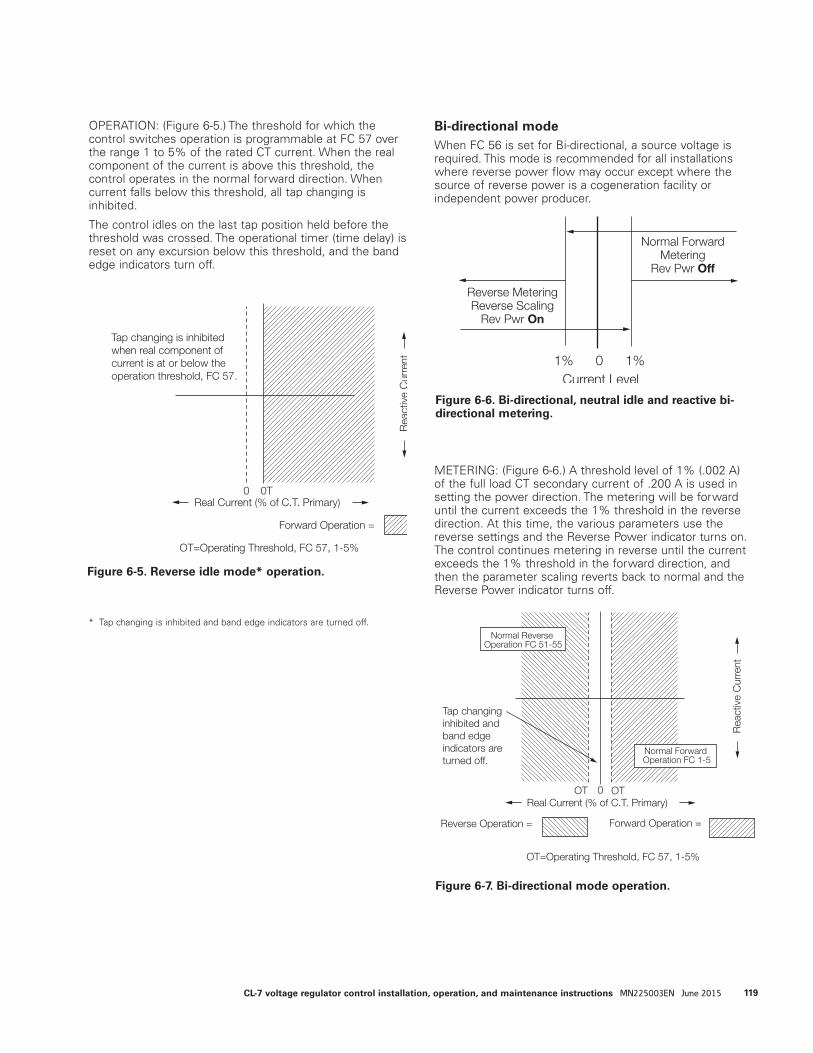
OPERATION: (Figure 6-5.) The threshold for which the control switches operation is programmable at FC 57 over the range 1 to 5% of the rated CT current. When the real component of the current is above this threshold, the control operates in the normal forward direction. When current falls below this threshold, all tap changing is inhibited.
The control idles on the last tap position held before the threshold was crossed. The operational timer (time delay) is reset on any excursion below this threshold, and the band edge indicators turn off.
Bi-directional mode When FC 56 is set for Bi-directional, a source voltage is required. This mode is recommended for all installations where reverse power flow may occur except where the source of reverse power is a cogeneration facility or independent power producer.
METERING: (Figure 6-6.) A threshold level of 1% (.002 A) of the full load CT secondary current of .200 A is used in setting the power direction. The metering will be forward until the current exceeds the 1% threshold in the reverse direction. At this time, the various parameters use the reverse settings and the Reverse Power indicator turns on. The control continues metering in reverse until the current exceeds the 1% threshold in the forward direction, and then the parameter scaling reverts back to normal and the Reverse Power indicator turns off.
Figure 6-6. Bi-directional, neutral idle and reactive bi-directional metering.
Normal ForwardMetering
Rev Pwr Off
Reverse MeteringReverse Scaling
Rev Pwr On
Current Level1% 0 1%
Figure 6-7. Bi-directional mode operation.
Rea
ctiv
e C
urre
nt
Real Current (% of C.T. Primary)
Forward Operation =
0 OT
OT=Operating Threshold, FC 57, 1-5%
Tap changing inhibited and band edge indicators are turned off.
Reverse Operation =
OT
Normal Reverse Operation FC 51-55
Normal Forward Operation FC 1-5
Figure 6-5. Reverse idle mode* operation.
Rea
ctiv
e C
urre
nt
Real Current (% of C.T. Primary)
Forward Operation =
0 0T
OT=Operating Threshold, FC 57, 1-5%
Tap changing is inhibited when real component of current is at or below the operation threshold, FC 57.
* Tap changing is inhibited and band edge indicators are turned off.
119CL-7 voltage regulator control installation, operation, and maintenance instructions MN225003EN June 2015
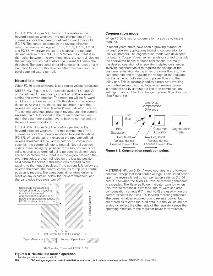
OPERATION: (Figure 6-7.)The control operates in the forward direction whenever the real component of the current is above the operator defined forward threshold (FC 57). The control operates in the reverse direction, using the reverse settings at FC 51, FC 52, FC 53, FC 54, and FC 55, whenever the current is above the operator defined reverse threshold (FC 57). When the current is in the region between the two thresholds, the control idles on the last tap position held before the current fell below the threshold. The operational timer (time delay) is reset on any excursion below the threshold in either direction, and the band edge indicators turn off.
Neutral idle modeWhen FC 56 is set to Neutral Idle, a source voltage is required.
METERING: (Figure 6-6) A threshold level of 1% (.002 A) of the full load CT secondary current of .200 A is used in setting the power direction. The metering will be forward until the current exceeds the 1% threshold in the reverse direction. At this time, the various parameters use the reverse settings and the Reverse Power indicator turns on. The control continues metering in reverse until the current exceeds the 1% threshold in the forward direction, and then the parameter scaling reverts back to normal and the Reverse Power indicator turns off.
OPERATION: (Figure 6-8) The control operates in the forward direction whenever the real component of the current is above the operation-defined forward threshold (FC 57). When the current exceeds the operator-defined reverse threshold (FC 57) and is held for 10 continuous seconds, the control will tap to neutral. Neutral position is determined using tap position. If the tap position is not valid, neutral is determined using percent regulation (buck and boost). When the current is in the region between the two thresholds, the control idles on the last tap position held before the forward threshold was crossed. While tapping to the neutral position, if the current falls below the reverse threshold, the control continues to tap until neutral position is reached. The operational timer (time delay) is reset on any excursion below the forward threshold, and the band edge indicators turn off.
Cogeneration modeWhen FC 56 is set for cogeneration, a source voltage is required.
In recent years, there have been a growing number of voltage regulator applications involving cogeneration by utility customers. The cogeneration mode was developed for Eaton's Cooper Power series regulator control to satisfy the specialized needs of these applications. Normally, the desired operation of a regulator installed on a feeder involving cogeneration is to regulate the voltage at the customer substation during times of power flow into the customer site and to regulate the voltage at the regulator (on the same output side) during power flow into the utility grid. This is accomplished by simply not reversing the control sensing input voltage when reverse power is detected and by altering the line-drop compensation settings to account for this change in power flow direction. (See Figure 6-9.)
METERING: (Figure 6-10.) Always operates in the forward direction except that load center voltage is calculated based upon the reverse line-drop compensation settings (FC 54 and FC 55) when the fixed 1% reverse metering threshold is exceeded. The Reverse Power indicator turns on when this reverse threshold is crossed. The forward line-drop compensation settings (FC 4 and FC 5) are used when the current exceeds the fixed 1% forward metering threshold. The demand values acquired during reverse power flow are stored as reverse metered data, but the values are not scaled (to reflect the other side of the regulator) since the operating direction of the regulator never truly reverses.
Line-DropCompensation
Difference
RegulatedVoltage during
Forward Power Flow
RegulatedVoltage during
Reverse Power Flow
UtilitySubstation
CogenerationSite
CustomerSubstation
StiffBus
Figure 6-9. Cogeneration regulation points.
Figure 6-8. Neutral idle mode* operation.
Rea
ctiv
e C
urre
nt
Real Current (% of C.T. Primary)
Forward Operation =
0 OT
OT=Operating Threshold, FC 57, 1-5%
Band edge indicators are turned off and tap changing is inhibited when real component of current is at or below the operation threshold, FC 57, in either direction.
Tap-to-Neutral =
OT
* Band edge indicators are turned off.120 CL-7 voltage regulator control installation, operation, and maintenance instructions MN225003EN June 2015
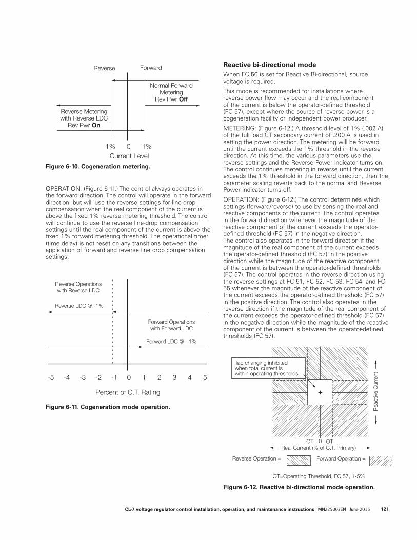
OPERATION: (Figure 6-11.) The control always operates in the forward direction. The control will operate in the forward direction, but will use the reverse settings for line-drop compensation when the real component of the current is above the fixed 1% reverse metering threshold. The control will continue to use the reverse line-drop compensation settings until the real component of the current is above the fixed 1% forward metering threshold. The operational timer (time delay) is not reset on any transitions between the application of forward and reverse line drop compensation settings.
Reactive bi-directional mode When FC 56 is set for Reactive Bi-directional, source voltage is required.
This mode is recommended for installations where reverse power flow may occur and the real component of the current is below the operator-defined threshold (FC 57), except where the source of reverse power is a cogeneration facility or independent power producer.
METERING: (Figure 6-12.) A threshold level of 1% (.002 A) of the full load CT secondary current of .200 A is used in setting the power direction. The metering will be forward until the current exceeds the 1% threshold in the reverse direction. At this time, the various parameters use the reverse settings and the Reverse Power indicator turns on. The control continues metering in reverse until the current exceeds the 1% threshold in the forward direction, then the parameter scaling reverts back to the normal and Reverse Power indicator turns off.
OPERATION: (Figure 6-12.) The control determines which settings (forward/reverse) to use by sensing the real and reactive components of the current. The control operates in the forward direction whenever the magnitude of the reactive component of the current exceeds the operator-defined threshold (FC 57) in the negative direction. The control also operates in the forward direction if the magnitude of the real component of the current exceeds the operator-defined threshold (FC 57) in the positive direction while the magnitude of the reactive component of the current is between the operator-defined thresholds (FC 57). The control operates in the reverse direction using the reverse settings at FC 51, FC 52, FC 53, FC 54, and FC 55 whenever the magnitude of the reactive component of the current exceeds the operator-defined threshold (FC 57) in the positive direction. The control also operates in the reverse direction if the magnitude of the real component of the current exceeds the operator-defined threshold (FC 57) in the negative direction while the magnitude of the reactive component of the current is between the operator-defined thresholds (FC 57).
Figure 6-12. Reactive bi-directional mode operation.
Rea
ctiv
e C
urre
nt
Real Current (% of C.T. Primary)
Forward Operation =
0 OT
OT=Operating Threshold, FC 57, 1-5%
Tap changing inhibited when total current is within operating thresholds.
Reverse Operation =
OT
+
Figure 6-10. Cogeneration metering.
Normal ForwardMetering
Rev Pwr Off
Reverse Meteringwith Reverse LDC
Rev Pwr On
Current Level1% 0 1%
Reverse Forward
Figure 6-11. Cogeneration mode operation.
-5 -4 -3 -2 -1 0 1 2 3 4 5
Reverse LDC @ -1%
Forward LDC @ +1%
Forward Operationswith Forward LDC
Percent of C.T. Rating
Reverse Operationswith Reverse LDC
121CL-7 voltage regulator control installation, operation, and maintenance instructions MN225003EN June 2015
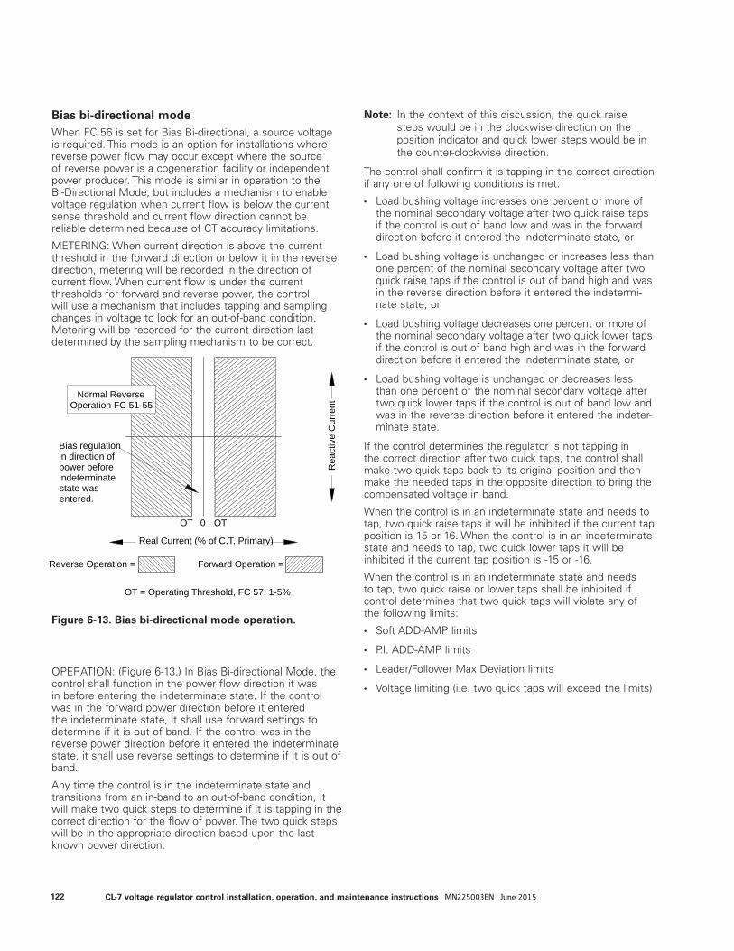
Bias bi-directional modeWhen FC 56 is set for Bias Bi-directional, a source voltage is required. This mode is an option for installations where reverse power flow may occur except where the source of reverse power is a cogeneration facility or independent power producer. This mode is similar in operation to the Bi-Directional Mode, but includes a mechanism to enable voltage regulation when current flow is below the current sense threshold and current flow direction cannot be reliable determined because of CT accuracy limitations.
METERING: When current direction is above the current threshold in the forward direction or below it in the reverse direction, metering will be recorded in the direction of current flow. When current flow is under the current thresholds for forward and reverse power, the control will use a mechanism that includes tapping and sampling changes in voltage to look for an out-of-band condition. Metering will be recorded for the current direction last determined by the sampling mechanism to be correct.
OPERATION: (Figure 6-13.) In Bias Bi-directional Mode, the control shall function in the power flow direction it was in before entering the indeterminate state. If the control was in the forward power direction before it entered the indeterminate state, it shall use forward settings to determine if it is out of band. If the control was in the reverse power direction before it entered the indeterminate state, it shall use reverse settings to determine if it is out of band.
Any time the control is in the indeterminate state and transitions from an in-band to an out-of-band condition, it will make two quick steps to determine if it is tapping in the correct direction for the flow of power. The two quick steps will be in the appropriate direction based upon the last known power direction.
ote:N In the context of this discussion, the quick raise steps would be in the clockwise direction on the position indicator and quick lower steps would be in the counter-clockwise direction.
The control shall confirm it is tapping in the correct direction if any one of following conditions is met:
• Load bushing voltage increases one percent or more of the nominal secondary voltage after two quick raise taps if the control is out of band low and was in the forward direction before it entered the indeterminate state, or
• Load bushing voltage is unchanged or increases less than one percent of the nominal secondary voltage after two quick raise taps if the control is out of band high and was in the reverse direction before it entered the indetermi-nate state, or
• Load bushing voltage decreases one percent or more of the nominal secondary voltage after two quick lower taps if the control is out of band high and was in the forward direction before it entered the indeterminate state, or
• Load bushing voltage is unchanged or decreases less than one percent of the nominal secondary voltage after two quick lower taps if the control is out of band low and was in the reverse direction before it entered the indeter-minate state.
If the control determines the regulator is not tapping in the correct direction after two quick taps, the control shall make two quick taps back to its original position and then make the needed taps in the opposite direction to bring the compensated voltage in band.
When the control is in an indeterminate state and needs to tap, two quick raise taps it will be inhibited if the current tap position is 15 or 16. When the control is in an indeterminate state and needs to tap, two quick lower taps it will be inhibited if the current tap position is -15 or -16.
When the control is in an indeterminate state and needs to tap, two quick raise or lower taps shall be inhibited if control determines that two quick taps will violate any of the following limits:
• Soft ADD-AMP limits
• P.I. ADD-AMP limits
• Leader/Follower Max Deviation limits
• Voltage limiting (i.e. two quick taps will exceed the limits)
Figure 6-13. Bias bi-directional mode operation.
Rea
ctiv
e C
urre
nt
Real Current (% of C.T. Primary)
Reverse Operation =
OT
Forward Operation =
OT = Operating Threshold, FC 57, 1-5%
OT 0
Bias regulationin direction of power before indeterminatestate was entered.
Normal ReverseOperation FC 51-55
122 CL-7 voltage regulator control installation, operation, and maintenance instructions MN225003EN June 2015
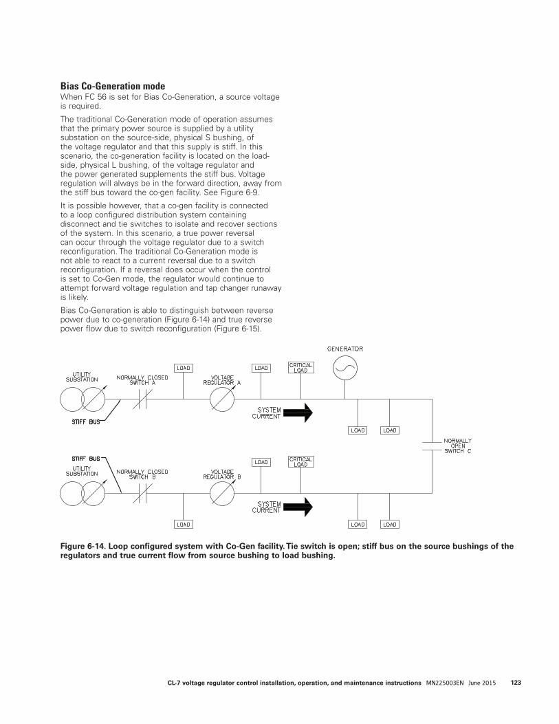
Bias Co-Generation modeWhen FC 56 is set for Bias Co-Generation, a source voltage is required.
The traditional Co-Generation mode of operation assumes that the primary power source is supplied by a utility substation on the source-side, physical S bushing, of the voltage regulator and that this supply is stiff. In this scenario, the co-generation facility is located on the load-side, physical L bushing, of the voltage regulator and the power generated supplements the stiff bus. Voltage regulation will always be in the forward direction, away from the stiff bus toward the co-gen facility. See Figure 6-9.
It is possible however, that a co-gen facility is connected to a loop configured distribution system containing disconnect and tie switches to isolate and recover sections of the system. In this scenario, a true power reversal can occur through the voltage regulator due to a switch reconfiguration. The traditional Co-Generation mode is not able to react to a current reversal due to a switch reconfiguration. If a reversal does occur when the control is set to Co-Gen mode, the regulator would continue to attempt forward voltage regulation and tap changer runaway is likely.
Bias Co-Generation is able to distinguish between reverse power due to co-generation (Figure 6-14) and true reverse power flow due to switch reconfiguration (Figure 6-15).
Figure 6-14. Loop configured system with Co-Gen facility. Tie switch is open; stiff bus on the source bushings of the regulators and true current flow from source bushing to load bushing.
123CL-7 voltage regulator control installation, operation, and maintenance instructions MN225003EN June 2015

Figure 6-15. Loop configured system with Co-Gen facility. Tie switch is closed. Stiff bus on the load bushing of volt-age regulator A with true current flow from load to source. Stiff bus on the source bushing of voltage regulator B with true current flow from source to load.
124 CL-7 voltage regulator control installation, operation, and maintenance instructions MN225003EN June 2015
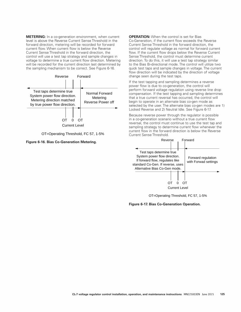
METERING: In a co-generation environment, when current level is above the Reverse Current Sense Threshold in the forward direction, metering will be recorded for forward current flow. When current flow is below the Reverse Current Sense Threshold in the forward direction, the control will use a test tap strategy and sample changes in voltage to determine a true current flow direction. Metering will be recorded for the current direction last determined by the sampling mechanism to be correct. See Figure 6-16.
OPERATION: When the control is set for Bias Co-Generation, if the current flow exceeds the Reverse Current Sense Threshold in the forward direction, the control will regulate voltage as normal for forward current flow. If the current flow drops below the Reverse Current Sense Threshold, the control must determine current direction. To do this, it will use a test tap strategy similar to the Bias Bi-directional mode. The control will utilize two quick test taps and sample changes in voltage. The current flow direction will be indicated by the direction of voltage change seen during the test taps.
If the test tapping and sampling determines a reverse power flow is due to co-generation, the control will perform forward voltage regulation using reverse line drop compensation. If the test tapping and sampling determines that a true current reversal has occurred, the control will begin to operate in an alternate bias co-gen mode as selected by the user. The alternate bias co-gen modes are 1) Locked Reverse and 2) Neutral Idle. See Figure 6-17.
Because reverse power through the regulator is possible in a co-generation scenario without a true current flow reversal, the control must continue to use the test tap and sampling strategy to determine current flow whenever the current flow in the forward direction is below the Reverse Current Sense Threshold.
Current LevelOTOT 0
Test taps determine trueSystem power flow direction.Metering direction matchedby true power flow direction.
Normal ForwardMetering
Reverse Power off
Reverse Forward
OT=Operating Threshold, FC 57, 1-5%
Current Level0
Test taps determine trueSystem power flow direction.If forward flow, regulates like
standard Co-Gen. If reverse, usesAlternative Bias Co-Gen mode.
Forward regulationwith Forwad settings
Reverse Forward
OTOT
OT=Operating Threshold, FC 57, 1-5%
Figure 6-16. Bias Co-Generation Metering.
Figure 6-17. Bias Co-Generation Operation.
125CL-7 voltage regulator control installation, operation, and maintenance instructions MN225003EN June 2015
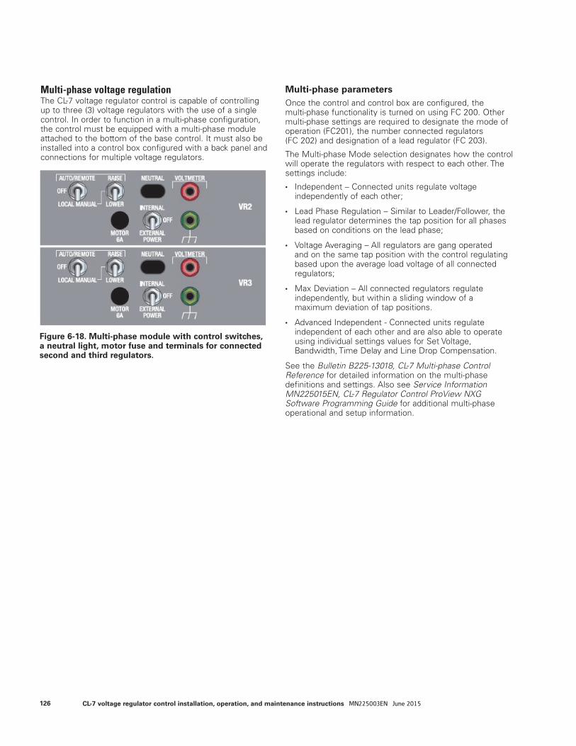
Multi-phase voltage regulationThe CL-7 voltage regulator control is capable of controlling up to three (3) voltage regulators with the use of a single control. In order to function in a multi-phase configuration, the control must be equipped with a multi-phase module attached to the bottom of the base control. It must also be installed into a control box configured with a back panel and connections for multiple voltage regulators.
Multi-phase parametersOnce the control and control box are configured, the multi-phase functionality is turned on using FC 200. Other multi-phase settings are required to designate the mode of operation (FC201), the number connected regulators (FC 202) and designation of a lead regulator (FC 203).
The Multi-phase Mode selection designates how the control will operate the regulators with respect to each other. The settings include:
• Independent – Connected units regulate voltage independently of each other;
• Lead Phase Regulation – Similar to Leader/Follower, the lead regulator determines the tap position for all phases based on conditions on the lead phase;
• Voltage Averaging – All regulators are gang operated and on the same tap position with the control regulating based upon the average load voltage of all connected regulators;
• Max Deviation – All connected regulators regulate independently, but within a sliding window of a maximum deviation of tap positions.
• Advanced Independent - Connected units regulate independent of each other and are also able to operate using individual settings values for Set Voltage, Bandwidth, Time Delay and Line Drop Compensation.
See the Bulletin B225-13018, CL-7 Multi-phase Control Reference for detailed information on the multi-phase definitions and settings. Also see Service Information MN225015EN, CL-7 Regulator Control ProView NXG Software Programming Guide for additional multi-phase operational and setup information.
Figure 6-18. Multi-phase module with control switches, a neutral light, motor fuse and terminals for connected second and third regulators.
126 CL-7 voltage regulator control installation, operation, and maintenance instructions MN225003EN June 2015
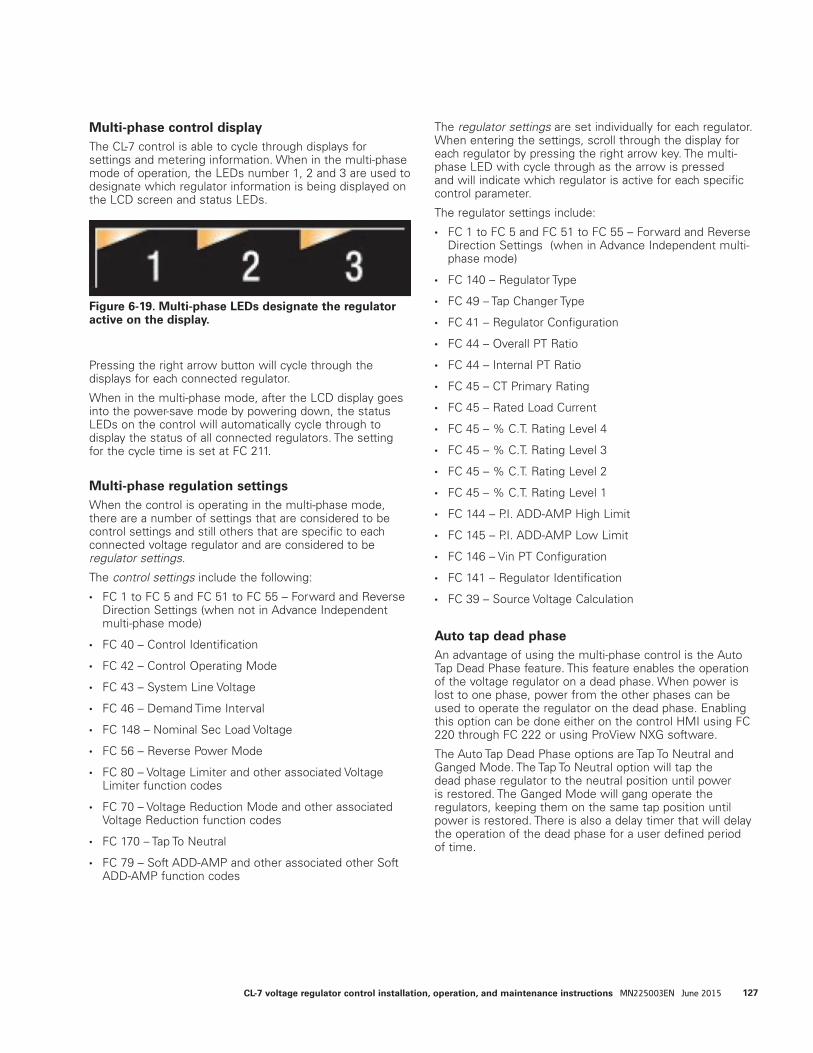
Multi-phase control displayThe CL-7 control is able to cycle through displays for settings and metering information. When in the multi-phase mode of operation, the LEDs number 1, 2 and 3 are used to designate which regulator information is being displayed on the LCD screen and status LEDs.
Pressing the right arrow button will cycle through the displays for each connected regulator.
When in the multi-phase mode, after the LCD display goes into the power-save mode by powering down, the status LEDs on the control will automatically cycle through to display the status of all connected regulators. The setting for the cycle time is set at FC 211.
Multi-phase regulation settingsWhen the control is operating in the multi-phase mode, there are a number of settings that are considered to be control settings and still others that are specific to each connected voltage regulator and are considered to be regulator settings.
The control settings include the following:
• FC 1 to FC 5 and FC 51 to FC 55 – Forward and Reverse Direction Settings (when not in Advance Independent multi-phase mode)
• FC 40 – Control Identification
• FC 42 – Control Operating Mode
• FC 43 – System Line Voltage
• FC 46 – Demand Time Interval
• FC 148 – Nominal Sec Load Voltage
• FC 56 – Reverse Power Mode
• FC 80 – Voltage Limiter and other associated Voltage Limiter function codes
• FC 70 – Voltage Reduction Mode and other associated Voltage Reduction function codes
• FC 170 – Tap To Neutral
• FC 79 – Soft ADD-AMP and other associated other Soft ADD-AMP function codes
The regulator settings are set individually for each regulator. When entering the settings, scroll through the display for each regulator by pressing the right arrow key. The multi-phase LED with cycle through as the arrow is pressed and will indicate which regulator is active for each specific control parameter.
The regulator settings include:
• FC 1 to FC 5 and FC 51 to FC 55 – Forward and Reverse Direction Settings (when in Advance Independent multi-phase mode)
• FC 140 – Regulator Type
• FC 49 – Tap Changer Type
• FC 41 – Regulator Configuration
• FC 44 – Overall PT Ratio
• FC 44 – Internal PT Ratio
• FC 45 – CT Primary Rating
• FC 45 – Rated Load Current
• FC 45 – % C.T. Rating Level 4
• FC 45 – % C.T. Rating Level 3
• FC 45 – % C.T. Rating Level 2
• FC 45 – % C.T. Rating Level 1
• FC 144 – P.I. ADD-AMP High Limit
• FC 145 – P.I. ADD-AMP Low Limit
• FC 146 – Vin PT Configuration
• FC 141 – Regulator Identification
• FC 39 – Source Voltage Calculation
Auto tap dead phaseAn advantage of using the multi-phase control is the Auto Tap Dead Phase feature. This feature enables the operation of the voltage regulator on a dead phase. When power is lost to one phase, power from the other phases can be used to operate the regulator on the dead phase. Enabling this option can be done either on the control HMI using FC 220 through FC 222 or using ProView NXG software.
The Auto Tap Dead Phase options are Tap To Neutral and Ganged Mode. The Tap To Neutral option will tap the dead phase regulator to the neutral position until power is restored. The Ganged Mode will gang operate the regulators, keeping them on the same tap position until power is restored. There is also a delay timer that will delay the operation of the dead phase for a user defined period of time.
Figure 6-19. Multi-phase LEDs designate the regulator active on the display.
127CL-7 voltage regulator control installation, operation, and maintenance instructions MN225003EN June 2015
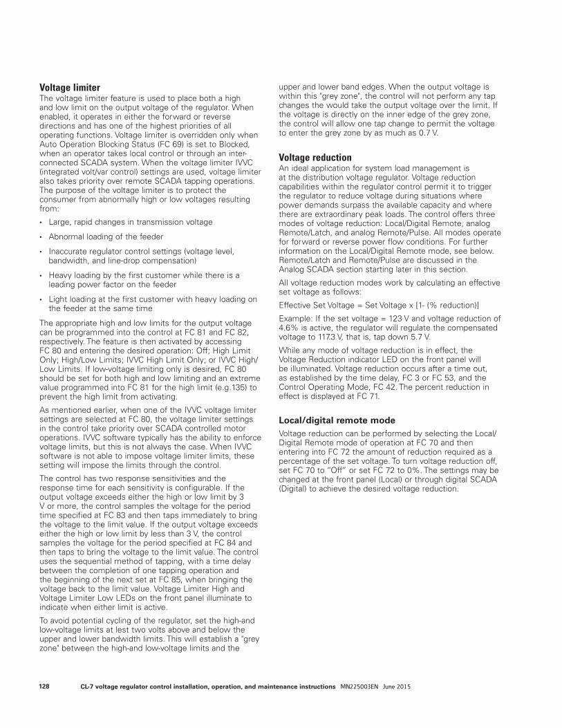
Voltage limiterThe voltage limiter feature is used to place both a high and low limit on the output voltage of the regulator. When enabled, it operates in either the forward or reverse directions and has one of the highest priorities of all operating functions. Voltage limiter is overridden only when Auto Operation Blocking Status (FC 69) is set to Blocked, when an operator takes local control or through an inter-connected SCADA system. When the voltage limiter IVVC (integrated volt/var control) settings are used, voltage limiter also takes priority over remote SCADA tapping operations. The purpose of the voltage limiter is to protect the consumer from abnormally high or low voltages resulting from:
• Large, rapid changes in transmission voltage
• Abnormal loading of the feeder
• Inaccurate regulator control settings (voltage level, bandwidth, and line-drop compensation)
• Heavy loading by the first customer while there is a leading power factor on the feeder
• Light loading at the first customer with heavy loading on the feeder at the same time
The appropriate high and low limits for the output voltage can be programmed into the control at FC 81 and FC 82, respectively. The feature is then activated by accessing FC 80 and entering the desired operation: Off; High Limit Only; High/Low Limits; IVVC High Limit Only; or IVVC High/Low Limits. If low-voltage limiting only is desired, FC 80 should be set for both high and low limiting and an extreme value programmed into FC 81 for the high limit (e.g.135) to prevent the high limit from activating.
As mentioned earlier, when one of the IVVC voltage limiter settings are selected at FC 80, the voltage limiter settings in the control take priority over SCADA controlled motor operations. IVVC software typically has the ability to enforce voltage limits, but this is not always the case. When IVVC software is not able to impose voltage limiter limits, these setting will impose the limits through the control.
The control has two response sensitivities and the response time for each sensitivity is configurable. If the output voltage exceeds either the high or low limit by 3 V or more, the control samples the voltage for the period time specified at FC 83 and then taps immediately to bring the voltage to the limit value. If the output voltage exceeds either the high or low limit by less than 3 V, the control samples the voltage for the period specified at FC 84 and then taps to bring the voltage to the limit value. The control uses the sequential method of tapping, with a time delay between the completion of one tapping operation and the beginning of the next set at FC 85, when bringing the voltage back to the limit value. Voltage Limiter High and Voltage Limiter Low LEDs on the front panel illuminate to indicate when either limit is active.
To avoid potential cycling of the regulator, set the high-and low-voltage limits at lest two volts above and below the upper and lower bandwidth limits. This will establish a "grey zone" between the high-and low-voltage limits and the
upper and lower band edges. When the output voltage is within this "grey zone", the control will not perform any tap changes the would take the output voltage over the limit. If the voltage is directly on the inner edge of the grey zone, the control will allow one tap change to permit the voltage to enter the grey zone by as much as 0.7 V.
Voltage reductionAn ideal application for system load management is at the distribution voltage regulator. Voltage reduction capabilities within the regulator control permit it to trigger the regulator to reduce voltage during situations where power demands surpass the available capacity and where there are extraordinary peak loads. The control offers three modes of voltage reduction: Local/Digital Remote, analog Remote/Latch, and analog Remote/Pulse. All modes operate for forward or reverse power flow conditions. For further information on the Local/Digital Remote mode, see below. Remote/Latch and Remote/Pulse are discussed in the Analog SCADA section starting later in this section.
All voltage reduction modes work by calculating an effective set voltage as follows:
Effective Set Voltage = Set Voltage x [1- (% reduction)]
Example: If the set voltage = 123 V and voltage reduction of 4.6% is active, the regulator will regulate the compensated voltage to 117.3 V, that is, tap down 5.7 V.
While any mode of voltage reduction is in effect, the Voltage Reduction indicator LED on the front panel will be illuminated. Voltage reduction occurs after a time out, as established by the time delay, FC 3 or FC 53, and the Control Operating Mode, FC 42. The percent reduction in effect is displayed at FC 71.
Local/digital remote modeVoltage reduction can be performed by selecting the Local/Digital Remote mode of operation at FC 70 and then entering into FC 72 the amount of reduction required as a percentage of the set voltage. To turn voltage reduction off, set FC 70 to “Off” or set FC 72 to 0%. The settings may be changed at the front panel (Local) or through digital SCADA (Digital) to achieve the desired voltage reduction.
128 CL-7 voltage regulator control installation, operation, and maintenance instructions MN225003EN June 2015
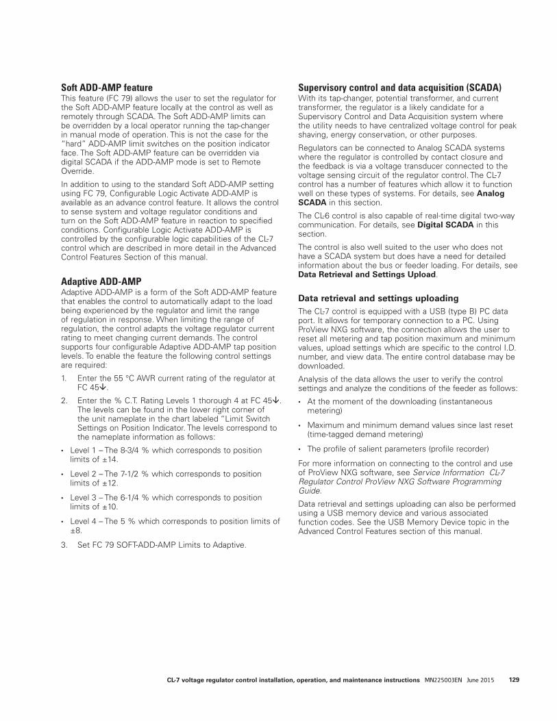
Soft ADD-AMP featureThis feature (FC 79) allows the user to set the regulator for the Soft ADD-AMP feature locally at the control as well as remotely through SCADA. The Soft ADD-AMP limits can be overridden by a local operator running the tap-changer in manual mode of operation. This is not the case for the “hard” ADD-AMP limit switches on the position indicator face. The Soft ADD-AMP feature can be overridden via digital SCADA if the ADD-AMP mode is set to Remote Override.
In addition to using to the standard Soft ADD-AMP setting using FC 79, Configurable Logic Activate ADD-AMP is available as an advance control feature. It allows the control to sense system and voltage regulator conditions and turn on the Soft ADD-AMP feature in reaction to specified conditions. Configurable Logic Activate ADD-AMP is controlled by the configurable logic capabilities of the CL-7 control which are described in more detail in the Advanced Control Features Section of this manual.
Adaptive ADD-AMPAdaptive ADD-AMP is a form of the Soft ADD-AMP feature that enables the control to automatically adapt to the load being experienced by the regulator and limit the range of regulation in response. When limiting the range of regulation, the control adapts the voltage regulator current rating to meet changing current demands. The control supports four configurable Adaptive ADD-AMP tap position levels. To enable the feature the following control settings are required:
1. Enter the 55 °C AWR current rating of the regulator at FC 45.
2. Enter the % C.T. Rating Levels 1 thorough 4 at FC 45. The levels can be found in the lower right corner of the unit nameplate in the chart labeled “Limit Switch Settings on Position Indicator. The levels correspond to the nameplate information as follows:
• Level 1 – The 8-3/4 % which corresponds to position limits of ±14.
• Level 2 – The 7-1/2 % which corresponds to position limits of ±12.
• Level 3 – The 6-1/4 % which corresponds to position limits of ±10.
• Level 4 – The 5 % which corresponds to position limits of ±8.
3. Set FC 79 SOFT-ADD-AMP Limits to Adaptive.
Supervisory control and data acquisition (SCADA)With its tap-changer, potential transformer, and current transformer, the regulator is a likely candidate for a Supervisory Control and Data Acquisition system where the utility needs to have centralized voltage control for peak shaving, energy conservation, or other purposes.
Regulators can be connected to Analog SCADA systems where the regulator is controlled by contact closure and the feedback is via a voltage transducer connected to the voltage sensing circuit of the regulator control. The CL-7 control has a number of features which allow it to function well on these types of systems. For details, see Analog SCADA in this section.
The CL-6 control is also capable of real-time digital two-way communication. For details, see Digital SCADA in this section.
The control is also well suited to the user who does not have a SCADA system but does have a need for detailed information about the bus or feeder loading. For details, see Data Retrieval and Settings Upload.
Data retrieval and settings uploadingThe CL-7 control is equipped with a USB (type B) PC data port. It allows for temporary connection to a PC. Using ProView NXG software, the connection allows the user to reset all metering and tap position maximum and minimum values, upload settings which are specific to the control I.D. number, and view data. The entire control database may be downloaded.
Analysis of the data allows the user to verify the control settings and analyze the conditions of the feeder as follows:
• At the moment of the downloading (instantaneous metering)
• Maximum and minimum demand values since last reset (time-tagged demand metering)
• The profile of salient parameters (profile recorder)
For more information on connecting to the control and use of ProView NXG software, see Service Information CL-7 Regulator Control ProView NXG Software Programming Guide.
Data retrieval and settings uploading can also be performed using a USB memory device and various associated function codes. See the USB Memory Device topic in the Advanced Control Features section of this manual.
129CL-7 voltage regulator control installation, operation, and maintenance instructions MN225003EN June 2015

Digital SCADARefer to the Advanced Control Features section for information on communications and physical interface.
Local operator securityThrough the communications channel, the SCADA master may read the CL-7 control data points, write to certain data points, or reset certain data points. The technique of writing to a data point is used for performing operations such as changing settings like Set Voltage or Reverse Power Mode, inhibiting automatic operation, or controlling the tap-changer motor, etc. Following is a discussion of the levels of security used to protect the local operator.
Supervisory switchThe CL-7 control is equipped with a Supervisory Off switch. When this switch is not in the off condition (the switch LED is not illuminated), SCADA may perform the normal read, write, and reset activity. When the switch is in the off condition (the switch LED is illuminated), SCADA may only read the database. This affords protection to the local operator at the front panel, while allowing the system operator to maintain surveillance.
Control switchIf the local operator switches the CONTROL FUNCTION switch to either OFF or LOCAL MANUAL, the control internal circuitry prohibits SCADA from controlling the tap-changer motor. Resets and other writes are allowed.
Active control security levelIf the local operator changes the control active security level to Operate level or above, or security override is set to override the Operate level or higher, this does not inhibit any SCADA activity. To inhibit SCADA writes and resets, the local operator should turn the Supervisory switch to Off.
ote:N A local operator wishing to check automatic opera-tion should check to make sure that the Blocking Status, FC 69, is set to Normal.
ote:N Changes to any of the communications parameters take effect immediately.
Analog SCADAThe CL-7 control can be used with Analog SCADA systems. Three general purpose inputs accessed on the control connection terminal board have been programmed by default for use as inputs for voltage reduction, Tap-to-Neutral, and auto-tap blocking. Most back-panel configurations also have provisions for remote motor control and transducer connections.
Discrete voltage reductionDuring voltage reduction, the control remains in the automatic mode. Standard, fixed configuration logic programmed into the control assigns General Purpose Input 1 (GPI 1) to be voltage reduction point 1. See Figures 6-6 and 6-7 for the location of the physical connections. This point can be used as point 1 for the Remote/Latch mode of voltage reduction or as the single pulse point for the Remote/Pulse mode of voltage reduction. If a voltage reduction point 2 is desired for Remote/Latch or Remote/Pulse, GPI 2 or GPI 3 can be reassigned or an auxiliary I/O module can be added and a point assigned. A nominal 120 Vac must be supplied to the GPI point(s) to enable analog voltage reduction. For information on configurable Logic, reassignment of GPI points and assignment of auxiliary I/O points to voltage reduction, see Service Information MN225015EN, CL-7 Regulator Control ProView NXG Software Programming Guide.
If dry contacts are to be used for analog voltage reduction, the voltage should be obtained at terminal V9 on the terminal board, an example connection is shown in Figure 6-6. This whetting voltage is only available when the control switch is in the Auto/Remote position. If whet contacts are used, the connections should be as shown in Figure 6-7.
The terminal board contacts assigned as GPIs are:
• GPI 1 is assigned to contact point 5.
• GPI 2 is assigned to contact point J.
• GPI 3 is assigned to contact point BR.
Analog remote/latching modeThis feature is set at FC 70. Up to three independent values of voltage reduction are possible. Levels 1, 2, and 3 are programmed at FC 73, FC 74, and FC 75, respectively. Voltage Reduction input 1 activates the voltage reduction programmed at FC 73; Voltage Reduction input 2 activates the voltage reduction programmed at FC 74; and latching both contacts activates the voltage reduction programmed at FC 75. Each of these function codes may be set from 0.1 to 10.0%. Read the section on Discrete Voltage Reduction above for information on the voltage reduction contact points.
130 CL-7 voltage regulator control installation, operation, and maintenance instructions MN225003EN June 2015
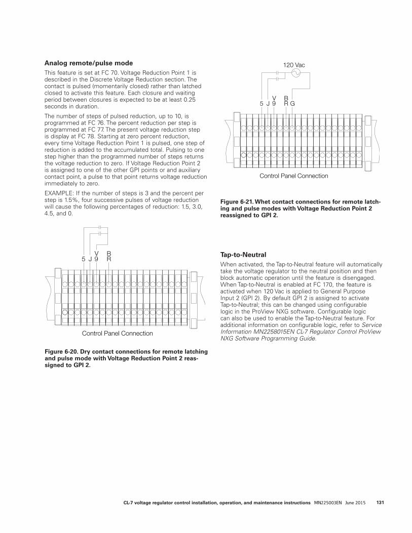
Analog remote/pulse modeThis feature is set at FC 70. Voltage Reduction Point 1 is described in the Discrete Voltage Reduction section. The contact is pulsed (momentarily closed) rather than latched closed to activate this feature. Each closure and waiting period between closures is expected to be at least 0.25 seconds in duration.
The number of steps of pulsed reduction, up to 10, is programmed at FC 76. The percent reduction per step is programmed at FC 77. The present voltage reduction step is display at FC 78. Starting at zero percent reduction, every time Voltage Reduction Point 1 is pulsed, one step of reduction is added to the accumulated total. Pulsing to one step higher than the programmed number of steps returns the voltage reduction to zero. If Voltage Reduction Point 2 is assigned to one of the other GPI points or and auxiliary contact point, a pulse to that point returns voltage reduction immediately to zero.
EXAMPLE: If the number of steps is 3 and the percent per step is 1.5%, four successive pulses of voltage reduction will cause the following percentages of reduction: 1.5, 3.0, 4.5, and 0.
Tap-to-NeutralWhen activated, the Tap-to-Neutral feature will automatically take the voltage regulator to the neutral position and then block automatic operation until the feature is disengaged. When Tap-to-Neutral is enabled at FC 170, the feature is activated when 120 Vac is applied to General Purpose Input 2 (GPI 2). By default GPI 2 is assigned to activate Tap-to-Neutral; this can be changed using configurable logic in the ProView NXG software. Configurable logic can also be used to enable the Tap-to-Neutral feature. For additional information on configurable logic, refer to Service Information MN2258015EN CL-7 Regulator Control ProView NXG Software Programming Guide.
Figure 6-20. Dry contact connections for remote latching and pulse mode with Voltage Reduction Point 2 reas-signed to GPI 2.
5 JV9
BR
Control Panel Connection
Figure 6-21. Whet contact connections for remote latch-ing and pulse modes with Voltage Reduction Point 2 reassigned to GPI 2.
5 JV9
BR
120 Vac
G
Control Panel Connection
131CL-7 voltage regulator control installation, operation, and maintenance instructions MN225003EN June 2015

Remote motor control and auto-tap blockingStandard, fixed configuration logic programmed into the control assigns General Purpose Input 3 (GPI 3) to be the input point for the External Auto Block Active output. Supplying 120 Vac to the point will inhibit auto-operation tapping until it is removed. When the motor is controlled remotely, it is necessary to inhibit automatic operation. As with the analog input points for voltage reduction, a whetting voltage from contact point V9 or a 120 Vac whet contact can be used to activate the auto-tap blocking feature.
ote:N GPI 3 is assigned to contact point BR as a default.
To remotely raise or lower the tap-changer, the appropriate set of contacts are momentarily closed. Interposing relays can be used, such that raise and lower contact closure cannot occur simultaneously. See Figure 6-18 for recommended connections on a standard back panel with the TB3 terminal board at the bottom of the control cabinet.
Alternate configurationThe CL-7 control panel typically operates with one set of configuration settings that are programmed or changed through the keypad or one of the available communications channels using ProView NXG software. Alternate Configuration modes allow the CL-7 control to be programmed with three additional sets of configuration settings that can then be activated at FC 450. Which Alternate Configuration is active can be selected at FC 452. The Alternate Configuration state can be monitored at FC 451 and will display Alt Config 1 Active, Alt Config 2 Active, Alt Config 3 Active, ARLC Active or ALRH Active.
When an Alternate Configuration mode is activated using FC 450, a set of alternate configuration settings will become active and will be used as the basis for the operation of the control. The control parameters included in the set of Alternate Configuration settings can be seen in Table 5-2 under the Alternate Config Section of the FEATURES menu.
Alternate Configuration settings can be entered using two methods: 1) Set the individual Alternate Configuration settings using the control HMI (see Table 5-2 for a list of applicable function codes). 2) Using ProView NXG software, enter the Alternate Configuration settings in the Alternate Configuration Setting dialog box and load the settings using one of the communications channels.
When the control is in the Alternate Configuration mode, the display for each of the affected control parameters will display the statement "(ALT CONFIG X)" at the bottom where X is the number of the active Alternate Configuration set. This will indicate that the alternate configuration setting is active and in use for control operation (see the example below).
001 Forward Set Voltage 120.0 Volts (ALT CONFIG 1)
When the Metering-PLUS Comp Voltage button is pressed, it will display “Alt Config X Active” on the bottom line as shown in the example below.
Comp Voltage 120.0 Band 119.0-121.0Using Func 1-5Alt Config 1 Active
Figure 6-22. Auto-tap blocking and remote motor control connections shown on the standard back panel with a TB3 terminal board.
V9
BR
L1
R1
Control Panel Connection
Raise
Lower
BlockingRelay
132 CL-7 voltage regulator control installation, operation, and maintenance instructions MN225003EN June 2015
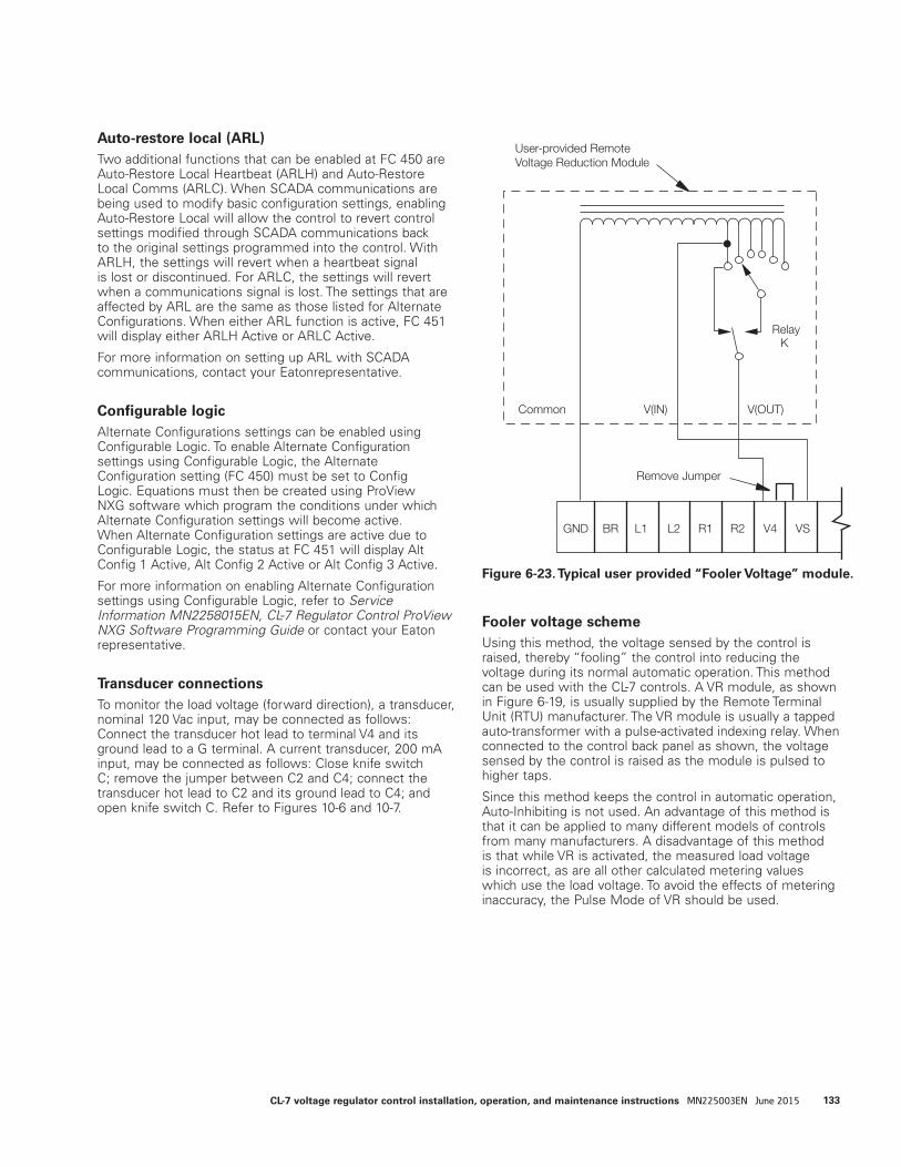
Auto-restore local (ARL)Two additional functions that can be enabled at FC 450 are Auto-Restore Local Heartbeat (ARLH) and Auto-Restore Local Comms (ARLC). When SCADA communications are being used to modify basic configuration settings, enabling Auto-Restore Local will allow the control to revert control settings modified through SCADA communications back to the original settings programmed into the control. With ARLH, the settings will revert when a heartbeat signal is lost or discontinued. For ARLC, the settings will revert when a communications signal is lost. The settings that are affected by ARL are the same as those listed for Alternate Configurations. When either ARL function is active, FC 451 will display either ARLH Active or ARLC Active.
For more information on setting up ARL with SCADA communications, contact your Eatonrepresentative.
Configurable logicAlternate Configurations settings can be enabled using Configurable Logic. To enable Alternate Configuration settings using Configurable Logic, the Alternate Configuration setting (FC 450) must be set to Config Logic. Equations must then be created using ProView NXG software which program the conditions under which Alternate Configuration settings will become active. When Alternate Configuration settings are active due to Configurable Logic, the status at FC 451 will display Alt Config 1 Active, Alt Config 2 Active or Alt Config 3 Active.
For more information on enabling Alternate Configuration settings using Configurable Logic, refer to Service Information MN2258015EN, CL-7 Regulator Control ProView NXG Software Programming Guide or contact your Eaton representative.
Transducer connectionsTo monitor the load voltage (forward direction), a transducer, nominal 120 Vac input, may be connected as follows: Connect the transducer hot lead to terminal V4 and its ground lead to a G terminal. A current transducer, 200 mA input, may be connected as follows: Close knife switch C; remove the jumper between C2 and C4; connect the transducer hot lead to C2 and its ground lead to C4; and open knife switch C. Refer to Figures 10-6 and 10-7.
Fooler voltage schemeUsing this method, the voltage sensed by the control is raised, thereby “fooling” the control into reducing the voltage during its normal automatic operation. This method can be used with the CL-7 controls. A VR module, as shown in Figure 6-19, is usually supplied by the Remote Terminal Unit (RTU) manufacturer. The VR module is usually a tapped auto-transformer with a pulse-activated indexing relay. When connected to the control back panel as shown, the voltage sensed by the control is raised as the module is pulsed to higher taps.
Since this method keeps the control in automatic operation, Auto-Inhibiting is not used. An advantage of this method is that it can be applied to many different models of controls from many manufacturers. A disadvantage of this method is that while VR is activated, the measured load voltage is incorrect, as are all other calculated metering values which use the load voltage. To avoid the effects of metering inaccuracy, the Pulse Mode of VR should be used.
Figure 6-23. Typical user provided “Fooler Voltage” module.
Common V(IN) V(OUT)
RelayK
GND BR L1 L2 R1 R2 V4 VS
Remove Jumper
User-provided Remote Voltage Reduction Module
133CL-7 voltage regulator control installation, operation, and maintenance instructions MN225003EN June 2015
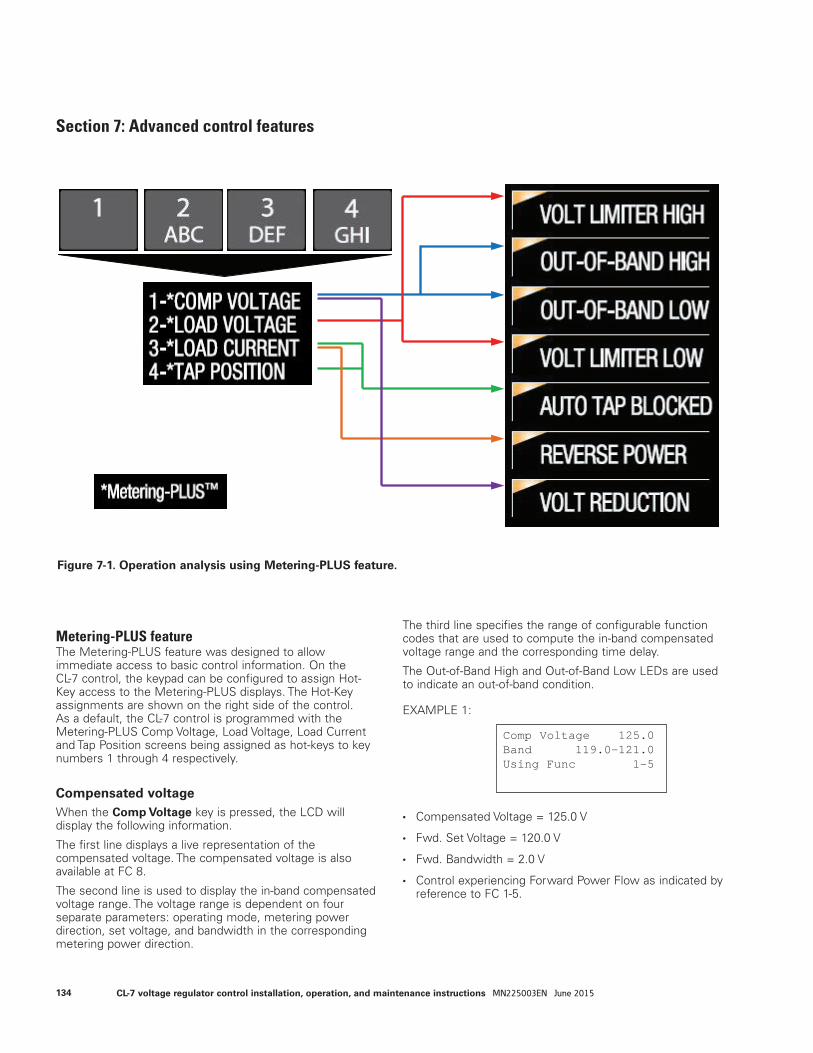
Section 7: Advanced control features
Metering-PLUS featureThe Metering-PLUS feature was designed to allow immediate access to basic control information. On the CL-7 control, the keypad can be configured to assign Hot-Key access to the Metering-PLUS displays. The Hot-Key assignments are shown on the right side of the control. As a default, the CL-7 control is programmed with the Metering-PLUS Comp Voltage, Load Voltage, Load Current and Tap Position screens being assigned as hot-keys to key numbers 1 through 4 respectively.
Compensated voltageWhen the Comp Voltage key is pressed, the LCD will display the following information.
The first line displays a live representation of the compensated voltage. The compensated voltage is also available at FC 8.
The second line is used to display the in-band compensated voltage range. The voltage range is dependent on four separate parameters: operating mode, metering power direction, set voltage, and bandwidth in the corresponding metering power direction.
The third line specifies the range of configurable function codes that are used to compute the in-band compensated voltage range and the corresponding time delay.
The Out-of-Band High and Out-of-Band Low LEDs are used to indicate an out-of-band condition.
EXAMPLE 1:
• Compensated Voltage = 125.0 V
• Fwd. Set Voltage = 120.0 V
• Fwd. Bandwidth = 2.0 V
• Control experiencing Forward Power Flow as indicated by reference to FC 1-5.
Comp Voltage 125.0 Band 119.0-121.0 Using Func 1-5
Figure 7-1. Operation analysis using Metering-PLUS feature.
134 CL-7 voltage regulator control installation, operation, and maintenance instructions MN225003EN June 2015
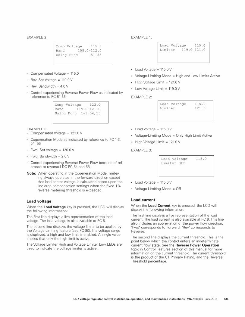
EXAMPLE 2:
• Compensated Voltage = 115.0
• Rev. Set Voltage = 110.0 V
• Rev. Bandwidth = 4.0 V
• Control experiencing Reverse Power Flow as indicated by reference to FC 51-55
EXAMPLE 3:• Compensated Voltage = 123.0 V
• Cogeneration Mode as indicated by reference to FC 1-3, 54, 55
• Fwd. Set Voltage = 120.0 V
• Fwd. Bandwidth = 2.0 V
• Control experiencing Reverse Power Flow because of ref-erence to reverse LDC FC 54 and 55
ote:N When operating in the Cogeneration Mode, meter-ing always operates in the forward direction except that load center voltage is calculated based upon the line-drop compensation settings when the fixed 1% reverse metering threshold is exceeded.
Load voltageWhen the Load Voltage key is pressed, the LCD will display the following information:
The first line displays a live representation of the load voltage. The load voltage is also available at FC 6.
The second line displays the voltage limits to be applied by the Voltage-Limiting feature (see FC 80). If a voltage range is displayed, a high and low limit is enabled. A single value implies that only the high limit is active.
The Voltage Limiter High and Voltage Limiter Low LEDs are used to indicate the voltage limiter is active.
EXAMPLE 1:
• Load Voltage = 115.0 V
• Voltage-Limiting Mode = High and Low Limits Active
• High Voltage Limit = 121.0 V
• Low Voltage Limit = 119.0 V
EXAMPLE 2:
• Load Voltage = 115.0 V
• Voltage-Limiting Mode = Only High Limit Active
• High Voltage Limit = 121.0 V
EXAMPLE 3:
• Load Voltage = 115.0 V
• Voltage-Limiting Mode = Off
Load currentWhen the Load Current key is pressed, the LCD will display the following information:
The first line displays a live representation of the load current. The load current is also available at FC 9. This line also includes an abbreviation of the power flow direction: "Fwd" corresponds to Forward, "Rev" corresponds to Reverse.
The second line displays the current threshold. This is the point below which the control enters an indeterminate current flow state. See the Reverse Power Operation topic in Control Features section of this manual for more information on the current threshold. The current threshold is the product of the CT Primary Rating, and the Reverse Threshold percentage.
Comp Voltage 123.0 Band 119.0-121.0 Using Func 1-3,54,55
Comp Voltage 115.0 Band 108.0-112.0 Using Func 51-55
Load Voltage 115.0 Limiter 119.0-121.0
Load Voltage 115.0 Limiter 121.0
Load Voltage 115.0 Limiter Off
135CL-7 voltage regulator control installation, operation, and maintenance instructions MN225003EN June 2015
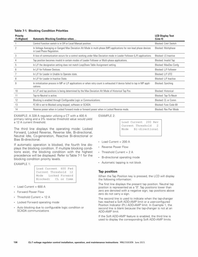
EXAMPLE: A 328 A regulator utilizing a CT with a 400 A primary rating and a 3% reverse threshold value would yield a 12 A current threshold.
The third line displays the operating mode: Locked Forward, Locked Reverse, Reverse Idle, Bi-directional, Neutral Idle, Co-generation, Reactive Bi-directional or Bias Bi-directional.
If automatic operation is blocked, the fourth line dis-plays the blocking condition. If multiple blocking condi-tions exist, the blocking condition with the highest precedence will be displayed. Refer to Table 7-1 for the blocking condition priority levels.EXAMPLE 1:
• Load Current = 600 A
• Forward Power Flow
• Threshold Current = 12 A
• Locked Forward operating mode
• Auto blocking due to configurable logic condition or SCADA communications
EXAMPLE 2:
• Load Current = 200 A
• Reverse Power Flow
• Threshold Current = 2 A
• Bi-directional operating mode
• Automatic tapping is not block
Tap positionWhen the Tap Position key is pressed, the LCD will display the following information:
The first line displays the present tap position. Neutral tap position is represented as a "0". Tap positions lower than zero are denoted with a negative sign; tap positions above zero do not carry a sign.
The second line is used to indicate when the tap-changer has reached a Soft ADD-AMP limit or a user-configured Position Indicator (P.I.) ADD-AMP limit. In Example 1, the second line is blank because the tap-changer is not at an ADD-AMP limit.
If the Soft ADD-AMP feature is enabled, the third line is used to display the corresponding Soft ADD-AMP limits.
Table 7-1. Blocking Condition Priorities
Load Current 600 FwdCurrent Threshold 12Mode Locked ForwardBlocked: CL or Comm
Load Current 200 RevCurrent Threshold 2Mode Bi-directional
Priority(1=Highest) Automatic Blocking Condition when…
LCD Display Text (Line 4)
1 Control Function switch is in Off or Local Manual position. Blocked: Cntrl Switch
2 In Voltage Averaging or Ganged Max Deviation Alt Mode in multi-phase (MP) applications for non-lead phase devices in Lead Phase Regulation.
Blocked: Multiphase
3 A loss of communication occurs for a control working under Max Deviation mode in Leader Follower (L/F) applications. Blocked: LS Inactive
4 Tap position becomes invalid in certain modes of Leader Follower or Multi-phase applications. Blocked: Invalid Tap
5 In L/F the designation setting does not match LoopShare Table Assignment setting. Blocked: MaxDev Confg
6 In L/F for Follower Devices. Blocked: L/F Follower
7 In L/F for Leader in Unable to Operate state. Blocked: L/F UTO
8 In L/F for Leader in Inactive State. Blocked: L/F Inactive
9 In initialization process in MP or L/F applications or when retry count is exhausted if device failed to tap in MP appli-cations.
Blocked: Synching
10 In L/F and tap positions is being determined by the Max Deviation Alt Mode of Historical Tap Pos. Blocked: Historical
11 Tap-to-Neutral is active. Blocked: Tap-To-Neutr
12 Blocking is enabled through Configurable Logic or Communications. Blocked: CL or Comm
13 FC 69 is set to Blocked using keypad, software or SCADA. Blocked: Func Code 69
14 Reverse power when in Locked Forward mode or forward power when in Locked Reverse mode. Blocked: Rev Pwr Mode
136 CL-7 voltage regulator control installation, operation, and maintenance instructions MN225003EN June 2015
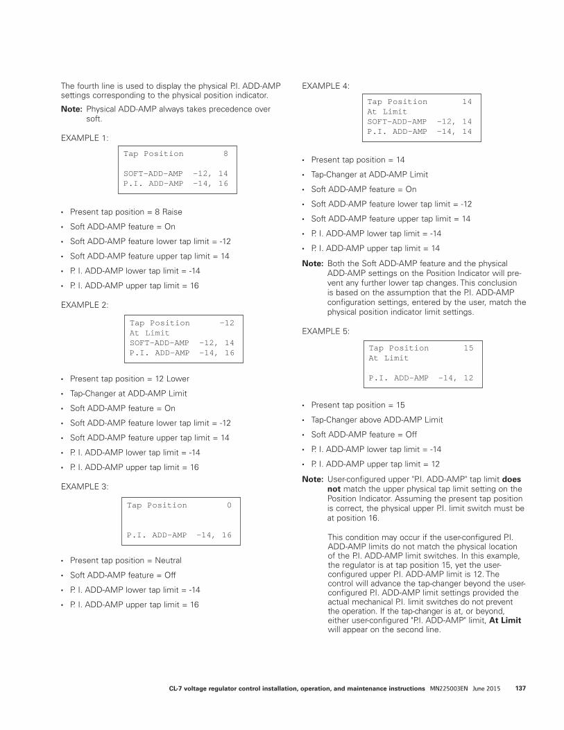
The fourth line is used to display the physical P.I. ADD-AMP settings corresponding to the physical position indicator.
ote:N Physical ADD-AMP always takes precedence over soft.
EXAMPLE 1:
• Present tap position = 8 Raise
• Soft ADD-AMP feature = On
• Soft ADD-AMP feature lower tap limit = -12
• Soft ADD-AMP feature upper tap limit = 14
• P. I. ADD-AMP lower tap limit = -14
• P. I. ADD-AMP upper tap limit = 16
EXAMPLE 2:
• Present tap position = 12 Lower
• Tap-Changer at ADD-AMP Limit
• Soft ADD-AMP feature = On
• Soft ADD-AMP feature lower tap limit = -12
• Soft ADD-AMP feature upper tap limit = 14
• P. I. ADD-AMP lower tap limit = -14
• P. I. ADD-AMP upper tap limit = 16
EXAMPLE 3:
• Present tap position = Neutral
• Soft ADD-AMP feature = Off
• P. I. ADD-AMP lower tap limit = -14
• P. I. ADD-AMP upper tap limit = 16
EXAMPLE 4:
• Present tap position = 14
• Tap-Changer at ADD-AMP Limit
• Soft ADD-AMP feature = On
• Soft ADD-AMP feature lower tap limit = -12
• Soft ADD-AMP feature upper tap limit = 14
• P. I. ADD-AMP lower tap limit = -14
• P. I. ADD-AMP upper tap limit = 14
ote:N Both the Soft ADD-AMP feature and the physical ADD-AMP settings on the Position Indicator will pre-vent any further lower tap changes. This conclusion is based on the assumption that the P.I. ADD-AMP configuration settings, entered by the user, match the physical position indicator limit settings.
EXAMPLE 5:
• Present tap position = 15
• Tap-Changer above ADD-AMP Limit
• Soft ADD-AMP feature = Off
• P. I. ADD-AMP lower tap limit = -14
• P. I. ADD-AMP upper tap limit = 12
ote:N User-configured upper "P.I. ADD-AMP" tap limit does not match the upper physical tap limit setting on the Position Indicator. Assuming the present tap position is correct, the physical upper P.I. limit switch must be at position 16.
This condition may occur if the user-configured P.I. ADD-AMP limits do not match the physical location of the P.I. ADD-AMP limit switches. In this example, the regulator is at tap position 15, yet the user-configured upper P.I. ADD-AMP limit is 12. The control will advance the tap-changer beyond the user-configured P.I. ADD-AMP limit settings provided the actual mechanical P.I. limit switches do not prevent the operation. If the tap-changer is at, or beyond, either user-configured "P.I. ADD-AMP" limit, At Limit will appear on the second line.
Tap Position 0
P.I. ADD-AMP -14, 16
Tap Position 14At LimitSOFT-ADD-AMP -12, 14P.I. ADD-AMP -14, 14
Tap Position 15At Limit
P.I. ADD-AMP -14, 12
Tap Position 8
SOFT-ADD-AMP -12, 14P.I. ADD-AMP -14, 16
Tap Position -12At LimitSOFT-ADD-AMP -12, 14P.I. ADD-AMP -14, 16
137CL-7 voltage regulator control installation, operation, and maintenance instructions MN225003EN June 2015
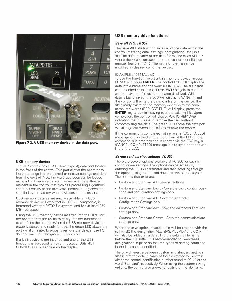
USB memory deviceThe CL-7 control has a USB Drive (type A) data port located in the front of the control. This port allows the operator to import settings into the control or to save settings and data from the control. Also, firmware upgrades can be loaded using a USB memory device. Firmware is the software resident in the control that provides processing algorithms and functionality to the hardware. Firmware upgrades are supplied by the factory when revisions are necessary.
USB memory devices are readily available; any USB memory device will work that is USB 2.0 compatible, is formatted with the FAT32 file system, and has at least 250 MB free space.
Using the USB memory device inserted into the Data Port, the operator has the ability to easily transfer information to and from the control. When the USB memory device is properly seated and ready for use, the green LED above the port will illuminate. To properly remove the device, use FC 953 and wait until the green LED goes out.
If a USB device is not inserted and one of the USB functions is accessed, an error message (USB NOT CONNECTED) will appear on the display.
USB memory drive functions
Save all data, FC 950The Save All Data function saves all of the data within the control (metering data, settings, configuration, etc.) in a file. The default name of the data file will be xxxxxALL.cl7 where the xxxxx corresponds to the control identification number found at FC 40. The name of the file can be modified as desired using the keypad.
EXAMPLE : 12345ALL.cl7To use the function, insert a USB memory device, access FC 950 and press ENTER. The control LCD will display the default file name and the word (CONFIRM). The file name can be edited at this time. Press ENTER again to confirm and the save the file using the name displayed. While data is being saved, the LCD will display (SAVING...), and the control will write the data to a file on the device. If a file already exists on the memory device with the same name, the words (REPLACE FILE) will display; press the ENTER key to confirm saving over the existing file. Upon completion, the control will display (OK TO REMOVE) indicating that it is safe to remove the card without compromising the data. The green LED above the data port will also go out when it is safe to remove the device.
If the command is completed with errors, a (SAVE FAILED) message is displayed on the fourth line of the LCD. If the command is in progress and is aborted via the ESC key, a (CANCEL COMPLETED) message is displayed on the fourth line of the LCD.
Saving configuration settings, FC 950There are several options available at FC 950 for saving configuration settings. The options can be access by entering the FC 950 parameter and then scrolling through the options using the up and down arrows on the keypad. The options that exist are:
• Custom and Standard All - Save all settings.
• Custom and Standard Basic - Save the basic control oper-ation and configuration settings only.
• Custom and Standard Alt - Save the Alternate Configuration Settings only.
• Custom and Standard Adv - Save the Advanced Features settings only.
• Custom and Standard Comm - Save the communications settings only.
When the save option is used, a file will be created with the suffix .cl7. The designation ALL, BAS, ALT, ADV and COM will also be added as a default to the settings file name before the .cl7 suffix. It is recommended to keep these designations in place so that the types of setting contained in the file can be identified.
The only difference between custom and standard settings files is that the default name of the file created will contain either the control identification number found at FC 40 or the word "Standard" respectively. When using the custom saving options, the control also allows for editing of the file name.
Figure 7-2. A USB memory device in the data port.
138 CL-7 voltage regulator control installation, operation, and maintenance instructions MN225003EN June 2015
EXAMPLES: 12345ALL.cl7 StandardBAS.cl7
To use the function, insert a USB memory device, access FC 950 and press the down arrow key to scroll through the save options. Press ENTER; this will bring up the default file name with the message (CONFIRM) on the bottom of the screen. For the custom save options, modify the file name if desired. Press ENTER to confirm. The LCD will display (SAVING...), and the control will save the configuration data to the memory device. If a file already exists on the memory device with the same name, the words (REPLACE FILE) will display; press the ENTER key to confirm saving over the existing file. Upon completion, the control will display (OK TO REMOVE). The USB memory device may be removed after this message is displayed and the green LED light goes out.
If the command is completed with errors, a (SAVE FAILED) message is displayed on the fourth line of the LCD. If the command is in progress and is aborted via the ESC key, a (CANCEL COMPLETED) message is displayed on the fourth line of the LCD.
Loading configuration data, FC 951Using FC 951 will allow the user to select among the configuration files located on a USB memory device and load the desired file. Any of the stored files with the .cl7 suffix can be selected and loaded.
An Admin level of security is required to perform this operation. After inserting a USB memory device, access FC 951. Press ENTER; this will bring up the first file name located on the device. If more than one .cl7 file is located on the device, a (More...) will appear on the screen. Use the down arrow to scroll to the desired file for loading. Press ENTER again and the control LCD will display (CONFIRM). Press ENTER again to confirm and begin loading the file. The LCD will display (LOADING...), and the control will load the configuration data from the memory device. Upon completion, the control will display (LOAD COMPLETE). The USB memory device may be removed after this message is displayed.
If the command is completed with errors, a (LOAD FAILED) message is displayed on the fourth line of the LCD. If the command is in progress and is aborted via the ESC key, a (CANCEL COMPLETE) message is displayed on the fourth line of the LCD.
Remove device, FC 953It is always recommended that the USB memory device not be removed from the control while the green LED above the port is illuminated. To prepare the control for removal of the device, access FC 953 and press ENTER; (CONFIRM) will appear on the display. Pressing ENTER again will cause the message (OK TO REMOVE) to display and the green LED to go out. The device may now be safely removed.
CommunicationsCommunicate with the CL-7 control using ProView NXG software or protocols such as DNP3 or IEC 60870. The ProView NXG software, used with a PC, can provide temporary local connection to the control.
Communication portsThere are two physical communications ports and a PC data port (USB type B) on the CL-7 control.
The PC data port is for use as a temporary local communication connection to the control. Connection is made to the PC data port by using a standard USB type A to USB type B cable (standard USB printer cable). When using ProView NXG software, a port configuration has been created to allow for easy connection. Clicking on the connect button will bring up a list of configured ports, click on Data Ports (USB Direct) to connect.
The communication ports Com 1 and Com 2 are for use as permanent communication connection to the control. Connection is made by using an optional communication accessory card inserted into the side of the control. A communications base card is also required. The port settings are configured using various function codes which can be found in the COMMUNICATIONS menu. See Tables 5-2 and 5-3 for a list of communication parameters and descriptions.
For more detailed instructions on using ProView NXG software, see Service Information MN2258015EN CL-7 Regulator Control ProView NXG Software Programming Guide.
For more detailed instruction on communications settings, protocols and capabilities, see Service Information S225-70-3 CL-7 Regulator Control Communications.
ProtocolsThere are two protocols resident in the CL-7 control: DNP3 and IEC 60870. Various other protocols are available, but require additional hardware and must be specified at the time of order. While only one protocol can be selected for a single Com port at a time, the two com ports can be set to different protocols. Both of the protocols are highly configurable.
Configurable logicConfigurable Logic is a powerful tool since it provides the user with the means to configure general logic equations. These logic equations can be used to perform discrete SCADA functions, modify control function, or add communications data points. Configurable Logic must be configured via the digital communications software, ProView NXG software.
Control functions codes can be used to enable configurable logic. See the information contained in Table 5-3 for FC 700-703 more information on this functionality.
See Service Information MN2258015EN CL-7 Regulator Control ProView NXG Software Programming Guide for more information on programming configurable logic.
139CL-7 voltage regulator control installation, operation, and maintenance instructions MN225003EN June 2015
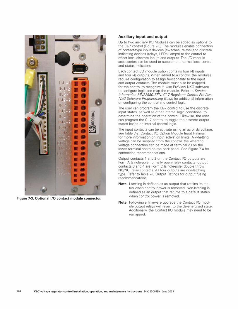
Auxiliary input and output Up to two auxiliary I/O Modules can be added as options to the CL-7 control (Figure 7-3). The modules enable connection of contact-type input devices (switches, relays) and discrete indicating devices (relays, LEDs, lamps) to the control to effect local discrete inputs and outputs. The I/O module accessories can be used to supplement normal local control and status indicators.
Each contact I/O module option contains four (4) inputs and four (4) outputs. When added to a control, the modules require configuration to assign functionality to the input and output contacts. The module must also be mapped for the control to recognize it. Use ProView NXG software to configure logic and map the module. Refer to Service Information MN2258015EN, CL-7 Regulator Control ProView NXG Software Programming Guide for additional information on configuring the control and control logic.
The user can program the CL-7 control to use the discrete input states, as well as other internal logic conditions, to determine the operation of the control. Likewise, the user can program the CL-7 control to toggle the discrete output states based on internal control logic.
The input contacts can be activate using an ac or dc voltage; see Table 7-2, Contact I/O Option Module Input Ratings for more information on input activation limits. A whetting voltage can be supplied from the control; the whetting voltage connection can be made at terminal V9 on the lower terminal board on the back panel. See Figure 7-4 for connection recommendations.
Output contacts 1 and 2 on the Contact I/O outputs are Form A (single-pole normally open) relay contacts; output contacts 3 and 4 are Form C (single-pole, double throw NO/NC) relay contacts. All four outputs are non-latching type. Refer to Table 7-3 Output Ratings for output fusing recommendations.
ote:N Latching is defined as an output that retains its sta-tus when control power is removed. Non-latching is defined as an output that returns to a default status when control power is removed.
ote:N Following a firmware upgrade the Contact I/O mod-ule output relays will revert to the de-energized state. Additionally, the Contact I/O module may need to be remapped.
Figure 7-3. Optional I/O contact module connector.
140 CL-7 voltage regulator control installation, operation, and maintenance instructions MN225003EN June 2015
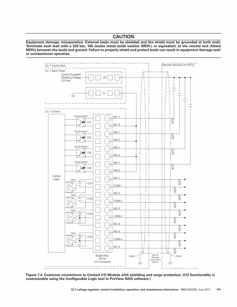
Single-Row 18-Pin
I/O Connector
IN1-1
IN1-2
IN2-1
IN2-2
IN3-1
IN3-2
IN4-1
IN4-2
CI1
CI2
CI3
CI4
Control Supplied Whetting Voltage 120 Vac
V9
G
ControlLogic NO-1
COM-1
NO-2
COM-2
NO-3
COM-3
NO-4
COM-4
NC-4
NC-3
CO1
CO2
CO3
CO4
CL-7 Control Box
CL-7 Back Panel
CL-7 Control
Remote Terminal Unit (RTU)
Not AllRemote
ConnectionsShown
ShieldShield
Optical Isolation
Optical Isolation
Optical Isolation
Optical Isolation
Relay
Relay
Relay
Relay
Figure 7-4. Customer connections to Contact I/O Module with shielding and surge protection. (I/O functionality is customizable using the Configurable Logic tool in ProView NXG software.)
CAUTION Equipment damage; misoperation. External leads must be shielded and the shield must be grounded at both ends. Terminate each lead with a 320 Vac, 160 Joules metal oxide varistor (MOV), or equivalent, at the remote end. Attach MOVs between the leads and ground. Failure to properly shield and protect leads can result in equipment damage and/or unintentional operation.
141CL-7 voltage regulator control installation, operation, and maintenance instructions MN225003EN June 2015
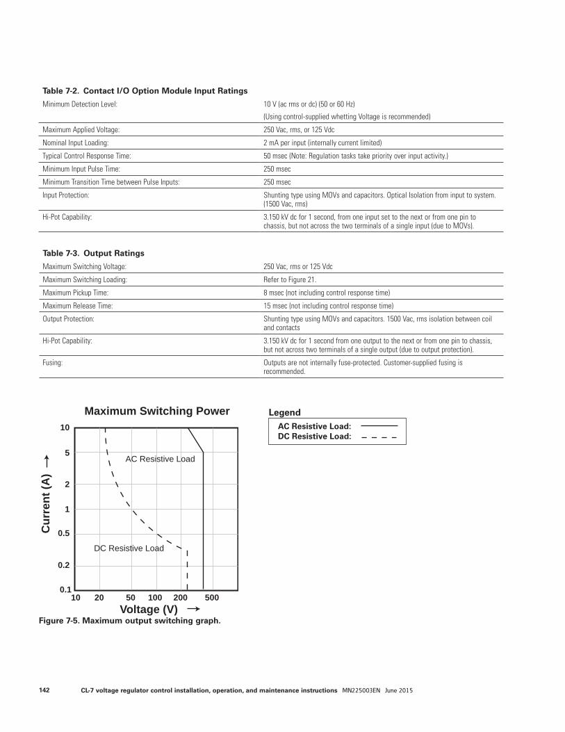
Table 7-2. Contact I/O Option Module Input Ratings
Minimum Detection Level: 10 V (ac rms or dc) (50 or 60 Hz)
(Using control-supplied whetting Voltage is recommended)
Maximum Applied Voltage: 250 Vac, rms, or 125 Vdc
Nominal Input Loading: 2 mA per input (internally current limited)
Typical Control Response Time: 50 msec (Note: Regulation tasks take priority over input activity.)
Minimum Input Pulse Time: 250 msec
Minimum Transition Time between Pulse Inputs: 250 msec
Input Protection: Shunting type using MOVs and capacitors. Optical Isolation from input to system. (1500 Vac, rms)
Hi-Pot Capability: 3.150 kV dc for 1 second, from one input set to the next or from one pin to chassis, but not across the two terminals of a single input (due to MOVs).
Table 7-3. Output Ratings
Maximum Switching Voltage: 250 Vac, rms or 125 Vdc
Maximum Switching Loading: Refer to Figure 21.
Maximum Pickup Time: 8 msec (not including control response time)
Maximum Release Time: 15 msec (not including control response time)
Output Protection: Shunting type using MOVs and capacitors. 1500 Vac, rms isolation between coil and contacts
Hi-Pot Capability: 3.150 kV dc for 1 second from one output to the next or from one pin to chassis, but not across two terminals of a single output (due to output protection).
Fusing: Outputs are not internally fuse-protected. Customer-supplied fusing is recommended.
Figure 7-5. Maximum output switching graph.
10
5
2
1
0.5
0.2
0.110 20 50 100 200 500
Cur
rent
(A)
Voltage (V)
Maximum Switching Power
AC Resistive Load
DC Resistive Load
AC Resistive Load: DC Resistive Load:
Legend
142 CL-7 voltage regulator control installation, operation, and maintenance instructions MN225003EN June 2015
AlarmsAn alarm is a binary (On/Off) flag that is activated when a user-defined condition is true. The status of an alarm can be viewed on the LCD display or through communications, including ProView NXG software. Alarms can only be configured via communications. See Service Information MN225015EN CL-7 Regulator Control ProView NXG Software Programming Guide for information on configuring alarms.
The user can define the priority of an alarm to cause the Alarm LED, Warning LED, or no LED to be illuminated. The assigned priority of the alarm also determines the order in which the alarms are viewed via the display.
• Assigning a Priority of 0–50 will cause the Alarm LED to be illuminated when the alarm condition is active.
• Assigning a Priority of 51–100 will cause the Warning LED to be illuminated when the alarm condition is active.
• Assigning a Priority of 101–127 will not cause an LED to be illuminated, but the condition can be viewed on the LCD display or through communications while the alarm condition is active.
A timer can also be set for each alarm. This will allow the alarm to become active only after the alarm condition has existed and the period of time specified by the timer (in seconds) has expired. When an alarm becomes active, it is given the state of Unacknowledged. If the alarm is configured to illuminate an LED, the LED will flash as long as the alarm is Unacknowledged. To acknowledge an alarm the Operate security level is required. After entering the security code, enter Alarms > Alarms Active Unacknowledged using the front-panel menu; the unacknowledged alarms will display. Press the ENTER key to display (ACKNOWLEDGE) and ENTER again to complete the operation. If the alarm is configured to illuminate an LED and it has been acknowledged, the LED will be on continuously. The alarm will turn off whenever the alarm condition is no longer true.
The control can also record an event or take a profile snapshot whenever an alarm becomes active or inactive. The control contains two types of user-configurable alarms: Status Alarms and Data Alarms.
The Status Alarm type is activated based upon the condition of a binary (On/Off) parameter. By default, Status Alarms become active when the parameter is On. The alarm, however, can be inverted so that it becomes active when the parameter is Off. See Service Information MN2258015EN CL-7 Regulator Control ProView NXG Software Programming Guide for a complete list and definitions of available Status alarms.
EXAMPLE:Configuring a Supervisory Active Alarm to be inverted with a Priority of 25 will cause the Alarm LED to flash whenever the Supervisory Switch is in the Off position.
The Data Alarm type is activated based upon the condition of an analog (numeric) parameter being above or below a threshold value. The operations counters and metering values are available as Data Alarms. See Service Information
MN2258015EN CL-7 Regulator Control ProView NXG Software Programming Guide for a complete list and definitions of available Status alarms.
EXAMPLE: Configuring a Compensated Voltage Low Alarm with a Threshold of 115 V with a Priority of 75 will cause the Warning LED to flash whenever the compensated voltage is below 115 V.
Sequence of events (SOE)An event is a time-stamped record of an alarm condition or control activity. The CL-7 control is designed to record a sequence of these events; event data is stored in non-volatile memory on the control. The last fifty events can be viewed via the front panel display using the top level nested menu item SEQUENCE OF EVENTS. The last 300+ events can be viewed using ProView NXG software.
Configuring SOE can only be done using software. There are a number of events that are pre-configured on every control. See Service Information MN2258015EN CL-7 Regulator Control ProView NXG Software Programming Guide for a list of available events and information on configuring SOE functionality.
Data profilerThe Data Profiler records the current state of parameters chosen by the user at regular intervals into non-volatile memory. The Data Profiler data can only be viewed using ProView NXG software. Configuring the Data Profiler must also be accomplished using the software. The user can choose to profile as many of the instantaneous and demand (present) parameters as desired. The sampling interval can be set from one (1) minute to one (1) day. The storage capacity for data is limited; the greater the number of parameters chosen and the shorter the sampling interval, the less overall time will pass before the record begins to be overwritten. In the software, a Trend Time will be displayed as the Profiler is configured which will be an estimate of the length of time data can be recorded before the oldest data is overwritten.
See Service Information MN2258015EN CL-7 Regulator Control ProView NXG Software Programming Guide for a list and description of available Data Profiler items and information on configuring Data Profiler functionality.
143CL-7 voltage regulator control installation, operation, and maintenance instructions MN225003EN June 2015

TIME-ON-TAP™ featureThe TIME-ON-TAP™ feature logs the percentage of time spent on each tap-changer position. The TIME-ON-TAP data is only viewable using ProView NXG software and is presented in bar graph format; see Figure 7-6.
Figure 7-6. TIME-ON-TAP sample graph.
144 CL-7 voltage regulator control installation, operation, and maintenance instructions MN225003EN June 2015
Preventive Maintenance TappingPreventive Maintenance Tapping (PMT™) will automatically operate the tap-changer according to user-configured parameters. Under certain operating conditions, load tap-changer contacts can become susceptible to coking. The PMT feature will operate the tap-changer to wipe the contact blades and prevent build-up of carbon. There are two different types of preventive maintenance tapping available: PMT Mode A and PMT Mode B.
PMT Mode AWhen enabled the control monitors tap position and, if it stays on any single tap position for a user-defined period of time (Time Delay, FC 302), the control will automatically raise the tap-changer one position, lower the tap-changer two positions, and then raise the tap-changer one position. When PMT Mode A is performed on a Quik-Drive tap-changer, this entire operation will take approximately one second. The user can monitor how much time is left prior to the maintenance tapping being performed at Countdown Delay, FC 301. To sample how the PMT Mode A functions, the user can use Issue Test, FC 303.
PMT Mode BWhen enabled, the control monitors tap position and, if it does not pass through neutral for a user-defined period of time (Time Delay, FC 322), the control will automatically tap through and past neutral one position. This operates and wipes the blades of the reversing switch. It then returns the tap-changer to the original tap position. Due to the possible large fluctuation in voltage while maintenance is being performed, there are more configuration points in PMT Mode B than in Mode A. The user can determine the time of day that PMT Mode B is allowed to operate, so that maintenance can be performed at night. To limit the amount of allowable voltage-swing when performing maintenance, the user can input the maximum deviation. Also, the user can input a current limit so that maintenance is only performed under light load conditions. Additionally, a master slave mode is available so multiple units can act at once to keep the supply balanced for three-phase loads that are sensitive to imbalance. The user can monitor how much time is left prior to the maintenance tapping being performed at Countdown Delay, FC 321. To sample how the PMT Mode B functions, the user can use Issue Test, FC 328.
Duty cycle monitorThe Duty Cycle Monitor calculates the amount of life used for each arcing surface contact on the voltage regulator Quik-Drive tap-changer. The control uses the metering values, such as current, voltage, power factor, and tap position, and a detailed data on the internal design of the voltage regulator to calculate the interrupting current and recovery voltage. This is then related to the test data for the appropriate Quik-Drive tap-changer. The Duty Cycle Monitor functions only on voltage regulators with a Quik-Drive tap-changer.
FC 333 displays the worst-case value of life used, expressed as a percentage, to the third decimal point. This value may be used to generate two different Data Alarms. The
first DCM Data Alarm is intended to be configured so that maintenance may be scheduled. The suggested setting is 75%. The second Data Alarm is intended to be set at a higher level, the suggested setting is 90%, in order to notify the user that a service outage due to contact failure may be imminent. For more information on Alarms, see the Alarms topic in this section of the manual.
A detailed percentage of life-used for each arcing contact is also available and can be viewed using ProView NXG software. When replacing a control on an existing voltage regulator, ProView NXG software must be used to enable and configure the Duty Cycle Monitor feature. Configuration values programmed in the software for the specific voltage regulator include the design number and an estimation of the amount of life already used.
ote:N Duty Cycle Monitor is active only on Eaton's Cooper Power series regulators with Quick-Drive tap-changers.
Leader/follower schemeThe Leader/Follower Scheme is an electronic scheme designed to coordinate the operation of two or three individual single-phase step voltage regulators. This feature is primarily used by utilities and others needing three-phase voltage regulation within certain parameters.
A fiber optic intelligent loop scheme (LoopShare) is used between controls providing the communications necessary between phases to initialize a tap change and provide positive feedback in maintaining regulation within the desired parameters. The status and settings for LoopShare are found at FC 860 through FC 863. As a result of the communications between all phases, access to certain data from all phases is available at the display of all controls involved and by using ProView NXG software.
If configured as a Leader or Follower device, the CL-7 control can be operated in one of two Ganged modes or a Group Coordinated mode. All configuration and setting values associated with the connected equipment must be configured separately for all connected voltage regulators. Leader/Follower Operation works on the understanding that all equipment connected and run in the Leader/Follower configuration must maintain communications with the operating group.
This scheme can also be used for paralleling substation voltage regulators with a set of power transformers used for increasing capacity and providing a backup for maintaining regulated power. For more details on the various Leader/Follower schemes and configuring the feature, see Service Information MN2258015EN CL-7 Regulator Control ProView NXG Software Programming Guide.
Voltage sag monitoringThe voltage sag monitor compares the voltage regulator load voltage with a reference value and determines if the load voltage has dropped below a defined threshold level for a defined period of time. The concept is based on the voltage quality curve defined by the Computer Business Equipment Manufacturer’s Association (CBEMA), which is meant as a guideline for the kind of voltage deviation that
145CL-7 voltage regulator control installation, operation, and maintenance instructions MN225003EN June 2015
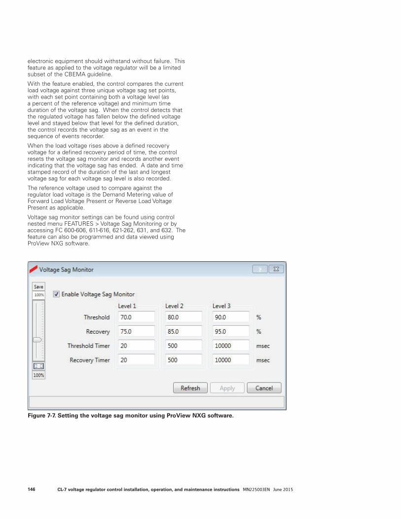
electronic equipment should withstand without failure. This feature as applied to the voltage regulator will be a limited subset of the CBEMA guideline.
With the feature enabled, the control compares the current load voltage against three unique voltage sag set points, with each set point containing both a voltage level (as a percent of the reference voltage) and minimum time duration of the voltage sag. When the control detects that the regulated voltage has fallen below the defined voltage level and stayed below that level for the defined duration, the control records the voltage sag as an event in the sequence of events recorder.
When the load voltage rises above a defined recovery voltage for a defined recovery period of time, the control resets the voltage sag monitor and records another event indicating that the voltage sag has ended. A date and time stamped record of the duration of the last and longest voltage sag for each voltage sag level is also recorded.
The reference voltage used to compare against the regulator load voltage is the Demand Metering value of Forward Load Voltage Present or Reverse Load Voltage Present as applicable.
Voltage sag monitor settings can be found using control nested menu FEATURES > Voltage Sag Monitoring or by accessing FC 600-606, 611-616, 621-262, 631, and 632. The feature can also be programmed and data viewed using ProView NXG software.
Figure 7-7. Setting the voltage sag monitor using ProView NXG software.
146 CL-7 voltage regulator control installation, operation, and maintenance instructions MN225003EN June 2015

Battery optionsThe CL-7 control may be equipped with a 13 A-Hr, 24 Vdc battery backup. The purpose of the battery backup is to maintain power to the control when system power is lost. The battery is not intended to run the tap-changer.
When the control is equipped with battery backup, the function codes are used to monitor battery function. When the battery is in use, FC 190 will display battery current and voltage values. Use FC 191 to initiate a battery test and display the results. An automatic battery test can be enabled at FC 192 which will run a battery test within 60 seconds of power up of the control and then every 12 hours thereafter.
Battery test results may display a code when the test is not successfully passed. The codes are:
1 – Battery failed test
2 – A battery test was already running
3 – Battery test was blocked
4 – Battery test was not run
5 – Auto battery test disabled.
Customer supplied battery powerThe CL-7 control can be powered using a substation battery with a voltage of 48 to 125 Vdc. With this option, terminals will be provided on the back panel of the control to connect battery power. The terminals will be connected to the control DC power jumper (see Figure 7-9). If a substation batter option is not provided, the DC power jumper must be in place in order to power the control.
DC power supply (13.5 Vdc)An optional 13.5 Vdc power supply is available for the CL-7 control. The power supply is intended to provide an auxiliary source to power communications equipment. The unit has a max output of 1.48 A for 1 second and max power of 14 W continuous and 20 W peak.
Figure 7-10 shows the DC power supply installed in the side of a CL-7 control. Power connections can be made to the orange plug; the top plug is the negative terminal and the bottom plug is the positive terminal.
Figure 7-8. Auxiliary control box with backup batteries.
Figure 7-10. DC power supply (13.5 Vdc) installed in the side of a CL-7 control.
Figure 7-9. DC power jumper in place on side of con-trol. This jumper must be in place to power the control when the substation battery option is not provided.
147CL-7 voltage regulator control installation, operation, and maintenance instructions MN225003EN June 2015
Section 8: Troubleshooting
When using the CL-7 control with an Eaton's Cooper Power series regulator, refer to Service Information MN225008EN (S225-10-30) VR-32 Voltage Regulator with Quik-Drive Tap-Changer Installation, Operation, and Maintenance Instructions for additional information on the regulator operation and maintenance.
External checkExamine the power connections first. For example, verify that the load lead is connected to the load (L) bushing, the source lead is connected to the source (S) bushing and that the source-load lead is connected to the source-load (SL) bushing. Check for other potential problems, such as an open ground connection.
Defining the problemDetermine which of the following categories best describes the malfunction and follow the corresponding steps. Refer to the schematics in the Appendix, Figures 10-1 through 10-8, while diagnosing the problem.
ote:N Parameter options accessed via menu or function code are shown in bold.
Settings of front panel switches are shown in bold.
Keypad directions are shown as follows: press keys as shown in bold; enter numbers as shown in italics.
ote:N The typical control box will have a single terminal board (TB3) at the bottom of the back panel. Legacy control boxes, CRA control boxes and a very few new units will have two terminal boards, TB1 at the top and TB2 at the bottom. TB3 will include most of the same terminals as found on TB1 and TB2. Troubleshooting principles will apply to any back-panel configuration.
Control panel troubleshooting
No motor powerIf the control panel powers up, but the motor will not run, first check the 6 A motor fuse on the control front panel. Remove the fuse from the control and check for continuity across the fuse. Spare fuses are shipped with each control and are located in the control box.
ote:N Use only 125 V, 6 amp, fast-blow fuses of the proper current rating. Failure to do so may cause unneces-sary fuse operation or insufficient protection of the regulator and control.
No control powerIf the control will not power up at all, check the power to the control:
1. With a voltmeter, check the voltage between terminals VS and G. The voltage should approximate the set voltage. If the voltage is present at terminal VS, then the problem is in the control. Replace the control.
2. Check the voltage-disconnect knife switch V1, V6 (if present), and the current shorting knife switch C on the back panel in the control enclosure. Close the V1 and V6 switches if open. Open the CT shorting switch (C) if closed.
3. Check the voltage between V1 and G. If the voltage is present at V1, then the problem could be in the wiring harness or ratio-correcting transformer. Check for loose connections or burnt wiring. Verify that the ratio-correcting transformer RCT1 is on the correct tap for the regulated voltage as shown on the nameplate on the control enclosure door.
4. If voltage is not present, then the problem is either in the control cable, junction box connection, or inside of the regulator.
Self-testThe control hardware performs self-diagnostic physical and memory checks. There are two events which force the control into the self-test routine: (1) Power is turned on; (2) Operator entry of the self-test mode (FC 91).
The duration of this test sequence is approximately seven (7) seconds. At completion, the display will indicate PASS or display an error message if a problem is found. (See Diagnostic Error Messages in the next section of this manual). The messages will remain in the display until the operator presses the ESC key or, after 20 minutes, the display will automatically be turned off.
ote:N After the self-test and the LCD displays PASS, press ESC key for further keypad use.
Diagnostic error messages Upon running the self-test, if an error is detected, a diagnostic error message will be displayed and the red DIAG ERROR LED will illuminate until the self-test is rerun without error.
ote:N The most common diagnostic errors can be rectified by changing parameters in the control. Review this section or call an Eaton representative for assistance.
A list of diagnostic error messages and explanations follows.
• Non-Volatile Settings Failed!—The firmware was unable to create, open, read or write the settings file.
• Frequency Detection Failed!—Detected system frequen-cy is below 40 Hz or above 70 Hz.
• No Data Acquisition!—Data failed to be acquired over a 1 second time period (data is acquired every 512 microsec-
WARNING Hazardous voltage. When troubleshooting energized equipment, protective gear must be worn to avoid personal contact with energized parts. Failure to comply can cause serious injury or death. VR-T213.0
148 CL-7 voltage regulator control installation, operation, and maintenance instructions MN225003EN June 2015
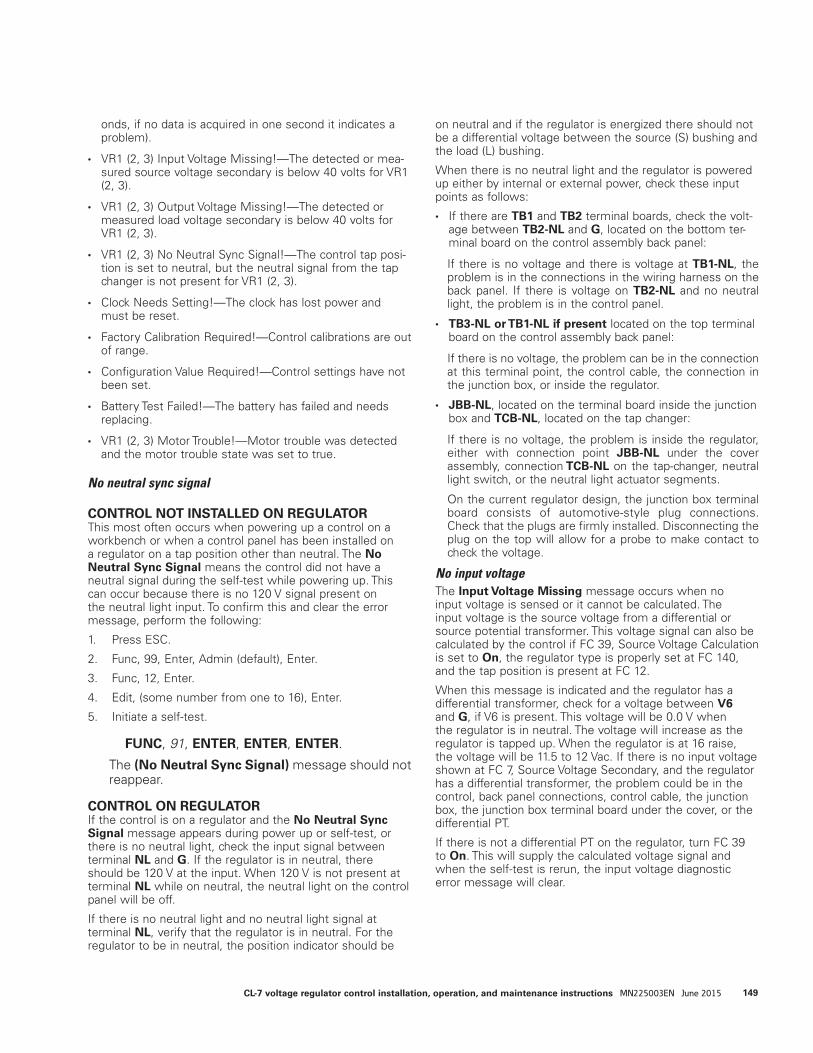
onds, if no data is acquired in one second it indicates a problem).
• VR1 (2, 3) Input Voltage Missing!—The detected or mea-sured source voltage secondary is below 40 volts for VR1 (2, 3).
• VR1 (2, 3) Output Voltage Missing!—The detected or measured load voltage secondary is below 40 volts for VR1 (2, 3).
• VR1 (2, 3) No Neutral Sync Signal!—The control tap posi-tion is set to neutral, but the neutral signal from the tap changer is not present for VR1 (2, 3).
• Clock Needs Setting!—The clock has lost power and must be reset.
• Factory Calibration Required!—Control calibrations are out of range.
• Configuration Value Required!—Control settings have not been set.
• Battery Test Failed!—The battery has failed and needs replacing.
• VR1 (2, 3) Motor Trouble!—Motor trouble was detected and the motor trouble state was set to true.
No neutral sync signal
CONTROL NOT INSTALLED ON REGULATORThis most often occurs when powering up a control on a workbench or when a control panel has been installed on a regulator on a tap position other than neutral. The No Neutral Sync Signal means the control did not have a neutral signal during the self-test while powering up. This can occur because there is no 120 V signal present on the neutral light input. To confirm this and clear the error message, perform the following:
1. Press ESC.
2. Func, 99, Enter, Admin (default), Enter.
3. Func, 12, Enter.
4. Edit, (some number from one to 16), Enter.
5. Initiate a self-test.
FUNC, 91, ENTER, ENTER, ENTER.
The (No Neutral Sync Signal) message should not reappear.
CONTROL ON REGULATORIf the control is on a regulator and the No Neutral Sync Signal message appears during power up or self-test, or there is no neutral light, check the input signal between terminal NL and G. If the regulator is in neutral, there should be 120 V at the input. When 120 V is not present at terminal NL while on neutral, the neutral light on the control panel will be off.
If there is no neutral light and no neutral light signal at terminal NL, verify that the regulator is in neutral. For the regulator to be in neutral, the position indicator should be
on neutral and if the regulator is energized there should not be a differential voltage between the source (S) bushing and the load (L) bushing.
When there is no neutral light and the regulator is powered up either by internal or external power, check these input points as follows:
• If there are TB1 and TB2 terminal boards, check the volt-age between TB2-NL and G, located on the bottom ter-minal board on the control assembly back panel:
If there is no voltage and there is voltage at TB1-NL, the problem is in the connections in the wiring harness on the back panel. If there is voltage on TB2-NL and no neutral light, the problem is in the control panel.
• TB3-NL or TB1-NL if present located on the top terminal board on the control assembly back panel:
If there is no voltage, the problem can be in the connection at this terminal point, the control cable, the connection in the junction box, or inside the regulator.
• JBB-NL, located on the terminal board inside the junction box and TCB-NL, located on the tap changer:
If there is no voltage, the problem is inside the regulator, either with connection point JBB-NL under the cover assembly, connection TCB-NL on the tap-changer, neutral light switch, or the neutral light actuator segments.
On the current regulator design, the junction box terminal board consists of automotive-style plug connections. Check that the plugs are firmly installed. Disconnecting the plug on the top will allow for a probe to make contact to check the voltage.
No input voltageThe Input Voltage Missing message occurs when no input voltage is sensed or it cannot be calculated. The input voltage is the source voltage from a differential or source potential transformer. This voltage signal can also be calculated by the control if FC 39, Source Voltage Calculation is set to On, the regulator type is properly set at FC 140, and the tap position is present at FC 12.
When this message is indicated and the regulator has a differential transformer, check for a voltage between V6 and G, if V6 is present. This voltage will be 0.0 V when the regulator is in neutral. The voltage will increase as the regulator is tapped up. When the regulator is at 16 raise, the voltage will be 11.5 to 12 Vac. If there is no input voltage shown at FC 7, Source Voltage Secondary, and the regulator has a differential transformer, the problem could be in the control, back panel connections, control cable, the junction box, the junction box terminal board under the cover, or the differential PT.
If there is not a differential PT on the regulator, turn FC 39 to On. This will supply the calculated voltage signal and when the self-test is rerun, the input voltage diagnostic error message will clear.
149CL-7 voltage regulator control installation, operation, and maintenance instructions MN225003EN June 2015
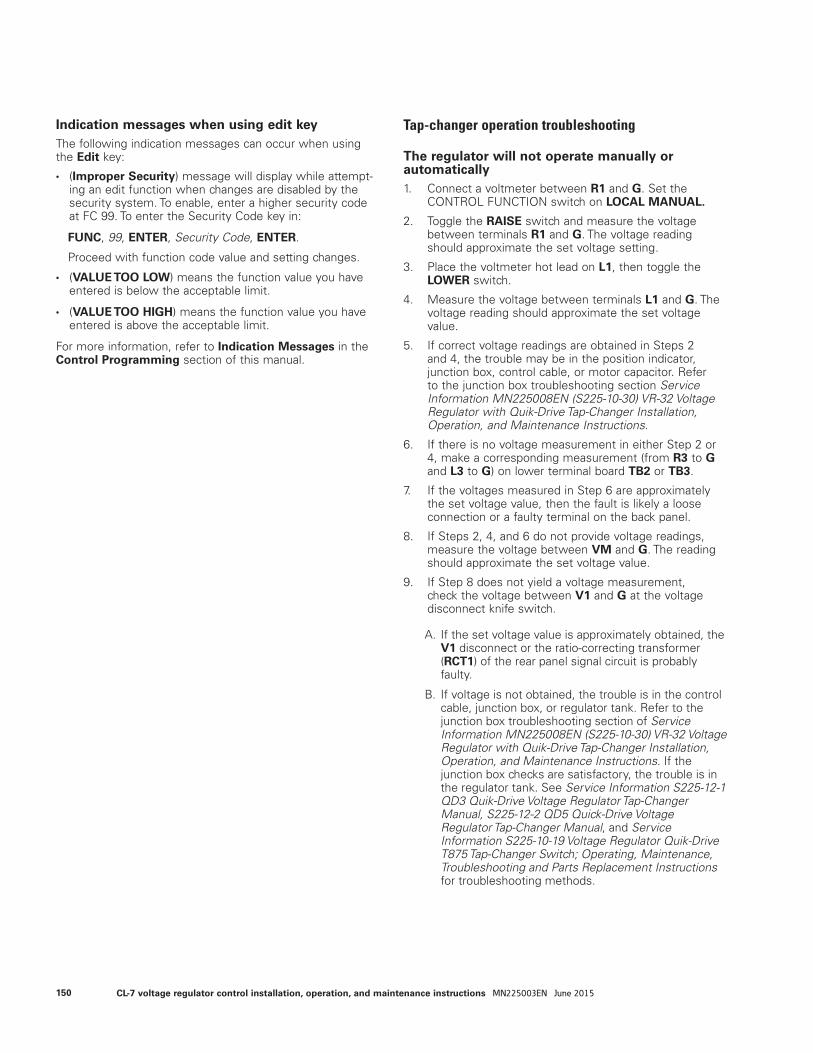
Indication messages when using edit keyThe following indication messages can occur when using the Edit key:
• (Improper Security) message will display while attempt-ing an edit function when changes are disabled by the security system. To enable, enter a higher security code at FC 99. To enter the Security Code key in:
FUNC, 99, ENTER, Security Code, ENTER.
Proceed with function code value and setting changes.
• (VALUE TOO LOW) means the function value you have entered is below the acceptable limit.
• (VALUE TOO HIGH) means the function value you have entered is above the acceptable limit.
For more information, refer to Indication Messages in the Control Programming section of this manual.
Tap-changer operation troubleshooting
The regulator will not operate manually or automatically1. Connect a voltmeter between R1 and G. Set the
CONTROL FUNCTION switch on LOCAL MANUAL.
2. Toggle the RAISE switch and measure the voltage between terminals R1 and G. The voltage reading should approximate the set voltage setting.
3. Place the voltmeter hot lead on L1, then toggle the LOWER switch.
4. Measure the voltage between terminals L1 and G. The voltage reading should approximate the set voltage value.
5. If correct voltage readings are obtained in Steps 2 and 4, the trouble may be in the position indicator, junction box, control cable, or motor capacitor. Refer to the junction box troubleshooting section Service Information MN225008EN (S225-10-30) VR-32 Voltage Regulator with Quik-Drive Tap-Changer Installation, Operation, and Maintenance Instructions.
6. If there is no voltage measurement in either Step 2 or 4, make a corresponding measurement (from R3 to G and L3 to G) on lower terminal board TB2 or TB3.
7. If the voltages measured in Step 6 are approximately the set voltage value, then the fault is likely a loose connection or a faulty terminal on the back panel.
8. If Steps 2, 4, and 6 do not provide voltage readings, measure the voltage between VM and G. The reading should approximate the set voltage value.
9. If Step 8 does not yield a voltage measurement, check the voltage between V1 and G at the voltage disconnect knife switch.
A. If the set voltage value is approximately obtained, the V1 disconnect or the ratio-correcting transformer (RCT1) of the rear panel signal circuit is probably faulty.
B. If voltage is not obtained, the trouble is in the control cable, junction box, or regulator tank. Refer to the junction box troubleshooting section of Service Information MN225008EN (S225-10-30) VR-32 Voltage Regulator with Quik-Drive Tap-Changer Installation, Operation, and Maintenance Instructions. If the junction box checks are satisfactory, the trouble is in the regulator tank. See Service Information S225-12-1 QD3 Quik-Drive Voltage Regulator Tap-Changer Manual, S225-12-2 QD5 Quick-Drive Voltage Regulator Tap-Changer Manual, and Service Information S225-10-19 Voltage Regulator Quik-Drive T875 Tap-Changer Switch; Operating, Maintenance, Troubleshooting and Parts Replacement Instructions for troubleshooting methods.
150 CL-7 voltage regulator control installation, operation, and maintenance instructions MN225003EN June 2015
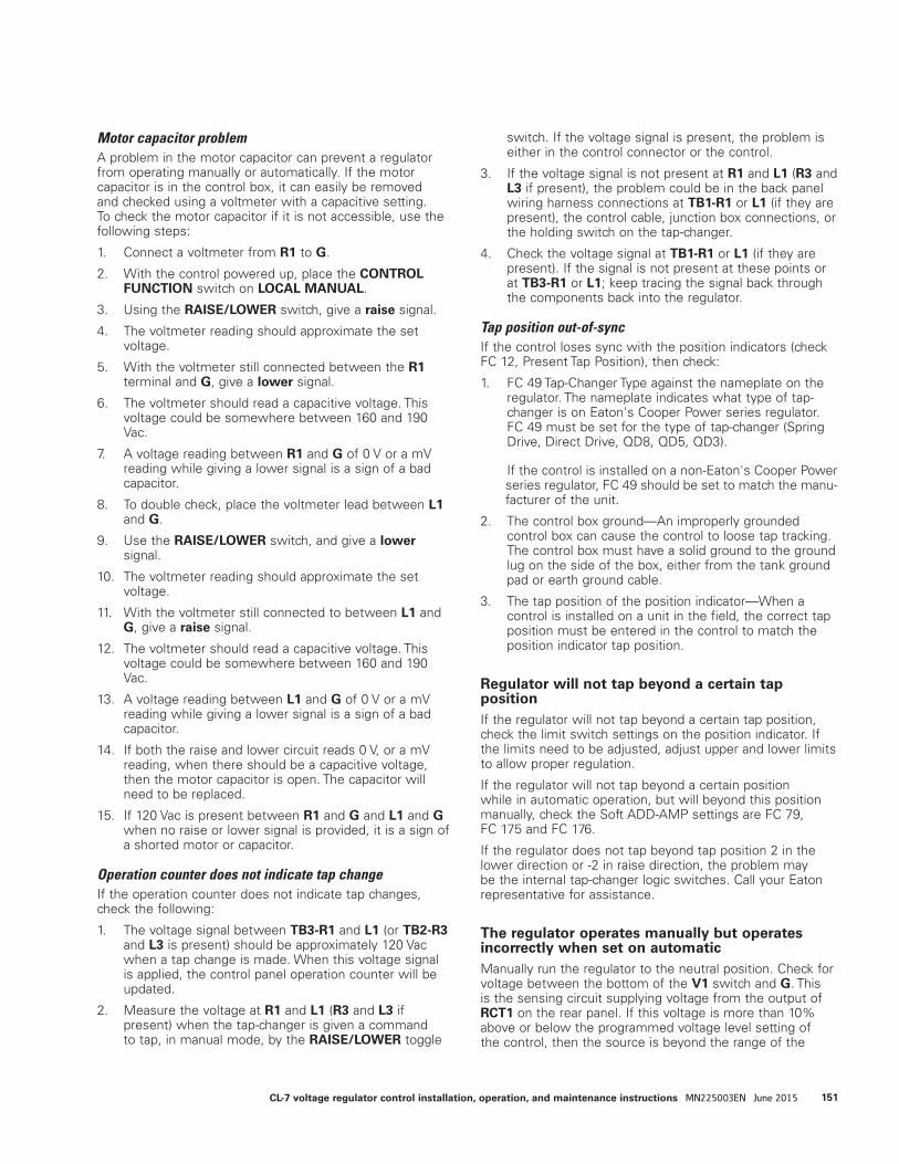
Motor capacitor problemA problem in the motor capacitor can prevent a regulator from operating manually or automatically. If the motor capacitor is in the control box, it can easily be removed and checked using a voltmeter with a capacitive setting. To check the motor capacitor if it is not accessible, use the following steps:
1. Connect a voltmeter from R1 to G.
2. With the control powered up, place the CONTROL FUNCTION switch on LOCAL MANUAL.
3. Using the RAISE/LOWER switch, give a raise signal.
4. The voltmeter reading should approximate the set voltage.
5. With the voltmeter still connected between the R1 terminal and G, give a lower signal.
6. The voltmeter should read a capacitive voltage. This voltage could be somewhere between 160 and 190 Vac.
7. A voltage reading between R1 and G of 0 V or a mV reading while giving a lower signal is a sign of a bad capacitor.
8. To double check, place the voltmeter lead between L1 and G.
9. Use the RAISE/LOWER switch, and give a lower signal.
10. The voltmeter reading should approximate the set voltage.
11. With the voltmeter still connected to between L1 and G, give a raise signal.
12. The voltmeter should read a capacitive voltage. This voltage could be somewhere between 160 and 190 Vac.
13. A voltage reading between L1 and G of 0 V or a mV reading while giving a lower signal is a sign of a bad capacitor.
14. If both the raise and lower circuit reads 0 V, or a mV reading, when there should be a capacitive voltage, then the motor capacitor is open. The capacitor will need to be replaced.
15. If 120 Vac is present between R1 and G and L1 and G when no raise or lower signal is provided, it is a sign of a shorted motor or capacitor.
Operation counter does not indicate tap changeIf the operation counter does not indicate tap changes, check the following:
1. The voltage signal between TB3-R1 and L1 (or TB2-R3 and L3 is present) should be approximately 120 Vac when a tap change is made. When this voltage signal is applied, the control panel operation counter will be updated.
2. Measure the voltage at R1 and L1 (R3 and L3 if present) when the tap-changer is given a command to tap, in manual mode, by the RAISE/LOWER toggle
switch. If the voltage signal is present, the problem is either in the control connector or the control.
3. If the voltage signal is not present at R1 and L1 (R3 and L3 if present), the problem could be in the back panel wiring harness connections at TB1-R1 or L1 (if they are present), the control cable, junction box connections, or the holding switch on the tap-changer.
4. Check the voltage signal at TB1-R1 or L1 (if they are present). If the signal is not present at these points or at TB3-R1 or L1; keep tracing the signal back through the components back into the regulator.
Tap position out-of-syncIf the control loses sync with the position indicators (check FC 12, Present Tap Position), then check:
1. FC 49 Tap-Changer Type against the nameplate on the regulator. The nameplate indicates what type of tap-changer is on Eaton's Cooper Power series regulator. FC 49 must be set for the type of tap-changer (Spring Drive, Direct Drive, QD8, QD5, QD3).
If the control is installed on a non-Eaton's Cooper Power series regulator, FC 49 should be set to match the manu-facturer of the unit.
2. The control box ground—An improperly grounded control box can cause the control to loose tap tracking. The control box must have a solid ground to the ground lug on the side of the box, either from the tank ground pad or earth ground cable.
3. The tap position of the position indicator—When a control is installed on a unit in the field, the correct tap position must be entered in the control to match the position indicator tap position.
Regulator will not tap beyond a certain tap positionIf the regulator will not tap beyond a certain tap position, check the limit switch settings on the position indicator. If the limits need to be adjusted, adjust upper and lower limits to allow proper regulation.
If the regulator will not tap beyond a certain position while in automatic operation, but will beyond this position manually, check the Soft ADD-AMP settings are FC 79, FC 175 and FC 176.
If the regulator does not tap beyond tap position 2 in the lower direction or -2 in raise direction, the problem may be the internal tap-changer logic switches. Call your Eaton representative for assistance.
The regulator operates manually but operates incorrectly when set on automaticManually run the regulator to the neutral position. Check for voltage between the bottom of the V1 switch and G. This is the sensing circuit supplying voltage from the output of RCT1 on the rear panel. If this voltage is more than 10% above or below the programmed voltage level setting of the control, then the source is beyond the range of the
151CL-7 voltage regulator control installation, operation, and maintenance instructions MN225003EN June 2015
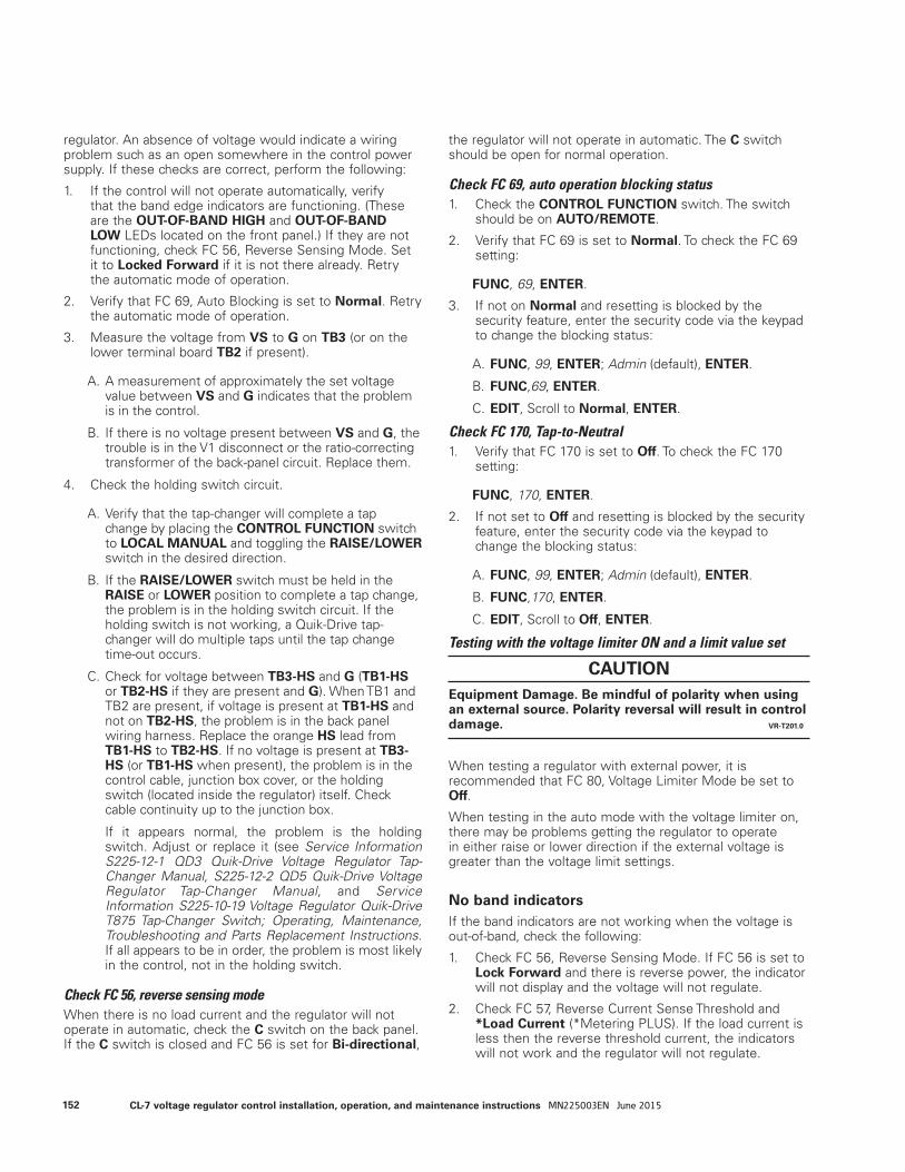
regulator. An absence of voltage would indicate a wiring problem such as an open somewhere in the control power supply. If these checks are correct, perform the following:
1. If the control will not operate automatically, verify that the band edge indicators are functioning. (These are the OUT-OF-BAND HIGH and OUT-OF-BAND LOW LEDs located on the front panel.) If they are not functioning, check FC 56, Reverse Sensing Mode. Set it to Locked Forward if it is not there already. Retry the automatic mode of operation.
2. Verify that FC 69, Auto Blocking is set to Normal. Retry the automatic mode of operation.
3. Measure the voltage from VS to G on TB3 (or on the lower terminal board TB2 if present).
A. A measurement of approximately the set voltage value between VS and G indicates that the problem is in the control.
B. If there is no voltage present between VS and G, the trouble is in the V1 disconnect or the ratio-correcting transformer of the back-panel circuit. Replace them.
4. Check the holding switch circuit.
A. Verify that the tap-changer will complete a tap change by placing the CONTROL FUNCTION switch to LOCAL MANUAL and toggling the RAISE/LOWER switch in the desired direction.
B. If the RAISE/LOWER switch must be held in the RAISE or LOWER position to complete a tap change, the problem is in the holding switch circuit. If the holding switch is not working, a Quik-Drive tap-changer will do multiple taps until the tap change time-out occurs.
C. Check for voltage between TB3-HS and G (TB1-HS or TB2-HS if they are present and G). When TB1 and TB2 are present, if voltage is present at TB1-HS and not on TB2-HS, the problem is in the back panel wiring harness. Replace the orange HS lead from TB1-HS to TB2-HS. If no voltage is present at TB3-HS (or TB1-HS when present), the problem is in the control cable, junction box cover, or the holding switch (located inside the regulator) itself. Check cable continuity up to the junction box.
If it appears normal, the problem is the holding switch. Adjust or replace it (see Service Information S225-12-1 QD3 Quik-Drive Voltage Regulator Tap-Changer Manual, S225-12-2 QD5 Quik-Drive Voltage Regulator Tap-Changer Manual, and Service Information S225-10-19 Voltage Regulator Quik-Drive T875 Tap-Changer Switch; Operating, Maintenance, Troubleshooting and Parts Replacement Instructions. If all appears to be in order, the problem is most likely in the control, not in the holding switch.
Check FC 56, reverse sensing modeWhen there is no load current and the regulator will not operate in automatic, check the C switch on the back panel. If the C switch is closed and FC 56 is set for Bi-directional,
the regulator will not operate in automatic. The C switch should be open for normal operation.
Check FC 69, auto operation blocking status1. Check the CONTROL FUNCTION switch. The switch
should be on AUTO/REMOTE.
2. Verify that FC 69 is set to Normal. To check the FC 69 setting:
FUNC, 69, ENTER.
3. If not on Normal and resetting is blocked by the security feature, enter the security code via the keypad to change the blocking status:
A. FUNC, 99, ENTER; Admin (default), ENTER.
B. FUNC,69, ENTER.
C. EDIT, Scroll to Normal, ENTER.
Check FC 170, Tap-to-Neutral1. Verify that FC 170 is set to Off. To check the FC 170
setting:
FUNC, 170, ENTER.
2. If not set to Off and resetting is blocked by the security feature, enter the security code via the keypad to change the blocking status:
A. FUNC, 99, ENTER; Admin (default), ENTER.
B. FUNC,170, ENTER.
C. EDIT, Scroll to Off, ENTER.
Testing with the voltage limiter ON and a limit value set
When testing a regulator with external power, it is recommended that FC 80, Voltage Limiter Mode be set to Off.
When testing in the auto mode with the voltage limiter on, there may be problems getting the regulator to operate in either raise or lower direction if the external voltage is greater than the voltage limit settings.
No band indicatorsIf the band indicators are not working when the voltage is out-of-band, check the following:
1. Check FC 56, Reverse Sensing Mode. If FC 56 is set to Lock Forward and there is reverse power, the indicator will not display and the voltage will not regulate.
2. Check FC 57, Reverse Current Sense Threshold and *Load Current (*Metering PLUS). If the load current is less then the reverse threshold current, the indicators will not work and the regulator will not regulate.
CAUTIONEquipment Damage. Be mindful of polarity when using an external source. Polarity reversal will result in control damage. VR-T201.0
152 CL-7 voltage regulator control installation, operation, and maintenance instructions MN225003EN June 2015

3. If the regulator has been serviced and the current transformer circuit was involved, check the polarity of the current transformer. If the polarity is reversed, the band indicators will not display.
Metering troubleshooting
Load voltage secondary (output voltage), does not match the voltmeter test terminal voltage When the output voltage at FC 6 is several volts different from the voltage at the voltmeter test terminals, verify that the following function code settings are per the nameplate:
1. Verify FC 43, System Line Voltage (Load Voltage) is set per the nameplate value.
2. Verify FC 44, Overall PT Ratio is set per the nameplate.
3. Verify RCT Control Tap located on the back panel of the control assembly is set per the nameplate.
4. Verify Control Winding E Tap and Differential Transformer P Taps, if present, are set per the nameplate. E taps are located on the terminal board on the tap-changer inside the tank. P taps may be located on the terminal board on the top of the tap-changer or on the differential potential transformer located on the side channel inside the regulator tank.
When all the settings are set per the nameplate, the regulator is in neutral, and the system line voltage or load voltage matches what is stated on the nameplate, the voltmeter test terminals on the control panel will read the value on the nameplate.
No load currentWhen there is no load current reading at FC 9, Load Current, Primary, or any of the metering components requiring current as part of the calculation, check the C switch on the back panel. The switch should be open. If the C is closed, the current transformer is shorted and no current reading is available.
Control calibration
All controls are factory-calibrated and should not need to be recalibrated. However, calibration can be performed for both the voltage and current circuits using the steps that follow. The factory calibration can be restored using FC 150.
Voltage calibration1. Connect an accurate true-RMS-responding voltmeter
to the voltmeter terminal. This voltmeter should have a base accuracy of at least 0.1% with calibration traceable to the National Bureau of Standards.
2. Connect a stable 50/60 Hz voltage source (with less than 5% harmonic content) to the External Source terminals.
3. Set the POWER switch to EXTERNAL.
4. Adjust the voltage source to provide 120.0 Vac to the control, as read on the reference voltmeter.
5. Before calibration can be performed, Security Level 3 must be activated by entering the proper security code at FC 99, Security Code.
FUNC, 99, ENTER; Admin (default), Enter.
6. Access FC 47, Voltage Calibration.
FUNC, 47, ENTER.
7. The display will show the voltage applied to the control. This should correspond to the reading on the reference voltmeter. If the control reading is significantly different, (0.6 volts or more), the calibration can be altered by pressing EDIT, keying in the correct voltage as displayed on the reference meter, and pressing ENTER. The voltage circuit is now calibrated.
ote:N When installing an Eaton's Cooper Power series control on a non-Eaton's Cooper Power series voltage regulator, the control MUST have the calibration process performed. To calibrate the control on the non-Eaton's Cooper Power series regulator the internal power (System Voltage) must be applied.
WARNING Explosion Hazard. Verify that both the neutral light and the position indicator hand indicate neutral when the tap-changer is physically in the neutral position. Lack of synchronization will cause an indefinite indication of NEUTRAL. Without both indications of neutral, bypassing of the regulator at a later time will not be possible, and the line must be de-energized to avoid shorting part of the series winding. Failure to comply can result in serious personal injury or death and equipment damage. VR-T212.0
CAUTION
Equipment Damage. Be mindful of polarity when using an external source. Polarity reversal will result in control damage. VR-T201.0
153CL-7 voltage regulator control installation, operation, and maintenance instructions MN225003EN June 2015
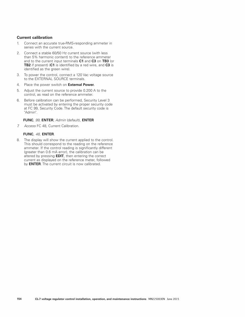
Current calibration1. Connect an accurate true-RMS-responding ammeter in
series with the current source.
2. Connect a stable 60/50 Hz current source (with less than 5% harmonic content) to the reference ammeter and to the current input terminals C1 and C3 on TB3 (or TB2 if present) (C1 is identified by a red wire, and C3 is identified as the green wire).
3. To power the control, connect a 120 Vac voltage source to the EXTERNAL SOURCE terminals.
4. Place the power switch on External Power.
5. Adjust the current source to provide 0.200 A to the control, as read on the reference ammeter.
6. Before calibration can be performed, Security Level 3 must be activated by entering the proper security code at FC 99, Security Code. The default security code is "Admin".
FUNC, 99, ENTER; Admin (default), ENTER
7. Access FC 48, Current Calibration.
FUNC, 48, ENTER.8. The display will show the current applied to the control.
This should correspond to the reading on the reference ammeter. If the control reading is significantly different (greater than 0.6 mA error), the calibration can be altered by pressing EDIT, then entering the correct current as displayed on the reference meter, followed by ENTER. The current circuit is now calibrated.
154 CL-7 voltage regulator control installation, operation, and maintenance instructions MN225003EN June 2015
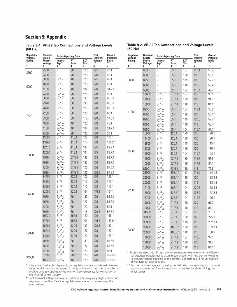
Regulator Voltage Rating
1
Nominal Single Phase Voltage 2
Ratio-Adjusting Data Test Terminal Voltage ** 6
Overall Potential Ratio ** 7
Internal Tap* 3
PT Ratio 4
RCT Tap 5
25002500
2400
-
-
20:1
20:1
120
120
125
120
20:1
20:1
5000
5000
4800
4160
2400
E1/P1E1/P1E1/P1E2/P2
40:1
40:1
40:1
20:1
120
120
104
120
125
120
120
120
40:1
40:1
34.7:1
20:1
7620
8000
7970
7620
7200
6930
4800
4160
2400
E1/P1E1/P1E1/P1E1/P1E1/P1E2/P2E2/P2E3/P3
60:1
60:1
60:1
60:1
60:1
40:1
40:1
20:1
133
133
127
120
115
120
104
120
120.5
120
120
120
120.5
120
120
120
66.5:1
66.5:1
63.5:1
60:1
57.5:1
40:1
34.7:1
20:1
13800
13800
13200
12470
12000
7970
7620
7200
6930
E1/P1E1/P1E1/P1E1/P1E2/P2E2/P2E2/P2E2/P2
115:1
115:1
115:1
115:1
57.5:1
57.5:1
57.5:1
57.5:1
120
115
104
104
133
133
120
120
120
120
125
125
125
120
120
120.5
115:1
110.2:1
99.7:1
99.7:1
63.7:1
63.7:1
57.5:1
57.5:1
14400
14400
13800
13200
12000
7970
7620
7200
6930
E1/P1E1/P1E1/P1E1/P1E2/P2E2/P2E2/P2E2/P2
120:1
120:1
120:1
120:1
60:1
60:1
60:1
60:1
120
115
110
104
133
127
120
115
120
120
120
115.5
120
120
120
120.5
120:1
115:1
110:1
104:1
66.5:1
63.5:1
60:1
57.5:1
19920
19920
17200
16000
15242
14400
7960
7620
7200
E1/P1E1/P1E2/P2E2/P2E2/P2E3/P3E3/P3E3/P3
166:1
166:1
120:1
120:1
120:1
60:1
60:1
60:1
120
104
133
127
120
133
127
120
120
119.5
120.5
120
120
120
120
120
166:1
143.9:1
133:1
127:1
120:1
66.5:1
63.5:1
60:1
3450034500
19920
E1/P1E2/P2
287.5:1
165.5:1
120
120
120
120.5
287.5:1
165.5:1
Regulator Voltage Rating 1
Nominal Single Phase Voltage 2
Ratio-Adjusting Data Test Terminal Voltage ** 6
Overall Potential Ratio ** 7
Internal Tap* 3
PT Ratio 4
RCT Tap 5
6600
6930
6600
6350
6000
5500
-
-
-
-
-
55:1
55:1
55:1
55:1
55:1
127
120
115
110
104
119.1
120
120.5
119
115.4
58.2:1
55:1
52.7:1
50.4:1
47.7:1
11000
11600
11000
10000
6930
6600
6350
6000
5500
E1/P1E1/P1E1/P1E2/P2E2/P2E2/P2E2/P2E2/P2
91.7:1
91.7:1
91.7:1
55:1
55:1
55:1
55:1
55:1
127
120
110
127
120
115
110
104
119.5
120
119
119.1
120
120.5
119
115.4
96:1
91.7:1
84.1:1
58.2:1
55.1:1
52.7:1
50.4:1
47.7:1
15000
15000
14400
13800
13200
12000
11000
10000
8600
E1/P1E1/P1E1/P1E1/P1E1/P1E2/P2E2/P2E3/P3
120:1
120:1
120:1
120:1
120:1
92.7:1
92.7:1
72.9:1
120
120
115
110
104
120
110
120
125
120
120
120
115.4
118.7
117.7
118
120:1
120:1
115:1
110:1
104:1
91.8:1
84.1:1
72.9:1
22000
23000
22000
20000
19100
15000
12700
11000
10000
E1/P1E1/P1E1/P1E1/P1E2/P2E2/P2E3/P3E3/P3
183.4:1
183.4:1
183.4:1
183.4:1
122.3:1
122.3:1
91.7:1
91.7:1
127
120
110
104
120
104
120
110
118.5
120
119
120.2
122.6
119.8
120
119
194.1:1
183.4:1
168.1:1
158.9:1
122.3:1
106:1
91.7:1
84.1:1
33000
34500
33000
30000
22000
20000
11600
11000
10000
E1/P1E1/P1E1/P1E2/P2E2/P2E3/P3E3/P3E3/P3
275:1
275:1
275:1
183.3:1
183.3:1
91.7:1
91.7:1
91.7:1
127
120
110
120
110
127
120
110
118.5
120
119
120
119
119.5
120
119
291:1
275:1
252.1:1
183.3:1
168:1
97:1
91.7:1
84.1:1
Section 9: Appendix
Table 9-1. VR-32 Tap Connections and Voltage Levels (60 Hz)
* P taps are used with E taps only on regulators where an internal differen-tial potential transformer is used in conjunction with the control winding to provide voltage supplies to the control. See nameplate for verification of this type of control supply.
** Test terminal voltage and overall potential ratio may vary slightly from one regulator to another. See the regulator nameplate for determining the exact values.
Table 9-2. VR-32 Tap Connections and Voltage Levels (50 Hz)
* P taps are used with E taps only on regulators where an internal differen-tial potential transformer is used in conjunction with the control winding to provide voltage supplies to the control. See nameplate for verification of this type of control supply.
** Test terminal voltage and overall potential ratio may vary slightly from one regulator to another. See the regulator nameplate for determining the exact values.
155CL-7 voltage regulator control installation, operation, and maintenance instructions MN225003EN June 2015
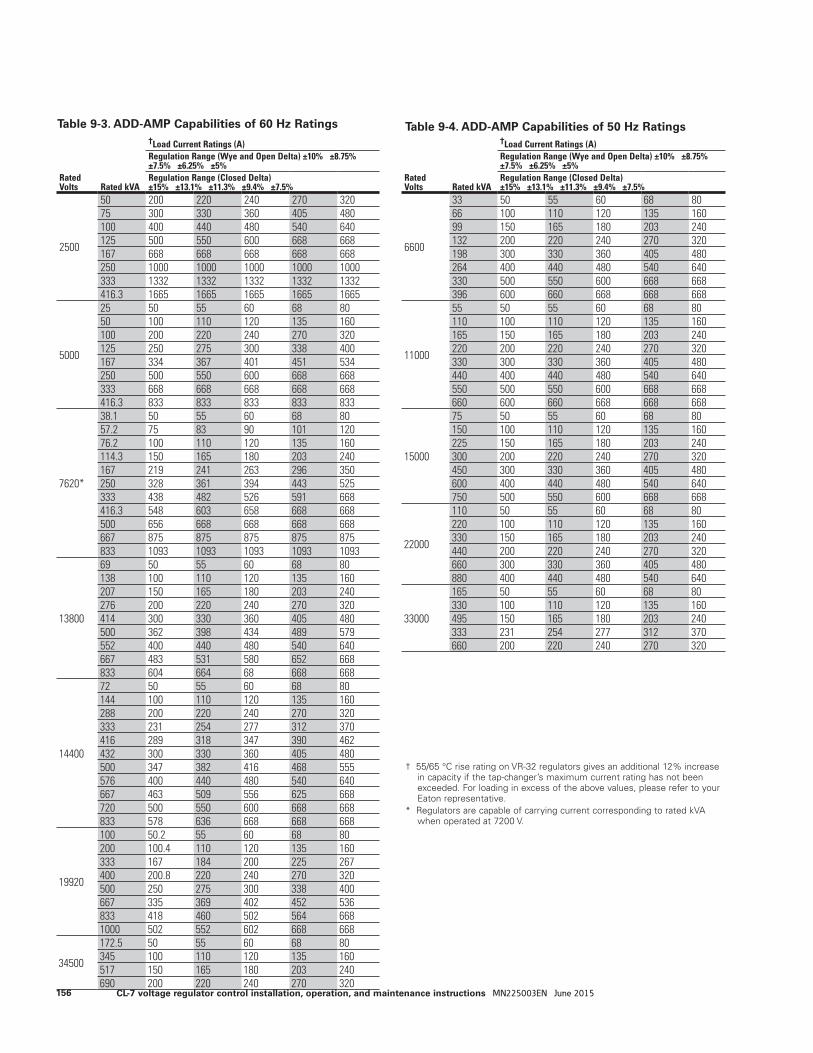
Rated Volts
Rated kVA
†Load Current Ratings (A)Regulation Range (Wye and Open Delta) ±10% ±8.75% ±7.5% ±6.25% ±5%Regulation Range (Closed Delta) ±15% ±13.1% ±11.3% ±9.4% ±7.5%
2500
50 200 220 240 270 32075 300 330 360 405 480100 400 440 480 540 640125 500 550 600 668 668167 668 668 668 668 668250 1000 1000 1000 1000 1000333 1332 1332 1332 1332 1332416.3 1665 1665 1665 1665 1665
5000
25 50 55 60 68 8050 100 110 120 135 160100 200 220 240 270 320125 250 275 300 338 400167 334 367 401 451 534250 500 550 600 668 668333 668 668 668 668 668416.3 833 833 833 833 833
7620*
38.1 50 55 60 68 8057.2 75 83 90 101 12076.2 100 110 120 135 160114.3 150 165 180 203 240167 219 241 263 296 350250 328 361 394 443 525333 438 482 526 591 668416.3 548 603 658 668 668500 656 668 668 668 668667 875 875 875 875 875833 1093 1093 1093 1093 1093
13800
69 50 55 60 68 80138 100 110 120 135 160207 150 165 180 203 240276 200 220 240 270 320414 300 330 360 405 480500 362 398 434 489 579552 400 440 480 540 640667 483 531 580 652 668833 604 664 68 668 668
14400
72 50 55 60 68 80144 100 110 120 135 160288 200 220 240 270 320333 231 254 277 312 370416 289 318 347 390 462432 300 330 360 405 480500 347 382 416 468 555576 400 440 480 540 640667 463 509 556 625 668720 500 550 600 668 668833 578 636 668 668 668
19920
100 50.2 55 60 68 80200 100.4 110 120 135 160333 167 184 200 225 267400 200.8 220 240 270 320500 250 275 300 338 400667 335 369 402 452 536833 418 460 502 564 6681000 502 552 602 668 668
34500
172.5 50 55 60 68 80345 100 110 120 135 160517 150 165 180 203 240690 200 220 240 270 320
Table 9-3. ADD-AMP Capabilities of 60 Hz Ratings
† 55/65 °C rise rating on VR-32 regulators gives an additional 12% increase in capacity if the tap-changer’s maximum current rating has not been exceeded. For loading in excess of the above values, please refer to your Eaton representative.
* Regulators are capable of carrying current corresponding to rated kVA when operated at 7200 V.
Table 9-4. ADD-AMP Capabilities of 50 Hz Ratings
Rated Volts
Rated kVA
†Load Current Ratings (A)Regulation Range (Wye and Open Delta) ±10% ±8.75% ±7.5% ±6.25% ±5%Regulation Range (Closed Delta) ±15% ±13.1% ±11.3% ±9.4% ±7.5%
6600
33 50 55 60 68 8066 100 110 120 135 16099 150 165 180 203 240132 200 220 240 270 320198 300 330 360 405 480264 400 440 480 540 640330 500 550 600 668 668396 600 660 668 668 668
11000
55 50 55 60 68 80110 100 110 120 135 160165 150 165 180 203 240220 200 220 240 270 320330 300 330 360 405 480440 400 440 480 540 640550 500 550 600 668 668660 600 660 668 668 668
15000
75 50 55 60 68 80150 100 110 120 135 160225 150 165 180 203 240300 200 220 240 270 320450 300 330 360 405 480600 400 440 480 540 640750 500 550 600 668 668
22000
110 50 55 60 68 80220 100 110 120 135 160330 150 165 180 203 240440 200 220 240 270 320660 300 330 360 405 480880 400 440 480 540 640
33000
165 50 55 60 68 80330 100 110 120 135 160495 150 165 180 203 240333 231 254 277 312 370660 200 220 240 270 320
156 CL-7 voltage regulator control installation, operation, and maintenance instructions MN225003EN June 2015

This page is intentionally left blank.
157CL-7 voltage regulator control installation, operation, and maintenance instructions MN225003EN June 2015
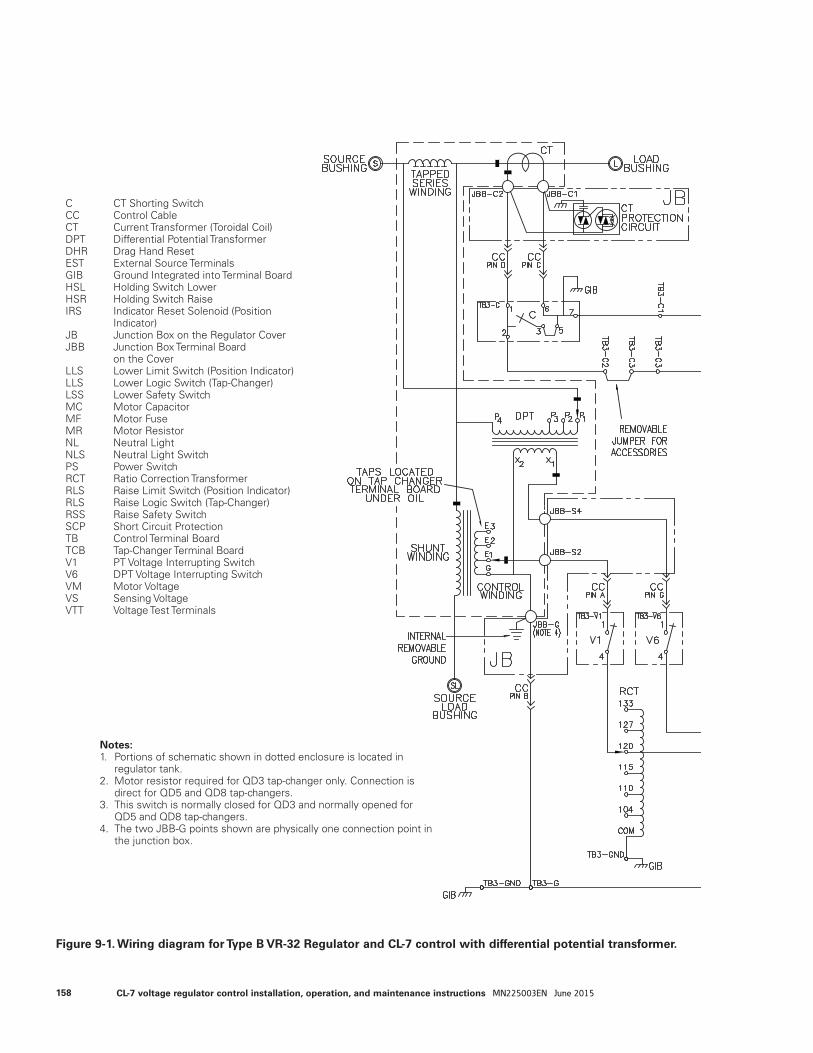
Figure 9-1. Wiring diagram for Type B VR-32 Regulator and CL-7 control with differential potential transformer.
Notes:1. Portions of schematic shown in dotted enclosure is located in
regulator tank.2. Motor resistor required for QD3 tap-changer only. Connection is
direct for QD5 and QD8 tap-changers.3. This switch is normally closed for QD3 and normally opened for
QD5 and QD8 tap-changers.4. The two JBB-G points shown are physically one connection point in
the junction box.
C CT Shorting SwitchCC Control CableCT Current Transformer (Toroidal Coil)DPT Differential Potential TransformerDHR Drag Hand ResetEST External Source TerminalsGIB Ground Integrated into Terminal BoardHSL Holding Switch LowerHSR Holding Switch RaiseIRS Indicator Reset Solenoid (Position Indicator)JB Junction Box on the Regulator CoverJBB Junction Box Terminal Board on the CoverLLS Lower Limit Switch (Position Indicator)LLS Lower Logic Switch (Tap-Changer)LSS Lower Safety SwitchMC Motor CapacitorMF Motor FuseMR Motor ResistorNL Neutral LightNLS Neutral Light SwitchPS Power SwitchRCT Ratio Correction TransformerRLS Raise Limit Switch (Position Indicator)RLS Raise Logic Switch (Tap-Changer)RSS Raise Safety SwitchSCP Short Circuit ProtectionTB Control Terminal BoardTCB Tap-Changer Terminal BoardV1 PT Voltage Interrupting SwitchV6 DPT Voltage Interrupting SwitchVM Motor VoltageVS Sensing VoltageVTT Voltage Test Terminals
158 CL-7 voltage regulator control installation, operation, and maintenance instructions MN225003EN June 2015

159CL-7 voltage regulator control installation, operation, and maintenance instructions MN225003EN June 2015
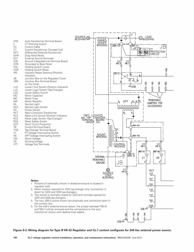
Figure 9-2. Wiring diagram for Type B VR-32 Regulator and CL-7 control configures for 240 Vac external power source.
ATB Auto-Transformer Terminal BoardC CT Shorting SwitchCC Control CableCT Current Transformer (Toroidal Coil)DPT Differential Potential TransformerDHR Drag Hand ResetEST External Source TerminalsGIB Ground Integrated into Terminal BoardGTB Grounded to Back PanelHSL Holding Switch LowerHSR Holding Switch RaiseIRS Indicator Reset Solenoid (Position Indicator)JB Junction Box on the Regulator CoverJBB Junction Box Terminal Board on the CoverLLS Lower Limit Switch (Position Indicator)LLS Lower Logic Switch (Tap-Changer)LSS Lower Safety SwitchMC Motor CapacitorMF Motor FuseMR Motor ResistorNL Neutral LightNLS Neutral Light SwitchPS Power SwitchRCT Ratio Correction TransformerRLS Raise Limit Switch (Position Indicator)RLS Raise Logic Switch (Tap-Changer)RSS Raise Safety SwitchSCP Short Circuit ProtectionTB Control Terminal BoardTCB Tap-Changer Terminal BoardV1 PT Voltage Interrupting SwitchV6 DPT Voltage Interrupting SwitchVM Motor VoltageVS Sensing VoltageVTT Voltage Test Terminals
Notes:1. Portions of schematic shown in dotted enclosure is located in regulator tank.2. Motor resistor required for QD3 tap-changer only. Connection is direct for QD5 and QD8 tap-changers.3. This switch is normally closed for QD3 and normally opened for QD5 and QD8 tap-changers.4. The two JBB-G points shown are physically one connection point in the junction box.5. For the 240 V external source option, the jumper between TB2-8 and TB2-7 will be removed and the connections to the auto transformer shown with dashed lines added.
160 CL-7 voltage regulator control installation, operation, and maintenance instructions MN225003EN June 2015
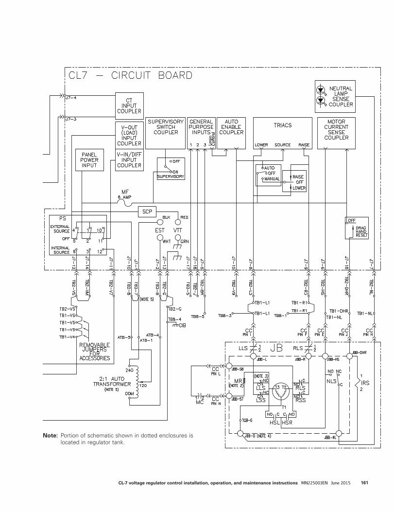
ote:N Portion of schematic shown in dotted enclosures is located in regulator tank.
161CL-7 voltage regulator control installation, operation, and maintenance instructions MN225003EN June 2015
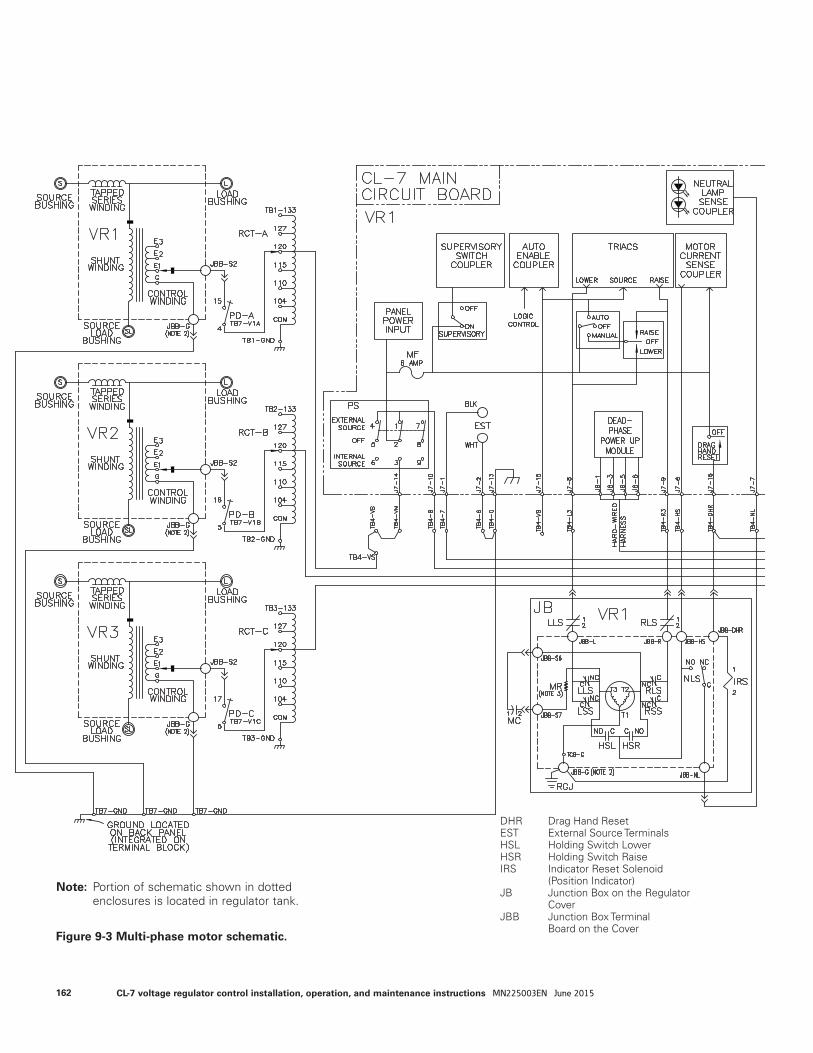
DHR Drag Hand ResetEST External Source TerminalsHSL Holding Switch LowerHSR Holding Switch RaiseIRS Indicator Reset Solenoid
(Position Indicator)JB Junction Box on the Regulator
CoverJBB Junction Box Terminal
Board on the Cover
ote:N Portion of schematic shown in dotted enclosures is located in regulator tank.
Figure 9-3 Multi-phase motor schematic.
162 CL-7 voltage regulator control installation, operation, and maintenance instructions MN225003EN June 2015
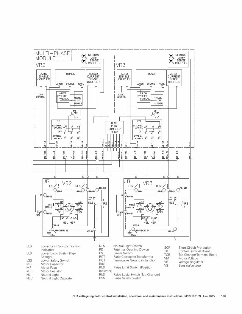
LLS Lower Limit Switch (Position Indicator)LLS Lower Logic Switch (Tap- Changer)LSS Lower Safety SwitchMC Motor CapacitorMF Motor FuseMR Motor ResistorNL Neutral LightNLC Neutral Light Capacitor
NLS Neutral Light SwitchPD Potential Opening DevicePS Power SwitchRCT Ratio Correction TransformerRGJ Removable Ground in Junction BoxRLS Raise Limit Switch (Position Indicator)RLS Raise Logic Switch (Tap-Changer)RSS Raise Safety Switch
SCP Short Circuit ProtectionTB Control Terminal BoardTCB Tap-Changer Terminal BoardVM Motor VoltageVR Voltage RegulatorVS Sensing Voltage
163CL-7 voltage regulator control installation, operation, and maintenance instructions MN225003EN June 2015

Figure 9-4. Multi-phase metering schematic
164 CL-7 voltage regulator control installation, operation, and maintenance instructions MN225003EN June 2015

CT Current Transformer (Toroidal Coil)CTP CT Protection DeviceDHR Drag Hand ResetEST External Source TerminalsJB Junction Box on the Regulator CoverJBB Junction Box Terminal Board on the CoverNL Neutral LightPD Potential Opening DevicePS Power SwitchRCT Ratio Correction TransformerSCP Short Circuit ProtectionTB Control Terminal BoardVS Sensing VoltageVTT Voltage Test Terminals
165CL-7 voltage regulator control installation, operation, and maintenance instructions MN225003EN June 2015
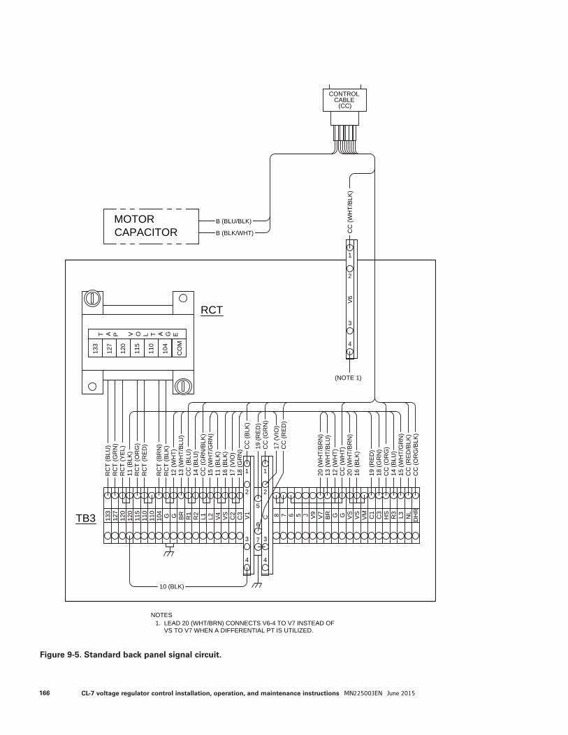
RC
T (B
LU)
RCT
RC
T (G
RN
)R
CT
(YE
L)
RC
T (O
RG
)
RC
T (B
RN
)R
CT
(BLK
)
133
127
120
115
110
CO
M
104
T A P V O L T A G E
V1
CONTROLCABLE
133
127
120
120
115
110
110
104 G G BR
R1
L2L1R2
V4
C3
C2
VS 8C 7 6 5 J V9
BR G G VS
VS
VM C1
C3
HS R3 L3 NL
DH
R
V7TB3
RC
T (R
ED
)
(CC)
12 (W
HT)
13 (W
HT/
BLU
)C
C (B
LU)
14 (B
LU)
CC
(GR
N/B
LK)
15 (W
HT/
GR
N)
11 (B
LK)
16 (B
LK)
17 (V
IO)
18 (G
RN
)
20 (W
HT/
BR
N)
13 (W
HT/
BLU
)
11 (B
LK)
MOTORCAPACITOR
B (BLU/BLK)
B (BLK/WHT)
12 (W
HT)
CC
(WH
T)20
(WH
T/B
RN
)16
(BLK
)
19 (R
ED
)18
(GR
N)
CC
(OR
G)
14 (B
LU)
15 (W
HT/
GR
N)
CC
(RE
D/B
LK)
CC
(OR
G/B
LK)
1
2
3 3
1
2
4 4
7
6
5
10 (BLK)
CC
(BLK
)
CC
(GR
N)
19 (R
ED
)
17 (V
IO)
CC
(RE
D)
V6
1
2
3
4C
C (W
HT/
BLK
)
(NOTE 1)
NOTES1. LEAD 20 (WHT/BRN) CONNECTS V6-4 TO V7 INSTEAD OF VS TO V7 WHEN A DIFFERENTIAL PT IS UTILIZED.
Figure 9-5. Standard back panel signal circuit.
166 CL-7 voltage regulator control installation, operation, and maintenance instructions MN225003EN June 2015
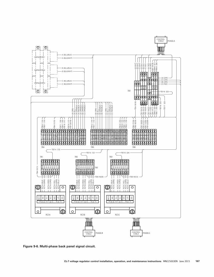
TB3TB2TB1
RCT-A RCT-B RCT-C
TB4 TB5 TB6
TB7
TB2
PHASE-B PHASE-C
PHASE-A
CAPACITOR-1
CAPACITOR-2
CAPACITOR-3
1 2 3 4 5 6 7 8 9
10 1112131415161718
133127120120115110110104G
ND
1 2 3 4 5 6 7 8 9
10 1112131415161718
133127120120115110110104G
ND
1 2 3 4 5 6 7 8 9
10 1112131415161718
133127120120115110110104G
ND
RC
T-A
(BLK
)R
CT-
A (B
RN
)
RC
T-A
(RE
D)
RC
T-A
(OR
G)
RC
T-A
(YE
L)R
CT-
A (G
RN
)R
CT-
A (B
LU)
RC
T-B
(BLK
)R
CT-
B (B
RN
)
RC
T-B
(RE
D)
RC
T-B
(OR
G)
RC
T-B
(YE
L)R
CT-
B (G
RN
)R
CT-
B (B
LU)
RC
T-C
(BLK
)R
CT-
C (B
RN
)
RC
T-C
(RE
D)
RC
T-C
(OR
G)
RC
T-C
(YE
L)R
CT-
C (G
RN
)R
CT-
C (B
LU)
133
127
120
115
110
CO
M
104
TAPVOLTAGE
133
127
120
115
110
CO
M
104
TAPVOLTAGE
133
127
120
115
110
CO
M
104
TAPVOLTAGE
1 2 3 4 5 6 7 8 9
7
111213141516171819202122DH
RD
HR
DH
RN
L
1 2 3 4 5 6 7 8 9
EP
I
1112131415161718
L-C
1 2 3 4 5 6 7 8 9
VS
B
1 2 3 4 5 6 7 8 9 101 2 3 4 5 6 7 8 9 10
11121314151617181920212210 111213141516171810 111210
11121 2 3 4 5 6 7 8 9 10
151617
4 5 6 9 1110
202122
121314
1 2 3 7 8
1819
8 6 5 J G G L3R3
HS
C3
C1
VMVS
VS
BRV7
V9
R-C
HS
CV
9BN
LBL-BR
-BH
SB
EP
O
NLC
V9C
VM
BV
MC
VS
BV
SC
VOB
VOC
VS
CV
7BV
7CC
1BC
3BC
1CC
3CTS
TSP
TSC
TSN
TB5-
2 (1
4)
TB1-
15(1
3)
TB5-
1 (1
4)
TB4-
11(1
5)
TB7-
1 (1
6)TB
4-7
(15)
TB1-
6 (1
1)
TB7-
9 (1
7)TB
7-20
(18)
TB4-
2 (1
4)TB
4-1
(14)
TB5-
17(1
9)TB
5-18
(19)
TB7-
10(2
0)TB
7-21
(21)
TB7-
11(2
0)TB
7-22
(26)
TB4-
10(1
6)
TB2-
15(1
2)TB
3-15
(24)
TB7-
10(2
2)TB
7-11
(22)
TB4-
14(1
7)TB
6-5
(20)
TB6-
7 (2
0)
V1C
CC
CB
CA
V1B
V1A
TB7-9 (22)
TB2-
6 (2
5)TB
3-6
(12)
TB6-
1 (1
9)TB
6-2
(19)
TB4-
15(1
8)TB
6-6
(21)
TB6-
8 (2
6)
TB7-
7 (2
2)
TB7-
8 (2
2)
TB7-4 (13)
TB4-
12(1
1)
TB5-15(25) TB5-16(12)
TB7-6 (24)TB7-5 (12)
CONTROLCABLE
CONTROLCABLE
(A) O
RN
(A) G
RN
/BLK
(A) B
LU
(A) R
ED
/BLK
(A) O
RN
/BLK
(B) O
RN
/BLK
(C) O
RN
/BLK
CONTROLCABLE
(B) O
RN
(B) G
RN
/BLK
(B) B
LU
(B) R
ED
/BLK
(C) O
RN
(C) G
RN
/BLK
(C) B
LU
(C) R
ED
/BLK
(A) W
HT
(B) W
HT
(C) W
HT
(A) B
LK(B
) BLK
(C) B
LK
(A) R
ED
(B) R
ED
(C) GRN(B) GRN
(A) GRN
(C) RED
A (BLU/BLK)
A (BLK/WHT)
B (BLU/BLK)
C (BLU/BLK)
B (BLK/WHT)
C (BLK/WHT)
Figure 9-6. Multi-phase back panel signal circuit.
167CL-7 voltage regulator control installation, operation, and maintenance instructions MN225003EN June 2015

This page is intentionally left blank.
168 CL-7 voltage regulator control installation, operation, and maintenance instructions MN225003EN June 2015

This page is intentionally left blank.
169CL-7 voltage regulator control installation, operation, and maintenance instructions MN225003EN June 2015

Eaton, Cooper Power, ADD-AMP, Metering-PLUS, PMT, Quik-Drive, Quik-Start, TIME-ON-TAP, and ProView NXG are valuable trademarks of Eaton in the U.S. and other countries. You are not permitted to use these trademarks without the prior written consent of Eaton. IEEE Std C37.90.1™-2012, IEEE Std C37.90.2™-2004, IEEE Std C57.13™-2008, IEEE Std C57.15™-2009, IEEE Std C57.91™-2011, and IEEE Std C57.131™-2012 standards are trademarks of the Institute of Electrical and Electronics Engineers, Inc., (IEEE). This product is not endorsed or approved by the IEEE.All other trademarks are property of their respective owners.
Eaton1000 Eaton BoulevardCleveland, OH 44122United StatesEaton.com
Eaton’s Cooper Power Systems Division2300 Badger DriveWaukesha, WI 53188United StatesEaton.com/cooperpowerseries
© 2015 EatonAll Rights ReservedPrinted in USAPublication No. MN225005EN / June 2015
!SAFETYFOR LIFE
For Eaton's Cooper Power series CL-7 regulator control product information, call 1-877-277-4636 or visit: www.eaton.com/cooperpowerseries.