Embed Size (px)
Citation preview
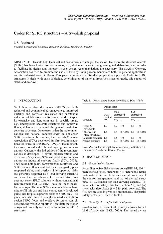
Tailor Made Concrete Structures – Walraven & Stoelhorst (eds)© 2008 Taylor & Francis Group, London, ISBN 978-0-415-47535-8
Codes for SFRC structures – A Swedish proposal
J. SilfwerbrandSwedish Cement and Concrete Research Institute, Stockholm, Sweden
ABSTRACT: Despite both technical and economical advantages, the use of Steel Fibre Reinforced Concrete(SFRC) has been limited to certain areas, e.g., shotcrete for rock strengthening and slabs-on-grade. In orderto facilitate its design and increase its use, design recommendations are necessary. The Swedish ConcreteAssociation has tried to promote the use of SFRC by issuing recommendations both for general applicationsand for industrial concrete floors. This paper summaries the Swedish proposal to a possible Code for SFRCstructures. It deals with basis of design, determination of material properties, slabs-on-grade, pile-supportedslabs, and overlays.
1 INTRODUCTION
Steel fibre reinforced concrete (SFRC) has bothtechnical and economical advantages, e.g., improvedductility and corrosion resistance and substantialreduction of laborious reinforcement work. Despiteits extensive and long-term use in specific areas,e.g., underground shotcrete structures and industrialfloors, it has not conquered the general market ofconcrete structures. One reason is that the major inter-national and national concrete codes do not coverSFRC structures. In Sweden, the Swedish ConcreteAssociation (SCA) developed its first recommenda-tions for SFRC in 1995 (SCA, 1997). At that moment,they were considered to be cutting-edge recommen-dations. Currently, the 3rd edition of the recommen-dations is developed. It covers modernizations andextensions. Very soon, SCA will publish recommen-dations on industrial concrete floors (SCA, 2008).They cover both plain, conventionally reinforced andSFR concrete floors and both slabs-on-grade, pile-supported slabs, and overlays. Pile-supported slabsare generally regarded as a load-carrying structureand since the Swedish code for concrete structuresdoes not cover SFRC solutions without conventionalreinforcement (“SFRC only”) have not been possi-ble to design. The new SCA recommendations havetried to fill this gap and have consequently developedguidelines for pile-supported slabs of SFRC only. Theguidelines also present straight-forward methods todesign SFRC floors and overlays for crack control.Together, the two SCA reports will facilitate the properdesign and probably increase the future use of SFRCstructures.
Table 1. Partial safety factors according to SCA (1997).
Design state
ULS – SLS –ULS – uncracked uncrackedcracked
Structure ηγm ηγm ζ ηγm ζ
Floors & 1.2 1.2 1.0 1.0 1.0pavements
Other cast-in 1.5 1.4 2-R/100 1.0 2-R/100place structures
Concrete products 1.5 1.5 1.0 1.0 1.0Precast elements 1.5 1.3 2-R/100 1.0 2-R/100
Note: R = residual strength factor according to Section 3.2.For tension: R = R2, for flexure: R = R1.
2 BASIS OF DESIGN
2.1 Partial safety factors
According to Swedish concrete code (BBK 04, 2004),there are four safety factors: (i) η = factor consideringsystematic difference between material properties ofthe control test specimen and that of the real struc-ture, (ii) γm = factor for load-carrying capacity, (iii)γn = factor for safety class (see Section 2.2), and (iv)ζ = crack safety factor (ζ = 2 for plain concrete). Thefirst two are usually given as a product ηγm.The partialsafety factors are listed in Table 1.
2.2 Security classes for industrial floors
Sweden uses a concept of security classes for allkind of structures (BKR, 2003). The security class
553
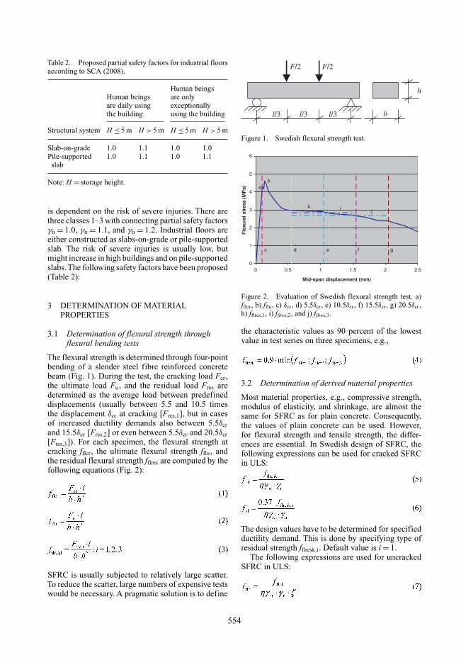
Table 2. Proposed partial safety factors for industrial floorsaccording to SCA (2008).
Human beingsHuman beings are onlyare daily using exceptionallythe building using the building
Structural system H ≤ 5 m H > 5 m H ≤ 5 m H > 5 m
Slab-on-grade 1.0 1.1 1.0 1.0Pile-supported 1.0 1.1 1.0 1.1
slab
Note: H = storage height.
is dependent on the risk of severe injuries. There arethree classes 1–3 with connecting partial safety factorsγn = 1.0, γn = 1.1, and γn = 1.2. Industrial floors areeither constructed as slabs-on-grade or pile-supportedslab. The risk of severe injuries is usually low, butmight increase in high buildings and on pile-supportedslabs. The following safety factors have been proposed(Table 2):
3 DETERMINATION OF MATERIALPROPERTIES
3.1 Determination of flexural strength throughflexural bending tests
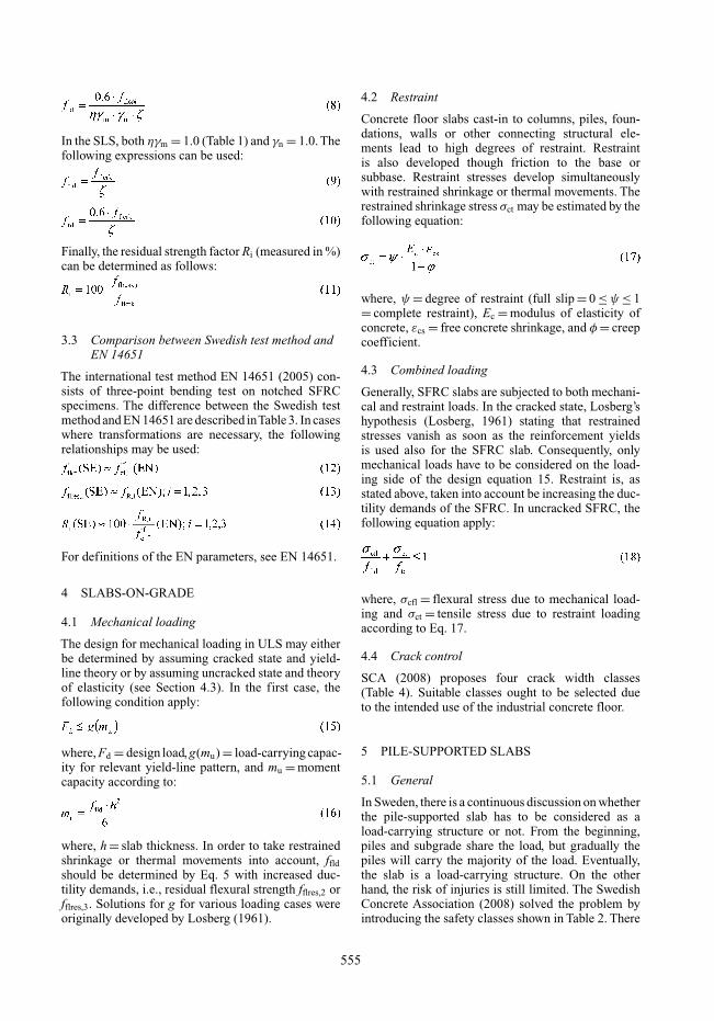
The flexural strength is determined through four-pointbending of a slender steel fibre reinforced concretebeam (Fig. 1). During the test, the cracking load Fcr ,the ultimate load Fu, and the residual load Fres aredetermined as the average load between predefineddisplacements (usually between 5.5 and 10.5 timesthe displacement δcr at cracking [Fres,1], but in casesof increased ductility demands also between 5.5δcrand 15.5δcr [Fres,2] or even between 5.5δcr and 20.5δcr[Fres,3]). For each specimen, the flexural strength atcracking fflcr , the ultimate flexural strength fflu, andthe residual flexural strength fflres are computed by thefollowing equations (Fig. 2):
SFRC is usually subjected to relatively large scatter.To reduce the scatter, large numbers of expensive testswould be necessary. A pragmatic solution is to define
F/2 F/2
l/3 l/3l/3
h
b
Figure 1. Swedish flexural strength test.
0
1
2
3
4
5
6
0 0.5 1 1.5 2 2.5
Mid-span displacement (mm)
Fle
xura
l st
ress
(M
Pa) a
b
c d e f g
h i j
Figure 2. Evaluation of Swedish flexural strength test. a)fflcr , b) fflu , c) δcr , d) 5.5δcr , e) 10.5δcr , f) 15.5δcr , g) 20.5δcr ,h) fflres,1, i) fflres,2, and j) fflres,3.
the characteristic values as 90 percent of the lowestvalue in test series on three specimens, e.g.,
3.2 Determination of derived material properties
Most material properties, e.g., compressive strength,modulus of elasticity, and shrinkage, are almost thesame for SFRC as for plain concrete. Consequently,the values of plain concrete can be used. However,for flexural strength and tensile strength, the differ-ences are essential. In Swedish design of SFRC, thefollowing expressions can be used for cracked SFRCin ULS:
The design values have to be determined for specifiedductility demand. This is done by specifying type ofresidual strength fflresk,i. Default value is i = 1.
The following expressions are used for uncrackedSFRC in ULS:
554
In the SLS, both ηγm = 1.0 (Table 1) and γn = 1.0. Thefollowing expressions can be used:
Finally, the residual strength factor Ri (measured in %)can be determined as follows:
3.3 Comparison between Swedish test method andEN 14651
The international test method EN 14651 (2005) con-sists of three-point bending test on notched SFRCspecimens. The difference between the Swedish testmethod and EN 14651 are described inTable 3. In caseswhere transformations are necessary, the followingrelationships may be used:
For definitions of the EN parameters, see EN 14651.
4 SLABS-ON-GRADE
4.1 Mechanical loading
The design for mechanical loading in ULS may eitherbe determined by assuming cracked state and yield-line theory or by assuming uncracked state and theoryof elasticity (see Section 4.3). In the first case, thefollowing condition apply:
where, Fd = design load, g(mu) = load-carrying capac-ity for relevant yield-line pattern, and mu = momentcapacity according to:
where, h = slab thickness. In order to take restrainedshrinkage or thermal movements into account, ffldshould be determined by Eq. 5 with increased duc-tility demands, i.e., residual flexural strength fflres,2 orfflres,3. Solutions for g for various loading cases wereoriginally developed by Losberg (1961).
4.2 Restraint
Concrete floor slabs cast-in to columns, piles, foun-dations, walls or other connecting structural ele-ments lead to high degrees of restraint. Restraintis also developed though friction to the base orsubbase. Restraint stresses develop simultaneouslywith restrained shrinkage or thermal movements. Therestrained shrinkage stress σct may be estimated by thefollowing equation:
where, ψ = degree of restraint (full slip = 0 ≤ ψ ≤ 1= complete restraint), Ec = modulus of elasticity ofconcrete, εcs = free concrete shrinkage, and φ = creepcoefficient.
4.3 Combined loading
Generally, SFRC slabs are subjected to both mechani-cal and restraint loads. In the cracked state, Losberg’shypothesis (Losberg, 1961) stating that restrainedstresses vanish as soon as the reinforcement yieldsis used also for the SFRC slab. Consequently, onlymechanical loads have to be considered on the load-ing side of the design equation 15. Restraint is, asstated above, taken into account be increasing the duc-tility demands of the SFRC. In uncracked SFRC, thefollowing equation apply:
where, σcfl = flexural stress due to mechanical load-ing and σct = tensile stress due to restraint loadingaccording to Eq. 17.
4.4 Crack control
SCA (2008) proposes four crack width classes(Table 4). Suitable classes ought to be selected dueto the intended use of the industrial concrete floor.
5 PILE-SUPPORTED SLABS
5.1 General
In Sweden, there is a continuous discussion on whetherthe pile-supported slab has to be considered as aload-carrying structure or not. From the beginning,piles and subgrade share the load, but gradually thepiles will carry the majority of the load. Eventually,the slab is a load-carrying structure. On the otherhand, the risk of injuries is still limited. The SwedishConcrete Association (2008) solved the problem byintroducing the safety classes shown in Table 2. There
555
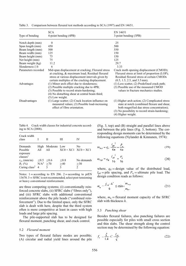
Table 3. Comparison between flexural test methods according to SCA (1997) and EN 14651.
SCA EN 14651Type of bending 4-point bending (4PB) 3-point bending (3PB)
Notch depth (mm) 0 25Span length (mm) 450 500Beam length (mm) 500 550Beam width (mm) 125 150Beam height (mm) 75 150Net height (mm) 75 125Beam weight (kg) 11.2 29.7Slenderness l/h 6 3.33Parameters recorded Mid-span displacement at cracking; Flexural stress Crack moth opening displacement (CMOD);
at cracking, & maximum load; Residual flexural Flexural stress at limit of proportion (LOP);stress at various displacement intervals given by Residual flexural stress at certain CMODscertain multiples of the cracking displacement. (0.5, 1.5, 2.5, and 3.5 mm).
Advantages (1) Minor arch effect due to slenderness; (1) Less scatter, (2) Predefined crack path;(2) Possible multiple cracking due to 4PB; (3) Possible use of the measured CMOD(3) Possible to record strain-hardening; values in fracture mechanics studies.(4) No disturbing shear at central beam third;(5) Low weight.
Disadvantages (1) Large scatter; (2) Crack location influence on (1) Higher arch action; (2) Complicated stressmeasured values; (3) Possible load-increasing state at notch (combined flexure and shear,effect of fibre orientation. both magnified due stress concentration);
(3) No possibility to record strain-hardening;(4) Higher weight.
Table 4. Crack width classes for industrial concrete accord-ing to SCA (2008).
Crack widthclass I II III IV
Demands High Moderate Low NoPossible All All XC0 + XC1 XC0 + XC1exposureclasses1
εcs (mm/m) ≤0.5 ≤0.6 ≤0.8 No demandsR1 (%) N/A3 ≥70 ≥40 ≥30Curing class2 4 3 3 2
Notes: 1 = according to EN 206. 2 = according to prEN13670. 3 = SFRC is not recommended, select post-tensioningor heavy conventional reinforcement.
are three competing systems; (i) conventionally rein-forced concrete slabs, (ii) SFRC slabs (“fibres only”),and (iii) SFRC slabs with additional conventionalreinforcement above the pile heads (“combined rein-forcement”). Due to the limited space, only the SFRCslab is dealt with here, despite that the third systemoften is more competitive at least in cases with highloads and large pile spacing.
The pile-supported slab has to be designed forflexural moment, punching shear, and crack control.
5.2 Flexural moment
Two types of flexural failure modes are possible;(A) circular and radial yield lines around the pile
(Fig. 3, top) and (B) straight and parallel lines aboveand between the pile lines (Fig. 3, bottom). The cor-responding design moments can be determined by thefollowing equations (Nylander & Kinnunen, 1974):
where, qd = design value of the distributed load,lpd = pile spacing, and Pu = ultimate pile load. Thedesign condition reads as follows:
where, mu = flexural moment capacity of the SFRCslab with thickness h.
5.3 Punching shear
Besides flexural failures, also punching failures arepossible especially for piles with small cross sectionand thin slabs. The shear strength along the controlsection may be determined by the following equation:
556
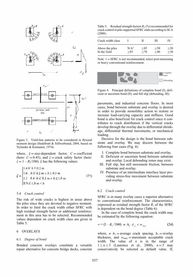
Figure 3. Yield-line patterns to be considered in flexuralmoment design (Hedebratt & Silfwerbrand, 2004, based onNylander & Kinnunen, 1974).
where, ξ = size-dependent factor, C = coefficient(here: C = 0.45), and ζ = crack safety factor (here:ζ = 1 – R2/100). ξ has the following values:
5.4 Crack control
The risk of wide cracks is highest in areas abovethe piles since they are devoted to negative moment.In order to limit the crack width either SFRC withhigh residual strength factor or additional reinforce-ment in this area has to be selected. Recommendedvalues dependent on crack width class are given inTable 5.
6 OVERLAYS
6.1 Degree of bond
Bonded concrete overlays constitute a versatilerepair alternative for concrete bridge decks, concrete
Table 5. Residual strength factors R2 (%) recommended forcrack control in pile-supported SFRC slabs according to SCA(2008).
Crack width class I II III IV
Above the piles N/A1 ≥85 ≥50 ≥30In the field ≥85 ≥70 ≥40 ≥30
Note: 1 = SFRC is not recommended, select post-tensioningor heavy conventional reinforcement.
Complete
bond
Debonding
Figure 4. Principal definitions of complete bond (I), defi-cient or uncertain bond (II), and full slip (debonding, III).
pavements, and industrial concrete floors. In mostcases, bond between substrate and overlay is desiredin order to provide monolithic action to restore orincrease load-carrying capacity and stiffness. Goodbond is also beneficial for crack control since it con-tributes to crack distribution if the vertical cracksdevelop through the overlay due to differential shrink-age, differential thermal movements, or mechanicalloading.
Decisive for the design is the bond between sub-strate and overlay. We may discern between thefollowing four cases (Fig. 4):
I. Complete bond between substrate and overlay.II. Deficient or uncertain bond between substrate
and overlay. Local debonding zones may exist.III. Full slip, but still movement friction, between
substrate and overlay.IV. Presence of an intermediate interface layer pro-
viding stress-free movement between substrateand overlay.
6.2 Crack control
SFRC is in many overlay cases a superior alternativeto conventional reinforcement. The characteristics,expressed as residual strength factor R, of the SFRCis dependent on the bond degree (Table 6).
In the case of complete bond, the crack width maybe estimated by the following equation:
where, n · h1 = average crack spacing, h1 = overlaythickness, and wmax = maximum acceptable crackwidth. The value of n is in the range of1 ≤ n ≤ 3 (Laurence et al., 2000), n = 3 mayconservatively be selected as default value. If,
557
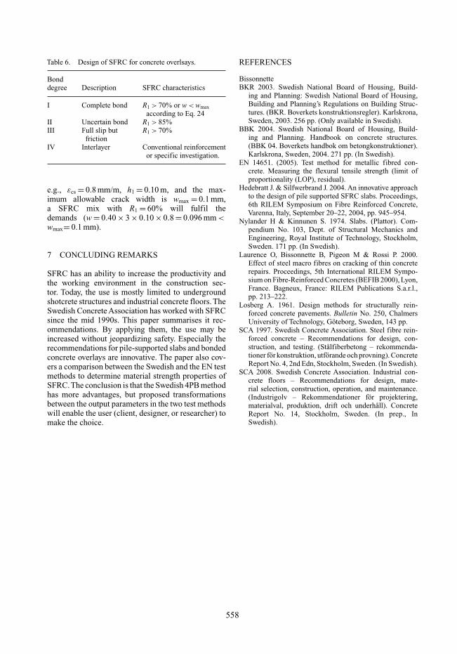
Table 6. Design of SFRC for concrete overlsays.
Bonddegree Description SFRC characteristics
I Complete bond R1 > 70% or w < wmaxaccording to Eq. 24
II Uncertain bond R1 > 85%III Full slip but R1 > 70%
frictionIV Interlayer Conventional reinforcement
or specific investigation.
e.g., εcs = 0.8 mm/m, h1 = 0.10 m, and the max-imum allowable crack width is wmax = 0.1 mm,a SFRC mix with R1 = 60% will fulfil thedemands (w = 0.40 × 3 × 0.10 × 0.8 = 0.096 mm <wmax= 0.1 mm).
7 CONCLUDING REMARKS
SFRC has an ability to increase the productivity andthe working environment in the construction sec-tor. Today, the use is mostly limited to undergroundshotcrete structures and industrial concrete floors. TheSwedish Concrete Association has worked with SFRCsince the mid 1990s. This paper summarises it rec-ommendations. By applying them, the use may beincreased without jeopardizing safety. Especially therecommendations for pile-supported slabs and bondedconcrete overlays are innovative. The paper also cov-ers a comparison between the Swedish and the EN testmethods to determine material strength properties ofSFRC.The conclusion is that the Swedish 4PB methodhas more advantages, but proposed transformationsbetween the output parameters in the two test methodswill enable the user (client, designer, or researcher) tomake the choice.
REFERENCES
BissonnetteBKR 2003. Swedish National Board of Housing, Build-
ing and Planning: Swedish National Board of Housing,Building and Planning’s Regulations on Building Struc-tures. (BKR. Boverkets konstruktionsregler). Karlskrona,Sweden, 2003. 256 pp. (Only available in Swedish).
BBK 2004. Swedish National Board of Housing, Build-ing and Planning. Handbook on concrete structures.(BBK 04. Boverkets handbok om betongkonstruktioner).Karlskrona, Sweden, 2004. 271 pp. (In Swedish).
EN 14651. (2005). Test method for metallic fibred con-crete. Measuring the flexural tensile strength (limit ofproportionality (LOP), residual).
Hedebratt J. & Silfwerbrand J. 2004. An innovative approachto the design of pile supported SFRC slabs. Proceedings,6th RILEM Symposium on Fibre Reinforced Concrete,Varenna, Italy, September 20–22, 2004, pp. 945–954.
Nylander H & Kinnunen S. 1974. Slabs. (Plattor). Com-pendium No. 103, Dept. of Structural Mechanics andEngineering, Royal Institute of Technology, Stockholm,Sweden. 171 pp. (In Swedish).
Laurence O, Bissonnette B, Pigeon M & Rossi P. 2000.Effect of steel macro fibres on cracking of thin concreterepairs. Proceedings, 5th International RILEM Sympo-sium on Fibre-Reinforced Concretes (BEFIB 2000), Lyon,France. Bagneux, France: RILEM Publications S.a.r.l.,pp. 213–222.
Losberg A. 1961. Design methods for structurally rein-forced concrete pavements. Bulletin No. 250, ChalmersUniversity of Technology, Göteborg, Sweden, 143 pp.
SCA 1997. Swedish Concrete Association. Steel fibre rein-forced concrete – Recommendations for design, con-struction, and testing. (Stålfiberbetong – rekommenda-tioner för konstruktion, utförande och provning). ConcreteReport No. 4, 2nd Edn, Stockholm, Sweden. (In Swedish).
SCA 2008. Swedish Concrete Association. Industrial con-crete floors – Recommendations for design, mate-rial selection, construction, operation, and maintenance.(Industrigolv – Rekommendationer för projektering,materialval, produktion, drift och underhåll). ConcreteReport No. 14, Stockholm, Sweden. (In prep., InSwedish).
558