Embed Size (px)
Citation preview
COMBAT INFORMATION
TRANSPORT SYSTEM
(CITS)
INFORMATION TRANSPORT SYSTEM (ITS) BASELINE PROGRAM DIRECTIVE (BPD)
For FY10 Projects
14 January 2010 Version 5.6
ii
Abstract The purpose of this document is to define a technical baseline which applies to all aspects of the ITS program. The document describes the set of capabilities that the CITS program management office (PMO) will consider when reviewing individual ITS solutions that are intended to meet base unique requirements. Specific installation/implementation direction is separated into multiple sections dealing with System, Network Hardware and Cable Distribution (both outside and inside) requirements. This document is based upon the following documents: Final Operational Requirements Document (ORD) for Combat Information Transport System (CITS), AFCA 003-97-I/II/III, 15 January 1998. ITS Architecture (Dated: 14 January 2010), Unified Capabilities Requirements (UCR) 2008, Dated 22 January 2009
iii
Table of Contents 1 Introduction ............................................................................................................................. 1
1.1 Overview .......................................................................................................................... 1
1.2 Deviation process ............................................................................................................. 1
2 ITS System Description ........................................................................................................... 1
2.1 General Definition ............................................................................................................ 1
2.2 General System Considerations ....................................................................................... 2
2.3 ITS Enterprise Architecture ............................................................................................. 3
2.4 ITS Operational Constraints ............................................................................................. 3
2.5 Main Medical Enclave (MME) and AFMSA support ...................................................... 3
2.6 Test Equipment ................................................................................................................ 4
2.7 Provisions for Equipment Redundancy ............................................................................ 4
2.8 Vendor Support ................................................................................................................ 4
3 Network Hardware Components ............................................................................................. 5
3.1 Interface Connection Data Rates ...................................................................................... 5
3.2 IPv6 Capable .................................................................................................................... 5
3.3 Support of QoS for Ethernet and SONET ........................................................................ 6
3.4 Network Timing ............................................................................................................... 6
3.5 Uninterruptible Power Supplies (UPS) ............................................................................ 6
3.6 Network Equipment Vendor Selection and Choices ........................................................ 7
3.7 Support of Reused Equipment.......................................................................................... 7
3.8 SONET Requirements ...................................................................................................... 7
3.9 Redundancy and Reliability ............................................................................................. 7
3.10 Element Managers ........................................................................................................ 8
3.11 Equipment Sizing and Expansion ................................................................................. 9
3.12 Non Core Capabilities and Services ............................................................................. 9
3.13 GigE VLAN Architecture ............................................................................................. 9
3.14 Provisioning of SONET Circuits .................................................................................. 9
3.15 Encryption Equipment ................................................................................................ 10
3.16 Support Services ......................................................................................................... 10
4 Cable Distribution Components ............................................................................................ 11
4.1 Outside Plant (OSP) Distribution System Specifics ...................................................... 11
iv
4.1.1 Fiber Optic Cabling- Capacity, Counts, and Type .................................................. 11
4.1.2 Fiber Optic Cabling- Performance .......................................................................... 12
4.1.3 Cable Routing, Meshing, and Building Entry Conduits ......................................... 12
4.1.4 Installation of Manhole, Handhole, and Duct System ............................................ 13
4.1.5 Termination of Fiber Optic Cables ......................................................................... 14
4.1.6 Comm Feature Location Data (GIS data) ............................................................... 14
4.1.7 Wireless Links and Other Link Technologies ........................................................ 14
4.1.8 Environmental, Historical and Cultural .................................................................. 15
4.1.9 Miscellaneous ......................................................................................................... 15
4.2 Inside Plant (ISP) Distribution System Specifics ........................................................... 15
4.2.1 Wiring between Communications Closets .............................................................. 15
4.2.2 Wireless User Connections (WLAN) ..................................................................... 15
4.2.3 New User Drops ...................................................................................................... 15
4.2.4 Existing User Drops ................................................................................................ 16
4.2.5 Power over Ethernet (PoE) ..................................................................................... 16
4.2.6 Labeling and Appearance ....................................................................................... 16
4.3 ITS Facility Components ............................................................................................... 17
4.3.1 Electrical Power ...................................................................................................... 17
4.3.2 Grounding ............................................................................................................... 17
4.3.3 CITS Equipment Enclosures or Communications Closets ..................................... 17
4.3.4 Patch Cables ............................................................................................................ 18
1
1 Introduction
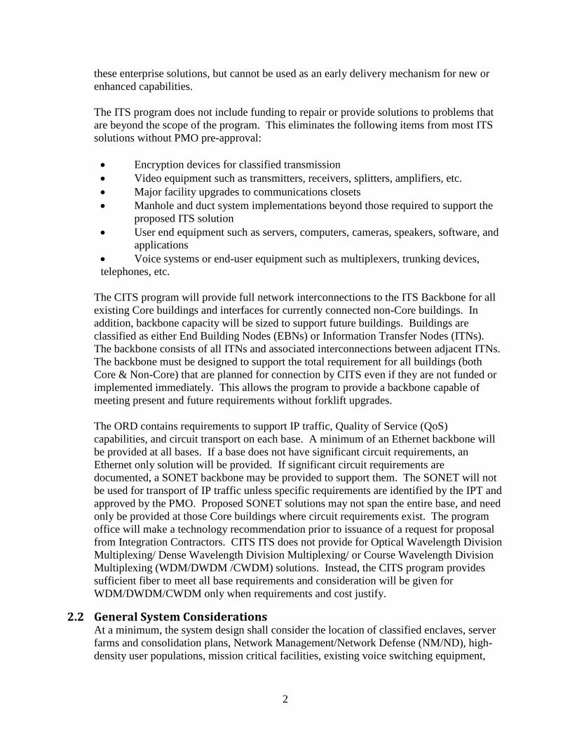
1.1 Overview This document defines the technical baseline which applies to all aspects of the ITS program. The document describes the set of capabilities that the CITS program management office (PMO) will consider when reviewing individual ITS solutions that are intended to meet base unique requirements. Specific installation/ implementation direction is separated into individual sections dealing with System, Network Hardware and Cable Distribution (both outside and inside) requirements.
The distribution system entails all outside plant (OSP) up to the first fiber optic patch panel upon building entry; as well as inside plant (ISP) distribution between communications closets and “1st 400 feet” user drops. The portion of the distribution system from the communications closets to the end user equipment is currently outside the scope of the ITS program’s funding except as highlighted below. The network hardware portion of the system is made up of all active components necessary for the ITS within a building. An ITS project includes the outside fiber plant, all distribution patch panels between connections and the electronics, all connections to any LAN distribution closets or other distribution points within the building, and all network electronics including the end user ports that connect the premise wiring to end user equipment. Additionally, ITS projects will address the necessary system support capabilities such as dedicated electrical power, communication equipment grounding and climate control equipment.
1.2 Deviation process As with any guidance document applicable to many different situations, optimization for a specific location may require deviations from the baseline. Each deviation from the baseline must be documented in the final base specific Telecommunication System Integration Plan (TSIP). If the implementation team’s PMO representative determines that a deviation is against an ORD requirement, additional guidance will be provided as to how the deviation should be handled.
2 ITS System Description
2.1 General Definition ITS is a high speed, broadband, robust digital information transport system. The Air Force direction to CITS to implement a “One Base--One Network” concept will be met by integrating all existing base data systems and providing the capability to integrate all existing and planned voice, video, imagery, and sensor systems including classified systems. The ITS program is only one component of the overall CITS Program. Because of the size of a typical project, ITS projects continue to address system requirements at the unit level with base-unique solutions. Enterprise wide requirements are currently addressed by other CITS components. The ITS program will attempt to provide a fully functional interface to
2
these enterprise solutions, but cannot be used as an early delivery mechanism for new or enhanced capabilities. The ITS program does not include funding to repair or provide solutions to problems that are beyond the scope of the program. This eliminates the following items from most ITS solutions without PMO pre-approval:
• Encryption devices for classified transmission • Video equipment such as transmitters, receivers, splitters, amplifiers, etc. • Major facility upgrades to communications closets • Manhole and duct system implementations beyond those required to support the
proposed ITS solution • User end equipment such as servers, computers, cameras, speakers, software, and
applications • Voice systems or end-user equipment such as multiplexers, trunking devices, telephones, etc.
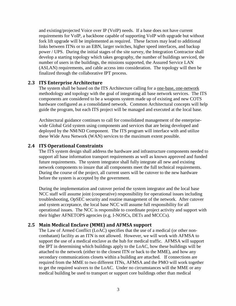
The CITS program will provide full network interconnections to the ITS Backbone for all existing Core buildings and interfaces for currently connected non-Core buildings. In addition, backbone capacity will be sized to support future buildings. Buildings are classified as either End Building Nodes (EBNs) or Information Transfer Nodes (ITNs). The backbone consists of all ITNs and associated interconnections between adjacent ITNs. The backbone must be designed to support the total requirement for all buildings (both Core & Non-Core) that are planned for connection by CITS even if they are not funded or implemented immediately. This allows the program to provide a backbone capable of meeting present and future requirements without forklift upgrades. The ORD contains requirements to support IP traffic, Quality of Service (QoS) capabilities, and circuit transport on each base. A minimum of an Ethernet backbone will be provided at all bases. If a base does not have significant circuit requirements, an Ethernet only solution will be provided. If significant circuit requirements are documented, a SONET backbone may be provided to support them. The SONET will not be used for transport of IP traffic unless specific requirements are identified by the IPT and approved by the PMO. Proposed SONET solutions may not span the entire base, and need only be provided at those Core buildings where circuit requirements exist. The program office will make a technology recommendation prior to issuance of a request for proposal from Integration Contractors. CITS ITS does not provide for Optical Wavelength Division Multiplexing/ Dense Wavelength Division Multiplexing/ or Course Wavelength Division Multiplexing (WDM/DWDM /CWDM) solutions. Instead, the CITS program provides sufficient fiber to meet all base requirements and consideration will be given for WDM/DWDM/CWDM only when requirements and cost justify.
2.2 General System Considerations At a minimum, the system design shall consider the location of classified enclaves, server farms and consolidation plans, Network Management/Network Defense (NM/ND), high-density user populations, mission critical facilities, existing voice switching equipment,
3
and existing/projected Voice over IP (VoIP) needs. If a base does not have current requirements for VoIP, a backbone capable of supporting VoIP with upgrade but without fork lift upgrade will be implemented as required. These factors may lead to additional links between ITNs or to an EBN, larger switches, higher speed interfaces, and backup power / UPS. During the initial stages of the site survey, the Integration Contractor shall develop a starting topology which takes geography, the number of buildings serviced, the number of users in the buildings, the missions supported, the Assured Service LAN (ASLAN) requirements, and cable access into consideration. The topology will then be finalized through the collaborative IPT process.
2.3 ITS Enterprise Architecture The system shall be based on the ITS Architecture calling for a one-base, one-network methodology and topology with the goal of integrating all base network services. The ITS components are considered to be a weapons system made up of existing and new COTS hardware configured as a consolidated network. Common Architectural concepts will help guide the program, but each ITS project will be managed and executed at the local base. Architectural guidance continues to call for consolidated management of the enterprise-wide Global Grid system using components and services that are being developed and deployed by the NM/ND Component. The ITS program will interface with and utilize these Wide Area Network (WAN) services to the maximum extent possible.
2.4 ITS Operational Constraints The ITS system design shall address the hardware and infrastructure components needed to support all base information transport requirements as well as known approved and funded future requirements. The system integrator shall fully integrate all new and existing network components to insure that all components meet the full technical requirements. During the course of the project, all current users will be cutover to the new hardware before the system is accepted by the government. During the implementation and cutover period the system integrator and the local base NCC staff will assume joint (cooperative) responsibility for operational issues including troubleshooting, OpSEC security and routine management of the network. After cutover and system acceptance, the local base NCC will assume full responsibility for all operational issues. The NCC is responsible to coordinate project activity and support with their higher AFNETOPS agencies (e.g. I-NOSCs, DETs and MCCCs).
2.5 Main Medical Enclave (MME) and AFMSA support The Law of Armed Conflict (LoAC) specifies that the use of a medical (or other non-combatant) facility as an ITN is not allowed. However, we will work with AFMSA to support the use of a medical enclave as the hub for medical traffic. AFMSA will support the IPT in determining which buildings apply to the LoAC, how these buildings will be attached to the network (either to the closest ITN or back to the MME), and how any secondary communications closets within a building are attached. If connections are required from the MME to two different ITNs, AFMSA and the PMO will work together to get the required waivers to the LoAC. Under no circumstances will the MME or any medical building be used to transport or support core buildings other than medical
4
buildings. All allied support funded by ITS must be in support of ITS requirements. The following rules govern what the CITS ITS program will provide for the MME. • Switches: The only switch that ITS will acquire and install is for the 1st comm
closet at the Main Medical Facility (MMF). Additional switches at the MMF and all other medical facilities are the responsibility of AFMSA.
• Fiber: If the MMF does not have adequate reusable fiber, ITS will install fiber to the nearest ITN. If medical buildings are currently connected to the MMF with adequate (per the BPD) reusable SM or MM fiber, we will install no new fiber. If a medical EBN is connected to another ITN (not the MMF) with adequate reusable fiber ITS will provide a VLAN solution back to the MMF. When a core medical EBN has inadequate fiber, ITS will install fiber to the nearest ITN (with a VLAN solution to the MMF) or the MMF, whichever is most cost effective.
2.6 Test Equipment ITS shall upgrade existing network analyzer(s) or purchase new Ethernet, and/or SONET capable network analyzer(s) as required by the design and determined during collaboration. Specific choices of test equipment hardware will be based on their cost effective utility for troubleshooting problems in an operational environment.
2.7 Provisions for Equipment Redundancy The Integrator will not purchase spares under the ITS contract. A limited set of redundant hardware items may be included in the design. These items will be limited to those that would cause a loss of system access to users until a replacement item is received. High availability and redundant items which are already in the design (such as chassis, dual PS, dual Sups) will not be purchased. These items will be included under the Vendor warranty and support contracts provided by CITS. The final list of equipment will be determined during collaboration by the IPT.
2.8 Vendor Support All major networking components (switches, routers, management software, etc.) both new and reused shall be covered by a vendor supplied standard warranty period. Ancillary devices (UPS, test equipment, management server platforms, etc.) shall also be covered by a vendor supplied standard warranty period. The ITS project will not purchase or supply warranty coverage beyond the vendor’s standard warranty period. All base specific details regarding vendor warranty coverage will be provided by the system integrator. For consistent information on warranty coverage, bases will be instructed to contact the ENSC helpdesk who will provide the latest information on CITS Enterprise-wide support. Expectations are that the CITS Enterprise Support contract will provide hardware support on an 8X5XNBD basis, while phone support and software updates will be available 24X7.
5
3 Network Hardware Components
3.1 Interface Connection Data Rates a. All connections between ITNs for IP traffic
shall utilize Gigabit Ethernet as a minimum. Multiple Ethernet links or higher speed links can be used if requirements justify the additional costs. Primary Ethernet links between ITNs shall be made using physically diverse fiber routes to adjacent ITN’s. Additional Ethernet links between ITNs, utilized for meshing of the network do not require physical separation from the primary fiber paths.
b. All new Ethernet backbone equipment shall be upgradeable to 10 Gig Ethernet and capable of supporting a semi-meshed design (> two 10 Gig uplinks).
c. Where SONET is required, OC-48 (2.4 Gbps) SONET shall be employed for the backbone. Higher speed connections can be used if requirements justify their use. SONET will only be deployed at ITNs where sufficient circuit requirements exist.
d. All new SONET backbone equipment shall be upgradeable to support OC-192 and WDM either internal or external to the box.
e. Gigabit Ethernet (1,000 Mbps) connections will normally be used between ITNs and EBNs. However, lower speed Fast Ethernet (100Mbps) may be re-used to support Non Core locations or where required. Multiple Ethernet links (trunks) can be used when justified by requirements. Usage of SONET equipment and connections to EBNs can be made only when circuit and bandwidth requirements exist in sufficient quantity to make this a best value solution for the Air Force.
3.2 IPv6 Capable a. All new layer 3 equipment must be IPv6
Capable as defined below. All reused layer 3 equipment must be either IPv6 Capable or Capability Available as defined here. The Integration Contractor must identify any additional items needed to fully implement IPv6 on the network (e.g. hardware or software needed to upgrade reuse equipment, element managers, etc.).
b. Each item delivered under this contract shall accurately transmit, receive, process, and function correctly using either the Internet Protocol Version 4 (IPv4) or Internet Protocol Version 6 (IPv6). For equipment to be deemed IPv6 Capable, the network equipment vendor must warrant that:
i. each item delivered complies with the current DISR* (was Joint Technical Architecture (JTA)) developed IPv6 standards profile;
ii. each item delivered maintains interoperability with IPv4 (specifically, is able to operate on/coexist on a network supporting IPv4 only, IPv6 only, or dual stack (i.e., a hybrid of IPv4 and IPv6)) and
iii. each item delivered is supported by the vendor’s IPv6 technical support.
6
iv. The vendor must also be committed to providing a transition path that maintains compliance with evolving requirements in the DISR profile.
c. Reused layer 2 equipment does not have to be IPv6 Capable. If available, new layer 2 equipment shall be purchased with support for assignment of an IPv6 management address.
d. New devices must implement IPv6 functions through hardware solutions. Hardware implementations are expected to provide better IPv6 performance. The network equipment vendor must provide data on equipment performance in a dual stack configuration.
e. Devices must provide IPv6 over all layer 2 protocols and methods supported by the proposed design.
f. The CITS program does not have the authority to implement IPv6 solutions on every project. However, individual projects may request permission to implement dual stack IPv4/IPv6 solutions on a case-by-case basis. Activation of a live IPv6 solution will only be fielded when approved by the PMO.
3.3 Support of QoS for Ethernet and SONET a. All new Ethernet and IP equipment shall
support standards-based, end-to-end QoS. b. Gigabit Ethernet solutions should include provisions for using QoS features to protect the
following classes of traffic: Switch Management, encrypted SIPRNet, Voice over IP (VoIP) Video over IP and any others that are sensitive to network loading and delays.
c. These QoS service levels must be maintained from EBN to EBN and switch-to-switch across the ITS backbone.
3.4 Network Timing a. A network timing tree design and analysis shall be accomplished for all ITS designs
employing SONET. In SONET networks, both a primary and secondary timing source shall be used and included in the design.
b. A timing tree design and analysis shall also be accomplished for all ITS designs employing Ethernet. Network Time Protocol (NTP) provides an efficient and scalable method for managed network elements to actively synchronize to an accurate time source. Insuring that there are always NTP servers available to provide time is critical. It is imperative that all single points of failure for the NTP infrastructure are eliminated.
3.5 Uninterruptible Power Supplies (UPS) a. For all ITNs supporting VoIP users, a manageable UPS capable of supporting full switch
operations for at least 2 hours for C2 Users or 8 hours for Special C2 Users shall be employed unless the building is equipped with emergency backup generators. Buildings which support VoIP and have backup emergency power generators will be equipped with a UPS capable of maintaining switch operation for a period of time sufficient to allow the Generator backup power to be brought on line.
b. In all other cases, ITNs and CEBNs shall contain a manageable UPS capable of, at a minimum, supporting an orderly shutdown or switchover to generator backup.
c. EBNs that support IP phones for C2 Users shall have 2 hour (8 hour for Special C2 Users) UPS for switch and IP appliance. If the building is equipped with emergency
7
backup generators, it will be equipped with a UPS capable of maintaining switch operation for a period of time sufficient to allow the Generator backup power to be brought on line. For all other EBNs surge protection at a minimum shall be provided.
d. If site unique requirements for classified or mission critical systems require sustained power exceeding these standards, additional capability can be provided with PMO approval given that the system being supported meets the same standards.
3.6 Network Equipment Vendor Selection and Choices a. It is a goal of the CITS program to use a single
vendor’s solution, with the exception of legacy equipment. This approach leads to simplified integration, training, operations, and maintenance costs. No more than 2 vendors’ products will be purchased by ITS, one for Ethernet and one for SONET.
b. ITS shall maximize the use of existing network equipment which fully meets requirements. Tradeoffs shall be made to minimize the total number of vendors supported on a site.
c. When considering the final vendor selection, the Integrator shall insure that all network equipment included in the selected design meets the mandatory technical requirements listed in the Vendor Selection Document (VSD).
3.7 Support of Reused Equipment All equipment planned for reuse in ITS shall have at least 5 years of serviceable life remaining, at the time of scheduled system acceptance, according to the manufacturer. Integration contractors will list all reusable equipment in their request for proposal (RFP) to equipment vendors.
3.8 SONET Requirements a. All SONET equipment fielded in the backbone shall be capable of upgrade to WDM and
OC-192 without forklift replacement. Equipment used to connect EBNs shall be capable of upgrade to at least OC-48. Bi-Directional Line Switched Ring (BLSR) support is required. Capacity that is initially deployed will be determined by the IPT.
b. All SONET equipment must support the standard SONET framing. c. SONET equipment shall support DS-1, DS-3, Gigabit Ethernet, and SONET interfaces at
a minimum. SONET equipment purchased for OCONUS installations may need to be capable of supporting alternative framing and circuit bandwidths required for that OCONUS location (i.e. E-1, E-3 etc.)
d. All SONET equipment must be able to report status via Simple Network Management Protocol (SNMP) v3 to the Network Management System (NMS) platform.
3.9 Redundancy and Reliability a. Equipment redundancy and/or multiple connections shall be used to implement network
architectures capable of meeting the ORD requirement for availability of 99.99%. b. In network segments where VoIP and/or Video over IP services will be implemented for
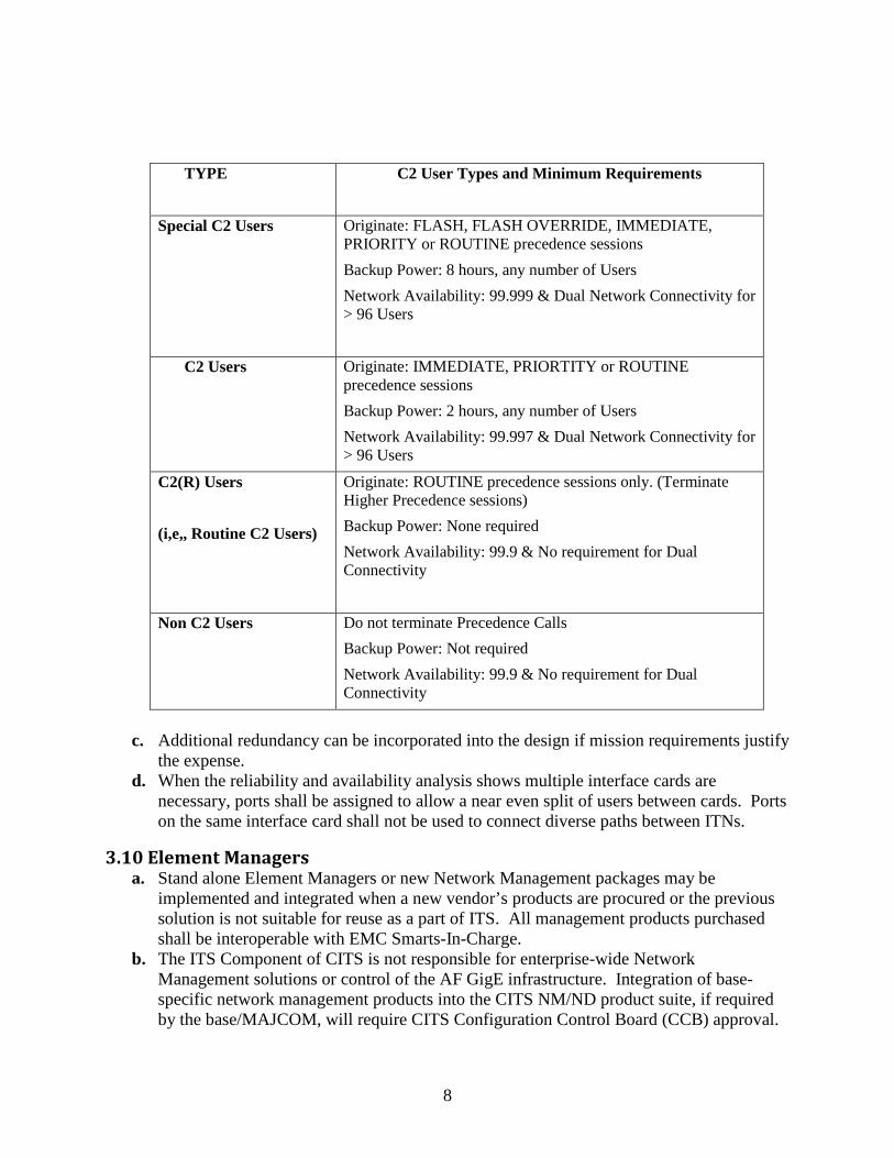
C2 and/or Special C2 users, ASLAN requirements for higher availability (e.g. 99.997% or 99.999% respectively) and reconfiguration from any network fault within 5 seconds) may be applicable and would require additional engineering. The following table lists the requirements of the various user types.
8
TYPE C2 User Types and Minimum Requirements
Special C2 Users Originate: FLASH, FLASH OVERRIDE, IMMEDIATE,
PRIORITY or ROUTINE precedence sessions Backup Power: 8 hours, any number of Users Network Availability: 99.999 & Dual Network Connectivity for > 96 Users
C2 Users Originate: IMMEDIATE, PRIORTITY or ROUTINE precedence sessions Backup Power: 2 hours, any number of Users Network Availability: 99.997 & Dual Network Connectivity for > 96 Users
C2(R) Users (i,e,, Routine C2 Users)
Originate: ROUTINE precedence sessions only. (Terminate Higher Precedence sessions) Backup Power: None required Network Availability: 99.9 & No requirement for Dual Connectivity
Non C2 Users Do not terminate Precedence Calls Backup Power: Not required Network Availability: 99.9 & No requirement for Dual Connectivity
c. Additional redundancy can be incorporated into the design if mission requirements justify
the expense. d. When the reliability and availability analysis shows multiple interface cards are
necessary, ports shall be assigned to allow a near even split of users between cards. Ports on the same interface card shall not be used to connect diverse paths between ITNs.
3.10 Element Managers a. Stand alone Element Managers or new Network Management packages may be
implemented and integrated when a new vendor’s products are procured or the previous solution is not suitable for reuse as a part of ITS. All management products purchased shall be interoperable with EMC Smarts-In-Charge.
b. The ITS Component of CITS is not responsible for enterprise-wide Network Management solutions or control of the AF GigE infrastructure. Integration of base-specific network management products into the CITS NM/ND product suite, if required by the base/MAJCOM, will require CITS Configuration Control Board (CCB) approval.
9
The PMO will obtain prior approval for any changes being made to the NM/ND hardware and software product suite.
c. The Integration Contractor will purchase and install any hardware / software upgrades and/or additional servers required to support ITS Element Managers; however, the Integrator will not be responsible for providing Authority to Operate (ATO) or C&A documentation.
d. Design of the IP subnet addressing for the management of the network devices will be coordinated with the base and MAJCOM.
e. Integration with Active Directory or any other Air Force applications will need to be coordinated with the base / MAJCOM on a case-by-case basis.
3.11 Equipment Sizing and Expansion a. The LAN design for an EBN shall be sized to
support the known and documented building requirements. However only those portions required to support the current and known future users at the time of the FDA shall be implemented. This does not eliminate the use of stackable switches since only the number of switches required to connect current users would be purchased and additional switches can be added to the stack for expansion.
b. If Stackable switches are used in the ITS design they must be a true stackable (Backplane stack) and appear as one switch to the NMS.
c. The ITS backbone switches shall be designed and sized to provide connectivity to all EBNs (both core and non-core EBNs as identified by the overall base topology), plus 20 percent expansion without ITN chassis replacement. However, only equipment required for current phase implementation shall be purchased.
3.12 Non Core Capabilities and Services a. Non Core buildings will not be physically surveyed by the Integration Contractor, so the
base will be totally responsible for providing information on how and where these building are attached to the ITS Backbone.
b. Non Core building requirements will NOT be used to justify additional capabilities or service features for the ITS Backbone.
c. Once the ITS Backbone is operational, base personnel (not the Integration Contractor) will be responsible for restoring services by configuring and re-attaching all Non Core switches.
3.13 GigE VLAN Architecture a. VLANs shall be structured to efficiently support the anticipated traffic flows on a base’s
network given the placement and performance of routers and switches in the design. b. VoIP and Video traffic shall utilize VLANs separate from data traffic. c. Network management traffic shall not share the same VLAN with user traffic.
3.14 Provisioning of SONET Circuits a. The Integration Contractor shall provision the SONET network to support those circuits
identified during the site survey and design. Test traffic (no operational data) will be used to demonstrate SONET functionality during System Acceptance Testing.
10
b. The base will assume primary responsibility for activation of operational circuits; however, once the SONET system has been tested and accepted by the Government, the Integration Contractor may help the base fulfill this task.
3.15 Encryption Equipment ITS does not procure or provide encryption equipment for the integration of classified information on ITS unless approved by the PMO.
3.16 Support Services a. The CITS PMO does not currently require ITS solutions to use Out-of-Band Management
techniques. b. ITS solutions shall incorporate open standards based routing protocols (such as OSPF).
Where appropriate, router authentication (e.g. MD5) shall be enabled for updates. c. When a base has already implemented Remote Access Management (with or without
Authentication), the Integration Contractor shall maintain the capability as a part of the new design. The Integrator shall take maximum advantage of any/all existing infrastructure including RADIUS or TACACS or similar systems.
d. The Integration Contractor shall work closely with base NCC staff to insure that all systems comply with local security guidelines. To help the PMO/Integration Contractor provide a suitable solution, the base NCC/MAJCOM need to provide technical details on how they currently meet applicable DISA Security Technical Implementation Guides (STIGs).
11
4 Cable Distribution Components
4.1 Outside Plant (OSP) Distribution System Specifics
4.1.1 Fiber Optic Cabling- Capacity, Counts, and Type a. Existing infrastructure (i.e. Manhole ducts and fiber etc.) shall be used to the maximum
extent possible b. All existing cables, when worthwhile test data is not available as determined by the IPT,
planned for reuse shall be tested (ALL unused fibers in the cable) with both OTDR and power meter before they are integrated into the design. If fibers in use must be considered in order to meet the minimum fiber count requirement, these fibers, the ones currently in use, must be tested and determined to be good before the fiber is considered viable for reuse. Large Fiber Count Cables, especially Hybrid cables, and un-terminated fibers identified for possible reuse shall be called to the attention of the IPT (specifically the PMO) for discussion and possible testing modifications. Any decisions resulting from these discussions shall be documented in section 2.3 of the TSIP. OTDR data shall be used to determine if bad fiber can be economically repaired or if it will require replacement. Testing of fibers, which have not been terminated, but ultimately are planned for reuse, is required.
c. Between an ITN and an EBN, existing 62.5 multi-mode fiber can be used if it will support Gigabit Ethernet. This reuse shall be called to the attention of the IPT and would typically limit distances to a maximum 550 meters.
d. The minimum existing fiber count acceptable for reuse is 6 between ITN and EBN and 18 between ITNs. In all cases where larger, more than 6 or 18 respectively, numbers of fibers are planned for use, the number of fibers used in the design, plus 4, is the minimum acceptable. In all cases the fiber is considered reusable when it is tested-good, unused, and available for ITS.
e. At no time shall non-building rated fiber optic cables entering a building exceed 50 feet in cable length without prior approval of the PMO.
f. Building rated cable shall be spliced, in equal counts, to the non-building rated cabling at the building entry point where 50 feet of non-building rated cable length will not reach the first communications closet/FODP, unless another design method is approved by the PMO.
g. Cabling between communications equipment locations shall have a minimum of 4 strands or if requirements dictate more connections at least 2 more than connection requirements.
h. New ITN-to-ITN fiber optic cabling shall contain a minimum of 36 fibers (all single mode), or the number of fibers needed to meet the architectural requirements mandated for the ASLAN plus 18 spares, if this number is greater.
i. New ITN-to-EBN fiber optic cabling shall contain a minimum of 12 fibers (all single mode), or the number of fibers needed to meet the architectural requirements mandated for the ASGLAN plus 6 spares, if this number is greater.
j. Direct bury cable shall be metallic armored. Alternatively, standard external grade fiber optic cable shall be placed in a high-density polyethylene (HDPE) SIDR 11 roll pipe having a nominal inside diameter of 1.25 inches. Only one cable shall be installed in
12
each HDPE pipe. One roll pipe in each run shall have a tracer wiring on the exterior surface of the pipe.
k. All runs shall use continuous fibers, with no intermediate patches, cross connects, and a minimum utilization of splices. Any splices that must be used shall be fusion splices. No mechanical splices are to be used.
l. Provide 50 feet of maintenance loops coiled in every third manhole, starting/ending in the first manhole exiting each building (i.e. the first manhole outside of each building will contain 50 feet of maintenance loop). If manhole spacing and/or congestion presents issues with the loop size or placement in the first manhole outside of a building or along the run, alternatives can be implemented with concurrence of the PMO.
m. A minimum coil of 25 feet of cable shall be installed on all cables entering and leaving a manhole splice case. For an interior splice, sufficient cable shall be left to enable repairs and changes. Adjustments can be made with PMO distribution engineer concurrence. Adjustments for design purposes shall be made and agreed to prior to FDA submission and adjustments during installation shall be made and agreed to prior the install effort and reflected on as-built CSIRs as needed.
n. All reused infrastructure shall meet all current installation and other requirements of the ITS program or shall be brought into compliance as a part of developing the ITS.
4.1.2 Fiber Optic Cabling- Performance a. The fiber cable shall comply with industry standards with regard to manufacturers’ cable
markings, armor jacket, rip cords, filling compound, fiber color coding, jacketing materials, etc.
b. ITS installed cable shall not contain factory fiber splices. c. The single mode fiber shall comply with industry standards with regard to mode field
diameter, core-cladding concentricity, attenuation, and dispersion characteristics at 1300 nm and 1550 nm.
d. The multi-mode optical fiber shall comply with industry standards for 62.5-µm fiber with regard to core-cladding concentricity, attenuation and modal bandwidth at 850 nm and 1300 nm. As an alternate, a splice free cable run of 50um laser optimized fiber may be used if approved by the PMO before FDA.
e. Cable plant shall be tested and proven to perform within expected tolerances.
4.1.3 Cable Routing, Meshing, and Building Entry Conduits Standard installation practice for ITS has EBNs connected to an ITN by a single cable route and entry conduit. Additional connections may be used if requirements justify the expense.
a. Each ITN shall be connected to at least two other ITNs. Additional connections may be used between ITNs if requirements justify the expense. In addition (for ITNs only), two of these connections must be physically diverse (separated by a minimum of 40 feet) cable routes. Physical diversity starts at the end of the entry conduit when direct buried or at the first manhole after leaving a building if the manhole is within 50 feet of the building. If the manhole is more than 50’ from the building, a new entryway must be provided or another method of physically protecting the cable may be used, with PMO approval. Changes to cable entries made during previous phases of ITS can only be reworked with approval of the PMO.
b. Of critical importance in using existing infrastructure in the network Backbone and its diversity. This diversity must be verified to ensure true physical separation in cable paths
13
between at least two connecting ITNs. The contractor will use all documentation available from government sources as well as physical cable identification to clearly identify cable separation along the entire length of all ITN backbone routes.
c. In all cases the contractor shall physically verify and mark the routes of backbone cables at the entry point(s) of each ITN and along the route until diversity is clearly demonstrated through manhole inspection. Cables used in the backbone cable shall be marked as a CITS backbone cable where ever the cable is inspected.
d. Conduit entering a MH/HH will be cut off even with the MH/HH wall and all conduits sealed with like material as the Manhole composition. On underground building entrances the conduit shall extend no more than 4” above the floor. Openings around the conduits shall be duct sealed or fire stopped as necessary.
4.1.4 Installation of Manhole, Handhole, and Duct System a. CITS will use the last existing conduit or innerduct if needed for the ITS installation. b. Where insufficient duct capacity exists to support the new ITS, direct bury (preferred) or
additional duct capacity shall be considered. c. Overbuilding of manholes and ducts requires coordination and approval of the PMO d. Repairing manholes and duct systems shall be considered when economically feasible.
Repairs shall only be done when necessitated by the ITS installation and with coordination with the CITS PMO.
e. All new manholes and handholds shall be fully enclosed pre-cast concrete in construction, have round cast iron cover/ring or shall be full sized, galvanized hinged lids and shall be rated for roadway traffic, and sized to accommodate the full build-out of the duct system.
f. New manholes/handholes shall be capable of being secured to prevent direct opening/access. However, this is not meant to be an elaborate system nor capable of meeting the requirements of a protected distribution system (PDS).
g. New duct/conduit building entries shall have a manhole/handhold or access point installed within 50’ of the building entrance.
h. All new direct buried armored cable or roll-pipe alternative, shall be installed with at least 36” of top cover depth.
i. All new manhole and duct systems shall use 4” schedule 40 PVC pipe and be installed below the normal frost line or with a minimum top cover depth of 36”. The one exception is when utilizing a 3’ X 5’ X 4’ full lid manhole with a 4-4” duct system (in 2 over 2 configuration), at which time it is permissible for the top duct to enter the manhole at a depth of not less than 30” from the surface. However, ducts shall transition to the minimal 36” top cover depth before extending more than 6’ from the side of the manhole.
j. In OCONUS designs an equal or better product can be utilized if identified and specified during the design collaboration and agreed to by the PMO prior to FDA.
k. Boring will be the preferred method of road and parking lot crossings. l. New duct trenched under roadways shall be encased in 900 psi concrete slurry filling the
entire trench depth less pavement surface requirements. Coordination with the PMO and base CE will be required and shall be documented in the TSIP for any variations to this requirement.
m. Sleeveless or uncased boring shall not be used. n. Ducts installed under runways, taxiways, railroad tracks, or other special conditions
require coordination with the base civil engineer and the PMO.
14
o. On backbone runs, alternative methods of protecting the ducts (i.e., concrete encasing and capping) are permitted only with coordination with the CITS PMO and if it is shown to be more cost effective than diverse routing.
p. Standard 1” Innerduct and/or flexible geotextile multiple cell innerduct shall be used to maximize capacity of the duct system.
q. All new CITS duct/fiber optic cable runs shall be capable of being tone-traced. Tone-tracing shall be accomplished by utilizing any one of several methods (see TSIP for additional details) to allow a tone signal to be sent along the duct/cable run. Tracing methods will be developed during collaboration and presented to PMO for review prior to Hardware Implementation Plan Review (HWIPR).
r. All above ground entries shall consist of an exterior rated NEMA pull box mounted on the building’s exterior wall, connected by UV rated schedule 80 PVC external riser(s) and shall have a 4” wall core thru to the interior wall surface sealed at least on the exterior side depending on the wall thickness, compliant with fire codes.
s. Tracer wire shall be pulled back from building entrances until it is underground to prevent lightning damage.
4.1.5 Termination of Fiber Optic Cables a. All fibers shall be terminated in a fiber optic distribution patch panel (FODP). b. All cables, FODP panels, and connectors, both new and reused, shall be clearly labeled,
adequately supported, and neatly dressed. In equipment rooms the cable is labeled were it comes into the room, and at the FODP. In MH’s labels are at both ducts and at the splice and on/near service loops.
c. No mechanical, butt-splice type connectors will be used. d. SC type or MTRJ small form factor connectors are preferred. Any other connector will
be agreed to in collaboration and approved prior to FDA. e. All work with the fiber optic cables shall be done by qualified and experienced fiber optic
technicians.
4.1.6 Comm Feature Location Data (GIS data) a. As part of the Geographic Information System (GIS) effort, the contractor shall use
Global Positioning Systems (GPS) and conventional surveying methods, to collect and report Comm. Feature Location Data (CFLD), as outlined in the TSIP, following Federal Geographic Data Committee (FGDC) - STD-007.4-2002 Geospatial Positioning Accuracy Standards Part 4, as it supports the National Spatial Data Infrastructure. With a 95% confidence level, CFLD shall be accurate to +/- 18” in the horizontal plane
b. The Vertical (Z) axis, data shall be taken at ground level. c. CFLD data will be in an excel spread sheet format.
4.1.7 Wireless Links and Other Link Technologies a. Wireless point-to-point links shall be considered when the cost and complexity of fiber
cabling is prohibitive. All wireless communications shall be bulk encrypted. The equipment shall be FIPS 140-2 Level 1 or Level 2 certified, and manageable from the NM/ND console.
b. Leased circuits or other techniques, with bulk encryption, shall be considered, as alternatives, when they have cost or performance advantages when compared to
15
dedicated fiber. Equipment, which is used for transmission, shall be FIPS 140-2 (FIPS 140-1) Level 1 or Level 2 certified.
c. Level 2 is employed for more sensitive information.
4.1.8 Environmental, Historical and Cultural a. The Integration Contractor shall be responsible for development of an AF form 813 with
the appropriate base CE shops to ensure that the ITS design does not adversely affect any environmental, historical or cultural issues within the base. There may be other processes and documentation needed depending on what is learned during the PMO pre-site. A copy of the AF 813 permit shall be included under separate cover as part of the FDA TSIP documentation.
b. Development of a National Pollution Discharge Elimination System (NPDES) permit, often also called a Storm Water Pollution Prevention Plan (SWPPP), takes various shapes according to the state in which the subject base is located. The integration contractor is responsible for developing and obtaining a NPDES permit and shall directly contact the appropriate state agency responsible for management/oversight of the federally mandated program. A copy of the NPDES permit shall be included under separate cover as part of the FDA TSIP documentation.
4.1.9 Miscellaneous a. Before the contractor may use any product that has an associated material safety data
sheet (MSDS) a copy for the MSDS must be supplied to the PMO. b. CITS will return disturbed areas of the base to similar conditions of those existing prior
to ITS installation within a reasonable period of time. Seeding or hydro-seeding shall be used to restore grassy areas.
4.2 Inside Plant (ISP) Distribution System Specifics
4.2.1 Wiring between Communications Closets Wiring between communications closets within an EBN or ITN should use fiber optic cable. Other media shall be considered when advantageous. Cables shall be installed in EMT or using other approved methods and includes a reasonable amount of racked and coiled cable at FODPs for maintenance needs in the future. All cables shall be terminated in appropriate patch panels and include at least 2 spare strands. Cables that are planned for reuse must be tested and proven good.
4.2.2 Wireless User Connections (WLAN) Wireless connections to users via access points (WLANs) are considered to be a part of the premises wiring and not included in the current program funding for implementation. Existing WLANs are grandfathered for continued use on ITS as currently implemented. For current WLAN policy on new installations or major upgrades consult with the PMO.
4.2.3 New User Drops a. Except as described below in “Existing User Drops”, new user drops are not covered with
the program’s current funding. Premise wiring is a responsibility of the MAJCOM. However, MAJCOM efforts to provide premise wiring shall be coordinated with ITS projects for that MAJCOM whenever possible.
16
b. Any newly installed user drops shall use CAT 6 materials, be installed to CAT 6 standards, and certified to meet ANSI/EIA/TIA CAT 6 performance requirements.
c. All new user drops will be installed according to BICSI Telecommunications Distribution methods manual.
d. Existing Multi-mode fiber optic drops can be employed in special situations where distances, environmental conditions, or situations make it the cost-effective solution for meeting the minimum requirement of Fast Ethernet to the end users.
4.2.4 Existing User Drops a. If the existing equipment location:
i. Meets CITS Equipment Enclosures or Communications Closet Requirements (CEECR):
• All existing user drops shall be used and assumed to be in good operating condition unless specific 1st 400’ work is authorized.
• If work is authorized to service/improve the existing user drops shall be tested to demonstrate 10/100/1000 Capability as described in the decision flow chart in the TSIP Part 8 of Distribution Appendix (figure D 46), the information will be recorded in the format shown in Table D 8
• If the existing patch cables are not compatible with the premises wiring and patch panels, new patch cords shall be installed.
ii. Does not meet CEECR and a new location is selected, the contractor shall consider relocating the patch panels, using longer patch cords, or coordinating with the site the rework of the premises wiring while an interim solution is employed. Since the ITS program is not currently funded for the first 400 feet, our goal is to maintain all existing user connections without repairing or replacing premises wiring.
iii. In cases where the location meets CEECR requirements but it makes technical and economical sense to consolidate closets, CITS will consider doing the “last 400 feet wiring” affected by comm. closet consolidation.
4.2.5 Power over Ethernet (PoE) Power over Ethernet, where implemented, shall comply with PoE standard 802.3af.
4.2.6 Labeling and Appearance In locations where changes are being made to the network equipment, racks, or associated support equipment, all cables, patch panels, and connectors, both new and reused shall be adequately supported and neatly dressed. With the exception of existing user wiring, all equipment and wiring will be properly labeled in any locations where work is required. It is the integration contractor’s responsibility to insure both new and reused equipment, patch panels, and wiring meets minimum ITS standards outlined in this document. Labeling standards on premise wiring shall be defined in the TSIP and determined by the IPT during collaboration.
a. All electrical work will be labeled at the circuit Panel with room and rack identification and at the equipment end with panel and circuit information.
17
b. IAW Defense Federal Acquisition Regulation (DFARS) 252.211-7003, DoD Unique Item Identification (UID), or a DoD recognized unique identification equivalent will be provided for: • All delivered items valued at $5,000 or more and • All manufacturer-serialized items less than $5,000 in value
4.3 ITS Facility Components
4.3.1 Electrical Power a. All ITNs shall contain a minimum of two dedicated power circuits (each of which shall
be sufficient to support the full suite of equipment). Installed within the rack or cabinet to prevent accidental disconnect of the network equipment and determined by the IPT during collaboration.
b. EBNs shall be on a minimum of a single dedicated power circuit (sufficient to support the entire suite of equipment). Installed within the rack or cabinet to prevent accidental disconnect of the network equipment and determined by the IPT during collaboration.
c. A new circuit of an equivalent OCONUS rating shall be used where applicable.
4.3.2 Grounding a. All ITS equipment shall be grounded for safety
and reliable performance in accordance with TIA/EIA 607, with 10 ohms as a goal and meet a 25 ohm requirement as a minimum.
b. The contractor is not to install any new facility grounds.
c. All existing building grounds that the contractor plans to use in the design shall be tested and presented to the PMO at the Hardware Integration Planning Review (HWIPR). Readings found during testing of grounding at main electrical service panels that are at or above 25 ohms or no building ground is found shall be reported to the PMO and base Civil Engineering during the next regular IPT and resolutions discussed during collaboration.
d. All new ground connections shall be tested for compliance.
e. All armored cable shall be grounded according to the manufacturers’ specification and NEC when entering or leaving a building.
f. Ground points shall follow the applicable local standards in OCONUS locations. g. All racks and cabinets shall be grounded per-manufacturers specification.
4.3.3 CITS Equipment Enclosures or Communications Closets a. ITS equipment shall be placed in existing communications closets whenever possible. b. If an adequate closet is not available, a cabinet capable of providing the necessary
environmental controls shall be provided. The cabinet shall provide physical protection for the equipment and electrical service and environmental support when none is available at a location. If a closet or room can be modified to support the equipment for approximately the same cost, this option may be used with PMO approval.
c. All ITS equipment shall be located in a physically controlled area (i.e. kept under lock and key where control is maintained by the NCC including, when possible, the power for the rack and end user patch panels). This area shall have sufficient heating, ventilation,
18
air conditioning, cable access, and space to allow for maintenance and operation of the equipment. If a grounding stud or clearly marked threaded grounding hole is provided the equipment must be grounded to the rack. If there is a question the installer should look to the manufacturer's specifications. An e-mail or written correspondence should be acquired from the manufacturer if any proof of this statement is needed
d. CITS will extend ductwork and/or install louvers to address ventilation problems within CITS equipment locations. If new HVAC is needed this will be discussed during the normal IPT meeting. Normally new HVAC is the responsibility of the base.
4.3.4 Patch Cables a. All patch cables, including fiber optic cables and UTP, shall be compatible with the
outside plant, premises wiring, and network equipment interfaces. Patch cables shall be properly supported, neatly dressed, and properly labeled.
b. CITS will not re-label user drop cables.